Embed Size (px)
Citation preview
ISSN 0016�7932, Geomagnetism and Aeronomy, 2015, Vol. 55, No. 4, pp. 547–554. © Pleiades Publishing, Ltd., 2015.Original Russian Text © R.I. Krasnoperov, R.V. Sidorov, A.A. Soloviev, 2015, published in Geomagnetizm i Aeronomiya, 2015, Vol. 55, No. 4, pp. 568–576.
547
1. INTRODUCTION
The International Real�Time Magnetic Observa�tory Network (INTERMAGNET) routinely recordscomponents of the Earth’s magnetic field and providesthe global scientific society with magnetic datarecorded and processed according to highest stan�dards. The INTERMAGNET network is a uniquesource of data for the interpolation and approximationof the magnetic field distribution with the goal ofmodeling the field and studying the geomagneticactivity (Berezko et al., 2011; Soloviev A. et al. 2012a;2013b). In particular, such techniques allow a deter�mination of the parameters of the Earth’s magneticfield in hard�to�reach regions of the Russian Federa�tion, where the deployment of geomagnetic observa�tories is impossible. The INTERMAGNET networktoday includes more than 130 magnetic observatorieslocated at different places, from polar archipelagos toequatorial regions. The density and geographical cov�erage of the geomagnetic observatory network is themost important factor in the construction of adequatemodels of the Earth’s magnetic field and the distribu�tion of its variations. The density is quite high in West�ern Europe, and the coverage is quite homogeneous inNorthern America, while the INTERMAGENT net�work is less dense in Asia and on the territory of USSR.In particular, only eight Russian, two Ukrainian, andone Kazakhstan observatories participate in theINTERMAGNET network. Thus, compensation forthe lack of Russian magnetic observatories should
contribute significantly to the development of a systemfor monitoring and estimating geomagnetic condi�tions on the Russian territory.
The first Russian magnetic observatories were ren�ovated according to the INTERMAGENT standardswith the support of the CRENEGON internationalproject (The Creation of a Renewed Network of BasicGeomagnetic Observatories of NIS Countries). Thisproject allowed five observatories of NIS countries tojoin the INTERMAGNET network. The Irkutsk mag�netic observatory started transmitting data into theINTERGAMGNET geomagnetic information nodesin 1998 and became the first Russian magnetic obser�vatory to officially enter the INTERMAGNET net�work in 1999 (Potapov et al., 2011). In 2002, anINTERMAGNET�standard magnetic observatorywas deployed on the basis of the Borok geophysicalobservatory (Yaroslavskaya oblast) as part of the col�laboration between the Schmidt Institute of Physics ofthe Earth, Russian Academy of Sciences, and the ParisInstitute of the Physics of Earth. This observatoryreceived official INTERMAGNET status in April2004 (Chulliat, 2008).
The development of a network of INTERMAGNET�standard magnetic observatories on the Russian territoryis an important applied research task that can be imple�mented by joint efforts of institutes of the Federal Agencyfor Scientific Organizations and ROSHYDROMET(Gvishiani et al., 2014; Soloviev et al., 2013a). Thedeployment of new INTERMAGENT magnetic
Modern Geodetic Methods for High�Accuracy Survey Coordination on the Example of Magnetic Exploration
R. I. Krasnoperova, R. V. Sidorova, and A. A. Solovieva, b
a Geophysical Center of the Russian Academy of Sciences, Moscow, Russiab Schmidt Institute of Physics of the Earth, Russian Academy of Sciences, Moscow, Russia
e�mail: [email protected]; [email protected]; [email protected] October 29, 2014; in final form, February 5, 2015
Abstract—The purposes and problems of the international network of geomagnetic observatoriesINTERMAGNET are briefly described in the work. The importance of the development of the Russian seg�ment of the network as a part of a system for monitoring and estimating geomagnetic conditions on the Rus�sian territory is emphasized. An example of the use of modern high�precision geodetic equipment for coor�dinate referencing of field geophysical observation is described. Factors that distort the referencing of fieldobservations in problems of survey, engineering, and technical geophysics are listed, as well as those relatedto detail and high�resolution geophysical surveying and those that require a corresponding accuracy of obser�vation point coordination. The magnetic exploration at the site of the Yamal INTERMAGNET�standardobservatory serves an example to describe a technique for geodetic provision of a detailed geophysical surveyby means of joint use of differential GNSS measurements and electronic tacheometry. The main advantagesand disadvantages of the technique suggested are listed.
DOI: 10.1134/S0016793215040076

548
GEOMAGNETISM AND AERONOMY Vol. 55 No. 4 2015
KRASNOPEROV et al.
observatories includes the mounting and putting intooperation of complexes of magnetic measuring instru�ments at existing and new geophysical stations andobservatories. A complete set of magnetic measuringinstruments at an observatory usually includes scalarand vector magnetometers, a declinometer/ inclinom�eter based on nonmagnetic theodolite, and a dataacquisition and transmission system. When deployinga magnetic observatory, the magnetic situation at thesite of deployment is important: there should be nosignificant anomalies of the strength of the magneticfield and its high gradients near observatory buildingsand facilities. Thus, geomagnetic exploration at theplanned magnetic observatory site is the most impor�tant and integral part of its deployment (Nechaev,2006; Jankowski and Sucksdorff, 1996; Newitt et al.,1996).
This specific problem of magnetic exploration con�cerns the detailed study of the magnetic properties ofthe upper part of the section and the search for a obser�vatory facility site that is free of magnetic disturbancesof both natural and technogenic origin, which affectthe quality of data recorded. Otherwise, uncommonmathematical methods for the recognition andremoval of technogenic disturbances in magnetogramsare required (Bogoutdinov et al., 2010; Soloviev et al.,2009; 2012b, 2012c; Sidorov et al., 2012). In this case,the problem of setting out a regular survey grid of acertain scale and coordinate referencing of the net�work arises. Ranging and use of squares, theodolites,and topographic measuring tape are common ways ofsolving this problem. However, stationing and coordi�nate referencing with the use of the above instru�ments require significant time. Approaches involvingthe use of electronic total stations (or electronic the�odolites with laser rangers) and GNSS receivers arethe most modern and effective. Let us further con�sider the advantages and disadvantages of these mod�ern approaches.
2. USE OF GLOBAL NAVIGATION SATELLITE SYSTEMS
During geophysical works in the field, the settingout and coordinate referencing of observation pointsare often carried out with the use of mobile GPS track�ers. These devices are relatively cheap, compact, anduser�friendly. They allow the quite rapid setting out ofsurvey grids and observation point referencing, as wellas other types of geodetic support of geophysicalworks. However, the use of portable GNSS devicesdoes not always provide sufficiently accurate coordi�nate referencing of observations, because such GNSSreceivers usually determine positions only via a freeopen code (a pseudo�random sequence that modu�lates a satellite�transmitted signal), which is transmit�ted at one carrier frequency. These receivers are com�monly called code. The accuracy of code measure�ments varies from 2 to 5–10 m, depending on the
observation conditions (Antonovich, 2006). Compa�rable observation accuracy is ensured with built�in orplug�in GNSS modules, with which some commonmodels of field magnetometers are equipped (e.g.,GEM Systems GSM�19GW or MMPOS�1/2, NPCQuantum Magnetometry, magnetometer (Denisov etal., 2006)). This accuracy is evidently insufficient forsuch geophysical engineering problems, the solutionof which requires surveying with 10�m spacing or less.
To increase the positioning accuracy of a single�frequency code GNSS receiver, the use of state andcommercial augmentation systems is provided. Thesignals of these systems allow the code measurementaccuracy to be increased to 0.5–1 m. However, theiruse has certain limitations. For example, the Ameri�can WAAS (Wide Area Augmentation System) andEuropean EGNOS (European Geostationary Naviga�tion Overlay System) systems cover the territories ofNorthern America and Europe, respectively. The Rus�sian SDCM (System for Differential Correction andMonitoring) has not been fully put into operation andit is not supported by all manufacturers of measuringinstruments. Commercial services (e.g., OmniSTAR)require payment for their use and also have some geo�graphical limitations.
The use of geodetic GNSS receivers, which allowphase measurements of satellite navigation signals,provides more accurate and reliable results. Real timekinematic (RTK) is the most common and rapid tech�nique. It allows a navigation solution by field phasemeasurements. The GNSS complexes of two receiversare used in this technique. One of the receivers is sta�tionary and mounted at a small distance (up to 10 km)from the worksite at a point with known or measuredcoordinates; it plays the role of a so�called base stationor base. The direct stationing and coordinate referenc�ing is carried out with a movable receiver–a so�calledmobile station or rover. The two receivers carry outobservation simultaneously, the base station transmitsmobile corrections through a radio channel (GSM,VHF), which allow an increase in the accuracy andreliability of the navigation solution. The positioningerror is about 10 cm in this case (Antonovich, 2006).
3. EXAMPLES OF USE OF GNSS MEASUREMENTS IN MAGNETIC
EXPLORATION
A detailed magnetic gradiometer survey was carriedout during deployment of the Klimovskaya magneticobservatory (Rotkovets geological and biological sta�tion of the Institute of Physiology of Natural Adapta�tion, Ural Branch, Russian Academy of Sciences,Konosha district, Arkhangelsk region, Russia) on theobservatory project land. First, the territory was ana�lyzed at a 10�m regular survey network to reveal thegeneral character of the anomalous magnetic field.The survey stationing was carried out with the use ofoptical theodolite and a fiberglass topographic mea�
GEOMAGNETISM AND AERONOMY Vol. 55 No. 4 2015
MODERN GEODETIC METHODS FOR HIGH�ACCURACY SURVEY COORDINATION 549
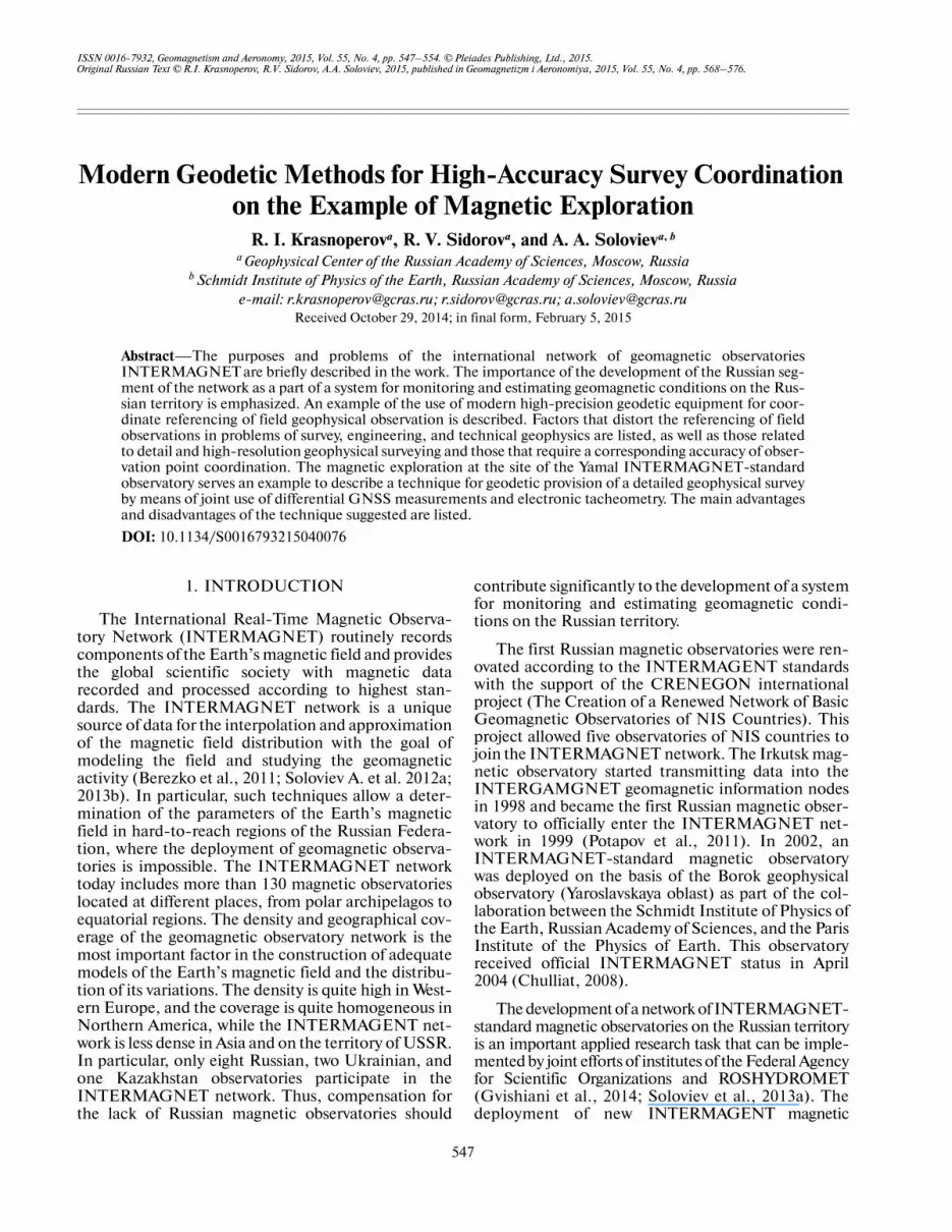
suring tape. The coordinates of survey points weredetermined by a magnetic gradiometer’s receiver atthe instants of recording. To detail the areas for obser�vatory buildings and fixing sites for pillars for observa�tory facilities, a micromagnetic survey with 1�m spac�ing was carried out automatically with a 1�s recordinginterval by a mobile proton magnetic gradiometer. Thepositions of survey points were determined with themagnetic gradiometer’s receiver. Figure 1 shows that
the coordinate referencing of observation points wereoften made with significant errors, though the observermoved along clearly marked profiles.
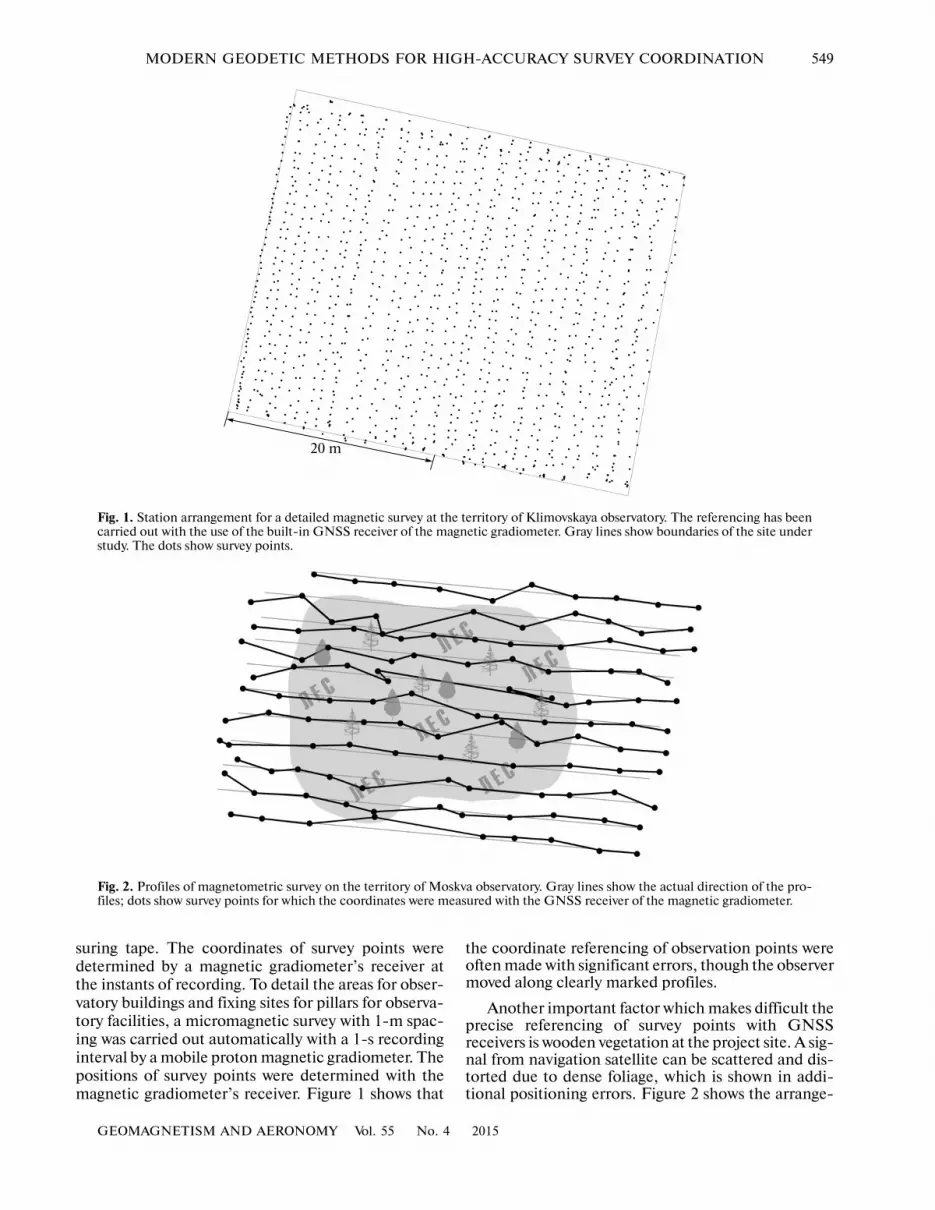
Another important factor which makes difficult theprecise referencing of survey points with GNSSreceivers is wooden vegetation at the project site. A sig�nal from navigation satellite can be scattered and dis�torted due to dense foliage, which is shown in addi�tional positioning errors. Figure 2 shows the arrange�
20 m
Fig. 1. Station arrangement for a detailed magnetic survey at the territory of Klimovskaya observatory. The referencing has beencarried out with the use of the built�in GNSS receiver of the magnetic gradiometer. Gray lines show boundaries of the site understudy. The dots show survey points.
Fig. 2. Profiles of magnetometric survey on the territory of Moskva observatory. Gray lines show the actual direction of the pro�files; dots show survey points for which the coordinates were measured with the GNSS receiver of the magnetic gradiometer.
550
GEOMAGNETISM AND AERONOMY Vol. 55 No. 4 2015
KRASNOPEROV et al.
ment of survey profiles during the magnetometricstudy of the territory around buildings of the Moskvamagnetic observatory (IZMIRAN, Troitsk, Moscow).The survey area was partially covered with trees. Thespace between profiles and the survey spacing werechosen as equal to 10 m. The setting out of survey pro�files and points was also carried out with the use ofoptical theodolite and a topographic measuring tape,and the coordinate referencing was conducted with abuilt�in GNSS receiver of a GSM�19GW magneticgradiometer. It is seen from Fig. 2 that the measuredpositions of survey stations significantly differ fromtheir actual positions at the marked survey profile.
Survey points positioning errors can cause falseextremums and condensation of isolines during map�ping, which will make it difficult to interpret theresults. This applies especially to high�precision high�resolution geophysical surveys.
4. ELECTRONIC TOTAL STATION AND ITS USE
An electronic total station is intended for measure�ments of horizontal and vertical angles and distancesand is an optical theodolite with an electronic systemfor measuring angles, a built�in laser range finder, anda field computer for processing the measurements.The operation of an electronic total station requires areflector mounted at a measured point. Reflectors inthe form of glass prisms mounted on a telescopic rodare the most common today. Modern electronic totalstations with certain limits can measure withoutreflectors with guidance to different physical objects orwith the use of special reflective film or retroreflectors.
The built�in software of modern electronic totalstation allows solving a wide range of geodetic prob�lems in situ, including the positioning of points; thecalculation of perimeters, areas, and volumes; thedesign of survey networks; and setting out of points (byangle and distance, by coordinates, by range betweenthe points) to a specified horizontal or inclined plane.Some total stations are equipped with a laser targetfinder to increase the efficiency of setting out ofpoints, and some are equipped with an optical track�light to simplify visual tracking of a bearing cross�sec�tion. Common interfaces (RS�232, USB, Bluetooth,Wi�Fi, etc.) are usually used in electronic total stationsfor data transmission to peripheral devices(Dement’ev et al., 2008).
Electronic total stations are widely used in differentgeodetic works; in particular, they can be effectivelyused for geodetic maintenance of field geological andgeophysical explorations. With an electronic total sta�tion, a survey network of any desired configuration canbe designed and set out. Necessary geophysical mea�surements can be carried out at set and fixed surveypoints. It should be noted that the precise coordinatereferencing of geophysical measurements requires the
presence of control points with known coordinates,relative to which the total station determines the coor�dinates of the survey points.
Local stations of the state geodetic network, sta�tions of local landmark networks, and other fixedpoints with known coordinates can serve as controlpoints. If such points are absent, a temporary controlnetwork can be deployed for these purposes. The coor�dinates of the control network points are easier todetermine from GNSS observations. This requires theuse of geodetic GNSS devices, which allow phasemeasurements at several carrier frequencies. Thecoordinate references in this case can be performed inthe total station computer after setting out of the sur�vey points. For this, it is necessary to input the coordi�nates of the total station point and specify the refer�ence direction for its horizontal circle to be orientedcorrectly. If a territory under study is covered withdense vegetation and the GNSS receivers cannot beused at the survey site, one can set out the control net�work at an open area at a certain distance from the site(at a forest edge or clearing, along a road or railway)and then set out a temporary line�angle traverse. Thus,the use of an electronic total station along with GNSSreceivers allows one to design a local survey network ofa desired configuration and perform the coordinatereferencing of survey points. The results of geodeticand geophysical measurements can then be easilyjointly processed in a computer. Some examples of theuse of high�precision geodetic instruments aredescribed in (Kaftan and Krasnoperov, 2015).
5. EXAMPLE OF JOINT USE OF ELECTRONIC TOTAL STATION AND GNSS
IN MEGNETIC EXPLORATION
The building of a new observatory at Yamal, inSabetta settlement (Yamal�Nenets AutonomousOkrug) was planned within the development of thenetwork of INTERMAGNET�standard observatorieson the Russian territory (Soloviev et al., 2013c). Mag�netic exploration of the project land was carried out byresearchers of the Laboratory of Geoinformatics andGeomagnetic Studies of the Geophysical Center of theRussian Academy of Sciences during the expedition toSabetta settlement The observatory was deployedwithin a project on the development of systems formonitoring and estimating the geomagnetic situationon the territory of the Russian Federation. The datawhich will be received at this observatory are expectedto be used for solving the problems of interpolationand approximation the magnetic field distributionduring the development of the South�Tambeyskoyegas�condensate field.
The region under study is located at the east of theYamal Peninsula on the coast of the Gulf of Ob (KaraSea). This region is arctic tundra with permafrost soils.When choosing the region for the study, both physico�geographical features (many tundra bogs and water
GEOMAGNETISM AND AERONOMY Vol. 55 No. 4 2015
MODERN GEODETIC METHODS FOR HIGH�ACCURACY SURVEY COORDINATION 551
reservoirs) and the arrangement of existing and pro�jected industrial objects and service lines (natural�gasliquefaction plant, sea port, airport, projected settle�ment) were considered. Finally, a land area for detailmagnetic exploration was chosen at a sufficient dis�tance (no less than 3 km) from probable sources ofnoise.
The works included three sessions of areal mag�netic survey of different scales. The first session wasperformed for an area of 250000 m2 (500 × 500 m)marked with a 50�m survey network (121 points).Maps of the anomaly component of the total vector ofthe magnetic field and its vertical gradient were con�structed on the basis of the survey results, and a site forthe next session was chosen. The second session ofmagnetic survey was performed for an area of 10000 m2
(100 × 100 m) marked with a 10�m survey network(121 points). It also resulted in maps of anomalousmagnetic field and the vertical gradient of the totalvector of magnetic field constructed in the GIS envi�ronment (Beriozko et al., 2011; Krasnoperov et al.,2012). On the basis of these measurement sessions, asquare site of 24 × 24 m was chosen, on which a 2�mnetwork for detail survey (169 points) was designed.
Three planned survey sessions, despite the redun�dancy of magnetic measurements during sequentialrefinement of the survey, are justified from the view�point of general principles of the geophysical researchmethodology. Thus, the guidance based on the experi�ence of researchers of the Irkutsk geomagnetic obser�vatory (Nechaev, 2006) suggests carrying out arealmagnetometry on several scales when choosing anobservatory site for a multilevel study of the characterof magnetic field anomaly distribution and the selec�tion of sites appropriate for building observatory facil�ities. A preliminary magnetic survey is carried out each100–200 m within a radius of 1–2 km from the chosensite and a 10�m interval survey is carried out immedi�ately at the building site. In our case, the reconnais�sance problem (ascertaining the general character ofmagnetic field anomalies) was solved via a 50�m inter�val survey carried out during the first step. The recon�naissance survey was also very important under snowcover conditions, where visual detection of disturbingobjects and obstacles was impossible.
The survey during the next step can be considered atask of detecting desired sites. The desired area, withinwhich variations in horizontal and vertical gradientsare minimal, was 24 × 24 m in size and, hence, thisregion could be found by three points in three neigh�boring profiles with a good probability (nine points intotal), which evidently satisfies the well�known three�sigma and three�point rule (Magnetic Survey, 1990;Khmelevskoi et al., 2004).
The problem of refinement was solved during thethird step on the basis of the results from the previoussurvey. According to the project, the magnetic obser�vatory should include the construction of an observa�
tion pavilion, where scalar and vector magnetometerand fluxgate theodolite for absolute observations are tobe mounted, and also an engineering building. Theobservation pavilion was 12 × 6 m in size; it wasdecided to choose an area 24 × 24 m for its location.Detailed mapping requires a step in the profiles of theobject under study to be at least ten times smaller thanits characteristic size (Magnetic survey, 1990); thisimplied that the resolution of 2 × 2 m was sufficient forthe site refinement. A similar observatory project wassuccessfully implemented earlier by the GeomagneticGroup of the USA Geological Service during deploy�ment of the Deadhorse Observatory in Alaska (Dead�horse, 2014). We should note that there are no require�ments for the absence of magnetic disturbances for theengineering building (a small building located at a dis�tance from the measuring pavilion) in which the con�trol and telecommunications facilities are mounted.
It was decided to select a square survey network(with the ratio of the profile step to the interprofilespace 1 : 1) at all survey steps because of the peculiarityof the stated problem. In geophysical survey observa�tions, profiles are projected across the course of targetobjects (Khmelevskoi et al., 2004), and the survey net�work is often constructed anisotropic, with a ratio ofthe profile step to interprofile space of 1 : 5 to 1 : 10. Inthe studied case, the location and orientation of theobservatory building at a final site of 24 × 24 m wereassumed arbitrary, and the target building sites couldbe considered equilateral. Therefore, it was decided toperform all of the survey steps on square survey grids.In addition, the survey results on isotropic (square)networks are more representative and obvious than onanisotropic networks, since magnetic anomalies aremapped from the results of the former without distor�tions caused by network inhomogeneity.
The magnetic survey was carried out with aGMS�19GW magnetic gradiometer. Magnetometersensors were mounted 56 cm apart on a separate rod.The recorded data were referenced to the UTC time�scale with a built�in GNSS receiver of the magneticgradiometer. To consider daily variation, an additionalGSM�19 proton magnetometer (magnetic�variationstation, (Magnetic Survey, 1990)) was used fixed at adistance of 700 m to the southeast of the survey net�work center. The time scales of the magnetic gradiom�eter and the magnetic�variation system were synchro�nized. The logging interval of the magnetic�variationstation was chosen to be equal to 10 s, which wasaccepted optimal for all of the survey steps.
A Trimble M3 DR 5'' electronic total station and aset of two geodetic GNSS receivers Javad Maxor andwere used for setting out the survey grid and coordi�nate referencing of the survey points. The receiverswere installed at points T1 and T3 of the temporarycontrol network. Their exact coordinates were foundduring processing the GNSS measurements. The totalstation was installed at T1 point. The horizontal circle

552
GEOMAGNETISM AND AERONOMY Vol. 55 No. 4 2015
KRASNOPEROV et al.
of the total station was oriented along the T1–T4 ref�erence direction, the azimuth of which was prelimi�nary calculated. The T4 point was chosen during thereconnaissance of the survey site; it specified the T1–T4 reference direction, relative to which the stationingand survey network setting out were conducted. Thesurvey network was then designed and calculated inthe total station computer. The setting out of the sur�vey network points was carried out using a prismreflector. The set out points were marked with non�magnetic wooden pickets. The error of the surveypoints setting out didn’t exceed 10 cm. The pointcoordinate referencing error using GNSS data, withthe long range between the survey site (1.1–1.7 km)and the total station taken into account, did notexceed 20 cm. The coordinates of the control pointsand survey network points were determined on a planein the UTM (Universal Transverse Mercator) coordi�nate system. The stationing and magnetic survey werecarried out in such a way that the effects of ferromag�netic elements of a marker (clothes details, prismreflector rod) on magnetic measurements were mini�mal. For this, a space between the marker and a mag�netometer operator were kept such that the effect ofdisturbances on the measurements could be consid�ered negligible.
6. ANALYSIS OF THE DEVELOPED TECHNIQUE
During the survey, the total vector and vertical gra�dient of the magnetic field strength were measured ateach survey point with the GNSS receiver of the mag�netic gradiometer, as well as the coordinates and UTCtime of measurements. This allowed the study of coor�dinate referencing errors through the comparison ofobservation point coordinates recorded with the mag�netic gradiometer receiver with the correspondingcoordinates found from geodetic measurements withGNSS receivers and the electronic total station. Thiscomparison also allowed estimation of the efficiencyof the magnetic gradiometer’s built�in GNSS receiverduring surveying with different resolution.
To estimate the coordinate referencing accuracy,the survey station coordinates found from geodeticmeasurements with the receivers and total station wereconsidered as reference. Let us designate these coordi�
nates in the UTM system as where is the station number (the total number of stations is n= 121 for the first and second survey sessions and n =
( , ),G Gi iX Y 1,...,i n=
169 for the third session). There is also a set of coordi�nates for each station determined with the GNSSreceiver of the magnetic gradiometer during magnetic
911.23
5.976.45
19.6813.69
12.446.73
11.3211.23
12.92 12.96
14.5414.34 14.04
15.21 18.51
16.8119.4
17.65
19.0317.26
15.4316.12
13.
12.97 13.36 13.57
13.01 13.07 13.06 13.51
.44 12.52 12.58 13.37
13.13 12.22 13.05 13.51
.29 11.89 12.59 13.56
12.58 11.18 13.22 13.7
12.91 12.36 12.79 13.55
12.07 12.77 12.79 13.
12.8612.68 13.51 13.82
12.32 12.82 13.41
(a)
(b)
(c)
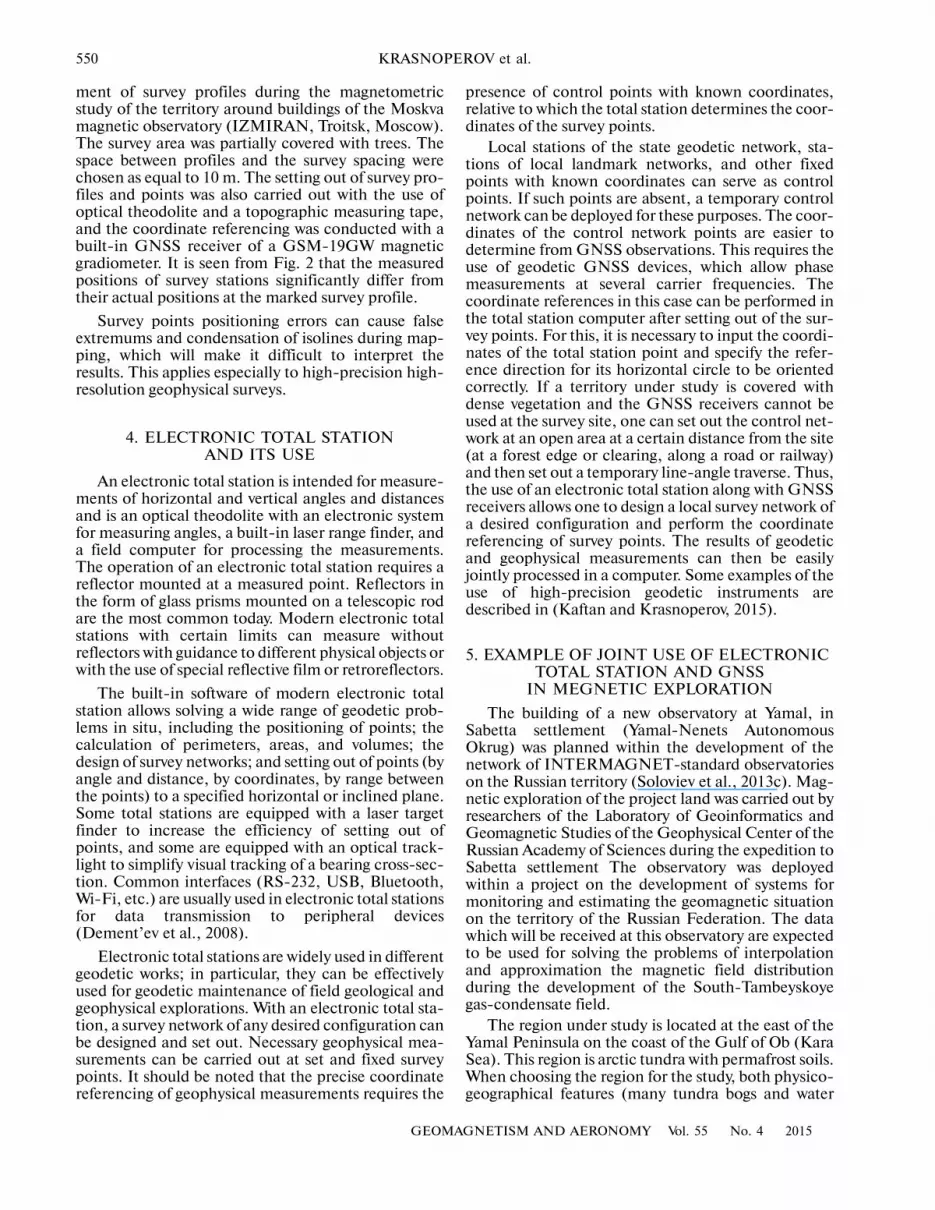
Fig. 3. Fragments of the magnetic survey networks nearSabetta settlement with a resolution of (a) 50 × 50 m, (b) 10 ×10 m, and (c) 2 × 2 m. Black dots show the set out pointsfor which the coordinates were found from geodetic mea�surements; empty circles show the points for which thepositions were determined with the GNSS receiver of themagnetic gradiometer. The network lines are dashed. Themeasured values of magnetic field anomalies are written.

GEOMAGNETISM AND AERONOMY Vol. 55 No. 4 2015
MODERN GEODETIC METHODS FOR HIGH�ACCURACY SURVEY COORDINATION 553
measurements. Let us designate them as Ifthe point set M = is consideredas a sample from the entire assembly, then the GNSS�receiver measurement error of the coordinates relativeto the reference coordinates from geodetic measure�ments (let us similarly designate them as the point setG = ) can be expressed as —the average with the standard deviation (Gmurman,2003), where:
The deviations for survey sites with resolutions 50 × 50,10 × 10, and 2 × 2 m are 2.1 ± 0.6 m; 1.4 ± 0.6 m, and1.7 ± 0.7 m, respectively. Thus, the coordinate error ofthe magnetic gradiometer receiver is 2 m on average.Though the error is constant in absolute value, thequality of the referencing of the survey points reduceswith an increase in the survey network resolution,since the error of 2 m is 4, 20, and 100% for surveyspacing of 50, 10, and 2 m, respectively. Figure 3exemplifies the mutual arrangement of points of the Mand G sets according to the survey results.
Thus, an electronic total station provides signifi�cantly more accurate coordinate referencing as com�pared to a code single�frequency built�in GNSSreceiver of a magnetic gradiometer. The coordinateerror of the latter is critical in the case of surveyingwith a resolution of 2 × 2 m or more, since it is compa�rable with the survey space. This undoubtedly impliesthat the importance of high�precision stationing andcoordinate referencing of the points increases as thelevel of survey detail rises.
7. CONCLUSIONS
Using magnetic explorations at the project site ofthe Yamal magnetic observatory as an example, aneffective technique for the coordinate provision ofgeophysical observations was developed with the use ofmodern geodetic technologies. The technique has sev�eral evident advantages, such as stationing efficiency(441 points were set out and surveyed for three workingdays at an area of 25 ha) and high accuracy of the coor�dinate referencing of the survey network. The surveynetwork setting out was designed in situ, and the coor�dinates of designed and set out points and magneticmeasurement results were digitized for mapping mag�netic anomalies.
The possibility of setting out the survey networkimmediately during the magnetic surveying is a featureof the technique. However, implementation of thisapproach requires a certain time for a marker to set outthe points according to instructions of a land surveyor(especially under a strong wind and poor visibility). Amagnetometer operator carried out measurementswith pauses; the main difficulty was the existence offerromagnetic details of the reflector, which did notallow the operator and land surveyor to work simulta�neously at close range. This approach is not alwayseffective due to pauses between measurements at sep�arate stations and measurement sessions as applied tothe magnetic survey if a magnetometric base networkis used for accounting for a daily magnetic variation(Magnetic Survey, 1990) instead of a magnetic�varia�tion system. In this case, preliminary setting out of ageodetic survey network is recommended. In addition,if the works are carried out at one small site with a sur�vey resolution of less than 10 × 10 m, the use of anelectronic total station for setting out the survey pointscan require more time than, e.g., network setting withthe use of a topographic measuring tape. In view ofthis, we recommend using an electronic total stationfor solving geodetic problems similar to the describedabove, where a series of surveys of different scales issupposed, including a detailed survey.
ACKNOWLEDGMENTS
The Trimble M3 DR 5'' electronic total station,additional equipment, and software were provided byPRIN Joint Stock Company (http://www.prin.ru).The authors are grateful to specialists of PRIN JointStock Company for consultations on the operation ofthe Trimble total station.
The work was carried out within the Federal TargetProgram of the Ministry of Education and Science of theRussian Federation (agreement no. 14.607.21.0058) andis a part of research aimed at the development of tech�niques for the interpolation and approximation of theEarth’s magnetic field distribution over the Russianterritory following the development of geomagneticsituation monitoring and estimation systems in theRussian Federation.
REFERENCES
Antonovich, K.M., Ispol’zovanie sputnikovykh radionavi�gatsionnykh sistem v geodezii (Use of Satellite Naviga�tion Systems in Geodesy), Moscow: FGUP “Kartgeot�sentr”, 2006, vol. 2.
Berezko, A.E., Khokhlov, A.V., Soloviev, A.A., Gvishiani, A.D.,Zhalkovsky, E.A., and Mandea, M., Atlas of Earth’smagnetic field, Rus. J. Earth Sci., 2011, vol. 12, no. 2,p. ES2001. doi 10.2205/2011ES000505
Beriozko, A., Lebedev, A., Soloviev, A., Krasnoperov, R.,and Rybkina, A., Geoinformation system with algo�rithmic shell as a new tool for Earth sciences, Rus. J.
( , ).M Mi iX Y
{ }1,...,( , )M Mi i
i nX Y =
{ 1,..., }( , )G Gi i
i nX Y = ±r s
1
1 ,n
i
i
r rn
=
= ∑
2
1
( )
,1
n
i
i
r r
sn
=
−
=
−
∑
2 2( ) ( ) .G M G Mi i i i ir X X Y Y= − + −

554
GEOMAGNETISM AND AERONOMY Vol. 55 No. 4 2015
KRASNOPEROV et al.
Earth Sci., 2011, vol. 12, no. 1, p. ES1001. doi 10.2205/2011ES000501
Bogoutdinov, Sh.R., Gvishiani, A.D., Agayan, S.M.,Solovyev, A.A., and Kin, E., Recognition of disturbanceswith specified morphology in time series. Part 1: Spikes onmagnetograms of the worldwide INTERMAGNET net�work, Izv., Phys. Solid Earth, 2010, no. 11, pp. 1004–1016.
Chulliat, A. and Anisimov, S., The Borok INTERMAGNETmagnetic observatory, Rus. J. Earth Sci., 2008, vol. 10,no. 3, p. ES3003. doi 10.2205/2007ES000238
Dement’ev, V.E., Sovremennaya geodezicheskaya tekhnika iee primenenie (Up�to�Date Geophysical Instrumentsand Their Use), Moscow: Akademicheskii Proekt,2008, 2nd ed.
Denisov, A.Y., Denisova, O.V., Sapunov, V.A., and Khomu�tov, S.Y., Measurement quality estimation of proton�precession magnetometers, Earth, Planets Space, 2006,vol. 58, no. 6, pp. 707–710.
Gmurman, V.E., Teoriya veroyatnostei i matematicheskayastatistika (Probability Theory and Mathematical Statis�tics), Moscow: Vysshaya Shkola, 2003, 9th ed.
Gvishiani, A., Lukianova, R., Soloviev, A., and Khokhlov, A.,Survey of geomagnetic observations made in the north�ern sector of Russia and new methods for analysingthem, Surv. Geophys., vol. 35, no. 5, pp. 1123–1154.
http://geomag.usgs.gov/monitoring/observatories/deadhorse/(accessed: 24.10.2014).
Jankowski, J. and Sucksdorff, C., IAGA: Guide for MagneticMeasurements and Observatory Practice, Warsaw:IAGA, 1996.
Kaftan, V.I. and Krasnoperov, R.I., Geodetic observationsat geomagnetic observatories, Geomagn. Aeron. (Engl.Trans.), vol. 55, no. 1, pp. 118–124.
Khmelevskoi, V.K., Gorbachev, Yu.I., Kalinin, A.V.,Popov, M.G., Seliverstov, N.I., and Shevnin, V.A.,Geofizicheskie metody issledovanii (Geophysical SurveyTechniques), Petropavlovsk�Kamchatskii: Izd�voKGPU, 2004.
Krasnoperov, R.I., Lebedev, A.Yu., Pyatygina, O.O.,Rybkina, A.I., and Shibaeva, A.A., Multidisciplineanalytical GIS for processing and representing remotesensing data, Sovrem. Problemy Distantsionnogo Zond�irovaniya Zemli Kosmosa, 2012, vol. 9, no. 3, pp. 50–54.
Magnitorazvedka: spravochnik geofizika (Magnetic Explo�ration: Handbook for Geophysicists), Nikitskii, V.E.and Glebovskii, Yu.S., Eds., Moscow: Nedra, 1990,2nd ed.
Nechaev, S.A., Rukovodstvo dlya statsionarnykh geomagnit�nykh nablyudenii (Guide for Stationary GeomagneticObservations), Irkutsk: V.B. Sochava Institute of Geog�raphy SB RAS, 2006.
Newitt, L.R., Barton, C.E., and Bitterly, J., Guide for Mag�netic Repeat Station Surveys, Boulder: IAGA, 1996.
Potapov, A.S., Khomutov, S.Yu., and Rasson, Zh.L.,CRENEGON Project and its effect on the develop�ment of magnetic observations in CIS states, Vestn.ONZ RAN, 2011, vol. 3, no. Z5005. doi 10.2205/2011NZ000107
Sidorov, R.V., Soloviev, A.A., and Bogoutdinov, Sh.R.,Application of the SP algorithm to the INTERMAGNETmagnetograms of the disturbed geomagnetic field, Izv.,Phys. Solid Earth, 2012, no. 5, pp. 410–414.
Soloviev, A.A., Khokhlov, A.V., Zhalkovskii, E.A.,Berezko, A.E., Lebedev, A.Yu., Kharin, E.P., Shesto�palov, I.P., Mandea, M., Kuznetsov, V.D., Bondar’, T.N.,Nechitailenko, V.A., Rybkina, A.I., Pyatygina, O.O.,and Shibaeva, A.A., Atlas magnitnogo polya Zemli,(Atals of the Earth’s Magnetic Field), Gvishiani, A.D.,Frolov, A.V., Lapshin, V.B., Eds., Moscow: GC RAS,2012a. doi 10.2205/2012Atlas_MPZ.
Soloviev, A.A., Agayan, S.M., Gvishiani, A.D., Bogoutdi�nov, Sh.R., and Shul’ya, A., Recognition of distur�bances with specified morphology in time series: Part 2.Spikes on 1�s magnetograms, Izv., Phys. Solid Earth,2012b, no. 5, pp. 395–409.
Soloviev, A.A., Bogoutdinov, Sh.R., Agayan, S.M., Gvi�shiani, A.D., and Kihn, E., Detection of hardware fail�ures at INTERMAGNET observatories: Application ofartificial intelligence techniques to geomagneticrecords study, Rus. J. Earth Sci., 2009, vol. 11, no. 2,p. ES2006. doi 10.2205/2009ES000387
Soloviev, A., Bogoutdinov, S., Gvishiani, A., Kulchinskiy, R.,Zlotnicki, J., Mathematical tools for geomagnetic datamonitoring and the INTERMAGNET Russian seg�ment, Data Sci. J., 2013a, vol. 12, p. WDS114–WDS119. doi 10.2481/dsj.WDS�019
Soloviev, A., Khokhlov, A., Jalkovsky, E., Berezko, A., Leb�edev, A., Kharin, E., Shestopalov, I., Mandea, M.,Kuznetsov, V., Bondar, T., Mabie, J., Nisilevich, M.,Nechitailenko, V., Rybkina, A., Pyatygina, O., andShibaeva, A., The Atlas of the Earth’s Magnetic Field,Gvishiani, A., Frolov, A., and Lapshin, V., Eds., Moscow:GC RAS, 2013b. doi 10.2205/2013BS011_Atlas_MPZ
Soloviev, A., Chulliat, A., Bogoutdinov, S., Gvishiani, A.,Agayan, S., Peltier, A., and Heumez, B., Automatedrecognition of spikes in 1 Hz data recorded at the EasterIsland magnetic observatory, Earth Planets Space,2012c, vol. 64, no. 9, pp. 743–752. doi 10.5047/eps.2012.03.004
Soloviev, A.A., Kaftan, V.I., Krasnoperov, R.I., andSidorov, R.V., Modern technological approaches fordeployment of INTERMAGNET observatories inRussia, in Materials of the partnership conference“Geophysical Observatories, Multifunctional GIS andData Mining”, in Geoinf. Res. Papers, Kedrov, E., Ed.,Moscow: GC RAS, 2013c, p. BS1004.
Translated by O. Ponomareva