Embed Size (px)
Citation preview
GEODETIC TRIANGULATION 2014
P.G.C.C.Fonseka
27th
November 2014
Department of Surveying & Geodesy
Faculty of Geomatics
Sabaragamuwa University of Sri Lanka
GEODETIC TRIANGULATION 2014
F A C U L T Y O F G E O M A T I C S
Page a
Geodetic Triangulation – 2014
By
P.G.C.C.Fonseka
FG 447
The report submitted to the Faculty of Geomatics, Sabaragamuwa University of Sri Lanka in
partial fulfillment of the requirements for the BSc. degree in Surveying Sciences.
Coordinator
Dr.Ranmalee Bandara
Supervisor
Dr.M.D.E.K.Gunathilake
FACULTY OF GEOMATICS
SABARAGAMUWA UNIVERSITY OF SRI LANKA
P.O. BOX 02
BELIHULOYA
GEODETIC TRIANGULATION 2014
F A C U L T Y O F G E O M A T I C S
Page b
DISCLAIMER
This document describes work undertaken as part of a programme of study at the
Faculty of Geomatics, Sabaragamuwa University of Sri Lanka. All views and opinions expressed
therein remain the sole responsibility of the author, and do not necessarily represent those of the
university.
GEODETIC TRIANGULATION 2014
F A C U L T Y O F G E O M A T I C S
Page c
ABSTRACT
This report includes information on project triangulation 2014 which was conducted by the
Faculty of Geomatics, Sbaragamuwa university of Sri lanka cooperated by the 2010/2011 batch
as a necessary practical program in year(III) semester(I) which had to be accomplished within
the given time period. For a geodetic survey the required horizontal control can be established by
triangulation, traversing or by a combination of both. However generally triangulation plays a
major role in establishing control points as it is preferred in hilly and undulated areas and stations
can be established within a comparatively large distance with only the basic requirement of
intervisibility. Triangulation is a rite of ascertaining the location of a point by measuring angles
to it from known points at either end of a fixed baseline, rather than measuring distances to the
point directly. The point can then be fixed as the third point of a triangle with one known side
and two known angles. The length of first line, which is measured precisely, is known as base
line. The other two computed sides are used as new base lines for two other triangles
interconnected with the first triangle. By extending this process, the measurements of further
interconnected triangles are taken. Coordinates of four unknown points were calculated with the
help of spherical coordinate calculation systems, adjustment computations and other relevant
theories, and also computer softwares such as Math Lab using two known points, in this case
Kirioluhena (1st order trig station) and Haawagala(2
nd order trig station).A precise theodolite was
used to measure the angles. Gas lamps were taken as a target for the night observations. However
GPS observations were also taken for the verification of precision. Besides the academic criteria
in organizing such project the practical deprival which had to be conquered, responsibilities and
team efforts were well maneuvered by the participants. Following chapters would explain the
procedure in a more detailed manner.
GEODETIC TRIANGULATION 2014
F A C U L T Y O F G E O M A T I C S
Page d
ACKNOWLEDGEMENT
This project would not have been possible without the support of many people. The author
wishes to express his gratitude to the dean of Faculty of Geomatics,Sabaragamuwa university of
Sri lanka Dr.K.R.M.U.Bandara and Dr. H.M.I Prasanna, head of the Department of Surveying
and Geodesy for providing necessary facilities and information. Deepest gratitude to the project
coordinator Dr. Ranmalee Bandaara, Senior Lecturer Department of Surveying and Geodesy,
who was abundantly helpful and offered invaluable assistance, support and guidance without
whose knowledge and assistance this study would not have been successful. Special thanks also
to authors supervisor Dr.M.D.E.K Gunathilaka for his guidance and encouragement The author
would also like to convey thanks to Mr.T.I.Munasinghe instructor in Faculty of Geomatics for
consulting as well as strengthening the group members in both physical and mental manner The
author wishes to express his love and gratitude to his beloved batch mates, senior and junior
brothers for their greatest support and help especially to group members for sharing the
literature, practical skills and invaluable assistance throughout hard times. And the author would
like to make this a opportunity to express his regards to all the other academic and non-academic
staff member of the faculty of Geomatics for their help noticed or unnoticed.
GEODETIC TRIANGULATION 2014
F A C U L T Y O F G E O M A T I C S
Page e
Contents 1. INTRODUCTION ...................................................................................................................... 1
1.1 Commencing of Triangulation ......................................................................................... 1
1.3 Triangulation in Sri lanka ...................................................................................................... 4
1.4 Triangulation in Sabaragamuwa University of Sri lanka ...................................................... 6
1.5 Project Triangulation 2014 .................................................................................................... 6
1.6 Objectives .............................................................................................................................. 8
2. MTHODOLOGY ...................................................................................................................... 10
2.1 Initial Preparations .............................................................................................................. 11
2.2. Preliminary Investigation ................................................................................................... 13
2.3 Inter visibility check in office ............................................................................................. 13
2.4 Reconnaissance Survey ....................................................................................................... 14
2.5 Organization of the program ............................................................................................... 15
2.6 Types of signals ................................................................................................................... 16
2.7 Observation ......................................................................................................................... 18
2.7.1 GPS Observations ......................................................................................................... 18
2.7.2 Angle Observation ........................................................................................................ 19
2.8 Computation Procedure and programming ......................................................................... 21
2.8.1 Computation procedure ................................................................................................ 21
2.8.2 Mean Included Angles and Standard Deviation…………………………………… ...23
2.8.3 Reduce Observed Directions and Distances to ellipsoid……………………………...23
2.8.4 Calculate approximate coordinates……………………………………………………23
2.8.5 Calculate approximate included angles and distances………………………………...25
2.8.6 Computer programming codes ..................................................................................... 25
3. RESULTS AND DISCUSSION ............................................................................................... 26
3.1 Results ................................................................................................................................. 26
1.2 Discussion ...................................................................................................................... 29
4. CONCLUTION AND RECOMMENDATIONS ..................................................................... 34
4.1 Conclusion ........................................................................................................................... 34
4.2 Recommendations ............................................................................................................... 35
GEODETIC TRIANGULATION 2014
F A C U L T Y O F G E O M A T I C S
Page f
5. REFERENCES AND BIBLIOGRAPHY ................................................................................. 38
List of Figures
Fig 1.1 The sketch of the Belgian triangulation
Of Gemma Frisius from the 16th century 1
Fig 1.2 Simple triangles 3
Fig 1.3 Braced quadrilaterals 3
Fig 1.4 Centered triangles and polygons 3
Fig 1.5 Triangulation Network of Sri Lanka 5
Fig 1.6 Network of Trig stations – 2014 7
Fig 2.1 Triangulation Figure 2014 12
Fig 2.2 Cross-sections from contours 14
Fig 2.3 Observation tower 17
Fig 2.4 Polythene Cover 17
Fig 2.5 GPS Instrument Locations 19
Fig 2.6 Angle Observation Order 20
Fig 2.7 Face left and faces right observations. 20
Fig 2.8 Proposed Figure 22
Fig 2.9 Actual Figure 22
GEODETIC TRIANGULATION 2014
F A C U L T Y O F G E O M A T I C S
Page g
List of Tables
Tbl 1.1 Information about the Stations 8
Tbl 2.1 Included Angles 13
Tbl 3.1 Given Data 23
Tbl 3.2 Known Station Coordinates 26
Tbl 3.3 Probable angles 27
Tbl 3.4 Angle Adjusted coordinates 27
Tbl 3.5 Processed GPS coordinates 28
Tbl 3.6 Comparison of coordinates 29
Tbl 3.7 Difference in coordinates 29
Tbl 3.8 GPS Accuracy 31
GEODETIC TRIANGULATION 2014
F A C U L T Y O F G E O M A T I C S
Page h
List of Appendices
Appendix A-Corrections 39
Appendix B-B matrix 40
Appendix C-Weight matrix 41
[GEODETIC TRIANGULATION 2014]
F A C U L T Y O F G E O M A T I C S
Page 1
1. INTRODUCTION
1.1 Commencing of Triangulation
Measuring of the distance of two points is possible by making a line between them and by
placing a measuring rod along it – supposed the distance is not too long between our points.
As the distance becomes longer, this procedure starts to be complicated and expensive:
distances of more than a several hundred meters are very hard to measure this way. If the
terrain between our points is rough or impassable, this method cannot be applied at all. A
new method was introduced at the end of the 16th, early 17th centuries. Measuring a longer
distance can be made by measuring a shorter line and some angles. The first triangulation was
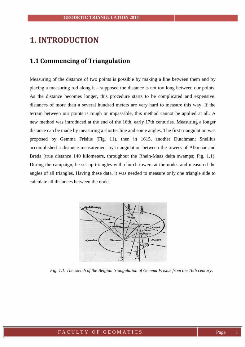
proposed by Gemma Frisius (Fig. 11), then in 1615, another Dutchman; Snellius
accomplished a distance measurement by triangulation between the towers of Alkmaar and
Breda (true distance 140 kilometers, throughout the Rhein-Maas delta swamps; Fig. 1.1).
During the campaign, he set up triangles with church towers at the nodes and measured the
angles of all triangles. Having these data, it was needed to measure only one triangle side to
calculate all distances between the nodes.
Fig. 1.1. The sketch of the Belgian triangulation of Gemma Frisius from the 16th century.
GEODETIC TRIANGULATION 2014
F A C U L T Y O F G E O M A T I C S
Page 2
1.2 Concept of Triangulation
In trigonometry and elementary geometry, triangulation is the process of finding a distance to
a point by calculating the length of one side of a triangle, given measurements of angles and
sides of the triangle formed by that point and two other reference points. Some identities
often used (valid only in flat or Euclidean geometry): The sum of the angles of a triangle is
pi rad or 180 degrees. The law of sine’s - The law of cosines - The Pythagorean theorem
Triangulation is used for many purposes, including surveying, navigation, metrology,
astrometry, binocular vision and gun direction of weapons.
Many of these surveying problems involve the solution of large meshes of triangles, with
hundreds or even thousands of observations. Complex triangulation problems involving real-
world observations with errors require the solution of large systems of simultaneous
equations to generate solutions.
The object of the Geodetic Surveying is to determine very precisely the relative or
absolute positions on the earth's surface of a system of widely separated points. The
relative positions are determined in terms of the lengths and azimuths of the lines
joining them. That positions are given in terms of latitude , longitude and elevation
above mean sea level. These geodetic points so, determined furnish the most precise
control to which a more detailed survey of intervening country may be referred. The
geodetic surveying is usually carried out by the Government Agency in Sri Lanka The
Survey Department.
Triangulation systems are classified according to the accuracy required for the horizontal
control. It depends on the type of survey, extent of the survey and purpose of the survey. On
the basis of accuracy and the purpose, the triangulation systems are generally classified as
under.
der triangulation.
.
GEODETIC TRIANGULATION 2014
F A C U L T Y O F G E O M A T I C S
Page 3
Primary triangulation
This is the highest order triangulation and is employed for very large areas. This provides
principal frame work for the national control network for subsidiary triangulations. This
grade triangulation is specially employed for the determination of the shape and size of the
earth surface and also for the small scaling mapping purposes.
Secondary triangulation
This is employed for running a second series of triangles by fixing, points at close intervals
inside the primary series of triangles. It consists of forming small well-conditioned triangles
with less precise instruments.
Tertiary triangulation
This is employed for providing control points between stations of primary and secondary
triangulation system, by running in a third series of triangles to furnish horizontal control for
details on a topographic survey. The triangles are of the smallest size in comparison with the
other two orders of triangulation.
Well - conditioned triangles
The arrangement of triangles in the layout and the magnitude of the angles in individual
triangles, affect the accuracy of a triangulation system.The shape of the triangle in which any
error in angular measurnments, has a minimum effect upon the length of the computed side,
is known as the well condition triangle.
Layout of the Triangulation
The arrangement of the various triangles of a triangulation series is known as the layout of
triangulation. A series of triangulation may consist of the following;
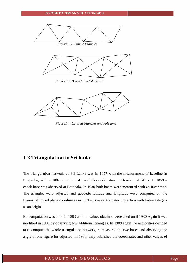
Simple triangles in chain (shown in figure1.2)
Braced quadrilaterals in chain (shown in figure 1.3)
Centred triangles and polygons (shown in figure 1.4)
GEODETIC TRIANGULATION 2014
F A C U L T Y O F G E O M A T I C S
Page 4
Figure 1.2: Simple triangles
Figure1.3: Braced quadrilaterals
Figure1.4: Centred triangles and polygons
1.3 Triangulation in Sri lanka
The triangulation network of Sri Lanka was in 1857 with the measurement of baseline in
Negombo, with a 100-foot chain of iron links under standard tension of 84Ibs. In 1859 a
check base was observed at Batticalo. In 1930 both bases were measured with an invar tape.
The triangles were adjusted and geodetic latitude and longitude were computed on the
Everest ellipsoid plane coordinates using Transverse Mercator projection with Pidurutalagala
as an origin.
Re-computation was done in 1893 and the values obtained were used until 1930.Again it was
modified in 1988 by observing few additional triangles. In 1989 again the authorities decided
to re-compute the whole triangulation network, re-measured the two bases and observing the
angle of one figure for adjusted. In 1935, they published the coordinates and other values of
GEODETIC TRIANGULATION 2014
F A C U L T Y O F G E O M A T I C S
Page 5
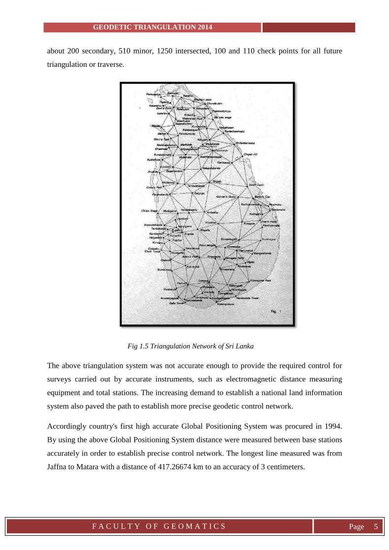
about 200 secondary, 510 minor, 1250 intersected, 100 and 110 check points for all future
triangulation or traverse.
Fig 1.5 Triangulation Network of Sri Lanka
The above triangulation system was not accurate enough to provide the required control for
surveys carried out by accurate instruments, such as electromagnetic distance measuring
equipment and total stations. The increasing demand to establish a national land information
system also paved the path to establish more precise geodetic control network.
Accordingly country's first high accurate Global Positioning System was procured in 1994.
By using the above Global Positioning System distance were measured between base stations
accurately in order to establish precise control network. The longest line measured was from
Jaffna to Matara with a distance of 417.26674 km to an accuracy of 3 centimeters.
GEODETIC TRIANGULATION 2014
F A C U L T Y O F G E O M A T I C S
Page 6
Finally the coordinates of all control points were computed and published in 1999 and the
average linear accuracy of the system was 1:790,000. This system was known as Sri Lanka
Datum 1999 (SLD 99) [3].
1.4 Triangulation in Sabaragamuwa University of Sri lanka
It was first initialized in 2001 as the 'Triangulation Program 2001'by the students of
Department of Surveying Sciences. The chosen station points were Kirimaduhela,New-
Kopiawatta,Kirioluhena,Kirimaduhela,Paraviyangala and Hawagala. As to fix the azimuth for
each line star observation sequences were also done. Hawagala and Kirioluhena were the
known coordinate control stations, which was used as the base line for the whole
triangulation process. These two points are included in the national triangulation network as
primary and secondary respectively. To perform a well-shaped triangulation network
additional stations suchas New-Paraviyangala, Kirimaduhela, Hawagala, Bogandeniyahena,
Wikiliya, Welihinna, Hatarabage, Mannanhinna etc. were taken. Since 2001 it was
continuously done up to the present 2014.
1.5 Project Triangulation 2014
The 2014 triangulation project was inaugurated by the batch of 2010/2011 starting on the 1st
of June 2014 and ending it successfully on the 10th of June 2014.The batch was sorted in to
six groups while six triangulation stations were chosen out of eight by considering the shape
of the network (the best figure was taken), intervisibility, participants, weather and
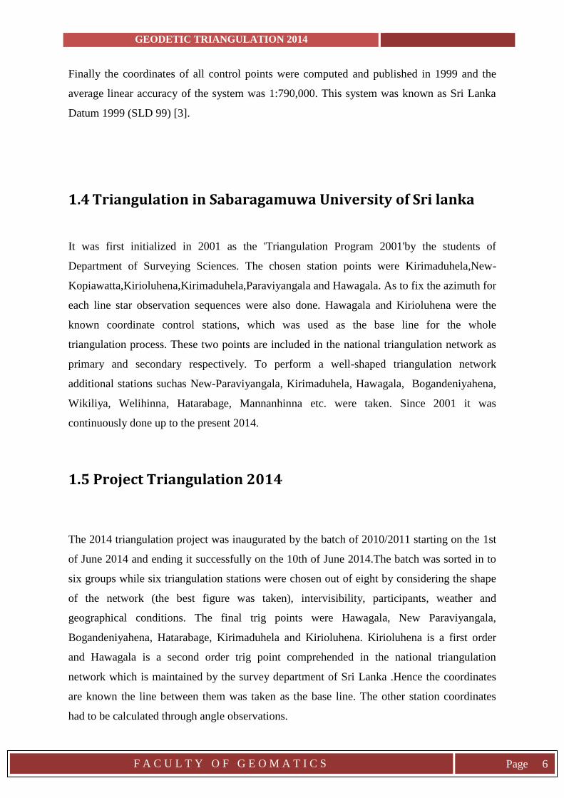
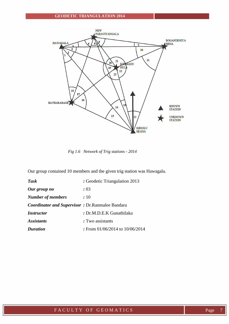
geographical conditions. The final trig points were Hawagala, New Paraviyangala,
Bogandeniyahena, Hatarabage, Kirimaduhela and Kirioluhena. Kirioluhena is a first order
and Hawagala is a second order trig point comprehended in the national triangulation
network which is maintained by the survey department of Sri Lanka .Hence the coordinates
are known the line between them was taken as the base line. The other station coordinates
had to be calculated through angle observations.
GEODETIC TRIANGULATION 2014
F A C U L T Y O F G E O M A T I C S
Page 7
Fig 1.6 Network of Trig stations - 2014
Our group contained 10 members and the given trig station was Hawagala.
Task : Geodetic Triangulation 2013
Our group no : 03
Number of members : 10
Coordinator and Supervisor : Dr.Ranmalee Bandara
Instructor : Dr.M.D.E.K Gunathilaka
Assistants : Two assistants
Duration : From 01/06/2014 to 10/06/2014
GEODETIC TRIANGULATION 2014
F A C U L T Y O F G E O M A T I C S
Page 8
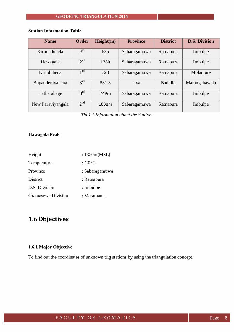
Station Information Table
Name Order Height(m) Province District D.S. Division
Kirimaduhela 3st 635 Sabaragamuwa Ratnapura Imbulpe
Hawagala 2rd
1380 Sabaragamuwa Ratnapura Imbulpe
Kirioluhena 1rd
728 Sabaragamuwa Ratnapura Molamure
Bogandeniyahena 3rd
581.8 Uva Badulla Marangahawela
Hatharabage 3rd
749m Sabaragamuwa Ratnapura Imbulpe
New Paraviyangala 2nd
1638m Sabaragamuwa Ratnapura Imbulpe
Tbl 1.1 Information about the Stations
Hawagala Peak
Height : 1320m(MSL)
Temperature : 20°C
Province : Sabaragamuwa
District : Ratnapura
D.S. Division : Imbulpe
Gramasewa Division : Marathanna
1.6 Objectives
1.6.1 Major Objective
To find out the coordinates of unknown trig stations by using the triangulation concept.
GEODETIC TRIANGULATION 2014
F A C U L T Y O F G E O M A T I C S
Page 9
1.6.2 Minor Objectives
To practice real world GPS observation.
Comparison of GPS system coordinates and triangulation coordinates of same control
points.
To build up the collaboration with various fields and societies.
To manage the entire project according to the given time frame.
To develop a computer program for practical and calculation necessities.
1.6.3 General uses of a triangulation project are as follows
Establishing accurate and precise ground control points for photogrammetric and
large scale surveys.
To determine the size and the shape of the earth by observing latitudes and longitudes
gravity and etc.
To take measurements of disfigurement of structures such as dams
Precise horizontal control network can be established for different types of surveying
tasks such as large engineering projects. Also some as follows,
Horizontal control for topographic surveys,
To fix the centerline, terminal points and shaft points for long
tunnel
To fix centerlines for long line highways, tunnels bridges, etc.
To fix centerlines, piers and abutments of long bridges.
For construction of buildings and public works of large extent
To transfer control points across large bodies of water in hydrographical
surveys.
For finding the direction of the movement of clouds.
For the Detection of crustal movements etc.
GEODETIC TRIANGULATION 2014
F A C U L T Y O F G E O M A T I C S
Page 10
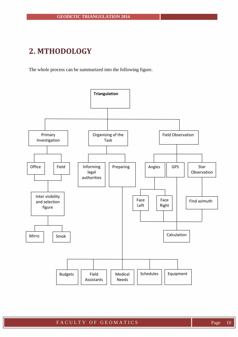
2. MTHODOLOGY
The whole process can be summarized into the following figure.
Primary Investigation
Field Observation Organizing of the Task
Triangulation
Budgets Field Assistants
Schedules Equipment Medical Needs
Smoke
Mirror
Inter visibility and selection
figure
Calculation
Angles GPS Star Observation
Informing legal
authorities
Preparing Office Field
Find azimuth Face Right
Face Left
GEODETIC TRIANGULATION 2014
F A C U L T Y O F G E O M A T I C S
Page 11
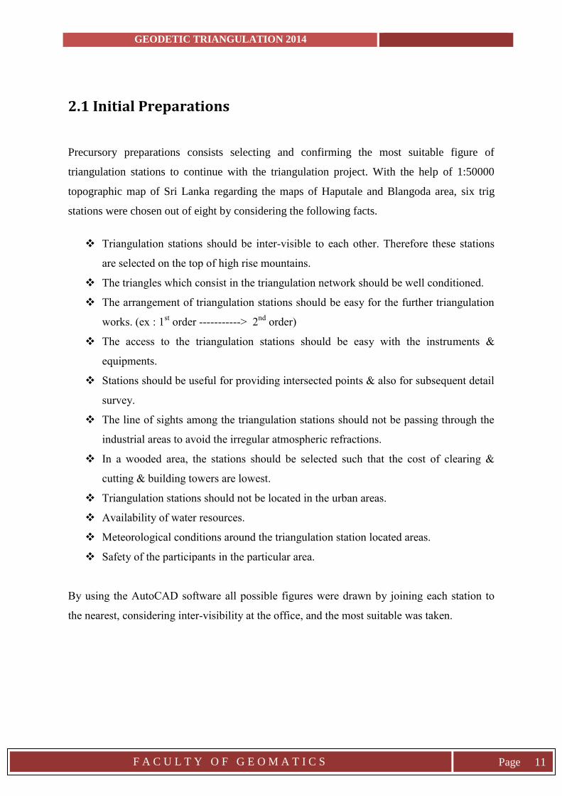
2.1 Initial Preparations
Precursory preparations consists selecting and confirming the most suitable figure of
triangulation stations to continue with the triangulation project. With the help of 1:50000
topographic map of Sri Lanka regarding the maps of Haputale and Blangoda area, six trig
stations were chosen out of eight by considering the following facts.
Triangulation stations should be inter-visible to each other. Therefore these stations
are selected on the top of high rise mountains.
The triangles which consist in the triangulation network should be well conditioned.
The arrangement of triangulation stations should be easy for the further triangulation
works. (ex : 1st order -----------> 2
nd order)
The access to the triangulation stations should be easy with the instruments &
equipments.
Stations should be useful for providing intersected points & also for subsequent detail
survey.
The line of sights among the triangulation stations should not be passing through the
industrial areas to avoid the irregular atmospheric refractions.
In a wooded area, the stations should be selected such that the cost of clearing &
cutting & building towers are lowest.
Triangulation stations should not be located in the urban areas.
Availability of water resources.
Meteorological conditions around the triangulation station located areas.
Safety of the participants in the particular area.
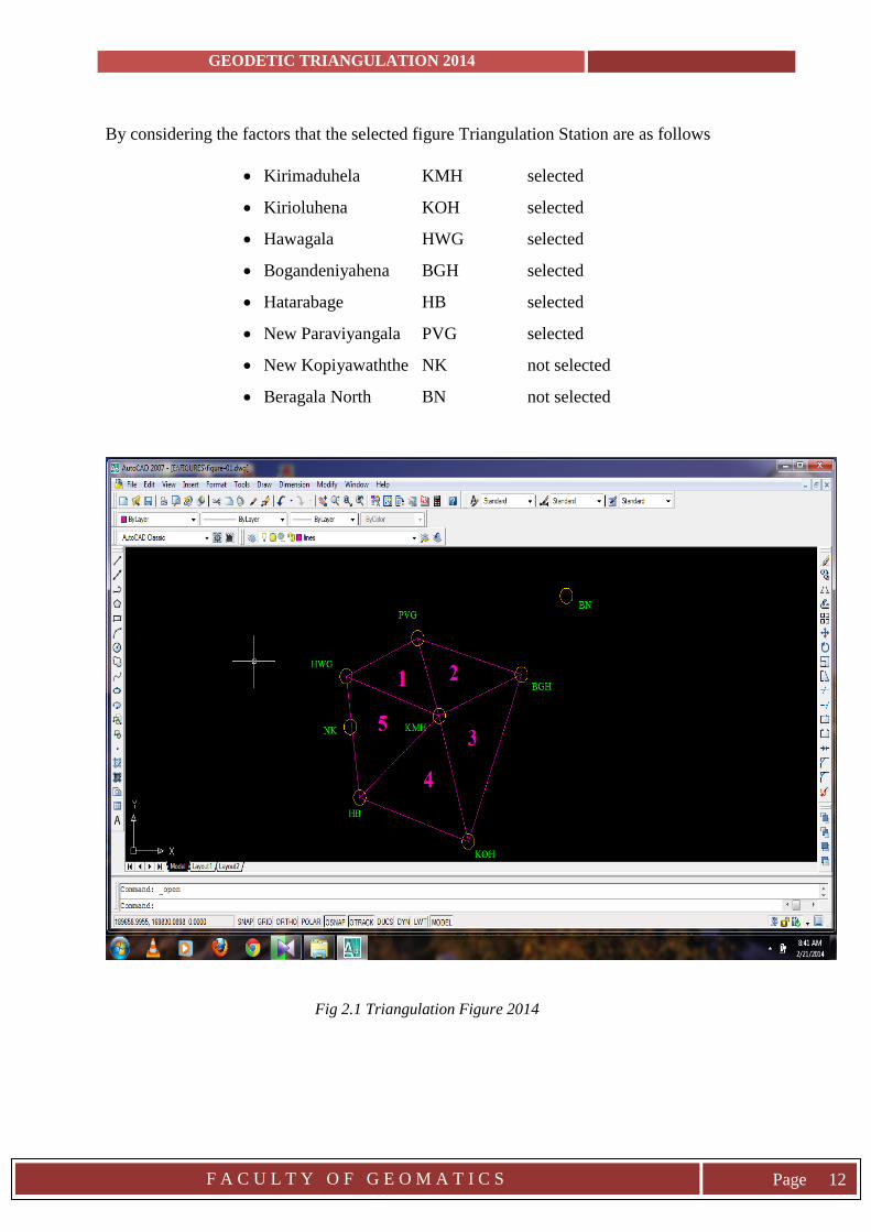
By using the AutoCAD software all possible figures were drawn by joining each station to
the nearest, considering inter-visibility at the office, and the most suitable was taken.
GEODETIC TRIANGULATION 2014
F A C U L T Y O F G E O M A T I C S
Page 12
By considering the factors that the selected figure Triangulation Station are as follows
Kirimaduhela KMH selected
Kirioluhena KOH selected
Hawagala HWG selected
Bogandeniyahena BGH selected
Hatarabage HB selected
New Paraviyangala PVG selected
New Kopiyawaththe NK not selected
Beragala North BN not selected
Fig 2.1 Triangulation Figure 2014
GEODETIC TRIANGULATION 2014
F A C U L T Y O F G E O M A T I C S
Page 13
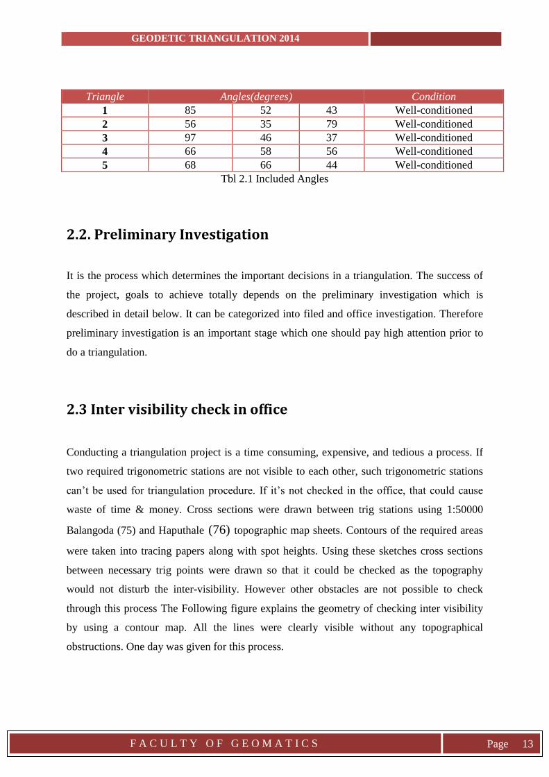
Triangle Angles(degrees) Condition
1 85 52 43 Well-conditioned
2 56 35 79 Well-conditioned
3 97 46 37 Well-conditioned
4 66 58 56 Well-conditioned
5 68 66 44 Well-conditioned
Tbl 2.1 Included Angles
2.2. Preliminary Investigation
It is the process which determines the important decisions in a triangulation. The success of
the project, goals to achieve totally depends on the preliminary investigation which is
described in detail below. It can be categorized into filed and office investigation. Therefore
preliminary investigation is an important stage which one should pay high attention prior to
do a triangulation.
2.3 Inter visibility check in office
Conducting a triangulation project is a time consuming, expensive, and tedious a process. If
two required trigonometric stations are not visible to each other, such trigonometric stations
can’t be used for triangulation procedure. If it’s not checked in the office, that could cause
waste of time & money. Cross sections were drawn between trig stations using 1:50000
Balangoda (75) and Haputhale (76) topographic map sheets. Contours of the required areas
were taken into tracing papers along with spot heights. Using these sketches cross sections
between necessary trig points were drawn so that it could be checked as the topography
would not disturb the inter-visibility. However other obstacles are not possible to check
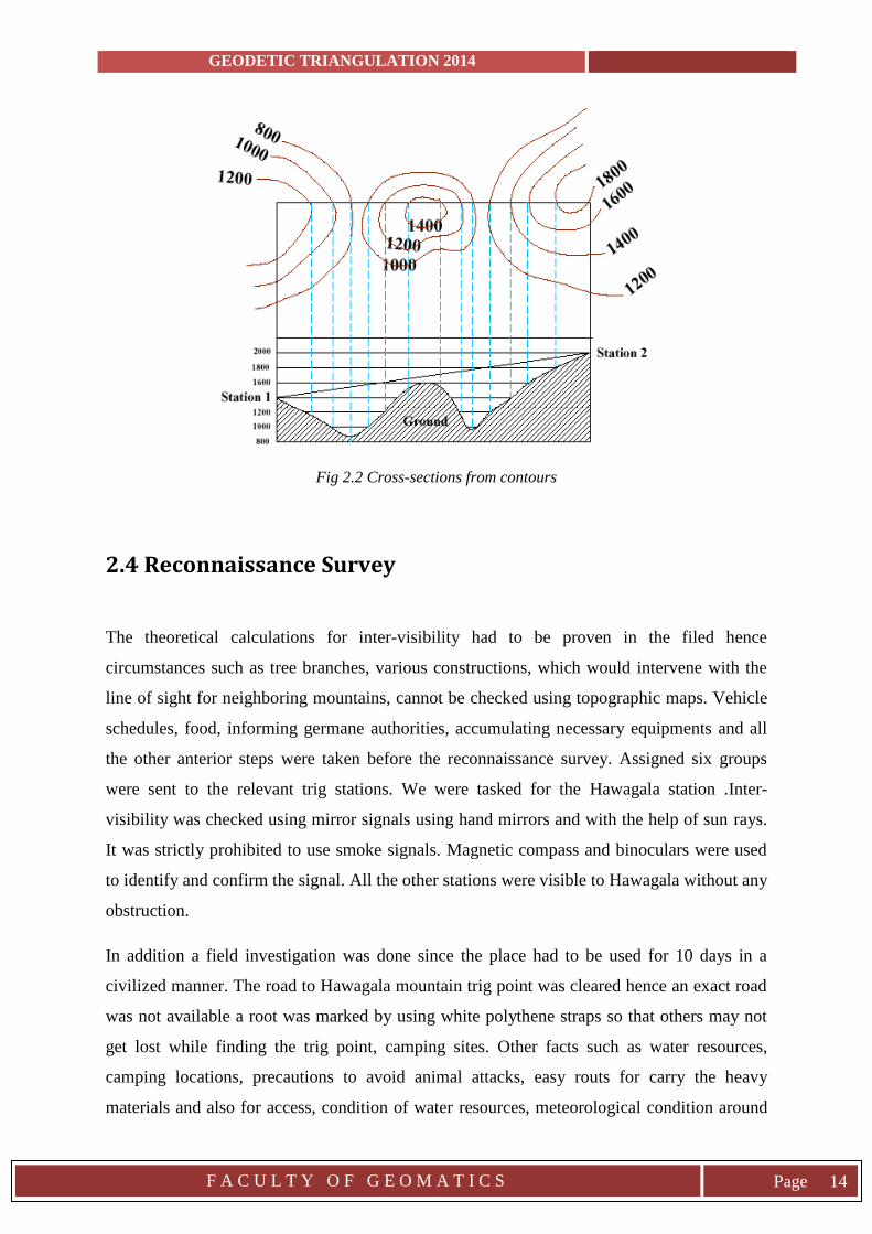
through this process The Following figure explains the geometry of checking inter visibility
by using a contour map. All the lines were clearly visible without any topographical
obstructions. One day was given for this process.
GEODETIC TRIANGULATION 2014
F A C U L T Y O F G E O M A T I C S
Page 14
Fig 2.2 Cross-sections from contours
2.4 Reconnaissance Survey
The theoretical calculations for inter-visibility had to be proven in the filed hence
circumstances such as tree branches, various constructions, which would intervene with the
line of sight for neighboring mountains, cannot be checked using topographic maps. Vehicle
schedules, food, informing germane authorities, accumulating necessary equipments and all
the other anterior steps were taken before the reconnaissance survey. Assigned six groups
were sent to the relevant trig stations. We were tasked for the Hawagala station .Inter-
visibility was checked using mirror signals using hand mirrors and with the help of sun rays.
It was strictly prohibited to use smoke signals. Magnetic compass and binoculars were used
to identify and confirm the signal. All the other stations were visible to Hawagala without any
obstruction.
In addition a field investigation was done since the place had to be used for 10 days in a
civilized manner. The road to Hawagala mountain trig point was cleared hence an exact road
was not available a root was marked by using white polythene straps so that others may not
get lost while finding the trig point, camping sites. Other facts such as water resources,
camping locations, precautions to avoid animal attacks, easy routs for carry the heavy
materials and also for access, condition of water resources, meteorological condition around
GEODETIC TRIANGULATION 2014
F A C U L T Y O F G E O M A T I C S
Page 15
the site were also take in to account as the successfulness of the whole program depends upon
these facts.
2.5 Organization of the program
The whole triangulation project was limited to a time frame of 10 days. So the task had to be
well prepared to avoid extra expenses and time. They were located far from the university
premises. Second trips could cost more money and time. Essential documents had to been
well prepared. Most of the trig points are located in forest areas far from civilized areas so
precautions had to be taken for the safety of participants and government authorities had to be
informed in case of legal responsibility. Most of the points were not easy to reach so other
available needs such as food and clothing along with tents had to be chosen well. The
available resources such as vehicles and instruments were limited. So to improve efficiency
schedules had to be prepared. Notice, task, direction and other necessary boards were
prepared by group members. Some of the equipment such as lamps, observation tower,
camping tents were provided by the university.
Main facts we focused on,
Duration of the survey.
Total cost for the project.
Water, foods, medicines and other day to day needs.
Necessary equipment for the task.
Transportation facilities in a case of an emergency.
Academic criteria, measurements and methods to observe.
Communication.
GEODETIC TRIANGULATION 2014
F A C U L T Y O F G E O M A T I C S
Page 16
Jurisdictions to be informed,
Divisional Secretariat Office Balangoda, Haldumulla, Imbulpe.
Gramaniladhari of each area.
Police Station of Balangoda, Pambahina, Kalthota.
Schedules to be prepared,
Vehicle for camp arrangement and removing, staff transportation.
Communication.
Transferring of Instruments.
Signaling and GPS, Theodolite observation time periods.
Necessary documents,
Angle observation sheet
GPS observation sheet
GPS transfer notebook
Diary
Important notes on work schedule for each day.
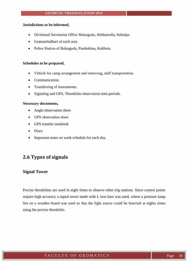
2.6 Types of signals
Signal Tower
Precise theodolites are used in night times to observe other trig stations. Since control points
require high accuracy a signal tower made with L iron bars was used, where a pressure lamp
lies on a wooden board was used so that the light source could be bisected at nights times
using the precise theodolite.
GEODETIC TRIANGULATION 2014
F A C U L T Y O F G E O M A T I C S
Page 17
Iorn Bars
Fig 2.3 Observation tower
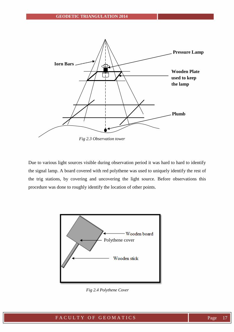
Due to various light sources visible during observation period it was hard to hard to identify
the signal lamp. A board covered with red polythene was used to uniquely identify the rest of
the trig stations, by covering and uncovering the light source. Before observations this
procedure was done to roughly identify the location of other points.
Polythene cover
Fig 2.4 Polythene Cover
Plumb
Wooden Plate
used to keep
the lamp
Pressure Lamp
GEODETIC TRIANGULATION 2014
F A C U L T Y O F G E O M A T I C S
Page 18
2.7 Observation
Equipment Used
- Precise theodolite with tripod (SOKKIA YMIA 5650).
- GPS with all accessories (Trimble 5700).
- Binoculars.
- Observation sheets.
2.7.1 GPS Observations
Triangulation was practiced in an era where GPS technology was not born yet. However GPS
observations were done so that the final results from the triangulation process could be
compared with and the precision could be checked.
Four GPS instruments were used which have trademarks as Leica & Trimble. They were used
in the static mode and method of surveying was radial. Since Kirioluhena is a 1st order trig
point the master GPS or the reference GPS was stationed there while Hawagala was used as
the check station because it’s a 2nd order trig point of the national triangulation system.
Those two stations created the base line as the coordinates are known. These two instruments
were kept working during observations while other two instruments were shifted between
HB, BH, NP, KH stations. Observations were taken according to the schedule.WGS84 was
used as the reference datum. The cut-off angle was 15° and logging interval was 1s.Erstwhile
conditions were good. At every half an hour required readings (battery level, memory status,
pdop, number of satellites, etc.) were recorded on the observation sheet. The whole process
was completed within a one day.
GEODETIC TRIANGULATION 2014
F A C U L T Y O F G E O M A T I C S
Page 19
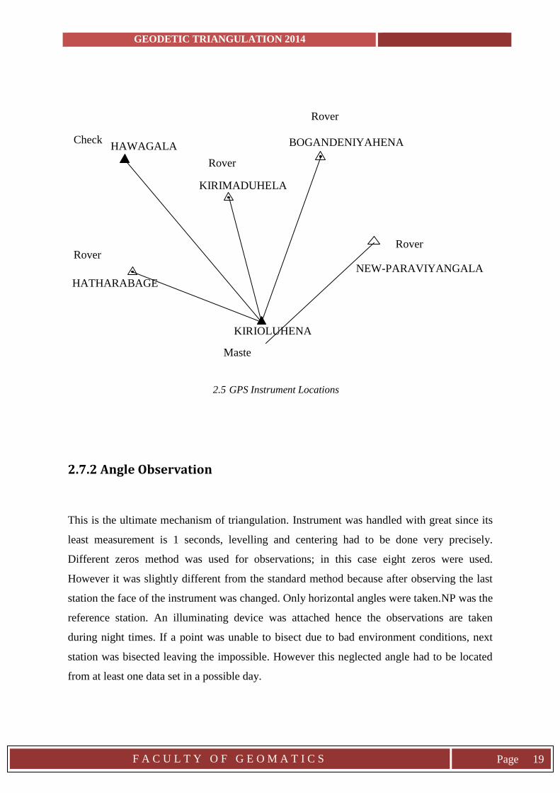
Rover
NEW-PARAVIYANGALA
2.5 GPS Instrument Locations
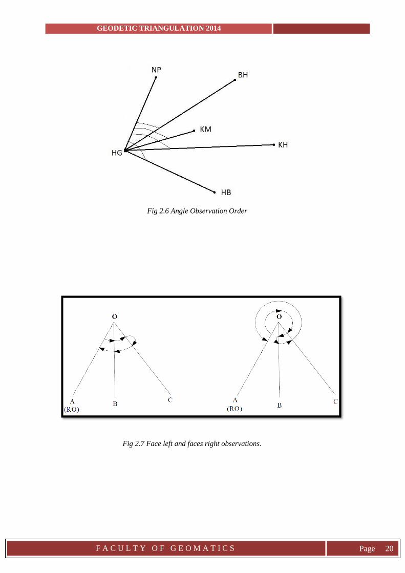
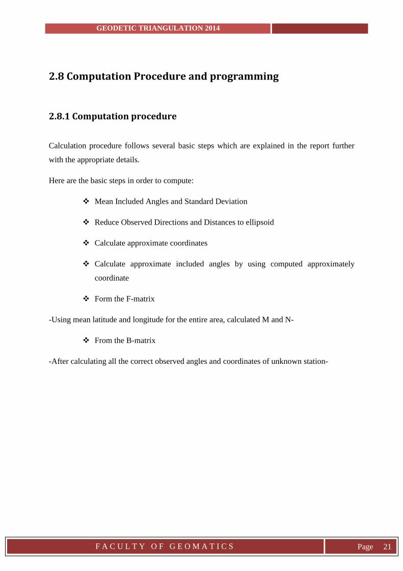
2.7.2 Angle Observation
This is the ultimate mechanism of triangulation. Instrument was handled with great since its
least measurement is 1 seconds, levelling and centering had to be done very precisely.
Different zeros method was used for observations; in this case eight zeros were used.
However it was slightly different from the standard method because after observing the last
station the face of the instrument was changed. Only horizontal angles were taken.NP was the
reference station. An illuminating device was attached hence the observations are taken
during night times. If a point was unable to bisect due to bad environment conditions, next
station was bisected leaving the impossible. However this neglected angle had to be located
from at least one data set in a possible day.
Maste
r
Check BOGANDENIYAHENA
KIRIOLUHENA
HAWAGALA
KIRIMADUHELA
HATHARABAGE
Rover
Rover
Rover
GEODETIC TRIANGULATION 2014
F A C U L T Y O F G E O M A T I C S
Page 20
Fig 2.6 Angle Observation Order
Fig 2.7 Face left and faces right observations.
GEODETIC TRIANGULATION 2014
F A C U L T Y O F G E O M A T I C S
Page 21
2.8 Computation Procedure and programming
2.8.1 Computation procedure
Calculation procedure follows several basic steps which are explained in the report further
with the appropriate details.
Here are the basic steps in order to compute:
Mean Included Angles and Standard Deviation
Reduce Observed Directions and Distances to ellipsoid
Calculate approximate coordinates
Calculate approximate included angles by using computed approximately
coordinate
Form the F-matrix
-Using mean latitude and longitude for the entire area, calculated M and N-
From the B-matrix
-After calculating all the correct observed angles and coordinates of unknown station-
GEODETIC TRIANGULATION 2014
F A C U L T Y O F G E O M A T I C S
Page 22
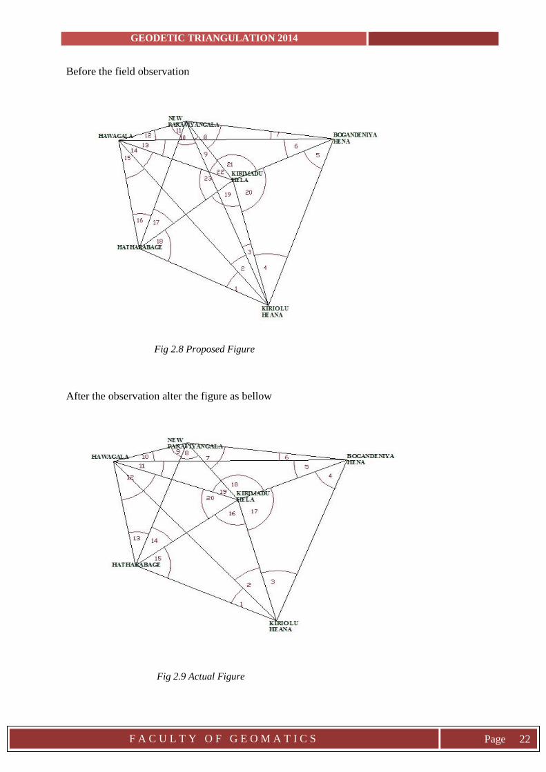
Before the field observation
Fig 2.8 Proposed Figure
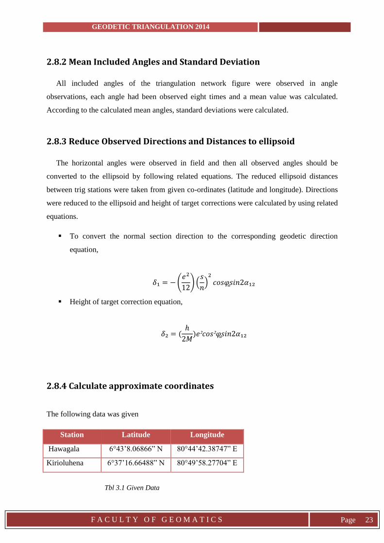
After the observation alter the figure as bellow
Fig 2.9 Actual Figure
GEODETIC TRIANGULATION 2014
F A C U L T Y O F G E O M A T I C S
Page 23
2.8.2 Mean Included Angles and Standard Deviation
All included angles of the triangulation network figure were observed in angle
observations, each angle had been observed eight times and a mean value was calculated.
According to the calculated mean angles, standard deviations were calculated.
2.8.3 Reduce Observed Directions and Distances to ellipsoid
The horizontal angles were observed in field and then all observed angles should be
converted to the ellipsoid by following related equations. The reduced ellipsoid distances
between trig stations were taken from given co-ordinates (latitude and longitude). Directions
were reduced to the ellipsoid and height of target corrections were calculated by using related
equations.
To convert the normal section direction to the corresponding geodetic direction
equation,
𝛿₁ = − (𝑒2
12) (
𝑠
𝑛)
2
𝑐𝑜𝑠𝜑 ͚𝑠𝑖𝑛2𝛼₁₂
Height of target correction equation,
𝛿₂ = (ℎ
2𝑀)𝑒²𝑐𝑜𝑠²�͚�𝑠𝑖𝑛2𝛼₁₂
2.8.4 Calculate approximate coordinates
The following data was given
Station Latitude Longitude
Hawagala 6°43’8.06866” N 80°44’42.38747” E
Kirioluhena 6°37’16.66488” N 80°49’58.27704” E
Tbl 3.1 Given Data
GEODETIC TRIANGULATION 2014
F A C U L T Y O F G E O M A T I C S
Page 24
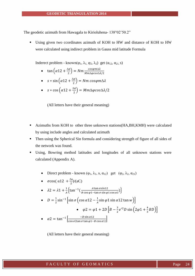
The geodetic azimuth from Hawagala to Kirioluhena- 138°02’50.2”
Using given two ccordinates azimuth of KOH to HW and distance of KOH to HW
were calculated using indirect problem in Gauss mid latitude Formula
Inderect problem - known(φ1, λ1, φ2, λ2) get (α12, α21, s)
tan (𝛼12 +Δ𝛼
2) = 𝑁𝑚
𝑐𝑜𝑠𝜑𝑚Δ𝜆
𝑀𝑚Δ𝜑𝑐𝑜𝑠Δ𝜆/2
𝑠 ∗ sin (𝛼12 +Δ𝛼
2) = 𝑁𝑚 𝑐𝑜𝑠𝜑𝑚Δ𝜆
𝑠 ∗ cos (𝛼12 +Δ𝛼
2) = 𝑀𝑚Δ𝜑𝑐𝑜𝑠Δ𝜆/2
(All letters have their general meaning)
Azimuths from KOH to other three unknown stations(HA,BH,KMH) were calculated
by using include angles and calculated azimuth
Then using the Spherical Sin formula and considering strength of figure of all sides of
the network was found.
Using, Bowring method latitudes and longitudes of all unknown stations were
calculated (Appendix A).
Direct problem - known (φ1, λ1, s, α12) get (φ2, λ2, α21)
𝜎cos ( α12 +Δα
2)/(aC)
𝜆2 = 𝜆1 +1
𝐴{tan−1(
𝐴 tan 𝜎𝑠𝑖𝑛12
𝐵 cos 𝜑1−tan 𝜎 sin 𝜑1 cos 𝛼1)}
𝐷 =1
2sin−1 [sin 𝜎 (cos 𝛼12 −
1
𝐴sin 𝜑1 sin 𝛼12 tan 𝑤)]
𝜑2 = 𝜑1 + 2𝐷 [𝐵 −3
2𝑒′2𝐷 sin (2𝜑1 +
4
3𝐵𝐷)]
𝛼2 = tan−1 [−𝐵 sin 𝛼12
cos 𝜎(tan 𝜎 tan 𝜑1−𝐵 cos 𝛼1)]
(All letters have their general meaning)
GEODETIC TRIANGULATION 2014
F A C U L T Y O F G E O M A T I C S
Page 25
2.8.5 Calculate approximate included angles and distances
Using the approximate coordinates, the approximate included angles and distances were
calculated (reverse of Mid Latitude Formula).
The radius of the meridian section (Mm) and prime vertical (Nm) is given by
𝑀𝑚 = 𝑎(1 − 𝑒2)/(1 − 𝑒2𝑠𝑖𝑛2𝜑)³̷₂
𝑁𝑚 = 𝑎/(1 − 𝑒2𝑠𝑖𝑛2𝜑)¹̷₂
The parameters of the WGS84 ellipsoid are given below
a=6378137 m
e²=0.00669437999014
2.8.6 Computer programming codes
The programming codes and the program was burned in the cd,
GEODETIC TRIANGULATION 2014
F A C U L T Y O F G E O M A T I C S
Page 26
3. RESULTS AND DISCUSSION
3.1 Results
The Triangulation Figure
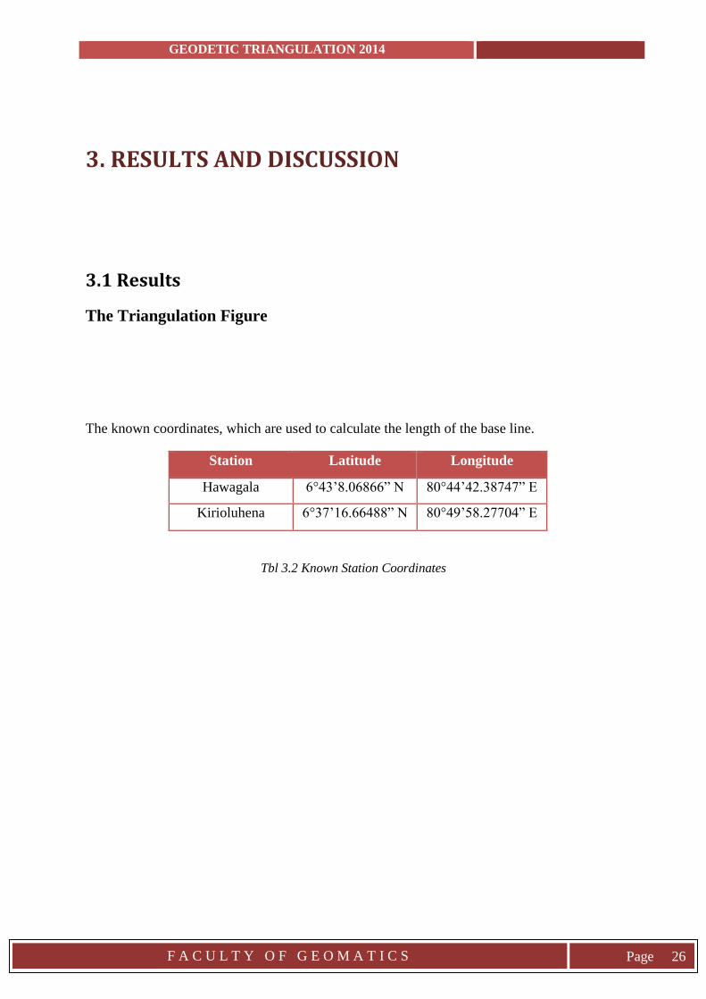
The known coordinates, which are used to calculate the length of the base line.
Station Latitude Longitude
Hawagala 6°43’8.06866” N 80°44’42.38747” E
Kirioluhena 6°37’16.66488” N 80°49’58.27704” E
Tbl 3.2 Known Station Coordinates
GEODETIC TRIANGULATION 2014
F A C U L T Y O F G E O M A T I C S
Page 27
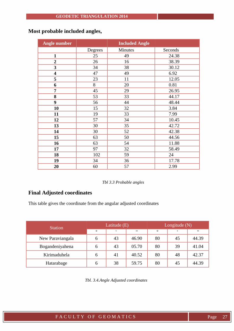
Most probable included angles,
Angle number Included Angle
Degrees Minutes Seconds
1 25 49 24.38
2 26 16 38.39
3 34 38 30.12
4 47 49 6.92
5 23 11 12.05
6 8 20 0.81
7 45 29 26.95
8 53 33 44.17
9 56 44 48.44
10 15 32 3.84
11 19 33 7.99
12 57 34 10.45
13 30 35 42.72
14 30 52 42.38
15 63 50 44.56
16 63 54 11.88
17 97 32 58.49
18 102 59 24
19 34 36 17.78
20 60 57 2.99
Tbl 3.3 Probable angles
Final Adjusted coordinates
This table gives the coordinate from the angular adjusted coordinates
Station Latitude (E) Longitude (N)
° ‘ “ ° ‘ “
New Paraviangala 6 43 46.90 80 45 44.39
Bogandeniyahena 6 43 05.70 80 39 41.04
Kirimaduhela 6 41 40.52 80 48 42.37
Hatarabage 6 38 59.75 80 45 44.39
Tbl. 3.4.Angle Adjusted coordinates
GEODETIC TRIANGULATION 2014
F A C U L T Y O F G E O M A T I C S
Page 28
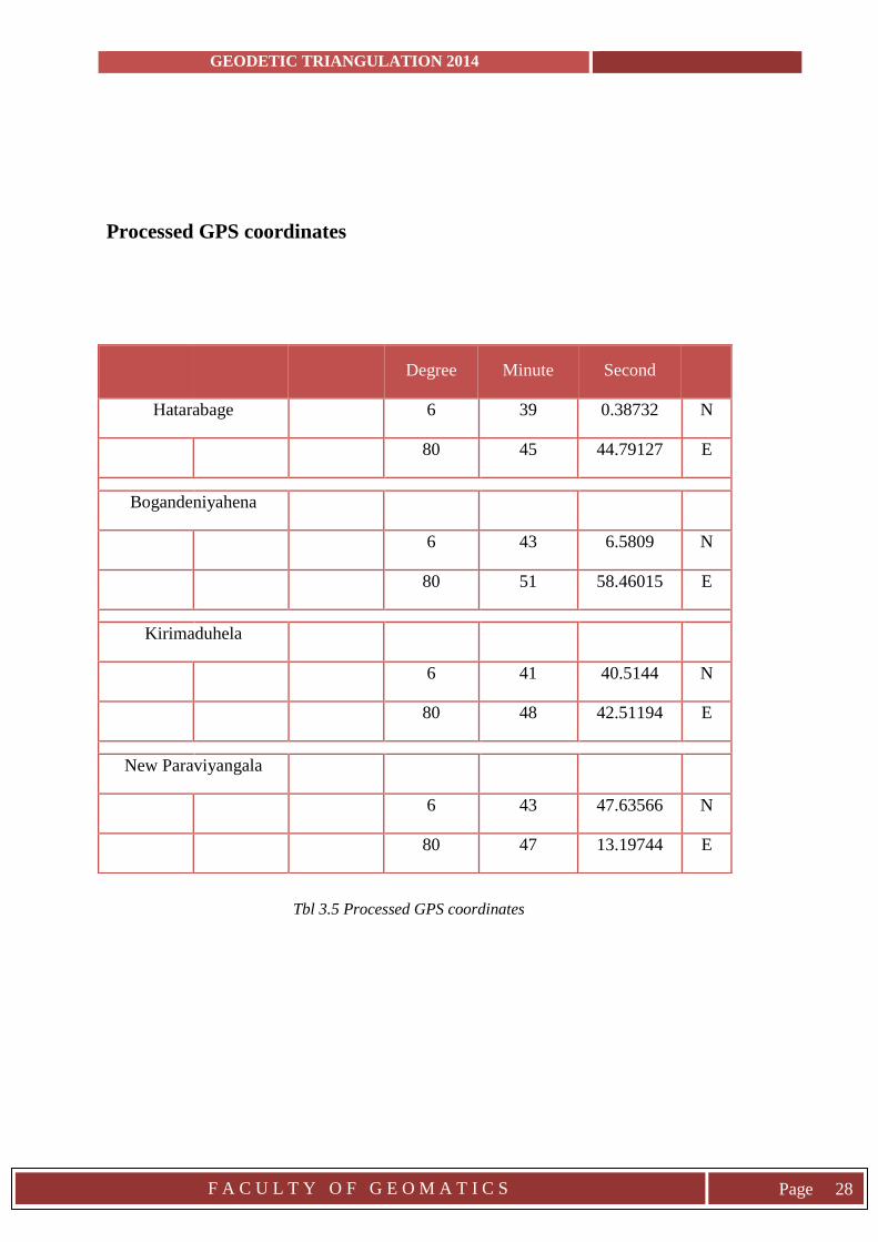
Processed GPS coordinates
Tbl 3.5 Processed GPS coordinates
Degree Minute Second
Hatarabage
6 39 0.38732 N
80 45 44.79127 E
Bogandeniyahena
6 43 6.5809 N
80 51 58.46015 E
Kirimaduhela
6 41 40.5144 N
80 48 42.51194 E
New Paraviyangala
6 43 47.63566 N
80 47 13.19744 E
GEODETIC TRIANGULATION 2014
F A C U L T Y O F G E O M A T I C S
Page 29
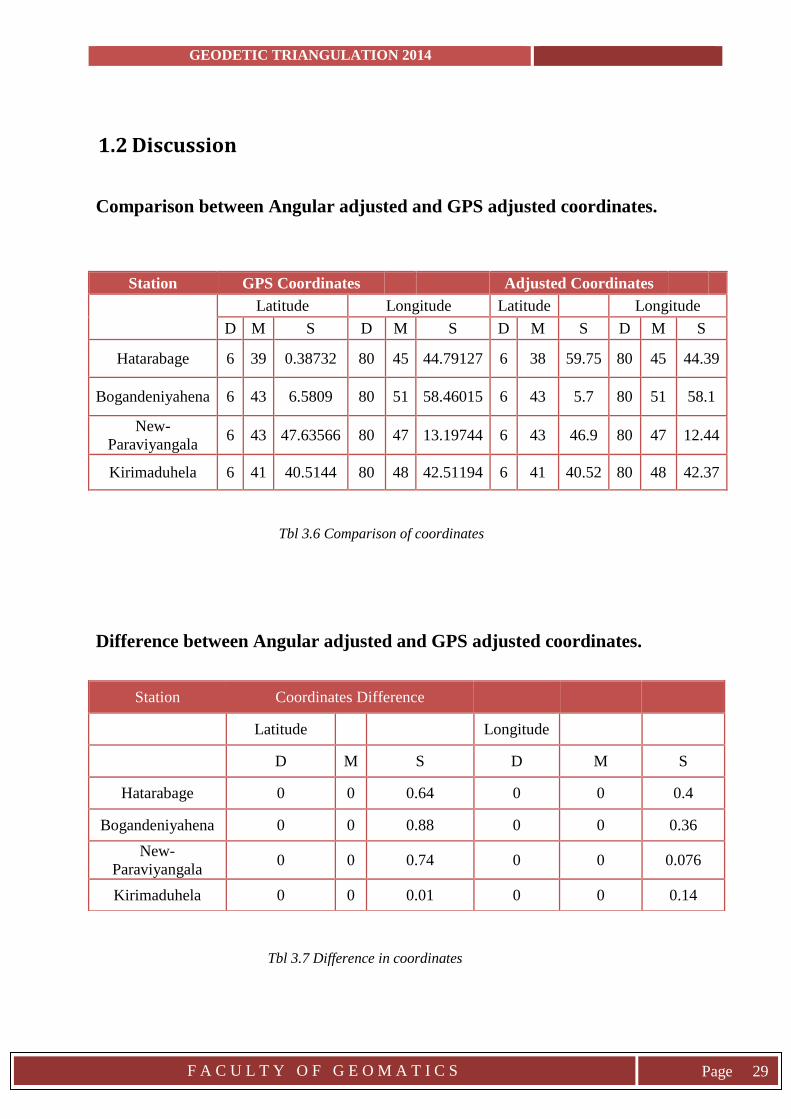
1.2 Discussion
Comparison between Angular adjusted and GPS adjusted coordinates.
Station GPS Coordinates
Adjusted Coordinates
Latitude Longitude Latitude
Longitude
D M S D M S D M S D M S
Hatarabage 6 39 0.38732 80 45 44.79127 6 38 59.75 80 45 44.39
Bogandeniyahena 6 43 6.5809 80 51 58.46015 6 43 5.7 80 51 58.1
New-
Paraviyangala 6 43 47.63566 80 47 13.19744 6 43 46.9 80 47 12.44
Kirimaduhela 6 41 40.5144 80 48 42.51194 6 41 40.52 80 48 42.37
Tbl 3.6 Comparison of coordinates
Difference between Angular adjusted and GPS adjusted coordinates.
Tbl 3.7 Difference in coordinates
Station Coordinates Difference
Latitude
Longitude
D M S D M S
Hatarabage 0 0 0.64 0 0 0.4
Bogandeniyahena 0 0 0.88 0 0 0.36
New-
Paraviyangala 0 0 0.74 0 0 0.076
Kirimaduhela 0 0 0.01 0 0 0.14
GEODETIC TRIANGULATION 2014
F A C U L T Y O F G E O M A T I C S
Page 30
Observation weighting gives greater influence to the most precise measurements during the
network adjustment process. Larger standard deviations mean grater measurement
uncertainty and lower precision for the measurements which are then given less weight in the
adjustment. Less number of iterations also decreases accuracy. When calculating approximate
coordinates, the Bowring method was used in the indirect form, instead of Guess mid latitude
formula to prevent iterations. Strength of figure was calculated before applying spherical sine
rule to find the most appropriate values. When calculating the correct coordinate least square
method was applied hence it refers to the notion that would recommend to minimize the
squared error between the data, which are trying to approximate and some functions or class
of functions that are trying to approximate the data with.
According to the above shown comparison table there is a negligible amount of difference
between them. When considering precision, we can be satisfied about the calculated
coordinates.
Suitable stations were chosen by considering well-conditioned triangles. After the field
investigation it was found that KH and NP were not inter-visible due to some huge forest
trees. So the figure was altered according to those conditions. However because of bad
weather changes KH was not observed from HW trig point. So the final figure was deviated
from the figure that was included in the proposal. Instead of 23 angles only 20 angles were
observed and taken for calculations. Some datasets were rejected due to incompleteness.
Some were not consisted with zeros. All the distances between station were less than 2Km,
though it’s a negligible amount when considering with earths radius, the triangles were
considered as spherical triangles.
When creating cross sections using contour maps to check whether the topography would not
disturb the inter-visibility NP was not in 1:50000 map sheets. So a rough location was
selected and the contours were drawn. However the uncertainty was vanished only after field
verifications were done. Field verification process plays a major role in organizing the
Triangulation program. All the future calculation figures and organization of the practical for
instead vehicle schedules, food and other supplies, reservations, amount of men need for
work, whether to continue with the project or not, and all these facts are pre-planned using
the data observed from the reconnaissance survey. If the total program was organized and
GEODETIC TRIANGULATION 2014
F A C U L T Y O F G E O M A T I C S
Page 31
was ongoing, some necessary stations are not inter-visible, that would be a total waste of time
and money.
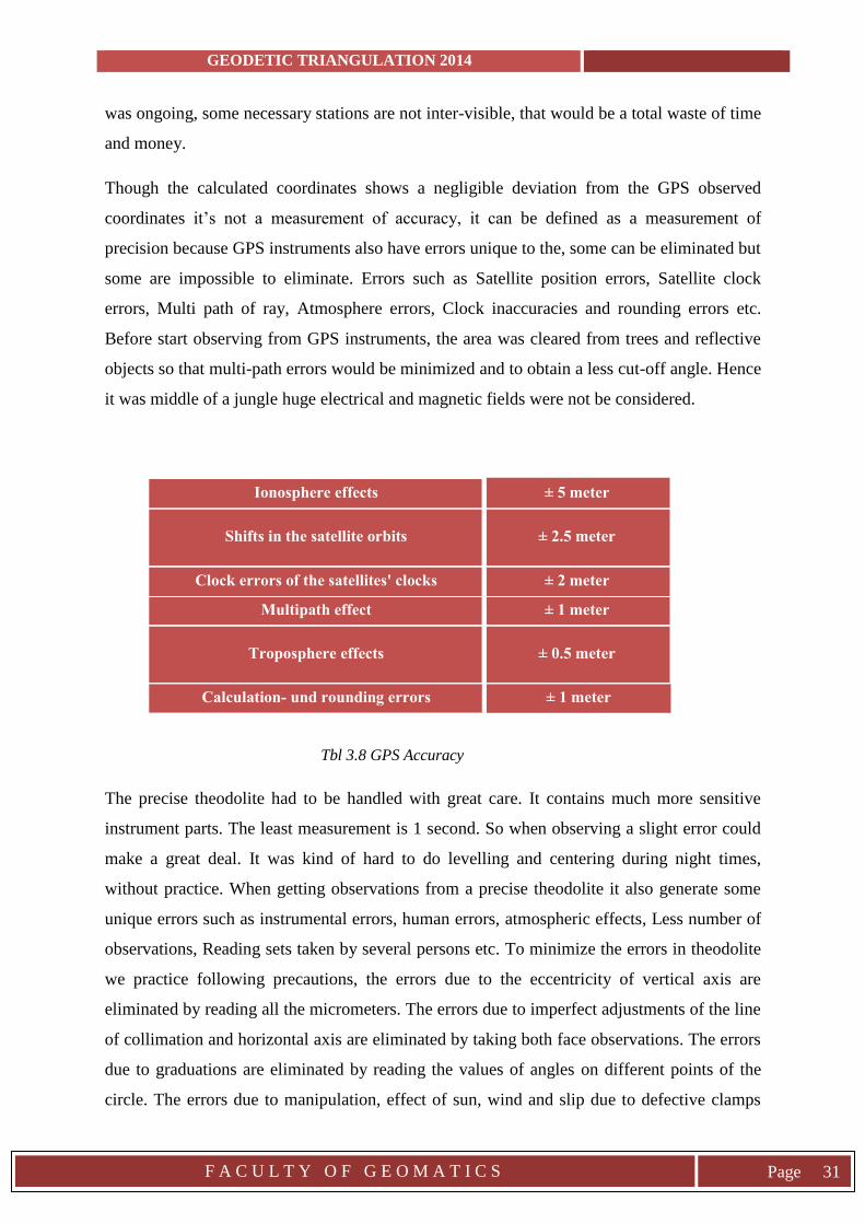
Though the calculated coordinates shows a negligible deviation from the GPS observed
coordinates it’s not a measurement of accuracy, it can be defined as a measurement of
precision because GPS instruments also have errors unique to the, some can be eliminated but
some are impossible to eliminate. Errors such as Satellite position errors, Satellite clock
errors, Multi path of ray, Atmosphere errors, Clock inaccuracies and rounding errors etc.
Before start observing from GPS instruments, the area was cleared from trees and reflective
objects so that multi-path errors would be minimized and to obtain a less cut-off angle. Hence
it was middle of a jungle huge electrical and magnetic fields were not be considered.
Tbl 3.8 GPS Accuracy
The precise theodolite had to be handled with great care. It contains much more sensitive
instrument parts. The least measurement is 1 second. So when observing a slight error could
make a great deal. It was kind of hard to do levelling and centering during night times,
without practice. When getting observations from a precise theodolite it also generate some
unique errors such as instrumental errors, human errors, atmospheric effects, Less number of
observations, Reading sets taken by several persons etc. To minimize the errors in theodolite
we practice following precautions, the errors due to the eccentricity of vertical axis are
eliminated by reading all the micrometers. The errors due to imperfect adjustments of the line
of collimation and horizontal axis are eliminated by taking both face observations. The errors
due to graduations are eliminated by reading the values of angles on different points of the
circle. The errors due to manipulation, effect of sun, wind and slip due to defective clamps
Ionosphere effects ± 5 meter
Shifts in the satellite orbits ± 2.5 meter
Clock errors of the satellites' clocks ± 2 meter
Multipath effect ± 1 meter
Troposphere effects ± 0.5 meter
Calculation- und rounding errors ± 1 meter
GEODETIC TRIANGULATION 2014
F A C U L T Y O F G E O M A T I C S
Page 32
are eliminated by taking half of the observations from left to right and other half from right to
left. The accidental errors due to bisection and reading are eliminated by taking number of
observations. And Errors in the graduated circle eliminated by taking different zeros, and
number of zeros. Imperfect bisections can occur because of several persons taking the same
data set. The eye sight from person to person differs. So only a one person should handle the
instrument at a time.
Some readings were omitted considering its variation from previous values. Completing a
one zero set both faces must be observed at one circle within ±5 seconds. Since the weather
was in an unfriendly manner it was really hard to observe other trig points. During this
weather condition, especially the wind it was very hard to maintain the centering and the
levelling of the precise theodolite. The observation tower and gas lamp were protected by
using covers from side to side. After eight days the observation tower was destroyed and the
reservation tents were torn apart. The gas lamp has to be well protected because it had a
chance of exploding.
Observations are done during night time is because during day times it’s hard to uniquely
identify the target since illuminating light sources are available everywhere. And the position
of the sun, humidity, refraction and other reasons the readings could be erroneous. However
even at night times it was kind of hard to observe the target by uniquely identifying it. So
night time would give more accurate results.
GEODETIC TRIANGULATION 2014
F A C U L T Y O F G E O M A T I C S
Page 33
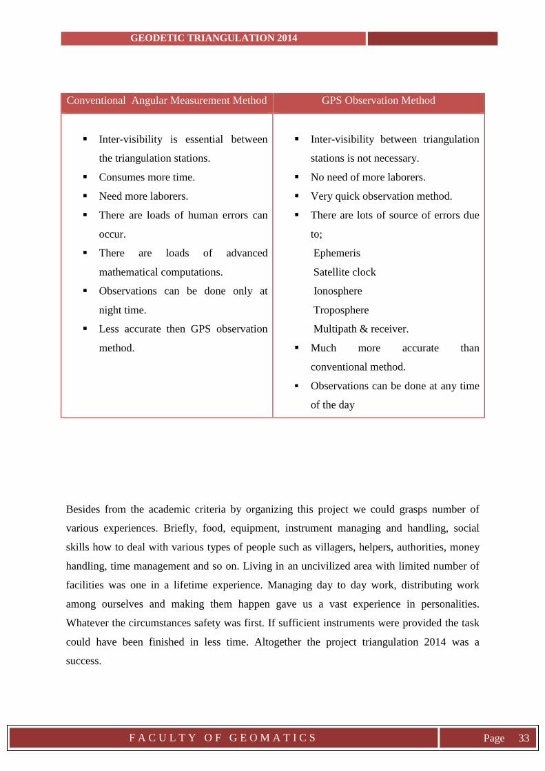
Conventional Angular Measurement Method GPS Observation Method
Inter-visibility is essential between
the triangulation stations.
Consumes more time.
Need more laborers.
There are loads of human errors can
occur.
There are loads of advanced
mathematical computations.
Observations can be done only at
night time.
Less accurate then GPS observation
method.
Inter-visibility between triangulation
stations is not necessary.
No need of more laborers.
Very quick observation method.
There are lots of source of errors due
to;
Ephemeris
Satellite clock
Ionosphere
Troposphere
Multipath & receiver.
Much more accurate than
conventional method.
Observations can be done at any time
of the day
Besides from the academic criteria by organizing this project we could grasps number of
various experiences. Briefly, food, equipment, instrument managing and handling, social
skills how to deal with various types of people such as villagers, helpers, authorities, money
handling, time management and so on. Living in an uncivilized area with limited number of
facilities was one in a lifetime experience. Managing day to day work, distributing work
among ourselves and making them happen gave us a vast experience in personalities.
Whatever the circumstances safety was first. If sufficient instruments were provided the task
could have been finished in less time. Altogether the project triangulation 2014 was a
success.
GEODETIC TRIANGULATION 2014
F A C U L T Y O F G E O M A T I C S
Page 34
4. CONCLUTION AND RECOMMENDATIONS
4.1 Conclusion
Triangulation process is an outdated one. It is still practiced so that the participants could get
an experience on how the program is conducted and for academic purposes such as to ensure
that the learnt theories are used in reality. And also to practice in advanced calculations, to try
new solving methods. Experience in handling instruments during tight situations, tough
environment and social phases. To take responsibility, to handle people and goods etc. At the
end were able to handle both the precise theodolite and the GPS instrument in a much easier
manner.
When comparing the conventional and the modern method results acquired from the
triangulation method is nearly equal to the results obtained from the GPS observations.
Which means high accuracy can be acquired. But what we have to focus here is the
procedure. If the coordinates were to find out using GPS instruments the task would have
been finished in less than two days. The conventional method took ten days It is true that the
GPS instruments are much expensive than a precise theodolite but when considering the
whole task using modern technology is very much easier, less calculations, less expensive,
time consuming. So the final conclusion would be that using modern technology such as GPS
to find coordinates of unknown points is much wiser and most suitable.
The final coordinates of the known points which are NP, BH, KH, and HB were calculated
using observed angles. The project triangulation 2014 was a considerably successful one.
GEODETIC TRIANGULATION 2014
F A C U L T Y O F G E O M A T I C S
Page 35
4.2 Recommendations
A major drawback for the triangulation 2014 was the season of the year that it was chosen to
practice the program. June was not a suitable time period, most of the equipment was
damaged and some were lost, angles were very hard to observe due to mist and rains. So
before organizing such considerably large practical program the season has to be chosen very
wise using not only statistical data but also information from native villages that lives nearby
field sites. According to them February, March is the most suitable season for conducting
such program where the sky is clearer and the atmosphere is dry.
Provided instruments from the University were not sufficient, both precise theodolites and
GPS instruments. So instruments had to be changed from station to station. Schedules had to
be made. It was time consuming. If sufficient instruments were provided the total practical
program could have been finished in less days than it took. Transportation vehicles would
have been available for more purposes and less fuel cost. The given GPS instrument batteries
have exceeded its charging discharging cycles. So they get drained in less time periods and
needed to be charged accordingly. This is also a waste of time. So these instruments need to
be repaired and upgraded accordingly to the available technology. And also for some trig
stations telephone signals were very poor. And mobile phone call costs too much. So it’s
better if the University can provide a different method of communication such as walky-
talkies.
During field investigation the recommended signaling method was mirror signaling.
However due to bad weather condition and the azimuth of the sun it was hard to identify
signals from other stations. There are instruments that create smoke without igniting fire.
Such instruments could be used. Betwixt the observation process at night time, the
identification method was to cover and uncover the gas lamp using red and black polythene.
But in modern days light sources in such manner are displayed everywhere. It’s hard to
identify uniquely. Instead of this method illuminating rods, luminous devices can be used
even in thick foggy conditions. They are much easy to transport and since the source can be
uniquely identified, it would preserve a huge amount of time.
GEODETIC TRIANGULATION 2014
F A C U L T Y O F G E O M A T I C S
Page 36
To obtain high accuracy results from the triangulation process it requires advanced
mathematical calculations and referencing. It’s much easier if the given time period for office
work and calculations was increased a little bit. For the calculation process it’s much easier
and outpaced using Mat Lab instead of C++, since predefined functions are available. So it
would be much more practical if the university can provide an academic propulsion
regarding Mat Lab, a theoretical background for students. A revision of previous lectures;
regarding Geodesy. This is necessary for calculations.
A large time gap was there between the preliminary survey and the actual triangulation task.
For our task it was like more than two months. So a lot could happen between two months.
Environment conditions could change rapidly. Preliminary precautions, plans could be a total
waste of time if things changed. So the program should be conducted as soon as possible
after the reconnaissance survey is finished.
Getting GPS observation was not a part of triangulation. It was done only so that the
precision could be checked and for more field experience. But hence there is no major
observation task done during day time its better if there observations which are done by the
precise theodolite could also be done using total stations and distances could be measure
using EDMs so that all these readings could be compared with each other and a person could
get more academic knowledge about these type of field work. Furthermore horizontal angles,
distances and coordinates could also be recorded for advanced studies. Triangulation is a
process that’s not practiced in the current world, but it’s done here because students could
gain more experience and knowledge theoretically and practically. For precise results star
observations also have be done in finding azimuths. So it’s better to add star observations
also for the practical task so that a participant could gain more comprehension.
Another problem we faced was that due to strong wind the mantle of the gas lamp gets
damaged. The outer core cracks when water is touched such as in rainy conditions.
Sometimes the available gas is not sufficient. In these conditions there is a possibility for the
lamp to explode which would put all the nearby students in danger. And also this caused
erroneous observations for other trig points. It’s much healthier if the university can provide
light sources which are not affected by wind, rain etc. Such as powerful lamps which works
with battery power.
These trig stations are far from civilized areas. Natural hazards can occur at any time, such as
forest fire, landslides etc. Animal attacks can happen at any moment. So in these tight
GEODETIC TRIANGULATION 2014
F A C U L T Y O F G E O M A T I C S
Page 37
situations decision making is what makes the whole situation reliable. It’s wiser if the
participants can have a training session on how to face these kinds of hazards. Medical
treatment such as vaccination for infections, diseases should be given to participants for their
protection. When living in such condition cleanliness plays a major role. Much more
powerful cleaning chemicals can be used. And also its better if the university can provide
fumes and creams which would give protection from various insects such as mosquitoes,
leaches etc.
Mostly these calculated coordinates are not used for any other purposes. If these coordinates
can be used for other different kind of field practical programs conducted by the Faculty of
Geomatics, these coordinates would automatically be checked repeatedly and a value will be
added for our final results. The location of the triangulation network should be different from
place to place so that the real time experience could be gain. Or else it would not be fresh and
observations can be copied. Another reference station can be added so that high accuracy can
be obtained. Modern technology has given more advanced instruments, so instead of
practicing outdated methods its more useful if this project can be conducted using those types
of instruments in a much wider range.

GEODETIC TRIANGULATION 2014
F A C U L T Y O F G E O M A T I C S
Page 38
5. REFERENCES AND BIBLIOGRAPHY
Dr.Punmia,Ashok k. Jain and Arun K. Jain,(2005).SURVEYING VOL
II.(15TH
ed.).JODAPUR RAJASTAN, MUMBAI MAHARASHTRA,
JODAPUR RAJASTAN.
Richard H. Rapp(1991),GEOMETRIC GEODESY PART 1,Columbus Ohio.
TRIANGULATION AND TRILATERATION www.newagepublishers.com/samplechapter/001033
TRIANGULATION en.wikipedia.org/wiki/Triangulation
Adjustment computations statistics and Least Squares in Surveying and
GIS,(1997)
Edited by: Paul R. Wolf and Charles D. Ghilani ,(pages 169-199)
GEODETIC TRIANGULATION 2014
F A C U L T Y O F G E O M A T I C S
Page 39
Appendices
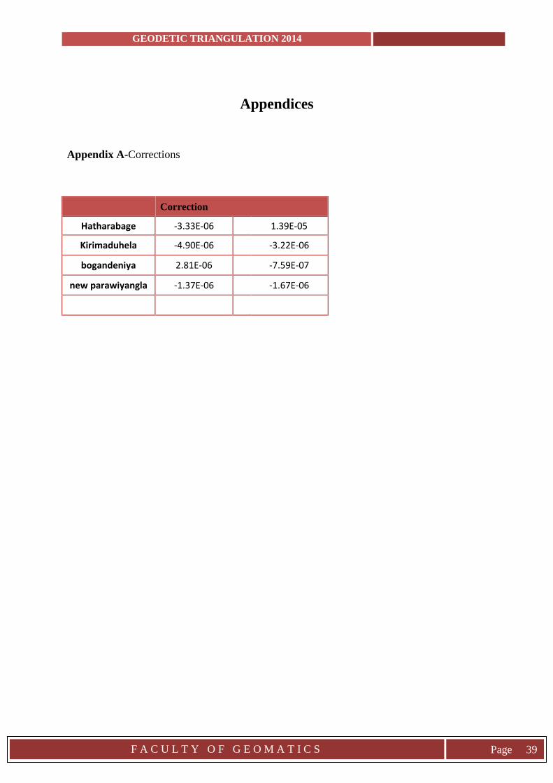
Appendix A-Corrections
Correction
Hatharabage -3.33E-06
1.39E-05
Kirimaduhela -4.90E-06
-3.22E-06
bogandeniya 2.81E-06
-7.59E-07
new parawiyangla -1.37E-06
-1.67E-06
GEODETIC TRIANGULATION 2014
F A C U L T Y O F G E O M A T I C S
Page 40
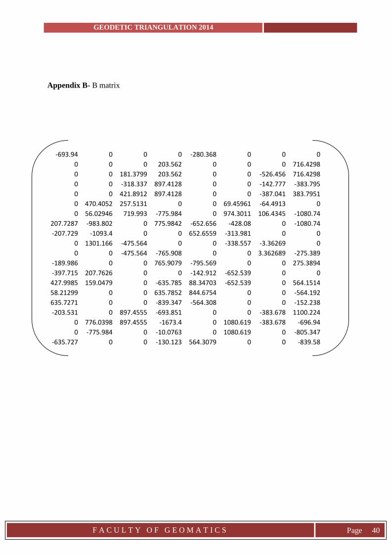
Appendix B- B matrix
-693.94 0 0 0 -280.368 0 0 0 0 0 0 203.562 0 0 0 716.4298 0 0 181.3799 203.562 0 0 -526.456 716.4298 0 0 -318.337 897.4128 0 0 -142.777 -383.795 0 0 421.8912 897.4128 0 0 -387.041 383.7951 0 470.4052 257.5131 0 0 69.45961 -64.4913 0 0 56.02946 719.993 -775.984 0 974.3011 106.4345 -1080.74
207.7287 -983.802 0 775.9842 -652.656 -428.08 0 -1080.74 -207.729 -1093.4 0 0 652.6559 -313.981 0 0
0 1301.166 -475.564 0 0 -338.557 -3.36269 0 0 0 -475.564 -765.908 0 0 3.362689 -275.389
-189.986 0 0 765.9079 -795.569 0 0 275.3894 -397.715 207.7626 0 0 -142.912 -652.539 0 0 427.9985 159.0479 0 -635.785 88.34703 -652.539 0 564.1514 58.21299 0 0 635.7852 844.6754 0 0 -564.192 635.7271 0 0 -839.347 -564.308 0 0 -152.238 -203.531 0 897.4555 -693.851 0 0 -383.678 1100.224
0 776.0398 897.4555 -1673.4 0 1080.619 -383.678 -696.94 0 -775.984 0 -10.0763 0 1080.619 0 -805.347
-635.727 0 0 -130.123 564.3079 0 0 -839.58
GEODETIC TRIANGULATION 2014
F A C U L T Y O F G E O M A T I C S
Page 41
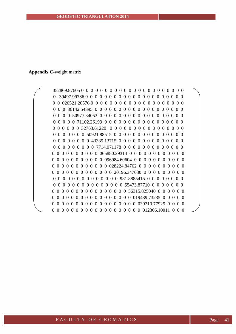
Appendix C-weight matrix
052869.87605 0 0 0 0 0 0 0 0 0 0 0 0 0 0 0 0 0 0 0 0 0 0
0 39497.99786 0 0 0 0 0 0 0 0 0 0 0 0 0 0 0 0 0 0 0 0 0
0 0 026521.20576 0 0 0 0 0 0 0 0 0 0 0 0 0 0 0 0 0 0 0 0
0 0 0 36142.54395 0 0 0 0 0 0 0 0 0 0 0 0 0 0 0 0 0 0 0
0 0 0 0 50977.34053 0 0 0 0 0 0 0 0 0 0 0 0 0 0 0 0 0 0
0 0 0 0 0 71102.26193 0 0 0 0 0 0 0 0 0 0 0 0 0 0 0 0 0
0 0 0 0 0 0 32763.61220 0 0 0 0 0 0 0 0 0 0 0 0 0 0 0 0
0 0 0 0 0 0 0 50921.88515 0 0 0 0 0 0 0 0 0 0 0 0 0 0 0
0 0 0 0 0 0 0 0 43339.13715 0 0 0 0 0 0 0 0 0 0 0 0 0 0
0 0 0 0 0 0 0 0 0 7714.071178 0 0 0 0 0 0 0 0 0 0 0 0 0
0 0 0 0 0 0 0 0 0 0 065880.29314 0 0 0 0 0 0 0 0 0 0 0 0
0 0 0 0 0 0 0 0 0 0 0 096984.60604 0 0 0 0 0 0 0 0 0 0 0
0 0 0 0 0 0 0 0 0 0 0 0 028224.84762 0 0 0 0 0 0 0 0 0 0
0 0 0 0 0 0 0 0 0 0 0 0 0 20196.347030 0 0 0 0 0 0 0 0 0
0 0 0 0 0 0 0 0 0 0 0 0 0 0 981.8885415 0 0 0 0 0 0 0 0
0 0 0 0 0 0 0 0 0 0 0 0 0 0 0 55473.87710 0 0 0 0 0 0 0
0 0 0 0 0 0 0 0 0 0 0 0 0 0 0 0 56315.825040 0 0 0 0 0 0
0 0 0 0 0 0 0 0 0 0 0 0 0 0 0 0 0 019439.73235 0 0 0 0 0
0 0 0 0 0 0 0 0 0 0 0 0 0 0 0 0 0 0 039210.77925 0 0 0 0
0 0 0 0 0 0 0 0 0 0 0 0 0 0 0 0 0 0 0 012366.10011 0 0 0


