Embed Size (px)
Citation preview
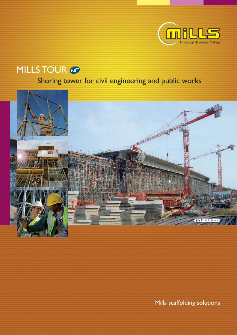
MILLS TOURShoring tower for civil engineering and public works
Mills scaffolding solutions
Made in France
M I L L S T O U R : S H O R I N G T O W E R F O R C I V I L E N G I N E E R I N G W O R K S
The MillsTour shoring system can be used to erect self-supporting shoring towers, in runs or blocks, to transmit
vertical loads to the ground.
For many years, Mills Tour has been the French market leaderfor civil engineering and public works.
This high performance shoring system has a telescopic level,modular units and lightweight components.
Mills Tour: shoring tower for civil engineering works
2
TABLE OF CONTENTSPresentation 1Assembly 6Tower configuration 8Specifications and load capacity 10Particular applications 14Components 20Recommendations 24
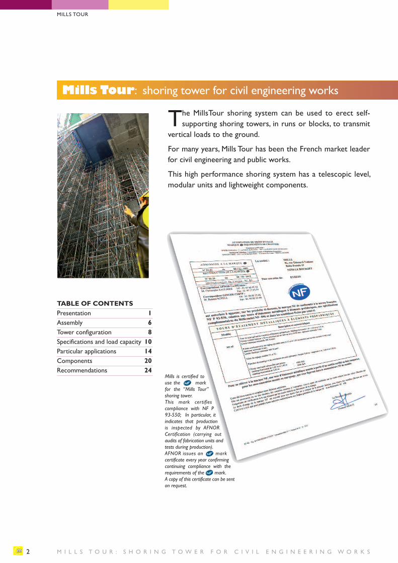
Mills is certified touse the mark for the “Mills Tour”shoring tower. This mark certifies compliance with NF P93-550; In particular, it indicates that productionis inspected by AFNOR Certification (carrying out audits of fabrication units andtests during production).AFNOR issues an markcertificate every year confirmingcontinuing compliance with the requirements of the mark.A copy of this certificate can be senton request.
MILLS TOUR
M I L L S T O U R : S H O R I N G T O W E R F O R C I V I L E N G I N E E R I N G W O R K S
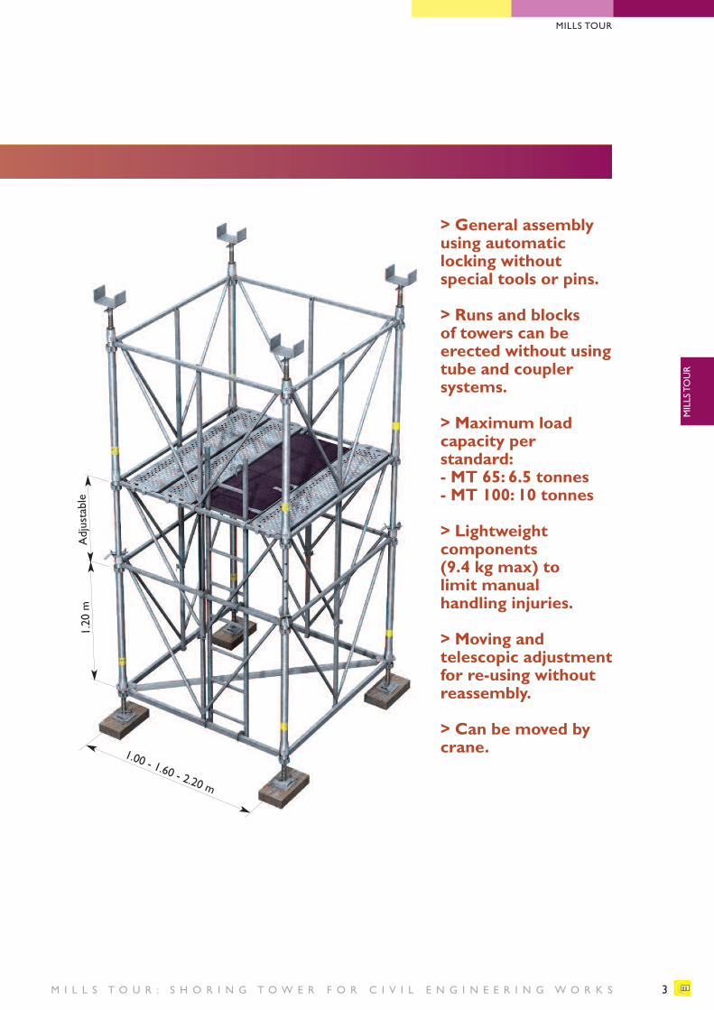
1.20 m
Adjustable
1.00 - 1.60 - 2.20 m
> General assemblyusing automaticlocking without special tools or pins.
> Runs and blocks of towers can be erected without usingtube and coupler systems.
> Maximum load capacity per standard:- MT 65: 6.5 tonnes - MT 100: 10 tonnes
> Lightweight components (9.4 kg max) to limit manual handling injuries.
> Moving and telescopic adjustmentfor re-using withoutreassembly.
> Can be moved bycrane.
3
MILLS TOUR
MILLS TOUR
M I L L S T O U R : S H O R I N G T O W E R F O R C I V I L E N G I N E E R I N G W O R K S
Mills Tour : modular and high performance
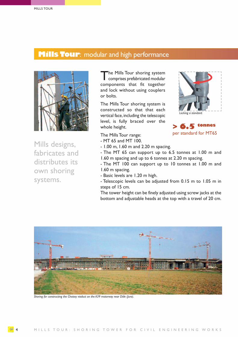
The Mills Tour shoring systemcomprises prefabricated modular
components that fit together and lock without using couplersor bolts.
The Mills Tour shoring system isconstructed so that that each vertical face, including the telescopiclevel, is fully braced over thewhole height.
The Mills Tour range: - MT 65 and MT 100.- 1.00 m, 1.60 m and 2.20 m spacing.- The MT 65 can support up to 6.5 tonnes at 1.00 m and 1.60 m spacing and up to 6 tonnes at 2.20 m spacing.- The MT 100 can support up to 10 tonnes at 1.00 m and 1.60 m spacing.- Basic levels are 1.20 m high.- Telescopic levels can be adjusted from 0.15 m to 1.05 m insteps of 15 cm.The tower height can be finely adjusted using screw jacks at thebottom and adjustable heads at the top with a travel of 20 cm.
Locking a standard.
Mills designs, fabricates and distributes itsown shoring systems.
> 6.5 tonnesper standard for MT65
4
MILLS TOUR
Shoring for constructing the Choisey viaduct on the A39 motorway near Dôle (Jura).
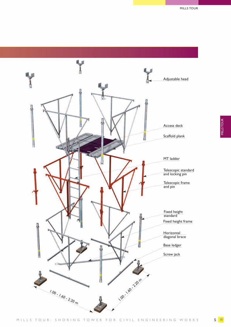
Adjustable head
Fixed heightstandard
Scaffold plank
Access deck
Fixed height frame
Telescopic frameand pin
MT ladder
Telescopic standardand locking pin
Horizontal diagonal brace
Base ledger
Screw jack
5
1.00 - 1.60 - 2.20 m 1.00 - 1.60 - 2.20 m
M I L L S T O U R : S H O R I N G T O W E R F O R C I V I L E N G I N E E R I N G W O R K S
MILLS TOUR
MILLS TOUR
M I L L S T O U R : S H O R I N G T O W E R F O R C I V I L E N G I N E E R I N G W O R K S
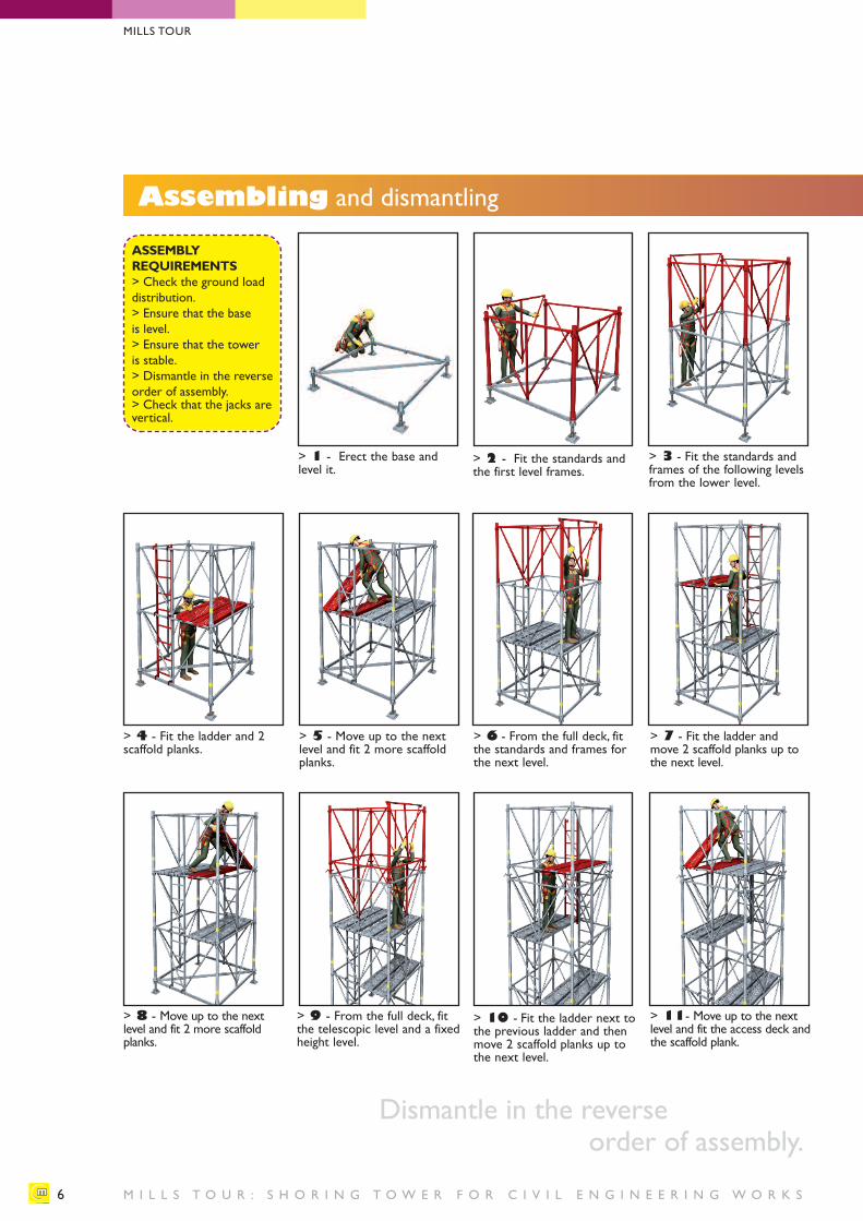
Assembling and dismantling
> 4 - Fit the ladder and 2scaffold planks.
> 5 - Move up to the nextlevel and fit 2 more scaffoldplanks.
> 6 - From the full deck, fitthe standards and frames forthe next level.
> 7 - Fit the ladder andmove 2 scaffold planks up tothe next level.
> 8 - Move up to the next level and fit 2 more scaffoldplanks.
> 9 - From the full deck, fitthe telescopic level and a fixedheight level.
> 10 - Fit the ladder next tothe previous ladder and thenmove 2 scaffold planks up tothe next level.
> 11- Move up to the next level and fit the access deck andthe scaffold plank.
ASSEMBLY REQUIREMENTS> Check the ground loaddistribution. > Ensure that the base is level.> Ensure that the tower is stable.> Dismantle in the reverseorder of assembly.> Check that the jacks arevertical.
> 1 - Erect the base and level it.
> 2 - Fit the standards andthe first level frames.
> 3 - Fit the standards andframes of the following levelsfrom the lower level.
6
Dismantle in the reverse order of assembly.
MILLS TOUR
7M I L L S T O U R : S H O R I N G T O W E R F O R C I V I L E N G I N E E R I N G W O R K S
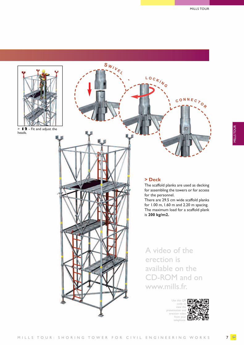
> 12 - Fit and adjust theheads.
SW I V E L
- L O C K I N G
C O N N E C T O R
A video of the erection is available on the CD-ROM and onwww.mills.fr.
> DeckThe scaffold planks are used as deckingfor assembling the towers or for accessfor the personnel.There are 29.5 cm wide scaffold planksfor 1.00 m, 1.60 m and 2.20 m spacing. The maximum load for a scaffold plankis 200 kg/m2.
MILLS TOUR
MILLS TOUR
Use this QRcode to view the
presentation anderection video
from your telephone.
M I L L S T O U R : S H O R I N G T O W E R F O R C I V I L E N G I N E E R I N G W O R K S
Composition and height of towers
8
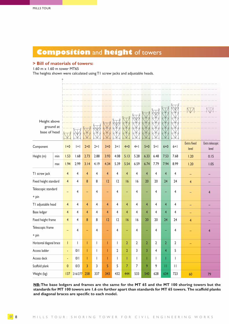
> Bill of materials of towers:1.60 m x 1.60 m tower MT65The heights shown were calculated using T1 screw jacks and adjustable heads.
Component
Height (m) min
max
Height aboveground at
base of head
1+0 1+1 2+0 2+1 3+0 3+1 4+0 4+1 5+0 5+1 6+0 6+1
1.53 1.68 2.73 2.88 3.93 4.08 5.13 5.28 6.33 6.48 7.53 7.68
1.94 2.99 3.14 4.19 4.34 5.39 5.54 6.59 6.74 7.79 7.94 8.99
Extra fixed Extra telescopiclevel level
1.20 0.15
1.20 1.05
T1 screw jack
Fixed height standard
Telescopic standard
+ pin
T1 adjustable head
Base ledger
Fixed height frame
Telescopic frame
+ pin
Horizontal diagonal brace
Access ladder
Access deck
Scaffold plank
Weight (kg)
4 4 4 4 4 4 4 4 4 4 4 4
4 4 8 8 12 12 16 16 20 20 24 24
– 4 – 4 – 4 – 4 – 4 – 4
4 4 4 4 4 4 4 4 4 4 4 4
4 4 4 4 4 4 4 4 4 4 4 4
4 4 8 8 12 12 16 16 20 20 24 24
– 4 – 4 – 4 – 4 – 4 – 4
1 1 1 1 1 1 2 2 2 2 2 2
- 0/1 1 1 1 2 2 3 3 4 4 5
- 0/1 1 1 1 1 1 1 1 1 1 1
0 0/3 3 3 5 5 7 7 9 9 11 11
137 216/277 258 337 343 432 444 533 540 628 634 723
– –
4 –
– 4
– –
– –
4 –
– 4
– –
60 79
NB:The base ledgers and frames are the same for the MT 65 and the MT 100 shoring towers but the standards for MT 100 towers are 1.6 cm further apart than standards for MT 65 towers. The scaffold planksand diagonal braces are specific to each model.
MILLS TOUR
9M I L L S T O U R : S H O R I N G T O W E R F O R C I V I L E N G I N E E R I N G W O R K S
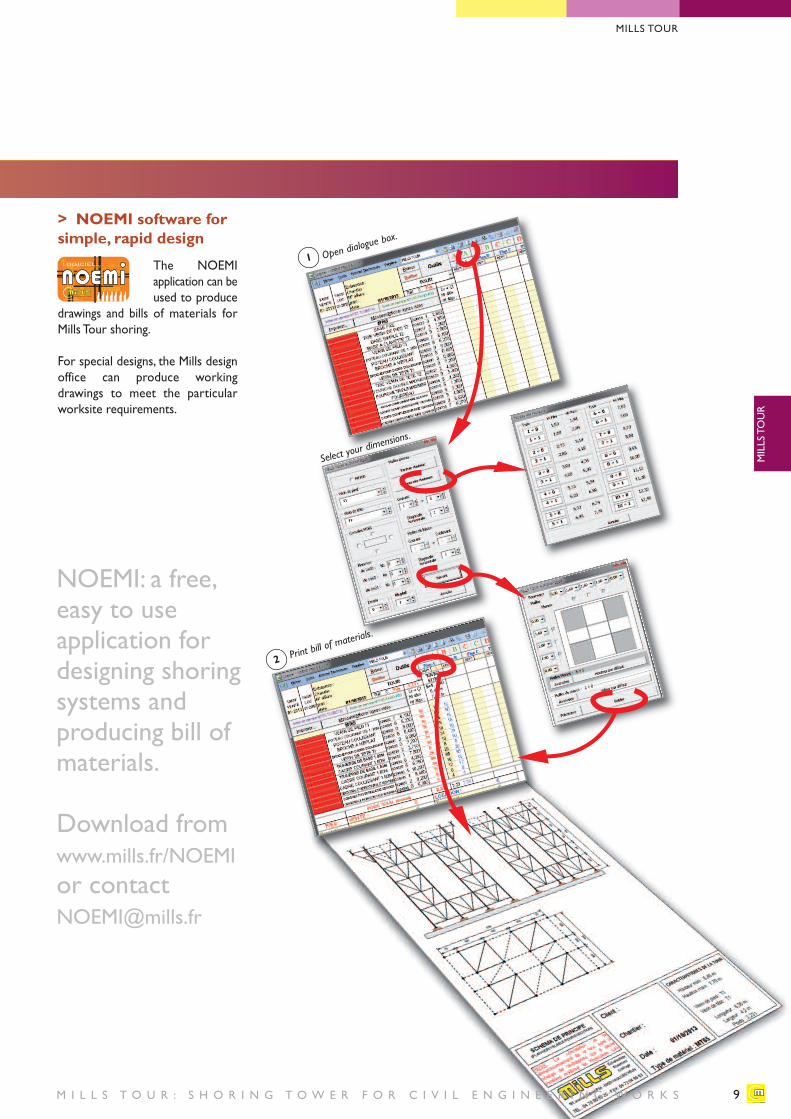
NOEMI: a free,easy to use application fordesigning shoringsystems and producing bill ofmaterials.
Download fromwww.mills.fr/NOEMIor [email protected]
> NOEMI software forsimple, rapid design
The NOEMI application can be used to produce
drawings and bills of materials forMills Tour shoring.
For special designs, the Mills designoffice can produce working drawings to meet the particularworksite requirements.
Open dialogu
e box.
Print bill of m
aterials.
Select your d
imensions.
1
2
MILLS TOUR
MILLS TOUR
1 2 3 4 5 17 8 9 9 9 0 0 1 2 3 4 5 17 8 9 9 9 0 0
1 2 3 4 5 17 8 90000000000 0 0 1 2 3 4 5 17 8 90000000000 0 0
1 2 3 4 5 17 8 900001 2 3 4 5 17 8 90000
LOGICIEL...
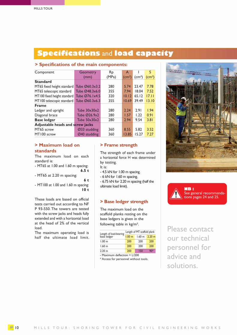
Specifications and load capacity
M I L L S T O U R : S H O R I N G T O W E R F O R C I V I L E N G I N E E R I N G W O R K S10
> Frame strengthThe strength of each frame undera horizontal force H was determinedby testing.It is:- 4.5 kN for 1.00 m spacing.- 6 kN for 1.60 m spacing.- 6.75 kN for 2.20 m spacing (half theultimate load limit).
> Base ledger strengthThe maximum load on the scaffold planks resting on thebase ledgers is given in the following table in kg/m².
> Maximum load onstandardsThe maximum load on each standard is:- MT65 at 1.00 and 1.60 m spacing:
6.5 t- MT65 at 2.20 m spacing:
6 t - MT100 at 1.00 and 1.60 m spacing:
10 t
These loads are based on officialtests carried out according to NFP 93-550. The towers are testedwith the screw jacks and heads fullyextended and with a horizontal loadat the head of 2% of the verticalload.The maximum operating load ishalf the ultimate load limit.
> Specifications of the main components:Component Geometry Rp A I S
(mm) (MPa) (cm2) (cm4) (cm3)Standard MT65 fixed height standard Tube Ø60.3x3.2 280 5.74 23.47 7.78MT65 telescopic standard Tube Ø48.3x6.0 355 7.94 18.04 7.52MT100 fixed height standard Tube Ø76.1x4.5 320 10.12 65.12 17.11MT100 telescopic standard Tube Ø60.3x6.3 355 10.69 39.49 13.10Frame Ledger and upright Tube 30x30x2 280 2.24 2.91 1.94Diagonal brace Tube Ø26.9x2 280 1.57 1.22 0.91Base ledger Tube 50x30x2 280 2.94 9.54 3.81Adjustable heads and screw jacksMT65 screw Ø33 studding 360 8.55 5.82 3.52MT100 screw Ø40 studding 360 13.85 15.27 7.27
Please contact our technical personnel for advice and solutions.
- Maximum deflection = L/200* Access for personnel without tools.
Length of load-bearingLength of MT scaffold plank
base ledger 1.00 m 1.60 m 2.20 m1.00 m 200 200 2001.60 m 200 200 2002.20 m 200 150 90*
MILLS TOUR
NB :See general recommenda-tions pages 24 and 25.
11M I L L S T O U R : S H O R I N G T O W E R F O R C I V I L E N G I N E E R I N G W O R K S
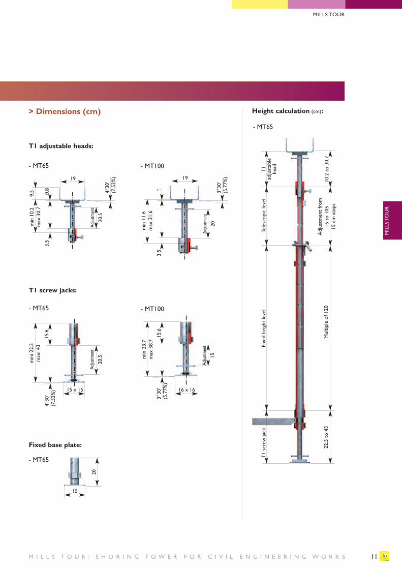
T1 adjustable heads:
> Dimensions (cm)
19
0.8 4°30’
(7.52%)
3.5
- MT65 - MT100
4°30’
(7.52%)
min10.2
max 30.7
9.5
Adjustment
20.5
15.6
- MT65
- MT65
Adjustment
20.5
Adjustment
15
19
3°30’
(5.77%)
T1 screw jacks:
Fixed base plate:
mini22.5
maxi 43
3°30’
(5.77%)
15.6
min23.7
max 38.7
15
15 x 15 16 x 16
- MT100
T1
adjustable
head
Height calculation (cm):
10.2 to 30.7
22.5 to 43
Adjustment from
15 to 105
15 cm steps
Multiple of 120
Telescopic level
Fixed height level
Adjustment
20
13.5
min11.6
max 31.6
20
T1 screw jack
MILLS TOUR
MILLS TOUR
- MT65
M I L L S T O U R : S H O R I N G T O W E R F O R C I V I L E N G I N E E R I N G W O R K S
Specifications and load capacity
12
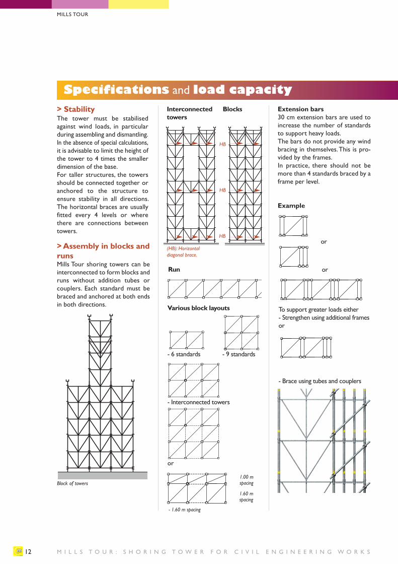
> StabilityThe tower must be stabilisedagainst wind loads, in particularduring assembling and dismantling.In the absence of special calculations,it is advisable to limit the height ofthe tower to 4 times the smallerdimension of the base.For taller structures, the towersshould be connected together oranchored to the structure to ensure stability in all directions. The horizontal braces are usuallyfitted every 4 levels or wherethere are connections betweentowers.
Extension bars30 cm extension bars are used toincrease the number of standardsto support heavy loads.The bars do not provide any windbracing in themselves. This is pro-vided by the frames.In practice, there should not bemore than 4 standards braced by aframe per level.
Example
Various block layouts
Run
Interconnectedtowers
Blocks
HB
HB
- 6 standards
or
or
To support greater loads either- Strengthen using additional framesor
- Brace using tubes and couplers
- 9 standards
- Interconnected towers
or
HB
(HB): Horizontaldiagonal brace.
Block of towers1.00 m spacing
1.60 m spacing
- 1.60 m spacing
MILLS TOUR
> Assembly in blocks andrunsMills Tour shoring towers can beinterconnected to form blocks andruns without addition tubes orcouplers. Each standard must bebraced and anchored at both endsin both directions.
13
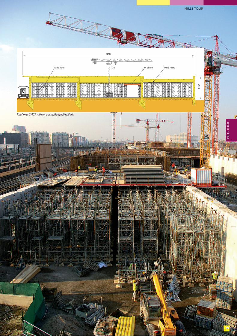
Mills PanoH beamG5Mills Tour
7993
1138
Roof over SNCF railway tracks, Batignolles, Paris
MILLS TOUR
MILLS TOUR
M I L L S T O U R : S H O R I N G T O W E R F O R C I V I L E N G I N E E R I N G W O R K S
Special features
14
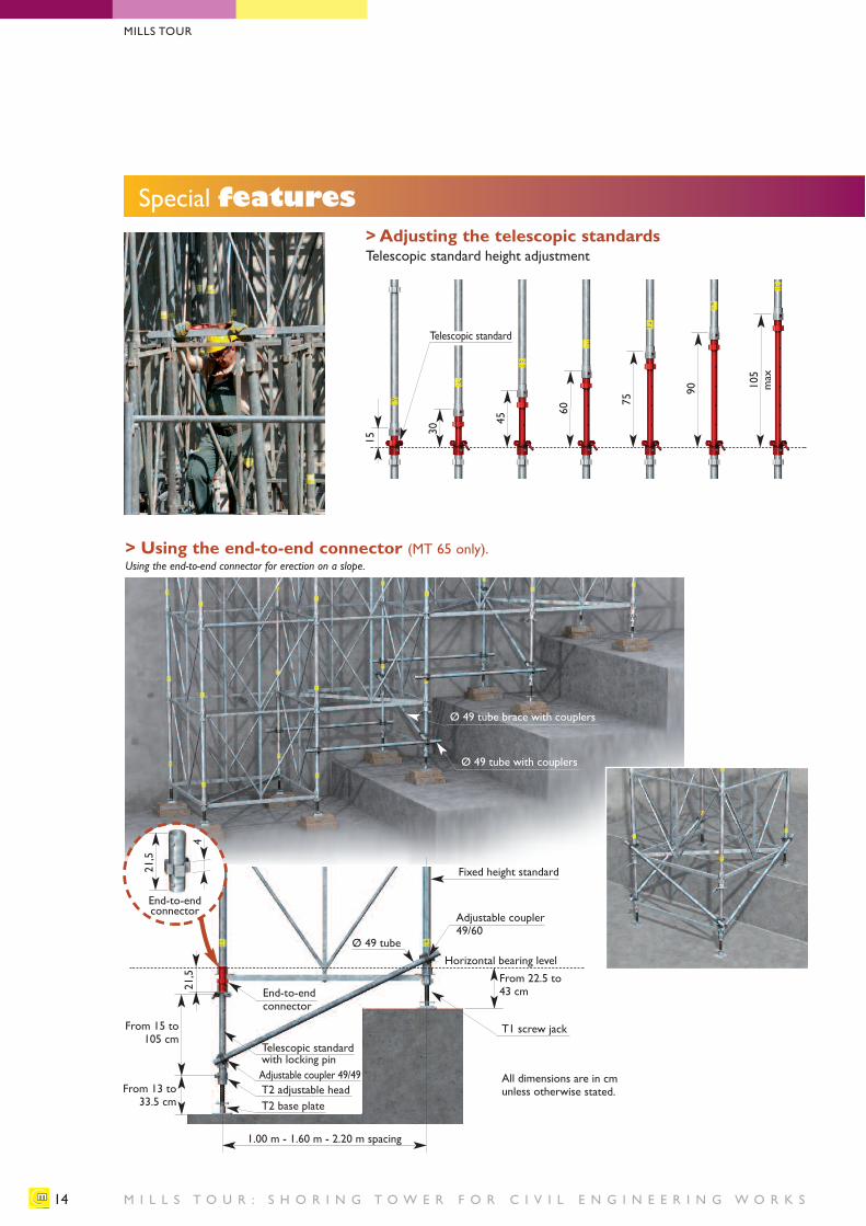
> Adjusting the telescopic standardsTelescopic standard height adjustment
15
30
Telescopic standard
45
60
75
90 105
max
21,5
From 15 to105 cm
From 13 to 33.5 cm
From 22.5 to43 cm
Horizontal bearing levelØ 49 tube
1.00 m - 1.60 m - 2.20 m spacing
Using the end-to-end connector for erection on a slope.
End-to-endconnector
Ø 49 tube with couplers
Ø 49 tube brace with couplers
T2 base plate T2 adjustable head
Telescopic standardwith locking pin
T1 screw jack
All dimensions are in cmunless otherwise stated.
Fixed height standard
Adjustable coupler49/60
Adjustable coupler 49/49
> Using the end-to-end connector (MT 65 only).
End-to-endconnector
21,5
4
MILLS TOUR
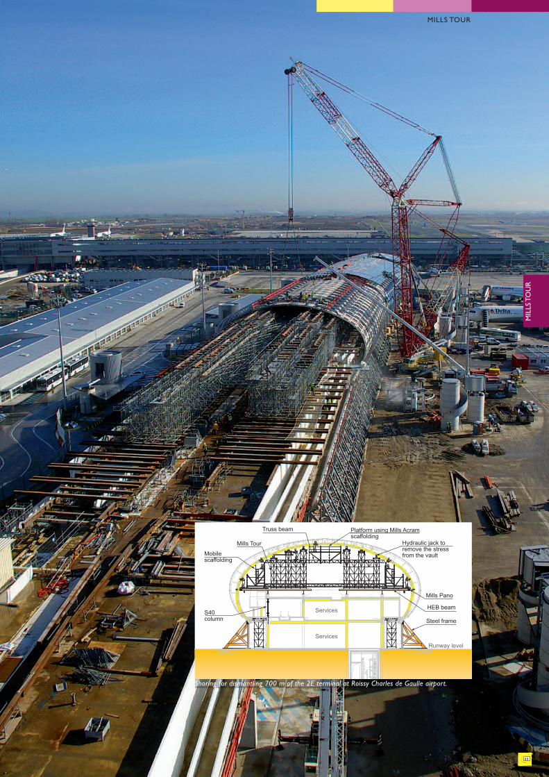
Mills Pano
Hydraulic jack to remove the stress from the vault
Platform using Mills Acram scaffolding
Truss beam
Mills Tour
Mobile scaffolding
S40 column
Services
ServicesRunway level
HEB beam
Steel frame
Shoring for dismantling 700 m of the 2E terminal at Roissy Charles de Gaulle airport.
15
MILLS TOUR
MILLS TOUR
M I L L S T O U R : S H O R I N G T O W E R F O R C I V I L E N G I N E E R I N G W O R K S
Special features
16
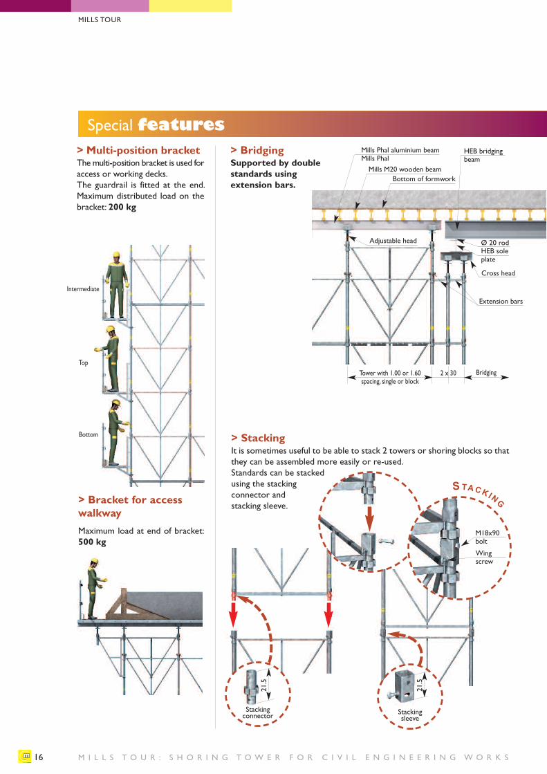
> Multi-position bracketThe multi-position bracket is used foraccess or working decks.The guardrail is fitted at the end.Maximum distributed load on thebracket: 200 kg
> Bracket for accesswalkwayMaximum load at end of bracket:500 kg
> BridgingSupported by doublestandards using extension bars.
Mills Phal aluminium beamMills PhalMills M20 wooden beam
Bottom of formwork
HEB bridgingbeam
Ø 20 rodHEB soleplate
Cross head
Extension bars
Adjustable head
Tower with 1.00 or 1.60spacing, single or block
Intermediate
Top
Bottom
2 x 30 Bridging
> StackingIt is sometimes useful to be able to stack 2 towers or shoring blocks so thatthey can be assembled more easily or re-used.Standards can be stackedusing the stackingconnector andstacking sleeve.
STACKING
M18x90bolt
Wingscrew
Stacking connector Stacking
sleeve
21.5
21.5
MILLS TOUR
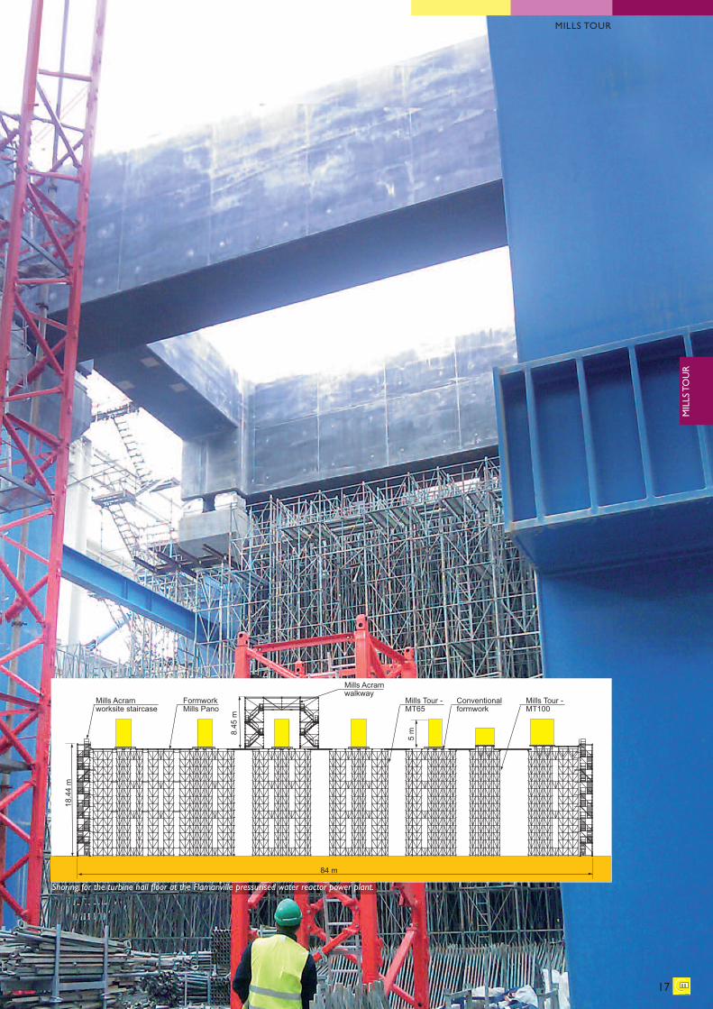
17
Formwork Mills Pano
Conventional formwork
Mills Tour -MT100
Mills Tour -MT65
Mills Acram walkway
Mills Acram worksite staircase
18.4
4 m
8.45
m
84 m
5 m
Shoring for the turbine hall floor at the Flamanville pressurised water reactor power plant.
MILLS TOUR
MILLS TOUR
M I L L S T O U R : S H O R I N G T O W E R F O R C I V I L E N G I N E E R I N G W O R K S
Special features
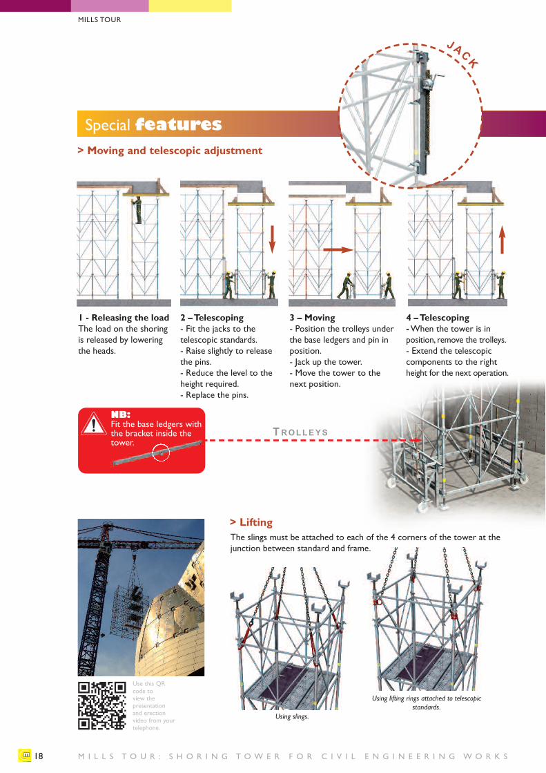
18
1 - Releasing the load The load on the shoringis released by loweringthe heads.
2 – Telescoping- Fit the jacks to the telescopic standards. - Raise slightly to releasethe pins.- Reduce the level to theheight required.- Replace the pins.
3 – Moving- Position the trolleys underthe base ledgers and pin inposition.- Jack up the tower.- Move the tower to thenext position.
4 – Telescoping-When the tower is in position, remove the trolleys.- Extend the telescopiccomponents to the rightheight for the next operation.
> Lifting
TROLLEYS
Using slings.
Using lifting rings attached to telescopicstandards.
JACK
NB: Fit the base ledgers withthe bracket inside thetower.
MILLS TOUR
Use this QR code to view the presentation and erection video from yourtelephone.
The slings must be attached to each of the 4 corners of the tower at thejunction between standard and frame.
> Moving and telescopic adjustment
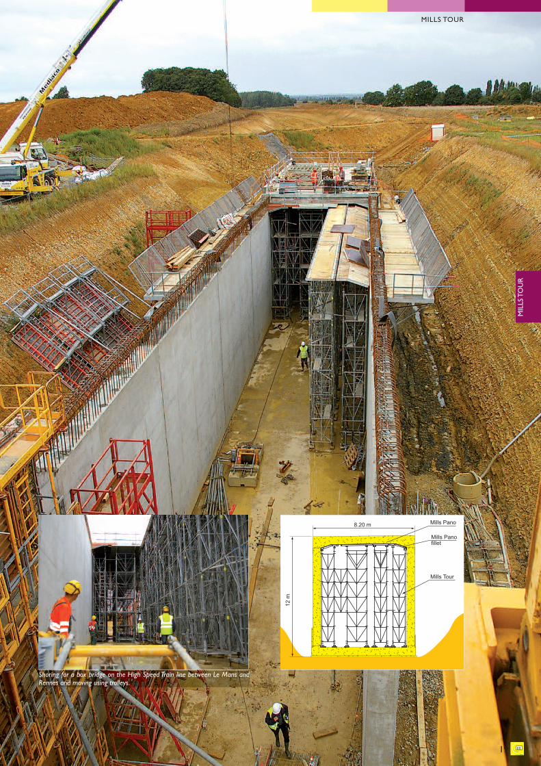
Mills Panofillet
12 m
Mills Pano
Mills Tour
8.20 m
Shoring for a box bridge on the High Speed Train line between Le Mans andRennes and moving using trolleys.
19
MILLS TOUR
MILLS TOUR
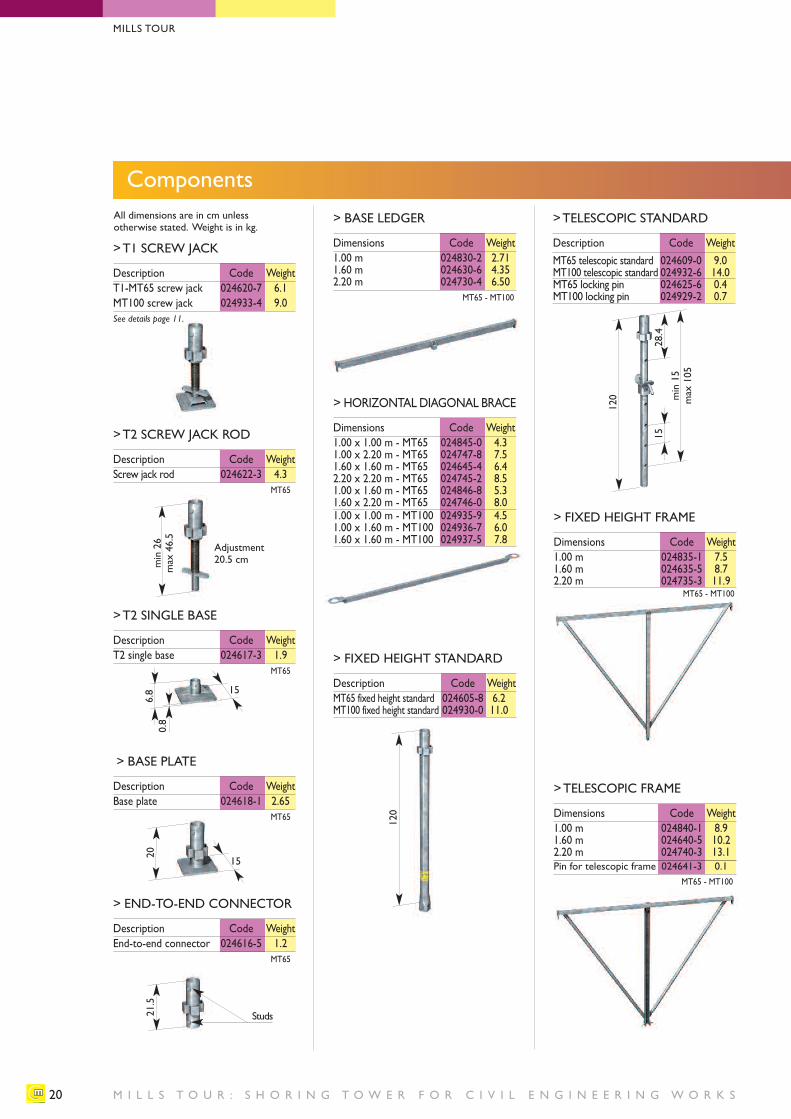
> FIXED HEIGHT STANDARD
Description Code WeightMT65 fixed height standard 024605-8 6.2MT100 fixed height standard 024930-0 11.0
120
M I L L S T O U R : S H O R I N G T O W E R F O R C I V I L E N G I N E E R I N G W O R K S
Components
20
All dimensions are in cm unless otherwise stated. Weight is in kg.
>T1 SCREW JACK
Description Code WeightT1-MT65 screw jack 024620-7 6.1MT100 screw jack 024933-4 9.0See details page 11.
> BASE LEDGER
Dimensions Code Weight1.00 m 024830-2 2.711.60 m 024630-6 4.352.20 m 024730-4 6.50
MT65 - MT100
> HORIZONTAL DIAGONAL BRACE
Dimensions Code Weight1.00 x 1.00 m - MT65 024845-0 4.31.00 x 2.20 m - MT65 024747-8 7.51.60 x 1.60 m - MT65 024645-4 6.42.20 x 2.20 m - MT65 024745-2 8.51.00 x 1.60 m - MT65 024846-8 5.31.60 x 2.20 m - MT65 024746-0 8.01.00 x 1.00 m - MT100 024935-9 4.51.00 x 1.60 m - MT100 024936-7 6.01.60 x 1.60 m - MT100 024937-5 7.8
15
>T2 SINGLE BASE
Description Code WeightT2 single base 024617-3 1.9
MT65
> BASE PLATE
Description Code WeightBase plate 024618-1 2.65
MT65
0.8
6.8
120
28.4
min15
max 105
15
20
15
> END-TO-END CONNECTOR
Description Code WeightEnd-to-end connector 024616-5 1.2
MT65
21.5
Studs
>TELESCOPIC STANDARD
Description Code WeightMT65 telescopic standard 024609-0 9.0MT100 telescopic standard 024932-6 14.0MT65 locking pin 024625-6 0.4MT100 locking pin 024929-2 0.7
> FIXED HEIGHT FRAME
Dimensions Code Weight1.00 m 024835-1 7.51.60 m 024635-5 8.72.20 m 024735-3 11.9
MT65 - MT100
>T2 SCREW JACK ROD
Description Code WeightScrew jack rod 024622-3 4.3
MT65
MILLS TOUR
min26
max 46.5
Adjustment20.5 cm
>TELESCOPIC FRAME
Dimensions Code Weight1.00 m 024840-1 8.91.60 m 024640-5 10.22.20 m 024740-3 13.1Pin for telescopic frame 024641-3 0.1
MT65 - MT100
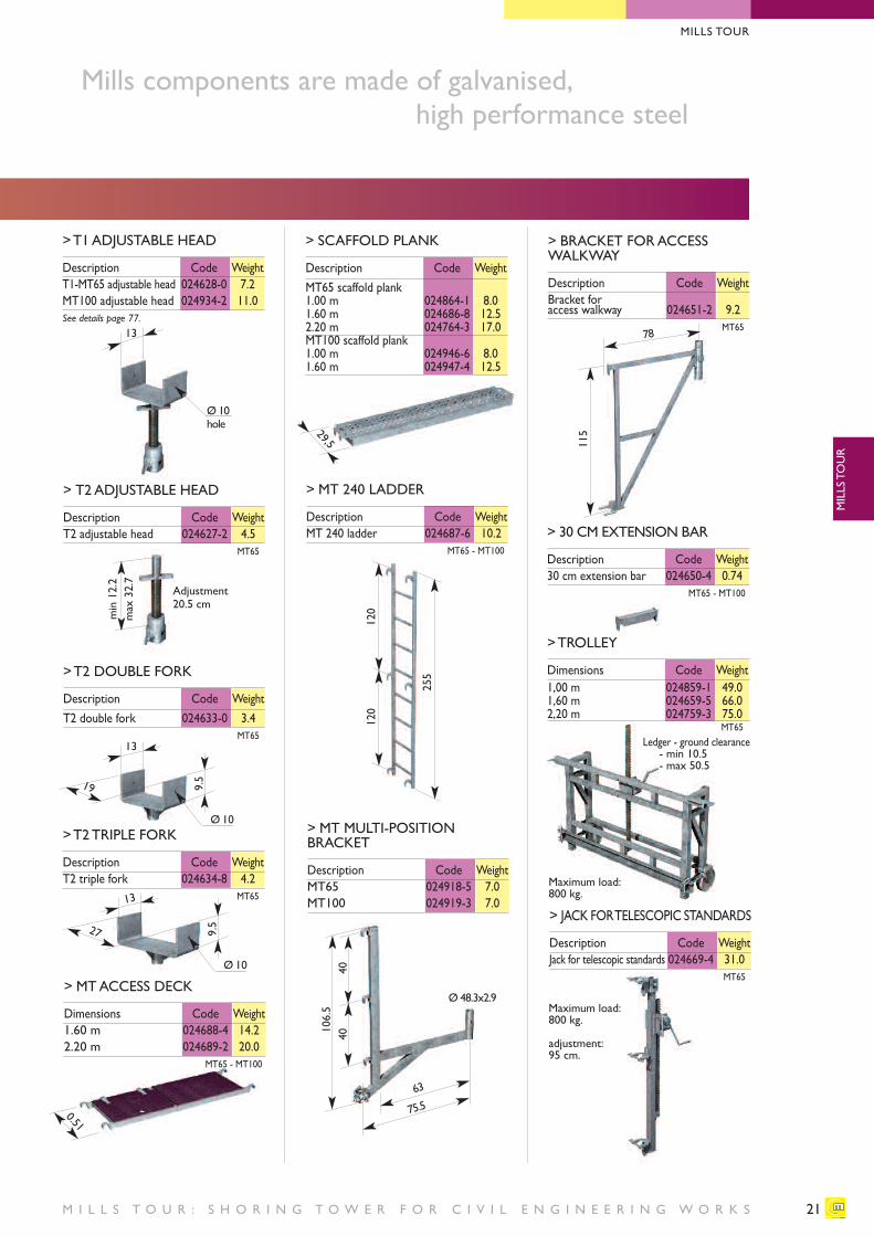
> SCAFFOLD PLANK
Description Code WeightMT65 scaffold plank1.00 m 024864-1 8.01.60 m 024686-8 12.52.20 m 024764-3 17.0MT100 scaffold plank1.00 m 024946-6 8.01.60 m 024947-4 12.5
21
Mills components are made of galvanised, high performance steel
> T2 ADJUSTABLE HEAD
Description Code WeightT2 adjustable head 024627-2 4.5
MT65
>T2 DOUBLE FORK
Description Code WeightT2 double fork 024633-0 3.4
MT65
>T2 TRIPLE FORK
Description Code WeightT2 triple fork 024634-8 4.2
MT65
13
Ø 10
Ø 10hole
>T1 ADJUSTABLE HEAD
Description Code WeightT1-MT65 adjustable head 024628-0 7.2MT100 adjustable head 024934-2 11.0See details page 77.
> MT 240 LADDER
Description Code WeightMT 240 ladder 024687-6 10.2
MT65 - MT100
> MT MULTI-POSITIONBRACKET
Description Code WeightMT65 024918-5 7.0MT100 024919-3 7.0
> BRACKET FOR ACCESSWALKWAY
Description Code WeightBracket for access walkway 024651-2 9.2
MT65
> 30 CM EXTENSION BAR
Description Code Weight30 cm extension bar 024650-4 0.74
MT65 - MT100
19
13
9.5
Ø 10
27
13
9.5
4040
106.5
29,5
0.51
120
115
255
120
Ledger - ground clearance- min 10.5- max 50.5
63
Ø 48.3x2.9
78
75.5
> MT ACCESS DECK
Dimensions Code Weight1.60 m 024688-4 14.22.20 m 024689-2 20.0
MT65 - MT100
>TROLLEY
Dimensions Code Weight1,00 m 024859-1 49.01,60 m 024659-5 66.02,20 m 024759-3 75.0
MT65
> JACK FOR TELESCOPIC STANDARDS
Description Code WeightJack for telescopic standards 024669-4 31.0
MT65
M I L L S T O U R : S H O R I N G T O W E R F O R C I V I L E N G I N E E R I N G W O R K S
MILLS TOUR
MILLS TOUR
min12.2
max 32.7
Adjustment20.5 cm
Maximum load: 800 kg.
Maximum load: 800 kg.
adjustment: 95 cm.
M I L L S T O U R : S H O R I N G T O W E R F O R C I V I L E N G I N E E R I N G W O R K S
Components
22
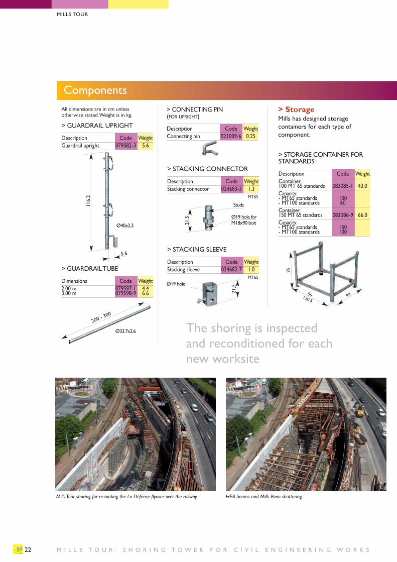
> GUARDRAIL UPRIGHT
Description Code WeightGuardrail upright 079582-3 5.6
5.6
116.2
> GUARDRAIL TUBE
Dimensions Code Weight2.00 m 079597-1 4.43.00 m 079598-9 6.6
200 - 300
> STORAGE CONTAINER FORSTANDARDS
Description Code WeightContainer 100 MT 65 standards 083085-1 43.0Capacity:- MT65 standards 100- MT100 standards 60Container 150 MT 65 standards 083086-9 66.0Capacity:- MT65 standards 150- MT100 standards 100
9986120.5
95
The shoring is inspected and reconditioned for each new worksite
Mills Tour shoring for re-routing the La Défense flyover over the railway. HEB beams and Mills Pano shuttering.
> StorageMills has designed storagecontainers for each type ofcomponent.
> STACKING CONNECTOR
Description Code WeightStacking connector 024683-5 1.3
MT65
21.5
> STACKING SLEEVE
Description Code WeightStacking sleeve 024682-7 1.0
MT65
21,5
Studs
Ø19 hole forM18x90 bolt
Ø19 hole
MILLS TOUR
Ø40x2.3
Ø33.7x2.6
> CONNECTING PIN(FOR UPRIGHT)
Description Code WeightConnecting pin 021009-6 0.25
All dimensions are in cm unless otherwise stated. Weight is in kg.
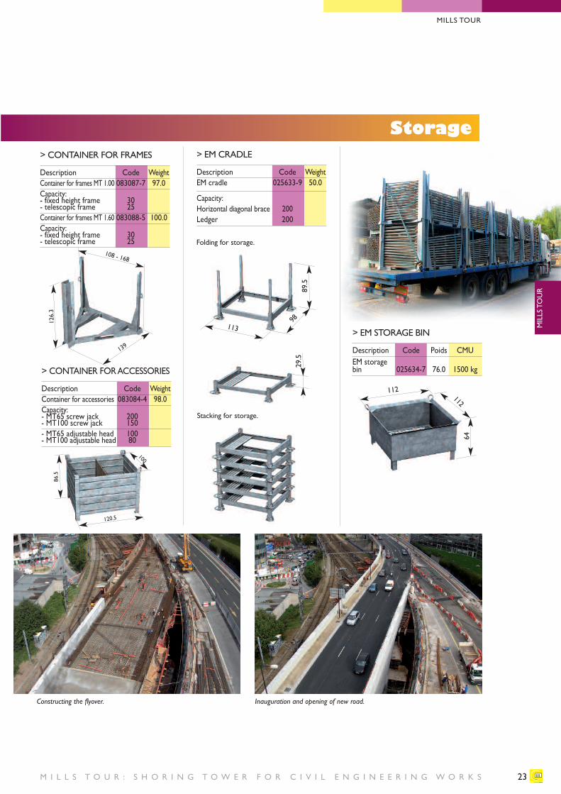
> CONTAINER FOR FRAMES
Description Code WeightContainer for frames MT 1.00 083087-7 97.0Capacity:- fixed height frame 30- telescopic frame 25Container for frames MT 1.60 083088-5 100.0Capacity:- fixed height frame 30- telescopic frame 25
112
64
112
23M I L L S T O U R : S H O R I N G T O W E R F O R C I V I L E N G I N E E R I N G W O R K S
Storage
139
108 - 168
126.3
86.5
100
120.5
> CONTAINER FOR ACCESSORIES
Description Code WeightContainer for accessories 083084-4 98.0Capacity:- MT65 screw jack 200- MT100 screw jack 150- MT65 adjustable head 100- MT100 adjustable head 80
> EM CRADLE
Description Code WeightEM cradle 025633-9 50.0
Capacity:Horizontal diagonal brace 200Ledger 200
Constructing the flyover. Inauguration and opening of new road.
> EM STORAGE BIN
Description Code Poids CMUEM storage bin 025634-7 76.0 1500 kg
MILLS TOUR
MILLS TOUR
113
89.5
Folding for storage.
98
29.5
Stacking for storage.
MILLS TOUR
R E G U L A T I O N S , S T A N D A R D S A N D R E C O M M E N D A T I O N S24
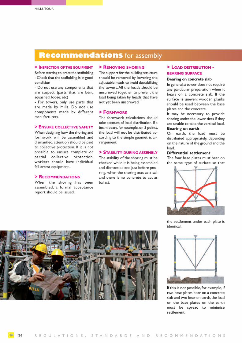
Recommendations for assembly> INSPECTION OFTHE EQUIPMENTBefore starting to erect the scaffolding- Check that the scaffolding is in goodcondition- Do not use any components thatare suspect (parts that are bent,squashed, loose, etc)- For towers, only use parts that are made by Mills. Do not use components made by different manufacturers.
> ENSURE COLLECTIVE SAFETYWhen designing how the shoring andformwork will be assembled anddismantled, attention should be paidto collective protection. If it is notpossible to ensure complete or partial collective protection, workers should have individual fall-arrest equipment.
> RECOMMENDATIONSWhen the shoring has been assembled, a formal acceptance report should be issued.
> REMOVING SHORINGThe support for the building structureshould be removed by lowering theadjustable heads to avoid destabilisingthe towers. All the heads should beunscrewed together to prevent theload being taken by heads that havenot yet been unscrewed.
> FORMWORKThe formwork calculations shouldtake account of load distribution. If abeam bears, for example, on 3 points,the load will not be distributed ac-cording to the simple geometric ar-rangement.
> STABILITY DURING ASSEMBLYThe stability of the shoring must bechecked while it is being assembledand dismantled and just before pou-ring, when the shoring acts as a sailand there is no concrete to act as ballast.
> LOAD DISTRIBUTION - BEARING SURFACE
Bearing on concrete slabIn general, a tower does not requireany particular preparation when itbears on a concrete slab. If the surface is uneven, wooden planksshould be used between the baseplates and the concrete.It may be necessary to provide shoring under the lower tiers if theyare unable to take the vertical load.Bearing on earthOn earth, the load must be distributed appropriately, dependingon the nature of the ground and theload.Differential settlementThe four base plates must bear onthe same type of surface so that
the settlement under each plate isidentical.
If this is not possible, for example, iftwo base plates bear on a concreteslab and two bear on earth, the loadon the base plates on the earthmust be spread to minimise settlement.
MILLS TOUR
MILLS TOUR
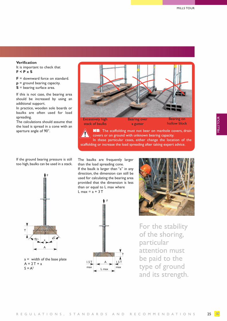
R E G U L A T I O N S , S T A N D A R D S A N D R E C O M M E N D A T I O N S 25
Excessively highstack of baulks
Bearing over a gutter
Bearing on hollow block
NB: The scaffolding must not bear on manhole covers, drain covers or on ground with unknown bearing capacity.In these particular cases, either change the location of the
scaffolding or increase the load spreading after taking expert advice.
VerificationIt is important to check thatF < P x S
F = downward force on standard. p = ground bearing capacity.S = bearing surface area.
If this is not case, the bearing areashould be increased by using an additional support. In practice, wooden sole boards orbaulks are often used for load spreading.The calculations should assume thatthe load is spread in a cone with anaperture angle of 90°.
a
T
A
45° 45°
F
If the ground bearing pressure is stilltoo high, baulks can be used in a stack.
a = width of the base plate A = 2 T + a S = A2
The baulks are frequently largerthan the load spreading cone. If the baulk is larger than “a” in anydirection, the dimension can still beused for calculating the bearing areaprovided that the dimension is lessthan or equal to L max whereL max = a + 3 T
A1.5 T
max
1.5 T
max
T
L max
F
For the stabilityof the shoring,particular attention must be paid to thetype of groundand its strength.
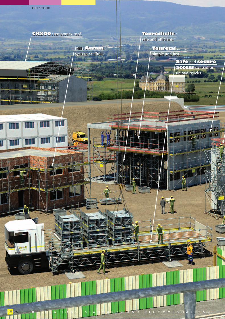
MillsAcram : system scaffold.
Safe and secureaccess to load orunload trucks.
CK800 : temporary roof. Tourechelle : safe and efficient.
Touretai : simple and fast.
MillsAcram : system scaffold.
Safe and secureaccess to load orunload trucks.
CK800 : temporary roof. Tourechelle : safe and efficient.
Touretai : simple and fast.
26
MILLS TOUR
R E G U L A T I O N S , S T A N D A R D S A N D R E C O M M E N D A T I O N S
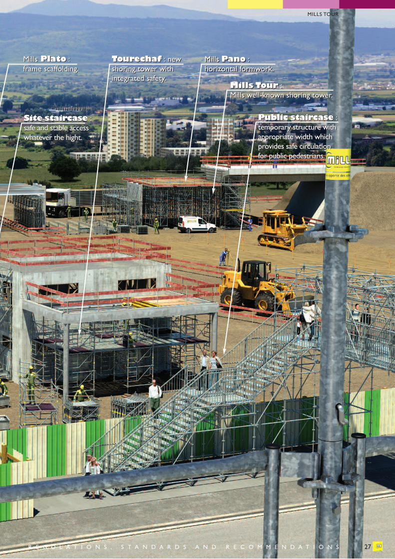
Public staircase : temporary structure withappropriate width whichprovides safe circulation for public pedestrians.
Mills Tour : Mills well-known shoring tower.
Tourechaf : newshoring tower withintegrated safety.
Mills Pano : horizontal formwork.
Public staircase : temporary structure withappropriate width whichprovides safe circulationfor public pedestrians.
Mills Tour : Mills well-known shoring tower.
Tourechaf : newshoring tower withintegrated safety.
Mills Pano : horizontal formwork.
Mills Plato : frame scaffolding.
Site staircase :safe and stable accesswhatever the hight.
Mills Plato : frame scaffolding.
Site staircase :safe and stable accesswhatever the hight.
27
MILLS TOUR
R E G U L A T I O N S , S T A N D A R D S A N D R E C O M M E N D A T I O N S
MILLS COMMUNICATION - 01/11/14 - PV
H E A D O F F I C E : 8 2 , R U E E D O UA R D VA I L L A N T - B P 1 1 9 - 9 3 3 5 1 L E B O U R G E T C E D E X
Bordeaux - ZA des Cantines - 486, allée des Cantines - 33127 SAINT-JEAN-D’ILLAC - Tel. +33 5 56 68 85 85 - Fax +33 5 56 68 85 86Dunkerque - ZA de le Poudrière - Route de l’Ouvrage Ouest - 59140 DUNKERQUE - Tel. +33 3 28 24 24 10 - Fax +33 3 28 24 22 77Le Havre - ZI de Port Jérôme - Route de Seine - 76170 LILLEBONNE - Tel. +33 2 35 39 02 45 - Fax +33 2 35 39 03 99Lyon - 161, avenue Gabriel Péri - 69120 VAULX-EN-VELIN - Tel. +33 4 78 80 88 25 - Fax +33 4 72 04 56 63Marseille - ZI des Estroublans - 22, avenue de Rome - 13127 VITROLLES - Tel. +33 4 42 89 68 00 - Fax +33 4 42 89 59 00Nantes - ZI de la Croix Rouge - 11, rue Jean Monnet - 44260 MALVILLE - Tel. +33 2 28 02 11 11 - Fax +33 2 28 02 10 58Paris - 82, rue Edouard Vaillant - BP 119 - 93351 LE BOURGET CEDEX - Tel. +33 1 48 35 65 65 - Fax +33 1 48 37 20 52Toulouse - Ctre Ccial de l'Hexagone - RN 20 - BP 60220 - 31142 ST ALBAN CEDEX - Tel. +33 5 61 70 22 93 - Fax +33 5 61 70 41 70Export - EMI : 165 boulevard Valmy - 92707 COLOMBES CEDEX - Tel. +33 1 57 60 94 05 - Fax +33 1 57 60 94 10
www.mills.fr


