Embed Size (px)
Citation preview

MILANO 1945
M E C H A N I C A L S E A L S
®
srl

2
Via Ortica, 6 - 20134 Milano, ITALYTel. +39 02 76110157 - Fax +39 02 7385445 - [email protected] - www.roten.it
M E C H A N I C A L S E A L S
®
srl

ISO 9001 Since 1993
ISO 14001 Since 2007
UNI EN ISO 9001 Certified Quality System since 1993
UNI EN ISO 14001Certified Environment Management System since 2007
Under request the components of our mechanical seals can be supplied with the following conformity:
Drinking water WRAS (BS 6920), D.M. 174, KTW, DVGW,
DVGW-W270, 3A, TZW, NSF, ACS.
Pharmaceutical USP CLASS VI.
Food zone FDA, (EC) n. 1935 Regulation and NSF.
Explosive environment2014/34/CE Directive – for cat. 1, cat. 2 and cat. 3.
Restrictions for dangerous substances and preparationsRoHS II Directive n. 2011 (EU)
Reg. (EC) n. 1272 - CLPReg. (EC) n. 1907 - Reach
n. 2003 Directive (EC).
For further information: [email protected]
1945MILANO
1945
GU
AR
ANTEED QUALITY SIN
CE
MILANO

2

3

4
Materials code key page 6
Choice and mounting of seals page 8
Self driving spring rotation page 9
Type 2 pages 10 - 11
Type 3 pages 12 - 13
Type 4 pages 14 - 15
Type 45 pages 16 - 17
Type 5 pages 18 - 19
Type 7 pages 20 - 21
Type 7K pages 22 - 23
Type 82-84 pages 24 - 25
Type 85 pages 26 - 27
Type 875DT pages 28 - 29
Type E pages 30 - 31
Type 8E pages 32 - 33
Type 85E pages 34 - 35
Type EHS pages 36 - 37
Hygienic-Food seals pages 38 - 39
Type L2 pages 40 - 41
Type L3 pages 42 - 43
Type L4 pages 44 - 45
Type L4KS1 page 46
Type L5 page 47
INDEX

5
Type RF page 48
Type R7F page 49
Type R580 page 50
Type R590 page 51
Type 822 - 842 - 844 pages 52 - 53
Type 877 pages 54 - 55
Dual configuration page 56
Special stationary seal ring page 57
Stationary with retaining plate page 58
Flanged stationary seat Type F page 59
Type 902 page 60
Type 922 page 61
Type 942 page 62
Type 972 page 63
Type 600SL page 64
Type 977 - 977A pages 65 - 67
Titanium mechanical seals page 68
Applications pages 70 - 73
Performance curve page 74
Absorbed power diagram page 75
Delivery capacity diagram page 76
Delivery capacity (Q-T) page 77
Most used circulation systems according to API 682/ISO 21049 page 78
Guide to mechanical seals selection pages 79 - 124

6
MATERIALS CODE KEYMATERIALS CODE APPLICATIONS Limit Temp. COMPONENTS
(NOTIONAL) °C
- +
STEELS
Cr. Stainless 431 G1 E Water - Hydrocarbons - Solvents • •
Cr-Ni Stainless 304 H1 F Food-Nitric Acid • • •
Cr-Ni-Mo Stainless 316 X1 G Acids (except halogenes and derivates) • • • •
Duplex Stainless D1 G Used for shrunk carbides •
Anticorrosion Superalloy L1 M Acids and their corrosive solutions • • • •
Anticorrosion Alloy L3 T Corrosive solutions •
Stellite Hardfacing on S.S. 316 J1 K Wear resistant •
Hardened S.S. D2 T Wear resistant •
Titanium T1 T Universal • • •
SMO 254 U1 X Sea water with temparature •
CARBON GRAPHITE
Normal V1 B Universal (except oxidatives) 180 •
Special V2 C Acids - Hydrocarbons - Heat 220 •
With metal SB V3 A Hydrocarbons - Oils - Greases - Ammonia - Heat 350 + •
Normal shrink in S.S. 316 X7 C Acids - Hydrocarbons - Heat 150 •
With metal SB shrink in S.S. 316 X9 A Hydrocarbons - Oils - Greases - Ammonia - Heat 180 + •
CARBIDES
Brazed Tungsten Carbide on S.S. X3 U1 Universal Abrasives - Acids - Salts - Bases •
Solid Corr. Res. Tungsten Carbide R1 U3 Universal Abrasives - Acids - Salts - Bases •
Solid Binderless Tungsten Carbide R3 U3 Universal Abrasives - Acids - Salts - Bases •
Silicon Carbide SiC (solid) K1 Q1 Universal Abrasives - Acids - Salts - Bases •
Silicon Carb. SiSiC with free Si (solid) K2 Q2 Universal Abrasives - Acids - Salts •
Silicon Carb. SiC Special PG (solid) K3 Q1 Universal Abrasives - Acids - Salts - Bases •
Silicon Carb. SiC/C (solid) K4 Q1 Universal Abrasives - Acids - Salts - Bases - Antisticking •
Silicon Carb. SiC shrink in Duplex D5 Q1 Universal Abrasives - Acids - Salts - Bases 150 •
Tungsten Carbide shrink in Duplex D6 U3 Universal Abrasives - Acids - Salts - Bases 150 •
Silicon Carb. SiC shrink in Titanium T5 Q1 Universal Abrasives - Acids - Salts - Bases 150 •
Tungsten Carb. shrink in Titanium T6 U3 Universal Abrasives - Acids - Salts - Bases 150 •
CERAMICS
Aluminium oxyde Z1 V Universal wear and corrosion resistant 180 •
ELASTOMERS
Nitrile (NBR) P1 P Water - Oils - Air - Hydrocarbons Gas and Liquid 25 90 • •
Ethylene Propylene (EPDM) E1 E Water - Acids - Alcohols - Acetates - Steam (No Hydrocarbons) 45 150 • •
Ethyl. Prop. (EPDM) FDA USP 3A E2 E Food adn pharmaceutical applications 45 150 •
Chloroprene (CR) N1 N Oils with gas (Refrigerators) 45 140 •
Chloroprene (CR) N2 N Oils with gas CFC (Refrigerators) 45 140 •
Fluoro Carbon (FPM) Y1 V Solvents - Acids - Miner. prod. (No Acetates - Chetons - Ethers) 30 180 • •
Fluoro Carbon (FPM) FDA USP 3A Y2 V Food adn pharmaceutical applications 30 180 •
Special Mixture Y3 X Special Fluorine compound for High temperatures 30 240 •
Special Mixture Y4 X Special Fluorine compound for methanol/gasoline mixtures 30 140 •
Silicone (MVQ) B1 S Steam - Heat - Food 85 230 •
Perfluoroelastomer W1 K Universal 20 220 •
FDA+USP approved Perfluorelastomer W4 K Perfluorelastomer for food application •
Coated F1 X Fluorine Elastomer with FEP sheet coating 0 180 •
NON ELASTOMERS
Gasket without asbestos A1 Y Universal (except Nitric Acid >20%) 70 350 •
Universal PTFE - TFM C1 T Acids - Solvents - Medicinals Prod. - Food 240 • •
Universal PTFE Red glass filled C4 Y1 Acids - Solvents - Medicinals Prod. - Food 240 • • •
SEE
NO
TE
SP
RIN
GS
GA
SK
ETS
BEL
LOW
S
SEA
L R
ING
S
FRA
MES
RO
TEN
ISO
- EN
NOTE :+ Materials marked + are not compatible with food and medicinal products (See page 38)
These materials may be delivered with a Suitability Certification for Pharmaceutic and Food use Others materials can be used to shrink carbides.On request you can have atex Directive 94/9/CE Certification. For further information contact our technical department.

7

8
CHOICE AND MOUNTING OF SEALSMOUNTING OF THE STATIONARY PART
• Always check with accuracy the size
and tolerance of the seal housing.
• Make sure that the stationary seal
housing and chamfer are free from
machine marks and with correct
chamfer.
• Moisten slightly the seal housing and
the gasket with alcohol, glycerine or
other elastomer suitable liquid.
• Press the stationary part into the
housing using a little hand press or a
pillar of a drilling machine (protect the
part that touches the lapped face with
a plastic material such as PVC, PTFE,
PVDF etc.).
WE ADVISE NOT TO HAVE THE MECHANICAL SEALS WORKING DRY.
LWORKING LENGTH
°
MOUNTING OF THE ROTARY PART
• Make sure that the shaft is polished, clean and free of
sharp edges.
• If necessary, polish the shaft by fine sand paper (grade 400)
• After having moistened the shaft slightly with alcohol, glycerine or
any other suitable liquid, mount the rotary part turning the mecha-
nical seal by a gentle movement opposite to the spring coiling.
• For series mountings use the sleeve (1) and the mounting
pushing tool (2).
• Make sure that both lapped faces are tight.
• You could cause damage by inserting grease, mineral oil
or other similar substances between the seal faces, which
must be kept extremely clean.
DURING THE MOUNTING OF MECHANICAL
SEALS WITH PTFE OR FEP GASKETS, WE
FURTHER ADVISE:
• The housing of the stationary part must be well
finished and polished. The ring may be slightly
heated (in water, so as to help its introduction).
• The shaft surface must be polished, with a
mounting facility (see item A), just like the
sleeve (1).
While mounting, the lapped surfaces shall not
touch dirt surfaces and they shall not be kept
with their faces turned upwards.
EXAMPLE OF MECHANICAL
SEAL DESIGNATION
Version RO o UN
Model 2
Diameter 38
Components code*
1. Spring X1
2. Shaft gasket (O-Ring) P1
3. Rotary ring G1
4. Stationary ring V1
5. Stationary gasket (O-Ring) P1
Rotation R o L
RO : ROTEN
UN : UNITEN
R : clockwise rotation
as seen from the motor
side
L : anticlockwise rotation
as seen from the motor
side
*In every drawing components are numbered and the sequence maintained to define, through the materials code table key, the accordingly chosen material.
Mechanical seal components can besupplied as spare parts
We supply mechanical seals under the name ROTEN according to our own mounting sizes, while under the name UNITEN we supply them according to EN 12756 mounting dimensions.

9
SELF DRIVING SPRING ROTATION
RIGHT ROTATION “R”SELF DRIVING SPRING
DX SX
OBSERVATION SIDE
LEFT ROTATION “L”SELF DRIVING SPRING
BI-DIRECTIONAL SPRING DRIVE SYSTEM “REV”
Counterclockwise rotation.Left spring “L”.
Clockwise rotation.Right spring “R”.
observer side(engine side)
observer side(engine side)
observer side(engine side)
Bi-directional seal “REV”.The spring does not drive, only gives compression.
"R"
"L"
"REV"
The rotation of mechanical seal is the same of
the shaft view from the engine side.
On many pumps the rotation side is shown on
the cover flange with an arrow.

10
TYPE 2
6 1 2 3 4 5l
H L20°
R L
ROTATION
MOT.
7
d1 d6 d7 d4h6 H11 H8 *
– 0A
l4l1 (l )1K
l6 lPd8
l5
CL
CC
±0,5
-0
Dimensions in mm. NB: The spacer is never to be considered for ROTEN 2.
UNITEN EN 12756
TYPE 2 - 2H 2K - 2KH
d1 d6 d7 d4 l1 L l4 l6 l5 H A d8 l7 lP l1K L 10 17 21 22 40 15 7 4 1,5 18 13 3 8,5 5 32,5 25,5 12 19 23 24 40 18 7 4 1,5 15 15 3 8,5 5 32,5 25,5 14 21 25 26 40 22 7 4 1,5 11 18 3 8,5 5 35 28 16 23 27 28 40 23 7 4 1,5 10 20 3 8,5 5 35 28 18 27 33 34 45 24 10 5 2 11 22 3 9 5 37,5 27,5 20 29 35 36 45 25 10 5 2 10 25 3 9 5 37,5 27,5 22 31 37 38 45 25 10 5 2 10 27 3 9 5 37,5 27,5 24 33 39 40 50 27 10 5 2 13 29 3 9 5 40 30 25 34 40 41 50 27 10 5 2 13 30 3 9 5 40 30 28 37 43 44 50 29 10 5 2 11 34 3 9 5 42,5 32,5 30 39 45 46 50 30 10 5 2 10 36 3 9 5 42,5 32,5 32 42 48 48 55 30 10 5 2 15 38 3 9 5 42,5 32,5 33 42 48 49 55 39 10 5 2 6 40 3 9 5 42,5 32,5 35 44 50 51 55 39 10 5 2 6 42 3 9 5 42,5 32,5 38 49 56 58 55 42 13 6 2 — 45 4 9 5 45 32 40 51 58 60 55 42 13 6 2 — 47 4 9 5 45 32 43 54 61 63 60 47 13 6 2 — 51 4 9 5 45 32 45 56 63 65 60 47 13 6 2 — 53 4 9 5 45 32 48 59 66 68 60 47 13 6 2 — 56 4 9 5 45 32 50 62 70 70 60 46 14 6 2,5 — 59 4 9 5 47,5 33,5 53 65 73 73 70 56 14 6 2,5 — 62 4 9 5 47,5 33,5 55 67 75 75 70 56 14 6 2,5 — 64 4 9 5 47,5 33,5 58 70 78 83 70 56 14 6 2,5 — 68 4 9 5 52,5 38,5 60 72 80 85 70 56 14 6 2,5 — 70 4 9 5 52,5 38,5 63 75 83 88 70 56 14 6 2,5 — 73 4 9 5 52,5 38,5 65 77 85 90 80 66 14 6 2,5 — 76 4 9 5 52,5 38,5 68 81 90 93 80 64 16 7 2,5 — 79 4 9 5 52,5 36,5 70 83 92 95 80 64 16 7 2,5 — 81 4 9 5 60 44 75 88 97 104 80 64 16 7 2,5 — 86 4 9 5 60 44 80 95 105 109 90 72 18 7 3 — 92 4 9 5 60 42 85 100 110 114 90 72 18 7 3 — 98 4 9 5 60 42 90 105 115 119 90 72 18 7 3 — 103 4 9 5 65 47 95 110 120 124 90 72 18 7 3 — 108 4 9 5 65 47 100 115 125 129 90 72 18 7 3 — 114 4 9 5 65 47
Dimensions in mm.* The size d
4 is considered the minimum dimension for the stuffing box diameter.
Where possible, it is better to have a larger dimension or a conical stuffing box.
(stationary seal ring with extended tail and slot)
(stationary seal ring with short tail)
ROTEN
TYPE 2 - 2H - U2 - U2H 2MC - 2MCH
d1 d6 d7 d4 l1 L l4 l6 l5 d8 l7 lP l1 L 6 10,6 13,1 16 19,5 15 4,5 2 1,2 2 6 3,5 — — 7÷9 13 17,1 20 20,5 15 5,5 2,8 1,2 2 6,2 3,5 15,5 10 10 14 18,1 21 20,5 15 5,5 2,8 1,2 2 6,2 3,5 17,5 12 11÷12 16,5 20,6 24 23,5 18 5,5 2,8 1,2 2 6,2 3,5 19,5 14 13÷14 19 23,1 27 28 22 6 2,8 1,2 2 6,7 4 23 17 15 21 26,9 31 29 22 7 3,7 1,3 2,5 7,6 4 24 17 16÷17 21 26,9 31 30 23 7 3,7 1,3 2,5 7,6 4 25 18 18 25 30,9 36 32 24 8 3,7 1,3 3 8,5 4,5 26 18 19÷20 25 30,9 36 33 25 8 3,7 1,3 3 8,5 4,5 28 20 21÷22 30 35,4 41 33 25 8 3,7 1,8 3,5 8,5 5 28 20 23÷24 30 35,4 41 35 27 8 3,7 1,8 3,5 8,5 5 30 22 25÷27 33 38,2 45 35,5 27 8,5 3,7 1,8 4 9,1 5 29,5 21 28 38 43,3 50 38 29 9 3,7 1,8 4 9,6 6 31 22 29÷32 38 43,3 50 39 30 9 3,7 1,8 4 9,6 6 32 23 33÷34 45 53,5 60 50,5 39 11,5 5,4 2,1 5 12 7,5 41,5 30 35÷37 45 53,5 60 50,5 39 11,5 5,4 2,1 5 12 7,5 41,5 30 38÷43 52 60,5 68 50,5 39 11,5 5,4 2,1 5 12 7,5 41,5 30 44÷49 57 65,5 72 52,5 41 11,5 5,4 2,1 5 13 8,5 42,5 31 50 64 72,5 80 56,5 45 11,5 5,4 2,1 5 13 8,5 46,5 35 55 64 72,5 80 58,5 47 11,5 5,4 2,1 5 13 8,5 48,5 37 60 72 79,3 87 60,5 49 11,5 5,4 2,1 5 13,5 8,5 48,5 37 65 77 84,5 92 62,5 51 11,5 5,4 2,1 5 13,5 8,5 50,5 39 70 82 89,5 97 62,5 51 11,5 5,4 2,1 5 13,5 8,5 50,5 39 75 87 94,5 102 68,5 57 11,5 5,4 2,1 5 13,5 8,5 57,5 46 80 92 99,5 107 70,5 59 11,5 5,4 2,1 5 13,5 8,5 59,5 48 85 98 105,5 113 72,5 59 13,5 5,4 2,6 5 13,5 8,5 59,5 46 90 105 111,5 120 75,5 62 13,5 5,4 2,6 5 13,5 8,5 62,5 49 95 110 116,5 130 75,5 62 13,5 5,4 2,6 5 13,5 8,5 64,5 51 100 114 119,5 136 88,5 75 13,5 5,4 2,6 5 13,5 8,5 78,5 65 110 124 132,2 150 92,5 75 17,5 7,1 3,9 5 13,5 8,5 78,5 61 120 134 142,2 160 102,5 85 17,5 7,1 3,9 5 13,5 8,5 90,5 73 130 145 153,2 172 112,5 95 17,5 7,1 3,9 5 13,5 8,5 99,5 82 135 152 161,2 180 113,5 95 18,5 7,1 3,9 5 13,5 8,5 101,5 83 140 157 164,3 185 118,5 100 18,5 7,1 3,9 5 13,5 8,5 108,5 90 150 167 174,2 200 128,5 110 18,5 7,1 3,9 5 13,5 8,5 118,5 100 160 188 195 220 141 120 21 9,1 3,9 5 15,5 8,5 121 100

11
TYPE 2The TYPE 2 is a mechanical seal, registrated as
Italian patent nr. 573771, 26/6/57. It is a seal
for general uses, such as water, food, chemical
products, hydrocarbons etc.
Produced since 1957 and sold in the whole world in
millions, it is still widely used.
Particularly economic and versatile, of easy mounting,
it may be supplied in different versions and with
different combinations, as the chart below shows.
Model 2 with hard metal rings code “X3” is suitable
for dirty, charged or very viscous liquids. Code “X3”
is anticorrosion tungsten carbide brazed with high
silver content alloy on AISI 316 stainless steel.
UN 2 LRO2 = UNITEN 2 model with working length "L" as ROTEN 2
UN 2MC = UNITEN 2 model with working length "L" as ROTEN 2MC
UN U2 = UNITEN 2 model with working length "L" as ROTEN 2
5
L
432176 R L
ROTATION
MOT.17 2 3 5 64
L
R L
ROTATION
MOT.
5
L
4328 17 6 R L
ROTATION
MOT
TYPE U2 with driving sleeve
TYPE 2H CAwith open cave and shrunk-in rotary seal ring
TYPE U2Hwith driving sleeve and open cave
and shrunk-in rotary seal ring
MAX. WORKING CONDITIONSThese depend on: ø shaft, pressu-re, speed, temperature and fluid to be sealed.
p≤ 16bar t = –35 ÷ 180°C v≤ 15m/s
TYPE 2 - 2H - 2MC - 2MCH - 2K - 2KH TYPE U2 - U2H STANDARD WITH OPEN CAVE (CA) STANDARD WITH OPEN CAVE (CA) STANDARD MATERIALS POS. COMPONENTS POS. COMPONENTS POS. COMPONENTS POS. COMPONENTS
1 Self-driving spring 1 Self-driving spring 1 Spring 1 Spring L1 X1
2 Washer 2 Washer G1 L1 X1
2 Shaft gasket 3 Shaft gasket 2 Shaft gasket 3 Shaft gasket B1 E1 F1 N1 P1 W1 Y1
3 Rotary seal ring 4 Rotary seal ring 3 Rotary seal ring 4 Rotary seal ring D5 D6 G1 J1 L1 X1 X3 X7
4 Stationary seal ring 5 Stationary seal ring 4 Stationary seal ring 5 Stationary seal ring C4 K1 R1 V1 V2 V3 X3
5 Stationary gasket 6 Stationary gasket 5 Stationary gasket 6 Stationary gasket B1 C1 E1 F1 N1 P1 W1 Y1
6 Spacer (if required) 7 Spacer (if required) G1 H1 X1
6 Grub screws 7 Grub screws H1 L1 X1
7 Driving "U" sleeve 8 Driving "U" sleeve L1 X1

12
TYPE 3
8 1 2l
H (Hk) L20°
R L
ROTATION
MOT.
7
d1 d6 d7 d4h6 H11 H8 *
– 0A
l4l1 (l )1K
l6 lPd8
l5
CL
CC
-0
3 4 5 6 7d3
±0,5
Dimensions in mm. NB: The spacer is never to be considered for ROTEN 3.
Dimensions in mm.+ This size is larger than the minumum prescribed by the EN norm* The size d
4 is considered the minimum dimension for the stuffing box diameter.
Where possible, it is better to have a larger dimension or a conical stuffing box.
(stationary seal ring with extended tail and slot)
(stationary seal ring with short tail)
ROTEN
TYPE 3
d1 d6 d7 d3 d4 l1 L l4 l6 l5 d8 l7 lP 10 14 18,1 20 21 20,5 15 5,5 2,8 1,2 2 6,2 3,5 11 16,5 20,6 22 24 23,5 18 5,5 2,8 1,2 2 6,2 3,5 12 16,5 20,6 22 24 23,5 18 5,5 2,8 1,2 2 6,2 3,5 13 19 23,1 25 27 28 22 6 2,8 1,2 2 6,7 4 14 19 23,1 25 27 28 22 6 2,8 1,2 2 6,7 4 15 21 26,9 26 31 29 22 7 3,7 1,3 2,5 7,6 4 16 21 26,9 26 31 30 23 7 3,7 1,3 2,5 7,6 4 17 21 26,9 26 31 30 23 7 3,7 1,3 2,5 7,6 4 18 25 30,9 33 36 32 24 8 3,7 1,3 3 8,5 4,5 19 25 30,9 33 36 33 25 8 3,7 1,3 3 8,5 4,5 20 25 30,9 33 36 33 25 8 3,7 1,3 3 8,5 4,5 21 30 35,4 36 41 33 25 8 3,7 1,8 3,5 8,5 5 22 30 35,4 36 41 33 25 8 3,7 1,8 3,5 8,5 5 23 30 35,4 38 41 35 27 8 3,7 1,8 3,5 8,5 5 24 30 35,4 38 41 35 27 8 3,7 1,8 3,5 8,5 5 25 33 38,2 40 45 35,5 27 8,5 3,7 1,8 4 9,1 5 28 38 43,3 42 50 38 29 9 3,7 1,8 4 9,6 6 29 38 43,3 46 50 39 30 9 3,7 1,8 4 9,6 6 30 38 43,3 46 50 39 30 9 3,7 1,8 4 9,6 6 32 38 43,3 46 50 39 30 9 3,7 1,8 4 9,6 6 33 45 53,5 48 54 50,5 39 11,5 5,4 2,1 5 12 7,5 35 45 53,5 50 56 50,5 39 11,5 5,4 2,1 5 12 7,5 38 52 60,5 56 62 50,5 39 11,5 5,4 2,1 5 12 7,5 40 52 60,5 58 64 50,5 39 11,5 5,4 2,1 5 12 7,5 43 52 60,5 59 65 50,5 39 11,5 5,4 2,1 5 12 7,5 45 57 65,5 61 70 52,5 41 11,5 5,4 2,1 5 13 8,5 48 57 65,5 66 72 52,5 41 11,5 5,4 2,1 5 13 8,5 50 64 72,5 67 75 56,5 45 11,5 5,4 2,1 5 13 8,5
UNITEN EN 12756
TYPE 3 3K
d1 d6 d7 d3 d4 l1 L l4 l6 l5 H A d8 l7 lP l1k L Hk 10 17 21 20 22 40 15 7 4 1,5 18 13 3 8,5 5 32,5 15 10,5
12 19 23 22 24 40 18 7 4 1,5 15 15 3 8,5 5 32,5 18 7,5
14 21 25 25 26 40 22 7 4 1,5 11 18 3 8,5 5 35 22 6
16 23 27 26 28 40 23 7 4 1,5 10 20 3 8,5 5 35 23 5
18 27 33 33 34 45 24 10 5 2 11 22 3 9 5 37,5 27,5 —
20 29 35 33 36 45 25 10 5 2 10 25 3 9 5 37,5 27,5 —
22 31 37 36 38 45 25 10 5 2 10 27 3 9 5 37,5 27,5 —
24 33 39 38 40 50 27 10 5 2 13 29 3 9 5 40 30 —
25 34 40 40 41 50 27 10 5 2 13 30 3 9 5 40 30 —
28 37 43 42 44 50 29 10 5 2 11 34 3 9 5 42,5 32,5 —
30 39 45 46 48+ 50 30 10 5 2 10 36 3 9 5 42,5 32,5 —
32 42 48 46 48 55 30 10 5 2 15 38 3 9 5 42,5 32,5 —
33 42 48 48 49 55 39 10 5 2 6 42 3 9 5 42,5 32,5 —
35 44 50 50 51 55 39 10 5 2 6 42 3 9 5 42,5 32,5 —
38 49 56 56 58 55 42 13 6 2 — 46 4 9 5 45 32 —
40 51 58 58 60 55 42 13 6 2 — 48 4 9 5 45 32 —
43 54 61 59 63 60 47 13 6 2 — 51 4 9 5 45 32 —
45 56 63 61 65 60 47 13 6 2 — 53 4 9 5 45 32 —
48 59 66 66 68 60 47 13 6 2 — 56 4 9 5 45 32 —
50 62 70 67 70 60 46 14 6 2,5 — 59 4 9 5 47,5 33,5 —

13
TYPE 3This is a particularly economic mechanical seal, highly
valuable and with interchangeable components.
The basic pairing Ceramic-Carbon provides TYPE 3
with a vast field of applications also with dirty liquids.
Its metallic parts are in stainless steel and the
gaskets may be in various kinds of elastomer, which
again widens the range of possible applications. It is
produced in large amounts for the most usual shaft
diameters, from 10 to 50 mm.
Pump manufacturers as well as installers and users
appreciate its technical and construction features
and its vast field of applications.
MAX. WORKING CONDITIONSThese depend on: ø shaft, pressure, speed,temperature and fluid to be sealed.
p≤ 16bar t = –35 ÷ 180°C v≤ 15m/s
TYPE 3 - 3K
POS. COMPONENTS STANDARD MATERIALS
1 Self-driving spring X1
2 Shaft gasket B1 E1 N1 P1 W1 Y1
3 Frame H1* X1
4 Rotary gasket B1 E1 N1 P1 W1 Y1
5 Rotary seal ring K1 K4 R1 V1 V2 V3 Z1
6 Stationary seal ring C4 K1 V1 V2 V3 R1 X3
7 Stationary gasket B1 E1 N1 P1 W1 Y1
8 Spacer (if required) G1 H1 X1
*Available up to Ø25 included

14
TYPE 4
1 5l
H L 20°
R L
ROTATION
MOT.
7
d1 d6 d7 d4h6 H11 H8 *
– 0A
l4l1 (l )1K
l6 lPd8
l5
CL
CC
+0,5–0
-0
7 2 3 4 6
Dimensions in mm.+ This size is larger than the minumum prescribed by the EN norm* The size d
4 is considered the minimum dimension for the stuffing box diameter.
Where possible, it is better to have a larger dimension or a conical stuffing box.Dimensions in mm.NB: The spacer is never to be considered for ROTEN 4.
(stationary seal ring with extended tail and slot)
(stationary seal ring with short tail)
ROTEN TYPE 4 - 4H - U4 - U4H
d1 d6 d7 d4 l1 L l4 l6 l5 d8 l7 lP 6 10,6 13,1 20 19,5 15 4,5 2 1,2 2 6 3,5 7÷9 13 17,1 23 20,5 15 5,5 2,8 1,2 2 6,2 3,5 10 14 18,1 24 20,5 15 5,5 2,8 1,2 2 6,2 3,5 11÷12 16,5 20,6 27 23,5 18 5,5 2,8 1,2 2 6,2 3,5 13÷14 19 23,1 30 28 22 6 2,8 1,2 2 6,7 4 15 21 26,9 31 29 22 7 3,7 1,3 2,5 7,6 4 16÷17 21 26,9 34 30 23 7 3,7 1,3 2,5 7,6 4 18 25 30,9 37 32 24 8 3,7 1,3 3 8,5 4,5 19÷20 25 30,9 39 33 25 8 3,7 1,3 3 8,5 4,5 21÷22 30 35,4 42 33 25 8 3,7 1,8 3,5 8,5 5 23÷24 30 35,4 44 35 27 8 3,7 1,8 3,5 8,5 5 25÷27 33 38,2 48 35,5 27 8,5 3,7 1,8 4 9,1 5 28 38 43,3 50 38 29 9 3,7 1,8 4 9,6 6 29÷32 38 43,3 53 39 30 9 3,7 1,8 4 9,6 6 33÷34 45 53,5 64 50,5 39 11,5 5,4 2,1 5 12 7,5 35÷37 45 53,5 64 50,5 39 11,5 5,4 2,1 5 12 7,5 38÷43 52 60,5 69 50,5 39 11,5 5,4 2,1 5 12 7,5 44÷45 57 65,5 76 52,5 41 11,5 5,4 2,1 5 13 8,5 46÷49 57 65,5 80 52,5 41 11,5 5,4 2,1 5 13 8,5 50 64 72,5 82 56,5 45 11,5 5,4 2,1 5 13 8,5 55 64 72,5 87 58,5 47 11,5 5,4 2,1 5 13 8,5 60 72 79,3 93 60,5 49 11,5 5,4 2,1 5 13,5 8,5 65 77 84,5 102 62,5 51 11,5 5,4 2,1 5 13,5 8,5 70 82 89,5 107 62,5 51 11,5 5,4 2,1 5 13,5 8,5 75 87 94,5 113 68,5 57 11,5 5,4 2,1 5 13,5 8,5 80 92 99,5 117 70,5 59 11,5 5,4 2,1 5 13,5 8,5 85 98 105,5 126 72,5 59 13,5 5,4 2,6 5 13,5 8,5 90 105 111,5 131 75,5 62 13,5 5,4 2,6 5 13,5 8,5 95 110 116,5 138 75,5 62 13,5 5,4 2,6 5 13,5 8,5 100 114 119,5 144 88,5 75 13,5 5,4 2,6 5 13,5 8,5 110 124 132,2 168 92,5 75 17,5 7,1 3,9 5 13,5 8,5 120 134 142,2 178 102,5 85 17,5 7,1 3,9 5 13,5 8,5 130 145 153,2 190 112,5 95 17,5 7,1 3,9 5 13,5 8,5 135 152 161,2 201 113,5 95 18,5 7,1 3,9 5 13,5 8,5 140 157 164,3 206 118,5 100 18,5 7,1 3,9 5 13,5 8,5 150 167 174,2 219 128,5 110 18,5 7,1 3,9 5 13,5 8,5 160 188 195 239 141 120 21 9,1 3,9 5 15,5 8,5
UNITEN EN 12756 TYPE 4 - 4H 4K - 4KH
d1 d6 d7 d4 l1 L l4 l6 l5 H A d8 l7 lP l1k L 10 17 21 22 40 15 7 4 1,5 18 13 3 8,5 5 32,5 25,5 12 19 23 24 40 18 7 4 1,5 15 15 3 8,5 5 32,5 25,5 14 21 25 26 40 22 7 4 1,5 11 18 3 8,5 5 35 28 16 23 27 28 40 23 7 4 1,5 10 20 3 8,5 5 35 28 18 27 33 34 45 24 10 5 2 11 22 3 9 5 37,5 27,5 20 29 35 36 45 25 10 5 2 10 25 3 9 5 37,5 27,5 22 31 37 38 45 25 10 5 2 10 27 3 9 5 37,5 27,5 24 33 39 40 50 27 10 5 2 13 29 3 9 5 40 30 25 34 40 41 50 27 10 5 2 13 30 3 9 5 40 30 28 37 43 44 50 29 10 5 2 11 34 3 9 5 42,5 32,5 30 39 45 48+ 50 30 10 5 2 10 36 3 9 5 42,5 32,5 32 42 48 48 55 30 10 5 2 15 38 3 9 5 42,5 32,5 33 42 48 54+ 55 39 10 5 2 6 40 3 9 5 42,5 32,5 35 44 50 54+ 55 39 10 5 2 6 42 3 9 5 42,5 32,5 38 49 56 58 55 42 13 6 2 — 45 4 9 5 45 32 40 51 58 60 55 42 13 6 2 — 47 4 9 5 45 32 43 54 61 63 60 47 13 6 2 — 51 4 9 5 45 32 45 56 63 65 60 47 13 6 2 — 53 4 9 5 45 32 48 59 66 73+ 60 47 13 6 2 — 56 4 9 5 45 32 50 62 70 75+ 60 46 14 6 2,5 — 59 4 9 5 47,5 33,5 53 65 73 73 70 56 14 6 2,5 — 62 4 9 5 47,5 33,5 55 67 75 80+ 70 56 14 6 2,5 — 64 4 9 5 47,5 33,5 58 70 78 83 70 56 14 6 2,5 — 68 4 9 5 — — 60 72 80 85 70 56 14 6 2,5 — 70 4 9 5 — — 63 75 83 88 70 56 14 6 2,5 — 73 4 9 5 — — 65 77 85 90 80 66 14 6 2,5 — 76 4 9 5 — — 68 81 90 93 80 64 16 7 2,5 — 79 4 9 5 — — 70 83 92 95 80 64 16 7 2,5 — 81 4 9 5 — — 75 88 97 104 80 64 16 7 2,5 — 86 4 9 5 — — 80 95 105 109 90 72 18 7 3 — 92 4 9 5 — — 85 100 110 114 90 72 18 7 3 — 98 4 9 5 — — 90 105 115 119 90 72 18 7 3 — 103 4 9 5 — — 95 110 120 131+ 90 72 18 7 3 — 108 4 9 5 — — 100 115 125 137+ 90 72 18 7 3 — 114 4 9 5 — —

15
TYPE 4This seal is fitted with PTFE gaskets and can be
used for most fluids provided that the operating
conditions are within the design limits and the face
materials are compatible.
The standard version contains stainless steel, PTFE
and Carbon, but to take full advantage of the
characteristics of PTFE, the seal can be supplied with
hard faces, hard metal inserts, special anticorrosion
alloys, special carbons, glass-filled PTFE and special
faces shrunk-fit into the frame.
The seal is suitable for most solvents, pharmaceutical
and chemical products at elevated temperatures.
L
RL
ROTATION
MOT.4 517 2 3 6 5
L
RL
ROTATION
MOT.2 3 4 6187
TYPE 4H with shrunk-in rotary seal ring
TYPE U4with driving sleeve and hard metal brazed facesMAX. WORKING CONDITIONS
These depend on: ø shaft, pressure, speed, temperature and fluid to be sealed.
p≤ 12bar t = 10 ÷ 180°C v≤ 15m/s
UN U4 LRO4 = UNITEN 4 model with working length "L" as ROTEN 4
TYPE 4 - 4H - 4K - 4KH TYPE U4 - U4H POS. COMPONENTS POS. COMPONENTS
STANDARD MATERIALS
1 Self-driving spring 1 Spring L1 X1
2 Gasket thrust washer 2 Gasket thrust washer L1 X1
3 Wedge shaft gasket (PTFE) 3 Wedge shaft gasket (PTFE) C1 C4**
4* Rotary seal ring 4* Rotary seal ring D5 D6 G1 J1 L1 X1 X3 X7
5 Stationary seal ring 5 Stationary seal ring C4 K1 R1 V1 V2 V3 X3
6 Stationary gasket 6 Stationary gasket B1 C1 C4** E1 F1 N1 P1 W1 Y1
7 Spacer (if required) G1 H1 X1
7 Grub screws H1 L1 X1
8 Driving "U" sleeve L1 X1
*Version 4 AA with open slot on rotating
**For particular operating conditions the wedge and stationary gasket may be manufactured in the code C4

16
TYPE 45
1 5l
H L20°
R L
ROTATION
MOT.
7
d1 d6 d7 d4h6 H11 H8 *
– 0A
l4
l1
l6 lPd8
l5
CL
CC
±0,5
-0
9 2 3 4 6 7 8
Dimensions in mm.+ This size is larger than the minumum prescribed by the EN norm* The size d
4 is considered the minimum dimension for the stuffing box diameter.
Where possible, it is better to have a larger dimension or a conical stuffing box.
Dimensions in mm.NB: The spacer is never to be considered for ROTEN 45.
(stationary seal ring with extended tail and slot)
(stationary seal ring with short tail)
ROTEN TYPE 45 U45
d1 d6 d7 d4 l1 L l4 l6 l5 d8 l7 lP l1 L 10 14 18,1 22 25,5 20 5,5 2,8 1,2 2 6,2 3,5 27,5 22 11 16,5 20,6 25 27,5 22 5,5 2,8 1,2 2 6,2 3,5 29,5 24 12 16,5 20,6 25 27,5 22 5,5 2,8 1,2 2 6,2 3,5 29,5 24 13 19 23,1 27 33 27 6 2,8 1,2 2 6,7 4 36 30 14 19 23,1 27 33 27 6 2,8 1,2 2 6,7 4 36 30 15 21 26,9 32 34 27 7 3,7 1,3 2,5 7,6 4 37 30 16 21 26,9 32 35 28 7 3,7 1,3 2,5 7,6 4 38 31 17 21 26,9 32 35 28 7 3,7 1,3 2,5 7,6 4 38 31 18÷20 25 30,9 36 38 30 8 3,7 1,3 3 8,5 4,5 42 34 21 30 35,4 41 38 30 8 3,7 1,8 3,5 8,5 5 42 34 22 30 35,4 41 38 30 8 3,7 1,8 3,5 8,5 5 42 34 23 30 35,4 41 40 32 8 3,7 1,8 3,5 8,5 5 44 36 24 30 35,4 41 40 32 8 3,7 1,8 3,5 8,5 5 44 36 25÷27 33 38,2 45 41,5 33 8,5 3,7 1,8 4 9,1 5 45,5 37 28 38 43,3 50 45 36 9 3,7 1,8 4 9,6 6 50 41 29÷32 38 43,3 50 46 37 9 3,7 1,8 4 9,6 6 51 42 33÷37 45 53,5 62 59,5 48 11,5 5,4 2,1 5 12 7,5 66,5 55 38÷43 52 60,5 70 59,5 48 11,5 5,4 2,1 5 12 7,5 66,5 55 44÷49 57 65,5 75 62,5 51 11,5 5,4 2,1 5 13 8,5 68,5 57 50 64 72,5 83 66,5 55 11,5 5,4 2,1 5 13 8,5 74,5 63 55 64 72,5 83 68,5 57 11,5 5,4 2,1 5 13 8,5 76,5 65 60 72 79,3 90 72,5 61 11,5 5,4 2,1 5 13,5 8,5 81,5 70 65 77 84,5 96 74,5 63 11,5 5,4 2,1 5 13,5 8,5 83,5 72 70 82 89,5 101 74,5 63 11,5 5,4 2,1 5 13,5 8,5 83,5 72 75 87 94,5 106 79,5 68 11,5 5,4 2,1 5 13,5 8,5 89,5 78 80 92 99,5 111 81,5 70 11,5 5,4 2,1 5 13,5 8,5 93,5 82 85 98 105,5 125 85,5 72 13,5 5,4 2,6 5 13,5 8,5 97,5 84 90 105 111,5 130 88,5 75 13,5 5,4 2,6 5 13,5 8,5 99,5 86 95 110 116,5 137 88,5 75 13,5 5,4 2,6 5 13,5 8,5 99,5 86 100 114 119,5 143 98,5 85 13,5 5,4 2,6 5 13,5 8,5 110,5 97 110 124 132,2 166 106,5 89 17,5 7,1 3,9 5 13,5 8,5 119,5 102 120 134 142,2 176 114,5 97 17,5 7,1 3,9 5 13,5 8,5 127,5 110 130 145 153,2 190 125,5 108 17,5 7,1 3,9 5 13,5 8,5 137,5 120 140 157 164,3 210 128,5 110 18,5 7,1 3,9 5 13,5 8,5 145,5 127 150 167 174,2 220 138,5 120 18,5 7,1 3,9 5 13,5 8,5 155,5 137
UNITEN EN 12756 TYPE 45
d1 d6 d7 d4 l1 L l4 l6 l5 H A d8 l7 lP 10 17 21 22 40 20 7 4 1,5 13 13 3 8,5 5 12 19 23 24 40 22 7 4 1,5 11 15 3 8,5 5 14 21 25 26 40 27 7 4 1,5 6 18 3 8,5 5 16 23 27 30+ 40 28 7 4 1,5 5 20 3 8,5 5 18 27 33 34 45 30 10 5 2 5 22 3 9 5 20 29 35 36 45 30 10 5 2 5 25 3 9 5 22 31 37 38 45 30 10 5 2 5 27 3 9 5 24 33 39 40 50 32 10 5 2 8 29 3 9 5 25 34 40 41 50 33 10 5 2 7 30 3 9 5 28 37 43 48+ 50 36 10 5 2 4 34 3 9 5 30 39 45 48+ 50 37 10 5 2 3 36 3 9 5 32 42 48 48 55 37 10 5 2 8 38 3 9 5 33 42 48 58+ 58+ 48+ 10 5 2 — 40 3 9 5 35 44 50 58+ 58+ 48+ 10 5 2 — 42 3 9 5 38 49 56 65+ 61+ 48+ 13 6 2 — 45 4 9 5 40 51 58 65+ 61+ 48+ 13 6 2 — 47 4 9 5 43 54 61 65+ 61+ 48+ 13 6 2 — 51 4 9 5 45 56 63 70+ 64+ 51+ 13 6 2 — 53 4 9 5 48 59 66 70+ 64+ 51+ 13 6 2 — 56 4 9 5 50 62 70 76+ 69+ 55+ 14 6 2,5 — 59 4 9 5 53 65 73 76+ 71+ 57+ 14 6 2,5 — 62 4 9 5 55 67 75 77+ 71+ 57+ 14 6 2,5 — 64 4 9 5 58 70 78 85+ 75+ 61+ 14 6 2,5 — 68 4 9 5 60 72 80 85 75+ 61+ 14 6 2,5 — 70 4 9 5 63 75 83 90+ 77+ 63+ 14 6 2,5 — 73 4 9 5 65 77 85 90 80 63 14 6 2,5 3 76 4 9 5 68 81 90 95+ 80 64 16 7 2,5 — 79 4 9 5 70 83 92 95 80 64 16 7 2,5 — 81 4 9 5 75 88 97 104 84+ 68+ 16 7 2,5 — 86 4 9 5 80 95 105 109 90 70 18 7 3 2 92 4 9 5 85 100 110 114 90 72 18 7 3 — 98 4 9 5 90 105 115 119 93+ 75+ 18 7 3 — 103 4 9 5 95 110 120 124 93+ 75+ 18 7 3 — 108 4 9 5 100 115 125 129 103+ 85+ 18 7 3 — 114 4 9 5

17
TYPE 45This seal combines all the features of the ROTEN
TYPE 5 with the added versatility of PTFE gaskets.
The seal faces and metallic components are from
the TYPE 5 with PTFE gaskets from the TYPE 4.
The range of application is therefore extended to
most fluids.
1 5
L
RL
ROTATION
MOT.9 2 3 4 6 7 8
1 5
L
RL
ROTATION
MOT.2 3 4 6 7 89 10
TYPE 45 TR CLpositive drive and stationary seal ring with
extended tail and slot.
TYPE U45with driving sleeve.
UN U45 LRO45 = UNITEN 45 model with working length "L" as ROTEN U45
MAX. WORKING CONDITIONS
These depend on: ø shaft, pressure, speed, temperature and fluid to be sealed.
p≤ 16bar t = 10 ÷ 200°C v≤ 15m/s
TYPE 45 TYPE U45 POS. COMPONENTS POS. COMPONENTS
STANDARD MATERIALS
1 Self-driving spring 1 Spring L1 X1
2 Gasket thrust washer 2 Gasket thrust washer L1 X1
3 Wedge shaft gasket (PTFE) 3 Wedge shaft gasket (PTFE) C1 C4**
4* Frame 4* Frame L1 X1
5 Rotary gasket 5 Rotary gasket B1 C1 C4** E1 F1 N1 P1 W1 Y1
6 Rotary seal ring 6 Rotary seal ring K1 K4 R1 Z1
7 Stationary seal ring 7 Stationary seal ring C4 V1 V2 V3 R1 K1
8 Stationary gasket 8 Stationary gasket B1 C1 C4** E1 F1 N1 P1 W1 Y1
9 Spacer (if required) G1 H1 X1
9 Grub screws H1 L1 X1
10 Driving "U" sleeve L1 X1
*Version 45 AA with open slot on frame
**For particular operating conditions the wedge and stationary gasket may be manufactured in the code C4

18
TYPE 5
1 5l
H L20
RL
ROTATION
MOT.
7
d1 d6 d7 d4h6 H11 H8 *
– 0A
l4l1 (l )1K
l6 lPd8
l5
CL
CC
-0
8 2 3 64 7
±0,5
Dimensions in mm.+ This size is larger than the minumum prescribed by the EN norm* The size d
4 is considered the minimum dimension for the stuffing box diameter.
Where possible, it is better to have a larger dimension or a conical stuffing box.Dimensions in mm. NB: The spacer is never to be considered for ROTEN 5.
(stationary seal ring with extended tail and slot)
(stationary seal ring with short tail)
ROTEN
TYPE 5 - U5 5H2
d1 d6 d7 d4 l1 L l4 l6 l5 d8 l7 lP l1 L 10 14 18,1 22 25,5 20 5,5 2,8 1,2 2 6,2 3,5 20,5 15 11 16,5 20,6 25 27,5 22 5,5 2,8 1,2 2 6,2 3,5 23,5 18 12 16,5 20,6 25 27,5 22 5,5 2,8 1,2 2 6,2 3,5 23,5 18 13 19 23,1 27 33 27 6 2,8 1,2 2 6,7 4 28 22 14 19 23,1 27 33 27 6 2,8 1,2 2 6,7 4 28 22 15 21 26,9 32 34 27 7 3,7 1,3 2,5 7,6 4 29 22 16 21 26,9 32 35 28 7 3,7 1,3 2,5 7,6 4 30 23 17 21 26,9 32 35 28 7 3,7 1,3 2,5 7,6 4 30 23 18 25 30,9 36 38 30 8 3,7 1,3 3 8,5 4,5 32 24 19÷20 25 30,9 36 38 30 8 3,7 1,3 3 8,5 4,5 33 25 21÷22 30 35,4 41 38 30 8 3,7 1,8 3,5 8,5 5 33 25 23÷24 30 35,4 41 40 32 8 3,7 1,8 3,5 8,5 5 35 27 25÷27 33 38,2 45 41,5 33 8,5 3,7 1,8 4 9,1 5 35,5 27 28 38 43,3 50 45 36 9 3,7 1,8 4 9,6 6 38 29 29÷32 38 43,3 50 46 37 9 3,7 1,8 4 9,6 6 39 30 33÷37 45 53,5 62 59,5 48 11,5 5,4 2,1 5 12 7,5 50,5 39 38÷43 52 60,5 70 59,5 48 11,5 5,4 2,1 5 12 7,5 50,5 39 44÷49 57 65,5 75 62,5 51 11,5 5,4 2,1 5 13 8,5 52,5 41 50 64 72,5 83 66,5 55 11,5 5,4 2,1 5 13 8,5 56,5 45 55 64 72,5 83 68,5 57 11,5 5,4 2,1 5 13 8,5 58,5 47 60 72 79,3 90 72,5 61 11,5 5,4 2,1 5 13,5 8,5 60,5 49 65 77 84,5 96 74,5 63 11,5 5,4 2,1 5 13,5 8,5 62,5 51 70 82 89,5 101 74,5 63 11,5 5,4 2,1 5 13,5 8,5 62,5 51 75 87 94,5 106 79,5 68 11,5 5,4 2,1 5 13,5 8,5 68,5 57 80 92 99,5 111 81,5 70 11,5 5,4 2,1 5 13,5 8,5 70,5 59 85 98 105,5 125 85,5 72 13,5 5,4 2,6 5 13,5 8,5 72,5 59 90 105 111,5 130 88,5 75 13,5 5,4 2,6 5 13,5 8,5 75,5 62 95 110 116,5 137 88,5 75 13,5 5,4 2,6 5 13,5 8,5 75,5 62 100 114 119,5 143 98,5 85 13,5 5,4 2,6 5 13,5 8,5 88,5 75 110 124 132,2 166 106,5 89 17,5 7,1 3,9 5 13,5 8,5 92,5 75 120 134 142,2 176 114,5 97 17,5 7,1 3,9 5 13,5 8,5 102,5 85 130 145 153,2 190 125,5 108 17,5 7,1 3,9 5 13,5 8,5 112,5 95 140 157 164,3 210 128,5 110 18,5 7,1 3,9 5 13,5 8,5 118,5 100 150 167 174,2 220 138,5 120 18,5 7,1 3,9 5 13,5 8,5 128,5 110
UNITEN EN 12756
TYPE 5 5K
d1 d6 d7 d4 l1 L l4 l6 l5 H A d8 l7 lP l1k L 10 17 21 22 40 15 7 4 1,5 18 13 3 8,5 5 32,5 25,5 12 19 23 24 40 18 7 4 1,5 15 15 3 8,5 5 32,5 25,5 14 21 25 26 40 22 7 4 1,5 11 18 3 8,5 5 35 28 16 23 27 30+ 40 23 7 4 1,5 10 20 3 8,5 5 35 28 18 27 33 34 45 24 10 5 2 11 22 3 9 5 37,5 27,5 20 29 35 36 45 25 10 5 2 10 25 3 9 5 37,5 27,5 22 31 37 38 45 25 10 5 2 10 27 3 9 5 37,5 27,5 24 33 39 40 50 27 10 5 2 13 29 3 9 5 40 30 25 34 40 41 50 27 10 5 2 13 30 3 9 5 40 30 28 37 43 48+ 50 29 10 5 2 11 34 3 9 5 42,5 32,5 30 39 45 48+ 50 30 10 5 2 10 36 3 9 5 42,5 32,5 32 42 48 48 55 30 10 5 2 15 38 3 9 5 42,5 32,5 33 42 48 49 55 39 10 5 2 6 40 3 9 5 42,5 32,5 35 44 50 58+ 55 39 10 5 2 6 42 3 9 5 42,5 32,5 38 49 56 65+ 55 42 13 6 2 — 45 4 9 5 45 32 40 51 58 65+ 55 42 13 6 2 — 47 4 9 5 45 32 43 54 61 65+ 60 47 13 6 2 — 51 4 9 5 45 32 45 56 63 70+ 60 47 13 6 2 — 53 4 9 5 45 32 48 59 66 70+ 60 47 13 6 2 — 56 4 9 5 45 32 50 62 70 76+ 60 46 14 6 2,5 — 59 4 9 5 47,5 33,5 53 65 73 76+ 70 56 14 6 2,5 — 62 4 9 5 47,5 33,5 55 67 75 75 70 56 14 6 2,5 — 64 4 9 5 47,5 33,5 58 70 78 83 70 56 14 6 2,5 — 68 4 9 5 52,5 38,5 60 72 80 85 70 56 14 6 2,5 — 70 4 9 5 52,5 38,5 63 75 83 88 70 56 14 6 2,5 — 73 4 9 5 52,5 38,5 65 77 85 90 80 66 14 6 2,5 — 76 4 9 5 52,5 38,5 68 81 90 93 80 64 16 7 2,5 — 79 4 9 5 52,5 36,5 70 83 92 95 80 64 16 7 2,5 — 81 4 9 5 60 44 75 88 97 104 80 64 16 7 2,5 — 86 4 9 5 60 44 80 95 105 109 90 72 18 7 3 — 92 4 9 5 60 42 85 100 110 114 90 72 18 7 3 — 98 4 9 5 60 42 90 105 115 119 90 72 18 7 3 — 103 4 9 5 65 47 95 110 120 124 90 72 18 7 3 — 108 4 9 5 65 47 100 115 125 129 90 72 18 7 3 — 114 4 9 5 65 47

19
TYPE 5The principal advantage of this seal is the possibility
to replace only the wearing faces during overhauls.
They can be supplied in materials such as pure
alumina ceramic, solid corrosion resistant tungsten
carbide and silicon carbide, normal carbon, metalised
carbon, filled PTFE etc.
Metallic parts are in stainless steel or in corrosion
resistant superalloys and “O” rings can be supplied
in any kind of rubber; the seal design is very resilient
compared to other seal types reducing the effects
of vibration and misalignment of the machine on
which it is installed. These features also give it great
versatility particularly for heavy duties.
1 5
L
RL
ROTATION
MOT.8 3 64 72 1 5
L
RL
ROTATION
MOT.3 64 78 9 2
TYPE 5 TR CLpositive drive and stationary seal ring with
extended tail and slot.
TYPE U5with driving sleeve. MAX. WORKING CONDITIONS
These depend on: ø shaft, pressure, speed, temperature and fluid to be sealed.
p≤ 16bar t = –45 ÷ 200°C v≤ 15m/s
UN 5 LRO2 = UNITEN 5 with working length "L" as ROTEN 2UN U5 LRO5 = UNITEN U5 model with working length "L" as ROTEN 5
TYPE 5 - 5H2 - 5K TYPE U5 POS. COMPONENTS POS. COMPONENTS
STANDARD MATERIALS
1 Self-driving spring 1 Spring L1 X1
2 Shaft gasket 2 Shaft gasket B1 E1 F1 N1 P1 W1 Y1
3 Frame 3 Frame L1 X1
4 Rotary gasket 4 Rotary gasket B1 C1 E1 F1 N1 P1 W1 Y1
5 Rotary seal ring 5 Rotary seal ring K1 K4 R1 Z1
6 Stationary seal ring 6 Stationary seal ring C4 K1 R1 V1 V2 V3
7 Stationary gasket 7 Stationary gasket B1 C1 E1 F1 N1 P1 W1 Y1
8 Spacer (if required) G1 L1 X1
8 Grub screws H1 L1 X1
9 Driving "U" sleeve L1 X1

20
TYPE 7
RL
ROTATION
MOT.7612345
l6 l5
d7 d6
±0,5l1L
H11
7-0l
pl8d
l4
CL
H8
CC
d1h6
20
d3
FOR RETAINING FLANGE INSTALLATION SEE PAGE 58
d3 = depends on the material of which the rotary ring is built . The indicated value is the maximum for this quote.
(stationary seal ring with extended tail and slot)
(stationary seal ring with short tail)
Dimensions in mm. Dimensions in mm.
ROTEN
TYPE 7 - 7H - 7R - 7RH
d1 d6 d7 d3 l1 L l4 l6 l5 d8 l7 lP 10 14 18,1 22 27,5 22 5,5 2,8 1,2 2 6,2 3,5 11÷12 16,5 20,6 24 29,5 24 5,5 2,8 1,2 2 6,2 3,5 13 19 23,1 26 30 24 6 2,8 1,2 2 6,7 4 14 19 23,1 27 32 26 6 2,8 1,2 2 6,7 4 15 21 26,9 28 33 26 7 3,7 1,3 2,5 7,6 4 16÷17 21 26,9 31 34 27 7 3,7 1,3 2,5 7,6 4 18 25 30,9 33 36 28 8 3,7 1,3 3 8,5 4,5 19 25 30,9 36 38 30 8 3,7 1,3 3 8,5 4,5 20 25 30,9 37 39 31 8 3,7 1,3 3 8,5 4,5 21÷22 30 35,4 39 39 31 8 3,7 1,8 3,5 8,5 5 23 30 35,4 42 40 32 8 3,7 1,8 3,5 8,5 5 24 30 35,4 42 42 34 8 3,7 1,8 3,5 8,5 5 25÷27 33 38,2 43 43,5 35 8,5 3,7 1,8 4 9,1 5 28 38 43,3 47 46 37 9 3,7 1,8 4 9,6 6 29÷32 38 43,3 52 48 39 9 3,7 1,8 4 9,6 6 33÷37 45 53,5 56 55,5 44 11,5 5,4 2,1 5 12 7,5 38÷43 52 60,5 69 58,5 47 11,5 5,4 2,1 5 12 7,5 44÷48 57 65,5 74 62,5 51 11,5 5,4 2,1 5 13 8,5 50 64 72,5 77 65,5 54 11,5 5,4 2,1 5 13 8,5 55 64 72,5 83 68,5 57 11,5 5,4 2,1 5 13 8,5 60 72 79,3 89 68,5 57 11,5 5,4 2,1 5 13,5 8,5 65 77 84,5 97 71,5 60 11,5 5,4 2,1 5 13,5 8,5 70 82 89,5 104 71,5 60 11,5 5,4 2,1 5 13,5 8,5 75 87 94,5 100 91,5 80 11,5 5,4 2,1 5 13,5 8,5 80 92 99,5 106 96,5 85 11,5 5,4 2,1 5 13,5 8,5 85 98 105,5 115 101,5 88 13,5 5,4 2,6 5 13,5 8,5 90 105 111,5 118 106,5 93 13,5 5,4 2,6 5 13,5 8,5 95 110 116,5 128 110,5 97 13,5 5,4 2,6 5 13,5 8,5 100 114 119,5 137 121,5 108 13,5 5,4 2,6 5 13,5 8,5 110 124 132,2 152 130,5 113 17,5 7,1 3,9 5 13,5 8,5 120 134 142,2 165 137,5 120 17,5 7,1 3,9 5 13,5 8,5 130 145 153,2 176 142,5 125 17,5 7,1 3,9 5 13,5 8,5 135 152 161,2 183 155,5 137 18,5 7,1 3,9 5 13,5 8,5 140 157 164,3 188 165,5 147 18,5 7,1 3,9 5 13,5 8,5 150 167 174,2 200 165,5 147 18,5 7,1 3,9 5 13,5 8,5
UNITEN EN 12756
TYPE 7 - 7H - 7R - 7RH
d1 d6 d7 d3 l1 L l4 l6 l5 d8 l7 lP 10 17 21 22 29 22 7 4 1,5 3 8,5 5 12 19 23 24 31 24 7 4 1,5 3 8,5 5 14 21 25 27 33 26 7 4 1,5 3 8,5 5 16 23 27 31 34 27 7 4 1,5 3 8,5 5 18 27 33 33 38 28 10 5 2 3 9 5 20 29 35 37 41 31 10 5 2 3 9 5 22 31 37 39 41 31 10 5 2 3 9 5 24 33 39 42 44 34 10 5 2 3 9 5 25 34 40 43 45 35 10 5 2 3 9 5 28 37 43 47 47 37 10 5 2 3 9 5 30 39 45 50 49 39 10 5 2 3 9 5 32 42 48 52 49 39 10 5 2 3 9 5 33 42 48 54 54 44 10 5 2 3 9 5 35 44 50 56 54 44 10 5 2 3 9 5 38 49 56 62 60 47 13 6 2 4 9 5 40 51 58 64 60 47 13 6 2 4 9 5 43 54 61 69 60 47 13 6 2 4 9 5 45 56 63 71 64 51 13 6 2 4 9 5 48 59 66 74 64 51 13 6 2 4 9 5 50 62 70 77 68 54 14 6 2,5 4 9 5 53 65 73 83 71 57 14 6 2,5 4 9 5 55 67 75 83 71 57 14 6 2,5 4 9 5 58 70 78 89 71 57 14 6 2,5 4 9 5 60 72 80 89 71 57 14 6 2,5 4 9 5 63 75 83 97 74 60 14 6 2,5 4 9 5 65 77 85 97 74 60 14 6 2,5 4 9 5 68 81 90 104 76 60 16 7 2,5 4 9 5 70 83 92 104 76 60 16 7 2,5 4 9 5 75 88 97 100 96 80 16 7 2,5 4 9 5 80 95 105 106 103 85 18 7 3 4 9 5 85 100 110 115 106 88 18 7 3 4 9 5 90 105 115 118 111 93 18 7 3 4 9 5 95 110 120 128 115 97 18 7 3 4 9 5 100 115 125 137 126 108 18 7 3 4 9 5

21
TYPE 7The Roten mechanical seal TYPE 7 is designed for
external mounting. The spring and sleeve are not in
contact with the pumped liquid (foods, chemicals,
corrosives, etc.) and unlike some other external
seals it can work against internal pressure.
These seals are avaiable in an extensive range of
materials including all stainless steels, anticorrosion
superalloys, alumina ceramic, hard facings, brazed
or massive anticorrosion hard metal, solid silicon
carbide, normal and special carbon, filled PTFE, etc.
“O” rings can be supplied in all types of rubber. We
always advise the mounting of the seal plate for the
conditions under which the seal is operating. It is
ideal with high or pulsing counterpressure or with
viscous or sticky fluids.
RL
ROTATION
MOT.761345
L
CL
CC
262345
L
CL
CC
1 7MOT.
TYPE 7Hwith shrunk-in faces
TYPE 7RBidirectional
TYPE 7 - 7H - 7R - 7RH
POS. COMPONENTS STANDARD MATERIALS
1 Self-driving spring X1
2 Shaft gasket B1 E1 F1 N1 P1 W1 Y1
3 Rotary seal ring D5 D6 J1 K1* L1 R1* X1 X3 X7 Z1*
4 Stationary seal ring C4 K1 R1 V1 V2 V3 X3
5 Stationary gasket B1 C1 E1 F1 N1 P1 W1 Y1
6 Grub screws H1 L1 X1
7 Driving sleeve X1 L1
*Materials available only for type 7
MAX. WORKING CONDITIONS
These depend on: ø shaft, pressure, speed, temperature and fluid to be sealed.
p≤ 12bar t = –35 ÷ 180°C v≤ 15m/s

22
TYPE 7K
MOT.2345
l6 l5
d7 d6
+0,5-0l1L
H11
7-0l
pl8d
l4
CL
H8
CC
d1h6
76 1
20°
d3
(stationary seal ring with extended tail and slot)
(stationary seal ring with short tail)
Dimensions in mm. Dimensions in mm.
FOR RETAINING FLANGE INSTALLATION SEE PAGE 58
ROTEN
TYPE 7K - 7KH
d1 d6 d7 d3 l1 L l4 l6 l5 d8 l7 lP 10 14 18,1 21 23,5 18 5,5 2,8 1,2 2 6,2 3,5 11÷12 16,5 20,6 23 23,5 18 5,5 2,8 1,2 2 6,2 3,5 13 19 23,1 25 24 18 6 2,8 1,2 2 6,7 4 14 19 23,1 25 24 18 6 2,8 1,2 2 6,7 4 15 21 26,9 26 26,1 19,1 7 3,7 1,3 2,5 7,6 4 16÷17 21 26,9 29 26,1 19,1 7 3,7 1,3 2,5 7,6 4 18 25 30,9 29 27,1 19,1 8 3,7 1,3 3 8,5 4,5 19 25 30,9 32 27,1 19,1 8 3,7 1,3 3 8,5 4,5 20 25 30,9 32 27,1 19,1 8 3,7 1,3 3 8,5 4,5 21÷22 30 35,4 35 27,1 19,1 8 3,7 1,8 3,5 8,5 5 23 30 35,4 37 27,1 19,1 8 3,7 1,8 3,5 8,5 5 24 30 35,4 37 27,1 19,1 8 3,7 1,8 3,5 8,5 5 25÷27 33 38,2 41 27,6 19,1 8,5 3,7 1,8 4 9,1 5 28 38 43,3 41 28,1 19,1 9 3,7 1,8 4 9,6 6 29÷32 38 43,3 47 28,1 19,1 9 3,7 1,8 4 9,6 6 33 45 53,5 48 30,6 19,1 11,5 5,4 2,1 5 12 7,5 35 45 53,5 49 30,6 19,1 11,5 5,4 2,1 5 12 7,5 38 52 60,5 53 32,6 21,1 11,5 5,4 2,1 5 12 7,5 40 52 60,5 55 32,6 21,1 11,5 5,4 2,1 5 12 7,5 43 52 60,5 60 32,6 21,1 11,5 5,4 2,1 5 12 7,5 44 57 65,5 60 32,6 21,1 11,5 5,4 2,1 5 13 8,5 45 57 65,5 60 32,6 21,1 11,5 5,4 2,1 5 13 8,5 48 57 65,5 65 32,6 21,1 11,5 5,4 2,1 5 13 8,5 50 64 72,5 65 32,6 21,1 11,5 5,4 2,1 5 13 8,5 55 64 72,5 74 33,6 22,1 11,5 5,4 2,1 5 13 8,5 60 72 79,3 79 37,3 25,8 11,5 5,4 2,1 5 13,5 8,5 65 77 84,5 87 37,3 25,8 11,5 5,4 2,1 5 13,5 8,5 70 82 89,5 93 37,3 25,8 11,5 5,4 2,1 5 13,5 8,5 75 87 94,5 98 37,3 25,8 11,5 5,4 2,1 5 13,5 8,5 80 92 99,5 104 37,3 25,8 11,5 5,4 2,1 5 13,5 8,5 85 98 105,5 108 39,3 25,8 13,5 5,4 2,6 5 13,5 8,5 90 105 111,5 113 39,3 25,8 13,5 5,4 2,6 5 13,5 8,5 95 110 116,5 118 39,3 25,8 13,5 5,4 2,6 5 13,5 8,5 100 114 119,5 123 39,3 25,8 13,5 5,4 2,6 5 13,5 8,5
UNITEN EN 12756 TYPE 7K - 7KH
d1 d6 d7 d3 l1 L l4 l6 l5 d8 l7 lP 10 17 21 21 25 18 7 4 1,5 3 8,5 5 12 19 23 23 25 18 7 4 1,5 3 8,5 5 14 21 25 25 25 18 7 4 1,5 3 8,5 5 16 23 27 26 26,1 19,1 7 4 1,5 3 8,5 5 18 27 33 29 29,1 19,1 10 5 2 3 9 5 20 29 35 32 29,1 19,1 10 5 2 3 9 5 22 31 37 35 29,1 19,1 10 5 2 3 9 5 24 33 39 37 29,1 19,1 10 5 2 3 9 5 25 34 40 37 29,1 19,1 10 5 2 3 9 5 28 37 43 41 29,1 19,1 10 5 2 3 9 5 30 39 45 43 29,1 19,1 10 5 2 3 9 5 32 42 48 47 29,1 19,1 10 5 2 3 9 5 33 42 48 48 29,1 19,1 10 5 2 3 9 5 35 44 50 49 29,1 19,1 10 5 2 3 9 5 38 49 56 53 34,1 21,1 13 6 2 4 9 5 40 51 58 55 34,1 21,1 13 6 2 4 9 5 43 54 61 60 34,1 21,1 13 6 2 4 9 5 45 56 63 60 34,1 21,1 13 6 2 4 9 5 48 59 66 65 34,1 21,1 13 6 2 4 9 5 50 62 70 65 35,1 21,1 14 6 2,5 4 9 5 53 65 73 74 36,1 22,1 14 6 2,5 4 9 5 55 67 75 74 36,1 22,1 14 6 2,5 4 9 5 58 70 78 79 39,8 25,8 14 6 2,5 4 9 5 60 72 80 79 39,8 25,8 14 6 2,5 4 9 5 63 75 83 87 39,8 25,8 14 6 2,5 4 9 5 65 77 85 87 39,8 25,8 14 6 2,5 4 9 5 68 81 90 93 41,8 25,8 16 7 2,5 4 9 5 70 83 92 93 41,8 25,8 16 7 2,5 4 9 5 75 88 97 98 41,8 25,8 16 7 2,5 4 9 5 80 95 105 104 43,8 25,8 18 7 3 4 9 5 85 100 110 108 43,8 25,8 18 7 3 4 9 5 90 105 115 113 43,8 25,8 18 7 3 4 9 5 95 110 120 118 43,8 25,8 18 7 3 4 9 5 100 115 125 123 43,8 25,8 18 7 3 4 9 5

23
TYPE 7KThe 7K mechanical seal is BIDIRECTIONAL and
is characterized by a short axial length. It allows
both internal and external mounting, even against
pressure just like TYPE 7.
It is manufactured in all steels, special alloys, hard
facings, hard metals, and silicon carbide. We always
advise the mounting details of the seal plate for the
conditions under which the seal is operating. It is
ideal with high or pulsing counterpressure or with
viscous or sticky fluids.
345 6
L
72 1MOT.
TYPE 7KHwith shrunk-in seal ring
MAX. WORKING CONDITIONSThese depend on: ø shaft, pressure, speed,temperature and fluid to be sealed.
p≤ 12bar t = –35 ÷ 180°C v≤ 15m/s
TYPE 7K - 7KH
POS. COMPONENTS STANDARD MATERIALS
1 Spring X1
2 Shaft gasket B1 E1 F1 N1 P1 W1 Y1
3 Rotary seal ring D5 D6 J1 L1 X1 X3 X7
4 Stationary seal ring C4 K1 R1 V1 V2 V3 X3
5 Stationary gasket B1 C1 E1 F1 N1 P1 W1 Y1
6 Grub screws H1 L1 X1
7 Driving sleeve L1 X1

24
TYPE 82-84
4l
L
20
MOT.
7
d1 d6 d7 d4h6 H11 H8 *
l4l1 (l )1K
l6lP
d8
l5
CL
CC
±0,5
-0
3 57 1d36 2
5l
L
20
MOT.
7
d1 d6 d7 d4h6 H11 H8 *
l4l1 (l )1K
l6lP
d8
l5
CL
CC
±0,5
-0
2 3 4 67 1d38
TYPE 84
(stationary seal ring with extended tail and slot)
(stationary seal ring with short tail)
Dimensions in mm. Dimensions in mm.
ROTEN TYPE 82 - 82H - 84 - 84H
d1 d6 d7 d3 d4 l1 L l4 l6 l5 d8 l7 lP 10 14 18,1 21 24 20,5 15 5,5 2,8 1,2 2 6,2 3,5 11 16,5 20,6 21 24 23,5 18 5,5 2,8 1,2 2 6,2 3,5 12 16,5 20,6 22 24 23,5 18 5,5 2,8 1,2 2 6,2 3,5 14 19 23,1 24 27 28 22 6 2,8 1,2 2 6,7 4 16 21 26,9 26 31 30 23 7 3,7 1,3 2,5 7,6 4 18 25 30,9 29 35 32 24 8 3,7 1,3 3 8,5 4,5 19 25 30,9 30 36 33 25 8 3,7 1,3 3 8,5 4,5 20 25 30,9 30 36 33 25 8 3,7 1,3 3 8,5 4,5 22 30 35,4 34 40 33 25 8 3,7 1,8 3,5 8,5 5 24 30 35,4 35 41 35 27 8 3,7 1,8 3,5 8,5 5 25 33 38,2 37 43 35,5 27 8,5 3,7 1,8 4 9,1 5 28 38 43,3 42 47 38 29 9 3,7 1,8 4 9,6 6 29 38 43,3 42 47 38 29 9 3,7 1,8 4 9,6 6 30 38 43,3 45 50 38 29 9 3,7 1,8 4 9,6 6 32 38 43,3 45 50 38 29 9 3,7 1,8 4 9,6 6 33 45 53,5 48 55 44,5 33 11,5 5,4 2,1 5 12 7,5 35 45 53,5 50 57 46,5 35 11,5 5,4 2,1 5 12 7,5 38 52 60,5 54 62 46,5 35 11,5 5,4 2,1 5 12 7,5 40 52 60,5 56 64 46,5 35 11,5 5,4 2,1 5 12 7,5 42 52 60,5 59 67 46,5 35 11,5 5,4 2,1 5 12 7,5 43 52 60,5 60 68 46,5 35 11,5 5,4 2,1 5 12 7,5 44 57 65,5 60 68 48,5 37 11,5 5,4 2,1 5 13 8,5 45 57 65,5 64 72 48,5 37 11,5 5,4 2,1 5 13 8,5 48 57 65,5 67 72 48,5 37 11,5 5,4 2,1 5 13 8,5 50 64 72,5 69 75 50,5 39 11,5 5,4 2,1 5 13 8,5 55 64 72,5 74 80 50,5 39 11,5 5,4 2,1 5 13 8,5 60 72 79,3 80 87 51,5 40 11,5 5,4 2,1 5 13,5 8,5 65 77 84,5 87 92 52,5 41 11,5 5,4 2,1 5 13,5 8,5 70 82 89,5 92 97 52,5 41 11,5 5,4 2,1 5 13,5 8,5 75 87 94,5 97 102 55,5 44 11,5 5,4 2,1 5 13,5 8,5 80 92 99,5 102 107 59,5 48 11,5 5,4 2,1 5 13,5 8,5 85 98 105,5 110 113 61,5 48 13,5 5,4 2,6 5 13,5 8,5 90 105 111,5 117 120 61,5 48 13,5 5,4 2,6 5 13,5 8,5 95 110 116,5 122 130 66,5 53 13,5 5,4 2,6 5 13,5 8,5 100 114 119,5 127 136 69,5 56 13,5 5,4 2,6 5 13,5 8,5 110 124 132,2 143 150 81,5 64 17,5 7,1 3,9 5 13,5 8,5 120 134 142,2 155 160 97,5 80 17,5 7,1 3,9 5 13,5 8,5 130 145 153,2 166 172 97,5 80 17,5 7,1 3,9 5 13,5 8,5
UNITEN EN 12756 TYPE 82 - 82H - 84 - 84H 82K - 82KH 84K - 84KH
d1 d6 d7 d3 d4 l1 L l4 l6 l5 d8 l7 lP l1k L 10 17 21 21 22 22 15 7 4 1,5 3 8,5 5 32,5 25,5 12 19 23 22 24 25 18 7 4 1,5 3 8,5 5 32,5 25,5 14 21 25 24 26 29 22 7 4 1,5 3 8,5 5 35 28 16 23 27 26 28 30 23 7 4 1,5 3 8,5 5 35 28 18 27 33 29 34 34 24 10 5 2 3 9 5 37,5 27,5 20 29 35 30 36 35 25 10 5 2 3 9 5 37,5 27,5 22 31 37 34 38 35 25 10 5 2 3 9 5 37,5 27,5 24 33 39 35 40 37 27 10 5 2 3 9 5 40 30 25 34 40 37 41 37 27 10 5 2 3 9 5 40 30 28 37 43 42 44 39 29 10 5 2 3 9 5 42,5 32,5 30 39 45 45 46 39 29 10 5 2 3 9 5 42,5 32,5 32 42 48 45 48 39 29 10 5 2 3 9 5 42,5 32,5 33 42 48 48 49 43 33 10 5 2 3 9 5 42,5 32,5 35 44 50 50 51 45 35 10 5 2 3 9 5 42,5 32,5 38 49 56 54 58 48 35 13 6 2 4 9 5 45 32 40 51 58 56 60 48 35 13 6 2 4 9 5 45 32 43 54 61 60 63 48 35 13 6 2 4 9 5 45 32 45 56 63 64 65 50 37 13 6 2 4 9 5 45 32 48 59 66 67 68 50 37 13 6 2 4 9 5 45 32 50 62 70 69 70 53 39 14 6 2,5 4 9 5 47,5 33,5 53 65 73 74 73 53 39 14 6 2,5 4 9 5 47,5 33,5 55 67 75 74 75 53 39 14 6 2,5 4 9 5 47,5 33,5 58 70 78 80 83 54 40 14 6 2,5 4 9 5 52,5 38,5 60 72 80 80 85 54 40 14 6 2,5 4 9 5 52,5 38,5 63 75 83 87 88 55 41 14 6 2,5 4 9 5 52,5 38,5 65 77 85 87 90 55 41 14 6 2,5 4 9 5 52,5 38,5 68 81 90 92 93 57 41 16 7 2,5 4 9 5 52,5 36,5 70 83 92 92 95 57 41 16 7 2,5 4 9 5 60 44 75 88 97 97 104 60 44 16 7 2,5 4 9 5 60 44 80 95 105 102 109 66 48 18 7 3 4 9 5 60 42 85 100 110 110 114 66 48 18 7 3 4 9 5 60 42 90 105 115 117 119 66 48 18 7 3 4 9 5 65 47 95 110 120 122 124 71 53 18 7 3 4 9 5 65 47 100 115 125 127 129 74 56 18 7 3 4 9 5 65 47

25
TYPE 82-84The TYPE 82 and TYPE 84 are BIDIRECTIONAL
mechanical seals and are therefore unaffected
by the direction of shaft rotation.
The drive is positively made by screws, which
lock onto the shaft; the spring only has the
function of holding the seal faces in contact.
The materials employed and the applications
are similar to those of TYPE 2 for TYPE 82
and of TYPE 4 for TYPE 84. These seals have
a limited axial length and compact shape for
fitting well into reduced spaces.
6
L
237 18 4 5MOT.
5
L
MOT.MOT.23 68 17 4
TYPE 82H CAwith open cave and shrunk-in rotary seal ring
TYPE 84Hwith shrunk-in seal ring
*For particular operating conditions the wedge and stationary gasket may be manufactured in the code C4
MAX. WORKING CONDITIONS
These depend on: ø shaft, pressure, speed, temperature and fluid to be sealed.
p≤ 12bar t = –35 ÷ 180°C v≤ 15m/s
TYPE 82 - 82H - 82K - 82KH TYPE 84 - 84H - 84K - 84KH STANDARD WITH OPEN CAVE (CA) STANDARD MATERIALS POS. COMPONENTS POS. COMPONENTS POS. COMPONENTS 1 Spring 1 Spring 1 Spring L1 X1
2 Washer G1 L1 X1
2 Gasket thrust washer L1 X1
2 Shaft gasket 3 Shaft gasket B1 E1 F1 N1 P1 W1 Y1
3 Wedge shaft gasket C1 C4*
3 Rotary seal ring 4 Rotary seal ring 4 Rotary seal ring D5 D6 J1 L1 X1 X3 X7
4 Stationary seal ring 5 Stationary seal ring 5 Stationary seal ring C4 K1 R1 V1 V2 V3 X3
5 Stationary gasket 6 Stationary gasket 6 Stationary gasket B1 C1 C4* E1 F1 N1 P1 W1 Y1
6 Grub screws 7 Grub screws 7 Grub screws H1 L1 X1
7 Drive ring 8 Drive ring 8 Drive ring L1 X1

26
TYPE 85
2 79 18 3 4 5 6l
L
20
MOT.
7
d1 d6 d7 d4h6 H11 H8 *
l4l1
l6 lPd8
l5
CL
CC
±0,2
d3
-0
Dimensions in mm.+ This size is larger than the minumum prescribed by the EN norm* The size d
4 is considered the minimum dimension for the stuffing box diameter.
Where possible, it is better to have a larger dimension or a conical stuffing box.
(stationary seal ring with extended tail and slot)
(stationary seal ring with short tail)
Dimensions in mm.
ROTEN TYPE 85 85M
d1 d6 d7 d3 d4 l1 L l4 l6 l5 d8 l7 lP l1 L 12 16,5 20,6 22,5 24 23,5 18 5,5 2,8 1,2 2 6,2 3,5 26,5 21 14 19 23,1 24,5 27 28 22 6 2,8 1,2 2 6,7 4 32,5 26,5 16 21 26,9 28,5 31 30 23 7 3,7 1,3 2,5 7,6 4 35,5 28,5 18 25 30,9 32,5 36 32 24 8 3,7 1,3 3 8,5 4,5 37,5 29,5 19 25 30,9 32,5 36 33 25 8 3,7 1,3 3 8,5 4,5 39 31 20 25 30,9 32,5 36 33 25 8 3,7 1,3 3 8,5 4,5 39 31 22 30 35,4 37 41 33 25 8 3,7 1,8 3,5 8,5 5 39 31 24 30 35,4 37 41 33 25 8 3,7 1,8 3,5 8,5 5 41 33 25 33 38,2 41 45 34,5 26 8,5 3,7 1,8 4 9,1 5 42,5 34 28 38 43,3 47 50 35 26 9 3,7 1,8 4 9,6 6 45 36 29 38 43,3 47 50 35 26 9 3,7 1,8 4 9,6 6 45 36 30 38 43,3 47 50 35 26 9 3,7 1,8 4 9,6 6 45 36 32 38 43,3 47 50 35 26 9 3,7 1,8 4 9,6 6 45 36 33 45 53,5 48 62 41,5 30 11,5 5,4 2,1 5 12 7,5 52,5 41 35 45 53,5 57 62 41,5 30 11,5 5,4 2,1 5 12 7,5 56,5 45 38 52 60,5 64 70 43,5 32 11,5 5,4 2,1 5 12 7,5 56,5 45 40 52 60,5 64 70 43,5 32 11,5 5,4 2,1 5 12 7,5 56,5 45 42 52 60,5 64 70 43,5 32 11,5 5,4 2,1 5 12 7,5 56,5 45 43 52 60,5 64 70 43,5 32 11,5 5,4 2,1 5 12 7,5 56,5 45 44 57 65,5 69 75 43,5 32 11,5 5,4 2,1 5 13 8,5 57,5 46 45 57 65,5 69 75 43,5 32 11,5 5,4 2,1 5 13 8,5 57,5 46 48 57 65,5 69 75 43,5 32 11,5 5,4 2,1 5 13 8,5 58,5 47 50 64 72,5 75 83 45 33,5 11,5 5,4 2,1 5 13 8,5 60 48,5 55 64 72,5 75 83 45 33,5 11,5 5,4 2,1 5 13 8,5 60 48,5 60 72 79,3 83 90 50 38,5 11,5 5,4 2,1 5 13,5 8,5 63,5 52 65 77 84,5 88 96 50 38,5 11,5 5,4 2,1 5 13,5 8,5 64,5 53 70 82 89,5 93 101 55,5 44 11,5 5,4 2,1 5 13,5 8,5 64,5 53 75 87 94,5 98 106 55,5 44 11,5 5,4 2,1 5 13,5 8,5 66,5 55 80 92 99,5 104 111 53,5 42 11,5 5,4 2,1 5 13,5 8,5 70,5 59 85 98 105,5 110 125 55,5 42 13,5 5,4 2,6 5 13,5 8,5 74,5 61 90 105 111,5 116 130 60,5 47 13,5 5,4 2,6 5 13,5 8,5 74,5 61 95 110 116,5 123 137 60,5 47 13,5 5,4 2,6 5 13,5 8,5 79,5 66 100 114 119,5 127 143 60,5 47 13,5 5,4 2,6 5 13,5 8,5 80,5 67
UNITEN EN 12756 TYPE 85 85N d1 d6 d7 d3 d4 l1 L l4 l6 l5 d8 l7 lP l1k L 12 19 23 22,5 24 25 18 7 4 1,5 3 8,5 5 32,5 25,5 14 21 25 24,5 26 29 22 7 4 1,5 3 8,5 5 35 28 16 23 27 28,5 28 30 23 7 4 1,5 3 8,5 5 35 28 18 27 33 32,5 34 34 24 10 5 2 3 9 5 37,5 27,5 20 29 35 32,5 36 35 25 10 5 2 3 9 5 37,5 27,5 22 31 37 37 38 35 25 10 5 2 3 9 5 37,5 27,5 24 33 39 37 40 35 25 10 5 2 3 9 5 40 30 25 34 40 41 42+ 36 26 10 5 2 3 9 5 40 30 28 37 43 47 48+ 36 26 10 5 2 3 9 5 42,5 32,5 30 39 45 47 48+ 36 26 10 5 2 3 9 5 42,5 32,5 32 42 48 47 48 36 26 10 5 2 3 9 5 42,5 32,5 33 42 48 48 49 40 30 10 5 2 3 9 5 42,5 32,5 35 44 50 57 58+ 40 30 10 5 2 3 9 5 42,5 32,5 38 49 56 64 65+ 45 32 13 6 2 4 9 5 45 32 40 51 58 64 65+ 45 32 13 6 2 4 9 5 45 32 43 54 61 64 65+ 45 32 13 6 2 4 9 5 45 32 45 56 63 69 70+ 45 32 13 6 2 4 9 5 45 32 48 59 66 69 70+ 45 32 13 6 2 4 9 5 45 32 50 62 70 75 76+ 47,5 33,5 14 6 2,5 4 9 5 47,5 33,5 53 65 73 75 76+ 47,5 33,5 14 6 2,5 4 9 5 47,5 33,5 55 67 75 75 76+ 47,5 33,5 14 6 2,5 4 9 5 47,5 33,5 58 70 78 83 84+ 52,5 38,5 14 6 2,5 4 9 5 52,5 38,5 60 72 80 83 85 52,5 38,5 14 6 2,5 4 9 5 52,5 38,5 63 75 83 88 89+ 52,5 38,5 14 6 2,5 4 9 5 52,5 38,5 65 77 85 88 90 52,5 38,5 14 6 2,5 4 9 5 52,5 38,5 68 81 90 93 94+ 60 44 16 7 2,5 4 9 5 52,5 36,5 70 83 92 93 95 60 44 16 7 2,5 4 9 5 60 44 75 88 97 98 104 60 44 16 7 2,5 4 9 5 60 44 80 95 105 104 109 60 42 18 7 3 4 9 5 60 42 85 100 110 110 114 60 42 18 7 3 4 9 5 60 42 90 105 115 116 119 65 47 18 7 3 4 9 5 65 47 95 110 120 123 124 65 47 18 7 3 4 9 5 65 47 100 115 125 127 129 65 47 18 7 3 4 9 5 65 47

27
TYPE 85This mechanical seal combines the advantage
of interchangeable seal faces as in ROTEN
5 with bidirectional rotation, compactness
and minimal axial length. The large range of
materials is similar to that of TYPE 5.
L
MOT.2 79 18 3 4 5 6
L
MOT.
2 79 18 3 4 5 6
L
MOT.2 79 18 3 4 5 6
l 1K ±0,2
TYPE 85Mwith cylindrical springAlso available TR CL
TYPE 85 TR CLwith positive drive rotary ring and stationary
ring with extended tail and slot.
TYPE 85Nwith sinusoidal wave spring
Also available TR CL
MAX. WORKING CONDITIONSThese depend on: ø shaft, pressure, speed, temperature and fluid to be sealed.
p≤ 16bar t = –45 ÷ 200°C v≤ 15m/s
UN 85M = UNITEN 85 model with working length "L" as ROTEN 85MRO 85N = ROTEN 85 model with working length "L" as UNITEN 85N
TYPE 85 - 85M - 85N
POS. COMPONENTS STANDARD MATERIALS
1 Spring L1 X1
2 Shaft gasket B1 E1 F1 N1 P1 W1 Y1
3 Frame L1 X1
4 Rotary gasket B1 C1 E1 F1 N1 P1 W1 Y1
5 Rotary seal ring K1 K4 R1 V1 V2 V3 Z1
6 Stationary seal ring C4 K1 R1 V1 V2 V3
7 Stationary gasket B1 C1 E1 F1 N1 P1 W1 Y1
8 Grub screws H1 L1 X1
9 Drive ring L1 X1

28
TYPE 875DT
67 11 5 4 2 110 93 8
Ll4lPd8
l1 (l )1K ±0,5
7-0ld7 d6
H1
CL
H8
CC
l6 l5
20
d1h6
d3 MOT.
(stationary seal ring with extended tail and slot)
(stationary seal ring with short tail)
Dimensions in mm.
FOR RETAINING FLANGE INSTALLATION SEE PAGE 58
Dimensions in mm.
ROTEN
TYPE 875DT
d1 d6 d7 d3 l1 L l4 l6 l5 d8 l7 lP 20 25 30,9 35 35,5 27,5 8 3,7 1,3 3 8,5 4,5
22 30 35,4 37 35,5 27.5 8 3,7 1,8 3,5 8,5 5
24 30 35,4 39 38 30 8 3,7 1,8 3,5 8,5 5
25 33 38,2 40 38,5 30 8,5 3,7 1,8 4 9,1 5
28 38 43,3 43 41,5 32,5 9 3,7 1,8 4 9,6 6
30 38 43,3 45 41,5 32,5 9 3,7 1,8 4 9,6 6
32 38 43,3 47 41,5 32,5 9 3,7 1,8 4 9,6 6
33 45 53,5 48 44 32,5 11,5 5,4 2,1 5 12 7,5
35 45 53,5 50 44 32,5 11,5 5,4 2,1 5 12 7,5
38 52 60,5 57 43,5 32 11,5 5,4 2,1 5 12 7,5
40 52 60,5 59 43,5 32 11,5 5,4 2,1 5 12 7,5
43 52 60,5 62 43,5 32 11,5 5,4 2,1 5 12 7,5
45 57 65,5 64 43,5 32 11,5 5,4 2,1 5 13 8,5
48 57 65,5 67 43,5 32 11,5 5,4 2,1 5 13 8,5
50 64 72,5 69 45 33,5 11,5 5,4 2,1 5 13 8,5
55 64 72,5 74 45 33,5 11,5 5,4 2,1 5 13 8,5
60 72 79,3 84 50 38,5 11,5 5,4 2,1 5 13,5 8,5
65 77 84,5 89 50 38,5 11,5 5,4 2,1 5 13,5 8,5
70 82 89,5 94 55,5 44 11,5 5,4 2,1 5 13,5 8,5
75 87 94,5 103 55,5 44 11,5 5,4 2,1 5 13,5 8,5
80 92 99,5 108 53,5 42 11,5 5,4 2,1 5 13,5 8,5
UNITEN EN 12756
TYPE 875DT
d1 d6 d7 d3 l1k L l4 l6 l5 d8 l7 lP 20 29 35 35 37,5 27,5 10 5 2 3 9 5 22 31 37 37 37,5 27.5 10 5 2 3 9 5 24 33 39 39 40 30 10 5 2 3 9 5 25 34 40 40 40 30 10 5 2 3 9 5 28 37 43 43 42,5 32,5 10 5 2 3 9 5 30 39 45 45 42,5 32,5 10 5 2 3 9 5 32 42 48 47 42,5 32,5 10 5 2 3 9 5 33 42 48 48 42,5 32,5 10 5 2 3 9 5 35 44 50 50 42,5 32,5 10 5 2 3 9 5 38 49 56 57 45 32 13 6 2 4 9 5 40 51 58 59 45 32 13 6 2 4 9 5 43 54 61 62 45 32 13 6 2 4 9 5 45 56 63 64 45 32 13 6 2 4 9 5 48 59 66 67 45 32 13 6 2 4 9 5 50 62 70 69 47,5 33,5 14 6 2,5 4 9 5 53 65 73 72 47,5 33,5 14 6 2,5 4 9 5 55 67 75 74 47,5 33,5 14 6 2,5 4 9 5 58 70 78 82 52,5 38,5 14 6 2,5 4 9 5 60 72 80 84 52,5 38,5 14 6 2,5 4 9 5 63 75 83 87 52,5 38,5 14 6 2,5 4 9 5 65 77 85 89 52,5 38,5 14 6 2,5 4 9 5 68 81 90 92 52,5 36,5 16 7 2,5 4 9 5 70 83 92 94 60 44 16 7 2,5 4 9 5 75 88 97 103 60 44 16 7 2,5 4 9 5 80 95 105 108 60 42 18 7 3 4 9 5

29
TYPE 875DTThis model combine the characteristics of the
TYPE 85 and the TYPE 7K. It has massive,
interchangeable faces, it is bi-directional and
with mechanical drive. It is very compact and
can be mounted outside and inside of the
media. His compact fitting dimensions are
according to EN 12 756 “K” version.
The rotating ring is positive drive by a frame
tooth.
MAX. WORKING CONDITIONSThese depend on: ø shaft, pressure, speed,temperature and fluid to be sealed.
p≤ 16bar t = –45 ÷ 200°C v≤ 15m/s
*These screws, when the seal is placed on the shaft, must be fixed to free the axial movement.
TYPE 875DT
POS. COMPONENTS STANDARD MATERIALS
1 Spring L1 X1
2 Shaft gasket B1 E1 F1 N1 P1 W1 Y1
3 Frame L1 X1
4 Rotary gasket B1 C1 E1 F1 N1 P1 W1 Y1
5 Rotary seal ring K1 K4 R1 Z1
6 Stationary seal ring C4 K1 R1 V1 V2 V3
7 Stationary gasket B1 C1 E1 F1 N1 P1 W1 Y1
8* Retaining screws L1 H1 X1
9 Drive sleeve L1 X1
10 Grub screws H1 L1 X1
11 Retainer ring L1 X1

30
TYPE E
1l
L20°
R L
ROTATION
MOT.
7
d1 d6 d7 d4h6 H11 H8 *– 0
A
l2
l1 (l )1K
lPd8
l5
CL
CC
+0,5–
-0
6 54
E
d2h6
R=1,6mm
3 mm2 3
10°
H L l4
l6
Dimensions in mm.+ This size is larger than the minumum prescribed by the EN norm* The size d
4 is considered the minimum dimension for the stuffing box diameter.
Where possible, it is better to have a larger dimension or a conical stuffing box.Dimensions in mm. NB: The spacer is never to be considered for ROTEN E.
(stationary seal ring with extended tail and slot)
(stationary seal ring with short tail)
LE
45°
NB.: THE BLUNTING OF THE BALANCE STEP IS AVAILABLE ONLY FOR THE ROTEN BALANCED SERIE
MECHANICAL SEALS.
ROTEN TYPE E - EH - E4 - E4H - E5
d1 d2 d6 d7 d4 d12 l1 L LE l4 l6 l5 d8 l7 lP 10 13 14 18,1 27 30 35,5 30 22 5,5 2,8 1,2 2 6,2 3,5 12 15 16,5 20,6 31 31 35,5 30 22 5,5 2,8 1,2 2 6,2 3,5 13 16 19 23,1 31 34 37 31 23 6 2,8 1,2 2 6,7 4 14 17 19 23,1 31 34 37 31 23 6 2,8 1,2 2 6,7 4 15 18 21 26,9 36 37 39 32 24 7 3,7 1,3 2,5 7,6 4 16 19 21 26,9 36 39 41 34 25 7 3,7 1,3 2,5 7,6 4 18 21 25 30,9 41 42 42 34 25 8 3,7 1,3 3 8,5 4,5 19 22 25 30,9 41 42 42 34 25 8 3,7 1,3 3 8,5 4,5 20 23 25 30,9 41 44 44 36 27 8 3,7 1,3 3 8,5 4,5 22 26 30 35,4 45 48 45 37 27 8 3,7 1,8 3,5 8,5 5 23 27 30 35,4 45 48 45 37 27 8 3,7 1,8 3,5 8,5 5 24 28 30 35,4 50 50 47 39 29 8 3,7 1,8 3,5 8,5 5 25 29 33 38,2 50 53 48,5 40 30 8,5 3,7 1,8 4 9,1 5 28 32 38 43,3 50 53 49 40 30 9 3,7 1,8 4 9,6 6 30 34 38 43,3 60 64 58 49 39 9 3,7 1,8 4 9,6 6 32 36 38 43,3 60 64 58 49 39 9 3,7 1,8 4 9,6 6 35 39 45 53,5 68 69 62,5 51 39 11,5 5,4 2,1 5 12 7,5 38 42 52 60,5 68 69 62,5 51 39 11,5 5,4 2,1 5 12 7,5 40 44 52 60,5 72 76 64,5 53 41 11,5 5,4 2,1 5 12 7,5 42 46 52 60,5 72 80 64,5 53 41 11,5 5,4 2,1 5 12 7,5 43 47 52 60,5 72 80 64,5 53 41 11,5 5,4 2,1 5 12 7,5 44 48 57 65,5 72 80 65,5 54 41 11,5 5,4 2,1 5 13 8,5 45 49 57 65,5 72 80 65,5 54 41 11,5 5,4 2,1 5 13 8,5 50 54 64 72,5 80 87 70,5 59 45 11,5 5,4 2,1 5 13 8,5 55 60 64 72,5 87 93 75,5 64 49 11,5 5,4 2,1 5 13 8,5 60 65 72 79,3 92 102 77,5 66 51 11,5 5,4 2,1 5 13,5 8,5 65 70 77 84,5 97 107 77,5 66 51 11,5 5,4 2,1 5 13,5 8,5 70 75 82 89,5 102 113 83,5 72 57 11,5 5,4 2,1 5 13,5 8,5 75 80 87 94,5 107 117 86,5 75 59 11,5 5,4 2,1 5 13,5 8,5 80 85 92 99,5 113 126 86,5 75 59 11,5 5,4 2,1 5 13,5 8,5 85 90 98 105,5 120 131 91,5 78 62 13,5 5,4 2,6 5 13,5 8,5 90 95 105 111,5 130 138 91,5 78 62 13,5 5,4 2,6 5 13,5 8,5 95 100 110 116,5 136 144 104,5 91 75 13,5 5,4 2,6 5 13,5 8,5 100 106 114 119,5 150 164 106,5 93 75 13,5 5,4 2,6 5 13,5 8,5 110 116 124 132,2 160 174 122,5 105 85 17,5 7,1 3,9 5 13,5 8,5 120 126 134 142,2 172 186 133,5 116 95 17,5 7,1 3,9 5 13,5 8,5 130 136 145 153,2 185 202 133,5 116 95 17,5 7,1 3,9 5 13,5 8,5 135 141 152 161,2 190 207 140,5 122 100 18,5 7,1 3,9 5 13,5 8,5 140 146 157 164,3 200 215 151,5 133 110 18,5 7,1 3,9 5 13,5 8,5 150 156 167 174,2 210 225 151,5 133 110 18,5 7,1 3,9 5 13,5 8,5 160 166 188 195 230 245 164 143 120 21 9,1 3,9 5 15,5 8,5
UNITEN EN 12756 TYPE E - EH - E4 - E4H - E5 EK - EKH - E4K E4KH - E5K
d1 d2 d6 d7 d4 d12 l1 l2 L LE l4 l6 l5 H A d8 l7 lP l1k L lE 10 14 17 21 26 26 50 18 43 32 7 4 1,5 – – 3 8,5 5 40 33 22 12 16 19 23 28 28 50 18 43 32 7 4 1,5 – – 3 8,5 5 40 33 22 14 18 21 25 34 34 55 18 39 37 7 4 1,5 9 22 3 8,5 5 42,5 35,5 24,5 16 20 23 27 36 36 55 18 40 37 7 4 1,5 8 25 3 8,5 5 42,5 35,5 24,5 18 22 27 33 38 38 55 20 41 35 10 5 2 4 27 3 9 5 45 35 25 20 24 29 35 40 40 60 20 43 40 10 5 2 7 29 3 9 5 45 35 25 22 26 31 37 42 42 60 20 43 40 10 5 2 7 31 3 9 5 45 35 25 24 28 33 39 44 44 60 20 50 40 10 5 2 – – 3 9 5 47,5 37,5 27,5 25 30 34 40 46 48+ 60 20 50 40 10 5 2 – – 3 9 5 47,5 37,5 27,5 28 33 37 43 49 54+ 65 20 55 45 10 5 2 – – 3 9 5 50 40 30 30 35 39 45 51 54+ 65 20 55 45 10 5 2 – – 3 9 5 50 40 30 32 38 42 48 58 58 65 20 55 45 10 5 2 – – 3 9 5 50 40 30 33 38 42 48 58 58 65 20 55 45 10 5 2 – – 3 9 5 50 40 30 35 40 44 50 60 60 65 20 55 45 10 5 2 – – 3 9 5 50 40 30 38 43 49 56 63 63 75 23 62 52 13 6 2 – – 4 9 5 52,5 39,5 29,5 40 45 51 58 65 67+ 75 23 62 52 13 6 2 – – 4 9 5 52,5 39,5 29,5 43 48 54 61 68 73+ 75 23 62 52 13 6 2 – – 4 9 5 52,5 39,5 29,5 45 50 56 63 70 75+ 75 23 62 52 13 6 2 – – 4 9 5 52,5 39,5 29,5 48 53 59 66 73 73 85 23 72 62 13 6 2 – – 4 9 5 52,5 39,5 29,5 50 55 62 70 75 80+ 85 25 71 60 14 6 2,5 – – 4 9 5 57,5 43,5 32,5 53 58 65 73 83 83 85 25 71 60 14 6 2,5 – – 4 9 5 57,5 43,5 32,5 55 60 67 75 85 85 85 25 71 60 14 6 2,5 – – 4 9 5 57,5 43,5 32,5 58 63 70 78 88 88 85 25 71 60 14 6 2,5 – – 4 9 5 62,5 48,5 37,5 60 65 72 80 90 90 95 25 81 70 14 6 2,5 – – 4 9 5 62,5 48,5 37,5 63 68 75 83 93 93 95 25 81 70 14 6 2,5 – – 4 9 5 62,5 48,5 37,5 65 70 77 85 95 95 95 25 81 70 14 6 2,5 – – 4 9 5 62,5 48,5 37,5 70 75 83 92 104 104 95 28 79 67 16 7 2,5 – – 4 9 5 70 54 42 75 80 88 97 109 109 105 28 89 77 16 7 2,5 – – 4 9 5 70 54 42 80 85 95 105 114 117+ 105 28 87 77 18 7 3 – – 4 9 5 70 52 42 85 90 100 110 119 122+ 105 28 87 77 18 7 3 – – 4 9 5 75 57 47 90 95 105 115 124 131+ 105 28 87 77 18 7 3 – – 4 9 5 75 57 47 95 100 110 120 129 137+ 105 28 87 77 18 7 3 – – 4 9 5 75 57 47 100 105 115 125 134 142+ 105 28 87 77 18 7 3 – – 4 9 5 75 57 47

31
TYPE ERoten TYPE E is a balanced seal for high
pressure fluids and is manufactured in the
same range of materials as ROTEN TYPE 2.
Version E4 is supplied with PTFE gaskets.
Version E5 allows to replace the wearing faces
(items 5 and 6) during overhauls, this being its
main characteristic.
TYPE EH
1
L
R L
ROTATION
MOT.57 3 4 621 d
L
RL
ROTATION
MOT.127 642 3 5
TYPE E5TRCL
1
L
R L
ROTATION
MOT.8 52 3 6 74
TYPE EH CAwith open cave and shrunk-in rotary seal ring
TYPE E4with PTFE gaskets
TYPE E5 TR CLwith driven rotary ring and stationary ring
with extended tail and slot
MAX. WORKING CONDITIONSThese depend on: ø shaft, pressure, speed, temperature and fluid to be sealed.
p≤ 40bar t = –35 ÷ 180°C v≤ 10m/s
WE RECOMMEND TO CONSULT OUR TECHNICAL
DEPARTMENT FOR ALL APPLICATIONS
INVOLVING BALANCED SEALS.
TYPE E - EH - EK - EKH TYPE TYPE STANDARD WITH OPEN CAVE (CA) E4 - E4H - E4K - E4KH E5 - E5K STANDARD MATERIALS POS. COMPONENTS POS. COMPONENTS POS. COMPONENTS POS. COMPONENTS
1 Self-driving spring 1 Self-driving spring 1 Self-driving spring 1 Self-driving spring L1 X1
2 Washer G1 L1 X1
2 Gasket thrust washer G1 L1 X1
2 Shaft gasket 3 Shaft gasket 2 Shaft gasket B1 E1 F1 N1 P1 W1 Y1
3 Wedge shaft gasket C1 C4**
3 Frame L1 X1
4 Rotary gasket B1 C1 C4** E1 F1 N1 P1 W1 Y1
3 Rotary seal ring 4 Rotary seal ring 4* Rotary seal ring D5 D6 G1 J1 L1 X1 X3 X7
5 Rotary seal ring C4 K1 R1 V1 V2 V3 Z1
4 Stationary seal ring 5 Stationary seal ring 5 Stationary seal ring 6 Stationary seal ring C4 K1 R1 V1 V2 V3 X3
5 Stationary gasket 6 Stationary gasket 6 Stationary gasket 7 Stationary gasket B1 C1 C4** E1 F1 N1 P1 W1 Y1
6 Spacer (if required) 7 Spacer (if required) 7 Spacer (if required) 8 Spacer (if required) G1 H1 X1
*Version E4 AA with open slot on rotating
**For particular operating conditions the wedge and stationary gasket may be manufactured in the code C4

32
TYPE 8E ±0,5l1 (l )1K
4l
L20°
MOT.
7d1 d6 d7 d4h6h6 H8 *
l2lP
d8
l5
CL
CC
-057 1d2
6 R=1,6mm3 mm3 2
l6l4L
H11
E
10
Dimensions in mm.* The size d
4 is considered the minimum dimension for the stuffing box diameter.
Where possible, it is better to have a larger dimension or a conical stuffing box.
(stationary seal ring with extended tail and slot)
(stationary seal ring with short tail)
Dimensions in mm.
ROTEN
TYPE 8E - 8EH
d1 d2 d6 d7 d4 l1 l2 L LE l4 l6 l5 d8 l7 lP 10 14 14 18,1 26 38,5 16,5 33 22 5,5 2,8 1,2 2 6,2 3,5
12 16 16,5 20,6 28 38,5 16,5 33 22 5,5 2,8 1,2 2 6,2 3,5
14 18 19 23,1 34 41,5 17 35,5 24,5 6 2,8 1,2 2 6,7 4
16 20 21 26,9 36 42,5 18 35,5 24,5 7 3,7 1,3 2,5 7,6 4
18 22 25 30,9 38 43 18 35 25 8 3,7 1,3 3 8,5 4,5
20 24 25 30,9 40 43 18 35 25 8 3,7 1,3 3 8,5 4,5
22 26 30 35,4 42 43 18 35 25 8 3,7 1,8 3,5 8,5 5
24 28 30 35,4 44 45,5 18 37,5 27,5 8 3,7 1,8 3,5 8,5 5
25 30 33 38,2 46 46 18,5 37,5 27,5 8,5 3,7 1,8 4 9,1 5
28 33 38 43,3 49 49 19 40 30 9 3,7 1,8 4 9,6 6
30 35 38 43,3 51 49 19 40 30 9 3,7 1,8 4 9,6 6
32 38 38 43,3 58 49 19 40 30 9 3,7 1,8 4 9,6 6
33 38 45 53,5 58 51,5 21,5 40 30 11,5 5,4 2,1 5 12 7,5
35 40 45 53,5 60 51,5 21,5 40 30 11,5 5,4 2,1 5 12 7,5
38 43 52 60,5 63 51 21,5 39,5 29,5 11,5 5,4 2,1 5 12 7,5
40 45 52 60,5 65 51 21,5 39,5 29,5 11,5 5,4 2,1 5 12 7,5
43 48 52 60,5 68 51 21,5 39,5 29,5 11,5 5,4 2,1 5 12 7,5
45 50 57 65,5 70 51 21,5 39,5 29,5 11,5 5,4 2,1 5 13 8,5
48 53 57 65,5 73 51 21,5 39,5 29,5 11,5 5,4 2,1 5 13 8,5
50 55 64 72,5 75 55 22,5 43,5 32,5 11,5 5,4 2,1 5 13 8,5
55 60 64 72,5 85 55 22,5 43,5 32,5 11,5 5,4 2,1 5 13 8,5
60 65 72 79,3 90 60 22,5 48,5 37,5 11,5 5,4 2,1 5 13,5 8,5
65 70 77 84,5 95 60 22,5 48,5 37,5 11,5 5,4 2,1 5 13,5 8,5
70 75 82 89,5 104 65,5 23,5 54 42 11,5 5,4 2,1 5 13,5 8,5
75 80 87 94,5 109 65,5 23,5 54 42 11,5 5,4 2,1 5 13,5 8,5
80 85 92 99,5 114 63,5 21,5 52 42 11,5 5,4 2,1 5 13,5 8,5
85 90 98 105,5 119 70,5 23,5 57 47 13,5 5,4 2,6 5 13,5 8,5
90 95 105 111,5 124 70,5 23,5 57 47 13,5 5,4 2,6 5 13,5 8,5
95 100 110 116,5 129 70,5 23,5 57 47 13,5 5,4 2,6 5 13,5 8,5
100 105 114 119,5 134 70,5 23,5 57 47 13,5 5,4 2,6 5 13,5 8,5
UNITEN EN 12756
TYPE 8E - 8EH
d1 d2 d6 d7 d4 l1K l2 L LE l4 l6 l5 d8 l7 lP 10 14 17 21 26 40 18 33 22 7 4 1,5 3 8,5 5 12 16 19 23 28 40 18 33 22 7 4 1,5 3 8,5 5 14 18 21 25 34 42,5 18 35,5 24,5 7 4 1,5 3 8,5 5 16 20 23 27 36 42,5 18 35,5 24,5 7 4 1,5 3 8,5 5 18 22 27 33 38 45 20 35 25 10 5 2 3 9 5 20 24 29 35 40 45 20 35 25 10 5 2 3 9 5 22 26 31 37 42 45 20 35 25 10 5 2 3 9 5 24 28 33 39 44 47,5 20 37,5 27,5 10 5 2 3 9 5 25 30 34 40 46 47,5 20 37,5 27,5 10 5 2 3 9 5 28 33 37 43 49 50 20 40 30 10 5 2 3 9 5 30 35 39 45 51 50 20 40 30 10 5 2 3 9 5 32 38 42 48 58 50 20 40 30 10 5 2 3 9 5 33 38 42 48 58 50 20 40 30 10 5 2 3 9 5 35 40 44 50 60 50 20 40 30 10 5 2 3 9 5 38 43 49 56 63 52,5 23 39,5 29,5 13 6 2 4 9 5 40 45 51 58 65 52,5 23 39,5 29,5 13 6 2 4 9 5 43 48 54 61 68 52,5 23 39,5 29,5 13 6 2 4 9 5 45 50 56 63 70 52,5 23 39,5 29,5 13 6 2 4 9 5 48 53 59 66 73 52,5 23 39,5 29,5 13 6 2 4 9 5 50 55 62 70 75 57,5 25 43,5 32,5 14 6 2,5 4 9 5 53 58 65 73 83 57,5 25 43,5 32,5 14 6 2,5 4 9 5 55 60 67 75 85 57,5 25 43,5 32,5 14 6 2,5 4 9 5 58 63 70 78 88 62,5 25 48,5 37,5 14 6 2,5 4 9 5 60 65 72 80 90 62,5 25 48,5 37,5 14 6 2,5 4 9 5 63 68 75 83 93 62,5 25 48,5 37,5 14 6 2,5 4 9 5 65 70 77 85 95 62,5 25 48,5 37,5 14 6 2,5 4 9 5 70 75 83 92 104 70 28 54 42 16 7 2,5 4 9 5 75 80 88 97 109 70 28 54 42 16 7 2,5 4 9 5 80 85 95 105 114 70 28 52 42 18 7 3 4 9 5 85 90 100 110 119 75 28 57 47 18 7 3 4 9 5 90 95 105 115 124 75 28 57 47 18 7 3 4 9 5 95 100 110 120 129 75 28 57 47 18 7 3 4 9 5 100 105 115 125 134 75 28 57 47 18 7 3 4 9 5

33
TYPE 8E The TYPE 8E is a compact, balanced, bi-directional
seal with mechanical drive of the rotating part by
driving screw.
The wide range of materials that we can supply
for the components, makes this model very
versatile and suitable for many application.
The Uniten version is full according to EN 12756
L1K.
The Roten model has the same rotating part of
the Uniten model.
WE RECOMMEND TO CONSULT OUR TECHNICAL
DEPARTMENT FOR ALL APPLICATIONS
INVOLVING BALANCED SEALS.
10
4MOT.
518
L
2 3 67
TYPE 8EH CAwith open cave and shrunk-in rotary seal ring
MAX. WORKING CONDITIONSThese depend on: ø shaft, pressure, speed,temperature and fluid to be sealed.
p≤ 40bar t = –35 ÷ 180°C v≤ 15m/s
TYPE 8E - 8EH STANDARD WITH OPEN CAVE (CA) STANDARD MATERIALS POS. COMPONENTS POS. COMPONENTS 1 Spring 1 Spring L1 X1
2 Washer G1 L1 X1
2 Shaft gasket 3 Shaft gasket B1 E1 F1 N1 P1 W1 Y1
3 Rotary seal ring 4 Rotary seal ring D5 D6 G1 J1 L1 X1 X3 X7
4 Stationary seal ring 5 Stationary seal ring C4 K1 R1 V1 V2 V3 X3
5 Stationary gasket 6 Stationary gasket B1 C1 E1 F1 N1 P1 W1 Y1
6 Grub screws 7 Grub screws H1 L1 X1
7 Drive ring 8 Drive ring L1 X1

34
TYPE 85EK(l
2 79 10 3 4 5 6l
L20°
MOT.
7
d1 d6 d7 d4h6 H11 H8
l4l6lP
d8
l5
CC
CL
-08 1
±0,5l1 1 )
Dimensions in mm.+ This size is larger than the minumum prescribed by the EN norm
(stationary seal ring with extended tail and slot)
(stationary seal ring with short tail)
Dimensions in mm.
ROTEN TYPE 85E - 85EN 85EM
d1 d6 d7 d4 l1 L l4 l6 l5 d8 l7 lP l1 L 20 25 30,9 44 35,5 27,5 8 3,7 1,3 3 8,5 4,5 43 35
22 30 35,4 47 35,5 27,5 8 3,7 1,8 3,5 8,5 5 43 35
24 30 35,4 50 38 30 8 3,7 1,8 3,5 8,5 5 45,5 37,5
25 33 38,2 52 38,5 30 8,5 3,7 1,8 4 9,1 5 46 37,5
28 38 43,3 54 41,5 32,5 9 3,7 1,8 4 9,6 6 49 40
30 38 43,3 56 41,5 32,5 9 3,7 1,8 4 9,6 6 49 40
32 38 43,3 62 41,5 32,5 9 3,7 1,8 4 9,6 6 49 40
35 45 53,5 65 44 32,5 11,5 5,4 2,1 5 12 7,5 51,5 40
38 52 60,5 68 43,5 32 11,5 5,4 2,1 5 12 7,5 51 39,5
40 52 60,5 70 43,5 32 11,5 5,4 2,1 5 12 7,5 51 39,5
43 52 60,5 73 43,5 32 11,5 5,4 2,1 5 12 7,5 51 39,5
45 57 65,5 75 43,5 32 11,5 5,4 2,1 5 13 8,5 51 39,5
48 57 65,5 78 43,5 32 11,5 5,4 2,1 5 13 8,5 51 39,5
50 64 72,5 80 45 33,5 11,5 5,4 2,1 5 13 8,5 55 43,5
55 64 72,5 90 45 33,5 11,5 5,4 2,1 5 13 8,5 55 43,5
60 72 79,3 95 50 38,5 11,5 5,4 2,1 5 13,5 8,5 60 48,5
65 77 84,5 100 50 38,5 11,5 5,4 2,1 5 13,5 8,5 60 48,5
70 82 89,5 109 55,5 44 11,5 5,4 2,1 5 13,5 8,5 65,5 54
75 87 94,5 114 55,5 44 11,5 5,4 2,1 5 13,5 8,5 65,5 54
80 92 99,5 119 53,5 42 11,5 5,4 2,1 5 13,5 8,5 63,5 52
85 98 105,5 124 55,5 42 13,5 5,4 2,6 5 13,5 8,5 70,5 57
90 105 111,5 129 60,5 47 13,5 5,4 2,6 5 13,5 8,5 70,5 57
95 110 116,5 134 60,5 47 13,5 5,4 2,6 5 13,5 8,5 70,5 57
100 114 119,5 140 60,5 47 13,5 5,4 2,6 5 13,5 8,5 70,5 57
UNITEN EN 12756 TYPE 85E - 85EN 85EM
d1 d6 d7 d4 l1k L l4 l6 l5 d8 l7 lP l1 L 20 29 35 44+ 37,5 27,5 10 5 2 3 9 5 45 35
22 31 37 47+ 37,5 27,5 10 5 2 3 9 5 45 35
24 33 39 50+ 40 30 10 5 2 3 9 5 47,5 37,5
25 34 40 52+ 40 30 10 5 2 3 9 5 47,5 37,5
28 37 43 54+ 42,5 32,5 10 5 2 3 9 5 50 40
30 39 45 56+ 42,5 32,5 10 5 2 3 9 5 50 40
32 42 48 62+ 42,5 32,5 10 5 2 3 9 5 50 40
33 42 48 62+ 42,5 32,5 10 5 2 3 9 5 50 40
35 44 50 65+ 42,5 32,5 10 5 2 3 9 5 50 40
38 49 56 68+ 45 32 13 6 2 4 9 5 52,5 39,5
40 51 58 70+ 45 32 13 6 2 4 9 5 52,5 39,5
43 54 61 73+ 45 32 13 6 2 4 9 5 52,5 39,5
45 56 63 75+ 45 32 13 6 2 4 9 5 52,5 39,5
48 59 66 78+ 45 32 13 6 2 4 9 5 52,5 39,5
50 62 70 80+ 47,5 33,5 14 6 2,5 4 9 5 57,5 43,5
53 65 73 88+ 47,5 33,5 14 6 2,5 4 9 5 57,5 43,5
55 67 75 90+ 47,5 33,5 14 6 2,5 4 9 5 57,5 43,5
58 70 78 93+ 52,5 38,5 14 6 2,5 4 9 5 62,5 48,5
60 72 80 95+ 52,5 38,5 14 6 2,5 4 9 5 62,5 48,5
63 75 83 98+ 52,5 38,5 14 6 2,5 4 9 5 62,5 48,5
65 77 85 100+ 52,5 38,5 14 6 2,5 4 9 5 62,5 48,5
70 83 92 109+ 60 44 16 7 2,5 4 9 5 70 54
75 88 97 114+ 60 44 16 7 2,5 4 9 5 70 54
80 95 105 119+ 60 42 18 7 3 4 9 5 70 52
85 100 110 124+ 60 42 18 7 3 4 9 5 75 57
90 105 115 129+ 65 47 18 7 3 4 9 5 75 57
95 110 120 134+ 65 47 18 7 3 4 9 5 75 57
100 115 125 140+ 65 47 18 7 3 4 9 5 75 57

35
TYPE 85E
MAX. WORKING CONDITIONSThese depend on: ø shaft, pressure, speed, temperature and fluid to be sealed.
p≤ 40bar t = –45 ÷ 200°C v≤ 15m/s
This is a balanced mechanical seal that works on a
straight shaft without balancing step. It combines
features of interchangeability of seal faces with
bi-directional rotation, compactness and reduced
axial length.
The large range of materials that can be used is
similar to that of TYPE 5.
The TYPES 85E, 85ETR, 85EN and 85ENTR of
UNITEN version are according to EN 12756 L1K.
WE ALWAYS ADVISE TO CONSULT OUR TECHNICAL
DEPARTMENT FOR ALL APPLICATIONS INVOLVING
BALANCED SEALS.
L
MOT.2 79 18 3 4 5 610
MOT.
2 79 110 3 4 5 6
L
8
L
MOT.2 79 18 3 4 5 610
TYPE 85EMwith cylindrical spring. Also available TR CL
TYPE 85E TR CLwith positive drive rotary ring and stationary
ring with extended tail and slot.
TYPE 85ENwith sinusoidal wave spring. Also available TR CL
TYPE 85E - 85EM - 85EN
POS. COMPONENTS STANDARD MATERIALS
1 Spring L1 X1
2 Shaft gasket B1 E1 F1 N1 P1 W1 Y1
3 Frame L1 X1
4 Rotary gasket B1 C1 E1 F1 N1 P1 W1 Y1
5 Rotary seal ring K1 K4 R1 V1 V2 V3 Z1
6 Stationary seal ring C4 K1 R1 V1 V2 V3
7 Stationary gasket B1 C1 E1 F1 N1 P1 W1 Y1
8 Grub screws H1 L1 X1
9 Balanced sleeve L1 X1
10 Sleeve gasket B1 E1 N1 P1 W1 Y1

36
TYPE EHS
4
L20
MOT.d1 d6 d7 d4h6 H11 H8 *
l4l6 lP
d8
l5
CL
CC
3 586d3
72 1
K(l ±0,2l1 1 )
l7 -0
Dimensions in mm.+ This size is larger than the minumum prescribed by the EN norm* The size d
4 is considered the minimum dimension for the stuffing box diameter.
Where possible, it is better to have a larger dimension or a conical stuffing box.
(stationary seal ring with extended tail and slot)
(stationary seal ring with short tail)
Dimensions in mm.
ROTEN
TYPE EHS - EHSH
d1 d6 d7 d3 d4 l1 L l4 l6 l5 d8 l7 lP 16 21 26,9 31 33 35 28 7 3,7 1,3 2,5 7,6 4
18 25 30,9 36 40 35,5 27,5 8 3,7 1,3 3 8,5 4,5
19 25 30,9 38 42 35,5 27,5 8 3,7 1,3 3 8,5 4,5
20 25 30,9 38 42 35,5 27,5 8 3,7 1,3 3 8,5 4,5
22 30 35,4 39 43 35,5 27,5 8 3,7 1,8 3,5 8,5 5
24 30 35,4 40 44 38 30 8 3,7 1,8 3,5 8,5 5
25 33 38,2 40 44 38,5 30 8,5 3,7 1,8 4 9,1 5
28 38 43,3 44 48 41,5 32,5 9 3,7 1,8 4 9,6 6
30 38 43,3 44 48 41,5 32,5 9 3,7 1,8 4 9,6 6
32 38 43,3 47 52 41,5 32,5 9 3,7 1,8 4 9,6 6
35 45 53,5 50 55 44 32,5 11,5 5,4 2,1 5 12 7,5
38 52 60,5 55 60 43,5 32 11,5 5,4 2,1 5 12 7,5
40 52 60,5 58 63 43,5 32 11,5 5,4 2,1 5 12 7,5
43 52 60,5 62 67 43,5 32 11,5 5,4 2,1 5 12 7,5
45 57 65,5 64 69 43,5 32 11,5 5,4 2,1 5 13 8,5
48 57 65,5 67 72 43,5 32 11,5 5,4 2,1 5 13 8,5
50 64 72,5 70 75 45 33,5 11,5 5,4 2,1 5 13 8,5
55 64 72,5 78 83 45 33,5 11,5 5,4 2,1 5 13 8,5
60 72 79,3 82 88 50 38,5 11,5 5,4 2,1 5 13,5 8,5
65 77 84,5 89 95 50 38,5 11,5 5,4 2,1 5 13,5 8,5
70 82 89,5 94 100 55,5 44 11,5 5,4 2,1 5 13,5 8,5
75 87 94,5 103 109 55,5 44 11,5 5,4 2,1 5 13,5 8,5
80 92 99,5 108 114 53,5 42 11,5 5,4 2,1 5 13,5 8,5
85 98 105,5 113 119 55,5 42 13,5 5,4 2,6 5 13,5 8,5
90 105 111,5 118 124 60,5 47 13,5 5,4 2,6 5 13,5 8,5
95 110 116,5 120 129 60,5 47 13,5 5,4 2,6 5 13,5 8,5
100 114 119,5 128 134 60,5 47 13,5 5,4 2,6 5 13,5 8,5
UNITEN EN 12756
TYPE EHS - EHSH
d1 d6 d7 d3 d4 l1K L l4 l6 l5 d8 l7 lP 16 23 27 31 33+ 35 28 7 4 1,5 3 8,5 5 18 27 33 36 40+ 37,5 27,5 10 5 2 3 9 5 20 29 35 38 42+ 37,5 27,5 10 5 2 3 9 5 22 31 37 39 43+ 37,5 27,5 10 5 2 3 9 5 24 33 39 40 44+ 40 30 10 5 2 3 9 5 25 34 40 40 44+ 40 30 10 5 2 3 9 5 28 37 43 44 48+ 42,5 32,5 10 5 2 3 9 5 30 39 45 44 48+ 42,5 32,5 10 5 2 3 9 5 32 42 48 47 52+ 42,5 32,5 10 5 2 3 9 5 33 42 48 48 53+ 42,5 32,5 10 5 2 3 9 5 35 44 50 50 55+ 42,5 32,5 10 5 2 3 9 5 38 49 56 55 60+ 45 32 13 6 2 4 9 5 40 51 58 58 63+ 45 32 13 6 2 4 9 5 43 54 61 62 67+ 45 32 13 6 2 4 9 5 45 56 63 64 69+ 45 32 13 6 2 4 9 5 48 59 66 67 72+ 45 32 13 6 2 4 9 5 50 62 70 70 75+ 47,5 33,5 14 6 2,5 4 9 5 53 65 73 74 79+ 47,5 33,5 14 6 2,5 4 9 5 55 67 75 78 83+ 47,5 33,5 14 6 2,5 4 9 5 58 70 78 80 85+ 52,5 38,5 14 6 2,5 4 9 5 60 72 80 82 88+ 52,5 38,5 14 6 2,5 4 9 5 63 75 83 87 93+ 52,5 38,5 14 6 2,5 4 9 5 65 77 85 89 95+ 52,5 38,5 14 6 2,5 4 9 5 70 83 92 94 100+ 60 44 16 7 2,5 4 9 5 75 88 97 103 109+ 60 44 16 7 2,5 4 9 5 80 95 105 108 114+ 60 42 18 7 3 4 9 5 85 100 110 113 119+ 60 42 18 7 3 4 9 5 90 105 115 118 124+ 65 47 18 7 3 4 9 5 95 110 120 123 129+ 65 47 18 7 3 4 9 5 100 115 125 128 134+ 65 47 18 7 3 4 9 5

37
TYPE EHSThe most important feature of the type EHS is
that the spring is not in contact with the sealed
medium. It’s a balanced and bi-directional
model. The balancing design is realized through
the driving sleeve and therefore it’s not needed
a stepped shaft.
It’s suitable for high pressure and for dirty or
viscous liquids. It’s also easy to clean due to
protected spring.
The Uniten version is full according with fitting
dimensions of EN 12756 K version for
unbalanced seals.
WE ALWAYS ADVISE TO CONSULT OUR
TECHNICAL DEPARTMENT FOR ALL
APPLICATION INVOLVING BALANCED SEALS.
MAX. WORKING CONDITIONSThese depend on: ø shaft, pressure, speed,temperature and fluid to be sealed.
p≤ 40bar t = –35 ÷ 230°C v≤ 15m/s
TYPE EHS - EHSH
POS. COMPONENTS STANDARD MATERIALS
1 Spring X1
2 Shaft gasket B1 E1 N1 P1 W1 Y1
3 Rotary seal ring D5 D6 J1 L1 X1 X3 X7
4 Stationary seal ring C4 K1 R1 V1 V2 V3 X3
5 Stationary gasket B1 C1 E1 F1 N1 P1 W1 Y1
6 Grub screws H1 L1 X1
7 Balanced sleeve L1 X1
8 Sleeve gasket B1 E1 N1 P1 W1 Y1

38
MOT. MOT.
MOT.MOT.
MOT.MOT.
HYGIENIC-FOOD SEALS
• Spring outside of the media - no contact with the sealed fluid.
• Grub screws out of the media - no contact with the sealed fluid.
• Bi-directional rotation.• Open design for easier CIP/
SIP process.• Possibility of shrunk faces.• Surfaces finish accuracy (Ra < 0,8 µm standard Ra <0,5 µm under request).• Possibility to get clean profile secondary gasket to reduce
to minimum dead spaces difficult to clean.
• Wide flexibility to customize the installation dimensions according to the customer need.
• Internal balanced seal or external mounted suitable to work with pressure.
• Wide range of materials for faces an gaskets, including hi-tech hard facing. FDA, WRC, BAM, NFS, 3A approved materials under requirement.
• Possibility to supply metals parts in titanium.
For more information and technical support on the use of these models, please contact our technical department.
The types shown on these pages are suitable for hygienic, pharmaceutical, sterile and food application due to the following important characteristics:
SPECIAL VERSION OF TYPE EHSInternal seal with driving between the shaft step
and impeller.
EHSRInternal seal with pin drive in a shaft slot.
EHSVPINTERNAL SEAL WITH PROTECTED SCREWS.
EH5Internal seal with interchangeable faces and withdriving between the shaft step and the impeller
SPECIAL VERSION OF TYPE EHSInternal seal with special design gasket and withdriving between the shaft step and the impeller.
SPECIAL VERSION OF TYPE EHSInternal seal with shaped gasket housing and withdriving between the shaft step and the impeller.

39
MOT.
MOT.
MOT.
HYGIENIC-FOOD SEALS
SInternal seal with external spring and drive with
pin on the shaft.
7KFExternal seal
S2Internal seal with external spring

40
TYPE L2
6
L
20°
RL
ROTATION
MOT.d1 d6 d7h6 H11
l4l1
l6
l5
7 3 4 5H8
1
±0,2
d3
lpd8
2l7 -0
CL
CC
Dimensions in mm.Dimensions in mm.
(stationary seal ring with extended tail and slot)
(stationary seal ring with short tail)
ROTEN
TYPE L2 - L23 - UL2 - LS
d1 d6 d7 d3 l1 L l4 l6 l5 d8 l7 lP 6 10,6 13,1 16 20,5 16 4,5 2 1,2 2 6 3,5
8 13 17,1 20 21,5 16 5,5 2,8 1,2 2 6,2 3,5
10 14 18,1 22 24,5 19 5,5 2,8 1,2 2 6,2 3,5
12 16,5 20,6 24 26 20,5 5,5 2,8 1,2 2 6,2 3,5
13 19 23,1 27 26,5 20,5 6 2,8 1,2 2 6,7 4
14 19 23,1 27 26,5 20,5 6 2,8 1,2 2 6,7 4
15 21 26,9 28 27,5 20,5 7 3,7 1,3 2,5 7,6 4
16 21 26,9 30 27,5 20,5 7 3,7 1,3 2,5 7,6 4
18 25 30,9 36 33,5 25,5 8 3,7 1,3 3 8,5 4,5
19 25 30,9 37 35 27 8 3,7 1,3 3 8,5 4,5
20 25 30,9 37 35,5 27,5 8 3,7 1,3 3 8,5 4,5
22 30 35,4 41,5 37,5 29,5 8 3,7 1,8 3,5 8,5 5
23 30 35,4 41,5 37,5 29,5 8 3,7 1,8 3,5 8,5 5
25 33 38,2 44,6 38 29,5 8,5 3,7 1,8 4 9,1 5
28 38 43,3 51,5 43 34 9 3,7 1,8 4 9,6 6
30 38 43,3 59 44 35 9 3,7 1,8 4 9,6 6
32 38 43,3 59 44 35 9 3,7 1,8 4 9,6 6
35 45 53,5 59 50 38,5 11,5 5,4 2,1 5 12 7,5
38 52 60,5 68 50 38,5 11,5 5,4 2,1 5 12 7,5
40 52 60,5 68 51,5 40 11,5 5,4 2,1 5 12 7,5
42 52 60,5 68 51,5 40 11,5 5,4 2,1 5 12 7,5
45 57 65,5 70 52,5 41 11,5 5,4 2,1 5 13 8,5
50 64 72,5 78 56,5 45 11,5 5,4 2,1 5 13 8,5
55 64 72,5 93 58,5 47 11,5 5,4 2,1 5 13 8,5
60 72 79,3 93 60,5 49 11,5 5,4 2,1 5 13,5 8,5
65 77 84,5 100 62,5 51 11,5 5,4 2,1 5 13,5 8,5
70 82 89,5 107 62,5 51 11,5 5,4 2,1 5 13,5 8,5
UNITEN EN 12756
TYPE L2 - L23 - UL2 - LS
d1 d6 d7 d3 l1 L l4 l6 l5 d8 l7 lP 10 17 21 22 26 19 7 4 1,5 3 8,5 5
12 19 23 24 27,5 20,5 7 4 1,5 3 8,5 5
14 21 25 27 27,5 20,5 7 4 1,5 3 8,5 5
16 23 27 30 27,5 20,5 7 4 1,5 3 8,5 5
18 27 33 36 35,5 25,5 10 5 2 3 9 5
20 29 35 37 37,5 27,5 10 5 2 3 9 5
22 31 37 41,5 39,5 29,5 10 5 2 3 9 5
24 33 39 41,5 39,5 29,5 10 5 2 3 9 5
25 34 40 44,6 39,5 29,5 10 5 2 3 9 5
28 37 43 51,5 44 34 10 5 2 3 9 5
30 39 45 59 45 35 10 5 2 3 9 5
32 42 48 59 45 35 10 5 2 3 9 5
33 42 48 59 48,5 38,5 10 5 2 3 9 5
35 44 50 59 48,5 38,5 10 5 2 3 9 5
38 49 56 68 51,5 38,5 13 6 2 4 9 5
40 51 58 68 53 40 13 6 2 4 9 5
43 54 61 70 54 41 13 6 2 4 9 5
45 56 63 70 54 41 13 6 2 4 9 5
48 59 66 78 59 45 14 6 2 4 9 5
50 62 70 78 59 45 14 6 2,5 4 9 5
53 65 73 93 61 47 14 6 2,5 4 9 5
55 67 75 93 61 47 14 6 2,5 4 9 5
58 70 78 93 63 49 14 6 2,5 4 9 5
60 72 80 93 63 49 14 6 2,5 4 9 5
63 75 83 100 65 51 14 6 2,5 4 9 5
65 77 85 100 65 51 14 6 2,5 4 9 5
68 81 90 107 67 51 16 7 2,5 4 9 5
70 83 92 107 67 51 16 7 2,5 4 9 5

41
TYPE L2The Roten seals series “L” are rubber bellow
seals. The type L2 has a mechanical drive
through the spring, more warrantied than
the drive through the rubber bellow but,
therefore, dependent from the rotation side.
It is unbalanced seal and It is particularly
suited for applications with products or work
conditions which O-Rings gaskets are not able
to satisfy (food, particularly viscous or fluids
that try to hinder the seal movement on the
shaft or to form deposits between shaft and
O-Ring).
MAX. WORKING CONDITIONSThese depend on: ø shaft, pressure, speed,temperature and fluid to be sealed.
p≤ 12bar t = –35 ÷ 180°C v≤ 15m/s
RL
ROTATION
MOT
18 9 2 6 7 3 4 5
L
RL
ROTATION
MOT.1 2 6 7 3 4 5
L
RL
ROTATION
MOT.
1 2 6 7 3 4 5
L
TYPE UL2with driving sleeve
TYPE L23 TYPE LSwith a cylindrical spring and axial tang.
TYPE L2 - L23 - LS TYPE UL2 POS. COMPONENTS POS. COMPONENTS
STANDARD MATERIALS
1 Self-driving spring 1 Spring L1 X1
2 Lip rubber shaft gasket 2 Lip rubber shaft gasket E1 P1 Y1
3 Rotary seal ring 3 Rotary seal ring C4 K1 R1 V1 V2 V3 X3 Z1
4 Stationary seal ring 4 Stationary seal ring C4 K1 R1 V1 V2 V3 X3
5 Stationary gasket 5 Stationary gasket E1 P1 Y1
6 Garter spring 6 Garter spring X1
7 Frame 7 Frame G1 L1 X1
8 Grub screws H1 L1 X1
9 Driving "U" sleeve L1 X1

4242
L l4l1
l6
l5
d1 d6 d7h6 H11 H8
±0,5
±0,5
±0,5
d3
20
l1KLK
LNl1N
MOT.
CC CM
TYPE L3
ROTEN
TYPE L3B
d1 d6 d7 d3 l1 L l4 l6 l5
10 15,5 19,2 24 21,1 14,5 6,6 3,8 1,2
12 17,5 21,6 25 20,6 15 5,6 3,8 1,2
14 20,5 24,6 29 22,6 17 5,6 3,8 1,2
15 20,5 24,6 29 23,6 17 6,6 3,8 1,2
16 22 28 29 24,5 17 7,5 5 1,5
18 24 30 32 27,5 19,5 8 5 1,5
20 29,5 35 37 29 21,5 7,5 5 1,5
22 29,5 35 37 29 21,5 7,5 5 1,5
24 32 38 42 30 22,5 7,5 5 1,5
25 32 38 42 30,5 23 7,5 5 1,5
28 36 42 49 35,5 26,5 9 5 1,5
30 39,2 45 49 37 26,5 10,5 5 1,5
32 42,2 48 52 38 27,5 10,5 5 1,5
35 46,2 52 56 39,5 28,5 11 5 1,5
38 49,2 55 58 40,3 30 10,3 5 1,5
40 52,2 58 62 40,8 30 10,8 5 1,5
45 55,3 64 67 41,6 30 11,6 6 2
48 59,7 68,4 71 42,1 30,5 11,6 6 2
50 60,8 69,3 73 42,1 30,5 11,6 6 2
55 66,5 75,4 80 48,3 35 13,3 6 2
58 69,5 78,4 84 50,3 37 13,3 6 2
60 71,5 80,4 87 51,3 38 13,3 6 2
65 76,5 85,4 92 53 40 13 6 2
68 82,7 91,5 96 53,7 40 13,7 6 2
70 83 92 99 53 40 13 6 2
75 90,2 99 104 54 40 14 6 2
80 95,2 104 112 55 40 15 6 2
ROTEN
TYPE L3C
d1 d1 d6 d7 d3 l1 L l4 l6 r mm inch 10 0,375" 11 24,6 24 34 25 9 7,5 1,2 12 0,500" 13,5 27,8 25 34 25 9 7,5 1,2 14 17 30,95 29 35,5 25 10,5 9 1,2 15 17 30,95 29 35,5 25 10,5 9 1,2 16 0,625" 17 30,95 29 35,5 25 10,5 9 1,5 18 0,750" 20 34,15 32 35,5 25 10,5 9 1,5 20 21,5 35,7 37 35,5 25 10,5 9 1,5 22 0,875" 23 37,3 37 35,5 25 10,5 9 1,5 24 26,5 40,5 42 35,5 25 10,5 9 1,5 25 1,000" 26,5 40,5 42 35,5 25 10,5 9 1,5 28 1,125" 29,5 47,65 49 45 33 12 10,5 1,5 30 32,5 50,8 49 45 33 12 10,5 1,5 32 1,250" 32,5 50,8 52 45 33 12 10,5 1,5 33 36,5 54 52 45 33 12 10,5 1,5 35 1,375" 36,5 54 56 45 33 12 10,5 1,5 38 1,500" 39,5 57,15 58 45 33 12 10,5 1,5 40 1,625" 42,5 60,35 62 45 33 12 10,5 1,5 43 1,750" 46 63,5 65 53 41 12 10,5 2,5 45 46 63,5 67 53 41 12 10,5 2,5 48 1,875" 49 66,7 71 53 41 12 10,5 2,5 50 2,000" 52 69,85 73 54,5 41 13,5 12 2,5 53 2,125" 55,5 73,05 78 54,5 41 13,5 12 2,5 55 2,250" 58,5 76,2 80 54,5 41 13,5 12 2,5 58 61,5 79,4 84 54,5 41 13,5 12 2,5 60 2,375" 61,5 79,4 87 54,5 41 13,5 12 2,5 63 2,500" 65 82,55 92 54,5 41 13,5 12 2,5 65 2,625" 68 92,1 92 65 49 16 14,5 2,5 68 71 95,25 96 65 49 16 14,5 2,5 70 2,750" 71 95,25 99 65 49 16 14,5 2,5 2,875" 74,5 98,25 104 68 52 16 14,5 2,5 75 3,000" 77,5 101,6 104 68 52 16 14,5 2,5 3,125" 80,5 111,15 112 76 56 20 18,5 2,5 80 3,250" 84 114,3 112 76 56 20 18,5 2,5 85 3,375" 87 117,5 120 76 56 20 18,5 2,5 3,500" 90,5 120,65 127 76 56 20 18,5 2,5 90 3,625" 93,5 123,85 127 79 59 20 18,5 2,5 95 3,750" 96,5 127 132 79 59 20 18,5 2,5 3,875" 100 130,2 137 82 62 20 18,5 2,5 100 4,000" 103 133,35 137 82 62 20 18,5 2,5
UNITEN EN 12756
TYPE L3 L3K L3N d1 d6 d7 d3 l1 L l4 l6 l5 l1k lk l1N lN 10 17 21 24 21,1 14,5 6,6 4 1,5 32,5 25,9 40 33,4 12 19 23 25 21,6 15 6,6 4 1,5 32,5 25,9 40 33,4 14 21 25 29 23,6 17 6,6 4 1,5 35 28,4 40 33,4 16 23 27 29 23,6 17 6,6 4 1,5 35 28,4 40 33,4 18 27 33 32 27 19,5 7,5 5 2 37,5 30 45 37,5 20 29 35 37 29 21,5 7,5 5 2 37,5 30 45 37,5 22 31 37 37 29 21,5 7,5 5 2 37,5 30 45 37,5 24 33 39 42 30 22,5 7,5 5 2 40 32,5 50 42,5 25 34 40 42 30,5 23 7,5 5 2 40 32,5 50 42,5 28 37 43 49 34 26,5 7,5 5 2 42,5 35 50 42,5 30 39 45 49 34 26,5 7,5 5 2 42,5 35 50 42,5 32 42 48 52 35 27,5 7,5 5 2 42,5 35 55 47,5 33 42 48 52 35 27,5 7,5 5 2 42,5 35 55 47,5 35 44 50 56 36 28,5 7,5 5 2 42,5 35 55 47,5 38 49 56 58 39 30 9 6 2 45 36 55 46 40 51 58 62 39 30 9 6 2 45 36 55 46 43 54 61 65 39 30 9 6 2 45 36 60 51 45 56 63 67 39 30 9 6 2 45 36 60 51 48 59 66 71 39,5 30,5 9 6 2 45 36 60 51 50 62 70 73 40 30,5 9,5 6 2,5 47,5 38 60 50,5 53 65 73 78 44 33 11 6 2,5 47,5 36,5 70 59 55 67 75 80 46 35 11 6 2,5 47,5 36,5 70 59 58 70 78 84 48 37 11 6 2,5 52,5 41,5 70 59 60 72 80 87 49 38 11 6 2,5 52,5 41,5 70 59 63 75 83 92 55 44 11 6 2,5 52,5 41,5 70 59 65 77 85 92 51 40 11 6 2,5 52,5 41,5 80 69 68 81 90 96 51,3 40 11,3 7 2,5 52,5 41,2 80 68,7 70 83 92 99 51,3 40 11,3 7 2,5 60 48,7 80 68,7 75 88 97 104 51,3 40 11,3 7 2,5 60 48,7 80 68,7 80 95 105 112 52 40 12 7 3 60 48 90 78 85 100 110 120 55 41 14 7 3 60 46 90 76 90 105 115 127 59 45 14 7 3 65 51 90 76 95 110 120 132 60 46 14 7 3 65 51 90 76 100 115 125 137 61 47 14 7 3 65 51 90 76
Dimensions in mm. Dimensions in mm.Dimensions in mm.
(stationary seal ring with short tail)
(cup mounted stationary seat)
L3 L3K L3N

4343
rL l4
l6
d1 d6 d7h6 H11 H8
l1 ±0,5
d3 MOT.
30L l4l1
l6
l5
d1 d6 d7h6 H11 H8
±0,5
d3 MOT.
TYPE L3It’s a rubber bellow seal with the drive of the
rotating part made by the friction between the
shaft and inside diameter of the rubber bellow.
The common materials for the faces are SiC/
SiC and Carbon/SiC. The rubber parts can be
supplied with material NBR, EPDM and FPM.
The metal parts are supplied in stainless
steel 304 or 316. It has a great flexibility
because can accept more better small shaft
misalignment and small axial movement.
MAX. WORKING CONDITIONSThese depend on: ø shaft, pressure, speed,temperature and fluid to be sealed.
p≤ 10bar t = –10 ÷ 120°C v≤ 10m/s
TYPE L3B TYPE L3C

4444
TYPE L4 l4l6
l5l1
d1 d6 d7h6 H11 H8
d3
20LK
K
CC CM
MOT.
Dimensions in mm. Dimensions in mm.Dimensions in mm.
(stationary seal ring with short tail)
(cup mounted stationary seat)
L4K
UNITEN EN 12756
TYPE L4K
d1 d6 d7 d3 l1k Lk l4 l6 l5 10 17 21 23 32,5 25,9 6,6 4 1,5
12 19 23 24 32,5 25,9 6,6 4 1,5
14 21 25 28 35 28,4 6,6 4 1,5
16 23 27 28 35 28,4 6,6 4 1,5
18 27 33 32 37,5 30 7,5 5 2
20 29 35 34 37,5 30 7,5 5 2
22 31 37 34 37,5 30 7,5 5 2
24 33 39 39 40 32,5 7,5 5 2
25 34 40 40 40 32,5 7,5 5 2
28 37 43 47 42,5 35 7,5 5 2
30 39 45 48 42,5 35 7,5 5 2
32 42 48 50 42,5 35 7,5 5 2
33 42 48 50 42,5 35 7,5 5 2
35 44 50 55 42,5 35 7,5 5 2
38 49 56 56 45 36 9 6 2
40 51 58 63 45 36 9 6 2
43 54 61 63 45 36 9 6 2
45 56 63 68 45 36 9 6 2
48 59 66 72 45 36 9 6 2
50 62 70 72 47,5 38 9,5 6 2,5
53 65 73 72 47,5 36,5 11 6 2,5
55 67 75 79 47,5 36,5 11 6 2,5
58 70 78 79 52,5 41,5 11 6 2,5
60 72 80 85 52,5 41,5 11 6 2,5
63 75 83 85 52,5 41,5 11 6 2,5
65 77 85 90 52,5 41,5 11 6 2,5
68 81 90 90 52,5 41,2 11,3 7 2,5
70 83 92 95 60 48,7 11,3 7 2,5
75 88 97 97 60 48,7 11,3 7 2,5
80 95 105 104 60 48 12 7 3
ROTEN
TYPE L4B
d1 d6 d7 d3 l1 L l4 l6 l5
10 15,5 19,2 23 22,6 16 6,6 3,8 1,2
12 17,5 21,6 24 23,1 17,5 5,6 3,8 1,2
14 20,5 24,6 28 23,1 17,5 5,6 3,8 1,2
15 20,5 24,6 28 24,1 17,5 6,6 3,8 1,2
16 22 28 28 26,5 19 7,5 5 1,5
18 24 30 32 28,5 20,5 8 5 1,5
20 29,5 35 34 29,5 22 7,5 5 1,5
22 29,5 35 34 31 23,5 7,5 5 1,5
24 32 38 39 32,5 25 7,5 5 1,5
25 32 38 40 34 26,5 7,5 5 1,5
28 36 42 47 35,5 26,5 9 5 1,5
30 39,2 45 48 35,5 25 10,5 5 1,5
32 42,2 48 50 39 28,5 10,5 5 1,5
35 46,2 52 55 39,5 28,5 11 5 1,5
38 49,2 55 56 42,5 32,2 10,3 5 1,5
40 52,2 58 63 45,5 34,7 10,8 5 1,5
45 55,3 64 68 50,8 39,2 11,6 6 2
48 59,7 68,4 72 56,3 44,7 11,6 6 2
50 60,8 69,3 72 57,3 45,7 11,6 6 2
55 66,5 75,4 79 62,3 49 13,3 6 2
58 69,5 78,4 79 65,3 52 13,3 6 2
60 71,5 80,4 85 66,3 53 13,3 6 2
65 76,5 85,4 90 67,3 54,3 13 6 2
68 82,7 91,5 90 69 55,3 13,7 6 2
70 83 92 95 69,3 56,3 13 6 2
75 90,2 99 97 70,3 56,3 14 6 2
80 95,2 104 104 74,3 59,3 15 6 2
ROTEN
TYPE L4CS L4CL d1 d1 d6 d7 d3 l1CS LCS l4 l6 r l1CL LCL mm inch 10 0,375" 11 24,6 23 34 25 9 7,5 1,2 53 44 12 0,500" 13,5 27,8 24 34 25 9 7,5 1,2 53 44 14 17 30,95 28 35,5 25 10,5 9 1,2 54,4 43,9 15 17 30,95 28 35,5 25 10,5 9 1,2 54,4 43,9 16 0,625" 17 30,95 28 35,5 25 10,5 9 1,5 54,4 43,9 18 0,750" 20 34,15 32 35,5 25 10,5 9 1,5 54,4 43,9 20 21,5 35,7 34 35,5 25 10,5 9 1,5 54,4 43,9 22 0,875" 23 37,3 34 35,5 25 10,5 9 1,5 54,4 43,9 24 26,5 40,5 39 35,5 25 10,5 9 1,5 54,4 43,9 25 1,000" 26,5 40,5 40 35,5 25 10,5 9 1,5 54,4 43,9 28 1,125" 29,5 47,65 47 45 33 12 10,5 1,5 72 60 30 32,5 50,8 48 45 33 12 10,5 1,5 72 60 32 1,250" 32,5 50,8 50 45 33 12 10,5 1,5 72 60 33 36,5 54 50 45 33 12 10,5 1,5 72 60 35 1,375" 36,5 54 55 45 33 12 10,5 1,5 72 60 38 1,500" 39,5 57,15 56 45 33 12 10,5 1,5 72 60 40 1,625" 42,5 60,35 63 45 33 12 10,5 1,5 72 60 43 1,750" 46 63,5 63 53 41 12 10,5 2,5 83 71 45 46 63,5 68 53 41 12 10,5 2,5 83 71 48 1,875" 49 66,7 72 53 41 12 10,5 2,5 83 71 50 2,000" 52 69,85 72 54,5 41 13,5 12 2,5 84,5 71 53 2,125" 55,5 73,05 79 54,5 41 13,5 12 2,5 84,5 71 55 2,250" 58,5 76,2 79 54,5 41 13,5 12 2,5 84,5 71 58 61,5 79,4 79 54,5 41 13,5 12 2,5 84,5 71 60 2,375" 61,5 79,4 85 54,5 41 13,5 12 2,5 84,5 71 63 2,500" 65 82,55 85 54,5 41 13,5 12 2,5 84,5 71 65 2,625" 68 92,1 90 65 49 16 14,5 2,5 86 70 68 71 95,25 90 65 49 16 14,5 2,5 86 70 70 2,750" 71 95,25 95 65 49 16 14,5 2,5 86 70 2,875" 74,5 98,25 97 68 52 16 14,5 2,5 89 73 75 3,000" 77,5 101,6 97 68 52 16 14,5 2,5 89 73 3,125" 80,5 111,15 104 76 56 20 18,5 2,5 99 79 80 3,250" 84 114,3 104 76 56 20 18,5 2,5 99 79

4545
TYPE L4
L l4l6
d1 d6 d7h6 H11 H8
l1CSCS
±0,5
d3
r
MOT.
L l4l6
d1 d6 d7h6 H11 H8
l1CLCL
±0,5
d3
r
MOT.
L l4l1
l6
l5
d1 d6 d7h6 H11 H8
±0,5
d3
30
MOT.
It’s a rubber bellow seal with the drive of the
rotating part made by the friction between
the shaft and inside diameter of the rubber
bellow. The common materials for the faces
are SiC/SiC and Carbon/SiC. The rubber
parts can be supplied with material NBR,
EPDM and FPM. The metal parts are supplied
in stainless steel 304 or 316. The rotating
ring has a drive through frame drive system.
TYPE L4B TYPE L4CS TYPE L4CL
MAX. WORKING CONDITIONSThese depend on: ø shaft, pressure, speed,temperature and fluid to be sealed.
p≤ 10bar t = –10 ÷ 120°C v≤ 10m/s

4646
TYPE L4KS1l4l6
l5
d1 d6 d7h6 H11 H8
d3
20
l1LK
K
CC CM
MOT.
±0,5
It’s a rubber bellow seal with the drive of the rotating part made by the friction
between the shaft and inside diameter of the rubber bellow. The common
materials for the faces are SiC/SiC and Carbon/SiC. The rubber parts can be
supplied with material NBR, EPDM and FPM. The metal parts are supplied in
stainless steel 304 or 316.
The rotating ring has a drive through frame drive system.
MAX. WORKING CONDITIONSThese depend on: ø shaft, pressure, speed,temperature and fluid to be sealed.
p≤ 10bar t = –10 ÷ 120°C v≤ 10m/s
Dimensions in mm.
(stationary seal ring with short tail)
(cup mounted stationary seat)
UNITEN EN 12756
TYPE L4KS1
d1 d6 d7 d3 l1k Lk l4 l6 l5 10 17 21 23 32,5 25,9 6,6 4 1,5 12 19 23 24 32,5 25,9 6,6 4 1,5 14 21 25 28 35 28,4 6,6 4 1,5 16 23 27 28 35 28,4 6,6 4 1,5 18 27 33 32 37,5 30 7,5 5 2 20 29 35 34 37,5 30 7,5 5 2 22 31 37 34 37,5 30 7,5 5 2 24 33 39 39 40 32,5 7,5 5 2 25 34 40 40 40 32,5 7,5 5 2 28 37 43 47 42,5 35 7,5 5 2 30 39 45 48 42,5 35 7,5 5 2 32 42 48 50 42,5 35 7,5 5 2 33 42 48 50 42,5 35 7,5 5 2 35 44 50 55 42,5 35 7,5 5 2 38 49 56 56 45 36 9 6 2 40 51 58 63 45 36 9 6 2 43 54 61 63 45 36 9 6 2 45 56 63 68 45 36 9 6 2 48 59 66 72 45 36 9 6 2 50 62 70 72 47,5 38 9,5 6 2,5
53 65 73 72 47,5 36,5 11 6 2,5 55 67 75 79 47,5 36,5 11 6 2,5 58 70 78 79 52,5 41,5 11 6 2,5 60 72 80 85 52,5 41,5 11 6 2,5 63 75 83 85 52,5 41,5 11 6 2,5 65 77 85 90 52,5 41,5 11 6 2,5 68 81 90 90 52,5 41,2 11,3 7 2,5 70 83 92 95 60 48,7 11,3 7 2,5 75 88 97 97 60 48,7 11,3 7 2,5 80 95 105 104 60 48 12 7 3

4747
TYPE L5
MAX. WORKING CONDITIONSThese depend on: ø shaft, pressure, speed,temperature and fluid to be sealed.
p≤ 10bar t = –10 ÷ 100°C v≤ 10m/s
l4l1
d1 d6 d7h6 H11 H8
d3
L
CM
MOT.
It’s a rubber bellow seal with the drive of the
rotating part made by the friction between
the shaft and inside diameter of the rubber
bellow. The common materials for the faces
are Carbon/Ceramic/NBR and SiC/SiC/
FPM. It’s used mainly on water pump for light
application. The metal parts are supplied in
stainless steel 304.
CN
MOT.
TYPE L5A
Dimensions in mm.
Dimensions in mm.
Dimensions in mm.
Dimensions in mm.
(cup mounted stationary seat)
ROTEN
TYPE L51
d1 d6 d7 d3 l1 L l4 8 10 26 24 16,5 11 5,5 12 14 26 24 18,5 13 5,5 14 16 35 32 21 13 8 15 17 38 35 21 13 8 16 18 38 35 21 13 8 20 22 45 42 23 13 10 25 27 50 42 24 14 10
ROTEN
TYPE L5 - L5A
d1 d6 d7 d3 l1 L l4 6 8 22 18 12 8 4 8 10 22 20 16,5 11 5,5 10 12 26 24 19 11 8 11 13 26 24 19 11 8 12 14 26 24 21 13 8 13 15 26 24 21 13 8 14 16 29,5 32 21 13 8 15 17 29,5 32 21 13 8 16 18 29,5 32 21 13 8 17 19 42 39 21 13 8 18 20 42 39 21 13 8 19 21 42 39 21 13 8 20 22 42 39 21 13 8 22 24 45 42 23 13 10 23 25 50 47 24 14 10 24 26 50 47 24 14 10 25 27 50 47 24 14 10 28 31 57 54 25 15 10 30 33 57 54 25 15 10 32 35 57 54 25 15 10 35 38 63 60 26 16 10 38 41 68 65 29 17 12 40 43 68 65 29 17 12 45 48 73 70 32 20 12 50 53 88 85 38 23 15 55 58 88 85 38 23 15 60 65 110 105 45 30 15 65 70 110 105 45 30 15 70 75 110 105 47 32 15
ROTEN
TYPE L5L11
d1 d6 d7 d3 l1 L l4 12 14 26 24 19 11 8
ROTEN
TYPE L51L11
d1 d6 d7 d3 l1 L l4 12 14 26 24 16,5 11 5,5
(o-ring mounted stationary seat)

48
TYPE RFA2
L ±0,5
E
m2
m1
MOT.d2d4h6
FHb S
A1
S a
d1h6
e+0,1–0
A metal bellow type seal
suitable for very high or very
low temperatures and other
applications where elastomer
or PTFE gaskets could cause
problems.
A1: Delivery pumped fluid recirculation, cooled or heated (API 682, plan 11, 12, 21, 22, 31, 41).
A2: Cooling or heating of the clamped stationary seat (API 682, symbol C, Q).
COMPONENTS MATERIALS STANDARD
Metallic parts X1
Rotary seal ring X3 J1
Stationary seal ring X3 V1 V2 V3
Gaskets A1 C1
MAX. WORKING CONDITIONSThese depend on: ø shaft, pressure, speed, temperature and fluid to be sealed.
p≤ 8bar t = –70 ÷ 350°C v≤ 10m/s
NB: To ensure the flatness of the lapped stationary ring, particular care must be
taken with the locking screws on the gland plate. The number of screws is dependent
on the seal size and cannot be less than : 4 till Ø20, 6 till Ø 28, 8 till Ø 60 and 12 till Ø
75. Also the screws must be tightened evenly to avoid distortion of the stationary ring.
The cooling circuits shown in the two drawings must be used according to the
requirements of the application.
Dimensions in mm.On request, the dimension d
2 can be adjusted to the customer need.
ROTEN
TYPE RF
d1 d2 L H b E F a S e m1 m2 d4 18 12 32 25 7 36 9 5 1 37,6 47,6 56 48 20 14 34 27 7 36 10 6 1 37,6 47,6 56 48 22 16 38 29 9 39 10 6 1 40,6 50,6 59 52 24 16 40 31 9 39 10 6 1 40,6 50,6 59 52 25 18 40 31 9 42 10 6 1 43,6 53,6 62 52 28 20 43 32 11 46 12 7 1 48 60 70 65 30 24 43 32 11 46 12 7 1 48 60 70 65 32 26 47 34 13 50 12 7 1 52 65 76 70 35 28 47 34 13 53 12 7 1 55 68 79 70 38 30 48 34 14 56 13 9 1 58 71 82 80 40 32 50 35 15 63 13 9 1 65 78 89 90 42 33 50 35 15 63 13 9 1 65 78 89 90 45 35 50 35 15 66 13 9 1 68 81 92 90 48 40 55 40 15 69 13 9 1 71 84 95 100 50 40 55 40 15 72 13 9 1 74 87 101 100 55 45 55 37 18 82 15,5 9 1,5 84,4 100,4 114 100 60 50 55 37 18 85 15,5 9 1,5 87,4 103,4 117 120 65 55 60 40 20 91 15,5 9 1,5 93,4 109,4 124 120 70 60 65 45 20 95 15,5 9 1,5 97,4 113,4 127 130 75 65 65 45 20 99 15,5 9 1,5 101,4 117,4 131 130

49
TYPE R7F
A4
A2A1F
S a
d1
e m2MOT.
m1A
E +0,1–0
A3L ±0,5
ROTEN R7F is a bellow type
seal for external mounting.
A1: Independent main cooling box (symbol C, API 682).
A2: Indispensable flushing, drainage and cooling circuit derived from the pump delivery (Plan 11, 12, 21, 22, 31, 41, API 682)
A3: Separated cooling box of the stationary face; it can be in series with the A1-box (symbol C,Q, API 682).
A4: Eventual waste-pipe (Plan 62 API 682).
COMPONENTS MATERIALS STANDARD
Metallic parts X1
Rotary seal ring X3 J1
Stationary seal ring X3 V1 V2 V3
Gaskets A1 C1 Y1 E1
MAX. WORKING CONDITIONSThese depend on: ø shaft, pressure, speed, temperature and fluid to be sealed.
p≤ 8bar t = –50 ÷ 250°C v≤ 10m/s
NB: To ensure the flatness of the lapped stationary ring, particular care must be
taken with the locking screws on the gland plate. The number of screws is dependent
on the seal size and cannot be less than : 4 till Ø20, 6 till Ø 28, 8 till Ø 60 and 12 till Ø
75. Also the screws must be tightened evenly to avoid distortion of the stationary ring.
The cooling circuits shown in the two drawings must be used according to the
requirements of the application.
Dimensions in mm.
ROTEN
TYPE R7F
d1 L E F a S A e m1 m2 18 38 36 9 5 1 36 37,6 47,6 56
20 38 36 10 6 1 36 37,6 47,6 56
22 39,5 39 10 6 1 38,5 40,6 50,6 59
24 39,5 39 10 6 1 38,5 40,6 50,6 59
25 39,5 42 10 6 1 38,5 43,6 53,6 62
28 46 46 12 7 1 47 48 60 70
30 46 46 12 7 1 47 48 60 70
32 48 50 12 7 1 50 52 65 76
35 48 53 12 7 1 55 55 68 79
38 50 56 13 9 1 58 58 71 82
40 50 63 13 9 1 61 65 78 89
43 53 63 13 9 1 64 65 78 89
45 53 66 13 9 1 68 68 81 92
48 55 69 13 9 1 70 71 84 95
50 55 72 13 9 1 74 74 87 101
55 58 82 15,5 9 1,5 76 84,4 100,4 114
60 58 85 15,5 9 1,5 81 87,4 103,4 117
65 60 91 15,5 9 1,5 87 93,4 109,4 124
70 65 95 15,5 9 1,5 92 97,4 113,4 127
75 68 99 15,5 9 1,5 98 101,4 117,4 131

50
TYPE R580L
MOT.d1 d6 d7h6 H11 H8
l
CL
20°
l5
d3
l4l6 lP
d8
l7-0
1K
TYPE R580 COMPONENTS STANDARD MATERIALS
Metal Bellows L3
Metalic parts X1
Rotary seal ring K1 R1 V2 V3
Stationary seal ring K1 R1 V2 V3
Gaskets E1 W1 Y1
TYPE R581 COMPONENTS STANDARD MATERIALS
Metal Bellows L1
Metalic parts L1
Rotary seal ring K1 R1 V2 V3
Stationary seal ring K1 R1 Z1
Gaskets E1 W1 Y1
MAX. WORKING CONDITIONSThese depend on: ø shaft, pressure, speed, temperature and fluid to be sealed.
p≤ 20bar t = –50 ÷ 280°C v≤ 15m/s
Dimensions in mm.
The type 580 is a welded
metal bellow seal that
doesn't have dynamic o-ring
on shaft and can avoid the
leakage problems due to
the hanging of elastomer
on the shaft. The bellow
form gives a good balancing
factor to the seal. This seal
can work with high and
very low temperature or
viscous liquids and slurries.
(stationary seal ring with extended tail and slot)
UNITEN EN 12756
TYPE R580 - R581
d1 d3 d6 d7 d8 l1K L l4 l6 l5 l7 lP 16 30.0 23 27 3 42.5 32.5 10.0 4 1.5 9 5 18 32.0 27 33 3 42.0 30.5 11.5 5 2.0 9 5 20 33.5 29 35 3 42.0 30.5 11.5 5 2.0 9 5 22 36.5 31 37 3 42.0 30.5 11.5 5 2.0 9 5 24 39.0 33 39 3 40.0 28.5 11.5 5 2.0 9 5 25 39.6 34 40 3 40.0 28.5 11.5 5 2.0 9 5 28 42.8 37 43 3 42.5 31.0 11.5 5 2.0 9 5 30 45.0 39 45 3 42.5 31.0 11.5 5 2.0 9 5 32 46.0 42 48 3 42.5 31.0 11.5 5 2.0 9 5 33 48.0 42 48 3 42.5 31.0 11.5 5 2.0 9 5 35 49.2 44 50 3 42.5 31.0 11.5 5 2.0 9 5 38 52.3 49 56 4 45.0 31.0 14.0 6 2.0 9 5 40 55.5 51 58 4 45.0 31.0 14.0 6 2.0 9 5 43 57.5 54 61 4 45.0 31.0 14.0 6 2.0 9 5 45 58.7 56 63 4 45.0 31.0 14.0 6 2.0 9 5 48 61.9 59 66 4 45.0 31.0 14.0 6 2.0 9 5 50 65.0 62 70 4 47.5 32.5 15.0 6 2.5 9 5 53 68.2 65 73 4 47.5 32.5 15.0 6 2.5 9 5 55 70.0 67 75 4 47.5 32.5 15.0 6 2.5 9 5 58 71.7 70 78 4 52.5 37.5 15.0 6 2.5 9 5 60 74.6 72 80 4 52.5 37.5 15.0 6 2.5 9 5 63 79.0 75 83 4 52.5 37.5 15.0 6 2.5 9 5 65 84.1 77 85 4 52.5 37.5 15.0 6 2.5 9 5 68 87.3 81 90 4 52.5 34.5 18.0 6 2.5 9 5 70 87.3 83 92 4 60.0 42.0 18.0 7 2.5 9 5 75 95.0 88 97 4 60.0 42.0 18.0 7 2.5 9 5 80 98.4 95 105 4 60.0 41.8 18.2 7 3.0 9 5 85 104.7 100 110 4 60.0 41.8 18.2 7 3.0 9 5 90 111.0 105 115 4 65.0 46.8 18.2 7 3.0 9 5 95 114.0 110 120 4 65.0 47.8 17.2 7 3.0 9 5 100 117.4 115 125 4 65.0 47.8 17.2 7 3.0 9 5

51
LB
MOT.d1 d6d2d3 d7h6 H11 H8
l41 5
1
TYPE RF590 COMPONENTS STANDARD MATERIALS
Metal Bellows L3
Metalic parts X1
Rotary seal ring K1 R1 V1 V2 V3
Stationary seal ring K1 R1
Gaskets expanded graphite
TYPE RF591 COMPONENTS STANDARD MATERIALS
Metal Bellows L3 DOUBLE PLY
Metalic parts X1
Rotary seal ring K1 R1 V1 V2 V3
Stationary seal ring K1 R1
Gaskets expanded graphite
MAX. WORKING CONDITIONSThese depend on: ø shaft, pressure, speed, temperature and fluid to be sealed.
p≤ 20bar t = –70 ÷ 350°C v≤ 15m/s
The type 590 is a welded
metal bellow seal that
doesn't have o-ring but a
special carbon packing
gasket that enlarge the
temperature working
limits on high and low
temperature. The bellow
form gives a good balancing
factor to the seal.
TYPE R590
Dimensions in mm.
UNITEN EN 12756
TYPE RF590 - RF591
d1 L+B d3 d2 d6 d7 l4
25 38,9 41,3 28 41 53 16
28 39,7 44,5 31 44 56 16
32 40,5 47,7 35 48 59 16
35 40,5 50,8 38 51 61 16
38 40,5 54 41 58 68 16
40 40,5 57,2 43 60 72 16
45 41,3 60,4 48 65 78 16
48 41,3 63,5 51 68 81 16
50 42,1 66,7 53 70 82 16
55 42,1 69,9 58 75 94 16
60 43,7 76,2 63 85 98 16
65 44,5 82,6 68 90 107 16
70 45,3 88,9 73 91 111 16
75 47,7 96,9 78 94 114 16
80 47,7 101,6 83 98 116 16
85 47,7 108 88 104 124 16
90 47,7 111,2 93 110 130 16
95 47,7 117,5 98 114 133 16
100 47,7 123,9 103 123 143 16

52
TYPE 822 - 842 - 844
l7-074 8 10
L20
MOT.d1 d6 d7h6 H11 H8
l4l1
l6lP
d8
l5
CL
CC
6-9
20
l5
d3d4*
1 2 3
±0,2
l4l6
lPd8
l7-0
l8
5 1112 13
(stationary seal ring with extended tail and slot)
(stationary seal ring with short tail)
Dimensions in mm.
ROTEN
TYPE 822 - 822H - 842 - 842H - 844 - 844H
d1 d6 d7 d3 d4 l1 L l4 l6 l5 d8 l7 l8 lP 22 30 35,4 36 41 53 37 8 3,7 1,8 3,5 8,5 55,4 5 24 30 35,4 39 41 53 37 8 3,7 1,8 3,5 8,5 55,4 5 25 33 38,2 40 45 54 37 8,5 3,7 1,8 4 9,1 57 5 28 38 43,3 43 48 57 39 9 3,7 1,8 4 9,6 61 6 30 38 43,3 46 50 60 42 9 3,7 1,8 4 9,6 64 6 32 38 43,3 46,5 50 60 42 9 3,7 1,8 4 9,6 64 6 33 45 53,5 53 60 68 45 11,5 5,4 2,1 5 12 73,4 7,5 35 45 53,5 53 60 68 45 11,5 5,4 2,1 5 12 73,4 7,5 38 52 60,5 56 63 75 52 11,5 5,4 2,1 5 12 80,4 7,5 40 52 60,5 58 65 75 52 11,5 5,4 2,1 5 12 80,4 7,5 42 52 60,5 61 68 75 52 11,5 5,4 2,1 5 12 80,4 7,5 43 52 60,5 61 68 75 52 11,5 5,4 2,1 5 12 80,4 7,5 44 57 65,5 66 72 78 55 11,5 5,4 2,1 5 13 80,4 8,5 45 57 65,5 66 72 78 55 11,5 5,4 2,1 5 13 85,4 8,5 48 57 65,5 69 75 78 55 11,5 5,4 2,1 5 13 85,4 8,5 50 64 72,5 71 80 80 57 11,5 5,4 2,1 5 13 89,4 8,5 55 64 72,5 76 83 85 62 11,5 5,4 2,1 5 13 92,4 8,5 60 72 79,3 88 95 95 72 11,5 5,4 2,1 5 13,5 108,4 8,5 65 77 84,5 93 100 95 72 11,5 5,4 2,1 5 13,5 108,4 8,5 70 82 89,5 98 105 95 72 11,5 5,4 2,1 5 13,5 108,4 8,5 75 87 94,5 100 107 101 78 11,5 5,4 2,1 5 13,5 114,4 8,5 80 92 99,5 105 112 101 78 11,5 5,4 2,1 5 13,5 114,4 8,5 85 98 105,5 118 125 109 82 13,5 5,4 2,6 5 13,5 122,4 8,5 90 105 111,5 120 127 109 82 13,5 5,4 2,6 5 13,5 122,4 8,5 95 110 116,5 126 133 114 87 13,5 5,4 2,6 5 13,5 127,4 8,5 100 114 119,5 132 140 119 92 13,5 5,4 2,6 5 13,5 132,4 8,5 110 124 132,2 150 158 129 94 17,5 7,1 3,9 5 13,5 143 8,5 120 134 142,2 160 168 136 101 17,5 7,1 3,9 5 13,5 150 8,5 130 145 153,2 175 183 136 101 17,5 7,1 3,9 5 13,5 150 8,5 135 152 161,2 180 188 142 105 18,5 7,1 3,9 5 13,5 156 8,5 140 157 164,3 185 193 147 110 18,5 7,1 3,9 5 13,5 161 8,5 150 167 174,2 195 203 147 110 18,5 7,1 3,9 5 13,5 161 8,5
UNITEN EN 12756
TYPE 822 - 822H - 842 - 842H - 844 - 844H
d1 d6 d7 d3 d4 l1 L l4 l6 l5 d8 l7 l8 lP 22 31 37 36 38 57 37 10 5 2 3 9 62 5
24 33 39 39 40 57 37 10 5 2 3 9 62 5
25 34 40 40 41 57 37 10 5 2 3 9 62 5
28 37 43 43 44 59 39 10 5 2 3 9 64 5
30 39 45 45 46 62 42 10 5 2 3 9 67 5
32 42 48 46,5 48 62 42 10 5 2 3 9 67 5
33 42 48 53 55+ 65 45 10 5 2 3 9 70 5
35 44 50 53 55+ 65 45 10 5 2 3 9 70 5
38 49 56 56 58 78 52 13 6 2 4 9 83 5
40 51 58 58 60 78 52 13 6 2 4 9 83 5
43 54 61 61 63 78 52 13 6 2 4 9 83 5
45 56 63 66 68+ 81 55 13 6 2 4 9 86 5
48 59 66 69 71+ 81 55 13 6 2 4 9 86 5
50 62 70 71 73+ 85 57 14 6 2,5 4 9 90 5
53 65 73 74 76+ 90 62 14 6 2,5 4 9 95 5
55 67 75 76 78+ 90 62 14 6 2,5 4 9 95 5
58 70 78 88 90+ 100 72 14 6 2,5 4 9 105 5
60 72 80 88 90+ 100 72 14 6 2,5 4 9 105 5
63 75 83 93 97+ 100 72 14 6 2,5 4 9 105 5
65 77 85 93 97+ 100 72 14 6 2,5 4 9 105 5
68 81 90 98 102+ 104 72 16 7 2,5 4 9 109 5
70 83 92 98 102+ 104 72 16 7 2,5 4 9 109 5
75 88 97 100 104 110 78 16 7 2,5 4 9 115 5
80 95 105 105 109 114 78 18 7 3 4 9 118 5
85 100 110 118 122+ 118 82 18 7 3 4 9 122 5
90 105 115 120 124+ 118 82 18 7 3 4 9 122 5
95 110 120 132 136+ 123 87 18 7 3 4 9 127 5
100 115 125 132 136+ 128 92 18 7 3 4 9 132 5Dimensions in mm.+ This size is larger than the minumum prescribed by the EN norm* The size d
4 is considered the minimum dimension for the stuffing box diameter.
Where possible, it is better to have a larger dimension of stuffing box.

53
TYPE 822 - 842 - 844It is a double pressurized back-to-back compact and
BIDIRECTIONAL multi-spring seal. Of easy mounting,
it may be supplied in materials that are available to
TYPE 2 and 4.
In the 822 version all gaskets are in elastomer
(O-Rings), while in the 844 version they are all in PTFE.
In order to use this model, you must provide an
auxiliary liquid circulation with higher pressure
than that of the sealed fluid.
L
MOT.74 8 116-91 2 3 12 13 145 10
L
MOT.64 7 95-81 2 3 10 11 12
TYPE 844TYPE 822
The types 822H, 842H and 844H are with shrunk-in rotary seal ring. The types 822, 822H, 842 and 842H can be with open cave (CA).*For particular operating conditions the wedge and stationary gasket may be manufactured in the code C4 (only for type 842,842H, 844 and 844H
MAX. WORKING CONDITIONS
These depend on: ø shaft, pressure, speed, temperature and fluid to be sealed.
p≤ 16bar t = –35 ÷ 180°C v≤ 15m/s
TYPE 822 - 822H TYPE 842 - 842H TYPE 844 - 844H
POS. COMPONENTS POS. COMPONENTS POS. COMPONENTS STANDARD MATERIALS
1 Stationary gasket 1 Stationary gasket 1 Stationary gasket B1 C1 C4* E1 F1 N1 P1 W1 Y1
2 Stationary seal ring 2 Stationary seal ring 2 Stationary seal ring C4 K1 R1 V1 V2 V3 X3
3 Rotary seal ring 3 Rotary seal ring 3 Rotary seal ring D5 D6 G1 J1 L1 X1 X3 X7
4 Shaft gasket B1 E1 F1 N1 P1 W1 Y1
4 Wedge shaft gasket (PTFE) 4 Wedge shaft gasket (PTFE) C1 C4*
5 Gasket thrust washer 5 Gasket thrust washer L1 X1
5 Spring 6 Spring 6 Spring L1 X1
6 Sleeve 7 Sleeve 7 Sleeeve L1 X1
7 Grub screws 8 Grub screws 8 Grub screws H1 L1 X1
8 Spring 9 Spring 9 Spring L1 X1
10 Gasket thrust washer L1 X1
11 Wedge shaft gasket (PTFE) C1 C4*
9 Shaft gasket 10 Shaft gasket B1 E1 F1 N1 P1 W1 Y1
10 Rotary seal ring 11 Rotary seal ring 12 Rotary seal ring D5 D6 G1 J1 L1 X1 X3 X7
11 Stationary seal ring 12 Stationary seal ring 13 Stationary seal ring C4 K1 R1 V1 V2 V3 X3
12 Stationary gasket 13 Stationary gasket 14 Stationary gasket B1 C1 C4* E1 F1 N1 P1 W1 Y1

54
TYPE 877
MOT.d6H11
d1 d6 d7h6 H11 H8
d7H8
l4l4l1
CL CC
20° 20°
l5 l5
d3
L±0,2
l6 l6lPd8
l7-01 2 3 4 7 12
13 5 13
8 9 1011
6
(stationary seal ring with extended tail and slot)
(stationary seal ring with short tail)
Dimensions in mm. Dimensions in mm.
ROTEN
TYPE 877 - 877H
d1 d6 d7 d3 l1 L l4 l6 l5 d8 l7 lP 20 25 30,9 40 39 23 8 3,7 1,3 3 8,5 4,5
25 33 38,2 44,5 42 25 8,5 3,7 1,8 4 9,1 5
28 38 43,3 47,5 43 25 9 3,7 1,8 4 9,6 6
30 38 43,3 50 45 27 9 3,7 1,8 4 9,6 6
32 38 43,3 52 45 27 9 3,7 1,8 4 9,6 6
35 45 53,5 56 51,5 28,5 11,5 5,4 2,1 5 12 7,5
43 52 60,5 71 53 30 11,5 5,4 2,1 5 12 7,5
50 64 72,5 80 53 30 11,5 5,4 2,1 5 13 8,5
55 64 72,5 88 58 35 11,5 5,4 2,1 5 13 8,5
65 77 84,5 98 58 35 11,5 5,4 2,1 5 13,5 8,5
70 82 89,5 108 58 35 11,5 5,4 2,1 5 13,5 8,5
75 87 94,5 120 63 40 11,5 5,4 2,1 5 13,5 8,5
80 92 99,5 125 63 40 11,5 5,4 2,1 5 13,5 8,5
85 98 105,5 130 67 40 13,5 5,4 2,6 5 13,5 8,5
90 105 111,5 135 72 45 13,5 5,4 2,6 5 13,5 8,5
95 110 116,5 140 72 45 13,5 5,4 2,6 5 13,5 8,5
100 114 119,5 145 72 45 13,5 5,4 2,6 5 13,5 8,5
UNITEN EN 12756
TYPE 877 877H
d1 d6 d7 d3 l1 L l4 l6 l5 d8 l7 lP 20 29 35 40 43 23 10 5 2 3 9 5
25 34 40 44,5 45 25 10 5 2 3 9 5
28 37 43 47,5 38 25 6,5 5 2 3 9 5
30 39 45 50 47 27 10 5 2 3 9 5
32 42 48 52 47 27 10 5 2 3 9 5
35 44 50 56 48,5 28,5 10 5 2 3 9 5
43 54 61 71 56 30 13 6 2 4 9 5
50 62 70 80 58 30 14 6 2,5 4 9 5
55 67 75 88 63 35 14 6 2,5 4 9 5
65 77 85 98 63 35 14 6 2,5 4 9 5
70 83 92 108 67 35 16 7 2,5 4 9 5
75 88 97 120 72 40 16 7 2,5 4 9 5
80 95 105 125 76 40 18 7 3 4 9 5
85 100 110 130 76 40 18 7 3 4 9 5
90 105 115 135 81 45 18 7 3 4 9 5
95 110 120 140 81 45 18 7 3 4 9 5
100 115 125 145 81 45 18 7 3 4 9 5

55
TYPE 877
TYPE 877 - 877H
POS. COMPONENTS STANDARD MATERIALS 1 Stationary gasket B1 C1 E1 F1 N1 P1 W1 Y1
2 Stationary seal ring C4 K1 R1 V1 V2 V3 X3
3 Rotary seal ring D5 D6 J1 L1 K1 R1 X1 X3 X7
4 Shaft gasket B1 E1 F1 N1 P1 W1 Y1
5 Spring L1 X1
6 Pins H1
7 Drive ring L1 X1
8 Shaft gasket B1 E1 F1 N1 P1 W1 Y1
9 Rotary seal ring D5 D6 J1 L1 K1 R1 X1 X3 X7
10 Stationary seal ring C4 K1 R1 V1 V2 V3 X3
11 Stationary gasket B1 C1 E1 F1 N1 P1 W1 Y1
12 Grub screws H1 L1 X1
13 Elastic ring L1 X1
The TYPE 877 is a compact double seal. It can work
with pressurized or not pressurized external flush.
It's bi-directional.
This seal has to be mounted with great care due to
strict tolerances and compact dimensions.
MAX. WORKING CONDITIONSThese depend on: ø shaft, pressure, speed,temperature and fluid to be sealed.
p≤ 20bar t = –40 ÷ 200°C v≤ 15m/s

56
DUAL CONFIGURATION
MOT.
MOT.
DUAL PRESSURIZED (ex. back-to-back)The double back-to-back mounting is indicated for adhesive, hot liquids or for those tending to form crystals, gas, etc.By this kind of mounting the contact between spring and pumped medium is avoided. The cooling-flushing is obtained by the circulation of an auxiliary liquid, compatible with the pumped medium. The former must have a pressure at least 0,5 bar higher than the fluid inside the pump body.
DUAL NON-PRESSURIZED (ex. tandem)The double in series mounting is needed when a cooling and flushing liquid is not available under pressure. By this kind of mounting the liquid may vary its pressure independently from the auxiliary one, while the latter does not have to be at a higher pressure than the fluid inside the body of the pump.

57
SPECIAL STATIONARY SEAL RING
l
20°
7
d1 d6 d7h6 HH11 8
l4l6
lPd8
l5
-0
CC STATIONARY WITH RETAINGAND ANTI-ROTATION FLANGE
STATIONARY SEAL RING ROTEN CCL.
DOUBLE O-RING “T”SHAPED STATIONARY
STATIONARY WITH HOLE FOR SEALTEMPERATURE MONITOR
Dimensions in mm.
STATIONARY SEAL RING ROTEN CCL
d1 d6 d7 l4 l6 l5 d8 l7 lP 6 10,6 13,1 4,5 2 1,2 2 4 2
7÷9 13 17,1 5,5 2,8 1,2 2 4 2
10 14 18,1 5,5 2,8 1,2 2 4 2
11÷12 16,5 20,6 5,5 2,8 1,2 2 4 2
13÷14 19 23,1 6 2,8 1,2 2 4 2
15÷17 21 26,9 7 3,7 1,3 2,5 4,5 2,2
18÷20 25 30,9 8 3,7 1,3 3 5 2,5
21÷24 30 35,4 8 3,7 1,8 3,5 5,5 2,7
25÷27 33 38,2 8,5 3,7 1,8 4 6 3
28÷32 38 43,3 9 3,7 1,8 4 6 3
33÷37 45 53,5 11,5 5,4 2,1 5 7 3,5
38÷43 52 60,5 11,5 5,4 2,1 5 7 3,5
44÷49 57 65,5 11,5 5,4 2,1 5 7 3,5
50÷55 64 72,5 11,5 5,4 2,1 5 7 3,5
60 72 79,3 11,5 5,4 2,1 5 7,2 3,7
65 77 84,5 11,5 5,4 2,1 5 7,2 3,7
70 82 89,5 11,5 5,4 2,1 5 7,2 3,7
75 87 94,5 11,5 5,4 2,1 5 7,2 3,7
80 92 99,5 11,5 5,4 2,1 5 7,2 3,7
85 98 105,5 13,5 5,4 2,6 5 7,2 3,7
90 105 111,5 13,5 5,4 2,6 5 7,2 3,7
95 110 116,5 13,5 5,4 2,6 5 7,2 3,7
100 114 119,5 13,5 5,4 2,6 5 7,2 3,7
110 124 132,2 17,5 7,1 3,9 5 8 4,5
120 134 142,2 17,5 7,1 3,9 5 8 4,5
130 145 153,2 17,5 7,1 3,9 5 8 4,5
135 152 161,2 18,5 7,1 3,9 5 8 4,5
140 157 164,3 18,5 7,1 3,9 5 8 4,5
150 167 174,2 18,5 7,1 3,9 5 8 4,5
160 188 195 21 9,1 3,9 5 10 6

58
STATIONARY WITH RETAINING PLATEl S
d1h6
45°
df dg
dMA
lU
MOT.
SCREWS No.
CL
CC
The stationary seat with retaining plate is used for the seals for outside mounting arrangement, to avoid that the pressure coming from the back of the stationary, push out from his housing the stationary seat. This mounting arrangement can be used also for the seals mounted inside, where there’s the possibility of strong vacuum, that can also pull out from his housing the stationary seat.
(stationary seal ring with extended tail and slot)
(stationary seal ring with short tail)
Dimensions in mm. Dimensions in mm.
ROTEN
d1 df dg ls lu N.SCR dMA
10 16,5 18,1 1,5 0,5 3 3 11÷12 19 20,6 1,5 0,5 3 3 13 21 23,1 1,5 0,5 3 3 14 21 23,1 1,5 0,5 3 3 15 24 26,9 1,5 0,5 3 3 16÷17 24 26,9 1,5 0,5 3 3 18 28 30,9 2 0,5 3 4 19 28 30,9 2 0,5 3 4 20 28 30,9 2 0,5 3 4 21÷22 33 35,4 2 0,5 3 4 23 33 35,4 2 0,5 3 4 24 33 35,4 2 0,5 3 4 25÷27 36 38,2 2,5 0,5 4 4 28 41,8 43,3 3 0,5 4 4 29÷32 41,8 43,3 3 0,5 4 4 33÷37 49 53,5 3 0,5 6 4 38÷43 56 60,5 3 0,5 6 4 44÷48 61 65,5 3 0,5 6 4 50 68,5 72,5 3,5 1 6 5 55 68,5 72,5 3,5 1 6 5 60 76 79,3 3,5 1 6 5 65 80,5 84,5 3,5 1 6 5 70 86,5 89,5 4 1,5 6 5 75 91,5 94,5 4 1,5 6 5 80 96,5 99,5 4 1,5 6 5 85 101,5 105,5 5 1,5 6 6 90 106,5 111,5 5 1,5 6 6 95 111,5 116,5 5 1,5 6 6 100 116,5 119,5 5 1,5 6 6 110 128 132,2 6 1,5 8 6 120 138 142,2 6 1,5 8 6 130 149 153,2 6 1,5 8 6 135 155 161,2 7 2 8 6 140 160 164,3 7 2 10 6 150 170 174,2 7 2 10 6
UNITEN EN 12756
d1 df dg ls lu N.SCR dMA
10 18 21 1,2 0,6 3 3 12 20 23 1,2 0,6 3 3 14 22 25 1,2 0,6 3 3 16 23 27 1,2 0,6 3 4 18 29 33 2,5 0,6 3 4 20 31 35 2,5 0,6 4 4 22 33 37 2,5 0,6 4 4 24 35 39 2,5 0,6 4 4 25 36 40 2,5 0,6 6 4 28 39 43 2,5 0,6 6 4 30 41 45 2,5 0,6 6 4 32 44 48 2,5 0,6 6 5 33 44 48 2,5 0,6 6 5 35 46 50 2,5 0,6 6 5 38 52 56 4,2 0,6 6 5 40 54 58 4,2 0,6 6 5 43 57 61 4,2 0,6 6 5 45 59 63 4,2 0,6 6 6 48 62 66 4,8 0,6 6 6 50 66 70 4,8 0,7 6 6 53 69 73 4,8 0,7 6 6 55 71 75 4,8 0,7 8 6 58 74 78 4,8 0,7 8 6 60 76 80 4,8 0,7 8 6 63 79 83 4,8 0,7 8 6 65 81 85 4,8 0,7 10 6 68 86 90 5,5 0,7 10 6 70 88 92 5,5 0,7 10 6 75 93 97 5,5 0,7 10 6 80 101 105 7 0,8 10 6 85 106 110 7 0,8 10 6 90 111 115 7 0,8 10 6 95 116 120 7 0,8 10 6 100 121 125 7 0,8 10 6

59
FLANGED STATIONARY SEAT TYPE F
A1 Cooling or heating circuit of the stuffing box jacket (Symbol C, API 682).A2 Recirculation of the cooled or heated delivery pumped fluid (API 682, plan 11, 12, 21, 22, 31, 41).A3 Heating or cooling circuit of the stationary seal ring that may be connected in parallel to A1 (API 682, symbol C, Q).A4 External seal quench (API 682, plan 62).
A Delivery pumped fluid recirculation (Plan 11, API 682), eventually cooled (Plan 21, API 682).B Cooling or heating of the stationary ring and of the eventual external seal box jacket by auxiliary circuit indepedent of the pumped medium
The dimension d4 it's to be considered only for inside mounted seal.
RL
ROTATIONMOT.d1 e
h6
m2
m1
+0,1 -0
d4 E
A
a
S BF
A4
a
+0,1 -0
FS
A2 A3
A1
E d1h6e
m2
m1
RL
ROTATIONMOT
A1
STATIONARY PART FOR INTERNAL SEALS
STATIONARY PART FOR EXTERNAL SEALS
Dimensions in mm.
ROTEN
TYPE F
d1 E F a S d4 e m1 m2 10 26 9 5 1 24 27,6 36,6 44
12 29 9 5 1 27 30,6 39,6 47
13 29 9 5 1 31 30,6 39,6 47
14 29 9 5 1 31 30,6 39,6 47
15 29 9 5 1 31 30,6 39,6 47
16 33 9 5 1 34 34,6 43,6 51
17 33 9 5 1 34 34,6 43,6 51
18 36 9 5 1 37 37,6 47,6 56
19 36 9 5 1 39 37,6 47,6 56
20 36 10 6 1 39 37,6 47,6 56
22 39 10 6 1 42 40,6 50,6 59
24 39 10 6 1 44 40,6 50,6 59
25 42 10 6 1 48 43,6 53,6 62
26 42 10 6 1 48 43,6 53,6 62
28 46 12 7 1 50 48 60 70
30 46 12 7 1 53 48 60 70
32 50 12 7 1 53 52 65 76
33 53 12 7 1 64 55 68 79
35 53 12 7 1 64 55 68 79
37 53 12 7 1 64 55 68 79
38 56 13 9 1 69 58 71 82
40 63 13 9 1 69 65 78 89
43 63 13 9 1 69 65 78 89
44 66 13 9 1 76 68 81 92
45 66 13 9 1 76 68 81 92
48 69 13 9 1 80 71 84 95
50 72 13 9 1 82 74 87 101
55 82 15,5 9 1,5 87 84,4 100,4 114
60 85 15,5 9 1,5 93 87,4 103,4 117
65 91 15,5 9 1,5 102 93,4 109,4 124
70 95 15,5 9 1,5 107 97,4 113,4 127
75 99 15,5 9 1,5 113 101,4 117,4 131
80 103 16,5 10 1,5 117 105,4 121,4 135
85 111 16,5 10 1,5 126 113,4 129,4 143
90 117 16,5 10 1,5 131 119,4 135,4 149
95 120 16,5 10 1,5 138 122,4 138,4 152
100 126 16,5 10 1,5 144 130 146 158
110 136 16,5 10 1,5 168 140 156 168
120 158 17,5 11 1,5 178 162 184 202
130 168 17,5 11 1,5 190 172 194 212
140 180 17,5 11 1,5 206 184 207 226
150 189 18,5 12 1,5 219 193 216 235
160 202 18,5 12 1,5 239 206 232 254

60
TYPE 902
MAX. WORKING CONDITIONSThese depend on: ø shaft, pressure, speed,temperature and fluid to be sealed.
p≤ 30bar t = –35 ÷ 200°C v≤ 15m/s
Ld6d5
d4d3d1h6
l4l1
SECTION A-AA
A S
d7 d2
Dimensions in mm.
Single cartridge balanced seal with flush.Can be used to substitute the packing in the old pumps. It’s very simple to install without necessity to check the installation dimensions. The springs are out of the media and this ensure no – clogging troubles free operation. The outside surface polished insure an easy clean of the part.
ROTEN
TYPE 902
d1 mm d1 inch d5 d6 S d7 L l4 d3 d2 d4 l1 24 - 73 103 12,5 93 30 20 42,2 42,8 58 68 25 1,000 73 103 12,5 93 30 20 42,2 42,8 58 68 28 1,125 78 105 12,5 95 30 20 43 45,9 61 68 30 - 79,5 105 12,5 95 30 20 45 48 63 68 32 1,250 82,5 108 12,5 100 30 20 48,5 50 65,5 68 33 - 82,5 108 12,5 100 30 20 48,5 50 65,5 68 35 1,375 84,5 112 12,5 101 30 20 50 53 68 68 38 1,500 87 118 12,5 106 30 20 53 56 72 68 40 - 90 124 12,5 110 30 20 54,8 58 73 68 42 - 96 140 14,5 120 30 20 58 60,8 75,5 68 43 1,625 96 140 14,5 120 30 20 58 60,8 75,5 68 45 1,750 96 140 14,5 125 30 20 60 63 77,8 68 48 1,875 96 144 14,5 126 30 20 63 65,9 81 66,5 50 2,000 101 148 14,5 130 30 20 64,9 68 82,8 68 53 2,125 109,5 150 17,5 135 30 20 70 73 87 68 55 - 109,5 150 17,5 135 30 20 70 73 87 68 58 - 119,5 157 17,5 140 29,5 20,5 75 78 93 68 60 2,250 119,5 157 17,5 140 29,5 20,5 75 78 93 68 - 2,375 119,5 157 17,5 140 29,5 20,5 75 78 93 68 63 2,500 126,5 165 17,5 149 32 20 81,3 87,4 101,5 70 65 - 126,5 165 17,5 149 32 20 81,3 87,4 101,5 70 68 2,625 128,5 170 17,5 156 32 20 86,4 91,4 107 70 70 2,750 128,5 170 17,5 156 32 20 86,4 91,4 107 70 - 2,875 146 185 17,5 165 38 27 93 99,5 120,5 83 75 - 146 185 17,5 165 38 27 93 99,5 120,5 83 - 3,000 152,5 190 17,5 171 38 27 98 104,5 130 83 80 3,125 152,5 190 17,5 171 38 27 98 104,5 130 83 - 3,250 165,5 210 20,5 190 38 27 103 109,5 132,8 83 85 3,375 165,5 210 20,5 190 38 27 103 109,5 132,8 83 90 3,500 170,5 210 20,5 190 38 27 108 114,5 140,8 83 - 3,625 172 215 20,5 185 38 27 113 119,5 140,8 83 95 3,750 172 215 20,5 185 38 27 113 119,5 140,8 83 100 3,875 177 220 20,5 190 37 27 118,5 124,5 146,5 82
COMPONENTS STANDARD MATERIALS
Housing, sleeve,drive ring, flanges L1 X1
Faces K1 R1 V1 V2 V3
Gaskets B1 E1 F1 N1 P1 W1 Y1

61
TYPE 922
MAX. WORKING CONDITIONSThese depend on: ø shaft, pressure, speed,temperature and fluid to be sealed.
p≤ 30bar t = –35 ÷ 200°C v≤ 15m/s
L
d4d3d1h6
l4
l1 d6d5SECTION A-A
A
A S
d7 d8 d2
Dimensions in mm.
Double cartridge balanced seal with flush barrier fluid capabilities. Can be used on all critical application where a double seal is needed (i.e. gluing media, hot or very dirt fluids…). It’s very compact and very simple to install, without necessity to check the installation dimensions. The springs are out of the media and this ensure no – clogging troubles free operation. The outside surface polished insure an easy clean of the part.
ROTEN
TYPE 922
d1 mm d1 inch d5 d6 S d7 L l4 d8 d3 d4 d2 l1 24 - 73 103 12,5 93 36,5 22,5 56 42,9 58 49 85 25 1,000 73 103 12,5 93 36,5 22,5 56 42,9 58 49 85 28 1,125 78 105 12,5 95 36,5 22,5 59 45,9 61 52 85 30 - 79,5 105 12,5 95 36,5 22,5 60 48 63 53 85 32 1,250 82,5 108 12,5 100 36,5 22,5 63 50 65,5 56 85 33 - 82,5 108 12,5 100 36,5 22,5 63 50 65,5 56 85 35 1,375 84,5 112 12,5 101 36,5 22,5 65 53 68 58 85 38 1,500 87 118 12,5 106 36,5 22,5 68 56 72 61 85 40 - 90 124 12,5 110 36,5 22,5 70 58 73 63 85 42 - 96 140 14,5 120 36,5 22,5 73 60,8 75,5 66 85 43 1,625 96 140 14,5 120 36,5 22,5 73 60,8 75,5 66 85 45 1,750 96 140 14,5 125 36,5 22,5 75 63 77,8 68 85 48 1,875 101 144 14,5 130 36,5 22,5 80 68 82,8 73 85 50 2,000 101 144 14,5 130 36,5 22,5 80 68 82,8 73 85 53 2,125 109,5 150 17,5 135 36,5 22,5 85,7 73 87 78,7 85 55 - 109,5 150 17,5 135 36,5 22,5 85,7 73 87 78,7 85 58 - 119,5 157 17,5 140 36,5 22,5 90 78 93 83 85 60 2,250 119,5 157 17,5 140 36,5 22,5 90 78 93 83 85 - 2,375 119,5 157 17,5 140 36,5 22,5 90 78 93 83 85 63 2,500 126,5 165 17,5 149 38,5 22,5 96 87,4 101,5 89 87 65 - 126,5 165 17,5 149 38,5 22,5 96 87,4 101,5 89 87 68 2,625 128,5 170 17,5 156 38,5 22,5 101 92 107 94 87 70 2,750 128,5 170 17,5 156 38,5 22,5 101 92 107 94 87 - 2,875 146 185 17,5 165 48 27 112,9 99,5 120,5 106 122,2 75 - 146 185 17,5 165 48 27 112,9 99,5 120,5 106 122,2 - 3,000 152,5 190 17,5 171 50,6 27 117 104,5 130 110 114,6 80 3,125 152,5 190 17,5 171 50,6 27 117 104,5 130 110 114,6 - 3,250 162 195 17,5 176 50,7 27 124 109,5 132,8 117 113,7 85 3,375 162 195 17,5 176 50,7 27 124 109,5 132,8 117 113,7 90 3,500 170,5 210 20,5 179,2 48,5 27 126,9 114,5 140,8 120 114 - 3,625 174 218,8 20,5 190 44,8 30 138 124,5 146,5 131 113,3 95 3,750 174 218,8 20,5 190 44,8 30 138 124,5 146,5 131 113,3 100 3,875 174 218,8 20,5 190 44,8 30 138 124,5 146,5 131 113,3
COMPONENTS STANDARD MATERIALS
Housing, sleeve,drive ring, flanges L1 X1
Faces K1 R1 V1 V2 V3
Gaskets B1 E1 F1 N1 P1 W1 Y1
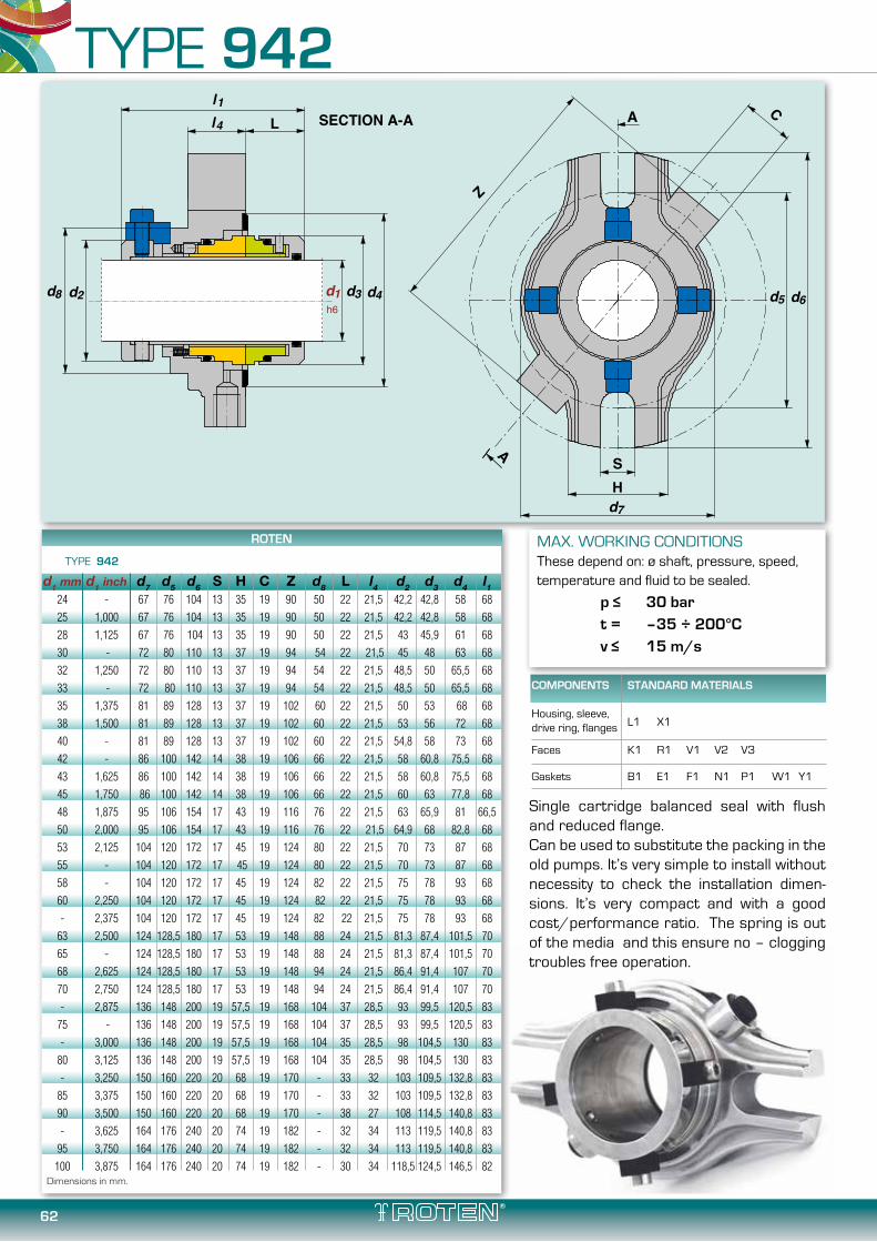
62
TYPE 942
MAX. WORKING CONDITIONSThese depend on: ø shaft, pressure, speed,temperature and fluid to be sealed.
p≤ 30bar t = –35 ÷ 200°C v≤ 15m/s
d4d3d1h6
Ll4l1
d6d5
SECTION A-A A
SH
A
Z
C
d7
d8 d2
Dimensions in mm.
Single cartridge balanced seal with flush and reduced flange.Can be used to substitute the packing in the old pumps. It’s very simple to install without necessity to check the installation dimen-sions. It’s very compact and with a good cost/performance ratio. The spring is out of the media and this ensure no – clogging troubles free operation.
ROTEN
TYPE 942
d1 mm d1 inch d7 d5 d6 S H C Z d8 L l4 d2 d3 d4 l1 24 - 67 76 104 13 35 19 90 50 22 21,5 42,2 42,8 58 68 25 1,000 67 76 104 13 35 19 90 50 22 21,5 42,2 42,8 58 68 28 1,125 67 76 104 13 35 19 90 50 22 21,5 43 45,9 61 68 30 - 72 80 110 13 37 19 94 54 22 21,5 45 48 63 68 32 1,250 72 80 110 13 37 19 94 54 22 21,5 48,5 50 65,5 68 33 - 72 80 110 13 37 19 94 54 22 21,5 48,5 50 65,5 68 35 1,375 81 89 128 13 37 19 102 60 22 21,5 50 53 68 68 38 1,500 81 89 128 13 37 19 102 60 22 21,5 53 56 72 68 40 - 81 89 128 13 37 19 102 60 22 21,5 54,8 58 73 68 42 - 86 100 142 14 38 19 106 66 22 21,5 58 60,8 75,5 68 43 1,625 86 100 142 14 38 19 106 66 22 21,5 58 60,8 75,5 68 45 1,750 86 100 142 14 38 19 106 66 22 21,5 60 63 77,8 68 48 1,875 95 106 154 17 43 19 116 76 22 21,5 63 65,9 81 66,5 50 2,000 95 106 154 17 43 19 116 76 22 21,5 64,9 68 82,8 68 53 2,125 104 120 172 17 45 19 124 80 22 21,5 70 73 87 68 55 - 104 120 172 17 45 19 124 80 22 21,5 70 73 87 68 58 - 104 120 172 17 45 19 124 82 22 21,5 75 78 93 68 60 2,250 104 120 172 17 45 19 124 82 22 21,5 75 78 93 68 - 2,375 104 120 172 17 45 19 124 82 22 21,5 75 78 93 68 63 2,500 124 128,5 180 17 53 19 148 88 24 21,5 81,3 87,4 101,5 70 65 - 124 128,5 180 17 53 19 148 88 24 21,5 81,3 87,4 101,5 70 68 2,625 124 128,5 180 17 53 19 148 94 24 21,5 86,4 91,4 107 70 70 2,750 124 128,5 180 17 53 19 148 94 24 21,5 86,4 91,4 107 70 - 2,875 136 148 200 19 57,5 19 168 104 37 28,5 93 99,5 120,5 83 75 - 136 148 200 19 57,5 19 168 104 37 28,5 93 99,5 120,5 83 - 3,000 136 148 200 19 57,5 19 168 104 35 28,5 98 104,5 130 83 80 3,125 136 148 200 19 57,5 19 168 104 35 28,5 98 104,5 130 83 - 3,250 150 160 220 20 68 19 170 - 33 32 103 109,5 132,8 83 85 3,375 150 160 220 20 68 19 170 - 33 32 103 109,5 132,8 83 90 3,500 150 160 220 20 68 19 170 - 38 27 108 114,5 140,8 83 - 3,625 164 176 240 20 74 19 182 - 32 34 113 119,5 140,8 83 95 3,750 164 176 240 20 74 19 182 - 32 34 113 119,5 140,8 83 100 3,875 164 176 240 20 74 19 182 - 30 34 118,5 124,5 146,5 82
COMPONENTS STANDARD MATERIALS
Housing, sleeve,drive ring, flanges L1 X1
Faces K1 R1 V1 V2 V3
Gaskets B1 E1 F1 N1 P1 W1 Y1

63
TYPE 972
MAX. WORKING CONDITIONSThese depend on: ø shaft, pressure, speed,temperature and fluid to be sealed. p≤ 30bar t = –35 ÷ 200°C v≤ 15m/s
d4d3d1h6
l4l1
d6d5
SECTION A-AA
SH
A
Z
C
d7
d8 d2
Dimensions in mm.
Double cartridge balanced seal with flush barrier fluid capabilities and reduced flange.Can be used on all critical application where a double seal is needed (i.e. gluing media, hot or very dirt fluids…). It’s very compact and very simple to install, without necessity to check the installation dimensions. The springs are out of the media and this ensure no – clogging troubles free operation. The reduced flange give the possibility to install the seal also when available space are limited.
ROTEN
TYPE 972
d1 mm d1 inch d7 d5 d6 d8 S H C Z d4 d2 d3 l1 L l4 24 - 67 76 104 51 13 35 19 90 58 49 42,9 85 22 21,5 25 1,000 67 76 104 51 13 35 19 90 58 49 42,9 85 22 21,5 28 1,125 67 76 104 53,8 13 35 19 90 61 52 45,5 85 22 21,5 30 - 72 80 110 55 13 37 19 94 63 53 48 85 22 21,5 32 1,250 72 80 110 58 13 37 19 94 65,5 56 50 85 22 21,5 33 - 72 80 110 58 13 37 19 94 65,5 56 50 85 22 21,5 35 1,375 72 80 110 60 13 37 19 94 68 58 53 85 22 21,5 38 1,500 81 89 128 63 13 37 19 102 72 61 56 85 22 21,5 40 - 81 89 128 65 13 37 19 102 73 63 58 85 22 21,5 42 - 86 100 142 68 14 38 19 106 75,5 66 60,8 85 22 21,5 43 1,625 86 100 142 68 14 38 19 106 75,5 66 60,8 85 22 21,5 45 1,750 86 100 142 70 14 38 19 106 77,8 68 63 85 22 21,5 48 1,875 95 106 154 75 17 43 19 116 82,8 73 68 85 22 21,5 50 2,000 95 106 154 75 17 43 19 116 82,8 73 68 85 22 21,5 53 2,125 95 106 154 80,7 17 43 19 116 87 78,7 73 85 22 21,5 55 - 95 106 154 80,7 17 43 19 116 87 78,7 73 85 22 21,5 58 - 104 120 172 85 17 45 19 124 93 83 78 85 22 21,5 60 2,250 104 120 172 85 17 45 19 124 93 83 78 85 22 21,5 - 2,375 104 120 172 85 17 45 19 124 93 83 78 85 22 21,5 63 2,500 124 128,5 180 91 17 53 19 148 101,5 89 87,4 87 24 21,5 65 - 124 128,5 180 91 17 53 19 148 101,5 89 87,4 87 24 21,5 68 2,625 124 128,5 180 96 17 53 19 148 107 94 92 87 24 21,5 70 2,750 124 128,5 180 96 17 53 19 148 107 94 92 87 24 21,5 - 2,875 136 148 200 110 19 57,5 19 168 120,5 106 99,5 122,2 34 28,5 75 - 136 148 200 110 19 57,5 19 168 120,5 106 99,5 122,2 34 28,5 - 3,000 136 148 200 114 19 57,5 19 168 130 110 104,5 114,6 35 28,5 80 3,125 136 148 200 114 19 57,5 19 168 130 110 104,5 114,6 35 28,5 - 3,250 150 160 220 124 20 68 19 170 132,8 117 109,5 113,7 38 27 85 3,375 150 160 220 124 20 68 19 170 132,8 117 109,5 113,7 38 27 90 3,500 150 160 220 124 20 68 19 170 140,8 120 114,5 114 38 27 - 3,625 164 176 240 135 20 74 19 182 146,5 131 124,5 113,3 33 30 95 3,750 164 176 240 135 20 74 19 182 146,5 131 124,5 113,3 33 30 100 3,875 164 176 240 135 20 74 19 182 146,5 131 124,5 113,3 33 30
COMPONENTS STANDARD MATERIALS
Housing, sleeve,
drive ring, flanges L1 X1
Faces K1 R1 V1 V2 V3
Gaskets B1 E1 F1 N1 P1 W1 Y1

64
TYPE 600SL
MAX. WORKING CONDITIONSThese depend on: ø shaft, pressu-re, speed, temperature and fluid to be sealed.
p≤ 30bar t = –35 ÷ 200°C v≤ 15m/s
d4 d6d5
d7
d1h6
l4l1
A
A
C
Z
SH
d2
SECTION A-A
Single cartridge balanced seal with flush. It’s a cartridge seal without sleeve that give great flexibili-ty to this seal. It’s very simple to install without necessity to check the installation dimen-sions. The springs are out of the media and this ensure no – clogging troubles free operation. The conical form of the stationary seat incre-ase the flush capabilities of the media. It has a good cost/performance ratio. All seal parts are out of stuffing box and this gives more fluid circulation on the seal area.
Dimensions in mm.
ROTEN
TYPE 600SL
d1 d2 d4 d7 d5 d6 l1 l4 C H S Z 24 42 58 67 76 104 41 22,5 19 35 13 90
25 42 58 67 76 104 41 22,5 19 35 13 90
28 42 61 67 76 104 41 23 19 35 13 90
30 54 63 72 80 110 41 21,5 19 37 13 94
32 54 65,5 72 80 110 41 21,5 19 37 13 94
33 54 65,5 72 80 110 41 21,5 19 37 13 94
35 61 68 81 89 128 41 21,5 19 37 13 102
38 61 70 81 89 128 41 21,5 19 37 13 102
40 61 72,8 81 89 128 41 21,5 19 37 13 102
42 65 75 86 100 142 41 21,5 19 38 14 106
43 65 75 86 100 142 41 2 1,5 19 38 14 106
45 65 77,8 86 100 142 41 21,5 19 38 14 106
48 74 82,8 95 106 154 41 21,5 19 43 17 116
50 74 82,8 95 106 154 41 21,5 19 43 17 116
53 74 87 95 106 154 41 21,5 19 43 17 116
55 80 87 104 120 172 41 21,5 19 45 17 124
58 80 93 104 120 172 41 21,5 19 45 17 124
60 80 93 104 120 172 41 21,5 19 45 17 124
65 87 101,5 124 134 180 45 26,5 19 53 17 136
70 87 107 124 134 180 50 26,5 19 53 17 136
75 113 120,5 136 148 200 55 26,5 19 59 19 148
80 114 130 136 148 200 55 26,5 19 59 19 148
85 123 135 150 160 220 55 26,5 19 68 20 160
90 123 141 150 160 220 55 26,5 19 68 20 160
95 134 141 164 176 240 55 26,5 19 74 20 172
100 134 152 164 176 240 55 26,5 19 74 20 172
105 134 152 164 176 240 55 26,5 19 74 20 172
COMPONENTS STANDARD MATERIALS
Housing, sleeve,drive ring, flanges L1 X1
Faces K1 R1 V1 V2 V3
Gaskets B1 E1 F1 N1 P1 W1 Y1

65
TYPE 977-977A
The cartridge 977 has been certified by TÜV North (Certificate TÜV 08 ATEX 353470 X) for applications in Category 1 Atex. With the installed thermocouples it is possible to monitor the temperature close to the faces. This is the area where heat is generated. The materials of the seal faces are dependant on the barrier fluid, which can be water or inert gas and these determine the application limits. The table shows the dimensions of the standard seal but we can produce the seal to customer dimensions if required by the application.The type 977A has the bearing integrated on the seal.The cartridge type 977 can be also supplied without Atex certification.

66
TYPE 977
Dimensions in mm. Additional sizes on request.
MAX. WORKING CONDITIONSThese depend on: ø shaft, pressure, speed,temperature and fluid to be sealed.
p≤ 40bar t = –50 ÷ 300°C v≤ 0-5m/s
ROTEN
TYPE 977
d3 d1 d4 d0 L l1 ØK n x d2 M2 Mg 40 175 110 90 170 15 145 4x18 M16 G 3/8
60 240 176 135 185 17 210 8x18 M16 G 3/8
80 275 204 155 200 20 240 8x22 M20 G1/2
100 305 234 190 210 20 270 8x22 M20 G1/2
120 330 260 215 240 20 295 8x22 M20 G1/2
140 395 313 250 255 20 350 12x22 M20 G1/2
160 395 313 265 260 25 350 12x22 M20 G1/2
180 445 364 310 275 25 400 12x22 M20 G1/2
200 445 364 310 290 25 400 12x22 M20 G1/2
220 505 422 340 320 25 460 16x22 M20 G1/2
COMPONENTS STANDARD MATERIALS
Housing, sleeve,drive ring, flanges L1 X1
Faces K1 R1 V1 V2 V3
Gaskets B1 E1 F1 N1 P1 W1 Y1
L
A A
B
B
C
C
1,5x
30°
8,5
Mg (OUT)
M2 - n°2 at 180°
Mg (IN)
d3 h6
e8
SEZIONE A-A SEZIONE C-C
SEZIONE B-BTEMPERATURE
SENSOR
TEMPERATURESENSOR
l 1
d2
dØK
ØK
1
d4d0

67
A A
B
B
C
C
1,5x
30°
8,5
Mg (OUT)
BEARING GREASE IN
BEARING GREASE OUT
M2 - n°2 at 180°
Mg (IN)
SEZIONE A-A
SEZIONE C-C
SEZIONE B-B
TEMPERATURESENSOR
TEMPERATURESENSOR
Ll 1
ØK
d3 h6
e8
d2
dØK1
d4d0
TYPE 977A
Dimensions in mm. Additional sizes on request.
MAX. WORKING CONDITIONSThese depend on: ø shaft, pressure, speed,temperature and fluid to be sealed.
p≤ 40bar t = –50 ÷ 300°C v≤ 0-5m/s
ROTEN
TYPE 977A with bearing
d3 d1 d4 d0 L l1 ØK n x d2 M2 Mg 40 175 110 90 210 15 145 4x18 M16 G 3/8
60 240 176 135 230 17 210 8x18 M16 G 3/8
80 275 204 155 270 20 240 8x22 M20 G1/2
100 305 234 190 270 20 270 8x22 M20 G1/2
120 330 260 215 300 20 295 8x22 M20 G1/2
140 395 313 250 315 20 350 12x22 M20 G1/2
160 395 313 265 315 25 350 12x22 M20 G1/2
180 445 364 310 330 25 400 12x22 M20 G1/2
200 445 364 310 350 25 400 12x22 M20 G1/2
220 505 422 340 370 25 460 16x22 M20 G1/2
COMPONENTS STANDARD MATERIALS
Housing, sleeve,drive ring, flanges L1 X1
Faces K1 R1 V1 V2 V3
Gaskets B1 E1 F1 N1 P1 W1 Y1

68
TITANIUM MECHANICAL SEALS
The TITANIUM seals are used in very aggressive application where the stainless steel it's no more enough to resist to corrosion.The titanium it's a not easy to work material. However Roten with his long experience and modern technology was able to produce seals with Titanium parts.
Type 33H, all material parts are in titanium including the self driving spring. Shrunk-in SiC rotating ring and massive stationary SiC ring.
External mounting seal type 7KH.
Balanced seal type 82EH for high pressure, bi-directional, all metal parts in titanium with SiC faces.

69
®
srl

70
APPLICATIONS

71
APPLICATIONS

72
APPLICATIONS

73
APPLICATIONS

74
10 20 30 40 50 60 70 80 90 100 110 120 130 140 1500
1
2
3
4
5
6
7
8
9
10
11
12
13
14
15
PR
ESS
UR
E (b
ar)
SHAFT DIAMETER (mm)
PERFORMANCE CURVE
Performance curves for working conditions of unbalanced ROTEN and UNITEN seals with clean water at 20°C.
N.B.: Curves for shafts at 2900 r.p.m.
INOX-CARBON ALUMINA-CARBON TC/Carbon-SIC/Carbon TC/TC-SIC/SIC

75
0 1 2 3 4 5 6 7 8 9 10 11 12
0,2
0,4
0,6
0,8
1,0
1,2
1,4
1,8
KW
1,6
0
0,4
0,8
1,2
1,6
2,0
2,4
2,8
3,6
3,2
KW
Ø20Ø30
Ø40
Ø50
Ø60
Ø70
Ø80
Ø90
Ø100
Ø110
Ø120
Ø130
Ø140
Ø150
PRESSURE (bar)
AB
SO
RB
ED P
OW
ER A
T 1
45
0 R
.P.M
.
AB
SO
RB
ED P
OW
ER A
T 2
90
0 R
.P.M
.
ABSORBED POWER DIAGRAM
Diagram of absorbed power by ROTEN and UNITEN unbalanced seals, depending on working pressure.
The mentioned values shall be increased or decreased of 20÷30% according to the features of the treated medium.The values of the test chart refer to steel/carbon seals with clean water at 20 °C.
We advise to consider the following test correcting coefficients for different pairings (experimental):SIC/CARBON x 0,85CERAMIC/CARBON x 0,90WC/CARBON x 0,90WC/SIC x 2,30WC/WC x 2,50SIC/SIC x 2,80

76
DELIVERY CAPACITY DIAGRAM
1,5
10
1,41,31,21,11,00,90,80,70,60,50,40,30,20,10
9876
5
4
3
2
1,5
1.9.8.7
.6
.5
.4
.3
.2
0,1
T
3530
25
20
15141312111087643 95
POWER TO BE DISPERSED - KW
Q-W
ATE
R D
ELIV
ERY
CA
PA
CIT
Y -
L/M
IN
Diagram of the water delivery capacities depending on the heat that has to be lost.
Diagram to determine the minimum indispensable water quantity to lose heat developed by the mechanical seal.After having obtained the absorbed power relating to
the used seal out of the preceding diagram, estimate the necessary delivery capacity, depending from the difference in temperature (ΔT) of in-flowing and out-flowing water.
N.B.: In-flowing water temperature must be lower or equal to that of the external environment.

77
DELIVERY CAPACITY (Q-T) TEMPERATURE DIAGRAM
0 100 200 300 400
1
2
3
4
Ø25
Ø50
Ø75
0
2
4
6
8
Ø100
Ø125
Ø150
t - PUMPING TEMPERATURE - °C
Q-C
OO
LIN
G L
IQU
ID D
ELIV
ERY
CA
PA
CIT
Y -
l/m
in. (
at 1
45
0 r
.p.m
.)
Q-C
OO
LIN
G L
IQU
ID D
ELIV
ERY
CA
PA
CIT
Y -
l/m
in.
(at
29
00
r.p
.m.)
Diagram to determine the cooling fluids delivery capacity depending on the temperature of the pumped medium for DUAL pressurised applications. These delivery capacities must be added to those necessary for the dispersion of the heat generated by the mechanical seal.
N.B.: The present test chart serves only as a guideline
MOTOR SIDE
t = PUMPINGTEMPERATURE
COOLING FLUID INCOMINGAT ROOM TEMPERATURE

78
MOST USED CIRCULATION SYSTEMS ACCORDING TO API 682/ISO 21049
PLAN 21
T1
if required
T1
if required
PLAN 23
T1
if required
PLAN 31
LSL
If sp
ecifi
ed
Rese
rvoi
r
LBI
In collection system
PS
Normally open
LBO
LI
PI
LSHMake upbarrier fluid
6
By vendor
By purchaser
D
Q
PLAN 51
if required
T1
PLAN 32
T1
P1
F1Optional
By vendor By purchase
LBO
LBI
Q
D
Q
D
COOLER
PI PRESSURE GAUGEWITH BLOCK VALVE
TI DIAL THERMOMETER
PRESSURE SWITCHWITH BLOCK VALVE
PS
CYCLONE SEPARATOR
FLOW INDICATORFI
Y-TYPE STRAINER
FLOW REGULATING VALVE
BLOCK VALVE
CHECK VALVE
ORIFICE
PLAN 01 PLAN 12
PLAN 22
PLAN 53A
PLAN 32
PLAN 02
PLAN 13 PLAN 23
PLAN 54
PLAN 41
API PLAN LEGEND
PLAN 11
PLAN 21
PLAN 31
PLAN 61PLAN 51
PLAN 62
Internal circulation from the pump case to the seal
Circulation from the pump discharge, through an orifice to the seal.
Circulation from the pump discharge, through a strainer and an orifice to the seal
Circulation from the seal chamber, through an orifice and back to pump suction.
Circulation from the pump discharge, troungh an orifice and a cooler to the seal.
Circulation from the pump discharge, through a strainer, an orifice and a cooler to the seal
Circulation by means of a pumping ring from the seal, through a cooler and back to the seal.
Circulation from the pump discharge through a cyclone separator.
Circulation with thermosiphon system, pressurized. Forced circulation by pumping ring or circulation pump.
Dead-end quench (usually methanol)
Reservoir
Circulation from the pump case throungh a cyclone separator, and clean fluid through a cooler to the seal.
Injection of clean fluid into the seal chamber from an external source.
Circulation of clean fluid from an external system.
External fluid quench (steam, gas, water, ect.)
Tapped connections for the customer's use.
Dead end seal chamber with no circulation. Stuffing box cooling and a neck bush are necessary, unless otherwise specified.

125125125

This catalogue illustrates the seal series we produce which have been
in use since the very beginning of our activity.
ALL M.S. PICTURES ARE ORIGINAL MADE IN ROTEN.
We are thankful towards all those clients who allowed us to earnestly develop
our work and to constantly improve our quality standards and efficiency.
All reported datas in this catalogue and all information therein derive
from our own experience over 70 years of activity in this field.
Thus their endurance depends on a number of various factors, our
products are guaranteed because of the quality of the materials we
indicate in the tables and their accurate manufacturing.
The reported measures in this catalogue are expressed in millimeters.
If needed, and with enough quantity, we can design and produce our
models with inch sizes.
Also note that the maximum values of working condition parameters,
shall not be applied simultaneously.
The information contained herein is correct at the time of issue, but
may be subject to change without prior notice.
We would be grateful and thanks in advance for the support the
readers, if they will report us printing errors that they will find in this
catalog and seal selection guide.
PRIN
T 20
16 -
REV.1
M E C H A N I C A L S E A L S
®
srl
THE INDEPENDENT SEAL MANUFACTURER

M E C H A N I C A L S E A L S
®
srl
Via Ortica, 620134 Milano, ITALY
Tel. +39 02 76110157Fax +39 02 7385445
[email protected] www.roten.it
ISO 9001 Since 1993
ISO 14001 Since 2007


OUR PARTNERS
1945MILANO
1945
GU
AR
ANTEED QUALITY SIN
CE
MILANO
s.p.a.
s.r.l.
s.r.l.
s.r.l.
ElEcTROmEchANicAl cARbONSVia S. Scolastica, 35 - 64013 Corropoli (Te) Italy Tel. +39 0861.839020 - Fax +39 0861.839050www.eurocarbo.it - [email protected]
SPRiNgS fOR iNdUSTRyVia C. Varalli, 1 - 20089 - Rozzano (MI) Italy Loc. ValleambrosiaTel. +39 02.89202678 - Fax. +39 02.57792002www.molinox.it - [email protected]
mEchANicAl SEAlS SERvicE-REcONdiTiON Via Liguria, 3420068 Peschiera Borromeo (MI) Italy Tel. +39 02.55303015 - Fax +39 02.55303024www.coemi-srl.it - [email protected]
SERiES mEchANicAl SEAlSVia Sighele, 3 - 20133 Milano (MI) ItalyTel. +39 02.7381652 - Fax +39 [email protected]
1973
1982
1990
1986


