Embed Size (px)
Citation preview
IEEE TRANSACTIONS ON ANTENNAS AND PROPAGATION, VOL. 61, NO. 2, FEBRUARY 2013 871
Measurement and Performance of Textile AntennaEfficiency on a Human Body in a
Reverberation ChamberStephen J. Boyes, Student Member, IEEE, Ping Jack Soh, Student Member, IEEE, Yi Huang, Senior Member, IEEE,
Guy A. E. Vandenbosch, Fellow, IEEE, and Neda Khiabani, Student Member, IEEE
Abstract—With the advent of on-body communication researchin recent years, there is a growing need for antenna developmentsthat satisfy a wide criteria (one being minimal efficiency degrada-tion) in order to be integrated successfully onto human subjects;one promising development is the textile antenna. In this paperwe investigate the efficiency performance of some newly designedsmall sized textile antennas on live human subjects using a rever-beration chamber. First, we show that the material selection ofthese textile antennas can have a crucial effect on the on-body fre-quency detuning and efficiency levels, as via a comparison we de-termine that a lossier textile antenna in free space can actually out-perform a higher free space efficient textile antenna when placedon-body. This has a profound impact on thematerial design choicesfor these small sized antennas. Second, we investigate the perfor-mance effects under bent conditions and finally we show that theoverall performance of the textile antenna can be mitigated some-what by variations in on-body distances from the human subject.It is revealed that in some cases a small 20 mm distance from thebody is sufficient for the radiation efficiency to approach the freespace levels. Theoretical, simulated and experimental evidence ispresented to verify the conclusions.
Index Terms—Antenna efficiency, on-body communications, re-verberation chamber, textile antennas.
I. INTRODUCTION
A GROWING interest is evident concerning body centricwireless communication technology, aimed at providing
solutions for a wide range of applications from the medical/healthcare industries, the consumer electronic industries, wear-able technology for the fashion industry and the military sectorto name but a few. A crucial component in the body centricwireless communication ‘chain’ concerns the antenna device it-self; the antenna should be ergonomically suitable for integra-tion onto a human body. Furthermore, the antenna should not be
Manuscript received April 13, 2012; revised June 20, 2012; accepted October11, 2012. Date of publication October 19, 2012; date of current version January30, 2013. This work was supported in part by the Engineering and Physical Sci-ence Research Council (EPSRC) U.K, the Malaysian Ministry of Higher Edu-cation (MOHE), and the EU-FP7 CARE Project.S. J. Boyes, Y. Huang, and N. Khiabani are with the Department of Electrical
Engineering and Electronics, University of Liverpool, Liverpool L69 3GJ, U.K.(e-mail: [email protected]; [email protected]; [email protected]).P. J. Soh and G. A. E. Vandenbosch are with the ESAT-TELEMIC Research
Division, Department of Electrical Engineering, Katholieke UniversiteitLeuven, 3001 Leuven, Belgium (e-mail: [email protected];[email protected]).Color versions of one or more of the figures in this paper are available online
at http://ieeexplore.ieee.org.Digital Object Identifier 10.1109/TAP.2012.2225817
obtrusive, it should be able to maintain flexibility, exhibit min-imal degradation in terms of bandwidth, reflection coefficientand efficiency performance, and be manufactured in a low costmanner. To satisfy this broad criterion, the textile antenna hasbeen developed and continues to receive ever growing attention[1]–[3].When communicating wirelessly in the proximity of a human
body, the propagation channel is dependent upon the body con-dition, the human activity being performed, the antenna posi-tion, the immediate surrounding environment and any interac-tion between the human body and the antenna [4]–[6]. There-fore, the radio propagation channel in this (on-body) scenariodirectly includes the body effect and is not usually stationary. Itbecomes important therefore to be able to characterize any an-tenna, specifically designed for use “on-body,” in a realistic sce-nario (i.e., on a human being) to attempt to accurately quantifythe effect of the human body on any associated antenna param-eters of interest.In this paper, the quantity of interest mainly concerns the
radiation and total radiation efficiency of some newly designedtextile antennas. The measurement facility chosen to performthe characterization is the reverberation chamber (RC). TheRC is now well known from studies such as [7]–[12], andcan be described as an electrically large shielded metallicenclosure which is designed to work in an “over-mode” con-dition. The fields inside this environment can be perturbed byvarious means to engender the average field distribution statis-tically homogeneous, as long as the field location is situatedapproximately from the chamber walls [13]. The fieldstatistics inside the chamber have received much theoreticaland practical treatment over the years and are well known, forexample see [14]. To review, the received complex signal inthis environment with no line of sight path manifests itself asbeing complex Gaussian (normally distributed), the magnitudesare Rayleigh distributed, the power exponentially distributedand the phase uniformly distributed over . It should also benoted however that a Rician distributed environment can alsobe emulated in the chamber as proposed in [15]. The choiceof measurement facility here has been chosen in part becauseof the statistically emulated environment it can offer, but alsobecause we feel it can offer an easier, more robust/less uncertainmeasured solution to the problem of textile antenna efficiencieswhen acquired on a human body. To explain further, it isinevitable that some human movements will be present duringany measurement procedure (from breathing, etc.). However,
0018-926X/$31.00 © 2012 IEEE

872 IEEE TRANSACTIONS ON ANTENNAS AND PROPAGATION, VOL. 61, NO. 2, FEBRUARY 2013
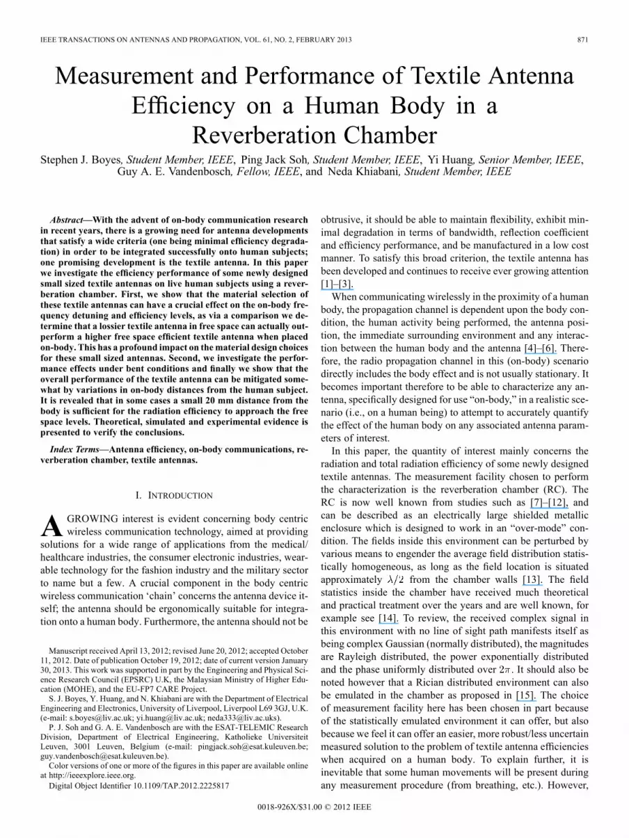
Fig. 1. Single band textile antenna radiating elements [ShieldIt radiating patch(left) and Copper radiating patch (right)].
Fig. 2. Single band textile antenna ground planes [ShieldIt ground plane (left)and Copper ground plane (right)].
in the RC environment these can be tolerated as they would addto the randomness of the fields inside the chamber which canbe viewed positively.To the best of our knowledge only one experiment concerning
antenna radiation efficiency using live human test subjects in anRC exists, see [16]. The conclusions drawn from this piece ofwork indicated that the RC was a repeatable test bed for wear-able antenna measurements using live human subjects; this po-tentially validates the prior stated reasoning on the choice offacility here. Further, the results presented indicated that theRC results obtained with human test subjects were sufficientlyrepresentative of results acquired using tissue phantoms—vali-dating the live human approach against phantom models oftenused in the field [16]. The antennas used in the study consistedof four low profile microstrip patch antennas constructed on adielectric substrate and a quarter wavelength monopole, withthe results indicating that the type of the antenna plays a moredependent role in determining the overall radiation efficiencyperformance when placed “on-body” as compared to the char-acteristics of any human subject.Elements for future work stated in [16] highlighted a need
for characterizing flexible/fabric antennas on body and also anassessment of movement related bending effects. This, there-fore, is what this paper seeks to address. This paper is orga-nized as follows. Section II will first define the quantities of in-terest in this study and the mathematical formula behind them toavoid any ambiguity, and second, introduce the antennas undertest (AUT). Section III presents detailed information concerningthe RC measurement procedures used in this manuscript andSection IV will disclose all results pertinent to the investiga-tion. An assessment of the measurement uncertainty is providedin Section V to benchmark the accuracy of the results presented.
II. DEFINITIONS
A. Antenna Efficiency
For the quantity of radiation efficiency we refer to the IEEEdefinition of “Ratio of total radiated power to net power ac-cepted by the antenna at its terminals.” Mathematically, whenacquired using a RC, (1) applies [17]
(1)
where: average of the scattering parameters, absolutevalue, transmission coefficient, reflection coeffi-cient, antenna under test, reference antennaand known reference efficiency. In our case the reflec-tion coefficient quantities here are not signified as being an en-semble average, this is because we choose to acquire this par-ticular parameter in an anechoic chamber as it was quicker forus to do so. It should be noted however that if the reflectioncoefficients are acquired in an RC then the quantity should besignified as being an ensemble average. For the quantity of totalradiation efficiency (or total efficiency for short) we imply thedefinition of “Ratio of total radiated power to the power inci-dent on the antenna port”. Mathematically, this is a product ofthe radiation efficiency and mismatch efficiency of an antennaas detailed in (2)
(2)
Again, the reflection coefficient parameter in our case is ac-quired in an anechoic chamber hence the omission of the en-semble average.
B. Antenna Descriptions
It is beyond the scope of this manuscript to present any op-timization analysis of the antennas under test; therefore in thissection they will only be briefly described. For further detailedinformation pertaining to the designs please refer to [3]. Onedistinct category of textile antenna is to be investigated in thispaper—designed for single band use at the 2.45 GHz indus-trial scientific and medical (ISM) frequency. The single bandantennas are based around the same PIFA topology and bothare constructed using a 6 mm thick felt fabric ( and
at 2.45 GHz [3]). The felt fabric is sandwichedbetween a ground plane and a slotted radiating patch, with twodifferent conductive textile materials being subject to investiga-tion [18], [19]:1) copper textile (plain woven and coated, 0.08 mm thick,
at 2.45 GHz);2) ShieldIt™ conductive fabric (0.17 mm thick,
at 2.45 GHz).The profile of each antenna can be viewed in Figs. 1 and 2.
III. MEASUREMENT PROCEDURES
The measurements utilized the RC at the University of Liver-pool. The chamber is constructed from galvanized steel and thedimensions are , and

BOYES et al.: MEASUREMENT AND PERFORMANCE OF TEXTILE ANTENNA EFFICIENCY ON A HUMAN BODY IN A RC 873
. The chamber is fitted with two principle sets of mechan-ical stirring paddles that rotate about a central shaft; one set con-figured for vertically polarized waves mounted towards a cornerof the chamber from the floor to the ceiling, the other configuredfor horizontally polarized waves mounted from the front to backwall at ceiling height. The paddles are therefore configured tobe able to stir orthogonal volumes of the chamber.As with any efficiency measurement in this facility, the
chamber required an initial reference measurement for cali-bration purposes. This was performed using a dual ridge hornantenna (Satimo SH2000), the antenna being selected as itsunidirectional pattern characteristics were similar to that ofthe AUT’s. For the single band antennas a frequency range of2–3.5 GHz was selected using 801 frequency data points, withthe number of data points being selected to ensure that a suffi-ciently large number of modes would be excited in the chamberthroughout the measured range. The calibration needed to beperformed while the human subject was located inside thechamber, as the presence of the human subject would severelyload the chamber. As such, it was expected to be the dominantcontributor to any loss mechanisms that exist (more so, than forexample, any wall losses, losses from aperture leakage and anyantenna loss). The stirring sequences used throughout (samefor reference calibration and AUT measurement) comprisedthe following parameters:1) mechanical stirring—5 degree (71 measurements);2) polarization stirring—two orthogonal linear polarizations;3) position stirring—5 separate receiver locationsThe above stirring mechanisms gave rise to a total of 710
measured samples per frequency point for both the referenceand AUT measurement. The reasons behind the stirring se-quences were twofold: firstly, a large number of samples (apercentage of the total being statistically independent) arerequired to keep the uncertainty in the measurements to anacceptable level, and secondly, the sequences meant that thehuman subject did not have to spend prolonged amounts oftime inside the chamber to complete each measured sequence(i.e., the subject could take regular breaks if need be).During the reference measurements, the human subject had
the AUT attached to the body via a rigid cable which was ter-minated in 50 ohms. During the on-body AUT measurements,the reference antenna remained inside the chamber—connectedvia the same rigid cable and terminated in 50 ohms. By this, thechamber loading was configured exactly the same from the ref-erence to the AUT measured sequences to ensure accuracy; noaspects differed in this regard whatsoever. Indeed, even the con-tents inside the human subjects pockets, etc. was always keptconstant (no mobile phone, coins, etc.) to ensure that consis-tency prevailed. Fig. 3 illustrates the set up used during the ref-erence measurements.The distance between the consecutive position locations
shown above was configured such that each location was largerthan the correlation distance (about ½ wavelength) to createindependent samples. The exact locations are summarized inthe following table.Further, throughout all position stirring locations (for both
the reference and AUT measurements), the separation between
Fig. 3. Measurement setup (reference in this case).
TABLE IPOSITION STIRRING LOCATIONS
human subject and reference antenna was always kept as a pre-scribed distance apart to avoid any coupling issuesthat could potentially corrupt any measured results.
IV. MEASUREMENT INVESTIGATION
In this investigation we will compare the radiation and totalradiation efficiency values of each AUT on different bodylocations with respect to their free space efficiency values. Bythis we not only want to assess which antenna yields the highestefficiency on body and in what location, but also chart thedifference in magnitude of the efficiency quantities to assesswhat degradation occurs when the textile antennas are locatedon-body in specific locations and proximity distances. Pleasenote that all free space efficiency values have been measured inthe same chamber by the same principle author, using the samestirring mechanisms to be able to compare directly. The mea-sured free space radiation and total radiation efficiency valuesthat are supplied are compared by simulated efficiency valuesprovided from CST Microwave Studio (based on the finite in-tegration technique) by an assessment from the gain/directivity[20]. All efficiency values herewith for the single band antennashave been frequency stirred by 20 MHz (i.e., over 11 frequencydata points); the 20 MHz frequency stirring value was selectedsuch that it was far less than the bandwidth of the antennas tominimize the reduction in frequency resolution. This section issubdivided into three smaller sections to assess both antennasperformance at given body locations and proximity distancesfrom the human test subject. From here on in, the AUT’s willbe referred to by their manufactured name: Coppertextile radiating element and ground plane, ShieldIttextile radiating element and ground plane.

874 IEEE TRANSACTIONS ON ANTENNAS AND PROPAGATION, VOL. 61, NO. 2, FEBRUARY 2013
Fig. 4. On chest 0 mm measured setup.
A. On Body 0 mm Measured Results
1) Chest 0 mm: In this investigation the antenna was locatedon the centre of the human subjects’ chest, 1.38m from the floor.The 0 mm dimension in this case does not mean that the an-tenna was physically touching the human subjects’ skin; rather,the human subject was wearing a woolen jumper 1.5 mm thick(constant throughout all experiments) and it was this which theantenna was placed against. The antenna element was not phys-ically strapped to the human by any means—standard Velcrostraps were used to fix the attached cable to the human beingwhich was sufficient to hold the antenna to the chest of the sub-ject. Throughout the measurement sequences this aspect wasrigorously checked and at no time did the antenna shift loca-tion. Fig. 4 illustrates the measured set up.In Fig. 4, the human subject faces the back wall with the an-
tenna on his chest. This aims to block any line of sight path fromthe transmitting antenna which is located behind the human sub-ject (off shot). The proximity distance between the body and theantenna in this particular investigation has been chosen to assessthe ‘worst case’ possible estimate that could be witnessed; thatis, we expect the severest loss.The antenna orientation in Fig. 4 (normal to the chest) has
been chosen because of the location of the SMA connector inthe antenna design, meaning that it was easier to secure the an-tenna in position at the 0 mm proximity distance in the mannershown. The radiation efficiency results for FLSL placed on thechest (0 mm) are disclosed in Fig. 5. Three separate measure-ments have been completed for this antenna and body locationto provide an indication as to the measurement repeatability. Acomparison with the free space radiation efficiency levels is alsoprovided so that the degradation in radiation efficiency can beeasily assessed.The total radiation efficiencies are shown in Fig. 6. The dis-
crepancy between the measured and simulated cases witnessedcan be attributed in part to differences between the measuredand simulated reflection coefficients. This in turn resulted fromslight differences in the fabricated dimensions between the sim-ulated model and physical design, and also the presence of theSMA connector.To address the nature of the antennas orientation at the 0 mm
proximity distance; specifically the fact that the radiating ele-ment is mounted perpendicular to the chest as opposed to being
Fig. 5. FLSL 0510 radiation efficiency at 0 mm for on-body chest & freespace.
Fig. 6. FLSL 0510 total radiation efficiency at 0 mm for on-body chest &free space.
Fig. 7. 0 mm measured set-up for alternative antenna polarization.
parallel, an investigation was undertaken to compare if any dif-ferences existed. This investigation utilized the exact samemea-surement parameters and procedures as previously discussedto ensure that an accurate comparison could be formed. Theon-body antenna location was configured such that the cablewas mounted and secured under the arm, enabling the antennaradiating patch to be away from the human body. The exactsame (0mm) proximity distance was alsomaintained with Fig. 7illustrating this particular set up.

BOYES et al.: MEASUREMENT AND PERFORMANCE OF TEXTILE ANTENNA EFFICIENCY ON A HUMAN BODY IN A RC 875
Fig. 8. FLSL 0510 comparison of deduced efficiency versus antenna orienta-tion at the 0 mm proximity distance.
The main purpose for this investigation was to assess if anydifferences are observed with respect to the antenna’s polariza-tion. For example, in on-body applications for consumer elec-tronics, the users’ movements could potentially alter the an-tennas polarization when worn on the clothing, which couldhave an impact on the antennas performance.From Fig. 8 we see that the resultant magnitudes of efficiency
at 0 mm are very close indeed, irrespective of the antennas per-pendicular or parallel on-body orientation. The differences inthe largest case are in the order of 4%. The reason for the simi-larity in the results is believed in part to be down to the emulatedmultipath environment which has contributed to help overcomeany differences in the antenna radiation patterns with respect tothe antennas on-body orientation [21]. Furthermore, because theantennas ground plane is small in dimension, we believe thatthis also a contributing factor as to why the different antennaorientations produce similar results—i.e., the results shown arevalid irrespective of the (0 mm) antenna orientation in this case.The parallel results measured in Fig. 8 were acquired on a dif-ferent human being than the perpendicular case which collec-tively shows that any efficiency results here are not too sensi-tive to the on-body antennas orientation within reason, and fur-thermore that the efficiency results are reproducible to differenthuman subjects.As stated prior, the reflection coefficients on body were ac-
quired in the anechoic chamber (AC) at the University of Liv-erpool. All antennas were strategically located in exactly thesame place as where the RC measurements took place on bodyto ensure accuracy in the measured reflection coefficient—thisaspect was checked and consistent results were obtained fromboth RC and AC facilities. The measured on body (chest 0 mm)reflection coefficients are issued in Fig. 9 and are compared withthe free space performance. The discrepancy between measuredand simulated quantities can be explained by slight differencesin the fabricated dimensions between the simulation and mea-surements, and the effect of the SMA connector represented bya simplified model in the simulation.From Figs. 5 and 6 we see that the levels of radiation and
total radiation efficiency are degraded considerably from thefree space efficiency levels. At the start of the measured fre-quency band (2 GHz) this is as much as 78.15% for the radi-
Fig. 9. FLSL 0510 reflection coefficients (dB) at 0 mm for on-body chest andfree space.
Fig. 10. SHSL 0510 radiation efficiency at 0 mm for on-body chest andfree space.
ation efficiency and 72.65% for the total radiation efficiency.The trend of the on body efficiency is also seen to rise over thefirst 600 MHz measured band; this believed to be attributableto the coupling between the human body and the antenna (re-membering the antenna is not physically touching the humanskin). Thus as the frequency begins to increase, the inter element(human body and antenna) spacing is also increasing. From themeasured reflection coefficients the antenna is also seen to ex-hibit a degree of detuning. At 2.45 GHz the mismatch efficiencymeasured on the chest is 78% as compared to the free spacevalue of 91%. With regards to the measurement repeatability, itis seen that the three separate measured runs undertaken yieldvery consistent levels of efficiency; this provided increased con-fidence that the measurement procedures undertaken were thusconsistent and not liable to wild fluctuations from one measure-ment to the next. The difference between the measured runs isin the order of 2% at its maximum.For the ShieldIt material (SHSL 0510) the measured set up
and procedures differed in no way from the prior (FLSL 0510)0 mm chest investigation so that a direct comparison could beformed; therefore, Fig. 4 again illustrates the set up. The radia-tion efficiency results for SHSL 0510 at 0 mm on the chest arepresented in Fig. 10.The total radiation efficiency results for SHSL 0510 are pre-
sented in Fig. 11.

876 IEEE TRANSACTIONS ON ANTENNAS AND PROPAGATION, VOL. 61, NO. 2, FEBRUARY 2013
Fig. 11. SHSL 0510 total radiation efficiency (%) at 0 mm for on-body chestand free space.
Fig. 12. SHSL 0510 reflection coefficients (dB) at 0 mm for on-body chest andfree space.
Comparing Figs. 5 and 6 with Figs. 10 and 11 we find that thetextile antenna constructed with the ShieldIt type material forthe radiating element and ground plane is lossier in free spaceconditions than the copper textile material—this is as predictedsince we expect the higher conductivity material to yield higherradiation efficiencies. However, when placed on the body, thelower conductivity (ShieldIt) material exhibits a larger amountof radiation and total radiation efficiency than its copper basedcounterpart—differences of 30% are evident for the radiationefficiency and 25% for the total radiation efficiency at 2.45 GHz.Theoretical and simulated evidence to explain and support thesetrends can be found in section C.The reflection coefficient of the SHSL 0510 antenna on-body
(chest 0 mm) is shown in Fig. 12. By comparing Figs. 9 and 12,we find that the ShieldIt textile antenna also exhibits a lesseramount of detuning as compared to the copper based counter-part. The mismatch efficiency at 2.45 GHz for the ShieldIt ma-terial is calculated at 90% as opposed to the 78% recorded forthe copper textile material.2) Bent (Elbow) 0 mm: This investigation looked to assess
the effect on radiation and total radiation efficiency under a bentconfiguration. The body area selected was the elbow. Fig. 13illustrates the set up used.This time the antenna had to be secured with the standard
Velcro ties owing to the loading placed on the antenna through
Fig. 13. On-body (elbow 0 mm) measurement set up.
Fig. 14. FLSL 0510 bent elbow (0 mm) radiation and total efficiencyversus free space and bent elbow reflection coefficients (dB).
bending. The bending radius (measured from the centre of theelbow to the edge of the elbow was 55 mm). The antenna el-ement was selected as the copper based textile (FLSL 0510)and was located 1.2 m from the chamber floor. The human sub-jects’ arm was fixed in place by a Velcro tie which was strappedaround the arm and shoulder. This was sufficient to hold thesubjects’ arm in place to prevent movement. The radiation ef-ficiency, total radiation efficiency and reflection coefficient re-sults can be viewed in Fig. 14.Comparing to the 0mm chest measurement (see Fig. 5) the ra-
diation efficiency values at 2 GHz would appear slightly higher,believed to be due to the absence ofmajor human organs near theantenna, but in the mid and upper frequency range the values be-came comparable. The comparable nature of the mid and upperfrequency range results are partly expected owing to the over-moded characteristics of the RC—(the fact that the angle of ar-rival of plane waves come from every conceivable directionwith equal probability meaning the radiation patterns of theAUT play no part [22]). However, the main effect here con-cerned the total radiation efficiency. The levels are 12% to 15%lower than the 0 mm chest values (Fig. 6) owing to the severedetuning in the magnitude of reflection coefficient; hence themismatch efficiency of the antenna at 2.45 GHz was reduced to62% as compared to the 78% witnessed on the chest at 0 mmand 91% in free space. The conclusion drawn from this investi-gation was that severely loading the antenna under a bent con-figuration is not good practice, and on the evidence of the results

BOYES et al.: MEASUREMENT AND PERFORMANCE OF TEXTILE ANTENNA EFFICIENCY ON A HUMAN BODY IN A RC 877
Fig. 15. FLSL 0510 chest 20 mm radiation and total efficiency versus freespace and chest 20 mm reflection coefficients (dB).
seen here perhaps should be avoided when an on-body antennalocation is to be chosen. In respect of these conclusions, this ex-periment was not repeated.
B. On Body 20 mm Measured Results
1) Chest 20 mm: The next investigation undertaken looked toassess the effect of having different spacing between the antennaand the human body—i.e., if the interelement spacing were to beslightly increased, what difference in the magnitude of the radi-ation and total radiation efficiency could be obtained. The theo-retical rationale guiding this investigation we considered to be afunction of (expected) decreased coupling between the antennaand human subject; noting that the medium that is coupling tothe antenna (i.e., the human being) will present a significant lossif the antenna is close enough. The antenna was again located inthe centre of the subjects’ chest, 1.38 m from the floor. The 20mm chest separation was achieved by employing a 90 degreeelbow connector to keep the antenna at a fixed distance. Theradiation efficiency, total radiation efficiency and reflection co-efficient performance of the copper textile (FLSL 0510) at thislocation and proximity distance can be viewed in Fig. 15.Comparing Figs. 5, 6 and 15 we find that the 20 mm distance
from the human subjects’ chest yields a clearly higher valueof both radiation and total radiation efficiency than the levelswitnessed on the chest at 0 mm. A 20% to 30% increase wasapparent in radiation efficiency in this case, and a 15% to 19%increase in total radiation efficiency across the measured band.Further, the radiation efficiency levels in Fig. 15 are also seen torise with increasing frequency which gave confidence to believethat the coupling theory could explain this trend. Further, wecan also see that the added distance from the human subjecthas reduced the loading effects sufficiently enough such thatno negative detuning is evident at this proximity distance. TheShieldIt material (SHSL 0510) performance at this location andproximity distance from the human subject can be viewed inFig. 16.Comparing Fig. 16 with Figs. 10 and 11 we find that again
the 20 mm distance off body can yield a higher level of radia-tion and total radiation efficiency as compared to the 0 mm dis-tance between antenna and human body. This trend can be ex-plained again by the reduced coupling between the antenna andhuman body due to the added (electrical) distance between both
Fig. 16. SHSL 0510 chest 20 mm radiation & total efficiency Vs freespace and chest 20 mm reflection coefficients (dB).
elements. Further, in this case we see that the antenna towardsthe end of the measured band has decoupled itself sufficientlyfrom the human body such that the radiation efficiency levelsapproach the free space levels witnessed. This fact could proveuseful when antennas with multi band operational frequenciesare used (progressively higher frequencies), such that the higherfrequency bands suffer less of a radiation efficiency degradationdue to antenna/body coupling—particularly so when located 20mm off the body as seen here. If we assess the effect on themeasured reflection coefficient we find that again no negativedetuning has taken place at all at the 20 mm distance using thisantenna—the antenna is operational over a similar bandwidthas free space. It is proved therefore that certain antennas can beplaced in a (relatively) close proximity to the human body in anoperational role, and suffer only minor detrimental performanceeffects.
C. Theoretical & Simulated Evidence
Drawing conclusion from Section III parts A and B we canclearly see that the antenna constructed from the lower conduc-tivity, thicker textile material (ShieldIt—SHSL 0510) outper-forms the thinner, higher conductivity copper textile antenna(FLSL 0510) when placed in various proximity distances of thehuman body in terms of both the efficiency and the frequencydetuning levels. This observation is in stark contrast to the freespace (efficiency) case and counter-intuitive to what we wouldnormally expect. The reason for the increased levels of effi-ciency and decreased levels of detuning can be explained asfollows. It is stated in [23] that demands placed upon antennaswith small ground planes, when placed near the proximity of ahuman body, can result in an interaction with the reactive nearfields of the antenna and cause a loss.The reason here for the difference in the magnitude of the
radiation efficiency is due to the fact that the lower conductivitymaterial based antenna has given rise to lower electric fields inthe body as more power has been lost in the antenna itself forthe same input power. This is understood to have had the effectof causing lower losses in the human body as opposed to thehigher conductivity material based antenna.To help reinforce this statement and provide evidence that the
theory can explain the trend witnessed, two simulated modelshave been adopted using CST Microwave Studio. The models

878 IEEE TRANSACTIONS ON ANTENNAS AND PROPAGATION, VOL. 61, NO. 2, FEBRUARY 2013
Fig. 17. Comparison of simulated radiated power (mW) and radiation effi-ciency at 0 mm on emulated muscle material.
Fig. 18. Comparison of simulated electric fields (V/m) at 10 mm depth insidemuscle emulated material.
have been mounted (at 0 mm) onto a structure whose materialparameters have been chosen to emulate muscle at 2.45 GHz( and [24]). Fig. 17 depicts thesimulated radiated power and radiation efficiency from the twomodels, showing clearly that the copper based textile antenna(FLSL) radiates less power into free space than the SHSL coun-terpart. Further, by definition, it is also seen to be less efficientwhen placed in conjunction with the simulated lossy structure.Fig. 18 depicts the simulated electric field magnitudes in the em-ulated muscle structure at a depth of 10 mm. A clear differenceis shown between the two antenna models which reinforces thetheory that explains this trend.By comparing the simulation results in Fig. 17 with the mea-
sured results from Figs. 5 and 10 (that is, the simulated and mea-sured radiation efficiencies at 0 mm) we find that the same con-clusions are upheld and validated from the measurement cases,but the measurement and simulated efficiency values do varybetween 7% to 20% in some cases. The reason for this can be at-tributed to the simplistic nature of the adopted simulated modelin that it has only taken into account the muscle parameter. Weknow obviously that the physical human being is far more com-plex. However, the primary purpose here was to underpin andsupplement the theoretical and measurement evidence, with asecondary aim being to provide a simple and resource efficientsimulation model which can be easily reproduced.
From a design perspective, the use of a specific human Voxelmodel is believed would improve the agreement between thesimulated and measured on-body efficiency values. As a meansof simple verification however, the simulation model is seen tobe sufficient enough in this case.
V. MEASUREMENT UNCERTAINTY
For the measurement uncertainty we consider the followingaspects. Firstly, it is known from [25] that direct coupling canbe a major source of uncertainty inherent during over the air(OTA) measurements in an RC; therefore direct coupling, usu-ally expressed as a Rician K factor, should be as small as pos-sible. Models were also presented in [25] that equate the totalstandard deviation of the average power transfer function to becomprised of the non line of sight number of independent sam-ples , the line of sight number of independent samples
and the Rician K factor as detailed in (3)
(3)
where: ,and average Rician K factor, comprising the samplesobtained from mechanical stirring, the various receiver positionlocations and different transmit polarizations used for polariza-tion stirring. Equation (4) details the calculation of the Rician Kfactor [15].
(4)
Equation (5) presents the calculation of the standard deviationin dB form [26]
(5)
To calculate the non line of sight number of independent sam-ples we employed the use of the autocorrelation function as de-fined in [27]. After which, we referred to [28] and repeated thisexperiment in terms of our own number of measured samples (inthis case 710 per frequency point) to obtain the correct criticalvalue for use in the autocorrelation calculation at a 99% confi-dence interval; thus the criterion was not used inthis instance. For the line of sight number of independent sam-ples we calculated via (6)
(6)
where: number of position locations andnumber of independent transmitting
antenna locations used in the . Before any standard devi-ations are issued, it is important to assess the statistics of themeasurement throughout the different measurement locationsused in the investigation. Any difference in the measuredstatistics at different on-body locations could result in differentuncertainties in the measurements which is unacceptable.Fig. 19 depicts the calculated Rician K factors from differenton-body locations. It shows that the measured statistics are

BOYES et al.: MEASUREMENT AND PERFORMANCE OF TEXTILE ANTENNA EFFICIENCY ON A HUMAN BODY IN A RC 879
Fig. 19. Measured Rician K factor at different on-body locations.
Fig. 20. Measured Rician K factor from different human beings.
comparable from one scenario to the next. Therefore, we wouldexpect that the uncertainty levels will be comparable from oneon-body location to the next if the exact same measurementparameters are employed.It is also important to check how the statistics deviate from
one human being to another. Fig. 20 illustrates the effect of dif-ferent human beings on the proportion of direct power in thechamber. Three male subjects were used with heights rangingfrom 1.74 to 1.8 m and weights ranging from 70. 5 to 81.3kg, with each subject wearing different clothing. All measure-ments were made on the chest at a 0 mm proximity distance.Fig. 20 shows that the statistics are comparable irrespective ofthe human being, thus the same emulated scenario can be real-ized from one human to the next.Overall, when assessing Figs. 19 and 20, we see that any un-
certainty contribution from line of sight coupling will be small.The figures prove that the fields inside the chamber are wellstirred; thus the chamber is a Rayleigh environment (in termsof measured magnitudes) and this does not deviate with respectto the on-body measurement location or different human testsubjects. This helps to realize a consistent platform from whichto measure antenna parameters on human beings. The standarddeviations are issued in Fig. 21, plotted in both linear and dBformat as a function of different on-bodymeasurement locationsused in this investigation.The standard deviation inherent in the antenna measurements
presented here is seen to be in the order of 0.22 dB for all of
Fig. 21. Standard deviations in linear and dB formats for various on-body lo-cations.
the different on-body locations tested. The uncertainty thereforeis seen to be comparable irrespective of the on-body locationchosen which means that any different on-body locations or anyslight movements that may have occurred in the measurementsdo not affect the measurement repeatability and/or accuracy.
VI. CONCLUSION
In this paper we have shown that efficiency measurementsperformed using textile antennas on live human beings can beperformed in an accurate and controlled manner, with the re-peatability in a 0 mm chest location being as close as 2%. Themagnitude of on-body losses experienced by a given textile an-tenna with a small ground plane is seen in this case to be a func-tion of the material properties of that antenna—a lower resis-tivity, thinner (copper based) textile material was seen to per-form worse when placed on body as compared to a larger resis-tivity, thicker material with the same overall design topology.This is believed to be due to the fact that the lower conductivitymaterial based antenna has given rise to lower electric fieldsin the body as more power has been lost in the antenna itselffor the same input power. This is a remarkable result from thisstudy, quite unexpected by the authors, that the lower resistivity,thinner copper based textile was seen to perform worse as op-posed to the higher resistivity, thicker textile material. This re-sult can have a profound impact on the material choice for thesesmall sized antennas in the sense that a higher conductivity ma-terial would appear not always to be the best option when oper-ating in close proximity to a human being.The magnitude of efficiency losses on body has been experi-
mentally shown to be mitigated somewhat by a variation in thedistance from the body—a small 20 mm distance from the body(for antenna SHSL) in this case was sufficient to show that a re-duction in radiation efficiency can be eliminated by up to 22%.For the single band (SHSL) antenna, at higher frequencies the 20mm (off) body result approached the radiation efficiency valuein free space. This result could prove useful when a location/onbody distance is to be chosen for a given antenna and if the ac-cession to multiple (higher) frequencies bands are envisaged.From the experiment that looked to assess the effect of
loading the antenna via bending, one can conclude that thisaspect is not good practice—the antenna was severely loadedfor a considerable period of time (more so than for example

880 IEEE TRANSACTIONS ON ANTENNAS AND PROPAGATION, VOL. 61, NO. 2, FEBRUARY 2013
if placed on a body part that relaxed the antenna from timeto time), and thus the detuning performance was seen to besevere in this scenario. From the results seen here this conditioncannot be recommended. With regards from the design aspectof on-body antennas, we feel it would be good practice to designand optimize with a given distance and body location in mind,preferably with the use of a body model if one is available. Theuse of multiband antennas is envisaged for future measurementwork to assess the performance of larger sized textile devices.
ACKNOWLEDGMENT
The authors would like to thank M. Raja and M. Zurita foruseful discussions and for their combined thoughts.
REFERENCES
[1] P. Salonen, L. Sydanheimo, M. Keskilammi, and M. Kivikoski, “Asmall planar inverted F antenna for wearable applications,” in Proc.3rd Int. Symp. Wearable Comput. Digest, 1999, pp. 95–100.
[2] P. Salonen, L. Sydanheimo,M. Keskilammi, and J. Rantanen, “A novelbluetooth antenna on flexible substrate for smart clothing,” in Proc.IEEE Int. Conf. Syst. Man Cybern., 2001, vol. 2, pp. 789–794.
[3] P. J. Soh, G. A. E. Vandenbosch, S. L. Ooi, and N. M. A. Rais, “De-sign of a broadband all textile slotted PIFA,” IEEE Trans. AntennasPropag., vol. 60, no. 1, pp. 379–384, Jan. 2012.
[4] Z. H. Hu, Y. I. Nechayev, P. S. Hall, and C. C. Constantinou, “Measure-ment and statistical analysis of on-body channel fading at 2.45 GHz,”IEEE Antenna Wireless Propag. Lett., vol. 55, no. 6, pp. 612–615, Jun.2007.
[5] D. Smith et al., “First and second order statistical characterizations ofthe dynamic body area propagation channel of various bandwidths,”Annal. Telecommun., pp. 1–7, Dec. 2010.
[6] K. Minseok and J. I. Takada, “Statistical model for 4.5 GHz narrow-band on-body propagation channel with specific actions,” IEEE An-tennas Wireless Propag. Lett., vol. 8, pp. 1250–1254, Dec. 2009.
[7] P. S. Kildal and K. Rosengren, “Correlation & capacity of MIMOSyst. & mutual coupling, radiation efficiency & diversity gain of theirantennas: Simulations & measurements in a reverberation chamber,”IEEE Commun. Mag., pp. 104–112, Dec. 2004.
[8] D. A. Hill, “Plane wave integral representation for fields in a reverber-ation chamber,” IEEE Trans. Electromagn. Compat., vol. 40, no. 3, pp.209–217, Aug. 1998.
[9] D. A. Hill et al., “Aperture excitation of electrically large lossy cavi-ties,” IEEE Trans. Electromagn. Compat., vol. 36, no. 3, pp. 169–179,Aug. 1994.
[10] P. S. Kildal and C. Carlsson, “Detection of a polarization imbalance inreverberation chambers and how to remove it by polarization stirringwhen measuring antenna efficiencies,” Microw. Opt. Technol. Lett.,vol. 34, pp. 145–149, Jul. 2002.
[11] L. R. Arnaut and G. Gradoni, “On distribution of fields and power inundermoded mode stirred reverberation chambers,” in Proc. GeneralAssembly Sci. Symp., Oct. 2011, pp. 1–4.
[12] L. R. Arnaut, “Effect of size, orientation and eccentricity of mode stir-rers on their performance in reverberation chambers,” IEEE Trans.Electromagn. Compat., vol. 48, pp. 600–602, Aug. 2006.
[13] D. A. Hill, “Boundary fields in reverberation chambers,” IEEE Trans.Electromagn. Compat., vol. 47, no. 2, pp. 281–290, 2005.
[14] J. G. Kostas and B. Boverie, “Statistical model for a mode stirredchamber,” IEEE Trans. Electromagn. Compat., vol. 33, no. 4, pp.366–370, Nov. 1991.
[15] C. L.Holloway et al., “On the use of reverberation chambers to simulatea Rician radio environment for the testing of wireless devices,” IEEETrans. Antennas Propag., vol. 54, no. 11, pp. 3167–3177, Nov. 2006.
[16] G. A. Conway, W. G. Scanlon, C. Orlenius, and C. Walker, “In situmeasurement of UHF wearable antenna radiation efficiency using areverberation chamber,” IEEE Antennas Wireless Propag. Lett., vol.7, pp. 271–274, 2008.
[17] G. le Fur, C. Lemoine, P. Besnier, and A. Sharaiha, “Performances ofUWB wheeler cap and reverberation chamber to carry out efficiencymeasurements of narrowband antennas,” IEEE Antennas WirelessPropag. Lett., vol. 8, pp. 332–335, 2009.
[18] J. Lilya and P. Salonen, “On the modeling of conductive textile mate-rials for softwear antennas,” in Proc. IEEE Antennas Propag. SocietyInt. Symp. (APSURSI 2009), Jun. 1–5, 2009, pp. 1–4.
[19] [Online]. Available: www.lessemf.com/fabric.html[20] [Online]. Available: http://www.cst.com[21] W. G. Scanlon and N. G. Evans, “Numerical analysis of bodyworn
antennas,” Electron. Commun. Eng. J., pp. 53–64, Apr. 2001.[22] K. Rosengren and P. S. Kildal, “Study of distributions of modes and
plane waves in reverberation chambers for characterization of antennasin multipath environments,” Microw. Opt. Technol. Lett., vol. 30, pp.386–391, Sep. 2001.
[23] P. S. Hall et al., “Antennas and propagation for on-body communica-tion Syst,” IEEE Antennas Propag. Mag., vol. 49, no. 3, pp. 41–58,Jun. 2007.
[24] P. S. Hall and Y. Hao, Antennas & Propagation for Body Centric Wire-less Communications. London, U.K.: Artech House, 2006, ch. Ch.2,p. 14.
[25] P. S. Kildal, S. H. Lai, and X. Chen, “Direct coupling as a residualerror contribution during OTA measurements of wireless devices ina reverberation chamber,” presented at the IEEE AP-S, Charlestown,WV, Jun. 2009.
[26] P. S. Kildal, X. Chen, C. Orlenius, M. Franzen, and C. L. Patane,“Characterization of reverberation chambers for OTA measurementsof wireless devices: Physical formulations of channel matrix and newuncertainty formula,” IEEE Trans. Antennas Propag., vol. 60, no. 8,pp. 3875–3891, Aug. 2012.
[27] BS EN 61000-4-21:2011 Electromagnetic Compatibility (EMC).Testing and Measurement Techniques. Reverberation Chamber TestMethods 2011.
[28] H. G. Krauthauser, T. Winzerling, and J. Nitsch, “Statistical interpreta-tion of autocorrelation coefficients for fields in mode stirred chambers,”in Proc. IEEE Int. Symp., Aug. 2005, pp. 550–555.
Stephen J. Boyes (S’08) entered academia full timein 2005 after a 10 year period of working full timein industry. He received the B.Eng. degree (Hons)in electronics and communications and the M.Sc.degree with distinction in microelectronic systemsand telecommunications from the University ofLiverpool, Liverpool, U.K., in 2008 and 2009, re-spectively. Since 2009, he has been working towardthe Ph.D. degree at the University of Liverpool, U.K.He is a Dual Qualified Engineer, also holding a
skilled level status in Mechanical/Manufacturing En-gineering. His research interests include antenna measurements, electromag-netics, reverberation chambers, and on-body communications.
Ping Jack Soh (S’09) received the Bachelor andMaster degrees in electrical engineering from Uni-versiti Teknologi Malaysia (UTM), Johor, Malaysia,in 2002 and 2005, respectively.From 2002 to 2004, he was a Test Engineer
working on new products’ test definition for man-ufacturing purposes, both hardware and software.Then in 2005, he joined Motorola TechnologyMalaysia as a Research and Development (R&D)Engineer for Electrical Design. There, he workedon the hardware development of two-way radios,
focusing on design, characterization and testing of new radios’ antennasand RF front-ends. In 2006, he joined the School of Computer and Commu-nication Engineering, Universiti Malaysia Perlis (UniMAP) as a Lecturer,before being promoted to Senior Lecturer in 2011. He is currently on studyleave and working towards his Doctoral degree in the Telecommunicationand Microwaves Research Division, Department of Electrical Engineering(ESAT-TELEMIC), Katholieke Universiteit Leuven, Belgium. His researchinterest includes the design, development and modeling of flexible, textile andplanar antennas, on-body communications, metamaterials, passive microwavecomponents, and microwave measurements.

BOYES et al.: MEASUREMENT AND PERFORMANCE OF TEXTILE ANTENNA EFFICIENCY ON A HUMAN BODY IN A RC 881
Yi Huang (S’91–M’96–SM’06) received B.Sc.degree in physics from Wuhan University, Wuhan,China, the M.Sc. degree in microwave engineeringfrom the Nanjing Research Institute of ElectronicsTechnology (NRIET), Nanjing, China, and theD.Phil. degree in communications from the Univer-sity of Oxford, London, U.K., in 1994.He has been conducting research in the areas of
wireless communications, applied electromagnetics,radar and antennas for the past 25 years. His experi-ence includes three years spent with NRIET (China)
as a Radar Engineer and various periods with the Universities of Birmingham,Oxford, and Essex at the U.K. as a Member of research staff. He worked asa Research Fellow at British Telecom Labs in 1994, and then joined the De-partment of Electrical Engineering & Electronics, the University of Liverpool,UK as a Faculty in 1995, where he is now a full Professor in Wireless Engi-neering, the Head of High Frequency Engineering Research Group and M.Sc.Programme Director. He has published over 200 refereed papers in leading in-ternational journals and conference proceedings, and is the principal author ofthe popular book Antennas: from Theory to Practice (John Wiley, 2008). Hehas received many research grants from research councils, government agen-cies, charity, EU and industry, acted as a consultant to various companies, andserved on a number of national and international technical committees. He hasbeen an Editor, Associate Editor, or Guest Editor of four international journals.Dr. Huang has been a keynote/invited speaker and organizer of many
conferences and workshops (e.g., IEEE iWAT 2010, WiCom 2006, 2010 andLAPC2012). He is at present the Editor-in-Chief of Wireless Engineeringand Technology, a U.K. National Rep. of European COST-IC1102, ExecutiveCommittee Member of the IET Electromagnetics PN, and a Fellow of IET.
Guy A. E. Vandenbosch (M’92–SM’08–F’13) re-ceived the M.S. and Ph.D. degrees in electrical en-gineering from the Katholieke Universiteit Leuven,Leuven, Belgium, in 1985 and 1991, respectively.From 1991 to 1993, he held a Postdoctoral
Research position at the Katholieke UniversiteitLeuven. Since 1993, he has been a Lecturer, andsince 2005, a Full Professor at the same university.He has taught, or teaches, courses on electromagneticWaves, antennas, electromagnetic compatibility,electrical engineering, electronics, and electrical
energy, and digital steering and measuring techniques in physics. His researchinterests are in the area of electromagnetic theory, computational electro-magnetics, planar antennas and circuits, nanoelectromagnetics, EM radiation,EMC, and bioelectromagnetics. His work has been published in 150 papersin international journals and has been presented in 250 papers at internationalconferences.Dr. Vandenbosch has been a Member of the “Management Committees” of
the consecutive European COST actions on antennas since 1993. Within theACE Network of Excellence of the EU (2004–2007), he was a Member of theExecutive Board and coordinated the activity on the creation of a European an-tenna software platform. At present, he leads the EuRAAP Working Group onSoftware and represents this group within the EuRAAP Delegate Assembly. Heis the holder of a certificate of the postacademic course in Electro-MagneticCompatibility at the Technical University Eindhoven, The Netherlands. From2001 to 2007, he was the President of SITEL, the Belgian Society of Engineersin Telecommunication and Electronics. Since 2008, he is a Member of the boardof FITCE Belgium, the Belgian branch of the Federation of Telecommunica-tions Engineers of the European Union. In the period 1999–2004, he was Vice-Chairman, and in the period 2005–2009 Secretary of the IEEE Benelux Chapteron Antennas en Propagation. Currently he holds the position of Chairman ofthis Chapter. From 2002–2004, he was Secretary of the IEEE Benelux Chapteron EMC. He currently is Secretary of the Belgian National Committee for Ra-dioelectricity (URSI), where he is also in charge of Commission E.
Neda Khiabani (S’12) received the B.Sc. and M.Sc.degrees in electrical engineering from K. N. ToosiUniversity of Technology (KNTU), Tehran, Iran,in 2004 and 2006, respectively. She is currentlyworking towards the Ph.D. degree in electrical en-gineering at the University of Liverpool, Liverpool,U.K.From 2004 to 2009, she was with Tele2Iran
(Taliya) in Tehran as a Radio Planning and Opti-mization Engineer. Her current research interestsinclude THz antenna design and analysis


