Embed Size (px)
Citation preview
www.ni igatausa.com
NIIGATA MACHINE TECHNO USA, INC. 1501 Landmeier Road, Elk Grove Village, IL 60007PH: 630-283-5880 https://www.niigatausa.com
NIIGATA MACHINE TECHNO CO., LTD. 1300 Okayama, Higashi-ku, Niigata City, Niigata 950-0821 JapanPH: +81-25-274-5121 https://n-mtec.com
PRECISION ALL ELECTRIC INJECTION MOLDING MACHINE
NEW MODEL
MD-S8000
2019.09.1,000.WTU
MD-S8000
[ H4 ] [ H1 ]
製品パンフレット[ MD-S8000 ] ●サイズ/W210 H279(1頁) ●刷色/基本4c ( 表紙のみ 4c+DIC621■ )
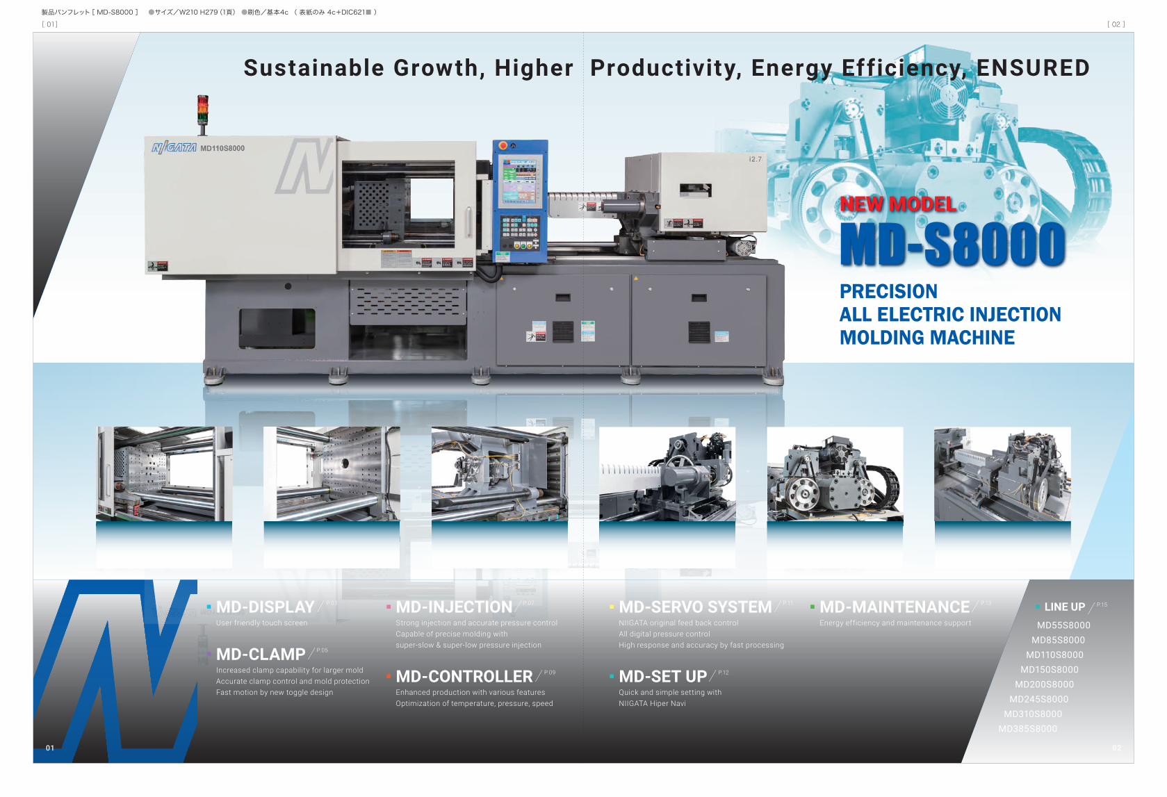
Sustainable Growth, Higher Productivity, Energy Efficiency, ENSURED
PRECISIONALL ELECTRIC INJECTIONMOLDING MACHINE
MD-SERVO SYSTEM NIIGATA original feed back controlAll digital pressure controlHigh response and accuracy by fast processing
P.11MD-INJECTIONStrong injection and accurate pressure controlCapable of precise molding withsuper-slow & super-low pressure injection
P.07
MD-CONTROLLEREnhanced production with various featuresOptimization of temperature, pressure, speed
P.09
MD-DISPLAYUser friendly touch screen
P.03
MD-CLAMPIncreased clamp capability for larger moldAccurate clamp control and mold protectionFast motion by new toggle design
P.05
LINE UPMD55S8000
MD85S8000MD110S8000
MD150S8000MD200S8000
MD245S8000MD310S8000
MD385S8000
P.15
MD-S8000
MD-SET UPQuick and simple setting withNIIGATA Hiper Navi
P.12
MD-MAINTENANCEEnergy efficiency and maintenance support
P.13
NEW MODEL
0201
[ 01] [ 02 ]
製品パンフレット[ MD-S8000 ] ●サイズ/W210 H279(1頁) ●刷色/基本4c ( 表紙のみ 4c+DIC621■ )
DISPLAYMD FUNCTIONAL & SMART
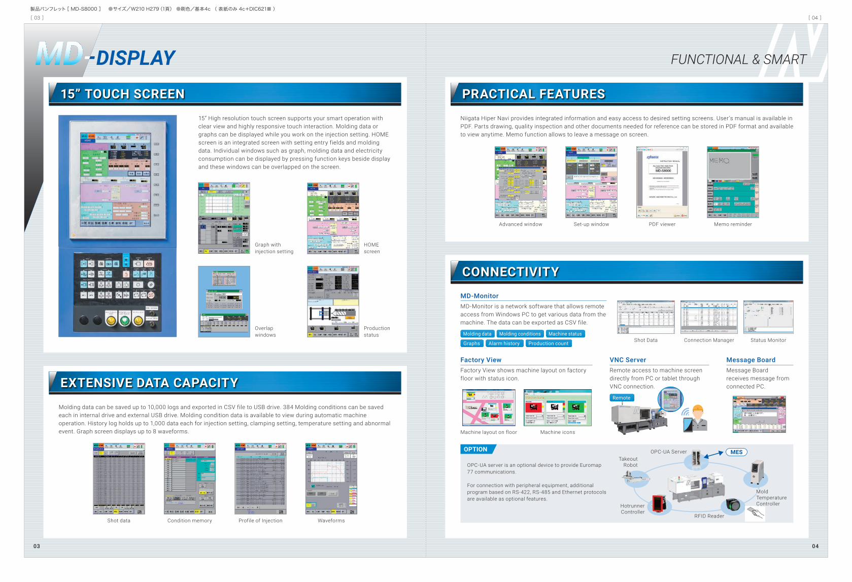
15” High resolution touch screen supports your smart operation with clear view and highly responsive touch interaction. Molding data or graphs can be displayed while you work on the injection setting. HOME screen is an integrated screen with setting entry fields and molding data. Individual windows such as graph, molding data and electricity consumption can be displayed by pressing function keys beside display and these windows can be overlapped on the screen.
Molding data can be saved up to 10,000 logs and exported in CSV file to USB drive. 384 Molding conditions can be saved each in internal drive and external USB drive. Molding condition data is available to view during automatic machine operation. History log holds up to 1,000 data each for injection setting, clamping setting, temperature setting and abnormal event. Graph screen displays up to 8 waveforms.
Graph withinjection setting
HOMEscreen
Overlapwindows
Shot data Condition memory Profile of Injection Waveforms
Productionstatus
Shot Data Connection Manager
Machine layout on floor Machine icons
TakeoutRobot
HotrunnerController
RFID Reader
Mold TemperatureController
OPC-UA Server
Status Monitor
MD-Monitor MD-Monitor is a network software that allows remote access from Windows PC to get various data from the machine. The data can be exported as CSV file.
Niigata Hiper Navi provides integrated information and easy access to desired setting screens. User’s manual is available in PDF. Parts drawing, quality inspection and other documents needed for reference can be stored in PDF format and available to view anytime. Memo function allows to leave a message on screen.
Advanced window Set-up window PDF viewer Memo reminder
15” TOUCH SCREEN PRACTICAL FEATURES
CONNECTIVITY
EXTENSIVE DATA CAPACITY
Molding data
OPTION
Remote
Graphs
Molding conditions
Alarm history Production count
Machine status
Factory View Factory View shows machine layout on factory floor with status icon.
Message Board Message Boardreceives message from connected PC.
VNC Server Remote access to machine screen directly from PC or tablet through VNC connection.
OPC-UA server is an optional device to provide Euromap 77 communications.
For connection with peripheral equipment, additional program based on RS-422, RS-485 and Ethernet protocols are available as optional features.
MES
0403
[ 03 ] [ 04 ]
製品パンフレット[ MD-S8000 ] ●サイズ/W210 H279(1頁) ●刷色/基本4c ( 表紙のみ 4c+DIC621■ )
CLAMP RIGID & SENSITIVE
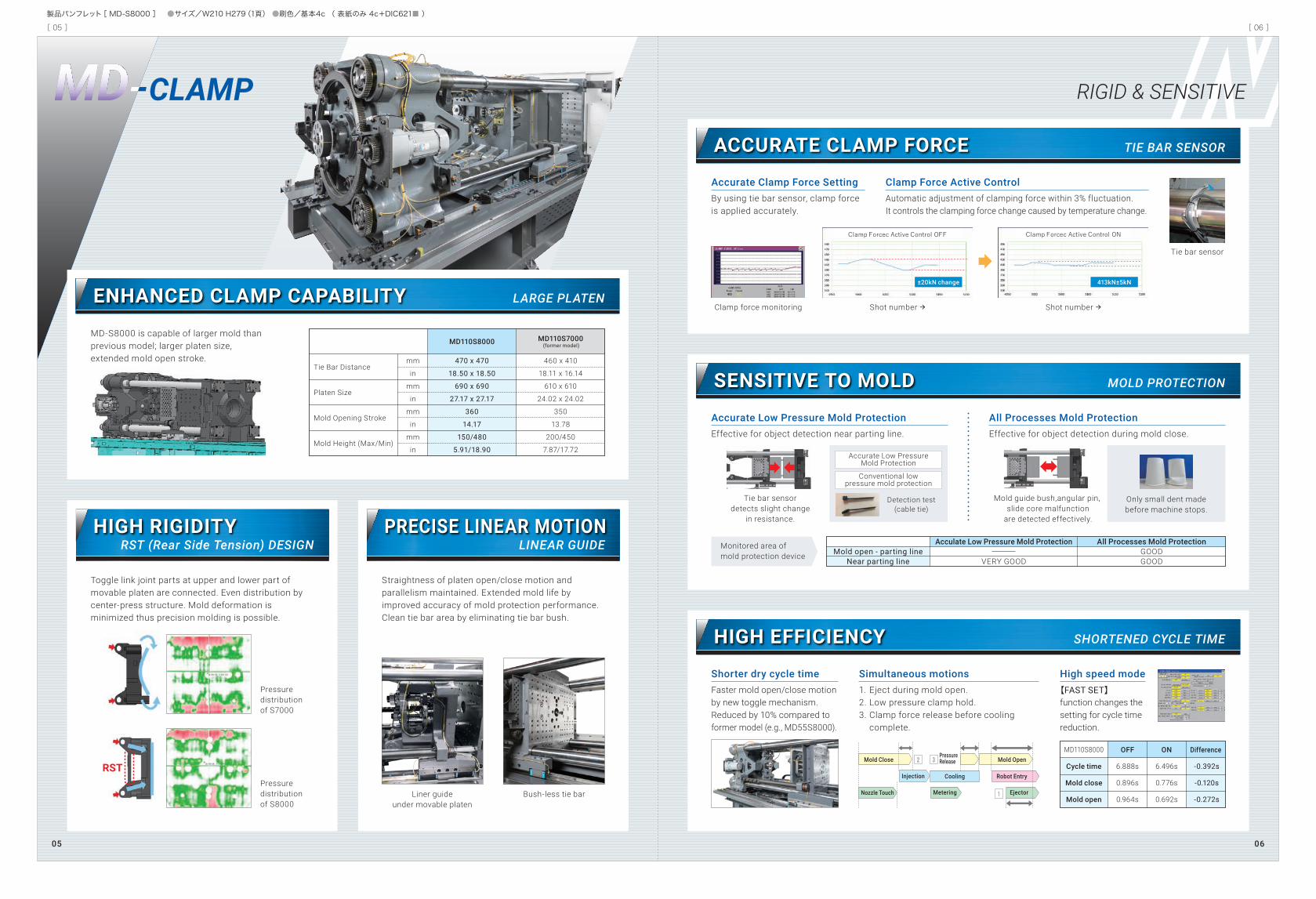
MD-S8000 is capable of larger mold than previous model; larger platen size, extended mold open stroke.
Toggle link joint parts at upper and lower part of movable platen are connected. Even distribution by center-press structure. Mold deformation is minimized thus precision molding is possible.
ENHANCED CLAMP CAPABILITY
ACCURATE CLAMP FORCE
SENSITIVE TO MOLD
HIGH EFFICIENCY
HIGH RIGIDITY
MD
RST (Rear Side Tension) DESIGN
Straightness of platen open/close motion and parallelism maintained. Extended mold life by improved accuracy of mold protection performance. Clean tie bar area by eliminating tie bar bush.
PRECISE LINEAR MOTIONLINEAR GUIDE
LARGE PLATEN
TIE BAR SENSOR
MOLD PROTECTION
SHORTENED CYCLE TIME
Tie Bar Distance
Platen Size
Mold Opening Stroke
Mold Height (Max/Min)
MD110S8000
mm
in
mm
in
mm
in
mm
in
470 x 470
18.50 x 18.50
690 x 690
27.17 x 27.17
360
14.17
150/480
5.91/18.90
MD110S7000 (former model)
460 x 410
18.11 x 16.14
610 x 610
24.02 x 24.02
350
13.78
200/450
7.87/17.72
Cycle time
Mold close
Mold open
MD110S8000
6.888s
0.896s
0.964s
6.496s
0.776s
0.692s
-0.392s
-0.120s
-0.272s
OFF ON Difference
Liner guideunder movable platen
Pressuredistributionof S8000
Pressuredistributionof S7000
Bush-less tie bar
Accurate Clamp Force Setting By using tie bar sensor, clamp force is applied accurately.
Accurate Low Pressure Mold Protection Effective for object detection near parting line.
High speed mode 【FAST SET】
function changes the setting for cycle time reduction.
Simultaneous motions 1. Eject during mold open.2. Low pressure clamp hold.3. Clamp force release before cooling
complete.
Shorter dry cycle time Faster mold open/close motion by new toggle mechanism. Reduced by 10% compared to former model (e.g., MD55S8000).
All Processes Mold Protection Effective for object detection during mold close.
Clamp Force Active Control Automatic adjustment of clamping force within 3% fluctuation. It controls the clamping force change caused by temperature change.
Tie bar sensor
Tie bar sensordetects slight change
in resistance.
Monitored area ofmold protection device Mold open - parting line
Near parting line
Acculate Low Pressure Mold Protection
VERY GOOD
All Processes Mold ProtectionGOODGOOD
Mold guide bush,angular pin, slide core malfunction
are detected effectively.
Shot number Shot number
Mold Close Mold Open
Robot Entry
EjectorNozzle Touch
Injection
Metering
PressureRelease
Cooling
Only small dent madebefore machine stops.
Detection test(cable tie)
Accurate Low PressureMold Protection
Conventional lowpressure mold protection
±20kN change 413kN±5kN
RST
Clamp force monitoring
0605
[ 05 ] [ 06 ]
製品パンフレット[ MD-S8000 ] ●サイズ/W210 H279(1頁) ●刷色/基本4c ( 表紙のみ 4c+DIC621■ )
General purpose NHP screw
High mixing NSS screw
Crystaline resin (PA)
Screw for connectors
Screw for optical products
Screw for fluorine resin
Screw for stable resin temperature
Purpose/resin
Material
Standard Option
Chr
ome
plat
ing
Wea
r res
ista
nt
Wea
r/co
rrosio
n res
istan
t
Supe
r wea
r/co
rrosio
n res
istan
t
Hig
hte
mpe
ratu
re
Spec
ial s
urfa
ce
trea
tmen
t
Supe
r cor
rosi
on
resi
stan
t
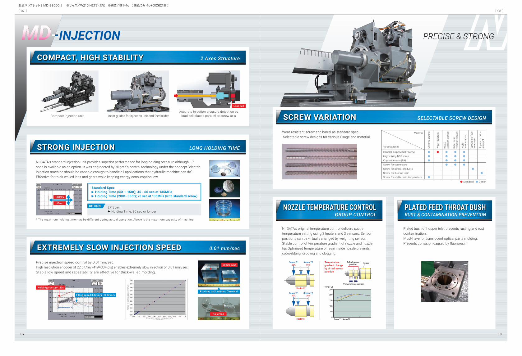
INJECTION PRECISE & STRONG
Compact injection unit
MDCOMPACT, HIGH STABILITY 2 Axes Structure
NIIGATA’s standard injection unit provides superior performance for long holding pressure although LP spec is available as an option. It was engineered by Niigata’s control technology under the concept “electric injection machine should be capable enough to handle all applications that hydraulic machine can do”. Effective for thick-walled lens and gears while keeping energy consumption low.
* The maximum holding time may be different during actual operation. Above is the maximum capacity of machine.
STRONG INJECTION LONG HOLDING TIME
Wear-resistant screw and barrel as standard spec. Selectable screw designs for various usage and material.
Accurate injection pressure detection by load cell placed parallel to screw axisLinear guides for injection unit and feed slides
Precise injection speed control by 0.01mm/sec.High resolution encoder of 22 bit/rev (4194304 pls) enables extremely slow injection of 0.01 mm/sec.Stable low speed and repeatability are effective for thick-walled molding.
SCREW VARIATION SELECTABLE SCREW DESIGN
EXTREMELY SLOW INJECTION SPEED 0.01 mm/sec
Load cell
Standard Spec Holding Time (55t – 150t); 45 - 60 sec at 135MPa Holding Time (200t- 385t); 70 sec at 135MPa (with standard screw)
50mm cube
No jetting
Provided by Sumitomo ChemicalHolding pressure 120s
135MPa
60secOPTION LP Spec
Holding Time; 80 sec or longer
Filling speed 0.3mm/s→3.0mm/s
NIIGATA’s original temperature control delivers subtle temperature setting using 2 heaters and 3 sensors. Sensor positions can be virtually changed by weighting sensor. Stable control of temperature gradient of nozzle and nozzle tip. Optimized temperature of resin inside nozzle prevents cobwebbing, drooling and clogging.
NOZZLE TEMPERATURE CONTROLGROUP CONTROL
Plated bush of hopper inlet prevents rusting and rust contamination. Must-have for translucent optical parts molding. Prevents corrosion caused by fluororesin.
PLATED FEED THROAT BUSHRUST & CONTAMINATION PREVENTION
Heater H1
Sensor T150%
Sensor T250%
Sensor T170%
Sensor T230%
Heater H1
Temperaturegradient changeby virtual sensorposition
HeaterActual sensorposition
Virtual sensor positionTemp (℃)
Sensor T2Sensor T1
250
200
150
100
50
0
0807
[ 07 ] [ 08 ]
製品パンフレット[ MD-S8000 ] ●サイズ/W210 H279(1頁) ●刷色/基本4c ( 表紙のみ 4c+DIC621■ )
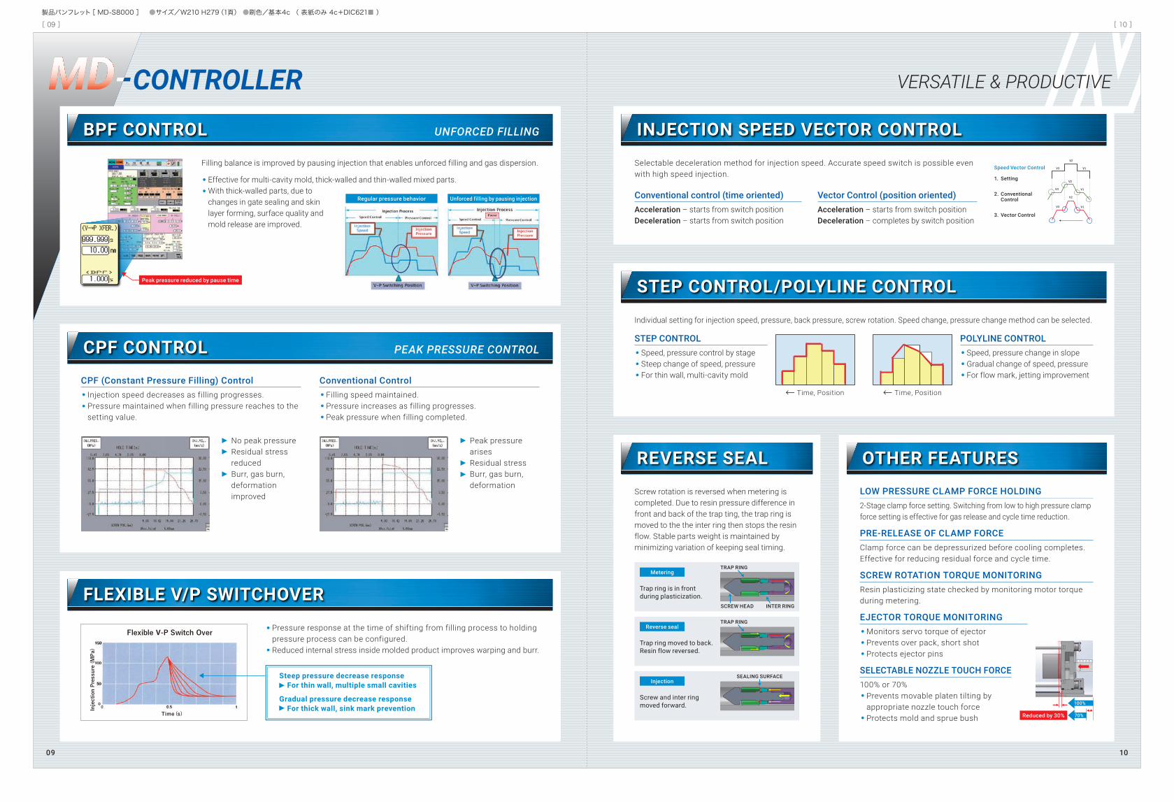
CONTROLLER VERSATILE & PRODUCTIVEMD
Filling balance is improved by pausing injection that enables unforced filling and gas dispersion.
Effective for multi-cavity mold, thick-walled and thin-walled mixed parts. With thick-walled parts, due to
changes in gate sealing and skin layer forming, surface quality and mold release are improved.
BPF CONTROL UNFORCED FILLING
Selectable deceleration method for injection speed. Accurate speed switch is possible even with high speed injection.
INJECTION SPEED VECTOR CONTROL
Individual setting for injection speed, pressure, back pressure, screw rotation. Speed change, pressure change method can be selected.
STEP CONTROL/POLYLINE CONTROL
Screw rotation is reversed when metering is completed. Due to resin pressure difference in front and back of the trap ting, the trap ring is moved to the the inter ring then stops the resin flow. Stable parts weight is maintained by minimizing variation of keeping seal timing.
REVERSE SEAL OTHER FEATURES
CPF CONTROL PEAK PRESSURE CONTROL
Pressure response at the time of shifting from filling process to holding pressure process can be configured.
Reduced internal stress inside molded product improves warping and burr.
FLEXIBLE V/P SWITCHOVER
CPF (Constant Pressure Filling) Control Injection speed decreases as filling progresses. Pressure maintained when filling pressure reaches to the
setting value.
Conventional Control Filling speed maintained. Pressure increases as filling progresses. Peak pressure when filling completed.
Steep pressure decrease response For thin wall, multiple small cavities Gradual pressure decrease response For thick wall, sink mark prevention
No peak pressure Residual stress
reduced Burr, gas burn,
deformation improved
Peak pressure arises
Residual stress Burr, gas burn,
deformation
Conventional control (time oriented) Acceleration – starts from switch position Deceleration – starts from switch position
STEP CONTROL Speed, pressure control by stage Steep change of speed, pressure For thin wall, multi-cavity mold
POLYLINE CONTROL Speed, pressure change in slope Gradual change of speed, pressure For flow mark, jetting improvement
LOW PRESSURE CLAMP FORCE HOLDING 2-Stage clamp force setting. Switching from low to high pressure clamp force setting is effective for gas release and cycle time reduction.
PRE-RELEASE OF CLAMP FORCE Clamp force can be depressurized before cooling completes. Effective for reducing residual force and cycle time.
SCREW ROTATION TORQUE MONITORING Resin plasticizing state checked by monitoring motor torque during metering.
Vector Control (position oriented) Acceleration – starts from switch position Deceleration – completes by switch position
EJECTOR TORQUE MONITORING Monitors servo torque of ejector Prevents over pack, short shot Protects ejector pins
SELECTABLE NOZZLE TOUCH FORCE 100% or 70% Prevents movable platen tilting by
appropriate nozzle touch force Protects mold and sprue bush Reduced by 30%
100%
70%
Time, Position Time, Position
Injection
TRAP RING
SCREW HEAD
SEALING SURFACE
INTER RING
Screw and inter ringmoved forward.
Reverse sealTRAP RING
Trap ring moved to back. Resin flow reversed.
Metering
Trap ring is in front during plasticization.
Speed Vector Control
1. Setting
2. Conventional Control
3. Vector Control
Peak pressure reduced by pause time
Regular pressure behavior Unforced filling by pausing injection
1009
[ 09 ] [ 10 ]
製品パンフレット[ MD-S8000 ] ●サイズ/W210 H279(1頁) ●刷色/基本4c ( 表紙のみ 4c+DIC621■ )
NIIGATALoad Cell
Input
Servo AmpNo.1
Servo MotorNo.2 Servo Motor
No.1
High Speed ControlSystem(PAT.)
Servo AmpNo.2
Direct SignalNo Controller
Load Cell
Input
Servo AmpNo.1
Servo Motor No.2 Servo MotorNo.1
Servo AmpNo.2
Controller(CPU, Input/Output unit)
NIIGATALoad Cell
Input
Servo AmpNo.1
Servo MotorNo.2 Servo Motor
No.1
High Speed ControlSystem(PAT.)
Servo AmpNo.2
Direct SignalNo Controller
Load Cell
Input
Servo AmpNo.1
Servo Motor No.2 Servo MotorNo.1
Servo AmpNo.2
Controller(CPU, Input/Output unit)
Output
DetectPressure
DetectPressure
Other Manufacturer
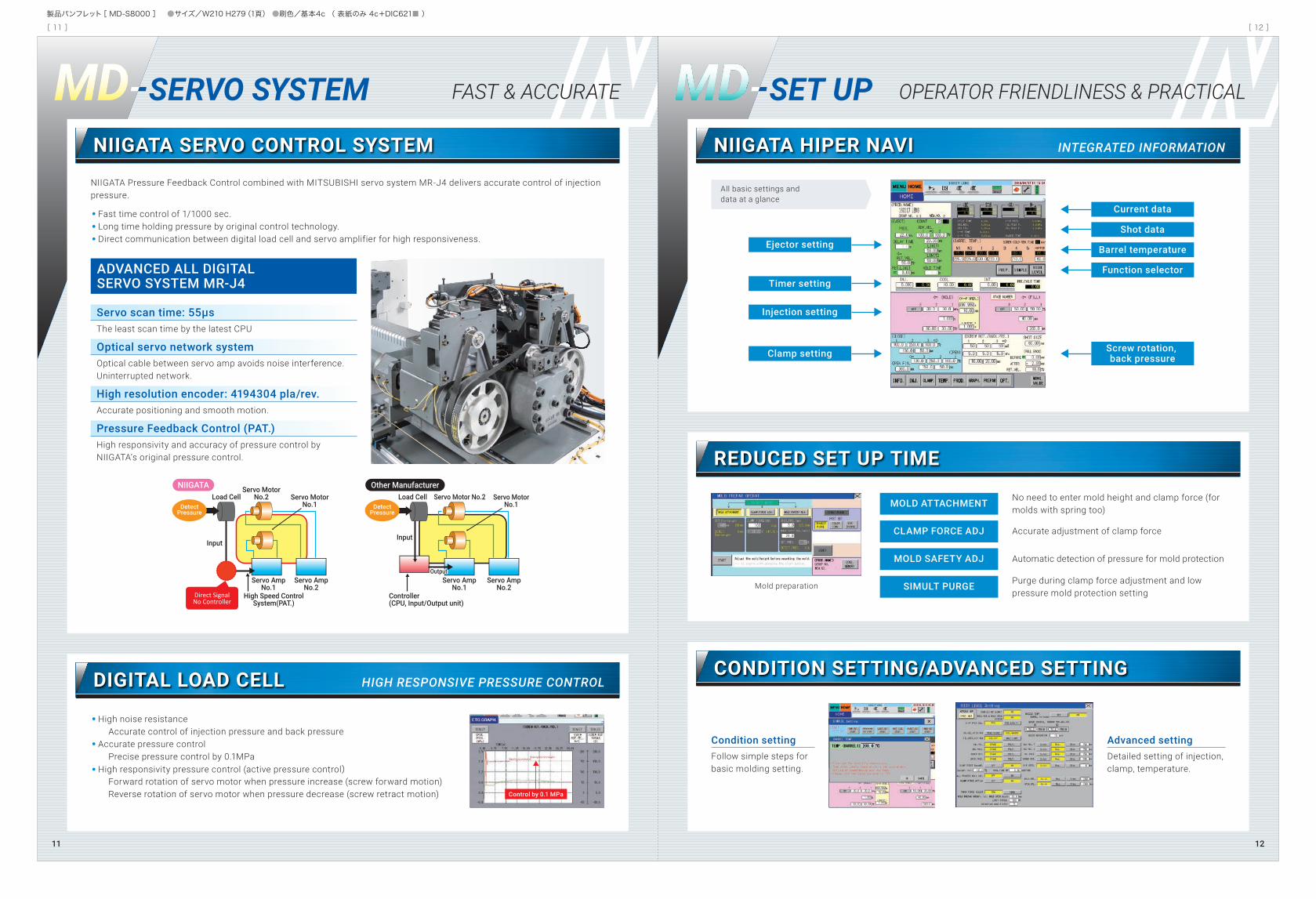
SERVO SYSTEM FAST & ACCURATE MD SET UPMD OPERATOR FRIENDLINESS & PRACTICAL
NIIGATA Pressure Feedback Control combined with MITSUBISHI servo system MR-J4 delivers accurate control of injection pressure.
Fast time control of 1/1000 sec. Long time holding pressure by original control technology. Direct communication between digital load cell and servo amplifier for high responsiveness.
High noise resistance Accurate control of injection pressure and back pressure Accurate pressure control Precise pressure control by 0.1MPa High responsivity pressure control (active pressure control) Forward rotation of servo motor when pressure increase (screw forward motion) Reverse rotation of servo motor when pressure decrease (screw retract motion)
NIIGATA SERVO CONTROL SYSTEM
DIGITAL LOAD CELL HIGH RESPONSIVE PRESSURE CONTROL
NIIGATA HIPER NAVI INTEGRATED INFORMATION
No need to enter mold height and clamp force (for molds with spring too)
REDUCED SET UP TIME
CONDITION SETTING/ADVANCED SETTING
Control by 0.1 MPa
Servo scan time: 55μs The least scan time by the latest CPU
Optical servo network system Optical cable between servo amp avoids noise interference. Uninterrupted network.
High resolution encoder: 4194304 pla/rev. Accurate positioning and smooth motion.
Pressure Feedback Control (PAT.) High responsivity and accuracy of pressure control by NIIGATA’s original pressure control.
ADVANCED ALL DIGITALSERVO SYSTEM MR-J4
All basic settings anddata at a glance
Ejector setting
Timer setting
Injection setting
Clamp setting
Current data
Barrel temperature
Shot data
Function selector
Screw rotation, back pressure
Mold preparation
Accurate adjustment of clamp force
Automatic detection of pressure for mold protection
Purge during clamp force adjustment and low pressure mold protection setting
Condition setting Follow simple steps for basic molding setting.
Advanced setting Detailed setting of injection, clamp, temperature.
MOLD ATTACHMENT
CLAMP FORCE ADJ
MOLD SAFETY ADJ
SIMULT PURGE
1211
[ 11 ] [ 12 ]
製品パンフレット[ MD-S8000 ] ●サイズ/W210 H279(1頁) ●刷色/基本4c ( 表紙のみ 4c+DIC621■ )
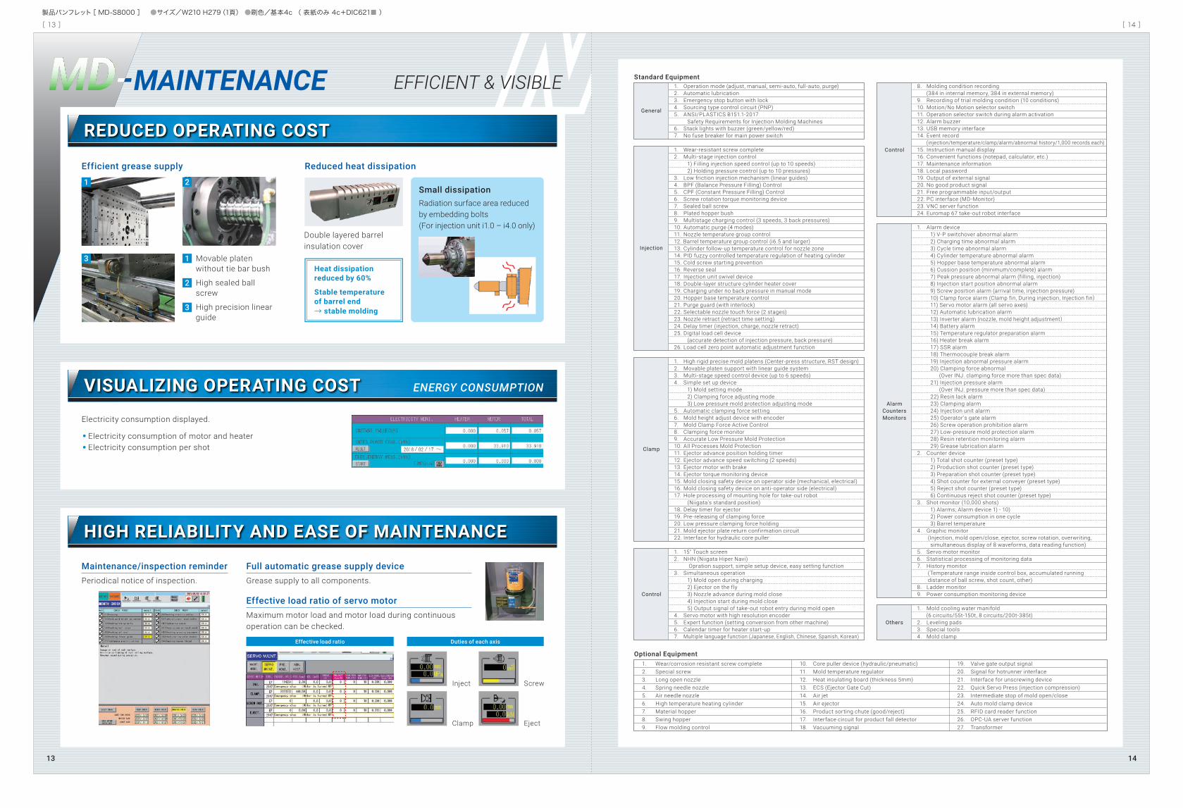
MAINTENANCEMD EFFICIENT & VISIBLE
REDUCED OPERATING COST
VISUALIZING OPERATING COST ENERGY CONSUMPTION
HIGH RELIABILITY AND EASE OF MAINTENANCE
Small dissipationRadiation surface area reduced by embedding bolts (For injection unit i1.0 – i4.0 only)
Movable platen without tie bar bush
High sealed ball screw
High precision linear guide
Efficient grease supply Reduced heat dissipation
Standard Equipment
Optional Equipment
Heat dissipationreduced by 60%
Stable temperatureof barrel end → stable molding
Electricity consumption displayed.
Electricity consumption of motor and heater Electricity consumption per shot
Maintenance/inspection reminder Periodical notice of inspection.
Full automatic grease supply device Grease supply to all components.
Effective load ratio of servo motor Maximum motor load and motor load during continuous operation can be checked.
Duties of each axisEffective load ratio
Clamp
Inject
Eject
Screw
General
Injection
Clamp
Control
Control
AlarmCountersMonitors
Others
1. Operation mode (adjust, manual, semi-auto, full-auto, purge)2. Automatic lubrication3. Emergency stop button with lock4. Sourcing type control circuit (PNP)5. ANSI/PLASTICS B151.1-2017 Safety Requirements for Injection Molding Machines6. Stack lights with buzzer (green/yellow/red)7. No fuse breaker for main power switch 1. Wear-resistant screw complete2. Multi-stage injection control 1) Filling injection speed control (up to 10 speeds) 2) Holding pressure control (up to 10 pressures)3. Low friction injection mechanism (linear guides)4. BPF (Balance Pressure Filling) Control5. CPF (Constant Pressure Filling) Control6. Screw rotation torque monitoring device7. Sealed ball screw8. Plated hopper bush9. Multistage charging control (3 speeds, 3 back pressures)10. Automatic purge (4 modes)11. Nozzle temperature group control12. Barrel temperature group control (i6.5 and larger)13. Cylinder follow-up temperature control for nozzle zone14. PID fuzzy controlled temperature regulation of heating cylinder15. Cold screw starting prevention16. Reverse seal17. Injection unit swivel device18. Double-layer structure cylinder heater cover19. Charging under no back pressure in manual mode20. Hopper base temperature control21. Purge guard (with interlock)22. Selectable nozzle touch force (2 stages)23. Nozzle retract (retract time setting)24. Delay timer (injection, charge, nozzle retract)25. Digital load cell device (accurate detection of injection pressure, back pressure)26. Load cell zero point automatic adjustment function 1. High rigid precise mold platens (Center-press structure, RST design)2. Movable platen support with linear guide system3. Multi-stage speed control device (up to 6 speeds)4. Simple set up device 1) Mold setting mode 2) Clamping force adjusting mode 3) Low pressure mold protection adjusting mode5. Automatic clamping force setting6. Mold height adjust device with encoder7. Mold Clamp Force Active Control8. Clamping force monitor9. Accurate Low Pressure Mold Protection10. All Processes Mold Protection11. Ejector advance position holding timer12. Ejector advance speed switching (2 speeds)13. Ejector motor with brake14. Ejector torque monitoring device15. Mold closing safety device on operator side (mechanical, electrical)16. Mold closing safety device on anti-operator side (electrical)17. Hole processing of mounting hole for take-out robot (Niigata's standard position)18. Delay timer for ejector19. Pre-releasing of clamping force20. Low pressure clamping force holding21. Mold ejector plate return confirmation circuit22. Interface for hydraulic core puller 1. 15" Touch screen2. NHN (Niigata Hiper Navi) Opration support, simple setup device, easy setting function3. Simultaneous operation 1) Mold open during charging 2) Ejector on the fly 3) Nozzle advance during mold close 4) Injection start during mold close 5) Output signal of take-out robot entry during mold open4. Servo motor with high resolution encoder5. Expert function (setting conversion from other machine)6. Calendar timer for heater start-up7. Multiple language function (Japanese, English, Chinese, Spanish, Korean)
8. Molding condition recording (384 in internal memory, 384 in external memory)9. Recording of trial molding condition (10 conditions)10. Motion/No Motion selector switch11. Operation selector switch during alarm activation12. Alarm buzzer13. USB memory interface14. Event record (injection/temperature/clamp/alarm/abnormal history/1,000 records each)15. Instruction manual display16. Convenient functions (notepad, calculator, etc.)17. Maintenance information18. Local password19. Output of external signal20. No good product signal 21. Free programmable input/output22. PC interface (MD-Monitor)23. VNC server function24. Euromap 67 take-out robot interface 1. Alarm device 1) V-P switchover abnormal alarm 2) Charging time abnormal alarm 3) Cycle time abnormal alarm 4) Cylinder temperature abnormal alarm 5) Hopper base temperature abnormal alarm 6) Cussion position (minimum/complete) alarm 7) Peak pressure abnormal alarm (filling, injection) 8) Injection start position abnormal alarm 9) Screw position alarm (arrival time, injection pressure) 10) Clamp force alarm (Clamp fin, During injection, Injection fin) 11) Servo motor alarm (all servo axes) 12) Automatic lubrication alarm 13) Inverter alarm (nozzle, mold height adjustment) 14) Battery alarm 15) Temperature regulator preparation alarm 16) Heater break alarm 17) SSR alarm 18) Thermocouple break alarm 19) Injection abnormal pressure alarm 20) Clamping force abnormal (Over INJ. clamping force more than spec data) 21) Injection pressure alarm (Over INJ. pressure more than spec data) 22) Resin lack alarm 23) Clamping alarm 24) Injection unit alarm 25) Operator's gate alarm 26) Screw operation prohibition alarm 27) Low-pressure mold protection alarm 28) Resin retention monitoring alarm 29) Grease lubrication alarm2. Counter device 1) Total shot counter (preset type) 2) Production shot counter (preset type) 3) Preparation shot counter (preset type) 4) Shot counter for external conveyer (preset type) 5) Reject shot counter (preset type) 6) Continuous reject shot counter (preset type)3. Shot monitor (10,000 shots) 1) Alarms; Alarm device 1) - 10) 2) Power consumption in one cycle 3) Barrel temperature4. Graphic monitor (Injection, mold open/close, ejector, screw rotation, overwriting, simultaneous display of 8 waveforms, data reading function)5. Servo motor monitor6. Statistical processing of monitoring data7. History monitor (Temperature range inside control box, accumulated running distance of ball screw, shot count, other)8. Ladder monitor9. Power consumption monitoring device 1. Mold cooling water manifold (6 circuits/55t-150t, 8 circuits/200t-385t)2. Leveling pads3. Special tools4. Mold clamp
1. Wear/corrosion resistant screw complete2. Special screw3. Long open nozzle4. Spring needle nozzle5. Air needle nozzle6. High temperature heating cylinder7. Material hopper8. Swing hopper9. Flow molding control
10. Core puller device (hydraulic/pneumatic)11. Mold temperature regulator12. Heat insulating board (thickness 5mm)13. ECS (Ejector Gate Cut)14. Air jet15. Air ejector16. Product sorting chute (good/reject)17. Interface circuit for product fall detector18. Vacuuming signal
19. Valve gate output signal 20. Signal for hotrunner interface 21. Interface for unscrewing device22. Quick Servo Press (injection compression)23. Intermediate stop of mold open/close24. Auto mold clamp device25. RFID card reader function26. OPC-UA server function27. Transformer
Double layered barrelinsulation cover
1
1 2
3
2
3
1413
[ 13 ] [ 14 ]
製品パンフレット[ MD-S8000 ] ●サイズ/W210 H279(1頁) ●刷色/基本4c ( 表紙のみ 4c+DIC621■ )
T・m-mminmmincm3cu-ingozMPapsiMPapsimm/sin/scm3/scu-in/smm/sin/scm3/scu-in/smin-1kg/hoz/smminkN
US ton--kW-kN
US tonmminmminmminmminmminmminmminkN
US tonkVA-AminminmintonUS-tonLgalL/mingal/minT
Injection Capacity *1
Screw Complete
Screw Stroke
Calculated Injection Volume *2
Injection Weight (PS) *3
Max. Injection Pressure *4
Max. Holding Pressure *4
StandardSpecification
LPSpecification
Screw Rotating Speed
Plasticizing Capacity (PS) *6
Nozzle Stroke
Nozzle Touch Force
Temp. Zones
Heater CapacityClamping System
Clamping Force
Distance Between Tie Bars ( H x V )
Platen Size ( H x V )
Min. Mold Size ( H x V ) *7
Mold Opening Stroke
Mold Height ( Min./Max.)
Open Daylight
Ejector Stroke
Ejector Force *8
Total Machine Power *9Power Source (Voltage × Frequency) *10Rated Current
MachineDimensions
Machine Weight
Hopper Capacity (OP.)
Cooling Water Consumption *12
Screw Type
Screw Diameter
Max. Injection Speed *5
Injection Rate
Max. Injection Speed *5
Injection Rate
Nozzle/Heating CylinderHopper Base
Length
Width
Height *11
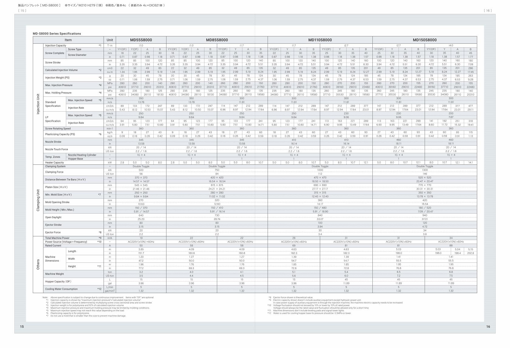
Note: Above specification is subject to change due to continuous improvement. Items with “OP.” are optional. *1 Injection capacity is shown by “maximum injection pressure”×”calculated injection volume”. *2 Calculated injection volume is determined by multiplying screw cross sectional area and screw stroke. *3 Injection weight is for polystyrene and 92% of calculated injection volume. *4 Maximum injection pressure and maximum holding pressure may be limited by molding conditions. *5 Maximum injection speed may not reach this value depending on the load. *6 Plasticizing capacity is for polystyrene. *7 Do not use a mold that is smaller than this size to prevent machine damage.
*8 Ejector force shown is theoretical value. *9 Electric capacity shown doesn't include auxiliary equipment except hydraulic power unit. In case power supply of auxiliary equipment is through the injection machine, the machine electric capacity needs to be increased. *10 Voltage fluctuation should not exceed by 10% or lower by 10% of rated power. Voltage should always be the rated value and fluctuation should be allowed only for a short time. *11 Machine dimensions don't include leveling pads and signal tower lights. *12 Water is used for cooling hopper base its pressure should be 0.5MPa or lower.
i1.0
35013.78
2509.84
360
34513.5820 / 142.2 / 1.61G + 41
Double Toggle50056
370 × 37014.57 × 14.57545 × 54521.46 × 21.46250 × 2509.84 × 9.84
27010.63
150 / 370 5.91 / 14.57
64025.20803.15202.219
AC220V(±10%)×60Hz503.85151.71.2047.21.9677.23.23.5153.9651.32
MD55S8000 MD85S8000 MD110S8000 MD150S8000UnitItemIn
ject
ion
Uni
tC
lam
ping
Uni
tO
ther
s
YY(OP.)180.71853.35221.34200.712804061028040610
895.43
643.91
90.09
2.8
Y(OP.)220.87853.35321.95301.062603771023534080
1338.12
955.80
180.18
5.0
A250.981003.94492.99451.592002901018026110
17210.50
1237.51
270.26
5.0
B301.181204.72855.19782.751402031012518130
24715.07
17710.80
430.42
8.0
i1.0
35013.78
2509.84
360
34513.5820 / 142.2 / 1.61G + 41
22AC220V(±10%)×60Hz
584.09160.81.2750.01.7669.34.04.4153.9651.32
YY(OP.)180.71853.35221.34200.712804061028040610
895.43
643.91
90.09
2.8
Y(OP.)220.87853.35321.95301.062603771023534080
1338.12
955.80
180.18
5.0
A250.981003.94492.99451.592002901018026110
17210.50
1237.51
270.26
5.0
B301.181204.72855.19782.751402031012518130
24715.07
17710.80
430.42
8.0
i1.7
30011.81
2509.84
360
34513.5820 / 142.2 / 1.61G + 41
22AC220V(±10%)×60Hz
584.09160.81.2750.01.7669.34.14.5153.9651.32
Double Toggle75084
420 × 42016.54 × 16.54615 × 61524.21 × 24.21280 × 28011.02 × 11.02
32012.60
150 / 410 5.91 / 16.14
73028.74803.15202.2
Double Toggle1000112
470 × 47018.50 × 18.50690 × 69027.17 × 27.17315 × 31512.40 × 12.40
36014.17
150 / 480 5.91 / 18.90
84033.071003.94303.4
Double Toggle1300146
520 × 52020.47 × 20.47770 × 77030.31 × 30.31350 × 35013.78 × 13.78
42016.54
180 / 520 7.09 / 20.47
94037.011204.72343.8
YY(OP.)220.87853.35321.95301.062603771023534080
1146.96
955.80
180.18
5.0
Y250.981003.94492.99451.592804061026037710
1478.97
1237.51
270.26
5.0
A301.181204.72855.19782.752002901018026110
21212.94
17710.80
430.42
8.0
B351.381405.511358.241244.371502176013519580
28917.64
24114.71
600.59
10.7
i1.7
30011.81
2509.84
360
41016.1420 / 142.2 / 1.61G + 41
26AC220V(±10%)×60Hz
694.63182.31.3954.71.8572.85.15.6153.9651.32
YY(OP.)220.87853.35321.95301.062603771023534080
1146.96
955.80
180.18
5.0
Y250.981003.94492.99451.592804061026037710
1478.97
1237.51
270.26
5.0
A301.181204.72855.19782.752002901018026110
21212.94
17710.80
430.42
8.0
B351.381405.511358.241244.371502176013519580
28917.64
24114.71
600.59
10.7
i2.7
30011.81
2309.06
360
41016.1420 / 142.2 / 1.61G + 41
31AC220V(±10%)×60Hz
814.63182.31.3954.71.8572.85.46.04511.8951.32
YY(OP.)250.981003.94492.99451.592804061026037710
1478.97
1136.90
270.26
5.0
Y301.181204.72855.19782.752703916024535530
21212.94
1639.95
430.42
8.0
A351.381405.511358.241244.372002901018026110
28917.64
22113.49
600.59
10.7
B401.571606.3020112.271856.531552248013519580
37723.01
28917.64
930.91
12.1
i2.7
30011.81
2309.06
360
46018.1120 / 142.2 / 1.61G + 41
31AC220V(±10%)×60Hz
815.03198.01.4155.51.9576.86.57.24511.8951.32
YY(OP.)250.981003.94492.99451.592804061026037710
1478.97
1136.90
270.26
5.0
Y301.181204.72855.19782.752703916024535530
21212.94
1639.95
430.42
8.0
A351.381405.511358.241244.372002901018026110
28917.64
22113.49
600.59
10.7
B401.571606.3020112.271856.531552248013519580
37723.01
28917.64
930.91
12.1
i4.0
30011.81
2007.87
360
46018.1120 / 142.2 / 1.61G + 41
34AC220V(±10%)×60Hz
88
1.4155.51.9576.86.87.54511.8951.32
YY(OP.)301.181204.72855.19782.752703916024535530
21212.94
1418.60
430.42
8.0
5.03198.0
Y351.381405.511358.241244.372603771023534080
28917.64
19211.72
600.59
10.7
A401.571606.3020112.271856.532002901018026110
37723.01
25115.32
930.91
12.1
5.04198.4
B451.771807.0928617.452639.281552248014020310
47729.11
31819.41
1151.13
14.1
5.15202.8
MD-S8000 Series Specifications
1615
[ 15 ] [ 16 ]
製品パンフレット[ MD-S8000 ] ●サイズ/W210 H279(1頁) ●刷色/基本4c ( 表紙のみ 4c+DIC621■ )
T・m-mminmmincm3cu-ingozMPapsiMPapsimm/sin/scm3/scu-in/smm/sin/scm3/scu-in/smin-1kg/hoz/smminkN
US ton--kW-kN
US tonmminmminmminmminmminmminmminkN
US tonkVA-AminminmintonUS-tonLgalL/mingal/min
Injection Capacity *1
Screw Complete
Screw Stroke
Calculated Injection Volume *2
Injection Weight (PS) *3
Max. Injection Pressure *4
Max. Holding Pressure *4
StandardSpecification
LPSpecification
Screw Rotating Speed
Plasticizing Capacity (PS) *6
Nozzle Stroke
Nozzle Touch Force
Temp. Zones
Heater CapacityClamping System
Clamping Force
Distance Between Tie Bars ( H x V )
Platen Size ( H x V )
Min. Mold Size ( H x V ) *7
Mold Opening Stroke
Mold Height ( Min./Max.)
Open Daylight
Ejector Stroke
Ejector Force *8
Total Machine Power *9Power Source (Voltage × Frequency) *10Rated Current
MachineDimensions
Machine Weight
Hopper Capacity (OP.)
Cooling Water Consumption *12
Screw Type
Screw Diameter
Max. Injection Speed *5
Injection Rate
Max. Injection Speed *5
Injection Rate
Nozzle/Heating CylinderHopper Base
Length
Width
Height *11
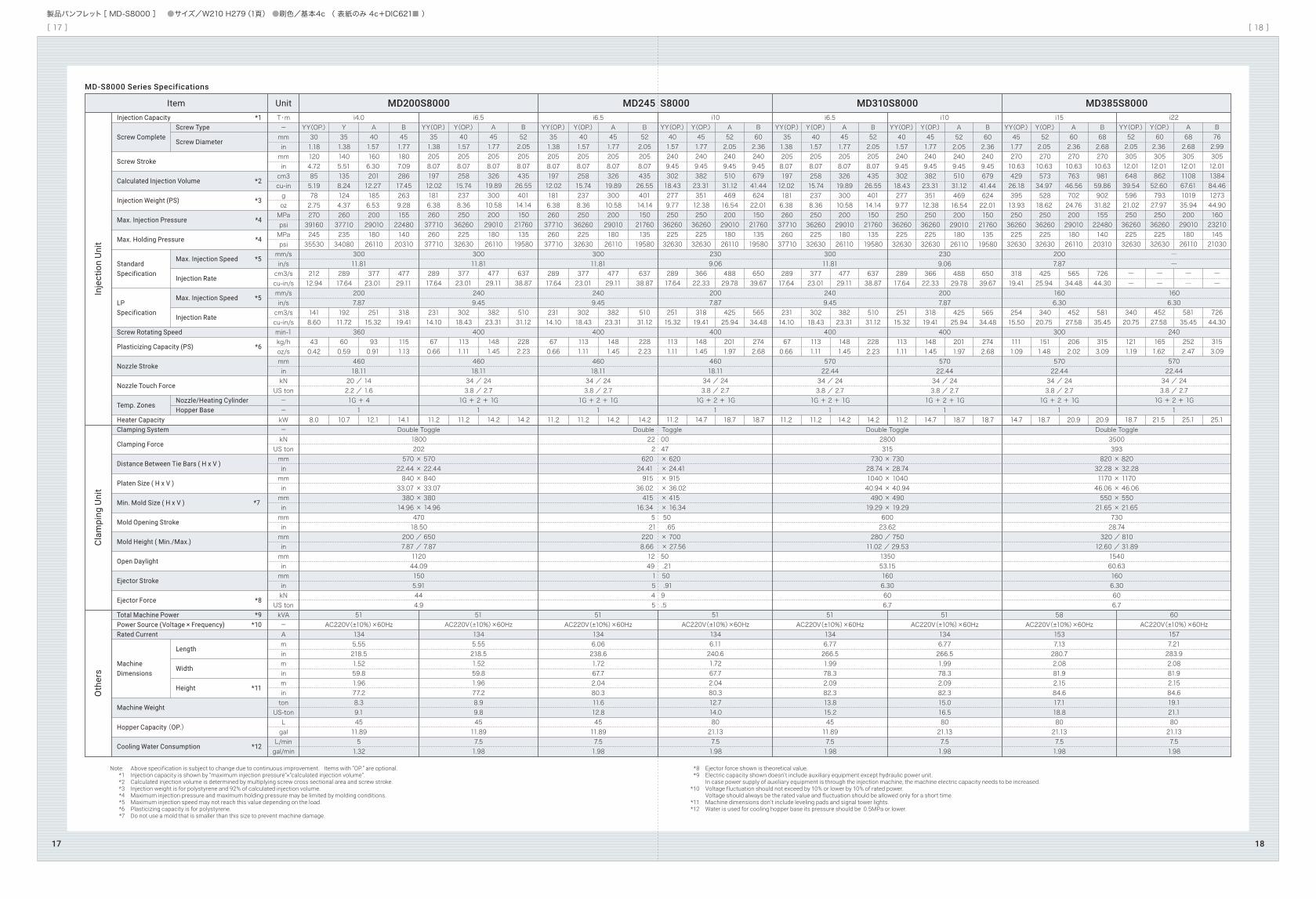
Note: Above specification is subject to change due to continuous improvement. Items with “OP.” are optional. *1 Injection capacity is shown by “maximum injection pressure”×”calculated injection volume”. *2 Calculated injection volume is determined by multiplying screw cross sectional area and screw stroke. *3 Injection weight is for polystyrene and 92% of calculated injection volume. *4 Maximum injection pressure and maximum holding pressure may be limited by molding conditions. *5 Maximum injection speed may not reach this value depending on the load. *6 Plasticizing capacity is for polystyrene. *7 Do not use a mold that is smaller than this size to prevent machine damage.
*8 Ejector force shown is theoretical value. *9 Electric capacity shown doesn't include auxiliary equipment except hydraulic power unit. In case power supply of auxiliary equipment is through the injection machine, the machine electric capacity needs to be increased. *10 Voltage fluctuation should not exceed by 10% or lower by 10% of rated power. Voltage should always be the rated value and fluctuation should be allowed only for a short time. *11 Machine dimensions don't include leveling pads and signal tower lights. *12 Water is used for cooling hopper base its pressure should be 0.5MPa or lower.
MD385S8000UnitItemIn
ject
ion
Uni
tC
lam
ping
Uni
tO
ther
s
Double Toggle3500393
820 × 82032.28 × 32.281170 × 117046.06 × 46.06550 × 55021.65 × 21.65
73028.74
320 / 81012.60 / 31.89
154060.631606.30606.7
i15
2007.87
1606.30
300
57022.4434 / 243.8 / 2.71G + 2 + 1G
1
58AC220V(±10%)×60Hz
1537.13280.72.0881.92.1584.617.118.88021.137.51.98
YY(OP.)451.7727010.6342926.1839513.932503626022532630
31819.41
25415.50
1111.09
14.7
Y(OP.)522.05 27010.63 57334.97 52818.62 2503626022532630
42525.94
34020.75
1511.48
18.7
A602.3627010.6376346.5670224.762002901018026110
56534.48
45227.58
2062.02
20.9
B682.6827010.6398159.8690231.821552248014020310
72644.30
58135.45
3153.09
20.9
i22
――
1606.30
240
57022.4434 / 243.8 / 2.71G + 2 + 1G
1
60AC220V(±10%)×60Hz
1577.21283.92.0881.92.1584.619.121.18021.137.51.98
YY(OP.)522.0530512.0164839.5459621.022503626022532630
――
34020.75
1211.19
18.7
Y(OP.)602.36 30512.01 86252.60 79327.97 2503626022532630
――
45227.58
1651.62
21.5
A682.6830512.01110867.61101935.942002901018026110
――
58135.45
2522.47
25.1
B762.9930512.01138484.46127344.901602321014521030
――
72644.30
3153.09
25.1
MD310S8000
Double Toggle2800315
730 × 73028.74 × 28.741040 × 104040.94 × 40.94490 × 49019.29 × 19.29
60023.62
280 / 75011.02 / 29.53
135053.151606.30606.7
i6.5
30011.81
2409.45
400
57022.4434 / 243.8 / 2.71G + 2 + 1G
1
51AC220V(±10%)×60Hz
1346.77266.51.9978.32.0982.313.815.24511.897.51.98
YY(OP.)351.38 2058.07 19712.02 1816.38 2603771026037710
28917.64
23114.10
670.66
11.2
Y(OP.)401.572058.0725815.742378.362503626022532630
37723.01
30218.43
1131.11
11.2
A451.772058.0732619.8930010.582002901018026110
47729.11
38223.31
1481.45
14.2
B522.052058.0743526.5540114.141502176013519580
63738.87
51031.12
2282.23
14.2
A522.052409.4551031.1246916.542002901018026110
48829.78
42525.94
2011.97
18.7
B602.362409.4567941.4462422.011502176013519580
65039.67
56534.48
2742.68
18.7
i10
2309.06
2007.87
400
57022.4434 / 243.8 / 2.71G + 2 + 1G
1
51AC220V(±10%)×60Hz
1346.77266.51.9978.32.0982.315.016.58021.137.51.98
YY(OP.)401.572409.4530218.432779.772503626022532630
28917.64
25115.32
1131.11
11.2
Y(OP.)451.772409.4538223.3135112.382503626022532630
36622.33
31819.41
1481.45
14.7
MD245 S8000
Double Toggle 22 00 2 47
620 × 620 24.41 × 24.41 915 × 915
36.02 × 36.02 415 × 415
16.34 × 16.34 5 50 21 .65 220 × 700 8.66 × 27.56
12 50 49 .21 1 50 5 .914 9 5 .5
i6.5
30011.81
2409.45
400
46018.1134 / 243.8 / 2.71G + 2 + 1G
1
51AC220V(±10%)×60Hz
1346.06238.61.7267.72.0480.311.612.84511.897.51.98
YY(OP.)351.382058.0719712.021816.382603771026037710
28917.64
23114.10
670.66
11.2
Y(OP.)401.572058.0725815.742378.362503626022532630
37723.01
30218.43
1131.11
11.2
A451.772058.0732619.8930010.582002901018026110
47729.11
38223.31
1481.45
14.2
B522.052058.0743526.5540114.141502176013519580
63738.87
51031.12
2282.23
14.2
i10
2309.06
2007.87
400
46018.1134 / 243.8 / 2.71G + 2 + 1G
1
51AC220V(±10%)×60Hz
1346.11240.61.7267.72.0480.312.714.08021.137.51.98
YY(OP.)401.572409.4530218.432779.772503626022532630
28917.64
25115.32
1131.11
11.2
Y(OP.)451.772409.4538223.3135112.382503626022532630
36622.33
31819.41
1481.45
14.7
MD200S8000
Double Toggle1800202
570 × 57022.44 × 22.44840 × 84033.07 × 33.07380 × 38014.96 × 14.96
47018.50
200 / 6507.87 / 7.87112044.091505.91444.9
i4.0
30011.81
2007.87
360
46018.1120 / 142.2 / 1.61G + 41
51AC220V(±10%)×60Hz
1345.55218.51.5259.81.9677.28.39.14511.8951.32
YY(OP.)301.181204.72855.19782.752703916024535530
21212.94
1418.60
430.42
8.0
Y351.381405.511358.241244.372603771023534080
28917.64
19211.72
600.59
10.7
A401.57 1606.30 20112.27 1856.53 2002901018026110
37723.01
25115.32
930.91
12.1
B451.771807.0928617.452639.281552248014020310
47729.11
31819.41
1151.13
14.1
i6.5
30011.81
2409.45
400
46018.1134 / 243.8 / 2.71G + 2 + 1G
1
51AC220V(±10%)×60Hz
1345.55218.51.5259.81.9677.28.99.84511.897.51.98
YY(OP.)351.382058.0719712.021816.382603771026037710
28917.64
23114.10
670.66
11.2
Y(OP.)401.572058.0725815.742378.362503626022532630
37723.01
30218.43
1131.11
11.2
A522.052409.4551031.1246916.542002901018026110
48829.78
42525.94
2011.97
18.7
B602.362409.4567941.4462422.011502176013519580
65039.67
56534.48
2742.68
18.7
A451.772058.0732619.8930010.582002901018026110
47729.11
38223.31
1481.45
14.2
B522.052058.0743526.5540114.141502176013519580
63738.87
51031.12
2282.23
14.2
MD-S8000 Series Specifications
1817
[ 17 ] [ 18 ]
製品パンフレット[ MD-S8000 ] ●サイズ/W210 H279(1頁) ●刷色/基本4c ( 表紙のみ 4c+DIC621■ )


