Embed Size (px)
Citation preview
Marine ProductsMarine Products
*Specifications may change without notice. DN1907OM008
Niigata MarineSelection Guide
https://www.ihi.co.jp/ips
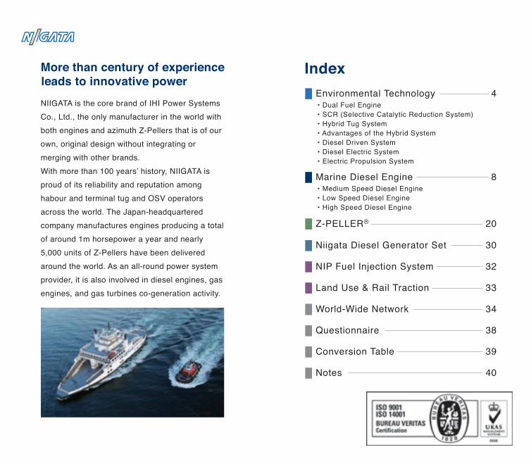
NIIGATA is the core brand of IHI Power Systems Co., Ltd., the only manufacturer in the world with both engines and azimuth Z-Pellers that is of our own, original design without integrating or merging with other brands. With more than 100 years’ history, NIIGATA is proud of its reliability and reputation among habour and terminal tug and OSV operators across the world. The Japan-headquartered company manufactures engines producing a total of around 1m horsepower a year and nearly 5,000 units of Z-Pellers have been delivered around the world. As an all-round power system provider, it is also involved in diesel engines, gas engines, and gas turbines co-generation activity.
More than century of experienceleads to innovative power
• Medium Speed Diesel Engine• Low Speed Diesel Engine• High Speed Diesel Engine
Marine Diesel Engine
• Dual Fuel Engine• SCR (Selective Catalytic Reduction System)• Hybrid Tug System• Advantages of the Hybrid System• Diesel Driven System• Diesel Electric System• Electric Propulsion System
Environmental Technology 4
8
20
30
32
33
34
Z-PELLER®
Niigata Diesel Generator Set
NIP Fuel Injection System
Land Use & Rail Traction
World-Wide Network
Index
38Questionnaire
39Conversion Table
40Notes
6L28AHX-DF8L28AHX-DF9L28AHX-DF
6L28AHX-DF8L28AHX-DF9L28AHX-DF
6MG25HX6MG28HX
6MG28AHX8MG28AHX9MG28AHX
222831
280280280
800800800
261034803915
192025602880
504959206370
509959706420
195519562051
120012001200
224023702370
445445445
331534453445
204020402040
Dimension (mm)
L1 L2 W1 W2 H1 H2 H3 H4Model
Max.Continuous Rating Engine Speed Cyl. Bore Piston Stroke Approx.Dry Mass
kWm PS min-1 mmmm tModel
390390390
35003550380039003900
967 967 96714381438
9671909143814381438
13231838222029603330
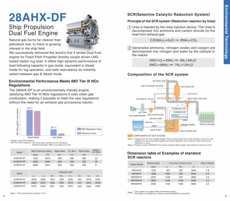
Dimensions of Reactor (mm) Mass of ReactorEngine Output
t kWmEngine Model
L W H1.82.62.53.23.2
Tier Ⅱ
Tier Ⅲ
IMO
NO
x [g
/kW ・
h eq
uiva
lent
]
Diesel Mode Gas Mode
Measured Value
IMO Regulation Value
Environmental Performance Meets IMO Tier III NOxRegulationsThe 28AHX-DF is an environmentally friendly engine, satisfying IMO Tier III NOx regulations.It uses clean gas combustion, making it possible to meet the new regulations without the need for an exhaust gas processing reactor.
Principle of the SCR system (Reduction reaction by Urea)
1 Urea is injected by the Urea injection device. The Urea is decomposed into ammonia and carbon dioxide by the heat from exhaust gas.
CO(NH2)2 + H2O 2NH3 + CO2
4NO + O2 + 4NH3 4N2 + 6H2O6NO2 + 8NH3 7N2 + 12H2O
SCR REACTOR SOOT BLOWING SYSTEM
AUTOMATIC VALVE
COMPRESSED AIR
WATER PUMP
BY-PASS LINE
ATOMIZING AIR
PURGING AIRNOZZLECLEANING WATER
UREA INJECTION UNIT
STOP VALVE
STOP VALVE
UREA DOSING UNIT
WATERUREA
ENGINE SIGNAL NIIGATA ENGINE
UREA TANK
UREA
UREA PUMP
AIR COMPRESSOR
AIR TANKMIST SEPARATOR
*Nitrogen oxide (NOx) emissions*IMO Tier III NOx regulations : New exhaust gas regulations by the International
Maritime Organization (IMO), to be applied from 2016.
2 Generated ammonia, nitrogen oxides and oxygen are decomposed into nitrogen and water by the catalyst in the reactor.
COMPONENTS OF SCR SYSTEM Please plan for the straight length of the exhaust pipe from Urea injection unit (A) to be 2000mm or more and total length from Urea injection unit to reactor inlet (A+B) to be 3000mm or more. Please contact NIIGATA if the above exhaust pipe length requirements cannot be met.
* See dimensional drawing in P.11.Note* This system can reduce NOx emissions by 80%. * This table is for MDO use. Please contact NIIGATA if using HFO. Note
Note 1
Note 2
Ship PropulsionDual Fuel Engine
28AHX-DFNatural gas burns far cleaner than petroleum fuel, to there is growing interest in the ship field.We successfully delivered the world’s first 4 stroke Dual Fuel engine for Fixed Pitch Propeller directly couple driven LNG fueled harbor tug boat. It offers high dynamic performance of load following capacity in gas mode, equivalent in diesel mode for tug operation, and safe redundancy as instantly switch between gas & diesel mode. Composition of the SCR system
Dimension table of Examples of standard SCR reactors
SCR(Selective Catalytic Reduction System)
B
4 5
Environmental Technology
Hybrid Tug System
Control Panel
GeneratorElectric motor
Control Panel
Electric motor
Generator
Control Panel
Electric motor
Control Panel
Generator
Generator
Electric motor
Liquid natural gas tank
Liquid natural gas tankNox removal equipment(Identification plant)
Control PanelElectric motor
Generator
* Conventional arrangement applies the same system.Note
Diesel Electric SystemModern power package integrated propulsion system shall take account of efficiency at saving energy which equal meaning for environmental control eventually.Diesel Electric driven
system is really one of solution as the symbol for future aspects of modernized power package. Motor driven application is available to be given satisfaction at any operator.
Electric Propulsion SystemThe electric propulsion system is a technology that improves energy efficiency
throughout the high value Multi Purpose OSV.
HybridConventional
Z-PELLER®Auxiliary engine
Main engine
Hotel load
Z-PELLER®
Auxiliary engine
Main engine
Hotel load
Battery(Option)
Motor / Generator
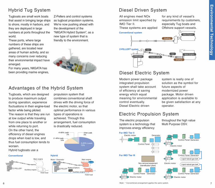
Tugboats are small work boats that assist in bringing large ships to shore, mostly in harbors, and they are deployed in large numbers at ports throughout the world. These ports, where large numbers of these ships are gathered, are located near areas of human activity, and so many concerns over reducing their environmental impact have emerged.For many years, NIIGATA has been providing marine engines,
Z-Pellers and control systems as tugboat propulsion systems. We’re now pushing ahead with the development of the “NIIGATA Hybird System”, as a new type of system that is friendly to the environment.
Advantages of the Hybrid SystemTugboats, which are designed to produce maximum output during operation, experience fluctuations in their engine-load factor while being piloted. The reason is that they are run at low output while traveling from one place to another or while returning to port. On the other hand, the efficiency of diesel engines drops when load is low, and thus fuel consumption tends to worsen. Hybrid tugboats use a
propulsion system that combines conventional shaft drives with the driving force of the electric motor, so that optimal performance in various types of operations is achieved. Through this arrangement, fuel consumption is drastically reduced.
Diesel Driven System
Conventional system
For IMO Tier Ⅱ
For IMO Tier Ⅲ
Shafting
Main Engine
Interm. shaftShafting
Main Engine
UJ
UJZ-PELLER®
Z-PELLER® system
All engines meet NOx emission limit specified by IMO Tier II.These systems are applied
for any kind of vessel’s requirements by customers, especially Tug boats and Offshore support vessels.
6 7
Environmental Technology
6MG28AHX6MG26HLX
5~9MG17AHX
6MG19HX
6MG22HX
6MG25HX
6MG26HLX
6MG28HX
6MG28AHX
8MG28HX
6MG34HX
8MG28AHX
9MG28AHX
8MG34HX
6MG41HX
12MG28AHX
16MG28AHX
18MG28AHX
PS
kWm
1000 2000 3000 4000 5000 7000 8000 9000Model
1000 30002000 4000 5000 6000 7000
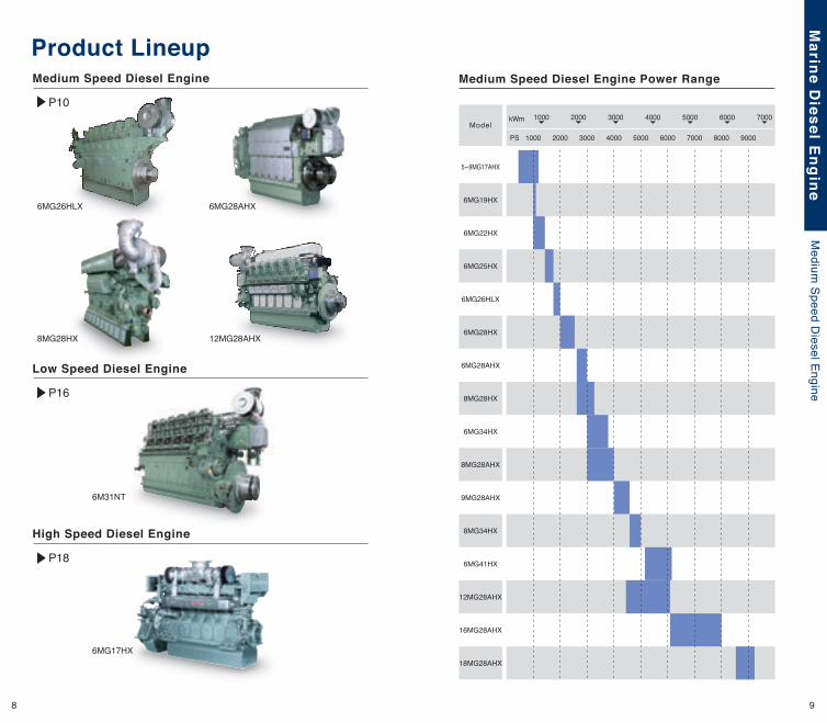
Medium Speed Diesel Engine Power RangeMedium Speed Diesel Engine
P10
12MG28AHX
Low Speed Diesel Engine
P16
High Speed Diesel Engine
P18
Product Lineup
6000
6M31NT
6MG17HX
8MG28HX
8 9
Marine D
iesel Engine
Medium
Speed Diesel Engine
5MG17AHX6MG17AHX7MG17AHX8MG17AHX9MG17AHX
5MG17AHX6MG17AHX7MG17AHX8MG17AHX9MG17AHX
6MG28AHX8MG28AHX9MG28AHX12MG28AHX16MG28AHX18MG28AHX
202628364550
280280280280280280
800800800800800800
301840244527603680489055
222029603330444059206660
6MG28AHX8MG28AHX9MG28AHX12MG28AHX16MG28AHX18MG28AHX
487057706220
———
465055506000526064507100
175018501850220023002350
120012001200145014501450
220023302330242525802780
445445445445445445
327534053405337035253725
204020402040191019101910
Dimension (mm)
L1 L2 W1 W2 H1 H2 H3 H4Model
Max.Continuous Rating Engine Speed Cyl. Bore Piston Stroke Approx. Dry Mass
kWm PS min-1 mmmm tModel
390390390390390390
8501020119013601530
6.88.19.410.711.9
714857100011421285
525630735840945
68081695210881224
500600700800900
29503235352038054090
35703855414044254710
15101510151015101510
780780780780780
15751670167016701755
310310310310310
23052400240024002485
14351435143514351435
Dimension (mm)
Propulsion
L1 L2 W1 W2 H1 H2 H3 H4Model
900min-1 1000min-1 1200min-1Approx.
Dry MasskWm PS kWm kWmPS PS t
Model
62575087510001125
L2
L1
W1
W2
H1
H2
H3
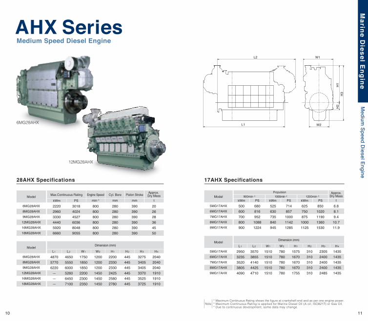
* Maximum Continuous Rating shows the figure at crankshaft end and as per one engine power.* Maximum Continuous Rating is applied for Marine Diesel Oil (A oil, ISO8217) or Gas Oil.* Due to continuous development, some data may change.
Note
AHX SeriesMedium Speed Diesel Engine
28AHX Specifications 17AHX Specifications
12MG28AHX
6MG28AHX
10 11
Marine D
iesel Engine
Medium
Speed Diesel Engine
Front-end unit (Optional)4
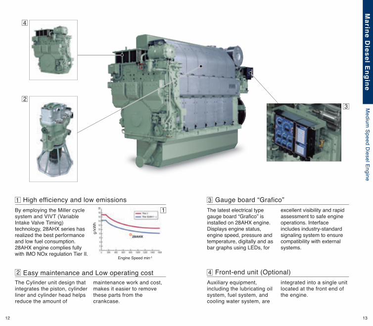
High efficiency and low emissions By employing the Miller cycle system and VIVT (Variable Intake Valve Timing) technology, 28AHX series has realized the best performance and low fuel consumption. 28AHX engine complies fully with IMO NOx regulation Tier II.
1 Gauge board “Grafico”3
2
1
3
Easy maintenance and Low operating cost2The Cylinder unit design that integrates the piston, cylinder liner and cylinder head helps reduce the amount of
maintenance work and cost, makes it easier to remove these parts from the crankcase.
Auxiliary equipment, including the lubricating oil system, fuel system, and cooling water system, are
integrated into a single unit located at the front end of the engine.
The latest electrical type gauge board “Grafico” is installed on 28AHX engine. Displays engine status, engine speed, pressure and temperature, digitally and as bar graphs using LEDs, for
excellent visibility and rapid assessment to safe engine operations. Interface includes industry-standard signaling system to ensure compatibility with external systems.
4
g / k
Wh
Engine Speed min-1
12 13
Marine D
iesel Engine
Medium
Speed Diesel Engine
Exhaust gas inletExhaust gas outlet
6MG19HX6MG22HX6MG25HX6MG26HLX6MG28HX8MG28HX6MG34HX8MG34HX6MG41HX
6MG19HX6MG22HX6MG25HX6MG26HLX6MG28HX8MG28HX6MG34HX8MG34HX6MG41HX
7.0 9.1
13.0 13.5 16.0 21.5 33.6 43.5 64.0
190220250260280280340340410
10001000750750750750620600520
103514451860206525803300412549506190
76110621368151818972427303336404552
291230273408346337044638453055906890
212223892886292131423319357335733875
147217292166220122602485258025802875
650660720720882834993993
1000
320330380380400400515515650
155016902080208022102210276027603030
800890
1040104011301130139013901796
809865992
103010011001916916
1225
666688758765823823
102811781848
Dimension (mm)
L H H1 H2 H3 H4 B1 B2 B3Model
Max.Continuous Rating Engine Speed Cyl. Bore Piston Stroke Approx.Dry Mass
kWm PS min -1 mmmm tModel
260280350350370370450450560
* Maximum Continuous Rating shows the figure at crankshaft end and as per one engine power.* Maximum Continuous Rating is applied for Marine Diesel Oil (A oil, ISO8217) or Gas Oil.* Due to continuous development, some data may change.
Note
6MG28HX
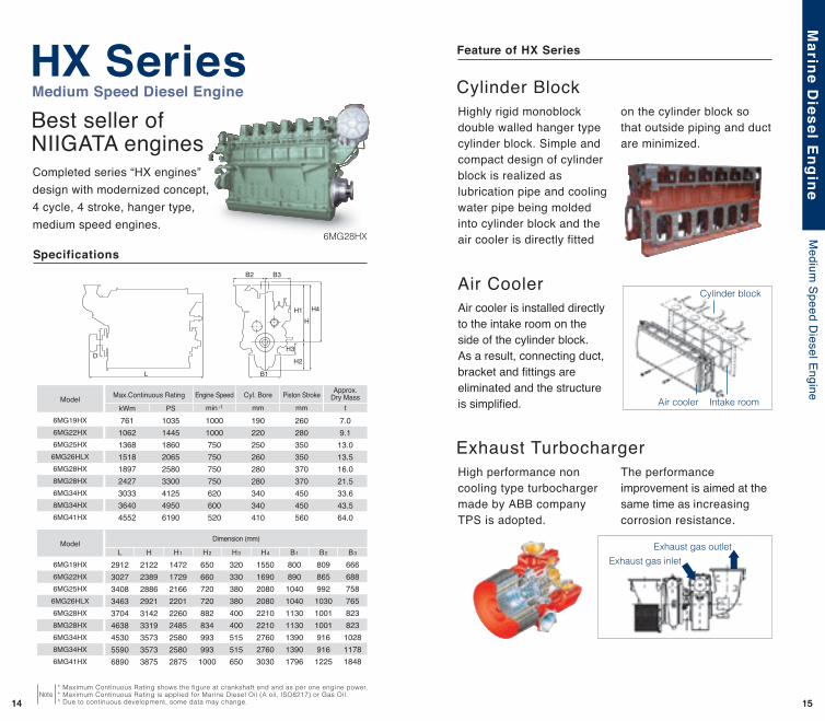
Best seller ofNIIGATA engines
HX SeriesMedium Speed Diesel Engine
Completed series “HX engines”design with modernized concept, 4 cycle, 4 stroke, hanger type,medium speed engines.
Cylinder BlockHighly rigid monoblock double walled hanger type cylinder block. Simple and compact design of cylinder block is realized as lubrication pipe and cooling water pipe being molded into cylinder block and the air cooler is directly fitted
on the cylinder block so that outside piping and duct are minimized.
Air CoolerAir cooler is installed directly to the intake room on the side of the cylinder block.As a result, connecting duct, bracket and fittings are eliminated and the structure is simplified.
Cylinder block
Intake roomAir cooler
Exhaust Turbocharger
Feature of HX Series
High performance non cooling type turbocharger made by ABB company TPS is adopted.
The performance improvement is aimed at the same time as increasing corrosion resistance.
SpecificationsB2 B3
B1
H4
HH1
H2
H3
L
D
14 1514 15
Marine D
iesel Engine
Medium
Speed Diesel Engine
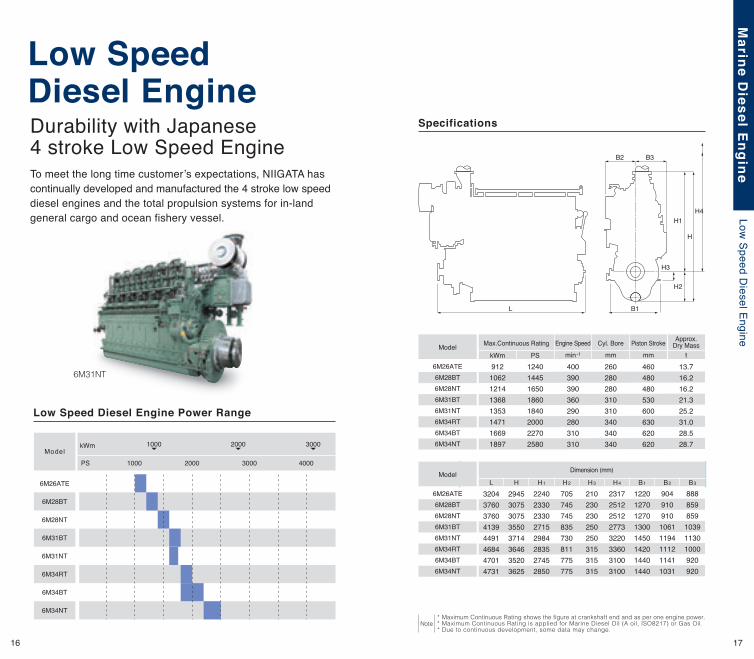
Durability with Japanese 4 stroke Low Speed Engine
6M26ATE6M28BT6M28NT6M31BT6M31NT6M34RT6M34BT6M34NT
6M26ATE6M28BT6M28NT6M31BT6M31NT6M34RT6M34BT6M34NT
6M26ATE
6M28BT
6M28NT
6M31BT
6M31NT
6M34RT
6M34BT
6M34NT
13.716.216.221.325.231.028.528.7
260280280310310340340340
400390390360290280310310
12401445165018601840200022702580
9121062121413681353147116691897
32043760376041394491468447014731
29453075307535503714364635203625
22402330233027152984283527452850
705745745835730811775775
210230230250250315315315
23172512251227733220336031003100
12201270127013001450142014401440
90491091010611194111211411031
888859859103911301000920920
Dimension (mm)
L H H1 H2 H3 H4 B1 B2 B3Model
Max.Continuous Rating Engine Speed Cyl. Bore Piston Stroke Approx.Dry Mass
kWm PS min-1 mmmm tModel
460480480530600630620620
PS
kWm
1000 2000 3000 4000
1000 2000 3000
L B1
B3B2
H1
H3
H2
H4
H
* Maximum Continuous Rating shows the figure at crankshaft end and as per one engine power.* Maximum Continuous Rating is applied for Marine Diesel Oil (A oil, ISO8217) or Gas Oil.* Due to continuous development, some data may change.
Note
6M31NT
Low Speed Diesel Engine
Low Speed Diesel Engine Power Range
Model
Specifications
To meet the long time customer’s expectations, NIIGATA has continually developed and manufactured the 4 stroke low speed diesel engines and the total propulsion systems for in-land general cargo and ocean fishery vessel.
16 17
Marine D
iesel Engine
Low Speed D
iesel Engine
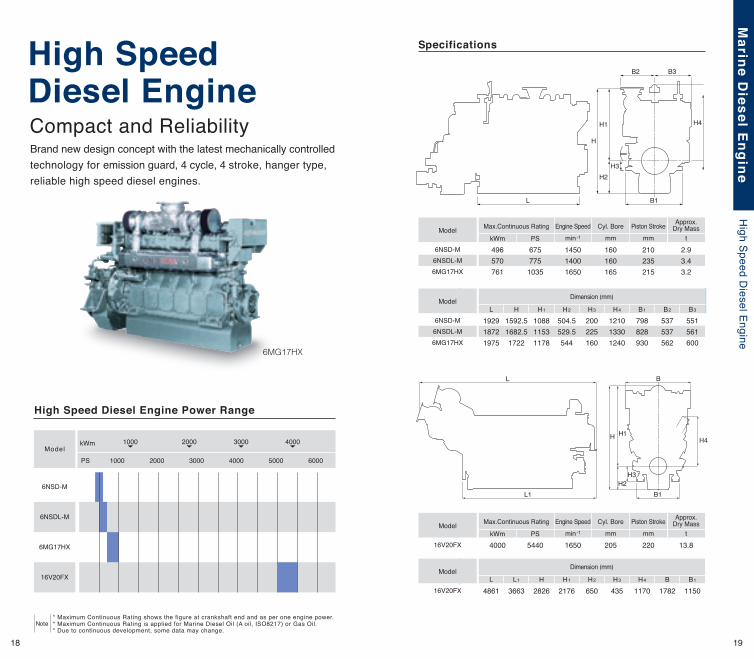
6NSD-M6NSDL-M6MG17HX
6NSD-M6NSDL-M6MG17HX
2.93.43.2
160160165
145014001650
6757751035
496570761
192918721975
1592.51682.51722
108811531178
504.5529.5544
200225160
121013301240
798828930
537537562
551561600
Dimension (mm)
L H H1 H2 H3 H4 B1 B2 B3Model
Max.Continuous Rating Engine Speed Cyl. Bore Piston Stroke Approx.Dry Mass
kWm PS min-1 mmmm tModel
210235215
13.8205165054404000
4861 3663 2826 2176 650 435 1170 1782 1150
Dimension (mm)
L L1 H H1 H2 H3 H4 B B1Model
Max.Continuous Rating Engine Speed Cyl. Bore Piston Stroke Approx.Dry Mass
kWm PS min-1 mmmm tModel
220
PS
kWm
1000 2000 3000 4000 5000 6000
1000 30002000 4000
L B1
B3B2
H1
H1
H2H3
B1
H4H
L
L1
B
H3H2
H4
H
* Maximum Continuous Rating shows the figure at crankshaft end and as per one engine power.* Maximum Continuous Rating is applied for Marine Diesel Oil (A oil, ISO8217) or Gas Oil.* Due to continuous development, some data may change.
Note
6MG17HX
Specifications
6NSD-M
6NSDL-M
6MG17HX
16V20FX
High SpeedDiesel Engine
High Speed Diesel Engine Power Range
Model
Compact and ReliabilityBrand new design concept with the latest mechanically controlled technology for emission guard, 4 cycle, 4 stroke, hanger type, reliable high speed diesel engines.
16V20FX
16V20FX
18 19
Marine D
iesel Engine
High Speed D
iesel Engine
Application of Z-PELLER®
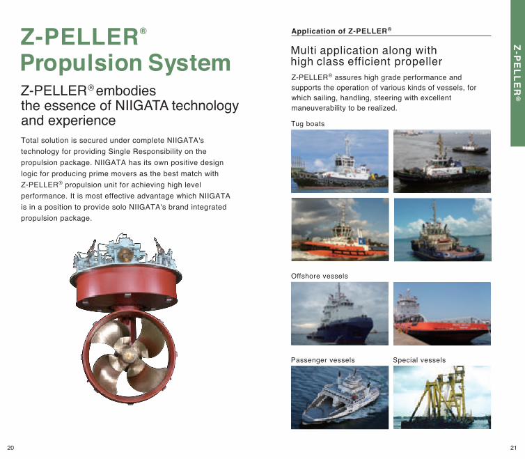
Total solution is secured under complete NIIGATA's technology for providing Single Responsibility on the propulsion package. NIIGATA has its own positive design logic for producing prime movers as the best match with Z-PELLER® propulsion unit for achieving high level performance. It is most effective advantage which NIIGATA is in a position to provide solo NIIGATA's brand integrated propulsion package.
Z-PELLER® assures high grade performance and supports the operation of various kinds of vessels, for which sailing, handling, steering with excellent maneuverability to be realized.
Multi application along with high class efficient propeller
Special vesselsPassenger vessels
Tug boats
Offshore vessels
Z-PELLER® Propulsion SystemZ-PELLER® embodies the essence of NIIGATA technology and experience
20 21
Z-PE
LLER
®
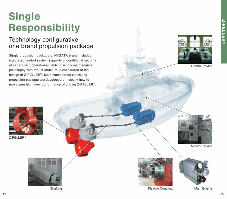
Flexible Coupling Main Engine
Monitor Device
Control Device
Z-PELLER®
Single propulsion package of NIIGATA brand includes integrated control system supports unconditional security at variety ship operational fields. Friendly maintenance philosophy with robust structure is considered at the design of Z-PELLER®. Main machineries consisting propulsion package are developed principally how to make sure high level performance of driving Z-PELLER®.
SingleResponsibilityTechnology configurative one brand propulsion package
Shafting22 23
Z-PE
LLER
®
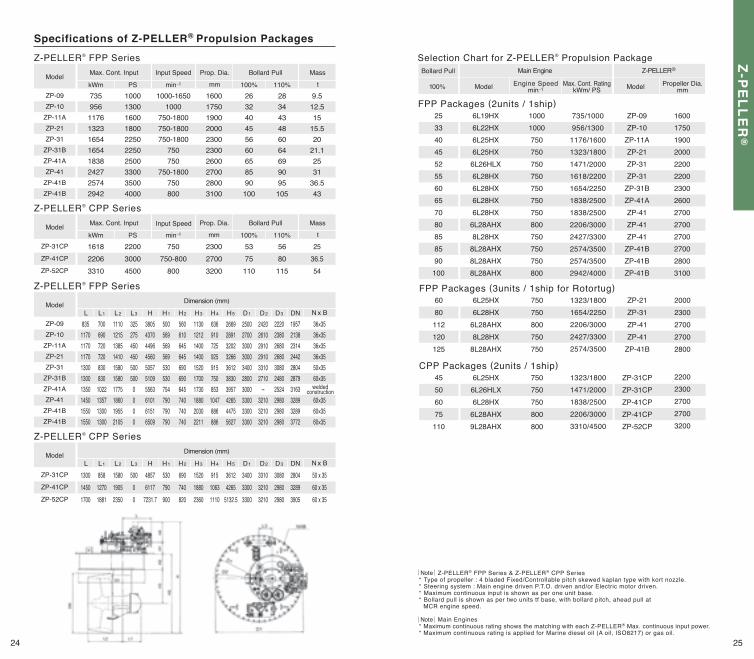
Specifications of Z-PELLER® Propulsion PackagesZ-PELLER® FPP Series
ZP-09ZP-10
ZP-11AZP-21ZP-31
ZP-31BZP-41AZP-41
ZP-41BZP-41B
73595611761323165416541838242725742942
1000130016001800225022502500330035004000
1000-16501000
750-1800750-1800750-1800
750750
750-1800750800
1600175019002000230023002600270028003100
263240455660658590
100
283443486064699095
105
9.512.515
15.520
21.12531
36.543
Max. Cont. Input Input Speed Prop. Dia. Bollard Pull Mass
kWm min-1PS 100% 110%mm tModel
ZP-09ZP-10
ZP-11AZP-21ZP-31
ZP-31BZP-41AZP-41
ZP-41BZP-41B
835117011701170130013001350145015501550
7006907207208308301022135713001300
1110121513851410158015801775186019552105
3252754504505005000000
3805437044964560505751095563610161516509
500569569569530530754790790790
560610645645690690645740740740
1130121214001400152017001730188020302211
636910725925915750853
1047886886
2669289132023266361238303957426544755627
2500270030003000340028003000330033003300
242026102910291033102710-
321032103210
2220238026802680308024802524298029802980
1957213823142442280428793163328932893772
36×3536×3536×3536×3550×3560×35
60×3560×3560×35
Dimension (mm)
L L1 L2 L3 H H1 H2 H3 H4 H5 D1 D2 D3 DN N x BModel
Z-PELLER® FPP Series
weldedconstruction
Dimension (mm)
L L1 L2 L3 H H1 H2 H3 H4 H5 D1 D2 D3 DN N x BModel
Z-PELLER® CPP Series
ZP-31CP
ZP-41CP
ZP-52CP
130014501700
85812701881
158019052350
50000
48576117
7231.7
530790900
690740820
152018802360
91510631110
36124265
5132.5
340033003300
331032103210
308029802980
280432893905
50 x 3560 x 3560 x 35
Main Engine Z-PELLER®
Model ModelEngine Speedmin-1
Propeller Dia.mm
Max. Cont. RatingkWm/ PS
Bollard Pull
100%
Selection Chart for Z-PELLER® Propulsion Package
FPP Packages (3units / 1ship for Rotortug)
CPP Packages (2units / 1ship)
6080112120125
6L25HX6L28HX
6L28AHX8L28HX
8L28AHX
750750800750750
1323/18001654/22502206/30002427/33002574/3500
ZP-09ZP-10
ZP-11AZP-21ZP-31ZP-31
ZP-31BZP-41AZP-41ZP-41ZP-41
ZP-41BZP-41BZP-41B
16001750190020002200220023002600270027002700270028003100
FPP Packages (2units / 1ship)25334045525560657080858590100
6L19HX6L22HX6L25HX6L25HX6L26HLX6L28HX6L28HX6L28HX6L28HX
6L28AHX8L28HX
8L28AHX8L28AHX8L28AHX
10001000750750750750750750750800750750750800
735/1000956/1300
1176/16001323/18001471/20001618/22001654/22501838/25001838/25002206/30002427/33002574/35002574/35002942/4000
Z-PELLER® CPP Series
ZP-31CP
ZP-41CP
ZP-52CP
161822063310
220030004500
750750-800
800
230027003200
5375
110
5680
115
2536.554
Max. Cont. Input Prop. Dia. Bollard Pull Mass
kWm min-1PS 100% 110%mm tModel Input Speed
45506075110
6L25HX6L26HLX6L28HX
6L28AHX9L28AHX
750750750800800
1323/18001471/20001838/25002206/30003310/4500
ZP-31CPZP-31CPZP-41CPZP-41CPZP-52CP
22002300270027003200
Note
Note
Z-PELLER® FPP Series & Z-PELLER® CPP Series* Type of propeller : 4 bladed Fixed/Controllable pitch skewed kaplan type with kort nozzle.* Steering system : Main engine driven P.T.O. driven and/or Electric motor driven.* Maximum continuous input is shown as per one unit base.* Bollard pull is shown as per two units tf base, with bollard pitch, ahead pull at MCR engine speed.
Main Engines* Maximum continuous rating shows the matching with each Z-PELLER® Max. continuous input power.* Maximum continuous rating is applied for Marine diesel oil (A oil, ISO8217) or gas oil.
ZP-21ZP-31ZP-41ZP-41
ZP-41B
20002300270027002800
24 25
Z-PE
LLER
®
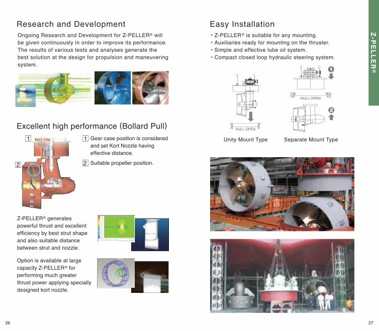
Easy InstallationResearch and DevelopmentOngoing Research and Development for Z-PELLER® will be given continuously in order to improve its performance. The results of various tests and analyses generate the best solution at the design for propulsion and maneuvering system.
Excellent high performance (Bollard Pull)
Z-PELLER® generates powerful thrust and excellent efficiency by best strut shape and also suitable distance between strut and nozzle.
Option is available at large capacity Z-PELLER® for performing much greater thrust power applying specially designed kort nozzle.
Unity Mount Type Separate Mount Type
HULL OPEN
HULL OPEN
1
2
1 Gear case position is considered and set Kort Nozzle having effective distance.
2 Suitable propeller position.
• Z-PELLER® is suitable for any mounting.• Auxiliaries ready for mounting on the thruster.• Simple and effective lube oil system.• Compact closed loop hydraulic steering system.
26 27
Z-PE
LLER
®
ENGINE min-1
100%
0 100%
min-1
100%kw
min-1
PROPELLER min-1
Slip losses
PROP Absorb
ENGINE min-1
100%
0 100%
min-1
100%kw
min-1
PROPELLER min-1
Slip losses
PROP Absorb
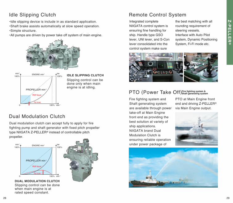
IDLE SLIPPING CLUTCHSlipping control can be done only when main engine is at idling.
DUAL MODULATION CLUTCHSlipping control can be done when main engine is at rated speed constant.
Idle Slipping Clutch
Dual Modulation ClutchDual modulation clutch can accept fully to apply for fire fighting pump and shaft generator with fixed pitch propeller type NIIGATA Z-PELLER® instead of controllable pitch propeller.
•Idle slipping device is include in as standard application.•Shaft brake assists automatically at slow speed operation.•Simple structure.•All pumps are driven by power take off system of main engine.
PTO (Power Take Off)Fire fighting system and Shaft generating system are available through power take-off at Main Engine front end as providing the best solution at variety of ship applications. NIIGATA brand Dual Modulation Clutch is ensuring reliable operation under power package of
PTO at Main Engine front end and driving Z-PELLER® via Main Engine output.
Integrated complete NIIGATA control system is ensuring fine handling for ship. Handle type GSO lever, UNI lever, and S-Con lever consolidated into the control system make sure
the best matching with all rounding requirement of steering vessels.Interface with Auto Pilot system, Dynamic Positioning System, Fi-Fi mode etc.
Remote Control System
Fire fighting system & Shaft generating system
28 29
Z-PE
LLER
®
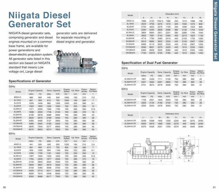
Specifications of Generator
Specification of Dual Fuel Generator
H1
H2
A1
A B1
H3
H
B
6NSD-G6L19HX6L22HX6L25HX6L26HLX6L28HX
6L28AHX8L28AHX9L28AHX
12V28AHX16V28AHX18V28AHX
6NSD-G6L19HX6L22HX6L25HX6L26HLX6L28HX
6L28AHX8L28AHX9L28AHX
12V28AHX16V28AHX18V28AHX
441661956125013971765210028003150420056006300
6009001300170019002400285538074283571076148566
406 615 894 1181 1320 1677 2003 2674 3008 4011 5348 6017
500 750
1100 1450 1650 2050 2500 3300 3750 5000 6650 7500
1200900900720720720720720720720720720
160190220250260280280280280280280280
210260280350350370390390390390390390
2.97
9.113
13.516202628364550
4856611029132314711838219029203285438058406570
6609001400180020002500297839704466595579408933
446 615 962 1250 1390 1746 2089 2789 3137 4183 5577 6274
550 750
1200 1550 1700 2150 2600 3450 3900 5200 6950 7800
150010001000750750750750750750750750750
160190220250260280280280280280280280
210260280350350370390390390390390390
2.97
9.113
13.516202628364550
Model
Engine Capacity Gene. Capacity EngineSpeed Cyl. Bore Piston
StrokeApprox.
Dry MasskWm kWePS min-1 mm mmkVA t
Model
50Hz
60HzEngine Capacity Gene. Capacity Engine
Speed Cyl. Bore PistonStroke
Approx.Dry Mass
kWm kWePS min-1 mm mmkVA t
6L28AHX-DF8L28AHX-DF9L28AHX-DF
6L28AHX-DF8L28AHX-DF9L28AHX-DF
172923052593
235131343525
1643 2199 2476
2050 2700 3050
720720720
280280280
390390390
222831
180124012701
244932643672
1711 2291 2579
2100 2850 3200
750750750
280280280
390390390
222831
Model
Engine Capacity Gene. Capacity EngineSpeed Cyl. Bore Piston
StrokeApprox.
Dry MasskWm kWePS min-1 mm mmkVA t
Model
50Hz
60HzEngine Capacity Gene. Capacity Engine
Speed Cyl. Bore PistonStroke
Approx.Dry Mass
kWm kWePS min-1 mm mmkVA t
6NSD-G6L19HX6L22HX6L25HX
6L26HLX6L28HX
6L28AHX8L28AHX9L28AHX
12V28AHX16V28AHX18V28AHX
189625242700320038643953471056106060526064507100
3122475649255545666470817760866091108651983910375
1592.522722579283629213142348536253625337035253725
108814721729206622012260241025502550242525802780
200320330380380400445445445445445445
121015501690213020802210210021002100191019101910
108814751553175417951824175020672067220023002350
798800890104010401130120012001200145014501450
Dimension (mm)
A A1 H H1 H2 H3 B B1Model
6L28AHX-DF8L28AHX-DF9L28AHX-DF
504959206370
509959706420
195519562051
120012001200
224023702370
445445445
331534453445
204020402040
Dimension (mm)
L1 L2 W1 W2 H1 H2 H3 H4Model
Niigata DieselGenerator SetNIIGATA diesel generator sets, comprising generator and diesel engines mounted on a common base frame, are available for power generations and diesel-electric propulsion system. All generator sets listed in this section are based on NIIGATA standard that means Low voltage onl,.Large diesel
generator sets are delivered for separate mounting of diesel engine and generator.
30 31
Niigata D
iesel Generator Set

Fuel Injection System
NICO Precision Co.,Inc.As a part of IHI Power Systems Co., Ltd.,embracing a solid commitment to uncompromisingly stringent quality control, NICO Precision manufactures products of superior quality and performance ensuring all users full peace of mind. We also provide services that all customers can truly appreciate.
Fuel Injection PumpsFuel injection pumps compress fuel oil and supply the oil, under high pressure, to the fuel injection nozzle. NICO Precision's fuel injection pumps boast outstanding quality and durability to withstand pressures up to 160MPa. They are used worldwide in engines of all kinds.
Fuel Injection NozzlesFuel Injection Nozzles atomize high-pressure oil and inject it into the engine's cylinders. NICO Precision's nozzles offer optimal performance that brings out excellent performance in the engine.
Fuel Injection ValvesFuel Injection Valves supply high-pressure oil from the fuel injection pump to the fuel injection nozzle in order to control injection starts. NICO Precision's fuel injection valves provide superlative reliability to prevent fuel leakage and robust durability to withstand high pressure levels.
Land Use
Rail Traction
NIIGATA Stationary Diesel & Gas engines and Gas Turbine engines as prime movers of generating sets have been delivered to the world-wide owners as applications for building, factory, power plant under the design for proven reliability, low emissions, low operating cost to meet owner’s requirements.
NIIGATA has been producing the railway vehicle engines for more 80 years and offer the high reliability and prominent power through our tradition, experience, and the-state-of-the-art. DMF13HZA
32 33
NIP Fuel Injection System / Land Use & Rail Traction
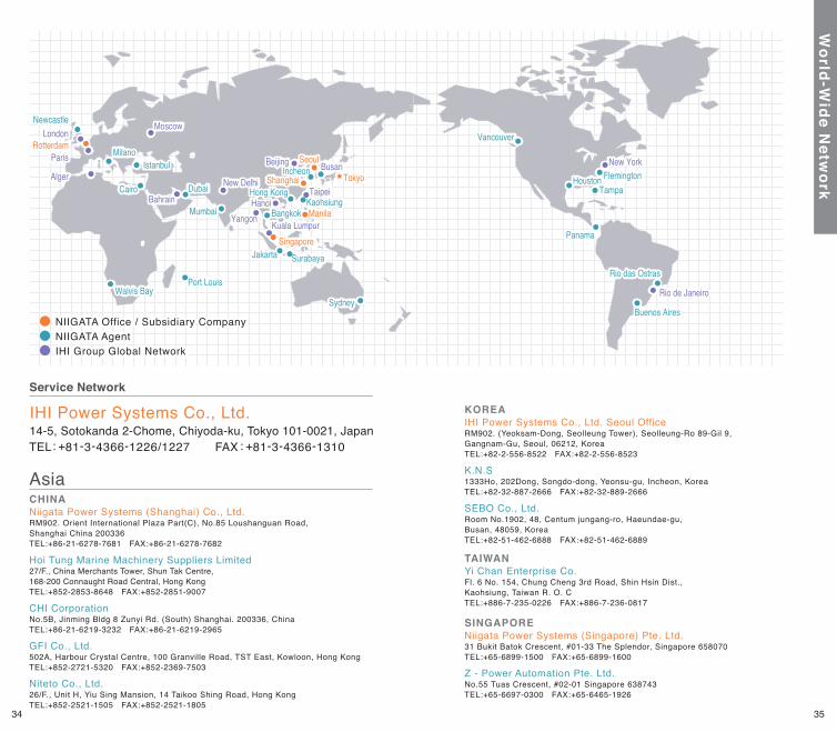
Service Network
14-5, Sotokanda 2-Chome, Chiyoda-ku, Tokyo 101-0021, JapanTEL : +81-3-4366-1226/1227 FAX : +81-3-4366-1310
IHI Power Systems Co., Ltd.
RM902. Orient International Plaza Part(C), No.85 Loushanguan Road, Shanghai China 200336TEL:+86-21-6278-7681 FAX:+86-21-6278-7682
Niigata Power Systems (Shanghai) Co., Ltd.CHINA
CHI Corporation
GFI Co., Ltd.
Niteto Co., Ltd.
Hoi Tung Marine Machinery Suppliers Limited
No.5B, Jinming Bldg 8 Zunyi Rd. (South) Shanghai. 200336, ChinaTEL:+86-21-6219-3232 FAX:+86-21-6219-2965
502A, Harbour Crystal Centre, 100 Granville Road, TST East, Kowloon, Hong KongTEL:+852-2721-5320 FAX:+852-2369-7503
26/F., Unit H, Yiu Sing Mansion, 14 Taikoo Shing Road, Hong KongTEL:+852-2521-1505 FAX:+852-2521-1805
27/F., China Merchants Tower, Shun Tak Centre, 168-200 Connaught Road Central, Hong KongTEL:+852-2853-8648 FAX:+852-2851-9007
SEBO Co., Ltd.
K.N.S
Room No.1902, 48, Centum jungang-ro, Haeundae-gu, Busan, 48059, KoreaTEL:+82-51-462-6888 FAX:+82-51-462-6889
1333Ho, 202Dong, Songdo-dong, Yeonsu-gu, Incheon, KoreaTEL:+82-32-887-2666 FAX:+82-32-889-2666
Asia
Fl. 6 No. 154, Chung Cheng 3rd Road, Shin Hsin Dist., Kaohsiung, Taiwan R. O. CTEL:+886-7-235-0226 FAX:+886-7-236-0817
Yi Chan Enterprise Co.TAIWAN
RM902. (Yeoksam-Dong, Seolleung Tower), Seolleung-Ro 89-Gil 9, Gangnam-Gu, Seoul, 06212, KoreaTEL:+82-2-556-8522 FAX:+82-2-556-8523
IHI Power Systems Co., Ltd. Seoul OfficeKOREA
31 Bukit Batok Crescent, #01-33 The Splendor, Singapore 658070TEL:+65-6899-1500 FAX:+65-6899-1600
Niigata Power Systems (Singapore) Pte. Ltd.
No.55 Tuas Crescent, #02-01 Singapore 638743TEL:+65-6697-0300 FAX:+65-6465-1926
Z - Power Automation Pte. Ltd.
SINGAPORE
Vancouver
Houston
Buenos AiresSydney
Seoul
Hong KongKaohsiung
Dubai
Jakarta
Mumbai
Cairo
Port Louis
New Delhi
Surabaya
RotterdamParis
AlgerNew York
Rio de Janeiro
LondonMoscow
BangkokHanoi
Taipei
Beijing
Kuala Lumpur
Shanghai
Manila
Singapore
TokyoIstanbul
Milano
Newcastle
Panama
Walvis Bay
Incheon Busan
TampaBahrain
Vancouver
Houston
Buenos AiresSydney
Seoul
Hong KongKaohsiung
Dubai
Jakarta
Mumbai
Cairo
Port Louis
New Delhi
Surabaya
RotterdamParis
AlgerNew York
Rio de Janeiro
Rio das OstrasRio das Ostras
LondonMoscow
BangkokHanoi
Taipei
Beijing
Kuala Lumpur
Shanghai
Manila
Singapore
TokyoIstanbul
Milano
Newcastle
Panama
Walvis Bay
Incheon BusanFlemingtonFlemington
TampaBahrain
YangonYangon
NIIGATA Office / Subsidiary CompanyNIIGATA AgentIHI Group Global Network
34 35
World-W
ide Netw
ork
RM312. Beursplein 37, 3011 AA Rotterdam, The NetherlandsTEL:+31-10-405-3085 FAX:+31-10-405-5067
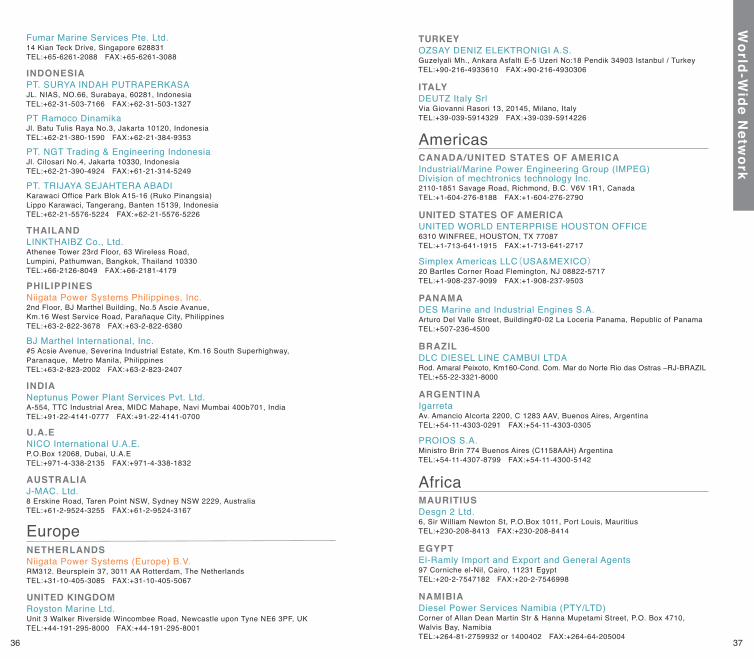
Niigata Power Systems (Europe) B.V.NETHERLANDS
Unit 3 Walker Riverside Wincombee Road, Newcastle upon Tyne NE6 3PF, UKTEL:+44-191-295-8000 FAX:+44-191-295-8001
Royston Marine Ltd.UNITED KINGDOM
Europe6, Sir William Newton St, P.O.Box 1011, Port Louis, MauritiusTEL:+230-208-8413 FAX:+230-208-8414
Desgn 2 Ltd.MAURITIUS
97 Corniche el-Nil, Cairo, 11231 EgyptTEL:+20-2-7547182 FAX:+20-2-7546998
El-Ramly Import and Export and General AgentsEGYPT
Corner of Allan Dean Martin Str & Hanna Mupetami Street, P.O. Box 4710, Walvis Bay, NamibiaTEL:+264-81-2759932 or 1400402 FAX:+264-64-205004
Diesel Power Services Namibia (PTY/LTD)NAMIBIA
Africa
14 Kian Teck Drive, Singapore 628831TEL:+65-6261-2088 FAX:+65-6261-3088
Fumar Marine Services Pte. Ltd.
JL. NIAS, NO.66, Surabaya, 60281, IndonesiaTEL:+62-31-503-7166 FAX:+62-31-503-1327
PT. SURYA INDAH PUTRAPERKASA
Jl. Batu Tulis Raya No.3, Jakarta 10120, IndonesiaTEL:+62-21-380-1590 FAX:+62-21-384-9353
PT Ramoco Dinamika
Jl. Cilosari No.4, Jakarta 10330, IndonesiaTEL:+62-21-390-4924 FAX:+61-21-314-5249
PT. NGT Trading & Engineering Indonesia
Karawaci Office Park Blok A15-16 (Ruko Pinangsia)Lippo Karawaci, Tangerang, Banten 15139, IndonesiaTEL:+62-21-5576-5224 FAX:+62-21-5576-5226
PT. TRIJAYA SEJAHTERA ABADI
Athenee Tower 23rd Floor, 63 Wireless Road, Lumpini, Pathumwan, Bangkok, Thailand 10330TEL:+66-2126-8049 FAX:+66-2181-4179
LINKTHAIBZ Co., Ltd.
INDONESIA
BJ Marthel International, Inc.#5 Acsie Avenue, Severina Industrial Estate, Km.16 South Superhighway, Paranaque, Metro Manila, PhilippinesTEL:+63-2-823-2002 FAX:+63-2-823-2407
2nd Floor, BJ Marthel Building, No.5 Ascie Avanue, Km.16 West Service Road, Parañaque City, PhilippinesTEL:+63-2-822-3678 FAX:+63-2-822-6380
Niigata Power Systems Philippines, Inc.PHILIPPINES
THAILAND
A-554, TTC Industrial Area, MIDC Mahape, Navi Mumbai 400b701, IndiaTEL:+91-22-4141-0777 FAX:+91-22-4141-0700
Neptunus Power Plant Services Pvt. Ltd.INDIA
P.O.Box 12068, Dubai, U.A.ETEL:+971-4-338-2135 FAX:+971-4-338-1832
NICO International U.A.E.U.A.E
8 Erskine Road, Taren Point NSW, Sydney NSW 2229, AustraliaTEL:+61-2-9524-3255 FAX:+61-2-9524-3167
J-MAC. Ltd.AUSTRALIA
Guzelyali Mh., Ankara Asfalti E-5 Uzeri No:18 Pendik 34903 Istanbul / TurkeyTEL:+90-216-4933610 FAX:+90-216-4930306
OZSAY DENIZ ELEKTRONIGI A.S.TURKEY
Via Giovanni Rasori 13, 20145, Milano, ItalyTEL:+39-039-5914329 FAX:+39-039-5914226
DEUTZ Italy SrlITALY
2110-1851 Savage Road, Richmond, B.C. V6V 1R1, CanadaTEL:+1-604-276-8188 FAX:+1-604-276-2790
Industrial/Marine Power Engineering Group (IMPEG) Division of mechtronics technology Inc.
CANADA/UNITED STATES OF AMERICA
6310 WINFREE, HOUSTON, TX 77087TEL:+1-713-641-1915 FAX:+1-713-641-2717
UNITED WORLD ENTERPRISE HOUSTON OFFICE
20 Bartles Corner Road Flemington, NJ 08822-5717TEL:+1-908-237-9099 FAX:+1-908-237-9503
Simplex Americas LLC(USA&MEXICO)
UNITED STATES OF AMERICA
Arturo Del Valle Street, Building#0-02 La Loceria Panama, Republic of PanamaTEL:+507-236-4500
DES Marine and Industrial Engines S.A.PANAMA
Rod. Amaral Peixoto, Km160-Cond. Com. Mar do Norte Rio das Ostras –RJ-BRAZILTEL:+55-22-3321-8000
DLC DIESEL LINE CAMBUI LTDABRAZIL
Av. Amancio Alcorta 2200, C 1283 AAV, Buenos Aires, ArgentinaTEL:+54-11-4303-0291 FAX:+54-11-4303-0305
Igarreta
Ministro Brin 774 Buenos Aires (C1158AAH) ArgentinaTEL:+54-11-4307-8799 FAX:+54-11-4300-5142
PROIOS S.A.
ARGENTINA
Americas
36 37
World-W
ide Netw
ork
Port or Stbd BothFW/SW Central coolingWet sump Dry sumpMDO HFO LNGDirect Diesel Electric
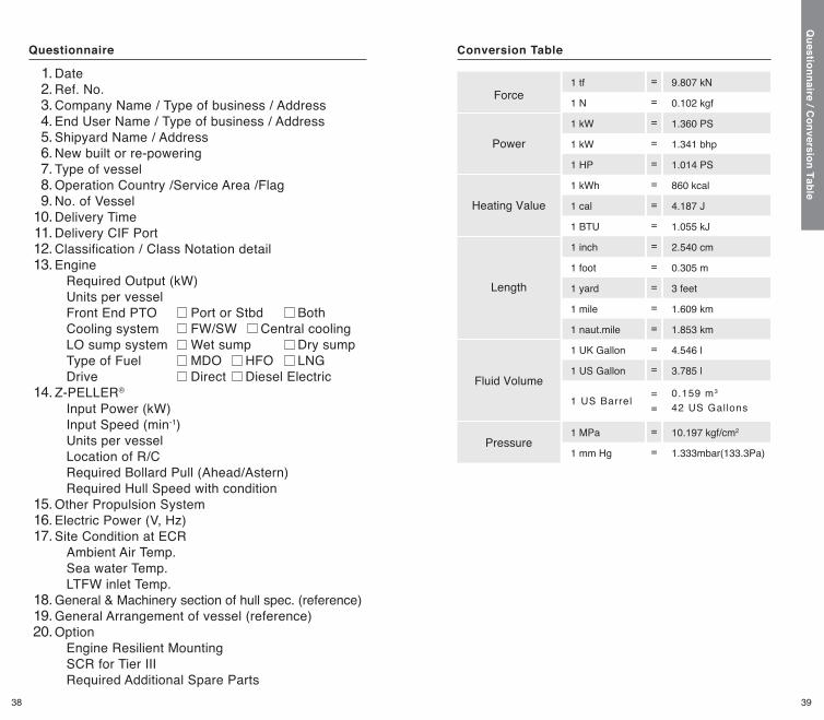
Conversion Table
Force
Power
Heating Value
Length
Fluid Volume
Pressure
1 tf
1 N
1 kW
1 kW
1 HP
1 kWh
1 cal
1 BTU
1 inch
1 foot
1 yard
1 mile
1 naut.mile
1 UK Gallon
1 US Gallon
1 MPa
1 mm Hg
9.807 kN
0.102 kgf
1.360 PS
1.341 bhp
1.014 PS
860 kcal
4.187 J
1.055 kJ
2.540 cm
0.305 m
3 feet
1.609 km
1.853 km
4.546 l
3.785 l
10.197 kgf/cm2
1.333mbar(133.3Pa)
=
=
=
=
=
=
=
=
=
=
=
=
=
=
=
=
=
==
Questionnaire
1 US Barrel0.159 m3
42 US Gallons
Date Ref. No.Company Name / Type of business / Address End User Name / Type of business / AddressShipyard Name / AddressNew built or re-poweringType of vesselOperation Country /Service Area /FlagNo. of Vessel Delivery TimeDelivery CIF PortClassification / Class Notation detailEngine Required Output (kW) Units per vessel Front End PTO Cooling system LO sump system Type of Fuel DriveZ-PELLER®
Input Power (kW) Input Speed (min-1) Units per vessel Location of R/C Required Bollard Pull (Ahead/Astern) Required Hull Speed with conditionOther Propulsion SystemElectric Power (V, Hz)Site Condition at ECR Ambient Air Temp. Sea water Temp. LTFW inlet Temp.General & Machinery section of hull spec. (reference)General Arrangement of vessel (reference)Option Engine Resilient Mounting SCR for Tier III Required Additional Spare Parts
1.2.3.4.5.6.7.8.9.
10.11.12.13.
14.
15.16.17.
18.19.20.
38 39
Questionnaire / C
onversion Table

Notes
40 41

Notes
42 43


