Embed Size (px)
Citation preview
MANUFACTURING TECHNOLOGY
MECHANICAL WORKING OF METALS
Manufacturing Technology
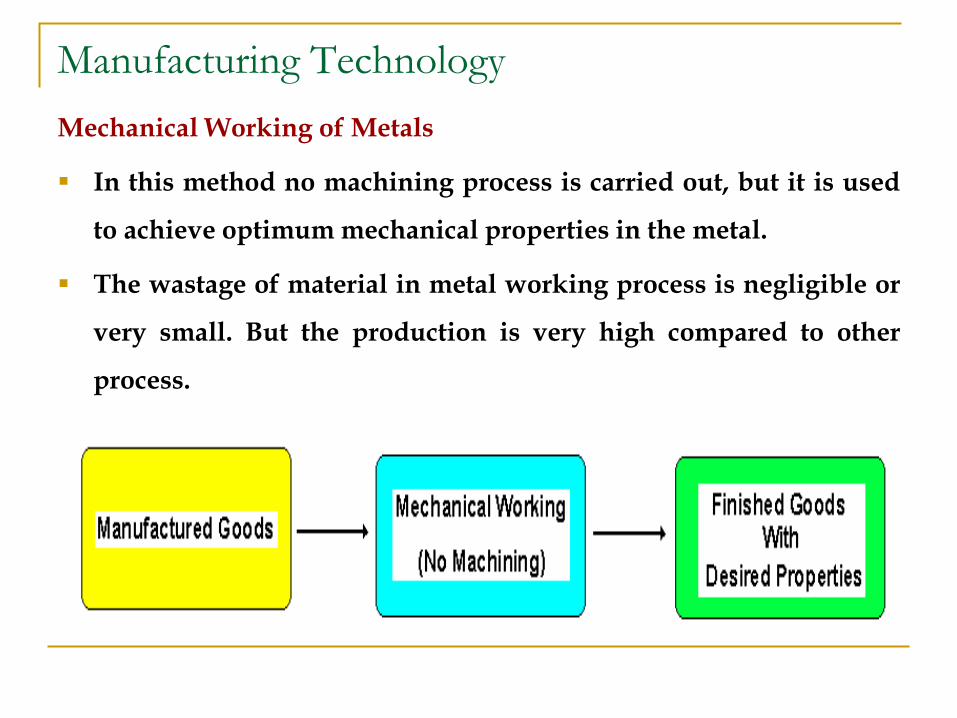
Mechanical Working of Metals
In this method no machining process is carried out, but it is used
to achieve optimum mechanical properties in the metal.
The wastage of material in metal working process is negligible or
very small. But the production is very high compared to other
process.
Manufacturing Technology
Types of Metal Working or Processing Methods
Mechanical processing
Hot working
Cold working
Thermal processing
Annealing
Recovery, recrystallization and growth
Heat treatments
Both of these are used to control properties of the final product
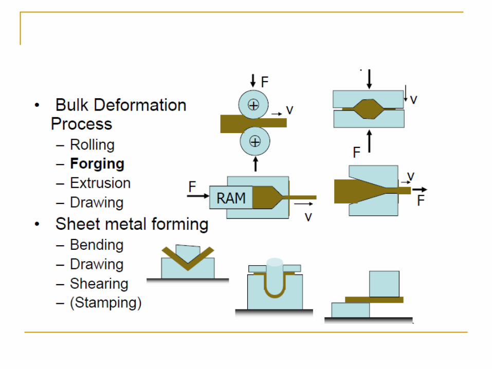
Metal Forming
Large group of manufacturing processes in which
plastic deformation is used to change the shape
of metal workpieces.
The tool, usually called a die, applies stresses
that exceed yield strength of metal.
The metal takes a shape determined by the
geometry of the die.
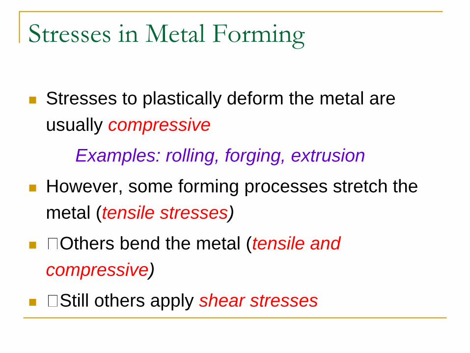
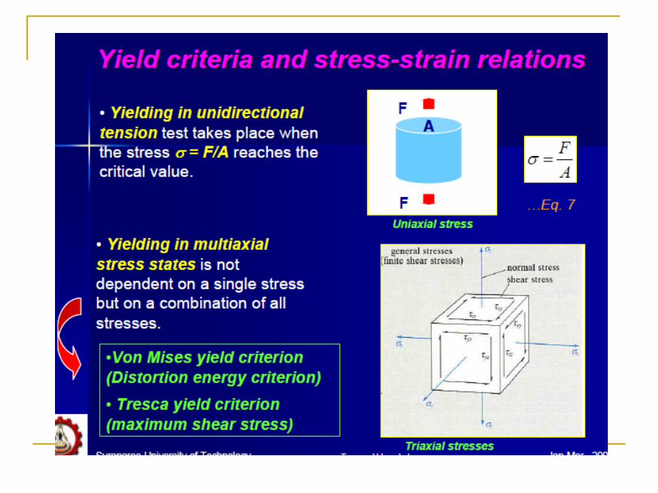
Stresses in Metal Forming
Stresses to plastically deform the metal are
usually compressive
Examples: rolling, forging, extrusion
However, some forming processes stretch the
metal (tensile stresses)
Others bend the metal (tensile and
compressive)
Still others apply shear stresses
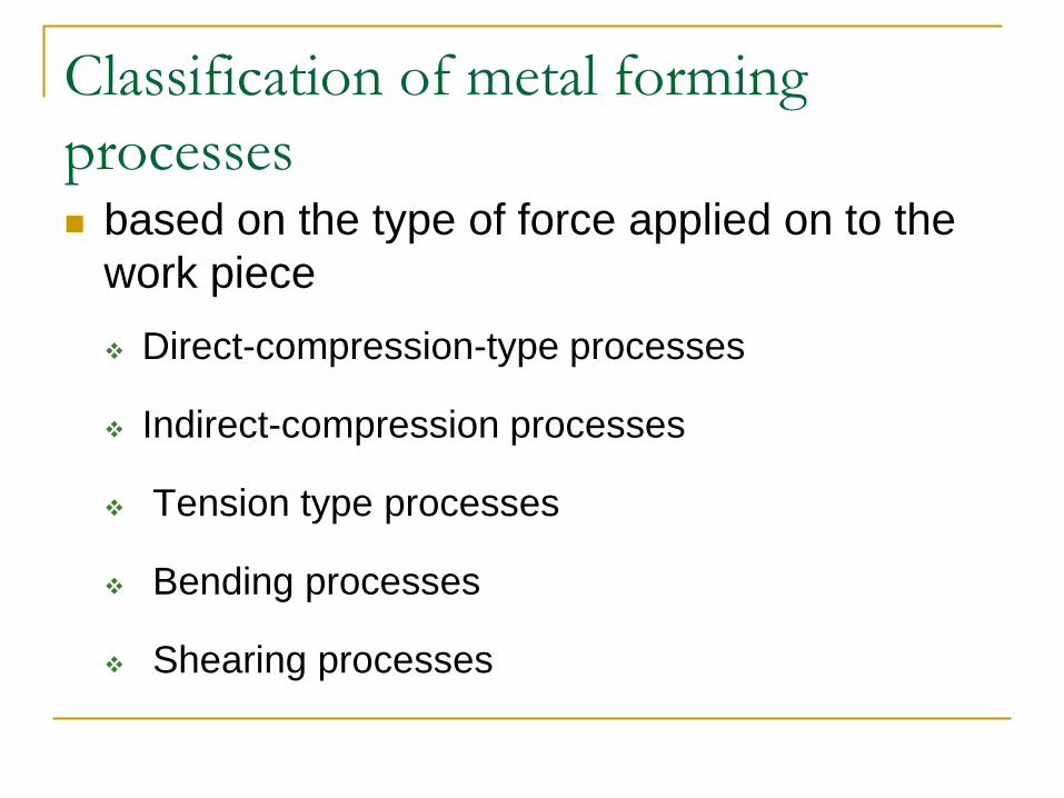
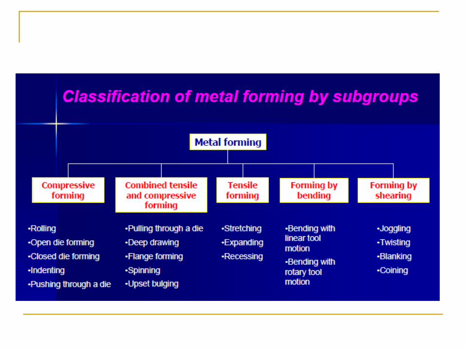
Classification of metal forming
processes
based on the type of force applied on to the
work piece
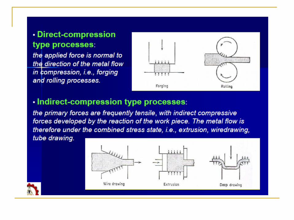
Direct-compression-type processes
Indirect-compression processes
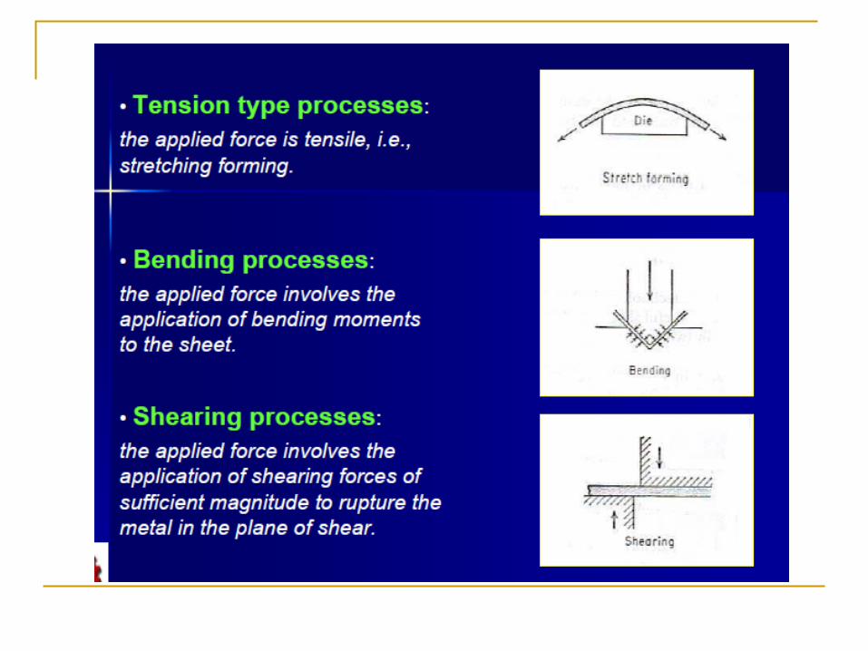
Tension type processes
Bending processes
Shearing processes

Material Properties in Metal Forming
Desirable material properties:
Low yield strength and high ductility
These properties are affected by temperature
Ductility increases and yield strength decreases
when work temperature is raised
Other factors:
Strain rate and friction
Bulk Deformation Processes
Characterized by significant deformations and
massive shape changes
"Bulk" refers to workparts with relatively low
surface area-to-volume ratios
Starting work shapes include cylindrical billets
and rectangular bars
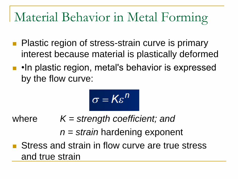
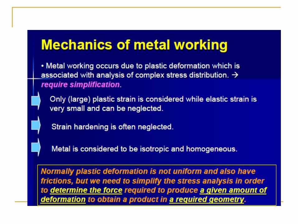
Material Behavior in Metal Forming
Plastic region of stress-strain curve is primary
interest because material is plastically deformed
•In plastic region, metal's behavior is expressed
by the flow curve:
where K = strength coefficient; and
n = strain hardening exponent
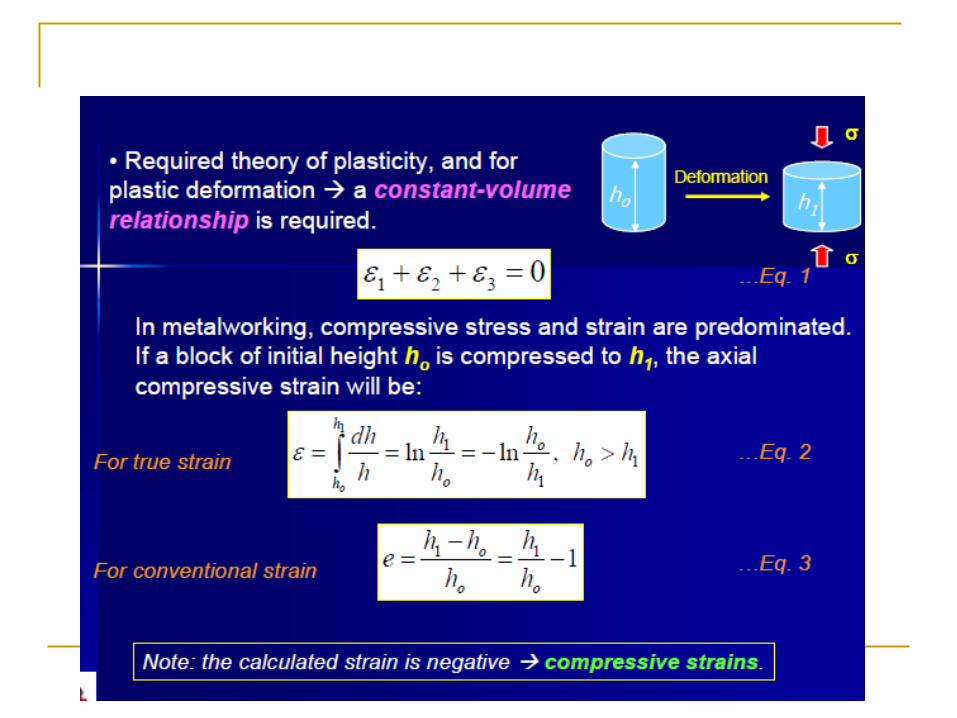
Stress and strain in flow curve are true stress
and true strain
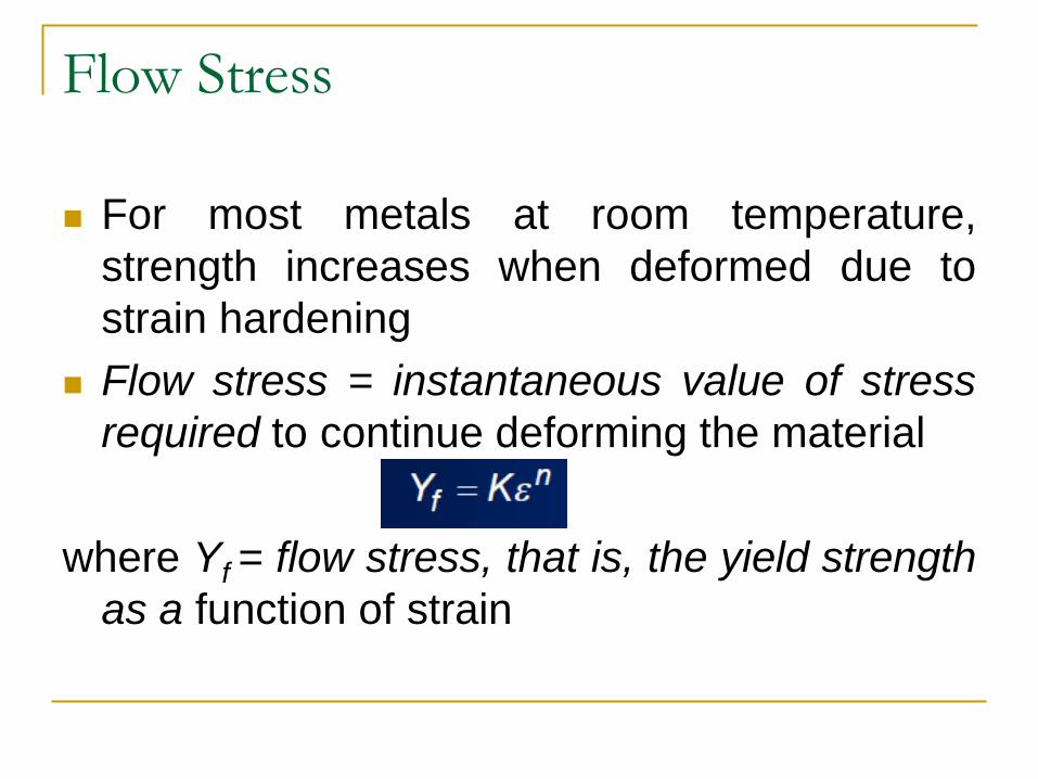
Flow Stress
For most metals at room temperature,
strength increases when deformed due to
strain hardening
Flow stress = instantaneous value of stress
required to continue deforming the material
where Yf = flow stress, that is, the yield strength
as a function of strain
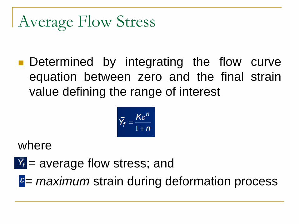
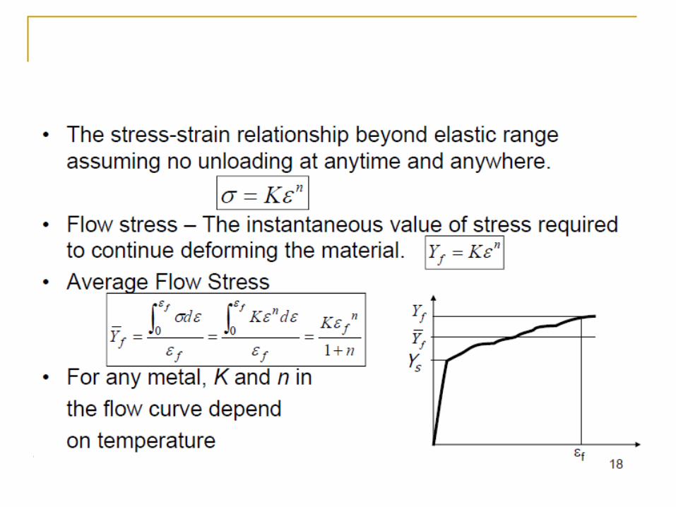
Average Flow Stress
Determined by integrating the flow curve
equation between zero and the final strain
value defining the range of interest
where
= average flow stress; and
= maximum strain during deformation process
Temperature in Metal Forming
For any metal, K and n in the flow curve
depend on temperature.
Both strength and strain hardening are
reduced at higher temperatures.
In addition, ductility is increased at higher
temperatures.
Temperature in Metal Forming
Any deformation operation can be
accomplished with lower forces and power at
elevated temperature
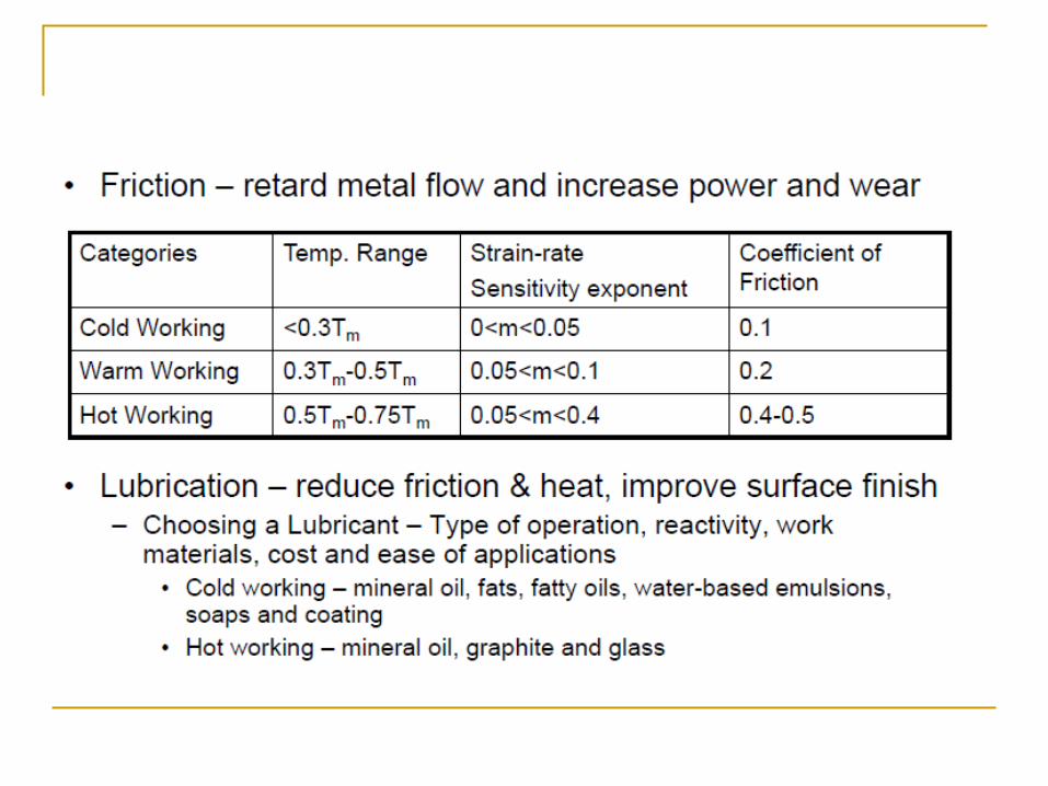
Three temperature ranges in metal forming:
Cold working
Warm working
Hot working
Strain Rate Sensitivity
Theoretically, a metal in hot working behaves like a
perfectly plastic material, with strain hardening
exponent n = 0
The metal should continue to flow at the same flow stress,
once that stress is reached
However, an additional phenomenon occurs during
deformation, especially at elevated temperatures:
Strain rate sensitivity
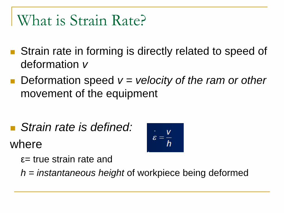
What is Strain Rate?
Strain rate in forming is directly related to speed of
deformation v
Deformation speed v = velocity of the ram or other
movement of the equipment
Strain rate is defined:
where
ε= true strain rate and
h = instantaneous height of workpiece being deformed
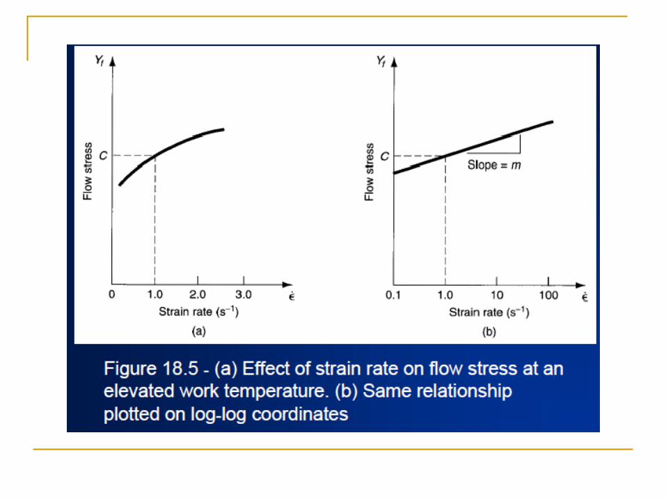
Effect of Strain Rate on Flow Stress
Flow stress is a function of temperature
At hot working temperatures, flow stress also
depends on strain rate
As strain rate increases, resistance to
deformation increases
This effect is known as strain-rate sensitivity
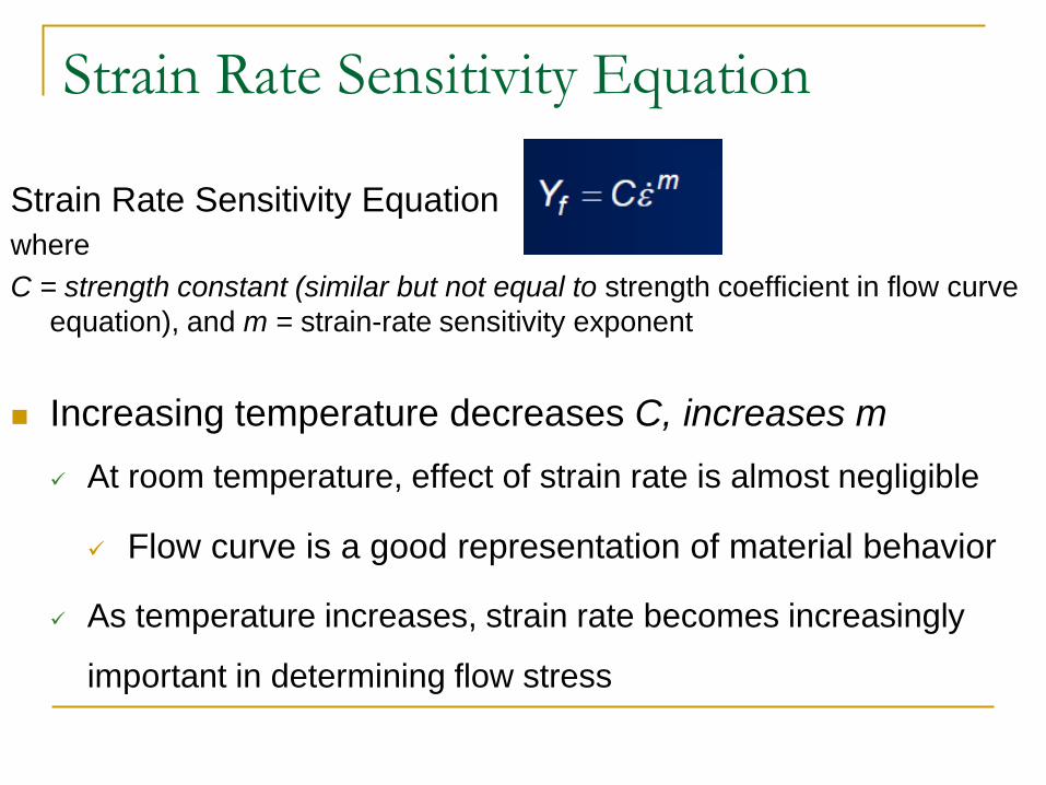
Strain Rate Sensitivity Equation
Strain Rate Sensitivity Equation
where
C = strength constant (similar but not equal to strength coefficient in flow curve
equation), and m = strain-rate sensitivity exponent
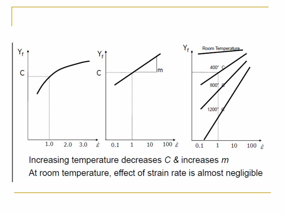
Increasing temperature decreases C, increases m
At room temperature, effect of strain rate is almost negligible
Flow curve is a good representation of material behavior
As temperature increases, strain rate becomes increasingly
important in determining flow stress
Friction in Metal Forming
In most metal forming processes, friction is
undesirable:
Metal flow is retarded
Forces and power are increased
Wears tooling faster
Friction and tool wear are more severe in hot
working
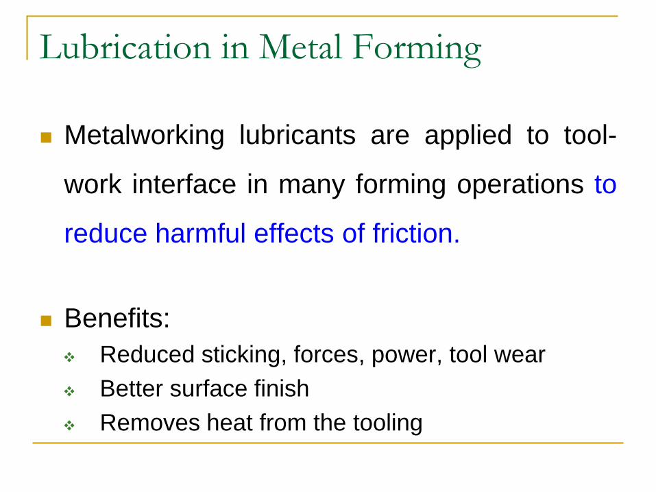
Lubrication in Metal Forming
Metalworking lubricants are applied to tool-
work interface in many forming operations to
reduce harmful effects of friction.
Benefits:
Reduced sticking, forces, power, tool wear
Better surface finish
Removes heat from the tooling
Considerations in Choosing a
Lubricant
Type of forming process (rolling, forging,
sheet metal drawing, etc.)
Hot working or cold working
Work material
Chemical reactivity with tool and work metals
Ease of application
Cost
Manufacturing Technology
Hot Working: T>0.5Tm
Mechanical working of a metal above the recrystallization
temperature but below the melting point is known as hot working.
The temperature at which the complete recrystallization of a metal
take place with in a specified time
The recrystallization temperature of metal will be about 30 to 40% of
its melting temperature.
Types
Forging
Rolling
Extrusion
Drawing
Manufacturing Technology
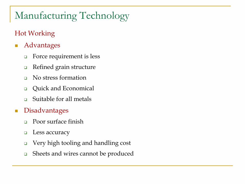
Hot Working
Advantages
Force requirement is less
Refined grain structure
No stress formation
Quick and Economical
Suitable for all metals
Disadvantages
Poor surface finish
Less accuracy
Very high tooling and handling cost
Sheets and wires cannot be produced
Manufacturing Technology
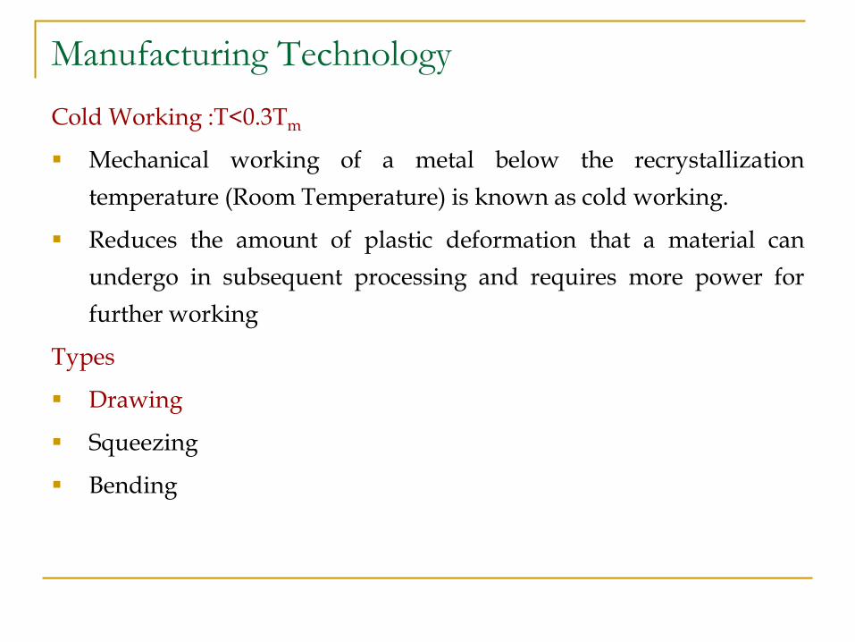
Cold Working :T<0.3Tm
Mechanical working of a metal below the recrystallization
temperature (Room Temperature) is known as cold working.
Reduces the amount of plastic deformation that a material can
undergo in subsequent processing and requires more power for
further working
Types
Drawing
Squeezing
Bending
Manufacturing Technology
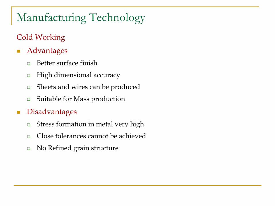
Cold Working
Advantages
Better surface finish
High dimensional accuracy
Sheets and wires can be produced
Suitable for Mass production
Disadvantages
Stress formation in metal very high
Close tolerances cannot be achieved
No Refined grain structure
Manufacturing Technology
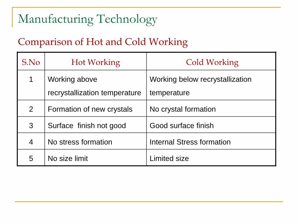
Comparison of Hot and Cold Working
S.No Hot Working Cold Working
1 Working above
recrystallization temperature
Working below recrystallization
temperature
2 Formation of new crystals No crystal formation
3 Surface finish not good Good surface finish
4 No stress formation Internal Stress formation
5 No size limit Limited size

Manufacturing Technology
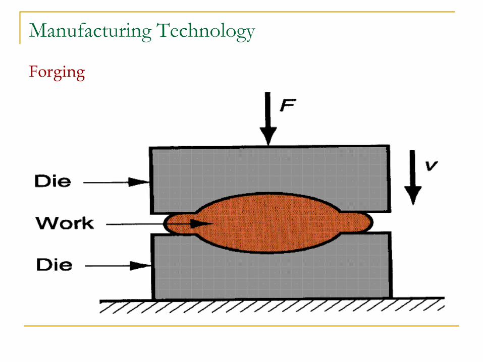
Forging
Forging is a process in which the work piece is shaped by
compressive forces applied through various dies and tools. It is one
of the oldest metalworking operations. Most forgings require a set
of dies and a press or a forging hammer.
Unlike rolling operations, which generally produce continuous
plates, sheets, strip, or various structural cross-sections, forging
operations produce discrete parts.
Typical forged products are bolts and rivets, connecting rods, shafts
for turbines, gears, hand tools, and structural components for
machinery, aircraft, railroads and a variety of other transportation
equipment.
Manufacturing Technology
Forging
Manufacturing Technology
Forging Methods
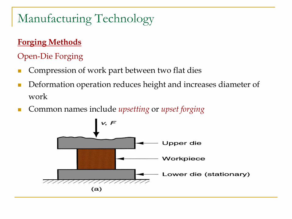
Open-Die Forging
Compression of work part between two flat dies
Deformation operation reduces height and increases diameter of
work
Common names include upsetting or upset forging
Manufacturing Technology
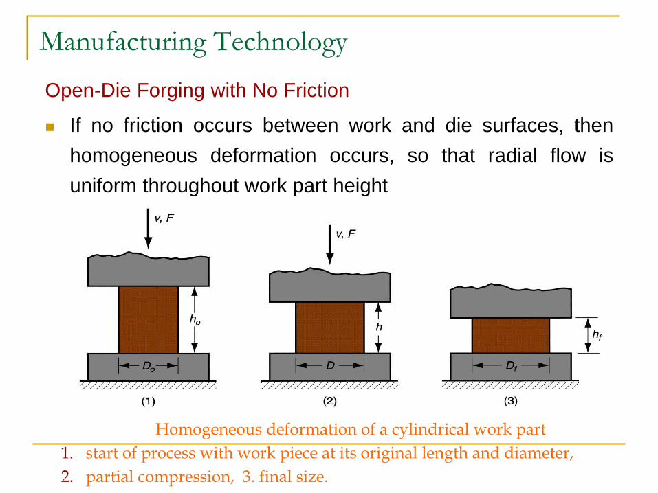
Open-Die Forging with No Friction
If no friction occurs between work and die surfaces, then
homogeneous deformation occurs, so that radial flow is
uniform throughout work part height
Homogeneous deformation of a cylindrical work part
1. start of process with work piece at its original length and diameter,
2. partial compression, 3. final size.
Manufacturing Technology
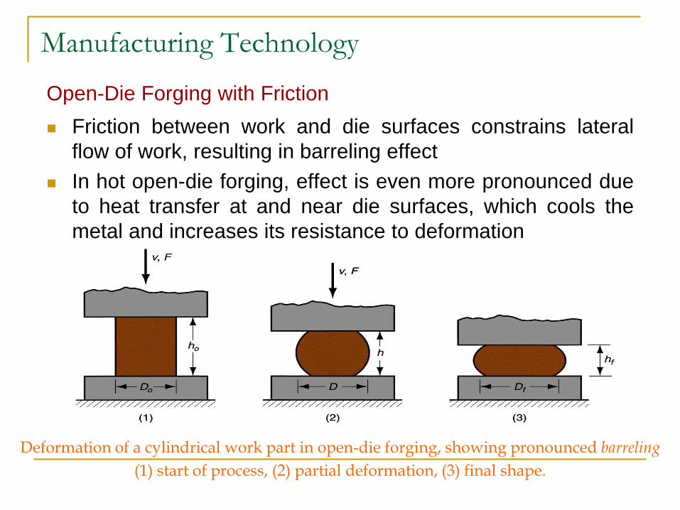
Open-Die Forging with Friction
Friction between work and die surfaces constrains lateral
flow of work, resulting in barreling effect
In hot open-die forging, effect is even more pronounced due
to heat transfer at and near die surfaces, which cools the
metal and increases its resistance to deformation
Deformation of a cylindrical work part in open-die forging, showing pronounced barreling
(1) start of process, (2) partial deformation, (3) final shape.
Manufacturing Technology
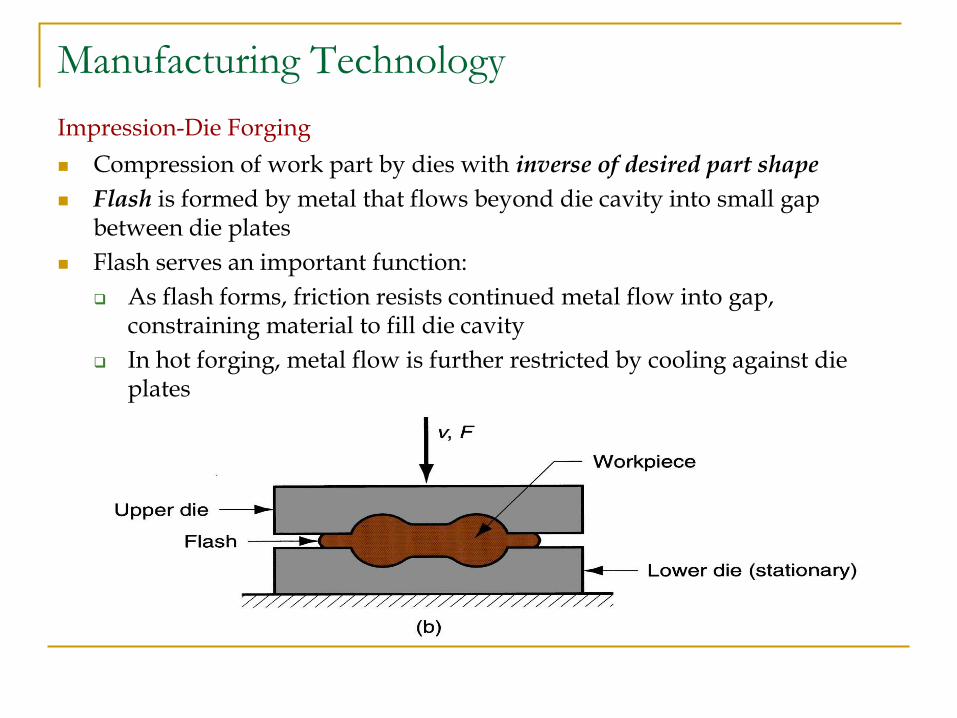
Impression-Die Forging
Compression of work part by dies with inverse of desired part shape
Flash is formed by metal that flows beyond die cavity into small gap between die plates
Flash serves an important function:
As flash forms, friction resists continued metal flow into gap, constraining material to fill die cavity
In hot forging, metal flow is further restricted by cooling against die plates
Manufacturing Technology
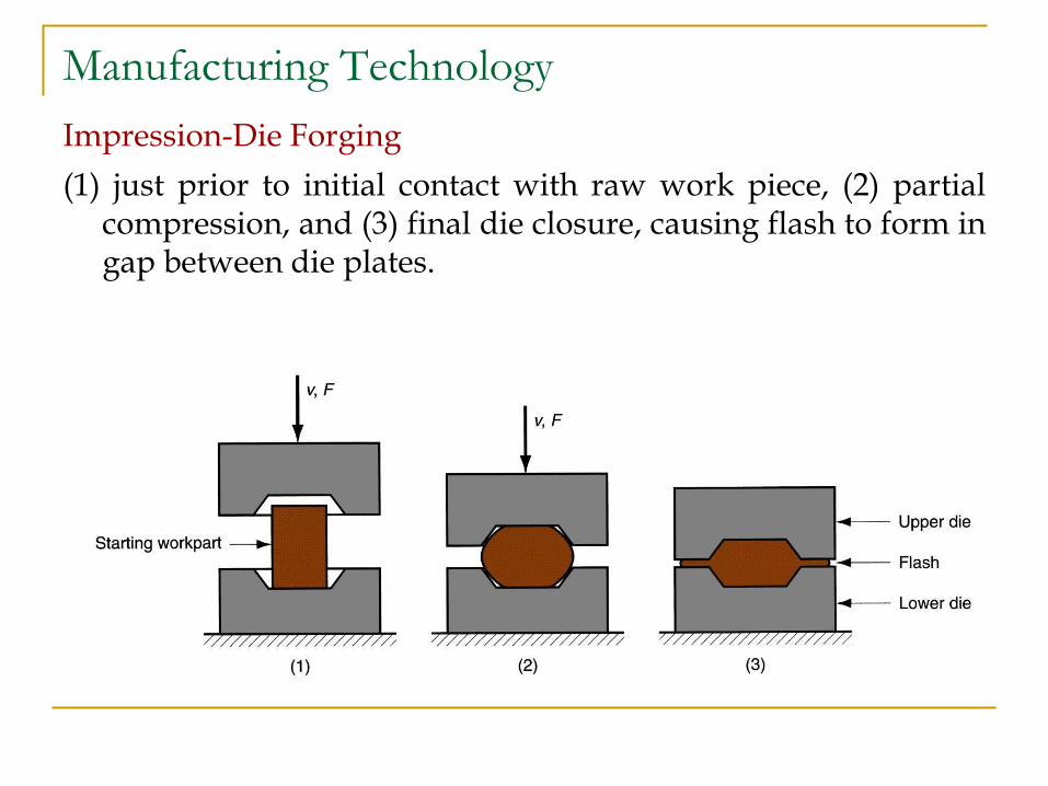
Impression-Die Forging
(1) just prior to initial contact with raw work piece, (2) partial compression, and (3) final die closure, causing flash to form in gap between die plates.
Manufacturing Technology
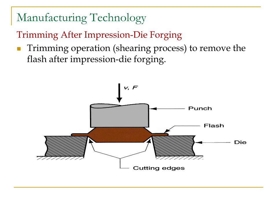
Trimming After Impression-Die Forging
Trimming operation (shearing process) to remove the flash after impression-die forging.
Manufacturing Technology
Advantages of impression-die forging compared to
machining from solid stock:
Higher production rates
Less waste of metal
Greater strength
Favorable grain orientation in the metal
Limitations:
Not capable of close tolerances
Machining often required to achieve accuracies and
features needed
Manufacturing Technology
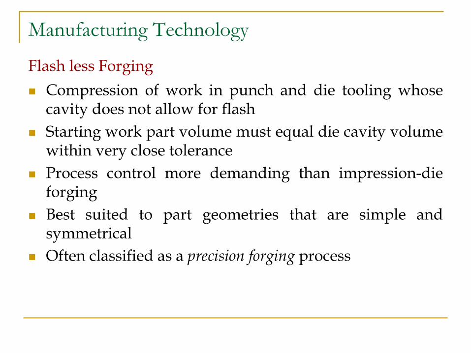
Flash less Forging
Compression of work in punch and die tooling whose cavity does not allow for flash
Starting work part volume must equal die cavity volume within very close tolerance
Process control more demanding than impression-die forging
Best suited to part geometries that are simple and symmetrical
Often classified as a precision forging process
Manufacturing Technology
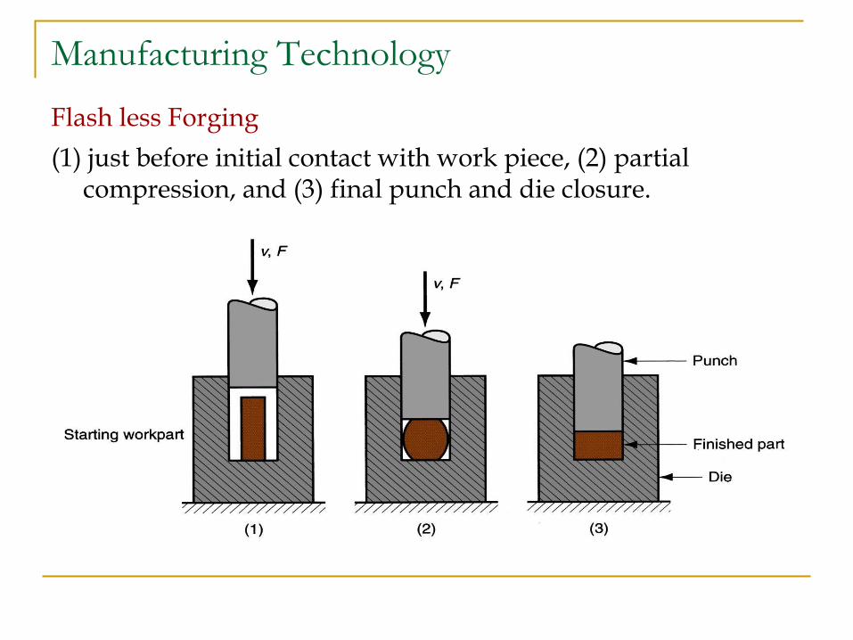
Flash less Forging
(1) just before initial contact with work piece, (2) partial compression, and (3) final punch and die closure.
Manufacturing Technology
Forging Hammers (Drop Hammers)
Apply impact load against work part
Two types
Gravity drop hammers - impact energy from falling
weight of a heavy ram
Power drop hammers - accelerate the ram by
pressurized air or steam
Disadvantage: impact energy transmitted through anvil
into floor of building
Commonly used for impression-die forging
Manufacturing Technology
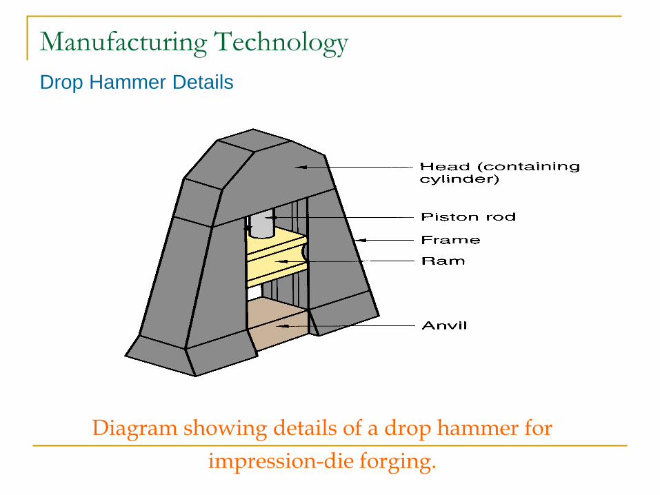
Drop Hammer Details
Diagram showing details of a drop hammer for
impression-die forging.
Manufacturing Technology
Forging Presses
Apply gradual pressure to accomplish compression operation
Types
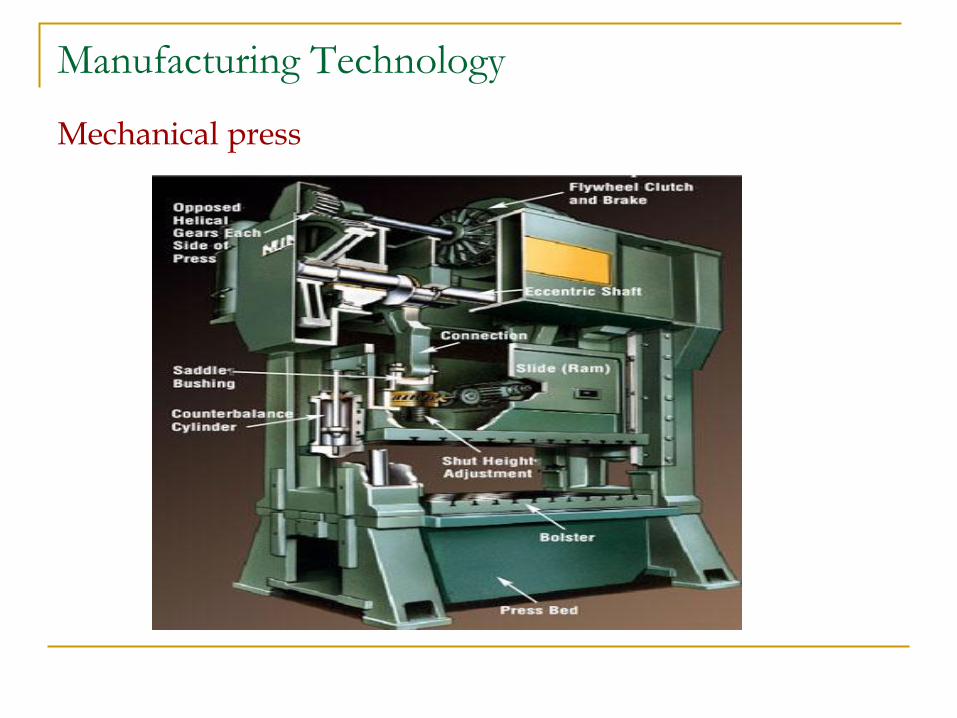
Mechanical press - converts rotation of drive motor into linear motion of ram
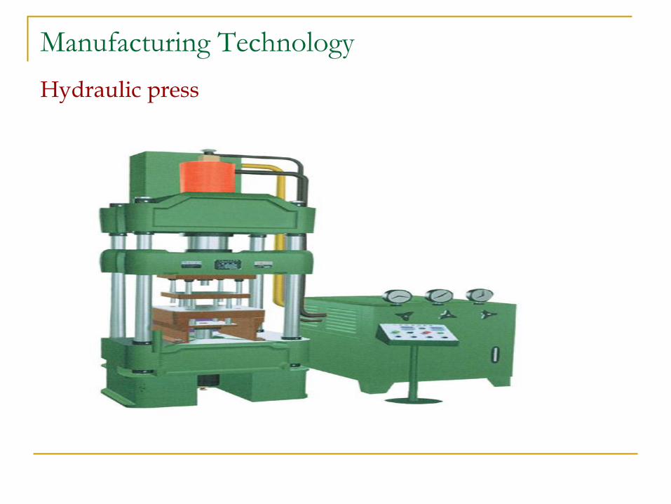
Hydraulic press - hydraulic piston actuates ram
Screw press - screw mechanism drives ram
Manufacturing Technology
Mechanical press
Manufacturing Technology
Hydraulic press
Manufacturing Technology
Upsetting and Heading
Forging process used to form heads on nails, bolts, and similar hardware products
More parts produced by upsetting than any other forging operation
Performed cold, warm, or hot on machines called headers or formers
Wire or bar stock is fed into machine, end is headed, then piece is cut to length
For bolts and screws, thread rolling is then used to form threads
Manufacturing Technology
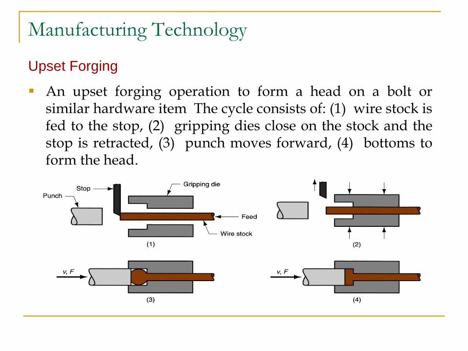
Upset Forging
An upset forging operation to form a head on a bolt or similar hardware item The cycle consists of: (1) wire stock is fed to the stop, (2) gripping dies close on the stock and the stop is retracted, (3) punch moves forward, (4) bottoms to form the head.
Manufacturing Technology
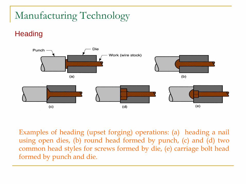
Heading
Examples of heading (upset forging) operations: (a) heading a nail using open dies, (b) round head formed by punch, (c) and (d) two common head styles for screws formed by die, (e) carriage bolt head formed by punch and die.
Manufacturing Technology
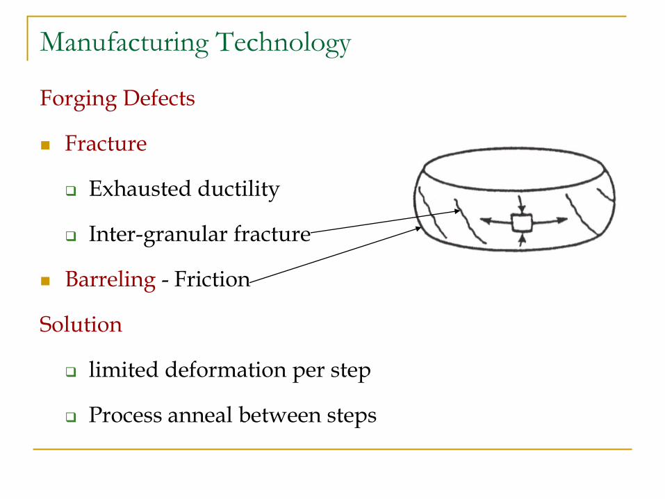
Forging Defects
Fracture
Exhausted ductility
Inter-granular fracture
Barreling - Friction
Solution
limited deformation per step
Process anneal between steps
Manufacturing Technology
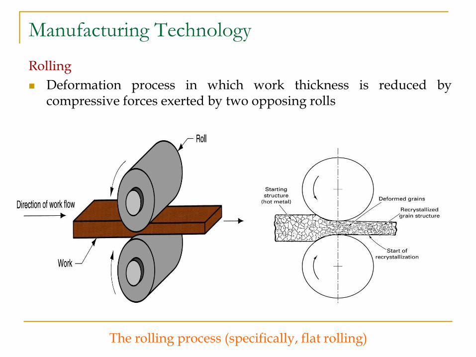
Rolling
Deformation process in which work thickness is reduced by compressive forces exerted by two opposing rolls
The rolling process (specifically, flat rolling)
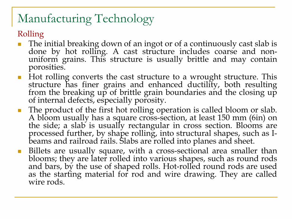
Manufacturing Technology Rolling The initial breaking down of an ingot or of a continuously cast slab is
done by hot rolling. A cast structure includes coarse and non-uniform grains. This structure is usually brittle and may contain porosities.
Hot rolling converts the cast structure to a wrought structure. This structure has finer grains and enhanced ductility, both resulting from the breaking up of brittle grain boundaries and the closing up of internal defects, especially porosity.
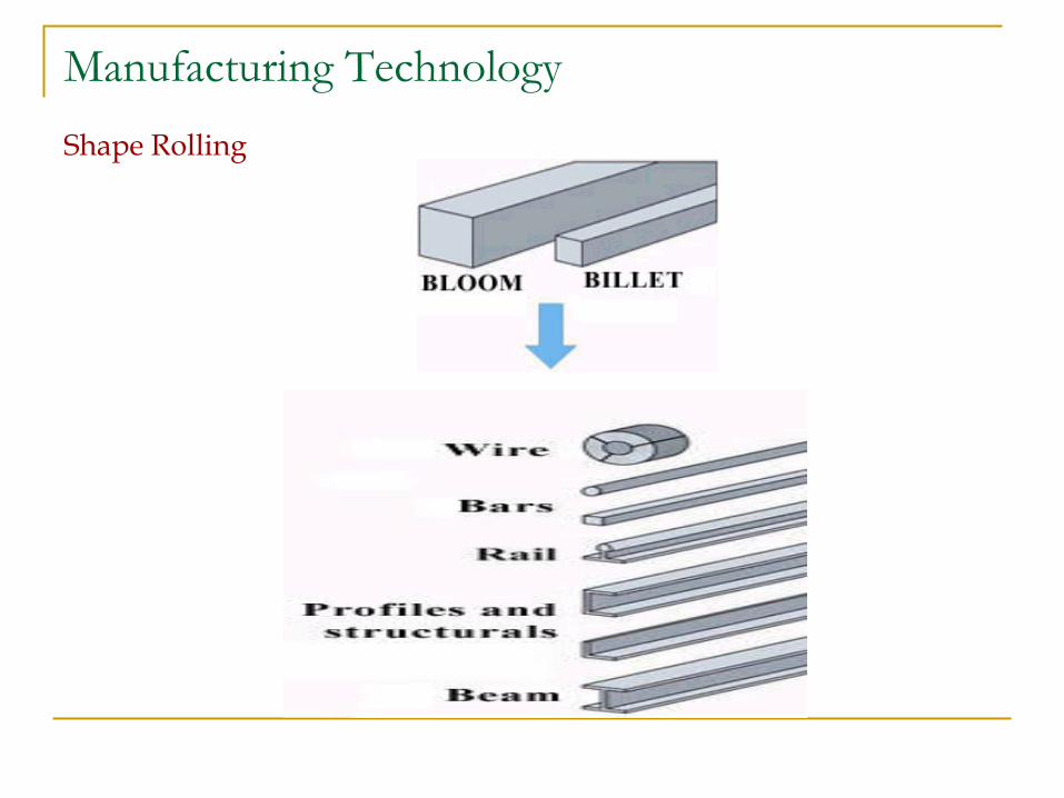
The product of the first hot rolling operation is called bloom or slab. A bloom usually has a square cross-section, at least 150 mm (6in) on the side; a slab is usually rectangular in cross section. Blooms are processed further, by shape rolling, into structural shapes, such as I-beams and railroad rails. Slabs are rolled into planes and sheet.
Billets are usually square, with a cross-sectional area smaller than blooms; they are later rolled into various shapes, such as round rods and bars, by the use of shaped rolls. Hot-rolled round rods are used as the starting material for rod and wire drawing. They are called wire rods.
Manufacturing Technology
Rolling
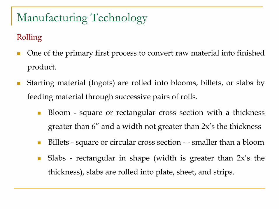
One of the primary first process to convert raw material into finished
product.
Starting material (Ingots) are rolled into blooms, billets, or slabs by
feeding material through successive pairs of rolls.
Bloom - square or rectangular cross section with a thickness
greater than 6” and a width not greater than 2x’s the thickness
Billets - square or circular cross section - - smaller than a bloom
Slabs - rectangular in shape (width is greater than 2x’s the
thickness), slabs are rolled into plate, sheet, and strips.
Manufacturing Technology
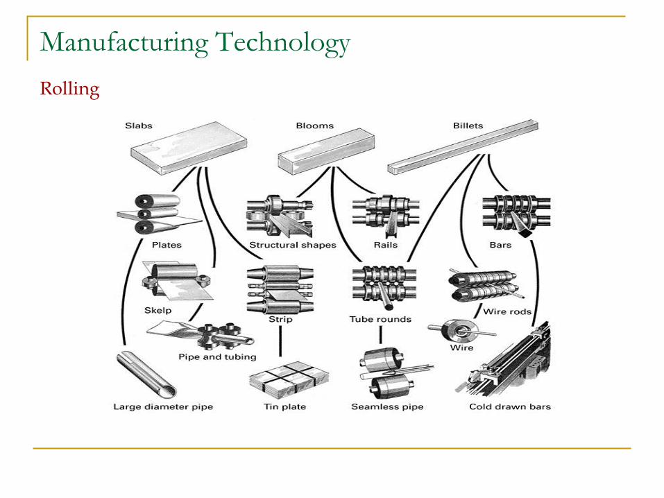
Rolling
Manufacturing Technology
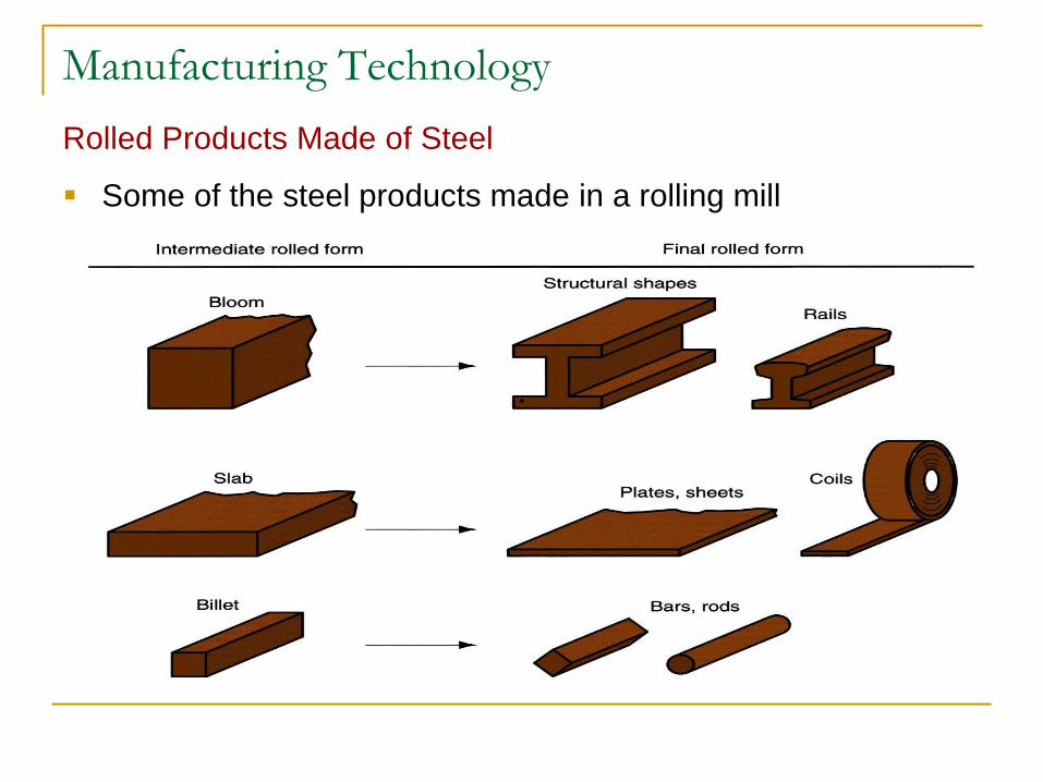
Rolled Products Made of Steel
Some of the steel products made in a rolling mill
.
Manufacturing Technology
Rotating rolls perform two main functions:
Pull the work into the gap between them by friction
between work part and rolls
Simultaneously squeeze the work to reduce its cross
section
Manufacturing Technology
Types of Rolling
Based on work piece geometry :
Flat rolling - used to reduce thickness of a rectangular cross
section
Shape rolling - square cross section is formed into a shape
such as an I-beam
Based on work temperature :
Hot Rolling – most common due to the large amount of
deformation required
Cold rolling – produces finished sheet and plate stock
Manufacturing Technology
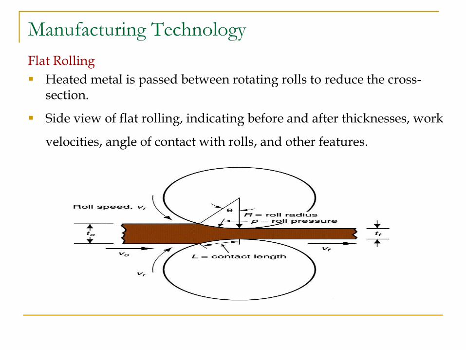
Flat Rolling
Heated metal is passed between rotating rolls to reduce the cross-section.
Side view of flat rolling, indicating before and after thicknesses, work
velocities, angle of contact with rolls, and other features.
Manufacturing Technology
Shape Rolling
Work is deformed into a contoured cross section rather than
flat (rectangular)
Accomplished by passing work through rolls that have the
reverse of desired shape
Products include:
Construction shapes such as I-beams, L-beams, and
U-channels
Rails for railroad tracks
Round and square bars and rods
Manufacturing Technology
Shape Rolling
Manufacturing Technology
Thread Rolling
Bulk deformation process used to form threads on cylindrical
parts by rolling them between two dies
Important commercial process for mass producing bolts and
screws
Performed by cold working in thread rolling machines
Advantages over thread cutting (machining):
Higher production rates
Better material utilization
Stronger threads and better fatigue resistance due to work
hardening
Manufacturing Technology
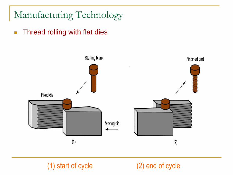
Thread rolling with flat dies
(1) start of cycle (2) end of cycle
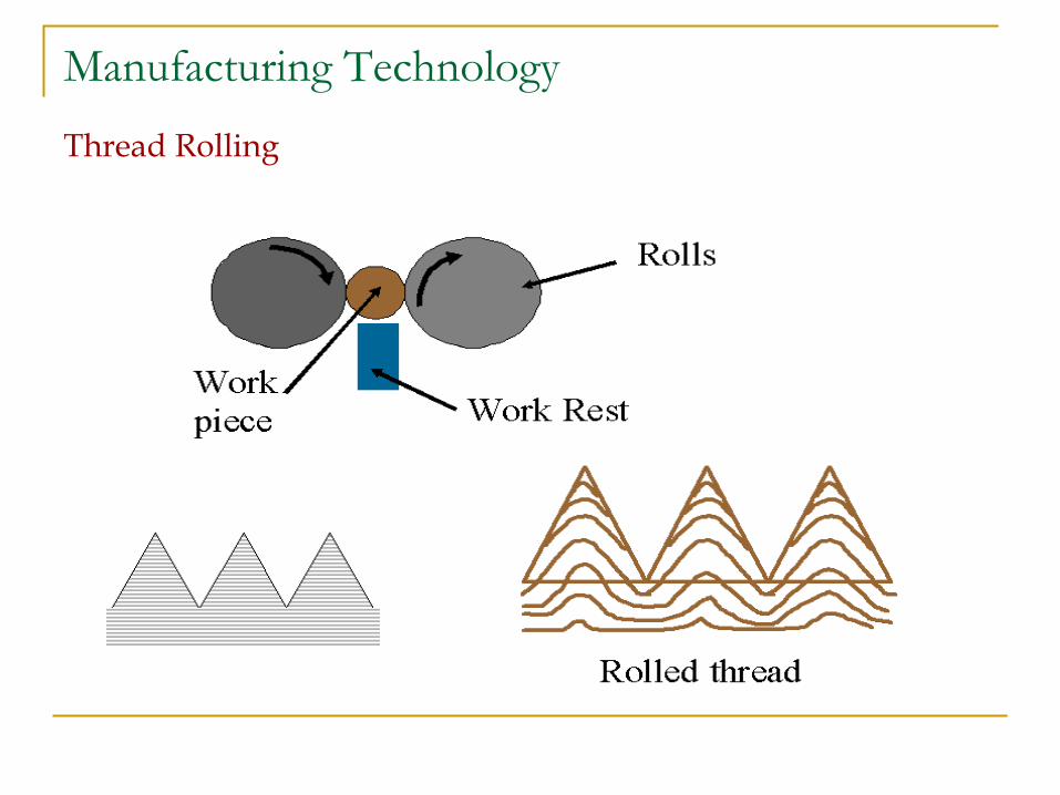
Manufacturing Technology
Thread Rolling
Manufacturing Technology
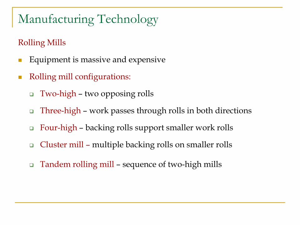
Rolling Mills
Equipment is massive and expensive
Rolling mill configurations:
Two-high – two opposing rolls
Three-high – work passes through rolls in both directions
Four-high – backing rolls support smaller work rolls
Cluster mill – multiple backing rolls on smaller rolls
Tandem rolling mill – sequence of two-high mills
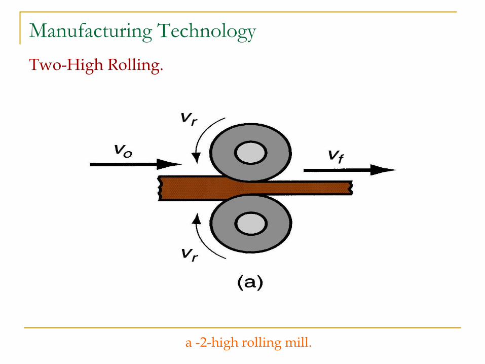
Manufacturing Technology
Two-High Rolling.
a -2-high rolling mill.
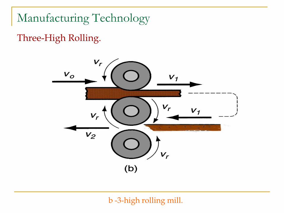
Manufacturing Technology
Three-High Rolling.
b -3-high rolling mill.
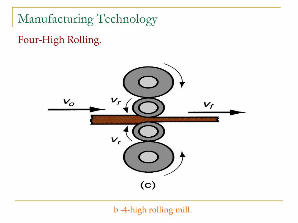
Manufacturing Technology
Four-High Rolling.
b -4-high rolling mill.

Manufacturing Technology
Cluster Mill
d -Cluster mill.
Manufacturing Technology
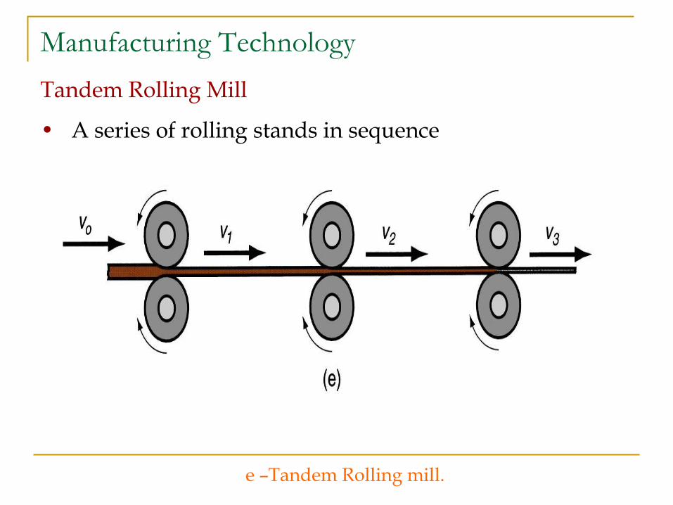
Tandem Rolling Mill
• A series of rolling stands in sequence
e –Tandem Rolling mill.

Manufacturing Technology
Rolling Defects
Waviness-a
Improper roller speeds
Zipper cracks-b
Too much rolling in center
Edge cracks-c
Too much rolling on outside
Alligatoring-d
Too much induced tensile stress in the part, or defects
Manufacturing Technology
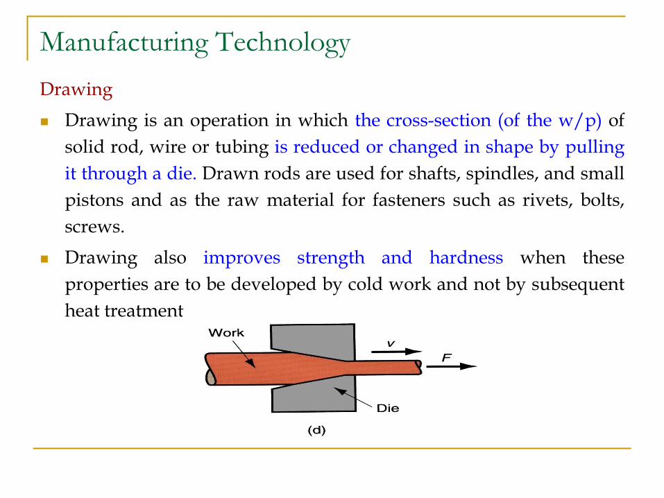
Drawing
Drawing is an operation in which the cross-section (of the w/p) of
solid rod, wire or tubing is reduced or changed in shape by pulling
it through a die. Drawn rods are used for shafts, spindles, and small
pistons and as the raw material for fasteners such as rivets, bolts,
screws.
Drawing also improves strength and hardness when these
properties are to be developed by cold work and not by subsequent
heat treatment.
Manufacturing Technology
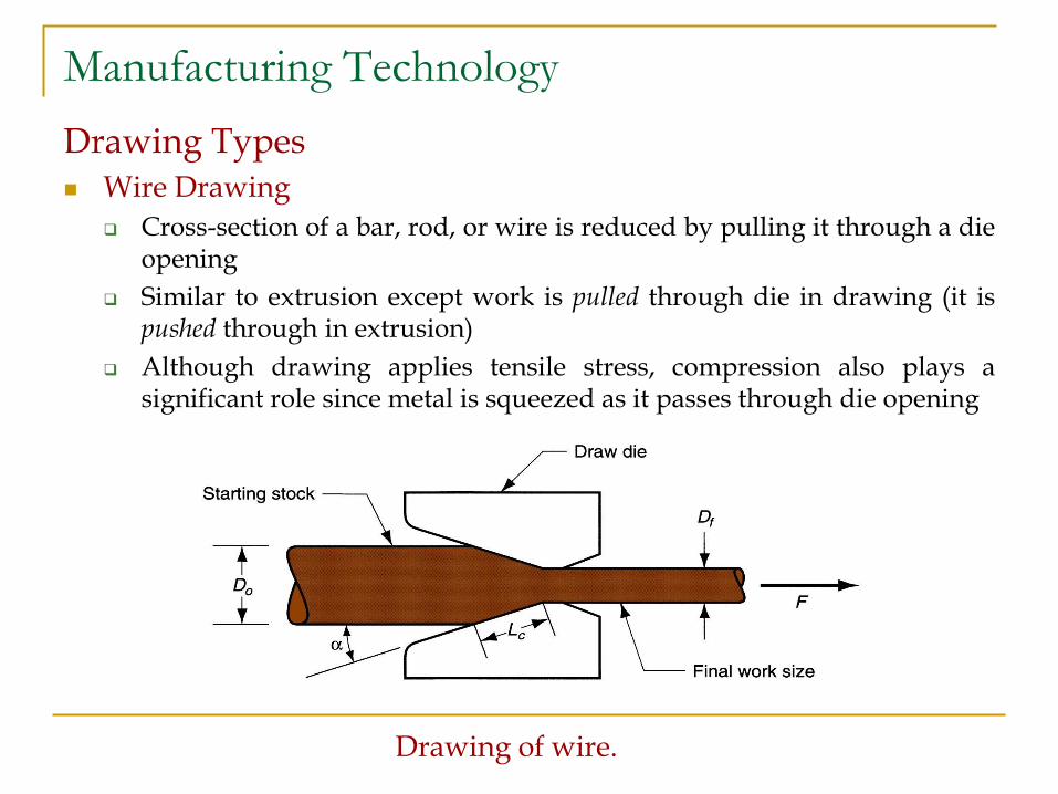
Drawing Types Wire Drawing
Cross-section of a bar, rod, or wire is reduced by pulling it through a die opening
Similar to extrusion except work is pulled through die in drawing (it is pushed through in extrusion)
Although drawing applies tensile stress, compression also plays a significant role since metal is squeezed as it passes through die opening
Drawing of wire.
Manufacturing Technology
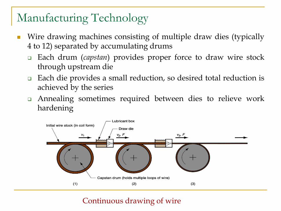
Wire drawing machines consisting of multiple draw dies (typically 4 to 12) separated by accumulating drums
Each drum (capstan) provides proper force to draw wire stock through upstream die
Each die provides a small reduction, so desired total reduction is achieved by the series
Annealing sometimes required between dies to relieve work hardening
Continuous drawing of wire
Manufacturing Technology
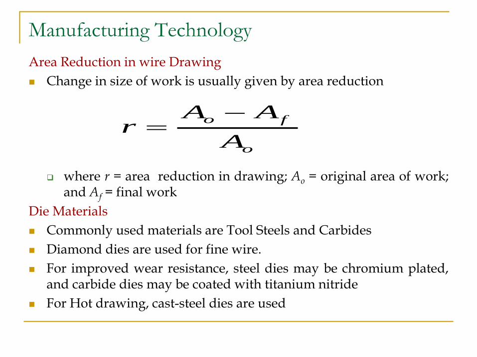
Area Reduction in wire Drawing
Change in size of work is usually given by area reduction
where r = area reduction in drawing; Ao = original area of work; and Af = final work
Die Materials
Commonly used materials are Tool Steels and Carbides
Diamond dies are used for fine wire.
For improved wear resistance, steel dies may be chromium plated, and carbide dies may be coated with titanium nitride
For Hot drawing, cast-steel dies are used
o
fo
A
AAr
Manufacturing Technology
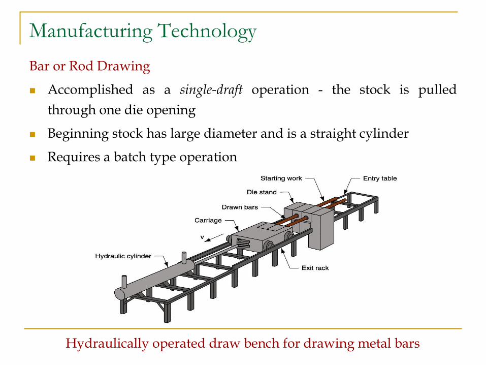
Bar or Rod Drawing
Accomplished as a single-draft operation - the stock is pulled
through one die opening
Beginning stock has large diameter and is a straight cylinder
Requires a batch type operation
Hydraulically operated draw bench for drawing metal bars
Manufacturing Technology
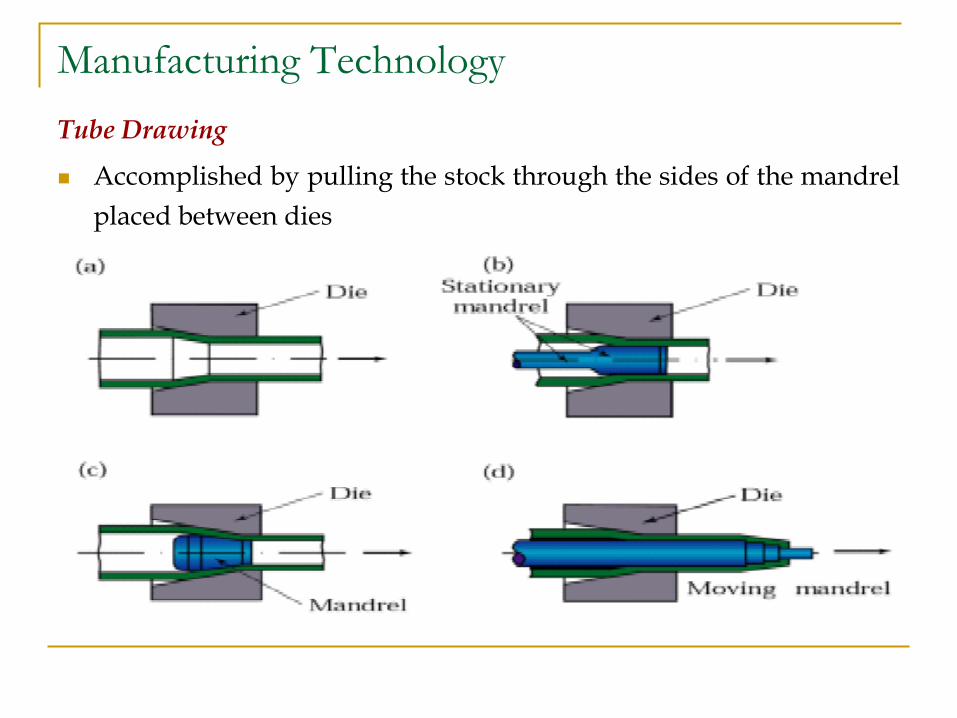
Tube Drawing
Accomplished by pulling the stock through the sides of the mandrel
placed between dies
Manufacturing Technology
Wire Drawing vs. Bar Drawing
Difference between bar drawing and wire drawing is stock size
Bar drawing - large diameter bar and rod stock
Wire drawing - small diameter stock - wire sizes down to 0.03
mm (0.001 in.) are possible
Although the mechanics are the same, the methods, equipment, and
even terminology are different
Manufacturing Technology
Preparation of Work for Drawing
Annealing – to increase ductility of stock
Cleaning - to prevent damage to work surface and draw die
Pointing – to reduce diameter of starting end to allow
insertion through draw die
Manufacturing Technology
Features of a Draw Die
Entry region - funnels lubricant into the die to prevent
scoring of work and die
Approach - cone-shaped region where drawing occurs
Bearing surface - determines final stock size
Back relief - exit zone - provided with a back relief angle
(half-angle) of about 30
Die materials: tool steels or cemented carbides
Manufacturing Technology
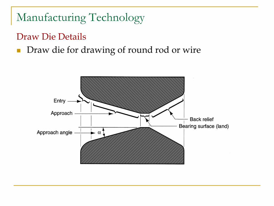
Draw Die Details
Draw die for drawing of round rod or wire
Manufacturing Technology
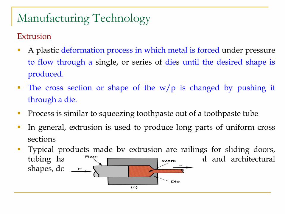
Extrusion
A plastic deformation process in which metal is forced under pressure
to flow through a single, or series of dies until the desired shape is
produced.
The cross section or shape of the w/p is changed by pushing it
through a die.
Process is similar to squeezing toothpaste out of a toothpaste tube
In general, extrusion is used to produce long parts of uniform cross
sections
Typical products made by extrusion are railings for sliding doors, tubing having carious cross-sections, structural and architectural shapes, door and windows frames.
Manufacturing Technology
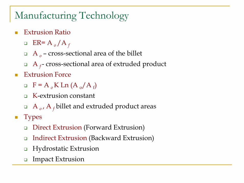
Extrusion Ratio
ER= A o /A f
A o – cross-sectional area of the billet
A f - cross-sectional area of extruded product
Extrusion Force
F = A o K Ln (A o/A f)
K-extrusion constant
A o , A f billet and extruded product areas
Types
Direct Extrusion (Forward Extrusion)
Indirect Extrusion (Backward Extrusion)
Hydrostatic Extrusion
Impact Extrusion
Manufacturing Technology
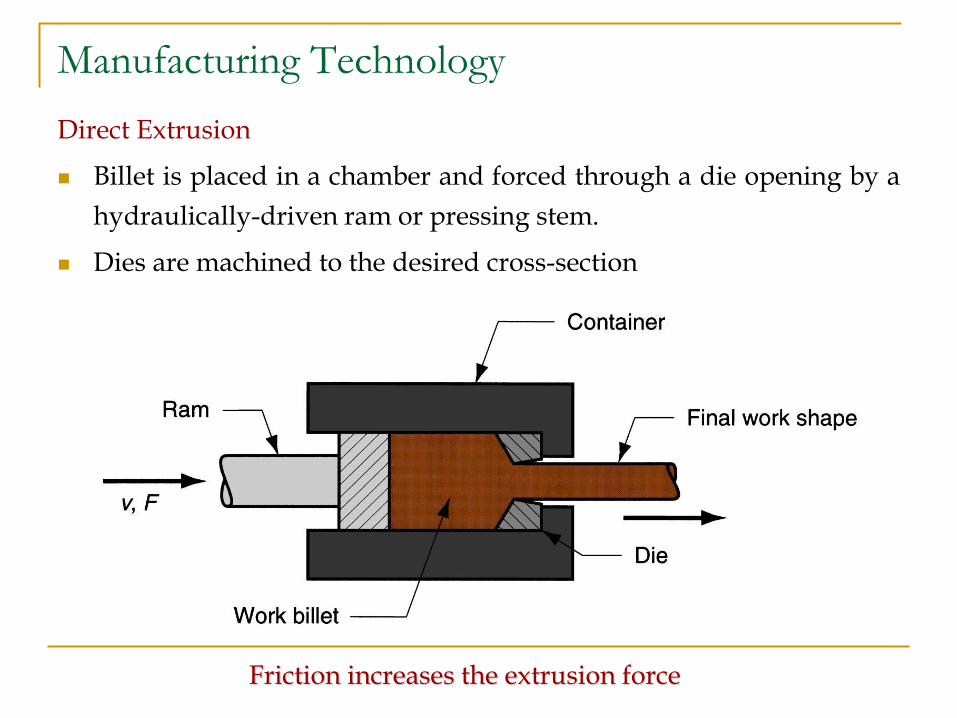
Direct Extrusion
Billet is placed in a chamber and forced through a die opening by a
hydraulically-driven ram or pressing stem.
Dies are machined to the desired cross-section
Friction increases the extrusion force
Manufacturing Technology
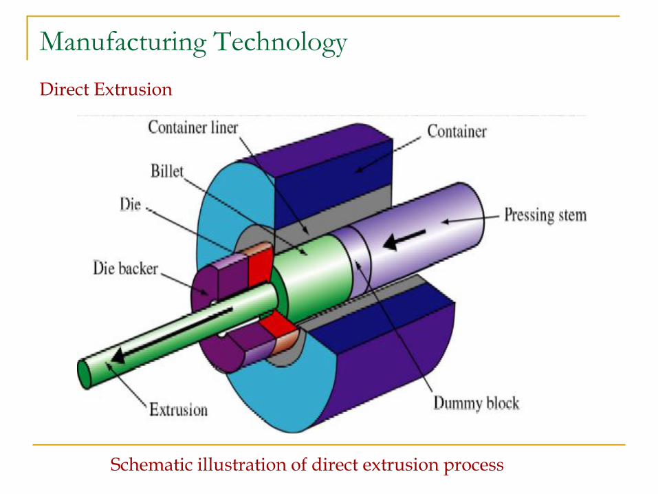
Direct Extrusion
Schematic illustration of direct extrusion process
Manufacturing Technology
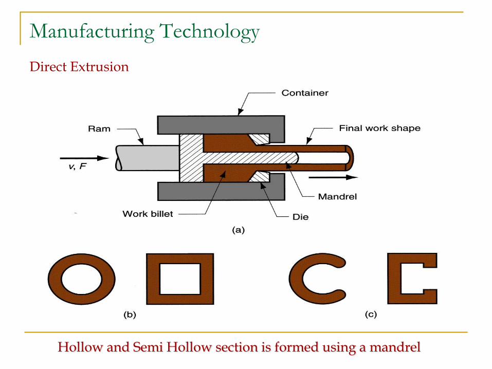
Direct Extrusion
Hollow and Semi Hollow section is formed using a mandrel
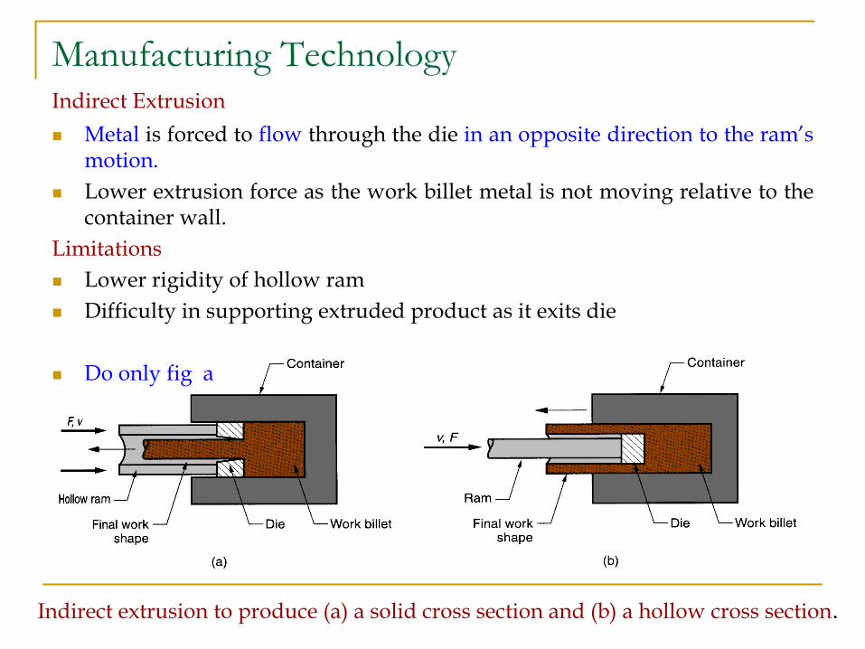
Manufacturing Technology Indirect Extrusion
Metal is forced to flow through the die in an opposite direction to the ram’s motion.
Lower extrusion force as the work billet metal is not moving relative to the container wall.
Limitations
Lower rigidity of hollow ram
Difficulty in supporting extruded product as it exits die
Do only fig a
Indirect extrusion to produce (a) a solid cross section and (b) a hollow cross section.
Manufacturing Technology
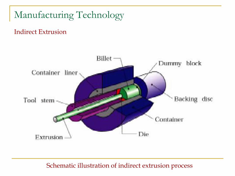
Indirect Extrusion
Schematic illustration of indirect extrusion process
Manufacturing Technology
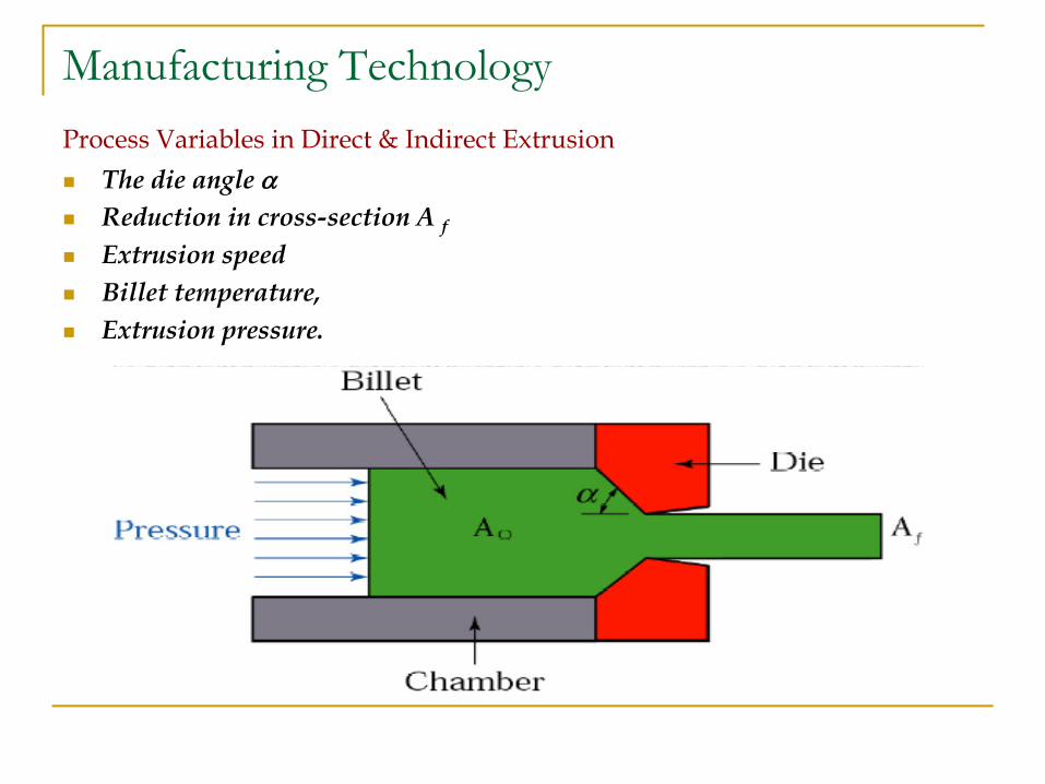
Process Variables in Direct & Indirect Extrusion
The die angle
Reduction in cross-section A f
Extrusion speed
Billet temperature,
Extrusion pressure.
Manufacturing Technology
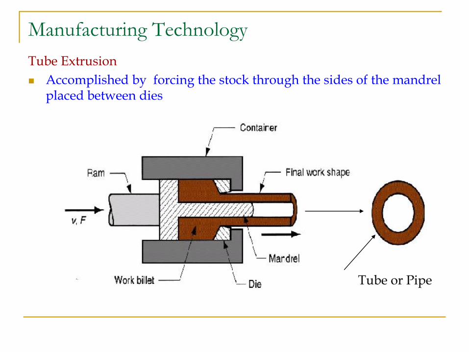
Tube Extrusion
Manufacturing Technology
Tube Extrusion
Accomplished by forcing the stock through the sides of the mandrel placed between dies
Tube or Pipe
Manufacturing Technology
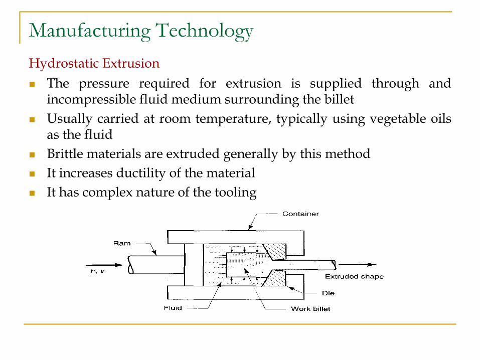
Hydrostatic Extrusion
The pressure required for extrusion is supplied through and incompressible fluid medium surrounding the billet
Usually carried at room temperature, typically using vegetable oils as the fluid
Brittle materials are extruded generally by this method
It increases ductility of the material
It has complex nature of the tooling
Manufacturing Technology
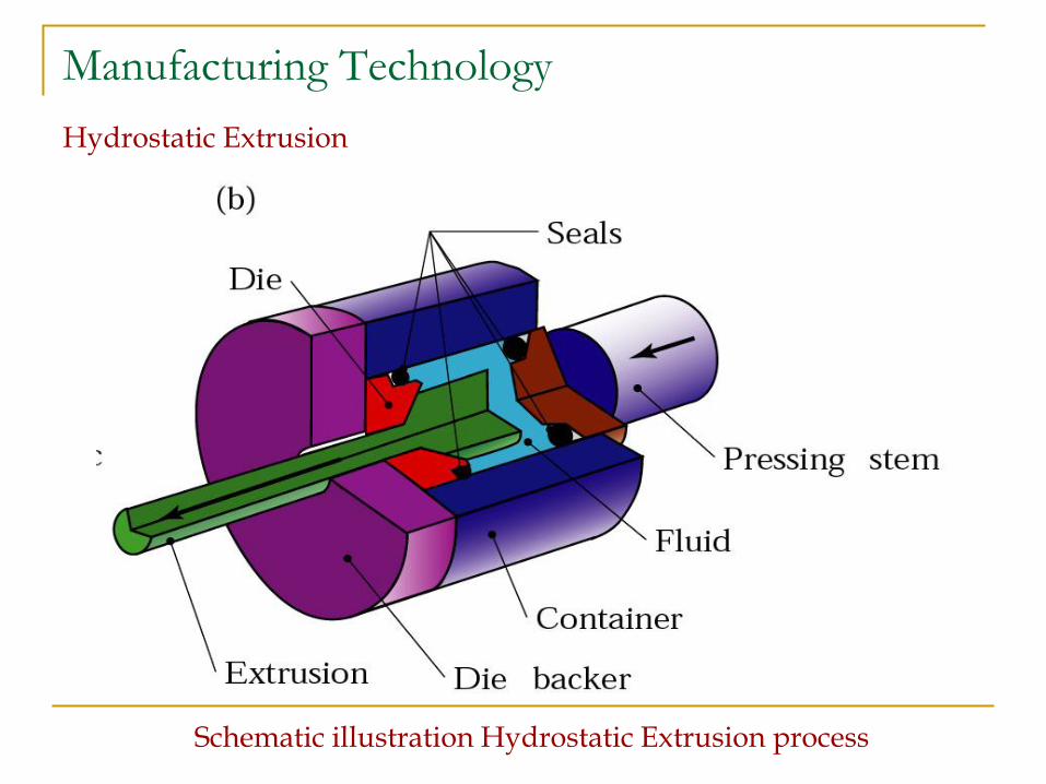
Hydrostatic Extrusion
Schematic illustration Hydrostatic Extrusion process
Manufacturing Technology
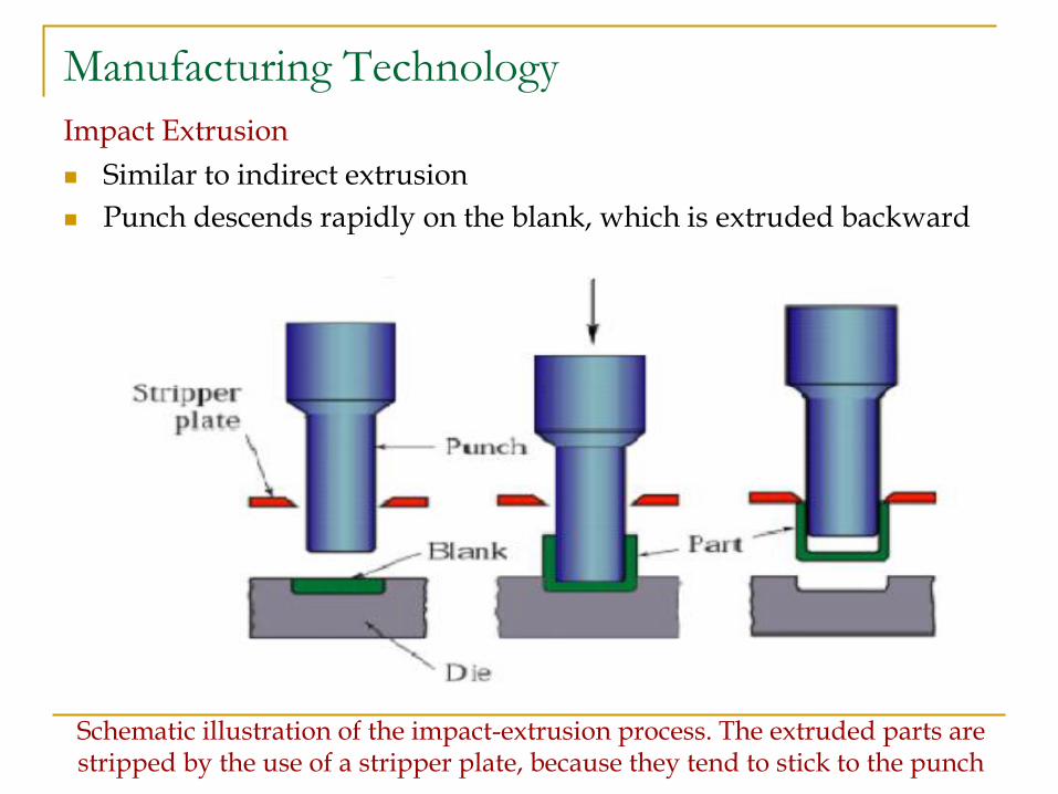
Impact Extrusion
Similar to indirect extrusion
Punch descends rapidly on the blank, which is extruded backward
Schematic illustration of the impact-extrusion process. The extruded parts are stripped by the use of a stripper plate, because they tend to stick to the punch
Manufacturing Technology
Hot extrusion
prior heating of billet to above its recrystallization temperature
Cold extrusion
prior heating of billet to below its recrystallization temperature
Advantages
Wide variety of shapes
High production rates
Improved microstructure and physical properties
Close tolerances are possible
Economical
Design flexibility
Limitation
part cross section must be uniform throughout length
Manufacturing Technology
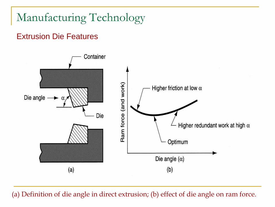
Extrusion Die Features
(a) Definition of die angle in direct extrusion; (b) effect of die angle on ram force.
Manufacturing Technology
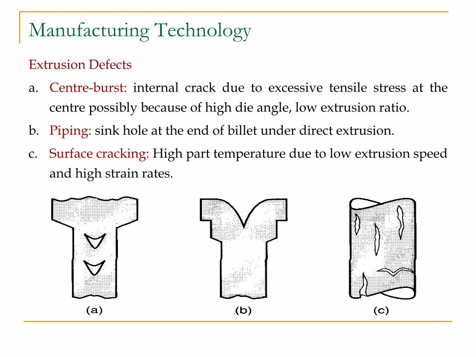
Extrusion Defects
a. Centre-burst: internal crack due to excessive tensile stress at the
centre possibly because of high die angle, low extrusion ratio.
b. Piping: sink hole at the end of billet under direct extrusion.
c. Surface cracking: High part temperature due to low extrusion speed
and high strain rates.
Manufacturing Technology
Factors Influencing the Extrusion Force
Friction
Material Properties
Reduction In Area
Speed
Temperature
Geometry Of The Die

END


