Embed Size (px)
Citation preview
2013
MacDill AFB General Design Guidelines
For
Facility Construction and Renovation
22 July 2013

MacDill AFB General Design Guidelines JULY 2013
1
NOTE: An attempt was made to mark all modifications to the pervious MacDill AFB General
Design Guide, dated 14 May 2012 in “RED”. It will be the guide user’s responsibility to carefully review the General Design Guidelines for verification of deleted / or revised information.
MacDill AFB General Design Guidelines JULY 2013
2
TABLE OF CONTENTS
I. MACDILL AFB REFERENCES 5
II. ARCHITECTURE: (INTERIOR) 7
A. GENERAL 7
B. FINISHES, COLORS, MATERIALS 8
C. WOOD & PLASTICS 8
D. SOUND ATTENUATION MATERIAL 8
E. INTERIOR PARTITION CONSTRUCTION 9
F. INTERIOR DOORS 9
G. CERAMIC AND PORCELAIN TILE 10
H. CARPET 10
I. PAINT 10
J. SUSPENDED CEILINGS 11
K. RESTROOM ACCESSORIES 12
L. TOILET PARTITIONS 12
M. SIGNAGE 12
III. ARCHITECTURE (EXTERIOR) 13
A. GENERAL 13
B. FINISHES, COLORS, MATERIALS 14
C. COLORS 14
D. EXISTING BUILDINGS, GENERAL 14
E. NEW CONSTRUCTION 15
F. WALL SURFACE TREATMENT 15
G. MISCELLANEOUS ROOF ITEMS 16
H. DOORS, EXTERIOR 16
I. WINDOWS, EXTERIOR 17
J. HVAC EQUIPMENT 17
IV. LANDSCAPE ARCHITECTURE 19
V. FIRE SUPPRESSION 21
A. GENERAL 21
B. Plumbing shall incorporate the following: 21
C. Plumbing Fixture Types: 21
VI. MECHANICAL (HVAC) 23
A. GENERAL 23
B. ENERGY CONSERVATION 25
VII. EMCS (ENERGY MANAGEMENT CONTROL SYSTEM): 26

MacDill AFB General Design Guidelines JULY 2013
3
A. METERING – GENERAL 26
B. Front End 26
C. Communication 26
D. DDC Hardware (controller) Requirements: 27
E. Graphics 28
F. Accessibility 28
G. Points to monitor or control 28
VIII. CIVIL 30
A. GENERAL 30
B. SELECTED UFC REFERENCES (Additional UFCs may apply): 30
C. ROADWAY UTILITY CROSSINGS 30
D. ROADS AND PARKING LOTS 30
E. AIRFIELD PAVEMENTS 31
F. STORM WATER SYSTEM 31
IX. Utility PRIVATIZATION 33
A. WATER and WASTEWATER (Private Utility) 33
B. NATURAL GAS (Private Utility) 34
X. ELECTRICAL 38
A. GENERAL 38
B. POWER ANALYSIS AND REQUIRED CALCULATIONS: 38
C. UNDERGROUND ELECTRICAL DISTRIBUTION 39
D. PRIMARY TERMINATION/SPLICES 39
E. OVERHEAD ELECTRICAL DISTRIBUTION 39
F. VAULT TYPE PAD-MOUNTED DISTRIBUTION SWITCHES 40
G. VAULT TYPE PAD MOUNTED SECTIONALIZING CABINETS 40
H. ELECTRICAL DISTRIBUTION MANHOLES 41
I. SERVICE ENTRANCES 41
J. METERS 41
K. PRIMARY TRANSFORMERS 42
L. LOW VOLTAGE TRANSFORMERS 43
M. MOTORS/EQUIPMENT 43
N. GROUNDING 44
O. SECONDARY LIGHTNING/SURGE PROTECTION 44
P. CONDUIT 44
Q. SECONDARY CONDUCTORS 45
R. DISTRBUTION SWITCHBOARDS 46
S. BRANCH/SUB ELECTRICAL PANELS 46
T. LIGHTING 46
U. FIRE DETECTION/MASS NOTIFICATION SYSTEMS: 48
MacDill AFB General Design Guidelines JULY 2013
4
V. EMERGENCY GENERATORS 49
W. HANGARS 49
X. ENERGY CONSERVATION 49
XI. COMMUNICATIONS 50
XII. SECURITY FORCES 50
XIII. SAFETY 51
A. GENERAL 51
B. GENERAL SAFETY REQUIREMENTS 51
XIV. GENERAL BIOENVIRONMENTAL ENGINEERING REQUIREMENTS 53
XV. EMERGENCY MEDICAL SERVICES 54
XVI. BASE ENVIRONMENTAL 55
A. COMPLIANCE 55
B. ENVIRONMENTAL RESTORATION: 60
XVII. CONTRACTOR’S REQUIREMENTS FOR GIS AND CADD DELIVERABLES 63
A. CONTRACT SERVICES 63
B. MINIMUM DRAWING REQUIREMENTS 63
C. GIS DATA 63
D. CADD DATA 64
E. DELIVERABLE FORMAT 65
F. GOVERNMENT FURNISHED REFERENCE MATERIALS 66
XVIII. APPENDICES 67
A. APPENDIX 1: HISTORIC BUILDINGS
B. APPENDIX 2: EMCS MONITORING POINTS (General)
C. APPENDIX 3: MACDILL AFB ACP
D. APPENDIX 4: MACDILL AFB TRAFFIC CONTROL STANDARDS
E. APPENDIX 5: MACDILL AFB LANDSCAPE THEME & DESIGN PROCEDURES
F. APPENDIX 6: ENVIRONMENTAL ACTION INFORMATION FOR PROJECT PLANNING AND EXECUTION
G. APPENDIX 7: ENVIRONMENTAL RESTORATION
H. APPENDIX 8: FGUA UTILITY PRIVATIZATION AGREEMENT (PARTIAL)
I. APPENDIX 9: FGUA FORMS
J. APPENDIX 10: EMCS Diagrams
K. APPENDIX 11: ETL 02-012 COMMUNICATIONS AND INFORMATION SYSTEM CRITERIA FOR AIR FORCE FACILITIES (MacDILL AFB SUPPLEMENT)
L. APPENDIX 12: LEED GUIDANCE – MINIMUM REQUIREMENTS
M. APPENDIX 13: ENERGY EFFICIENT EQUIPMENT GUIDELINES
N. APPENDIX 14: HAZARDOUS MATERIAL REPORTING FORMS
O. APPENDIX 15: AIR QUALITY
P. APPENDIX 16: PEOPLES GAS STANDARDS
MacDill AFB General Design Guidelines JULY 2013
5
MacDill AFB
General Design Guidelines 22 July 2013
This design guide provides information regarding facility and infrastructure design at MacDill AFB. It is not intended to be all encompassing. There are additional documents that determine project specific final design and construction requirements. This document does, however, provide guidance for frequently asked questions as well as basic design elements and concepts that have evolved at MacDill AFB. Brand names, or the basis of design products, are often used in order to establish a minimum acceptable level of quality, finish, size, thickness, durability, testing agency compliance, and code compliance. Equally qualified, alternate products will be considered if the products meet or exceed all the salient characteristic attributes of the basis of design. NOTICE TO DESIGNERS: The designer shall be aware that any information (including information marked as as-built or record drawings) provided to the contractor or the contractor’s engineer will require independent verification. The government cannot confirm that all documentation has been completed. All information provided will require independent field verification to include: field surveys, soft-dig investigation, ground penetrating radar (GPR) or other means. Further, in the older developed area of the base it is highly recommended that the engineer execute a GPR survey to detect abandoned foundations that have been terminated below grade, the location of abandoned utilities or even verify the location of existing utilities. The project specific documents, specifications and drawings take precedence over these General Design Guidelines. I. MACDILL AFB REFERENCES
MacDill AFB provides the information below as design guidance. Unless more stringent / restrictive design and construction requirements have been called for in the specific project design package documents provided by MacDill AFB, the references below shall be used to establish a minimum level of performance. This document as well as all codes and other references, will change over time. It is incumbent up the designers to verify they have the current applicable references for the particular project. Designers must visit the appropriate web sites in order to verify applicability. The following requirements are listed in order of relevant priority. If there is a conflict, then the requirements will be considered in the order listed below with the highest priority listed first. The website http://www.wbdg.org/ can be accessed for the various documents listed.
1. UNIFIED FACILITY CRITERIA (UFC),
2. ENGINEERING TECHNICAL LETTERS (ETL),
3. AIR FORCE INSTRUCTIONS (AFI),
4. AIR FORCE MANUALS (AFM),
5. AIR FORCE HANDBOOKS (AFH),
6. AIR FORCE DESIGN GUIDES, OCCUPANCY SPECIFIC (AFDG),
7. Other relevant references. A few of these publications are referenced below as well as elsewhere in the project documents
MacDill AFB General Design Guidelines JULY 2013
6
Some documents referenced are marked “For Official Use Only” (FOUO). If restricted documents are needed for your particular design, please notify your designated POC for assistance.
A. The Department of Defense has established the International Building Code, 2009 and all associated references as the overall general code see UFC 1-200-01.
B. MacDill AFB, due to its location and unusually severe climate conditions, requires the design and construction to comply with the following references in order to reduce long term repair and maintenance costs:
1. The latest edition of the Florida Building Code, Chapter 13, Energy.
2. The latest edition of the Florida Building Code, Exterior claddings, attachments, and appurtenances shall meet Miami-Dade notice of acceptance requirements.
C. Noted References due to our requirement the following UFCs will be strictly enforced:
1. UFC 4-021-01 DESIGN AND O & M: MASS NOTIFICATION SYSTEMS
2. UFC 4-010-01 DOD MINIMUM ANTITERRORISM STANDARDS FOR BUILDINGS
3. UFC 4-020-01 DOD SECURITY ENGINEERING FACILITIES PLANNING MANUAL
4. UFC 4-023-03 DESIGN OF BUILDINGS TO RESIST PROGRESSIVE COLLAPSE
5. DCI DIRECTOR OF CENTRAL INTELLIGENCE DIRECTIVE No. 6/9 – Physical Security Standards for Sensitive Compartmented Information Facilities (SCIF)
6. MACDILL AFB TRAFFIC CONTROL STANDARDS, revised Nov 2009 (see APPENDIX 4)
D. For compliance to energy related design guidelines, meet applicable standard requirements in the following order of priority:
1. Energy Policy Act 2005
2. Applicable USAF UFCs (Unified Facility Criteria) and (ETLs (Engineering Technical Letters).
3. Florida Building Code, latest version, Chapter 13.
4. MacDill Air Force Base Energy Management Policy
5. LEED for New Construction and Major Renovations. See APPENDIX 12 for guidance and minimum program requirements.
MacDill AFB General Design Guidelines JULY 2013
7
II. ARCHITECTURE: (INTERIOR)
A. GENERAL
1. Government provided project documents are not assembly drawings or instructions. The sample list below outlines the many items a successful design/build or design/bid/build contractor is expected to be able to expertly perform. Every project may not require each item listed below:
a. Install all items or elements level, true, plumb, square, true to line without warping, binding, kinking, bends, or twisting.
b. Anchor and adhere items or elements securely. c. Sealants and weatherproofing must be appropriate for substrates, joints, and specific conditions. d. Clean and protect items or elements from damage. e. Equalize margins. f. Scribe and trim neatly eliminating burrs, snags, and splits. g. Protect existing elements from damage. h. Protect new work and ‘existing to remain’ from damage, soiling, or pilfering. i. Verify that substrates are in appropriate condition prior to installing new materials such as
moisture content, cleanliness, primer, and temperature. j. New material shall be acclimated to jobsite conditions. k. Verify that room temperature and humidity are correct for intended work. l. Fill and seal all annular spaces around pipes, ducting, and various penetrations with appropriate
materials such as behind plumbing escutcheons, trim, and flanges. UL listed foams/sealants are required where penetrations of rated assemblies occur.
m. Final cleaning, dusting, polishing, touch up, and adjustments are required. n. Use the correct type and length of fasteners for any particular application. When a fastener is used
to anchors an item located in an area subject to water exposure, the hole into which the fastener is installed shall be filled with sealant prior to fastener insertion.
o. Install appropriate solid blocking in walls and ceilings to support various attachments. p. Properly brace tops of walls where door jambs are located to provide solid, vibration-free door
operation. q. Fill, seal, finish all gaps, cracks, and seams with appropriate materials such as filling the gap
between the suspended ceiling perimeter angle and the wall, the gap between the water closet and the floor, the gap between the door frame and the wall, and the gap between cabinetry and the wall, perimeter joint at windows, grills, louvers and so forth.
r. Removal of any existing slab on grade requires the treatment of the exposed soil with properly applied termidor termiticide, and installation of a minimum 6 mil visqueen vapor barrier prior to slab replacement.
s. New door openings in existing CMU walls shall require new precast lintels for support of the remaining wall, and the new lintel must be tied into the existing wall with filled cells and #5 rebar continuous vertically minimum. The designer of record shall provide specific requirements.
t. All visible surfaces, except concrete walkways, roofs, and glazing, shall require, as a minimum, a painted finish (i.e., appropriate prime and preparation with a minimum three brush applied coats of paint).
u. Install transition strips of appropriate material at all floor finish changes. Tile to tile may require an accent tile to accommodate color transitions.
v. Wax, buff, polish, and burnish all VCT flooring as part of final cleaning and protect until final acceptance.
w. All demolition of existing materials for access to concealed or obstructed elements, such as plumbing, will require that the demolished material be replaced with matching or like-kind material (i.e., CMU with CMU or plaster with plaster), unless otherwise noted (UON) .
x. Prior to any demolition (e.g., saw cutting), a thorough investigation and verification of existing conditions must be performed in order to avoid damage to concealed elements such as electrical, plumbing, fire sprinklers, and gas lines.
y. Typically, the distance from a gypsum board wall 90 degree corner to the edge of a door frame/trim should be 2 to 3-inches.
MacDill AFB General Design Guidelines JULY 2013
8
z. All edges of visible elements are expected to be finished and sealed even though that particular edge may not be readily visible such as tops and bottoms of doors.
aa. The exterior perimeter envelope of the building must be completely sealed and air tight in order to prevent infiltration of warm humid air or exfiltration of interior air.
bb. The exterior thermal envelope of the building must be continuous and uniform, from floor slab to insulated roof deck. As needed, UL rated foamed insulation with comparable R-value must be installed in order to fill and seal gaps, cracks, and annular rings. When project work disturbs existing envelopes, the new work must comply with these requirements.
cc. Materials, assemblies, and products shall be American made, and shall comply with all appropriate requirements of the Federal Acquisition Regulation (FAR).
dd. As appropriate for any given material, finishes shall be of maximum coating thickness, durable, scrubbing tolerant, cleanable, soiling resistant, low maintenance, and mold and mildew resistant.
ee. All materials are to be asbestos and lead free. ff. Unless otherwise noted, all interior window sills should be Corian, price group “F”.\
B. FINISHES, COLORS, MATERIALS
1. For all designs, the design/build team must prepare complete finish/color/material schedules as well as presentation boards. They must review with the Government / user at the 65% design stage, at the latest.
C. WOOD & PLASTICS
1. Custom built cabinetry shall be all plywood construction. Wet location approved particle board may be used for cabinet doors only if laminate selection dictates. Cabinets shall, as a minimum, be constructed as specified, and shall meet the requirements of AWI’s Architectural Woodwork Quality Standards latest edition for premium grades of interior architectural wood work, construction, finishes, and other requirements, and shall be test report verifiable.
2. Wall and base cabinet assemblies shall consist of individual units joined into continuous sections. Fastenings and anchorage shall be accomplished to permit removal and replacement of individual units without affecting the remainder of the installation.
3. Drawers shall be removable, equipped with extra heavy duty, full extension guides, and shall be equipped with position stops to avoid accidental complete withdrawals. Shelves shall be ¾-inches thick minimum and be fixed or adjustable as indicated. Cabinetry construction is typically flush overlay.
4. Cabinet door hardware shall be premium grade and allow for multi directional adjustments.
5. Countertops and 4-inch high back splashes are to be Corian, price Group “F” or equivalent.
D. SOUND ATTENUATION MATERIAL
1. Gypsum board walls required to be sound attenuated shall be filled with mineral wool batts, 2.0 pcf density, UON. Fiberglass batts are not acceptable due to density deficiencies.
2. Specific STC requirements shall dictate exact construction.
MacDill AFB General Design Guidelines JULY 2013
9
E. INTERIOR PARTITION CONSTRUCTION
1. Typically, interior gypsum board walls shall be floor to deck above, and be constructed of one layer of 5/8-inch gypsum board on each side of 3-5/8-inch, 24 gauge, galvanized steel studs at 16-inches on center maximum. Attachment must be according to the US Gypsum Association as well as the building code, minimum.
2. Walls which do not extend to the deck above shall terminate at 12 inches above the highest adjacent wall.
3. Gypsum board wall finish shall be Level 5, UON. ASTM requirements must be followed in order to achieve the specified Sound Transfer Coefficient (STC).
4. Gypsum board shall be installed according to manufacturer specifications and ASTM C 840-99.
5. Imported board is not allowed. All wet areas subject to water build up, splashing, condensate, or tile require Dense Shield or cement board. Green board can be allowed when not subject to the preceding conditions.
F. INTERIOR DOORS
1. Typically, interior wood door slabs shall be 1 & ¾-inch thick, solid core, particleboard core, 1LD2, 32 lbs/cu ft, hardwood rails & stiles, birch veneer, white birch, (all sapwood), custom grade, stain grade, and book matched.
2. The basis of design for interior steel doors shall be as manufactured by Steelcraft. Slabs to be 16 gauge, cold rolled G60 galvannealed steel, seamless with appropriate foamed insulated core to enhance sound control. Doors shall be factory primed /ANSI a224.1.
3. Hardware must be able to accept the Best cores that are MacDill standard requirements. All proposed hardware schedules must be reviewed by the base locksmith for compliance as well as keying. The base is to receive two finished keys and three blank keys per lock. The designer and the user must review all functions and determine master keying requirements. The review cannot occur later than the 65% design review.
4. Hinges must be heavy duty, 5 knuckle, stainless steel base metal and finish with NRP. Best hardware: 45H Series; interchangeable cores; stainless steel base metal lever style 14; escutcheon J; compatible strike; 630 satin stainless steel.
5. Lock sets and cores shall be purchased by the contractor. The contractor shall install lockable construction cores to be used during the construction phase. After the facility is accepted by the base, the base locksmith will remove the construction cores and install the Best cores, which have been provided under the construction contract. UON, the final cores are to be sent directly to the base locksmith from the manufacturer. For projects with 80 or more doors, the contractor must supply a certified hardware installer under the employ of an Architectural Hardware Consultant (AHC).
6. The basis of design for steel frames shall be as manufactured by Steelcraft, 16 gauge, G60 galvannealed steel, and primed for jobsite finishing. Reinforce at all hardware locations with galvannealed steel: 7 gauge at hinges; 14 gauge at strike. Kerfed frames for gasketed sound and air infiltration control.
7. The designer must provide a complete door hardware and accessories schedule as well as cut sheets for all items. This information must be carefully reviewed with the user no later than the 65% design stage.
MacDill AFB General Design Guidelines JULY 2013
10
G. CERAMIC AND PORCELAIN TILE
1. All tile work shall be performed only by companies that are members of the Tile Council of America and shall comply with the latest TCNA installation handbook.
2. All floor tile grout should typically be pigmented Laticrete Spectralock Pro Grout.
3. Do not install porous surfaces in high traffic areas.
4. Use lower absorption level tiles to have a greater resistance against stains.
5. Install larger tiles, 12-inch x 12-inch in high traffic areas to minimize grout lines.
6. Basis of design for public areas shall be Daltile 12-inch x 12-inch. Continental Slate, color Asian Black, to be verified. The base should typically match the tile and be 4-inches tall.
7. Restroom floor tile basis of design shall be Daltile Mosaics Unglazed Porcelain Keystones, 2-inch x 2-inch top range of cost chart. Exact color TBD.
8. Restroom wall tile basis of design shall be Daltile 4 inch X 4 inch wall tile, semi-gloss, Mayan White D400. A 3 tile accent border/band consisting of 3 additional, different color tiles installed in checker-board fashion will be required starting at 5 feet above the finished floor.
H. CARPET
1. All work to be performed by contractors/installers who are Certified Floor covering Installers (CFI) from the International Certified Flooring Installer Association or manufacturer approved installer.
2. All carpeted areas must conform to CFR Part 1630, Standard for the Surface Flammability of Carpets and Rugs (FF 1-70) (pill test) and performance characteristics.
3. Federal agencies are required by law, Executive Orders (EO), FAR, Defense Federal Acquisition Regulation (DFAR), and Air Force Policy to consider environmentally preferable products (Electronic Transmittal Letter (ETL) 07-04: Air Force Carpet Standard).
4. Provide low volatile organic compound (VOC) products for carpet, adhesives, sealants, and carpet cushions.
5. Install solid colored carpets only in commanders’ suites, chapels, DV suites, and family housing units or as borders.
6. Basis of design shall be Shaw Connect Tile, Style 59342, color; Harbouring Desire, color 40485, multi level pattern loop, with SSP monolithic installation. The wall base should typically be Johnsonite 1/8-inch thick vinyl and be 4-inches high.
7. Static free Carpet: Computer Room, etc.
I. PAINT
1. New paints and coatings basis of design shall be low VOC as manufactured by ICI Paints Dulux (now a Glidden Company).
2. All surfaces exposed to view must be properly primed and painted. This includes some items which may be factory finished, but not be of the appropriate color. Dark bronzed finishes are specifically excluded as well as any Kawneer exterior doors.
MacDill AFB General Design Guidelines JULY 2013
11
3. Partial or spot painting is not acceptable. If part of a surface requires painting, then the entire surface will have to be painted or repainted in order to reach a corner or a different material.
4. Typically, interior paint colors should be a subtle off white (ICI White on White) or light grey (ICI Crystal) depending on the interior color scheme. Exact color must be verified with user via color submittals.
5. Paint categories are listed below (draw downs to be submitted for all paints/colors):
a. P1 Dulux ultra eggshell acrylic 1403: Three coats, brush or roller, minimum over properly prepared and primed substrate with color to be determined by exact location. This application includes elements/areas such as interior gypsum board walls, both new and patched, interior gypsum board soffits, ceilings, except in wet areas, and interior exposed concrete elements.
b. P2 Dulux professional acrylic semi-gloss: Three coats, brush, minimum over properly prepared and primed substrate with color to be determined by exact location. This application includes elements/areas such as interior wood trim, wood shelves, wet area gypsum board walls, ceilings, janitor closets, storage rooms, electrical, mechanical, communication, interior steel doors, interior steel door frames, and interior steel window frames.
c. P3 Dulux professional exterior 100% acrylic semi-gloss finish: Three coats, brush applied, minimum over properly prepared and primed substrate, color to be determined by exact location. This application includes elements/areas such as exterior sheet metal, flashings, and parapet caps.
d. P4 Dulux ultra-hide durus exterior acrylic flat masonry finish: Three coats, brush or roller, minimum over properly prepared and primed substrate with color to be determined by exact location. This application will include elements/areas such as cement stucco, exposed concrete, and generally the exterior of the entire building vertical and horizontal appropriate surfaces.
e. P5 Dulux ultra-hide durus alkyd gloss exterior house and trim paint – Three coats, brush only, minimum over properly prepared and primed substrate with color to be determined by exact location. This application will include elements/areas such as exterior steel doors, exterior steel frames, interior & exterior steel railings, exterior steel grills/louvers, d.i.p. downspouts and brackets, and miscellaneous steel.
J. SUSPENDED CEILINGS
1. Ceiling system shall be installed in strict compliance with the particular manufacturers’ specifications as well as ASTM C 636-96, with the following exceptions: lay-in light fixtures and HVAC grills will be supported independently of ceiling grid; support wire shall be plumb to within 1-inch horizontal for each 12-inches vertical, 4 degrees (use steel cross members of proper size as needed to achieve this requirement).
2. Tiles shall be snug to grid, and the grid shall be square and level. Penetrations shall be centered in tiles and the system shall be centered within room.
3. Install hold down clips as noted.
4. Ceiling type ACT 1 (general areas):
a. Armstrong Dune; 24-inch x 24-inch x 5/8-inch; angled tegular; ASTM 1264 classification Type III, Form 2, pattern CE; white on white, Armstrong, Prelude XL, 15/16-inch exposed tee.
b. Upon completion of the work, provide the user with replacement tiles at the rate of 2 percent of the total installed area. Coordinate delivery of these tiles with the IAP inspector.
MacDill AFB General Design Guidelines JULY 2013
12
K. RESTROOM ACCESSORIES
1. Restrooms require complete array of accessories, to be coordinated with the user.
2. Toilet accessories shall be provided and installed by the contractor. Toilet accessories will include toilet paper holders, paper towel dispensers, and soap dispensers. Paper towel holders shall be sized to fit "Big 8" rolls and toilet paper holders shall be able to use "Jumbo Roll JRT". All mounting locations shall receive reinforcement as required to ensure secure installation of toilet accessories.
L. TOILET PARTITIONS
1. The toilet partitions and urinal screens basis of design shall be Bradmar as manufactured by Bradley Corporation. Install in strict accordance with manufacturer’s requirements.
2. Partitions shall be floor mounted and overhead braced.
3. Color to be S406, desert stone (to be verified at time of submittal). Continuous wall brackets and color coordinated accessories are required.
M. SIGNAGE
1. Identification signage basis of design shall be a product of Scott Sign Systems Inc, (www.scottsigns.com).
2. Interior signs identifying the men’s and women’s restrooms shall be ADA compliant, ADA blue, and shall be 8-inch x 6-inch molded plaques (apmena68 and apwoma68).
3. Interior signs identifying all specifically designated rooms such as janitors closets, communication, storage, break room, electrical, conference room (two required, one at each door) shall be interior ADA appliqué, square edge, 6-inches high x 8-inches wide with ‘rm xxx’, ‘janitor closet,’ and braille. Lettering shall be 1-inch Helvetica caps lettering, stacked as needed. Clear non-glare acrylic back painted. Color TBD.
4. Interior signs identifying all offices to be series s2100 with 3-inch header, ‘rm xxx’, 1-inch Helvetica and Braille with four insert slots at 1-inch high for each location. In addition to the partitioned offices, provide these signs for any open office/work station areas. 1 slot per person/work station.
5. Exterior signs identifying exterior accessed rooms shall be exterior photopolymer, approximately 8-inches wide x 6-inches high, 1-inch letters, with room name, room number, and Braille. Color TBD.
6. Installed sign location is typically on the strike side of the room door, approximately 3-inches from the steel jamb edge and approximately 44-inches from the floor to the sign top.
7. Signs are typically square edge.
8. Air Force Sign Standard must be consulted for latest additional requirements.
9. LED lighting for exit signs and bulletin boards is required.
MacDill AFB General Design Guidelines JULY 2013
13
III. ARCHITECTURE (EXTERIOR)
A. GENERAL
Government provided project documents are not assembly drawings or instructions. The sample list below outlines some of the many items that the successful design/build or design/bid/build contractor is expected to be able to expertly perform. Every project may not require each item listed below: 1. Install items or elements level, true, plumb, square, true to line without warping, binding, kinking,
bends, or twisting.
2. Anchor and adhere items or elements securely.
3. Sealants and weatherproofing must be appropriate for substrates, joints and specific conditions.
4. Clean and protect items or elements from damage.
5. Equalize margins.
6. Scribe and trim neatly eliminating burrs, snags, and splits.
7. Protect existing elements from damage.
8. Protect new work and ‘existing to remain’ from damage, soiling, or pilfering.
9. Verify that substrates are in appropriate condition prior to installing new materials such as moisture content, cleanliness, primer, and temperature.
10. New material shall be acclimated to jobsite conditions.
11. Fill and seal all annular spaces around pipes, ducting, and various penetrations with appropriate materials such as behind escutcheons, trim, and flanges. UL listed foams or sealants shall be required where penetrations of rated assemblies occur.
12. Final cleaning, touch up, and adjustments shall be required.
13. Install appropriate type and length of fasteners for any particular application. All exterior fasteners shall be type 316 stainless steel, except where specifically noted otherwise; is critically contrary to; or invalidates the warranty of a particular manufactured system or element. When a fastener anchors an item located in an area subject to water exposure, the hole into which the fastener is installed should be filled with sealant prior to fastener insertion.
14. Fill, seal, finish all gaps, cracks, and seams with appropriate materials such as the gap between the window frame and the wall, trims and walls, door frame and the wall, and all thresholds to be set in a full sealant bed.
15. New door openings in existing CMU walls require new precast lintels for support of the remaining wall, and the new lintel must be tied into the existing wall with filled cells and #5 rebar continuous vertically minimum. The designer of record shall provide specific requirements.
16. All visible surfaces, except concrete walkways, roofs, and glazing, shall be, as a minimum, a painted finish with appropriate prime/preparation and minimum three coats of paint.
MacDill AFB General Design Guidelines JULY 2013
14
17. All demolition of existing materials for access to concealed or obstructed elements, such as plumbing, will require that the demolished material be replaced with matching or like-kind material (i.e., CMU with CMU or plaster with plaster), UON.
18. Prior to any demolition (e.g., saw cutting), a thorough investigation and verification of existing conditions must be performed in order to avoid damage to concealed elements such as electrical, plumbing, fire sprinklers, and gas lines.
19. All visible surfaces, except concrete walkways, roofs, and glazing, shall require, as a minimum, a painted finish (i.e., appropriate prime and preparation with a minimum three coats of paint).
20. The exterior perimeter envelope of the building must be completely sealed and air tight in order to prevent infiltration of warm humid air or exfiltration of interior air. All new penetrations must comply with this requirement.
21. The exterior thermal envelope of the building must be continuous and uniform, from floor slab to insulated roof deck. As needed, UL rated foamed insulation with comparable R-value must be installed in order to fill and seal gaps, cracks, and annular rings. When project work disturbs existing envelopes, the new work must comply with these requirements.
22. Materials, assemblies, and products shall be American made, and shall comply with all appropriate requirements of the FAR.
23. Finishes shall be maximum coating thickness, durable, scrubbing tolerant, cleanable, soiling resistant, low maintenance, and mold and mildew resistant, where appropriate, for any given material.
24. All materials shall be asbestos and lead free.
25. If existing openings are to be filled in, the filled opening must match the adjacent building construction materials and finish. Partial painting is not permitted.
26. Existing nonconforming fabric canopies are to be replaced with conforming canopies.
B. FINISHES, COLORS, MATERIALS
1. For all designs, the design/build team must prepare complete finish/color/material schedules as well as presentation boards. They must review with the Government / user at the 65% design stage, at the latest.
C. COLORS
1. Refer to the base Architectural Compatibility Plan (ACP) (APPENDIX 3) color scheme for exterior building colors (i.e., two colors: one base color and one color for roof and trim).
2. All colors, interior and exterior, must be submitted for Government approval.
D. EXISTING BUILDINGS, GENERAL
1. Representative examples of period architecture are to be preserved and used.
2. Rehabilitate and maintain buildings in a manner consistent with the original character. Where possible, eliminate incompatible appendages, such as exterior stairs, awnings, and canopies that were not part of the original structures.
3. Limit size of new additions to be in scale with original building.
MacDill AFB General Design Guidelines JULY 2013
15
4. Avoid alterations that detract from the design integrity of a building or that negatively impact adjacent buildings.
5. When possible, locate additions to form spaces, develop views, or screen poor views as described under guidelines for new construction.
6. Locate additions to minimize intrusions on character defining features such as massing, rhythm, setbacks, elevations, rooflines, or primary entrances.
7. When appropriate, match original materials and construction techniques where structural and decorative elements of the building façade need repair or replacement.
8. Clean and repair exposed and visible surfaces. Paint only materials that were originally painted, such as fascias, cornices, trims, or doors. Do not paint concrete, copper, brass, glass, brick, stone and slate.
9. Remove, where possible, all extraneous elements (such as utility lines, support brackets, pipes and vents), that detract from the building facades. When this is not possible, paint an appropriate color to minimize visual impact.
10. Locate equipment (such as transformers, HVAC apparatus, telephone cabinets, dumpsters) in areas where they will have minimum detrimental effect on the appearance of existing structures. Provide screening where necessary.
E. NEW CONSTRUCTION
1. Exteriors of new buildings shall be split-faced CMU, stucco, or a combination of the two. Thought must be given to match surrounding areas. When appropriate, select material, finishes and details to be consistent and compatible with existing materials, finishes, and details in their respective districts.
2. When appropriate, make new buildings compatible in style, scale, proportion, orientation, and directional emphasis with existing structures in their respective districts.
3. Locate new structures to visually define space, to reinforce spatial enclosure, create vistas, frame views, and guide the eye to landmarks.
4. Avoid intrusions into positive open spaces
F. WALL SURFACE TREATMENT
1. Existing Buildings
a. Clean brick, stone, wood, and metal surfaces by appropriate method. Investigate alternatives, and choose the least harmful cleaning method. Never sandblast old brick, stone or wood surfaces.
b. Repair walls, where necessary, by removing loose material and patching holes and cracks with new material to match adjoining surfaces.
c. Repair joints in masonry walls by pointing. Joints should be raked tooled, struck, or otherwise treated to match original joint techniques.
d. Avoid cosmetic application of new synthetic materials resembling original materials; such materials will not weather and age the same as existing natural materials. When new synthetic materials must be used, avoid combining with existing materials to achieve resemblance with original appearance.
MacDill AFB General Design Guidelines JULY 2013
16
2. New Construction
a. Use split face CMU or stucco as a unifying material in all districts, if suitable as exterior cladding for a particular new structure. Match colors in the tan or buff range.
b. Match new surfaces with existing ones in size, texture, color, and use the same bonding patterns.
G. MISCELLANEOUS ROOF ITEMS
1. All roof top elements on sloped standing seam metal roofs, which can be viewed, shall be coated to match the roof color.
2. Downspouts are to be painted to match the background color against which they are viewed. This often results in the downspout being painted more than a single color.
3. New roofs and major roof replacements shall meet or exceed the following Solar Roof Reflectance Index (SRI) for a minimum of 75% of the roof surface.
a. SRI > 78 for low slope roofs (<2:12) b. SRI > 29 for high slope roofs (>2:12)
H. DOORS, EXTERIOR
1. Main entrances to facilities shall be designed to be readily discernible.
2. Primary entrance doors are typically aluminum and glass, dark bronze anodized frames.
3. All exterior doors shall be protected from the direct effects of weather to the extent reasonable. The main entrance(s) shall generally include a building canopy that is part of the building architecture for new facilities and major renovations.
4. Typically, the aluminum and glass exterior door basis of design shall be the Kawneer 350IR, blast tested to 5.8 psi, wet glazed, insulated, bronzed, 3-inch x 1/2-inch cross rail., thermally broken frames.
5. Hardware must be able to accept the Best cores that are MacDill standard requirements. All proposed hardware schedules must be reviewed by the base locksmith for compliance as well as keying. The base is to receive two finished keys and three blank keys per lock. The user must review all functions, and determine master keying requirements. The review cannot occur later than the 65% design review.
6. All exterior doors must comply with Antiterrorism/Force Protection (ATFP) requirements. See Unified Facilities Criteria (UFC) 4-010-01, DoD Minimum Antiterrorism Standards for Buildings, includes Change 1.
7. All exterior doors are expected to also comply with Miami-Dade Notice of Acceptance (NOA) and pass large and small projectile testing. ATFP requirements may override NOA requirements where no other options exist.
8. Typically, exterior steel doors and frames basis of design shall be as manufactured by Steelcraft. Slabs to be 16 gauge, cold rolled G60 galvannealed steel, seamless with appropriate foamed insulated core. Doors shall be factory primed/ANSI a224.1. The steel frames basis of design shall be as manufactured by Steelcraft, 16 gauge, G60 galvannealed steel, primed for jobsite finishing. Reinforced at all hardware locations with galvannealed steel: 7 gauge at hinges; 14 gauge at strike. Kerfed frames for gasketed sound and air infiltration control. Hinges must be heavy duty, 5 knuckle, stainless steel, base metal and finish with NRP. Best hardware: 45H Series; interchangeable cores; stainless steel base metal lever style 14; escutcheon J; compatible strike; 630 satin stainless steel.
MacDill AFB General Design Guidelines JULY 2013
17
9. Locksets and cores
a. Locksets and cores shall be purchased by the contractor. b. The contractor shall install lockable construction cores to be used during the construction phase.
After the facility is accepted by the base, the base locksmith will remove the construction cores and install the Best cores, which have been provided under the construction contract. The final cores are to be sent directly to the base locksmith from the manufacturer.
c. For projects of 30 or more doors, the contractor must supply a certified hardware installer under the employ of an AHC.
10. At ‘existing to remain’ exterior doors, all weather stripping and sealants shall be replaced.
11. The designer must provide a complete door hardware and accessories schedule as well as cut sheets for all items. This information must be carefully reviewed with the Government / user no later than the 65% design stage.
I. WINDOWS, EXTERIOR
1. Generally, dark bronze Class I anodized, tinted, insulated, single hung windows, with thermally broken frames (exterior glazed muntins and screens to be determined where operable windows are utilized).
2. All windows shall be double paned with tinting.
3. Minimum performance requirements for aluminum windows, terminology, and standards of performance, fabrication, and workmanship are those specified and recommended in AAMA/NWWDA 101/i.s.2 - 97 and applicable general recommendations published by AAMA. Conform to more stringent requirements as indicated in specific project documents.
4. Blast Resistance:
a. ASTM F1642-04: Standard test method for glazing and glazing systems subject to air blast
loadings: Minimal hazard response at a 4 psi pressure, 30 psi-msec impulse, blast load. b. US General Services Administration (GSA) test protocol GSA-TS01-2003: Standard test method
for glazing and window systems subject to dynamic overpressure loadings: Level 2 protection at a 4 psi pressure, 30 psi-msec impulse, blast load.
c. Department of Defense (DOD) ATFP construction standards, UFC 4-010-01: Medium level of protection at a 4 psi pressure, 30 psi-msec impulse, blast load.
5. New window installation shall require shop drawings that are engineered, signed, and sealed by a
Florida registered structural engineer. The drawings should show anchors, anchor holes in frames, hardware, operators, and other components as appropriate if not included in manufacturer's standard data.
J. HVAC EQUIPMENT
1. Existing Structures:
a. Avoid placement of window air conditioning units on the facades of buildings in the Campus District. Where air conditioning equipment is required, a central system should be installed.
b. Avoid placing HVAC equipment (e.g., heat pumps and cooling towers) outside of existing structures. Where such equipment must remain, shall be screened from view, but not to restrict air flow. Screen walls must meet ACP requirements.
c. Hose bib and receptacle are required in screened mechanical yards for future maintenance by base support shops.
MacDill AFB General Design Guidelines JULY 2013
18
2. New Structures:
a. Avoid installation of HVAC or other utility equipment such as transformers and telephone cabinets on the exterior of new structures. Install such equipment in a mechanical room.
b. Where required on facades, mechanical rooms should be simple in design and finished to match adjoining surfaces.
3. General Levels of Improvement for Existing Buildings.
a. It is recognized that achievement of stated design objectives will not always be completely possible in degree of visibility, use, or importance.
b. Three levels of improvement are proposed for existing buildings. These are the following:
i. Level 1: Painting and renovation of existing finishes. Improvements typically consist of maintaining existing cladding materials but using a more compatible color scheme in the future. Improvements incorporate at least one element of the Base/District unifying characteristics, and help achieve a degree of visual coherence.
ii. Level 2: Changing existing cladding material and/or revisions to existing doors and windows. Improvements would typically consist of the changing the existing cladding material to ACP compatible material. Improvements will enhance appearance, extended period of maintenance cost benefit, and can also accommodate energy saving measures. Replace windows and doors to further enhance energy conservation, and to help achieve a degree of visual coherence. Exterior appurtenances, such as HVAC equipment or antennas, shall be screened or removed. Careful consideration must be given to the screening of HVAC equipment so as not to create a short cycling of condenser air circulation.
iii. Level 3: Alteration of building form/style or revision to existing doors and windows. Improvements involve major alterations to the building form, and style to make the structure compatible with the ACP. The following alterations are recommended: change flat roof to pitched hipped roof with large overhangs; add entry portico compatible with pitched roof; horizontal treatment of new windows and materials; resurfacing with more permanent and compatible materials; provide new casement windows.
c. While the highest level of improvement may be the ultimate objective, a lower level of
implementation is preferable to be partially attained. d. Implementation of the highest improvement level may cost more initially but may be worth the
expense if reduced maintenance and energy consumption can be obtained (use life cycle cost analysis according to the Energy Policy Act 2005) and NIST BLCC, latest version.
e. Not all Level 3 improvements are appropriate to each district.

MacDill AFB General Design Guidelines JULY 2013
19
IV. LANDSCAPE ARCHITECTURE
A. Refer to the MacDill AFB ACP for landscaping requirements at MacDill AFB. See APPENDIX 3 and APPENDIX 5.
B. UFC 4-010-01, page B-7 B-1.2 Standard 2 for unobstructed space: It is assumed that aggressors will not attempt to place explosive devices in areas near buildings where these explosive devices could be visually detected by building occupants observing the area around the building. Therefore, ensure that obstructions within 10 meters (33 feet) of inhabited buildings or portions thereof do not allow for concealment from observation of explosive devices 150 mm (6-inches) or greater in height. This does not preclude the placement of site furnishings or plantings around buildings. It only requires conditions such that any explosive devices placed in that space would be observable by building occupants.
C. For existing buildings where the standoff distances for parking and roadways have been established at less than 10-meters (33-feet) in accordance with paragraph B-1.1.2.2, the unobstructed space may be reduced to be equivalent to that distance.
D. Plant growth should not allow for the concealment of explosive devices for up to three years from the planting date. Selected plant growth should be such that quick visual detection of a potential explosive device is possible through the plant growth. Also, remember everything around a facility becomes part of the blast when it occurs.
E. Plant selection takes into account a variety of elements:
1. See the list of plants suitable for MacDill AFB compiled as part of the ACP
2. Take into consideration the MacDill AFB guidelines as described in the document titled: Landscape
Theme and Design Procedures (APPENDIX 5).
3. The Florida Cooperative Extension Service (University of Florida) publications website (http://edis.ifas.ufl.edu/TOPIC_Landscape_Plants) is a good source of information for landscaping in Florida. Utilize xeriscape plantings using Florida native plants where possible.
4. White House memorandum #W50737 (dated 26 April 1994) mandates the use of regionally native plants at federal installations. Exotic species are not authorized.
5. Plants must be tolerant and capable of withstanding the full range of potential climate conditions located in south, central Florida.
6. Select plants that require little or no maintenance (trimming/shaping).
7. Consider the sun and shade conditions where each plant is to live—most plants have very specific sun and shade requirements.
8. Poisonous plants and plants with thorns are not authorized in Military Family Housing areas.
9. Take into account the plant’s mature size.
F. Soil quality is fairly consistent across the base. It is very sandy, which means excellent drainage and little organic content. Remember that shoreline areas have increased soil salinity and saltwater spray.
G. An automatic irrigation system is highly recommended for any landscaping. Use controllers and spray heads compatible with and approved by MacDill AFB.
MacDill AFB General Design Guidelines JULY 2013
20
H. All rock beds shall be treated with a pre-emergent herbicide and then top-dressed with 10 ml of weed fabric.
I. All plant beds and tree rings shall be treated with a pre-emergent herbicide and then top-dressed with 3” cypress mulch. All new trees shall have a tree ring with a minimum of 24” radius. All new trees and palms shall be staked. All existing trees to remain shall have a 6’ radius mulch ring at a depth of 3”.
J. Shredded cypress mulch is normally installed in a 3-inch layer in all plant beds, except in certain areas near the flight line because of Foreign Object Debris (FOD). Coordinate with Airfield Operations for landscaping near the airfield perimeter.
K. Provide an 18” wide mulch area between a building and its foundation planting.
L. Mowing strips installed around new construction shall be concrete.
M. Grasses
1. Argentine Bahia grass (preferred unless stated otherwise):
a. Excellent drought tolerance b. Requires little or no maintenance after it is established c. Poor salt tolerance
2. St. Augustine grass:
a. Requires irrigation b. Highly tolerant to soil salinity
3. Seashore Paspalum
a. For ditch banks, shoreline and wet areas b. Excellent salt tolerance
4. Site areas disturbed as a result of construction shall be resodded with Argentine Bahia sod unless the
site has special sod requirements.
5. Seeding with grass and cover crop seed may be permitted in remote locations if prior approval is obtained from the contracting officer. The contractor shall assure good growth and at least 90% coverage after 3 months. In order to prevent erosion the contractor shall provide mulch in potential erosion prone areas. Any site erosion within a 3 month period following the installation shall be repaired and the area reseeded (or sodded).
N. Irrigation Systems: Install only temporary irrigation system to establish sod, tree, and/or flowers initial growth. Only install a permanent irrigation system if required per the project statement of work. All irrigation systems will require a backflow device.
O. Irrigation meters: Install water meter on the irrigation systems to measure the amount of potable water used. Meters must meet the same requirements as for potable water services and shall be remote readable from EMCS or automated meter reading program.
MacDill AFB General Design Guidelines JULY 2013
21
V. FIRE SUPPRESSION
A. GENERAL
1. All buildings shall be designed per NFPA 13, Life Safety Code and UFC 3-600-01.
2. Specifications for fire suppression systems shall include a statement requiring the design of the sprinkler system be under the direct supervision of a Professional Engineer experienced in the design of this type of work and licensed in the State of Florida. Shop drawings for fire suppression systems shall be required and shall bear the seal of the engineer of record.
3. Fire flow testing for the water supply shall be performed in accordance with NFPA 291, Recommended Practice for Fire Flow Testing and Marking of Hydrants. Coordinate the operation of any fire hydrants with the utility privatization authority (FGUA).
4. Existing conditions, such as as-built drawings or existing design drawings shall be reviewed and integrated into the new design drawings, calculations, and specifications as necessary to show all components of the existing suppression system.
B. Plumbing shall incorporate the following:
1. Use only Type K or L copper piping for the domestic water piping inside facilities.
2. Dielectric unions shall be used where dissimilar metals are in contact.
3. MacDill AFB does not allow the use of waterless urinals
4. Minimum Sanitary main from building shall be 4” minimum, with not less than a 2.5fps hydraulic velocity flow.
5. Provide a two-way ground cleanout (GCO) on all sewer – soil or waste lines which enter the building.
6. Furnish minimum plumbing fixtures as indicated in the International Plumbing Code.
7. Provide branch isolation valves for branch piping serving multiple fixtures.
C. Plumbing Fixture Types:
1. Water Closets - Flushometer Valve as specified below, siphon jet, elongated bowl, top supply spud, floor or wall mounted. Seat: plastic, elongated, open front.
2. Water Closets (handicapped) -Top rim of bowl shall be 18 inches above the floor. All other characteristics shall be the same as (a) above.
3. Lavatories - Enameled cast iron or vitreous china.
4. Wheelchair sinks - Vitreous china, 20 inches by 27 inches deep.
5. Urinal - Wall hung. Siphon-jet or washout. Flushometers as specified below.
6. Kitchen Sinks - Single or double bowl, ledge back with holes for faucet and spout, stainless steel.
7. Service Sinks - Enameled cast iron. 3” minimum Trap standard, wall mounted or floor mounted.
8. Food Service - Stainless steel with drain board. Faucet: As required.

MacDill AFB General Design Guidelines JULY 2013
22
9. Water Coolers - Self-contained. Exposed surfaces shall be stainless steel. Wall mounted surface. Wall mounted semi-recessed. Wall mounted recessed. Handicapped. Free standing.
10. Showers - Wall mounted for stall or bath tub.
11. Bathtubs - Straight front recessed. Enameled cast iron, porcelain enameled. Formed steel, plastic without wall, plastic with high wall.
12. Flushometers shall be specified as dual flush flushometers, or approved equal, to match the base standard

MacDill AFB General Design Guidelines JULY 2013
23
VI. MECHANICAL (HVAC)
A. GENERAL
1. Mechanical (HVAC) shall incorporate the following:
a. All ductwork must be sheet metal, no fibrous duct board is allowed. b. HVAC mechanical rooms for EMCS controls shall have network connections including two phone
lines and one LAN. c. Applicable HVAC units shall be connected to the LAN per Section VI herein: EMS. d. HVAC units must have connections to the Fire Alarm system e. Ensure that space is available for alarm panel connections. f. Avoid placing HVAC units and any other mechanical equipment on top of roofs (i.e., no
penetrations through roofs) due to problems with roof leaks, accessibility, and maintainability requirements. If rooftop equipment is necessary, use existing roof warranty holder to perform the work, if applicable.
g. All HVAC equipment, such as air handler units, VAV boxes, and air terminals, shall be accessible for maintenance via removable ceiling tiles or access panels.
h. Access points shall be located and large enough to allow for filter replacement. i. Place all utilities underground, if possible, especially laterals to buildings. All exposed piping,
insulation, and supports must be painted to match the structure. Protective sleeves must be used if pipe or insulation must be run above ground.
j. Observe ASHRAE Std. 62, latest edition. Ensure buildings maintain a positive air pressure at all times. Air handlers should be cleanable and accessible for proper maintenance. All ductwork, supply, and return, shall be insulated and constructed of material that is cleanable.
k. Provide either copper or aluminum fin and tube condensers with factory applied coating to prevent corrosion of outdoor air cooled air conditioning equipment.
l. Make sure durability, availability of replacement parts in the local area, maintainability, type of warranty, and service from the local manufacturing representatives are taken into consideration. Typically, the basis of design for HVAC is McQuay, Carrier or Trane.
m. Maintain space humidity at 50% +/- 10% unless humidity control is stated otherwise by building user.
n. Building pressurization of approximately 8% greater than the exhaust volume is recommended to offset infiltration.
o. Provide proper specifications for air filters to ensure indoor air quality requirements are met. p. Verify that existing space is sufficient to properly route ductwork (i.e., ceiling plenums and
chases) and piping. Coordinate with other disciplines q. Install isolation valves for all equipment and proper air venting for all piping systems as required.
Isolation valves should be located at all branches serving two or more fixtures. r. Use double wall, insulated air handling units. s. Pre-treat ventilation air when feasible and perform a NIST BLLC analysis, latest version as
documentation. t. Verify that size and connection methods are compatible with existing systems. u. Include vibration isolation on all supply and exhaust fans, energy recovery units, and when needed
elsewhere. v. A-E shall thoroughly coordinate mechanical and electrical coordination between sheets for motor
sizing and electrical loads. w. Use double-walled, pre-insulated pipe for buried, chilled water piping between the mechanical
room and the chiller. x. Obtain permits for air pollution emissions for boiler and incinerator installation. y. Install a sufficient number of volume dampers to allow a constant volume system to be balanced
as required. All outlets require a volume damper. z. Use a four pipe system with provisions for heat recovery on HVAC condensers (Desuperheaters,
Heat recovery, etc.) for pre-heating hot water. aa. Toilet room areas shall be properly ventilated according to the International Mechanical Code, or
ASHRAE, whichever is greatest. All toilet room ventilation systems shall be controlled by
MacDill AFB General Design Guidelines JULY 2013
24
lighting occupancy sensors. All building automation controls are to be DDC type. No pneumatic controls shall be used.
bb. All dorm designs shall comply with ETL 93-2 Dorm Design in Humid Areas or latest version. cc. To meet SMACNA recommendations the designer should indicate the operating pressure in the
various elements of the duct system on the plans. dd. The duct aspect ratio should be keep as low as possible to reduce duct cost. ee. Seal duct to SMACNA high and low pressure duct construction. This will add approximately 5%
of ductwork first cost. If the sealing of an average low pressure duct system is eliminated, an allowance of a minimum of 15% duct leakage should be used for calculations.
ff. IBC or FL State Building Code states rooms containing boilers, central heating plant, or hot water supply boilers shall have a one hour rated separation, except where the large piece of fuel equipment does not exceed 400,000 Btu/hr.
gg. Verify that the expansion tank is on suction side of circulation pumps. hh. Heating systems shall use 50% by volume Ethylene Glycol. ii. All exterior equipment shall be concealed to improve facility aesthetics while still providing ease
in access for maintenance and repair. jj. UFC 4-010-01 “DOD Minimum Antiterrorism Standards for Buildings” requires emergency air
intake shutoffs and that building air intake be located 10-feet or greater above the adjacent ground surface.
kk. The primary method of space conditioning will be ducted HVAC systems using a building-wide chilled water loop for cooling and a building-wide hot water loop for heating. Individual split systems, window units, fan coil units, are not preferred.
ll. Demand controlled ventilation (DCV) will be designed and installed in all air handling units. CO2 sensors will be installed in the return air duct and will control the position of the outdoor air damper based on occupancy.
mm. If not controlled by the EMCS, programmable thermostats should be installed to reduce space temperatures to requirements listed in the Energy Management Policy Manual. Zone air sensors will have the capability to monitor temperature, humidity, and CO2
nn. Pump and fan motors over 10 hp will be controlled with VFD’s. Pump VFDs will respond to downstream system pressure and Fan VFD will respond to downstream static pressure.
oo. Any rooftop air conditioning systems shall utilize heat pump technology for building heating. Electric heat strips shall only be used as secondary heating.
pp. Air-side HVAC system design will include dedicated outdoor air AHUs on systems with design outdoor air flow rates above 1000 CFM to pre-condition outdoor air before serving distribution AHUs or conditioned space. The dedicated outdoor air handler will be equipped with an energy recover ventilator utilizing a desiccant heat wheel or flat plate heat exchanger to transfer load between exhaust air and outdoor air.
qq. Chilled water systems over 100 tons will be water cooled chillers using a cooling tower. If an existing water-cooled chilled water system already existed at the facility, a load analysis will be completed to understand the potential to add load to the existing chilled water system.
rr. Chilled water pumping systems will be primary only systems (using one chilled water loop) with one set of pumping systems. Pumping systems greater than 10 hp will be controlled with VFD with the use of two way valves at air handling units. Pressure transducers will be installed at AHU farthest away from the pumping system and will control pump VFD.
ss. Chilled water delta T (difference between the supply and return chilled water temperature) will be designed to be 15 °F at all times or the maximum allowable per the chiller manufacturer’s specifications.
tt. Chilled water supply temperature will be designed to be no lower than 45 °F at all times. Increasing the chilled water temperature during mild outdoor air temperature (chilled water temperature reset) will be enabled when the control system allows.
uu. Chilled water shall be used for server room cooling unless otherwise noted. vv. Refrigerant ownershiop cannot be sold or transferred outside of the Department of Defense
(DOD). The Air Force has a Refrigerant Management Handbook that governs the use of refrigerants and all work shall conform to this policy.
MacDill AFB General Design Guidelines JULY 2013
25
B. ENERGY CONSERVATION
Shall comply with ASHRAE 90.1A as Energy Standard for equipment efficiency: 1. Specify maximum chiller and condensing unit efficiencies consistent with equipment that is at or near
the top of industry standards. Select units that operate at maximum efficiency at predominant load condition.
2. Use chiller waste heat recovery where applicable particularly where dehumidification is required.
3. Energy performance must meet or exceed the requirement of ETL 94-4, Energy Usage Criteria for Facilities in the Military Construction Program. Additionally, energy performance must meet the Energy Policy Act of 2005 (LCCA exceed ASHRAE 90.1 by 30%).
4. Use premium efficiency rating for all motors.
5. Use variable speed fans and pumps unless another alternative provides a lower life-cycle cost or if a special system constraint requires constant speed equipment.
6. All installed equipment shall adhere to the Energy Efficiency Equipment Guidelines located in APPENDIX 13.
MacDill AFB General Design Guidelines JULY 2013
26
VII. EMCS (ENERGY MANAGEMENT CONTROL SYSTEM):
The base Civil Engineering Energy Management Control System (EMCS) section controls all HVAC and integrated lighting controls systems. A. METERING – GENERAL
1. Civil engineering will be notified if any work will require an electric, water or gas meter to be out of service, disconnected, or temporarily removed. Readings from before the meter is out of service will be taken and provided to the construction inspector. If the meter is to be permanently removed, then a new meter complying with the base’s meter policy will be installed and the cost will be incorporated in the cost of the project. If the meter will not be replaced then the existing meter will be reinstalled and programmed correctly.
2. All projects, renovation or construction exceeding the amount of $200,000 per facility will be required to install a new electric, water, and gas meter compliant with the bases approved meter installation.
3. Contractor will provide civil engineering with information from all newly installed and replaced meters:
Building number served Location in/on building Manufacturer Model Number Multiplier (if applicable)
4. New electric meters will be programmed with the correct CT (current transformer) and/or PT (potential
transformer) so that display readings will accurately show the utility usage. New meters (electric, water or gas) will be zeroed out or the initial meter reading at the time of installation reported.
5. Electric, gas and water meters will be fully commissioned onto the base Utility Management Control System (UMCS) via the wireless metering communications system. Electric meters will collect pulse signal outputs from the gas and water meters located at the facility so that this information will be collected by the Base UMCS.
6. See Electric, Water and Gas sections for specific information on meter type and installation requirements.
B. Front End
1. All new construction or any renovated DDC system must be fully compatible with the unified MacDill AFB LCS 8520 server. Any modifications to this front end server must be fully compatible with UFGS 25 10 10 and use open LON Works.
2. All new construction or major renovation projects must be fully integrated into this front end system.
3. Communication between the Building UNC or equivalent and the central console in the Energy Management Section shall be via a LAN connection.
C. Communication
1. A CAT6 line shall be installed from the EMCS main control panel to the closest COMM room for communication to the (CEOV) EMS Section.
MacDill AFB General Design Guidelines JULY 2013
27
2. The building automation system shall be open source non-proprietary such that the Government or its agents are able to perform repair, replacement, upgrades, and expansions of the system without further dependence on the original Contractor. This includes, but is not limited to the following:
a. Install hardware such that individual control equipment can be replaced by similar control equipment from other equipment manufacturers with no loss of system functionality.
b. Necessary documentation (including rights to documentation and data), configuration information, configuration tools, programs, drivers, and other software shall be licensed to and otherwise remain with the Government.
c. At MacDill AFB the following systems are prohibited for new installation:
i. BACNet ii. Proprietary DDC Systems iii. Pneumatic systems or combination Direct Digital Control (DDC)/Pneumatic systems
d. Gateways may be used for the following:
i. A single major component (chiller, boiler, etc) ii. Legacy or existing equipment in a building that is to remain
3. As stated in the HVAC section, two phone lines and one LAN connection shall be run to the
mechanical room to all controled unit(s).
D. DDC Hardware (controller) Requirements:
1. For new construction, only the following manufacturer’s will be used unless otherwise noted:
a. Carrier b. Tekplan (Invensys) c. Trane d. Johnson Controls
2. For work on existing DDC systems the new equipment must be the same manufacturer and type as the
existing system. Alternatively, the existing system may be entirely replaced with a new system of acceptable type. All points that are monitored and controlled by the existing system shall be present on the new system.
3. DDC Hardware Requirements
a. All field level controllers are to comply with UFGS 23 09 23 and must be able to be programmed with Lon Maker Turbo or other equivalent non proprietary software.
b. Be connected to a TP/FT-10 ANSI/EIA 709.3 control network. c. Communicate over the control network via ANSI/EIA 709.1B exclusively. d. Communicate with other DDC hardware using only SNVTs. e. Conform to the LonMark® Interoperability Guidelines. f. Be locally powered; link power (over the control network) is not acceptable. g. Be fully configurable via standard or user-defined configuration parameter types (SCPT or
UCPT), standard network variable type (SNVT) network configuration inputs (nci), or hardware settings on the controller itself to support the application. All settings and parameters used by the application shall be configurable via standard or user-defined configuration parameter types (SCPT or UCPT), standard network variable type (SNVT) network configuration inputs (nci), or hardware settings on the controller itself.
h. Provide input and output SNVTs required to support monitoring and control (including but not limited to scheduling, alarming, trending and overrides) of the application. Required SNVTs include but are not limited to: SNVT outputs for all hardware I/O, SNVT outputs for all set points.
MacDill AFB General Design Guidelines JULY 2013
28
SNVT inputs for overrides of all set points, and SNVT inputs for overrides of all hardware Outputs.
4. Application Specific Controllers have a fixed factory-installed application program (i.e. Program ID)
with configurable settings and do not have the ability to be programmed for custom applications. In addition to the requirements for all DDC Hardware ASCs shall:
a. Be LonMark Certified unless otherwise approved. b. Be configurable via an LNS plug-in unless otherwise approved.
5. Application Generic Controllers (AGCs) have a fixed application program which includes the ability to
be programmed for custom applications. In addition to the requirements for all DDC Hardware AGCs shall:
a. Have a fixed Program ID and fixed XIF file. b. Be fully programmable and configurable for the application through one or more LNS plug-in
unless otherwise approved. c. General Purpose Programmable Controllers (GPPCs) are not installed with a fixed factory-
installed application program and must be programmed for the application. d. At MacDill AFB, Local Display Panels (LDPs) shall be installed at a minimum in each
mechanical room where an AHU exists and programmed as per the Point Schedules. E. Graphics
1. Provide dynamic graphic displays for use on the central console in the Energy Management Section. Maintain consistent graphical displays with already established programming (See APPENDIX 10 – EMCS DIAGRAMS for accepted graphic displays of system components including AHU’s, VAV’s, FTU’s, Chillers, Boilers, Meters, Etc.).
a. Provide a main graphic for the overall building that displays thermostat locations, static pressure sensors, Shelter-in-Place shut-off switch, outside air temperature/humidity, Time/Date stamp, and other general information. The main graphic shall also contain links to other graphic screens for individual systems. Include room numbers if possible.
b. Provide a dynamic point for each system component (e.g., air handling units, chiller plants, boilers, and utility meters). All inputs and outputs for each component shall be displayed on the graphic. Each graphic shall contain links to the main graphic and other related graphics. Each graphic shall represent the type of equipment displayed with sensors, relays, status, or alarms.
c. For variable speed AHU’s, provide VAV index page separate to include space temperature, active space temperature, airflow set points, actual airflows and discharge temperatures. Graphics shall represent the type of equipment displayed.
F. Accessibility
1. Specification must contain a statement that requires that all DDC field panels, subpanels, and microcontrollers shall be completely programmable through the central console in Building 247 via the LAN. Specification must also contain statement that requires that the central console in Building 247 has override capabilities on all analog and digital outputs.
2. There shall be no devices that contain features that can only be accessed in the field with special equipment or connectors.
G. Points to monitor or control
1. See APPENDIX 2 for general points to consider for monitoring.
2. Provide override capabilities of all end devices (i.e., actuators and Start/Stop relays).
MacDill AFB General Design Guidelines JULY 2013
29
3. User adjustable set points shall be on equipment page (e.g., airflow, temperature, static pressures, and CO2). Additional points may be needed for each specific project such as a system with an emergency generator may have certain chillers interlocked.
4. Prior to DDC system installation the following should be submitted for Government Approval:
a. Points Schedules: Submit Points Schedules using the Points Schedule template located at https://eko.usace.army.mil/fa/bas/ for each piece of DDC Hardware. Points Schedules shall be submitted in hard copy (11”x17”) and electronic format. Electronic submission shall be in [AutoCAD] [Microstation] [Excel] format and submitted on CD or DVD.
b. Control System Schematic diagram and Sequence of Operation for each HVAC system.
5. Deliverables: Upon completion of project the following should be delivered to the Government for acceptance:
a. Final (as-built) commissioned Turbo LONWORKS® Network Services (LNS®) database with Lon Credits transferred to the Government.
b. eXternal Information Files (XIF), Resource files and Plug-ins for the completed system. c. Point Schedules: Final (as-built) Points Schedules d. Control System Schematic diagram and Sequence of Operation for each HVAC system. e. Programming Software: All software, including licensing information and user manuals, necessary
to program GPPCs installed under this contract. f. GPPC and AGC Application Source Code: Copies of the installed application programs (all
software that is not common to every controller of the same manufacturer and model) as source code compatible with the supplied programming software.
g. Operation and Maintenance Instructions including procedures for system start-up, operation and shut-down, a routine maintenance checklist, and a qualified service organization list.
h. Quality Control (QC) checklist completed by the Contractor's Chief Quality Control (QC) Representative
MacDill AFB General Design Guidelines JULY 2013
30
VIII. CIVIL
A. GENERAL
1. The Contractor performing the construction or any party performing any field work that involves any type of excavation shall process a Civil Engineering Work Clearance Request (AF Form103) prior to perfoming any work that requires excavation. All base utilities shall have been marked by the Base CE Shops and Utility Companies. The utility marking shall be protected and any required remarking may result in additional cost to the requestor of the markings.
2. It is the contractors responsibility to validate the utility location within 5' of the utility/ground markings. This may be accomplished by performing a test hole or series of holes using equipment that will not damage the underground utility if it is within 5' of the marking. If the contractor is unsure, they are to contact the coordinating office for the utility in question and receive documented approval before proceeding with their excavation/dig.
3. Hand digging to locate utilities shall be mandatory. These utility locations shall be left uncovered until that portion of the installation is beyond that particular utility location, and the construction inspector has observed the intersection of the conflicting utilities, and approves continuation of the installation.
4. Any construction project utilizing a crane needs to have a FAA form 7460-1 filled out . An aeronautical determination by the FAA is required for the crane. Coordinate with Planning. (45 days)
5. Any project on the airfield needs to be coordinated with Planning for a Temporary airfield construction waiver prior to start of the project. (30 days)
B. SELECTED UFC REFERENCES (Additional UFCs may apply):
a. UFC 3-201-01 Civil Engineering
b. UFC 3-250-01FA Pavement Design for Roads, Streets, Walks, and Open Storage Areas c. UFC 3-250-03 Standard Practice Manual for Flexible Pavements d. UFC 3-250-04 Standard Practice for Concrete Pavements, with Change 2 e. UFC 3-250-08FA Standard Practice for Sealing Joints and Cracks in Rigid and Flexible
Pavements f. UFC 3-260-01 Airfield and Heliport Planning and Design g. UFC 3-260-02 Pavement Design for Airfields h. UFC 3-270-01 Asphalt Maintenance and Repair i. UFC 3-270-07 O&M: Airfield Damage Repair
C. ROADWAY UTILITY CROSSINGS
1. Install utilities under pavement using horizontal directional bore. This will apply to communications ducts, electrical power ducts, force main piping, water main and similar installations.
2. Open cut will be considered for the following items:
a. Gravity sewer piping where the slope of the piping is critical. b. Storm sewer piping c. The installation of large piping or ducts where horizontal directional bore may not be practical.
The approval to open cut the roadway pavement will require prior government approval.
D. ROADS AND PARKING LOTS
1. Use FDOT Standard Specifications for Road and Bridge Construction (FDOT Specifications) and the FDOT Roadway and Traffic Design Standards (FDOT Indexes) unless specifically amended herein.
MacDill AFB General Design Guidelines JULY 2013
31
2. MacDill AFB Traffic Control Standards (APPENDIX 4) shall apply.
3. Curbs: Install Miami Type curbs, FDOT Type-F or FDOT Type-D curbs as applicable to meet field conditions.
4. Driving Lane Delineators: The delineators shall be permanently mounted, round, and white with two reflective bands. Basis of Design shall be TAPCO Super Duck delineators or government approved equal.
5. Public sidewalk curb ramps: Construct curb ramps in accordance with FDOT Index 304. The installed tactile surface material shall be an approved FDOT product and the material color shall be black.
6. Utility crossings: All utility crossing shall be installed using jack-and-bore or by horizontal directional bore. If an open cut is approved the compaction shall be in accordance with FDOT Specification. Base material shall be replaced two times the original thickness or 12 inches, whichever is greater.
7. Repair sidewalks between contraction and expansion joints only. Narrow cuts across sidewalks will not be accepted.
8. New sidewalks shall be constructed in accordance with FDOT Index 310.
9. UFC 4-010-01 “DOD Minimum Antiterrorism Standards for Buildings” provides specific standoff requirements for parking area and roadways from buildings.
E. AIRFIELD PAVEMENTS
1. Placing asphalt in sinkhole-prone areas:
a. Certain areas of the airfield are prone to sinkholes. In these areas, airfield repaving operations have resulted in additional sinkholes or areas of surface subsidence. It has been determined that the use of a standard vibratory compactor may exacerbate the problem. For future pavement work, including base construction or asphalt surface construction, standard vibratory compactors shall no longer be allowed. As an alternate, it is recommended that the contractor use a heavy static roller or possibly an oscillation type vibratory roller (e.g., HAMM Model HD 0120V) to achieve the required compaction requirements stated in the specifications. The use of these rollers produces less ground vibrations.
b. This statement only addresses one piece of equipment. The contractor shall use all other equipment and incidentals required to complete the project construction. The main concern is the desire to reduce excessive ground vibration.
F. STORM WATER SYSTEM
1. Prior to any construction, hand digging to locate utilities shall be mandatory. These utility locations shall be left uncovered until that portion of the installation is beyond that particular utility location. The construction inspector must observe the intersection of the conflicting utilities, and approve continuation of the installation.
2. Use FDOT Standard Specifications for Road and Bridge Construction (FDOT Specifications) and the FDOT Roadway and Traffic Design Standards (FDOT Indexes).
3. Pipe shall be concrete Class III (meeting FDOT Specification Section 941) or ribbed polyethylene (meeting FDOT specification Section 948) designed for traffic loading (AASHTO H-20). The inside surface of all pipe shall be smooth.
4. Manholes and drainage structures shall be manufactured in accordance with FDOT Indexes.
MacDill AFB General Design Guidelines JULY 2013
32
5. All manhole covers shall be cast iron and have the word “STORM” marked in each cover.
6. Provide a minimum cover of 3 feet from the top of the pipe unless otherwise specified. Shallower installations (if required to meet site conditions) will require encasement of the pipe or use of Class IV concrete pipe.
7. Storm system piping shall be sized using the rational method using the FDOT “Rainfall Intensity-Duration-Frequency Curves” for Zone 6 or SCS Method all for a 5 year/24 hour return period storm event.
8. Storm water systems that increase impervious areas will require permitting through the Southwest Florida Water Management District (SWFWMD), for additional information see the Base Environmental Section of this General Design Guide.
9. Design shall limit developed site runoff to pre-developed 5 year/24 hour and 25 year/24 hour storm events peak rates.
10. Storm water treatment pond control structures shall include a 4-inch thick concrete apron installed under the skimmer and to about 6-inches outside the limits of the skimmer. The engineer shall assure that there is adequate capacity for the design flow under skimmer and between the skimmer and the control structure.
MacDill AFB General Design Guidelines JULY 2013
33
IX. UTILITY PRIVATIZATION
The Water and Wastewater systems at MacDill AFB are owned and operated by the Florida Governmental Utility Authority (FGUA). See APPENDIX 8 and APPENDIX 9 for more information.
A. WATER and WASTEWATER (Private Utility)
1. On 21 June 2010 the MacDill AFB utilities privatization (UP) contract for water and wastewater was awarded to Florida Governmental Utility Authority (FGUA) by DLA Energy (formerly DESC). On 1 March 2011 the water chlorination and distribution system, and the wastewater collection, treatment, and reuse systems (excluding golf course irrigation lines) at MacDill AFB was transferred to Florida Governmental Utility Authority (FGUA) by means of a Utility System Bill of Sale. Water and wastewater services are provided to MacDill by means of the UP contract. Therefore, FGUA is the sole provider of these utility services to the installation. In addition FGUA is the Permittee for the wastewater system and holds the identification number for the public water system. The Government has entered into a fifty-year contract with FGUA for utility services provided via their water and wastewater systems. Over the course of the fifty year contract, FGUA is responsible for provision of utility services, to include operation, maintenance, repair, renewals, and replacements for the systems. This includes all exterior and underground pipes, manholes, water towers, pump and lift stations (interior and exterior), valves, backflow preventer devices, and other related conveyance infrastructure. Each facility will have points of demarcation (PODs) for FGUA owned infrastructure.
2. FGUA Contact Information:
Florida Governmental Utility Authority Glenn E. Forrest, P.E., Utility Manager, MacDill AFB 280 Wekiva Springs Road, Suite 2000 Longwood, FL 32779 407-629-6900 office (407) 803-3478 cell [email protected]
3. Planning: FGUA is required to submit annually an Annual System Deficiency Corrections/Upgrades/Connections and Renewals and Replacements Plan. The 6 CES Contracting Officer Representative (COR), with input from 6 CES/CEP, is responsible for providing information to FGUA on MacDill’s planned programs, such as MILCON. The purpose is to define projects which could alter demands placed on the water and wastewater systems, or which could modify or relocate existing infrastructure.
4. Design:
a. Project Design for 3rd
Party Construction: All agencies that design projects for construction on MacDill AFB must coordinate with FGUA on all proposed actions that might impact the utility systems. Projects that cause impact include: temporary connections, such as connecting to a fire hydrant for water; disconnections due to demolition; new connections due to facility construction; replacing existing lines and components; any project that involves work on utilities past the PODs, which demarcate Government ownership. 6 CES is the primary agency designing projects, accomplishing work through 6 CONS via the MACC contract. Also the US Army Corps of Engineers designs and oversees MILCON projects. Because FGUA owns the utility systems, these project designs must be coordinated with FGUA. Coordination is also necessary because FGUA must ensure the utility systems provide adequate system capacity as the water and wastewater systems are repaired and/or replaced. FGUA must also ensure utility systems are not compromised or damaged. Requests for design coordination will typically have a set of 30 percent design plans. These requests must be forwarded to FGUA via the COR, who will have set
MacDill AFB General Design Guidelines JULY 2013
34
up parallel notification processes. FGUA shall have a minimum of two weeks to review the project and provide comments. FGUA comments are to be incorporated to the extent that FGUA will accept the utility components after construction is complete.
b. Design Standards: Designs that install, alter, disconnect or connect (temporary of permanently), or cause adverse impacts to the systems must incorporate FGUA’s design standards, and are subject to FGUA inspection during construction. For water and wastewater systems FGUA follows Hillsborough County design standards, or equivalent. Hillsborough County design standards are located at: http://www.hillsboroughcounty.org/index.aspx?nid=2067
5. Project Review: Please note that FGUA requires a minimum of two weeks review time. Comments
from FGUA will be transmitted to the COR and other appropriate individuals. The design must meet FGUA’s approval to the extent that FGUA will accept the utility components after construction is complete.
6. Fees: As the utility owner and sole utility service provider to MacDill under the UP contract, FGUA can charge fees. The Per the UP contract, FGUA has the right to reasonably inspect 3rd party construction projects ($150/hour for Contract Operator and $120/hour for Systems Manager). FGUA will prepare a Water & Sewer Utility Construction Fees Letter specific for the project. This letter will list the construction and inspection fee lump sum, and the temporary construction water meter cost. This letter will be used in developing the government cost estimate and 3rd party construction solicitation. FGUA costs will be identified in the solicitation. Also FGUA required forms will be identified in the solicitation. The 3rd party construction contractor shall pay FGUA these costs and submit completed forms to FGUA.
7. Meters: Please note that per AFCESA policy meters on privatized water and wastewater systems shall not be AMR type that can be connected to the Air Force network.
8. Construction: Only FGUA can connect/disconnect into FGUA owned utilities. No 3rd party contractor can connect/disconnect to a FGUA owned utility unless authorized by FGUA.
a. 3rd
Party Construction: The 3rd party construction contractor must coordinate with FGUA prior to the start of utility work. This coordination involves payment of fees and submission of the following forms: FGUA Form 427, FGUA Form 11, and FGUA Form 301. The construction contractor is expected to notify FGUA at the appropriate times for inspection during the course of the project. Please note that if new sewer and water infrastructure is constructed by a 3rd party contractor, the new infrastructure belongs to the Government (6 CES) until the new infrastructure can be officially conveyed to FGUA and the UP contract modified. FGUA has the right not to accept infrastructure that is installed by others if the construction does not meet FGUA standards. In the meantime, the Government will own and provide for the operation and maintenance of the new infrastructure until it can be brought up to acceptable standards. The COR is responsible for initiating the process to transfer the new infrastructure to FGUA.
9. Connection: Utility construction may also be accomplished through the UP contract using the
connection contract clauses. The COR provides a project description, government cost estimate, and arranges for a MIPR to be sent to DLA. Upon award by DLA, the UP contractor constructs the infrastructure and owns it.
B. NATURAL GAS (Private Utility)
The Natural Gas System at MacDill AFB are owned and operated by TECo Peoples Gas (PGS). See APPENDIX 16 for more information. 1. On 26 March 2012 the MacDill AFB utilities privatization (UP) contract for natural gas was awarded
to TECO Peoples Gas (PGS) by DLA Energy (formerly DESC). On 23 September 2012 the natural gas system at MacDill AFB will be transferred to PGS by means of a Utility System Bill of Sale. Natural gas services will be provided to MacDill by means of the UP contract. PGS also provides the
MacDill AFB General Design Guidelines JULY 2013
35
commodity. Therefore, PGS is the sole provider of these utility services to the installation. The Government has entered into a fifty-year contract with PGS for utility services provided via their natural gas system. Over the course of the fifty year contract, PGS is responsible for provision of utility services, to include operation, maintenance, repair, renewals, and replacements for the system. This includes all exterior and underground pipes, meters, valves, and other related conveyance infrastructure. Each facility will have points of demarcation (PODs) for PGS owned infrastructure.
2. PSG Contact Information:
TECO Peoples Gas James Billington, Division Supervisor 1400 Channelside Drive Tampa, FL 33605 813-275-3819 office 727-423-7618 cell [email protected]
3. Planning: PGS is required to submit annually an Annual System Deficiency Corrections/Upgrades/Connections and Renewals and Replacements Plan. The 6 CES Contracting Officer Representative (COR), with input from 6 CES/CEP, is responsible for providing information to PGS on MacDill’s planned programs, such as MILCON. The purpose is to define projects which could alter demands placed on the natural gas system, or which could modify or relocate existing infrastructure.
4. Design:
a. Project Design for 3rd
Party Construction: All agencies that design projects for construction on MacDill AFB must coordinate with PGS on all proposed actions that might impact the utility system. Projects that cause impact include: temporary connections; disconnections due to demolition; new connections due to facility construction; replacing existing lines and components; any project that involves work past the PODs, which demarcate Government ownership. 6 CES is the primary agency designing projects, accomplishing work through 6 CONS via the MACC contract. Also the US Army Corps of Engineers designs and oversees MILCON projects. Because PGS owns the utility system, these project designs must be coordinated with PGS. Coordination is also necessary because PGS must ensure the utility system provides adequate capacity as lines are repaired and/or replaced. PGS must also ensure the utility system is not compromised or damaged. Requests for design coordination will typically have a set of 30 percent design plans. These requests must be forwarded to PSG via the COR, who will have set up parallel notification processes. PGS shall have a minimum of two weeks to review the project and provide comments. PGS comments are to be incorporated to the extent that PGS will accept the utility components after construction is complete.
b. Design Standards:
i. Designs that install, alter, disconnect or connect (temporary of permanently), or cause adverse impacts to the natural gas system must incorporate PGS’s design standards, and are subject to PGS inspection during construction. PGS design standards are provided as an attachment to this design guide.
ii. Please note that PGS requires a minimum of two weeks review time. Comments from PGS will be transmitted to the COR and other appropriate individuals. The design must meet PGS’s approval to the extent that PGS will accept the utility components after construction is complete.
5. Fees: As the utility owner and sole utility service provider to MacDill under the UP contract, PGS can
charge temporary and permanent connection fees. The Per the UP contract, PGS has the right to reasonably inspect 3rd party construction projects. PGS will prepare a Natural Gas Utility Construction Fees Letter specific for the project. This letter will list the construction fee lump sum. This letter will

MacDill AFB General Design Guidelines JULY 2013
36
be used in developing the government cost estimate and 3rd party construction solicitation. PGS costs will be identified in the solicitation. Also PGS required forms will be identified in the solicitation. The 3rd party construction contractor shall pay PGS these costs and submit completed forms to PGS.
6. Meters: Please note that per AFCESA policy meters on privatized natural gas systems shall not be AMR type that can be connected to the Air Force network.
7. Construction: Only PGS can connect/disconnect into PGS owned natural gas lines. No 3rd party contractor can connect/disconnect to a PGS owned line unless authorized by PGS.
a. 3rd
Party Construction: The 3rd party construction contractor must coordinate with PGS prior to the start of utility work. This coordination involves payment of fees and submission of PGS forms. The construction contractor is expected to notify PGS at the appropriate times for inspection during the course of the project. Please note that if new natural gas infrastructure is constructed by a 3rd party contractor, the new infrastructure belongs to the Government (6 CES) until the new infrastructure can be officially conveyed to PGS and the UP contract modified. PGS has the right not to accept infrastructure that is installed by others if the construction does not meet PGS standards. In the meantime, the Government will own and provide for the operation and maintenance of the new infrastructure until it can be brought up to acceptable standards. The COR is responsible for initiating the process to transfer the new infrastructure to PGS. Construction categories are listed below. New Connection with Meter and Equipment that Uses Natural Gas: If the project meets the
MACC provisions, the letter from PGS will state the fee is zero, and PGS will construct the new utility line to the POD. The letter will state exactly what work PGS will perform, including site preparation and finish work. This will enable the 3rd party construction contractor to properly phase the construction so that both parties work as a team. The 3rd party construction contractor is responsible for utility construction from the POD on. PGS will own the new utility line to the POD.
New Connection with Meter and Equipment that Uses Natural Gas: If the project does not meet the MACC provisions, PGS will prepare a letter that describes two scenarios. The 1st scenario will state the fee PGS will charge to construct the new line to the POD, and will detail exactly what work is included. The 3rd party construction contractor will pay the fee to PGS. PGS will own the new line to the POD. The 2nd scenario addresses the case where the 3rd party construction contractor builds the new line. The letter will state the fee PGS will charge for making the final connection of the new line to the PGS owned natural gas main. The 3rd party construction contractor will pay the fee to PGS. The government will own this new line until it can be transferred to PGS.
Temporary Connections/Disconnections: For any project requiring temporary natural gas connections and eventual disconnections, the PGS letter will state the fee to make the temporary connection and eventual disconnection. The letter will state exactly what work PGS will perform, including site work. An example of this would be connecting a thermal oxidizing unit-which may operate for several years- to a PGS owned main. The 3rd party construction contractor will pay the fee to PGS.
Permanent Disconnections, including Removing/Abandoning Natural Gas Lines: PGS will prepare a letter that describes two scenarios. The 1st scenario will state the fee PGS will charge to disconnect from the main and remove/abandon the line up to the POD. The letter will detail exactly what work is included. In this case it is very important that the 3rd party contractor understands his scope regarding clearing obstructions out of the way for PGS, such as removing pavement. The 3rd party construction contractor will pay the fee to PGS. The 2nd scenario addresses the case where the 3rd party construction contractor removes /abandons the line after PGS has disconnected it from the main. The letter will detail exactly what work is included. The 3rd party construction contractor will pay the fee to PGS.
Altering Existing Natural Gas Lines (such as location, size, material): PGS will prepare a letter that describes two scenarios. The 1st scenario will state the fee PGS will charge to construct the alteration up to the POD. The letter will detail exactly what work is included. In
MacDill AFB General Design Guidelines JULY 2013
37
this case it is very important that the 3rd party contractor understands his scope regarding clearing obstructions out of the way for PGS, such as removing pavement. The 3rd party construction contractor will pay the fee to PGS. PGS will own the new line to the POD. The 2nd scenario addresses the case where the 3rd party construction contractor constructs the alteration, keeping in mind that only PGS can connect/disconnect to PGS owned lines The letter will detail exactly what work is included. The 3rd party construction contractor will pay the fee to PGS. The government will own this new line until it can be transferred to PGS.
8. Connection: Utility construction may also be accomplished through the UP contract using the
connection contract clauses. The COR provides a project description, government cost estimate, and arranges for a MIPR to be sent to DLA. Upon award by DLA, the UP contractor constructs the infrastructure and owns it.
MacDill AFB General Design Guidelines JULY 2013
38
X. ELECTRICAL
A. GENERAL
1. All design and installation shall be prepared and executed in accordance with the most current edition of the following:
National Electric Code National Electrical Safety Code International Building Code National Safety Code NFPA 70E NFPA 101 UFC 3_520_01 – Interior Electrical Systems UFC 3_501_01 – Electrical Engineering UFC 3_550_01 – Exterior Electrical Power Distribution
2. Electrical equipment identification tags and schematics - All electrical distribution components and units shall be designated and numbered (i.e. power distribution panels “PP-4” or transformer “XR-12”), and labeled with an etched plastic laminate identification tag reflecting abbreviated designation. A framed one-line schematic drawing of the electrical system, measuring no less than 11” x 17”, shall be mounted in the electrical room. All labor, equipment, materials and rentals/fees required to provide all electrical identification tags and schematics shall be at no additional cost to the Government and is considered field overhead; therefore part of the Contractor’s coefficient.
3. For high voltage overhead and underground lines, follow Tampa Electrical Company (TECO), the local power company’s Construction Specifications and AMC ETL 07-1 Design Criteria for Underground Electrical Distribution Systems Using Directional Boring (DB) Methods for Installing High Density Polyethylene Electrical (HDPE) Conduit. All roadways and paved areas will be bored. No paved areas will be cut and trenched to install electrical or communication lines, UON. Refer to ETL 07-1 for additional requirements.
4. ALL specifications and design criteria listed within this document are required to be met as a minimum standard on ALL projects, U.O.N.
5. Fault current available at the MacDill Ave substation (East or West 13.2kV bus) is as follows:
a. Three Phase 8500 A b. Single Phase - Ground 8900 A
B. POWER ANALYSIS AND REQUIRED CALCULATIONS:
1. All load analysis and calculation requirements listed within shall be performed in accordance with UFC 3-501-01 Chapter 3. The load analysis shall be provided for all projects and for the entire electrical distribution system associated with the facility and provided with the 95% design submitted for approval by the contractor, U.O.N. The calculations and power analysis shall be performed with Easy Power (latest suite) or equal software which is fully compatible with Easy Power (latest Suite). The contractor shall provide the calculations and incorporate the findings from the analysis within the 95% design submittal. All calculations shall be performed utilizing the selected equipment to be installed for both primary (13,200V) and secondary voltage distribution systems and equipment associated with the project. If actual equipment installed differs from the basis of design, the contractor shall be required to submit new calculations for approval. When additional equipment or load is being added to a primary conductor/circuit associated with a project, the analysis shall be performed to the furthest most upstream device, in most cases, this would be to the substation Relay/Breaker. The
MacDill AFB General Design Guidelines JULY 2013
39
contractor is responsible for changing/updating all settings on both new and existing equipment. A list of the required calculations are as follows:
a. FAULT CURRENT (AIC) CALCULATIONS b. PRIMARY LOAD ANALYSIS c. SECONDARY LOAD ANALYSIS d. COORDINATION STUDY e. ARC FLASH STUDY
C. UNDERGROUND ELECTRICAL DISTRIBUTION
1. All three phase underground medium/high-voltage shielded cable shall be 15 kV, 133% EPR, 1/3 concentric neutral, MV-105, copper. All single phase underground medium/high-voltage shielded cable shall be 15 kV, 133% EPR, Full concentric neutral, MV-105, copper. All electrical medium voltage lines shall be in a minimum schedule 40 PVC, UON, conduit and encased in red-dyed concrete.
2. All new cables shall be installed with fault indicators. Basis of design – Raychem.
3. Cable/conductor field testing shall be performed in accordance with the current edition of IEEE Std 400.2.
D. PRIMARY TERMINATION/SPLICES
1. Use cold shrink or heat shrink type splices and pole-top terminations.
2. Neither “T” nor “Y” splices are allowed on any underground medium/high voltage feeders.
3. Pre-molded elbow-type or bolt-together terminations (200 or 600 A) for underground cables are not acceptable (UFC 3-550-01). Only 600 A Bolt-T and 200 Load break terminals are allowed within above grade transformers, sectionalizing cabinets and switchgear UON.
4. Terminations and splices shall not limit the ampacity of the cable.
5. All conductors shall be INDIVIDUALLY fire wrapped in accordance with UFC 3-550-01. Basis of design – 3M Scotch 77 Fire and Electric Arc Proofing Tape.
E. OVERHEAD ELECTRICAL DISTRIBUTION
1. All new poles shall be concrete (A-type construction unless otherwise directed by the base).
2. All down guys shall be covered at ground level with tamper proof guy guards.
3. Pole grounds shall be externally mounted. Do not ground any pole mounted devices unless required by the manufacturer.
4. For Triplex type overhead secondary lines, aluminum may be used.
5. All pole mounted devices shall be constructed of a non-metallic material, such as, fiberglass.
6. Use non metallic cutouts and 10 kV (8.4 MCOV) heavy duty distribution type lightning arrestors and external ground wire.
7. High voltage insulators shall be clamp type-rated at 25 kV.
MacDill AFB General Design Guidelines JULY 2013
40
8. All new power distribution construction shall be below grade, no new overhead power lines will be constructed, UON.
F. VAULT TYPE PAD-MOUNTED DISTRIBUTION SWITCHES
1. All pad mounted switches shall be of the FR3 Biodegradable oil type, 316, stainless steel components and 316 stainless steel enclosure, with dead-front construction only.
2. Each switched way shall have all three phase, three position (Open, Closed, Grounded), single-handle gang operated with switch position viewing window. The operating handles shall be located on the opposite side of the tank from the cable entrance bushings such that switch operating personnel will not be exposed to the switch cable entrance bushings, terminations and cable during switching.
3. All switch gear ways shall be lockable by penta bolt and provided with a Best 7 pin format padlock keyed to the base standard transformer key.
4. All Variable Fault Interrupter (VFI) protected way controllers shall be electronic and have multiple trip options computer programmable in field to adjust for future settings. All ways shall be protected with an electronic trip control re-programmable in the field without additional equipment required, and shall include all necessary software and interface cables if applicable.
5. All switchgear shall be base standard factory painted brown color.
6. . Do not install any switchgear below grade. Switchgear shall be installed on a vault type pad with a rectangular spring loaded lockable galvanized, 2-piece access lid. Switchgear pads are to be set at 6-inches above grade.
7. All unused Load Break and dead break bushings shall be protected with a load break protective cap with drain wire, basis of design will be Cooper
8. All unused load break and dead break bushing wells shall be protected with an insulated bushing well plug, basis of design will be Cooper.
G. VAULT TYPE PAD MOUNTED SECTIONALIZING CABINETS
1. Sectionalizing cabinets shall be constructed of 316 stainless steel enclosure with dead front construction only.
2. All gear shall be lockable by penta bolt and provided with a Best 7 pin format padlock keyed to the base standard key.
3. Equipment shall be factory painted manor house brown, and shall meet corrosion resistant specifications.
4. Sectionalizing cabinet shall be installed on a vault type pad 4 feet deep minimum and shall extend a minimum of 6 inches beyond each side of the gear and shall be set at 6 inches above grade.
5. All unused load break and dead break bushings and bushing wells shall be protected with either a protective cap with drain wire or insulated bushing well plug, Basis Of Design (BOD) Cooper.
MacDill AFB General Design Guidelines JULY 2013
41
H. ELECTRICAL DISTRIBUTION MANHOLES
1. Electrical Primary distribution manholes shall be octagonal precast concrete set at grade (8’x8’x6’ minimum, UON) with a traffic grade rectangular, two piece galvanized spring loaded lockable access lid.
2. Electrical Secondary distribution manholes shall be sized per NEC with a traffic grade rectangular, two piece galvanized spring loaded lockable access lid.
3. Round entry rings and lids are not allowed.
4. Manhole access lids shall be bonded to ground via a ground strap tied to the manhole grounding system.
5. All manholes will be grounded and will have an appropriately sized ground cable around the inside of the manhole. Ground rod shall be installed outside the manhole, with the grounding conductor penetration no lower than 18-inches below the top of the manhole.
6. Access lids will be clearly marked “Electric” in a permanent method.
7. All manholes will be supplied with high strength plastic (non-metallic) cable racks and rails.
8. All manholes will have a sump pit with removable cover similar to communications manholes.
I. SERVICE ENTRANCES
1. New service entrances shall be underground in conduit.
2. All concrete encased duct banks shall be dyed red.
3. Conductors rated 600 volts and below may be in direct buried conduit.
4. Metal caution tape shall be provided 12-inches above conduit.
5. All existing and new services modified/installed shall be provided a placard indicating the new calculated available AIC Ratiing permanently affixed to the outside of the equipment
6. All new and existing services/equipment associated with a projects shall be provided with the current UFC 3-501-01 Arc Flash Warning labeling.
J. METERS
1. Advanced meters are required at all facilities that meet the feasibility criteria of the current AF Facility Metering Policy, latest version and the DOD 4170.11 criteria, and must meet the UFGS 26 27 13.10 30 requirements of being MV-90 compatible. Meter location shall be coordinated with the Base.
a. UP TO AND INCLUDING 400 Amp BUILDING SERVICE: Meter BOD: Square D PM 820 - shall be of the microprocessor based intelligent type, with
communications capabilities including Ethernet gateway, radio frequency, and fiber optic modem. Ethernet/RF accessory or an equivalent poly-phase electricity meters suitable for billing, allocation of cost, and recording of data for energy management and control applications
MacDill AFB General Design Guidelines JULY 2013
42
Meter Enclosure: If noted to be mounted on the exterior, all devices shall be enclosed in a NEMA 3R, 316 stainless steel box with hinged door. Provide meter bypass switch. Provide split core type current transformers for the service, sized for the service amps or larger.
Wireless Antennae and Enclosure: 316 Stainless Steel NEMA 3R (if mounted on exterior) Air Guard Radio 2.4 & 5.8 GZ secure wireless Ethernet radio with FIPS140-2 compliant and dual power supply. 10DBI Omni antenna with lightning arrester included. The antenna is to be mounted on side of meter enclosure by the Contractor. Where remote antenna mount is indicated additional cable is to be provided..
If the Meter/Antennae enclosures are to be mounted either near the transformer or free standing the meter shall be concrete post mounted, and supported by stainless steel unistrut. The meter/antennae enclosures and associated equipment shall be powder coated to the manor house brown standard, the conduit shall be painted. If mounted to exterior of the facility, the meter/antennae enclosures, all associated equipment and conduit color shall match the surrounding area.
All Current Transformer (CT) cabling shall be installed below grade when installed within the secondary or primary compartment of a tansformer.
b. ABOVE 400 Amp BUILDING SERVICE: Meter BOD: ION 8600 Advanced Revenue Socket Meter with FIPS Approved Wireless
Radio with factory assembled enclosure. The meter needs to meet additional specifications below and shall meet EPACT 05 criteria. (Part Number #9788E860CRADIO).
Enclosure (Total): 316 Stainless Steel NEMA 3R rated (if mounted on exterior), total dual compartment dimensions: 38” x 12” x 53”.
Enclosure top compartment: ION S8600C0C0E6E0B0K , Form 9S, 3 element, 4 wire, 60Hz system frequency, with 2MB onboard memory, 2 data recorders 32 channels), sag/swell detection, Ethernet, RS-232/485, MV-90, Infrared Optical Port, 4 Form C Digital Outputs, 3 Form A Digital Inputs, Password protected. Input disconnect for meter voltage connection, CT shorting block for current transformers (CTs not included).
Enclosure bottom compartment: Air Guard Radio 2.4 & 5.8 GZ secure wireless Ethernet radio with FIPS140-2 compliant and dual power supply. 10DBI Omni antenna with lightning arrester included. The antenna is to be mounted on side of meter enclosure by the Contractor. Where remote antenna mount is indicated additional cable is to be provided.
If the Meter/Antennae enclosures are to be mounted either near the transformer or free standing the meter shall be concrete post mounted, and supported by stainless steel unistrut. The meter/antennae enclosures and associated equipment shall be powder coated to the manor house brown standard, the conduit shall be painted. If mounted to exterior of the facility, the meter/antennae enclosures, all associated equipment and conduit color shall match the surrounding area.
All Current Transformer (CT) cabling shall be installed below grade when installed within the secondary or primary compartment of a tansformer.
2. Temporary electric meters shall be installed at each construction site (for monitoring purposes only). Civil engineer squadron shall be notified when a temporary meter is installed at a construction site.
3. Commissioning and Line of Sight (L.O.S) surveying shall be completed for all newly installed wireless meters and antennaes to ensure a fully operational system. The meter shall properly report to building 347 head end wireless network prior to acceptance. The L.O.S. survey shall be done prior to the 95% design submittal and the results provided with the 95% design submittal. The antennae shall be properly installed at the location indicated by the L.O.S. survey results.
K. PRIMARY TRANSFORMERS
1. Primary transformers shall be Delta primary, Wye secondary, 200 A dead front feed through type with 10 kV Heavy duty lightning arrestor elbows on the feed through side. Adapters shall be supplied as necessary to accommodate surge arrestors when feed through side is being utilized.
MacDill AFB General Design Guidelines JULY 2013
43
2. All transformers shall be filled with biodegradable oil, i.e. FR3.
3. All new single phase pad mounted transformers shall be connected as Delta primary, Wye secondary with fully rated concentric netural.
4. All new service transformers shall be mounted on a 10-inch pad (5 inches above finished grade and 5-inches below).
5. All pad mounted transformer shall be lockable by penta bolt and provided with a Best 7 pin format padlock keyed to the base standard transformer key.
6. All pad mounted transformers shall be a NEMA 4X constructed of 316 stainless steel (Tank, Tank base, Cabinet, Fins), and painted the base standard factory manor house brown color.
7. All transformers shall come equipped with 3 – load-break on-off internal liquid emersed switches to allow for all switch options: A, B, A and B, and C. All transformers shall have a five position no load tap changer, with normal tap plus two each 2.5% taps above and below, a pressure relief and a drain valve within.
8. No rebuilt or re-manufactured transformers are allowed.
9. All transformers shall be internally fused and include bay-o-net fusing. If the transformers are fed from an overhead line, 200A rated fused cutouts (minimum) and 10KV distribution class, heavy duty lightning arrestors shall be provided so that fuses and arrestors can be standardized.
L. LOW VOLTAGE TRANSFORMERS
1. Facilities with computer loads shall have 220 degrees F, UL listed transformers with a K-factor of not less than 4.0 according to ANSI/EEE C57.1986 or 220 degrees F or UL listed harmonic mitigating transformer according to ANSI/IEEE standards including C57.12.91, C57.96, C57.110 with secondary neutral rated 200% of phase or Environment Potential harmonic mitigating and surge suppression device BOD: 2800 Series.
2. No rebuilt or re-manufactured transformers are allowed.
M. MOTORS/EQUIPMENT
1. DISCONNECT SWITCHES: Fusible disconnect switches should be used only where special considerations require its use. Provide heavy duty type safety switches on systems rated for greater than 240V and general use for those rated below 240V. Use fused switches, when necessary, that utilize Class R fuse holders and fuses. Use NEMA 4X stainless steel switch enclosures for switches located outside or on building exteriors. Utilize non-fused disconnect switches as local disconnects only, properly protected by a HACR rated upstream protective device.
2. MOTOR CONTROL CIRCUITS (STARTERS): Provide motor starters when required by the manufacturer or where specifically required. Provide manual control capability for all installations having automatic control that operates the motor directly. Use a double-throw, three-position switch or other suitable device (marked MANUAL-OFF-AUTOMATIC) for the manual control of motors. All motors shall have premium efficiency ratings per the Energy Policy Act of 2005 (EPACT 2005).
3. VOLTAGE/WIRING: Use three-phase motors if more than 5 horsepower rating when such service is available. If three-phase service is not available, operate motors 5 horsepower and larger at phase-to-phase voltage rather than phase-to-neutral voltage. Motors smaller than 5 horsepower should be single phase, with phase-to-phase voltage preferred over phase-to-neutral voltage. Do not use 230V motors on 208V systems because the utilization voltage will commonly be below the -10% tolerance on the
MacDill AFB General Design Guidelines JULY 2013
44
voltage rating for which the motor is designed (a 230V motor is intended for use on a nominal 240V system).
N. GROUNDING
1. All grounding shall be in compliance with AFI 32-1065.
2. All lighting protection and static ground systems shall be designed and installed in accordance with UFC 3-575-01.
3. Upon completion of a lightning protection system installation/modification, the contractor shall provide a third party certificate of compliance indicating that the entire facility complies with all of the requirements of both the AFI 32-1065 and UFC 3-575-01.
4. Ground rods, where used, shall be 3/4-inch copper clad, minimum length of 10 feet.
5. Ground resistance shall be no more than 5 ohms through certain Air Force facilities, and may require ground resistance to be less than the minimum specified in the NEC (UFC 3-550-01).
6. Switchgear and transformer grounds shall be a 4-rod grid, 2 feet from the pad.
7. All below grade connections shall be exothermically welded.
8. Grounding for lightning arrestors on distribution lines shall be 15 ohms or less.
9. Equipment ground conductors shall be an insulated conductor sized according to the NEC. Secondary distribution grounding system resistance shall be no more than 5 ohms.
10. Test Wells shall be installed at ground level points to access ground grid. Periodic testing is required by DoD.
O. SECONDARY LIGHTNING/SURGE PROTECTION
1. Provide UL 1449, 3rd Edition listed lightning/surge protection for all phase and neutral conductors at service entrance and branch panels for the appropriate category as defined in ANSI C62.1, and C62.45 and tested as defined in ANSI/IEEE C62.41.
2. Selected device shall meet or exceed with the requirements of UFC 3_520_01 – Interior Electrical Systems - Section 3-4.
P. CONDUIT
1. Conduit selection and usage shall be in accordance with UFC 3-520-01.
2. Whenever possible, all exterior mounted conduit/conductors shall be placed below grade.
3. Underground primary conduit shall be no less than 4-inches schedule 40 PVC concrete encased in red-dyed concrete. UL listed Schedule 80 High Density Polyethylene (HDPE) with tape and wall thickness of .432” shall be used for all directional boring, which shall be installed and only utilized in accordance with ETL 07-1.
4. All primary below grade schedule 40 PVC conduit shall be installed with GRS 90 degree elbows, U.O.N.
MacDill AFB General Design Guidelines JULY 2013
45
5. All conduits shall be painted to match surrounding area. Additionally, all exposed conduits to free standing electrical equipment shall be painted to match equipment.
6. For transitions from underground to above ground, the 90 degree elbow and beyond shall be Galvanized Rigid Steel conduit.
7. Galvanized Rigid Steel (GRS) conduit shall be specified when installed within masonry or concrete walls and slabs, wherever exposed to weather, and whenever exposed to physical damage.
8. Electrical Metallic Tubing (EMT) shall be specified for branch circuits and feeders above suspended ceilings or exposed where not subject to physical damage within the interior of the building. Do not use EMT underground, encased in concrete, mortar or grout, hazardous locations, outdoors nor in pump rooms. Use die-cast compression connectors and couplings.
9. Polyvinyl Chloride (PVC) shall be specified as Schedule 40 PVC for service entrance conduits from the service utility to the substation to the service entrance or underground below floor slabs. Do not use PVC above the ground level slab of buildings.
10. Surface Metal Raceways (not PVC Raceway) shall only be used for building improvements or renovations where surface mounting interior conduits is a must. Surface Metal Raceways shall be two-piece painted steel, totally enclosed with snap-cover.
11. Multi-outlet assemblies are only allowed for applications where a variety of cord and plug connect equipment will be utilized in a limited space, such as in certain areas of medical facilities, shops and laboratories.
12. Flexible Metallic Conduit (FMC) shall only be used for recessed and semi-recessed lighting fixtures or equipment subject to vibration and as a whip connection to motors.
13. Electrical Non-Metallic tubing (ENT) and Flexible Non-Metallic Conduit (FNC) and associated fittings are prohibited to be installed in any base installation.
14. Metal-Clad Cable (MC) shall only be used as a whip from a junction box to a light fixture or a wiring device. The maximum length for a single run of MC is 10 linear feet.
Q. SECONDARY CONDUCTORS
1. Copper (no aluminum) with THHN/THWN insulation, UNO.
2. Minimum wire size shall be #12.
3. All circuits shall have dedicated, full sized neutral wire.
4. All secondary below grade termination/splices shall be listed for use in wet locations and shall comply with 310.8C of the NEC.
5. Romex style conductors are not allowed within commercial construction.
MacDill AFB General Design Guidelines JULY 2013
46
R. DISTRBUTION SWITCHBOARDS
1. 1200AMP RATED AND LARGER MAIN DISTRIBUTION SWITCHBOARDS
a. If there will be three or more 400A or larger breakers installed due to large equipment demand requirements then the main switchboard shall be of the Power-Style QED-6 type, or equal.
b. If there will be less than three 400A or larger breakers installed due to large equipment demand requirements then the main switchboard shall be of the QED-2 type, or equal.
c. The equipment and breakers shall be accurately rated and sized for the building demand per NEC requirements.
d. Main switchboard breakers shall be PowerPact with Micrologic molded case circuit breakers, or equal. Breaker options and style shall be determined and set in compliance with the EasyPower study provided by the engineer of record.
e. 25% spare breaker spaces shall be provided when deciding the number of available circuit breakers.
f. All buses shall be copper.
2. UP TO 1200A MAIN DISTRIBUTION SWITCHBOARDS
a. Shall be Power-Style QED-2 or equal, and accurately rated and sized for the building demand per NEC requirements,.
b. Main switchboard breakers shall be PowerPact with Micrologic molded case circuit breakers, or equal. Breaker options and style shall be determined and set in compliance with the EasyPower study provided by the engineer of record.
c. 25% spare breaker spaces shall be provided when deciding the number of available circuit breakers.
d. All buses shall be copper.
S. BRANCH/SUB ELECTRICAL PANELS
1. Bolt-on breakers with trip indicators shall be specified.
2. Hinged Door.
3. Provide 25% minimum spare breakers and 25% spaces for electrical distribution panels.
4. Provide at least two spare 1-inch stubbed-out conduits to above ceiling at panel location.
5. Use only copper buses.
6. Provide 200% neutral bus for all computer loads.
T. LIGHTING
1. All design and installation shall be prepared and executed in accordance with the most current edition of the following: UFC 3_530_01 – Interior, Exterior Lighting and Controls.
2. Contractor shall perform photometric calculations during the 65% design phase and submit as part of the 65% submittal drawings unless otherwise noted. Photometric foot candle levels shall be in accordance with UFC 3-530-01.
3. All installed lamps, fixtures, ballast, and lighting control equipment must comply with the Energy Efficient Equipment Guide in APPENDIX 13.
MacDill AFB General Design Guidelines JULY 2013
47
4. For most applications, interior lighting color temperature must be rated to 3500K. Exterior lighting color temperature must be rated to 4100K.
5. Incandescent lighting is prohibited unless given authorization by 6 CES.
6. Low or high pressure sodium fixtures are prohibited.
7. LED Requirements
a. Must comply with ETL 12-15. b. The contractor is responsible for providing a signed letter of acceptance and agreement that the
lighting manufacturer used (whether BOD or not) is supplying LED technology the meets the specifications as required in the MacDill Guidelines (Including amendment one) and ETL 12-15
c. Must be rated to operate +40 degrees C or above. d. Must be rated to a minimum of 60 lumens per watt driven at 350 mA e. Must be rated to a minimum of 50 lumens per watt driven at 525 mA f. Fixtures, lamps and drivers must be purchased with a warranty of at least 5 years.
8. Fluorescent Requirements
a. Fluorescent lighting is the minimum standard for MacDill AFB but specific applications require more advanced lighting technologies such as LED or induction. See sections below for more information.
b. Use T-8 or T5 lamps with <= 10% THD Programmed start electronic ballast designed to operate with low mercury, energy efficient lamps. Lighting shall be the most efficient lighting compliant with energy star and justifiable through NIST BLCC, latest version.
9. Lighting Controls:
Controls shall comply with UFC 3-530-01. Dual Technology occupancy sensors shall be used in all areas, UON, including but not limited
to break rooms, bath rooms, offices, conference rooms and corridors. Corridor lighting levels will be decreased by half when unoccupied using ceiling mounted occupancy sensors. Reduced lighting levels can be accomplished by turning off every other fixture or by the use of dimmable or dual ballasts configuration. Occupancy control coverage plans shall be provided to ensure proper coverage of both technologies of all space within the area of work.
Timer Switches: Provide and install push button timer switches in exterior task lighting, mechanical and electrical rooms. Switches shall be set to the option to have lights flash 5 minutes prior to off. Basis of Design – Wattstopper – TS-400.
Bi-Level Switching shall be in compliance with UFC 3-530-01.
10. Specific Lighting Requirements: All LED lighting fixture manufacturers are required to fill out, sign and submit with closeout documents the ETL 12-4 LED Lighting – Specification Compliance documents located in Appendix 13. This is a binding document of compliance to ensure that all LED products are constructed and perform as stated by the manfucturer.
a. Airfield Lighting Requirements Use UFC 3-535-01, Visual Air Navigation Facilities LED products are only allowed/required in accordance with ETL 11-29.
b. Street lighting Requirements Use cobra head fixture unless otherwise noted. Must be LED Fixture color must be dark bronze Consult APPENDIX 13 for basis of design
MacDill AFB General Design Guidelines JULY 2013
48
c. Post Top requirements
Shall be LED Fixture color must be dark bronze Lamp posts are anodized aluminum, Dark Bronze color. Refer to the Base ACP plan for
design style. Pole and base shall be 296 style, 16-ft, with Hubbell Helix Screw type base T1120566 with
poured in place 24”x16” round pad, UON. Consult APPENDIX 13 for basis of design
d. Parking lot Requirements Shall be shoe box style fixture Shall be LED. Shall have Bi-Level option, controlled by motion detection. Utilize 360° motion detectors,
pattern shall cover all parking lot area. Fixture color must be dark bronze. Consult APPENDIX 13 for basis of design
e. Wall pack Requirements
Shall be LED Shall have emergency backup battery when required Shall have Bi-Level option, controlled by motion detection. For fixtures over 25 watts, utilize
motion detectors, detection pattern shall cover all lighted area. Consult APPENDIX 13 for basis of design.
f. Landscape Lighting Shall be LED.
U. FIRE DETECTION/MASS NOTIFICATION SYSTEMS:
1. All design and installation shall be prepared and executed in accordance with the most current edition of the following:
UFC 3_600_01 - Fire Protection Engineering for Facilities – CHAPTER 5, UFC 3_601_02 – Operation and Maintenance: Inspection, Testing, and maintenance of Fire
Protection systems UFC 4_021_01 – Mass Notification Systems
2. All new systems shall be fire alarm/mass notification combination systems.
3. All fully renovated systems (more than 50% of fire detection system value) shall be converted to fire alarm/mass notification combination systems.
4. The standard is heat detectors vice smoke detectors unless otherwise noted or specifically required by code.
5. Systems must report to central alarm center via FM radio transceiver/receiver operating on 165.1375 MHz and must be completely compatible with Monaco BT-XM Radio Fire Alarm Reporting Transceiver/receiver and controller.
6. Contractor to provide all commissioning and any additional equipment necessary to properly report to the fire station network, including by not limited to, transceiver/receiver, surge suppression, omni-directional antenna, and cable.
MacDill AFB General Design Guidelines JULY 2013
49
V. EMERGENCY GENERATORS
1. Generators shall be in compliance with AFI 32-1063.
2. All generators shall be added to the MAFB Air Permit prior to installation by the contractor.
3. The contractor must maintain a usage log for all portable/temporary generator use to implement task associated with this specification.
4. Diesel only generators with fuel on site to operate a minimum of 72 hours. Use caution during design to ensure that generator fueling access is included. Base refueling vehicles have a limited hose length and adequate fueling access (within 50 feet of the tank) is critical. If the capability exists, generators shall be dual fuel capable where justifiable per NIST BLCC, latest version.
5. Auto transfer switches shall be 4-pole only (switched neutral), with maintenance bypass isolation. No exercise timer. Transfer switch to operate by linear solenoid. Exterior mounted in NEMA 4X stainless steel enclosure.
6. Manufacturer basis of design for generators: Cummins, Caterpillar or Kohler. Manufacturer basis of design for Transfer Switches: GE/Zenith, Cummins, ASCO or Russelectric.
W. HANGARS
1. Existing electric distribution voltages vary within every hangar. Contractor shall verify equipment voltage requirements with available voltages. Contractor shall provide all additional equipment necessary for proper operation, i.e. 240/416 volt and/or 277/480 volt.
X. ENERGY CONSERVATION
1. Energy performance must meet or exceed the requirement of ETL 94-4, Energy Usage Criteria for Facilities in the Military Construction Program & Energy Policy Act of 2005, as well as, UFC 3-400-01, Energy Conservation, with Change 4.
2. Use premium efficiency on all motors.
3. Use variable speed fans and pumps unless other alternatives provide a lower life-cycle-cost or special system constraints require constant speed equipment.
4. Lighting:
a. Security and Non-security outside lights: Utilize astronomical time clocks with battery backup in conjunction with a lighting control panel connected to the EMCS system (if existing), UON. Program the non-security lights to shut off when not needed.
b. Exit signs: Use LED type.
5. Plug Loads
a. Flat screen monitors will be LED and energy star approved. b. Appliances will not be installed in individual offices for personal use only. c. Data center and server room temperatures will be designed for 75 degrees F.
MacDill AFB General Design Guidelines JULY 2013
50
XI. COMMUNICATIONS
A. Communications equipment and wiring installations shall meet the requirements of the following ETLs:
1. ETL 02-12: Communications and Information System Criteria for Air Force Facilities
2. ETL 02-12 MacDill AFB Supplement:, Communications and Information System Criteria for Air Force Facilities ( APPENDIX 11)
3. UFC 3-580-01: Communications Building Cabling systems Planning and Design
XII. SECURITY FORCES
A. Work that Security Forces are generally concerned with:
1. Any work being conducted in restricted or controlled areas.
2. All flight line projects regardless of location or degree of work require airfield escorts. Escort requirements will be identified in the statement of work. Escorts will be provided by the construction contractor. Contact Security Forces for specific escort qualifications and training requirements.
3. Special purpose construction: armories, munitions, fund storage areas; drug vault or storage areas; secure rooms or vaults for classified storage.
4. Facilities requesting or requiring alarms.
5. Special purpose fencing.
6. The effect a project will have on traffic flow or road closures.
MacDill AFB General Design Guidelines JULY 2013
51
XIII. SAFETY
A. GENERAL
The safety guide outline is provided for use by 6 AMW Safety, 6 CES Fire Department, and 6th Medical Group Bioenvironmental Engineering. Additional compliance shall be adhearence to Safety and Health Requirments Manual, US Army Corps of Engineers EM 385-1-1 latest revision. The guide provides a general overview of safety items or issues for the A-E to consider when developing a project as well as specific, supplemental information to serve as a quick reference, only, when used at the job site. The guide includes the following: 1. Contractors shall comply with the safety requirements as stipulated in the applicable contract and
requirements applicable to the environment and the work being performed. Applicable standards and regulations are available at Civil Engineering and the above agencies.
2. Wing Safety and Fire Department personnel may periodically visit the work site. If a discrepancy of a minor nature is discovered, it will be brought to the attention of the government representative who has been assigned to monitor the project. The inspector will advise the contractor of the problem in need of corrective action. Contractors shall comply with this request as soon as possible. In the event of a serious discrepancy and safety hazard found on the job, the Safety Office/Fire Department Inspector will notify the government representative (Contracting Officer) for immediate corrective action.
3. The Occupational Safety and Health Agency (OSHA), which administers the Williams-Steiger Occupational Safety and Health Act of 1970, has a regional office in Tampa, Florida. Contractors shall abide by all federal regulations, especially, Public Law 91-596, Sect. (5)(a)(1); 29 CFR 1910; and 29 CFR 1926. Contractors are additionally open for a safety inspection by OSHA representatives.
4. Emergency Telephone Numbers:
Operation Number
Fire 911 Police 911 Medical 911
5. Business Telephone Numbers and Locations
Operation Number Location 6 AMW Safety 828-4652 Bldg 299 (MacDill AFB) Bioenvironmental 827-9570 Bldg 1078 (MacDill AFB) Fire Department 828-4236 Bldg 26 (MacDill AFB) Security Forces 828-2000 Bldg 528 (MacDill AFB) 6 AMW Hospital 828-2333 Bldg 171 (MacDill AFB)
B. GENERAL SAFETY REQUIREMENTS
1. Study the job from a safety angle:
a. Think before starting work. b. Look around and search for hazards, then take precautions to prevent accidents from happening. c. Be sure all necessary protective equipment is obtained before the start to work. If there is doubt
about hazards or the proper protective clothing or equipment, consult project’s foreman.
MacDill AFB General Design Guidelines JULY 2013
52
2. Practice good housekeeping in the work area:
a. Pick up tools. b. Do not leave materials and scrap where they will be hazardous to other personnel (e.g., tripping
hazards or sharp objects).
3. Obey all warning signs such as “KEEP OUT,” “NO SMOKING,” “EYE PROTECTION REQUIRED,” “AUTHORIZED PERSONNEL ONLY,” and “RESTRICTED AREA.”
4. Report any unsafe conditions or acts to the project’s foreman immediately. Contact the 6 AMW Safety Office at 828-4652, if assistance is required.
5. Fighting or horseplay is not tolerated.
6. Never jump from any elevated surface.
7. The handling of explosives is extremely dangerous. On all work of this nature, consult the project’s foreman.
8. Ensure that all personnel performing work are advised of the heavy traffic at MacDill AFB. Contractor and contractor’s personnel shall be briefed on abiding by the posted speed limits, respect “NO PARKING” signs, yield to emergency vehicles, and obey other appropriate road signs which govern traffic flow. Failure to obey will result in a driving citation issued by the MacDill Security Forces Squadron on a DD Form 1805.
9. Ensure that all personal protective equipment that is needed is provided and used by the contractor’s employees.
10. Confined Space Entry: Permits must be approved and signed by the 6 AMW Safety Office, 6 AMW Fire Department, and the 6 AMW Bioenvironmental Engineering Office prior to entry. Also, the Contractor must provide atmospheric monitoring capability as needed. 6 AMW will not provide this service.
MacDill AFB General Design Guidelines JULY 2013
53
XIV. GENERAL BIOENVIRONMENTAL ENGINEERING REQUIREMENTS
1. The contractor shall be responsible for OSHA compliance at the job site. Sometimes the contractor’s activities may pose a health risk to Air Force Personnel in the area. If such a potential health threat should occur, the Bioenvironmental Engineering Office will work through the contractor monitor to help resolve the problem.
2. Many areas on MacDill have been designated as Hazardous Noise Areas. DOD personnel are required to wear hearing protection in these areas. The Air Force noise standard is more conservative than OSHA’s (29 CFR 1910.95). Please contact the Bioenvironmental Engineering Office for noise level information.
3. Contractors must send in a chemical inventory and a material safety data sheet (MSDS) for all chemicals that will be brought onto the installation. This inventory must be coordinated through the HAZMART (828-2582). In the same manner, if the contractor has any concerns of Air Force chemical use in the construction area, that information can be obtained through the Bioenvironmental Engineering Office or the HAZMART.
4. If the contractor is going to bring any radioactive material, ionizing radiation producing equipment, non-ionizing radiation producing equipment or lasers, coordination through the base Radiation Safety Officer (at the Bioenvironmental Engineering Office) prior to entering the installation is required. Also, compliance with all Nuclear Regulatory Commission (NRC) regulations is the contractor’s responsibility.
5. All asbestos and lead-based paint abatement, contact, disturbance, and demolition must be done in agreement with all applicable Federal, State, and Local regulations and guidelines. All contract workers must be trained in the proper handling of asbestos and lead based paint if the workers are performing this type of work. If, during the completion of the contract, workers come across a material that has not been identified as non-asbestos, and it cannot be assumed that the material is not asbestos containing (e.g., wood or glass), the contract monitor must be notified prior to disturbance.
6. All repairs and construction that affect potable water lines in child care facilities must be tested to ensure all requirements of the 1988 Lead Contamination Control Act (LCCA) are met.
MacDill AFB General Design Guidelines JULY 2013
54
XV. EMERGENCY MEDICAL SERVICES
1. The 6 AMW Medical Group (Base Medical Clinic) will respond to medical emergencies on base. For contractor personnel needing emergency treatment, service will be provided, but service are limited to stabilization of the injured.
2. The contractor must provide for ongoing treatment at an off base facility.
3. Services provided by the Base Medical Clinic must be reimbursed by the contractor.
MacDill AFB General Design Guidelines JULY 2013
55
XVI. BASE ENVIRONMENTAL
A. COMPLIANCE
CEV prepared a guidance document that includes additional and detailed information for regulatory requirements and project planning during project design and execution. This document is incorporated as part of this design guide document in APPENDIX 6. 1. STORM WATER & WATER UTILITY PERMITS:
a. The regulatory authority for storm water permits is Southwest Florida Water Management District (SWFWMD). Storm water permits are required anytime a project includes construction of impervious surfaces (e.g., parking lots, buildings) or the construction, demolition or alteration of storm water managements systems of any significance.
b. The regulatory authority for wastewater permits is the Environmental Protection Commission of
Hillsborough County (EPC-HC). In general, wastewater permits shall be required anytime a project has a lift station constructed or, in other words, there is a connection to the sanitary sewer system that involves more than a single service lateral (i.e., construction of a collection system serving more than one facility).
c. The regulatory authority for potable water is the Hillsborough County Health Department (DOH).
A drinking water permit shall be obtained for construction of any water main. Building service line permitting is evaluated on a case-by-case basis.
d. The regulatory authority for permitting storm water discharge from construction sites is the
Florida Department of Environmental Protection (FDEP). A permit Notice of Intent and Storm water Pollution Prevention Plan shall be obtained for any construction project that disturbs one1 acre or more of land.
e. The A-E shall sign and seal the permit application prior to 6 AMW/CC or 6 CES/CC signatures.
The permit shall include the agency required number of copies of permit application, 65% design plans, specifications, and required calculations.
f. Ensure the 6 AMW/CC or 6 CES/CC name is current and spelled correctly. Also confirm the
correct address for 6 AMW/CC or 6 CES/CC is included on the permit application (contact 6 CES/CEVT for examples of correct permit applications)
g. Include in the design (A-E) cost the permit application fees.
h. Permit Processing Time: It takes an average of 1 weeks to get the permit application signed by 6
CES/CL, and then the regulators have 30 days to “respond”, not “approve”, the application. Another 1-2 weeks is needed for permits requiring coordination through FGUA. This whole process takes 2 ½ months to get a permit in-hand for the contractor once the permit application package has been received from the A-E. In most instances, there are questions from the regulators that must be addressed before a permit is issued, further delaying the approval process. (Note: every time the regulators have questions, the processing clock resets.)
i. For MACC contracts the final permits shall be submitted to 6 CES/CEVC as part of the 95%
design submittal. A construction notice to proceed will not be issued until the final permit has been received.
j. With respect to storm water permits: The A-E shall bear full responsibility to accurately conceive
and design the water quality treatment system based on acceptable practices for design as endorsed by SWFWMD and the Florida Department of Environmental Protection (FDEP). The water quality treatment system shall incorporate design guidelines set forth in the SWFWMD
MacDill AFB General Design Guidelines JULY 2013
56
Environmental Resource Permitting Basis of Review Manual (most current edition). Modeling of existing and proposed conditions shall be accomplished through the use of a locally accepted storm water modeling program.
k. With respect to sanitary sewer and drinking water permits: The A-E shall bear full responsibility
to accurately conceive, and design the proposed utility system and/or modifications to the existing system(s) based on acceptable practices for design as required by Environmental Protection Commission of Hillsborough County (EPC-HC), Department of Health and the Florida Department of Environmental Protection (FDEP). A-E shall bear full responsibility for providing timely and accurate responses to requests from EPC-HC, DOH and FDEP upon receipt of permit application. By law the A-E has 30 days to respond to the requests, after which time the permit may be denied if a response has not been received by EPC-HC, DOH and FDEP.
l. Certain requirements apply to the discharge of produced groundwater from sites that are not
subject to Environmental Restoration Program (ERP) regulations. Please see section B.2. for information on dewatering in restoration/contaminated sites. Produced groundwater from non-contaminated sites may not be discharged to the storm sewer system or surface water without coverage under the Generic Permit for the Discharge of Produced Groundwater from any Non-Contaminated Site Activity. Produced groundwater may be allowed to infiltrate back into the soil in proximity to the withdrawal location. To discharge produced groundwater to the storm sewer or surface water, the water must meet the coastal waters screening values outlined in the table below. The water must be sampled before commencement of discharge and again within thirty days after commencement, and then once every six months for the duration of the project. All discharges must be free from floating solids, visible foam, turbidity, or visible oil.
2. ASBESTOS
a. Design firms designing projects that involve constructing new buildings or other structures, or potentially modifying existing buildings or other structures (demolition and/or renovation) at MacDill AFB shall comply with EPA-NESHAP, OSHA, and Hillsborough County EPC regulations regarding asbestos containing materials.
b. New projects plans and specifications shall stipulate that no asbestos containing materials (ACM)
will be used in any construction at MacDill AFB.
c. The design phase of projects for modifying existing structures located at MacDill AFB shall include a complete or partial asbestos survey of the facility to determine if ACM is present in any part of the structure that will be modified or disturbed.
d. The construction phase of projects for modifying existing structures located at MacDill AFB shall
include: abatement, encapsulation, enclosure or repair of ACM as necessary.
e. All asbestos design projects concerning MacDill AFB shall be coordinated with the Civil Engineer Squadron Environmental Flight, 6 CES/CEVH.
3. AIR QUALITY:
a. Air pollution sources include, but are not limited to, external combustion sources (boilers), internal combustion sources (gas, diesel, propane, natural gas – fired generators and other internal combustion driven types of equipment), woodworking shops, paint spray booths, fuel storage and dispensing operations, welding operations, abrasive cleaning, degreasers, users or emitters of ozone depleting substances and/or hazardous air pollutants (HAPS).
b. Design firms working on projects that involve the creation or changing, in any way, of an air
pollution source located at MacDill AFB shall coordinate with the Environmental Protection Commission of Hillsborough County (EPCHC) through 6 CES/CEVC to modify the existing air
MacDill AFB General Design Guidelines JULY 2013
57
operating permit or, for a new air source, apply for a construction permit. The cost of any fees and permit application involved shall be included in the design firm’s proposal with MacDill AFB for the particular project.
c. No person shall cause, suffer, allow, or permit the discharge of air pollutants which cause or
contribute to an objectionable odor. No person shall store, pump, handle, process, load, unload or use in any process or installation, volatile organic compounds or organic solvents without applying known and existing vapor emission control devices or systems.
d. General Visible Emissions Standard. No person shall cause, let, permit, suffer or allow to be
discharged into the atmosphere the emissions of air pollutants from any activity, the density of which is equal to or greater than that designated as Number 1 on the Ringelmann Chart (20 percent opacity).
e. Requirements for Fugitive Dust (unconfined emissions of particulate matter): Any project that
may cause fugitive dust shall comply with the requirements in APPENDIX 15. Examples include, but are not limited to, demolition, site preparation and land clearing, pavement construction, street sweeping, abrasive blasting, open burning, grinding operations.
f. Requirements for Internal Combustion Engines (ICE): Any project that involves the installation
or modification of an ICE shall comply with the requirements in APPENDIX 15.
g. Requirements for Natural Gas-Fired Heating Units or other External Combustion Units: Any project that involves the installation or modification of an external combustion unit shall comply with the requirements in APPENDIX 15.
h. Requirements for Refrigerants/Ozone Depleting Substance: The use of any Class I Ozone
Depleting Substance (ODS) on MacDill AFB is prohibited. The use of any II ODS for any new HVAC unit on MacDill AFB is prohibited. Any project that involves performing any service, maintenance, repair and/or disposal of any appliance containing a refrigerant shall comply with the requirements in APPENDIX 15.
4. LEAD-BASED PAINT (LBP):
a. Contracts/Contractors engaged in demolition, construction, renovation, or any other services involving LBP surfaces shall comply with Air Force Standards, applicable Federal, State and Local codes and regulations.
b. The design phase of projects for modifying existing structures located at MacDill AFB shall
include a complete or partial lead-based survey of the facility to determine if LBP is present in any part of the structure that will be modified or disturbed.
c. The construction phase of projects for modifying existing structures located at MacDill AFB shall
include abatement, encapsulation, enclosure, or repair of LBP as necessary.
d. The contractor shall ensure workers are informed of and protected with the necessary protective equipment, in accordance with OSHA regulations 29 CFR1926.62, 1910.1025 and 1910.134.
e. All work shall be accomplished by trained and certified personnel in LBP operations.
f. All contractor work plans shall address abatement/encapsulation requirements, paint removal,
material storage, containing and controlling lead dust and debris, daily and final cleanup, worker and occupant protection, inspecting and testing requirements, waste storage and disposal requirements, and recordkeeping and notification requirements.

MacDill AFB General Design Guidelines JULY 2013
58
g. Coordination with 6 CES/CEV is mandatory prior to initiating any contract involving lead-based paint.
5. GREEN PROCUREMENT
a. All Contracts/contractors providing goods or services to MacDill AFB shall be reviewed for EPA Comprehensive Procurement Guideline items, USDA Bio-Preferred Program, Department of Energy Federal Energy Program (Energy Star, standby power, water efficiency), EPA Significant New Alternatives Program (SNAP), and EPA Priority Chemicals (PROACT) regarding building materials, supplies, products, and specify percentages of recycled-content being used/supplied to the government.
b. The contractor shall complete and submit a Green Procurement Determination Form to identify
products that are subject to these purchasing requirements and/or claim an exemption from the requirements if appropriate.
c. Service contract managers shall also review all contract specifications that apply to EPA Guideline
Items in accordance with The Air Force Affirmative Procurement Program, Executive Order 12873 Section 6002 of Resource Conservation and Recovery Act, and the FAR prior to the implementation of the contract.
6. HAZARDOUS MATERIALS MANAGEMENT
a. Federal Standard 313, Material Safety Data Sheets (MSDS): For each DO issued against this contract, the Contractor must identify and report hazardous material usage to the contracting officer or designated field representative using the Contractor HazMat List (APPENDIX 14). Contractors are required to maintain copies of MSDSs for all hazardous materials used on MAFB at the job site. Installation of new or replacement of existing Uninterruptible Power Supplies (UPS) requires completion of the UPS data sheet to the contracting officer or designated field representative. The contractor shall remove all unused hazardous materials from MAFB, in accordance with applicable laws, regulations and standard, upon completion of work.
b. Definition of Hazardous Materials: Refer to hazardous and toxic materials/substances included in
Subparts H and Z of 29 CFR 1910 as well as Federal Standard. 313.
c. Hazardous Materials Inventory Report: Contractors shall complete and submit a Contractor Hazmat Profile Work Sheet contained in APPENDIX 14. Projects that will only involve the use of items contained on the exempt list, (APPENDIX 14) contains “Exempt items” listing) the Contractor shall sign the certification statement on the Contractor Hazmat Profile Work Sheet. Contractors shall identify all the “non-exempt” hazardous materials they intend to use on the project in advance. The contractor shall develop a list of these materials with “not to exceed” quantities in the format provided in APPENDIX 14. The report shall list, with regard to the subject delivery order, all anticipated hazardous materials usage on MAFB to comply with 40 Code of Federal Regulations (CFR) Protection of Environment, Parts 355, 370 and 372. The spreadsheet and electronic copies of the associated MSDS’s shall be provided as a submittal to the CEC representative and the designated Government Quality Assurance Personnel. Material Safety Data Sheets that were previously submitted and approved are not required to be resubmitted for each use however the materials and anticipated quantities will be listed and submitted on the materials list (APPENDIX 14).
d. If the base deems a contractor’s proposed material line item inappropriate because of safety or
environmental concerns, CEC shall advise the contractor that he/she must refrain from using that material on the project. The contractor shall be required to provide an alternative material or process that meets the contract requirements.
MacDill AFB General Design Guidelines JULY 2013
59
e. The base shall complete its review of the contractor’s proposed HAZMAT list and respond within 5 business days. If the base fails to respond within 5 work days from receipt of the submittal, the contractor shall assume the list of non-exempt HAZMAT items is approved.
f. If the contractor determines he/she will need additional HAZMAT materials after project
initiation, he/she shall send an email with the requested item(s) to the CEC and CEV representative. The CEV representative shall expedite base coordination with the goal of responding within 1 business day.
g. The contractor shall not use supplemental HAZMAT items on the project until they are reviewed.
Costs for delays caused by the contractor requiring review after contract start for items not identified in their HAZMAT items submittal, shall be the responsibility of the contractor.
h. The contractor shall maintain a copy of the original and supplemental item list and associated
MSDS’s at the work site in accordance with 29 CFR 1910.1200.
i. CEC shall make periodic checks of the contractor’s HAZMAT records and materials on hand to ensure he/she is staying within the reviewed list and quantities.
j. At completion of his/her work, the contractor shall remove all unused HAZMAT from the
worksite and dispose of it off base in accordance with all environmental laws and regulations. 7. HAZARDOUS WASTE
a. Contractors are responsible for the identification, characterization, storage, and disposal of any waste that may be regulated under the Resource Conservation and Recovery Act (RCRA), hazardous waste regulations, 40 CFR 260-279.
b. 6 CES/CEVC must be coordinated with prior to the generation of any hazardous waste. Any
shipments of hazardous waste will be coordinated and approved through 6 CES/CEVC prior to shipment off-base for disposal.
c. All manifests/land disposal restrictions must be signed by 6 CES/CEVC prior to shipment off-
base.
8. UNDERGROUND AND ABOVEGROUND STORAGE TANKS:
a. USTs and ASTs shall comply with all requirements for new systems as stated in Florida Administrative Code (FAC) 62-761, Underground Storage Tank Systems and 62-762, Aboveground Storage Tank Systems. All tanks, piping, and associated equipment shall be FDEP approved.
b. Unless otherwise noted, USTs shall not be installed.
c. ASTs shall be double walled.
d. Installation of storage tanks greater than 550 gallons requires a permit from the Environmental
Protection Commission of Hillsborough County (EPCHC) and registration with the State of Florida. Contractor is responsible for preparing the permit application package, including all necessary supporting data and the permit application fee. Permit package shall be provided to 6 CEV for review prior to submittal to the EPCHC.
MacDill AFB General Design Guidelines JULY 2013
60
9. SOLID WASTE / RECYCLING:
a. All construction contractors shall use appropriately-sized dumpsters. Construction and demolition waste comprises approximately 20% to 30% of all the solid waste generated at MacDill AFB. A large part of this waste stream is recyclable such as the metal, dry wall, wood and the concrete.
b. All demolition debris that can be salvaged and resold shall be included in the construction contract
specifications. The proceeds from the sales shall go to reducing the cost of the construction contract. The total tonnage recycled from the project shall be reported to CEVC.
c. Construction and demolition contractors shall provide the base with their proposal a recycling plan
to properly depose of this valuable material.
d. The contractor shall submit construction and demolition (C+D) disposal tonnages and cost data using the MacDill AFB Construction & Demolition Debris Disposal Form at 50% and 100% construction.
10. NATURAL CULTURAL RESOURCES:
a. The contractor shall be in compliance with compliance with the National Environmental Policy Act.
b. MacDill AFB aims to protect their natural resources, which usually involves building
preservation, archeological site protection, protection of endangered species, protection of wetlands, protection of 100-yr flood plain, etc. CEV can assist the contractor with developing a work approach that ensure the protection of natural and cultural resources and compliance with Air Force, local, state, federal regulations and how these items must be considered and dealt with. The requirements will vary dependent upon the project location and scope. Construction within wetlands shall be avoided.
c. Generally, all new construction should require the completion of section I of an AF Form 813 by
the proponent (user/requester).
d. Any project involving the demolition of a building constructed before 1989 shall require coordination with the State Historic Preservation Office. Likewise, any project involving the renovation of a (APPENDIX 1) building shall require coordination with State Historic Preservation Office (SHPO). Before 6 CES/CEV can coordinate with the SHPO, they will require from 6 CES/CEC an engineering assessment.
B. ENVIRONMENTAL RESTORATION:
If construction is planned for an area that is located within the boundary of (a) known contaminated site(s), the Contractor shall be provided with Site Summary document that includes information on the nature of the contaminant(s) at the site(s), as well as the media affected (groundwater, soil, or sediment). Depending on the nature of the contaminant, the Contractor shall comply with the following procedures: 1. When excavating on (a) site(s) known to have soil/sediment contamination, any material excavated as
a result of construction activity must be backfilled to the location from which it was removed. If there is not enough space in the excavation area to replace all the removed material, the soil/sediment must be stockpiled in a manner as not to spread contamination; i.e., staging in a roll off container or piling on a layer of polyethylene plastic sheeting (if this method is used, soil must also be covered with plastic to prevent rain from spreading contamination). Prior to removal from site, the staged material must be analyzed, at the Contractor’s expense, by a certified lab. The attached Site Summary document lists the contaminant information for the site and should be provided to the lab when arranging for analysis. The Contractor shall provide the results of lab analysis to 6 CES/CEVR for interpretation prior to any action. The soil/sediment resulting from construction activity on a
MacDill AFB General Design Guidelines JULY 2013
61
contaminated site may never be placed on another area of the site or used for backfill anywhere else on the installation. Upon notice from 6 CES/CEVR, the Contractor will be required remove the stockpiled material from the site and arrange for transport to an appropriate receiving facility;
a. If test results are below FDEP Soil Cleanup Target Levels (SCTLs), the soil/sediment must be hauled off-site and transported, at the Contractor’s expense, to a landfill/facility that accepts Class III wastes, in accordance with Florida Administrative Code (F.A.C.) 62-701, Solid Waste Management Facilities;
b. If soil/sediment is found to exceed FDEP SCTLs, the soil/sediment must be hauled off-site and
transported, at the Contractor’s expense, to a landfill/facility that accepts Class II waste, in accordance with F.A.C. 62-701, Solid Waste Management Facilities. In addition, the Contractor must coordinate with 6 CES/CEVR for signatures on the non-hazardous waste profiles/manifests that are required for transport.
2. When excavating on (a) site(s) known to have groundwater contamination, groundwater extracted as a
result of excavation must be contained and analyzed, at the Contractor’s expense, by a certified lab. The attached Site Summary document lists the contaminant information for the site and should be provided to the lab when arranging for analysis. In addition, the Contractor may wish to test for the parameters outlined in XVI.A.1.l at this time. If the known contaminants come back below GCTLs, the water may be discharged into the storm sewer system or surface water if these additional criteria are met.
The Contractor shall provide the results of lab analysis to 6 CES/CEVR for interpretation prior to any action. Produced groundwater is never to be discharged back to the site. Upon notice from 6 CES/CEVR, the Contractor will be required to dispose of dewater product in one of the following ways: a. If the test results are below FDEP Groundwater Cleanup Target Levels (GCTLs) and DOES NOT
EXCEED the parameters for Coastal Waters (referenced in XVI.A.1.l), in accordance with F.A.C. 62-621.302, the Contractor may discharge the groundwater to stormwater drainage system;
b. If the test results are below FDEP Groundwater Cleanup Target Levels (GCTLs), but EXCEEDS
the parameters for Coastal Waters, in accordance with F.A.C. 62-621.302, the contaminated groundwater must be transported off-site for disposal/treatment at the Contractor's expense, in accordance with the MacDill AFB Basewide Environmental Restoration Work Plan, Appendix A, Standard Operating Procedure (SOP) Number 4, Investigation Derived Waste (IDW) Management. In addition, the Contractor must coordinate with 6 CES/CEVR for signatures on the non-hazardous waste profiles/manifests that are required for transport;
c. If the test results are above FDEP GCTLs, the contaminated groundwater must be transported off-
site for disposal/treatment at the Contractor's expense, in accordance with the MacDill AFB Basewide Environmental Restoration Work Plan, Appendix A, Standard Operating Procedure (SOP) Number 4, Investigation Derived Waste (IDW) Management. In addition, the Contractor must coordinate with 6 CES/CEVR for signatures on the non-hazardous waste profiles/manifests that are required for transport;
d. If the test results are above FDEP GCTLs and there is only petroleum contaminates in the
groundwater, than a Generic Permit for Discharge from a Petroleum Contaminated Site may be obtained from FDEP in order to treat the contaminated groundwater and discharge it to the stormwater drainage system in accordance with the requirements of the FDEP.
3. The Contractor shall consider any drill cuttings or slurries generated from excavation activities within
a known contaminated site to be Investigation Derived Waste (IDW), and must be disposed of in accordance with the MacDill AFB Basewide Environmental Restoration Work Plan, Appendix A, Standard Operating Procedure (SOP) Number 4, Investigation Derived Waste (IDW) Management. In
MacDill AFB General Design Guidelines JULY 2013
62
addition, the Contractor must coordinate with 6 CES/CEVR for signatures on the non-hazardous waste profiles/manifests that are required for transport.
4. Groundwater monitoring wells may be located in the project area. Approximate well locations are provided upon project design; however, more wells may exist in the project area than are shown. The Contractor shall survey the site prior to start of work for exact locations of all wells. Great care must be taken to protect all the wells found in the project area; as such wells must be identified and clearly marked;
a. If any of these wells are damaged during this project, the Contractor shall either repair or abandon and reinstall the well at the Contractor's expense, in accordance with the MacDill AFB Basewide Environmental Restoration Work Plan, Appendix A, Standard Operating Procedure (SOP) Number 6, Well Installation, Development, and Abandonment Procedures. The determination as to whether the well can be repaired or must be properly abandoned and a new well installed will be made by MacDill AFB Environmental Restoration Personnel;
b. If the work is such that damage to a well is unavoidable, the well must be properly abandoned
prior to construction activities and a new well installed at the Contractor's expense upon completion of construction activities. The Contractor shall coordinate the well abandonment and reinstallation activities with MacDill AFB Environmental Restoration Personnel (ERP) to ensure that well locations are acceptable to regulators before construction activities take place;
c. Wells must be abandoned/reinstalled by a Florida licensed driller and surveyed by a Registered
Land Surveyor in the State of Florida. Well locations are to be surveyed to within 1 foot accuracy using Florida State plane, West Zone, North American Datum, 1983 (NAD 83). Ground surface elevations and top of concrete pad elevations will be surveyed to within 0.1 ft accuracy; and top of casing elevations will be surveyed to within 0.01 ft accuracy. Elevations will be referenced to the National Geodetic Vertical Datum of 1929 (NGVD-29);
d. All field logs, permits and survey forms must be provided to 6 CES/CEVR at the completion of
well abandonment/installation. The Contractor must coordinate with 6 CES/CEVR to obtain well tag specifications and ordering information.
5. See APPENDIX 7 for more information.
MacDill AFB General Design Guidelines JULY 2013
63
XVII. CONTRACTOR’S REQUIREMENTS FOR GIS AND CADD DELIVERABLES
The following are specifications to add to contracts to ensure the organization receives products that will seamlessly integrate with existing GIS and CADD data models. The MacDill AFB Civil Engineer squadron may define specific data model as it applies to the contract.
A. CONTRACT SERVICES
1. These deliverables include, but are not limited to:
Site plans As-built drawings Engineering designs, plans, or surveys Topographic surveys or studies Boundary or cadastral surveys Master plan drawings Utility (e.g., water, sewer, power, storm) designs, plans, surveys, and studies Pavement, grading, or excavation plans
B. MINIMUM DRAWING REQUIREMENTS
1. Use the MacDill AFB cover sheet, haul route, and general notes / symbols sheets as part of the drawing set.
2. The Contractor/Engineer is permitted to add their company name to the cover sheet and other plan sheets.
3. Drawing fonts shall be legible at a reduced print size of 11” X 17”.
4. All plans shall have a graphic scale and north arrow (where necessary).
5. All drawings shall have the project number (NVZR xx-xxxx), approved project title and Facility Number.
6. For clarity all civil projects shall contain as a minimum demolition plan, site plan, grading/drainage plan and utility plan sheets.
7. All As-Built drawings shall be clearly marked as “As-Built.”
8. At a minimum 100% Design CADD drawings shall be submitted.
9. For projects that involve multiple facilities, As-Builts shall be submitted as each facility or milestone is completed. For example, building renovation, demolition, and new construction.
C. GIS DATA
The contractor shall provide GIS deliverables in the following format:
1. All locational (point, line, and polygon feature(s)) data collected shall be delivered in ESRI 10.x format along with the original source files. The Geospatial files shall have an external spatial reference (.prj) file attached specifying the parameters of the coordinate system used (as provided by the government). All topologically correct geospatial data shall overlay on the installations latest orthorectified imagery provided by the government. All accuracy errors shall be reported to the contract program manager.
MacDill AFB General Design Guidelines JULY 2013
64
2. All graphic and non-graphic data will be collected in the format defined by the Spatial Data Standards for Facilities, Infrastructure and Environment (SDSFIE) release 2.600, except where modified by the Government. This standard can be found at: http://www.sdsfie.org/
3. The contractor shall provide a quality control (QC) report that must state whether all inconsistencies in the data generated were corrected, or it must detail the remaining errors by case. The contractor shall utilize a topology build and clean routine to assure that there are no overshoots or undershoots in the line work, slivers or dangles in polygons, and that there is complete closure of polygons with a maximum fuzzy tolerance value of 10-9. The quality report must identify the software (name and version) and satisfy these conditions:
a. The edges of all digitized vector data or raster imagery must exactly match digitally with those of all adjacent maps.
b. The digital representation of the common boundaries for all graphic features must be exactly the same, regardless of feature layer. Each feature within a theme must be represented by a single graphic element (e.g., polygon, line, or line string).
c. Lines and line strings which represent the same graphic element must be continuous (i.e., not broken or segmented), unless that segmentation reflects a specific visual line type. Lines or line strings representing the same type of data must not cross except at intersections.
d. Polygons must be closed (i.e., the first x- and y-coordinates must exactly match the last x- and y-coordinates). Each polygon must have a single unique centroid to which attributes (i.e., an attribute table) can be attached. Polygons of the same coverage must not overlap and must cover the area of interest completely (i.e., have no gaps in coverage).
e. All graphic elements that connect must exactly connect digitally, without overlaps or gaps. f. Straight lines must be represented by only the beginning and ending x- and y-coordinate points.
Line strings must not cross back on themselves or be of zero length.
4. Feature Attributes: The contractor shall identify the classification, type, size, location, ID number, and any other necessary attributes (specified by the Government) for all surveyed, mapped, designed, or proposed features.
5. Facility floor plan data to include the room perimeter and building lines. Information shall include only the area of the facility affected by the project. For new facilities the data shall also include the interior building footprint.
a. Room and hallway areas in a polygon layer. b. Building floor plan in a polyline layer, to include exterior and interior walls, door swings, stairs,
openings, columns, and floor level changes. c. Interior building footprint in a polygon layer (where required).
6. All symbol libraries, font libraries, text size, text format, and text placement shall be prepared in
accordance with and conform to the Spatial Data Standards for Facilities, Infrastructure and Environment (SDSFIE) Release 2.6 (or most current available).
7. The contractor shall not develop new libraries without prior written approval from the Government.
D. CADD DATA
The contractor shall provide CADD deliverables in the following format: 1. All data deliverables shall be in a digital (electronic information) format and shall be delivered in
AutoCAD 2007 (or higher) or Microstation Version V8 2004, XM or V8i. Drawings shall be delivered in .DWG or .DGN file formats. Each electronic file shall contain no more than one sheet file. Electronic files shall be delivered in their original format. No converted files will be accepted.
MacDill AFB General Design Guidelines JULY 2013
65
2. The contractor shall use the A/E/C CADD Standard 3.0 (or latest version) when creating or revising any CADD data deliverables. These standards can be found or reviewed at: https://cadbim.usace.army.mil/CAD.
3. The Industry Standard model file and sheet naming conventions, consisting of a Discipline/Code Designator, Drawing Type Code, Sheet Type Code/Designator, and Sheet Sequence Identifiershall be used for all submissions - diagrams of this naming convention can be found in the A/E/C CADD Standard.
4. The coordinate system used for CADD files shall be State Plane Coordinates North American Datum 1983 (NAD83) Projection, Florida West 0902 Feet.
5. Graphics depicted in all submitted plan drawings shall occupy their actual geographic coordinates. Acceptable orientation of plans on the sheet files ranges from North appearing straight up (preferable) with regard to the top of the sheet or within 90 degrees to the left or right (9 o’clock to 3 o’clock).
6. Text on all files shall be depicted straight up with regard to the top of the sheet or generally within 90 degrees to the left (9 o’clock), and be to the minimum text height according to the A/E/C CADD Standard 3.0.
7. All submittals should include any standards sheets (abbreviations, symbols, fonts, etc.) necessary for a complete project, and document any nonstandard fonts, tables, symbols, etc. that are used.
8. All drawing files, unless otherwise specified, will use units of feet and inches.
9. Acceptable drawing scales depend on the type of drawing and the size of area the drawing encompasses. A detailed description of which drawing scale to select can be found in the A/E/C CADD Standard Release 3.0 (or latest version). Similar drawing layouts shall be produced using the same standard scale.
E. DELIVERABLE FORMAT
Note: No deviations from the Government's established standards will be permitted unless prior written
approval of such deviation has been issued by the Government. All linkages of non-graphical data with
graphic elements, relationships between data objects and attributes, and report formats shall be
maintained.
All data deliverables (i.e., plans, surveys, studies, imagery, and designs) shall be in a digital (electronic information) format and shall be delivered in a format that is directly compatible with the Spatial Data
Standards for Facilities, Infrastructure and Environment (SDSFIE) version 2.600. Digital format shall include CD/DVD ROM. No flash drives, thumb drives, etc., will be accepted.
The following procedures must be performed before a file is placed on the delivery media:
1. Include all files, both graphic and non-graphic, required for the project. Make sure all files are in the same directory, and that references to those files do not include device or directory specifications.
2. Ensure all required reference (external reference) files are attached and without device or directory specifications, and unnecessary reference (external reference) files are detached.
3. Remove all extraneous graphics/text outside the project border area, and set the active parameters to a standard setting (or the setting contained in the seed or prototype file).
MacDill AFB General Design Guidelines JULY 2013
66
4. Include any standard sheets (e.g., abbreviations, symbols, etc.) and files (e.g., symbol libraries, font libraries, color tables, pen tables, plot configuration files, and user command files) necessary for a complete project.
5. Digital Media must have an external label with project NVZR number, a short description of contents, and a sequence number if there are multiple volumes.
6. A transmittal sheet must accompany the media containing the information included on the external labels, total number of volumes being delivered, and a list of file names and file descriptions on each volume.
F. GOVERNMENT FURNISHED REFERENCE MATERIALS
The Government shall provide the contractor with data and information concerning all necessary and pertinent functions and principal features of the identified project. These items will include: 1. The installation's latest geo-referenced digital planimetric data and/or base map in ESRI Arc/Info 10.x
format or best format available, with associated data files.
2. The installation’s latest orthorectified imagery and specified geospatial parameters (coordinate system, datum, projection, distance units).
3. Any pertinent and necessary prototype or seed files.
4. Any other data or schematics deemed necessary for project completion, pending approval from the Government.
MacDill AFB General Design Guidelines JULY 2013
67
XVIII. APPENDICES
A. APPENDIX 1: HISTORIC BUILDINGS:
B. APPENDIX 2: EMCS MONITORING POINTS (General)
C. APPENDIX 3: MACDILL AFB ACP
D. APPENDIX 4: MACDILL AFB TRAFFIC CONTROL STANDARDS
E. APPENDIX 5: MACDILL AFB LANDSCAPE THEME & DESIGN PROCEDURES
F. APPENDIX 6: ENVIRONMENTAL ACTION INFORMATION FOR PROJECT PLANNING AND EXECUTION
G. APPENDIX 7: ENVIRONMENTAL RESTORATION
H. APPENDIX 8: FGUA UTILITY PRIVATIZATION AGREEMENT (PARTIAL)
I. APPENDIX 9: FGUA FORMS
J. APPENDIX 10: EMCS Diagrams
K. APPENDIX 11: ETL 02-012 COMMUNICATIONS AND INFORMATION SYSTEM CRITERIA FOR AIR FORCE FACILITIES (MacDILL AFB SUPPLEMENT)
L. APPENDIX 12: LEED GUIDANCE – MINIMUM REQUIREMENTS
M. APPENDIX 13: ENERGY EFFICIENT EQUIPMENT GUIDELINES
N. APPENDIX 14: HAZARDOUS MATERIAL REPORTING FORMS
O. APPENDIX 15: AIR QUALITY
P. APPENDIX 16: PEOPLES GAS STANDARDS
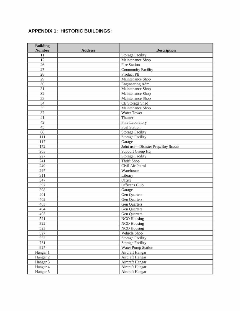
APPENDIX 1: HISTORIC BUILDINGS:
Building Number
Address
Description
11 Storage Facility 12 Maintenance Shop 26 Fire Station 27 Community Facility 28 Product Plt 29 Maintenance Shop 30 Engineering Adm 31 Maintenance Shop 32 Maintenance Shop 33 Maintenance Shop 34 CE Storage Shed 35 Maintenance Shop 37 Water Tower 41 Theater 42 Pme Laboratory 45 Fuel Station 68 Storage Facility 111 Storage Facility 117 Garage 172 Joint use—Disaster Prep/Boy Scouts 205 Support Group Hq 227 Storage Facility 241 Thrift Shop 249 Civil Air Patrol 297 Warehouse 311 Library 347 Office 397 Officer's Club 398 Garage 401 Gen Quarters 402 Gen Quarters 403 Gen Quarters 404 Gen Quarters 405 Gen Quarters 521 NCO Housing 522 NCO Housing 523 NCO Housing 527 Vehicle Shop 552 Storage Facility 731 Storage Facility 927 Water Pump Station
Hangar 1 Aircraft Hangar Hangar 2 Aircraft Hangar Hangar 3 Aircraft Hangar Hangar 4 Aircraft Hangar Hangar 5 Aircraft Hangar
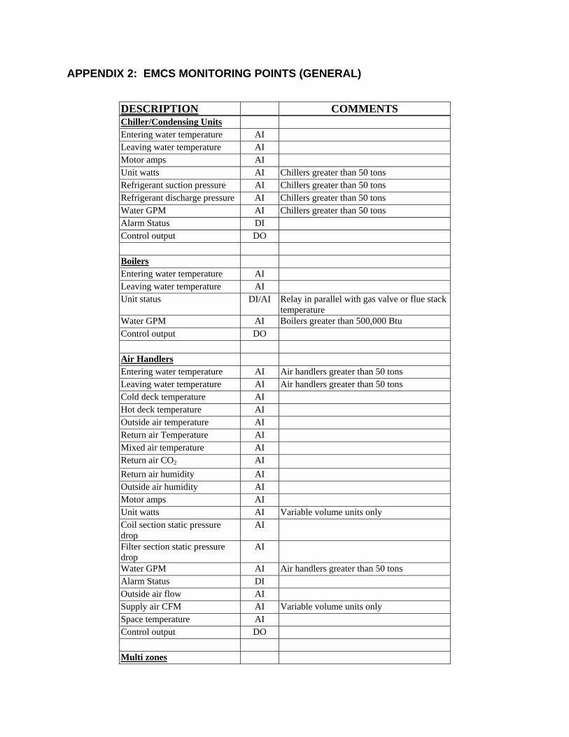
APPENDIX 2: EMCS MONITORING POINTS (GENERAL)
DESCRIPTION COMMENTS Chiller/Condensing Units Entering water temperature AI Leaving water temperature AI Motor amps AI Unit watts AI Chillers greater than 50 tons Refrigerant suction pressure AI Chillers greater than 50 tons Refrigerant discharge pressure AI Chillers greater than 50 tons Water GPM AI Chillers greater than 50 tons Alarm Status DI Control output DO Boilers Entering water temperature AI Leaving water temperature AI Unit status DI/AI Relay in parallel with gas valve or flue stack
temperature Water GPM AI Boilers greater than 500,000 Btu Control output DO Air Handlers Entering water temperature AI Air handlers greater than 50 tons Leaving water temperature AI Air handlers greater than 50 tons Cold deck temperature AI Hot deck temperature AI Outside air temperature AI Return air Temperature AI Mixed air temperature AI Return air CO2 AI
Return air humidity AI Outside air humidity AI Motor amps AI Unit watts AI Variable volume units only Coil section static pressure drop
AI
Filter section static pressure drop
AI
Water GPM AI Air handlers greater than 50 tons Alarm Status DI Outside air flow AI Supply air CFM AI Variable volume units only Space temperature AI Control output DO Multi zones
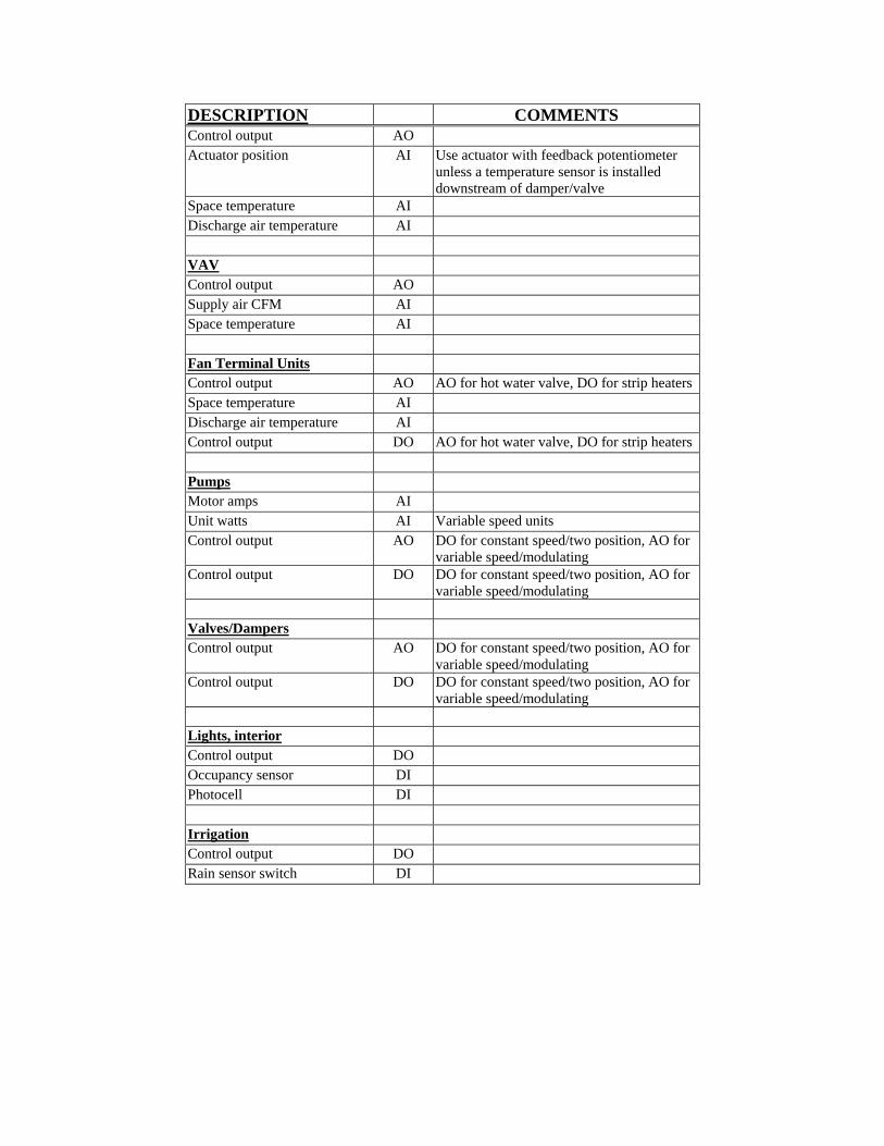
DESCRIPTION COMMENTS Control output AO Actuator position AI Use actuator with feedback potentiometer
unless a temperature sensor is installed downstream of damper/valve
Space temperature AI Discharge air temperature AI VAV Control output AO Supply air CFM AI Space temperature AI Fan Terminal Units Control output AO AO for hot water valve, DO for strip heaters Space temperature AI Discharge air temperature AI Control output DO AO for hot water valve, DO for strip heaters Pumps Motor amps AI Unit watts AI Variable speed units Control output AO DO for constant speed/two position, AO for
variable speed/modulating Control output DO DO for constant speed/two position, AO for
variable speed/modulating Valves/Dampers Control output AO DO for constant speed/two position, AO for
variable speed/modulating Control output DO DO for constant speed/two position, AO for
variable speed/modulating Lights, interior Control output DO Occupancy sensor DI Photocell DI Irrigation Control output DO Rain sensor switch DI
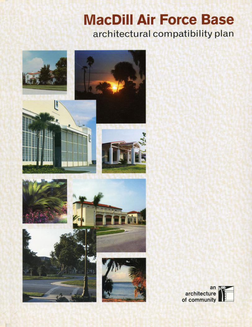
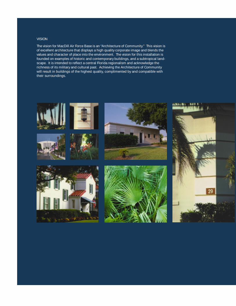
VISION
The vision for MacDill Air Force Base is an “Architecture of Community.” This vision isof excellent architecture that displays a high quality corporate image and blends thevalues and character of place into the environment. The vision for this installation isfounded on examples of historic and contemporary buildings, and a subtropical land-scape. It is intended to reflect a central Florida regionalism and acknowledge therichness of its military and cultural past. Achieving the Architecture of Communitywill result in buildings of the highest quality, complimented by and compatible withtheir surroundings.
INTRODUCTION ............................................. 2
BUILDING DESIGN STANDARDS ...................... 6
Community ................................................. 7
Character ............................................... 7
Wall Systems ......................................... 8
Applied Colors ...................................... 10
Roof Systems ........................................ 12
Entrances ............................................. 13
Screens and Enclosures ........................ 14
Ancillary Structures ............................... 16
Industrial / Flightline Area ...................... 17
NAVCENT Compound ............................. 18
Commercial Area .................................. 19
Historic Structures ............................... 20Family Housing ........................................ 22
SITE DESIGN STANDARDS ........................... 24
Site Development ..................................... 25
Siting .................................................. 25
Landform ............................................. 26
Site Furnishings ....................................27
Roadways ............................................ 30
Parking Areas ....................................... 31
Pedestrian Circulation .......................... 33
Signage ............................................... 34
Lighting ............................................... 35
Utilities .................................................37
Landscape .............................................. 38
Open Space ......................................... 39
Streetscaping ...................................... 40
Facility Landscaping .............................. 41
IMPLEMENTATION ........................................ 42
APPENDICES .............................................. 46
Materials and Colors .............................. A1
Plans and Guides ................................. A2
Landscape Materials ............................ A3
ACP Design Checklist ........................... A4
Index ................................................... A5
1Table of Contents
table of contents

architectural compatibility plan – MacDill Air Force Base2
The Architectural Compatibility Plan (ACP) defines a clear design vocabularyto be used throughout the base, providing specific standards to be observed inall aspects of exterior design. Compatible architecture is accomplished notonly with buildings that are similar, but also through the use of common designforms, details, materials, site features, and streetscapes.
The ACP’s goal is to create a visually unified environment based on a sense ofcommunity similar to a campus or small town. The primary design goal is todirect development of MacDill towards a livable, attractive, and visually cohe-sive Air Force base.
The plan helps build quality places that contribute to the community. It willmerge the historic and contemporary styles of architecture on MacDill AirForce Base.
introduction

introduction 3
Purpose
The purpose of the ACP is to define specificdesign standards for buildings, sitedevelopment, and streetscapes that serve tointegrate the visual character throughout thebase.
The ACP will help ensure consistent qualitydesign decisions by commanders, planners,architects, engineers, maintenance staff,and residents. It promotes clear, concisecommunication between MacDill AFB asthe client and design professionals.
This plan applies to self-help initiatives,small projects, and operations andmaintenance activities as well as largeconstruction efforts.
The ACP is referenced from and supportsthe MacDill General Plan as a key compo-nent plan.
How to Use This Plan
The Building Design Standards Sectiongives requirements for facilities within eachof the architectural settings and special useareas. For special use areas, refer to thecommunity setting standards and then thespecial use area standards for morespecific information.
The Site Design Standards Section providesinformation on site development andamenities to be applied throughout theinstallation.
The Implementation Section of the booklethighlights key elements to help ensuresuccess in designing and constructingexcellent facilities. The implementationsection is used to facilitate the coordinationand approval of design submittals. Itdiscusses the traditional design process,highlights the importance of site analysis,and describes the role of the ArchitecturalCompatibility Review Board (ACRB). Allfuture construction and renovation efforts forall customers and funding sources willadhere to the guidelines in this ACP.Designs must be approved by the ACRBprior to contract advertising.
Finally, the appendices provide additionalinformation including a general index, listsof building materials, site amenities, paintcolors, landscape materials, and reviewchecklists for the ACRB and projectpersonnel. Use the appendices in conjunc-tion with the booklet as a quick deskreference to specific materials and colorspecifications.
A poster is available upon request thatdisplays photographic examples ofcommunity at MacDill Air Force Base.
Note: Not all photos in this ACP are taken from MacDillAFB. Some photos are from off-base locations, whichdemonstrate the intended standard / vision.
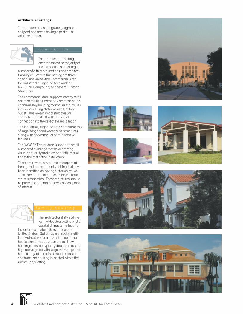
architectural compatibility plan – MacDill Air Force Base4
Architectural Settings
The architectural settings are geographi-cally defined areas having a particularvisual character.
c o m m u n i t y
This architectural settingencompasses the majority ofthe installation supporting a
number of different functions and architec-tural styles. Within this setting are threespecial use areas (the Commercial Area,the Industrial / Flightline Area and theNAVCENT Compound) and several HistoricStructures.
The commercial area supports mostly retailoriented facilities from the very massive BX/ commissary building to smaller structuresincluding a filling station and a fast foodoutlet. This area has a distinct visualcharacter unto itself with few visualconnections to the rest of the installation.
The industrial / flightline area contains a mixof large hangar and warehouse structuresalong with a few smaller administrativefacilities.
The NAVCENT compound supports a smallnumber of buildings that have a strongvisual continuity and provide subtle, visualties to the rest of the installation.
There are several structures interspersedthroughout the community setting that havebeen identified as having historical value.These are further identified in the Historicstructures section. These structures shouldbe protected and maintained as focal pointsof interest.
f a m i l y h o u s i n g
The architectural style of theFamily Housing setting is of acoastal character reflecting
the unique climate of the southeasternUnited States. Buildings are mostly multi-family structures organized into neighbor-hoods similar to suburban areas. Newhousing units are typically duplex units, sethigh above grade with large overhangs andhipped or gabled roofs. Unaccompaniedand transient housing is located within theCommunity Setting.
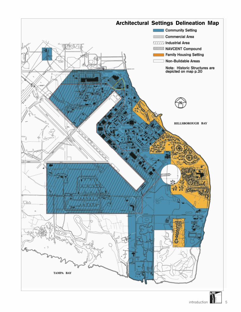
introduction 5
Architectural Settings Delineation Map
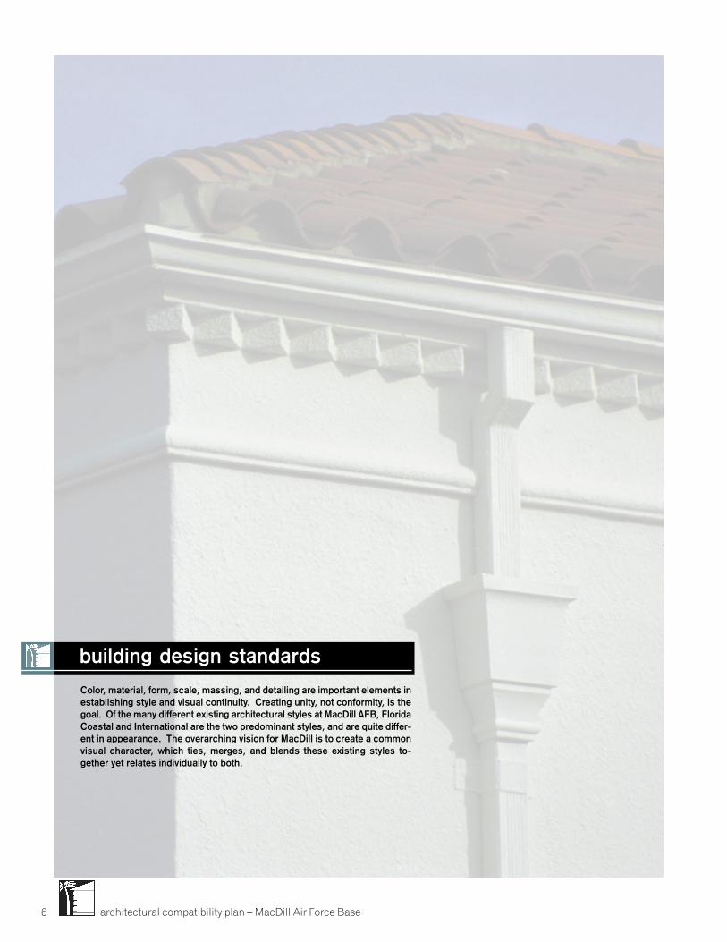
architectural compatibility plan – MacDill Air Force Base6
Color, material, form, scale, massing, and detailing are important elements inestablishing style and visual continuity. Creating unity, not conformity, is thegoal. Of the many different existing architectural styles at MacDill AFB, FloridaCoastal and International are the two predominant styles, and are quite differ-ent in appearance. The overarching vision for MacDill is to create a commonvisual character, which ties, merges, and blends these existing styles to-gether yet relates individually to both.
building design standards
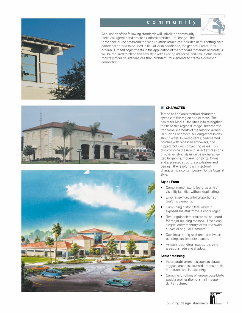
building design standards 7
� CHARACTER
Tampa has an architectural characterspecific to the region and climate. Thedesire for MacDill facilities is to strengthenthe tie to this regional image. Incorporatetraditional elements of the historic vernacu-lar such as horizontal building expressions,stucco walls, louvered vents, pedimentedporches with recessed entryways, andhipped roofs with projecting eaves. It willalso combine these with select expressionsof other existing styles on base character-ized by quoins, modern horizontal forms,and expressed structure of pilasters andbeams. The resulting architecturalcharacter is a contemporary Florida Coastalstyle.
Style / Form
� Compliment historic features on high-visibility facilities without duplicating.
� Emphasize horizontal proportions onBuilding elements.
� Combining historic features withexposed skeletal frame is encouraged.
� Rectangular elements are the standardfor major building masses. Use clean,simple, contemporary forms and avoidcurves or angular elements.
� Develop a strong relationship betweenbuildings and exterior spaces.
� Articulate building facades to createareas of shade and shadow.
Scale / Massing
� Incorporate amenities such as plazas,loggias, arcades, covered entries, trellisstructures, and landscaping.
� Combine functions whenever possible toavoid a proliferation of small indepen-dent structures.
Application of the following standards will link all the communityfacilities together and create a uniform architectural image. Thethree special use areas and the many historic structures included in this setting haveadditional criteria to be used in lieu of, or in addition to, the general Communitycriteria. Limited adjustments in the application of the standard materials and detailswill be required to blend the new style with existing adjacent facilities. Some areasmay rely more on site features than architectural elements to create a commonconnection.
c o m m u n i t y
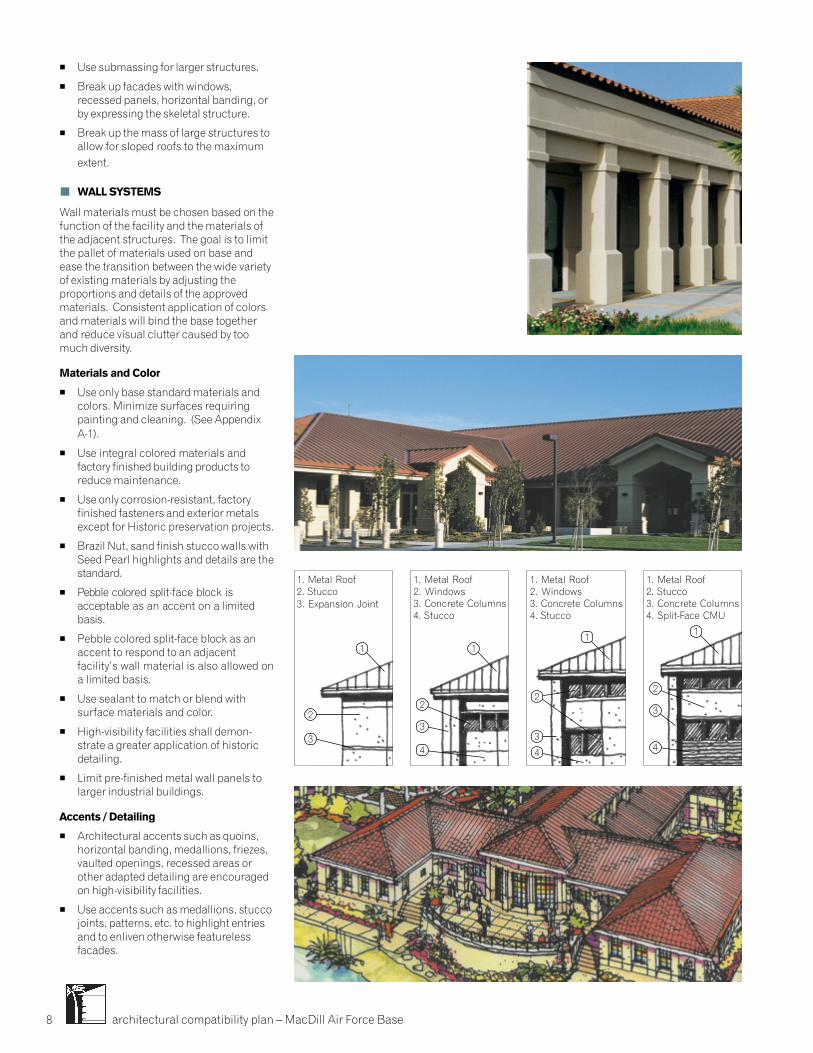
architectural compatibility plan – MacDill Air Force Base8
� Use submassing for larger structures.
� Break up facades with windows,recessed panels, horizontal banding, orby expressing the skeletal structure.
� Break up the mass of large structures toallow for sloped roofs to the maximumextent.
� WALL SYSTEMS
Wall materials must be chosen based on thefunction of the facility and the materials ofthe adjacent structures. The goal is to limitthe pallet of materials used on base andease the transition between the wide varietyof existing materials by adjusting theproportions and details of the approvedmaterials. Consistent application of colorsand materials will bind the base togetherand reduce visual clutter caused by toomuch diversity.
Materials and Color
� Use only base standard materials andcolors. Minimize surfaces requiringpainting and cleaning. (See AppendixA-1).
� Use integral colored materials andfactory finished building products toreduce maintenance.
� Use only corrosion-resistant, factoryfinished fasteners and exterior metalsexcept for Historic preservation projects.
� Brazil Nut, sand finish stucco walls withSeed Pearl highlights and details are thestandard.
� Pebble colored split-face block isacceptable as an accent on a limitedbasis.
� Pebble colored split-face block as anaccent to respond to an adjacentfacility’s wall material is also allowed ona limited basis.
� Use sealant to match or blend withsurface materials and color.
� High-visibility facilities shall demon-strate a greater application of historicdetailing.
� Limit pre-finished metal wall panels tolarger industrial buildings.
Accents / Detailing
� Architectural accents such as quoins,horizontal banding, medallions, friezes,vaulted openings, recessed areas orother adapted detailing are encouragedon high-visibility facilities.
� Use accents such as medallions, stuccojoints, patterns, etc. to highlight entriesand to enliven otherwise featurelessfacades.
1 11 1
4
3
2
4
3
2
4
3
2
1. Metal Roof2. Stucco3. Expansion Joint
1. Metal Roof2. Windows3. Concrete Columns4. Stucco
1. Metal Roof2. Windows3. Concrete Columns4. Stucco
1. Metal Roof2. Stucco3. Concrete Columns4. Split-Face CMU
3
2
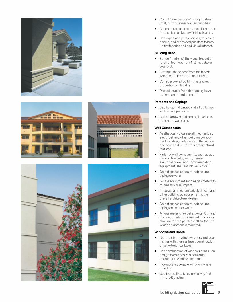
building design standards 9
� Do not “over decorate” or duplicate intotal, historic styles for new facilities.
� Accents such as quoins, medallions, andfriezes shall be factory finished colors.
� Use expansion joints, reveals, recessedpanels, and expressed pilasters to breakup flat facades and add visual interest.
Building Base
� Soften (minimize) the visual impact ofraising floor level to +11.5 feet abovesea level.
� Distinguish the base from the facadewhere earth berms are not utilized.
� Consider overall building height andproportion on detailing.
� Protect stucco from damage by lawnmaintenance equipment.
Parapets and Copings
� Use horizontal parapets at all buildingswith low-sloped roofs.
� Use a narrow metal coping finished tomatch the wall color.
Wall Components
� Aesthetically organize all mechanical,electrical, and other building compo-nents as design elements of the facadeand coordinate with other architecturalfeatures.
� Finish of wall components, such as gasmeters, fire bells, vents, louvers,electrical boxes, and communicationequipment, shall match wall color.
� Do not expose conduits, cables, andpiping on walls.
� Locate equipment such as gas meters tominimize visual impact.
� Integrate all mechanical, electrical, andother building components into theoverall architectural design.
� Do not expose conduits, cables, andpiping on exterior walls.
� All gas meters, fire bells, vents, louvres,and electrical / communications boxesshall match the painted wall surface onwhich equipment is mounted.
Windows and Doors
� Use aluminum windows doors and doorframes with thermal break constructionon all exterior surfaces.
� Use combination of windows or mulliondesign to emphasize a horizontalcharacter in window openings.
� Incorporate operable windows wherepossible.
� Use bronze tinted, low-emissivity (notmirrored) glazing.
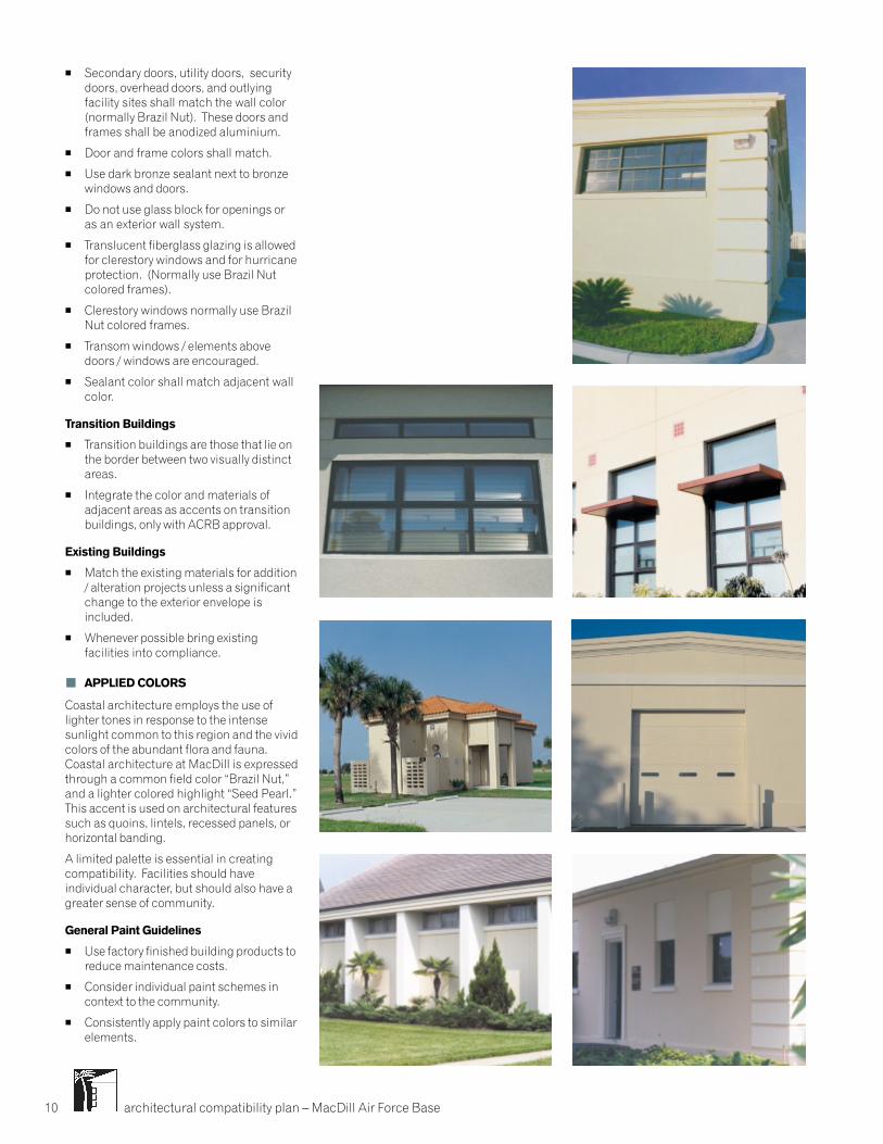
architectural compatibility plan – MacDill Air Force Base10
� Secondary doors, utility doors, securitydoors, overhead doors, and outlyingfacility sites shall match the wall color(normally Brazil Nut). These doors andframes shall be anodized aluminium.
� Door and frame colors shall match.
� Use dark bronze sealant next to bronzewindows and doors.
� Do not use glass block for openings oras an exterior wall system.
� Translucent fiberglass glazing is allowedfor clerestory windows and for hurricaneprotection. (Normally use Brazil Nutcolored frames).
� Clerestory windows normally use BrazilNut colored frames.
� Transom windows / elements abovedoors / windows are encouraged.
� Sealant color shall match adjacent wallcolor.
Transition Buildings
� Transition buildings are those that lie onthe border between two visually distinctareas.
� Integrate the color and materials ofadjacent areas as accents on transitionbuildings, only with ACRB approval.
Existing Buildings
� Match the existing materials for addition/ alteration projects unless a significantchange to the exterior envelope isincluded.
� Whenever possible bring existingfacilities into compliance.
� APPLIED COLORS
Coastal architecture employs the use oflighter tones in response to the intensesunlight common to this region and the vividcolors of the abundant flora and fauna.Coastal architecture at MacDill is expressedthrough a common field color “Brazil Nut,”and a lighter colored highlight “Seed Pearl.”This accent is used on architectural featuressuch as quoins, lintels, recessed panels, orhorizontal banding.
A limited palette is essential in creatingcompatibility. Facilities should haveindividual character, but should also have agreater sense of community.
General Paint Guidelines
� Use factory finished building products toreduce maintenance costs.
� Consider individual paint schemes incontext to the community.
� Consistently apply paint colors to similarelements.
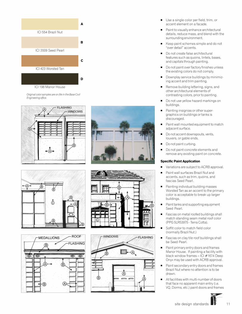
site design standards 11
Original color samples are on file in the Base CivilEngineering office.
� Use a single color per field, trim, oraccent element on a facade.
� Paint to visually enhance architecturaldetails, reduce mass, and blend with thesurrounding environment.
� Keep paint schemes simple and do not“over detail” accents.
� Do not create false architecturalfeatures such as quoins, lintels, bases,and capitals through painting.
� Do not paint over factory finishes unlessthe existing colors do not comply.
� Downplay service buildings by minimiz-ing accent and trim painting.
� Remove building lettering, signs, andother architectural elements ofcontrasting colors, prior to painting.
� Do not use yellow hazard markings onbuildings.
� Painting insignias or other super-graphics on buildings or tanks isdiscouraged.
� Paint wall mounted equipment to matchadjacent surface.
� Do not accent downspouts, vents,louvers, or gable ends.
� Do not paint curbing.
� Do not paint concrete elements andremove any existing paint on concrete.
Specific Paint Application
� Variations are subject to ACRB approval.
� Paint wall surfaces Brazil Nut andaccents, such as trim, quoins, andfascias Seed Pearl.
� Painting individual building massesWorsted Tan as an accent to the primarycolor is acceptable to break up largerbuildings.
� Paint tanks and supporting equipmentSeed Pearl.
� Fascias on metal roofed buildings shallmatch standing seam metal roof color(PPG 5LR53975 - Terra Cotta).
� Soffit color to match field color(normally Brazil Nut.)
� Fascias on clay tile roof buildings shallbe Seed Pearl.
� Paint primary entry doors and framesManor House. If painting a facility withblack window frames – ICI #1674 DeepOnyx may be used with ACRB approval.
� Paint secondary entry doors and framesBrazil Nut where no attention is to bedrawn.
� At facilities with multi-number of doorsthat face no apparent main entry (i.e.VQ, Dorms, etc.) paint doors and frames
ICI 198 Manor House
ICI 423 Worsted Tan
ICI 2009 Seed Pearl
ICI 554 Brazil Nut
A
B
C
D

architectural compatibility plan – MacDill Air Force Base12
� Downspout finish shall match the wallcolor.
� Do not use exposed angled leaders.
Vents / Equipment
� Minimize, consolidate, and organizeroof penetrations on the least visibleside of the building.
� PVC pipes and other roof elements mustbe finished to match the roof color.
PPG 5LR53975 Terra Cotta
� ROOF SYSTEMS
As one of the most visually formidablepieces of a building, the roof color, material,and form play a large role in architecturalcompatibility. Terra cotta colored standingseam metal hipped roofs are the standard.Terra cotta tile hipped roofs are allowed onhigh-visibility facilities with ACRB approval.
Decision shall be based on facility locationon base, function of building, adjacencies,priority / hierarchy of facilities within basecommunity.
Configuration
� Use hipped roofs with pitches between3:12 and 5:12 as the primary buildingform for all facility types.
� Open gabled elements may be used toaccent entries.
� Use large overhangs between 2 feet and3 feet proportional to the size and heightof the building.
� Break up overall roof massing on largerstructures.
� Minimize thickness of roof edge toexpress a thin edge.
� Low-sloped roofs are only allowed forlarger structures in combination withhipped roofs, or to match existingconditions on add / alt projects.
Materials and Color
� Use only the approved Terra Cotta (PPG5LR53975) colored standing seammetal, 16 inch wide panel with 2 inchraised seam.
� Ancillary buildings will use terra cottatile on hipped roofs.
� Use speckled terra cotta tile to reflectthe historic structures.
� Use membrane roofing with a minimumslope of 1/2 : 12 for low-sloped roofs.
Gutters, Fascias, and Downspouts
� Generally, the depth of fascias shall beno larger than 8 inches.
� Fascia finish shall match the roof colorwhen occurring with metal roofing.
� Flashing color shall match roof color.
� Stepped flashing at the intersection ofroofs and walls shall match wall color.
� The use of gutters is encouraged.
� Gutters on sloped roofs shall be factoryfinished to match the roof color.
� Minimize the negative visual impact ofdownspouts by coordinating placementwith architectural features.
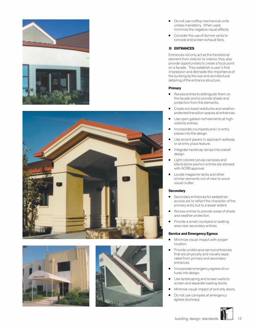
building design standards 13
� Do not use rooftop mechanical unitsunless mandatory. When used,minimize the negative visual effects.
� Consider the use of dormer vents toconceal and screen exhaust fans.
� ENTRANCES
Entrances not only act as the transitionalelement from exterior to interior, they alsoprovide opportunities to create a focal pointon a facade. They establish a user’s firstimpression and delineate the importance ofthe building by the size and architecturaldetailing of the entrance structure.
Primary
� Recess entries to distinguish them onthe facade and to provide shade andprotection from the elements.
� Create enclosed vestibules and weather-protected transition spaces at entrances.
� Use open gabled roof elements at high-visibility entries.
� Incorporate courtyards and / or entryplazas into the design.
� Use accent pavers in approach walkwayor at entry plaza feature.
� Integrate handicap ramps into overalldesign.
� Light colored canvas canopies andstand-alone pavilion entries are allowedwith ACRB approval.
� Locate magazine racks and othersimilar elements out of view to avoidvisual clutter.
Secondary
� Secondary entrances for pedestrianaccess are to reflect the character of theprimary entry but to a lesser extent.
� Recess entries to provide areas of shadeand weather protection.
� Provide a small courtyard or seatingarea near secondary entries.
Service and Emergency Egress
� Minimize visual impact with properlocation.
� Provide unobtrusive service entrancesthat are physically and visually sepa-rated from primary and secondaryentrances.
� Incorporate emergency egress struc-tures into design.
� Use landscaping and screen walls toscreen and separate loading docks.
� Minimize visual impact of exit-only doors.
� Do not use canopies at emergencyegress doorways.
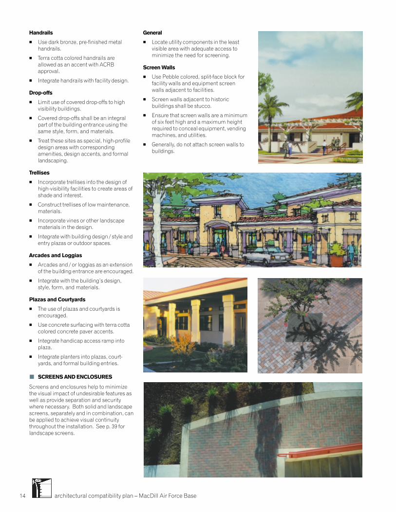
architectural compatibility plan – MacDill Air Force Base14
Handrails
� Use dark bronze, pre-finished metalhandrails.
� Terra cotta colored handrails areallowed as an accent with ACRBapproval.
� Integrate handrails with facility design.
Drop-offs
� Limit use of covered drop-offs to highvisibility buildings.
� Covered drop-offs shall be an integralpart of the building entrance using thesame style, form, and materials.
� Treat these sites as special, high-profiledesign areas with correspondingamenities, design accents, and formallandscaping.
Trellises
� Incorporate trellises into the design ofhigh-visibility facilities to create areas ofshade and interest.
� Construct trellises of low maintenance,materials.
� Incorporate vines or other landscapematerials in the design.
� Integrate with building design / style andentry plazas or outdoor spaces.
Arcades and Loggias
� Arcades and / or loggias as an extensionof the building entrance are encouraged.
� Integrate with the building’s design,style, form, and materials.
Plazas and Courtyards
� The use of plazas and courtyards isencouraged.
� Use concrete surfacing with terra cottacolored concrete paver accents.
� Integrate handicap access ramp intoplaza.
� Integrate planters into plazas, court-yards, and formal building entries.
� SCREENS AND ENCLOSURES
Screens and enclosures help to minimizethe visual impact of undesirable features aswell as provide separation and securitywhere necessary. Both solid and landscapescreens, separately and in combination, canbe applied to achieve visual continuitythroughout the installation. See p. 39 forlandscape screens.
General
� Locate utility components in the leastvisible area with adequate access tominimize the need for screening.
Screen Walls
� Use Pebble colored, split-face block forfacility walls and equipment screenwalls adjacent to facilities.
� Screen walls adjacent to historicbuildings shall be stucco.
� Ensure that screen walls are a minimumof six feet high and a maximum heightrequired to conceal equipment, vendingmachines, and utilities.
� Generally, do not attach screen walls tobuildings.

building design standards 15
� Construct free-standing garden walls ofbuff colored split-face block with pebblecolored accents.
� Do not place screen walls immediatelyadjacent to roadways or sidewalks.
� Use landscaping to soften walls.
Fencing
� Fencing adjacent to high-visibilityfacilities, such as the Child DevelopmentCenter, must be of high quality materialssuch as decorative metal fencing.
� Use stucco columns with black metalfence infill for screen walls that don’trequire visual separation.
� Dark brown, vinyl-covered chain linkfence in industrial and low-visibility sitesis allowed with ACRB approval.
� Perimeter fencing shall respond to thesite context.
� Use decorative metal and stucco, split-faced block, or stucco with accent.
Dumpster Enclosures
� Locate dumpsters to minimize visualimpact.
� Construct dumpster enclosures in allsettings of buff colored split-face blockwith pebble colored accents.
� In high-visibility locations provideWorsted Tan colored metal gates toscreen dumpsters.
� Provide Brazil Nut colored protectivebollards.
� Design enclosures as part of buildingservice areas for new facilities.
� Provide concrete pads and accessaprons.
� Include landscaping areas andprovisions for pedestrians access.
Force Protection
� Integrate security walls with the buildingarchitecture.
� Use a combination of walls, bollards,and tension cables with landscape beds.
� Do not paint Jersey Barriers.
� Minimize the visibility of all forceprotection devices with landscaping andintegral designs.
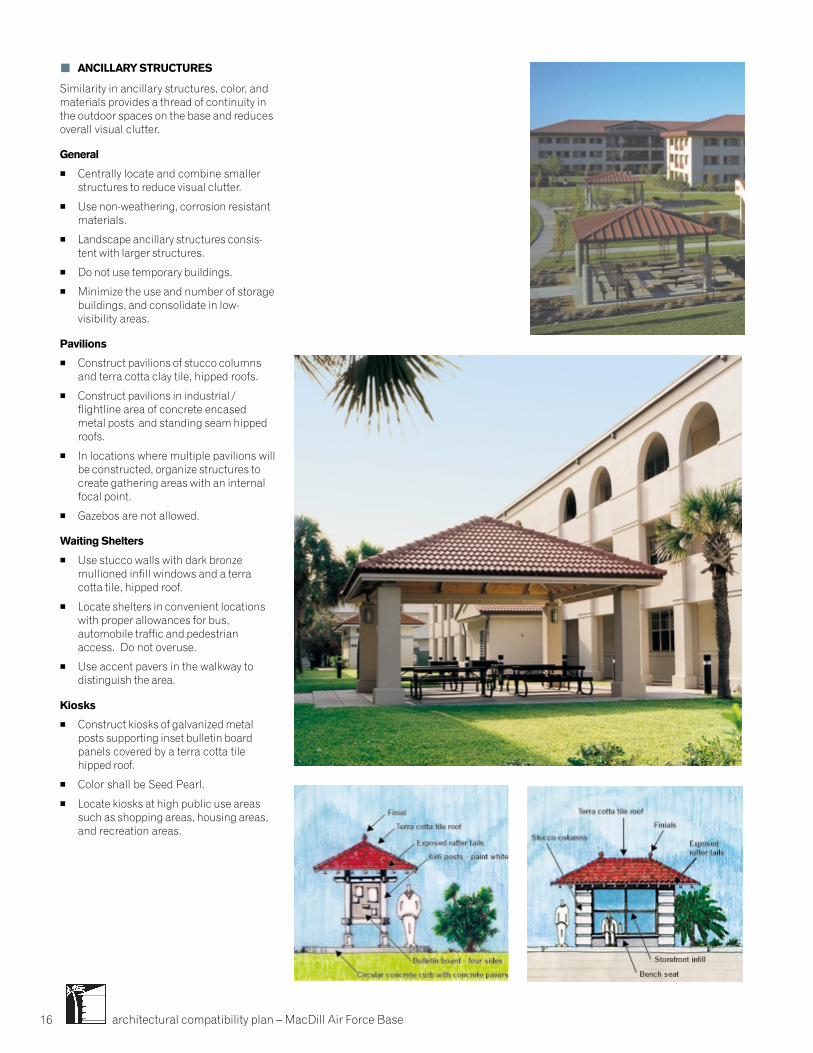
architectural compatibility plan – MacDill Air Force Base16
� ANCILLARY STRUCTURES
Similarity in ancillary structures, color, andmaterials provides a thread of continuity inthe outdoor spaces on the base and reducesoverall visual clutter.
General
� Centrally locate and combine smallerstructures to reduce visual clutter.
� Use non-weathering, corrosion resistantmaterials.
� Landscape ancillary structures consis-tent with larger structures.
� Do not use temporary buildings.
� Minimize the use and number of storagebuildings, and consolidate in low-visibility areas.
Pavilions
� Construct pavilions of stucco columnsand terra cotta clay tile, hipped roofs.
� Construct pavilions in industrial /flightline area of concrete encasedmetal posts and standing seam hippedroofs.
� In locations where multiple pavilions willbe constructed, organize structures tocreate gathering areas with an internalfocal point.
� Gazebos are not allowed.
Waiting Shelters
� Use stucco walls with dark bronzemullioned infill windows and a terracotta tile, hipped roof.
� Locate shelters in convenient locationswith proper allowances for bus,automobile traffic and pedestrianaccess. Do not overuse.
� Use accent pavers in the walkway todistinguish the area.
Kiosks
� Construct kiosks of galvanized metalposts supporting inset bulletin boardpanels covered by a terra cotta tilehipped roof.
� Color shall be Seed Pearl.
� Locate kiosks at high public use areassuch as shopping areas, housing areas,and recreation areas.
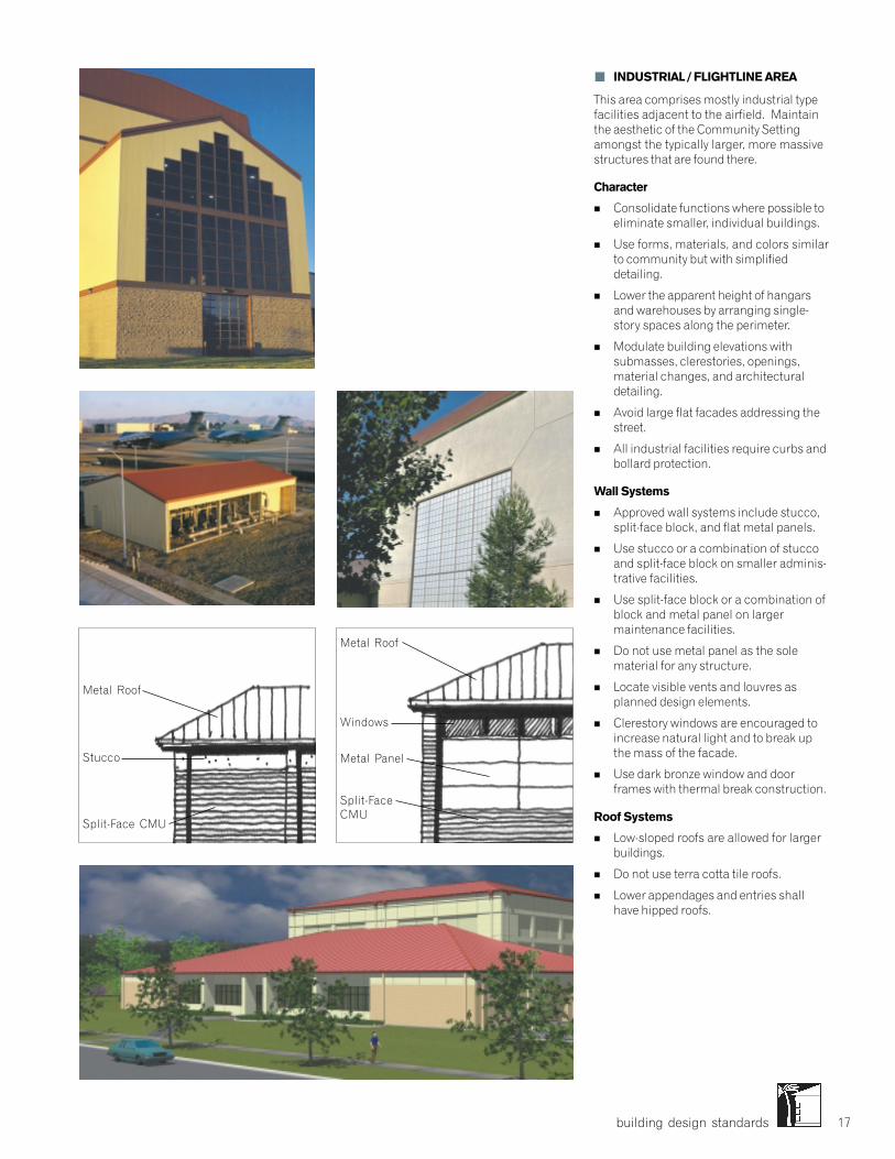
building design standards 17
� INDUSTRIAL / FLIGHTLINE AREA
This area comprises mostly industrial typefacilities adjacent to the airfield. Maintainthe aesthetic of the Community Settingamongst the typically larger, more massivestructures that are found there.
Character
� Consolidate functions where possible toeliminate smaller, individual buildings.
� Use forms, materials, and colors similarto community but with simplifieddetailing.
� Lower the apparent height of hangarsand warehouses by arranging single-story spaces along the perimeter.
� Modulate building elevations withsubmasses, clerestories, openings,material changes, and architecturaldetailing.
� Avoid large flat facades addressing thestreet.
� All industrial facilities require curbs andbollard protection.
Wall Systems
� Approved wall systems include stucco,split-face block, and flat metal panels.
� Use stucco or a combination of stuccoand split-face block on smaller adminis-trative facilities.
� Use split-face block or a combination ofblock and metal panel on largermaintenance facilities.
� Do not use metal panel as the solematerial for any structure.
� Locate visible vents and louvres asplanned design elements.
� Clerestory windows are encouraged toincrease natural light and to break upthe mass of the facade.
� Use dark bronze window and doorframes with thermal break construction.
Roof Systems
� Low-sloped roofs are allowed for largerbuildings.
� Do not use terra cotta tile roofs.
� Lower appendages and entries shallhave hipped roofs.
Metal Roof
Stucco
Split-Face CMU
Metal Roof
Windows
Metal Panel
Split-FaceCMU
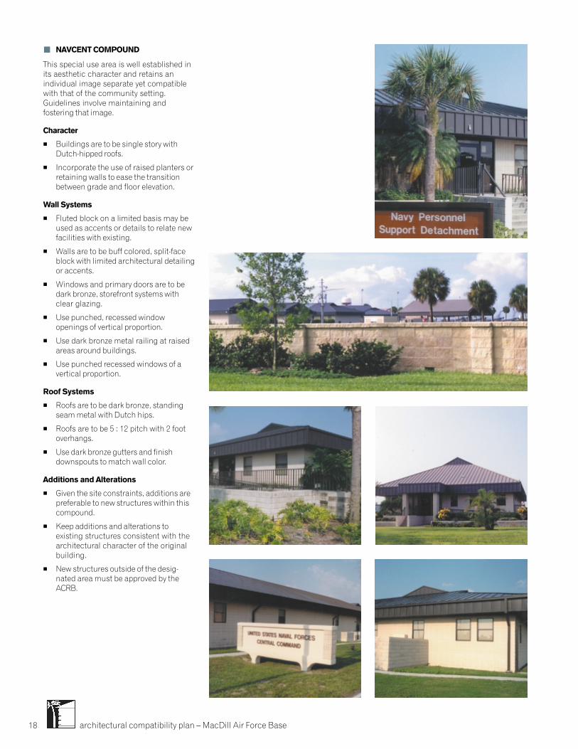
architectural compatibility plan – MacDill Air Force Base18
� NAVCENT COMPOUND
This special use area is well established inits aesthetic character and retains anindividual image separate yet compatiblewith that of the community setting.Guidelines involve maintaining andfostering that image.
Character
� Buildings are to be single story withDutch-hipped roofs.
� Incorporate the use of raised planters orretaining walls to ease the transitionbetween grade and floor elevation.
Wall Systems
� Fluted block on a limited basis may beused as accents or details to relate newfacilities with existing.
� Walls are to be buff colored, split-faceblock with limited architectural detailingor accents.
� Windows and primary doors are to bedark bronze, storefront systems withclear glazing.
� Use punched, recessed windowopenings of vertical proportion.
� Use dark bronze metal railing at raisedareas around buildings.
� Use punched recessed windows of avertical proportion.
Roof Systems
� Roofs are to be dark bronze, standingseam metal with Dutch hips.
� Roofs are to be 5 : 12 pitch with 2 footoverhangs.
� Use dark bronze gutters and finishdownspouts to match wall color.
Additions and Alterations
� Given the site constraints, additions arepreferable to new structures within thiscompound.
� Keep additions and alterations toexisting structures consistent with thearchitectural character of the originalbuilding.
� New structures outside of the desig-nated area must be approved by theACRB.
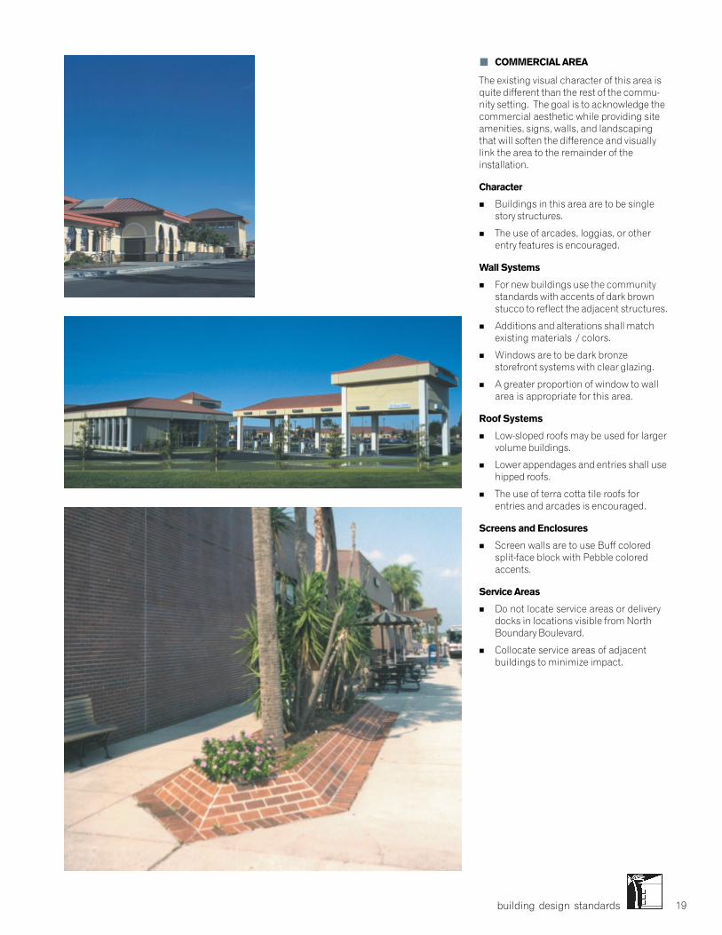
building design standards 19
� COMMERCIAL AREA
The existing visual character of this area isquite different than the rest of the commu-nity setting. The goal is to acknowledge thecommercial aesthetic while providing siteamenities, signs, walls, and landscapingthat will soften the difference and visuallylink the area to the remainder of theinstallation.
Character
� Buildings in this area are to be singlestory structures.
� The use of arcades, loggias, or otherentry features is encouraged.
Wall Systems
� For new buildings use the communitystandards with accents of dark brownstucco to reflect the adjacent structures.
� Additions and alterations shall matchexisting materials / colors.
� Windows are to be dark bronzestorefront systems with clear glazing.
� A greater proportion of window to wallarea is appropriate for this area.
Roof Systems
� Low-sloped roofs may be used for largervolume buildings.
� Lower appendages and entries shall usehipped roofs.
� The use of terra cotta tile roofs forentries and arcades is encouraged.
Screens and Enclosures
� Screen walls are to use Buff coloredsplit-face block with Pebble coloredaccents.
Service Areas
� Do not locate service areas or deliverydocks in locations visible from NorthBoundary Boulevard.
� Collocate service areas of adjacentbuildings to minimize impact.
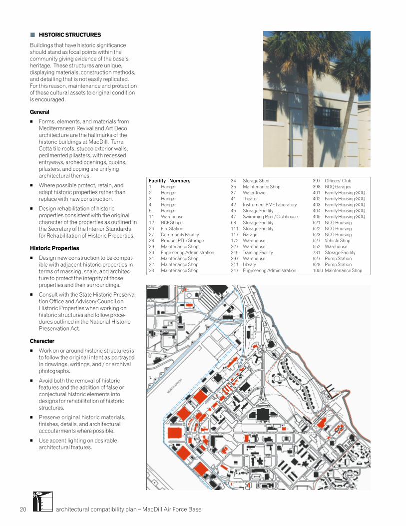
architectural compatibility plan – MacDill Air Force Base20
� HISTORIC STRUCTURES
Buildings that have historic significanceshould stand as focal points within thecommunity giving evidence of the base’sheritage. These structures are unique,displaying materials, construction methods,and detailing that is not easily replicated.For this reason, maintenance and protectionof these cultural assets to original conditionis encouraged.
General
� Forms, elements, and materials fromMediterranean Revival and Art Decoarchitecture are the hallmarks of thehistoric buildings at MacDill. TerraCotta tile roofs, stucco exterior walls,pedimented pilasters, with recessedentryways, arched openings, quoins,pilasters, and coping are unifyingarchitectural themes.
� Where possible protect, retain, andadapt historic properties rather thanreplace with new construction.
� Design rehabilitation of historicproperties consistent with the originalcharacter of the properties as outlined inthe Secretary of the Interior Standardsfor Rehabilitation of Historic Properties.
Historic Properties
� Design new construction to be compat-ible with adjacent historic properties interms of massing, scale, and architec-ture to protect the integrity of thoseproperties and their surroundings.
� Consult with the State Historic Preserva-tion Office and Advisory Council onHistoric Properties when working onhistoric structures and follow proce-dures outlined in the National HistoricPreservation Act.
Character
� Work on or around historic structures isto follow the original intent as portrayedin drawings, writings, and / or archivalphotographs.
� Avoid both the removal of historicfeatures and the addition of false orconjectural historic elements intodesigns for rehabilitation of historicstructures.
� Preserve original historic materials,finishes, details, and architecturalaccouterments where possible.
� Use accent lighting on desirablearchitectural features.
Facility NumbersFacility NumbersFacility NumbersFacility NumbersFacility Numbers1 Hangar2 Hangar3 Hangar4 Hangar5 Hangar11 Warehouse12 BCE Shops26 Fire Station27 Community Facility28 Product PTL / Storage29 Maintenance Shop30 Engineering Administration31 Maintenance Shop32 Maintenance Shop33 Maintenance Shop
34 Storage Shed35 Maintenance Shop37 Water Tower41 Theater42 Instrument PME Laboratory45 Storage Facility47 Swimming Pool / Clubhouse68 Storage Facility111 Storage Facility117 Garage172 Warehouse227 Warehouse249 Training Facility297 Warehouse311 Library347 Engineering Administration
397 Officers’ Club398 GOQ Garages401 Family Housing GOQ402 Family Housing GOQ403 Family Housing GOQ404 Family Housing GOQ405 Family Housing GOQ521 NCO Housing522 NCO Housing523 NCO Housing527 Vehicle Shop552 Warehouse731 Storage Facility927 Pump Station928 Pump Station1050 Maintenance Shop
1
2
3
4
5
1112
26
27
2932
31
28
41
37
30
34
3335
4142
45
172
227
249
297
311
347
397
521 522
523
552
527
927
928
1050
398
731
47
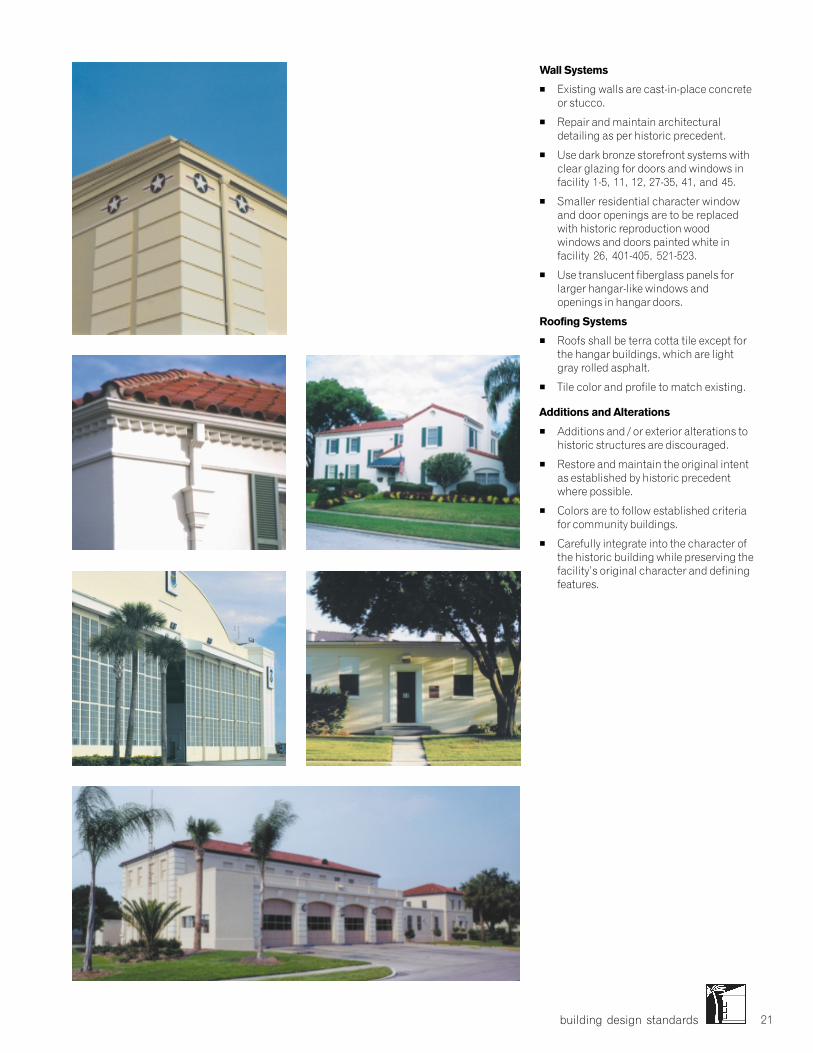
building design standards 21
Wall Systems
� Existing walls are cast-in-place concreteor stucco.
� Repair and maintain architecturaldetailing as per historic precedent.
� Use dark bronze storefront systems withclear glazing for doors and windows infacility 1-5, 11, 12, 27-35, 41, and 45.
� Smaller residential character windowand door openings are to be replacedwith historic reproduction woodwindows and doors painted white infacility 26, 401-405, 521-523.
� Use translucent fiberglass panels forlarger hangar-like windows andopenings in hangar doors.
Roofing Systems
� Roofs shall be terra cotta tile except forthe hangar buildings, which are lightgray rolled asphalt.
� Tile color and profile to match existing.
Additions and Alterations
� Additions and / or exterior alterations tohistoric structures are discouraged.
� Restore and maintain the original intentas established by historic precedentwhere possible.
� Colors are to follow established criteriafor community buildings.
� Carefully integrate into the character ofthe historic building while preserving thefacility’s original character and definingfeatures.
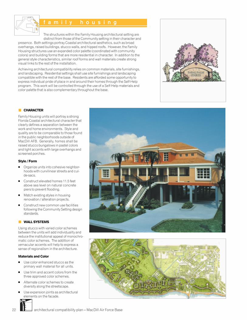
architectural compatibility plan – MacDill Air Force Base22
� CHARACTER
Family Housing units will portray a strongFlorida Coastal architectural character thatclearly defines a separation between thework and home environments. Style andquality are to be comparable to those foundin the public neighborhoods outside ofMacDill AFB. Generally, homes shall beraised stucco bungalows in pastel colorsand light accents with large overhangs andscreened porches.
Style / Form
� Organize units into cohesive neighbor-hoods with curvilinear streets and cul-de-sacs.
� Construct elevated homes 11.5 feetabove sea level on natural concretepiers to prevent flooding.
� Match existing styles in housingrenovation / alteration projects.
� Construct new common use facilitiesfollowing the Community Setting designstandards.
� WALL SYSTEMS
Using stucco with varied color schemesbetween the units will add individuality andreduce the institutional appeal of monochro-matic color schemes. The addition ofvernacular accents will help to express asense of regionalism in the architecture.
Materials and Color
� Use color enhanced stucco as theprimary wall material for all units.
� Use trim and accent colors from thethree approved color schemes.
� Alternate color schemes to creatediversity along the streetscape.
� Use expansion joints as architecturalelements on the facade.
The structures within the Family Housing architectural setting aredistinct from those of the Community setting in their character and
presence. Both settings portray Coastal architectural aesthetics, such as broadoverhangs, raised buildings, stucco walls, and hipped roofs. However, the FamilyHousing structures use an expanded color palette (coordinated with communitycolors) and building forms that are more residential in character. In addition to thegeneral style characteristics, similar roof forms and wall materials create strongvisual links to the rest of the installation.
Achieving architectural compatibility relies on common materials, site furnishings,and landscaping. Residential settings shall use site furnishings and landscapingcompatible with the rest of the base. Residents are afforded some opportunity toexpress individual pride of place in and around their homes through the Self-Helpprogram. This work will be controlled through the use of a Self-Help materials andcolor palette that is also complementary throughout the base.
f a m i l y h o u s i n g

building design standards 23
� Paint existing housing (not historic) tomatch new housing color schemes.
� Do not paint exposed concrete piers orfoundations, windows and doors.
� Use vinyl or vinyl-clad wood windows inwhite for all applications.
� Use factory finished aluminium doors atall entry points.
� Incorporate glazing in all primary entrydoors.
� Provide hurricane protection atopenings with laminated glass oroperable shutters.
� Use wood, shadowbox fencing for trashenclosures and backyard privacy only inFamily Housing.
10437 10415 10400
10446 10441 10400
10431 10411 10400
Color Palette
A
B
C
Roof
Roof
Roof
� ROOF SYSTEMS
Use roof configuration and color to link theFamily Housing setting to the rest of theinstallation.
Configuration
� Use hipped roofs with between 4 :12 and6 : 12 pitch.
� Consider the use of dormers or louveredDutch hips.
Materials and Color
� Use shingles with an architecturalprofile.
� Alternate established color schemes toincrease the visual diversity.
� Use fascias, gutters, downspouts, andsoffits finished to match the trim.
� Use factory finished, corrosion resistentmaterials.
� ENTRANCES
Design entrances and porches that expressthe unique coastal climate while promotingoutdoor activities and community interac-tion.
Primary
� Emphasize the public nature of theprimary entry by creating a porch forneighborhood or family interaction.
� Provide limited opportunities forpersonal expression at the front porchwith furnishings, planters, flags, etc.
Secondary
� Provide a stoop or patio at all secondaryentrances when units are at grade.
� The use of bug screens to encloseporches is encouraged.
Lighting
� Provide adequate lighting for safety andcomfort without allowing light pollution.
� Use recessed or consistently styled wall-mounted light fixtures.
� ANCILLARY STRUCTURES
� All ancillary structures shall beconsistent with Community setting.
� STREET LIGHTING
� Follow Housing Community Plan fortype and placement of lighting within theFamily Housing Setting.
Original color samples are on file in the Base CivilEngineering office.
architectural compatibility plan – MacDill Air Force Base24
A sense of community relies heavily on the character of the landscape and theelements within it. Site elements and development methods used consis-tently throughout the installation provide a common thread of visual continuityto the base as a whole. They bring consistency to the landscape between thedifferent architectural settings and special use areas as well as a blending ofthe various aesthetics of the existing structures on base.
Circulation systems such as roadways, walkways, and parking areas andsupport systems such as signage, lighting, and utilities are visual constantsthroughout the base that link the individual settings and areas together.
site design standards
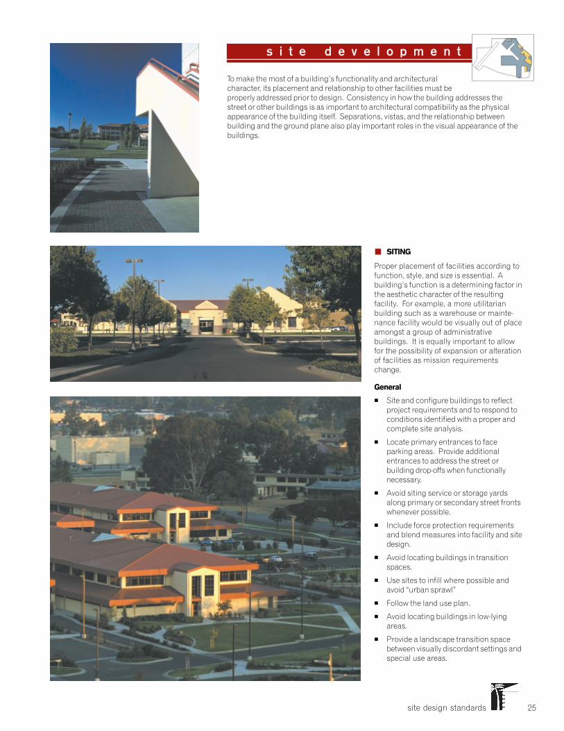
site design standards 25
To make the most of a building’s functionality and architecturalcharacter, its placement and relationship to other facilities must beproperly addressed prior to design. Consistency in how the building addresses thestreet or other buildings is as important to architectural compatibility as the physicalappearance of the building itself. Separations, vistas, and the relationship betweenbuilding and the ground plane also play important roles in the visual appearance of thebuildings.
s i t e d e v e l o p m e n t
� SITING
Proper placement of facilities according tofunction, style, and size is essential. Abuilding’s function is a determining factor inthe aesthetic character of the resultingfacility. For example, a more utilitarianbuilding such as a warehouse or mainte-nance facility would be visually out of placeamongst a group of administrativebuildings. It is equally important to allowfor the possibility of expansion or alterationof facilities as mission requirementschange.
General
� Site and configure buildings to reflectproject requirements and to respond toconditions identified with a proper andcomplete site analysis.
� Locate primary entrances to faceparking areas. Provide additionalentrances to address the street orbuilding drop-offs when functionallynecessary.
� Avoid siting service or storage yardsalong primary or secondary street frontswhenever possible.
� Include force protection requirementsand blend measures into facility and sitedesign.
� Avoid locating buildings in transitionspaces.
� Use sites to infill where possible andavoid “urban sprawl”
� Follow the land use plan.
� Avoid locating buildings in low-lyingareas.
� Provide a landscape transition spacebetween visually discordant settings andspecial use areas.
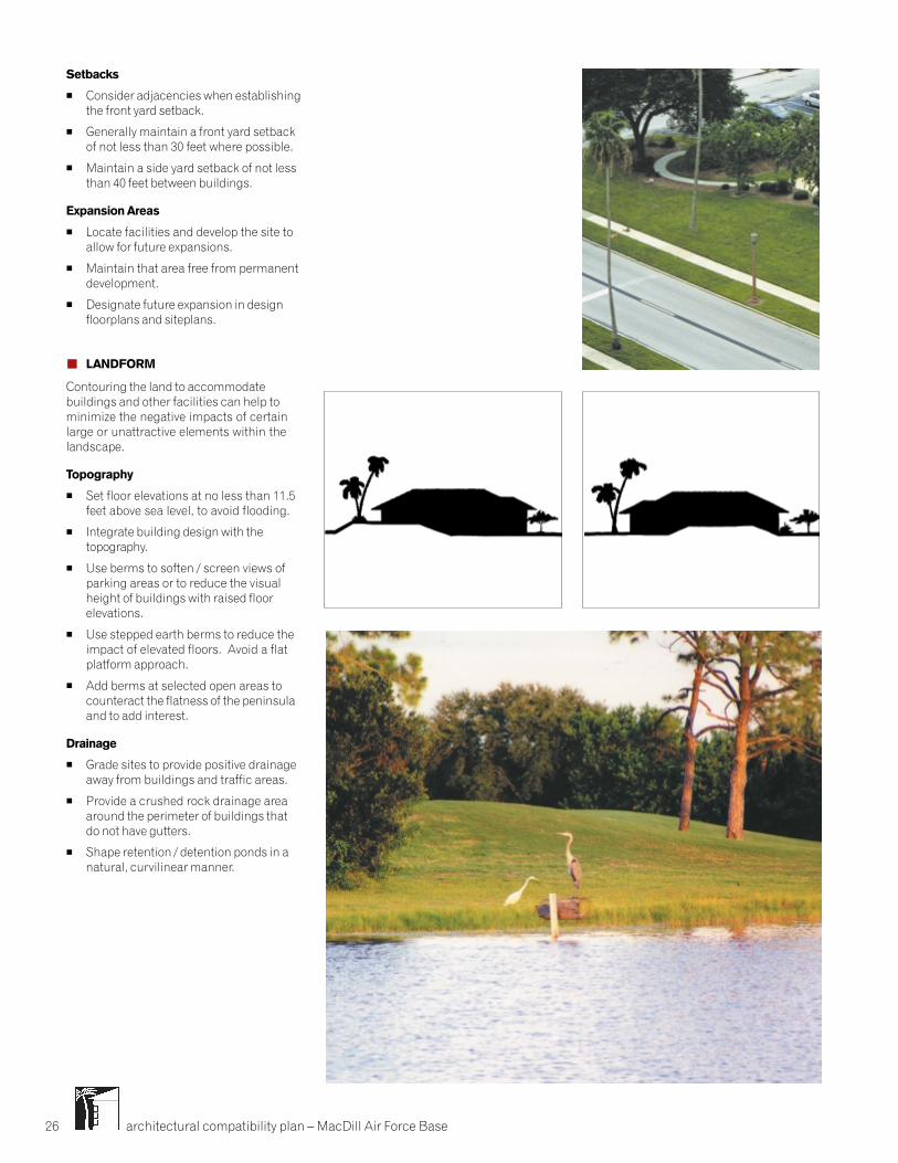
architectural compatibility plan – MacDill Air Force Base26
Setbacks
� Consider adjacencies when establishingthe front yard setback.
� Generally maintain a front yard setbackof not less than 30 feet where possible.
� Maintain a side yard setback of not lessthan 40 feet between buildings.
Expansion Areas
� Locate facilities and develop the site toallow for future expansions.
� Maintain that area free from permanentdevelopment.
� Designate future expansion in designfloorplans and siteplans.
� LANDFORM
Contouring the land to accommodatebuildings and other facilities can help tominimize the negative impacts of certainlarge or unattractive elements within thelandscape.
Topography
� Set floor elevations at no less than 11.5feet above sea level, to avoid flooding.
� Integrate building design with thetopography.
� Use berms to soften / screen views ofparking areas or to reduce the visualheight of buildings with raised floorelevations.
� Use stepped earth berms to reduce theimpact of elevated floors. Avoid a flatplatform approach.
� Add berms at selected open areas tocounteract the flatness of the peninsulaand to add interest.
Drainage
� Grade sites to provide positive drainageaway from buildings and traffic areas.
� Provide a crushed rock drainage areaaround the perimeter of buildings thatdo not have gutters.
� Shape retention / detention ponds in anatural, curvilinear manner.
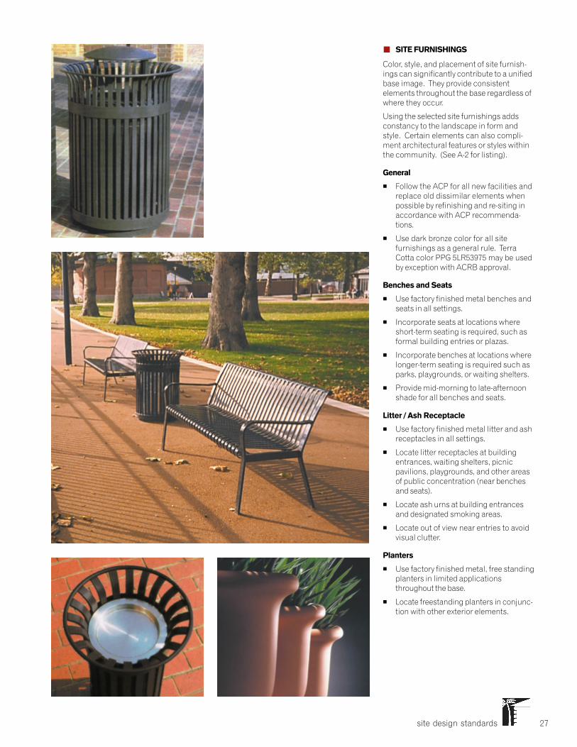
site design standards 27
� SITE FURNISHINGS
Color, style, and placement of site furnish-ings can significantly contribute to a unifiedbase image. They provide consistentelements throughout the base regardless ofwhere they occur.
Using the selected site furnishings addsconstancy to the landscape in form andstyle. Certain elements can also compli-ment architectural features or styles withinthe community. (See A-2 for listing).
General
� Follow the ACP for all new facilities andreplace old dissimilar elements whenpossible by refinishing and re-siting inaccordance with ACP recommenda-tions.
� Use dark bronze color for all sitefurnishings as a general rule. TerraCotta color PPG 5LR53975 may be usedby exception with ACRB approval.
Benches and Seats
� Use factory finished metal benches andseats in all settings.
� Incorporate seats at locations whereshort-term seating is required, such asformal building entries or plazas.
� Incorporate benches at locations wherelonger-term seating is required such asparks, playgrounds, or waiting shelters.
� Provide mid-morning to late-afternoonshade for all benches and seats.
Litter / Ash Receptacle
� Use factory finished metal litter and ashreceptacles in all settings.
� Locate litter receptacles at buildingentrances, waiting shelters, picnicpavilions, playgrounds, and other areasof public concentration (near benchesand seats).
� Locate ash urns at building entrancesand designated smoking areas.
� Locate out of view near entries to avoidvisual clutter.
Planters
� Use factory finished metal, free standingplanters in limited applicationsthroughout the base.
� Locate freestanding planters in conjunc-tion with other exterior elements.
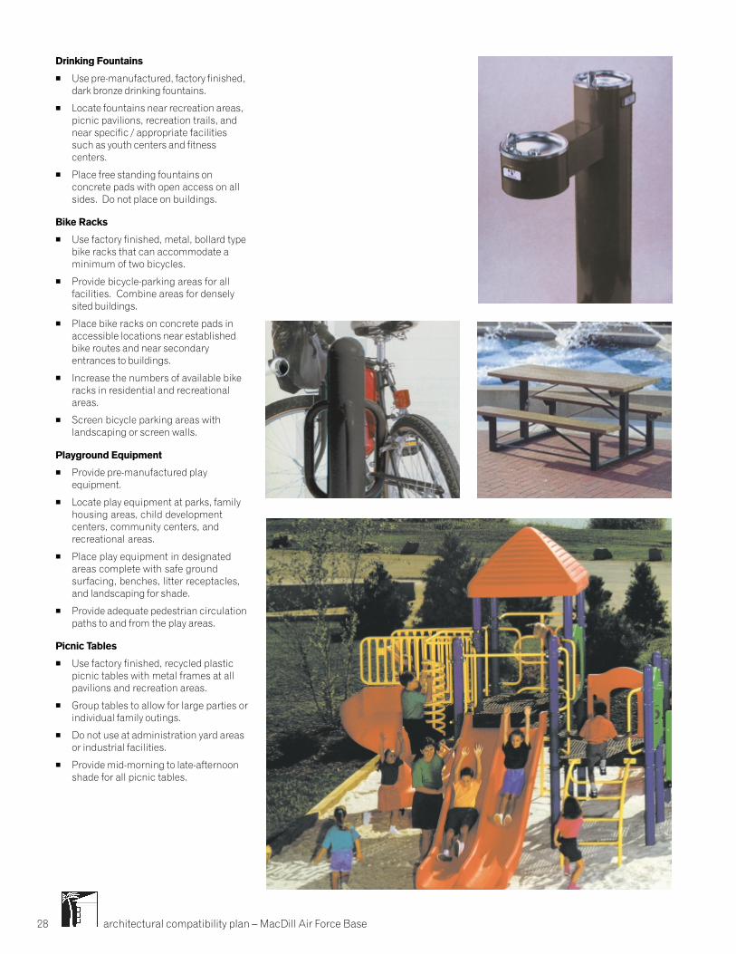
architectural compatibility plan – MacDill Air Force Base28
Drinking Fountains
� Use pre-manufactured, factory finished,dark bronze drinking fountains.
� Locate fountains near recreation areas,picnic pavilions, recreation trails, andnear specific / appropriate facilitiessuch as youth centers and fitnesscenters.
� Place free standing fountains onconcrete pads with open access on allsides. Do not place on buildings.
Bike Racks
� Use factory finished, metal, bollard typebike racks that can accommodate aminimum of two bicycles.
� Provide bicycle-parking areas for allfacilities. Combine areas for denselysited buildings.
� Place bike racks on concrete pads inaccessible locations near establishedbike routes and near secondaryentrances to buildings.
� Increase the numbers of available bikeracks in residential and recreationalareas.
� Screen bicycle parking areas withlandscaping or screen walls.
Playground Equipment
� Provide pre-manufactured playequipment.
� Locate play equipment at parks, familyhousing areas, child developmentcenters, community centers, andrecreational areas.
� Place play equipment in designatedareas complete with safe groundsurfacing, benches, litter receptacles,and landscaping for shade.
� Provide adequate pedestrian circulationpaths to and from the play areas.
Picnic Tables
� Use factory finished, recycled plasticpicnic tables with metal frames at allpavilions and recreation areas.
� Group tables to allow for large parties orindividual family outings.
� Do not use at administration yard areasor industrial facilities.
� Provide mid-morning to late-afternoonshade for all picnic tables.
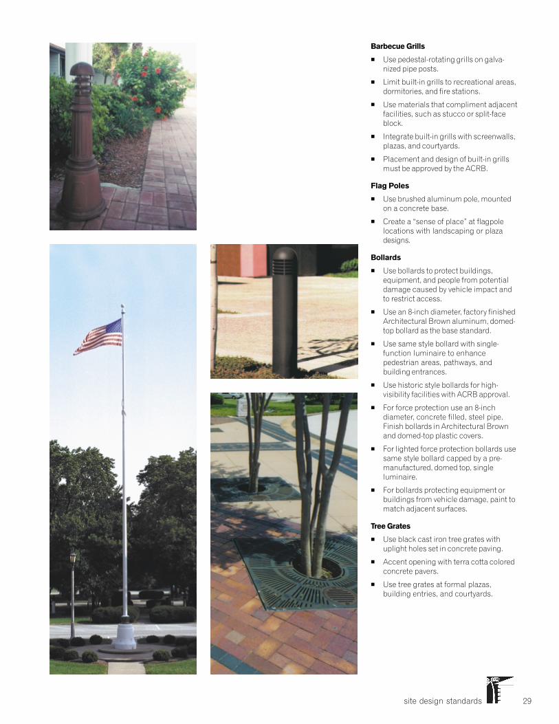
site design standards 29
Barbecue Grills
� Use pedestal-rotating grills on galva-nized pipe posts.
� Limit built-in grills to recreational areas,dormitories, and fire stations.
� Use materials that compliment adjacentfacilities, such as stucco or split-faceblock.
� Integrate built-in grills with screenwalls,plazas, and courtyards.
� Placement and design of built-in grillsmust be approved by the ACRB.
Flag Poles
� Use brushed aluminum pole, mountedon a concrete base.
� Create a “sense of place” at flagpolelocations with landscaping or plazadesigns.
Bollards
� Use bollards to protect buildings,equipment, and people from potentialdamage caused by vehicle impact andto restrict access.
� Use an 8-inch diameter, factory finishedArchitectural Brown aluminum, domed-top bollard as the base standard.
� Use same style bollard with single-function luminaire to enhancepedestrian areas, pathways, andbuilding entrances.
� Use historic style bollards for high-visibility facilities with ACRB approval.
� For force protection use an 8-inchdiameter, concrete filled, steel pipe.Finish bollards in Architectural Brownand domed-top plastic covers.
� For lighted force protection bollards usesame style bollard capped by a pre-manufactured, domed top, singleluminaire.
� For bollards protecting equipment orbuildings from vehicle damage, paint tomatch adjacent surfaces.
Tree Grates
� Use black cast iron tree grates withuplight holes set in concrete paving.
� Accent opening with terra cotta coloredconcrete pavers.
� Use tree grates at formal plazas,building entries, and courtyards.
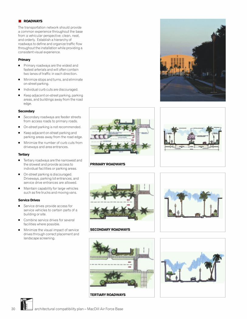
architectural compatibility plan – MacDill Air Force Base30
� ROADWAYS
The transportation network should providea common experience throughout the basefrom a vehicular perspective; clean, neat,and orderly. Establish a hierarchy ofroadways to define and organize traffic flowthroughout the installation while providing aconsistent visual experience.
Primary
� Primary roadways are the widest andfastest arterials and will often containtwo lanes of traffic in each direction.
� Minimize stops and turns, and eliminateon-street parking.
� Individual curb cuts are discouraged.
� Keep adjacent on-street parking, parkingareas, and buildings away from the roadedge.
Secondary
� Secondary roadways are feeder streetsfrom access roads to primary roads.
� On-street parking is not recommended.
� Keep adjacent on-street parking andparking areas away from the road edge.
� Minimize the number of curb cuts fromdriveways and area entrances.
Tertiary
� Tertiary roadways are the narrowest andthe slowest and provide access toindividual facilities or parking areas.
� On-street parking is discouraged.Driveways, parking lot entrances, andservice drive entrances are allowed.
� Maintain capability for large vehiclessuch as fire trucks and moving vans.
Service Drives
� Service drives provide access forservice vehicles to certain parts of abuilding or site.
� Combine service drives for severalfacilities where possible.
� Minimize the visual impact of servicedrives through correct placement andlandscape screening.
PRIMARY ROADWAYS
TERTIARY ROADWAYS
SECONDARY ROADWAYS
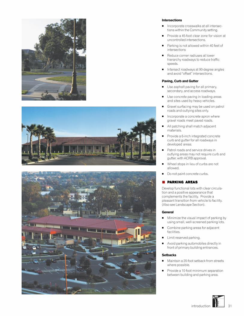
introduction 31
Intersections
� Incorporate crosswalks at all intersec-tions within the Community setting.
� Provide a 45-foot clear zone for vision atuncontrolled intersections.
� Parking is not allowed within 40 feet ofintersections
� Reduce corner radiuses at lowerhierarchy roadways to reduce trafficspeeds.
� Intersect roadways at 90-degree anglesand avoid “offset” intersections.
Paving, Curb and Gutter
� Use asphalt paving for all primary,secondary, and access roadways.
� Use concrete paving in loading areasand sites used by heavy vehicles.
� Gravel surfacing may be used on patrolroads and outlying sites only.
� Incorporate a concrete apron wheregravel roads meet paved roads.
� All patching shall match adjacentmaterials.
� Provide a 6-inch integrated concretecurb and gutter for all roadways indeveloped areas.
� Patrol roads and service drives inoutlying areas may not require curb andgutter, with ACRB approval.
� Wheel stops in lieu of curbs are notallowed.
� Do not paint concrete curbs.
� PPPPPARKING AREAARKING AREAARKING AREAARKING AREAARKING AREASSSSS
Develop functional lots with clear circula-tion and a positive appearance thatcomplements the facility. Provide apleasant transition from vehicle to facility.(Also see Landscape Section).
General
� Minimize the visual impact of parking byusing small, well-screened parking lots.
� Combine parking areas for adjacentfacilities.
� Limit reserved parking.
� Avoid parking automobiles directly infront of primary building entrances.
Setbacks
� Maintain a 20-foot setback from streetswhere possible.
� Provide a 10-foot minimum separationbetween building and parking area.
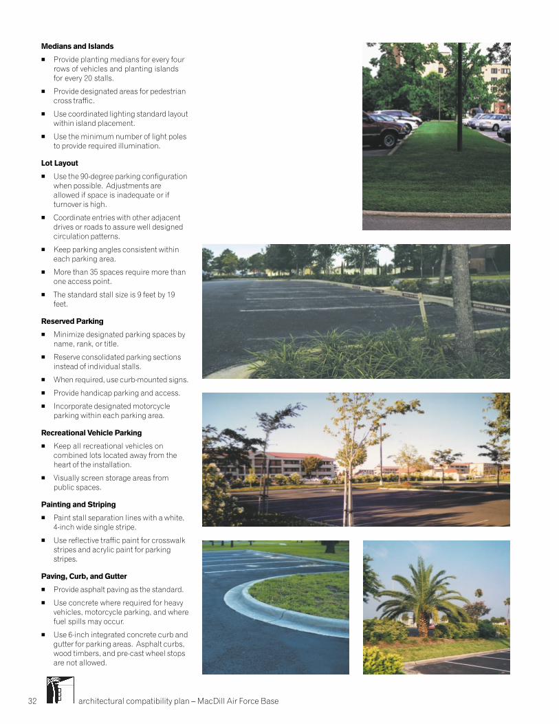
architectural compatibility plan – MacDill Air Force Base32
Medians and Islands
� Provide planting medians for every fourrows of vehicles and planting islandsfor every 20 stalls.
� Provide designated areas for pedestriancross traffic.
� Use coordinated lighting standard layoutwithin island placement.
� Use the minimum number of light polesto provide required illumination.
Lot Layout
� Use the 90-degree parking configurationwhen possible. Adjustments areallowed if space is inadequate or ifturnover is high.
� Coordinate entries with other adjacentdrives or roads to assure well designedcirculation patterns.
� Keep parking angles consistent withineach parking area.
� More than 35 spaces require more thanone access point.
� The standard stall size is 9 feet by 19feet.
Reserved Parking
� Minimize designated parking spaces byname, rank, or title.
� Reserve consolidated parking sectionsinstead of individual stalls.
� When required, use curb-mounted signs.
� Provide handicap parking and access.
� Incorporate designated motorcycleparking within each parking area.
Recreational Vehicle Parking
� Keep all recreational vehicles oncombined lots located away from theheart of the installation.
� Visually screen storage areas frompublic spaces.
Painting and Striping
� Paint stall separation lines with a white,4-inch wide single stripe.
� Use reflective traffic paint for crosswalkstripes and acrylic paint for parkingstripes.
Paving, Curb, and Gutter
� Provide asphalt paving as the standard.
� Use concrete where required for heavyvehicles, motorcycle parking, and wherefuel spills may occur.
� Use 6-inch integrated concrete curb andgutter for parking areas. Asphalt curbs,wood timbers, and pre-cast wheel stopsare not allowed.
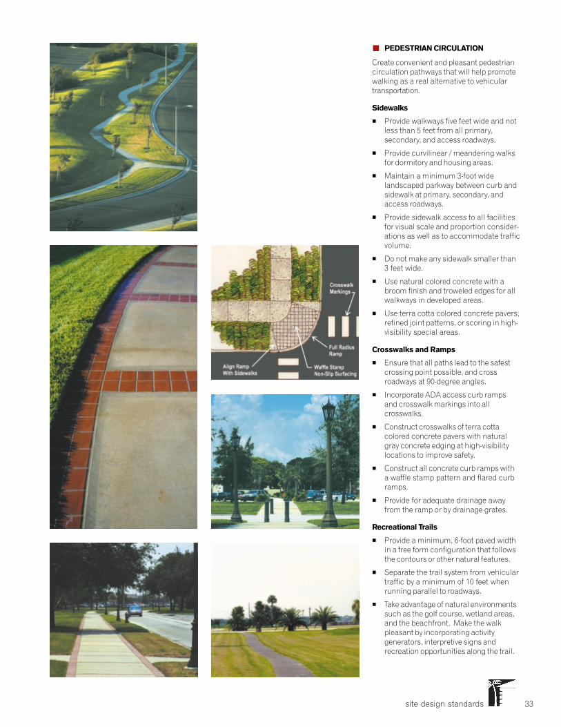
site design standards 33
� PEDESTRIAN CIRCULATION
Create convenient and pleasant pedestriancirculation pathways that will help promotewalking as a real alternative to vehiculartransportation.
Sidewalks
� Provide walkways five feet wide and notless than 5 feet from all primary,secondary, and access roadways.
� Provide curvilinear / meandering walksfor dormitory and housing areas.
� Maintain a minimum 3-foot widelandscaped parkway between curb andsidewalk at primary, secondary, andaccess roadways.
� Provide sidewalk access to all facilitiesfor visual scale and proportion consider-ations as well as to accommodate trafficvolume.
� Do not make any sidewalk smaller than3 feet wide.
� Use natural colored concrete with abroom finish and troweled edges for allwalkways in developed areas.
� Use terra cotta colored concrete pavers,refined joint patterns, or scoring in high-visibility special areas.
Crosswalks and Ramps
� Ensure that all paths lead to the safestcrossing point possible, and crossroadways at 90-degree angles.
� Incorporate ADA access curb rampsand crosswalk markings into allcrosswalks.
� Construct crosswalks of terra cottacolored concrete pavers with naturalgray concrete edging at high-visibilitylocations to improve safety.
� Construct all concrete curb ramps witha waffle stamp pattern and flared curbramps.
� Provide for adequate drainage awayfrom the ramp or by drainage grates.
Recreational Trails
� Provide a minimum, 6-foot paved widthin a free form configuration that followsthe contours or other natural features.
� Separate the trail system from vehiculartraffic by a minimum of 10 feet whenrunning parallel to roadways.
� Take advantage of natural environmentssuch as the golf course, wetland areas,and the beachfront. Make the walkpleasant by incorporating activitygenerators, interpretive signs andrecreation opportunities along the trail.
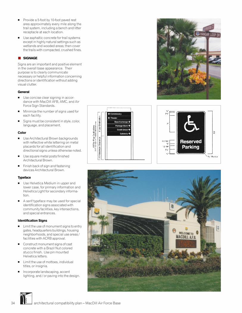
architectural compatibility plan – MacDill Air Force Base34
� Provide a 5-foot by 10-foot paved restarea approximately every mile along thetrail system, including a bench and litterreceptacle at each location.
� Use asphaltic concrete for trail systemsexcept in highly natural settings such aswetlands and wooded areas; then coverthe trails with compacted, crushed fines.
� SIGNAGE
Signs are an important and positive elementin the overall base appearance. Theirpurpose is to clearly communicatenecessary or helpful information concerningdirections or identification without addingvisual clutter.
General
� Use concise clear signing in accor-dance with MacDill AFB, AMC, and AirForce Sign Standards.
� Minimize the number of signs used foreach facility.
� Signs must be consistent in style, color,language, and placement.
Color
� Use Architectural Brown backgroundswith reflective white lettering on metalplacards for all identification anddirectional signs unless otherwise noted.
� Use square metal posts finishedArchitectural Brown.
� Finish back of sign and fasteningdevices Architectural Brown.
Typeface
� Use Helvetica Medium in upper andlower case, for primary information andHelvetica Light for secondary informa-tion.
� A serif typeface may be used for specialidentification signs associated withcommunity facilities, key intersections,and special entrances.
Identification Signs
� Limit the use of monument signs to entrygates, headquarters buildings, housingneighborhoods, and special use areas /facilities with ACRB approval.
� Construct monument signs of castconcrete with a Brazil Nut coloredstucco finish. Use pin mountedHelvetica letters.
� Limit the use of mottoes, individualtitles, or insignia.
� Incorporate landscaping, accentlighting, and / or paving into the design.
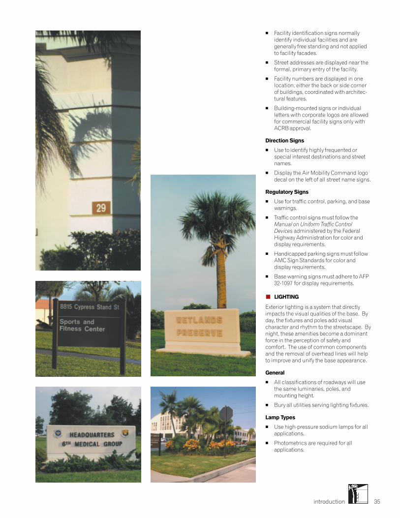
introduction 35
� Facility identification signs normallyidentify individual facilities and aregenerally free standing and not appliedto facility facades.
� Street addresses are displayed near theformal, primary entry of the facility.
� Facility numbers are displayed in onelocation, either the back or side cornerof buildings, coordinated with architec-tural features.
� Building-mounted signs or individualletters with corporate logos are allowedfor commercial facility signs only withACRB approval.
Direction Signs
� Use to identify highly frequented orspecial interest destinations and streetnames.
� Display the Air Mobility Command logodecal on the left of all street name signs.
Regulatory Signs
� Use for traffic control, parking, and basewarnings.
� Traffic control signs must follow theManual on Uniform Traffic ControlDevices administered by the FederalHighway Administration for color anddisplay requirements.
� Handicapped parking signs must followAMC Sign Standards for color anddisplay requirements.
� Base warning signs must adhere to AFP32-1097 for display requirements.
� LIGHTING
Exterior lighting is a system that directlyimpacts the visual qualities of the base. Byday, the fixtures and poles add visualcharacter and rhythm to the streetscape. Bynight, these amenities become a dominantforce in the perception of safety andcomfort. The use of common componentsand the removal of overhead lines will helpto improve and unify the base appearance.
General
� All classifications of roadways will usethe same luminaries, poles, andmounting height.
� Bury all utilities serving lighting fixtures.
Lamp Types
� Use high-pressure sodium lamps for allapplications.
� Photometrics are required for allapplications.
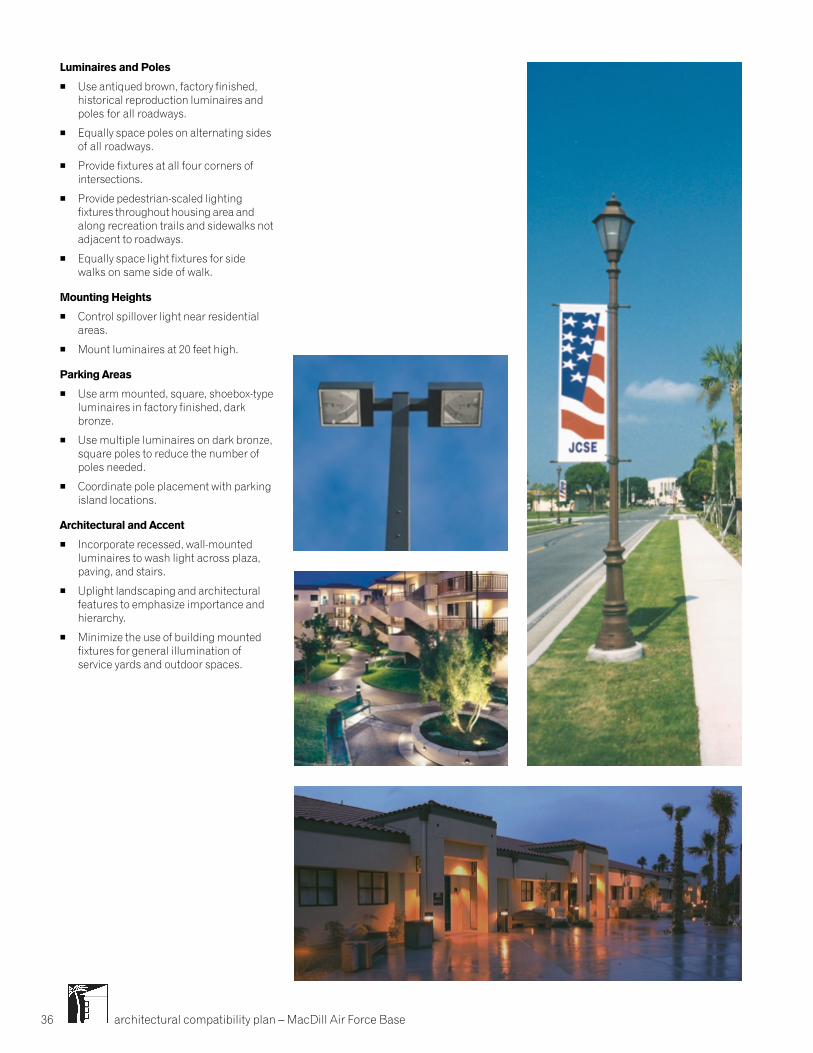
architectural compatibility plan – MacDill Air Force Base36
Luminaires and Poles
� Use antiqued brown, factory finished,historical reproduction luminaires andpoles for all roadways.
� Equally space poles on alternating sidesof all roadways.
� Provide fixtures at all four corners ofintersections.
� Provide pedestrian-scaled lightingfixtures throughout housing area andalong recreation trails and sidewalks notadjacent to roadways.
� Equally space light fixtures for sidewalks on same side of walk.
Mounting Heights
� Control spillover light near residentialareas.
� Mount luminaires at 20 feet high.
Parking Areas
� Use arm mounted, square, shoebox-typeluminaires in factory finished, darkbronze.
� Use multiple luminaires on dark bronze,square poles to reduce the number ofpoles needed.
� Coordinate pole placement with parkingisland locations.
Architectural and Accent
� Incorporate recessed, wall-mountedluminaires to wash light across plaza,paving, and stairs.
� Uplight landscaping and architecturalfeatures to emphasize importance andhierarchy.
� Minimize the use of building mountedfixtures for general illumination ofservice yards and outdoor spaces.
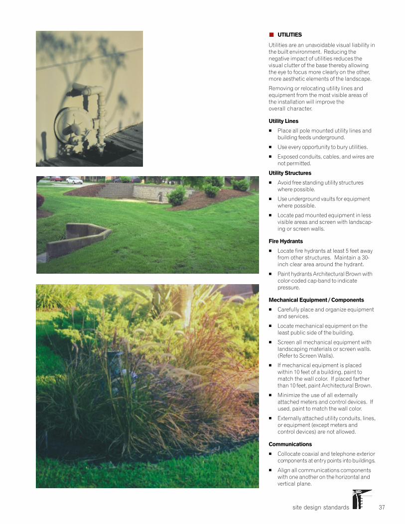
site design standards 37
� UTILITIES
Utilities are an unavoidable visual liability inthe built environment. Reducing thenegative impact of utilities reduces thevisual clutter of the base thereby allowingthe eye to focus more clearly on the other,more aesthetic elements of the landscape.
Removing or relocating utility lines andequipment from the most visible areas ofthe installation will improve theoverall character.
Utility Lines
� Place all pole mounted utility lines andbuilding feeds underground.
� Use every opportunity to bury utilities.
� Exposed conduits, cables, and wires arenot permitted.
Utility Structures
� Avoid free standing utility structureswhere possible.
� Use underground vaults for equipmentwhere possible.
� Locate pad mounted equipment in lessvisible areas and screen with landscap-ing or screen walls.
Fire Hydrants
� Locate fire hydrants at least 5 feet awayfrom other structures. Maintain a 30-inch clear area around the hydrant.
� Paint hydrants Architectural Brown withcolor-coded cap-band to indicatepressure.
Mechanical Equipment / Components
� Carefully place and organize equipmentand services.
� Locate mechanical equipment on theleast public side of the building.
� Screen all mechanical equipment withlandscaping materials or screen walls.(Refer to Screen Walls).
� If mechanical equipment is placedwithin 10 feet of a building, paint tomatch the wall color. If placed fartherthan 10 feet, paint Architectural Brown.
� Minimize the use of all externallyattached meters and control devices. Ifused, paint to match the wall color.
� Externally attached utility conduits, lines,or equipment (except meters andcontrol devices) are not allowed.
Communications
� Collocate coaxial and telephone exteriorcomponents at entry points into buildings.
� Align all communications componentswith one another on the horizontal andvertical plane.
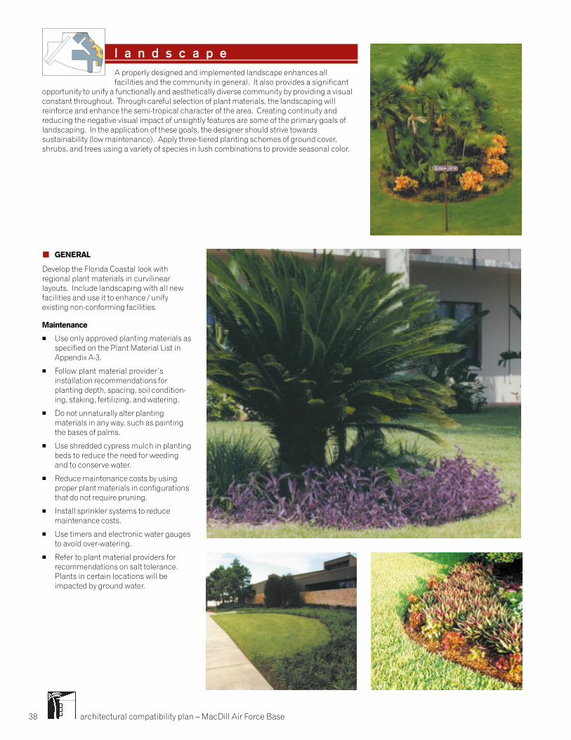
architectural compatibility plan – MacDill Air Force Base38
� GENERAL
Develop the Florida Coastal look withregional plant materials in curvilinearlayouts. Include landscaping with all newfacilities and use it to enhance / unifyexisting non-conforming facilities.
Maintenance
� Use only approved planting materials asspecified on the Plant Material List inAppendix A-3.
� Follow plant material provider’sinstallation recommendations forplanting depth, spacing, soil condition-ing, staking, fertilizing, and watering.
� Do not unnaturally alter plantingmaterials in any way, such as paintingthe bases of palms.
� Use shredded cypress mulch in plantingbeds to reduce the need for weedingand to conserve water.
� Reduce maintenance costs by usingproper plant materials in configurationsthat do not require pruning.
� Install sprinkler systems to reducemaintenance costs.
� Use timers and electronic water gaugesto avoid over-watering.
� Refer to plant material providers forrecommendations on salt tolerance.Plants in certain locations will beimpacted by ground water.
l a n d s c a p eA properly designed and implemented landscape enhances allfacilities and the community in general. It also provides a significant
opportunity to unify a functionally and aesthetically diverse community by providing a visualconstant throughout. Through careful selection of plant materials, the landscaping willreinforce and enhance the semi-tropical character of the area. Creating continuity andreducing the negative visual impact of unsightly features are some of the primary goals oflandscaping. In the application of these goals, the designer should strive towardssustainability (low maintenance). Apply three-tiered planting schemes of ground cover,shrubs, and trees using a variety of species in lush combinations to provide seasonal color.
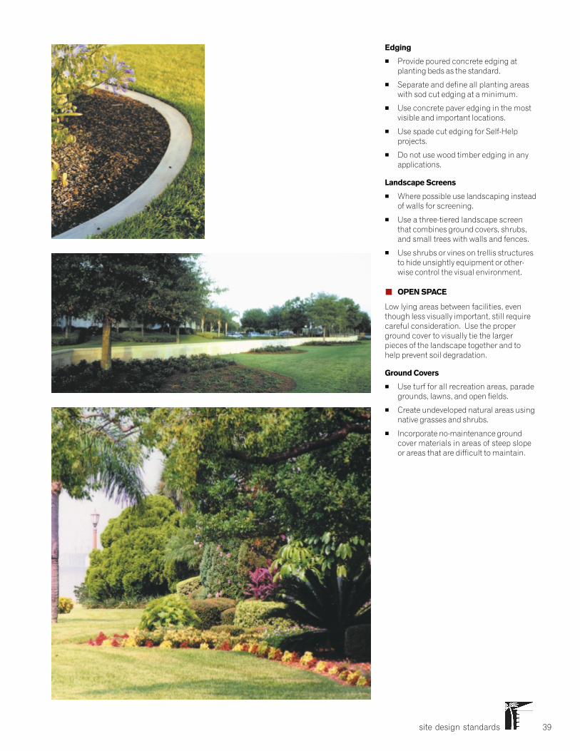
site design standards 39
Edging
� Provide poured concrete edging atplanting beds as the standard.
� Separate and define all planting areaswith sod cut edging at a minimum.
� Use concrete paver edging in the mostvisible and important locations.
� Use spade cut edging for Self-Helpprojects.
� Do not use wood timber edging in anyapplications.
Landscape Screens
� Where possible use landscaping insteadof walls for screening.
� Use a three-tiered landscape screenthat combines ground covers, shrubs,and small trees with walls and fences.
� Use shrubs or vines on trellis structuresto hide unsightly equipment or other-wise control the visual environment.
� OPEN SPACE
Low lying areas between facilities, eventhough less visually important, still requirecareful consideration. Use the properground cover to visually tie the largerpieces of the landscape together and tohelp prevent soil degradation.
Ground Covers
� Use turf for all recreation areas, paradegrounds, lawns, and open fields.
� Create undeveloped natural areas usingnative grasses and shrubs.
� Incorporate no-maintenance groundcover materials in areas of steep slopeor areas that are difficult to maintain.
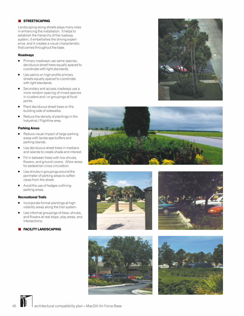
architectural compatibility plan – MacDill Air Force Base40
� STREETSCAPING
Landscaping along streets plays many rolesin enhancing the installation. It helps toestablish the hierarchy of the roadwaysystem, it embellishes the driving experi-ence, and it creates a visual characteristicthat carries throughout the base.
Roadways
� Primary roadways use same species,deciduous street trees equally spaced tocoordinate with light standards.
� Use palms on high-profile primarystreets equally spaced to coordinatewith light standards.
� Secondary and access roadways use amore random spacing of mixed speciesin clusters and / or groupings at focalpoints.
� Plant deciduous street trees on thebuilding side of sidewalks.
� Reduce the density of plantings in theIndustrial / Flightline area.
Parking Areas
� Reduce visual impact of large parkingareas with landscape buffers andparking islands.
� Use deciduous street trees in mediansand islands to create shade and interest.
� Fill in between trees with low shrubs,flowers, and ground covers. Allow areasfor pedestrian cross circulation.
� Use shrubs in groupings around theperimeter of parking areas to softenviews from the street.
� Avoid the use of hedges outliningparking areas.
Recreational Trails
� Incorporate formal plantings at highvisibility areas along the trail system.
� Use informal groupings of trees, shrubs,and flowers at rest stops, play areas, andintersections.
� FACILITY LANDSCAPING
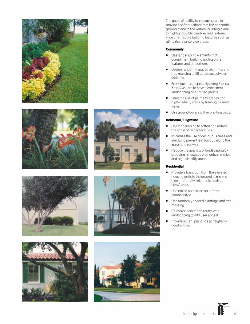
site design standards 41
The goals of facility landscaping are toprovide a soft transition from the horizontalground plane to the vertical building plane,to highlight building entries and features.Hide unattractive building features such asutility risers or service areas.
Community
� Use landscaping elements thatcompliment building architecturalfeatures and proportions.
� Design randomly spaced plantings andtree massing to fill-out areas betweenfacilities.
� Front facades, especially along FloridaKeys Ave., are to have a consistentlandscaping of a limited palette.
� Limit the use of palms to entries andhigh-visibility areas by framing desiredviews.
� Use ground covers within planting beds.
Industrial / Flightline
� Use landscaping to soften and reducethe scale of larger facilities.
� Minimize the use of deciduous trees andshrubs to prevent leaf buildup along theapron and runway.
� Reduce the quantity of landscaping bygrouping landscape elements at entriesand high-visibility areas.
Residential
� Provide a transition from the elevatedhousing units to the ground plane andhide unattractive elements such asHVAC units.
� Use mixed species in an informalplanting style.
� Use randomly spaced plantings and treemassing.
� Reinforce pedestrian routes withlandscaping to add user appeal.
� Provide accent plantings at neighbor-hood entries.
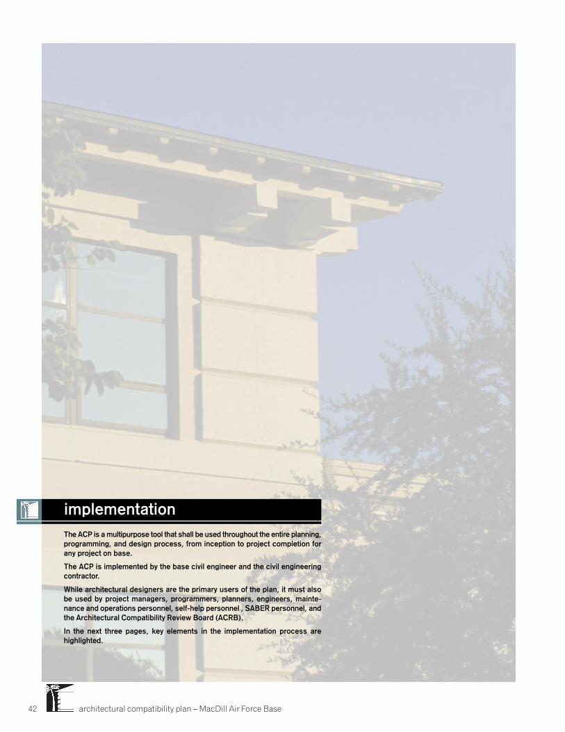
architectural compatibility plan – MacDill Air Force Base42
The ACP is a multipurpose tool that shall be used throughout the entire planning,programming, and design process, from inception to project completion forany project on base.
The ACP is implemented by the base civil engineer and the civil engineeringcontractor.
While architectural designers are the primary users of the plan, it must alsobe used by project managers, programmers, planners, engineers, mainte-nance and operations personnel, self-help personnel , SABER personnel, andthe Architectural Compatibility Review Board (ACRB).
In the next three pages, key elements in the implementation process arehighlighted.
implementation
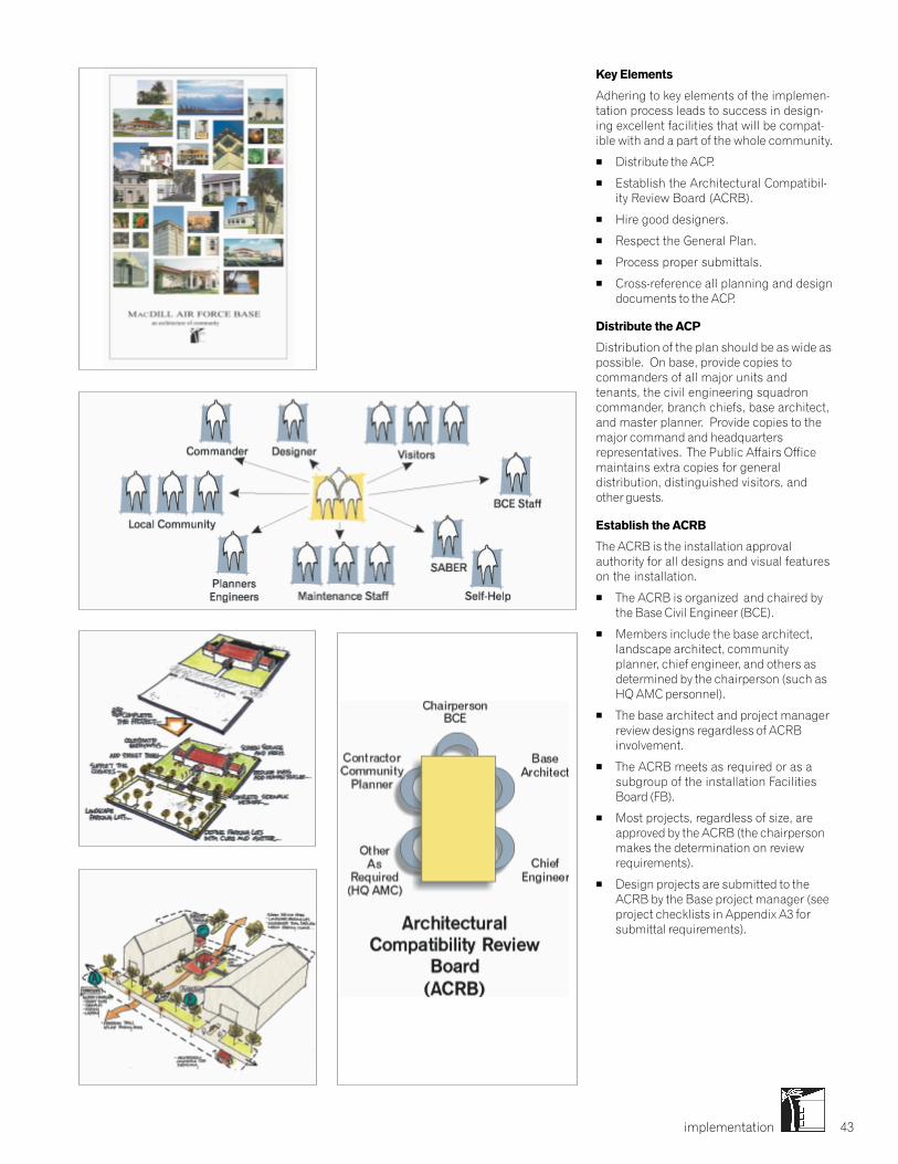
implementation 43
Key Elements
Adhering to key elements of the implemen-tation process leads to success in design-ing excellent facilities that will be compat-ible with and a part of the whole community.
� Distribute the ACP.
� Establish the Architectural Compatibil-ity Review Board (ACRB).
� Hire good designers.
� Respect the General Plan.
� Process proper submittals.
� Cross-reference all planning and designdocuments to the ACP.
Distribute the ACP
Distribution of the plan should be as wide aspossible. On base, provide copies tocommanders of all major units andtenants, the civil engineering squadroncommander, branch chiefs, base architect,and master planner. Provide copies to themajor command and headquartersrepresentatives. The Public Affairs Officemaintains extra copies for generaldistribution, distinguished visitors, andother guests.
Establish the ACRB
The ACRB is the installation approvalauthority for all designs and visual featureson the installation.
� The ACRB is organized and chaired bythe Base Civil Engineer (BCE).
� Members include the base architect,landscape architect, communityplanner, chief engineer, and others asdetermined by the chairperson (such asHQ AMC personnel).
� The base architect and project managerreview designs regardless of ACRBinvolvement.
� The ACRB meets as required or as asubgroup of the installation FacilitiesBoard (FB).
� Most projects, regardless of size, areapproved by the ACRB (the chairpersonmakes the determination on reviewrequirements).
� Design projects are submitted to theACRB by the Base project manager (seeproject checklists in Appendix A3 forsubmittal requirements).
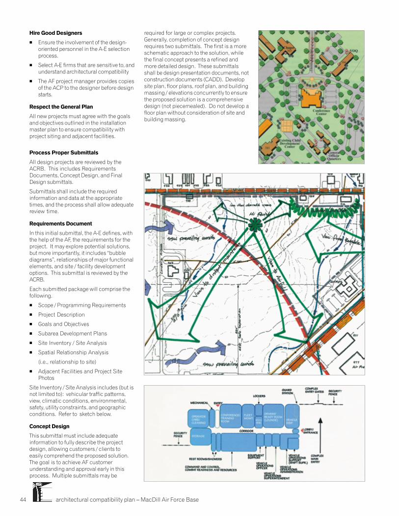
architectural compatibility plan – MacDill Air Force Base44
Hire Good Designers
� Ensure the involvement of the design-oriented personnel in the A-E selectionprocess.
� Select A-E firms that are sensitive to, andunderstand architectural compatibility
� The AF project manager provides copiesof the ACP to the designer before designstarts.
Respect the General Plan
All new projects must agree with the goalsand objectives outlined in the installationmaster plan to ensure compatibility withproject siting and adjacent facilities.
Process Proper Submittals
All design projects are reviewed by theACRB. This includes RequirementsDocuments, Concept Design, and FinalDesign submittals.
Submittals shall include the requiredinformation and data at the appropriatetimes, and the process shall allow adequatereview time.
Requirements Document
In this initial submittal, the A-E defines, withthe help of the AF, the requirements for theproject. It may explore potential solutions,but more importantly, it includes “bubblediagrams”, relationships of major functionalelements, and site / facility developmentoptions. This submittal is reviewed by theACRB.
Each submitted package will comprise thefollowing.
� Scope / Programming Requirements
� Project Description
� Goals and Objectives
� Subarea Development Plans
� Site Inventory / Site Analysis
� Spatial Relationship Analysis
(i.e., relationship to site)
� Adjacent Facilities and Project SitePhotos
Site Inventory / Site Analysis includes (but isnot limited to): vehicular traffic patterns,view, climatic conditions, environmental,safety, utility constraints, and geographicconditions. Refer to sketch below.
Concept Design
This submittal must include adequateinformation to fully describe the projectdesign, allowing customers / clients toeasily comprehend the proposed solution.The goal is to achieve AF customerunderstanding and approval early in thisprocess. Multiple submittals may be
required for large or complex projects.Generally, completion of concept designrequires two submittals. The first is a moreschematic approach to the solution, whilethe final concept presents a refined andmore detailed design. These submittalsshall be design presentation documents, notconstruction documents (CADD). Developsite plan, floor plans, roof plan, and buildingmassing / elevations concurrently to ensurethe proposed solution is a comprehensivedesign (not piecemealed). Do not develop afloor plan without consideration of site andbuilding massing.

implementation 45
� Mechanical / Electrical / Communica-tion Entrances and Equipment Locations/ Configuration.
� Building Sections
� Roof Plan
� Massing or Perspective Sketches
� Study Model (as required)
� Cost Estimate
Final Design
The final design shall demonstrate that theproject remains consistent with theapproved concept design. It includes highlydeveloped drawings that further refine anddetail the visual and functional quality of thedesign.
Each submittal will be comprised of acomplete comprehensive package thatincludes but is not limited to:
� Formal Colored Rendering (early in thisphase)
� Material / Color Boards (interior andexterior)
� Catalog Cut (photos)
� Design Analysis
� Cost Estimate
� Construction Documents
Contract documents must be in AutoCADDand include comprehensive drawings andspecifications to ensure that a project canbe constructed to meet all of the require-ments and standards defined by the ACP.
All mechanical and electrical drawingsmust be consistent with the architecturaldrawings. All utility elements such as lightfixtures, transformers, panels, grilles, vents,piping, etc., must be shown on the architec-tural drawings.
ACRB Checklists
Smaller projects and service contracts arereviewed by the BCE using the checklist,located in the Appendix, and are submittedto the ACRB as required. The Base projectmanager is responsible for providing thedesign checklist to the ACRB for comple-tion.
The design checklist will assist the designreview agencies in conducting consistentarchitectural reviews for ACP compliance.The project checklist is designed for usewith major projects including militaryconstruction, nonappropriated funds,maintenance, and family housing projectsrequiring professional design services.Smaller projects include simplifiedacquisition contracts, in-house operationsand maintenance projects, self-help, andhousing projects that do not require contractdesign services.
The ACRB reviews the packages as part ofthe concept development process. If theinitial submittal is not approved, or if thereare significant concerns or comments, aresubmittal is provided prior to proceedingto the next design stage.
Each submittal will be comprised of acomplete comprehensive packageincluding:
� Concise Verbalized Design Concept
� Systems Description
� Adjacent Facilities and Project SitePhoto
� Site Plans (colored)
� Floor Plans
� Composite Elevations (with color andshadows)
architectural compatibility plan – MacDill Air Force Base46
A1 Materials and Colors
A2 Plans and Guides
A3 Landscape Materials
A4 ACRB Design Checklists
A5 Index
appendices
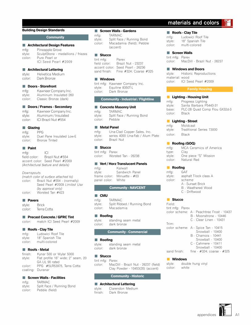
appendices A1
materials and colors� Screen Walls - Gardensmfg: TARMACstyle: Split Face / Running Bondcolor: Macadamia (field); Pebble
(accent)
� Stuccotint mfg: Parexfield color: Brazil Nut - 23237accent color: Seed Pearl - 26236sand finish: Fine #324; Coarse #325
� Windowstint mfg: Kawneer Company Inc.style: Equiline 8350T-Lcolor: Dark Bronze
Community - Industrial / Flightline
� Concrete Masonry Unitmfg: TARMACstyle: Split Face / Running Bondcolor: Pebble
� Metal Panelmfg: Una-Clad Copper Sales, Inc.style: series 4000 Una-Fab / Alum Platecolor: Brazil Nut
� Stuccotint mfg: Parexcolor: Worsted Tan - 26238
� Vert / Horz Translucent Panelsmfg: Kalwallstyle: Sandwich Panelframe color: Minuette - #03panel color: White
Community - NAVCENT
� CMUmfg: TARMACstyle: Split Ribbed / Running Bondcolor: Macadamia
� Roofingstyle: standing seam metalcolor: dark bronze
Community - Commercial
� Roofingstyle: standing seam metalcolor: dark bronze
� Stuccotint mfg: Parexcolor: MacDill - Brazil Nut - 26237 (field)
Clay Powder - 10453(35) (accent)
Community - Historic
� Architectural Letteringstyle: Clarendon Mediumfinish: Dark Bronze
Building Design Standards
Community
� Architectural Design Featuresmfg: Pineapple Grovestyle: SculptStone - medallions / friezescolor: Pure Pearl or
ICI Seed Pearl #2009
� Architectural Letteringstyle: Helvetica Mediumcolor: Dark Bronze
� Doors - Storefrontmfg: Kawneer Company Inc.style: Aluminum Insulated 260color: Classic Bronze (dark)
� Doors / Frames - Secondarymfg: Kawneer Company Inc.style: Aluminum / Insulatedcolor: ICI Brazil Nut #554
� Glazingmfg: PPGstyle: Duel Pane Insulated Low-Ecolor: Bronze Tinted
� Paintmfg: ICIfield color: Brazil Nut #554accent color: Seed Pearl #2009(Architectural feature and details)
Downspouts(match color of surface attached to)color: Brazil Nut #554 - (normally)
Seed Pearl #2009 Limited Use(by approval only)
color: Worsted Tan #423
� Paversstyle: Brickcolor: Terra Cotta
� Precast Concrete / GFRC Tintcolor: match ICI Seed Pearl #2009
� Roofs - Clay Tilemfg: Ludowici Roof Tilestyle: 18” Spanish Tilecolor: multi-colored
� Roofs - Metalfinish: Kynar 500 or Wylar 5000style: Flat profile 16” wide; 2” seam, 20
GA UL 90 ratedcolor: PPG #5LR53975, Terra Cottacoating: Duranar
� Screen Walls - Facilitiesmfg: TARMACstyle: Split Face / Running Bondcolor: Pebble (field)
� Roofs - Clay Tilemfg: Ludowici Roof Tilestyle: 18” Spanish Tilecolor: multi-colored
� Screen Wallstint mfg: Parexcolor: MacDill - Brazil Nut - 26237
� Windows and Doorsstyle: Historic Reproductionsmaterial: woodcolor: ICI Seed Pearl #2009
Family Housing
� Lighting - Housing Unitmfg: Progress Lightingstyle: Santa Barbara P5443-31base: PLC-28 Quad Comp Flou GX32d-3color: Black
� Lighting - Streetmfg: Moldcaststyle: Traditional Series 73000
color: Black
� Roofing (GOQ)mfg: MCA Ceramics of Americatype: Claystyle: One piece “S” Missioncolor: Natural Red
� Roofingmfg: GAFstyle: asphalt T-lock class Acolor: scheme
A - Sunset BrickB - Weathered WoodC - Driftwood
� StuccoField:tint mfg: Parexcolor scheme: A - Peachtree Frost - 10437
B - Moonstrone - 10446C - Clear Linen - 10431
Trim:color scheme: A - Spice Tan - 10415
Snowball - 10400B - Chamois - 10441
Snowball - 10400C - Cahmere - 10411
Snowball - 10400sand finish: fine - #324; coarse - #325
� Windowsstyle: double hung vinylcolor: white
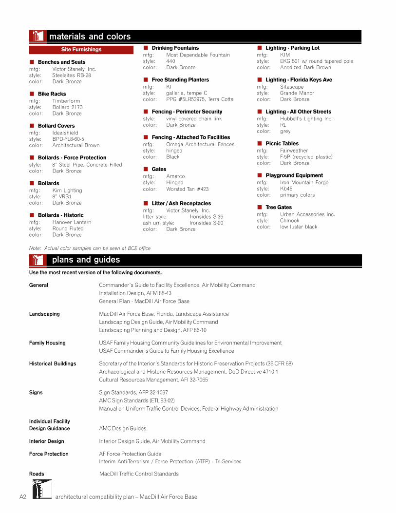
architectural compatibility plan – MacDill Air Force BaseA2
Use the most recent version of the following documents.
General Commander’s Guide to Facility Excellence, Air Mobility CommandInstallation Design, AFM 88-43General Plan - MacDill Air Force Base
Landscaping MacDill Air Force Base, Florida, Landscape AssistanceLandscaping Design Guide, Air Mobility CommandLandscaping Planning and Design, AFP 86-10
Family Housing USAF Family Housing Community Guidelines for Environmental ImprovementUSAF Commander’s Guide to Family Housing Excellence
Historical Buildings Secretary of the Interior’s Standards for Historic Preservation Projects (36 CFR 68)Archaeological and Historic Resources Management, DoD Directive 4710.1Cultural Resources Management, AFI 32-7065
Signs Sign Standards, AFP 32-1097AMC Sign Standards (ETL 93-02)Manual on Uniform Traffic Control Devices, Federal Highway Administration
Individual FacilityDesign Guidance AMC Design Guides
Interior Design Interior Design Guide, Air Mobility Command
Force Protection AF Force Protection GuideInterim Anti-Terrorism / Force Protection (ATFP) - Tri-Services
Roads MacDill Traffic Control Standards
plans and guides
Site Furnishings
� Benches and Seatsmfg: Victor Stanely, Inc.style: Steelsites RB-28color: Dark Bronze
� Bike Racksmfg: Timberformstyle: Bollard 2173color: Dark Bronze
� Bollard Coversmfg: Idealshieldstyle: BPD-YL8-60-5color: Architectural Brown
� Bollards - Force Protectionstyle: 8” Steel Pipe, Concrete Filledcolor: Dark Bronze
� Bollardsmfg: Kim Lightingstyle: 8” VRB1color: Dark Bronze
� Bollards - Historicmfg: Hanover Lanternstyle: Round Flutedcolor: Dark Bronze
� Drinking Fountainsmfg: Most Dependable Fountainstyle: 440color: Dark Bronze
� Free Standing Plantersmfg: KIstyle: galleria, tempe Ccolor: PPG #5LR53975, Terra Cotta
� Fencing - Perimeter Securitystyle: vinyl covered chain linkcolor: Dark Bronze
� Fencing - Attached To Facilitiesmfg: Omega Architectural Fencesstyle: hingedcolor: Black
� Gatesmfg: Ametcostyle: Hingedcolor: Worsted Tan #423
� Litter / Ash Receptaclesmfg: Victor Stanely, Inc.litter style: Ironsides S-35ash urn style: Ironsides S-20color: Dark Bronze
� Lighting - Parking Lotmfg: KIMstyle: EKG 501 w/ round tapered polecolor: Anodized Dark Brown
� Lighting - Florida Keys Avemfg: Sitescapestyle: Grande Manorcolor: Dark Bronze
� Lighting - All Other Streetsmfg: Hubbell’s Lighting Inc.style: RLcolor: grey
� Picnic Tablesmfg: Fairweatherstyle: F-5P (recycled plastic)color: Dark Bronze
� Playground Equipmentmfg: Iron Mountain Forgestyle: Kb45color: primary colors
� Tree Gatesmfg: Urban Accessories Inc.style: Chinookcolor: low luster black
materials and colors
Note: Actual color samples can be seen at BCE office
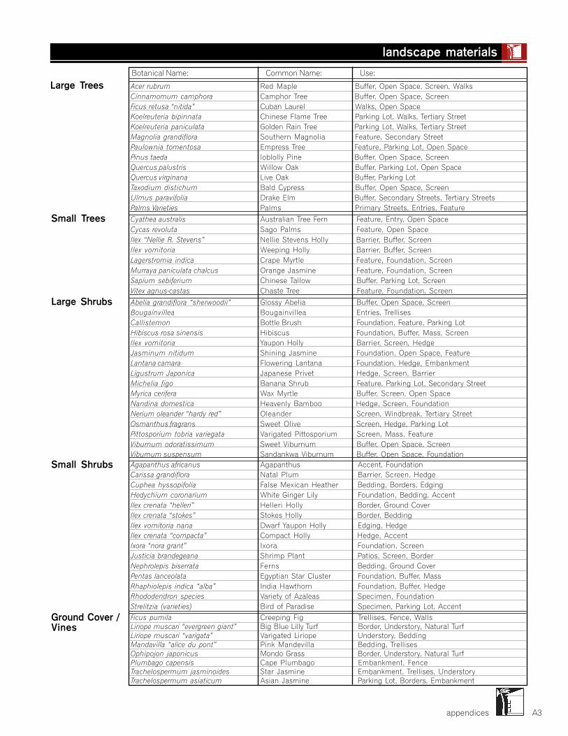
appendices A3
Ficus pumila Creeping Fig Trellises, Fence, WallsLiriope muscari “evergreen giant” Big Blue Lilly Turf Border, Understory, Natural TurfLiriope muscari “varigata” Varigated Liriope Understory, BeddingMandavilla “alice du pont” Pink Mandevilla Bedding, TrellisesOphipojon japonicus Mondo Grass Border, Understory, Natural TurfPlumbago capensis Cape Plumbago Embankment, FenceTrachelospermum jasminoides Star Jasmine Embankment, Trellises, UnderstoryTrachelospermum asiaticum Asian Jasmine Parking Lot, Borders, Embankment
Large Trees
Small Trees
Large Shrubs
Small Shrubs
Ground Cover /Vines
Botanical Name: Common Name: Use:
Acer rubrum Red Maple Buffer, Open Space, Screen, WalksCinnamomum camphora Camphor Tree Buffer, Open Space, ScreenFicus retusa “nitida” Cuban Laurel Walks, Open SpaceKoelreuteria bipinnata Chinese Flame Tree Parking Lot, Walks, Tertiary StreetKoelreuteria paniculata Golden Rain Tree Parking Lot, Walks, Tertiary StreetMagnolia grandiflora Southern Magnolia Feature, Secondary StreetPaulownia tomentosa Empress Tree Feature, Parking Lot, Open SpacePinus taeda loblolly Pine Buffer, Open Space, ScreenQuercus palustris Willow Oak Buffer, Parking Lot, Open SpaceQuercus virginana Live Oak Buffer, Parking LotTaxodium distichum Bald Cypress Buffer, Open Space, ScreenUlmus paravifolia Drake Elm Buffer, Secondary Streets, Tertiary StreetsPalms Varieties Palms Primary Streets, Entries, Feature
Cyathea australis Australian Tree Fern Feature, Entry, Open SpaceCycas revoluta Sago Palms Feature, Open SpaceIlex “Nellie R. Stevens” Nellie Stevens Holly Barrier, Buffer, ScreenIlex vomitoria Weeping Holly Barrier, Buffer, ScreenLagerstromia indica Crape Myrtle Feature, Foundation, ScreenMurraya paniculata chalcus Orange Jasmine Feature, Foundation, ScreenSapium sebiferium Chinese Tallow Buffer, Parking Lot, ScreenVitex agnus-castas Chaste Tree Feature, Foundation, Screen
Abelia grandiflora “sherwoodii” Glossy Abelia Buffer, Open Space, ScreenBougainvillea Bougainvillea Entries, TrellisesCallistemon Bottle Brush Foundation, Feature, Parking LotHibiscus rosa sinensis Hibiscus Foundation, Buffer, Mass, ScreenIlex vomitoria Yaupon Holly Barrier, Screen, HedgeJasminum nitidum Shining Jasmine Foundation, Open Space, FeatureLantana camara Flowering Lantana Foundation, Hedge, EmbankmentLigustrum Japonica Japanese Privet Hedge, Screen, BarrierMichelia figo Banana Shrub Feature, Parking Lot, Secondary StreetMyrica cerifera Wax Myrtle Buffer, Screen, Open SpaceNandina domestica Heavenly Bamboo Hedge, Screen, FoundationNerium oleander “hardy red” Oleander Screen, Windbreak, Tertiary StreetOsmanthus fragrans Sweet Olive Screen, Hedge, Parking LotPittosporium tobria variegata Varigated Pittosporium Screen, Mass, FeatureViburnum odoratissimum Sweet Viburnum Buffer, Open Space, ScreenViburnum suspensum Sandankwa Viburnum Buffer, Open Space, FoundationAgapanthus africanus Agapanthus Accent, FoundationCarissa grandiflora Natal Plum Barrier, Screen, HedgeCuphea hyssopifolia False Mexican Heather Bedding, Borders, EdgingHedychium coronarium White Ginger Lily Foundation, Bedding, AccentIlex crenata “helleri” Helleri Holly Border, Ground CoverIlex crenata “stokes” Stokes Holly Border, BeddingIlex vomitoria nana Dwarf Yaupon Holly Edging, HedgeIlex crenata “compacta” Compact Holly Hedge, AccentIxora “nora grant” Ixora Foundation, ScreenJusticia brandegeana Shrimp Plant Patios, Screen, BorderNephrolepis biserrata Ferns Bedding, Ground CoverPentas lanceolata Egyptian Star Cluster Foundation, Buffer, MassRhaphiolepis indica “alba” India Hawthorn Foundation, Buffer, HedgeRhododendron species Variety of Azaleas Specimen, FoundationStrelitzia (varieties) Bird of Paradise Specimen, Parking Lot, Accent
landscape materials
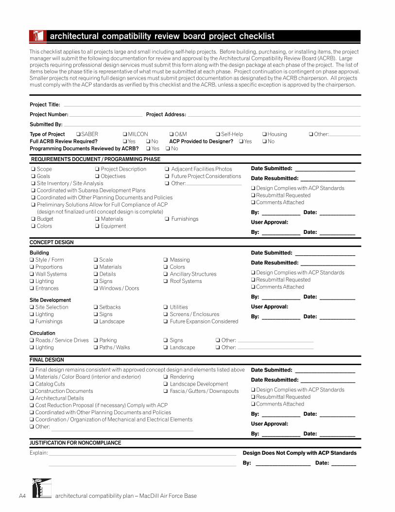
architectural compatibility plan – MacDill Air Force BaseA4
Date Submitted: ______________________
Date Resubmitted: ____________________
��Design Complies with ACP Standards��Resubmittal Requested��Comments Attached
By: ______________ Date: _____________
User Approval:
By: ______________ Date: _____________
Design Does Not Comply with ACP Standards
By: ____________________ Date: _________
This checklist applies to all projects large and small including self-help projects. Before building, purchasing, or installing items, the projectmanager will submit the following documentation for review and approval by the Architectural Compatibility Review Board (ACRB). Largeprojects requiring professional design services must submit this form along with the design package at each phase of the project. The list ofitems below the phase title is representative of what must be submitted at each phase. Project continuation is contingent on phase approval.Smaller projects not requiring full design services must submit project documentation as designated by the ACRB chairperson. All projectsmust comply with the ACP standards as verified by this checklist and the ACRB, unless a specific exception is approved by the chairperson.
architectural compatibility review board project checklist
JUSTIFICATION FOR NONCOMPLIANCE
Explain:
FINAL DESIGN
� Final design remains consistent with approved concept design and elements listed above� Materials / Color Board (interior and exterior) � Rendering� Catalog Cuts � Landscape Development��Construction Documents � Fascia / Gutters / Downspouts� Architectural Details� Cost Reduction Proposal (if necessary) Comply with ACP� Coordinated with Other Planning Documents and Policies� Coordination / Organization of Mechanical and Electrical Elements� Other:
Date Submitted: ______________________
Date Resubmitted: ____________________
��Design Complies with ACP Standards��Resubmittal Requested��Comments Attached
By: ______________ Date: _____________
User Approval:
By: ______________ Date: _____________
Date Submitted: ______________________
Date Resubmitted: ____________________
��Design Complies with ACP Standards��Resubmittal Requested��Comments Attached
By: ______________ Date: _____________
User Approval:
By: ______________ Date: _____________
CONCEPT DESIGN
Building� Style / Form � Scale � Massing� Proportions � Materials � Colors� Wall Systems � Details � Ancillary Structures� Lighting � Signs � Roof Systems� Entrances � Windows / Doors
Site Development� Site Selection � Setbacks � Utilities� Lighting � Signs � Screens / Enclosures� Furnishings � Landscape � Future Expansion Considered
Circulation� Roads / Service Drives � Parking � Signs � Other:� Lighting � Paths / Walks � Landscape �� Other:
REQUIREMENTS DOCUMENT / PROGRAMMING PHASE
� Scope � Project Description � Adjacent Facilities Photos� Goals � Objectives � Future Project Considerations� Site Inventory / Site Analysis � Other:� Coordinated with Subarea Development Plans� Coordinated with Other Planning Documents and Policies� Preliminary Solutions Allow for Full Compliance of ACP
(design not finalized until concept design is complete)� Budget � Materials � Furnishings� Colors � Equipment
Project Title:
Project Number: Project Address:
Submitted By:
Type of Project ��SABER ��MILCON ��O&M ��Self-Help ��Housing ��Other:Full ACRB Review Required? ��Yes ��No ACP Provided to Designer? ��Yes ��NoProgramming Documents Reviewed by ACRB? ��Yes ����No
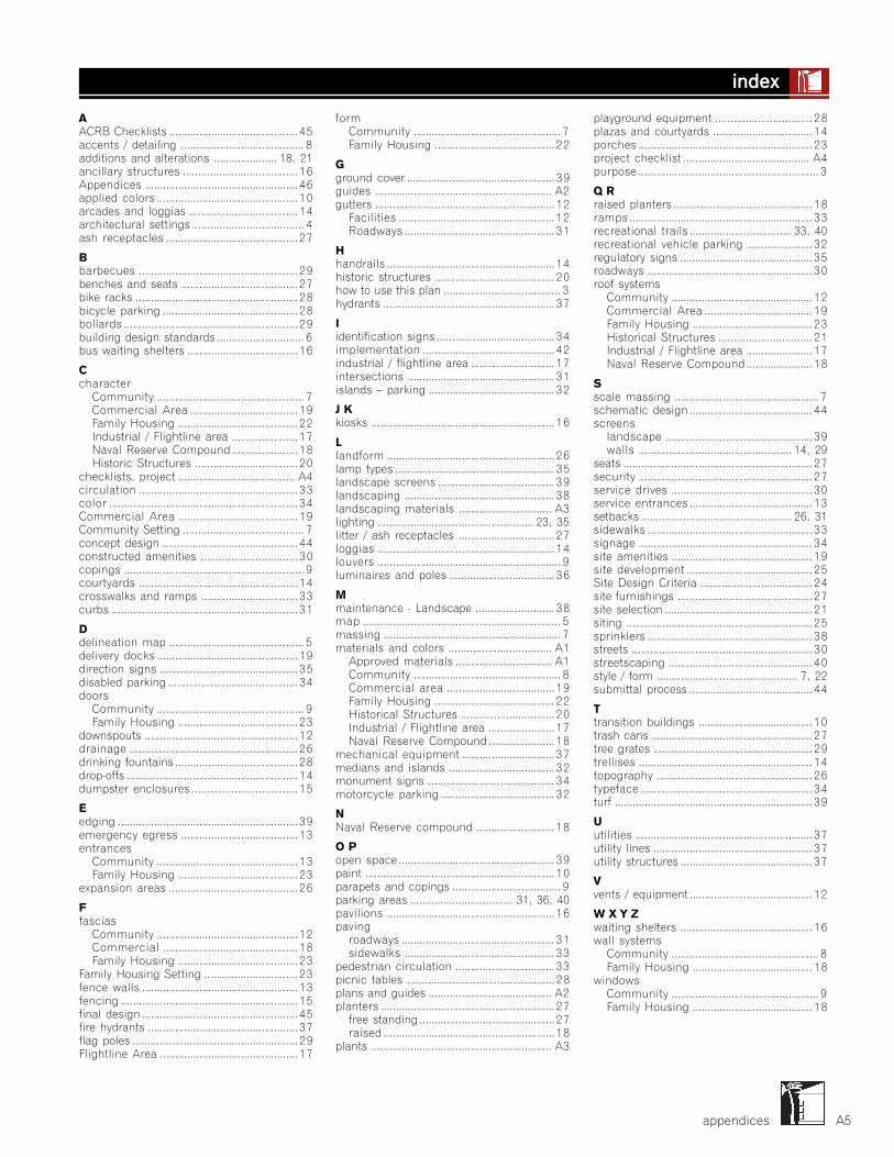
appendices
AACRB Checklists ........................................... 45accents / detailing ......................................... 8additions and alterations ..................... 18, 21ancillary structures ...................................... 16Appendices ................................................... 46applied colors ............................................... 10arcades and loggias .................................... 14architectural settings ..................................... 4ash receptacles ............................................ 27
Bbarbecues ..................................................... 29benches and seats ....................................... 27bike racks ...................................................... 28bicycle parking ............................................. 28bollards .......................................................... 29building design standards ............................. 6bus waiting shelters ..................................... 16
Ccharacter
Community ................................................. 7Commercial Area .................................... 19Family Housing ........................................ 22Industrial / Flightline area ...................... 17Naval Reserve Compound ...................... 18Historic Structures .................................. 20
checklists, project ....................................... A4circulation ..................................................... 33color ............................................................... 34Commercial Area ........................................ 19Community Setting ........................................ 7concept design ............................................. 44constructed amenities ................................ 30copings ............................................................ 9courtyards ..................................................... 14crosswalks and ramps ................................ 33curbs .............................................................. 31
Ddelineation map ............................................. 5delivery docks ............................................... 19direction signs .............................................. 35disabled parking ........................................... 34doors
Community ................................................. 9Family Housing ........................................ 23
downspouts ................................................... 12drainage ........................................................ 26drinking fountains ......................................... 28drop-offs ......................................................... 14dumpster enclosures ................................... 15
Eedging ............................................................ 39emergency egress ....................................... 13entrances
Community ............................................... 13Family Housing ........................................ 23
expansion areas ........................................... 26
Ffascias
Community ............................................... 12Commercial ............................................. 18Family Housing ........................................ 23
Family Housing Setting ............................... 23fence walls .................................................... 13fencing ........................................................... 15final design .................................................... 45fire hydrants .................................................. 37flag poles ....................................................... 29Flightline Area .............................................. 17
formCommunity ................................................. 7Family Housing ........................................ 22
Gground cover ................................................. 39guides ........................................................... A2gutters ............................................................ 12
Facilities .................................................... 12Roadways .................................................. 31
Hhandrails ........................................................ 14historic structures ........................................ 20how to use this plan ....................................... 3hydrants ......................................................... 37
Iidentification signs ....................................... 34implementation ............................................ 42industrial / flightline area ............................ 17intersections ................................................. 31islands – parking .......................................... 32
J Kkiosks ............................................................. 16
Llandform ........................................................ 26lamp types ..................................................... 35landscape screens ....................................... 39landscaping .................................................. 38landscaping materials ............................... A3lighting .................................................... 23, 35litter / ash receptacles ................................ 27loggias ........................................................... 14louvers ............................................................. 9luminaires and poles ................................... 36
Mmaintenance - Landscape .......................... 38map .................................................................. 5massing ........................................................... 7materials and colors .................................. A1
Approved materials ................................ A1Community ................................................. 8Commercial area .................................... 19Family Housing ........................................ 22Historical Structures ............................... 20Industrial / Flightline area ...................... 17Naval Reserve Compound ...................... 18
mechanical equipment ............................... 37medians and islands ................................... 32monument signs .......................................... 34motorcycle parking ...................................... 32
NNaval Reserve compound .......................... 18
O Popen space .................................................... 39paint ............................................................... 10parapets and copings .................................... 9parking areas .................................. 31, 36, 40pavilions ........................................................ 16paving
roadways ................................................... 31sidewalks .................................................. 33
pedestrian circulation ................................. 33picnic tables ................................................. 28plans and guides ......................................... A2planters .......................................................... 27
free standing ............................................. 27raised ......................................................... 18
plants ............................................................ A3
playground equipment ................................ 28plazas and courtyards ................................. 14porches .......................................................... 23project checklist .......................................... A4purpose ............................................................ 3
Q Rraised planters .............................................. 18ramps ............................................................. 33recreational trails .................................. 33, 40recreational vehicle parking ...................... 32regulatory signs ............................................ 35roadways ....................................................... 30roof systems
Community ............................................... 12Commercial Area .................................... 19Family Housing ........................................ 23Historical Structures ............................... 21Industrial / Flightline area ...................... 17Naval Reserve Compound ...................... 18
Sscale massing ................................................ 7schematic design ......................................... 44screens
landscape ................................................. 39walls ................................................... 14, 29
seats ............................................................... 27security .......................................................... 27service drives ............................................... 30service entrances ......................................... 13setbacks .................................................. 26, 31sidewalks ....................................................... 33signage .......................................................... 34site amenities ............................................... 19site development .......................................... 25Site Design Criteria ..................................... 24site furnishings ............................................. 27site selection ................................................. 21siting .............................................................. 25sprinklers ....................................................... 38streets ............................................................ 30streetscaping ................................................ 40style / form ............................................... 7, 22submittal process ......................................... 44
Ttransition buildings ...................................... 10trash cans ...................................................... 27tree grates ..................................................... 29trellises .......................................................... 14topography .................................................... 26typeface ......................................................... 34turf .................................................................. 39
Uutilities ........................................................... 37utility lines ..................................................... 37utility structures ............................................ 37
Vvents / equipment ......................................... 12
W X Y Zwaiting shelters ............................................ 16wall systems
Community ................................................. 8Family Housing ........................................ 18
windowsCommunity ................................................. 9Family Housing ........................................ 18
A5
index
Prepared By:
Nakata Planning Group, LLC516 North TejonColorado Springs, Colorado [email protected]
Robert L. Preston, AICPPrincipal-In-Charge
In Association With:
6th Civil Engineer Squadron7621 Hillsborough Loop DriveMacDill Air Force Base, Florida 33621813.828.4709
HQ AMC / DESIGN CENTERDirectorate of Civil Engineer SquadronProject Engineering Division507 Symington DriveScott Air Force Base, IL 62225618.229.0447https://www.scott.af.mil/hqamc/ce/cec/cecd/guides.cfm
Photography By:
Nakata Planning Group, LLC
Jim Fennell, AIA
Lee Meier, RA
architectural compatibility plan – MacDill Air Force Base


January 2001

MACDILL AFB 19 MAY 2003 REVISION 2
TRAFFIC CONTROL
STANDARDS 6th AIR MOBILITY WING
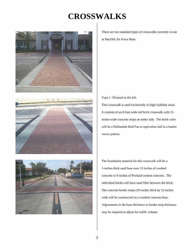
CROSSWALKS
2
There are two standard types of crosswalks currently in use
at MacDill Air Force Base.
Type 1 -Pictured to the left.
This crosswalk is used exclusively in high visibility areas.
It consists of an 8-foot wide red brick crosswalk with 12-
inches wide concrete strips on either side. The brick color
will be a Hollandale Red/Tan or equivalent laid in a basket
weave pattern.
The foundation material for this crosswalk will be a
1-inches thick sand base over 12-inches of crushed
concrete or 6-inches of Portland cement concrete. The
individual bricks will have sand filler between the brick.
The concrete border strips (10-inches thick by 12-inches
wide will be constructed on a crushed concrete base.
Adjustments in the base thickness or border strip thickness
may be required to adjust for traffic volume.
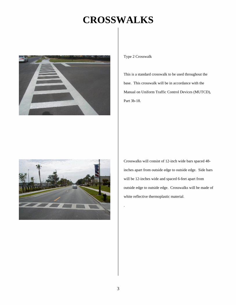
CROSSWALKS
3
Type 2 Crosswalk
This is a standard crosswalk to be used throughout the
base. This crosswalk will be in accordance with the
Manual on Uniform Traffic Control Devices (MUTCD),
Part 3b-18.
Crosswalks will consist of 12-inch wide bars spaced 48-
inches apart from outside edge to outside edge. Side bars
will be 12-inches wide and spaced 6-feet apart from
outside edge to outside edge. Crosswalks will be made of
white reflective thermoplastic material.
.
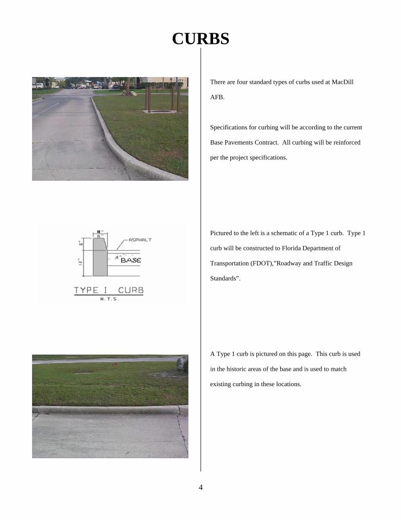
CURBS
4
There are four standard types of curbs used at MacDill
AFB.
Specifications for curbing will be according to the current
Base Pavements Contract. All curbing will be reinforced
per the project specifications.
Pictured to the left is a schematic of a Type 1 curb. Type 1
curb will be constructed to Florida Department of
Transportation (FDOT),”Roadway and Traffic Design
Standards”.
A Type 1 curb is pictured on this page. This curb is used
in the historic areas of the base and is used to match
existing curbing in these locations.
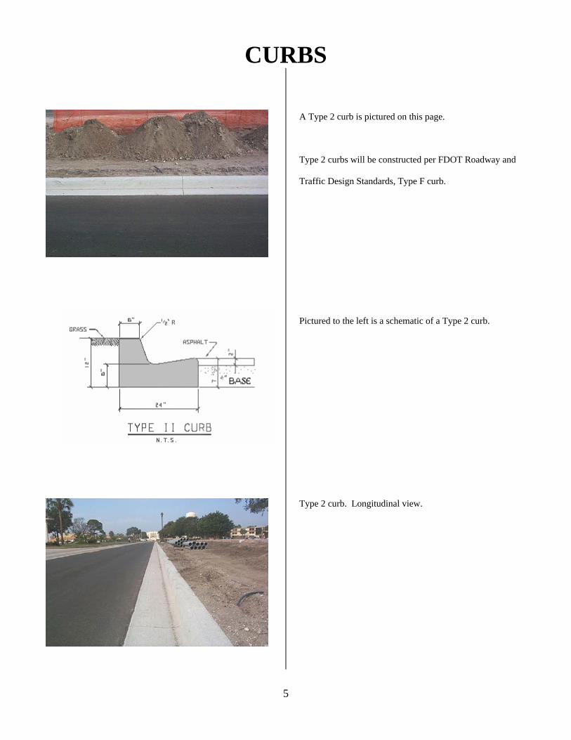
CURBS
5
A Type 2 curb is pictured on this page.
Type 2 curbs will be constructed per FDOT Roadway and
Traffic Design Standards, Type F curb.
Pictured to the left is a schematic of a Type 2 curb. Type 2 curb. Longitudinal view.
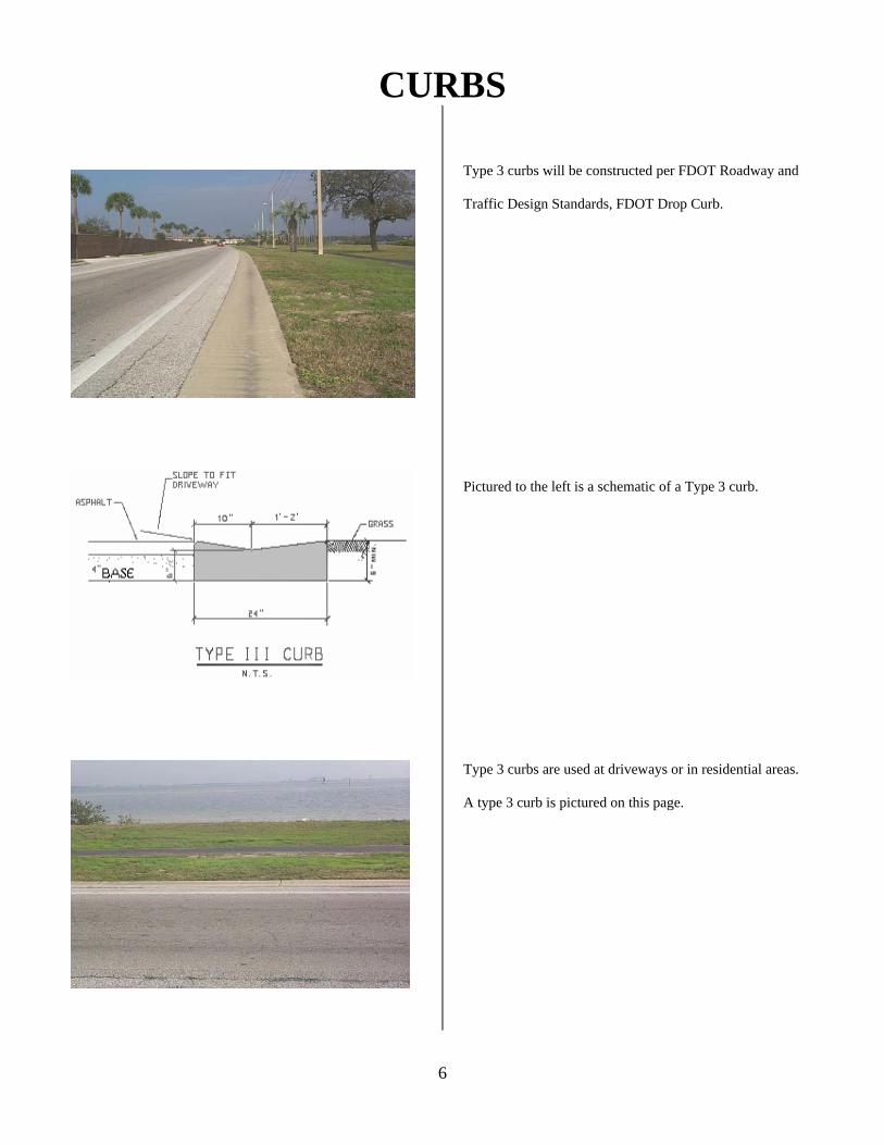
CURBS
6
Type 3 curbs will be constructed per FDOT Roadway and
Traffic Design Standards, FDOT Drop Curb.
Pictured to the left is a schematic of a Type 3 curb. Type 3 curbs are used at driveways or in residential areas. A type 3 curb is pictured on this page.
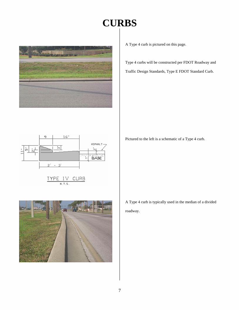
CURBS
7
A Type 4 curb is pictured on this page.
Type 4 curbs will be constructed per FDOT Roadway and
Traffic Design Standards, Type E FDOT Standard Curb.
Pictured to the left is a schematic of a Type 4 curb. A Type 4 curb is typically used in the median of a divided roadway.
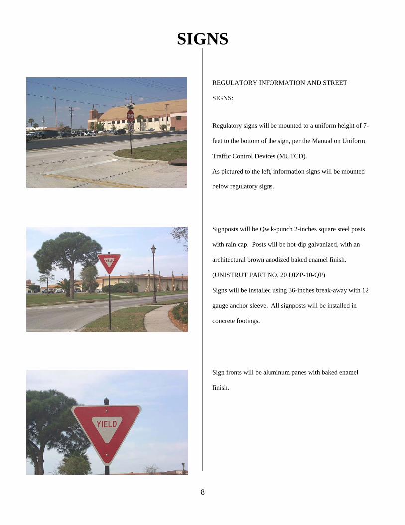
SIGNS
8
REGULATORY INFORMATION AND STREET
SIGNS:
Regulatory signs will be mounted to a uniform height of 7-
feet to the bottom of the sign, per the Manual on Uniform
Traffic Control Devices (MUTCD).
As pictured to the left, information signs will be mounted
below regulatory signs.
Signposts will be Qwik-punch 2-inches square steel posts
with rain cap. Posts will be hot-dip galvanized, with an
architectural brown anodized baked enamel finish.
(UNISTRUT PART NO. 20 DIZP-10-QP)
Signs will be installed using 36-inches break-away with 12
gauge anchor sleeve. All signposts will be installed in
concrete footings.
Sign fronts will be aluminum panes with baked enamel
finish.
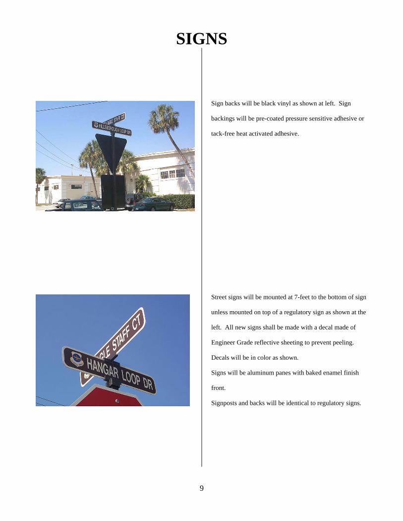
SIGNS
9
Sign backs will be black vinyl as shown at left. Sign
backings will be pre-coated pressure sensitive adhesive or
tack-free heat activated adhesive.
Street signs will be mounted at 7-feet to the bottom of sign
unless mounted on top of a regulatory sign as shown at the
left. All new signs shall be made with a decal made of
Engineer Grade reflective sheeting to prevent peeling.
Decals will be in color as shown.
Signs will be aluminum panes with baked enamel finish
front.
Signposts and backs will be identical to regulatory signs.
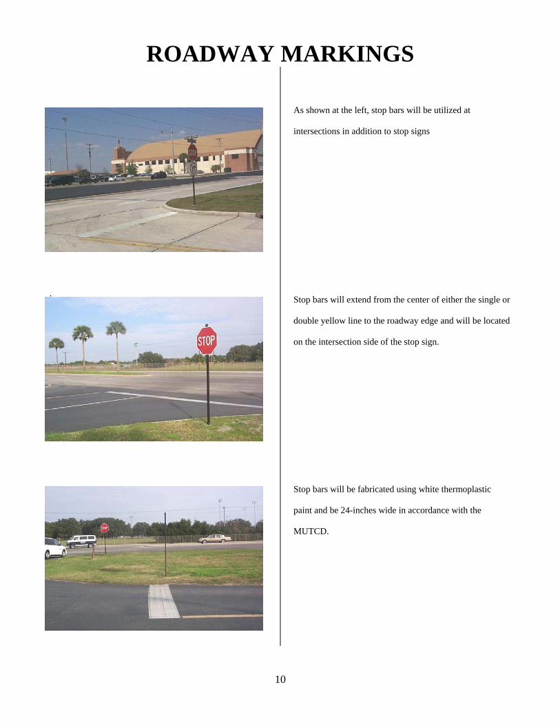
ROADWAY MARKINGS
10
.
As shown at the left, stop bars will be utilized at
intersections in addition to stop signs
Stop bars will extend from the center of either the single or
double yellow line to the roadway edge and will be located
on the intersection side of the stop sign.
Stop bars will be fabricated using white thermoplastic
paint and be 24-inches wide in accordance with the
MUTCD.

ROADWAY MARKINGS
11
Roadway centerlines will be yellow thermoplastic as
shown at the left, unless approval is granted for an
alternate type of marking by the Pavements Engineer. In
“No Passing” zones, double solid yellow lines are
required.
Roadway edge lines will be solid white 6-inches wide
reflective painted lines.
Lines dividing two lanes of traffic in the same direction
will be white thermoplastic dotted lines in accordance with
the MUTCD.
Shown at the left are examples of directional arrows used
to control traffic entering intersections. Directional arrows
must be white reflective thermoplastic and in accordance
with MUTCD standards.
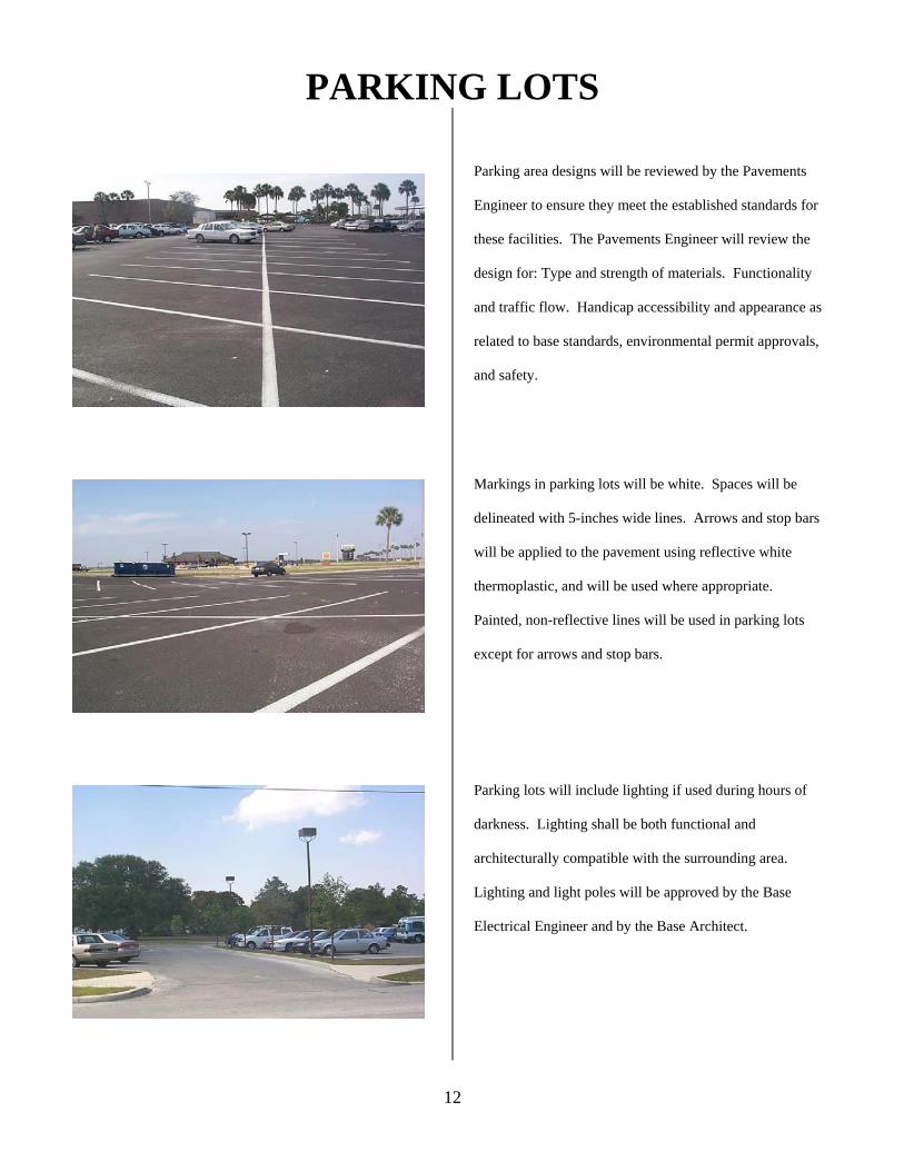
PARKING LOTS
12
Parking area designs will be reviewed by the Pavements
Engineer to ensure they meet the established standards for
these facilities. The Pavements Engineer will review the
design for: Type and strength of materials. Functionality
and traffic flow. Handicap accessibility and appearance as
related to base standards, environmental permit approvals,
and safety.
Markings in parking lots will be white. Spaces will be
delineated with 5-inches wide lines. Arrows and stop bars
will be applied to the pavement using reflective white
thermoplastic, and will be used where appropriate.
Painted, non-reflective lines will be used in parking lots
except for arrows and stop bars.
Parking lots will include lighting if used during hours of
darkness. Lighting shall be both functional and
architecturally compatible with the surrounding area.
Lighting and light poles will be approved by the Base
Electrical Engineer and by the Base Architect.
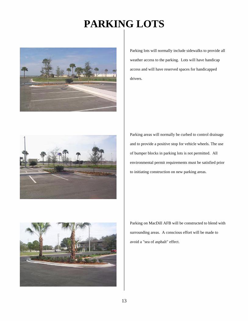
PARKING LOTS
13
Parking lots will normally include sidewalks to provide all
weather access to the parking. Lots will have handicap
access and will have reserved spaces for handicapped
drivers.
Parking areas will normally be curbed to control drainage
and to provide a positive stop for vehicle wheels. The use
of bumper blocks in parking lots is not permitted. All
environmental permit requirements must be satisfied prior
to initiating construction on new parking areas.
Parking on MacDill AFB will be constructed to blend with
surrounding areas. A conscious effort will be made to
avoid a "sea of asphalt" effect.
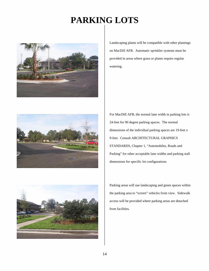
PARKING LOTS
14
Landscaping plants will be compatible with other plantings
on MacDill AFB. Automatic sprinkler systems must be
provided in areas where grass or plants require regular
watering.
For MacDill AFB, the normal lane width in parking lots is
24-feet for 90 degree parking spaces. The normal
dimensions of the individual parking spaces are 19-feet x
9-feet. Consult ARCHITECTURAL GRAPHICS
STANDARDS, Chapter 1, “Automobiles, Roads and
Parking” for other acceptable lane widths and parking stall
dimensions for specific lot configurations
Parking areas will use landscaping and green spaces within
the parking area to “screen” vehicles from view. Sidewalk
access will be provided where parking areas are detached
from facilities.
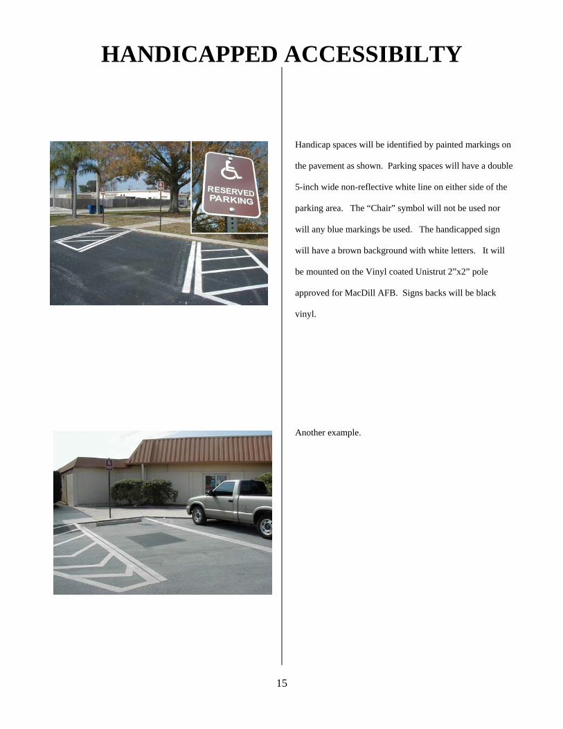
HANDICAPPED ACCESSIBILTY
15
Handicap spaces will be identified by painted markings on
the pavement as shown. Parking spaces will have a double
5-inch wide non-reflective white line on either side of the
parking area. The “Chair” symbol will not be used nor
will any blue markings be used. The handicapped sign
will have a brown background with white letters. It will
be mounted on the Vinyl coated Unistrut 2”x2” pole
approved for MacDill AFB. Signs backs will be black
vinyl.
Another example.
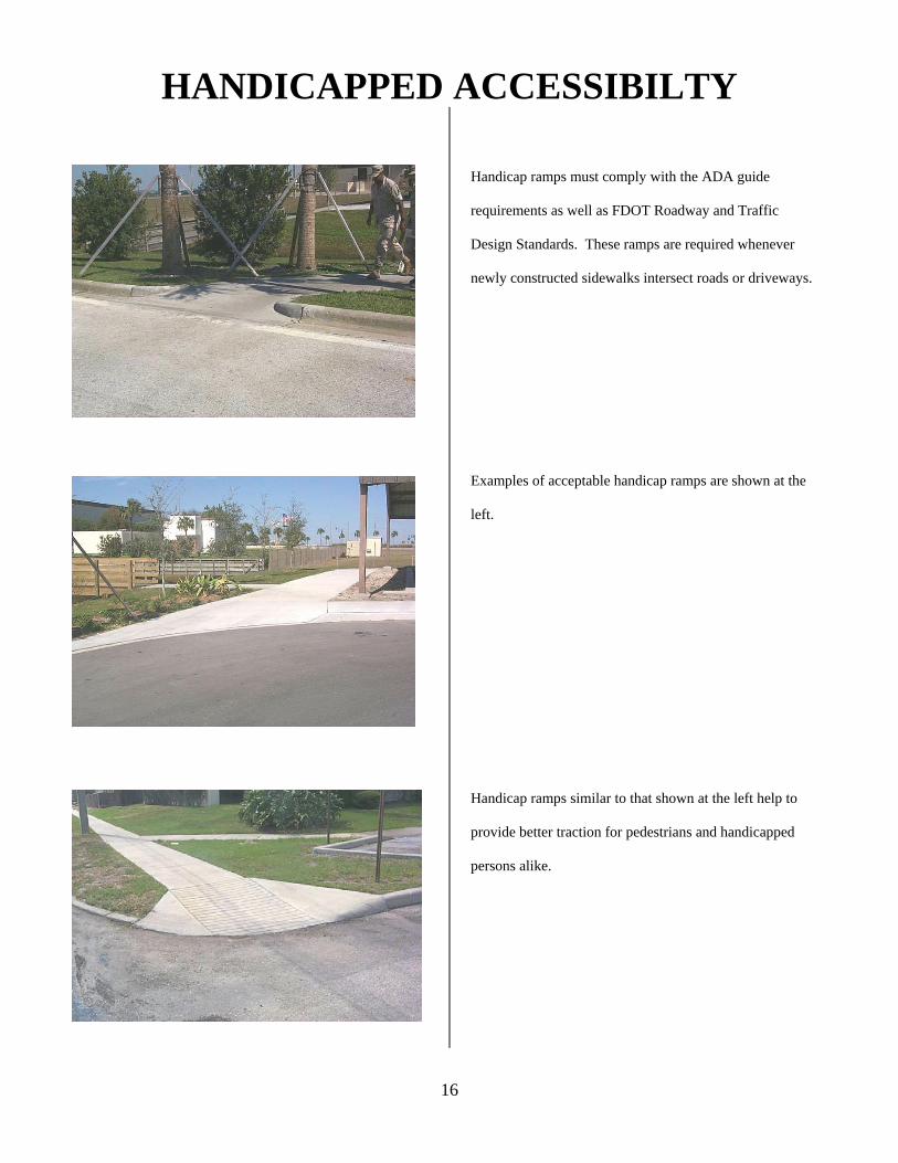
HANDICAPPED ACCESSIBILTY
16
Handicap ramps must comply with the ADA guide
requirements as well as FDOT Roadway and Traffic
Design Standards. These ramps are required whenever
newly constructed sidewalks intersect roads or driveways.
Examples of acceptable handicap ramps are shown at the
left.
Handicap ramps similar to that shown at the left help to
provide better traction for pedestrians and handicapped
persons alike.
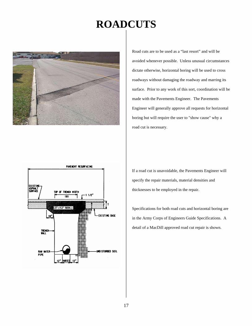
ROADCUTS
17
Road cuts are to be used as a “last resort” and will be
avoided whenever possible. Unless unusual circumstances
dictate otherwise, horizontal boring will be used to cross
roadways without damaging the roadway and marring its
surface. Prior to any work of this sort, coordination will be
made with the Pavements Engineer. The Pavements
Engineer will generally approve all requests for horizontal
boring but will require the user to "show cause" why a
road cut is necessary.
If a road cut is unavoidable, the Pavements Engineer will
specify the repair materials, material densities and
thicknesses to be employed in the repair.
Specifications for both road cuts and horizontal boring are
in the Army Corps of Engineers Guide Specifications. A
detail of a MacDill approved road cut repair is shown.
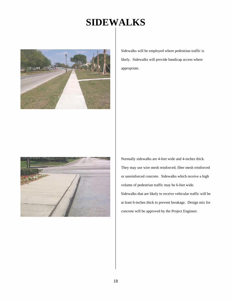
SIDEWALKS
18
Sidewalks will be employed where pedestrian traffic is
likely. Sidewalks will provide handicap access where
appropriate.
Normally sidewalks are 4-feet wide and 4-inches thick.
They may use wire mesh reinforced; fiber mesh reinforced
or unreinforced concrete. Sidewalks which receive a high
volume of pedestrian traffic may be 6-feet wide.
Sidewalks that are likely to receive vehicular traffic will be
at least 6-inches thick to prevent breakage. Design mix for
concrete will be approved by the Project Engineer.
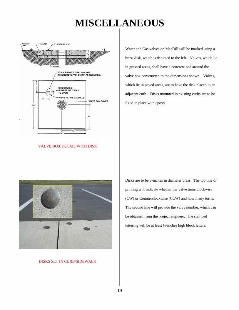
MISCELLANEOUS
19
VALVE BOX DETAIL WITH DISK
DISKS SET IN CURB/SIDEWALK
Water and Gas valves on MacDill will be marked using a
brass disk, which is depicted to the left. Valves, which lie
in grassed areas, shall have a concrete pad around the
valve box constructed to the dimensions shown. Valves,
which lie in paved areas, are to have the disk placed in an
adjacent curb. Disks mounted in existing curbs are to be
fixed in place with epoxy.
Disks are to be 3-inches in diameter brass. The top line of
printing will indicate whether the valve turns clockwise
(CW) or Counterclockwise (CCW) and how many turns.
The second line will provide the valve number, which can
be obtained from the project engineer. The stamped
lettering will be at least ¼-inches high block letters.
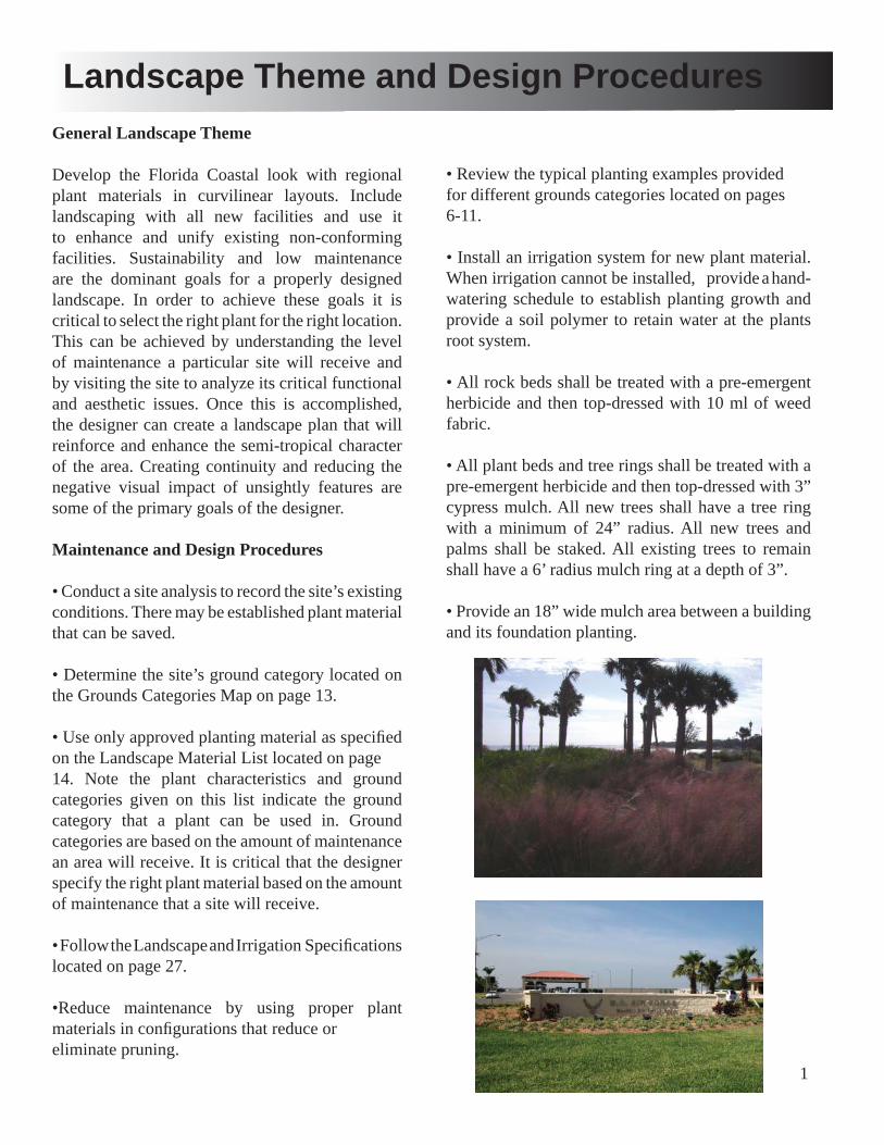
1
General Landscape Theme
Develop the Florida Coastal look with regional plant materials in curvilinear layouts. Include landscaping with all new facilities and use it to enhance and unify existing non-conforming facilities. Sustainability and low maintenance are the dominant goals for a properly designed landscape. In order to achieve these goals it is critical to select the right plant for the right location. This can be achieved by understanding the level of maintenance a particular site will receive and by visiting the site to analyze its critical functional and aesthetic issues. Once this is accomplished, the designer can create a landscape plan that will reinforce and enhance the semi-tropical character of the area. Creating continuity and reducing the negative visual impact of unsightly features are some of the primary goals of the designer.
Maintenance and Design Procedures
• Conduct a site analysis to record the site’s existing conditions. There may be established plant material that can be saved.
• Determine the site’s ground category located on the Grounds Categories Map on page 13.
• Use only approved planting material as specifi ed on the Landscape Material List located on page 14. Note the plant characteristics and ground categories given on this list indicate the ground category that a plant can be used in. Ground categories are based on the amount of maintenance an area will receive. It is critical that the designer specify the right plant material based on the amount of maintenance that a site will receive.
• Follow the Landscape and Irrigation Specifi cations located on page 27.
•Reduce maintenance by using proper plant materials in confi gurations that reduce or eliminate pruning.
Landscape Theme and Design Procedures
• Review the typical planting examples provided for different grounds categories located on pages 6-11.
• Install an irrigation system for new plant material. When irrigation cannot be installed, provide a hand-watering schedule to establish planting growth and provide a soil polymer to retain water at the plants root system.
• All rock beds shall be treated with a pre-emergent herbicide and then top-dressed with 10 ml of weed fabric.
• All plant beds and tree rings shall be treated with a pre-emergent herbicide and then top-dressed with 3” cypress mulch. All new trees shall have a tree ring with a minimum of 24” radius. All new trees and palms shall be staked. All existing trees to remain shall have a 6’ radius mulch ring at a depth of 3”.
• Provide an 18” wide mulch area between a building and its foundation planting.
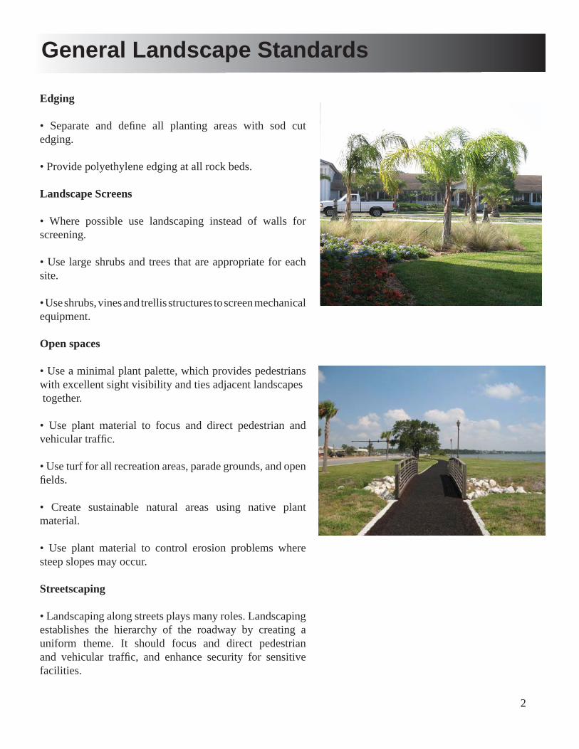
2
Edging
• Separate and defi ne all planting areas with sod cut edging.
• Provide polyethylene edging at all rock beds.
Landscape Screens
• Where possible use landscaping instead of walls for screening.
• Use large shrubs and trees that are appropriate for each site.
• Use shrubs, vines and trellis structures to screen mechanical equipment.
Open spaces
• Use a minimal plant palette, which provides pedestrians with excellent sight visibility and ties adjacent landscapes together.
• Use plant material to focus and direct pedestrian and vehicular traffi c.
• Use turf for all recreation areas, parade grounds, and open fi elds.
• Create sustainable natural areas using native plant material.
• Use plant material to control erosion problems where steep slopes may occur.
Streetscaping
• Landscaping along streets plays many roles. Landscaping establishes the hierarchy of the roadway by creating a uniform theme. It should focus and direct pedestrian and vehicular traffi c, and enhance security for sensitive facilities.
General Landscape Standards
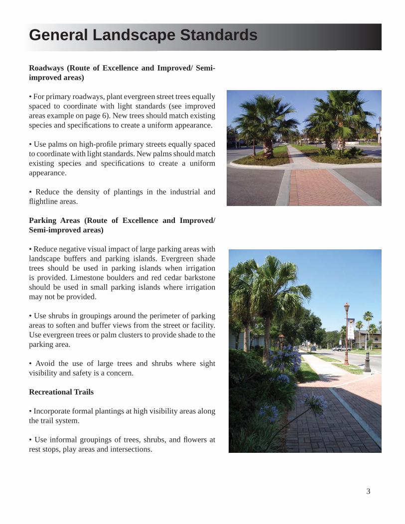
3
Roadways (Route of Excellence and Improved/ Semi-improved areas)
• For primary roadways, plant evergreen street trees equally spaced to coordinate with light standards (see improved areas example on page 6). New trees should match existing species and specifi cations to create a uniform appearance.
• Use palms on high-profi le primary streets equally spaced to coordinate with light standards. New palms should match existing species and specifi cations to create a uniform appearance.
• Reduce the density of plantings in the industrial and fl ightline areas.
Parking Areas (Route of Excellence and Improved/ Semi-improved areas)
• Reduce negative visual impact of large parking areas with landscape buffers and parking islands. Evergreen shade trees should be used in parking islands when irrigation is provided. Limestone boulders and red cedar barkstone should be used in small parking islands where irrigation may not be provided.
• Use shrubs in groupings around the perimeter of parking areas to soften and buffer views from the street or facility. Use evergreen trees or palm clusters to provide shade to the parking area.
• Avoid the use of large trees and shrubs where sight visibility and safety is a concern.
Recreational Trails
• Incorporate formal plantings at high visibility areas along the trail system.
• Use informal groupings of trees, shrubs, and fl owers at rest stops, play areas and intersections.
General Landscape Standards
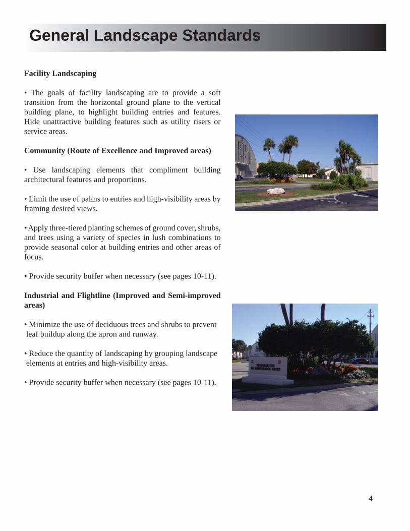
4
Facility Landscaping
• The goals of facility landscaping are to provide a soft transition from the horizontal ground plane to the vertical building plane, to highlight building entries and features. Hide unattractive building features such as utility risers or service areas.
Community (Route of Excellence and Improved areas)
• Use landscaping elements that compliment building architectural features and proportions.
• Limit the use of palms to entries and high-visibility areas by framing desired views.
• Apply three-tiered planting schemes of ground cover, shrubs, and trees using a variety of species in lush combinations to provide seasonal color at building entries and other areas of focus.
• Provide security buffer when necessary (see pages 10-11).
Industrial and Flightline (Improved and Semi-improved areas)
• Minimize the use of deciduous trees and shrubs to prevent leaf buildup along the apron and runway.
• Reduce the quantity of landscaping by grouping landscape elements at entries and high-visibility areas.
• Provide security buffer when necessary (see pages 10-11).
General Landscape Standards

5
General Offi cers Quarters
• Use landscaping elements that compliment building architectural features and proportions.
• Limit the use of palms to entries and high-visibility areas by framing desired views.
• Apply three-tiered planting schemes of ground cover, shrubs, and trees using a variety of species in lush combinations to provide seasonal color at building entries and other areas of focus.
• Provide security buffer when necessary (see pages 10-11). Military Family Housing
• Use palms or accent trees on the corners of the front facade.
• Use evergreen shade trees to line the roadways.
• Limit the use of shrubs and ground cover due to limited irrigation.
• Provide irrigation bubblers at trees or a hand-watering schedule to establish growth.
• Lawn areas must be bahia sod due to limited irrigation.
• Provide accent plantings at neighborhood entries and signs
General Landscape Standards
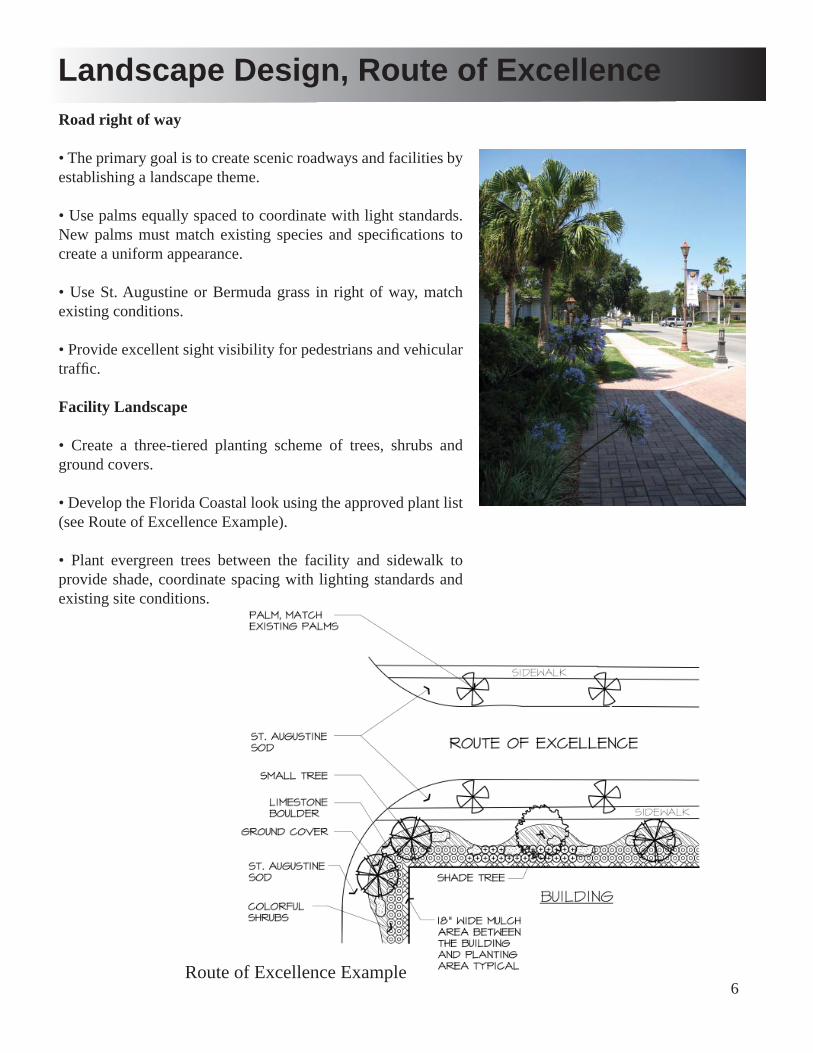
6
Landscape Design, Route of ExcellenceRoad right of way
• The primary goal is to create scenic roadways and facilities by establishing a landscape theme.
• Use palms equally spaced to coordinate with light standards. New palms must match existing species and specifi cations to create a uniform appearance.
• Use St. Augustine or Bermuda grass in right of way, match existing conditions.
• Provide excellent sight visibility for pedestrians and vehicular traffi c.
Facility Landscape
• Create a three-tiered planting scheme of trees, shrubs and ground covers.
• Develop the Florida Coastal look using the approved plant list (see Route of Excellence Example).
• Plant evergreen trees between the facility and sidewalk to provide shade, coordinate spacing with lighting standards and existing site conditions.
Route of Excellence Example
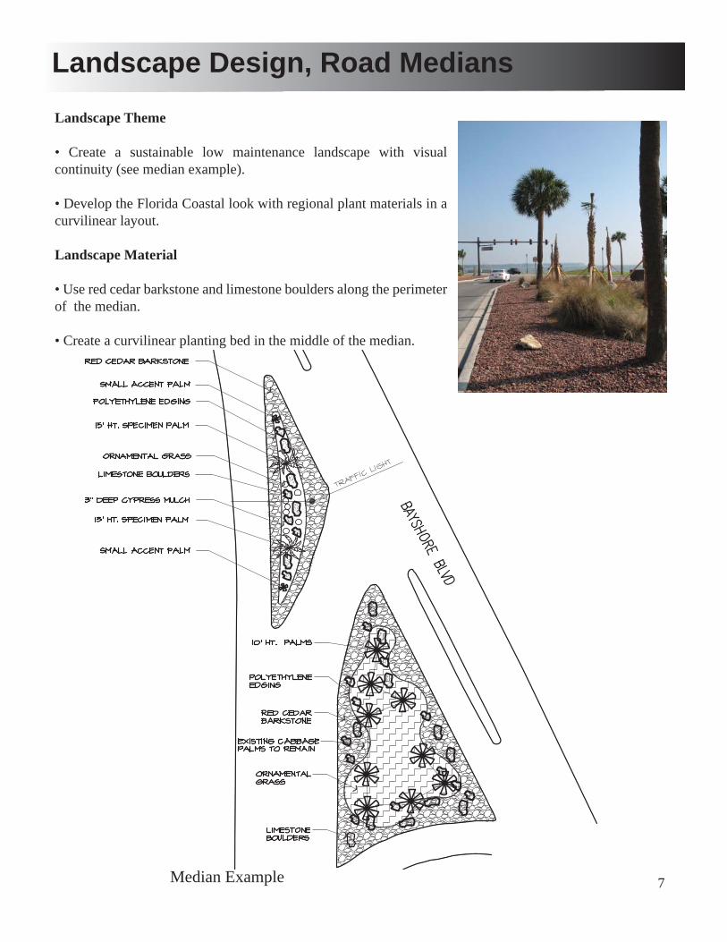
7
Landscape Design, Road Medians
Landscape Theme
• Create a sustainable low maintenance landscape with visual continuity (see median example).
• Develop the Florida Coastal look with regional plant materials in a curvilinear layout.
Landscape Material
• Use red cedar barkstone and limestone boulders along the perimeter of the median.
• Create a curvilinear planting bed in the middle of the median.
Median Example

8
Landscape Design- Improved Areas
Improved Facility Landscaping
• Provide a soft transition from the horizontal ground plane to the vertical building plane.
• Highlight building entries and features.
• Hide unattractive building features such as utility risers or service areas.
• Develop the Florida Coastal look with regional plant materials in a curvilinear layout.
• Minimize plant material in areas of low visibility.
Improved Facility Example
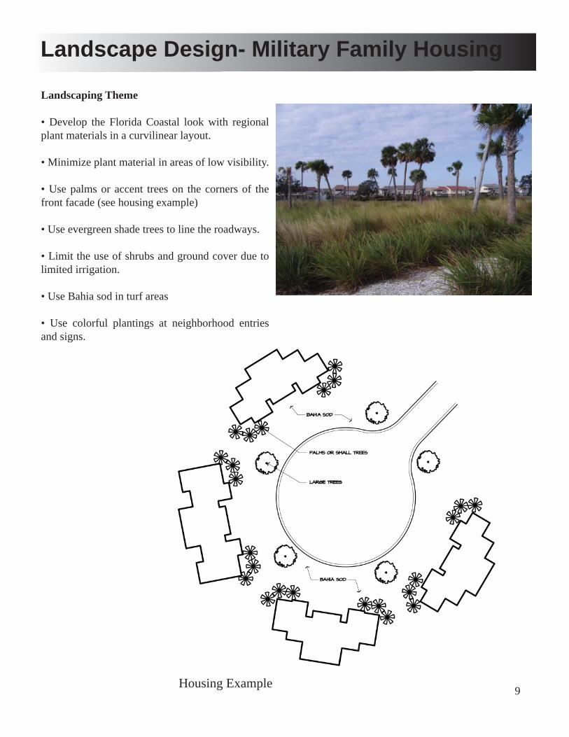
9
Landscape Design- Military Family Housing
Landscaping Theme
• Develop the Florida Coastal look with regional plant materials in a curvilinear layout.
• Minimize plant material in areas of low visibility.
• Use palms or accent trees on the corners of the front facade (see housing example)
• Use evergreen shade trees to line the roadways.
• Limit the use of shrubs and ground cover due to limited irrigation.
• Use Bahia sod in turf areas
• Use colorful plantings at neighborhood entries and signs.
Housing Example
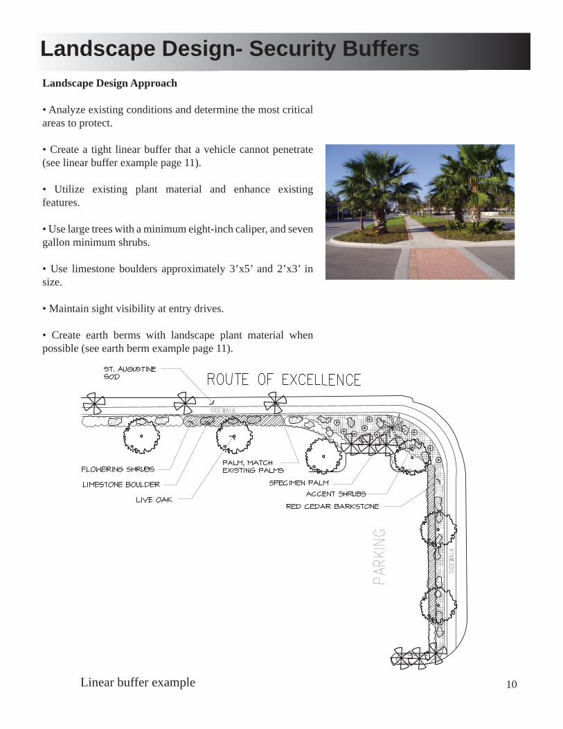
10
Landscape Design- Security BuffersLandscape Design Approach
• Analyze existing conditions and determine the most critical areas to protect.
• Create a tight linear buffer that a vehicle cannot penetrate (see linear buffer example page 11).
• Utilize existing plant material and enhance existing features.
• Use large trees with a minimum eight-inch caliper, and seven gallon minimum shrubs.
• Use limestone boulders approximately 3’x5’ and 2’x3’ in size.
• Maintain sight visibility at entry drives.
• Create earth berms with landscape plant material when possible (see earth berm example page 11).
Linear buffer example
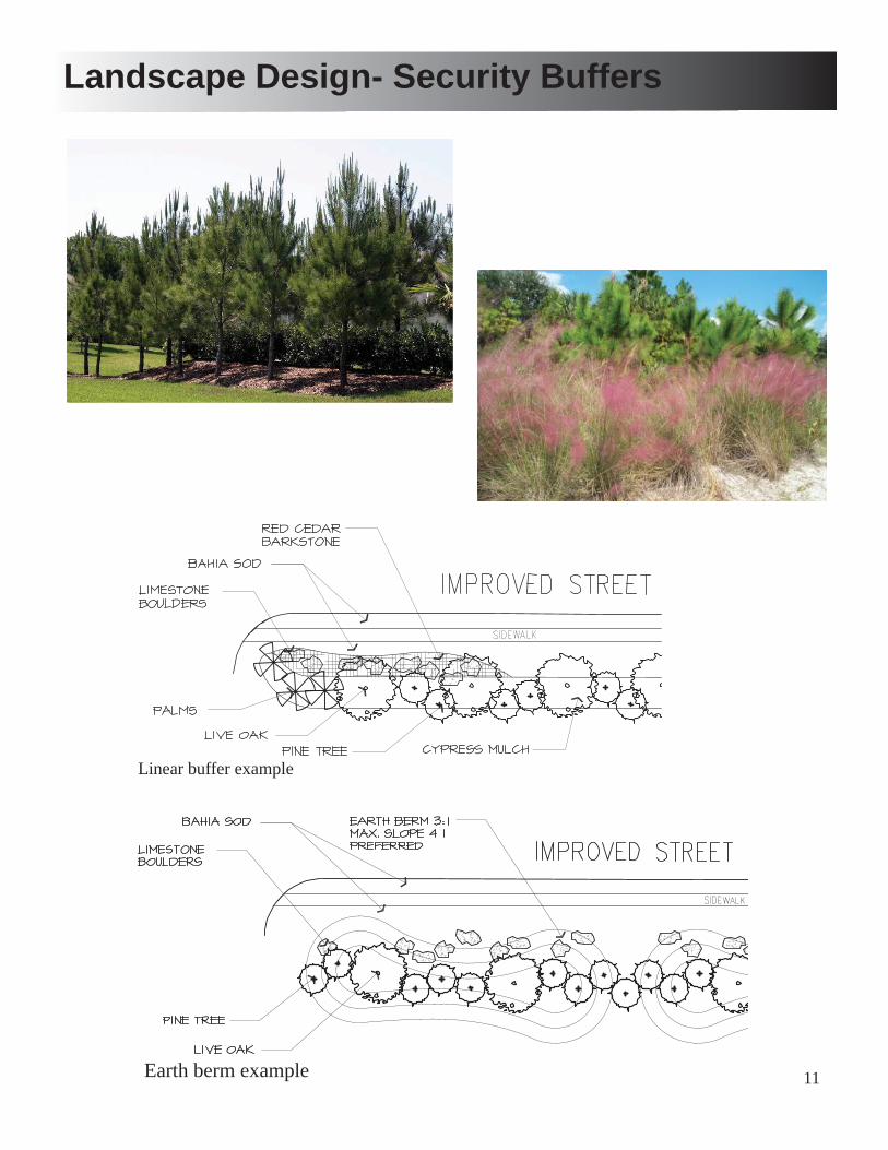
11
Landscape Design- Security Buffers
Linear buffer example
Earth berm example
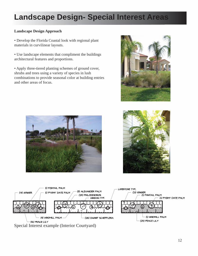
12
Landscape Design- Special Interest Areas
Landscape Design Approach
• Develop the Florida Coastal look with regional plant materials in curvilinear layouts.
• Use landscape elements that compliment the buildings architectural features and proportions.
• Apply three-tiered planting schemes of ground cover, shrubs and trees using a variety of species in lush combinations to provide seasonal color at building entries and other areas of focus.
Special Interest example (Interior Courtyard)
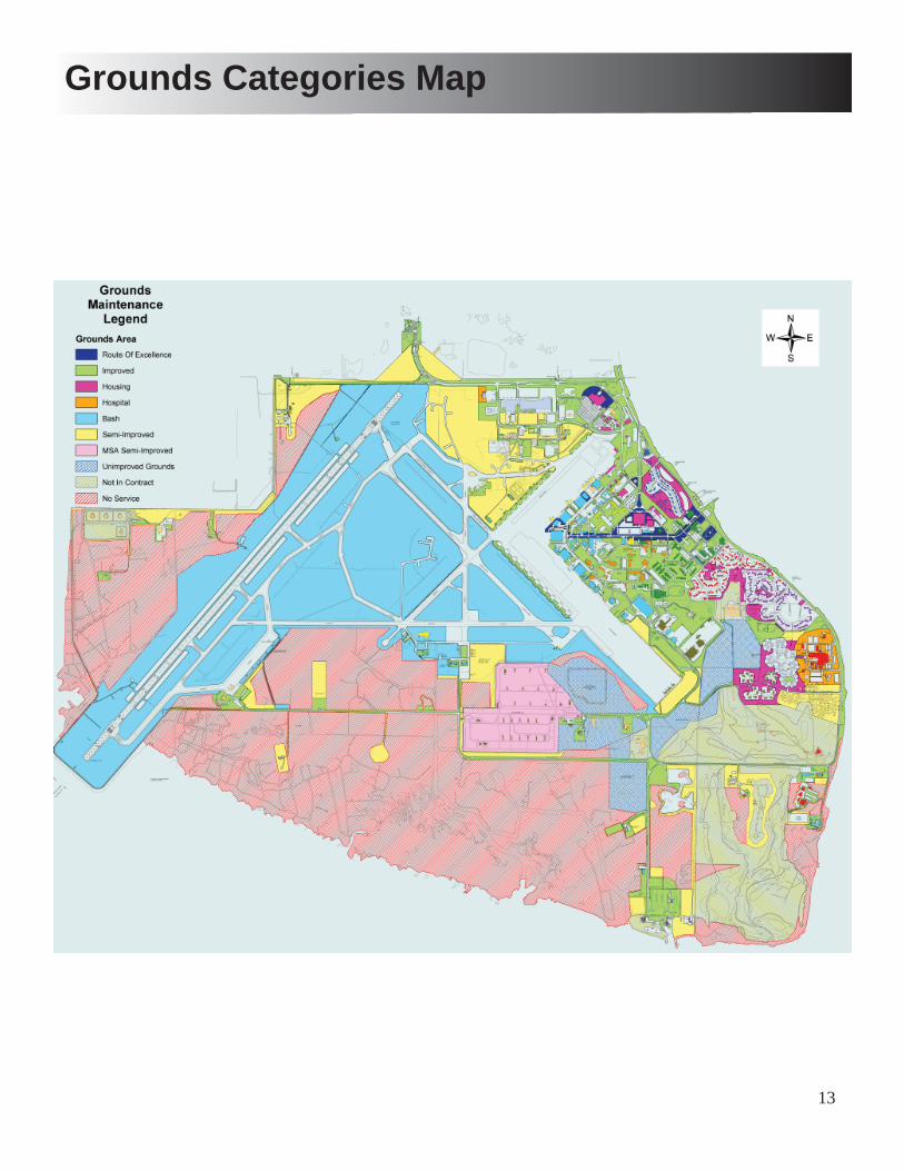
13
Grounds Categories Map
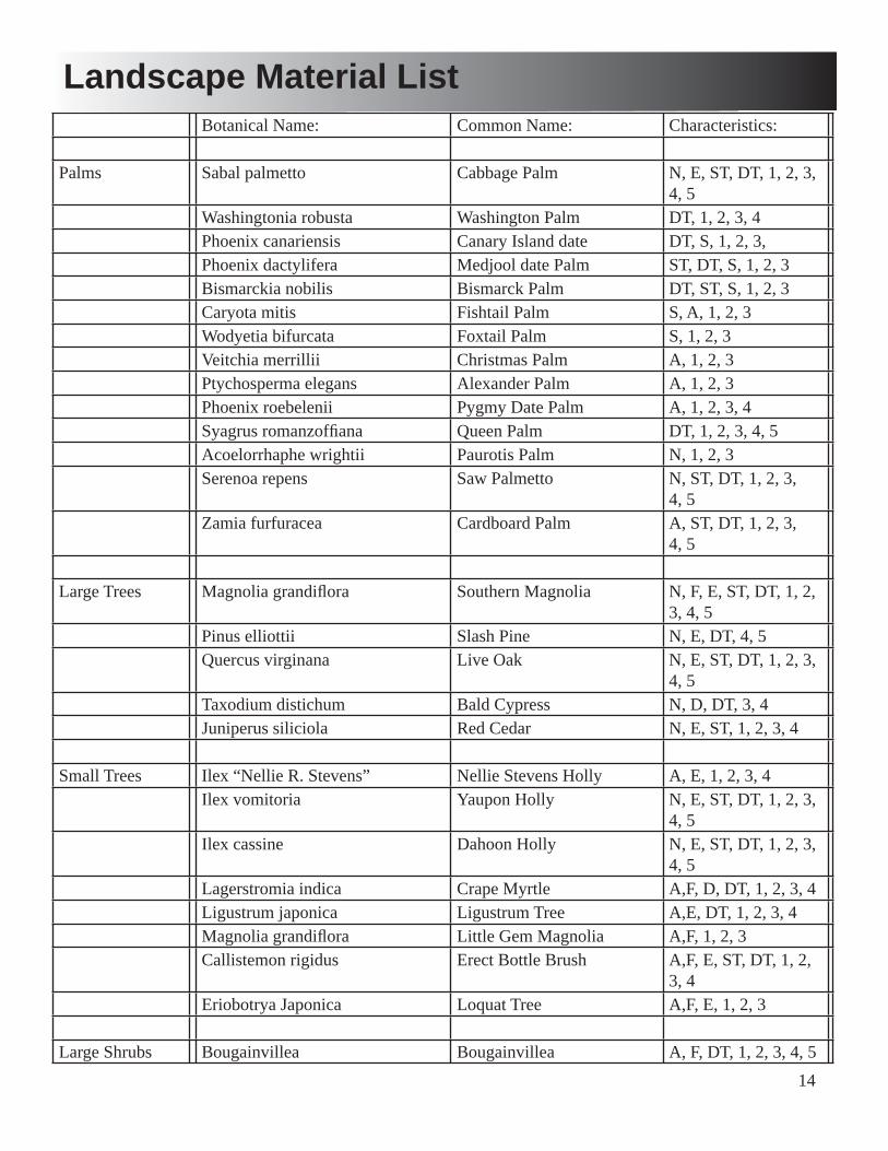
14
Botanical Name: Common Name: Characteristics:
Palms Sabal palmetto Cabbage Palm N, E, ST, DT, 1, 2, 3, 4, 5
Washingtonia robusta Washington Palm DT, 1, 2, 3, 4Phoenix canariensis Canary Island date DT, S, 1, 2, 3,Phoenix dactylifera Medjool date Palm ST, DT, S, 1, 2, 3Bismarckia nobilis Bismarck Palm DT, ST, S, 1, 2, 3Caryota mitis Fishtail Palm S, A, 1, 2, 3Wodyetia bifurcata Foxtail Palm S, 1, 2, 3Veitchia merrillii Christmas Palm A, 1, 2, 3Ptychosperma elegans Alexander Palm A, 1, 2, 3Phoenix roebelenii Pygmy Date Palm A, 1, 2, 3, 4Syagrus romanzoffi ana Queen Palm DT, 1, 2, 3, 4, 5Acoelorrhaphe wrightii Paurotis Palm N, 1, 2, 3Serenoa repens Saw Palmetto N, ST, DT, 1, 2, 3,
4, 5Zamia furfuracea Cardboard Palm A, ST, DT, 1, 2, 3,
4, 5
Large Trees Magnolia grandifl ora Southern Magnolia N, F, E, ST, DT, 1, 2, 3, 4, 5
Pinus elliottii Slash Pine N, E, DT, 4, 5Quercus virginana Live Oak N, E, ST, DT, 1, 2, 3,
4, 5Taxodium distichum Bald Cypress N, D, DT, 3, 4Juniperus siliciola Red Cedar N, E, ST, 1, 2, 3, 4
Small Trees Ilex “Nellie R. Stevens” Nellie Stevens Holly A, E, 1, 2, 3, 4Ilex vomitoria Yaupon Holly N, E, ST, DT, 1, 2, 3,
4, 5Ilex cassine Dahoon Holly N, E, ST, DT, 1, 2, 3,
4, 5Lagerstromia indica Crape Myrtle A,F, D, DT, 1, 2, 3, 4Ligustrum japonica Ligustrum Tree A,E, DT, 1, 2, 3, 4Magnolia grandifl ora Little Gem Magnolia A,F, 1, 2, 3Callistemon rigidus Erect Bottle Brush A,F, E, ST, DT, 1, 2,
3, 4Eriobotrya Japonica Loquat Tree A,F, E, 1, 2, 3
Large Shrubs Bougainvillea Bougainvillea A, F, DT, 1, 2, 3, 4, 5
Landscape Material List
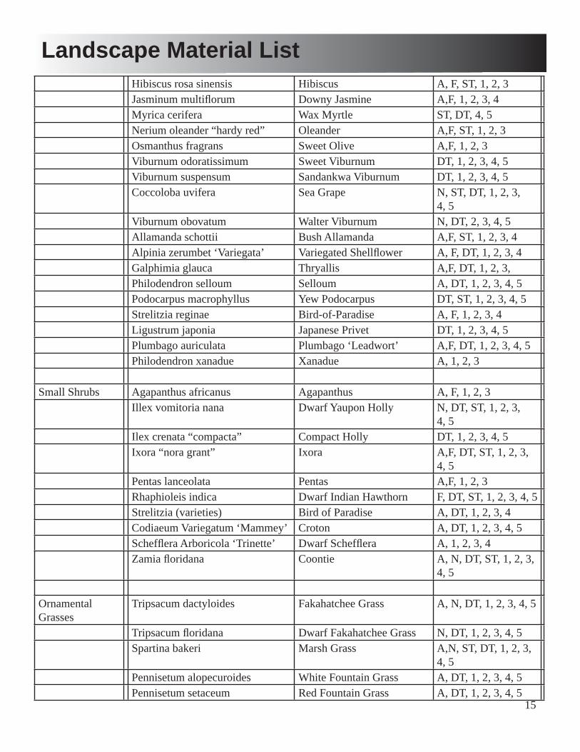
15
Hibiscus rosa sinensis Hibiscus A, F, ST, 1, 2, 3Jasminum multifl orum Downy Jasmine A,F, 1, 2, 3, 4Myrica cerifera Wax Myrtle ST, DT, 4, 5Nerium oleander “hardy red” Oleander A,F, ST, 1, 2, 3Osmanthus fragrans Sweet Olive A,F, 1, 2, 3 Viburnum odoratissimum Sweet Viburnum DT, 1, 2, 3, 4, 5Viburnum suspensum Sandankwa Viburnum DT, 1, 2, 3, 4, 5Coccoloba uvifera Sea Grape N, ST, DT, 1, 2, 3,
4, 5Viburnum obovatum Walter Viburnum N, DT, 2, 3, 4, 5Allamanda schottii Bush Allamanda A,F, ST, 1, 2, 3, 4Alpinia zerumbet ‘Variegata’ Variegated Shellfl ower A, F, DT, 1, 2, 3, 4Galphimia glauca Thryallis A,F, DT, 1, 2, 3, Philodendron selloum Selloum A, DT, 1, 2, 3, 4, 5Podocarpus macrophyllus Yew Podocarpus DT, ST, 1, 2, 3, 4, 5Strelitzia reginae Bird-of-Paradise A, F, 1, 2, 3, 4Ligustrum japonia Japanese Privet DT, 1, 2, 3, 4, 5Plumbago auriculata Plumbago ‘Leadwort’ A,F, DT, 1, 2, 3, 4, 5Philodendron xanadue Xanadue A, 1, 2, 3
Small Shrubs Agapanthus africanus Agapanthus A, F, 1, 2, 3Illex vomitoria nana Dwarf Yaupon Holly N, DT, ST, 1, 2, 3,
4, 5Ilex crenata “compacta” Compact Holly DT, 1, 2, 3, 4, 5Ixora “nora grant” Ixora A,F, DT, ST, 1, 2, 3,
4, 5Pentas lanceolata Pentas A,F, 1, 2, 3Rhaphioleis indica Dwarf Indian Hawthorn F, DT, ST, 1, 2, 3, 4, 5Strelitzia (varieties) Bird of Paradise A, DT, 1, 2, 3, 4Codiaeum Variegatum ‘Mammey’ Croton A, DT, 1, 2, 3, 4, 5Scheffl era Arboricola ‘Trinette’ Dwarf Scheffl era A, 1, 2, 3, 4Zamia fl oridana Coontie A, N, DT, ST, 1, 2, 3,
4, 5
Ornamental Grasses
Tripsacum dactyloides Fakahatchee Grass A, N, DT, 1, 2, 3, 4, 5
Tripsacum fl oridana Dwarf Fakahatchee Grass N, DT, 1, 2, 3, 4, 5Spartina bakeri Marsh Grass A,N, ST, DT, 1, 2, 3,
4, 5Pennisetum alopecuroides White Fountain Grass A, DT, 1, 2, 3, 4, 5Pennisetum setaceum Red Fountain Grass A, DT, 1, 2, 3, 4, 5
Landscape Material List
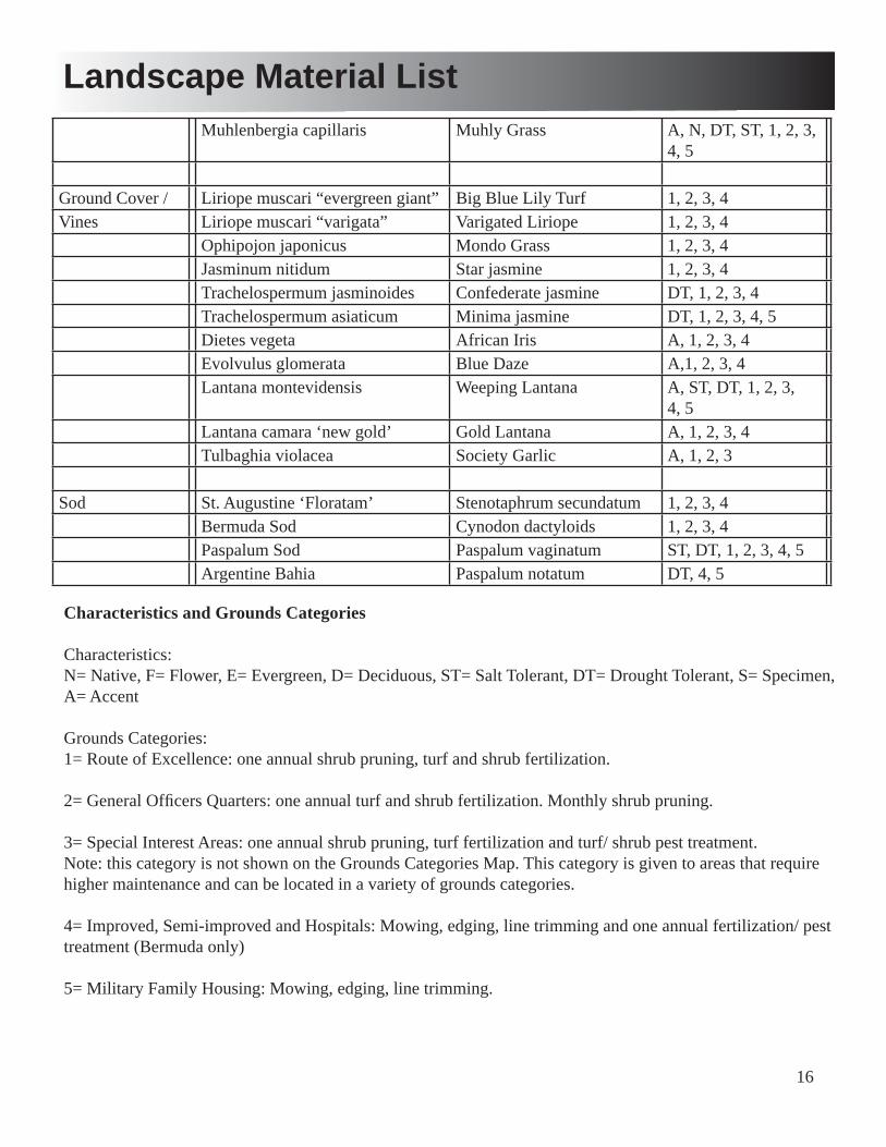
16
Muhlenbergia capillaris Muhly Grass A, N, DT, ST, 1, 2, 3, 4, 5
Ground Cover / Liriope muscari “evergreen giant” Big Blue Lily Turf 1, 2, 3, 4Vines Liriope muscari “varigata” Varigated Liriope 1, 2, 3, 4
Ophipojon japonicus Mondo Grass 1, 2, 3, 4Jasminum nitidum Star jasmine 1, 2, 3, 4Trachelospermum jasminoides Confederate jasmine DT, 1, 2, 3, 4Trachelospermum asiaticum Minima jasmine DT, 1, 2, 3, 4, 5Dietes vegeta African Iris A, 1, 2, 3, 4Evolvulus glomerata Blue Daze A,1, 2, 3, 4Lantana montevidensis Weeping Lantana A, ST, DT, 1, 2, 3,
4, 5Lantana camara ‘new gold’ Gold Lantana A, 1, 2, 3, 4Tulbaghia violacea Society Garlic A, 1, 2, 3
Sod St. Augustine ‘Floratam’ Stenotaphrum secundatum 1, 2, 3, 4Bermuda Sod Cynodon dactyloids 1, 2, 3, 4Paspalum Sod Paspalum vaginatum ST, DT, 1, 2, 3, 4, 5Argentine Bahia Paspalum notatum DT, 4, 5
Characteristics and Grounds Categories
Characteristics:N= Native, F= Flower, E= Evergreen, D= Deciduous, ST= Salt Tolerant, DT= Drought Tolerant, S= Specimen, A= Accent
Grounds Categories:1= Route of Excellence: one annual shrub pruning, turf and shrub fertilization. 2= General Offi cers Quarters: one annual turf and shrub fertilization. Monthly shrub pruning. 3= Special Interest Areas: one annual shrub pruning, turf fertilization and turf/ shrub pest treatment.Note: this category is not shown on the Grounds Categories Map. This category is given to areas that require higher maintenance and can be located in a variety of grounds categories.
4= Improved, Semi-improved and Hospitals: Mowing, edging, line trimming and one annual fertilization/ pest treatment (Bermuda only) 5= Military Family Housing: Mowing, edging, line trimming.
Landscape Material List
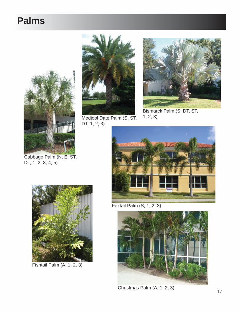
17
Palms
Cabbage Palm (N, E, ST, DT, 1, 2, 3, 4, 5)
Medjool Date Palm (S, ST, DT, 1, 2, 3)
Bismarck Palm (S, DT, ST, 1, 2, 3)
Fishtail Palm (A, 1, 2, 3)
Foxtail Palm (S, 1, 2, 3)
Christmas Palm (A, 1, 2, 3)
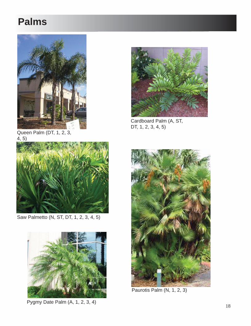
18
Palms
Queen Palm (DT, 1, 2, 3, 4, 5)
Paurotis Palm (N, 1, 2, 3)
Saw Palmetto (N, ST, DT, 1, 2, 3, 4, 5)
Cardboard Palm (A, ST, DT, 1, 2, 3, 4, 5)
Pygmy Date Palm (A, 1, 2, 3, 4)

19
Large Trees
Southern Magnolia (N, F, E, ST, DT, 1, 2, 3, 4, 5)
Slash Pine (N, E, DT, 4, 5)
Live Oak (N, E, ST, DT, 1, 2, 3, 4, 5)
Bald Cypress (N, D, DT, 3, 4)
Red Cedar (N, E, ST, 1, 2, 3, 4)
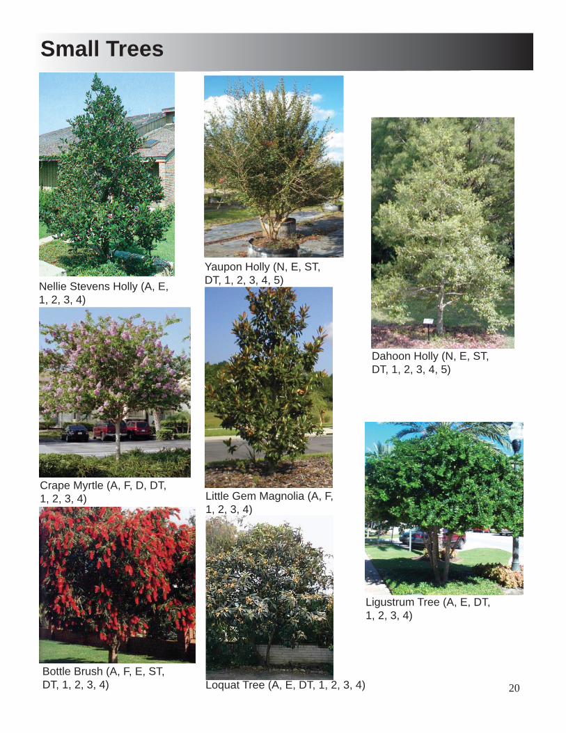
20
Small Trees
Nellie Stevens Holly (A, E, 1, 2, 3, 4)
Yaupon Holly (N, E, ST, DT, 1, 2, 3, 4, 5)
Dahoon Holly (N, E, ST, DT, 1, 2, 3, 4, 5)
Crape Myrtle (A, F, D, DT, 1, 2, 3, 4)
Ligustrum Tree (A, E, DT, 1, 2, 3, 4)
Little Gem Magnolia (A, F, 1, 2, 3, 4)
Bottle Brush (A, F, E, ST, DT, 1, 2, 3, 4) Loquat Tree (A, E, DT, 1, 2, 3, 4)
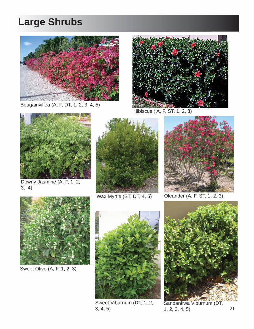
21
Large Shrubs
Bougainvillea (A, F, DT, 1, 2, 3, 4, 5)Hibiscus ( A, F, ST, 1, 2, 3)
Downy Jasmine (A, F, 1, 2, 3, 4)
Wax Myrtle (ST, DT, 4, 5) Oleander (A, F, ST, 1, 2, 3)
Sweet Olive (A, F, 1, 2, 3)
Sweet Viburnum (DT, 1, 2, 3, 4, 5)
Sandankwa Viburnum (DT, 1, 2, 3, 4, 5)
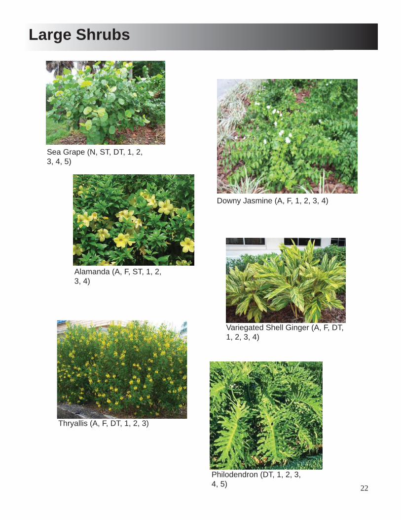
22
Large Shrubs
Sea Grape (N, ST, DT, 1, 2, 3, 4, 5)
Alamanda (A, F, ST, 1, 2, 3, 4)
Variegated Shell Ginger (A, F, DT, 1, 2, 3, 4)
Thryallis (A, F, DT, 1, 2, 3)
Philodendron (DT, 1, 2, 3, 4, 5)
Downy Jasmine (A, F, 1, 2, 3, 4)
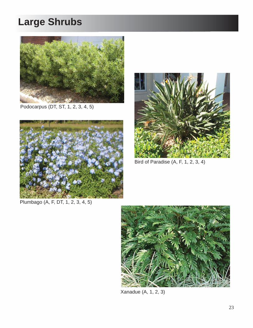
23
Large Shrubs
Podocarpus (DT, ST, 1, 2, 3, 4, 5)
Bird of Paradise (A, F, 1, 2, 3, 4)
Plumbago (A, F, DT, 1, 2, 3, 4, 5)
Xanadue (A, 1, 2, 3)
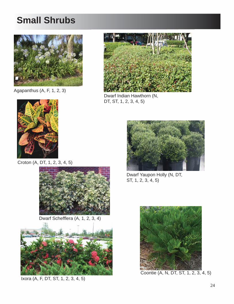
24
Small Shrubs
Agapanthus (A, F, 1, 2, 3)Dwarf Indian Hawthorn (N, DT, ST, 1, 2, 3, 4, 5)
Croton (A, DT, 1, 2, 3, 4, 5)
Dwarf Scheffl era (A, 1, 2, 3, 4)
Coontie (A, N, DT, ST, 1, 2, 3, 4, 5)
Dwarf Yaupon Holly (N, DT, ST, 1, 2, 3, 4, 5)
Ixora (A, F, DT, ST, 1, 2, 3, 4, 5)
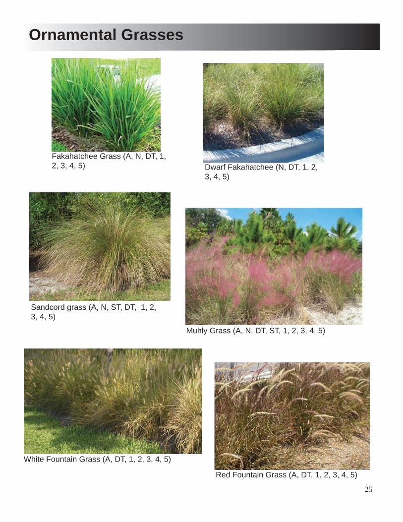
25
Ornamental Grasses
Fakahatchee Grass (A, N, DT, 1, 2, 3, 4, 5) Dwarf Fakahatchee (N, DT, 1, 2,
3, 4, 5)
Sandcord grass (A, N, ST, DT, 1, 2, 3, 4, 5)
Muhly Grass (A, N, DT, ST, 1, 2, 3, 4, 5)
White Fountain Grass (A, DT, 1, 2, 3, 4, 5)
Red Fountain Grass (A, DT, 1, 2, 3, 4, 5)

26
Ground Covers
Liriope (1, 2, 3, 4) Varigated Liriope (1, 2, 3, 4)
Mondo Grass (1, 2, 3, 4)
Confederate Jasmine (A, DT, 1, 2, 3, 4)
African Iris (A, 1, 2, 3, 4)
Minima Jasmine (DT,1, 2, 3, 4, 5)
Purple Lantana (A, ST, DT, 1, 2, 3, 4, 5)
Gold Lantana (A, 1, 2, 3, 4)
Society Garlic (A, 1, 2, 3)
27
Landscape Specifi cationsPart one – general
1.01 Extent of landscape development work is shown on the drawings and in the notes and schedules
1.02 Provide trees, palms, shrubs, and ground cover of quality, size, genus, species and variety shown. Described in grades and standards for nursery, latest edition, published by the Florida department of agriculture and consumer services. Provide healthy, vigorous stock, free of disease, insects, eggs, larvae, and defects such as knots, injuries, abrasions or disfi gurement. Do not make substitutions. If specifi ed landscape materials are not obtainable, submit proof of non-availability to landscape architect or project manager, together with proposal for use of equivalent material.
1.03 Provide protective covering during delivery of plant materials. Plant stock immediately, or store in a shaded area, keep rootballs moist at all times. Do not remove stock from containers until planting time. Time delivery so that sod will be installed within 24 hours after arrival at site.
1.04 Determine location of underground utilities and perform work in a manner which will avoid possible damage. Hand excavate if required, when conditions detrimental to plant growth are encountered, such as rubble fi ll, adverse drainage conditions, or obstructions, notify the landscape architect or project manager before planting. Contractor shall examine subgrade, verify elevations, observe overall site conditions and notify project manager of any unsatisfactory conditions. The contractor shall not proceed with work, until conditions have been corrected.
1.05 Warranty trees, palms, shrubs and ground cover, for a period of one year after date of substantial completion, against defects including death and unsatisfactory growth, except for defects resulting from neglect by owner, abuse or damage by others, or unusual phenomena or incidence which are beyond the contractor control. Remove and replace trees, palms, shrubs, and ground cover found to be dead or in unhealthy condition during warranty period. Warranty lawns through specifi ed lawn maintenance period, and until fi nal acceptance.
Part two – products
2.01 The contractor shall have a sample of site soil tested to determine soil analysis. Tests results shall determine appropriate soil amendments for lawn and landscape areas. Contractor shall submit copies of test results and proposed soil amendments to the owner and the landscape architect for approval. Soil testing and soil amendments approval shall be accomplished.
2.02 Landscape mix - 60% peat humus, 20% wood chips, 20% compost, N.P.K. 3.2.1, As manufactured by hillary peat or approved equal.
2.03 Mulch - organic mulch free from deleterious materials and consisting of the following: shredded - grade a, cypress mulch or red cedar barkstone
2.04 Fertilizer - for trees, palms, shrubs, and ground cover, provide “agriform” tables by sierra chemical co., Slow release tablets, 20 - 10 - 5 formulation or approved equal. Tablet amounts shall be as follows:
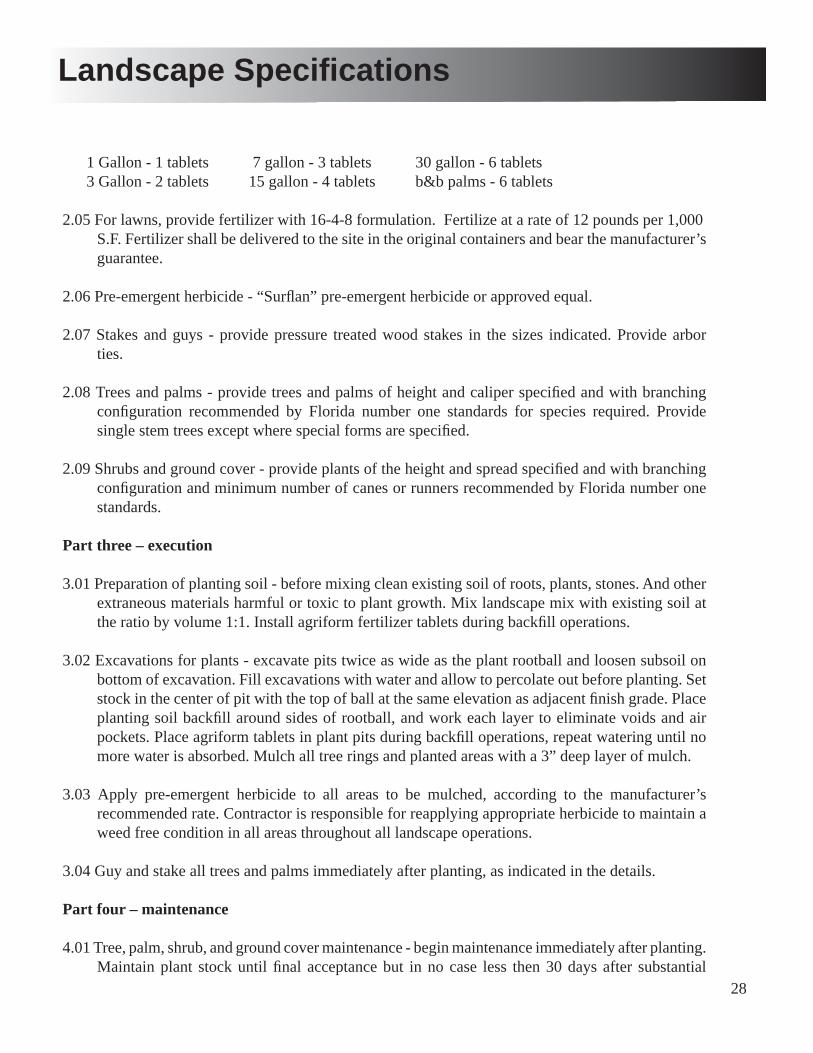
28
Landscape Specifi cations
1 Gallon - 1 tablets 7 gallon - 3 tablets 30 gallon - 6 tablets 3 Gallon - 2 tablets 15 gallon - 4 tablets b&b palms - 6 tablets
2.05 For lawns, provide fertilizer with 16-4-8 formulation. Fertilize at a rate of 12 pounds per 1,000 S.F. Fertilizer shall be delivered to the site in the original containers and bear the manufacturer’s guarantee.
2.06 Pre-emergent herbicide - “Surfl an” pre-emergent herbicide or approved equal. 2.07 Stakes and guys - provide pressure treated wood stakes in the sizes indicated. Provide arbor
ties.
2.08 Trees and palms - provide trees and palms of height and caliper specifi ed and with branching confi guration recommended by Florida number one standards for species required. Provide single stem trees except where special forms are specifi ed.
2.09 Shrubs and ground cover - provide plants of the height and spread specifi ed and with branching confi guration and minimum number of canes or runners recommended by Florida number one standards.
Part three – execution
3.01 Preparation of planting soil - before mixing clean existing soil of roots, plants, stones. And other extraneous materials harmful or toxic to plant growth. Mix landscape mix with existing soil at the ratio by volume 1:1. Install agriform fertilizer tablets during backfi ll operations.
3.02 Excavations for plants - excavate pits twice as wide as the plant rootball and loosen subsoil on bottom of excavation. Fill excavations with water and allow to percolate out before planting. Set stock in the center of pit with the top of ball at the same elevation as adjacent fi nish grade. Place planting soil backfi ll around sides of rootball, and work each layer to eliminate voids and air pockets. Place agriform tablets in plant pits during backfi ll operations, repeat watering until no more water is absorbed. Mulch all tree rings and planted areas with a 3” deep layer of mulch.
3.03 Apply pre-emergent herbicide to all areas to be mulched, according to the manufacturer’s recommended rate. Contractor is responsible for reapplying appropriate herbicide to maintain a weed free condition in all areas throughout all landscape operations.
3.04 Guy and stake all trees and palms immediately after planting, as indicated in the details.
Part four – maintenance
4.01 Tree, palm, shrub, and ground cover maintenance - begin maintenance immediately after planting. Maintain plant stock until fi nal acceptance but in no case less then 30 days after substantial

29
completion. Maintain by pruning, weeding, and adjusting irrigation as required for healthy growth. Tighten and repair stake and guy supports and reset trees and palms to proper grades or vertical position as required. Spray as needed to keep plant stock free of insects and disease.
4.02 During landscape work, keep pavements clean and work area in an orderly condition. Protect landscape work and materials from damage due to operations by other contractors and trades. Maintain protection during installation and maintenance periods. Treat, repair, or replace damaged landscape work as directed.
4.03 Contractor shall remove staking and guying materials after one growing season.
Part fi ve - inspection and acceptance
5.01 When landscape work is completed, landscape architect or project manager will make an inspection to determine acceptability. When landscape work does not comply with requirements, replace rejected work and continue maintenance until reinspected by the landscape architect or project manager. Remove rejected plants and materials promptly from the project site.
Part six - existing plant material fertilization
6.01 For shrubs and ground cover the fertilizer applications shall be as follows March, June, September, and December. Use a 8-10-10 formulation at a rate of two pounds per 100 sf.
6.02 For trees the fertilizer applications shall be as follows: March, June and September. Use a 13-6-10 formulation at a rate of two pounds per inch of caliper of less than 6” caliper and fi ve pounds per inch of caliper over 6” caliper.
6.03 For palms the fertilizer applications shall be as follows: March, July and October. Use a palm special 10-5-5 formulation at a rate of seven pounds per palm trunk. Apply palm foliar spray mix to all foliage surface as follows: April, august and November.
6.04 For lawns the fertilizer applications shall be as follows: February, April, June September and December. Use a 16-4-8 formulation at a rate of 5 -6 pounds per 1,000 sf.
6.05 Do not allow chemicals to fall on, or translocate on, off-site area. Do not allow water containing toxic amounts of chemicals to pool or puddle after completion of operations.
Landscape Specifi cations

30
Part one – general
1.01 Extent of irrigation work includes irrigation system for landscape areas as shown on the drawings. Work includes installation of underground irrigation system for project site, ready to permanently operate, in compliance with all applicable codes.
1.02 Product data - submit for approval, manufacturer’s technical data for the following items: backfl ow preventer, electric valve, gate valve, valve box, wire, controller, rain check, spray, rotor heads and drip irrigation equipment.
1.03 Record drawings - following completion and acceptance of irrigation installation furnish “as-built” drawings showing all irrigation heads, valves, controllers, and pipe locations to scale. Contractor shall provide a diagram of list of zones, inside each controller cover.
Part two – products
2.01 Pressure pipe - comply with the following for pressure piping: ANSI/ASTM a 120. Schedule 40.
2.02 Lateral pipe - comply with the following for lateral piping: ANSI/ASTM a 120, schedule 40. Provide galvanized pipe where required by local code or as indicated in drawings.
2.03 Pipe fi ttings - comply with the following: ASTM d2466 socket fi ttings with ASTM d2564 solvent cement.
2.04 Solvent cement and cleaner - provide quick drying and fast holding products such as manufactured by arrow or approved equal. Pipe cleaner shall be. Purple.
2.05 Electric valves shall be globe valves operated by low-power solenoid, normally closed, with manual fl ow adjustment.
2.06 Gate valves shall be bronze, threaded, and of line size. Gate valves shall be installed in a plastic valve box, in the same manner as electric valves.
2.07 Spray and rotor heads shall be pop-up type or installed on risers, as indicated .On the irrigation plan. Heads shall be connected to pipes with fl ex pipe attachments. Spray and rotor heads shall be Rainbird and Hunter.
2.08 Valve boxes shall be green plastic 10” round, with lid. Valves in boxes shall be set in a 3” deep, clean gravel bed.
2.09 Controller shall include transformer and wiring to hardwire into building electrical system. Controller shall have power backup to maintain settlings at least eight hours without building power. Provide lockable cover.
2.10 Wiring shall be type UF, control cable, with PVC insulation, color coded. Common wire shall be white.
Irrigation Specifi cations
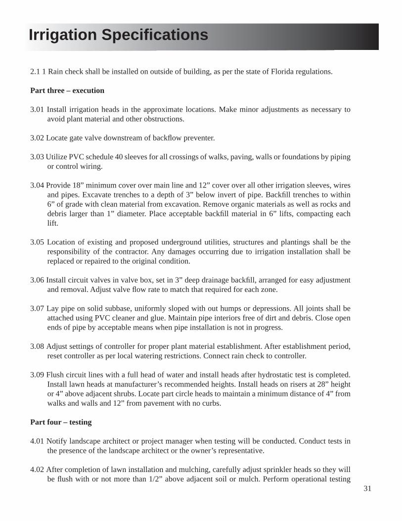
31
Irrigation Specifi cations
2.1 1 Rain check shall be installed on outside of building, as per the state of Florida regulations.
Part three – execution
3.01 Install irrigation heads in the approximate locations. Make minor adjustments as necessary to avoid plant material and other obstructions.
3.02 Locate gate valve downstream of backfl ow preventer.
3.03 Utilize PVC schedule 40 sleeves for all crossings of walks, paving, walls or foundations by piping or control wiring.
3.04 Provide 18” minimum cover over main line and 12” cover over all other irrigation sleeves, wires and pipes. Excavate trenches to a depth of 3” below invert of pipe. Backfi ll trenches to within 6” of grade with clean material from excavation. Remove organic materials as well as rocks and debris larger than 1” diameter. Place acceptable backfi ll material in 6” lifts, compacting each lift.
3.05 Location of existing and proposed underground utilities, structures and plantings shall be the responsibility of the contractor. Any damages occurring due to irrigation installation shall be replaced or repaired to the original condition.
3.06 Install circuit valves in valve box, set in 3” deep drainage backfi ll, arranged for easy adjustment and removal. Adjust valve fl ow rate to match that required for each zone.
3.07 Lay pipe on solid subbase, uniformly sloped with out humps or depressions. All joints shall be attached using PVC cleaner and glue. Maintain pipe interiors free of dirt and debris. Close open ends of pipe by acceptable means when pipe installation is not in progress.
3.08 Adjust settings of controller for proper plant material establishment. After establishment period, reset controller as per local watering restrictions. Connect rain check to controller.
3.09 Flush circuit lines with a full head of water and install heads after hydrostatic test is completed. Install lawn heads at manufacturer’s recommended heights. Install heads on risers at 28” height or 4” above adjacent shrubs. Locate part circle heads to maintain a minimum distance of 4” from walks and walls and 12” from pavement with no curbs.
Part four – testing
4.01 Notify landscape architect or project manager when testing will be conducted. Conduct tests in the presence of the landscape architect or the owner’s representative.
4.02 After completion of lawn installation and mulching, carefully adjust sprinkler heads so they will be fl ush with or not more than 1/2” above adjacent soil or mulch. Perform operational testing

32
Irrigation Specifi cations
after sprinkler heads have been adjusted to their fi nal positions. Contractor shall demonstrate that each zone meets coverage requirements and that automatic controls function properly. Contractor shall uncover pipe and valve connections as directed by the owner’s representative. Proper spray patterns, correct nozzle radius, and clean nozzles will all be required for fi nal system approval.
4.03 After system testing approval, contractor shall instruct the owner’s personnel in the operation and maintenance of the system, including spray pattern and valve adjustments, and programming the controller.
Establishment Period Watering Schedule (for areas with no irrigation)
1.01 During landscape installation the contractor shall water-in installed landscape materials and continue watering until substantial completion. At substantial completion the contractor shall begin the following 90 day watering schedule. The landscape contractor shall water all plant materials shown on the landscape planting plans, for a thirteen week, ninety day watering period based on the following plant establishment period schedule.
30 gallon container plants: 25 gallon water/each application 15 gallon container plants: 10 gallon water/each application 3 gallon container plants: 5 gallon water/each application 1 gallon container plants: 2 gallon water/each application
1st 4 weeks at 3 applications per week = 12 events 2nd 4 weeks at 2 applications per week = 8 events 3rd 5 weeks at 1 application per week = 5 events Total number of applications = 25 events
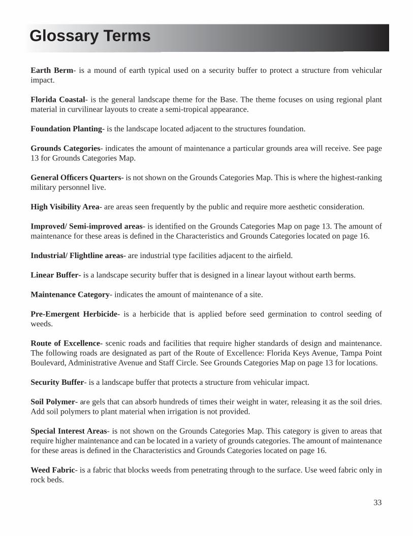
33
Glossary Terms
Earth Berm- is a mound of earth typical used on a security buffer to protect a structure from vehicular impact.
Florida Coastal- is the general landscape theme for the Base. The theme focuses on using regional plant material in curvilinear layouts to create a semi-tropical appearance.
Foundation Planting- is the landscape located adjacent to the structures foundation.
Grounds Categories- indicates the amount of maintenance a particular grounds area will receive. See page 13 for Grounds Categories Map.
General Offi cers Quarters- is not shown on the Grounds Categories Map. This is where the highest-ranking military personnel live.
High Visibility Area- are areas seen frequently by the public and require more aesthetic consideration.
Improved/ Semi-improved areas- is identifi ed on the Grounds Categories Map on page 13. The amount of maintenance for these areas is defi ned in the Characteristics and Grounds Categories located on page 16.
Industrial/ Flightline areas- are industrial type facilities adjacent to the airfi eld.
Linear Buffer- is a landscape security buffer that is designed in a linear layout without earth berms.
Maintenance Category- indicates the amount of maintenance of a site.
Pre-Emergent Herbicide- is a herbicide that is applied before seed germination to control seeding of weeds.
Route of Excellence- scenic roads and facilities that require higher standards of design and maintenance. The following roads are designated as part of the Route of Excellence: Florida Keys Avenue, Tampa Point Boulevard, Administrative Avenue and Staff Circle. See Grounds Categories Map on page 13 for locations.
Security Buffer- is a landscape buffer that protects a structure from vehicular impact.
Soil Polymer- are gels that can absorb hundreds of times their weight in water, releasing it as the soil dries. Add soil polymers to plant material when irrigation is not provided.
Special Interest Areas- is not shown on the Grounds Categories Map. This category is given to areas that require higher maintenance and can be located in a variety of grounds categories. The amount of maintenance for these areas is defi ned in the Characteristics and Grounds Categories located on page 16.
Weed Fabric- is a fabric that blocks weeds from penetrating through to the surface. Use weed fabric only in rock beds.
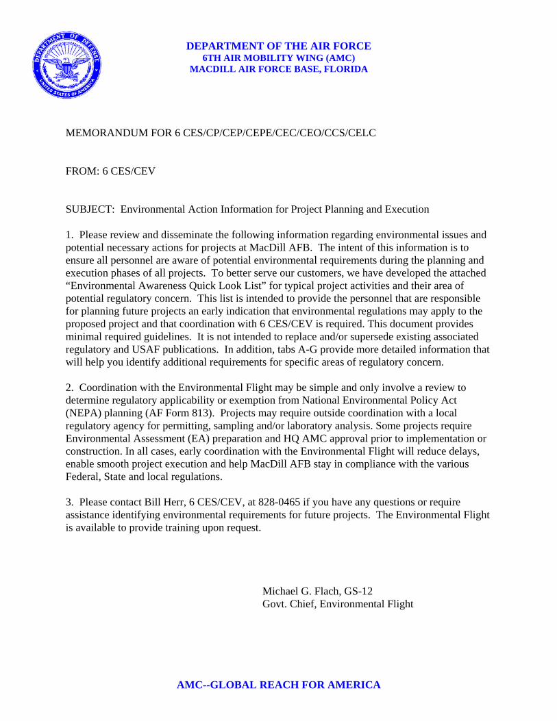
DEPARTMENT OF THE AIR FORCE 6TH AIR MOBILITY WING (AMC)
MACDILL AIR FORCE BASE, FLORIDA
AMC--GLOBAL REACH FOR AMERICA
MEMORANDUM FOR 6 CES/CP/CEP/CEPE/CEC/CEO/CCS/CELC FROM: 6 CES/CEV SUBJECT: Environmental Action Information for Project Planning and Execution 1. Please review and disseminate the following information regarding environmental issues and potential necessary actions for projects at MacDill AFB. The intent of this information is to ensure all personnel are aware of potential environmental requirements during the planning and execution phases of all projects. To better serve our customers, we have developed the attached “Environmental Awareness Quick Look List” for typical project activities and their area of potential regulatory concern. This list is intended to provide the personnel that are responsible for planning future projects an early indication that environmental regulations may apply to the proposed project and that coordination with 6 CES/CEV is required. This document provides minimal required guidelines. It is not intended to replace and/or supersede existing associated regulatory and USAF publications. In addition, tabs A-G provide more detailed information that will help you identify additional requirements for specific areas of regulatory concern. 2. Coordination with the Environmental Flight may be simple and only involve a review to determine regulatory applicability or exemption from National Environmental Policy Act (NEPA) planning (AF Form 813). Projects may require outside coordination with a local regulatory agency for permitting, sampling and/or laboratory analysis. Some projects require Environmental Assessment (EA) preparation and HQ AMC approval prior to implementation or construction. In all cases, early coordination with the Environmental Flight will reduce delays, enable smooth project execution and help MacDill AFB stay in compliance with the various Federal, State and local regulations. 3. Please contact Bill Herr, 6 CES/CEV, at 828-0465 if you have any questions or require assistance identifying environmental requirements for future projects. The Environmental Flight is available to provide training upon request.
Michael G. Flach, GS-12 Govt. Chief, Environmental Flight
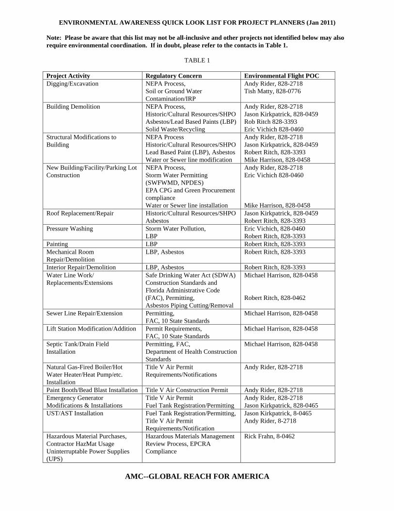
AMC--GLOBAL REACH FOR AMERICA
ENVIRONMENTAL AWARENESS QUICK LOOK LIST FOR PROJECT PLANNERS (Jan 2011) Note: Please be aware that this list may not be all-inclusive and other projects not identified below may also require environmental coordination. If in doubt, please refer to the contacts in Table 1.
TABLE 1
Project Activity Regulatory Concern Environmental Flight POC Digging/Excavation NEPA Process,
Soil or Ground Water Contamination/IRP
Andy Rider, 828-2718 Tish Matty, 828-0776
Building Demolition NEPA Process, Historic/Cultural Resources/SHPO Asbestos/Lead Based Paints (LBP) Solid Waste/Recycling
Andy Rider, 828-2718 Jason Kirkpatrick, 828-0459 Rob Ritch 828-3393 Eric Vichich 828-0460
Structural Modifications to Building
NEPA Process Historic/Cultural Resources/SHPO Lead Based Paint (LBP), Asbestos Water or Sewer line modification
Andy Rider, 828-2718 Jason Kirkpatrick, 828-0459 Robert Ritch, 828-3393 Mike Harrison, 828-0458
New Building/Facility/Parking Lot Construction
NEPA Process, Storm Water Permitting (SWFWMD, NPDES) EPA CPG and Green Procurement compliance Water or Sewer line installation
Andy Rider, 828-2718 Eric Vichich 828-0460 Mike Harrison, 828-0458
Roof Replacement/Repair Historic/Cultural Resources/SHPO Asbestos
Jason Kirkpatrick, 828-0459 Robert Ritch, 828-3393
Pressure Washing Storm Water Pollution, LBP
Eric Vichich, 828-0460 Robert Ritch, 828-3393
Painting LBP Robert Ritch, 828-3393 Mechanical Room Repair/Demolition
LBP, Asbestos Robert Ritch, 828-3393
Interior Repair/Demolition LBP, Asbestos Robert Ritch, 828-3393 Water Line Work/ Replacements/Extensions
Safe Drinking Water Act (SDWA) Construction Standards and Florida Administrative Code (FAC), Permitting, Asbestos Piping Cutting/Removal
Michael Harrison, 828-0458 Robert Ritch, 828-0462
Sewer Line Repair/Extension Permitting, FAC, 10 State Standards
Michael Harrison, 828-0458
Lift Station Modification/Addition Permit Requirements, FAC, 10 State Standards
Michael Harrison, 828-0458
Septic Tank/Drain Field Installation
Permitting, FAC, Department of Health Construction Standards
Michael Harrison, 828-0458
Natural Gas-Fired Boiler/Hot Water Heater/Heat Pump/etc. Installation
Title V Air Permit Requirements/Notifications
Andy Rider, 828-2718
Paint Booth/Bead Blast Installation Title V Air Construction Permit Andy Rider, 828-2718 Emergency Generator Modifications & Installations
Title V Air Permit Fuel Tank Registration/Permitting
Andy Rider, 828-2718 Jason Kirkpatrick, 828-0465
UST/AST Installation Fuel Tank Registration/Permitting, Title V Air Permit Requirements/Notification
Jason Kirkpatrick, 8-0465 Andy Rider, 8-2718
Hazardous Material Purchases, Contractor HazMat Usage Uninterruptable Power Supplies (UPS)
Hazardous Materials Management Review Process, EPCRA Compliance
Rick Frahn, 8-0462

LIST OF ATTACHMENTS Air Quality………………………………………………......................A Air Quality Design/Planning Review Checklist.……………….A National Environmental Policy Act (NEPA) & State Historic Preservation Office (SHPO)……………….................... B Actions Which Trigger Review/Consultation……...…..……..... B Historic Buildings List………………………………….............B Petroleum, Oil, Lubricants & Storage Tanks……………...................... C Installation/Upgrade Application Storage Tank Systems............ C Toxics and Lead Based Paints………………………............................ D Decision Tree Asbestos NESHAP Notification…………. .......... D Hillsborough County Asbestos Notification Requirements......... D Potential Sources of Asbestos…………………………………..D Wastewater and Water Quality............................................................... E Drinking Water Permitting Information Brief.............................. E Sanitary Sewer Permitting Information Brief............................... E Utility System Certification of Completion Information Brief.... E On-Site Septic System Information Brief..................................... E
SWFWMD Storm Water System Permitting Information Brief.. E Green Procurement Program EPA Comp. Guidelines............................ F Green Procurement Program Fact Sheet for Contractors............. F Green Procurement Program Fact Sheet MacDill AFB............... F Hazardous Materials……………………………………………………G
Contractor Hazmat List………………………………………….G Exempt Items…………………………………………………....G Uninterruptible Power Supplies………………………………....G
ATTACHMENT A
AIR QUALITY
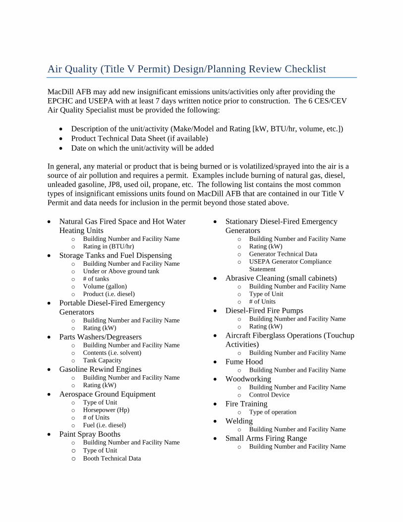
Air Quality (Title V Permit) Design/Planning Review Checklist MacDill AFB may add new insignificant emissions units/activities only after providing the EPCHC and USEPA with at least 7 days written notice prior to construction. The 6 CES/CEV Air Quality Specialist must be provided the following:
• Description of the unit/activity (Make/Model and Rating [kW, BTU/hr, volume, etc.]) • Product Technical Data Sheet (if available) • Date on which the unit/activity will be added
In general, any material or product that is being burned or is volatilized/sprayed into the air is a source of air pollution and requires a permit. Examples include burning of natural gas, diesel, unleaded gasoline, JP8, used oil, propane, etc. The following list contains the most common types of insignificant emissions units found on MacDill AFB that are contained in our Title V Permit and data needs for inclusion in the permit beyond those stated above. • Natural Gas Fired Space and Hot Water
Heating Units o Building Number and Facility Name o Rating in (BTU/hr)
• Storage Tanks and Fuel Dispensing o Building Number and Facility Name o Under or Above ground tank o # of tanks o Volume (gallon) o Product (i.e. diesel)
• Portable Diesel-Fired Emergency Generators
o Building Number and Facility Name o Rating (kW)
• Parts Washers/Degreasers o Building Number and Facility Name o Contents (i.e. solvent) o Tank Capacity
• Gasoline Rewind Engines o Building Number and Facility Name o Rating (kW)
• Aerospace Ground Equipment o Type of Unit o Horsepower (Hp) o # of Units o Fuel (i.e. diesel)
• Paint Spray Booths o Building Number and Facility Name o Type of Unit o Booth Technical Data
• Stationary Diesel-Fired Emergency Generators
o Building Number and Facility Name o Rating (kW) o Generator Technical Data o USEPA Generator Compliance
Statement
• Abrasive Cleaning (small cabinets) o Building Number and Facility Name o Type of Unit o # of Units
• Diesel-Fired Fire Pumps o Building Number and Facility Name o Rating (kW)
• Aircraft Fiberglass Operations (Touchup Activities)
o Building Number and Facility Name
• Fume Hood o Building Number and Facility Name
• Woodworking o Building Number and Facility Name o Control Device
• Fire Training o Type of operation
• Welding o Building Number and Facility Name
• Small Arms Firing Range o Building Number and Facility Name
ATTACHMENT B
NATIONAL ENVIRONMENTAL POLICY ACT (NEPA) & STATE HISTORIC PRESERVATION
OFFICE (SHPO)
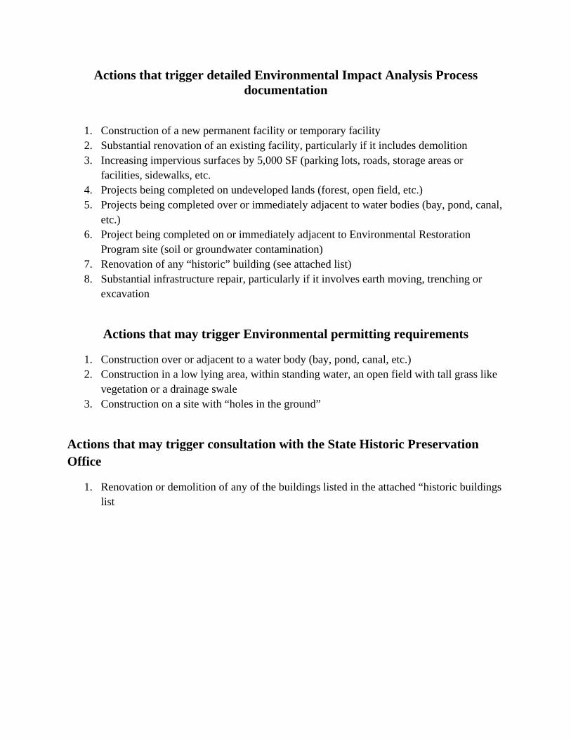
Actions that trigger detailed Environmental Impact Analysis Process documentation
1. Construction of a new permanent facility or temporary facility 2. Substantial renovation of an existing facility, particularly if it includes demolition 3. Increasing impervious surfaces by 5,000 SF (parking lots, roads, storage areas or
facilities, sidewalks, etc. 4. Projects being completed on undeveloped lands (forest, open field, etc.) 5. Projects being completed over or immediately adjacent to water bodies (bay, pond, canal,
etc.) 6. Project being completed on or immediately adjacent to Environmental Restoration
Program site (soil or groundwater contamination) 7. Renovation of any “historic” building (see attached list) 8. Substantial infrastructure repair, particularly if it involves earth moving, trenching or
excavation
Actions that may trigger Environmental permitting requirements
1. Construction over or adjacent to a water body (bay, pond, canal, etc.) 2. Construction in a low lying area, within standing water, an open field with tall grass like
vegetation or a drainage swale 3. Construction on a site with “holes in the ground”
Actions that may trigger consultation with the State Historic Preservation Office
1. Renovation or demolition of any of the buildings listed in the attached “historic buildings list
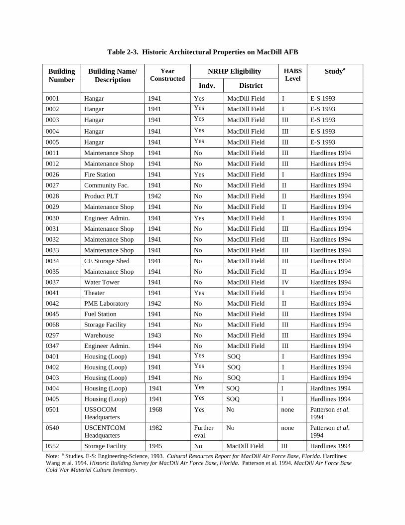
Table 2-3. Historic Architectural Properties on MacDill AFB
BuildingNumber
Building Name/ Description
Year Constructed
NRHP Eligibility HABS Level
Studya
Indv. District
0001 Hangar 1941 Yes MacDill Field I E-S 1993
0002 Hangar 1941 Yes MacDill Field I E-S 1993
0003 Hangar 1941 Yes MacDill Field III E-S 1993
0004 Hangar 1941 Yes MacDill Field III E-S 1993
0005 Hangar 1941 Yes MacDill Field III E-S 1993
0011 Maintenance Shop 1941 No MacDill Field III Hardlines 1994
0012 Maintenance Shop 1941 No MacDill Field III Hardlines 1994
0026 Fire Station 1941 Yes MacDill Field I Hardlines 1994
0027 Community Fac. 1941 No MacDill Field II Hardlines 1994
0028 Product PLT 1942 No MacDill Field II Hardlines 1994
0029 Maintenance Shop 1941 No MacDill Field II Hardlines 1994
0030 Engineer Admin. 1941 Yes MacDill Field I Hardlines 1994
0031 Maintenance Shop 1941 No MacDill Field III Hardlines 1994
0032 Maintenance Shop 1941 No MacDill Field III Hardlines 1994
0033 Maintenance Shop 1941 No MacDill Field III Hardlines 1994
0034 CE Storage Shed 1941 No MacDill Field III Hardlines 1994
0035 Maintenance Shop 1941 No MacDill Field II Hardlines 1994
0037 Water Tower 1941 No MacDill Field IV Hardlines 1994
0041 Theater 1941 Yes MacDill Field I Hardlines 1994
0042 PME Laboratory 1942 No MacDill Field II Hardlines 1994
0045 Fuel Station 1941 No MacDill Field III Hardlines 1994
0068 Storage Facility 1941 No MacDill Field III Hardlines 1994
0297 Warehouse 1943 No MacDill Field III Hardlines 1994
0347 Engineer Admin. 1944 No MacDill Field III Hardlines 1994
0401 Housing (Loop) 1941 Yes SOQ I Hardlines 1994
0402 Housing (Loop) 1941 Yes SOQ I Hardlines 1994
0403 Housing (Loop) 1941 No SOQ I Hardlines 1994
0404 Housing (Loop) 1941 Yes SOQ I Hardlines 1994
0405 Housing (Loop) 1941 Yes SOQ I Hardlines 1994
0501 USSOCOM Headquarters
1968 Yes No none Patterson et al. 1994
0540 USCENTCOM Headquarters
1982 Further eval.
No none Patterson et al. 1994
0552 Storage Facility 1945 No MacDill Field III Hardlines 1994
Note: a Studies. E-S: Engineering-Science, 1993. Cultural Resources Report for MacDill Air Force Base, Florida. Hardlines: Wang et al. 1994. Historic Building Survey for MacDill Air Force Base, Florida. Patterson et al. 1994. MacDill Air Force Base Cold War Material Culture Inventory.
ATTACHMENT C
PETROLEUM, OIL, LUBRICANTS AND STORAGE TANKS
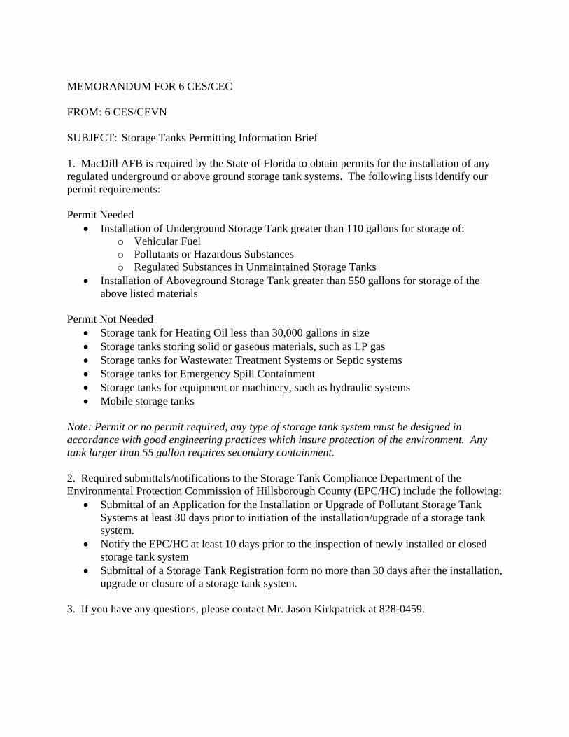
MEMORANDUM FOR 6 CES/CEC FROM: 6 CES/CEVN SUBJECT: Storage Tanks Permitting Information Brief 1. MacDill AFB is required by the State of Florida to obtain permits for the installation of any regulated underground or above ground storage tank systems. The following lists identify our permit requirements: Permit Needed
• Installation of Underground Storage Tank greater than 110 gallons for storage of: o Vehicular Fuel o Pollutants or Hazardous Substances o Regulated Substances in Unmaintained Storage Tanks
• Installation of Aboveground Storage Tank greater than 550 gallons for storage of the above listed materials
Permit Not Needed
• Storage tank for Heating Oil less than 30,000 gallons in size • Storage tanks storing solid or gaseous materials, such as LP gas • Storage tanks for Wastewater Treatment Systems or Septic systems • Storage tanks for Emergency Spill Containment • Storage tanks for equipment or machinery, such as hydraulic systems • Mobile storage tanks
Note: Permit or no permit required, any type of storage tank system must be designed in accordance with good engineering practices which insure protection of the environment. Any tank larger than 55 gallon requires secondary containment. 2. Required submittals/notifications to the Storage Tank Compliance Department of the Environmental Protection Commission of Hillsborough County (EPC/HC) include the following:
• Submittal of an Application for the Installation or Upgrade of Pollutant Storage Tank Systems at least 30 days prior to initiation of the installation/upgrade of a storage tank system.
• Notify the EPC/HC at least 10 days prior to the inspection of newly installed or closed storage tank system
• Submittal of a Storage Tank Registration form no more than 30 days after the installation, upgrade or closure of a storage tank system.
3. If you have any questions, please contact Mr. Jason Kirkpatrick at 828-0459.
ATTACHMENT D
TOXICS ASBESTOS AND LEAD BASED PAINTS
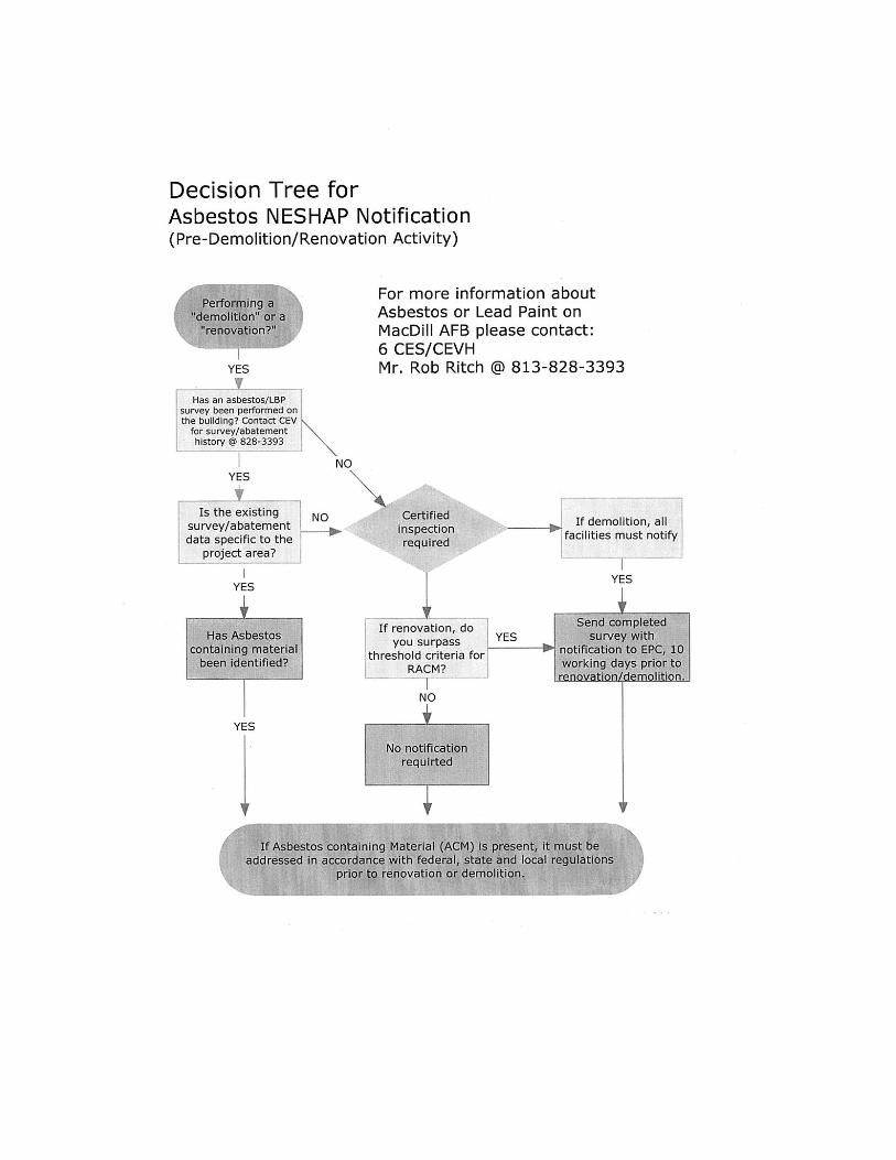
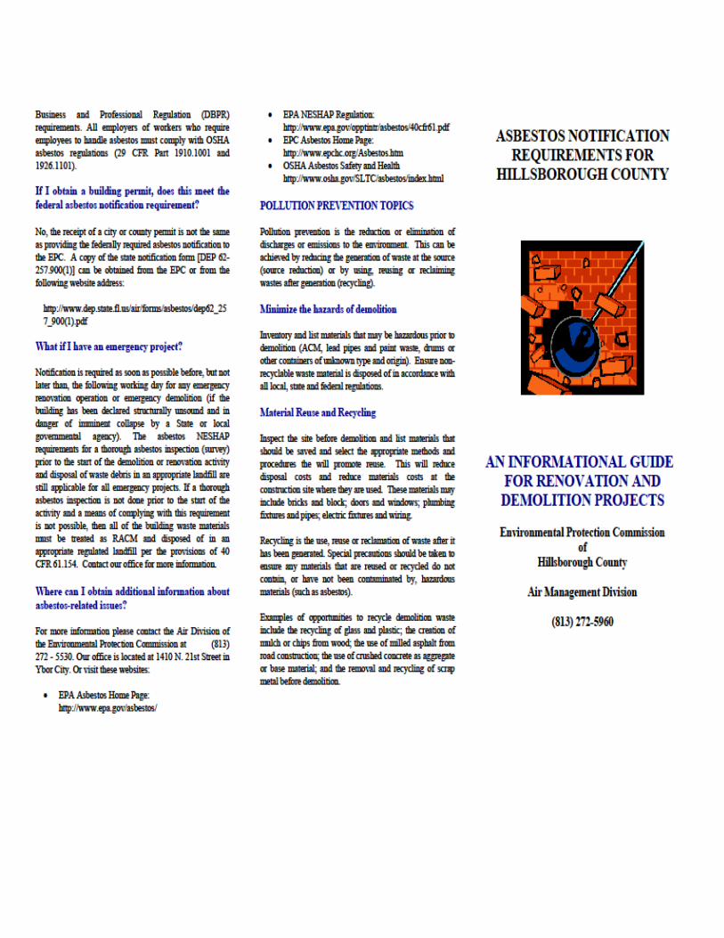
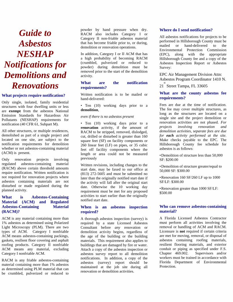
Guide to Asbestos NESHAP
Notifications for Demolitions and
Renovations What projects require notification?
Only single, isolated, family residential structures with four dwelling units or less are exempt from the asbestos National Emission Standards for Hazardous Air Pollutants (NESHAP) requirements for notification (40 CFR 61, Subpart M).
All other structures, or multiple residences, demolished as part of a single project and located on one site, are subject to the notification requirements for demolition whether or not asbestos-containing material (ACM) is present.
Only renovation projects involving regulated asbestos-containing material (RACM) above certain threshold amounts require notification. Written notification is not required for renovation projects where asbestos containing materials are not disturbed or made regulated during the planned activity.
What is Asbestos-Containing Material (ACM) and Regulated Asbestos-Containing Material (RACM)?
ACM is any material containing more than 1% asbestos as determined using Polarized Light Microscopy (PLM). There are two types of ACM. Category I nonfriable ACM means asbestos-containing packings, gaskets, resilient floor covering and asphalt roofing products. Category II nonfriable ACM means any material, excluding Category I nonfriable ACM.
RACM is any friable asbestos-containing material containing more than 1% asbestos as determined using PLM material that can be crumbled, pulverized or reduced to
powder by hand pressure when dry. RACM also includes Category I or Category II non-friable asbestos material that has become friable prior to, or during, demolition or renovation operations.
In addition, Category I or II ACM that has a high probability of becoming RACM (crumbled, pulverized or reduced to powder) during demolition must be removed prior to the start of the demolition activity.
What are the notification requirements?
Written notification is to be mailed or hand-delivered:
• Ten (10) working days prior to a demolition,
even if there is no asbestos present
• Ten (10) working days prior to a renovation activity, if the amount of RACM to be stripped, removed, dislodged, cut, drilled or disturbed is greater than 160 square feet (SF) on facility components or 260 linear feet (LF) on pipes, or 35 cubic feet off facility components where the length or area could not be measured previously
Written revisions, including changes to the start date, may be faxed to our office at (813) 272-5605 and must be submitted no later than the originally notified start date if the activity will fall after the original start date. Otherwise the 10 working day requirement must be met for any proposed activities to start earlier than the originally notified start date.
When is an asbestos inspection required?
A thorough asbestos inspection (survey) is required by a state Licensed Asbestos Consultant before any renovation or demolition activity begins, regardless of the age of the building or the building materials. This requirement also applies to buildings that are damaged by fire or water. Attach a copy of the asbestos inspection or asbestos survey report to all demolition notifications. In addition, a copy of the asbestos (survey) report should be maintained at the job site during all renovation or demolition activities.
Where do I send notification?
All asbestos notifications for projects to be performed in Hillsborough County must be mailed or hand-delivered to the Environmental Protection Commission (EPC), along with the appropriate Hillsborough County fee and a copy of the Asbestos Inspection Report or Asbestos Survey:
EPC Air Management Division Attn: Asbestos Program Coordinator 1410 N.
21st
Street Tampa, FL 33605
What are the county asbestos fee requirements?
Fees are due at the time of notification. The fee may cover multiple structures, as long as the structures are located on a single site and the project demolition or renovation activities are not phased. For projects involving renovation and demolition activities, separate fees are due for each activity performed at the site. Make checks payable to the EPC. The Hillsborough County fee schedule for asbestos is as follows:
• Demolition of structure less than 50,000 SF: $200.00
• Demolition of structure greater/equal to 50,000 SF: $300.00
• Renovation 160 SF/260 LF up to 1000 SF/LF: $300.00
• Renovation greater than 1000 SF/LF: $500.00
Who can remove asbestos-containing material?
A Florida Licensed Asbestos Contractor must perform all activities involving the removal or handling of ACM and RACM. Licensure is not required if certain criteria are met for moving, removal, or disposal of asbestos containing roofing materials, resilient flooring materials, and exterior conduit or piping as specified under F.S. Chapter 469.002. Supervisors and/or workers must be trained in accordance with Florida Department of Environmental Protection.
Where can asbestos be found and when can it be a problem?
Most products made today do not contain asbestos. Those few products made which still contain asbestos that could be inhaled are required to be labeled as such. However, until the 1970s, many types of building products and insulation materials used in construction contained asbestos. Common products that might have contained asbestos in the past and conditions which may release fibers include:
• STEAM PIPES, BOILERS and FURNACE DUCTS insulated with an asbestos blanket or asbestos paper tape. These materials mat release asbestos fibers if damaged, repaired or removed improperly.
• RESILIENT FLOOR TILES (vinyl asbestos, asphalt and rubber), the backing on vinyl sheet flooring and adhesives used for installing floor tile. Sanding, scraping, or grinding can release asbestos fibers.
• CEMENT SHEET, MILLBOARD and PAPER used as insulation around furnaces and wood burning stoves. Repairing or removing appliances may release asbestos fibers. So may cutting, tearing, sanding, drilling or sawing.
• DOOR GASKETS in furnaces, wood stoves and coal stoves. Worn seals can release asbestos fibers during use.
• SOUNDPROOFING or DECORATIVE MATERIALS sprayed on walls and ceilings. Loose, crumbling or water damaged materials may release asbestos fibers. Sanding, drilling or scraping will also result in the release of asbestos fibers.
• PATCHING and JOINT COMPOUNDS for walls and ceilings and some TEXTURED PAINTS. Sanding, scraping or drilling these surfaces may release asbestos fibers.
• ASBESTOS CEMENT ROOFING, SHINGLES and SIDING. These products are not likely to release asbestos fibers unless sawed, drilled or cut.
• ARTIFICIAL ASHES and EMBERS sold for use in gas‐fired fireplaces. Also, other older household products such as FIREPROOF GLOVES, STOVE‐TOP PADS, IRONING BOARD COVERS and certain HAIRDRYERS.
• AUTOMOTIVE BRAKE PADS and LININGS, CLUTCH FACES and GASKETS.
ATTACHMENT E
WASTEWATER AND WATER QUALITY
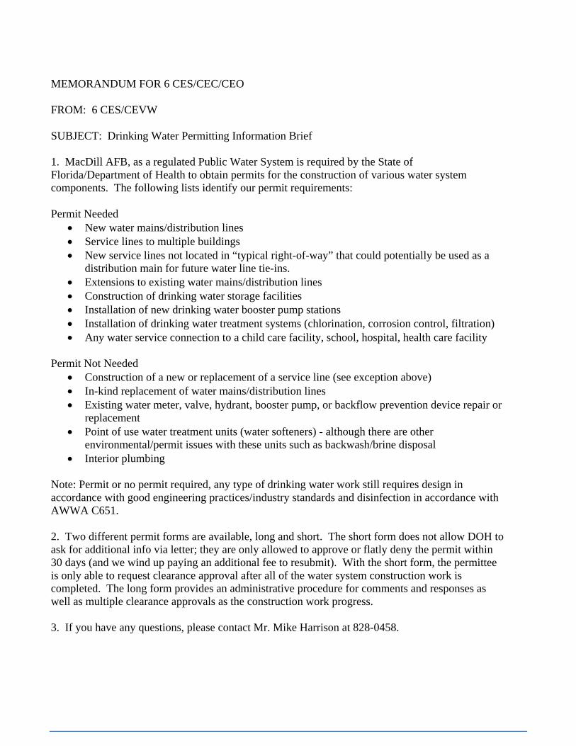
MEMORANDUM FOR 6 CES/CEC/CEO FROM: 6 CES/CEVW SUBJECT: Drinking Water Permitting Information Brief 1. MacDill AFB, as a regulated Public Water System is required by the State of Florida/Department of Health to obtain permits for the construction of various water system components. The following lists identify our permit requirements: Permit Needed
• New water mains/distribution lines • Service lines to multiple buildings • New service lines not located in “typical right-of-way” that could potentially be used as a
distribution main for future water line tie-ins. • Extensions to existing water mains/distribution lines • Construction of drinking water storage facilities • Installation of new drinking water booster pump stations • Installation of drinking water treatment systems (chlorination, corrosion control, filtration) • Any water service connection to a child care facility, school, hospital, health care facility
Permit Not Needed
• Construction of a new or replacement of a service line (see exception above) • In-kind replacement of water mains/distribution lines • Existing water meter, valve, hydrant, booster pump, or backflow prevention device repair or
replacement • Point of use water treatment units (water softeners) - although there are other
environmental/permit issues with these units such as backwash/brine disposal • Interior plumbing
Note: Permit or no permit required, any type of drinking water work still requires design in accordance with good engineering practices/industry standards and disinfection in accordance with AWWA C651. 2. Two different permit forms are available, long and short. The short form does not allow DOH to ask for additional info via letter; they are only allowed to approve or flatly deny the permit within 30 days (and we wind up paying an additional fee to resubmit). With the short form, the permittee is only able to request clearance approval after all of the water system construction work is completed. The long form provides an administrative procedure for comments and responses as well as multiple clearance approvals as the construction work progress. 3. If you have any questions, please contact Mr. Mike Harrison at 828-0458.
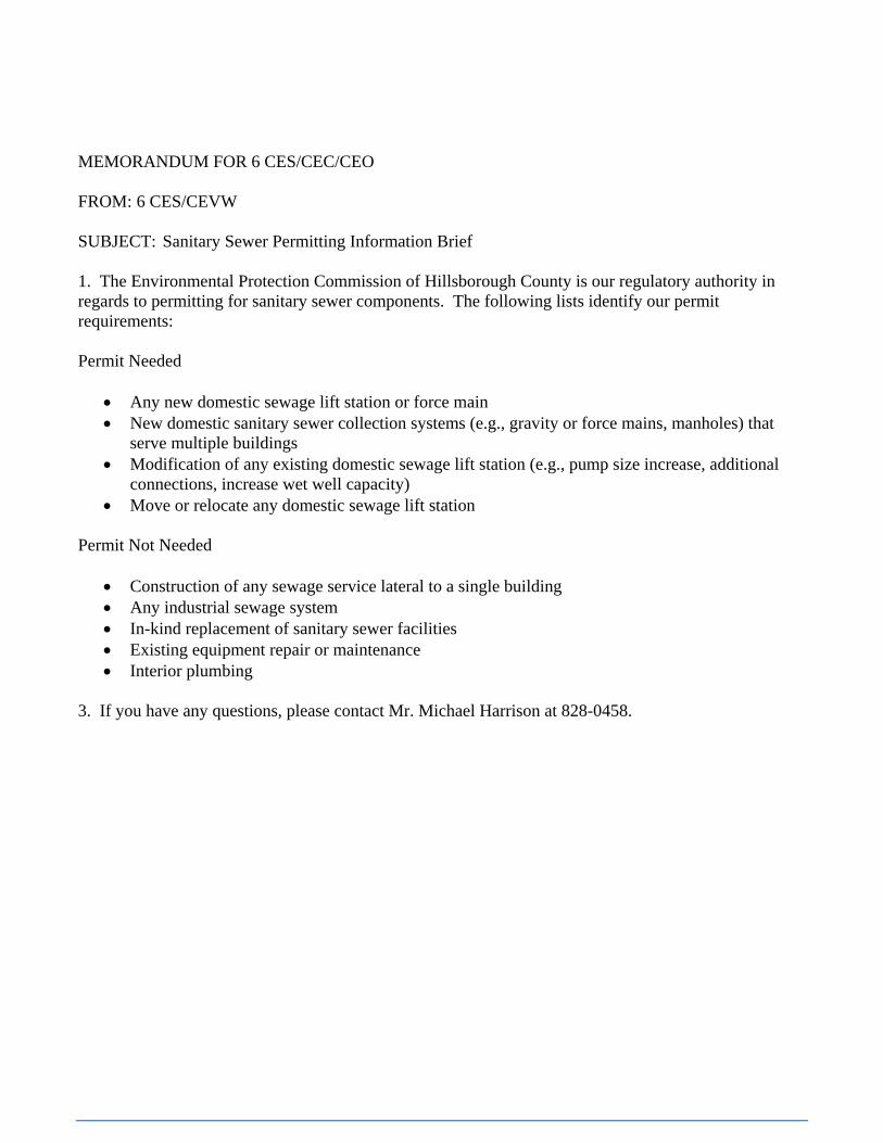
MEMORANDUM FOR 6 CES/CEC/CEO FROM: 6 CES/CEVW SUBJECT: Sanitary Sewer Permitting Information Brief 1. The Environmental Protection Commission of Hillsborough County is our regulatory authority in regards to permitting for sanitary sewer components. The following lists identify our permit requirements: Permit Needed
• Any new domestic sewage lift station or force main • New domestic sanitary sewer collection systems (e.g., gravity or force mains, manholes) that
serve multiple buildings • Modification of any existing domestic sewage lift station (e.g., pump size increase, additional
connections, increase wet well capacity) • Move or relocate any domestic sewage lift station
Permit Not Needed
• Construction of any sewage service lateral to a single building • Any industrial sewage system • In-kind replacement of sanitary sewer facilities • Existing equipment repair or maintenance • Interior plumbing
3. If you have any questions, please contact Mr. Michael Harrison at 828-0458.
MEMORANDUM FOR 6 CES/CEC/CEO FROM: 6 CES/CEVW SUBJECT: Utility System Certification of Completion Information Brief 1. All contractors that install wastewater, stormwater, or drinking water utility systems at MacDill AFB shall ensure that the following procedures are followed. The purpose of these procedures is to maintain 100 percent compliance with Florida Administrative Codes, including all related construction permits issued to the base under these codes. 2. All contractors shall complete the installation of the utility systems only in accordance with approved project specifications and design drawings issued for construction. When complete (including all manholes, electrical connections, sediment removal, cleaning, bacteriological analysis, or pressure testing), the contractor shall have the work inspected by the designated project construction manager. The construction manager shall determine if the work is complete and the system can operate in accordance with the engineering design 3. After the construction manager accepts the utility system as complete and operational, the engineer of record for the project shall immediately complete the Certification of Completion of Construction form. Two copies of the form (including all supporting documentation) and as-built drawings shall be submitted to the base Environmental Flight (6 CES/CEVW) for signature by the base authorities (6 AMW/CC and 6 CES/CC) and submission to the appropriate regulatory agency prior to placing the system into operation. The engineer of record shall ensure that any substantial deviations from the approved plans and specifications are noted in the appropriate section and the forms and drawings are signed and sealed. 4. The construction manager also shall notify 6 CES/CEVW that the utility system is ready for regulatory inspection. 6 CES/CEVW will contact the appropriate regulatory agency and schedule an inspection. This step can occur before the entire construction project is complete as long as the utility system is accepted as ready for operation. The contractor shall ensure that all required regulatory inspections are completed and the systems approved for use before the utility systems are placed into operation. 5. These actions shall not exceed 30 days from the date the system was inspected by the project construction manager and deemed complete and operational. 6. Please contact Mr. Michael Harrison of the base Environmental Flight at 828-0458 if you have any questions regarding these procedures.
MEMORANDUM FOR 6 CES/CEC/CEO FROM: 6 CES/CEVW SUBJECT: On-Site Septic System Information Brief 1. It is 6 CES/CEV policy to connect all domestic wastewater discharges to the existing wastewater collection system and base wastewater treatment plant. However, the WWTP service area does not completely encompass the base and, therefore, MacDill AFB needs to use on-site septic systems for wastewater treatment and disposal. This memo provides information for personnel that will design new, repair/upgrade, or maintain existing on-site septic systems. 2. The regulatory agency responsible for on-site septic systems is the Florida Department of Health (including the local Hillsborough County office) with information and permitting forms posted at http://www.doh.state.fl.us/Environment/ostds/index.html. Permits are required for the following activities: Drainfield Replacement Tank resize/upgrade New tank and drainfield 3. Most State-licensed on-site septic system contractors will obtain the required (the recommended approach) permit with the required site and facility information and can obtain the permit the same day it is applied for. There is a permit fee of about $120. As-builts and a final inspection by DOH are requirements of the permit (typically contractor accomplished). 4. If you have any questions, please contact Mr. Michael Harrison at 828-0458.
MEMORANDUM FOR 6 CES/CEC/CEO FROM: 6 CES/CEVT SUBJECT: Southwest Florida Water Management District (SWFWMD) Stormwater Management System Permitting Information Brief 1. The SWFWMD requires Environmental Resource permits (ERPs) for construction of impervious surface (e.g., pavements, buildings), stormwater management systems (retention ponds, swales, stormwater pipes/culverts), or work in wetlands. The ERPs must include design drawings and a drainage report that meets their Basis of Review requirements before construction begins. For more information please refer to http://www.swfwmd.state.fl.us/permits/erp/. 2. To prevent project delays, 60-90 days should be allowed for the permitting process, although more time may be required if SWFWMD requests additional information. MacDill AFB is the permittee for all projects on base. Application forms will be signed by 6 CES Director. CEV can provide the most recent version of application forms. It is imperative that CEV be included in the permit application process and receives copies of all submittals and communications. Contractors/consultants may not engage SWFWMD without prior CEV approval. Current application fee information can be found in the attached excerpt from Chapter 40D of the Florida Administrative Code. 3. 6 CES is responsible for the operation and maintenance of all constructed and permitted stormwater management systems. The following O&M instructions should be included in SWFWMD applications:
WET POND The system, as designed, will require minimal maintenance, however, the following is noted: 1. Remove all construction sand and silt from detention pond prior to finalizing the construction. 2. Remove sand and silt from around the outfall piping into the pond as may be required. (Frequency will depend upon how roadway and grassed areas of contributing drainage areas are maintained). Care is to be exercised so that sand & silt is removed before it infringes on the littoral shelf. 3. Check orifice or weir at the control structure at least yearly to assure that it is free of debris, which may have an effect on hydraulic functions. 4. Do not use herbicides or other chemicals in the pond, which will damage or kill vegetation on the littoral shelf. 5. Monitor the littoral shelf including submittal of brief report to SWFWMD every 3 months for the first year and every 6 months for the following 2 years. The report submitted is to be brief and is to include a photograph along with a status report on the shelf condition. At the end of the 3-year reporting period the planted littoral shelf species shall show an 85% survival rate. Modifications to the shelf shall be made if it is found that this survival rate cannot be met. DRY POND The system, as designed, will require minimal maintenance, however, the following is noted: 1. Remove all construction sand and silt from treatment / detention pond prior to finalizing the construction. 2. Remove sand and silt from around the outfall piping into the pond as may be required (frequency will depend upon how roadway/parking lot and grassed areas of contributing drainage areas are maintained). Care is to be exercised so that sand & silt is removed before it interferes with the control structure operation and pond treatment volume. 3. Inspect the operation of the underdrains. if treatment volume is not restored within 72 hours following a storm event the underdrain may require maintenance. 4. Check the skimmer and weir at the control structure at least yearly to assure that it is free of debris, which may have an effect on hydraulic functions. 3. If you have any questions, please contact Mr. Eric Vichich at 828-0460.
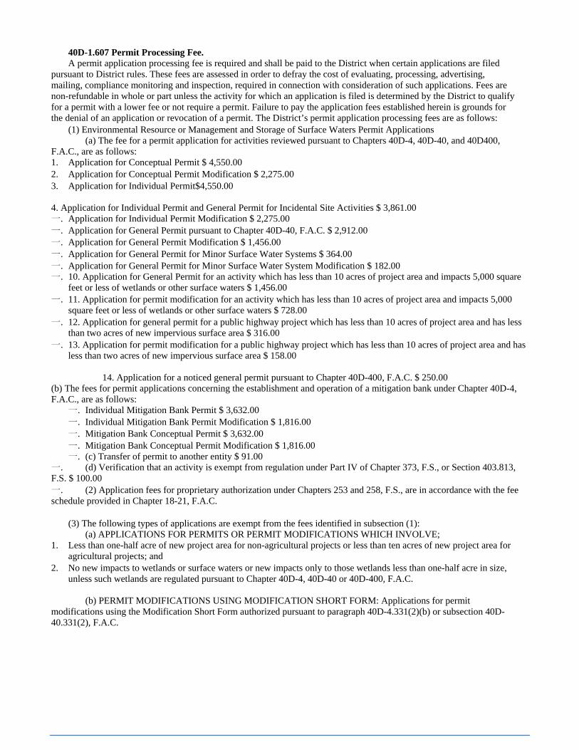
40D-1.607 Permit Processing Fee. A permit application processing fee is required and shall be paid to the District when certain applications are filed
pursuant to District rules. These fees are assessed in order to defray the cost of evaluating, processing, advertising, mailing, compliance monitoring and inspection, required in connection with consideration of such applications. Fees are non-refundable in whole or part unless the activity for which an application is filed is determined by the District to qualify for a permit with a lower fee or not require a permit. Failure to pay the application fees established herein is grounds for the denial of an application or revocation of a permit. The District’s permit application processing fees are as follows:
(1) Environmental Resource or Management and Storage of Surface Waters Permit Applications (a) The fee for a permit application for activities reviewed pursuant to Chapters 40D-4, 40D-40, and 40D400,
F.A.C., are as follows: 1. Application for Conceptual Permit $ 4,550.00 2. Application for Conceptual Permit Modification $ 2,275.00 3. Application for Individual Permit$4,550.00 4. Application for Individual Permit and General Permit for Incidental Site Activities $ 3,861.00 一. Application for Individual Permit Modification $ 2,275.00 一. Application for General Permit pursuant to Chapter 40D-40, F.A.C. $ 2,912.00 一. Application for General Permit Modification $ 1,456.00 一. Application for General Permit for Minor Surface Water Systems $ 364.00 一. Application for General Permit for Minor Surface Water System Modification $ 182.00 一. 10. Application for General Permit for an activity which has less than 10 acres of project area and impacts 5,000 square
feet or less of wetlands or other surface waters $ 1,456.00 一. 11. Application for permit modification for an activity which has less than 10 acres of project area and impacts 5,000
square feet or less of wetlands or other surface waters $ 728.00 一. 12. Application for general permit for a public highway project which has less than 10 acres of project area and has less
than two acres of new impervious surface area $ 316.00 一. 13. Application for permit modification for a public highway project which has less than 10 acres of project area and has
less than two acres of new impervious surface area $ 158.00
14. Application for a noticed general permit pursuant to Chapter 40D-400, F.A.C. $ 250.00 (b) The fees for permit applications concerning the establishment and operation of a mitigation bank under Chapter 40D-4, F.A.C., are as follows:
一. Individual Mitigation Bank Permit $ 3,632.00 一. Individual Mitigation Bank Permit Modification $ 1,816.00 一. Mitigation Bank Conceptual Permit $ 3,632.00 一. Mitigation Bank Conceptual Permit Modification $ 1,816.00 一. (c) Transfer of permit to another entity $ 91.00
一. (d) Verification that an activity is exempt from regulation under Part IV of Chapter 373, F.S., or Section 403.813, F.S. $ 100.00 一. (2) Application fees for proprietary authorization under Chapters 253 and 258, F.S., are in accordance with the fee schedule provided in Chapter 18-21, F.A.C.
(3) The following types of applications are exempt from the fees identified in subsection (1): (a) APPLICATIONS FOR PERMITS OR PERMIT MODIFICATIONS WHICH INVOLVE;
1. Less than one-half acre of new project area for non-agricultural projects or less than ten acres of new project area for agricultural projects; and
2. No new impacts to wetlands or surface waters or new impacts only to those wetlands less than one-half acre in size, unless such wetlands are regulated pursuant to Chapter 40D-4, 40D-40 or 40D-400, F.A.C.
(b) PERMIT MODIFICATIONS USING MODIFICATION SHORT FORM: Applications for permit
modifications using the Modification Short Form authorized pursuant to paragraph 40D-4.331(2)(b) or subsection 40D-40.331(2), F.A.C.

ATTACHMENT F
GREEN PROCUREMENT PROGRAM
MACDILL AFB
GREEN PROCUREMENT PROGRAM
Fact Sheet Most projects require compliance with MacDill’s Green Procurement Program. The GPP mandatory purchasing lists include such common items as: carpet, insulation, cement, paint and roof coatings. The Green Procurement Program, also known as the GPP, is a purchasing program to protect the environment and reduce energy consumption with environmentally friendly goods and services. The GPP includes six mandatory program elements and one voluntary element. The mandatory programs are:
Products manufactured from recycled and reclaimed materials as identified in EPA’s Comprehensive Procurement Guideline (CPG). Biobased products identified by USDA are made from rapidly renewable plant materials (usually agricultural products). Examples include straw-board construction panels, soy inks, vegetable-based lubricating oils, and “plastics” made from starch.
Energy Star® labeled lighting equipment, roofing products, heating and cooling systems and appliances, or Low Standby Power office equipment that switches into a “sleep” mode, are examples of energy-efficient products.
The EPA SNAP Program lists alternatives to ozone-depleting substances.
Substitutes for the EPA Priority Chemicals(lead, PCB, mercury, naphthalene, and cadmium) are identified by the base pollution prevention program.
It’s the Law!______________________________________________________________________ GPP was originally authorized under the Resource Conservation and Recovery Act (RCRA), which requires federal agencies to “give preference in their purchasing programs to products and practices that conserve and protect natural resources and the environment.” Executive Order (EO) 13423, “Strengthening Federal Environmental, Energy, and Transportation Management”, fully explains the GP program elements. The 2002 “Farm Bill” requires us to purchase biobased products. The Energy Policy Act and EO 13123 require us to purchase energy efficient products and AFVs. The Federal Acquisition Regulations (FAR) Subparts 23.2, 23.4, 23.7 and 23.8 support these requirements. GPP applies to commodity purchases, construction contracts, service contracts, items bought from base supply stores, items used for in-house construction and services, and everything else purchased by Air Force personnel and their contractors.
Purchases of alternative fueled vehicles (AFV), alternative fuels and fuel efficient vehicles are required for Federal fleets and supported by GSA and DLA.
The voluntary program element, Environmentally Preferable Purchasing, promotes purchase of goods and services that have lesser or decreased effects on human health and the environment compared to competing goods that serve the same purpose.
Why “buy green”? • Benefit the environment by conserving
resources, preventing waste, reducing landfill space, conserving energy and water, and reducing pollution.
• Reduce life cycle costs and stimulate recycling markets.
• Close the recycling loop by purchasing products made from materials that have been recycled.
• Show the USAF’s commitment to environmental stewardship.
• Demonstrate compliance with laws, regulations and executive orders.

It is everyone’s responsibility to comply with GPP requirements. Government-wide Purchase Card (GPC) purchases, purchase orders, and contracts must all address the procurement or use of GPP items, regardless of the amount of money to be spent. Contract statements of work (SOWs) and specifications and service contract Performance Work Statements must require the use of GPP-compliant items. The GPP requirements are outlined in the base GPP Plan. Training and documentation are critical elements in achieving compliance with these requirements. See the Air Force Guide to Green Purchasing (at AFCEE web link below) for more information.
Here are additional resources for more information on the GPP: MacDill Environmental POC: Eric Vichich, 828-0460, [email protected] The “USAF Guide to Green Purchasing:” http://www.afcee.brooks.af.mil/eq/ap/gg/guide.doc Additional information by program element: -Recovered/recycled materials: http://epa.gov/cpg -USDA Biobased: http://www.biobased.oce.usda.gov/fb4p/Default.aspx -EnergyStar items: http://www.energystar.gov/products -FEMP Low Power Standby devices: http://oahu.lbl.gov -ODSs (Ozone Depleting Substances): http://www.epa.gov/ozone/snap/lists/index.html
Are there any exemptions from having to buy compliant recycled-content or biobased products?
Yes. The following are acceptable reasons for not buying a compliant product:
• Product costs more than a comparable non-recycled/biobased product • Product does not meet reasonable technical requirements • Product is not available competitively within a reasonable period of time
Where can I buy GPP-compliant products? Many GPP-compliant goods are available from the purchasing programs already known to you, and other resources that are relatively new:
√ Javits-Wagner-O’Day (JWOD) Procurement List products can be purchased from office supply stores or online. In the JWOD Catalog, http://www.nib.org/JWOD%20Catalog/index.html, look for the recycling symbol and the earth-friendly JWOD logo.
√ The Biobased Manufacturers Association offers an online catalog of biobased products: www.thefarmdepot.com/tfd/bma/departments.jsp
√ For Federal Prison Industries, Inc. (UNICOR) products and services, see www.unicor.gov. Visit http://www.unicor.gov/about/erecycle.htm for information on their environmental initiatives.
√ Energy Star® and FEMP computers and other information technology products are available through the AFWay Computer Store purchasing system. See www.energystar.gov/products for information about other energy efficient products.
√ Visit the Alternative Fuels Data Center for information about AFVs and alternative fuels: http://www.eere.energy.gov/afdc/
√ EPA’s EPP Database is a comprehensive source of information about environmentally preferable products: http://yosemite1.epa.gov/oppt/eppstand2.nsf
Green Procurement Requirements Reference Sheet
Select Sources of Supply GSA: http://www.gsa.gov/environ DLA:
http://www.dscr.dla.mil/catalogs/catalog.htm Energy Star®: http://www.energystar.gov/ (note:
Energy Star® does not sell products, but provides a list of manufacturers and their certified products) JWOD:
http://www.nib.org/JWOD%20Catalog/index.html UNICOR: www.unicor.gov/about/erecycle.htm FEMP: http://oahu.lbl.gov/cgi-bin/search_data.pl
Determining EPP Attributes for Specific Purchase Types • For paints, carpet, office supplies, cleaners and particle board purchases: http://www.greenseal.org/recommendations.htm • For cleaners: http://www.epa.gov/opptintr/epp/cleaners/select/ For construction projects:
http://www.epa.gov/opptintr/epp/tools/bees.htm
GPP Compliant Product Listings
• CPG: http://www.epa.gov/cpg/products.htm (see reverse side of this page for the 2004 list of recycled-content products)
• Biobased: http://www.biobased.oce.usda.gov/fb4p/Default.aspx
• FEMP: http://oahu.lbl.gov
• Energy Star: http://www.energystar.gov/index.cfm?fuseaction=find_a_product.
• Alternatives to Ozone-Depleting Substances: http://www.epa.gov/ozone/snap/lists/index.html
Resources for EPP Product Selection EPA Database of Environmentally Preferable Products and Services: http://yosemite1.epa.gov/oppt/eppstand2.nsf
The EPA-designated CPG items are:
Construction Products __Carpet __Carpet Cushion __Cement and Concrete __Floor Tile/Patio Blocks __Flowable Fill
__Insulation __Latex Paint __Laminated Paperboard __Modular Threshold Ramps __Non-Pressure Pipe
__Railroad Grade Crossing Surfaces __Roofing Materials __Shower/Restroom Dividers __Structural Fiberboard
Landscaping Products __Compost from Yard/Food Waste __Compost from Manure/Biosolids
__Garden/Soaker Hoses __Fertilizers
__Lawn and Garden Edging __Plastic Timbers and Posts
Non-Paper Office Products __Binders __Clipboards (Plastic) __Plastic File Folders __Plastic Clip Portfolios __Plastic Presentation Folders
__Office Furniture __Office Recycling Containers __Office Waste Containers __Plastic Desktop Accessories __Plastic Envelopes
__Plastic Trash Bags __Remanufactured Printer Ribbons __Remanufactured Toner Cartridges
Paper and Paper Products __Printing and Writing Paper __Newsprint __Bathroom Tissue __Paper Towels __Paper Napkins __Facial Tissue
__General Purpose Industrial Wipers __Corrugated Containers __Solid Fiber Boxes __Folding Cartons __Industrial Paperboard (tubes, cores, drums)
__Misc. (book covers, mailing tubes, pad backs) __Padded Mailers __Carrierboard __Brown Papers (Wrapping Paper and Bags)__Tray Liners (Place Mats)
Park and Recreation Products __Benches and Picnic Tables __Plastic Fencing
__Playground Equipment __Rubber/Plastic Running Tracks
__Rubber/Plastic Playground Surfaces
Transportation Products __Channelizers __Concrete __Delineators
__Flexible Delineators __Parking Stop __Traffic Barricades
__Traffic Cones
Vehicular Products __Engine Coolants __Rebuilt Vehicular Parts
__Re-refined Lubricating Oils __Retread Tires
Miscellaneous Products __Awards/Plaques __Bike Racks __Blasting Grit
__Industrial Drums __Manual-Grade Strapping __Mats
__Pallets __Signs and Posts __Sorbents
The USDA-designated biobased items are:
___ Mobile Equipment Hydraulic Fluid ___ Roof Coatings
___ Water Tank Coatings ___ Diesel Fuel Additives
___ Penetrating Lubricants ___ Bedding, Bed Linens and Towels
___ Adhesive and Mastic Removers ___ Insulating Foam for Wall Construction ___ Hand Cleaners and Sanitizers ___ Composite Panels ___ Fluid-filled Transformers ___ Biodegradable Containers ___ Fertilizers ___ Metalworking Fluids ___ Sorbents ___ Graffiti and Grease Removers
___ 2-Cycle Engine Oils ___ Lip Care Products ___ Biodegradable Films ___ Stationary Equipment Hydraulic Fluids ___ Biodegradable Cutlery ___ Glass Cleaners ___ Greases ___ Dust Supressants ___ Carpets ___ Carpet and Upholstery Cleaners
___ Bath and Tile Cleaners ___ Clothing Products ___ Concrete and Asphalt Release Fluids ___ Cutting, Drilling and Tapping Oils ___ De-icers ___ Durable and Plastic Films ___ Firearm Lubricants ___ Floor Strippers ___ Laundry Products ___ Wood and Concrete Sealers
The EnergyStar and/or FEMP Low-Power Standby Devices are:
___ Battery Chargers ___ Clothes Washers ___ Dehumidifiers ___ Dishwashers ___ Refrigerators & Freezers
___ Air-source Heat Pumps ___ Boilers ___ Central AC ___ Ceiling Fans ___ Furnaces
___ Home Sealing (Insulation and Air Sealing) ___ Roof Products ___ Windows, Doors & Skylights ___ Cordless Phones
___ Room AC ___ Room Air Cleaners ___ Water Coolers ___ Computers ___ Copiers ___ Fax Machines ___ Laptops ___ Mailing Machines ___ Monitors ___ Multifunction Devices ___ Printers ___ Scanners ___ Water Coolers
___ Geothermal Heat Pumps ___ Home Sealing (Insulation) ___ Light Commercial ___ Programmable Thermostats ___ Ventilating Fans ___ Compact Fluorescent Light Bulbs (CFLs) ___ Residential Light Fixtures ___ Ceiling Fans ___ Exit Signs ___ Traffic Signals ___ Transformers ___ Vending Machines
___ Combination Units (TVs) ___ DVD Products ___ External Power Adapters ___ Home Audio ___ Televisions ___ VCRs ___ Commercial Fryers ___ Commercial Hot Food Holding Cabinets ___ Commercial Solid Door Refrigerators and Freezers ___ Commercial Steam Cookers
ATTACHMENT G
HAZARDOUS MATERIALS AND UPS
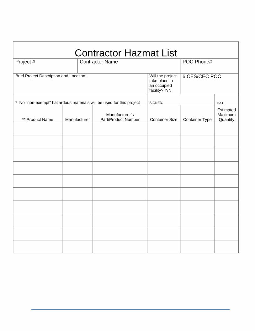
Contractor Hazmat List Project # Contractor Name POC Phone#
Brief Project Description and Location: Will the project take place in an occupied facility? Y/N
6 CES/CEC POC
* No "non-exempt" hazardous materials will be used for this project SIGNED: DATE
** Product Name Manufacturer Manufacturer's
Part/Product Number Container Size Container Type
Estimated Maximum Quantity
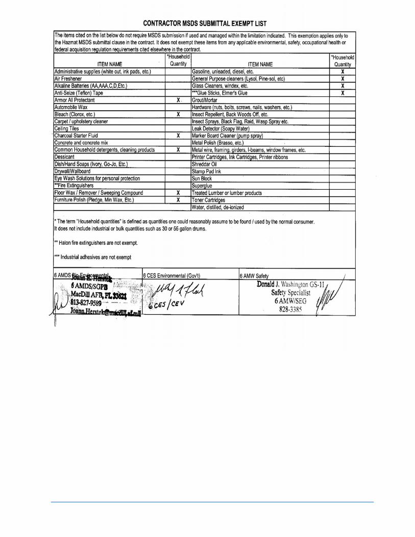

Uninterruptible Power Supply Data Sheet
Building # Room # Org UPS Make / Model Battery
Make/Model
Total Quantity of Batteries


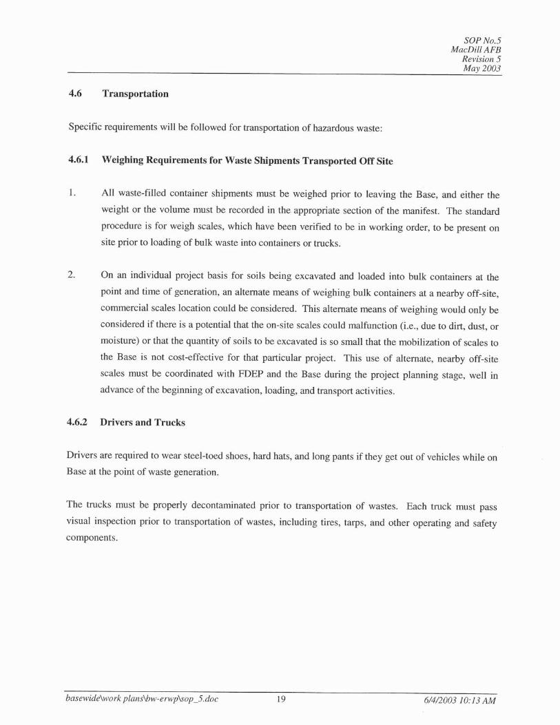
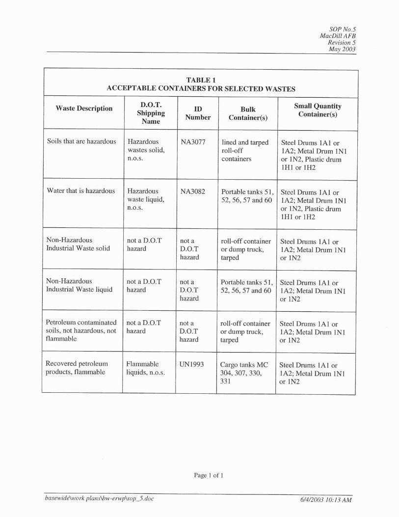
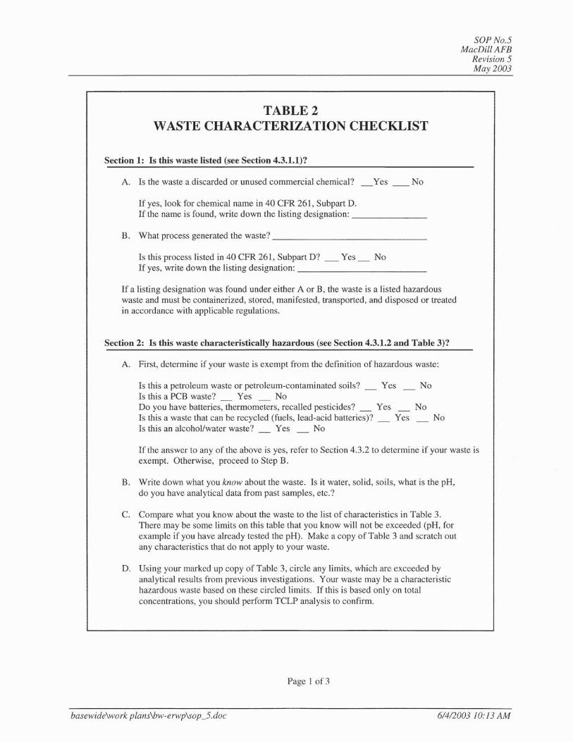
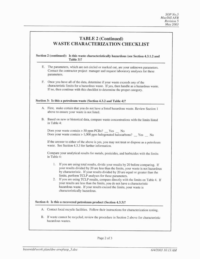
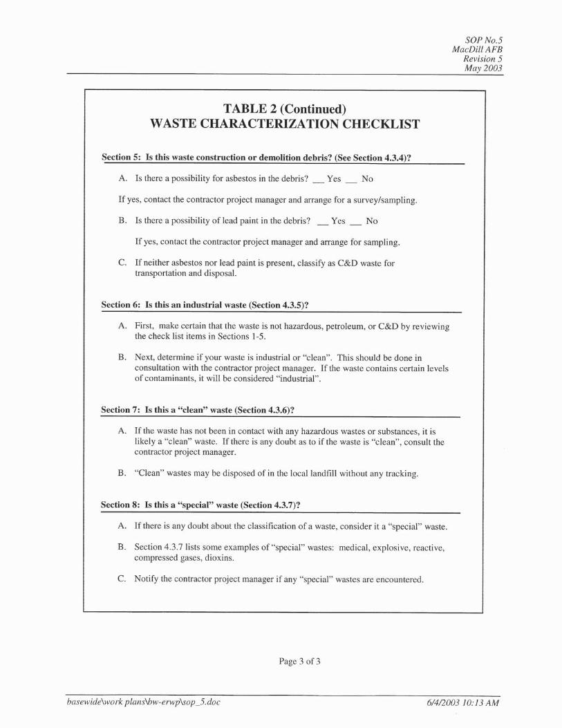
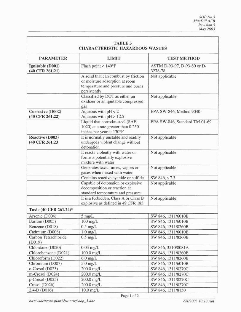
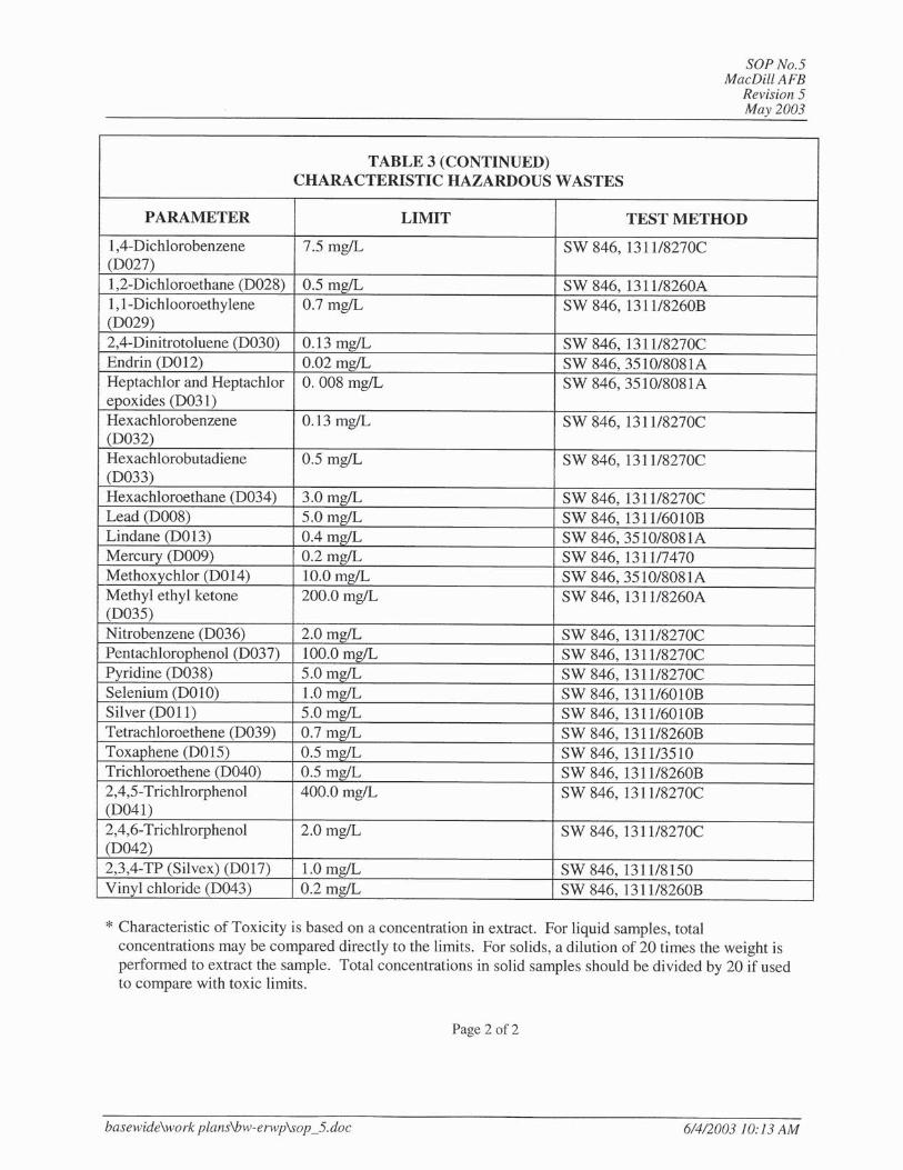

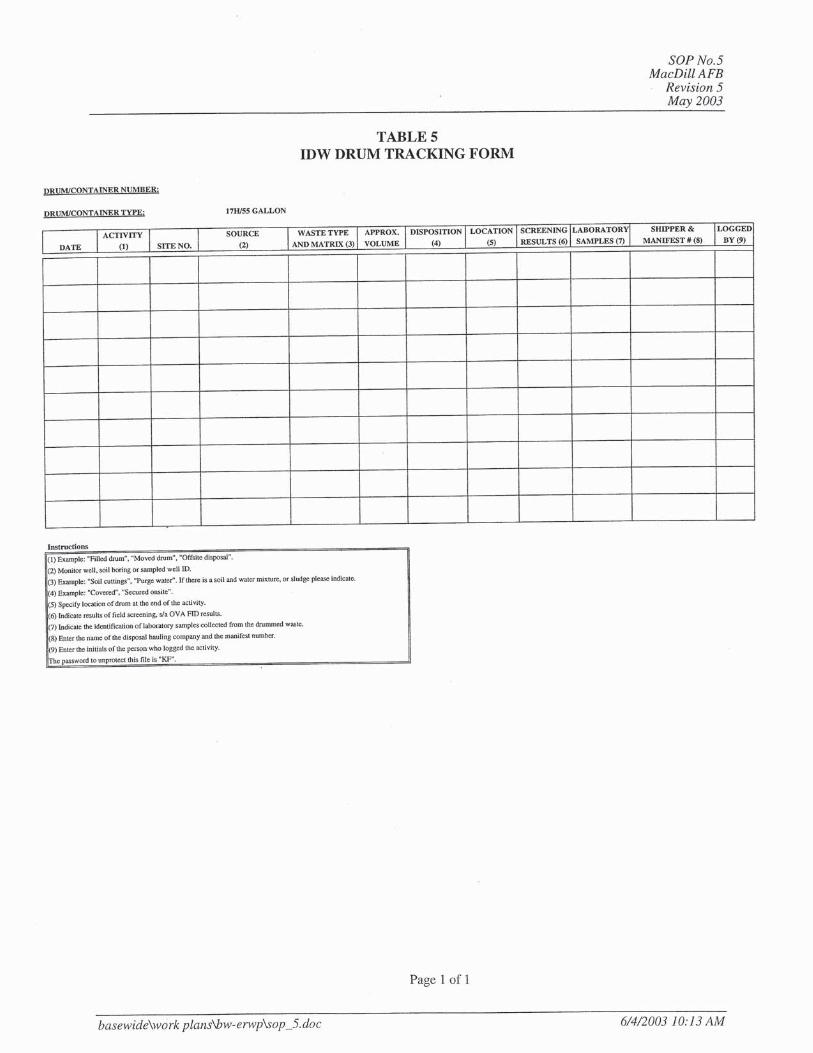
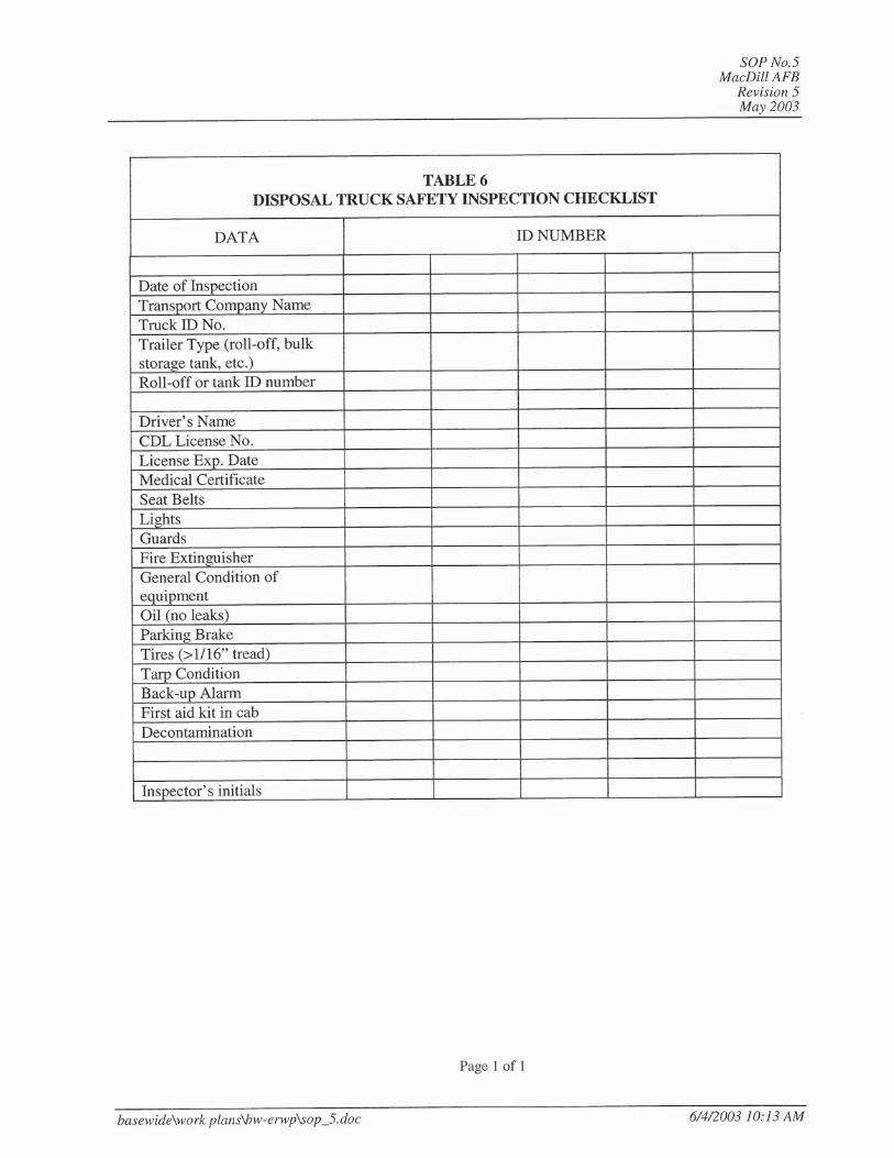
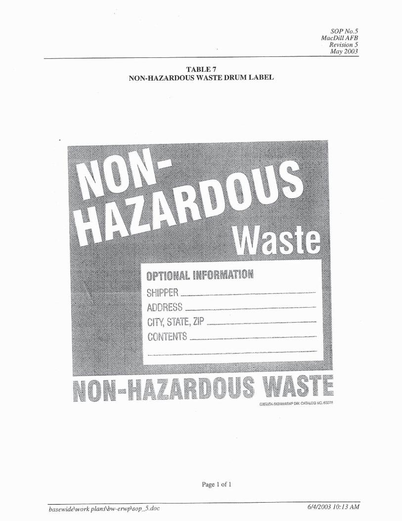
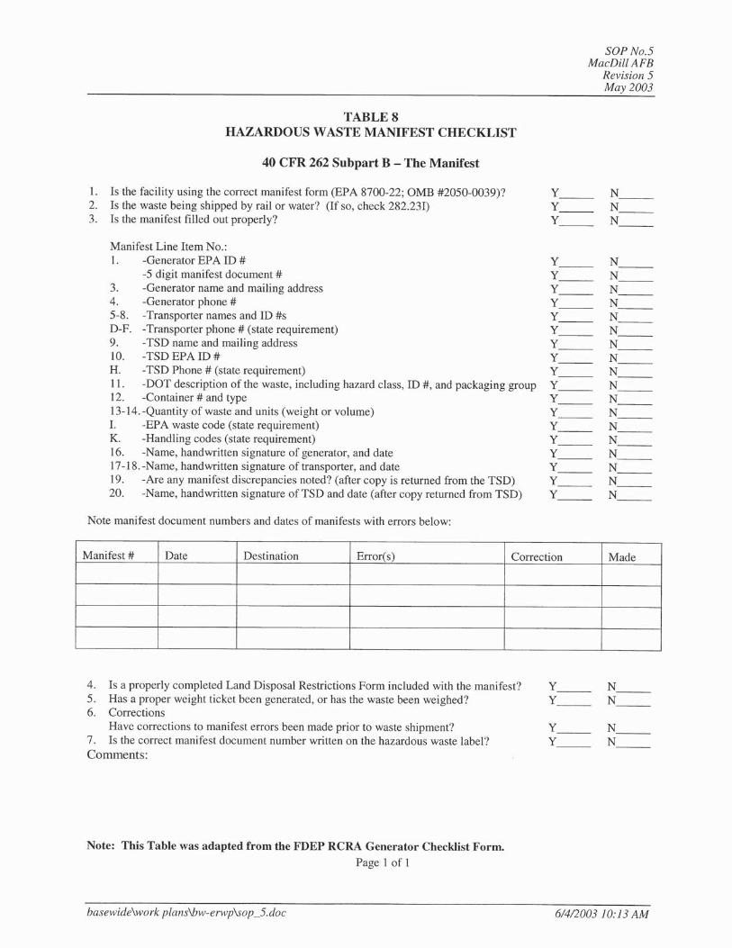


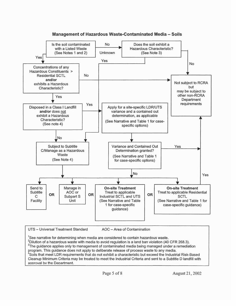
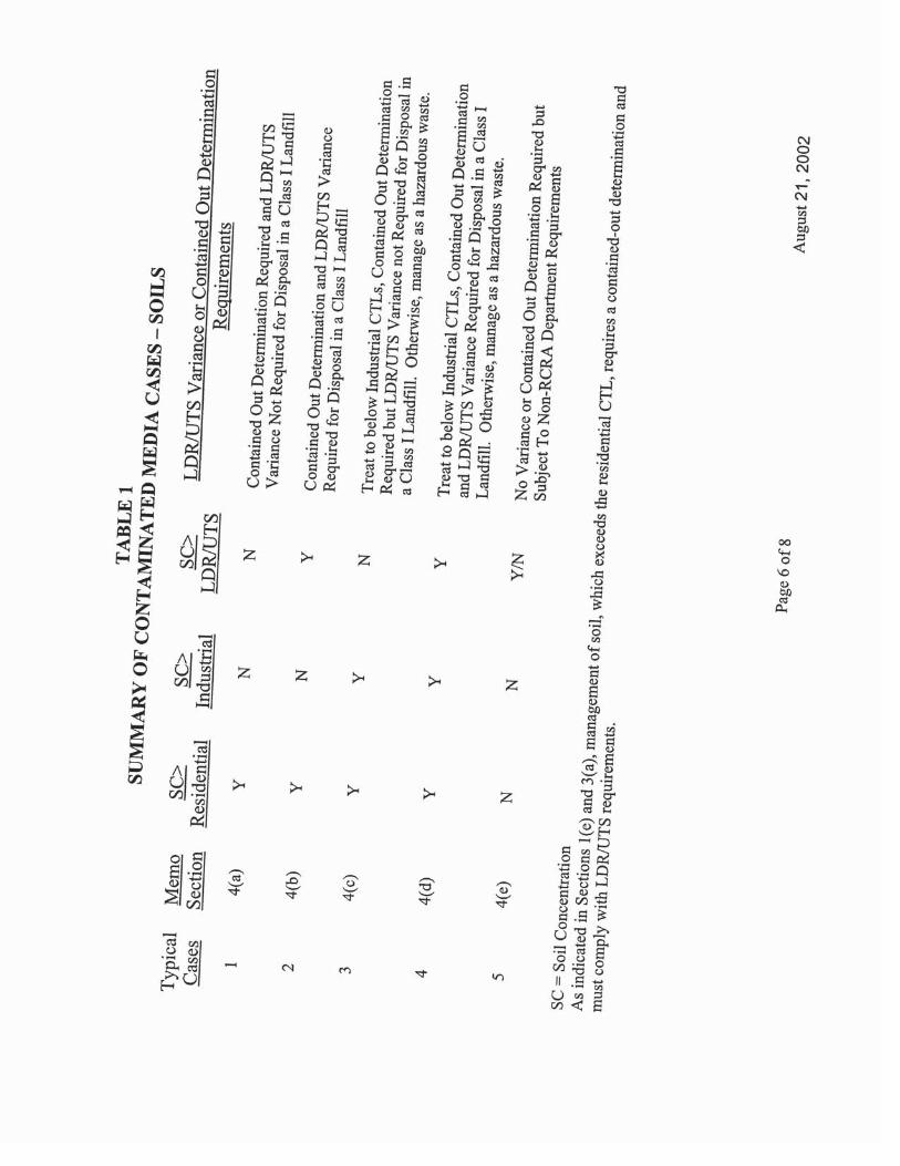
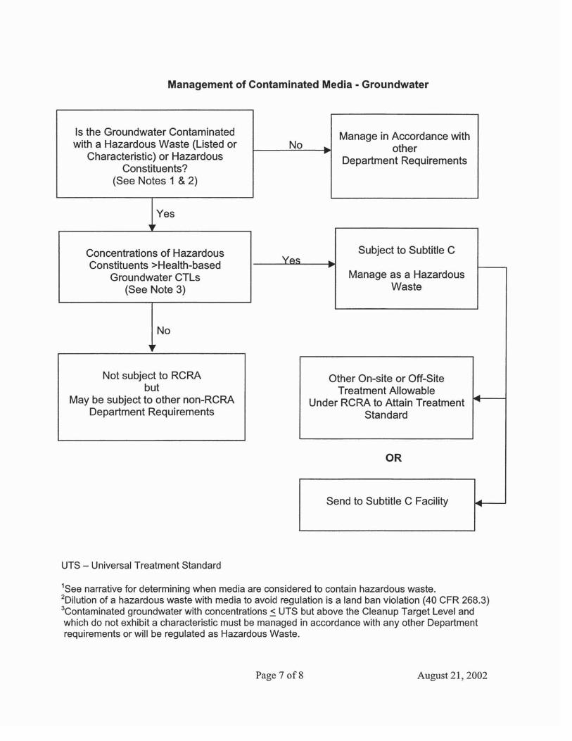
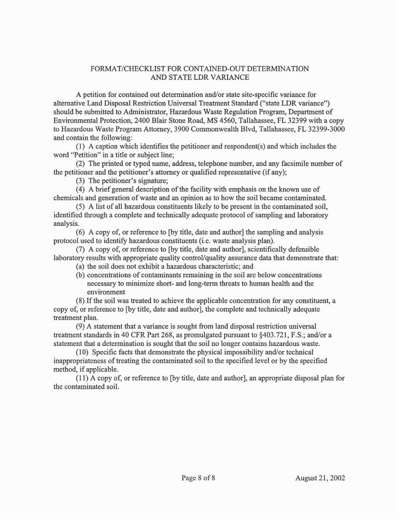
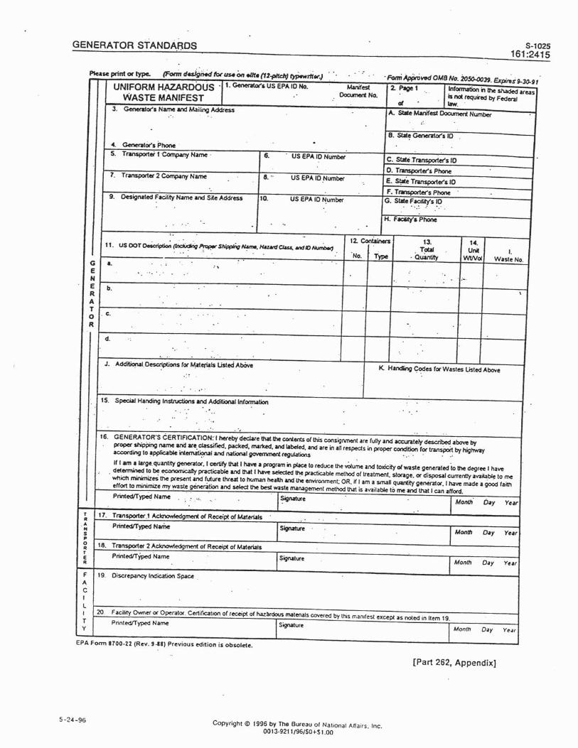
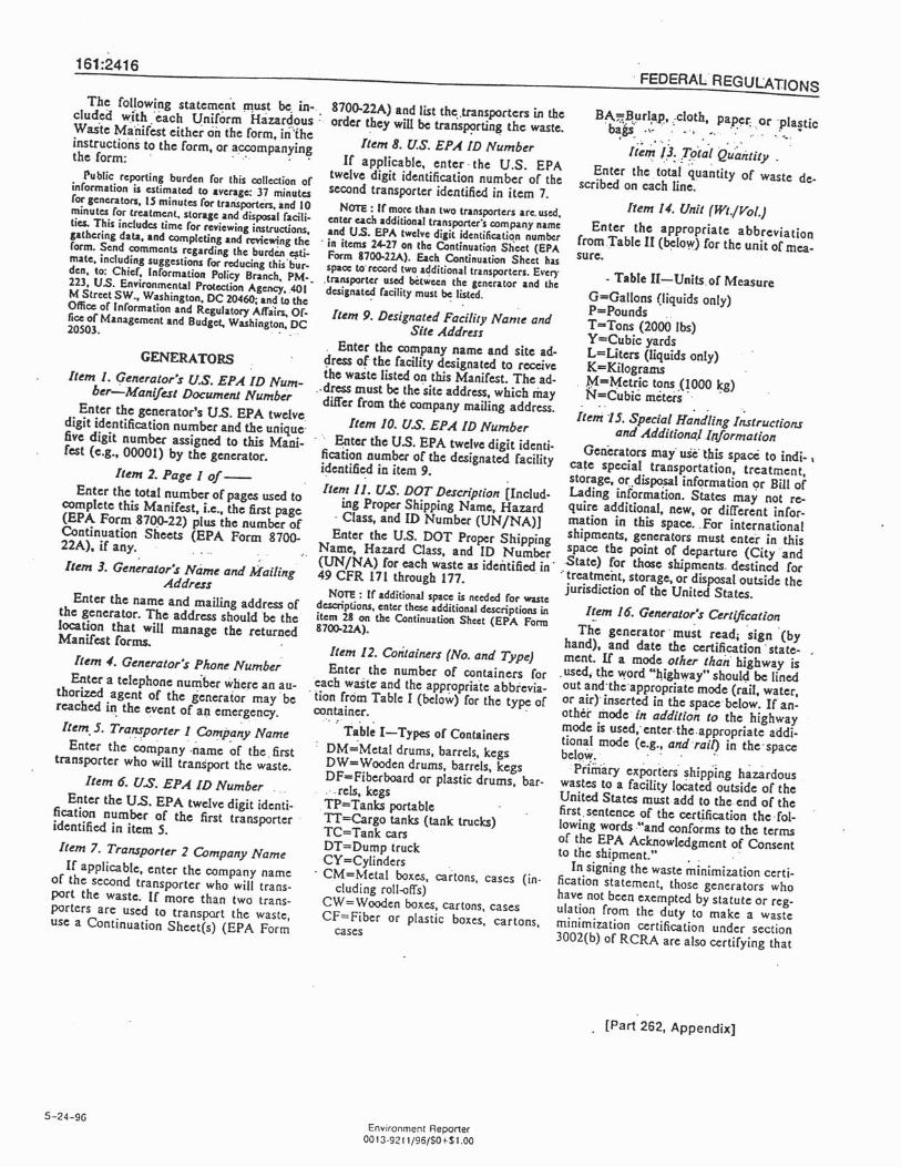
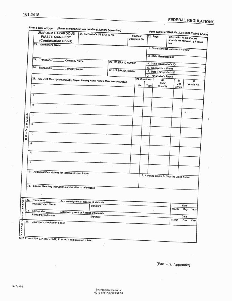
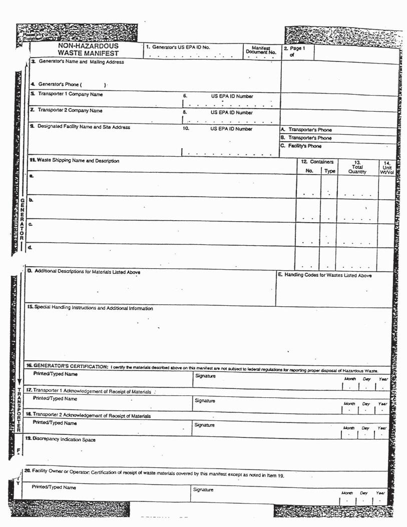


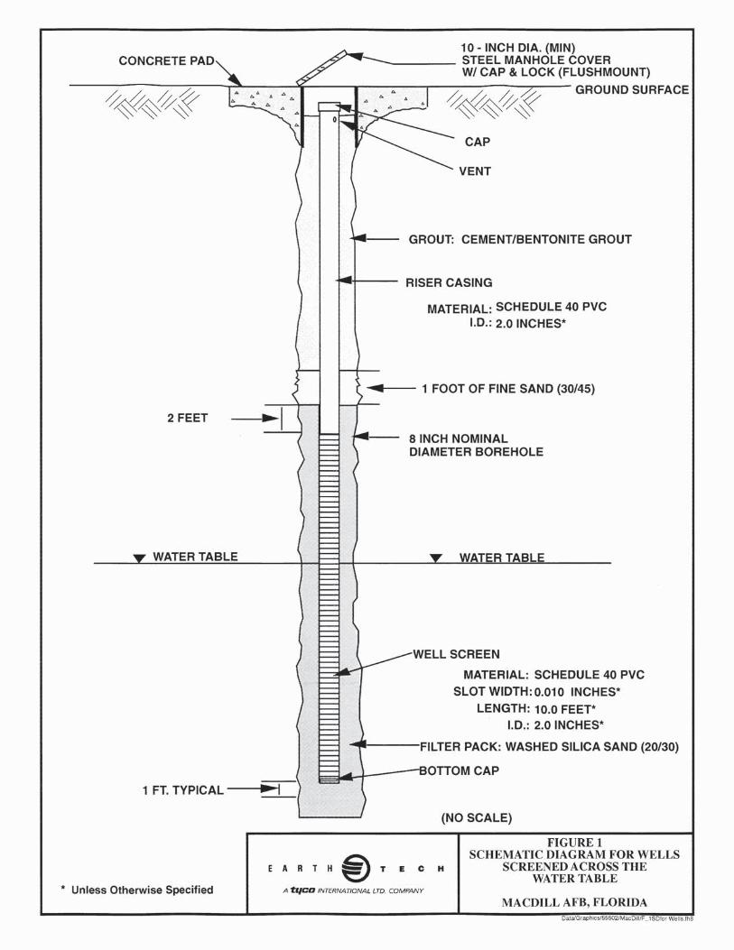
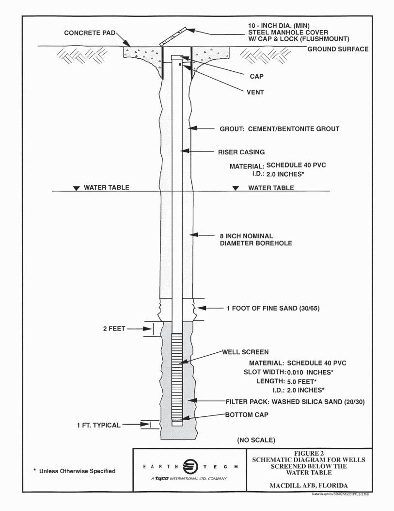
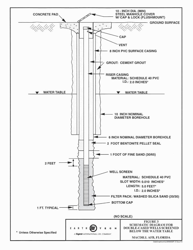
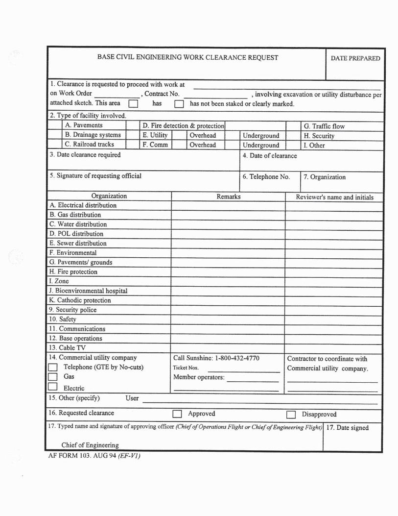
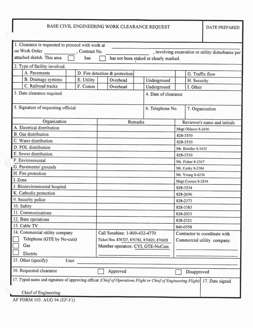
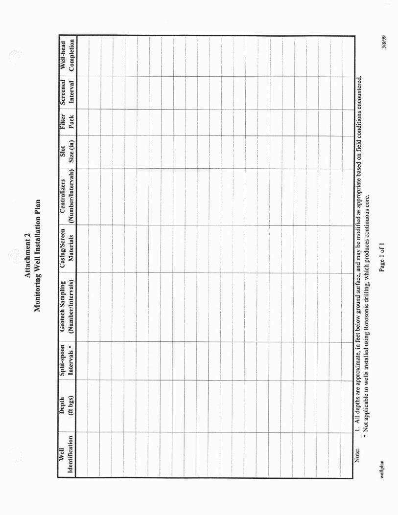
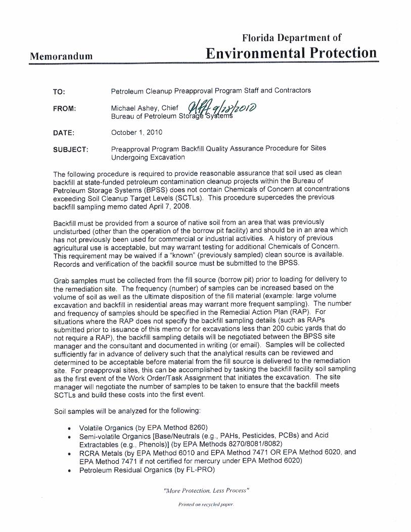
SELECTED SECTIONS OF THE UTILITY PRIVATIZATION AGREEMENT
See the following pages for information. Only a partial document is included. If the entire document is required to complete the design is can be requested by the Contractor through the Government.
UPGRADES / CONNECTIONS AND RENEWALS AND REPLACEMENTS
C.11 SDCs / Upgrades / Connections and Renewals and Replacements C.11.1 Due Diligence Adjustment C.11.2 SDCs / Upgrades / Connections and Renewals and Replacements C.11.2.1 Initial System Deficiency Corrections / Connections Charges C.11.2.2 Future System Deficiency Correction / Connections charges C.11.2.2 Future System Deficiency Corrections / Connections Charges C.11.2.3 Renewal and Replacements C.11.2.4 Annual System Deficiency Corrections / Upgrades / Connections and Renewals and
Replacement Plan C.11.2.4.1 Initial System Deficiency Corrections / Upgrades / Connections and Renewals and
Replacement Plan. C.11.2.4.2 Annual system Deficiency Corrections/Upgrades/Connections and Renewal Replacement
Plan. C.11.2.5 SDCs / Upgrades C.11.2.6 Renewals and Replacements C.11.2.7 Requirements and Standards C.11.2.8 Anticipated Connection and Disconnections C.11.3 Connections and Disconnections C.11.3.1 Temporary Connections C.11.3.2 Permanent Connections C.11.3.3 Third Party Construction C.12 Operations and Maintenance / Quality Management C.13 Transition Plan C.14 Historical, Architectural, Landscaping Requirements C.15 Specialty Training UTILITY PRIVATIZATION -- POTABLE WATER INFORMATION B.1 General Description of the Utility System B.1.1 Utility System Description B.1.2 Lateral Extent of Utility System Right-of-Access B.1.3 Utility System Points of Demarcation B.1.4 Unique Points of Demarcation UTILITY PRIVATIZATION -- WASTEWATER INFORMATION B.1 General Description of the Utility System B.1.1 Utility System Description B.1.2 Lateral Extent of Utility System Right-of-Access B.1.3 Utility System Points of Demarcation B.1.4 Unique Points of Demarcation
UTILITYPRIVATIZATION
UPGRADES/CONNECTIONSANDRENEWALSANDREPLACEMENTS
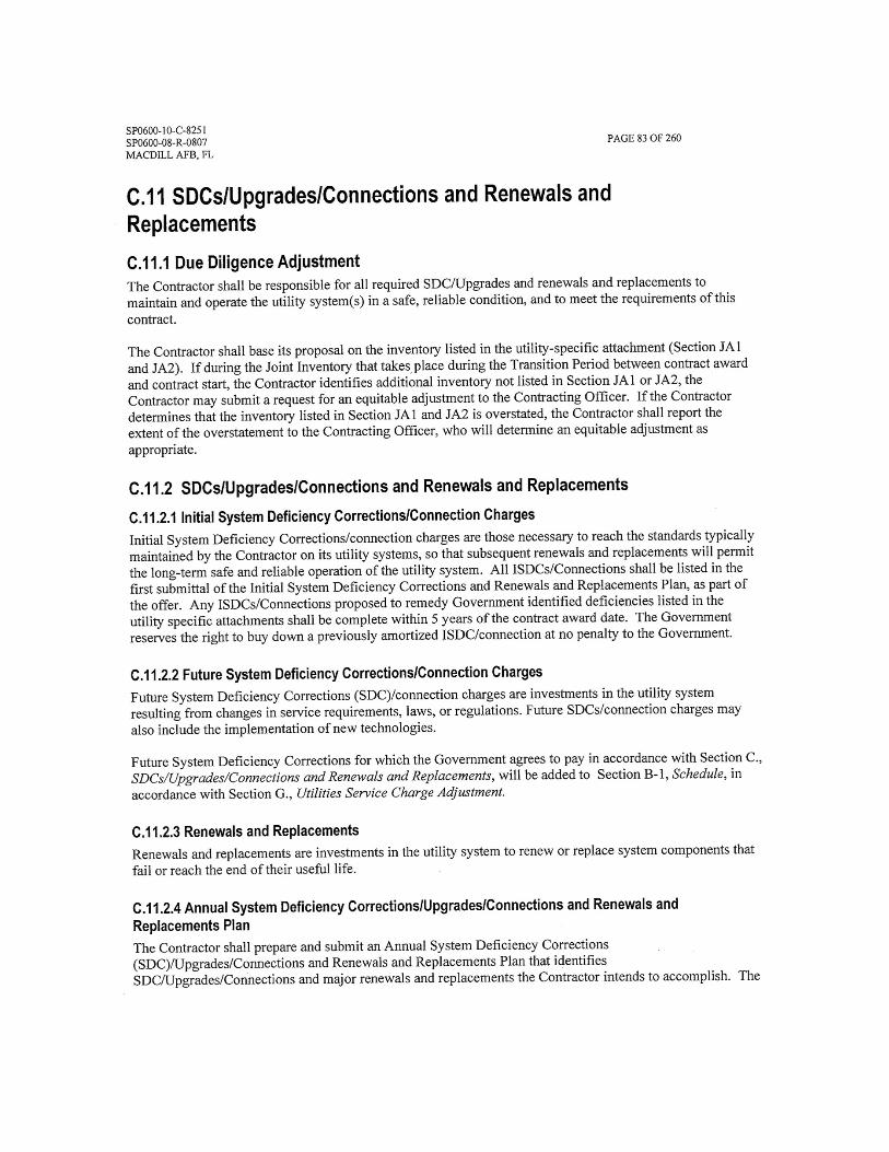

UTILITYPRIVATIZATION
POTABLEWATERINFORMATION
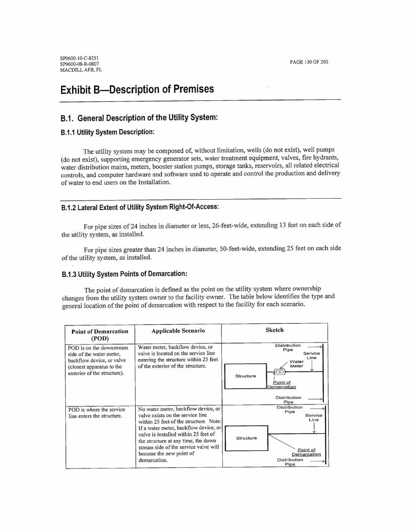
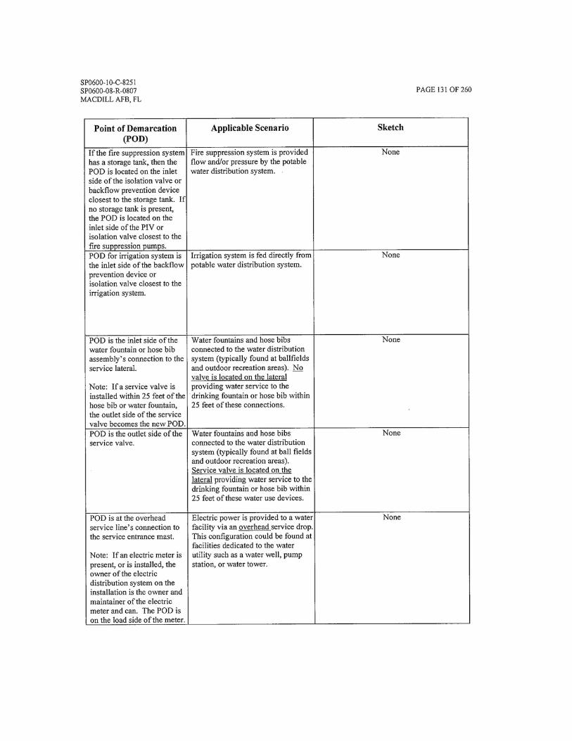
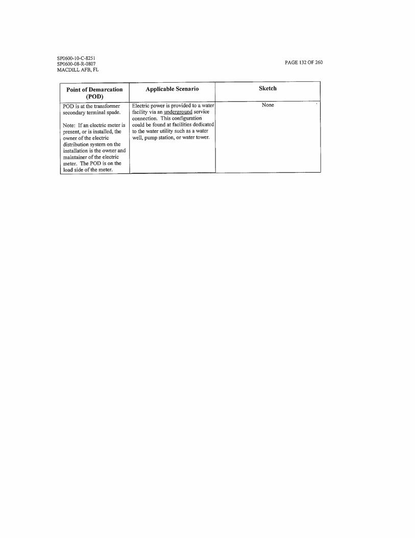
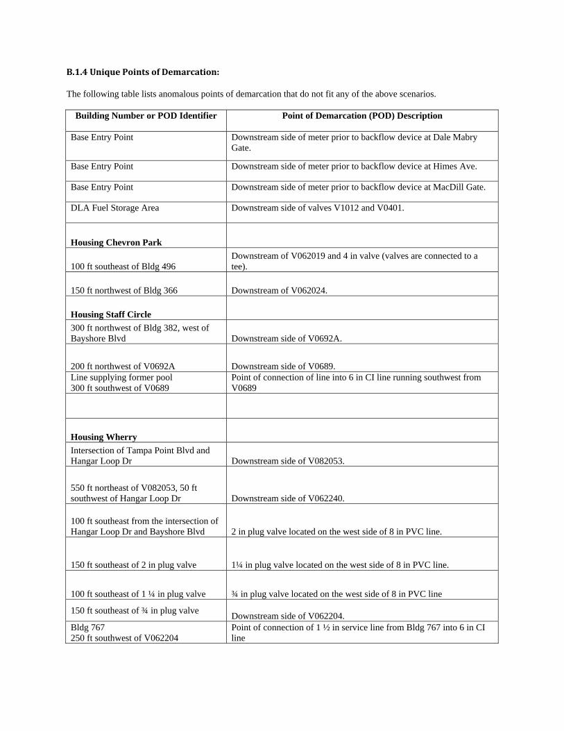
B.1.4UniquePointsofDemarcation:
The following table lists anomalous points of demarcation that do not fit any of the above scenarios.
Building Number or POD Identifier Point of Demarcation (POD) Description
Base Entry Point Downstream side of meter prior to backflow device at Dale Mabry Gate.
Base Entry Point Downstream side of meter prior to backflow device at Himes Ave.
Base Entry Point Downstream side of meter prior to backflow device at MacDill Gate.
DLA Fuel Storage Area Downstream side of valves V1012 and V0401.
Housing Chevron Park
100 ft southeast of Bldg 496 Downstream of V062019 and 4 in valve (valves are connected to a tee).
150 ft northwest of Bldg 366 Downstream of V062024.
Housing Staff Circle
300 ft northwest of Bldg 382, west of Bayshore Blvd Downstream side of V0692A.
200 ft northwest of V0692A Downstream side of V0689. Line supplying former pool 300 ft southwest of V0689
Point of connection of line into 6 in CI line running southwest from V0689
Housing Wherry
Intersection of Tampa Point Blvd and Hangar Loop Dr Downstream side of V082053.
550 ft northeast of V082053, 50 ft southwest of Hangar Loop Dr Downstream side of V062240.
100 ft southeast from the intersection of Hangar Loop Dr and Bayshore Blvd 2 in plug valve located on the west side of 8 in PVC line.
150 ft southeast of 2 in plug valve 1¼ in plug valve located on the west side of 8 in PVC line.
100 ft southeast of 1 ¼ in plug valve ¾ in plug valve located on the west side of 8 in PVC line
150 ft southeast of ¾ in plug valve Downstream side of V062204.
Bldg 767 250 ft southwest of V062204
Point of connection of 1 ½ in service line from Bldg 767 into 6 in CI line
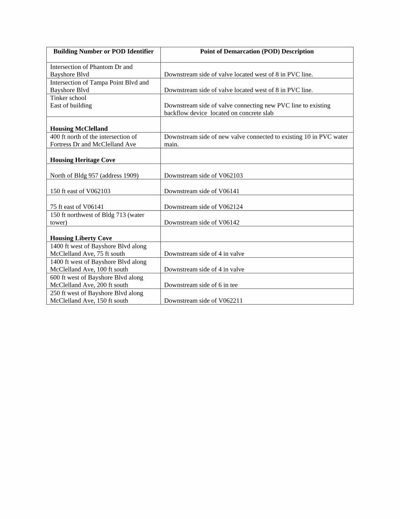
Building Number or POD Identifier Point of Demarcation (POD) Description
Intersection of Phantom Dr and Bayshore Blvd Downstream side of valve located west of 8 in PVC line. Intersection of Tampa Point Blvd and Bayshore Blvd Downstream side of valve located west of 8 in PVC line. Tinker school East of building
Downstream side of valve connecting new PVC line to existing backflow device located on concrete slab
Housing McClelland 400 ft north of the intersection of Fortress Dr and McClelland Ave
Downstream side of new valve connected to existing 10 in PVC water main.
Housing Heritage Cove
North of Bldg 957 (address 1909) Downstream side of V062103
150 ft east of V062103 Downstream side of V06141
75 ft east of V06141 Downstream side of V062124 150 ft northwest of Bldg 713 (water tower) Downstream side of V06142
Housing Liberty Cove 1400 ft west of Bayshore Blvd along McClelland Ave, 75 ft south Downstream side of 4 in valve 1400 ft west of Bayshore Blvd along McClelland Ave, 100 ft south Downstream side of 4 in valve 600 ft west of Bayshore Blvd along McClelland Ave, 200 ft south Downstream side of 6 in tee 250 ft west of Bayshore Blvd along McClelland Ave, 150 ft south Downstream side of V062211

UTILITYPRIVATIZATION
WASTEWATERINFORMATION
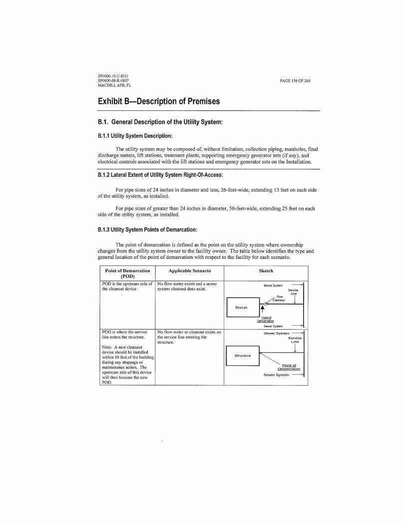
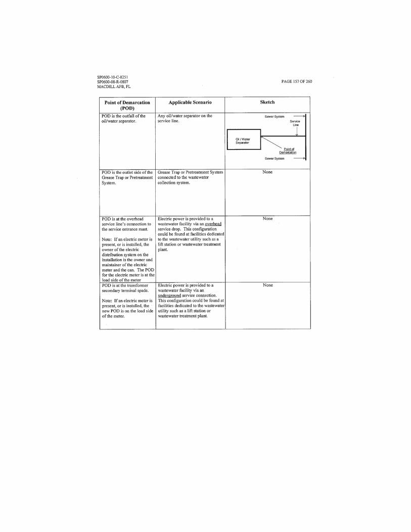
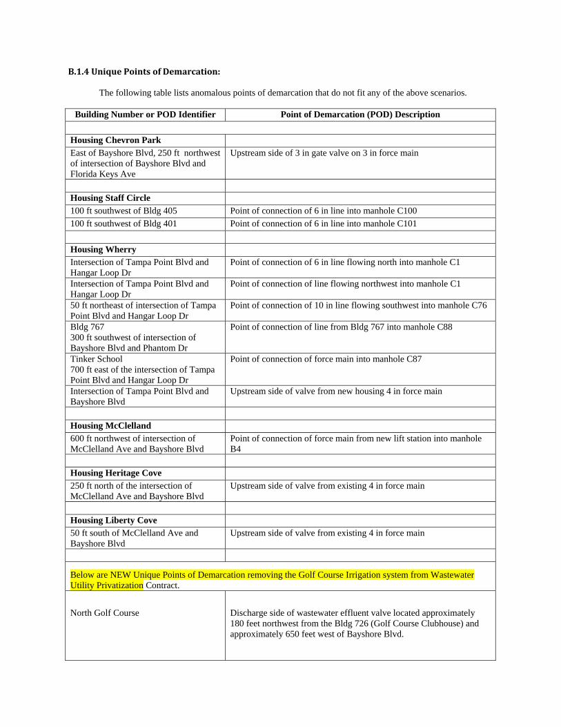
B.1.4UniquePointsofDemarcation:
The following table lists anomalous points of demarcation that do not fit any of the above scenarios.
Building Number or POD Identifier Point of Demarcation (POD) Description
Housing Chevron Park
East of Bayshore Blvd, 250 ft northwest of intersection of Bayshore Blvd and Florida Keys Ave
Upstream side of 3 in gate valve on 3 in force main
Housing Staff Circle
100 ft southwest of Bldg 405 Point of connection of 6 in line into manhole C100
100 ft southwest of Bldg 401 Point of connection of 6 in line into manhole C101
Housing Wherry
Intersection of Tampa Point Blvd and Hangar Loop Dr
Point of connection of 6 in line flowing north into manhole C1
Intersection of Tampa Point Blvd and Hangar Loop Dr
Point of connection of line flowing northwest into manhole C1
50 ft northeast of intersection of Tampa Point Blvd and Hangar Loop Dr
Point of connection of 10 in line flowing southwest into manhole C76
Bldg 767 300 ft southwest of intersection of Bayshore Blvd and Phantom Dr
Point of connection of line from Bldg 767 into manhole C88
Tinker School 700 ft east of the intersection of Tampa Point Blvd and Hangar Loop Dr
Point of connection of force main into manhole C87
Intersection of Tampa Point Blvd and Bayshore Blvd
Upstream side of valve from new housing 4 in force main
Housing McClelland
600 ft northwest of intersection of McClelland Ave and Bayshore Blvd
Point of connection of force main from new lift station into manhole B4
Housing Heritage Cove
250 ft north of the intersection of McClelland Ave and Bayshore Blvd
Upstream side of valve from existing 4 in force main
Housing Liberty Cove
50 ft south of McClelland Ave and Bayshore Blvd
Upstream side of valve from existing 4 in force main
Below are NEW Unique Points of Demarcation removing the Golf Course Irrigation system from Wastewater Utility Privatization Contract.
North Golf Course
Discharge side of wastewater effluent valve located approximately 180 feet northwest from the Bldg 726 (Golf Course Clubhouse) and approximately 650 feet west of Bayshore Blvd.
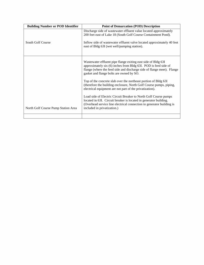
Building Number or POD Identifier Point of Demarcation (POD) Description
South Golf Course
Discharge side of wastewater effluent value located approximately 200 feet east of Lake 18 (South Golf Course Containment Pond). Inflow side of wastewater effluent valve located approximately 40 feet east of Bldg 63I (wet well/pumping station).
North Golf Course Pump Station Area
Wastewater effluent pipe flange exiting east side of Bldg 63I approximately six (6) inches from Bldg 63I. POD is feed side of flange (where the feed side and discharge side of flange meet). Flange gasket and flange bolts are owned by SO. Top of the concrete slab over the northeast portion of Bldg 63I (therefore the building enclosure, North Golf Course pumps, piping, electrical equipment are not part of the privatization). Load side of Electric Circuit Breaker to North Golf Course pumps located in 63I. Circuit breaker is located in generator building. (Overhead service line electrical connection to generator building is included in privatization.)
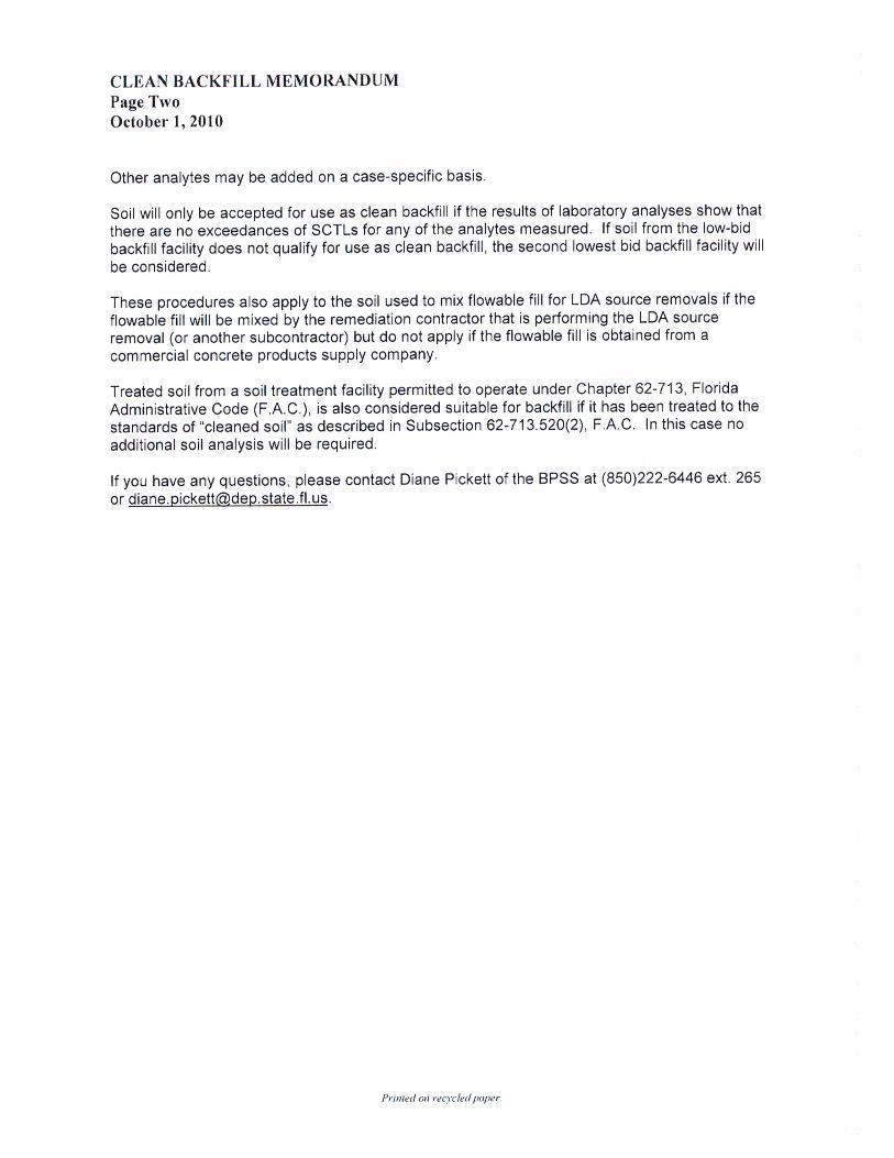
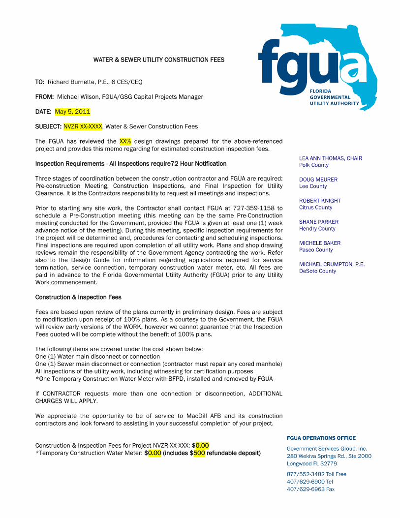
WATER & SEWER UTILITY CONSTRUCTION FEES
TO: Richard Burnette, P.E., 6 CES/CEQ
FROM: Michael Wilson, FGUA/GSG Capital Projects Manager
DATE: May 5, 2011
SUBJECT: NVZR XX-XXXX, Water & Sewer Construction Fees
The FGUA has reviewed the XX% design drawings prepared for the above-referenced
project and provides this memo regarding for estimated construction inspection fees.
Inspection Requirements - All Inspections require72 Hour Notification
Three stages of coordination between the construction contractor and FGUA are required:
Pre-construction Meeting, Construction Inspections, and Final Inspection for Utility
Clearance. It is the Contractors responsibility to request all meetings and inspections.
Prior to starting any site work, the Contractor shall contact FGUA at 727-359-1158 to
schedule a Pre-Construction meeting (this meeting can be the same Pre-Construction
meeting conducted for the Government, provided the FGUA is given at least one (1) week
advance notice of the meeting). During this meeting, specific inspection requirements for
the project will be determined and, procedures for contacting and scheduling inspections.
Final inspections are required upon completion of all utility work. Plans and shop drawing
reviews remain the responsibility of the Government Agency contracting the work. Refer
also to the Design Guide for information regarding applications required for service
termination, service connection, temporary construction water meter, etc. All fees are
paid in advance to the Florida Governmental Utility Authority (FGUA) prior to any Utility
Work commencement.
Construction & Inspection Fees
Fees are based upon review of the plans currently in preliminary design. Fees are subject
to modification upon receipt of 100% plans. As a courtesy to the Government, the FGUA
will review early versions of the WORK, however we cannot guarantee that the Inspection
Fees quoted will be complete without the benefit of 100% plans.
The following items are covered under the cost shown below:
One (1) Water main disconnect or connection
One (1) Sewer main disconnect or connection (contractor must repair any cored manhole)
All inspections of the utility work, including witnessing for certification purposes
*One Temporary Construction Water Meter with BFPD, installed and removed by FGUA
If CONTRACTOR requests more than one connection or disconnection, ADDITIONAL
CHARGES WILL APPLY.
We appreciate the opportunity to be of service to MacDill AFB and its construction
contractors and look forward to assisting in your successful completion of your project.
Construction & Inspection Fees for Project NVZR XX-XXX: $0.00
*Temporary Construction Water Meter: $0.00 (includes $500 refundable deposit)
LEA ANN THOMAS, CHAIR
Polk County
DOUG MEURER
Lee County
ROBERT KNIGHT
Citrus County
SHANE PARKER
Hendry County
MICHELE BAKER
Pasco County
MICHAEL CRUMPTON, P.E.
DeSoto County
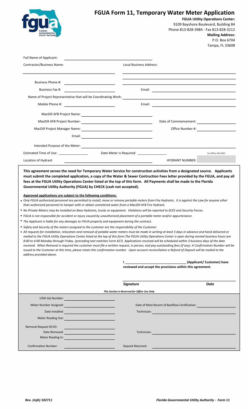
Full Name of Applicant:
Contractor/Business Name: Local Business Address:
Business Phone #:
Business Fax #: Email:
Name of Project Representative that will be Coordinating Work:
Mobile Phone #: Email:
MacDill AFB Project Name:
MacDill AFB Project Number: Date of Commencement:
MacDill Project Manager Name: Office Number #:
Email:
Intended Purpose of the Meter:
Estimated Time of Use: ________________ Date Meter is Required: ________________
Location of Hydrant HYDRANT NUMBER:
•
•
•
•
•
•
Signature Date
USW Job Number:
Meter Number Assigned: Date of Most Recent of Backflow Certification:
Date Installed: Technician:
Meter Reading Out:
Removal Request RCVD:
Date Removed: Technician:
Meter Reading In:
Confirmation Number: Deposit Returned:
FGUA Form 11, Temporary Water Meter Application
Approved applications are subject to the following conditions:
For Office USE ONLY
FGUA Utility Operations Center:
9109 Bayshore Boulevard, Building 84
Phone 813-828-3984 - Fax 813-828-3212
Mailing Address:
P.O. Box 6704
Tampa, FL 33608
I __________________________________ (Applicant/ Customer) have
reviewed and accept the provisions within this agreement.
This agreement serves the need for Temporary Water Service for construction activities from a designated source. Applicants
must submit the completed application, a copy of the Water & Sewer Contruction Fees letter provided by the FGUA, and pay all
fees at the FGUA Utility Operations Center listed at the top of this form. All Payments shall be made to the Florida
Governmental Utility Authority (FGUA) by CHECK (cash not accepted).
Only FGUA authorized personnel are permitted to install, move or remove portable meters from Fire Hydrants. It is against the Law for anyone other
than authorized personnel to tamper with or obtain unmetered water from a MacDill AFB Fire Hydrant.
No Private Meters may be installed on Base Hydrants, trucks or equipment. Violations will be reported to 6CES and Security Forces.
FGUA is not responsible for accident or injury caused by unauthorized placement of a portable meter and/or appurtenance.
The Applicant is liable for any damages to FGUA property and equipment during the contract.
This Section is Reserved for Office Use Only
Safety and Security of the meters assigned to the customer are the responsibility of the Customer.
All requests for installation, relocation and removal of potable water meters must be made in writing at least 3 days in advance and hand delivered or
mailed to the FGUA Utility Operations Center listed at the top of this form.The FGUA Utility Operations Center is open during normal business hours are
8:00 to 4:00 Monday through Friday. (preceding text matches Form 427). Applications received will be scheduled within 3 business days of the date
received. When Removal is required the customer must file a written request, in person, and pay outstanding fees (if any). A Confirmation Number will be
issued to the Customer at this time, please retain this confirmation number. Upon account reconciliation a Refund of Deposit will be mailed to the
address provided above.
Rev. (mjh) 102711 Florida Governmental Utility Authority - Form 11
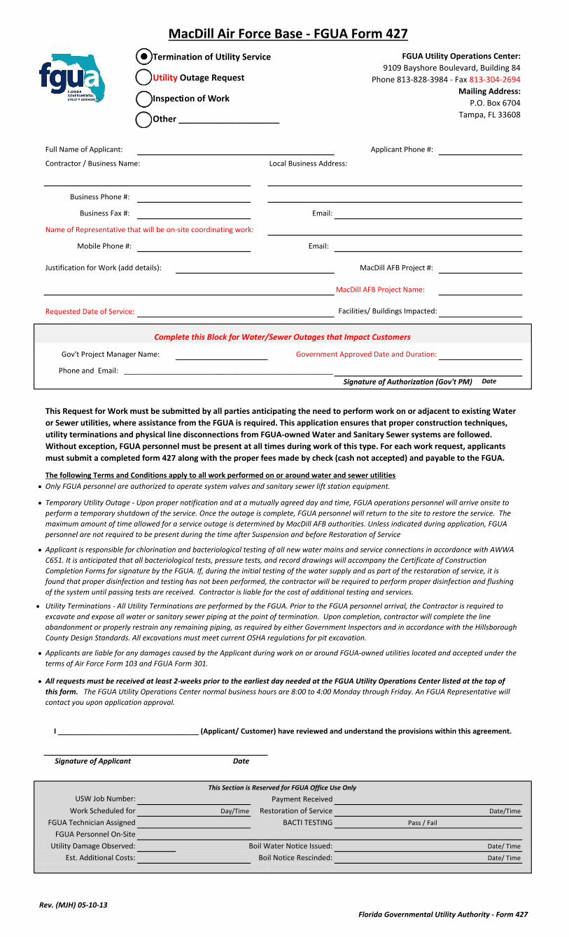
Full Name of Applicant: Applicant Phone #:
Contractor / Business Name: Local Business Address:
Business Phone #:
Business Fax #: Email:
Name of Representative that will be on-site coordinating work:
Mobile Phone #: Email:
Justification for Work (add details): MacDill AFB Project #:
MacDill AFB Project Name:
Requested Date of Service: Facilities/ Buildings Impacted:
Government Approved Date and Duration:
Signature of Authorization (Gov't PM) Date
•
•
•
•
•
•
Signature of Applicant Date
USW Job Number: Payment Received
Work Scheduled for Day/Time Restoration of Service Date/Time
FGUA Technician Assigned BACTI TESTING Pass / Fail
FGUA Personnel On-Site
Utility Damage Observed: Boil Water Notice Issued: Date/ Time
Est. Additional Costs: Boil Notice Rescinded: Date/ Time
I ___________________________________ (Applicant/ Customer) have reviewed and understand the provisions within this agreement.
⃝ Other _____________________
All requests must be received at least 2-weeks prior to the earliest day needed at the FGUA Utility Operations Center listed at the top of
this form. The FGUA Utility Operations Center normal business hours are 8:00 to 4:00 Monday through Friday. An FGUA Representative will
contact you upon application approval.
Utility Terminations - All Utility Terminations are performed by the FGUA. Prior to the FGUA personnel arrival, the Contractor is required to
excavate and expose all water or sanitary sewer piping at the point of termination. Upon completion, contractor will complete the line
abandonment or properly restrain any remaining piping, as required by either Government Inspectors and in accordance with the Hillsborough
County Design Standards. All excavations must meet current OSHA regulations for pit excavation.
The following Terms and Conditions apply to all work performed on or around water and sewer utilities
Complete this Block for Water/Sewer Outages that Impact Customers
Phone and Email: ____________________________________________________
MacDill Air Force Base - FGUA Form 427
Gov't Project Manager Name:
FGUA Utility Operations Center:
9109 Bayshore Boulevard, Building 84
Phone 813-828-3984 - Fax 813-304-2694
Mailing Address:
P.O. Box 6704
Tampa, FL 33608
This Section is Reserved for FGUA Office Use Only
⃝ Termination of Utility Service
⃝ Utility Outage Request
⃝ Inspection of Work
Applicants are liable for any damages caused by the Applicant during work on or around FGUA-owned utilities located and accepted under the
terms of Air Force Form 103 and FGUA Form 301.
Applicant is responsible for chlorination and bacteriological testing of all new water mains and service connections in accordance with AWWA
C651. It is anticipated that all bacteriological tests, pressure tests, and record drawings will accompany the Certificate of Construction
Completion Forms for signature by the FGUA. If, during the initial testing of the water supply and as part of the restoration of service, it is
found that proper disinfection and testing has not been performed, the contractor will be required to perform proper disinfection and flushing
of the system until passing tests are received. Contractor is liable for the cost of additional testing and services.
This Request for Work must be submitted by all parties anticipating the need to perform work on or adjacent to existing Water
or Sewer utilities, where assistance from the FGUA is required. This application ensures that proper construction techniques,
utility terminations and physical line disconnections from FGUA-owned Water and Sanitary Sewer systems are followed.
Without exception, FGUA personnel must be present at all times during work of this type. For each work request, applicants
must submit a completed form 427 along with the proper fees made by check (cash not accepted) and payable to the FGUA.
Only FGUA personnel are authorized to operate system valves and sanitary sewer lift station equipment.
Temporary Utility Outage - Upon proper notification and at a mutually agreed day and time, FGUA operations personnel will arrive onsite to
perform a temporary shutdown of the service. Once the outage is complete, FGUA personnel will return to the site to restore the service. The
maximum amount of time allowed for a service outage is determined by MacDill AFB authorities. Unless indicated during application, FGUA
personnel are not required to be present during the time after Suspension and before Restoration of Service
Rev. (MJH) 05-10-13Florida Governmental Utility Authority - Form 427
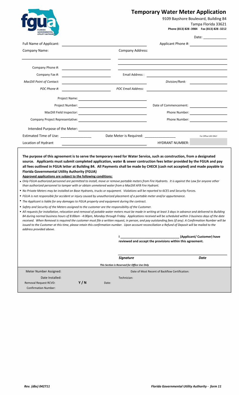
Temporary Water Meter Application
Date: ____________
Full Name of Applicant: Applicant Phone #:
Company Name: Company Address:
Company Phone #:
Company Fax #: Email Address :
MacDill Point of Contact: Division/Rank:
POC Phone #: POC Email Address:
Project Name:
Project Number: Date of Commencement:
MacDill Field Inspector: Phone Number:
Company Project Representative: Phone Number:
Intended Purpose of the Meter:
Estimated Time of Use: ________________ Date Meter is Required: ________________
Location of Hydrant HYDRANT NUMBER:
•
•
•
•
•
•
Signature Date
Meter Number Assigned: Date of Most Recent of Backflow Certification:
Date Installed: Technician:
Removal Request RCVD: Y / N Date:
Confirmation Number:
9109 Bayshore Boulevard, Building 84
Tampa Florida 33621 Phone (813) 828 -3984 Fax (813) 828 -3212
Safety and Security of the Meters assigned to the customer are the responsibility of the Customer.
All requests for installation, relocation and removal of potable water meters must be made in writing at least 3 days in advance and delivered to Building
84 during normal business hours of 8:00am - 4:00pm, Monday through Friday. Applications received will be scheduled within 3 business days of the date
received. When Removal is required the customer must file a written request, in person, and pay outstanding fees (if any). A Confirmation Number will be
issued to the Customer at this time, please retain this confirmation number. Upon account reconciliation a Refund of Deposit will be mailed to the
address provided above.
For Office USE ONLY
I __________________________________ (Applicant/ Customer) have
reviewed and accept the provisions within this agreement.
The purpose of this agreement is to serve the temporary need for Water Service, such as construction, from a designated
source. Applicants must submit completed application, water & sewer contruction fees letter provided by the FGUA and pay
all fees outlined in FGUA letter at Building 84. All Payments shall be made by CHECK (cash not accepted) and made payable to
Florida Governmental Utility Authority (FGUA) Approved applications are subject to the following conditions:
Only FGUA authorized personnel are permitted to install, move or remove portable meters from Fire Hydrants. It is against the Law for anyone other
than authorized personnel to tamper with or obtain unmetered water from a MacDill AFB Fire Hydrant.
No Private Meters may be installed on Base Hydrants, trucks or equipment. Violations will be reported to 6CES and Security Forces.
FGUA is not responsible for accident or injury caused by unauthorized placement of a portable meter and/or appurtenance.
The Applicant is liable for any damages to FGUA property and equipment during the contract.
This Section is Reserved for Office Use Only
Rev. (dbs) 042711 Florida Governmental Utility Authority - form 11
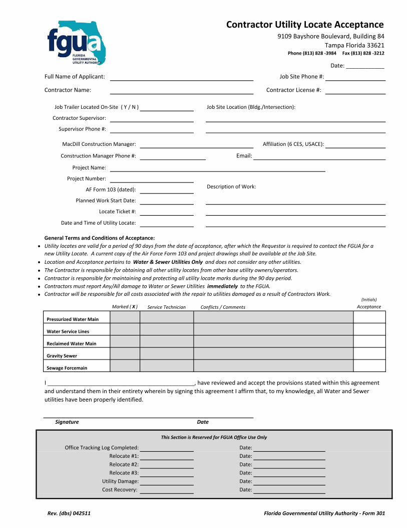
Contractor Utility Locate Acceptance
Date: ____________
Full Name of Applicant: Job Site Phone #:
Contractor Name: Contractor License #:
Job Trailer Located On-Site ( Y / N ) Job Site Location (Bldg./Intersection):
Contractor Supervisor:
Supervisor Phone #:
MacDill Construction Manager: Affiliation (6 CES, USACE):
Construction Manager Phone #: Email:
Project Name:
Project Number:
AF Form 103 (dated): Description of Work:
Planned Work Start Date:
Locate Ticket #:
Date and Time of Utility Locate:
General Terms and Conditions of Acceptance:
•
•
•
•••
(Initials)
Marked ( X ) Service Technician Acceptance
Pressurized Water Main
Water Service Lines
Reclaimed Water Main
Gravity Sewer
Sewage Forcemain
Office Tracking Log Completed: Date:
Relocate #1: Date:
Relocate #2: Date:
Relocate #3: Date:
Utility Damage: Date:
Cost Recovery: Date:
Contractors must report Any/All damage to Water or Sewer Utilities immediately to the FGUA.
9109 Bayshore Boulevard, Building 84
Tampa Florida 33621 Phone (813) 828 -3984 Fax (813) 828 -3212
Location and Acceptance pertains to Water & Sewer Utilities Only and does not consider any other utilities.
The Contractor is responsible for obtaining all other utility locates from other base utility owners/operators.
Utility locates are valid for a period of 90 days from the date of acceptance, after which the Requestor is required to contact the FGUA for a
new Utility Locate. A current copy of the Air Force Form 103 and project drawings shall be available at the Job Site.
This Section is Reserved for FGUA Office Use Only
Contractor will be responsible for all costs associated with the repair to utilities damaged as a result of Contractors Work.
Signature Date
Contractor is responsible for maintaining and protecting all utility locate marks during the 90 day period.
Conflicts / Comments
I ______________________________________________, have reviewed and accept the provisions stated within this agreement
and understand them in their entirety wherein by signing this agreement I affirm that, to my knowledge, all Water and Sewer
utilities have been properly identified.
Rev. (dbs) 042511 Florida Governmental Utility Authority - Form 301
Utility Service Termination Application
Name of Applicant: Date:
Company Name: Company Address:
Company Phone #:
Company Fax #: Company Email:
MacDill Point of Contact: POC Organization:
POC Phone #: POC Email:
Project Name:
Project Number:
MacDill Construction Manager: Phone Number:
Company Project Representative: Phone Number:
Check One: Sanitary Sewer_____ Water Distribution_____
Termination Conducted By: Contractor_________ FGUA________________
Brief description of utility termination requested. Be sure to include facility number/site location and pipe size:
Estimated Project Start Date: ________________ Estimated Date Disconnection Required ________________
Terms and Conditions:
Signature: Date:
Office Tracking Log Completed: Date:
Work ID #
Construction Inspector: Signature:
Date Completed: Time On-Site:
Utility Damage: Date:
Cost Recovery: Date:
9110 Bayshore Boulevard, Building 84
MacDill AFB, Florida 33621 Phone (813) 828-3984 Fax (813) 828 -0000
All requests must be made in writing and delivered to the FGUA in Building 84 during normal business hours of 8:00 to 4:00 Monday through
Friday. Approved applications will be scheduled within 5 business days of the date received.
This Section is Reserved for Office Use Only
All fittings and tools used to cut and cap water piping must be properly disinfected in accordance with AWWA C651, Current Edition.
The purpose of this application is to ensure proper utility terminations and physical line disconnection from FGUA-owned water and sanitary
sewer utilities. Applicants must submit a completed application along with the proper fees. Applications that are approved are subject to the
following conditions:
Only FGUA personnel are authorized to operate water system valves and sanitary sewer lift station equipment.
I_________________________ (Requesting Person/Company) have reviewed the Utility Service Termination Application and
agree to all of the Terms and Conditions.
The Applicant is liable for any damages to FGUA-owned utility lines, including all costs and repairs to marked utility lines damaged by contractor
during their work.
All work acomplished by contractor must be inspected by FGUA prior to backfilling. Contractor is required to make all corrections identified by
the FGUA constuction inspector.
Contractor is required to excavate and expose all water or sanitary sewer piping at the point of termination; FGUA will perform and complete the
proper cut and capping proceedure. Contractor may request, by identifying so on this application, to perform the cut and cap proceedure in
accordance with specifications provided by FGUA. If this is approved, Contractor must contact FGUA to schedule an inspection of the work
before work commencement.
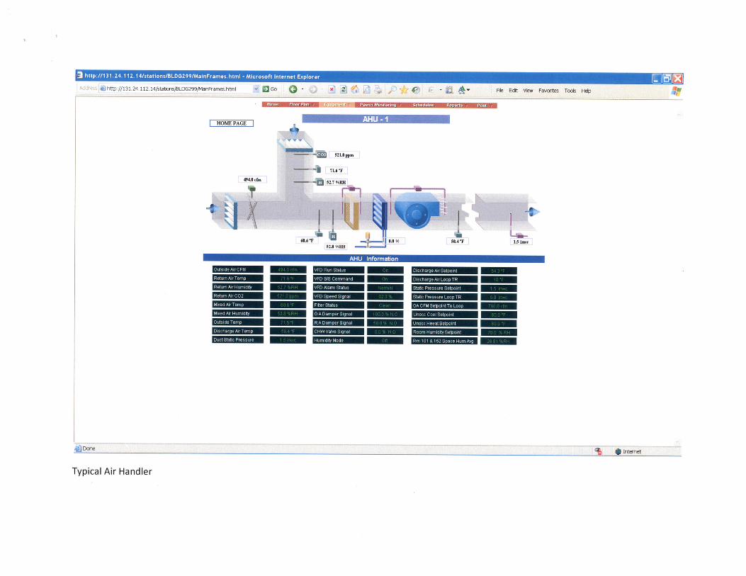
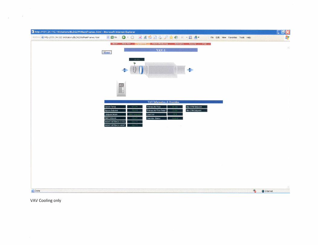
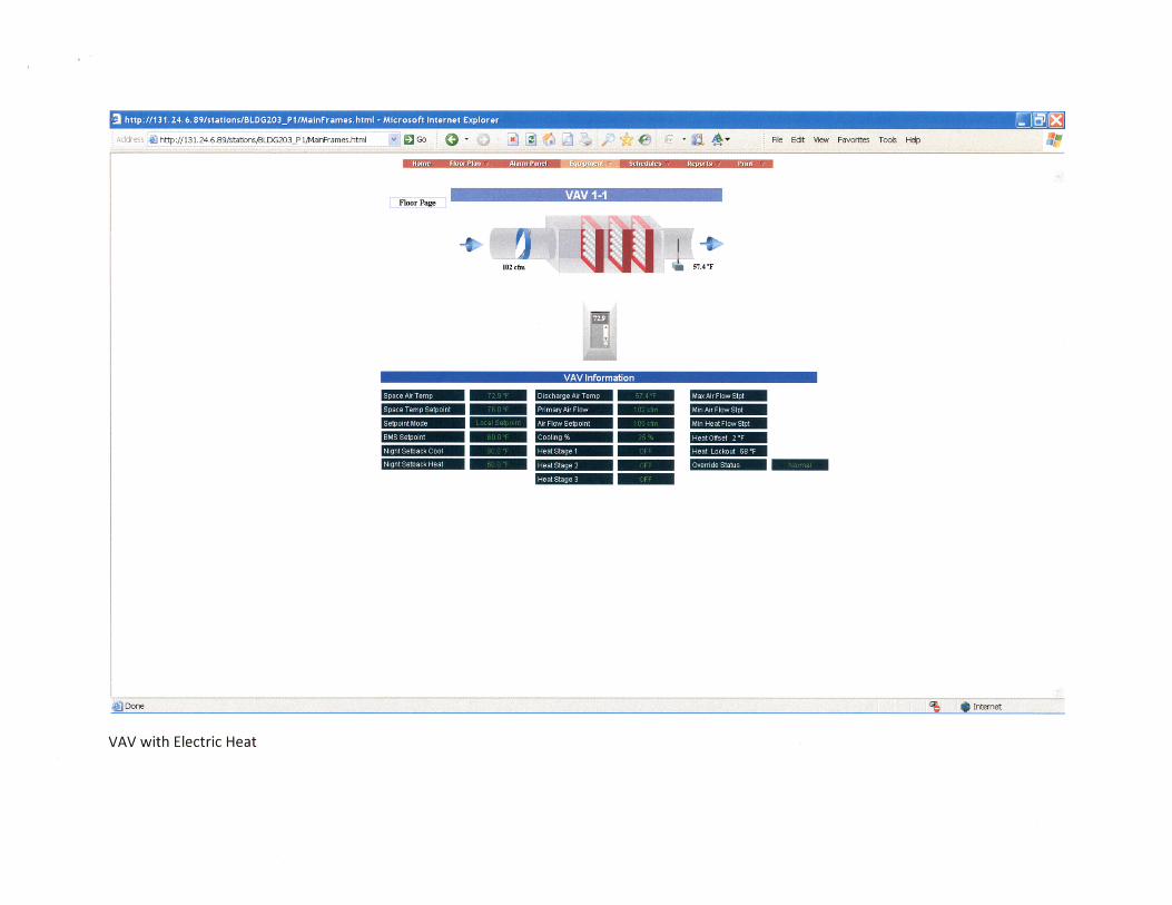
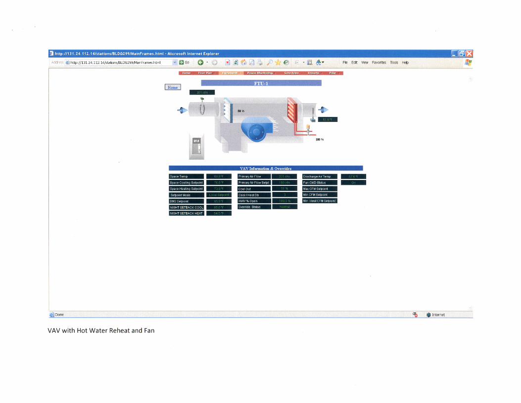
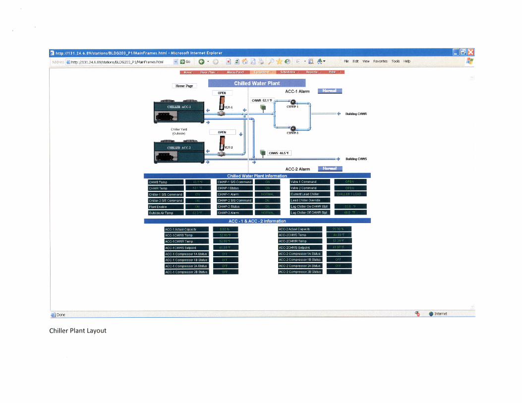
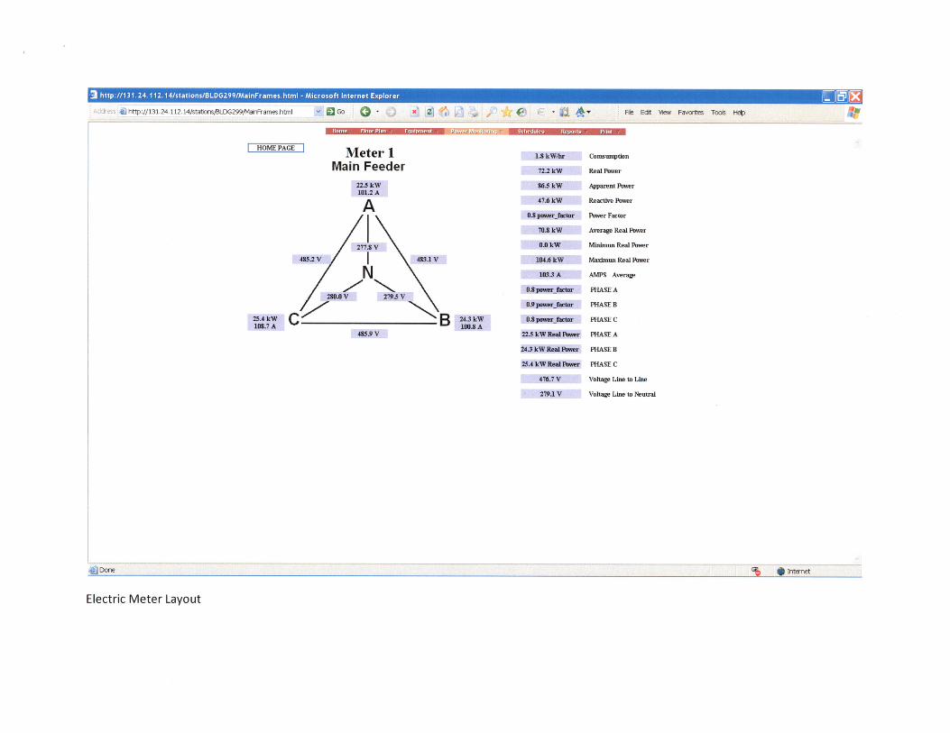
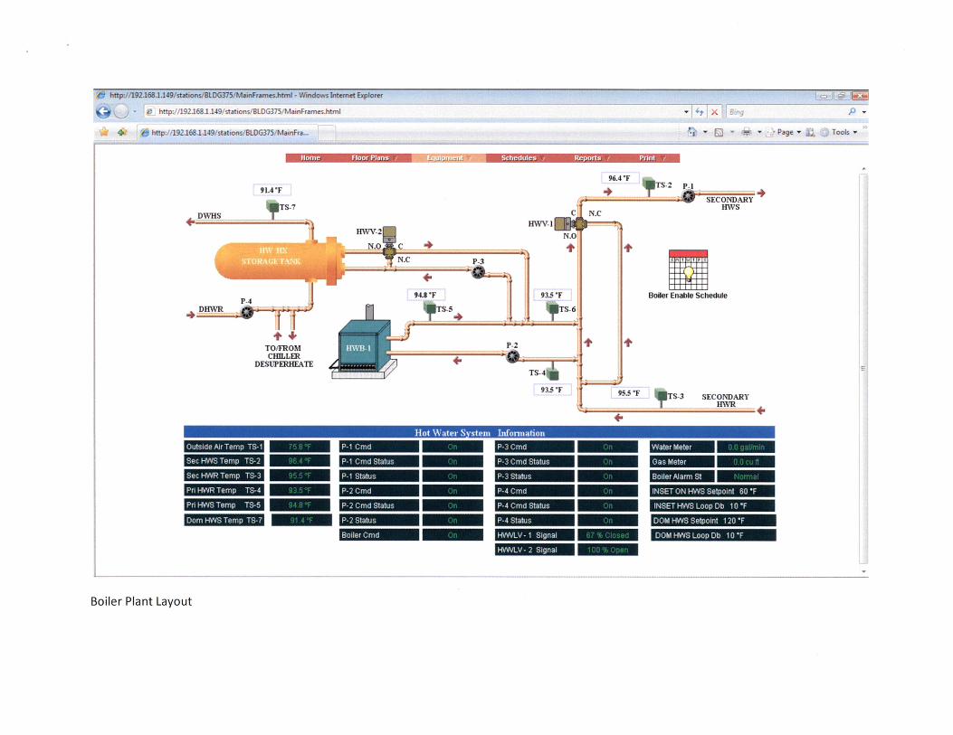
6th Communications Squadron Supplement
to
Engineering Technical Letter (ETL) 02-12: Communications and Information System
Criteria for Air Force Facilities, dated 27 June 2002
Communication Systems
24 July 2008
OPR: 6 CS/SCXX

- ii -
Page intentionally left blank
- iii -
Table of Contents Section Page ETL 02-12 para ref #
1. Purpose 1 1.
2. Scope 1 1.1.1.
3. Referenced Pubs 1 4 & 5
4. RUS/REA Bulletins 1 4 & 5
5. General Requirements-Intent 1 1.1.
6. Cable Management Plan 2 no ref.
7. Designer/Installer Qualifications 2 9.4.2.
8. Inside Wire and Cabling
8.1. Inside Fiber Optic Cable 3 8.3.1.
8.2. Inside Copper Cable 3 8.3.3.8.1.
8.3. House Backbone Cable 4 8.3.3.8.2. and 8.3.3.8.3.
8.4. Telecommunications Outlets 5 8.3.3.9.
8.5. Miscellaneous (Phones, PA Systems, LMR etc.) 6 no ref.
8.6. SIPRNET 7 1.1.1.
9. Communications Equipment Room and Distribution Frame
9.1. Communications Equipment Room 8 8.3.3.2.
9.2. Telecommunications Closet 9 8.3.3.3.
10. Exterior Work
10.1. Comm. Cables between Buildings 10 8.3.3.8.4.
10.2. Outside Copper Cable 10 no ref.
10.3. Outside Fiber Optic Cable 10 no ref.
10.4. Outside Plant Cable Entrance 11 8.3.3.2.1.
10.5. Conduits and Duct Banks 11 no ref.
10.6. Conduit Rodding and Cleaning 12 no ref.
10.7. Innerduct Installation 12 no ref.
10.8. Manholes 13 no ref.
10.9. Direct Buried Cable 14 no ref.
11. Installation and Testing 14 8.7.
12. CONSTRUCTION AND AS-BUILT DRAWINGS
- iv -
12.1. Design Drawings 15 9.4.4.
12.2. Underground Cable Drawings 15 9.4.4.
12.3. Direct Buried Cable Drawings 16 9.4.4.
12.4. Underground Conduit Drawings 16 9.4.4.
12.5. As-Built Drawings 17 9.4.4.
13. O & M Manuals 18 9.4.4.
14. DD-Form 1391, MilCon Project Data 18 9.2.
- 1 -
SECTION 1. PURPOSE: 1.01. This supplement clarifies communications requirements for MacDill AFB facilities not covered in ETL 02-12. This supplement shall be used in conjunction with ETL 02-12. The 6th Communications Squadron Communications System Officer (CSO) or designee is the only one who can authorize deviation from this supplement. SECTION 2. SCOPE. 2.01. This specification shall be used to plan, design, review and evaluate telecommunications cabling and distribution systems for service connections, pre-wiring of new and renovated facilities to support communications – computer systems (C-CS). This specification addresses C-CS as they relate to interior wiring, exterior duct bank and communications cable to the appropriate service connection point(s). SECTION 3. REFERENCED PUBLICATIONS.
- ANSI/ICEA S-80-576 Standard (Std) for Telecomm Wire and Cable for Wiring of Premises - TIA/EIA-569-A Commercial Building Std for Telecommunications Pathways and Spaces - TIA/ EIA 590 Std for Physical Location & Protection of Below-Ground F.O. Plant
- ANSI/TIA/EIA TSB-75 Additional Horizontal Cabling Practices for Open Offices - Unified Facilities Criteria 4-021-01 Design and O & M: Mass Notification Systems
SECTION 4. BULLETINS.
- REA 1753F-601 (PE-90) Fiber Cable, Outside - REA 1753F-205 (PE-39) Copper Cable, Outside - REA 1753F-208 (PE-89) Copper Cable, Outside - RUS 1751F-640 Design of Buried Plant – Physical Considerations - RUS 1751F-642 Construction Route Planning of Buried Plant - RUS 1751F-644 Underground Plant Construction
SECTION 5. GENERAL REQUIREMENTS-INTENT 5.1. Whenever new construction or renovation takes place, the design, installation, and all related costs necessary to complete interior wiring and extend the conduit, ductwork and manhole system to the new or renovated location shall be included in the project cost. 5.1.1. Renovation shall include removal of old/unused telecommunications cabling from interior of facilities. 6th Communication Squadron (CS) will identify old/unused cabling. 5.1.2. Prior to demolition of any facility, 6th CS personnel shall remove the outside plant communications cables (copper and fiber) serving the facility, if applicable. These cables shall be removed back to the splice point and capped. The 6th Civil Engineering Squadron (project manager) shall notify the 6th Communications Squadron (Plans Office) at least 45 days prior to facilitate scheduling of work. 5.1.3. Prior to demolition or renovation of any facility, all network devices, LMR equipment and antennas serving the facility, which shall be impacted by the construction, shall be removed/relocated.
- 2 -
The 6th Civil Engineering Squadron (project manager) shall notify the 6th Communications Squadron (Plans Office) at least 30 days prior to facilitate scheduling of work. Submit the removal/relocation request using automated Form 3215. The 6th Communications Squadron shall remove the antennas. 5.1.4. Communications design criteria is grouped into three areas: inside wire & cable; communications equipment room & distribution frame; and exterior work. The design requirements may vary depending on the size and type of facility being built or renovated. 5.1.5. The facility design shall provide for concealment of wiring/cabling systems, adequate space for installation, maintenance of C-CS equipment and wiring, and proper separation for specialized systems, if required. 5.1.6. The building communications infrastructure shall provide 50% spare capacity for future expansion of the user’s voice, network, security and video requirements. 5.1.7. The most practical cable/wire distribution system shall be selected, consistent with facility size/function and current/projected C-CS requirements. 5.1.8. To minimize the long-term cost of the infrastructure, local standards are established as follows and shall only be changed when approved in writing by the base CSO or their designee. These standards are intended to reduce cost associated with post construction C-CS requirements, to promote common skills among maintenance personnel and to minimize the necessity for excessive on-hand spare parts and equipment. SECTION 6. CABLE MANAGEMENT PLAN.
6.1. Cable management is the planning, designing and accounting of cables routed throughout the building. Placement of any cable system in the building shall follow a well organized and well designed cable management plan. By keeping a record of cable pair counts and assignments and the routing of riser, tie, and distribution cables, future rearrangements or alterations to the wiring system shall be easier. The overall cable management shall be implemented in accordance with TIA/EIA-606 (Administration Standard for the Telecommunications Infrastructure of Commercial Buildings).
6.2. The 6th Communications Squadron project manager shall review and approve the proposed cable management plan prior to construction SECTION 7. DESIGNER-INSTALLER QUALIFICATIONS. 7.1. All furnished and installed equipment and all work accomplished under this section shall be performed by a certified telecommunications contractor, with the exception of furnishing and installing conduit, electrical boxes and pull wires. The contractor shall have the following qualifications in telecommunication systems installations: 7.2. The contractor shall have a minimum of 3 years experience in the application, installation, splicing and testing of the specified telecommunications systems and equipment. 7.3. All craftsmen installing fiber optic and level Cat-6 cables and their associated hardware shall have certification that they are qualified to install and test the provided equipment and materials. General electrical trade staff (electricians) shall not be used for the installation of the premises distribution system cables and associated hardware. Electricians shall be used for installation of the raceway systems.
- 3 -
7.4. All installers assigned to the installation of this system or any of its components shall have a minimum of 3 years experience in the installation of telecommunications system components. SECTION 8. INSIDE WIRE AND CABLING 8.1 INSIDE FIBER OPTIC CABLE 8.1.1. Fiber cable type shall depend on the user/base requirements. 6th Communications Squadron (Plans Office) shall make final decision (ex: 8.3/125 microns for single mode and 62.5/125 microns for multi-mode). 8.1.2. All fiber cables shall be run in inner duct, with an individual inner duct for every fiber cable. Secure the inner duct along the route with cable ties or U-shaped mounting brackets. Protective bushing(s) shall be used where the fiber enters and exits the interduct. All plastic cable ties shall be trimmed with a flush-cut tool to ensure that no sharp edges result. 8.1.3. Fiber cable installed inside conduit/ducts shall have no less than ¼ inch air gap existing around the outside perimeter of the cable.
8.1.4. Fiber optic cable shall be installed from the facility demarcation back to the nearest service connection point(s) (Information Transfer Node - ITN). The cable shall be connected/terminated to existing infrastructure. This may require the installation of a new/addition to the manhole/ductbank system. The contractor shall complete the connection/termination. 8.1.5. The fiber optic patch panel shall provide a location for maintenance and cross-connecting of fiber optic cables. Patch panel shall have connectors that interface the inside plant cable with the outside plant cable. Panels shall have engraved laminated plastic nameplates above each connector. The nameplates shall indicate panel designation. 8.2. INSIDE COPPER CABLE 8.2.1. Copper cable shall be CAT-6 cable. The CAT-6 cable used for voice shall be gray and the CAT-6 cable used for data shall be blue 8.2.2. Maintain manufacturer’s recommended minimum bend radius of the cables at all times. Do not stretch, stress, tightly coil, bend or crimp the workstation cables when leaving them out of the way of other trades during the staging of the work. All severely stressed cables shall be replaced by the contractor at the contractor’s expense. 8.2.3. This system shall support voice, local area network (LAN) and cable TV (CATV) connectivity for the facility. Work includes all wiring, cables, jacks, conduits and mounting devices necessary for a complete and usable system. The cabling shall extend from the distribution panel at the service entrance (comm equipment room) to all parts of the building. 8.2.4. Whenever exposed in environmental air spaces, only plenum-rated cable shall be used. Plenum rated innerduct can not be a substitute for the plenum-rated cable requirement.
8.2.5. Provide a dedicated cable for each outlet.
- 4 -
8.2.6. No communications system shall be removed without notifying the 6th Communications Squadron (Plans Office). This notification shall minimize possible communications failure for base users. 8.2.7. The cable termination configuration shall be 568A for network (LAN) and 568B for telephones. 8.2.8. Each cable shall be numbered corresponding to the outlet. 8.2.9. Each voice and data cable shall terminate on 110 punch-downs on back of patch panels (or on 110-type patch panels) at the distribution frame. All 110 type patch panels shall be mounted in a standard communications rack (19 inches wide). 8.2.10. All cables shall be the proper type for installation in the particular environment they are to be used. (i.e., have the proper fire rating in accordance with the current NEC/NFPA 70, usually plenum rated cable). 8.2.11. Cables shall not be supported by suspended ceilings or any of its components. 8.2.12. An additional one foot of cable shall be left on or near the network patch panel for future cable re-termination. An additional 6 inches to 8 inches of each cable shall be left at or near each outlet box/jack for future cable re-termination. No micro bends shall be permitted less than 2 inch bend radius for the entire cable run. Cable runs shall be continuous full length. No splices are allowed between contacts on patch panel and workstation jacks. 8.2.13. All telephone cables shall be bundled separately from LAN cables. 8.2.14. All indoor cable and wiring shall be supported every 36 inches (910 mm) or less utilizing industry recognized and approved hardware such as cable straps, hangers, steel messenger cables, D-rings, racks, etc. Cable and wiring support shall be self supporting and not rely on or be supported by other pipes, cables, or conduits. The cable shall be neatly bundled and tied with tie wraps into groups of 50 or less. 8.2.15. Cables entering and leaving a conduit or duct shall be supported in a manner in which the cable is not stressed at the edge or rim of the conduit. Indoor conduits shall be firmly anchored and supported, and installed IAW the NEC. Protective bushing(s) shall be used where the cable(s) enters and exits the interduct. 8.2.16. Ends of conduits shall be deburred to prevent cable damage during installation. 8.3. HOUSE BACKBONE CABLE. (Used to connect communications equipment rooms (CERs) to satellite telephone closets (TCs)) 8.3.1. The house backbone cable shall consist of riser and horizontal cables. The riser cables provide connection between the telephone patch panels in the TCs and the telephone patch panels or main distribution frame in the CER. The horizontal cables connect individual subscriber telephones and LAN outlets to their respective 110-type patch panels in the TCs. 8.3.2. The riser and horizontal cables shall have an appropriate fire rating for the environment where they are to be installed.
- 5 -
8.3.3. The house backbone cable shall be designed to interconnect patch panels in each TCs to its service entrance in the CER with dedicated pair counts (i.e., no multiple counts). This configuration shall ensure all pairs appear at the building service entrance. 8.3.4. Where patch panels in various TCs require interconnectivity, those connections shall be made at the main distribution patch panel located in the CER. The patch panels, in various TCs, shall not be connected directly from TC (frame) to TC (frame). 8.3.5. All patch panels in different TCs shall be connected to the main distribution patch panel in the CER. The patch panels in one TC shall not be directly connected to patch panels in another TC. 8.3.6. Riser cables (copper) shall be provided in multiples of 25 pairs and shall be UL type 24 AWG CMR rated. The riser cable (copper) shall be sized with an additional 50% spare pairs over and above the number of pairs needed to terminate all station outlets. 8.3.7. Riser cables (fiber) shall be provided in multiples of 12 strands, single mode. The minimum quantity is 12 strands between rooms/closets. 8.3.8. All pairs/strands shall be terminated at each end of every cable. All cables shall be labeled at each end with its respective pair/strand counts. 8.3.9. Telecommunications cables running parallel to electrical cables shall be separated by a minimum of 12 inches. If minimum separation is not possible, telecommunications cables shall be separated from the electrical cables with ferrous metal barrier (i.e., metal conduit). 8.3.10. Telecommunications cables and electrical cables/conduits shall cross at 90 degree angles. 8.4. TELECOMMUNICATIONS OUTLETS. 8.4.1. Telecommunications outlets shall be quadplex (double gang box, with quadplex faceplate) unless otherwise specified by the customer and approved by the communications squadron. 8.4.2. Outlets shall be provided in the following configuration:
8.4.2.1. All four outlets shall be wired using the Cat-6 RJ-45 connectors, ran back to the assigned communications patch panel in the communications room. One of the jacks shall be wired for LAN and the other shall be wired for phone. The remaining faceplate slots shall be covered with a faceplate cap. 8.4.2.2. For administrative office areas, there shall be one outlet every eight linear feet of useable perimeter wall space or one outlet for every 48 square feet of office space, whichever provides a higher outlet density. For areas other than offices, the outlet density shall be determined by the 6th Communications Squadron (Plans Office) and the user/occupant of the facility. 8.4.2.3. Each jack shall be an 8-position, 8-wire modular jack. Both flush and surface mount outlets shall be provided as appropriate. Flush mounted types shall be suitable for mounting in standard electrical outlet boxes (preferred method). 8.4.2.4. Surface mounted types shall be suitable for mounting on walls and baseboards. Where modular furniture is to be used, outlets suitable for mounting in modular raceways shall be provided.
- 6 -
8.4.2.5. Each outlet shall be labeled to show its relationship with the cables terminated on it, and each jack shall be labeled to indicate its use, i.e., voice and network. If an outdoor outlet is necessary it shall be corrosion resistant, weatherproof and designed to mate with a standard 4-wire modular plug. 8.4.2.6. Telecommunications outlets shall be mounted at 18 inches above the floor, to the centerline of the cover plate, unless noted otherwise (except wall mounted phones, para 8.5.1). 8.4.2.7. If the facility is to be furnished with modular office furniture, the outlet locations shall be matched to the furniture design. The multi-user Telecommunications Outlet Assembly can be used for a zone distribution system to support the area with modular furniture. (ref: ANSI/TIA/EIA TSB 75). 8.4.2.8. Some rooms, such as conference rooms, may require floor mounted communications outlets. These outlets shall be installed flush with the floor. The location shall be determined by the building occupants (users) and coordinated with 6th Communications Squadron personnel. The quantity and type of outlets shall be determined by 6th Communications Squadron personnel based on user requirements.
8.5. MISCELLANEOUS TYPE PHONES and PUBLIC ADDRESS SYSTEMS (when applicable). 8.5.1. Wall-mounted Telephone Instrument. The wall-mounted instrument shall mount to a standard modular wall plate jack (type 630), without the need for a telephone line cord. Instruments not designed to mount on a wall plate jack shall be connected to wall jack with a line cord. The handset shall be securely held on the handset rest to prevent an accidental off-hook condition. The phone shall be mounted 60 inches above the finished floor. 8.5.2. Outdoor Telephone. This instrument shall be a sealed outdoor weatherproof telephone designed to terminate a single switched or nonswitched line. This phone shall be equipped with a handset, six foot double jacketed retractile coiled handset cord (or armored handset cord), and base unit. The faceplate, handset, and other exterior hardware shall be corrosion resistant. These telephones shall be capable of being housed inside the outdoor enclosure. 8.5.3. Outdoor Telephone Enclosure. The weatherproof enclosure shall be designed for outdoor applications capable of wall or pole mounting. The enclosure shall provide a water-tight, dust-tight, and corrosion resistant housing for a telephone. A sealed hinged door shall be provided, equipped with a return spring to ensure automatic door closure. The enclosure shall be externally labeled and provided with a mechanical door lock. 8.5.4. Hazardous Area/Explosion Proof Telephone. This instrument shall be an explosion-proof phone enclosed in a sealed metal housing containing all electrical components except for the handset and cord. The housing shall provide protection against an internal spark or flame from reaching the surrounding atmosphere. This telephone shall be designed for both indoor and outdoor hazardous areas, and shall operate in hazardous locations Class I (Groups A, B, C, D), Class II (Groups E, G), and Class III for both Divisions I and II as defined in the ANSI C2 National Electric Safety Code (NESC), article 500. This phone shall be capable of being housed inside the outdoor enclosure. 8.5.5. Radio and Public Address (Mass Notification) Systems. Radio and public address systems shall be provided in inhabited buildings, primary gathering buildings (ex: dining and activity areas of service clubs, hospitals, training facilities, etc), billeting facilities and elsewhere as required to provide real-time
- 7 -
mass voice notification communications to all building occupants a regular basis. The design guidance for the mass notification system is contained in the Unified Facilities Criteria (UFC) 4-021-01, most current version. 8.5.5.1. Radio systems shall provide for both AM and FM signal reception. Antenna installations shall conform to base standards. 8.5.6. LMR Antenna, Video Camera conduits and CATV. 8.5.6.1. Install two conduits (one for electric from the electrical room and one for video from the communications room) to each projected video camera location. These conduits shall prevent holes from being drilled in walls after construction completion. As a minimum, the conduit shall be 3/4 inches in diameter, with 1/4 inch nylon pull cords. Install caps on the ends of conduits that are on the exterior of the building. 8.5.6.2. Install one conduit from the communications room (near copper cable demarc point) to each projected antenna location. This conduit shall prevent holes from being drilled in walls after construction completion. As a minimum, the conduit shall be 3/4 inches in diameter, with 1/4 inch nylon pull cords. Install a cap on the end of conduit that is on the exterior of the building. 8.6.3. Cable TV. The facility owner/occupant shall identify requirements and CATV outlet locations. The CATV specifications and service connection point shall be obtained from the base contracting office, in coordination with 6th Communications Squadron and the local cable company representatives. 8.6. SECURE INTERNET PROTOCOL NETWORK (SIPRNET) (provided when required by comm. squadron). 8.6.1. Data outlets shall use double-gang, 117mm (4-11/16 inches) square by 54mm (2-1/8 inches) deep electrical boxes. Both flush and surface mount outlet shall be provided as appropriate. Flush mounted types shall be flush mounted to wall surface 42.5cm (18 inches) above the finished floor and not placed within 1m (36 inches) of an Non-secure Internet Protocol Network (NIPRNET) LAN outlet. 8.6.1.1. Outlet face plates shall be single gang with two (dual) 8-pin modular RJ-45 jacks which shall be the appropriate connectors for service to be provided. 8.6.1.2. Outlet face plates shall be red in color to signify classified drop locations.
8.6.2. Copper connectors shall be EIA/TIA enhanced category 6, 8-pin/8-position insulation displacement terminations.
8.6.2.1. Cat-6 cable shall be shielded twisted pair cable with a red jacket to signify classified cable runs. Red Cat-6 cable shall hold a minimum of 1m (36in) separation from any other LAN/Phone Cabling. The only time cable can cross the path of Regular CAT-6 is at a 90 degree angle.
8.6.3. If fiber optic cable is requested instead of Cat-6 cable, the fiber optic connectors (outlets) in the user’s work area shall be MTRJ type. MTRJ type shall be used when required to maintain system configuration uniformity, security or other user specified reasons.
- 8 -
8.6.4. SIPRNET Data Outlets shall be located to meet customer’s needs. If the facility shall be classified as open storage or sensitive compartmentalize information facility (SCIF), drops shall be every 10 feet or 100 square feet of office space. 8.6.5. Security requirements for processing classified information may vary and facility design shall be handled on a case-by-case basis. The facility owner/occupant shall identify all requirements and coordinate with the appropriate agencies. SECTION 9. COMMUNICATIONS EQUIPMENT ROOM AND DISTRIBUTION FRAME *Note – All facilities shall contain at least one communication equipment room or telecommunications closet. 9.1. Communications Equipment Room. 9.1.1. Communications Equipment Room (CER). The CER is normally the entrance point in the facility for all incoming communications ducts and cables. It is the primary location for C-CS equipment such as local area network (LAN) switches, routers, servers and patch panels. 9.1.2. The CER’s doors shall open out and be keyed (MacDill’s 14-2 key) to allow 6th Communications Squadron personnel 24/7 access. CER’s shall not be used as storage. 9.1.3. Special purpose facilities that have unusually heavy telecommunications requirements as well as those facilities that have very limited telecommunications requirements shall be designed to meet the users requirements in a cost-effective manner. 9.1.4. Whenever feasible, CERs shall be centrally located in the facility, along an exterior wall. 9.1.5. Installation contractor shall be responsible for installation of copper riser cable and fiber optic cable connections and terminations between communications rooms. See Section on House Backbone Cable, para 8.3 for additional information. 9.1.6. Two (or more) 19-inch equipment racks (telephone and network equipment) shall be installed and securely fastened to the floor, with a 3 foot clearance on all sides for maintenance of C-CS equipment. 9.1.7. The comm. room shall have a minimum of one quadplex, 20 amp, dedicated electrical circuit, with isolated ground on each wall. An additional duplex convenience outlet shall be located away from the telecommunications outlets to provide power to operate service and maintenance equipment. 9.1.8. The comm. room shall have adequate lighting. It shall be free of any electromagnetic fields and shall not be susceptible to water damage from water pipes or HVAC systems. 9.1.9. As a minimum the room shall be kept between 68 to 78 degrees F, with a positive air pressure (to provide a dust free environment. 9.1.10. Fire Protection, if required, shall be provided as per applicable code. 9.1.11. If sprinklers are required within the equipment area, the heads shall be provided with wire cages to prevent accidental operation. Water pipes shall not be routed over the equipment locations. Drainage troughs shall be placed under the sprinkler pipes to prevent leakage onto the equipment within the room

- 9 -
in accordance with (IAW) TIA/EIA-569A. 9.1.12. A minimum of three 4-inch (102mm) floor sleeves shall be installed between stacked telecomm closets. A floor sleeve is a four-inch nominal inside diameter conduit section installed through the floor to allow passage of cables between floors. Protective bushings shall be used at both ends of the conduit (metallic and nonmetallic) to avoid damaging cable jackets during installation. The sleeve shall extend three inches (75mm) up from the floor to prevent water flow from floor to floor. The comm closets shall be vertically aligned to the maximum extent possible. Provide fire stop in accordance with the fire codes where conduits penetrate fire rated ceilings walls or floors. 9.2. TELECOMMUNICATIONS CLOSET. 9.2.1. Telecommunications closets (TC) are the facilities for housing telecommunications equipment, cable terminations, and cross-connect wiring. The closet is the transition point between the riser/backbone cable and horizontal/subscriber cables (homeruns to outlets). Closet sizes shall vary depending on the floor space that they serve. 9.2.2. The TC’s doors shall open out and be keyed to allow 6th Communications Squadron personnel 24/7 access. TC’s shall not be used for storage. 9.2.3. The closets shall be centrally located within the floor space that they serve so that no copper cable run is longer than 293 feet (90 meters) from the closet to the workstation outlet, including vertical distances to wall telecommunications outlets. 9.2.4. The telecommunications closet shall not serve an area in excess of 10,000 square feet. If either maximum requirement (cable run length or square footage) is exceeded, additional telecommunications closets shall be added. 9.2.5. Where multiple TCs are required, attention shall be given to their strategic placement to support interconnection via three 4-inch conduits between each room as well as the primary telecommunications room in which the cable head/fiber connections are to be located. Four 1-inch innerducts shall be provided inside the one of the 4-inch conduits or conduit raceways, with pull cord, as a dedicated, direct path between each TC and the primary telecommunications rooms. 9.2.6. All LAN runs shall be continuous (homerun) from wall outlet to network patch panel equipment located in TCs or communications equipment rooms. SECTION 10. EXTERIOR WORK 10.1. Communications Cables To and Between Buildings. 10.1.1 For Base Fiber Optic Backbone Connections to Information Transfer Nodes (ITNs):
Gigabit Ethernet Connections - 36 Strand Single Mode (SM) Fiber 8.3/125 micron
10.1.2 For Base Fiber Optic Satellite Connections (to building):
- 10 -
Switched Ethernet Connections - 12 Strand SM Fiber 8.3/125 micron
10.1.3 Minimum of 25 pair copper cable to each new facility for new installations 10.2. OUTSIDE COPPER CABLE 10.2.1. All copper conductors for cables less than 2,100 pair shall be not less than 24 AWG. All copper cable conductors for cables more than 2,100 shall be 24 AWG. However, if cable shall not fit inside a 4” duct, than copper conductors may be 26 AWG. All splices shall be spliced with singular splice connectors and shall be sealed in a stainless steel type closure. 10.2.2. All outdoor metallic Twisted Pair (TP) Cable shall be filled core type. 10.2.3. Copper cable shall be installed from the facility demarcation back to the nearest service connection point(s). The cable shall be connected/terminated to existing infrastructure. The contractor shall complete the connection/termination. 10.3. OUTSIDE FIBER OPTIC CABLE. 10.3.1. The filled fiber optic cable portion of the outside plant shall comply with industry standards. The fiber optic cable used indoors shall comply with industry standards. 10.3.2. Fiber cable type shall depend on the user/base requirements. 6th Communications Squadron (Plans Office) shall make final decision (ex: 8.3/125 microns for single mode and 62.5/125 microns for multi-mode). 10.3.3. Fiber cable installed:
10.3.3.1. In manholes, handholes or cable vaults shall be neatly formed, racked, supported and secured in place. 10.3.3.2. Through manholes, handholes or cable vaults shall be labeled / tagged (ref: EIA/TIA-606, Administration Standards for Telecommunications Infrastructure of Commercial Buildings).
- 11 -
10.4. OUTSIDE PLANT CABLE ENTRANCE. 10.4.1. Provide a minimum of four 4-inch (102 mm) entrance ducts (copper, fiber, CATV and spare) into the telecommunications room. One of the ducts shall contain four 1” inner ducts; this duct shall be used for fiber optic cable. The copper, fiber and spare ducts shall extend into a communications manhole with available service connection point/s. The CATV duct shall not enter the communications manhole. The CATV duct shall extend 5-feet, straight out, from the building foundation and be capped. 10.4.2. The ducts shall stub up 3 inches (75 mm) above the floor in the telecommunications room. Provide 1/4 inch nylon pull rope in all ducts and innerducts. 10.4.3. Facilities with large telecommunications requirements may require the installation of more ducts. These ducts shall be run underground from the building to the nearest communication connection point where adequate service is available. One of the ducts shall contain four 1” inner ducts; this duct shall be used for fiber optic cable. 10.4.4. Conduits shall be PVC schedule 40 pipe, as a minimum. 10.4.5. Ends of PVC conduits shall be deburred to prevent cable damage during installation. 10.4.6. The telephone cable pair size required from the nearest communications connection point to the comm room shall be dictated by the 6th Communications Squadron. 10.4.7. The fiber optic cable and copper cable shall be terminated within 50 feet of the cable stub-up, if the cable is not riser rated (Recommended copper cable protector: Circa, C3B1E, Surge Protection Module, 3-element gas, 5-pin, 3-electrode or equivalent protector). If the cable can not be terminated within 50 feet of the stub-up, the cable shall be placed in a metal conduit that is grounded. 10.4.8. The contractor shall provide gel filled base cable, IAW the Rural Electrical Association (REA) standard PE-39 or PE-89 from main communications panel to the nearest communications connection point with sufficient vacant pairs to provide each facility with required cable pairs. 10.4.9. All pedestals and outdoor housings shall be permanently labeled using not less than 1/4 inch stamped or painted lettering and shall include the terminal number, cable number and pair count. Where there are cable load points, identify the load point number for the cable. 10.4.10. Underground plant construction shall be completed IAW RUS Bulletin 1751F-644. 10.5. CONDUITS AND DUCT BANK. 10.5.1. Where PVC conduits are installed, a metallic tracer wire shall be installed within the conduit or 6 inches above the duct bank to assist in future location efforts, with bonding to occur inside each manhole and at CER grounding frame. 10.5.2. Conduit Protection (info in this para was obtained from RUS Bulletin 1751F-643) 10.5.3. Top protection (concrete cap or concrete slurry encasement) shall be provided where conduits are to be installed under roads, parking lots, paved areas and areas which may be paved at a later date.
- 12 -
10.5.4. Concrete bases shall be used whenever the ground is spongy or yielding, such as swamps or marshlands, or where bases are desirable as leveling mediums under conditions where sand base trenches are subjected to washing out. 10.5.5. Communications cable duct banks that cross under railroads, runways, and aircraft parking ramps, shall be concrete encased or directional bore and use High-Density Polyethylene (HDPE) pipe at sufficient depth to prevent damage to the ducts or cables. Use the method that is more economical. 10.5.6. When determined necessary to simplify installations, conduit shall be curved to provide gentle sweeps, with a minimum radius of 25 feet, for a total bending radius not to exceed 180 degrees between manholes. 10.5.7. All conduits shall be sloped toward each opposing manhole at a slope of 3 inches per 100 feet of run to promote drainage of any accumulated liquids. 10.5.8. The ducts shall be buried a minimum of 36 inches and have a minimum bending radius of 36 inches (910 mm). 10.5.9. There shall not be more than the equivalent of two (2) 90-degree bends (180-degrees total) between pull points, including offsets and kicks. 10.6. Conduit Rodding and Cleaning. 10.6.1. Before installation of underground cables, conduits shall be rodded to determine if conduits are free of foreign obstructions which may prevent placement of cables in conduits. Rodding consists of pulling a test mandrel through the conduits to remove the obstruction. The diameter of the test mandrel shall be 0.25 inches (6mm) smaller in diameter than the inside diameter of conduit. 10.6.2. Conduits suspected or found to contain particles of earth, sand, gravel, etc. shall be cleaned by pulling a stiff bristled brush through the conduits. 10.6.3. Conduits suspected or found to be obstructed with foreign materials which can not be removed by rodding and/or cleaning shall be immediately reported to the base communications squadron project manager. The comm squadron project manager shall coordinate with appropriate agencies to determine a corrective action. 10.7. Innerduct Installation. 10.7.1. Innerducts installed:
10.7.1.1. Shall be used for each fiber optic cable installed. 10.7.1.2. Shall not have an inside diameter less than one inch. 10.7.1.3. Shall be sized for each fiber optic cable such that no less than ¼” air gap exists between the inside perimeter of the innerducts and the outside perimeter of the cable. In addition, shall be sized such that an air gap exists between the innerduct(s) and the conduit/ducts. 10.7.1.4. In a conduit shall be provided up to the capacity of the conduit.
- 13 -
10.7.1.5. Shall be capped, plugged or sealed, if unused. 10.7.1.6. Through each manhole or cable vault shall be labeled/tagged with cable ID number for the fiber optic cable installed within the innerduct or the word “VACANT”. Contact the 6th Communications Squadron project manager for proper cable, manhole, numbers, etc. 10.7.1.7. Shall be provided with a waterproof corrosion-resistant pull rope for future cable installations.
10.7.2. Exterior duct and communications cable systems to support all valid requirements shall be installed from the facility’s CER to the closest service connection point(s). This includes entrance ducts (including spares), conduits, duct and manhole systems to the closest base service connection point(s), and necessary provisions for crossing roads and other paved areas. 10.8. Manholes (MH). 10.8.1. Manholes shall be installed for all connections to the existing cable plant as required to maintain a maximum manhole spacing of 475 feet. Additional manholes may be required to provide adequate control of connection and distribution of the cable plant. The manhole covers shall be flush with the ground. The ground shall slope down from the top of the manhole. 10.8.2. All manholes shall be designed and constructed to provide a clear floor space of 8 feet x 10 feet measured inside the manhole. An alternate size of 6 feet x 8 feet may be approved only when no primary backbone cable passes through the manhole (lateral or dead end service only). All manholes shall provide a clear height of not less than 7 feet. Mandatory appurtenances include grounding bus bar and grounding rod and related conductors and wiring, a ladder or steps, cable rack supports, a 12-inch diameter sump with a polymer cover, pull in irons, frame and a manhole cover cast with the word “COMMUNICATIONS” exposed to the surface. Conduits shall enter the manholes 4 to 5 feet from floor on the end and be perpendicular to the wall. The conduit entry point shall be sealed. 10.8.3. Handholes, when specified, shall be nominally 4 feet x 4 feet x 4 feet inner dimensions and are provided with a grounding rod, cable rack supports sump drain and pulling irons. The design and construction shall be similar to a manhole. The base communications squadron shall specify when handholes shall be used. 10.8.4. Manholes/handholes shall be constructed from a precast, water resistant concrete equipped with a removable cover. The manhole size and type shall be specified. Manhole wall recesses, cable rack supports, sumps, pulling-in irons, frame and cover, and ground rod shall be provided in all manholes. 10.8.5. A 3/4 inch x 10 foot copper clad steel ground rod shall be installed in the floor of each manhole provided. Four inches of the rod, plus or minus 1/2 inch, shall extend above the finished floor level. The rod shall not enter the manhole more than 3 inches nor less than two inches out from the vertical surface of the adjacent wall. The installed ground shall have an impedance of 25 ohms or less. Precast manholes provided may require the ground rod to enter through the duct window. 10.8.6. Manhole and handhole covers may require locking devices. The covers requiring locking devices shall be identified by the communications squadron during the project design reviews.
- 14 -
10.9. DIRECT BURIED CABLE (cable placed in ditch, not in conduit) 10.9.1. Cable warning tape shall be a minimum of three inches wide, orange in color, and used for buried applications to mark cable paths. Warning tape shall be installed 12 inches below existing grade. Cable tags shall be provided for all cables at splice points, termination points and manholes/hand holes. All tags shall be permanently labeled and corrosion resistant IAW EIA-606. 10.9.2. Power and communications cables shall be separated by 12 inches (30.48cm) of well tamped, fine earth protection. The cable at the top of the crossing, whether power or communications cable, shall receive the same additional protection. 10.9.3. Communications cables shall be separated/protected from gas and water mains by 3 inches of concrete or 12 inches of fine earth. If the communications cables cross over the main, extend additional cable protection 3 feet from each side of the crossing. SECTION 11. INSTALLATION AND TESTING 11.1. The contractor shall install the telecommunications and distribution system in accordance with manufacturer’s specifications and current industry standards and procedures. All components and elements shall be properly identified and marked. 11.2. Before a contractor splices into the existing copper or fiber cable plant, a pre-test shall be accomplished to establish pre-existing cable conditions. The results of the pre-test shall be forwarded to 6th Communications Squadron project manager before splicing operations can start. An Optical Time Domain Reflectometer (OTDR) or other test equipment capable of showing splice loss shall be used to test for db loss in fiber optic cable. 11.3. After fiber optic cable is installed, all fiber optic cable shall be tested for db loss to ensure compliance with applicable industry standards. An OTDR or other test equipment capable of showing splice loss shall be used to test for db loss. 11.4. All copper cable splicing shall be completed using singular splicing connectors. 11.5. All copper cables shall be tested for the following: continuity, shorts, opens, grounds and crosses. In addition all level Cat-6 cables shall be tested to ensure compliance with TIA/EIA 568A standards. Test results shall be provided to base communications squadron project manager. 11.6. Provide a cover letter (on letter size, white paper) signed by LAN installer/tester certifying complete compliance with level Cat-6 or gigabit ethernet standards as specified by the latest EIA/TIA specifications. The cable certification letter shall contain a list of each test conducted and the test results. Also, provide an electronic copy of the certification letter and test results. The electronic copy shall be able to be read and processed by readily available Microsoft Word (version 2003 or newer) word processors or Microsoft Excel (Version 2003 or newer). The cable certification letter shall be turned over to the 6th Communications Squadron Plans Office when the facility is transferred from the construction agent to the Air Force.
- 15 -
11.7. Any cable(s) damaged during pulling shall be the responsibility of the pulling party/parties. Any cables failing tests shall be re-terminated, re-routed, re-tested, etc., until no other alternatives exist. At this time it shall be assumed that a bad cable run has resulted and the pulling party/parties shall have to bear the responsibility of re-pulling new cable to replace it. 11.8. Terminate all fiber optic cable and copper cables at both ends. Cables shall be labeled IAW TIA/EIA 606. Provide drawings, patch panel documentation, full testing and required reports, and warranty all parts and labor for a minimum of one year (using existing cable tests as reference point). 11.9. All contractor cable installations shall be inspected and tested; all defects discovered shall be repaired at no cost to the government SECTION 12. DRAWINGS: DESIGN, CONSTRUCTION, AND AS-BUILTS 12.1. DESIGN DRAWINGS (shall include the Following Levels).
12.1.1. Site plan – shows physical and logical connections for a campus or site plan view. It shows actual buildings, major system nodes, exterior cables and exterior pathways. Includes site plan, riser drawings and pathways. 12.1.2. Floor layouts – shows layout of a complete building for each floor, revealing horizontal pathways, backbone systems, location of serving zones, access points and other systems. 12.1.3. Serving zones – shows outlets locations, telecommunications equipment rooms, access points, cable identifiers and riser diagrams. 12.1.4. Equipment rooms – shows layout for such things as racks, ladder racks and patch panels. Show elevations for racks, backboards, cables, conduits, etc. 12.1.5. Details – shows faceplate labeling, faceplate type, installation procedures, detail racking, fire-stopping, raceways and other project details. 12.1.6. Schedules – covers all miscellaneous requirements of the communications system.
12.2. UNDERGROUND CABLE CONSTRUCTION DRAWINGS (cable pulled through underground conduit) 12.2.1. The following information shall be included on construction drawings: 12.2.1. Size, gauge, pair count, cable number and cutting (cable) length of cable being placed. 12.2.2. Duct configuration of each run where cable is being placed. 12.2.3. Size, gauge, count, cable length and cable stub-up locations into buildings, if applicable. 12.2.4. Splice items (type of connectors and splice case) 12.2.5. Type, size, pair count and number of each terminal to be placed.
- 16 -
12.2. 6. All existing cables and terminals along the same route serving the same area (all cables and terminals in the construction area). 12.2.7. Any special precautions to observe. 12.2.8. Manhole cable racking diagram. 12.2.9. Direction to the dial central office, if dial central office is not shown on the drawings 12.3. DIRECT BURIED CABLE CONSTRUCTION DRAWINGS. 12.3.1. The following information shall be included on construction drawings: 12.3.1. Splice items. 12.3.2. Type, size, gauge, pair count, cable number and cutting (cable) length of cable. 12.3.3. Location of the cable in relation to curb or property lines, or other fixed points. 12.3.4. Type, size, pair count and number of each terminal to be placed. 12.3.5. Wiring limits and preferred count of each terminal being placed. 12.3.6. Depth cable is to be placed. 12.3.7. Type of construction, length of crossing under pavement, sidewalk, roadway, etc. 12.3.8. Direction to the dial central office, if dial central office is not shown on the drawings. 12.4. UNDERGROUND CONDUIT DRAWINGS. 12.4.1. The following information shall be included on construction drawings: 12.4.1.1. Number, type and size of ducts in each run; the type of protection; minimum depth of cover and duct configuration.
12.4.1.2. Size and type of each manhole; the thickness of the roof, wall and floor; the size and type of frame and cover; the minimum height of collar, the size of the drain or sump and the location of pulling-in irons.
12.4.1.3. Location of the conduit run with respect to the curb line, property line, right-of-way, or other fixed points. 12.4.1.4. Location of each manhole with respect to at least two fixed points. 12.4.1.5. Wall-to-wall and center-to-center measurements on main conduit runs; and the measurements on lateral ducts from the manhole wall to the end of the lateral duct at buildings, poles, etc.
- 17 -
12.4.1.6. Radius of all bends in the main conduit. 12.4.1.7. Any repair or rebuilding required of existing conduit or manholes. 12.4.1.8. Locations of all surface and underground obstacles. 12.41.9. Type, amount and condition of pavement or sidewalk to be cut and repaired. 12.4.1.10. Type of subsoil, if known. 12.4.1.11. Location of pull rope/cord. 12.4.2. The outside plant housings, buried splices, cable or wire lengths, etc., required for cable or wire repairs shall be so designated on the construction drawings to facilitate trouble-shooting later. 12.5. “AS-BUILT” DRAWINGS. 12.5.1. Following the project or turnover, the contractor shall furnish 2 copies of system drawings showing schematics of the entire communications and distribution systems and the physical runs of all communications wiring and equipment installed. These drawings shall be turned over to the 6CS (Plans Office) when the facility is transferred from the construction agent to the Air Force and will be provided in electronic format via CD/DVD ROM 12.5.2. The first copy shall be delivered in AutoCAD 2000 (or higher) or Microstation Ver. J (or higher) format, delivered in .DWG or .DGN file formats and will contain no more than 1 sheet.
12.5.2.1 Use the A/E/C CADD standard for the naming convention.
12.5.2.2 As a minimum, the contractor shall show cross-connect and termination points for each cable pair, locations and identification number for each modular outlet, and the location and value of each line amplifier and multi-port device throughout the cable system.
12.5.2.3 A communication riser diagram and cable routing shall also be shown. These drawings shall be updated to final "as built" conditions by the construction contractor and turned over to the 6th CS Plans Office.
12.5.3 The second copy shall be delivered in ESRI-ArcGIS 9.2 Personal GeoDatabase format, will include all locational (point, line, and polygon feature(s)) along with the original source files.
12.5.3.1 The Geospatial files shall have an external spatial reference (.prj) file attached specifying the parameters of the coordinate system used (as provided by the 6th CS).
12.5.3.2 All topologically correct geospatial data shall overlay on the installations latest orthorectified imagery that will be provided.
12.5.3.3 The contractor shall identify the classification, type, size, location, ID number, and any other necessary attributes (specified by the 6th CS) for all surveyed, mapped, designed, or proposed features.
- 18 -
12.5.3.4 All symbol and font libraries, text size, format, and placement shall be prepared in accordance with and conform to the Spatial Data Standards for Facilities, Infrastructure and Environment (SDSFIE) Release 2 (or most current available).
12.5.3.5 The contractor shall provide metadata files for all locational data produced and shall conform to the Federal Geographic Data Committee’s “Content Standard for Digital Geospatial Metadata, Version 2.0” (or latest version) The output from the metadata generator software shall be provided in ASCII text. The digital metadata files shall be provided to the 6th CS Plans Office along with each final product deliverable, unless otherwise approved in writing by the 6th CS CSO.
SECTION 13. OPERATION AND MAINTENANCE MANUALS FOR THE INSTALLED PREMISE DISTRIBUTION SYSTEM 13.1. Contractor shall furnish commercial-off-the-shelf manuals (operation, installations, configuration and maintenance) for all products installed as part of the premise distribution system. SECTION 14. DD FORM 1391, MILITARY CONSTRUCTION PROJECT DATA 14.1. The DD Form 1391s for MILCON projects shall include site location, building sizes, scope of work, as well as the communication infrastructure costs (covered with MILCON funds). Communications equipment and other costs that are not covered with MILCON funds shall be annotated in the "Comm Cost Funded by SC" column:
14.1.1. End instruments (telephones, secure telephone units [STU], secure terminal equipment [STE], computers, printers, video projectors, scanners, fax machines, copiers) and installation.
14.1.2. Terminations of building wiring infrastructure at equipment or onto existing base
networks (connection at communications/network equipment jack). 14.1.3. Special-purpose equipment (e.g., secure switches, radio transmitters, and audio-visual equipment) and installation.
14.1.4. Switching equipment (telephone switches, additional telephone central office line cards, and LAN switches) and installation.
14.1.5. Optical carrier equipment and installation.
14.1.6. CATV amplifiers and splitters which shall be government-owned.
14.1.7. Network servers, routers and installation.
14.1.8. Encryption equipment for classified systems and installation.
14.1.9. Power conditioning equipment such as uninterruptible power supplies (UPS) and
installation. 14.1.10. Associated system engineering for items identified in this list.

LEED 2009 Minimum Program Requirements
Apply to
LEED 2009 for New Construction and Major Renovations, LEED 2009 for Core & Shell development, LEED 2009 for Schools, LEED 2009 for Commercial Interiors, and LEED
2009 for Existing Buildings: Operations & Maintenance
Do not apply to LEED for Homes, LEED for Neighborhood Development, or any
LEED rating system adopted prior to 2009
Version November 2009
This version adds to the April 2009 version clarifying language, but not new requirements, that was approved by the LEED Steering Committee and the USGBC
Executive Committee in November 2009
INTRODUCTION This document identifies the MPRs, or minimum characteristics that a project must possess in order to be eligible for LEED Certification. These requirements define the types of buildings that the LEED Green Building Rating Systems were designed to evaluate, and taken together serve three goals: to give clear guidance to customers, to protect the integrity of the LEED program, and to reduce complications that occur during the LEED certification process. The requirements in this document will apply to all those, and only those projects seeking to demonstrate conformance with the rating systems listed above. Definitions, exceptions, and more extensive guidance relating to these MPRs are available in a separate document titled: LEED 2009 MPR Supplemental Guidance. Terms that are italicized and underlined
here are defined in the Supplemental Guidance document (they are marked as such only the first time that they appear).
At this time U.S. Green Building Council, Inc. has authorized the Green Building Certification Institute (GBCI) to confer LEED Certification. GBCI has agreed to consider requests for exceptions to MPRs that are not already defined in the LEED 2009 MPR Supplemental Guidance document on a case-by-case basis for special circumstances. In addition to complying with the MPRs, a project must also demonstrate compliance with all rating system requirements in order to achieve LEED Certification.
1. MUST COMPLY WITH ENVIRONMENTAL LAWS New Construction, Core & Shell, Schools, Commercial Interiors The LEED project building or space, all other real property within the LEED project boundary, and all project work must comply with applicable federal, state, and local building-related environmental laws and regulations in place where the project is located. This condition must be satisfied from the date of LEED project registration or the commencement of schematic design, whichever comes first, up and until the date that the building receives a certificate of occupancy
or similar official indication that it is fit and ready for use.
Existing Buildings: O&M The LEED project building, all other real property within the LEED project boundary, any project work, and all normal building operations occurring within the LEED project building and the LEED project boundary must comply with applicable federal, state, and local building-related environmental laws and regulations in place where the project is located. This condition must be satisfied from the commencement of the LEED project’s initial LEED-EB: O&M performance period
through the expiration date of the LEED Certification.
All Rating Systems A lapse in a project’s compliance with a building-related environmental law or regulation that results from an unforeseen and unavoidable circumstance shall not necessarily result in non-compliance with this MPR. Such lapses shall be excused so long as they are remediated as soon as feasibly possible.
2. MUST BE A COMPLETE, PERMANENT BUILDING OR SPACE
All Rating Systems All LEED projects must be designed for, constructed on, and operated on a permanent location on already existing land
. LEED projects shall not consist of mobile structures, equipment, or vehicles. No building or space that is designed to move at any point in its lifetime may pursue LEED Certification.
New Construction, Core & Shell, Schools LEED projects must include the new, ground-up design and construction, or major renovation, of at least one commercial, institutional, or high-rise residential building in its entirety
.
Commercial Interiors The LEED project scope must include a complete interior space
distinct from other spaces within the same building with regards to at least one of the following characteristics: ownership, management, lease, or party wall separation.
Existing Buildings: O&M LEED projects must include at least one existing commercial, institutional, or high-rise residential building in its entirety.
3. MUST USE A REASONABLE SITE BOUNDARY
New Construction, Core and Shell, Schools, Existing Buildings: O&M
1. The LEED project boundary must include all contiguous land that is associated
with and supports normal building operations for the LEED project building, including all land that was or will be disturbed for the purpose of undertaking the LEED project
2. The LEED project boundary may not include land that is owned by a party other than that which owns the LEED project unless that land is associated with and supports normal building operations for the LEED project building.
.
3. LEED projects located on a campus must have project boundaries such that if all the buildings on campus become LEED certified, then 100% of the gross land area on the campus would be included within a LEED boundary. If this requirement is in conflict with MPR #7, Must Comply with Minimum Building Area to Site Area Ratio, then MPR #7 will take precedence.
4. Any given parcel of real property may only be attributed to a single LEED project building.
5. Gerrymandering
of a LEED project boundary is prohibited: the boundary may not unreasonably exclude sections of land to create boundaries in unreasonable shapes for the sole purpose of complying with prerequisites or credits.
Commercial Interiors If any land was or will be disturbed for the purpose of undertaking the LEED project, then that land must be included within the LEED project boundary.
4. MUST COMPLY WITH MINIMUM FLOOR AREA REQUIREMENTS
New Construction, Core and Shell, Schools, Existing Buildings: O&M The LEED project must include a minimum of 1,000 square feet (93 square meters) of gross floor area.
Commercial Interiors The LEED project must include a minimum of 250 square feet (22 square meters) of gross floor area.
5. MUST COMPLY WITH MINIMUM OCCUPANCY RATES
New Construction, Core & Shell, Schools, and Commercial Interiors Full Time Equivalent Occupancy The LEED project must serve 1 or more Full Time Equivalent
(FTE) occupant(s), calculated as an annual average in order to use LEED in its entirety. If the project serves less than 1 annualized FTE, optional credits from the Indoor Environmental Quality category may not be earned (the prerequisites must still be earned).
Existing Buildings: O&M Full Time Equivalent Occupancy The LEED project must serve 1 or more Full Time Equivalent (FTE) occupant(s), calculated as an annual average in order to use LEED in its entirety. If the project serves less than 1 annualized FTE, optional credits from the Indoor Environmental Quality category may not be earned (the prerequisites must still be earned). Minimum Occupancy Rate The LEED project must be in a state of typical physical occupancy
, and all building systems must be operating at a capacity necessary to serve the current occupants, for a period that includes all performance periods as well as at least the 12 continuous months immediately preceding the first submission for a review.
6. MUST COMMIT TO SHARING WHOLE-BUILDING ENERGY AND WATER USAGE DATA
All Rating Systems All certified projects must commit to sharing with USGBC and/or GBCI all available actual whole-project energy and water usage data for a period of at least 5 years. This period starts on the date that the LEED project begins typical physical occupancy if certifying under New Construction, Core & Shell, Schools, or Commercial Interiors, or the date that the building is awarded certification if certifying under Existing Buildings: Operations & Maintenance. Sharing this data includes supplying information on a regular basis in a free, accessible, and secure online tool or, if necessary, taking any action to authorize the collection of information directly from service or utility providers. This commitment must carry forward if the building or space changes ownership or lessee.
7. MUST COMPLY WITH A MINIMUM BUILDING AREA TO SITE AREA RATIO
All Rating Systems The gross floor area of the LEED project building must be no less than 2% of the gross land area within the LEED project boundary.
Atch 1(1 of 10)
LED TECHNOLOGY TECHNICAL SPECIFICATION INFORMATION
PART 1 GENERAL
Note: The electrical designer must edit the bracketed information within this attachment for the requirements of the project.
1-1 REFERENCES
The publications listed below form a part of this specification to the extent referenced. Publications are referenced within the text by their basic designation only.
AMERICAN NATIONAL STANDARDS INSTITUTE (ANSI)
ANSI C62.41.1-2002 IEEE Guide on the Surge Environment in Low-Voltage (1000 V and less) AC Power Circuits
ANSI C62.41.2-2002 IEEE Recommended Practice on Characterization of Surges in Low-Voltage (1000 V and less) AC Power Circuits
ANSI C78.377-2008 Specifications for the Chromaticity of Solid State Lighting Products for Electric Lamps
ANSI C136.31-2010 Roadway and Area Lighting Equipment – Luminaire Vibration
ANSI C136.3-2005 (R2009) Roadway and Area Lighting Equipment – Luminaire Attachments
AMERICAN SOCIETY FOR TESTING AND MATERIALS INTERNATIONAL (ASTM)
ASTM B117-09 Standard Practice for Operating Salt Spray (Fog) Apparatus
ASTM G154 Standard Practice for Operating Fluorescent Light Apparatus for UV Exposure of Nonmetallic Materials
DEPARTMENT OF DEFENSE (DoD)Air ForceETL 11-1 Civil Engineer Industrial Control System Information
Assurance ComplianceETL 12-15 Light-Emitting Diode (LED) Fixture Design and
Installation Criteria for Interior and Exterior Lighting Applications
Joint ServiceUFGS 26 56 00 Exterior Lighting
Atch 1(2 of 10)
FEDERAL COMMUNICATIONS COMMISSION (FCC)
(FCC) Title 47, Class B Non-consumer Emission Limits for ElectronicSubpart B, Section 15 Noise
ILLUMINATING ENGINEERING SOCIETY OF NORTH AMERICA (IESNA)
HB-10-11 IES Lighting HandbookLM-79-08 Electrical and Photometric Measurements of Solid-State
Lighting ProductsLM-80-08 Measuring Lumen Maintenance of LED Light SourcesRP-8 Roadway Lighting ANSI ApprovedTM 15-07 Luminaire Classification System for Outdoor LuminairesTM-21-11 Projecting Long Term Lumen Maintenance of LED Light
Sources
INSTITUTE OF ELECTRICAL AND ELECTRONICS ENGINEERS (IEEE)
IEEE STDSPCD1155 IEEE Standards Dictionary: Glossary of Terms & Definitions
INTERNATIONAL ELECTROTECHNICAL COMMISSION (IEC)
IEC 60529-2004 Degrees of Protection Provided by Enclosures (IP Code)IEC 60068-2-30 Environmental Testing - Part 2–30: Tests - Test Db:
Damp heat, cyclic (12 h + 12 h cycle)IEC 60068-2-14 Environmental Testing. Tests. Test N. Change of
temperature
NATIONAL ELECTRICAL MANUFACTURERS ASSOCIATION (NEMA)
NEMA C136.10 American National Standard for Roadway and Area Lighting Equipment�Locking-Type Photocontrol Devices and Mating Receptacles�Physical and Electrical Interchangeability and Testing
NEMA IC S6 Industrial Control and Systems: EnclosuresWD 7-2000 NEMA Guide Publication: Occupancy Motion Sensors
NATIONAL FIRE PROTECTION ASSOCIATION (NFPA)
NFPA 70 National Electrical Code (NEC)
UNDERWRITERS LABORATORIES (UL)
UL 773 Standard for Plug-In, Locking Type Photocontrols for Use with Area Lighting
Atch 1(3 of 10)
UL 773A Standard for Nonindustrial Photoelectric Switches for Lighting Control
UL 1310 Standard for Class 2 Power Units
1-2 DEFINITIONS
Unless otherwise specified or indicated, electrical and electronics terms used in these specifications and on the drawings shall be as defined in IEEE STDSPCD1155.
a. Useful Life – the operating hours before reaching 70% of the initial rated lumen output point with no catastrophic failures under normal conditions.
b. Correlated Color Temperature (CCT) – a visible light characteristic of comparing a light source to a theoretical, heated black body radiator (measured in kelvin).
c. Effective Projected Area (EPA) – the wind loading of the fixture.
d. International Protection (IP) Rating – delineates the level at which foreign objects and water can intrude inside a device.
e. Restriction of Hazardous Substances (RoHS) – products that are RoHS-compliant do not contain any of the following materials: lead (Pb), mercury (Hg), cadmium (Cd), hexavalent chromium (Cr6+), polybrominated byphenyls (PBB), and polybrominated byphenyl ether (PBBE).
1-3 SUBMITTALS. Government approval is required for items (a) through (d).
a. Shop drawings.
b. Certified lighting design incorporating requirements outlined in ETL 12-15, paragraphs 8 and 10, where applicable. Consider possible snow and ice buildup. The luminaire fixture weight and effective projected area shall not exceed the pole’s requirements for all dynamic loading; e.g. wind, snow, ice.
c. IESNA LM-79 report on manufacturer’s standard production model luminaire to include:
� Testing agency, report number, date, manufacturer’s name, catalog number, LED driver, drive current, ambient temperature.
� Luminaire efficacy (lumens/watt), minimum light output, zonal lumen density.� Color qualities (CCT, CRI, chromaticity).� ANSI C78.377 Duv.� Electrical measurements (input voltage, input current, input power [watts]).� Spectral distribution over visible wavelengths (mW/nm).� Absolute intensity candlepower (cd) summary table.� Isocandela plot.

Atch 1(4 of 10)
� Luminance summary table.� Illuminance – point to point.� Illuminance – cone of light plot.� Illuminance – isofootcandle plot.� Illuminance – roadway isofootcandle plot (if streetlight).� Picture of sample.� Photometric file, including BUG rating.
d. IESNA LM-80 report on LED package, array, or module, to include:
� Testing agency, report number, date, type of equipment, and LED light source being tested.
� All data required by IESNA LM-80.
Note: Test laboratories for the IESNA LM-79 and IESNA LM-80 reports shall be one of the following:� National Voluntary Laboratory Accreditation Program (NVLAP) -
accredited for solid-state lighting testing as part of the Energy-Efficient Lighting Products laboratory accreditation program.
� One of the qualified labs listed on the Department of Energy (DOE) SSL web site (http://www1.eere.energy.gov/buildings/ssl/test_labs.html).
� A manufacturer’s in-house lab that meets the following criteria:(1) Manufacturer has been regularly engaged in the design and
production of HID roadway and area luminaires and the manufacturer’s lab has been successfully certifying these fixtures for a minimum of 15 years,
(2) Annual equipment calibration, including photometer calibration, in accordance with the NIST.
e. Computer-generated photometric analysis of the designed-to values for the “end of useful life” of the lighting installation, using an LLD value of 0.7. Submittal shall include the following:
� Horizontal illuminance measurements at finished grade. Spacing between computer calculation points shall be 10 feet.
� Vertical illuminance measurements at 5-foot intervals above finished grade.� Minimum footcandle level.� Maximum footcandle level.� Average maintained footcandle level.� Maximum and minimum ratio (horizontal).
f. Product Certificates:
� Submitted by the installing contractor, certification from the manufacturer indicating the expected useful life of the provided luminaires. The useful life
Atch 1(5 of 10)
shall be directly correlated to the IESNA LM-80 test data, interpreted per IESNA TM-21. Minimum LED life shall be 50,000 hours.
� Manufacturer certification that fixture meets recyclability requirements.� Manufacturer certification that the luminaires satisfy “Part 1-4 GENERAL
REQUIREMENTS” and “Part 2 PRODUCTS” portions of this specification.
1-4 GENERAL REQUIREMENTS
Include dimensions, EPA, accessories, and installation and construction details.
1-5 SAFETY CERTIFICATION
Provide safety certification and file number as required for the luminaire family that shall be listed, labeled, or identified per the NEC. Applicable testing bodies are determined by the Occupational Safety and Health Administration (OSHA) as nationally recognized testing laboratories (NRTL) and include CSA (Canadian Standards Association), ETL (Edison Testing Laboratory), and UL.
1-6 MATERIAL AND EQUIPMENT MANUFACTURING DATE
Products manufactured more than one (1) year prior to date of delivery to site shall not be used, unless specified otherwise.
1-7 WARRANTY
LED luminaires and replacement lamps available today claim long life (e.g., 50,000 hours or more), which exceeds the life ratings of nearly all other light sources (except for some electrodeless sources). These claims are based on the estimated lumen depreciation of the LED used in the product and often do not account for other components or failure modes. Projected life of LED luminaires is a key component to payback scenarios in project evaluations; therefore, it is critical that products perform as promised and anticipated. Since life claims provided by suppliers are typically 50,000 hours or more and the initial cost of exterior LED luminaires may be significant, warranties shall include product performance as claimed in terms of useful life.
Life claims by LED luminaire manufacturers shall take into account the whole system, not just the LEDs. A key lesson learned from early market introduction of compact fluorescent lamps was that long-life claims need to be credible and backed up with adequate manufacturer warranties.
Equipment items shall be supported by service organizations that are reasonably convenient to the equipment installation in order to render satisfactory service to the equipment on a regular and emergency basis during the warranty period of the contract.
Note: On-site replacement includes transportation, removal, and installation of new products.
Atch 1(6 of 10)
a. The LED manufacturer shall provide a written five-year on-site replacement “finish” warranty for luminaires. Finish warranty shall include warranty against failure or substantial deterioration such as blistering, cracking, peeling, chalking, or fading.
b. The LED manufacturer shall provide a written five-year on-site replacement warranty for defective or non-starting power supply units and LED source assemblies, which include, but are not limited to, LED packages, LED arrays, LED modules, LED dies, encapsulates, and phosphors.
c. The LED manufacturer shall provide a written five-year on-site replacement warranty for any LED source assembly, package, array, or module, which does not include the power supply, against 10% or more of the individual LEDs in that assembly, package, array, or module failing to illuminate.
d. The LED manufacturer warranty period shall begin on the date of final acceptance, as executed by a DD Form 1354. The contractor will provide the contracting officer with the signed warranty certificates prior to final payment.
PART 2 PRODUCTS
2-1 LUMINAIRES
Provide luminaires complete with LED light source and power supply unit. Details, shapes, and dimensions are indicative of the general type desired but are not intended to restrict selection to luminaires of a particular manufacturer. Luminaires of similar design, light distribution and brightness characteristics, and of equal finish and quality will be acceptable.
2-1.1 GENERAL PRODUCT REQUIREMENTS
a. Luminaires shall be UL-listed for wet locations and wiring cavities shall be field-accessible for service or repair needs.
b. Luminaires must be rated for operation in ambient temperatures from -30 °C to [+40 °C] [+50 °C].
c. Luminaires shall be full cutoff or fully-shielded as defined by IESNA RP-8. Alternatively, the full cutoff can be validated by meeting the following IESNA TM-15 BUG ratings (backlight, uplight, and glare):
� Maximum uplight (U) rating of U1.� Maximum glare (G) rating equal to G2.
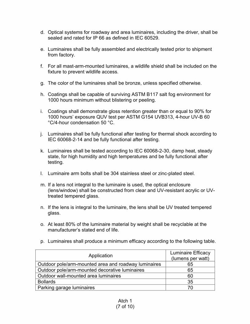
Atch 1(7 of 10)
d. Optical systems for roadway and area luminaires, including the driver, shall be sealed and rated for IP 66 as defined in IEC 60529.
e. Luminaires shall be fully assembled and electrically tested prior to shipment from factory.
f. For all mast-arm-mounted luminaires, a wildlife shield shall be included on the fixture to prevent wildlife access.
g. The color of the luminaires shall be bronze, unless specified otherwise.
h. Coatings shall be capable of surviving ASTM B117 salt fog environment for 1000 hours minimum without blistering or peeling.
i. Coatings shall demonstrate gloss retention greater than or equal to 90% for 1000 hours’ exposure QUV test per ASTM G154 UVB313, 4-hour UV-B 60 °C/4-hour condensation 50 °C.
j. Luminaires shall be fully functional after testing for thermal shock according to IEC 60068-2-14 and be fully functional after testing.
k. Luminaires shall be tested according to IEC 60068-2-30, damp heat, steady state, for high humidity and high temperatures and be fully functional after testing.
l. Luminaire arm bolts shall be 304 stainless steel or zinc-plated steel.
m. If a lens not integral to the luminaire is used, the optical enclosure (lens/window) shall be constructed from clear and UV-resistant acrylic or UV-treated tempered glass.
n. If the lens is integral to the luminaire, the lens shall be UV treated tempered glass.
o. At least 80% of the luminaire material by weight shall be recyclable at the manufacturer’s stated end of life.
p. Luminaires shall produce a minimum efficacy according to the following table.
Application Luminaire Efficacy(lumens per watt)
Outdoor pole/arm-mounted area and roadway luminaires 65Outdoor pole/arm-mounted decorative luminaires 65Outdoor wall-mounted area luminaires 60Bollards 35Parking garage luminaires 70
Atch 1(8 of 10)
q. Luminaires shall incorporate modular electrical connections and be constructed to allow replacement of all or part of the optics, heat sinks, power supply units, and electrical components using only a simple tool, such as a screwdriver.
r. Luminaires shall bear a nameplate inscribed with the manufacturer's name, address, model number, date of manufacture, and serial number, securelyaffixed in a conspicuous place. The nameplate of the distributing agent will not be acceptable.
s. Roadway and area mast-arm-mounted luminaires shall have an integral tilt adjustment of ±5°, in accordance with ANSI C136.3.
t. Luminaires must pass 3G vibration testing in accordance with ANSI C136.31.
u. Luminaires shall have surge protection to meet “C Low” waveforms as defined in ANSI/IEEE C62.41.2, Scenario 1 Location Category C.
v. Luminaires shall incorporate provisions to attach a twist-lock style photocell.
2-1.2 WIRING
Twist-style wire nuts and tap-style stripless connectors are not acceptable for factory electrical connections.
2-1.3 POWER SUPPLY UNITS
Note 1: Remove bracketed options that are not applicable to your project.
Note 2: Normal ambient temperature of 40 �C (104 �F) will be adequate for typical night-time operating environments. Selection of 50 �C (122 �F) will increase the system cost and should be used when required for a specific project location. Coordinate with [40] [50] bracketed options in other parts of specification as well. Use a dimmable driver for all applications that may utilize controls (e.g., curfew, motion sensing) as part of the project.
a. Minimum efficiency of 85%.
b. The maximum drive current to each individual LED shall not exceed 600 mA.
c. Rated to operate between -30 °C to [+40 °C] [+50 °C].
d. Designed to operate on voltage system [120V to 277V] [480V] nominal. Fluctuations in line voltage up to 15% shall have no visible effect on the luminous output.
e. Operating frequency: 50/60 Hz.
Atch 1(9 of 10)
f. ������������� ����������
g. ��������������������������������������������������!�".
h. Comply with FCC 47 CFR Section 15, Class B, non-consumer RFI/EMI standards.
i. Reduction of hazardous substances- (RoHS-) compliant.
j. Luminaires under a covered structure shall be UL-listed Class P with a sound rating of “A.”
k. Driver shall be dimmable and compatible with standard dimming control circuits.
l. Driver shall be protected against damage due to either an open-circuit or short-circuit fault condition on the driver output. The driver shall resume normal operation when the fault is removed.
m. Over-temperature protection shall be provided to cut off output power if temperature limit is exceeded. The driver shall resume normal operation when within normal operating temperature.
2-1.4 LED LIGHT SOURCE
Note 1: Select CCT values and CRI bracketed options based on application. If a design strategy is to blend with traditional lighting systems in the local area, pick a CCT in the 4,000-5,000 K range. This temperature is a warmer light source than 6500 K and provides a balance between color temperature, color rendering, and efficacy of the light source. LED chips are manufactured to achieve maximum efficacy related to a specific color temperature and this varies with chip manufacturer and binning.Note 2: High pressure sodium is 2700 K, warm metal halide is 3200 K, clear metal halide is 4000 K, and moonlight is 4100 K.Note 3: 6500 K is a cooler temperature and should only be used when color rendering or environmental concerns such as sky glow are not a factor. Objects appear bluish and items in the red color spectrum may appear distorted.
a. Correlated color temperature (CCT) shall be in accordance with ANSI C78.377.
� [Nominal CCT: 3000 K: 3045 ± 175 K]� [Nominal CCT 3500 K: 3465 ± 245 K]� [Nominal CCT: 4000 K: 3985 ± 275 K]� [Nominal CCT 4500 K: 4503 ± 243 K]� [Nominal CCT 5000 K: 5028 ± 283 K]� [Nominal CCT 5700 K: 5665 ± 355 K]
Atch 1(10 of 10)
� [Nominal CCT: 6500 K: 6530 ± 510 K]
b. Color Rendering Index (CRI) shall be > 65 for all CCTs.
c. Thermal management shall be passive by design and shall consist of heat sinks with no fans, pumps, or liquids.
2-2 ELECTRICAL SYSTEM
2-2.1 SURGE PROTECTION: Comply with ETL 12-15, paragraph 10.5.
2-2.2 DAYLIGHTING CONTROLS
a. All street, exterior parking lot, drive, and front aisle areas shall be controlled such that exterior luminaires shall not operate during hours of daylight.
b. Controls may include a combination photocell plus time switch or an energy management system.
c. Controls shall allow automatic on and off settings based on daylighting, plus timed off settings after expected activity ends.
d. The energy management system shall employ predetermined control strategies to include automatic dimming for adaptive standards, and remote control shall be in accordance with ETL 11-1, Civil Engineer Industrial Control System Information Assurance Compliance.
e. Consult Unified Facilities Guide Specification (UFGS) 26 56 00, Exterior Lighting, for photocell, time switch, and occupancy control requirements.
Atch 2(1 of 1)
DISTRIBUTION LIST
DEPARTMENT OF DEFENSE
Defense Commissary Agency (1)Design and Construction Division2250 Foulois St., Suite 2Lackland AFB, TX 78236
AAFES (1)ATTN: RE-CPO Box 660202Dallas, TX 75266-0202
SPECIAL INTEREST ORGANIZATIONS
Information Handling Services (1)15 Inverness Way EastEnglewood CO 80150
Construction Criteria Database (1)National Institute of Bldg. Sciences1201 L Street NW, Suite 400Washington, DC 20005

6 CES MAFB CONTRACTOR HAZMAT LIST PROJECT #
CONTRACTOR NAME: POC PHONE #
BRIEF PROJECT DESCRIPTION AND LOCATION 6CES/CEC POC
PRODUCT NAME MANUFACTURER
MANUFACTURER PART/PRODUCT
NUMBER CONTAINER
SIZE CONTAINER
TYPE ESTIMATED MAXIMUM
QUANTITY
BIO-ENVIRONMENTAL REVIEW SAFETY REVIEW ENVIRONMENTAL REVIEW
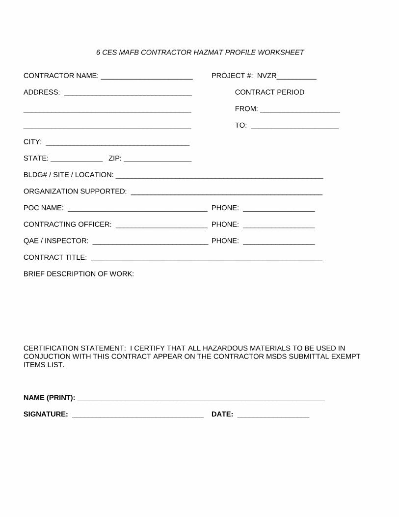
6 CES MAFB CONTRACTOR HAZMAT PROFILE WORKSHEET CONTRACTOR NAME: _______________________ PROJECT #: NVZR__________ ADDRESS: ________________________________ CONTRACT PERIOD __________________________________________ FROM: ____________________ __________________________________________ TO: ______________________ CITY: ____________________________________ STATE: _____________ ZIP: _________________ BLDG# / SITE / LOCATION: ____________________________________________________ ORGANIZATION SUPPORTED: ________________________________________________ POC NAME: ___________________________________ PHONE: __________________ CONTRACTING OFFICER: _______________________ PHONE: __________________ QAE / INSPECTOR: _____________________________ PHONE: __________________ CONTRACT TITLE: __________________________________________________________ BRIEF DESCRIPTION OF WORK: CERTIFICATION STATEMENT: I CERTIFY THAT ALL HAZARDOUS MATERIALS TO BE USED IN CONJUCTION WITH THIS CONTRACT APPEAR ON THE CONTRACTOR MSDS SUBMITTAL EXEMPT ITEMS LIST. NAME (PRINT): ______________________________________________________________ SIGNATURE: _________________________________ DATE: __________________
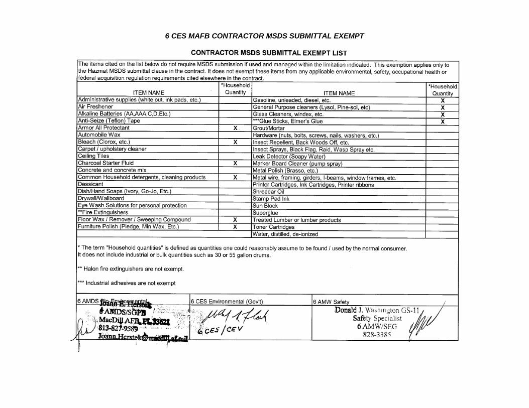
6 CES MAFB CONTRACTOR MSDS SUBMITTAL EXEMPT
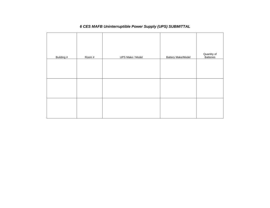
6 CES MAFB Uninterruptible Power Supply (UPS) SUBMITTAL
Building # Room # UPS Make / Model Battery Make/Model Quantity of Batteries
APPENDIX 15
REQUIREMENTS FOR FUGITIVE DUST
1. Emissions of Unconfined Particulate Matter. No person to cause, let, permit, suffer or allow
the emissions of unconfined particulate matter from any activity, including, but not limited
to, vehicular movement; transportation of materials; construction; alteration, demolition or
wrecking or industrial related activities such as loading, unloading, storing or handling;
without taking reasonable precautions to prevent such emissions. Reasonable Precautions
include, but are not limited to, the following:
a. Paving and Maintenance of roads, parking areas, and yards;
b. Application of water or chemicals to control emissions from such activities as
demolition of buildings, grading roads, construction, and land clearing;
c. Application of asphalt, water, oil, chemicals, or other dust suppressants to unpaved
roads, yards, open stock piles, and similar sources;
d. Removal of particulate matter from roads and other paved areas under the control of
the permittee to prevent reentrainment, and from buildings or work areas to prevent
particulate from becoming airborne;
e. Landscaping or planting of vegetation;
f. Use of hoods, fans, filters, and similar equipment to contain and/or vent particulate
matter; and
g. Confining abrasive blasting, where possible.
2. Keep dust down at all times, including during nonworking periods. Sprinkle or treat, with
dust suppressants, the soil at the site, haul roads, and other areas disturbed by operations.
Dry power brooming will not be permitted. Instead, use vacuuming, wet mopping, wet
sweeping, or wet power brooming. Air blowing will be permitted only for cleaning
nonparticulate debris such as steel reinforcing bars. Only wet cutting will be permitted for
cutting concrete blocks, concrete, and bituminous concrete. Do not unnecessarily shake bags
of cement, concrete mortar, or plaster.
3. Dirt and Fugitive Dust Control Plan Submittal
Submit truck and material haul routes along with a plan for controlling dirt, debris, and dust on
MacDill AFB. As a minimum, identify in the plan the subcontractor and equipment for cleaning
along the haul route and measures to reduce dirt, dust, and debris from roadways.
4. REFERENCES
UFGS-01 57 19.00 20 Temporary Environmental Controls
Rule 62-296.320(4)(c) Florida Administrative Code
APPENDIX 15
REQUIREMENTS FOR NATURAL GAS-FIRED HEATING UNITS OR OTHER
EXTERNAL COMBUSTION UNITS
External combustion sources include steam/electric generating plants, industrial boilers, and
commercial and domestic combustion units. Coal, fuel oil, and natural gas are the major fossil
fuels used by these sources. Liquefied petroleum fuels are also used in relatively small
quantities. Power generation, process heating, and space heating are some of the largest fuel
combustion sources of sulfur oxides, nitrogen oxides, and particulate emissions.
The contractor shall notify 6 CES/CEV 30 days prior to installation of any new permanent or
temporary natural gas-fired or other external combustion systems. The notification shall include,
at a minimum, the building number, manufacturer, model number, and heat input rating in
BTU/hour. All natural gas fired or other external combustion systems shall be added to the
MAFB Title V Air Operating Permit by 6 CES/CEV prior to installation by the contractor.
REFERENCES
Rule 62-210.300 Florida Administrative Code
AP-42, Volume I, Chapter 1: External Combustion Sources
APPENDIX 15
REQUIREMENTS FOR INTERNAL COMBUSTION ENGINES (ICE)
1. The contractor shall supply an Internal Combustion Engine in compliance with the U.S.
Environmental Protection Agency requirements, including but not limited to the
following:
Note: Unless otherwise noted, the latest version of a publication applies.
a. Engineering Technical Letter (ETL) 11-21 (Change 2): Emergency and Standby
Generator Design, Maintenance, and Testing Criteria
b. 40 CFR Part 60, Subpart IIII, Standards of Performance for Stationary Compression
Ignition Internal Combustion Engines
c. 40 CFR Part 60, Subpart JJJJ, Standards of Performance for Stationary Spark
Ignition Internal Combustion Engines
d. 40 CFR Part 63, Subpart ZZZZ, National Emissions Standards for Hazardous Air
Pollutants for Stationary Reciprocating Internal Combustion Engines
e. 40 CFR Part 89, Control of Emissions from New and In-Use Nonroad Compression-
Ignition Engines
f. 40 CFR Part 90, Control of Emissions from Nonroad Spark-Ignition Engines at or
Below 19 Kilowatts
g. 40 CFR Part 91, Control of Emissions from Marine Spark-Ignition Engines
h. 40 CFR Part 94, Control of Emissions from Marine Compression-Ignition Engines
i. 40 CFR Part 1039, Control of Emissions from New and In-Use Nonroad
Compression-Ignition Engines
j. 40 CFR Part 1048, Control of Emissions from New, Large Nonroad Spark-Ignition
Engines
k. 40 CFR Part 1054, Control of Emissions from New, Small Nonroad Spark-Ignition
Engines and Equipment
l. 40 CFR Part 1068, General Compliance Provisions for Highway, Stationary, and
Nonroad Programs
2. Engine Labeling: The engines shall be labeled according to the provisions including, but
not limited, 40 CFR parts 89, 90, 94, 1039 1042, 1048, 1054, or 1068, as required and
applicable.
3. Inspection: The engine is required to be inspected/accepted by 6 CES/CEV
4. Submittals
Note: Shall be provided at least 30 days prior to delivery of the Internal Combustion Engine
a. kW and Hp Rating
b. Engine Model Number
c. Engine Serial Number
d. Engine Technical Data Sheet and, if applicable, Emergency Generator or Fire Pump
Technical Data Sheet
e. Statement of Exhaust Emissions or Emission Data Sheet
f. USEPA Certificate of Conformity for the engine supplied
g. Documentation of presence of a non-resettable hour meter
APPENDIX 15
REQUIREMENTS FOR REFRIGERANTS
1. DEFINITIONS:
“Appliance” means any device which contains and uses a refrigerant and which is used for
household or commercial purposes, including any air conditioner, refrigerator, chiller, or freezer.
"Refrigerant" means any substance consisting in part or whole of a class I or class II ozone
depleting substance that is used for heat transfer purposes and provides a cooling effect.
"Substitute" means any chemical or product, whether existing or new, that is used by any person
as an EPA approved replacement for a class I or II ozone-depleting substance in a given
refrigeration or air-conditioning end-use.
"Class I substance" refers to the controlled substances contained in the list found on EPA's
website at the following address: http://www.epa.gov/ozone/science/ods/classone.html
"Class II substance" refers to the controlled substances contained in the list found on EPA's
website at the following address: http://www.epa.gov/ozone~science/ods/c1asstwo.html
"Full charge" means the amount of refrigerant required for normal operating characteristics and
conditions of the appliance as determined using one of the following four methods:
Use the equipment manufacturer's determination of the correct full charge for the
equipment,
Determine the full charge by making appropriate calculations based on component sizes,
density of refrigerant, volume of piping, and other relevant considerations;
Use actual measurements of the amount of refrigerant added or evacuated from the
appliance; and/or
Use an established range based on the best available data regarding the normal operating
characteristics and conditions for the appliance, where the midpoint of the range will
serve as the full charge and where records are maintained in accordance with §82.166( q).
2. SUBMITTALS
a. Provide the name, address, and phone number of any contractor/subcontractor contracted
by MacDill AFB/USACE/Others to service, maintain, repair and/or dispose of any
appliance containing a refrigerant.
b. Provide the name of each technician, including supervisors and managers, performing
any service, maintenance, repair and/or disposal of any appliance containing a refrigerant.
c. Provide a copy of each technician's certification indicating training in refrigerant
recycling by an EPA approved training program, including the date of certification for
each technician and the level of certification.
d. Answer “Yes”, if the appliance(s) the contractor installed, serviced, maintained, repaired
and/or disposed located within the jurisdiction of the MacDill AFB that contained and
used a class I, class II, or substitute refrigerant in amounts greater than 50 pounds.
e. If the answer to Question (d.) is “Yes” provide the following:
i. Facility Name
ii. Building #
iii. Appliance Model #

Issued by: Approved by:
The version of this document
which is posted on the TECO
Peoples Gas intranet is the only current, authorized version.
Version Date:
Corp. Engin. M. Haney May 20, 2009 Document by: Next Review Date: Replaces Version Date:
J. Wykoff May 2010 January 15, 2009
Construction
Standards
Manual
MAY 20, 2009 ANNUAL UPDATE
Only the version of this document which is posted
on the TECO Peoples Gas intranet website shall be considered the current, Authorized Version. See the next page for important information
regarding mid-year revisions and updates.
Forward corrections or suggestions to
Jeff Wykoff, Manager, Technical Services
[email protected], TECO Plaza 7
Title
Page
Construction Standards Manual
Issued by: Approved by:
The version of this document
which is posted on the TECO
Peoples Gas intranet is the only current, authorized version.
Version Date:
Corp. Engin. M. Haney May 26, 2009 Document by: Next Review Date: Replaces Version Date:
J. Wykoff May 2010 May 20, 2009
ANNUAL UPDATE 1. Annual update changes can be identified by a vertical line in the right margin. Removed text
appears as italicized strikethrough font and added text in underlined font. 2. Annual update changes are not highlighted (only mid-year revisions are). 3. For Annual Updates, the dates in all footers will change to reflect the update. 4. The table below summarizes the changes.
05/20/09
1. Title Page (date changed, disclaimer added)
2. Index and Footers – (changed page numbers, added disclaimer, changed dates)
3. Update and Revisions Tables (added new page)
4. Index Pages (corrected, updated page numbers)
5. Section 4.4, “Method of Construction, Welding Steel”, Item 3.a, “Welds” (additional reference language)
6. Section 4.5, “Testing of Welders (added Item 13, “Nondestructive Testing for Systems Operating with MAOP Less Than Twenty Percent (20%) SMYS”)
7. Section 5.3, ”Method of Construction, Installation of Plastic Pipe” (corrected item numbering)
8. Section 6.5, “Visual Inspection and Electrical Testing of Coating” (revised entire section)
9. Section 6.6, “Steel Fittings, Valves, and Appurtenance Coatings” (revised title and entire section)
MID-YEAR REVISIONS
1. Operations Leadership and Management teams shall be notified of revisions issued by Corporate
Engineering Services via electronic mail. 2. The revised version of the entire manual will be posted in the TECO Peoples Gas intranet page on
the date of the email notification.
3. Mid-year revisions are identified with highlighted text. Removed text appears in highlighted
strikethrough font and added text in highlighted underlined font. 4. The subsequent annual update will incorporate the previous annual update and mid-year revisions
by reverting to normal text font. 5. For mid-year revision issuances only, the date in the footer will be updated in just the affected
section(s).
6. It is the responsibility of Operations Leadership and Management to ensure all printed versions of this document are current and reflect the current, Authorized Version posted on the TECO Peoples Gas intranet website.
04/26/09 1. Section 4.5, “Testing of Welders”, Item 13, “Nondestructive Testing for Systems Operating
with MAOP Less Than Twenty Percent (20%) SMYS” (added conditions and clarifications).
.
.
.
.
Revision /
Updates
Log
Page
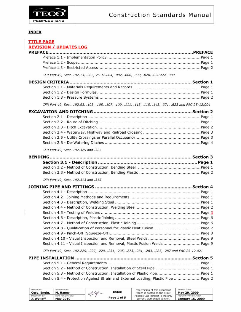
Construction Standards Manual
Issued by: Approved by:
The version of this document
which is posted on the TECO
Peoples Gas intranet is the only current, authorized version.
Version Date:
Corp. Engin. M. Haney May 20, 2009 Document by: Next Review Date: Replaces Version Date:
J. Wykoff May 2010 January 15, 2009
INDEX
TITLE PAGE
REVISION / UPDATES LOG
PREFACE ...................................................................................................... PREFACE
Preface 1.1 - Implementation Policy ......................................................................... Page 1
Preface 1.2 - Scope ................................................................................................ Page 1
Preface 1.3 - Restricted Access ................................................................................ Page 2
CFR Part 49, Sect. 192.13, .305, 25-12.004, .007, .008, .009, .020, .030 and .080
DESIGN CRITERIA ...................................................................................... Section 1
Section 1.1 - Materials Requirements and Records ..................................................... Page 1
Section 1.2 - Design Formulas ................................................................................. Page 1
Section 1.3 - Pressure Systems ............................................................................... Page 2
CFR Part 49, Sect. 192.53, .103, .105, .107, .109, .111, .113, .115, .143, .371, .623 and FAC 25-12.004
EXCAVATION AND DITCHING ..................................................................... Section 2
Section 2.1 - Description ........................................................................................ Page 1
Section 2.2 - Route of Ditching ................................................................................ Page 1
Section 2.3 - Ditch Excavation ................................................................................. Page 2
Section 2.4 - Waterway, Highway and Railroad Crossing ............................................. Page 3
Section 2.5 - Utility Crossings or Parallel Occupancy ................................................... Page 3
Section 2.6 - De-Watering Ditches ........................................................................... Page 4
CFR Part 49, Sect. 192.325 and .327
BENDING .................................................................................................... Section 3
Section 3.1 - Description ...................................................................... Page 1
Section 3.2 - Method of Construction, Bending Steel ................................................. Page 1
Section 3.3 - Method of Construction, Bending Plastic ................................................ Page 2
CFR Part 49, Sect. 192.313 and .315
JOINING PIPE AND FITTINGS .................................................................... Section 4
Section 4.1 - Description ........................................................................................ Page 1
Section 4.2 - Joining Methods and Requirements ....................................................... Page 1
Section 4.3 - Description, Welding Steel ................................................................... Page 1
Section 4.4 - Method of Construction, Welding Steel .................................................. Page 2
Section 4.5 - Testing of Welders .............................................................................. Page 3
Section 4.6 - Description, Plastic Joining ................................................................... Page 6
Section 4.7 - Method of Construction, Plastic Joining .................................................. Page 6
Section 4.8 - Qualification of Personnel for Plastic Heat Fusion ..................................... Page 7
Section 4.9 - Pinch-Off (Squeeze-Off) ....................................................................... Page 8
Section 4.10 - Visual Inspection and Removal, Steel Welds ......................................... Page 9
Section 4.11 - Visual Inspection and Removal, Plastic Fusion Welds ............................. Page 9
CFR Part 49, Sect. 192.225, .227, .229, .231, .235, .273, .281, .283, .285, .287 and FAC 25-12.021
PIPE INSTALLATION .................................................................................. Section 5
Section 5.1 - General Requirements ......................................................................... Page 1
Section 5.2 - Method of Construction, Installation of Steel Pipe .................................... Page 1
Section 5.3 - Method of Construction, Installation of Plastic Pipe .................................. Page 1
Section 5.4 - Protection Against Strain and External Loading, Plastic Pipe ..................... Page 2
Index
Page 1 of 5
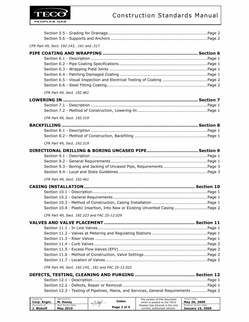
Construction Standards Manual
Issued by: Approved by:
The version of this document
which is posted on the TECO
Peoples Gas intranet is the only current, authorized version.
Version Date:
Corp. Engin. M. Haney May 20, 2009 Document by: Next Review Date: Replaces Version Date:
J. Wykoff May 2010 January 15, 2009
Section 5.5 - Grading for Drainage ........................................................................... Page 2
Section 5.6 - Supports and Anchors ......................................................................... Page 2
CFR Part 49, Sect. 192.143, .161 and .317
PIPE COATING AND WRAPPING ................................................................. Section 6
Section 6.1 - Description ........................................................................................ Page 1
Section 6.2 - Pipe Coating Specifications ................................................................... Page 1
Section 6.3 - Wrapping Field Joints .......................................................................... Page 1
Section 6.4 - Patching Damaged Coating .................................................................. Page 1
Section 6.5 - Visual Inspection and Electrical Testing of Coating .................................. Page 2
Section 6.6 - Steel Fitting Coating ............................................................................ Page 2
CFR Part 49, Sect. 192.461
LOWERING IN ............................................................................................ Section 7
Section 7.1 - Description ........................................................................................ Page 1
Section 7.2 - Method of Construction, Lowering-In ..................................................... Page 1
CFR Part 49, Sect. 192.319
BACKFILLING ............................................................................................. Section 8
Section 8.1 - Description ........................................................................................ Page 1
Section 8.2 - Method of Construction, Backfilling ....................................................... Page 1
CFR Part 49, Sect. 192.319
DIRECTIONAL DRILLING & BORING UNCASED PIPE ................................... Section 9
Section 9.1 - Description ........................................................................................ Page 1
Section 9.2 - General Requirements ......................................................................... Page 1
Section 9.3 - Boring and Jacking of Uncased Pipe, Requirements ................................. Page 3
Section 9.4 - Local and State Guidelines ................................................................... Page 3
CFR Part 49, Sect. 192.461
CASING INSTALLATION ............................................................................ Section 10
Section 10.1 - Description ....................................................................................... Page 1
Section 10.2 - General Requirements ....................................................................... Page 1
Section 10.3 - Method of Construction, Casing Installation .......................................... Page 1
Section 10.4 - Plastic Insertion, Into New or Existing Unvented Casing ......................... Page 2
CFR Part 49, Sect. 192.323 and FAC 25-12.029
VALVES AND VALVE PLACEMENT .............................................................. Section 11
Section 11.1 - In Line Valves ................................................................................... Page 1
Section 11.2 - Valves at Metering and Regulating Stations .......................................... Page 1
Section 11.3 - Riser Valves ..................................................................................... Page 1
Section 11.4 - Curb Valves ...................................................................................... Page 2
Section 11.5 - Excess Flow Valves (EFV) ................................................................... Page 2
Section 11.6 - Method of Construction, Valve Settings ................................................ Page 2
Section 11.7 - Location of Valves ............................................................................. Page 2
CFR Part 49, Sect. 192.145, .181 and FAC 25-12.022
DEFECTS, TESTING, CLEANING AND PURGING ......................................... Section 12
Section 12.1 - Description ....................................................................................... Page 1
Section 12.2 - Defects, Repair or Removal ................................................................ Page 1
Section 12.3 - Testing of Pipelines, Mains, and Services, General Requirements ............ Page 2
Index
Page 2 of 5
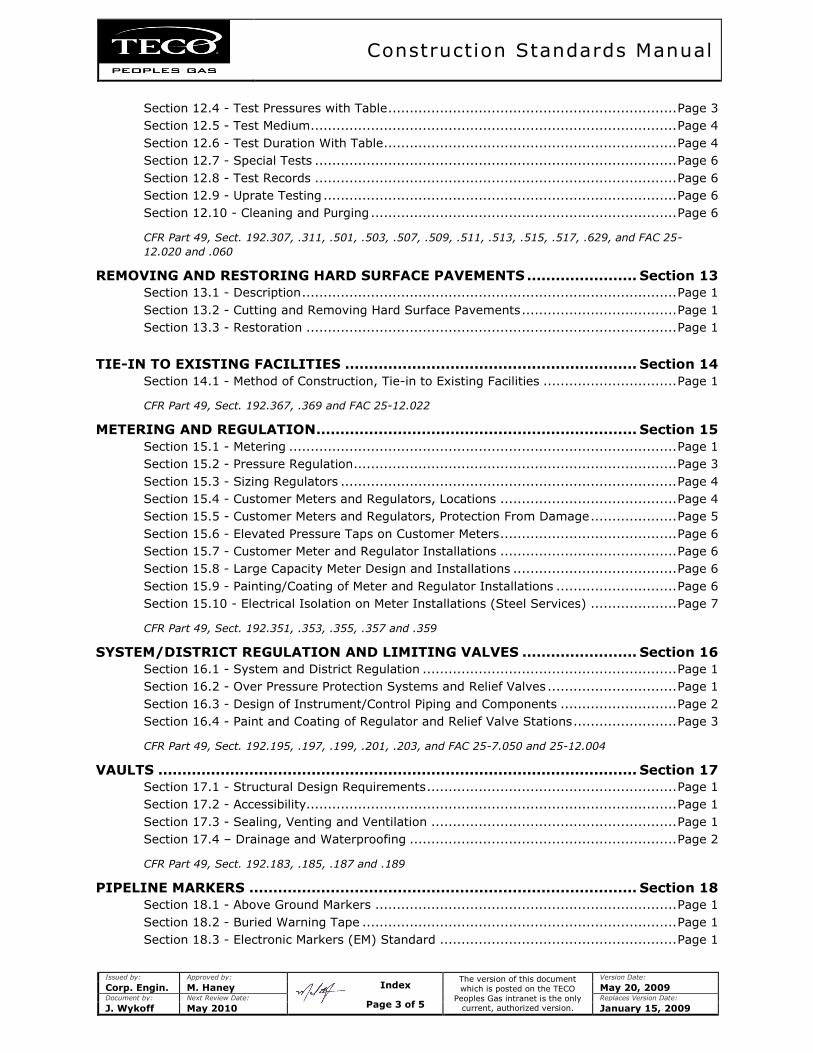
Construction Standards Manual
Issued by: Approved by:
The version of this document
which is posted on the TECO
Peoples Gas intranet is the only current, authorized version.
Version Date:
Corp. Engin. M. Haney May 20, 2009 Document by: Next Review Date: Replaces Version Date:
J. Wykoff May 2010 January 15, 2009
Section 12.4 - Test Pressures with Table ................................................................... Page 3
Section 12.5 - Test Medium ..................................................................................... Page 4
Section 12.6 - Test Duration With Table .................................................................... Page 4
Section 12.7 - Special Tests .................................................................................... Page 6
Section 12.8 - Test Records .................................................................................... Page 6
Section 12.9 - Uprate Testing .................................................................................. Page 6
Section 12.10 - Cleaning and Purging ....................................................................... Page 6
CFR Part 49, Sect. 192.307, .311, .501, .503, .507, .509, .511, .513, .515, .517, .629, and FAC 25-
12.020 and .060
REMOVING AND RESTORING HARD SURFACE PAVEMENTS ....................... Section 13
Section 13.1 - Description ....................................................................................... Page 1
Section 13.2 - Cutting and Removing Hard Surface Pavements .................................... Page 1
Section 13.3 - Restoration ...................................................................................... Page 1
TIE-IN TO EXISTING FACILITIES ............................................................. Section 14
Section 14.1 - Method of Construction, Tie-in to Existing Facilities ............................... Page 1
CFR Part 49, Sect. 192.367, .369 and FAC 25-12.022
METERING AND REGULATION ................................................................... Section 15
Section 15.1 - Metering .......................................................................................... Page 1
Section 15.2 - Pressure Regulation ........................................................................... Page 3
Section 15.3 - Sizing Regulators .............................................................................. Page 4
Section 15.4 - Customer Meters and Regulators, Locations ......................................... Page 4
Section 15.5 - Customer Meters and Regulators, Protection From Damage .................... Page 5
Section 15.6 - Elevated Pressure Taps on Customer Meters ......................................... Page 6
Section 15.7 - Customer Meter and Regulator Installations ......................................... Page 6
Section 15.8 - Large Capacity Meter Design and Installations ...................................... Page 6
Section 15.9 - Painting/Coating of Meter and Regulator Installations ............................ Page 6
Section 15.10 - Electrical Isolation on Meter Installations (Steel Services) .................... Page 7
CFR Part 49, Sect. 192.351, .353, .355, .357 and .359
SYSTEM/DISTRICT REGULATION AND LIMITING VALVES ........................ Section 16
Section 16.1 - System and District Regulation ........................................................... Page 1
Section 16.2 - Over Pressure Protection Systems and Relief Valves .............................. Page 1
Section 16.3 - Design of Instrument/Control Piping and Components ........................... Page 2
Section 16.4 - Paint and Coating of Regulator and Relief Valve Stations ........................ Page 3
CFR Part 49, Sect. 192.195, .197, .199, .201, .203, and FAC 25-7.050 and 25-12.004
VAULTS .................................................................................................... Section 17
Section 17.1 - Structural Design Requirements .......................................................... Page 1
Section 17.2 - Accessibility...................................................................................... Page 1
Section 17.3 - Sealing, Venting and Ventilation ......................................................... Page 1
Section 17.4 – Drainage and Waterproofing .............................................................. Page 2
CFR Part 49, Sect. 192.183, .185, .187 and .189
PIPELINE MARKERS ................................................................................. Section 18
Section 18.1 - Above Ground Markers ...................................................................... Page 1
Section 18.2 - Buried Warning Tape ......................................................................... Page 1
Section 18.3 - Electronic Markers (EM) Standard ....................................................... Page 1
Index
Page 3 of 5
Construction Standards Manual
Issued by: Approved by:
The version of this document
which is posted on the TECO
Peoples Gas intranet is the only current, authorized version.
Version Date:
Corp. Engin. M. Haney May 20, 2009 Document by: Next Review Date: Replaces Version Date:
J. Wykoff May 2010 January 15, 2009
CFR Part 49, Sect. 192.707
CLASS LOCATIONS ................................................................................... Section 19
Section 19.1 - Description ....................................................................................... Page 1
Section 19.2 - Building and Dwelling Count by Class .................................................. Page 1
Section 19.3 - Boundaries ....................................................................................... Page 1
CFR Part 49, Sect. 192.5
CORROSION CONTROL ............................................................................. Section 20
Section 20.1 - Description ....................................................................................... Page 1
Section 20.2 - External Corrosion Control for Buried or Submerged Pipelines ................. Page 1
Section 20.3 - Coating System ................................................................................ Page 1
Section 20.4 - Protective Coatings and Surface Preparation ......................................... Page 1
Section 20.5 - Cathodic Protection System ................................................................ Page 2
Section 20.6 - Electrical Isolation ............................................................................. Page 2
Section 20.7 - Test Point Stations ............................................................................ Page 3
Section 20.8 - Test Leads ....................................................................................... Page 4
Section 20.9 - Interference Currents ........................................................................ Page 4
Section 20.10 - Atmospheric Protection .................................................................... Page 5
CFR Part 49, Sect. 192 Subpart I
CLEARING AND GRADING ......................................................................... Section 21
Section 21.1 - Description ....................................................................................... Page 1
Section 21.2 - Method of Construction, Clearing and Grading ...................................... Page 1
CONSTRUCTION NOTIFICATION ............................................................... Section 22
Section 22.1 - Notice of Major Construction ............................................................... Page 1
FAC 25-12.080 and .082
MATERIAL SPECIFICATIONS .................................................................... Section 23
Section 23.1 – Records ........................................................................................... Page 1
Section 23.2 – Standard Material List ....................................................................... Page 1
Section 23.3 – Non-Conformance to Florida Public Service Commission Rules ................ Page 1
Section 23.4 – Pipe and Fitting Markings ................................................................... Page 1
CFR Part 49, Sect. 192.63 and FAC 25-12.028
BARRICADING WORK AREAS, GUIDELINES .............................................. Section 24
Section 24.1 – Objectives ....................................................................................... Page 1
Section 24.2 – Traffic Control .................................................................................. Page 1
HAULING AND STRINGING ....................................................................... Section 25
Section 25.1 - Description ....................................................................................... Page 1
Section 25.2 - Method of Construction, Hauling and Stringing ...................................... Page 1
STREAM CROSSINGS ................................................................................ Section 26
Section 26.1 - Description ....................................................................................... Page 1
Section 26.2 - Method of Construction ...................................................................... Page 1
Index
Page 4 of 5
Construction Standards Manual
Issued by: Approved by:
The version of this document
which is posted on the TECO
Peoples Gas intranet is the only current, authorized version.
Version Date:
Corp. Engin. M. Haney May 20, 2009 Document by: Next Review Date: Replaces Version Date:
J. Wykoff May 2010 January 15, 2009
RIVER CLAMPS AND ANCHORS ................................................................. Section 27
Section 27.1 - Description ....................................................................................... Page 1
Section 27.2 - Method of Construction, River Clamps and Anchors ............................... Page 1
CLEAN UP ................................................................................................. Section 28
Section 28.1 - Description ....................................................................................... Page 1
Section 28.2 - Method of Construction, Clean Up ....................................................... Page 1
INSTALLATION OF GAS SERVICE LINES ................................................... Section 29
Section 29.1 - Description ....................................................................................... Page 1
Section 29.2 - Method of Construction, Installation of Gas Service Lines ....................... Page 1
Section 29.3 - Method of Construction, Gas Service Lines Into Buildings ....................... Page 1
Section 29.4 - Method of Construction, Gas Service Lines Under Buildings .................... Page 1
Section 29.5 - Plastic Service Lines .......................................................................... Page 2
Section 29.6 - Risers .............................................................................................. Page 2
CFR Part 49, Sect. 192.361 and FAC 25-12.024
Index
Page 5 of 5
Construction Standards Manual
Issued by: Approved by:
The version of this document
which is posted on the TECO
Peoples Gas intranet is the only current, authorized version.
Version Date:
Corp. Engin. M. Haney May 20, 2009 Document by: Next Review Date: Replaces Version Date:
J. Wykoff May 2010 January 15, 2009
PREFACE
Preface 1.1 – Implementation Policy
1. It is the policy of TECO Peoples Gas (Peoples Gas) to construct, operate and maintain natural
gas systems in a manner which is safe and consistent with good industry practice.
2. Furthermore, Peoples Gas shall comply with all federal, state and local gas codes; generally,
these codes set minimum standards but do not specify the manner in which the minimums are
to be achieved.
a. Therefore, Peoples Gas has issued this Construction Standards Manual and any
supplemental documents, the Operating and Maintenance Procedures Manual,
the Appendix B - Standard Material List, Appendix C - Standard for Pressure
Piping -Joining By Welding, and the Emergency Procedures Manual, all of which
are used in achieving its goals as well as the requirements of the codes.
3. The records, reports, and forms required by the regulations covered by these policies may be
in either paper or electronic form, and archived as appropriate.
4. The Division Manager shall be responsible for the implementation of the policy unless
otherwise identified.
a. The following words and phrases which are used throughout the manual are used
synonymously: local operating center, Supervisor, Supervisor in charge of the
operation, Division Manager, and Division Manager’s designated representative.
5. Where the word “include” occurs, it means including but not limited to. Where the word “may”
is used it means “is permitted to” or “is authorized to”. Where the words “may not” are used it
means “is not permitted to” or “is not authorized to”. Where the word “shall” is used it is used
in the mandatory and imperative sense. Where a singular word tense is used, it includes the
plural. Where a plural word tense is used, it includes the singular. Where a masculine gender
word is used, it includes the feminine, and vice versa.
Preface 1.2 – Scope
1. This Construction Standards Manual covers the design and construction practices associated
with the Peoples Gas natural gas distribution system, with the intent that all components of
the Peoples Gas distribution system are consistently installed and maintained in a manner
that:
a. meets state of Florida and federal requirements;
b. provides for public safety;
c. ensures efficient design;
d. protects the environment; and,
e. exemplifies the use of best industry practices in order to provide reliability.
2. The scope of this manual is limited to the Peoples Gas pipeline system starting from the outlet
of the sale meter from the natural gas suppliers to the outlet of the customer’s meter.
(continued)
Preface
Page 1 of 2
Construction Standards Manual
Issued by: Approved by:
The version of this document
which is posted on the TECO
Peoples Gas intranet is the only current, authorized version.
Version Date:
Corp. Engin. M. Haney May 20, 2009 Document by: Next Review Date: Replaces Version Date:
J. Wykoff May 2010 January 15, 2009
3. This manual addresses requirements of federal regulations as embodied in CFR 49,
Part 192, Pipeline Safety Regulations and the Florida Public Service Commission embodied in
the state of Florida Administrative Code (FAC), Chapters 25-7 and 25-12 (said rules are
incorporated into these standards by reference).
4. Field inspections shall be conducted sufficient to assure compliance with these Construction
Standards.
5. The Implementation Policy described in the Peoples Gas Operating and Maintenance
Procedures Manual is incorporated into this Manual.
Reference: CFR49 Parts 192.13 and 192.305; FAC 25-12.004, .007, .008, .009, .020, .030 and .080.
Preface 1.3 – Restricted Access
This document is restricted to use by Peoples Gas employees, authorized contractors and their
employees, and regulatory personnel. If found, please mail this handbook to TECO Peoples Gas, P.O.
Box 2562, Tampa, Florida 33601-2562, Attention: Engineering Services Department/Plaza 7.
Telephone (800) 282-4441 or contact the local TECO Peoples Gas office.
Preface
Page 2 of 2
Construction Standards Manual
Issued by: Approved by:
The version of this document
which is posted on the TECO
Peoples Gas intranet is the only current, authorized version.
Version Date:
Corp. Engin. M. Haney May 20, 2009 Document by: Next Review Date: Replaces Version Date:
J. Wykoff May 2010 January 15, 2009
SECTION 1 - DESIGN CRITERIA
Section 1.1 – Materials Requirements and Records
1. All pipeline materials used in the Peoples Gas distribution systems, including all pipeline and
service line appurtenances:
a. must be capable of maintaining their structural integrity under anticipated
temperature and environmental conditions;
b. must be chemically compatible with the gas being transported;
c. must comply with the requirements of Section 23, “Material Specifications” of this
manual;
d. must be listed as an approved item in the Peoples Gas document, Appendix B -
Standard Material List (or as approved by Peoples Gas’ corporate Engineering
Services), which is incorporated as a part of the Peoples Gas Construction Standards;
and,
e. must be purchased through the Peoples Gas Purchasing Department (including all
emergency orders).
2. A record of all materials used shall be made for each construction and maintenance project on
Peoples Gas systems using the appropriate Peoples Gas form(s) applicable to the work being
performed.
Section 1.2 - Design Formulas
1. Steel pipelines must be designed in accordance with the following:
P = 2St x F x E x T
D
where:
P = design pressure in pounds per square inch gage (PSIG);
S = yield strength in pounds per square inch (as stated in the listed specifications
of the pipe);
D = nominal outside diameter of the pipe in inches (as shown on the mill test
reports);
t = nominal wall thickness of the pipe in inches (as shown on the mill test
reports);
F = design factor;
E = longitudinal joint factor (1.00 for API specification 5L and 0.60 for ASTM A53
Furnace Butt Weld); and,
T = temperature de-rating factor (1.00 when the gas temperature is less than two
hundred fifty degrees Fahrenheit (250°F).
(continued)
Section 1
Page 1 of 3
Construction Standards Manual
Issued by: Approved by:
The version of this document
which is posted on the TECO
Peoples Gas intranet is the only current, authorized version.
Version Date:
Corp. Engin. M. Haney May 20, 2009 Document by: Next Review Date: Replaces Version Date:
J. Wykoff May 2010 January 15, 2009
2. See the Peoples Gas document Appendix B - Standard Material List for the approved steel
pipe.
3. X-trube tubing shall not be installed within the Peoples Gas distribution system.
4. Each steel service line to be operated at less than one hundred pounds per square inch gage
(100 PSIG) must be constructed of pipe designed for a minimum of one hundred pounds per
square inch gage (100 PSIG).
5. Plastic (PE) pipelines shall be designed using the following:
P = 2St x .32
(D-t)
where:
P = design pressure in pounds per square inch gage (PSIG);
S = Long Term Hydrostatic strength in pounds per square inch (PE2406 Type II
Grade 3 material is one thousand two hundred fifty pound per square inch
gage (1250 PSIG);
t = specified wall thickness in inches; and,
D = specified outside diameter in inches.
Section 1.3 - Pressure Systems
1. See also Section 12.0, “Defects, Testing, Cleaning and Purging” for pressure test
requirements.
2. Utilization Pressure Systems
a. All utilization pressure gas distribution systems shall be designed so that the normal
operating pressure shall be seven inches water column (7" WC) for natural gas.
i. NOTE: the maximum allowable operating pressure shall be fourteen inches
water column (14" WC) for natural gas.
b. Care should be exercised to assure that the gas distribution system is not operated at
a pressure of less than five inches water column (5" WC) even under peak conditions.
c. Plastic pipe gas mains and service lines may be installed in utilization pressure
systems.
3. Medium Pressure Systems
a. All medium pressure gas distribution systems shall be designed to operate at a
maximum pressure of ten pounds per square inch gage (10 PSIG) and a minimum
pressure of one pound per square inch gage (1 PSIG).
b. Plastic pipe gas mains and service lines may be installed in medium pressure gas
distribution systems.
(continued)
Section 1
Page 2 of 3

Construction Standards Manual
Issued by: Approved by:
The version of this document
which is posted on the TECO
Peoples Gas intranet is the only current, authorized version.
Version Date:
Corp. Engin. M. Haney May 20, 2009 Document by: Next Review Date: Replaces Version Date:
J. Wykoff May 2010 January 15, 2009
4. Intermediate Pressure Systems
a. All intermediate pressure gas distribution systems shall be designed to operate at a
maximum pressure of sixty pounds per square inch gage (60 PSIG) and a minimum
pressure of ten pounds per square inch gage (10 PSIG).
b. Plastic pipe gas mains and service lines may be installed in intermediate pressure gas
distribution systems.
5. High Pressure Systems
a. All high pressure gas distribution systems shall be designed to operate at the
maximum allowable delivery pressure of the gas distribution system and at a
minimum pressure of sixty pounds per square inch gage (60 PSIG).
b. The maximum actual delivery pressure, however, must not exceed a pressure which
will produce a hoop stress in the pipe in excess of twenty percent of the specified
minimum yield strength (20% of SMYS).
c. Plastic pipe gas mains and service lines shall not be installed in high pressure gas
distribution systems without prior approval of the Peoples Gas’ corporate Engineering
Services department.
6. Transmission Pressure Systems
a. Any pipeline that operates at a pressure that produces a hoop stress in excess of
twenty percent specified minimum yield strength (20% of SMYS) shall be considered a
transmission system.
b. Transmission pipelines may have special construction requirements and all such
pipelines shall be designed by and installed under the direction of Peoples Gas’
corporate Engineering Services.
c. New transmission pipe, valves, fittings, or other line components installed after May
23, 2007 must have features incorporated into the design and construction to reduce
the risk of internal corrosion.
d. Unless it is impracticable to do so, each new transmission line or replacement of line
pipe, valve, fitting, or other line component shall:
i. be configured to reduce the risk that liquids will collect in the line;
ii. have effective liquid removal features; and,
iii. allow the use of devices for monitoring internal corrosion at locations with
significant potential for internal corrosion.
e. When an operator changes the configuration of a transmission line, design criteria
shall consider the impact on the existing downstream system for the risk of increased
internal corrosion.
i. Records and/or written procedures must be maintained that demonstrate
compliance with this criteria.
f. Any physical or operational change(s) or modification(s) to transmission lines must be
designed, approved and implemented by Peoples Gas’ corporate Engineering Services.
g. Only steel pipe shall be used in transmission systems.
Section 1
Page 3 of 3
Construction Standards Manual
Issued by: Approved by:
The version of this document
which is posted on the TECO
Peoples Gas intranet is the only current, authorized version.
Version Date:
Corp. Engin. M. Haney May 20, 2009 Document by: Next Review Date: Replaces Version Date:
J. Wykoff May 2010 January 15, 2009
SECTION 2 - EXCAVATION AND DITCHING
Section 2.1 - Description
1. Section 2, “Excavation and Ditching” includes:
a. all excavation, whether by trenching machine, by plowing-in, by power shovel, by
hand, or by other methods which may be necessary after clearing and grading has
been completed (as specified in Section 21, “Clearing and Grading” of these
Standards); and,
b. the preparation of a trench or bell hole in which construction or maintenance work is
to be undertaken.
2. The word "ditching" as used herein shall mean:
a. the maintenance of the ditch or bell hole;
b. temporary damming, pumping, bailing, draining and dewatering where required; and,
c. the furnishings and placing of any temporary shoring used to maintain the ditch.
3. Installation of plastic pipe by "plow" or "plowing-in" is acceptable provided adequate care is
taken to assure that the pipe and tracer wire is not damaged due to cuts or abrasions or
subjected to stretching during installation.
4. It is Peoples Gas’ policy to protect all wetlands and other environmentally sensitive areas
whether or not they are indicated on construction drawings.
a. To prevent spilling or dumping spoil into wetlands, drainage systems or natural bodies
of water, silt screens and other protection devices shall be used.
b. Spoil must be placed upland or removed from the site.
c. Spoil shall not be placed (even temporarily) in wetland or drainage areas.
d. The jurisdictional authority will make the determination in questionable areas as to
whether an area is a wetland or environmentally sensitive area.
Section 2.2 - Route of Ditching
1. The route laid out along right-of-way not under paved streets or highways will be established
insofar as possible to avoid damage to trees or their roots, but where major roots of trees are
encountered, the ditch shall be altered to avoid damage to roots by ditching around or under
said roots.
2. All stumps and roots shall be cut out of the ditch line and removed to at least six inches (6")
below ditch grade and clean fill shall be used to back-fill and tamp.
a. No chips or parts of stumps shall be left in the ditch.
2. The spoil bank from ditching operations should not be mixed with loose debris or foreign
matter that then might be used in backfilling the ditch line.
(continued)
Section 2
Page 1 of 4
Construction Standards Manual
Issued by: Approved by:
The version of this document
which is posted on the TECO
Peoples Gas intranet is the only current, authorized version.
Version Date:
Corp. Engin. M. Haney May 20, 2009 Document by: Next Review Date: Replaces Version Date:
J. Wykoff May 2010 January 15, 2009
3. Prior to any excavation, notification to the Sunshine State One Call Center of Florida shall be
made as required by the "Underground Facility Damage Safety Act", Chapter 556, Florida
Statutes.
4. Existing utilities and appurtenances crossing or in immediate proximity to the ditch shall be
located and necessary action taken to safeguard them during excavation (See Section 2.5,
“Utility Crossing or Parallel Occupancy”, below, for minimum clearances and other
requirements).
Section 2.3 - Ditch Excavation
1. Ditches shall be excavated for each size range of pipe within maximum widths throughout the
ditch depths (see table shown below), and to minimum widths and depths to provide minimum
cover:
Minimum Maximum
Pipe Size Width of Ditch Width of Ditch*
4" and smaller Twice pipe diameter 12"
6" to 12" Twice pipe diameter 24"
*The Division Manager can waive these limitations where ground conditions warrant.
2. Unless otherwise specified by the governing authority, the minimum cover over distribution
piping shall be twenty four inches (24”); service lines shall be eighteen inches (18”) on public
right-of-way and twelve inches (12”) when on private property.
a. Where these cover provisions cannot be met or where external loads may be
excessive, the pipeline shall be cased, bridged, or specially designed to withstand
anticipated load.
3. Unless otherwise specified by the governing authority, each buried transmission line must be
installed with the minimum cover as follows:
Location Normal Soil Consolidated Rock
Class 1* 30" 18"
Class 2, 3, and 4* 36" 24"
Drainage Ditches or Public Roads 36" 24"
* Note: class locations are defined below in this Construction Standards Manual, Section
19, “Class Locations”.
4. The depth of cover shall be measured from the average level of the paved thoroughfare or
graded right-of-way of the two sides of the ditch to the top of pipe or pipe covering after pipe
has been installed in the ditch.
5. The ditch shall be true to line and grade as established and shall be carefully graded by hand
wherever necessary to meet the requirements of this section and to provide an even bed for
the full length of pipe.
(continued)
Section 2
Page 2 of 4
Construction Standards Manual
Issued by: Approved by:
The version of this document
which is posted on the TECO
Peoples Gas intranet is the only current, authorized version.
Version Date:
Corp. Engin. M. Haney May 20, 2009 Document by: Next Review Date: Replaces Version Date:
J. Wykoff May 2010 January 15, 2009
6. Employees in an excavation shall be protected from cave-in in accordance with the TECO
Peoples Gas Excavation Program and OSHA (29 CFR, Part 1926), Subpart P – Excavations.
7. Where pedestrian or vehicular traffic is to be maintained over or adjacent to excavations,
proper safeguards shall be provided to protect the traffic and the excavation in accordance
with Peoples Gas System, governmental or other applicable Americans with Disability Act
requirements (such safeguards shall include but not be limited to walkways, bridges, guard
rails, warning lights, etc.).
8. Undercutting of the sides of excavations shall not be permitted unless special shoring or
bracing is installed.
9. Tunneling or cave-type excavations in the sidewall of the excavation will not be permitted.
10. A safety hat shall be worn by all personnel required to pass through or work in areas where
there is danger of being struck by objects or materials.
11. If petroleum contaminated soils or water are encountered, excavation is to stop immediately
and notification given to the Division Manager and Peoples Gas’ corporate Engineering
Services.
12. NOTE: Should any of the above standards in this section be interpreted to be in conflict with
OSHA Standards, the OSHA requirement will be the controlling regulation.
Section 2.4 - Waterway, Highway and Railroad Crossing
1. Along approaches to any waterway, highway or railroad crossing, the depth of ditch shall be
increased to the extent considered necessary to allow gradual change in the bottom of the
ditch to permit the pipe to bend gradually and naturally in following the ditch bottom.
Section 2.5 - Utility Crossing or Parallel Occupancy
1. Where a distribution main or service line crosses over or under interfering pipes of other
utilities, appurtenances or other underground structures, a minimum separation of six inches
(6”) should be maintained.
a. The bottom of the ditch should be lowered or raised, or the ditch relocated laterally to
maintain the desired clearance.
b. Should raising of the ditch reduce the specified normal cover to the extent that less
than the required six inch (6”) clearance is provided, the clearance should be obtained
by lowering the gas line if the raised pipe would have less than the minimum cover
allowed in the Construction Standards.
c. If this clearance cannot be attained, the line must be protected from damage that
might result from the proximity of the other structure.
2. Where a transmission line crosses over or under interfering pipes of other utilities,
appurtenances or other underground structures, a minimum separation of not less than twelve
inches (12”) should be maintained.
(continued)
Section 2
Page 3 of 4
Construction Standards Manual
Issued by: Approved by:
The version of this document
which is posted on the TECO
Peoples Gas intranet is the only current, authorized version.
Version Date:
Corp. Engin. M. Haney May 20, 2009 Document by: Next Review Date: Replaces Version Date:
J. Wykoff May 2010 January 15, 2009
a. The bottom of the ditch should be lowered or raised, or the ditch relocated laterally to
maintain the desired clearance.
b. Should raising of the ditch reduce the specified normal cover, to the extent that less
than the required twelve inch (12”) clearance is provided, the clearance should be
obtained by lowering the gas line if the raised pipe would have less than the minimum
cover allowed in these Construction Standards.
c. If this clearance cannot be attained, the line must be protected from damage that
might result from the proximity of the other structure.
3. Where raised pipe will rest on backfilled material, backfill shall be thoroughly tamped to
provide solid bearing for the pipe.
4. The depth of ditch shall increase or decrease gradually to allow the pipe to bend gradually and
naturally in following the ditch bottom without requiring bends in the pipe.
5. Where a transmission line, distribution main, or service line parallels other lines, not less than
twelve inches (12”) separation will be maintained from such other lines.
a. The required separation from parallel lines shall be obtained by moving the ditch line
laterally rather than through reduction of the normal minimum cover over the gas line.
b. In those instances where maintenance of the minimum clearance between pipes is
impracticable, such separation may be reduced provided an adequate insulating
material, fiberboard or other non-electrical conductive cushioning material is placed
between the pipes.
c. The foregoing clearances shall be the minimum clearances allowable, but if the owners
of interfering lines or regulatory authorities require greater clearances, such
reasonable requirements shall be complied with.
6. Each plastic pipe main or service line must be installed with sufficient clearance, or must be
insulated from any sources of heat, so as to prevent that heat from impairing the serviceability
of the pipe.
Section 2.6 - De-Watering Ditches
1. Where pumping of ditches in urban areas is required, whether due to presence of storm water
or ground water, special care shall be given to avoid any damage or disfigurement to either
private or public property including streets.
2. Constant vigilance shall be maintained to prevent the entrance of water into the gas pipe.
Section 2
Page 4 of 4
Construction Standards Manual
Issued by: Approved by:
The version of this document
which is posted on the TECO
Peoples Gas intranet is the only current, authorized version.
Version Date:
Corp. Engin. M. Haney May 20, 2009 Document by: Next Review Date: Replaces Version Date:
J. Wykoff May 2010 January 15, 2009
SECTION 3 - BENDING
Section 3.1 - Description
1. Section 3, “Bending”, includes all work necessary to shape the pipe to conform to the trench.
Section 3.2 - Method of Construction, Bending Steel
1. The intent of this section of the Construction Standards is to provide for the use of factory
fabricated tube turns (elbows) for direction changes.
a. However, under certain circumstances, it may be necessary to effect a change in
direction of the pipe by cold field bends which shall be permitted only with the
approval of the Division Manager.
2. Where the terrain is such that the pipe will not conform to the profile of the ditch, bends shall
be placed in the pipe at points which will coincide with points of change in the grade of the
ditch.
3. All bends shall be made so that there will be a minimum of five feet (5’) between any
circumferential weld, coupling, collar, etc. in the pipe and the nearest part of the bend.
4. All sag bends and side bends shall fit the trench neatly, and over bends shall be eight inches
(8”) to twelve inches (12”) above the trench bottom.
5. All side bends shall rest against the wall of the trench farthest from the inside of the curvature
of the bend.
6. Transmission lines which operate at a pressure producing a hoop stress of twenty percent
(20%) or more of the specified minimum yield strength (SMYS) must be installed so that the
pipe fits the ditch so as to minimize stresses and protect the pipe coating.
7. All bends shall be free from buckling, cracks or other evidence of mechanical damage.
8. All bends, other than wrinkle bends, shall not have a difference between the maximum and
minimum diameters in excess of two and one half percent (2.5%) of the normal diameter.
9. In addition, for cold bends on sizes twelve inches (12”) and larger, the longitudinal axis of the
pipe shall not be deflected more than fifteen degrees (15) in any length along the pipe axis
equal to the diameter of the pipe.
10. The difference between the minimum and maximum diameters does not apply to cold field
bends on API 5L pipe four inches (4”) and smaller in diameter, operating at ten percent (10%)
or less of the specified minimum yield strength (SMYS) providing the radii is equal to, or
greater than, five (5) times the diameter of the pipe and there is not a circumferential weld in
the bend.
11. Wrinkle bends are not permitted on pipe that produces a hoop stress of thirty percent (30%)
or more of specified minimum yield strength (SMYS).
(continued)
Section 3
Page 1 of 2

Construction Standards Manual
Issued by: Approved by:
The version of this document
which is posted on the TECO
Peoples Gas intranet is the only current, authorized version.
Version Date:
Corp. Engin. M. Haney May 20, 2009 Document by: Next Review Date: Replaces Version Date:
J. Wykoff May 2010 January 15, 2009
12. When wrinkle bends are made in welded pipe, the longitudinal weld shall be located as near as
practicable to the neutral axis of the bend.
13. The bend must not have any sharp kinks and the crotch of the wrinkles must be a distance of
at least one pipe diameter apart.
14. All wrinkle bends shall be reported to and approved by Peoples Gas’ corporate Engineering
Services.
14. No circumferential welds are permitted in the bend.
Section 3.3 - Method of Construction, Bending Plastic
1. When plastic pipe is installed, factory fabricated fittings (elbows) shall be used for sharp
direction changes, take-offs, etc. All plastic pipe and fittings shall be installed according to
manufacturer’s installation specifications.
Section 3
Page 2 of 2
Construction Standards Manual
Issued by: Approved by:
The version of this document
which is posted on the TECO
Peoples Gas intranet is the only current, authorized version.
Version Date:
Corp. Engin. M. Haney May 26, 2009 Document by: Next Review Date: Replaces Version Date:
J. Wykoff May 2010 May 20, 2009
SECTION 4 - JOINING PIPE AND FITTINGS
Section 4.1 – Description
1. Section 4, “Joining Pipe and Fittings” includes all work necessary for welding or fusing pipe
joints.
Section 4.2 - Joining Methods and Requirements
1. This section shall include work necessary for welding or fusing pipe joints.
2. This sub-part does not apply to joining during the manufacture of pipe or pipeline components,
all joints shall met the minimum requirement for joining materials in pipelines, other than by
welding.
3. All joints shall meet the minimum requirement for joining materials in pipelines, other than by
welding.
4. All joining will be made in such a manner that the strength of the joint exceeds the minimum
stress and strain factors of the pipe as specified by the manufacturer.
5. All joints made should sustain the longitudinal pullout or thrust forces caused by contraction or
expansion of the piping system or by anticipated external or internal loading.
6. Each joint must be made in accordance with the written procedures of this manual that have
been proven by test or experience to produce strong gas tight joints.
7. Joints shall be made by persons qualified through experience or training and having
successfully completed the Peoples Gas testing procedures.
8. Each joint will be visually inspected upon completion to insure compliance with procedures.
Section 4.3 - Description, Welding Steel
1. All electric and gas welding shall comply with written procedures (See Appendix C -
Standard for Pressure Piping -Joining By Welding).
2. All welders must be qualified showing they have successfully completed the Peoples Gas
welder qualification test procedures within the period specified in Appendix C - Standard for
Pressure Piping -Joining By Welding.
3. Acetylene welding of pipe joints is required on pipe sizes one and three quarters inches (1-
3/4”) nominal diameter and smaller.
4. Acetylene or electric arc welding of pipe joints may be used for pipe sized larger than one and
three quarters inches (1-3/4”) nominal diameter up through two and three eighths (2-3/8”)
inches nominal diameter.
5. Electric arc welding of pipe joints is required on pipe sizes larger than two and three eighths
(2-3/8”) inches nominal diameter (see Appendix C - Standard for Pressure Piping -
Joining By Welding).
(continued)
Section 4
Page 1 of 9

Construction Standards Manual
Issued by: Approved by:
The version of this document
which is posted on the TECO
Peoples Gas intranet is the only current, authorized version.
Version Date:
Corp. Engin. M. Haney May 26, 2009 Document by: Next Review Date: Replaces Version Date:
J. Wykoff May 2010 May 20, 2009
6. Weld-on fittings will normally be electric welded, but may be acetylene welded, if test welds
made by the welders and tested in accordance with the Peoples Gas procedures are acceptable
(see Appendix C - Standard for Pressure Piping -Joining By Welding).
Section 4.4 - Method of Construction, Welding Steel
1. General Procedure
a. Welding equipment shall be of a size and type suitable for the work and shall be
maintained in a condition that ensures acceptable welds, continuity of operation and
safety of personnel.
b. Arc welding equipment shall be operated within the proper amperage and voltage
ranges.
c. When practical, all welding shall be done on skids and by rolling the sections being
turned from time to time so that the welds shall always be made at or near the top of
the pipe.
d. The spacing of the pipe before welding, the kind of materials used in the process of
welding, and the kind and character of the weld applied, the time of completing the
weld and any other work incidental to securing a high standard of work shall be in
accordance with Peoples Gas current welding procedures and the best welding
practice.
e. Welders shall exercise precaution at all times and in all areas to prevent fires from any
cause.
2. Filler Metals
a. All filler metals (welding rods) shall conform to one of the following specifications
(reference: API 1104-94):
• AWS A5.1
• AWS A5.2
• AWS A5.5
• AWS A5.17
• AWS A5,18
• AWS A5.20
• AWS A5.28
• AWS A5.29
3. Welds
a. Welds on a steel pipeline to be operated at a pressure that produces a hoop stress of
twenty percent (20%) or more of SMYS must be nondestructively tested per Section
4.5, “Testing of Welders”, items 12 and 13.
b. Only one repair will be allowed per failed weld; additional failure will require removal
of a cylinder section of pipe.
c. The open single beveled type butt weld shall be used for all joints in the run of pipe.
d. Flanges, except for slip on type, will be of the butt type with beveled ends for single
beveled type butt welds.
e. The pipe will be furnished with bevels for the purpose of welding.
f. Pipe ends prepared in the field for joining shall be beveled to the same angle as mill
beveled pipe by using oxyacetylene flame cutting or other approved means.
(continued)
Section 4
Page 2 of 9
Construction Standards Manual
Issued by: Approved by:
The version of this document
which is posted on the TECO
Peoples Gas intranet is the only current, authorized version.
Version Date:
Corp. Engin. M. Haney May 26, 2009 Document by: Next Review Date: Replaces Version Date:
J. Wykoff May 2010 May 20, 2009
g. On buried mains, each pipe weld or branch connection will be separated by a minimum
distance of three (3) pipe diameters or twelve inches (12”), whichever is greater,
from other welds or connections unless otherwise approved by the Division Manager.
Section 4.5 - Testing of Welders
1. Only qualified welders will be permitted to weld on pressure containing components.
2. Before being permitted to work, welders must pass the required test in Appendix C -
Standard for Pressure Piping -Joining By Welding.
3. Pipelines that operate at a pressure that produces a hoop stress of twenty percent (20%) or
more require special welder testing requirements as outlined in Appendix C - Standard for
Pressure Piping -Joining By Welding.
4. Each welder must be re-qualified by testing, and a record of each test shall be made on PGS
Form No. 424, Welder Qualification Test (see Appendix C - Standard for Pressure Piping -
Joining By Welding).
i. A record of each welder's complete test shall be retained on file by the local Division.
5. At any time, any reasonable means of determining the character of each welder's work,
including non destructive testing in the field, may be employed.
6. All welders should be observed by a Peoples Gas inspector to assure that they are following
the Peoples Gas welding procedures and that the welds produced visually meet standards.
7. Any deviation from Peoples Gas welding procedures will be corrected immediately, and any
weld that does not pass the visual inspection or pressure test will be cut out and tested in
accordance with the current Peoples Gas welding standards for gas piping.
8. In addition, from time to time during the course of their work, the Division Manager or
designee may have removed and destructively tested a production weld, to determine whether
the weld is satisfactory.
a. If the test of this weld, visual examination, or pressure testing does not meet Peoples
Gas standards, each of the welds previously made by this welder will be tested until
two consecutive welds pass the test.
b. The welder will not make any additional welds on gas carrying facilities until the
welder has been retrained in accordance with Peoples Gas procedures and, at the end
of re training, the welder shall submit a test weld for requalification which has been
tested and approved.
9. The following additional limitations apply to welders:
a. A welder shall not weld with a particular welding process unless, within the preceding
six (6) calendar months, he has engaged in welding with that process.
b. A welder shall not weld on pipe to be operated at a pressure that produces a hoop
stress of twenty percent (20%) or more of SMYS unless within the preceding seven (7)
months the welder has had one weld tested and found acceptable under Appendix C -
Standard for Pressure Piping -Joining By Welding.
(continued)
Section 4
Page 3 of 9
Construction Standards Manual
Issued by: Approved by:
The version of this document
which is posted on the TECO
Peoples Gas intranet is the only current, authorized version.
Version Date:
Corp. Engin. M. Haney May 26, 2009 Document by: Next Review Date: Replaces Version Date:
J. Wykoff May 2010 May 20, 2009
c. A welder shall not weld unless within the preceding fifteen (15) months, but at the
least once each calendar year, the welder has requalified.
d. A welder shall not weld unless a production weld is cut out within the preceding seven
(7) months and at least twice each calendar year, tested, and found acceptable in
accordance with Appendix C - Standard for Pressure Piping -Joining By
Welding.
i. Exception: for welders who work on only service lines 2” or smaller, two
sample welds shall be tested and found acceptable.
10. Preparation of a Joint for Welding
a. The surfaces to be welded shall be smooth, uniform, and free from laminations, tears,
and slag.
b. Scale, grease, paint and other deleterious materials that might adversely affect the
welding shall be removed.
c. Alignment
i. The alignment of abutting ends shall minimize the off-set between surfaces.
ii. For pipe ends of the same thickness, the offset shall not exceed one sixteenth
inch (1/16”).
iii. If a larger off-set is caused by dimensional variances, it shall be equally
distributed around the circumference of the pipe.
d. Lineup Clamps
i. Lineup clamps shall be used as necessary.
ii. When the lineup clamp is can be safely removed before the root bead is
completed, the completion of the bead shall be in equal segments spaced
equally around the circumference of the pipe.
iii. However, when conditions make it difficult to prevent movement of the pipe or
the weld will be unduly stressed once the lineup clamp is removed then the
root bead will be completed before the clamp is removed.
e. Field Bevel
i. Pipe ends should be field beveled by machine tool or machine oxygen cutting.
ii If necessary, manual oxygen cutting may also be used.
iii. The beveled ends shall be reasonably smooth and uniform.
f. Weather Conditions
i. Welding shall not be done when the quality of the completed weld would be
impaired by the prevailing weather conditions, including but not limited to
airborne moisture, blowing sands or high winds.
ii. Windshields shall be used when necessary.
g. Clearance
i. When the pipe is to be welded above ground, the working clearance around
the pipe should not be less than sixteen inches (16”).
(continued)
Section 4
Page 4 of 9
Construction Standards Manual
Issued by: Approved by:
The version of this document
which is posted on the TECO
Peoples Gas intranet is the only current, authorized version.
Version Date:
Corp. Engin. M. Haney May 26, 2009 Document by: Next Review Date: Replaces Version Date:
J. Wykoff May 2010 May 20, 2009
ii. When the pipe is welded in the trench, the bell hole shall be large enough to
provide the welder with ready access to the joint.
h. Cleaning Between Beads
i. Scale and slag shall be removed from each bead and groove between beads.
ii. Power tools are preferable but hand tools may be used.
i. Position Welds
i. All position welds shall be made with the parts to be jointed securely fastened
against movement.
j. Cleaning Final Welds
i. The completed weld shall be thoroughly cleaned and brushed.
k. Filler and Finish Beads
i. At no point shall the crown surface be below the outside surface of the pipe
nor should it be raised above the parent metal by more than one sixteenths
inch (1/16”).
ii. Two beads shall not be started at the same location.
iii. The face of the completed bead should be approximately one eighth inch
(1/8”) wider than the width of the original groove.
11. Visual Inspection of Welds
a. Visual inspection of welds must be conducted to ensure that:
i. The welding is performed in accordance with welding procedures.
ii. The weld is acceptable under Section 6 of API Standard 1104.
12. Nondestructive Testing for Systems Operating with MAOP Exceeding Twenty Percent (20%)
SMYS
a. Nondestructive testing of welds shall be performed by any process, other than
trepanning, that will indicate defects that may affect the integrity of the weld.
b. The acceptability of discontinuities located by radiographic, magnetic particle, liquid
penetrant and ultrasonic test method is determined according to Section 6 of API
Standard 1104.
c. Nondestructive testing of weld shall be performed by persons trained and qualified in
the established procedures and with the equipment employed in testing.
d. Procedures must be established for the proper interpretation of each nondestructive
test of a weld to ensure acceptability of the weld.
e. When nondestructive testing is required, the following percentages of each day’s field
butt welds, selected at random, must be tested over their entire circumference:
i. In Class I locations at least ten percent (10%);
ii. In Class 2 locations at least fifteen percent (15%);
iii. In Class 3 & 4 locations, one hundred percent (100%), unless impracticable, in
which case at least ninety percent (90%).
(continued)
Section 4
Page 5 of 9
Construction Standards Manual
Issued by: Approved by:
The version of this document
which is posted on the TECO
Peoples Gas intranet is the only current, authorized version.
Version Date:
Corp. Engin. M. Haney May 26, 2009 Document by: Next Review Date: Replaces Version Date:
J. Wykoff May 2010 May 20, 2009
f. At pipeline tie-ins, including tie-ins of replacement sections, one hundred percent
(100%) of a sample of each welders work for each day must be nondestructively
tested.
g. Records of nondestructive testing showing location of the test, the number of girth
welds made, the number tested, the number rejected and the disposition of the rejects
must be maintained for the life of the system.
h. If a piece from a percentage sample fails, another percentage sample will be taken.
i. If another sample fails, all of the work from that welder shall be nondestructively
tested and the welder will be asked to take a requalification test before being allowed
to weld on pressurized piping.
13. Nondestructive Testing for Systems Operating with MAOP Less Than Twenty Percent (20%)
SMYS
a. During the construction of any steel pipeline operating at MAOP less than twenty
percent (20%) of SYMYS, a minimum of ten percent (10%) of the welds, selected at
random, shall be non-destructively tested over their entire circumference. on
pipelines:
i. which are operating at MAOP less than twenty percent (20%) of SMYS; and,
ii. which are four and one half inch (4.5”) O.D. or greater; and,
iii. which are one thousand (1,000) linear feet or more in length.
This requirement does not apply to valves, appurtenances and fabricated assemblies.
Section 4.6 - Description, Plastic Joining
1. The handling and installation of plastic pipe shall comply with manufacturer's written
procedures and specifications.
2. Care shall be taken that the pipe does not suffer sharp blows, cuts or gouges, nor is subjected
to excessive deformation prior to, or during, installation.
3. Care should also be taken that the pipe is not subjected to solar radiation for long periods of
time while in storage.
4. Personnel shall exercise due precaution at all times to prevent damage to plastic pipe or
fittings during installation.
5. Damaged items shall be removed and replaced prior to placing the line into service.
Section 4.7 - Method of Construction, Plastic Joining
1. The preferred method of joining plastic pipe, tubing and fittings shall be the heat fusion
method.
2. Approved mechanical connectors are permitted only with prior approval of the Division
Manager.
3. All joints in plastic piping systems shall be made in accordance with qualified procedures,
which have been established and proven by test to produce gas tight joints at least as strong
as the pipe being joined.
(continued)
Section 4
Page 6 of 9
Construction Standards Manual
Issued by: Approved by:
The version of this document
which is posted on the TECO
Peoples Gas intranet is the only current, authorized version.
Version Date:
Corp. Engin. M. Haney May 26, 2009 Document by: Next Review Date: Replaces Version Date:
J. Wykoff May 2010 May 20, 2009
4. All joints in plastic pipe and fittings shall be made only by personnel qualified by training and
testing in accordance with the procedures required for the type of joint involved.
5. There are several plastic joining techniques which would adversely affect the integrity of the
pipe and shall not be permitted:
a. Plastic pipe shall not be threaded.
b. Plastic pipe joints shall not be mitered.
c. Plastic pipe shall have no bending through the finished connection.
d. Direct application of a flame to plastic pipe is prohibited.
e. No change from the manufacture’s joining procedures.
f. The use of adhesives in joining plastic pipe is forbidden.
Section 4.8 - Qualification of Personnel for Plastic Heat Fusion
1. Only qualified personnel will be permitted to join plastic.
2. The training shall be on one or more of the following depending upon the method(s) of joining
that the personnel will use in the field:
a. socket fusion;
b. saddle fusion;
c. butt fusion;
d. mechanical connectors
e. electro fusion
f. cross fusion
3. Each person must be re-qualified annually.
a. Further, they must also maintain their qualification by using the joining technique
during the twelve (12) month period.
4. A person shall be disqualified under any procedure should they have three (3) joints or three
percent (3%) of their joints, whichever is less, fail within any twelve (12) month period.
a. The failure is relative to pressure testing, and not pertinent to bad fusions which are
corrected prior to testing.
b. A record of the personnel undertaking plastic training shall be maintained until the
next training is recorded.
c. These records shall include the date, type of training and joining techniques each
person is qualified to use. In addition, a record of joining failures shall be incorporated
as part of that record.
5. The training and qualification under this section shall be made in accordance with the
manufacturer's written procedures and specifications.
(continued)
Section 4
Page 7 of 9
Construction Standards Manual
Issued by: Approved by:
The version of this document
which is posted on the TECO
Peoples Gas intranet is the only current, authorized version.
Version Date:
Corp. Engin. M. Haney May 26, 2009 Document by: Next Review Date: Replaces Version Date:
J. Wykoff May 2010 May 20, 2009
Section 4.9 – Pinch-Off (Squeeze-Off)
1. Steel Pipe
a. Only a device manufactured specifically for pinching off steel pipe may be used; pinch-
off is permitted only if the following conditions are met and procedures followed:
i. The pinching surface of the device shall be smooth with no sharp edges or
nicks or burrs.
ii. The device will be placed on the pipe so the seam of the pipe is approximately
in the center of the pinching bar (either top or bottom).
iii. Prevention of accidental ignition shall follow Peoples Gas’ Operations and
Maintenance Manual, Section 26, “Prevention of Accidental Ignition”,
as well as any applicable published Peoples Gas job procedures and safety
programs.
iv. Pinch off should not be made within twelve inches (12") of any fitting, welded,
screwed, or mechanical.
v. Special attention will be made to ensure that the operating pressure of the
pipe to be pinched-off does not exceed the pinch-off tool manufacturer’s
maximum pressure rating limits for the tool.
2. Plastic Pipe
a. Only a device manufactured specifically for squeezing off plastic polyethylene pipe may
be used; squeeze-off is permitted only if the following conditions are met and
procedures followed:
i. The pipe manufacturer's written procedures and specifications on squeeze-off
of the plastic pipe must be adhered to.
ii. The squeeze-off tool must have preset mechanical gap stops.
iii. The squeezing surface of the squeeze-off tool shall be smooth, with no sharp
edges or nicks or burrs.
iv. Prevention of accidental ignition shall follow Peoples Gas’ Operations and
Maintenance Manual, Section 26, “Prevention of Accidental Ignition”,
as well as any applicable job procedures and safety programs.
v. Squeeze-off shall not be made within twelve inches (12") of any fitting, fused
or mechanical.
vi. Where plastic pipe is squeezed, it is recommended the squeeze area be identified prior
to backfill; even though squeeze-off procedures can be utilized without damaging most
polyethylene pipe, the pipe should not be subjected to this operation more than once in the
same place (see manufacturer specifications).
(continued)
Section 4
Page 8 of 9
Construction Standards Manual
Issued by: Approved by:
The version of this document
which is posted on the TECO
Peoples Gas intranet is the only current, authorized version.
Version Date:
Corp. Engin. M. Haney May 26, 2009 Document by: Next Review Date: Replaces Version Date:
J. Wykoff May 2010 May 20, 2009
Section 4.10 - Visual Inspection and Removal, Steel Welds
1. Welded joints in steel piping not meeting the following visual criteria shall be removed; the
weld must:
a. be free of cracks;
b. be free of inadequate penetration;
c. be free of non-repaired burn through, or other defects; and;
d. present a professional, workmanship like appearance.
Any technicians responsible for work not meeting the above criteria must follow the
requirements of the Peoples Gas document, Appendix C - Standard for Pressure Piping -
Joining By Welding, for retraining and testing.
Section 4.11 - Visual Inspection and Removal, Plastic Fusion Welds
1. It shall be the responsibility of the person fabricating a plastic fusion joint to insure that its
integrity is consistent with the standards outlined herein and in Appendix C - Standard for
Pressure Piping -Joining By Welding and is of good workmanship.
2. The work of all persons joining plastic pipe and fittings should be visually inspected in the field
at least monthly, or as frequently as practical, to assure that the Peoples Gas procedures in
this Standard are being followed and that joints produced visually meet the requirements of
applicable rules and manufacturer’s specifications.
3. Any deviation from the Peoples Gas joining procedures must be corrected immediately, and
any joint that does not pass visual inspection or pressure test shall be removed, reworked, or
rendered usable.
a. Any technician responsible for producing an unacceptable joint shall have any
preceding joints inspected until there are two consecutive acceptable joints.
b. At that point, if three joints, or three (3%) of the joints inspected (whichever is the
lesser) fail, the technician shall be disqualified from performing further work on gas
carrying facilities until they have been re-trained and re-qualified in accordance with
the manufacturer's written procedures and specifications.
Section 4
Page 9 of 9
Construction Standards Manual
Issued by: Approved by:
The version of this document
which is posted on the TECO
Peoples Gas intranet is the only current, authorized version.
Version Date:
Corp. Engin. M. Haney May 20, 2009 Document by: Next Review Date: Replaces Version Date:
J. Wykoff May 2010 January 15, 2009
SECTION 5 - PIPE INSTALLATION
Section 5.1 - General Requirements
1. The requirements of this section applies also to all handling and hauling of pipe from the
designated storage areas prior to the actual joining and installing of the pipe.
2. To prevent the entrance of animals, foreign matter and materials or water from entering the
pipeline or pipe section, the open ends of all sections of pipe that have been joined shall be
closed at night and shall not be reopened until work is resumed:
a. Night caps, so constructed that they will prevent the entrance of moisture into the
pipe, shall be used and shall be securely fastened to the pipe in such a manner that
the wind cannot blow them loose.
b. The practice of stuffing cloth or paper in the open ends of the pipe is not approved.
c. For plastic pipe, if night caps are fabricated, it is suggested that a plastic cap be
constructed that can be attached with a compression coupling and removed for reuse.
3. Pipeline markers shall be installed as required below in this Construction Standards
Manual, Section 18, “Pipeline Markers”.
4. Care shall be exercised when joining sections of pipe to minimize the possibility that any
foreign matter remains within the line after completion.
a. Any obstructions found shall be removed.
Section 5.2 - Method of Construction, Installation of Steel Pipe
1. Before each section of steel pipe is joined, the internal surface shall be suitably clean (see
below Section 12.10, “Cleaning”, for final cleaning requirements).
2. Where possible during construction, the pipe will be raised and supported at a suitable
distance from the open end such that the open end will be below the level of the pipe at the
point of support.
3. Sections of coated pipe shall not be dragged or pulled into position without adequate
protection for the protective coating:
a. When coated pipe is loaded on trucks or trailers, suitable padding shall be placed
between the supports and pipe to prevent damage to the coating.
4. At waterways or at other locations, where it may be necessary to pull or drag sections of pipe
into place, the coated pipe shall be protected in such manner as to prevent damage to the
coating or to the pipe and the bottom of the ditch shall conform to the pipe.
Section 5.3 - Method of Construction, Installation of Plastic Pipe
1. Before each section of plastic pipe is joined, the internal surface shall be suitably clean (see
below this Construction Standards Manual, Section 12.10, “Cleaning and Purging”, for
final cleaning requirements).
(continued)
Section 5
Page 1 of 3
Construction Standards Manual
Issued by: Approved by:
The version of this document
which is posted on the TECO
Peoples Gas intranet is the only current, authorized version.
Version Date:
Corp. Engin. M. Haney May 20, 2009 Document by: Next Review Date: Replaces Version Date:
J. Wykoff May 2010 January 15, 2009
2. Plastic pipe shall not be installed above ground, except:
a. plastic pipe may be installed on bridges provided it:
i. is protected from mechanical damage (such as installing in a metallic casing);
ii. protected from ultraviolet radiation; and,
iii. is not allowed to exceed the pipe temperature limits as specified in 49 CFR
192.123.
b. as provided below in this Construction Standards Manual, Section 29,
“Installation of Gas Service Lines”.
3. Plastic pipe shall not be installed in underground vaults, manholes, or other similar facilities,
unless encased in gas tight metallic pipe and fittings for its entire length in the facility.
4. Continuous wire, electrically conductive tape or other means of locating the pipe will be
installed in conjunction with all direct buried plastic mains and service lines.
a. NOTE: The wire or tape can be considered a source of heat since it may become
accidentally electrically energized.
i. Therefore, the wire should be placed approximately six inches (6”) above the
plastic pipe where practicable.
Section 5.4 - Protection Against Strain and External Loading, Plastic Pipe
1. Plastic pipe shall not be installed so that it supports external loads.
2. Plastic pipe shall be installed so as to minimize shear or tensile stresses and strain.
a. Reinforcing sleeves may be used whenever plastic pipe extends from, or crosses, any
rigid or semi-rigid facility or fixture, such as, but not limited to, the following:
i. steel to plastic by any type of compression or transition fitting;
ii. plastic into steel or cast iron casing;
iii. plastic main to plastic service line;
iv. anodeless risers to plastic; and,
v. steel valves in a plastic line.
Section 5.5 - Grading for Drainage
1. When required on a low pressure distribution system, mains and service lines will be graded
so as to drain to drips.
Section 5.6 - Supports and Anchors
1. General
a. Each pipeline and its components must have enough anchors or supports to:
i. prevent undue strain;
ii. resist longitudinal forces caused by a bend or offset in the pipe; and,
iii. prevent or limit excessive vibration.
(continued)
Section 5
Page 2 of 3

Construction Standards Manual
Issued by: Approved by:
The version of this document
which is posted on the TECO
Peoples Gas intranet is the only current, authorized version.
Version Date:
Corp. Engin. M. Haney May 20, 2009 Document by: Next Review Date: Replaces Version Date:
J. Wykoff May 2010 January 15, 2009
2. Underground
a. Each underground pipeline that is being connected to a relatively unyielding line or
other fixed object must have enough flexibility to provide for possible movement, or it
must have an anchor that will limit the movement of the pipeline.
b. Each underground pipeline that is being connected to new branches must have a firm
foundation for both the header and the branch to prevent lateral and vertical
movement.
3. Exposed
a. Exposed pipelines must have enough supports or anchors to protect the exposed pipe
joints from the maximum end forces caused by internal pressure and any additional
forces caused by temperature expansion or contraction or by the weight of the pipe
and its contents.
b. Each support or anchor on an exposed pipeline must be made of durable, non
combustible material and must be designed and installed as follows:
i. expansion and contraction of the pipeline between supports or anchors may
not be restricted;
ii. provision must be made for the service conditions involved;
iii. movement of the pipeline should not cause disengagement of the support
equipment; and,
iv. be electrically isolated from its support structure.
c. Each aboveground facility must be protected from accidental damage by vehicular
traffic or other similar causes either by being placed at a safe distance from the traffic
or by installing barricades such as protective posts.
6. Supports on exposed pipeline operated at a stress level of fifty percent (50%) or more of
specified minimum yield strength (SMYS) must comply with the following:
a. a structural support will not be welded directly to the pipe;
b. the support must be provided by a member that completely encircles the pipe.
Section 5
Page 3 of 3
Construction Standards Manual
Issued by: Approved by:
The version of this document
which is posted on the TECO
Peoples Gas intranet is the only current, authorized version.
Version Date:
Corp. Engin. M. Haney May 20, 2009 Document by: Next Review Date: Replaces Version Date:
J. Wykoff May 2010 January 15, 2009
SECTION 6 - PIPE COATING AND WRAPPING
Section 6.1 - Description
1. Section 6, “Pipe Coating and Wrapping”, includes all work and equipment necessary to apply
field coatings to steel pipe and fittings, or to repair damaged coating on factory coated pipe
and fittings.
Section 6.2 - Pipe Coating Specifications
1. All steel pipe installed underground shall be factory coated with an approved coating, as
specified in the Peoples Gas document, Appendix B - Standard Material List.
2. When coated pipe is loaded on trucks or trailers, suitable padding shall be placed between the
supports and pipe to prevent damage to the coating.
3. See also Peoples Gas Operations and Maintenance Manual, Section 27.10, “Pipeline
Coating”.
Section 6.3 - Wrapping Field Joints
1. Factory coated pipe shall have a cut back free of any coating material except primer.
2. The ends of any pipe which is cut in the field shall be prepared in the same manner.
3. After field joints have been welded and inspected, the pipe coating shall be cut back
sufficiently to remove any damaged coating.
4. Field joints shall be free of any oxidation, dried and thoroughly cleaned of all dirt, grease, weld
spatter, and loose or damaged coating.
5. The pipe shall be covered with an approved primer, and coated with either mastic, an
approved epoxy, or wrapped with hot or cold applied tape.
6. Primer shall be compatible with the coating being applied.
7. The coating shall be carefully applied according to the manufacturer's specification to assure
complete coverage without airspace or holidays.
8. The field applied coating shall overlap the factory coating on both sides of the joint by at least
two inches (2”).
Section 6.4 - Patching Damaged Coatings
1. Each joint of steel pipe and all fittings shall be carefully inspected for damage.
2. Any coating found to be damaged will be repaired and left in a condition equal to or better
than the original coating.
(continued)
Section 6
Page 1 of 2
Construction Standards Manual
Issued by: Approved by:
The version of this document
which is posted on the TECO
Peoples Gas intranet is the only current, authorized version.
Version Date:
Corp. Engin. M. Haney May 20, 2009 Document by: Next Review Date: Replaces Version Date:
J. Wykoff May 2010 January 15, 2009
Section 6.5 - Visual Inspection and Electrical Testing of Coating
1. Immediately prior to placing or lowering pipe into a ditch, the coating on steel pipe and
fittings, including field joints, shall be visually inspected for damage.
2. Any damage found is to be repaired prior to backfill will be repaired and left in condition equal
to or better than the original coating.
3. Thin film epoxy coated pipe shall be inspected with a holiday detector per manufacturers’
instructions and specifications.
3. The coating on steel pipe and fittings, including field joints, shall be inspected with electronic
holiday detection equipment which shall:
a. be operated by properly trained and qualified personnel and according to manufacturer
instructions;
b. be set at the proper voltage for the coating type and thickness being inspected
(sufficient to provide a spark that will span a gap equal to or greater than the coating
thickness);
c. be properly calibrated and batteries fully charged prior to use;
d. be utilized with electrode attachments specifically designed for the shape of the
surface (regular and/or irregular) being inspected (i.e., straight pipe, valves, fittings,
etc.); and,
e. provide both visual and audible alerts upon detection of a holiday.
4. It is recommended installations of pipe greater than two and three eighths of an inch (2-3/8")
nominal pipe size, and longer than two thousand feet (2000’), be inspected with a low
amperage holiday detector.
Section 6.6 – Steel Fitting Coatings
1. All steel fittings placed underground will be coated with an approved primer, mastic, epoxy or
tape (hot or cold applied).
2. Fittings with factory coatings shall be inspected for damage, any coating found to be damaged
will be repaired and left in condition equal to or better than the original coating.
Section 6.6 – Steel Valves, Fittings and Appurtenance Coatings
1. All steel valves, fittings and appurtenances placed underground will be coated with an
approved primer, mastic, epoxy or tape (hot or cold applied) and shall be inspected for
damage using an electronic holiday detector (per Section 6.5, “Visual Inspection and
Electrical Testing of Coating”, above).
2. Any coating found to be damaged will be repaired and left in condition equal to or better than
the original coating.
Section 6
Page 2 of 2

Construction Standards Manual
Issued by: Approved by:
The version of this document
which is posted on the TECO
Peoples Gas intranet is the only current, authorized version.
Version Date:
Corp. Engin. M. Haney May 20, 2009 Document by: Next Review Date: Replaces Version Date:
J. Wykoff May 2010 January 15, 2009
SECTION 7 - LOWERING-IN
Section 7.1 - Description
1. Lowering-in, covered in this section, includes all work required while placing the piping into the
trench after welding and coating has been completed.
Section 7.2 - Method of Construction, Lowering-In
1. Steel pipe may be lowered into the trench immediately after patching of coating and
inspection operations have been completed, but shall be handled as provided in these
Standards.
2. Before lowering the pipe, the route of the line shall be inspected and construction personnel
shall remove all foreign material such as skids, sharp rocks, roots, brush, stumps, heavy
clods, paving rubble (especially asphaltic material) and other objectionable debris likely to
damage the pipe coating or plastic pipe.
3. Where necessary, the trench shall be center-filled with selected materials to provide an
adequate, firm support foundation for the pipe several inches above the bottom of the trench.
3. Any acceptable manner of lowering in the pipe may be used, provided that excessive strain is
not placed upon the pipe and the coating is not injured.
a. In case of injury to protective coatings, the loose material shall be removed and the
coating returned to a condition equal to that of the uninjured portion.
4. Coated pipe should be handled with slings made of belting having a minimum width equal to
the diameter of the pipe.
a. Slings shall be constructed so that they can be removed from under the pipe without
dragging metal eyes or clevises against the coating.
5. When coated pipe is loaded on trucks or trailers, suitable padding shall be placed between the
supports and pipe to prevent damage to the coating.
Section 7
Page 1 of 1
Construction Standards Manual
Issued by: Approved by:
The version of this document
which is posted on the TECO
Peoples Gas intranet is the only current, authorized version.
Version Date:
Corp. Engin. M. Haney May 20, 2009 Document by: Next Review Date: Replaces Version Date:
J. Wykoff May 2010 January 15, 2009
SECTION 8 - BACKFILLING
Section 8.1 - Description
1. Backfilling, covered in this section, includes all work necessary to place backfill material into
the trench and to restore to original condition all roadways, parkways, alleys, lanes, levees,
creek banks, hillsides, and other places where the right of way has been excavated.
Section 8.2 - Method of Construction, Backfilling
1. When a ditch is backfilled, it must be backfilled in a manner that provides firm support under
the pipe and prevents damage to the pipe and pipe coating from equipment or from backfill
material.
2. Backfill restoration must be completed in accordance with local municipal standards.
a. In addition, when local municipal standards do not apply, the backfill area shall be left
in a condition satisfactory to the Division Manager.
3. It is Peoples Gas’ policy to protect all wetlands and other environmentally sensitive areas
whether or not they are indicated on construction drawings.
a. To prevent spilling or dumping spoil into wetlands, drainage systems or natural bodies
of water, silt screens and other protection devices shall be used.
b. Spoil must be placed upland or removed from the site.
c. Spoil shall not be placed (even temporarily) in wetland or drainage areas.
d. The jurisdictional authority will make the determination in questionable areas as to
whether an area is a wetland or environmentally sensitive area.
Section 8
Page 1 of 1
Construction Standards Manual
Issued by: Approved by:
The version of this document
which is posted on the TECO
Peoples Gas intranet is the only current, authorized version.
Version Date:
Corp. Engin. M. Haney May 20, 2009 Document by: Next Review Date: Replaces Version Date:
J. Wykoff May 2010 January 15, 2009
SECTION 9 - DIRECTIONAL DRILLING & BORING UNCASED PIPE
Section 9.1 - Description
1. This section is intended to aid in the design and operation of directional boring as well as
boring and jacking projects.
Section 9.2 - General Requirements
1. General
a. Directional boring is a means of installing pipelines that can be more cost effective and
lessen the environmental impact of traditional methods.
b. A basic directional bore operation utilizes a drilling machine, which pushes a pilot drill
rod through the ground.
i. The direction that the pilot rod takes is controlled by the position of the boring
head as it is being pushed.
ii. A locating device provides information for the drilling operator to track the
boring head position and direction of travel.
c. The pilot hole may then enlarged with reamers.
i. The type and size of the pipeline, the soil type, the bore path and other criteria
will dictate the reaming operation.
ii. In some cases the pilot hole may be reamed and the pipe pulled in one step.
d. Each directional bore is unique and therefore must be designed using all the
information available.
e. In order to accomplish a quality and timely directional bore, the following items should
be considered and addressed as necessary:
i. Field data, terrain, depth requirements, obstacles, and soil type;
ii. Standard pipe calculations (sizing, strength, testing);
iii. Directional boring calculations (minimum bend radius, maximum allowable
tensile pull, buoyancy, design curve); and,
iv. Drilling design limitations (drilling machine capabilities, soil conditions,
available work area).
2. Field Data
a. Observations of the bore location should be made so as to determine the entry and
exit points.
b. Consideration should be given to surface obstructions at the rig site and the pipe pull
back area.
c. The size of the area of the rig site will depend on the rig size; common sizing is as
follows:
i. Small rig: 25’ x 50’;
ii. Medium rig: 50’ x 100’; and,
iii. Large rig: 100’ x 150’.(continued)
(continued)
Section 9
Page 1 of 3
Construction Standards Manual
Issued by: Approved by:
The version of this document
which is posted on the TECO
Peoples Gas intranet is the only current, authorized version.
Version Date:
Corp. Engin. M. Haney May 20, 2009 Document by: Next Review Date: Replaces Version Date:
J. Wykoff May 2010 January 15, 2009
d. The boring contractor should be consulted during the bid process to determine the size
of the rig site as well as the pipe pull back area.
e. The locations of other utilities and buried obstructions are vital to planning the bore
path.
f. Also, soil or core samples may be required to help choose the best bore path.
g. In some boring projects, such as highway and river crossings, the bore path is
dependent on minimum depth of cover requirements.
h. The normal depth for gas piping installed by directional boring shall be ten feet (10’).
i. However, bores under residential streets and residential driveways in
subdivisions may be shallower.
ii. Bore depths less than ten feet (10’) other than residential driveways shall
require approval from Peoples Gas’ corporate Engineering Services.
iii. Occasionally, bore depths much greater than ten feet (10’) may be required,
depending upon the requirements of the owner of the obstacle which is being
avoided.
3. Standard Pipe Sizing and Calculations
a. In order to alleviate damage to pipe from tensile stress during pullback, it may be
necessary to calculate an increase in the size of the wall thickness of the pipe that will
be used.
i. Corporate Engineering Services shall be consulted prior to any directional
boring project to calculate the proper pipe sizing and specifications to be used.
b. Wall thickness can also be used to negate the buoyancy of a pipeline installed in wet
ground.
4. Coating
a. Steel pipe being used for directional bores less than the feet (10’) deep and it that is
also installed in areas that will be accessible in the future shall be coated with thin film
epoxy, at a minimum.
b. Steel pipe being used for directional bores ten feet (10’) deep or more shall be coated
with Dualkote as a minimum.
i. Where bore length, depth, geotechnical information and/or bore location
indicate a need for additional coating protection, PowerCrete shall be used.
c. All joints on steel pipe used in directional boring shall be coated with R95 two part
epoxy (or equivalent) applied according to manufacturer’s recommendations.
5. Bore Review
a. Before permits are submitted to any governing agency, or any project/job is sent out
for bid, Peoples Gas’ corporate Engineering Services shall review directional bore plans
for:
i. All bores greater than or equal to one thousand five hundred feet (1,500’) in
length;
(continued)
Section 9
Page 2 of 3
Construction Standards Manual
Issued by: Approved by:
The version of this document
which is posted on the TECO
Peoples Gas intranet is the only current, authorized version.
Version Date:
Corp. Engin. M. Haney May 20, 2009 Document by: Next Review Date: Replaces Version Date:
J. Wykoff May 2010 January 15, 2009
ii. All railroad crossings; and,
iii. All river or wetland crossings that require sovereign submerged easements.
6. Coating Inspection
a. If inspection of the pipe end exiting a bore indicates possible coating damage from the
drilling process, Peoples Gas’ corporate Engineering Services shall be immediately
notified and consulted to determine the course of action which shall be taken.
7. As-Built
a. The drilling contractor shall provide as-built plan and profile drawings on any
directional bore which is equal to or greater than ten feet (10’) in depth.
Section 9.3 - Boring and Jacking of Uncased Pipe, Requirements
1. Street intersections, driveways or other surfaces, which cannot be open cut, may be crossed
by boring and jacking the pipe under the paved surface.
2. Points of boring and jacking will usually be along straight runs of ditch, so that only moderate
widening of normally required pipe ditching will be necessary to provide adequate tail ditch.
a. However, where necessary, special tail ditch shall be opened as a part of the normal
work of boring and jacking and installing pipe.
b. Where the length of special tail ditches must be restricted, that pipe should be inserted
into the trench in more than one section, requiring a weld and coating of joint as each
additional section is fed into the trench.
c. Welding and coating at joints shall be completed as outlined in these Standards.
3. If inspection of the pipe end exiting a bore indicates possible coating damage from the
drilling process, Peoples Gas’ corporate Engineering Services shall be immediately
notified and consulted to determine the course of action which shall be taken.
4. Care shall be used to prevent the entrance of water into the pipe during the boring and jacking
installation.
5. The bore pipe should also be pigged separately if it was auger-bored before making the tie-in
to the rest of the new line.
Section 9.4 – Local and State Guidelines
1. All drilling/boring installation shall be done in accordance with local and state guidelines.
Section 9
Page 3 of 3

Construction Standards Manual
Issued by: Approved by:
The version of this document
which is posted on the TECO
Peoples Gas intranet is the only current, authorized version.
Version Date:
Corp. Engin. M. Haney May 20, 2009 Document by: Next Review Date: Replaces Version Date:
J. Wykoff May 2010 January 15, 2009
SECTION 10 - CASING INSTALLATION
Section 10.1 - Description
1. This shall include all work necessary to excavate, bore, weld, install pipe and casing under
streets, highways, railroads, and other places where such casing is required, and to backfill
and repair such excavations.
Section 10.2 - General Requirements
1. The installation of casings with the use of metallic pipeline is prohibited unless necessary for
the installation process of the pipeline or justifiably required by an appropriate governmental
authority.
Section 10.3 - Method of Construction, Casing Installation
1. For crossings requiring casing, the installation shall be accomplished by directional drilling,
boring, and jacking or by other means approved by the jurisdiction having authority.
a. Directional drilling, boring or tracing shall comply with Florida Department of
Transportation (FDOT) standards and specifications.
2. Normally, either bare line pipe or mill reject of standard wall thickness will be used.
a. Care should be taken to assure that the wall thickness of the casing is adequate to
provide the strength necessary to withstand anticipated superimposed loads of the
transportation facility.
3. Cased crossings of railroads, highways, streets or other such facilities shall be installed in
accordance with the requirements of the authorities having jurisdiction over the facility being
crossed.
a. Written authority for such crossings will be obtained from the necessary authority prior
to commencement of such work.
b. The length of casing will be governed by requirements contained in the crossing
permits obtained from permitting authorities.
4. On casing installations in excess of one hundred fifty feet (150’), consideration should be
given to pigging prior to installation of the carrier pipe.
a. Pipe shall be drawn into casings in a manner to avoid contacting the casing wall.
b. The leading end of the carrier pipe must be capped during insertion.
5. All steel pipe installed in casings shall be supported within the casing and separated from it by
the use of spacers located in order to prevent contact between pipe and casing.
a. An internal spacer shall be placed within four inches (4”) of casing ends.
b. Casing seals of an approved type shall be installed on casing ends.
6. Precautions should be taken so as not to damage the pipe or its protective covering.
a. Cathodic protection test stations shall be installed on both the casing and steel carrier
pipes.
(continued)
Section 10
Page 1 of 2
Construction Standards Manual
Issued by: Approved by:
The version of this document
which is posted on the TECO
Peoples Gas intranet is the only current, authorized version.
Version Date:
Corp. Engin. M. Haney May 20, 2009 Document by: Next Review Date: Replaces Version Date:
J. Wykoff May 2010 January 15, 2009
b. If an electrical test made upon completion of the pipe installation show carrier pipe is
electrically connected to the casing, the contact shall be cleared before putting the line
into service.
c. Casing shall be vented to the atmosphere by the installation of a two inches (2”) or
larger vent line.
d. The vent must be protected from the weather to prevent water from entering the
casing.
Section 10.4 - Plastic Insertion, Into New or Existing Unvented Casing
1. Plastic pipe may be inserted in steel, cast iron, wrought iron or plastic casing with the
following special considerations:
a. When plastic pipe is inserted into the casing, care shall be exercised so as to protect
the pipe from damage due to rocks, sharp ends, etc., in the casing.
i. In addition, the plastic pipe will be protected against external physical damage
during the installation.
ii. Protective sleeves, where possible, should be installed at each casing end to
protect the carrier pipe against external loading at the ends of the casing.
iii. The ends should be sealed to prevent the possibility of water and dirt from
entering the casing.
b. Each length of pipe and each other component must be visually inspected at the site of
installation to ensure that it has not sustained any visually determinable damage that
could impact its serviceability.
c. The backfill shall be carefully compacted under and around the plastic pipe and sleeves
to provide a firm support and reduce shear stress.
d. Casing to be bonded across for locating purposes or other locating means installed
(tracer wire, electronic markers, etc.).
Section 10
Page 2 of 2
Construction Standards Manual
Issued by: Approved by:
The version of this document
which is posted on the TECO
Peoples Gas intranet is the only current, authorized version.
Version Date:
Corp. Engin. M. Haney May 20, 2009 Document by: Next Review Date: Replaces Version Date:
J. Wykoff May 2010 January 15, 2009
SECTION 11 - VALVES AND VALVE PLACEMENT
Section 11.1 - In Line Valves
1. Valves installed in mains or service lines (in line valves) shall be either lubricated plug valves,
gate valves, ball valves or poly valves.
2. Valves in sizes larger than two inches (2”) in diameter shall be fusible, welded or flanged end.
3. Valves in sizes six inch (6”) in diameter and larger may be gear operated if required.
4. Any application that does not meet one of the criteria above, or is greater than eight inches
(8”) in diameter should be referred to Peoples Gas’ corporate Engineering Services.
a. Valves eight inches (8”) in diameter and larger shall be gear drive.
5. The following guidelines will be used in selecting steel ball valves:
Pressure Standard Diameter
< 275 Psig ANSI 150 Valves ¾” – 12” Floater
< 740 Psig ANSI 300 Valves ¾” – 6” Floater
< 350 Psig ANSI 300 Valves 8” Floater
> 350 and < 740 Psig ANSI 300 Valves 8” Trunnion
< 740 Psig ANSI 300 Valves > 8” Trunnion
> 740 and < 1480 Psig ANSI 600 Valves ¾” – 12” Trunnion
Section 11.2 - Valves at Metering and Regulator Stations
1. Each district regulator station controlling the flow or pressure into a distribution system must
have a valve installed on the inlet piping at a distance from the regulator station sufficient to
permit the operation of the valve during an emergency that might preclude access to the
station.
a. Wherever practical, this distance should be ten feet (10’) to fifty feet (50’) and the
maximum distance should not exceed five hundred feet (500’).
b. Gate station and critical valves above ground should be trunnion ball valves with block
and bleed.
Section 11.3 - Riser Valves
1. All riser valves on steel or plastic service lines shall be ball valves or lubricated plug valves.
2. All riser valves installed on non-activated service lines shall be turned off, locked with a
locking device and plugged before leaving the job site.
((ccoonnttiinnuueedd))
Section 11
Page 1 of 3
Construction Standards Manual
Issued by: Approved by:
The version of this document
which is posted on the TECO
Peoples Gas intranet is the only current, authorized version.
Version Date:
Corp. Engin. M. Haney May 20, 2009 Document by: Next Review Date: Replaces Version Date:
J. Wykoff May 2010 January 15, 2009
Section 11.4 - Curb Valves
1. Curb valves shall be installed on those service lines where the meter and service stop are so
located that the service stop is not in a readily accessible location.
2. Curb valves must be installed on high, intermediate and medium pressure systems if the
service line is two inches (2”) or larger in diameter and serves a shopping center, school,
church, industrial plant or other building where twenty-five (25) or more people may normally
be expected to reside or congregate.
3. The curb valve shall be located at the main or adjacent to the property line, where practical.
Section 11.5 - Excess Flow Valves (EFV)
1. EFVs shall be installed on all new residential service lines and service replacements that
operate continuously throughout the year at a pressure not less than ten pounds per square
inch gage (10 PSIG) that serve a single residence.
2. EFVs should be installed on the service line as close to the service tee as is practical, but care
should be taken to avoid paved surfaces.
3. An EFV need not be installed when prior experience with mains in the area indicate
contaminants in the gas stream could interfere with the operations of the EFV, or when an
emergency or short time notice replacement makes it impracticable to notify the service line
customer before replacing a service line.
4. When pressure testing service lines with EFVs, caution should be taken to ensure the EFV is
not activated.
Section 11.6 - Method of Construction, Valve Settings
1. Underground valves should be equipped with, or be adapted to, a two inch (2”) square
operating nut.
2. When placed in a buried box or enclosure, the valve installation shall be designed so as to
avoid transmitting external loads onto the main.
3. Installation of valves shall be done in accordance with manufacturer’s specifications.
4. All valves when installed shall not be placed in stress due to misalignment or loading from
items such as heavy meters or regulators.
Section 11.7 - Location of Valves 1. Distribution Pipeline Valves
a. Distribution pipeline valves shall be installed in-line to permit shutting down a section
of distribution system.
i. In general, valves should be spaced to reduce the time to shut down a section
of main in an emergency.
(continued)
Section 11
Page 2 of 3
Construction Standards Manual
Issued by: Approved by:
The version of this document
which is posted on the TECO
Peoples Gas intranet is the only current, authorized version.
Version Date:
Corp. Engin. M. Haney May 20, 2009 Document by: Next Review Date: Replaces Version Date:
J. Wykoff May 2010 January 15, 2009
b. System design shall be reviewed when extensions, replacements, or other system
changes are made to determine spacing and other requirements based on operating
pressure, main size, local physical conditions and other considerations.
c. Each valve on a main designed for operating or emergency purposes shall comply with
the following:
i. The valve shall be placed in a readily accessible location to facilitate its
operation in an emergency.
ii. The operating stem or mechanism shall be readily accessible.
iii. If the valve is installed in a buried box or enclosure, then it shall be installed in
a manner to avoid transmitting external loads to the main.
iv. Key valves must be marked in accordance with the Peoples Gas Operating
and Maintenance Procedures Manual, Section 24.4, “Marking of
Emergency Valves”.
2. Transmission Pipeline Valve Spacing
a. Transmission pipeline systems shall have sectionalizing block valves spaced as follows,
unless Peoples Gas’ corporate Engineering Services determines that an alternative
spacing would apply an equivalent level of safety:
i. Any point on a pipeline in a Class 4* location must be within two and one half
(2.5) miles of a valve.
ii. Any point on a pipeline in a Class 3* location must be within four (4) miles of a
valve.
iii. Any point on a pipeline in a Class 2* location must be within seven and one
half (7.5) miles of a valve.
iv. Any point on a pipeline in a Class 1* location must be within ten (10) miles of
a valve.
* Note: class locations are defined below in this Construction Standards Manual,
Section 19, “Class Locations”.
3. Transmission Pipeline Valve Considerations
a. Each sectionalizing block valve on a transmission pipeline shall comply with the
following:
i. The valve and the operating device must be readily accessible to open or close
and protected from tampering or damage.
ii. The valve must be supported to prevent settling or movement of the pipe.
4. Transmission Pipeline Blowdowns
a. Each section of the transmission pipe line must have a blow-down located between
main line valves with enough capacity to allow the line to be blown down as rapidly as
practical.
i. Each blow-down must be located so that the gas can be safely blown to the
atmosphere.
ii. If the gas line is located adjacent to an overhead electric line, then the gas
must be directed away from the electric conductors.
Section 11
Page 3 of 3
Construction Standards Manual
Issued by: Approved by:
The version of this document
which is posted on the TECO
Peoples Gas intranet is the only current, authorized version.
Version Date:
Corp. Engin. M. Haney May 20, 2009 Document by: Next Review Date: Replaces Version Date:
J. Wykoff May 2010 January 15, 2009
SECTION 12 - DEFECTS, TESTING, CLEANING AND PURGING
Section 12.1 - Description
1. This section covers the repair or removal of defects, as well as the testing, cleaning, and
purging of pipelines.
Section 12.2 – Defects, Repair or Removal
1. Defects in Material
a. Any imperfection or damage to pipe or other components that impairs the
serviceability, must be removed or repaired.
b. Any pipe, fittings or appurtenances replaced must be pre-tested according to this
Section 12.
2. Repair to Steel Pipe
a. A dent is defined as any depression in a steel pipe that produces a gross disturbance
in the curvature of the pipe wall without reducing the pipe-wall thickness.
b. The depth of a dent is measured as the gap between the lowest points of the dent and
the original contour of the pipe.
c. Dents must be removed in pipe which operates at pressures producing hoop stress
greater than or equal to twenty percent of specified minimum yield strength (20%
SMYS) if either of both of the following are present:
i. The dent contains a stress concentrator such as a scratch, gouge, groove or
arc burn.
ii. There is a dent that affects the longitudinal weld or a circumferential weld.
d. Dents must be removed in pipe which operates at pressures producing hoop stress
greater than or equal to forty percent of specified minimum yield strength (40%
SMYS) if either of both of the following are present:
i. The depth of the dent is more than one quarter inch (1/4”) in pipe twelve and
three quarter inches (12-3/4”) or less in outer diameter.
ii. The depth of the dent is more than two percent (2%) of the nominal pipe
diameter in pipe greater than twelve and three quarter inches (12-3/4”) in
outer diameter.
e. Each arc burn on steel pipe to be operated at a pressure that produces a hoop stress
of forty percent of specified minimum yield strength (40% SMYS) or greater must be
repaired or removed.
i. If a repair is made by grinding, the arc burn must be completely removed,
and;
ii. the remaining wall thickness must be at least equal to either the minimum wall
thickness required by the tolerances to which the pipe was manufactured, or,
the nominal wall thickness required for the design pressure of the pipeline.
(continued)
Section 12
Page 1 of 7
Construction Standards Manual
Issued by: Approved by:
The version of this document
which is posted on the TECO
Peoples Gas intranet is the only current, authorized version.
Version Date:
Corp. Engin. M. Haney May 20, 2009 Document by: Next Review Date: Replaces Version Date:
J. Wykoff May 2010 January 15, 2009
f. Gouges, groves, arc burns or dents must be removed by cutting out the damaged
portion as a cylinder and shall not be repaired by the use of insert patching or
pounding out.
3. Repair to Steel Pipe Joints
a. In steel, all defective joints, other than welded joints, shall be taken apart and
reassembled correctly.
b. Welded joints that do not meet the requirements above in this Construction
Standards Manual, Section 4, “Joining Pipe and Fittings” may be repaired by
grinding the weld out, providing the remaining wall thickness of the pipe or fittings is
equal to either:
i. the minimum thickness required by the tolerances in the specifications to
which the pipe was manufactured; or,
ii. the nominal wall thickness required for the design pressure of the pipeline.
c. The repair shall be made under the same welding procedure as the original weld and a
close inspection must be made to determine acceptability and be retested as required.
4. Repair to Plastic Pipe Joints
a. In plastic, all defective joints shall be removed and replaced; heat fusion joints that do
not meet the requirements above in this Construction Standards Manual, Section
4, “Joining Pipe and Fittings” shall be removed.
Section 12.3 - Testing of Pipelines, Mains and Services, General Requirements
1. As portions of a pipeline and piping are sufficiently completed, they shall be subjected to
pressure tests in accordance with the current requirements of the Title 49 Code of Federal
Regulations, Part 192, Pipeline Safety Regulations, and these Construction Standards.
2. Each segment of pipeline, main or service shall have the maximum allowable operating
pressure (MAOP), the test medium, the maximum test pressure, the minimum test pressure,
the duration of the test period specified.
3. Corporate Engineering Services shall be responsible for the design and implementation of
testing plans for pipelines and piping that will operate at greater than twenty percent (20%)of
specified minimum yield strength (SMYS).
4. All piping shall be pressure tested with proper documentation including small sections of main
replaced for repair or maintenance purposes.
a. See also Peoples Gas’ Operating and Maintenance Manual, Section 21, “Test
Requirements for Reinstating Main and Service Lines”.
5. All necessary safety precautions during the time of testing shall be made in order to protect
both construction personnel and the general public from accidents due to rupture of any of the
piping or appurtenances.
6. Defects identified during testing shall be made and the repaired or replaced section shall be
re-tested prior to placement of the section into service.
(continued)
Section 12
Page 2 of 7
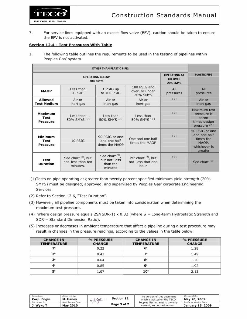
Construction Standards Manual
Issued by: Approved by:
The version of this document
which is posted on the TECO
Peoples Gas intranet is the only current, authorized version.
Version Date:
Corp. Engin. M. Haney May 20, 2009 Document by: Next Review Date: Replaces Version Date:
J. Wykoff May 2010 January 15, 2009
7. For service lines equipped with an excess flow valve (EFV), caution should be taken to ensure
the EFV is not activated.
Section 12.4 - Test Pressures With Table
1. The following table outlines the requirements to be used in the testing of pipelines within
Peoples Gas’ system.
OTHER THAN PLASTIC PIPE:
PLASTIC PIPE OPERATING BELOW
20% SMYS
OPERATING AT OR OVER
20% SMYS
MAOP Less than 1 PSIG
1 PSIG up to 100 PSIG
100 PSIG and over, or under
20% SMYS
All pressures
All pressures
Allowed Test Medium
Air or inert gas
Air or inert gas
Air or inert gas
( 1 )
Air or inert gas
Maximum Test
Pressure
Less than 50% SMYS ( 3 )
Less than 50% SMYS ( 3 )
Less than 50% SMYS ( 3 )
( 1 )
Maximum test pressure is
three times design pressure ( 4 )
Minimum Test
Pressure 10 PSIG
90 PSIG or one and one half
times the MAOP
One and one half times the MAOP
( 1 )
50 PSIG or one
and one half times the
MAOP, whichever is
greater
Test Duration
See chart (2), but not less than ten
minutes.
See chart (2), but not less
than ten minutes
Per chart (2), but not less that one
hour
( 1 )
See chart ( 2 )
(1) Tests on pipe operating at greater than twenty percent specified minimum yield strength (20%
SMYS) must be designed, approved, and supervised by Peoples Gas’ corporate Engineering
Services.
(2) Refer to Section 12.6, “Test Duration”.
(3) However, all pipeline components must be taken into consideration when determining the
maximum test pressure.
(4) Where design pressure equals 2S/(SDR-1) x 0.32 (where S = Long-term Hydrostatic Strength and
SDR = Standard Dimension Ratio).
(5) Increases or decreases in ambient temperature that affect a pipeline during a test procedure may
result in changes in the pressure readings, according to the values in the table below:
CHANGE IN TEMPERATURE
(DEGREES FAHRENHEIT)
% PRESSURE CHANGE
CHANGE IN TEMPERATURE
(DEGREES FAHRENHEIT)
% PRESSURE CHANGE
1 0.22 6 1.28
2 0.43 7 1.49
3 0.64 8 1.70
4 0.85 9 1.92
5 1.07 10 2.13
Section 12
Page 3 of 7
Construction Standards Manual
Issued by: Approved by:
The version of this document
which is posted on the TECO
Peoples Gas intranet is the only current, authorized version.
Version Date:
Corp. Engin. M. Haney May 20, 2009 Document by: Next Review Date: Replaces Version Date:
J. Wykoff May 2010 January 15, 2009
Section 12.5 - Test Medium
1. Normally air would be used as a test medium, however, in testing mains where test pressures
will exceed the pressure available from an air compressor, or where conditions dictate the use
of another test medium, water or an inert gas may be used.
a. Where water is used, the maximum test duration is eight (8) hours.
b. Water filled facilities shall be pressured by use of a high pressure pump.
c. Where the main is tested with water, the service lines should be tested separately with
the inert gas used as a pressure medium for the test of the main.
d. When mains are filled with water, the water shall be injected behind a pig to insure a
complete, air-free fill.
e. The test medium shall be disposed of in accordance with local and state environmental
regulations.
2. When it is impracticable to use water for testing, the test pressure may be applied by
pressuring to the maximum possible with the air compressor and by obtaining the additional
increase required by injecting nitrogen (N2), carbon dioxide (CO2) or another inert gas. It is
recommended that prior to such testing, Peoples Gas’ corporate Engineering Services be
consulted.
3. It is recommended that the following precautions be taken when nitrogen is being used:
a. Take necessary steps to assure that the nitrogen will not escape or be purged into a
confined space (such as a bell hole) in which an employee might need to enter.
b. Check the atmosphere in confined space for lack of oxygen or assure that the oxygen
level is adequate due to normal air movement (winds) or by aeration by mechanical
means such as a blower or air mover.
Section 12.6 - Test Duration With Table
1. Gas mains and service lines shall be pressure tested in accordance with the aforementioned
requirements for a period of time conforming to the requirements outlined in the table in this
section in item 5 below, titled “Minimum Leak Test Duration for Gas Mains and Service Lines”.
2. Pipe operating at pressures less than one hundred pounds per square inch gage (100 PSIG)
shall be leak tested per the requirements outlined in item 1 above, but not less than ten (10)
minutes.
3. Pipe operating at pressures greater than one hundred pounds per square inch gage (100
PSIG) and less than twenty percent specified minimum yield strength (20% SMYS) shall be
leak tested per the requirements outlined in item 1 above, but not less than sixty (60)
minutes.
4. Tests on pipe operating at greater than twenty percent specified minimum yield strength (20%
SMYS) must be designed, approved, and supervised by Peoples Gas’ corporate Engineering
Services.
(continued)
Section 12
Page 4 of 7
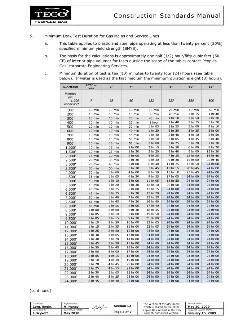
Construction Standards Manual
Issued by: Approved by:
The version of this document
which is posted on the TECO
Peoples Gas intranet is the only current, authorized version.
Version Date:
Corp. Engin. M. Haney May 20, 2009 Document by: Next Review Date: Replaces Version Date:
J. Wykoff May 2010 January 15, 2009
5. Minimum Leak Test Duration for Gas Mains and Service Lines
a. This table applies to plastic and steel pipe operating at less than twenty percent (20%)
specified minimum yield strength (SMYS).
b. The basis for the calculations is approximately one half (1/2) hour/fifty cubic feet (50
CF) of interior pipe volume; for tests outside the scope of the table, contact Peoples
Gas’ corporate Engineering Services.
c. Minimum duration of test is ten (10) minutes to twenty four (24) hours (see table
below). If water is used as the test medium the minimum duration is eight (8) hours).
DIAMETER 1.25” or
less 2” 4” 6” 8” 10” 12”
Minutes
per 1,000
linear feet
7
15
60
132
227
350
500
100’ 10 min 10 min 10 min 15 min 25 min 40 min 50 min
200’ 10 min 10 min 15 min 30 min 45 min 1 hr 15
min
1 hr 40
min 300’ 10 min 10 min 20 min 45 min 1 hr 10
min
1 hr 50
min
2 hr 30
min 400’ 10 min 10 min 25 min 1 hour 1 hr 40
min
2 hr 25
min
3 hr 20
min 500’ 10 min 10 min 30 min 1 hr 05
min
1 hr 55
min
3 hr 00
min
4 hr 10
min 600’ 10 min 10 min 40 min 1 hr 20
min
2 hr 20
min
3 hr 35
min
5 hr 00
min 700’ 10 min 10 min 45 min 1 hr 40
min
2 hr 40
min
4 hr 10
min
5 hr 50
min 800’ 10 min 15 min 50 min 1 hr 50
min
3 hr 05
min
4 hr 45
min
6 hr 40
min 900’ 10 min 15 min 55 min 2 hr 00
min
3 hr 25
min
5 hr 20
min
7 hr 30
min 1,000’ 10 min 15 min 1 hr 00
min
2 hr 15
min
3 hr 50
min
6 hr 00
min
8 hr 20
min 1,500’ 10 min 25 min 1 hr 30
min
3 hr 20
min
5 hr 40
min
9 hr 00
min
12 hr 30
min 2,000’ 15 min 30 min 2 hr 00
min
4 hr 25
min
7 hr 35
min
12 hr 00
min
16 hr 40
min 2,500’ 20 min 35 min 2 hr 30
min
5 hr 30
min
9 hr 30
min
15 hr 00
min
20 hr 40
min 3,000’ 20 min 45 min 3 hr 00
min
6 hr 40
min
11 hr 25
min
17 hr 50
min
24 hr 00
min 3,500’ 30 min 50 min 3 hr 30
min
7 hr 45
min
13 hr 15
min
20 hr 45
min
24 hr 00
min 4,000’ 30 min 1 hr 00
min
4 hr 00
min
8 hr 50
min
15 hr 10
min
23 hr 45
min
24 hr 00
min 4,500’ 35 min 1 hr 05
min
4 hr 30
min
9 hr 55
min
17 hr 05
min
24 hr 00
min
24 hr 00
min 5,000’ 40 min 1 hr 10
min
5 hr 00
min
11 hr 05
min
18 hr 55
min
24 hr 00
min
24 hr 00
min 5,500’ 40 min 1 hr 20
min
5 hr 30
min
12 hr 10
min
20 hr 50
min
24 hr 00
min
24 hr 00
min 6,000’ 45 min 1 hr 25
min
6 hr 00
min
13 hr 15
min
24 hr 00
min
24 hr 00
min
24 hr 00
min 6,500’ 45 min 1 hr 35
min
6 hr 30
min
13 hr 20
min
24 hr 00
min
24 hr 00
min
24 hr 00
min 7,000’ 50 min 1 hr 40
min
7 hr 00
min
15 hr 25
min
24 hr 00
min
24 hr 00
min
24 hr 00
min 7,500’ 55 min 1 hr 45
min
7 hr 30
min
16 hr 40
min
24 hr 00
min
24 hr 00
min
24 hr 00
min 8,000’ 55 min 1 hr 55
min
8 hr 00
min
17 hr 40
min
24 hr 00
min
24 hr 00
min
24 hr 00
min 8,500’ 1 hr 00
min
2 hr 00
min
8 hr 30
min
18 hr 45
min
24 hr 00
min
24 hr 00
min
24 hr 00
min 9,000’ 1 hr 05
min
2 hr 10
min
9 hr 00
min
19 hr 50
min
24 hr 00
min
24 hr 00
min
24 hr 00
min 9,500’ 1 hr 05
min
2 hr 15
min
9 hr 30
min
21 Hr 00
min
24 hr 00
min
24 hr 00
min
24 hr 00
min 10,000’ 1 hr 10
min
2 hr 20
min
10 hr 00
min
22 hr 05
min
24 hr 00
min
24 hr 00
min
24 hr 00
min 11,000’ 1 hr 15
min
2 hr 35
min
11 hr 00
min
22 hr 05
min
24 hr 00
min
24 hr 00
min
24 hr 00
min 12,000’ 1 hr 25
min
2 hr 50
min
12 hr 00
min
24 hr 00
min
24 hr 00
min
24 hr 00
min
24 hr 00
min 13,000’ 1 hr 30
min
3 hr 05
min
13 hr 00
min
24 hr 00
min
24 hr 00
min
24 hr 00
min
24 hr 00
min 14,000’ 1 hr 40
min
3 hr 20
min
14 hr 00
min
24 hr 00
min
24 hr 00
min
24 hr 00
min
24 hr 00
min 15,000’ 1 hr 45
min
3 hr 30
min
15 hr 00
min
24 hr 00
min
24 hr 00
min
24 hr 00
min
24 hr 00
min 16,000’ 1 hr 50
min
3 hr 45
min
16 hr 00
min
24 hr 00
min
24 hr 00
min
24 hr 00
min
24 hr 00
min 17,000’ 2 hr 00
min
4 hr 00
min
17 hr 00
min
24 hr 00
min
24 hr 00
min
24 hr 00
min
24 hr 00
min 18,000’ 2 hr 05
min
4 hr 15
min
18 hr 00
min
24 hr 00
min
24 hr 00
min
24 hr 00
min
24 hr 00
min 19,000’ 2 hr 10
min
4 hr 30
min
19 hr 00
min
24 hr 00
min
24 hr 00
min
24 hr 00
min
24 hr 00
min 20,000’ 2 hr 20
min
4 hr 45
min
20 hr 00
min
24 hr 00
min
24 hr 00
min
24 hr 00
min
24 hr 00
min 21,000’ 2 hr 25
min
4 hr 55
min
21 hr 00
min
24 hr 00
min
24 hr 00
min
24 hr 00
min
24 hr 00
min 22,000’ 2 hr 30
min
5 hr 05
min
22 hr 00
min
24 hr 00
min
24 hr 00
min
24 hr 00
min
24 hr 00
min 23,000’ 2 hr 40
min
5 hr 25
min
23 hr 00
min
24 hr 00
min
24 hr 00
min
24 hr 00
min
24 hr 00
min 24,000’ 2 hr 45
min
5 hr 40
min
24 hr 00
min
24 hr 00
min
24 hr 00
min
24 hr 00
min
24 hr 00
min
(continued)
Section 12
Page 5 of 7
Construction Standards Manual
Issued by: Approved by:
The version of this document
which is posted on the TECO
Peoples Gas intranet is the only current, authorized version.
Version Date:
Corp. Engin. M. Haney May 20, 2009 Document by: Next Review Date: Replaces Version Date:
J. Wykoff May 2010 January 15, 2009
Section 12.7 - Special Tests
1. At the discretion of the Division Manager, sections of the pipe installed under major traffic
arteries or railroads in casing or in bored or jacked openings, which would be difficult or
expensive to repair after completion of the line, will be pressure tested before they are tied in.
Section 12.8 - Test Records
1. A separate written record shall be made of each test and shall be kept for the life of the facility
tested.
a. See Peoples Gas’ Operating and Maintenance Manual forms at Section 13, Page
4, “Pipeline Test Record” and Section 14, Page 6, “Hydrostatic Test Report”.
2. The record shall include:
a. The description and location of the facility tested.
b. The signature of the employee responsible for the test.
c. The test medium used.
d. The test pressure.
e. The test duration.
6. The leaks or failure found and the corrections made.
3. A pressure recorder may be used to record shut-in pressure for mains under test.
a. Test charts, tables, or any other documents should be labeled and attached to the test
report to become a part of the permanent records.
Section 12.9 - Uprate Testing
1. Where a main or segment of a distribution system, including service lines, is being tested for
purposes of uprating, the requirements outlined in Peoples Gas’ Operating and Maintenance
Manual, Section 9, “Uprating” shall be followed.
Section 12.10 - Cleaning and Purging
1. Upon completion of a test, or a retest if repairs were required, gas mains and service lines
shall be thoroughly cleaned and purged prior to placing them in service.
2. Steel lines, one and one quarter inch (1-¼”) and smaller, and all plastic lines shall be cleaned
by blowing them out with air and/or inert gas to insure the removal of all construction dirt,
rust, scale and foreign matter in the pipe.
3. Adequate volume and velocity of air must be provided to assure that the lines are clean.
4. Steel mains larger than one and one quarter inch (1-¼”) shall be "pigged" until all
objectionable foreign material is removed.
(continued)
Section 12
Page 6 of 7

Construction Standards Manual
Issued by: Approved by:
The version of this document
which is posted on the TECO
Peoples Gas intranet is the only current, authorized version.
Version Date:
Corp. Engin. M. Haney May 20, 2009 Document by: Next Review Date: Replaces Version Date:
J. Wykoff May 2010 January 15, 2009
5. The Division Manager shall determine the need for pigging of plastic mains.
6. Transmission pipelines may have special cleaning requirements which will be specified by
Peoples Gas’ corporate Engineering Services.
7. The purging procedure shall be followed as outlined in Peoples Gas’ Operating and
Maintenance Manual, Section 12, “Purging of Pipelines”.
Section 12
Page 7 of 7
Construction Standards Manual
Issued by: Approved by:
The version of this document
which is posted on the TECO
Peoples Gas intranet is the only current, authorized version.
Version Date:
Corp. Engin. M. Haney May 20, 2009 Document by: Next Review Date: Replaces Version Date:
J. Wykoff May 2010 January 15, 2009
SECTION 13 - REMOVING AND RESTORING HARD SURFACE PAVEMENTS
Section 13.1 - Description
1. This shall include work made in cutting, removing, and restoring hard surface pavement.
Section 13.2 - Cutting and Removing Hard Surface Pavements
1. Where mains and laterals are to be laid beneath hard surface pavements, such hard surface
pavements shall be cut only at those locations as specified on the plans and/or specifications.
2. When practical, asphalt and/or concrete surfaces shall be cut ahead of the ditching operation,
and in such a manner so as to result in a smooth edge along the cut.
3. Spoils from cut pavements, not suitable for incorporation in trench backfill, shall be disposed
of away from the construction site.
Section 13.3 - Restoration
1. All restoration shall be completed in a timely manner, using suitable materials that comply
with the local permitting agency and/or the Division Manager's specifications.
a. All restoration shall be left in "as good or better" condition upon completion.
2. Where the street has not been paved, but has a hard surface composed of gravel, crushed
rock, shell or other similar material, construction personnel shall leave the trench overfilled.
a. When directed, construction personnel shall dress the backfill back to the base of the
existing hard surface, and then place the new hard surface.
Section 13
Page 1 of 1
Construction Standards Manual
Issued by: Approved by:
The version of this document
which is posted on the TECO
Peoples Gas intranet is the only current, authorized version.
Version Date:
Corp. Engin. M. Haney May 20, 2009 Document by: Next Review Date: Replaces Version Date:
J. Wykoff May 2010 January 15, 2009
SECTION 14 - TIE-IN TO EXISTING FACILITIES
Section 14.1 - Method of Construction, Tie-In to Existing Facilities
1. Cast Iron
a. Where a threaded tap is made in cast iron, the diameter of the tapped hole may not
be more than twenty five percent (25%) of the nominal diameter of the pipe unless
the pipe is reinforced with an approved saddle type fitting.
b. The exception to this is that a one and one quarter inch (1-1/4") tap may be made in
a four inch (4") cast iron main without reinforcement.
c. Existing taps may be used in cast iron pipe if they are free of cracks and have good
threads.
d. Taps will be spaced a minimum of eighteen inches (18”) apart.
e. Each service line connection to the main shall, whenever practical, be located on the
top of the main.
f. A compression type fitting should be used to connect the service line to the cast iron
main.
i. They shall be designed and installed to effectively sustain longitudinal pull out
due to expected external forces, and insulated as required in Peoples Gas’
Operating and Maintenance Manual, Section 27.6, “Electrical
Isolation”.
ii. Gasket materials used in these fittings must be compatible with natural gas.
g. Tapping of mains for large diameter lateral mains, or service lines, shall be
accomplished by use of an approved tapping fitting or saddle
i. The correct tapping and stopper tools must be used with the fittings.
2. Steel or Plastic
a. Where a tie into steel or plastic is made, the connection shall according to the
requirements outlined in the Peoples Gas document, Appendix C - “Standard for
Pressure Piping -Joining By Welding”.
b. Tie-ins to existing coal tar or asphaltic wrap pipe require special procedures outlined in
the safety program “Asbestos Awareness and Management”, as posted on the
Peoples Gas intranet.
3. General
a. During any tie-in to existing facilities, the requirements and procedures outlined in
Peoples Gas’ Operating and Maintenance Manual, Section 26, “Prevention of
Accidental Ignition” shall be followed.
Section 14
Page 1 of 1
Construction Standards Manual
Issued by: Approved by:
The version of this document
which is posted on the TECO
Peoples Gas intranet is the only current, authorized version.
Version Date:
Corp. Engin. M. Haney May 20, 2009 Document by: Next Review Date: Replaces Version Date:
J. Wykoff May 2010 January 15, 2009
SECTION 15 - METERING & REGULATION
Section 15.1 - Metering
1. Sizing
a. All meters that will be operating within low pressure natural gas systems of seven
inches water column (7" W.C.) shall be sized for a pressure of one half inch water
column (1/2” W.C.) meter differential at the maximum required capacity.
b. Meters to be used on other than low pressure systems:
i. All meters delivering a pressure of seven inches water column (7” WC) shall be
sized for a one inch water column (1” W.C.) meter differential at peak
capacity.
ii. All meters delivering pressure in pounds shall generally be sized for a two
inches water column (2” W.C.) meter differential at peak capacity.
iii. All residential meters connected to a single appliance shall be designed with a
diversity factor of one (1).
iv. All residential meters connected to multiple appliances shall be designed with a
diversity factor of zero point seventy five (0.75).
v. All commercial meters shall be designed with a load factor of one (1) for the
total connected load.
c. The charts in Appendix D - Standard Meter Assemblies shall be used for meter
selection.
2. Maximum Operating Pressure
a. A meter may not be operated at a pressure that exceeds the manufacturer's maximum
allowable operating pressure (MAOP).
b. Each newly installed meter manufactured after November 17, 1970 must have been
tested to a minimum pressure of ten pounds per square inch gage (10 PSIG).
c. Each meter having a one half inch (1/2") differential rating of four hundred cubic feet
per hour (400 CFH) or more will have a working pressure of at least ten pounds per
square inch gage (10 PSIG).
i. All meters that have a rating smaller than four hundred cubic feet per hour
(400 CFH) will have a working pressure of at least five pounds per square inch
gage (5 PSIG).
d. All meters proposed to operate at elevated pressure will have a maximum allowable
operating pressure (MAOP) equal to or greater than the proposed maximum operating
pressure.
3. Metering at Standard Low Pressure
a. A standard index shall be used when metering at seven inches water column (7” W.C.)
for natural gas.
(continued)
Section 15
Page 1 of 7
Construction Standards Manual
Issued by: Approved by:
The version of this document
which is posted on the TECO
Peoples Gas intranet is the only current, authorized version.
Version Date:
Corp. Engin. M. Haney May 20, 2009 Document by: Next Review Date: Replaces Version Date:
J. Wykoff May 2010 January 15, 2009
4. Metering of Firm Natural Gas at Elevated Pressures:
a. System Pressures
i. The meter shall be equipped with an instrument that will correct volumes at
metered conditions to volumes at fourteen point nine eight pounds per square
inches atmospheric (14.98 PSIA) base pressure and fourteen point seven three
pounds per square inches atmospheric (14.73 PSIA) pressure.
ii. This index shall normally read in one hundred cubic feet (100 CCF) when
installed on a meter with a five cubic feet (5 CF) or ten cubic feet (10 CF)
drive.
iii. The index should read in thousand cubic feet (MCF) when installed on a meter
with a one hundred cubic feet (100 CF) drive.
b. Set Pressures
i. When metering at constant pressures, the upstream regulator must be capable
of maintaining the average operating pressure (absolute) within plus one
percent (+ 1.0%) of the set point.
ii. As a general rule, a compensating index that corrects volumes at the set
pressure to volumes at fourteen point nine eight pounds per square inches
atmospheric (14.98 PSIA) base pressure and fourteen point seven three
pounds per square inches atmospheric (14.73 PSIA) pressure shall be used.
iii. The compensating index shall have a red face, or other readily distinguishable
type dial, so that it can be easily recognized as other than the normal standard
index.
5. Metering of Interruptible Natural Gas at Elevated Pressures:
a. When measuring at line pressure or for an interruptible customer the meter shall be
equipped with a pressure-recording device.
6. Encoder–Receiver-Transmitter Devices (ERT) in Automatic Meter Reading (AMR) Systems
a. ERT units should be installed in the following situations:
i. A new meter is installed on an existing AMR route;
ii. The meter reader would have difficulty gaining access (i.e. fencing, physical
barrier);
iii. Reading the meter would cause the meter reader to be exposed to a safety
hazard (i.e. dogs); or,
iv. The time to manually access and read the meter is greater than four (4)
minutes.
7. Programming Residential ERT Units:
a. The residential ERT should be programmed to match the index (i.e. 7” WC or 2 PSIG),
which includes meter drive and pressure.
i. This will result in a corrected read to CIS and the pressure factor in CIS should
always be one (1).
(continued)
Section 15
Page 2 of 7
Construction Standards Manual
Issued by: Approved by:
The version of this document
which is posted on the TECO
Peoples Gas intranet is the only current, authorized version.
Version Date:
Corp. Engin. M. Haney May 20, 2009 Document by: Next Review Date: Replaces Version Date:
J. Wykoff May 2010 January 15, 2009
ii. The appropriate compensating index code should be added to the index field.
iii. When an ERT unit is placed on a commercial metering pressure above seven
inches water column (7” WC), then the mechanical index used will be a
standard index and the ERT factor will be set to one (1).
iv. The appropriate billing factor shall be entered into the billing system.
Section 15.2 - Pressure Regulation
1. All regulators will be sized according to manufacturer's specifications and good engineering
practice.
2. Low Pressure Delivery
a. The standard regulator setting for service to customers at low pressure, where inlet
gas pressure does not exceed sixty pounds square inch gage (60 PSIG), shall be a
single regulator with internal relief and with no external control lines.
i. The outlet pressure shall be either seven inches water column (7" W.C.) or two
pounds square inch gage (2 PSIG) for natural gas unless a different utilization
pressure is agreed upon between Peoples Gas and the customer and is
provided for in the billing rate.
ii. The internal relief of the regulator shall limit the outlet pressure to two pounds
square inch gage (2 PSIG) or less if the delivery pressure is less than one
pound square inch gage (1 PSIG).
iii. If the delivery pressure is two pounds square inch gage (2 PSIG), then the
internal relief shall limit the delivery pressure to five pounds square inch gage
(5 PSIG) or less.
b. The standard regulator setting for service to customers at low pressure, where the
inlet gas pressure is in excess of sixty pounds square inch gage (60 PSIG), but not
more than one hundred twenty five pounds square inch gage (125 PSIG), shall consist
of:
i. An upstream regulator selected for inlet pressures of up to one hundred
twenty five pounds square inch gage (125 PSIG) and outlet pressures of five
pounds square inch gage (5 PSIG) to sixty pounds square inch gage (60
PSIG).
ii. A relief valve of adequate capacity to insure that the inlet pressure to the
downstream regulator does not exceed sixty pounds square inch gage (60
PSIG) in the event of failure of the upstream regulator (this may be internal to
the upstream regulator if capacity is adequate).
iii. A downstream regulator of equal characteristics to that required by item a.
above.
2. Elevated Pressure Delivery
a. When the delivery pressure to the customer is at elevated pressure, verification of
system pressure is required prior to any agreement between the Peoples Gas and the
customer. Note: this higher delivery pressure must not exceed the safe operating
conditions of the facilities downstream.
(continued)
Section 15
Page 3 of 7
Construction Standards Manual
Issued by: Approved by:
The version of this document
which is posted on the TECO
Peoples Gas intranet is the only current, authorized version.
Version Date:
Corp. Engin. M. Haney May 20, 2009 Document by: Next Review Date: Replaces Version Date:
J. Wykoff May 2010 January 15, 2009
b. A single regulator in conjunction with a relief valve may be used where inlet pressures
do not exceed one hundred twenty five pounds square inch gage (125 PSIG).
i. The regulator and relief valve shall be equal to those provided for initial stage
deliveries described in item 2.b.(i) and item 2.b.(ii) above.
ii. The relief valve installed must have adequate capacity to insure that the inlet
pressure to the meter or to the customer's facilities shall not exceed the
maximum permissible operating pressure thereof or a lower pressure, if
conditions indicate that such lower pressure should be maintained.
c. Regulators selected for delivery to customers on "set pressure" billing rates shall meet
the requirements described above and shall be capable of maintaining average
operating pressures (absolute) within plus one percent (+ 1.0%).
d. In those cases where the standard design will not fulfill the needs of the customer,
special designs including the required regulation and relief valves, shall be utilized. In
such cases, the design and selection of equipment and material shall comply with the
intent of CFR 49, Part 192 and these Standards.
Section 15.3 - Sizing Regulators
1. In sizing regulators to realize full capacity, the downstream piping may be enlarged one to two
pipe diameters greater than the regulator size.
2. Capacity should be calculated at the lowest inlet pressure expected and the maximum load
anticipated.
3. The spring should be selected so as not to exceed ten percent (10%) of the maximum and
minimum range of the spring.
4. When installing a regulator upstream of a meter, it should be spring loaded, pilot operated, or
pressure loaded.
5. Load conditions should determine whether a spring loaded or pilot loaded regulator should be
used.
a. If a constant pressure set point is required, then a pilot operated regulator shall be
used.
b. When metering pressure is five pounds square inch gage (5 PSIG) and above, a pilot
loaded regulator with an external relief shall be used.
6. Consideration should be given in the pressure rating of the material used in construction of the
regulator.
a. In some regulators, the diaphragm case is of a lower pressure rating than the body.
Section 15.4 - Customer Meters and Regulators, Locations
1. See also Peoples Gas’ Operating and Maintenance Manual, Section 39.2, “Location of
Meters and Associated Appurtenances - General Requirements” for policy on locating
meters outside of buildings.
(continued)
2. Utility owned service regulators shall be located outside in a ventilated area.
Section 15
Page 4 of 7
Construction Standards Manual
Issued by: Approved by:
The version of this document
which is posted on the TECO
Peoples Gas intranet is the only current, authorized version.
Version Date:
Corp. Engin. M. Haney May 20, 2009 Document by: Next Review Date: Replaces Version Date:
J. Wykoff May 2010 January 15, 2009
3. Utility meters located inside of a building shall:
a. be located in a ventilated space;
b. be located not more than five feet (5’) off of the floor; and,
c. be accessible to personnel twenty four (24) hours a day.
4. Utility owned gas piping serving meters located inside of a building shall:
a. operate at a pressure that does not exceed two pounds square inch gage (2 PSIG);
b. be accessible for leak survey;
c. as of July 1, 2008, be welded steel pipe; and,
d. be painted and identified as property of Peoples Gas.
Section 15.5 - Customer Meters and Regulators, Protection From Damage
1. Protection from Vacuum or Back Pressure
a. If the customer's equipment might create either a vacuum or a back pressure, a low
pressure valve or a check valve shall be installed to protect the distribution system.
2. Service Regulator Vents and Relief Vents
a. The outside terminal of each service regulator vent and relief vent must:
i. be rain and insect resistant;
ii. be located at a place where gas from the vent can escape freely into the
atmosphere and away from any opening into a building (if located near a
source of ignition, the terminal must be vented a minimum of three feet (3’)
away from such source);
iii. be protected from damage caused by submergence in areas where flooding
may occur; and,
iv. be of adequate size to permit immediate discharge of the venting gas and to
prevent over pressurizing customer houseline, the minimum size being that of
the vent opening in the regulator (note: it may be necessary to make the vent
piping larger than the vent opening so that the vent capacity is not reduced;
always follow manufacturer’s instructions).
3. Pits and Vaults
a. Each pit or vault that houses a customer meter or regulator at a place where vehicular
traffic is anticipated must be able to support that traffic.
4. General
a. Meter and regulators will be protected from damage by outside forces by use of
barricades properly placed.
b. Vent piping shall be metallic.
(continued)
Section 15
Page 5 of 7

Construction Standards Manual
Issued by: Approved by:
The version of this document
which is posted on the TECO
Peoples Gas intranet is the only current, authorized version.
Version Date:
Corp. Engin. M. Haney May 20, 2009 Document by: Next Review Date: Replaces Version Date:
J. Wykoff May 2010 January 15, 2009
Section 15.6 - Elevated Pressure Taps on Customer Meters
1. Pressure taps shall be provided at all meter installations.
Section 15.7 - Customer Meter and Regulator Installations
1. Also see Peoples Gas’ approved Appendix D - Standard Meter Assemblies.
2. The customer's meter/regulator set must be designed and installed so as to minimize stress
on the meter and connected piping.
3. On residential installations where the meter/regulator set is connected to steel house piping,
the connected piping normally provides adequate support:
a. however, a meter bracket may be used for additional support on these residential sets
that are connected to copper tubing or other flexible house piping.
4. All thread nipples used in the Peoples Gas distribution system should be ASTM A53, Type "E"
or "F" so as to ensure adequate mechanical strength in the wall thickness beneath the
threads.
5. Multi-meter sets shall not have more than ten (10) meters supplied through a common
regulator at a pressure that is the same as the metering pressure.
Section 15.8 - Large Capacity Meter Design and Installations
1. A large capacity meter includes diaphragm type meters that have a three thousand cubic foot
per hour (3,000 CFH) capacity at two inches water column (2" W.C.) pressure, plus all rotary
and turbine type meters; see approved Peoples Gas’ Appendix D - Standard Meter
Assemblies.
a. New installations will have adequate bypass and test connections to simplify and speed
up the field testing and adjustment procedure.
b. Rotary meters will have a strainer/filter installed upstream of the meter.
c. Turbine meters will have a filter installed upstream of the meter.
d. Pressure taps will be provided upstream and downstream of all large meters for
differential tests.
2. Division Manager or designee should prepare documentation for large meter installations.
3. The information should include maximum volume and pressure, minimum pressure, and
proposed sizing of all equipment including meters, regulators (orifice size) and relief valves.
4. The Division Manager or designee shall review and approve the design prior to construction.
Section 15.9 - Painting/Coating of Meter and Regulator Installations
1. All meter and regulator installation loops will be protected from atmospheric corrosion by
painting exposed piping and coating underground piping as follows:
(continued)
Section 15
Page 6 of 7
Construction Standards Manual
Issued by: Approved by:
The version of this document
which is posted on the TECO
Peoples Gas intranet is the only current, authorized version.
Version Date:
Corp. Engin. M. Haney May 20, 2009 Document by: Next Review Date: Replaces Version Date:
J. Wykoff May 2010 January 15, 2009
a. Preparation
i. Areas of corrosion are to be cleaned with a wire brush and/or file to remove all
particles of corrosion and be wiped clean.
ii. Masking tape shall be applied to insulator and the tape painted over. The tape
will be removed when the painting is complete.
b. Exposed Piping
i. Primer shall be applied and allowed to dry in accordance with the
manufacturers instructions.
ii. The finished coat shall be applied to the entire meter loop from a point
approximately four inches (4”) above the ground; this may include the meter
if necessary.
2. See also Peoples Gas’ Operating and Maintenance Manual, Section 27.12, “Atmospheric
Corrosion Control”.
Section 15.10 - Electrical Isolation on Meter Installations (Steel Services)
1. Small Meter
a. For individual customer services, use an insulating meter stop.
b. For multi-customer service sets (serving apartments, etc.), use an insulating meter
stop on the riser before the meter manifold.
2. Large Meter
a. Piping size through one and one quarter inch (1¼”) use an insulating meter stop.
b. Piping size larger than one and one quarter inch (1¼”) use an insulating union or
flange insulation.
Section 15
Page 7 of 7
Construction Standards Manual
Issued by: Approved by:
The version of this document
which is posted on the TECO
Peoples Gas intranet is the only current, authorized version.
Version Date:
Corp. Engin. M. Haney May 20, 2009 Document by: Next Review Date: Replaces Version Date:
J. Wykoff May 2010 January 15, 2009
SECTION 16 - SYSTEM/DISTRICT REGULATION AND LIMITING VALVES
Section 16.1 - System and District Regulation
1. A district regulator station is one that regulates the supply of gas to a distribution main or
network of mains serving more than one customer.
2. Regulators, relief valves, valves and other fittings shall be sized according to manufacturer's
specifications and good engineering practice.
a. Each district regulator station shall include pressure relief or pressure limiting devices
adequate to protect the distribution system served from over pressuring in the event
of failure of the station to function properly.
3. Pressure taps shall be installed on both the upstream and downstream sides of all regulator
stations.
4. For maximum allowable operating pressures (MAOP) on distribution systems, see Peoples Gas’
Operating and Maintenance Manual, Section 7, “Maximum Allowable Operating
Pressure”.
5. All designs must be approved by the Division Manager or Peoples Gas’ corporate Engineering
Services.
Section 16.2 - Over Pressure Protection Systems and Relief Valves
1. Relief Valves
a. Each pressure relief or pressure limiting device:
i. must be constructed of materials such that the operation of the device will not
be impaired by corrosion;
ii. must have valves and valve seats that are designed not to stick in a position
that will make the device inoperative;
iii. must be designed and installed so that it can be readily operated to determine
if the valve is free, be tested to determine the pressure at which it will operate
and be tested for leakage when in the closed position;
iv. must have support made of a non-combustible material;
v. must have discharge stacks, vents, or outlet ports designed to prevent
accumulation of water, ice or snow and located so that gas can be discharged
into the atmosphere without undue hazard;
vi. must be designed and installed so that the size of the openings, pipe and
fittings located between the system to be protected and the pressure relieving
device, and the size of the vent line, are adequate to prevent hammering of
the valve and to prevent impairment of relief capacity;
vii. must, where installed at a district regulator station to protect a pipeline
system from over pressuring, be designed and installed to prevent any single
incident such as an explosion in a vault or damage by a vehicle from affecting
the operation of both the overpressure protective device and the district
regulator; and,
(continued)
Section 16
Page 1 of 3

Construction Standards Manual
Issued by: Approved by:
The version of this document
which is posted on the TECO
Peoples Gas intranet is the only current, authorized version.
Version Date:
Corp. Engin. M. Haney May 20, 2009 Document by: Next Review Date: Replaces Version Date:
J. Wykoff May 2010 January 15, 2009
viii. must, except for a valve that will isolate the system under protection from its
source of pressure, be designed to prevent unauthorized operation of any
valve that will make the pressure relief valve or pressure limiting device
inoperative.
2. Required Capacity of Pressure Relieving and Limiting Station
a. Each pressure relief station or pressure limiting station or group of stations installed to
protect a pipeline must have enough capacity, and must be set to operate to prevent
over pressuring of the protected system.
i. On systems with a maximum allowable operating pressure (MAOP) of greater
than sixty pounds per square inch gage (60 PSIG), the relief valve will be set
at the maximum allowable operating pressure (MAOP) plus ten percent (10%).
ii. On systems with a maximum allowable operating pressure (MAOP) between
twelve pounds per square inch gage (12 PSIG) and sixty pounds per square
inch gage (60 PSIG), the relief valve will be set at the system maximum
allowable operating pressure (MAOP) plus six pounds per square inch gage (6
PSIG).
iii. On systems with a maximum allowable operating pressure (MAOP) between
one pound per square inch gage (1 PSIG) and less than twelve pounds per
square inch gage (12 PSIG), the relief valve will be set at no more than fifty
percent (50%) above the system maximum allowable operating pressure
(MAOP).
iv. On low pressure systems, the relief valve will be set to give full capacity relief
at a maximum pressure build up to sixteen inches water column (16" W.C.) on
natural gas.
b. When more than one pressure regulator feeds into a distribution system, relief valves
or other protective devices must be installed at each station to ensure that the
complete failure of the largest capacity regulator in that station will not impose
pressures on any part of the distribution system in excess of those listed in item 2.a.
above.
Section 16.3 - Design of Instrument/Control Piping and Components
1. A shutoff valve must be installed at each takeoff line as near as practical to the point of
takeoff. Blow down valves must be installed where necessary.
2. Pipe or components in which liquids may accumulate must have drains or drips.
3. Pipe or components subject to clogging from solids or deposits must have suitable connections
for cleaning.
4. The arrangement of pipe, components, and supports must provide safety under anticipated
operating stresses.
5. Each joint between sections of pipe, and between pipe and valves or fittings, must be made in
a manner suitable for the anticipated pressure and temperature conditions.
a. Slip type expansion joints may not be used.
(continued)
Section 16
Page 2 of 3
Construction Standards Manual
Issued by: Approved by:
The version of this document
which is posted on the TECO
Peoples Gas intranet is the only current, authorized version.
Version Date:
Corp. Engin. M. Haney May 20, 2009 Document by: Next Review Date: Replaces Version Date:
J. Wykoff May 2010 January 15, 2009
b. Expansion must be allowed for by providing flexibility within the system itself.
6. Each control line must be protected from anticipated causes of damage, and must be designed
and installed to prevent damage to any one control line from making both the regulator and
the overpressure protective device inoperative.
7. Supply and control lines should be sloped downward from instruments to avoid the flow of
liquids in these lines.
Section 16.4 - Paint and Coating of Regulator and Relief Valve Stations
1. All regulator and relief valve stations will be protected from atmospheric corrosion by painting
exposed piping and coating underground piping as detailed above in this Construction
Standards Manual, Section 15.9, “Painting/Coating of Meter and Regulator
Installations”.
Section 16
Page 3 of 3

Construction Standards Manual
Issued by: Approved by:
The version of this document
which is posted on the TECO
Peoples Gas intranet is the only current, authorized version.
Version Date:
Corp. Engin. M. Haney May 20, 2009 Document by: Next Review Date: Replaces Version Date:
J. Wykoff May 2010 January 15, 2009
SECTION 17 - VAULTS
Section 17.1 - Structural Design Requirements
1. Each underground vault or pit for valves, pressure relieving, pressure limiting or pressure
regulating stations, must be able to withstand the loads which may be imposed upon it, and
protect installed equipment.
2. There must be sufficient working space so that all of the equipment required in the vault or pit
can be properly installed, operated and maintained.
3. Each pipe entering, or within, a regulator vault or pit must be steel, except instrument and
control piping which may be copper, steel or other acceptable material.
a. Plastic is not an acceptable material.
b. Where pipe extends through the vault or pit structure, the openings must be sealed to
prevent the passage of gases or liquids through the opening.
Section 17.2 - Accessibility Each vault must be installed in an accessible location and be, in so far as practical, away from the
following:
1. Street intersections or points where traffic is heavy or dense.
2. Points of minimum elevation, catch basins, or places where the access cover will be in the
course of surface waters; and,
3. Water, electric, steam, or other facilities.
Section 17.3 - Sealing. Venting and Ventilation Each underground vault or closed top pit containing either a pressure regulating or reducing station,
or a pressure limiting or relieving station, must be sealed, vented or ventilated, as follows:
1. When the internal volume exceeds two hundred cubic feet (200 CF):
a. The vault or pit must be ventilated with two ducts, each having at least the ventilating
effect of a pipe four inches (4”) in diameter.
b. The ventilation must be enough to minimize the formation of a combustible
atmosphere in the vault or pit.
c. The ducts must be high enough above grade to disperse any gas/air mixtures that
might be discharged.
2. When the internal volume is more than seventy five (75) cubic feet but less than two hundred
cubic feet (200 CF):
a. If the vault is located under an area carrying vehicular traffic, it must have a tight
fitting cover without open holes through which an exposed gas/air mixture might be
ignited, and there must be a means for testing the internal atmosphere before
removing the cover.
(continued)
Section 17
Page 1 of 2
Construction Standards Manual
Issued by: Approved by:
The version of this document
which is posted on the TECO
Peoples Gas intranet is the only current, authorized version.
Version Date:
Corp. Engin. M. Haney May 20, 2009 Document by: Next Review Date: Replaces Version Date:
J. Wykoff May 2010 January 15, 2009
b. If the vault is located in the area which does not carry vehicular traffic, it may be:
i. installed as detailed above in item (1) (a); or,
ii. installed as detailed above in item (2) (a); or,
iii. it may have openings in the cover or grating and if they have an effective
ventilating area in a ratio of less than twenty cubic feet (20 CF) of volume to
one (1) square foot of ventilation (in which case, no additional venting is
required).
Section 17.4 - Drainage and Water Proofing
1. Each vault must be designed so as to minimize the entrance of water.
2. A vault containing gas piping may not be connected by means of a drain connection to any
other underground structure.
3. All electrical equipment in vaults must conform to the applicable requirements of Class 1,
Group D, of the National Electrical Code, ANSI Standard C1.
Section 17
Page 2 of 2

Construction Standards Manual
Issued by: Approved by:
The version of this document
which is posted on the TECO
Peoples Gas intranet is the only current, authorized version.
Version Date:
Corp. Engin. M. Haney May 20, 2009 Document by: Next Review Date: Replaces Version Date:
J. Wykoff May 2010 January 15, 2009
SECTION 18 - PIPELINE MARKERS
Section 18.1 - Above Ground Markers
1. A line marker must be placed as close as practical directly over the top of each buried
distribution main and transmission line:
a. at each crossing of a public road and railroad;
b. wherever necessary to identify the location of the pipeline to reduce the possibility of
damage or interference; and,
c. where the pipeline enters under and exits from under a waterway or body of water.
2. A line marker is not required for the following buried pipeline locations:
a. distribution mains in Class 3* or Class 4* locations where an active damage
prevention program is in effect (Sunshine State One Call).
* Note: class locations are defined below in this Construction Standards Manual, Section
19, “Class Locations”.
3. Pipelines above ground must be marked in areas which are accessible to the public.
4. The following must be written legibly on all markers on a background of sharply contrasting
colors:
a. the word “Warning” or “Caution” followed by the words “Gas (or the name of the gas
transported) Pipeline” all of which, except for markers in heavily developed urban
areas, must be in letters at least one inch (1”) high with quarter inch (¼“)wide stroke;
and,
b. the name of the pipeline operator and telephone number (including area code) where
the operator can be reached at all times.
5. The Division Manager or designee will have the final determination as to where pipeline
markers will be placed.
6. In general, consecutive visible above ground markers should be placed with the sight of one
another.
Section 18.2 - Buried Warning Tape
1. Buried warning tape shall be buried in the trench above all polyethylene (PE) gas main and
service lines.
2. The warning tape will be installed approximately twelve inches (12”) above the gas main.
Section 18.3 - Electronic Markers (EM) Standard
1. 3M™ Electronic Marking Buoys (EM) shall be used as a company standard to mark Peoples Gas
pipelines as outlined in this section.
a. Use of any other electronic buoy must be approved by Peoples Gas’ corporate
Engineering Services.
(continued)
2. Required EM applications include:
Section 18
Page 1 of 3
Construction Standards Manual
Issued by: Approved by:
The version of this document
which is posted on the TECO
Peoples Gas intranet is the only current, authorized version.
Version Date:
Corp. Engin. M. Haney May 20, 2009 Document by: Next Review Date: Replaces Version Date:
J. Wykoff May 2010 January 15, 2009
a. whenever undetectable facilities are discovered and exposed;
b. at the end of newly installed gas mains;
c. service stubs greater than two feet (2’) in length;
d. interface points for corrosion protection systems;
e. newly installed insulators in cathodic protection systems;
f. newly installed gas facilities in parallel with, and in close proximity to, existing high
pressure facilities; and,
g. cast iron mains when they are exposed.
3. Recommended EM applications include:
a. retro-fitted emergency valves;
b. newly installed emergency valves;
c. underground valves of all types;
d. excess flow valves;
e. squeeze points;
f. service taps;
g. changes in direction made with fittings, i.e.:
i. depth changes; and,
ii. laterals, tees, crosses, branches;
h. bends/changes of direction;
i. encasement ends;
j. water crossings;
k. major road crossings;
l. rail crossings;
m. retrofit paralleling gas facilities in close proximity; and,
n. new directional drilled facilities at depths of ten feet (10’) or more.
4. Installation Procedures
a. In wet or other areas where marker movement is possible a tie-down procedure shall
be used:
i. Secure the marker by inserting a cable tie through the tie down tabs and
connect to the key point.
ii. If the key point is metallic, the ball marker should be separated from it with a
minimum of six inches (6”) of dirt.
(continued)
Section 18
Page 2 of 3
Construction Standards Manual
Issued by: Approved by:
The version of this document
which is posted on the TECO
Peoples Gas intranet is the only current, authorized version.
Version Date:
Corp. Engin. M. Haney May 20, 2009 Document by: Next Review Date: Replaces Version Date:
J. Wykoff May 2010 January 15, 2009
b. Do not install the EM deeper than manufacture’s maximum recommended depth.
i. Normally five feet (5’) deep.
c. Hand-fill at least six inches (6”) of dirt over the marker and hand stabilize to protect
the marker.
i. Mechanical tamping should not be used without at least eighteen inches (18”)
of backfill in place.
d. EM buoys must be incorporated into the Peoples Gas geographic information system
(GIS)
i. Field dimensioning is required.
e. To increase the detection area, it is recommended to place the marker at thirty inches
(30”).
i. If additional fill to finish grade or a cut to finish grade is anticipated, place the
marker at the appropriate depth to accommodate for such changes.
5. Spacing
a. The minimum distance between markers should be six feet (6’).
b. The recommended distance between markers should not exceed one hundred feet
(100’).
c. At changes in direction spacing should be selected to clearly communicate the
horizontal pipeline route.
i. At bends the recommended spacing is two feet (2’).
Section 18
Page 3 of 3

Construction Standards Manual
Issued by: Approved by:
The version of this document
which is posted on the TECO
Peoples Gas intranet is the only current, authorized version.
Version Date:
Corp. Engin. M. Haney May 20, 2009 Document by: Next Review Date: Replaces Version Date:
J. Wykoff May 2010 January 15, 2009
SECTION 19 - CLASS LOCATIONS
Section 19.1 - Description A “class location unit” is an area that extends two hundred twenty (220) yards on either side of the
centerline of any continuous one (1) mile length of pipeline except as provided in item (3) (b) of this
section below.
Section 19.2 – Building and Dwelling Count by Class For the purpose of this section, each separate dwelling unit in a multiple dwelling unit building is
counted as a separate building intended for human occupancy:
1. A Class 1 location is any class location unit that has ten (10) or fewer buildings intended for
human occupancy.
2. A Class 2 location is any class location unit that has more than ten (10) but less than forty six
(46) buildings intended for human occupancy.
3. A Class 3 location is:
a. Any class location unit that has forty six (46) or more buildings intended for human
occupancy; or,
b. An area where the pipeline lies within one hundred (100) yards of any of the following:
i. a building that is occupied by twenty (20) or more persons during normal use;
or,
ii. a small, well-defined outside area that is occupied by twenty (20) or more
persons during normal use, such as a playground, recreation area, outdoor
theater, or other place of public assembly.
4. A Class 4 location is any class location unit where buildings with four (4) or more stories above
ground are prevalent.
Section 19.3 - Boundaries
The boundaries of the class locations may be adjusted as follows:
a. A Class 4 location ends two hundred twenty (220) yards from the nearest building with
four (4) or more stories above ground.
b. When a cluster of buildings intended for human occupancy requires a Class 2 or 3
location, the class location ends two hundred twenty (220) yards from the nearest
building in the cluster.
Section 19
Page 1 of 1
Construction Standards Manual
Issued by: Approved by:
The version of this document
which is posted on the TECO
Peoples Gas intranet is the only current, authorized version.
Version Date:
Corp. Engin. M. Haney May 20, 2009 Document by: Next Review Date: Replaces Version Date:
J. Wykoff May 2010 January 15, 2009
SECTION 20 - CORROSION CONTROL
Section 20.1 - Description This section prescribes minimum requirements and procedures for the protection of metallic pipelines
and components from external and atmospheric corrosion for new piping systems.
1. External and internal corrosion shall be controlled consistent with condition of the piping
system and the environment in which the system is located.
2. NACE RP-01-69/NACE RP-06-75, NACE RP–02-75 may be referenced for guidance.
3. The Division Manager shall be responsible to ensure that any cathodic protection system is
properly designed and installed.
Section 20.2 - External Corrosion Control for Buried or Submerged Pipelines
1. All new metallic pipelines and service lines installed shall be externally coated and cathodically
protected.
Section 20.3 – Coating System
1. The performance of the coating system is dependent on surface preparation, coating material
application methods and testing methods.
2. Factory applied coating is preferred for all pipeline components to ensure adequate surface
preparation and coating application under controlled conditions.
3. Pipe coating shall be inspected visually and may be inspected by an electric holiday detector
just prior to lowering pipe into ditch.
4. Any holiday or other damage to the coating detrimental to effective corrosion control shall be
repaired.
5. The backfilling operation shall be inspected for quality, compaction and placement of material
to prevent damage to pipe coating.
Section 20.4 – Protective Coatings and Surface Preparation
1. External protective coating, applied for the purpose of external corrosion control must:
a. have surface preparation compatible with the coating to be applied, and:
i. the pipe surface shall be free of deleterious materials such as rust, scale,
moisture, dirt, oils, lacquers, and varnish; and,
ii. the surface shall be inspected for irregularities which could protrude through
the coating (any such irregularities shall be removed);
b. have sufficient adhesion to the metal surface to effectively resist under-film migration
of moisture;
c. be sufficiently ductile to resist cracking;
(continued)
Section 20
Page 1 of 5
Construction Standards Manual
Issued by: Approved by:
The version of this document
which is posted on the TECO
Peoples Gas intranet is the only current, authorized version.
Version Date:
Corp. Engin. M. Haney May 20, 2009 Document by: Next Review Date: Replaces Version Date:
J. Wykoff May 2010 January 15, 2009
d have sufficient strength to resist damage due to handling and soil stress; and,
e. have properties compatible with any supplemental cathodic protection.
2. Each external protective coating which is an electrically insulating type must also have low
moisture absorption and high electrical resistance.
3. Each external protective coating must be inspected just prior to lowering the pipe into the
ditch and backfilling and any damage to coating must be repaired.
4. Each external protective coating must be protected from damage resulting from adverse ditch
conditions or damage from supporting blocks.
5. If coated pipe is installed by boring, driving, or other similar method, precautions must be
taken to minimize damage to the coating during installation.
6. Repairs should be made with approved material and procedure when any defects in the
coating are made or found.
(Ref: CFR 49 Part 192.461)
Section 20.5 – Cathodic Protection Systems
1. The objective of using cathodic protection is to control the corrosion of metallic surfaces in
contact with electrolyte.
2. A cathodic protection system provided by a galvanic anode or impressed current anode system
shall be installed that will mitigate corrosion and contain a method of determining the degree
of cathodic protection achieved on the buried or submerged piping system.
3. A cathodic protection system shall preferably be installed at the same time as the construction
but no later than one (1) year after completion of construction.
4. Cathodic protection shall be controlled so as not to damage the protective coating, pipe, or
components.
5. Owners of known underground structures which may be affected by installation of a cathodic
protection system shall be notified of said installation and where necessary, joint bonding
surveys shall be conducted by parties involved.
6. The cathodic protection system shall be compatible with coating used on the pipeline.
(Ref: ASME B 31.4 – 99)
Section 20.6 – Electrical Isolation
1. Each buried or submerged pipeline must be electrically isolated from other underground
metallic structures, unless the pipeline and the other structures are electrically interconnected
and cathodically protected as a single unit.
(continued)
Section 20
Page 2 of 5

Construction Standards Manual
Issued by: Approved by:
The version of this document
which is posted on the TECO
Peoples Gas intranet is the only current, authorized version.
Version Date:
Corp. Engin. M. Haney May 20, 2009 Document by: Next Review Date: Replaces Version Date:
J. Wykoff May 2010 January 15, 2009
2. One or more insulating devices must be installed where electrical isolation of a portion of a
pipeline is necessary to facilitate the application of corrosion control.
3. Except for unprotected copper inserted in ferrous pipe, each pipeline must be electrically
isolated from metallic casings that are a part of the underground system.
a. However, if isolation is not achieved because it is impracticable, other measures must
be taken to minimize corrosion of the pipeline inside the casing.
4. Inspection and electrical tests must be made to assure that electrical isolation is adequate.
5. An insulating device may not be installed in an area where a combustible atmosphere is
anticipated unless precautions are taken to prevent arcing.
6. Where a pipeline is located in close proximity to electrical transmission tower footings, ground
cables or counterpoise, or in other areas where fault currents or unusual risk of lighting may
be anticipated, it must be provided with protection against damage due to fault currents or
lightning and protective measures must also be taken at insulating devices.
Section 20.7 – Test Point Stations
1. A sufficient number of test point stations, or other contact points for electrical measurement to
determine the level of cathodic protection, shall be provided for each protected system.
2. Steel gas service lines, and test leads are acceptable test point stations.
3. Probe bars should not be used.
a. However, steel service lines should be used only with caution as a means for
contacting the gas main under test, as good electrical continuity must be present
between the gas main and the gas service line to ensure that the test is valid.
4. Test point stations should be installed, where practical, at the following locations:
a. all casing installations under highways, roadways and railroads;
b. all points of isolation, on primary gas feeder lines (i.e. at insulating flanges);
c. selected points on the system sufficient in number so that adequate electrical tests
may be made to evaluate the system level of cathodic protection.
i. these test point stations would normally be at the points where the lowest
potential measurements are expected on the system (i.e., at the most remote
points in the gas system).
d. on isolated sections of coated steel pipeline installed for repair purposes on a bare
steel or cast iron pipeline system; and,
e. at canals, rivers, creeks, etc.
5. A record of test point station locations shall be maintained on PGS Form No. 645 or Form 313,
“Cathodic Protection Data” (see Peoples Gas’ Operating and Maintenance Manual, Section
27, “Corrosion Control”).
(continued)
Section 20
Page 3 of 5
Construction Standards Manual
Issued by: Approved by:
The version of this document
which is posted on the TECO
Peoples Gas intranet is the only current, authorized version.
Version Date:
Corp. Engin. M. Haney May 20, 2009 Document by: Next Review Date: Replaces Version Date:
J. Wykoff May 2010 January 15, 2009
6. It shall be the responsibility of the Division Manager to determine the location of test point
stations.
Section 20.8 – Test Leads
Each test lead installation shall conform to the following:
1. Each test lead wire must be connected to the gas pipeline so as to remain mechanically secure
and electrically conductive.
2. Each test lead wire must be attached to the pipeline so as to minimize stress concentration on
the pipe.
a. Attachment of the test lead to the pipeline should be by the thermite welding process,
that is, by brazing the lead to a steel tab and then welding the tab to the pipeline, or
by other methods approved by the General Manager, Engineering Services.
b. Welding a test lead to the main shall not be permitted.
3. Each bared test lead wire and bared metallic area at point of connection to the pipeline must
be coated with an electrical insulating material compatible with the pipe coating and the
insulation on wire.
4. The coding of test lead wires shall be as follows:
a. anode wire (from the anode lead to the pipeline: RED;
b. casing wire: YELLOW;
c. test lead wire: GREEN OR BLACK.
5. The coding of insulating fittings shall be as follows:
a. north and west: WHITE;
b. south and east: BLUE OR BLACK.
6. Colored plastic sleeves may be used on existing wires.
7. Number 10 or 12 TW wire shall be the minimum gage used for test lead wires; and,
8. Care shall be taken when backfilling to avoid damage to test leads.
9. Test leads should not be shorted to metallic valve boxes or to conduit comprising the test
point.
Section 20.9 – Interference Currents
1. Each pipeline system which is subjected to stray currents shall have in effect a continuing
program to minimize the detrimental effects of such currents.
(continued)
Section 20
Page 4 of 5

Construction Standards Manual
Issued by: Approved by:
The version of this document
which is posted on the TECO
Peoples Gas intranet is the only current, authorized version.
Version Date:
Corp. Engin. M. Haney May 20, 2009 Document by: Next Review Date: Replaces Version Date:
J. Wykoff May 2010 January 15, 2009
2. Each impressed current type cathodic protection system or galvanic anode system must be
designed and installed so as to minimize any adverse effects on existing adjacent underground
metallic structures.
Section 20.10 – Atmospheric Protection
1. Pipe and components that are exposed to the atmosphere shall be protected from external
corrosion by use of corrosion resistant steel or application of protective coating or paint unless
the operating company can demonstrate by test, investigation, or experience in area of
application that a corrosive atmosphere does not exist.
2. Protective coating or paint shall be applied to a clean surface and shall be suitable material to
provide adequate protection from the environment.
Section 20
Page 5 of 5
Construction Standards Manual
Issued by: Approved by:
The version of this document
which is posted on the TECO
Peoples Gas intranet is the only current, authorized version.
Version Date:
Corp. Engin. M. Haney May 20, 2009 Document by: Next Review Date: Replaces Version Date:
J. Wykoff May 2010 January 15, 2009
SECTION 21 - CLEARING AND GRADING
Section 21.1 - Description
1. This work shall include the clearing of all trees, brush, hedges, or other obstacles, with the
exceptions noted below, lying within the confines of the route of the line.
2. The term "grading" includes all excavation and the forming of embankments, diverting of
ditches or small streams, building of temporary bridges and roads, or work performed to
facilitate movement of equipment onto and along the route.
Section 21.2 - Method of Construction, Clearing and Grading
1. Where cultivated shrubbery, trees, or valuable growing timber is encountered on the route of
the line, it may be required that such shrubbery, trees, or growing timber be left standing.
2. Where large trees are cut on the right of way, they shall be cut close to the ground so that the
remaining stumps will not extend more than three inches (3”) above the ground level.
3. Branches and leaves removed from such trees shall be placed in piles, along with brush or
undergrowth that has been cut, and shall be disposed of away from the construction site.
4. Brush and other debris should not be shoved into piles with earth from grading, nor placed in
the ditch line.
5. Excess excavated material shall be placed in piles.
6. Such material shall not be scattered along the right of way, and shall not be placed in low
areas along the route of the facilities, without the consent of the Division Manager.
7. Material removed from creek banks shall not be placed in the creek bed at points that will
interfere with excavation of the ditch across the creek bed.
8. After pipe has been installed and such other operations that may be necessary have been
completed, material excavated from hillsides, creek banks, and other places shall be replaced
in its original position and protected from slides and erosion by riprap, wash breakers,
terraces, or such other means as may be designated by the Division Manager or designee.
9. Clearing and grading shall be affected in a manner that shall cause minimum inconvenience to
the interests and property of landowners, tenants and the general public.
10. It is important the methods used during clearing and grading activity be in accordance with all
local, municipal, state, and environmental agency standards having jurisdiction.
Section 21
Page 1 of 1
Construction Standards Manual
Issued by: Approved by:
The version of this document
which is posted on the TECO
Peoples Gas intranet is the only current, authorized version.
Version Date:
Corp. Engin. M. Haney May 20, 2009 Document by: Next Review Date: Replaces Version Date:
J. Wykoff May 2010 January 15, 2009
SECTION 22 - CONSTRUCTION NOTIFICATION
Section 22.1 – Notice of Major Construction
1. Notice shall be given by the Division Manager or designee to the Florida Public Service
Commission with a copy forwarded to Peoples Gas’ corporate Engineering Services, on PGS
Form No. 603, “Notice of Major Construction”, in duplicate, at least twenty-five (25) days prior
to commencement of construction, when both of the following conditions have been met on
pipeline construction projects:
a. The proposed construction shall be installed within the Peoples Gas natural gas
distribution systems; and,
b. This requirement shall apply to new construction, replacement, relocation or insertion
on lines at least two inches (2") in diameter and at least two thousand linear feet
(2000 LF) in total length including service lines.
Section 22
Page 1 of 1
Construction Standards Manual
Issued by: Approved by:
The version of this document
which is posted on the TECO
Peoples Gas intranet is the only current, authorized version.
Version Date:
Corp. Engin. M. Haney May 20, 2009 Document by: Next Review Date: Replaces Version Date:
J. Wykoff May 2010 January 15, 2009
SECTION 23 - MATERIAL SPECIFICATIONS
Section 23.1 – Records
1. Records shall be kept sufficient to prove that all materials and components used, or intended
to be used, in the Peoples Gas distribution systems meet the applicable specifications listed in
the rules and/or the standards adopted by this Construction Standards Manual and the Peoples
Gas Operating and Maintenance Procedures Manual.
Section 23.2 – Standard Material List
1. Standard materials used in the Peoples Gas distribution systems are included in Peoples Gas
Appendix B - Standard Material List and must be ordered in accordance with Peoples Gas
approved practices. (See Peoples Gas’ Purchasing department policies and procedures).
2. Peoples Gas’ corporate Engineering Services department shall review the product specification
of a fitting/component, test new materials to ensure that they meet the applicable standards
and add such items after evaluation to the Peoples Gas Appendix B - Standard Material
List.
a. This review and testing may be at the request of the Division Manager or designee, or
as a matter of routine evaluation by Peoples Gas’ corporate Engineering Services’
personnel.
Section 23.3 – Non-Conformance to Florida Public Service Commission Rules
1. If a fitting or other pipeline component does not conform to the standards or specifications, as
adopted by the Florida Public Service Commission Rules, Peoples Gas’ corporate Engineering
Services may petition the Florida Public Service Commission for approval for the use of the
fitting/component.
a. Such petition shall, if possible, identify the material with a comparable material, and it
should be shown that the material, unless otherwise noted, would comply with the
specifications of the compared material.
b. Complete information as to the chemical composition and physical properties shall be
supplied to the Florida Public Service Commission and the Florida Public Service
Commission's approval must be obtained prior to the actual use of the fitting or
component.
Section 23.4 – Pipe and Fitting Markings
1. All pipe installed in the Peoples Gas distribution systems shall be properly stenciled with the
manufacturer's pipe specifications in a location where the stencil can readily be seen.
2. All fittings and components installed within the Peoples Gas distribution systems shall:
a. be individually stenciled; or,
b. have the manufacturer's trademark identifying the manufacturer that supplied the
material; or,
(continued)
Section 23
Page 1 of 2

Construction Standards Manual
Issued by: Approved by:
The version of this document
which is posted on the TECO
Peoples Gas intranet is the only current, authorized version.
Version Date:
Corp. Engin. M. Haney May 20, 2009 Document by: Next Review Date: Replaces Version Date:
J. Wykoff May 2010 January 15, 2009
c. shall be received in cartons with the manufacturer's specifications clearly marked:
i. Note: all fittings not marked individually or not having the manufacturer's
trademark shall be kept in the original manufacturer's cartons until used for
installation.
3. If any material received does not meet all the requirements above and as specified in the
Peoples Gas Standard Material List, a report shall be completed by the Division Manager or
designee stating the exceptions and shall be promptly submitted to Peoples Gas’ Purchasing
department.
Section 23
Page 2 of 2
Construction Standards Manual
Issued by: Approved by:
The version of this document
which is posted on the TECO
Peoples Gas intranet is the only current, authorized version.
Version Date:
Corp. Engin. M. Haney May 20, 2009 Document by: Next Review Date: Replaces Version Date:
J. Wykoff May 2010 January 15, 2009
SECTION 24 - BARRICADING WORK AREAS, GUIDELINES
Section 24.1 - Objectives
1. Work area protection should be planned with the following objectives in mind:
a. To provide maximum protection for employees in the work area;
b. To provide maximum safety for passing motorists and pedestrians; and,
c. To maintain a free flow of traffic consistent with the work area that is protected.
Section 24.2 – Traffic Control
1. Planning for Traffic Control:
a. Defining detailed standards that would be adequate to cover all applications is not
practical; no one set of signs or other traffic control devices can typically satisfy all
conditions for a given project.
b. The traffic control selected for each situation should be based on the type of highway,
traffic conditions, the duration of the work operation, physical constraints, and the
nearness of the workspace to traffic.
2. City, County, and Private Roadways:
a. The authority of a public body or official having jurisdiction for guiding traffic may
adopt traffic control plans or devices.
b. Methods used during construction, maintenance and utility activity shall be in
accordance with all existing local and municipal traffic control standards.
c. When non-existent, the standards used shall comply and be in accordance with U.S.
Department of Transportation-Part VI of the Manual on Uniform Traffic Control Devices
(MUTCD).
3. Florida Department of Transportation Rights-of-Way:
a. The contractor shall be responsible for ensuring that each employee who is supervising
the selection and placement of Maintenance of Traffic Control Devices be properly
trained by attending and successfully completing Florida Department of Transportation
(FDOT) approved Maintenance of Traffic (MOT) training course, or the permittee's
approved MOT course.
b. Any person supervising MOT activities shall at all times have in their possession proof
that they are certified in MOT setup.
c. Methods used during construction, maintenance and utility activity shall be in
accordance with FDOT Standards Indexes 601 thru 660.
d. In some cases actual field conditions and/or utility work scenarios may not be identical
to those represented in the standards; therefore, combining one or more, or the use of
a portion of these standards, is allowed as long as the safety provisions of the MUTCD
are maintained and not taken out of context.
e. For specifics, refer to the current copy of the FDOT Utility Accommodation Manual.
(continued)
Section 24
Page 1 of 2

Construction Standards Manual
Issued by: Approved by:
The version of this document
which is posted on the TECO
Peoples Gas intranet is the only current, authorized version.
Version Date:
Corp. Engin. M. Haney May 20, 2009 Document by: Next Review Date: Replaces Version Date:
J. Wykoff May 2010 January 15, 2009
4. Rail Flagging:
a. All permitted utility work performed on an operation rail corridor shall comply with the
flagging requirements of the operating railroad.
b. Reference: Florida Department of Transportation - Utility Accommodation Manual U.S.
Department of Transportation - Part VI of the Manual on Uniform Traffic Control
Devices.
Section 24
Page 2 of 2

Construction Standards Manual
Issued by: Approved by:
The version of this document
which is posted on the TECO
Peoples Gas intranet is the only current, authorized version.
Version Date:
Corp. Engin. M. Haney May 20, 2009 Document by: Next Review Date: Replaces Version Date:
J. Wykoff May 2010 January 15, 2009
SECTION 25 - HAULING AND STRINGING
Section 25.1 - Description
1. This shall include all unloading, hauling, storage, handling and stringing of pipe, paint, valves,
fittings and other material required for construction.
2. This work shall include the handling and hauling of all materials from the time of receiving
until the final installation of the materials on the job, and the hauling of surplus materials back
to the Peoples Gas storage areas.
3. Also see related information above in this Construction Standards Manual, Section 6,
“Pipe Coating and Wrapping“, and Section 7, “Lowering-In”.
Section 25.2 - Method of Construction, Hauling and Stringing
1. Construction personnel shall haul and string all pipe and other materials along the route of the
line in a satisfactory manner that will avoid damage.
2. Coated pipe shall not be rolled or thrown from the bed of a truck to the ground.
3. The stringing of the pipe shall be performed in such a manner as to cause the least
interference with normal use of the streets, highways and land crossed by the route of the line
and, in congested areas.
4. It may be required that pipe and other materials be strung along the pipeline only as needed
for incorporation into the system that same day.
5. Pipe on slopes should be checked, wedged or staked to prevent rolling.
Section 25
Page 1 of 1
Construction Standards Manual
Issued by: Approved by:
The version of this document
which is posted on the TECO
Peoples Gas intranet is the only current, authorized version.
Version Date:
Corp. Engin. M. Haney May 20, 2009 Document by: Next Review Date: Replaces Version Date:
J. Wykoff May 2010 January 15, 2009
SECTION 26 - STREAM CROSSINGS
Section 26.1 - Description
1. This section refers to trenching, excavation, directional boring and all other work necessary for
the installation of pipelines across creeks, streams, drainage ditches and adjacent low lands or
flood plains.
Section 26.2 - Method of Construction, Stream Crossings
1. The trench for such lines shall be excavated to such width and depth as required by the
permitting agency.
2. The section of pipe to be installed across the normal channel of all such streams will be
weight-coated with concrete or similar material as needed to ensure negative buoyancy to
protect the pipe.
3. Construction personnel shall conduct the work required in such a manner so that excavations
and installation of pipe will not hinder the flow of water.
Section 26
Page 1 of 1
Construction Standards Manual
Issued by: Approved by:
The version of this document
which is posted on the TECO
Peoples Gas intranet is the only current, authorized version.
Version Date:
Corp. Engin. M. Haney May 20, 2009 Document by: Next Review Date: Replaces Version Date:
J. Wykoff May 2010 January 15, 2009
SECTION 27 - RIVER CLAMPS AND ANCHORS
Section 27.1 - Description
1. This shall include all work necessary to unload, haul, string, and install river clamps at
locations and in the manner designated by the Peoples Gas.
Section 27.2 - Method of Construction, River Clamps and Anchors
1. Pre cast concrete or cast iron river clamps shall be installed at locations designated on the
plans.
2. One or more thicknesses of rock shield shall be placed between the pipe and each river clamp,
as necessary.
3. The clamp shall be fitted securely to the pipe and all bolts shall be firmly tightened.
4. Where clamps are installed on long sections of pipe, care shall be taken to prevent buckling of
the pipe from the weight of the clamps.
Section 27
Page 1 of 1
Construction Standards Manual
Issued by: Approved by:
The version of this document
which is posted on the TECO
Peoples Gas intranet is the only current, authorized version.
Version Date:
Corp. Engin. M. Haney May 20, 2009 Document by: Next Review Date: Replaces Version Date:
J. Wykoff May 2010 January 15, 2009
SECTION 28 - CLEAN UP
Section 28.1 - Description
1. All work necessary to restore the right of way to its original condition, in accordance with local,
municipal and state requirements.
Section 28.2 - Method of Construction - Clean-Up
1. Personnel shall clean up immediately behind construction along streets, alleys, highways and
right of way provided, and shall remove all remaining debris.
2. The route of the lines and other working areas shall be restored as nearly as possible to their
original condition.
3. Surplus material that remains on the right of way or in contractor warehouses, after
construction is completed, shall be returned to the Peoples Gas warehouse, or to such other
convenient point that may be designated by the Division Manager or designee.
Section 28
Page 1 of 1
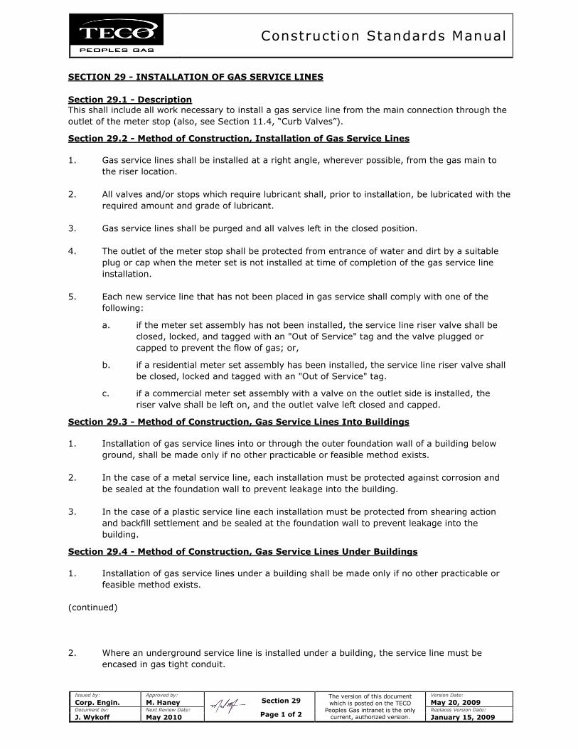
Construction Standards Manual
Issued by: Approved by:
The version of this document
which is posted on the TECO
Peoples Gas intranet is the only current, authorized version.
Version Date:
Corp. Engin. M. Haney May 20, 2009 Document by: Next Review Date: Replaces Version Date:
J. Wykoff May 2010 January 15, 2009
SECTION 29 - INSTALLATION OF GAS SERVICE LINES
Section 29.1 - Description This shall include all work necessary to install a gas service line from the main connection through the
outlet of the meter stop (also, see Section 11.4, “Curb Valves”).
Section 29.2 - Method of Construction, Installation of Gas Service Lines
1. Gas service lines shall be installed at a right angle, wherever possible, from the gas main to
the riser location.
2. All valves and/or stops which require lubricant shall, prior to installation, be lubricated with the
required amount and grade of lubricant.
3. Gas service lines shall be purged and all valves left in the closed position.
4. The outlet of the meter stop shall be protected from entrance of water and dirt by a suitable
plug or cap when the meter set is not installed at time of completion of the gas service line
installation.
5. Each new service line that has not been placed in gas service shall comply with one of the
following:
a. if the meter set assembly has not been installed, the service line riser valve shall be
closed, locked, and tagged with an "Out of Service" tag and the valve plugged or
capped to prevent the flow of gas; or,
b. if a residential meter set assembly has been installed, the service line riser valve shall
be closed, locked and tagged with an "Out of Service" tag.
c. if a commercial meter set assembly with a valve on the outlet side is installed, the
riser valve shall be left on, and the outlet valve left closed and capped.
Section 29.3 - Method of Construction, Gas Service Lines Into Buildings
1. Installation of gas service lines into or through the outer foundation wall of a building below
ground, shall be made only if no other practicable or feasible method exists.
2. In the case of a metal service line, each installation must be protected against corrosion and
be sealed at the foundation wall to prevent leakage into the building.
3. In the case of a plastic service line each installation must be protected from shearing action
and backfill settlement and be sealed at the foundation wall to prevent leakage into the
building.
Section 29.4 - Method of Construction, Gas Service Lines Under Buildings
1. Installation of gas service lines under a building shall be made only if no other practicable or
feasible method exists.
(continued)
2. Where an underground service line is installed under a building, the service line must be
encased in gas tight conduit.
Section 29
Page 1 of 2
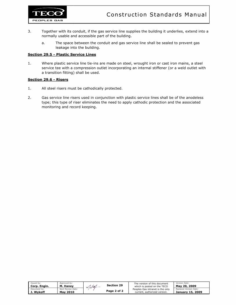
Construction Standards Manual
Issued by: Approved by:
The version of this document
which is posted on the TECO
Peoples Gas intranet is the only current, authorized version.
Version Date:
Corp. Engin. M. Haney May 20, 2009 Document by: Next Review Date: Replaces Version Date:
J. Wykoff May 2010 January 15, 2009
3. Together with its conduit, if the gas service line supplies the building it underlies, extend into a
normally usable and accessible part of the building.
a. The space between the conduit and gas service line shall be sealed to prevent gas
leakage into the building.
Section 29.5 - Plastic Service Lines
1. Where plastic service line tie-ins are made on steel, wrought iron or cast iron mains, a steel
service tee with a compression outlet incorporating an internal stiffener (or a weld outlet with
a transition fitting) shall be used.
Section 29.6 - Risers
1. All steel risers must be cathodically protected.
2. Gas service line risers used in conjunction with plastic service lines shall be of the anodeless
type; this type of riser eliminates the need to apply cathodic protection and the associated
monitoring and record keeping.
Section 29
Page 2 of 2
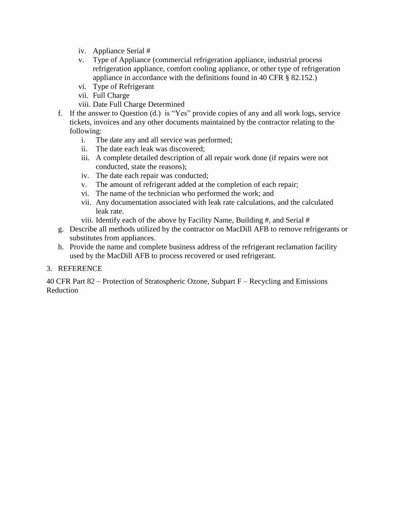
iv. Appliance Serial #
v. Type of Appliance (commercial refrigeration appliance, industrial process
refrigeration appliance, comfort cooling appliance, or other type of refrigeration
appliance in accordance with the definitions found in 40 CFR § 82.152.)
vi. Type of Refrigerant
vii. Full Charge
viii. Date Full Charge Determined
f. If the answer to Question (d.) is “Yes” provide copies of any and all work logs, service
tickets, invoices and any other documents maintained by the contractor relating to the
following:
i. The date any and all service was performed;
ii. The date each leak was discovered;
iii. A complete detailed description of all repair work done (if repairs were not
conducted, state the reasons);
iv. The date each repair was conducted;
v. The amount of refrigerant added at the completion of each repair;
vi. The name of the technician who performed the work; and
vii. Any documentation associated with leak rate calculations, and the calculated
leak rate.
viii. Identify each of the above by Facility Name, Building #, and Serial #
g. Describe all methods utilized by the contractor on MacDill AFB to remove refrigerants or
substitutes from appliances.
h. Provide the name and complete business address of the refrigerant reclamation facility
used by the MacDill AFB to process recovered or used refrigerant.
3. REFERENCE
40 CFR Part 82 – Protection of Stratospheric Ozone, Subpart F – Recycling and Emissions
Reduction

Operating
And
Maintenance
Procedure
Manual
November 1, 2011 Page 1 of 178
IMPLEMENTATION POLICY
It is the policy of TECO Peoples Gas to construct, operate and maintain natural gas
systems in a manner which is safe and consistent with good industry practice.
Furthermore, TECO Peoples Gas shall comply with all federal, state and local gas
codes. Generally these codes set minimum standards but do not specify the
manner in which the minimums are to be achieved. Therefore, TECO Peoples Gas
has issued the Operating and Maintenance Procedures Manual, Construction
Standards, Standard Material List and Emergency Procedures Manual, to be used
in achieving its goals as well as the requirements of the codes.
The records, reports, and forms required by the regulations covered by these
policies may be in either paper or electronic form, and archived accordingly.
The Division Manager shall be responsible for the implementation of the policy
unless otherwise identified. The following words and phrases which are used
throughout the manual are used synonymously: local operating center, Supervisor,
Supervisor in charge of the operation, Division Manager, and Division Manager’s
designated representative.
Where the word “include” occurs, it means including but not limited to. Where the
word “may” is used it means “is permitted to” or “is authorized to”. Where the
words “may not” are used it means “is not permitted to” or “is not authorized to”.
Where the word “shall” is used it is used in the mandatory and imperative sense.
Where a singular word tense is used, it includes the plural. Where a plural word
tense is used, it includes the singular. Where a masculine gender word is used, it
includes the feminine, and vice versa.

November 1, 2011 Page 3 of 178
INDEX
Safety-Related Conditions ........................................................................................................Section 1
Section 1.1 - General....................................................................................................... Page 13
Section 1.2 - Reporting Safety - Related Conditions. ..................................................... Page 13
Incident Reporting ....................................................................................................................Section 2
Section 2.1 - General....................................................................................................... Page 16
Section 2.2 - Reports and Reporting of Accidents, Leaks, or Incidents ......................... Page 16
Class Locations - Transmission ................................................................................................Section 3
Section 3.1 - Population Density Indexes and Initial Determination.............................. Page 18
Section 3.2 - Change in Class Location & Required Study ............................................ Page 18
Section 3.3 - Class Change & MAOP Confirmation or Revision................................... Page 19
Section 3.4 - Reports and Records .................................................................................. Page 20
Continuing Surveillance............................................................................................................Section 4
Section 4.1 - General....................................................................................................... Page 22
Section 4.2 - System Review .......................................................................................... Page 22
Section 4.3 - Frequency of Review ................................................................................. Page 23
Section 4.4 - Class Location Survey ............................................................................... Page 23
Section 4.5 - Class Determination .................................................................................. Page 23
Section 4.6 - Changes in Class Location ........................................................................ Page 24
Section 4.7 - Unaccounted - For - Gas ............................................................................ Page 24
Section 4.8 - System Alterations ..................................................................................... Page 24
Section 4.9 - Future Load Capability .............................................................................. Page 24
Section 4.10 - Remedial Action ...................................................................................... Page 25
Damage Prevention Program ....................................................................................................Section 5
Section 5.1 - General....................................................................................................... Page 26
Section 5.2 - Damage Prevention Requirements ............................................................ Page 26
Section 5.3 - One Call ..................................................................................................... Page 27
Section 5.4 - One-Call Systems ...................................................................................... Page 27
Section 5.5 - Field Locating ............................................................................................ Page 28
Section 5.6 - Pipeline Markers ........................................................................................ Page 28
Section 5.7 - Protecting Cast Iron Pipeline - Excavations and Undermining ................. Page 28
Section 5.8 - Coordination Before the Project ................................................................ Page 29
Section 5.9 - Annual Advisory Letter ............................................................................. Page 29
Section 5.10 - General Public Program ........................................................................... Page 29
Section 5.11 - Responsibility and Record Keeping ........................................................ Page 30
Investigation of Failures ...........................................................................................................Section 6
Section 6.1 - General....................................................................................................... Page 31
Section 6.2 - Conclusion and Report Preparation ........................................................... Page 31
November 1, 2011 Page 4 of 178
Maximum Allowable Operating Pressure .................................................................................Section 7
Section 7.1 - General....................................................................................................... Page 32
Section 7.2 - Establishment of MAOP ............................................................................ Page 32
Section 7.3 - Increasing MAOP on Existing Systems ................................................... Page 32
Section 7.4 - New Systems ............................................................................................ Page 32
Pressure Monitoring .................................................................................................................Section 8
Section 8.1 - Operating Pressure (Distribution) ............................................................. Page 33
Section 8.2 - Pressure Records........................................................................................ Page 33
Section 8.3 - Over-Pressure Report ................................................................................ Page 33
Up-Rating ..................................................................................................................................Section 9
Section 9.1 - General....................................................................................................... Page 34
Section 9.2 - Uprating to Less Than 30% SMYS........ ................................................... Page 36
Section 9.3 - Uprating to Greater Than 30% SMYS ...................................................... Page 37
Section 9.4 - Uprating, While Out of Service..... ............................................................ Page 37
Section 9.5 - New Maximum Operating Pressure...... .................................................... Page 38
Section 9.6 - Records..................................................... ................................................. Page 38
Odorization of Gas ..................................................................................................................Section 10
Section 10.1 - General..................................................................................................... Page 42
Section 10.2 - Types of Odorant ..................................................................................... Page 42
Section 10.3 - Rate of Odorization ................................................................................. Page 42
Section 10.4 - Odorizer Equipment ................................................................................ Page 43
Section 10.5 - Preparation of Odorization Records & Surveys ...................................... Page 43
Section 10.6 - Odorant Injection Records ....................................................................... Page 43
Section 10.7 - Odorant Intensity Survey Records ........................................................... Page 43
Section 10.8 - Incident Testing ....................................................................................... Page 44
Section 10.9 - Odorization Problems .............................................................................. Page 44
Tapping Pipelines Under Pressure ..........................................................................................Section 11
Section 11.1 - Personnel Qualifications .......................................................................... Page 47
Section 11.2 - Identification of Pipe and Suitability for Tapping ................................... Page 47
Section 11.3 - Additional Requirements for Transmission Systems .............................. Page 47
Section 11.4 - Stopping ................................................................................................... Page 48
Purging of Pipelines ................................................................................................................Section 12
Section 12.1 - Purging with Natural Gas or Propane Gas............................................... Page 49
Section 12.2 - Purging with Air or an Inert Gas ............................................................. Page 49
Section 12.3 - Special Conditions ................................................................................... Page 49
Section 12.4 - Responsibility .......................................................................................... Page 49
November 1, 2011 Page 5 of 178
Repair Procedures - Distribution ............................................................................................Section 13
Section 13.1 - General..................................................................................................... Page 50
Section 13.2 - Repair of Steel Pipe ................................................................................. Page 50
Section 13.3 - Weld Repair ............................................................................................. Page 50
Section 13.4 - Repair of Plastic....................................................................................... Page 50
Section 13.5 - Mechanical Joints .................................................................................... Page 51
Section 13.6 - Inspection and Testing ............................................................................. Page 51
Section 13.7 - Reports and Records ................................................................................ Page 52
Repair Procedures - Transmission ..........................................................................................Section 14
Section 14.1 - General..................................................................................................... Page 54
Section 14.2 - Repair of Steel Lines Operating at Twenty Percent SMYS or More ...... Page 54
Section 14.3 - Testing of Repairs ................................................................................... Page 54
Section 14.4 - Permanent Field Repair of Welds ............................................................ Page 55
Section 14.5 - Reports and Records ................................................................................ Page 56
Patrolling & Leak Survey - Transmission. .............................................................................Section 15
Section 15.1 - General..................................................................................................... Page 60
Section 15.2 - Transmission Facilities ............................................................................ Page 60
Section 15.3 - Surface Patrol .......................................................................................... Page 61
Section 15.4 - Reports and Records ................................................................................ Page 62
Record Keeping - Transmission..............................................................................................Section 16
Section 16.1 - General..................................................................................................... Page 64
Patrolling - Distribution ..........................................................................................................Section 17
Section 17.1 - General..................................................................................................... Page 65
Section 17.2 - Patrol Frequency ...................................................................................... Page 65
Section 17.3 - Patrol Requirements ................................................................................ Page 65
Section 17.4 - Reports and Records ................................................................................ Page 67
Leak Survey - Distribution......................................................................................................Section 18
Section 18.1 - General..................................................................................................... Page 69
Section 18.2 - Distribution Survey Frequency ................................................................ Page 69
Section 18.3 - Survey Procedure ..................................................................................... Page 70
Section 18.4 - Business District ...................................................................................... Page 71
Section 18.5 - Types of Leak Surveys (Removed) ......................................................... Page 71
Section 18.6 - Reports and Records ................................................................................ Page 72
Leak Classification & Action Criteria ....................................................................................Section 19
Section 19.1 - Leak Classification and Action Criteria .................................................. Page 75
Section 19.2 - Follow-Up Inspection .............................................................................. Page 77
November 1, 2011 Page 6 of 178
Line Markers for Mains & Transmission Lines. .....................................................................Section 20
Section 20.1 - General..................................................................................................... Page 78
Section 20.2 - Placement of Markers .............................................................................. Page 78
Section 20.3 - Minimum Specifications.......................................................................... Page 79
Section 20.4 - Warning Signs ......................................................................................... Page 79
Test Requirements for Reinstating Main & Service Lines .....................................................Section 21
Section 21.1 - Reconnection of Temporarily Disconnected Services ............................. Page 80
Section 21.2 - Reconnection of Temporarily Disconnected Mains or Pipelines ............ Page 80
Section 21.3 - Reinstating Service in Abandoned Lines................................................. Page 81
Abandonment or Inactivation of Facilities .............................................................................Section 22
Section 22.1 - Abandonment of Pipelines....................................................................... Page 82
Regulator Station Inspection ...................................................................................................Section 23
Section 23.1 - General..................................................................................................... Page 84
Section 23.2 - Operational Inspection ............................................................................. Page 84
Section 23.3 - Primary Inspection ................................................................................... Page 88
Section 23.4 - Determination of Required Relief Capacity ............................................ Page 89
Section 23.5 - Miscellaneous Station Equipment Inspection .......................................... Page 89
Section 23.6 - System Changes ....................................................................................... Page 89
Section 23.7 - Final Inspection ....................................................................................... Page 90
Section 23.8 - Reports and Records ................................................................................ Page 90
Section 23.9 - Telemetry or Recording Gauges .............................................................. Page 91
Emergency Valve Procedure...................................................................................................Section 24
Section 24.1 - General..................................................................................................... Page 94
Section 24.2 - Designation of Emergency Valves .......................................................... Page 94
Section 24.3 - Valve Inspections .................................................................................... Page 95
Section 24.4 - Marking of Emergency Valves ................................................................ Page 96
Section 24.5 - Reports and Records ............................................................................... Page 97
Vault Maintenance ..................................................................................................................Section 25
Section 25.1 - General................................................................................................... Page 100
Section 25.2 - Vault Inspection ..................................................................................... Page 100
Section 25.3 - Reports and Records .............................................................................. Page 100
Prevention of Accidental Ignition ...........................................................................................Section 26
Section 26.1 - General................................................................................................... Page 102
Section 26.2 - Welding, Cutting and Other Hot Work ................................................. Page 103
Section 26.3 - Isolating Pipelines.................................................................................. Page 104
Section 26.4 - Notification Prior to Purge or Blow-down ............................................ Page 105
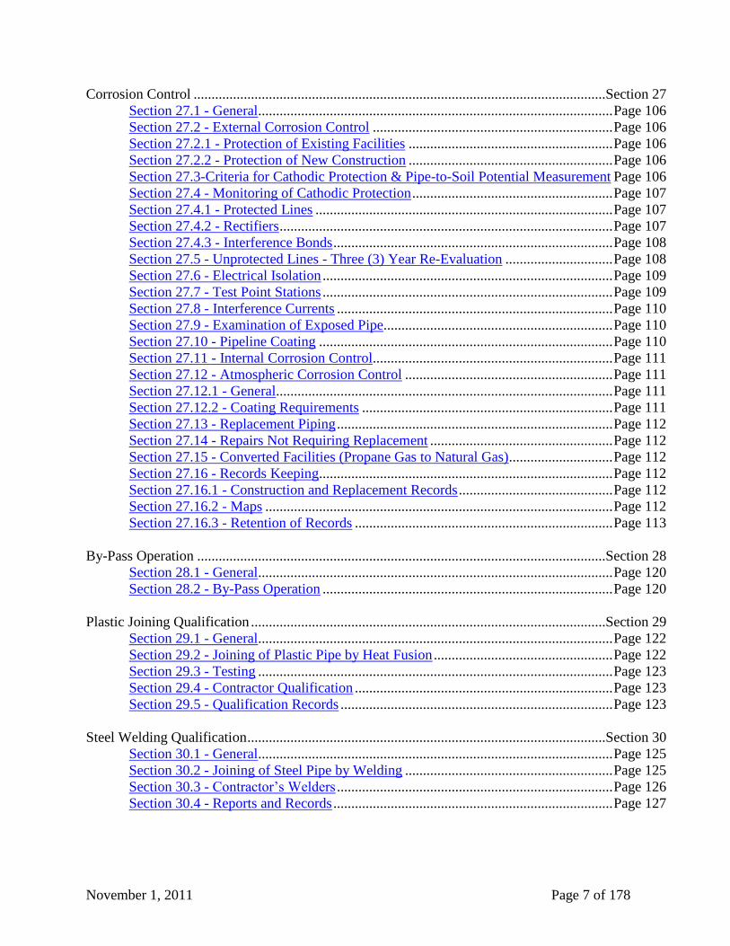
November 1, 2011 Page 7 of 178
Corrosion Control ...................................................................................................................Section 27
Section 27.1 - General................................................................................................... Page 106
Section 27.2 - External Corrosion Control ................................................................... Page 106
Section 27.2.1 - Protection of Existing Facilities ......................................................... Page 106
Section 27.2.2 - Protection of New Construction ......................................................... Page 106
Section 27.3-Criteria for Cathodic Protection & Pipe-to-Soil Potential Measurement Page 106
Section 27.4 - Monitoring of Cathodic Protection ........................................................ Page 107
Section 27.4.1 - Protected Lines ................................................................................... Page 107
Section 27.4.2 - Rectifiers ............................................................................................. Page 107
Section 27.4.3 - Interference Bonds .............................................................................. Page 108
Section 27.5 - Unprotected Lines - Three (3) Year Re-Evaluation .............................. Page 108
Section 27.6 - Electrical Isolation ................................................................................. Page 109
Section 27.7 - Test Point Stations ................................................................................. Page 109
Section 27.8 - Interference Currents ............................................................................. Page 110
Section 27.9 - Examination of Exposed Pipe................................................................ Page 110
Section 27.10 - Pipeline Coating .................................................................................. Page 110
Section 27.11 - Internal Corrosion Control................................................................... Page 111
Section 27.12 - Atmospheric Corrosion Control .......................................................... Page 111
Section 27.12.1 - General.............................................................................................. Page 111
Section 27.12.2 - Coating Requirements ...................................................................... Page 111
Section 27.13 - Replacement Piping ............................................................................. Page 112
Section 27.14 - Repairs Not Requiring Replacement ................................................... Page 112
Section 27.15 - Converted Facilities (Propane Gas to Natural Gas)............................. Page 112
Section 27.16 - Records Keeping.................................................................................. Page 112
Section 27.16.1 - Construction and Replacement Records ........................................... Page 112
Section 27.16.2 - Maps ................................................................................................. Page 112
Section 27.16.3 - Retention of Records ........................................................................ Page 113
By-Pass Operation ..................................................................................................................Section 28
Section 28.1 - General................................................................................................... Page 120
Section 28.2 - By-Pass Operation ................................................................................. Page 120
Plastic Joining Qualification ...................................................................................................Section 29
Section 29.1 - General................................................................................................... Page 122
Section 29.2 - Joining of Plastic Pipe by Heat Fusion .................................................. Page 122
Section 29.3 - Testing ................................................................................................... Page 123
Section 29.4 - Contractor Qualification ........................................................................ Page 123
Section 29.5 - Qualification Records ............................................................................ Page 123
Steel Welding Qualification ....................................................................................................Section 30
Section 30.1 - General................................................................................................... Page 125
Section 30.2 - Joining of Steel Pipe by Welding .......................................................... Page 125
Section 30.3 - Contractor’s Welders ............................................................................. Page 126
Section 30.4 - Reports and Records .............................................................................. Page 127
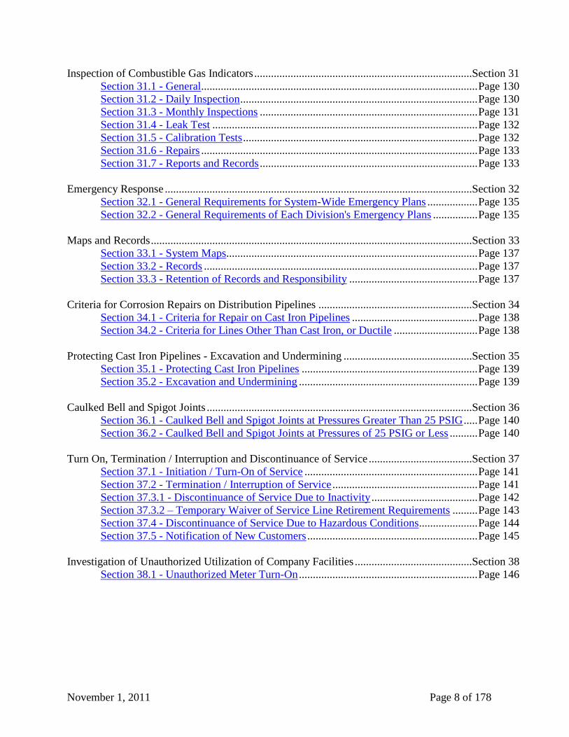
November 1, 2011 Page 8 of 178
Inspection of Combustible Gas Indicators ..............................................................................Section 31
Section 31.1 - General................................................................................................... Page 130
Section 31.2 - Daily Inspection ..................................................................................... Page 130
Section 31.3 - Monthly Inspections .............................................................................. Page 131
Section 31.4 - Leak Test ............................................................................................... Page 132
Section 31.5 - Calibration Tests .................................................................................... Page 132
Section 31.6 - Repairs ................................................................................................... Page 133
Section 31.7 - Reports and Records .............................................................................. Page 133
Emergency Response ..............................................................................................................Section 32
Section 32.1 - General Requirements for System-Wide Emergency Plans .................. Page 135
Section 32.2 - General Requirements of Each Division's Emergency Plans ................ Page 135
Maps and Records ...................................................................................................................Section 33
Section 33.1 - System Maps.......................................................................................... Page 137
Section 33.2 - Records .................................................................................................. Page 137
Section 33.3 - Retention of Records and Responsibility .............................................. Page 137
Criteria for Corrosion Repairs on Distribution Pipelines .......................................................Section 34
Section 34.1 - Criteria for Repair on Cast Iron Pipelines ............................................. Page 138
Section 34.2 - Criteria for Lines Other Than Cast Iron, or Ductile .............................. Page 138
Protecting Cast Iron Pipelines - Excavation and Undermining ..............................................Section 35
Section 35.1 - Protecting Cast Iron Pipelines ............................................................... Page 139
Section 35.2 - Excavation and Undermining ................................................................ Page 139
Caulked Bell and Spigot Joints ...............................................................................................Section 36
Section 36.1 - Caulked Bell and Spigot Joints at Pressures Greater Than 25 PSIG ..... Page 140
Section 36.2 - Caulked Bell and Spigot Joints at Pressures of 25 PSIG or Less .......... Page 140
Turn On, Termination / Interruption and Discontinuance of Service .....................................Section 37
Section 37.1 - Initiation / Turn-On of Service .............................................................. Page 141
Section 37.2 - Termination / Interruption of Service .................................................... Page 141
Section 37.3.1 - Discontinuance of Service Due to Inactivity ...................................... Page 142
Section 37.3.2 – Temporary Waiver of Service Line Retirement Requirements ......... Page 143
Section 37.4 - Discontinuance of Service Due to Hazardous Conditions ..................... Page 144
Section 37.5 - Notification of New Customers ............................................................. Page 145
Investigation of Unauthorized Utilization of Company Facilities ..........................................Section 38
Section 38.1 - Unauthorized Meter Turn-On ................................................................ Page 146
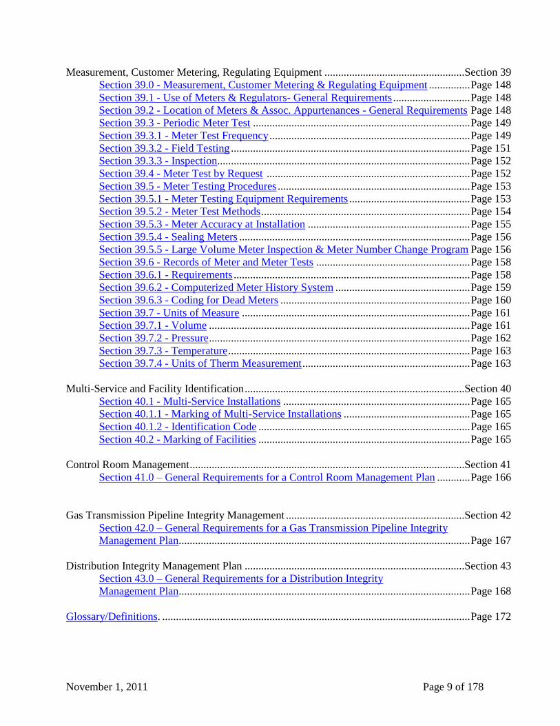
November 1, 2011 Page 9 of 178
Measurement, Customer Metering, Regulating Equipment ...................................................Section 39
Section 39.0 - Measurement, Customer Metering & Regulating Equipment ............... Page 148
Section 39.1 - Use of Meters & Regulators- General Requirements ............................ Page 148
Section 39.2 - Location of Meters & Assoc. Appurtenances - General Requirements Page 148
Section 39.3 - Periodic Meter Test ............................................................................... Page 149
Section 39.3.1 - Meter Test Frequency ......................................................................... Page 149
Section 39.3.2 - Field Testing ....................................................................................... Page 151
Section 39.3.3 - Inspection............................................................................................ Page 152
Section 39.4 - Meter Test by Request .......................................................................... Page 152
Section 39.5 - Meter Testing Procedures ...................................................................... Page 153
Section 39.5.1 - Meter Testing Equipment Requirements ............................................ Page 153
Section 39.5.2 - Meter Test Methods ............................................................................ Page 154
Section 39.5.3 - Meter Accuracy at Installation ........................................................... Page 155
Section 39.5.4 - Sealing Meters .................................................................................... Page 156
Section 39.5.5 - Large Volume Meter Inspection & Meter Number Change Program Page 156
Section 39.6 - Records of Meter and Meter Tests ........................................................ Page 158
Section 39.6.1 - Requirements ...................................................................................... Page 158
Section 39.6.2 - Computerized Meter History System ................................................. Page 159
Section 39.6.3 - Coding for Dead Meters ..................................................................... Page 160
Section 39.7 - Units of Measure ................................................................................... Page 161
Section 39.7.1 - Volume ............................................................................................... Page 161
Section 39.7.2 - Pressure ............................................................................................... Page 162
Section 39.7.3 - Temperature ........................................................................................ Page 163
Section 39.7.4 - Units of Therm Measurement ............................................................. Page 163
Multi-Service and Facility Identification ................................................................................Section 40
Section 40.1 - Multi-Service Installations .................................................................... Page 165
Section 40.1.1 - Marking of Multi-Service Installations .............................................. Page 165
Section 40.1.2 - Identification Code ............................................................................. Page 165
Section 40.2 - Marking of Facilities ............................................................................. Page 165
Control Room Management ....................................................................................................Section 41
Section 41.0 – General Requirements for a Control Room Management Plan ............ Page 166
Gas Transmission Pipeline Integrity Management .................................................................Section 42
Section 42.0 – General Requirements for a Gas Transmission Pipeline Integrity
Management Plan.......................................................................................................... Page 167
Distribution Integrity Management Plan ................................................................................Section 43
Section 43.0 – General Requirements for a Distribution Integrity
Management Plan.......................................................................................................... Page 168
Glossary/Definitions. ................................................................................................................ Page 172
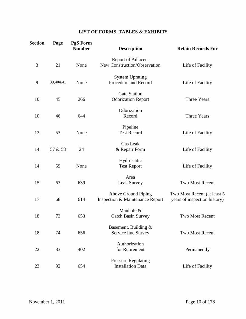
November 1, 2011 Page 10 of 178
LIST OF FORMS, TABLES & EXHIBITS
Section Page PgS Form
Number
Description
Retain Records For
3
21
None
Report of Adjacent
New Construction/Observation
Life of Facility
9
39,40&41
None
System Uprating
Procedure and Record
Life of Facility
10
45
266
Gate Station
Odorization Report
Three Years
10
46
644
Odorization
Record
Three Years
13
53
None
Pipeline
Test Record
Life of Facility
14
57 & 58
24
Gas Leak
& Repair Form
Life of Facility
14
59
None
Hydrostatic
Test Report
Life of Facility
15
63
639
Area
Leak Survey
Two Most Recent
17
68
614
Above Ground Piping
Inspection & Maintenance Report
Two Most Recent (at least 5
years of inspection history)
18
73
653
Manhole &
Catch Basin Survey
Two Most Recent
18
74
656
Basement, Building &
Service line Survey
Two Most Recent
22
83
402
Authorization
for Retirement
Permanently
23
92
654
Pressure Regulating
Installation Data
Life of Facility
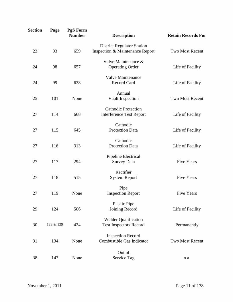
November 1, 2011 Page 11 of 178
Section Page PgS Form
Number
Description
Retain Records For
23
93
659
District Regulator Station
Inspection & Maintenance Report
Two Most Recent
24
98
657
Valve Maintenance &
Operating Order
Life of Facility
24
99
638
Valve Maintenance
Record Card
Life of Facility
25
101
None
Annual
Vault Inspection
Two Most Recent
27
114
668
Cathodic Protection
Interference Test Report
Life of Facility
27
115
645
Cathodic
Protection Data
Life of Facility
27
116
313
Cathodic
Protection Data
Life of Facility
27
117
294
Pipeline Electrical
Survey Data
Five Years
27
118
515
Rectifier
System Report
Five Years
27
119
None
Pipe
Inspection Report
Five Years
29
124
506
Plastic Pipe
Joining Record
Life of Facility
30
128 & 129
424
Welder Qualification
Test Inspectors Record
Permanently
31
134
None
Inspection Record
Combustible Gas Indicator
Two Most Recent
38
147
None
Out of
Service Tag
n.a.

November 1, 2011 Page 12 of 178
Section Page PgS Form
Number
Description
Retain Records For
39
164
640
Large Volume Meter Installation
Maintenance Report
One Most Recent
November 1, 2011 Page 13 of 178
OPERATING AND MAINTENANCE PROCEDURE
Subject: Date Issued:
SAFETY - RELATED CONDITIONS October 1, 2003
Reference:
Title 49 Code of Federal Regulations, Part 192.605, 191.23 and 191.25
Date Revised:
July 31, 2011
Section 1 – Safety Related Conditions
Approved:
Section 1.1 - General
TECO Peoples Gas is committed to the construction, maintenance and operation of its facilities
in a manner that is safe to the public and employees. All employees, including management,
supervisors and non-supervisory employees, shall use good judgment in performing all work in a
safe manner. It is the obligation of the individual employee who is aware of an unsafe or
potentially unsafe condition to immediately bring the matter to the attention of the employee's
supervisor.
The Supervisor will report the safety-related condition to the Division Manager. The Division
Manager will prepare the report itemizing the information required by Title 49 Code of Federal
Regulations, Part 191.25 (b).
Section 1.2 - Reporting Safety-Related Conditions
State and federal regulations require that "safety-related conditions" be reported in writing. The
report must be received in the State and Federal office:
Within five (5) working days after determining that a safety-related condition exists,
But no later than ten (10) working days after the discovery of the safety-related condition.
1. Except as stated in item (b) below, a report is required for the following situations defined
by the regulations as safety-related conditions:
a. In the case of pipelines that operate at a hoop stress of twenty percent (20%) or more of
SMYS:
i. General corrosion that has reduced the wall thickness to less than that required for the
maximum allowable operation pressure.
ii. Localized corrosion pitting to a degree where leakage might result.
iii. Any material defect or physical damage that impairs its serviceability
(continued on next page)
November 1, 2011 Page 14 of 178
OPERATING AND MAINTENANCE PROCEDURE
Subject: Date Issued:
SAFETY - RELATED CONDITIONS October 1, 2003
Reference:
Title 49 Code of Federal Regulations, Part 192.605, 191.23 and 191.25
Date Revised:
July 31, 2011
Section 1 – Safety Related Conditions (continued)
Approved:
b. For all distribution, transmission, and gathering systems where:
i. Unintended movement or abnormal forces caused by environmental causes, such as
earthquake, landslide, or flood that impairs the serviceability of a pipeline.
ii. Any over-pressure condition that exceeded the maximum allowable operating
pressure plus the buildup allowed for over pressure protection devices.
iii. A leak in a gas pipeline that constitutes an emergency, but that is not otherwise
reportable.
iv. Any safety-related condition that could lead to an imminent hazard and that requires a
twenty-percent (20%) or more reduction in operating pressure or the shutdown of a
pipeline.
2. A report is NOT required if the condition:
a. Is temporarily or permanently repaired or replaced within five (5) working days after
determination, except that reports are required for generalized corrosion as described in
Section 1.2, item 1.a.i. above or localized corrosion on pipelines not effectively coated
and cathodically protected and meeting Section 1.2, item1.a.ii, above.
b. Exists on a pipeline that is more than two hundred twenty (220) yards from any building
intended for human occupancy or outdoor place of assembly, except railroad, paved road,
street or highway.
c. Exists on a master meter system or a customer-owned service line.
d. Results in a reportable incident before the deadline.
(continued on next page)
November 1, 2011 Page 15 of 178
OPERATING AND MAINTENANCE PROCEDURE
Subject: Date Issued:
SAFETY - RELATED CONDITIONS October 1, 2003
Reference:
Title 49 Code of Federal Regulations, Part 192.605, 191.23 and 191.25
Date Revised:
July 31, 2011
Section 1 – Safety Related Conditions (continued)
Approved:
3. Telephone Report: Because of the time limit, each condition stated above shall be reported
by telephone directly to the Division Manager within five (5) working days from the time of
discovery. The following information is required:
a. Name and principal address of Operator.
b. Date of report.
c. The name, job title and business telephone number of person submitting report.
d. The name, job title, and business telephone number of the person who determined that the
condition exists.
e. The date the condition was discovered and the date that condition was first determined to
be a safety-related condition as defined in item 1. (above, this Section 1.2).
f. The location of the condition, with reference to the nearest street address, survey station
number, milepost, landmark, or name of pipeline, as appropriate.
g. A description of the condition, including circumstances leading to its discovery and any
significant effects of the condition on safety.
h. The corrective action taken (including reduction of pressure or shutdown) before the
report is submitted and the planned follow-up for future corrective action, include the
anticipated schedule for starting and concluding such action.
November 1, 2011 Page 16 of 178
OPERATING AND MAINTENANCE PROCEDURE
Subject: Date Issued:
INCIDENT REPORTING October 1, 2003
Reference:
Title 49 Code of Federal Regulations, Part 191.3, 191.5,
191.9 and 191.15, Florida Administrative Code 25-7.018 and 25-12.084
Date Revised:
July 31, 2011
Section 2 – Incident Reporting
Approved:
Section 2.1 - General
This Procedure describes the criteria for reporting certain natural gas leaks and facility failures
involving the TECO Peoples Gas distribution and transmission systems as required by the above
listed federal and state regulations. The Division Managers shall be responsible for making
certain that the Florida Public Service Commission (FPSC) and US Department of
Transportation (USDOT) are properly notified of reportable accidents, leaks, or incidents.
Section 2.2 - Reports and Reporting of Accidents, Leaks, or Incidents:
1. At the earliest practical moment following discovery, TECO Peoples Gas shall notify the
FPSC by telephone of any event that involves a release of gas from its pipeline(s) which:
a. Caused a death or any personal injury requiring inpatient hospitalization;
b. Required taking any segment of transmission pipeline out of service;
c. Resulted in gas igniting
d. Caused estimated damage to the property of TECO Peoples Gas, or others, or both
(including gas loss), totaling $10,000 or more;
e. Could reasonably be judged as significant even though it does not meet the other
requirements.
2. TECO Peoples Gas need not give notice of an event that met only the criteria of
subparagraphs (b) or (c) of the above paragraph, if it occurred solely as a result of, or in
connection with, planned or routine maintenance or construction.
3. TECO Peoples Gas shall immediately report to the FPSC any distribution system-related
accident or failure which interrupts service to either ten percent (10%) or more of its
division meters or five hundred (500) or more meters.
(continued on next page)
November 1, 2011 Page 17 of 178
OPERATING AND MAINTENANCE PROCEDURE
Subject: Date Issued:
INCIDENT REPORTING October 1, 2003
Reference:
Title 49 Code of Federal Regulations, Part 191.3, 191.5,
191.9 and 191.15, Florida Administrative Code 25-7.018 and 25-12.084
Date Revised:
July 31, 2011
Section 2 – Incident Reporting (continued)
Approved:
4. The telephone notice shall be made to the FPSC emergency line, Pipeline Safety Section at
(850) 413-6650, and shall include the following:
a. Company name (TECO Peoples Gas), name of person making report and their telephone
numbers.
b. Location of leak or incident.
c. Time of accident/incident.
d. Fatalities and/or personal injuries.
e. Other significant facts relevant to the accident or incident
5. In addition to notifying the FPSC by telephone, TECO Peoples Gas is responsible for
notifying the USDOT of an incident that results in a death or personal injury necessitating in
patient hospitalization; or estimated property damage, including cost of gas lost of TECO
Peoples Gas or others or both, of fifty thousand dollars ($50,000) or more. Each notice
required shall be made by telephone to 800-424-8802 and shall include the same
information reported to the FPSC.
6. TECO Peoples Gas shall report, in writing, a summary of each accident or incident as
described above. The report shall be submitted to the FPSC as soon as practical, but not
more than thirty (30) days after detection, using the most current version of the form as
supplied by the U.S. Department of Transportation Pipeline and Hazardous Materials Safety
Administration: “Incident Report For Gas Distribution System - PHMSA F 7100.1” for gas
distribution incidents and “Incident Report for Gas Transmission and Gathering Pipeline
Systems – PHMSA F 7100.2” for gas transmission incidents. The submitter is required to
use the most current version of the official form. If the incident meets the criteria of Section
2.2.5 above, the appropriate report (PHMSA F 7100.1 or PHMSA F 7100.2) will be
submitted PHMSA online at PHMSA’s OPS Online Data Entry and Operator Registration
System site (http://opsweb.phmsa.dot.gov/cfdocs/opsapps/pipes/main.cfm).
November 1, 2011 Page 18 of 178
OPERATING AND MAINTENANCE PROCEDURE
Subject: Date Issued:
CLASS LOCATIONS – TRANSMISSION October 1, 2003
Reference:
Title 49 Code of Federal Regulations, Part 192.609 and 192.611
Date Revised:
July 31, 2011
Section 3 – Class Locations/Transmission
Approved:
Section 3.1 - Population Density Indexes and Initial Determination
Prior to pipeline construction, population density indexes are to be determined by aerial
photography or field survey in order to identify all locations for engineering design and testing
consideration.
The Corporate Engineering Department shall be responsible for the initiation of class location
surveys necessary to prepare the pipeline density indexes.
Section 3.2 - Change in Class Location & Required Study
Whenever an increase in population density, as determined from field surveys or other forms of
continuing surveillance, indicates a change in class location for a segment of an existing steel
pipeline operating at hoop stress that is more than forty percent (40%) of SMYS, or indicates that
the hoop stress corresponding to the established maximum allowable operating pressure for a
segment of existing pipeline is not commensurate with the present class location, the Division
Manager shall immediately make a study to determine:
1. The present class location for the segment involved.
2. The design, construction, and testing procedures followed in the original construction and a
comparison of these procedures with those required for the present class location.
3. The physical condition of the segment to the extent that can be ascertained from available
records.
4. The operating and maintenance history of the segment.
5. The maximum actual operating pressure and the corresponding operating hoop stress, taking
pressure gradient into account, for the segment involved.
6. The actual area affected by the population density increase, and physical barriers or other
factors, which may limit further expansion of the densely populated area.
The Division Manager shall upon completion of the above-referenced project, initiate action as
specified below at Section 3.3, “Class Change & MAOP Confirmation or Revision”.
November 1, 2011 Page 19 of 178
OPERATING AND MAINTENANCE PROCEDURE
Subject: Date Issued:
CLASS LOCATIONS – TRANSMISSION October 1, 2003
Reference:
Title 49 Code of Federal Regulations, Part 192.609 and 192.611
Date Revised:
July 31, 2011
Section 3 – Class Locations/Transmission (continued)
Approved:
Section 3.3 - Class Change & MAOP Confirmation or Revision
The Corporate Engineering Department shall, upon receipt of the study referenced above at
Section 3.2, “Change in Class Location & Required Study”, Section 3, Page 21, develop a plan
for MAOP confirmation or revision of the segment of pipeline involved. Confirmation or
revision necessary by changes in class location must be completed within twenty four (24)
months of the change in class location.
1. If the segment involved has been previously tested in place for a period of not less than eight
(8) hours, and the segment is in satisfactory physical condition, the MAOP must be
confirmed or reduced so that the corresponding hoop stress will not exceed:
a. Seventy-two percent (72%) of SMYS nor eighty percent (80%) of the test pressure in
Class 2 locations.
b. Sixty percent (60%) of SMYS nor sixty six and seven tenths percent (66.7%) of the test
pressure in Class 3 locations.
c. Fifty percent (50%) of SMYS nor fifty five and five tenths percent (55.5%) of the test
pressure in Class 4 locations.
2. If the segment involved has not been previously tested in place as described in item 1 above,
the MAOP must be reduced so that the corresponding hoop stress is not more than that
allowed under Title 49, Code of Federal Regulations, Paragraph 192.619 for new segments of
pipeline in the existing class location.
3. If the segment involved has not been qualified for operation under items 1 or 2 above, it must
be tested in accordance with Title 49 Code of Federal Regulations, Subpart J-Test
Requirements. The MAOP must then be established so as to be equal to or less than the
following:
a. The MAOP after re-qualification test is 0.8 times the test pressure in Class 2 locations,
0.667 times the test pressure in Class 3 locations, or 0.555 times the test pressure in Class
4 locations.
b. The MAOP may not exceed the MAOP established before the confirmation or revision.
c. The corresponding hoop stress may not exceed that which is specified in item 2 above.
November 1, 2011 Page 20 of 178
OPERATING AND MAINTENANCE PROCEDURE
Subject: Date Issued:
CLASS LOCATIONS – TRANSMISSION October 1, 2003
Reference:
Title 49 Code of Federal Regulations, Part 192.609 and 192.611
Date Revised:
July 31, 2011
Section 3 – Class Locations/Transmission (continued)
Approved:
Section 3.4 - Reports and Records
The form, “Report of Adjacent New Construction/Observation” (see sample below at Section 3,
Page 21), shall be completed by the Division Manager to report building construction within six
hundred sixty feet (660’) of a pipeline.
The report shall be forwarded to Corporate Engineering to determine if a change in class location
has occurred.
November 1, 2011 Page 21 of 178
OPERATING AND MAINTENANCE PROCEDURE
Subject: Date Issued:
CLASS LOCATIONS – TRANSMISSION October 1, 2003
Reference:
Title 49 Code of Federal Regulations, Part 192.609 and 192.611
Date Revised:
July 31, 2011
Section 3 – Class Locations/Transmission (continued)
Approved:
REPORT OF ADJACENT NEW CONSTRUCTION / OBSERVATION
MONITORING FOR CONSTRUCTION IN THE AREA OF THE
_______________________________TRANSMISSION MAIN
SERVING______________________________________
NAME: ___________________________________ DATE: __________________
FINDINGS:
A. I HAVE MONITORED ALL _____ MILES OF THE TRANSMISSION MAIN
SERVING _______________________________ AND I HAVE FOUND NO
CONSTRUCTION IN THE AREA AROUND THE ______________________________
TRANSMISSION MAIN.
B. I HAVE MONITORED ALL _____ MILES OF THE TRANSMISSION MAIN
SERVING _______________________________ AND I HAVE FOUND
CONSTRUCTION IN THE AREA AROUND THE ______________________________
TRANSMISSION MAIN. THE CONSTRUCTION WAS BETWEEN THE FOLLOWING
MILE POST MARKERS:
__________ AND __________
__________ AND __________
__________ AND __________
REMARKS:___________________________________________________________________
______________________________________________________________________________
(use back of page if necessary)
______________________________________________ SIGNATURE
November 1, 2011 Page 22 of 178
OPERATING AND MAINTENANCE PROCEDURE
Subject: Date Issued:
CONTINUING SURVEILLANCE October 1, 2003
Reference:
Title 49 Code of Federal Regulations, Part 192.605, 192.609, and 192.613
Date Revised:
July 31, 2011
Section 4 – Continuing Surveillance
Approved:
Section 4.1 - General
The surveillance of TECO Peoples Gas’ gas system is a combined effort of different groups.
Surveillance is carried out in order to discover leaks and failures, minimize corrosion damage,
determine maintenance and repair requirements, monitor the operating condition of the system,
and take appropriate action.
Leaks and failures of gas system components are readily discovered during normal operations.
The Operations personnel also discover leaks or failures during routine leak surveys and other
investigations. The corrosion personnel monitor cathodic protection levels. The personnel of
this service also provide leakage and failure surveillance during their routine operations.
Personnel on both routine and incidental assignments shall be alert for conditions that would
interfere with the safe operation of the gas system. These conditions shall be reported to their
immediate supervisor.
Section 4.2 - System Review
As a means of maintaining the integrity of the systems, continuing surveillance through the
analysis of completed inspection and maintenance records, daily operating reports, and other
operating records shall be on-going and conducted so as to identify any system facilities
experiencing abnormal or unusual operating and maintenance conditions.
The Division Manager must periodically review each pipeline and/or system under his/her
jurisdiction. Consideration should be given to all of the following:
1. Class location at the time of the review and any changes in location class.
2. Alterations or additions to the system, which may change, pressure or flow maximums.
3. Patrols.
4. Leak or failure frequency.
5. Changes in corrosion control requirements or corrosion failures.
(continued on next page)
November 1, 2011 Page 23 of 178
OPERATING AND MAINTENANCE PROCEDURE
Subject: Date Issued:
CONTINUING SURVEILLANCE October 1, 2003
Reference:
Title 49 Code of Federal Regulations, Part 192.605, 192.609, and 192.613
Date Revised:
July 31, 2011
Section 4 – Continuing Surveillance (continued)
Approved:
6. Loss of flow efficiency or excessive pressure drops either system-wide or localized.
7. Ability of the pipeline or system to handle future loads within the prescribed operating
pressure range.
8. Unaccounted-for-gas.
If the review indicates that the facility is, or will be, in unsatisfactory condition, one of the
following actions shall be undertaken:
1. A procedure shall be initiated to recondition the segment and, if necessary, establish a new
MAOP.
2. The MAOP shall be reduced to a safe pressure after considering the conditions present.
3. A procedure shall be initiated to phase out or replace the unsatisfactory segment.
Section 4.3 - Frequency of Reviews
The reviews will be on-going, but at a minimum a complete review of each pipeline or system
shall be made annually by the Division Manager.
Section 4.4 - Class Location Survey
Changes in class location generally occur as a result of community development and expansion.
Such changes will be observed as they occur. Whenever such increases in population density in
an area are noted, a survey of the affected area should be made by field observation. The entire
area shall be surveyed as part of the periodic review.
Section 4.5 - Class Determination
The class location of each area surveyed shall be determined.
(continued on next page)
November 1, 2011 Page 24 of 178
OPERATING AND MAINTENANCE PROCEDURE
Subject: Date Issued:
CONTINUING SURVEILLANCE October 1, 2003
Reference:
Title 49 Code of Federal Regulations, Part 192.605, 192.609, and 192.613
Date Revised:
July 31, 2011
Section 4 – Continuing Surveillance (continued)
Approved:
Section 4.6 - Changes in Class Location
Whenever there is a change in the class location of any facility, the Division Manager must
determine the effect of the change on the facility. The design, construction, and testing
procedures followed in the original construction must be compared with the requirements for the
new location class.
If this review determines that the maximum operating pressure of the facility is greater than that
permitted by the new class location, the system must be down-rated, confirmed, or up-rated.
Section 4.7 - Unaccounted-For-Gas
The trend of unaccounted-for-gas is an important tool in verification of the effectiveness of a
maintenance program. Therefore, the Division Manager shall continuously monitor this trend.
Investigative action shall be taken whenever the loss exceeds two percent (2%) for distribution
systems.
Section 4.8 - System Alterations
Once a system has been rated, all design and construction shall be done to the standard thus
established. If any review, inspection, or survey determines that materials or methods which do
not comply have been used, the system shall be down-rated, up-rated by appropriate procedure,
or that portion replaced.
Section 4.9 - Future Load Capability
It is the responsibility of the Region Operations Manager to evaluate load increases and the
ability of the system to handle such growth within established pressure ranges. If it is
determined that it will not be possible for the system to serve an anticipated new load, one of the
following steps shall be taken:
1. The system shall be reinforced (additional capacity supplied).
2. The system shall be up-rated.
Unexpected pressure drops from normal load increases are not considered emergency situations
although temporary pressure increases may be required.
(continued on next page)
November 1, 2011 Page 25 of 178
OPERATING AND MAINTENANCE PROCEDURE
Subject: Date Issued:
CONTINUING SURVEILLANCE October 1, 2003
Reference:
Title 49 Code of Federal Regulations, Part 192.605, 192.609, and 192.613
Date Revised:
July 31, 2011
Section 4 – Continuing Surveillance (continued)
Approved:
Section 4.10 - Remedial Action
All unusual leaks, failures, changes in cathodic protection voltage and current levels, and
operating or maintenance conditions will be brought to the attention of the Division Manager.
All segments of pipeline found to be in an unsatisfactory condition shall be repaired or replaced
as soon as practical. In the event that the condition presents a hazard, the repair or replacement
will be accomplished immediately. The Region Operations Manager shall prepare plans and
programs for upgrading and reconditioning and for phasing out facilities that cannot be
reconditioned.
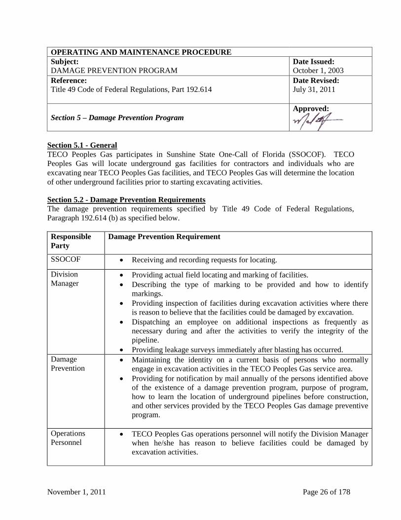
November 1, 2011 Page 26 of 178
OPERATING AND MAINTENANCE PROCEDURE
Subject: Date Issued:
DAMAGE PREVENTION PROGRAM October 1, 2003
Reference:
Title 49 Code of Federal Regulations, Part 192.614
Date Revised:
July 31, 2011
Section 5 – Damage Prevention Program
Approved:
Section 5.1 - General
TECO Peoples Gas participates in Sunshine State One-Call of Florida (SSOCOF). TECO
Peoples Gas will locate underground gas facilities for contractors and individuals who are
excavating near TECO Peoples Gas facilities, and TECO Peoples Gas will determine the location
of other underground facilities prior to starting excavating activities. Section 5.2 - Damage Prevention Requirements
The damage prevention requirements specified by Title 49 Code of Federal Regulations,
Paragraph 192.614 (b) as specified below.
Responsible
Party
Damage Prevention Requirement
SSOCOF Receiving and recording requests for locating.
Division
Manager Providing actual field locating and marking of facilities.
Describing the type of marking to be provided and how to identify
markings.
Providing inspection of facilities during excavation activities where there
is reason to believe that the facilities could be damaged by excavation.
Dispatching an employee on additional inspections as frequently as
necessary during and after the activities to verify the integrity of the
pipeline.
Providing leakage surveys immediately after blasting has occurred.
Damage
Prevention
Maintaining the identity on a current basis of persons who normally
engage in excavation activities in the TECO Peoples Gas service area.
Providing for notification by mail annually of the persons identified above
of the existence of a damage prevention program, purpose of program,
how to learn the location of underground pipelines before construction,
and other services provided by the TECO Peoples Gas damage preventive
program.
Operations
Personnel TECO Peoples Gas operations personnel will notify the Division Manager
when he/she has reason to believe facilities could be damaged by
excavation activities.
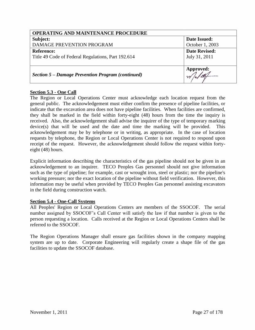
November 1, 2011 Page 27 of 178
OPERATING AND MAINTENANCE PROCEDURE
Subject: Date Issued:
DAMAGE PREVENTION PROGRAM October 1, 2003
Reference:
Title 49 Code of Federal Regulations, Part 192.614
Date Revised:
July 31, 2011
Section 5 – Damage Prevention Program (continued)
Approved:
Section 5.3 - One Call
The Region or Local Operations Center must acknowledge each location request from the
general public. The acknowledgement must either confirm the presence of pipeline facilities, or
indicate that the excavation area does not have pipeline facilities. When facilities are confirmed,
they shall be marked in the field within forty-eight (48) hours from the time the inquiry is
received. Also, the acknowledgement shall advise the inquirer of the type of temporary marking
device(s) that will be used and the date and time the marking will be provided. This
acknowledgement may be by telephone or in writing, as appropriate. In the case of location
requests by telephone, the Region or Local Operations Center is not required to respond upon
receipt of the request. However, the acknowledgement should follow the request within forty-
eight (48) hours.
Explicit information describing the characteristics of the gas pipeline should not be given in an
acknowledgement to an inquirer. TECO Peoples Gas personnel should not give information
such as the type of pipeline; for example, cast or wrought iron, steel or plastic; nor the pipeline's
working pressure; nor the exact location of the pipeline without field verification. However, this
information may be useful when provided by TECO Peoples Gas personnel assisting excavators
in the field during construction watch.
Section 5.4 - One-Call Systems
All Peoples' Region or Local Operations Centers are members of the SSOCOF. The serial
number assigned by SSOCOF’s Call Center will satisfy the law if that number is given to the
person requesting a location. Calls received at the Region or Local Operations Centers shall be
referred to the SSOCOF.
The Region Operations Manager shall ensure gas facilities shown in the company mapping
system are up to date. Corporate Engineering will regularly create a shape file of the gas
facilities to update the SSOCOF database.
November 1, 2011 Page 28 of 178
OPERATING AND MAINTENANCE PROCEDURE
Subject: Date Issued:
DAMAGE PREVENTION PROGRAM October 1, 2003
Reference:
Title 49 Code of Federal Regulations, Parts 192.614 and 192.755
Date Revised:
July 31, 2011
Section 5 – Damage Prevention Program (continued)
Approved:
Section 5.5 - Field Locating
All locating in the field shall be recorded on the SSOCOF Locate Ticket.
Section 5.6 - Pipeline Markers
1. Temporary Marking
Temporary marking devices shall be flags, stakes, paint or other suitable ways of identifying
pipeline facilities in the field. Whenever possible, these temporary marking devices shall be
yellow; to conform to the international color code system for utility locating that has been
adopted by TECO Peoples Gas.
Temporary marking devices should be placed horizontally within twelve inches (12") on either
side of the facility. Vertical marking, when requested by the excavator, should be within
eighteen inches (18") of the top or bottom of the pipeline.
2. Permanent Marking
Permanent pipeline markers shall be installed as outlined in TECO Peoples Gas’ Construction
Standards at Section 18.0, “Pipeline Markers”. The Region or Local Operations Center shall
initiate, on a continual basis, a review of the need for additional markers due to changes in
structures on the pipeline such as new roads, railroad or canal crossings. In addition, surveys
shall be made to ensure the presence of the installed markers. For example, the pipeline markers
may be noted on leak survey maps and/or records and any missing markers may be reported to
the Region or Local Operations Center.
Section 5.7 - Protecting Cast Iron Pipelines - Excavations and Undermining
Additional care shall be used when excavating around cast iron with mechanical equipment. The
main should be exposed (undermined) as little as possible and only as needed to perform the
work. When a section of a buried cast iron pipeline is exposed, that segment, where necessary,
must be protected against vibration, damage from heavy construction equipment, from trains,
from trucks, from buses, or from blasting as well as impact forces by vehicles or earth
movement. Protection from damage, which could occur during apparent future excavations near
the pipeline or other foreseeable outside forces, which might subject that segment of the pipeline
to bending stress, is required.
November 1, 2011 Page 29 of 178
OPERATING AND MAINTENANCE PROCEDURE
Subject: Date Issued:
DAMAGE PREVENTION PROGRAM October 1, 2003
Reference:
Title 49 Code of Federal Regulations, Part 192.614
Date Revised:
July 31, 2011
Section 5 – Damage Prevention Program (continued)
Approved:
Section 5.8 - Coordination Before the Project
TECO Peoples Gas shall maintain contact with the various governmental agencies and other
companies with underground facilities and shall encourage them to coordinate construction
projects with TECO Peoples Gas.
Whenever notice of a project located near TECO Peoples Gas’ facilities is received, the owner
and contractor shall both be contacted. In all cases, information regarding the extent and
location of the TECO Peoples Gas facilities shall be given.
In cases involving directional boring in the vicinity of TECO Peoples Gas’ facilities, on-site
monitoring by TECO Peoples Gas representatives may be required to insure the integrity of the
gas facilities.
Section 5.9 - Annual Advisory Letter
The Public Information Program advises excavators of the hazards of accidental contact with
utility facilities and how to minimize these hazards.
A letter warning of the hazards of accidental contact with utility facilities shall be sent to firms
and individuals engaged in excavation activities in the TECO Peoples Gas service territory. The
letter shall be mailed annually.
Section 5.10 - General Public Program
There shall be an ongoing program advising the general public and customers of the hazards of
accidental contact with utility facilities and how to recognize and report a gas emergency. The
program will use bill inserts, media advertising, and other suitable public information and
education methods.
At least once each year, odor impregnated bill stuffers shall be included with bills so gas users
can become familiar with the odor of gas. Additionally, advertisements shall annually be placed
in the largest local daily newspapers serving each Operating Center informing the General Public
what to do in a gas emergency and how to contact TECO Peoples Gas. The program must be
conducted in English and other languages commonly understood by a significant number and
concentration of the non-English speaking population.
November 1, 2011 Page 30 of 178
OPERATING AND MAINTENANCE PROCEDURE
Subject: Date Issued:
DAMAGE PREVENTION PROGRAM October 1, 2003
Reference:
Title 49 Code of Federal Regulations, Part 192.614
Date Revised:
July 31, 2011
Section 5 – Damage Prevention Program (continued)
Approved:
Section 5.11 - Responsibility and Record Keeping
It shall be the responsibility of the Region or Local Operations Center to make inspections,
furnish locations and complete and retain the appropriate records.
November 1, 2011 Page 31 of 178
OPERATING AND MAINTENANCE PROCEDURE
Subject: Date Issued:
INVESTIGATION OF FAILURES October 1, 2003
Reference:
Title 49 Code of Federal Regulations, Part 192.617
Date Revised:
July 31, 2011
Section 6 – Investigation of Failures
Approved:
Section 6.1 - General The purpose of a gas-related accident investigation is to determine the cause, not to reach initial
conclusions. The scope of an investigation shall depend upon the nature of the accident or
failure.
The first person to arrive at an accident site shall, after meeting the requirements of TECO
Peoples Gas’ Emergency Plan make every effort to preserve the scene (as much as practical
under the conditions) until the investigation team arrives. Also, the names of any witnesses
should be recorded and furnished to the investigation team upon arrival.
The Division Manager is responsible for the timely investigation of all failures occurring on the
gas system. The Division Manager shall, upon notification of an accident or failure, designate an
investigation team to visit the site for the purpose of gathering evidence in determining the cause
of the incident.
The Division Manager may request the services of TECO Peoples Gas’ Insurance, Legal, and
Safety departments, as well as outside investigative experts for assistance in ensuring an
impartial, complete investigation and proper preservation of evidential material.
Where deemed necessary, in order to determine the cause of any failure, samples of the failed
facility or equipment will be secured for laboratory analysis. Information obtained from the
analysis will be used to minimize the possibility of a recurrence.
Section 6.2 - Conclusion and Report Preparation The investigation team shall, after analysis of the facts, reach a conclusion as to the cause (or
probable cause) of an accident or failure. The written report shall include as exhibits all
information relevant to the determination (test results, photographs, drawings, statements,
laboratory analysis, etc.). Any recommendations, which may avert future incidents of a similar
nature, shall be so stated in the report. The Division Manager shall review the report and take
necessary action.
November 1, 2011 Page 32 of 178
OPERATING AND MAINTENANCE PROCEDURE
Subject: Date Issued:
MAXIMUM ALLOWABLE OPERATING PRESSURE October 1, 2003
Reference:
Title 49 Code of Federal Regulations, Part 192.619, 192.621 and 192.623,
Florida Administrative Code 25-12.083
Date Revised:
July 31, 2011
Section 7 – Maximum Allowable Operating Pressure
Approved:
Section 7.1 - General
Maximum Allowable Operating Pressure (MAOP) has been established by TECO Peoples Gas
as follows, steel and plastic facilities shall not be operated at a pressure that exceeds the lowest
of the following;
1. The design pressure of the weakest element in the system which will be subjected to the line
pressure.
2. The pressure obtained by dividing the pressure to which the pipeline was tested by the
appropriate factor from the following table:
Steel Installed Steel Installed
On or before After Polyethylene
Nov 11, 1970 November 11, 1970 Plastic Pipe
1.4 1.5 1.5
3. The maximum safe pressure as determined by the Operating Center after considering history
of the segment based upon actual operating pressures, corrosion records, leak records, etc.
The establishment of MAOP shall be the responsibility of the Division Manager.
Section 7.2 - Establishment of MAOP
A system must not be operated at pressure greater than that designed as the maximum operating
pressure for that system.
Section 7.3 – Increasing MAOP on Existing Systems Prior to increasing the MAOP of an existing system, a written plan is to be formulated and
submitted to Corporate Engineering according to the requirements contained in this manual
below at Section 9.1, “Uprating”
Section 7.4 - New Systems The designer of the system must determine operating pressures in new systems and these
pressures shall be based on current and future flows on the system and on the economics of
construction, operation and maintenance. Maximum operating pressure should be specified and
the system shall be designed, constructed and tested accordingly.
November 1, 2011 Page 33 of 178
OPERATING AND MAINTENANCE PROCEDURE
Subject: Date Issued:
PRESSURE MONITORING October 1, 2003
Reference:
Title 49 Code of Federal Regulations 192.741; Florida Administrative
Code 25-7.050
Date Revised:
July 31, 2011
Section 8 – Pressure Monitoring
Approved:
Section 8.1 - Operating Pressure (Distribution)
Systems must not be operated at a pressure lower than that required for safe operation of a
properly adjusted customer appliance. In high-pressure distribution systems, this pressure must
be considered to be the minimum pressure recommended for proper operation of the regulators.
In low-pressure systems, this pressure shall be considered to be three inches (3") water column
(WC). For the purpose of compliance with this paragraph, pressure must be at the lowest
pressure point in the system.
Section 8.2 - Pressure Records All gas systems that are supplied by two (2) or more regulator stations shall have installed a
permanent pressure recorder or telemeter system. The Operating Center/Region shall determine
whether any pressure recorders and/or telemeter system will be installed on a natural gas system
that is supplied by only one (1) regulator station. All pressure recording records shall be checked
for abnormally high or low pressures and for erratic regulation. If records indicate this type of
action, regulators and auxiliary equipment must be inspected and necessary measures must be
employed to correct the unsatisfactory conditions.
All pressure recording devices and telemeter systems shall be calibrated annually by the
Operating Center/Region and accuracy shall be maintained within the manufacturers’
specifications.
Section 8.3 - Over-Pressure Report
Each time the actual operating pressure in any system exceeds the maximum allowable or
certified operating pressure, the qualified person shall report this in writing to the Division
Manager within five (5) working days. This report shall include:
1. System identification and station identification if a regulator malfunction occurs;
2. Date of occurrence;
3. Maximum actual operating pressure and the percent by which it exceeds the maximum
allowable or certified operating pressure;
4. Description of the operation or over-pressure protection devices; and,
5. The reason for the over-pressure and the action taken to prevent a recurrence.
November 1, 2011 Page 34 of 178
OPERATING AND MAINTENANCE PROCEDURE
Subject: Date Issued:
UPRATING October 1, 2003
Reference:
Title 49 Code of Federal Regulations, Parts 192.551, 192.553, 192.555,
and 192.557; Florida Administrative Code 25-12.083
Date Revised:
July 31, 2011
Section 9 – Up-Rating
Approved:
Section 9.1 - General Prior to increasing the MAOP of an existing system, a written plan is to be formulated and
submitted to TECO Peoples Gas’ corporate Engineering Services at least thirty (30) days prior to
the proposed start date of the actual uprating.
The following procedures shall be followed and fully documented on a permanent record by the
operations personnel:
1. Review the design of the system to be uprated, including the type of materials used, the
maintenance records and history, and the previous gas leak survey records.
2. Verify the specifications of pressure regulation equipment, relief valves, distribution and gas
service line valves and instrumentation to ensure the adequacy of the equipment to operate
at the higher MAOP.
3. Prior to the initial pressure elevation, arrange to have conducted a leak survey. All leaks
found must be repaired and documented, except a leak determined not to be potentially
hazardous need not be repaired if it is monitored during the pressure increase and it does not
become potentially hazardous.
4. Where required, adequately reinforce, or anchor, any offsets, bends and dead ends in
coupled pipe to avoid movement of the pipe in the event that the offset, bend, or dead end is
exposed during an excavation.
5. When determined to be necessary, install system isolation valve(s).
6. Repair or replace those parts of the system proposed to be uprated, which are unsatisfactory
or inadequate for the higher MAOP.
7. Where required, install suitable pressure limiting devices and instrumentation. Establish the
location of temporary recording gauges, or test gauges, to be used during the uprating.
(continued on next page)
November 1, 2011 Page 35 of 178
OPERATING AND MAINTENANCE PROCEDURE
Subject: Date Issued:
UPRATING October 1, 2003
Reference:
Title 49 Code of Federal Regulations, Parts 192.551, 192.553, 192.555,
and 192.557; Florida Administrative Code 25-12.083
Date Revised:
July 31, 2011
Section 9 – Up-Rating (continued)
Approved:
8. Prior to the actual pressure increase, physically disconnect all deteriorated, inactive lines
from the system to be uprated and abandon in accordance with abandonment procedures
outlined below at Section 22, “Abandonment or Inactivation of Facilities”.
9. Consider excavation of mains and service lines to determine the physical condition of the
pipe. The inspection should include such items as the type coating, the method of joining,
any evidence of external corrosion, sampling of the methods of service line tie-ins and the
location of the service lines.
10. Isolate the system to be uprated from any other systems not proposed to be elevated at this
time.
11. If the pressure is increased in steps, the pressure should be held constant after each
incremental pressure increase and the system that is affected in the uprating shall be
surveyed for evidence of any leaks. The maximum pressure increments should be equal to
ten (10) psig or twenty-five percent (25%) of the total pressure increase, whichever
produces the fewer number of increments. However, when uprating a utilization pressure
system to a pressure that is higher than the pressure that is delivered to the customer (i.e.
service regulators are required), there must be at least two (2) approximately equal,
incremental increases.
12. If the system to be uprated is to be tested at a one-time only pressure test, the system shall
be tested in the same manner as new construction. (See Section 12.0, “Defects - Testing -
Cleaning - Purging”, of the Construction Standards)
13. Prior to the uprating, each building served must be inspected for an accessible shut-off valve
located outside of the building structure. A shut-off valve shall be installed on any building
which the inspection shows does not have such a valve, or the meter set(s) must be relocated
to the outside of the building.
(continued on next page)
November 1, 2011 Page 36 of 178
OPERATING AND MAINTENANCE PROCEDURE
Subject: Date Issued:
UPRATING October 1, 2003
Reference:
Title 49 Code of Federal Regulations, Parts 192.551, 192.553, 192.555,
and 192.557; Florida Administrative Code 25-12.083
Date Revised:
July 31, 2011
Section 9 – Up-Rating (continued)
Approved:
14. If the pressure in the mains or service lines, or both, is to be higher than the pressure
delivered to the customer, a service regulator shall be installed on each service line and each
service regulator shall be tested to determine that it is functioning correctly. When service
regulators have just been installed on any service lines, the pressure must first be increased
just sufficiently so that the service regulator can be tested for proper functioning.
15. All personnel participating in the pressure elevation must be instructed in the procedures to
be followed prior to, and during the uprating.
Section 9.2 - Uprating to Less Than 30% SMYS
The following steps are required when increasing high pressure to a greater high pressure but
less than that required producing a hoop stress of thirty percent (30%) of SMYS in steel pipe and
in all plastic or cast iron systems:
1. Complete the preliminary steps required above.
2. If the new maximum allowable operating pressure will exceed sixty (60) PSIG, survey all
regular customers' meter installations. Rebuild any installations as required.
3. Provide for a supply source to introduce higher-pressure gas into the system; over-pressure
protection must be included.
4. Isolate the system to be uprated from all of the parts of the system that will remain at the
lower pressure.
5. Increase pressure to the new uprate test pressure in increments of ten (10) PSIG or
twenty-five percent (25%) of the difference between the new uprate test pressure and old
maximum allowable operating pressure, whichever is greater, there must be at least two (2)
increments and allow the pressure to stabilize between each increase.
6. Conduct a leak survey between each increase, and repair all leaks which are potentially
hazardous.
7. After the uprate test is completed, lower the pressure down to the new normal operating
pressure.
November 1, 2011 Page 37 of 178
OPERATING AND MAINTENANCE PROCEDURE
Subject: Date Issued:
UPRATING October 1, 2003
Reference:
Title 49 Code of Federal Regulations, Parts 192.551, 192.553, 192.555,
and 192.557; Florida Administrative Code 25-12.083
Date Revised:
July 31, 2011
Section 9 – Up-Rating (continued)
Approved:
Section 9.3 - Uprating to Greater Than 30% SMYS
Pressure increases which will result in a hoop stress of thirty percent (30%) of SMYS or more at
the new maximum allowable pressure may be made while the facility is in service only if:
1. The facility was constructed before September 12, 1970. The new maximum allowable
operating pressure is limited to a value equal to the highest actual pressure to which the
facility has been subjected (either during test or in operation) divided by the appropriate
factor.
2. The facility is in a Class 1 location and impracticable to remove from service for testing and
it is in satisfactory condition for the pressure increase. The new maximum allowable
operating pressure does not exceed eighty percent (80%) of that allowed for in a new facility
at the same location.
All other facilities must be uprated while out of service. If uprating in service is permitted, it
shall be done in accordance with the requirements of less than thirty percent (30%) SMYS above
except that the pressure increase increments shall be ten percent (10%) of the actual operating
pressure before uprating or twenty-five percent (25%) of the total pressure increase, whichever is
greater. Section 9.4 - Uprating, While Out of Service Any facility may be uprated while out of service. All facilities operating in stress ranges of thirty
percent (30%) or more of SMYS for which upgrading in service is not permitted must be taken
out of service before uprating is complete. All facilities to be uprated while out of service must
be physically disconnected from all other parts of the gas system throughout the program.
Before any pressure increase is made the preliminary steps must be completed. A pressure test
shall then be done in accordance with the procedures required for a new line in the same
location.
Once the previously established MAOP has been reached, the increase in pressure must be made
in increments that are equal to:
1. Ten percent (10%) of the pressure before the uprating; or,
2. Twenty-five percent (25%) of the total pressure increases whichever produces the fewer
number of increments.
November 1, 2011 Page 38 of 178
OPERATING AND MAINTENANCE PROCEDURE
Subject: Date Issued:
UPRATING October 1, 2003
Reference:
Title 49 Code of Federal Regulations, Parts 192.551, 192.553, 192.555,
and 192.557; Florida Administrative Code 25-12.083
Date Revised:
July 31, 2011
Section 9 – Up-Rating (continued)
Approved:
Section 9.5 - New Maximum Operating Pressure Any new MAOP established under this section may not exceed the MAOP that would be
allowed under Section 12 of the Construction Standards Manual, for a new segment of pipeline
constructed of the same materials in the same location.
Section 9.6 - Records 1. The Division Manager shall be responsible for developing and forwarding the written
uprating plan to Corporate Engineering.
2. The proposed written plan for pressure elevation is to be submitted to the Florida Public
Service Commission by Corporate Engineering prior to elevating the pressure. If no reply is
received within fifteen (15) days from the Florida Public Service Commission, it can be
assumed that the uprating plan is acceptable as submitted.
3. The Division Manager shall be responsible for the supervision and implementation of the
written uprating plan.
4. The Division Manager shall be responsible for maintaining the permanent records of all
requirements of this section. These records shall be retained for the life of the segment of the
system to be uprated.
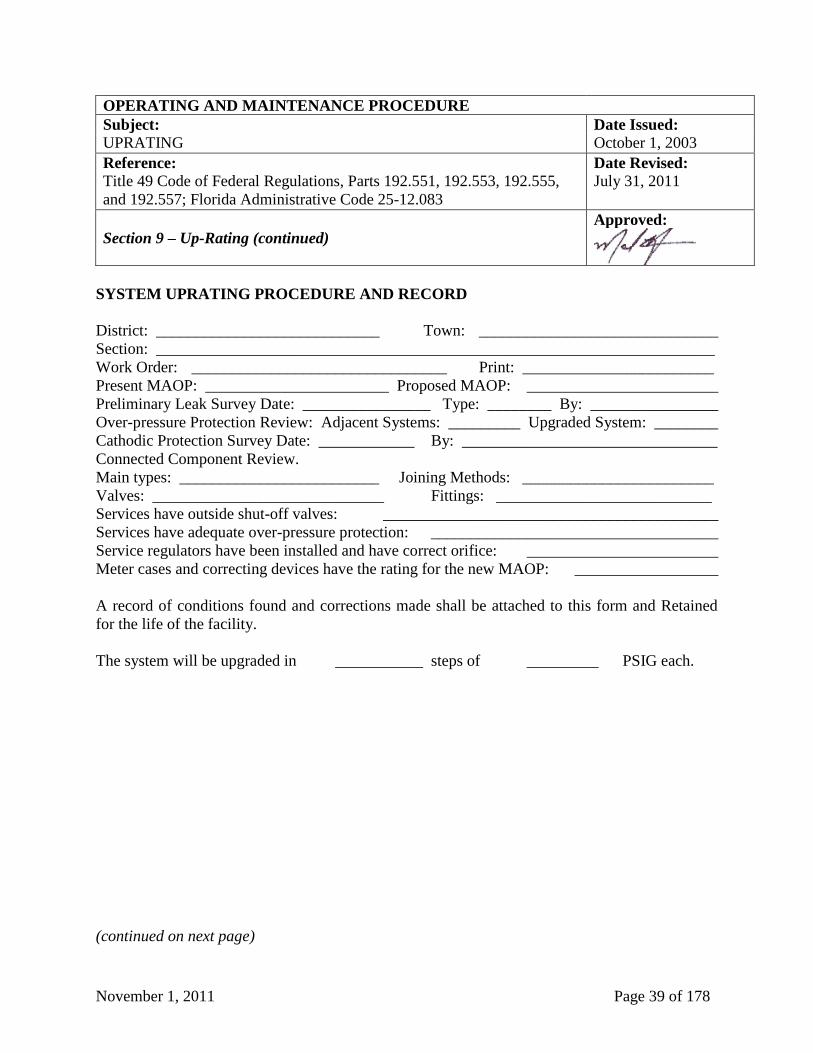
November 1, 2011 Page 39 of 178
OPERATING AND MAINTENANCE PROCEDURE
Subject: Date Issued:
UPRATING October 1, 2003
Reference:
Title 49 Code of Federal Regulations, Parts 192.551, 192.553, 192.555,
and 192.557; Florida Administrative Code 25-12.083
Date Revised:
July 31, 2011
Section 9 – Up-Rating (continued)
Approved:
SYSTEM UPRATING PROCEDURE AND RECORD
District: ____________________________ Town: ______________________________
Section: ______________________________________________________________________
Work Order: ________________________________ Print: ________________________
Present MAOP: _______________________ Proposed MAOP: ________________________
Preliminary Leak Survey Date: ________________ Type: ________ By: ________________
Over-pressure Protection Review: Adjacent Systems: _________ Upgraded System: ________
Cathodic Protection Survey Date: ____________ By: ________________________________
Connected Component Review.
Main types: _________________________ Joining Methods: ________________________
Valves: _____________________________ Fittings: ___________________________
Services have outside shut-off valves: __________________________________________
Services have adequate over-pressure protection: ____________________________________
Service regulators have been installed and have correct orifice: ________________________
Meter cases and correcting devices have the rating for the new MAOP: __________________
A record of conditions found and corrections made shall be attached to this form and Retained
for the life of the facility.
The system will be upgraded in ___________ steps of _________ PSIG each.
(continued on next page)
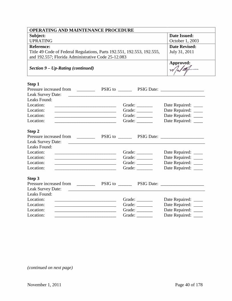
November 1, 2011 Page 40 of 178
OPERATING AND MAINTENANCE PROCEDURE
Subject: Date Issued:
UPRATING October 1, 2003
Reference:
Title 49 Code of Federal Regulations, Parts 192.551, 192.553, 192.555,
and 192.557; Florida Administrative Code 25-12.083
Date Revised:
July 31, 2011
Section 9 – Up-Rating (continued)
Approved:
Step 1
Pressure increased from ________ PSIG to ______ PSIG Date: ___________________
Leak Survey Date: ____________________________________________________________
Leaks Found:
Location: ___________________________ Grade: _______ Date Repaired: ____
Location: ___________________________ Grade: _______ Date Repaired: ____
Location: ___________________________ Grade: _______ Date Repaired: ____
Location: ___________________________ Grade: _______ Date Repaired: ____
Step 2
Pressure increased from ________ PSIG to ______ PSIG Date: ___________________
Leak Survey Date: ____________________________________________________________
Leaks Found:
Location: ___________________________ Grade: _______ Date Repaired: ____
Location: ___________________________ Grade: _______ Date Repaired: ____
Location: ___________________________ Grade: _______ Date Repaired: ____
Location: ___________________________ Grade: _______ Date Repaired: ____
Step 3
Pressure increased from ________ PSIG to ______ PSIG Date: ___________________
Leak Survey Date: ____________________________________________________________
Leaks Found:
Location: ___________________________ Grade: _______ Date Repaired: ____
Location: ___________________________ Grade: _______ Date Repaired: ____
Location: ___________________________ Grade: _______ Date Repaired: ____
Location: ___________________________ Grade: _______ Date Repaired: ____
(continued on next page)
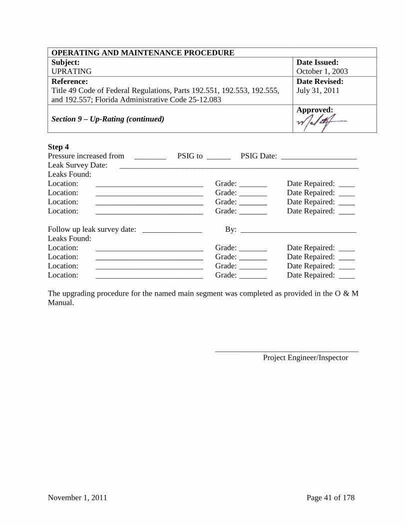
November 1, 2011 Page 41 of 178
OPERATING AND MAINTENANCE PROCEDURE
Subject: Date Issued:
UPRATING October 1, 2003
Reference:
Title 49 Code of Federal Regulations, Parts 192.551, 192.553, 192.555,
and 192.557; Florida Administrative Code 25-12.083
Date Revised:
July 31, 2011
Section 9 – Up-Rating (continued)
Approved:
Step 4
Pressure increased from ________ PSIG to ______ PSIG Date: ___________________
Leak Survey Date: ____________________________________________________________
Leaks Found:
Location: ___________________________ Grade: _______ Date Repaired: ____
Location: ___________________________ Grade: _______ Date Repaired: ____
Location: ___________________________ Grade: _______ Date Repaired: ____
Location: ___________________________ Grade: _______ Date Repaired: ____
Follow up leak survey date: _______________ By: _____________________________
Leaks Found:
Location: ___________________________ Grade: _______ Date Repaired: ____
Location: ___________________________ Grade: _______ Date Repaired: ____
Location: ___________________________ Grade: _______ Date Repaired: ____
Location: ___________________________ Grade: _______ Date Repaired: ____
The upgrading procedure for the named main segment was completed as provided in the O & M
Manual.
____________________________________
Project Engineer/Inspector
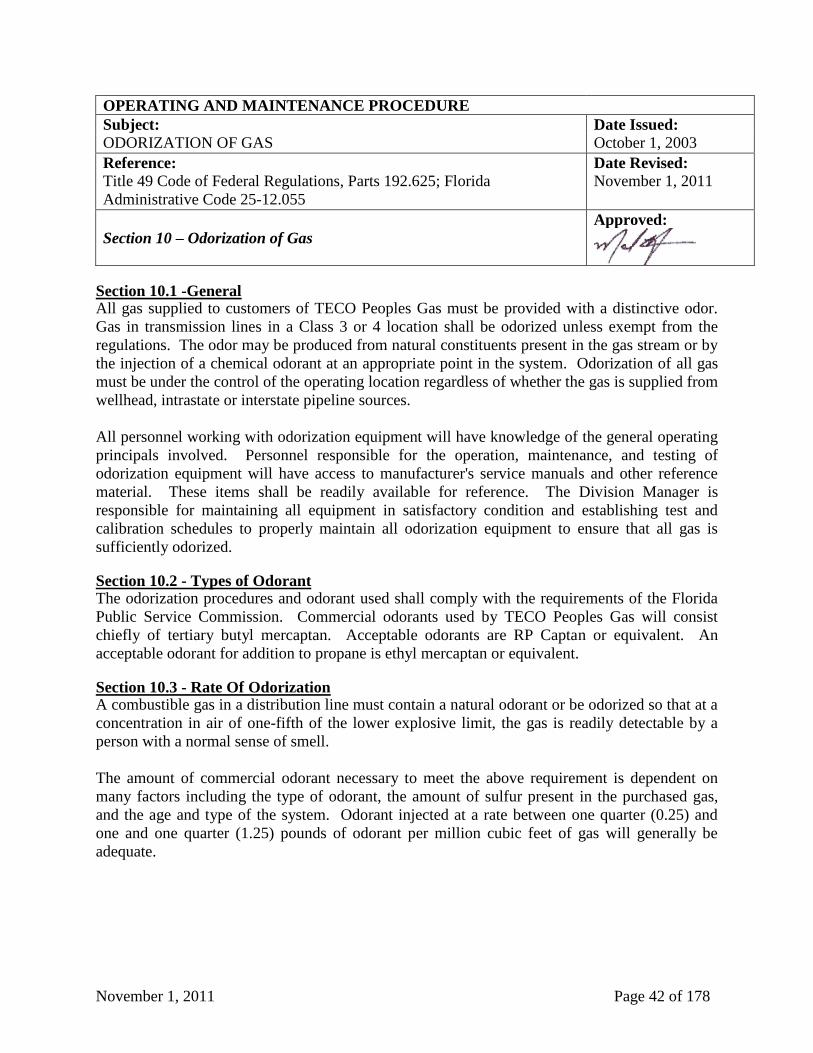
November 1, 2011 Page 42 of 178
OPERATING AND MAINTENANCE PROCEDURE
Subject: Date Issued:
ODORIZATION OF GAS October 1, 2003
Reference:
Title 49 Code of Federal Regulations, Parts 192.625; Florida
Administrative Code 25-12.055
Date Revised:
November 1, 2011
Section 10 – Odorization of Gas
Approved:
Section 10.1 -General All gas supplied to customers of TECO Peoples Gas must be provided with a distinctive odor.
Gas in transmission lines in a Class 3 or 4 location shall be odorized unless exempt from the
regulations. The odor may be produced from natural constituents present in the gas stream or by
the injection of a chemical odorant at an appropriate point in the system. Odorization of all gas
must be under the control of the operating location regardless of whether the gas is supplied from
wellhead, intrastate or interstate pipeline sources.
All personnel working with odorization equipment will have knowledge of the general operating
principals involved. Personnel responsible for the operation, maintenance, and testing of
odorization equipment will have access to manufacturer's service manuals and other reference
material. These items shall be readily available for reference. The Division Manager is
responsible for maintaining all equipment in satisfactory condition and establishing test and
calibration schedules to properly maintain all odorization equipment to ensure that all gas is
sufficiently odorized.
Section 10.2 - Types of Odorant The odorization procedures and odorant used shall comply with the requirements of the Florida
Public Service Commission. Commercial odorants used by TECO Peoples Gas will consist
chiefly of tertiary butyl mercaptan. Acceptable odorants are RP Captan or equivalent. An
acceptable odorant for addition to propane is ethyl mercaptan or equivalent.
Section 10.3 - Rate Of Odorization A combustible gas in a distribution line must contain a natural odorant or be odorized so that at a
concentration in air of one-fifth of the lower explosive limit, the gas is readily detectable by a
person with a normal sense of smell.
The amount of commercial odorant necessary to meet the above requirement is dependent on
many factors including the type of odorant, the amount of sulfur present in the purchased gas,
and the age and type of the system. Odorant injected at a rate between one quarter (0.25) and
one and one quarter (1.25) pounds of odorant per million cubic feet of gas will generally be
adequate.
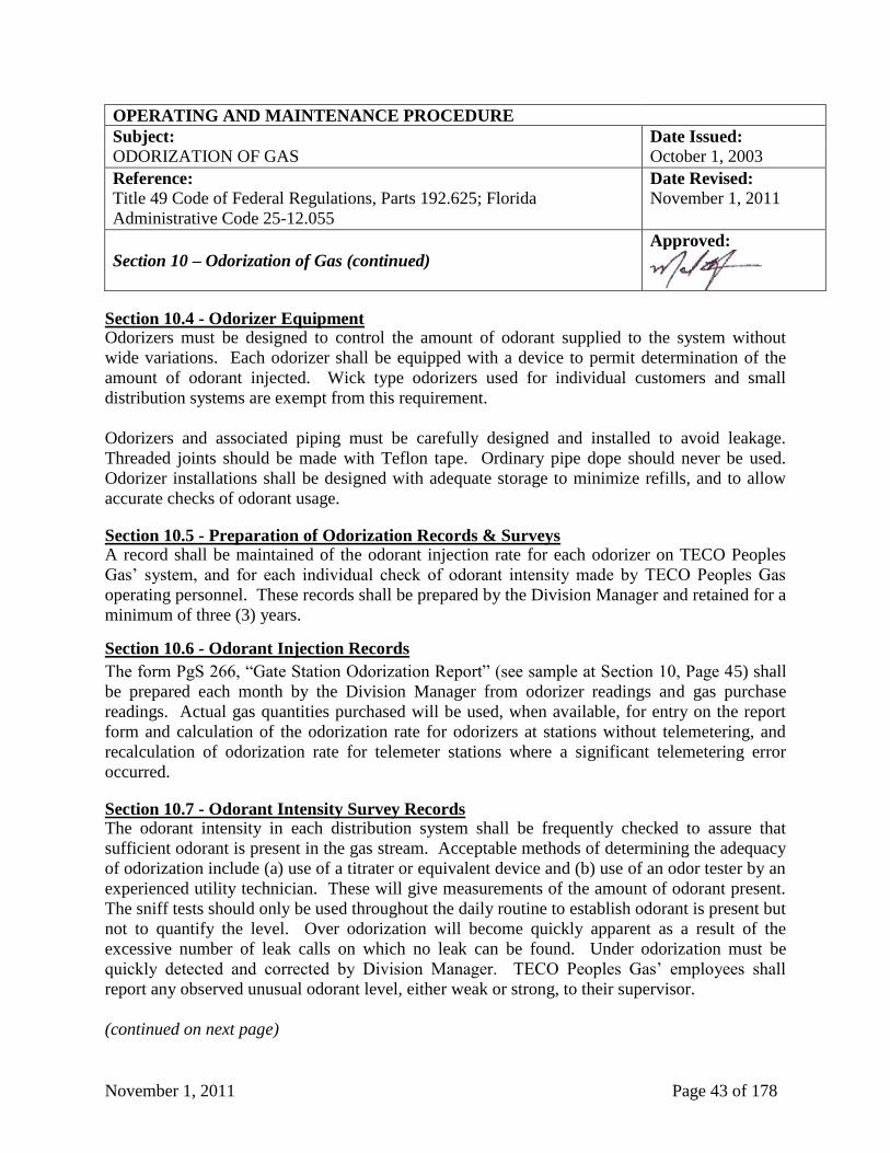
November 1, 2011 Page 43 of 178
OPERATING AND MAINTENANCE PROCEDURE
Subject: Date Issued:
ODORIZATION OF GAS October 1, 2003
Reference:
Title 49 Code of Federal Regulations, Parts 192.625; Florida
Administrative Code 25-12.055
Date Revised:
November 1, 2011
Section 10 – Odorization of Gas (continued)
Approved:
Section 10.4 - Odorizer Equipment Odorizers must be designed to control the amount of odorant supplied to the system without
wide variations. Each odorizer shall be equipped with a device to permit determination of the
amount of odorant injected. Wick type odorizers used for individual customers and small
distribution systems are exempt from this requirement.
Odorizers and associated piping must be carefully designed and installed to avoid leakage.
Threaded joints should be made with Teflon tape. Ordinary pipe dope should never be used.
Odorizer installations shall be designed with adequate storage to minimize refills, and to allow
accurate checks of odorant usage.
Section 10.5 - Preparation of Odorization Records & Surveys A record shall be maintained of the odorant injection rate for each odorizer on TECO Peoples
Gas’ system, and for each individual check of odorant intensity made by TECO Peoples Gas
operating personnel. These records shall be prepared by the Division Manager and retained for a
minimum of three (3) years.
Section 10.6 - Odorant Injection Records
The form PgS 266, “Gate Station Odorization Report” (see sample at Section 10, Page 45) shall
be prepared each month by the Division Manager from odorizer readings and gas purchase
readings. Actual gas quantities purchased will be used, when available, for entry on the report
form and calculation of the odorization rate for odorizers at stations without telemetering, and
recalculation of odorization rate for telemeter stations where a significant telemetering error
occurred.
Section 10.7 - Odorant Intensity Survey Records The odorant intensity in each distribution system shall be frequently checked to assure that
sufficient odorant is present in the gas stream. Acceptable methods of determining the adequacy
of odorization include (a) use of a titrater or equivalent device and (b) use of an odor tester by an
experienced utility technician. These will give measurements of the amount of odorant present.
The sniff tests should only be used throughout the daily routine to establish odorant is present but
not to quantify the level. Over odorization will become quickly apparent as a result of the
excessive number of leak calls on which no leak can be found. Under odorization must be
quickly detected and corrected by Division Manager. TECO Peoples Gas’ employees shall
report any observed unusual odorant level, either weak or strong, to their supervisor.
(continued on next page)
November 1, 2011 Page 44 of 178
OPERATING AND MAINTENANCE PROCEDURE
Subject: Date Issued:
ODORIZATION OF GAS October 1, 2003
Reference:
Title 49 Code of Federal Regulations, Parts 192.625; Florida
Administrative Code 25-12.055
Date Revised:
November 1, 2011
Section 10 – Odorization of Gas (continued)
Approved:
The Division Manager shall establish a schedule for conducting odorant intensity checks at
regular intervals at various locations on each separately odorized system. These tests must be
conducted at least twelve (12) times per calendar year, at intervals not to exceeding forty-five
(45) days.
Odorant intensity checks should be taken at the ends of each system to determine the area of
weakest odorant intensity. These odorant intensity checks should be recorded on form PgS 644,
“Odorization Record” (see sample at Section 10, Page 46). Check point locations should be
reviewed annually to account for gas distribution system growth.
Twenty four (24) hour checks of the odorant injection rate shall be made at the discretion of the
Division Manager and reported on the form PgS 266, “Gate Station Odorization Report” (see
sample at Section 10, Page 45).
Section 10.8 - Incident Testing Odor levels shall be immediately checked when an incident occurs involving natural gas. The
odor level shall be checked in the vicinity of the incident utilizing an odor meter or similar
testing device.
Section 10.9 - Odorization Problems Inadequate odorization can be detected by personnel in the field which includes odor meter tests
or verbal notices by construction and maintenance personnel commenting on the quantity of
odorant in the gas. Customers and Leak Survey Technicians also provide input on inadequate or
excessive odorization. In the event of odorization problems, an immediate response shall be
made to determine and correct the cause.
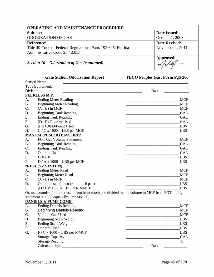
November 1, 2011 Page 45 of 178
OPERATING AND MAINTENANCE PROCEDURE
Subject: Date Issued:
ODORIZATION OF GAS October 1, 2003
Reference:
Title 49 Code of Federal Regulations, Parts 192.625; Florida
Administrative Code 25-12.055
Date Revised:
November 1, 2011
Section 10 – Odorization of Gas (continued)
Approved:
Gate Station Odorization Report TECO Peoples Gas: Form PgS 266 Station Name: _________________________________________________________________
Type Equipment: _________________________________________________________________
Division _________________________________________ Date _____________
PEERLESS M.P. A. Ending Meter Reading ____________________________MCF
B. Beginning Meter Reading ____________________________MCF
C. (A - B) in MCF ____________________________MCF
D. Beginning Tank Reading ____________________________GAL
E. Ending Tank Reading ____________________________GAL
F. (D - E) Odorant Used ____________________________GAL
G. (F x 6.8) Odorant Used ____________________________LBS
H. G / C x 1000 = LBS per MCF ____________________________LBS
MANUAL PUMP BYPASS DRIP
A. FGT Gas Volume Statement ____________________________MCF
B. Beginning Tank Reading ____________________________GAL
C. Ending Tank Reading ____________________________GAL
D. Odorant Used ____________________________GAL
E. D X 6.8 ____________________________LBS
F. D / A x 1000 = LBS per MCF ____________________________LBS
N-JEX (YZ SYSTEM)
A. Ending Meter Read ____________________________MCF
B. Beginning Meter Read ____________________________MCF
C. (A - B) in MCF ____________________________MCF
D. Odorant used (taken from touch pad) ____________________________LBS
E. (D / C)* 1000 = LBS PER MMCF ____________________________LBS
Or, use pounds of odorant used from front touch pad divided by the volume in MCF from FGT billing
statement X 1000 equals lbs. Per MMCF,
DANIELS & PUMP COMB.
A. Ending Daniels Reading ____________________________MCF
B. Beginning Daniels Reading ____________________________MCF
C. Volume Gas Used ____________________________MCF
D. Beginning Scale Weight ____________________________LBS
E. Ending Scale Weight ____________________________LBS
F. Odorant Used ____________________________LBS
G. F / C x 1000 = LBS per MMCF ____________________________LBS
Storage Capacity ____________________________GAL
Storage Reading ____________________________%
Calculated by: __________________________________________ Date: ____________
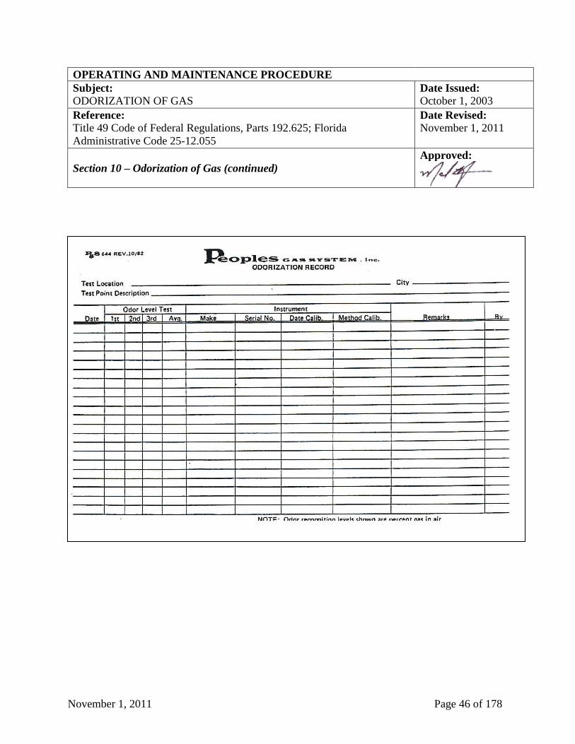
November 1, 2011 Page 46 of 178
OPERATING AND MAINTENANCE PROCEDURE
Subject: Date Issued:
ODORIZATION OF GAS October 1, 2003
Reference:
Title 49 Code of Federal Regulations, Parts 192.625; Florida
Administrative Code 25-12.055
Date Revised:
November 1, 2011
Section 10 – Odorization of Gas (continued)
Approved:
November 1, 2011 Page 47 of 178
OPERATING AND MAINTENANCE PROCEDURE
Subject: Date Issued:
TAPPING PIPELINES UNDER PRESSURE October 1, 2003
Reference:
Title 49 Code of Federal Regulations, Parts 192.627
Date Revised:
September 10, 2007
Section 11 – Tapping Pipelines Under Pressure
Approved:
Section 11.1 -Personnel Qualifications
TECO Peoples Gas construction crews shall be qualified by on-the-job training and experience
before attempting to make a hot tap or stopping operation. Personnel performing hot taps and
stopping operations shall be familiar with the pressure limitations of the hot tapping equipment
to be used and thoroughly trained in the mechanical procedures and safety precautions associated
with the use of such equipment. Only qualified, personnel shall be used for hot tapping.
Section 11.2 Identification of Pipe and Suitability for Tapping The designer is responsible for the design of the tap and placing a notation on the sketch if the
pressure is other than normal distribution pressure; however, the person performing the work is
responsible for verifying that this information is on the sketch and resolving any questions
concerning the accuracy of the information.
The person performing the work shall thoroughly review applicable maps and records to
determine the location of other lines, which may be in the vicinity of the pipeline to be tapped.
The outside diameter, coating, pipe material, joint connection and manufacturers markings on the
exposed pipe shall be reviewed to ensure that the exposed pipe is the one to be tapped. When
identification of the pipe is uncertain, TECO Peoples Gas shall consider extending the
excavation. During the tapping operation, qualified personnel shall verify pressure and line
contents on initial line perforation.
Tapping or drilling machines shall not be used in tunnels, manholes, or other places, which
cannot be vented. When machines or fittings are removed from live mains, the openings shall be
plugged as soon as possible.
Section 11.3 - Additional Requirements for Transmission Systems Under normal circumstances, the hot tap will not be made on an operating pipeline at pressures
over fifty percent (50%) of the maximum allowable operating pressure. Sufficient time will be
allowed for the gas flow rate to reach equilibrium condition at the reduced pressure before
making the hot tap.
The tap shall be located on a straight section of pipe, removed a sufficient distance from any
bend so as to minimize secondary stresses due to shifting of the main line. The tap shall not be
made through any weld - circumferential or longitudinal seam weld, or its heat-affected zone.
(continued on next page)
November 1, 2011 Page 48 of 178
OPERATING AND MAINTENANCE PROCEDURE
Subject: Date Issued:
TAPPING PIPELINES UNDER PRESSURE October 1, 2003
Reference:
Title 49 Code of Federal Regulations, Parts 192.627
Date Revised:
September 10, 2007
Section 11 – Tapping Pipelines Under Pressure (continued)
Approved:
The pipe to be tapped shall be free of laminations and free of any significant external or internal
corrosion. The wall thickness of the pipe to be tapped is to be compared to that at original
construction. The pipe to be tapped shall not be operating at a temperature above two hundred
(200°F) Degrees Fahrenheit.
On a standard hot tap where the tap is less than or equal to one half (1/2) the diameter of the
carrier pipe, the welded nipple will be leak tested. Prior to the test, a saddle shall be installed for
the purpose of providing additional strength for the fillet weld on the nipple. The leak test shall
be a hydrostatic or gas test at a pressure not to exceed the design pressure of the carrier pipe.
On a hot tap where the tap is greater than one half (1/2) the diameter of the carrier pipe, a full
encirclement, fully welded fitting, shall be used. The tap fitting shall be leak tested prior to
cutting the coupon from the carrier pipe.
Because of the exposure to personnel, precautions should be taken to remove personnel a safe
distance from the test site. The operator conducting the test should take measures to avoid
personal exposure to hazards associated with a possible test failure.
The test duration should be one (1) hour.
All welding performed in the installation of the tap shall be non-destructively tested in
accordance with Title 49, Code of Federal Regulations, Parts 192.241 and 192.243.
A record shall be made of each hot tap installed on a transmission pipeline, and records shall be
retained for the life of the pipeline.
Section 11.4 - Stopping Stopping operations shall be planned to minimize customer service interruptions. The stopper
fittings, stopping machines and stoppers must be rated for the main pressure. Planning for
stopping operations shall identify the gas supply for all connected main segments. When using a
bypass or when there are two or more feeds into the area, a pressure gauge shall be installed on
the live side of each stopper fitting.
November 1, 2011 Page 49 of 178
OPERATING AND MAINTENANCE PROCEDURE
Subject: Date Issued:
PURGING OF PIPELINES October 1, 2003
Reference:
Title 49 Code of Federal Regulations, Parts 192.629
Date Revised:
July 31, 2011
Section 12 – Purging of Pipelines
Approved:
Section 12.1 - Purging with Natural Gas or Propane Gas
When piping is being purged of air by the use of natural gas or propane gas, the natural gas or
propane gas must be released into one end of the line in a moderately rapid and continuous flow.
This operation will continue until the piping being purged is free of air. If the natural or propane
gas cannot be supplied in sufficient quantity to prevent the formation of an explosive mixture, a
slug of inert gas must be released into the line before the natural or propane gas. When the
natural gas or propane gas is being vented into the open air, each potential source of ignition
must be removed from the area as outlined below at Section 26, “Prevention of Accidental
Ignition”. After purging is complete, a test shall be made with a combustible gas indicator to
ensure a combustible mixture does not remain.
Section 12.2 - Purging with Air or an Inert Gas
If piping is being purged of gas by the use of air or an inert gas, the air must be released into one
end of the line in a moderately rapid and continuous flow. This operation will continue until the
piping being purged is free of gas. If the air cannot be supplied in sufficient quantity to prevent
the formation of an explosive mixture, a slug of inert gas must be released into the line before the
air. When natural or propane gas is being vented into the open air, each potential source of
ignition must be removed from the area as outlined below at Section 26, “Prevention of
Accidental Ignition”. After purging is completed, a test shall be made with a combustible gas
indicator to ensure a combustible mixture does not remain.
Section 12.3 - Special Conditions
Facilities which do not fall under the specific provision of this Section 12 shall be purged per the
standards outlined in "Purging Principals and Practice" published by the American Gas
Association.
Section 12.4 - Responsibility
It shall be the responsibility of the Supervisor in charge of the operation to ensure that the proper
purging practices are being followed and to detail specific purging practices not covered by this
Section 12.
November 1, 2011 Page 50 of 178
OPERATING AND MAINTENANCE PROCEDURE
Subject: Date Issued:
REPAIR PROCEDURES - DISTRIBUTION October 1, 2003
Reference:
Title 49 Code of Federal Regulations, Parts 192.701 and 192.703
Date Revised:
July 31, 2011
Section 13 – Repair Procedures - Distribution
Approved:
Section 13.1 - General
Maintenance of the gas system is the responsibility of the Division Manager. If at any time, a
distribution facility is discovered to be damaged or deteriorated to the point that its service
ability is impaired, or if a leak is found that creates a hazard, immediate measures shall be taken
to implement the emergency plan. If it is not feasible to make a permanent repair at the time of
discovery, temporary repairs can be made; however, permanent repairs shall be made as soon as
possible. When the repair is made by replacing the damaged segment of pipeline by welding in
another segment of pipe of equal or greater strength pre-tested pipe can be used.
Section 13.2 - Repair of Steel Pipe
Lines operating at less than twenty percent (20%) of SMYS must be repaired by one of the
following methods:
1. Cutting out a cylinder and replacing the damaged piece of pipe.
2. Applying a full encirclement split sleeve.
3. Applying a properly designed bolt-on leak clamp or sleeve.
4. Applying a fillet-welded steel plate patch with rounded corners of similar material of equal or
greater strength, which is not more than one-half (1/2) the diameter of the pipe.
Section 13.3 - Weld Repair
Steel lines operating at less than twenty percent (20%) of SMYS that have welds which are
leaking or have otherwise failed may be repaired by installing a full encirclement welded split
sleeve of appropriate design, or by removing a section of pipe containing the weld and replacing
it with a section of new pipe of equal or greater strength.
Section 13.4 - Repair of Plastic
The repair of plastic pipe or couplings shall be made by replacing the damaged or leaking pipe or
coupling with a new section of pipe of equal or greater strength rating. The recommendations of
the plastic manufacturer should be taken into consideration when determining the type of repair
that is to be made.
November 1, 2011 Page 51 of 178
OPERATING AND MAINTENANCE PROCEDURE
Subject: Date Issued:
REPAIR PROCEDURES - DISTRIBUTION October 1, 2003
Reference:
Title 49 Code of Federal Regulations, Parts 192.701 and 192.703
Date Revised:
July 31, 2011
Section 13 – Repair Procedures – Distribution (continued)
Approved:
Section 13.5 - Mechanical Joints The use of compression type fitting for repairs to plastic pipe is permitted if the fitting is
designed to withstand longitudinal pullout. The fitting must be installed in accordance with the
manufacturer's procedures. Each compression type joint on plastic pipe must be made with a
rigid stiffener that fits the inside diameter of the pipe closely in order that the plastic pipe cannot
be crushed. Any gasket material in the fitting must be compatible with the plastic. Nonferrous
fittings shall be used when joining plastic pipe to plastic pipe for repairs. All joints must be
designed and installed to sustain the forces caused by expansion or contraction of the piping or
anticipated external or internal forces. Each joint must be made in accordance with written
procedures that have been proven by test or experience to produce strong gas-tight joints (may be
manufacturer's recommendations). Each joint must be inspected to insure compliance with the
procedure.
Section 13.6 - Inspection and Testing All pipe and materials shall be transported to and handled with care at the site to prevent damage.
All material must be visually inspected before installation, and damage found shall be repaired.
If repair is impossible or impracticable, the material shall not be used. All pipes must be
examined visually both inside and out before it is installed in the pipeline. Any loose rust, scale,
or foreign material shall be removed from the inside by swabbing before the piece is installed. A
second surface inspection must be made immediately prior to lowering-in.
Special inspection requirements for pipe of various materials are indicated below.
1. Coated steel pipe must be visually inspected and should be checked with a holiday detector.
Any areas of coating damage must be inspected in detail to make sure that the pipe
underneath has not also been damaged. Any coating damage shall be repaired.
2. Plastic pipe must be inspected visually prior to lowering.
Defects found in the pipe must be repaired as indicated in this procedure before the pipe is
placed in service.
(continued on next page)
November 1, 2011 Page 52 of 178
OPERATING AND MAINTENANCE PROCEDURE
Subject: Date Issued:
REPAIR PROCEDURES - DISTRIBUTION October 1, 2003
Reference:
Title 49 Code of Federal Regulations, Parts 192.701 and 192.703
Date Revised:
July 31, 2011
Section 13 – Repair Procedures – Distribution (continued)
Approved:
Any heat fusion joint that appears defective (visual inspection) or fails a nondestructive test must
be removed from the line.
If the repair has been made by replacing a pipe section, it must be tested as though it were a new
line in the same location. The test shall be made on the section before installation. All tie-in
welds, clamps, sleeves and saddles must be visually inspected and soap tested at line pressure.
Section 13.7 - Reports and Records 1. The form PgS 24, “Gas Leak & Repair Form” (see sample below at Section 14, Pages 57 and
58), must be completed by the utility technician to document the disposition of leaks, how
the leak was repaired and the probable root cause of the leak.
2. The form, “Pipeline Test Record” (see sample below at Section 13, Page 53), must be
reviewed by the Division Manager to document the testing of pipe.
The originals of the above referenced reports and forms are to be maintained for the life of the
facility.
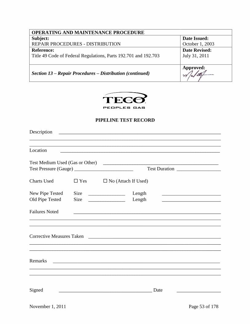
November 1, 2011 Page 53 of 178
OPERATING AND MAINTENANCE PROCEDURE
Subject: Date Issued:
REPAIR PROCEDURES - DISTRIBUTION October 1, 2003
Reference:
Title 49 Code of Federal Regulations, Parts 192.701 and 192.703
Date Revised:
July 31, 2011
Section 13 – Repair Procedures – Distribution (continued)
Approved:
PIPELINE TEST RECORD
Description __________________________________________________________________
______________________________________________________________________________
______________________________________________________________________________
Location _________________________________________________________________
Test Medium Used (Gas or Other) _______________________________________________
Test Pressure (Gauge) ________________________ Test Duration __________________
Charts Used Yes No (Attach If Used)
New Pipe Tested Size _______________ Length ________________________
Old Pipe Tested Size _______________ Length ________________________
Failures Noted ____________________________________________________________
______________________________________________________________________________
______________________________________________________________________________
Corrective Measures Taken ______________________________________________________
______________________________________________________________________________
______________________________________________________________________________
Remarks ____________________________________________________________________
______________________________________________________________________________
______________________________________________________________________________
Signed ______________________________________ Date __________________
November 1, 2011 Page 54 of 178
OPERATING AND MAINTENANCE PROCEDURE
Subject: Date Issued:
REPAIR PROCEDURES - DISTRIBUTION October 1, 2003
Reference:
Title 49 Code of Federal Regulations, Parts 192.701 and 192.703
Date Revised:
July 31, 2011
Section 14 – Repair Procedures – Transmission
Approved:
Section 14.1 - General
All segments of TECO Peoples Gas operating pipeline shall be maintained in accordance with
prescribed safety requirements. All leaks or damage caused by external forces, or detected by
prescribed inspection procedures shall be repaired promptly.
Permanent repair on leaks and damage shall be made as soon as possible after discovery. If the
pipeline can be removed from service, the repair will be made by replacing the damaged segment
of pipeline, and welding in another segment of pipe of equal or greater strength. In the event that
a permanent repair cannot be made within a reasonable time, the actual operating pressure will
be reduced and temporary methods capable of operating at the reduced pressure will be used. If
the leak, damage, or imperfection in a pipeline is in an area where danger to life or property
exists, TECO Peoples Gas personnel shall take immediate temporary measures to protect people
first and property second. Consult the Emergency Procedures Manual for steps to be followed in
an emergency condition.
Section 14.2 - Repair of Steel Lines Operating at Twenty Percent of SMYS or More
Each imperfection or damage found in operating pipelines must be repaired by cutting out the
damaged pipe and replacing it with a pipe of equal or greater design strength if it is feasible to do
so. A full encirclement welded split sleeve of appropriate design may be applied over the defect
if it is not feasible to replace the section. If the line is not taken out of service during the repair
procedure, operating pressure must be reduced to less than twenty percent (20%) of the SMYS of
the pipe.
Section 14.3 - Testing of Repairs
All repairs made by welding will be tested and inspected in accordance with Title 49, Code of
Federal Regulations, Parts 192.241 and 192.243. The Division Manager will be responsible for
visual inspection of the welding, and for acceptance of nondestructive tests.
TECO Peoples Gas utilizes radiographic inspection, also referred to as X-rays, as its standard
nondestructive test of welding. Only firms with qualified radiographers, using accepted
procedures, will be employed to provide radiographic inspection.
(continued on next page)
November 1, 2011 Page 55 of 178
OPERATING AND MAINTENANCE PROCEDURE
Subject: Date Issued:
REPAIR PROCEDURES - TRANSMISSION October 1, 2003
Reference:
Title 49 Code of Federal Regulations, Part 192.701, 192.703, and 192.711
through 192.719
Date Revised:
July 31, 2011
Section 14 – Repair Procedures – Transmission (continued)
Approved:
The Radiographic Contractor is responsible for preparation of the nondestructive test report,
including the disposition of defective welds, and forwarding to the Division Manager as a
permanent record.
If a segment of the pipeline is repaired by cutting out the defective portion of the pipe as a
cylinder, the replacement pipe must be tested to the pressure required for a new line installed in
the same location. TECO Peoples Gas shall utilize a hydrostatic test to meet this requirement.
The hydrostatic test may be made on the pipe prior to installing it in the pipeline. All girth butt
welds not strength tested are tested after installation by radiographic inspection. If pre-tested
pipe is not used, then the segment of pipeline, which has been repaired, will be hydrostatically
tested after the pipe has been installed.
The hydrostatic test reports and radiographic inspection reports will be retained as a permanent
record. The radiographic films will be identified and retained for a period of five (5) years.
Section 14.4 - Permanent Field Repair of Welds All welds shall meet the requirements of API Standard 1104 and Title 49, Code of Federal
Regulations, Part 192. All welds on pipe or fittings which are found unacceptable under API
Standard 1104 or Title 49, Code of Federal Regulations, Parts 192.241 (c) shall be repaired in
accordance with requirements of API Standard 1104 or Title 49, Code of Federal Regulations,
Part 192.245. The TECO Peoples Gas welding inspector shall be responsible for determining the
need for repairs. All nondestructive test methods are limited in the information that can be
derived from the indications they produce. The qualified person may therefore reject any weld
that appears to meet these acceptance standards if, in the qualified person’s opinion, the depth of
a discontinuity may be detrimental to the weld.
In addition to meeting the above requirements, welds may not be repaired if they exceed the
following conditions:
1. No single defect to exceed twelve and one-half percent (12.5%) of the pipe circumference
2. The maximum accumulated defects do not exceed twenty-five percent (25%) of the pipe
circumference.
(continued on next page)
November 1, 2011 Page 56 of 178
OPERATING AND MAINTENANCE PROCEDURE
Subject: Date Issued:
REPAIR PROCEDURES - TRANSMISSION October 1, 2003
Reference:
Title 49 Code of Federal Regulations, Part 192.701, 192.703, and 192.711
through 192.719
Date Revised:
July 31, 2011
Section 14 – Repair Procedures – Transmission (continued)
Approved:
3. If a defect is longer than eight percent (8%) of the circumference, a minimum of eight
percent (8%) of sound metal shall be between the maximum defect and any adjacent defect.
If defects exceed the above conditions, the weld must be replaced by cutting out as a cylinder the
section of pipe containing the defective weld, and replacing that section of pipe. All cracked
welds will be replaced. If feasible, the line shall be taken out of service while the weld is being
repaired. All welds repaired or replaced shall be nondestructively tested and inspected in
accordance with Title 49, Code of Federal Regulations, Part 192.719. If the testing shows any
defect in a repair weld, the weld will be cut out as a cylinder and replaced. If a defective weld
cannot be repaired in accordance with the above procedures, the weld may be repaired by
installing a full encirclement welded split sleeve of appropriate design.
Section 14.5 - Reports and Records
1. The form PgS 24, “Gas Leak and Repair Form” (see sample below at Section 14, Pages 57
and 58) must be completed by the Division Manager to document the disposition of leaks,
how the leak was repaired and the probable cause of the leak.
2. The form, “Hydrostatic Test Report” (see sample below at Section 14, Page 59) must be
completed by the Division Manager to document the testing of the pipe.
The originals of the above referenced reports and forms are to be maintained for the life of the
facility.
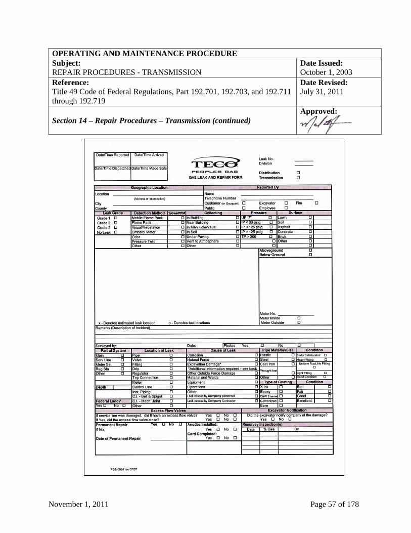
November 1, 2011 Page 57 of 178
OPERATING AND MAINTENANCE PROCEDURE
Subject: Date Issued:
REPAIR PROCEDURES - TRANSMISSION October 1, 2003
Reference:
Title 49 Code of Federal Regulations, Part 192.701, 192.703, and 192.711
through 192.719
Date Revised:
July 31, 2011
Section 14 – Repair Procedures – Transmission (continued)
Approved:
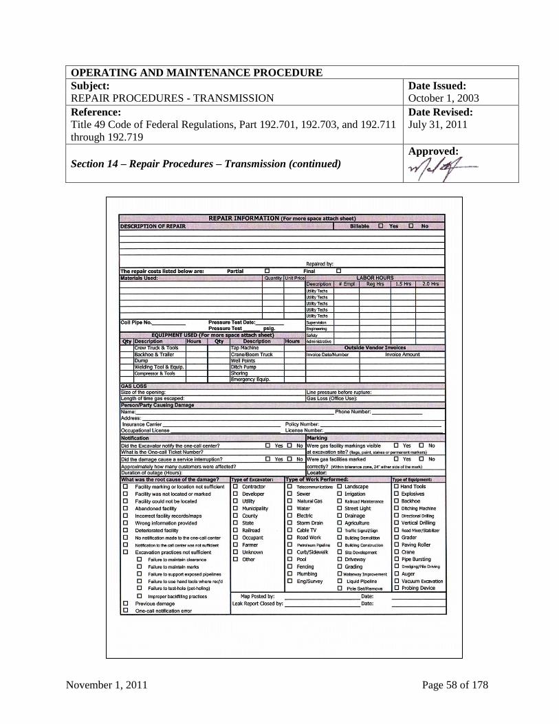
November 1, 2011 Page 58 of 178
OPERATING AND MAINTENANCE PROCEDURE
Subject: Date Issued:
REPAIR PROCEDURES - TRANSMISSION October 1, 2003
Reference:
Title 49 Code of Federal Regulations, Part 192.701, 192.703, and 192.711
through 192.719
Date Revised:
July 31, 2011
Section 14 – Repair Procedures – Transmission (continued)
Approved:
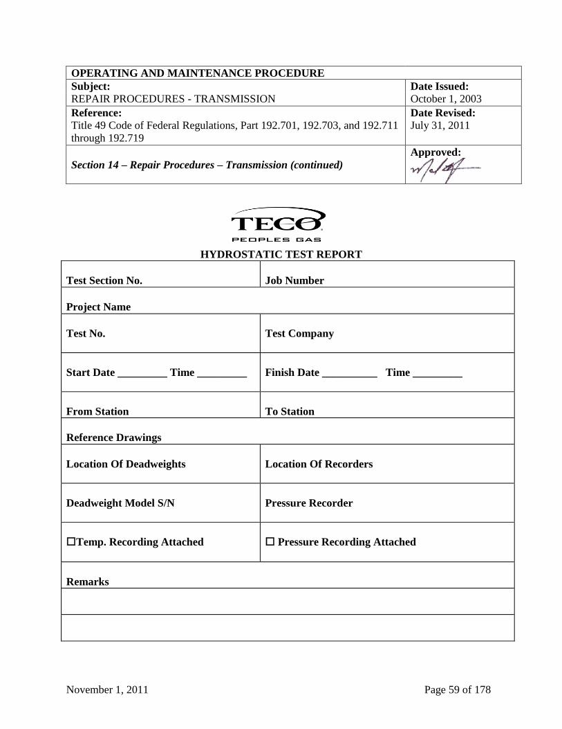
November 1, 2011 Page 59 of 178
OPERATING AND MAINTENANCE PROCEDURE
Subject: Date Issued:
REPAIR PROCEDURES - TRANSMISSION October 1, 2003
Reference:
Title 49 Code of Federal Regulations, Part 192.701, 192.703, and 192.711
through 192.719
Date Revised:
July 31, 2011
Section 14 – Repair Procedures – Transmission (continued)
Approved:
HYDROSTATIC TEST REPORT
Test Section No.
Job Number
Project Name
Test No.
Test Company
Start Date _________ Time _________
Finish Date __________ Time _________
From Station
To Station
Reference Drawings
Location Of Deadweights
Location Of Recorders
Deadweight Model S/N
Pressure Recorder
Temp. Recording Attached
Pressure Recording Attached
Remarks
November 1, 2011 Page 60 of 178
OPERATING AND MAINTENANCE PROCEDURE
Subject: Date Issued:
PATROLLING AND LEAK SURVEY - TRANSMISSION October 1, 2003
Reference:
Title 49 Code of Federal Regulations, Part 192.705 and 192.706
Date Revised:
July 31, 2011
Section 15 – Patrolling and Leak Survey - Transmission
Approved:
Section 15.1 - General
The purpose of pipeline patrol is to observe surface conditions on and adjacent to TECO Peoples
Gas’ rights-of-way which might affect safe operation of the system. Methods of patrolling
include walking, driving, flying or other appropriate means of traversing the right-of-way.
The type of examination and frequency with which it is made will depend on the location and
type of system. Any safety-related conditions such as earth movement, material defects, etc.,
may be reportable.
The Division Manager shall prepare a plan indicating the scheduling of all patrols for the coming
year.
Section 15.2 - Transmission Facilities
All transmission lines must be patrolled and a leak survey must be made in accordance with the
following schedule:
Class 1
Locations Patrol at least once each calendar year, at intervals not exceeding fifteen (15)
months. Patrol highway and railroad crossings at least twice each calendar
year, at intervals not exceeding seven and one-half (7.5) months. Conduct a
leak survey at least once each calendar year, at intervals not exceeding
fifteen (15) months, with a continuous sampling type leak indicator. Class 2
Locations
Class 3
Locations
Patrol at least twice each calendar year, at intervals not exceeding seven and
one-half months. Patrol highway and railroad crossings at least four (4)
times each calendar year, at intervals not exceeding four and one-half (4.5)
months. Conduct a leak survey at least once each calendar year, at intervals
not exceeding fifteen (15) months, with a continuous sampling type leak
indicator.
Class 4
Locations
Patrol at least four (4) times each calendar year at intervals not exceeding
four and one-half (4.5) months. A leak survey must be conducted with a
continuous sampling type leak indicator at least once each calendar year, at
intervals not exceeding fifteen (15) months.
November 1, 2011 Page 61 of 178
OPERATING AND MAINTENANCE PROCEDURE
Subject: Date Issued:
PATROLLING AND LEAK SURVEY - TRANSMISSION October 1, 2003
Reference:
Title 49 Code of Federal Regulations, Part 192.705 and 192.706
Date Revised:
July 31, 2011
Section 15 – Patrolling and Leak Survey – Transmission (continued)
Approved:
If the system transports gas without odor or odorant, the leak survey schedule becomes the same
as the patrol schedule for Class 3 and Class 4 locations.
While surveying, if a read occurs on the leak detection instrument, it shall be immediately
rechecked and validated. If the leak is valid, it shall be pinpointed by means of bar test holes.
Reads shall be taken with the CGI to determine the extent and classification of the leak. The
area of migration shall also be determined. The form PgS 24, “Gas Leak and Repair Form” (see
sample above at Section 14, Pages 57 and 58) shall be prepared at any time a leak is found.
Upon receipt of this form, the Division Manager shall initiate repair of the leak. Priority for
repair depends upon the leak classification. Any Grade 1 leak shall be given immediate
attention. Other leaks shall be handled in a routine manner. Refer to Section 19 for Leak
Classification and Action Criteria.
Section 15.3 - Surface Patrol The Division Manager shall ensure that their personnel observe the rights-of way and adjacent
area for evidence of:
1. Gas leaks;
2. Exposed pipe;
3. Line breaks;
4. Erosion;
5. Equipment working on or near the pipeline;
6. New construction which may be located within two hundred twenty (220) yards on either
side of the pipeline;
7. Any other unusual condition or hazard along, near, or approaching the right-of-way; and,
8. Condition of pipeline markers.
Field operating personnel shall immediately notify the Division Manager of any activity which
may adversely affect the safe operation of the pipeline system.
November 1, 2011 Page 62 of 178
OPERATING AND MAINTENANCE PROCEDURE
Subject: Date Issued:
PATROLLING AND LEAK SURVEY - TRANSMISSION October 1, 2003
Reference:
Title 49 Code of Federal Regulations, Part 192.705 and 192.706
Date Revised:
July 31, 2011
Section 15 – Patrolling and Leak Survey – Transmission (continued)
Approved:
Section 15.4 Reports and Records
1. The form, “Report of Adjacent New Construction/Observation” (see sample above at Section
3, Page 21), shall be completed by the Division Manager to document the patrolling of
pipelines.
2. The form PgS 639, “Area Leak Survey” (see sample below at Section 15, Page 63), shall be
completed by the Division Manager to document the leak surveying of pipelines.
3. A print of area surveyed shall be dated, signed and highlighted by the Division Manager to
document the area surveyed.
The originals of the above referenced reports and forms are to be maintained for the life of the
facility.
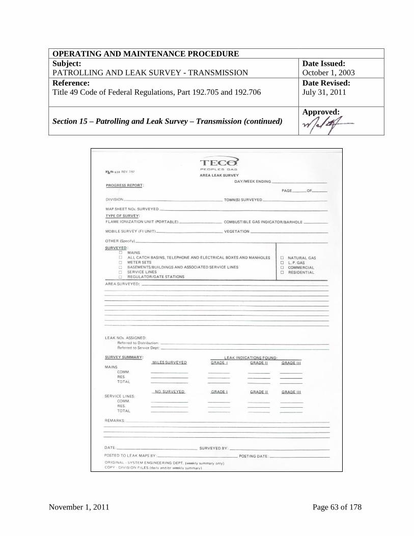
November 1, 2011 Page 63 of 178
OPERATING AND MAINTENANCE PROCEDURE
Subject: Date Issued:
PATROLLING AND LEAK SURVEY - TRANSMISSION October 1, 2003
Reference:
Title 49 Code of Federal Regulations, Part 192.705 and 192.706
Date Revised:
July 31, 2011
Section 15 – Patrolling and Leak Survey – Transmission (continued)
Approved:
November 1, 2011 Page 64 of 178
OPERATING AND MAINTENANCE PROCEDURE
Subject: Date Issued:
RECORD KEEPING - TRANSMISSION October 1, 2003
Reference:
Title 49 Code of Federal Regulations, Part 192.709
Date Revised:
September 10, 2007
Section 16 – Record Keeping - Transmission
Approved:
Section 16.1 - General
Repair and corrosion records shall be kept until the segment is retired. TECO Peoples Gas shall
keep the date, location, and description of each repair made to pipe (including pipe-to pipe
connections) for as long as the segment of transmission line involved remains in service. Leak
surveys, line patrol and inspection reports are to be kept for five (5) years.
November 1, 2011 Page 65 of 178
OPERATING AND MAINTENANCE PROCEDURE
Subject: Date Issued:
PATROLLING - DISTRIBUTION October 1, 2003
Reference:
Title 49 Code of Federal Regulations, Part 192.721
Date Revised:
July 31, 2011
Section 17 – Patrolling - Distribution
Approved:
Section 17.1 - General
Patrolling of the TECO Peoples Gas distribution system is done on a systematic basis in an effort
to locate mains in places or on structures where anticipated physical movement or external
loading could cause failure or leakage. Where the main or support structure is constructed and
maintained to resist anticipated movement and external loads, the Division Manager may
determine that patrols of the facility are not necessary. Patrolling may be accomplished in
conjunction with leakage surveys, scheduled inspections and other routine activities. The
frequency of patrolling mains must be determined by the severity of the conditions, which could
cause failure or leakage, and the consequent hazards to public safety. The Division Manager
shall prepare a plan indicating the scheduling of all patrols for the coming year.
In addition to the scheduled patrolling procedure the qualified employees have been instructed to
report hazardous or potentially hazardous conditions when found as a result of their normal work
activities.
Section 17.2 - Patrol Frequency
Distribution system patrolling will be performed in business districts, at intervals not exceeding
four and one half (4.5) months, but at least four (4) times each calendar year; outside business
districts at intervals not exceeding seven and one half (7.5) months, but at least twice each
calendar year.
Section 17.3 - Patrol Requirements
The Division Manager shall prepare a list of critical areas that exist on distribution pipeline
facilities. This list will be reviewed and updated before each patrol. Each facility should be
checked for the following:
1. Mains on Bridges
a. Secure hangers or supports.
b. Missing bolts in expansion joints, compression couplings, or flanges.
c. Physical condition of piping (check for pulled compression couplings).
(continued on next page)
November 1, 2011 Page 66 of 178
OPERATING AND MAINTENANCE PROCEDURE
Subject: Date Issued:
PATROLLING - DISTRIBUTION October 1, 2003
Reference:
Title 49 Code of Federal Regulations, Part 192.721
Date Revised:
July 31, 2011
Section 17 – Patrolling – Distribution (continued)
Approved:
d. Deteriorated coating at ends of pipe.
e. Condition of paint (excessive rust).
f. Debris lodged against pipe from high water.
g. Presence of pipeline markers on main.
2. Regulator Stations and Similar Installations
a. Adequate locks on gates and valves (by-pass valves must be locked closed and relief
valves must be locked open).
b. Physical condition of piping (checks for pulled compression couplings and pipe in strain).
c. Condition of paint (excessive rust).
d. Presence of pipeline marker.
e. Condition of orifice fittings, valves and other items in pits.
f. Evidence of corrosion or deterioration of coating.
3. Vault Vents, Relief Valves, Casing Vents, Blow-off Stacks
a. Locks where needed.
b. Physical condition of piping (straight and plumb).
c. Condition of paint (excessive rust).
d. Presence of pipeline marker.
(continued on next page)
November 1, 2011 Page 67 of 178
OPERATING AND MAINTENANCE PROCEDURE
Subject: Date Issued:
PATROLLING - DISTRIBUTION October 1, 2003
Reference:
Title 49 Code of Federal Regulations, Part 192.721
Date Revised:
July 31, 2011
Section 17 – Patrolling – Distribution (continued)
Approved:
4. Pipeline Location Markers
a. Condition of support - post, pole, etc. (straight and plumb).
b. Condition of paint (excessive rust).
c. Actual marker sign in place.
5. Pipeline Other Locations
a. Exposed pipe.
b. Gas leaks.
c. Line breaks.
d. Erosion.
e. Equipment working on or near pipeline.
f. Other evidence of unsafe conditions.
The results of the critical area patrol shall be reviewed by the Division Manager for changes or
deficiencies and remedial action taken where warranted.
Section 17.4 - Reports and Records
1. The form PgS 614, “Above Ground Piping Inspection and Maintenance Report” (see sample
at Section 17, Page 68) shall be completed by the Division Manager to document the results
of the patrol, including such items as leak indications, encroachments, erosion, other
conditions which may affect the safety of the line and recommendations for action.
The originals of the above referenced reports and forms are to be maintained for the life of the
facility.
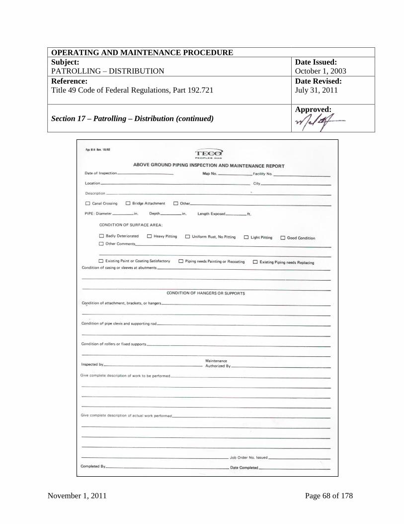
November 1, 2011 Page 68 of 178
OPERATING AND MAINTENANCE PROCEDURE
Subject: Date Issued:
PATROLLING – DISTRIBUTION October 1, 2003
Reference:
Title 49 Code of Federal Regulations, Part 192.721
Date Revised:
July 31, 2011
Section 17 – Patrolling – Distribution (continued)
Approved:
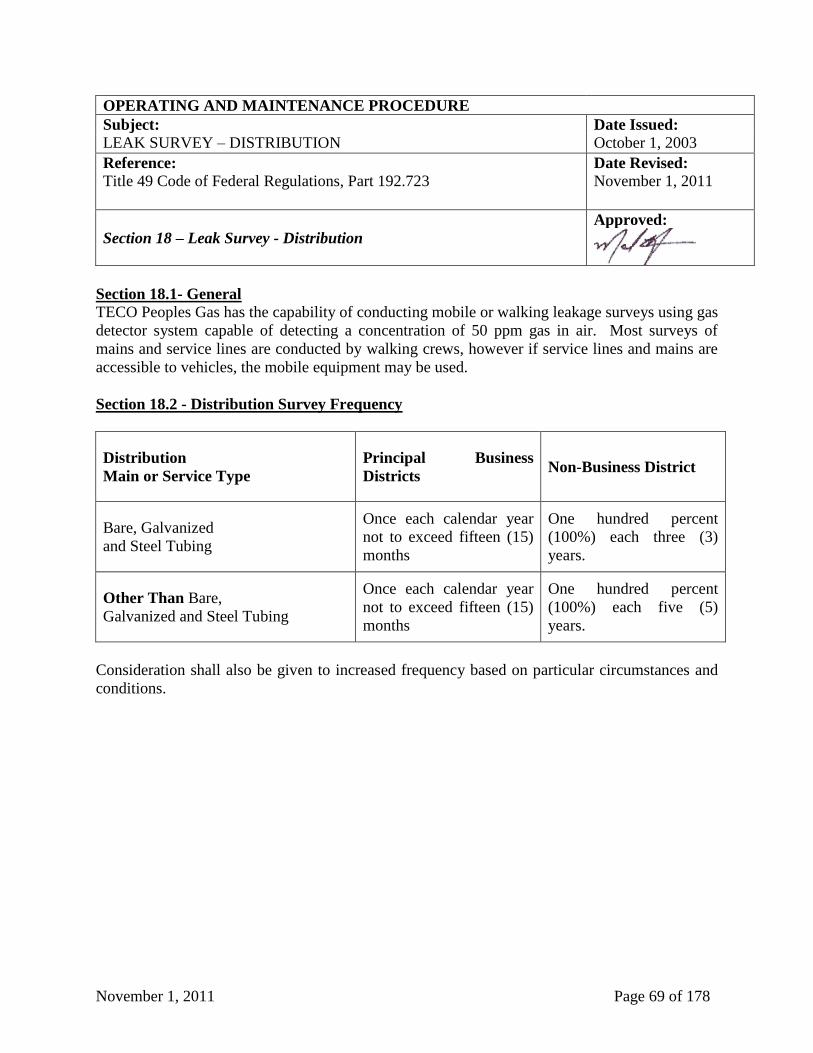
November 1, 2011 Page 69 of 178
OPERATING AND MAINTENANCE PROCEDURE
Subject: Date Issued:
LEAK SURVEY – DISTRIBUTION October 1, 2003
Reference:
Title 49 Code of Federal Regulations, Part 192.723
Date Revised:
November 1, 2011
Section 18 – Leak Survey - Distribution
Approved:
Section 18.1- General
TECO Peoples Gas has the capability of conducting mobile or walking leakage surveys using gas
detector system capable of detecting a concentration of 50 ppm gas in air. Most surveys of
mains and service lines are conducted by walking crews, however if service lines and mains are
accessible to vehicles, the mobile equipment may be used.
Section 18.2 - Distribution Survey Frequency
Distribution
Main or Service Type
Principal Business
Districts Non-Business District
Bare, Galvanized
and Steel Tubing
Once each calendar year
not to exceed fifteen (15)
months
One hundred percent
(100%) each three (3)
years.
Other Than Bare,
Galvanized and Steel Tubing
Once each calendar year
not to exceed fifteen (15)
months
One hundred percent
(100%) each five (5)
years.
Consideration shall also be given to increased frequency based on particular circumstances and
conditions.
November 1, 2011 Page 70 of 178
OPERATING AND MAINTENANCE PROCEDURE
Subject: Date Issued:
LEAK SURVEY – DISTRIBUTION October 1, 2003
Reference:
Title 49 Code of Federal Regulations, Part 192.723
Date Revised:
November 1, 2011
Section 18 – Leak Survey – Distribution (continued)
Approved:
Section 18.3 - Survey Procedure
Leak surveys shall be conducted on a periodic basis in accordance with the above Section 18.2,
“Distribution Survey Frequency”.
The frequency of leak surveys may be more frequent than the minimum requirements as set
forth. The following are some factors that may be considered for the increase in survey
frequency.
1. Pipe material (i.e. cast iron, galvanized, etc.).
2. Pipe joints (i.e. screwed, compression coupling, etc.).
3. Soils, paving, etc.
4. Population density.
5. Leakage history.
All positive indications of combustible gas or vapor present in the general vicinity of a gas main,
service line, or other gas facilities shall be assumed to be of natural gas origin until proven
otherwise. If combustible materials other than natural gas are indicated, then the appropriate
governmental authority should be notified of such findings so that corrective action may be taken
by them.
Area leak surveys are to be recorded on the various forms that are noted in this Section. The leak
survey records shall be retained for the period specified in the forms section located in the front
of this manual.
Each leak indication, up to the outlet of the meter, shall be documented on a separate form PgS
24, “Gas Leak and Repair Form” (see sample above at Section 14, Pages 57 and 58). A leak
number shall be assigned and recorded on form PgS 639, “Area Leak Survey” (see sample above
at Section 15, Page 63).
(continued on next page)
November 1, 2011 Page 71 of 178
OPERATING AND MAINTENANCE PROCEDURE
Subject: Date Issued:
LEAK SURVEY – DISTRIBUTION October 1, 2003
Reference:
Title 49 Code of Federal Regulations, Part 192.723, Florida
Administrative Code 25-12.041 and 12.042
Date Revised:
November 1, 2011
Section 18 – Leak Survey – Distribution (continued)
Approved:
All leak surveys of gas mains shall be documented on individual sets of Operating Center maps
designated as leak survey records or within the Company’s GIS. Mains should be marked as
surveyed. Each main and facilities survey shall be coded to indicate which year that the leak
survey was completed.
Section 18.4 - Business Districts
Business districts are the principal business areas in an urban community. In determining
business districts, the following areas should be considered:
1. The general public regularly congregates or where the majority of buildings on either side of
the street are utilized for economic, industrial, religious, educational, health or recreational
purposes.
2. Gas facilities are under continuous paving that extends from the centerline of the
thoroughfare to the building wall or from the main to the building wall.
3. The atmosphere in manholes, catch basins, curb boxes, cracks in pavement or sidewalks, and
other surface openings to underground facilities, which might provide an opportunity for
finding combustible gas, shall be checked with a gas detection instrument in such a manner
that the presence of gas leaking though cracks or the accumulation of gas within manholes
would be detected.
4. Any other location or site, which in the judgment of TECO Peoples Gas should be so
designated.
Section 18.5 – Types of Leak Surveys
(Section removed as of September 2010)
November 1, 2011 Page 72 of 178
OPERATING AND MAINTENANCE PROCEDURE
Subject: Date Issued:
LEAK SURVEY – DISTRIBUTION October 1, 2003
Reference:
Title 49 Code of Federal Regulations, Part 192.723, Florida
Administrative Code 25-12.041 and 12.042
Date Revised:
November 1, 2011
Section 18 – Leak Survey – Distribution (continued)
Approved:
Section 18.6 - Reports and Records
1. The form PgS 24, “Gas Leak & Repair Form” (see sample above at Section 14, Pages 57 and
58), must be completed by the qualified field technician to document the location and grade
of the leak.
2. The form PgS 639, “Area Leak Survey” (see sample above at Section 15, Page 63), must be
completed by the qualified field technician to document the amount of mains and services
surveyed and the number of leaks found. In place of form PgS 639, the company’s GIS can
also be utilized to record this information.
3. A print of area surveyed shall be dated, signed and highlighted by qualified field technician
to document the area surveyed or the Company’s GIS will be used to record the information.
The original of the above referenced reports and forms are to be maintained for the life of the
facility.
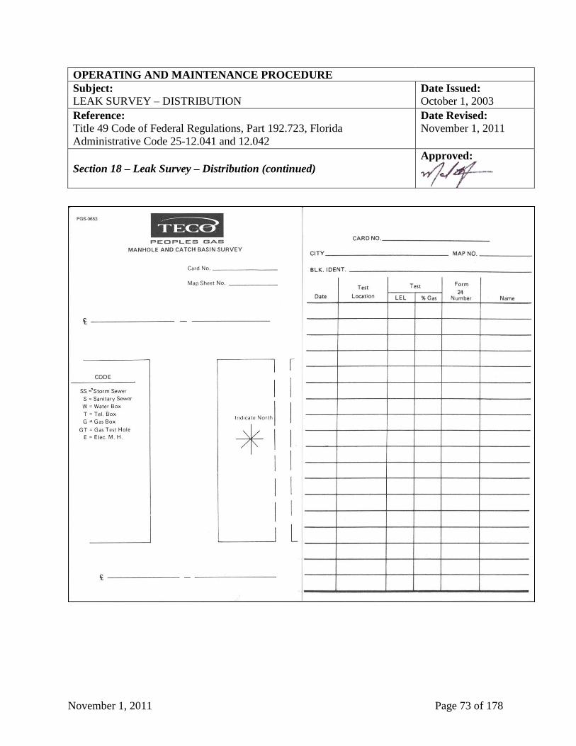
November 1, 2011 Page 73 of 178
OPERATING AND MAINTENANCE PROCEDURE
Subject: Date Issued:
LEAK SURVEY – DISTRIBUTION October 1, 2003
Reference:
Title 49 Code of Federal Regulations, Part 192.723, Florida
Administrative Code 25-12.041 and 12.042
Date Revised:
November 1, 2011
Section 18 – Leak Survey – Distribution (continued)
Approved:
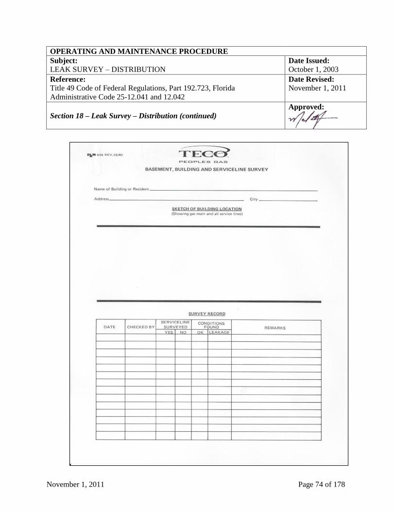
November 1, 2011 Page 74 of 178
OPERATING AND MAINTENANCE PROCEDURE
Subject: Date Issued:
LEAK SURVEY – DISTRIBUTION October 1, 2003
Reference:
Title 49 Code of Federal Regulations, Part 192.723, Florida
Administrative Code 25-12.041 and 12.042
Date Revised:
November 1, 2011
Section 18 – Leak Survey – Distribution (continued)
Approved:
November 1, 2011 Page 75 of 178
OPERATING AND MAINTENANCE PROCEDURE
Subject: Date Issued:
LEAK CLASSIFICATION AND ACTION CRITERIA October 1, 2003
Reference:
Title 49 Code of Federal Regulations, Part 192.706 and 192.723; Florida
Administrative Code 25-12.040
Date Revised:
September 10, 2007
Section 19 – Leak Classification and Action Criteria
Approved:
Section 19.1 - Leak Classification and Action Criteria
The procedure established by TECO Peoples Gas for handling gas leak complaint reports
received from customers, the general public, TECO Peoples Gas employees, or anyone else is
outlined in the Emergency Procedures Manual. The following establishes a procedure by which
leakage indications of flammable gas can be graded and controlled. Particular care must be
taken to determine whether or not any leakage discovered is entering a building or sewer system.
When evaluating any suspected gas leak, the initial step is to determine the perimeter of the
potential leak area. When the perimeter extends to a building wall, the investigation should
continue into the building. Leaks shall be isolated to the general location of mains and services;
meter set assemblies, district regulators, customer's piping or appliances. Appropriate personnel
shall then classify the leak and take action in accordance with the following schedule.
Grade 1 Leak - Definition
A Grade 1 leak is one that represents an existing or probable hazard to persons or property, and
requires immediate repair or continuous action until the conditions are no longer hazardous.
Grade 1 Leak - Action Criteria
The Grade 1 leak requires prompt action to protect life and property, and continuous action until
the conditions are no longer hazardous. The prompt action in some instances may require one or
more of the following:
1. Implementation of the Emergency Procedures, per Emergency Procedures Manual.
2. Evacuation of premises.
3. Blocking off an area.
4. Rerouting traffic.
5. Elimination of ignition sources.
6. Stopping the flow of gas by closing valves, etc.
7. Notification of police and fire departments.
(continued on next page)
November 1, 2011 Page 76 of 178
OPERATING AND MAINTENANCE PROCEDURE
Subject: Date Issued:
LEAK CLASSIFICATION AND ACTION CRITERIA October 1, 2003
Reference:
Title 49 Code of Federal Regulations, Part 192.706 and 192.723; Florida
Administrative Code 25-12.040
Date Revised:
September 10, 2007
Section 19 – Leak Classification and Action Criteria (continued)
Approved:
Grade 2 Leak - Definition
A Grade 2 leak is one that is recognized as being non-hazardous at the time of detection but
justifies scheduled repair based on probable future hazard.
Grade 2 - Action Criteria Leaks should be repaired or cleared within ninety (90) days from the date the leak was reported,
unless due to resurvey the leak was determined to be a Grade 3 leak as defined below. In
determining the repair priority, criteria such as the following should be considered:
1. Amount and migration of gas.
2. Proximity of gas to buildings and subsurface structures.
3. Extent of pavement.
4. Soil type, and soil conditions (such as frost cap, moisture and natural venting).
Grade 2 leaks may vary greatly in degree of potential hazard. Some Grade 2 leaks, when
evaluated by the above criteria, may justify scheduled repair within the next five (5) working
days. Others will justify repair within thirty (30) days or during the working day on which the
leak is discovered. These situations should be brought to the attention of the individual
responsible for scheduling leak repair.
On the other hand, many Grade 2 leaks, because of their location and magnitude, can be
scheduled for repair on a normal routine basis with periodic re-inspection as necessary.
Grade 3 Leak - Definition A Grade 3 leak is one that is non-hazardous at the time of detection and can be reasonably
expected to remain non-hazardous.
(continued on next page)
November 1, 2011 Page 77 of 178
OPERATING AND MAINTENANCE PROCEDURE
Subject: Date Issued:
LEAK CLASSIFICATION AND ACTION CRITERIA October 1, 2003
Reference:
Title 49 Code of Federal Regulations, Part 192.706 and 192.723; Florida
Administrative Code 25-12.040
Date Revised:
September 10, 2007
Section 19 – Leak Classification and Action Criteria (continued)
Approved:
Grade 3 Leak - Action Criteria Above ground grade 3 leaks shall be repaired within ninety (90) days from the date the leak was
originally located unless the leak is upgraded or does not produce a positive leak indication when
a soap and water solution, or its equivalent, is applied on suspected locations at operating
pressure. Grade 3 leaks that are underground shall be reevaluated at least once every six (6)
months until cleared. The frequency of reevaluation shall be determined by the location and
magnitude of the leak.
Section 19.2 - Follow - Up Inspection The adequacy of all the repairs of leaks shall be checked by appropriate methods immediately
after the repairs are completed. Where there is residual gas in the ground, a follow-up inspection
using a gas detector instrument must be made as soon as practical but in no case later than one
(1) month for Grade 1 leaks and six (6) months for Grade 2 leaks. The date and status of recheck
shall be recorded on the leak repair records.
November 1, 2011 Page 78 of 178
OPERATING AND MAINTENANCE PROCEDURE
Subject: Date Issued:
LINE MARKERS FOR MAINS AND TRANSMISSION LINES October 1, 2003
Reference:
Title 49 Code of Federal Regulations, Part 192.707; Florida
Administrative Code 25-12.050
Date Revised:
July 31, 2011
Section 20 – Line Markers for Mains and Transmission Lines
Approved:
Section 20.1 - General Gas transmission and distribution mains in Class 1 and 2 areas and all exposed mains shall be
marked. Transmission mains should be marked to the extent possible in Class 3 and 4 areas
unless placement of a marker is impractical. Markers should be placed in other areas where the
public needs to be aware of the presence of gas mains. Signs identifying and warning of the
hazard of smoking and open flames shall be posted on all large regulating stations. All
hazardous location areas on the above mains shall be marked and maintained during patrol of the
lines.
Pipeline markers are utilized to identify the location of TECO Peoples Gas pipelines in order to
reduce the possibility of damage or interference. The installation of permanent markers on
private property may take place wherever the party exerting control over the surface use of the
land will permit such installations. The placement of temporary markers is advisable in areas of
known heavy construction activity (particularly along highways and major excavations) during
the period construction is in progress.
The Division Manager is responsible for the proper marking of gas facilities. The condition of
signs and markers shall be inspected at the time of the routine inspection of the facility and
deteriorated signs and markers repaired or replaced.
Section 20.2 -_Placement of Markers
Markers should be placed at intervals that would allow an individual to trace the route of the
main and to readily warn the public of the presence of the main. Marking hazardous locations on
transmission and distribution mains are encouraged. Main markers should be located:
1. At all water crossings.
2. At transmission valves or other appropriate locations near the valve.
3. At each public road and railroad crossing. The markers should face toward railroad.
November 1, 2011 Page 79 of 178
OPERATING AND MAINTENANCE PROCEDURE
Subject: Date Issued:
LINE MARKERS FOR MAINS AND TRANSMISSION LINES October 1, 2003
Reference:
Title 49 Code of Federal Regulations, Part 192.707; Florida
Administrative Code 25-12.050
Date Revised:
July 31, 2011
Section 20 – Line Markers for Mains and Transmission Lines (cont.)
Approved:
Section 20.3 - Minimum Specifications
Federal regulations require that the marker must contain:
1. The word "WARNING", or "CAUTION" or "DANGER".
2. The words "GAS PIPELINE", all in letters at least one inch (1”) high with a quarter inch
(1/4’) stroke.
3. The name “TECO Peoples Gas".
4. The telephone number (including area code) where TECO Peoples Gas can be reached at all
times.
Section 20.4 - Warning Signs
Whenever the permanent possibility of accidental ignition of gas exists, permanent signs warning
of the possibility of ignition shall be posted in a conspicuous place. Suitable warning signs shall
also be posted as needed to warn the general public whenever a temporary danger of ignition
exists because of an operation being performed.
November 1, 2011 Page 80 of 178
OPERATING AND MAINTENANCE PROCEDURE
Subject: Date Issued:
TEST REQUIREMENTS FOR REINSTATING MAIN AND SERVICE
LINES
October 1, 2003
Reference:
Title 49 Code of Federal Regulations, Part 192.505,192.507, 192.509,
192.511, 192.513 and 192.725
Date Revised:
September 10, 2007
Section 21 – Test Requirements for Reinstating Main and Service Lines
Approved:
Section 21.1 - Reconnection of Temporarily Disconnected Services
Before a service line, which has been disconnected from the serving main, can be reconnected, it
must be tested in the same manner as a new service line. If the service was damaged, replace the
damaged section and test from the point of damage to the meter stop. In addition, there shall be
sufficient bar testing from the main to the damaged section using a combustible gas indicator. If
there is any indication of physical movement caused by the damage, the line must be tested from
the main to the meter stop.
Section 21.2 - Reconnection of Temporarily Disconnected Mains or Pipelines
Mains or pipelines, which have been disconnected from their source of supply, must be tested in
accordance with the following requirements before they can be reused:
1. Facilities Not Disturbed: Piping facilities, which are disconnected temporarily, need not be
tested if they are not disturbed.
2. Facilities Moved Within a Trench: Piping facilities which are moved within a trench, but not
lifted out of the trench, shall be pressure tested in the same manner as a new line in the same
location.
3. Facilities Lifted From a Trench: Piping facilities which are lifted out of a trench and either
returned to the same trench or moved to a new trench shall be visually inspected to make sure
that all welds are sound -and that no damage has been done to the pipe. They must then be
tested in the same manner as new lines in their final location.
4. Facilities Cut Into Sections: Piping facilities, which are cut into sections, must be reinstalled
as though they were new facilities. All new welds must be tested as required for new
facilities.
November 1, 2011 Page 81 of 178
OPERATING AND MAINTENANCE PROCEDURE
Subject: Date Issued:
TEST REQUIREMENTS FOR REINSTATING MAIN AND SERVICE
LINES
October 1, 2003
Reference:
Title 49 Code of Federal Regulations, Part 192.505,192.507, 192.509,
192.511, 192.513 and 192.725
Date Revised:
September 10, 2007
Section 21 – Test Requirements for Reinstating Main and Service Lines
(continued)
Approved:
Section 21.3 - Reinstating Service in Abandoned Lines
Abandoned service lines, before being reactivated, shall be tested in the same manner as new
service lines. Service lines temporarily disconnected because of main renewals, or other planned
work, shall be tested from the point of disconnection to the service line riser valve at the meter
location or as a unit with the main renewal. This test shall be undertaken in the same manner as
a new gas service line. However, if a bypass is installed to keep a service line active, the portion
maintained in continuous active use need not be tested.
November 1, 2011 Page 82 of 178
OPERATING AND MAINTENANCE PROCEDURE
Subject: Date Issued:
ABANDONMENT OR INACTIVATION OF FACILITIES October 1, 2003
Reference:
Title 49 Code of Federal Regulations, Part 192.727
Date Revised:
September 10, 2007
Section 22 – Abandonment or Inactivation of Facilities
Approved:
Section 22.1 - Abandonment of Pipelines
The following procedures shall be followed for abandonment or inactivation of facilities:
1. Check Prior to Abandonment: Office records should be checked and necessary field checks
should be made to insure the pipelines or mains scheduled for abandonment are disconnected
from all sources and supplies of gas (such as other pipelines, mains, crossover piping, meter
stations, customer piping, control lines, and other appurtenances).
Abandonment procedures used in the Division shall include the following:
1. Facilities abandoned in place shall be physically disconnected from the active system piping
and the open ends of the abandoned facility shall be permanently sealed.
2. All abandoned facilities, when purged must be purged in accordance with Section 12,
Purging, of this manual, to prevent the development of a potentially hazardous condition.
3. An abandoned pipeline facility need not be purged when the volume is so small that there is
no potential hazard. All other abandoned pipeline facilities shall be purged.
4. Service lines connected to abandoned mains shall be permanently sealed below grade at the
customer end of the service lines.
5. Vaults abandoned in place shall be filled with a suitable compacted material.
6. Service lines abandoned from active mains should be disconnected as close to the main as
practical. Both ends of the abandoned portion of the service line nearest the main should be
sealed.
The record of the facility's abandonment shall appear on form PgS 402, “Authorization For
Retirement (AFR)” (see sample below at Section 22, Page 83). These records shall be retained
in the Operating Center.
November 1, 2011 Page 83 of 178
OPERATING AND MAINTENANCE PROCEDURE
Subject: Date Issued:
ABANDONMENT OR INACTIVATION OF FACILITIES October 1, 2003
Reference:
Title 49 Code of Federal Regulations, Part 192.727
Date Revised:
September 10, 2007
Section 22 – Abandonment or Inactivation of Facilities (continued)
Approved:
November 1, 2011 Page 84 of 178
OPERATING AND MAINTENANCE PROCEDURE
Subject: Date Issued:
REGULATOR STATION INSPECTION October 1, 2003
Reference:
Title 49 Code of Federal Regulations, Part 192.739, 192.741 and 192.743
Date Revised:
July 31, 2011
Section 23 – Regulator Station Inspection
Approved:
Section 23.1 - General
All town border stations and pressure reducing stations must comply with the following
inspection requirements. Individual component inspections shall be made concurrently with
other inspections when practical. At least once each calendar year and at intervals not exceeding
fifteen (15) months, each pressure limiting station, relief device (except rupture discs), and
pressure regulating station must be inspected to determine that it is in good mechanical
condition.
All personnel working with station equipment should have knowledge of the general operating
principals involved. Personnel responsible for the operation, maintenance, and testing of station
equipment will be responsible for accumulating manufacturer's service manuals and other
reference material. These items should be readily available for reference. The Division Manager
is responsible for maintaining all equipment in satisfactory condition, establishing test and
calibration schedules to properly maintain all station equipment and to ensure that these
inspections are completed. A capacity calculation shall be made to determine that the station has
adequate capacity for the service in which it is employed.
Section 23.2 - Operational Inspection
This inspection is a visual and operational check for the proper functioning of equipment. The
operational inspection is designed to verify that the regulating station is operating as designed
and to identify any needed repairs. The operational inspection does not require the disassembly
of regulators or relief valves. Employees performing operation inspections should have:
1. The regulator station data sheet, form PgS 654, "Pressure Regulating Installation Data" (see
sample below at Section 23, Page 92) or equivalent information within the GIS database.
2. The regulator station inspection form PgS 659, “District Regulator Station Inspection and
Maintenance Report” (see sample below at Section 23, Page 93) or equivalent information
within the GIS database.
3. The current station drawing.
(continued on next page)
November 1, 2011 Page 85 of 178
OPERATING AND MAINTENANCE PROCEDURE
Subject: Date Issued:
REGULATOR STATION INSPECTION October 1, 2003
Reference:
Title 49 Code of Federal Regulations, Part 192.739, 192.741 and 192.743
Date Revised:
July 31, 2011
Section 23 – Regulator Station Inspection (continued)
Approved:
4. A combustible gas indicator.
5. Accurate pressure gauges capable of measuring both the inlet and outlet pressure of the
station.
6. The manufacturer's instruction manual for each regulator and relief valve type in the station.
Operational Inspection Steps
1. Leak Check - Using a CGI set on the LEL scale, check for the presence of gas at the
following locations:
a. Atmosphere of vault or structure.
b. The piping and equipment in the station.
c. Regulator and relief valve diaphragm vents.
d. Relief valve vent stacks.
2. Visual Inspections - Visual inspections shall be made to determine that a satisfactory
condition exists which will allow proper operation of the equipment. The following should
be included in the inspection (where necessary).
a. Station piping supports, pits, and vaults for general condition and indications of ground
settlement. NOTE: Prior to entering a vault which has restricted openings (such as
manholes) or which is more than four feet (4’) deep, and while working therein, tests
should be made of the atmosphere in the vault (see below at Section 25, Vault
Maintenance).
b. Station doors and gates, as well as pit and vault covers to insure that they are functioning
properly and that access is adequate and free from obstructions.
(continued on next page)
November 1, 2011 Page 86 of 178
OPERATING AND MAINTENANCE PROCEDURE
Subject: Date Issued:
REGULATOR STATION INSPECTION October 1, 2003
Reference:
Title 49 Code of Federal Regulations, Part 192.739, 192.741 and 192.743
Date Revised:
July 31, 2011
Section 23 – Regulator Station Inspection (continued)
Approved:
c. Ventilating equipment installed in station buildings or vaults for proper operation, and for
evidence of accumulation of water or other obstructions.
d. Control, sensing, and supply lines for conditions, which could result in a failure.
e. All locking devices for proper operation.
f. Overall Station condition shall be checked for appearance, paint condition, weeds, and
debris.
g. Presence and condition of warning signs.
h. Check piping for corrosion and proper installation.
i. Ascertain that proper protection from hazards exists.
3. Pressure Gauges - Verify the accuracy of the inlet and outlet dial and recording pressure
gauges with a test gauge or dead weight tester. If the indicated error is greater than two
percent (2%) of full scale, the gauge should be re-calibrated or replaced. If the shutoff valve
ahead of the gauge is defective, the valve shall be repaired or replaced. Gauge accuracy
should be checked before operating any bypass or changing the station operation to inspect or
maintain the pressure regulating equipment. All gauge valves must be in the full open
position.
(continued on next page)

November 1, 2011 Page 87 of 178
OPERATING AND MAINTENANCE PROCEDURE
Subject: Date Issued:
REGULATOR STATION INSPECTION October 1, 2003
Reference:
Title 49 Code of Federal Regulations, Part 192.739, 192.741 and 192.743
Date Revised:
July 31, 2011
Section 23 – Regulator Station Inspection (continued)
Approved:
4. Regulator Check - Close the valve downstream of the regulator and observe the pressure
buildup between the regulator and valve. An excessive or rapid buildup indicates a defective
regulator valve. Whenever excessive or rapid buildup occurs, a primary inspection shall be
performed on the defective regulator. Note: If the control line tap is downstream of the
valve, it will be necessary to isolate the control line and using nitrogen, induce a higher
pressure in the control line to cause the regulator to move to the closed position. Open the
valve (or reconnect the control line) and check that the regulator returns to its normal
operating pressure. The regulator set point should be the same as shown on the data sheet.
Perform the same test for the monitor regulator. For small single run regulator stations, a
pressure check made at the station or at a customer service regulator tap will satisfy this
requirement.
5. Supply and Control Line Filters - Inspect any filters in control and pilot supply lines. Clean
the filter or, if necessary, replace the filter.
6. Overpressure Protection - Close the shutoff valve ahead of the relief valve, and using
nitrogen, propane or natural gas, check the set point of the relief valve. If the set point is
different from the set point shown on the data sheet, adjust the set point. After checking and
adjusting the relief valves, open the shutoff valve and check the relief for positive shutoff.
Whenever a positive shutoff does not occur, a primary inspection shall be performed on the
defective relief valve. Use a CGI to check for the presence of gas in the relief valve stack. If
the station is not in a locked fence enclosure or in a vault, the relief valve shutoff valve shall
be locked in the open position.
7. Valves - An inspection and/or test of valves shall be made to insure that the valves will
operate and are correctly positioned (caution should be used to avoid any undesirable effect
on pressures during operational checks.) The required locking devices shall be installed and
the locks operable. Each valve shall be partially turned to assure that it can be operated when
needed. Each valve shall be checked for proper position, open or closed. The following
valves should be included in the inspection and/or test:
a. Station inlet, outlet and bypass valves.
(continued on next page)
November 1, 2011 Page 88 of 178
OPERATING AND MAINTENANCE PROCEDURE
Subject: Date Issued:
REGULATOR STATION INSPECTION October 1, 2003
Reference:
Title 49 Code of Federal Regulations, Part 192.739, 192.741 and 192.743
Date Revised:
July 31, 2011
Section 23 – Regulator Station Inspection (continued)
Approved:
b. Relief device isolating valves.
c. Control, sensing and supply line valves.
Section 23.3 - Primary Inspection
The primary inspection is the complete tear down of pressure regulating equipment, allowing the
inspection of the operating components of the regulator. The regulator orifices, valves, and
linkages are inspected for wear and proper operation, and any defective parts are replaced. A
primary inspection shall be performed whenever defective equipment is found or deemed
necessary by the Division Manager. NOTE: the primary inspection covers the disassembly of
each defective regulator, relief valve, and pilot regulator.
Primary Regulator Inspection Steps
1. Clean regulator bowl and examine for signs of erosion caused by dirt in the flowing gas
stream.
2. Examine valves and seats for wear, nicks, or depressions and replace as required.
3. Examine valve stems and guides for wear and binding and replace as required.
4. Check pilot and regulator springs to determine that they are the correct spring for the
application and are the springs listed on the form PgS 654, "Pressure Regulating Installation
Data" (see sample below at Section 23, Page 92) or the equivalent information is listed in the
Company GIS.
5. Elastomer elements shall be removed and replaced as needed.
6. Check for proper diaphragm operation. As a general rule the diaphragm cases should not be
disassembled in the field. A periodic inspection of the diaphragm is not needed. If
deterioration of the diaphragm is suspected or the diaphragm appears to be leaking, the
regulator should be removed from service and repaired in a shop or if more appropriate, a
field repair conducted.
November 1, 2011 Page 89 of 178
OPERATING AND MAINTENANCE PROCEDURE
Subject: Date Issued:
REGULATOR STATION INSPECTION October 1, 2003
Reference:
Title 49 Code of Federal Regulations, Part 192.739, 192.741 and 192.743
Date Revised:
July 31, 2011
Section 23 – Regulator Station Inspection (continued)
Approved:
Section 23.4 - Determination of Required Relief Capacity The maximum possible flow through the source supplying the system being protected shall be
determined.
1. When the source is controlled by TECO Peoples Gas, recognized engineering formulas shall
be used to make the calculations based on data published by or otherwise obtained from the
manufacturer of the equipment used as a pressure source or pressure control component.
a. A lesser capacity than calculated above is acceptable if calculations of flow in the piping
on the inlet or outlet of the equipment show a lesser throughput to be the maximum.
b. Data used in these calculations should be selected so that the capacity calculated will
represent the maximum throughput in actual operations including emergencies.
Minimum demand may be considered.
2. When TECO Peoples Gas does not have control of the source, information should be
obtained to adequately determine the maximum flow and pressure capacity of that source.
This information may then be used as the basis for relief capacity requirements.
3. When more than one pressure regulating or compressor station feeds a pipeline, relief
capacity based on complete failure of the largest capacity regulator or compressor should be
adequate.
Section 23.5 - Miscellaneous Station Equipment Inspection
During the inspection the following maintenance should also be performed:
1. All filters, strainers, separators, and similar items where dirt or liquid may collect shall be
checked and action taken, if necessary, to place the item in full operating condition.
2. Miscellaneous station equipment shall be checked for hazardous conditions and proper
operation.
Section 23.6 - System Changes Whenever there are changes in the system which could increase the supply of gas from the
source, the capacity of the control device, or the ability of the relief device to handle the required
flow, a re -determination shall be made.
November 1, 2011 Page 90 of 178
OPERATING AND MAINTENANCE PROCEDURE
Subject: Date Issued:
REGULATOR STATION INSPECTION October 1, 2003
Reference:
Title 49 Code of Federal Regulations, Part 192.739, 192.741 and 192.743
Date Revised:
July 31, 2011
Section 23 – Regulator Station Inspection (continued)
Approved:
Section 23.7 - Final Inspection
The final inspection procedure shall include the following:
1. A check for proper position of all valves. Special attention should be given to regulator
station bypass valves, relief device isolating valves, and valves in control, sensing and supply
lines.
2. Restoration of all locking and security devices to the proper position.
Section 23.8 - Reports and Records
There are two record forms for pressure regulating stations:
1. The form Pgs 654, “Pressure Regulating Installation Data” (see sample below at Section 23,
Page 92) or its equivalent in the Company’s GIS, must be completed by the qualified person
to document the capacity of a district regulator station. This form is a listing of all equipment
and specifications in the station and shall be complete and correct. The MAOP, equipment
capacities, and set points are critical. The form shall be revised whenever equipment or
equipment set points are changed and shall be verified and, if necessary, corrected at the
annual inspection. If over-pressure protection is provided by a relief valve, the calculation of
the relief valve capacity shall be attached to the form.
The drawing or sketch on the form must be completed by the qualified person to provide a
graphic outline of the station. The drawing shall be changed any time the station is revised,
and shall be verified and, if necessary, corrected at the annual inspection.
2. The form PgS 659, “District Regulator Station Inspection and Maintenance Report” (see
sample below at Section 23, Page 93) or its equivalent in the Company’s GIS, must be
completed by the qualified person to document the inspection and maintenance of regulator
stations and gate stations. The form provides a record of the annual operating or primary
inspection. It verifies that the station was inspected and details any work completed during
the inspection.
The originals of the above referenced reports and forms are to be maintained for the life of the
facility.
November 1, 2011 Page 91 of 178
OPERATING AND MAINTENANCE PROCEDURE
Subject: Date Issued:
REGULATOR STATION INSPECTION October 1, 2003
Reference:
Title 49 Code of Federal Regulations, Part 192.739, 192.741 and 192.743
Date Revised:
July 31, 2011
Section 23 – Regulator Station Inspection (continued)
Approved:
Section 23.9 – Telemetry or Recording Gauges
Any part of the gas distribution system that is supplied by more than one district regulator station
must be equipped with telemetry or recording pressure gauges to indicate the gas pressure in the
system.
The Division Manager shall determine the need for telemetry or recording pressure gauges on
systems that are supplied by one district regulator station based on the number of customers
supplied, operating pressures in the system, system capacity and other applicable operating
conditions.
Whenever there are indications of high or low pressure the station equipment must be inspected
and necessary measures taken to correct any unsatisfactory operating conditions.
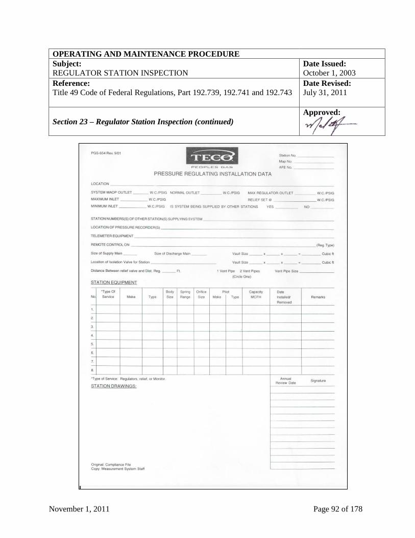
November 1, 2011 Page 92 of 178
OPERATING AND MAINTENANCE PROCEDURE
Subject: Date Issued:
REGULATOR STATION INSPECTION October 1, 2003
Reference:
Title 49 Code of Federal Regulations, Part 192.739, 192.741 and 192.743
Date Revised:
July 31, 2011
Section 23 – Regulator Station Inspection (continued)
Approved:
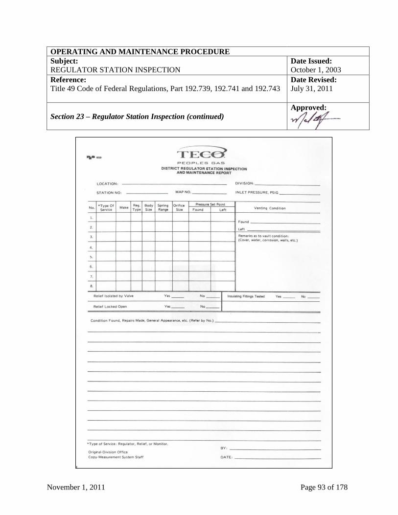
November 1, 2011 Page 93 of 178
OPERATING AND MAINTENANCE PROCEDURE
Subject: Date Issued:
REGULATOR STATION INSPECTION October 1, 2003
Reference:
Title 49 Code of Federal Regulations, Part 192.739, 192.741 and 192.743
Date Revised:
July 31, 2011
Section 23 – Regulator Station Inspection (continued)
Approved:
November 1, 2011 Page 94 of 178
OPERATING AND MAINTENANCE PROCEDURE
Subject: Date Issued:
EMERGENCY VALVE PROCEDURE October 1, 2003
Reference:
Title 49 Code of Federal Regulations, Part 192.745 and 192.747
Date Revised:
July 31, 2011
Section 24 – Emergency Valve Procedure
Approved:
Section 24.1 - General
All transmission and distribution emergency valves must comply with the following inspection
requirements. Individual component inspections shall be made concurrently with other
inspections when practicable. At least once each calendar year and at intervals not exceeding
fifteen (15) months, each transmission and distribution emergency valve must be serviced,
inspected, and partially operated to determine that it is in good mechanical condition.
Section 24.2 - Designation of Emergency Valves
Selected valves are designated as emergency valves. The emergency valves are necessary for the
safe optimum operation of the system.
Transmission main emergency valves include:
1. Block valves that are spaced so that every point on main segment is within the required
spacing for the class location.
2. Block valves that are located at the beginning of each lateral.
3. Block valves that control the flow of gas to regulator stations serving towns, large
subdivisions, and large customers.
4. Block valves that control the flow of gas to mains in emergency locations such as stream or
aerial crossings.
5. Block valves that are located at the inlet and outlet of compressor stations. Provisions must
be made for the rapid blow-down of each segment of transmission main that can be isolated
by closing block valves.
Distribution main emergency valves are:
1. Valves that control the flow of gas to distribution regulator stations. These valves should be
located a safe distance from the station, but not more than five hundred feet (500') from the
station inlet.
(continued on next page)
November 1, 2011 Page 95 of 178
OPERATING AND MAINTENANCE PROCEDURE
Subject: Date Issued:
EMERGENCY VALVE PROCEDURE October 1, 2003
Reference:
Title 49 Code of Federal Regulations, Part 192.745 and 192.747
Date Revised:
July 31, 2011
Section 24 – Emergency Valve Procedure (continued)
Approved:
2. Sectionalizing valves - Valves shall be spaced within each distribution system to reduce the
time to shut down a segment of the system in an emergency. In determining the spacing of
these valves, the following factors shall be evaluated:
a. Volume and pressure of gas between valves.
b. Size of area and population density between valves required to isolate the area as well as
the accessibility of the required valves.
c. The minimum number of personnel required to shut down and restore the area.
d. Other means and availability of required equipment to control the flow of gas in the event
of an emergency.
e. The number and type of customers, such as hospitals, schools, commercial and industrial
loads, etc., that will be affected.
3. Valves that control gas flow to mains in vulnerable locations such as water crossings.
4. Valves that are installed at other locations as deemed necessary by the Division Manager.
Section 24.3 - Valve Inspections
Each designated sectionalized or emergency valve will be inspected as often as necessary to
insure access and operating capability, but not to exceed intervals of fifteen (15) months, but at
least once each calendar year.
The inspection will include:
1. A check for adequate lubrication.
2. Proper alignment to permit use of a key or wrench.
3. Operate the valve.
(continued on next page)
November 1, 2011 Page 96 of 178
OPERATING AND MAINTENANCE PROCEDURE
Subject: Date Issued:
EMERGENCY VALVE PROCEDURE October 1, 2003
Reference:
Title 49 Code of Federal Regulations, Part 192.745 and 192.747
Date Revised:
July 31, 2011
Section 24 – Emergency Valve Procedure (continued)
Approved:
4. Clear any debris or obstruction that might interfere with or delay the operation of the valve.
5. Check location references that are recorded on the map to insure the valve can be readily
located from records.
6. Verification of valve number tag.
NOTE: A record will be kept of the periodic inspections and will contain sufficient information
to show compliance with these procedures.
Section 24.4 – Marking of Emergency Valves
All emergency valves shall be physically identified using a durable tag or other approved
equivalent method of marking and shall be numbered using an identification system appropriate
to the Local Operating Center/Region requirements.
Above ground emergency valves and emergency valves located in vaults shall have a permanent
(or visible until next inspection) identification (i.e. durable tags, painted numbers) affixed to
them. The marking shall appear on the valve body or hand wheel.
Buried valves operated by a valve key wrench shall have the marking in a visible location or on
the inside of the valve curb box or stand pipe where the cover will not destroy the markings.
The preferred method of marking shall be a tag of durable brass, aluminum, or non-corrosive
material where corrosion may exist, or other approved material in the material list affixed with
glue, wire, or screws and shall be stamped with a minimum of one quarter inch (1/4”) characters
identifying the valve. The marking should be placed on the north inside edge of the valve box
approximately one sixteenth inch (1/16”) from the top edge of the valve box. The tag should be
secured to a cast iron valve box with a three-eighths inch (3/8”) No. 7 cadmium plated sheet
metal screws or approved glue. The area of the valve box where the marking is to be affixed
should be cleaned and filed to insure complete closure.
Emergency valve box covers shall be painted an identifying color. Yellow shall be used if not
reserved by another utility.
November 1, 2011 Page 97 of 178
OPERATING AND MAINTENANCE PROCEDURE
Subject: Date Issued:
EMERGENCY VALVE PROCEDURE October 1, 2003
Reference:
Title 49 Code of Federal Regulations, Part 192.745 and 192.747
Date Revised:
July 31, 2011
Section 24 – Emergency Valve Procedure (continued)
Approved:
Section 24.5 - Reports and Records
1. The form PgS 657, “Valve Maintenance and Operating Order” (see sample below at Section
24, Page 98) or its equivalent in the Company’s GIS, must be completed by the Division
Manager to document the location and maintenance of emergency valves.
2. The form PgS 638, “Valve Maintenance Record Card” (see sample below at Section 24, Page
99) or its equivalent in the Company’s GIS, must be completed by qualified field technician
to document maintenance of emergency valves.
The originals of the above referenced reports and forms are to be maintained for the life of the
facility.
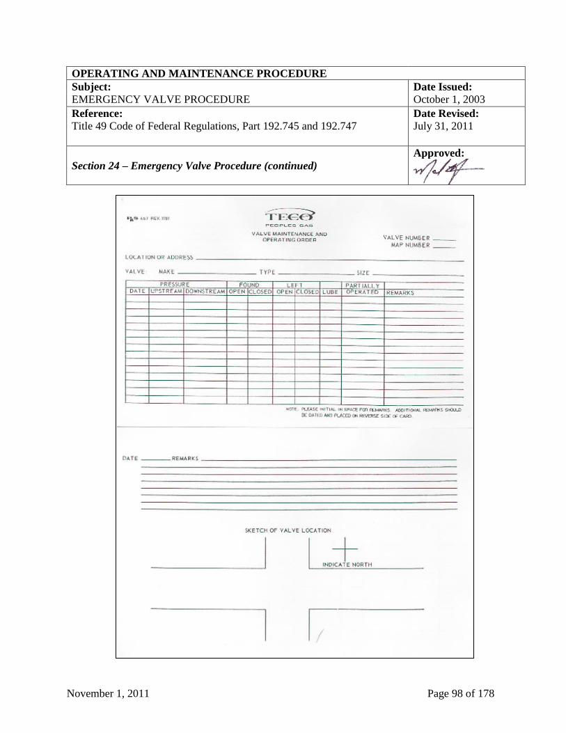
November 1, 2011 Page 98 of 178
OPERATING AND MAINTENANCE PROCEDURE
Subject: Date Issued:
EMERGENCY VALVE PROCEDURE October 1, 2003
Reference:
Title 49 Code of Federal Regulations, Part 192.745 and 192.747
Date Revised:
July 31, 2011
Section 24 – Emergency Valve Procedure (continued)
Approved:
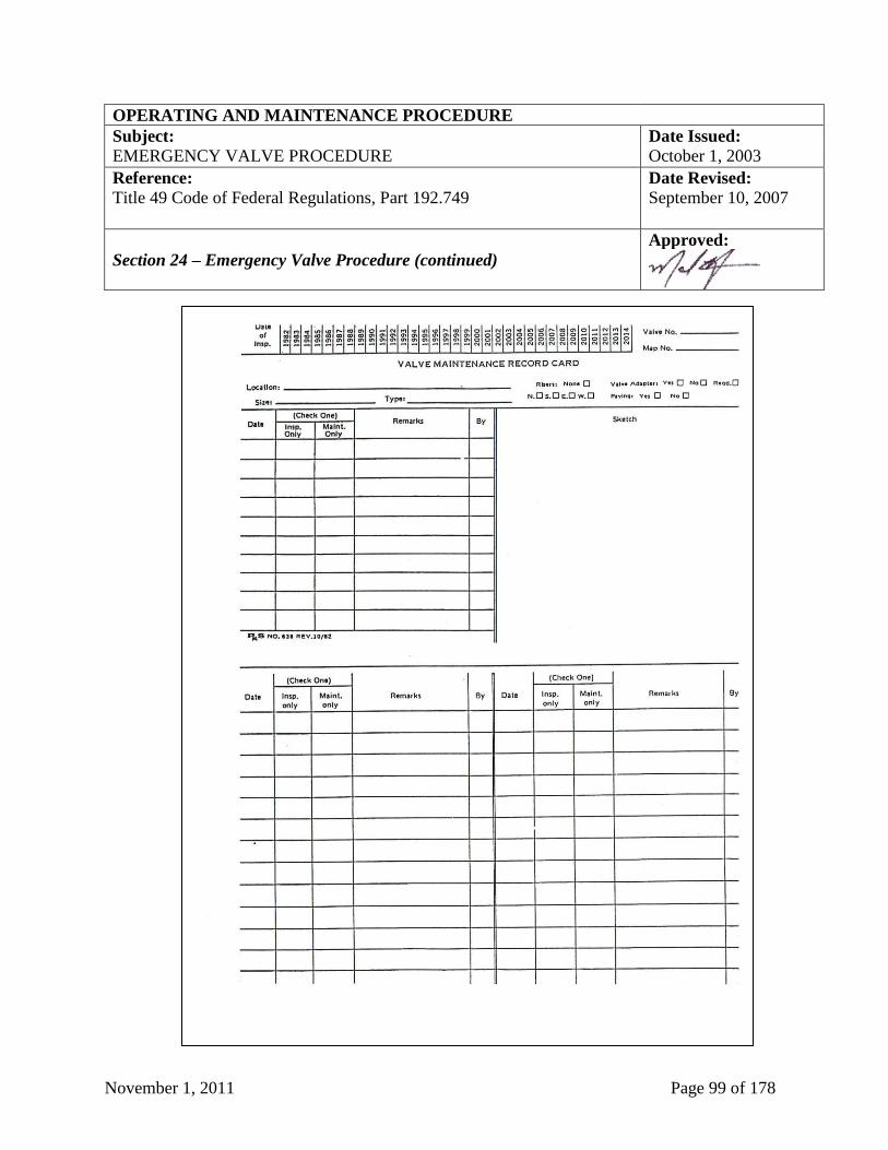
November 1, 2011 Page 99 of 178
OPERATING AND MAINTENANCE PROCEDURE
Subject: Date Issued:
EMERGENCY VALVE PROCEDURE October 1, 2003
Reference:
Title 49 Code of Federal Regulations, Part 192.749
Date Revised:
September 10, 2007
Section 24 – Emergency Valve Procedure (continued)
Approved:
November 1, 2011 Page 100 of 178
OPERATING AND MAINTENANCE PROCEDURE
Subject: Date Issued:
VAULT MAINTENANCE October 1, 2003
Reference:
Title 49 Code of Federal Regulations, Part 192.749
Date Revised:
September 10, 2007
Section 25 – Vault Maintenance (continued)
Approved:
Section 25.1 - General
Each vault housing pressure regulating and pressure limiting equipment, and having a volumetric
internal content of two hundred (200) cubic feet or more, must be inspected at intervals not
exceeding fifteen (15) months, but at least once each calendar year, to determine that it is in good
physical condition and adequately ventilated. Individual component inspections shall be made
concurrently with other inspections when practical.
Section 25.2 - Vault Inspection
All vaults as described above must be inspected and necessary maintenance must be performed.
Such inspections must include:
1. That the vault is structurally sound and no bearing on pipeline facilities.
2. That the cover presents no hazard to the public or equipment in the vault.
3. The facilities in vault are subjected to external corrosion.
4. The ventilation in vault is adequate.
5. If gas leaks are found in vaults, the source will be determined and leaks repaired.
6. If ventilating equipment is used, check for proper operation.
Section 25.3 - Reports and Records
The form, “Annual Vault Inspection” (see sample below at Section 25, Page 101) or its
equivalent in the Company’s GIS, shall be completed by the qualified person to document the
inspection of the vaults over two hundred (200) cubic feet in volume.
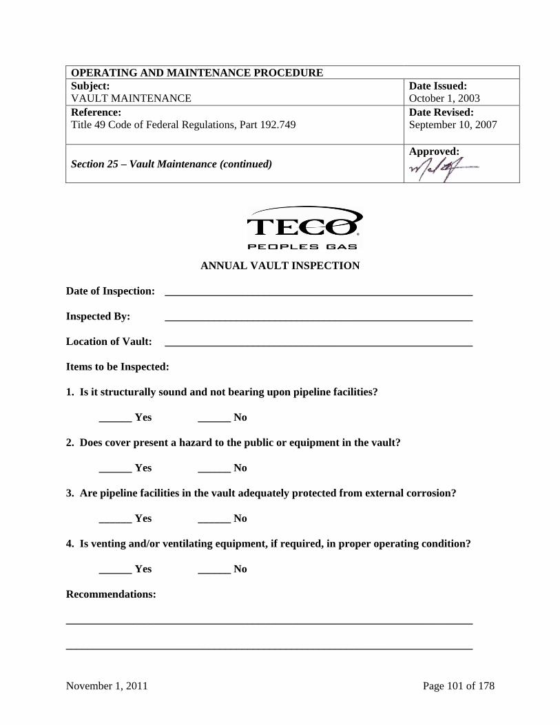
November 1, 2011 Page 101 of 178
OPERATING AND MAINTENANCE PROCEDURE
Subject: Date Issued:
VAULT MAINTENANCE October 1, 2003
Reference:
Title 49 Code of Federal Regulations, Part 192.749
Date Revised:
September 10, 2007
Section 25 – Vault Maintenance (continued)
Approved:
ANNUAL VAULT INSPECTION
Date of Inspection: ________________________________________________________
Inspected By: ________________________________________________________
Location of Vault: ________________________________________________________
Items to be Inspected:
1. Is it structurally sound and not bearing upon pipeline facilities?
______ Yes ______ No
2. Does cover present a hazard to the public or equipment in the vault?
______ Yes ______ No
3. Are pipeline facilities in the vault adequately protected from external corrosion?
______ Yes ______ No
4. Is venting and/or ventilating equipment, if required, in proper operating condition?
______ Yes ______ No
Recommendations:
__________________________________________________________________________
__________________________________________________________________________
November 1, 2011 Page 102 of 178
OPERATING AND MAINTENANCE PROCEDURE
Subject: Date Issued:
PREVENTION OF ACCIDENTAL IGNITION October 1, 2003
Reference:
Title 49 Code of Federal Regulations, Part 192.751
Date Revised:
September 10, 2007
Section 26 – Prevention of Accidental Ignition
Approved:
Section 26.1 - General
The danger of accidental ignition must be minimized in any structure or area where the presence
of gas constitutes a hazard of fire or explosion. Employees shall be aware of the hazard of
accidental ignition and take positive steps to reduce the hazard. Fire extinguishers shall be
readily available when operations involve escaping gas. TECO Peoples Gas has taken Steps to
minimize the danger of accidental ignition of gas in any structure or area where the presence of
gas constitutes a hazard of fire or explosion, including the following:
1. Smoking and open flames: Smoking and open flames are prohibited.
a. In structures or areas containing gas facilities where possible leakage or presence of gas
constitutes a hazard of fire or explosion.
b. In the open, when accidental ignition of gas-air mixture might cause personal injury or
property damage.
2. Accidental electric arcing: To prevent accidental ignition of electric arcing, the following
should be considered:
a. Flashlights, portable flood lights, extension cords, and any other electrically powered
tools or equipment should be of a type approved for use in hazardous atmospheres.
b. Internal combustion engines that power trucks, cars, compressors, pumps, generators, and
equipment should not be operated in suspected or known hazardous atmospheres.
c. Bonding to provide electrical continuity should be considered around all cuts separating
metallic pipes, which may have natural gas present. This bond should be installed prior
to cutting and maintained until all reconnections are completed or a gas-free environment
exists. Bond cables should be installed in such a manner to assure that they do not
become dislodged during construction and that they provide minimal electrical resistance
between pipe sections.
(continued on next page)

November 1, 2011 Page 103 of 178
OPERATING AND MAINTENANCE PROCEDURE
Subject: Date Issued:
PREVENTION OF ACCIDENTAL IGNITION October 1, 2003
Reference:
Title 49 Code of Federal Regulations, Part 192.751
Date Revised:
September 10, 2007
Section 26 – Prevention of Accidental Ignition (continued)
Approved:
d. The potential ignition of gas that can be caused by static electric charges induced on the
outside surface of plastic piping should be eliminated during cutting operations.
Acceptable methods of accomplishing this include covering the pipe surfaces with wet
rags or thoroughly spraying the exposed pipe with a compatible electrically conductive
liquid or water.
e. Static electric charges induced on the inside surfaces of plastic piping by gas flow cannot
be eliminated by the methods outlined in item 2.d. above. Appropriate steps, such as
flow control from a location a safe distance from the location of the escaping gas, should
be taken to minimize the escape of gas and to protect personnel from the potential
hazards. A plastic vent or blow-down should not be used due to the possibility of internal
static electric charge causing ignition of the escaping gas.
3. Other sources of ignition: Care should be taken in selecting the proper hand tools for use in
hazardous atmospheres and in handling tools to reduce the potential for a spark.
Section 26.2 - Welding, Cutting and Other Hot Work
1. General: Prior to welding, cutting, or other hot-work in or around a structure or area
containing gas facilities, a thorough check should be made with a gas detector for the
presence of a combustible gas mixture. Welding should begin only when safe conditions are
indicated.
2. Pipelines Filled with Gas: When a pipeline or main is to be kept full of gas during welding or
cutting operations, the following are recommended:
a. A slight flow of gas should be kept moving toward the cutting or welding operation.
b. The gas pressure at the site of the work should be controlled by suitable means.
c. All slots or open ends should be closed with tape, tightly fitted canvas, or other suitable
material immediately after a cut is made.
d. Two openings should not be uncovered at the same time.
(continued on next page)
November 1, 2011 Page 104 of 178
OPERATING AND MAINTENANCE PROCEDURE
Subject: Date Issued:
PREVENTION OF ACCIDENTAL IGNITION October 1, 2003
Reference:
Title 49 Code of Federal Regulations, Part 192.751
Date Revised:
September 10, 2007
Section 26 – Prevention of Accidental Ignition (continued)
Approved:
3. Pipelines Containing Air:
a. Before the work is started, and at intervals as the work progresses, the atmosphere in the
vicinity of the zone to be heated should be tested with a combustible gas indicator or by
other suitable means.
b. Unless a suitable means (such as an air blower) is used to prevent a combustible mixture
in the work area, welding, cutting, or other operations that could be a source of ignition
should not be performed on a pipeline, main, or auxiliary apparatus that contains air and
is connected to a source of gas.
c. When the means noted in 3.b. above are not used, one or more of the following
precautions (depending upon circumstances at the job) are suggested:
i. The pipe or other equipment upon which the welding or cutting is to be done should
be purged with an inert gas.
ii. The pipe or other equipment upon which the welding or cutting is to be done should
be continuously purged with air in such a manner that a combustible mixture does not
form in the facility at the work area.
Section 26.3 - Isolating Pipelines
1. General: Planned work on gas facilities should incorporate procedures to shut off or
minimize the escape of gas. No portion of a pipeline, large service, or main should be cut out
under pressure, unless the flow of gas is shut off or minimized by the use of line valves, line
plugging equipment, bags, stoppers, or pipe squeezers. Where one hundred percent (100%)
shutoff is not feasible, the following precautions are recommended:
a. Plan the job to minimize the escape of gas and sequence steps to limit the time and
amount of gas to which personnel are exposed.
b. The size and position of the cut should allow the gas to vent properly even with an
employee in the excavation.
(continued on next page)
November 1, 2011 Page 105 of 178
OPERATING AND MAINTENANCE PROCEDURE
Subject: Date Issued:
PREVENTION OF ACCIDENTAL IGNITION October 1, 2003
Reference:
Title 49 Code of Federal Regulations, Part 192.751
Date Revised:
September 10, 2007
Section 26 – Prevention of Accidental Ignition (continued)
Approved:
c. Protection of personnel working in a gaseous atmosphere under an overhang or in a
tunnel or manhole.
2. Isolating Pipeline Segments:
a. Preliminary Action: TECO Peoples Gas should conduct a pre-work meeting(s) to review
the work with the personnel involved.
This includes the method of isolation, the purpose of each phase, drawings, procedures,
schematics as applicable, and responsibilities of each individual including the designation
of an individual in charge of the operation.
b. Isolation Precautions: Isolation equipment left unattended should have a positive means
of preventing unauthorized operation. A positive means should be provided at the work
site to alert and protect personnel from unintentional pressuring. Consideration should be
given to the use or installation of items such as relief valves, rupture discs, pressure
gauges, pressure recorders, vents, pressure alerting devices, and other pressure detecting
devices. Isolation equipment should be inspected and maintained prior to use.
Temporary closures capable of withstanding full line pressure should have a means to
determine pressure build-up (such as gauges and venting).
c. Monitoring Isolated Segments: Monitoring procedures should be established based on the
pressure, volumes, closures, and other pertinent factors. Personnel assigned to operate
isolation equipment should have a means to determine pressure build-ups (such as gauges
and vents). Personnel monitoring at remote locations should have communication with
the work site and the person in charge of the operation.
Section 26.4 - Notifications Prior to Purge or Blow-down
1. Public Officials: The appropriate public officials should be notified prior to a purge or blow-
down in those situations where the normal flow of traffic through the area might be disturbed
or where it is anticipated that there will be calls from the public regarding the purge or blow-
down.
November 1, 2011 Page 106 of 178
OPERATING AND MAINTENANCE PROCEDURE
Subject: Date Issued:
CORROSION CONTROL October 1, 2003
Reference:
Title 49 Code of Federal Regulations, Part 192, Subpart I; Florida
Administrative Code 25-12.052 and 12.054
Date Revised:
July 31, 2011
Section 27 – Corrosion Control
Approved:
Section 27.1 - General The Division Manager shall continuously sample and evaluate the effectiveness of the corrosion
control program. The program must be carried out by or be administered by a person qualified
by experience and training in pipeline corrosion control methods.
When a condition of active corrosion is found, positive action must be taken to mitigate and
control the effects of the corrosion. Schedules must be established for application of corrosion
control. Monitoring effectiveness must be adequate to mitigate and control the effects of the
corrosion prior to its becoming a public hazard or endangering public safety.
Section 27.2 - External Corrosion Control
Section 27.2.1 - Protection of Existing Facilities All buried or submerged steel pipelines installed before August 1, 1971, must be cathodically
protected where active corrosion is found. "Active corrosion" is defined as continuing corrosion,
which, unless controlled, could result in a condition that is detrimental to public safety. "Active
corrosion" shall be determined by leak history and other records and by examination of exposed
pipe surfaces during excavations.
If gas leakage results from active corrosion of a pipeline, the pipeline shall be replaced with non-
metallic pipe; or repaired and cathodic protection applied to meet the requirements of Title 49
Code of Federal Regulations, Part 192 Subpart I.
Section 27.2.2 - Protection of New Construction
Each buried pipeline installed after July 31, 1971 must be protected against external corrosion
per Title 49 Code of Federal Regulations, Part 192 Subpart I.
Section 27.3 - Criteria for Cathodic Protection and Pipe-to-Soil Potential Measurements
Unless directed otherwise, copper-copper sulfate reference electrodes are to be used in pipe-to-
soil potential measurements. These reference electrodes shall be properly maintained.
Unless directed otherwise, pipe-to-soil potential measurements to determine the level of cathodic
protection are to be made with respect to close earth, that is, a reference electrode located as near
as possible to the earth directly over the structure in question. The placement of a reference
electrode in the immediate vicinity of a galvanic anode shall not be acceptable for any electrical
measurements used to determine the adequacy of cathodic protection.
November 1, 2011 Page 107 of 178
OPERATING AND MAINTENANCE PROCEDURE
Subject: Date Issued:
CORROSION CONTROL October 1, 2003
Reference:
Title 49 Code of Federal Regulations, Part 192, Subpart I; Florida
Administrative Code 25-12.052 and 12.054
Date Revised:
July 31, 2011
Section 27 – Corrosion Control (continued)
Approved:
Section 27.4 - Monitoring of Cathodic Protection
Section 27.4.1 - Protected Lines
Each pipeline that is under cathodic protection must be tested at least once each calendar year,
but with intervals not exceeding fifteen (15) months. The test shall include determination
whether the level of cathodic protection meets the requirements Title 49 Code of Federal
Regulations, Part 192 Subpart I.
Separately protected gas service lines and short sections of mains (i.e. mains not over one
hundred (100) feet in length), shall be surveyed on a sampling basis. At least ten (10%) percent
of these separately protected lines and short sections of gas mains, distributed over the entire
system, should be surveyed each calendar year, with a different ten (10%) percent checked each
calendar year, so that all of the separately protected service lines and short sections of mains are
surveyed in each ten (10) year period.
The form PgS 313, “Cathodic Protection Data” (see sample below at Section 27, Page 116), or
alternatively, form PgS 645, “Cathodic Protection Data” (see sample below at Section 27, Page
115) must be completed by a qualified person for each test lead point existing in the system
(either form may be utilized at the discretion of the Division Manager).
Section 27.4.2 - Rectifiers
Each impressed current power source (i.e. rectifier systems) shall be inspected six (6) times
annually at intervals not exceeding two and one-half (2 1/2) months to ensure that the rectifier is
operating properly.
The form PgS 515, “Rectifier System Report” (see sample below at Section 27, Page 118), must
be completed by a qualified person to document the condition of rectifier units.
November 1, 2011 Page 108 of 178
OPERATING AND MAINTENANCE PROCEDURE
Subject: Date Issued:
CORROSION CONTROL October 1, 2003
Reference:
Title 49 Code of Federal Regulations, Part 192, Subpart I; Florida
Administrative Code 25-12.052 and 12.054
Date Revised:
July 31, 2011
Section 27 – Corrosion Control (continued)
Approved:
Section 27.4.3 - Interference Bonds
Each major interference bond, the failure of which would jeopardize the cathodic protection
applied to the pipeline, must be electrically checked for proper performance six (6) times
annually, at intervals not exceeding two and one half (2 1/2) months.
Each minor interference bond must be checked at least once each calendar year, with intervals
not exceeding fifteen (15) months.
The form PgS 668, “Cathodic Protection Interference Test Report” (see sample below at Section
27, Page 114), must be completed by a qualified person to document readings at interference
bonds with other companies.
Section 27.5 - Unprotected Lines - Three (3) Year Re-evaluation
All steel gas pipelines that are not cathodically protected shall be reevaluated every three (3)
years at intervals not exceeding thirty-nine (39) months. Reevaluations on unprotected pipe shall
consist of pipe to soil potential measurements taken at spacing intervals of one hundred (100)
feet (or less) along the pipeline. At each station, the pipe to soil potential shall be measured
directly over the pipeline, the close reading. In areas where peaks in the potential measurements,
that is, potential measurements one hundred millivolts (.100v) more negative than normal,
further investigation is required.
Additional pipe-to-soil measurements shall be taken forward and to the rear of the peak at
spacing intervals of twenty feet (20’). The number of additional stations shall be dependent on
the amount of pipe with high negative potentials. Also, at each of the spacing intervals of twenty
feet (20’), a side drain potential, remote, shall be made at a point approximately ten (10) feet
perpendicular to the pipeline.
(continued on the next page)
November 1, 2011 Page 109 of 178
OPERATING AND MAINTENANCE PROCEDURE
Subject: Date Issued:
CORROSION CONTROL October 1, 2003
Reference:
Title 49 Code of Federal Regulations, Part 192, Subpart I; Florida
Administrative Code 25-12.052 and 12.054
Date Revised:
July 31, 2011
Section 27 – Corrosion Control (continued)
Approved:
The close profile shall be compared to the remote profile. Close potential measurements more
negative than remote potential measurements indicate anodic areas, that is, “hot spots”, requiring
further inspection to determine the need for applying cathodic protection. Close potential
measurements less negative than remote measurements indicate cathodic areas requiring no
further action. If gas leakage results from active corrosion of a pipeline, remedial action shall
include application of cathodic protection. Cathodic protection installed for remedial action shall
be tested at least once every calendar year, but with intervals not exceeding fifteen (15) months,
unless the pipeline is replaced with non-metallic pipe.
The form PgS 294, “Pipeline Electrical Survey Data (see sample below at Section 27, Page 117),
must be completed by a qualified person to document electrical survey results.
Section 27.6 - Electrical Isolation
Each buried or submerged gas pipeline must be electrically isolated from other underground
metallic structures unless the entire network is to be cathodically protected as one unit.
Each gas pipeline should be protected against lightning or fault currents in areas of known
unusual risk. Some of these areas include electrical transmission tower footings, lightning rod
grounding systems, ground cables or counter poise. Zinc grounding cells shall be used, when
required, as a protective measure. An insulating device may not be installed in an area where a
combustible atmosphere is anticipated unless lead wires are attached to either side of the
insulating device and extended to a safe location outside the area in question, or other
precautions are taken to prevent arcing.
The location of underground insulating devices installed on gas mains shall be posted to TECO
Peoples Gas’ maps and records.
Section 27.7 - Test Point Stations
A sufficient number of test point stations, or other contact points for electrical measurement to
determine the level of cathodic protection, shall be provided for each protected system. Probe
bars should not be used. Steel gas service lines, and test leads are acceptable test point stations,
however, steel service lines should be used only with caution as a means for contacting the gas
main under test to insure good electrical continuity.
November 1, 2011 Page 110 of 178
OPERATING AND MAINTENANCE PROCEDURE
Subject: Date Issued:
CORROSION CONTROL October 1, 2003
Reference:
Title 49 Code of Federal Regulations, Part 192, Subpart I; Florida
Administrative Code 25-12.052 and 12.054
Date Revised:
July 31, 2011
Section 27 – Corrosion Control (continued)
Approved:
Section 27.8 - Interference Currents
Each cathodic protection system must be designed and installed so as to minimize any adverse
effects on existing adjacent underground metallic facilities. Where it is known, or suspected,
that stray currents are affecting TECO Peoples Gas’ gas lines or foreign structures, tests must be
made to determine the extent of the interference. Remedial measures must be taken to eliminate
the detrimental effects of these interference currents. Interference testing shall be coordinated
with the operators of affected structures.
Section 27.9 - Examination of Exposed Pipe
All exposed portions of buried gas pipelines shall be examined for evidence of external
corrosion. The section of gas pipeline exposed should be examined to determine the condition of
the coating and for evidence of active corrosion if a bare portion of the pipeline is exposed.
Note: Generally, pitting, blistering, or graphitization of the pipeline surface shall be considered
evidence of active corrosion. If active corrosion exists, steps must be taken for implementation
of one of the remedial measures outlined below.
The form, “Pipe Inspection Report” (see sample below at Section 27, Page 119), must be
completed by a qualified person to document the condition of pipe, which is exposed during
excavation.
Section 27.10 - Pipeline Coating
Steel pipeline purchased by TECO Peoples Gas and proposed for use underground shall be
factory coated with an approved coating specified in TECO Peoples Gas’ Standard Materials
List. Field joint wraps shall be made by persons qualified by experience and training and shall
be made in accordance with the manufacturer's specifications.
All metallic joints must be externally coated with a material suitable for corrosion control prior
to burial. Coating of irregular fittings such as valves, as well as propane tanks to be buried, shall
be made with TECO Peoples Gas approved mastic. Steel gas pipeline joints shall be coated with
approved materials. Field-applied coatings shall overlap the factory coating on both sides of the
joint by at least two inches.
Coating shall be inspected prior to lowering into the ditch. Any damage must be repaired.
(continued on next page)

November 1, 2011 Page 111 of 178
OPERATING AND MAINTENANCE PROCEDURE
Subject: Date Issued:
CORROSION CONTROL October 1, 2003
Reference:
Title 49 Code of Federal Regulations, Part 192, Subpart I; Florida
Administrative Code 25-12.052 and 12.054
Date Revised:
July 31, 2011
Section 27 – Corrosion Control (continued)
Approved:
The amount of cathodic protection must be controlled so as not to damage the protective coating
or the pipe.
Note: Voltage sufficient to cause damage to the coating or the pipe can be reached with an
impressed current-type cathodic protection system (i.e. a rectifier-type cathodic protection
system).
Section 27.11 - Internal Corrosion Control
Pipe removed from operating service for any reason shall be examined for evidence of internal
corrosion. If evidence of internal corrosion is found, any adjacent pipe should be inspected to
determine the extent of the internal corrosion.
Section 27.12 - Atmospheric Corrosion Control
Section 27.12.1 - General Above-ground facilities through which gas moves, including pipe, valves, and other
appurtenances attached to the pipe, and all gas metering stations, gas pressure regulator stations,
and other fabricated assemblies shall be inspected for evidence of active corrosion at intervals
not exceeding three (3) years and remedial action shall be taken, where necessary. Note: Minor
oxidation, which occurs upon most metal surfaces exposed to the atmosphere, is not considered
to be the type of atmospheric corrosion requiring remedial action.
Section 27.12.2 - Coating Requirements
All portions of gas pipeline that are exposed to the atmosphere must be coated with a material
suitable to protect the pipeline from atmospheric corrosion:
1. On New Construction: On exposed portions of the pipeline, for example, at rivers, canals,
intercostals waterways and at ditch crossings, the normal coating as specified for
underground pipelines is sufficient to protect against atmospheric corrosion. Gas metering
facilities, gas pressure regulators, propane gas tanks and other associated aboveground piping
must be coated with an approved paint that is suitable to prevent atmospheric corrosion.
2. On Existing Facilities: All exposed portions of existing metallic gas pipelines and all
aboveground piping facilities shall be coated and painted with approved coating materials.
November 1, 2011 Page 112 of 178
OPERATING AND MAINTENANCE PROCEDURE
Subject: Date Issued:
CORROSION CONTROL October 1, 2003
Reference:
Title 49 Code of Federal Regulations, Part 192, Subpart I; Florida
Administrative Code 25-12.052 and 12.054
Date Revised:
July 31, 2011
Section 27 – Corrosion Control (continued)
Approved:
Section 27.13 - Replacement Piping
Whenever a section of buried or submerged pipeline is replaced because of corrosion and the
replacement is with metallic pipe, the new pipe must be cathodically protected. A determination
should be made on the feasibility of localized cathodic protection or cathodically protecting the
repaired segment and adjacent segments as a single unit.
Section 27.14 - Repairs Not Requiring Replacement
Whenever a corrosion leak is repaired on a segment of a gas pipeline, that segment of pipeline
shall be considered a "hot spot". The location shall be evaluated to determine if necessary to
attach an anode to the pipeline at this location to mitigate corrosion.
Section 27.15 - Converted Facilities (Propane Gas to Natural Gas)
For converted systems the required level of cathodic protection must be applied within one (1)
year following the conversion.
Section 27.16 - Records Keeping
Section 27.16.1 - Construction and Replacement Records
Records of construction and replacement of gas pipelines shall be maintained sufficient to show
the nature of the work undertaken; the actual location of the work undertaken, the date of
installation and the date cathodic protection was applied.
Records shall be kept sufficient to prove that the materials and components used, or intended for
use in the gas pipeline, meet the applicable specifications.
Section 27.16.2 - Maps Maps or records showing the location of cathodically protected pipelines, cathodic protection
facilities, galvanic anodes and neighboring structures bonded to the cathodic protection system
shall be maintained for the life of the facility (LOF).
November 1, 2011 Page 113 of 178
OPERATING AND MAINTENANCE PROCEDURE
Subject: Date Issued:
CORROSION CONTROL October 1, 2003
Reference:
Title 49 Code of Federal Regulations, Part 192, Subpart I; Florida
Administrative Code 25-12.052 and 12.054
Date Revised:
July 31, 2011
Section 27 – Corrosion Control (continued)
Approved:
Section 27.16.3 - Retention of Records
Following forms are to be utilized for Corrosion Control data:
1. The form PgS 668, “Cathodic Protection Interference Test Report” (see sample below at
Section 27, Page 114), documenting readings at interference bonds with other companies,
must be retained for the life of the facilities.
2. The form PgS 313, “Cathodic Protection Data” (see sample below at Section 27, Page 116),
or alternatively, form PgS 645, “Cathodic Protection Data” (see sample below at Section 27,
Page 115) documenting each test lead point existing in the system, must be retained for the
life of the facilities.
3. The form PgS 294, “Pipeline Electrical Survey Data (see sample below at Section 27, Page
117), documenting electrical survey results, must be retained for five (5) years.
4. The form PgS 515, “Rectifier System Report” (see sample below at Section 27, Page 118),
documenting the condition of rectifier units, must be retained for five (5) years.
5. The form, “Pipe Inspection Report” (see sample below at Section 27, Page 119),
documenting the condition of pipe which is exposed during excavation, shall be retained for
five (5) years.
The above records of each test, survey or inspection shall be maintained in sufficient detail to
demonstrate the adequacy of the corrosion control measures. Records required by Sections
27.4.1, 27.4.3 and 27.11 shall be retained for the life of the facility.
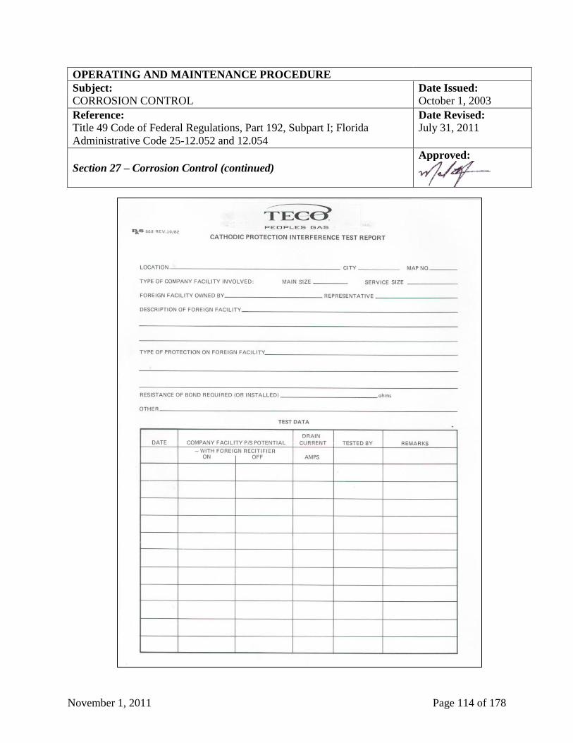
November 1, 2011 Page 114 of 178
OPERATING AND MAINTENANCE PROCEDURE
Subject: Date Issued:
CORROSION CONTROL October 1, 2003
Reference:
Title 49 Code of Federal Regulations, Part 192, Subpart I; Florida
Administrative Code 25-12.052 and 12.054
Date Revised:
July 31, 2011
Section 27 – Corrosion Control (continued)
Approved:
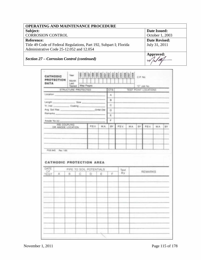
November 1, 2011 Page 115 of 178
OPERATING AND MAINTENANCE PROCEDURE
Subject: Date Issued:
CORROSION CONTROL October 1, 2003
Reference:
Title 49 Code of Federal Regulations, Part 192, Subpart I; Florida
Administrative Code 25-12.052 and 12.054
Date Revised:
July 31, 2011
Section 27 – Corrosion Control (continued)
Approved:
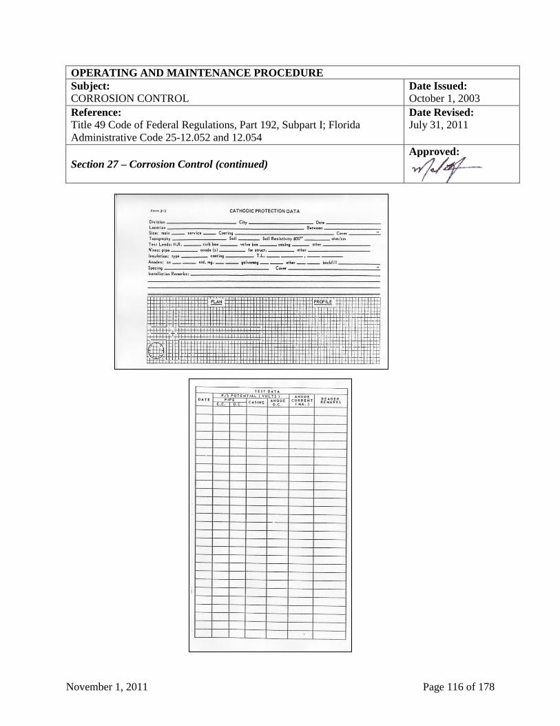
November 1, 2011 Page 116 of 178
OPERATING AND MAINTENANCE PROCEDURE
Subject: Date Issued:
CORROSION CONTROL October 1, 2003
Reference:
Title 49 Code of Federal Regulations, Part 192, Subpart I; Florida
Administrative Code 25-12.052 and 12.054
Date Revised:
July 31, 2011
Section 27 – Corrosion Control (continued)
Approved:
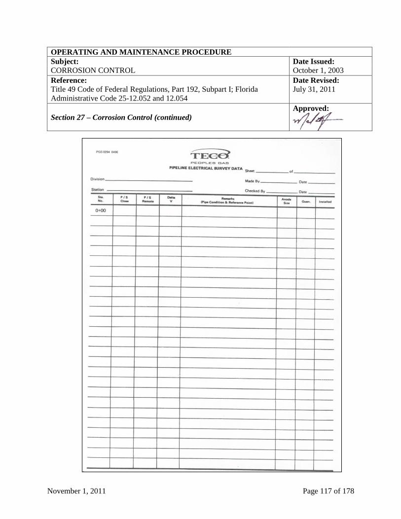
November 1, 2011 Page 117 of 178
OPERATING AND MAINTENANCE PROCEDURE
Subject: Date Issued:
CORROSION CONTROL October 1, 2003
Reference:
Title 49 Code of Federal Regulations, Part 192, Subpart I; Florida
Administrative Code 25-12.052 and 12.054
Date Revised:
July 31, 2011
Section 27 – Corrosion Control (continued)
Approved:
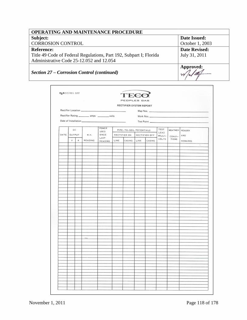
November 1, 2011 Page 118 of 178
OPERATING AND MAINTENANCE PROCEDURE
Subject: Date Issued:
CORROSION CONTROL October 1, 2003
Reference:
Title 49 Code of Federal Regulations, Part 192, Subpart I; Florida
Administrative Code 25-12.052 and 12.054
Date Revised:
July 31, 2011
Section 27 – Corrosion Control (continued)
Approved:
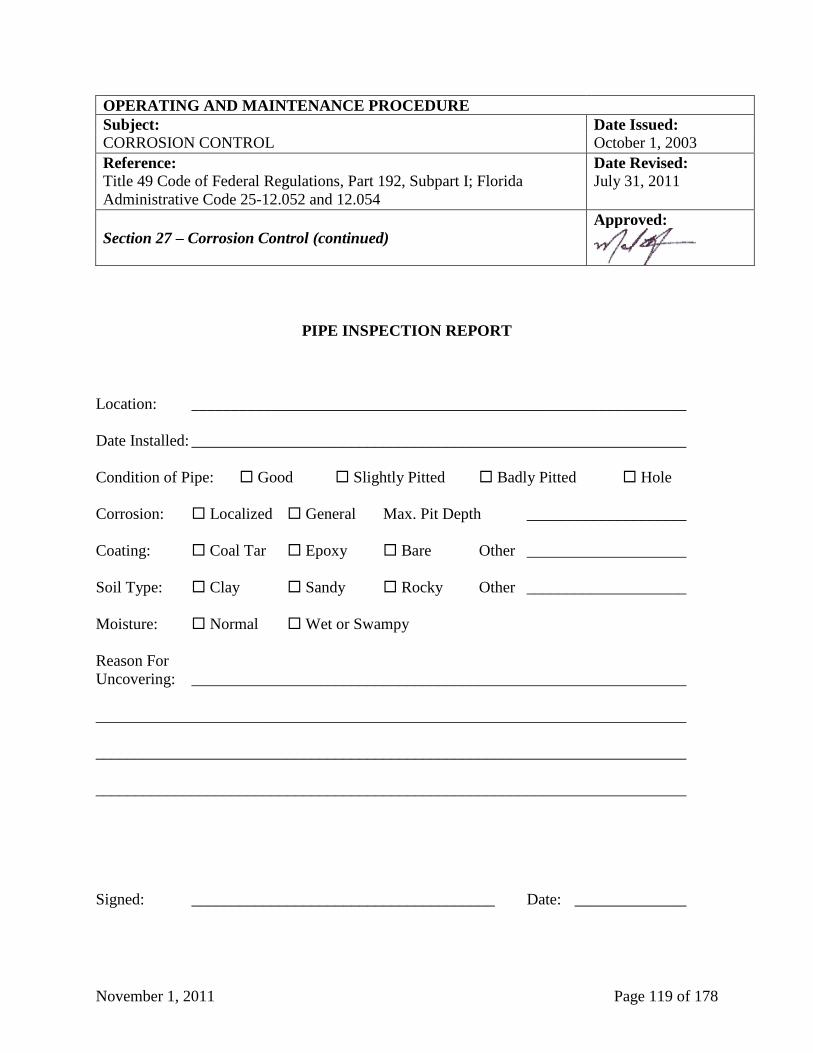
November 1, 2011 Page 119 of 178
OPERATING AND MAINTENANCE PROCEDURE
Subject: Date Issued:
CORROSION CONTROL October 1, 2003
Reference:
Title 49 Code of Federal Regulations, Part 192, Subpart I; Florida
Administrative Code 25-12.052 and 12.054
Date Revised:
July 31, 2011
Section 27 – Corrosion Control (continued)
Approved:
�
PIPE INSPECTION REPORT
Location: ______________________________________________________________
Date Installed: ______________________________________________________________
Condition of Pipe: Good Slightly Pitted Badly Pitted Hole
Corrosion: Localized General Max. Pit Depth ____________________
Coating: Coal Tar Epoxy Bare Other ____________________
Soil Type: Clay Sandy Rocky Other ____________________
Moisture: Normal Wet or Swampy
Reason For
Uncovering: ______________________________________________________________
__________________________________________________________________________
__________________________________________________________________________
__________________________________________________________________________
Signed: ______________________________________ Date: ______________
November 1, 2011 Page 120 of 178
OPERATING AND MAINTENANCE PROCEDURE
Subject: Date Issued:
BY-PASS OPERATION October 1, 2003
Reference:
Title 49 Code of Federal Regulations, Part 192
Date Revised:
September 10, 2007
Section 28 – By-Pass Operation
Approved:
Section 28.1 - General
The by-passing of a regulator station must be planned, and the plan followed.
Section 28.2 - By-Pass Operation
By-passing pressure regulators is a complex procedure that requires comprehensive planning and
careful execution. Overpressure of the supplied system or service interruptions are possible
results of an improperly operated by-pass. A plan should be developed and all the involved
employees prior to starting the bypass procedure should review the plan.
The planning should:
1. Identify the maximum and minimum pressures allowed on the downstream or supplied
system.
2. Review the station drawings for correctness.
3. Identify the valves to be operated and determine the sequence of valve operation.
4. Identify the gauge taps to be used. Be sure that the gauge taps are on the supplied system and
not the piping segment that will be isolated.
5. Identify the overpressure protection available on the supplied system during the by-pass
procedure.
The job procedure should:
1. Review the by-pass plan.
2. Designate the by-pass operator.
(continued the next page)
November 1, 2011 Page 121 of 178
OPERATING AND MAINTENANCE PROCEDURE
Subject: Date Issued:
BY-PASS OPERATION October 1, 2003
Reference:
Title 49 Code of Federal Regulations, Part 192
Date Revised:
September 10, 2007
Section 28 – By-Pass Operation (continued)
Approved:
3. Install the pressure gauges that the by-pass operator will use to monitor the system pressure.
These gauges must be in good condition and calibrated. These gauges should be visible to
the by-pass operator throughout the by-pass procedure. One of the gauges on the supplied
system should have sufficient range to measure pressures up to the normal regulator station
inlet pressure.
4. Locate and operate the valves that will be used in the by-pass procedure.
5. Place the by-pass in operation. Allow the system to stabilize prior to working on the
regulator. The bypass operator shall remain at the by-pass valve throughout the procedure
and continuously monitor the system pressure. The system pressure must be maintained
between the established maximum and minimum limits.
6. If at any time during the by-pass operation the by-pass operator cannot maintain the pressure
within the prescribed limits, the operator shall:
a. Place the regulator back in operation and return the system to normal operation. If it is
not possible to return the system to normal operation, turn off the supply of gas to the
system and notify the appropriate supervisors of the emergency.
b. It will then be necessary to follow the steps outlined in the emergency plan for restoring
gas service.
After completing the work, return the station to normal operation. Place the regulator back in
service, and close the by-pass valve. Carefully observe the station operation to assure that all
equipment is properly operating and the equipment set points are correct. If a temporary by-pass
was used, remove the piping. Lock the by-pass valve on the customer set, where applicable.
November 1, 2011 Page 122 of 178
OPERATING AND MAINTENANCE PROCEDURE
Subject: Date Issued:
PLASTIC JOINING QUALIFICATIONS October 1, 2003
Reference:
Title 49 Code of Federal Regulations, Part 192.281, 192.283, 192.285 and
192.287; Florida Administrative Code 25-12.021
Date Revised:
July 31, 2011
Section 29 – Plastic Joining Qualifications
Approved:
Section 29.1 - General
Personnel joining plastic pipe shall be trained in the approved joining procedures and shall
complete the prescribed tests. Records of the training and qualification tests shall be maintained.
Section 29.2 - Joining of Plastic Pipe by Heat Fusion
A copy of each written procedure being used for joining plastic pipe must be available to the
person making joints and to the person inspecting joints at the site where joining is
accomplished. Plastic pipe that is joined by heat fusion must not be disturbed until it has
properly set. The joining must be protected from weather conditions that would impair the
quality of the joint.
Personnel qualified for the work by experience or training must make all heat fusion joints.
Before any plastic joiner is permitted to make any production joints in plastic pipe, such joiner is
required to demonstrate qualification by successfully completing the appropriate test as
prescribed by the manufacturer of the pipe.
All personal qualifications and requalification tests, whether successful or not, shall be recorded
on test report forms. The Division Manager shall retain one copy of this report. Copies of any
previously given test may also be obtained from the Division Manager. Any person who
successfully passes the qualification test shall be given the qualification papers appropriate to the
method under which they qualified.
After initial qualification, an individual may make production joints using any procedure, for
which the individual is qualified for a period of one (1) year, unless the individual is found to be
unable to make satisfactory production joints.
Each person who joins plastic pipe shall be qualified by training and experience in each
procedure the individual uses to join plastic pipe. Each person shall demonstrate the ability to
join plastic by making and having tested a specimen joint of each procedure the individual uses
to join plastic pipe. A person must make at least one joint in a procedure each twelve (12)
months to remain qualified in that procedure. A person who has had more than three percent
(3%) of the joints made found unacceptable by test must be retrained and retested before making
additional plastic pipe joints. The procedures used to join plastic pipe are mechanical coupling,
heat socket fusion, heat butt fusion, heat saddle fusion, and electrofusion.

November 1, 2011 Page 123 of 178
OPERATING AND MAINTENANCE PROCEDURE
Subject: Date Issued:
PLASTIC JOINING QUALIFICATIONS October 1, 2003
Reference:
Title 49 Code of Federal Regulations, Part 192.281, 192.283, 192.285 and
192.287; Florida Administrative Code 25-12.021
Date Revised:
July 31, 2011
Section 29 – Plastic Joining Qualifications (continued)
Approved:
Section 29.3 - Testing
Plastic pipe joints submitted for test shall be made in the presence of a qualified person who is
qualified by experience or training in inspecting plastic pipe joints, and the test results shall be
documented on form PgS 506, “Plastic Pipe Joining Record” (see sample below at Section 29,
Page 124). The completed joints and longitudinal straps shall be compared with a satisfactory
joint or pictures of a satisfactory joint. Joints having defects or inconsistencies shall be rejected
and additional joints submitted for test.
Section 29.4 - Contractor Qualification
Contractor's employees who join plastic pipe must pass the same qualification tests as TECO
Peoples Gas employees on an annual basis.
Section 29.5 - Qualification Records
The Division Manager will maintain the permanent records of TECO Peoples Gas employees
who are qualified to join plastic pipe.
1. The form PgS 506, “Plastic Pipe Joining Record” (see sample below at Section 29, Page
124), shall be completed by the Division Manager or qualified person for each employee who
passed the required qualification tests.
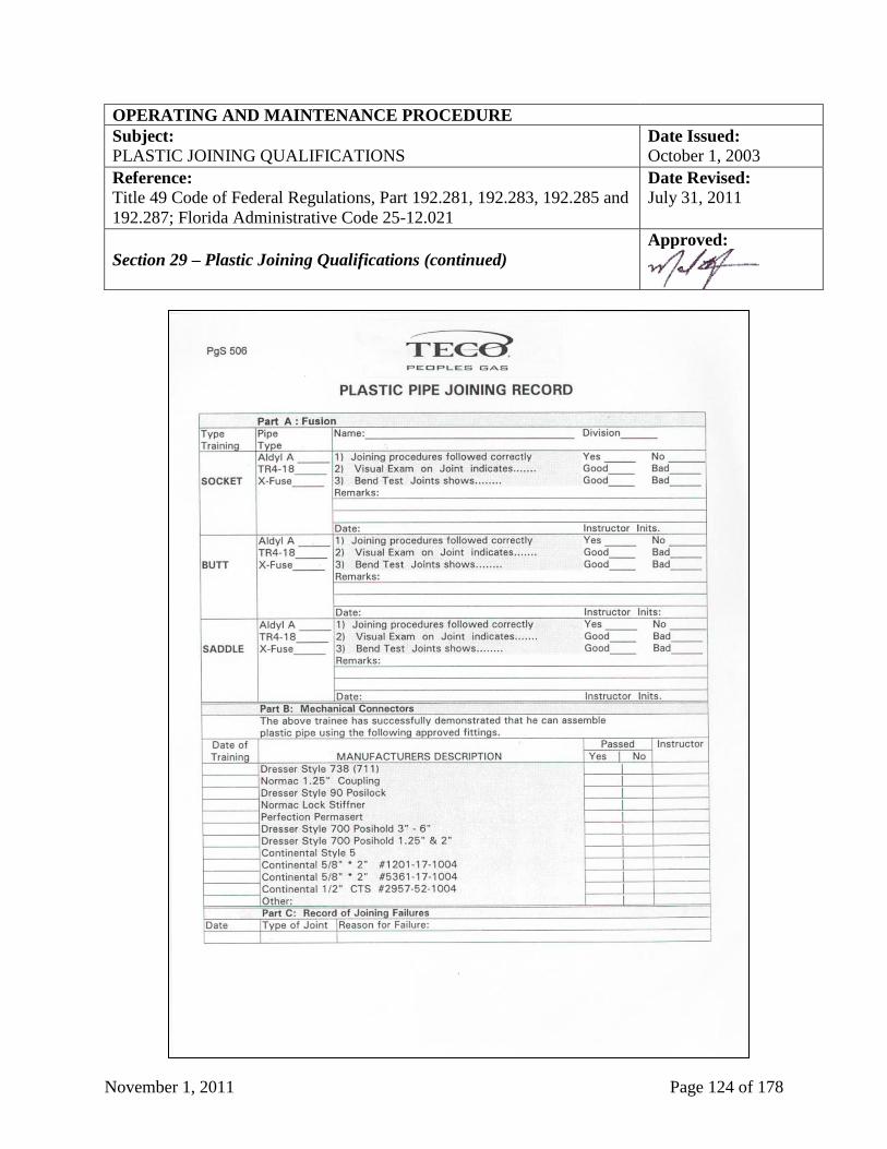
November 1, 2011 Page 124 of 178
OPERATING AND MAINTENANCE PROCEDURE
Subject: Date Issued:
PLASTIC JOINING QUALIFICATIONS October 1, 2003
Reference:
Title 49 Code of Federal Regulations, Part 192.281, 192.283, 192.285 and
192.287; Florida Administrative Code 25-12.021
Date Revised:
July 31, 2011
Section 29 – Plastic Joining Qualifications (continued)
Approved:
November 1, 2011 Page 125 of 178
OPERATING AND MAINTENANCE PROCEDURE
Subject: Date Issued:
STEEL WELDING QUALIFICATIONS October 1, 2003
Reference:
Title 49 Code of Federal Regulations, Part 192 Subpart E; Florida
Administrative Code 25-12.027
Date Revised:
July 31, 2011
Section 30 – Steel Welding Qualifications
Approved:
Section 30.1 - General
Qualified-welding procedures shall be used for welding on natural gas facilities. Personnel
welding on steel pipe shall be trained in the qualified procedures and shall complete the
prescribed tests. Records of the training and qualification tests shall be maintained.
The two welding processes used in normal gas work are oxygen-acetylene, and shielded metal
arc. The processes are further divided into welding procedures based on outside diameter, wall
thickness, specification and grade of pipe, type or filler material, variables in the welding
equipment, position of the pipe and position of the weld.
Section 30.2 - Joining of Steel Pipe by Welding
Welding is the preferred method of joining steel pipe and/or fittings. All welding must be
performed in accordance with established, written procedures approved by the Division
Manager. No change shall be made in the welding procedures or welding specifications without
approval from the Division Manager. Welders who are qualified in accordance with written
procedures must perform all welding. Each welding procedure (rod type, machine setting and
other factors influencing the weld) used in the installation of gas facilities must be qualified to
produce welds meeting the requirements of these procedures. The quality of the test weld used
to qualify the procedure must be determined by destructive testing. Each welding procedure
must be recorded in detail including the results of the qualifying weld tests. The record must be
retained and followed whenever the procedure is used.
Once qualified, a procedure must not be changed without qualification of the new procedure. A
change may be made from one pre-qualified procedure to another at any time. All welders must
be qualified before they can be permitted to weld on any of the TECO Peoples Gas facilities.
Each welder must be qualified in accordance with Appendix C of TECO Peoples Gas’
Construction Standards.
All welder qualification tests and re-qualification tests, whether successful or not, shall be
recorded on the weld test report form. The Division Manager shall retain one copy of this report.
Any welder who successfully passes the qualification test shall be given the qualification papers
appropriate to the method under which he qualified. No welder whose qualification is based on
nondestructive testing may weld compressor station pipe and components.
(continued on next page)
November 1, 2011 Page 126 of 178
OPERATING AND MAINTENANCE PROCEDURE
Subject: Date Issued:
STEEL WELDING QUALIFICATIONS October 1, 2003
Reference:
Title 49 Code of Federal Regulations, Part 192 Subpart E; Florida
Administrative Code 25-12.027
Date Revised:
July 31, 2011
Section 30 – Steel Welding Qualifications (continued)
Approved:
A qualified welder may weld on TECO Peoples Gas facilities using any welding procedure for
which he has qualified, unless he is found to be unable to make satisfactory production welds.
After the initial qualification in a welding process, the individual must engage in that welding
process and have one (1) production weld tested and found acceptable within the preceding six
(6) months and two (2) production welds each year. All tests must be in accordance with the
qualifying test or the welder must re-qualify.
Special attention should be given to unequal internal diameters. If the internal offset is less than
three thirty-seconds (3/32”) inch, special treatment is not necessary. If it is more than three
thirty-seconds (3/32”) inch then a transition piece of intermediate wall thickness should be
welded between the unequal diameters or pipe end preparation performed in accordance with
Appendix C of TECO Peoples Gas’ Construction Standards.
The welding operation must be protected from weather conditions that would impair the quality
of the completed weld. Before beginning any welding, the welding surfaces must be clean and
free of any material that may be detrimental to the weld. When position welds are to be made, a
sufficient area around the weld shall be cleared to permit the welder complete access. The ends
to be joined must be aligned to provide the most favorable condition for the deposit of the root
bead. The alignment must be preserved while the root bead is being deposited.
The Division Manager or designate shall review and sign all employees’ form PgS 424, “Welder
Qualification Test Inspectors Record” (see sample below at Section 30, Page 128 and 129), of
acceptable test welds. The qualified person shall verify that a welder has engaged in that
welding process and has had one production weld tested and found acceptable within the
preceding six (6) months and two (2) production welds each year by completing the above
referenced form. If a welder has not engaged in a given welding process and had production
welds tested and found acceptable within the previous calendar six months, or if there is reason
to question his welding ability, he shall re-qualify by making the acceptable series of test welds
for the process(es).
Section 30.3 - Contractor’s Welders Contractor’s welders shall pass the same qualified tests as TECO Peoples Gas employees. If
additional welding procedures are developed for an individual project, the contractor's welders
shall qualify using these procedures. The Division Manager is responsible for keeping the
necessary records documenting the qualification and maintenance of qualification records for
contractor’s welders.
November 1, 2011 Page 127 of 178
OPERATING AND MAINTENANCE PROCEDURE
Subject: Date Issued:
STEEL WELDING QUALIFICATIONS October 1, 2003
Reference:
Title 49 Code of Federal Regulations, Part 192 Subpart E; Florida
Administrative Code 25-12.027
Date Revised:
July 31, 2011
Section 30 – Steel Welding Qualifications (continued)
Approved:
Section 30.4 - Reports and Records
The form PgS 424, “Welder Qualification Test Inspectors Record” (see sample below at Section
30, Page 128 and 129) must be completed by the Division Manager (or designee) to document
the qualification and maintenance of qualification of each welder.
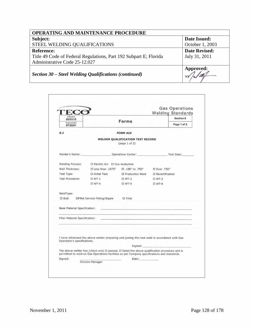
November 1, 2011 Page 128 of 178
OPERATING AND MAINTENANCE PROCEDURE
Subject: Date Issued:
STEEL WELDING QUALIFICATIONS October 1, 2003
Reference:
Title 49 Code of Federal Regulations, Part 192 Subpart E; Florida
Administrative Code 25-12.027
Date Revised:
July 31, 2011
Section 30 – Steel Welding Qualifications (continued)
Approved:
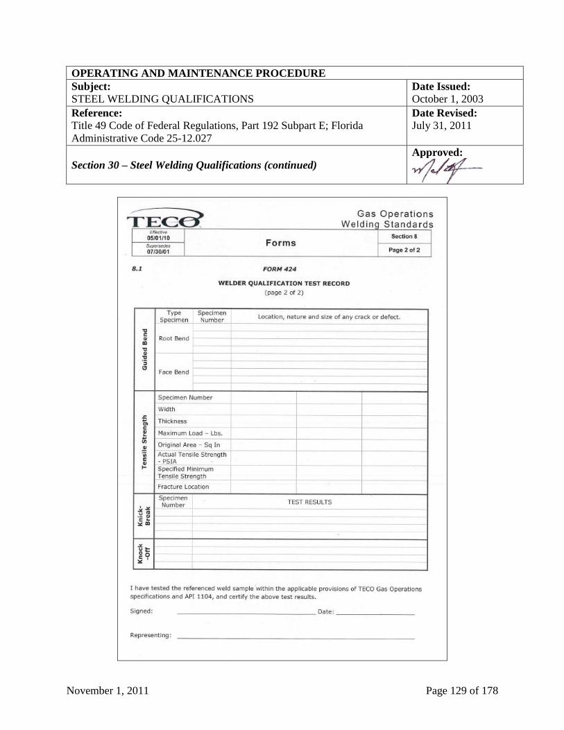
November 1, 2011 Page 129 of 178
OPERATING AND MAINTENANCE PROCEDURE
Subject: Date Issued:
STEEL WELDING QUALIFICATIONS October 1, 2003
Reference:
Title 49 Code of Federal Regulations, Part 192 Subpart E; Florida
Administrative Code 25-12.027
Date Revised:
July 31, 2011
Section 30 – Steel Welding Qualifications (continued)
Approved:
November 1, 2011 Page 130 of 178
OPERATING AND MAINTENANCE PROCEDURE
Subject: Date Issued:
INSPECTION OF COMBUSTIBLE GAS INDICATORS October 1, 2003
Reference:
None Date Revised:
November 1, 2011
Section 31 – Inspection of Combustible Gas Indicators
Approved:
Section 31.1 - General
All combustible gas indicators (CGI) shall be inspected at the specified intervals, and at any
other time there is reason to believe that a CGI is not operating properly, the CGI shall not be
used until it has been inspected, calibrated, and repaired if necessary.
Section 31.2 - Daily Inspection
Prior to the first use of the CGI each day, the following inspections shall be made:
For a manual pump instrument:
1. Visually inspect the CGI with emphasis on the aspirator bulb, sample line, and probe.
Look for cracks or leaks that would dilute the sample.
2. Adjust voltage to proper level. If the voltage cannot be adjusted to proper level, replace
the batteries.
3. Zero the LEL and percent gas ranges.
4. Verify instrument detects natural gas in the LEL and percent range before use.
For an electronic type instrument:
1. Push the POWER button to initiate operation. Watch display screen for any information
unit displays such as CAL DUE, if unit is not within calibration dates recalibrate before
use.
2. If the display fails to illuminate or “BAT LOW” is shown on the display, replace the
batteries.
3. Prior to use, test the integrity of the sensor cap and tubing. Use your finger to block the
inlet of the sensor cap for 4-5 seconds. The display will read “FLOW BLOCKED” if all
seals are intact. If this does not occur change the sensor cap and “O” rings. During pump
flow block, a beep will occur every 2 seconds until the pump restarts and adequate flow
is present.
(continued on next page)
November 1, 2011 Page 131 of 178
OPERATING AND MAINTENANCE PROCEDURE
Subject: Date Issued:
INSPECTION OF COMBUSTIBLE GAS INDICATORS October 1, 2003
Reference:
None Date Revised:
November 1, 2011
Section 31 – Inspection of Combustible Gas Indicators (continued)
Approved:
4. The display will indicate LEL readings (when so equipped) by displaying an “L” next to
the percent symbol. All LEL readings have a resolution of 0.1% LEL.
5. Verify instrument detects natural gas in the LEL and percent range before use.
6. When used for leak survey, verify instrument detects natural gas at the 50 ppm range
Section 31.3 - Monthly Inspections
The outlined inspection of each CGI shall be made and recorded each month. The employee to
whom the CGI is assigned shall make the inspection.
For a manual pump instrument:
1. Visually inspect the CGI with emphasis on the aspirator bulb, sample line, and probe.
Look for cracks and leaks that would dilute the sample. Check batteries for signs of
leakage and swelling. Check the accessories required for proper operation. Inspect
filters and replace if dirty.
2. Adjust voltage to proper level. If the voltage cannot be adjusted to proper level, replace
batteries.
3. Zero the LEL and percent gas ranges.
4. Calibrate the CGI on both the LEL scale and the percent gas scale.
5. Record the inspection on the form, “Inspection Record Combustible Gas Indicator” (see
sample below at Section 31, Page 134), and verify with signature.
For an electronic type instrument:
1. Push the POWER button to initiate operation. Watch display screen for any information
unit displays such as CAL DUE, if unit is not within calibration dates recalibrate before
use.
(continued on next page)
November 1, 2011 Page 132 of 178
OPERATING AND MAINTENANCE PROCEDURE
Subject: Date Issued:
INSPECTION OF COMBUSTIBLE GAS INDICATORS October 1, 2003
Reference:
None Date Revised:
November 1, 2011
Section 31 – Inspection of Combustible Gas Indicators (continued)
Approved:
2. If the display fails to illuminate or “BAT LOW” is shown on the display, replace the
batteries.
3. Prior to use, test the integrity of the sensor cap and tubing. Use your finger to block the
inlet of the sensor cap for 4-5 seconds. The display will read “FLOW BLOCKED” if all
seals are intact. If this does not occur change the sensor cap and “O” rings. During pump
flow block, a beep will occur every 2 seconds until the pump restarts and adequate flow
is present.
4. The display will indicate LEL readings (when so equipped) by displaying an “L” next to
the percent symbol. All LEL readings have a resolution of 0.1% LEL.
5. Verify instrument detects natural gas in the LEL and percent range before use.
6. When used for leak survey, verify instrument detects natural gas at the 50 ppm range.
The inspection record shall be for a calendar year and retained for one additional year.
Section 31.4 - Leak Test
This leak test will indicate a leak in the hoses and internal piping in the combustible gas indicator
(CGI). Cover the inlet with finger or thumb and flatten bulb with two (2) or three (3) squeezes.
Keeping the inlet covered, cover the bulb outlet check valve with thumb and release bulb. The
bulb should not fully inflate for thirty (30) seconds.
Section 31.5 - Calibration Tests
CGI's shall be calibrated on the LEL and 100% scale with a calibration kit. The percent
methane-in-air mixture is shown on the label of the individual gas sample tanks. Set the
instrument on the LEL scale and draw a sample into the instrument from the LEL sample tank.
The reading should be between the high and low limits as recommended by the manufacturer.
Set the instrument on the percent gas scale and draw a sample into the instrument from the 100%
sample tank. The instrument should register 100%.
November 1, 2011 Page 133 of 178
OPERATING AND MAINTENANCE PROCEDURE
Subject: Date Issued:
INSPECTION OF COMBUSTIBLE GAS INDICATORS October 1, 2003
Reference:
None Date Revised:
November 1, 2011
Section 31 – Inspection of Combustible Gas Indicators (continued)
Approved:
Section 31.6 - Repairs
Local personnel shall replace batteries, accessories, and filters on a need basis, and may replace
filaments and ballast lamps. Instruments requiring more extensive repairs shall be forwarded to
the manufacturer or a qualified service contractor.
Section 31.7 - Reports and Records
The form, “Inspection Record Combustible Gas Indicator” (see sample below at Section 31,
Page 134) must be completed by the Division Manager to document the inspection and repair of
combustible gas indicators.
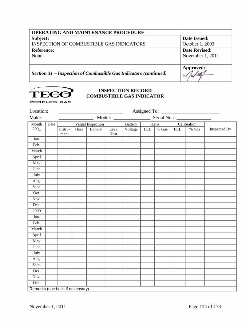
November 1, 2011 Page 134 of 178
OPERATING AND MAINTENANCE PROCEDURE
Subject: Date Issued:
INSPECTION OF COMBUSTIBLE GAS INDICATORS October 1, 2003
Reference:
None Date Revised:
November 1, 2011
Section 31 – Inspection of Combustible Gas Indicators (continued)
Approved:
INSPECTION RECORD
COMBUSTIBLE GAS INDICATOR
Location: __________________________ Assigned To: ________________________
Make: ______________ Model: _______________ Serial No.: ______________
Month
200_
Date Visual Inspection Battery Zero Calibration
Inspected By Instru-
ment
Hose Battery Leak
Test
Voltage LEL % Gas LEL % Gas
Jan. Feb.
March April May June July Aug. Sept. Oct. Nov. Dec. 2000 Jan. Feb.
March April May June July Aug. Sept. Oct. Nov. Dec.
Remarks (use back if necessary)
November 1, 2011 Page 135 of 178
OPERATING AND MAINTENANCE PROCEDURE
Subject: Date Issued:
EMERGENCY RESPONSE October 1, 2003
Reference:
Title 49 Code of Federal Regulations, Part 192.605; Florida
Administrative Code 25-7.018, 25-12.041, 25-12.084
Date Revised:
September 10, 2007
Section 32 – Emergency Response
Approved:
Section 32.1 - General Requirements for System-Wide Emergency Plans
Emergency plans shall be kept in the form of an Emergency Procedure Manual. These plans
shall include emergency plans for each of the following general items:
1. Fires and explosions.
2. System failures.
3. Load curtailments/interruption of gas supply.
4. Natural disasters (i.e. hurricanes, tornadoes and flooding).
5. Civil disturbances.
6. National emergencies.
7. Reporting to the US Department of Transportation (USDOT), PHMSA - the Pipeline and
Hazardous Materials Safety Administration, Washington, DC.
8. Reporting to the Florida Public Service Commission.
Section 32.2 - General Requirements of Each Division's Emergency Plans
Each Operating Center/Region Emergency Procedure Manual should include the following
information:
1. An emergency organization chart and chain of command to report and to supervise
emergency situations.
2. A list of company personnel (including addresses and telephone numbers) who will be
contacted as the emergency might dictate.
3. After-hours emergency response.
(continued on next page)
November 1, 2011 Page 136 of 178
4. A list of public officials (including title, address and telephone number) who may be
contacted during the various types of emergency situations.
5. A list of sources of supplies (i.e., hardware stores, lumber yards) that might be used in case
of an emergency situation.
6. A list of emergency supplies and equipment to be kept in the Division.
7. A list of contractors.
8. A list of other utility companies in the area.
9. A list of local radio and television stations and newspapers, with the list including main
news telephone numbers and after-hours emergency new telephone numbers.
10. A list of restaurants and catering services.
11. A list of lodging accommodations and emergency shelters.
12. A list of hospitals, rest homes and other key locations that would be given preferential
service.
13. A list of interruptible rate customers and other large volume customers.
14. System map(s) showing isolation sections and emergency valve locations required to
implement the isolation of each selected section.
This information shall be reviewed annually by the location and revised as necessary.
TECO Peoples Gas personnel shall be acquainted with that portion of the emergency plan that
applies to their duties and responsibilities and shall be informed of changes and additions to the
emergency plan as they occur.
A liaison in each Region shall be maintained with appropriate local public officials with respect
to the emergency plan.
OPERATING AND MAINTENANCE PROCEDURE
Subject: Date Issued:
EMERGENCY RESPONSE October 1, 2003
Reference:
Title 49 Code of Federal Regulations, Part 192.605; Florida
Administrative Code 25-7.018, 25-.041, 25-12.084
Date Revised:
September 10, 2007
Section 32 – Emergency Response (continued)
Approved:
November 1, 2011 Page 137 of 178
OPERATING AND MAINTENANCE PROCEDURE
Subject: Date Issued:
MAPS & RECORDS October 1, 2003
Reference:
Title 49 Code of Federal Regulations, Florida Administrative Code 25-
12.060 and 25-12.061
Date Revised:
September 10, 2007
Section 33 – Maps & Records
Approved:
Section 33.1 System Maps
System maps of each Local Operating Center’s distribution area shall be maintained on file in
each facility. Such maps and/or related records shall readily identify the location and size of the
system’s facilities and include other information pertinent to the safe design, operation, and
maintenance of the system.
Section 33.2 Records
All tabulations, standards, drawings, and other records or documentation of incidents, procedures
or studies related to or arising from compliance with this manual shall be retained by the Local
Operating Center/Region and shall be available for review by the Regulatory personnel.
Section 33.3 Retention of Records and Responsibility
1. Records pertaining to the system design and/or records necessary for the future evaluation of
the system’s safety shall be retained for the life of the facility (L.O.F.) involved.
2. Records not included in item 1 above, which are periodically superseded, by updated or
revised records shall be retained for the two (2) most recent inspections or surveys.
3. Records not included in items 1 or 2 above shall be retained for as long as they are in current
use or until superseded by updated or revised documents.
It shall be the responsibility of the Division Manager or his designated representative to ensure
compliance with the provisions of this manual.
November 1, 2011 Page 138 of 178
OPERATING AND MAINTENANCE PROCEDURE
Subject: Date Issued:
CRITERIA FOR CORROSION REPAIRS ON DISTRIBUTION
PIPELINES
October 1, 2003
Reference:
Title 49 Code of Federal Regulations, Part 192.487 and 192.489 Date Revised:
September 10, 2007
Section 34 – Criteria for Corrosion Repairs on Distribution Pipelines
Approved:
Section 34.1 – Criteria for Repairs on Cast Iron Pipelines
1. General Graphitization: Each segment of cast iron or ductile iron pipe on which general
graphitization is found to a degree where a fracture or any leakage might result must be
replaced.
2. Localized Graphitization: Each segment of cast iron or ductile iron pipe on which localized
graphitization is found to a degree where any leakage might result, must be replaced or
repaired, or sealed by internal sealing methods adequate to prevent or arrest any leakage.
Section 34.2 – Criteria for Repairs on Lines Other Than Cast Iron. or Ductile 1. General Corrosion: Except for cast iron or ductile iron pipe, each segment of generally
corroded gas distribution line pipe with a remaining wall thickness less than that required for
the maximum allowable operating pressure of the pipeline, or a remaining wall thickness less
than thirty (30%) percent of the nominal wall thickness, must be replaced. However, if the
area of general corrosion is small, the corroded pipe may be repaired. Corrosion pitting so
closely grouped as to affect the overall strength of the pipe is considered general corrosion
for the purposes of this paragraph.
2. Localized Corrosion Pitting: Except for cast iron or ductile iron pipe, each segment of gas
distribution line pipe with localized corrosion pitting to a degree where leakage might result
must be replaced or repaired.
November 1, 2011 Page 139 of 178
OPERATING AND MAINTENANCE PROCEDURE
Subject: Date Issued:
PROTECTING CAST IRON PIPELINES - EXCAVATION &
UNDERMINING
October 1, 2003
Reference:
Title 49 Code of Federal Regulations, Part 192.755
Date Revised:
September 10, 2007
Section 35 – Protecting Cast Iron Pipelines – Excavation &
Undermining
Approved:
Section 35.1 – Protecting Cast Iron Pipelines
Additional care shall be used when excavating around cast iron with mechanical equipment. The
main should be exposed (undermined) as little as possible and only as needed to perform the
work. When a section of a buried cast iron pipeline is disturbed, that segment, where necessary,
must be protected against vibration, damage from heavy construction equipment, from trains,
from trucks, from buses, or from blasting as well as impact forces by vehicles or earth
movement.
Section 35.2 – Excavation and Undermining
Protection from damage which could occur during apparent future excavations near the pipeline
or other foreseeable outside forces which might subject that segment of the pipeline to bending
stress is required.
November 1, 2011 Page 140 of 178
OPERATING AND MAINTENANCE PROCEDURE
Subject: Date Issued:
CAULKED BELL AND SPIGOT JOINTS October 1, 2003
Reference:
Title 49 Code of Federal Regulations, Part 192.753
Date Revised:
September 10, 2007
Section 36 – Caulked Bell and Spigot Joints
Approved:
Section 36.1 – Caulked Bell and Spigot Joints at Pressures Greater Than 25 PSIG
Each standard cast iron caulked bell and spigot joint that is subject to a pressure greater than
twenty-five (25) psig, must be sealed with a mechanical leak clamp or a material or device which
does not reduce the flexibility of the joint; permanently bonds either chemically or mechanically,
or both with the bell and spigot metal surfaces; and, seals and bonds in a manner that meets the
strength, environmental, and chemical compatibility requirements of Section 1.1.1, Materials -
General, of TECO Peoples Gas’ Construction Standards.
Section 36.2 – Caulked Bell and Spigot Joints at Pressures of 25 PSIG or Less
Any unclamped standard cast iron bell and spigot joints subject to pressures of twenty-five (25)
psig or less that are exposed for any reason, regardless of operating pressures, are to be sealed by
a means other than by caulking.
November 1, 2011 Page 141 of 178
OPERATING AND MAINTENANCE PROCEDURE
Subject: TURN ON, TERMINATION/INTERRUPTION Date Issued:
& DISCONTINUANCE OF SERVICE October 1, 2003
Reference:
Title 49 Code of Federal Regulations Part 192.727 & 192.16;, Florida
Administrative Code Chapters 25-7.089, 25-12.043, 25-12.044 and 25-
12.045
Date Revised:
July 31, 2011
Section 37 – Turn On, Termination/Interruption & Discontinuance of
Service
Approved:
Section 37.1 – Initiation / Turn-On of Service
Service shall be initiated only by authorized personnel knowledgeable in the turn-on procedures
of the TECO Peoples Gas.
Gas service may be declined to a customer or any customer equipment until the customer
complies with all applicable gas codes that have been adopted by the local authority having
jurisdiction.
Service shall not be established to any customer until it has been determined that a constant
pressure can be contained by the piping (see Job Procedures No. 01-001, Turn-On).
Section 37.2 – Termination / Interruption of Service
The procedures outlined below should be followed each time a service is turned off, or when
TECO Peoples Gas becomes aware that the gas to a customer has been interrupted, whether
intentionally or unintentionally:
1. Where applicable, verify the meter number on the meter with the meter number on the
service order.
2. If the meter is left on the service line riser at the time of termination/interruption, the service
line riser valve is to be turned off. A blind or slug is to be installed in the meter swivel, or in
a union, or other fittings, on the outlet side of the service line riser valve. The service line
riser valve is to be locked in the closed position and an "Out of Service" tag (see sample
below at Section 38, Page 147) is to be installed.
3. If the meter is left on the service line riser at the time of an interruption, the service line riser
valve is to be turned off and locked in the closed position.
4. If the meter is removed from the service line at the time of termination/interruption, the
service line riser valve is to be locked and tagged with an "Out of Service" tag (see sample
below at Section 38, Page 147) and the service line and the customer's house line shall be
plugged or capped. The regulator(s) should be removed, if any are installed.
(continued on next page)
November 1, 2011 Page 142 of 178
OPERATING AND MAINTENANCE PROCEDURE
Subject: TURN ON, TERMINATION/INTERRUPTION Date Issued:
& DISCONTINUANCE OF SERVICE October 1, 2003
Reference:
Title 49 Code of Federal Regulations Part 192.727 & 192.16;, Florida
Administrative Code Chapters 25-7.089, 25-12.043, 25-12.044 and 25-
12.045
Date Revised:
July 31, 2011
Section 37 – Turn On, Termination/Interruption & Discontinuance of
Service (continued)
Approved:
5. If there is no meter on the service line, such as a service line downstream of a master meter
installation, the valve is to be locked in the closed position, an "Out of Service" tag (see
sample below at Section 38, Page 147) is to be installed and a blind inserted in a union, or
other fittings on the outlet side of service line valve. The regulator(s) should be removed, if
any are installed.
The exception to the procedure above could be when company representatives normally
performing meter reading terminate service for non-payment, or for another similar reason. In
this situation, the service line riser valve would be locked and tagged with an "Out of Service"
tag (see sample below at Section 38, Page 147), but the blind may not be installed. The company
representative will then report their actions taken to the Utility Coordinator so that a Utility Tech
can be sent to install a blind at the earliest practical opportunity.
Section 37.3.1 – Discontinuance of Service Due to Inactivity
The following actions shall be taken for inactive service lines that have been used, but have
become inactive without reuse:
1. If there is no prospect for reuse, the service line shall be retired and physically abandoned
within three (3) months.
2. Except as noted below*, after a service line has been inactive for a period of twenty-four (24)
months and there is a prospect for reuse of the line, one of the following actions shall be
taken within six (6) months:
a. Disconnect the service line from all sources of gas and abandon or remove.
b. A valve on the service line shall be locked in the closed position and the service line
plugged to prevent the flow of gas.
c. Remove the meter and plug the end of the service line to prevent the flow of gas.
3. Except as noted below*, after sixty (60) months of inactivity, service lines shall be retired
and physically abandoned within six (6) months.
(continued on next page)
November 1, 2011 Page 143 of 178
OPERATING AND MAINTENANCE PROCEDURE
Subject: TURN ON, TERMINATION/INTERRUPTION Date Issued:
& DISCONTINUANCE OF SERVICE October 1, 2003
Reference:
Title 49 Code of Federal Regulations Part 192.727 & 192.16; Florida
Administrative Code Chapters 25-7.089, 25-12.043, 25-12.044 and 25-
12.045
Date Revised:
July 31, 2011
Section 37 – Turn On, Termination/Interruption & Discontinuance of
Service (continued)
Approved:
* See Section 37.3.2, “Temporary Waiver Of Service Line Retirement Requirements Until
December 2009” for alternate requirements. The requirement to comply with item 1., above,
remains unchanged.
One of the following actions must be taken to abandon a service line:
1. Disconnect the service line from all sources of gas at the nearest point to the main where
cutting of pavement is permitted.
2. Where cutting of pavement is not permitted, the service line shall be disconnected at the
nearest point, not under a paved surface.
NOTE: The stub of the service line shall be disconnected closer to the main or at the main, if at
some later date it becomes accessible during normal operations.
Records of the size, material and location of remaining service stubs shall be kept. These records
must be readily available to personnel assigned to pipeline locating activities. It shall be the
responsibility of the Division Manager to initiate the review of the necessary records to ensure
compliance with the procedure outlined in this Section 37.3.1, “Discontinuance of Service Due
to Inactivity”.
Section 37.3.2- Temporary Waiver of Service Line Retirement Requirements
Effective on June 8, 2007, the Florida Public Service Commission granted members of the
Florida Natural Gas Association a temporary waiver of the requirements of Florida
Administrative Code (FAC), Chapter 25.12.045, items (1)(b) and (1)(c) for a two (2) year period.
The waiver is subject to the terms, conditions, and requirements outlined below.
1. The two (2) year waiver of action is available for gas services under the following scenarios:
a. Any service line that reached two (2) years of inactivity after December 31, 2006 is
exempt from the requirements of Section 37.3.1, “Discontinuance of Service Due To
Inactivity”, item 2., above.
(continued on next page)
November 1, 2011 Page 144 of 178
OPERATING AND MAINTENANCE PROCEDURE
Subject: TURN ON, TERMINATION/INTERRUPTION Date Issued:
& DISCONTINUANCE OF SERVICE October 1, 2003
Reference:
Title 49 Code of Federal Regulations Part 192.727 & 192.16; Florida
Administrative Code Chapters 25-7.089, 25-12.043, 25-12.044 and 25-
12.045
Date Revised:
July 31, 2011
Section 37 – Turn On, Termination/Interruption & Discontinuance of
Service (continued)
Approved:
i. Services reaching two (2) years of inactivity prior to December 31, 2006 are not
eligible for the temporary waiver, and must be acted upon in compliance with the
requirements of Section 37.3.1, “Discontinuance of Service Due To Inactivity”, item
2., above.
b. Any service line that reached five (5) years of inactivity after December 31, 2006 is
exempt from the requirements of Section 37.3.1, “Discontinuance of Service Due To
Inactivity”, item 3., above.
i. Services reaching five (5) years of inactivity prior to December 31, 2006 are not
eligible for the temporary waiver, and must be acted upon in compliance with the
requirements of Section 37.3.1, “Discontinuance of Service Due To Inactivity”, item
3., above.
2. In the event that the waiver is withdrawn after the two (2) year period, TECO Peoples Gas
will have until December 31, 2011 to become compliant with the requirements of Sections
37.3.1, “Discontinuance of Service Due To Inactivity”, items 2. and 3., above.
3. The temporary waiver of action does not affect any actions required by Section 37.2,
“Termination / Interruption of Service”, or any other sections of this manual.
5. TECO Peoples Gas shall continue to monitor abandoned service lines and maintain records
as identified in Section 37.3.1“.
Section 37.4 – Discontinuance of Gas Service Due to Hazardous Conditions
When TECO Peoples Gas personnel become aware of any hazardous condition relative to a
customer's piping, or appliances, one (1) of the following actions shall be taken:
1. Discontinue service to the hazardous piping or appliance(s).
2. Discontinue service to the customer and take action as outlined above at Section 37.2,
“Termination/Interruption of Service”, of this manual.
(continued on next page)
November 1, 2011 Page 145 of 178
OPERATING AND MAINTENANCE PROCEDURE
Subject: TURN ON, TERMINATION/INTERRUPTION Date Issued:
& DISCONTINUANCE OF SERVICE October 1, 2003
Reference:
Title 49 Code of Federal Regulations Part 192.727 & 192.16; Florida
Administrative Code Chapters 25-7.089, 25-12.043, 25-12.044 and 25-
12.045
Date Revised:
July 31, 2011
Section 37 – Turn On, Termination/Interruption & Discontinuance of
Service (continued)
Approved:
Service shall not be reinstated until the defect or deficiency is corrected and the provisions are
met in compliance with the requirements at Section 37.1, “Initiation / Turn-On of Service”,
above.
Section 37.5 – Notification of New Customers
This section applies to new customers that have buried piping on their property which is not
owned, monitored, nor maintained by TECO Peoples Gas. TECO Peoples Gas is required to
notify such customers, within ninety (90) days of initiating service, of the following:
1. TECO Peoples Gas does not own, monitor, nor maintain the customer’s buried piping.
2. If the customer's buried piping is not maintained, it may be subject to the potential hazards of
corrosion and leakage.
3. Buried gas piping should be: (i) Periodically inspected for leaks; (ii) Periodically inspected
for corrosion if the piping is metallic; and (iii) Repaired if any unsafe condition is discovered.
4. When excavating near buried gas piping, the piping should be located in advance, and the
excavation done by hand.
5. Service providers, including plumbing, heating and air conditioning contractors can assist the
customer in locating, inspecting, and repairing the customer's buried piping.
TECO Peoples Gas initially notified each customer via mail prior to the required notification
date of August 14, 1996. TECO Peoples Gas currently provides the customer the above required
information in writing in two forms:
1. The “At Your Service” booklet which contains the above buried piping information and is
provided to customers at the time of initiation of new gas service (see Job Procedures No. 01-
001, Turn-On).
2. A printed section, “Buried Piping Notification” appears on the back of all TECO Peoples
Gas’ monthly natural gas bills.
November 1, 2011 Page 146 of 178
OPERATING AND MAINTENANCE PROCEDURE
Subject: INVESTIGATION OF UNAUTHORIZED Date Issued:
UTILIZATION OF COMPANY FACILITIES October 1, 2003
Reference:
Florida Administrative Code Chapter 25-12.046
Date Revised:
July 31, 2011
Section 38 – Investigation of Unauthorized Utilization of Company
Facilities
Approved:
Section 38.1 – Unauthorized Meter Turn-On
All unauthorized meter turn-ons or restoration of gas service shall be investigated to determine
beyond a reasonable doubt, that a hazardous condition does not exist. The following steps shall
be taken:
1. Ascertain that appropriate tests and investigations have been made and that no leaks exist in
the piping system downstream of the meter set;
2. Determine that all connected gas appliances are operating satisfactorily, or are turned off;
3. If entry cannot be gained to the premises or a hazardous condition is found, the service line
riser valve controlling service to the premises shall be locked in the closed position and
tagged with an “Out of Service” tag (see sample below at Section 38, Page 147); and;
4. When an unauthorized establishment of gas service has occurred on a meter manifold or
common header, an immediate investigation shall be made to determine if adjacent facilities
have been tampered with or other unauthorized gas service has been established. All inactive
services shall be checked for compliance with the requirements above at Section 37.1,
Initiation / Turn-on of Service, or Section 37.2, “Termination / Interruption of Service”.
5. Any unauthorized operation of any other equipment on TECO Peoples Gas’ facilities shall be
immediately investigated to determine the effect upon the system. All prudent measures to
assure the safety of customers and the public shall be taken.
It shall be the responsibility of the Division Manager to initiate and maintain records of the
investigations and actions taken in compliance with this section.
November 1, 2011 Page 147 of 178
OPERATING AND MAINTENANCE PROCEDURE
Subject: INVESTIGATION OF UNAUTHORIZED Date Issued:
UTILIZATION OF COMPANY FACILITIES October 1, 2003
Reference:
Florida Administrative Code Chapter 25-12.046
Date Revised:
July 31, 2011
Section 38 – Investigation of Unauthorized Utilization of Company
Facilities (continued)
Approved:
November 1, 2011 Page 148 of 178
OPERATING AND MAINTENANCE PROCEDURE
Subject: Date Issued:
MEASUREMENT, CUSTOMER METERING, REGULATING
EQUIPMENT
October 1, 2003
Reference:
Florida Administrative Code Chapter 25-7.021, 25-7.049, 25-7.059
through 25-7.066, 25-7.070, 25-7.079-.080, and 25-7.084
Date Revised:
September 10, 2007
Section 39 – Measurement, Customer Metering, Regulating Equipment
Approved:
Section 39.0 - Measurement, Customer Metering and Regulating Equipment
Section 39.1 - Use of Meters and Regulators - General Requirements
1. All gas sold and used by TECO Peoples Gas shall be metered except in the case of an
emergency or when otherwise authorized by the Vice-President of Operations.
2. TECO Peoples Gas shall install, own, operate and maintain all equipment necessary for the
regulation and measurement of gas to its customers, except if additional meters and/or
regulators are furnished and installed for the convenience of the customer.
3. Pre-payment meters shall not be used to bill customers.
4. When there is more than one (1) meter at a common location, the meter installation shall be
tagged or permanently marked to indicate the facility being metered.
Section 39.2 - Location of Meters and Associated Appurtenances - General Requirements
1. Each customer shall furnish a convenient, accessible and safe place in which a meter(s) and
associated appurtenances can be installed, operated and maintained. This location, insofar as
practical, shall be outside the building and free of excessive temperature variations or other
causes that might affect meter operation or accuracy.
2. If changes in conditions on the customer's premises adversely affect the accessibility or
safety of a meter location, the customer shall be responsible for the cost of relocating the
meter, its appurtenances and related piping to a location meeting TECO Peoples Gas’
requirements.
3. Meters shall be electrically isolated from the house piping and protected from atmospheric
corrosion and other damage.
November 1, 2011 Page 149 of 178
OPERATING AND MAINTENANCE PROCEDURE
Subject: Date Issued:
MEASUREMENT, CUSTOMER METERING, REGULATING
EQUIPMENT
October 1, 2003
Reference:
Florida Administrative Code Chapter 25-7.021, 25-7.049, 25-7.059
through 25-7.066, 25-7.070, 25-7.079-.080, and 25-7.084
Date Revised:
September 10, 2007
Section 39 – Measurement, Customer Metering, Regulating Equipment
(continued)
Approved:
Section 39.3 - Periodic Meter Tests
Section 39.3.1 - Meter Test Frequency
1. Residential meters are tested according to a statistical sampling plan approved by the Florida
Public Service Commission. For residential diaphragm-type positive displacement meters
having a capacity of less than or equal to two hundred fifty (250) cfh @ one half inch (½”)
WC, the following process shall be implemented:
a. Annually, a sample of three hundred fifteen (315) of the above class residential meters
shall be tested.
b. Meters chosen for the sample shall have been in service for at least five (5) years, and:
i. Thirty percent (30%) shall be those with the longest time in service (oldest
installation dates).
ii. Thirty percent (30%) shall be those showing the highest amount of gas measured
(readings).
iii. Forty percent (40%) shall be random selections from the balance of meters in
service for at least five (5) years.
c. The maximum meter test failure rate for the sampled group shall be twenty-one (21)
meters.
i. If the sample meter test failure rate is twenty-two (22) or greater, corporate
Engineering Services shall isolate the error population based on an analysis of the
sample meter test failures.
ii. A new sample of the isolated error group consisting of at least fifty (50) meters will
be taken within six (6) months following identification. Corporate Engineering
Services will be responsible for analyzing the isolated error population and
developing routines and/or programs to assist in analysis.
(continued on next page)
November 1, 2011 Page 150 of 178
OPERATING AND MAINTENANCE PROCEDURE
Subject: Date Issued:
MEASUREMENT, CUSTOMER METERING, REGULATING
EQUIPMENT
October 1, 2003
Reference:
Florida Administrative Code Chapter 25-7.021, 25-7.049, 25-7.059
through 25-7.066, 25-7.070, 25-7.079-.080, and 25-7.084
Date Revised:
September 10, 2007
Section 39 – Measurement, Customer Metering, Regulating Equipment
(continued)
Approved:
2. All commercial diaphragm-type positive displacement meters having a capacity of less than
or equal to two hundred fifty (250) cfh @ one half inch (½”) WC shall be periodically
removed, inspected and tested at least once every one hundred twenty (120) months.
3. Commercial diaphragm-type positive displacement having a capacity greater than two
hundred fifty (250) cfh but less than or equal to two thousand five hundred (2,500) cfh @
one half inch (½”) WC shall be field or shop tested in accordance with the “American Gas
Association Gas Measurement Manual: Meter Proving, Part Number Twelve, 1984 Edition”,
at least once every one hundred twenty (120) months.
4. Meters having a capacity greater than two thousand five hundred (2,500) cfh @ one half
inch (½”) WC shall be field or shop tested in accordance with the American Gas
Association’s “Gas Measurement Manual: Meter Proving, Part Number Twelve, 1984
Edition”, at least once every sixty (60) months.
5. Instruments and Auxiliary Devices:
Any instruments and auxiliary devices when used in conjunction with any meter to correct
the metered volume for pressure or temperature shall be adjusted to an accuracy level to
assure that the combined accuracy of the instrument and auxiliary device, or both, and the
associated meter do not exceed one percent (1 %) error fast or two percent (2%) error slow.
To ensure and verify the performance of each instrument and auxiliary device, each
instrument and device shall be checked at the same test interval as prescribed for the
associated meter.
November 1, 2011 Page 151 of 178
OPERATING AND MAINTENANCE PROCEDURE
Subject: Date Issued:
MEASUREMENT, CUSTOMER METERING, REGULATING
EQUIPMENT
October 1, 2003
Reference:
Florida Administrative Code Chapter 25-7.021, 25-7.049, 25-7.059
through 25-7.066, 25-7.070, 25-7.079-.080, and 25-7.084
Date Revised:
September 10, 2007
Section 39 – Measurement, Customer Metering, Regulating Equipment
(continued)
Approved:
Section 39.3.2 - Field Testing
1. All side-connect meters of greater than two thousand five hundred (2,500) CFH shall be
equipped with test connections and a bypass, or bypass connections, in order to facilitate
field testing. Test connections on meters two thousand five hundred one (2,501) CFH up to
ten thousand (10,000) CFH shall have taps of at least one and seven-eights inches (1 7/8") in
diameter. Test connections on meters of capacity larger than ten thousand (10,000) CFH
shall have taps of at least three inches (3") or larger in diameter. Auto adjusting turbine
meters four inches (4") or larger do not require test connections.
2. Field testing of customers' meters shall be made by measurement personnel with a Field
Transfer Prover. Air is to be used for the test medium. After the meter has been by-passed, a
pressure test shall be made at normal operating pressure to ensure that the piping connections
and valves do not leak or pass gas.
3. Any Field Transfer Prover used shall be operated in accordance with the manufacturer's
recommendations.
4. Diaphragm meters with a test dial of five (5) cubic feet or less shall be tested at a flow rate of
one hundred percent (100%) of the rated capacity and also at twenty percent (20%) of the
rated capacity. All other meters shall be tested in accordance with manufacturers’
recommendations and the American Gas Association’s “Measurement Manual: Meter
Proving Part No. 12, 1978 edition”.
5. The meter test data shall be entered into the Computerized Meter History System.
November 1, 2011 Page 152 of 178
OPERATING AND MAINTENANCE PROCEDURE
Subject: Date Issued:
MEASUREMENT, CUSTOMER METERING, REGULATING
EQUIPMENT
October 1, 2003
Reference:
Florida Administrative Code Chapter 25-7.021, 25-7.049, 25-7.059
through 25-7.066, 25-7.070, 25-7.079-.080, and 25-7.084
Date Revised:
September 10, 2007
Section 39 – Measurement, Customer Metering, Regulating Equipment
(continued)
Approved:
Section 39.3.3 – Inspection
1. When a meter installation is visited for purposes of testing, all the related equipment, such as
pressure regulators, pressure relief valves, filters, valves, etc. shall be visually inspected. If
maintenance to valves, filters and accessory equipment is necessary, it shall either be
undertaken by operations personnel at that time, or a report shall be submitted to schedule
maintenance promptly. A soap test of exposed pipe and fittings affected by the work shall be
made to ensure no leakage.
2. A leak report, form PgS 24, “Gas Leak and Repair Form” (see sample above at Section 14,
Pages 57 and 58), shall be prepared on any leak and shall be submitted to the appropriate
department. If a hazardous leak is found that cannot be repaired by the personnel on site,
additional help shall be requested and the leak shall be repaired or regraded before leaving
the location.
Information should be entered on form PgS 640, “Large Volume Meter Installation
Maintenance Report” (see sample below at Section 39, Page 164), whenever maintenance is
undertaken.
Section 39.4 Meter Test by Request
1. At a customers' written request, the TECO Peoples Gas shall, without charge, test the
accuracy of the meter in use at the customer's premises if the meter has not been tested by the
Company or by the Florida Public Service Commission during the twelve (12) months prior
to the request.
2. If a customer requests a meter test more frequently than provided for in item 1 above, TECO
Peoples Gas may require a deposit to defray the cost of the test. The deposit shall not exceed
the amount stipulated in Florida Administrative Code Chapter 25-7.65 (2). If the algebraic
sum of the open and check error of the meter is found to be more than two percent (2 %) fast,
the deposit shall be refunded. If below this accuracy limit, the deposit may be retained as a
service charge.
(continued on next page)
November 1, 2011 Page 153 of 178
OPERATING AND MAINTENANCE PROCEDURE
Subject: Date Issued:
MEASUREMENT, CUSTOMER METERING, REGULATING
EQUIPMENT
October 1, 2003
Reference:
Florida Administrative Code Chapter 25-7.021, 25-7.049, 25-7.059
through 25-7.066, 25-7.070, 25-7.079-.080, and 25-7.084
Date Revised:
September 10, 2007
Section 39 – Measurement, Customer Metering, Regulating Equipment
(continued)
Approved:
3. A customer, or authorized representative, may request and witness the meter test. On
request, a written report may be given of the results of the meter test by TECO Peoples Gas.
4. At the request of a customer, arrangements shall be made for a meter test to be conducted by
an independent meter testing facility of the customer's choosing. The customer shall be
responsible for negotiating and paying the independent meter testing facility any fee charged
for the test. The independent meter testing facility shall, at a minimum, conform to the
requirements of the “American Gas Association Gas Measurement Manual: Meter Proving,
Part Number Twelve, 1984 edition”. The customer shall pay for all charges to TECO
Peoples Gas associated with a meter test by an independent meter testing facility. TECO
Peoples Gas shall provide a detailed breakdown of such costs and may require payment of
such costs prior to the actual meter test. If the meter is found to be running faster than the
established limits by (2) above, the costs shall be refunded. If the meter operates within the
allowable limits in (2) above, TECO Peoples Gas may retain the payment received as a
service charge. Where appropriate, the meter may be field tested by the independent meter
testing facility.
5. TECO Peoples Gas may, at its discretion, conduct its own test of the meter in conformance
with the testing standards established by these rules. In the event that separate tests of the
same meter conflict, the Florida Public Service Commission shall resolve the matter at the
request of TECO Peoples Gas or the customer.
Section 39.5 Meter Testing Procedures
Section 39.5.1 Meter Testing Equipment Requirements
1. TECO Peoples Gas shall own or have access to all testing equipment, including bell-type
meter prover(s) of not less than five (5) cubic feet capacity and/or other meter testing
device(s) approved by the Vice President, Operations. The equipment shall be maintained in
correct adjustment so that it is capable of determining the accuracy of service meters to
within one-half of one percent (0.5 %). The meter testing equipment shall be available for
inspection by the Florida Public Service Commission.
(continued on next page)
November 1, 2011 Page 154 of 178
OPERATING AND MAINTENANCE PROCEDURE
Subject: Date Issued:
MEASUREMENT, CUSTOMER METERING, REGULATING
EQUIPMENT
October 1, 2003
Reference:
Florida Administrative Code Chapter 25-7.021, 25-7.049, 25-7.059
through 25-7.066, 25-7.070, 25-7.079-.080, and 25-7.084
Date Revised:
September 10, 2007
Section 39 – Measurement, Customer Metering, Regulating Equipment
(continued)
Approved:
2. The accuracy of all meter testing equipment shall be established in accordance with the
procedures set forth in the “American Gas Association Measurement Manual: Meter Proving,
Part Number Twelve, 1984 edition”.
3. All alterations, accidents or repairs to meter testing equipment which might affect the
accuracy or operation of the equipment shall be promptly reported to corporate Engineering
Services. Corporate Engineering Services shall be responsible for reporting the details of the
accident or the repairs made, in writing, to the Florida Public Service Commission. This
report shall be submitted through and be approved by the Vice President, Operations.
4. Each meter testing device shall have the necessary accessories needed for accurate meter
testing and shall be stored so that it shall not be exposed to drafts or excessive temperature
variations.
Section 39.5.2 Meter Test Methods
1. General:
All meter tests shall be performed by trained personnel using approved methods and
equipment.
2. Diaphragm meters with a test dial of five (5) cubic feet or less:
The accuracy of customer service meters of this type shall be determined by passing air from
a standard bell-type meter prover or a calibrated test meter at a rate of flow designated herein
when the liquid in the prover tank, the test equipment, the atmosphere of the room and the
meter to be tested are for all practical purposes the same temperature. The amount of air
passed shall be sufficient to cause the meter test dial to make one (1) revolution. The meter
shall be tested at two (2) rates of flow:
a. An open run test which shall be at a rate of flow at one hundred percent (100 %) of rated
capacity.
(continued on next page)
November 1, 2011 Page 155 of 178
OPERATING AND MAINTENANCE PROCEDURE
Subject: Date Issued:
MEASUREMENT, CUSTOMER METERING, REGULATING
EQUIPMENT
October 1, 2003
Reference:
Florida Administrative Code Chapter 25-7.021, 25-7.049, 25-7.059
through 25-7.066, 25-7.070, 25-7.079-.080, and 25-7.084
Date Revised:
September 10, 2007
Section 39 – Measurement, Customer Metering, Regulating Equipment
(continued)
Approved:
b. A check rate test which shall be at a rate of flow approximately twenty percent (20 %) of
rated capacity.
The averages of the tests at the two (2) rates of flow shall agree within one percent (1 %),
and the average error of the meter shall be considered to be the algebraic sum of
twenty-five percent (25 %) of the average error indicated by the open run test and
seventy-five percent (75 %) of the average error indicated by the check rate test:
For example:
Open Rate of + 1.75 and Check Rate of +0.75:
(25 % x 1.75 = .4375) + (75 % x 0.75 = .5625) = 1.0 %
3. Other meters:
Provision shall be made by each Operating Center for testing other diaphragm-type meters
with a test dial of over five (5) cubic feet or other type meters such as turbine, rotary
displacement, and orifice meters in accordance with manufacturer's recommendations and the
“American Gas Association Gas Measurement Manual: Meter Proving, Part Number Twelve,
1984 edition”.
Section 39.5.3 - Meter Accuracy at Installation
1. A new meter shall not be more than plus or minus one percent (1 %) when installed at a
customer's premise. Manufacturer's test data may be used if there is no indication of damage
resulting from the shipping. If damage is apparent and in order for the manufacturers test
data to be used, a sample of not less than ten percent (10%) of the meters in the damaged
shipment shall be tested and found to be within accuracy limits. If any meter of this sample
is found not to be within accuracy limits, the entire shipment must be tested and where
necessary, the meters adjusted within accuracy limits.
(continued on next page)

November 1, 2011 Page 156 of 178
OPERATING AND MAINTENANCE PROCEDURE
Subject: Date Issued:
MEASUREMENT, CUSTOMER METERING, REGULATING
EQUIPMENT
October 1, 2003
Reference:
Florida Administrative Code Chapter 25-7.021, 25-7.049, 25-7.059
through 25-7.066, 25-7.070, 25-7.079-.080, and 25-7.084
Date Revised:
September 10, 2007
Section 39 – Measurement, Customer Metering, Regulating
Equipment (continued)
Approved:
2. Every meter removed from service when opened for repairs shall be adjusted to be not more
than plus or minus one percent (1%) before being reset; and, if not opened for repairs, any
meter may be reset without adjustment if found to be not to be more than plus or minus one
percent (1 %) in error provided that the meter is otherwise in good condition.
3. The difference of percent accuracy between the check rate and open rate of a repaired meter
of two hundred fifty (250) cfh or less capacity shall not exceed one percent (1 %) (see
previous section). A plus or minus one half of one percent (0.5%) difference is the desired
accuracy for a repaired meter. The meter error shall be determined by the algebraic formula
given above at Section 39.5.2. (1) “Meter Test Methods”.
4. No meter shall be installed unless it has been tested and found to be within the accuracy
limits prescribed above at Section 39.5.3.(1) “Meter Accuracy at Installation” and with a test
period no longer than twelve (12) months prior to the date of installation. Manufacturer test
data may be used to ensure they are within the accuracy limits.
Section 39.5.4 - Sealing Meters
1. All meters tested for installation shall be sealed at the time of the test by the person
performing the test. The seal shall be of a type that will ensure detection of tampering.
When a compression type lead seal or a snap tin-type seal is used, a sealing tool bearing
TECO Peoples Gas’ logo and location identification shall be used.
Section 39.5.5 - Large Volume Meter Inspection and Meter Number Change Program
The following procedures should be checked when conducting a Large Volume Meter Inspection
or when undertaking a Meter Number Change Program:
1. If the metering pressure is greater than seven inches water column (7" W.C.) and a correcting
device, (i.e. a Compensating Index, BPI, or electronic instrument), is not installed, the
pressure factor shall appear in the billing records.
(continued on next page)
November 1, 2011 Page 157 of 178
OPERATING AND MAINTENANCE PROCEDURE
Subject: Date Issued:
MEASUREMENT, CUSTOMER METERING, REGULATING
EQUIPMENT
October 1, 2003
Reference:
Florida Administrative Code Chapter 25-7.021, 25-7.049, 25-7.059
through 25-7.066, 25-7.070, 25-7.079-.080, and 25-7.084
Date Revised:
September 10, 2007
Section 39 – Measurement, Customer Metering, Regulating
Equipment (continued)
Approved:
2. If the metering pressure is greater than seven inches water column (7" W.C.), the regulator
shall be tagged indicating the required operating pressure. This includes installations with
Compensating Indexes as well as Standard Indexes.
3. If the Index does not read in CCF, the billing records shall indicate the proper multiplier, (i.e.
“10” for MCF, etc). See below at Section 39.7, “Units of Measure”.
4. If the meter has a Compensating Index, the metering pressure should agree with that shown
on the Index. If the index atmospheric and base pressure is different than billing atmospheric
and base pressure, the delivery pressure shall be adjusted.
In addition, a TECO Peoples Gas service order should be completed when the meter number is
changed indicating the following:
1. New meter number.
2. Old meter number.
3. New index reading.
4. Old index reading (same as new).
5. Pressure Factor, even though unchanged, if the metering pressure is greater than seven inches
water column (7" W.C.) and no correcting device (i.e. Compensating Index, BPI, etc.) is
installed.
6. Meter Index Multiplier, even though unchanged, if the index reads in other than CCF.
7. Type index in use (i.e. Standard, Compensating, BPI, electronic correction device, etc.).
November 1, 2011 Page 158 of 178
OPERATING AND MAINTENANCE PROCEDURE
Subject: Date Issued:
MEASUREMENT, CUSTOMER METERING, REGULATING
EQUIPMENT
October 1, 2003
Reference:
Florida Administrative Code Chapter 25-7.021, 25-7.049, 25-7.059
through 25-7.066, 25-7.070, 25-7.079-.080, and 25-7.084
Date Revised:
September 10, 2007
Section 39 – Measurement, Customer Metering, Regulating
Equipment (continued)
Approved:
Section 39.6 - Records of Meters and Meter Tests
Section 39.6.1 - Requirements
1. TECO Peoples Gas shall maintain a permanent meter record for each meter which TECO
Peoples Gas owns or uses for any purpose. This meter record shall include the following:
a. Date of purchase.
b. Identification number.
c. Size or capacity of the meter.
d. Date and place of installation and removal for the last three (3) locations where the meter
was installed.
These records shall be retained until the meter is destroyed or permanently removed from
service.
2. The original meter test data shall be recorded and retained at least until superseded by a later
test. These records shall indicate the following:
a. Sufficient information to identify the meter.
b. Reason for the test.
c. Date of the test and the reading of the meter.
d. Computed accuracy both "as found" and "as left".
(continued on next page)
November 1, 2011 Page 159 of 178
OPERATING AND MAINTENANCE PROCEDURE
Subject: Date Issued:
MEASUREMENT, CUSTOMER METERING, REGULATING
EQUIPMENT
October 1, 2003
Reference:
Florida Administrative Code Chapter 25-7.021, 25-7.049, 25-7.059
through 25-7.066, 25-7.070, 25-7.079-.080, and 25-7.084
Date Revised:
September 10, 2007
Section 39 – Measurement, Customer Metering, Regulating
Equipment (continued)
Approved:
e. Repairs made, if any.
f. Name or the initials of the person performing the test.
3. TECO Peoples Gas shall, at the request of the Florida Public Service Commission, report a
summary of the "as found" tests.
4. TECO Peoples Gas shall file a report with the Florida Public Service Commission on or
before February 10th of each calendar year. This report shall contain complete information
regarding:
a. Number of meters in service by installation date.
b. Number of meters tested.
c. Number of meters past due for tests.
d. All refunds and other related information requests.
The corporate Engineering Services group shall be responsible for preparation of this report.
This report shall be submitted through, and be approved by, the Vice President, Operations.
Section 39.6.2 - Computerized Meter History System
TECO Peoples Gas shall utilize a computerized meter history system to process and accumulate
plant accounting data, premise location test repair information and other pertinent information on
all meters owned by TECO Peoples Gas. TECO Energy’s Information Services (IS) group is
responsible for the system within the main frame computer, while providing routine monthly and
special request reports. TECO Peoples Gas’ Operating Centers, corporate Engineering Services,
and Plant Accounting are responsible for input data.
(continued on next page)
November 1, 2011 Page 160 of 178
OPERATING AND MAINTENANCE PROCEDURE
Subject: Date Issued:
MEASUREMENT, CUSTOMER METERING, REGULATING
EQUIPMENT
October 1, 2003
Reference:
Florida Administrative Code Chapter 25-7.021, 25-7.049, 25-7.059
through 25-7.066, 25-7.070, 25-7.079-.080, and 25-7.084
Date Revised:
September 10, 2007
Section 39 – Measurement, Customer Metering, Regulating
Equipment (continued)
Approved:
The system is designed to accommodate the following needs:
1. Furnish information required by the Florida Public Service Commission.
2. Provide TECO Peoples Gas with the necessary information to assure accurate measurement
and efficient and economical operational.
3. Provide data for TECO Peoples Gas’ periodic meter change-out program.
4. Provide data for the adjustment of bills for meter error.
5. Provide plant accounting data.
Section 39.6.3 - Coding For Dead Meters
The following coding should be utilized to indicate in the Meter Accounting and Control System
(MACS) why a dead meter is not registering:
1. Internal Inspection - (coded as 999). This group requires internal inspection to find the cause
of the meter not running. This may be any of the following:
a. Internal leak, holes in the diaphragm, broken valve cover, etc.
b. Broken or disengaged parts.
c. Corrosion or frozen moving parts.
d. Out of timing.
2. Obvious Leaks - (coded as 888). This group will not be set up on the prover, as the visual
inspection deems a test impossible due to obvious outside leaks such as:
a. Part of the casing is missing.
(continued on next page)
November 1, 2011 Page 161 of 178
OPERATING AND MAINTENANCE PROCEDURE
Subject: Date Issued:
MEASUREMENT, CUSTOMER METERING, REGULATING
EQUIPMENT
October 1, 2003
Reference:
Florida Administrative Code Chapter 25-7.021, 25-7.049, 25-7.059
through 25-7.066, 25-7.070, 25-7.079-.080, and 25-7.084
Date Revised:
September 10, 2007
Section 39 – Measurement, Customer Metering, Regulating Equipment
(continued)
Approved:
b. Case is corroded through (holes are showing).
c. Case damaged through impact.
d. All screws left loose after inspection in the Division.
3. Damaged Index - (coded as 777). Included within this group is damage to the index and/or
index drive. The meter may or may not run, but there is no reading to compare to the prover
scale.
4. Flooded - (coded as 666). This group has too much water in the meter to be poured out and
any proof obtained will be erratic.
Section 39.7 - Units of Measure
Section 39.7.1 - Volume
CF = l ft l x l x l = 1
CCF = 100 ft 100 x 1 x 1 = 100
MCF = 1000 ft 100 x 1 x 10 = 1000
MMCF = 1,000,000 ft 100 x 1 x 10,000 = 1,000,000
Therm = 100,000 BTU
November 1, 2011 Page 162 of 178
OPERATING AND MAINTENANCE PROCEDURE
Subject: Date Issued:
MEASUREMENT, CUSTOMER METERING, REGULATING
EQUIPMENT
October 1, 2003
Reference:
Florida Administrative Code Chapter 25-7.021, 25-7.049, 25-7.059
through 25-7.066, 25-7.070, 25-7.079-.080, and 25-7.084
Date Revised:
September 10, 2007
Section 39 – Measurement, Customer Metering, Regulating Equipment
(continued)
Approved:
Section 39.7.2 - Pressure
Inches of W.C. (IWC) Used for lower pressures;
Inches of Hg (IHg) Used for medium pressures;
Ounces per inch (OSI) Used for lower pressures;
Pound per Inch (PSI) Used for highest pressures;
1 - Inch of W.C. = 0.074 IHg = 0.58 OSI = 0.036 PSI
1 - Inch of Hg = 13.6 IWC = 7.8 OSI = 0.49 PSI
1 - Ounce per Sq. In. = 1.73 IWC = 0.128 IHg = 0.063 PSI
1 - Pound per Sq. In. = 27.7 IWC = 2.04 IHg = 16.0 OSI
Contract delivery pressure to customer is:
7 IWC = 0.5IHg = 4 OSI = 0.25 PSI
Gas delivered at any other pressure has to be corrected to 7 IWC by use of the following
formula and example for billing:
Correction Multiplier = Actual Pressure + Atmospheric Pressure
Contract Pressure + Atmospheric Pressure
Example: 5.0 Psig + 14.73 Psig = 19.73 =
1.317
0.25 Psig + 14.73 Psig 14.98
The Contract Pressure plus the Atmospheric Pressure is equal to our Contract Base Pressure
of 14.98.
November 1, 2011 Page 163 of 178
OPERATING AND MAINTENANCE PROCEDURE
Subject: Date Issued:
MEASUREMENT, CUSTOMER METERING, REGULATING
EQUIPMENT
October 1, 2003
Reference:
Florida Administrative Code Chapter 25-7.021, 25-7.049, 25-7.059
through 25-7.066, 25-7.070, 25-7.079-.080, and 25-7.084
Date Revised:
September 10, 2007
Section 39 – Measurement, Customer Metering, Regulating Equipment
(continued)
Approved:
Section 39.7.3 - Temperature
The unit used is Degrees of the Fahrenheit Scale (degrees F). The most common temperature
used in gas measurement is 60 degrees F. This is called the Temperature Base.
Section 39.7.4 - Units Of Therm Measurement
1 Therm = 100 CF = 1 CCF =
100,000 BTU
10 Therms = 10 CCF = 1 MCF =
1,000,000 BTU
100 Therms = 10 MCF = 10,000,000 BTU
1,000 Therms = 100 MCF = 100,000,000 BTU
10,000 Therms = 1 MMCF
100,000 Therms = 10 MMCF
1,000,000 Therms = 100 MMCF
10,000,000 Therms = 1000 MMCF
100,000,000 Therms = 10,000 MMCF
1,000,000,000 Therms = 100,000 MMCF
Note: These conversions assume one thousand (1000) BTU/CF gas heat content. Actual
conversions will vary with gas heat content.
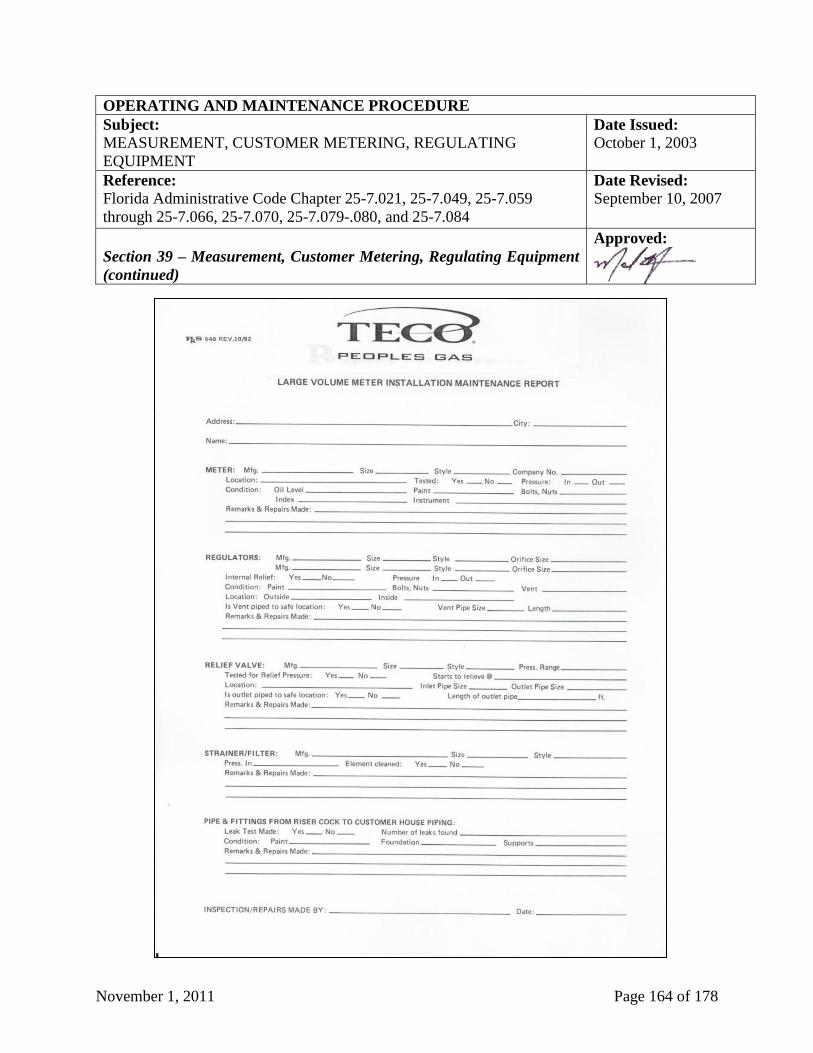
November 1, 2011 Page 164 of 178
OPERATING AND MAINTENANCE PROCEDURE
Subject: Date Issued:
MEASUREMENT, CUSTOMER METERING, REGULATING
EQUIPMENT
October 1, 2003
Reference:
Florida Administrative Code Chapter 25-7.021, 25-7.049, 25-7.059
through 25-7.066, 25-7.070, 25-7.079-.080, and 25-7.084
Date Revised:
September 10, 2007
Section 39 – Measurement, Customer Metering, Regulating Equipment
(continued)
Approved:
November 1, 2011 Page 165 of 178
OPERATING AND MAINTENANCE PROCEDURE
Subject: Date Issued:
MULTI-SERVICE AND FACILITY IDENTIFICATION October 1, 2003
Reference:
Florida Administrative Code Chapter 25-7.059 and 25-12.050
Date Revised:
September 10, 2007
Section 40 – Multi-Service and Facility Identification
Approved:
Section 40.1 – Multi-Service Installations
Section 40.1.1 – Marking of Multi-Service Installations
Where there is more than one (1) meter at a common location, each meter set is to be tagged or
permanently marked to indicate the part of the building or the area being supplied.
See also above at Section 39.1, "Use of Meters & Regulators - General Requirements”.
Section 40.1.2 – Identification Code
When apartment numbers or letters are in use, they shall be utilized to identify the service line
valve that serves the specific apartment unit. However, when numbers or letters are not
available, the Operating Center should refer to the code shown below for marking procedures.
This code shall be used to identify the building, or the area being supplied from a particular
meter:
Location:
N = North S = South E = East W = West
R = Rear F = Front B = Basement
Section 40.2 – Marking of Facilities
Each customer meter, regulator station, or any other above ground gas facility shall be
permanently marked to identify TECO Peoples Gas’ name and phone number. Marking shall be
accomplished by using permanent signs, markers, decals or other appropriate means.
November 1, 2011 Page 166 of 178
OPERATING AND MAINTENANCE PROCEDURE
Subject: Date Issued:
CONTROL ROOM MANAGEMENT August 1, 2011
Reference:
Title 49 Code of Federal Regulations, Part 192
Date Revised:
n/a
Section 41 – Control Room Management
Approved:
Section 41.0 – General Requirements for a Control Room Management Plan
Procedures for control room management are kept in the form of a Control Room Management.
This manual will implement the applicable control room management procedures required by 49
CFR 192.631.
November 1, 2011 Page 167 of 178
OPERATING AND MAINTENANCE PROCEDURE
Subject: Gas Transmission Integrity Management Date Issued:
December 17, 2004
Reference:
Title 49 Code of Federal Regulations 192 Subpart O
Date Revised:
n/a
Section 42 – Gas Transmission Pipeline Integrity Management
Approved:
Section 42.0 – General Requirements for a Gas Transmission Pipeline Integrity
Management Plan
Requirements for an integrity management program on any gas transmission pipeline are kept in
the form of a Pipeline Integrity Management Plan. This plan/manual shall include requirements
for each of the following elements:
1. Identification of all high consequence areas, in accordance with § 192.905.
2. A baseline assessment plan meeting the requirements of § 192.919 and § 192.921.
3. Identification of threats to each covered pipeline segment, which must include data
integration and a risk assessment. An operator must use the threat identification and risk
assessment to prioritize covered segments for assessment (§ 192.917) and to evaluate the
merits of additional preventive and mitigative measures (§ 192.935) for each covered
segment.
4. A direct assessment plan, if applicable, meeting the requirements of § 192.923, and
depending on the threat assessed, of § § 192.925, 192.927, or 192.929.
5. Provisions meeting the requirements of § 192.933 for remediating conditions found during an
integrity assessment.
6. A process for continual evaluation and assessment meeting the requirements of § 192.937.
7. If applicable, a plan for confirmatory direct assessment meeting the requirements of §
192.931.
8. Provisions meeting the requirements of § 192.935 for adding preventive and mitigative
measures to protect the high consequence area.
9. A performance plan as outlined in ASME/ANSI B31.8S, section 9 that includes performance
measures meeting the requirements of § 192.945
(continued on next page)
November 1, 2011 Page 168 of 178
OPERATING AND MAINTENANCE PROCEDURE
Subject: Gas Transmission Integrity Management Date Issued:
July 31, 2011
Reference:
Title 49 Code of Federal Regulations 192 Subpart O
Date Revised:
n/a
Section 42 – Gas Transmission Pipeline Integrity Management
Approved:
10. Record keeping provisions meeting the requirements of § 192.947.
11. A management of change process as outlined in ASME/ANSI B31.8S, section 11.
12. A quality assurance process as outlined in ASME/ANSI B31.8S, section 12.
13. A communication plan that includes the elements of ASME/ANSI B31.8S, section 10, and
that includes procedures for addressing safety concerns raised by--
a. OPS; and
b. A State or local pipeline safety authority when a covered segment is located in a State
where OPS has an interstate agent agreement.
14. Procedures for providing (when requested), by electronic or other means, a copy of the
operator's risk analysis or integrity management program to--
a. OPS; and
b. A State or local pipeline safety authority when a covered segment is located in a State
where OPS has an interstate agent agreement.
15. Procedures for ensuring that each integrity assessment is being conducted in a manner that
minimizes environmental and safety risks.
16. A process for identification and assessment of newly-identified high consequence areas. (See
§ 192.905 and § 192.921.)
November 1, 2011 Page 169 of 178
OPERATING AND MAINTENANCE PROCEDURE
Subject: Distribution Integrity Management Program Date Issued:
August 2, 2011
Reference:
Title 49 Code of Federal Regulations 192 Subpart O
Date Revised:
n/a
Section 43 – Distribution Integrity Management Program
Approved:
Section 43.0 – General Requirements for a Distribution Integrity Management Plan
Requirements for a distribution integrity management program are kept in the form of a Gas
Distribution Integrity Management Program. A written integrity management plan must contain
procedures for developing and implementing the following elements:
1. Knowledge. An operator must demonstrate an understanding of its gas distribution system
developed from reasonably available information.
a. Identify the characteristics of the pipeline's design and operations and the
environmental factors that are necessary to assess the applicable threats and risks to
its gas distribution pipeline.
b. Consider the information gained from past design, operations, and maintenance.
c. Identify additional information needed and provide a plan for gaining that
information over time through normal activities conducted on the pipeline (for
example, design, construction, operations or maintenance activities).
d. Develop and implement a process by which the IM program will be reviewed
periodically and refined and improved as needed.
e. Provide for the capture and retention of data on any new pipeline installed. The data
must include, at a minimum, the location where the new pipeline is installed and the
material of which it is constructed.
2. Identify threats. The operator must consider the following categories of threats to each gas
distribution pipeline: corrosion, natural forces, excavation damage, other outside force
damage, material or welds, equipment failure, incorrect operations, and other concerns that
could threaten the integrity of its pipeline. An operator must consider reasonably available
information to identify existing and potential threats. Sources of data may include, but are not
limited to, incident and leak history, corrosion control records, continuing surveillance
records, patrolling records, maintenance history, and excavation damage experience.
(continued on next page)
November 1, 2011 Page 170 of 178
OPERATING AND MAINTENANCE PROCEDURE
Subject: Distribution Integrity Management Program Date Issued:
July 31, 2011
Reference:
Title 49 Code of Federal Regulations 192 Subpart O
Date Revised:
n/a
Section 43 – Distribution Integrity Management Program
Approved:
3. Evaluate and rank risk. An operator must evaluate the risks associated with its distribution
pipeline. In this evaluation, the operator must determine the relative importance of each
threat and estimate and rank the risks posed to its pipeline. This evaluation must consider
each applicable current and potential threat, the likelihood of failure associated with each
threat, and the potential consequences of such a failure. An operator may subdivide its
pipeline into regions with similar characteristics (e.g., contiguous areas within a distribution
pipeline consisting of mains, services and other appurtenances; areas with common materials
or environmental factors), and for which similar actions likely would be effective in reducing
risk.
4. Identify and implement measures to address risks. Determine and implement measures
designed to reduce the risks from failure of its gas distribution pipeline. These measures must
include an effective leak management program (unless all leaks are repaired when found).
5. Measure performance, monitor results, and evaluate effectiveness.
a. Develop and monitor performance measures from an established baseline to evaluate
the effectiveness of its IM program. An operator must consider the results of its
performance monitoring in periodically re-evaluating the threats and risks. These
performance measures must include the following:
i. Number of hazardous leaks either eliminated or repaired as required by §
192.703(c) of this subchapter (or total number of leaks if all leaks are repaired
when found), categorized by cause;
ii. Number of excavation damages;
iii. Number of excavation tickets (receipt of information by the underground
facility operator from the notification center);
iv. Total number of leaks either eliminated or repaired, categorized by cause;
v. Number of hazardous leaks either eliminated or repaired as required by §
192.703(c) (or total number of leaks if all leaks are repaired when found),
categorized by material; and
vi. Any additional measures the operator determines are needed to evaluate the
effectiveness of the operator's IM program in controlling each identified
threat.
(continued on next page)
November 1, 2011 Page 171 of 178
OPERATING AND MAINTENANCE PROCEDURE
Subject: Distribution Integrity Management Program Date Issued:
July 31, 2011
Reference:
Title 49 Code of Federal Regulations 192 Subpart O
Date Revised:
n/a
Section 43 – Distribution Integrity Management Program
Approved:
6. Periodic Evaluation and Improvement. An operator must re-evaluate threats and risks on its
entire pipeline and consider the relevance of threats in one location to other areas. Each
operator must determine the appropriate period for conducting complete program evaluations
based on the complexity of its system and changes in factors affecting the risk of failure. An
operator must conduct a complete program re-evaluation at least every five years. The
operator must consider the results of the performance monitoring in these evaluations.
7. Report results. Report, on an annual basis, the four measures listed in paragraphs (e)(1)(i)
through (e)(1)(iv) of this section, as part of the annual report required by § 191.11. An
operator also must report the four measures to the state pipeline safety authority if a state
exercises jurisdiction over the operator's pipeline.
November 1, 2011 Page 172 of 178
OPERATING AND MAINTENANCE PROCEDURE
Subject: Date Issued:
GLOSSARY October 1, 2003
Reference:
Title 49 Code of Federal Regulations, Part 192
Date Revised:
September 10, 2007
Approved:
Glossary
Term Definition
Anode The electrode in a corrosion cell at which oxidation (corrosion)
occurs. In the corrosion process, the area where metal ions enter
solution.
Abandoned Pipeline A pipeline that is physically separated from its source of gas and is no
longer maintained under Title 49 Code of Federal Regulations, Part
192.
Abandonment The process of abandoning a pipeline.
CGI Combustible Gas Indicator, which is used to determine the presence of
natural gas
Cathodic The electrode in a corrosion cell at which reduction occurs. In the
corrosion process, the area where electrons do not enter solution
Class Location An onshore area that extends two hundred twenty (220) yards on
either side of the centerline of any continuous 1 mile length of a
pipeline. The Class location ends two hundred twenty (220) yards
from the last feature that defines the class location.
Class 1 location is an offshore area; or any class location unit that has
ten (10) or less buildings intended for human occupancy.
Class 2 location is any class location unit that has more than 10 but
less than forty six (46) buildings intended for human occupancy.
When all buildings intended for human occupancy within a Class 2
or 3 are in a single cluster, the class location ends two hundred
twenty (220) yards from the nearest building in the cluster.
November 1, 2011 Page 173 of 178
OPERATING AND MAINTENANCE PROCEDURE
Subject: Date Issued:
GLOSSARY October 1, 2003
Reference:
Title 49 Code of Federal Regulations, Part 192
Date Revised:
September 10, 2007
Approved:
Term Definition
Class Location (continued) Class 3 location is any class location unit that has forty six (46) or
more buildings intended for human occupancy; or an area where the
pipeline lies within one hundred (100) yards of either a building or
a small, well-defined area (such as a playground, recreation area,
outdoor theater, or other place of public assembly) that is occupied
by twenty (20) or more persons on at least 5 days a week for ten
(10) weeks in any twelve (12)-month period. (The days and weeks
need not be consecutive.) When all buildings intended for human
occupancy within a Class 2 or 3 are in a single cluster, the class
location ends two hundred twenty (220) yards from the nearest
building in the cluster.
Class 4 location is any class location where buildings of four (4) or
more stories above ground are prevalent. A Class 4 location ends
two hundred twenty (220) yards from the nearest building with four
or more stories above ground.
Control Line The pipe, valves and fittings used to interconnect air, gas or
hydraulically operated control apparatus.
Corrosion The deterioration of metal or its properties because of a reaction
with its environment.
Curb Valve A valve installed for the purpose of shutting off the gas supply to a
building. It is installed below grad in a service line, at or near the
property line. It is operated by use of a key or wrench, through a curb
box or standpipe.
Customer Meter The device, which measures gas, delivered to a customer for
consumption of the premises.
Deactivation The process of making the pipeline inactive.
Distribution Main Any main installed within a community to convey.
November 1, 2011 Page 174 of 178
OPERATING AND MAINTENANCE PROCEDURE
Subject: Date Issued:
GLOSSARY October 1, 2003
Reference:
Title 49 Code of Federal Regulations, Part 192
Date Revised:
September 10, 2007
Approved:
Term Definition
Heat Fusion A joint made in thermoplastic piping by heating the parts sufficiently
to permit fusion of the materials when the parts are pressed together.
High Pressure
Distribution System
A distribution system in which the gas pressure in the main is higher
than the pressure provided to the customer.
Inactive Pipeline A pipeline that is being maintained under Title 49 Code of Federal
Regulations, Part 192 but is not presently being used to transport gas.
Leak Any unintended escape of natural gas.
Leakage Survey A systematic inspection made for the purpose of finding leaks in a gas
piping system.
.
Length A piece of pipe as delivered from the steel mill, sometimes also called
a "joint".
Line Section A continuous run of transmission line between adjacent compressor
stations, between a compressor station and storage facilities, between a
compressor station and a block valve, or between adjacent block
valves.
Low Pressure
Distribution System
A distribution system in which the gas pressure in the main is
substantially the same as the pressure provided to the customer.
Main Piping from which an extension of service is available.
Maximum Allowable
Operating Pressure
(MAOP)
The maximum pressure at which any pipeline or facility may be
operated.
November 1, 2011 Page 175 of 178
OPERATING AND MAINTENANCE PROCEDURE
Subject: Date Issued:
GLOSSARY October 1, 2003
Reference:
Title 49 Code of Federal Regulations, Part 192
Date Revised:
September 10, 2007
Approved:
Term Definition
Meter Set Assembly The piping installed to connect the inlet side of the meter to the gas
service line, and to connect the outlet side of the meter to the
customer's fuel line.
Monitor Regulator A pressure regulator, set in series with another pressure regulator,
for the purpose of providing automatic over-pressure protection in
the event of a malfunction of the primary regulator.
Offshore Beyond the line of ordinary low water along that portion of the
coast of the United States that is in direct contact with the open
seas and beyond the line marking the seaward limit of inland
waters.
Operational
Inspection
The inspection performed at stated intervals to assure that
equipment is properly operating and that the equipment set points
are correct.
Over-Pressure When pressures exceeding the maximum allowed operating
pressures of components on a system.
Over-Pressure
Protection
The use of a device or equipment installed for the purpose of
preventing pressure in a pipe system or other facility from
exceeding a predetermined limit.
Over-Pressure
Protection Station
A relief valve or pressure relief installed in a separate vault or
structure or at a separate vault or at a separate site from the
regulator station it is protecting.
Pipeline or Pipeline
System
All of the parts of the conduit through which gas is transported
including such items as valves, pipe, fittings and other
appurtenances attached to the pipe, stations and fabricated
assemblies.
November 1, 2011 Page 176 of 178
OPERATING AND MAINTENANCE PROCEDURE
Subject: Date Issued:
GLOSSARY October 1, 2003
Reference:
Title 49 Code of Federal Regulations, Part 192
Date Revised:
September 10, 2007
Approved:
Term Definition
Pipeline Facility Any new or existing pipeline including rights-of-way and any
equipment or building used in the transportation or treatment of natural
gas.
Pressure Pressure in the pipeline expressed in pounds per square inch above
atmospheric pressure i.e., gage pressure (abbreviation = PSIG), unless
otherwise stated.
Pressure Limiting Station Any installation used to assure that pressures in any pipeline would not
exceed a certain maximum
Pressure Regulating
Station
Consists of apparatus installed for the purpose of automatically
reducing and regulating the gas pressure in the downstream
transmission, main holder, pressure vessel or compressor station piping
to which it is connected. Included in the station are any enclosures and
ventilating equipment, and any piping and auxiliary equipment (such as
valves, control instruments or control lines).
Pressure Relief The apparatus installed to vent gas from a main in order to prevent the
gas pressure from exceeding a predetermined limit. May be installed in
an over pressure protection station.
Primary Inspection The teardown of individual equipment components to inspect internal
condition. A primary inspection includes all of the test and checks of
an operational inspection.
Private Right-Of-Way A right-of-way that is not located on a road street or highway used by
the public, not on railroad right-of-way.
Qualified Welding
Procedure
A tested and proven detailed method by which sound welds having
suitable mechanical properties can be produced. API standard 1104 is
the guide for qualifying welding procedures.
November 1, 2011 Page 177 of 178
OPERATING AND MAINTENANCE PROCEDURE
Subject: Date Issued:
GLOSSARY October 1, 2003
Reference:
Title 49 Code of Federal Regulations, Part 192
Date Revised:
September 10, 2007
Approved:
Term Definition
Qualified Welder An individual who has demonstrated his ability to produce welds meeting
the requirements of API Standard 1104.
Response Time The time interval from when the leak was reported to the time the
employee arrives at the premises and starts the investigation.
SMYS Specified minimum yield strength is:
a. For steel pipe manufactured in accordance with a listed
specification, the yield strength specified at the minimum in that
specification; or,
b. For steel pipe manufactured in accordance with an unknown or
unlisted specification, the yield strength determined in
accordance with Title 49 Code of Federal Regulations, Part
192.107(b).
Service That portion of the gas piping between the main and the customer meter
set, and is not normally available for the extension of service.
Service Line Valve A valve located in the service line ahead of the service regulator, or ahead
of the meter when there is no regulator.
Service Regulator A device installed on a gas service to control the pressure of the gas
delivered to the customer.
Short Section of Pipe A segment of pipeline one hundred feet (100’) or less in length.
Stopcock Valve on the riser, just before the customer meter.
November 1, 2011 Page 178 of 178
OPERATING AND MAINTENANCE PROCEDURE
Subject: Date Issued:
GLOSSARY October 1, 2003
Reference:
Title 49 Code of Federal Regulations, Part 192
Date Revised:
September 10, 2007
Approved:
Term Definition
Supervisor in Charge The supervisor designated as being responsible for coordinating all
field activities.
Test Station A wire or other point on underground piping where electric contact
for corrosion control testing purposes can be made.
Transmission Main Means a pipeline, other than a gathering line, that:
1. Transports gas from a gathering line or storage facility to a
distribution center, storage facility, or large volume customer that is
not downstream from a distribution center;
2. Operates at a hoop stress of twenty percent (20%) or more of
SMYS; or,
3. Transports gas within a storage field. A large volume customer
may receive similar volumes of gas as a distribution center, and
includes factories, power plants and institutional users of gas.
Under-Pressure When pressures less than those required operating equipment safely
is experienced.
Vault An underground structure which may be entered, and which is
designed to contain piping or piping components.