Embed Size (px)
Citation preview

ISSN 2040-3364
www.rsc.org/nanoscale Volume 5 | Number 19 | 7 October 2013 | Pages 8727–9430
PAPERKoziol, Kulkarni et al.Lipid nanoscaff olds in carbon nanotube arrays
Nanoscale
PAPER
Publ
ishe
d on
14
June
201
3. D
ownl
oade
d by
Uni
vers
ity o
f C
ambr
idge
on
16/0
3/20
14 2
2:10
:01.
View Article OnlineView Journal | View Issue
aDepartment of Materials Science and Metal
Street, Cambridge – CB2 3QZ, UK. E-mail: k
567; Tel: +44 (0)122 33 34 356bInstitute of Chemical Biology, Department
Exhibition Road, London - SW7 2AZ, UK. E
(0)1772 89 4981; Tel: +44 (0)1772 89 3491
† Electronic supplementary informationX-ray scattering (WAXS) data on the alignand time resolved 2-d images of egg ovapicture of the present work. See DOI: 10.1
‡ Current address: Centre for Materials ScPreston PR1 2HE, UK.
Cite this: Nanoscale, 2013, 5, 8992
Received 25th April 2013Accepted 12th June 2013
DOI: 10.1039/c3nr02068a
www.rsc.org/nanoscale
8992 | Nanoscale, 2013, 5, 8992–900
Lipid nanoscaffolds in carbon nanotube arrays†
Catharina Paukner,a Krzysztof K. K. Koziol*a and Chandrashekhar V. Kulkarni‡*b
We present the fabrication of lipid nanoscaffolds inside carbon nanotube arrays by employing the
nanostructural self-assembly of lipid molecules. The nanoscaffolds are finely tunable into model
biomembrane-like architectures (planar), soft nanochannels (cylindrical) or 3-dimensionally ordered
continuous bilayer structures (cubic). Carbon nanotube arrays hosting the above nanoscaffolds are
formed by packing of highly oriented multiwalled carbon nanotubes which facilitate the alignment of
lipid nanostructures without requiring an external force. Furthermore, the lipid nanoscaffolds can be
created under both dry and hydrated conditions. We show their direct application in reconstitution of
egg proteins. Such nanoscaffolds find enormous potential in bio- and nano-technological fields.
Introduction
Designing of structural and functional models using biologi-cally relevant molecules is becoming a more popular pathwaytowards mimicking and hence understanding the complexbiological structures and related phenomena. Lipid assemblingand transitions closely model some of the cellular components,especially biomembrane structures, transformations and func-tions.1,2 The hydrophilic headgroup and hydrophobic tail oflipid molecules induce an amphiphilic character, whichtogether with physicochemical triggers facilitate their self-assembly into 1, 2, and 3 dimensional inverse (type 2) nano-structures in water and stand in contrast to hydrophilicsurfactant molecules which form normal (type 1) nano-structures (also called phases, mesophases or liquid crystalline(LC) nanostructures).3–12 They display remarkable topologiesbased on spherical, planar, cylindrical or complex, albeit nelyordered geometries like cubic phases.3,13–16 Recent reviews onlipid cubic phases have focused on their types, structures,characterization and typical applications.3,17,18 Lipid nano-structures are widely used, for instance, as emulsiers andsolubility enhancers,19,20 for separation of biomolecules,21
protein crystallization, synthesis of metal nanoparticles,22 DNA/
lurgy, University of Cambridge, Pembroke
[email protected]; Fax: +44 (0)122 33 34
of Chemistry, Imperial College London,
-mail: [email protected]; Fax: +44
(ESI) available: Additional wide anglement of lipid nanostructures, controllbumin encapsulation and a summary039/c3nr02068a
ience, University of Central Lancashire,
0
lipid complexes for gene therapy,23 and electrophoresis gels foramphiphilic molecules.21 Hierarchically ordered lipid assem-blies and their potential applications have also been discussedby a few authors, lately.24 A very important application of thesehierarchical structures is the delivery of drugs and variousactive molecules.25,26
Biomembranes represent locally at lipid bilayers (type 0)formed by two lipid monolayers with their chain regions facingeach other. However, lipid ordering is not only limited toentirely spherical or locally at outer cell membranes but alsocontributes to the structuring of the inner membranes ofendoplasmic reticulum and Golgi apparatus.12,27 At the macro-scopic level, the lipid nanostructures are found in the form of alayer or coat on various organs of plants and animals, forinstance, the hydrophobic layer on plant leaves contains lipidmolecules to reduce water loss.28 Biological nanochannelsformed by coating of lipid material inside the olfactory sensillaof insect antennae facilitate capture, pre-concentration, andtranslocation of chemicals called pheromones.29 It is thereforeessential not only to mimic planar lipid bilayers but thesemodels should also be able to imitate lipid decorated macro-scopic surfaces, aqueous nanochannels as well as 3-dimen-sionally ordered lipidic architectures.
In order to explore new avenues of bio-mimicry discussedabove and further improve the advantages of lipid nano-structural assemblies, we added a new component to our study,which is an elegant, organized system based on carbon nano-tubes (CNTs). CNTs are made entirely of carbon, rolled-upgraphene layers with hemispherical end caps.30 They can bedivided into the group of single and multi-walled nanotubes.They are popular in many scientic and technological disci-plines and have enormous commercial interest.31 The commongrounds for exploiting CNTs for diverse applications are theirremarkable properties including high strength and elasticity,high thermal and electric conductivities, their tendency for
This journal is ª The Royal Society of Chemistry 2013
Paper Nanoscale
Publ
ishe
d on
14
June
201
3. D
ownl
oade
d by
Uni
vers
ity o
f C
ambr
idge
on
16/0
3/20
14 2
2:10
:01.
View Article Online
surface modications and biocompatibility.32 The latter beingthe main motive for applications of CNTs in the biotechnolog-ical elds.
A range of biomolecules including lipid, surfactant andprotein molecules33–35 have been used to improve the dispersionproperties of CNTs; earlier limited by their pre-existing chem-istry. Most of the amphiphilic molecules not only interact butalso self-organize on the CNT surface. The self-assembling ofsurfactants (e.g. sodium dodecyl sulphate-SDS and octadecyl-trimethylammonium bromide-OTAB)36–38 and lipids (e.g. dipal-mitoylphosphatidylcholine-DPPC, dihexanoylphosphatidylcho-line-DHPC and lysophosphatidylcholine-LPC) on the CNTsurface has been studied theoretically – using moleculardynamics and coarse grain simulations33,39,40 – and experimen-tally – using transmission electron microscopy (TEM).33,36,41
Nevertheless, almost all of the reported studies were focused onsimple micellar organizations in dilute solutions and isotropicsystems based on single walled CNTs.33,36–41
In this work we employed a more sophisticated approach byusing ‘carbon nanotube arrays’ consisting of highly orientedmulti-walled (MW) CNTs42 and loading them with 1, 2 or 3-dimensionally ordered nely tunable lipid nanostructures forthe fabrication of ‘lipid nanoscaffolds’ (ESI Fig SI1†).43,44 TheCNT arrays were synthesized in house using a chemical vapordeposition (CVD) process, the details of which have been pub-lished elsewhere.42 CNT arrays constitute densely packed multi-walled CNTs (packing density of �5 � 106 CNTs per mm2)highly oriented along their long-axis (with a typical degree ofalignment of 88%).42 This whole assembly can be easilymanipulated on the lab scale, primarily for lipid interactions.
ExperimentalMaterials
Lipids namely dioleoyl phosphatidylethanolamine (DOPE) anddioleoyl phosphatidylcholine (DOPC) were purchased fromAvanti Polar Lipids, Inc. Monoolein (MO) and chloroform(CHCl3) were purchased from Sigma Aldrich Co. (UK). Water(ddH2O) was puried using a Millipore system (MilliporeCompany). As mentioned earlier the CNT arrays were synthe-sized in our lab using a chemical vapor deposition (CVD)process.
MethodsSample preparation
About 2.0 mg of lipids (4.0 mg for MO) were dissolved in 200 mlchloroform (CHCl3) in marked (5 ml) glass tubes. SubsequentlyCNT arrays (single block of approximate dimensions of 2 mm �10 mm � 15 mm in each solution) were immersed in abovesolutions and tubes were le open for solvent evaporation(�48 h). For hydrated samples, these (lipid loaded) arrays werekept in ddH2O for about 2 h. To avoid the evaporation of water(due to vacuum), hydrated samples were enclosed by sealedglass capillaries. Isotropic samples were prepared by dispersingCNT arrays in a lipid solution (in CHCl3 or water) via ultra-sonication (2 min, 1 W) and consequent solvent evaporation.
This journal is ª The Royal Society of Chemistry 2013
For protein samples, the egg white was separated from yolk andtransferred to the marked tube followed by dilution with water(1 : 1). In another sample, about 5.0–6.0 mg of MO was added tothe above mixture. CNT arrays were then immersed in thesemixtures for two days before further studies.
Scanning electron microscopy (SEM)
Micro-structural analysis of native and lipid coated CNT arrayswas performed using a JEOL6340 FEGSEM (JEOL Ltd., Tokyo,Japan) instrument operated at 5 kV.
Small angle X-ray scattering and data analysis
Small and wide angle X-ray scattering (SAXS and WAXS)measurements were performed on a Nanostar machine (fromBruker AXS LTD, UK.). Cu Ka (0.1542 nm) radiation wasfocused to 1 mm diameter using two cross-coupled mirrorsand a pinhole optics set up. Diffracted 2-D patterns wereobtained using a VANTEC-2000 Detector. Backgroundsubtraction was performed on the 2D image before furtherdata processing. Silver behenate and Al2O3 were used as cali-bration standards for SAXS and WAXS respectively. The d-spacings were calculated from 2q values obtained from inte-grated 1-D plots using the famous Bragg's diffraction formula,nl ¼ 2d sinq, here, n ¼ order of reection and d ¼ d-spacing.The lattice parameters for lamellar (alam), cubic (acubic) andhexagonal (ahex) nanostructures were calculated (accuracyof �0.15 nm) using following formulae: alam ¼ (n/dlam);
acubic ¼�1 .d� ffiffiffiffiffiffiffiffiffiffiffiffiffiffiffiffiffiffiffiffiffiffiffiffiffi
h2 þ k2 þ l2p
; ahex ¼ 2ffiffiffiffiffiffiffiffiffiffiffiffiffiffiffiffiffiffiffiffiffiffiffiffiffiffih2 þ k2 þ hk
p
�dhex ffiffiffi3
p!.
Here, h, k, l ¼ Miller indices. The temperature of the samplechamber was controlled at an accuracy of �2 �C.
Results and discussionLipid nanoscaffolds in CNT arrays at ambient temperature
As mentioned earlier, lipids are known to self-assemble intoremarkable nano-geometries in aqueous medium.45 The typeand dimensions of nanostructures can be controlled bychanging various parameters including the chemical structureof the lipid molecule, composition of the lipid mixture,concentration of water (ranging from dry to fully hydratedstates) and the temperature of the system.43,44 In general, thebiomembranes are comprised of an assortment of lipids varyingin type of polar headgroup, number, length and saturation–unsaturation of alkyl chains.12 To mimic the planar as well asnon-lamellar biomembrane structures we selected threedifferent types of pure lipids that form distinct lipid nano-structures of lamellar,46,47 cubic43,48 and hexagonal49 type. Two ofthese lipids, dioleoyl phosphatidylcholine (DOPC) and dioleoylphosphatidylethanolamine (DOPE), are major constituents ofbiomembranes. The third, monoolein (MO), is commercially avery important lipid. DOPC is a phospholipid with a polarcholine headgroup and the tail is composed of two fatty acidchains based on oleic (unsaturated) acid. It is a major constit-uent of cell membranes and lecithin.50 DOPE consists of an
Nanoscale, 2013, 5, 8992–9000 | 8993
Nanoscale Paper
Publ
ishe
d on
14
June
201
3. D
ownl
oade
d by
Uni
vers
ity o
f C
ambr
idge
on
16/0
3/20
14 2
2:10
:01.
View Article Online
ethanolamine polar headgroup and it is thought to be relevantfor biological systems such as membranes.51 MO is composed ofa single 18-C hydrocarbon chain containing a cis double bond atthe 9–10 position with a comparatively small glycerol head-group. MO and its commercial derivatives are widely used forprotein crystallization and drug delivery applications.43
To access the maximum feasibility of the CNT arrays forcommercial and biological applications, the experiments wereperformed at ambient (25 � 2 �C) and physiological (37 � 2 �C)temperatures as well as under dry and hydrated sample condi-tions. Initially, the aforementioned lipids were individuallyinltrated into the CNT arrays using their �1% (w/w) solutionin chloroform which was later removed via evaporation. In thecase of MO, it was possible to introduce its molten form into thearrays via dip-coating (other lipids partly decomposed beforemelting). Following this process of inltration, the lipid mole-cules have three places to interact with the array: rst, on theouter macroscopic surface created by an array which lies in therange of 4 � 1014 nm2 (determined for the typical arraydimension of 15 mm � 10 mm � 2 mm, see Fig. 1); second, inthe interstitial spaces of an array which are of the scale of 100–500 nm amongst the neighboring CNTs;52 and third, insideindividual MWCNTs (inner diameter 9 � 4 nm and outerdiameter 44 � 20 nm).42 However, the last option is highlyunlikely given that the dimension of CNTs is too small to tmore than two lipid bilayers or any other pre-assembled lipidnanostructure, especially cubic nanostructures (lattice param-eters �9–10 nm).
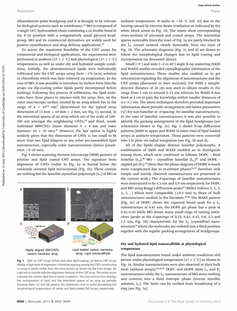
Fig. 1 shows scanning electron microscopy (SEM) pictures ofpristine and lipid coated CNT arrays. The signature fromalignment of CNTs visible in Fig. 1a is buried below therandomly oriented lipid microcrystals (Fig. 1b). These crystalsare nothing but the lamellar crystalline polymorph (LC) of MO at
Fig. 1 SEM on CNT arrays before and after lipid loading. (a) Native CNT arraysdisplay a high level of alignment. Interstitial spacing among the CNTs constitutingan array is clearly visible from the cross-section as shown by the inset image. (b)Lipid micro-crystals hide the alignment features of the CNT array. The white arrowindicates the molten lipid due to beam irradiation. The inset picture here displaysthe incorporation of lipid into the interstitial spaces of an array by partiallyblocking them. (c) and (d) present the schematics (not to scale) elucidating themorphological organization of native and lipid coated CNT arrays, respectively.
8994 | Nanoscale, 2013, 5, 8992–9000
ambient temperature. It melts at �38 �C (ref. 43) due to theheating caused by electron beam irradiation as indicated by thewhite block arrow in Fig. 1b. The insets show correspondingcross-sections of uncoated and coated arrays. The interstitialspaces noticeable from the inset of Fig. 1a are partly blocked bythe LC crystal network clearly detectable from the inset ofFig. 1b. The schematic diagrams (Fig. 1c and d) are drawn tofollow the morphological changes due to lipid coating andincorporation (as discussed above).
Small (<5�) and wide (�4 to 40�) angle X-ray scattering (SAXSand WAXS) studies revealed crystallographic information of thelipid nanostructures. These studies also enabled us to getinformation regarding the alignment of nanostructures and theCNT arrays (discussed in later sections). For SAXS a sample-detector distance of 26 cm was used to obtain results in therange from 1 nm to around 4–11 nm whereas for WAXS it wasxed at 4 cm to gain the knowledge within smaller distances of0.1–1.5 nm. The above techniques therefore provided importantinformation about periodic arrangement and lattice parameters(‘a’) for non-lamellar or ‘d-spacing’ for lamellar nanostructures.In the case of lamellar nanostructures it was also possible toidentify the packing arrangement of the lipid headgroups (seeschematics shown in Fig. 2c). Fig. 2 shows X-ray diffractionpatterns (SAXS in upper and WAXS in lower row) of lipid loadedarrays at ambient temperature. These patterns were convertedinto 1-D plots via radial integration (see Fig. 2b and d).
All of the lipids display distinct lamellar polymorphs. Acombination of SAXS and WAXS enabled us to distinguishamong them, which were conrmed as follows: DOPC – uidlamellar (La),46 MO – crystalline lamellar (LC)43 and DOPE –
rippled gel (Pd).53 (Note that the phase diagram of DOPE is muchmore complicated due to re-entrant phases53,54 therefore onlysimple and mainly observed nanostructures are presented inthe current work.) The d-spacings of lamellar nanostructureswere determined to be 4.3 nm and 4.9 nm respectively for DOPCand MO using Bragg's diffraction peaks13 (Miller indices: 1, 2, 3,4, 5,.) which were comparable (�0.2 nm) to those of bulknanostructures studied in the literature.46,48 The WAXS pattern(Fig. 2e) of DOPC shows the expected broad peak for a Lananostructure at 0.45 nm, the DOPE gel phase has a peak at0.42–0.45 while MO shows many small rings of varying inten-sities (peaks at the d-spacings of 0.24, 0.43, 0.45, 0.8, 1.2 and1.5 nm, Fig. 2d) characteristic for the LC (crystalline) nano-structure55 where themolecules are ordered into a xed positiontogether with the regular packing arrangement of headgroups.
Dry and hydrated lipid nanoscaffolds at physiologicaltemperature
The lipid nanostructures found under ambient conditions stillpersist under physiological temperature (37� 2 �C) as shown inFig. 3a. Similar nanostructures were also observed in their bulkform (without arrays).46,48,56 DOPC and DOPE show La and Pdnanostructures while the LC nanostructure of MO starts meltingand converts into a uid isotropic phase (inverse micellarsolution, L2). The latter can be veried from broadening of aring (see Fig. 3a).
This journal is ª The Royal Society of Chemistry 2013
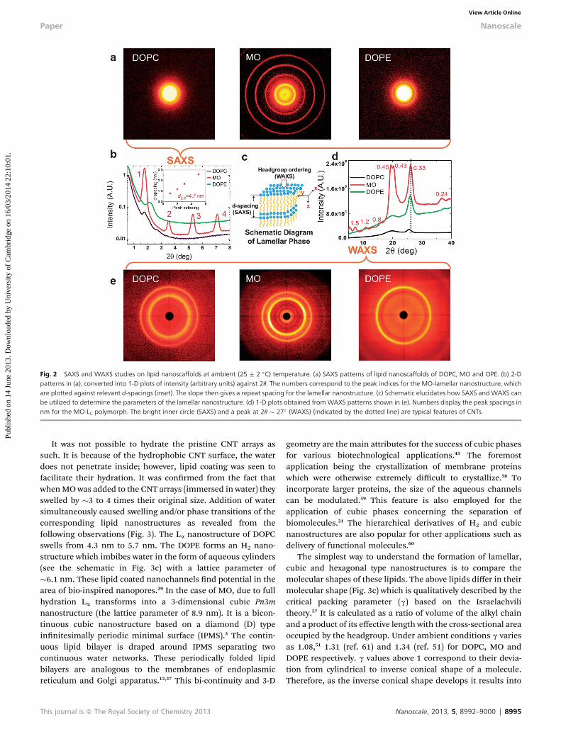
Fig. 2 SAXS and WAXS studies on lipid nanoscaffolds at ambient (25 � 2 �C) temperature. (a) SAXS patterns of lipid nanoscaffolds of DOPC, MO and OPE. (b) 2-Dpatterns in (a), converted into 1-D plots of intensity (arbitrary units) against 2q. The numbers correspond to the peak indices for the MO-lamellar nanostructure, whichare plotted against relevant d-spacings (inset). The slope then gives a repeat spacing for the lamellar nanostructure. (c) Schematic elucidates how SAXS and WAXS canbe utilized to determine the parameters of the lamellar nanostructure. (d) 1-D plots obtained fromWAXS patterns shown in (e). Numbers display the peak spacings innm for the MO-LC polymorph. The bright inner circle (SAXS) and a peak at 2q � 27� (WAXS) (indicated by the dotted line) are typical features of CNTs.
Paper Nanoscale
Publ
ishe
d on
14
June
201
3. D
ownl
oade
d by
Uni
vers
ity o
f C
ambr
idge
on
16/0
3/20
14 2
2:10
:01.
View Article Online
It was not possible to hydrate the pristine CNT arrays assuch. It is because of the hydrophobic CNT surface, the waterdoes not penetrate inside; however, lipid coating was seen tofacilitate their hydration. It was conrmed from the fact thatwhenMO was added to the CNT arrays (immersed in water) theyswelled by �3 to 4 times their original size. Addition of watersimultaneously caused swelling and/or phase transitions of thecorresponding lipid nanostructures as revealed from thefollowing observations (Fig. 3). The La nanostructure of DOPCswells from 4.3 nm to 5.7 nm. The DOPE forms an H2 nano-structure which imbibes water in the form of aqueous cylinders(see the schematic in Fig. 3c) with a lattice parameter of�6.1 nm. These lipid coated nanochannels nd potential in thearea of bio-inspired nanopores.29 In the case of MO, due to fullhydration La transforms into a 3-dimensional cubic Pn3mnanostructure (the lattice parameter of 8.9 nm). It is a bicon-tinuous cubic nanostructure based on a diamond (D) typeinnitesimally periodic minimal surface (IPMS).3 The contin-uous lipid bilayer is draped around IPMS separating twocontinuous water networks. These periodically folded lipidbilayers are analogous to the membranes of endoplasmicreticulum and Golgi apparatus.12,27 This bi-continuity and 3-D
This journal is ª The Royal Society of Chemistry 2013
geometry are the main attributes for the success of cubic phasesfor various biotechnological applications.43 The foremostapplication being the crystallization of membrane proteinswhich were otherwise extremely difficult to crystallize.58 Toincorporate larger proteins, the size of the aqueous channelscan be modulated.59 This feature is also employed for theapplication of cubic phases concerning the separation ofbiomolecules.21 The hierarchical derivatives of H2 and cubicnanostructures are also popular for other applications such asdelivery of functional molecules.60
The simplest way to understand the formation of lamellar,cubic and hexagonal type nanostructures is to compare themolecular shapes of these lipids. The above lipids differ in theirmolecular shape (Fig. 3c) which is qualitatively described by thecritical packing parameter (g) based on the Israelachvilitheory.57 It is calculated as a ratio of volume of the alkyl chainand a product of its effective length with the cross-sectional areaoccupied by the headgroup. Under ambient conditions g variesas 1.08,51 1.31 (ref. 61) and 1.34 (ref. 51) for DOPC, MO andDOPE respectively. g values above 1 correspond to their devia-tion from cylindrical to inverse conical shape of a molecule.Therefore, as the inverse conical shape develops it results into
Nanoscale, 2013, 5, 8992–9000 | 8995
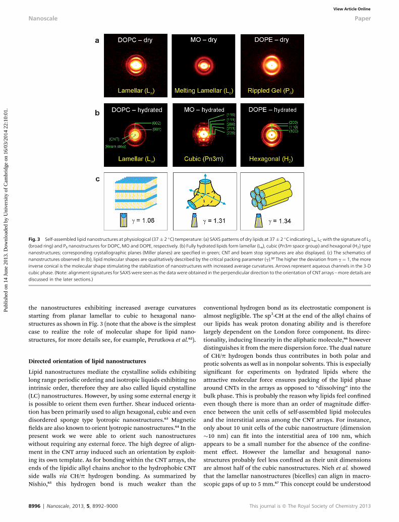
Fig. 3 Self-assembled lipid nanostructures at physiological (37� 2 �C) temperature: (a) SAXS patterns of dry lipids at 37� 2 �C indicating La, LC with the signature of L2(broad ring) and Pd nanostructures for DOPC, MO and DOPE, respectively. (b) Fully hydrated lipids form lamellar (La), cubic (Pn3m space group) and hexagonal (H2) typenanostructures; corresponding crystallographic planes (Miller planes) are specified in green; CNT and beam stop signatures are also displayed. (c) The schematics ofnanostructures observed in (b), lipid molecular shapes are qualitatively described by the critical packing parameter (g).57 The higher the deviation from g ¼ 1, the moreinverse conical is the molecular shape stimulating the stabilization of nanostructures with increased average curvatures. Arrows represent aqueous channels in the 3-Dcubic phase. (Note: alignment signatures for SAXSwere seen as the data were obtained in the perpendicular direction to the orientation of CNTarrays –more details arediscussed in the later sections.)
Nanoscale Paper
Publ
ishe
d on
14
June
201
3. D
ownl
oade
d by
Uni
vers
ity o
f C
ambr
idge
on
16/0
3/20
14 2
2:10
:01.
View Article Online
the nanostructures exhibiting increased average curvaturesstarting from planar lamellar to cubic to hexagonal nano-structures as shown in Fig. 3 (note that the above is the simplestcase to realize the role of molecular shape for lipid nano-structures, for more details see, for example, Perutkova et al.62).
Directed orientation of lipid nanostructures
Lipid nanostructures mediate the crystalline solids exhibitinglong range periodic ordering and isotropic liquids exhibiting nointrinsic order, therefore they are also called liquid crystalline(LC) nanostructures. However, by using some external energy itis possible to orient them even further. Shear induced orienta-tion has been primarily used to align hexagonal, cubic and evendisordered sponge type lyotropic nanostructures.63 Magneticelds are also known to orient lyotropic nanostructures.64 In thepresent work we were able to orient such nanostructureswithout requiring any external force. The high degree of align-ment in the CNT array induced such an orientation by exploit-ing its own template. As for bonding within the CNT arrays, theends of the lipidic alkyl chains anchor to the hydrophobic CNTside walls via CH/p hydrogen bonding. As summarized byNishio,65 this hydrogen bond is much weaker than the
8996 | Nanoscale, 2013, 5, 8992–9000
conventional hydrogen bond as its electrostatic component isalmost negligible. The sp3-CH at the end of the alkyl chains ofour lipids has weak proton donating ability and is thereforelargely dependent on the London force component. Its direc-tionality, inducing linearity in the aliphatic molecule,66 howeverdistinguishes it from themere dispersion force. The dual natureof CH/p hydrogen bonds thus contributes in both polar andprotic solvents as well as in nonpolar solvents. This is especiallysignicant for experiments on hydrated lipids where theattractive molecular force ensures packing of the lipid phasearound CNTs in the arrays as opposed to “dissolving” into thebulk phase. This is probably the reason why lipids feel connedeven though there is more than an order of magnitude differ-ence between the unit cells of self-assembled lipid moleculesand the interstitial areas among the CNT arrays. For instance,only about 10 unit cells of the cubic nanostructure (dimension�10 nm) can t into the interstitial area of 100 nm, whichappears to be a small number for the absence of the conne-ment effect. However the lamellar and hexagonal nano-structures probably feel less conned as their unit dimensionsare almost half of the cubic nanostructures. Nieh et al. showedthat the lamellar nanostructures (bicelles) can align in macro-scopic gaps of up to 5 mm.67 This concept could be understood
This journal is ª The Royal Society of Chemistry 2013
Paper Nanoscale
Publ
ishe
d on
14
June
201
3. D
ownl
oade
d by
Uni
vers
ity o
f C
ambr
idge
on
16/0
3/20
14 2
2:10
:01.
View Article Online
as a ‘transient cage effect’68 which means if we wait long enoughthe orientated nanostructures might relax into isotropic orbulk-like assemblies. This effect could be partly due to theviscoelastic nature of lipid nanostructures;69,70 however thissubject needs further investigation.
In short, the hydrophilic head groups prevent the lipidsfrom ordering parallel to the CNTs; instead they are forced tocome into contact with the CNT surface by their hydrophobicchain region to minimize the interfacial energy. As a conse-quence the hydrophilic headgroups should face inwards. Thisfacilitates the absorption of water by the lipid coated CNTarrays, which is rather difficult for native (not loaded withlipids) CNT arrays.
The alignment of lipid nanostructures was observed in bothdry and hydrated CNT arrays. In the case of dry samples,initially the lipids were dissolved in chloroform which aidedtheir diffusion among the CNT arrays. During the evaporationof chloroform, the lipids aligned themselves as described above.The alignment was still retained upon complete evaporation of
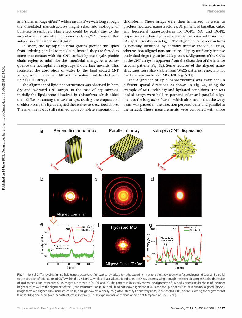
Fig. 4 Role of CNTarrays in aligning lipid nanostructures: (a)first two schematics depto the direction of orientation of CNTs within the CNT arrays, while the last schematicof lipid coated CNTs; respective SAXS images are shown in (b), (c), and (d). The pattebright core) as well as the alignment of the LC nanostructure. Images (c) and (d) do nimage shows an aligned cubic nanostructure. (e) and (g) show azimuthally integratedlamellar (dry) and cubic (wet) nanostructures respectively. These experiments were
This journal is ª The Royal Society of Chemistry 2013
chloroform. These arrays were then immersed in water toproduce hydrated nanostructures. Alignment of lamellar, cubicand hexagonal nanostructures for DOPC, MO and DOPE,respectively in their hydrated state can be observed from theirSAXS patterns shown in Fig. 3. The alignment of nanostructuresis typically identied by partially intense individual rings,whereas non-aligned nanostructures display uniformly intenseindividual rings Fig. 3a (middle picture). Alignment of the CNTsin the CNT arrays is apparent from the distortion of the intensecircular pattern (Fig. 3a). Some features of the aligned nano-structures were also visible from WAXS patterns, especially forthe LC nanostructure of MO (ESI, Fig. SI2†).
The alignment of lipid nanostructures was examined indifferent spatial directions as shown in Fig. 4a, using theexample of MO under dry and hydrated conditions. The MOloaded arrays were held in perpendicular and parallel align-ment to the long axis of CNTs (which also means that the X-raybeam was passed in the direction perpendicular and parallel tothe arrays). These measurements were compared with those
ict the experiments where the X-ray beamwas focused perpendicular and parallelindicates the X-ray beam passing through the isotropic sample, i.e. the dispersionrn in (b) clearly shows the alignment of CNTs (distorted circular shape of the innerot show alignment of CNTs and the lipid nanostructure is also not aligned. (f) SAXSintensity (in arbitrary units) versus theta (360�) plots elucidating the alignments ofdone at ambient temperature (25 � 2 �C).
Nanoscale, 2013, 5, 8992–9000 | 8997
Nanoscale Paper
Publ
ishe
d on
14
June
201
3. D
ownl
oade
d by
Uni
vers
ity o
f C
ambr
idge
on
16/0
3/20
14 2
2:10
:01.
View Article Online
from an isotropic sample prepared by ultrasonication of arraysin a lipid–water mixture (shown in Fig. 4b–d).
The alignment of the lipid nanostructure, LC, is evidentfrom the perpendicular arrangement, whereas all four rings onthe parallel arrangement exhibited uniform intensity, depict-ing an unaligned LC nanostructure. Azimuthally integrated 1-Dintensity proles (along 360�) in different regions (different chivalues) clearly highlight the alignment as shown in Fig. 4e.Isotropic samples did not show any alignment or signature ofthe periodic arrangement of the lipid nanostructure.This could be attributed to a very thin layering of lipid onto theCNT surface rather than a multilayer structure resulting intopatterns perceived in the other two cases. A fascinatingpattern was observed using hydrated MO aligned in aperpendicular direction to the array. Here, all the visible rings(corresponding Miller planes of (110), (111), (200), (211) and(220) with typical indexing of O2,O3,O4,O6, and O8 for Pn3mnanostructures) show clear signatures of alignment (Fig. 4fand g). Similar patterns were also observed by Hamley et al.71
and Seddon et al.,72 however the orientation was induced byapplying shear forces. In our case, the alignment was aconsequence of the templating property of CNT arrays. Earlier,Nieh et al.67 have used such connement for aligninglamellar lipid domains, however according to our knowledgethis is the rst published report of hexagonal and cubic lipidnanostructures. These results have potential signicance fororientation induced nucleation and crystallization ofbiomolecules.
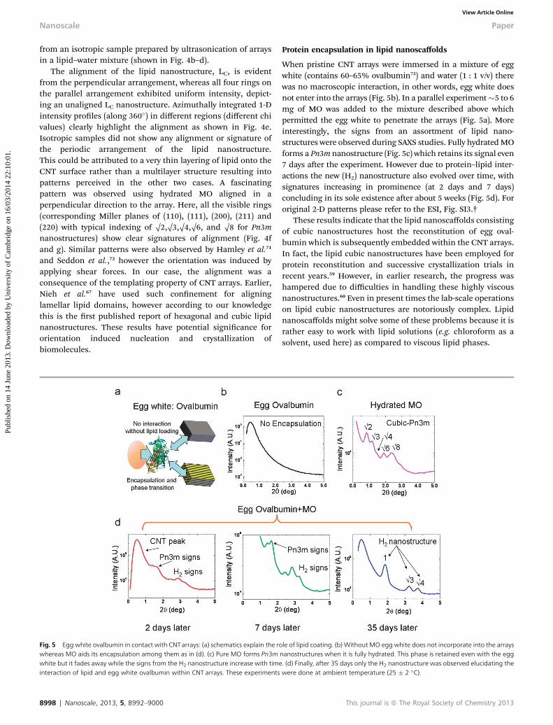
Fig. 5 Egg white ovalbumin in contact with CNTarrays: (a) schematics explain the rowhereas MO aids its encapsulation among them as in (d). (c) Pure MO forms Pn3mwhite but it fades away while the signs from the H2 nanostructure increase with timeinteraction of lipid and egg white ovalbumin within CNT arrays. These experiments
8998 | Nanoscale, 2013, 5, 8992–9000
Protein encapsulation in lipid nanoscaffolds
When pristine CNT arrays were immersed in a mixture of eggwhite (contains 60–65% ovalbumin73) and water (1 : 1 v/v) therewas no macroscopic interaction, in other words, egg white doesnot enter into the arrays (Fig. 5b). In a parallel experiment�5 to 6mg of MO was added to the mixture described above whichpermitted the egg white to penetrate the arrays (Fig. 5a). Moreinterestingly, the signs from an assortment of lipid nano-structures were observed during SAXS studies. Fully hydratedMOforms a Pn3m nanostructure (Fig. 5c) which retains its signal even7 days aer the experiment. However due to protein–lipid inter-actions the new (H2) nanostructure also evolved over time, withsignatures increasing in prominence (at 2 days and 7 days)concluding in its sole existence aer about 5 weeks (Fig. 5d). Fororiginal 2-D patterns please refer to the ESI, Fig. SI3.†
These results indicate that the lipid nanoscaffolds consistingof cubic nanostructures host the reconstitution of egg oval-bumin which is subsequently embedded within the CNT arrays.In fact, the lipid cubic nanostructures have been employed forprotein reconstitution and successive crystallization trials inrecent years.59 However, in earlier research, the progress washampered due to difficulties in handling these highly viscousnanostructures.60 Even in present times the lab-scale operationson lipid cubic nanostructures are notoriously complex. Lipidnanoscaffolds might solve some of these problems because it israther easy to work with lipid solutions (e.g. chloroform as asolvent, used here) as compared to viscous lipid phases.
le of lipid coating. (b) Without MO egg white does not incorporate into the arraysnanostructures when it is fully hydrated. This phase is retained even with the egg. (d) Finally, after 35 days only the H2 nanostructure was observed elucidating thewere done at ambient temperature (25 � 2 �C).
This journal is ª The Royal Society of Chemistry 2013
Paper Nanoscale
Publ
ishe
d on
14
June
201
3. D
ownl
oade
d by
Uni
vers
ity o
f C
ambr
idge
on
16/0
3/20
14 2
2:10
:01.
View Article Online
Conclusions
The lipid nanoscaffolds were fabricated on the macroscopicsurface and among the interstitial connements of CNT arrays.Despite the inclusion in CNT arrays, the nanostructural features ofthe bulk lipid phases were retained. These nanostructures alreadyhave a great propensity for ne tuning of their assembly type andnanoscale dimensions. The morphological regularity, nanoscaleconnements and template for orientation are some of theexclusive characteristics possessed by the CNT arrays. Thereforethe combination of the best properties of CNT arrays and lipidassembling, presented here, could emerge with many new appli-cations among biotechnological disciplines, for instance formaking bio-inspired nanopores. Furthermore, lipid loaded CNTarrays can potentially function as portable biomembranes whichcan be reversibly dried and hydrated as per requirements. Thelipid nanoscaffolds could work as hosts for reconstitution ofproteins and other biomolecules providing native like environ-ments. Encapsulation of egg white proteins demonstrates theirrst application as protein hosting nanoscaffolds. The alignmentof lipid nanostructuresmay offer additional benets by generatingtemplated architectures or orientation induced biomolecularcrystallization. Finally, employing these nanoscaffolds in a readyformat could possibly avoid the essential step of dispersing theCNTs in a viewpoint of their potential applications.
Acknowledgements
CVK would like to acknowledge a Marie Curie Fellowship(during 2005–2008) from the European Commission. CP waspartly funded by Erasmus student exchange programme fromthe European Union during her summer project. The projectwas funded by The Royal Society grant (KKoziol).
References
1 Y.-H. M. Chan and S. G. Boxer, Curr. Opin. Chem. Biol., 2007,11, 581–587.
2 B. de Kruijff, Curr. Opin. Chem. Biol., 1997, 1, 564–569.3 J. M. Seddon and R. H. Templer, in Handbook of BiologicalPhysics, ed. R. Lipowsky and E. Sackmann, Elsevier ScienceB.V., Amsterdam, 1995, vol. 1, ch. 3, pp. 97–160.
4 S. Engstrom, P. Wadsten-Hindrichsen and B. Hernius,Langmuir, 2007, 23, 10020–10025.
5 L. K. Shrestha, T. Sato, D. P. Acharya, T. Iwanaga, K. Aramakiand H. Kunieda, J. Phys. Chem. B, 2006, 110, 12266–12273.
6 G. Persson, H. Edlund and G. Lindblom, Prog. Colloid Polym.Sci., 2004, 123, 36–39.
7 J. Barauskas and T. Landh, Langmuir, 2003, 19, 9562–9565.8 G. G. Chernik, Curr. Opin. Colloid Interface Sci., 1999, 4, 381–390.
9 H. Qiu and M. Caffrey, J. Phys. Chem. B, 1998, 102, 4819–4829.10 C. Czeslik, R. Winter, G. Rapp and K. Bartels, Biophys. J.,
1995, 68, 1423–1429.11 J. Seddon, J. Hogan, N. Warrender and E. Pebay-Peyroula, in
Trends in Colloid and Interface Science IV, 1990, pp. 189–197.12 C. V. Kulkarni, Nanoscale, 2012, 4, 5779–5791.
This journal is ª The Royal Society of Chemistry 2013
13 S. T. Hyde, in Handbook of Applied Surface and ColloidChemistry, ed. K. Holmberg, John Wiley & Sons, Ltd., 2001,ch. 16, pp. 299–332.
14 G. J. T. Tiddy, Phys. Rep., 1980, 57, 2–46.15 S. T. Hyde, L. de Campo and C. Oguey, So Matter, 2009, 5,
2782–2794.16 G. C. Shearman, A. I. I. Tyler, N. J. Brooks, R. H. Templer,
O. Ces, R. V. Law and J. M. Seddon, J. Am. Chem. Soc.,2009, 131, 1678–1679.
17 J. M. Seddon, J. Robins, T. Gulik-Krzywicki and H. Delacroix,Phys. Chem. Chem. Phys., 2000, 2, 4485–4493.
18 J. M. Seddon and R. H. Templer, Philos. Trans. R. Soc., A,1993, 344, 377–401.
19 N. Garti, Colloids Surf., A, 1999, 152, 125–146.20 K. Sato, Eur. J. Lipid Sci. Technol., 1999, 101, 467–474.21 Application: Ehud M. Landau and Javier V. Navarro, US Pat.,
US2001/0025791A1, 2001.22 Y. Song, R. M. Dorin, R. M. Garcia, Y. B. Jiang, H.Wang, P. Li,
Y. Qiu, F. van Swol, J. E. Miller and J. A. Shelnutt, J. Am.Chem. Soc., 2008, 130, 12602–12603.
23 S. Chesnoy and L. Huang, Annu. Rev. Biophys. Biomol. Struct.,2000, 29, 27–47.
24 A. Yaghmur and O. Glatter, Adv. Colloid Interface Sci., 2009,147–148, 333–342.
25 A. Ganem-Quintanar, D. Quintanar-Guerrero and P. Buri,Drug Dev. Ind. Pharm., 2000, 26, 809–820.
26 P. T. Spicer, K. L. Hayden, M. L. Lynch, A. Ofori-Boateng andJ. L. Burns, Langmuir, 2001, 17, 5748–5756.
27 Z. A. Almsherqi, S. D. Kohlwein and Y. Deng, J. Cell Biol.,2006, 173, 839–844.
28 M. Riederer and L. Schreiber, J. Exp. Bot., 2001, 52, 2023–2032.
29 E. C. Yusko, J. M. Johnson, S. Majd, P. Prangkio,R. C. Rollings, J. Li, J. Yang and M. Mayer, Nat.Nanotechnol., 2011, 6, 253–260.
30 S. Ijima, Nature, 1991, 354, 356.31 M. Endo, T. Hayashi, Y. A. Kim, M. Terrones and
M. S. Dresselhaus, Philos. Trans. R. Soc., A, 2004, 362,2223–2238.
32 E. Dervishi, Z. Li, Y. Xu, V. Saini, A. R. Biris, D. Lupu andA. S. Biris, Part. Sci. Technol., 2009, 27, 107–125.
33 R. Qiao and P. C. Ke, J. Am. Chem. Soc., 2006, 128, 13656–13657.
34 D. Cui, J. Nanosci. Nanotechnol., 2007, 7, 1298–1314.35 M. Li, E. Dujardin and S. Mann, Chem. Commun., 2005,
4952–4954.36 C. Richard, F. Balavoine, P. Schultz, T. W. Ebbesen and
C. Mioskowski, Science, 2003, 300, 775–778.37 Z. Xu, X. Yang and Z. Yang, Nano Lett., 2010, 10, 985–991.38 J. G. Duque, C. G. Densmore and S. K. Doorn, J. Am. Chem.
Soc., 2010, 132, 16165–16175.39 N. Patra and P. Kral, J. Am. Chem. Soc., 2011, 133, 6146–6149.40 E. J. Wallace and S. P. S. Mark, Nanotechnology, 2009, 20,
045101.41 Y. Wu, J. S. Hudson, Q. Lu, J. M. Moore, A. S. Mount,
A. M. Rao, E. Alexov and P. C. Ke, J. Phys. Chem. B, 2006,110, 2475–2478.
Nanoscale, 2013, 5, 8992–9000 | 8999
Nanoscale Paper
Publ
ishe
d on
14
June
201
3. D
ownl
oade
d by
Uni
vers
ity o
f C
ambr
idge
on
16/0
3/20
14 2
2:10
:01.
View Article Online
42 C. Singh, M. S. P. Shaffer and A. H. Windle, Carbon, 2003, 41,359–368.
43 C. V. Kulkarni, W. Wachter, G. R. Iglesias, S. Engelskirchenand S. Ahualli, Phys. Chem. Chem. Phys., 2011, 13, 3004–3021.
44 C. V. Kulkarni, T. Y. Tang, A. M. Seddon, J. M. Seddon, O. Cesand R. H. Templer, So Matter, 2010, 6, 3191–3194.
45 J. M. Seddon, Biochim. Biophys. Acta, Rev. Biomembr., 1990,1031, 1–69.
46 M. Hishida, H. Seto, P. Kaewsaiha, H. Matsuoka andK. Yoshikawa, Colloids Surf., A, 2006, 284–285, 444–447.
47 S. Tristram-Nagle, H. I. Petrache and J. F. Nagle, Biophys. J.,1998, 75, 917–925.
48 J. Briggs, H. Chung and M. Caffrey, J. Phys. II, 1996, 6, 723–751.
49 K. Gawrisch, V. A. Parsegian, D. A. Hajduk, M. W. Tate,S. M. Graner, N. L. Fuller and R. P. Rand, Biochemistry,1992, 31, 2856–2864.
50 T. Gobley, J. Pharm. Chim., 1850, 3, 401–430.51 D. Marsh, Biophys. J., 1996, 70, 2248–2255.52 S. W. Pattinson, K. Prehn, I. A. Kinloch, D. Eder,
K. K. K. Koziol, K. Schulte and A. H. Windle, RSC Adv.,2012, 2, 2909–2913.
53 E. Y. Shalaev and P. L. Steponkus, Biochim. Biophys. Acta,Biomembr., 1999, 1419, 229–247.
54 M. M. Kozlov, S. Leikin and R. P. Rand, Biophys. J., 1994, 67,1603–1611.
55 H. Qiu and M. Caffrey, Biomaterials, 2000, 21, 223–234.56 T. Kaasgaard and C. J. Drummond, Phys. Chem. Chem. Phys.,
2006, 8, 4957–4975.57 J. Israelachvili, Intermolecular and Surface Forces, Academic
Press, London, 1991.
9000 | Nanoscale, 2013, 5, 8992–9000
58 V. Cherezov, E. Abola and R. C. Stevens,Methods in molecularbiology, Clion, N.J, 2010, vol. 654, pp. 141–168.
59 A. Zabara and R. Mezzenga, So Matter, 2012, 8, 6535–6541.60 C. V. Kulkarni and O. Glatter, in Self-Assembled
Supramolecular Architectures: Lyotropic Liquid Crystals, ed.N. Garti, John Wiley & Sons, Inc., 2012, ch. 6.
61 A. Yaghmur, P. Laggner, S. Zhang and M. Rappolt, PLoS One,2007, 2, e479.
62 S. Perutkova, M. Daniel, M. Rappolt, G. Pabst, G. Dolinar,V. Kralj-Iglic and A. Iglic, Phys. Chem. Chem. Phys., 2011,13, 3100–3107.
63 G. Schmidt, W. Richtering, P. Lindner and P. Alexandridis,Macromolecules, 1998, 31, 2293–2298.
64 J. J. Vallooran, S. Bolisetty and R. Mezzenga, Adv. Mater.,2011, 23, 3932–3937.
65 M. Nishio, Phys. Chem. Chem. Phys., 2011, 13, 13873–13900.66 J. Ran and M. W. Wong, J. Phys. Chem. A, 2006, 110, 9702–
9709.67 M. P. Nieh, V. A. Raghunathan, H. Wang and J. Katsaras,
Langmuir, 2003, 19, 6936–6941.68 E. R.Weeks and D. A.Weitz, Chem. Phys., 2002, 284, 361–367.69 M. M. Alam and R. Mezzenga, Langmuir, 2011, 27, 6171–6178.70 R. Mezzenga, C. Meyer, C. Servais, A. I. Romoscanu,
L. Sagalowicz and R. C. Hayward, Langmuir, 2005, 21, 3322.71 I. W. Hamley, J. A. Pople, C. Booth, L. Derici, M. Imperor-
Clerc and P. Davidson, Phys. Rev. E: Stat., Nonlinear, SoMatter Phys., 1998, 58, 7620–7628.
72 A. M. Seddon, G. Lotze, T. S. Plivelic and A. M. Squires, J. Am.Chem. Soc., 2011, 133, 13860–13863.
73 P. E. Stein, A. G. W. Leslie, J. T. Finch and R. W. Carrell,J. Mol. Biol., 1991, 221, 941–959.
This journal is ª The Royal Society of Chemistry 2013


