Embed Size (px)
Citation preview

A t
4
till lhuIllflllflhll fill]
Leworthy Street Bardon WPS WP22 Main Switchboard OM Manual
Q-Pulse Id TMS632 Active 29/01/2014 Page 1 of 158

ELECTRIC
BRISBANE CITY COUNCIL
LEWORTHY STREET WATER PUMP STATION WP22
CONTRACT BW.10-03/04
Job Number JO 7104
MAIN SWITCHBOARD
OPERATIONS and MAINTENANCE MANUAL
MANUFACTURED BY
SJ Electric (Qld) 19 Elliot Street Albion Qld. 4010
Telephone 07 3256 1522 Fax 07 3256 1533
Completed 30-June-2004
CONETACT YOUR NEAREST BRANCH PHONE 300 720 ®Pe SJ ELECTRIC (VIC) PTY LTD
A.B.N. 82 074 448 481 R.E.C. 13700
SJ ELECTRIC (OLD) PTY LTD A.B.N. 22 573 962 619 R.E.C. 7623
SJ ELECTRIC (NSW) PTY LTD A.B.N. 68 537 948 401 R.E.C. 23788C
SJ ELECTRIC (WA) PTY LTD A.B.N. 47 078 494 738 R.E.C. EC006006
MELBOURNE BRISBANE SYDNEY PERTH
Ank 76 Commercial Drive,
Thomastown Vic 3074
19 Elliot Street,
Albion Old 4010
25 Lidco Street,
Arndell Park NSW 2148
226 Planet Street,
Carlisle WA 6101
Phone: (03) 9466 3977 Phone: (07) 3256 1522 Phone: (02) 9672 7922 Phone: (08) 9470 4292
Fax: (03) 9466 4752 Fax: (07) 3256 1533 Fax 9672 7252 Fax: (08) 9470 4787
Email: [email protected] Email: [email protected] Email: graemec©sjelectricnsw.com.au Email: [email protected]
ELECTRICAL ENGINEERS, CONTRACTORS & SWITCHBOARD MANUFACTURERS OAST - 02AV - ISSUE No 3
Leworthy Street Bardon WPS WP22 Main Switchboard OM Manual
Q-Pulse Id TMS632 Active 29/01/2014 Page 2 of 158

INDEX
SECTION 1. GENERAL
1.1 General Workplace Health & Safety 1.2 Project Overview 1.3 Plant Maintenance 1.4 Electrical Control System 1.5 Control & Monitoring System
2. MANUFACTURER'S TECHNICAL DATA 2.1 Merlin Gerin - NS Series Circuit Breakers. 2.2 Merlin Gerin - Multi 9 Circuit breaker. 2.3 Crompton - Phase failure Relay 2.4 Crompton - Current Transducer 2.5 Critec - Surge Divertor 2.6 Kraus & Namer - Control Selector Switches 2.7 Telemecanique - Z:13 Series Pushbuttons, indicators & controls 2.8 Telemecanique - Contactors LCF 2.9 Izumi - Control Relays + Bases 2.10 Emotron - Soft Starters 2.11 Emotron - Modbus Interface
3. DRAWINGS 3.1 Drawing Register 3.2 General Arrangement Drawings 3.3 Equipment Schedule
4. INSPECTION & TEST RESULTS
Leworthy Street Bardon WPS WP22 Main Switchboard OM Manual
Q-Pulse Id TMS632 Active 29/01/2014 Page 3 of 158

Page 1
General Workplace Health and Safety
The Workplace Health and Safety Act (1995) sets out the laws about
Workplace Health and Safety for all workplaces, workplace activities and
specified high-risk plant. The Electrical Safety Act (2002) sets out the
laws covering electrical safety. Nothing in this document is designed, in
any way, to undermine the authority of the Acts.
All reasonable care must always be taken to ensure the plant is without
risk to the health and safety of personnel operating and maintaining plant
and equipment.
Employers have an obligation to ensure the workplace health and safety
of all personnel at work.
It is employer responsibility to ensure that all persons entering or working
on the premises use appropriate personal protective equipment.
Personal protective equipment includes gloves, safety glasses, hard hats,
ear protection, safe foot ware and, where necessary, specialist protective
clothing for hazardous areas.
Any item of equipment should always be isolated before maintenance or
repairs commence to ensure that inadvertent operation of the item does
not result in risk to the health and safety of any person.
Where the item is isolated, any total or partial shutdown should not allow
a hazardous situation to be created.
Where the item cannot be isolated, another person should be stationed at
the controls of the item and an effective means of direct communication
should exist between the persons carrying out the maintenance and the
person at the controls.
General Operating Principles
All persons working the premises must be qualified Electrical Engineers
or electrical trades persons capable of performing the required tasks
competently. All personnel must also be familiar with plant and
equipment.
Adequate information, instruction, training and supervision must be
provided to enable personnel to perform work without risk to health and
safety.
Work in an orderly way.
FAJob Drawings And Documents\07104 Leworthy Street Psn\Manuals\Leworthy Street General.doc
Leworthy Street Bardon WPS WP22 Main Switchboard OM Manual
Q-Pulse Id TMS632 Active 29/01/2014 Page 4 of 158

Page 2
Plan work in advance to avoid hazardous situations.
Warn others of any hazards.
Make inquiries before starting work, particularly on any unfamiliar
installation or equipment.
Before any work begins ensure that any instructions received or given are
fully understood.
Concentrate on the task on hand.
Do not distract others or allow yourself to be distracted by foolish actions.
Work from a safe and convenient position that provides a maximum
working space that you do not have to over reach, you cannot slip, trip or
stumble and so endanger yourself and others.
Keep the working area tidy and free of unwanted materials and
equipment.
Use insulated tools where possible.
Inspect tools and equipment regularly and ensure that any necessary
maintenance is carried out.
Keep yourself in good health.
Do not work if ill or over tired, to the extent that your concentration,
movement or alertness is affected. Illness or fatigue can endanger yourself
and others.
F:\Job Drawings And Documents\07104 Leworthy Street Psn\Manuals\Leworthy Street General.doc
Leworthy Street Bardon WPS WP22 Main Switchboard OM Manual
Q-Pulse Id TMS632 Active 29/01/2014 Page 5 of 158

Page 3
Project Overview
Contract BW .10-03/04 was for the Design, manufacture, installation and
testing of a new Main switchboard for the Leworthy Street Water Pump
Station WP 22 located in Brisbane.
Equipment provided by SJ Electric ensures safe and efficient operation of the
Inlet Works. Equipment supplied and installed by SJ Electric includes: -
Switchboard;
Generator Terminal Box
The switchboard incorporates the latest technology in motor control, power
monitoring, and instrumentation. It is important engineers; technicians and
operators are familiar with the equipment installed before attempting any
adjustments, modifications or maintenance.
The following Sections of this manual contain a comprehensive description of
all equipment supplied, by SJ Electric. It is recommended that this manual be
referred to before carrying out any work on any equipment.
F: \Job Drawings And Documents\07104 Leworthy Street Psn\Manuals\Leworthy Street General.doc
Leworthy Street Bardon WPS WP22 Main Switchboard OM Manual
Q-Pulse Id TMS632 Active 29/01/2014 Page 6 of 158

Page 4
Plant Maintenance
To ensure proper operation of the plant the following should be observed: -
The plant should be kept clean and tidy at all times. Not only is this of
aesthetic value, it extends equipment life.
Check that all plant and equipment is operating correctly. Correctly
operating equipment promotes overall plant efficiency.
All items and areas of equipment should be hosed down and cleaned
regularly.
WARNING
Avoid directly hosing any drive motor or electrical item.
All maintenance, service, modifications and significant deviations from
Normal operating conditions should be recorded in the Plant Service Log
After a month of operation, check the tension of all bolts associated with
the plant and thereafter periodically. Bolted connections on painted
surfaces can loosen due to thinning of the paint underneath the bolt head-
bearing surface. Motor mounting bolts and other bolted connections
subjected to vibration should be periodically checked for loosening.
WARNING
Before starting work on any item ensure that the power supply is
isolated, tagged off, and the item cannot be started.
The importance of preventative maintenance cannot be over-emphasized.
Regular maintenance and suitable care of the equipment will ensure a
long and reliable service life of the equipment.
Many stoppages can be avoided by following the recommended
maintenance procedures. Do not wait until you hear the grinding of
equipment that has broken down. If you see any item wearing down,
replace it, before it causes damage to other associated items.
Preventive Maintenance
FAJob Drawings And Documents\07104 Leworthy Street Psn\Manuals\Leworthy Street General.doc
Leworthy Street Bardon WPS WP22 Main Switchboard OM Manual
Q-Pulse Id TMS632 Active 29/01/2014 Page 7 of 158

Page 5
Maintenance procedures recommended to extend switchboard life are outlined
as follows: -
Switchboard exterior should be regularly wiped down with a solvent base
cleaner such as "Spray & Wipe". This will ensure longevity of the
powder- coated surface.
Accessible areas like distribution boards and motor starter panels should
be cleaned with a vacuum cleaner to remove dust and foreign matter.
Connections and efficient operation of circuit breakers, contactors and
isolators should be checked every 12 months - especially where connected
to busbars.
Busbar connections should be checked every 12 months.
Globes for indicator lights should be checked on a weekly basis with any
faulty lamps replaced.
Electrical Control System
General Description
Electrical control equipment for the installation is housed in the switchboard
located on the rear wall of the pump station.
Main Incomer
Generator Incomer
FA.Job Drawings And Documents\07104 Leworthy Street Psn\Manuals\Leworthy Street General.doc
Leworthy Street Bardon WPS WP22 Main Switchboard OM Manual
Q-Pulse Id TMS632 Active 29/01/2014 Page 8 of 158

Page 6
Distribution Section
Pump Control Cubicles
Common Control Cubicle.
The switchboard has been constructed of mild steel of a dead front
construction.
Control and Monitoring System.
The control and monitoring of the system is performed by the Brisbane Water
telemetry system and was not included in this contract.
FA.Job Drawings And Documents\07104 Leworthy Street Psn\Manuals\Leworthy Street General.doc
Leworthy Street Bardon WPS WP22 Main Switchboard OM Manual
Q-Pulse Id TMS632 Active 29/01/2014 Page 9 of 158

TECHNICAL DATA SHEET For
Leworthy Street Pump Station
Equipment Type:
Location:
Model Numbers:
Manufacturer:
Supplier:
Circuit Breaker
Main Incomer Pump Circuit Breakers
NS 400 & NS630
Merlin GerM
Schneider Electric. 30 Graystone Street TINGALPA QLD 4173
Ph: 07 3890 2112 Fx: 07 3890 2098
Leworthy Street Bardon WPS WP22 Main Switchboard OM Manual
Q-Pulse Id TMS632 Active 29/01/2014 Page 10 of 158

Compact: functions and characteristics
general characteristics
conformity with standards
C Gri
t
Standardised characteristics indicated on the rating plate Ui: rated insulation voltage Uimp: rated impulse withstand voltage Icu: ultimate breaking capacity, for various values of the rated operational voltage Ue cat: utilisation category lcw: short-time withstand current lcs: service breaking capacity In: rated current
suitable for isolation
Compact circuit breakers and auxiliaries comply with the following international recommendations:
IEC 947-1: general rules; IEC 947-2: circuit breakers; IEC 947-3: switches, disconnectors,
switch-disconnectors, etc; IEC 947-4: contactors and motors starters IEC 947-5.1 and following - control circuit
devices and switching elements; automatic control components. In that these recommendations are applied in most countries, Compact circuit breakers and auxiliaries comply with European (EN 60947-1 and EN 60947-2) and the corresponding national standards:
France NF; Germany VDE; U.K BS; Austrialia AS; Italy CEI.
They also comply with the specifications of the marine classification companies (Veritas, Lloyd's Register of Shipping, Det Norske Veritas, etc). Compact circuit breakers are also designed for the protection of machine tools in that they comply with French standard NF C 79-130 and with the recommendations issued by the CNOMO organisation. Concerning the United States UL, Canadian CSA, Mexican NOM and Japanese JIS standards, please consult us.
pollution degree Compact circuit breakers are certified for operation in pollution-degree III environments as defined by IEC standard 947 (industrial environments).
tropicalisation Compact and derived circuit breakers comply with NF C 63-100 standard level 2 conditions (95% relative humidity at 45°C or 80% at 55°C, hot and humid climate conditions). They also comply with the following standards:
IEC 68-2-30 damp heat; IEC 68-2-2 dry heat; IEC 68-2-11 salt spray; IEC 68-2-1 low temperatures.
environmental protection Compact circuit breakers take into account current concerns for environmental protection. Most components are recyclable and parts are marked as specified in applicable standards.
ambient temperature Compact circuit breakers can be used at
temperatures ranging from -25°C to 70°C. Above 40°C (or 65°C for circuit breakers used to protect motor feeders), always take into account the derating coefficients indicated in the documentation;
wherever possible the circuit breakers should be put into service at their normal ambient operating temperature, however this can be done at temperatures between -35°C and -25°C as long as this condition does not last for an extended period;
in their original pack, Compact circuit breakers may be stored at temperatures ranging from -50° to +85°C.
discrimination eIn most cases, discrimination is total between two Compact NS circuit breakers equipped with standard trip units (or between Compact NS and Multi 9 circuit breakers). The table opposite indicates the combinations providing total discrimination for N-type circuit breakers equipped with standard trip units.
D 2( \ I
Pa e,s ^ , tin , A downstream circuit breaker rating (A)
NS 160 2 1
25° 250
4 ' 0
630 6 0:
..-
multi 9 C6ON 10...25 32...40 63
Compact NS8OH 2.5...6.3 12.5
25...80 NS100N 16...100 NS160N 125...160 NS250N 200...250 e
total discrimination: only the circuit breaker immediately upstream from a fault trips.
14 Merlin Gerin
Leworthy Street Bardon WPS WP22 Main Switchboard OM Manual
Q-Pulse Id TMS632 Active 29/01/2014 Page 11 of 158

suitability for isolation positive contact indication
a
All Compact circuit breakers are suitable for isolation as defined in IEC standard 947-2:
the isolation position corresponds to the 0 (OFF position);
the operating handle cannot indicate the "off " position unless the contacts are effectively open;
padlocks may not be installed unless the contacts are open. Installation of a rotary handle or a motor mechanism does not alter the reliability the position indication system.
The isolation function is certified by tests guaranteeing:
the mechanical reliability of the position indication system;
the absence of leakage currents; overvoltage withstand capacity between
upstream and downstream connections.
installation in class II switchboards All Compact circuit breakers, even when fitted with a rotary handle or a motor mechanism, may be installed through the door of class II switchboards (as per IEC standard 664).
Installation requires no special operations because the Compact provides class II
insulation between the front face and all internal circuits.
degree of protection (as per standards IEC 529)
rsistrmlbrealcertwitti tenninalashilas
0
with to le "kb ---,-101;
11 100 0
kr...
with direct rotary handle standard / VDE IP40
...,,,spued. in sWitaboard with toggle IP 40
with direct rotary handle standard / VDE MCC CNOMO
IP40 IP43 1P54
01"'"
II
with extended rotary handle
..,
vd
P55
with motor mechanism IP40
Merlin Gerin 15
Leworthy Street Bardon WPS WP22 Main Switchboard OM Manual
Q-Pulse Id TMS632 Active 29/01/2014 Page 12 of 158

Compact: functions and characteristics
protection of low-voltage distribution networks (cont.)
circuit breakers for power distribution switchboards
Compact NS250H
a a a
Compact NS630L
(*) 2P only for N-types
(' for operational voltage up to 500 V
,Cornpact:cif óuittikis. number of poles
electrical ;charictenstics'as rated current (A) In 40°C rated insulation voltage (V) Ui rated impulse withstand voltage (kV) Uimp rated operational voltage (V) Ue AC 50/60 Hz
DC
ultimate breaking capacity (kA rms)
lcu AC 50/60 Hz 220/240 V
380/415 V 440 V
500 V
DC
525 V
660/690 V
250 V (1 P)
500 V (2 P in series) service breaking capacity utilisation category suitability for isolation endurance (C-0 cycles)
lcs (% Icu)
mechanical electrical 440 V- In/2
440 V- In
ectrical chaiicWtia, as pgs staudard ktnia breaking capacity (kA) 240 V
480 V
600 V
REOPS11011 cLee following protection against overcurrents (A)
interchangeable tnp units Ir setting current
earth fault protection add-on Vigi module Vigirex relay
.nstaflatiOnian&ConneCtiorfoi-/',- fixed/front connection fixed/rear connection plug-in (on base) withdrawable (on chassis)
LnlcatLoid measuemnt auahis auxiliary switches electronic trip unit related functions voltage presence indicator current transformer module ammeter module insulation monitoring module
r-FICLIOAL. 1 e s auxiliary releases motor mechanism rotary handles (direct, extended) manual/automatic source changeover systems
rnstalliti dna conife7rtitto accesoiies bare cable connectors terminal extensions and spreaders terminal shields and phase barriers escutcheons
CliKelisioreind welrfcr, dimensions LxHxD(mm)
j- 4";',',;
2/3 poles, fixed, FC
4 poles, fixed, FC weight (kg) 3 poles, fixed, FC
4 poles, fixed, FC
16 Merlin Garin
Leworthy Street Bardon WPS WP22 Main Switchboard OM Manual
Q-Pulse Id TMS632 Active 29/01/2014 Page 13 of 158

1 _
$16 g24 ,,.- 0 .; ' NS400 -
$03- 2 () , 3, 4
100
2 (1, 2 (*), 3, 4 3, 4 3 4 3 4
'IZig 250 160 400 630
750 750 750 750 750 8 8 8 8 8 690 690 690 690 690 500
85 100
500 500
N
85 100 150
500
85 100 150
500
N
100 150 150
N
85 H
100 150 85 25 70 150 36 70 150 36 70 150 45 70 150 45 70 150 25 65 130 35 65 130 35 65 130 42 65 130 42 65 130 18 50 100 30 50 70 30 50 70 30 50 100 30 50 70 18 35 100 22 35 50 22 35 50 22 35 100 22 35 50 8 10 75 8 10 20 8 10 20 10 20 75 10 20 35
, 50 85 100 50 85 100 50 85 100 85 85 50 85 100 50 85 100 50 85 100 85 85 100% 100% 100% 100% 100% 100% 100% 100% 100% 100% 100% 100% 100%** 100%** 100%** A A A A A A A A A A A A A A A
a a s a is 50000 40000 20000 15000 15000 50000 40000 20000 12000 8000 30000 20000 10000 6000 4000
85 200 85 100 200 85 100 200 100 85 100 200 85 100 200 25 65 130 35 65 130 35 65 130 42 65 130 42 65 130 10 35 50 20 35 50 20 35 50 20 35 50 20 35 50
gg:
12.5...100 12.5...160 12.5...250 160...400 250...630
a s ill a
m
w e a N
is a a w a
a a a
A '
a a
a a
. r 2
105 x 161 x 86 105 x 161 x 86 105 x 161 x 86 140x 255x 110 140 x 255 x110 140 x 161 x 86 140 x 161 x 86 140 x 161 x 86 185 x 255 x 110 185 x 255 x110 1.6 1.6 1.9 6.0 6.0 2.1 2.1 2.3 7.8 7.8
Merlin Gerin 17
Leworthy Street Bardon WPS WP22 Main Switchboard OM Manual
Q-Pulse Id TMS632 Active 29/01/2014 Page 14 of 158

Compact: functions and characteristics
protection of LV distribution networks trip units for Compact NS400 and NS630
for AC networks, Compact NS400 and NS630 circuit breakers can be equipped with electronic trip units STR23SE or STR53UE. 4 circuit breaker ratings are available:
NS400: 150, 250 and 400 A, NS630: 630 A: for DC networks, the Compact NS400/630
are equipped with MP trip units (magnetic, non interchangeable).
current setting (A) 60 150
IRstandard protection with discrimination
250 400 500 630
- ":44,7tiPaNWI: 4V4,14
elprotection for protection for DC generator-supplied networks networks, protection for long cable runs
Trip units STR23SE and STR53UE Protection for all types of loads, from 60 to 630 A, is possible with only two catalogue numbers:
trip units STR23SE and STR53UE can be mounted on all Compact NS400 and NS630, types N, H or L. Trip unit STR53UE offers a greater number of protection settings and optional indication, measurement and communication functions;
trip units do not have a predefined rating. The tripping threshold depends only on the circuit breaker rating and the long time protection setting.
For example, trip unit STR23SE with maximum settings, has a tripping threshold of:
250 A, if mounted on a Compact NS400 - 250 A rating, o 630 A, if mounted on a Compact NS630;
electronic trip units adapt to both 3P and 4P circuit breakers. 4P circuit breakers are equipped as standard with a sealable three- position neutral protection setting: 3d (neutral unprotected), 4d (neutral protection at Ir), 3d + N/2 (neutral protection at 0.5 times Ir) where Ir is the trip unit current setting.
ORIL(nit;f0'1*-4 Co 400 and IN S6 rating (A) In 20 to 70"C 150 150 400 630 150 ZOO 400 ti:su for circuit breaker Compact NS400 N/H/L
Compact NS630 N/H/L
overloacEprot ction,(Iong ti tripping Ir 20 to 70°C (*) threshold (A)
e ,, l''
adjustable (48 settings) 0.4...1 x In
adjustable (48 settings) 0.4...1 x In
adjustable neutral 4P 3d no protection no protection (protection 4P 4d 1 x 1r 1 x 1r
4P 3d + N/2 0.5 x Ir 0.5 x Ir tripping time (s) fixed adjustable (min...max) at 1.5 x Ir 90...180 17...25 34...50 69...100 138...200 277...400
at 6 x Ir 5...7.5 0.4...0.5 1.6...2 3.2...4 6.4...8 12.8...16 at 7.2 Ir 3.2...5.0 0.5...0.7
- ',,, &
adjustable (8 1.5...10 x Ir
1.1...1.4
, ' . 4464.- settings)
2.2...2.8
e
4.4...5.5 ., .,.
8 8 11
/ 110 =circui protegtion, shorttme . ..,
tripping Im or lsd threshold (A)
adjustable settings) 2...10 x Ir
accuracy ± 15% ± 15% time delay (ms) max. overcurrent
time before tripping fixed 4 40
adjustable (4 settings + constant "12t = function") 4 15 < 60 < 140 < 230
total breaking time < 60 < 60 < 140 < 230 < 350
rticiredi instant
indication of type of fault zone selective interlocking (ZSI) communication (COM) built-in ammeter I
adjustable (8 settings) 1.5...11 x In
(standard)
"earth-fault" protection (1) ( If the STR23SE/STR53UE, are used at high operating temperature, the setting must take into account the thermal limits of the circuit breaker; the overload protection setting cannot exceed 0.95 at 60°C and 0.90 at 70°C for the Compact NS400, and 0.95 at 50°C, 0.90 at 60°C and 0.85 at 70°C for the Compact NS630.
26 Merlin Germ
Leworthy Street Bardon WPS WP22 Main Switchboard OM Manual
Q-Pulse Id TMS632 Active 29/01/2014 Page 15 of 158

electronic trip unit STR23SE
a
protection LT (long time) overload protection, adjustable threshold, based on the actual rms current as defined by IEC 947-2, appendix F:
o adjustable threshold (1) using six lo base settings (0.5 to 1) and fine adjustment Ir with eight settings ranging from (0.8 to 1),
non-adjustable tripping time (2);
ST (short-time) short-circuit protection: adjustable threshold 1m (3), fixed time delay (4), with or without
constant 12t function; I (instantaneous) short-circuit protection,
fixed threshold (5).
other functions
setting example
Indications Load indication (LED) in front (7):
goes on at: 90 % of Ir threshold; flashes at: >105 % or more of Ir threshold.
4,47 Jo I
sam P n nu 4th5tittin"
vong,tripping,thTshold, rpxlo, Ir - 630--N,Ol5 (3 x-0.'=,-2501A,
3'!4.'"f ' ag ;*
Test Test connector in front (8), for connection to a mini test kit or calibration test kit (see page 73) to check circuit breaker operation after fitting the trip unit or other accessories.
lo .8 .9
.7 1
63
5
x In
40 ketx0:8 7160 A
Ir .9 .93
88 _.95 .85 .98
.8 1
x to
Merlin Germ 27
Leworthy Street Bardon WPS WP22 Main Switchboard OM Manual
Q-Pulse Id TMS632 Active 29/01/2014 Page 16 of 158

Compact: functions and characteristics
auxiliaries
auxiliary switches
for Compact Compact NS100 to NS630
for Compact c801 to C1251
Changeover contact Auxiliary switches remote the circuit breaker operating status and can thus be used for indications, electrical locking, relays, etc.
Functions OF (open/closed): indicates the position of
the circuit breaker contacts; SD (trip indication): indicates that the
circuit breaker has tripped due to: Dan overload, o a short-circuit, Dan earth fault, o the operation of a voltage release or of the "push-to-trip" button, the operation of plug-in base or chassis when breaker is on. Resets when the circuit breaker is reset;
SDE (fault indication): indicates that the circuit breaker has tripped due to an overload, a short-circuit or an earth fault. Resets when the circuit breaker is reset;
SDV (Vigi fault indication): indicates that the circuit breaker has tripped due to an earth fault. Resets when the Vigi module is reset;
CAM (early-make or early-break function): indicates the position of the rotary handle. Used in particular for advanced-opening safety trip devices;
connected/disconnected: indicates the position of a withdrawable breaker.
Electrical characteristics for Compact NS100 to NS630
switching of very low loads: All the above auxiliary switches are also available in "low-lever versions capable of switching very low loads (e.g. for the control of PLCs or electronic circuits).
Standards Auxiliary switches comply with IEC 947-5.
Installation functions OF, SD, SDE and SDV:
o the switches clip into slots behind the front of the circuit breaker (or the Vigi module for the SDV function); ofor Compact NS80...630, one model serves for all indication functions depending on where it is fitted in the circuit breaker. The SDE function on a circuit breaker equipped with a thermal-magnetic trip unit requires the SDE actuator;
CAM: to be fitted in the rotary handle module. Depending on how it is installed, it ensures either the CAO (early-break) or the CAF (early-make) function;
"connected/disconnected" function: 2 parts to be fitted on the chassis and the withdrawable circuit breaker.
Communication Auxiliary switches for Compact NS are also available in communicating version and can be installed in place of the standard switches (see Digipact catalogue).
Connection See page 68.
conventional switches "low-level" switches rated thermal current (A) 6 5 minimum load 10 mA with 24 V 1 mA with V
AC15 DC AC
AC15 bC
,
1--,:- DC12 DC14
AC : utilisation category (IEC 947-5-1) AC12 AC12 DC12 DC14 operational current (A) 24 V 6 6 2.5 1 5 3 5 1
48 V 6 6 2.5 0.2 5 3 2.5 0.2 110 V 6 5 0.8 0.05 5
.-5
2.5 0.8 0.05 220/240 V 6 4 2 250 V 0.3 0.03 0.3 0.03 380/415 V 6 3 5 1.5 440 V 6 3 5 1.5 660/690 V 6 0.1
Electrical characteristics for Compact C801 to C1251 rated thermal current (A)
n on
operational current (A) AC
2
connec disconnected 5 220 V
380 V
DC 24 V
48 V
110V 220 V
1.4 1.4 1.4
2.8 2 2.8 2
1 1
0.3 1
0.1 0.15 0.1 0.15
64 Merlin Coin
Leworthy Street Bardon WPS WP22 Main Switchboard OM Manual
Q-Pulse Id TMS632 Active 29/01/2014 Page 17 of 158
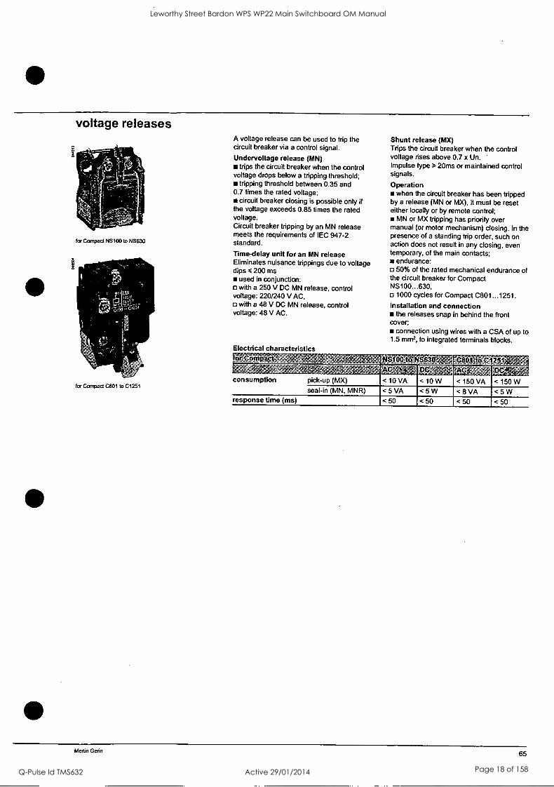
voltage releases
for Compact NS100 to NS630
MIL
an
for Compact C801 to C1251
A voltage release can be used to trip the circuit breaker via a control signal.
Undervoltage release (MN) trips the circuit breaker when the control
voltage drops below a tripping threshold; tripping threshold between 0.35 and
0.7 times the rated voltage; circuit breaker closing is possible only if
the voltage exceeds 0.85 times the rated voltage. Circuit breaker tripping by an MN release meets the requirements of IEC 947-2 standard.
Time-delay unit for an MN release Eliminates nuisance trippings due to voltage dips 200 ms
used in conjunction: o with a 250 V DC MN release, control voltage: 220/240 V AC,
with a 48 V DC MN release, control voltage: 48 V AC.
Electrical characteristics
Shunt release (MX) Trips the circuit breaker when the control voltage rises above 0.7 x Un. Impulse type 20ms or maintained control signals.
Operation when the circuit breaker has been tripped
by a release (MN or MX), it must be reset either locally or by remote control;
MN or MX tripping has priority over manual (or motor mechanism) closing. In the presence of a standing trip order, such on action does not result in any closing, even temporary, of the main contacts;
endurance: 50% of the rated mechanical endurance of
the circuit breaker for Compact NS100...630,
1000 cycles for Compact C801...1251. Installation and connection
the releases snap in behind the front cover;
connection using wires with a CSA of up to 1.5 mm2, to integrated terminals blocks.
or Compact NSIOOato 0 rg80'J t.01205 ., ,,, Wig
< 10 VA
DDINS4 acip-;a. < 150 VA
lot < 150 W consumption pick-up (MX) <10 W
seal-in (MN, MNR) < 5 VA < 5 W < 8 VA < 5 W response time (ms) < 50 < 50 < 50 < 50
Merlin Gerin 65
Leworthy Street Bardon WPS WP22 Main Switchboard OM Manual
Q-Pulse Id TMS632 Active 29/01/2014 Page 18 of 158

TECHNICAL DATA SHEET
For
Leworthy Street Pump Station
Equipment Type: Phase Failure Relay
Location: Common Control
Model Numbers: 252-PSGW
Manufacturer: Crompton
Supplier: Alstrom. 3/7 Miller Street Murrarie QLD 4172
Ph: 07 3890 4412 Fx: 07 3890 4413
Leworthy Street Bardon WPS WP22 Main Switchboard OM Manual
Q-Pulse Id TMS632 Active 29/01/2014 Page 19 of 158

- I
Application:
el Portable pumps
Portable compressors
Eg Motor driven mixing equipment
Motors - Single Phasing
Gensets - correct engine rotation
All portable equipment
Ei All rotating machines
We also manufacture front of panel mounting phase sequence indicators
Protector Trip Relays 250 Series DIN Rail and Wall Mounted - Phase Sequence and Phase Failure
(ar;;-(,-
14 11 12 PROTECTOR
1124
216-'4"*29 014 Y.
Introduction
The Crompton phase sequence and phase failure protector relays are designed to monitor the correct phase rotation or sequence of three phase, 3 or 4 wire, supply systems for protection against incorrect phase sequence, loss of one phase and under voltage.
Rotating machines are particularly vulnerable to incorrect phase sequence. Three phase motors can rotate in the wrong direction, potentially leading to physical damage or the risk of injury to personnel, yet voltage and current readings may appear normal. If one phase is lost because of a blown fuse, electric motors can continue to operate (single phasing) which can result in severe electrical or mechanical damage.
Product Function
For permanent installations, this relay should be used to monitor the incoming supply, protecting all equipment against incorrect connection at initial installation or after maintenance work. Rotating machines that cannot tolerate reverse rotation or pose significant risk to personnel under this condition should be individually protected with this relay. The possibility of incorrect supply connection is much more likely in portable equipment or marine applications
The protector continuously monitors the three phase supply. With the correct phase sequence applied, the front panel LED will illuminate and the output relay will be energized. An incorrect sequence or missing phase will de-energize the relay, and the LED will be extinguished. If the supply drops below 85% of its nominal voltage, this condition will also cause a trip.
Protection against
Incorrect phase sequence
Loss of one phase
Under voltage
Important note: If one phase is lost due to a blown fuse, some loads can re-generate the missing voltage. This relay can be used as a phase failure relay providing the regenerated voltage in the open phase is less than 70% of the nominal supply voltage. If there is the possibility of a higher regenerated voltage, the phase balance relay 252-PSF should be used.
Protection for
Portable electrical equipment
Incorrect sequence connection
Loss of one phase (which can result in severe electrical/ mechanical damage or physical/personnel damage due to reverse rotation of motor driven equipment)
Web: www.crompton-instruments.com Email: crompton.infoalltycoelectronics.eom 2002
Leworthy Street Bardon WPS WP22 Main Switchboard OM Manual
Q-Pulse Id TMS632 Active 29/01/2014 Page 20 of 158

I I
-ompton 137-712111
1 Protector Relays
aa,
Protector Trip Relays 250 Series DIN Rail and Wall Mounted - Phase Sequence and Phase Failure
Specification
Approvals: U.L recognized up to 300V Overload: 1.2 x continuously CSA Approved up to 240V 1.5 x for 10 x 10 seconds to
Nominal Voltage: 100, 110, 120, 208, 220, Symmetric
230, 240, 277, 380, 400, Undenroltage Protection: 415, 440 & 480V Preset at 85% of nominal
System Frequency: 50, 60, or 400Hz (specify) Weight: Approximately 0.4kg
Burden: 3VA approx.
Product Code Examples
Relay
3 Phase 3 or 4 wire
3 Phase 3 or 4 wire
FREirpu5.7771 120Vi aktOlie,
%att. 16V Q.:60 tlz:'
Connection Diagrams
Protection igAissrpaziii Catalogue No.
Phase sequence, under voltage
Phase sequence, under voltage
252-PVRU-PQBX-C6
252-PVRU-S8BX-C6
252-PVR Relay
Contact Set 1 Contact Set 2
14 11 12 22 21 24 PROTECTOS1
L1 : 24 21,.22 11*.,4;:: +ED
L3 L2
L1 L2 L3
Input
Note: No neutral connection is required
Web: www.crompton-instruments.com Email: crompton.inlotttycoelectronics.com 2002
Leworthy Street Bardon WPS WP22 Main Switchboard OM Manual
Q-Pulse Id TMS632 Active 29/01/2014 Page 21 of 158

TECHNICAL DATA SHEET
For
Leworthy Street Pump Station
Equipment Type: Circuit Breaker
Location: Switchboard Distribution Chassis
Model Numbers: Multi 9
Manufacturer: Merlin Gerin
Supplier: Schneider Electric. 30 Graystone Street TINGALPA QLD 4173
Ph: 07 3890 2112 Fx: 07 3890 2098
Leworthy Street Bardon WPS WP22 Main Switchboard OM Manual
Q-Pulse Id TMS632 Active 29/01/2014 Page 22 of 158

circuit protection C6ON circuit-breakers circuit-breakers up to 63 A B and C curves
IEC 898: 6000 Al, IEC 947-2: 10 kA
functions The circuit-breakers combine the following functions: - protection of circuits against short-circuit currents, - protection of circuits against overload currents, - control,
- isolation, - protection of persons against indirect contact in TN and IT earthing systems.
C6ON circuit-breakers are used in the tertiary sector and industry.
description
catalogue numbers
24057
technical data common to C6ON circuit- breakers b power circuit v voltage rating: 440 V CA v breaking capacity according to IEC 947-2, lou ultimate breaking capacity (0-CO cycle) : Lratiriok ,type 'GT( '677- 43real" cad
sicri
0.5...63 1 P 230...240 10 400...415 3 (1)
P + N, 2P, 3P, 4P 230...240 20 2P, 3P, 4P 400...415 10
(1) breaking capacity under 1 pole in an IT insulated earthing system (case of the double fault). y limitation class (IEC 898): 3 v number of cycles (0-C): 20 000 b environment v tropicalisation: treatment 2 (relative humidity: 95 % at 55 °C) v connection: tunnel terminals for the following cables: - 16 mm2 flexible or 25 mm2 rigid up to rating 25 A - 25 mm2 flexible or 35 mm2 rigid for 32 to 63 A ratings.
B curve use when there are weak short-circuit currents (generators, long cables). technical data b power circuit: v ratings: 6 to 63 A set at 30 °C v tripping curve: the magnetic trip units operate between 3 and 5 In v breaking capacity according to IEC 898, 101 ultimate breaking capacity (0-CO cycle) :
tatiAg- "type : breakig CIO b-att9cny
etilAJA
10...63 1P 230...400 6 000 1P + N 230 6 000 2P, 3P, 4P 400 6 000
y limitation class (IEC 898): 3
C curve use cables feeding conventional loads. technical data b power circuit v ratings: 0.5 to 63 A set at 30 °C v tripping curve: the magnetic trip units operate between 5 and 10 In v breaking capacity according to IEC 898, Icri ultimate breaking capacity (0-CO cycle) rating; - v !MAIM (A)
148'n A
0.5...63 1P 230...400 6 000 1P + N 230 6 000 2P, 3P, 4P 400 6 000
v limitation class (IEC 898): 3
C6ON B curve
1P 6 10 16 20 25 32 40 50 63
24049 2 12 24050 2 12 24051 2 12 24052 2 12 24053 2 12 24054 2 12 24055 2 12 24056 2 12 24057 2 12
90062E.fm/2 Merlin Gerin Updated: 4/07/01 Schneider Electric
Leworthy Street Bardon WPS WP22 Main Switchboard OM Manual
Q-Pulse Id TMS632 Active 29/01/2014 Page 23 of 158

circuit protection C6ON circuit-breakers circuit-breakers up to 63 A B and C curves
IEC 898: 6000 Al, IEC 947-2: 10 kA
catalogue numbers
40
24083
24094
24107
24248
24262
catakig nan rnocChpeitla
C6ON B curve (continued
2P 1 3
2 4
3P 1 3 5
* *
2 4 6
4P 1 3 5 7 * * * *
2 4 6 8
C6ON C curve
1P 1
*
2
Schneider Electric W Merlin Gerin
6 24075 4 6 10 24076 4 6 16 24077 4 6 20 24078 4 6 25 24079 4 6 32 24080 4 6 40 24081 4 6 50 24082 4 6 63 24083 4 6
6 24088 6 4 10 24089 6 4 16 24090 6 4 20 24091 6 4 25 24092 6 4 32 24093 6 4 40 24094 6 4 50 24095 6 4 63 24096 6 4
6 24101 8 3 10 24102 8 3 16 24103 8 3 20 24104 8 3 25 24105 8 3 32 24106 8 3 40 24107 8 3 50 24108 8 3 63 24109 8 3
0,5 24067 2 12 1 24235 2 12 2 24236 2 12 3 24237 2 12 4 24238 2 12 6 24239 2 12 10 24240 2 12 16 24242 2 12 20 24243 2 12 25 24244 2 12 32 24245 2 12 40 24246 2 12 50 24247 2 12 63 24248 2 12
1 24249 4 6 2 24250 4 6 3 24251 4 6 4 24252 4 6 6 24253 4 6 10 24254 4 6 16 24256 4 6 20 24257 4 6 25 24258 4 6 32 24259 4 6 40 24260 4 6 50 24261 4 6 63 24262 4 6
Updated: 4/07/01 90062E f m/3
Leworthy Street Bardon WPS WP22 Main Switchboard OM Manual
Q-Pulse Id TMS632 Active 29/01/2014 Page 24 of 158

circuit protection C6ON circuit-breakers circuit-breakers up to 63 A B and C curves
IEC 898: 6000 IEC 947-2: 10 kA
catalogue numbers
24272
24285
24304
2P
2 4
0.5 1
2 3 4 6 10 16 20 25 32 40 50 63
24068 4 6 24263 4 6 24264 4 6 24265 4 6 24266 4 6 24267 4 6 24268 4 6 24270 4 6 24271 4 6 24272 4 6 24273 4 6 24274 4 6 24275 4 6 24276 4 6
3P 0.5 24069 6 4 1 3 5 1 24277 6 4 >k * * 2 24278 6 4
3 24279 6 4 4 24280 6 4 6 24281 6 4 10 24282 6 4
2 4 6 16 20 25 32 40 50 63
4P 0.5 1 3 5 7 1 * * * * 2
3 4
6 10
2 4 6 8 16 20 25 32 40 50 63
24284 6 4 24285 6 4 24286 6 4 24287 6 4 24288 6 4 24289 6 4 24290 6 4
24070 8 3 24291 8 3 24292 8 3 24293 8 3 24294 8 3 24295 8 3 24296 8 3 24298 8 3 24299 8 3 24300 8 3 24301 8 3 24302 8 3 24303 8 3 24304 8 3
additional information
Vigi modules: page 90115/2 electrical auxiliaries: page 9014212 accessories: page 91903/2 dimensions: page 90148/2
curves: page 90180/2
90062E frn/4 Merlin Gerin Updated: 4/07/01 Schneider Electric
Leworthy Street Bardon WPS WP22 Main Switchboard OM Manual
Q-Pulse Id TMS632 Active 29/01/2014 Page 25 of 158

TECHNICAL DATA SHEET
For
Leworthy Street Pump Station
Equipment Type: Current Transducer
Location: Pump Control
Model Numbers: D414-5A 24vdc
0 Manufacturer: Crompton
Supplier: Alstrom. 3/7 Miller Street Murrarie QLD 4172
Ph: 07 3890 4412 Fx: 07 3890 4413
Leworthy Street Bardon WPS WP22 Main Switchboard OM Manual
Q-Pulse Id TMS632 Active 29/01/2014 Page 26 of 158

-
riompton E=Es
rtan
Moulded Case Current Transformers 802 Series Instrument Transformers
Model 802-943
Specifications
Model 802-940
Application: Generally for Ammeter use only
Manufactured to meet the requirements of UL 1244 and revisions
Flexible leads are UL 1015 105C CSA Frequency: 50-400 Hz approved, #16 AWG, 24" long
Installation Class: 0.6 KV. BIL. 10 KV. full wave Non-standard lengh to be specifed
Terminals are brass studs No. 8-32 UNC with one flat washer, lockwasher and regular nut
UL Recognized
ABS Approved Dimensions (inches)
Ordering Information
Catalogue Number
U-NTLS
U-NWLS
U-PBLS
U-PDLS
U-PKLS
U-PBLS
U-PSLS
U-PZLS
U-RLLS
U-RSLS
U-RXLS
0.96
60:5; r5.5;', 80.5411,
r 1.2C5": * 1%
1%
+1%
+1% + 1%
+1%
0.40
0.41
0.42
0.43
0.43
0.44 0.44
0.45
0.48
0.51
9;FrAl.., 0.54
Other ratios available on request.
NOTE: When ordering, prefix Cat. No with model designation required. i.e. 802-943U-NTLS or 802-940U-NTLS
Web: www.crompton-instruments.com Email: crompton.intoetycoelectronics.com 2002
Leworthy Street Bardon WPS WP22 Main Switchboard OM Manual
Q-Pulse Id TMS632 Active 29/01/2014 Page 27 of 158

TECHNICAL DATA SHEET
For
Leworthy Street Pump Station
Equipment Type: Surge Diverter
Location: Main Incomer
Model Numbers: TDS-MT-277
Manufacturer: Critec
Supplier: Energy Correction Options P.O.Box 431 Kelvin Grove Q1d,4059 Te1:33560577 Fax:33561432
Leworthy Street Bardon WPS WP22 Main Switchboard OM Manual
Q-Pulse Id TMS632 Active 29/01/2014 Page 28 of 158

Detailed Specifications for ERICO's TDS-MOVTEC SURGE DIVERTER TDS-MT-277
Applications Lightning transients and surges are a major cause of expensive electronic equip- ment failure and business disruption. Damage may result in loss of computers, data and communications, loss of revenue, and loss of profits. The new TDS- MOVTEC family of surge diverters offer economical and reliable protection from power transients in even the most strenuous applications.
Transient Discriminating Technology (TDS) introduces the first quantum leap in transient suppression technology for mains powered equipment. It offers a new level of safety and reliability, yet retains optimum protection levels critical for electronic equipment. TDS is an active frequency based device that discriminates between the slower mains voltages and the higher speed transients. When transient frequencies are detected the patented TDS "Quick-Switch" technology "switches in" robust protection devices to limit the transient to safe levels. The frequency discrimination circuit controlling the TDS "Quick-Switch" ensures that the device is virtually immune to the effects of the 50/60Hz sustained over- voltages, allowing fault voltages of up to 480Vrms without degradation, and providing over-voltage robustness in excess of the demanding new and emerging standards.
TDS technology is essential for any site where abnormal over-voltages can occur or where the possible catastrophic failure of traditional technologies due to over- voltage events can not be tolerated.
Since 75% of all lightning strikes comprise multiple strokes through the one air to
ground channel, often as little as 30 milliseconds apart, conventional MOVs can rapidly accumulate heat and self destruct just when they are most needed. TDS- MOVTECs are high capacity surge diverters and are the most advanced surge protection devices currently in place to offer low let through levels at sites with poor voltage regulation. Internal electronics continuously monitor TDS- MOVTEC protection, and their status is displayed on a 5-segment LED bar graph. Alarm contacts are provided which may be used to shut down the system or activate an external warning if the internal surge material is below optimum condition.
Features Robust against abnormal over-voltage
UL1449 Edition 2 compliant (pending)
Single phase primary protection for extremly high exposure sites and point- of-entry protection applications
Single mode protection, configurable to Ph-N, Ph-E or N-E protection
Small foot print for more effective use of realestate.
Fail safe voltage free alarm contacts
5 segment electronic status indication ideal for poorly illuminated locations
Long Service life
Lug terminals for connection of large cables
CRDWELD® CRITEC® ERITECH® WELDED ELECTRICAL CONNECTIONS SURGE PROTECTION DEVICES LIGHTNING PROTECTION/GROUNDING CO®
Leworthy Street Bardon WPS WP22 Main Switchboard OM Manual
Q-Pulse Id TMS632 Active 29/01/2014 Page 29 of 158

TDS-MOVTEC SURGE DIVERTER TDS-MT-277
SPECIFICATIONS Operation: Nominal input voltage
Input frequency
Max. permissible abnormal over-voltage Power systems
Earth leakage current Protection:
Modes Let through voltage @ 3kA 8/20ps
Let through voltage @ 20IcA 8/201is Surge rating 8/20ps
Surge rating 10/350us Energy rating
Multipulsetm' capability Aggregate surge material Alarms and Indicators:
Protection status indication User configurable alarm contacts
Breakdown isolation MOVTEC alarm actuation point
Physicals: Operating conditions
Enclosure style Dimensions (W x D x H)
Weight
Encapsulation Enclosure material
Surface finish Wiring terminals
Warranty Test standards:
Approvals
Estimated Life of MOVTEC and TDS-MOVTEC
11A 10 100
Number of Impulses
I35kA tionec
1,000
TDS -Hoytec
Cat
Cat
Cat C
Cat 13
10,000
Surge rated to meet
220 -277 Vrms 50/60 Hz
480 Vrms TN-C, TN-S, TN-C-S (MEN), TT <2mA
Ph-N, Ph-E or N-E <740V
<970V 100kA 20kA 4800J Yes
200kA 8/20us
5-segment LED bar graph Voltage free relay contact (NO) 4kV
.60% status (two LEDs off)
-35 to +55°C, 0-90% humidity Proprietry 45 x 140 x 140mm
600g (approx.) Shockguard Flame Retardent UL94V-0 Highly Polished M6 Swift Thread and Bolt 5 years
UL1449 Edition 2 (pending) AS 3260, IEC 950 C-Tick Certificate of suitability, Electricity Regulator ANSI/IEEE C62.41-1991 Cat A, Cat B, Cat C. ANSI/IEEE C62.45-1987 Life cycle testing. AS/NZS 1768-1991 Cat A, Cat.B, Cat C. BS 6651:1992 Cat A, Cat B. IEC801-5 Installation Class 5.
IEC 61643-1
Note: Other operating voltages and frequencies are available on application. For specifications on other TDS products, refer to relevant Specifications Sheet. Exceeding nominal operating voltage while transient events occur may affect product life.
TDS, MULTIPULSE, PROLINE, CRITEC, MOVTEC, DINLINE and SURGE REDUCTION FILTER are trademarks of ERICO.
Due to a policy of continual product development, specifications are subject to change without notice. © Copyright 1998
Model Number
TDS-MT-277
Description
TDS MOVTEC 220-277V 100KA
Hobart Sydney Melbourne Canberra
ph:+61 3 6237-3200
ph:+61 2 9479-8500
ph:+61 3 9894-2677 ph:+61 2 6257-3055
fax+61 3 6273-0399 fax+61 2 9980-5092 fax+61 3 9894-3216 fax 2 6257-3127
Adelaide ph:+61 8 8366-6555 fax +61 8 8366-6556 Perth ph:+61 8 9358-1233 fax +61 8 9358-1404 Singapore ph:+ 65-763-2477 fax+ 65 763-2397 Thailand ph:+ 662 627-9037-8 fax+662 627-9168
enrcri e cn
ERICO's coordinated approach to facility protection - CADWELD, CRITEC, ERITECH www.erico.com
Co
Leworthy Street Bardon WPS WP22 Main Switchboard OM Manual
Q-Pulse Id TMS632 Active 29/01/2014 Page 30 of 158

TECHNICAL DATA SHEET
For
Leworthy Street Pump Station
Equipment Type: Control Selector Switches
Location: Common Control
Model Numbers: CAD12A222-600
Manufacturer: Kraus & Namer
Supplier: Australian Solenoids Pty Ltd 22 Brookes Street, Bowen Hills, Qld 4006 Phone (07) 3252 8344 Fax (07) 3252 1497
Leworthy Street Bardon WPS WP22 Main Switchboard OM Manual
Q-Pulse Id TMS632 Active 29/01/2014 Page 31 of 158

4) KRA US & NAIMER BLUE LINE SWITCHGEAR
www.krausnaimer.com (1) Catalog 100 CL Switches 10 A-20 A C, CA, CAD Switches 10 A-315 A L Switches 350 A-2400 A
K
____11111011
Leworthy Street Bardon WPS WP22 Main Switchboard OM Manual
Q-Pulse Id TMS632 Active 29/01/2014 Page 32 of 158

Switch Function and Configuration L Switches
Function/Type Escutch. Plate Handle Code Stages
Double Latching
Connection Diagram
L350 L351 L630 211E, L631 .I
Li000 cx RP (3 L1001 L1250 L1251
ON/OFF Switches with 90° Switching
1 pole L1600 2 pole 3 pole
e° -.127-
e... .,..7- :A296-:600, S2'94:), _*6,'
4 8 12
1 17
\I 4 xl
1 1 1 1-3 pole
16 32 48
° 0-6
.A292=606 ins 1 pole L2000 2 pole 9tiP ' '' 1C) 1 T
\ \ 1- and 2 pole
2640 1-
Double-throw Switches without OFF" 60° Switching
1 pole L350/L351 2 pole 3 pole 4 pole
V
1 pole L400 2 pole 3 pole 4 pole
1 pole L600 2 pole 3 pole 4 pole
1V=
V
V
1 2 4 5 7 8 10 11 y y y 3 9 12
1-4 pole
ar- A220' 3 e 2-4!6-50/ 6 fA-2:V-, 9
12 4'Ve.747,4
1 pole L630/L631 2 pole 3 pole
1 2
V
1 pole L800 2 pole 3 pole
* I 2
1 pole L1000/L1001 2 pole
1 pole L1200
1 pole L1250/L1251
V
1 7
V
1 pole L1600 *
V
1 pole L2000 1 2
V
Sf
-4;
25 27
1`1 lx 1`1
18
3 9 15 21 27 33 35 45
I 1 111
2 14 26 77
1-4 pole
1-4 pole
4 8 12
y
3 6 9
1-3 pole
4 8 12
1 9 17 25 33 41
1 I 16 32
1-3 pole
6 12 I\ 1
1 and 2 pole
1 13
24
8
10
121 18
Additional length for switches size S2 for mounting E/EF = 27 mm 26 Additional length for switches size S3 for mounting E/EF = 31,5 mm and mounting ERNE = 20,1 mm
Leworthy Street Bardon WPS WP22 Main Switchboard OM Manual
Q-Pulse Id TMS632 Active 29/01/2014 Page 33 of 158

Mounting C, CA, CAD, CL Switches
Single Hole Mounting Terminals rotated 90° -
Code CA4 CA4-1 CL4
CAD.. CA1 0- CA25 CL1O
With locking nut and shaft seal, protection IP 65
Without escutcheon plate
With square escutcheon plate
With rectangular escutcheon plate
`' 4" " " With size S1 escutcheon plate and heavy duty latching
Mounting key for locking nut
mm
FS1 16/22
FS1A/ 16/22 '
- -V
F,T3
32
FS2 16/22
S21 16/22
,e 4 4
16/22 16/22
mm
22 22 22/30 22/30
22 22 22/30 22/30
22 22
Leworthy Street Bardon WPS WP22 Main Switchboard OM Manual
Q-Pulse Id TMS632 Active 29/01/2014 Page 34 of 158

mm Dimensions inch
4111
Single Hole Mounting or Base Mounting
FS1... FH3...
FT1... FS2...
FT3... FT2...
FT4...
0
FS1...
FS2...
FS4...
A.
FH3...
FT1...
FT2...
FS4...
FT3...
FT4...
VE VE-V
A
B
C
CA10 CA11 CA10B CAD11 CA11B CAD1 2 CA20 CA252 CA20B 48 48 48 (64) 64 1.89 1.89 1.89 (2.52) 2.52
43 45 46 56 1.69 1.77 1.81 2.20
10,5 10,5 10,5 13,5 .41 .41 .41 .53
4,1 4,1 4,1 4,1 Di .16 .16 .16 .16
5 5 5 5 D2 .20 .20 .20 .20
31,59 8-15 .31,59
8-15 D3 8-15
.31-.59 .39-S9 10-15
1.42 1.42 36 36 36 (48) 48
1.42 (1.89) 1.89
.09 .09 2,2 2,2 3,2 2,5
.13 .10
CA10 CAA 1
CA4 CAD11 CA4-1 C L4 CAD1 2 CLIO CA20 CA25
A/E
B
C
D
F
M
FH3...
FH3...
30 1.18
-
30 1.18
48 1.89
64 2.52
48 1.89
64 2.52
48 1.89
64 2.52
48 1.89
64 2.52
28 1.10
35x46 1.38x1.81
43 1.69
50x56 1.97x2.20
45 1.77
46 1.81
5 .20
5 .20
6 .24
6 .24
6 .24
6 .24
29,5 1.16
29,5 1.16
39 1.54
39 1.54
39 1.54
39 1.54
39 1.54
39 1.54
..
12,5 .49
12,5 .49
20 .79
27 1.07
20 .79
27 1.07
20 .79
27 1.07
20 .79
27 1.07
VE22
VE22V
2.
VF22
VF22V
L' 3.7 .15'
CA25B C26 C32 C422 C43 C80 C125 L switches
Size $2
C315 L switches
Size S3
64 64 64 64 (88) 88 88 88 88 128 2.52 2.52 2.52 2.52 (3.46) 3.46 3.46 3.46 3.46 5.04 56 58 60 66 84 84 88 88 126 2.20 2.28 2.36 2.60 3.30 3.30 3.46 3.46 4.96 13,5 13,5 13,5 13,5 16 16 16 16 19,3 .53 .53 .53 .53 .63 .63 .63 .63 .76
4,1 4,1 4,1 5,4 5,4 5,4 5,4 5,4 7 .16 .16 .16 .21 .21 .21 .21 .21 .28
5 5 5 5 6 6 6 6 7 .20 .20 .20 .20 .24 .24 .24 .24 .28 10-15 .39,59
10-15 .39-.59
10-15 .39-.59
10-15 39-S9
13-17 .51-S7
13-17 .51-.67
13-17 .51-S7
13-17 .51,67
15,5-20 .61-39
48 48 48 48 (68) 68 68 68 68 104 1.89 1.89 1.89 1.89 (2.68) 2.68 2.68 2.68 2.68 4.09 2,5 5 5 7 8,9 8,9 27 11,4 .10 .20 .20 .20 .28 .35 .35 1.06 .45
Dimensions in ( ) for revertive mounting plate
48 'see page 51
Leworthy Street Bardon WPS WP22 Main Switchboard OM Manual
Q-Pulse Id TMS632 Active 29/01/2014 Page 35 of 158

TECHNICAL DATA SHEET
For
Leworthy Street Pump Station
Equipment Type: Pushbuttons, Indicator Lights &.
Location: Switchboard Starter Section Common Control
Model Numbers: ZB Series
Manufacturer: TELEMECANIQUE
Supplier: Schneider Electric. 30 Graystone Street TINGALPA QLD 4173
Ph: 07 3890 2112 Fx: 07 3890 2098
Leworthy Street Bardon WPS WP22 Main Switchboard OM Manual
Q-Pulse Id TMS632 Active 29/01/2014 Page 36 of 158

Ltrig: 1.)eseription;
ID
.155 II IS
::,:, :6 e-z, r: ' r---,-.1_!..:tr 'fa.,:".!-"-IX",.-A'';'-'7;,:,34:- ",{7.-::. ,...`"-4,77:1zir ,,,-: :.....,:t; , .`':if:;;-,...%F.--_-. - -- r.;,.;,..d.w5-..-- .5.)%::. , T--I",,, -17,.h.',.-01.22%style 5Zrange' ibfiditifitrOZandi%igitalling.iiiiits,ebtrikisWg'-4:.- ',:A.- _-o,!;;- 1. t.,,,..* ","..':7 c'F.' - - .."Sf:t.t,:f._;,-, Xvt.' i.,,,,_,...:;_, .,-,1,...": :.-,,...A,tiTy..,-:-.:,, _ ,:^1._-, -
''',""---:2;.::4 ',.',,,,, i`" ,'2.,, . -.._, .:
JO
`41 het.
3
- 0 r j''' -.;:
roa
1A4.5
Jj
Leworthy Street Bardon WPS WP22 Main Switchboard OM Manual
Q-Pulse Id TMS632 Active 29/01/2014 Page 37 of 158

General (continued) Control and signalling units 0 22 Harmony® style 5 Pushbuttons, switches and pilot lights, with double insulated bezel
Characteristics : References :
pages 36011/2 to 36011/5 pages 3601212 to 36019/3 pages 36021/2 to 36021/9 Dimensions :
r"-rirsolowumemour
Leworthy Street Bardon WPS WP22 Main Switchboard OM Manual
Q-Pulse Id TMS632 Active 29/01/2014 Page 38 of 158

TECHNICAL DATA SHEET
For
Leworthy Street Pump Station
Equipment Type: Contactor
Location: Switchboard Starter Section
Model Numbers: LCF 225
Manufacturer: TELEMECANIQUE
Supplier: Schneider Electric. 30 Graystone Street TINGALPA QLD 4173
Ph: 07 3890 2112 Fx: 07 3890 2098
Leworthy Street Bardon WPS WP22 Main Switchboard OM Manual
Q-Pulse Id TMS632 Active 29/01/2014 Page 39 of 158

Characteristics Contactors Type LC1-F (115 to 800 A) Control circuit : a.c. or d.c. supply
T e
EnvlionnYent:
1.61:-F150, LC1-F1gc
Rated insulation voltage (Ui) toriformm to IEC 9474-1 . - ' ' V 1000 " - 1000 1000',
Conformin- toVDE 0110 r C - - -- V 1500 '.,,=:- 1500", ,1, 1500
Rated impulse withstand Coil not connected to the ' er Circuit -,,,' - .
voltage (Ulm"
Conforming to standards EN 60947-1fEN 60947 -441; IEC 947-1, IEC 947-4-1 JEM 1038
Product certifications CSA, UL, By GL, DWI, RINA, MAROS, LR 0 ,
Degree of protection _ .-.
COniorming to IEC 529 IP 20 front Id& with shrouds LA9,F , ,- - ,- ' 2 ,,.
- Conforming to VDE 0106 Front face protected again.stclit=ect finger contact with shrouds LA9-F
Protective treatment Standard version -- "T- H" -.. ' - ", -'''
Ambient air temperature around the device
Storage °O - 60 .4: 80 5
Operation , °C - 5 ..+, 55
Permissible at Uc (1) : 40 +.70
Maximum operating altitude Without derating 3000--'
Operating positions Without derating , ,.
.
f,,,,,,' '
,..,
,..
With derating
5-, , ,
,i/
4r1,4 M "
Apply the - - , pull-in voltage,
' the operational
,
following deratmg coefficients- :0.75 on the 0'9 on the drcip-out voltage and 0 a on current in AC-1
following derating coefficients .1 15 on the 11 on the drop-out voltage and 0.8 on
l 'c in AC-1
Making and breaking capaCities nor-the, durabilities can be assured
c, - Apply the
pull -in ,voltage, / : A, the a Opertionaurrent
In either,case; neither,lhe electrical and Mechanical
Forbidden
,--
Shock resistance (2) 1/2 sine wave = 11 ms
Contactor open 9 qn 9 gn, ' 7 gn ,
ContactOrtioSed ,
,
16 qn ",-,.
,
15 qn, 15 gn -
Vibration resistance (2) 5 300 Hz
Contactor open', 2 qn 2 gn 2 gn,
Contactortloseil 6tri 6 gn ,-;,-
5 qn (1) In these conditions, it is recommended that LX9-F coils be used for contactor sizes F115 to F225. (2) In the least favourable direction, without change of contact state (coil at Uc). For conditions requiring a much higher value resistance to mechanical shock, the use of our shock-proof contactors is recommended. Please consult your Regional Sales Office.
Selection guide : References : Dimensions : Schemes : pages 24565/2 to 24564/3 pages 25008/2 and 25008/3 pages 25011/2 and 2501113 page 25011/7
25007_Ver700-EN.fm/2 Telemecanique Schneider Electric
Leworthy Street Bardon WPS WP22 Main Switchboard OM Manual
Q-Pulse Id TMS632 Active 29/01/2014 Page 40 of 158

LC1 -F225 I
- LC1-F330:, LC7 -F400 . t-'
1000
1500
8
1000 -
156
ILC1-F630 LC1-F500 LC1-660
, l000 -foOo . -lobo
1500 1600 - -- 1500
4000
1500 .
EN 60947-1, EN 60947-4-1, IEC 947-1, IEC 947-4-1, JEM 1038 -;
CSA, UL.,-BV, GL, DNV, RINA, RMROS I UL, CSA , . ''' , -;
IP 20 front face with shrouds LA9-F - ,
,
,
Front face protected against direct finger contactwrthihroudSCA9-F -
, -TH" , ,-
- 60 + 80 ',' -_ 60 + 80
5 + 56 - 5 + 55
- 40,'+ 70 7 5. + 55
3000' ...
30°
v Apply the following derating coefficients:0 75 on the pull-in voltage. 0 9 on the drop-out voltage and 0 8 on the operational current in AC-1
ouniC -
Apply' the following derating Coefficients .1.15'On'the pull-in voltage, 1.1 on the drop-out voltage and 0 8 on the Opei:ational current In AC -1
, > In either case neither the making and breaking capacities nor the electncal and mechanical durabilibes can be assured ' - - mechanical
, .
,
6 gn ', 6 gn, 6 gn,, 9 gn 6 qn 5 gn , _ ,
6 qn ,r,
15 qn 15 qn 15 qn , 115 gn' 15 on 15 qn" ' 15 gn, 15 gn
2 gn, 2gn ' 2gn 1 5 qn -. 2- on - 2gn 2 5 gn 2gn , , , ,..
5 n , 5 gn .. ,
5 gn 5 gn 4 on , 4 qn ,
6 5 gn 4,gn ti i In thine,u n.snelofonne of le rowno-nnuarseleati fkmf I VO_P resole ha curl frsr rnnfnefne co,onc Pl1R ft, CI'IR (2) In the least favourable direction, without change of contact state (coil at Uc . For conditions requiring a much higher value resistance to mechanical shock, the use of our shock-proof contactors is recommended. Please consult your Regional Sales Office.
Schneider Electric Telemecanique 25007 Veiliki-EN fm/3
Leworthy Street Bardon WPS WP22 Main Switchboard OM Manual
Q-Pulse Id TMS632 Active 29/01/2014 Page 41 of 158

Characteristics Contactors Type LC1-F (115 to 800 A) Control circuit : d.c. supply
Type
Con 91cir91 ct araCtenStitS h LX4 coil
Rated control circuit voltage (Uc)
Control voltage limits (0 5 55 °C)
Operational ; 7,
- Dropout,
LC1-F150 - ,
24 460 -24' 460
85 .1 1 Uc -- 015 -02 Uc
0 85. 1 1'Uc
015 02 Uc
1C1;f185 _
24 460
t1 Uc
015 .0.2 Uc
Average consumption at 20 °C and at Uc 7' Inniih
..,.. 560 " '
660 . - co:; -
,
' -
Sealed 4 5
Average operating time at Uc (1) ,Closing - -°C' - ms . ,
30 40, , "
30' 40; , , 30 'A0 -
Obening 70* ,
ms . 30 .50 30 sci, . 30. 50 ..< '
Note i The arcing imadepends on the circuit switched by the poles- For normal 3 -phase applications, the arcing time ms, usually less than 10 ms The load is isolated from the supply after a time equal to the'sum of Ahe opening time and the arcing time - ' .":-"
Mechanical durability at Uc in millions of operabrib cycles
-
10 10 10
Maximum operating rate at ambient temperature 5 55 °C
-.. , - ,
.t In operating cycles per hour ; .; 2400 2400 , 2400
Cabling Flexible cable without cable end
1 condbctors", ' ,.
Min /max c s a 1/4 - ,1/4 114
-'
2 loonr:1Ucters , ,
-
mm2 1/4 . 1/4 1/4
Flexible cable with cable end 1 conductor ,.. , '
mm2 , 1/4 . , 1/4
_, 1/4
2 conductors 1/2 5 - '
1/2.5 , 112 5 "
Solid cable without cable end I conductor -, mm2 1/4," 1/4 - 1/4
2'OonduOtors - 1/4 1/4 ,
1/4' . .
Tightening torque N m 1'2 1 2 1.2 ,
Mechanical latching 6ue to their rating, La1-F contactors'cannot be ,fitted with LA6-DK add-Oh mechenical latch blocks. -
For similar type of ,operation, use magnetic latching contactors C121:F . ,' , See Oxide 26091/2 to 26008/9 , "
(1) The operating times depend on the type of contactor electromagnet and its control mode. The closing time "C" is measured from the moment the coil supply is switched on to initial contact of the main poles. The opening time "Cr is measured from the moment the coil supply is switched off to the moment the main poles separate.
Selection guide : References : Dimensions : Schemes :
pages 24565/2 to 24564/3 pages 25008/2 and 25008/3 pages 25011/2 and 25011/3 page 2501117
25007_v,er7:00-EN.fmm Telemecanique Schneider Electric
Leworthy Street Bardon WPS WP22 Main Switchboard OM Manual
Q-Pulse Id TMS632 Active 29/01/2014 Page 42 of 158

LC1 -F4002
24 460 ' 24 :460 .
0 85. 1.11.1c
,
015 .02 UC
= , a 85 .1.1',Uc
0.15 0 2 Uc
-, 0.85 .1.1 Uc
0 15...02 Uc,. .
,. 0 85
6.2
.1 1 Uc ,
.035 UC' "
LC_ 1-F509,
< y ,
48 .440
- -- L61.4.30 , LC1-F780 LC1-F11301Y-:
110 ' 440
, 0 85 .1 1 LIc : 0.85 1 1 Up, 0 85' 1 1U
- 0.3..035 l/c - 02 .035 Uc` 02 0 4uc -
k
- - - .,. -
,...
' 110 '400
085 .1.1 ue
.05Uc",
800 759.4 1000 ' , 1109, 1600' 2 x 1006 ' 190
2 x 21 ' , ,-
12 ,
. / ' .,, - 30 40 , -
, ,
40. 50 ...' ,
40 . 60 .: ,':
50 60 ; 50'. 60 60 70. 70 80 .:- . ,
60 80
,i0. 50 40 .. 65 , 40 , 65 ' 45 `60 46, .60, , 40 50 , 100 130 , 46 50
Note : The arcing time,depends on the circuit switched by the poles For eormal, 3-phase appliCatiOns, the arcing time is usually less than- 0 ms, The load is isolated from the supply aftere bmeequal to the sum of the opening time and the arcing time
10 10 10 10 10 5 5 ,
2400 2400 2400 2400 / 2400 , 1200 ' ,e 600 , 600
Min /max. c.s a , 1/4 1/4 ' 1/4 , - 1/4
--, ' 1/4 1/4 1/4 1/4 ,
1/4 , 1/4 1/4 1/4' '
"-; ,
1/4 1/4 1/4 1/4 '
1/4 1/4' , 1/4.. , - 1/4, ', 1/4 1/4 , .
1/4 1/4 ,
1/2.5" 1/2'5 = 1/2'5 1/2 5 1/2.5 1/76 in 5 1/2 5
1/4 1/4 1/4 114 114 1/4 z 114 , 1/4 .;
1/4 1/4, 1/4 1/4". '1/4 1/4 1/4 1/4
1 2 1 2 - 12 . - 1 2:- 1 2 1 2 1 2 1 2
Due, to their rating, LC1-F contactors cannot be fitted with LA6713K add-on mechanical latch blocks For similar type of ojereon, use magnetic latching cont3ctortCR1-F- z'%
See Pages 26001/2 to26008/9 , . , - ,
The operating times depend on the type of contactor electromagnet and its control mode. The closing time "C" is measured from the moment the coil supply is switched on to initial contact of the main poles. The opening time "0" is measured from the moment the coil supply is switched off to the moment the main poles separate.
Schneider Electric IF Telemecanique 25007_V,41.09-EN.fm/9
Leworthy Street Bardon WPS WP22 Main Switchboard OM Manual
Q-Pulse Id TMS632 Active 29/01/2014 Page 43 of 158

References Contactors Type LC1-F a.c. 50/60 Hz supply coils /N.
LX1-FFsse
U(1-FGeee
Maximum ambient air temperature : 55'C. Above this, use an LX9-F coil, see page 25014/7. Operating cycles/hour (0 5 55 °C) : 5 2400. Control circuit Average
resistance voltage Uc 50 Hz V
Uc 60 Hz V
*6066iitadtois,-VC
24 42
at 20 °C ± 10 %
it5-and
Inductance of dosed circuit
0.27 0.94 0.78
Voltage code
Reference Weight
kg
0.04 0.13 0.11
B5 05 E6
LX1-FF024 LX1-FF042 LX1-FF040
0.430 0.430 0.430
48 - 1.17 0.16 E5 LX1-FF048 0.430 - 110 4.55 0.59 F6 LX1-FF092 0.430 - 120 4.77 0.64 G6 LX1-FF095 0.430 110 - 6.38 0.86 F5 UMFF110 0.430 115 - 6.38 0.86 FE5 UMFF110 0.430 1271132 - 9.14 1.15 G5 LX1-FF127 0.430 - 200/208 14.5 1.87 L6 LX1-FF162 0.430 - 220 18.4 2.38 M6 LX1-FF184 0.430 - 240 18.9 2.5 U6 LX1-FF187 0.430 220 265/277 28.1 344 M5 UMFF220 0.430 230 - 28.1 3.44 P5 UMFF220 0.430 240 - 31.1 4.1 U5 LX1-FF240 0.430 - 380 57.2 7.05 Q6 U1 -FF316 0.430 - 440 72.6 9.21 R6 LX1-FF360 0.430 380 460/480 86.9 10.3 Q5 LX1-FF380 0.430 400 - 86.9 10.3 V5 UMFF380 0.430 415 - 95.1 12 N5 LX1-FF415 0.430 500 - 141 17 S5 UMFF500 0.430 - 660 172 20.3 Y6 LX1-FF550 0.430 660/690 - 254 28.9 Y5 LX1-FF660 0.430 - 1000 414 48.9 - LX1-FF850 0.430 1000 - 610 68.5 - LX1-FF1000 0.430
Specifications Average consumption at 20 °C :
- inrush 50 Hz : 550 VA ; 60 Hz : 660 VA, - sealed 50 Hz: 45 VA ; 60 Hz : 55 VA, cos 9= 0.3. Heat dissipation : 12...16 W. 0 rating time at Uc closing = 23 35 n, opening = 5 - --15 ms
i
21-rj) Foncontacin +el- .1 0-47fr22,
24 0.18 0.03 B5 LX1-F0024 0.550 42 0.57 0.09 LX1-FG042 0.550
48 0.47 0.08 E6 LX1-FG040 0.550 48 0.71 0.12 E5 LX1-FG048 0.550
110 2.74 0.44 F6 DC1-FG092 0.550 115/120 2.87 0.49 G6 LX1-FG095 0.550
110 4.18 0.65 F5 DC1-FG110 0.550 115 4.18 0.65 FE5 LX1-FG110 0.550 127/132 5.35 0.86 G5 LX1-FG127 0.550
200/208 8.8 1.41 L6 DC1-FG162 0.550 220 11.1 1.8 M6 U(1-FG184 0.550 240 11A 1.87 U6 LX1-FG187 0.550
220 265/277 16.5 2.59 M5 DC1-FG220 0.550 230 16.5 2.59 P5 IA1-FG220 0.550 240 20.1 3.09 U5 LX1-FG240 0.550
380 34 5.32 Q6 LX1-FG316 0.550 440 43.5 6.94 R6 LX1-FG360 0.550
380 460/480 51.3 7.75 Q5 LX1-FG380 0.550 400 51.3 7.75 V5 DC1-FG380 0.550 415 62.3 9.06 N5 DC1-FG415 0.550 500 82.7 12.8 S5 DC1-FG500 0.550
660 103 15.3 Y6 LX1-FG550 0.550 660/690 154 21.8 Y5 LX1-FG660 0.550
1000 249 36.6 LX1-FG850 0.550 1000 370 51.6 LX1-FG1000 0.550
Specifications Average consumption at 20 °C :
- inrush 50 Hz : 805 VA ; 60 Hz : 970 VA, - sealed 50 Hz : 55 VA ; 60 Hz : 66 VA, cos 9 = 0.3. Heat dissipation : 18...24 W. Operating time at Uc : closing = 20...35 ms, opening = 7...15 ms.
Schemes :
page 25011/7
25014_Nkr6 00-EN.fm/2 W Telemecanique Schneider Electric
Leworthy Street Bardon WPS WP22 Main Switchboard OM Manual
Q-Pulse Id TMS632 Active 29/01/2014 Page 44 of 158

TECHNICAL DATA SHEET
For
Leworthy Street Pump Station
Equipment Type: Control Relays + Bases
Location: Common Control
Model Numbers: RY4S
Manufacturer: IZUNI
Supplier:
Leworthy Street Bardon WPS WP22 Main Switchboard OM Manual
Q-Pulse Id TMS632 Active 29/01/2014 Page 45 of 158

idec Relays
Key features of the RY series include:
Compact miniature size saves space
2PDT and 4PDT models, available with bifurcated crossbar contacts, ensure reliable low-current switching for dry circuit applications
Choice of plug-in/solder or PCB type terminals
Options include check button for test operation and indicator lights
DIN rail, surface, panel, and PCB type sockets available for a wide range of mounting applications
Contact Material RYZ RY4: Silver (Ag), gold-plated RY22.RY42 Ag-Pd alloy RM: Silver (Ag)
Contact Resistance RY2. RY4: 50mi2 maximum RY22 RY42: 100mS1 maximum RM: 30mQ maximum
Minimum Applicable Load
RY2, RY4: 5V DC, 10mA/24V DC, 5mA RM2: 24VDC/10mA, 5VDC/20mA (r value) Bifurcated
eference contacts: RY22, RY42:
1V DC, 100pA (reference value)
Operating Time 20ms maximum
Release Time toms maximum
Maximum Continuous Applied Voltage (AC/DC) at 20°C
110% of the rated voltage
Minimum Operating Voltage (AC/DC) at 20°C
80% of the rated voltage
Drop-Out Voltage (AC) 30% or more of the rated voltage
Drop-Out Voltage (DC) 10% or more of the rated voltage
La = o
'...
Power Consumption
RY2, RY22 DC: approximately 0.8W AC: approximately 1.1VA (50Hz), IVA (60Hz) RY4, RY42, RM2: DC: approximately 0.9W
approximately 1.4VA (50Hz), 12VA (60Hz) AC:
:= 5
Hcl- cn
Insulation Resistance 100M11 minimum (measured with 500V DC megger)
Dielectric Strength
RY2, RY22 Between live and dead parts: 1,500V AC, I minute; Between contact and coil: 1,500V AC, 1 minute; Between contacts of different poles: 1,500V AC, 1 minute; Between contacts of the same pole: 1,000V AC, 1 minute RY4, RY42, RM2,: Between live and dead parts: 2,000V AC, 1 minute; Between contact and coil: 2,000V AC, 1 minute; Between contacts of differ- ent poles: 2,000V AC, 1 minute; Between contacts of the same pole: 1,000V AC, 1 minute
Frequency Response 1,800 operations/hour
Temperature Rise Coil: 85°C maximum Contact 65°C maximum
Vibration Resistance 0 to 6G (55Hz maximum)
Shock Resistance RY2. RY22 100N (approximately 106) RY4, RY42, RM2 200N (approximately 206)
Life Electrical
Expectancy
RY2, RY4: over 200,000 operations (120V, 3A) RY22. RY42: over 200,000 operations (120V AC, 1A) RM2: over 500,00 operations (240V AC, 5A)
Mechanical over 50,000,000 operations
Operating Temperature -30 to +70°C
Weight DPDT: 23g; 4PDT: 34g (approximately)
www.idec.com
ii
RY/RM Series
311 UL Recognized Files No. E55996
MOW SIMI
File No. 8020813332452
E
eCSA Certified File No.LR35144
Ordering Information
Order standard voltages for fastest delivery. Allow extra delivery time for non-standard voltages.
Basic Part No. Coil Voltage:
RY4S-U AC110-120V
USA: (800) 262-IDEC or (408) 747-0550, Canada (888) 317-IDEC E-17
Leworthy Street Bardon WPS WP22 Main Switchboard OM Manual
Q-Pulse Id TMS632 Active 29/01/2014 Page 46 of 158

.410kY/RM Series idRelays ec
Part Numbers
Part Numbers: RY/RM Series with Options
03
Cc Coil Ratings
Termination
S
Solder /plug -in
Contact Configuration
DPDT small footprint
Basic Part No.
RY2S-U
Indicator Light
RY2S-UL
Check Button
RY2S-UC
Indicator Light and Check Button
RY2S-ULC
Top Bracket
RY2S-UT
DPDT (bifurcated contacts)
RY22S-U RY22S-UL RY22S-UC RY22S-ULC RY22S-UT
DPDT wide footprint RM2S-U RM2S-UL RM2S-UC RM2S-ULC RM2S-UT -
4PDT RY4S-U RY4S-UL RY4S-UC RY4S-ULC RY4S-UT
4PDT (bifurcated contacts)
RY42S-U RY42S-UL RY42S-UC RY42S-ULC RY42S-UT
V PCB 0.031
(0.8mm) wide
DPDT small footprint RY2V-U RY2V-UL RY2V-UC RY2V-ULC - DPDT
(bifurcated contacts) RY72V-U RY22V-UL RY22V-UC RY22V-ULC -
DPDT wide footprint RM2V-U RM2V-UL RM2V-UC RM2V-ULC - 4PDT RY4V-U RY4V-UL RY4V-UC RY4V-ULC - 4PDT
(bifurcated contacts) RY42V-U RY42V-UL RY42V-UC RY42V-ULC -
Ratings
Rated Voltage (V)
AC
Rated Current t15% at 20°C
60Hz 50Hz
.
I., . I
Coil Inrush (60Hz) Energizing De-Energizing
6V 150mA 200mA 170mA 240mA 18.80 9.411 250mA 340mA 0.09H 0.08H 0.06H 0.04H
12V 75mA 100mA 86mA 121mA 76.812 39.30 120mA 170mA 0.37H 0.30H 0.2211 0.16H
24V 37mA 50mA 42mA 60.5mA 30011 1530 56mA 85mA 1.511 1.2H .9H 0.63H
120V* 7.5mA 11mA 8.6mA 13.1inA 7,68012 4,17011 12mA 16mA 37H 33H 22H 15H
240V t 3.2mA 5.5mA 3.7mA 6.6mA 31,20011 15,21012 7mA 8mA 13011 130H 77H 62H
6V 128mA 150mA 470 400 DC N/A
12V 64mA 75mA 18811 1600
24V 32mA 36.9mA 7500 6500
48V 18mA 18.5mA 2,6600 2,6000
110V# 9.1mA 12,10011
ili* For RY4/RY42/RM2 relays = AC110/120V AC.
t For RY4/RY42/RM2 relays = 220/240V AC.
t For RY4 /RY42 /RM2 relays = 100/110V DC
Contact Ratings (gold plated) RY4, RY2
MIIIIINitiiiiiiiiiiii 30V DC
DPDT 3A 3A 3A 1.5A
4PDT 5A 5A 5A 1.5A
100V DC DPDT 0.2A - 0.2A 0.2A
4PDT 0.2A - 0.2A 0.2A
120V AC DPDT 3A 3A 1.5A 1.5A
4PDT 5A 5A 5A 5A
240V AC DPDT 3A 3A 0.8A 0.8A
4PDT 5A 5A 5A 5A
E-18 www.idec.com
Contact Ratings (bifurcated) RY42, RY22
Voltage Resistive UL/CSA Inductive UL/CSA
30V DC
120V AC
240V AC
Contact Ratings RM2
1A
1A
0.8A
0.5A
0.5A
0.4A
30V DC
110V DC
120V AC
240V AC
Resistive Inductive
Nominal
5A 5A 5A
Nominal
2.5A
0.4A 0.4A 0.4A
5A 5A 5A 2.5A
5A 5A 5A 2A
111 CSA
2.5A
2A
2.5A
0.4A
2.5A
2A
USA: (800) 262-IDEC or (408) 747-0550, Canada (888) 317-IDEC
Leworthy Street Bardon WPS WP22 Main Switchboard OM Manual
Q-Pulse Id TMS632 Active 29/01/2014 Page 47 of 158

idec Relays
RY4Part Numbers: Sockets .
.
RY2S RY22S
SY2S-05 SY2S-05C SY2S-51 SY2S-61
RM2 SM2S-05 SM2S-05C SM2S-51 SY4S-61 SY4S-62 RY4S
RY42S SY4S-05 SY4S-05C SY4S-51
illSee Section F for details on sockets. All DIN rail mount sockets shown above can be mounted using DIN rail BNDNI000.
Part Number Use With
SY2S -02F1® SFA-1010 SY2S-05, -05C SFA-202®
SFA-3010 SFA-302® SY2S-51, -61
SY4S-51F10
SY4S -02F1® SFA-1010 SY2S-05, -05C S FA-202®
S FA-3010 S FA-302® SY4S-51, -61
SY4S-51F1®
Top latch Side latch
0 Pullover spring
RY/RM Series
Internal Circuits
4110 www.idec.com
13 14
I-) I+)
RYZ RY22
3 4
9 rijr2j41 M.D> imI>
13 14
(+1
7"" 1_41
<Fim
9 12 m-eirlf- 13(4 (+)14
RM
RY4, RY42
ilkImage as viewed from bottom of relay. Refer to socket for exact wiring layout (Section F).
USA: (800) 262-IDEC or (408) 747-0550, Canada (888) 3I7-IDEC E-19
Leworthy Street Bardon WPS WP22 Main Switchboard OM Manual
Q-Pulse Id TMS632 Active 29/01/2014 Page 48 of 158

/RM Series
RY4/RM2
V a 30.5-
resistive/
DC
RY Bifurcated
RY2
1000
B 500
a 0
o. 100 a
e 50
20
a 1....1 . . . 1 . . . I I I
5 10 50 100 200 300
Load Voltage (V)
0.5 -
001 . . . 5 10 50 100 200 300
Load Voltage (V)
AC 110V Resistive
AC 220V Resistive
RY4
0 5 2
Load Current (A)
3
10'
10°
10'
-e
10'
RY4 AC Load
10'
o t). 106 C
0.
0
105
104
RY4 DC Load
Itt= num.
MIM. MILINIMMilha...411.....11MWT4MtilaTirrn =MI IlMiatirAlliM= 30V DC lesistive
30V DC
1,1V risammiTi 1A 2A 3A 4A 5A 1A 2A 3A 4A 5A
.E-20
Load Current (A)
www.idec.com
Load Current (A)
RY2
1000
s 500
0
100
m 50
3
Relays idec
E - O :
3 0.5-
01
DC inflective
resistive
AC 4Wuoi
DC resistive
II 111111 I 1111111 I I
5 10 50 100 200 300
Load Voltage (V)
Bifurcated Contacts RY42, RY22
1000
500
c't
0 100
50
20
10
AC 110V Resistive
AC 220V Resistive
AC 110V Inductive
220V Inductive
RM2
Load Current (A)
AC 100V Resistive
AC 220V Resistive
1000
g 500
a O
4". AC 110V Induclive
AC 220V Inductive
100 1 2 3 4 5
Load Current (A)
00
Load Current (A)
DC 30V Resistive
DC 30V Inductive
DC 100V Resistive
DC 100V Inductive
100 1 2 3 4
Load Current (A)
5
USA: (800) 262-IDEC or (408) 747-0550, Canada (888) 317-IDEC
Leworthy Street Bardon WPS WP22 Main Switchboard OM Manual
Q-Pulse Id TMS632 Active 29/01/2014 Page 49 of 158

idec Relays RY/RM Series
Dimensions
Solder Terminal Plug-in RY2S RY22S
RY4S RY42S
Total length from panel surface including socket SY2S-02: 2.40" (61.6mm) maximum; SY2S-51: 1.56" (40rnm) Total length from panel surface including hold-down spring: SY2S-02: 2.48' (63.6mm) maximum; SY25 -51: 1.64' (42mm)
0.103" (2.64mm)
0 0.119" x 0.047" (3.05 x 1.2mm) Hole
E E
.40" (36mm) 0.214" Or Less (5.5mm)
0.552" (14.15mm)
Total length from panel surface including socket: SY4S-02: 2.40" (61.6mm) maximum; SY4S-51: 1.56" (40mm) Total length from surface including hold-down spring: SY4S-02: 2.48" (63.6mm) maximum; SY4S-51: 1.64 (42mm)
1 0.103"
(2.64mm)
1 0 0.1 9 x 0.047" (3.05 x 1.2mm) Hole
f, 0.019" (0.5mm)
0
.40" (36mm) 0.214" or Less (5.5mm)
PCB Terminal RY2V
RY22V
0.032" (0.8mm)
1.40" (36mm) or Less 0.138"
(3.5mm)
0.103" (2.64mm)
E
0.019" r.:1
(0.5mm)
PCB Terminal RY4V, RY42V
0.827* (21.2mm)
0.28" (7.2mm)
0 E
0.764" (19.6mm)
ME. 0.52"
(13.3mm)
0 0.195' (5mm) 2 Holes
With Top Bracket Plug-in RY2S-UT, RY22S-UT
0.103"
(00..5.019 0.162" n; E (4.15mm)
,
0.25" (6.4mm)
RY4S-UT RY42S-UT
0.646" (16.6mm)
L 0.148" (3.8mm)
I-1 0.552"
(14.15mm)
RY4V, RY42V: 0.031" (0.8mm)
0 103' (2.64mm)
j_ E
0.019" (0.5mm) p_
O
1.40" (36mm) RY4 , RY42V: or Less 0.137" (3.5mm)
www.idec.com
(4 4mm)
RY4V, RY42V: 0 0.039" (1mm)
14 Ho es
(21.5mm)
0.078"
.40" (36mm) or Less
0.253" (6.5mm)
0.253" (6.5mm)
ni (7)
5
0.102° (2.6mm)
0.019" 0.5mm)
0.162" (4.15mm)
N.
0.175" (4.5mm)
4
0.253" (6.5mm)
PCB Terminal RM2S, RMZV
0.161" (4.13mm)
E E
N,1
0 172' (4 4mm 3 Places
0.50" (12.8mm)
0.254" (6.5mm)
(21.7mm)
1.40" (36mm or Less 0.214"
(5.5mm)
RM2V: 0 0.039" (1mm) 8 Holes
0.161" (4.13mm) 0.019" (0 5mm)1 E i F,
= T 0
.40" (36mm) or Less
O
N
b?!1 IF !V .4.4 146.41
0.50"
- 0.254" 0.827" (21.2mm) 0.519" (6.5mm)
(13.3mm)
(12.8mm)
USA: (800) 262-IDEC or (408) 747-0550, Canada (888) 317-IDEC E-21
Leworthy Street Bardon WPS WP22 Main Switchboard OM Manual
Q-Pulse Id TMS632 Active 29/01/2014 Page 50 of 158

idec Sockets SY Series: DIN Rail Snap-Mount
SY4S Sockets
SY4S-05 Style 14-blade, snap-mount/surface mount
Terminal/Torque M3 screw with captive wire clamp (5.5 - 9 in lbs)
Wire Size Maximum up to 2-414AWG
Electrical Rating 300V, 7A
Compatible Relay RY4S, RY42S, RU4S, RU42S, RM2S, *RY2KS, *RY2LS (latching relay)
Compatible Timer GT5Y
Hold-Down Spring SY4S-51F1 for all relays; SY4S-51F3 for RY2KS only
Hold-Down Clip SFA-101 (top notch), SFA-202 (side notch) for all relays and timers
SY4S-05C Fingersafe Style 14-blade, snap-mount/surface mount
TenninaVTorque M3 screw with captive wire clamp, fingersafe (5.5 - 9 ine lbs)
Wire Size Maximum up to 2414AWG
Electrical Rating 300V, 7A
Compatible Relay RY4S, RY42S, RM2S, RU4S, RU42S, *RY2KS, "RY2LS (latching relay)
Compatible Timer GT5Y
Hold-Down Spring SY4S-51F1 for all relays; SY4S-51F3 for RY2KS only
Hold-Down Clip SFA-101 (top notch), SFA-202 (side notch) for GT5Y timer and relays
I. For socket mounting accessories, see page F-27.
2. For hold-down clip/spring selections, see page F-4.
www.idec.com
30
6
M3 Screw
28,5 when using BAA
18
18.5
25
DIN Rail (BAA)
2-e4.2 Mounting Hole M4 screw hole)
26
4max. 4.8min.
5.9max.
32.5 when using BAA
o3.2min.
2-04.2 Mounting Hole (M4 screw hole)
(cannot use ring terminal)
Terminal Arrangement
USA: (800) 262-IDEC or (408) 747-0550, Canada (888) 317-IDEC F-17
Leworthy Street Bardon WPS WP22 Main Switchboard OM Manual
Q-Pulse Id TMS632 Active 29/01/2014 Page 51 of 158

TECHNICAL DATA SHEET For
OCU NO.1 MCC
Equipment Type: Soft Starters
Location: Starter Sections
Model Numbers: MSF-017,060 & 075
Manufacturer: Emotron
Supplier: Emsby Pty Ltd P.O.Box 954 Archerfield Qld, 4108 Tel: 3274 2566 Fax:3274 2387
Leworthy Street Bardon WPS WP22 Main Switchboard OM Manual
Q-Pulse Id TMS632 Active 29/01/2014 Page 52 of 158

Valid for the following Soft starter Models: MSF-017 to MSF-1400
MSF SOFT STARTER
INSTRUCTION MANUAL
Document number: 01-1363-01 Edition: r2 Date of release: 2001-04-20
Copyright Emotron AB 2000 Emotron retain the right to change specifications and illustrations in the text, without prior notification. The contents of this document may not be copied without the explicit permission of Emotron AB.
Leworthy Street Bardon WPS WP22 Main Switchboard OM Manual
Q-Pulse Id TMS632 Active 29/01/2014 Page 53 of 158

SAFETY INSTRUCTIONS
Safety The soft starter should be installed in a cabinet or in an electrical control room.
The device must be installed by trained personnel. Disconnect all power sources before servicing. Always use standard commercial fuses, slow blow e.g. type gi, gG, to protect the wiring and prevent short circuiting. To protect the thyristors against short-circuit currents, superfast semiconductor fuses can be used if preferred. The normal guarantee is
valid even if superfast semiconductor fuses are not used.
Operating and maintenance personnel 1. Read the whole Instruction Manual before install-
ing and putting the equipment into operation. 2. During all work (operation, maintenance, repairs,
etc.) observe the switch-off procedures given in this instruction as well as any other operating instruction for the driven machine or system. See Emergency below
3. The operator must avoid any working methods which reduce the safety of the device.
4. The operator must do what he can to ensure that no unauthorised person is working on the device.
5. The operator must immediately report any changes to the device which reduce its safety to the user.
6. The user must undertake all necessary measures to operate the device in perfect condition only.
Installation of spare parts We expressly point out that any spare parts and accesso- ries not supplied by us have also not been tested or approved by us.
Installing and/or using such products can have a negative effect on the characteristics designed for your device. The manufacturer is not liable for damage aris- ing as a result of using non-original parts and accesso- ries.
Emergency You can switch the device off at any time with the mains switch connected in front of the soft starter (both motor and control voltage must be switched off).
Dismantling and scrapping The enclosure of the soft starter is made of recyclable material as aluminium, iron and plastic. Legal require- ments for disposal and recycling of these materials must be complied with.
The soft starter contains a number of components demanding special treatment, as for example thyristors. The circuit board contain small amounts of tin and lead. Legal requirements for disposal and recycling of these materials must be complied with.
2
Leworthy Street Bardon WPS WP22 Main Switchboard OM Manual
Q-Pulse Id TMS632 Active 29/01/2014 Page 54 of 158

CONTENTS
1. GENERAL INFORMATION 6 5.6 Keyboard lock 23
1.1 Integrated safety systems 6 5.7 Overview of soft starter opera-tion and parameter set-up. 23
1.2 Safety measures 6 1.3 Notes to the Instruction Manual 6 6. INSTALLATION AND 1.4 How to use the Instruction Manual 6 CONNECTION 24 1.5 Standards 6 6.1 Installation of the soft starter in a cabinet 24 1.6 Tests in accordance with norm EN60204 6 6.2 Connections 28 1.7 Inspection at delivery 7 6.3 Connection and setting on the 1.7.1 Transport and packing 7 PCB control card 32 1.8 Unpacking of MSF-310 and larger types 7 6.4 Minimum wiring 33
6.5 Wiring examples 34 2. DESCRIPTION 8
2.1 General 8 7. FUNCTIONAL DESCRIPTION 2.2 MSF control methods 9 SET-UP MENU 35
2.2.1 General features 9 7.1 Ramp up/down parameters 36 7.1.1 RMS current [005] 36 3. HOW TO GET STARTED 10 7.2 Start/stop/reset command 37
3.1 Checklist 10 7.2.1 2-wire start/stop with automatic reset 3.2 Main functions/Applications 10 at start 37
3.3 Motor Data 10 7.2.2 2-wire start/stop with separate reset 37
3.4 Setting of the start and stop ramps 11 7.2.3 3-wire start/stop with automatic reset at
3.5 Setting the start command 12 start. 37
3.6 Viewing the motor current 12 7.3 Menu expansion setting. 38
3.7 Starting 12 7.4 Voltage control dual ramp 38 7.5 Torque control parameters 39
4. APPLICATIONS AND FUNCTIONS 7.6 Current limit (Main Function) 39 SELECTION 13 7.6.1 Voltage ramp with current limit 39
4.1 Soft starter rating according to AC53a 13 7.6.2 Current limit 40
4.2 Soft starter rating according to AC53b 13 7.7 Pump control (Main Function) 40
4.3 MSF Soft starter ratings 14 7.8 Analogue Input Control (Main Function) 41
4.4 The Application Ratings List 14 7.9 Full voltage start, D.O.L. (Main Function) 41
4.5 The Application Functions List 16 7.10 Torque control (Main function) 42
4.6 Function and combination matrix 19 7.11 Torque boost 43
4.7 Special condition 20 7.12 Bypass 43
4.7.1 Small motor or low load 20 7.13 Power Factor Control 46
4.7.2 Ambient temperature below OxC 20 7.14 Brake functions 46
4.7.3 Phase compensation capacitor 20 7.15 Slow speed and Jog functions 48
4.7.4 Pole-changing contactor and two speed motor 20 7.15.1 Slow speed controlled by an external signal. ..48
4.7.5 Shielded motor cable 20 7.15.2 Slow speed during a selected time 49
4.7.6 Slip ring motors 20 7.15.3 Jog Functions 49
4.7.7 Pump control with soft starter and frequency 7.15.4 DC-brake after slow speed at stop [040] 49 inverter together 20 7.16 Motor data setting 50
4.7.8 Starting with counter clockwise rotating loads20 7.17 Programmable relay K1 and K2 51 4.7.9 Running motors in parallel 20 7.18 Analogue output 52 4.7.10 How to calculate heat dissipation in cabinets .20 7.19 Digital input selection 53 4.7.11 Insulation test on motor 20 7.20 Parameter Set 54 4.7.12 Operation above 1000 m 20 7.21 Motor protection, overload (F2 alarm) 55 4.7.13 Reversing 20 7.22 Mains protection 56
5. OPERATION OF THE SOFT 7.23 Application protection (load monitor) 57
STARTER 21 7.23.1 Load monitor max and min/protection
(F6 and F7 alarms) 57 5.1 General description of user interface 21 7.23.2 Pre-alarm 58 5.2 PPU unit 21 7.24 Resume alarms 61 5.3 LED display 22 7.24.1 Phase input failure Fl 61 5.4 The Menu Structure 22 7.24.2 Run at current limit time-out F4 61 5.5 The keys 23 7.25 Slow speed with JOG 61
3
Leworthy Street Bardon WPS WP22 Main Switchboard OM Manual
Q-Pulse Id TMS632 Active 29/01/2014 Page 55 of 158

7.26 7.27
Automatic return menu 62
Communication option, related Parameters 62 List of tables Table 1 Applications Rating List 15
7.28 Reset to factory setting [199] 63 Table 2 Application Function List 17 7.29 View operation 63 Table 3 Combination matrix 19 7.30 Keyboard lock 65 Table 4 Start/stop combination. 19 7.31 Alarm list 65 Table 5 The keys 23
8. PROTECTION AND ALARM .... 66 Table 6 Control modes 23 Table 7 MSF-017 to MSF-250. 25
8.1 Alarm description 66 Table 8 MSF-017 to MSF-250 25
8.1.1 Alarm with stop and requiring a separate reset66 Table 9 MSF-310 to MSF-1400 25
8.1.2 Alarm with stop and requiring only a new start command 66 Table 10 MSF-310 to MSF-1400. 25
8.1.3 Alarm with continue run 66 Table 11 Busbar distances 26
8.2 Alarm overview 67 Table 12 PCB Terminals 32 Table 13 Set-up Menu overview 35
9. TROUBLE SHOOTING 68
9.1 Fault, cause and solution 68
10. MAINTENANCE 71
11. OPTIONS 72
11.1 Serial communication 72
11.2 Field bus systems 72 11.3 External PPU. 72 11.3.1 Cable kit for external current transformers 72 11.4 Terminal clamp 73
12. TECHNICAL DATA 74
13. SET-UP MENU LIST 79
14. INDEX 82
REPRESENTATION 85
4
Leworthy Street Bardon WPS WP22 Main Switchboard OM Manual
Q-Pulse Id TMS632 Active 29/01/2014 Page 56 of 158

List of figures Fig. 54 Wiring for slow speed external input. 53 Fig. 1 Scope of delivery 7 Fig. 55 Parameter overview 54 Fig. 2 Unpacking of MSF-310 and larger models. 7 Fig. 56 Connection of external control inputs. 54 Fig. 3 Voltage control 8 Fig. 57 The thermal curve 55 Fig. 4 Current control 8 Fig. 58 Load monitor alarm functions. 60 Fig. 5 Torque control 8 Fig. 59 The 2 Jog keys. 61 Fig. 6 Standard wiring. 10 Fig. 60 Option RS232/485 72 Fig. 7 Example of start ramp with main Fig. 61 Option Profibus 72
function voltage ramp. 12 Fig. 62 Shows an example of the External PPU
Fig. 8 Rating example AC53a. 13 after it has been built in. 72 Fig. 9 Duty cycle, non bypass 13 Fig. 63 Cable kit 72 Fig. 10 Rating example AC53b. 13 Fig. 64 The terminal clamp. 73 Fig. 11 Duty cycle, bypassed 13 Fig. 12 MSF soft starter models. 21 Fig. 13 PPU unit. 21 Fig. 14 LED indication at different operation situation. .22 Fig. 15 Menu structure. 22 Fig. 16 MSF-017 to MSF-250 dimensions. 24 Fig. 17 Hole pattern for MSF-017 to MSF-250 24 Fig. 18 Hole pattern for MSF-170 to MSF-250
with upper mounting bracket instead of DIN-rail. 24
Fig. 19 MSF -310 to MSF -835. 26 Fig. 20 Hole pattern for screw attachment,
MSF-310 to MSF-835. Hole distance (mm). 26 Fig. 21 Busbar distances MSF -310 to MSF -835. 26 Fig. 22 MSF -1000 to -1400 27 Fig. 23 Hole pattern busbar MSF -1000 to -1400. 27 Fig. 24 Connection of MSF-017 to MSF -085. 28 Fig. 25 Connection of MSF-110 to MSF-145. 29 Fig. 26 Connection of MSF-170 to MSF-250 30 Fig. 27 Connection of MSF-170 to MSF-1400. 31 Fig. 28 Connections on the PCB, control card. 32 Fig. 29 Wiring circuit, "Minimum wiring" 33 Fig. 30 Analogue input control, parameter set,
analogue output and PTC input. 34 Fig. 31 Forward/reverse wiring circuit. 34 Fig. 32 Menu numbers for start/stop ramps,
initial voltage at start and step down voltage at stop. 36
Fig. 33 Menu numbers for dual voltage ramp at start/stop, initial voltage at start and step down-voltage at stop. 38
Fig. 34 Current limit 39 Fig. 35 Current limit 40 Fig. 36 Pump control 40 Fig. 37 Wiring for analogue input 41 Fig. 38 Setting voltage or current for analogue input. 41 Fig. 39 Full voltage start. 41 Fig. 40 Torque control at start/stop. 42 Fig. 41 Current and speed in torque control. 42 Fig. 42 The principle of the Torque Booster when
starting the motor in voltage ramp mode. 43 Fig. 43 Bypass wiring example MSF 310-1400. 44 Fig. 44 Current transformer position when Bypass
MSF-017 to MSF-250. 45 Fig. 45 Current transformer position when Bypass
MSF-310 to MSF-1400 45 Fig. 46 Braking time 46 Fig. 47 Soft brake wiring example. 47 Fig. 48 Slow speed controlled by an external signal. 48 Fig. 49 Slow speed at start/stop during a
selected time. 49 Fig. 50 Start/stop sequence and relay function
"Operation" and "Full voltage ". 51 Fig. 51 Wiring for analogue output. 52 Fig. 52 Setting of current or voltage output. 52 Fig. 53 Setting of .11 for current or voltage control. 53
5
Leworthy Street Bardon WPS WP22 Main Switchboard OM Manual
Q-Pulse Id TMS632 Active 29/01/2014 Page 57 of 158

1. GENERAL INFORMATION
1.1 Integrated safety systems The device is fitted with a protection system which reacts to:
Over temperature. Voltage unbalance. Over- and under voltage. Phase reversal Phase loss Motor overload protection thermal and PTC. Motor load monitor, protecting machine or process max or min alarm Starts per hour limitation
The soft starter is fitted with a connection for pro- tective earth 1 (PE).
MSF soft starters are all enclosed IP 20, except MSF-1000 and MSF-1400 which are delivered as open chassi IPOO.
1.2 Safety measures These instructions are a constituent part of the device and must be:
Available to competent personnel at all times. Read prior to installation of the device. Observed with regard to safety, warnings and infor- mation given.
The tasks in these instructions are described so that they can be understood by people trained in electrical engineering. Such personnel must have appropriate tools and testing instruments available. Such personnel must have been trained in safe working methods.
The safety measures laid down in DIN norm VDE 0100 must be guaranteed.
The user must obtain any general and local operating permits and meet any requirements regarding:
Safety of personnel. Product disposal. Environmental protection.
NOTE! The safety measures must remain in force at all times. Should questions or uncertainties arise, please contact your local sales outlet.
6 GENERAL INFORMATION
1.3 Notes to the Instruction Manual
WARNING! Warnings are marked with a warning triangle.
Serial number The information given in these instructions only applies to the device with the serial number given on the label on the front page. A plate with the serial number is fixed to the device.
Important For all enquiries and spare parts orders, please quote the correct name of the device and serial number to ensure that your inquiry or order is dealt with correctly and swiftly.
NOTE! These instructions only apply to the soft starters having the serial number given on the front page, and not for all models.
1.4 How to use the Instruction Manual
This instruction manual tells you how to install and operate the MSF soft starter. Read the whole Instruc- tion Manual before installing and putting the unit into operation. For simple start-up, read chapter 2. page 8 to chapter 3. page 10.
Once you are familiar with the soft starter, you can operate it from the keyboard by referring to the chap- ter 13. page 79. This chapter describes all the functions and possible setting.
1.5 Standards The device is manufactured in accordance with these regulations.
IEC 947-4-2 EN 60204-1 Electrical equipment of machines, part 1, General requirements and VDE 0113. EN 50081-2, EMC Emission EN 50081-1, EMC Emission with bypass EN 50082-2, EMC Immunity GOST UL508
1.6 Tests in accordance with norm EN60204
Before leaving the factory, the device was subjected to the following tests:
Through connection of earthing system; a) visual inspection. b) check that earthing wire is, firmly connected. Insulation Voltage Function
Leworthy Street Bardon WPS WP22 Main Switchboard OM Manual
Q-Pulse Id TMS632 Active 29/01/2014 Page 58 of 158

1.7 Inspection at delivery
Fig. 1 Scope of delivery.
1.7.1 Transport and packing The device is packed in a carton or plywood box for delivery. The outer packaging can be returned. The devices are carefully checked and packed before dis- patch, but transport damage cannot be ruled out.
Check on receipt: Check that the goods are complete as listed on the delivery note, see type no. etc. on the rating plate.
Is the packaging damaged? Check the goods for damage (visual check).
If you have cause for complaint If the goods have been damaged in transport:
Contact the transport company or the supplier immediately. Keep the packaging (for inspection by the transport company or for returning the device).
Packaging for returning the device Pack the device so that it is shock-resistant.
Intermediate storage After delivery or after it has been dismounted, the device can be stored before further use in a dry room.
1.8 Unpacking of MSF-310 and larger types
The soft starter is attached to the plywood box/loading stool by screws, and the soft starter must be unpacked as follows:
1. Open only the securing plates at the bottom of the box (bend downwards). Then lift up the box from the loading stool, both top and sides in one piece.
2. Loosen the three (3 pcs) screws on the front cover of the soft starter, down by the lower logo.
3. Push up the front cover about 20 mm so that the front cover can be removed.
4. Remove the two (2 pcs) mounting screws at the bottom of the soft starter.
5. Lift up the soft starter at the bottom about 10 mm and then push backwards about 20 mm so that the soft starter can be removed from the mounting hooks* at the top. The hooks are placed under the bottom plate and cannot be removed until the soft starter is pulled out.
6. Loosen the screws (2 pcs) for the mounting hooks and remove the hooks.
7. The hooks are used as an upper support for mount- ing the soft starter.
Fig. 2 Unpacking of MSF-310 and larger models.
GENERAL INFORMATION 7
Leworthy Street Bardon WPS WP22 Main Switchboard OM Manual
Q-Pulse Id TMS632 Active 29/01/2014 Page 59 of 158

2. DESCRIPTION
2.1 General The MSF is installed directly between the mains and the supply cable to the motor. If a mains contactor is
used it can be activated by the integrated K1 relay.
The MSF is developed for soft starting, stopping and braking three-phase motors.
There are 3 different kinds of soft starting control methods:
Control method 1-Phase The single phase controlled soft starters provide only a reduction in starting torque no control of current or torque. These starters need a main and bypass contactor as well as external motor protec- tions. This is a open loop voltage controller. These starters are mainly in the power up to 7.5 kW. Control method 2-Phase The two phase starters can start a motor without a mains contactor, but in that case voltage still is present at the motor when it's stopped. These start- ers are mainly in the power up to 22 kW Control method 3-Phase In the three phase Soft Starters there are different technologies:
Voltage control Current control Torque control
Voltage control This method is the most used control method. The starter gives a smooth start but doesn't get any feedback on current or torque. The typical settings to optimize a voltage ramp are: Initial voltage, ramp time, dual ramp time.
Current (A)
FLC -
03-F116
Time
Fig. 3 Voltage control
8 DESCRIPTION
Current control The voltage ramp can be used with a current limit which stops the voltage ramp when the set maximum current level is reached. The maximum current level is the main setting and must be set by the user depending the maximum current allowed for the application.
Current (A)
Current Limit
FLC
Time
03-F111
Fig. 4 Current control
Torque control Is the most sufficient way of starting motors. Unlike voltage and current based systems the soft starter moni- tors the torque need and allows to start with the lowest possible current. Using a closed loop torque controller also linear ramps are possible. The voltage ramp can not hold back the motor starting torque this results in a current peak and unlinear ramps. In the current ramp there will be no peak current, but a higher current for a longer period of time during the start compared to torque control. Current starting doesn't give linear ramps. The linear ramps are very important in many applications. For an example, to stop a pump with an unlinear ramp will give water hammer. Soft starters which doesn't monitor the torque, will start and stop to fast if the load is lighter than the setting of current or ramp time.
Fig. 5 Torque control
Leworthy Street Bardon WPS WP22 Main Switchboard OM Manual
Q-Pulse Id TMS632 Active 29/01/2014 Page 60 of 158

2.2 MSF control methods MSF Soft Starters control all three phases supplied to the motor. It manages all the 3 possible starting meth- ods where the closed loop Torque control is the most efficient way of starting and stopping motors.
2.2.1 General features As mentioned above soft starters offer you several fea- tures and the following functions are available:
Torque controlled start and stop Current limit control at start Application "Pump" External analogue input control Torque booster at start Full voltage start (D.O.L) Dual voltage ramp at start and stop Bypass Dynamic DC-brake or Softbrake Slow speed at start and stop Jogging forward and reverse Four parameter sets Analogue output indicating current, power or voltage Viewing of current, voltage, power, torque, power consumption, elapsed time etc. Integrated safety system acc. to § 1.1, page 6, with an alarm list.
DESCRIPTION 9
Leworthy Street Bardon WPS WP22 Main Switchboard OM Manual
Q-Pulse Id TMS632 Active 29/01/2014 Page 61 of 158

3. HOW TO GET STARTED
L2
L3
N
PE
L1 1213 PE 01 02 PE K1 n 23L,3 24 33k24
71 72 T3 PE 11 12 13 14 15 16 17 18 19
Ltri start /slop
69 70
75 76 77
03-F17
Fig. 6 Standard wiring.
This chapter describes briefly the set-up for basic soft start and soft stop by using the default "Voltage Ramp" function.
WARNING! Mounting, wiring and setting the device into operation must be carried out by properly trained personnel. Before set-up, make sure that the installation is according to chapter 6. page 24 and the Checklist below.
3.1 Checklist Mount the soft starter in accordance with chapter 6. page 24. Consider the power loss at rated current when dimensioning a cabinet, max. ambient temperature is 40°C (see chapter 12. page 74). Connect the motor circuit according to Fig. 6. Connect the protective earth. Connect the control voltage to terminals 01 and 02 (100 - 240 VAC or 380-500 VAC). Connect relay K1 (PCB terminals 21 and 22) to the contactor - the soft starter then controls the contac- tor. Connect PCB terminals 12 and 13 to, e.g., a 2-way switch (closing non-return) or a PLC, etc., to obtain control of soft start/soft stop.1) Check that the motor and supply voltage corre- sponds to values on the soft starter's rating plate. Ensure the installation complies with the appropri- ate local regulations.
1) The menu 006 must be put to 01 for start/stop command from keyboard.
10 HOW TO GET STARTED
3.2 Main functions/Applications
WARNING! Make sure that all safety measures have been taken before switching on the supply.
Switch on the control voltage (normally 1 x 230 V), all segments in the display and the two LED's will be illu- minated for a few seconds. Then the display will show menu 001. An illuminated display indicates there is supply voltage on the PCB. Check that you have mains voltage on the mains contactor or on the thyristors. The settings are carried out according to following:
The first step in the settings is to set menu 007 and 008 to "ON" to reach the main functions 020-025 and motor data 041-046.
NOTE! The main function Is chosen according to the application. The tables in the applications and functions selection (table 1, page 15), gives the information to choose the proper main function.
3.3 Motor Data Set the data, according to the motor type plate to obtain optimal settings for starting, stopping and motor protection.
NOTE! The default settings are for a standard 4-pole motor acc. to the nominal power of the soft-starter. The soft starter will run even if no specific motor data is selected, but the performance will not be optimal.
Leworthy Street Bardon WPS WP22 Main Switchboard OM Manual
Q-Pulse Id TMS632 Active 29/01/2014 Page 62 of 158

0 4 1 0 0
0 Nominal motor voltage
Default: 400 V
Range: 200-700 V
0 4 2 0 0
4 5 Nominal motor current
Default: Nominal current soft starter
Range: 25% - 150% of Insoft in Amp
0 4 3 0 0
2 Nominal motor power
Default: Nominal power soft starter
Range: 25% - 300% of Prisoft in kW
0 4 4 0 0
4 5 0 Nominal motor speed
Default: Nominal speed soft starter Range: 500-3600 rpm
0 4 5 0 0
8 6 Nominal motor cos phi
Default: 0.86
Range: 0.50-1.00
4 6 0 0
5 0 Nominal frequency
Default: 50 Hz
Range: 50/60 Hz
NOTE! Now go back to menu 007 and set it to "oFF' and then to menu 001.
3.4 Setting of the start and stop ramps
The menu's 002 and 003 can now be set to adjust the start ramp up time and the stop ramp down time.
0 0 2 0 0
0 Start time ramp 1
Default: 10 sec
Range: 1-60 sec
Estimate the starting-time for the motor/machine. Set "ramp up time" at start (1-60 sec). Key "ENTER 4-1 " to confirm new value. Key "NEXT ", "PREV 4- " to change menu.
0 4 0 0
0 F F
Stop time ramp 1
Default: oFF
Range: oFF, 2-120 sec
Set "ramp down time" at stop (2-120 s). "oFF" if only soft start requires.
HOW TO GET STARTED 11
Leworthy Street Bardon WPS WP22 Main Switchboard OM Manual
Q-Pulse Id TMS632 Active 29/01/2014 Page 63 of 158

3.5 Setting the start command 3.7 Starting As default the start command is set for remote opera- tion via terminal 11, 12 and 13. For easy commission- ing it is possible to set the start command on the start key on the keyboards. This is set with menu 006.
0 6 0 0
2 Selection of control mode
Default: 2
Range: 1,2,3
Menu 006 must be set to 1 to be able to operate from keyboard.
NOTE! Factory default setting Is remote control (2).
To start and stop from the keyboard, the "START/ STOP" key is used.
To reset from the keyboard, the "ENTER 40 / RESET" key is used. A reset can be given both when the motor is running and when the motor is stopped. A reset by the keyboard will not start or stop the motor.
3.6 Viewing the motor current Set the display to menu 005. Now the Motor current can be viewed on the display.
0 0 5 0 0
O. 0 RMS current read-out
Default:
Range: 0.0-9999 Amp.
NOTE! The menu 005 can be selected at any time when the motor Is running.
12 HOW TO GET STARTED
WARNING! Make sure that all safety measures have been taken before starting the motor in order to avoid personal injury.
Start the motor by pressing the "START/STOP" key on the keyboard or through the remote control, PCB terminal 11, 12 and 13. When the start command is given, the mains contactor will be activated by relay K1 (PCB terminal 21 and 22), and the motor then starts softly.
Fig. 7 Example of start ramp with main function voltage ramp.
Leworthy Street Bardon WPS WP22 Main Switchboard OM Manual
Q-Pulse Id TMS632 Active 29/01/2014 Page 64 of 158

4. APPLICATIONS AND FUNCTIONS SELECTION
This chapter is a guide to select the correct soft starter rating and the selection of the Main function and addi- tional functions for each different application.
To make the right choice the following tools are used:
The norm AC53a. This norm helps selecting the soft starter rating with regard to duty cycle, starts per hour and maximum starting current. The Application Rating Ust. With this list the soft starter rating can be selected depending on the kind of application used. The list use 2 levels of the AC53a norm. See table 1, page 15. The Application Function Ust. This table gives an complete overview of most common applications and duties. For each applica- tions the menu's that can be used are given. See table 2, page 17. Function and Combination matrix. With these tables it is easy to see which combina- tions of Main and additional functions are possible, see table 3, page 19 and table 4, page 19.
4.1 Soft starter rating according to AC53a
The IEC947-4-2 standard for electronic starters defines AC53a as a norm for dimensioning of a soft starter.
The MSF soft starter is designed for continuous running. In the Applications table (table 1, page 15) two levels of AC53a are given. This is also given in the technical data tables (see chapter 12. page 74).
210A : AC-53a 5.0 - 30 : 50 - 10
(0345m
Starts per hour
On-load factor (on-load duty cycle as percent- age of operation cycle)
Start time (seconds)
Start current (multiple of FLC)
Rated FLC (Full Load Current) of starter under prescribed condi- tions .
Fig. 8 Rating example AC53a.
The above example indicates a current rating of 210 Amps with a start current ratio of 5.0 x FLC (1050A) for 30 seconds with a 50% duty cycle and 10 starts per hour.
NOTE! If more than 10 starts/hour or other duty cycles are needed, please contact your supplier.
I-
0
Starts per hour
Start Duration
Run Time Off Time
- - - -
TIME
Duty Cycle = (Start Duration + Run Time)
(Start Duration + Run Time + Off Time) (03-F60)
Fig. 9 Duty cycle, non bypass.
4.2 Soft starter rating according to AC53b
This norm is made for Bypass operation. Because the MSF soft starter is designed for continuous operation this norm is not used in the selection tables in this chapter.
210A : AC-53b 5 0 - 30 : 1440
Off time (seconds between starts)
Start time (seconds)
Start current (multiple of FCL) Rated FLC (Full Load Cur- rent) of starter under prescribed conditions
Fig. 10 Rating example AC53b.
I- z LLJ CC CC
C.)
Start Duration
Off Time
TIME (03-F61)
Fig. 11 Duty cycle, bypassed
The above example indicates a current rating of 210 Amps with a start current ratio of 5.0 x FLC (1050A) for 30 seconds with a 24-minute period between starts.
APPLICATIONS AND FUNCTIONS SELECTION 13
Leworthy Street Bardon WPS WP22 Main Switchboard OM Manual
Q-Pulse Id TMS632 Active 29/01/2014 Page 65 of 158

4.3 MSF Soft starter ratings According to the norms AC53a and AC53b a soft starter can have many current ratings.
NOTE! Because the MSF soft starter is designed for continuous operation the norm AC53b Is not used In the application rating ilst.
With help of the Application Rating List with typical starting currents and categories in the AC53a level (see table 1, page 15 and table 2, page 17) it is easy to select the proper soft starter rating with the application.
The Application Rating List uses two levels for the AC53a norm:
AC53a 5.0-30:50-10 (heavy duty) This level will be able to start all applications and follows directly the type number of the soft starter. Example: MSF 370 is 370 Amps FLC and then 5
time this current in starting. AC 53a 3.0-30:50-10 (normal/light duty) This level is for a bit lighter applications and here the MSF can manage a higher FLC. Example: MSF 370 in this norm manage 450 Amps FLC and the 3 times this current in starting
NOTE! To compare Soft Starters It's Important to ensure that not only FLC (Full Load Current) Is compared but also that the operating parameters are Identical.
4.4 The Application Ratings List Table 1 gives the Application Ratings List. With this list the rating for the soft starter and Main Function menu can be selected.
Description and use of the table: Applications. This column gives the various applications. If the machine or application is not in this list, try to iden- tify a similar machine or application. If in doubt pleas contact your supplier. AC53a ratings. The rating according to AC53a norm is here classi- fied in 2 ratings. The first for normal/light duty (3.0-30:50-10) and the second for heavy duty (5.0-30:50-10) Typical Starting current. Gives the typical starting current for each applica- tion Main Function menu. The Main Function menu is advised here. "25;=1", means: program selection 1 in menu 25. Stop function. Gives a possible Stop function if applicable. "36;=1 / 38-40", means: program selection 1 in menu 36, also menus 38 to 40 can be selected.
14 APPLICATIONS AND FUNCTIONS SELECTION
EXAMPLE: Roller Mill:
This is an application for heavy duty, Typical starting current of 350%. Main function Torque ramp start (menu 25) will give the best results. Stop function Dynamic Brake (menu 36, selection 1) can be used. As well as the Slow Speed at start and stop (menu 38-40) can be used for better start and stop per- formance.
Leworthy Street Bardon WPS WP22 Main Switchboard OM Manual
Q-Pulse Id TMS632 Active 29/01/2014 Page 66 of 158

Table 1 Applications Rating List
Applications AC53a 3.0-30:50-10 (normal/light)
AC 53a 5.0-30:50-10
(heavy)
Typical starting
current %
Main function Menu nr.
Stop function Menu nr.
General & Water
Centrifugal Pump
Submersible Pump
Conveyor
Compressor: Screw
Compressor, Reciprocating
Fan
Mixer
Agitator
x 300 22 22 x 300 22 22
x 300-400 25;=1 36;=1 / 38-40 x 300 25 -
x 400 25;=1 .
x 300 25;=2 x 400-450 25;=1 -
x 400 25;=1
Metals & Mining
Belt Conveyor
Dust Collector
Grinder
Hammer Mill
Rock Crusher
Roller Conveyor
Roller Mill
Tumbler
Wire Draw Machine
x 400 25;=1 36; =1 / 38-40 x 350 x 300 25;=1 36;=1
x 450 25:=1 36;=2 x 400 25; =1 -
x x 350 25;=1 36;=1 / 38-40 x 450 25; =1 36;=1 or 2
x 400 25;=1 .
x 450 25;=1 36;=1 or 2
Food Processing
Bottle Washer
Centrifuge
Dryer
Mill
Palletiser
Separator
Slicer
x 300 25;=2 x 400 25;=1 36;=1 or 2
x 400 25;=2 x 450 25;=1 36;=1 or 2
x 450 25;=1 x 450 25;=1 36;=1 or 2
x 300 25; =1
Pulp and Paper
Re-Pulper
Shredder
Trolley
x 450 25;=1 x 450 25; =1
x 450 25;=1
Petrochemical
Ball Mill
Centrifuge
Extruder
Screw Conveyor
x 450 25;=1 x 400 25;=1 36;=1 or 2
x 500 25;=1 x 400 25;=1
Transport & Machine Tool
Ball Mill
Grinder
Material Conveyor
Palletiser
Press
Roller M ill
Rotary Table
Trolley
Escalator
x 450 25;=1 x 350 25;=1 36;=1 x 400 25;=1 36;=1 / 38-40 x 450 25:=1 x 350 25;=1 x 450 25;=1
_ x 400 25;=1 36;=1 / 38-40 x 450 25;=1 x 300-400 25;=1
Lumber & Wood Products
Bandsaw
Chipper
Circular Saw
Debarker
Planer
Sander
x 450 25;=1 36;=1 or 2
x 450 25;=1 36;=1 or 2
x 350 25;=1 36;=1 or 2
-, x 350 25;=1 36;=1 or 2
x 350 25;=1 36;=1 or 2
x 400 25;=1 36;=1 or 2
APPLICATIONS AND FUNCTIONS SELECTION 15
Leworthy Street Bardon WPS WP22 Main Switchboard OM Manual
Q-Pulse Id TMS632 Active 29/01/2014 Page 67 of 158

4.5 The Application Functions List This list gives an overview of many different applica- tions/duties and a possible solution with one of the many MSF functions.
Description and use of the table: Application /Duty. This column gives the various applications and level of duty. If the machine or application is not in this list, try to identify a similar machine or application. If in doubt pleas contact your supplier. Problem. This column describes possible problems that are familiar for this kind of application. Solution MSF. Gives the possible solution for the problem using one the MSF function. Menus. Gives the menu numbers and selection for the MSF function. "25;=1", means: program selection 1 in menu 25. "36;=1 / 34,35", means: program selection 1 in menu 36, menus 34 and 35 are related to this func- tion.
16 APPLICATIONS AND FUNCTIONS SELECTION
Leworthy Street Bardon WPS WP22 Main Switchboard OM Manual
Q-Pulse Id TMS632 Active 29/01/2014 Page 68 of 158

Table 2 Application Function List
Application/ Duty Problem Solution MSF Menus
PUMP Normal
Too fast start and stops MSF Pump application with following start/stop features: 22 Non linear ramps Linear ramps without tacho. Water hammer Torque ramps for quadratic load High current and peaks during starts. Pump is going in wrong direction Phase reversal alarm 88 Dry running Shaft power underload 96-99 High load due to dirt in pump Shaft power overload 92-95
COMPRESSOR Normal
Mechanical shock for compressor, motor and transmissions Linear Torque ramp or current limit start. 25;=1 or
20,21 Small fuses and low current available. Screw compressor going in wrong direction Phase sequence alarm 88 Damaged compressor if liquid ammonia enters the compressor screw. Shaft power overload 92-95
Energy consumption due to compressor is run- ning unloaded Shaft power underload 96-99
CONVEYOR Normal/Heavy
Mechanical shocks for transmissions and trans- ported goods. Linear Torque ramp 25;=1
Filling or unloading conveyors Slow speed and accurate position control. 37-40,57,58 Conveyor jammed Shaft power overload 92-95 Conveyor belt or chain is off but the motor is still running Shaft power underload 96-99
Starting after screw conveyor have stopped due to overload. Jogging in reverse direction and then starting in forward.
Conveyor blocked when starting Locked rotor function 75
FAN Normal High starting current in end of ramps Torque ramp for quadratic need 25;=2
Slivering belts.
Fan is going in wrong direction when starting. Catches the motor and going easy to zero speed and then starting in right direction.
Belt or coupling broken Shaft power underload 96-99 Blocked filter or closed damper.
PLANER Heavy
High inertia load with high demands on torque and current control.
Linear Torque ramp gives linear acceleration and lowest possible starting current. 25;=1
Need to stop quick both by emergency and pro- duction efficiency reasons.
Dynamic DC brake without Contactor for medium loads and controlled sensor less soft brake with reversing con- factor for heavy loads.
36;=1,34,35 36;=2,34,35
High speed lines Conveyor speed set from planer shaft power analog out- ut. 54-56
Worn out tool Shaft power overload 92-95 Broken coupling Shaft power underload 96-99
ROCK CRUSHER Heavy
High enertia Linear Torque ramp gives linear acceleration and lowest possible starting current. 25;=1
Heavy load when starting with material Torque boost 30,31 Low power if a diesel powered generator is used.
Wrong material in crusher Shaft power overload 92-95 Vibrations during stop Dynamic DC brake without Contactor 36;=1,34,35
BANDSAW Heavy
High inertia load with high demands on torque and current control.
Linear Torque ramp gives linear acceleration and lowest possible starting current. 25;=1
Need to stop quick both by emergency and pro- duction efficiency reasons.
Dynamic DC brake without Contactor for medium loads and controlled sensor less soft brake with reversing con- tactor for heavy loads.
36;=1,34,35 36;=2,34,35
High speed lines Conveyor speed set from band saw shaft power analog output. 54-56
Worn out saw blade Shaft power overload
Broken coupling, saw blade or belt Shaft power underload
CENTRIFUGE Heavy High inertia load
Linear Torque ramp gives linear acceleration and lowest possible starting current. 25;=1
To high load or unbalanced centrifuge Shaft power overload
Controlled stop Dynamic DC brake without Contactor for medium loads and controlled sensor less soft brake with reversing con- tactor for heavy loads.
36;=1,34,35 36;=2,34,35
Need to open centrifuge in a certain position. Braking down to slow speed and then positioning control. 37-40,57,58
APPLICATIONS AND FUNCTIONS SELECTION 17
Leworthy Street Bardon WPS WP22 Main Switchboard OM Manual
Q-Pulse Id TMS632 Active 29/01/2014 Page 69 of 158

Table 2 Application Function List
Application/ Duty Problem Solution MSF Menus
MIXER Heavy Different materials Linear Torque ramp gives linear acceleration and lowest
possible starting current. 25;=1
Need to control material viscosity Shaft power analog output 54-56 Broken or damaged blades Shaft power overload 92-95
Shaft power underload 96-99
HAMMER MILL Heavy Heavy load with high breakaway torque Linear Torque ramp gives linear acceleration and lowest
possible starting current. 25;=1
Torque boost in beginning of ramp. 30,31 Jamming Shaft power overload 92-95
Fast stop Controlled sensor less soft brake with reversing contactor for heavy loads.
Motor blocked Locked rotor function 75
EXAMPLE: Hammer Mill:
This is an application for heavy duty, Main function Torque ramp start (menu 25) will give the best results. Torque boost to overcome high breakaway torque (menu 30 and 31) Overload alarm function for jamming protection (menu 92 and 95) Stop function Soft Brake (menu 36, selection 2) can be used. Menu 34 and 35 to set the brake time and strength.
18 APPLICATIONS AND FUNCTIONS SELECTION
Leworthy Street Bardon WPS WP22 Main Switchboard OM Manual
Q-Pulse Id TMS632 Active 29/01/2014 Page 70 of 158

4.6 Function and combination matrix
Table 3 gives an overview of all possible functions and combination of functions.
1. Select function in the horizontal "Main Function" column. Only one function can be selected in this column, at a time.
2. In the vertical column "Additional Functions" you will find all possible function that can be used together with your selected main function.
Table 3 Combination matrix
cr, c 0 0 c =
To c 0 .73
lc Main Functions '0 Q
a+ , .... 0 t) °- E (13
6 o 0
a o r, 0- E CU
(73 = 0
ER1
0') 0 - Cn
co
o_ >,
co
Cf) m 1:D
r2 ..E.
0 0 8 ... C.)
42 +- 0 3 o a
....., 2 o --- r, o 0 .sa
S Er 0 1-
To c _
ct - --, -a 2 .0 a) -,Y
.c :.-.
130 .E la 0 -,
-0 6 a , 0
V)
a,
172 ,
C o 0 ,- 2 - i=
0 a)
u
o -Th
Q)
17) ,- E' 0 C) - 52 t ..D,
x w
g :,70 ..
a, a- 2 0. 0 ..... CD a E 0
12, 0 0 ... ai
Cr) 4-, 0 E 2 co 0_
cr) 0 a)
-(f3
m ,-,'--
0 CD
> 0 .,_ ,c,
E" >, 0
.---. CN 6 0 ..-- o .X 2 15
0 cn
Voltage ramp start/stop (default) X X X X X X X X X X X
Torque control start/stop (menu 025) X X X X X X X X X
Voltage ramp with current limit (menu 020) X X X X X X X X X X X
Current limit start (menu 021) X X X X X X X X X X X
Pump control (menu 022) X X X
Analog input (menu 023) X X
Direct on line start (menu 024) X X X
By using one parameter set, the following start/stop table is given.
Table 4 Start/stop combination.
NOTE! Voltage and torque ramp for starting only with softbrake.
START FUNCTION
z 0 0 z m LL
0- 0- I- co
a ..).
,U; - E 2occc 008- teg '5 >
a o ig -5 ,- '
cr i5
1-
_ o :-.
0-2r, E = a
...
To c a
a 0 a) , . 0.2% a) .= 0
a) x 0 ,-- 03
0 .-' 0 ;.)
g15 c >, 0
a)
0 cn
Voltage ramp start X X X X
Torque control start X X X X
Current limit start X X X X
Voltage ramp with current limit X X X X
Pump control X X
Analog input X X
Direct on line start X
By using different parameter sets for start and stop, it is
possible to combine all start and stop functions.
APPLICATIONS AND FUNCTIONS SELECTION 19
Leworthy Street Bardon WPS WP22 Main Switchboard OM Manual
Q-Pulse Id TMS632 Active 29/01/2014 Page 71 of 158

4.7 Special condition
4.7.1 Small motor or low load The minimum load current for the soft starter is 10% of the rated current of the soft starter. Except for the MSE-017 there the min. current is 2 A. Example MSE-210, rated current = 210 A. Min. Current 21 A. Please note that this is "min. load current" and not min. rated motor current.
4.7.2 Ambient temperature below 0°C For ambient temperatures below 0°C e.g. an electrical heater must be installed in the cabinet. The soft starter can also be mounted in some other place, due to that the distance between the motor and the soft starter is
not critical.
4.7.3 Phase compensation capacitor If a phase compensation capacitor is to be used, it must be connected at the inlet of the soft starter, not between the motor and the soft starter.
4.7.4 Pole-changing contactor and two speed motor
The switching device must be connected between the output of the soft starter and the motor.
4.7.5 Shielded motor cable It is not necessary to use shielded wires together with soft starters. This is due to the very low radiated emis- sions.
NOTE! The soft starter should be wired with shielded con- trol cable to fulfill EMC regulations acc. to § 1.5, page 6.
4.7.6 Slip ring motors Slip ring motors can not be used together with the soft starter. Unless the motor is rewinded (as a squirrel cage motor). Or keep the resistors in, please contact your supplier.
4.7.7 Pump control with soft starter and frequency inverter together
It is possible e.g. in a pump station with two or more pumps to use one frequency inverter on one pump and soft starters on each of the other pumps. The flow of the pumps can then be controlled by one common control unit.
4.7.8 Starting with counter clockwise rotating loads
It is possible to start a motor clockwise, even if the load and motor is rotating counter clockwise e.g. fans. Depending on the speed and the load "in the wrong direction" the current can be very high.
20 APPLICATIONS AND FUNCTIONS SELECTION
4.7.9 Running motors in parallel When starting and running motors in parallel the total amount of the motor current must be equal or lower than the connected soft starter. Please note that it is not possible to make individual settings for each motor. The start ramp can only be set for an average starting ramp for all the connected motors. This applies that the start time may differ from motor to motor. This is also even if the motors are mechanically linked, depending on the load etc.
4.7.10 How to calculate heat dissipation in cabinets
See chapter 12. page 74 "Technical Data", "Power loss at rated motor load (IN)", "Power consumption control card" and "Power consumption fan". For further cal- culations please contact your local supplier of cabinets, e.g. Rittal.
4.7.11 Insulation test on motor When testing the motor with high voltage e.g. insula- tion test the soft starter must be disconnected from the motor. This is due to the fact that the thyristors will be seriously damage by the high peak voltage.
4.7.12 Operation above 1000 m All ratings are stated at 1000 m over sea level. If a MSF is placed for example at 3000 m it must be derated unless that the ambient temperature is lower than 40 C and compensate for this higher pressure.
To get information about motors and drives at higher altitudes please contact your supplier to get technical information nr 151.
4.7.13 Reversing Motor reversing is always possible. See Fig. 31 on page 34 for the advised connection of the reverse contactors.
At the moment that the mains voltage is switched on, the phase sequence is monitored by the control board. This information is used for the Phase Reverse Alarm (menu 88, see § 7.22, page 56).
However if this alarm is not used (factory default), it is also possible to have the phase reversal contactors in the input of the soft starter.
Leworthy Street Bardon WPS WP22 Main Switchboard OM Manual
Q-Pulse Id TMS632 Active 29/01/2014 Page 72 of 158

5. OPERATION OF THE SOFT STARTER
Fig. 12 MSF soft starter models.
5.1 General description of user interface
WARNING! Never operate the soft starter with removed front cover.
To obtain the required operation, a number of parame- ters must be set in the soft starter.
Setting/configuration is done either from the built- in keyboard or by a computer/control system through the serial interface or bus (option). Controlling the motor i.e. start/stop, selection of parameter set, is done either from the keyboard, through the remote control inputs or through the serial interface (option).
Setting
WARNING! Make sure that all safety measures have been taken before switching on the supply.
Switch on the supply (normally 1 x 230 V), all seg- ments in the display will light up for a few seconds. Then the display will show menu 001. An illuminated display indicates there is supply voltage on the PCB.
Check that you have voltage on the mains contactor or on the thyristors. To be able to use all extended functions and optimize of the performance, program the motor data.
5.2 PPU unit
03-F28
B. B. B. 0 RUMINA
O SIARTATOP
El. Et El. Et VALUE of
d
i r st (Q os lOS
atop mok oae aatop (%)
0 4 i (m) 0 5 c oe Swami Nob or IStolded (madam
7/// STOP ; ////. PREV NEXT
Fig. 13 PPU unit.
The programming and presentation unit (PPU) build-in operator panel with two light emitting diodes, three + four seven-segment LED-displays and a key- board.
is a
OPERATION OF THE SOFT STARTER 21
Leworthy Street Bardon WPS WP22 Main Switchboard OM Manual
Q-Pulse Id TMS632 Active 29/01/2014 Page 73 of 158

5.3 LED display The two light emitting diodes indicates start/stop and running motor/machine. When a start command is
given either from the PPU, through the serial interface (option) or through the remote control inputs, the start/stop-LED will be illuminated.
At a stop command the start/stop-LED will switch off. When the motor is running, the running-LED is
flashing during ramp up and down and is illuminated continuously at full motor voltage.
Running-LED, flashing
StarUstop- LED, on
Running- LED, on
Running-LED, flashing
Start/stop- LED, off
Fig. 14 LED indication at different operation situation.
5.4 The Menu Structure The menus are organised in a simple one level structure with the possibility to limit the number of menus that are reachable by setting the value in menu 007 to "oFF" (factory setting). With this setting only the basic menus 001, 002, 003, 004, 005, 006 and 007 can be reached.
This to simplify the setting when only voltage start/ stop ramps are used.
If menu 007 is in "on" and menu 008 "oFF" it is possible to reach all viewing menus and alarm lists as well.
Key lock status 221
9,117.1 List
001II0loni2tilasItvaortItaragme
ramp RMS currents and voltages' 211-216 I in each phase I 003 'Step down voltage at stop
Viewed soft starter data' 201-208 I 0041 Stop ramp time
Reset to factory settings 1
199
Serial communication 1
111 -114
Automatic return menu 1 105
"JOG" enable 1103-104 i
Run at F1 &F4 alarm 1 101 -102
Machine protection 1 089 -099
005 RMS current
006 Control mode
Menu expander
Menu expander
Main supply protection 1 081 -0881
Motor protection 1 071 -075
061 I Parameter set
1 016 -018
1 020-025
1
030 -040
1 0/41 -046 'Nominal motor parameters
1 051 -052 'Relay K1 &K2 functions
) I
054-056 Analogue output
057-058 Digital input
Dual ramp start/stop
Initial and end torque at start
Main functions
Additional functions
03-F30
Fig. 15 Menu structure.
22 OPERATION OF THE SOFT STARTER
Leworthy Street Bardon WPS WP22 Main Switchboard OM Manual
Q-Pulse Id TMS632 Active 29/01/2014 Page 74 of 158

5.5 The keys The function of the keyboard are based on a few simple rules. At power up menu 001 is shown automatically. Use the "NEXT " and "PREV "keys to move between menus. To scroll through menu numbers, press and hold either the "NEXT " or the "PREV
" key. The "+" and "-" keys are used to increase respectively decrease the value of setting. The value is flashing during setting. The "ENTER " key con- firms the setting just made, and the value will go from flashing to stable. The "START/STOP" key is only used to start and stop the motor/machine. The F-7) and (Ri keys are only used for JOG from the keyboard. Please note one has to select enable in menu 103 or 104, see § 7.25, page 61.
Table 5 The keys
Start/stop motor operation. START STOP
Display previous menu. PREV
Display next menu.
. ...0.
NEXT
Decrease value of setting.
Increase value of setting.
Confirm setting just made. Alarm reset.
ENTER 4111 RESET
JOG Reverse
JOG Forward
Table 6 Control modes
5.6 Keyboard lock The keyboard can be locked to prohibit operation and parameter setting by an unauthorised. Lock keyboard by pressing both keys "NEXT " and "ENTER ...1" for at least 2 sec. The message '- Loc' will display
when locked. To unlock keyboard press the same 2 keys "NEXT 1 " and "ENTER .4..1 " for at least 2 sec. The message 'unlo' will display when unlocked.
In locked mode it is possible to view all parameters and read-out, but it is forbidden to set parameters and to operate the soft starter from the keyboard.
The message '-Loc' will display if trying to set a parameter or operate the soft starter in locked mode.
The key lock status can be read out in menu 221.
221 0°
no Locked keyboard info
Default: no
Range: no, YES
no Keyboard is not locked
YES Keyboard is locked
5.7 Overview of soft starter opera- tion and parameter set-up.
Table with the possibilities to operate and set para- meters in soft starter.
Control mode is selected in menu 006 and Parame- ter set is selected in menu 061. For the keyboard lock function, see § 7.30, page 65.
Operation/ Set-up
Control mode
Start/Stop JOG fwd/rev Alarm reset
Setting of parameters
Parameter set with external selection
Menu 061=0
Parameter set with internal selection
Menu 061=1-4
Keyboard Menu 006=1
Unlocked keyboard
Keyboard Keyboard Keyboard Keyboard
Locked keyboard
Remote Menu 006=2
Unlocked keyboard
Remote Remote Remote and keyboard Remote Keyboard
Locked keyboard
Remote Remote Remote Remote
Serial comm. Menu 006=3
Unlocked keyboard
Serial comm Serial comm . Serial comm and keyboard Serial comm
Locked keyboard
Serial comm Serial comm Serial comm Serial comm
OPERATION OF THE SOFT STARTER 23
Leworthy Street Bardon WPS WP22 Main Switchboard OM Manual
Q-Pulse Id TMS632 Active 29/01/2014 Page 75 of 158

6. INSTALLATION AND CONNECTION
Mounting, wiring and setting the device into operation must be carried out by trained personnel (electricians specialised in heavy current technology):
In accordance with the local safety regulations of the electricity supply company. In accordance with DIN VDE 0100 for setting up heavy current plants.
Care must be taken to ensure that personnel do not come into contact with live circuit components.
WARNING! Never operate the soft starter with removed front cover.
6.1 Installation of the soft starter in a cabinet
When installing the soft starter: - Ensure that the cabinet will be sufficiently
ventilated, after the installation. - Keep the minimum free space, see the tables
on page 25. - Ensure that air can flow freely from the
bottom to the top.
NOTE! When installing the soft starter, make sure it does not come into contact with live components. The heat generated must be dispersed via the cooling fins to prevent damage to the thyristors (free circulation of air).
MSF-017 to MSF-835 soft starters are all delivered as
enclosed versions with front opening. The units have bottom entry for cables etc. see Fig. 25 on page 29 and Fig. 27 on page 31. MSF-1000 and MSF-1400 are delivered as open chassis.
NOTE! The soft starter should be wired with shielded con- trol cable to fulfill EMC regulations acc. to § 1.5, page 6.
NOTE! For UL-approval use 75°C Copper wire only.
MSF-017 to MSF-250
0 I
WI
Fig. 17 Hole pattern for MSF-017 to MSF-250 (backside view)
Fig. 16 MSF-017 to MSF-250 dimensions.
24 INSTALLATION AND CONNECTION
Fig. 18 Hole pattern for MSF-170 to MSF-250 with upper mounting bracket instead of DIN-rail.
Leworthy Street Bardon WPS WP22 Main Switchboard OM Manual
Q-Pulse Id TMS632 Active 29/01/2014 Page 76 of 158

MSF-017 to MSF-250
Table 7 MSF-017 to MSF-250.
MSF model
Class Connection Cony./ Fan
Dimension HxWxD (mm)
Hole dist. w1 (mm)
Hole dist. h1 (mm)
Diam./ screw
Weight (kg)
-017, -030 IP 20 Busbars Convection 320x126x260 78.5 265 5.5/M5 6.7 -045, -060, -075, -085 IP 20 Busbars Fan 320x126x260 78.5 265 5.5/M5 6.9
-110, -145 IP 20 Busbars Fan 400x176x260 128.5 345 5.5/M5 12.0 -170, -210, -250 IP 20 Busbars Fan 500x260x260 208.5 445 5.5/M5 20
Table 8 MSF-017 to MSF-250
MSF model
Minimum
above 1)
free space
below
(mm):
at side
Dimension Connection busbars Cu
lightening torque for bolt (Nm)
Cable PE-cable Supply and PE
-017, -030, -045 100 100 0 15x4 (M6), PE (M6) 8 8 0.6 -060, -075, -085 100 100 0 15x4 (M8), PE (M6) 12 8 0.6 -110,-145 100 100 0 20x4 (M10), PE (M8) 20 12 0.6 -170, -210, -250 100 100 0 30x4 (M10), PE (M8) 20 12 0.6 1) Above: wall-soft starter or soft starter-soft starter
MSF-310 to MSF-1400
Table 9 MSF-310 to MSF-1400 see Fig. 20 on page 26.
MSF model
Class Connection Conv./ Fan
Dimension HxWxD (mm)
Hole dist. w1 (mm)
Hole dist. hl (mm)
Diam./ screw
Weight (kg)
-310 IP 20 Busbars Fan 532x547x278 460 450 8.5/M8 42 -370, -450 IP 20 Busbars Fan 532x547x278 460 450 8.5/M8 46 -570 IP 20 Busbars Fan 687x640x302 550 600 8.5/M8 64 -710 IP 20 Busbars Fan 687x640x302 550 600 8.5/M8 78 -835 IP 20 Busbars Fan 687x640x302 550 600 8.5/M8 80 -1000, -1400 'POO Busbar Fan 900x875x336 Fig 23 8.5/M8 175
Table 10 MSF-310 to MSF-1400.
MSF model
Minimum free space (mm): Dimension Connection, busbars Al
Tightening torque for bolt (Nm)
above 1) below at side Cable PE-cable Supply and PE
-310, -370, -450 -570, -710, -835
-1000, -1400
100 100 100
100 100 100
0
0
100
40x8 (M12) 40x10 (M12) 75x10 (M12)
50 50 50
12 12 12
0.6 0.6 0.6
1) Above: Wall-soft starter or soft starter-soft starter
INSTALLATION AND CONNECTION 25
Leworthy Street Bardon WPS WP22 Main Switchboard OM Manual
Q-Pulse Id TMS632 Active 29/01/2014 Page 77 of 158

Fig. 19 MSF -310 to MSF -835.
Fig 20 Hole pattern for screw attachment, MSF-310 to
MSF-835. Hole distance (mm).
26 INSTALLATION AND CONNECTION
MSF e f
-310 to -450 44 39 -570 to -835 45.5 39
Observe that the two supplied mounting hooks (see § 1.8, page 7 and Fig. 2 on page 7 must be used for mounting the soft starter as upper support (only MSF- 310 to MSF-835).
0 0
3
W3 W2 W1
h1
Fig. 21 Busbar distances MSF -310 to MSF -835.
Table 11 Busbar distances
MSF model Dist. hi (mm)
Dist. wl (mm)
Dist. w2 (mm)
Dist. w3 (mm)
-310 to -450
-570 to -835
-1000 -1400
104
129
33
35
55
206
239.5
322.5
379
444
590.5
Leworthy Street Bardon WPS WP22 Main Switchboard OM Manual
Q-Pulse Id TMS632 Active 29/01/2014 Page 78 of 158

0
Fig. 22 MSF -1000 to -1400
825
0
0
0
0
590.5 322.5
03-F13
Fig. 23 Hole pattern busbar MSF -1000 to -1400.
INSTALLATION AND CONNECTION 27
Leworthy Street Bardon WPS WP22 Main Switchboard OM Manual
Q-Pulse Id TMS632 Active 29/01/2014 Page 79 of 158

6.2 Connections
0
3 2
IA D C
O 0 0000 0000 0 0 D 0000 C 0000
O 0-11
03-F54_1
O
1 4
0 0
n7innFirr'' Qmiww_FrowE:
1313012121130
Mr, 101W1 :IA
NM POO ,11
wr-limo T1111"1 T2 -
CO .1 L2
T3
Eal
0 0
Fig. 24 Connection of MSF-017 to MSF -085.
Connection of MSF-017 to MSF-085
Device connections 1. Protective earth, (PE), Mains supply, Motor
(on the right and left inside of the cabinet) 2. Protective earth, --i- (PE), Control voltage 3. Control voltage connection 01, 02
4. Mains supply Ll, L2, 1.3
5. Motor power supply T1, T2, T3 6. Current transformers (possible to mount outside
for bypass see § 7.12, page 43) 7. Mounting of EMC gland for control cables
28 INSTALLATION AND CONNECTION
Leworthy Street Bardon WPS WP22 Main Switchboard OM Manual
Q-Pulse Id TMS632 Active 29/01/2014 Page 80 of 158
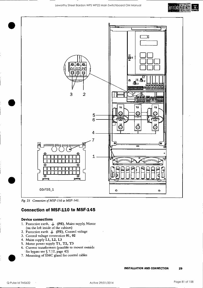
Fig. 25 Connection of MSF-110 to MSF-145.
Connection of MSF-110 to MSF-145
Device connections 1. Protective earth, I- (PE), Mains supply, Motor
(on the left inside of the cabinet) 2. Protective earth 1- (PE), Control voltage 3. Control voltage connection 01, 02 4. Mains supply Li, L2, L3 5. Motor power supply Ti, T2, T3 6. Current transformers (possible to mount outside
for bypass see § 7.12, page 43) 7. Mounting of EMC gland for control cables
INSTALLATION AND CONNECTION 29
Leworthy Street Bardon WPS WP22 Main Switchboard OM Manual
Q-Pulse Id TMS632 Active 29/01/2014 Page 81 of 158
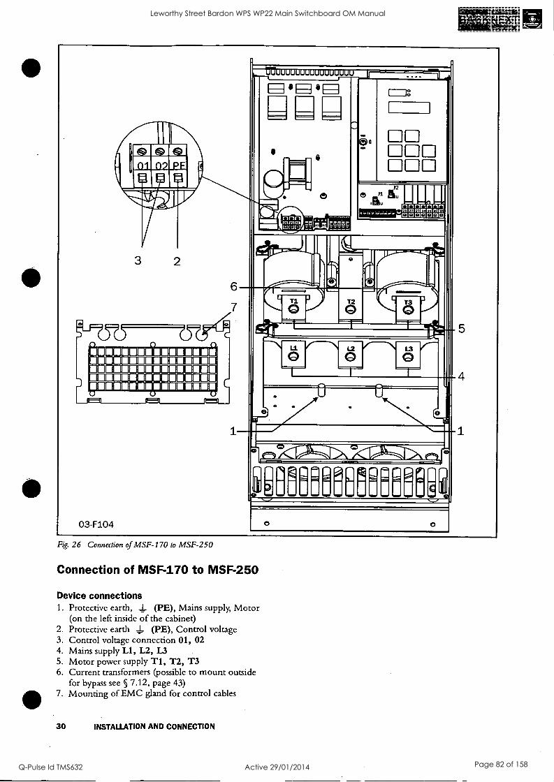
111 111111; MIN I ROA MINIMININI 111111111111211111111M111111111
IIMIUMI111.11111 111.111...1
03-F104
Fig. 26 Connection of MSF-170 to MSF-250
Connection of MSF-170 to MSF-250
Device connections 1. Protective earth, 1 (PE), Mains supply, Motor
(on the left inside of the cabinet) 2. Protective earth L (PE), Control voltage 3. Control voltage connection 01, 02 4. Mains supply Li, L2, L3 5. Motor power supply T1, T2, T3 6. Current transformers (possible to mount outside
for bypass see § 7.12, page 43) 7. Mounting of EMC gland for control cables
30 INSTALLATION AND CONNECTION
Leworthy Street Bardon WPS WP22 Main Switchboard OM Manual
Q-Pulse Id TMS632 Active 29/01/2014 Page 82 of 158

Fig. 27 Connection of MSF-170 to MSF-1400.
Connection of MSF-310 to MSF-1400
Device connections 1. Protective earth, J- (PE), Mains supply and
Motor 2. Protective earth, 4_ (PE), Control voltage 3. Control voltage connection 01, 02
4. Mains supply Li, 12, L3 5. Motor power supply Ti, T2, T3
6. Current transformers (possible to mount outside
for bypass see § 7.12, page 43)
7. Mounting of EMC gland for control cables
INSTALLATION AND CONNECTION 31
Leworthy Street Bardon WPS WP22 Main Switchboard OM Manual
Q-Pulse Id TMS632 Active 29/01/2014 Page 83 of 158

6.3 Connection and setting on the PCB control card
Fig. 28 Connections on the PCB, control card.
Table 12 PCB Terminals
Terminal Function Electrical characteristics 01
Supply voltage 100-240 VAC t10%/380-500 VAC t 10% 02 PE Gnd 1- 11
Digital inputs for start/stop and reset. 0-3 V -> 0; 8-27 V-> 1. Max. 37 V for 10 sec. Impedance to 0 VDC: 2.2 ka 12
13 Supply/control voltage to PCB terminal 11 and 12, 10 kfl potentiometer, etc.
+12 VDC t5%. Max. current from +12 VDC: 50mA. Short circuit proof.
14 Remote analogue input control, 0-10 V, 2-10 V, 0-20 mA and 4-20 mA /digital input.
Impedance to terminal 15 (0 VDC) voltage signal: 125 K2, current signal: 100 Si
15 GND (common) 0 VDC
16 Digital inputs for selection of parameter set.
0-3 V -> 0; 8-27 V-> 1. Max. 37 V for 10 sec. Imped- ance to 0 VDC: 2.2 ka 17
18 Supply/control voltage to PCB terminal 16 and 17, 10 lin potentiometer, etc.
+12 VDC t5%. Max. current from +12 VDC = 50mA. Short circuit proof.
19 Remote analogue output control Analogue Output contact: 0-10V, 2-10V; min load impedance 70051 0-20mA and 4-20mA;max load impedance 75051
21 Programmable relay Kl. Factory setting is "Opera- tion indication by closing terminal 21- 22.
1-pole closing contact, 250 VAC 8A or 24 VDC 8A resistive, 250 VAC, 3A inductive. 22
23 Programmable relay K2. Factory setting is "Full volt- age" indication by closing terminal 23-24.
1-pole closing contact, 250 VAC 8A or 24 VDC 8A resistive, 250 VAC, 3A inductive. 24
31 Alarm relay K3, closed to 33 at alarm. 1-pole change over contact, 250 VAC 8A or 24 VDC 8A resistive, 250 VAC, 3A inductive. 32 Alarm relay K3, opened at alarm.
33 Alarm relay K3, common terminal.
69-70 PTC Thermistor input Alarm level 2.4 kil Switch back level 2.2 kn.
71-72* Clickson thermistor Controlling soft starter cooling fine temperature MSF-310 - MSF -1400
73-74* NTC thermistor Temperature measuring of soft starter cooling fine
75 Current transformer input, cable S1 (blue) Connection of L1 or T1 phase current transformer
76 Current transformer input, cable S1 (blue) Connection of L3, T3 phase (MSF 017 - MSF 250) or L2, T2 phase (MSF 310 - MSF 1400)
77 Current transformer input, cable S2 (brown) Common connection for terminal 75 and 76
78* Fan connection 24 VDC
79* Fan connection 0 VDC
*Internal connection, no customer use.
32 INSTALLATION AND CONNECTION
Leworthy Street Bardon WPS WP22 Main Switchboard OM Manual
Q-Pulse Id TMS632 Active 29/01/2014 Page 84 of 158

6.4 Minimum wiring
IJ. L2 1.3 PE
0
1011240 - +10%
PE
L1 L2 L3 PE 01 02 PE 21bK1 22 23_(2 N 33k3j 2 69 70
T1 T2 T3 PE 11 12 13 14 15 16 17 18 19 75 76 77
start /stop
_ _ _ _
V w PE
03-F25
Fig. 29 Wiring circuit, "Minimum wiring".
The figure above shows the "minimum wiring". See § 6.1, page 24, for tightening torque for bolts etc. 1. Connect Protective Earth (PE) to earth screw
marked (PE). 2. Connect the soft starter between the 3-phase mains
supply and the motor. On the soft starter the mains side is marked Ll, L2 and L3 and the motor side with T1, T2 and T3.
3. Connect the control voltage (100-240 VAC) for the control card at terminal 01 and 02.
4. Connect relay K1 (terminals 21 and 22) to the con- trol circuit.
5. Connect PCB terminal 12 and 13 (PCB terminal 11-12 must be linked) to, e.g. a 2-position switch (on/oFF) or a PLC, etc., to obtain control of soft start/stop. (For start/stop command from keyboard menu 006 must be set to 01).
6. Ensure the installation complies with the appropri- ate local regulations.
NOTE! The soft starter should be wired with shielded control cable to fulfill EMC regulations acc. to § 1.5, page 6.
NOTE! If local regulations say that a mains contactor should be used, the Kl then controls It. Always use standard commercial, slow blow fuses, e.g. type gi, gG to protect the wiring and prevent short circuiting. To protect the thydstors against short- circuit currents, superfast semiconductor fuses can be used if preferred. The normal guarantee is valid even if superfast semiconductor fuses are not used. All signal inputs and
outputs are galvanically insulated from the mains supply.
INSTALLATION AND CONNECTION 33
Leworthy Street Bardon WPS WP22 Main Switchboard OM Manual
Q-Pulse Id TMS632 Active 29/01/2014 Page 85 of 158

6.5 Wiring examples Fig. 30 gives an wiring example with the following functions.
Analogue input control, see § 7.7, page 40 Parameter set selection, see § 7.20, page 54 Analogue output, see § 7.18, page 52 PTC input, see § 7.21, page 55
For more information see § 6.3, page 32.
11
L2
L3
PE
LI 12 L3 PE 0102 PE 2 22
TI T2 T3 PE
PTC
11 12 13
start /stop
23L 24 33k3j 1 69 70
14 15 16 17 18 19 75 76 77
PS2
PSI
Analogue in + Analogue out O 10V
2 10V
O 20nA 4 2OmA
Parameter set PS1 PS2
open open
2 closed open
3 open closed
4 closed closed
03-F18
Fig. 30 Analogue input control, parameter set, analogue output and PTC input.
Fig. 31 Forward /reverse wiring circuit.
34 INSTALLATION AND CONNECTION
Leworthy Street Bardon WPS WP22 Main Switchboard OM Manual
Q-Pulse Id TMS632 Active 29/01/2014 Page 86 of 158

7. FUNCTIONAL DESCRIPTION SET-UP MENU
This chapter describes all the parameters and functions in numerical order as they appear in the MSE Table 13 gives an overview of the menus, see also Chapter 13. page 79 (set-up menu list).
Table 13 Set-up Menu overview
Menu number Parameter group Menu numbers See §
Basic functions 001-008 Basic
Ramp up/down parameters 001-005 7.1 Start/Stop/Reset command 006 7.2 Menu Expansion 007-008 7.3
Extended functions 011-199
Voltage control dual ramp 011-014 7.4 Torque control parameters 016-018 7.5 Main functions 020-025 7.6 - 7.10 Additional functions 030-036 7.11 - 7.14
Slow speed and Jog functions 037-040, 57-58, 103-104
7.15, 7.19, 7.25
Motor Data Setting 041-046 7.16
Outputs Relays 051-052 7.17 Analogue output 054-056 7.18
Input Digital input 057-058 7.19 Parameter set selection 061 7.20
Motor protection 071-075 7.21 Main protection 081-088 7.22 Application protection 089-099 7.23 Resume alarms 101, 102 7.24
Auto return menu 105 7.26 Factory defaults 199 7.28
View functions 201-915
Main view 201-208 7.29 RMS current per phase 211-213 7.29 RMS voltage per phase 214-216 7.29 Keyboard lock status 221 7.30 Alarm list 901-915 7.31
FUNCTIONAL DESCRIPTION SET-UP MENU 35
Leworthy Street Bardon WPS WP22 Main Switchboard OM Manual
Q-Pulse Id TMS632 Active 29/01/2014 Page 87 of 158

7.1 Ramp up/down parameters
Fig. 32 Menu numbers for start/stop ramps, initial voltage at start and step down voltage at stop.
Determine the starting time for the motor/machine. When setting the ramp times for starting and stopping, initial voltage at start and step down voltage at stop, proceed as follow:
001 o
3 0 Setting the initial voltage at start ramp 1
Default: 30%
Range: 25 - 90% Un
Set the initial voltage. Normally the factory setting, 30% of Un, is a suitable choice.
002 ( Do
10 Setting of start ramp 1
Default: 10 sec
Range: 1-60 sec
Set "Ramp up time" at start.
003°°
1 0 0 Setting of step down voltage stop ramp 1
Default: 100%
Range: 100-40% of Un
Step down vo tage at stop can be used to stop smoothly.
36 FUNCTIONAL DESCRIPTION SET-UP MENU
004°°
o F
Setting of stop ramp 1
Default: oFF
Range: oFF, 2-120 sec
oFF Stop ramp disabled
2-120 Set 'Tamp down time" at stop
7.1.1 RMS current [005]
0 0 5 °0
0. 0 RMS current
Default:
Range: 0.0-9999Amp
Read-out of the RMS motor current.
NOTE! This is the same read-out as function 201, see § 7.28, page 63.
Leworthy Street Bardon WPS WP22 Main Switchboard OM Manual
Q-Pulse Id TMS632 Active 29/01/2014 Page 88 of 158

7.2 Start/stop/reset command Start/stop of the motor and reset of alarm is done either from the keyboard, through the remote control inputs or through the serial interface (option). The remote control inputs start/stop/reset (PCB terminals 11, 12 and 13) can be connected for 2-wire or 3-wire control.
0 6 °0
2 Selection of control mode
Default: 2
Range: 1,2,3
1
START/STOP/RESET command via the keyboard. - Press the "START/STOP" key on the keyboard to start and stop the soft starter.
- Press "ENTER/RESET" key to reset a trip condition.
2
Via Remote control. START/STOP/ RESET commands. The following control methods are possible: - 2-wire start/stop with automatic
reset, see § 7.2.1, page 37. - 2-wire start/stop with separate
reset, see § 7.2.2, page 37. - 3-wire start/stop with automatic
reset at start, see § 7.2.3, page 37.
WARNING! The motor will start if terminals 11, 12, 13 is In start position.
3
START/STOP/RESET commands via serial interface option. Read the operating instruction supplied with this option.
NOTE! A reset via the keyboard will not start or stop the motor.
NOTE! Factory default setting is 2, remote control.
To start and stop from the keyboard, the "START/ STOP" key is used.
To reset from the keyboard, the "ENTER .4_1 / RESET" key is used. A reset can be given both when the motor is running and when the motor is stopped. A reset from the keyboard will not start or stop the motor.
' 4
7.2.1 2-wire start/stop with automatic reset at start
Closing PCB terminals 12 and 13, and a jumper between terminal 11 and 12, will give a start com- mand. Opening the terminals will give a stop. If PCB terminals 12 and 13 is closed at power up a start com- mand is given (automatic start at power up). When a start command is given there will automatically be a reset.
7.2.2 2-wire start/stop with separate reset
Closing PCB terminals 11, 12 and 13 will give a start and opening the terminals 12 and 13 will give a stop. If PCB terminals 12 and 13 are closed at power up a start command is given (automatic start at power up). When PCB terminals 11 and 13 are opened and closed again a reset is given. A reset can be given both when the motor is running and stopped and doesn't affect the start/stop.
7.2.3 3-wire start/stop with automatic reset at start.
rzyrvrIt-Lr--2"ry rillfflagnETIMMI tIntnrirlittierlet30iiii)cr;IMIT3111
W.171DOCILD1-260 imiatakialatitala
PCB terminal 12 and 13 are normally closed and PCB terminal 11 and 13 are normally open. A start com- mand is given by momentarily closing PCB terminal 11 and 13. To stop, PCB terminal 12 and 13 are momentarily opened.
When a start command is given there will automat- ically be a reset. There will not be an automatic start at power up.
FUNCTIONAL DESCRIPTION SET-UP MENU 37
Leworthy Street Bardon WPS WP22 Main Switchboard OM Manual
Q-Pulse Id TMS632 Active 29/01/2014 Page 89 of 158

7.3 Menu expansion setting. In order to use the viewing menus and/or the extended functions menu 007 must be set to "On", then one reach read out of the viewing menus 201- 915. To be able to set any extended functions in the menus 011-199 menu 008 must be set to "on" as well.
0 0 7 ° o
Selecting
O F F
of extended functions and viewing functions
Default: oFF
Range: oFF, on
oFF Only function 1-7 are visible
on - View functions 201-915 are visible - Extended functions (menu 008) selectable
00 8°° 0
o F F
Selecting of extended functions
Default: oFF
Range: oFF, on
oFF Only view function 201-915 are visi- ble.
on All the function menus are visible
NOTE! Menu 007 must be "on".
7.4 Voltage control dual ramp To achieve even smoother ramps at start and or stop, a
dual ramp can be used.
Fig 33 Menu numbers for dual voltage ramp at start/stop, initial voltage at start and step down-voltage at stop.
The settings are carried out by beginning with the set- tings in menus 001-004 and 007-008 and proceed with the following steps:
38 FUNCTIONAL DESCRIPTION SET-UP MENU
011 Cl0
9 0 Setting the initial voltage at start ramp 2
Default: 90%
Range: 30-90% Un
Set the start voltage for start ramp 2. The initial voltage for start ramp 2 is limited to the initial volt- age at start (menu 001), see § 7.1, page 36.
0 1 2 °0
o F F
Setting of start ramp 2
Default: oFF
Range: oFF, 1-60 sec
oFF Start ramp 2 disabled
1-60 Set the start ramp 2 time. A dual voltage ramp is active.
0130
4 0 Setting of step down voltage in stop ramp 2
Default: 40%
Range: 100-40% Un
Set the step down voltage for stop ramp 2. The step down voltage for stop ramp 2 is limited to the step down voltage at stop (menu 003).
0 1 4 °0
o F F
Setting of stop ramp time 2
Default: oFF
Range: oFF, 2-120 sec
oFF Stop ramp 2 disabled
1-60 Set the stop ramp 2 time. A dual voltage stop ramp is active.
Leworthy Street Bardon WPS WP22 Main Switchboard OM Manual
Q-Pulse Id TMS632 Active 29/01/2014 Page 90 of 158
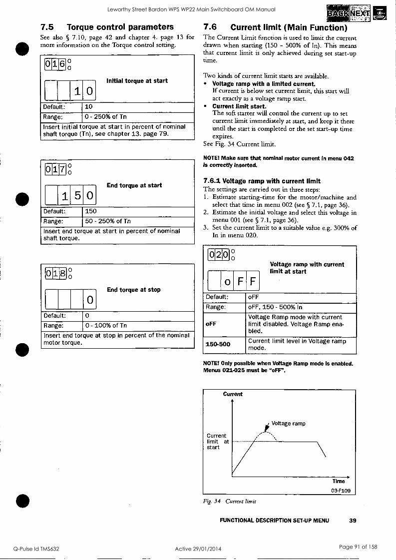
(11)-.
7.5 Torque control parameters 7.6 Current limit (Main Function) See also § 7.10, page 42 and chapter 4. page 13 for The Current Limit function is used to limit the current more information on the Torque control setting. drawn when starting (150 - 500% of In). This means
that current limit is only achieved during set start-up time. 0 1 6 ° o
10 Initial torque at start
Default: 10
Range: 0 - 250% of Tn
Insert initial torque at start in percent of nominal shaft torque (Tn), see chapter 13. page 79.
017 ° o
End
1 5 0 torque at start
Default: 150
Range: 50 - 250% of Tn
Insert end torque at start in percent of nominal shaft torque.
0180 ,
0 End torque at stop
Default: 0
Range: 0 - 100% of Tn
Insert end torque at stop in percent of the nominal motor torque.
Two kinds of current limit starts are available. Voltage ramp with a limited current. If current is below set current limit, this start will act exactly as a voltage ramp start. Current limit start. The soft starter will control the current up to set current limit immediately at start, and keep it there until the start is completed or the set start-up time expires.
See Fig. 34 Current limit.
NOTE! Make sure that nominal motor current In menu 042 Is correctly inserted.
7.6.1 Voltage ramp with current limit The settings are carried out in three steps: 1. Estimate starting-time for the motor/machine and
select that time in menu 002 (see § 7.1, page 36). 2. Estimate the initial voltage and select this voltage in
menu 001 (see § 7.1, page 36). 3. Set the current limit to a suitable value e.g. 300% of
In in menu 020.
2 0 °o
Voltage ramp with current
o F F limit at start
Default: oFF
Range: oFF, 150 - 500% In
oFF Voltage Ramp mode with current limit disabled. Voltage Ramp ena- bled.
150-500 Current limit level in Voltage ramp mode.
NOTE! Only possible when Voltage Ramp mode is enabled. Menus 021-025 must be "oFF".
Current
Current limit at start
g Voltage ramp
Time
03-F109
Fig. 34 Current limit
FUNCTIONAL DESCRIPTION SET-UP MENU 39
Leworthy Street Bardon WPS WP22 Main Switchboard OM Manual
Q-Pulse Id TMS632 Active 29/01/2014 Page 91 of 158

7.6.2 Current limit The settings are carried out in two steps: 1. Estimate starting time for the motor/machine and
select that time in menu 002 (see § 7.1, page 36). 2. Set the current limit to a suitable value e.g. 300% of
In in menu 021.
021 °0
o F F
Current limit at start
Default: oFF
Range: oFF, 150 - 500% In
oFF Current limit mode disabled. Voltage Ramp enabled.
150-500 Current limit level in current limit mode.
NOTE! Only possible when Voltage Ramp mode is enabled. Menus 020, 022-025 must be "oFF".
NOTE! Even though the current limit can be set as low as 150% of the nominal motor current value, this minimum value cannot be used generally. Considerations must be given to the starting torque and the motor before setting the appropriate current limft. "Real start time" can be longer or shorter than the set values depending on the load conditions. This applies to both current limit methods.
Current
Current Limit
FLC
Starting time Time 03-F110
Fig. 35 Current limit
If the starting time is exceeded and the soft starter is
still operating at current level, an alarm will be acti- vated. It is possible to let the soft starter to either stop operation or to continue. Note that the current will rise uncontrolled if the operation continues (see §
7.24.2, page 61).
40 FUNCTIONAL DESCRIPTION SET-UP MENU
7.7 Pump control (Main Function) By choosing pump control you will automatically get a stop ramp set to 15 sec. The optimising parameters for this main function are start and stop time; initial torque at start and end torque at start and stop. End torque at stop is used to let go of the pump when it's no longer producing pressure/flow, which can vary on different pumps. See Fig. 36.
Fig. 36 Pump control
Pump application The pump application is using Torque ramps for quad- ratic load. This gives lowest possible current and linear start and stop ramps. Related menus are 2, 4 (see § 7.1, page 36), 16, 17 and 18 (see § 7.5, page 39).
022°°
o F F
Setting of pump control
Default: oFF
Range: oFF, on
oFF Pump control disabled. Voltage Ramp enabled.
on Pump control application is enabled.
NOTE! Only possible when Voltage Ramp mode is enabled. Menu 020-021, 023-025 must be "oFF".
Leworthy Street Bardon WPS WP22 Main Switchboard OM Manual
Q-Pulse Id TMS632 Active 29/01/2014 Page 92 of 158
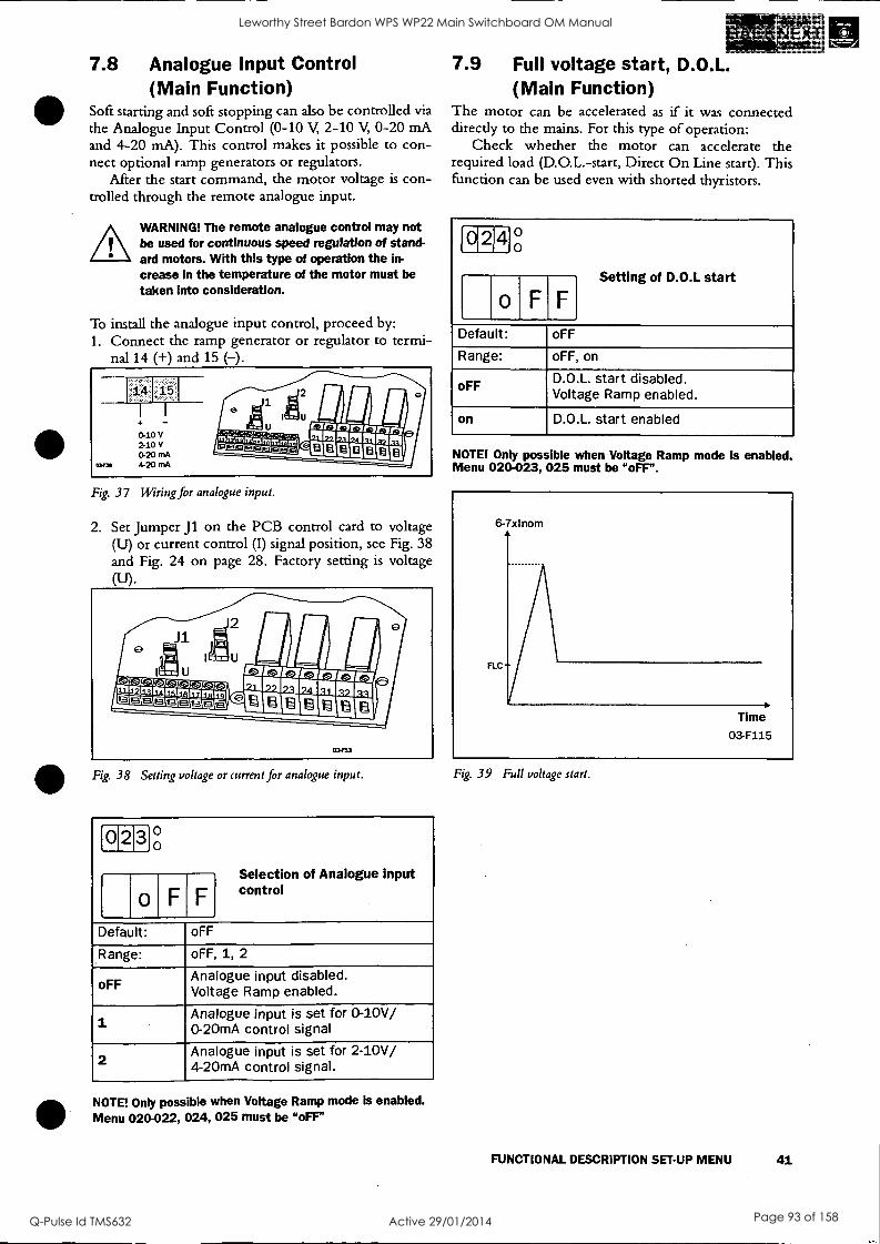
7.8 Analogue Input Control (Main Function)
Soft starting and soft stopping can also be controlled via the Analogue Input Control (0-10 V, 2-10 V, 0-20 mA and 4-20 mA). This control makes it possible to con- nect optional ramp generators or regulators.
After the start command, the motor voltage is con- trolled through the remote analogue input.
WARNING! The remote analogue control may not be used for continuous speed regulation of stand- ard motors. With this type of operation the in-
crease In the temperature of the motor must be taken Into consideration.
To install the analogue input control, proceed by: 1. Connect the ramp generator or regulator to termi-
nal 14 (+) and 15 (-).
Fig. 37 Wiring for analogue input.
2. Set Jumper J1 on the PCB control card to voltage (U) or current control (I) signal position, see Fig. 38 and Fig. 24 on page 28. Factory setting is voltage
J1
,111. MM. rarinnrar , rzi E rs-1 Es1C.< s. Cs9 C.: 01111MEPINIMN
-13] Mk" Eel_ (1313Cit11303 IZEIMMIMEICItin
03F53
0
9
Fig. 38 Setting voltage or current for analogue input.
2 3 °0
input
o F F
Selection of Analogue control
Default: oFF
Range: oFF, 1, 2
oFF Analogue input disabled. Voltage Ramp enabled.
1 Analogue input is set for 0-10V/ 0-20mA control signal
2 Analogue input is set for 2-10V/ 4-20mA control signal.
NOTE! Only possible when Voltage Ramp mode is enabled. Menu 020-022, 024, 025 must be "oFF'
7.9 Full voltage start, D.O.L. (Main Function)
The motor can be accelerated as if it was connected directly to the mains. For this type of operation:
Check whether the motor can accelerate the required load (D.O.L.-start, Direct On Line start). This function can be used even with shorted thyristors.
0 2 4 ° 0
o F F
Setting of D.O.L start
Default: oFF
Range: oFF, on
oFF D.O.L. start disabled. Voltage Ramp enabled.
on D.O.L. start enabled
NOTE! Only possible when Voltage Ramp mode is enabled. Menu 020-023, 025 must be "oFF".
Fig. 39 Full voltage start.
FUNCTIONAL DESCRIPTION SET-UP MENU 41
Leworthy Street Bardon WPS WP22 Main Switchboard OM Manual
Q-Pulse Id TMS632 Active 29/01/2014 Page 93 of 158

7.10 Torque control (Main function) This main function can be used to make a start accord- ing to a pre -defined torque reference curve. Two dif- ferent load characteristics, linear and square, are possible to select.
At start/stop the torque controller will follow the selected characteristic.
A torque start/stop behaviour can be seen in Fig. 40.
A perfect start and stop with torque ramps have a good linearity of current. To optimise this, use the set- ting of initial torque (menu 16) and end torque (menu 18). See also § 7.5, page 39.
Example: Default for initial torque is 10% so if starting a more heavy load this will result in a small current peak in beginning of ramp. By increasing this value to 30/ 70% the current peak will not appear.
The end torque is increased mainly if the applica- tion has a high inertial load, like planers, saws and centrifuges. A current peak will appear in the end of ramp because the load is pushing the speed more or less by itself. By increasing this level to 150-250% the current will be linear and low.
0250
o F F
Torque control at start/stop
Default: oFF
Range: oFF, 1, 2
oFF Torque control is disabled Voltage Ramp enabled.
1 Torque control with linear torque characteristic
2 Torque control with square torque characteristic
NOTE! Torque control mode is only possible when Voltage Ramp mode is enabled (menu 020-024 are "oFF").
2.5 Tr,
2 Tn
1.5 In
Tn
0.5 Tn
Torque
1 Linear
2 Square End torque
Nominal Torque
Initial torque End torque at stop
Time
03-F37
Start time Stop time
Fig. 40 Torque control at start/stop.
Fig. 41 Current and speed in torque control.
42 FUNCTIONAL DESCRIPTION SET-UP MENU
Leworthy Street Bardon WPS WP22 Main Switchboard OM Manual
Q-Pulse Id TMS632 Active 29/01/2014 Page 94 of 158

7.11 Torque boost The Torque Booster enables a high torque to be obtained by providing a high current during 0.1 -2 sec at start. This enables a soft start of the motor even if the break away torque is high at start. For example in crushing mills applications etc.
When the torque booster function has finished, starting continues according to the selected start mode.
Torque boost Current limit -
Full speed Load current -
03-F40 Time
Fig. 42 The principle of the Torque Booster when starting the motor in voltage ramp mode.
See § 4.6, page 19, which main function that can be used with the torque boost.
0 0 0
boost time
o F F
Torque active
Default: oFF
Range: oFF, 0.1 - 2 sec
oFF Torque boost disabled
0.1-2.0 Set the Torque boost time.
031 ° 0
limit
3 0 0 Torque boost current
Default: 300
Range: 300 - 700% of In
The Torque boost current controller use selected value as the motor current reference.
NOTE! Check whether the motor can accelerate the load with "Torque booster", without any harmful mechanical stress.
7.12 Bypass In cases of high ambient temperatures or other reason it may sometimes be necessary to use a by-pass contactor to minimize the power loss at nominal speed (see Tech- nical Data). By using the built-in Full Voltage Relay function an external contactor can be used to Bypass the soft starter when operating at nominal speed.
Bypass contactor can also be used if soft stop is required. Normally a Bypass contactor is not necessary as the device is designed for continues running condi- tions, see Fig. 29 on page 33 for wiring example.
NOTE! If one like to use the alarm functions, the extended functions or the viewing functions the 2-pcs current transformers must be mounted outside the soft start as shown in Fig. 44 and Fig. 45 on page 45. For this purpose an optional extension cable for the current transformers is available. Code No 01-2020-00.
032 0 o
o F F
Setting of Bypass
Default: oFF
Range: oFF, on
oFF Bypass disabled
on
Bypass enabled. Program either relay K1 or K2 to function 2 to control the bypass con- tactor, see menu 51/52.
CAUTION! If the current transformers are not mounted as in Fig. 43 on page 44 and § 6.2, page 28, the alarm and viewing functions will not work. Do not forget to set menu 032 to ON, otherwise there will be an F12 alarm and at the stop command will be a freewheeling stop.
For further information see chapter 6.2 page 28.
FUNCTIONAL DESCRIPTION SET-UP MENU 43
Leworthy Street Bardon WPS WP22 Main Switchboard OM Manual
Q-Pulse Id TMS632 Active 29/01/2014 Page 95 of 158

L1
L2
L3
N
0
L1 L2 L3 PE 01 02 PE 21L" 22 23
T1 12 T3 PE -
24 331 311 32
11 12 13 14 15 16 17 18 19
start /slop
T1 /3 PE
Current transformer position and connection
For MSF-017 to MSF-250, see Fig. 44.
For MSF-310 to MSF-1400, see Fig. 45.
69 70
75 76 77
O w PE
03-F19
Fig 43 Bypass wiring example MSF 310-1400.
44 FUNCTIONAL DESCRIPTION SET-UP MENU
Leworthy Street Bardon WPS WP22 Main Switchboard OM Manual
Q-Pulse Id TMS632 Active 29/01/2014 Page 96 of 158

T1
Brown to terminal 77
SOFTSTARTER
Blue to terminal 75
12 T3
Brown to terminal 77
Blue to terminal 76
V
MOTOR 03-F56
Fig 44 Current transformer position when Bypass MSF-017 to MSF-250.
T1
Brown to terminal 77
SOFTSTARTER
Brown to terminal 77
T2
Blue to terminal 75
U
Blue to terminal 76
MOTOR
V
T3
w
03-F57
Fig. 45 Current transformer position when Bypass MSF-310 to MSF-1400.
FUNCTIONAL DESCRIPTION SET-UP MENU 45
Leworthy Street Bardon WPS WP22 Main Switchboard OM Manual
Q-Pulse Id TMS632 Active 29/01/2014 Page 97 of 158

7.13 Power Factor Control During operation, the soft starter continuously moni- tors the load on the motor. Particularly when idling or when only partially loaded, it is sometimes desirable to improve the power factor. If Power factor control (PFC) is selected, the soft starter reduces the motor voltage when the load is lower. Power consumption is reduced and the degree of efficiency improved.
033
o F F
Setting of PFC
Default: oFF
Range: oFF, on
oFF PFC disabled
on PFC enabled. The Full voltage relay function does not work.
41, NOTE! If the PFC Is used the EMC-directive is not fulfilled.
7.14 Brake functions There are two built in braking methods for applications were the normal stop ramp is not enough.
Dynamic DC-brake Increases the braking torque by decreasing speed. Soft brake Gives a high torque at the start of the braking and then also increasing torque by decreasing speed.
In both methods the MSF detects when the motor is
standing still, so rotating in wrong direction is avoided.
Dynamic Vector Brake Possible to stop motors with high inertia loads from close to synchronous speed. At 70% of the nominal speed a DC-brake is acti- vated until the motor is standing still or the selected Braking Time has expired (see menu 34, next page). No contactor needed. For extra safety, the soft starter has a digital input signal for monitoring standstill so that at real motor standstill will stop the output voltage immediately (see § 7.19, page 53).
Soft brake Even very high inertia loads can be stopped The Soft brake is a controlled reversing of the motor as the MSF measures the speed during brak- ing. Two contactors are needed which can be placed on the in- or output of the soft starter. On the input the first contactor is connected to relay K1 which is
also used as a mains contactor. At 30% of the nominal speed a DC-brake is acti- vated until the motor is standing still or the selected Braking Time has expired (menu 34, next page).
46 FUNCTIONAL DESCRIPTION SET-UP MENU
For extra safety, the soft starter has a digital input signal for monitoring standstill. So that the output voltage is stopped immediately (see menu 57-58, § 7.19, page 53).
See Fig. 47 on page 47 for the following set-up sequence:
Soft brake is activated if menu 36=2 and menu 34 has a time selected (see next page). Menu 51 and 52 are automatically set to 5 and 4 to get the correct relay functions on K1 and K2 (see § 7.17, page 51). Relay K1 should be used to connect a contactor for supply Ll, L2, L3 to MSF or motor. Relay K2 is used to connect phase shifting contac- tor to change Ll, L2 and L3 to MSF or motor. At start K1 is activated and connects Ll, L2, L3 then the motor starts. At stop K1 opens and discon- nects Ll, L2, and L3 and after is K2 connects with the other phase sequence and the braking of the motor is active.
NOTE! Soft brake uses both programmable relays. For other functions, see also the function table in chapter 7. page 35.
NOTE! For several start/stops ft is recommend to use the PTC Input.
WARNING! If the Soft Brake function has been selected once and after that the Bypass function is selected, then the relay functions on K1 and K2 remain in the Soft Brake functionality. Therefore it
is necessary to change the relay functions in menu 51-52 manually to the Bypass functions (see § 7.17, page 51) or reset to default In menu 199 (see § 7.28, page 63) and select the Bypass function again.
034ro
o F F
Braking time
Default: oFF
Range: oFF, 1- 120 sec
oFF Brake function disabled
1-120 Brake time
Fig. 46 Braking time
Leworthy Street Bardon WPS WP22 Main Switchboard OM Manual
Q-Pulse Id TMS632 Active 29/01/2014 Page 98 of 158

0 3 5 0 0
1 0 0 Braking Strength
Default: 100
Range: 100 - 500%
0 3 6 ° o
1 Brake method
Default: 1
Range: 1, 2
1 Dynamic vector brake, active
2 Soft brake active
Li 1.2
L3
N
PE
%
Q1 fwd)
Q2 rev)
Li 1.2 L3 PE 01 02 PE 21 --......._)
K122 23L 24
T1 T2 T3 PE
- - 33 K3 32 K3 69 70
11 12 13 14 15 16 17 18 19 75 76 77
v
it PE
1 .7;1-.- 0 start /stop
03-F106
Fig. 47 Soft brake wiring example.
FUNCTIONAL DESCRIPTION SET-UP MENU 47
Leworthy Street Bardon WPS WP22 Main Switchboard OM Manual
Q-Pulse Id TMS632 Active 29/01/2014 Page 99 of 158

7.15 Slow speed and Jog functions The soft starter is able to run the motor at a fixed slow speed for a limited period of time.
The slow speed will be about 14% of the full speed in the forward direction and 9% in the reverse direc- tion.
The following functions are possible: Slow speed controlled by an external signal. The digital input is used to run at slow speed at a
start or stop command for a selected number of pulses (edges) generated by an external sensor (photo cell, micro switch, etc.). See § 7.19, page 53 for more instructions. Slow Speed during a selected time period. The slow speed will be active after a stop command for a selected time period. See § 7.19, page 53 for more instructions. Slow Speed using the "JOG"-commands. The slow Speed can be activated via the JOG keys on the keyboard or externally via the analogue input. See § 7.25, page 61 for more instructions.
7.15.1 Slow speed controlled by an external signal.
With these setting it is possible to have an external pulse or edge signal controlling the time that the Slow Speed is active either after a Start command or a Stop command or at both commands. The following menu's are involved:
Menu Function See page
57 Digital input selection page 53
58 Pulse selection page 53
37 Slow speed torque page 49
38 Slow speed time at start page 49
39 Slow speed time at stop page 49
40 DC-Brake at slow speed page 49
Installation is as follows: 1. Set the analogue input selection for Slow Speed
operation. Menu 57=2. See § 7.19, page 53. See Fig. 37 on page 41 for a wiring example.
2. Select in menu 38 (see § 7.15.2, page 49) the Slow Speed at Start time. This time will now be the abso- lute maximum time for Slow Speed to be active after a start command, in case the external signal will not appear.
3. Select in menu 39 (see § 7.15.2, page 49) the Slow Speed at Stop time. This time will now be the abso- lute maximum time for Slow Speed to be active after a stop command, in case the external signal will not appear.
4. Select in menu 57 (see § 7.19, page 53) the number of edges to be ignored by the Slow Speed input, before a start or stop is executed at slow speed. The edges are generated by an external sensor (photo cell, micro switch, etc.).
48 FUNCTIONAL DESCRIPTION SET-UP MENU
The Slow Speed torque (menu 37) and DC-Brake after Slow Speed (menu 40) can be selected if needed. (see § 7.15.4, page 49).
When the number of edges exceeds or the time expire, a start according to selected main function is made.
At stop, the motor will ramp down (if selected) and DC brake (if selected) before a slow speed forward at stop will begin. Slow speed will last as long as the number of edges on the external input is below param- eter value in menu 036 and the max duration time doesn't expires. When the number of edges exceeds or the time expire, a stop is made.
In Fig. 48 on page 48 the selected number of edges are 4. It is recommended to select DC-brake (se § 7.14, page 46) before a slow speed at stop if it is a high inertia load. See Fig. 29 on page 33 for wiring diagram. In case one use DC-brake, see § 7.15.4, page 49.
Speed
nN
0.14 nN Slow
speed at start
Start command
External Open signal
Closed
Ramp time at start
Full voltage running
Ramp time' Slow at stop speed including DCbrake time
Time when signal is ignored
at stop Stopped
Time
03-F44
Fig. 48 Slow speed controlled by an external signal.
This additional function can be used together with most of the main functions (see § 4.6, page 19).
0370
10 Slow speed torque
Default: 10
Range: 10-100
Select the magnitude of the slow speed torque.
Leworthy Street Bardon WPS WP22 Main Switchboard OM Manual
Q-Pulse Id TMS632 Active 29/01/2014 Page 100 of 158

7.15.2 Slow speed during a selected time It is possible to have a slow speed in forward direction before a start and after a stop. The duration of the slow speed is selectable in menus 038 and 039.
It is recommended to select DC brake (see § 7.14, page 46) before a slow speed at stop if it is a high inertia load. This slow speed function is possible in all control modes, keyboard, remote and serial communication.
0 3 6 °0
of Slow speed time at start
Default: oFF
Range: oFF, 1- 60 sec
oFF Slow speed at start is disabled
1-60 Set slow speed time at start.
0390
o F F
Slow speed time at stop
Default: oFF
Range: oFF, 1- 60 sec
oFF Slow speed at stop is disabled
1-60 Set slow speed time at stop.
Nominal speed
0.14 .nN
03-F41
Slow speed
Slow speed lat start
Start command
Ramp time at Full voltage Ramp time Slow speed start running stop in at stop
lading bbrrake time
Stop command Stopped
Fig. 49 Slow speed at start/stop during a selected time.
The Slow speed torque (menu 37) and the DC-Brake after Slow speed (menu 40, § 7.15.4, page 49) can be selected if needed.
7.15.3 Jog Functions The Jog commands can be used to let the motor run at a Slow speed (forward or reverse) as long as the Jog command is active.
The Jog commands can be activated in 2 different ways:
Jog keys The Jog-Forward and Jog-reverse keys on the con- trol panel. The keys can be programmed separate for each function. See § 7.25, page 61 for more instructions External Jog command The external command is given via terminal 14 at the digital input. Only 1 function (forward or reverse) can be programmed to the digital input at the time. See § 7.19, page 53 for more instructions.
7.15.4 DC-brake after slow speed at stop [040] A DC-brake after a sloW speed at stop is possible to have, i.e. for a high inertia load or for a precise stop.
The current is controlled and the reference value for the normal DC-brake function is used (see § 7.15.4, page 49). The duration for the DC-brake is possible to select.
This DC-brake function is not applied when the "JOG In " and "JOG 0." keys are used.
040 g
o F F
DC-Brake at slow speed
Default: oFF
Range: oFF, 1-60
oFF DC-brake after slow speed at stop disabled.
1-60 DC-brake duration time after slow speed at stop.
FUNCTIONAL DESCRIPTION SET-UP MENU 49
Leworthy Street Bardon WPS WP22 Main Switchboard OM Manual
Q-Pulse Id TMS632 Active 29/01/2014 Page 101 of 158

7.16 Motor data setting The first step in the settings is to set menu 007 and 008 to "on" to be able to reach the menus 041-046 and enter the motor data.
NOTE! The default factory settings are for a standard 4-pole motor acc. to the nominal current and power of the soft starter. The soft starter will run even if no specific motor data is selected, but the performance will not be optimal.
4 1 10 o
4 0 0 Nominal motor voltage
Default: 400 V
Range: 200-700 V
Make sure the soft starters maximum voltage rat- ing is suitable for chosen motor voltage.
0 4 2 0 0
1 7 Nominal motor current
Default: Nominal soft starter current Range: 25% - 150% of Insoft in Amp.
0 4 3 0 0
7. 5 Nominal motor power
Default: Nominal soft starter power
Range: 25% - 300% of Pnsoft in kW
4 4 0 0
i. 4 5 Nominal motor speed
Default: Nnsoft in rpm
Range: 500-3600 rpm
50 FUNCTIONAL DESCRIPTION SET-UP MENU
014 5 0 0
0. 8 6 Nominal motor cos phi
Default: 0.86 Range: 0.50-1.00
0 4 6 0 0
5 0 Nominal frequency
Default: 50 Hz
Range: 50/60 Hz
NOTE! Now go back to menu 007, 008 and set it to "oFF' and then to menu 001.
Leworthy Street Bardon WPS WP22 Main Switchboard OM Manual
Q-Pulse Id TMS632 Active 29/01/2014 Page 102 of 158

7.17 Programmable relay K1 and K2 The soft starter has three built-in auxiliary relays, K3 (change over contacts), is always used as an alarm relay. The other two relays, K1 and K2 (closing contacts), are programmable.
K1 and K2 can be set to either "Operation", "Full Voltage" or "Pre-alarm" indication. If DC-brake is chosen the relay K2 will be dedicated to this function.
Fig. 50 Start/stop sequence and relay function "Operation" and "Full voltage".
0510 Setting of K1 indication
Default: 1
Range: 1,2,3,4,5 1 K1 is set for "Operation"
2 K1 is set for "Full Voltage"
3 K1 is set for "Power pre-alarm"
4 No function
5 K1 is set for "Run"
0 5 ° o
2 Setting of K2 indication
Default: 2
Range: 1, 2, 3, 4, 5
1 K2 is set for "Operation"
2 K2 is set for "Full Voltage"
3 K2 is set for "Power pre-alarm"
4 K2 is set for "Softbrake"
5 K2 is set for "Run"
WARNING! if the Soft Brake function has been selected once and after that the Bypass function Is selected, then the relay functions on K1. and K2 remain in the Soft Brake functionality. Therefore It is necessary to change the relay functions in menu 51-52 manually to the Bypass functions (see § 7.12, page 43) or reset to default in menu 199 (see § 7.28, page 63) and select the Bypass function again.
FUNCTIONAL DESCRIPTION SET-UP MENU 51
Leworthy Street Bardon WPS WP22 Main Switchboard OM Manual
Q-Pulse Id TMS632 Active 29/01/2014 Page 103 of 158

7.18 Analogue output The soft starter can present current, voltage and power on an analogue output terminal, for connection to a recording instrument or a PLC. The output can be configured in 4 different ways, 0-10V, 2-10y, 0-20mA or 4-20 mA. To install the instrument proceed as follows:
1. Connect the instrument to terminal 19 (+) and 15 (-).
Fig. 51 Wiring for analogue output.
2. Set Jumper J2 on the PCB board to voltage (U) or current (I) signal position. Factory setting is voltage (U). See Fig. 52 on page 52 and Fig. 24 on page 28.
Fig. 52 Setting of current or voltage output.
3. Set the parameter in menu 054.
0 5 4 °0
o F F Analogue output
Default: oFF
Range: oFF, 1, 2
oFF Analogue ouput is disabled
1 Analogue output is set to 0-10V/0-20mA
2 Analogue output is set to 0-10V/ 4-20mA
52 FUNCTIONAL DESCRIPTION SET-UP MENU
4. Choose a read-out value in menu 055
055°0
1.
Analogue output value
Default: 1
Range: 1, 2, 3
1 RMS current, default range 0-5xin
2 Line input RMS voltage, default range 0-720V
3 Output shaft power, default range 0-2xPn
5. Set analogue output gain to adjust the range of cho- sen analogue output value in menu 056.
5 6 0 0
0 0 Analogue output gain
Default: 100%
Range: 5-150%
Example on settings:
Set value !scale Uscale Pscale
100% 0-5x1n 0-720V 0-2x Pn
50% 0-2.5xIn 0-360V 0-Pn
Leworthy Street Bardon WPS WP22 Main Switchboard OM Manual
Q-Pulse Id TMS632 Active 29/01/2014 Page 104 of 158

7.19 Digital input selection The analogue input can be used as a digital input. This is programmed in Menu 57. There are 4 different func- tions:
Rotation sensor input for braking functions. See § 7.14, page 46. Slow speed external controlled. See § 7.15.1, page 48. Jog functions forward or reverse enabled. See § 7.25, page 61.
Fig. 53 shows how to set the input for voltage or cur- rent control, with jumper J1 the control board. The default setting for J1 is voltage control.
Fig. 53 Setting offs for current or voltage control.
Fig. 54 shows a wiring example for the analogue input as it is used for digital input.
Fig. 54 Wiring for slow speed external input.
NOTE! If the Main Function Analogue control is program- med (see § 7.8, page 41) the analogue input can not be used for digital signal Input. The menu 57 Is then automatically set to OFF.
0 5 7 ° o
o F F Digital input selection
Default: oFF
Range: oFF, 1-4
oFF No digital input control
1 Rotation sensor for brake functions
2 Slow speed function
3 Jog forward command
4 Jog reverse command
NOTE! Jog forward, reverse has to be enabled, see § 7.25, Page 61.
Depending on the selection made in menu 57, menu 58 is used to program the number of the edges. The edges can be generated by an external sensor (photo cell, micro switch etc.).
0 5 8 ° o
1 Digital input pulses
Default: 1
Range: 1-100 If Menu 57=1 A positive or negative edge at analogue input from a rotation sensor will give a signal to stop the braking voltage. If Menu 57=2 The number of edges to be ignored by the slow speed input, before a start or stop is executed at slow speed.
FUNCTIONAL DESCRIPTION SET-UP MENU 53
Leworthy Street Bardon WPS WP22 Main Switchboard OM Manual
Q-Pulse Id TMS632 Active 29/01/2014 Page 105 of 158

7.20 Parameter Set Parameter Set, an important function which can be handy when using one soft starter to switch in and start different motors, or working under variable load con- ditions. For example; starting and stopping conveyor belts with different weight on the goods from time to time.
For sets of parameters can be controlled either from the keyboard, the external control inputs or the serial interface (option). Up to 51 different parameters can be set for each Parameter Set.
IParameter Set 4
Parameter Set 3
Parameter Set 2
001, 002, 003, 004, 006, 011, 012, 013, 014, 016, 017, 020, 021, 022, 023, 024, 025, 030, 031, 032, 033, 034, 035, 036, 037, 038, 039, 040, 041, 042, 043, 044, 045, 055, 056, 057, 058, 074, 075, 081, 082, 083, 084, 085, 086, 091, 092, 093, 094, 095, 096, 097, 098, 099, 101, 102,103,104
03-F48
Common for all parameter set
007, 008, 046, 051, 052, 061, 071, 072, 088, 089, 105, 111, 112, 113, 114, 199, 206
Fig. 55 Parameter overview
When 'Parameter set' in menu 061 is set to 0 (external selection), only parameters in menu 006 (Control mode) and 061 (Parameter set) can be changed. All other parameters are not allowed to change.
It is possible to change parameter set at stop and at full voltage running.
54 FUNCTIONAL DESCRIPTION SET-UP MENU
06 1 c '0
Parameter set
Default: 1
Range: 0, 1, 2, 3, 4
0 Parameter set are selected by the external input 16 and 17 (see below).
1, 2, 3, 4 Selection of parameter set 1-4.
Fig. 56 Connection of external control inputs.
Parameter Set PS1 (16-18) PS2 (17-18)
1 Open Open 2 Closed Open 3 Open Closed 4 Closed Closed
Leworthy Street Bardon WPS WP22 Main Switchboard OM Manual
Q-Pulse Id TMS632 Active 29/01/2014 Page 106 of 158

7.21 Motor protection, overload (F2 alarm)
In many cases it is convenient to have a complete starter. The soft starter have a possibility to use either an input PTC signal from the motor, an internal ther- mal model of the motor for thermal protection or both together at the same time. Slight overload for long time and several overloads of short duration will be detected with both methods.
0710
no Motor PTC input
Default: no
Range: no, YES
no Motor PTC input is disabled
YES
Motor PTC input is activated: - Connect the PTC to terminals 69
and 70, see table 12, page 32 and § Fig. 30, page 34.
- A to hot motor will give an F2 alarm. The alarm can only be reset- ted after cooling down of the motor.
NOTE! Open terminals will give an F2 alarm immediately. Make sure the PTC is always connected or the terminals are shorted.
NOTE! The Internal motor thermal protection will still generate an alarm If It Is not selected oFF.
0 2 ° o
1 0 Internal motor thermal protection
Default: 10
Range: oFF, 2-40 sec
oFF Internal motor protection is disabled.
240
Selection of the thermal curve according to Fig. 57 - Check that menu 042 is set to the
proper motor current (see § 7.16, page 50).
- If the current exceeds the 100% level an F2 alarm is activated.
- The motor model thermal capacity must cool down to 95% before reset can be accepted.
- Used thermal capacity in menu 073 in § 7.21, page 55.
NOTE! If 'Bypass' is used check that the current trans- formers are placed and connected correctly (see Fig. 43 on page 44).
CAUTION! Used thermal capacity is set to 0 if the control board loses Its supply (terminal 01 and 02). This means that the internal thermal model starts with a 'cold' motor, which perhaps in reality is not the case. This means that the motor can be overheated.
) Fig. 57 The thermal curve
FUNCTIONAL DESCRIPTION SET-UP MENU 55
Leworthy Street Bardon WPS WP22 Main Switchboard OM Manual
Q-Pulse Id TMS632 Active 29/01/2014 Page 107 of 158

0730
0 Used thermal capacity
Default: -
Range: 0-150%
Read-out of the used thermal capacity. If menu 072 'Internal motor thermal protection' is selected oFF, the capacity is shown as if the default class 10 was selected.
0740
o F F
Starts per hour limitation
Default: oFF
Range: oFF, 1-99/hour
oFF Starts per hour limitation is disabled.
1-99 Sets the start per hour limitation alarm. If the selected number is exceeded, alarm F11 occurs.
0750
o F F
Locked rotor alarm
Default: oFF
Range: oFF, 1.0-10.0 sec
oFF Locked rotor alarm is disabled
1.0-10.0 An F5 alarm is given when the rotor locks. The alarm is active during starting and running.
56 FUNCTIONAL DESCRIPTION SET-UP MENU
7.22 Mains protection
081 0 0
1 0 Voltage unbalance alarm
Default: 10
Range: 2 -25% Un
Insert limit in % of nominal motor voltage. Max unbalance in voltage between the 3 input phases is compared with the selected value. This is a cate- gory 2 alarm.
0820
o F F Response delay voltage unbalance alarm
Default: oFF
Range: oFF, 1-60 sec
oFF Unbalance voltage alarm is disabled
1-60 Set the response delay time for unbalanced voltage alarm F8.
0830
1 1 5 Over voltage alarm
Default: 115
Range: 100 -150% lip Insert limit in % of nominal motor voltage. Max volt- age of the 3 input phases is compared with the selected value. This is a category 2 alarm.
0840
o F F Response delay over voltage alarm
Default: oFF
Range: oFF, 1-60 sec
oFF Overvoltage alarm is disabled
3.-60 Set the response delay time for over voltage alarm F9.
Leworthy Street Bardon WPS WP22 Main Switchboard OM Manual
Q-Pulse Id TMS632 Active 29/01/2014 Page 108 of 158

NOTE! The actual phase sequence can be viewed In menu 87,
101815 ° 0
o F F Under voltage alarm
Default: 85
Range: 75-100 Un
Insert limit in % of nominal motor voltage. Min volt- age of the 3 input phases is compared with the selected value. This is a category 2 alarm.
086 ° o
o F F Response delay under voltage alarm
Default: oFF
Range: oFF, 1-60 sec
oFF Under voltage alarm is disabled
1-60 Set the response delay time for under voltage alarm F10
0870 Phase sequence
Default: -
Range: L123, L321
L123 is the d'rect phase sequence. L321 is the reverse phase sequence.
088 ° o
o F F Phase reversal alarm
Default: oFF
Range: oFF, on
oFF Phase reversal alarm is disabled
on
Sets the phase reversal Alarm. - Switch on the power supply first.
The phase sequence is stored as the correct sequence.
- Sets the menu 088 to "on". - Any reversal of phase sequence will
cause alarm F16.
7.23 Application protection (load monitor)
7.23.1 Load monitor max and min/protection (F6 and F7 alarms)
MSF has a built in load monitor based on the output shaftpower. This is a unique and important function which enables protection of machines and processes driven by the motor connected to the soft starter. Both a Min and Max limit is possible to select.
In combination with the pre-alarm function, see § 7.23.2, page 58, this create a powerful protection. An auto set function is also included for an automatic set- ting of the alarm limits. A start-up delay time can be selected to avoid undesired alarms at start-up, see Fig. 58 on page 60.
NOTE! The load monitor alarms are all disabled during a stop ramp.
01819 °0
n o Auto set power limits
Default: no
Range: no, YES
no Auto set is disabled
YES Auto set is activated if ENTER is pressed.
0900
0 Output shaftpower in %
Default: -
Range: 0-200%
Measured output shaftpower in % of nominal motor power.
NOTE! System must be In full voltage running before an auto set is permitted.
The actual power is regarded as 1.00xP The set levels are:
Power max alarm limit[092]: Power max pre-alarm limit[094]: Power min pre-alarm limit[096]: Power min alarm limit[098]:
act.
1.15xP actual 1.10xP actual 0.90xP actual 0.85xP actual
A successful auto set shows a message 'Set' for 3 s and if something goes wrong a message 'no' will be showed.
FUNCTIONAL DESCRIPTION SET-UP MENU 57
Leworthy Street Bardon WPS WP22 Main Switchboard OM Manual
Q-Pulse Id TMS632 Active 29/01/2014 Page 109 of 158

91 °°
10 Start delay power limits
Default: 10 sec
Range: 1-250 sec
From start command during selected delay time, all power load monitor alarms and pre-alarms are disa- bled.
0 9 2 ° o
1 1 5 Max power alarm limit
Default: 115
Range: 5-200% Pn
Insert limit in % of nominal motor power. The actual power in % of nominal motor power, could be read out in menu 090. If output shaft power exceeds selected limit, an F6-alarm occurs after the response delay time. The 'Auto set' function in menu 089, affect this limit even if the alarm is set "oFF" in menu 093. This is a category 1 alarm.
.093 g
o F F
Response delay max alarm
Default: oFF
Range: oFF, 0.1-25.0 sec
oFF Max Alarm is disabled.
0.1-25.0 Sets the response delay of the Max Alarm level.
58 FUNCTIONAL DESCRIPTION SET-UP MENU
7.232 Pre-alarm It could be useful to know if the load is changing towards a load alarm limit. It is possible to insert both a Max and Min pre-alarm limit based on the motor out- put shaft power. If the load exceeds one of these limits, a pre-alarm condition occurs.
It should be noted that it is not normal alarms. They will not be inserted in the alarm list, not activat- ing the alarm relay output, not displayed on the display and they will not stop operation. But it is possible to activate relay K1 or K2 if a pre-alarm condition occurs. To have pre-alarm status on any of these relays, select value 3 in menu 051 or 052 (see § 7.17, page 51).
A start-up delay time can be selected in menu 091 to avoid undesired pre-alarms at start-up. Note that this time is also shared with power Max and MM alarms.
NOTE! The pre-alarm status Is always available on the serial communication.
0940
1 1 Max power pre-alarm limit
Default: 110
Range: 5 -200% Pn
Insert limit in % of nominal motor power. The actual power in % of nominal motor power, could be read out in menu 090. If output shaft power exceeds selected limit, a pre-alarm occurs after the respon- se delay time. The 'Auto set' function in menu 089, affect selected limit even if the pre-alarm is set "oFF" in menu 095.
0950
o F F Max pre-alarm response delay
Default: oFF
Range: oFF, 0.1 - 25.0 sec
oFF Max Pre-Alarm is disabled.
0.1-25.0 Sets the response delay of the Max Pre-Alarm level.
Leworthy Street Bardon WPS WP22 Main Switchboard OM Manual
Q-Pulse Id TMS632 Active 29/01/2014 Page 110 of 158

9 6 ° 0
9 0 Min power pre-alarm limit
Default: 90%
Range: 5 -200% Pn
Insert limit in % of nominal motor power. The actual power in % of nominal motor power, could be read out in menu 090. If output shaft power goes below selected limit, a pre-alarm occurs after the response delay time. The 'Auto set' function in menu 089, affect selected limit even if the pre- alarm is set "oFF" in menu 097.
097°° o
o F Min pre-alarm response delay
Default: oFF
Range: oFF, 0.1 - 25.0 sec
oFF Min Pre-Alarm is disabled.
0.1-25.0 Sets the response delay of the Min Pre-Alarm level. The Min Pre-alarm is disabled during a stop ramp down.
0980
8 5 Min power alarm limit
Default: 85
Range: 5-200% Pn
Insert limit in % of nominal motor power. The actual power in % of nominal motor power, could be read out in menu 090. If output shaft power goes below selected limit, an F7-alarm occurs after the response delay time. The 'Auto set' function in menu 089, affect this limit even if the alarm is set 'oFF' in menu 099. This is a category 1 alarm.
0990°
o F F
Min alarm response delay
Default: oFF
Range: oFF, 0.1-25.0 sec
oFF Min Alarm is disabled
0.1-25.0 Sets the response delay of the Min Alarm level. The Min alarm is disa- bled during a stop ramp down.
FUNCTIONAL DESCRIPTION SET-UP MENU 59
Leworthy Street Bardon WPS WP22 Main Switchboard OM Manual
Q-Pulse Id TMS632 Active 29/01/2014 Page 111 of 158

0 '1
1
0:4.
oo
oo
92 M
ax A
larm
(11
5%)
Sta
rt r
amp
94 M
ax P
re-a
larm
(11
0%)
100%
D
efau
lt:P
Nom
or
Aut
oset
:PM
OM
EN
TA
RY
96 M
in P
re-a
larm
(90
%)
98 M
in A
larm
(85
%)
Max
Ala
rm
Max
Pre
-ala
rm
Min
Pre
-ala
rm
Min
Ala
rm
10
93 R
espo
nse
Del
ay (
1s)
Und
er lo
ad s
ituat
ion
Ove
rload
situ
atio
n
--,-
-4-h
p.11
=11
1111
111-
--
95 R
espo
nse
Del
ay (
1s)
91 S
tart
Del
ay(1
0s)
97 R
espo
nse
Del
ay (
1s)
ON
=
99 R
espo
nse
Del
ay (
1s)
193
Res
pons
e D
elay
(1s
)
95 R
espo
nse
Del
ay (
is)
03-F
96
Leworthy Street Bardon WPS WP22 Main Switchboard OM Manual
Q-Pulse Id TMS632 Active 29/01/2014 Page 112 of 158

7.24 Resume alarms
7.24.1 Phase input failure Fl Multiple phase failure. Shorter failure than 100ms is ignored. If failure duration time is between 100 ms and 2 s, operation is temporary stopped and a soft start is made if the failure disappears before 2 s. If failure duration time is longer than 2 s, an Fl alarm is given in cat. 2. Single phase failure. During start up (acceleration) the behaviour is like multiple phase failure below. When full voltage running there is a possibility to select the behaviour.
1 0 1 ° 0
n o Run at single phase loss
Default: no
Range: no, YES
no Soft starter trips if a single phase loss is detected. Alarm Fl (category 2) will appear after 2 sec.
YES
Soft starter continues to run after a single phase loss. - Alarm Fl appears after 2 sec. - If the loose phase is reconnect the alarm is reset automatically.
- If running on 2 phases, a stop com- mand will give a Direct on line stop (freewheel)
7.24.2 Run at current limit time-out F4 In modes 'Current limit at start' and 'Voltage ramp with current limit at start' an alarm is activated if still operating at current limit level when selected ramp time exceeds. If an alarm occurs there is a possibility to select the behaviour.
10 2 °0
n o Run at current limit time-out
Default: no
Range: no, YES
no Soft starter trips if the current limit time-out is exceeded. Alarm F4 (cate- gory 2) appears.
YES
Soft starter continues to run after the current limit time-out has exceeded: - Alarm F4 appears - The current is no longer controlled
and the soft starters ramps up to full voltage with a 6s ramp time.
- Reset the alarm with either ENTER/ RESET key or by giving a stop com- mand.
7.25 Slow speed with JOG Slow speed with "JOG" is possible from the "JOG" keys, but also from terminals, see menu 57 page 53 and serial comm. The "JOG" is ignored if the soft starter is running. The slow speed "JOG" function has to be enabled for both forward and reverse directions in menus 103 and 104, see below.
NOTE! The enable functions is for all control modes.
1030
o F F
JOG forward enable
Default: oFF
Range: oFF, on
oFF JOG forward disabled
on JOG forward enabled
1 0 4 ° o
oFF JOG reverse enable
Default: oFF
Range: oFF, on
oFF JOG reverse disabled
on JOG reverse enabled
03-F108
Fig 59 The 2 Jog keys.
FUNCTIONAL DESCRIPTION SET-UP MENU 61
Leworthy Street Bardon WPS WP22 Main Switchboard OM Manual
Q-Pulse Id TMS632 Active 29/01/2014 Page 113 of 158

7.26 Automatic return menu Often it is desirable to have a specific menu on the dis- play during operation, i.e. RMS current or power con- sumption. The Automatic return menu function gives the possibility to select any menu in the menu system.
The menu selected will come up on the display after 60 sec. if no keyboard activity. The alarm messages (F1 -F16) have a priority over menu 105 (as they have for all menus).
1051° 0
o F F
Automatic return menu
Default: oFF
Range: oFF, 1-999
1-999 Pressing "+"/"-" will lead through the menu system.
7.27 Communication option, related Parameters
The following parameters have to be set-up: - Unit address. - Baud rate.
Parity - Behaviour when contact broken.
Setting up the communication parameter must be made in local 'Keyboard control' mode. See § 7.2, page 37.
111 °°
1.
Serial comm unit address
Default: 1
Range: 1-247
This parameter will select the unit address.
1120°
9. 6 Serial comm baudrate
Default: 9.6
Range: 2.4, 4.8, 9.6, 19.2, 38.4 kBaud
This parameter will select the baudrate.
62 FUNCTIONAL DESCRIPTION SET-UP MENU
1130°
0 Serial comm parity
Default: 0
Range: 0.1
This parameter will select the parity. 0 No parity. 1 Even parity.
Serial comm. broken alarm If control mode is 'Serial comm. control' and no con- tact is established or contact is broken the Soft starter consider the contact to be broken after 15 sec, the soft starter can act in three different ways:
1 Continue without any action at all. 2 Stop and alarm after 15 sec. 3 Continue and alarm after 15 sec.
If an alarm occurs, it is automatically reset if the com- munication is re-established. It is also possible to reset the alarm from the soft starter keyboard.
114 ° o
1 Serial comm. contact interrupted
Default: 1
Range: oFF, 1, 2
This parameter will control the behaviour in the soft starter when the serial comm. is interrupted. oFF No alarm and continue operation. 1 Alarm and stop operation. 2 Alarm and continue operation.
Leworthy Street Bardon WPS WP22 Main Switchboard OM Manual
Q-Pulse Id TMS632 Active 29/01/2014 Page 114 of 158

7.28 Reset to factory setting [199] When selecting reset to factory settings:
All parameters in all parameter sets will have default factory settings. Menu 001 will appear on the display. Note that the alarm list, the power consumption and the operation time will not have default set- tings.
1 9 9 ° o
n o Reset to factory settings
Default: no
Range: no, YES
no No reset
YES Reset all functions to the factory defaults incl. all 4 Parameter Sets.
NOTE! Reset to factory settings Is not allowed at run.
7.29 View operation
General The soft start includes as standard a numerous metering functions which eliminates the need of additional transducers and meters.
Measured values - Current RMS 3-phase current and per phase - Voltage RMS 3-phase voltage and per phase - Output shaft power /torque kW/Nm - Power factor - Power consumption in kWh - Operation time in hours
Viewing of the measured values After setting motor data and extended functions one can set menu 008 in oFF and will then automatically move to menu 201, the first menu viewing the meas- ured values and thus eliminate to scroll through menu 011 to menu 199.
2010
0. 0 RMS current
Default: -
Range: 0.0 - 9999Amp
Read-out of the RMS motor current.
page 36.
202g
0.0 RMS main voltage
Default: -
Range: 0-720V
The RMS input main voltage.
2 0 3 ° o
0. Output motor shaftpower
Default: -
Range: -9999 -+9999kW
Viewing will show negative value if generator mode.
2 4 ° o
0. 0 Power factor
Default: -
Range: 0.00-1
View the actual power factor.
NOTE! The power factor viewing will not work at bypass even If the current transformers are mounted outside the soft start.
2 0 5 0°
0.0 0 0 Total power consumption
Default: -
Range: 0.000 -2000MWh
View the total power consumption.
FUNCTIONAL DESCRIPTION SET-UP MENU 63
Leworthy Street Bardon WPS WP22 Main Switchboard OM Manual
Q-Pulse Id TMS632 Active 29/01/2014 Page 115 of 158

06 ° o
no Reset of power consumption
Default: no
Range: no, YES
no No reset of power consumtion.
YES Reset power consumption in menu 205 to 0.000.
[207°0 o
0. 0 Motor shaft torque
Default: -
Range: -9999 - + 9999Nm
Viewing will show negative value if generator mode.
2080
0.0 Operation time
Default: -
Range: Hours
Operation time is calculated when the soft starter is in RUN mode. After 9999 hours the display will show two values. Example: 12467 hours shows 1 1 sec
2467 5sec
2110
0. RMS current in phase LI
Default: -
Range: 0.0 - 9999Amp
View the current in phase L1.
64 FUNCTIONAL DESCRIPTION SET-UP MENU
2120
0.0 RMS current in phase L2
Default: -
Range: 0.0 - 9999Amp
View the current in phase L2.
213°0
0. RMS current In phase L3
Default: -
Range: 0.0 - 9999Amp
View the current in phase L3.
2140
0 Main voltage u-u
Default: -
Range: 0-720V
View main voltage L1-L2.
2150
0 Main voltage L1-L3
Default: -
Range: 0 - 720V
View main voltage L1-L3.
2160
0 Main voltage L2-L3
Default: -
Range: 0 - 720V
View main voltage L2-L3.
--- t1111).4
Leworthy Street Bardon WPS WP22 Main Switchboard OM Manual
Q-Pulse Id TMS632 Active 29/01/2014 Page 116 of 158

7.30 Keyboard lock The keyboard can be locked to prohibit operation and parameter setting by an unauthorised. Lock keyboard by pressing both keys "NEXT " and "ENTER
" for at least 2 sec. The message '- Loc' will display when locked. To unlock keyboard press the same 2 keys "NEXT " and "ENTER .0 " for at least 2 sec. The message 'unlo' will display when unlocked.
In locked mode it is possible to view all parameters and read-out, but it is forbidden to set parameters and to operate the soft starter from the keyboard.
The message '-Loc' will display if trying to set a parameter or operate the soft starter in locked mode.
The key lock status can be read out in menu 221.
[2 2 1 g
no Locked keyboard info
Default: no
Range: no, YES
no Keyboard is not locked
YES Keyboard is locked
7.31 Alarm list The alarm list is generated automatically. It shows the latest 15 alarms (F1 - F16). The alarm list can be useful when tracing a failure in the soft starter or its control circuit. Press key "NEXT --. " or "PREV " to reach the alarm list in menus 901-915 (menu 007 has to be ON).
9010
l Alarm
Default: -
Range: F1-F16
View actual alarm
FUNCTIONAL DESCRIPTION SET-UP MENU 65
Leworthy Street Bardon WPS WP22 Main Switchboard OM Manual
Q-Pulse Id TMS632 Active 29/01/2014 Page 117 of 158

0,
8. PROTECTION AND ALARM
The soft starter is equipped with a protection system for the motor, the machine and for the soft starter itself. Three categories of alarm are available:
Category 1 Alarm that stops the motor and need a separate reset before a new start can be accepted. Category 2 Alarm that stops the motor and accepts a new start command without any separate reset. Category 3 Alarm that continues to run the motor.
All alarm, except pre-alarm, will activate the alarm relay output K3, flash a red fault number on the display and it will also be placed in the alarm list. As long as the alarm is active, the display is locked in the alarm indication.
The relay output K3 can be used in the control cir- cuit for actions needed when alarm occurs.
If more than one alarm is active, it is the last alarm that is presented on the display.
8.1 Alarm description
8.1.1 Alarm with stop and requiring a separate reset
Operation will stop for a category 1 alarm. A separate reset is needed before a new start command is accepted. It is possible to reset from keyboard (pushing "ENTER /RESET ") regardless of selected control mode. It is also possible to reset the alarm from the actual control mode (i.e. if control mode is serial com- munication, a reset is possible to do from serial com- munication).
A reset is accepted first when the alarm source goes back to normal.
When a reset is made, the alarm relay output K3 is deactivated, the alarm indication on the display disap- pear and the original menu shows.
After a reset is made the system is ready for a new start command.
8.1.2 Alarm with stop and requiring only a new start command
Operation will stop for a category 2 alarm. A restart can be done and at the same time the alarm relay out- put K3 is deactivated, the alarm indication on the dis- play disappear and the original menu shows.
It is still possible to reset the alarm in the same way as for category 1 alarms (see 8.1.1), if a start is not required at the time.
66 PROTECTION AND ALARM
8.1.3 Alarm with continue run Operation will continue run for a category 3 alarm. Some different reset behaviour is possible (see remarks for the specific alarms in § 8.2, page 67).
Automatic reset when the alarm source goes back to normal. Automatic reset when a stop command is given. Manual reset during run.
When the reset occurs, the alarm relay output K3 is deactivated, the alarm indication on the display disap- pear and the original menu shows.
Leworthy Street Bardon WPS WP22 Main Switchboard OM Manual
Q-Pulse Id TMS632 Active 29/01/2014 Page 118 of 158

8.2 Alarm overview
Display indication Protective function Alarm category Remark
Fl Phase input failure.
Cat 3. Run with auto reset.
Single phase failure when full voltage running if menu 101 'Run at phase loss' = YES. If the fault phase comes back, an automatic reset is made.
Cat 2. Stop with reset in start. Multiple phase failure or single phase failure when not full voltage running or if menu 101 ' Run at phase loss' = no.
F2 Motor protection, overload. Cat 1. Stop with manual reset.
If menu 071 'Motor PTC input' = YES, cool down the motor. If menu 071 'Motor PTC input' = no, the internal model has to 'cool' down.
F3 Soft start overheated Cat 1. Stop with manual reset. If not cooled down, a reset will not be accepted.
F4 Full speed not reached at set current limit and start time.
If menu 102 'Run at current limit time-out' = no. Cat 2. Stop with reset in start.
The current limit start is not corn- pleted.
If menu 102 'Run at current limit time-out' = YES. Cat 3. Run with manual reset.
When start time expired, a 6 sec ramp is used to reach full voltage, without control of the current. Reset the alarm with either a manual reset or a stop command.
F5 Locked rotor. Cat 1. Stop with manual reset. Motor and/or machine protection.
F6 Above max power limit. Cat 1. Stop with manual reset. Machine protection.
F7 Below min power limit. Cat 1. Stop with manual reset. Machine protection. F8 Voltage unbalance. Cat 2. Stop with reset in start. Motor protection. F9 Over voltage. Cat 2. Stop with reset in start. Motor protection. F10 Under voltage. Cat 2. Stop with reset in start. Motor protection.
F11 Starts / hour exceeded. Cat 2. Stop with reset in start. Motor and/or machine protection.
F12 Shorted thyristor. Cat 3. Run with manual reset.
When stop command comes, the stop will be a 'Direct On Line' stop, and the soft starter will be resetted. After this fault it is possible to start only in 'Direct On Line' mode. One or more thyristors probably damaged.
F13 Open thyristor. Cat 1. Stop with manual reset. One or more thyristors probably dam- aged.
F14 Motor terminal open. Cat 1. Stop with manual reset. Motor not correctly connected.
F15 Serial communication broken.
If menu 114 Serial comm. con- tact broken = 1. Cat 2. Stop with reset in start.
Serial communication broken will stop operation. Run from keyboard if nec- essary.
If menu 114 Serial comm. con- tact broken = 2. Cat 3. Run with auto reset.
Serial communication broken will not stop operation. Stop from keyboard if necessary.
F16 Phase reversal alarm. Cat 1. Stop with manual reset. Incorrect phase order on main voltage input.
PROTECTION AND ALARM 67
...-.../
Leworthy Street Bardon WPS WP22 Main Switchboard OM Manual
Q-Pulse Id TMS632 Active 29/01/2014 Page 119 of 158

9. TROUBLE SHOOTING
9.1 Fault, cause and solution
Observation Fault indication Cause Solution
The display is not illuminated. None No control voltage. Switch on the control voltage.
The motor does not run.
Fl (Phase input failure)
Fuse defective. Renew the fuse.
No mains supply. Switch the main supply on.
F2 (Motor protection, overload)
Perhaps PTC connection. Perhaps incorrect nominal motor current inserted (menu 042).
Check the PTC input if PTC protec- tion is used. If internal protection is used, per- haps an other class could be used (menu 072). Cool down the motor and make a reset.
F3 (Soft start overheated)
Ambient temperature to high. soft starter duty cycle exceeded. Perhaps fan failure.
Check ventilation of cabinet. Check the size of the cabinet. Clean the cooling fins. If the fan(s) is not working cor- rect, contact your local MSF sales outlet.
F4 (Full speed not reached at set current limit and start time)
Current limit parameters are perhaps not matched to the load and motor.
Increase the starting time and/or the current limit level.
F5 (Locked rotor)
Something stuck in the machine or perhaps motor bearing fail- ore.
Check the machine and motor bearings. Perhaps the alarm delay time can be set longer (menu 075).
F6 (Above max power limit) Overload
Over load. Check the machine. Perhaps the alarm delay time can be set longer (menu 093).
F7 (Below min power limit) Underload
Under load. Check the machine. Perhaps the alarm delay time can be set longer (menu 099).
F8 (Voltage unbalance) Main supply voltage unbalance. Check mains supply.
F9 (Over voltage) Main supply over voltage. Check mains supply.
F10 (Under voltage) Main supply under voltage. Check mains supply.
F11 (Starts / hour exceeded)
Number of starts exceeded according to menu 074.
Wait and make a new start. Perhaps the number of starts / hour could be increased in menu 074.
F13 (Open thyristor) Perhaps erhaps a damaged thyristor.
Make a reset and a restart. If the same alarm appears immediately, contact your local MSF sales out- let.
F14 (Motor terminal open)
Open motor contact, cable or motor winding.
If the fault is not found, reset the alarm and inspect the alarm list. If alarm F12 is found, a thyristor is probably shorted. Make a restart. If alarm F14 appears immediately, contact your local MSF sales outlet.
68 TROUBLE SHOOTING
Leworthy Street Bardon WPS WP22 Main Switchboard OM Manual
Q-Pulse Id TMS632 Active 29/01/2014 Page 120 of 158

Observation Fault indication Cause Solution
The motor does not run.
F15 (Serial communication bro- ken)
Serial communication broken.
Make a reset and try to establish contact. Check contacts, cables and option board. Verify - System address (menu 111).
Baudrate (menu 112). - - Parity ty (menu 113). If the fault is not found, run the motor with keyboard control if urgent (set menu 006 to "1"). See also manual for serial communica- tion.
F16 (Phase reversal)
Incorrect phase sequence on main supply. Switch L2 and L3 input phases.
Start command comes perhaps from incorrect control source. (I.e. start from keyboard when remote control is selected).
Give start command from correct source (menu 006).
-Loc System in keyboard lock. Unlock keyboard by pressing the keys 'NEXT' and 'ENTER' for at least 3 sec.
The motor is run- ning but an alarm is given.
Fl (Phase input failure)
Failure in one phase. Perhaps fuse defective.
Check fuses and mains supply. Deselect 'Run at single phase input failure' in menu 101, if stop is desired at single phase loss.
F4 (Full speed not reached at set current limit and start time)
Current limit parameters are perhaps not matched to the load and motor.
Increase the starting time and/or the current limit level. Deselect 'Run at current limit time-out' in menu 102, if stop is desired at current limit time-out.
F12 (Shorted thyristor)
Perhaps a damaged thyristor.
When stop command is given, a free wheel stop is made. Make a reset and a restart. If alarm F14 appears immediately, contact your local MSF sales outlet. If it is urgent to start the motor, set soft starter in 'Direct On Line' (menu 024). It is possible to start in this mode.
By pass contactor is used but menu 032 'Bypass' is not set to "on".
Set menu 032 'Bypass' to "on".
F15 (Serial communication bro- ken)
Serial communication broken.
Make a reset and try to establish contact. Check contacts, cables and option board. Verify - System address (menu 111). - Baudrate (menu 112). - Parity (menu 113). If the fault is not found, run the motor with keyboard control if urgent, see also manual for serial communication.
TROUBLE SHOOTING 69
Leworthy Street Bardon WPS WP22 Main Switchboard OM Manual
Q-Pulse Id TMS632 Active 29/01/2014 Page 121 of 158

Observation Fault indication Cause Solution
The motor jerks etc.
When starting, motor reaches full speed but it jerks or vibrates.
If 'Torque control' or 'Pump con- trol' is selected, it is necessary to input motor data into the sys- tern.
Input nominal motor data in menus 041-046. Select the proper load characteristic in menu 025. Select a correct initial- and end torque at start in menus 016 and 017. If 'Bypass' is selected, check that the current transformers are correct connected.
Starting time too short. Increase starting time.
Starting voltage incorrectly set. Adjust starting voltage.
Motor too small in relation to rated current of soft starter.
Use a smaller model of the soft starter.
Motor too large in relation to load of soft starter. Use larger model of soft starter.
Starting voltage not set correctly
Readjust the start ramp.
Select the current limit function.
Starting or stopping time too long, soft does not work.
Ramp times not set correctly. Readjust the start and/or stop ramp time.
Motor too large or too small in relation to load. Change to another motor size.
The monitor func- tion does not work. No alarm or pre-alarm
It is necessary to input nominal motor data for this function. Incorrect alarm levels.
Input nominal motor data in menus 041-046. Adjust alarm levels in menus 091 - 099. If 'Bypass' is selected, check that the current transformers are correct con- nected.
Unexplainable alarm. F5, F6, F7, F8, F9, F10 Alarm delay time is to short.
Adjust the response delay times for the alarms in menus 075, 082, 084, 086, 093 and 099.
The system seems locked in an alarm.
F2 (Motor protection, overload)
PTC input terminal could be open. Motor could still be to warm. If internal motor protection is used, the cooling in the internal model take some time.
PTC input terminal should be short circuit if not used. Wait until motor PTC gives an OK (not over- heated) signal. Wait until the internal cooling is done. Try to reset the alarm after awhile.
F3 (Soft start overheated)
Ambient temperature to high. Perhaps fan failure.
Check that cables from power part are connected in terminals 073, 074, 071 and 072. MSF-017 to MSF-145 should have a short circuit between 071 and 072. Check also that the fan(s) is rotat- ing.
Parameter will not be accepted.
_ _ _ _ If the menu number is one of 020 - 025, only one can bee selected. In other words only one main mode is possible at a time.
Deselect the other main mode before selecting the new one.
r set' is If menu 061, 'Parameter i i set to "0", the system is in a
remote parameter selection mode. It is now impossible to change most of the parameters.
Set the menu 061, 'Parameter set' to a value between "1" - "4" and then it is possible to change any parameter.
During acceleration, decelera- tion, slow speed, DC brake a. nd Power factor control mode, it is impossible to change parame- ters.
Set parameters during stop or full voltage running.
If control source is serial comm., it is impossible to change parameters from key- board and vice versa.
Change parameters from the actual control source.
Some menus include only read out values and not parameters.
Read-out values can not be alte- red. In table 13, page 35, read-out menus has '-' in the factory set- ting column.
-Loc Keyboard is locked. Unlock keyboard by pressing the keys 'NEXT' and 'ENTER' for at least 3 sec.
70 TROUBLE SHOOTING
Leworthy Street Bardon WPS WP22 Main Switchboard OM Manual
Q-Pulse Id TMS632 Active 29/01/2014 Page 122 of 158

10. MAINTENANCE
In general the soft starter is maintenance free. There are however some things which should be checked regu- larly. Especially if the surroundings are dusty the unit should be cleaned regularly.
WARNING! Do not touch parts Inside the enclosure of the unit. when the control and motor voltage Is switched on.
Regular maintenance Check that nothing in the soft starter has been dam- aged by vibration (loose screws or connections). Check external wiring, connections and control signals. Tighten terminal screws and busbar bolts if necessary. Check that PCB boards, thyristors and cooling fin are free from dust. Clean with compressed air if necessary. Make sure the PCB boards and thyristors are undamaged. Check for signs of overheating (changes in colour on PCB boards, oxidation of solder points etc.). Check that the temperature is within permissible limits. Check that the cooling fan/s permit free air flow. Clean any external air filters if necessary.
In the event of fault or if a fault cannot be cured by using the fault-tracing table in chapter 9. page 68.
MAINTENANCE 71
Leworthy Street Bardon WPS WP22 Main Switchboard OM Manual
Q-Pulse Id TMS632 Active 29/01/2014 Page 123 of 158

11. OPTIONS
The following option are available. Please contact your supplier for more detailed information.
11.1 Serial communication For serial communication the MODBUS RTU (RS232/RS485) option card is available order number: 01-1733-00.
Fig. 60 Option RS232/485
11.2 Field bus systems Various option cards are available for the following bus systems:
PROFIBUS DP order number: 01-1734-01 Device NET, order number: 01-1736-01 LONWORKS: 01-1737-01 FIP 10: 01-1738-01 INTERBUS-S: 01-1735-01
Each system has his own card. The option is delivered with an instruction manual containing the all details for the set-up of the card and the protocol for program- ming.
Fig. 61 Option Profibus
72 OPTIONS
11.3 External PPU. The external PPU option is used to move the PPU (keyboard) from the soft starter to the front of a panel door or control cabinet.
The maximum distance between the soft starter and the external PPU is 3 m. The option can be factory mounted (01-2138-01) or it can be built in later (01-2138-00). For both versions instruction /data sheet are available.
Fig. 62 Shows an example of the External PPU after it has been built in.
11.3.1 Cable kit for external current transformers
This kit is used for the bypass function, to connect the external current transformers more easy. order number: 01-2020-00.
Fig. 63 Cable kit
Leworthy Street Bardon WPS WP22 Main Switchboard OM Manual
Q-Pulse Id TMS632 Active 29/01/2014 Page 124 of 158

11.4 Terminal clamp Data: Single cables, Cu or Al Cables 95-300 mm2 MSF type Cu Cable 310 Bolt for connection to busbar M10 Dimensions in mm 33x84x47 mm Order No. single 9350 Data: Parallel cables, Cu or Al Cables 2x95-300 mm2 MSF type and Cu Cable 310 to -835 Bolt for connection to busbar M10 Dimensions in mm 35x87x65 Order No. parallel 9351
Fig. 64 The terminal clamp.
OPTIONS 73
Leworthy Street Bardon WPS WP22 Main Switchboard OM Manual
Q-Pulse Id TMS632 Active 29/01/2014 Page 125 of 158

12. TECHNICAL DATA
3x200-525 V 50/60 Hz Model MSF-017 MSF-030 MSF-045 MSF060
Soft starter rating according to AC35a, see chapter 4. page 13
5.0-30:50-10 heavy
3.0-30:50-10 normal/light
5.0-30:50-10 heavy
3.0-30:50-10 normal/light
5.0-30:50-10 heavy
3.0-30:50-10 normal/light
5.0-30:50-10 heavy
3.0-30:50-10 normal/fight
Rated current of soft starter (A) 17 22 30 37 45 60 60 72 Recommended motor size (kW) for 400 V 7.5 11 15 18.5 22 30 30 37 Recommended motor size (kW) for 525 V 11 15 18.5 22 30 37 37 45 Order number: supply voltage (100-240V) 01-1301-01 01-1302-01 01-1303-01 01-1304-01 Order number: supply voltage (380-500V) 01-1301-02 01-1302-02 01-1303-02 01-130402
3x200-690V 50/60Hz Model MSF-017 MSF-030 MSF-045 MSF-060 Rated current of soft starter (A) 17 22 30 37 45 60 60 72 Motor power for 690V 15 18.5 22 30 37 55 55 75* Order number: supply voltage (100-240V) 01-1321-01 01-1322-01 01-1323-01 01-1324-01 Order number: supply voltage (380-500V) 01-1321-02 01-1322-02 01-1323-02 01-1324-02
Electrical Data
Recommended wiring fuse (A) 1) 25/50 I 32 35/80 -I 50 50/125 I 80 63/160 I 100 Semi-conductor fuses, if required 80 A 125 A 160 A 200 A
Power loss at rated motor load (W) 50 I 70 90 I 120 140 I 180 180 I 215 Power consumption control card 20 VA 20 VA 25 VA 25 VA
Mechanical Data
Dimensions in mm HxWxD 320x126x260 320x126x260 320x126x260 320x126x260 Mounting position (Vertical/Horizontal) Vertical Vertical Vert. or Horiz. Vert. or Horiz. Weight (kg) 6.7 6.7 6.9 6.9 Connection busbars Cu, (bolt) 15x4 (M6) 15x4 (M6) 15x4 (M6) 15x4 (M8) Cooling system Convection Convection Fan Fan
General Electrical Data
Number of fully controlled phases 3
Voltage tolerance control Control +/- 10%
Voltage tolerance motor Motor 200-525 +/- 10%/200-690 + 5%, -10%
Recommended fuse for control card (A) Max 10 A
Frequency 50/60 Hz
Frequency tolerance +/- 10%
Relay contacts 3 x 8A, 250 V resistive load, 3A 250VAC inductive (PF=0.4)
Type of protection/insulation
Type of casing protection I IP 20
Other General Data
Ambient temperatures
In operation 0.40 *C
Max. e.g. at 80% IN 50 °C
In storage (-25) - (+70) ``C
Relative air humidity 95%, non-condensing
Max. altitude without derating (See separate: Technical information 151) 1000 m
Norms/Standards, Conform to: IEC 947-4-2, EN 292, EN 60204-1, UL508
EMC, Emission EN 50081-2, (EN 50081-1 with bypass contactor) EMC, Immunity EN 50082-2
1) Recommended wiring fuses for: Heavy (first column): ramp/direct start Normal/Light (second column): ramp start
NOTE! Short circuit withstand MSF017-060 5000 rms A when used with K5 or RK5 fuses.
* 2-pole motor
74 TECHNICAL DATA
Leworthy Street Bardon WPS WP22 Main Switchboard OM Manual
Q-Pulse Id TMS632 Active 29/01/2014 Page 126 of 158

3x200-525 V 50/60 Hz Model MSF075 MSF-085 MSF110 MSF-145
Soft starter rating according to AC35a, see chapter 4. page 13
5.0-30:50-10 heavy
3.0-30:5040 normal /light
5.0-30:50-10 heavy
3.0-30:50-10 normal/light
5.0-30:50-10 heavy
3.0-30:50-10 normal/light
5.0-30:50-10 heavy
3.0-30:50-10 normal/light
Rated current of soft starter (A) 75 85 85 96 110 134 145 156 Recommended motor size (kW) for 400 V 37 45 45 55* 55 75 75 Recommended motor size (kW) for 525 V 45 55 55 75* 75 90 90 110
Order number for supply voltage (100-240 V) 01-1305-01 01-1306-01 01-1307-01 01-1308-01 Order number for supply voltage (380-550 V) 01-1305-02 01-1306-02 01-1307-02 01-1308-02
3x200-690 V 50/60 Hz Model MSF075 MSF-085 MSF-110 MSF145 Rated current of soft starter (A) 75 85 85 90 110 134 145 156 Motor power for 690V 55 75 75 90 90 110 132 160* Order number for supply voltage (100-240 V) 01-1325-01 01-1326-01 01-1327-01 01-1328-01 Order number for supply voltage (380-550 V) 01-1325-02 01-1326-02 01-1327-02 01-1328-02
Electrical Data
Recommended wiring fuse (A) 1) 80/200 1 100 100/250 I 125 125/315 I 180 160/400 I 200 Semi-conductor fuses, if required 250 A 315 A 350 A 450 A
Power loss at rated motor load (W) 230 I 260 260 ll 290 330 1 400 440 I 470 Power consumption control card 25 VA 25 VA 25 VA 25 VA
Mechanical Data
Dimensions in mm HxWxD 320x126x260 320x126x260 400x 176x 260 400x176x260 Mounting position (Vertical/Horizontal) Vert. or Horiz. Vert. or Horiz. Vert. or Horiz. Vert. or Horiz.
Weight (kg) 6.9 6.9 12 12 Connection, busbars Cu, (bolt) 15x4 (M8) 15x4 (M8) 20x4 (M10) 20x4 (M10) Cooling system Fan Fan Fan Fan
General Electrical Data
Number of fully controlled phases 3
Voltage tolerance control Control +/- 10%
Voltage tolerance motor Motor 200-525 +/ 10%/200-690 + 5%, -10%
Recommended fuse for control card (A) Max 10 A
Frequency 50/60 Hz
Frequency tolerance +/- 10%
Relay contacts 8A, 250 V resistive load, 3A, 250 V inductive load (PF=0.4)
Type of protection/Insulation
Type of casing protection I
IP 20
Other General Data
Ambient temperatures In operation 0 - 40 °C
Max. e.g. at 80% IN 50 °C
In storage (-25) - (+70) °C
Relative air humidity 95%, non-condensing
Max. attitude without derating (See separate: Technical information 151) 1000 m
Norms/Standards, Conform to: IEC 947-4-2, EN 292, EN 60204-1, UL508
EMC, Emission EN 50081-2, (EN 50081-1 with bypass contactor)
EMC, Immunity EN 50082-2
1) Recommended wiring fuses for: Heavy (first column): ramp/direct start Normal/lJeft (second column): ramp start
NOTE! Short circuit withstand M5F075145 10000 rims A when used with K5 or RK5 fuses.
* 2-pole motor
TECHNICAL DATA 75
Ilkty
\--
Leworthy Street Bardon WPS WP22 Main Switchboard OM Manual
Q-Pulse Id TMS632 Active 29/01/2014 Page 127 of 158

3x200-525 V 50/60 Hz Model MSF-170 MSF-210 MSF-250 MSF-310 MSF-370
Soft starter rating according to AC35a, see chapter 4. page 13 50-10
heavy
3.0-30: 50-10
normal/light
5.0-30: 50-10 heavy
50-10 normal/light
5.0-30: 50-10 heavy
3.0-30: 50-10
nomtal/light
5.0-30: 50-10 heavy
3.0-30: 50-10
normal/light
5.0-30: 50-10 heavy
50-10 normal/light
Rated current of soft starter (A) 170 210 210 250 250 262 310 370 370 450 Recommended motor size (kW) for 400 V 90 110 110 132 132 160* 160 200 200 250 Recommended motor size (kW) for 525 V 110 132 132 160 160 200* 200 250 250 315 Order no. for supply voltage (100-240V) 01-1309-11 01-1310-11 01-1311-11 01-1312-01 01-1313-01 Order no. for supply voltage (380-550V) 01-1309-12 01-1310-12 01-1311-12 01-1312-02 01. 1313-02
3x200-690 V 50/60 Hz Model MSF-170 MSF-210 MSF-250 MSF-310 MSF-370
Rated current of soft starter (A) 170 210 210 250 250 262 310 370 370 450 Motor power for 690 V 160 200 200 250 250 250 315 355 355 400 Order no. for supply voltage (100-240V) 01-1329-01 01-1330-01 01-1331-01 01-1332-01 01-1333-01 Order no. for supply voltage (380-550V) 01-1329-02 01-1330-02 01-1331-02 01-1332-02 01-1333-02
Electrical Data
Recommended wiring fuse (A) 1) 200/4001 200 250/4001 315 250/5001 315 315/6301 400 400/8001 500 Semi-conductor fuses, if required 700 A 700 A 700 A 800 A 1000 A
Power loss at rated motor load (W) 510 1 630 630 1 750 750 W 930 I 1100 1100 1 1535 Power consumption control card 35 VA 35 VA 35 VA 35 VA 35 VA
Mechanical Data
Dimensions mm HxWx D in brackets 500x260x260 500x260x260 500x260x260 532x547x278 532x 547x278 Mounting position (Vertical/Horizontal) Vert. or Horiz. Vert. or Horiz. Vert. or Horiz. Vert. or Horiz. Vert. or Horiz. Weight (kg) 20 20 20 42 46 Connection, Busbars Al/Cu (bolt) 30x4 (M10) 30x4 (M10) 30x4 (M10) 40x8 (M12) 40x8 (M12) Cooling system Fan Fan Fan Fan Fan
General Electrical Data
Number of fully controlled phases 3
Voltage tolerance control Control +/- 10%
Voltage tolerance motor Motor 200-525 +/- 10%/200-690 + 5%, -10%
Recommended fuse for control card (A) Max 10 A
Frequency 50/60 Hz
Frequency tolerance +/- 10%
Relay contacts 8A, 250 V resistive load, 3A, 250 V inductive load (PF=0.4)
Type of protection/Insulation
Type of casing protection IP 20
Other General Data
Ambient temperatures In operation 0 - 40 °C
Max. e.g. at 80% IN 50 °C
In storage (-25) - (+70) °C
Relative air humidity 95%, non-condensing
Max. altitude without derating (See separate: Technical information 151) 1000 m
Norms /Standards, Conform to: IEC 947-4-2, EN 292, EN 602041, (UL508, only MSF-170 to MSF-250)
EMC, Emission EN 50081-2, (EN 50081-1 with bypass contactor) EMC, Immunity EN 50082-2
1) Recommended wiring fuses for: Heavy (first column): ramp/direct start Normal/Light (second column): ramp start
NOTEI Short circuit withstand MSF170-250 18000 rms A when used with KS or RK5 fuses.
* 2-pole motor
76 TECHNICAL DATA
Leworthy Street Bardon WPS WP22 Main Switchboard OM Manual
Q-Pulse Id TMS632 Active 29/01/2014 Page 128 of 158

3x200-525V 50/60Hz Model MSF450 MSF-570 MSF-710 MSF-835 MSF-1000 MSF-1400
Soft starter rating according to AC35a, see chapter 4. page 13
5.0-30: 50-10 heavy
3.0-30: 50-10
normal/ light
5.0-30:
-...- heavy
3.0-30: 50-10
normal/ 5.0-30: ,i0 heavy
3.0-30: 50-10
normal/ 5.0-30: n..n '""" heavy
3.0-30: 50-10
normal/ 5.0-30: c,., heavy
3.0-30: 50-10
norml/ light
5.0-30: cn_, n
heavy
3.0-30: 50-10
noral/ flight
Rated current of soft starter (A) 450 549 570 710 710 835 835 960 1000 1125 1400 1650 Recommended motor size (kW) for 400 V 250 315 315 400 400 450 450 560 560 630 800 930 Recommended motor size (kW) for 525 V 315 400 400 500 500 560 600 630 660 710 1000 250 Order no. for supply voltage (100-240V) 01-1341-01 01-1315-01 01-1316-01 01-1317-01 01-1318-01 01-1319-01 Order no. for supply voltage (380-550V) 01-1314-02 01-1315-02 01-1316-02 01-1317-02 01-1318-02 01-1319-02
3x200-690V 50/60Hz Model MSF450 MSF -570 MSF-710 MSF-835 MSF-1000 MSF-1400 Rated current of soft starter (A) 450 549 570 640 710 835 835 880 1000 1125 1400 1524 Motor power for 690 V 400 560 560 630 710 800 800 1000 1120 1400 1600 Order no. for supply voltage (100-240V) 01-1334-01 01-1335-01 01-1336-01 01-1337-01 01-1338-01 01-1339-01 Order no. for supply voltage (380-550V) 01-1334-02 01-1335-02 01-1336-02 01-1337-02 01-1338-02 01-1339-02
Electrical Data
Recommended wiring fuse (A 1) 500/1 k I 630 630/1 k 1 800 800/1 Ic1 1 k 1 k/1.2 kl 1 k 1k/1.4 kl 1.2 k 1.4 k/1.8 II 1.8 k Semi-conductor fuses, if required 1250 A 1250 A 1800 A 2500 A 3200 A 4000 A
Power loss at rated motor load (W) 1400 I 1730 1700 I 2100 2100 1 2500 2500 I 2875 3000 1 3375 4200 1 4950 Power consumption control card 35 VA 35 VA 35 VA 35 VA 35 VA 35 VA
Mechanical Data
Dimensions mm HxWxD incl. brackets 532x547x278 687x640x302 687x640x302 687x640x302 900x875x336 900x875x336 Mounting position (Vertical/Horizontal) Vert. or Horiz. Vert. or Horiz Vert. or Horiz. Vert. or Horiz. Vert. or Horiz. Vert. or Horiz. Weight (kg) 46 64 78 80 175 175 Connection, Busbars Al (bolt) 40x8 (M12) 40x10 (M12) 40x10 (M12) 40x10 (M12) 75x10 (M12) 75x10 (M12) Cooling system Fan Fan Fan Fan Fan Fan
General Electrical Data
Number of fully controlled phases 3
Voltage tolerance control Control +/- 10%
Voltage tolerance motor Motor 200-525 +/- 10%/200-690 + 5%, -10%
Recommended fuse for control card (A) Max 10 A
Frequency 50/60 Hz
Frequency tolerance +/- 10%
Relay contacts 8A, 250 V resistive load, 3A, 250 V inductive load (PF=0.4)
Type of protection/Insulation
Type of casing protection I
IP 20 I
IPOO
Other General Data
Ambient temperatures In operation 0.40 °C
Max. e.g. at 80% IN 50 °C
In storage (-25) - (+70) °C
Relative air humidity 95%, non-condensing
Max. altitude without derating (See separate: Technical information 151) 1000 m
Norma /Standards, Conform to: IEC 947-4-2, EN 292, EN 60204-1
EMC, Emission EN 50081-2, (EN 50081-1 with bypass contactor) EMC, Immunity EN 50082-2
1) Recommended wiring fuses for: Heavy (first column): ramp/direct start Normal /Light (second column): ramp start
TECHNICAL DATA 77
Leworthy Street Bardon WPS WP22 Main Switchboard OM Manual
Q-Pulse Id TMS632 Active 29/01/2014 Page 129 of 158

Semi-conductor fuses Always use standard commercial fuses to protect the wiring and prevent short circuiting. To protect the thy- ristors against short-circuit currents, superfast semicon- ductor fuses can be used if preferred (e.g. Bussmann type FWP or similar, see table below).
The normal guarantee is valid even if superfast semiconductor fuses are not used.
Type FWP Bussmann fuse
A 1
2 t (fuse) x 1000
M SF-017 80 2.4 M SF-030 125 7.3 M SF-045 150 11.7 M SF-060 200 22 M SF-075 250 42.5 M SF-085 300 71.2 M SF-110 350 95.6 M SF-145 450 137
M SF-170B 700 300 M SF-210B 700 300 M SF-250B 800 450 M SF-310 800 450 M SF-370 1000 600 M SF-450 1200 2100 M SF-570 1400 2700 M SF-710 1800 5300 M SF-835 2000 M SF-1000 2500 M SF-1400 3500
78 TECHNICAL DATA
Leworthy Street Bardon WPS WP22 Main Switchboard OM Manual
Q-Pulse Id TMS632 Active 29/01/2014 Page 130 of 158

13. SET-UP MENU LIST
nMumbeenu r Function/Parameter Range Par.set Factory ttin se g Value Page
001 Initial voltage at start 25 - 90% of U 1- 4 30 page 36 002 Start time ramp 1 1- 60 sec 1- 4 10 page 36 003 Step down voltage at stop 100 - 40% U 1- 4 100 page 36 004 Stop time ramp 1 oFF, 2 - 120 sec 1- 4 oFF page 36 005 Current 0.0 - 9999 Amp page 36 006 Control mode 1, 2, 3 1- 4 2 page 37 007 Extended functions & metering oFF, on oFF page 38
008 Extended functions oFF, on oFF page 38
011 Initial voltage start ramp 2 30 - 90% U 1- 4 90 page 38 012 Start time ramp 2 oFF, 1- 60 sec 1- 4 oFF page 38 013 Step down voltage stop ramp 2 100 - 40% U 1- 4 40 page 38 014 Stop time ramp 2 oFF, 2 - 120 sec 1- 4 oFF page 38
016 Initial torque at start 0 - 250% Tn 1- 4 10 page 39 017 End torque at start 50 - 250% Tn 1- 4 150 page 39 018 End torque at stop 0-100% Tn 1- 4 0 page 39 020 Voltage ramp with current limit at start oFF, 150 - 500% In 1- 4 oFF page 39 021 Current limit at start oFF, 150 - 500% In 1- 4 oFF page 40 022 Pump control oFF, on 1- 4 oFF page 40 023 Remote analogue control oFF, 1, 2 1- 4 oFF page 41 024 Full voltage start D.O.L oFF, on 1- 4 oFF page 41 025 Torque control oFF, 1, 2 1- 4 oFF page 42
030 Torque boost active time oFF, 0.1 - 2.0 sec 1- 4 oFF page 43 031 Torque boost current limit 300 - 700% In 1- 4 300 page 43 032 Bypass oFF, on 1- 4 oFF page 43 033 Power Factor Control PFC oFF, on 1- 4 oFF page 46 034 Brake active time oFF, 1 - 120 sec 1- 4 oFF page 47 035 Braking strength 100 - 500% 1- 4 100 page 47
036 Braking methods 1, 2 1- 4 1 page 47 037 Slow speed torque 10 - 100 1- 4 10 page 49 038 Slow speed time at start oFF, 1- 60 sec 1- 4 oFF page 49 039 Slow speed time at stop oFF, 1- 60 sec 1- 4 oFF page 49 040 DC-Brake at slow speed oFF, 1-60 sec 1- 4 oFF page 49
041 Nominal motor voltage 200 - 700 V 1- 4 400 page 50
042 Nominal motor current 25-150% Insoft in Amp 1- 4 Insoft in Amp page 50
043 Nominal motor power 25 - 300% of Pnsoft in kW 1- 4 Pnsoft in kW page 50
044 Nominal speed 500 - 3600 rpm 1- 4 Nnsoft in rpm page 50 045 Nominal power factor 0.50 - 1.00 1- 4 0.86 page 50 046 Nominal frequency 50, 60 Hz 50 page 50
SET-UP MENU LIST 79
le Leworthy Street Bardon WPS WP22 Main Switchboard OM Manual
Q-Pulse Id TMS632 Active 29/01/2014 Page 131 of 158

Of)
enu nuMmber Function/Parameter Range Par.set
Factory setting Value Page
051 Programmable relay K1 1, 2, 3, (4), 5 1 page 51 052 Programmable relay K2 1, 2, 3, 4, 5 2 page 51
054 Analogue output oFF, 1, 2 1- 4 oFF page 52 055 Analogue output value 1, 2, 3 1- 4 1 page 52 056 Scaling analogue output 5 - 150% 1- 4 100 page 52 057 Digital input selection oFF, 1, 2, 3, 4 1- 4 oFF page 53 058 Digital input pulses 1-100 1- 4 1 page 53
061 Parameter set 0, 1, 2, 3, 4 1 page 54
071 Motor PTC input no, YES no page 55 072 Internal motor thermal protection class oFF, 2 - 40 sec 10 page 55 073 Used thermal capacity 0 - 150% page 55 074 Starts per hour limitation oFF, 1- 99/hour 1- 4 oFF page 55 075 Locked rotor alarm oFF, 1.0 - 10.0 sec 1- 4 oFF page 55
081 Voltage unbalance alarm 2 - 25% Un 1- 4 10 page 56 082 Response delay voltage unbalance alarm oFF, 1- 60 sec 1- 4 oFF page 56 083 Over voltage alarm 100 - 150% Un 1- 4 115 page 56 084 Response delay over voltage alarm oFF, 1- 60 sec 1- 4 oFF page 56 085 Under voltage alarm 75 -100% Un 1- 4 85 page 57 086 Response delay under voltage alarm oFF, 1- 60 sec 1- 4 oFF page 57 087 Phase sequence L123, L321 page 57 088 Phase reversal alarm oFF, on oFF page 57
089 Auto set power limits no, YES no page 57 090 Output shaft power 0.0 - 200.0% Pn page 57 091 Start delay power limits 1- 250 sec 1- 4 10 page 58 092 Max power alarm limit 5 - 200% Pn 1- 4 115 page 58 093 Max alarm response delay oFF, 0.1 - 25.0 sec 1- 4 oFF page 58 094 Max power pre-alarm limit 5 - 200% Pn 1- 4 110 page 58 095 Max pre-alarm response delay oFF, 0.1 - 25.0 sec 1- 4 oFF page 58 096 Min pre-alarm power limit 5 - 200% Pn 1- 4 90 page 58 097 Min pre-alarm response delay oFF, 0.1 - 25.0 sec 1- 4 oFF page 59 098 Min power alarm limit 5 - 200%Pn 1- 4 85 page 59 099 Min alarm response delay oFF, 0.1 - 25.0 sec 1- 4 oFF page 59
101 Run at single phase input failure no, YES 1- 4 no page 61 102 Run at current limit time-out no, YES 1- 4 no page 61
103 Jog forward enable oFF, on 1- 4 oFF page 61 104 Jog reverse enable oFF, on 1- 4 oFF page 61
105 Automatic return menu oFF, 1-999 oFF page 62
111 Serial comm. unit address 1- 247 1 page 62 112 Serial comm. baudrate 2.4 - 38.4 kBaud 9.6 page 62
80 SET-UP MENU LIST
Leworthy Street Bardon WPS WP22 Main Switchboard OM Manual
Q-Pulse Id TMS632 Active 29/01/2014 Page 132 of 158
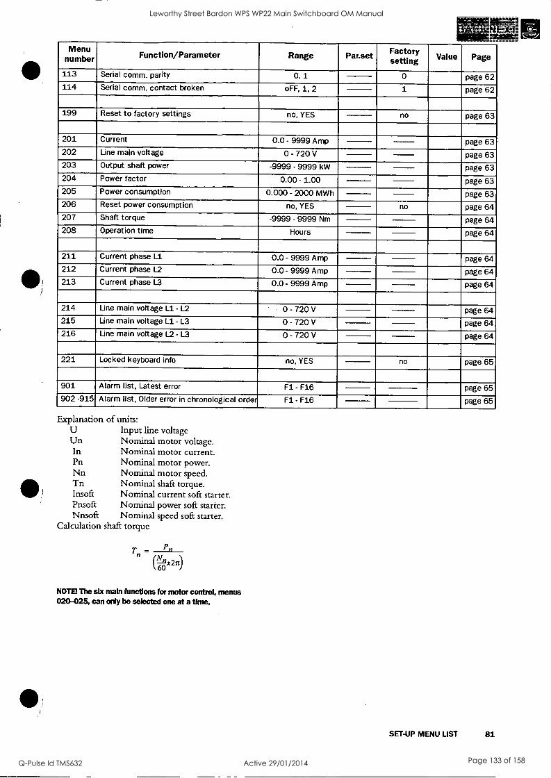
nMumenu ber Function/Parameter Range Par.set Factory se fting Value Page
113 Serial comm. parity 0, 1 0 page 62 114 Serial comm. contact broken oFF, 1, 2 1 page 62
199 Reset to factory settings no, YES no page 63
201 Current 0.0 - 9999 Amp page 63 202 Line main voltage 0 - 720 V page 63 203 Output shaft power -9999 - 9999 kW page 63 204 Power factor 0.00 - 1.00 page 63 205 Power consumption 0.000 - 2000 MWh page 63 206 Reset power consumption no, YES no page 64 207 Shaft torque -9999 - 9999 Nm page 64 208 Operation time Hours page 64
211 Current phase L1 0.0 - 9999 Amp page 64 212 Current phase L2 0.0 - 9999 Amp page 64 213 Current phase L3 0.0 - 9999 Amp page 64
214 Line main voltage L1- L2 0 - 720 V page 64 215 Line main voltage L1- L3 0 - 720 V page 64 216 Line main voltage L2 - L3 0 - 720 V page 64
221 Locked keyboard info no, YES no page 65
901 Alarm list, Latest error Fl - F16 page 65 902 -915 Alarm list, Older error in chronological order Fl - F16 page 65
Explanation of units: U Input line voltage Un Nominal motor voltage.
Nominal motor current. Nominal motor power. Nominal motor speed. Nominal shaft torque. Nominal current soft starter. Nominal power soft starter. Nominal speed soft starter.
Calculation shaft torque
In Pn Nn Tn Insoft Pnsoft Nnsoft
T = - Pn 0x270
NOTE The six main functions for motor control, menus 020-025, can only be selected one at a time.
SET-UP MENU LIST 81
Leworthy Street Bardon WPS WP22 Main Switchboard OM Manual
Q-Pulse Id TMS632 Active 29/01/2014 Page 133 of 158

14. INDEX
Numerics Device connections 28, 31 Keyboard lock 23, 65 2-wire start/stop 37 different operation situation 22 keys 23 3-wire start/stop 37 Digital inputs 32
Dimension 25, 74 L A DIN VDE 0100 24 LED display 22 Above max power limit 67 Direct On Line start 41 Live circuit components 24 Alarm category 67 Dismantling 2 Load monitor 57 Alarm list 65 Display next window 23 Locked rotor 67 Alarm reset 23 Display previous window 23 Low load 20 Ambient temperatures . 10, 77
20, 74, 75, Dual voltage ramp 38
M analogue control 32 E
Main functions 81 Analogue input 32, 41 Electrical characteristic 32 Mains contactor 10 Analogue output 32, 52 Electrical Data 74, 75, 76, 77 Mains supply 28, 31 Analogue output gain 52 EMC 74, 75, 76, 77 Mains voltage 10 Analogue output value 52 Emergency 2 MAINTENANCE 71 Auto set power limits 57 End torque 39 Matrix 19 automatic reset 37 Max power alarm limit 58 Automatic return menu 62 F Max power pre-alarm limit 58
Factory settings 63 Max pre-alarm response delay 58 B Features 9 Mechanical Data 74, 75, 76, 77 Basic parameter setting 10 Forward/reverse 34 Menu Below min power limit 67 Free circulation of air 24 001 36 Brake method 47 frequency 50 002 11, 36 Braking Strenght 47 Frequency inverter 20 003 36 Braking time 46 Front cover 21 004 11, 36 Busbars 25, 26 Full speed not reached 67 005 12, 36 Bypass 43 Full voltage 51 006 12, 37 Bypass contactor 44 Full voltage start 41 007 38
Function 79 008 38 C 011 38
Cabinet 24 G 012 38
Checklist 10 General Data 74 013 38 Clickson thermistor 32 General description 21 014 38
Combination matrix 19 016 39
Complaint 7 H 017 39
Confirm setting 23 Heat dissipation 20 020 39
Connections 28, 32 High ambient temperatures 43 021 40
Control mode 23, 37 022 40 Control voltage 32 023 41
control voltage 33 Increase value 23 024 41
Control voltage connection 28, 31 Increase value of setting 23 025 42
Cooling fins 24 Initial torque 39 030 43
cos phi 50 Initial voltage at start ramp 1 36 031 43
Current 63 Initial voltage at start ramp 2 38 032 43
Current in phase Ll 64 INSPECTION AT DELIVERY 7 033 46
Current in phase L2 64 Installation 24 034 46
Current in phase L3 64 Insulation test 20 035 47
Current limit 39 036 47
Current limit time-out 61 J 037 48
Current transformer 45 JOG Forward 23, 61 038 039
49 49
D
D.O.L start DC-brake DC-Brake at slow speed
41
46 49
JOG fwd/rev JOG Reverse 23, Jumper J1 Jumper J2
23 61
41
52
040 041 042 043
49 11, 50
50 11, 50
044 11, 50 Decrease value Decrease value of setting
23 23
K
Keyboard 23 045 046
11, 50 11, 50
82 INDEX
T-
Leworthy Street Bardon WPS WP22 Main Switchboard OM Manual
Q-Pulse Id TMS632 Active 29/01/2014 Page 134 of 158

)
051 052 054 055 056 057 058 061 071 072 073 074 075 081 082 083 084 085 086 087 088 089 090 091 092 093 094 095 096 097 098 099 101
102 103 104 105 199 201 202 203 204 205 206 207 208 211 212 213 214 215 216 221 901 RMS current read-out
Menu expansion Menu Structure Min alarm response delay Min power alarm limit Min power pre-alarm limit Min pre-alarm response delay Minimum free space Motor
51
51
52 52
52 53 53 54 55 55
56 56 56 56 56 56 56 57 57 57 57 57 57 58 58 58 58 58 59 59 59 59 61
61
61
61
62 63 63 63 63 63 63 64 64 64 64 64 64 64 64 64
23, 65 65 12 38 22 59 59 59 59
24, 25 31
Motor current 50 Motor data 50 Motor power 50 Motor power supply 28, 31 Motor protection, overload 55, 67 Motor shaft torque 64 Motor speed 50 Motor terminal open 67 Motor voltage 50 MOUNTING 24 MOUNTING/WIRING 24
N
Next 23 Nominal frequency 11
Nominal motor cos phi 11
Nominal motor current 11
Nominal motor power 11
Nominal motor speed 11 Norms/Standards 74, 75, 76, 77 NTC thermistor 32
0 Open thyristor 67 Operation 51 Operation time 63, 64 Operation/Set-up 23 Operator panel 21 Output motor shaftpower 63 Output shaftpower 57, 63 Over voltage 56, 67
Parallel 20 Parallel cables 73 Parameter 79 Parameter Set 32, 54 PFC 46 Phase compensation capacitor 20 Phase input failure 67 Phase loss 61 Phase reversal alarm 67 Phase sequence 57 Pole-changing contactor 20 Potentiometer 32 Power consumption 63 Power factor 63 Power Factor Control 46 Power loss 10 PPU unit 21 Pre-alarm 51, 58 Prevent damage to the thyristors ....24 Previous 23 Programmable relay 51 Programming and presentation unit (PPU) 21 protection/insulation ... 74, 75, 76, 77 Protective earth 28, 31 PTC 55 PTC Thermistor input 32 Pump control 40
Q Quick Set-up 10
R
Rating plate 10 Recyclable material 2 Regular maintenance 71 Relay K1 32, 51 Relay K2 32 Relay K3 32 Remote 23 Reset 23 reset 66 Response delay max alarm 58 RMS current 36, 63 RMS main voltage 63 Rotating loads 20 Running motors 20 Running-LED 22
S
Safety 2, 6 Safety measures 10 Scrapping 2
Selection of control mode 12 Semiconductor fuses 33, 78 Serial comm. 23 Serial communication broken 67 Shaftpower 57, 63 Shielded motor cable 20 Shorted thyristor 67 Simple soft start and soft stop 10 Slip ring motors 20 Slow blow fuses 33 Slow speed time at start 49 Slow speed time at stop 49 Slow speed torque 48 Small motor 20 Softbrake 51
Softstart overheated 67 Spare parts 2 standard commercial fuses 78 Standard wiring 10, 33 Standards 6 Start command 22 Start delay power limits 58 Start ramp 1 36 Start ramp 2 38 Start the motor 12 Start time ramp 1 11
Start/Stop 12, 23 Start/stop combination 19 Start/stop/reset from keyboard 12
Start/stop-LED 22 Starting 12
STARTING/OPERATING 79 Starts per hour 67 Starts per hour limitation 56 Step down voltage in stop ramp 2 38 Step down voltage stop ramp 1 36 Stop command 22 Stop ramp 1 36
INDEX 83
Leworthy Street Bardon WPS WP22 Main Switchboard OM Manual
Q-Pulse Id TMS632 Active 29/01/2014 Page 135 of 158

Stop ramp time 2 38 Stop time ramp 1 11
storage 7 Supply voltage switch
32, 74 2
Switch the device off 2 Switch-off procedures 2
T
TECHNICAL DATA 74 Terminal 32 Terminal clamp 78 Terminals 32 Thermal capacity 56 Thermal protection 55 Tightening torque 25 Torque boost active time 43 Torque boost current limit 43 Torque booster 43 Torque control 42 Trained personnel 2, 10 Transport 7 TROUBLESHOOTING 68 Two speed motor 20
U
Under voltage 57, 67 Unpacking 7
V
VIEW OPERATION 63 Voltage 63 Voltage unbalance 56, 67
Weight 74 Wiring circuit 33 Wiring example 34
84 INDEX
Leworthy Street Bardon WPS WP22 Main Switchboard OM Manual
Q-Pulse Id TMS632 Active 29/01/2014 Page 136 of 158

i
REPRESENTATION
ADL Co. P.O. Box 47 12 50 40 MOSCOW Russia Tel. 00007- 095268 7423 Fax 00007- 095268 0348 [email protected]
AUTOMATECH Sp.zo.o ul. Ry-zowa 84 PL-02482 OPACZ-KOLONIA Poland Tel. 0048- 22-723 06 62 Fax 0048- 22-723 06 06 [email protected]
Elimko 8. Cadde 68. Sokak Nr. 16 06510 Emek-ANKARA Turkey Tel. 0090 - 312 212 64 50 Fax 0090 - 312 212 41 43
Elpro Drive , S. R. 0. ul. Miru 3 CZ 73961 TRINEC Tjeckien Republic Tel. 00420W 659434661 Fax 00420W 659325864 [email protected]
Emotron AB Box 222 25 SE-250 24 HELSINGBORG Sweden Tel. +46 42 169900 Fax +46 42 169949 [email protected]
Emotron Antriebssysteme GmbH Goethestrasse 6 38855 WERNIGERODE Germany Tel. 0049- 3943 92050 Fax 0049- 3943 92055 [email protected]
Emotron B.V. P.O. Box 132 5531 NX BLADEL Holland Tel. 0031- 497 389222 Fax 0031- 497 386275 [email protected]
Emotron Drives (UK) Ltd Spaces Business Centre Radway Green Park Alsager Cheshire CW2 5PR Great Britain Tel. 0044- 1270 879440 Fax 0044- 1270 886119 [email protected]
Emotron El-F1 SA Arlbau 229 ES-08021 BARCELONA Spain Tel. 0034- 93 209 14 99 Fax 0034- 93 209 12 45 [email protected]
Emotron Inc 3440 Granite Circle TOLEDO, OH 43617 USA Tel. 001- (419) 841-7774 Fax 001- (419) 843-5816 [email protected]
Emsby 27 Rodwell Street QUE - 4108 ARCHERFIELD Australia Tel. 0061- 7 3274 2566 Fax 0061- 7 3274 2387 [email protected]
Esquire Engineering sdn bhd 13, JIn Jurutera U1/23, Seksyen U1 Hicom-Glenmarie Industrial Park 40000 Shah Alam SELANGOR Malaysia Tel. 0060- 3 519 1958 Fax 0060- 3 519 1960 [email protected]
HEDT EC OY
P.O.B 110 SF-00201 HELSINGFORS Finland Tel. 00358- 9 682881 Fax 00358- 9 674918 [email protected]
Ingenior Ivar Pettersen ASPostboks 166 N-3001 DRAMMEN Norway Tel. 0047- 32 21 21 21 Fax 0047- 32 21 21 99 [email protected]
K.K. El-Fi 2-184 Hagoromocho 1900021 Tachakawa J- TOKYO Japan Tel. 0081- 42 528 8820 Fax 0081- 42 528 8821 [email protected]
MAS for Eng. & Trad From Tahreer St 12, a-Abee Erna-ma St. DOKKI GIZA
Egypt Tel. 0020- 2 3357947 Fax 0020- 2 3357948
Mohamad Eid Kari Marjeh -square, Euphorat st. Dagestani Bld. 1st. Fl. POB 31203 DAMASKUS Syria Tel. 00963- 11 222 3867 Fax 00963- 11 224 5425
Pardis International Golbarg W. Kerman S. Rahmati E. No.202 TEHERAN Iran Tel. 0098- 21 7838571 Fax 0098- 21 7838571 [email protected]
Saftronics (PTY) LTD
27 Heronmere Road P 0 Box 38045 2016 BOOYSENS South Africa Tel. 0027- 11 434 1345 Fax 0027- 11 434 1359 [email protected]
TENSON Engineering Ltd Room 908, Nan Fung Commercial Center 19 LAM LOK St KOWLOON BAY Hong Kong Tel. +852 2758 0878 Fax +852 2759 5335 [email protected]
WELLFORD CHILE S.A. ENCA LA 103645 Madrid No 1602 - Santiago SANTIAGO Chile Tel. 0056- 2 556 26 55 Fax 0056- 2 556 35 28 [email protected]
Voltampere s.a. 2nd klm Lagada-Redina GR-57200 THESSALONIKI Greece Tel. 0030- 394 26188 Fax 0030- 394 26189 [email protected]
www.emotron.com
85
Leworthy Street Bardon WPS WP22 Main Switchboard OM Manual
Q-Pulse Id TMS632 Active 29/01/2014 Page 137 of 158

TECHNICAL DATA SHEET
For
OCU NO.1 MCC
Equipment Type: Modbus Interface
Location: Starter Sections
Model Numbers: MSF-017
Manufacturer: Emotron
Supplier: Emsby Pty Ltd P.O.Box 954 Archerfield Qld, 4108 Tel: 3274 2566 Fax:3274 2387
Leworthy Street Bardon WPS WP22 Main Switchboard OM Manual
Q-Pulse Id TMS632 Active 29/01/2014 Page 138 of 158

3.2 Installation of MSF-170 to MSF-1400
NOTE! Under construction, to be defined.
3.3 RS485 Multipoint network The RS485 port (see Fig. 4) is used for multi point communi- cation. A host computer (PC/PLC) can address (master) maxi- mum 247 slave stations (nodes). See Fig. 7.
BUS MASTER
RS 035
VFB
Id 1
MSF
Id 2 VFX
Id
F10
Fig. 7 RS 485 mulitpoint network
3.3.1 RS485 connection
Table 25 RS485 pinning
RS485 pin Function
1 Ground
2 A-line
3 B-line
4 PE
The connector is a 4-pole male connector. The wiring should be done according to Fig. 8.
SOFTSTARTER MSF DATA 31
Leworthy Street Bardon WPS WP22 Main Switchboard OM Manual
Q-Pulse Id TMS632 Active 29/01/2014 Page 139 of 158

Mater Slave 1 Ban e 2
Canneartlan to Rid tun R7U Haat PC/ PLC
Male ao nnearto to on Mad too BTU o plan Gado
Fig. 8 RS485 wiring
3.3.2 RS485 termination. The RS485 network must always be terminated, to avoid trans- mission problem. The termination must take place at the end of the network. In Fig. 8 this means that the termination must take place at the slave 2 unit.
Switch Si (see Fig. 4) sets the termination ON or OFF as indicated in the Fig. 9 and Fig. 10.
F14
F15
Fig. 9 Termination is OFF.
Fig. 10 Termination is ON.
NOTE! Physical connection can be either RS232 or RS485, not both on the same time.
32 SOFTSTARTER MSF DATA
Leworthy Street Bardon WPS WP22 Main Switchboard OM Manual
Q-Pulse Id TMS632 Active 29/01/2014 Page 140 of 158

3.4 RS232 point to point network The RS232 port is used for point to point communication as a master slave. See fig Fig. 11.
PC RS232 Ennotron product
F13
Fig. 11 RS232 point to point network
3.4.1 RS232 connection
Table 26 RS232 pinning
RS232 pin Function
2 TX from module
3 RX to module
5 Ground
3.4.2 RS232 wiring The RS232 port consists of a sub-D 9 pole female connector. The wiring should be done according to Fig. 11.
NOTE! Use an 1:1 cable WITHOUT a pin 2.3 crossing.
SOFTSTARTER MSF DATA 33
Leworthy Street Bardon WPS WP22 Main Switchboard OM Manual
Q-Pulse Id TMS632 Active 29/01/2014 Page 141 of 158

Fig. 12 RS232 wiring.
Fernadepoileginr DI Mod!! to BTU °piing aard
NOTE! Physical connection can be either RS232 or RS485, not both on the same time.
3.5 Set-up Communication Parameters for Softstarter MSF
The following parameters have to be set-up: - Unit address. - Baud rate. - Parity - Behaviour when contact broken.
Setting up the communication parameter must be made in local 'Keyboard control' mode. See 3.6.1, page 38.
34 SOFTSTARTER MSF DATA
Leworthy Street Bardon WPS WP22 Main Switchboard OM Manual
Q-Pulse Id TMS632 Active 29/01/2014 Page 142 of 158

SI 0
0
0
1 I 2 I 3 I 4 I 5 I 6 I 7 9- 10 I 11 I 12 I 13 I " 14 I 15 16
LEWORTHY STREET - WP22 WATER PUMP STATION ELECTRICAL DRAWINGS
r ELECTRICAL DRAWING LIST
N
DRAWING NUMBER TITLE
486/4/7-JM001 DRAWING INDEX
486/4/7-JM002 MAIN SWITCHBOARD INCOMER SINGLE LINE DIAGRAM
486/4/7-JM003 MAIN SWITCHBOARD SINGLE LINE DIAGRAM
486/4/7-JM004 BASIC TRANSFER SWITCH SCHEMATIC DIAGRAM
486/4/7-JM005 PUMP 1 SOFT STARTER SCHEMATIC DIAGRAM
486/4/7-JM006 PUMP 2 SOFT STARTER SCHEMATIC DIAGRAM
486/4/7-JM007 MAIN SWITCHBOARD GENERAL ARRANGEMENT
486/4/7-JM008 MAIN SWITCHBOARD TERMINATION DIAGRAM
486/4/7-JM009 GENERATOR CONNECTION BOX GENERAL ARRANGEMENT
486/4/7-JM010 PUMP STATION GENERAL ARRANGEMENT
486/4/7-JM011 PUMP STATION SECTION A
486/4/7-JM012 PUMP STATION SECTION B if
AS CONSTRUCTED -.'S.
C 03.08.04 AS CONSTRUCTED B 17-10-03 ISSUED FOR CONSTRUCTION R.K. A 8-8-03 ISSUED FOR -FENDER RK
`No DATE AMENDMENT INITIALS/
DATE PRODUCTION / NETWORK DELEGATE
MANAGER DATE ENGINEERING K.LAM. 28-7-03
PRINCIPAL R.P.E.Q. NO. DATE ENGINEER A.MOONEY. 5596 7-03
JOB FILE - 'DAD FILE 47JM001-RevC.dwa _
DESIGN R.K. 2-7-03
A * DESIGN CHECK A.M. 7-03
DRAWN H.T.
1207_033 -1 "-.--bane lality DRAFTING CHECK R.K. Brisbane
Brisbanwateer--, Engineering
.;j
PROJECT
LEWORTHY STREET WP22 WATER PUMP STATION SWITCHBOARD UPGRADE
MAIN SWITCHBOARD
DRAWING SCHEDULE
SCALE NTS
A.H. DATUM
° 1 OF 1
DRAWING N°
486/4/7-JM001 1 2 3
I 4
I 5
1 6 I 7
I 8 1 9 10 11 12 I 13 I 14 I 15 I 16
SHEETS
AMEND.
C
E
F
Leworthy Street Bardon WPS WP22 Main Switchboard OM Manual
Q-Pulse Id TMS632 Active 29/01/2014 Page 143 of 158

1 2 I 3 I 4 I 5 6 7 8 9 10 ' I 11 12 I 13 14 15 I 16
E N R
1
1
B
1
t1.1 MAIN
ISOLATOR
4-00A
ENERGEX CT METERING
COMPARTMENT
ENERGEX METER
1 -1 PANEL OUTSIDE PUMP
STATION WALL'
L_.______1
01
----1, 6A
MAIN SWITCH 1
400A
MONITORING RELAY CROMTON
2S2 -PSGW
MAIN SWITCH
2 400A
WALL MOUNTED
GENERATOR CONNECTION i
BOX (REFER DRG
486/4/7-JM009)
NR W B
CONTINUED ON ORG.
486/4/7-M005
Q2
6A X.1....C,
- - 7 PHASE FAILURE. RELAY x L...0
1 --1--43
1 CROMPTON
ID 252-PSGW
30 SPO
SPARE
10A 10 GPO MOUNTED
ON ESCUTCHEON
GENERATOR 240v
CONTROL b TERMINATION DIAGRAM
I REFER DRGS. 486/4/7-M004 E.
486/4/7-1M007.
x 051 32A
or"
Or c-x
R
1
W
10
B
2
3
11
12
X 052 16A
z...-
0T-x1:152 10A
054 32A
Q55
4
S
13
056 6A x Q57 6A x 058 6A
059
SPACE
6
14
7
15
16 060
8
9
17 .061
18 062 6A X
SPACE
SPACE.
SPACE
GPO END BOARD & 1 IN ROOM
PUMP STATION INTERNAL LIGHTS
DISTRIBUTION BOARD SINGLE LINE DIAGRAM
RTU SUPPLY
BTS COMPARTMENT LIGHT
MARSHALLING CUBICLE LIGHT _
PUMP 1 STARTER COMPARTMENT LIGHT
PUMP 2 STARTER COMPARTMENT LIGHT
1 I 2 I 3 I 4 I 5 6 7 9 12 13
AS CONSTRUCTED
C 03.08.04 AS CONSTRUCTED B 17-10-03 ISSUED FOR CONSTRUCTION R.K. A 8-8-03 ISSUED FOR TENDER HT No DATE AMENDMENT INITIALS
PRODUCTION P I NETWORK DELEGATE
DATE
MANAGER ENGINEERING K.LAM
DATE 28-7-03
PRINCIPAL ENGINEER A.MOONEY.
R.P.E.Q. NO. 5596
DATE 7-03
JOB FILE - N
CAD FILE 47JM002-RevC.dwg I DESIGN
DESIGN CHECK
DRAWN
DRAFTING CHECK
R.K. 25-6-03
AM. 7-03
H.T. 26-6-03
R.K. 10-7-03 Brisbane City
Brisbane ProJects Engi
PROJECT
LEWORTHY STREET WP22 WATER PUMP STATION SWITCHBOARD UPGRADE
>TITLE
MAIN SWITCHBOARD INCOMER
SINGLE LINE DIAGRAM
JSCALE NTS
A.H. DATUM
1 OF 1
DRAWING N°
486/4/7-J M 002 SHEETS
AMEND.
C
14 I 15 I 16
Leworthy Street Bardon WPS WP22 Main Switchboard OM Manual
Q-Pulse Id TMS632 Active 29/01/2014 Page 144 of 158
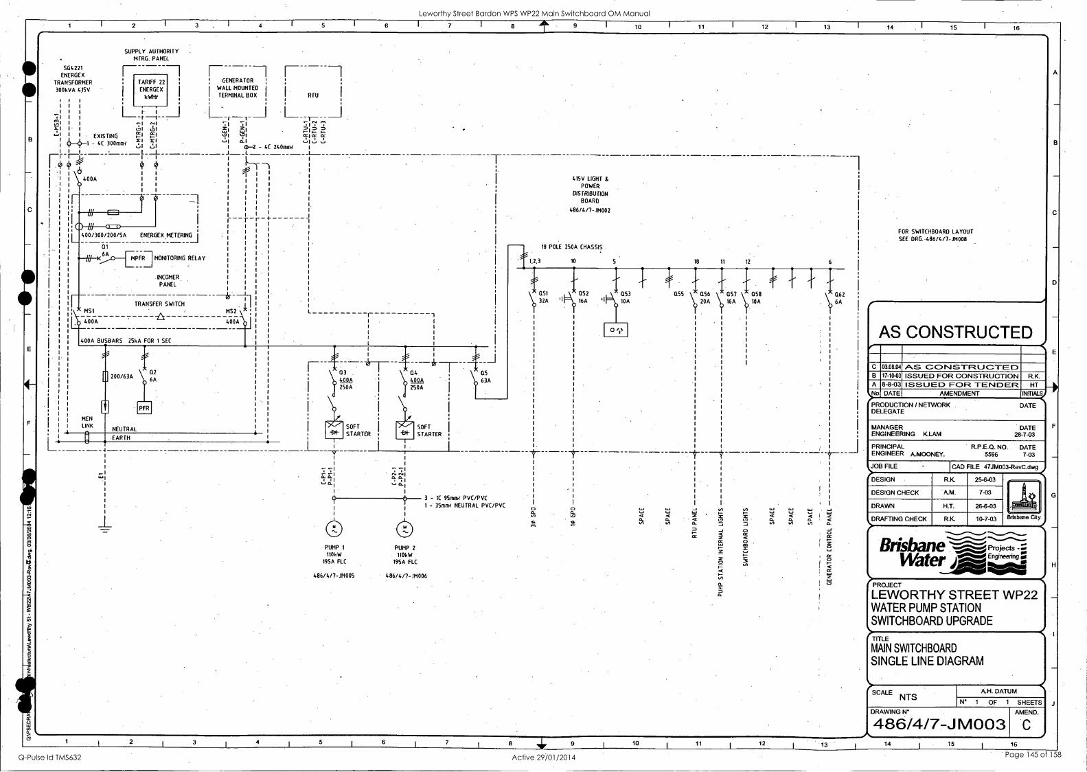
F
10 11 12 13 14 15 16
504221 ENERGEX
TRANSFORMER
300kVA 415V
0:1
SUPPLY AUTHORITY MFRG. PANEL
TARIFF 22 ; GENERATOR
ENERGEX I
kW1ir
WALL MOUNTED
I. TERMINAL BOX I. I, RTU
; I 1 H-r -1- _ i 1 -.1 I DI ,;1
EXISTING r_i
.. ail . 0 0 ILI
M Cr I..-
Cr -
CC I-
1.3 I
,I, a. i %-.1 I I
4. 4 1 - 4C 300mml ..t: :
(1)--2 - 4C 240mry IJ A-I
I- I
i
4:, + T 4..
400A 1 1
1 1
1 I
L.
400/300/200/SA ENERGEX METERING
6A MPFR MONITORING RELAY
.INCOMER.
PANEL
TRANSFER SWITCH MS1 MS2 \i<
..)0 400A 400A
- -r -r -+
400A BUSBARS 2SkA FOR 1 SEC
L
.20
MEN
LINK
0 200/63A
NEUTRAL
* 02 6A
-EARTH 4
r---- x -
), a.0 400A 250A
415V LIGHT & POWER
015 TRIBUTION
BOARD
486/4/7-M002
18 POLE 250A CHASSIS
1,2,3 10 5 18 11 12 6
32A I
Q52 16A
Q53
10A
055 as6 0.57 Q
10SA
8
20A 16A
%_J it X X
04 QS
400A 63A 250A
SOFT
STARTER
PUMP 1 PUMP 2
110kW 110kW 195A FLC 195A FLC
SOFT
STARTER
3 1C 95mo/ PVC/PVC 1 - 35onw NEUTRAL PVC/PVC
486/4/7-JMOO5 486/4/7-JM006
I
0 0 c- I, 11- O. ...., ......1
In 4..0 ' '
N .
VI EX II VI CL
en
1.1.1
a.
062 6A
1 3 I
4 I
5 I
6 I
7 I 8 9 I 10 I 11 I 12 13
FOR SWITCHBOARD LAYOUT
SEE DRG.-4136/4/1-114008
I
AS CONSTRUCTED
C 03.08.04 AS CONSTRUCTED B 17-10-03 ISSUED FOR CONSTRUCTION R.K. A 8-8-03 ISSUED FOR TENDER HT
t,No DATE AMENDMENT INITIALS
' PRODUCTION / NETWORK . DATE DELEGATE
MANAGER DATE ENGINEERING KLAM 28-7-03
PRINCIPAL R.P.E.Q. NO. DATE ENGINEER A.MOONEY. 5596 7-03
JOB FILE - I CAD FILE 47JM003-RevC.dwg
.? DESIGN R.K 25-6-03
-4. DESIGN CHECK A.M. 7-03
DRAWN H.T. 26-6-03 rig -- 1Tin.
,DRAFTING CHECK R.K 10-7-03 Brisbane City
Projects -: Watere I 01% I II I I
LEWORTHY STREET WP22 WATER PUMP STATION SWITCHBOARD UPGRADE
-1IITAIEN SWITCHBOARD
SINGLE LINE DIAGRAM
SCALE NTS
A.H. DATUM
N° 1 OF 1 SHEETS
DRAWING N°
486/4/7-J M003 AMEND.
C
14 15 16
Leworthy Street Bardon WPS WP22 Main Switchboard OM Manual
Q-Pulse Id TMS632 Active 29/01/2014 Page 145 of 158

sr 0 0
kb
cc
0
1 2 3 4 5 6 7 9 10 11 12 13 14 15 16
2
3
4
5
6
7
8
9
10
11
12
13
14
15
16
17
18
19
20
21
22
23
24
25
26
27
28
29
30
31
32
33
34
35
36
37
601
X6-01
604
X6-04 605
.0 X6-05
606
X6-06 607
.er X6-07
X6-08
X6-09
608
GFAILED
b
GFAULT
GFUELL
b
GRUNNING
115 A
609
610
MPFR-1
X6-10
.0" 611
X6-11 612
ATS-MS1 .
108 -----01113
X6-12 613
X6-13
X6-14
614
ATS-MS2
lOR - 011R
615
X6-15
far X6-16
616
GRSTART
11 -----014
.0" X6-17
617
618
GRSTOP
X6-18
X6-19 620
X6-20 621
X6-21 622
.er X6-22
0 GAUT°.
xl V x2
GCONN
b
GOPEN
GCBT
COMMON 24vdc -ve
GENERATOR FAILED RLY 9
GENERATOR FAULT RLY 10
GENERATOR LOW FUEL RLY 11
GENERATOR RUNNING RLY 12
GENERATOR RUNNING INDICATOR
GENERATOR CONNECTED RLY 13
MAINS FAILURE
MAINS ATS STATUS
GENERATOR ATS STATUS
REMOTE START SIGNAL
REMOTE STOP SIGNAL
GENERATOR CANOPY DOORS OPEN
GENERATOR NOT IN AUTO MODE
GENERATOR MCCB TRIPPED
2
3
4
6
7
8
RTU 24Vdc FROM RTU CONTROL PANEL
> RTU-dim3.00 < dim3.01 8 8
10 > RTU-4im3.01 <
11 > RTU-dim3.02 <
12 > RTU-dim3.03 <
13 > RTU-dim3.04 <
14 > RTU-dim1.6 <
dim3.00 7 7
IS
16 > RTU-dim1.7 <
17
20
dim3.02 9 9
dim3.03 10 10
dim3 .04 11
dim1.6
x2
H4
xl
dim1.7
12 12 - 13
14 14
15 15
dam 1.11
21 < RTU-domI.11 - 22
23. > RTU-dim1.15 <
26
16 16
dim1.15
dorsi° 27 < RTUzdam1.0 - 28
29
30
31
32
33
CONTINUED ON DRG.
486/4/7-H1005
GOPEN
GAUTO
GMCBT
/7 17
GFAILED
GFAULT
t4- 1l
GFUELL
GRUNNING
14
GCONN
14 MPFR-2 22'
40
0 GENERATOR FAILED
GENERATOR FAULT
GENERATOR LOW FUEL
GENERATOR RUNNING
GENERATOR CONNECTED
MAINS POWER FAILURE
NORMAL SUPPLY ON INDICATOR
MAINS POWER ON
24
PFR-1
14 _011
GRSTART
b
GRSTOP
b
R L
0 # 0 CONT. ON LINE 106
19 19 H6 A
40
41
42
GENERATOR REMOTE START 20
0 GENERATOR REMOTE STOP 22
xl x2
PUMP STATION REMOTE
SELECTED
(RTU CABINET) SITE ATTENTION ALARM RESET P/B (SWE3D)
SITE ATTENTION INDICATOR
"-) x - FLASHING LIGHT ON WALL
34
35
36
37
3 7 9 10 11
OUTPUTS CONNECTED TO THE .RTU TERMINALS ONLY.1NOT CONNECTED
TO RTU - PROVISION FOR FUTURE CONTROL
12 13
SYMBOLS LEGEND
> ???_?I??? <= INPUT
< 777_70777 >. OUTPUT
C..91-XX
= I/O ADDRESS
A=ANALOG, 0=DIGITAL
RTU=REMOTE TERMINATION UNIT,
= EXTERNAL WIRING
= FUSED TERMINALS ( 0.IA U.N.O. (MARSHALLING CUBICLE)
O = LINK TERMINALS (MARSHALLING CUBICLE)
= TERMINALS
= FIELD TERMINALS
AS CONSTRUCTED
C 03.08.04 AS CO NJ Si-Fzuc-ra ID B 17-10-03 ISSUED FOR CONSTRUCTION R.K.
A 8-8-03 ISSUED FOR TENDER HT No DATE AMENDMENT INITIALS
PRODUCTION I NETWORK DATE DELEGATE
MANAGER DATE ENGINEERING KLAN 28-7-03
PRINCIPAL R.P.E.Q. NO. . DATE ENGINEER A.MOONEY. 5596 7-03
JOB FILE .- I CAD FILE 47JM004-RevB.dwg
DESIGN R.K 25-6-03
A * DESIGN CHECK A.M. 7-03
DRAWN
DRAFTING CHECK
H.T.
R.K
25-6-03
10-7 -03
--rtiri Tim
Brisbane City
BrisbanC viosos Projects water 01000 Engineering
>PROJECT
LEWORTHY STREET WP22 WATER PUMP STATION SWITCHBOARD UPGRADE
>TITLE
MAIN SWITCHBOARD
BASIC TRANSFER SWITCH SCHEMATIC DIAGRAM
>SCALE NTS
A.H. DATUM
° 1 OF 1
DRAWING N°
486/4/7-J M004 A
14
<
E
AMEND.
SHEETS j
15 16
Leworthy Street Bardon WPS WP22 Main Switchboard OM Manual
Q-Pulse Id TMS632 Active 29/01/2014 Page 146 of 158

0
N
rn
Im
N
E
1 3 4 6 7 8 9 10 11 12 13 I 14 I 15 I 16
51
52
53
54
SS
56
51
56
59
60
61
62
63
64
65
66
67
68
69
10
71
72
73
74
. 75
76
77
78
79
80
81
82
83
84
85
86
87
88
89
90
91
92
93
94
95
96
97
98
99
100
- / / / / CONTINUED FROM DRAWING 486/4/7-11002 . - - N R il 13 102
103
F1 - F3 S(NGl 104 , , 200/63A ARRESTORS < 1D - E ;az 1K1-1 An O Irr237 to 105 ta,
101 .1 70 n<1 T 105 106 207 1K3 -1 1K5-1- 2K1-3
1K1 F 106 Ill 13 . 14 1 I 1 VI W 1K6-1 104 0 I= 107 ,__,) : li 0
----"' I
=- 108 CINIMIUM3 OREM 206 REFLUX MICRO
150 ' 61 kV 1K8 109 0_ __1',,,,_ 122
1
' 110 . 1K2 F
13 is 1
111 111) 1H1 F
112 1K4-1 119
11
[]HRNI F
113
(01 F
114 IK8-1 no 1T1 F
RESET - 1K7-1 ALY1 A2 1
- 75 ..1 K3-_,.......2.111___N_, 111
-
116 _IT1 -1 2 a1K 3 F
15 , 1 I NL3 117
WHITE NEUTRAL LINK 32A NI -1 'CED 11R
119 RIO 1K9-1 IA) 1H2 F 103 E/STOP II
03 6A 100 K3-3 200A ------ .----ri----122"r;)
-,.1.e. TERASAKI on 1K2-1 110 (W) 1H3 p
XS40 ONJ 250 ------- 121
. Ir..0.8 11(4
_..._.. ___ _ 01 LI ISS Ti --r"
SOFT -PUMP No. 1 ns 1K4 p jr___,...4, 0L2 STARTER 110 kW
123 21 K1 22 .....,...-- -is
Al 1 A2 1 --e......--....> L3 EMOTRON T3 ... F.L.C. 195 AMPS 124 . - .
31 K3 33 in . 1K5 p
13 14 1, MSF-170
PE PE -- 125 /11 IKI-2 110 12.
69 70 126 I
...--------°' - . . . . . ... / 13
1-T2 52 IV / SOFT STARTER 127
6 I BRIDGE , Ili m' ' EMOTRON 1-T1 ii NSF -170 0 128
129
130 I
,,,.-- GNOG > A-LINE '
RS485-A RS-485 COP
11 B-LINE 131 R548 -B
FROM POWE N PEo i
132 . RS485 -A - : RS-485 COP
TO SLAVE 2 133
134 RTU 24Vdc
CONTINUED FROM 0R4,
135 486/4/7-11004 A i
136 2
137 RTU DIGITAL INPUTS 1K2-2
138 CONTROL CIRCUIT AV > RTU-chin1.8 12 8
diTT11.13 24 20
dim 19 21 21 1K4 -2 139 > RTU-dim1.9( -*---
114 61 RUN/STOP STATUS
22 22 1K8-2 140 >RTU-dim1.10( 6'1'11° REFLUX MICROSWITE
8
./ d1m1 11 23 23 1K5-3 141 > RTU-dim1.1 ks -.0,-- SOFT STARTER TRIP
142 > RTU-dim1.12( dim1.12 II 32 EMERGENCY STOP P1
143 >RTU- dim1.1 dim1.13 n 33 a- LOCAL RESET P/B
Rill DIGITAL OUTPLI 144 2, 24 II 1K6
<RTU-dom1.3> dmi 3 145 a . 6 PUMP 1 - RUN/STOP
107
11.6
doml 4 20 25 1K7 plimP 1- FAULT REST <RTU-dom1.4)-- 141 ,Mb
148
PUMP 1- STATUS IN( (RTU-dom1.0 tk- domI 0 7 34 31. ll 1K9 119 149 a . 0 EWE) / J / / / CONTINUED IN DRAWING 486/4/7-M006 150
LINE .1 1.11- 1)1
CONTINUED ON ORG.
406/4/7-11006
UMP 1 - RUN RELAY 05. 125, 206
UMP 1 - REFLUX MICROSWITCH STATUS RELAY 14. 140.
UMP 1 - CONTROL CIRCUIT AVAILABLE RELAY 21, 137
UMP - RUNNING INDICATOR
UMP 1 - HOURS RUN METER
UMP 1 - STARTER CUBICLE FAN
UMP 1 - REFLUX FAIL TO OPEN DELAY TIMER 16
UMP 1 - REFLUX FAIL TO OPEN RELAY 06 115, 120. 139
UMP 1 - TRIPPED INDICATOR
UMP 1 - STARTER AVAILABLE INDICATOR
UMP 1 - RUN CONTACTOR 12. 138
UN? 1 - SOFT STARTER FAULT AUXILIARY RELAY 6 119, 140
MS LINK METER
MS LINK
AILABLE
STATUS
ED
B
S.
RELAY
T RELAY
ICATOR RELAY
4 6 7
SYMBOLS LEGEND
> ??7-7I777 85010
?7?-?0?7? OUTPUT
L 1/0 ADDRESS
A ANALOG, 0402ITAL
RTUREMOTE TERMINATION UNIT,
. EXTERNAL WANG
FUSED TERMINALS 1 0.1A U11.0. 1
1MARSMALLING (UMEW
O a LW TERMINALS INARSMALLING CUBICLE)
O . TERMINALS
181 FIELD TERMINALS
AS CONSTRUCTED
C 03.08.04 AS CONSTRUCTED B 17-10-03 ISSUED FOR CONSTRUCTION R.K A 8-8-03 ISSUED FOR TENDER HT No DATE AMENDMENT INITIALS i PRODUCTION / NETWORK DELEGATE
DATE
MANAGER ENGINEERING K.LAM
DATE 28-7-03
PRINCIPAL ENGINEER A.MOONEY.
R.P.E.Q. NO. 5596
DATE 7-03
,JOB FILE CAD FILE 47JM005-RevC.dwg i DESIGN
DESIGN CHECK
DRAWN
DRAFTING CHECK
R.K 25-6-03
A.M. 7-03
H.T. 25-6-03
R.K 10-7-03 Brisbane City
Brisbane Projects
Water owEnglneenng.: ___404001041 PROJECT
LEWORTHY STREET WP22 WATER PUMP STATION SWITCHBOARD UPGRADE
DRAWING
PEA! N SWITCHBOARD PUMP 1 - SOFT STARTER SCHEMATIC DIAGRAM SCALE
NTS
DRAWING N°
A.H. DATUM
o 1 OF 1 SHEETS j
486/4/7-J M005 AMEND.
9 10 11 12 13 14 15 16
Leworthy Street Bardon WPS WP22 Main Switchboard OM Manual
Q-Pulse Id TMS632 Active 29/01/2014 Page 147 of 158

B
C
E
4-
F
1 1 2 3 4 5 6 7 8 9 10 11 I 12 13 I 14 1 15 I 16
51
152 E
153
1S4
155
ISO
158
IS9
ssa
161
52
163
164
165
161
ssa
169
170
al
171
173
174
175
176
m
1711
179
180
181
162
183
184
185
187
tOS
189
190
192
193
194
195
116
191
238
191
200
10 " /- N
V
/ R
/ ki
/ 8
CONTINUED FROM DRAWING 486/4/7-1M005 LINE 10
202
203
201. u.t ....., I- ..,C 0 ,.. S
205 0 Laa -a Cr
2" 2---0 0
202 2K1-1 it2
1 STAR T STOP 210-1 21(5-1
ma 11(1-3
247 21(1 F 20S
207
ZOI
109
I i 208 21(6-I 704
I
13 11
r
.;
F
2
F
F
F
F
2
r 2
F
F
p
2 p
1 1 .../".... .
200 (5S7 22I 21(8
210
211
212
.
- 213
214
26
216
- NL 4 217
WHITE NEUTRAL LINK 32A NI -1
218 CEM
.0_ _1..,.....__
200 a 2K2 IL .11 13
IRIrol, 2H1
2K4-1 209 i1 %Diva
FIRM2
31 ...----. p,
21(8-1 210 211
RESET ------- 21(7 -1 ALT1 NH 21(3-2 in IQ
A2
-I-1-- Lr frri 213 21(3 5/16 13 IA
203 . E/STOP 2" .--.
Q4 6A 200
1--'lL"at
200 2K9-I nt IA1
to 21(2-1
.....''' 2K 3 -3
.2H2
200A TERASAIQ X00N1S4 250 400 g1
_..._......-...-. s-i-o
221
121_,,_,
...---- 25 IWI 2H3
1K4 _._ .. ._..._ _ I
.. .. 2
-
.2
--1--- LI Ti ..
1SS PUMP No. 2
SOFT A 123
.
21 1(1 22 2 21(4
' --f- L2 T2 110 kW
STARTER F.L.C. 195 AMPS 224
........-- -o
31 K3 33 Al M A7_
217 m ZKS .----95...1,.....- 0L3 EMOTRON T3
MSF-170 225 no ------ -c'
21(1-2 219 12 13 ii 14 2
oPE
69 70 226 I
....,''' 13 0 ?
1 -T2 NI SOFT STARTER 227 210 0 1-T1 MI I BRIDGE
228 21(7-2'
.-1'1"211-1-0 EM
11 MSOTRON F-170
,., GNDo > A-LINEo RS485-A
0 -- 221
230 ' 231 75 B-LINEo RS485-13 RS-485 COP
FROM SLAV( PEo
232
L. 233
234 RTU 249111
CONTINUED f11001 ORG. 235 416/4/7-111005
A 236
r
237
238
239
240
241
242
as 243
63A TERASAKI 244 XS125111 63
. 3 .
20 -i 2K2-
1
RTU DIGITAL INPUTS
CONTROL CIRCUIT AV
RUN/STOP STATUS
REFLUX MICROSWITC
SOFT STARTER TRIP
EMERGENCY STOP P
LOCAL RESET P/B
RTU DIGITAL OUTPU
> RTU-dim2.0< dim2.0 26 1221((
dim2.1 2K4-2 > RTU-dim2.1<
if 27
61
dim2 2 AI 21(8-2 / to > RTU-dim2.2 \
5 2K5-3
> RTU-dim2.3< .dim2.3 .: n
21 .2
36 > RTU-dim2 4<
dim2.4 35
dim2.5 36 36 > RTU-dim2.5< -6--
dom1.5 I 30 2K6
PUMP 2 - RUN/STOP 207
PUMP 2- FAULT RES 228
PUMP 2- STATUS It 219
245
TO DISTRIBUTION BOARD
(REFER ORG. 486/4/7-1110021 246
247
<RTU-dom1.5>- In
A'0 0
3 31 2K7 .----31.....1.....---
x1, 4!.....:----
i dom1.6 <RTU domI.6>-
a
li III 11
246
249
250
2K9 (RTU-dom1.08.,k-
dom1.08 n . a e
UMP 2 - RUN RELAY 05, 225, 106
UMP 2 - REFLUX MICROSWITCH STATUS RELAY 14, 240,
UMP 2 - CONTROL CIRCUIT AVAILABLE RELAY 21, 131,
UMP 2 - RUNNING INDICATOR
UMP 2 - HOURS RUN METER
UMP 2 - STARTER CUBICLE FAN
UMP 2 - REFLUX FAIL TO OPEN DELAY TIMER 16
UMP 2 - REFLUX FAIL TO OPEN RELAY 06 215, 220, 239
UMP 2 - TRIPPED INDICATOR
UMP 2 - STARTER AVAILABLE INDICATOR
SYMBOLS LEGEND
> 777-71777 <. MPUT
(777-70777 > OUTPUT
I L VO ADDRESS
(..---- A ANALOG, 005CITAL
RTUREMOTE rutrumAnot4 UNIT.
EXTERNAL WING to, way,
Fusto TERMINALS ( 0.1A U.11.0. 1
NARSHAIIMG C151017
O LINN TERTINALS IMARSHALLING Clean
0 TERMINALS
1113.D TERMINALS
1
AS CONSTRUCTED UMP 2 - RUN CONTACTOR 12. 238 UMP 2 - SOFT STARTER FAULT AUXILIARY RELAY 06 219, 240
MS LINK
AILABLE
STATUS
ED
/8
S
RELAY
ET RELAY
DICATOR RELAY
3 4 7 10 11 12 13
C 03.08.04 AS CC) s-r Ft L.1 C'TE Ci B 17-10-03 ISSUED FOR CONSTRUCTION R.K. A 8-8-03 ISSUED FOR 'TENDER HT No DATE AMENDMENT INITIALS
PRODUCTION /NETWORK DELEGATE .
DATE r%
MANAGER ENGINEERING K LAM
DATE 28-7-03
PRINCIPAL ENGINEER A.MOONEY.
R.P.E.Q. NO. 5596
DATE 7-03
JOB FILE - N
1CAD FILE 47JM006-RevC.dwg
DESIGN
DESIGN CHECK
DRAWN
DRAFTING CHECK
R.K 25-6-03
A.M. 7-03
H.T. 25-6-03
R.K 1D-7-03
A
B
E
F
DrisbBr ane Projects
Water 110%14110 Engineering
-VW iftMgliij PROJECT
LEWORTHY STREET WP22 WATER PUMP STATION SWITCHBOARD UPGRADE
MAIN SWITCH BOARD PUMP 2 - SOFT STARTER SCHEMATIC DIAGRAM
(SCALE NTS
A.H: DATUM N
N° 1 OF 1 SHEETS
DRAWING N°
486/4/7-J M006 AMEND.
C I 14 15 16
J
Leworthy Street Bardon WPS WP22 Main Switchboard OM Manual
Q-Pulse Id TMS632 Active 29/01/2014 Page 148 of 158

1 I 2 3 1 4 5 I 6 I 7 I 8 T 9 1 10 11 I 12 - I 13 I 14 15. 16
GENERATOR
TERMINAL BOX
MAIN SWITCHBOARD
INCOMERS SECTION INCOMERS
TERMINAL STRIP
MAIN SWITCHBOARD
MARSHALLING SECTION MARSHALLING
TERMINAL STRIP MULTI-PIN SOCKET 601
WILCO WIBM-27 XG-01 601 INCOMERS SECTION --(INTERNAL) 20C E
XG-02 602 PUMP 1 STARTER --(INTERNAL) 16C E 2
XG 03 603 PUMP 2 STARTER 12C E -(1NTERNAL) 3
12C E 604 GFAILED
XG-04 604 4 605 nGFAULT
XG OS 605 5 606 LI
XG-06 606 6 607
OGFUEL
GRUNNING XG-07 607 7
607 XG-07 8
608 v GCONN XG-08 608 9
609 MPFR XG 09 609 10
610 XG-10 610 11
611 ATS-MSI XG-II 611 12
612 XG-I2 612 13
613 ATS-MS2 XG 13 613 14
XG 14 614 614
15 615 GRSTART
XG-15 615 16
XG-16 616 616
17 617 GRSTOP
XG-17 617 18 618
XG-18 618 19
X6-19 SPARE 20 GOPEN
XG-20 SPARE 21 GAUTO
XG-21 SPARE 22 GCBT
XG-22 SPARE 23
XG-23 B 24
XG-24 N 25
XG-25 r- - - - - - 26
27 DISTRIBUTION I
BOARD 28 POWER SOCKET 062
!") 29
WILCO WIBM-532R 4C E
if NB 30
El3 31
O III 32
415V MAIN SWITCH 2 33
34 R
35 REMOTE 400A PANEL DRAIN W RESERVOIR 36
B SET OF 5 LEVEL INDICATOR 37 CLIPSAL 3PL4PDS
N 38
39
40
MAIN SWITCHBOARD FIELD .0 -100% = 4-20mA
41
42
FROM SOFT STARTERS 551 TERMINALS 69, 70
PUMP 1 TERMINAL STRIP
'Ti
SO
51
11T2 52
53
CON 1
2C E
r---- I REFLUX MICRO I
1°
FROM SOFT STARTERS
PUMP
2TI
2 TERMINAL STRIP I REFLUX MICRO I
1 54
55 2C E
D __I
56 SS1 TERMINALS 69, 70 12T2
57
lg 24V DC
IE COM
don3.00
dim3.01
dim3.02
dim3.03
dim3.04
dtm1.06
dim1.07
dom1.10
dom111
dtm115
duri1.02
dom100
&ill 08
dun109
&mt. 10
dim1.11
doM103
dom1.04
dim2.00
dim2.01
dun2.02
dun2.03
dom1.05
dom1.06
dun1.12
dim1.13
dun1.07
dun2.04
dim2.05
dun1.08
aom1.00.-
aom1.00-
RTU -1 ) ZC E
( RTU-2 24C E
( RTU-3 I2C E _/
RIO PANEL
REFER DRG. 486/4/7-1m014
AS CONSTRUCTED D 03.08.04 AS OONS-rFzuc-rac, C 21-1-04 Do Ft. G REF A.CI E C.) R.K. B 17-10-03 ISSUED FOR CONSTRUCTION RK A 8-8-03 ISSUED FOR TENDER HT
No DATE AMENDMENT INITIALS i PRODUCTION / NETWORK DELEGATE
S. DATE
MANAGER ENGINEERING K LAM
DATE 28-7-03
PRINCIPAL ENGINEER A.MOONEY.
R.P.E.Q. NO. 5596
DATE 7-03
,JOB FILE - I CAD FILE 47JM007-RevD.dwg
DESIGN
DESIGN CHECK
DRAWN
DRAFTING CHECK
R.K. 2-7-03
7-03
H.T. 2-7-03
R.K. 10-7-03
Brio.,640 Frojects - Watew Engineering
Brisbane cit
PROJECT
LEWORTHY STREET WP22 WATER PUMP STATION SWITCHBOARD UPGRADE
TITLE
MAIN SWITCHBOARD
TERMINATION DIAGRAM
SCALE NTS
A.H. DATUM
° 1
DRAWING N°
OF 1 SHEETS
AMEND.
486/4/7-J M007 D
1 I 2 I 3 5 6 I 7 I 8 9 I 10 1 11 I 12 I 13 1 14 I 15 I 16
Leworthy Street Bardon WPS WP22 Main Switchboard OM Manual
Q-Pulse Id TMS632 Active 29/01/2014 Page 149 of 158

-
is
0
ce
12
w
7
CONSTRUCTION NOTES
FAULT LEVEL 25kA for 1 second
DEGREE of PROTECTION _IP42 DEGREE of SEGREGATION FORM 3h
MAIN BUSBAR RATING _400A @
30C RISE ABOVE 40C AMBIENT
CASE & GEAR PANELS_ 2.0mm ZINC ANNEALSHEET STEEL .
COVERS & DOORS _ 1.6mm ZINC ANNEALSHEET STEEL .
PLINTH SO ANGLE IRON FRAME WITH 1.6 mm S/S TEEL COVER ON FRONT.
DOORS FITTED WITH 2 CHROME PLATED PINTLE HINGES 8 COIN TYPE 1/4 TURN LOCKS. 105' 00OR STAYS 8 EARTH STRAPS. LIFT OFF COVERS FITTED WITH TWO LIFTING HANDLES & FOUR 1/4 TURN LOCKS.
COVER OVER ENERGEX PANEL FITTED WITH SEALABLE 1/4 TURN LOCKS
EXTERIOR FINISH:- POWDER COATED OULUX ORANGE I X15 I
INTERIOR FINISH:- POWDER COATED OULUX BRIGHT WHITE ( 32166 I BCC
DOOR & ESCUTCHEON EARTHS LABELS ARE ENGRAVED TRAFFOLYTE, M3 S/S SCREW AFFIXED.
STANDARD SPECIFICATION ( PSE-SS001 I APPLIES.
FOR SCHEMATIC & WIRING DIAGRAMS SEE DRAWINGS Nos 486/4/7-1M002 to 486/4/7-1M007.
CONTROL WIRING IS A MINIMUM V90 FLEX. NUMBERED USING 3 *GRAPHOPLAST' S12000 SYSTEM, CABLES ARE TERMINATED USING CRIMP LUGS COMPATIBLE WITH THE
EQUIPMENT.
COLOUR CODING WILL GENERALLY BE AS FOLLOWS:- 2.5sqmm Wird Red, White, Blue PHASE WIRING
1.5scirom Red, Blue, Black POTENTIAL METERING
2.5sqmm _Red, White. Blue, Grey CURRENT METERING 1.5sqmm White 240Vac CONTROL
1.5sqmm _Black 240Vac NEUTRAL 0.5sqmm _Orange 24V ELV POSITIVE 0.5sqmm Violet 24V ELV NEGATIVE 0.5sqmm _ Grey 24V RTU I/O POSITIVE 0.5sqmm Grey 24V RTU I/O NEGATIVE
2.5sqmm Green /Yellow EARTH 4.0sciihm _Green/Yellciw
0 BUSBAR ZONE
0 0
0 0 BUSBAR ZONE
0 0
0 - 0 BUSBAR ZONE
0
BASIC TRANSFER SWITCH CONTROL
MODE
Ei 000e Er
OUTLET
FILTER
SK3326200
OUTLET
FILTER
SK3326200
Efi
KEYPAD- 0 0 ®0 0 0 0 0
KEYPAD F-1 ® ® eo H 0 0 0 0
PUMP No. 2 0 0
t.., . . NJ
-I CO
LAJ
.2 L-i
0 0
0 0
ENERGEX CTs
(SEALABLE LIFT OFF
COVER)
®
PUMP No. 1
INLET
FAN 8 FILTER
SK3326100
INLET
FAN 8
FILTER
SK3326100
MARSHALLING
CUBICLE CABLE ZONE DISTRIBUTION
BOARD
MAIN ENERGEX ISOLATOR
Ot PADLOCKABLE OR
LOCKABLE TO ENERGEX
REQUIREMENT
® 0
0 0
1111.04 AS ONSTRIATIO
-10-01 ISSISFORONSIROCICK
A 1443 SSEORN 031111
NO DATE memoir
A
FRONT VIEW
PRINCIPAL ENGINEO3 &MOONEY.
R.PLO. NO. 5095 1-01
DATE
NANACER ENGINEERING IL LAN 29-743
DATE
eE
NI PROOUCDON / NETWORK muam INITIALS
1/4 TURN
COIN LOCKS
0. 411
MAX. 2100
NOTES
1. DIMENSIONS ARE NOMINAL.
900 600 600
i
r . I-
1 BASIC TRANSFER SWITCH
VFD VFO
4 4,14 r-
.5 LA ....
CC
3
LA
,S
1 0 PI VI
CONTACTOR CONTACTOR
I
.t
L.._1 1K4 . 2K4
I
40 x 60 r -4 PUMP No. 1 PUMP No. 2
FUSES
16 III ,E, u 40 x 60
o . o ...,
40 .x 60
z o " .. -- co
CONTROL 8 CONTROL & o
'II fr'
I i
TERMINALS TERMINALS .6,,,.. .,15._,.
IR IR
_Er, nnn uu LI
40 x 60 40 x 60 im,
n LINKS
CTs
r 7 I
ENERGEX 100 x 80 . - _ _ _
- - - - ----_- - - -------------
-CABLE ZONE: _- _ _ ...
------------- ----------- - - ..-
a I
DISTRIBUTION
BOARD
10 I
18 POLE
-I - CI
cl ... I- _.
.
1- ,_, D 0 0
0 I--
_... ul
x
4r)
z -±- c. i...
_CHASSIS_
.--
CHASSIS
GP O - S T R OMB ERG ISOLATOR
OETL400 DI _-
II !
- 0 a 1,
--'
200 700 450 300 450
MEN LINK
FRONT VIEW (OUTER DOORS REMOVED
10
GPO
(Z)
30 SPO
500
VFD
CONTACTOR
DISTRIBUTION
BOARD
GPO
1
SECTION A
AS CONSTRUCTED NOME DATE JOB FIE
Brisbane Dater '"=
PROJECT
LEWOR THY STREET WP22 WATER PUMP STATION
DESIGN NK. 244-03 ATM FILE 4704001144.0 thog
DRAWN KT. 244-03 SURVEY No. FELD BOOK
CHECKED AK. 22-5-03 Brisbane My SURVEYED AN DAMN WIN
TITLE
SWITCHBOARD GENERAL ARRANGEMENT
SCALE 1:10 Oil SHEETS
DRAWING fr
486 4 7-JM008 AMEND.
Leworthy Street Bardon WPS WP22 Main Switchboard OM Manual
Q-Pulse Id TMS632 Active 29/01/2014 Page 150 of 158

a.
0
et
at
PADLOCKABLE
SWING HANDLE
NOTE 4 .
600
FRONT VIEW
Ar"-
/ 0 0 0 R B E
'P., 0
(-) s" -
Cl
AL.
FRONT ELEVATION
400
WILCO SOCKET WIBM-27
WILCO SOCKET WIBM-532R
L_
400
440
560
DETAIL 2
CABLE ENTRY PLATE
EQPT MTG PLATE
4@80=320
42
5
62
CO
06
DETAIL 1
SOCKET PANEL - 2mm SM (PART OF EQPT MTG PL)
400
SEE DETAIL 2
560x360x3 GL PL
ON 520x320 CUTOUT
IN BASE OF CABINET
CABLE GLAND LOCATIONS
CHROMED BARREL BOLTS
FULL LENGTH S/S HINGE
SECTION A-A
NOTES
GEN CABLES WITH PLUGS
1P20 COVER
440x160x3 FLAP ON 400x120 CUTOUT
HINGED FULL LENGTH WITH S/S PIANO HINGE
& CLOSED WITH 2 SLIDE BOLTS FROM INSIDE
GEN CABLES W/O.PLUGS
GENSET CABLES
Fr,
A 4
24V 2A PLG/SKT
1111110111111111111111111N111111111111 rmssisrEsismvskuumr.vmommus...01Aus 11111111111111111111111111111
177
DOTTED LINES
= ALTERNATIVE CONNECTIONS
TO GENSET
WITHOUT PLG/SKT
FULL LENGTH S/S PIANO HINGE
1. ENCLOSURE = B&R 21214/S OR EQUAL 1.6mm s/s IP66 C/W PADLOCKABLE SWING HANDLE L INTERNAL EQUIPMENT PLATE & MTG. KIT & MEB/S WALL MTG EIKTS.
2. BASE OF CUBICLE TO BE CUTOUT 520x320 FOR 560x360x3mm ALUMINUM CABLE ENTRY PLATE.
3. FLAP ON CABLE ENTRY PLATE TO BE 1.6mmS/S HINGED
ALONG LONG EDGE AND HELD CLOSED WITH 2 CHROME PLATED BARREL BOLTS.
4. DOOR FITTED WITH SINGLE LATCHING 'SELECTRIX' TYPE 1107 -PSCO1 PADLOCKABLE HANDLE.
TO MAIN SWITCHBOARD
AS CONSTRUCTED
C .08.04AS CONSTRUCTED B -10-03ISSUED FOR CONSTRUCTION R.K A
N' 8-8-03 Date
ISSUED FOR TENDER HT Revision Initlah
Principal Date Engineer A.MOONEY. 5596 7-03
Manager Date Engineering K. LAM 28-7-03
Production/Network Date Delegate
Name Date
Design R.K 2-7-03
Drawn H.T. 2-7-03
Checked R.K. 22-7-03 Brbbane City
Job File
Filename 47,10109-RevCekg Sheet Sire
Sunray No. Field Book
Surveyed A.H. DATUM
Brisbane Projects Engheeriv g
Project -
LEWORTHY STREET WP22 WATER PUMP STATION
Title
GENERATOR CONNECTION BOX GENERAL ARRANGEMENT
Scale Pr Shares
Urainig3N6/417 M009 Rev
Leworthy Street Bardon WPS WP22 Main Switchboard OM Manual
Q-Pulse Id TMS632 Active 29/01/2014 Page 151 of 158

2 4 6 10 11 12 ' 13 14 15 16
O 111
ENERGEX
METERING
PANEL
PROPOSED
ANTENNA
LEWORTHY STREET PUMP STATION
BRICK WALL
GATE ENERGEX
TRANSFORMER
RTU CONTROL PANEL
425
EXISTING
TELECOM
SOCKET
_ _L_
PROVISION FOR
FUTURE VSOs
EXISTING CABLE
TRENCH
c
2 VII -
cc
0
C t- o
<NI
OVERHEAD CRANE
NEW CABLE TRENCH
100
320 790
380 310 580
BRICK WALL
VERTICAL CABLE
LADDER
141
0
EXISTING CABLE TRENCH
SAFETY RAIL
/-SAFETY CHAIN
LADDER TO
rPUMP FLOOR
REFLUX VALVES
PUMP &
MOTOR
UNIT
141
0
EQUIPMENT
REMOVAL
DOORS
0 O LI1
GENERATOR
CONNECTION BOX
21800
MAIN
ACCESS
DOOR
FLOW
TRANSMITTER
SITE ENTRY KEYPAD
SUCTION & DELIVERY
PRESSURE TRANSMITTERS
7300
PUMP STATION PLAN
NOTES
1. THIS DRAWING SHOULD BE READ IN CONJUNCTION WITH THE FOLLOWING DRAWINGS: 486/4/7-JM001 TO 486/4/7-M012.
2. THIS DRAWING SUPERSEDES DRAWING NUMBER
486/6/80-JM1T132E.
AS CONSTRUCTED
C
B
A
No DATE
03.08.04 AS 1 UCT a ID 17-10-03 ISSUED FOR CONSTRUCTION 8-8-03 ISSUED FOR TENDER
AMENDMENT
R.K.
HT INITIALS i
PRODUCTION / NETWORK DELEGATE
DATE
MANAGER ENGINEERING K. LAM
DATE 28-7-03
PRINCIPAL ENGINEER A.MOONEY.
R.P.E.Q. NO. 5596
DATE 7-03
JOB FILE - CAD FILE 47JM010-RevC.dwg 1 DESIGN R.K. 10-7-03
DESIGN CHECK
DRAWN
A.M. 22-7-03
H.T. 10-7-03 .
DRAFTING CHECK R.K. 22 -7 -03 Brisbane City
tines _ Brisbane
Water --41"11010111%111"1111
A
B
C
F
PROJECT
LEWORTHY STREET WP22 WATER PUMP STATION SWITCHBOARD UPGRADE
>TITLE PUMP STATION GENERAL ARRANGEMENT
SCALE NTS
A.H. DATUM
N° OF SHEETS j DRAWING N°
486/4/7-JM010 A
AMEND.
C 2 3 4 5 6 7 8 9 10 11 12 13 14 15 16
Leworthy Street Bardon WPS WP22 Main Switchboard OM Manual
Q-Pulse Id TMS632 Active 29/01/2014 Page 152 of 158

0 0
0
65
3 4 5 6 7 8 9 10 11 12 13 14 15 16
LEGEND
CONDUITS
PVC DUCTING
LLI
ALARM LICAIT
150
X02
ATTENTION IF ALARM ACTIVE
CONTACT CONTROL ROOM
1000
LOCATION
OFRTU0 MARSHALLING BOX
DRG Nos. 1006 - 0327
GPO
400
RADIO COMMS. CONDUIT
TO AERIAL ON ROOF
r
A
0 0
0 0
0 0 0 0 0
INCOMING CABLE ENTRY POINT
THROUGH WALL
MDF
INCOMING
TELECOM CABLE
PUMP STATION
SECTION SC AL E :N T S
TELECOM
SOCKETS
& DUCT
FOR EXISTING
& NEW RTUs.
HANDRAIL
PUMP FLOOR
4 5 6 7 8 9 10 11 12 13
NOTES
1. THIS DRAWING SHOULD BE READ IN CONJUNCTION WITH THE
FOLLOWING DRAWINGS: 486/4/7-JM001 TO 486/4/7-JM012.
2. THIS DRAWING SUPERSEDES DRAWING NUMBER
486/6/80-1MIT133E.
AS CONSTRUCTED
C 03.08.04 AS CONSTRUCTED B 17-10-03 ISSUED FOR CONSTRUCTION R.K. A 8-8-03 ISSUED FOR TENDER HT No DATE AMENDMENT INITIALS
PRODUCTION /NETWORK DATE DELEGATE
MANAGER DATE ENGINEERING K. LAM 28-7-03
PRINCIPAL R.P.E.Q. NO. DATE ENGINEER A.MOONEY. 5596 7-03
JOB FILE - CAD FILE 47JM011-RevC.dwg
DESIGN R.K 10-7-03
DESIGN CHECK A.M. 7-03
DRAWN
DRAFTING CHECK
H.T.
R.K
10-7-03
10-7-03
"7II h
Blisbarle City
--,...--._..'"-.,--...._. "...-0---..^...-.. ..**.-'°...0.10 Projects -: Bn'sbane 0.m,
.00111%m0 Engineering Waterilitionouri 114111110%111
PROJECT
LEWORTHY STREET WP22 WATER PUMP STATION SWITCHBOARD UPGRADE
TITLE PUMP STATION SECTION eSCALE
NTS AH. DATUM N
N° OF SHEETS
DRAWING N°
486/4/7-JM011 ,..
AMEND.
C . 14 15 16
E
F
Leworthy Street Bardon WPS WP22 Main Switchboard OM Manual
Q-Pulse Id TMS632 Active 29/01/2014 Page 153 of 158

kf
65
C
3 10 11 12 13 14 15 16
LEGEND
CONDUITS
PVC DUCTING
LEWORTHY STREET PUMPING STATION
25mm CONDUITS COl C66 ONDUITS TO BE
TO SITE ENTRY cos co, LENGTHENED
KEYPAD BESIDE DOOR .......------- ,
AA
v
...
..
...,
,...
/
0
FUTURE VFDs 100 X 50 DUCT
.. ,...
MAIN
SWITCHBOARD
,- -,- -,
-1- 20A 30 SPO
.
RTU CONTROL PANEL
', 1
4
rd
0 15A 10 GPO
2100
2300
2580
SECTION SCALE:NTS
1 2 8 9 10 12 13
NOTES
1. THIS DRAWING SHOULD BE READ IN CONJUNCTION WITH THE
FOLLOWING DRAWINGS: 486/4/7-51001 TO 486/4/7-JM012.
2. THIS DRAWING SUPERSEDES DRAWING NUMBER
486/6/80- JM1T133E.
AS CONSTRUCTED
C 03.08.04 AS C Co NI S 1- F2 U GTE ID B 17-10-03 ISSUED FOR CONSTRUCTION R.K. A 8-8-03 ISSUED FOR TENDER HT
,No DATE AMENDMENT INITIALS
PRODUCTION / NETWORK DATE
MANAGER DATE ENGINEERING K LAM 28-7-03
PRINCIPAL R.P.E.Q. NO. DATE ENGINEER A.MOONEY. . 5596 7-03
JOB FILE . - I CAD FILE 47JM012-RevC.dwg
DESIGN R.K 10-7-03
DESIGN CHECK A.M. 7-03 A
DRAWN H.T. 10-7-03 __.... _ rilll
DRAFTING CHECK R.K 10 -7-03 Brisbane City
-...._...--..._..----..------.-- -....--.0--..-...--,..-.. r' e....
'---....-,0,..... EPnrCginieecterisng- Iii.1... 14fater.4.0.441 Ilft".1
PROJECT
LEWORTHY STREET WP22 WATER PUMP STATION SWITCHBOARD UPGRADE
TITLE PUMP STATION SECTION '1E3'
C SCALE
NTS AH. DATUM
N° OF SHEETS
DRAWING N°
486/4/7-J M012 ,..
AMEND.
C , 14 15 16
E
Leworthy Street Bardon WPS WP22 Main Switchboard OM Manual
Q-Pulse Id TMS632 Active 29/01/2014 Page 154 of 158

DR
AW
ING
RE
GIS
TE
R
Dw
g N
o D
escr
iptio
n R
ev 0
R
ev 1
R
ev 2
R
ev 3
R
ev 4
R
ev 5
07
165-
E-0
01
MA
IN S
WIT
CH
BO
AR
D G
EN
ER
AL
AR
RA
NG
EM
EN
T -
486/
4/7-
JM01
3 D
ec-0
3 D
ec-0
3 07
165-
E-0
02
MA
IN S
WIT
CH
BO
AR
D G
EN
ER
AL
AR
RA
NG
EM
EN
T S
EC
TIO
NS
-
486/
4/7-
JM01
3 D
ec-0
3 D
ec-0
3 D
ec-0
3 07
165-
E-0
03
GE
NE
RA
TO
R C
ON
NE
CT
ION
S B
OX
- 48
6/4/
7-JM
009
Dec
-03
Dec
-03
Leworthy Street Bardon WPS WP22 Main Switchboard OM Manual
Q-Pulse Id TMS632 Active 29/01/2014 Page 155 of 158

4.-
o
0 a,
33 m m
3333 co c0 a3 c0
3 al m 33333333
m 03 m c0 03 CD a3
3 [0
3 /33
3 m 03 333333333 m .33 c0 cr3 a3 a3 03
,,,..
0 x 1-
o e-
o ,- c0 4.17 CO 417 ma aD (17 cc) CD cs7 aD CD u, CD CD CD 4.10 CD CO CD 4.0 (0 a7 CD CO
0 N U)
4 00 LO
X 400 u l
ul x
U l
O. 1 - _ r 4 )
O. O. c -c t i , 6
CL -a w
CL 1 = U)
0 I= u)
a 1=
U)
0 to x c4
0. CL
Z5 Z5
0 CL
Zi Z5
0.
V5
CL O.
Z5 6 O.
6 CL CL
1= 1= 05 u)
O. CL = -0 i5 65
a O. 1= 1= co c7)
CL 0 1= 1=
co 0
0 .ca 03 -A
tp
c7)
. o ... c 0 ..:c
0 co
cm C "E
m cc
E 0 , ,,,,
0 >7
a m
u) 15
o z
cq
a Z a E =
EL
- ,- ci z la
E CL
_4 ,t ..._ lc C) NON .a. -1 y 0
.-
,_ cv t- 0 cv (V
- 01 1- a .,-
.0.
cv - ,1,
;' NY 04 ,...
,- y ,-
co u, cs,
01 01 co co) 01 01
cl 01 u) 0) - 01 c,,
CV u) cv
04 u)
,_
CD
03
co ..= m 2 5 0, a M
Mu)m
Ta
E 0 Z
1.)
-X
ED.
co
5 2 5 ,,
14,. a
u) ,-
2 E ,...
cst a ,_- a
cc u_ LL
1:i. uL CL
2
ES co
0 75 cL 5 0-Em`c 0 a) 0 0 m .c CL CL
c') .-
O. ma- 8 - P-
.0 03 0 o
Jo -c Sam § c2 co
.c 0,
-0 -I CO o
0- = m
., a E m 0-
, o .c ._
co -. 1.1 oc
12 0 co .- 0 9, .c `- 0 E
- 0 (a
co
_v 53
0 e
co
5 2
C.) c o
-.. 7 xa
2 5
El
.- CO m2
cq CO
a
6
CC IL. CL
ce 1.1_
a. 2
e (1) .c 0 > b o ..., c n co2x.n
E ..... CO
o , -0 .., c w m
a vi- Ozz.-
o ID
0 n 0. i 2 CL a'
0 1S 7 0 co cc
a a r ..*
0 //)
't .,,,
y
01 a (.6 a s-
0
ci r.-_,
Y m oi 01- co' Y .__.. "- 03 0'- Y Y . .-
- - <0 y ,-
n <0 0 w0) .g
0 zr.
VS c as Ti 0 CI
U)
' P
CO C - E
.c
.§ co " 5 0 0 co
3!,
cm
T?
-e.
-E-
0 0 - 2 o C 0 0
I .6 str .- i co
o .., e- 04 o o aaaaaaoa 0a ..m.
u) o a, m- to 0 co C4 o o
ae C :.:i
15 0 zw
_x c
c If 0
Ln a
0 Ts
t 0 c, c
ci Z .4 03 0
.c v 0
u c
Ca
CD 01 MM 2E 0 CD et 40 Z
Ca
CD 04 Ca CJ 0 2E cr 0 CO 0 04 V CO z
,- m, 04 0) co al cv 01 0) 0)
cm cm 04
aD c0 04 0 0) 04
z 0, 07 cc, a0 1.- 0 CC Z
0 CL 0, 0 0. CD
. .--
04 2 al 01
0.-
ON ...... C3 c) . 't U)
C) 1-
5z 04 ;F 0 0 ., ,- Z 0)
.... " 0 ES
03 ,-, In 0D c0 UD 4D 04 04
00 aD u.) 0 00 03 ma um 04 C4
et el CD C7 c0 c0 In to 04 cv
CV .- C3 C) 03 00 in 0 04 04
0 00 ,- '- -J
C9 CO
00 e- .- Ul LU 0.1 CI 0
01 00 01 01 cO Ca a) 01) 04 04
o E E
U
0 0 ,. ea cl
03
o __-I
0 0 E 0 cc LO
ecI
> N L ° up CV
04
CV gN4
ES .c
cs
.er co
W o < 03 4) + co .../ N
D 4. 4 01
A >-, LL <
4.0 co
o. E 0 a.
" u, CO > < _,I, 444 co x
co
CD 04 Ca
2 (n&
Z
0 0 00 .4. a) 00 in
ad, "co
o o CV 0. ce 7 LL u- 9 (i)
CD op
,- ,..) c)
0...
zss7 N U
LLI 0 ,- < co 03 z c)
"0,-
Ce
10 c) CD 1
6 tCcA
01
6 Nal
NN 04 04 04 cv e- CD ..* ..m cm, cu .- ..- 04 e- 04 ,- 01 01 01 04 e- 01 0, .. , .... ., ',. ,,. ,,. ,, 1.... 1.... '... 1... ,1.. .,. A.. ,I. 1.... 11. S". C4
0 -V ea 2
CCcCCCC C 0 L9 csccccc o 2
-C 'a 0 0 CD C9
0 o 2 2E
'a "c 0 0 C9 L9
o as
2 2
C -a 0 0 CD CD
o 011.1U.I2 2E 2E
U 0E0 C2 CD
C ° a LsEocc ca2=
C) 07
C 2 a
oi: 0 C)
C C 0 C 0 04 00 iE 00
2E 2E
CCCCCCCC "C C CD CD
CD L9
Gcc.G.G..c..c5. 'a iE 0 0 2222222200(7)22MM
'a 'a 0 0 CD C9
iE i: a) 0
'a 'c 0 0 C9 CD
i: 'a 0 0
"a C 0 0 CD L9
iE i: 0 a)
2 e 0 ca
cCCC 'a CD
(22 Tsccsc a iE .- el
*a "a 0 0 CD 1-9
iE 'c 0 0
-c 0 LD
i5 0
z _. .."' SC
0 7 13.
E 8 c:. - E
E 0 7 717-
11 I--
0 7 a -E 8 aa
E 0 0 I--
C oc
Oa ' cccE- 'E 000(DEE007740CD 2E
c c -c -c
04 ' 0°
'c :E.
2E 2E
. n .- cr
c al 8
0 0
I-- Lu
.cc 8 0W ....cE.-EEE 0 'E
Lu 2
. 7 Q
al
ID E
--. 11
CD 03 7 7 a- 0' ccc m2 m8
o 0 1- 1-
a
03
as
I--
.. C 0 E 0. 7 cr IJJ
CL I- < c) ? (r) ..
e 'a 0
CL I- < CD . o - a' 0 0 t 15 _le 0 0 2
.,,.a3 0 ac
ac 0 O 1= 0 2 - en i5 E m 12
.c 13 0 c 0 co 2E X
ri5 .- as as 03 0 13 CO 0 O.5
.-1 0 c ... 060 E
Q. E 1.- o < c) aD
0 15 :0 a 22 11 MILL22b i 0 .. . - - 5 5 11. IL
>, co
a CC
E 7 0 - .4-4 ia 0 0 . CD - 3 2 o
CL CL
Ca 1- e C.)
0 CD V 4-. 0 m> 0 0) 3 a
'-- 0 7 CL 07
.c 0
.§
u) .z ,5)
4-
.° .0 0 CO
-1 7:
.c 4.2
.§ (f)
8 "
0 0
o .0 i5 D
O. L. o
>. 0 0 0 cc cc
15
F.t. .-1 L. o 2 rs -
43
E co LI z 2 6 a. tE
CD 000U)C0C0<01-777 ,c
,T3
c ° 0 0 i 2 cl. C"
0 .9 = OBED co or
8 '&) sr
2 2
" 0 ti - c o 0 co as
:i 00
tr) _v 0
112 ,,- co SC ..
w 3 2
-0 (..)
CL co
co
, 0 - >, a' MO ,.. 0 .1.1 c - 0 CC
3,17 T3 CO o 0 03 7: c c 0 D D 1 .2 as II)
0- CL
X3 CO a)
7: c 0 7 2 CO
CL
',13
7c M
E Cr) Cla
_,,e co
E La
co..-Atocococoe .... .-, D CI 2 0 5 oc CL CL 1- (4) < 04 CD 0a ,-
lb. 0c M
E ca _.
as
La P_'
%I !-. Cl 7777.- 0 2 cc t)
CL CL U) 01 < CD CV ,- 01
... as as
E E
!. !..
E E 5 b 0_ 0_ U) Up
CD CD 04 ,-
0 co ,e LI.' 0 !... C° 0 .5 ." ,., c) --
(..) CL a) .-
0 < ,- cD
c :3 - E 0 4-,
a_ D 0 0 2
, c
47.1 0 0 J: 0
a, CO .I: LU 0
ca E co 1.t
1.23
0 - i- 17
V) 0 aD I
.
m 71.
3 CO
lb z E 0 ..,
sr O 8
Leworthy Street Bardon WPS WP22 Main Switchboard OM Manual
Q-Pulse Id TMS632 Active 29/01/2014 Page 156 of 158

C.
o-
0 CO CO m 03 03 03 03 03 03 CO CO
CO CO OD CO CO CO CO CO ci; II CO (0 (0
1 111 111
0 N CO
1 i i
0 .0
.- I- ,..,
1 .-E .
}- 'C CCI-
0 E, N
< >
CV
N
_.,
0
0 co c --E . 43
cF,2000 Li
.c on
CO
C c (i) t t C3
15 - _No 0 0 -. 0 8 CO co - 2 65
= 0 0_
a) c 0
.,..
7) E
I
0 C 0 0
.52 0 0 - c C
-..- E 0 01-72-C
F- I:, tt C30.c
.L'i IL
M
M NI' -
CO z u., t o =
,x) D y D
0 0 rt 1. To ,- c L.- - -, E c 0 w I.- CLAN - ;
2 I- I-
7 0 cl .- :a. D
D
« I
ta V, m33 U_
c-a (0 ,t ut)
,93,
< E 8 /-
I I
0 LT, 2
0- U_
to to c0 .- 1... 0 6 4.
2 2
M
.F, k
I-
0 0 0
C C3 7. 03 C .. N 0 Ci
03 0_
o u) 0
IZ (1)Mii oi °J,
I-- cIXI ...- CU
CV CV
-: CV
..- .-
CV
C')
..-.
''' E
Eo
5 0 Z
C/ 0- ' t 0_ cl
(NI
Q Ye:17 n2 co
(1;1 CV
' 2 '
co M = 0:1 5 ..7.
S.
o. u)
71; cOPDFO'cOcOc0C0 to CV
" . r ) in CV CV
Cog COI
N00 CV CV
0 CC 4 ) t 0 0 )
CV CV
1.0 C3
CC 4 Z ' CI.C.L.
U- c:, 0 cr -1 0
0 CO
17/ / 1 Lc(
U.) 03 03 N N
CO 0 N / ( 0 1.
,I3 st.) 03 co ni oo)
0) (/- if) (f)
- N.- 9 In < co co c-) on
c) " C V I= 1- Z ..s.
,--
> > cp N cs, CO CO L ° > < > to . 03 It N N
,,,
2 -c 0
CO
x co
To , cE
t-=
8 ri, a) c
6 Z
C
to o Z .- -2
LoMMM n m> 03 rI ,...
-Iv cococo (1)XXX < W , W it)
CO N
« .1)
» < ,/,
o 0 N (C)
Ie.) 0 (..) ca + 0 c) rec, .-
wi cv o) el
.- 1- N- .- .- ..- .- CV .- CV .- v- CD CO C0 CO CC, CV CV - .1- .- I.' N- CV
.- .- CV CO .- el CO C.' CV (D
.4. CO CV G
CV CV CV CV CV CV CV CV
'C'C'C'C'C'C'CCCCCC 0 0000000 .s -(DIVV(7VS-1°---- M
0 e . s . s M M
w a)
5 5
M M
a) w
S 5
M M
0 4) 77777 0' (7
0 :6;14;0 % g 0 03 I- i--
al a)
Cr 0' 5 5
% %
0 CO I- i-
4)
Cr
E 0 co I- CC
N N cC
0 0 W LIJ CD 0
4) 4) 7 7 Cr 0' .a. Z 0 m E E 0 cp
-ci) iii I- --
E 0 in 0 00
E o IA m .
.)g 8 0 t o
0 .c Ol 0.055 8 8 == ..- ..-
.)g x c w w 0 0 -C .0 a. CL
.a< .x c c w w 0 0 .0 -C
0_ a.CeXCL C0 03 (.0
i I 1111 0
E
< CZ
6 _m (ci
112
co - -- pp=mm,..B...-03XI i-2
c)o CL 1-- < (.4040(0a<c.) c()
6 6 -Ne -,C co co
2 2 CO 03
_. r..
2 2 - - 0 CL CIL V) (0 < < CO N
6 O -Y .3e co 0 2 2
CO CO .... rt..-
i-2 2 - - 0 0 Cl- CL (.0 C0 < < 1- .-
, a,- w _Ne
co
2 2.2.
,- 03 CO ,-, m , 2 - -0 0
a. a- I-- (0 < CO c0
,-- 0 >..
Ws 71,- .... .... c u.- 0-...,mDm 0 .- ...=, 0 c c0m==n0=mD-0-0
.-71 0
>, -o mi co o 4)
c o o = v -0 .0 ,c ..0 co co
0- Cl.
-o 0 CD
c o ,.0 = i
.0 0 .0 0 co 0 0- U.
< E « 8 oi ..-
I I0,00 co Ca 0 0 0 0
U. LI-
(I) 0 co co -0 '0 = -c es to
.-- m 0 to 0 U. 1.1-
Z Z 01 07 - .- -1 -, " .--
Ca il2 0 - V -C ..g.
ea) -a .0.0 >> 0
-C3
0
0 w .c c c F-11)
-le c.0000 :1-
-5 .5 -. co .§
'C' (4 s- E 0 I- CI
TC; ..... ..xa) 0 -6 0 0 cn co
T2 L- ..... 0 c 0 0-
In 0 To
To .5. ..0 E E a)
0 1-70411 1- -8 = 0 cnow=om LI u..
co 0 0 D. 13 uj
.E)
c c ,....- - E E I- I-
to
V) 0 co
LL
< E « 8
ea s- I I
CO 0) a) 0 0 co
LL U-
.... CC a) E
`E
W
03 CL
15 0. E u) 1- F.. 0 c 0 a) 0 - 00E82'55 cEi5.5i3own OW-C..E-SiZO
Z. ...c-
11 *.:.1
8 8
Li)
Z-to- 2 'Li c 8 m re
..y c c cc :3 1.1-
a, To - ,.. u
..5
Z E
Leworthy Street Bardon WPS WP22 Main Switchboard OM Manual
Q-Pulse Id TMS632 Active 29/01/2014 Page 157 of 158

111111111111111111 - , m
os
or
4ED
IDED
a
4 1 k
A
RAI
I 4,
t
f
11111111111111111
11111111111111111
so
Leworthy Street Bardon WPS WP22 Main Switchboard OM Manual
Q-Pulse Id TMS632 Active 29/01/2014 Page 158 of 158


