Embed Size (px)
Citation preview
USB Proceedings
ICIT 2011
2011 IEEE International Conference
on Industrial Technology
Auburn University
Auburn, AL, U.S.A.
14 - 16 March, 2011
Sponsored by
The Institute of Electrical and Electronics Engineers (IEEE)
IEEE Industrial Electronics Society (IES)
Co-sponsored by
Auburn University, AL
© 2011 IEEE. Personal use of this material is permitted. However, permission to
reprint/republish this material for advertising or promotional purposes or for creating new
collective works for resale or redistribution to servers or lists, or to reuse any copyrighted
component of this work in other works must be obtained from the IEEE.
IEEE Catalog Number: CFP11CIT-USB
ISBN: 978-1-4244-9065-3
2
Ladder Programs Validation Through Model-CodeTraceability
Leonardo Rodrigues SampaioAngelo Perkusich
Federal University of Campina GrandeElectrical Engineering and Informatics Center
Embedded Systems and Pervasive Computing LabCampina Grande, Paraıba, BrazilEmails: [email protected]
Leandro Dias da SilvaFederal University of Alagoas
Computing InstituteMaceio, Alagoas, Brazil
Email: [email protected]
Abstract—Control systems are used in industry for processautomation and to increase the reliability and dependability whenexecuting critical tasks. Failures in the operation of such systemsmay cause expensive losses and can compromise the plant safety.Therefore, it is necessary to define techniques, methods and toolsto increase the dependability as well as reliability. Verificationand validation techniques developed by the academy often excelin technical aspects but have little acceptance in industry due tothe need of advanced knowledge in formal methods. The goalof this work is to introduce a user-friendly visual conformancevalidation method to increase the dependability of programmablelogic controllers software. Also, a tool to hide formal aspectsrelated to the implementation details from users during the testphase of Ladder programs without the need of specific trainingin formal methods.
I. INTRODUCTION
Control systems have a wide range of applications in indus-try, such as for supervisory control, regulation, maintenance,control of other devices or systems, and often operate moni-toring devices to ensure a higher dependability and reliability.Safety Instrumented Systems (SIS) [8][7] are responsible forkeeping the plant in a safe operating state, besides failureson components or in the supervisory control system. Suchsystems are of ultimate need in critical industries, such as oilexploration and production, where failures can lead to heavymoney and environmental losses.
Programmable logic controllers (PLCs) are industrial com-puters with sensors and actuators controlled by a user program,usually written in one of the five languages defined in the IEC61131-3 standard [15]. PLCs were initially designed with thegoal of replacing the control systems based on relays, andto be competitive in terms of cost, and be robust enough tooperate in hostile environments. Also, they must be easilyreplaceable, reusable, and the programming method should besimple enough to be understood by the factory floor personnel[3].
PLCs are widely used in industry due to its flexibility, lowcost, easy programming and maintenance [16]. Critical tasks
are controlled by PLCs and require a high level of confidencein its operation, fault tolerance and continuous operation, withthe objective of avoiding losses. In order to achieve this, itis necessary to take into account both functional requirementsduring the analysis phase and issues inherent to the softwaredevelopment process, such as analysis of conformance be-tween the specification and the implementation, as well astesting.
A typical development process of a control system imple-mented on a target PLC consists of a requirements specifi-cation stage, followed by the implementation of the programin one of the programming languages for PLCs defined inthe IEC 61131-3 standard, and subsequent compilation anddeployment.
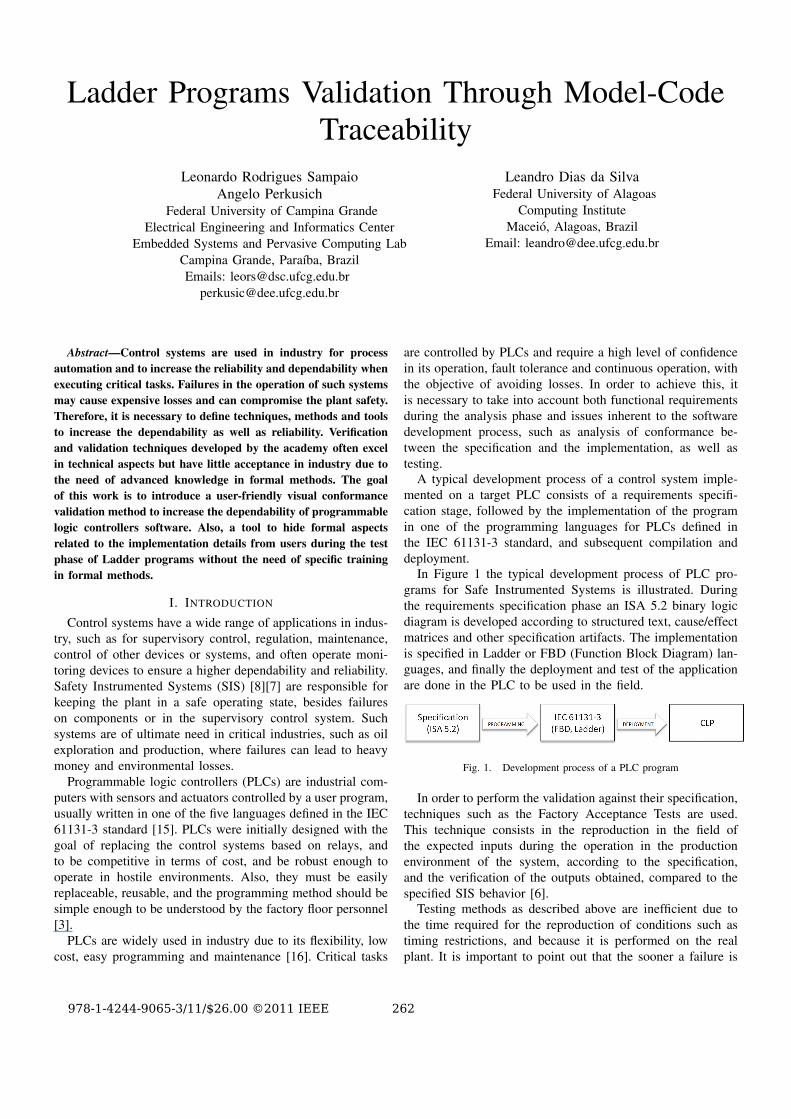
In Figure 1 the typical development process of PLC pro-grams for Safe Instrumented Systems is illustrated. Duringthe requirements specification phase an ISA 5.2 binary logicdiagram is developed according to structured text, cause/effectmatrices and other specification artifacts. The implementationis specified in Ladder or FBD (Function Block Diagram) lan-guages, and finally the deployment and test of the applicationare done in the PLC to be used in the field.
Fig. 1. Development process of a PLC program
In order to perform the validation against their specification,techniques such as the Factory Acceptance Tests are used.This technique consists in the reproduction in the field ofthe expected inputs during the operation in the productionenvironment of the system, according to the specification,and the verification of the outputs obtained, compared to thespecified SIS behavior [6].
Testing methods as described above are inefficient due tothe time required for the reproduction of conditions such astiming restrictions, and because it is performed on the realplant. It is important to point out that the sooner a failure is
978-1-4244-9065-3/11/$26.00 ©2011 IEEE 262
detected in a software development cycle, the lower is the costto fix it [14]. Therefore, delaying the testing phase until theend of the process may lead to additional costs that could beavoided.
There are several studies that address the conformanceverification between the specification and the implementation[4], however the techniques proposed by the academy [14]often require an extensive knowledge of the system operatoron verification techniques, or specialized personnel to operatethe system so that the method can be run correctly and theoutputs can be obtained and interpreted successfully.
In order to correctly operate the most common verificationtools it is necessary a deep knowledge about the whole ver-ification and modeling processes, including the intermediatelanguages and formalisms used, how inputs and outputs arespecified, which are the inherent limitations and what kind ofadjustments and abstractions have to be made.
What is expected in the industry is that programmers andengineers that have deep knowledge of the diagrams that theydeal with daily, do not need to learn other type of specificationsand formalisms to solve problems that are originally relatedsolely to their routine work tools.
In this work a method for the automated generation andexecution of conformance tests between specification models,given by an ISA 5.2 diagram, and the implementation, givenby a Ladder program, of control systems implemented usingPLCs is presented. A failure in the implementation can beeasily identified from the execution traces generated in thetest phase, excluding from the process the need for an expertto interpret the outputs generated by the method.
The focus of this work is on collecting traceability in-formation during the generating a timed automata modelrepresenting the specification and implementation diagrams.This information is used by our implementation for a furtherinterpretation of a trace that describes a test case, in orderto identify which parts of the original Ladder program areproblematic, visually and automatically. Also, in the contextof this work a real industrial case related to an oil companyis used to illustrate the effective use of the method and thetool introduced. The example is from Petrobras1, a Brazilianoil company, which intensively uses SIS in their explorationand production systems.
The remaining of this paper is organized as follows. InSection 2 related work is discussed. In Section 3 the IEC61131-3 standard and Ladder language are introduced. InSection 4 the modeling processes are defined. In Section 5 theconcept of traceability between model and code is illustrated.In Section 6 a case study is shown and in Section 7 theconclusion and future works are presented.
II. RELATED WORK
The industry has a great interest in developing applicationsfor verification and validation of PLC programs using sim-ulation and emulation, which are not the main focus of the
1http://www.petrobras.com.br/
academy due to lack of use of formal methods in this context.The development of tools that do not deal with some level offormality tend to be specific to the problem and to not supporta general analysis [4]. Therefore, a work that unites the twoworlds can bring a contribution to both research areas.
In [12] a case study about the application of an onlineautomated test case generator (UPPAAL-Tron2), i.e., able togenerate and run tests event by event in real-time, is presented.The execution of the tool after modeling the expected behav-ior of the system and the environment and the subsequentbuild of an interface for communication with the controlsystem showed several differences between specification andimplementation even with a reduced execution time. This tooldepends on the system modeling in the UPPAAL3 tool, usingtimed automata, and a knowledge of the operation of the testertool, which disqualifies it as friendly to developers of controlsystems and other business agents in industry.
In [2] it is proposed a method for model-based verificationof temporal properties extracted automatically from Ladderdiagrams. The authors propose to verify generic properties onthe diagrams, such as lack of concurrency issues, and onlysimple Ladder elements are taken into account in the subsetof the language defined in the metamodel. Timed elementsare not considered, for example. The conversion betweentextual syntax and metamodel has not been implemented,which makes the method dependent on various aspects of usermanual intervention.
A programming method for PLCs which incorporates simu-lation is proposed in [10]. A visual validation of the programsbehavior based on synchronization with a three-dimensionalvirtual model of the factory plant is defined. The operationof the method depends on the specification of a model ofthe plant based on DEVS formalism and a mapping betweenthe simulation model and the control program itself. Theauthors’ proposal creates a series of additional steps during thedevelopment phase, which can require an extensive period ofadaptation of the processes, making the method more suitablefor a prototyping environment than to check the software itself.
III. IEC 61131-3 STANDARD AND THE LADDER
LANGUAGE
The IEC 61131-3 standard defines five languages for the im-plementation of programs on programmable logic controllers:Instruction List (IL), Function Block Diagrams (FBD), LadderDiagram (Ladder), Structured Text (ST) e Sequential FunctionChart (SFC).
Ladder is a graphical language that represents the logicof program implementation by rungs, which are blocks ofinstructions that resemble functions in structured programminglanguages. During the scan cycle of a PLC logic resultingfrom the execution of each rung is calculated and the outputvariables are updated at the end of the cycle.
2http://www.cs.aau.dk/˜marius/tron/3http://www.uppaal.com/
263
The execution of a Ladder program after being deployedon a PLC follows three steps: first input variables are readand stored in a memory buffer, then the Ladder program isevaluated according to the inputs, the outputs are calculatedand stored in an output buffer and finally the outputs areenergized according to the values stored in memory.
The scope of the language considered in this paper coversthe following items: TON (or TMR), TP and TOF timers,contacts (normally open and closed) and coils.
IV. TIMED AUTOMATA MODELING
Oliveira et al. introduces in [5] a method for extractingtimed automata models from a ISA 5.2 specification and aLadder program, for subsequent automated generation of testcases and confrontation between the two with the executionof acceptance tests.
The verdict generated by the UPPAAL-TRON tool [11]is specified by a trace, described in terms of transitionsand events in the timed automata [1] network generated thatrepresents the specification and implementation, rather than interms of rungs, inputs and outputs of Ladder Diagrams andISA 5.2. That is, a final step of interpretation of the output ofthe method is required, which can only be done by an expertor knowledgeable of the intermediary formalism used.
This work extends [5], using the extraction method of thetimed automata network and adding a final step of refinementin the display of the traces generated by tester test TRON, sothat the events described are interpreted and parts of the Laddercode that are not in accordance with the ISA 5.2 specificationare displayed visually.
V. MODEL-CODE TRACEABILITY
The concept of traceability between model and code can bedefined as a methodology that allows tracking of informationbetween design models and source code or other modelsautomatically generated from them. The connections betweenmodel and code are allowed from the introduction of specifictags in the generated code to store information about thetransformations of models held together with links to the inputand output elements of these transformations [9].
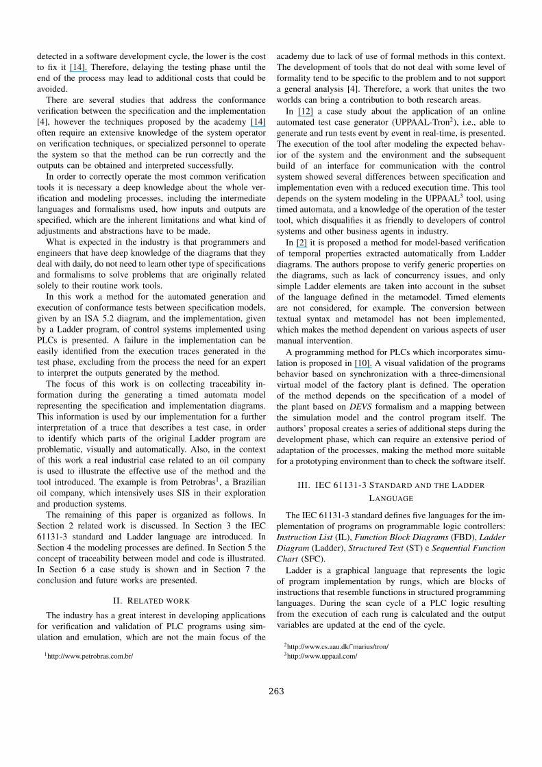
Figure 2 shows the automated process, in which the im-plementation introduced in [5] was instrumented in order toprovide traceability information between the original models(specification languages and implementation) and the inter-mediate models (timed automata networks) so that XMLtemplates generated in UPPAAL format contains informationthat allows traceability between the model and the code in theanalysis stage of the traces generated from the tests execution.
Based on an error trace generated by a FAIL verdict releasedby the TRON tester there is a software module responsiblefor identifying which parts of code are responsible for thefault condition from the information collected during tracinggeneration of templates .
Fig. 2. Automated test process
VI. CASE STUDY
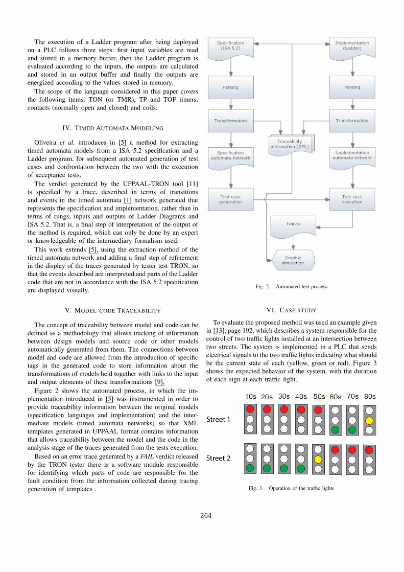
To evaluate the proposed method was used an example givenin [13], page 192, which describes a system responsible for thecontrol of two traffic lights installed at an intersection betweentwo streets. The system is implemented in a PLC that sendselectrical signals to the two traffic lights indicating what shouldbe the current state of each (yellow, green or red). Figure 3shows the expected behavior of the system, with the durationof each sign at each traffic light.
Fig. 3. Operation of the traffic lights
264
A. Modeling
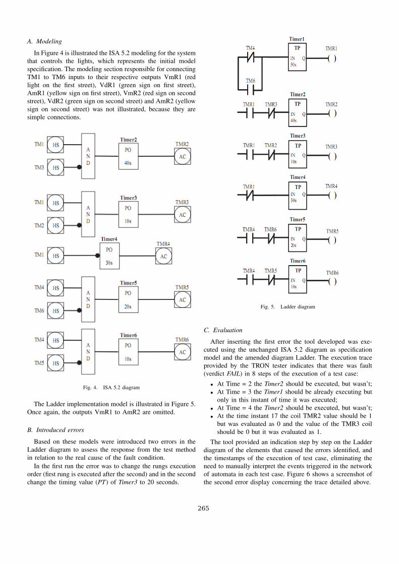
In Figure 4 is illustrated the ISA 5.2 modeling for the systemthat controls the lights, which represents the initial modelspecification. The modeling section responsible for connectingTM1 to TM6 inputs to their respective outputs VmR1 (redlight on the first street), VdR1 (green sign on first street),AmR1 (yellow sign on first street), VmR2 (red sign on secondstreet), VdR2 (green sign on second street) and AmR2 (yellowsign on second street) was not illustrated, because they aresimple connections.
Fig. 4. ISA 5.2 diagram
The Ladder implementation model is illustrated in Figure 5.Once again, the outputs VmR1 to AmR2 are omitted.
B. Introduced errors
Based on these models were introduced two errors in theLadder diagram to assess the response from the test methodin relation to the real cause of the fault condition.
In the first run the error was to change the rungs executionorder (first rung is executed after the second) and in the secondchange the timing value (PT) of Timer3 to 20 seconds.
Fig. 5. Ladder diagram
C. Evaluation
After inserting the first error the tool developed was exe-cuted using the unchanged ISA 5.2 diagram as specificationmodel and the amended diagram Ladder. The execution traceprovided by the TRON tester indicates that there was fault(verdict FAIL) in 8 steps of the execution of a test case:
∙ At Time = 2 the Timer2 should be executed, but wasn’t;∙ At Time = 3 the Timer1 should be already executing but
only in this instant of time it was executed;∙ At Time = 4 the Timer2 should be executed, but wasn’t;∙ At the time instant 17 the coil TMR2 value should be 1
but was evaluated as 0 and the value of the TMR3 coilshould be 0 but it was evaluated as 1.
The tool provided an indication step by step on the Ladderdiagram of the elements that caused the errors identified, andthe timestamps of the execution of test case, eliminating theneed to manually interpret the events triggered in the networkof automata in each test case. Figure 6 shows a screenshot ofthe second error display concerning the trace detailed above.
265

Fig. 6. Error trace visualization
For the second evaluation stage TRON generated an execu-tion trace with three errors for the test case generated, againthrowing a FAIL verdict:
∙ At Time = 74 the Timer3 should be executed, but wasn’t;∙ At Time = 75 the Timer4 should be executed, but wasn’t;∙ At Time = 86 the Timer1 should not be executed, but it
was.
The tool again presented in the diagram elements involvedin the error condition, isolating parts of the problematic code.
VII. CONCLUSION
In this work a visual verification method of Ladder pro-grams for programmable logic controllers is presented. Thecontribution is the creation of a method to benefit fromthe formal theory involved in the automated generation ofconformance tests from the specification and implementation,without demanding a deep knowledge of these concepts forthe operation of the tool, which has a low complexity userinterface.
The use of the method introduced in this work providesan efficient means of testing, allowing code and specificationto be confronted in the early stages of the developmentof the control system. An error is quickly identified andinterpreted by programmers, engineers and other techniciansinvolved, isolating problematic code parts identified by thetests generated and executed automatically.
ACKNOWLEDGMENT
This work was supported in part by Universidade Federalde Campina Grande (UFCG), Electrical Engineering GraduateProgram (Programa de Pos-Graduacao em Engenharia Eletrica- PPgEE), Informatics Graduate Program (Programa de Pos-Graduacao em Informatica - COPIN), CNPq and CAPES.
REFERENCES
[1] R. Alur and D. L. Dill, “A theory of timed automata,” TheoreticalComputer Science, vol. 126, no. 2, pp. 183–235, 1994.
[2] D. F. Bender, B. Combemale, X. Crgut1, J. M. Farines, B. Berthomieu,and F. Vernadat, “Ladder metamodeling and PLC program validationthrough time petri nets,” in ECMDA-FA ’08: Proceedings of the 4thEuropean conference on Model Driven Architecture. Berlin, Heidelberg:Springer-Verlag, 2008, pp. 121–136.
[3] L. A. Bryan and E. A. Bryan, Programmable Controllers: Theory andImplementation, S. Phillipo, Ed. Industrial Text Company, 1997,illustrator-Kory, Gina.
[4] H. Darabi, R. Sampath, and D. Naylor, “PLC formal controlmethodologies: Does academia supply what industry demands?”Technical Conference Paper, International Society of Automation, 2002.[Online]. Available: http://www.isa.org/CustomSource/ISA/Div PDFs/PDF News/ACS 2.pdf
[5] K. de Vasconcelos Oliveira, A. Perkusich, A. M. N. e Lima, K. Gorgonio,and L. D. da Silva, “Standard-based Formal Validation of ProgrammableLogic Controller Programs,” in IEEE-ICIT 2010: International Confer-ence on Industrial Technology, Vina Del Mar, Chile, March 2010, pp.1655 –1660.
[6] A. A. Frederickson and D. Mr., “Functional safety - safety instrumentedsystems for the process industry sector,” IEC std 61511, 2003.
[7] W. M. Goble and H. Cheddie, Safety Instrumented Systems Verification:Practical Probabilistic Calculations. ISA, 2005.
[8] P. Gruhn and H. L. Cheddie, Safety Instrumented Systems: Design,Analysis, and Justification, 2nd ed. ISA, 2006.
[9] L. Guo and A. Roychoudhury, “Debugging statecharts via model-code traceability,” in ISoLA, ser. Communications in Computer andInformation Science, T. Margaria and B. Steffen, Eds., vol. 17. Springer,2008, pp. 292–306.
[10] M. Ko, S.-C. Park, and G.-N. Wang, “Visual validation of PLC pro-grams,” in 22nd European Conference on Modeling and Simulations(ECMS), Nicosia, Cyprus, June 2008, pp. 410–415.
[11] K. G. Larsen, M. Mikucionis, and B. Nielsen, Uppaal Tron User Manual,2007.
[12] K. G. Larsen, M. Mikucionis, B. Nielsen, and A. Skou, “Testing real-time embedded software using UPPAAL-TRON: an industrial casestudy,” in EMSOFT ’05: Proceedings of the 5th ACM internationalconference on Embedded software. New York, NY, USA: ACM, 2005,pp. 299–306.
[13] E.-R. Olderog and H. Dierks, Real-Time Systems: Formal Specificationand Automatic Verification; electronic version. Leiden: CambridgeUniv. Press, 2008.
[14] B. Peischl and F. Wotawa, “Error traces in model-based debugging ofhardware description languages,” in AADEBUG’05: Proceedings of thesixth international symposium on Automated analysis-driven debugging.New York, NY, USA: ACM, 2005, pp. 43–48.
[15] PLCopen, IEC 61131-3: a standard programming resource. Inhttp://www.plcopen.org/, PLCopen For Efficiency in Automation, 2004.
[16] A. Sulflow and R. Drechsler, “Verification of PLC programs usingformal proof techniques,” Formal Methods for Automation and Safety inRailway and Automotive Systems (FORMS/FORMAT 2008), pp. 43–50,2008.
266