Embed Size (px)
Citation preview
INVESTIGATIVE CONSTRUCTION OF BUILDINGS USING BAKED CLAYPOST-REINFORCED BEAM PANELS
Salim KHOSO a*, Abdul Aziz ANSARI b, Farhan Hussain WAGAN c
aLecturer; Department of Civil Engineering, Quaid-e-Awam University College of Engineering, Science & Technology(QUCEST), Larkana, Sindh, Pakistan*E-mail address: [email protected]
bProf.; Department of Civil Engineering, Mehran University of Engineering & Technology, (SZAB) CampusKhairpur Mir’s, Sindh, Pakistan
c Junior Lab, Eng.; Department of Civil Engineering, Quaid-e-Awam University College of Engineering,Science & Technology (QUCEST), Larkana, Sindh, Pakistan
Received: 21.07.2014; Revised: 4.08.2014; Accepted: 21.10.2014
Ab s t r a c tReinforced cement concrete is a composite matrix building material widely used all around the globe. It has been in use overhundred years. However, for reasons pertaining to the increase in cost of basic constituents of concrete namely, steel, cementand more importantly transportation cost of these material to the desired construction sites, particularly rural areas, it hasbeen deemed that the use of soil (clayey/alluvial/and fertile) in nature in the production of baked clay panels as structuralmembers is an economical alternative to RC. It is however, faster than RC construction at the same time, such as alterna-tives do not compromise the strength and durability of the structure it is built from. With this particular intention in mind,a systematic programme of experimental study visualizing the future construction in the rural areas at relatively cheap andaffordable prices for the poor masses, a large number of beam panels were cast, baked, post reinforced, cured and tested.This paper intends to further experiment shear and flexural strength of plain baked clay i.e. no reinforcement or anchor-age steel was provided during the study of baked clay behaviour. The study took into account the modulus of rapture, shearand flexural behaviour, mode of failure, crack pattern and the ultimate load carrying capacity of clay beams. However, fun-damental structural properties and material constants i.e. compressive strength, Poisson’s ratio and modulus of elasticityof the material cut from the beams after testing them, were also determined experimentally. The results are encouraging.However, from these tests it is found that shear strength is the dominant factor in making clay beams more resistant toloads.
S t r e s z c z en i eŻelbet jest materiałem kompozytowym na bazie cementu powszechnie stosowanym na całym świecie. Używany jest od ponad100 lat. Jednakże ze względu na rosnący koszt podstawowych składników, w tym stali i cementu, a co najważniejsze koszttransportu tych materiałów na miejsce budowy, w szczególności na obszarach wiejskich, uznano, że wykorzystanie gruntównaturalnych (gliniastych/łęgowych/żyznych) do produkcji spiekanych paneli glinianych jako elementów konstrukcyjnychjest ekonomiczną alternatywą dla żelbetu. Element te są szybsze w produkcji i montażu, a ich zastosowanie nie ma negatyw-nego wpływu na wytrzymałość i trwałość konstrukcji. Mając na uwadze przyszłość budownictwa na ubogich terenach wiej-skich, przeprowadzono badania na znacznej liczbie glinianych belek zbrojonych. Celem prezentowanego artykułu było wyko-nanie dalszych badań ścinania i zginania belek niezbrojonych. Badania obejmowały moduł zniszczenia, zachowanie przy ści-naniu i zginaniu, model zniszczenia, obraz rys oraz nośność belek. Dodatkowo zbadano również podstawowe właściwościmechaniczne oraz stałe materiałowe na próbkach pobranych z tych elementów, w tym wytrzymałość na ściskanie, współczyn-nik Poissona i moduł sprężystości. Wyniki badań są obiecujące. Jednakże, w badaniach stwierdzono, że wytrzymałość na ści-nanie jest czynnikiem decydującym o nośności belek glinianych.
Keywo rd s : Beam Panels; Cement; Clay; Compressive Strength; Pit-sand; Plate Support; Shear.
4/2014 A R C H I T E C T U R E C I V I L E N G I N E E R I N G E N V I R O N M E N T 57
A R C H I T E C T U R E C I V I L E N G I N E E R I N G E N V I R O N M E N TThe Si les ian Univers i ty of Technology No. 4/2014
S . K h o s o , A . A . A n s a r i , F . H . W a g a n
1. INTRODUCTIONOne of the significant challenges to the socio-eco-nomic development of under developed countriesresides in the utilization of the local natural resourcesby using both the empirical data of ancestral practicesand the modern exploration technologies for controland scientific elaboration of those materials [1]. Clayis a very common, abundant and inexpensive materi-al. It is easy to extract and does not require significanttransformation. Clay is also a capricious materialwith very variable physical properties. Clay createsmany problems when it shrinks during drying and fir-ing. Certain clays shrink more than others. The fin-ished products of clay crack during cooling [2].Advocating clay as the first choice for rendering strawbale walls as well as any other conventional wall sys-tem is predominantly linked to its great benefits toour health and the environment. Earth has a vasttechnical and architectural potential in the construc-tion industry and the fact that it has been used in thesimplest and most sophisticated structures all overthe world supports its importance in this industrytoday [3]. Clay is cohesive material and this propertyimproves if clay is micro-fined and properly kneadedafter mixing the water. Wet clay having a sufficientquantity of water acts like a lubricant but with only alittle quantity of water, it acts like a plastic body. Ithas no elastic limit and could be worked to any shapewith little pressure without rupturing. Clay possessesthe property of a binding agent [4].International Resource Institute (IRI) has recentlybeen involved in Natural Composite Architectureusing a composite of bentonite clay/cellulosefibre/straw bale wall and roof system [5]. Polymer clayhas been in use as man-made modelling material justlike ceramic. It is being supplied by various suppliersunder the brand name as FIMO. FIMO is easy to useextremely versatile plastic based modelling clay [6].A systematic review of a large number of journalspertaining to the field of Civil Engineering includingthose of ACI, ASCE and British Institute of CivilEngineering was carried out but as expected, there isno research conducted up to this time mentioned forstudying the behaviour of the pre-fabricated, post-reinforced baked clay structural panels which wouldbe used as replacement for pre-cast concrete panelsfor erection of buildings at relatively lower cost with-out sacrificing durability, reliability and elegance.Although hundreds of technical publications regard-ing the properties and uses of clay for various pur-poses were found in the Journals, they mostly dis-cussed the geotechnical, geological, chemical and
agricultural aspects of clay. Complete series of book-lets published by the United Nation’s Economic &Social Commission for Asia & Pacific RegionBangkok, giving details of research conducted onindigenous materials of construction and low costhousing does not include any research on the struc-tural panels as tested during present study [7]. Bakedclay brick fragments were used in cement concrete ascoarse aggregate [8] and the same aggregate was latertreated with cement slurry to reduce its porosity andincrease the strength [9]. For several years hundredsof researchers worked on various aspects of concrete(both plain and reinforced) as major material of con-struction for buildings, bridges and other structures.However, economy could be achieved if local materi-als of construction are used instead of transportingheavy and expensive materials like hill sand, coarseaggregate of rock origin, cement and steel bars overlong distance particularly in fertile plains of variouscountries. The most commonly and universally avail-able materials of construction such as the clay, siltand pit sand have not been resorted to for the con-struction with pre-perceived notion that these areinferior and therefore could not be used for qualitywork. In fact clay has remained in use right from theearly civilizations like that of Moen-jo-daro,Mesopotamia [10] and Nile delta in the shape of sundried and burnt bricks for masonry. Mechanized sys-tems have been devised to densify bricks with higherstrength resembling that of concrete blocks by apply-ing immense three-dimensional compression forcompaction [11]. During preliminary experimentalstudy by the authors [12] which consisted of mould-ing, compacting, baking and testing hundreds of claycylindrical and cubical specimens having variousintensities of compression for compaction and clay topit-sand ratio as the parameters, it was clearly mani-fested that strength of this particular type of materialcould equally be as good as that of cement concrete,if properly compacted. The cement concrete used incommon buildings for R.C construction is normallydesigned for compressive strength of 20 N/mm2
(3000psi). But from our study it was quite visible thatwith properly controlled conditions and 70:30, clay:pit-sand ratio the strength could comfortably beincreased much more beyond this limit by increasingthe compacting force and decreasing the water con-tent which obviously reduces the voids. All theseaspects self-evidently imply to the direction whereinstead of bricks, structural panels could be manufac-tured, baked and used for swift quality constructionof buildings at relatively lower cost than concrete.Economy of construction can be achieved:
58 A R C H I T E C T U R E C I V I L E N G I N E E R I N G E N V I R O N M E N T 4/2014
I N V E S T I G AT I V E C ONS T RU C T I O N O F BU I L D I N G S US I N G B A K E D C L AY POS T- R E I N F O R C E D B E AM PAN E L S
i. By using very cheap local materials i.e. clay andpit-sand.
ii. Mechanized mass scale production of the panels ofstructural members with relatively lower cost ofproduction under very controlled conditions emu-lating those of laboratory.
iii.Saving in terms of cost of transportation of heavymaterials over long distances.
iv.Minimization of expenditure for finishing likeplastering and painting.
v. Quick and speedy erection of building by makinguse of pre-cast panels
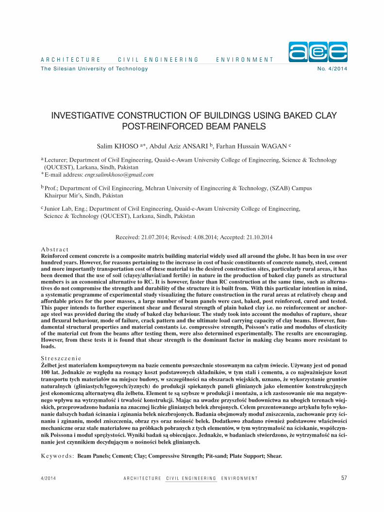
2. PRESENT INVESTIGATIONStiff steel moulds were fabricated for casting thespecimens for beam panels. The design of thesemoulds was accomplished on the basis of stress analy-sis performed by using computer based numericalapproach. The major force for which these mouldswere to be designed was the lateral outward forceinduced by vertical compression applied for com-paction. A Plate Bending, rectangular, eight-nodeFinite Element, originally formulated by Hinton andOwen was employed to perform elastic analysis par-ticularly in terms of maximum deflection at freeedges (upper edges of long walls of the moulds) andbending moments at fixed edges of the long sides ofthe mould, the thickness of which was assumed in thefirst instance. The base slab is firmly supported allover by the ground. The thickness of this plate wasalso assumed and then its adequacy was checkedagainst induced stresses. The long walls wereanalysed as fixed at both the ends and the bottomwhile the top edge was a free edge. Since the com-pressive load was applied vertically downward forcompaction and the clay was nearly in the plasticstate, it was presumed that all the force was trans-ferred to the long sides of the mould as lateral forcewhich was normal to the inner surfaces of the longsides of plates. The distribution of this force wasassumed to be uniform. Special arrangement forapplying the pre-compression manually, (so that den-sity could be improved, compaction to the desireddegree could be achieved), was designed and fabri-cated. During casting of models it was observed thatdue to lateral deformation bulging took place beyondacceptable limits. Therefore a system of restrainingthe lateral deformation was designed and made useof after trying various options. This arrangement ispresented in Figure 1, which is the best and most effi-cient amongst those tried by authors. Mixing of mate-
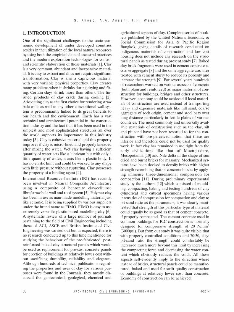
rials depended upon best proportions of clay and pitsand with earlier research presented in [13], Totalwater content as percentage in terms of dry materialwas maintained at about 20 percent on the basis ofthe results pertaining to workability and strength tobe achieved. The clay was obtained from varioussources at a depth of 4 ft from the ground level. It wasdried at a temperature of 105°C for 24 hours. Theclay was then pulverized for micro-fining it. Then asin previous research conducted by the authors [13]30% of pit-sand, was mixed. Mixing of the materialsand the water was done with the electrically operatedPan mixer. Mixing was done for approximately 10minutes for each batch. After delivery of the materi-al in the mould, compressive force for first test seriesof 3.5 N/mm2 was applied and measured with thehelp of electric load cells and digital display amplifi-er system. Compression was applied by tightening thewing nuts as shown in Fig. 2.
CIVIL
EN
GIN
EER
IN
G
ce
4/2014 A R C H I T E C T U R E C I V I L E N G I N E E R I N G E N V I R O N M E N T 59
Figure 1.Stiff steel mould for casting clay beam panels with lateralconfinement
Figure 2.Arrangement for applying compression by tightening wingnut
S . K h o s o , A . A . A n s a r i , F . H . W a g a n
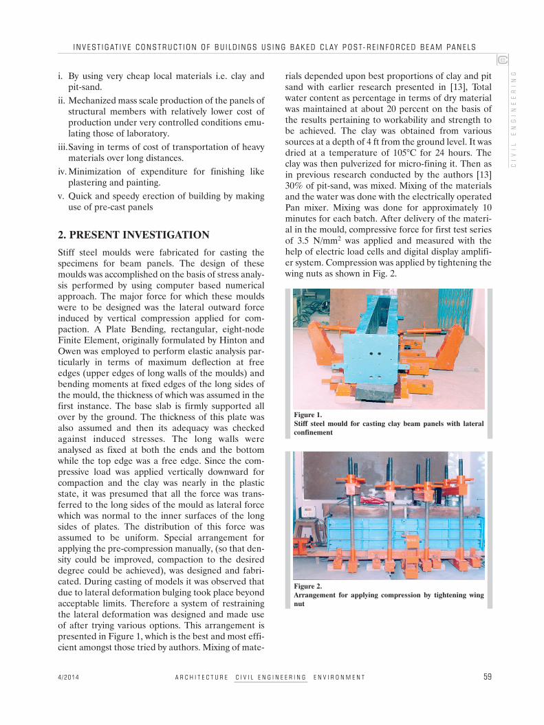
Several impediments and hurdles were experienced.For example enormous shrinkage occurred duringdrying which caused cracking of the beams renderingthem useless. The drying under the shade withoutexposure to sunshine with a thin plastic wrappersolved the problem. Special scheme was resorted toby providing a heavy wooden plank fitted with a verysmooth surfaced metallic sheet properly oiled to sup-port the beam specimen at the bottom during its dry-ing period; so that shrinkage and consequent defor-mation (i.e. shortening of the beams) did not causeany cracking. However, a system of slight compres-sion with the help of springs was also devised andused, as shown in Fig. 3.
It must be mentioned here that the beams cast, dried,baked and tested during this experimental investiga-tion were 6 inches (150 mm) wide 12 inches(300 mm) deep and 6.5 ft (1950 mm) long initially butwere reduced in length by 4 inches (100 mm),breadth decreased by 0.3 inches (7.2 mm) while thedepth showed a shrinkage of 0.6 inches (14.3 mm).After drying for sufficient time under the shade thebeams were exposed to sunshine to exclude as muchmoisture as possible which was trapped deep insidethem. The beams were then placed in the Kiln wherethe temperature was measured with the help of ther-mo-couples. Initially a lower temperature of 250°Cwas maintained for six hours. The temperature wasthen raised gradually to 950°C and was maintained atthis level for 22 hours. Then the temperature waslowered slowly and the fire was stopped and the kilnwas allowed to cool down over next two days. Thetemperature and time periods were selected after try-ing a large number of temperature and duration com-binations to achieve the best possible results becausethe thickness of beams is obviously much more than
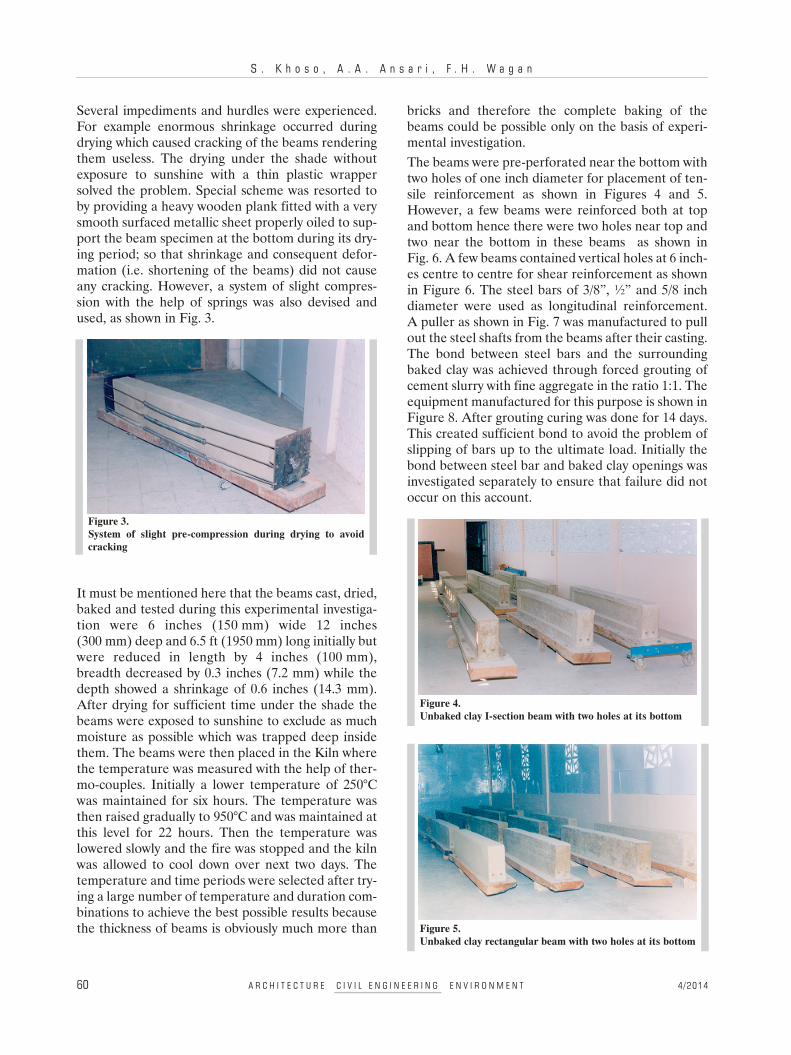
bricks and therefore the complete baking of thebeams could be possible only on the basis of experi-mental investigation.The beams were pre-perforated near the bottom withtwo holes of one inch diameter for placement of ten-sile reinforcement as shown in Figures 4 and 5.However, a few beams were reinforced both at topand bottom hence there were two holes near top andtwo near the bottom in these beams as shown inFig. 6. A few beams contained vertical holes at 6 inch-es centre to centre for shear reinforcement as shownin Figure 6. The steel bars of 3/8”, ½” and 5/8 inchdiameter were used as longitudinal reinforcement.A puller as shown in Fig. 7 was manufactured to pullout the steel shafts from the beams after their casting.The bond between steel bars and the surroundingbaked clay was achieved through forced grouting ofcement slurry with fine aggregate in the ratio 1:1. Theequipment manufactured for this purpose is shown inFigure 8. After grouting curing was done for 14 days.This created sufficient bond to avoid the problem ofslipping of bars up to the ultimate load. Initially thebond between steel bar and baked clay openings wasinvestigated separately to ensure that failure did notoccur on this account.
60 A R C H I T E C T U R E C I V I L E N G I N E E R I N G E N V I R O N M E N T 4/2014
Figure 3.System of slight pre-compression during drying to avoidcracking
Figure 4.Unbaked clay I-section beam with two holes at its bottom
Figure 5.Unbaked clay rectangular beam with two holes at its bottom
I N V E S T I G AT I V E C ONS T RU C T I O N O F BU I L D I N G S US I N G B A K E D C L AY POS T- R E I N F O R C E D B E AM PAN E L S
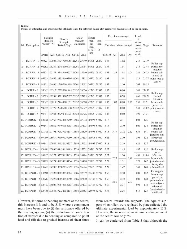
Special trolley was designed and fabricated for safelifting of the beams from place to place. Platform Liftwas designed, manufactured and installed beside thekiln for safe lifting up of clay beam models which areso fragile that even a slight jerk could reduce them topieces, as shown in Fig. 9.Mobile Lift as shown in Fig. 10 was designed andmanufactured for carrying the beams to the testinglaboratory for placement of these models on themachine for testing.Figures 11 and 12 show Torsee Testing Machine thatwas used to test the beams. Load cells were usedtogether with digital display system to measure inten-sity of the load independently. Demec Gauge wasused to measure the strain at various locations withreference to the neutral axis. Thirteen pairs of demecpads were stuck on the beam to measure the strainwith the help of demec gauge. To test the fundamen-tal structural properties of the beam material itselfspecimens were cut from the intact portions of beamsafter testing.
CIVIL
EN
GIN
EER
IN
G
e
4/2014 A R C H I T E C T U R E C I V I L E N G I N E E R I N G E N V I R O N M E N T 61
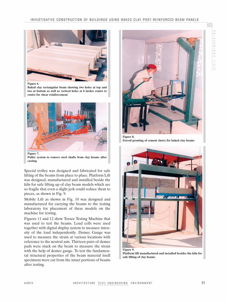
Figure 6.Baked clay rectangular beam showing two holes at top andtwo at bottom as well as vertical holes at 6 inches centre tocentre for shear reinforcement
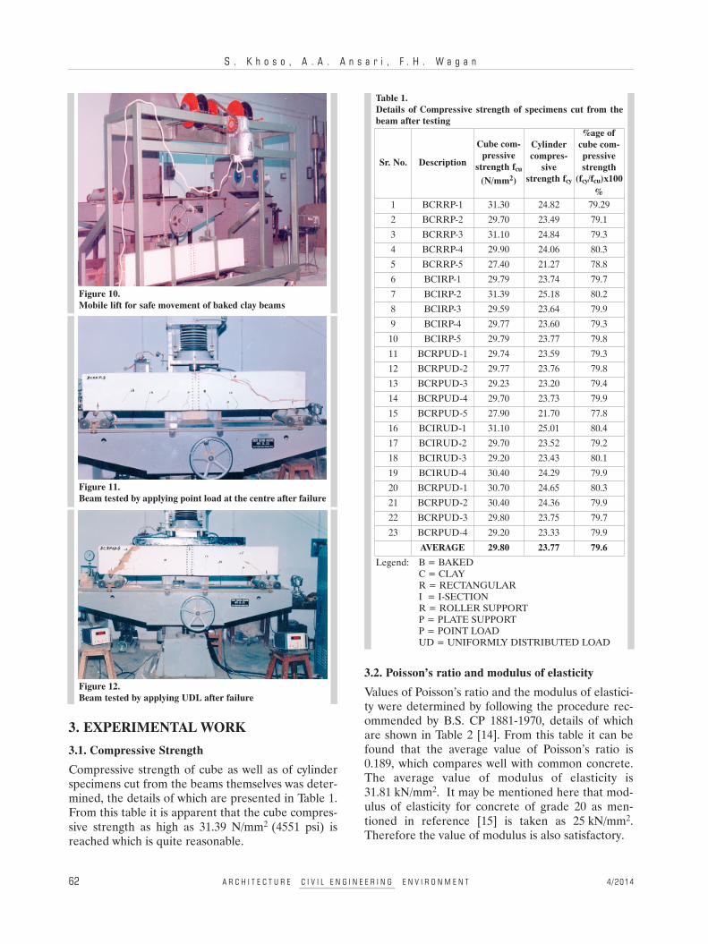
Figure 7.Puller system to remove steel shafts from clay beams aftercasting
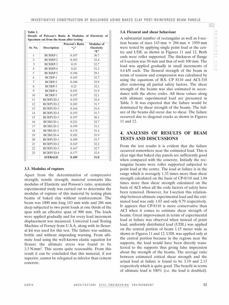
Figure 8.Forced grouting of cement slurry for baked clay beams
Figure 9.Platform lift manufactured and installed besides the kiln forsafe lifting of clay beams
c
S . K h o s o , A . A . A n s a r i , F . H . W a g a n
3. EXPERIMENTAL WORK3.1. Compressive StrengthCompressive strength of cube as well as of cylinderspecimens cut from the beams themselves was deter-mined, the details of which are presented in Table 1.From this table it is apparent that the cube compres-sive strength as high as 31.39 N/mm2 (4551 psi) isreached which is quite reasonable.
3.2. Poisson’s ratio and modulus of elasticityValues of Poisson’s ratio and the modulus of elastici-ty were determined by following the procedure rec-ommended by B.S. CP 1881-1970, details of whichare shown in Table 2 [14]. From this table it can befound that the average value of Poisson’s ratio is0.189, which compares well with common concrete.The average value of modulus of elasticity is31.81 kN/mm2. It may be mentioned here that mod-ulus of elasticity for concrete of grade 20 as men-tioned in reference [15] is taken as 25 kN/mm2.Therefore the value of modulus is also satisfactory.
62 A R C H I T E C T U R E C I V I L E N G I N E E R I N G E N V I R O N M E N T 4/2014
Figure 12.Beam tested by applying UDL after failure
Figure 10.Mobile lift for safe movement of baked clay beams
Figure 11.Beam tested by applying point load at the centre after failure
Table 1.Details of Compressive strength of specimens cut from thebeam after testing
Sr. No. Description
Cube com-pressive
strength fcu
(N/mm2)
Cylindercompres-
sivestrength fcy
%age ofcube com-pressivestrength
(fcy/fcu)x100%
1 BCRRP-1 31.30 24.82 79.292 BCRRP-2 29.70 23.49 79.13 BCRRP-3 31.10 24.84 79.34 BCRRP-4 29.90 24.06 80.35 BCRRP-5 27.40 21.27 78.86 BCIRP-1 29.79 23.74 79.77 BCIRP-2 31.39 25.18 80.28 BCIRP-3 29.59 23.64 79.99 BCIRP-4 29.77 23.60 79.310 BCIRP-5 29.79 23.77 79.811 BCRPUD-1 29.74 23.59 79.312 BCRPUD-2 29.77 23.76 79.813 BCRPUD-3 29.23 23.20 79.414 BCRPUD-4 29.70 23.73 79.915 BCRPUD-5 27.90 21.70 77.816 BCIRUD-1 31.10 25.01 80.417 BCIRUD-2 29.70 23.52 79.218 BCIRUD-3 29.20 23.43 80.119 BCIRUD-4 30.40 24.29 79.920 BCRPUD-1 30.70 24.65 80.321 BCRPUD-2 30.40 24.36 79.922 BCRPUD-3 29.80 23.75 79.723 BCRPUD-4 29.20 23.33 79.9
AVERAGE 29.80 23.77 79.6Legend: B = BAKED
C = CLAYR = RECTANGULARI = I-SECTIONR = ROLLER SUPPORTP = PLATE SUPPORTP = POINT LOADUD = UNIFORMLY DISTRIBUTED LOAD
I N V E S T I G AT I V E C ONS T RU C T I O N O F BU I L D I N G S US I N G B A K E D C L AY POS T- R E I N F O R C E D B E AM PAN E L S
3.3. Modulus of ruptureApart from the determination of compressivestrength, tensile strength, material constants likemodulus of Elasticity and Poisson’s ratio, systematicexperimental study was carried out to determine themodulus of rupture of this material by testing plainbeams of baked clay without reinforcement. Thebeam was 1000 mm long 143 mm wide and 286 mmdeep subjected to two point loads at one thirds of thespan with an effective span of 900 mm. The loadswere applied gradually and for every load incrementdisplacement was measured. Universal Load TestingMachine of Forney from U.S.A. along with its flexur-al kit was used for this test. The failure was sudden,brittle and without impending warning. From ulti-mate load using the well-known elastic equation forflexure the ultimate stress was found to be3.3 N/mm2. This seems quite reasonable. From thisresult it can be concluded that this material, if notsuperior, cannot be relegated as inferior than cementconcrete.
3.4. Flexural and shear behaviourA substantial number of rectangular as well as I-sec-tion beams of sizes 143 mm × 286 mm × 1950 mmwere tested by applying single point load at the cen-tre and UDL as shown in Figures 11 and 12. Bothends were roller supported. The thickness of flangeof I-section was 50 mm and that of web 100 mm. Theload was applied gradually in small increments of4.6 kN each. The flexural strength of the beam interms of tension and compression was calculated byusing the equations of B.S. CP 8110 and ACI-318after removing all partial safety factors. The shearstrength of the beams was also estimated in accor-dance with the above codes. All these values alongwith ultimate experimental load are presented inTable 3. It was expected that the failure would bedominated by shear strength of the beams. The fail-ure of the beams did occur due to shear. The failureoccurred due to diagonal cracks as shown in Figures11 and 12.
4. ANALYSIS OF RESULTS OF BEAMTESTS AND DISCUSSIONSFrom the test results it is evident that the failureoccurred somewhere near the estimated load. This isclear sign that baked clay panels are sufficiently goodwhen compared with the concrete. Initially the rec-tangular beams were roller supported subjected topoint load at the centre. The load at failure is in therange which is averagely 1.33 times more than shearstrength calculated on the basis of CP-8110 and 1.04times more than shear strength calculated on thebasis of ACI when all the code factors of safety havebeen removed. However, for I-section this relation-ship between ultimate experimental load and the esti-mated load was only 1.03 and only 0.79 respectively.It appears that CP-8110 is more conservative thanACI when it comes to estimate shear strength ofbeams. Great improvement in terms of experimentalload at failure was observed when instead of pointload, uniformly distributed load (UDL) was appliedon the central portion of beam 1.15 meter wide asshown in Figures 11 and 12. UDL was applied only atthe central portion because in the regions near thesupports, the load would have been directly trans-ferred to the supports thus giving false impressionabout the strength of the beams. The average ratiobetween estimated critical shear strength and theactual load at failure is found to be 3.19 and 2.13respectively which is quite good. The benefit in termsof ultimate load is 100% (i.e. the load is doubled).
CIVIL
EN
GIN
EER
IN
G
ce
4/2014 A R C H I T E C T U R E C I V I L E N G I N E E R I N G E N V I R O N M E N T 63
Table 2.Details of Poisson’s Ratio & Modulus of Elasticity ofSpecimen cut from the beam after testing
Sr. No. DescriptionPoisson’s Ratio
“µ”Modulus ofElasticity
“E”1 BCRRP-1 0.187 30.72 BCRRP-2 0.183 32.43 BCRRP-3 0.19 32.74 BCRRP-4 0.24 31.25 BCRRP-5 0.196 29.16 BCIRP-1 0.183 32.77 BCIRP-2 0.188 32.98 BCIRP-3 0.22 32.19 BCIRP-4 0.191 31.910 BCIRP-5 0.197 32.111 BCRPUD-1 0.193 32.412 BCRPUD-2 0.185 31.713 BCRPUD-3 0.164 31.414 BCRPUD-4 0.193 31.715 BCRPUD-5 0.197 30.116 BCIRUD-1 0.221 32.717 BCIRUD-2 0.199 31.118 BCIRUD-3 0.174 31.419 BCIRUD-4 0.185 31.920 BCRPUD-1 0.189 31.721 BCRPUD-2 0.165 32.222 BCRPUD-3 0.167 32.723 BCRPUD-4 0.177 32.9
AVERAGE 0.189 31.8
S . K h o s o , A . A . A n s a r i , F . H . W a g a n
However, in terms of bending moment at the centre,this increase is found to be 31% where a componentmust have been due to (i) the resistance offered bythe loading system, (ii) the reduction of concentra-tion of stresses due to bending as compared to pointload and (iii) due to gradual increase of shear force
from centre towards the supports. The type of sup-port when rollers were replaced by plates affected theultimate experimental load by approximately 12%.However, the increase of maximum bending momentat the centre was only 2%.It can be conferred from Table 3 that although the
64 A R C H I T E C T U R E C I V I L E N G I N E E R I N G E N V I R O N M E N T 4/2014
Table 3.Details of estimated and experimental ultimate loads for different baked clay reinforced beams tested by the authors.
S# Description
FlexuralStrength“Steel” (N)
FlexuralStrength
“Baked Clay”
ShearStrengthCalculated
Experi-men-talload@ fail-ure
Exp.load______2
Exp. Shear strength_______________________
Calculated shear strength
Levelof
stressfrommeas-uredstrain
%age Remarks
CP8110 ACI CP8110 ACI CP110 ACI CP8110 Av. ACI Av.
1. BCRRP – 1 95523 107804134347103968 21261 27740 56595 28297 1.33
1.33
1.02
1.04
213 73.79Roller sup-ported rec-tangularbeams sub-jected to
point load atcenter
2. BCRRP – 2 94282 106247127480103014 21261 26964 56595 28297 1.33 1.04 213 73.44
3. BCRRP – 3 95521 107175133489103777 21261 27740 56595 28297 1.33 1.02 221 76.73
4. BCRRP – 4 95523 106652128338103396 21261 27302 56595 28297 1.33 1.04 219 75.77
5. BCRRP – 5 91801 104466117607101488 21261 25682 56595 28297 1.33 1.10 263 89.15
6. BCIRP – 1 93042 100315125290101465 20832 26626 42795 21397 1.03
1.03
0.80
0.79
541 234.12Roller sup-portedI-Sectionbeams sub-jected to
point load atcenter
7. BCIRP – 2 95523 102239132019102027 20832 27425 42795 21397 1.03 0.78 466 204.38
8. BCIRP – 3 93042 100817124449101091 20832 26560 42795 21397 1.03 0.80 550 237.1
9. BCIRP – 4 94282 100779125206101278 20832 26527 42795 21397 1.03 0.80 541 234.2
10. BCIRP – 5 93841 100944125290 10465 20832 26626 42795 21397 1.03 0.80 499 215.1
11. BCRRUD – 1 100321107960196032159290 17886 27032 114095 57047 3.18
3.19
2.11
2.13
604 135Roller sup-ported rec-tangularbeams sub-jected to uni-formly dis-tributed load.
12. BCRRUD – 2 99141 108032196495158703 17886 27133 114095 57047 3.18 2.10 600 134
13. BCRRUD – 3 101501107791192937158117 17886 26829 114095 57047 3.18 2.12 634 141
14. BCRRUD – 4 97960 108019196107159290 17886 27133 115015 57047 3.21 2.10 596 132
15. BCRRUD – 5 99141 107084184152156357 17886 25952 114095 57047 3.18 2.19 621 137
16. BCIRUD – 1 100884105096201433156893 17526 27322 79595 39797 2.27
2.27
1.45
1.48
487 152 Roller sup-porterI-Sectionbeams sub-jected to uni-formly dis-tributed load.
17. BCIRUD – 2 99967 104277192373155453 17526 26494 79595 39797 2.27 1.50 491 153.4
18. BCIRUD – 3 99769 104224189134159136 17526 26428 79595 39797 2.27 1.51 525 162
19. BCIRUD – 4 100489104236196907156029 17526 26924 79595 39797 2.27 1.47 541 168
20. BCRPUD – 1 100911108393202633159584 17886 27639 127435 63717 3.56
3.55
2.30
2.33
609 122Rectangularbeams sup-ported on
plate on bothends subject-ed to uni-
formly distrib-uted load.
21. BCRPUD – 2 100619108278200650159290 17886 27470 127435 63717 3.56 2.32 600 120
22. BCRPUD – 3 100497108028196673158703 17886 27133 127435 63717 3.56 2.34 592 118
23. BCRPUD – 4 100136107848192732158117 17886 26863 126975 63717 3.56 2.36 617 123
I N V E S T I G AT I V E C ONS T RU C T I O N O F BU I L D I N G S US I N G B A K E D C L AY POS T- R E I N F O R C E D B E AM PAN E L S
failure was dominated by shear, the strain in bakedclay at the level of flexural steel is an indication thatthe yielding point had already been exceeded whilethe compressive strength of baked clay did not reachits ultimate crushing value, when UDL was applied. Itmust be mentioned here that in Pakistan for the sakeof economy the reinforcing steel bars are mostlymanufactured from the scrap. Therefore, the batch ofsteel bars procured for our research did not show thestandard values but experimentally it was found thatalthough no distinct yield point was visible, the aver-age 0.2% proof stress was calculated to be554.2 N/mm2 and the average ultimate stress was652 N/mm2. The percentage elongation was quite lowwhen compared with the code value. However, steeldid not reach its ultimate value and it did not breakin the beams which were tested by applying UDL.Although maximum shear is at the support and if theshear alone is responsible for the failure, such anincrease of ultimate load could not have beenachieved. It may be mentioned here that the UDLwas applied by the system so that the friction could beminimized in order to let the baked clay materialundergo compression without being deterred by theload application system.At the beginning the load was measured in DVMunits, with the help of load cell and digital display sys-tem. Through calibration this load was converted intoNewtons. One DVM unit was equal to 460 N. SinceDVM units were same for all the five beams withineach group, the variation less than 460 N could not bemeasured. Hence the values became same for all thebeams of the same group. Thus it can be deducedthat if buildings are to be constructed in the ruralareas where hill sand, coarse aggregate and cementare not available locally this material can also servethe local population well within affordable prices.This material could prove suitable for multi-storeybuildings of reasonable height. Therefore we shallstick to the original idea of producing structural pan-els on large scale with minimum of reinforcement, nocement, no aggregate of hill origin but clay and pit-sand, dune-sand and river bed sand; all availablelocally and cheaply. A very respectable average ofultimate load for rectangular beams supported onsteel plate with UDL has been achieved which is 3.55and 2.3 (CP-8110 & ACI respectively) times morethan the estimated strength in terms of shear. Beamsthat we tested were only 1.95 meter long. However, inreal structures beams could be very long and morecommonly loads are distributed because slab trans-fers the load to the beam along its entire span, the
structure produced with panels of pre-perforatedpost-reinforced baked clay shall exhibit even betterperformance. Apart from beams panels of columnsor even slabs shall also be tested leading to a com-plete process for construction of buildings with clay.
5. CONCLUSION(i) As compared to normal cement concrete the
compressive strength of baked clay panel with aproportion of 70:30 percent of clay: pit sand,holds promise to achieve strength as good asconcrete C 16/20 with only moderate compres-sion force of 3.5 N/mm2 for compaction. A valueof crushing strength as high as 31.39 N/mm2
(4551 psi) is reached.(ii) The Poisson’s ratio and modulus of elasticity of
baked clay panels are in good agreement withthose of concrete C 16/20.
(iii) The modulus of rupture of this baked clay mate-rial is also in good agreement with that of con-crete C 16/20.
(iv) The research regarding use of this material par-ticularly in the rural areas holds promise forstructurally sound and economically viablebuildings for almost every type of use.
(v) It is quite apparent that the failure of beams isdominated by shear rather than flexure; there-fore shear strength must be improved to ensureductile failure due to yielding of steel in tensilezone.
(vi) Split of bottom cover, slipping of bar or destruc-tion of bond between steel and surroundingmaterial did not take place.
ACKNOWLEDGEMENTSThe research work, details of which are presented inthis paper was carried out in the StructuresLaboratory of Civil Engineering Department, Quaid-e-Awam University of Engineering Science &Technology, (QUEST), Nawabshah, Sindh, Pakistan.The authors are grateful to the University authoritiesfor providing facilities and funds to make thisresearch possible.
CIVIL
EN
GIN
EER
IN
G
ce
4/2014 A R C H I T E C T U R E C I V I L E N G I N E E R I N G E N V I R O N M E N T 65
S . K h o s o , A . A . A n s a r i , F . H . W a g a n
REFERENCES[1] Lindahl A., Sandgren P., Olsson S., Sköld P.; Physical
and chemical studies of raw clay materials fromdeposits in the Bani and Niger River Inland Deltas inthe Jenne Region, middle east Mali. Proceedings ofConference on Structures of Vulnerability:Mobilisation and Resistance, Stockholm, Sweden,2005
[2] Pottery La Pipe d’Argile – ClayElectronic document:http://www.lapipedargile.com/argile/largile-ger.html
[3] Strawtec; Clay: the highest quality from design to con-struction,Electronic document:http://strawtec.com.au/content.php?id=39&ch=Clay
[4] Kulkarni G. J.; A text book of engineering materials.Eleventh edition, Kirit Ambala Patl, Ahemednagar,1980, p.55
[5] Lance D.; National composite architecture: Buildingwithout use of lumber, concrete, steel, or petroleumproducts. The Last Straw Journal, No.17Electronic document:http://www.networkearth.org/naturalbuilding/composite.html
[6] Garie S.; Creative clay for creative people.Electronic document:http://www.garieinternational.com.sg/clay/clay.htm
[7] Booklet Series, on Low Cost Housing IndigenousMaterials, United Nations Economics SocialCommission for Asia and Pacefic Region, Bangkok10200, Thailand
[8] Memon. M., Memon. M. A., Durrani N. A.; Behaviourof concrete with indigenous aggregate. MehranUniversity Research Journal of Engineering andTechnology, Vol.11, No.4, 1992; p.25-30
[9] Memon. M., Durrani N. A., Memon N.A.; Treatment ofindigenous aggregate. Mehran University ResearchJournal of Engineering and Technology, Vol.4, No.2,1995; p.13-19
[10] Magnus M.; The archaeology of the Bible lands. 1977,p.195-208
[11] Kulkarni G. J.; Semi dry process or pressed brickprocess, constituent of Brick Clay. EngineeringMaterials, 1980; p.64-65
[12] Memon. M., Ansari.A.A., Shaikh. A.M.; Preliminarystudy of structural properties of baked clay. MehranUniversity Research Journal of Engineering &Technology, Vol.18, No.3, 1999; p.161-166
[13] Ansari. A. A., Memon. M.; Fundamental structuralproperties of compacted baked clay specimens.Proceedings of the 3rd International CivilEngineering Congress, The Institute of EngineersPakistan, Karachi, Pakistan, 2003
[14] British standard Code of Practice, BS-1881, part V:Method of Testing Concrete.
[15] Astill A. W., Martin L. H.; Elementary structuraldesign in concrete to CP 110. Hodder Arnold, UK,1975; p.7
[16] Khoso S., Wagan F. H., Khan S. J., Bhatti N. K.,Ansari A. A.; Qualitative analysis of baked clay bricksavailable in Larkana Region, Pakistan. Architecture –Civil Engineering – Environment, Vol.7, No.2, 2014;p.41-50
66 A R C H I T E C T U R E C I V I L E N G I N E E R I N G E N V I R O N M E N T 4/2014


