Embed Size (px)
Citation preview

Internship
Report
Muhammad Owais Mehmood
NUST-PNEC
Internee Pakistan CAA
Electronics Engineering Depot
23rd
Jun to 13th
Jul 2012
Pakistan Civil Aviation Authority

Internship Report EED-CAA
Page 2
List of contents
Introduction…………………………………………………………………………………………………3
Radar Central Workshop……………………………………………………………………………………4
Navigational Aids…………………………………………………………………………………………..9
HF (high frequency) section………………………………………………………………………………12
VHF/UHF section…………………………………………………………………………………………13
Telecom section…………………………………………………………………………………………...14
General electronics section………………………………………………………………………………..15
Internship Report EED-CAA
Page 3
Pakistan's Civil Aviation Authority (CAA) is a regulatory authority, whose responsibility is to oversee
and regulate all aspects of civil aviation in Pakistan. Nearly all civilian airports and aviation facilities in
Pakistan are owned and operated by the CAA. CAA's head office is situated in terminal 1 of Jinnah
International Airport in Karachi.
Pakistan Civil Aviation Authority is a Public sector autonomous body working under the Federal
Government of Pakistan through the Ministry of Defense. It was established on 7th December, 1982 as an
autonomous body. Prior to its creation, a Civil Aviation Department in the Ministry of Defense used to
manage the civil aviation related activities.
CAA is also a member of the International Civil Aviation Organization (ICAO).
Electronics Engineering Depot (EED)
Electronics engineering depot (EED) in Karachi is the central and the biggest facility of CAA all over
Pakistan with respect to electronics engineering services provided by the authority. EED covers all the
electronic equipments which provide aviation services all over Pakistan. The EED holds following major
functions at CAA:
Procurement of all new aviation equipments (Radars, Voice logging systems, ILS etc) and
thorough testing of each equipment after purchase.
Providing on field repair and maintenance facilities all over Pakistan through its trained
personnel.
Workshops for extensive repair facilities at EED in case the equipment could not be repaired at
site.
The EED is divided into sub sections, each dealing with the equipment of its own concern. These sections
are:
Radar central workshop (RCWS)
Navigational Aids section
VHF/UHF section
HF section
General electronics section
Telecom section
Each section has the test equipment and trained personnel to deal with the problems occurring in their
respective fields.
Our training program at EED was designed in such a way so that that we could understand the
functionality of each section. We spent the allocated time in each section and got familiar with the
functioning of equipment as well as the repairing tools used. Following is the short detail of each
section‘s equipment and operation.

Internship Report EED-CAA
Page 4
Radar Central Workshop (RCWS)
RADAR stands for ‗Radio detection and Ranging‘. Radar is an equipment which is used to detect objects
using ‗Radio Waves‘. It is a way to detect and study far off targets by transmitting a radio pulse in the
direction of the target and observing the reflection of the wave. It‘s basically radio echo.
In civil aviation radars are used to monitor and control commercial air traffic. A radar can provide
following information about a target which helps in managing the air traffic.
Target range
Target angles (azimuth & elevation)
Target size (radar cross section)
Target speed (Doppler)
Target features (imaging)
As far as civil aviation is concerned, the radars used can be divided into two main types:
Primary surveillance Radar
Secondary surveillance Radar
Primary surveillance Radar (PSR):
Primary Radar works on the principle in which the radar transmitter sends out a pulse of radio energy, of
which a very small proportion is reflected from the surface or structure of the target aircraft back to the
radar receiver.
The azimuth orientation of the radar antenna provides the bearing of the aircraft from the ground station,
and the time taken for the pulse to reach the target and return provides a measure of the distance of the
target from the ground station. The bearing and distance of the target can then be converted into a ground
position for display to the Air Traffic Controller. Target elevation (altitude) is not normally measured by
ATC primary radars. The advantage of Primary Surveillance Radar (PSR) is that it operates totally
independently of the target aircraft - that is, no action from the aircraft is required for it to provide a radar
return.
The disadvantages of PSR are that, firstly, enormous amounts of power must be radiated to ensure returns
from the target. This is especially true if long range is desired. Secondly, because of the small amount of
Internship Report EED-CAA
Page 5
energy returned at the receiver, returns may be easily disrupted due to such factors as changes of target
attitude or signal attenuation due to heavy rain. This may cause the displayed target to 'fade'.
PSR‘s are further divided into two categories based on the type of signal emitted by the radar:
Continuous wave Radar
Pulsed wave Radar
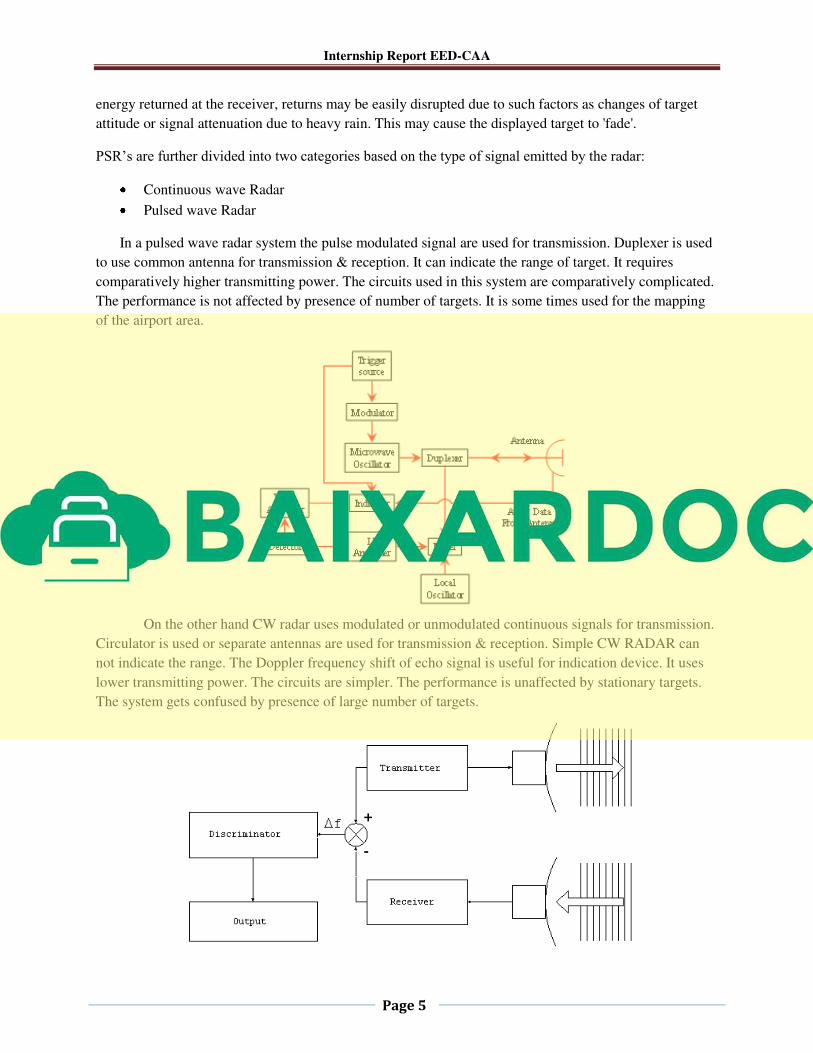
In a pulsed wave radar system the pulse modulated signal are used for transmission. Duplexer is used
to use common antenna for transmission & reception. It can indicate the range of target. It requires
comparatively higher transmitting power. The circuits used in this system are comparatively complicated.
The performance is not affected by presence of number of targets. It is some times used for the mapping
of the airport area.
On the other hand CW radar uses modulated or unmodulated continuous signals for transmission.
Circulator is used or separate antennas are used for transmission & reception. Simple CW RADAR can
not indicate the range. The Doppler frequency shift of echo signal is useful for indication device. It uses
lower transmitting power. The circuits are simpler. The performance is unaffected by stationary targets.
The system gets confused by presence of large number of targets.
Internship Report EED-CAA
Page 6
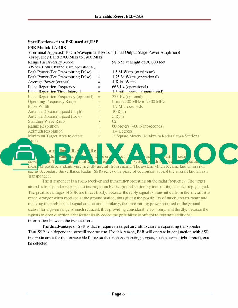
Specifications of the PSR used at JIAP
PSR Model: TA-10K (Terminal Approach 10 cm Waveguide Klystron (Final Output Stage Power Amplifier))
(Frequency Band 2700 MHz to 2900 MHz)
Range (In Diversity Mode) = 98 NM at height of 30,000 feet
(When Both Channels are operational)
Peak Power (Per Transmitting Pulse) = 1.5 M Watts (maximum)
Peak Power (Per Transmitting Pulse) = 1.25 M Watts (operational)
Average Power (output) = 4 Kilo- Watts
Pulse Repetition Frequency = 666 Hz (operational)
Pulse Repetition Time Interval = 1.5 milliseconds (operational)
Pulse Repetition Frequency (optional) = 333 Hz (optional)
Operating Frequency Range = From 2700 MHz to 2900 MHz
Pulse Width = 1.7 Microseconds
Antenna Rotation Speed (High) = 10 Rpm
Antenna Rotation Speed (Low) = 5 Rpm
Standing Wave Ratio < 02
Range Resolution = 60 Meters (400 Nanoseconds)
Azimuth Resolution = 1.4 Degrees
Minimum Target Area to detect = 2 Square Meters (Minimum Radar Cross-Sectional
Area)
Secondary surveillance Radar (SSR):
The disadvantages of PSR led to the employment of another aspect of wartime radar
development. This was the Identification Friend or Foe (IFF) system, which had been developed as a
means of positively identifying friendly aircraft from enemy. The system which became known in civil
use as Secondary Surveillance Radar (SSR) relies on a piece of equipment aboard the aircraft known as a
'transponder'.
The transponder is a radio receiver and transmitter operating on the radar frequency. The target
aircraft's transponder responds to interrogation by the ground station by transmitting a coded reply signal.
The great advantages of SSR are three: firstly, because the reply signal is transmitted from the aircraft it is
much stronger when received at the ground station, thus giving the possibility of much greater range and
reducing the problems of signal attenuation; similarly, the transmitting power required of the ground
station for a given range is much reduced, thus providing considerable economy; and thirdly, because the
signals in each direction are electronically coded the possibility is offered to transmit additional
information between the two stations.
The disadvantage of SSR is that it requires a target aircraft to carry an operating transponder.
Thus SSR is a 'dependant' surveillance system. For this reason, PSR will operate in conjunction with SSR
in certain areas for the foreseeable future so that 'non-cooperating' targets, such as some light aircraft, can
be detected.
Internship Report EED-CAA
Page 7
Modes of SSR
SSR has several modes of operation.
The basic civil mode is Mode A. In this mode the aircraft's transponder provides positive aircraft
identification by transmitting a four-digit code to the ground station. The code system is octal;
that is, each of the code digits may be any of the numbers 0-7. There are thus 4096 possible four-
digit codes.
Another principal SSR mode currently used is Mode C. In this mode the aircraft's altitude,
derived from on-board instruments, is transmitted to the ground station in addition to the identity.
A further mode, Mode S (or 'Mode Select'), is also used. Aircraft equipped with transponders
supporting this mode are assigned a permanent identification which can be selectively addressed
by the ground radar. This reduces problems of garbling between SSR returns from aircraft in
close proximity. Mode S also offers a wider range of data to be transmitted, including potentially
an uplink of data from the ground station to the aircraft although this capability is presently not
used in Pakistan.
Additional SSR Modes are used by military aircraft.
Specifications of secondary surveillance radar used at JIAP
SSR Model: RSM-870 (Radar Secondary Mono Pulse)
Range (One Way) = 200 NM (1 NM = 1852 Meters)
Interrogation Frequency = 1030 MHz
Reply from Transponder = 1090 MHz (This is not part of SSR Equipment)
Power Consumption = 600 Watts
Pulse Width = 0.8 Microseconds
Capacity = 300 Aircrafts (Processing)
Operating band = L – Band
Transmitter output Power (High) = 1.5 K Watts
SSR Modes (Available) = Alpha (Identity) & Charlie (Altitude)
For repair and maintenance of these radars and other radars installed all over Pakistan following
equipments are present in the RCWS:
1. AFIT-1500 In Circuit digital IC Tester (Excluding RAM & EPROM ICs) up to 24 Pins Digital /
TTL ICs only.
2. Tracker ―Huntron=5100DS‖ (Hardware change Cold Tester)
3. Micro-System Trouble Shooter.
4. Frequency Counter
5. Power Meter.
6. Synthesizer / Level Generator.
7. VHF Switch.
Internship Report EED-CAA
Page 8
8. Relay Actuator
9. System Power Supply of Hewlett Packard.
10. Combinational System S-645 Programmable Fault Finder of Schlumberger. (Unserviceable)
11. Curve Tracer. Tektronix-571
12. EPROM Programmer ―Unisite‖ 13. TEST BENCH OF RICS TXM-4200 SYSTEM
14. Chip Master Compact (Digital IC Tester)
15. Linear Master Compact (Analogue ICs Tester)
16. Component Analyzer (Up to 3-Pins Components Tester)
17. Relative Humidity & Temperature Tester.
18. ROBIN Microwave Leakage Tester.
19. BK Precision Auto Ranging Capacitance Meter, Model 830A
20. BK Precision Inductance Meter, Model # 875B
21. Fluke Scope Meter, Model # 199C
22. Fluke Multimeters, Model # 187
23. Toolkit Xcelite TC-100ST
24. Soldering Station ―Weller‖
25. Huntron Pro-Track-I Model 20
26. DATAMAN Universal EPROM Programmer
27. De-Soldering Station ―Weller‖ . 28. Huntron Scanner-I (part of Tracker)
29. Agilent Digital Colour LCD Oscilloscope
30. 6-GHz Spectrum Analyzer Model FSL6
31. Battery Load Tester (200A)
32. ERSA Infra-Red Rework Station IR/PL-550A
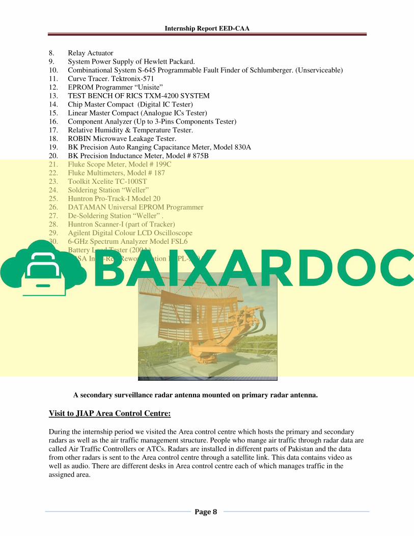
A secondary surveillance radar antenna mounted on primary radar antenna.
Visit to JIAP Area Control Centre:
During the internship period we visited the Area control centre which hosts the primary and secondary
radars as well as the air traffic management structure. People who mange air traffic through radar data are
called Air Traffic Controllers or ATCs. Radars are installed in different parts of Pakistan and the data
from other radars is sent to the Area control centre through a satellite link. This data contains video as
well as audio. There are different desks in Area control centre each of which manages traffic in the
assigned area.
Internship Report EED-CAA
Page 9
Navigational Aids Section
The department of Navigational aids deals with equipment used in en route navigation and terminal
navigation.
En Route Navigation equipment: When the plane is successfully in the air after take off then the navigational aids used to guide the aircraft
to its destination are known as En route navigation. The most basic equipment used for en route
navigation are:
NDB (Non directional beacon)
VOR (Very high frequency Omni-directional Ranging)
DME (distance measuring equipment)
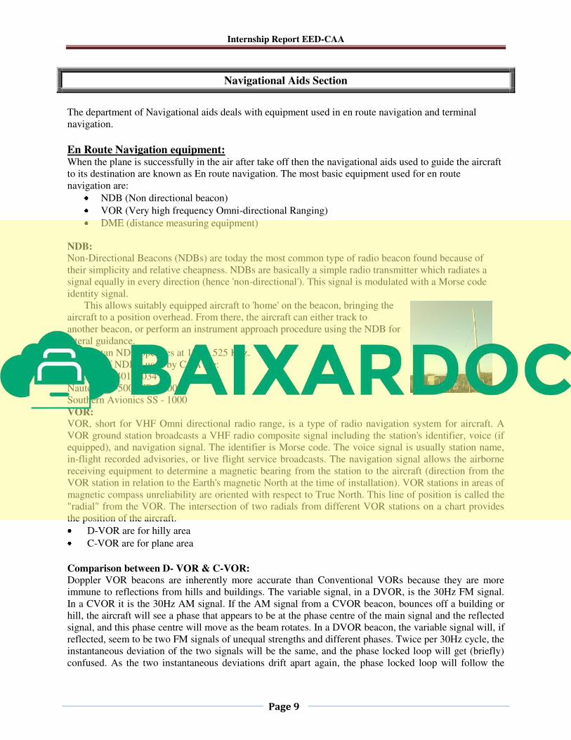
NDB: Non-Directional Beacons (NDBs) are today the most common type of radio beacon found because of
their simplicity and relative cheapness. NDBs are basically a simple radio transmitter which radiates a
signal equally in every direction (hence 'non-directional'). This signal is modulated with a Morse code
identity signal.
This allows suitably equipped aircraft to 'home' on the beacon, bringing the
aircraft to a position overhead. From there, the aircraft can either track to
another beacon, or perform an instrument approach procedure using the NDB for
lateral guidance.
In Pakistan NDB operates at 190 – 525 Khz.
Models of NDBs. used by CAA are:
Aerocom 5401, 5034
Nautel ND-500, ND-2000
Southern Avionics SS - 1000
VOR: VOR, short for VHF Omni directional radio range, is a type of radio navigation system for aircraft. A
VOR ground station broadcasts a VHF radio composite signal including the station's identifier, voice (if
equipped), and navigation signal. The identifier is Morse code. The voice signal is usually station name,
in-flight recorded advisories, or live flight service broadcasts. The navigation signal allows the airborne
receiving equipment to determine a magnetic bearing from the station to the aircraft (direction from the
VOR station in relation to the Earth's magnetic North at the time of installation). VOR stations in areas of
magnetic compass unreliability are oriented with respect to True North. This line of position is called the
"radial" from the VOR. The intersection of two radials from different VOR stations on a chart provides
the position of the aircraft.
D-VOR are for hilly area
C-VOR are for plane area
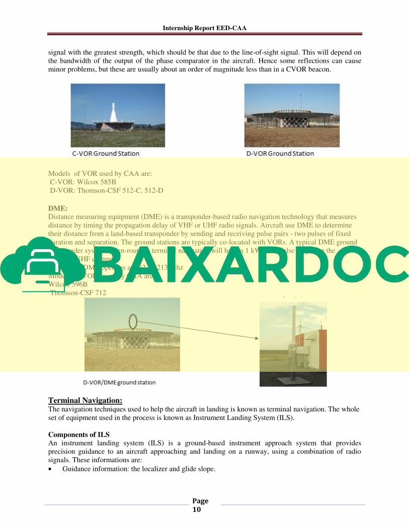
Comparison between D- VOR & C-VOR:
Doppler VOR beacons are inherently more accurate than Conventional VORs because they are more
immune to reflections from hills and buildings. The variable signal, in a DVOR, is the 30Hz FM signal.
In a CVOR it is the 30Hz AM signal. If the AM signal from a CVOR beacon, bounces off a building or
hill, the aircraft will see a phase that appears to be at the phase centre of the main signal and the reflected
signal, and this phase centre will move as the beam rotates. In a DVOR beacon, the variable signal will, if
reflected, seem to be two FM signals of unequal strengths and different phases. Twice per 30Hz cycle, the
instantaneous deviation of the two signals will be the same, and the phase locked loop will get (briefly)
confused. As the two instantaneous deviations drift apart again, the phase locked loop will follow the
Internship Report EED-CAA
Page
10
signal with the greatest strength, which should be that due to the line-of-sight signal. This will depend on
the bandwidth of the output of the phase comparator in the aircraft. Hence some reflections can cause
minor problems, but these are usually about an order of magnitude less than in a CVOR beacon.
Models of VOR used by CAA are:
C-VOR: Wilcox 585B
D-VOR: Thomson-CSF 512-C, 512-D
DME: Distance measuring equipment (DME) is a transponder-based radio navigation technology that measures
distance by timing the propagation delay of VHF or UHF radio signals. Aircraft use DME to determine
their distance from a land-based transponder by sending and receiving pulse pairs - two pulses of fixed
duration and separation. The ground stations are typically co-located with VORs. A typical DME ground
transponder system for en-route or terminal navigation will have a 1 kW peak pulse output on the
assigned UHF channel.
In Pakistan DME operates at 962 – 1213 Mhz
Models of VORs used by CAA are:
Wilcox 596B
Thomson-CSF 712
Terminal Navigation: The navigation techniques used to help the aircraft in landing is known as terminal navigation. The whole
set of equipment used in the process is known as Instrument Landing System (ILS).
Components of ILS
An instrument landing system (ILS) is a ground-based instrument approach system that provides
precision guidance to an aircraft approaching and landing on a runway, using a combination of radio
signals. These informations are:
Guidance information: the localizer and glide slope.


![Aircraft Icing Handbook [2000 CAA]](https://img.dokumen.tips/doc/110x75/6315555285333559270d144e/aircraft-icing-handbook-2000-caa.jpg)


