Embed Size (px)
Citation preview

Instructions for Naval hot tapping equipment and valves
2 3wwwvexvecom
Contents1 List of parts
11 287195 DN 25-100 4
12 Exploded view 6
2 Preparations 7
21 Preparing the pipe and valve 7
22 Preparing the hot tapping drill 8
3 Hot tapping 9
31 Checklist for power drill 9
32 Drilling 10
33 Technical criteria for power drill 10
4 Installation dimensions and RPM settings 11
41 DN 25 11
42 DN 32 12
43 DN 40 13
44 DN 50 14
45 DN 65 15
46 DN 80 16
47 DN 100 17
48 DN 125150 18
49 Full bore DN 150 19
410 DN 200 20
5 Hot tapping through DN 150 full bore valve 21
2 3wwwvexvecom wwwvexvecom
NOTE
This manual must be read and its instructions must be followed when installing operating andor performing maintenance on the valve as well as its manual gear or actuator
These instructions are of general nature and do not cover all possible operating scenarios For more specific guidance on the installation operation and maintenance of the valve or its suitability for an intended use please contact the manufacturer
Vexve Oy reserves the right to make alterations to these instructions
Vexve Oy is not responsible for damages caused by incorrect transportation handling installation operation or maintenance Furthermore Vexve Oy is not responsible for damage caused by foreign objects or impurities
WarrantyWarranty according to Vexve Oyrsquos ldquoGeneral terms and conditions of salerdquo
The warranty covers manufacturing and material faults The warranty does not apply to damages caused by inappropriate installation operation maintenance or storage ie these instructions must be followed for the warranty to apply Vexve Oy requires that any faulty products under warranty are to be returned to the factory for inspection Only after the product has been found faulty Vexve Oy can grant compensation
Please refer to Vexve Oyrsquos ldquoGeneral terms and conditions of salerdquo for detailed warranty clauses The document is available from the manufacturer
Warnings and symbolsIgnoring the warnings and symbols may lead to serious injury or equipment damage Persons authorized to use the equipment must be familiar with the warnings and instructions
Appropriate transportation storage and installation as well as careful commissioning are essential to ensure faultless and stable operation
The following symbols are used in this manual to draw attention to actions essential to ensure the proper use and safety of the device
Meaning of the symbol NOTE
The NOTE symbol is used for actions and functions that are essential for the proper use of the device Ignoring this symbol may have harmful consequences
Meaning of the symbol WARNING
The WARNING symbol is used for actions and functions that if carried out incorrectly may lead to injury or equipment damage
copy 2020 Vexve Oy - All product names trademarks and registered trademarks are property of Vexve Oy
4 5wwwvexvecom
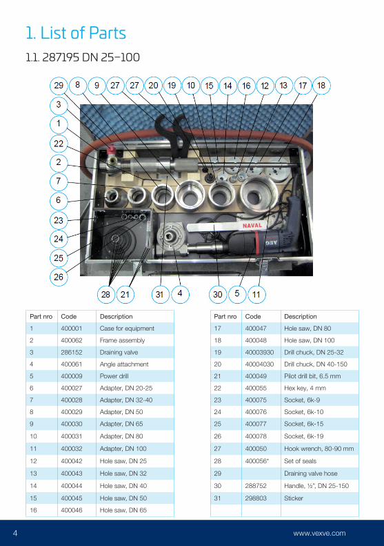
1 List of Parts11 287195 DN 25ndash100
Part nro Code Description
1 400001 Case for equipment
2 400062 Frame assembly
3 286152 Draining valve
4 400061 Angle attachment
5 400009 Power drill
6 400027 Adapter DN 20-25
7 400028 Adapter DN 32-40
8 400029 Adapter DN 50
9 400030 Adapter DN 65
10 400031 Adapter DN 80
11 400032 Adapter DN 100
12 400042 Hole saw DN 25
13 400043 Hole saw DN 32
14 400044 Hole saw DN 40
15 400045 Hole saw DN 50
16 400046 Hole saw DN 65
Part nro Code Description
17 400047 Hole saw DN 80
18 400048 Hole saw DN 100
19 40003930 Drill chuck DN 25-32
20 40004030 Drill chuck DN 40-150
21 400049 Pilot drill bit 65 mm
22 400055 Hex key 4 mm
23 400075 Socket 6k-9
24 400076 Socket 6k-10
25 400077 Socket 6k-15
26 400078 Socket 6k-19
27 400050 Hook wrench 80-90 mm
28 400056 Set of seals
29 Draining valve hose
30 288752 Handle frac12rdquo DN 25-150
31 298803 Sticker
4 5wwwvexvecom wwwvexvecom
Code Description
400033 O-ring D33 x 3 FPM for DN 20-25 adapter
400034 O-ring D47 x 3 FPM for DN 32-40 adapter
400035 O-ring D58 x 5 FPM for DN 50 adapter
400036 O-ring D75 x 5 FPM for DN 65 adapter
400037 O-ring D88 x 5 FPM for DN 80 adapter
400038 O-ring D11367 x 533 FPM for DN 100 adapter
400026 O-ring D60 x 5 FPM
400022 Shaft seal D2030 x 7
400056 contains
6 7wwwvexvecom
21 Exploded view
6 7wwwvexvecom wwwvexvecom
2 Preparations21 Preparing the pipe and valveLocate the exact point for the joint on the main pipe line and prepare the main pipe for welding of the valve Check the place of the joint on the main pipe (if the main pipe is a weld seam tube avoid welding the hot tapping valve on the weld seam)
Prepare the weld end of the hot tapping valve to match the radius (ldquoRrdquo) of the main pipe and taper the edges as required for the best welding result (see figure 1)
The weld seam has to comply with the local requirements for size and strength A support collar is to be used when necessary
NOTE The threaded end of the valve may be prepared for welding or shortened only after drilling through the main pipe
Figure 1
8 9wwwvexvecom
22 Preparing the hot tapping drillSelect the hole saw that corresponds to the valversquos DN size Also select a drill chuck and adapter of corresponding size from the case First install the adapter to the tool and after that install the drill chuck assembly (drill chuck + pilot drill bit + hole saw) on the shaft of the tool
Check that the edge of Frame I is aligned with the groove on Frame II (see figure 4 the groove is on the threaded area of Frame II) This setup corresponds to the maximum feeding distance This position must not be exceeded under any circumstances when the tool is pressurized
Make sure that the valve is fully OPEN Attach the complete tool assembly to the threads on the valve and test that the hole saw can freely slide through the ball in the valve
After welding the tightness of the seam can be tested eg by pressure testing the joint with compressed air through the hot tapping toolrsquos draining valve
Figure 2 Figure 3
Figure 4
The valve may be welded to the main pipe at any angle between 0deg and 360deg (see figure 2) but it must be at a 90deg angle to the longitudinal axis of the main pipe (see figure 3)
8 9wwwvexvecom wwwvexvecom
Attach the draining valve with hose to Frame II and close the draining valve
Before drilling through the main pipe test that the valve can be closed release the shaftrsquos locking mechanism by pulling the spring loaded part 400012 (see page 6) and slide out the shaft until it mechanically stops at the outermost position Close and open the hot tapping valve to verify it is working properly
Select a locking position that corresponds to the size of the hot tapping valve and lock the shaft to the selected position (three alternatives mdashgt see page 6)
3 Hot tapping31 Checklist for power drill the rotation direction must be clockwise
the percussion function must not be on under any circumstances
select rotation speed area 1 or 2 (see figure 5)
set RPM scale A - F (see figure 6)
Figure 5 Figure 6
10 11wwwvexvecom
32 Drilling
When starting the drilling ie when drilling the pilot hole use high RPM (460 RPM) area 2 and scale F Feed the drill through steadily and smoothly During drilling it is recommended to keep the draining valve open to remove the cuttings
Stop after only drilling through with the pilot drill bit Adjust the speed of rotation area (1 or 2) and scale (A-F) for the actual hole cutting and close the draining valve
Feed the hole saw through steadily and smoothly During cutting you may keep the draining valve open close it after finishing
Release the shaft locking mechanism and slide the shaft to its outermost position (due to pressure in the valve the shaft slides out automatically) then close the hot tapping valve Open the draining valve to release the pressure from the hot tapping valve
WARNING Before releasing the shaftrsquos locking mechanism move your head away from shaftrsquos end to avoid impact The shaft will slide out rapidly under water pressure
NOTE Before removing the drilling tool from the hot tapping valve make sure that the valve is fully closed check the markings at the stem The tightness of the hot tapping valve must be verified by using the draining valve no water must flow through the draining valve after the hot tapping valve is closed
After the drilling is finished it is important to clean the hot tapping tool from any metal chips and other impurities that have come in the drilling process
Disassemble the hot tapping drill first remove the draining valve and after that remove the tool (incl adapter) from the hot tapping valve Then disassemble the drill in the reverse order as you had assembled it
Closing the stem by welding If required the stem can be permanently closed by welding Remove the PTFE sealing underneath the cap before welding
33 Technical criteria for power drillWe recommend the following power drills
Milwaukee PD2E 24RS
AEG SB2E 1200 RST
If you use another drill make sure that it fulfills the following criteria
input power min 1000 W speed of rotation areas Area 1 0 - 1000 RPM Area 2 0 - 3000 RPM required speed adjustments are available for differently-sized hole saws
the drillrsquos neck diameter must be 43 mm
NOTE If you select another brand or model please check with the manufacturer that it fulfills above mentioned criteria
10 11wwwvexvecom wwwvexvecom
4 Installation dimensions and RPM settings41 DN 25Locking groove No 1 Hole saw Oslash 24 mm
Speed 370 RPM Area 2 Scale D
With main pipeline sizes DN 32 the feeding of the saw must be stopped at least 10 mm before the maximum feeding distance
The ldquoArdquo dimensions are valid for Lenox and Sandvik hole saws
Main pipeline nominal size A B C
DN 32 99+0 -5
20 105
DN 40 100+0 -10
20 105
DN 50 101+0 -10
20 105
DN 65 102+0 -10
20 105
DN 80 102+0 -10
20 105
DN 100 103+0 -10
20 105
DN 125 103+0 -10
20 105
DN 150 103+0 -10
20 105
DN ge 200
105+0 -10 20 105
12 13wwwvexvecom
41 DN 32Locking groove No 1 Hole saw Oslash 30 mm
Main pipeline nominal size A B C
DN 40 85+2 -0
20 93
DN 50 87+0 -10
20 93
DN 65 89+0 -10
20 93
DN 80 90+0 -10
20 93
DN 100 91+0 -10
20 93
DN 125 91+0 -10
20 93
DN 150 92+0 -10
20 93
DN 200 92+0 -10
20 93
DN 300 92+0 -10
20 93
DN 400 92+0 -10
20 93
DN ge500 93+0 -10
20 93
Speed 285 RPM Area 2 Scale C1
When drilling through a DN 40 pipe feeding must be stopped 10 mm before the maximum feeding distance and when drilling through a DN 50 pipe it must be stopped 15 mm before the maximum feeding distance With other pipe sizes the maximum feeding distance can be used
The ldquoArdquo dimensions are valid for Lenox and Sandvik hole saws
12 13wwwvexvecom wwwvexvecom
41 DN 40Locking groove No 2 Hole saw Oslash 38 mm
Main pipeline nominal size A B C
DN 50 90+0 -10
20 111
DN 65 93+0 -10
20 111
DN 80 94+0 -10
20 111
DN 100 95+0 -10
20 111
DN 125 96+0 -10
20 111
DN 150 96+0 -10
20 111
DN 200 97+0 -10
20 111
DN ge300 98+0 -10
20 111
Speed 230 RPM Area 2 Scale B1
For pipe sizes DN ge100 with wall thickness ge 10 mm it is recommended to deduct 10 mm from the above rdquoArdquo dimensions to guarantee that the hole saw goes fully through the wall of the main pipe
The above rdquoArdquo dimensions are valid for Lenox holesaws When using a Sandvik hole saw an additional 10 mm must be deducted from these dimensions (A 38 mm diameter Sandvik hole saw is 10 mm lower than an equivalent Lenox one)
14 15wwwvexvecom
41 DN 50Locking groove No 2 Hole saw Oslash 48 mm
Main pipeline nominal size A B C
DN 65 120+0 -0
20 131
DN 80 121+0 -10
20 131
DN 100 124+0 -10
20 131
DN 125 126+0 -10
20 131
DN 150 127+0 -10
20 131
DN 200 128+0 -10
20 131
DN 300 129+0 -10
20 131
DN 400 129+0 -10
20 131
DN ge500 131+0 -10
20 131
Speed 180 RPM Area 1 Scale E
When drilling a DN 65 pipe feeding must be stopped 10 mm before the maximum feeding distance
The rdquoArdquo dimensions are valid for Lenox and Sandvik hole saws
14 15wwwvexvecom wwwvexvecom
41 DN 65Locking groove No 2 Hole saw Oslash 64 mm
Main pipeline nominal size A B C
DN 80 111+2 0
20 140
DN 100 116+2 0
20 140
DN 125 118+2 0
20 140
DN 150 120+2 0
20 140
DN 200 1220 -5
20 140
DN 300 1240 -5
20 140
DN 400 1250 -5
20 140
DN 500 1260 -5
20 140
DN 600 1260 -5
20 140
DN ge800 1260 -5
20 140
Speed 135 RPM Area 1 Scale C
The rdquoArdquo dimensions are valid for Lenox and Sandvik hole saws
16 17wwwvexvecom
46 DN 80Locking groove No 3 Hole saw Oslash 76 mm
Main pipeline nominal size A B C
DN 100 1730 -5
20 204
DN 125 1770 -5
20 204
DN 150 1800 -5
20 204
DN 200 1830 -5
20 204
DN 250 1850 -5
20 204
DN 300 1860 -5
20 204
DN 400 1860 -5
20 204
DN 500 1870 -5
20 204
DN 600 1880 -5
20 154
DN ge800 1880 -5
20 154
Speed 115 RPM Area 1 Scale B
The rdquoArdquo dimensions are valid for Lenox and Sandvik hole saws
It is necessary to weld 50 mm prolongation pipe to the valve weld end so that measurement C=204 mm can be achieved
16 17wwwvexvecom wwwvexvecom
47 DN 100Locking groove No 3 Hole saw Oslash 95 mm
Main pipeline nominal size A B C
DN 125 131+2 0
20 157
DN 150 136+2 0
20 157
DN 200 141+0 -2
20 157
DN 250 144+0 -2
20 157
DN 300 147+0 -5
20 157
DN 400 148+0 -5
20 157
DN 500 150+0 -5
20 157
DN 600 150+0 -5
20 157
DN ge800 152+0 -5
20 157
Speed 90 rmin Area 1 Scale A
The rdquoArdquo dimensions are valid for Lenox and Sandvik hole saws
18 19wwwvexvecom
48 DN 125150Locking groove No 3 Hole saw Oslash 121 mm
Main pipeline nominal size A B C
DN 200 153+0 -10
20 175
DN 250 158+0 -10
20 175
DN 300 161+0 -10
20 175
DN 400 165+0 -10
20 175
DN 500 165+0 -10
20 175
DN 600 168+0 -10
20 175
DN ge800 170+0 -10
20 175
Speed 75-90 RPM Area 1 Scale A
The rdquoArdquo dimensios are valid for Lenox and Sandvik hole saws
18 19wwwvexvecom wwwvexvecom
49 Full bore DN 150Locking groove No 2 Hole saw Oslash 146 mm
Main pipeline nominal size A B C
DN 200 230+0 -10
20 265
DN 250 240+0 -10
20 265
DN 300 245+0 -10
20 265
DN 400 250+0 -10
20 265
DN ge500 255+0 -10
20 265
Speed 75-90 RPM Area 1 Scale A
The rdquoArdquo dimensions are valid for Lenox and Sandvik hole saws
20 21wwwvexvecom
410 DN 200Locking groove No 2 Hole saw Oslash 146 mm
Main pipeline nominal size A B C
DN 250 240+0 -10
20 265
DN 300 245+0 -10
20 265
DN 400 250+0 -10
20 265
DN ge500 255+0 -10
20 265
Speed 75-90 RPM Area 1 Scale A
The rdquoArdquo dimensions are valid for Lenox and Sandvik hole saws
20 21wwwvexvecom wwwvexvecom
5 Hot tapping through DN 150 full bore valve (or DN 200 reduced bore)
Naval standard hot tapping tool can be used also for DN 150 full bore valve
Following matters must be observed
New - +200mm - Longer shaft is needed
Hole saw 146 mm and center drill 8 mm must be used
Instead of standard adapter the tool and valves are assembled together with 2 pcs of PN 25 flanges sealing and boltsnuts The flange could be dismantled later
The stem of the valve is hexagon 32 mm
Part numbers are
- Long shaft (artnr 400210) and chuck (artnr 400240)
- Hole saw 146 mm (artnr 400072)
- Adapter for FB DB 150 (art nr 400066) and adapter for DN 200 with the flange (artnr 400067)
Procedure
1 Tapping center drill shall not be drilled with the highest speed but so that the drilling machine goes with 200rmin Position rdquo2rdquo - rolling plate rdquoArdquo
2 Hole saw speed - position ldquo1rdquo and rolling plate rdquoArdquo
3 Push down slowly
4 Push down and take up push down and take up
5 Cut off the connection flange with for example angle grinder or some cutting tool designed for metal Cut the pipe right below the flange as near the flange as possible
22 23wwwvexvecom
22 23wwwvexvecom wwwvexvecom
wwwvexvecom
042
020
- A
ll rig
hts
rese
rved
Vexve Oy
Pajakatu 11 38200 Sastamala Finland
tel +358 10 734 0800 vexvecustomervexvecom
Riihenkalliontie 10 23800 Laitila Finland

2 3wwwvexvecom
Contents1 List of parts
11 287195 DN 25-100 4
12 Exploded view 6
2 Preparations 7
21 Preparing the pipe and valve 7
22 Preparing the hot tapping drill 8
3 Hot tapping 9
31 Checklist for power drill 9
32 Drilling 10
33 Technical criteria for power drill 10
4 Installation dimensions and RPM settings 11
41 DN 25 11
42 DN 32 12
43 DN 40 13
44 DN 50 14
45 DN 65 15
46 DN 80 16
47 DN 100 17
48 DN 125150 18
49 Full bore DN 150 19
410 DN 200 20
5 Hot tapping through DN 150 full bore valve 21
2 3wwwvexvecom wwwvexvecom
NOTE
This manual must be read and its instructions must be followed when installing operating andor performing maintenance on the valve as well as its manual gear or actuator
These instructions are of general nature and do not cover all possible operating scenarios For more specific guidance on the installation operation and maintenance of the valve or its suitability for an intended use please contact the manufacturer
Vexve Oy reserves the right to make alterations to these instructions
Vexve Oy is not responsible for damages caused by incorrect transportation handling installation operation or maintenance Furthermore Vexve Oy is not responsible for damage caused by foreign objects or impurities
WarrantyWarranty according to Vexve Oyrsquos ldquoGeneral terms and conditions of salerdquo
The warranty covers manufacturing and material faults The warranty does not apply to damages caused by inappropriate installation operation maintenance or storage ie these instructions must be followed for the warranty to apply Vexve Oy requires that any faulty products under warranty are to be returned to the factory for inspection Only after the product has been found faulty Vexve Oy can grant compensation
Please refer to Vexve Oyrsquos ldquoGeneral terms and conditions of salerdquo for detailed warranty clauses The document is available from the manufacturer
Warnings and symbolsIgnoring the warnings and symbols may lead to serious injury or equipment damage Persons authorized to use the equipment must be familiar with the warnings and instructions
Appropriate transportation storage and installation as well as careful commissioning are essential to ensure faultless and stable operation
The following symbols are used in this manual to draw attention to actions essential to ensure the proper use and safety of the device
Meaning of the symbol NOTE
The NOTE symbol is used for actions and functions that are essential for the proper use of the device Ignoring this symbol may have harmful consequences
Meaning of the symbol WARNING
The WARNING symbol is used for actions and functions that if carried out incorrectly may lead to injury or equipment damage
copy 2020 Vexve Oy - All product names trademarks and registered trademarks are property of Vexve Oy
4 5wwwvexvecom
1 List of Parts11 287195 DN 25ndash100
Part nro Code Description
1 400001 Case for equipment
2 400062 Frame assembly
3 286152 Draining valve
4 400061 Angle attachment
5 400009 Power drill
6 400027 Adapter DN 20-25
7 400028 Adapter DN 32-40
8 400029 Adapter DN 50
9 400030 Adapter DN 65
10 400031 Adapter DN 80
11 400032 Adapter DN 100
12 400042 Hole saw DN 25
13 400043 Hole saw DN 32
14 400044 Hole saw DN 40
15 400045 Hole saw DN 50
16 400046 Hole saw DN 65
Part nro Code Description
17 400047 Hole saw DN 80
18 400048 Hole saw DN 100
19 40003930 Drill chuck DN 25-32
20 40004030 Drill chuck DN 40-150
21 400049 Pilot drill bit 65 mm
22 400055 Hex key 4 mm
23 400075 Socket 6k-9
24 400076 Socket 6k-10
25 400077 Socket 6k-15
26 400078 Socket 6k-19
27 400050 Hook wrench 80-90 mm
28 400056 Set of seals
29 Draining valve hose
30 288752 Handle frac12rdquo DN 25-150
31 298803 Sticker
4 5wwwvexvecom wwwvexvecom
Code Description
400033 O-ring D33 x 3 FPM for DN 20-25 adapter
400034 O-ring D47 x 3 FPM for DN 32-40 adapter
400035 O-ring D58 x 5 FPM for DN 50 adapter
400036 O-ring D75 x 5 FPM for DN 65 adapter
400037 O-ring D88 x 5 FPM for DN 80 adapter
400038 O-ring D11367 x 533 FPM for DN 100 adapter
400026 O-ring D60 x 5 FPM
400022 Shaft seal D2030 x 7
400056 contains
6 7wwwvexvecom
21 Exploded view
6 7wwwvexvecom wwwvexvecom
2 Preparations21 Preparing the pipe and valveLocate the exact point for the joint on the main pipe line and prepare the main pipe for welding of the valve Check the place of the joint on the main pipe (if the main pipe is a weld seam tube avoid welding the hot tapping valve on the weld seam)
Prepare the weld end of the hot tapping valve to match the radius (ldquoRrdquo) of the main pipe and taper the edges as required for the best welding result (see figure 1)
The weld seam has to comply with the local requirements for size and strength A support collar is to be used when necessary
NOTE The threaded end of the valve may be prepared for welding or shortened only after drilling through the main pipe
Figure 1
8 9wwwvexvecom
22 Preparing the hot tapping drillSelect the hole saw that corresponds to the valversquos DN size Also select a drill chuck and adapter of corresponding size from the case First install the adapter to the tool and after that install the drill chuck assembly (drill chuck + pilot drill bit + hole saw) on the shaft of the tool
Check that the edge of Frame I is aligned with the groove on Frame II (see figure 4 the groove is on the threaded area of Frame II) This setup corresponds to the maximum feeding distance This position must not be exceeded under any circumstances when the tool is pressurized
Make sure that the valve is fully OPEN Attach the complete tool assembly to the threads on the valve and test that the hole saw can freely slide through the ball in the valve
After welding the tightness of the seam can be tested eg by pressure testing the joint with compressed air through the hot tapping toolrsquos draining valve
Figure 2 Figure 3
Figure 4
The valve may be welded to the main pipe at any angle between 0deg and 360deg (see figure 2) but it must be at a 90deg angle to the longitudinal axis of the main pipe (see figure 3)
8 9wwwvexvecom wwwvexvecom
Attach the draining valve with hose to Frame II and close the draining valve
Before drilling through the main pipe test that the valve can be closed release the shaftrsquos locking mechanism by pulling the spring loaded part 400012 (see page 6) and slide out the shaft until it mechanically stops at the outermost position Close and open the hot tapping valve to verify it is working properly
Select a locking position that corresponds to the size of the hot tapping valve and lock the shaft to the selected position (three alternatives mdashgt see page 6)
3 Hot tapping31 Checklist for power drill the rotation direction must be clockwise
the percussion function must not be on under any circumstances
select rotation speed area 1 or 2 (see figure 5)
set RPM scale A - F (see figure 6)
Figure 5 Figure 6
10 11wwwvexvecom
32 Drilling
When starting the drilling ie when drilling the pilot hole use high RPM (460 RPM) area 2 and scale F Feed the drill through steadily and smoothly During drilling it is recommended to keep the draining valve open to remove the cuttings
Stop after only drilling through with the pilot drill bit Adjust the speed of rotation area (1 or 2) and scale (A-F) for the actual hole cutting and close the draining valve
Feed the hole saw through steadily and smoothly During cutting you may keep the draining valve open close it after finishing
Release the shaft locking mechanism and slide the shaft to its outermost position (due to pressure in the valve the shaft slides out automatically) then close the hot tapping valve Open the draining valve to release the pressure from the hot tapping valve
WARNING Before releasing the shaftrsquos locking mechanism move your head away from shaftrsquos end to avoid impact The shaft will slide out rapidly under water pressure
NOTE Before removing the drilling tool from the hot tapping valve make sure that the valve is fully closed check the markings at the stem The tightness of the hot tapping valve must be verified by using the draining valve no water must flow through the draining valve after the hot tapping valve is closed
After the drilling is finished it is important to clean the hot tapping tool from any metal chips and other impurities that have come in the drilling process
Disassemble the hot tapping drill first remove the draining valve and after that remove the tool (incl adapter) from the hot tapping valve Then disassemble the drill in the reverse order as you had assembled it
Closing the stem by welding If required the stem can be permanently closed by welding Remove the PTFE sealing underneath the cap before welding
33 Technical criteria for power drillWe recommend the following power drills
Milwaukee PD2E 24RS
AEG SB2E 1200 RST
If you use another drill make sure that it fulfills the following criteria
input power min 1000 W speed of rotation areas Area 1 0 - 1000 RPM Area 2 0 - 3000 RPM required speed adjustments are available for differently-sized hole saws
the drillrsquos neck diameter must be 43 mm
NOTE If you select another brand or model please check with the manufacturer that it fulfills above mentioned criteria
10 11wwwvexvecom wwwvexvecom
4 Installation dimensions and RPM settings41 DN 25Locking groove No 1 Hole saw Oslash 24 mm
Speed 370 RPM Area 2 Scale D
With main pipeline sizes DN 32 the feeding of the saw must be stopped at least 10 mm before the maximum feeding distance
The ldquoArdquo dimensions are valid for Lenox and Sandvik hole saws
Main pipeline nominal size A B C
DN 32 99+0 -5
20 105
DN 40 100+0 -10
20 105
DN 50 101+0 -10
20 105
DN 65 102+0 -10
20 105
DN 80 102+0 -10
20 105
DN 100 103+0 -10
20 105
DN 125 103+0 -10
20 105
DN 150 103+0 -10
20 105
DN ge 200
105+0 -10 20 105
12 13wwwvexvecom
41 DN 32Locking groove No 1 Hole saw Oslash 30 mm
Main pipeline nominal size A B C
DN 40 85+2 -0
20 93
DN 50 87+0 -10
20 93
DN 65 89+0 -10
20 93
DN 80 90+0 -10
20 93
DN 100 91+0 -10
20 93
DN 125 91+0 -10
20 93
DN 150 92+0 -10
20 93
DN 200 92+0 -10
20 93
DN 300 92+0 -10
20 93
DN 400 92+0 -10
20 93
DN ge500 93+0 -10
20 93
Speed 285 RPM Area 2 Scale C1
When drilling through a DN 40 pipe feeding must be stopped 10 mm before the maximum feeding distance and when drilling through a DN 50 pipe it must be stopped 15 mm before the maximum feeding distance With other pipe sizes the maximum feeding distance can be used
The ldquoArdquo dimensions are valid for Lenox and Sandvik hole saws
12 13wwwvexvecom wwwvexvecom
41 DN 40Locking groove No 2 Hole saw Oslash 38 mm
Main pipeline nominal size A B C
DN 50 90+0 -10
20 111
DN 65 93+0 -10
20 111
DN 80 94+0 -10
20 111
DN 100 95+0 -10
20 111
DN 125 96+0 -10
20 111
DN 150 96+0 -10
20 111
DN 200 97+0 -10
20 111
DN ge300 98+0 -10
20 111
Speed 230 RPM Area 2 Scale B1
For pipe sizes DN ge100 with wall thickness ge 10 mm it is recommended to deduct 10 mm from the above rdquoArdquo dimensions to guarantee that the hole saw goes fully through the wall of the main pipe
The above rdquoArdquo dimensions are valid for Lenox holesaws When using a Sandvik hole saw an additional 10 mm must be deducted from these dimensions (A 38 mm diameter Sandvik hole saw is 10 mm lower than an equivalent Lenox one)
14 15wwwvexvecom
41 DN 50Locking groove No 2 Hole saw Oslash 48 mm
Main pipeline nominal size A B C
DN 65 120+0 -0
20 131
DN 80 121+0 -10
20 131
DN 100 124+0 -10
20 131
DN 125 126+0 -10
20 131
DN 150 127+0 -10
20 131
DN 200 128+0 -10
20 131
DN 300 129+0 -10
20 131
DN 400 129+0 -10
20 131
DN ge500 131+0 -10
20 131
Speed 180 RPM Area 1 Scale E
When drilling a DN 65 pipe feeding must be stopped 10 mm before the maximum feeding distance
The rdquoArdquo dimensions are valid for Lenox and Sandvik hole saws
14 15wwwvexvecom wwwvexvecom
41 DN 65Locking groove No 2 Hole saw Oslash 64 mm
Main pipeline nominal size A B C
DN 80 111+2 0
20 140
DN 100 116+2 0
20 140
DN 125 118+2 0
20 140
DN 150 120+2 0
20 140
DN 200 1220 -5
20 140
DN 300 1240 -5
20 140
DN 400 1250 -5
20 140
DN 500 1260 -5
20 140
DN 600 1260 -5
20 140
DN ge800 1260 -5
20 140
Speed 135 RPM Area 1 Scale C
The rdquoArdquo dimensions are valid for Lenox and Sandvik hole saws
16 17wwwvexvecom
46 DN 80Locking groove No 3 Hole saw Oslash 76 mm
Main pipeline nominal size A B C
DN 100 1730 -5
20 204
DN 125 1770 -5
20 204
DN 150 1800 -5
20 204
DN 200 1830 -5
20 204
DN 250 1850 -5
20 204
DN 300 1860 -5
20 204
DN 400 1860 -5
20 204
DN 500 1870 -5
20 204
DN 600 1880 -5
20 154
DN ge800 1880 -5
20 154
Speed 115 RPM Area 1 Scale B
The rdquoArdquo dimensions are valid for Lenox and Sandvik hole saws
It is necessary to weld 50 mm prolongation pipe to the valve weld end so that measurement C=204 mm can be achieved
16 17wwwvexvecom wwwvexvecom
47 DN 100Locking groove No 3 Hole saw Oslash 95 mm
Main pipeline nominal size A B C
DN 125 131+2 0
20 157
DN 150 136+2 0
20 157
DN 200 141+0 -2
20 157
DN 250 144+0 -2
20 157
DN 300 147+0 -5
20 157
DN 400 148+0 -5
20 157
DN 500 150+0 -5
20 157
DN 600 150+0 -5
20 157
DN ge800 152+0 -5
20 157
Speed 90 rmin Area 1 Scale A
The rdquoArdquo dimensions are valid for Lenox and Sandvik hole saws
18 19wwwvexvecom
48 DN 125150Locking groove No 3 Hole saw Oslash 121 mm
Main pipeline nominal size A B C
DN 200 153+0 -10
20 175
DN 250 158+0 -10
20 175
DN 300 161+0 -10
20 175
DN 400 165+0 -10
20 175
DN 500 165+0 -10
20 175
DN 600 168+0 -10
20 175
DN ge800 170+0 -10
20 175
Speed 75-90 RPM Area 1 Scale A
The rdquoArdquo dimensios are valid for Lenox and Sandvik hole saws
18 19wwwvexvecom wwwvexvecom
49 Full bore DN 150Locking groove No 2 Hole saw Oslash 146 mm
Main pipeline nominal size A B C
DN 200 230+0 -10
20 265
DN 250 240+0 -10
20 265
DN 300 245+0 -10
20 265
DN 400 250+0 -10
20 265
DN ge500 255+0 -10
20 265
Speed 75-90 RPM Area 1 Scale A
The rdquoArdquo dimensions are valid for Lenox and Sandvik hole saws
20 21wwwvexvecom
410 DN 200Locking groove No 2 Hole saw Oslash 146 mm
Main pipeline nominal size A B C
DN 250 240+0 -10
20 265
DN 300 245+0 -10
20 265
DN 400 250+0 -10
20 265
DN ge500 255+0 -10
20 265
Speed 75-90 RPM Area 1 Scale A
The rdquoArdquo dimensions are valid for Lenox and Sandvik hole saws
20 21wwwvexvecom wwwvexvecom
5 Hot tapping through DN 150 full bore valve (or DN 200 reduced bore)
Naval standard hot tapping tool can be used also for DN 150 full bore valve
Following matters must be observed
New - +200mm - Longer shaft is needed
Hole saw 146 mm and center drill 8 mm must be used
Instead of standard adapter the tool and valves are assembled together with 2 pcs of PN 25 flanges sealing and boltsnuts The flange could be dismantled later
The stem of the valve is hexagon 32 mm
Part numbers are
- Long shaft (artnr 400210) and chuck (artnr 400240)
- Hole saw 146 mm (artnr 400072)
- Adapter for FB DB 150 (art nr 400066) and adapter for DN 200 with the flange (artnr 400067)
Procedure
1 Tapping center drill shall not be drilled with the highest speed but so that the drilling machine goes with 200rmin Position rdquo2rdquo - rolling plate rdquoArdquo
2 Hole saw speed - position ldquo1rdquo and rolling plate rdquoArdquo
3 Push down slowly
4 Push down and take up push down and take up
5 Cut off the connection flange with for example angle grinder or some cutting tool designed for metal Cut the pipe right below the flange as near the flange as possible
22 23wwwvexvecom
22 23wwwvexvecom wwwvexvecom
wwwvexvecom
042
020
- A
ll rig
hts
rese
rved
Vexve Oy
Pajakatu 11 38200 Sastamala Finland
tel +358 10 734 0800 vexvecustomervexvecom
Riihenkalliontie 10 23800 Laitila Finland
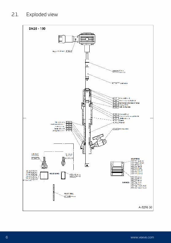
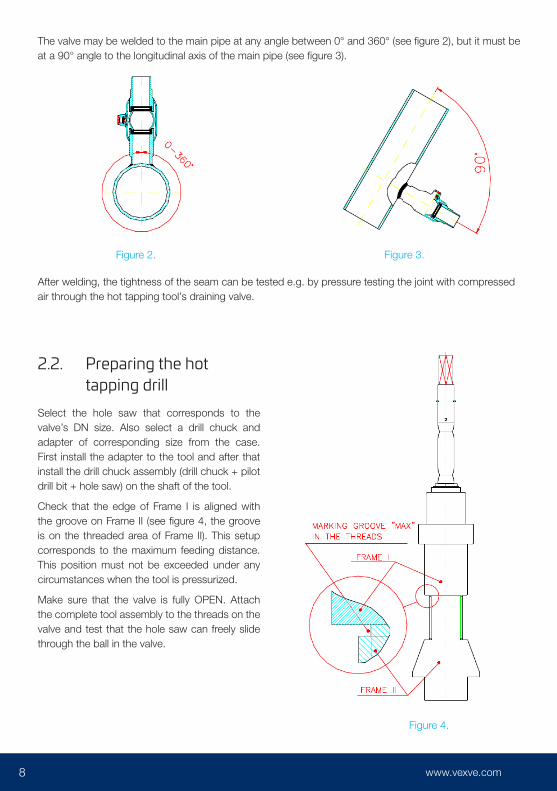
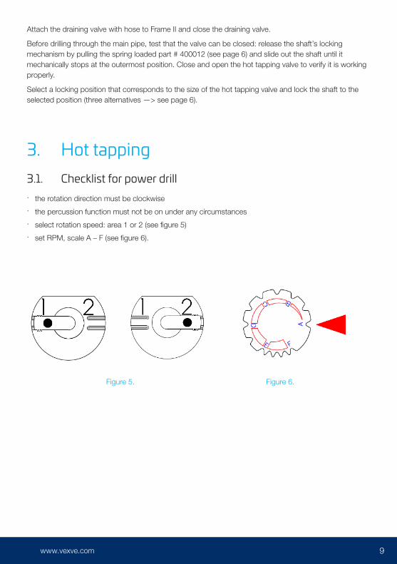
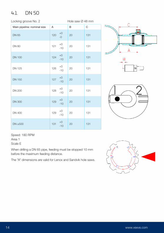
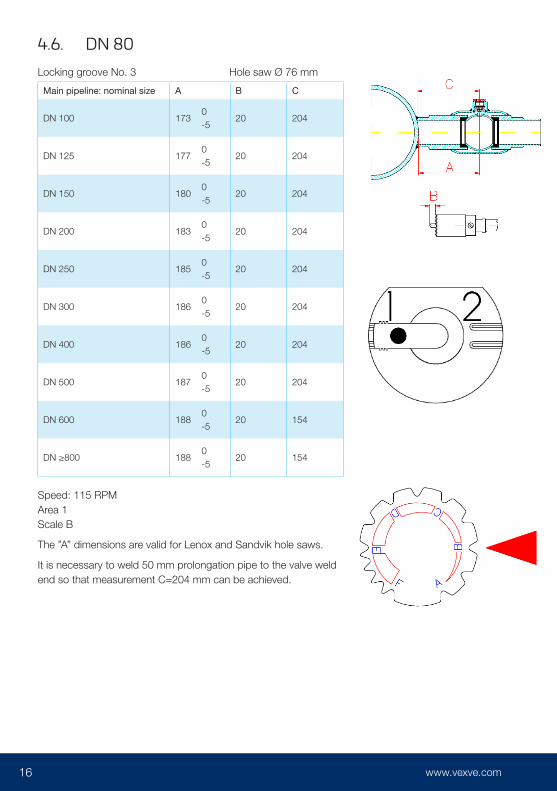
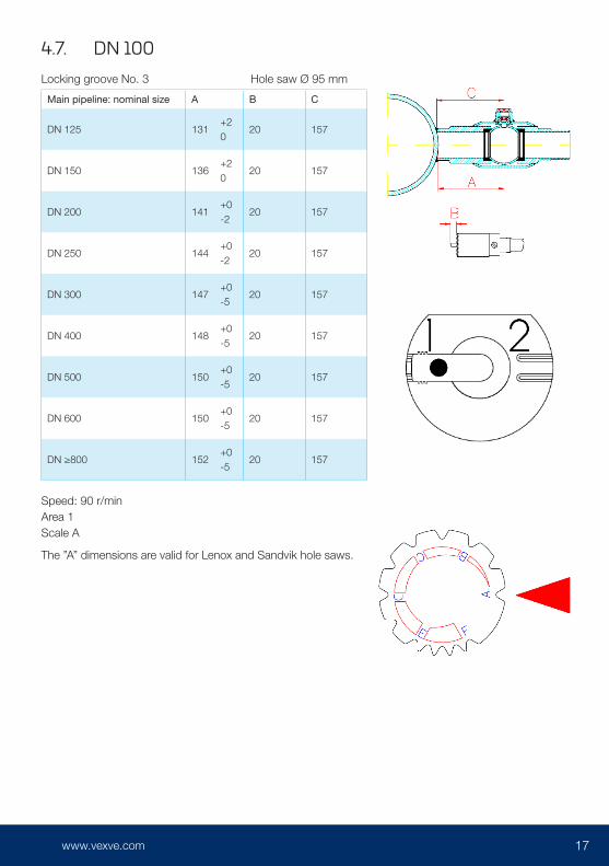

22 23wwwvexvecom
22 23wwwvexvecom wwwvexvecom
wwwvexvecom
042
020
- A
ll rig
hts
rese
rved
Vexve Oy
Pajakatu 11 38200 Sastamala Finland
tel +358 10 734 0800 vexvecustomervexvecom
Riihenkalliontie 10 23800 Laitila Finland

22 23wwwvexvecom wwwvexvecom
wwwvexvecom
042
020
- A
ll rig
hts
rese
rved
Vexve Oy
Pajakatu 11 38200 Sastamala Finland
tel +358 10 734 0800 vexvecustomervexvecom
Riihenkalliontie 10 23800 Laitila Finland

wwwvexvecom
042
020
- A
ll rig
hts
rese
rved
Vexve Oy
Pajakatu 11 38200 Sastamala Finland
tel +358 10 734 0800 vexvecustomervexvecom
Riihenkalliontie 10 23800 Laitila Finland


