Embed Size (px)
Citation preview

Injection Compression MouldingProcesses – Machine Technology
Process Control – Applications
2
Advantages and applications
ICM
Injection compression moulding (ICM) aside from reduced material shear and less orienta-tion, offers numerous qualitative advantages for injection-moulding parts. ICM also permits a re duction in injection pressure, clamping force, and cycle time. Added to this is often an impro-ved hold pressure effect, which minimises sink marks and warpage.
Advantages of injection compression moulding for the process• Compensates shrinkage by compressing the
melt through the clamping movement• Distributed, uniformly acting holding pressure• Reduces holding pressure time, shortens cycle
times• Permits overpacking of cavity• Reduces clamping force requirements
• Less orientation and molecule alignment during injection
• Easier and faster mould fi lling through improved venting
• Less material shear
Advantages of injection compression moulding for moulded part properties• Eliminates sink marks with thicker wall
sections and at the end of the fl ow path• Reduces to warpage susceptibility improves
long-time dimensional stability• Reduces stresses in mats or fi lms in direct
back injection for decorative parts• Reduces fi bre degradation in parts made of
long-fi bre-reinforced thermoplastics (LFTs) and, consequently, improved mechanical part properties
• Improves optical properties in the case of transparent parts
There is a trade-off between the numerous ad-vantages and the extra expense for the machine and mould as well as restrictions in terms of part geometry:• In addiction the IM machine requires an injec-
tion compression control system whose extra price, however, is frequently exaggerated
• The physical design of the mould must be adapted to injection compression moulding in order to prevent the melt from penetrating into the parting line. There are a number of technical solutions to overcome this problem
• Undercuts or penetrations across the com-pression direction are problematic
• Only components that are of very great depth in the injection direction are very diffi cult to produce by injection compression moulding
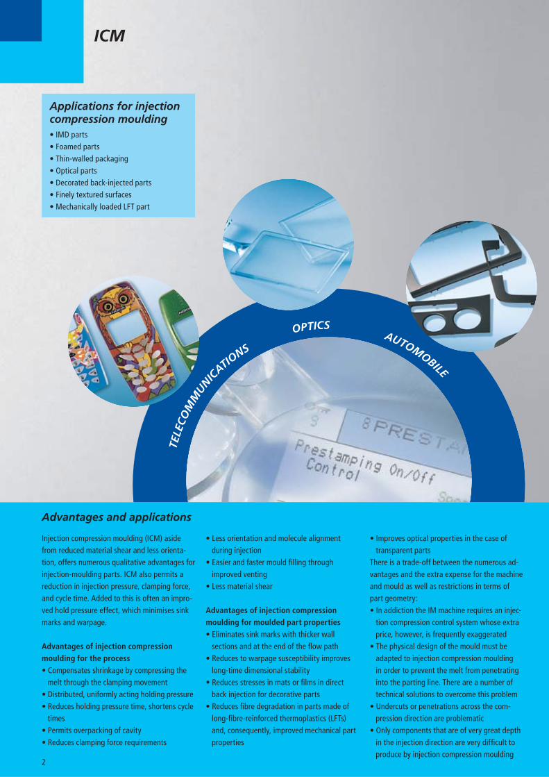
Applications for injection compression moulding• IMD parts• Foamed parts• Thin-walled packaging• Optical parts• Decorated back-injected parts• Finely textured surfaces• Mechanically loaded LFT part
TEL
ECO
MM
UNIC
ATIONS
OPTICS AUTOMOBILE
3
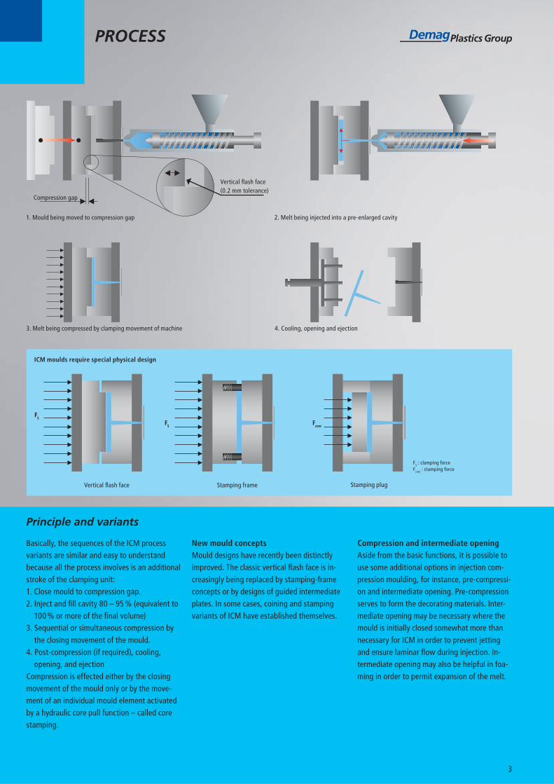
Basically, the sequences of the ICM process variants are similar and easy to understand because all the process involves is an additional stroke of the clamping unit:1. Close mould to compression gap.2. Inject and fi ll cavity 80 – 95 % (equivalent to
100 % or more of the fi nal volume)3. Sequential or simultaneous compression by
the closing movement of the mould.4. Post-compression (if required), cooling,
opening, and ejectionCompression is effected either by the closing movement of the mould only or by the move-ment of an individual mould element activated by a hydraulic core pull function – called core stamping.
New mould conceptsMould designs have recently been distinctly improved. The classic vertical fl ash face is in-creasingly being replaced by stamping-frame concepts or by designs of guided intermediate plates. In some cases, coining and stamping variants of ICM have established themselves.
Compression and intermediate openingAside from the basic functions, it is possible to use some additional options in injection com-pression moulding, for instance, pre-compressi-on and intermediate opening. Pre-compression serves to form the decorating materials. Inter-mediate opening may be necessary where the mould is initially closed somewhat more than necessary for ICM in order to prevent jetting and ensure laminar fl ow during injection. In-termediate opening may also be helpful in foa-ming in order to permit expansion of the melt.
Principle and variants
PROCESS
ICM moulds require special physical design
FS
FS Fcore
Vertical fl ash face Stamping frame Stamping plug
FS : clamping forceFcore : stamping force
1. Mould being moved to compression gap 2. Melt being injected into a pre-enlarged cavity
3. Melt being compressed by clamping movement of machine 4. Cooling, opening and ejection
Compression gap
Vertical fl ash face (0.2 mm tolerance)
1 2
3
4
Variety and transparency
Sequential ICM control is essentially an ex-tension of the NC4 or NC5 controller. As such it is available for all Demag machines of the Con-cept, System, Systec, IntElect, and Titan series. The extended ICM control, which imposes additional requirements on drive technology, can be integrated into the all-electric IntElect with out any problem. In the case of the hydrau-lic machines, it would be necessary to look into the cost of confi guring the hydraulics in each specifi c case.
Integration into the NC4 controllerThere are three screen pages in the NC4 control system of the Demag machines to manipulate injection compression moulding. The options summarised on the screen pages 9 (“ICM con-trol”) and 8 (“Pre-compression/intermediate
ICM CONTROL
opening”) are easy to understand. The ICM control is, of course, fully integrated in the screen page 18 (“Flexible machine sequence”).
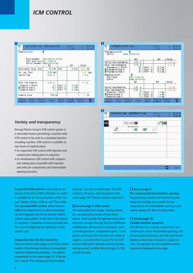
1 Screen page 9: ICM controlThe many options for modes, starting events, etc, are selected by means of drop-down menus. These provide the operator with a host of process variants through the use of different combinations. All important parameters, such as mould protection, compression speed, travel points, and many other functions are visible at a glance. As a protective function for the ICM process, ICM control provides monitoring time settings as well as delay time settings to 1/100 second accuracy.
2 Screen page 8: Pre-compression/intermediate openingProgramming switches with monitoring and delay time settings are provided for pre-compression and intermediate opening as are various options for their starting events.
3 Screen page 18: Flexible machine sequenceAll ICM functions, namely, compression, pre-compression and/or intermediate opening, and all associated movements are fully tied into the familiar presentation of machine sequences. Thus, the operator has the complete process sequences displayed on one page.
Demag Plastics Group’s ICM control system is a selectable feature permitting a machine with ICM control to be used as a standard injection moulding machine. ICM control is available at two levels of sophistication:• As sequential ICM control with injection and
compression taking place in sequence.• As simultaneous ICM control with compres-
sion taking place in parallel with injection and with pre-compression and intermediate opening functions.
5
Merits and demerits of clamping principles in injection compression moulding have to be taken into account in selecting an injection moulding machine
Full hydraulic injection moulding machine Toggle injection moulding machine
+/0 Two/three-platen confi guration Design Three-platen confi guration 0
+/0 Small/medium Space requirements Medium 0
+ Hydraulic Clamping principle Hydromechanical ++
++ 100 % of clamping force Compression force Abt. 50 % of clamping force –
+ Exact, but no mechanical advantage Compression gap positioning Extremely accurate due to mechanical advantage of toggle ++
0 Diffi cult, mainly when operating with small compression gaps Control of ICM stroke Good control also for small compression gaps ++
+ Hydromechanical Force transmission Mechanical ++
0 Hydraulic Carriage locking Hydromechanical +
– None Clamping force reserve 10 – 15 % ++
++ most advantageous + advantageous 0 indifferent – disadvantageous
MACHINE TECHNOLOGY
By relying on the clamping unit of injection moulding machines ICM offers the advantage of a substantially higher force reserve compa-red to stamping plugs in the mould. In contrast to hydraulic two-platen machines, toggle clamp units transmit the force uniformly and centrally into the mould with – in contrast to widely held prejudices – a clearly suffi cient compression force. The toggle has proved advantageous especially in fi lling asymmetrically arranged ca-vities or cavities with long-fl ow paths. The spe-cial kinematics of the toggle provide extremely accurate mould movements near the locking range and, consequently, permit highly accura-te positioning for small compression gaps and effi cient management of the ICM processes.The simultaneous variant of ICM control on Demag machines incorporates two interesting
special functions: carriage fi xing via locking circuit enables the crosshead of the toggle to be arrested, and the stamping frame acting via the core pull control can be operated by means of a hydraulic cylinder in order to obtain variable settings of a defi ned back pressure.
ICM control retrofi tsICM control is not limited to new machines. All existing Demag machines with an NC4 con-troller (DIAS or C-DIAS-CPU) can be retrofi tted with the sequential ICM control. Retrofi tting the extended ICM control on hydraulic ma-chines mostly also calls for a hydraulic system retrofi t.
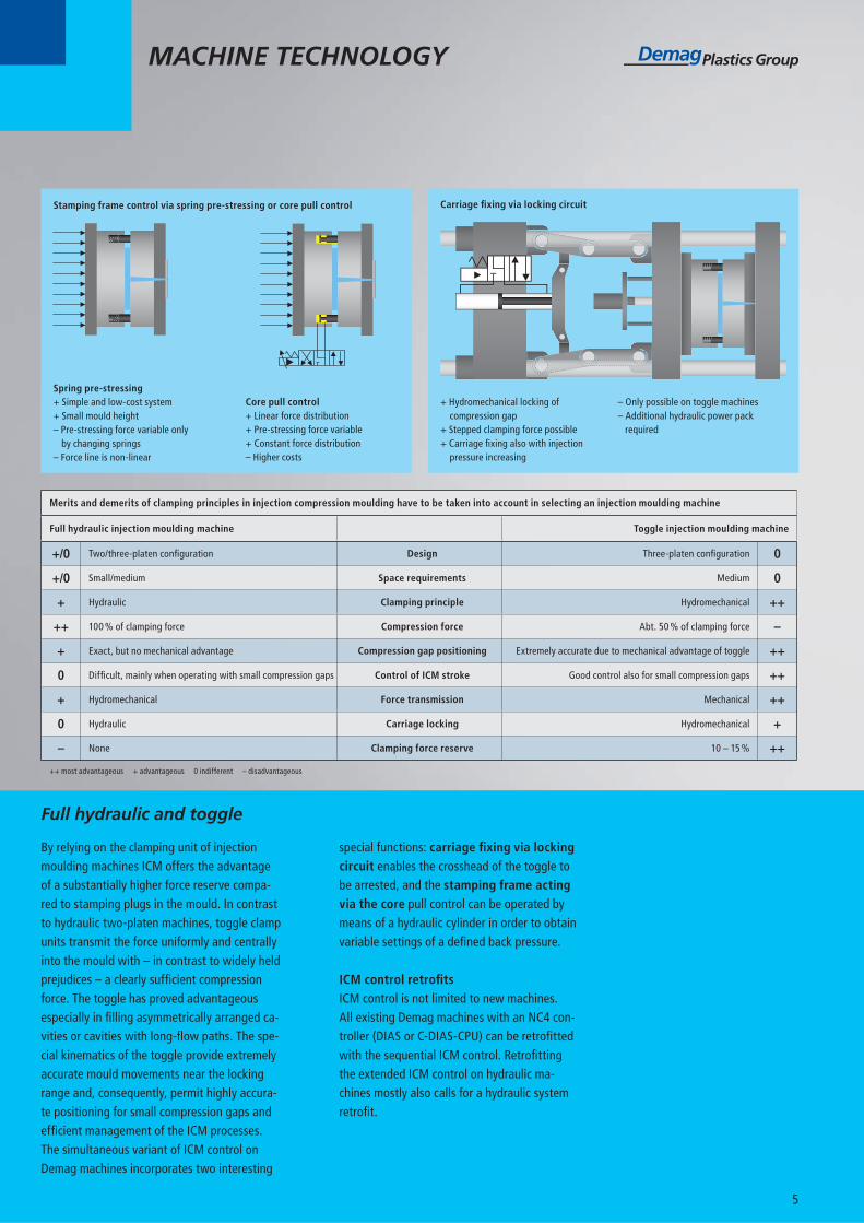
+ Hydromechanical locking of compression gap
+ Stepped clamping force possible+ Carriage fi xing also with injection
pressure increasing
– Only possible on toggle machines– Additional hydraulic power pack
required
Carriage fi xing via locking circuit
Full hydraulic and toggle
Spring pre-stressing+ Simple and low-cost system+ Small mould height– Pre-stressing force variable only by changing springs– Force line is non-linear
Core pull control+ Linear force distribution+ Pre-stressing force variable+ Constant force distribution– Higher costs
Stamping frame control via spring pre-stressing or core pull control
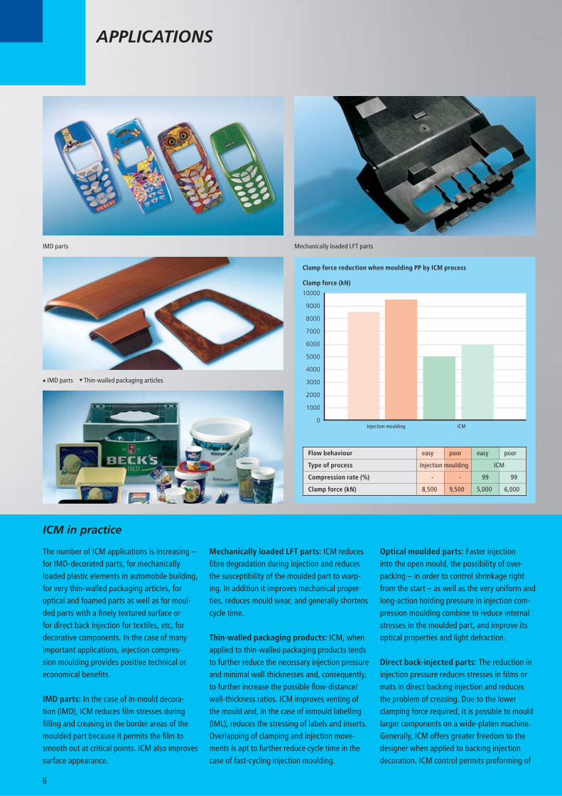
Mechanically loaded LFT partsIMD parts
IMD parts Thin-walled packaging articles
6
The number of ICM applications is increa sing – for IMD-decorated parts, for mechanically loaded plastic elements in automobile building, for very thin-walled packaging articles, foroptical and foamed parts as well as for moul-ded parts with a fi nely textured surface or for direct back injection for textiles, etc, for decorative components. In the case of many important applications, injection compres-sion moulding provides positive technical or economical benefi ts.
IMD parts: In the case of in-mould decora-tion (IMD), ICM reduces fi lm stresses during fi lling and creasing in the border areas of the moulded part because it permits the fi lm to smooth out at critical points. ICM also improves surface appearance.
ICM in practice
Mechanically loaded LFT parts: ICM reduces fi bre degradation during injection and reduces the susceptibility of the moulded part to warp-ing. In addition it improves mechanical proper-ties, reduces mould wear, and generally shortens cycle time.
Thin-walled packaging products: ICM, when applied to thin-walled packaging products tends to further reduce the necessary injection pressure and minimal wall thicknesses and, con sequently, to further increase the possible fl ow-distance/wall-thickness ratios. ICM im proves venting of the mould and, in the case of inmould labelling (IML), reduces the stressing of labels and inserts. Overlapping of clamping and injection move-ments is apt to further reduce cycle time in the case of fast-cycling injection moulding.
APPLICATIONS
Optical moulded parts: Faster injection into the open mould, the possibility of over-packing – in order to control shrinkage right from the start – as well as the very uniform and long-action holding pressure in injection com-pression moulding combine to reduce internal stresses in the moulded part, and improve its optical properties and light defraction.
Direct back-injected parts: The reduction in injection pressure reduces stresses in fi lms or mats in direct backing injection and reduces the problem of creasing. Due to the lower clam ping force required, it is possible to mould larger components on a wide-platen machine. Generally, ICM offers greater freedom to the designer when applied to backing injection decoration. ICM control permits preforming of
Clamp force reduction when moulding PP by ICM process
10000
9000
8000
7000
6000
5000
4000
3000
2000
1000
0
Clamp force (kN)
Injection moulding ICM
Flow behaviour easy poor easy poor
Type of process
Compression rate (%) - - 99 99
Clamp force (kN) 8,500 9,500 5,000 6,000
Injection moulding ICM

Advantage of process through overpacking
Optical moulded parts
Decorative backing-injected parts Foamed moulded parts
Finely textured surfaces
7
the decorative materials by means of a preced-ing compression stroke.
Finely textured surfaces: ICM moulding en sures exact and uniform duplication of micro-textures on the moulded part surface – espe-cially at the end of the fl ow path. It facilitates combining different textures and improves the degree of reproduction.
Foamed parts: Intermediate opening prevents premature foaming of the melt, where chemical blowing agents have been added or mechanical blowing has been applied. The more homog-enous pressure conditions in the mould and the more uniform holding pressure have an infl u-ence on the cell structure and improve venting as well as surface quality.
Injection pressure reduction through ICM applied to direct backing injection
900
800
700
600
500
400
300
200
100
0
Maximum injection pressure (bar)
Standard injection moulding with hold pressure (2s/400 bar) ICM start injection ICM start hold pressure (V=1 %) ICM start hold pressure (V=99 %) easy fl ow ICM start hold pressure (V=99 %) poor fl ow
Injection moulding ICM
95 – 98 % cavity volume100 % fi nal volumeholding pressure
80 – 90 % cavity volume>100 % fi nal volume
Compression + holding pressure
Change-over pointPossible fi lling volume
Compensating shrinkage
Cavity fi lling
www.dpg.com
3091
Spr
itzpr
ägen
-GB
1007
he
ww
w.d
a-ka
po.d
e
AsiaDemag (Malaysia) Sdn Bhd15-E, 5th Floor, Block 1Worldwide Business ParkJalan 13/50, Section 1340000 Shah AlamSelangor Darul Ehsan, MalaysiaTel.: +60-3-55 12 97 40Fax: +60-3-55 12 97 60E-Mail: [email protected]
BrazilDemag Ergotech Brasil Ltda.Av. Ceci, 608 – Galpao B11Tamboré06460-120 Barueri (SP)Tel.: +55-11-41 95-41 12Fax: +55-11-41 95-41 13E-Mail: [email protected]
ChinaDemag Plastics Machinery (Ningbo) Co., Ltd.No.669, Kunlunshan Road, Beilun District, Ningbo, 315800, Zhejiang Province, P.R.ChinaTel.: +86-5 74-86 18 15 00Fax: +86-5 74-86 18 15 18E-Mail: [email protected]
ChinaDemag Ergotech GmbH Shanghai Rep. Offi ce6F, No. 1221, Hami Road, Shanghai 200335, ChinaTel.: +86-21-52 19 50 00Fax: +86-21-52 19 62 50E-Mail: [email protected]
CISMannesmann Demag PlastservicePrombaza OAO „Stroitransgaz“d.Ascherino Leninskiy raion142717 Moscow regionTel.: +74-95-9 37 97 64Fax: +74-95-9 33 00 78E-Mail: [email protected]
FranceDemag Ergotech France sasZac du Mandinet9, rue des Campanules77185 LognesTel.: +33-1-60 33 20 10Fax: +33-1-60 06 28 89E-Mail: [email protected]
GermanyDemag Ergotech GmbHWerk SchwaigAltdorfer Str. 1590571 SchwaigTel.: +49-9 11-50 61-0Fax: +49-9 11-50 61-2 65E-Mail: [email protected]
GermanyDemag Ergotech GmbHWerk WieheDonndorfer Str. 306571 WieheTel.: +49-3 46 72-97-0Fax: +49-3 46 72-97-333E-Mail: [email protected]
IndiaL&T-Demag Plastics Machinery LimitedMount-Poonamallee RoadManapakkam/Chennai 600 089Tel.: +91-44-22 49-04 32Fax: +91-44-22 49-49 52E-Mail: [email protected]
ItalyDemag Plastics Group Italia s.r.l.Via Bassano 303012 Anagni (FR)Tel.: +39-07 75-77 20 04Fax: +39-07 75-77 20 04E-Mail: [email protected]
PolandDemag Plastics Group Sp. z o.o.ul. Jagiellonska 81-8342-200 CzestochowaTel.: +48-34-3 70 95 40Fax: +48-34-3 70 94 86E-Mail: [email protected]
SpainDemag Ergotech España, S.L.Pol. Ind. Can CalderónAvd. Riera de FonollarEsquina C/Murcia, n°37-A, Nave F08830 – Sant Boi de Llobregat (Barcelona)Tel.: +34-93-6 52 95 30Fax: +34-93-6 54 78 10E-Mail: [email protected]
United KingdomDemag Hamilton Ltd.Hamilton House, Broadfi eldsBicester Road, AylesburyBucks, HP19 8AYTel.: +44-12 96-31 82 00Fax: +44-12 96-42 62 22E-Mail: [email protected]
USADemag Plastics Group Corp.11792 Alameda DriveStrongsville, Ohio 44149-3011Tel.: +1-4 40-8 76-89 48Fax: +1-4 40-8 76-64 39E-Mail: [email protected]
Many moulders today operate three shifts, some on 365 days of the year – this calls for a maximum of availability of the machines, spare parts, and service support. Backed by highly skilled service teams, advanced spare parts logistics, and multiple service levels to address a customer’s specifi c needs, we provide total support world-wide: from straightforward inspections through com-prehensive maintenance, and extended warranties for high capacity utilisation levels to emergency hotline support, and training of your personnel.Full documentation and a digital catalogue ensure that spare parts are delivered to you in a minimum of time, usually within a few hours. Users of older machines can have them upgraded by our retrofi t service at fair prices, for instance, by state-of-the-art control software or for specialised injection-moulding processes. In short, the Demag Service provides you with whatever support you need to complete your jobs effi ciently and to schedule.
The responsibility to ensure that everything runs smoothly


