Embed Size (px)
Citation preview
ELTR 105 (DC 2), section 3
Recommended schedule
Day 1Topics: Inductance and inductorsQuestions: 1 through 20Lab Exercises: Series inductances (question 81) and parallel inductances (question 82)
Day 2Topics: Capacitance and capacitorsQuestions: 21 through 40Lab Exercises: Series capacitances (question 83) and parallel capacitances (question 84)
Day 3Topics: Time constantsQuestions: 41 through 60Lab Exercise: RC discharge circuit (question 85)
Day 4Topics: Time constant circuitsQuestions: 61 through 80Lab Exercise: Time-delay relay (question 86)
Day 5Exam 3: includes RC discharge circuit performance assessmentTroubleshooting Assessment due: Loaded voltage divider (question 87)Question 88: Troubleshooting logQuestion 89: Sample troubleshooting assessment grading criteria
Practice and challenge problemsQuestions: 90 through the end of the worksheet
1
ELTR 105 (DC 2), section 3
Skill standards addressed by this course section
EIA Raising the Standard; Electronics Technician Skills for Today and Tomorrow, June 1994
B Technical Skills – DC circuitsB.03 Demonstrate an understanding of the meaning of and relationships among and between voltage, current,
resistance and power in DC circuits.B.07 Demonstrate an understanding of the physical, electrical characteristics of capacitors and inductors.B.21 Understand principles and operations of DC RC and RL circuits.B.22 Fabricate and demonstrate DC RC and RL circuits.B.23 Troubleshoot and repair DC RC and RL circuits.
B Basic and Practical Skills – Communicating on the JobB.01 Use effective written and other communication skills. Met by group discussion and completion of labwork.B.03 Employ appropriate skills for gathering and retaining information. Met by research and preparation
prior to group discussion.B.04 Interpret written, graphic, and oral instructions. Met by completion of labwork.B.06 Use language appropriate to the situation. Met by group discussion and in explaining completed labwork.B.07 Participate in meetings in a positive and constructive manner. Met by group discussion.B.08 Use job-related terminology. Met by group discussion and in explaining completed labwork.B.10 Document work projects, procedures, tests, and equipment failures. Met by project construction and/or
troubleshooting assessments.C Basic and Practical Skills – Solving Problems and Critical Thinking
C.01 Identify the problem. Met by research and preparation prior to group discussion.C.03 Identify available solutions and their impact including evaluating credibility of information, and locating
information. Met by research and preparation prior to group discussion.C.07 Organize personal workloads. Met by daily labwork, preparatory research, and project management.C.08 Participate in brainstorming sessions to generate new ideas and solve problems. Met by group discussion.
D Basic and Practical Skills – ReadingD.01 Read and apply various sources of technical information (e.g. manufacturer literature, codes, and
regulations). Met by research and preparation prior to group discussion.E Basic and Practical Skills – Proficiency in Mathematics
E.01 Determine if a solution is reasonable.E.02 Demonstrate ability to use a simple electronic calculator.E.05 Solve problems and [sic] make applications involving integers, fractions, decimals, percentages, and
ratios using order of operations.E.06 Translate written and/or verbal statements into mathematical expressions.E.12 Interpret and use tables, charts, maps, and/or graphs.E.13 Identify patterns, note trends, and/or draw conclusions from tables, charts, maps, and/or graphs.E.15 Simplify and solve algebraic expressions and formulas.E.16 Select and use formulas appropriately.E.17 Understand and use scientific notation.E.18 Use properties of exponents and logarithms.
2
ELTR 105 (DC 2), section 3
Common areas of confusion for students
Difficult concept: Rates of change.When learning the relationships between voltage and current for inductors and capacitors, one must
think in terms of how fast a variable is changing. The amount of voltage induced across an inductor isproportional to how quickly the current through it changes, not how strong the current is. Likewise, theamount of current ”through” a capacitor is proportional to how quickly the voltage across it changes. Thisis the first hurdle in calculus: to comprehend what a rate of change is, and it is not obvious.
Common mistake: Series and parallel relationships for capacitors.How inductors add and diminish in series and parallel (respectively) is easy to grasp because it resembles
the relationships for resistors. Capacitors are ”backwards” to both resistors and inductors, though, whichcauses confusion.
The best way I know how to overcome this confusion is to relate the series or parallel connection ofcapacitors to changes in physical dimension for a theoretical capacitor, and ask what change in capacitancesuch a change in dimension will yield. Connecting capacitors in series may be modeled by increasing thedistance between plates of a theoretical capacitor, decreasing capacitance. Connecting capacitors in parallelis analogous to increasing the plate area of a theoretical capacitor, increasing capacitance.
Difficult concept: The time-constant equation.Many students find the time-constant equation difficult because it involves exponents, particularly
exponents of Euler’s constant e. This exponent is often expressed as a negative quantity, making it evenmore difficult to understand. The single most popular mathematical mistake I see students make with thisequation is failing to properly follow algebraic order of operations. Some students try to overcome thisweakness by using calculators which allow parenthetical entries, nesting parentheses in such a way that thecalculator performs the proper order of operations. However, if you don’t understand order of operationsyourself, you will not know where to properly place the parentheses. If you have trouble with algebraic orderof operations, there is no solution but to invest the necessary time and learn it!
Beyond mathematical errors, though, the most common mistake I see students make with the timeconstant equation is mis-application. One version of this equation expresses increasing quantities, whileanother version expresses decreasing quantities. You must already know what the variables are going to doin your time-constant circuit before you know which equation to use! You must also be able to recognize oneversion of this equation from the other: not by memory, lest you should forget; but by noting what the resultof the equation does as time (t) increases. Here again there will be trouble if you are not adept applyingalgebraic order of operations.
3
Questions
Question 1
As an electric current is passed through a coil of wire, it creates a magnetic field. If the magnitude ofthis current changes over time, so will the strength of the magnetic field.
We also know that a magnetic field flux that changes over time will induce a voltage along the length ofa wire coil. Explain how the complementary principles of electromagnetism and electromagnetic inductionmanifest themselves simultaneously in the same wire coil to produce self-induction.
Also, explain how Lenz’s Law relates to the polarity of the coil’s self-induced voltage.file 00263
Question 2
Inductance is a very important property in many types of electric circuits. Define what ”inductance”is, and what causes it.
file 01136
Question 3∫
f(x) dx Calculus alert!
Ohm’s Law tells us that the amount of voltage dropped by a fixed resistance may be calculated as such:
E = IR
However, the relationship between voltage and current for a fixed inductance is quite different. The”Ohm’s Law” formula for an inductor is as such:
e = Ldi
dt
What significance is there in the use of lower-case variables for current (i) and voltage (e)? Also, whatdoes the expression di
dtmean? Note: in case you think that the d’s are variables, and should cancel out in
this fraction, think again: this is no ordinary quotient! The d letters represent a calculus concept known asa differential, and a quotient of two d terms is called a derivative.
file 01381
4
Question 4∫
f(x) dx Calculus alert!
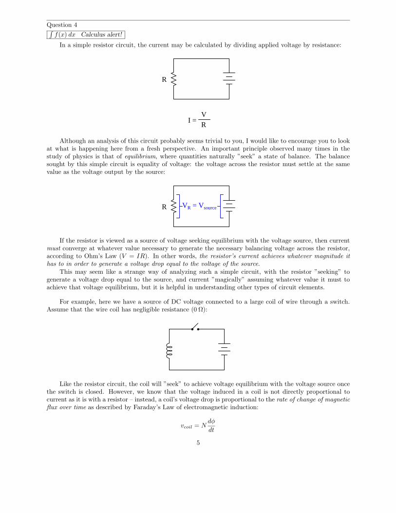
In a simple resistor circuit, the current may be calculated by dividing applied voltage by resistance:
R
I = V
R
Although an analysis of this circuit probably seems trivial to you, I would like to encourage you to lookat what is happening here from a fresh perspective. An important principle observed many times in thestudy of physics is that of equilibrium, where quantities naturally ”seek” a state of balance. The balancesought by this simple circuit is equality of voltage: the voltage across the resistor must settle at the samevalue as the voltage output by the source:
R VR = Vsource
If the resistor is viewed as a source of voltage seeking equilibrium with the voltage source, then currentmust converge at whatever value necessary to generate the necessary balancing voltage across the resistor,according to Ohm’s Law (V = IR). In other words, the resistor’s current achieves whatever magnitude ithas to in order to generate a voltage drop equal to the voltage of the source.
This may seem like a strange way of analyzing such a simple circuit, with the resistor ”seeking” togenerate a voltage drop equal to the source, and current ”magically” assuming whatever value it must toachieve that voltage equilibrium, but it is helpful in understanding other types of circuit elements.
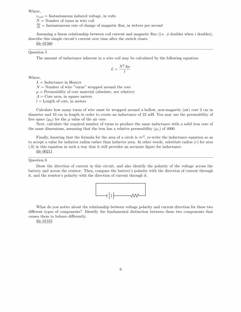
For example, here we have a source of DC voltage connected to a large coil of wire through a switch.Assume that the wire coil has negligible resistance (0 Ω):
Like the resistor circuit, the coil will ”seek” to achieve voltage equilibrium with the voltage source oncethe switch is closed. However, we know that the voltage induced in a coil is not directly proportional tocurrent as it is with a resistor – instead, a coil’s voltage drop is proportional to the rate of change of magneticflux over time as described by Faraday’s Law of electromagnetic induction:
vcoil = Ndφ
dt
5
Where,vcoil = Instantaneous induced voltage, in voltsN = Number of turns in wire coildφdt
= Instantaneous rate of change of magnetic flux, in webers per second
Assuming a linear relationship between coil current and magnetic flux (i.e. φ doubles when i doubles),describe this simple circuit’s current over time after the switch closes.
file 01560
Question 5
The amount of inductance inherent in a wire coil may be calculated by the following equation:
L =N2Aµ
l
Where,L = Inductance in HenrysN = Number of wire ”turns” wrapped around the coreµ = Permeability of core material (absolute, not relative)A = Core area, in square metersl = Length of core, in meters
Calculate how many turns of wire must be wrapped around a hollow, non-magnetic (air) core 2 cm indiameter and 10 cm in length in order to create an inductance of 22 mH. You may use the permeability offree space (µ0) for the µ value of the air core.
Next, calculate the required number of turns to produce the same inductance with a solid iron core ofthe same dimensions, assuming that the iron has a relative permeability (µr) of 4000.
Finally, knowing that the formula for the area of a circle is πr2, re-write the inductance equation so asto accept a value for inductor radius rather than inductor area. In other words, substitute radius (r) for area(A) in this equation in such a way that it still provides an accurate figure for inductance.
file 00211
Question 6
Draw the direction of current in this circuit, and also identify the polarity of the voltage across thebattery and across the resistor. Then, compare the battery’s polarity with the direction of current throughit, and the resistor’s polarity with the direction of current through it.
What do you notice about the relationship between voltage polarity and current direction for these twodifferent types of components? Identify the fundamental distinction between these two components thatcauses them to behave differently.
file 01555
6
Question 7
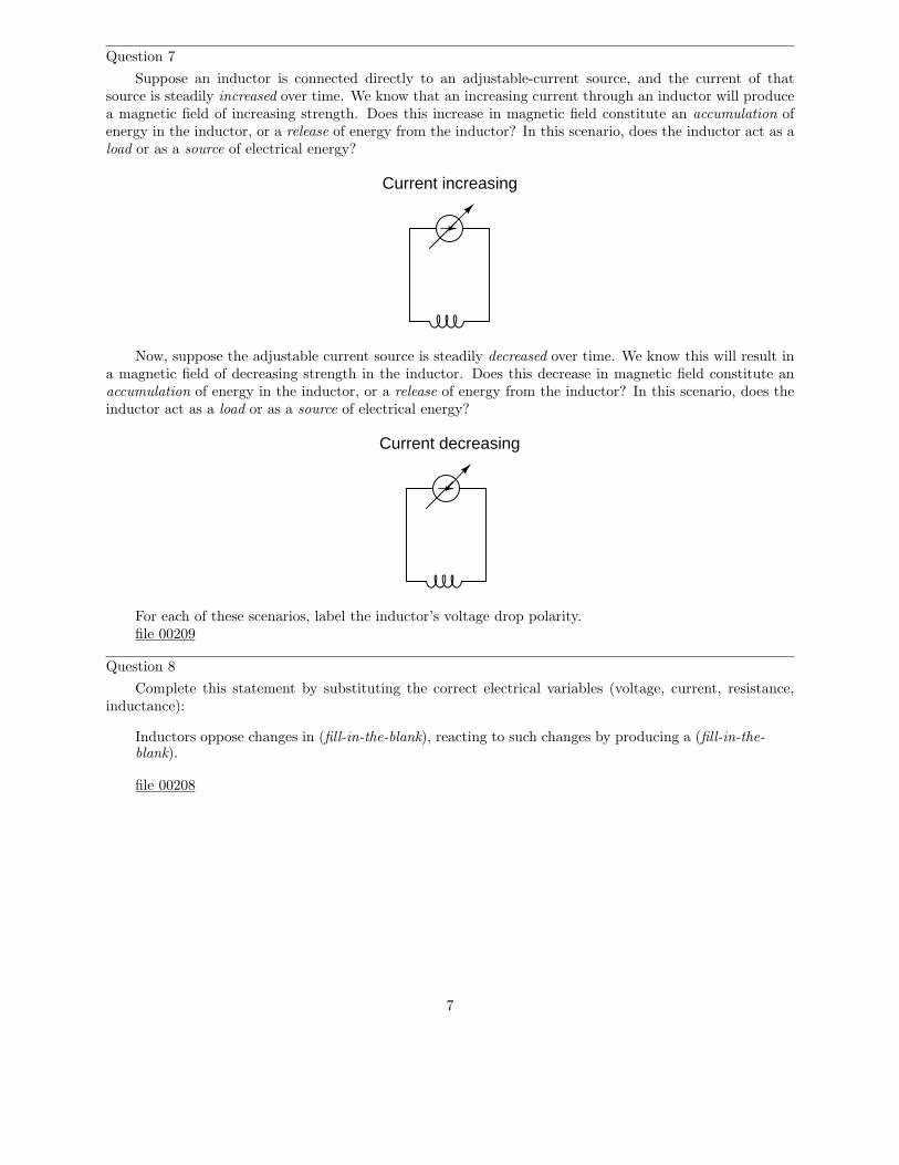
Suppose an inductor is connected directly to an adjustable-current source, and the current of thatsource is steadily increased over time. We know that an increasing current through an inductor will producea magnetic field of increasing strength. Does this increase in magnetic field constitute an accumulation ofenergy in the inductor, or a release of energy from the inductor? In this scenario, does the inductor act as aload or as a source of electrical energy?
Current increasing
Now, suppose the adjustable current source is steadily decreased over time. We know this will result ina magnetic field of decreasing strength in the inductor. Does this decrease in magnetic field constitute anaccumulation of energy in the inductor, or a release of energy from the inductor? In this scenario, does theinductor act as a load or as a source of electrical energy?
Current decreasing
For each of these scenarios, label the inductor’s voltage drop polarity.file 00209
Question 8
Complete this statement by substituting the correct electrical variables (voltage, current, resistance,inductance):
Inductors oppose changes in (fill-in-the-blank), reacting to such changes by producing a (fill-in-the-blank).
file 00208
7
Question 9
Many precision resistors utilize a wire-wound construction, where the resistance is determined by thetype and length of wire wrapped around a spool. This form of construction allows for high precision ofresistance, with low temperature sensitivity if certain metal alloys are used for the wire.
Unfortunately, though, wrapping wire around a spool forms a coil, which will naturally possess asignificant amount of inductance. This is generally undesirable, as we would like to have resistors possessingonly resistance, with no ”parasitic” properties.
There is, however, a special way in which a wire coil may be wound so as to have almost no inductance.This method is called bifilar winding, and it is common in wire-wound resistor construction. Describe howbifilar winding works, and why it eliminates parasitic inductance.
file 00375
Question 10
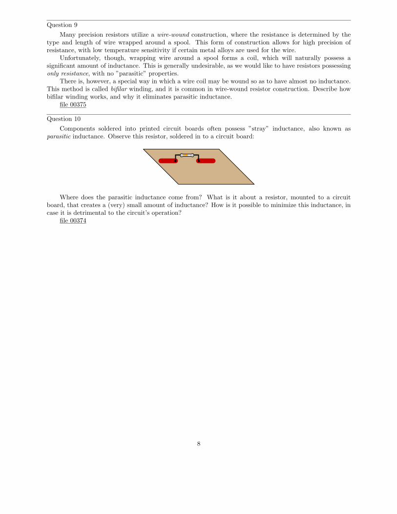
Components soldered into printed circuit boards often possess ”stray” inductance, also known asparasitic inductance. Observe this resistor, soldered in to a circuit board:
Where does the parasitic inductance come from? What is it about a resistor, mounted to a circuitboard, that creates a (very) small amount of inductance? How is it possible to minimize this inductance, incase it is detrimental to the circuit’s operation?
file 00374
8
Question 11
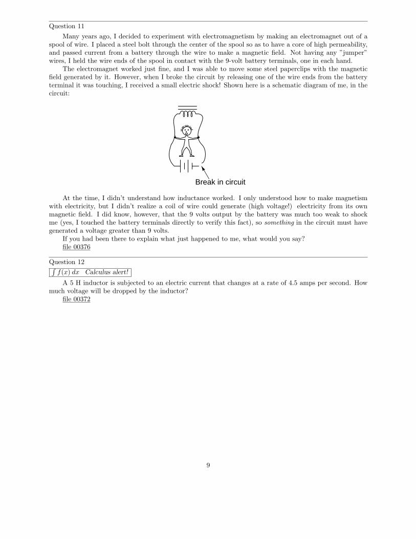
Many years ago, I decided to experiment with electromagnetism by making an electromagnet out of aspool of wire. I placed a steel bolt through the center of the spool so as to have a core of high permeability,and passed current from a battery through the wire to make a magnetic field. Not having any ”jumper”wires, I held the wire ends of the spool in contact with the 9-volt battery terminals, one in each hand.
The electromagnet worked just fine, and I was able to move some steel paperclips with the magneticfield generated by it. However, when I broke the circuit by releasing one of the wire ends from the batteryterminal it was touching, I received a small electric shock! Shown here is a schematic diagram of me, in thecircuit:
Break in circuit
At the time, I didn’t understand how inductance worked. I only understood how to make magnetismwith electricity, but I didn’t realize a coil of wire could generate (high voltage!) electricity from its ownmagnetic field. I did know, however, that the 9 volts output by the battery was much too weak to shockme (yes, I touched the battery terminals directly to verify this fact), so something in the circuit must havegenerated a voltage greater than 9 volts.
If you had been there to explain what just happened to me, what would you say?file 00376
Question 12∫
f(x) dx Calculus alert!
A 5 H inductor is subjected to an electric current that changes at a rate of 4.5 amps per second. Howmuch voltage will be dropped by the inductor?
file 00372
9
Question 13∫
f(x) dx Calculus alert!
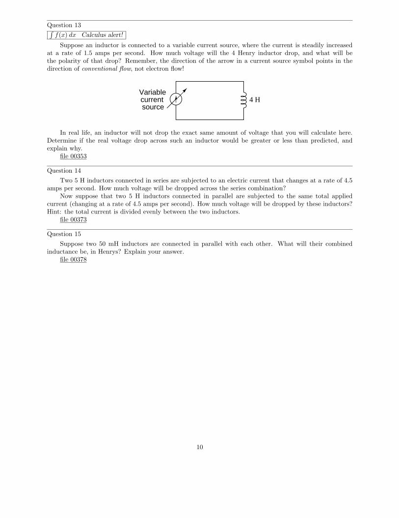
Suppose an inductor is connected to a variable current source, where the current is steadily increasedat a rate of 1.5 amps per second. How much voltage will the 4 Henry inductor drop, and what will bethe polarity of that drop? Remember, the direction of the arrow in a current source symbol points in thedirection of conventional flow, not electron flow!
Variablecurrentsource
4 H
In real life, an inductor will not drop the exact same amount of voltage that you will calculate here.Determine if the real voltage drop across such an inductor would be greater or less than predicted, andexplain why.
file 00353
Question 14
Two 5 H inductors connected in series are subjected to an electric current that changes at a rate of 4.5amps per second. How much voltage will be dropped across the series combination?
Now suppose that two 5 H inductors connected in parallel are subjected to the same total appliedcurrent (changing at a rate of 4.5 amps per second). How much voltage will be dropped by these inductors?Hint: the total current is divided evenly between the two inductors.
file 00373
Question 15
Suppose two 50 mH inductors are connected in parallel with each other. What will their combinedinductance be, in Henrys? Explain your answer.
file 00378
10
Question 16
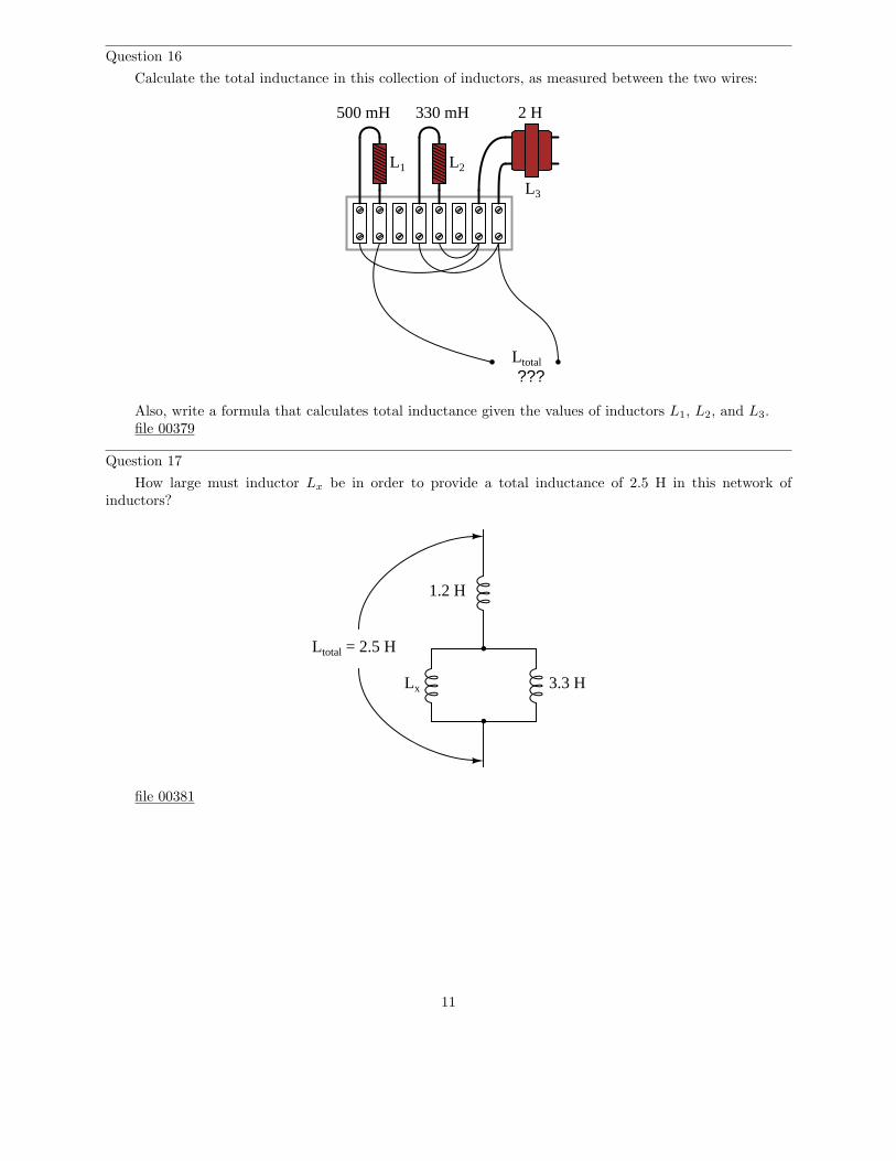
Calculate the total inductance in this collection of inductors, as measured between the two wires:
???
500 mH 330 mH 2 H
Ltotal
L1 L2
L3
Also, write a formula that calculates total inductance given the values of inductors L1, L2, and L3.file 00379
Question 17
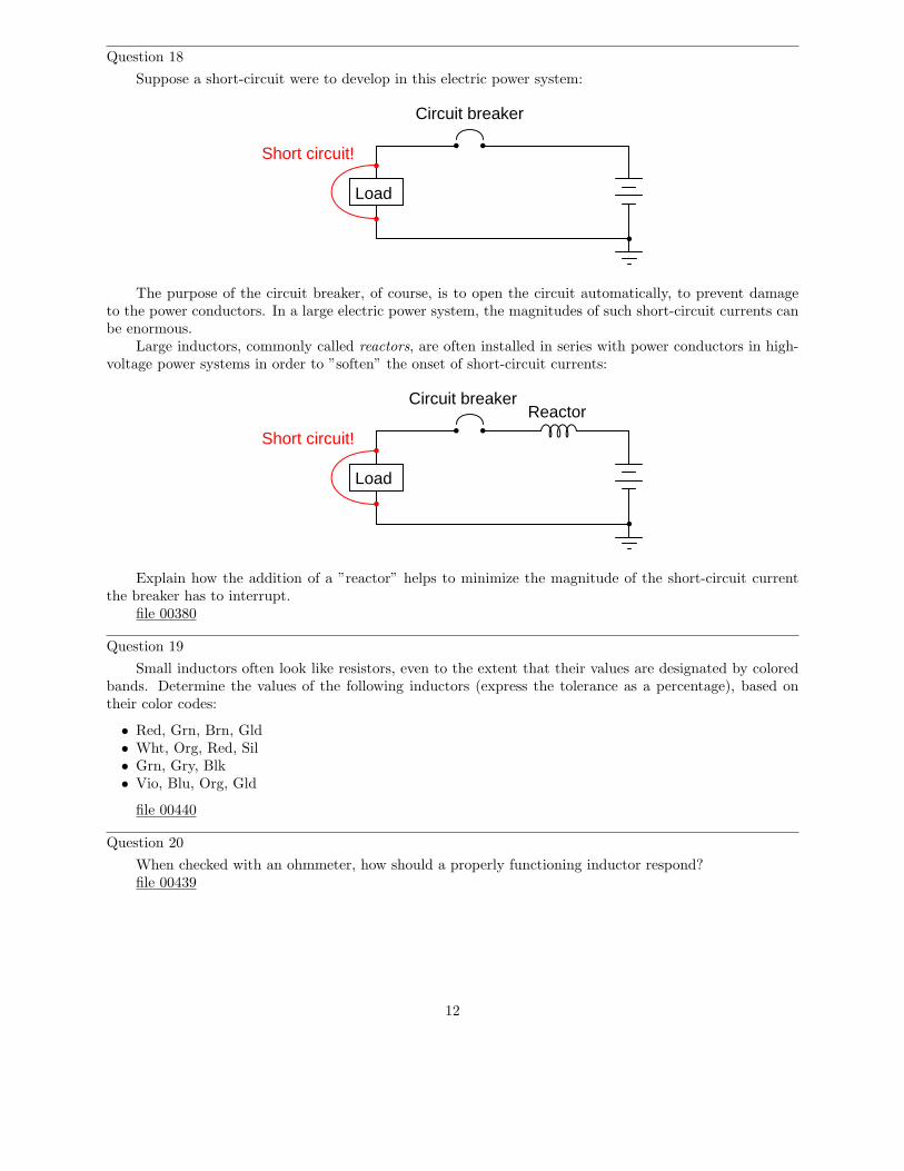
How large must inductor Lx be in order to provide a total inductance of 2.5 H in this network ofinductors?
Lx
Ltotal = 2.5 H
1.2 H
3.3 H
file 00381
11
Question 18
Suppose a short-circuit were to develop in this electric power system:
Load
Circuit breaker
Short circuit!
The purpose of the circuit breaker, of course, is to open the circuit automatically, to prevent damageto the power conductors. In a large electric power system, the magnitudes of such short-circuit currents canbe enormous.
Large inductors, commonly called reactors, are often installed in series with power conductors in high-voltage power systems in order to ”soften” the onset of short-circuit currents:
Load
Circuit breaker
Short circuit!
Reactor
Explain how the addition of a ”reactor” helps to minimize the magnitude of the short-circuit currentthe breaker has to interrupt.
file 00380
Question 19
Small inductors often look like resistors, even to the extent that their values are designated by coloredbands. Determine the values of the following inductors (express the tolerance as a percentage), based ontheir color codes:
• Red, Grn, Brn, Gld• Wht, Org, Red, Sil• Grn, Gry, Blk• Vio, Blu, Org, Gld
file 00440
Question 20
When checked with an ohmmeter, how should a properly functioning inductor respond?file 00439
12
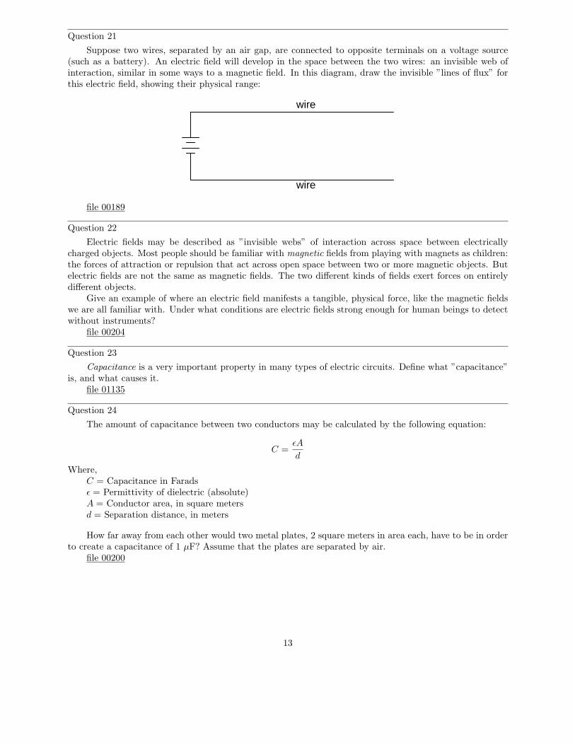
Question 21
Suppose two wires, separated by an air gap, are connected to opposite terminals on a voltage source(such as a battery). An electric field will develop in the space between the two wires: an invisible web ofinteraction, similar in some ways to a magnetic field. In this diagram, draw the invisible ”lines of flux” forthis electric field, showing their physical range:
wire
wire
file 00189
Question 22
Electric fields may be described as ”invisible webs” of interaction across space between electricallycharged objects. Most people should be familiar with magnetic fields from playing with magnets as children:the forces of attraction or repulsion that act across open space between two or more magnetic objects. Butelectric fields are not the same as magnetic fields. The two different kinds of fields exert forces on entirelydifferent objects.
Give an example of where an electric field manifests a tangible, physical force, like the magnetic fieldswe are all familiar with. Under what conditions are electric fields strong enough for human beings to detectwithout instruments?
file 00204
Question 23
Capacitance is a very important property in many types of electric circuits. Define what ”capacitance”is, and what causes it.
file 01135
Question 24
The amount of capacitance between two conductors may be calculated by the following equation:
C =ǫA
d
Where,C = Capacitance in Faradsǫ = Permittivity of dielectric (absolute)A = Conductor area, in square metersd = Separation distance, in meters
How far away from each other would two metal plates, 2 square meters in area each, have to be in orderto create a capacitance of 1 µF? Assume that the plates are separated by air.
file 00200
13
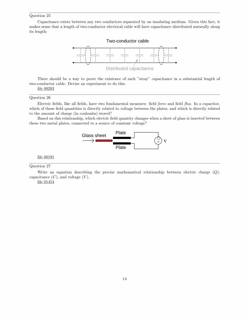
Question 25
Capacitance exists between any two conductors separated by an insulating medium. Given this fact, itmakes sense that a length of two-conductor electrical cable will have capacitance distributed naturally alongits length:
Distributed capacitance
Two-conductor cable
There should be a way to prove the existence of such ”stray” capacitance in a substantial length oftwo-conductor cable. Devise an experiment to do this.
file 00203
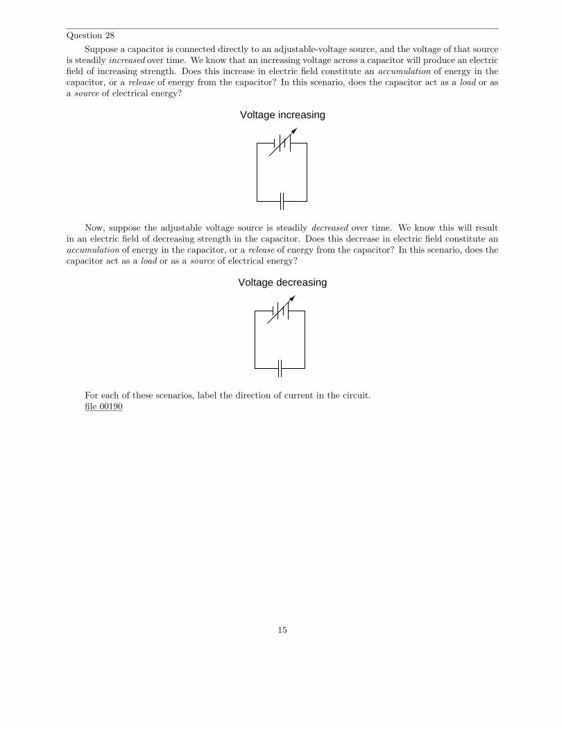
Question 26
Electric fields, like all fields, have two fundamental measures: field force and field flux. In a capacitor,which of these field quantities is directly related to voltage between the plates, and which is directly relatedto the amount of charge (in coulombs) stored?
Based on this relationship, which electric field quantity changes when a sheet of glass is inserted betweenthese two metal plates, connected to a source of constant voltage?
Plate
Plate
Glass sheet +− V
file 00191
Question 27
Write an equation describing the precise mathematical relationship between electric charge (Q),capacitance (C), and voltage (V ).
file 01454
14
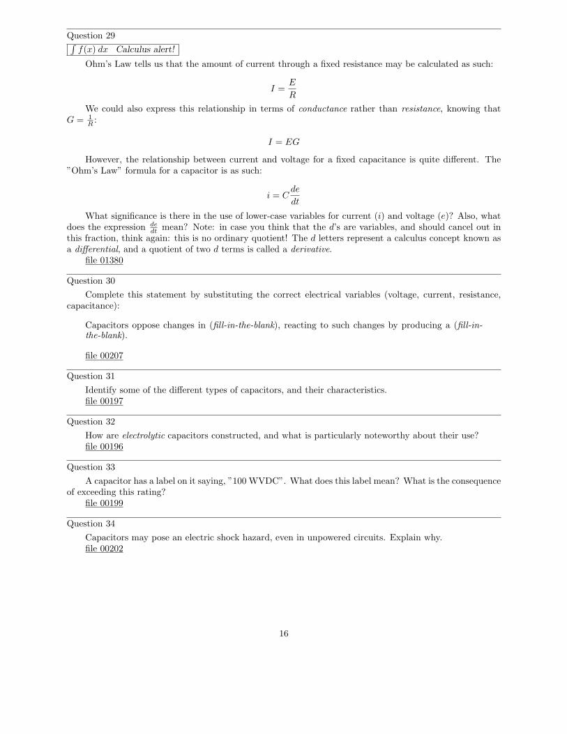
Question 28
Suppose a capacitor is connected directly to an adjustable-voltage source, and the voltage of that sourceis steadily increased over time. We know that an increasing voltage across a capacitor will produce an electricfield of increasing strength. Does this increase in electric field constitute an accumulation of energy in thecapacitor, or a release of energy from the capacitor? In this scenario, does the capacitor act as a load or asa source of electrical energy?
Voltage increasing
Now, suppose the adjustable voltage source is steadily decreased over time. We know this will resultin an electric field of decreasing strength in the capacitor. Does this decrease in electric field constitute anaccumulation of energy in the capacitor, or a release of energy from the capacitor? In this scenario, does thecapacitor act as a load or as a source of electrical energy?
Voltage decreasing
For each of these scenarios, label the direction of current in the circuit.file 00190
15
Question 29∫
f(x) dx Calculus alert!
Ohm’s Law tells us that the amount of current through a fixed resistance may be calculated as such:
I =E
R
We could also express this relationship in terms of conductance rather than resistance, knowing thatG = 1
R:
I = EG
However, the relationship between current and voltage for a fixed capacitance is quite different. The”Ohm’s Law” formula for a capacitor is as such:
i = Cde
dt
What significance is there in the use of lower-case variables for current (i) and voltage (e)? Also, whatdoes the expression de
dtmean? Note: in case you think that the d’s are variables, and should cancel out in
this fraction, think again: this is no ordinary quotient! The d letters represent a calculus concept known asa differential, and a quotient of two d terms is called a derivative.
file 01380
Question 30
Complete this statement by substituting the correct electrical variables (voltage, current, resistance,capacitance):
Capacitors oppose changes in (fill-in-the-blank), reacting to such changes by producing a (fill-in-the-blank).
file 00207
Question 31
Identify some of the different types of capacitors, and their characteristics.file 00197
Question 32
How are electrolytic capacitors constructed, and what is particularly noteworthy about their use?file 00196
Question 33
A capacitor has a label on it saying, ”100 WVDC”. What does this label mean? What is the consequenceof exceeding this rating?
file 00199
Question 34
Capacitors may pose an electric shock hazard, even in unpowered circuits. Explain why.file 00202
16
Question 35
A 470 µF capacitor is subjected to an applied voltage that changes at a rate of 200 volts per second.How much current will there be ”through” this capacitor?
Explain why I placed quotation marks around the word ”through” in the previous sentence. Why can’tthis word be used in its fullest sense when describing electric current in a capacitor circuit?
file 00194
Question 36
Two 470 µF capacitors connected in series are subjected to a total applied voltage that changes at arate of 200 volts per second. How much current will there be ”through” these capacitors? Hint: the totalvoltage is divided evenly between the two capacitors.
Now suppose that two 470 µF capacitors connected in parallel are subjected to the same total appliedvoltage (changing at a rate of 200 volts per second). How much total current will there be ”through” thesecapacitors?
file 00201
Question 37
Suppose two 33 µF capacitors are connected in series with each other. What will their combinedcapacitance be, in Farads? Explain your answer.
file 00198
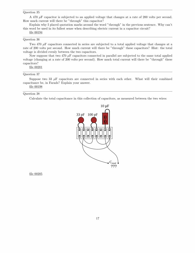
Question 38
Calculate the total capacitance in this collection of capacitors, as measured between the two wires:
--
Ctotal
???
33 pF 100 pF
10 µF
file 00205
17
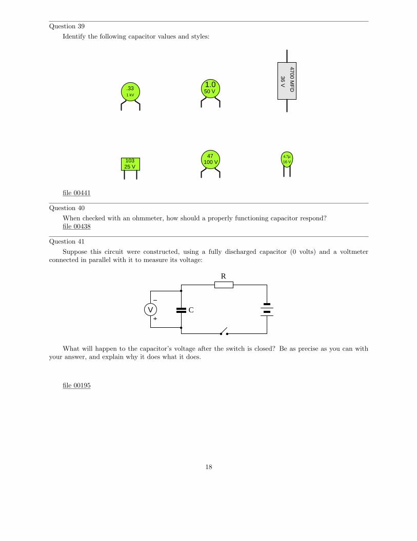
Question 39
Identify the following capacitor values and styles:
4700 MF
D
36 V
25 V103
4.7µ16 V
.331 kV
1.050 V
47100 V
file 00441
Question 40
When checked with an ohmmeter, how should a properly functioning capacitor respond?file 00438
Question 41
Suppose this circuit were constructed, using a fully discharged capacitor (0 volts) and a voltmeterconnected in parallel with it to measure its voltage:
R
CV
What will happen to the capacitor’s voltage after the switch is closed? Be as precise as you can withyour answer, and explain why it does what it does.
file 00195
18
Question 42
Suppose this circuit were constructed, using an inductor and an ammeter connected in series with it tomeasure its current:
A-
+
L
R
What will happen to the inductor’s current after the switch is closed? Be as precise as you can withyour answer, and explain why it does what it does.
file 00377
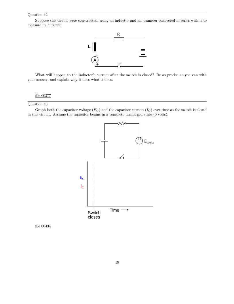
Question 43
Graph both the capacitor voltage (EC) and the capacitor current (IC) over time as the switch is closedin this circuit. Assume the capacitor begins in a complete uncharged state (0 volts):
Time
EC
IC
Switchcloses
+− Esource
file 00434
19
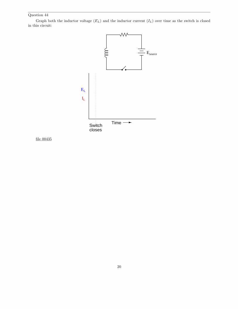
Question 44
Graph both the inductor voltage (EL) and the inductor current (IL) over time as the switch is closedin this circuit:
TimeSwitchcloses
EL
IL
Esource
file 00435
20
Question 45
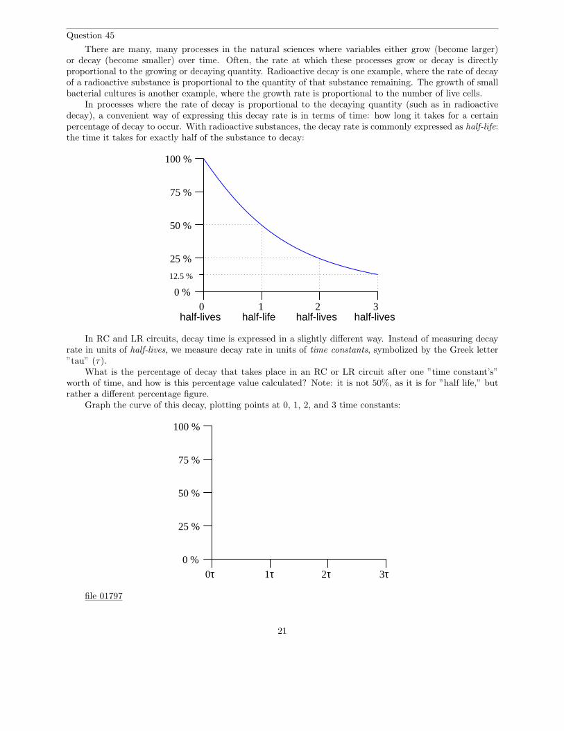
There are many, many processes in the natural sciences where variables either grow (become larger)or decay (become smaller) over time. Often, the rate at which these processes grow or decay is directlyproportional to the growing or decaying quantity. Radioactive decay is one example, where the rate of decayof a radioactive substance is proportional to the quantity of that substance remaining. The growth of smallbacterial cultures is another example, where the growth rate is proportional to the number of live cells.
In processes where the rate of decay is proportional to the decaying quantity (such as in radioactivedecay), a convenient way of expressing this decay rate is in terms of time: how long it takes for a certainpercentage of decay to occur. With radioactive substances, the decay rate is commonly expressed as half-life:the time it takes for exactly half of the substance to decay:
0 %
25 %
50 %
75 %
100 %
0half-lives
1half-life
2 3half-lives half-lives
12.5 %
In RC and LR circuits, decay time is expressed in a slightly different way. Instead of measuring decayrate in units of half-lives, we measure decay rate in units of time constants, symbolized by the Greek letter”tau” (τ).
What is the percentage of decay that takes place in an RC or LR circuit after one ”time constant’s”worth of time, and how is this percentage value calculated? Note: it is not 50%, as it is for ”half life,” butrather a different percentage figure.
Graph the curve of this decay, plotting points at 0, 1, 2, and 3 time constants:
0 %
25 %
50 %
75 %
100 %
1τ 2τ 3τ0τ
file 01797
21
Question 46
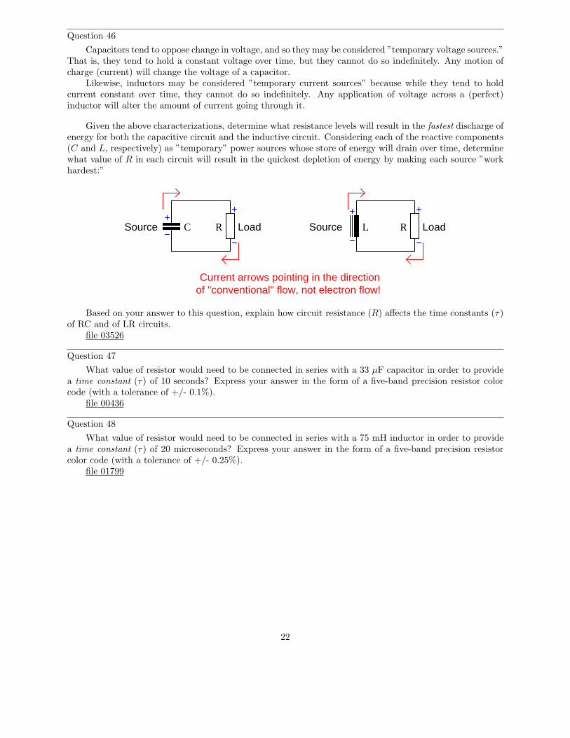
Capacitors tend to oppose change in voltage, and so they may be considered ”temporary voltage sources.”That is, they tend to hold a constant voltage over time, but they cannot do so indefinitely. Any motion ofcharge (current) will change the voltage of a capacitor.
Likewise, inductors may be considered ”temporary current sources” because while they tend to holdcurrent constant over time, they cannot do so indefinitely. Any application of voltage across a (perfect)inductor will alter the amount of current going through it.
Given the above characterizations, determine what resistance levels will result in the fastest discharge ofenergy for both the capacitive circuit and the inductive circuit. Considering each of the reactive components(C and L, respectively) as ”temporary” power sources whose store of energy will drain over time, determinewhat value of R in each circuit will result in the quickest depletion of energy by making each source ”workhardest:”
Source LoadC R Source LoadRL
Current arrows pointing in the directionof "conventional" flow, not electron flow!
Based on your answer to this question, explain how circuit resistance (R) affects the time constants (τ)of RC and of LR circuits.
file 03526
Question 47
What value of resistor would need to be connected in series with a 33 µF capacitor in order to providea time constant (τ) of 10 seconds? Express your answer in the form of a five-band precision resistor colorcode (with a tolerance of +/- 0.1%).
file 00436
Question 48
What value of resistor would need to be connected in series with a 75 mH inductor in order to providea time constant (τ) of 20 microseconds? Express your answer in the form of a five-band precision resistorcolor code (with a tolerance of +/- 0.25%).
file 01799
22
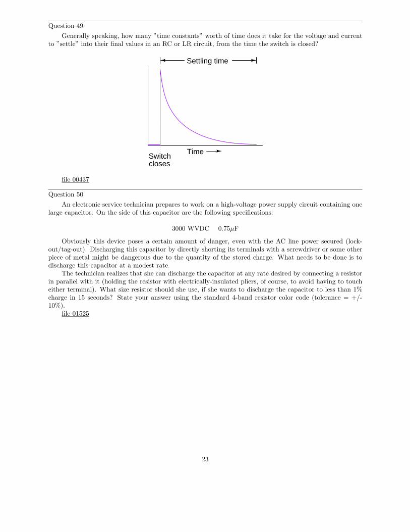
Question 49
Generally speaking, how many ”time constants” worth of time does it take for the voltage and currentto ”settle” into their final values in an RC or LR circuit, from the time the switch is closed?
TimeSwitchcloses
Settling time
file 00437
Question 50
An electronic service technician prepares to work on a high-voltage power supply circuit containing onelarge capacitor. On the side of this capacitor are the following specifications:
3000 WVDC 0.75µF
Obviously this device poses a certain amount of danger, even with the AC line power secured (lock-out/tag-out). Discharging this capacitor by directly shorting its terminals with a screwdriver or some otherpiece of metal might be dangerous due to the quantity of the stored charge. What needs to be done is todischarge this capacitor at a modest rate.
The technician realizes that she can discharge the capacitor at any rate desired by connecting a resistorin parallel with it (holding the resistor with electrically-insulated pliers, of course, to avoid having to toucheither terminal). What size resistor should she use, if she wants to discharge the capacitor to less than 1%charge in 15 seconds? State your answer using the standard 4-band resistor color code (tolerance = +/-10%).
file 01525
23
Question 51
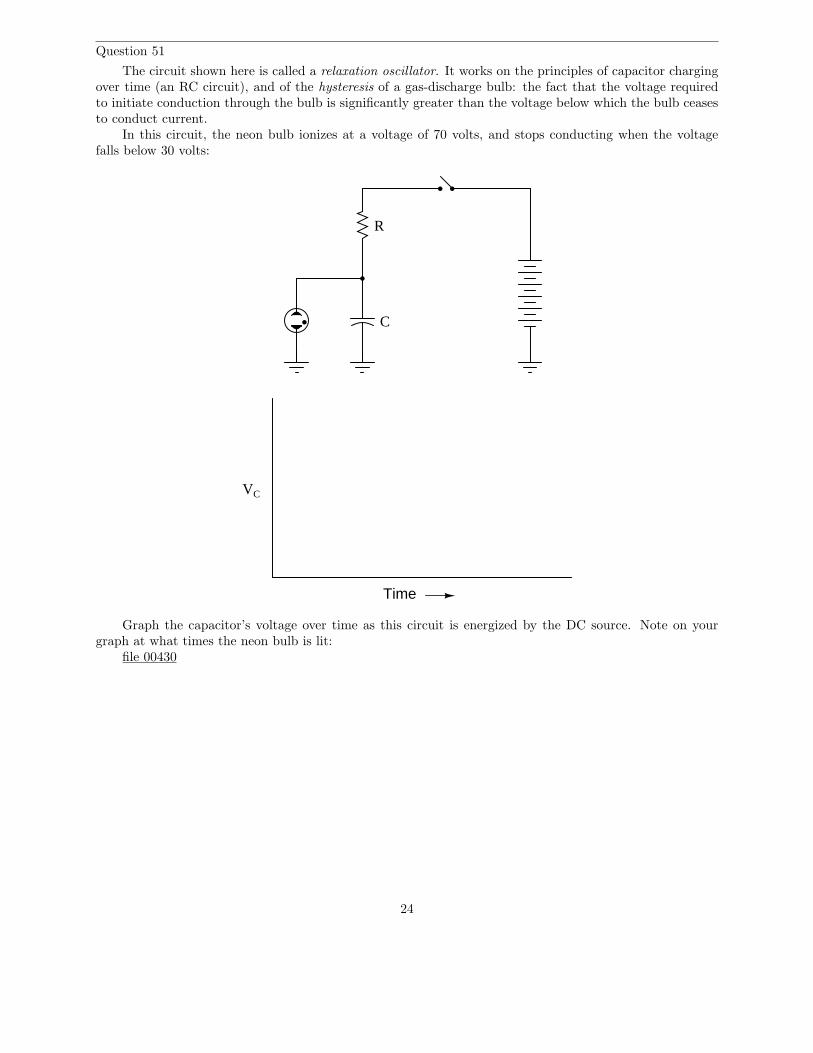
The circuit shown here is called a relaxation oscillator. It works on the principles of capacitor chargingover time (an RC circuit), and of the hysteresis of a gas-discharge bulb: the fact that the voltage requiredto initiate conduction through the bulb is significantly greater than the voltage below which the bulb ceasesto conduct current.
In this circuit, the neon bulb ionizes at a voltage of 70 volts, and stops conducting when the voltagefalls below 30 volts:
Time
VC
C
R
Graph the capacitor’s voltage over time as this circuit is energized by the DC source. Note on yourgraph at what times the neon bulb is lit:
file 00430
24
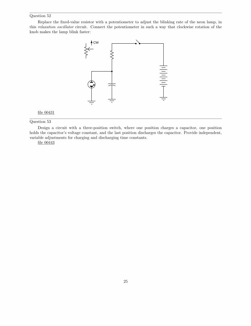
Question 52
Replace the fixed-value resistor with a potentiometer to adjust the blinking rate of the neon lamp, inthis relaxation oscillator circuit. Connect the potentiometer in such a way that clockwise rotation of theknob makes the lamp blink faster:
CW
file 00431
Question 53
Design a circuit with a three-position switch, where one position charges a capacitor, one positionholds the capacitor’s voltage constant, and the last position discharges the capacitor. Provide independent,variable adjustments for charging and discharging time constants.
file 00443
25
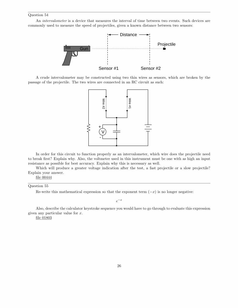
Question 54
An intervalometer is a device that measures the interval of time between two events. Such devices arecommonly used to measure the speed of projectiles, given a known distance between two sensors:
Sensor #1 Sensor #2
Distance
ProjectileGun
A crude intervalometer may be constructed using two thin wires as sensors, which are broken by thepassage of the projectile. The two wires are connected in an RC circuit as such:
Wire #1
Wire #2
+V
-
In order for this circuit to function properly as an intervalometer, which wire does the projectile needto break first? Explain why. Also, the voltmeter used in this instrument must be one with as high an inputresistance as possible for best accuracy. Explain why this is necessary as well.
Which will produce a greater voltage indication after the test, a fast projectile or a slow projectile?Explain your answer.
file 00444
Question 55
Re-write this mathematical expression so that the exponent term (−x) is no longer negative:
e−x
Also, describe the calculator keystroke sequence you would have to go through to evaluate this expressiongiven any particular value for x.
file 01803
26
Question 56
At a party, you happen to notice a mathematician taking notes while looking over the food table whereseveral pizzas are set. Walking up to her, you ask what she is doing. ”I’m mathematically modeling theconsumption of pizza,” she tells you. Before you have the chance to ask another question, she sets hernotepad down on the table and excuses herself to go use the bathroom.
Looking at the notepad, you see the following equation:
Percentage =(
e−t
6.1
)
× 100%
Where,t = Time in minutes since arrival of pizza.
The problem is, you don’t know whether the equation she wrote describes the percentage of pizza eatenor the percentage of pizza remaining on the table. Explain how you would determine which percentage thisequation describes. How, exactly, can you tell if this equation describes the amount of pizza already eatenor the amount of pizza that remains to be eaten?
file 03549
27
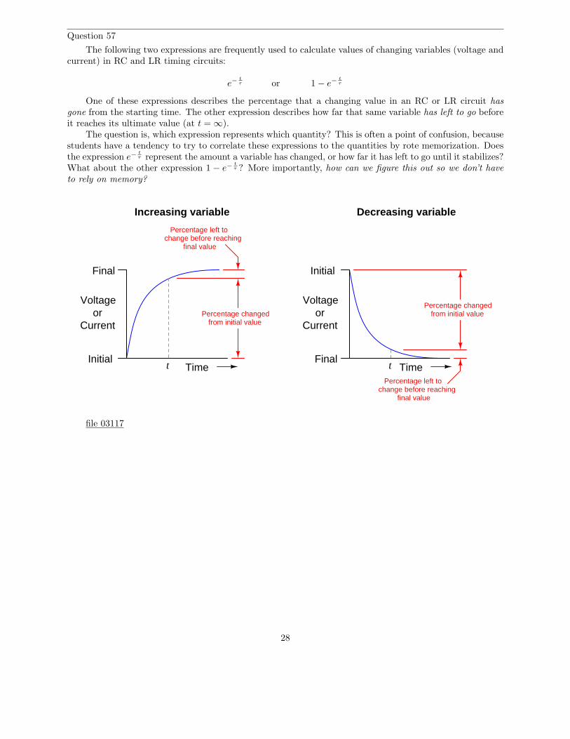
Question 57
The following two expressions are frequently used to calculate values of changing variables (voltage andcurrent) in RC and LR timing circuits:
e−t
τ or 1 − e−t
τ
One of these expressions describes the percentage that a changing value in an RC or LR circuit hasgone from the starting time. The other expression describes how far that same variable has left to go beforeit reaches its ultimate value (at t = ∞).
The question is, which expression represents which quantity? This is often a point of confusion, becausestudents have a tendency to try to correlate these expressions to the quantities by rote memorization. Doesthe expression e−
t
τ represent the amount a variable has changed, or how far it has left to go until it stabilizes?What about the other expression 1 − e−
t
τ ? More importantly, how can we figure this out so we don’t haveto rely on memory?
TimeInitial
Final
t
Voltageor
CurrentPercentage changed
from initial value
Percentage left tochange before reaching
final value
TimeFinal
t
Voltageor
Current
Percentage changedfrom initial value
Percentage left tochange before reaching
final value
Initial
Increasing variable Decreasing variable
file 03117
28
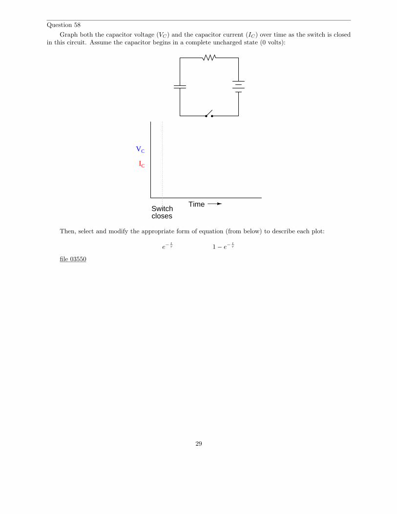
Question 58
Graph both the capacitor voltage (VC) and the capacitor current (IC) over time as the switch is closedin this circuit. Assume the capacitor begins in a complete uncharged state (0 volts):
Time
IC
Switchcloses
VC
Then, select and modify the appropriate form of equation (from below) to describe each plot:
e−t
τ 1 − e−t
τ
file 03550
29
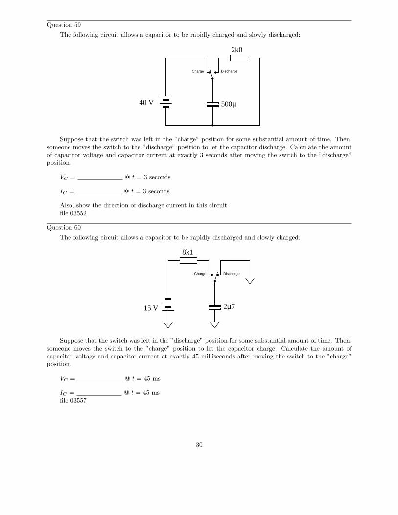
Question 59
The following circuit allows a capacitor to be rapidly charged and slowly discharged:
40 V
Charge Discharge
500µ
2k0
Suppose that the switch was left in the ”charge” position for some substantial amount of time. Then,someone moves the switch to the ”discharge” position to let the capacitor discharge. Calculate the amountof capacitor voltage and capacitor current at exactly 3 seconds after moving the switch to the ”discharge”position.
VC = @ t = 3 seconds
IC = @ t = 3 seconds
Also, show the direction of discharge current in this circuit.file 03552
Question 60
The following circuit allows a capacitor to be rapidly discharged and slowly charged:
Charge Discharge
15 V 2µ7
8k1
Suppose that the switch was left in the ”discharge” position for some substantial amount of time. Then,someone moves the switch to the ”charge” position to let the capacitor charge. Calculate the amount ofcapacitor voltage and capacitor current at exactly 45 milliseconds after moving the switch to the ”charge”position.
VC = @ t = 45 ms
IC = @ t = 45 msfile 03557
30
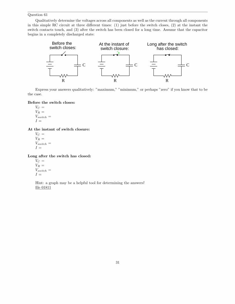
Question 61
Qualitatively determine the voltages across all components as well as the current through all componentsin this simple RC circuit at three different times: (1) just before the switch closes, (2) at the instant theswitch contacts touch, and (3) after the switch has been closed for a long time. Assume that the capacitorbegins in a completely discharged state:
R
C
R
C
switch closes:Before the At the instant of
switch closure:
R
C
has closed:Long after the switch
Express your answers qualitatively: ”maximum,” ”minimum,” or perhaps ”zero” if you know that to bethe case.
Before the switch closes:VC =VR =Vswitch =I =
At the instant of switch closure:VC =VR =Vswitch =I =
Long after the switch has closed:VC =VR =Vswitch =I =
Hint: a graph may be a helpful tool for determining the answers!file 01811
31
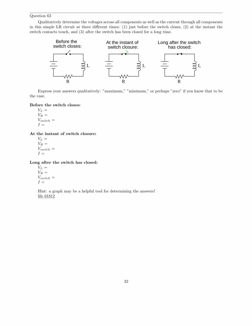
Question 62
Qualitatively determine the voltages across all components as well as the current through all componentsin this simple LR circuit at three different times: (1) just before the switch closes, (2) at the instant theswitch contacts touch, and (3) after the switch has been closed for a long time.
R R
switch closes:Before the At the instant of
switch closure:
R
has closed:Long after the switch
LLL
Express your answers qualitatively: ”maximum,” ”minimum,” or perhaps ”zero” if you know that to bethe case.
Before the switch closes:VL =VR =Vswitch =I =
At the instant of switch closure:VL =VR =Vswitch =I =
Long after the switch has closed:VL =VR =Vswitch =I =
Hint: a graph may be a helpful tool for determining the answers!file 01812
32
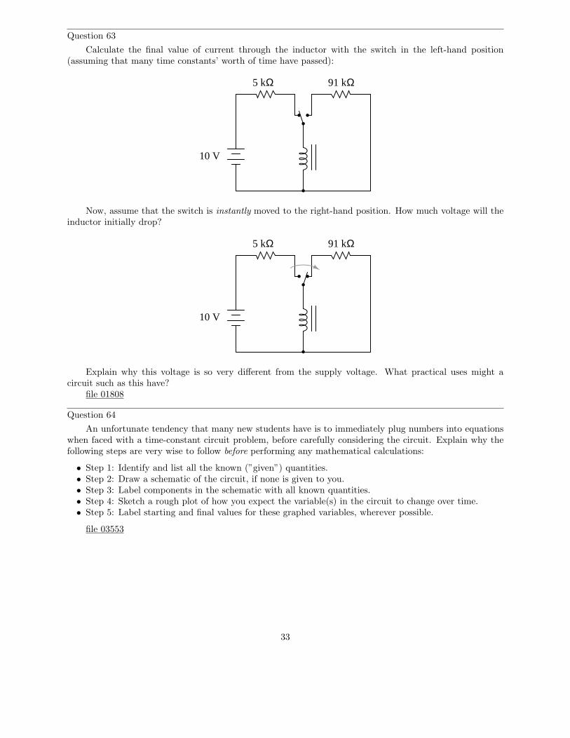
Question 63
Calculate the final value of current through the inductor with the switch in the left-hand position(assuming that many time constants’ worth of time have passed):
10 V
5 kΩ 91 kΩ
Now, assume that the switch is instantly moved to the right-hand position. How much voltage will theinductor initially drop?
10 V
5 kΩ 91 kΩ
Explain why this voltage is so very different from the supply voltage. What practical uses might acircuit such as this have?
file 01808
Question 64
An unfortunate tendency that many new students have is to immediately plug numbers into equationswhen faced with a time-constant circuit problem, before carefully considering the circuit. Explain why thefollowing steps are very wise to follow before performing any mathematical calculations:
• Step 1: Identify and list all the known (”given”) quantities.• Step 2: Draw a schematic of the circuit, if none is given to you.• Step 3: Label components in the schematic with all known quantities.• Step 4: Sketch a rough plot of how you expect the variable(s) in the circuit to change over time.• Step 5: Label starting and final values for these graphed variables, wherever possible.
file 03553
33
Question 65
Suppose a capacitor is charged to a voltage of exactly 100 volts, then connected to a resistor so itdischarges slowly. Calculate the amount of voltage remaining across the capacitor terminals at the followingpoints in time:
• 1 time constant (τ) after connecting the resistor:• 2 time constants (2τ) after connecting the resistor:• 3 time constants (3τ) after connecting the resistor:• 4 time constants (4τ) after connecting the resistor:• 5 time constants (5τ) after connecting the resistor:
file 03551
Question 66
Calculate the voltage across a 470 µF capacitor after discharging through a 10 kΩ resistor for 9 seconds,if the capacitor’s original voltage (at t = 0) was 24 volts.
Also, express this amount of time (9 seconds) in terms of how many time constants have elapsed.file 00452
Question 67
Calculate the current through a 250 mH inductor after ”charging” through a series-connected resistorwith 100 Ω of resistance for 6 milliseconds, powered by a 12 volt battery. Assume that the inductor is perfect,with no internal resistance.
Also, express this amount of time (6 milliseconds) in terms of how many time constants have elapsed.file 00453
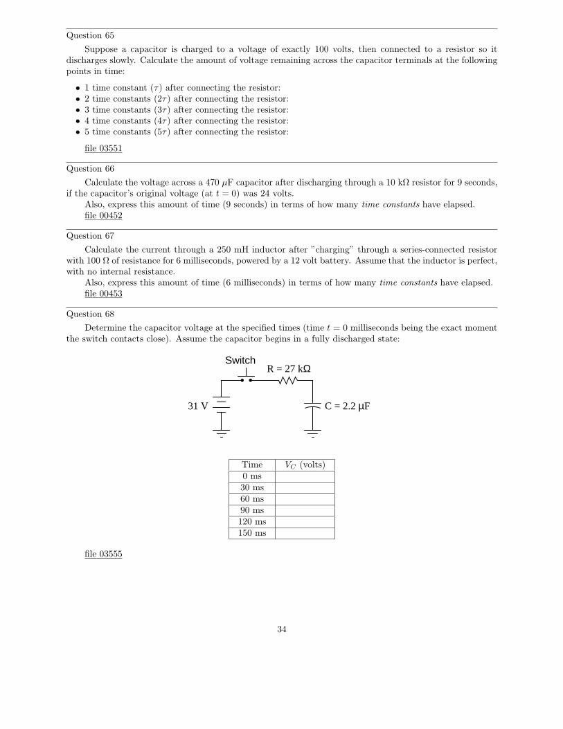
Question 68
Determine the capacitor voltage at the specified times (time t = 0 milliseconds being the exact momentthe switch contacts close). Assume the capacitor begins in a fully discharged state:
Switch
31 V
R = 27 kΩ
C = 2.2 µF
Time VC (volts)0 ms30 ms60 ms90 ms120 ms150 ms
file 03555
34
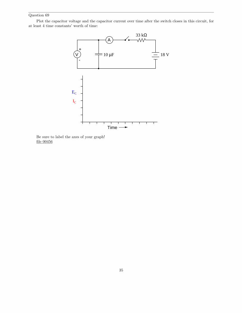
Question 69
Plot the capacitor voltage and the capacitor current over time after the switch closes in this circuit, forat least 4 time constants’ worth of time:
+V
-
A
10 µF
33 kΩ
18 V
EC
IC
Time
Be sure to label the axes of your graph!file 00456
35
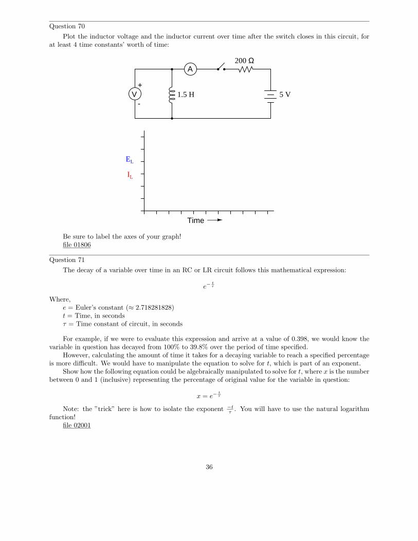
Question 70
Plot the inductor voltage and the inductor current over time after the switch closes in this circuit, forat least 4 time constants’ worth of time:
+V
-
A
Time
1.5 H
200 Ω
5 V
EL
IL
Be sure to label the axes of your graph!file 01806
Question 71
The decay of a variable over time in an RC or LR circuit follows this mathematical expression:
e−t
τ
Where,e = Euler’s constant (≈ 2.718281828)t = Time, in secondsτ = Time constant of circuit, in seconds
For example, if we were to evaluate this expression and arrive at a value of 0.398, we would know thevariable in question has decayed from 100% to 39.8% over the period of time specified.
However, calculating the amount of time it takes for a decaying variable to reach a specified percentageis more difficult. We would have to manipulate the equation to solve for t, which is part of an exponent.
Show how the following equation could be algebraically manipulated to solve for t, where x is the numberbetween 0 and 1 (inclusive) representing the percentage of original value for the variable in question:
x = e−t
τ
Note: the ”trick” here is how to isolate the exponent −tτ
. You will have to use the natural logarithmfunction!
file 02001
36
Question 72
Calculate the amount of time it takes for a 33 µF capacitor to charge from 0 volts to 20 volts, if poweredby a 24 volt battery through a 10 kΩ resistor.
file 01814
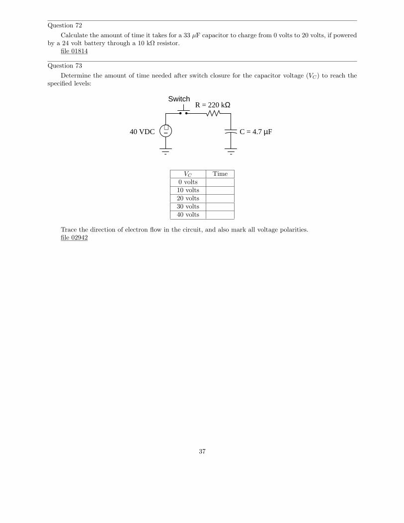
Question 73
Determine the amount of time needed after switch closure for the capacitor voltage (VC) to reach thespecified levels:
40 VDC C = 4.7 µF
R = 220 kΩSwitch
+−
VC Time0 volts10 volts20 volts30 volts40 volts
Trace the direction of electron flow in the circuit, and also mark all voltage polarities.file 02942
37
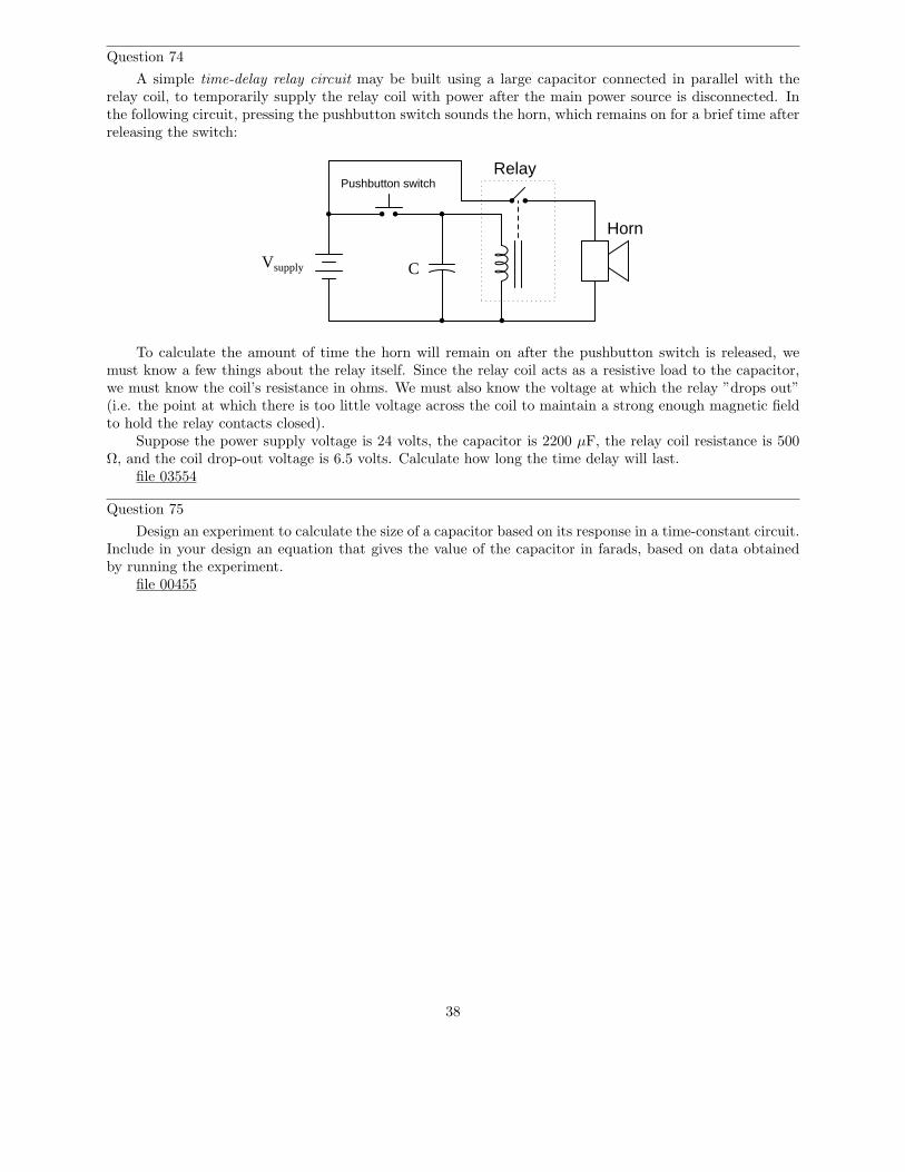
Question 74
A simple time-delay relay circuit may be built using a large capacitor connected in parallel with therelay coil, to temporarily supply the relay coil with power after the main power source is disconnected. Inthe following circuit, pressing the pushbutton switch sounds the horn, which remains on for a brief time afterreleasing the switch:
Vsupply
Pushbutton switchRelay
Horn
C
To calculate the amount of time the horn will remain on after the pushbutton switch is released, wemust know a few things about the relay itself. Since the relay coil acts as a resistive load to the capacitor,we must know the coil’s resistance in ohms. We must also know the voltage at which the relay ”drops out”(i.e. the point at which there is too little voltage across the coil to maintain a strong enough magnetic fieldto hold the relay contacts closed).
Suppose the power supply voltage is 24 volts, the capacitor is 2200 µF, the relay coil resistance is 500Ω, and the coil drop-out voltage is 6.5 volts. Calculate how long the time delay will last.
file 03554
Question 75
Design an experiment to calculate the size of a capacitor based on its response in a time-constant circuit.Include in your design an equation that gives the value of the capacitor in farads, based on data obtainedby running the experiment.
file 00455
38
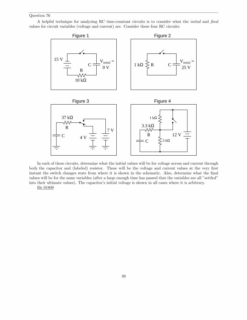
Question 76
A helpful technique for analyzing RC time-constant circuits is to consider what the initial and finalvalues for circuit variables (voltage and current) are. Consider these four RC circuits:
Figure 1 Figure 2
15 V
10 kΩ
Vinitial =
0 V
Vinitial =1 kΩ
25 V
Figure 4Figure 3
3.3 kΩ
5 kΩ
1 kΩ
12 V4 V
7 V
37 kΩ
C C
CC
RR
R
R
In each of these circuits, determine what the initial values will be for voltage across and current throughboth the capacitor and (labeled) resistor. These will be the voltage and current values at the very firstinstant the switch changes state from where it is shown in the schematic. Also, determine what the finalvalues will be for the same variables (after a large enough time has passed that the variables are all ”settled”into their ultimate values). The capacitor’s initial voltage is shown in all cases where it is arbitrary.
file 01809
39
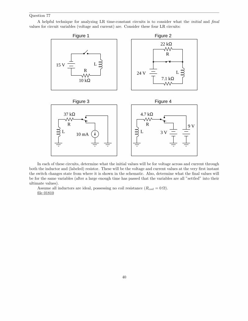
Question 77
A helpful technique for analyzing LR time-constant circuits is to consider what the initial and finalvalues for circuit variables (voltage and current) are. Consider these four LR circuits:
Figure 1 Figure 2
15 V
10 kΩ
Figure 4Figure 3
37 kΩ
R
R
L
R
L24 V7.1 kΩ
10 mAL
22 kΩ
R
L 3 V
9 V
4.7 kΩ
In each of these circuits, determine what the initial values will be for voltage across and current throughboth the inductor and (labeled) resistor. These will be the voltage and current values at the very first instantthe switch changes state from where it is shown in the schematic. Also, determine what the final values willbe for the same variables (after a large enough time has passed that the variables are all ”settled” into theirultimate values).
Assume all inductors are ideal, possessing no coil resistance (Rcoil = 0 Ω).file 01810
40
Question 78
A formula I like to use in calculating voltage and current values in either RC or LR circuits has twoforms, one for voltage and one for current:
V (t) = (Vf − V0)
(
1 −1
et
τ
)
+ V0 (for calculating voltage)
I(t) = (If − I0)
(
1 −1
et
τ
)
+ I0 (for calculating current)
The ”0” subscript represents the condition at time = 0 (V0 or I0, respectively), representing the ”initial”value of that variable. The ”f” subscript represents the ”final” or ”ultimate” value that the voltage or currentwould achieve if allowed to progress indefinitely. Obviously, one must know how to determine the ”initial”and ”final” values in order to use either of these formulae, but once you do you will be able to calculate anyvoltage and any current at any time in either an RC or LR circuit.
What is not so obvious to students is how each formula works. Specifically, what does each portion of itrepresent, in practical terms? This is your task: to describe what each term of the equation means in yourown words. I will list the ”voltage” formula terms individually for you to define:
V (t) =
(Vf − V0) =
(
1 −1
et
τ
)
=
file 01813
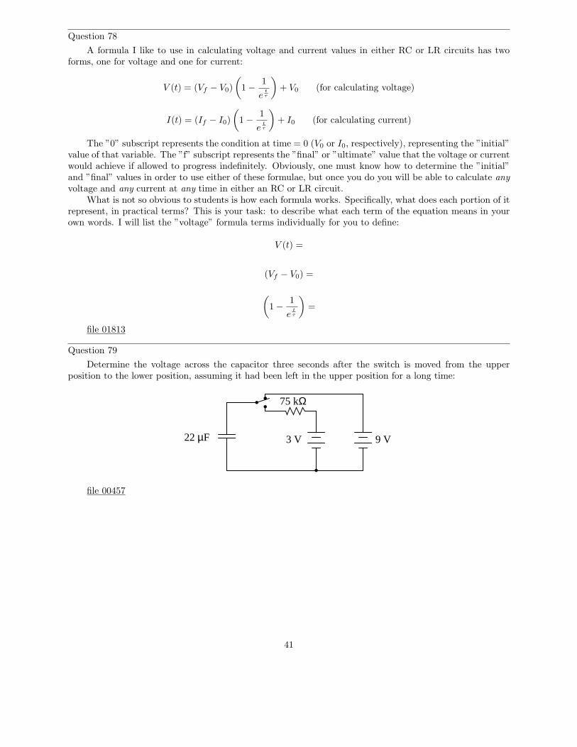
Question 79
Determine the voltage across the capacitor three seconds after the switch is moved from the upperposition to the lower position, assuming it had been left in the upper position for a long time:
22 µF
75 kΩ
3 V 9 V
file 00457
41
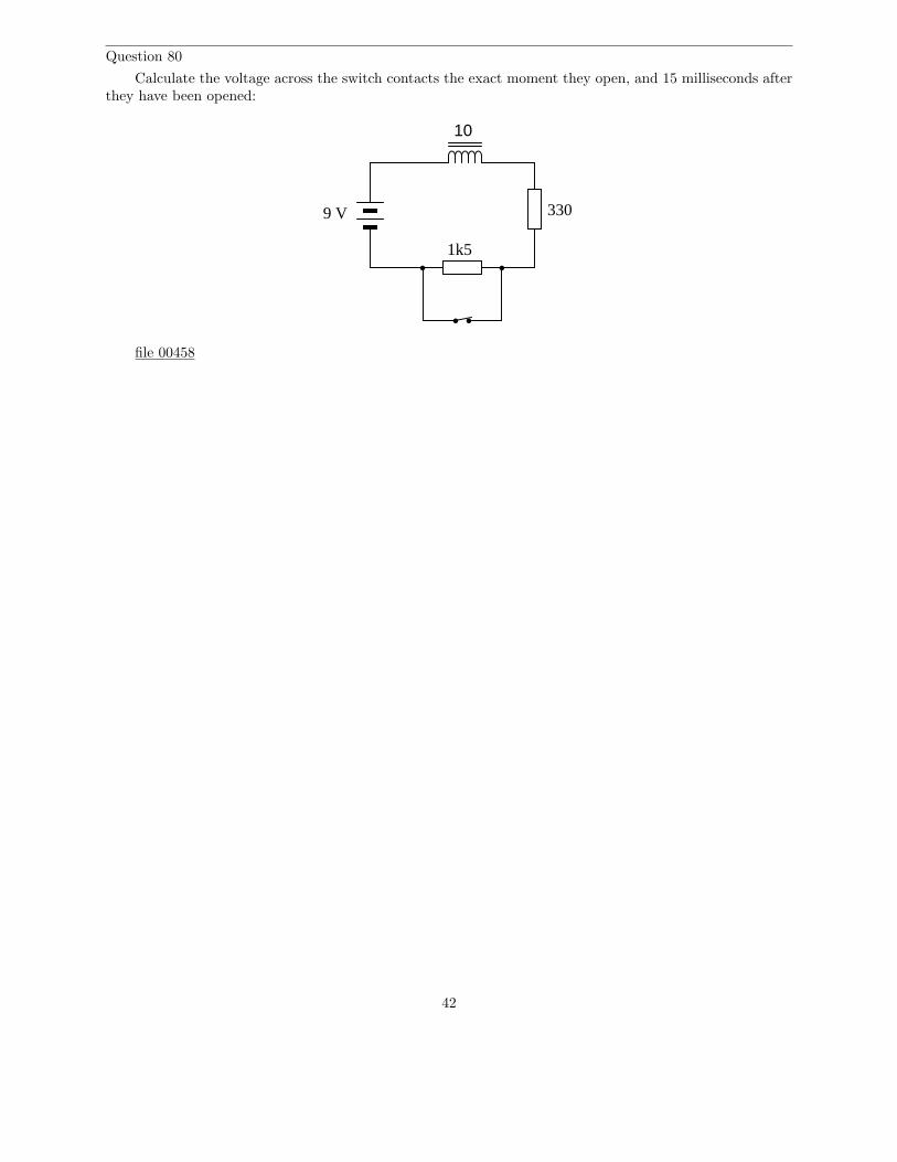
Question 80
Calculate the voltage across the switch contacts the exact moment they open, and 15 milliseconds afterthey have been opened:
9 V
1k5
10
330
file 00458
42
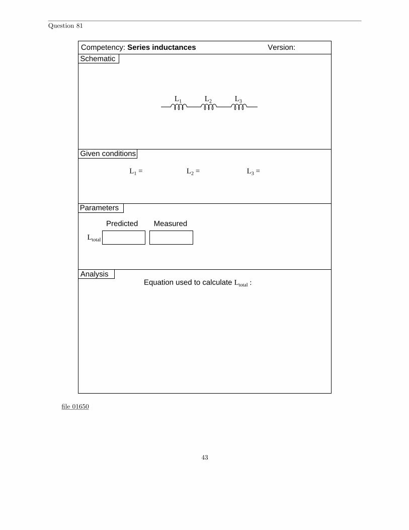
Question 81
Given conditions
Predicted Measured
Version:
Schematic
Parameters
Competency: Series inductances
L1 L2 L3
L1 = L2 = L3 =
Ltotal
AnalysisEquation used to calculate Ltotal :
file 01650
43
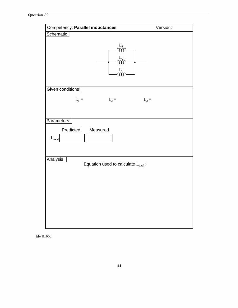
Question 82
Given conditions
Predicted Measured
Version:
Schematic
Parameters
L1
L2
L3
L1 = L2 = L3 =
Ltotal
Competency: Parallel inductances
AnalysisEquation used to calculate Ltotal :
file 01651
44
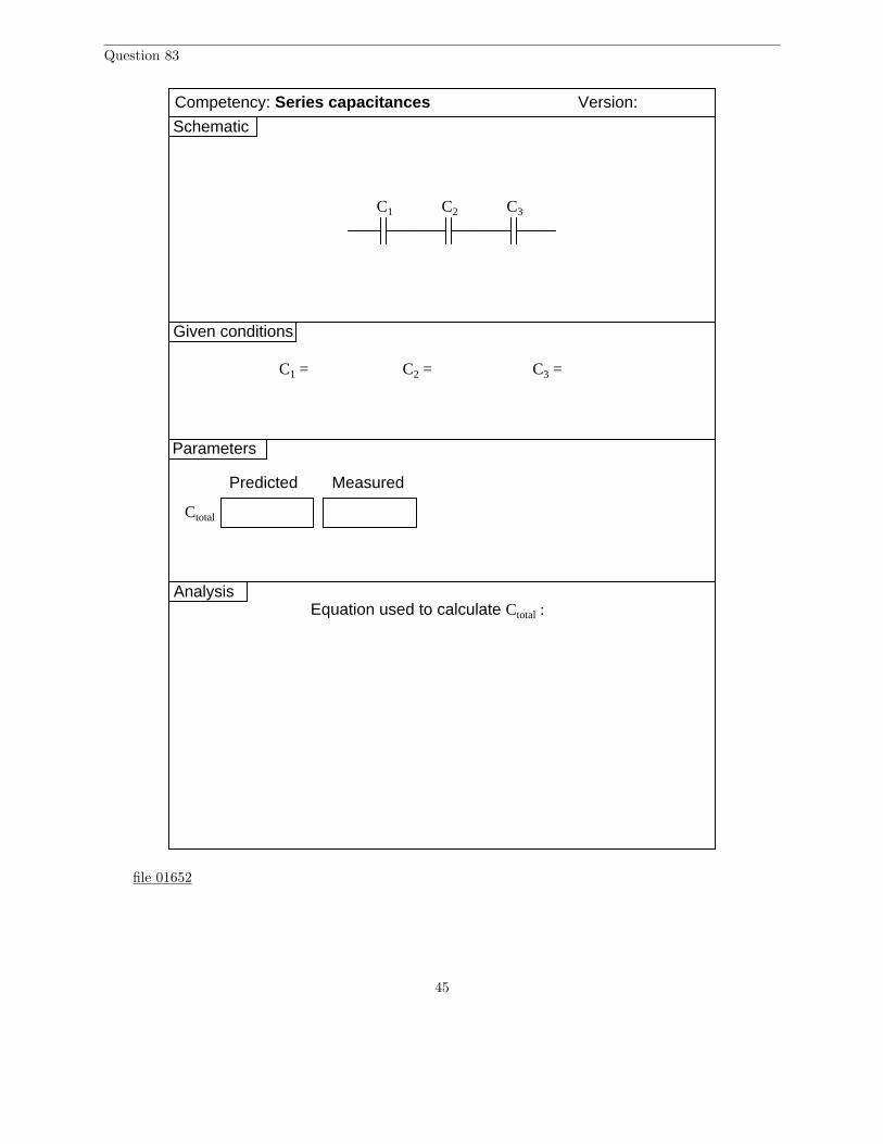
Question 83
Given conditions
Predicted Measured
Version:
Schematic
Parameters
C1 C2 C3
C1 = C2 = C3 =
Competency: Series capacitances
Ctotal
AnalysisEquation used to calculate Ctotal :
file 01652
45
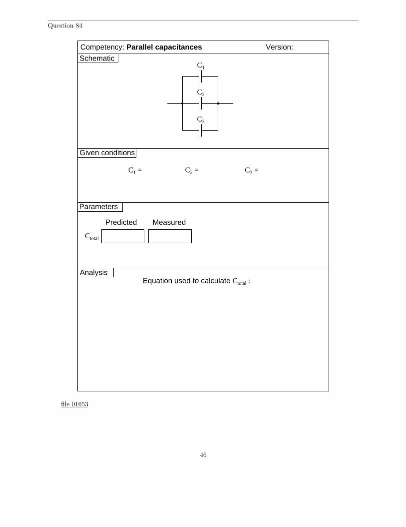
Question 84
Given conditions
Predicted Measured
Version:
Schematic
Parameters
C1
C2
C3
C1 = C2 = C3 =
Ctotal
Competency: Parallel capacitances
AnalysisEquation used to calculate Ctotal :
file 01653
46
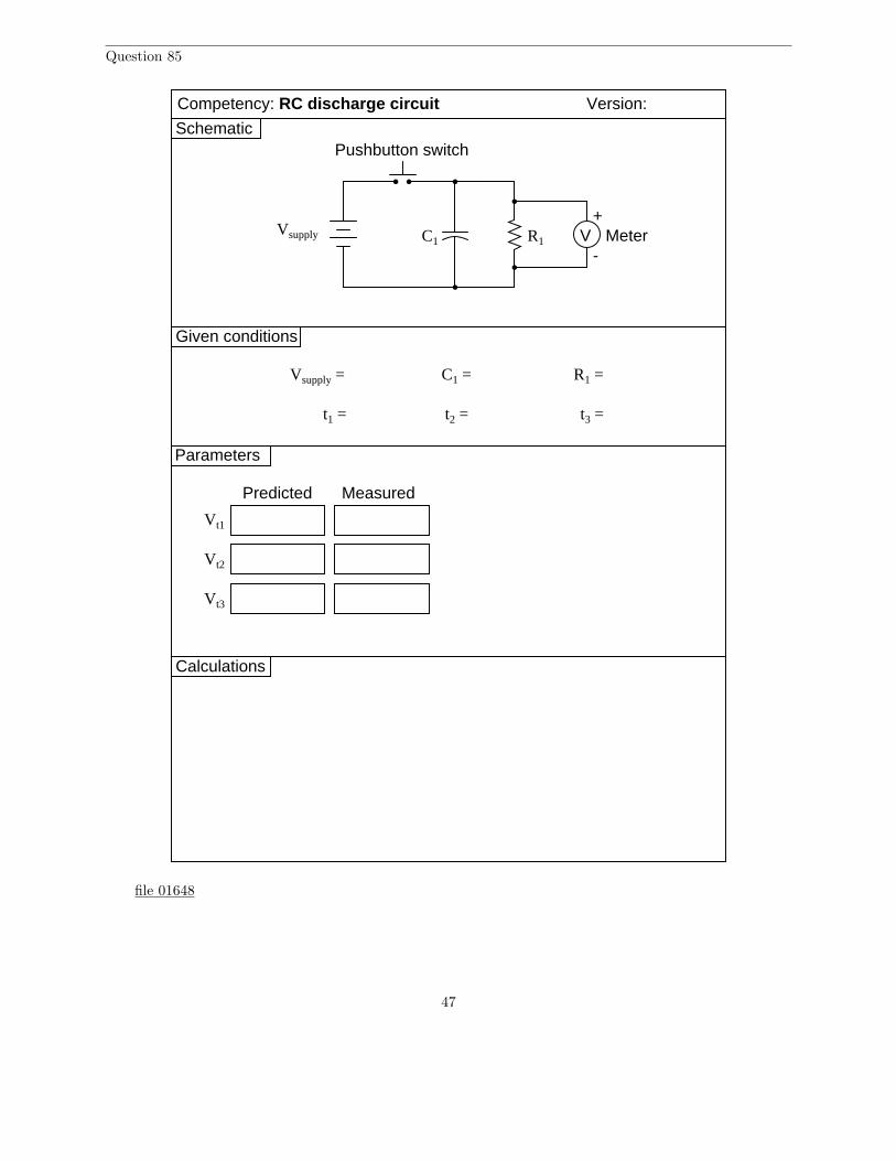
Question 85
Given conditions
Version:
Schematic
Parameters
Predicted
Vsupply
Vsupply =
C1
C1 =
Measured
R1
R1 =
Vt1
Vt2
Vt3
t1 = t2 = t3 =
Competency: RC discharge circuit
+V
-Meter
Pushbutton switch
Calculations
file 01648
47
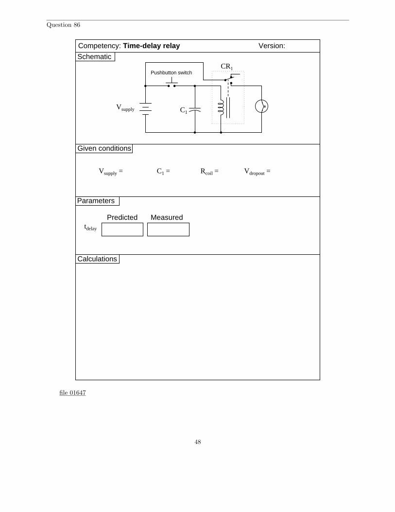
Question 86
Given conditions
Version:
Schematic
Parameters
Predicted
Vsupply
Vsupply =
Competency: Time-delay relay
C1
CR1
C1 = Rcoil = Vdropout =
Measuredtdelay
Pushbutton switch
Calculations
file 01647
48
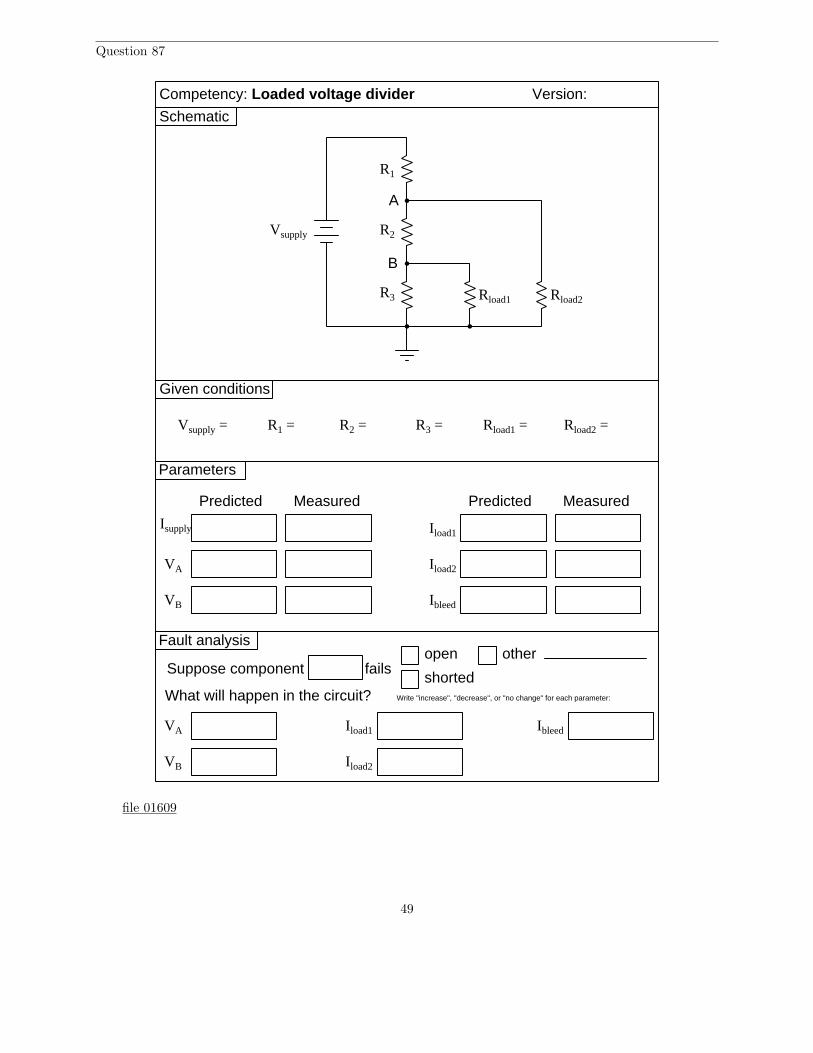
Question 87
R1
Given conditions
Vsupply = R1 =
Predicted Measured
Version:
Schematic
Parameters
R2
R3
R2 = R3 =
Isupply
Predicted Measured
Vsupply
Competency: Loaded voltage divider
Rload1 Rload2
Rload1 = Rload2 =
A
B
VA
VB
Iload1
Iload2
Ibleed
Fault analysis
Suppose component fails open
shorted
other
What will happen in the circuit? Write "increase", "decrease", or "no change" for each parameter:
VA
VB
Iload1
Iload2
Ibleed
file 01609
49

Question 88
Conclusions(i.e. What this tells me . . . )
Troubleshooting log
(i.e. What I did and/or noticed . . . )Actions / Measurements / Observations
file 03933
50
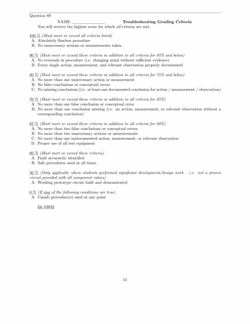
Question 89
NAME: Troubleshooting Grading CriteriaYou will receive the highest score for which all criteria are met.
100 % (Must meet or exceed all criteria listed)A. Absolutely flawless procedureB. No unnecessary actions or measurements taken
90 % (Must meet or exceed these criteria in addition to all criteria for 85% and below)A. No reversals in procedure (i.e. changing mind without sufficient evidence)B. Every single action, measurement, and relevant observation properly documented
80 % (Must meet or exceed these criteria in addition to all criteria for 75% and below)A. No more than one unnecessary action or measurementB. No false conclusions or conceptual errorsC. No missing conclusions (i.e. at least one documented conclusion for action / measurement / observation)
70 % (Must meet or exceed these criteria in addition to all criteria for 65%)A. No more than one false conclusion or conceptual errorB. No more than one conclusion missing (i.e. an action, measurement, or relevant observation without a
corresponding conclusion)
65 % (Must meet or exceed these criteria in addition to all criteria for 60%)A. No more than two false conclusions or conceptual errorsB. No more than two unnecessary actions or measurementsC. No more than one undocumented action, measurement, or relevant observationD. Proper use of all test equipment
60 % (Must meet or exceed these criteria)A. Fault accurately identifiedB. Safe procedures used at all times
50 % (Only applicable where students performed significant development/design work – i.e. not a provencircuit provided with all component values)A. Working prototype circuit built and demonstrated
0 % (If any of the following conditions are true)A. Unsafe procedure(s) used at any point
file 03932
51
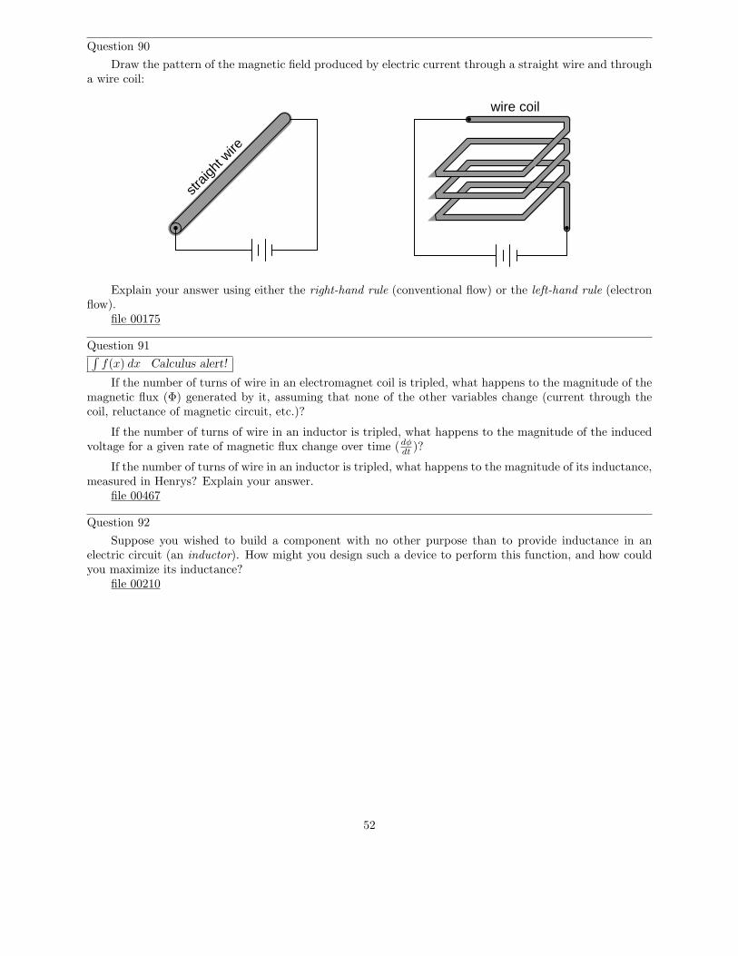
Question 90
Draw the pattern of the magnetic field produced by electric current through a straight wire and througha wire coil:
straig
ht w
ire
wire coil
Explain your answer using either the right-hand rule (conventional flow) or the left-hand rule (electronflow).
file 00175
Question 91∫
f(x) dx Calculus alert!
If the number of turns of wire in an electromagnet coil is tripled, what happens to the magnitude of themagnetic flux (Φ) generated by it, assuming that none of the other variables change (current through thecoil, reluctance of magnetic circuit, etc.)?
If the number of turns of wire in an inductor is tripled, what happens to the magnitude of the inducedvoltage for a given rate of magnetic flux change over time (dφ
dt)?
If the number of turns of wire in an inductor is tripled, what happens to the magnitude of its inductance,measured in Henrys? Explain your answer.
file 00467
Question 92
Suppose you wished to build a component with no other purpose than to provide inductance in anelectric circuit (an inductor). How might you design such a device to perform this function, and how couldyou maximize its inductance?
file 00210
52
Question 93
Magnetic fields, like all fields, have two fundamental measures: field force and field flux. In an inductor,which of these field quantities is directly related to current through the wire coil, and which is directly relatedto the amount of energy stored?
Based on this relationship, which magnetic field quantity changes when a bar of iron is brought closerto a wire coil, connected to a source of constant current?
Coil
Iron bar
file 01137
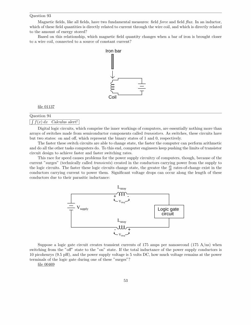
Question 94∫
f(x) dx Calculus alert!
Digital logic circuits, which comprise the inner workings of computers, are essentially nothing more thanarrays of switches made from semiconductor components called transistors. As switches, these circuits havebut two states: on and off, which represent the binary states of 1 and 0, respectively.
The faster these switch circuits are able to change state, the faster the computer can perform arithmeticand do all the other tasks computers do. To this end, computer engineers keep pushing the limits of transistorcircuit design to achieve faster and faster switching rates.
This race for speed causes problems for the power supply circuitry of computers, though, because of thecurrent ”surges” (technically called transients) created in the conductors carrying power from the supply tothe logic circuits. The faster these logic circuits change state, the greater the di
dtrates-of-change exist in the
conductors carrying current to power them. Significant voltage drops can occur along the length of theseconductors due to their parasitic inductance:
Logic gatecircuit
Vsupply
Lstray
Lstray
+ -
+-
Vdrop
Vdrop
Suppose a logic gate circuit creates transient currents of 175 amps per nanosecond (175 A/ns) whenswitching from the ”off” state to the ”on” state. If the total inductance of the power supply conductors is10 picohenrys (9.5 pH), and the power supply voltage is 5 volts DC, how much voltage remains at the powerterminals of the logic gate during one of these ”surges”?
file 00469
53
Question 95∫
f(x) dx Calculus alert!
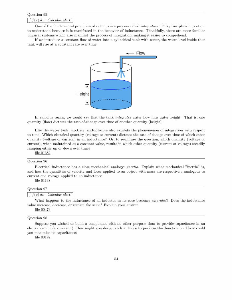
One of the fundamental principles of calculus is a process called integration. This principle is importantto understand because it is manifested in the behavior of inductance. Thankfully, there are more familiarphysical systems which also manifest the process of integration, making it easier to comprehend.
If we introduce a constant flow of water into a cylindrical tank with water, the water level inside thattank will rise at a constant rate over time:
Flow
Height
In calculus terms, we would say that the tank integrates water flow into water height. That is, onequantity (flow) dictates the rate-of-change over time of another quantity (height).
Like the water tank, electrical inductance also exhibits the phenomenon of integration with respectto time. Which electrical quantity (voltage or current) dictates the rate-of-change over time of which otherquantity (voltage or current) in an inductance? Or, to re-phrase the question, which quantity (voltage orcurrent), when maintained at a constant value, results in which other quantity (current or voltage) steadilyramping either up or down over time?
file 01382
Question 96
Electrical inductance has a close mechanical analogy: inertia. Explain what mechanical ”inertia” is,and how the quantities of velocity and force applied to an object with mass are respectively analogous tocurrent and voltage applied to an inductance.
file 01138
Question 97∫
f(x) dx Calculus alert!
What happens to the inductance of an inductor as its core becomes saturated? Does the inductancevalue increase, decrease, or remain the same? Explain your answer.
file 00473
Question 98
Suppose you wished to build a component with no other purpose than to provide capacitance in anelectric circuit (a capacitor). How might you design such a device to perform this function, and how couldyou maximize its capacitance?
file 00192
54
Question 99
What is a Leyden Jar, and how it its construction similar to the construction of all capacitors?file 00186
Question 100
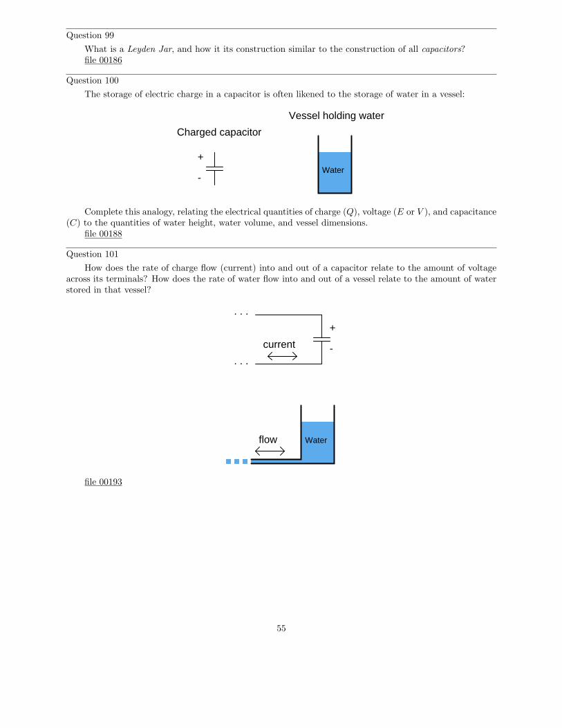
The storage of electric charge in a capacitor is often likened to the storage of water in a vessel:
+
-Water
Charged capacitor
Vessel holding water
Complete this analogy, relating the electrical quantities of charge (Q), voltage (E or V ), and capacitance(C) to the quantities of water height, water volume, and vessel dimensions.
file 00188
Question 101
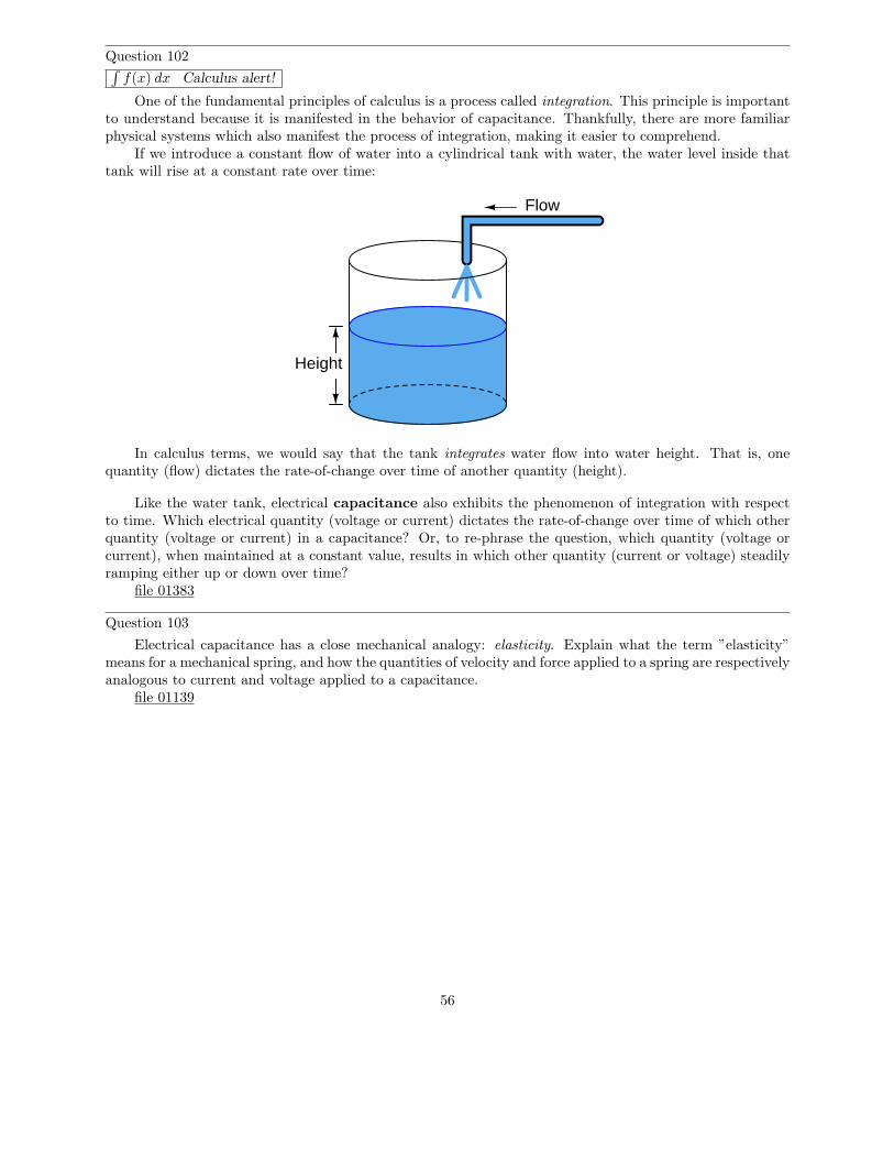
How does the rate of charge flow (current) into and out of a capacitor relate to the amount of voltageacross its terminals? How does the rate of water flow into and out of a vessel relate to the amount of waterstored in that vessel?
+
-
Waterflow
current
. . .
. . .
file 00193
55
Question 102∫
f(x) dx Calculus alert!
One of the fundamental principles of calculus is a process called integration. This principle is importantto understand because it is manifested in the behavior of capacitance. Thankfully, there are more familiarphysical systems which also manifest the process of integration, making it easier to comprehend.
If we introduce a constant flow of water into a cylindrical tank with water, the water level inside thattank will rise at a constant rate over time:
Flow
Height
In calculus terms, we would say that the tank integrates water flow into water height. That is, onequantity (flow) dictates the rate-of-change over time of another quantity (height).
Like the water tank, electrical capacitance also exhibits the phenomenon of integration with respectto time. Which electrical quantity (voltage or current) dictates the rate-of-change over time of which otherquantity (voltage or current) in a capacitance? Or, to re-phrase the question, which quantity (voltage orcurrent), when maintained at a constant value, results in which other quantity (current or voltage) steadilyramping either up or down over time?
file 01383
Question 103
Electrical capacitance has a close mechanical analogy: elasticity. Explain what the term ”elasticity”means for a mechanical spring, and how the quantities of velocity and force applied to a spring are respectivelyanalogous to current and voltage applied to a capacitance.
file 01139
56
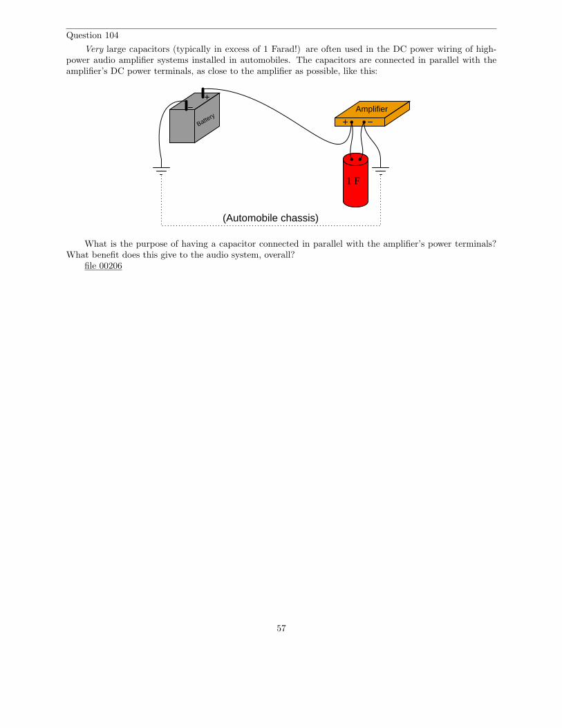
Question 104
Very large capacitors (typically in excess of 1 Farad!) are often used in the DC power wiring of high-power audio amplifier systems installed in automobiles. The capacitors are connected in parallel with theamplifier’s DC power terminals, as close to the amplifier as possible, like this:
Amplifier
Battery
1 F
(Automobile chassis)
What is the purpose of having a capacitor connected in parallel with the amplifier’s power terminals?What benefit does this give to the audio system, overall?
file 00206
57
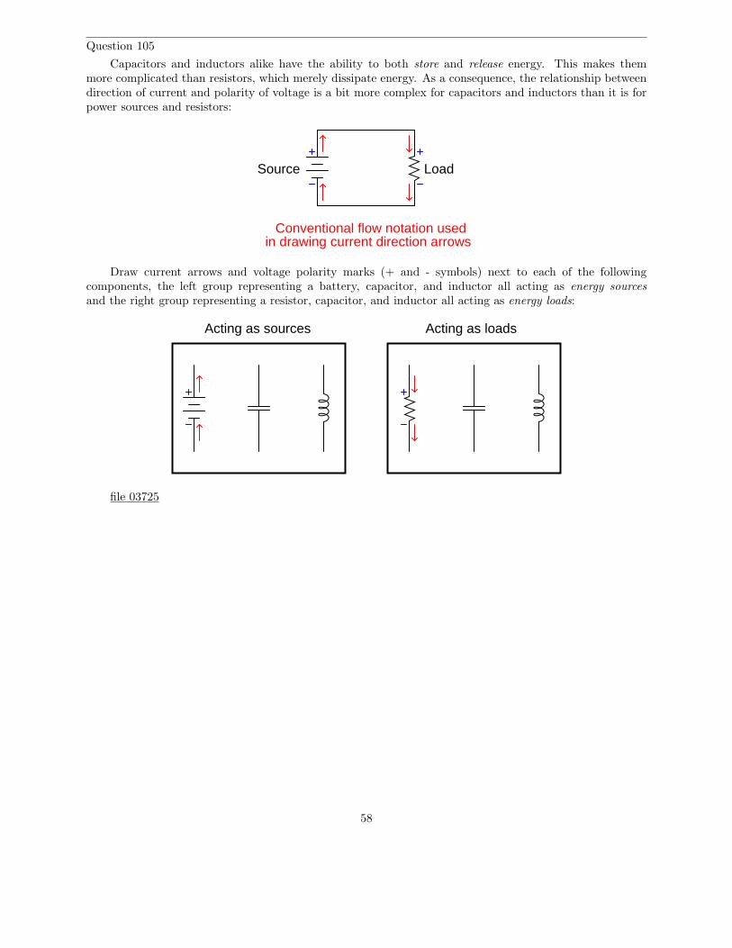
Question 105
Capacitors and inductors alike have the ability to both store and release energy. This makes themmore complicated than resistors, which merely dissipate energy. As a consequence, the relationship betweendirection of current and polarity of voltage is a bit more complex for capacitors and inductors than it is forpower sources and resistors:
Source Load
Conventional flow notation used in drawing current direction arrows
Draw current arrows and voltage polarity marks (+ and - symbols) next to each of the followingcomponents, the left group representing a battery, capacitor, and inductor all acting as energy sourcesand the right group representing a resistor, capacitor, and inductor all acting as energy loads:
Acting as sources Acting as loads
file 03725
58
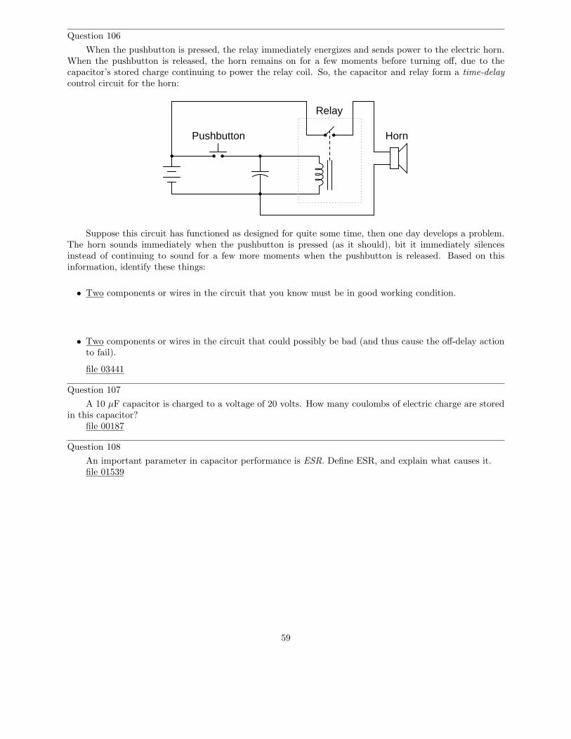
Question 106
When the pushbutton is pressed, the relay immediately energizes and sends power to the electric horn.When the pushbutton is released, the horn remains on for a few moments before turning off, due to thecapacitor’s stored charge continuing to power the relay coil. So, the capacitor and relay form a time-delaycontrol circuit for the horn:
Relay
HornPushbutton
Suppose this circuit has functioned as designed for quite some time, then one day develops a problem.The horn sounds immediately when the pushbutton is pressed (as it should), bit it immediately silencesinstead of continuing to sound for a few more moments when the pushbutton is released. Based on thisinformation, identify these things:
• Two components or wires in the circuit that you know must be in good working condition.
• Two components or wires in the circuit that could possibly be bad (and thus cause the off-delay actionto fail).
file 03441
Question 107
A 10 µF capacitor is charged to a voltage of 20 volts. How many coulombs of electric charge are storedin this capacitor?
file 00187
Question 108
An important parameter in capacitor performance is ESR. Define ESR, and explain what causes it.file 01539
59
Question 109
Capacitors often have letter codes following the three-digit number codes. For example, here are sometypical capacitor codes, complete with letters:
• 473K• 102J• 224M• 331F
Determine the meaning of letters used on capacitor labels, what the respective numeric values are forall the available letters, and then finally what these four specific number/letter codes mean (shown above).
file 03651
60
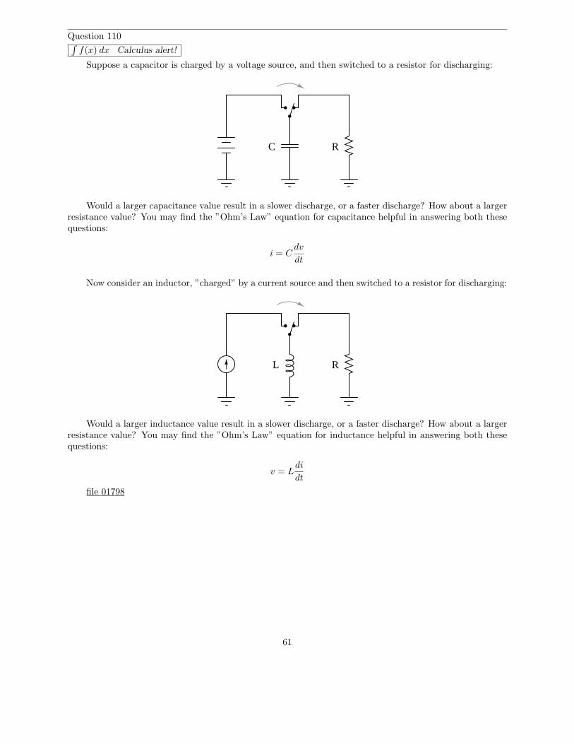
Question 110∫
f(x) dx Calculus alert!
Suppose a capacitor is charged by a voltage source, and then switched to a resistor for discharging:
C R
Would a larger capacitance value result in a slower discharge, or a faster discharge? How about a largerresistance value? You may find the ”Ohm’s Law” equation for capacitance helpful in answering both thesequestions:
i = Cdv
dt
Now consider an inductor, ”charged” by a current source and then switched to a resistor for discharging:
RL
Would a larger inductance value result in a slower discharge, or a faster discharge? How about a largerresistance value? You may find the ”Ohm’s Law” equation for inductance helpful in answering both thesequestions:
v = Ldi
dt
file 01798
61
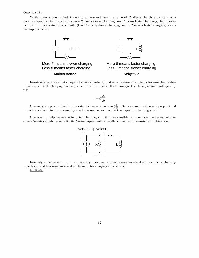
Question 111
While many students find it easy to understand how the value of R affects the time constant of aresistor-capacitor charging circuit (more R means slower charging; less R means faster charging), the oppositebehavior of resistor-inductor circuits (less R means slower charging; more R means faster charging) seemsincomprehensible:
More R means slower charging
R
C
Less R means faster charging
R
L
More R means faster chargingLess R means slower charging
Makes sense! Why???
Resistor-capacitor circuit charging behavior probably makes more sense to students because they realizeresistance controls charging current, which in turn directly effects how quickly the capacitor’s voltage mayrise:
i = Cdv
dt
Current (i) is proportional to the rate of change of voltage (dvdt
). Since current is inversely proportionalto resistance in a circuit powered by a voltage source, so must be the capacitor charging rate.
One way to help make the inductor charging circuit more sensible is to replace the series voltage-source/resistor combination with its Norton equivalent, a parallel current-source/resistor combination:
R L
Norton equivalent
Re-analyze the circuit in this form, and try to explain why more resistance makes the inductor chargingtime faster and less resistance makes the inductor charging time slower.
file 03533
62
Question 112
The decay of a variable (either voltage or current) in a time-constant circuit (RC or LR) follows thismathematical expression:
e−t
τ
Where,e = Euler’s constant (≈ 2.718281828)t = Time, in secondsτ = Time constant of circuit, in seconds
Calculate the value of this expression as t increases, given a circuit time constant (τ) of 1 second.Express this value as a percentage:
t = 1 secondt = 2 secondst = 3 secondst = 4 secondst = 5 secondst = 6 secondst = 7 secondst = 8 secondst = 9 secondst = 10 seconds
Based on your calculations, how would you describe the change in the expression’s value over time as tincreases?
file 00442
63
Question 113
The decay of a variable (either voltage or current) in a time-constant circuit (RC or LR) follows thismathematical expression:
e−t
τ
Where,e = Euler’s constant (≈ 2.718281828)t = Time, in secondsτ = Time constant of circuit, in seconds
Calculate the value of this expression as t increases, given a circuit time constant (τ) of 2 seconds.Express this value as a percentage:
t = 1 secondt = 2 secondst = 3 secondst = 4 secondst = 5 secondst = 6 secondst = 7 secondst = 8 secondst = 9 secondst = 10 seconds
Also, express the percentage value of any increasing variables (either voltage or current) in an RC orLR charging circuit, for the same conditions (same times, same time constant).
file 00450
Question 114
Write a mathematical expression for calculating the percentage value of any increasing variables (eithervoltage or current) in an RC or LR time-constant circuit.
Hint: the formula for calculating the percentage of any decreasing variables in an RC or LC time-constantcircuit is as follows:
e−t
τ
Where,e = Euler’s constant (≈ 2.718281828)t = Time, in secondsτ = Time constant of circuit, in seconds
Here, the value of the expression starts at 1 (100%) at time = 0 and approaches 0 (0%) as time approaches∞. What I’m asking you to derive is an equation that does just the opposite: start with a value of 0 whentime = 0 and approach a value of 1 as time approaches ∞.
file 00451
64
Question 115
Calculating variables in reactive circuits using time-constant formulae can be time consuming, due toall the keystrokes necessary on a calculator. Even worse is when a calculator is not available! You shouldbe prepared to estimate circuit values without the benefit of a calculator to do the math, though, because acalculator may not always be available when you need one.
Note that Euler’s constant (e) is approximately equal to 3. This is not a close approximation, but closeenough for ”rough” estimations. If we use a value of three instead of e’s true value of 2.718281828· · ·, wemay greatly simplify the ”decay” time constant formula:
Percentage of change ≈ 3−t
τ
Suppose that a capacitive discharge circuit begins with a full-charge voltage of 10 volts. Calculate thecapacitor’s voltage at the following times as it discharges, assuming τ = 1 second:
t = 0 seconds ; EC =t = 1 second ; EC =t = 2 seconds ; EC =t = 3 seconds ; EC =t = 4 seconds ; EC =t = 5 seconds ; EC =
Without using a calculator, you should at least be able to calculate voltage values as fractions if notdecimals!
file 01804
Question 116
Calculating variables in reactive circuits using time-constant formulae can be time consuming, due toall the keystrokes necessary on a calculator. Even worse is when a calculator is not available! You shouldbe prepared to estimate circuit values without the benefit of a calculator to do the math, though, because acalculator may not always be available when you need one.
Note that Euler’s constant (e) is approximately equal to 3. This is not a close approximation, but closeenough for ”rough” estimations. If we use a value of three instead of e’s true value of 2.718281828· · ·, wemay greatly simplify the ”increasing” time constant formula:
Percentage of change ≈ 1 − 3−t
τ
Suppose that a capacitive charging circuit begins fully discharged (0 volts), and charges to an ultimatevalue of 10 volts. Calculate the capacitor’s voltage at the following times as it discharges, assuming τ = 1second:
t = 0 seconds ; EC =t = 1 second ; EC =t = 2 seconds ; EC =t = 3 seconds ; EC =t = 4 seconds ; EC =t = 5 seconds ; EC =
Without using a calculator, you should at least be able to calculate voltage values as fractions if notdecimals!
file 01805
65
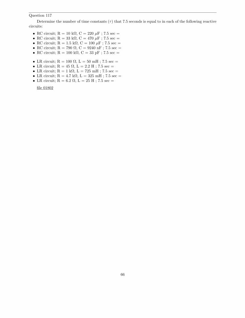
Question 117
Determine the number of time constants (τ) that 7.5 seconds is equal to in each of the following reactivecircuits:
• RC circuit; R = 10 kΩ, C = 220 µF ; 7.5 sec =• RC circuit; R = 33 kΩ, C = 470 µF ; 7.5 sec =• RC circuit; R = 1.5 kΩ, C = 100 µF ; 7.5 sec =• RC circuit; R = 790 Ω, C = 9240 nF ; 7.5 sec =• RC circuit; R = 100 kΩ, C = 33 pF ; 7.5 sec =
• LR circuit; R = 100 Ω, L = 50 mH ; 7.5 sec =• LR circuit; R = 45 Ω, L = 2.2 H ; 7.5 sec =• LR circuit; R = 1 kΩ, L = 725 mH ; 7.5 sec =• LR circuit; R = 4.7 kΩ, L = 325 mH ; 7.5 sec =• LR circuit; R = 6.2 Ω, L = 25 H ; 7.5 sec =
file 01802
66

Question 118
Suppose we were measuring the interior temperature of an insulated box recently removed from arefrigerator, as it was being warmed by the ambient air around it:
Box
(Ambient air warmer than inside of box)
Graphing the box’s temperature over time, we see a curve that looks something like this:
Time
Box temp.(degrees)
(minutes)
An engineer approaches you and says she wants you to build an electrical circuit that models thisthermal system. What kind of circuit would you consider building for the engineer, to make a realisticelectrical analogue of the box’s temperature? Be as specific as you can in your answer.
file 01218
Question 119
When a circuit designer needs a circuit to provide a time delay, he or she almost always chooses an RCcircuit instead of an LR circuit. Explain why this is.
file 01800
67
Question 120
At a party, you happen to notice a mathematician taking notes while looking over the food table whereseveral pizzas are set. Walking up to her, you ask what she is doing. ”I’m mathematically modeling theconsumption of pizza,” she tells you. Before you have the chance to ask another question, she sets hernotepad down on the table and excuses herself to go use the bathroom.
Looking at the notepad, you see the following equation:
Percentage =(
1 − e−t
5.8
)
× 100%
Where,t = Time in minutes since arrival of pizza.
The problem is, you don’t know whether the equation she wrote describes the percentage of pizza eatenor the percentage of pizza remaining on the table. Explain how you would determine which percentage thisequation describes. How, exactly, can you tell if this equation describes the amount of pizza already eatenor the amount of pizza that remains to be eaten?
file 03309
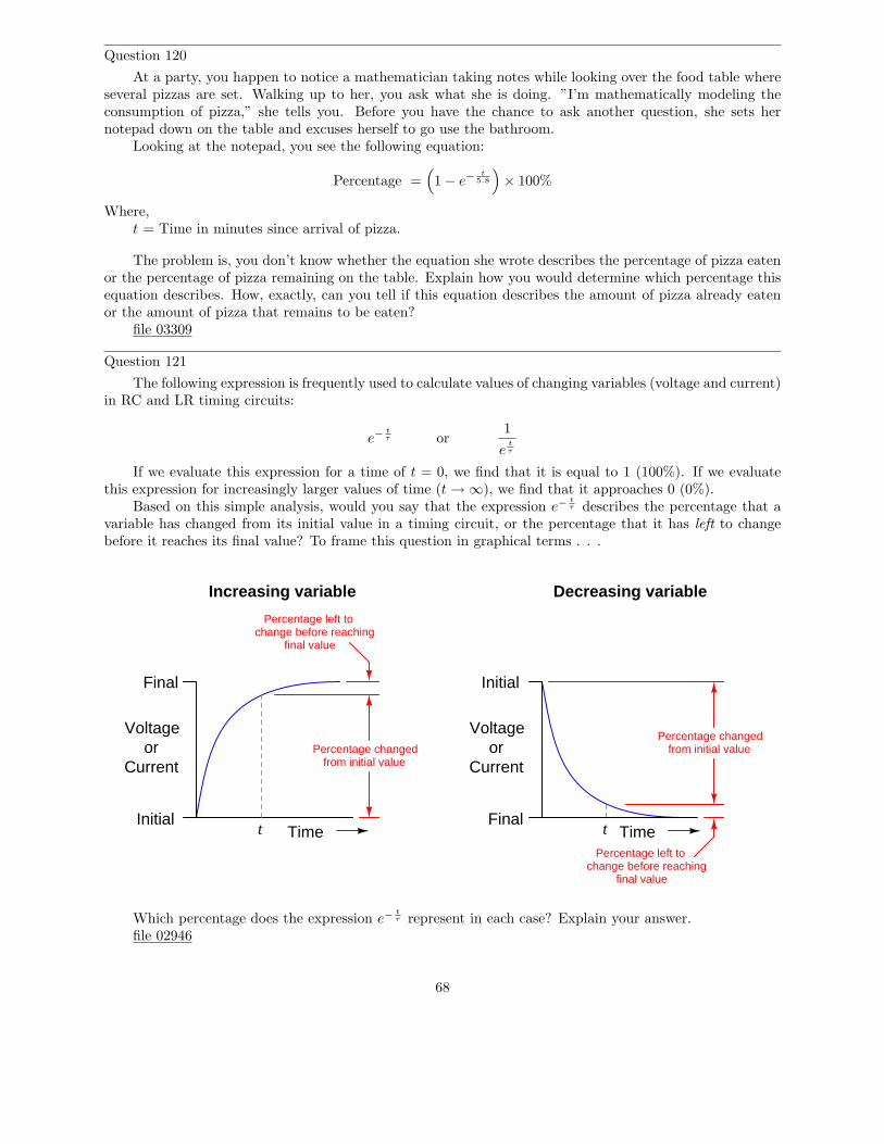
Question 121
The following expression is frequently used to calculate values of changing variables (voltage and current)in RC and LR timing circuits:
e−t
τ or1
et
τ
If we evaluate this expression for a time of t = 0, we find that it is equal to 1 (100%). If we evaluatethis expression for increasingly larger values of time (t → ∞), we find that it approaches 0 (0%).
Based on this simple analysis, would you say that the expression e−t
τ describes the percentage that avariable has changed from its initial value in a timing circuit, or the percentage that it has left to changebefore it reaches its final value? To frame this question in graphical terms . . .
TimeInitial
Final
t
Voltageor
CurrentPercentage changed
from initial value
Percentage left tochange before reaching
final value
TimeFinal
t
Voltageor
Current
Percentage changedfrom initial value
Percentage left tochange before reaching
final value
Initial
Increasing variable Decreasing variable
Which percentage does the expression e−t
τ represent in each case? Explain your answer.file 02946
68
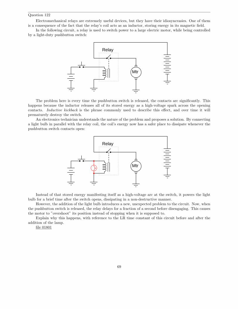
Question 122
Electromechanical relays are extremely useful devices, but they have their idiosyncrasies. One of themis a consequence of the fact that the relay’s coil acts as an inductor, storing energy in its magnetic field.
In the following circuit, a relay is used to switch power to a large electric motor, while being controlledby a light-duty pushbutton switch:
Relay
Mtr
The problem here is every time the pushbutton switch is released, the contacts arc significantly. Thishappens because the inductor releases all of its stored energy as a high-voltage spark across the openingcontacts. Inductive kickback is the phrase commonly used to describe this effect, and over time it willprematurely destroy the switch.
An electronics technician understands the nature of the problem and proposes a solution. By connectinga light bulb in parallel with the relay coil, the coil’s energy now has a safer place to dissipate whenever thepushbutton switch contacts open:
Relay
Mtr
Instead of that stored energy manifesting itself as a high-voltage arc at the switch, it powers the lightbulb for a brief time after the switch opens, dissipating in a non-destructive manner.
However, the addition of the light bulb introduces a new, unexpected problem to the circuit. Now, whenthe pushbutton switch is released, the relay delays for a fraction of a second before disengaging. This causesthe motor to ”overshoot” its position instead of stopping when it is supposed to.
Explain why this happens, with reference to the LR time constant of this circuit before and after theaddition of the lamp.
file 01801
69
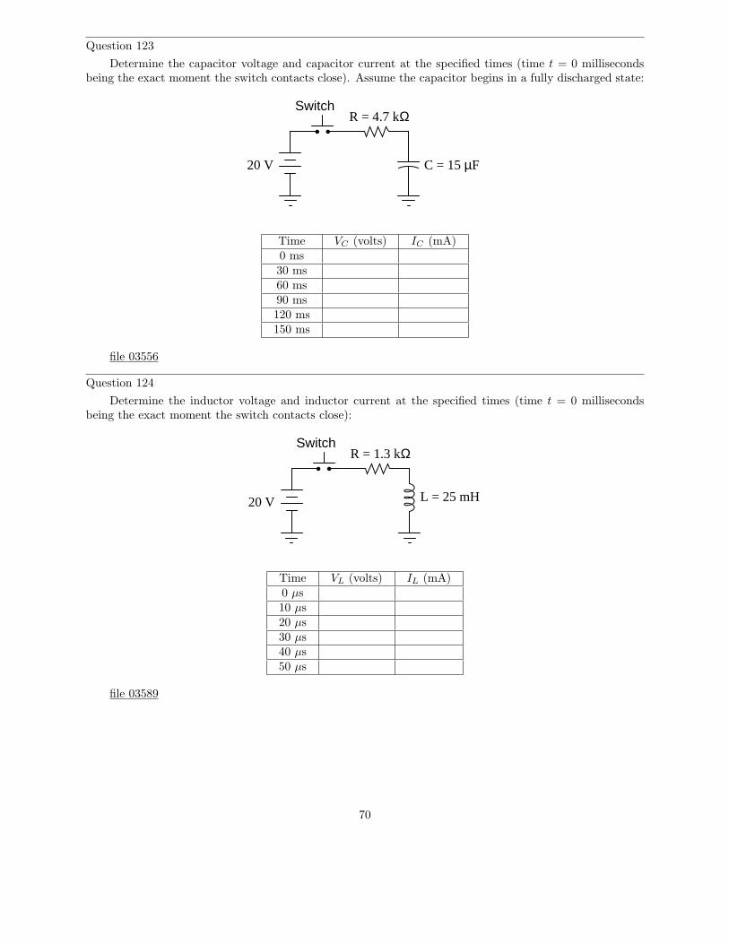
Question 123
Determine the capacitor voltage and capacitor current at the specified times (time t = 0 millisecondsbeing the exact moment the switch contacts close). Assume the capacitor begins in a fully discharged state:
Switch
20 V C = 15 µF
R = 4.7 kΩ
Time VC (volts) IC (mA)0 ms30 ms60 ms90 ms120 ms150 ms
file 03556
Question 124
Determine the inductor voltage and inductor current at the specified times (time t = 0 millisecondsbeing the exact moment the switch contacts close):
Switch
20 V
R = 1.3 kΩ
L = 25 mH
Time VL (volts) IL (mA)0 µs10 µs20 µs30 µs40 µs50 µs
file 03589
70
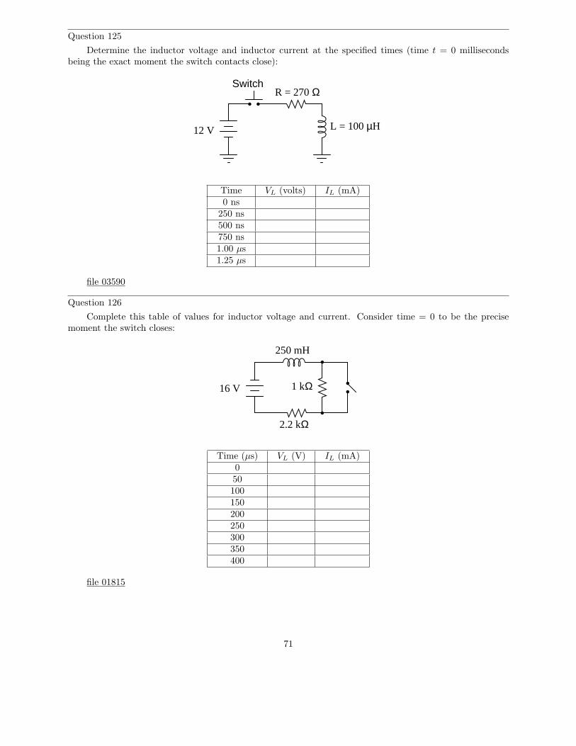
Question 125
Determine the inductor voltage and inductor current at the specified times (time t = 0 millisecondsbeing the exact moment the switch contacts close):
Switch
L = 100 µH
R = 270 Ω
12 V
Time VL (volts) IL (mA)0 ns
250 ns500 ns750 ns1.00 µs1.25 µs
file 03590
Question 126
Complete this table of values for inductor voltage and current. Consider time = 0 to be the precisemoment the switch closes:
250 mH
2.2 kΩ
1 kΩ16 V
Time (µs) VL (V) IL (mA)050100150200250300350400
file 01815
71
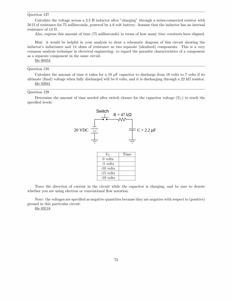
Question 127
Calculate the voltage across a 2.5 H inductor after ”charging” through a series-connected resistor with50 Ω of resistance for 75 milliseconds, powered by a 6 volt battery. Assume that the inductor has an internalresistance of 14 Ω.
Also, express this amount of time (75 milliseconds) in terms of how many time constants have elapsed.
Hint: it would be helpful in your analysis to draw a schematic diagram of this circuit showing theinductor’s inductance and 14 ohms of resistance as two separate (idealized) components. This is a verycommon analysis technique in electrical engineering: to regard the parasitic characteristics of a componentas a separate component in the same circuit.
file 00454
Question 128
Calculate the amount of time it takes for a 10 µF capacitor to discharge from 18 volts to 7 volts if itsultimate (final) voltage when fully discharged will be 0 volts, and it is discharging through a 22 kΩ resistor.
file 02941
Question 129
Determine the amount of time needed after switch closure for the capacitor voltage (VC) to reach thespecified levels:
Switch
20 VDC
R = 47 kΩ
C = 2.2 µF
VC Time0 volts-5 volts-10 volts-15 volts-19 volts
Trace the direction of current in the circuit while the capacitor is charging, and be sure to denotewhether you are using electron or conventional flow notation.
Note: the voltages are specified as negative quantities because they are negative with respect to (positive)ground in this particular circuit.
file 03118
72
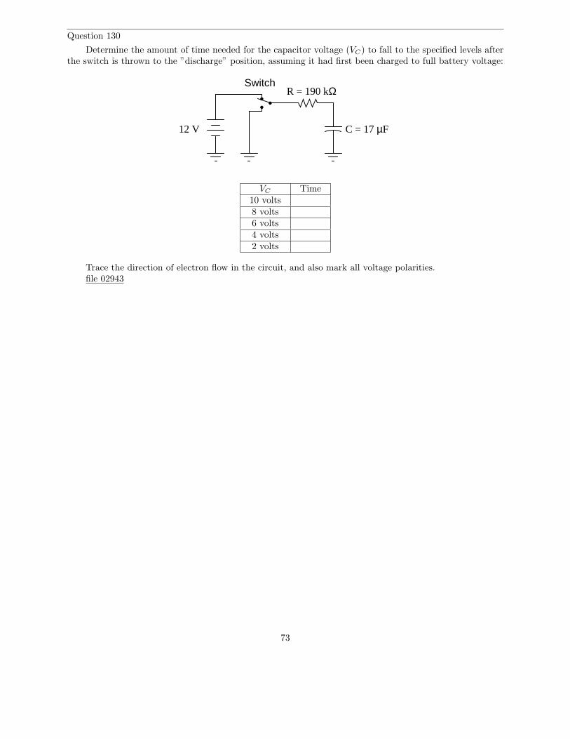
Question 130
Determine the amount of time needed for the capacitor voltage (VC) to fall to the specified levels afterthe switch is thrown to the ”discharge” position, assuming it had first been charged to full battery voltage:
Switch
12 V
R = 190 kΩ
C = 17 µF
VC Time10 volts8 volts6 volts4 volts2 volts
Trace the direction of electron flow in the circuit, and also mark all voltage polarities.file 02943
73
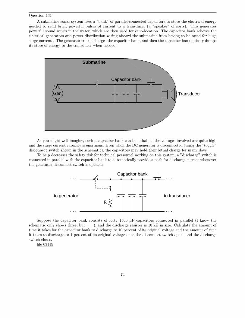
Question 131
A submarine sonar system uses a ”bank” of parallel-connected capacitors to store the electrical energyneeded to send brief, powerful pulses of current to a transducer (a ”speaker” of sorts). This generatespowerful sound waves in the water, which are then used for echo-location. The capacitor bank relieves theelectrical generators and power distribution wiring aboard the submarine from having to be rated for hugesurge currents. The generator trickle-charges the capacitor bank, and then the capacitor bank quickly dumpsits store of energy to the transducer when needed:
Gen Transducer
Capacitor bank
Submarine
As you might well imagine, such a capacitor bank can be lethal, as the voltages involved are quite highand the surge current capacity is enormous. Even when the DC generator is disconnected (using the ”toggle”disconnect switch shown in the schematic), the capacitors may hold their lethal charge for many days.
To help decreases the safety risk for technical personnel working on this system, a ”discharge” switch isconnected in parallel with the capacitor bank to automatically provide a path for discharge current wheneverthe generator disconnect switch is opened:
Capacitor bank. . .
. . .
to transducer
. . .
. . .
to generatorR
Suppose the capacitor bank consists of forty 1500 µF capacitors connected in parallel (I know theschematic only shows three, but . . .), and the discharge resistor is 10 kΩ in size. Calculate the amount oftime it takes for the capacitor bank to discharge to 10 percent of its original voltage and the amount of timeit takes to discharge to 1 percent of its original voltage once the disconnect switch opens and the dischargeswitch closes.
file 03119
74
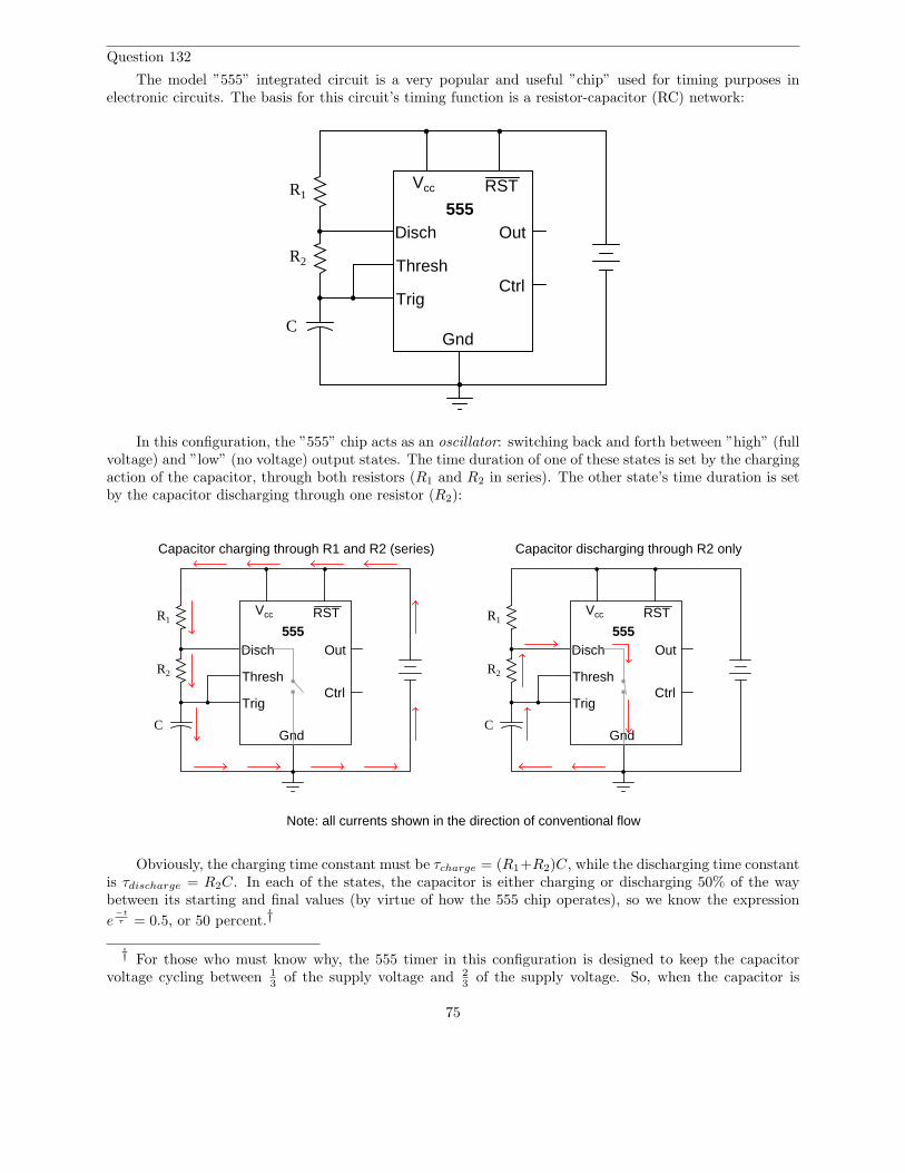
Question 132
The model ”555” integrated circuit is a very popular and useful ”chip” used for timing purposes inelectronic circuits. The basis for this circuit’s timing function is a resistor-capacitor (RC) network:
555Disch
Thresh
Trig
Gnd
Vcc RST
Out
Ctrl
R1
R2
C
In this configuration, the ”555” chip acts as an oscillator: switching back and forth between ”high” (fullvoltage) and ”low” (no voltage) output states. The time duration of one of these states is set by the chargingaction of the capacitor, through both resistors (R1 and R2 in series). The other state’s time duration is setby the capacitor discharging through one resistor (R2):
555Disch
Thresh
Trig
Gnd
Vcc RST
Out
Ctrl
R1
R2
C
Capacitor charging through R1 and R2 (series)
555Disch
Thresh
Trig
Gnd
Vcc RST
Out
Ctrl
R1
R2
C
Capacitor discharging through R2 only
Note: all currents shown in the direction of conventional flow
Obviously, the charging time constant must be τcharge = (R1+R2)C, while the discharging time constantis τdischarge = R2C. In each of the states, the capacitor is either charging or discharging 50% of the waybetween its starting and final values (by virtue of how the 555 chip operates), so we know the expression
e−t
τ = 0.5, or 50 percent.†
† For those who must know why, the 555 timer in this configuration is designed to keep the capacitorvoltage cycling between 1
3 of the supply voltage and 23 of the supply voltage. So, when the capacitor is
75
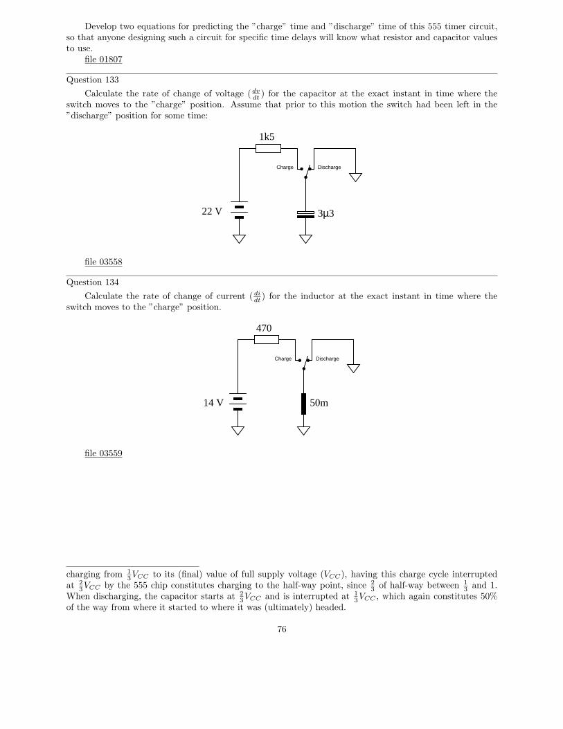
Develop two equations for predicting the ”charge” time and ”discharge” time of this 555 timer circuit,so that anyone designing such a circuit for specific time delays will know what resistor and capacitor valuesto use.
file 01807
Question 133
Calculate the rate of change of voltage (dvdt
) for the capacitor at the exact instant in time where theswitch moves to the ”charge” position. Assume that prior to this motion the switch had been left in the”discharge” position for some time:
Charge Discharge
22 V
1k5
3µ3
file 03558
Question 134
Calculate the rate of change of current ( didt
) for the inductor at the exact instant in time where theswitch moves to the ”charge” position.
Charge Discharge
50m
470
14 V
file 03559
charging from 13VCC to its (final) value of full supply voltage (VCC), having this charge cycle interrupted
at 23VCC by the 555 chip constitutes charging to the half-way point, since 2
3 of half-way between 13 and 1.
When discharging, the capacitor starts at 23VCC and is interrupted at 1
3VCC , which again constitutes 50%of the way from where it started to where it was (ultimately) headed.
76
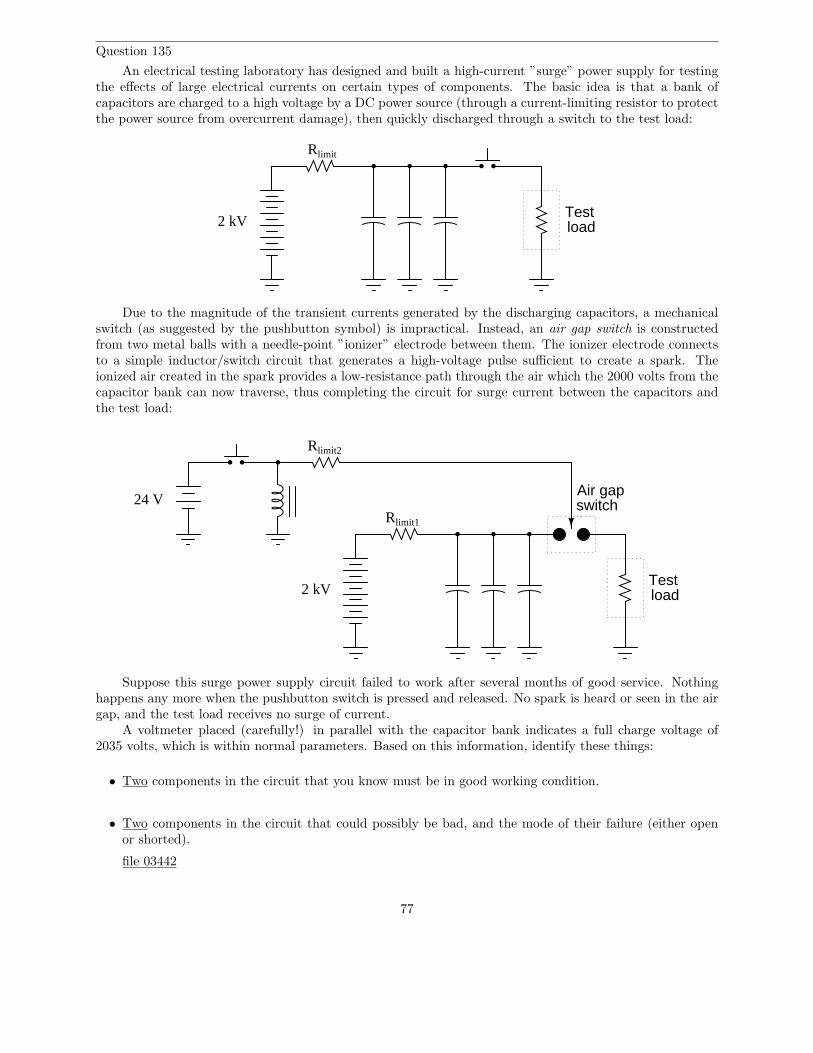
Question 135
An electrical testing laboratory has designed and built a high-current ”surge” power supply for testingthe effects of large electrical currents on certain types of components. The basic idea is that a bank ofcapacitors are charged to a high voltage by a DC power source (through a current-limiting resistor to protectthe power source from overcurrent damage), then quickly discharged through a switch to the test load:
2 kV
Rlimit
Testload
Due to the magnitude of the transient currents generated by the discharging capacitors, a mechanicalswitch (as suggested by the pushbutton symbol) is impractical. Instead, an air gap switch is constructedfrom two metal balls with a needle-point ”ionizer” electrode between them. The ionizer electrode connectsto a simple inductor/switch circuit that generates a high-voltage pulse sufficient to create a spark. Theionized air created in the spark provides a low-resistance path through the air which the 2000 volts from thecapacitor bank can now traverse, thus completing the circuit for surge current between the capacitors andthe test load:
2 kVTestload
Air gapswitch24 V
Rlimit1
Rlimit2
Suppose this surge power supply circuit failed to work after several months of good service. Nothinghappens any more when the pushbutton switch is pressed and released. No spark is heard or seen in the airgap, and the test load receives no surge of current.
A voltmeter placed (carefully!) in parallel with the capacitor bank indicates a full charge voltage of2035 volts, which is within normal parameters. Based on this information, identify these things:
• Two components in the circuit that you know must be in good working condition.
• Two components in the circuit that could possibly be bad, and the mode of their failure (either openor shorted).
file 03442
77
Question 136∫
f(x) dx Calculus alert!
Inductors store energy in the form of a magnetic field. We may calculate the energy stored in aninductance by integrating the product of inductor voltage and inductor current (P = IV ) over time, sincewe know that power is the rate at which work (W ) is done, and the amount of work done to an inductortaking it from zero current to some non-zero amount of current constitutes energy stored (U):
P =dW
dt
dW = P dt
U = W =
∫
P dt
Find a way to substitute inductance (L) and current (I) into the integrand so you may integrate tofind an equation describing the amount of energy stored in an inductor for any given inductance and currentvalues.
file 03547
Question 137∫
f(x) dx Calculus alert!
Capacitors store energy in the form of an electric field. We may calculate the energy stored in acapacitance by integrating the product of capacitor voltage and capacitor current (P = IV ) over time, sincewe know that power is the rate at which work (W ) is done, and the amount of work done to a capacitortaking it from zero voltage to some non-zero amount of voltage constitutes energy stored (U):
P =dW
dt
dW = P dt
U = W =
∫
P dt
Find a way to substitute capacitance (C) and voltage (V ) into the integrand so you may integrate tofind an equation describing the amount of energy stored in a capacitor for any given capacitance and voltagevalues.
file 03548
78
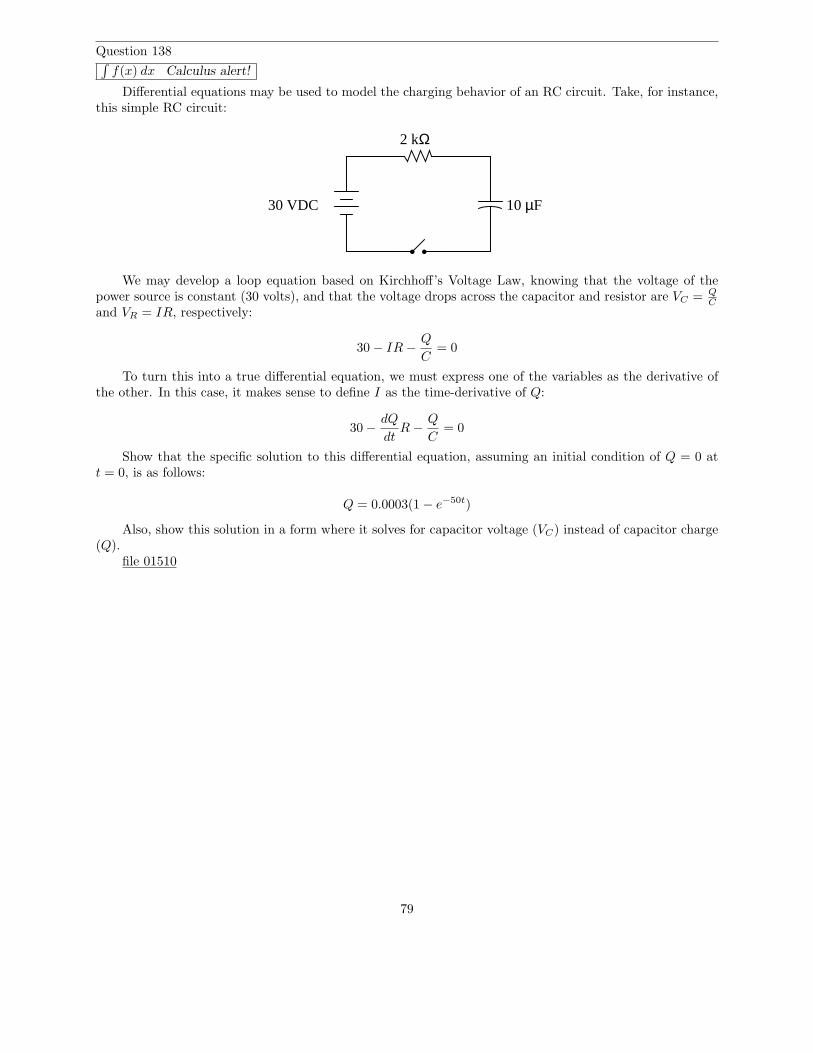
Question 138∫
f(x) dx Calculus alert!
Differential equations may be used to model the charging behavior of an RC circuit. Take, for instance,this simple RC circuit:
2 kΩ
10 µF30 VDC
We may develop a loop equation based on Kirchhoff’s Voltage Law, knowing that the voltage of thepower source is constant (30 volts), and that the voltage drops across the capacitor and resistor are VC = Q
C
and VR = IR, respectively:
30 − IR −Q
C= 0
To turn this into a true differential equation, we must express one of the variables as the derivative ofthe other. In this case, it makes sense to define I as the time-derivative of Q:
30 −dQ
dtR −
Q
C= 0
Show that the specific solution to this differential equation, assuming an initial condition of Q = 0 att = 0, is as follows:
Q = 0.0003(1 − e−50t)
Also, show this solution in a form where it solves for capacitor voltage (VC) instead of capacitor charge(Q).
file 01510
79
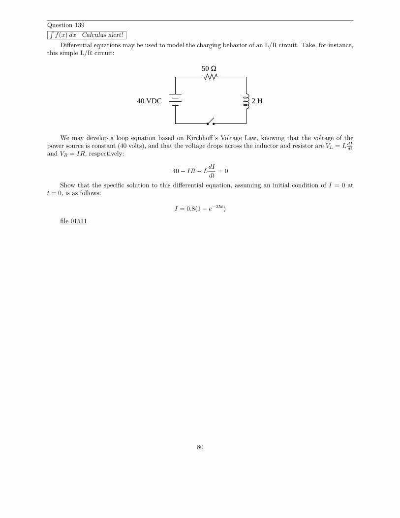
Question 139∫
f(x) dx Calculus alert!
Differential equations may be used to model the charging behavior of an L/R circuit. Take, for instance,this simple L/R circuit:
2 H
50 Ω
40 VDC
We may develop a loop equation based on Kirchhoff’s Voltage Law, knowing that the voltage of thepower source is constant (40 volts), and that the voltage drops across the inductor and resistor are VL = LdI
dt
and VR = IR, respectively:
40 − IR − LdI
dt= 0
Show that the specific solution to this differential equation, assuming an initial condition of I = 0 att = 0, is as follows:
I = 0.8(1 − e−25t)
file 01511
80
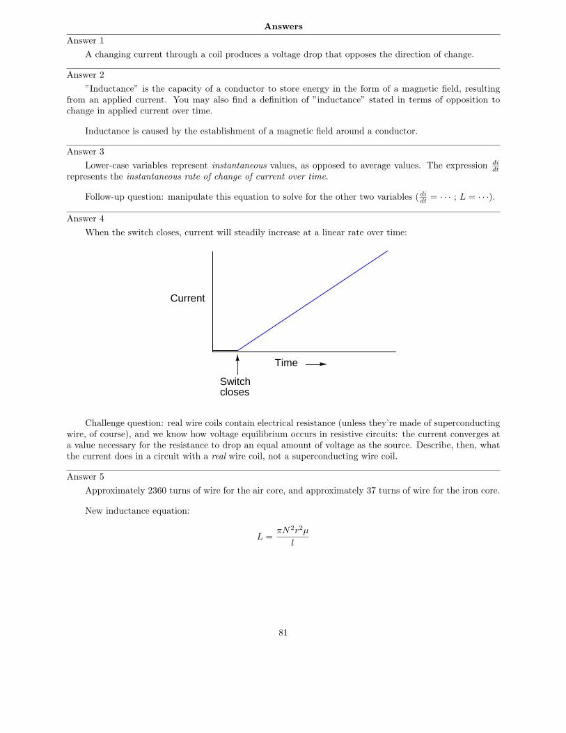
Answers
Answer 1
A changing current through a coil produces a voltage drop that opposes the direction of change.
Answer 2
”Inductance” is the capacity of a conductor to store energy in the form of a magnetic field, resultingfrom an applied current. You may also find a definition of ”inductance” stated in terms of opposition tochange in applied current over time.
Inductance is caused by the establishment of a magnetic field around a conductor.
Answer 3
Lower-case variables represent instantaneous values, as opposed to average values. The expression didt
represents the instantaneous rate of change of current over time.
Follow-up question: manipulate this equation to solve for the other two variables ( didt
= · · · ; L = · · ·).
Answer 4
When the switch closes, current will steadily increase at a linear rate over time:
Time
Current
Switchcloses
Challenge question: real wire coils contain electrical resistance (unless they’re made of superconductingwire, of course), and we know how voltage equilibrium occurs in resistive circuits: the current converges ata value necessary for the resistance to drop an equal amount of voltage as the source. Describe, then, whatthe current does in a circuit with a real wire coil, not a superconducting wire coil.
Answer 5
Approximately 2360 turns of wire for the air core, and approximately 37 turns of wire for the iron core.
New inductance equation:
L =πN2r2µ
l
81
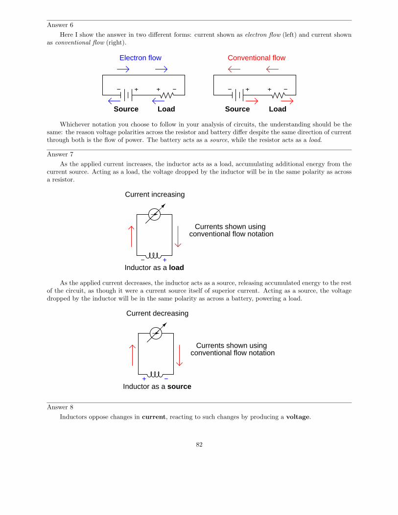
Answer 6
Here I show the answer in two different forms: current shown as electron flow (left) and current shownas conventional flow (right).
Electron flow Conventional flow
Source Load Source Load
Whichever notation you choose to follow in your analysis of circuits, the understanding should be thesame: the reason voltage polarities across the resistor and battery differ despite the same direction of currentthrough both is the flow of power. The battery acts as a source, while the resistor acts as a load.
Answer 7
As the applied current increases, the inductor acts as a load, accumulating additional energy from thecurrent source. Acting as a load, the voltage dropped by the inductor will be in the same polarity as acrossa resistor.
Current increasing
Inductor as a load
Currents shown usingconventional flow notation
As the applied current decreases, the inductor acts as a source, releasing accumulated energy to the restof the circuit, as though it were a current source itself of superior current. Acting as a source, the voltagedropped by the inductor will be in the same polarity as across a battery, powering a load.
Currents shown usingconventional flow notation
Current decreasing
Inductor as a source
Answer 8
Inductors oppose changes in current, reacting to such changes by producing a voltage.
82
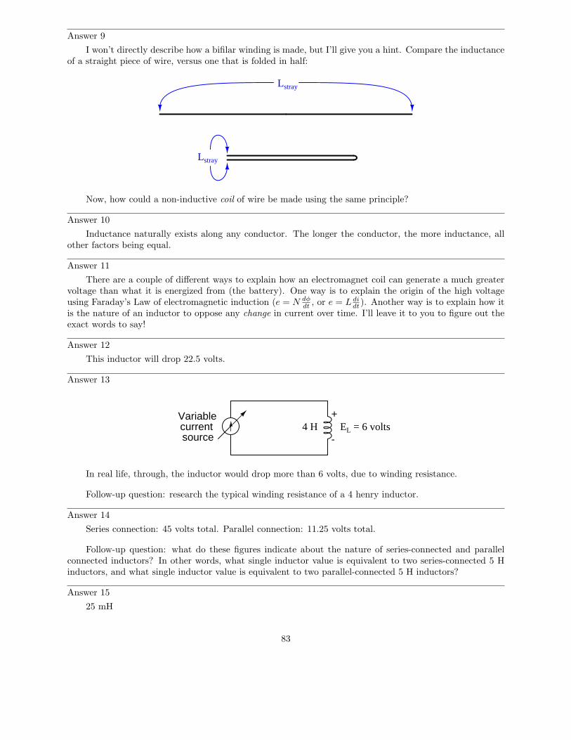
Answer 9
I won’t directly describe how a bifilar winding is made, but I’ll give you a hint. Compare the inductanceof a straight piece of wire, versus one that is folded in half:
Lstray
Lstray
Now, how could a non-inductive coil of wire be made using the same principle?
Answer 10
Inductance naturally exists along any conductor. The longer the conductor, the more inductance, allother factors being equal.
Answer 11
There are a couple of different ways to explain how an electromagnet coil can generate a much greatervoltage than what it is energized from (the battery). One way is to explain the origin of the high voltageusing Faraday’s Law of electromagnetic induction (e = N dφ
dt, or e = L di
dt). Another way is to explain how it
is the nature of an inductor to oppose any change in current over time. I’ll leave it to you to figure out theexact words to say!
Answer 12
This inductor will drop 22.5 volts.
Answer 13
Variablecurrentsource
4 H+
-EL = 6 volts
In real life, through, the inductor would drop more than 6 volts, due to winding resistance.
Follow-up question: research the typical winding resistance of a 4 henry inductor.
Answer 14
Series connection: 45 volts total. Parallel connection: 11.25 volts total.
Follow-up question: what do these figures indicate about the nature of series-connected and parallelconnected inductors? In other words, what single inductor value is equivalent to two series-connected 5 Hinductors, and what single inductor value is equivalent to two parallel-connected 5 H inductors?
Answer 15
25 mH
83
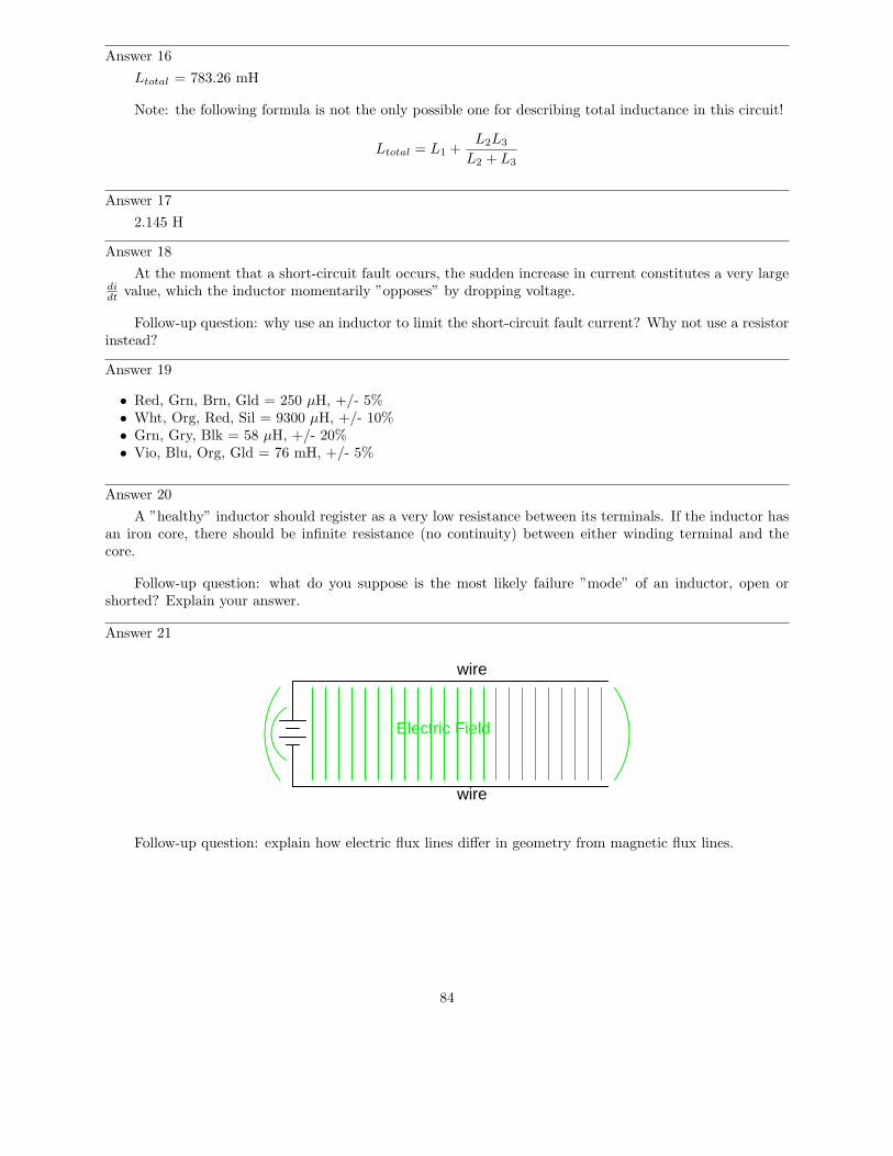
Answer 16
Ltotal = 783.26 mH
Note: the following formula is not the only possible one for describing total inductance in this circuit!
Ltotal = L1 +L2L3
L2 + L3
Answer 17
2.145 H
Answer 18
At the moment that a short-circuit fault occurs, the sudden increase in current constitutes a very largedidt
value, which the inductor momentarily ”opposes” by dropping voltage.
Follow-up question: why use an inductor to limit the short-circuit fault current? Why not use a resistorinstead?
Answer 19
• Red, Grn, Brn, Gld = 250 µH, +/- 5%• Wht, Org, Red, Sil = 9300 µH, +/- 10%• Grn, Gry, Blk = 58 µH, +/- 20%• Vio, Blu, Org, Gld = 76 mH, +/- 5%
Answer 20
A ”healthy” inductor should register as a very low resistance between its terminals. If the inductor hasan iron core, there should be infinite resistance (no continuity) between either winding terminal and thecore.
Follow-up question: what do you suppose is the most likely failure ”mode” of an inductor, open orshorted? Explain your answer.
Answer 21
wire
wire
Electric Field
Follow-up question: explain how electric flux lines differ in geometry from magnetic flux lines.
84
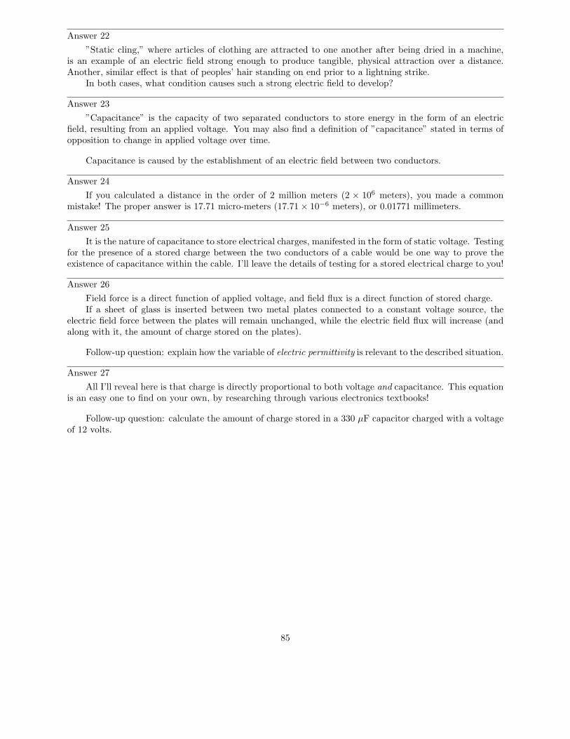
Answer 22
”Static cling,” where articles of clothing are attracted to one another after being dried in a machine,is an example of an electric field strong enough to produce tangible, physical attraction over a distance.Another, similar effect is that of peoples’ hair standing on end prior to a lightning strike.
In both cases, what condition causes such a strong electric field to develop?
Answer 23
”Capacitance” is the capacity of two separated conductors to store energy in the form of an electricfield, resulting from an applied voltage. You may also find a definition of ”capacitance” stated in terms ofopposition to change in applied voltage over time.
Capacitance is caused by the establishment of an electric field between two conductors.
Answer 24
If you calculated a distance in the order of 2 million meters (2 × 10⁶ meters), you made a commonmistake! The proper answer is 17.71 micro-meters (17.71 × 10⁻⁶ meters), or 0.01771 millimeters.
Answer 25
It is the nature of capacitance to store electrical charges, manifested in the form of static voltage. Testingfor the presence of a stored charge between the two conductors of a cable would be one way to prove theexistence of capacitance within the cable. I’ll leave the details of testing for a stored electrical charge to you!
Answer 26
Field force is a direct function of applied voltage, and field flux is a direct function of stored charge.If a sheet of glass is inserted between two metal plates connected to a constant voltage source, the
electric field force between the plates will remain unchanged, while the electric field flux will increase (andalong with it, the amount of charge stored on the plates).
Follow-up question: explain how the variable of electric permittivity is relevant to the described situation.
Answer 27
All I’ll reveal here is that charge is directly proportional to both voltage and capacitance. This equationis an easy one to find on your own, by researching through various electronics textbooks!
Follow-up question: calculate the amount of charge stored in a 330 µF capacitor charged with a voltageof 12 volts.
85
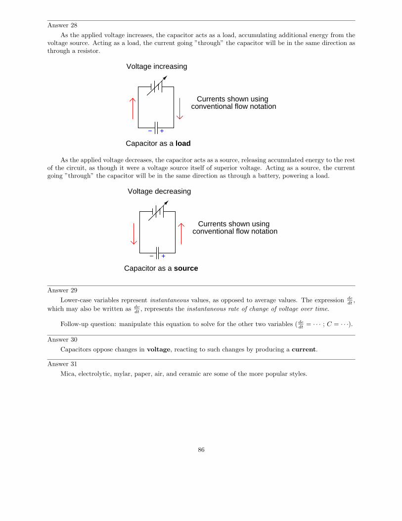
Answer 28
As the applied voltage increases, the capacitor acts as a load, accumulating additional energy from thevoltage source. Acting as a load, the current going ”through” the capacitor will be in the same direction asthrough a resistor.
Currents shown usingconventional flow notation
Voltage increasing
Capacitor as a load
As the applied voltage decreases, the capacitor acts as a source, releasing accumulated energy to the restof the circuit, as though it were a voltage source itself of superior voltage. Acting as a source, the currentgoing ”through” the capacitor will be in the same direction as through a battery, powering a load.
Currents shown usingconventional flow notation
Voltage decreasing
Capacitor as a source
Answer 29
Lower-case variables represent instantaneous values, as opposed to average values. The expression dedt
,
which may also be written as dvdt
, represents the instantaneous rate of change of voltage over time.
Follow-up question: manipulate this equation to solve for the other two variables (dedt
= · · · ; C = · · ·).
Answer 30
Capacitors oppose changes in voltage, reacting to such changes by producing a current.
Answer 31
Mica, electrolytic, mylar, paper, air, and ceramic are some of the more popular styles.
86
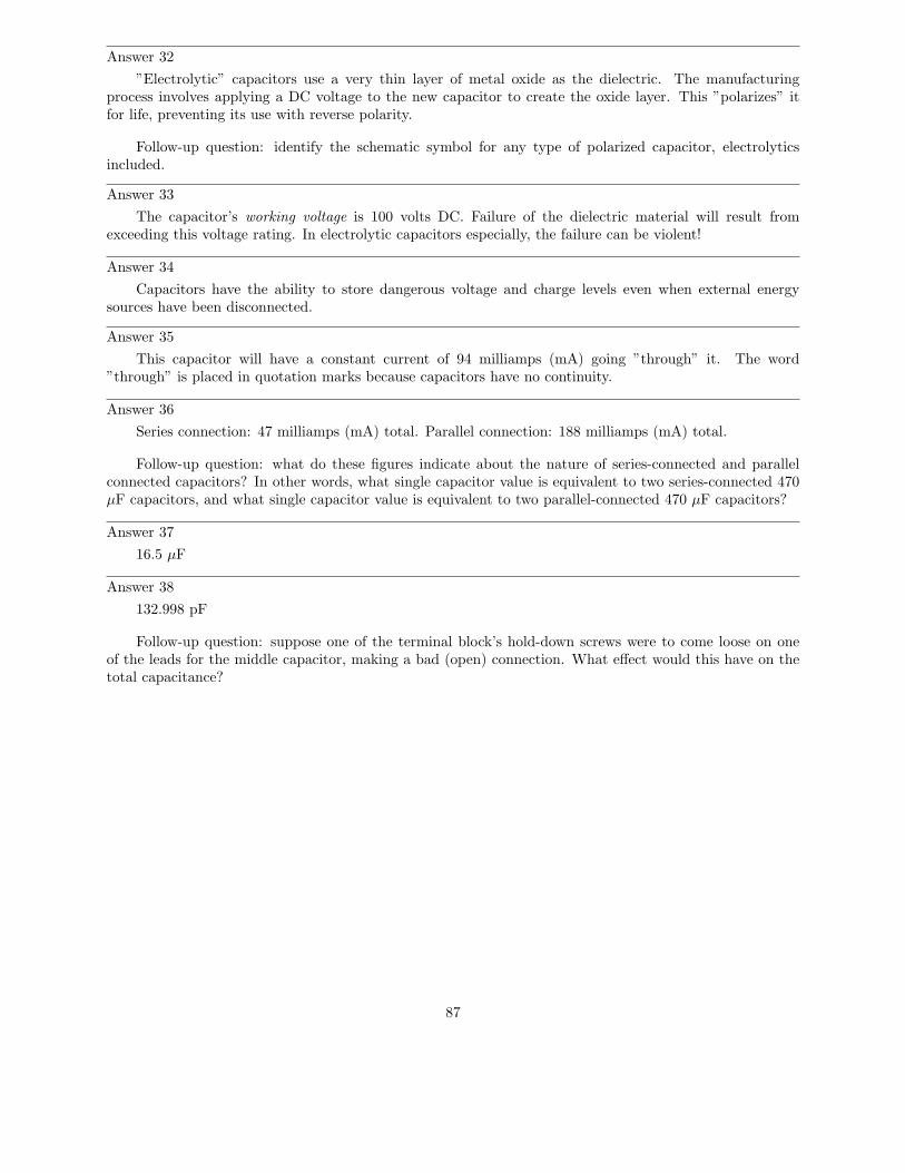
Answer 32
”Electrolytic” capacitors use a very thin layer of metal oxide as the dielectric. The manufacturingprocess involves applying a DC voltage to the new capacitor to create the oxide layer. This ”polarizes” itfor life, preventing its use with reverse polarity.
Follow-up question: identify the schematic symbol for any type of polarized capacitor, electrolyticsincluded.
Answer 33
The capacitor’s working voltage is 100 volts DC. Failure of the dielectric material will result fromexceeding this voltage rating. In electrolytic capacitors especially, the failure can be violent!
Answer 34
Capacitors have the ability to store dangerous voltage and charge levels even when external energysources have been disconnected.
Answer 35
This capacitor will have a constant current of 94 milliamps (mA) going ”through” it. The word”through” is placed in quotation marks because capacitors have no continuity.
Answer 36
Series connection: 47 milliamps (mA) total. Parallel connection: 188 milliamps (mA) total.
Follow-up question: what do these figures indicate about the nature of series-connected and parallelconnected capacitors? In other words, what single capacitor value is equivalent to two series-connected 470µF capacitors, and what single capacitor value is equivalent to two parallel-connected 470 µF capacitors?
Answer 37
16.5 µF
Answer 38
132.998 pF
Follow-up question: suppose one of the terminal block’s hold-down screws were to come loose on oneof the leads for the middle capacitor, making a bad (open) connection. What effect would this have on thetotal capacitance?
87
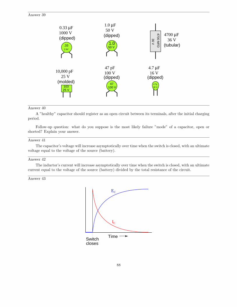
Answer 39
4700 MF
D
36 V
25 V103
4.7µ16 V
0.33 µF1000 V(dipped)
1.0 µF50 V
(dipped)
10,000 pF25 V
(molded)(dipped)
47 pF100 V
(dipped)
(tubular)
4700 µF36 V
16 V4.7 µF
.331 kV
1.050 V
47100 V
Answer 40
A ”healthy” capacitor should register as an open circuit between its terminals, after the initial chargingperiod.
Follow-up question: what do you suppose is the most likely failure ”mode” of a capacitor, open orshorted? Explain your answer.
Answer 41
The capacitor’s voltage will increase asymptotically over time when the switch is closed, with an ultimatevoltage equal to the voltage of the source (battery).
Answer 42
The inductor’s current will increase asymptotically over time when the switch is closed, with an ultimatecurrent equal to the voltage of the source (battery) divided by the total resistance of the circuit.
Answer 43
Time
EC
Switchcloses
IC
88
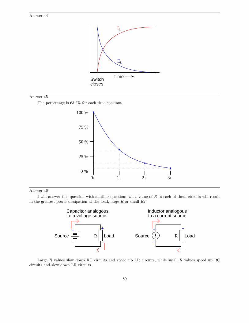
Answer 44
TimeSwitchcloses
IL
EL
Answer 45
The percentage is 63.2% for each time constant.
0 %
25 %
50 %
75 %
100 %
1τ 2τ 3τ0τ
Answer 46
I will answer this question with another question: what value of R in each of these circuits will resultin the greatest power dissipation at the load, large R or small R?
Source LoadR Source LoadR
Capacitor analogousto a voltage source
Inductor analogousto a current source
Large R values slow down RC circuits and speed up LR circuits, while small R values speed up RCcircuits and slow down LR circuits.
89
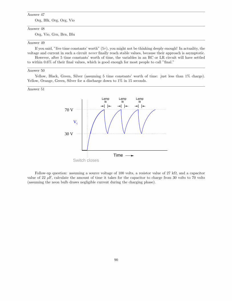
Answer 47
Org, Blk, Org, Org, Vio
Answer 48
Org, Vio, Grn, Brn, Blu
Answer 49
If you said, ”five time constants’ worth” (5τ), you might not be thinking deeply enough! In actuality, thevoltage and current in such a circuit never finally reach stable values, because their approach is asymptotic.
However, after 5 time constants’ worth of time, the variables in an RC or LR circuit will have settledto within 0.6% of their final values, which is good enough for most people to call ”final.”
Answer 50
Yellow, Black, Green, Silver (assuming 5 time constants’ worth of time: just less than 1% charge).Yellow, Orange, Green, Silver for a discharge down to 1% in 15 seconds.
Answer 51
Time
Vc
Switch closes
30 V
70 V
Lamplit
Lamplit
Lamplit
Follow-up question: assuming a source voltage of 100 volts, a resistor value of 27 kΩ, and a capacitorvalue of 22 µF, calculate the amount of time it takes for the capacitor to charge from 30 volts to 70 volts(assuming the neon bulb draws negligible current during the charging phase).
90
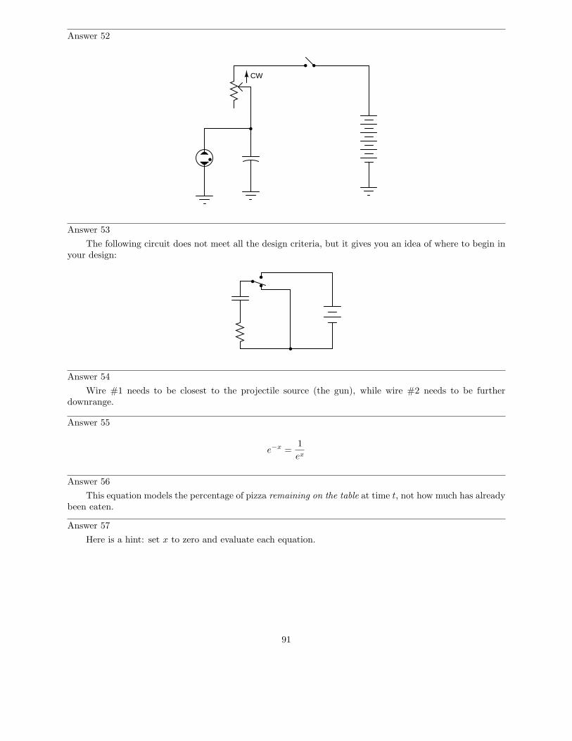
Answer 52
CW
Answer 53
The following circuit does not meet all the design criteria, but it gives you an idea of where to begin inyour design:
Answer 54
Wire #1 needs to be closest to the projectile source (the gun), while wire #2 needs to be furtherdownrange.
Answer 55
e−x =1
ex
Answer 56
This equation models the percentage of pizza remaining on the table at time t, not how much has alreadybeen eaten.
Answer 57
Here is a hint: set x to zero and evaluate each equation.
91
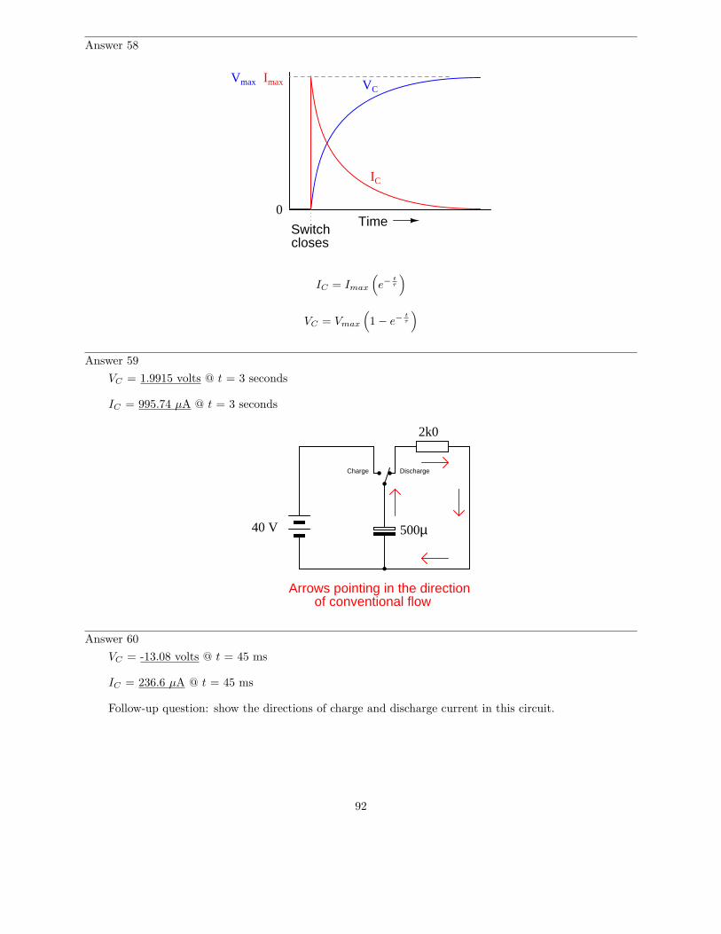
Answer 58
TimeSwitchcloses
IC
VCVmax Imax
0
IC = Imax
(
e−t
τ
)
VC = Vmax
(
1 − e−t
τ
)
Answer 59
VC = 1.9915 volts @ t = 3 seconds
IC = 995.74 µA @ t = 3 seconds
40 V
Charge Discharge
Arrows pointing in the directionof conventional flow
500µ
2k0
Answer 60
VC = -13.08 volts @ t = 45 ms
IC = 236.6 µA @ t = 45 ms
Follow-up question: show the directions of charge and discharge current in this circuit.
92
Answer 61
Before the switch closes:VC = zeroVR = zeroVswitch = maximumI = zero
At the instant of switch closure:VC = zeroVR = maximumVswitch = zeroI = maximum
Long after the switch has closed:VC = maximumVR = zeroVswitch = zeroI = zero
Follow-up question: which of these variables remained the same immediately before and immediatelyafter switch closure? Explain why.
Answer 62
Before the switch closes:VL = zeroVR = zeroVswitch = maximumI = zero
At the instant of switch closure:VL = maximumVR = zeroVswitch = zeroI = zero
Long after the switch has closed:VL = zeroVR = maximumVswitch = zeroI = maximum
Follow-up question: which of these variables remained the same immediately before and immediatelyafter switch closure? Explain why.
Answer 63
Iswitch−left = 2 mAVswitch−right = 182 V
Follow-up question: suppose this circuit were built and tested, and it was found that the voltagedeveloped across the inductor at the moment the switch moved to the right-hand position far exceeded 182volts. Identify some possible problems in the circuit which could account for this excessive voltage.
93
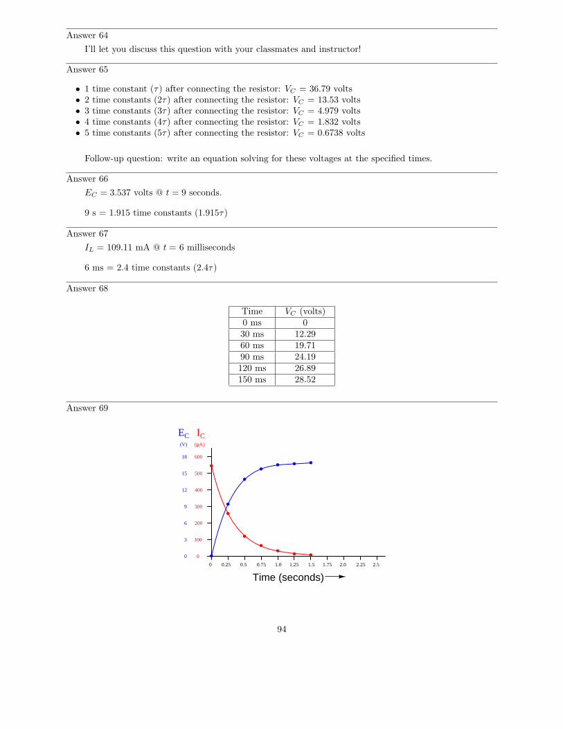
Answer 64
I’ll let you discuss this question with your classmates and instructor!
Answer 65
• 1 time constant (τ) after connecting the resistor: VC = 36.79 volts• 2 time constants (2τ) after connecting the resistor: VC = 13.53 volts• 3 time constants (3τ) after connecting the resistor: VC = 4.979 volts• 4 time constants (4τ) after connecting the resistor: VC = 1.832 volts• 5 time constants (5τ) after connecting the resistor: VC = 0.6738 volts
Follow-up question: write an equation solving for these voltages at the specified times.
Answer 66
EC = 3.537 volts @ t = 9 seconds.
9 s = 1.915 time constants (1.915τ)
Answer 67
IL = 109.11 mA @ t = 6 milliseconds
6 ms = 2.4 time constants (2.4τ)
Answer 68
Time VC (volts)0 ms 030 ms 12.2960 ms 19.7190 ms 24.19120 ms 26.89150 ms 28.52
Answer 69
EC IC
0 0.25 0.5 0.75 1.0 1.25 1.5 1.75 2.0 2.25 2.5
Time (seconds)
3
6
9
12
15
18
0
600
500
400
300
200
100
0
(µA)(V)
94
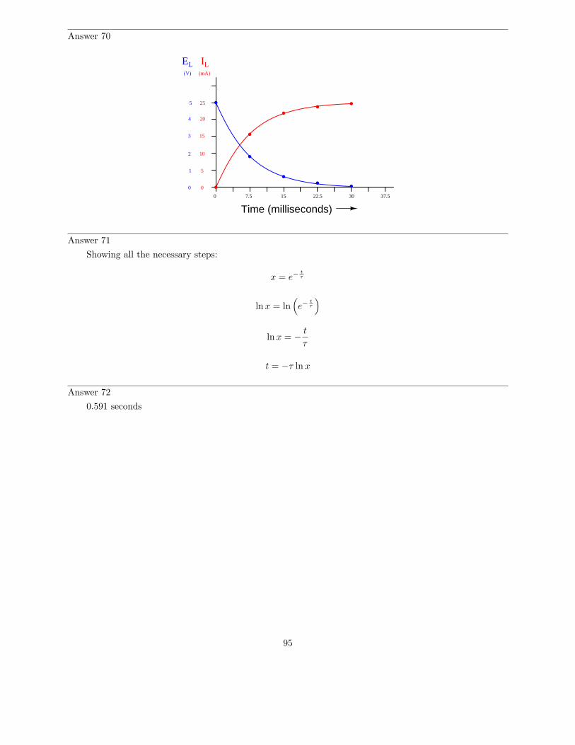
Answer 70
0
0 0
(V)
EL IL(mA)
1
2
3
4
5 25
20
15
10
5
Time (milliseconds)7.5 15 22.5 30 37.5
Answer 71
Showing all the necessary steps:
x = e−t
τ
lnx = ln(
e−t
τ
)
lnx = −t
τ
t = −τ lnx
Answer 72
0.591 seconds
95
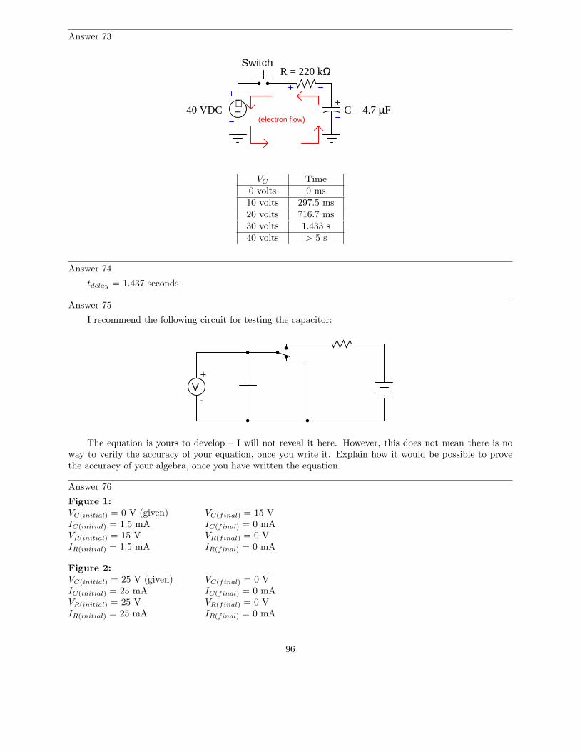
Answer 73
40 VDC C = 4.7 µF
R = 220 kΩSwitch
(electron flow)
+−
VC Time0 volts 0 ms10 volts 297.5 ms20 volts 716.7 ms30 volts 1.433 s40 volts > 5 s
Answer 74
tdelay = 1.437 seconds
Answer 75
I recommend the following circuit for testing the capacitor:
+V
-
The equation is yours to develop – I will not reveal it here. However, this does not mean there is noway to verify the accuracy of your equation, once you write it. Explain how it would be possible to provethe accuracy of your algebra, once you have written the equation.
Answer 76
Figure 1:VC(initial) = 0 V (given) VC(final) = 15 VIC(initial) = 1.5 mA IC(final) = 0 mAVR(initial) = 15 V VR(final) = 0 VIR(initial) = 1.5 mA IR(final) = 0 mA
Figure 2:VC(initial) = 25 V (given) VC(final) = 0 VIC(initial) = 25 mA IC(final) = 0 mAVR(initial) = 25 V VR(final) = 0 VIR(initial) = 25 mA IR(final) = 0 mA
96
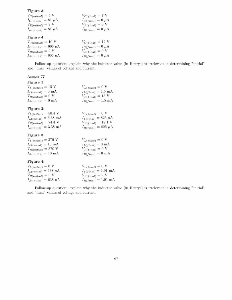
Figure 3:VC(initial) = 4 V VC(final) = 7 VIC(initial) = 81 µA IC(final) = 0 µAVR(initial) = 3 V VR(final) = 0 VIR(initial) = 81 µA IR(final) = 0 µA
Figure 4:VC(initial) = 10 V VC(final) = 12 VIC(initial) = 606 µA IC(final) = 0 µAVR(initial) = 2 V VR(final) = 0 VIR(initial) = 606 µA IR(final) = 0 µA
Follow-up question: explain why the inductor value (in Henrys) is irrelevant in determining ”initial”and ”final” values of voltage and current.
Answer 77
Figure 1:VL(initial) = 15 V VL(final) = 0 VIL(initial) = 0 mA IL(final) = 1.5 mAVR(initial) = 0 V VR(final) = 15 VIR(initial) = 0 mA IR(final) = 1.5 mA
Figure 2:VL(initial) = 50.4 V VL(final) = 0 VIL(initial) = 3.38 mA IL(final) = 825 µAVR(initial) = 74.4 V VR(final) = 18.1 VIR(initial) = 3.38 mA IR(final) = 825 µA
Figure 3:VL(initial) = 370 V VL(final) = 0 VIL(initial) = 10 mA IL(final) = 0 mAVR(initial) = 370 V VR(final) = 0 VIR(initial) = 10 mA IR(final) = 0 mA
Figure 4:VL(initial) = 6 V VL(final) = 0 VIL(initial) = 638 µA IL(final) = 1.91 mAVR(initial) = 3 V VR(final) = 9 VIR(initial) = 638 µA IR(final) = 1.91 mA
Follow-up question: explain why the inductor value (in Henrys) is irrelevant in determining ”initial”and ”final” values of voltage and current.
97
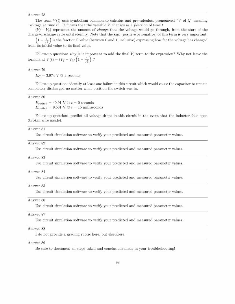
Answer 78
The term V (t) uses symbolism common to calculus and pre-calculus, pronounced ”V of t,” meaning”voltage at time t”. It means that the variable V changes as a function of time t.
(Vf − V0) represents the amount of change that the voltage would go through, from the start of thecharge/discharge cycle until eternity. Note that the sign (positive or negative) of this term is very important!
(
1 − 1
et
τ
)
is the fractional value (between 0 and 1, inclusive) expressing how far the voltage has changed
from its initial value to its final value.
Follow-up question: why is it important to add the final V0 term to the expression? Why not leave the
formula at V (t) = (Vf − V0)(
1 − 1
et
τ
)
?
Answer 79
EC = 3.974 V @ 3 seconds
Follow-up question: identify at least one failure in this circuit which would cause the capacitor to remaincompletely discharged no matter what position the switch was in.
Answer 80
Eswitch = 40.91 V @ t = 0 secondsEswitch = 9.531 V @ t = 15 milliseconds
Follow-up question: predict all voltage drops in this circuit in the event that the inductor fails open(broken wire inside).
Answer 81
Use circuit simulation software to verify your predicted and measured parameter values.
Answer 82
Use circuit simulation software to verify your predicted and measured parameter values.
Answer 83
Use circuit simulation software to verify your predicted and measured parameter values.
Answer 84
Use circuit simulation software to verify your predicted and measured parameter values.
Answer 85
Use circuit simulation software to verify your predicted and measured parameter values.
Answer 86
Use circuit simulation software to verify your predicted and measured parameter values.
Answer 87
Use circuit simulation software to verify your predicted and measured parameter values.
Answer 88
I do not provide a grading rubric here, but elsewhere.
Answer 89
Be sure to document all steps taken and conclusions made in your troubleshooting!
98
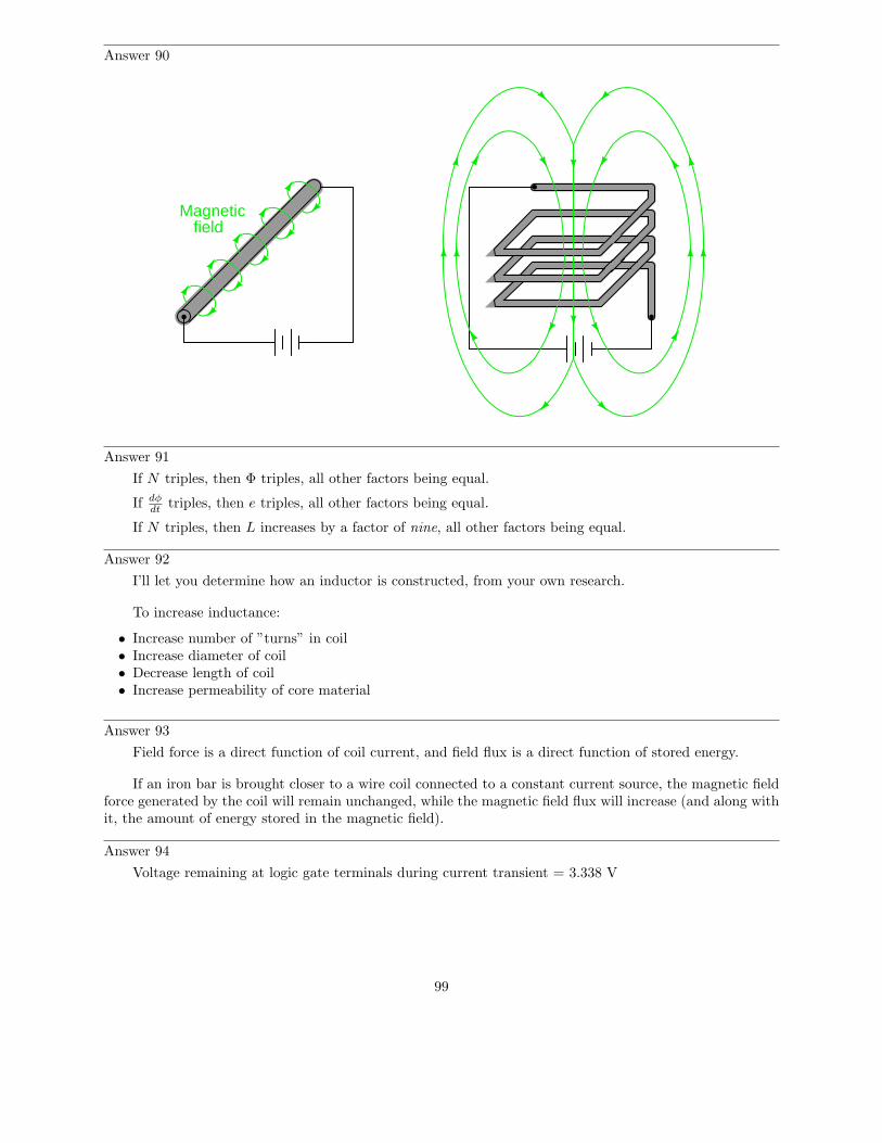
Answer 90
Magneticfield
Answer 91
If N triples, then Φ triples, all other factors being equal.
If dφdt
triples, then e triples, all other factors being equal.
If N triples, then L increases by a factor of nine, all other factors being equal.
Answer 92
I’ll let you determine how an inductor is constructed, from your own research.
To increase inductance:
• Increase number of ”turns” in coil• Increase diameter of coil• Decrease length of coil• Increase permeability of core material
Answer 93
Field force is a direct function of coil current, and field flux is a direct function of stored energy.
If an iron bar is brought closer to a wire coil connected to a constant current source, the magnetic fieldforce generated by the coil will remain unchanged, while the magnetic field flux will increase (and along withit, the amount of energy stored in the magnetic field).
Answer 94
Voltage remaining at logic gate terminals during current transient = 3.338 V
99
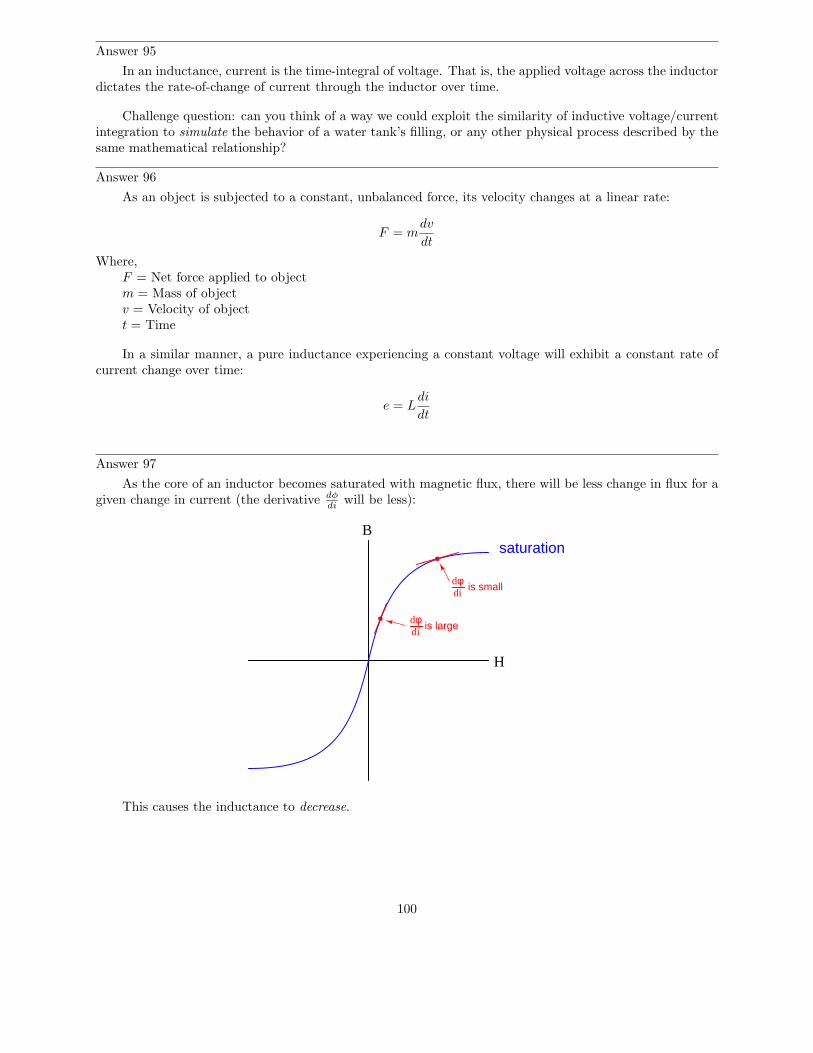
Answer 95
In an inductance, current is the time-integral of voltage. That is, the applied voltage across the inductordictates the rate-of-change of current through the inductor over time.
Challenge question: can you think of a way we could exploit the similarity of inductive voltage/currentintegration to simulate the behavior of a water tank’s filling, or any other physical process described by thesame mathematical relationship?
Answer 96
As an object is subjected to a constant, unbalanced force, its velocity changes at a linear rate:
F = mdv
dt
Where,F = Net force applied to objectm = Mass of objectv = Velocity of objectt = Time
In a similar manner, a pure inductance experiencing a constant voltage will exhibit a constant rate ofcurrent change over time:
e = Ldi
dt
Answer 97
As the core of an inductor becomes saturated with magnetic flux, there will be less change in flux for agiven change in current (the derivative dφ
diwill be less):
B
H
saturation
dφdi
is large
dφdi
is small
This causes the inductance to decrease.
100
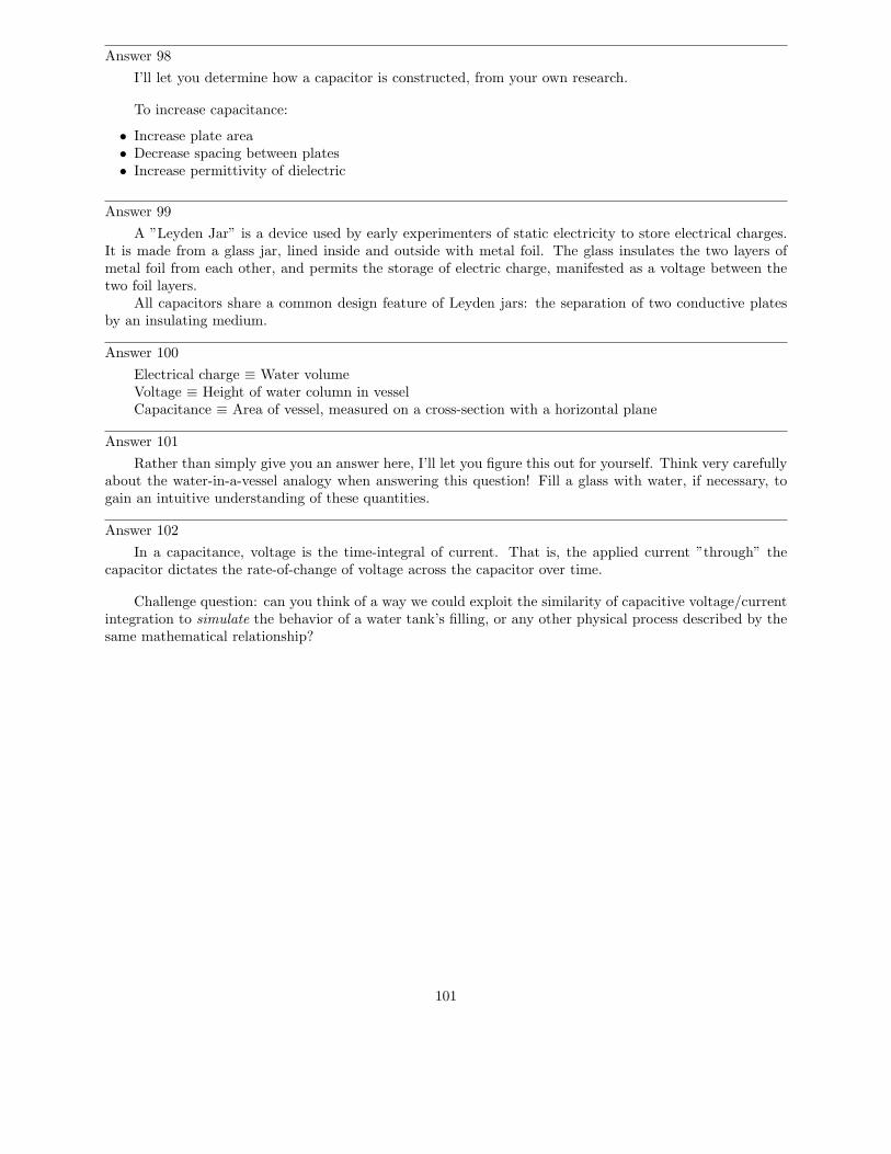
Answer 98
I’ll let you determine how a capacitor is constructed, from your own research.
To increase capacitance:
• Increase plate area• Decrease spacing between plates• Increase permittivity of dielectric
Answer 99
A ”Leyden Jar” is a device used by early experimenters of static electricity to store electrical charges.It is made from a glass jar, lined inside and outside with metal foil. The glass insulates the two layers ofmetal foil from each other, and permits the storage of electric charge, manifested as a voltage between thetwo foil layers.
All capacitors share a common design feature of Leyden jars: the separation of two conductive platesby an insulating medium.
Answer 100
Electrical charge ≡ Water volumeVoltage ≡ Height of water column in vesselCapacitance ≡ Area of vessel, measured on a cross-section with a horizontal plane
Answer 101
Rather than simply give you an answer here, I’ll let you figure this out for yourself. Think very carefullyabout the water-in-a-vessel analogy when answering this question! Fill a glass with water, if necessary, togain an intuitive understanding of these quantities.
Answer 102
In a capacitance, voltage is the time-integral of current. That is, the applied current ”through” thecapacitor dictates the rate-of-change of voltage across the capacitor over time.
Challenge question: can you think of a way we could exploit the similarity of capacitive voltage/currentintegration to simulate the behavior of a water tank’s filling, or any other physical process described by thesame mathematical relationship?
101
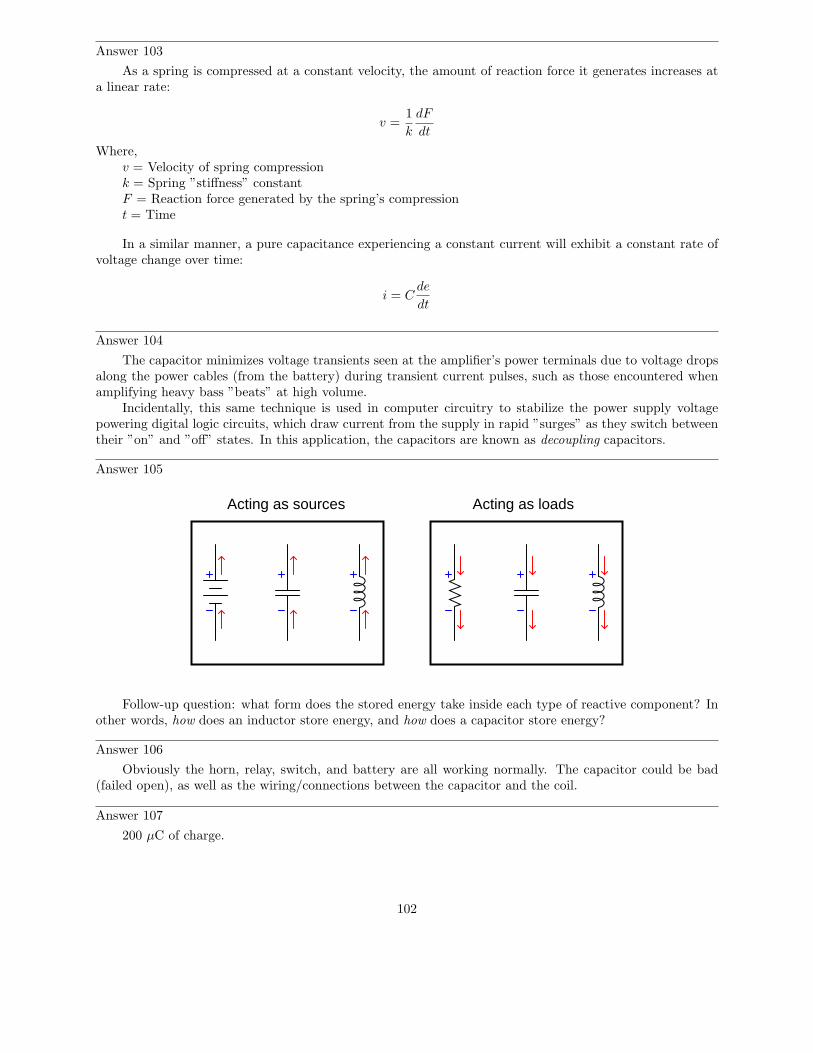
Answer 103
As a spring is compressed at a constant velocity, the amount of reaction force it generates increases ata linear rate:
v =1
k
dF
dt
Where,v = Velocity of spring compressionk = Spring ”stiffness” constantF = Reaction force generated by the spring’s compressiont = Time
In a similar manner, a pure capacitance experiencing a constant current will exhibit a constant rate ofvoltage change over time:
i = Cde
dt
Answer 104
The capacitor minimizes voltage transients seen at the amplifier’s power terminals due to voltage dropsalong the power cables (from the battery) during transient current pulses, such as those encountered whenamplifying heavy bass ”beats” at high volume.
Incidentally, this same technique is used in computer circuitry to stabilize the power supply voltagepowering digital logic circuits, which draw current from the supply in rapid ”surges” as they switch betweentheir ”on” and ”off” states. In this application, the capacitors are known as decoupling capacitors.
Answer 105
Acting as sources Acting as loads
Follow-up question: what form does the stored energy take inside each type of reactive component? Inother words, how does an inductor store energy, and how does a capacitor store energy?
Answer 106
Obviously the horn, relay, switch, and battery are all working normally. The capacitor could be bad(failed open), as well as the wiring/connections between the capacitor and the coil.
Answer 107
200 µC of charge.
102
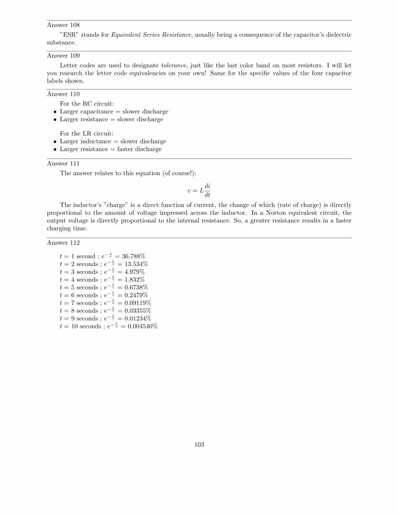
Answer 108
”ESR” stands for Equivalent Series Resistance, usually being a consequence of the capacitor’s dielectricsubstance.
Answer 109
Letter codes are used to designate tolerance, just like the last color band on most resistors. I will letyou research the letter code equivalencies on your own! Same for the specific values of the four capacitorlabels shown.
Answer 110
For the RC circuit:• Larger capacitance = slower discharge• Larger resistance = slower discharge
For the LR circuit:• Larger inductance = slower discharge• Larger resistance = faster discharge
Answer 111
The answer relates to this equation (of course!):
v = Ldi
dt
The inductor’s ”charge” is a direct function of current, the change of which (rate of charge) is directlyproportional to the amount of voltage impressed across the inductor. In a Norton equivalent circuit, theoutput voltage is directly proportional to the internal resistance. So, a greater resistance results in a fastercharging time.
Answer 112
t = 1 second ; e−t
τ = 36.788%t = 2 seconds ; e−
t
τ = 13.534%t = 3 seconds ; e−
t
τ = 4.979%t = 4 seconds ; e−
t
τ = 1.832%t = 5 seconds ; e−
t
τ = 0.6738%t = 6 seconds ; e−
t
τ = 0.2479%t = 7 seconds ; e−
t
τ = 0.09119%t = 8 seconds ; e−
t
τ = 0.03355%t = 9 seconds ; e−
t
τ = 0.01234%t = 10 seconds ; e−
t
τ = 0.004540%
103
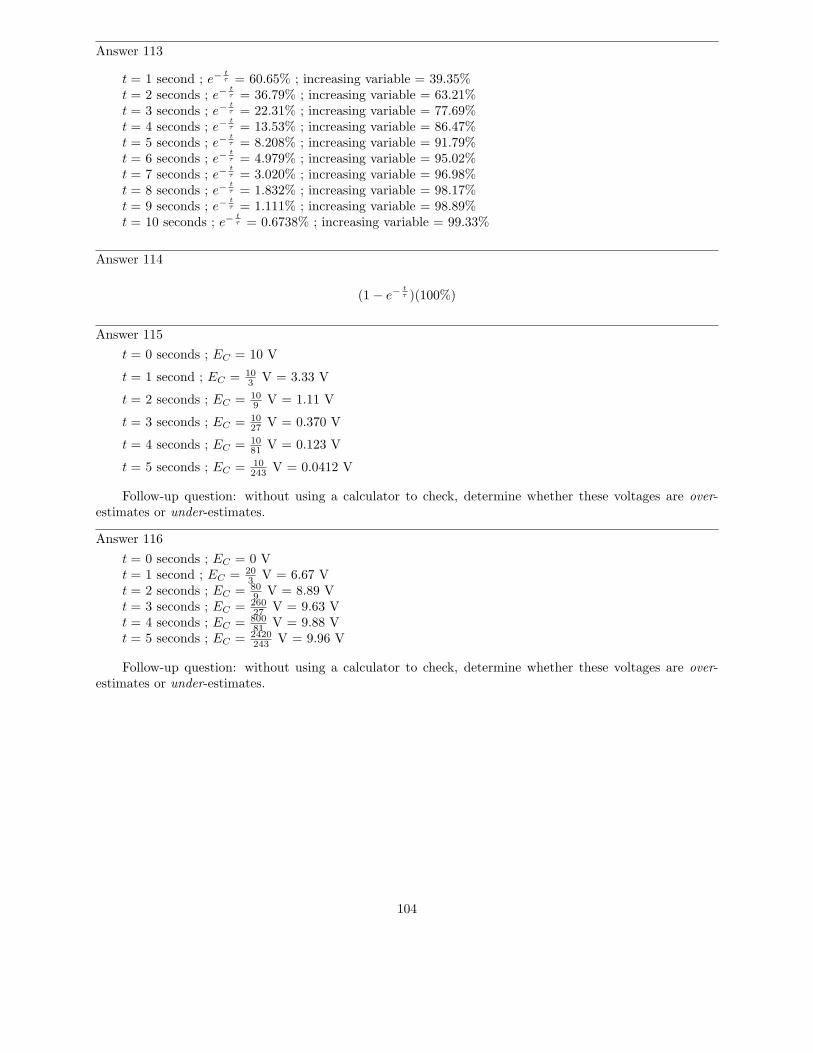
Answer 113
t = 1 second ; e−t
τ = 60.65% ; increasing variable = 39.35%t = 2 seconds ; e−
t
τ = 36.79% ; increasing variable = 63.21%t = 3 seconds ; e−
t
τ = 22.31% ; increasing variable = 77.69%t = 4 seconds ; e−
t
τ = 13.53% ; increasing variable = 86.47%t = 5 seconds ; e−
t
τ = 8.208% ; increasing variable = 91.79%t = 6 seconds ; e−
t
τ = 4.979% ; increasing variable = 95.02%t = 7 seconds ; e−
t
τ = 3.020% ; increasing variable = 96.98%t = 8 seconds ; e−
t
τ = 1.832% ; increasing variable = 98.17%t = 9 seconds ; e−
t
τ = 1.111% ; increasing variable = 98.89%t = 10 seconds ; e−
t
τ = 0.6738% ; increasing variable = 99.33%
Answer 114
(1 − e−t
τ )(100%)
Answer 115
t = 0 seconds ; EC = 10 V
t = 1 second ; EC = 103 V = 3.33 V
t = 2 seconds ; EC = 109 V = 1.11 V
t = 3 seconds ; EC = 1027 V = 0.370 V
t = 4 seconds ; EC = 1081 V = 0.123 V
t = 5 seconds ; EC = 10243 V = 0.0412 V
Follow-up question: without using a calculator to check, determine whether these voltages are over-estimates or under-estimates.
Answer 116
t = 0 seconds ; EC = 0 Vt = 1 second ; EC = 20
3 V = 6.67 Vt = 2 seconds ; EC = 80
9 V = 8.89 Vt = 3 seconds ; EC = 260
27 V = 9.63 Vt = 4 seconds ; EC = 800
81 V = 9.88 Vt = 5 seconds ; EC = 2420
243 V = 9.96 V
Follow-up question: without using a calculator to check, determine whether these voltages are over-estimates or under-estimates.
104
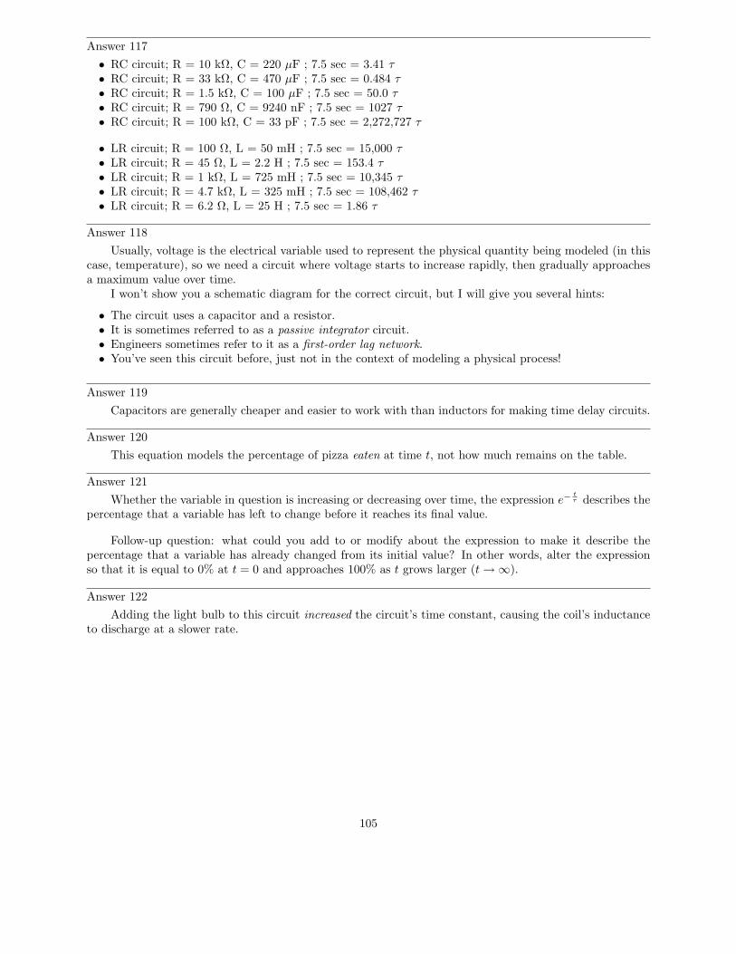
Answer 117
• RC circuit; R = 10 kΩ, C = 220 µF ; 7.5 sec = 3.41 τ• RC circuit; R = 33 kΩ, C = 470 µF ; 7.5 sec = 0.484 τ• RC circuit; R = 1.5 kΩ, C = 100 µF ; 7.5 sec = 50.0 τ• RC circuit; R = 790 Ω, C = 9240 nF ; 7.5 sec = 1027 τ• RC circuit; R = 100 kΩ, C = 33 pF ; 7.5 sec = 2,272,727 τ
• LR circuit; R = 100 Ω, L = 50 mH ; 7.5 sec = 15,000 τ• LR circuit; R = 45 Ω, L = 2.2 H ; 7.5 sec = 153.4 τ• LR circuit; R = 1 kΩ, L = 725 mH ; 7.5 sec = 10,345 τ• LR circuit; R = 4.7 kΩ, L = 325 mH ; 7.5 sec = 108,462 τ• LR circuit; R = 6.2 Ω, L = 25 H ; 7.5 sec = 1.86 τ
Answer 118
Usually, voltage is the electrical variable used to represent the physical quantity being modeled (in thiscase, temperature), so we need a circuit where voltage starts to increase rapidly, then gradually approachesa maximum value over time.
I won’t show you a schematic diagram for the correct circuit, but I will give you several hints:
• The circuit uses a capacitor and a resistor.• It is sometimes referred to as a passive integrator circuit.• Engineers sometimes refer to it as a first-order lag network.• You’ve seen this circuit before, just not in the context of modeling a physical process!
Answer 119
Capacitors are generally cheaper and easier to work with than inductors for making time delay circuits.
Answer 120
This equation models the percentage of pizza eaten at time t, not how much remains on the table.
Answer 121
Whether the variable in question is increasing or decreasing over time, the expression e−t
τ describes thepercentage that a variable has left to change before it reaches its final value.
Follow-up question: what could you add to or modify about the expression to make it describe thepercentage that a variable has already changed from its initial value? In other words, alter the expressionso that it is equal to 0% at t = 0 and approaches 100% as t grows larger (t → ∞).
Answer 122
Adding the light bulb to this circuit increased the circuit’s time constant, causing the coil’s inductanceto discharge at a slower rate.
105
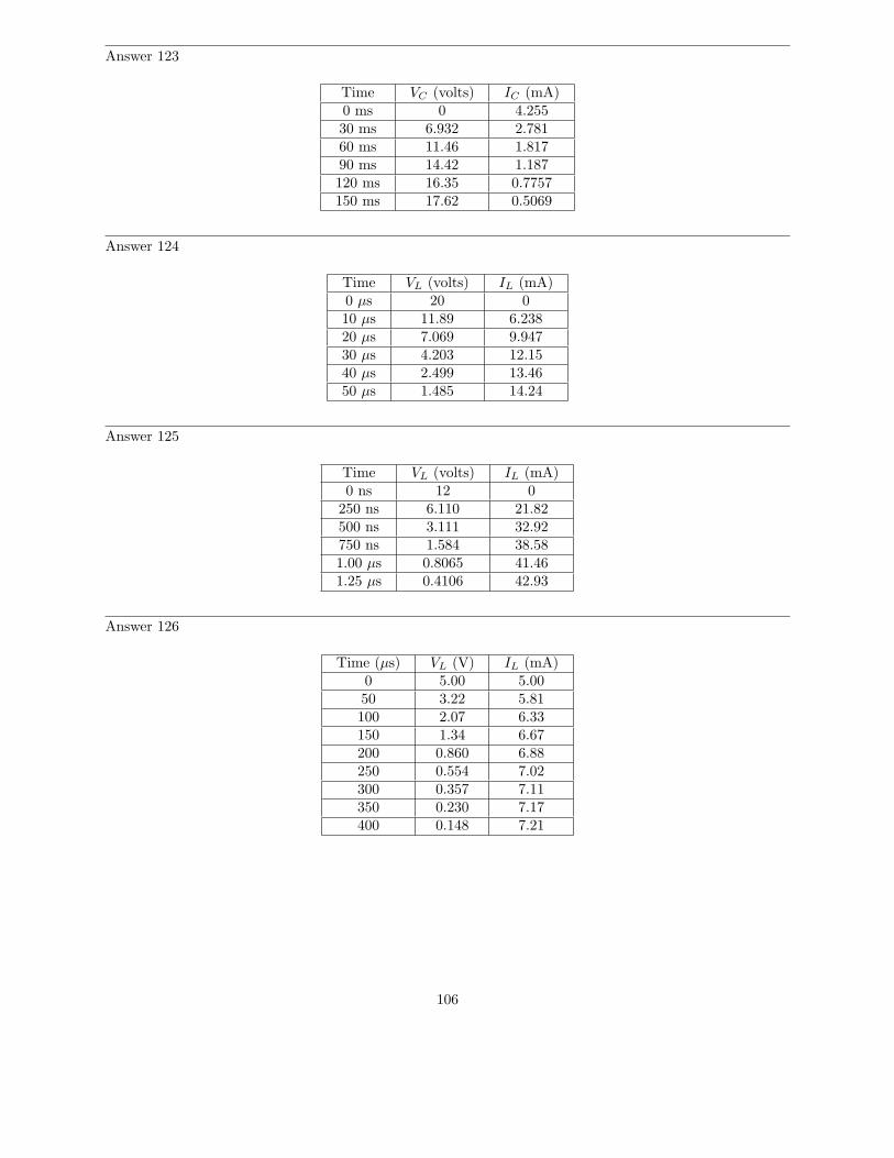
Answer 123
Time VC (volts) IC (mA)0 ms 0 4.25530 ms 6.932 2.78160 ms 11.46 1.81790 ms 14.42 1.187120 ms 16.35 0.7757150 ms 17.62 0.5069
Answer 124
Time VL (volts) IL (mA)0 µs 20 010 µs 11.89 6.23820 µs 7.069 9.94730 µs 4.203 12.1540 µs 2.499 13.4650 µs 1.485 14.24
Answer 125
Time VL (volts) IL (mA)0 ns 12 0
250 ns 6.110 21.82500 ns 3.111 32.92750 ns 1.584 38.581.00 µs 0.8065 41.461.25 µs 0.4106 42.93
Answer 126
Time (µs) VL (V) IL (mA)0 5.00 5.0050 3.22 5.81100 2.07 6.33150 1.34 6.67200 0.860 6.88250 0.554 7.02300 0.357 7.11350 0.230 7.17400 0.148 7.21
106
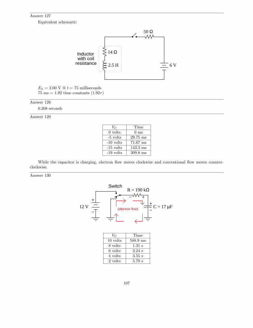
Answer 127
Equivalent schematic:
6 V2.5 H
50 Ω
14 ΩInductorwith coil
resistance
EL = 2.00 V @ t = 75 milliseconds75 ms = 1.92 time constants (1.92τ)
Answer 128
0.208 seconds
Answer 129
VC Time0 volts 0 ms-5 volts 29.75 ms-10 volts 71.67 ms-15 volts 143.3 ms-19 volts 309.8 ms
While the capacitor is charging, electron flow moves clockwise and conventional flow moves counter-clockwise.
Answer 130
Switch
(electron flow)12 V
R = 190 kΩ
C = 17 µF
VC Time10 volts 588.9 ms8 volts 1.31 s6 volts 2.24 s4 volts 3.55 s2 volts 5.79 s
107
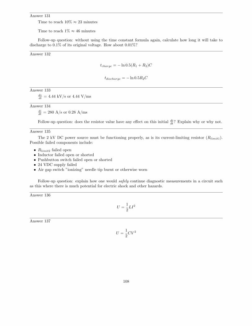
Answer 131
Time to reach 10% ≈ 23 minutes
Time to reach 1% ≈ 46 minutes
Follow-up question: without using the time constant formula again, calculate how long it will take todischarge to 0.1% of its original voltage. How about 0.01%?
Answer 132
tcharge = − ln 0.5(R1 + R2)C
tdischarge = − ln 0.5R2C
Answer 133dvdt
= 4.44 kV/s or 4.44 V/ms
Answer 134didt
= 280 A/s or 0.28 A/ms
Follow-up question: does the resistor value have any effect on this initial didt
? Explain why or why not.
Answer 135
The 2 kV DC power source must be functioning properly, as is its current-limiting resistor (Rlimit1).Possible failed components include:
• Rlimit2 failed open• Inductor failed open or shorted• Pushbutton switch failed open or shorted• 24 VDC supply failed• Air gap switch ”ionizing” needle tip burnt or otherwise worn
Follow-up question: explain how one would safely continue diagnostic measurements in a circuit suchas this where there is much potential for electric shock and other hazards.
Answer 136
U =1
2LI2
Answer 137
U =1
2CV 2
108
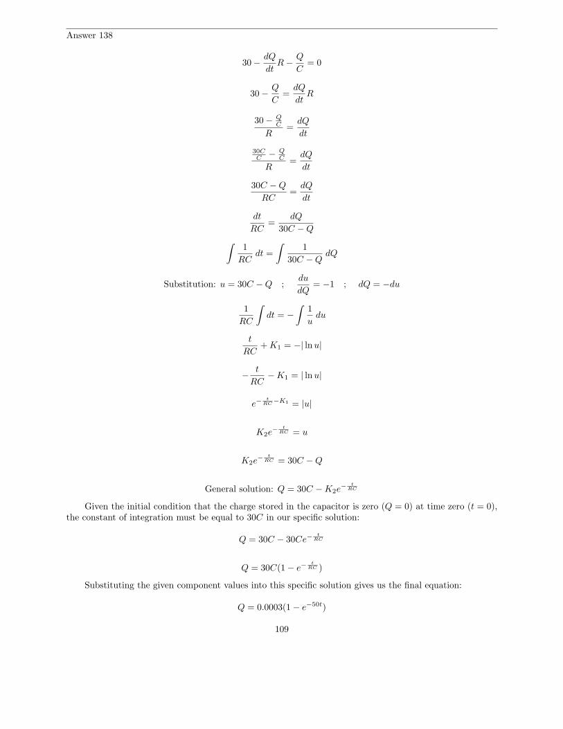
Answer 138
30 −dQ
dtR −
Q
C= 0
30 −Q
C=
dQ
dtR
30 − QC
R=
dQ
dt
30CC
− QC
R=
dQ
dt
30C − Q
RC=
dQ
dt
dt
RC=
dQ
30C − Q
∫
1
RCdt =
∫
1
30C − QdQ
Substitution: u = 30C − Q ;du
dQ= −1 ; dQ = −du
1
RC
∫
dt = −
∫
1
udu
t
RC+ K1 = −| ln u|
−t
RC− K1 = | ln u|
e−t
RC−K1 = |u|
K2e−
t
RC = u
K2e−
t
RC = 30C − Q
General solution: Q = 30C − K2e−
t
RC
Given the initial condition that the charge stored in the capacitor is zero (Q = 0) at time zero (t = 0),the constant of integration must be equal to 30C in our specific solution:
Q = 30C − 30Ce−t
RC
Q = 30C(1 − e−t
RC )
Substituting the given component values into this specific solution gives us the final equation:
Q = 0.0003(1 − e−50t)
109
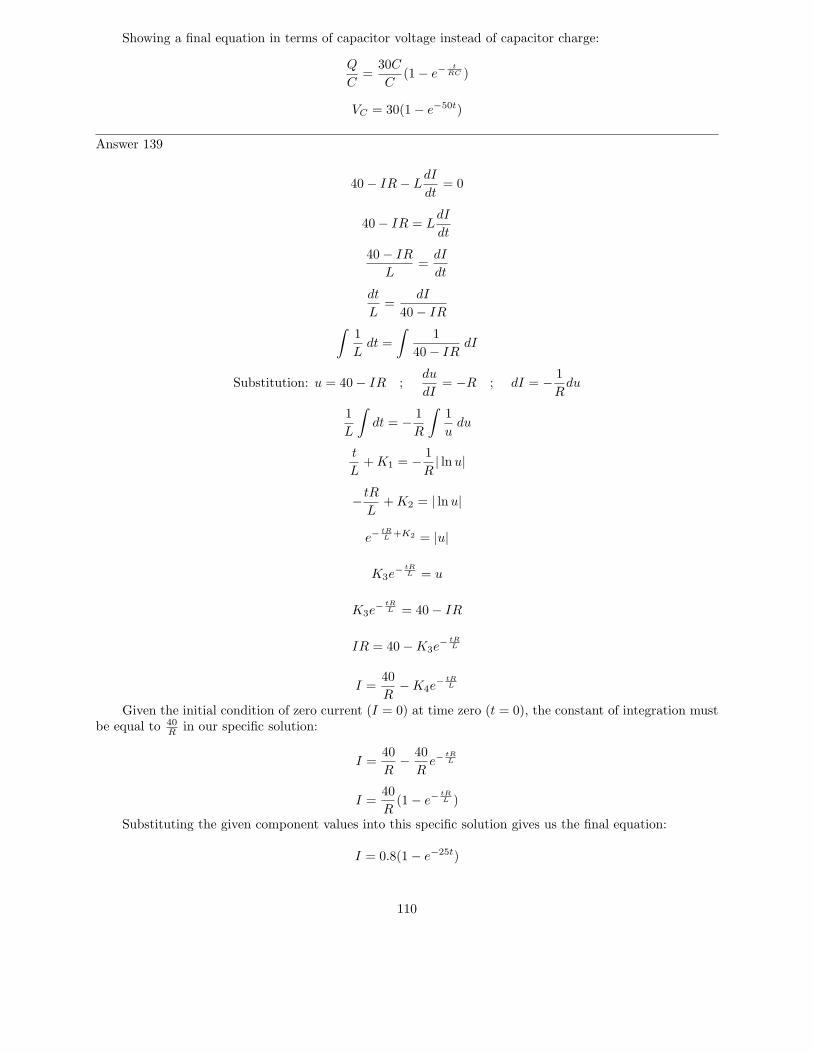
Showing a final equation in terms of capacitor voltage instead of capacitor charge:
Q
C=
30C
C(1 − e−
t
RC )
VC = 30(1 − e−50t)
Answer 139
40 − IR − LdI
dt= 0
40 − IR = LdI
dt
40 − IR
L=
dI
dt
dt
L=
dI
40 − IR∫
1
Ldt =
∫
1
40 − IRdI
Substitution: u = 40 − IR ;du
dI= −R ; dI = −
1
Rdu
1
L
∫
dt = −1
R
∫
1
udu
t
L+ K1 = −
1
R| ln u|
−tR
L+ K2 = | ln u|
e−tR
L+K2 = |u|
K3e−
tR
L = u
K3e−
tR
L = 40 − IR
IR = 40 − K3e−
tR
L
I =40
R− K4e
−
tR
L
Given the initial condition of zero current (I = 0) at time zero (t = 0), the constant of integration mustbe equal to 40
Rin our specific solution:
I =40
R−
40
Re−
tR
L
I =40
R(1 − e−
tR
L )
Substituting the given component values into this specific solution gives us the final equation:
I = 0.8(1 − e−25t)
110
Notes
Notes 1
Self-induction is not a difficult concept to grasp if one already possesses a good understanding ofelectromagnetism, electromagnetic induction, and Lenz’s Law. Some students may struggle understandingself-induction, because it is probably the first application they’ve seen where these three phenomena inter-relate simultaneously.
Notes 2
Ask students what unit of measurement inductance is expressed in. Also, ask them if they think theinductance of any given conductor changes with the applied current or stored energy, or if inductance is aquantity independent of particular electrical conditions.
Notes 3
I have found that the topics of capacitance and inductance are excellent contexts in which to introducefundamental principles of calculus to students. The time you spend discussing this question and questionslike it will vary according to your students’ mathematical abilities.
Even if your students are not ready to explore calculus, it is still a good idea to discuss how therelationship between current and voltage for an inductance involves time. This is a radical departure fromthe time-independent nature of resistors, and of Ohm’s Law!
Notes 4
Students who do not yet understand the concept of inductance may be inclined to suggest that thecurrent in this circuit will be infinite, following Ohm’s Law (I = E/R). One of the purposes of this questionis to reveal such misunderstandings, so that they may be corrected.
This circuit provides an excellent example of the calculus principle integration, where the applicationof a steady voltage across the inductor results in a steadily increasing current. Whether or not you shouldtouch on this subject depends on the mathematical aptitude of your students.
Notes 5
This problem is first and foremost an algebraic manipulation exercise: solving for N given the valuesof the other variables. Students should be able to research the value of µ0 quite easily, being a well-definedphysical constant.
Note that in this equation, the Greek letter ”mu” (µ) is not a metric prefix, but rather an actual variable!This confuses many students, who are used to interpreting µ as the metric prefix ”micro” ( 1
1,000,000 ).
Note also how the re-written equation puts pi (π) ahead of all the variables in the numerator of thefraction. This is not absolutely necessary, but it is conventional to write constants before variables. Do notbe surprised if some students ask about this, as their answers probably looked like this:
L =N2πr2µ
l
Notes 6
This type of distinction is very important in the study of physics as well, where one must determinewhether a mechanical system is doing work or whether work is being done on it. A clear understanding ofthe relationship between voltage polarity and current direction for sources and loads is very important forstudents to have before they study reactive devices such as inductors and capacitors!
111
Notes 7
Relating the polarity of voltage across an inductor to a change of applied current over time is a complexconcept for many students. Since it involves rates of change over time, it is an excellent opportunity tointroduce calculus concepts ( d
dt).
Vitally important to students’ conceptual understanding of an inductor exposed to increasing ordecreasing currents is the distinction between an electrical energy source versus a load. Students need tothink ”battery” and ”resistor,” respectively when determining the relationship between direction of currentand voltage drop. The complicated aspect of inductors (and capacitors!) is that they may switch characterin an instant, from being a source of energy to being a load, and visa-versa. The relationship is not fixed asit is for resistors, which are always energy loads.
Notes 8
Emphasize to your students that inductance is an essentially reactive property, opposing change incurrent over time. It is not steady current that inductors react to, only changing current.
Notes 9
This technique is very useful in reducing or eliminating parasitic inductance. Typically, parasiticinductance is not a problem unless very high rates of current change are involved, such as in high-frequencyAC circuits (radio, high-speed digital logic, etc.). In such applications, knowing how to control strayinductance is very important to proper circuit operation.
Notes 10
In high-frequency AC circuits, such as computer circuits where pulses of voltage oscillate at millions ofcycles per second, even short lengths of wire or traces on a circuit board may present substantial trouble byvirtue of their stray inductance. Some of this parasitic inductance may be reduced by proper circuit boardassembly, some of it by a re-design of component layout on the circuit board.
According to an article in IEEE Spectrum magazine (”Putting Passives In Their Place”, July 2003,Volume 40, Number 7, page 29), the transient currents created by fast-switching logic circuits can be as highas 500 amps/ns, which is a di
dtrate of 500 billion amps per second!! At these levels, even a few picohenrys of
parasitic inductance along component leads and circuit board traces will result in significant voltage drops.
Notes 11
One way to help understand how an inductor could produce such large voltages is to consider it as atemporary current source, which will output as much voltage as necessary in an effort to maintain constantcurrent. Just as ideal current sources are dangerous to open-circuit, current-carrying inductors are likewisecapable of generating tremendous transient voltages.
Although there was no real safety hazard with my experiment, there potentially could have been,provided different circumstances. Discuss with your students what would have been necessary to create anactual safety hazard.
Notes 12
Don’t give your students the equation with which to perform this calculation! Let them find it on theirown. The di
dtnotation may be foreign to students lacking a strong mathematical background, but don’t let
this be an obstacle to learning! Rather, use this as a way to introduce those students to the concept of ratesof change, and to the calculus concept of the derivative.
112
Notes 13
Ahhh, the controversy of conventional versus electron flow. The existence of two contradictingconventions for denoting direction of electric current irritates me to no end, especially when the one uponwhich almost all electronic device symbolism is based on is actually incorrect with regard to charge flowthrough metallic conductors (the majority case in electric circuits)! Your students will surely encounter both”conventional” and ”electron” flow in their careers, so be sure to introduce them to both conventions.
Discuss with your students the consequences of winding resistance in real inductors. Is it significant?Work together with your students to calculate how much extra voltage would be dropped across the inductor,based on their research on the typical winding resistance of a 4 henry inductor (ask them where they obtainedthe information!), given a di
dtrate of 1.5 amps per second.
Ask your students if they think it might be possible to create an inductor with no ”stray” resistance atall to interfere with perfect, theoretical inductor behavior. What would be required to make the ”perfect”inductor?
Notes 14
If your students are having difficulty answering the follow-up question in the Answer, ask them tocompare these voltage figures (45 V and 11.25 V) against the voltage that would be dropped by just one ofthe 5 H inductors under the same condition (an applied current changing at a rate of 4.5 amps per second).
It is, of course, important that students know how series-connected and parallel connected inductorsbehave. However, this is typically a process of rote memorization for students rather than true understanding.With this question, the goal is to have students come to a realization of inductor connections based on theirunderstanding of series and parallel voltages and currents.
Notes 15
Ask your students this question: given capacitors and inductors, which of these component types behavemore like resistors, in terms of their series versus parallel equivalent values?
Notes 16
It is most helpful to first draw a schematic diagram for this inductor network before trying to perform anyinductance calculations, in order that a clear understanding of the series/parallel connections be established.
Notes 17
Inductors tend to be even more scarce than resistors in regard to the availability of different values, soknowing how to combine different inductors together to achieve a desired total inductance is a practical skill.
It should be noted to your students that inductors may interact with one another if placed too close,due to the magnetic field of one inductor ”linking” with the coil of another inductor. This is called mutualinductance, and if present alters the otherwise straightforward series-parallel inductance relationships thatone would expect to be analogous to series-parallel resistances.
Notes 18
Power system reactors are usually installed in substations, where they appear as coils of wire (no ironcore) a few feet in diameter, usually located near circuit breakers.
Notes 19
Students will note a lot of similarities between the inductor color code and the resistor color code, butthey should also note one significant difference!
113
Notes 20
Have your students actually test a few inductors with their ohmmeters in class. Unlike capacitor checkingwith an ohmmeter, there is never a substantial ”charging” period! If your students have already learnedabout capacitor checking with an ohmmeter, ask them to explain why there is no ”charging” action indicatedby the ohmmeter when connected to an inductor.
If there were an observable ”charging” time exhibited by an inductor when measured by an ohmmeter,what would it appear as, in terms of the ohmmeter’s indication?
Normally, I don’t give away answers to follow-up questions in the ”Notes” section, but here I feel itmay be necessary. Studies have shown that inductors have about an equal chance of failing open as they dofailing shorted. Of course, this will vary with the specific design and application of the inductor, but thereis no mode of failure clearly more probable than the other.
Notes 21
Students may note that electric lines of flux do not follow the same paths that magnetic lines of fluxwould. Whereas magnetic lines of flux are always circular, electric lines of flux always terminate betweenpoints.
Note to your students the relevance of this fact in shielding: unlike magnetic shields which must divertthe inevitable paths of magnetic flux lines, electric shields are able to terminate electric flux lines.
Notes 22
Electric field force is also used in some precision voltage measuring instruments (”electrostatic” metermovements), as well as the more common electroscope. If you happen to have either an electrostatic metermovement or an electroscope available in your classroom, use it to demonstrate the physical effects of electricfields.
Notes 23
Ask students what unit of measurement capacitance is expressed in. Also, ask them if they think thecapacitance of any given conductor pair changes with the applied voltage or stored energy, or if capacitanceis a quantity independent of particular electrical conditions.
Notes 24
This problem is first and foremost an algebraic manipulation exercise. Then, it is merely a matter ofsolving for d given the proper values. Finding ǫ could be difficult, though, and this is by design: I wantstudents to learn the significance of absolute permittivity!
Notes 25
The purpose of this question is to make students think critically and creatively about capacitance. Thereis more than one way to test for capacitance in a cable, so do not limit students to one method only!
Notes 26
The concept of a field is quite abstract. Electric fields in particular are abstract because they cannot betangibly perceived, at least not outside of dangerous voltage levels. Magnetic fields, which everyone shouldbe familiar with from playing with magnets, may serve as an illustration of fields in general, but it is veryimportant for students of electricity and electronics to understand that electric and magnetic fields are twodifferent entities, albeit closely related (by Maxwell’s Laws).
Notes 27
This is one of those equations usually discussed somewhere in the first few months of basic electronicseducation, and promptly forgotten by most. It can be very useful, however, when dealing with charge pumpsand other switched-capacitor circuitry.
114
Notes 28
Relating the direction of current in a capacitor to a change of applied voltage over time is a complexconcept for many students. Since it involves rates of change over time, it is an excellent opportunity tointroduce calculus concepts ( d
dt).
Vitally important to students’ conceptual understanding of a capacitor exposed to increasing ordecreasing voltages is the distinction between an electrical energy source versus a load. Students need tothink ”battery” and ”resistor,” respectively when determining the relationship between direction of currentand voltage drop. The complicated aspect of capacitors (and inductors!) is that they may switch characterin an instant, from being a source of energy to being a load, and visa-versa. The relationship is not fixed asit is for resistors, which are always energy loads.
Notes 29
I have found that the topics of capacitance and inductance are excellent contexts in which to introducefundamental principles of calculus to students. The time you spend discussing this question and questionslike it will vary according to your students’ mathematical abilities.
Even if your students are not ready to explore calculus, it is still a good idea to discuss how therelationship between current and voltage for a capacitance involves time. This is a radical departure fromthe time-independent nature of resistors, and of Ohm’s Law!
Notes 30
Emphasize to your students that capacitance is an essentially reactive property, opposing change involtage over time. It is not steady voltage that capacitors react to, only changing voltage.
Notes 31
There is much to be researched on different capacitor types and characteristics! Encourage your studentsto research both textbooks and capacitor manufacturer literature for more information.
Notes 32
There are many features of electrolytic capacitors unique to that type, not the least of which being theirmeans of manufacture. Since these capacitors are used so often for low-voltage electronic applications, it iswell worth the students’ time to study them well and know their idiosyncrasies.
Notes 33
As with resistors and resistance ratings, there is more to the rating of a capacitor than merelycapacitance! Discuss with your students the importance of safety when working with capacitors, not onlyfrom shock hazard but also from explosions (resulting from excessive voltage).
Notes 34
An interesting follow-up question to pose would be: how do we safely discharge a capacitor chargedwith dangerous levels of voltage?
Notes 35
Don’t give your students the equation with which to perform this calculation! Let them find it on theirown. The dv
dtnotation may be foreign to students lacking a strong mathematical background, but don’t let
this be an obstacle to learning! Rather, use this as a way to introduce those students to the concept of ratesof change, and to the calculus concept of the derivative.
115
Notes 36
If your students are having difficulty answering the follow-up question in the Answer, ask them tocompare these current figures (47 mA and 188 mA) against the current that would go through just oneof the 470 µF capacitors under the same condition (an applied voltage changing at a rate of 200 volts persecond).
It is, of course, important that students know how series-connected and parallel connected capacitorsbehave. However, this is typically a process of rote memorization for students rather than true understanding.With this question, the goal is to have students come to a realization of capacitor connections based on theirunderstanding of series and parallel voltages and currents.
Notes 37
Capacitors often confuse new students of electronics because their values do not add up the same asresistors. It is important in answering this question that your students understand why series capacitancescombine as they do. There is more than one way to explain this phenomenon – explain in terms of capacitordimensions, or in terms of voltage drop and charge storage.
Notes 38
It is most helpful to first draw a schematic diagram for this capacitor network before trying to performany capacitance calculations, in order that a clear understanding of the series/parallel connections beestablished.
Notes 39
Ask your students how they can tell whether a capacitor’s value is given in microfarads or picofarads.There is a way, even if the metric prefix is not printed on the capacitor!
Notes 40
Have your students actually test a few capacitors with their ohmmeters in class. For large capacitorvalues, the charging time may be substantial! Students need to be aware of this, and the effect it has on theohmmeter’s indication.
Although an ohmmeter check of a capacitor is not a comprehensive analysis, it is certainly better thannothing, and will detect the more common faults.
Notes 41
A qualitative analysis of this circuit’s behavior may be performed without using any calculus, or evenalgebra. Ask students to explain what happens to current in the circuit as the capacitor’s voltage begins toincrease, and then what effect that has on the rate of voltage rise, and so on, graphing the results for all toosee.
Hint: the rate of voltage rise across a capacitor is in direct proportion to the quantity of current going”through” the capacitor.
Notes 42
A qualitative analysis of this circuit’s behavior may be performed without using any calculus, or evenalgebra. Ask students to explain what happens to the voltage across the inductor as the circuit currentbeings to increase, and what effect that has on the rate of current rise, and so on, graphing the results forall too see.
Hint: the rate of current rise through an inductor is in direct proportion to the quantity of voltagedropped across the inductor.
Notes 43
Have your students explain why the voltage and current curves are shaped as they are.
116
Notes 44
Have your students explain why the voltage and current curves are shaped as they are.
Notes 45
I like to use the example of radioactive decay to introduce time constants, because it seems most peoplehave at least heard of something called ”half-life,” even if they don’t know exactly what it is.
Incidentally, the choice to measure decay in either ”half lives” or ”time constants” is arbitrary. The curvefor radioactive decay is the exact same curve as that of an RC or LR discharge process, and is characterizedby the same differential equation:
dQ
dt= −kQ
Where,Q = Decaying variable (grams of substance, volts, amps, whatever)k = Relative decay ratet = Time
By solving this separable differential equation, we naturally arrive at an equation expressing Q in termsof an exponential function of e:
Q = Q0e−kt
Thus, it makes more sense to work with units of ”time constants” based on e than with ”half lives,”although admittedly ”half-life” is a concept that makes more intuitive sense. Incidentally, 1 half-life is equalto 0.693 time constants, and 1 time constant is equal to 1.443 half-lives.
Notes 46
The leap I expect students to make here is to think about the exchange of energy for both capacitorsand inductors as they deliver power to a resistive load. Which ever values of R make the respective sourceswork the hardest (dissipate the most power at the load) will be the values that make the reactive componentsdischarge quickest.
Notes 47
In order for students to answer this question, they must research the RC time constant equation andreview the 5-band resistor color code.
Notes 48
In order for students to answer this question, they must research the LR time constant equation andreview the 5-band resistor color code.
Notes 49
The stock answer of ”5 time constants” as the amount of time elapsed between the transient event andthe ”final” settling of voltage and current values is widespread, but largely misunderstood. I’ve encounteredmore than a few graduates of electronics programs who actually believe there is something special about thenumber 5, as though everything grinds to a halt at exactly 5 time constants worth of time after the switchcloses.
In reality, the rule of thumb of ”5 time constants” as a settling time in RC and LR circuits is anapproximation only. Somewhere I recall reading an old textbook that specified ten time constants as thetime required for all the variables to reach their final values. Another old book declared seven time constants.I think we’re getting impatient as the years roll on!
117
Notes 50
In order to answer this question, students must not only be able to calculate time constants for a simpleRC circuit, but they must also remember the resistor color code so as to choose the right size based on color.A very practical problem, and important for safety reasons too!
Notes 51
What we have here is a very simple strobe light circuit. This circuit may be constructed in the classroomwith minimal safety hazard if the DC voltage source is a hand-crank generator instead of a battery bankor line-powered supply. I’ve demonstrated this in my own classroom before, using a hand-crank ”Megger”(high-range, high-voltage ohmmeter) as the power source.
Notes 52
Ask your students to explain why the potentiometer has the speed-changing effect it does on the circuit’sflash rate. Would there be any other way to change this circuit’s flash rate, without using a potentiometer?
Notes 53
This is an interesting question, as the students are challenged with the design of a circuit, and thatthe example circuit shown in the answer does not completely fulfill the specified criteria. In order for astudent to derive a circuit from the one given in the answer, they must first assess that circuit’s operation,to determine what it can and cannot do.
Note that it will not suffice to merely replace the fixed-value resistor with a variable resistor, as thiswould not provide independent adjustment of charging and discharging time constants.
Notes 54
This is an interesting question because it requires the students to reason through the function of apractical measuring circuit. Not only must students grasp the charge/discharge behavior of a capacitor,but they also must relate it to the practical purpose of the intervalometer, recognizing the importance ofvoltmeter characteristics as well. Expect substantial discussion on this question.
Notes 55
I am usually not a fan of discussing calculator keystroke sequences to college-level students, but I haveresorted to this at the college where I teach because so many of my students have no idea of how to evaluateexponential expressions! Of course, the actual keystrokes one must push to evaluate this expression dependon the brand of calculator used.
Notes 56
While some may wonder what this question has to do with electronics, it is an exercise in qualitativeanalysis. This skill is very important for students to master if they are to be able to distinguish between theequations e−
t
τ and 1 − e−t
τ , both used in time-constant circuit analysis.The actual procedure for determining the nature of the equation is simple: consider what happens as t
begins at 0 and as it increases to some arbitrary positive value. Some students may rely on their calculators,performing actual calculations to see whether the percentage increases or decreases with increasing t.Encourage them to analyze the equation qualitatively rather than quantitatively, though. They shouldbe able to tell which way the percentage changes with time without having to consider a single numericalvalue!
Notes 57
It is very important for students to understand what this expression means and how it works, lest theyrely solely on memorization to use it in their calculations. As I always tell my students, rote memorizationwill fail you! If a student does not comprehend why the expression works as it does, they will be helpless toretain it as an effective ”tool” for performing calculations in the future.
118
Notes 58
Have your students explain why the voltage and current curves are shaped as they are.
Notes 59
Here, students must choose which equation(s) to use for the calculation, calculate the time constant forthe circuit, and put all the variables in the right place to obtain the correct answers. Discuss all these stepswith your students, allowing them to explain how they approached the question.
If anyone asks, let them know that the capacitor symbol shown represents a polarized (electrolytic)capacitor.
Notes 60
Here, students must choose which equation(s) to use for the calculation, calculate the time constant forthe circuit, and put all the variables in the right place to obtain the correct answers. Discuss all these stepswith your students, allowing them to explain how they approached the question.
If anyone asks, let them know that the capacitor symbol shown represents a polarized (electrolytic)capacitor.
Notes 61
The purpose of this question is to preview the concept of ”initial” and ”final” values in RC circuits,before they learn to use the ”universal time constant formula.”
Notes 62
The purpose of this question is to preview the concept of ”initial” and ”final” values in RC circuits,before they learn to use the ”universal time constant formula.”
Notes 63
The main purpose of this question is to get students thinking in terms of ”initial” and ”final” valuesfor LR circuits, and how one might calculate them. It is largely a conceptual question, with just a bit ofcalculation necessary.
One practical application of this circuit is for ”stepping up” DC voltage. The circuit topology shown inthe question is that of an inverting converter circuit. This form of DC-DC converter circuit has the abilityto step voltage up or down, depending on the duty cycle of the switch’s oscillation.
Notes 64
This is advice I always give my students, after seeing so many students get themselves into trouble byblindly plugging numbers into equations. Think before you act, is the motto here!
Actually, this general advice applies to most all physics-type problems: identify what it is you’re tryingto solve and what you have to work with before jumping into calculations.
Notes 65
Although students should be able to look up approximate answers to this question from almost anybeginning electronics textbook, the point here is to get them to relate the question to an actual formula sothey may calculate this on their own.
Notes 66
Here, students must choose which equation to use for the calculation, calculate the time constant forthe circuit, and put all the variables in the right place to obtain the correct answer. Discuss all these stepswith your students, allowing them to explain how they approached the question.
119
Notes 67
Here, students must choose which equation to use for the calculation, calculate the time constant forthe circuit, and put all the variables in the right place to obtain the correct answer. Discuss all these stepswith your students, allowing them to explain how they approached the question.
Notes 68
Be sure to have your students share their problem-solving techniques (how they determined whichequation to use, etc.) in class.
Notes 69
I intentionally left the graph unscaled in the problem, so that students might determine their own scalesto plot the points in. The scaling shown in the answer is obviously not ideal, as the graphs have reachedtheir terminal values (for all practical purposes) well before the horizontal axis is complete.
Notes 70
I intentionally left the graph unscaled in the problem, so that students might determine their own scalesto plot the points in. The scaling shown in the answer is obviously not ideal, as the graphs have reachedtheir terminal values (for all practical purposes) well before the horizontal axis is complete.
120
Notes 71
In my experience, most American high school graduates are extremely weak in logarithms. Apparentlythis is not taught very well at the high school level, which is a shame because logarithms are a powerfulmathematical tool. You may find it necessary to explain to your students what a logarithm is, and exactlywhy it ”un-does” the exponent.
When forced to give a quick presentation on logarithms, I usually start with a generic definition:
Given: ba = c
Logarithm defined: logb c = a
Verbally defined, the logarithm function asks us to find the power (a) of the base (b) that will yield c.
Next, I introduce the common logarithm. This, of course, is a logarithm with a base of 10. A few quickcalculator exercises help students grasp what the common logarithm function is all about:
log 10 =
log 100 =
log 1000 =
log 10000 =
log 100000 =
log1
10=
log1
100=
log1
1000=
After this, I introduce the natural logarithm: a logarithm with a base of e (Euler’s constant):
Natural logarithm defined: lnx = loge x
Have your students do this simple calculation on their calculators, and explain the result:
ln 2.71828 =
Next comes an exercise to help them understand how logarithms can ”undo” exponentiation. Have yourstudents calculate the following values:
e2 =
e3 =
e4 =
121
Now, have them take the natural logarithms of each of those answers. They will find that they arriveat the original exponent values (2, 3, and 4, respectively). Write this relationship on the board as such foryour students to view:
ln e2 = 2
ln e3 = 3
ln e4 = 4
Ask your students to express this relationship in general form, using the variable x for the power insteadof an actual number:
ln ex = x
It should now be apparent that the natural logarithm function has the ability to ”undo” a power of e.Now it should be clear to your students why the given sequence of algebraic manipulations in the answer forthis question is true.
Notes 72
In order for students to solve this problem, they must algebraically manipulate the ”normal” time-constant formula to solve for time instead of solving for voltage.
Notes 73
Some students may write 5.17 seconds as the time required to charge to 40 volts (5 time constants’ worthof time). If so, remind them that the ”standard” of 5τ is arbitrary, and that theoretically the capacitor neveractually reaches full charge.
Notes 74
In order for students to solve this problem, they must algebraically manipulate the ”normal” time-constant formula to solve for time instead of solving for voltage.
Notes 75
In developing equations, students often feel ”abandoned” if the instructor does not provide an answerfor them. How will they ever know if their equation is correct? If the phenomenon the equation seeks topredict is well-understood, though, this is not a problem.
Notes 76
Once students grasp the concept of initial and final values in time-constant circuits, they may calculateany variable at any point in time for any RC or LR circuit (not for RLC circuits, though, as these requirethe solution of a second-order differential equation!). All they need is the universal time-constant equation:
x = xinitial + (xfinal − xinitial)(
1 − e−t
τ
)
(x, of course, represents either voltage or current, depending on what is being calculated.)
One common mistake new students often commit is to consider ”initial” values as those values of voltageand current existing in the circuit before the switch is thrown. However, ”initial” refers to those values atthe very first instant the switch moves to its new position, not before.
122
Notes 77
Once students grasp the concept of initial and final values in time-constant circuits, they may calculateany variable at any point in time for any RC or LR circuit (not for RLC circuits, though, as these requirethe solution of a second-order differential equation!). All they need is the universal time-constant equation:
x = xinitial + (xfinal − xinitial)(
1 − e−t
τ
)
(x, of course, represents either voltage or current, depending on what is being calculated.)
One common mistake new students often commit is to consider ”initial” values as those values of voltageand current existing in the circuit before the switch is thrown. However, ”initial” refers to those values atthe very first instant the switch moves to its new position, not before.
Notes 78
This so-called ”universal time-constant formula” is my own (Tony R. Kuphaldt’s) invention. A productof frustration from trying to teach students to calculate variables in RC and LR time-constant circuits usingone formula for decay and another one for increasing values, this equation works for all conditions. Vitallyimportant to this formula’s accuracy, however, is that the student correctly assesses the initial and finalvalues. This is the biggest problem I see students having when they go to calculate voltages or currents intime-constant circuits.
In my Lessons In Electric Circuits textbook, I introduce this formula in a slightly different form:
∆V = (Vf − V0)
(
1 −1
et
τ
)
This explains the purpose of my follow-up question: to challenge students who might simply read thebook’s version of the formula and not consider the difference between it and what is presented here!
Notes 79
This problem is unique in that the capacitor does not discharge all the way to 0 volts when the switch ismoved to the lower position. Instead, it discharges down to a (final) value of 3 volts. Solving for the answerrequires that students be a bit creative with the common time-constant equations (e−
t
τ and 1 − e−t
τ ).The follow-up question is simply an exercise in troubleshooting theory.
Notes 80
There is quite a lot to calculate in order to reach the solutions in this question. There is more than onevalid way to approach it, as well. An important fact to note: the voltage across the switch contacts, in bothexamples, is greater than the battery voltage! Just as capacitive time-constant circuits can generate currentsin excess of what their power sources can supply, inductive time-constant circuits can generate voltages inexcess of what their power sources can supply.
The follow-up question is simply an exercise in troubleshooting theory.
123
Notes 81
You will need an inductance meter in your lab to do this exercise. If you don’t have one, you shouldget one right away!
General concepts and principles to emphasize
• Self-induction (i.e. how a single coil is able to experience induction as a consequence of a changingcurrent passing through it)
• Faraday’s Law of electromagnetic induction: E = N dφdt
• Lenz’s Law (that the direction of induced current tends to oppose the instigating change)• The relationship between inductor coil geometry, core material, and inductance
Suggestions for Socratic discussion and experimentation
• Identify ways to modify each inductor so as to create more total inductance.• Explain why total inductance relates to individual inductor values, basing your explanation strictly on
an analysis of voltages and currents in this network.• Suppose these inductors were built such that their magnetic fields were not contained within their
structures, but rather were “open” and could thereby interact with the magnetic fields from otherinductors. What would happen if we placed two of these series-connected inductors close together sothat their magnetic fields opposed each other? What would happen if we placed two of these series-connected inductors close together so that their magnetic fields aided each other?
• A technique used in making wire-wound resistors is something called a bifilar winding. Bifilar windingshave nearly zero inductance. Research how a bifilar winding is made, and then explain how it works tominimize induction and also why this might be important for making resistors.
124
Notes 82
You will need an inductance meter in your lab to do this exercise. If you don’t have one, you shouldget one right away!
General concepts and principles to emphasize
• Self-induction (i.e. how a single coil is able to experience induction as a consequence of a changingcurrent passing through it)
• Faraday’s Law of electromagnetic induction: E = N dφdt
• Lenz’s Law (that the direction of induced current tends to oppose the instigating change)• The relationship between inductor coil geometry, core material, and inductance
Suggestions for Socratic discussion and experimentation
• Identify ways to modify each inductor so as to create more total inductance.• Explain why total inductance relates to individual inductor values, basing your explanation strictly on
an analysis of voltages and currents in this network.• Suppose these inductors were built such that their magnetic fields were not contained within their
structures, but rather were “open” and could thereby interact with the magnetic fields from otherinductors. What would happen if we placed two of these series-connected inductors close together sothat their magnetic fields opposed each other? What would happen if we placed two of these series-connected inductors close together so that their magnetic fields aided each other?
• A technique used in making wire-wound resistors is something called a bifilar winding. Bifilar windingshave nearly zero inductance. Research how a bifilar winding is made, and then explain how it works tominimize induction and also why this might be important for making resistors.
Notes 83
Many modern digital multimeters come equipped with capacitance measurement built-in. If yourstudents do not have these meters, you will either need to provide one for them to use, or provide anLCR meter. If you don’t have either one of these instruments, you should get one right away!
General concepts and principles to emphasize
• The relationship between capacitor plate geometry, dielectric material, and capacitance
Suggestions for Socratic discussion and experimentation
• Identify ways to modify each capacitor so as to create more total capacitance.• Explain why total capacitance relates to individual capacitor values, basing your explanation strictly on
an analysis of voltages and currents in this network.
125
Notes 84
Many modern digital multimeters come equipped with capacitance measurement built-in. If yourstudents do not have these meters, you will either need to provide one for them to use, or provide anLCR meter. If you don’t have either one of these instruments, you should get one right away!
General concepts and principles to emphasize
• The relationship between capacitor plate geometry, dielectric material, and capacitance
Suggestions for Socratic discussion and experimentation
• Identify ways to modify each capacitor so as to create more total capacitance.• Explain why total capacitance relates to individual capacitor values, basing your explanation strictly on
an analysis of voltages and currents in this network.
126
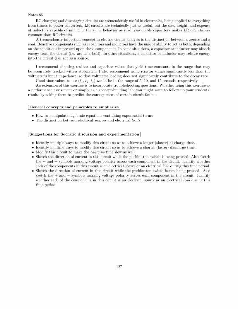
Notes 85
RC charging and discharging circuits are tremendously useful in electronics, being applied to everythingfrom timers to power converters. LR circuits are technically just as useful, but the size, weight, and expenseof inductors capable of mimicing the same behavior as readily-available capacitors makes LR circuits lesscommon than RC circuits.
A tremendously important concept in electric circuit analysis is the distinction between a source and aload. Reactive components such as capacitors and inductors have the unique ability to act as both, dependingon the conditions impressed upon these components. In some situations, a capacitor or inductor may absorbenergy from the circuit (i.e. act as a load). In other situations, a capacitor or inductor may release energyinto the circuit (i.e. act as a source).
I recommend choosing resistor and capacitor values that yield time constants in the range that maybe accurately tracked with a stopwatch. I also recommend using resistor values significantly less than thevoltmeter’s input impedance, so that voltmeter loading does not significantly contribute to the decay rate.
Good time values to use (t1, t2, t3) would be in the range of 5, 10, and 15 seconds, respectively.An extension of this exercise is to incorporate troubleshooting questions. Whether using this exercise as
a performance assessment or simply as a concept-building lab, you might want to follow up your students’results by asking them to predict the consequences of certain circuit faults.
General concepts and principles to emphasize
• How to manipulate algebraic equations containing exponential terms• The distinction between electrical sources and electrical loads
Suggestions for Socratic discussion and experimentation
• Identify multiple ways to modify this circuit so as to achieve a longer (slower) discharge time.• Identify multiple ways to modify this circuit so as to achieve a shorter (faster) discharge time.• Modify this circuit to make the charging time slow as well.• Sketch the direction of current in this circuit while the pushbutton switch is being pressed. Also sketch
the + and − symbols marking voltage polarity across each component in the circuit. Identify whethereach of the components in this circuit is an electrical source or an electrical load during this time period.
• Sketch the direction of current in this circuit while the pushbutton switch is not being pressed. Alsosketch the + and − symbols marking voltage polarity across each component in the circuit. Identifywhether each of the components in this circuit is an electrical source or an electrical load during thistime period.
127
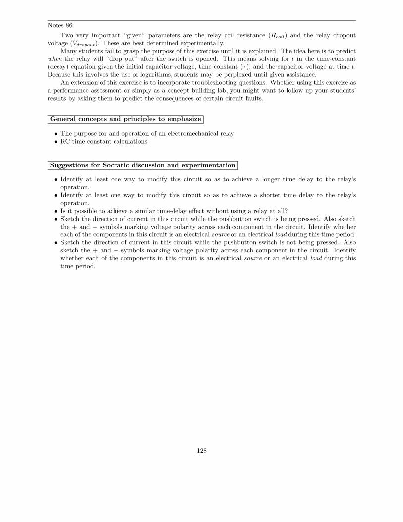
Notes 86
Two very important “given” parameters are the relay coil resistance (Rcoil) and the relay dropoutvoltage (Vdropout). These are best determined experimentally.
Many students fail to grasp the purpose of this exercise until it is explained. The idea here is to predictwhen the relay will “drop out” after the switch is opened. This means solving for t in the time-constant(decay) equation given the initial capacitor voltage, time constant (τ), and the capacitor voltage at time t.Because this involves the use of logarithms, students may be perplexed until given assistance.
An extension of this exercise is to incorporate troubleshooting questions. Whether using this exercise asa performance assessment or simply as a concept-building lab, you might want to follow up your students’results by asking them to predict the consequences of certain circuit faults.
General concepts and principles to emphasize
• The purpose for and operation of an electromechanical relay• RC time-constant calculations
Suggestions for Socratic discussion and experimentation
• Identify at least one way to modify this circuit so as to achieve a longer time delay to the relay’soperation.
• Identify at least one way to modify this circuit so as to achieve a shorter time delay to the relay’soperation.
• Is it possible to achieve a similar time-delay effect without using a relay at all?• Sketch the direction of current in this circuit while the pushbutton switch is being pressed. Also sketch
the + and − symbols marking voltage polarity across each component in the circuit. Identify whethereach of the components in this circuit is an electrical source or an electrical load during this time period.
• Sketch the direction of current in this circuit while the pushbutton switch is not being pressed. Alsosketch the + and − symbols marking voltage polarity across each component in the circuit. Identifywhether each of the components in this circuit is an electrical source or an electrical load during thistime period.
128
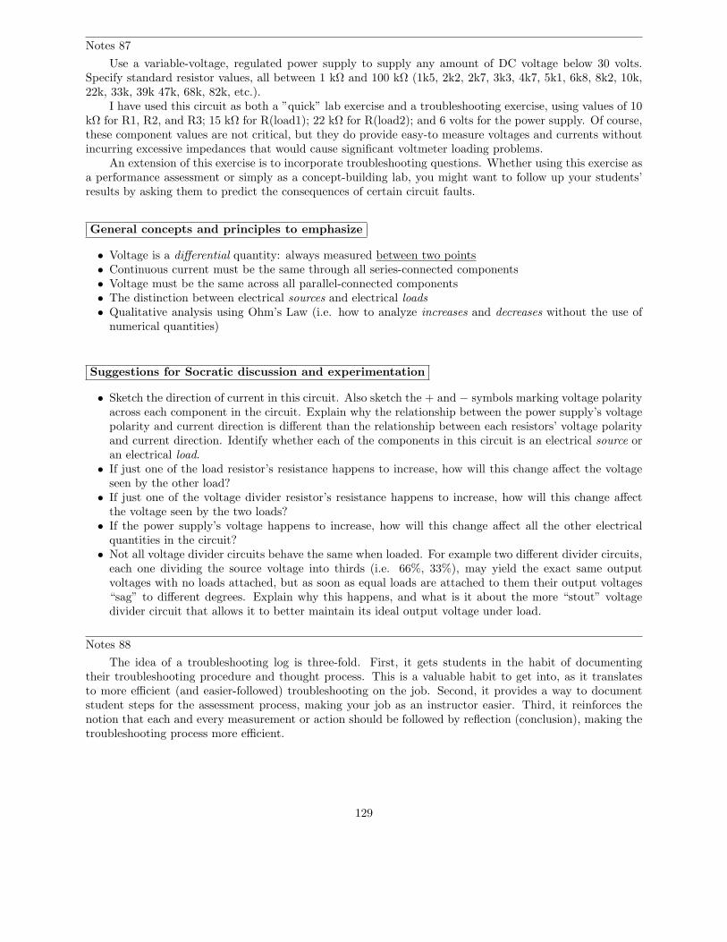
Notes 87
Use a variable-voltage, regulated power supply to supply any amount of DC voltage below 30 volts.Specify standard resistor values, all between 1 kΩ and 100 kΩ (1k5, 2k2, 2k7, 3k3, 4k7, 5k1, 6k8, 8k2, 10k,22k, 33k, 39k 47k, 68k, 82k, etc.).
I have used this circuit as both a ”quick” lab exercise and a troubleshooting exercise, using values of 10kΩ for R1, R2, and R3; 15 kΩ for R(load1); 22 kΩ for R(load2); and 6 volts for the power supply. Of course,these component values are not critical, but they do provide easy-to measure voltages and currents withoutincurring excessive impedances that would cause significant voltmeter loading problems.
An extension of this exercise is to incorporate troubleshooting questions. Whether using this exercise asa performance assessment or simply as a concept-building lab, you might want to follow up your students’results by asking them to predict the consequences of certain circuit faults.
General concepts and principles to emphasize
• Voltage is a differential quantity: always measured between two points• Continuous current must be the same through all series-connected components• Voltage must be the same across all parallel-connected components• The distinction between electrical sources and electrical loads• Qualitative analysis using Ohm’s Law (i.e. how to analyze increases and decreases without the use of
numerical quantities)
Suggestions for Socratic discussion and experimentation
• Sketch the direction of current in this circuit. Also sketch the + and − symbols marking voltage polarityacross each component in the circuit. Explain why the relationship between the power supply’s voltagepolarity and current direction is different than the relationship between each resistors’ voltage polarityand current direction. Identify whether each of the components in this circuit is an electrical source oran electrical load.
• If just one of the load resistor’s resistance happens to increase, how will this change affect the voltageseen by the other load?
• If just one of the voltage divider resistor’s resistance happens to increase, how will this change affectthe voltage seen by the two loads?
• If the power supply’s voltage happens to increase, how will this change affect all the other electricalquantities in the circuit?
• Not all voltage divider circuits behave the same when loaded. For example two different divider circuits,each one dividing the source voltage into thirds (i.e. 66%, 33%), may yield the exact same outputvoltages with no loads attached, but as soon as equal loads are attached to them their output voltages“sag” to different degrees. Explain why this happens, and what is it about the more “stout” voltagedivider circuit that allows it to better maintain its ideal output voltage under load.
Notes 88
The idea of a troubleshooting log is three-fold. First, it gets students in the habit of documentingtheir troubleshooting procedure and thought process. This is a valuable habit to get into, as it translatesto more efficient (and easier-followed) troubleshooting on the job. Second, it provides a way to documentstudent steps for the assessment process, making your job as an instructor easier. Third, it reinforces thenotion that each and every measurement or action should be followed by reflection (conclusion), making thetroubleshooting process more efficient.
129
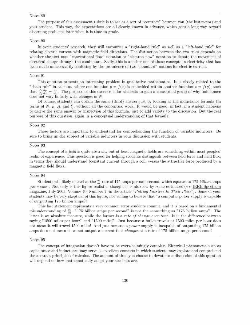
Notes 89
The purpose of this assessment rubric is to act as a sort of “contract” between you (the instructor) andyour student. This way, the expectations are all clearly known in advance, which goes a long way towarddisarming problems later when it is time to grade.
Notes 90
In your students’ research, they will encounter a ”right-hand rule” as well as a ”left-hand rule” forrelating electric current with magnetic field directions. The distinction between the two rules depends onwhether the text uses ”conventional flow” notation or ”electron flow” notation to denote the movement ofelectrical charge through the conductors. Sadly, this is another one of those concepts in electricity that hasbeen made unnecessarily confusing by the prevalence of two ”standard” notions for electric current.
Notes 91
This question presents an interesting problem in qualitative mathematics. It is closely related to the”chain rule” in calculus, where one function y = f(x) is embedded within another function z = f(y), suchthat dz
dydydx
= dzdx
. The purpose of this exercise is for students to gain a conceptual grasp of why inductancedoes not vary linearly with changes in N .
Of course, students can obtain the same (third) answer just by looking at the inductance formula (interms of N , µ, A, and l), without all the conceptual work. It would be good, in fact, if a student happensto derive the same answer by inspection of this formula, just to add variety to the discussion. But the realpurpose of this question, again, is a conceptual understanding of that formula.
Notes 92
These factors are important to understand for comprehending the function of variable inductors. Besure to bring up the subject of variable inductors in your discussion with students.
Notes 93
The concept of a field is quite abstract, but at least magnetic fields are something within most peoples’realm of experience. This question is good for helping students distinguish between field force and field flux,in terms they should understand (constant current through a coil, versus the attractive force produced by amagnetic field flux).
Notes 94
Students will likely marvel at the didt
rate of 175 amps per nanosecond, which equates to 175 billion ampsper second. Not only is this figure realistic, though, it is also low by some estimates (see IEEE Spectrummagazine, July 2003, Volume 40, Number 7, in the article ”Putting Passives In Their Place”). Some of yourstudents may be very skeptical of this figure, not willing to believe that ”a computer power supply is capableof outputting 175 billion amps?!”
This last statement represents a very common error students commit, and it is based on a fundamentalmisunderstanding of di
dt. ”175 billion amps per second” is not the same thing as ”175 billion amps”. The
latter is an absolute measure, while the former is a rate of change over time. It is the difference betweensaying ”1500 miles per hour” and ”1500 miles”. Just because a bullet travels at 1500 miles per hour doesnot mean it will travel 1500 miles! And just because a power supply is incapable of outputting 175 billionamps does not mean it cannot output a current that changes at a rate of 175 billion amps per second!
Notes 95
The concept of integration doesn’t have to be overwhelmingly complex. Electrical phenomena such ascapacitance and inductance may serve as excellent contexts in which students may explore and comprehendthe abstract principles of calculus. The amount of time you choose to devote to a discussion of this questionwill depend on how mathematically adept your students are.
130
Notes 96
Explain to your students how the similarities between inertia and inductance are so close, that inductorscan be used to electrically model mechanical inertia.
Notes 97
Ask your students to identify what condition(s) might lead to a condition of saturation. And, even ifthe extreme ends of the B −H curve are avoided, what does the nonlinear shape of the B −H plot indicateabout the linearity of an inductor? The inductance formula (e = L di
dt) assumes perfect linearity, but is this
really true for an inductor whose core exhibits this kind of magnetic flux/force relationship?
Notes 98
These factors affecting capacitance are very hypothetical when dealing with fixed-value capacitors. Afterall, few people will ever have to design or construct a capacitor. However, these factors are very practical andimportant to understand when dealing with stray capacitance between conductors, where conductor layoutand placement are well within the control of those building an electrical system!
These factors are also important to understand for comprehending the function of variable capacitors.Be sure to bring up the subject of variable capacitors in your discussion with students.
Notes 99
Encourage your students to find a picture of a Leyden Jar, or even to build their own. One can’t helpbut notice the functional equivalence between a capacitor and a jar: storing charge versus storing substance!
A jar is not the only object which may be transformed into a capacitor. Aluminum foil and papersheets may also be used to make a rudimentary capacitor. Have your students experiment with buildingtheir own capacitors, especially if they have access to a capacitance meter which may be used to comparethe capacitance of different designs.
Notes 100
Many students find this a helpful analogy of capacitor action. But it helps even more if students worktogether to build the analogy, and to truly understand it.
Perform some ”thought experiments” with vessels of different size, relating the outcomes to chargestorage in capacitors of different size.
Notes 101
The existence of such an appropriate analogy for capacitor action makes an explanation unnecessary,even if the concept takes a bit of thought to comprehend at first. It is important that students clearlydistinguish the quantities of current, voltage, and charge in a capacitor circuit just as they clearly distinguishthe quantities of liquid height, flow rate, and liquid volume in a hydraulic system.
Notes 102
The concept of integration doesn’t have to be overwhelmingly complex. Electrical phenomena such ascapacitance and inductance may serve as excellent contexts in which students may explore and comprehendthe abstract principles of calculus. The amount of time you choose to devote to a discussion of this questionwill depend on how mathematically adept your students are.
Hopefully, the challenge question will stir your students’ imaginations, as they realize the usefulness ofelectrical components as analogues for other types of physical systems.
131
Notes 103
Note to your students that spring stiffness (k) and capacitance (C) are inversely proportional to oneanother in this analogy.
Explain to your students how the similarities between inertia and capacitance are so close, that capacitorscan be used to electrically model mechanical springs!
Notes 104
Audio system engineering usually inspires interest among music-loving students, especially youngstudents who crave maximum audio power in their automobiles’ sound systems! This question is designedto provoke interest as much as it is intended to explore capacitor function.
With regard to ”decoupling” capacitors, your students will likely have to use capacitors in this mannerwhen they progress to building semiconductor circuits. If you have a printed circuit board from a computer(a ”motherboard”) available to show your students, it would be a good example of decoupling capacitors inuse.
Notes 105
Although the answer may seem a bit too easy – nay, even obvious – the point here is to get studentsto correlate the behavior of capacitors and inductors in terms of components they already understand verywell. Then, they may correctly associate direction of current with polarity of voltage drop according to thedirection of energy flow (source versus load) the reactive component is subjected to.
Notes 106
The purpose of this troubleshooting question is to get students to think in terms of fault elimination:deciding what things cannot be bad in order to better isolate what might be bad.
Notes 107
Don’t give your students the equation with which to perform this calculation! Let them find it on theirown.
Notes 108
Discuss with your students why ESR matters, especially in decoupling applications where capacitors areexpected to handle large dv
dttransients.
132
Notes 109
The capacitor tolerance codes are easy enough for students to research on their own. For your ownreference, though:
• D = ± 0.5%• F = ± 1%• G = ± 2%• H = ± 3%• J = ± 5%• K = ± 10%• M = ± 20%• P = +100%, -0%• Z = +80%, -20%
Same for the four capacitor labels given in the question:
• 473K = 47 nF ± 10%• 102J = 1 nF ± 5%• 224M = 0.22 µF ± 20%• 331F = 330 pF ± 1%
Notes 110
Students usually want to just use the τ = RC and τ = LR
formulae to answer questions like this, butunfortunately this does not lend itself to a firm conceptual understanding of time-constant circuit behavior.
If students need hints on how to answer the capacitance and inductance questions, ask them what thefundamental definitions of ”capacitance” and ”inductance” are (the ability to store energy . . .). Then askthem what takes longer to discharge (given the same power, or rate of energy release per unit time), a largereservoir of energy or a small reservoir of energy.
If students need hints on how to answer the resistance questions, ask them what each type of reactivecomponent resists change in (voltage for capacitors and current for inductors). Then ask them whatcondition(s) are necessary to cause the most rapid change in those variables (high current for capacitorsand high voltage for inductors). This is most evident by inspection of the differential equations i = C dv
dtand
v = L didt
.
Notes 111
My answer could stand to be a little more detailed, but the main idea here is to have students piecetogether their own argument explaining why inductor charging rate is directly proportional to resistance. Ofcourse, this is yet another example of the usefulness of Thevenin/Norton equivalent circuits. Sometimes asimple source conversion from one form to the other is all that is needed to achieve a conceptual breakthrough!
Notes 112
The purpose of this question is for students to learn the significance of the expression e−t
τ by ”playing”with the numbers. The negative exponent may confuse some students, so be sure to discuss its significancewith all students, so that all understand what it means.
Another concept for students to grasp in this question is that of an asymptotic function: a function thatapproaches a final value in incrementally smaller intervals.
133
Notes 113
Do not simply tell your students how to calculate the values of the increasing variable. Based on theirqualitative knowledge of time-constant circuit curves and their ability to evaluate the downward (decay)expression, they should be able to figure out how to calculate the increasing variable’s value over time aswell.
Some students will insist that you give them an equation to do this. They want to be told what todo, rather than solve the problem on their own based on an observation of pattern. It is very importantthat students of any science learn to recognize patterns in data, and that they learn to fit that data into amathematical equation. If nothing else, these figures given in the answer for both decreasing and increasingvariables should be plain enough.
Notes 114
Being able to derive an equation from numerical data is a complex, but highly useful, skill in allthe sciences. Sure, your students will be able to find this mathematical expression in virtually any basicelectronics textbook, but the point of this question is to derive this expression from an examination of data(and, of course, an examination of the other time-constant expression: e−
t
τ ).Be sure to challenge your students to do this, by asking how they obtained the answer to this question.
Do not ”settle” for students simply telling you what the equation is – ask them to explain their problem-solving techniques, being sure that all students have contributed their insights.
Notes 115
Calculating the voltage for the first few time constants’ worth of time should be easy without a calculator.I strongly encourage your students to develop their estimation skills, so that they may solve problems withoutbeing dependent upon a calculator. Too many students depend heavily on calculators – some are evendependent on specific brands or models of calculators!
Equally important as being able to estimate is knowing whether or not your estimations are over orunder the exact values. This is especially true when estimating quantities relevant to safety and/or reliability!
Notes 116
Calculating the voltage for the first few time constants’ worth of time should be easy without a calculator.I strongly encourage your students to develop their estimation skills, so that they may solve problems withoutbeing dependent upon a calculator. Too many students depend heavily on calculators – some are evendependent on specific brands or models of calculators!
Equally important as being able to estimate is knowing whether or not your estimations are over orunder the exact values. This is especially true when estimating quantities relevant to safety and/or reliability!
Notes 117
An interesting thing to note here is the span of time constant values available from commoncapacitor/inductor/resistor sizes. As students should notice, the capacitor-resistor combinations (all verypractical values, I might add) create both longer and shorter time constant values than the inductor-resistorcombinations, and that is even including the 25 Henry - 6.2 Ohm combination, which would be difficult(read: expensive) to achieve in real life.
134
Notes 118
I like to show this question to beginning students because it shows them an aspect of electrical circuitsthat they probably never thought to consider: that the behavior of a circuit might mimic the behavior ofsome other type of physical system or process, and that this principle might be exploited as a modeling toolfor engineers. Before the advent of inexpensive digital computers, the analog computer was the simulationtool of choice among engineers of all persuasions. Using resistors, capacitors, and amplifier circuits, thesemarvelous machines modeled all kinds of physical systems, as electrical constructs of mathematical equations.
But even without knowing anything about calculus, amplifier circuits, or any advanced electronicconcepts, beginning students should be able to understand the principle at work in this question.
Notes 119
The answer given here is purposely minimal. You should ask your students to give responses morethoughtful than this! Ask them why capacitors are cheaper than inductors. Ask them to explain what ismeant by ”easier to work with,” in technical terms.
Notes 120
While some may wonder what this question has to do with electronics, it is an exercise in qualitativeanalysis. This skill is very important for students to master if they are to be able to distinguish between theequations e−
t
τ and 1 − e−t
τ , both used in time-constant circuit analysis.The actual procedure for determining the nature of the equation is simple: consider what happens as t
begins at 0 and as it increases to some arbitrary positive value. Some students may rely on their calculators,performing actual calculations to see whether the percentage increases or decreases with increasing t.Encourage them to analyze the equation qualitatively rather than quantitatively, though. They shouldbe able to tell which way the percentage changes with time without having to consider a single numericalvalue!
Notes 121
It is very important for students to understand what this expression means and how it works, lest theyrely solely on memorization to use it in their calculations. As I always tell my students, rote memorizationwill fail you! If a student does not comprehend why the expression works as it does, they will be helpless toretain it as an effective ”tool” for performing calculations in the future.
A good way to suggest students approach a problem such as this is to imagine t increasing in value. Ast grows larger, what happens to the expression’s overall value? Then, compare which of the two percentages(percentage traversed, or percentage remaining) follow the same trend. One not need touch a calculator tofigure this out!
Notes 122
This answer is rather minimal, if not obvious. Of course, if the relay takes longer to de-energize, andwe were told this has something to do with time constants, then the time constant of the circuit musthave increased. What is not so obvious is why τ increased. Discuss this with your students, and see whatconclusions they reached.
Notes 123
Be sure to have your students share their problem-solving techniques (how they determined whichequation to use, etc.) in class.
Notes 124
Be sure to have your students share their problem-solving techniques (how they determined whichequation to use, etc.) in class.
135
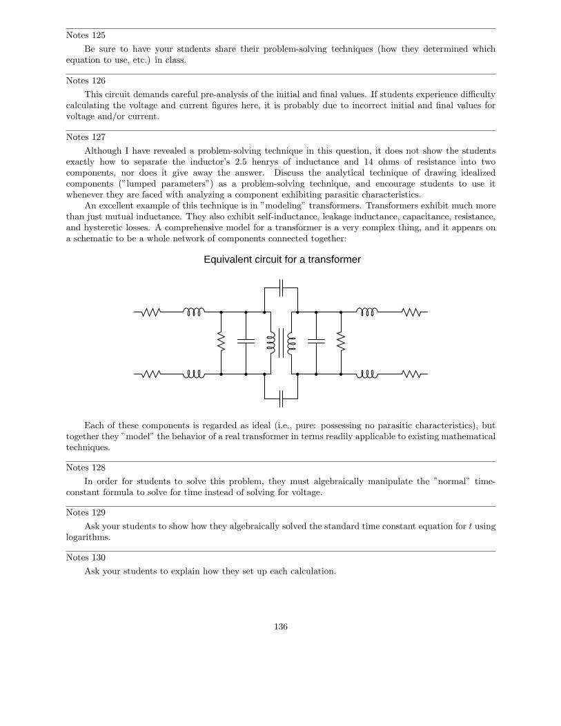
Notes 125
Be sure to have your students share their problem-solving techniques (how they determined whichequation to use, etc.) in class.
Notes 126
This circuit demands careful pre-analysis of the initial and final values. If students experience difficultycalculating the voltage and current figures here, it is probably due to incorrect initial and final values forvoltage and/or current.
Notes 127
Although I have revealed a problem-solving technique in this question, it does not show the studentsexactly how to separate the inductor’s 2.5 henrys of inductance and 14 ohms of resistance into twocomponents, nor does it give away the answer. Discuss the analytical technique of drawing idealizedcomponents (”lumped parameters”) as a problem-solving technique, and encourage students to use itwhenever they are faced with analyzing a component exhibiting parasitic characteristics.
An excellent example of this technique is in ”modeling” transformers. Transformers exhibit much morethan just mutual inductance. They also exhibit self-inductance, leakage inductance, capacitance, resistance,and hysteretic losses. A comprehensive model for a transformer is a very complex thing, and it appears ona schematic to be a whole network of components connected together:
Equivalent circuit for a transformer
Each of these components is regarded as ideal (i.e., pure: possessing no parasitic characteristics), buttogether they ”model” the behavior of a real transformer in terms readily applicable to existing mathematicaltechniques.
Notes 128
In order for students to solve this problem, they must algebraically manipulate the ”normal” time-constant formula to solve for time instead of solving for voltage.
Notes 129
Ask your students to show how they algebraically solved the standard time constant equation for t usinglogarithms.
Notes 130
Ask your students to explain how they set up each calculation.
136
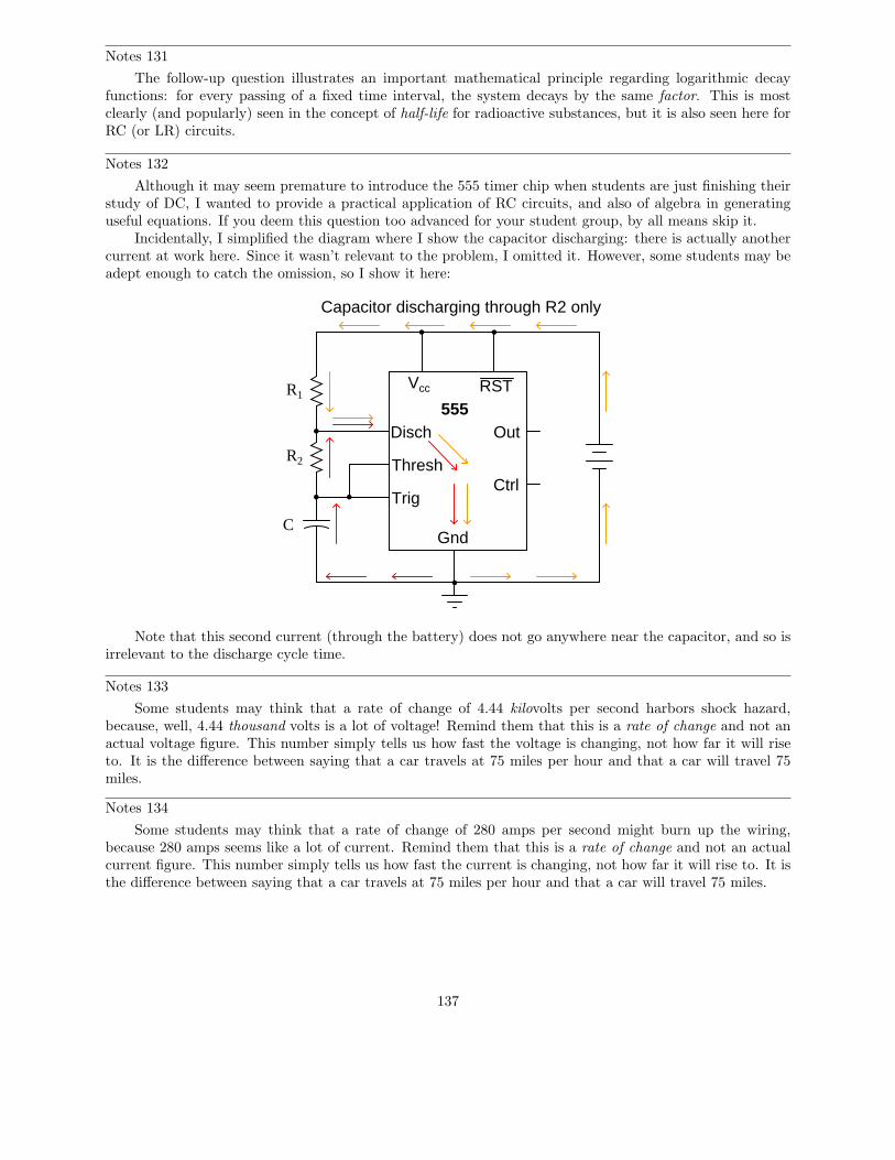
Notes 131
The follow-up question illustrates an important mathematical principle regarding logarithmic decayfunctions: for every passing of a fixed time interval, the system decays by the same factor. This is mostclearly (and popularly) seen in the concept of half-life for radioactive substances, but it is also seen here forRC (or LR) circuits.
Notes 132
Although it may seem premature to introduce the 555 timer chip when students are just finishing theirstudy of DC, I wanted to provide a practical application of RC circuits, and also of algebra in generatinguseful equations. If you deem this question too advanced for your student group, by all means skip it.
Incidentally, I simplified the diagram where I show the capacitor discharging: there is actually anothercurrent at work here. Since it wasn’t relevant to the problem, I omitted it. However, some students may beadept enough to catch the omission, so I show it here:
555Disch
Thresh
Trig
Gnd
Vcc RST
Out
Ctrl
R1
R2
C
Capacitor discharging through R2 only
Note that this second current (through the battery) does not go anywhere near the capacitor, and so isirrelevant to the discharge cycle time.
Notes 133
Some students may think that a rate of change of 4.44 kilovolts per second harbors shock hazard,because, well, 4.44 thousand volts is a lot of voltage! Remind them that this is a rate of change and not anactual voltage figure. This number simply tells us how fast the voltage is changing, not how far it will riseto. It is the difference between saying that a car travels at 75 miles per hour and that a car will travel 75miles.
Notes 134
Some students may think that a rate of change of 280 amps per second might burn up the wiring,because 280 amps seems like a lot of current. Remind them that this is a rate of change and not an actualcurrent figure. This number simply tells us how fast the current is changing, not how far it will rise to. It isthe difference between saying that a car travels at 75 miles per hour and that a car will travel 75 miles.
137
Notes 135
In addition to introducing the concept of an air gap switch and the notion of a ”surge” power supply,this question challenges students to envision practical problems and their respective diagnostic techniques.
It goes without saying that a circuit such as this is very dangerous, and its construction should not beattempted by anyone lacking a thorough understanding of its relevant hazards. Having said that, I will admitto having built one myself, simply to test the validity of an air gap switch for high-voltage, high-current,transient switching. Yes, the concept does work!
Notes 136
The integration required to obtain the answer is commonly found in calculus-based physics textbooks,and is an easy (power rule) integration.
Notes 137
The integration required to obtain the answer is commonly found in calculus-based physics textbooks,and is an easy (power rule) integration.
Notes 138
RC time constant circuits are an excellent example of how to apply simple differential equations. In thiscase, we see that the differential equation is first-order, with separable variables, making it comparativelyeasy to solve.
It should also be evident to students that any initial condition of capacitor charge may be set into thegeneral solution (by changing the value of the constant).
Notes 139
L/R time constant circuits are an excellent example of how to apply simple differential equations. In thiscase, we see that the differential equation is first-order, with separable variables, making it comparativelyeasy to solve.
It should also be evident to students that any initial condition for current may be set into the generalsolution (by changing the value of the constant).
138