Embed Size (px)
Citation preview
Easy Design Procedure of PCB Inductors Using WEBENCH Coil Designer
Catalin Bibirica, Sandu Cristian, Lucian Ene, Mihai Iordache University Politehnica of Bucharest, Dept. of Electrical Engineering, Bucharest, ROMANIA
Abstract - This paper describes the use of WEBENCH Coil Designer for generating wireless power transfer PCB induc-tors for low and medium power portable systems without the need of complex calculations or complex layout design. This tool is also used to generate the design files that engi-neers can include in their final designs. These results are of great importance in the wireless charging domain, with ap-plicability from mobile phones to industrial equipment charging. The designed coil inductors can also be used in medical equipment by printing them on flexible materials. To minimize the cost and design time for new products, the use of a specialized tool, like WEBENCH Coil Designer, is recommended for new and experienced engineers. Switching to PCB inductors is more cost effective and creates more stable inductors with precise electrical parameters and good repeatability.
Cuvinte cheie: bobine, transfer de putere fara fir, WEBENCH Coil Designer.
Keywords: inductors, wireless power transfer, WEBENCH Coil Designer.
I. INTRODUCTION
Our In the last few years, more and more attention is given to the wireless power charging, from charging mo-bile phones to charging medical [1][7] and industrial equipment. While the usual solution is widely accepted, using copper strands to form coil inductors, the necessity for cheaper and easier to implement inductors has in-creased the use of PCB (Printed Circuit Board) coil induc-tors.
While these PCB inductors add little to almost zero ad-ditional production cost, they are sometimes hard to im-plement due to the numerous difficulties engineers face while designing such inductors, mainly PCB layout and coil parameters calculations [8][9].
This paper addresses those issues by using WEBENCH Coil Designer, a free tool from Texas Instruments (TI), [2], to design, calculate and export the desired PCB induc-tor so it can be directly use on the final production PCB in Wireless Power Transfer (WPT) applications. This proce-dure is very useful to design the magnetic coupled coils used for the recharging the medical implant batteries.
II. PCB VS. COIL INDUCTORS
Coil inductors have been used from the beginning due to several features: they were relatively easy to make, had good power transfer efficiency and they occupy a small space.
In modern systems, this leads to variations in the oscillating frequency of the LC main oscillator that, in term, changes the wireless power transfer frequency and may lead to audible buzzing of the WPT system or decrease WPT efficiency.
While making more strictly controlled inductors is possible, the new inductors become more expensive and occupy more space.
Switching to PCB inductors is more cost effective and creates more stable inductors with precise electrical parameters and good repeatability.
Those inductors are made by creating circular patterns on the copper layer using the layout software (like Altium Designer). This pattern is electrically connected to the rest of the circuit and when current passes throw it, it acts like a traditional inductor. Because of the limited number of available layers (usually two layers, but can go up to 8 or more), the actual inductance is less than a traditional inductor. Modern systems compensate this by increasing the transmission frequency.
These types of inductors have to be greatly simulated in a specialized simulation program (like ANSYS Maxwell, [3 - 10]) with great results but with additional cost and time.
So, to minimize the cost and design time for new products, the use of a specialized tool, like WEBENCH Coil Designer, is recommended for new and experienced engineers.
III. THE DESIGN PROCEDURE FOR PCBCOIL GENERATION
WEBENCH Coil Designer is a free online tool for helping engineers design wireless sensor coils that are used with Texas Instruments products (LDC series of integrated circuits (ICs)) [3] but this paper will describe an alternative use: generating low and medium power inductors with a maximum radius of 149mm used for Wireless Power Transfer systems.
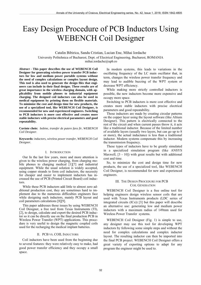
WEBENCH Coil Designer (Fig. 1) is simple to use, any designer may use this tool for developing WPT inductors by following some simple steps and without the need for complex calculations and complex inductor layout. The resulting inductor can then be imported into the final PCB project. WEBENCH Coil Designer offers a great variety of exporting options to adapt for any program the engineer might be used to.
Annals of the University of Craiova, Electrical Engineering series, No. 42, Issue 1, 2018; ISSN 1842-4805
32
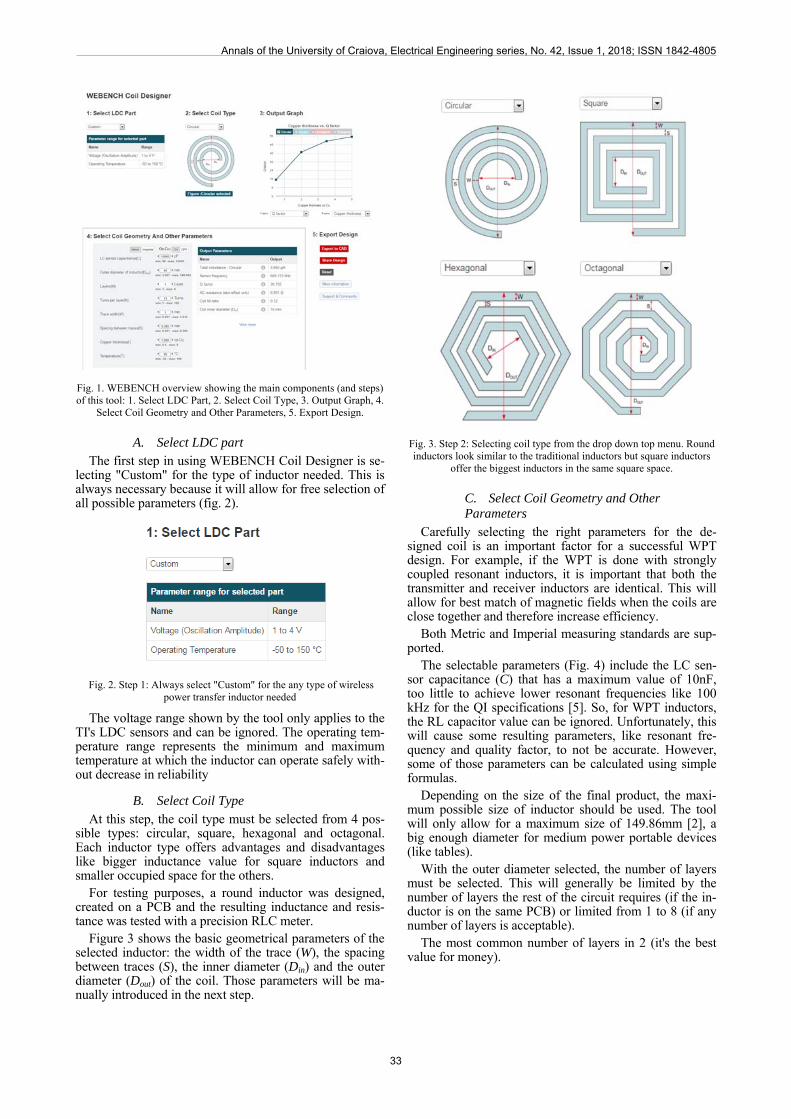
Fig. 1. WEBENCH overview showing the main components (and steps) of this tool: 1. Select LDC Part, 2. Select Coil Type, 3. Output Graph, 4.
Select Coil Geometry and Other Parameters, 5. Export Design.
A. Select LDC part The first step in using WEBENCH Coil Designer is se-
lecting "Custom" for the type of inductor needed. This is always necessary because it will allow for free selection of all possible parameters (fig. 2).
Fig. 2. Step 1: Always select "Custom" for the any type of wireless power transfer inductor needed
The voltage range shown by the tool only applies to the TI's LDC sensors and can be ignored. The operating tem-perature range represents the minimum and maximum temperature at which the inductor can operate safely with-out decrease in reliability
B. Select Coil Type At this step, the coil type must be selected from 4 pos-
sible types: circular, square, hexagonal and octagonal. Each inductor type offers advantages and disadvantages like bigger inductance value for square inductors and smaller occupied space for the others.
For testing purposes, a round inductor was designed, created on a PCB and the resulting inductance and resis-tance was tested with a precision RLC meter.
Figure 3 shows the basic geometrical parameters of the selected inductor: the width of the trace (W), the spacing between traces (S), the inner diameter (Din) and the outer diameter (Dout) of the coil. Those parameters will be ma-nually introduced in the next step.
Fig. 3. Step 2: Selecting coil type from the drop down top menu. Round inductors look similar to the traditional inductors but square inductors
offer the biggest inductors in the same square space.
C. Select Coil Geometry and Other Parameters
Carefully selecting the right parameters for the de-signed coil is an important factor for a successful WPT design. For example, if the WPT is done with strongly coupled resonant inductors, it is important that both the transmitter and receiver inductors are identical. This will allow for best match of magnetic fields when the coils are close together and therefore increase efficiency.
Both Metric and Imperial measuring standards are sup-ported.
The selectable parameters (Fig. 4) include the LC sen-sor capacitance (C) that has a maximum value of 10nF, too little to achieve lower resonant frequencies like 100 kHz for the QI specifications [5]. So, for WPT inductors, the RL capacitor value can be ignored. Unfortunately, this will cause some resulting parameters, like resonant fre-quency and quality factor, to not be accurate. However, some of those parameters can be calculated using simple formulas.
Depending on the size of the final product, the maxi-mum possible size of inductor should be used. The tool will only allow for a maximum size of 149.86mm [2], a big enough diameter for medium power portable devices (like tables).
With the outer diameter selected, the number of layers must be selected. This will generally be limited by the number of layers the rest of the circuit requires (if the in-ductor is on the same PCB) or limited from 1 to 8 (if any number of layers is acceptable).
The most common number of layers in 2 (it's the best value for money).
Annals of the University of Craiova, Electrical Engineering series, No. 42, Issue 1, 2018; ISSN 1842-4805
33
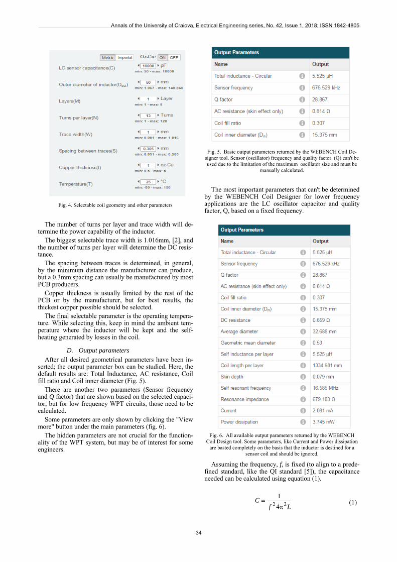
Fig. 4. Selectable coil geometry and other parameters
The number of turns per layer and trace width will de-termine the power capability of the inductor.
The biggest selectable trace width is 1.016mm, [2], and the number of turns per layer will determine the DC resis-tance.
The spacing between traces is determined, in general, by the minimum distance the manufacturer can produce, but a 0.3mm spacing can usually be manufactured by most PCB producers.
Copper thickness is usually limited by the rest of the PCB or by the manufacturer, but for best results, the thickest copper possible should be selected.
The final selectable parameter is the operating tempera-ture. While selecting this, keep in mind the ambient tem-perature where the inductor will be kept and the self-heating generated by losses in the coil.
D. Output parameters After all desired geometrical parameters have been in-
serted; the output parameter box can be studied. Here, the default results are: Total Inductance, AC resistance, Coil fill ratio and Coil inner diameter (Fig. 5).
There are another two parameters (Sensor frequency and Q factor) that are shown based on the selected capaci-tor, but for low frequency WPT circuits, those need to be calculated.
Some parameters are only shown by clicking the "View more" button under the main parameters (fig. 6).
The hidden parameters are not crucial for the function-ality of the WPT system, but may be of interest for some engineers.
Fig. 5. Basic output parameters returned by the WEBENCH Coil De-signer tool. Sensor (oscillator) frequency and quality factor (Q) can't be used due to the limitation of the maximum oscillator size and must be
manually calculated.
The most important parameters that can't be determined by the WEBENCH Coil Designer for lower frequency applications are the LC oscillator capacitor and quality factor, Q, based on a fixed frequency.
Fig. 6. All available output parameters returned by the WEBENCH Coil Design tool. Some parameters, like Current and Power dissipation
are basted completely on the basis that the inductor is destined for a sensor coil and should be ignored.
Assuming the frequency, f, is fixed (to align to a prede-fined standard, like the QI standard [5]), the capacitance needed can be calculated using equation (1).
LfC
22 4
1
(1)
Annals of the University of Craiova, Electrical Engineering series, No. 42, Issue 1, 2018; ISSN 1842-4805
34
The quality factor, Q, can also be calculated using a simple formula (2):
R
fLQ
2 (2)
Equations (1) and (2) are based on the coil inductance, L, and coil resistance, R.
The quality factor, Q, can be used to compare different types and inductor sizes. The bigger the quality factor is, the more efficient the inductor will be and the power loss will decrease [6].
Another way to analyze the newly created inductor is using the provided graphs. WEBENCH Coil Designer allows for a multitude of parameters that can be used on the Y-axis and Y-axis (Fig. 7).
Fig. 7. Example of possible graph generated by the WEBENCH Coil Designer tool. Using this visual representation, design engineers can optimize the WPT inductor according to their needs and constraints.
E. Export design
The final step in using WEBENCH Coil Designer is exporting to the preferred design program. The options are: Altium Designer, Cadence Allegro, CadSoft EAGLE PCB, DesignSpark PCB and Mento Graphics PADS PCB.
The export functionality has a few limitations. The first and major limitation is the number of layers that can be exported: 2 and 4. This can easily be bypassed from the PCB design program, where more layers can be copied or deleted.
Another limitation is that, when exporting, a free ac-count is required.
IV. EXPERIMENTAL RESULTS
In order to test and validate the WEBENCH Coil De-signer tool, some inductors were manufactured with the manual toner transfer method.
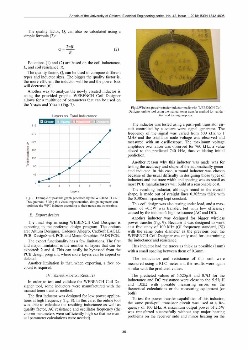
The first inductor was designed for low power applica-tions at high frequency (fig. 8). In this care, the online tool was able to calculate the resulting inductance as well as quality factor, AC resistance and oscillator frequency (the chosen parameters were sufficiently high so that no man-ual parameter calculations were needed).
Fig.8.Wireless power transfer inductor made with WEBENCH Coil Designer online tool using the manual toner transfer method for valida-
tion and testing purposes.
The inductor was tested using a push-pull transistor cir-cuit controlled by a square ware signal generator. The frequency of the signal was varied from 500 kHz to 1 MHz and the oscillator node voltage was observed and measured with an oscilloscope. The maximum voltage amplitude oscillation was observed for 760 kHz, a value closed to the predicted 740 kHz, thus validating initial prediction.
Another reason why this inductor was made was for testing the accuracy and shape of the automatically gener-ated inductor. In this case, a round inductor was chosen because of the usual difficulty in designing those types of inductors and the trace width and spacing was as small as most PCB manufacturers will build at a reasonable cost.
The resulting inductor, although round in the overall shape, is made out of straight lines 0.305mm thick with the 0.305mm spacing kept constant.
This coil design was also testing under load, and a max-imum of ~0.5W was transfer, but with low efficiency caused by the inductor's high resistance (AC and DC).
Another inductor was designed for bigger wireless power transfer (fig. 9). Because it was designed to work at a frequency of 100 kHz (QI frequency standard, [5]) with the same outer diameter as the previous one, the WEBENCH Coil Designer was only used for determining the inductance and resistance.
This inductor had the traces as thick as possible (1mm) with a small spacing between them of 0.3mm.
The inductance and resistance of this coil were measured using a RLC meter and the results were again similar with the predicted values.
The predicted values of 5.525µH and 0.7Ω for the inductance and DC resistance were close to the 5.53µH and 1.02Ω with possible measuring errors on the theoretical calculations or the measuring equipment (or both).
To test the power transfer capabilities of this inductor, the same push-pull transistor circuit was used at a fre-quency of 100 kHz. A maximum output power of 2.5W was transferred successfully without any major heating problems on the receiver side and minor heating on the
Annals of the University of Craiova, Electrical Engineering series, No. 42, Issue 1, 2018; ISSN 1842-4805
35
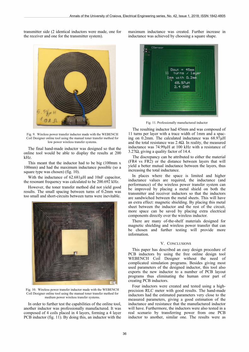
transmitter side (2 identical inductors were made, one for the receiver and one for the transmitter system).
Fig. 9. Wireless power transfer inductor made with the WEBENCH Coil Designer online tool using the manual toner transfer method for
low power wireless transfer systems.
The final hand-made inductor was designed so that the online tool would be able to display the results at 200 kHz.
This meant that the inductor had to be big (100mm x 100mm) and had the maximum inductance possible (so a square type was chosen) (fig. 10).
With the inductance of 62.681µH and 10nF capacitor, the resonant frequency was calculated to be 200.692 kHz.
However, the toner transfer method did not yield good results. The small spacing between turns of 0.2mm was too small and short-circuits between turns were inevitable.
Fig. 10. Wireless power transfer inductor made with the WEBENCH Coil Designer online tool using the manual toner transfer method for
medium power wireless transfer systems.
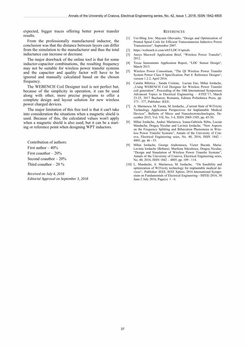
In order to further test the capabilities of the online tool, another inductor was professionally manufactured. It was composed of 4 coils placed in 4 layers, forming a 4 layer PCB inductor (fig. 11). By doing this, an inductor with the
maximum inductance was created. Further increase in inductance was achieved by choosing a square shape.
Fig. 11. Professionally manufactured inductor
The resulting inductor had 45mm and was composed of 11 turns per layer with a trace width of 1mm and a spac-ing on 0.2mm. The calculated inductance was 68.97µH and the total resistance was 2.4Ω. In reality, the measured inductance was 74.99µH at 100 kHz with a resistance of 3.27Ω, giving a quality factor of 14.4.
The discrepancy can be attributed to either the material (FR4 vs FR2) or the distance between layers that will yield a better mutual inductance between the layers, thus increasing the total inductance.
In places where the space is limited and higher inductance values are required, the inductance (and performance) of the wireless power transfer system can be improved by placing a metal shield on both the transmitter and receiver inductors so that the inductors are sandwiched between the metal sheets. This will have an extra effect: magnetic shielding. By placing this metal sheet between the inductor and the rest of the circuit, more space can be saved by placing extra electrical components directly over the wireless inductor.
There are many of-the-shelf materials designed for magnetic shielding and wireless power transfer that can be chosen and further testing will provide more information.
V. CONCLUSIONS
This paper has described an easy design procedure of PCB inductors by using the free online design tool WEBENCH Coil Designer without the need of complicated simulation programs. Besides giving most used parameters of the designed inductor, this tool also exports the new inductor to a number of PCB layout programs thus eliminating the human error part of creating PCB inductors.
Four inductors were created and tested using a high-precision RLC meter with good results. The hand-made inductors had the estimated parameters very close to the measured parameters, giving a good estimation of the inductance and resistance that the manufactured inductor will have. Furthermore, the inductors were also tested in a real scenario by transferring power from one PCB inductor to another, similar one. The results were as
Annals of the University of Craiova, Electrical Engineering series, No. 42, Issue 1, 2018; ISSN 1842-4805
36
expected, bigger traces offering better power transfer results.
From the professionally manufactured inductor, the conclusion was that the distance between layers can differ from the simulation to the manufacturer and thus the total inductance can increase or decrease.
The major drawback of the online tool is that for some inductor-capacitor combinations, the resulting frequency may not be suitable for wireless power transfer systems and the capacitor and quality factor will have to be ignored and manually calculated based on the chosen frequency.
The WEBENCH Coil Designer tool is not perfect but, because of the simplicity in operation, it can be used along with other, more precise programs to offer a complete design and layout solution for new wireless power charged devices.
The major limitation of this free tool is that it can't take into consideration the situations when a magnetic shield is used. Because of this, the calculated values won't apply when a magnetic shield is also used, but it can be a start-ing or reference point when designing WPT inductors.
Contribution of authors: First author – 40% First coauthor – 20% Second coauthor – 20% Third coauthor – 20 %
Received on July 4, 2018 Editorial Approval on September 3, 2018
REFERENCES
[1] Uei-Ming Jow, Maysam Ghovanlo, “Design and Optimization of Printed Spiral Coils for Efficient Transcutaneous Inductive Power Transmission“, September 2007.
[2] https://webench.ti.com/wb5/LDC/#/spirals [3] Ansys Maxwell Application Brief, “Wireless Power Transfer“,
2012. [4] Texas Instruments Application Report, “LDC Sensor Design“,
March 2015. [5] Wireless Power Consortium, “The QI Wireless Power Transfer
System Power Class 0 Specification, Part 4: Reference Designs“, version 1.2.2, April 2016.
[6] Catalin Bibirica , Sandu Cristian, Lucian Ene, Mihai Iordache, „Using WEBENCH Coil Designer for Wireless Power Transfer coil generation”, Proceeding of the 10th International Symposium Advanced Topics in Electrical Engineering – ATEE’17, March 23-25, 2017 Bucharest, Romania, Editura Politehnica Press, pp. 373 - 377, Publisher: IEEE.
[7] A. Marinescu, M. Tarata, M. Iordache, „Current State of WiTricity Technology Application Perspectives for Implantable Medical Devices”, Bulletin of Micro and Nanoelectrotechnologies, De-cember 2015, Vol. VII, No. 3-4, ISSN 2069-1505, pp. 45-50.
[8] Mihai Iordache, Andrei Marinescu, Ioana-Gabriela Sîrbu, Lucian Mandache, Dragoş Niculae and Lavinia Iordache, “New Aspects on the Frequency Splitting and Bifurcation Phenomena in Wire-less Power Transfer Systems”, Annals of the University of Crai-ova, Electrical Engineering seies, No. 40, 2016, ISSN 1842 – 4805, pp. 46 - 53.
[9] Mihai Iordache, George Andronescu, Victor Bucată, Maria-Lavinia Iordache (Bobaru), Marilena Stăculescu, Dragoş Niculae, “Design and Simulation of Wireless Power Transfer Systems”, Annals of the University of Craiova, Electrical Engineering seies, No. 40, 2016, ISSN 1842 – 4805, pp. 109 - 114.
[10] L. Mandache, A. Marinescu, M. Iordache, “On feasibility and optimization of WiTricity technology for implantable medical de-vices“, Publisher: IEEE, IEEE Xplore, 2016 International Sympo-sium on Fundamentals of Electrical Engineering - ISFEE-2016, 30 June-2 July 2016, Page(s): 1 - 6.
Annals of the University of Craiova, Electrical Engineering series, No. 42, Issue 1, 2018; ISSN 1842-4805
37


