Embed Size (px)
Citation preview
HUMAN FACTORS SURVEY OF LOCOMOTIVE CABS
30 JUNE 1972
PREPARED FOR
i DEPARTMENT OF TRANSPORTATION
, : i 3ERAL RAILROAD ADMINISTRATION
. i Washington, D.C.
I
07-Human Factors
. .- - _ ' ~~~- 31jb
TECHN!CAL R t P O K i S T A N C . i i D 7 i T L t :-:.:
/ 1. R ~ P Q : ~ 1 4 0 . 1 2. Gorrrnmenl Accer%:on S O . 7 3 , 2 e c 8 p i c n f ' s i a t u l o g No. I I \
30 June 1972 ! ' Human Factors Survey of Locomotive Cabs 6. Prrlormlnr U r g v n l i o r l o n Codc t i 8. Pcrlorming Orponm7r!ioo Repor? No.
John P. Jankovich, Ph.D., Research Engineer I
1 Naval Ammunition Depot
i Indiana 47522
I
1 1 . Con, .oc , 0 : Grrn , No. i
I i Purpose of the investigation was to review design of locomotive cabs
i from the hnman factors point of view. The follo~iing areas of human I factors engineering are discussed: construction of cab interiors; I
design of controls and displays; atmospheric conditions in the cab; noise and vibration; seat design; physiology and vigilance of train 1 driving. 1
Federal Railroad Administration 400 7th Street SW. Washington, D. C. 20591 -- - --
Discussion of each subject is divided into three sections: (1) survey of relevant literature, (2) conditions on domestic locomotives, and (3) recommendations to improve present models and future design. The recommendations relate only to the designs reviewed under the scope of this study and represent the viewpoint of the author and not necessarily those of the FRA.
1 ! 14 sponsor,ng A~~~~~ c o d e I
I ---I
I !
18. Distilbution Stolemen! ! Human Factor Engineering Availability is unlimited. ~ocument/ Locomotive Cab Design may be purchased from the National 1 Engine Crew Accidents Technical Information Service, Cab Environment Springfield, Virginia 22151, for !
-. $3.00 a copy. . 0 s C " l 0 4 a g e )
i
Form D:IT F 1700.7 la-c-,l
I5 Suoalrmen:orr l io tr , t- I 1
NAVAL AMMUNIT ION DEPOT CRANE, I N D I A N A 47522
HUMAN FACTORS SURVEY OF LOCOMOTIVE CABS
30 June 1972
PREPARED BY
RELEASED BY
RESEARCH AND DEVELOPMENT DEPARTMENT
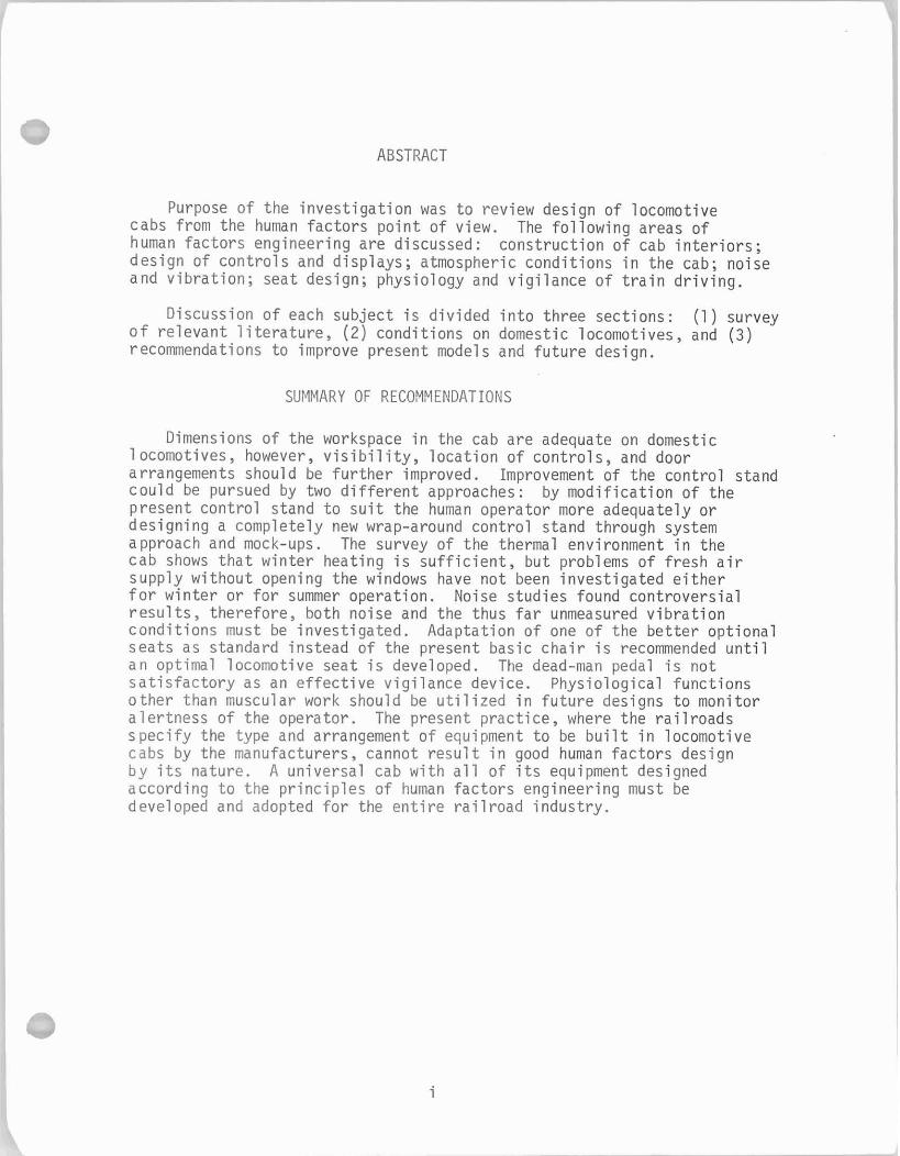
ABSTRACT
Purpose o f t he i n v e s t i g a t i o n was t o rev iew design o f locomotive cabs from the human f a c t o r s p o i n t o f view. The f o l l o w i n g areas o f human f a c t o r s engineer ing a re discussed: cons t ruc t i on o f cab i n t e r i o r s ; des ign o f c o n t r o l s and d isp lays ; atmospheric cond i t i ons i n t he cab; noise and v i b r a t i o n ; seat design; phys io logy and v i g i l a n c e o f t r a i n d r i v i n g .
Discussion o f each sub jec t i s d i v i d e d i n t o t h ree sec t ions : (1 ) survey o f r e l e v a n t l i t e r a t u r e , ( 2 ) cond i t i ons on domestic locomotives, and (3) recommendations t o improve present models and f u t u r e design.
SUMMARY OF RECOMMENDATIONS
Dimensions o f the workspace i n the cab a re adequate on domestic locomot ives, however, v i s i b i l i t y , l o c a t i o n o f c o n t r o l s , and door arrangements should be f u r t h e r improved. Improvement o f t he c o n t r o l stand c o u l d be pursued by two d i f f e r e n t approaches: by m o d i f i c a t i o n o f t he present c o n t r o l s tand t o s u i t the human opera tor more adequately o r des ign ing a complete ly new wrap-around c o n t r o l stand through system approach and mock-ups. The survey o f t he thermal environment i n the cab shows t h a t w i n t e r heat ing i s s u f f i c i e n t , bu t problems o f f r e s h a i r supp ly w i t h o u t opening the windows have n o t been i n v e s t i g a t e d e i t h e r f o r w i n t e r o r f o r summer operat ion. Noise s tud ies found con t rove rs ia l r e s u l t s , t he re fo re , both noise and the thus f a r unmeasured v i b r a t i o n c o n d i t i o n s must be i nves t i ga ted . Adaptat ion o f one o f t he b e t t e r op t i ona l sea ts as standard i ns tead o f the present basic c h a i r i s recommended u n t i l an opt imal locomot ive seat i s developed. The dead-man pedal i s no t s a t i s f a c t o r y as an e f f e c t i v e v i g i l a n c e device. Phys io log ica l f unc t i ons o t h e r than muscular work should be u t i l i z e d i n f u t u r e designs t o mon i to r a l e r t n e s s o f t he opera tor . The present p rac t i ce , where the r a i l r o a d s s p e c i f y the type and arrangement o f equipment t o be b u i l t i n locomot ive cabs by the manufacturers, cannot r e s u l t i n good human f a c t o r s design b y i t s nature. A un i ve rsa l cab w i t h a l l o f i t s equipment designed accord ing t o t he p r i n c i p l e s o f human f a c t o r s engineer ing must be developed and adopted f o r the e n t i r e r a i l r o a d i n d u s t r y .
TABLE OF CONTENTS
INTRODUCTION . . . . . . . . . . . . . . . . . . . . . . . . . . . . . 1
1 . HUMAN FACTORS DESIGN OF LOCOMOTIVE CAB INTERIORS . . . . . . . . . 4
1 . 1 L i t e r a t u r e Survey o f Locomot ive Cab Design . . . . . . . . . . . 4
1.2 Design o f Domestic Locomot ive Cabs . . . . . . . . . . . . . . 13
1.3 Work Space Recommendation . . . . . . . . . . . . . . . . . . 52
2 . DESIGN OF CONTROL EQUIPMENT ON LOCOMOTIVES . . . . . . . . . . . . 57
2.1 L i t e r a t u r e Survey o f Locomot ive Cab C o n t r o l s . 57
2.2 C o n t r o l s on Domestic Locomot ives . . . . . . . . . . . . . . . 76
2.3 Recommendations on Human F a c t o r s Design o f C o n t r o l s . . . . . 129
3 . ATMOSPHERIC ENVIRONMENT IN LOCOMOTIVE CABS . . . . . . . . . . . 132
3.1 Review o f L i t e r a t u r e on Cab H e a t i n g and V e n t i l a t i o n . . . . . 132
3.2 H e a t i n g and V e n t i l a t i o n on Domestic Locomotives . . . . . . . 138
3.3 Recommendations t o Improve Atmospher ic C o n d i t i o n i n t h e Cab . . . . . . . . . . . . . . . . . . . . . . . . . . . . . 148
4 . NOISE AND VIBRATION I N LOCOMOTIVE CABS . . . . . . . . . . . . . 150
4.1 Survey o f t h e L i t e r a t u r e . . . . . . . . . . . . . . . . . . 150
4.2 Noise and V i b r a t i o n on Domestic Locomot ives . . . . . . . . . 162
4.3 Recommendations . . . . . . . . . . . . . . . . . . . . . . . 171
5 . SEATING OF THE OPERATOR IN LOCOMOTIVE CABS . . . . . . . . . . . 174
5.1 Review o f t h e L i t e r a t u r e on Cab Seat Design . . . . . . . . .l 74
5.2 Design o f Seats on Domestic Locomot ives . . . . . . . . . . 181
5.3 Recommendations on Seat Design . . . . . . . . . . . . . . 192
6 . PHYSIOLOGY AND VIGILANCE REQUIREMENTS OF TRAIN DRIVING . . . . . 199
6.1 Review o f t h e L i t e r a t u r e . . . . . . . . . . . . . . . . . . 199
6.2 V i g i l a n c e Devices on Domestic Locomot ives and Recommendations . . . . . . . . . . . . . . . . . . . . . . 212
BIBLIOGRAPHY . . . . . . . . . . . . . . . . . . . . . . . . . . . . 214
LIST OF TABLES
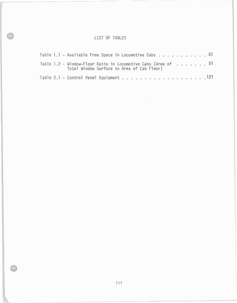
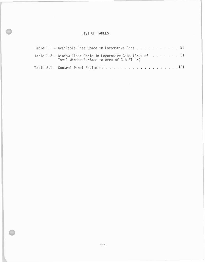
Table 1.1 . Available Free Space i n Locomotive Cabs . . . . . . . . . . . 5 1
Table 1 .2 . Window-Floor Ratio in Locomotive Cabs (Area of . . . . . . . 5 1 Total Window Surface t o Area of Cab Floor)
Table 2.1 . Control Panel Equipment . . . . . . . . . . . . . . . . . . . 121
L IST OF TABLES
T a b l e 1.1 . A v a i l a b l e Free Space i n Locomot ive Cabs . . . . . . . . . . . 51
Tab le 1 .2 . Window-Floor R a t i o i n Locomot ive Cabs (Area o f . . . . . . . 51 T o t a l Window Sur face t o Area o f Cab F l o o r )
T a b l e 2.1 . C o n t r o l Panel Equipment . . . . . . . . . . . . . . . . . . . 121
- LIST OF ILLUSTRATIONS
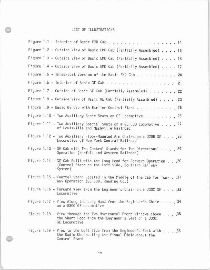
F i g u r e 1.1 - I n t e r i o r o f Basic EMD Cab . . . . . . . . . . . . . . . . . 14
F i g u r e 1.2 - Outside View o f Basic EMD Cab ( P a r t i a l l y Assembled) . . . . 15
F i g u r e 1.3 - Outside View o f Basic EMD Cab ( P a r t i a l l y Assembled) . . . . 16
F i g u r e 1.4 - Outside View o f Basic EMD Cab ( P a r t i a l l y Assembled) . . . . 17
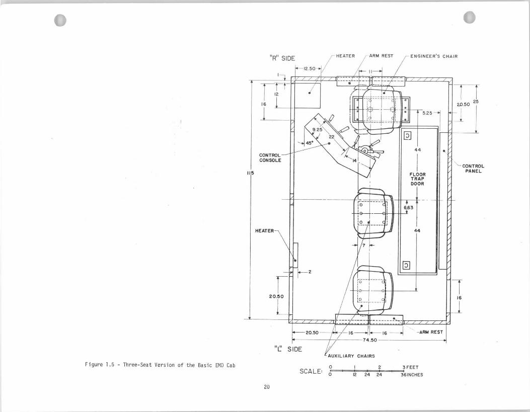
F i g u r e 1.5 - Three-seat Version o f the Basic EMD Cab . . . . . . . . . . 20
F i g u r e 1 . 6 - I n t e r i o r o f B a s i c G E C a b . . . . . . . . . . . . . . . . . 21
F i g u r e 1.7 - Outside o f Basic GE Cab ( P a r t i a l l y Assembled) . . . . . . . 22
F i g u r e 1.8 - Outside View o f Basic GE Cab ( P a r t i a l l y Assembled) . . . . .23
F i g u r e 1.9 - Basic GE Cab w i t h E a r l i e r Contro l Stand . . . . . . . . . . 25
F i g u r e 1.10 - Two A u x i l i a r y Basic Seats on GE Locomotive . . . . . . . . 26
F i g u r e 1.11 - Two A u x i l i a r y Special Seats on a GE U30 Locomotive . . . . 27 o f L o u i s v i l l e and Nashv i l l e Ra i l r oad
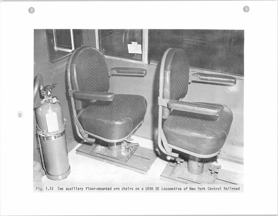
F i g u r e 1.12 - Two A u x i l i a r y Floor-Mounted A r m Chai rs on a U28B GE . . . -28 Locomotive o f New York Centra l Ra i l r oad
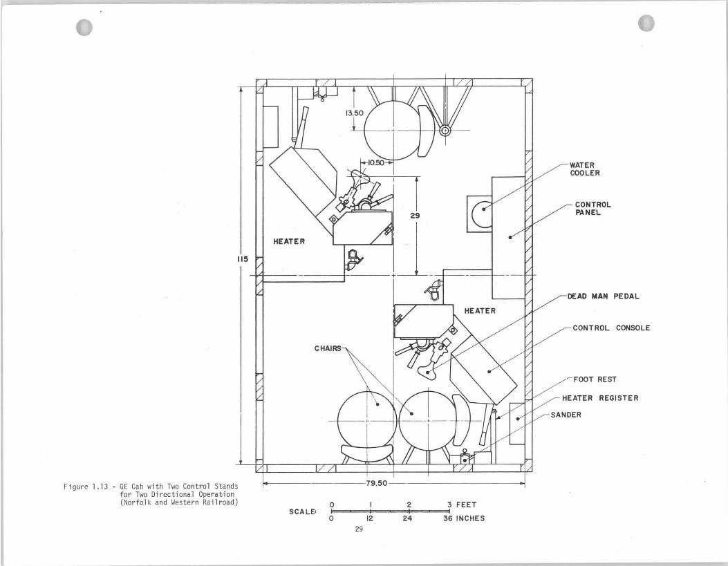
F i g u r e 1.13 - GE Cab w i t h Two Contro l Stands f o r Two D i r e c t i o n a l . . . . 29 Operat ion (No r fo l k and Western Ra i l r oad )
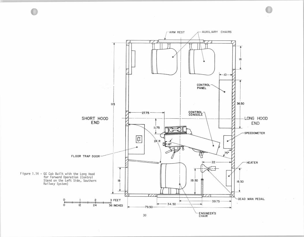
F i g u r e 1.14 - GE Cab B u i l t w i t h the Long Hood f o r Forward Operat ion . . .30 (Contro l Stand on the L e f t Side, Southern Railway System)
F i g u r e 1.15 - Contro l Stand Located i n t he Middle o f t he Cab f o r Two- . .31 Way Operat ion (GE U30, Reading Co.)
F i g u r e 1.16 - Forward View from the Locomotive
Engineer 's Chai r on a U30C GE . . . . 33
F i g u r e 1.17 - View Along the Long Hood from the Engineer 's Chai r . . . . 34 on a U30C GE Locomotive
F igure 1.18 - View through the Two Hor izon ta l F ron t Windows above . . . . 35 the Shor t Hood from the Engineer 's Seat on a U30C GE Locomotive
F igure 1.19 - View t o the L e f t Side from the Engineer 's Seat w i t h . . . .36 the Radio Obst ruc t ing the Visual F i e l d above t h e Contro l Stand
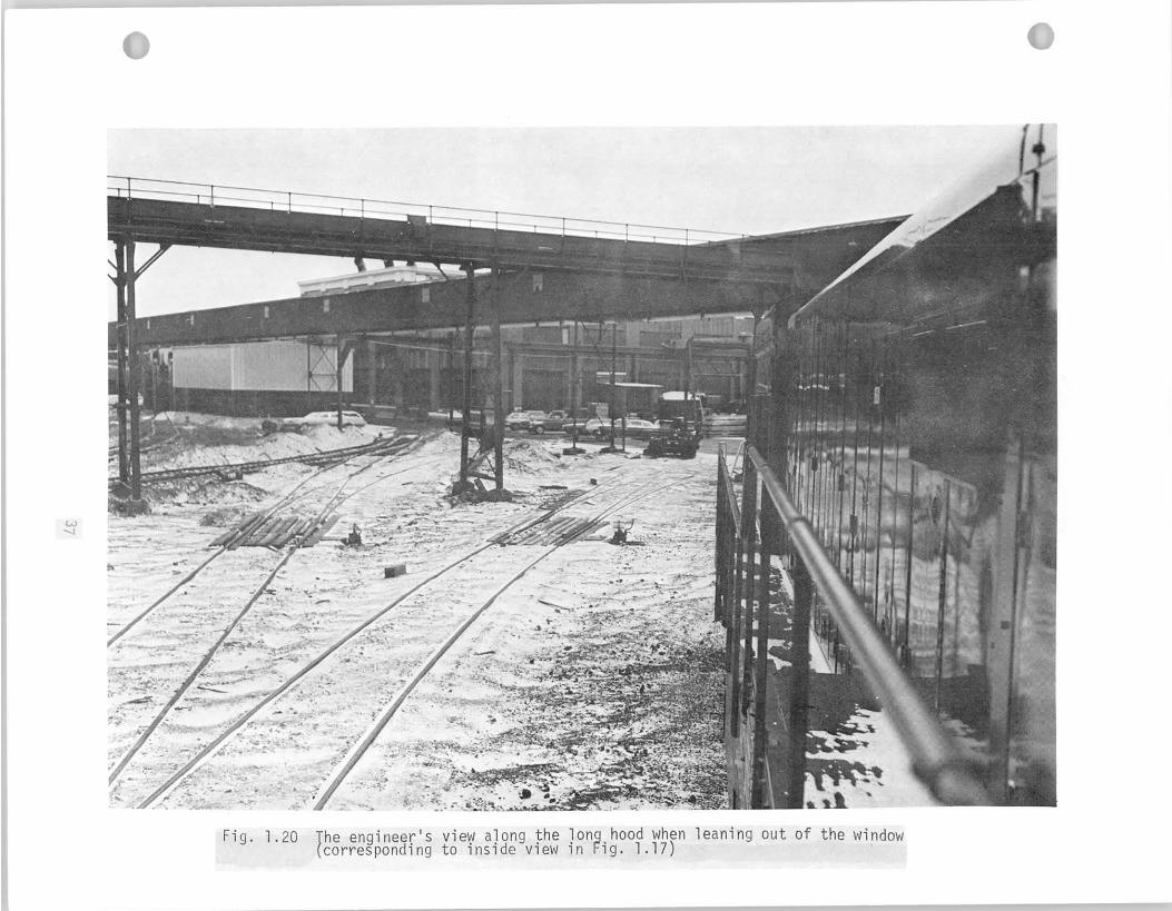
F igu re 1.20 - The Engineer 's View Along the Long Hood When . . . . . . 37 Leaning Out o f t h e Window (Corresponding t o Ins ide View i n F ig . 1.17).
F igure 1.21 - Undesirable Locat ion o f Water Cooler and Heater . . . . . 39 i n the Middle o f the Cab. Note sharp edges and corners, f r e e p i p i n g and valves (GE U25 Model )
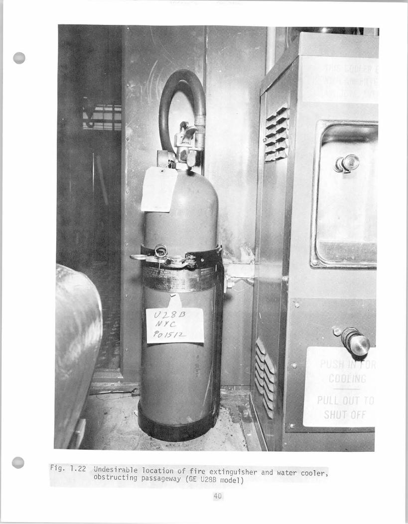
F i g u r e 1.22 - Undesirable Locat ion o f F i r e Ext inguisher and Water . . .40 Cooler, Obst ruc t ing Passageway (GE U28B Model)
F i g u r e 1.23 - Free P ip ing and Pro t rud ing Hand Wheel o f the Heater . . 4 2 Valve are Undesirable (GE U28B Model)
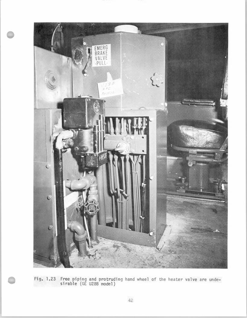
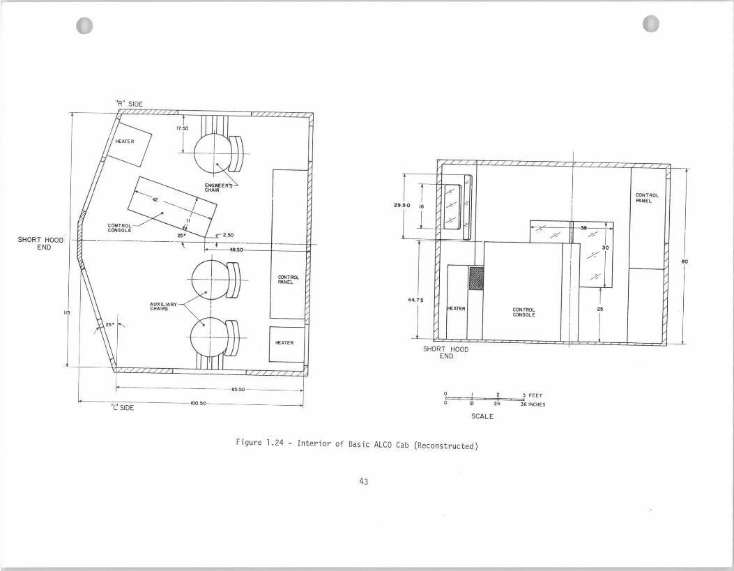
F igu re 1.24 - I n t e r i o r o f Basic ALCO Cab (Reconstructed) . . . . . . . 43
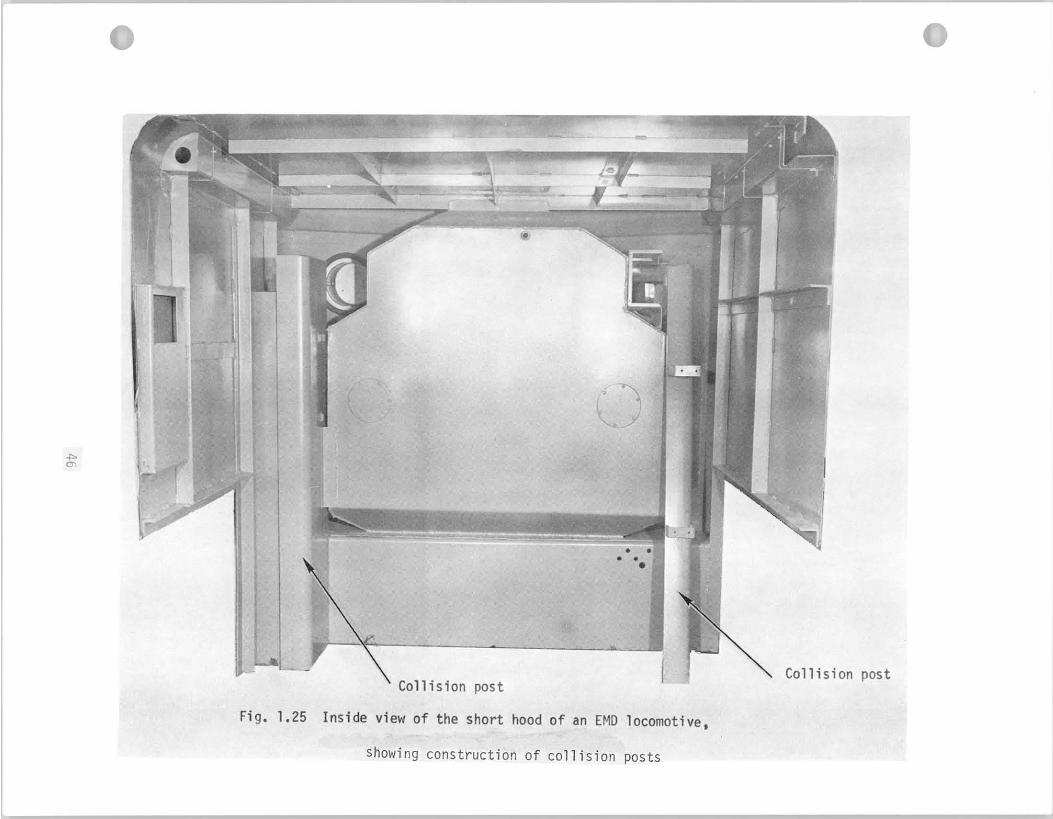
F i g u r e 1.25 - Ins ide View o f the Short Hood o f an EMD Locomotive . . . 46 Showing Construct ion o f C o l l i s i o n Posts
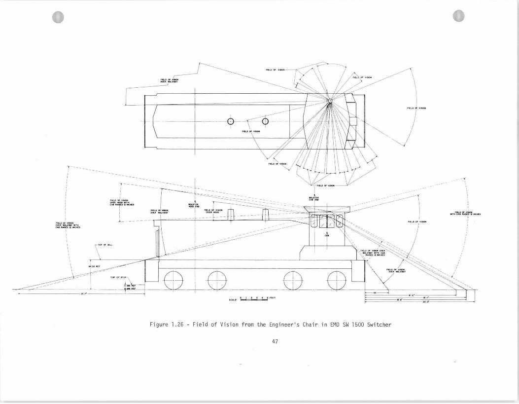
F i g u r e 1.26 - F i e l d o f V i s ion from the Engineer 's Chair i n EMD . . . . 47 SW 1500 Swi tcher
F igure 1.27 - F i e l d o f V i s ion from the Engineer 's Chair i n a Basic . . 48 EMD Cab
F i g u r e 1.28 - I n t e r i o r o f the Proposed Standard Cab, Canadian . . . . A9 Nat ional Railways
F igu re 2.1 - D r i v e r ' s Desk Layout, B r i t i s h Railways Line-Service . . 5 8 Diesel Locomotives
F igure 2.2 - The F i r s t French Standard Contro l Stand, Introduced . . 61 i n 1954 f o r the "9200" Class E l e c t r i c Locomotives
F i g u r e 2.3 - Advanced Version o f the F i r s t French Standard Contro l . 63 Stand, as Used on the "16000" Class Locomotives
F i g u r e 2.4 - Proposed Contro l Stand f o r French D iese l -E lec t r i c . . . 64 Locomotives
F igure 2.5 - Proposed Control Stand f o r French E l e c t r i c Locomotive . 65
F i g u r e 2.6 - Control Stand on EMD Locomotives . . . . . . . . . . . .78
F i g u r e 2.7 - Basic Contro l Stand on EMD Locomotives . . . . . . . . . 79
F i g u r e 2.8 - Control Stand on EM0 Locomotives . . . . . . . . . . . 81
F i g u r e 2.9 - Automatic Brake Handle Pos i t ions on EMD Locomotives . . .83
F i g u r e 2.10 - Automatic Brake Handle Pos i t ions on GE Locomotives . . .83
F i g u r e 2.11 - Independent Brake Handle Pos i t ions a r e I d e n t i c a l . . . . 83 on Both EM0 and GE Locomotives
F i g u r e 2.12 - Three-lever Contro l Stand was Used on U25, U28, . . . . 87 U30 GE Locomotives
F i g u r e 2.13 - Two-lever Contro l Stand was Used on U23, U33 GE . . . . 89 Locomotives
F i g u r e 2.14 - GE Contro l Stands were Equipped w i t h EM0 C o n t r o l l e r s . . 90 i n 1971
F i g u r e 2.15 - AAR Standard Contro l Stand B u i l t byGE t o be Int roduced 93 i n 1972
F i g u r e 2.16 - T h r o t t l e and Reverse Lever Pos i t i ons on a Three-Lever . 94 GE Contro l Stand
F igure 2.17 - T h r o t t l e and Combined Se lec to r and Reverse Lever . . . . 94 Pos i t i ons on a Two-Lever GE Contro l Stand
F i g u r e 2.18a- Contro l Stand Arrangement - ALCO El662 . . . . . . . . . 96
F i g u r e 2.18b- C i r c u i t Breaker Panel on Rear Wall o f Cab -ALCO El662 . 96
F i g u r e 2.19 - Late Model ALCO Contro l Stand (C630, 1966 Product ion) . 97
F i g u r e 2.20 - Proposed Standard Contro l Stand o f t he Canadian . . . . 99 Nat ional Railways
F i g u r e 2.21 - M o d i f i c a t i o n o f the Three Lever GE Contro l Stand . . . 100
F i g u r e 2.22 - M o d i f i c a t i o n o f the Two Lever GE Contro l Stand . . . . 101 (U23 Model, Lake Superior and Ishpeming Ra i l r oad )
F i g u r e 2.23 - M o d i f i c a t i o n o f the Two Lever GE Contro l Stand . . . . 102
(U23 Model, Lake Superior & Ishpeming Ra i l r oad )
F i g u r e 2.24 - Sander Switch on GE Locomotives . . . . . . . . . . . . 104
F i g u r e 2.25 - Sander Switch on EMD Locomotives ( 9 4 0 , 1970 Model) . . 105
F i g u r e 2.26 - Late Model ALCO Contro l Stand (C630, 1966 Product ion) . 106
F i g u r e 2.27 - I n d i c a t o r Gauges on Fron t Wall o f Late Model ALCO . . . 107 Locomotive (C630, 1966 Product ion)
F i g u r e 2.28a- Contro l Stand Arrangement - ALCO OL500C . . . . . . . . 108
F i g u r e 2.28b- C i r c u i t Breaker Panel (Rear Wall o f Cab) ALCO DL500C . 108 /-\
Figure 2.29a - Contro l Stand Arrangement - ALCO Dl535 . . . . . . . . 109
F i g u r e 2.29b - C i r c u i t Breaker Panel (Rear Wall o f Cab) - ALCO . . . 109 DL535
F i g u r e 2.30a - Contro l Stand - ALCO DL560 . . . . . . . . . . . . . . 110
F igure 2.30b - C i r c u i t Breaker Panel - ALCO DL560 . . . . . . . . . . 110
F i g u r e 2.31 - Cont ro l Stand and Contro l Panel i n SW1500 Switcher . . 112 (1971 Product ion)
F i g u r e 2.32 - Cab I n t e r i o r on Switcher SW1500 (1971 Product ion) . . . 113 Showing Lower H a l f of Contro l Stand w i t h t he Dead- man Pedal and Cab Heater
F igure 2.33 - Contro l Stand i n an EMD S-90 Switcher Manufactured . . 114
i n 1943 bu t S t i l l i n Operat ion
F i g u r e 2.34 - The Engineer o f t h i s Recent Product ion (1970) SD-40 . 115 Locomotive Wrapped a Rag Around the Handle o f the Horn f o r Ease o f I d e n t i f i c a t i o n
F i g u r e 2.35 - Contro l Stand i n RS-3 ALCO Switcher (1955 Product ion) . 116
F i g u r e 2.36 - Contro l Stand i n S-2 ALCO Switcher (1950 Product ion) . 118
F i g u r e 2.37 - Contro l Stand o f an 5-2 Baldwin Switcher (1953 . . . . 119 Product ion) w i t h the Contro l Panel on the Hood Wal l , Shown i n the Background
F igu re 2.38 - Brake Stand i n an S-2 Baldwin Switcher (1953 Prod) . . 120
F i g u r e 2.39 - Basic Contro l Panel on EMD Locomotives. . . . . . . . . 122
F i g u r e 2.40 - C i r c u i t Breaker Panel on EMD Locomotives . . . . . . . 122
F i g u r e 2.41 - Basic Contro l Panel on GE Locomotives . . . . . . . . . 124
F i g u r e 2.42 - Basic Contro l Panel on ALCO Locomotives . . . . . . . . 125
F i g u r e 2.43 - Basic Cont ro l Panel on ALCO Locomotives . . . . . . . . 126
F i g u r e 2.44 - V a r i a t i o n o f t he Basic GE Contro l Panel I n s t a l l e d . . . 127 i n a U25 Locomotive
F igure 2.45 - Contro l Console i n GE's E l e c t r i c Locomotives . . . . . 128 ( B u i l t i n 1966)
F i g u r e 3.1 - Proposed V e n t i l a t i o n System f o r t he German Federal . . 134 Railways
Figure 3.2 . Temperature Dis t r ibut ion Showing Cab Temperature . . . . . 140 Rise Above Outside Temperature (Road Test : GP35, No . 724. 40 mph. Cab Forward . Supplementary Side Wall Breaker on "high" a t Fireman's Side. Basic Heater on "medium" a t Engineer 's S ide)
F igure 3.3 . Temperature Di s t r ibu t ion Showing Rela t ive Cab . . . . . . 142 Temperature Rise Above Outside Temperature
. . . . . . Figure 3 . 4 . Al l -E lec t r i c Heating Temperature Di s t r ibu t ion 143 Showing Cab Temperature Above Outside Temperature
F igure 3.5 . Cab Warm-up Time . . . . . . . . . . . . . . . . . . . . 144
Figure 3.6 . Heat Output of Hot Water and E l e c t r i c Heaters . . . . . . 144
Figure 4.1 . Sound Environment i n Locomotive Cabs . . . . . . . . . . 163
Figure 4.2 . Sound Environment in G E Cabs. Without t h e Horn . . . . . :I65 Sounding
Figure 4.3 . Sound Environment in G E Cabs with Horn Sounding . . . . . 166
Figure 4.4 . Human Tolerance t o Ver t ica l Vibrat ion . . . . . . . . . . 168
Figure 5.1 . Proposed Standard Seat f o r the German Federal . . . . . . 175 Railways
Figure 5.2 . Standard Seat of the Swiss Federal Railways . . . . . . . 177 I n s t a l l e d in the Cab
Figure 5 .3 . Standard Sea t of the Swiss Federal Railways . . . . . . . 177 I n s t a l l e d on a Fork L i f t
Figure 5.4 . Basic EM0 Locomotive Chair . . . . . . . . . . . . . . 182
Figure 5.5 . Basic G E Wall Mounted S l id ing Seat . . . . . . . . . . 183
Figure 5.6 . Special EM0 Chair on Penn Central Locomotives . . . . . . 185
. . . . Figure 5.7 . Special EM0 Chair on Southern Pac i f i c Locomotives 187
Figure 5.8 . Special EMD Chair on Union P a c i f i c Locomotives . . . . 188
Figure 5.9 . Basic G E Seat w i t h Arm Rests . . . . . . . . . . . . . . 189
Figure 5.10. Optional G E Wall Mounted S l id ing Seat . . . . . . . . . . 190
. . . . . . Figure 5.11. Optional GE Floor Mounted Seat with Arm Rests 191 P~
v i i i
F i g u r e 5.12 - Seat f o r Sonar Operators which Could be Adopted . . . . . 193 f o r Use on Locomotives
F i g u r e 5.13 - Anthropometr ic Dimensions t o be Co l lec ted on . . . . . . . 197 Locomotive Engineers f o r Good Seat Design
INTRODUCTION
The need f o r a human f a c t o r s survey o f domestic locomotives
was po in ted o u t by a prev ious study prepared by SysteMed, Inc. i n
A Study o f Human Factors A f f e c t i n g the Safe ty o f Ra i l r oad Operat ions. (135)
O b j e c t i v e o f t h i s i n v e s t i g a t i o n was ( 1 ) t o survey the human f a c t o r s
c o n d i t i o n s i n the cabs o f domestic locomotives and ( 2 ) t o rev iew
r e l e v a n t l i t e r a t u r e on human f a c t o r s cab design. Th is r e p o r t has
been compiled as a comparative s tudy o f human f a c t o r s design aspects
o f in te rmed ia te and h igh horsepower locomotives. It covers t he
c o n s t r u c t i o n o f cab i n t e r i o r s , l o c a t i o n and opera t ion o f c o n t r o l s and
a i r brake equipment; the atmosphere, no ise and v i b r a t i o n i n locomot ive
cabs; the design o f locomot ive seats, phys io log i ca l and v i g i l a n c e
requi rements o f t r a i n d r i v i n g . The r e s u l t s o f t he s tudy show
improvements i n cab cons t ruc t i on and design approaches which could
make cond i t i ons i n locomot ive cabs more s u i t a b l e t o the needs and
performance c a p a b i l i t i e s o f human operators. Guidel ines a re a l s o
presented t o improve f u t u r e designs and i n d i c a t e where f u t u r e research
i s needed due t o unique human f a c t o r s cond i t i ons i n locomot ive
opera t ions .
The f o l l o w i n g models o f locomotives a re covered i n the r e p o r t :
EMD (E lec t ro Mot ive D i v i s i o n o f General Motors C o r ~ o r a t i o n ) - , ~ ~ 3 0 , GP35, GP38, GP39, and GP40; SD35, SD38, ~ ~ 3 9 , SD40, and SD45.
GE (General E l e c t r i c Co.) B and C models o f t he U23, U25, U28, U30, U33, and U36.
ALCO (Alco Products I nc . ) C420, C424, C425, C430, C628, C630, and C636.
Add i t i ona l data are prov ided on the EMD swi tchers SW1000, SW1500.
I n each area o f human f a c t o r s , the r e p o r t f i r s t discusses f i n d i n g s
which are general and app l i cab le t o most o f the models. Perspect ive
d i f f e r e n c e s are po in ted ou t l a t e r according t o spec ia l designs found
on locomotives o f var ious manufacture, and on i n d i v i d u a l models.
Based on a survey o f locomotives manufactured p rev ious l y and
i n opera t ion present ly , c o l l e c t e d from a number o f p ro fess iona l
sources , (30139y71 y 1 0 8 y 1 3 0 ) i t i s bel ieved t h a t the r e p o r t covers most
o f the major types o f locomotives i n use by the domestic r a i l r o a d s
today.
Data were c o l l e c t e d f o r the r e p o r t by v i s i t i n g the locomotive
manufacturers: E l e c t r o Mot ive D i v i s i o n o f General Motors i n LaGrange,
I 1 1 i n o i s and Transpor ta t ion Systems Business D i v i s i o n o f General
E l e c t r i c i n Er ie , Pennsylvania. Technical data, r e s u l t s o f research
measurements, drawings o f locomotive cabs and c o n t r o l s were obta ined
f rom the manufacturers. I n o rder t o rev iew and photograph o l d e r
locomotives s t i l l i n opera t ion and t o revea l respect ive d i f f e rences
between models o f prev ious and recent manufacture, t h ree yards o f
t h e L o u i s v i l l e and Nashv i l l e Ra i l road were v i s i t e d . I n compi la t ion
o f the data, the assis tance g iven by personnel o f the Human Factors
Branch, Transpor ta t ion Systems Center, DOT, Cambridge, Massachusetts,
d u r i n g mutual v i s i t s t o both Cambridge and NAD Crane, Indiana i s
appreciated.
Present ly , the domestic r a i l r o a d companies purchase i n e f f e c t
"custom b u i l t " locomotives because the r a i l r o a d s spec i fy , by vendor,
many o f the i tems on the locomotive such as the cab seats; engineer 's
c o n t r o l panel layout ; speedometer and speed recorder ; deadman pedal - s i z e and l oca t i on ; rad io , i n c l u d i n g l oca t i on ; type and model o f seat and
s e a t arrangement; water c o o l e r / r e f r i g e r a t o r ; f i r e ex t i ngu i she r ,
i n c l u d i n g l oca t i on ; horn, 3 o r 5 chime and l oca t i on ; and e tc . T i t l e
49 Chapter 11 Paragraph 230.200a o f the FRA Rules s ta tes t h a t " the
Ra i l road Company i s responsib le f o r the general design cons t ruc t ion ,
inspect ion and r e p a i r o f a l l locomotives used o r permi t ted t o be used on
i t s l i n e . " A d d i t i o n a l l y , some design d e t a i l s have been c o n t r o l l e d by
agreements between i n d i v i d u a l r a i l r o a d s and t h e i r employees' union. The
r e l a t i o n s h i p o f the operator t o the f r o n t window and c o n t r o l console,
i n c l u d i n g cab l oca t i on , i s one example.
These procedures, however, cannot assure a good human f a c t o r s design
o f locomotive cabs. I d e a l l y , a standard locomotive cab should be designed
according t o accepted human engineer ing p r i n c i p l e s , i n c l u d i n g cons idera t ion
t o such environmental f a c t o r s as noise, v e n t i l a t i o n , heat ing, v i b r a t i o n
and seat ing, besides arrangement o f con t ro l s and d isp lays; and such a
standard cab should be b u i l t on a l l f u t u r e locomotives w i t h a minimum
o f m o d i f i c a t i o n among the var ious models.
1. HUMAN FACTORS DESIGN OF LOCOMOTIVE CAB INTERIORS
1.1 -. L i t e r a t u r e Survey o f Locomotive Cab Design
D r i v i n g p o s i t i o n i n the cab o f a r a i l r o a d locomot ive has been
s e v e r e l y l i m i t e d u n t i l l a t e by the steam locomot ive b o i l e r o r mot ive
power u n i t . Thus the engineer 's v i sua l f i e l d and comfor t have been
r e s t r i c t e d considerably . The i n t r o d u c t i o n o f f ron t -end cabs and
short-hood cons t ruc t i on changed the cond i t i ons and s i g n i f i c a n t
advantages can be achieved by designing the cab according t o the
p r i n c i p l e s o f human f a c t o r s engineer ing t o s u i t t he human c a p a b i l i t i e s
and comfor t requirements o f the opera tor .
The design and l a y o u t o f t he d r i v i n g cab on d i e s e l locomotives
has been t r a d i t i o n a l l y t he r e s p o n s i b i l i t y o f the manufacturer and
t h e buyer. I n 1958, however, t he I n t e r n a t i o n a l Union o f Railways (U.I.C.)
i s s u e d i t s f i r s t recommendations under Code 625 and requ i red these
and subsequent s p e c i f i c a t i o n s t o become o b l i g a t o r y f o r i nco rpo ra t i on i n t o
i n t e r n a t i o n a l European stock b u i l t a f t e r the dates o f issue. (36)
The f i r s t o f these r e g u l a t i o n s concerned f i r e precaut ions and
f i r e f i g h t i n g mat te rs r e l a t i n g t o the s a f e t y o f d r i v i n g personnel.
I t drew a t t e n t i o n t o the importance o f us ing non-flammable m a t e r i a l
i n the p r o x i m i t y t o the engine and regu la ted the ex te rna l temperature
o f lagged p ipes. The nex t i ssue under Code 625 U I C s p e c i f i e d requirements
f o r g l a z i n g the d r i v i n g compartment. It d i f f e r e n t i a t e s between windows
which have t o be f i t t e d w i t h unbreakable g lass and remain i n t a c t and
t ranspa ren t a f t e r damage and those which may be broken t o pe rm i t e x i t
i n case o f emergency. One f r o n t window o r a s i d e window on each s ide o f
the driving compartment i s required t o be large enough to allow a
man t o pass through the frame a f t e r the glass has been broken.
The seated position of the crew i s embraced by Series 3 of Code
625, issued i n 1959, which recommends i t to be a s high above r a i l
level a s possible. The importance of providing protection t o the
man by h i g h strength cab construction i s a l so emphasized in this
s e r i e s . In order t o protect the crew i n accidents, a l l heavy
equipment i s required t o r e s i s t a t l e a s t 39 deceleration. Sharp
edges, corners, and loose f i t t i n g s a re t o be avoided i n cab design.
In 1960, Series 4 of Code 625 was issued to cover the engineer 's
sea t ing position more adequately. I t requires the cab t o be bu i l t
f o r one-man operation and arranged so t ha t i t can be driven by the
dr iver standing a s well a s s i t t i n g . The space t o be provided a t
seated eye level has t o be a t l e a s t 72 1/2" high, 47" long, and 78 1/2"
wide. A distance of 19 1/2 t o 47" from the engineer 's eye t o the
f r o n t window i s s t ipulated and the use of mirrors fo r backward vision
i s n o t permitted. The driving position has t o be such tha t backward
observation i s possible w i t h o u t having to hang out of the window.
Adjustable foot rests and seats a re recommended which must be
comfortable and permit the driver t o operate standing. All control
handles and gauges i n frequent use a re t o be conveniently grouped
and eas i ly seen from the driving position. The height of the top of
t he window i s required t o be a t l e a s t 67" from the cab f loor and
defogging system, an t ig la re screens and windshield wipers must be provided n
To avoid confusion of controls , the f i f t h of the se r ies under
Code 625 specif ies t h a t a l l controls must be separate i n function, e .g . ,
a combined power control and brake lever would not be acceptable.
Wheel or handle type control i s acceptable fo r power control . The
wheel should ro ta te ve r t i ca l l y or nearly so and i n each case the degree
i t i s advanced from the zero position must be readi ly discernable. (36)
The above recommendations of UIC const i tu te the f i r s t systematic
appl icat ion of human fac tors engineering i n the design of locomotive
cabs.
Much European work has concentrated on physical and environmental
aspects of cab design. Sanitary and hygenic problems of rai lroad
engineering have a long history i n Germany and the human factors aspects
o f cab design a re of special concern t o the physicians of the German
Railways. (55) German work recommends 350-530 f t 3 space t o be optimum
in the locomotive cab. (49) For European conditions, 280 f t 3 space could
be considered a s a good compromise according to the report . The
height and w i d t h of the cab a re suggested t o be 79". The surface
f i n i s h of the cab i n t e r io r must be of low spectral reflectance, l i gh t color ,
a n d easy t o clean. The colors of signal l i gh t s and their complementary
co lors should not be used. Additional data concerning the recommended
dimensions fo r designing locomotive cabs were received from Dr. Wittgens,
President of Human Factors Group, International Union of Railway
~ h y s i c i a n s . ( ' ~ ~ ) These recommendations, prepared fo r the International
U n i o n of Railways (UIC),suggest t ha t the cab dimensions a re t o be 79"
high, 73" wide, and 70" deep a t the eye height of the seated engineer,
i .e., between the w indsh ie ld and the f i r s t o b j e c t behind i t (such
a s cab w a l l , c o n t r o l panel, door, e t c . ) . The d is tance between the
eng inee r ' s head and the w indsh ie ld should be 20" t o 47". The doors
shou ld p rov ide p r o t e c t i o n aga ins t no ise and ou ts ide a i r p o l l u t a n t s .
Bo th the ou ts ide doors and the cab serv ice doors must be 23 1/2"
w ide and 73" h igh. The r a t i o o f window area t o f l o o r area should be
a minimum o f 0.4 which corresponds t o t he Sov ie t standard. (97) The
1 ower edge o f t he f r o n t window should be 37 1/4" high, and the upper
edge 73" above the cab f l o o r . The f l o o r must be e a s i l y c leanable,
n o t s l i ppe ry , and should p rov ide i n s u l a t i o n aga ins t c o l d and noise.
A 14 x 12 x 59" c l o s e t o r cab ine t i s recommended f o r s t o r i n g c l o t h s
w i t h i n reach o f the seated engineer. Two a d d i t i o n a l c l o t h hooks
shou ld be l oca ted i n reach o f the seated engineer. The s t a i r s l ead ing
i n t o the cab must be an equal d is tance f rom each o t h e r -- a maximum
o f 13 3/4" i s recommended, w i t h t he lowest s t a i r about 13 3/4" above
t h e r a i l sur face. S t a i r w id th should be 12 t o 16", s t a i r depth 2 " .
Hand ra i l s must be p laced on both s ides o f the doors and s t a i r s . The
r a i l s should s t a r t a t 35" above the r a i l and the upper end should n o t
b e l ess than 47" above f l o o r l e v e l o f the cab. The door handles
must be 3" f rom the door edge, 2" above the door sur face w i t h a
4 1/2" minimum length.
The fundamental problems o f cab s t r u c t u r e and equipment were
analyzed on th ree e l e c t r i c and two d iese l locomotives o f t he P o l i s h
Rai lways. (79) By means o f a ques t ionna i re and a human f a c t o r s c h e c k l i s t ,
s i g n i f i c a n t d i f f e rences were found among the var ious models i n t he eng ineer 's FT
workspace, desk arrangement, and instrument design, sea t construction
and location, and sani tary and hygenic ins ta l la t ions . Size of the
cab f loor area varied between 23.2 t o 31.0 f t 2 ; the cab space was 3
found t o be 229 f t t o 337 f t 3 . The r a t i o of the area of windows
t o the area of cab f loor i s recommended to be a t l e a s t 0.40. This
value was exceeded on a l l locomotives examined. The investigation of
t h e locomotives and sani tary equipment found t h a t most of the models
had a cloth c lo se t , food warmer, and wash basin; however, only a few
had food storage box, f i r s t aid k i t , and t o i l e t .
Cabs i n c i t y t r a n s i t cars a re of en t i r e ly d i f fe ren t construction;
frequently half of the tota l width i s used t o house the driver and
the operator ' s space and vent i la t ion requirements a re often
unsat isf ied. A means of emergency ex i t i s required and the cab should
be designed t o protect the dr iver i n a co l l i s i on , aspects often n o t
found in present units. (122) Another paper a lso emphasizes t h a t sa fe ty
(74) should be of primary concern in the design of locomotive cabs.
Protection of the individual must be designed both i n t o the operational
aspects of controls and signaling and in the constructional aspects of
1 ocomotive cabs. Coll ision protection i s a lso an important feature
o f cab design. The locomotive body should Protect the engineer against
col l is ion forces a s much as possible and the cab in te r io r should be f r e e
of sharp edges and corners which could induce in jur ies . (49
Series 3 of Code 625 issued by the International Union of Railways
( U . I C . ) recommends t h a t a1 1 cab doors be arranged t o open inwards.
Many railroads do not agree w i t h t h i s l a t t e r provision and prefer the 0
I
oppos i te f o r the e x i t t o the catwalks o f the locomotive. (36) With
t h i s arrangement the d r i v e r can escape q u i c k l y i f a c o l l i s i o n i s
imminent and no f u r t h e r a c t i o n can be taken by him. This i s q u i t e
i n keeping w i t h past experience where men jumped from locomotives
immediately p r i o r t o c o l l i s i o n , and i n some cases avoided ser ious
i n j u r y . Furthermore, the swi tch ing locomotive w i t h o n l y r e a r access
t o the cab can present a specia l problem under dera i lment cond i t ions .
I f r a i l w a y cars p i l e up on the back-end and no o the r access i s
prov ided, the crew can have d i f f i c u l t y i n g e t t i n g out . A door f o r e -
and-af t i s more ati is factory but , here again, if the machine s e t t l e s
o n i t s s ide the f r o n t door can be on the under s ide and r e a r door
obs t ruc ted . Side doors a r e thus r e a l l y t o be p re fe r red t o meet such
e v e n t u a l i t i e s .
Optimal s i z e o f the window area i s a l s o sub jec t t o controversy.
The German, Pol ish, and Russian l i t e r a t u r e s t i p u l a t e s t h a t the r a t i o
o f the t o t a l window area t o the area o f cab f l o o r must be a t l e a s t
0.40. 54379y97) A German r e p o r t recommends t h a t the v i sua l f i e l d
must be as b i g as possib le, and i n a swi tch ing engine the bumpers
must be v i s i b l e from the normal opera t ing posture. (49) However, perhaps
one o f the most unexpected reac t i ons observed has been the d iscomfor t
which too good a v i s i b i l i t y has brought about. Too l a r g e a view o f
t h e t r a c k beneath the d r i v e r ' s d i r e c t v i s i o n i s unnecessary, and
v e r y l a r g e low windows have been a source o f some annoyance. Backward
g l a r e from marker l i g h t s i n f o g have caused these t o be considerably toned
down and s ide g l a r e from low s u n l i g h t has been a f u r t h e r problem w i t h .h
very large front windows. The U.I.C. requirement that windows
shall be as small as possible to provide greater strength to
the cab is thus of interest. It conforms to general operating
requirements as well. (36) The cabs are fully glazed above waist height
and are fitted with v-shaped sloping driving windshields on the French
Railways Type 68,000 diesel-electric locomotive designed for mixed
traffic duties on non-electrified main line routes. The locomotive
has two identical full-width driving cabs at each end.
Windshield material must be'carefully chosen. Several requirements
must be satisfied: strength, transmissibility, freedom of color
distortion, scratch resistance, and scattering of light. Distinct
differences have been observed in the light scattering ratio of
various windshield types. (lo7) The structural nature of the surface
can adversely affect visibility and perceptibility of objects.
There is a threshold for light scattering and beyond that limit even
small increases are strongly noticeable, thus reducing perceptibility
of objects through the windshield.
Since December 1970, Penn Central uses Lexan to replace broken side
windows in locomotives, passenger cars, and cabooses. (Io3) ex an is a high strength, impact resistant polycarbonate, developed by General
Electric. Its thermal conductivity is one-third that of glass, thus it
decreases conventional heat loss through the cab windows. Most
recently an improved form called Lexan MR-4000 has been marketed,
which has clearer seeing qualities and higher resistance to scarring
from abrasions or chemicals. Penn Central already started using the
improved ve rs ion f o r replacement windows.
I n development o f f u t u r e t r a n s p o r t a t i o n systems, cons idera t ion
has t o be g iven t o t he s t a t i s t i c a l l y average opera tor (Ref. 132, p.68).
Most prev ious s tud ies have been d i r e c t e d toward reac t i ons o f h i g h l y
s k i l l e d and t r a i n e d personnel such as m i l i t a r y o r a i r l i n e p i l o t s . Many
s t u d i e s i n t he pas t consider o n l y causal r e l a t i o n s h i p s which a re va lue
judgments by an i n d i v i d u a l i n v e s t i g a t o r concerning f a i l u r e s l ead ing t o
breakdowns o r acc idents. As a f i r s t s tep i n development o f f u t u r e
hardware, l a b o r a t o r y s imu la t i on o f the man-machine i n t e r a c t i o n i s
recommended . Simula t ion techniques have been success fu l l y app l i ed
t o opt imal development o f a i r c r a f t , m i l i t a r y tanks, and submarines.
Less complex s imu la t ions cou ld advantageously be app l i ed f o r the design
o f t r a n s p o r t a t i o n equipment.
I n t he s tudy o f t he locomotive eng ineer 's work, the r e l a t i o n s h i p
(139,140) between man, machine, and working environment must be combined.
Th is work study, whose pr imary aim i s t o e s t a b l i s h r a t i o n a l use o f resources
i n l abo r and management, con ta ins a n a l y t i c a l techniques f o r assessment
o f jobs, p a r t i c u l a r l y o f locomot ive engineers i n the working environment.
A French r e p o r t discusses the design aspects o f cab cons t ruc t i on
and c o n t r o l systems i n e l e c t r i c locomotives. (96) The r e p o r t emphasizes
t h a t i n cons t ruc t i on o f a locomotive s e r v i c e a b i l i t y and ease o f
maintenance must a l s o be g iven cons idera t ion . Designers o f t he EMD
6600 Centennial locomotive p a i d p a r t i c u l a r a t t e n t i o n t o mainta inabi 1 i t y . (2 )
T h i s model i s equipped w i t h a modular e x c i t a t i o n system, w i t h several R
i nhe ren t advantages. The most impor tan t i s t h a t the component i n
t r o u b l e can be unplugged and replaced i n a mat te r o f minutes. A l l
ma jo r e lec t ron i cs , e x c i t a t i o n , wheel s l i p , and o the r c o n t r o l s a re
mounted on modules t h a t do n o t r e q u i r e removal o r replacement o f
t e rm ina l connections. The modules a re housed i n t he c o n t r o l cab ine t
o f t he cab. The modular p l u g - i n components concept was in t roduced
t o the r a i l r o a d s i n 1960 by General E l e c t r i c and has been cont inued i n
a l l locomotive models. GE has made cont inua l improvements i n t he "b lue
ca rds " - the name used f o r t he modular p l u g - i n components - from hand
w i r e d t o machine d ip-soldered p r i n t e d c i r c u i t cards o f t he XR se r i es
locomot ive s t y l e .
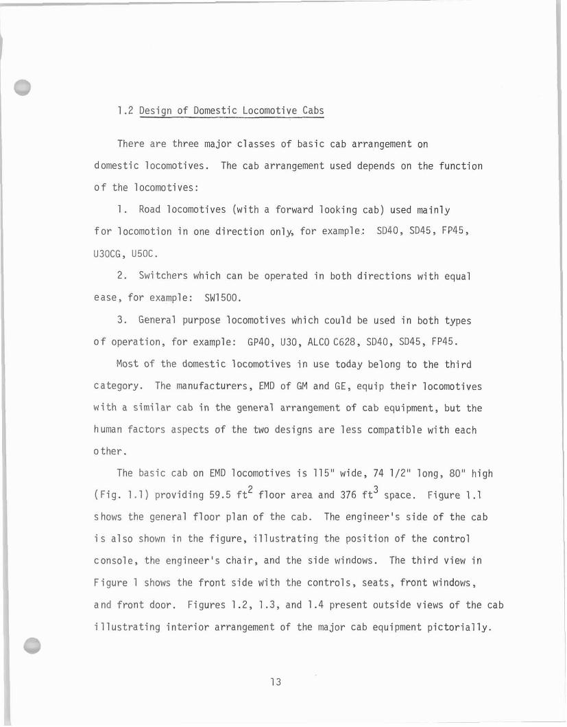
1.2 Design of Domestic Locomotive Cabs
There are three major classes of basic cab arrangement on
domestic locomotives. The cab arrangement used depends on the function
of the locomotives:
1 . Road locomotives (with a forward looking cab) used mainly
f o r locomotion in one direction only, fo r example: 9 4 0 , SD45, FP45,
U3OCG, U50C.
2. Switchers which can be operated i n both directions with equal
ease , f o r example: SW1500.
3. General purpose locomotives which could be used in b o t h types
o f operation, for example: GP40, U30, ALCO C628, SD40, SD45, FP45.
Most of the domestic locomotives i n use today belong t o the third
category. The manufacturers, EMD of GM and G E , equip the i r locomotives
w i t h a similar cab in the general arrangement of cab equipment, but the
human factors aspects of the two designs are less compatible with each
other .
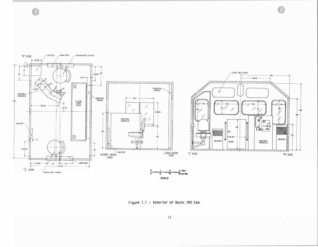
The basic cab on EMD locomotives i s 115" wide, 74 1/2" long, 80" high
2 3 (Fig. 1.1) providing 59.5 f t f loor area and 376 f t space. Figure 1.1
shows the general f loor plan of the cab. The engineer's s ide of the cab
i s also shown i n the f igure , i l l u s t r a t i ng the position of the control
console, the engineer's chair , and the side windows. The third view i n
Figure 1 shows the f ront s ide with the controls, sea t s , f ron t windows,
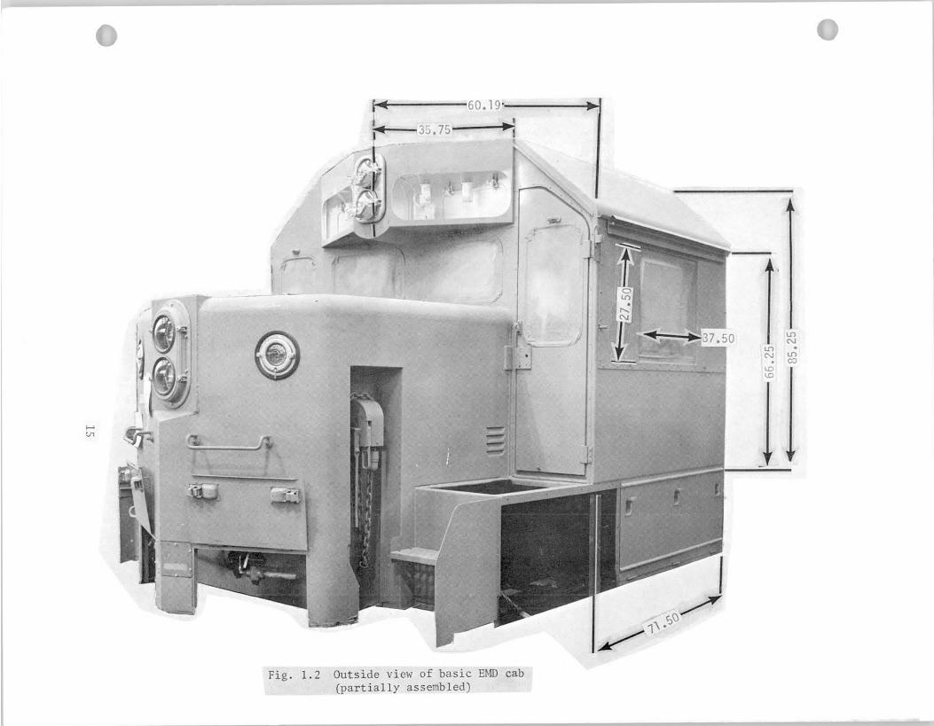
and f ron t door. Figures 1.2, 1.3, and 1.4 present outside views of the cab
i l l u s t r a t i n g in t e r io r arrangement of the major cab equipment p ic tor ia l ly . 7
0 1 2 ,Peel 0 e 2. d a , ~ c ' e
SCALE
Figure 1.1 - In t e r i o r of Basic EMD Cab
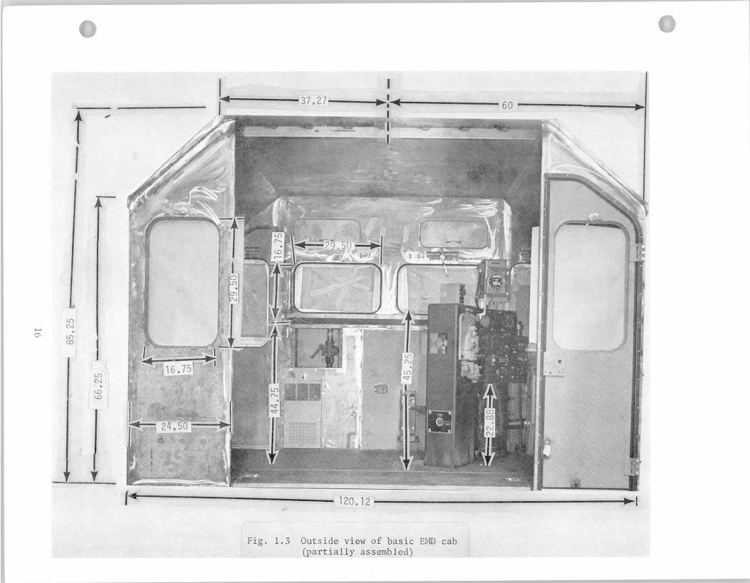
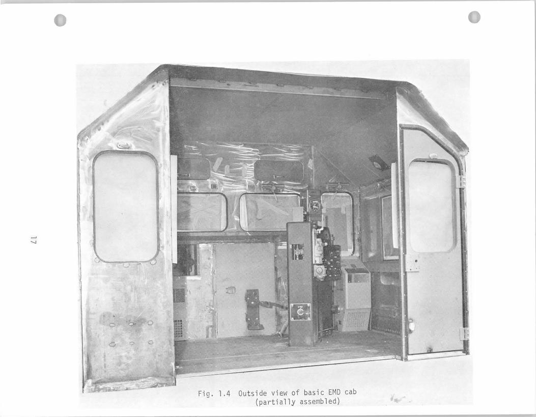
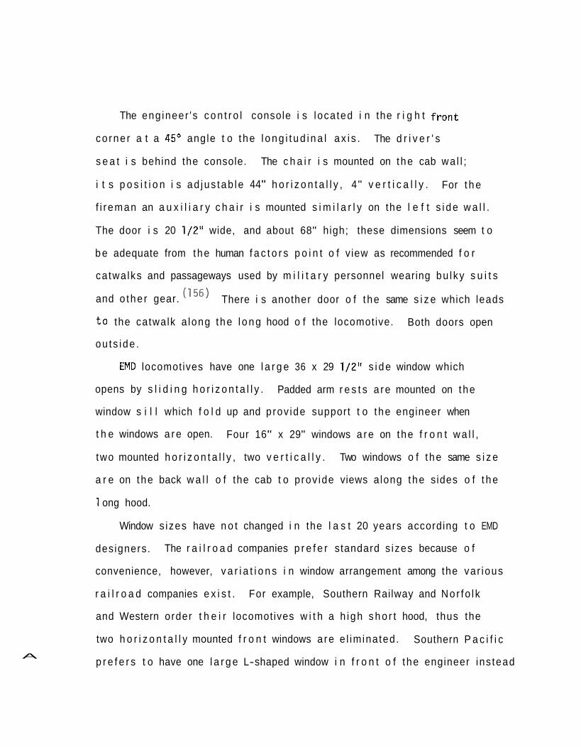
The eng ineer 's c o n t r o l console i s loca ted i n the r i g h t f r o n t
co rne r a t a 45' angle t o t he l o n g i t u d i n a l a x i s . The d r i v e r ' s
s e a t i s behind the console. The c h a i r i s mounted on the cab wa l l ;
i t s p o s i t i o n i s ad jus tab le 44" h o r i z o n t a l l y , 4" v e r t i c a l l y . For t h e
f i r eman an a u x i l i a r y c h a i r i s mounted s i m i l a r l y on the l e f t s i d e w a l l .
The door i s 20 1/2" wide, and about 68" high; these dimensions seem t o
b e adequate from the human f a c t o r s p o i n t o f v iew as recommended f o r
ca twa lks and passageways used by m i l i t a r y personnel wearing bu l ky s u i t s
and o the r gear. There i s another door o f t he same s i z e which leads
t o the catwalk a long the l o n g hood o f the locomotive. Both doors open
ou ts ide .
EM0 locomotives have one l a r g e 36 x 29 1/2" s i d e window which
opens by s l i d i n g h o r i z o n t a l l y . Padded arm r e s t s a re mounted on the
window s i l l which f o l d up and prov ide support t o t he engineer when
t h e windows a r e open. Four 16" x 29" windows a r e on the f r o n t w a l l ,
two mounted h o r i z o n t a l l y , two v e r t i c a l l y . Two windows o f t he same s i z e
a r e on the back w a l l o f the cab t o p rov ide views a long the sides o f t h e
1 ong hood.
Window s izes have n o t changed i n the l a s t 20 years according t o EMD
designers. The r a i l r o a d companies p r e f e r standard s izes because o f
convenience, however, v a r i a t i o n s i n window arrangement among the var ious
r a i l r o a d companies e x i s t . For example, Southern Railway and Nor fo l k
and Western order t h e i r locomotives w i t h a h igh s h o r t hood, thus the
two h o r i z o n t a l l y mounted f r o n t windows a re e l im ina ted . Southern P a c i f i c
p r e f e r s t o have one l a r g e L-shaped window i n f r o n t o f t he engineer ins tead A
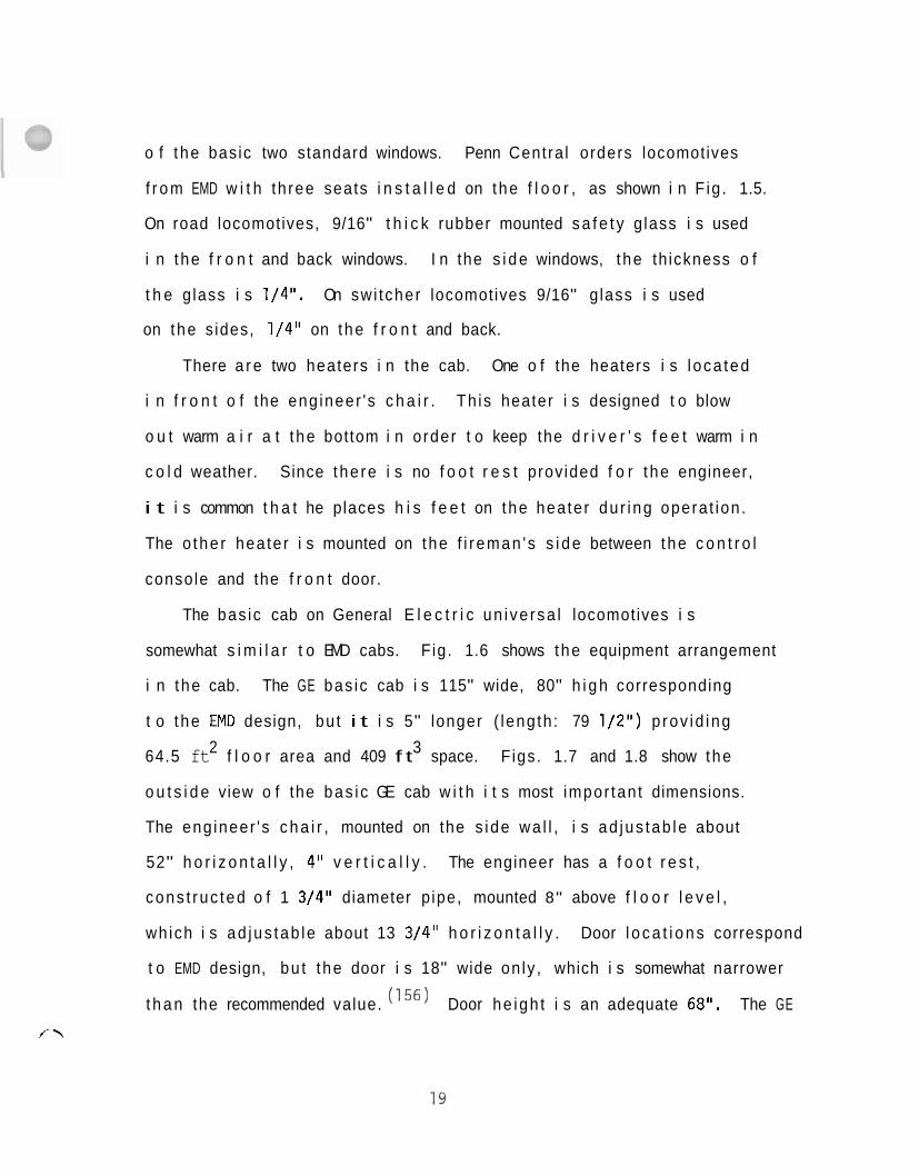
o f t he basic two standard windows. Penn Centra l orders locomotives
f r o m EMD w i t h th ree seats i n s t a l l e d on the f l o o r , as shown i n F ig . 1.5.
On road locomotives, 9/16" t h i c k rubber mounted s a f e t y g lass i s used
i n t he f r o n t and back windows. I n the s i d e windows, t he th ickness o f
t h e g lass i s 1/4". On swi tcher locomotives 9/16" g lass i s used
on the s ides, 1/4" on the f r o n t and back.
There a r e two heaters i n the cab. One o f the heaters i s l oca ted
i n f r o n t o f the eng ineer 's c h a i r . Th is heater i s designed t o blow
o u t warm a i r a t t he bottom i n o rder t o keep the d r i v e r ' s f e e t warm i n
c o l d weather. Since the re i s no f o o t r e s t prov ided f o r t he engineer,
i t i s common t h a t he places h i s f e e t on the heater du r i ng opera t ion .
The o the r heater i s mounted on the f i r eman ' s s i d e between the c o n t r o l
console and the f r o n t door.
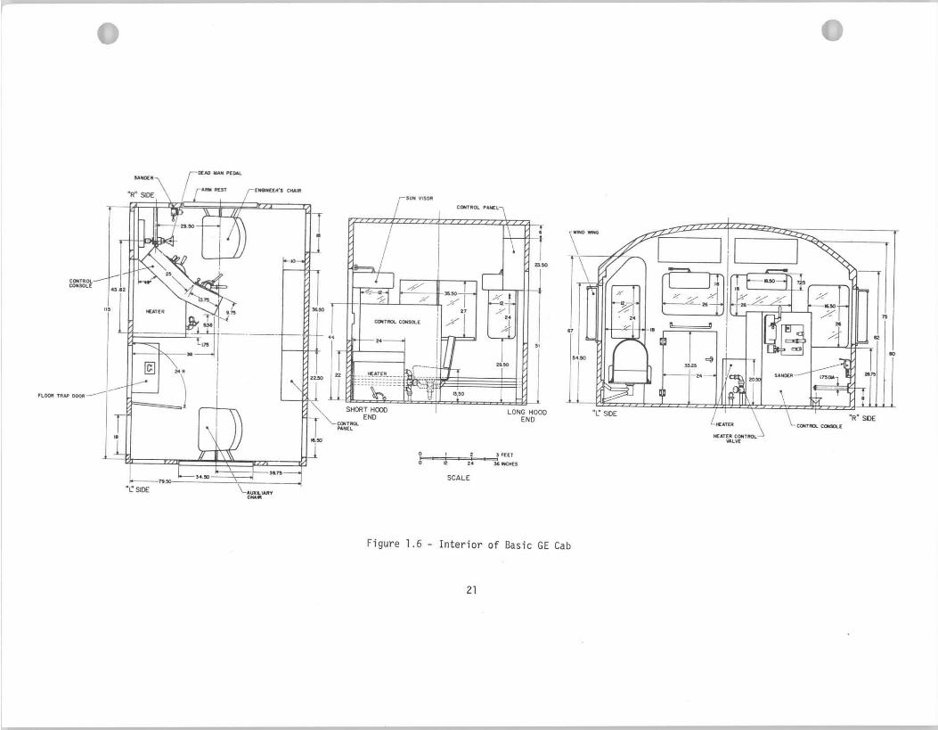
The bas ic cab on General E l e c t r i c un i ve rsa l locomotives i s
somewhat s i m i l a r t o EMD cabs. F ig. 1.6 shows the equipment arrangement
i n t he cab. The GE bas ic cab i s 115" wide, 80" h i g h corresponding
t o t he EM0 design, bu t i t i s 5" longer ( leng th : 79 1/2") p rov id ing
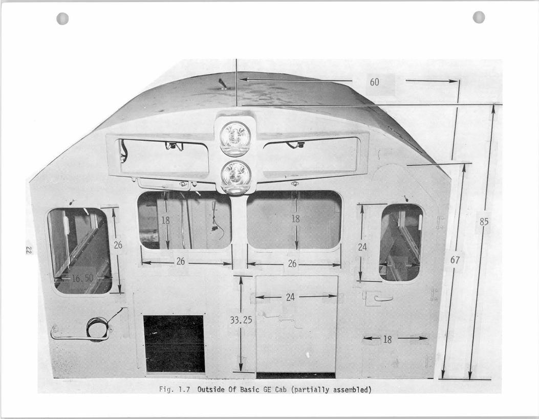
2 3 64.5 ft f l o o r area and 409 f t space. F igs. 1.7 and 1.8 show the
o u t s i d e view o f the bas i c GE cab w i t h i t s most impor tan t dimensions.
The eng ineer 's c h a i r , mounted on the s ide wa l l , i s ad jus tab le about
52" h o r i z o n t a l l y , 4" v e r t i c a l l y . The engineer has a f o o t r e s t ,
cons t ruc ted o f 1 3/4" diameter p ipe, mounted 8" above f l o o r l e v e l ,
wh ich i s ad jus tab le about 13 3/4" h o r i z o n t a l l y . Door l o c a t i o n s correspond
t o EMD design, bu t t he door i s 18" wide on ly , which i s somewhat narrower
t h a n the recommended value. Door he igh t i s an adequate 68". The GE
f---
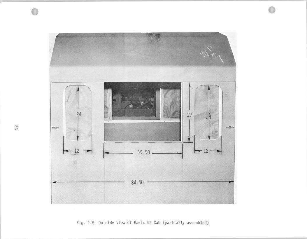
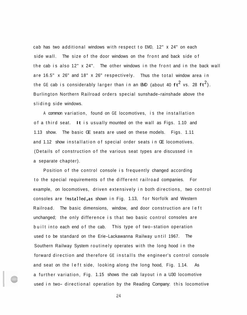
cab has two a d d i t i o n a l windows w i t h respect t o EMD, 12" x 24" on each
s ide w a l l . The s i z e o f the door windows on the f r o n t and back s ide o f
t h e cab i s a l so 12" x 24". The o ther windows i n the f r o n t and i n the back wa l l
a r e 16.5" x 26" and 18" x 26" respec t i ve l y . Thus the t o t a l window area i n
2 2 t h e GE cab i s considerably l a r g e r than i n an EMD (about 40 f t vs. 28 f t ) .
B u r l i n g t o n Northern Ra i l road orders spec ia l sunshade-rainshade above t h e
s l i d i n g s ide windows.
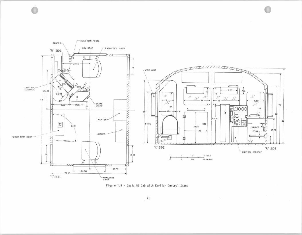
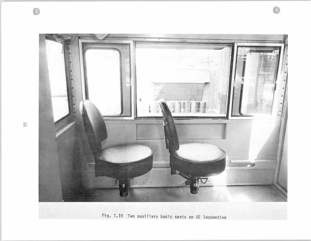
A common v a r i a t i o n , found on GE locomotives, i s the i n s t a l l a t i o n
o f a t h i r d seat. It i s u s u a l l y mounted on the wa l l as F igs. 1.10 and
1.13 show. The basic GE seats are used on these models. F igs. 1.11
and 1.12 show i n s t a l l a t i o n o f spec ia l o rder seats i n GE locomotives.
( D e t a i l s o f cons t ruc t i on o f the var ious seat types are discussed i n
a separate chapter ) .
Pos i t i on o f the c o n t r o l console i s f requen t l y changed according
t o the specia l requirements o f the d i f f e r e n t r a i l r o a d companies. For
example, on locomotives, d r i ven ex tens i ve l y i n both d i r e c t i o n s , two c o n t r o l
consoles are ins ta l led ,as shown i n F ig . 1.13, f o r Nor fo lk and Western
Ra i l road . The basic dimensions, window, and door cons t ruc t i on a r e l e f t
unchanged; the on l y d i f f e r e n c e i s t h a t two basic c o n t r o l consoles are
b u i l t i n t o each end o f the cab. This type o f two- s ta t ion opera t ion
used t o be standard on the Erie-Lackawanna Railway u n t i l 1967. The
Southern Railway System r o u t i n e l y operates w i t h the long hood i n the
forward d i r e c t i o n and the re fo re GE i n s t a l l s the eng ineer 's c o n t r o l console
and seat on the l e f t s ide, l ook ing a long the long hood, F ig . 1.14. As
a f u r t h e r v a r i a t i o n , F ig . 1.15 shows the cab l ayou t i n a U30 locomotive
used i n two- d i r e c t i o n a l operat ion by the Reading Company: t h i s locomotive
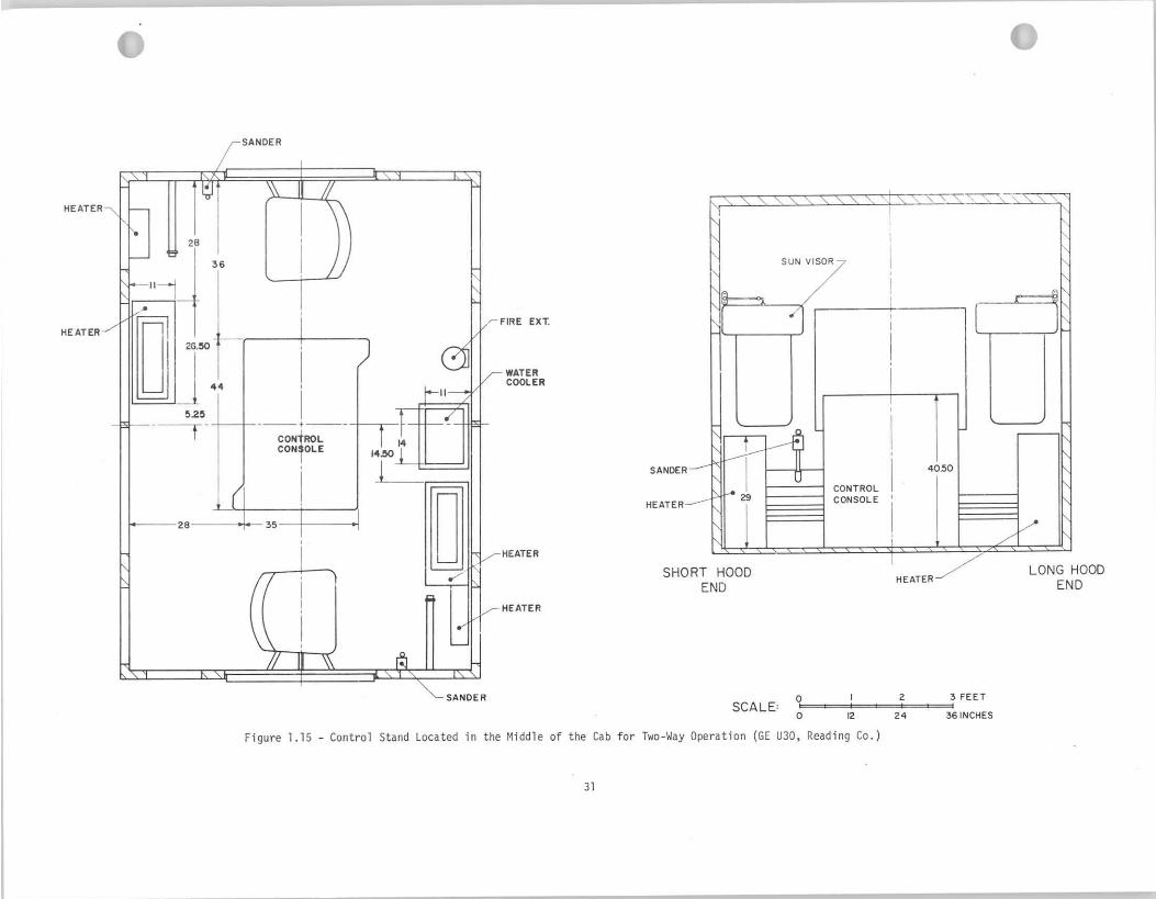
i s equipped w i t h one control console located in the middle of the cab
w i t h a brake stand and control display u n i t on both the l e f t and the
r i g h t side.
I t should be noted t h a t the basic control console on G E locomotives
b u i l t before December 1966 was substant ia l ly d i f fe ren t from tha t shown
i n the previous figures (e.g. , Fig. 1.6). That e a r l i e r control console
consisted of two separate cabinets, one being the brake stand and the
o ther was the control u n i t . (Details of the d i f fe ren t control models
a r e discussed i n Chapter 2 of t h i s report ) .
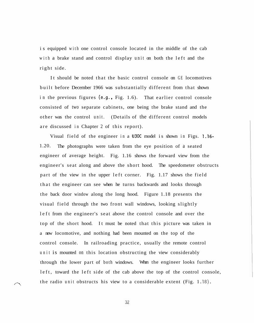
Visual f i e ld of the engineer i n a U30C model i s shown i n Figs. 1.16-
1.20. The photographs were taken from the eye position of a seated
engineer of average height. Fig. 1.16 shows the forward view from the
engineer 's sea t along and above the short hood. The speedometer obstructs
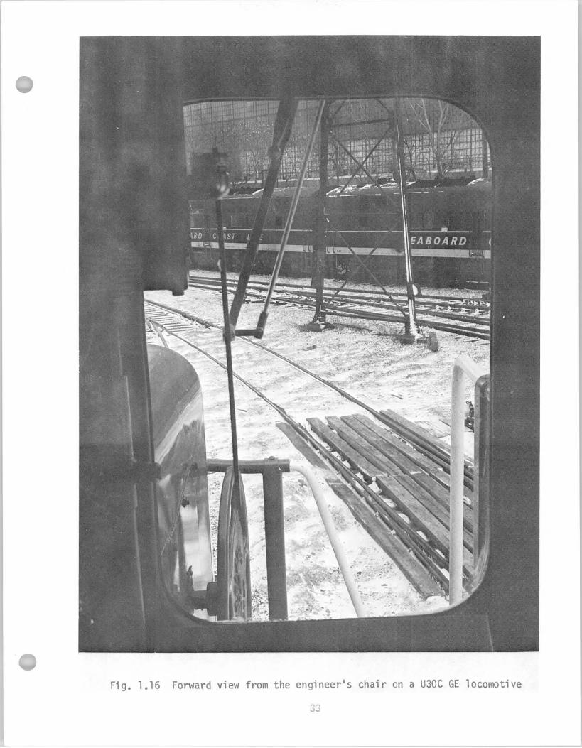
p a r t of the view in the upper l e f t corner. Fig. 1.17 shows the f i e l d
t h a t the engineer can see when he turns backwards and looks through
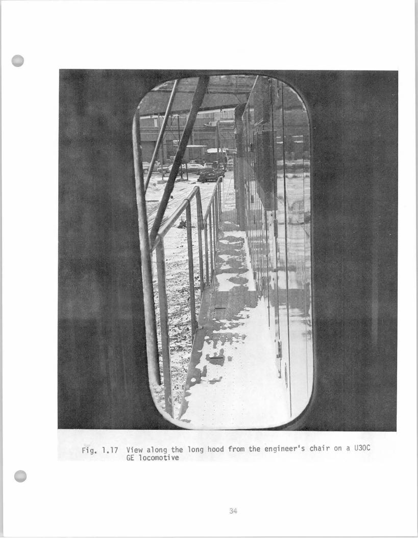
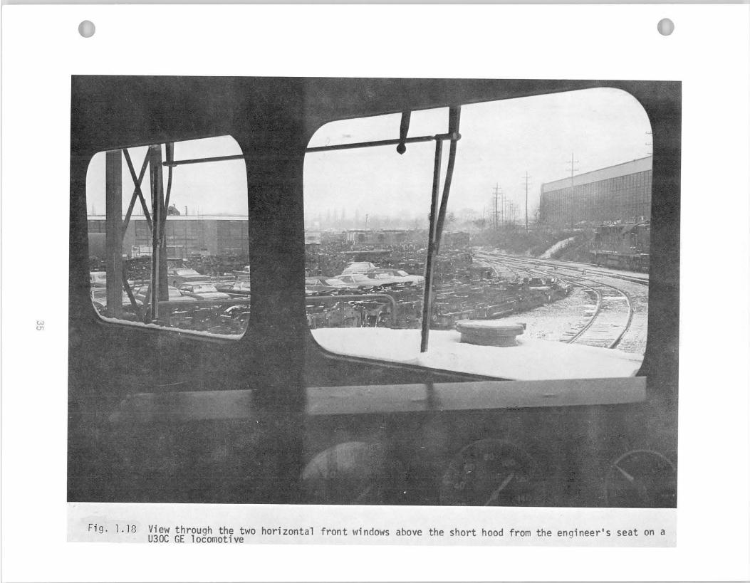
the back door window along the long hood. Figure 1.18 presents the
visual f i e ld through the two front wall windows, looking s l i gh t ly
l e f t from the engineer's sea t above the control console and over the
top of the short hood. I t must be noted tha t t h i s picture was taken in
a new locomotive, and nothing had been mounted on the top of the
control console. In railroading practice, usually the remote control
u n i t i s mounted on t h i s location obstructing the view considerably
through the lower par t of b o t h windows. When the engineer looks fur ther
l e f t , toward the l e f t s ide of the cab above the top of the control console,
t h e radio u n i t obstructs his view to a considerable extent (Fig. 1 . l a ) . '7
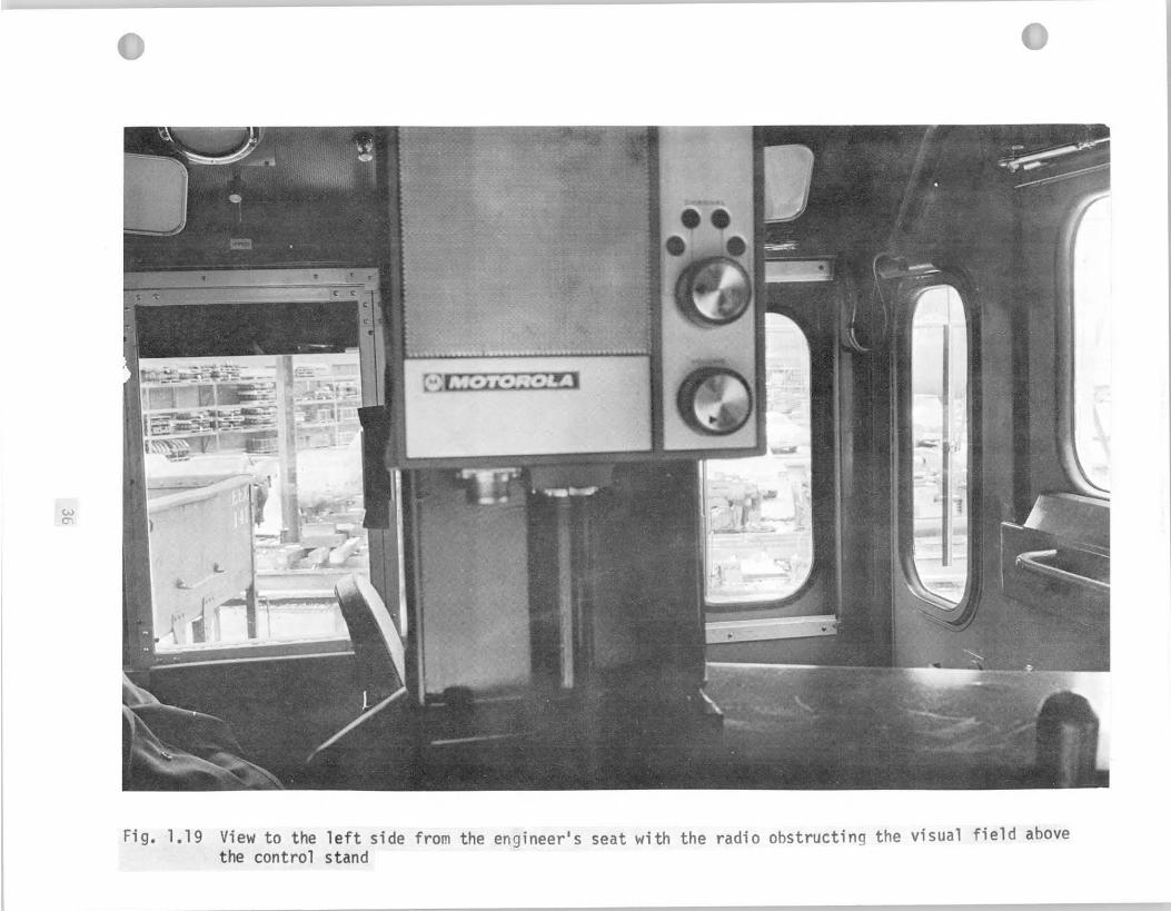
The f i gu re shows the view through the f r o n t door window and through
t h e l e f t s ide windows. The v i sua l f i e l d o f the d r i v e r would be very
good i f n o t obstructed by the r a d i o . O f course, i t could be argued
t h a t the engineer does n o t keep h i s head i n a f i x e d , unmovable
p o s i t i o n l i k e the one from which the previous p i c t u r e s were taken,
and he cou ld move and look "around" the obs t ruc t ions . However, such
movement should n o t be needed because simple rearrangement o f a few
inst ruments could e l i m i n a t e most obs t ruc t ions from the f i e l d o f v i s i o n .
F i g . 1.20 shows how the engineer can improve v i s i b i l i t y by lean ing o u t
o f the s ide window: the p i c t u r e shows the background view taken along
t h e long hood, corresponding t o F ig. 1.17, which was photographed from
i n s i d e the cab.
F ig . 1.19 shows a hand r a i l ( l e f t lower corner ) mounted above
t h e descent door t o the sho r t hood. Such hand r a i l s a re recommended.
The l o c a t i o n and design o f some cab equipment, however, should be
condemned from the human f a c t o r s p o i n t o f view. For example, (as shown
i n Figs. 1.21 and 1.22) the water coo le r , i n s t a l l e d f requen t l y i n
locomotives, stands p r a c t i c a l l y i n the middle o f the cab and obs t ruc ts
t h e passageway. Sharp corners and edges o f the coo ler cab ine t
c o n s t i t u t e p o t e n t i a l danger i f a person stumbled o r f e l l . Water coo lers
ought t o be b u i l t i n t o the c o n t r o l panel f l u s h w i t h the back o f the
w a l l of the cab. GE mod i f ied i n s t a l l a t i o n o f t h e water coo ler on more
recent model s . Fig. 1.21 a l so shows a spec ia l heater i n a b25 cab. The heater,
j u s t as the water coo ler , has sharp edges and obs t ruc ts the passageway.
Furthermore, the pipes lead ing t o and from the heater a re f r e e l y
38
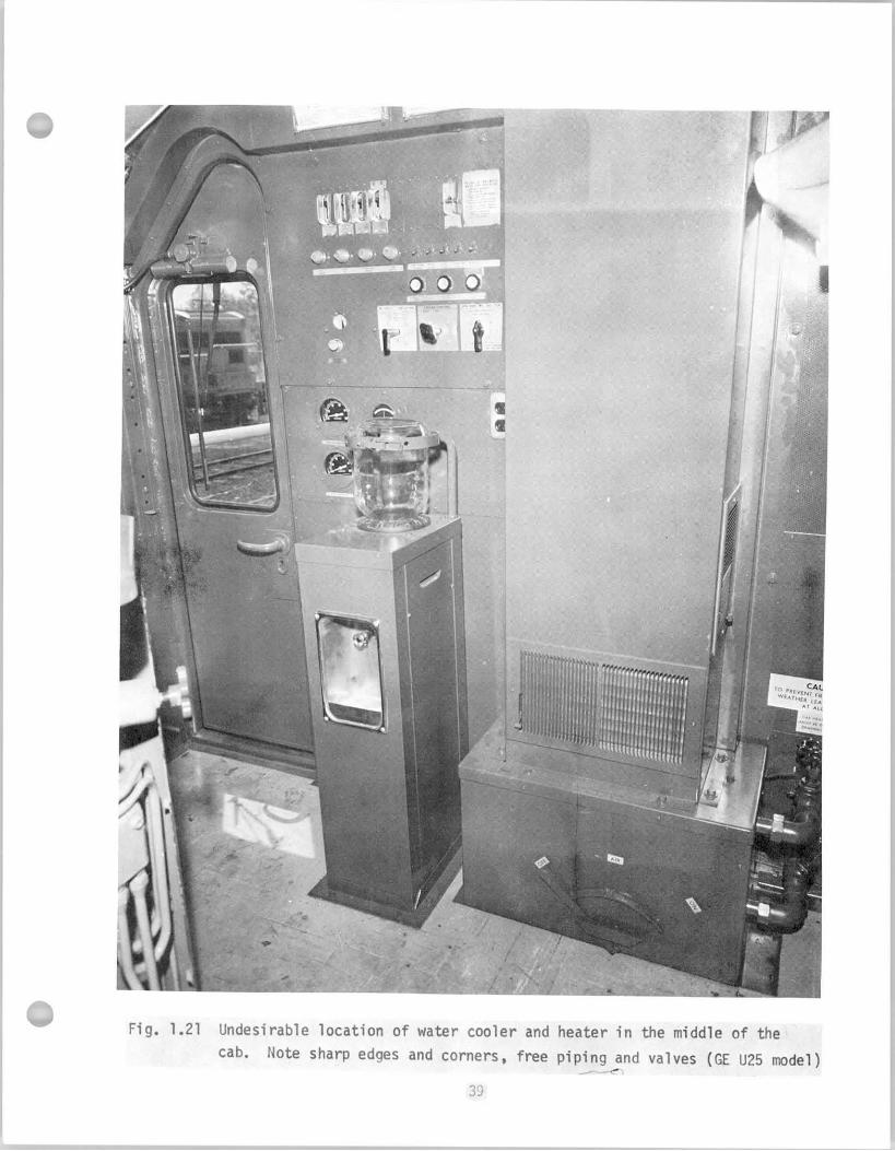
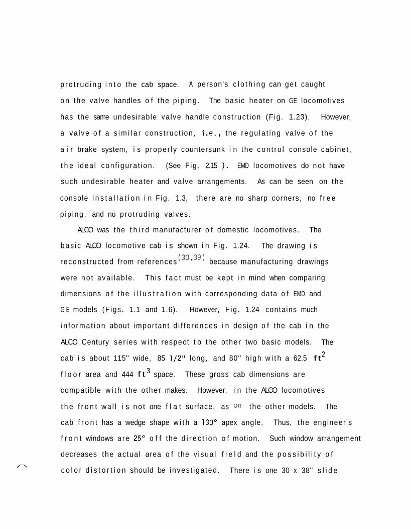
p r o t r u d i n g i n t o the cab space. A person's c l o t h i n g can ge t caught
o n the va lve handles o f t he p i p i n g . The basic heater on GE locomotives
has the same undesi rable va lve handle cons t ruc t i on (F ig . 1.23). However,
a va l ve o f a s i m i l a r cons t ruc t i on , i .e . , the r e g u l a t i n g va lve o f t he
a i r brake system, i s p rope r l y countersunk i n t he c o n t r o l console cab ine t ,
t h e i dea l con f i gu ra t i on . (See F ig . 2.15 ) . EMD locomotives do n o t have
such undesi rable heater and valve arrangements. As can be seen on the
console i n s t a l l a t i o n i n F ig . 1.3, there are no sharp corners, no f r e e
p ip ing , and no p ro t rud ing valves.
ALCO was the t h i r d manufacturer o f domestic locomotives. The
b a s i c ALCO locomot ive cab i s shown i n F ig . 1.24. The drawing i s
recons t ruc ted from references (30y39) because manufactur ing drawings
were n o t ava i l ab le . Th is f a c t must be kept i n mind when comparing
dimensions o f t he i l l u s t r a t i o n w i t h corresponding data o f EMD and
G E models (F igs . 1.1 and 1.6). However, F ig . 1.24 conta ins much
i n f o r m a t i o n about impor tan t d i f f e r e n c e s i n design o f the cab i n the
ALCO Century se r i es w i t h respec t t o the o the r two basic models. The
cab i s about 115" wide, 85 2 1/2" long, and 80" h igh w i t h a 62.5 ft
3 f l o o r area and 444 f t space. These gross cab dimensions a re
compat ib le w i t h the o the r makes. However, i n t he ALCO locomotives
t h e f r o n t w a l l i s n o t one f l a t surface, as on the o the r models. The
cab f r o n t has a wedge shape w i t h a 130' apex angle. Thus, t he engineer 's
f r o n t windows a r e 25" o f f the d i r e c t i o n o f motion. Such window arrangement
decreases the ac tua l area o f the v i sua l f i e l d and the p o s s i b i l i t y o f
c o l o r d i s t o r t i o n should be i nves t i ga ted . There i s one 30 x 38" s l i d e r\
window on each s ide o f the cab. Size o f the doors i s 19 1/2 x 73"
w i t h windows o f 10 1/2 x 30". The eng ineer 's window i s 13 1/2" wide,
29 1/2" high, and the ho r i zon ta l f r o n t windows are 16 x 36". Size o f
2 t h e t o t a l window area i s about 30 f t . Design o f the c o n t r o l console on ALCO locomotives i s unique:
b a s i c a l l y i t i s a simple 11 x 42 x 44.75" cab ine t u n l i k e the broken
p a t t e r n s o f o the r models, which i s pos i t ioned a t a 25' angle t o
t h e l o n g i t u d i n a l ax i s o f the locomotive. Arrangement o f the c o n t r o l s
i s discussed i n d e t a i l i n Chapter 11. There are two heaters i n the cab:
one i s i n the l e f t f r o n t corner i n f r o n t o f the engineer, the o the r i s
1 ocated i n the r i g h t back corner behind the f i reman 's seat. A th ree seat
v e r s i o n i s shown i n F ig . 1.24.
Locomotive models o f a l l three manufacturers, discussed above, a r e
equipped w i t h a t o i l e r which i s b u i l t i n t o the s h o r t hood. The
o n l y except ion i s G E ' s C ser ies , where i t i s b u i l t i n t o the l ong hood.
However, on the corresponding models i n the B ser ies , the normal shor t
hood arrangement i s used.
S t a t i s t i c a l l y every locomotive i s invo lved i n a c o l l i s i o n accident
once i n every ten years, according t o FRA data. Therefore, bo th EMD and
G E b u i l d c o l l i s i o n p r o t e c t i o n measures i n t o the locomotive body. The s h o r t
hood i s made o f 11 gauge s tee l p l a t e on EMD and .0901' p l a t e on GE locomotives,
which can prov ide some p r o t e c t i o n t o the engineer i n case o f c o l l i s i o n w i t h
a t r u c k a t a crossing. Locomotives equipped w i t h snow plows are pro tec ted
i n c o l l i s i o n s w i t h automobiles. I n r e a r end t r a i n c o l l i s i o n s , f requen t l y the
1 i g h t e r caboose i s l i f t e d , s l i d e s over the locomotive chassis and crushes /-\
t h e sho r t hood and the cab. As p r o t e c t i o n i n such accidents, two c o l l i s i o n
pos ts a re b u i l t i n t o the f r o n t corners o f the sho r t hood, as shown i n
F i g . 1.25 on EMD locomotives. The GE c o l l i s i o n posts a re b u i l t i n t o the
p l a t f o r m main s i l l s and p r o j e c t upward i n t o the f r o n t corners o f the s h o r t
hood.
Good v i s i b i l i t y from the engineer 's seat i s e s p e c i a l l y important i n
swi tch ing . Therefore, sw i tch ing engines have evolved d i f f e r e n t l y from
general purpose locomotives. The cab i s u s u a l l y mounted a t the end o f
t h e chassis and the locomotive has on l y one hood. The windows are l a rge ,
t h e y extend f requen t l y even below w a i s t l i n e o f the engineer on t h e f r e e
end o f the locomotive. The f i e l d o f v i s i o n on a SW1500 swi tcher from the
eye he igh t o f an average operator i s shown i n F ig . 1.26. The locomotive
i s manufactured i n e i t h e r the normal vers ion o r a 12" ra i sed f l o o r
m o d i f i c a t i o n a t the engineer 's pos i t i on . I n the l a t t e r case, the cab
end f i e l d o f v i s i o n along the cab end o f the locomotive i s n o t a f f e c t e d
b u t the view along the hood i s improved. From the r a i s e d f l o o r , the
engineer can see the r a i l s 3 ' 7 " c l o s e r ' t o the end o f the locomotive.
When the cab i s ra ised, the v i sua l f i e l d above the hood becomes wider
(10.5' vs. 9.5') and v i s i b i l i t y o f s i gna ls improves. The l i m i t s
o f v i s i o n over the catwalk become wider (24.5' vs. 22.5') from an e leva to r
sw i t che r cab. The SWlOOO locomotives have i d e n t i c a l cab arrangements. The
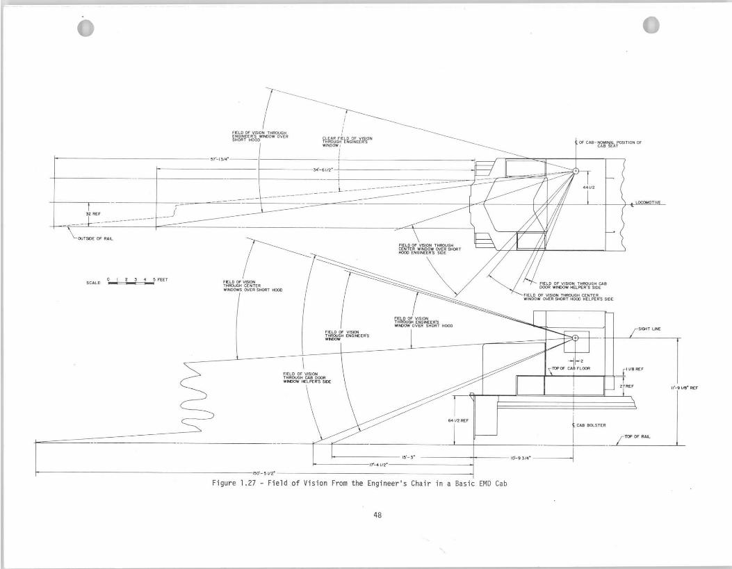
f i e l d o f v i s i o n on a basic EM0 locomotive i s shown i n F ig. 1.27.
Canadian Nat ional Railways i n i t i a t e d a p r o j e c t i n June 1971 t o
des ign a locomotive cab su i ted o p t i m a l l y t o the human operator . The
cab i s planned t o s a t i s f y human f a c t o r s requirements o f t r a i n operat ion.
Const ruc t ion o f a f u l l s i z e mock-up was a l so planned. F i g . 1.28, adapted
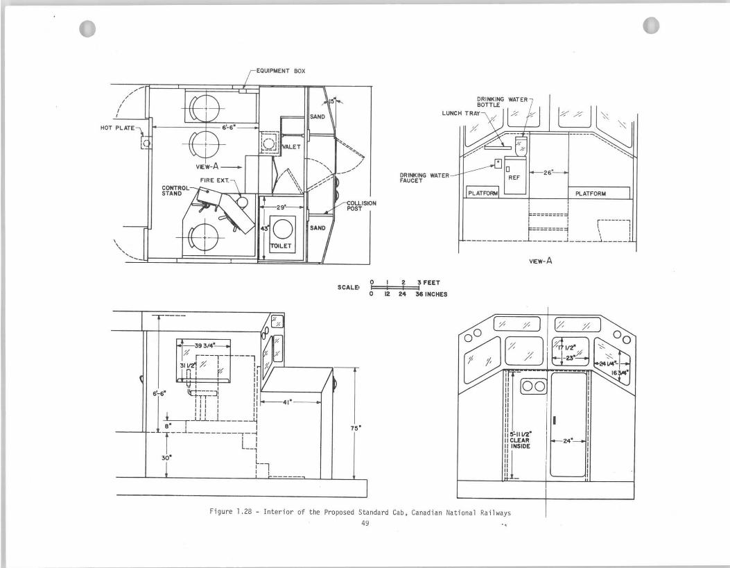
from Canadian Nat ional Railways P ro jec t No. 7131, shows the proposed
1 ayout o f the cab. Wall arrangement seems t o be an adapt ion o f the
bas i c ALCO design (F ig. 1.24), bu t the i n t e r i o r arrangement o f cab
equipment i s new. The c o n t r o l stand w i l l be based on the new A.A.R.
recommended standard as d e t a i l e d i n A.A.R. c i r c u l a r No. DV1768 dated
May 22, 1972; food warmer, and d r i n k i n g water w i l l b e provided; an ash
t r a y and c lo thes c l o s e t a re planned t o be standard items. For improving
crew safety, strengthened cab s t ruc ture , f u l l w id th s h o r t hood, redesigned
c o l l i s i o n posts, snow plow, d e f l e c t i v e an t ic l imbers , good v i s i b i l i t y ,
p o s i t i v e f r e s h a i r exchange, and a back door on both sides are recommended.
F o r personal comfor t improved heat ing and e l im ina t i on o f d r a f t s , r e f r i g e r a t o r ,
a f u l l he igh t and v e n t i l a t e d and heated t o i l e t room, improved seats and
arm res ts , lunch t r a y and beverage holder, and a n t i - g l a r e g lass are
proposed. Development o f such a standard cab f o r domestic locomotives
should be g r e a t l y encouraged.
Table 1.1 i s presented t o summarize the s i z e o f a v a i l a b l e f r e e space
i n the cab on var ious locomotive models. Data o f the t a b l e show the
f l o o r area and the volume o f f r e e space i n domestic and f o r e i g n locomotive
cabs. Table 1.2 summarizes the window-area- to- floor-area r a t i o . The
area o f the t o t a l cab window sur face i s compared t o t h e area o f cab f l o o r
i n order t o i n d i c a t e v i s i b i l i t y cond i t ions on d i f f e r e n t locomotives. On
some EMD switchers, some windows are e l im ina ted, as opt ion, t o g i ve the
crew more p r o t e c t i o n from thrown rocks. Furthermore, too l a r g e window
area increases the heat load i n the cab. The cab becomes too ho t i n the
summer and too co ld i n the w in te r .
I
1
50
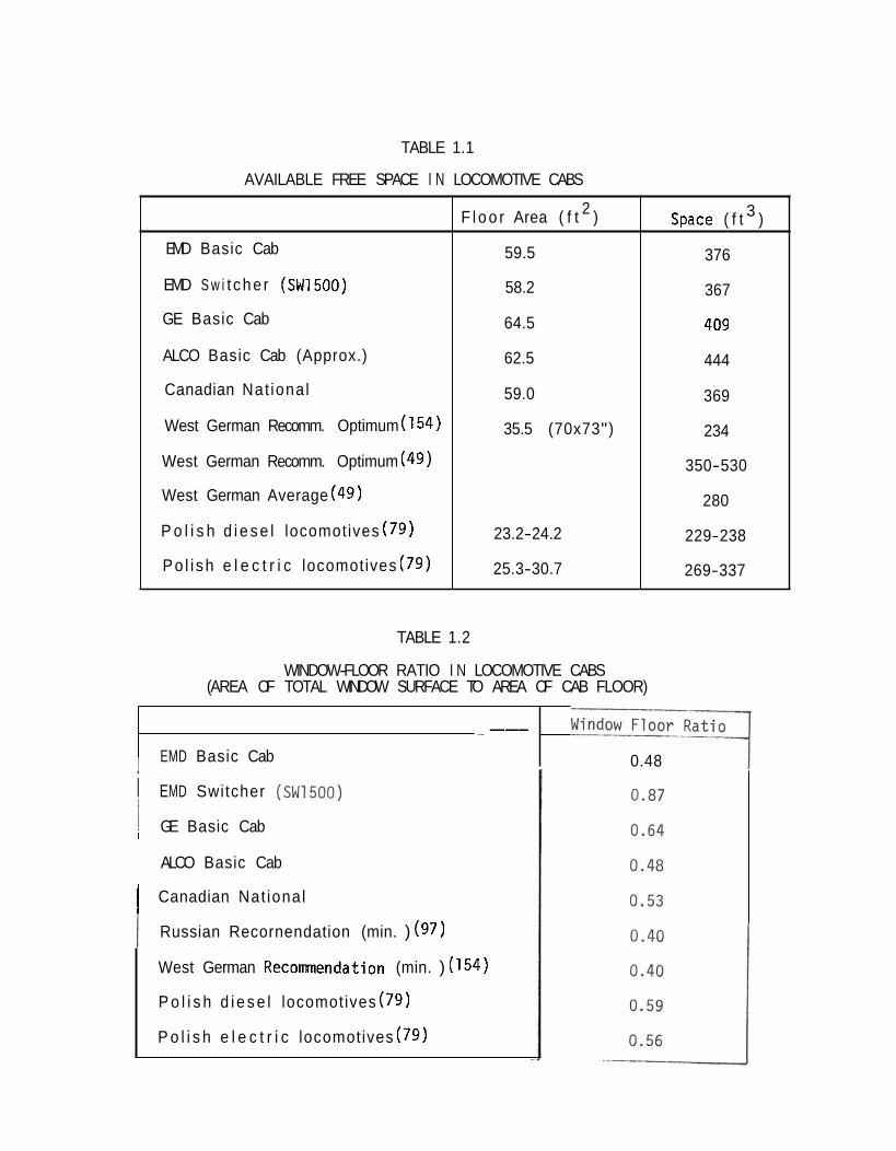
TABLE 1.2
i EMD Switcher (swi5oo)
1 GE Basic Cab I
WINDOW-FLOOR RATIO I N LOCOMOTIVE CABS (AREA OF TOTAL WINDOW SURFACE TO AREA OF CAB FLOOR)
ALCO Basic Cab
- ---
I EMD Basic Cab
( Canadian Nat ional
0.48
I Russian Recornendation (min. ) (97)
West German Recommendation (min. ) (154)
P o l i s h d i e s e l locomotives (79)
P o l i s h e l e c t r i c locomotives (79)
TABLE 1.1
AVAILABLE FREE SPACE I N LOCOMOTIVE CABS
F l o o r Area ( f t 2 ) space ( f t 3 )
EMD Basic Cab
EMD S w i t che r (SW1500)
GE Basic Cab
ALCO Basic Cab (Approx.)
Canadian Nat ional
West German Recomm. Optimum (154)
West German Recomm. Optimum (49)
West German Average (49)
P o l i s h d i e s e l locomotives (79)
Po l i sh e l e c t r i c locomotives (79)
59.5
58.2
64.5
62.5
59.0
35.5 (
23.2-24.
25.3-30.
70x73")
2
7
376
367
409
444
369
234
350-530
280
229-238
269-337
1.3 W ~ r k Soace Recommendations
Design o f t he locomot ive cab as a work space comprises th ree f i e l d s
o f human f a c t o r s engineering: (1 ) work space dimensions, (2) l o c a t i o n
o f con t ro l s , and (3) v i s i b i l i t y .
(1 ) Work Space Dimensions: Gross dimensions o f t he eng ineer 's
cab on domestic locomotives s a t i s f y r e l e v a n t human f a c t o r s recomendat ions.
A minimum of 76" he igh t al lowance i s recommended f o r work places t o
p r o v i d e clearance f o r s tanding operat ions. (92) Most o f t he locomotives
2 have 75" below the c e i l i n g . As a minimum, 65 t o 100 f t f l o o r area i s
recommended per worker f o r i n d u s t r i a l a p p l i c a t i o n s . The f l o o r area i n
2 domest ic locomotive cabs i s 60-65 ft which cou ld be considered adequate
s i n c e the operator i s r e s t r i c t e d t o the d r i v i n g p o s i t i o n du r i ng opera t ion
o f t he t r a i n and i s n o t requ i red t o move f rom one p o s i t i o n t o another
when per forming h i s f unc t i on .
F i x t u r e s and c o n t r o l s should be designed i n such a way t h a t c l o t h
snagging, head bumping, and bumping i n t o sharp corners o r edges i s
minimized. Thus i t i s recommended t h a t heaters and water coo le rs be
recessed i n t o the cab w a l l . Regulat ing valves on GE locomotives should
n o t be pro t rud ing , f r e e p i p i n g must be covered by the breaker housing.
Hand r a i l s should be mounted i n t he cab above the h o r i z o n t a l f r o n t
windows and on the i n s i d e o f the door frames. The top p a r t o f t he
door frame, l ead ing i n t o the sho r t hood compartment~could be pa in ted
w i t h the usual warning s igna l code o f y e l l o w and b lack s t r i p e s . S t a i r s
descending i n t o t h i s compartment should be i l l u m i n a t e d . S t a i r dimensions

should correspond t o recommendations: 30 t o 45' o f i n c l i n e angle,
7-7 1/2" r i s e , 9 1/2-11" t read depth.
It i s reconmended t h a t the f r o n t doors open outward, doors t o t he
engine room and nose compartment open outward from the cab i n t e r i o r .
General purpose locomotives ( road- swi tchers) should have the doors a t
back w a l l , one on each s ide l ead ing t o t he walkways. S i m i l a r l y , one
door on each side, opening outward, should l ead t o walkways on swi tcher
locomot ives. The present door i n the middle t o t he crosswalk should a l s o
open outward.
(2 ) Locat ion o f Contro ls : The workspace envelop o f c o n t r o l s must
be compatible w i t h t he anthropometr ic dimensions o f the user popu la t ion .
Cont ro ls and d i sp lays should be loca ted w i t h due regard t o ope ra to r ' s
s ize, h i s p o s i t i o n (seated o r s tanding) , d i r e c t i o n he can look most
e a s i l y , and spaces i n which he can manipulate c o n t r o l s bes t . M i l i t a r y
human f a c t o r s standards s p e c i f y t h a t f o r seated operat ions the seat
should a d j u s t v e r t i c a l l y from 16 t o 21 inches i n increments o f no more
than one inch.(") The support backrest must r e c l i n e between 103' and
115'. The backrest should engage the lumbar and tho rac i c regions o f t he
back. Armrest should be p ivoted, be a t l e a s t 2 inches wide and 8
inches long. A l l c o n t r o l s r e q u i r i n g p rec i se and f requent opera t ion
s h a l l be mounted between 8 and 30 inches above the s i t t i n g surface.
D isp lays mounted on v e r t i c a l panels and used i n normal equipment operat ions
must be p laced i n an area between 6 and 48 inches above the s i t t i n g
sur face . I n d i c a t o r s t h a t must be read p r e c i s e l y and f r e q u e n t l y must be
p laced i n an area between 14 and 37 inches above the s i t t i n g sur face
and no f u r t h e r than 22 inches from the c e n t e r l i n e .
However, i n a p p l i c a t i o n o f such data t o cab design, due cons ide ra t i on
,7
'7
must be g iven t o the unique work requirements o f locomotive operat ions.
I n the cab the c o n t r o l s a r e n o t loca ted d i r e c t l y i n f r o n t o f the engineer,
bu t t o h i s l e f t s ide when f a c i n g forward. Locat ing the c o n t r o l s on one s ide
makes i t poss ib le t h a t he can operate the locomotive i n reverse d i r e c t i o n
w i t h r e l a t i v e ease. But because o f t h i s compromise, l o c a t i o n and arrangement
o f c o n t r o l s f o r forward opera t ion a r e l e s s than opt imal . The c o n t r o l l e r ,
the brake stand, and the instruments are loca ted i n the per iphery o f
t h e opt imal range o f reach and v i sua l f i e l d o f a seated operator f a c i n g
forward. I n o rder t o operate the c o n t r o l s more comfortably, the engineer
i s f requent ly fo rced t o t u r n and face the c o n t r o l console. Consequently,
he must t w i s t h i s head and look over h i s shoulder t o see forward. Turning
t h e head i s t i resome and r e s u l t s i n l ess t ime look ing forward. Systematic
and thorough i n v e s t i g a t i o n i s needed t o e s t a b l i s h an optimum design
f o r the c o n t r o l stand which both s u i t s the human operator more
s a t i s f a c t o r i l y and accomplishes the present requirements o f t r a i n
operat ion. The i n v e s t i g a t i o n i s recommended t o be based on the ana lys is
o f the eng ineer 's job. A mock-up anc; a model u n i t should then be
designed and b u i l t w i t h both func t ions , t o perform the locomotive
c o n t r o l f unc t i ons and s a t i s f y the p r i n c i p l e s o f human f a c t o r s engineering.
I t i s recommended t h a t the a l l new models be v e r i f i e d i n a th ree-
dimensional mock-up where l i v e subjects represent ing the extremes o f
t h e user expected popu la t ion can a c t u a l l y t ry o u t the layout .
The B r i t i s h Motor I ndus t r y Research Associat ion publ ished a r e p o r t
t o summarize th ree experimental techniques designed t o assess the
usefu lness o f the s t a t i c mock-up method f o r designing cab layouts. (127)
Resu l ts from the mock-up are tes ted f o r se l f- consis tency, f o r concordance
w i t h d r i v e r s ' preferences i n t h e i r own vehic les, and i n a comparison w i t h
A
a standard l a y o u t on the basis of d r i v e r performance i n a c o n t r o l l e d
d r i v i n g t r i a l . The mock-up method i s found t o g i v e se l f - cons i s ten t r e s u l t s .
A mock-up i s made i n which the p o s i t i o n s o f t h e v e h i c l e c o n t r o l s and seat ing
a r e e a s i l y ad jus tab le . A subject , u s u a l l y a commercial v e h i c l e d r i v e r ,
i s asked t o s i t i n the mock-up and t o s t a t e the p re fe r red p o s i t i o n o f
t h e ad jus tab le p a r t s o f t h e mock-up. The r e s u l t s from many subjects
a r e then combined t o form a l a y o u t meeting the preferences o f the greates t
number o f subjects.
There are two f u r t h e r i nves t i ga t i ons which must be c a r r i e d o u t t o
show t h a t meaningful r e s u l t s a re being obtained. One o f these i s t o show
t h a t the preferences expressed by the subjects a r e se l f - cons i s ten t and
are n o t in f luenced by the circumstances o f the t e s t . The o the r necessary
i n v e s t i g a t i o n i s t o show t h a t the preferences expressed by the sub jec t
i n the mock-up are i n agreement w i t h t h e i r preferences i n the d r i v i n g
cab o f the ac tua l veh ic le .
I n the f i t t i n g t r i a l s method care must be taken t o e l im ina te the
e f f e c t o f i n i t i a l s e t t i n g s o f dimensions. The f i t t i n g t r i a l s method
appears t o p rov ide se l f - cons i s ten t r e s u l t s which a r e obtained repeatably
by d i f f e r e n t experimenters. I n the cons t ruc t i on o f a mock-up, cons idera t ion
should be g iven t o fea tures such as shape and p o s i t i o n o f windscreen,
o therw ise the r e s u l t s w i l l n o t apply t o the cab being designed.
A l l normal and emergency opera t ing c o n t r o l s must be w i t h i n reach
s o t h a t the operator does n o t have t o leave h i s normal eye-reference
p o s i t i o n . This should i nc lude a u x i l i a r y i tems such as ash t rays ,
and r a d i o con t ro l s .
The t r a i n i s c o n t r o l l e d most ly from a s i t t i n g pos i t i on . Height o f n

t he t o p o f t he c o n t r o l console should no t be more than 25" above t h e
sea t i ng sur face because s h o r t operators must a l s o be ab le t o see over t he
equipment rack . It i s n o t t he case when r a d i o and remote c o n t r o l
u n i t s a re mounted on the top o f t he c o n t r o l console.
Occasional ly , t he engineer cou ld operate i n t he s tanding p o s i t i o n
a s an a l t e r n a t i v e o r change-over from the seated p o s i t i o n . Designing
a work p lace which a l l ows the man t o s h i f t h i s posture reduces muscular
f a t i g u e f rom prolonged e f f o r t i n any one p o s i t i o n . I n t h i s s i t u a t i o n
t h e o p e r a t o r ' s v i s u a l and manual areas must be designed t o be opt imal
f o r t he s i t t i n g p o s i t i o n and the pedal areas t o be opt imal f o r the
s tand ing p o s i t i o n .
( 3 ) V i s i b i l i t y . Data on the eng ineer 's f i e l d o f v i s i o n were
a v a i l a b l e f o r one locomotive model o n l y (F ig . 1.26). The photographs i n
F i g s . 1.16 t o 1.20 i n d i c a t e t h a t t he eng ineer 's view i s l i m i t e d even
f r o m a basic GE cab which has the l a r g e s t window area among a l l o the r
models because o f t he a d d i t i o n o f f o u r s idewal l windows. Recommendations
t o improve v i s i b i l i t y o r t o en la rge cab window area must a l s o consider
s a f e t y o f the engineer i n acc idents and p r o t e c t i o n aga ins t vandalism.
V i s i b i l i t y on o the r locomotives than presented here must a l s o be i n -
v e s t i g a t e d i n order t o determine whether the v i sua l f i e l d o f t he opera tor
i s adequate f o r sa fe operat ion.
2. DESIGN OF CONTROL EQUIPMENT ON LOCOMOTIVES
2.1 Li tera ture Survey of Locomotive Cab Controls
Design and layout of cab controls on diesel locomotives evolved
slowly to i t s present stage. Standardization has n o t been reached
y e t , b u t currently considerable e f fo r t s a re being made by the
manufacturers, rai lroad companies and transportation au thor i t i es t o
develop a uniformly accepted standard design to optimally suit the
human operator.
Control design standards a r e being used in European countries. In
most cases the layout has been designed by the d i f fe ren t rai lroad
au tho r i t i e s and has t o be conformed to by a l l suppliers. However, in
some cases the builders have s e t a standard and cer ta in administrations
have accepted i t in the i n t e r e s t of the manufacturing advantage obtained
thereby. (36) Examples of these approaches can be found in development
o f standard seats fo r the German Federal Railways and fo r the Swiss
Federal Railways ( I4 ' ) or in the design of a standard control s t a n d
by the Canadian National Railways. A s imilar trend i s apparent in
domestic locomotive development. The Association of American Railroads
has proposed principles t o be incorporated into a standardized locomotive
cab(6) and one of the major manufacturers, GE,built 'a prototype control
console according t o the AAR recommendations (Fig. 2.15).
The importance of standardization of controls i s pointed o u t most
recent ly by F . D . Accord ( 2 ) , General Superintendent of the Union Pacific
Railroad Company. His paper concludes t ha t without standardization of
con t ro l s , the engineman operating on one ra i l road in the country cannot A
be f a m i l i a r w i t h the c o n t r o l s used by o thers and i s d a i l y confronted
w i t h a new type o f c o n t r o l opera t ion which can o n l y lead t o opera t ing
e r r o r s and r e s u l t a n t c o s t l y problems and delays. S i g n i f i c a n t d i f f e rences
can be found even between the most modern locomotives such as EMD 6600
Centennial and GE U50C. (However, s ince the p u b l i c a t i o n o f the paper,
s tandard i za t i on on domestic locomotives has progressed.) For example,
a f t e r June 1971, GE used the EMD three handle c o n t r o l l e r (1970 t o l a t e 1971)
pending t h e set t lement on a standard th ree handle c o n t r o l l e r design by the
AAR. I n September 1971 the AAR adopted the GE vers ion o f the th ree handle
c o n t r o l l e r as the AAR standard c o n t r o l l e r . Since t h a t t ime a l l GE locomotives
have been equipped w i t h the AAR standard c o n t r o l l e r .
Standardizat ion i n Europe was s i g n i f i c a n t l y advanced i n 1958 when the
I n t e r n a t i o n a l Union o f Railways (U.I.C.) began i s s u i n g recommendations
t o be even tua l l y o b l i g a t o r y f o r i nco rpo ra t i on i n t o i n t e r n a t i o n a l European
r o l l i n g stock. Some o f these recommendations cover design o f the eng ineer 's
c o n t r o l stand.
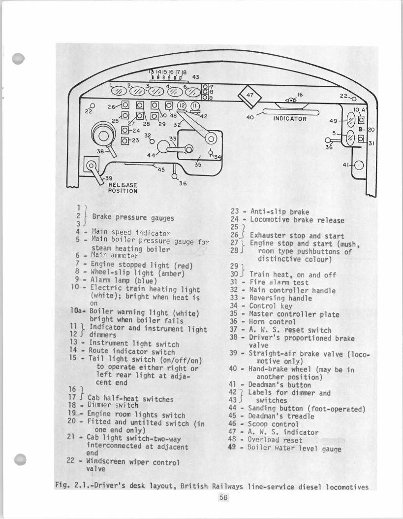
The l ayou t o f the B r i t i s h Railways d r i v e r ' s desk i s shown i n F ig . 2.1.
As a f u r t h e r development a combination o f c o n t r o l s f o r a d iese l locomotive
and an e l e c t r i c u n i t has been devised by the Southern Region o f the
B r i t i s h Railways. (Note t h a t on domestic e l e c t r i c locomotives, b u i l t by
GE f o r the Muskingum E l e c t r i c Rai l road, the engineer 's con t ro l console
i s i d e n t i c a l t o t h a t used on d iese l s , F ig . 2.16. There i s a d i f f e r e n c e
o n l y i n design o f the engine c o n t r o l panel [F ig. 2.41 vs. 2.453). Development
o f an electropneumatic brake system was repor ted i n ~ r i t a i n ( " ~ ) which i s
pos i t i oned on the l e f t s ide o f the c o n t r o l desk, as usual . The brak ing
e f f o r t i s c o n t r o l l e d w i t h a continuous c i r c u l a r c o n t r o l l e r b u i l t i n t o the
desk. The system does no t need pressure l i n e connections i n s i d e the
cab, thus var ious e f f e c t i v e i n s u l a t i o n techniques cou ld be used t o
achieve good environmental c o n t r o l f o r the engineer.
I n France, the c o n t r o l s o f e l e c t r i c locomotives have been standardized. (42)
The common form o f c o n t r o l l e r on e l e c t r i c locomotives was a "notching up"
l e v e r which moved step-by-step around a notched quadrant. An a l t e r n a t i v e
was a handwheel which was turned through some 270' i n a s i m i l a r sequence
o f d e f i n i t e steps. I n d.c. locomotives a separate handle genera l l y
had t o be manipulated once o r twice du r ing no tch ing t o change motor
groupings. I n 1954, however, a d i f f e r e n t method o f c o n t r o l made i t s
appearance. The d r i v e r no longer turned the handwheel cont inuously i n
one d i r e c t i o n t o notch up, b u t moved i t t o and f r o , each such a c t i o n
advancing t h e equipment one notch. The f i r s t a p p l i c a t i o n o f the system
t o a l a r g e number o f locomotives i n France was made i n the Bo-Bo "9200"
c l a s s , b u i l t from 1957 onwards. F ig . 2.2 shows the d r i v i n g c o n t r o l s i n
one o f these locomotives. French op in ion p re fe rs t o make the d r i v e r
respons ib le f o r a d j u s t i n g h i s r a t e o f no tch ing t o s u i t the load and
cond i t i ons o f adhesion, r a t h e r than t o g i v e him means f o r a d j u s t i n g
t h e s e t t i n g o f a c u r r e n t l i m i t r e l a y as has become t h e p r a c t i c e i n
Belgium. Only one ammeter i s f i t t e d , and t h i s reads the cu r ren t o f one
t r a c t i o n motor. A l l t h e most recent e l e c t r i c locomotives, d.c. and a.c.,
a r e ncw being f i t t e d w i t h an a n t i - s l i p device. A warning l i g h t i s
i l l u m i n a t e d u n t i l the s l i p has been corrected, and w h i l e i t i s showing
t h e d r i v e r suspends notching. Re fe r r i ng t o the diagram o f the desk, F i g
2.2, the whee l- s l ip warnings are the center p a i r o f f o u r s igna l lamps G.
S i m i l a r c o n t r o l s a re used i n the "9400" c lass m i x e d- t r a f f i c d.c. Bo-Bo
1 ocomotives.
Fig.2.3 shows the d r i v e r ' s desk i n t h e "16000" c lass f o r f a s t ma in- l ine
0
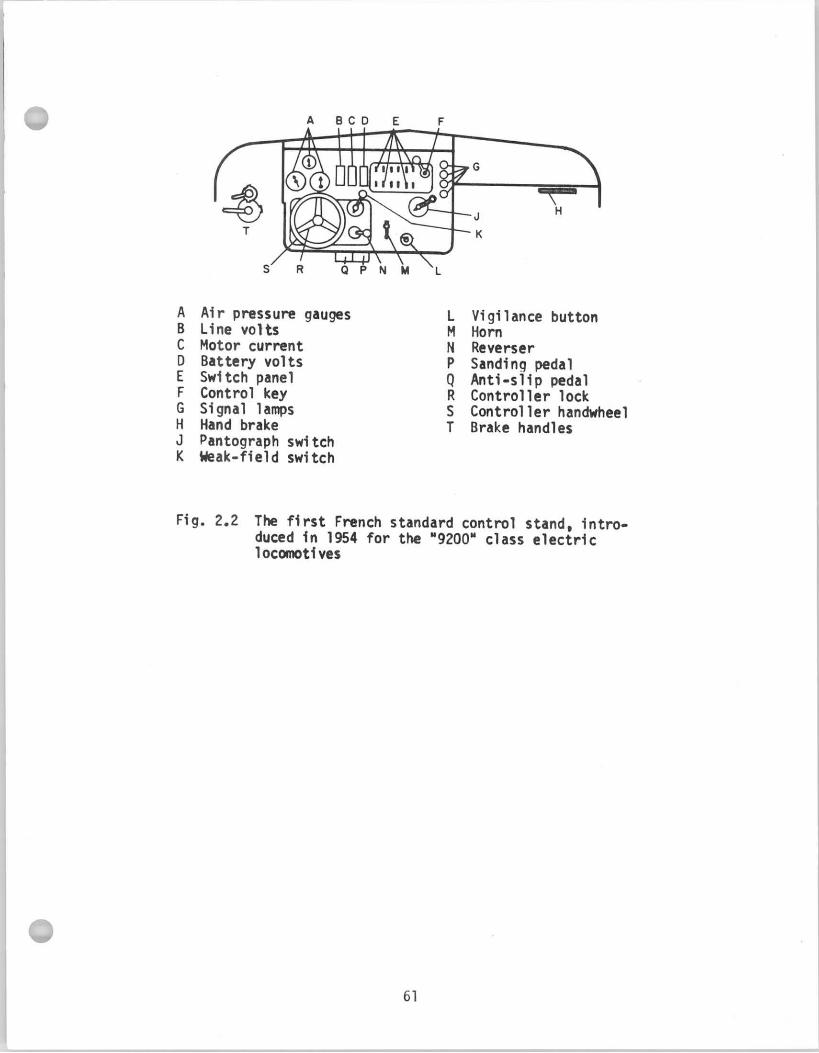
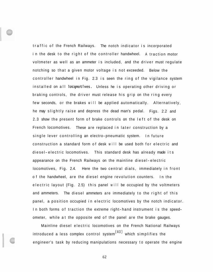
t r a f f i c o f the French Railways. The notch i n d i c a t o r i s incorporated
i n the desk t o the r i g h t o f the c o n t r o l l e r handwheel. A t r a c t i o n motor
vo l tme te r as w e l l as an ammeter i s included, and the d r i v e r must regu la te
no tch ing so t h a t a g iven motor vo l tage i s n o t exceeded. Below the
c o n t r o l l e r handwheel i n F ig . 2.3 i s seen the r i n g o f the v i g i l a n c e system
i n s t a l l e d on a l l locqmotives. Unless he i s opera t ing o ther d r i v i n g o r
b r a k i n g con t ro l s , the d r i v e r must re lease h i s g r i p on t h e r i n g every
f e w seconds, o r the brakes w i l l be app l ied au tomat ica l l y . A l t e r n a t i v e l y ,
he may s l i g h t l y r a i s e and depress the dead man's pedal. Figs. 2.2 and
2 .3 show t h e present form o f brake c o n t r o l s on the l e f t o f the desk on
French locomotives. These a r e replaced i n l a t e r cons t ruc t i on by a
s i n g l e l e v e r c o n t r o l l i n g an electro-pneumatic system. I n f u t u r e
c o n s t r u c t i o n a standard form o f desk w i l l be used both f o r e l e c t r i c and
d i e s e l - e l e c t r i c locomotives. This standard desk has a l ready made i t s
appearance on the French Railways on the main l ine d i e s e l - e l e c t r i c
locomotives, F ig . 2.4. Here the two c e n t r a l d i a l s , immediately i n f r o n t
o f the handwheel, a r e the d i e s e l engine r e v o l u t i o n counters. I n t h e
e l e c t r i c l a y o u t (Fig. 2.5) t h i s panel w i l l be occupied by the vol tmeters
and ammeters. The d i e s e l ammeters are immediately t o the r i g h t o f t h i s
panel , a p o s i t i o n occupied i n e l e c t r i c locomotives by the notch i n d i c a t o r .
I n bo th forms o f t r a c t i o n the extreme r igh t- hand instrument i s the speed-
ometer, wh i l e a t the opposi te end o f the panel a r e the brake gauges.
Ma in l ine d iese l e l e c t r i c locomotives on the French Nat ional Railways
in t roduced a l ess complex c o n t r o l system (40) which s i m p l i f i e s the
eng ineer 's task by reducing manipulat ions necessary t o operate the engine
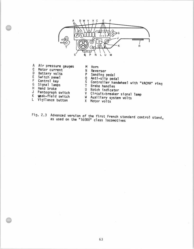
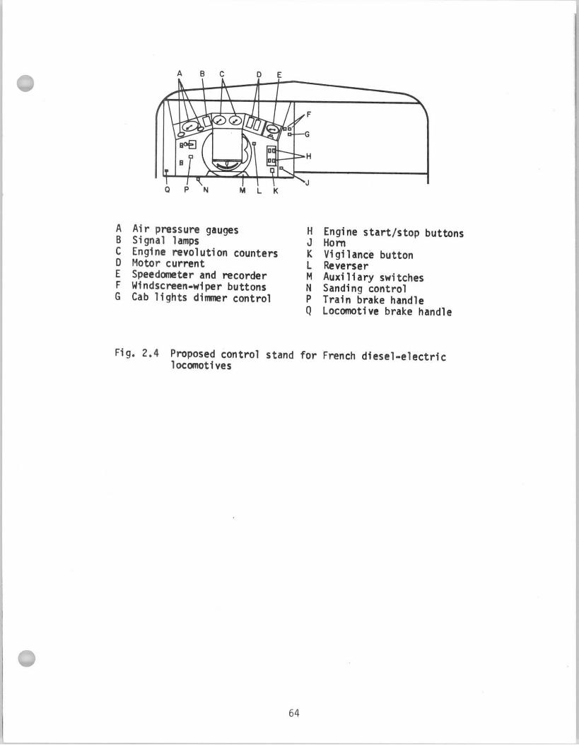
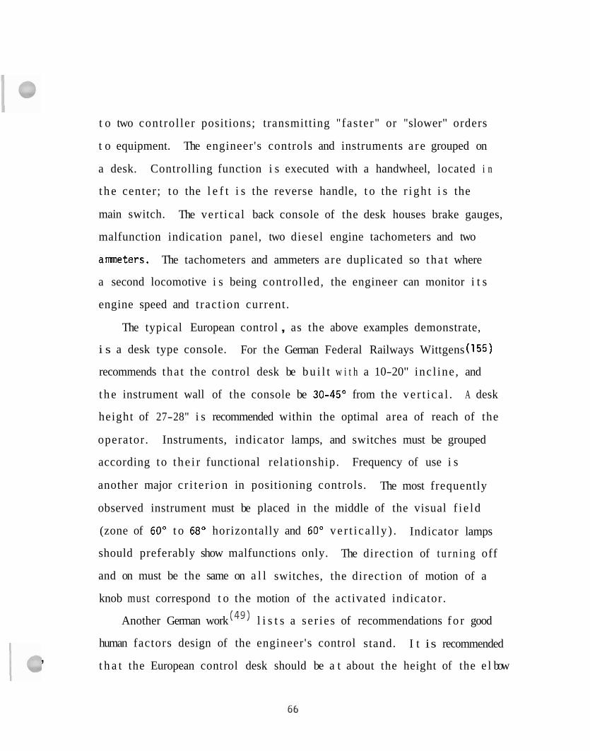
t o two control ler positions; transmitting "fas ter" or "slower" orders
t o equipment. The engineer's controls and instruments a r e grouped on
a desk. Controlling function i s executed with a handwheel, located i n
t h e center; to the l e f t i s the reverse handle, t o the r i gh t i s the
main switch. The ver t ical back console of the desk houses brake gauges,
malfunction indication panel, two diesel engine tachometers and two
ammeters. The tachometers and ammeters are duplicated so tha t where
a second locomotive i s being controlled, the engineer can monitor i t s
engine speed and t ract ion current.
The typical European control , as the above examples demonstrate,
i s a desk type console. For the German Federal Railways Wittgens (155)
recommends tha t the control desk be b u i l t w i t h a 10-20" inc l ine , and
t h e instrument wall of the console be 30-45' from the ve r t i ca l . A desk
height of 27-28" i s recommended within the optimal area of reach of the
operator. Instruments, indicator lamps, and switches must be grouped
according to t he i r functional relationship. Frequency of use i s
another major c r i te r ion in positioning controls. The most frequently
observed instrument must be placed in the middle of the visual f i e ld
(zone of 60" t o 68' horizontally and 60" ve r t i ca l ly ) . Indicator lamps
should preferably show malfunctions only. The direction of t u rn ing off
and on must be the same on a l l switches, the direction of motion of a
knob must correspond t o the motion of the activated indicator.
Another German work (49) l i s t s a se r ies of recommendations f o r good
human factors design of the engineer's control stand. I t is recommended
t h a t the European control desk should be a t about the height of the e l bow ,
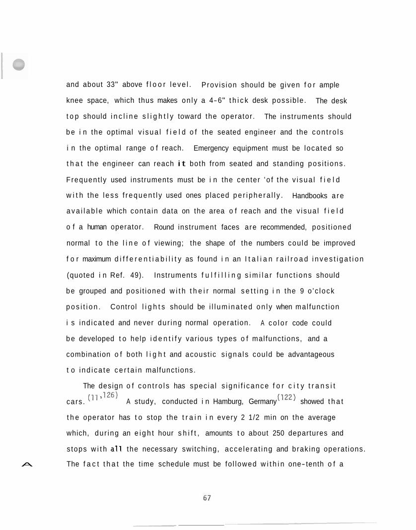
and about 33" above f l o o r l e v e l . Prov is ion should be g iven f o r ample
knee space, which thus makes on l y a 4-6" t h i c k desk poss ib le . The desk
t o p should i n c l i n e s l i g h t l y toward the operator . The inst ruments should
b e i n the opt imal v i s u a l f i e l d o f the seated engineer and the c o n t r o l s
i n the opt imal range o f reach. Emergency equipment must be loca ted so
t h a t the engineer can reach i t both from seated and standing pos i t i ons .
Frequent ly used instruments must be i n the center ' o f t h e v i s u a l f i e l d
w i t h the l e s s f r e q u e n t l y used ones placed p e r i p h e r a l l y . Handbooks a r e
a v a i l a b l e which conta in data on the area o f reach and the v i sua l f i e l d
o f a human operator. Round instrument faces are recommended, pos i t ioned
normal t o the l i n e o f viewing; the shape of the numbers cou ld be improved
f o r maximum d i f f e r e n t i a b i l i t y as found i n an I t a l i a n r a i l r o a d i n v e s t i g a t i o n
(quoted i n Ref. 49). Instruments f u l f i l l i n g s i m i l a r f unc t i ons should
be grouped and pos i t ioned w i t h t h e i r normal s e t t i n g i n the 9 o ' c lock
p o s i t i o n . Control l i g h t s should be i l l u m i n a t e d o n l y when mal func t ion
i s i nd i ca ted and never du r ing normal operat ion. A c o l o r code could
b e developed t o help i d e n t i f y var ious types o f mal funct ions, and a
combinat ion o f both l i g h t and acoust ic s igna ls could be advantageous
t o i n d i c a t e c e r t a i n mal funct ions.
The design o f c o n t r o l s has spec ia l s i g n i f i c a n c e f o r c i t y t r a n s i t
cars . , lz6) A study, conducted i n Hamburg, Germany ( I z2 ) showed t h a t
t h e operator has t o stop the t r a i n i n every 2 1/2 min on the average
which, du r ing an e i g h t hour s h i f t , amounts t o about 250 departures and
s tops w i t h a1 1 the necessary swi tch ing, acce le ra t i ng and brak ing operat ions.
The f a c t t h a t the t ime schedule must be fo l lowed w i t h i n one- tenth o f a A
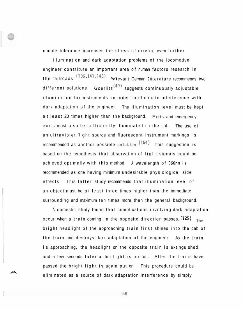
minute to lerance increases the s t ress o f d r i v i n g even f u r t h e r .
I l l u m i n a t i o n and dark adaptat ion problems o f the locomotive
engineer c o n s t i t u t e an important area o f human f a c t o r s research i n
t h e r a i l r o a d s . (106y141 y143) Re1 evant German 1 i t e r a t u r e recommends two
d i f f e r e n t so lu t ions . G o e r l i t z (49) suggests cont inuous ly ad jus tab le
i l l u m i n a t i o n f o r instruments i n order t o e l i m i n a t e i n te r fe rence w i t h
da rk adaptat ion o f the engineer. The i l l u m i n a t i o n l e v e l must be kept
a t l e a s t 20 t imes h igher than t h e background. E x i t s and emergency
e x i t s must a l s o be s u f f i c i e n t l y i l l u m i n a t e d i n the cab. The use o f
a n u l t r a v i o l e t 1 i g h t source and f luorescent inst rument markings i s
recommended as another poss ib le solut ion.(154) This suggestion i s
based on the hypothesis t h a t observat ion of l i g h t s igna ls cou ld be
achieved o p t i m a l l y w i t h t h i s method. A wavelength o f 366nm i s
recommended as one having minimum undesi rable phys io log i ca l s ide
e f f e c t s . This l a t t e r study recommends t h a t i l l u m i n a t i o n l e v e l o f
a n o b j e c t must be a t l e a s t t h ree times h igher than the immediate
surrounding and maximum ten times more than the general background.
A domestic study found t h a t compl icat ions i n v o l v i n g dark adapta t ion
occur when a t r a i n coming i n t h e opposi te d i r e c t i o n passes. (125) ~h~
b r i g h t head l i gh t o f the approaching t r a i n f i r s t shines i n t o the cab o f
t h e t r a i n and destroys dark adaptat ion o f the engineer. As the t r a i n
i s approaching, the head l igh t on the opposite t r a i n i s ext inguished,
and a few seconds l a t e r a dim l i g h t i s p u t on. A f t e r t h e t r a i n s have
passed the b r i g h t l i g h t i s again pu t on. This procedure could be
e l im ina ted as a source o f dark adapta t ion i n te r fe rence by s imply A
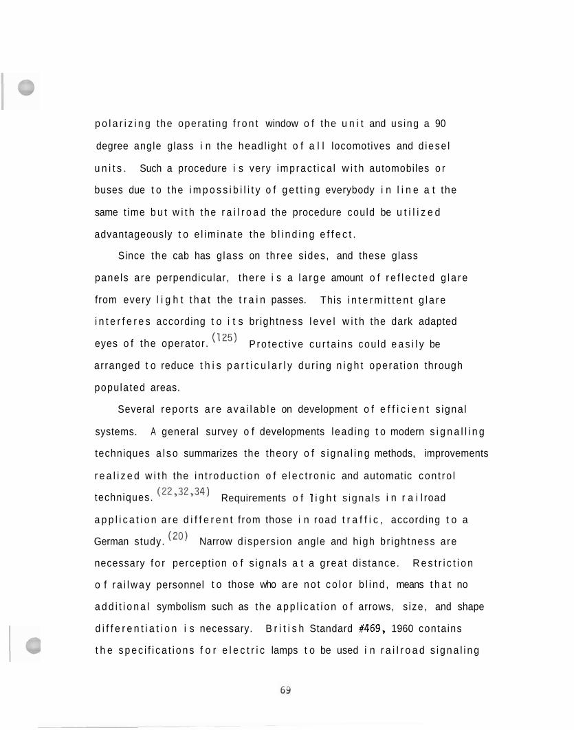
p o l a r i z i n g the opera t ing f r o n t window o f the u n i t and us ing a 90
degree angle glass i n the head l igh t o f a l l locomotives and d iese l
u n i t s . Such a procedure i s very imprac t i ca l w i t h automobiles o r
buses due t o the i m p o s s i b i l i t y o f g e t t i n g everybody i n l i n e a t the
same t ime b u t w i t h the r a i l r o a d the procedure could be u t i l i z e d
advantageously t o e l im ina te the b l i n d i n g e f f e c t .
Since the cab has g lass on th ree s ides, and these glass
panels a re perpendicular, t he re i s a l a r g e amount o f r e f l e c t e d g l a r e
from every l i g h t t h a t the t r a i n passes. This i n t e r m i t t e n t g l a r e
i n t e r f e r e s according t o i t s br ightness l e v e l w i t h the dark adapted
eyes o f the operator . P ro tec t i ve c u r t a i n s cou ld e a s i l y be
arranged t o reduce t h i s p a r t i c u l a r l y du r ing n i g h t opera t ion through
populated areas.
Several repo r t s a r e a v a i l a b l e on development o f e f f i c i e n t s igna l
systems. A general survey o f developments lead ing t o modern s i g n a l l i n g
techniques a l s o summarizes the theory o f s i g n a l i n g methods, improvements
r e a l i z e d w i t h the i n t r o d u c t i o n o f e l e c t r o n i c and automatic con t ro l
techniques. (22y32'34) Requirements o f 1 i g h t s igna ls i n r a i l road
a p p l i c a t i o n a r e d i f f e r e n t f rom those i n road t r a f f i c , according t o a
German study. (20) Narrow d ispers ion angle and h igh br igh tness are
necessary f o r percept ion o f s igna ls a t a g rea t d is tance. R e s t r i c t i o n
o f r a i l w a y personnel t o those who are n o t c o l o r b l i n d , means t h a t no
a d d i t i o n a l symbolism such as the a p p l i c a t i o n o f arrows, s ize, and shape
d i f f e r e n t i a t i o n i s necessary. B r i t i s h Standard #469, 1960 conta ins
t h e s p e c i f i c a t i o n s f o r e l e c t r i c lamps t o be used i n r a i l r o a d s i g n a l i n g
systems. (I9) The standard also specifies technical requirements and
methods of tests to be used for determining quality and interchangeability
o f lamps in indicators, searchlight signals, illuminated diagrams and
control panels, position light junction indicators and multi-aspect color
1 ight signals.
Improvements are reported to increase brightness of flashing light
grade crossing signal by over 400% with a simple design change in the
bulb. (83) Preliminary tests to determine feasibility of a reflectorized
bulb concept were made using the Association of American Railroads
No. 88 bulb aluminized over one-half its area; this paper also presents
beam pattern of signal and light intensity distribution along the vertical
axis. Another study, (86) aimed at improving railroad light signals,
presents a chart for obtaining the visual range of colored point sources
of signal lights; a diagram is based on the threshold value of 50%
detection obtained in a laboratory experiment; factors determining
visual range of point sources are discussed and the visual range of the
1 ights is described.
For improving perception of roadway signals by the engineers changes
are proposed concerning the location of these signals. (I2') An amendment
of the present rules is suggested that would lift the prohibition in
the existing rules against left-hand signals, and require only that each
signal be so located that it can readily be associated with the tracks
on which it governs movements.
There are attempts to provide information to the engineer inside
the cab on the railroad signals in addition to traditional displays.
British Railways introduced a unique signalling system in cabs of switching
locomotives.(113) A display located inside the locomotive cab shows
a replica, in miniature, of bump signal aspects of the marshalling yard,
providing continuous visual information to the operator. A constant
two-way radio communication is also maintained between the engineer
and the control room. Burlington installed a cab signaling system (111)
in which wayside signals are displayed continuously in the cab with a
color light system displaying automatically route line up and track
occupancy. In another signal display information system, the route
information concerning past, present, and oncoming signal conditions
is relayed to the train for presentation to the engineer. (99)
One system designed in Japan (46) displays signal position, coupled
with an additional sound alarm for stop signals. Audio frequency
signaling methods are employed with a carrier frequency of 1920 Hz,
and modulation frequencies of 15, 20, 30, 40, and 80 Hz, superimposed
on 60 Hz normal signaling current.
An on-board signal and speed control system employed by the
Chicago Transit Authority for its Lake Street line uses high frequency
track circuits to carry information and instructions directly to the
motorman. The system provides five speed commands, including a
stop command. Each of the speed commands is enforced by automatic
overspeed control.
More recent developments of the above cab signaling systems are
a 1 so reported. ('I6) This new display system provides the engineer with
/r\
not only an indication of the passed and approaching s ignals , b u t has
an automatic speed control system. Distance between the locomotive
and the approaching signal i s displayed in d ig i ta l form, and the
engineer is in a two-way speech communication with the control center.
The application of VHF radio communication has been t r i ed on the
German Federal Railways instead of wayside signals. (44) ~ 0 t h signaling
problems and remote control of locomotives have been t r i ed in main-
l i n e operation a s well a s in switching and short distance t r a f f i c .
Radio communication proved to be advantageous when provided to switch
crewmen i n yard work. ( 'I9) The switch crew carried pocket s i ze
transmitter- receiver radios in ground work. The radio u n i t could be
worn in a chest harness permitting the wearer t o have his hands f r e e
t o throw switches, climb on f r e igh t cars. The antenna i s "dibble"
type, f l ex ib le wire t h a t hangs down from the un i t ; the radio weighs
37 oz. , has 1.4 watts of RF power, and can operate through the base
s t a t i o n repeater t o provide coverage over the e n t i r e yard.
Recent progress i n automation of the Bri t ish Railways i s reported.
1 1 4 1 1 5 1 1 8 The approached and passed s ignals a re displayed i n the
cab f o r the engineer. ( 4 ) Data ut i l ized by the system are processed i n
two small computers on the t ra in and the distance r u n t o the signal
and t r a in location a r e displayed i n d ig i ta l form. The next step in
development i s planned to be the incorporation of a speed supervisory
system. In the Soviet Union, fo r automation of rai lroad controls , design,
and application of control computers has a l so been matched t o the
capab i l i t i e s of the human operator to achieve optimal performance. (157)

The s ign i f i cance o f human element i n r a i l r o a d s i g n a l i n g i s po in ted
o u t i n a Nat ional Transpor ta t ion Safety Board Report. (94) R a i l road
s i g n a l i n g systems, even though performing as designed, do n o t
compensate f o r human f a i l u r e and prevent acc idents. A r e l a t i o n s h i p
has been developed between s ignal system, opera t ing ru les , and the
human element t h a t i s responsive t o both. Spec i f i c cases are c i t e d
i n which the discrepancies a r e exposed and examined w i t h i n the contex t
o f a f u n c t i o n a l l y coherent man-machine system.
~ r a s o v s k i y ( ~ ~ ) a l s o emphasizes t h a t due cons idera t ion must be
g i v e n t o the operato& sensory c a p a b i l i t i e s . I n development o f f u t u r e
automatic r a i l r o a d systems the importance o f the proper d i s t r i b u t i o n
o f the workload between the man and the automatic device must be f u l l y
understood . (24) Man has d e f i n i t e parameters and l i m i t a t i o n s which
must be taken i n t o account i n designing the system such as:
( a ) the human neural system can e f f e c t i v e l y handle on l y one s igna l a t
a time; (b ) a s ignal a r r i v i n g du r ing the t ime o f processing o f the prev ious
s i g n a l i s perceived and stored; ( c ) when the number o f incoming s igna ls
increases, the operator t rans fe rs them i n t o the long- term memory ( f o r
r e c a l l ) which requ i res a d d i t i o n a l time; and (d) human capac i ty f o r
a t t e n t i o n can extend t o no more than approximately seven ob jec ts
s imul taneously. Reduction o f the operator's work1 oad must be resolved
o n the bas is o f human f a c t o r s engineer ing p r i n c i p l e s , such as the
a p p l i c a t i o n o f the opt imal form o f i n fo rma t ion d i sp lay ; p a r t i a l l y o r
complete ly automating dec is ion making; improving con t ro l ac t i ons by
development o f r a t i o n a l designs o f the con t ro l s . I n s tudying causal A
f a c t o r s o f highway and r a i l w a y accidents, v i sua l a t t e n t i o n has been
analyzed i n terms o f i n fo rma t ion theory by means o f a t e s t o f the
s i n g l e channel hypothesis, which suggests t h a t messages (s igna ls ,
s t i m u l i , pa t te rns , e tc . ) a re processed one a t a t ime, i .e . , sequen t ia l l y
b y a c e n t r a l i n fo rma t ion processing mechanism. (87) The var ious
experiments have prov ided data t h a t tend t o con f i rm t h i s hypothesis.
Not a l l poss ib le sensory channels o f the i n d i v i d u a l a r e f u l l y
u t i l i z e d i n r a i l r o a d con t ro l s . The a u d i t o r y system i s one which seems
t o be the l e a s t s t ra ined. Therefore, s igna l i ng in fo rmat ion could be
a l s o g iven through t h e a p p l i c a t i o n o f tone s igna ls . Menkes ) repor ted
developments o f a tone s i g n a l i n g system as adaptat ion o f rad io te legraphy
t o r a i l r o a d te legraph t ransmiss ion on c o n t r o l s i gna ls and r e p o r t back
s i g n a l s i n remote superv isory c o n t r o l systems and s ta tus s igna ls . The
a p p l i c a t i o n o f a u d i t o r y s igna ls t o the locomotive engineer cou ld be
another method t o d i s t r i b u t e i n p u t i n fo rma t ion more evenly o r r e i n f o r c e
o t h e r sensory channels w i t h a u d i t o r y s igna ls .
Hughes A i r c r a f t Company (67) prepared a l i t e r a t u r e survey on command
c o n t r o l o f high-speed ground t r a n s p o r t a t i o n systems. The r e p o r t a l so
rev iews the s ta te- o f - the- a r t i n r a i l w a y command and con t ro l systems,
proposals and design concepts o f automation systems, car de tec t i on and
i d e n t i f i c a t i o n techniques, b u t does no t discuss the human element and
system design c r i t e r i a f o r the human operator. T ra in con t ro l
systems a r e analyzed from the system engineer ing p o i n t o f view and
t h e sensing, processing, c o n t r o l l i n g , communication, and d i s p l a y elements
a r e explored i n d e t a i l i n respect t o hardware bu t n o t t o the human
requirements o f the system. I n the design o f a good s i g n a l i n g system,
due cons idera t ion should be g iven t o the human component both from a
psychophysical p o i n t o f view and from the vas t personal experience o f
t h e operators. (66)
Safety i n r a i l r o a d operat ions i s the r e s u l t o f mutual i n t e r a c t i o n
o f a l a r g e number o f precaut ions, s a f e t y r u l e s , and sa fe ty equipment,
such as cab warning devices, s igna l and swi tch apparatus, s a f e t y t racks ,
r a i l r o a d c ross ing p ro tec t i ons , avalanche warning devices, fa1 1 i n g rock
de tec to rs , t r a i n d ispatch ing communication system. (128) To achieve the
h ighes t s a f e t y l e v e l o f the whole system, p r i o r i t y and s i g n i f i c a n c e o f
development o f the system components must be opt imized. A mathematical
model i s presented i n t h i s paper on how op t im iza t i on i n the development
o f r a i l r o a d sa fe ty devices can be r e a l i z e d w i t h i n a t o t a l prescr ibed
c o s t . Simple summation o f bes t so lu t i ons o f t h e components, sec t ion by
sec t ion , reg ion by region, year by year might n o t necessar i l y r e f l e c t
t h e o p t i m a l i t y o f a system on the whole i n the long run. (1
2.2 Contro ls on Domestic Locomotives
Design o f the c o n t r o l s loca ted i n s i d e the eng ineer 's cab a re
d iscussed i n t h i s chapter from the human f a c t o r s p o i n t o f view. Two
major groups o f c o n t r o l equipment a re l oca ted i n s i d e the cab: (1)
eng inee r ' s c o n t r o l stand, and (2 ) engine c o n t r o l panel.
(1 ) The engineer's c o n t r o l stand houses equipment which the engineer
operates r o u t i n e l y t o d r i v e the locomotive. F u n c t i o n a l l y t he c o n t r o l s
separate i n t o two d i s t i n c t groups:
(a) A i r brake system, comprising the automatic and independent
b rake systems.
(b) Contro l u n i t which inc ludes :
- s e l e c t o r l e v e r
- reverse l e v e r (except on two- lever GE models)
- t h r o t t l e l e v e r
- pressure gauges
- load c u r r e n t i n d i c a t o r
- switches and i n d i c a t o r l i g h t s
(2 ) The engine c o n t r o l panel loca ted on the r e a r wa l l o f t he cab
con ta ins i n d i c a t o r s , switches, c i r c u i t breakers, and fuses which do n o t
r e q u i r e constant a c t i v a t i o n du r i ng normal operat ion.
A comparative s tudy o f t he eng ineer 's c o n t r o l stand on locomotives
o f d i f f e r e n t makes revea ls t h a t a l l th ree manufacturers inc luded f u n c t i o n a l l y
i d e n t i c a l equipment and the th ree types o f locomotives can be operated
i n m u l t i p l e w i t h each o the r . S i m i l a r f unc t i ons a re c o n t r o l l e d by s i m i l a r
equipment:
A
- levers a re used fo r t h r o t t l e , reverse, and selector controls, f o r the brakes and fo r act ivat ing the a i r horn.
- display dial gauges a r e used fo r indication of a i r pressures, load current , and speed.
- switches a r e used for engine and generator control , l i gh t s , dimming, and sounding.
- push buttons fo r ground r e se t , attendant c a l l , and bell operations, and
- indicator l igh ts t o show s t a t e of engine conditions.
The braking system, control switches, push buttons, and indicator
l i g h t s a r e similar on locomotives of a l l manufacturers though the i r
locat ion and shape a re di f ferent . Details of the EMD control stand
a r e described f i r s t , and respective differences will then be pointed
ou t l a t e r i n the chapter. Figs. 2.6 and 2.7 show the control stand
o n recent EMD locomotives. Fig. 2.8 i l l u s t r a t e s photographically the
r e l a t i v e position of a seated engineer with respect t o the stand in the
cab. The cont ro l le r , located on the r i gh t , consis ts of the selector
handle, t h r o t t l e handle, and reverser handle. The selector handle
has three positions: power, park, and braking. I t s position i s
indicated in an illuminated window d i r ec t l y above the selector lever .
O n models bu i l t before June 1971 the lever i s spring-loaded and returns
t o center position a f t e r each movement. On models bu i l t a f t e r t h a t
d a t e , the lever i s not spring-loaded and will remain in the position i t
i s placed. The reverser has three positions and controls locomotive
movement -- forward, i d l e , and reverse. The t h r o t t l e lever controls
engine power and speed. I t has ten posit ions, namely stop, i d l e , and
r u n n i n g speeds 1 through 8. Each of these positions i s displayed t o the A
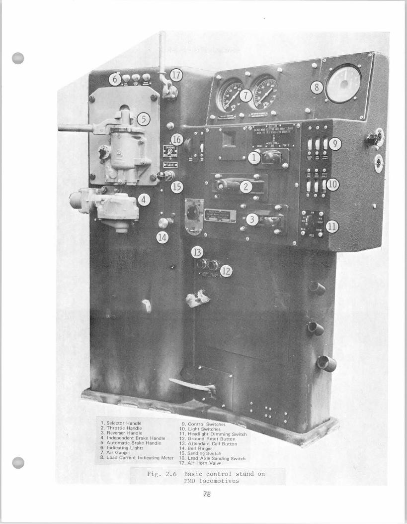
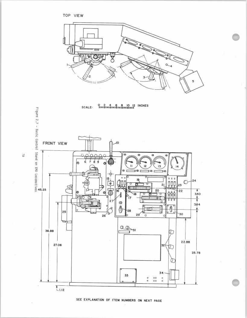
EXPLANATION OF INDEX NUMBERS I N FIG 2.7
BASIC CONTROL STAND OF EMD LOCOMOTIVES
- Auto B. V . Release 18 - Signal L i g h t Reset - I.B.V. Release 19 - Dynamic Brake On-Off Switch - D i r e c t i o n a l Handle 20 - Power T h r o t t l e Lever and I n d i c a t o r - Speed I n d i c a t o r Rheostat 21 - Engine Run I n d i c a t o r - Speed I n d i c a t o r 22 - Generator F i e l d I n d i c a t o r - Signal L i g h t 23 - Fuel Pump I n d i c a t o r - P.C.S. Open 24 - Gauge L i g h t Rheostat - Wheel S l i p 25 - Radio - Brake Warning 26 - B e l l 0- Horn 27 - Power Reduction I n d i c a t o r 1- Main Reservoi r I n d i c a t o r 28 - Power Reduction Lever 2- Brake Cy l inder I n d i c a t o r 29 - Reverser 3- Brake Pressure Flow I n d i c a t o r 30 - Headl ight Bright-Dim I n d i c a t o r 4- Brake Power I n d i c a t o r 31 - Attendant C a l l -Reset I n d i c a t o r 5- Sander 32 - Brake Handle Storage Racks 6- Dynamic Brake Contro l I n d i c a t o r 33 - Prov is ion o f Dead Man Pedal 7- Fast-Slow I n d i c a t o r 34 - Buzzer
12345678911111111
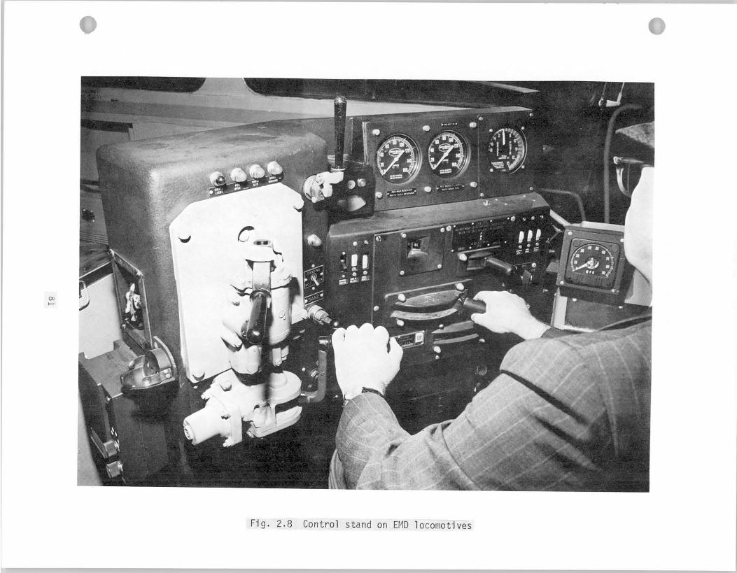
engineer i n an i l l u m i n a t e d i n d i c a t o r window i n the upper l e f t co rne ro f the
c o n t r o l l e r . The d r i v e r increases d iese l engine speed by p u l l i n g the t h r o t t l e
from i t s f a r t h e s t p o s i t i o n toward h imse l f . The handles on t h e c o n t r o l l e r
a r e i n t e r l o c k e d f o r safe separat ion and avo id ing accidenta l i n c o r r e c t
s w i t c h i n g o f the con t ro l s . B a s i c a l l y i n t e r l o c k i n g prevents changing
p o s i t i o n o f bo th s e l e c t o r and reverser when the t h r o t t l e i s above i d l e
and the reverser cannot be moved when the se lec to r i s i n brak ing.
Brake equipment i s loca ted t o the l e f t o f the c o n t r o l l e r . I t cons i s t s
o f two separate valves: the automatic brake va lve and the independent
brake valve. The automatic va lve i s designed f o r r e g u l a t i n g brake-pipe
pressure t o c o n t r o l bo th locomotive and t r a i n brakes. The independent
v a l v e w i 11 app ly and re lease locomotive brakes independent o f the t r a i n
brakes. The independent va lve a l s o c o n t r o l s the re lease o f the locomotive
brakes (due t o an automatic brake a p p l i c a t i o n w h i l e i n f o rce ) w i thou t
r e l e a s i n g the t r a i n brakes. F igures 2.9 and 2.11 show opera t ing p o s i t i o n s
o f the brake levers . There i s no d i f f e rence i n opera t ion o f the brake
system on locomotives made by d i f f e r e n t manufacturers. As F i g . 2.10 shows,
t h e p o s i t i o n s o f the automatic brake l e v e r on GE locomotives are p r a c t i c a l l y
i d e n t i c a l t o those on EMD's (F ig . 2.9).
Two gauges are loca ted on the eng ineer 's c o n t r o l stand (see F igs . 2.6
and 2.7). One gauge i n d i c a t e s bo th the main r e s e r v o i r ( red hand) and
e q u a l i z i n g r e s e r v o i r (wh i te hand) pressures. The o the r gauge ind i ca tes
brake p ipe (wh i te hand) and brake c y l i n d e r pressures ( red hand). A
t h i r d op t i ona l gauge i n d i c a t e s the a p p l i c a t i o n and suppression pressures
used i n con junc t ion w i t h the th ree s a f e t y devices ( s a f e t y c o n t r o l f o o t
I I I
l I
I A
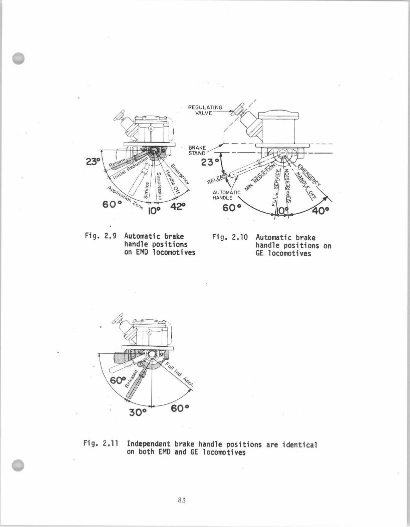
pedal , locomotive overspeed, and t r a i n c o n t r o l ). The load c u r r e n t
i n d i c a t i n g meter i s loca ted a l s o on the eng ineer 's c o n t r o l console
and i t measures c u r r e n t f l o w i n g through the t r a c t i o n motors. It i s
a n i n d i c a t i o n o f the p u l l i n g and dynamic brak ing fo rces developed by
t h e locomotive. I t i s graduated i n 25 ampere increments from 0 t o 1500
amperes. I t may be c o l o r coded o r equipped w i t h a r a t i n g p l a t e t o i n d i c a t e
ope ra t i ng t ime l i m i t s a t var ious t r a c t i o n motors loads when operat ing below
minimum cont inuous speed.
A dual read ing load c u r r e n t i n d i c a t i n g meter i s being used on more
r e c e n t models t o i n d i c a t e the c u r r e n t f l o w i n g through the t r a c t i o n motors
o n separate scales f o r motor ing and dynamic braking. The motoring scale
reads from center t o r i g h t , the dynamic brak ing scale from center t o l e f t .
I t i s graduated i n 20 ampere increments from 0 t o 1500 amperes i n motor ing
and 0 t o 800 amperes i n dynamic brak ing. The motor ing scale i s whi te, w i t h
r e d band from 1040 t o 1500 amperes. The dynamic brak ing scale i s ye l low.
T h i s meter i s standard on u n i t s b u i l t a f t e r June 1971.
Many ra i lways prov ide a Brake Pipe Flow Gauge which i nd i ca tes t o the
engineer the r a t e o f f l o w o f a i r i n the brake p ipe i n the locomotive. This
gauge i s o f considerable help t o the engineer i n determin ing the s t a t e o f
charge o f t h e t r a i n brake system.
A group o f switches i s loca ted along the f r o n t face o f the
c o n t r o l l e r , each i d e n t i f i e d by a name p l a t e i n d i c a t i n g swi tch func t i on .
The switches a r e i n the ON p o s i t i o n when moved upward. Before the
engine i s t o be s ta r ted , t h e c o n t r o l and f u e l pump swi tch must be
placed ON. To ob ta in power from the locomotive, the generator f i e l d
s w i t c h must be ON. To ob ta in c o n t r o l o f engine speed, the engine r u n
swi tch must be ON. These th ree important switches are grouped a t t he
A
r igh t side of the control ler . They must be placed in the OFF position
on control lers of t r a i l i ng units. The sand switch will sand the f ron t
o f the number one truck (lead truck) of the locomotive. When i t i s
being used, the sand l i gh t will be l ighted. This method of sanding
dresses the r a i l and i s adequate for most operations. The t ra inl ined
sanding lever will sand a l l units i n the locomotive consis t . The sand
wi l l flow i n the direction the locomotive reverser is positioned (forward
o r reverse). The manual emergency sand switch i s used to sand in both
forward and reverse directions. A red indicating l i gh t above the switch
w i l l be l ighted when t h i s switch i s on.
A f i ve position headlight dimming switch i s located on the
cont ro l le r to the r i gh t of the t h ro t t l e . In one position i t provides
f o r dim headlights on both ends of the locomotive. In the other four
posit ions i t provides for a bright or medium headlight a t e i ther the
f r o n t or the rear of the locomotive.
Several push buttons are usually mounted on the control console.
The ground r e se t pushbutton resets the ground relay. Attendant ca l l
pushbutton rings the alarm bel l . I t i s used as a communicating signal
on the locomotive consist . Alarm bell s i lencer and indicating l i g h t
(opt ional) consists of red pushbutton w i t h an indicating l i gh t inside
the button. When any protective device connected to the alarm c i r cu i t
t r i p s , the alarm bell will sound. Momentarily pressing the alarm bell
s i l ence r (red pushbutton) will s i lence the alarm bell and l i g h t the
alarm indicating l i g h t inside the pushbutton. The l i g h t replaces the
be l l i n indicating a protective device has tripped. I t will remain
l ighted unt i l the protective device has been rese t or the affected uni t
I
I I I
I
1
- ,' \
i s i s o l a t e d . The f o u r i n d i c a t i n g l i g h t s p rov ide v i s u a l i n d i c a t i o n o f
t h e f o l l o w i n g locomot ive ope ra t i ng cond i t i ons : (1 ) Wheel- sl ip - i n t e r m i t t e n t f lashes o f t he whee l- s l ip l i g h t i n d i c a t e a wheel s l i p
has occurred on the locomotive cons i s t . However, a wheel s l i p l i g h t
f l a s h i n g s low ly and p e r s i s t e n t l y o r a constant l i g h t may i n d i c a t e one
p a i r o f wheels i s s l i d i n g . (2 ) P.C. Open - when t h i s l i g h t i s on i t
i n d i c a t e s the power c u t - o f f sw i tch has t r i pped , which w i l l p revent
t he engine f rom responding t o t he t h r o t t l e . (3) Sand - t h i s w i l l be
1 i g h t e d as an i n d i c a t i o n t h a t the sanding swi tch i s turned on. ( 4 )
Dynamic brake warning l i g h t - w i l l come on when excessive dynamic
b rake cu r ren ts a re developed on one o f t he u n i t s i n the c o n s i s t .
The eng ineer 's c o n t r o l stand i s d i f f e r e n t on GE locomotives, though
i t houses s i m i l a r c o n t r o l s f o r per forming i d e n t i c a l f unc t i ons t o those found on
EMD's. F igs. 2.12 - 2.15 i l l u s t r a t e t he major steps i n the h i s t o r i c a l
development o f the GE c o n t r o l stand. On e a r l i e r GE locomotives two
designs o f t he c o n t r o l stand were used. The p r i n c i p a l d i f f e r e n c e between
t h e two i s i n the f u n c t i o n o f the s e l e c t o r and reverse levers , as o u t l i n e d
below:
A th ree- lever c o n t r o l stand (F igs . 2.12 and 2.16) was used on a l l
U25 and U28 u n i t s . The U30 u n i t s b u i l t be fo re 1968 a l so use t h i s design.
The se lec to r- leve r has s i x p o s i t i o n s , which a re B, OFF, 1, 2, 3, and 4.
The reverse- lever has th ree p o s i t i o n s forward, n e u t r a l , and reverse as
normal. The t h r o t t l e l e v e r has an i d l e p o s i t i o n p lus e i g h t major and
e i g h t in te rmed ia te pos i t i ons . Major p o s i t i o n s a r e marked by number.
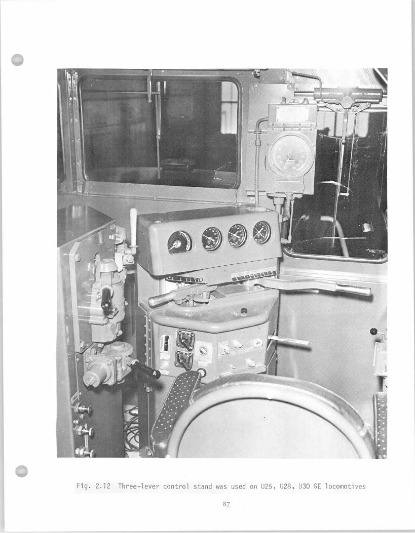
In termediate p o s i t i o n s a re marked by a d o t o r one-hal f mark. Each
numbered t h r o t t l e p o s i t i o n changes the engine speed. The in te rmed ia te
(one- hal f mark) pos i t i ons change the amount o f e x c i t a t i o n .
The two- lever c o n t r o l stand (F ig . 2.13 and 2.17) was used on a l l U23
and U33 u n i t s u n t i l 1970. It a l s o i s used on U30 u n i t s b u i l t between 1967
and 1970. The s e l e c t o r l e v e r combines the func t i ons o f t he s e l e c t o r and
reverser . It has f i v e pos i t i ons , which a re used t o s e l e c t d i r e c t i o n o f
movement as we l l as type o f opera t ion (motor ing o r dynamic b rak ing) . The mid-
p o s i t i o n o f the s e l e c t o r l e v e r i s OFF. The f i r s t p o s i t i o n t o the r i g h t i s
f o rward motor ing; the second p o s i t i o n i s forward dynamic brak ing. The f i r s t
p o s i t i o n t o the l e f t i s reverse motor ing; the second p o s i t i o n i s reverse
dynamic brak ing. The t h r o t t l e l e v e r has an i d l e p o s i t i o n and e i g h t power
p o s i t i o n s . Engineers found the combined se lec to r and reverse l e v e r very
undesirable.
As a s tep i n s tandard iz ing locomotive c o n t r o l s pending complet ion
o f t he AAR s tanda rd i za t i on work on locomot ive con t ro l s , GE used EMD's
c o n t r o l l e r u n i t (F igure 2.14) on locomotives b u i l t i n 1971 and some locomotives
b u i l t e a r l y i n 1972. A f u r t h e r stage o f s tanda rd i za t i on i s planned by GE w i t h
the i n t r o d u c t i o n o f a domestic standard console du r i ng the summer o f 1972.
GE has b u i l t a prototype console and i s prepared t o go i n t o f u l l product ion
a s soon as the a i r brake gage arrangement d e t a i l s a re resolved. This new
standard, shown i n F ig . .2.15, has been developed on the bas is o f recommendations
s e t by AAR (Report o f Committee on E l e c t r i c a l Equipment-Roll ing Stock, Docket
NO. EE-30):
"A. T h r o t t l e Handle. This handle w i l l perform the f u n c t i o n o f c o n t r o l l i n g the power ou tpu t o f the locomotive. This handle w i l l have an i d l e p o s i t i o n and opera t ing de ten t p o s i t i o n s 1 through 8. This handle w i l l be the longes t o f the th ree and w i l l be a f l a t ho r i zon ta l oval shape. Movement toward the engineer w i l l increase power.
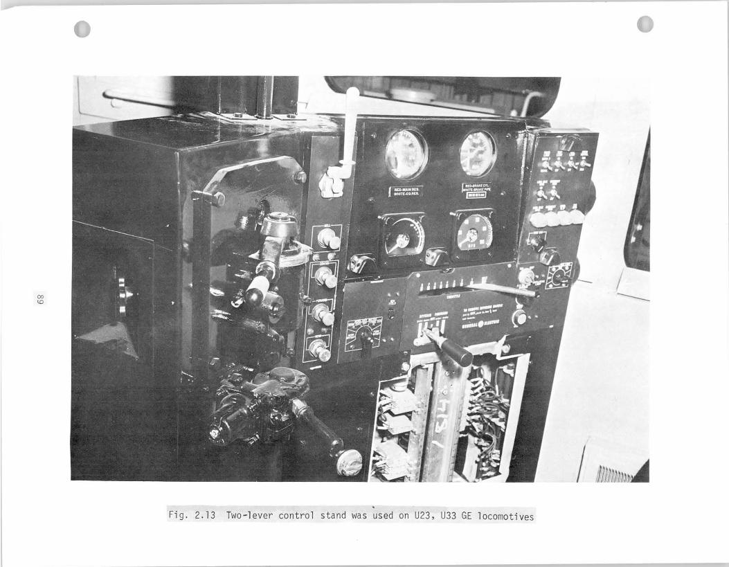
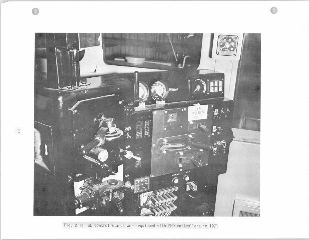
B. Braking Handle. This handle w i l l perform the dynamic brak ing func t i on . The handle w i l l have an o f f p o s i t i o n , minimum brake p o s i t i o n which w i l l s e t up dynamic braking, and then f r e e movement toward a maximum brake p o s i t i o n . Between minimum brake and maximum brake the re w i l l be notchless modulat ion o f the amount o f brak ing. The shape o f t h i s handle w i l l be a f l a t v e r t i c a l oval t h a t w i l l match the f l a t palm o f the hand when pushing away t o increase brak ing.
C. Reverser Handle. This handle w i l l determine the locomotive d i r e c t i o n . There w i l l be three d e f i n i t e p o s i t i o n s -- forward, o f f , and reverse. Shape w i l l be round."
I n t e r l o c k i n g o f the c o n t r o l l e r w i l l be as fo l l ows t o p rov ide the
maximum sa fe ty :
1 . The brake handle must be i n the " o f f " p o s i t i o n before the t h r o t t l e handle can be moved o u t o f the " i d l e " p o s i t i o n .
2. The t h r o t t l e handle must be i n " i d l e " and the reverser handle i n " forward" o r " reverse" before the brake handle can be moved.
3. The reverser handle must be i nse r ted before the t h r o t t l e handle may be moved ou t o f " i d l e " .
4. The reverser handle may o n l y be moved i n t o " forward" o r " reverse" w i t h the t h r o t t l e i n the " i d l e " p o s i t i o n and the brake i n " o f f " .
5. The reverser handle may n o t be moved o u t o f " forward" o r " reverse" w i t h e i t h e r the t h r o t t l e handle o r brake handle i n e i t h e r a power o r b rak ing p o s i t i o n .
6. When the reverser handle i s removed, n e i t h e r the t h r o t t l e handle nor the brake handle may be moved ou t o f the " i d l e " o r brake " o f f " p o s i t i o n respec t i ve l y .
P r i n c i p a l Features o f the Standard Contro l Stand
1. Three handles, 'each performing a separate f u n c t i o n
2. The t h r o t t l e i s t o perform on ly the power func t ion , removing any quest ion as t o the opera t ing mode o f the locomotive.
3 . The dynamic brake l e v e r operates i n the opposi te d i r e c t i o n and serves on ly t o c o n t r o l dynamic brak ing.
4. Reverser handles w i l l a l l be standard, making them interchangeable regardless o f manufacturer o f locomotive.
, ,
5. Dual reading ammeters f o r power and dynamic brak ing a r e t o be standard on the recommended c o n t r o l stand.
6. A l l gauges a r e t o be the l a r g e 4 1/2 i n c h s i z e w i t h back l i g h t i n g f o r maximum v i s i b i l i t y .
The AAR standard as o u t l i n e d above has i n t e r l o c k i n g fea tures s i m i l a r
t o the EMEand GE models a l ready i n use. It does no t have p o s i t i o n i n d i c a t o r
windows because i t shows l e v e r p o s i t i o n s d i r e c t l y on the handle housing
i ns tead , which i s a des i rab le fea tu re . The standard recommendations
d iscuss i n d i c a t o r gauges, bu t do n o t extend t o i nc lude opt imal design
o f switches, push buttons, and i n d i c a t o r l i g h t s . It would be a l so
advantageous t o recommend standardized l o c a t i o n o f a l l the above
components on a f u t u r e standard console. Locat ion o f the var ious
components must be determined by grouping f u n c t i o n a l l y dependent c o n t r o l s
f o r ease o f operat ion.
On the new standard, as GE b u i l t i t (Fig. 2.15), a l l d i a l i n d i c a t o r s
a r e c i r c u l a r w i t h the zero s e t t i n g a t about the 8 o ' c l o c k pos i t i on .
The load c u r r e n t i n d i c a t o r i s mounted s l i g h t l y lower than the pressure
gauges. However, a1 1 d i a l s should be a l igned. Furthermore, the c u r r e n t
i n d i c a t o r has square housing which does n o t a f f e c t i t s human f a c t o r s
va lue because i t s face i s round corresponding t o the o ther gauges,
b u t lowers aes the t i c appeal o f the whole design. From the human f a c t o r s
p o i n t o f view, i t i s more des i rab le t o have the opera t ing normal p o s i t i o n
o f a l l d i a l po in te rs un i fo rm ly a t the 9 o ' c lock l oca t i on . Such a change
would r e q u i r e minor m o d i f i c a t i o n o f the inst ruments only.
The load meter o f GE locomotives i s s l i g h t l y d i f f e r e n t from EMD's.
I t i s graduated i n 100 ampere increments. The cont inuous motor ing zone
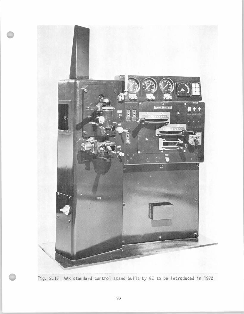
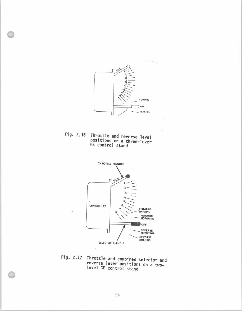
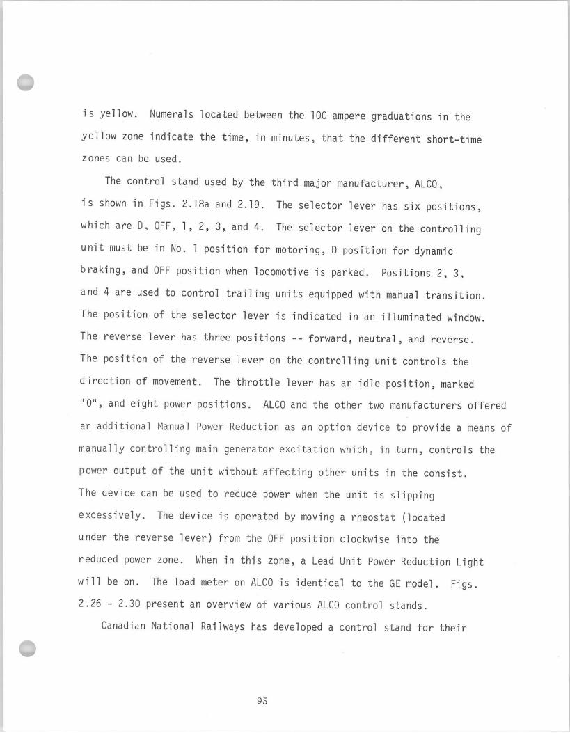
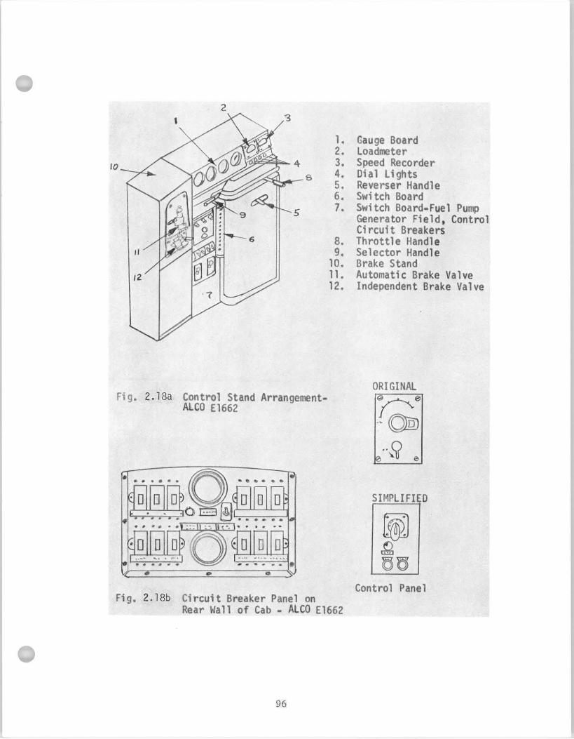
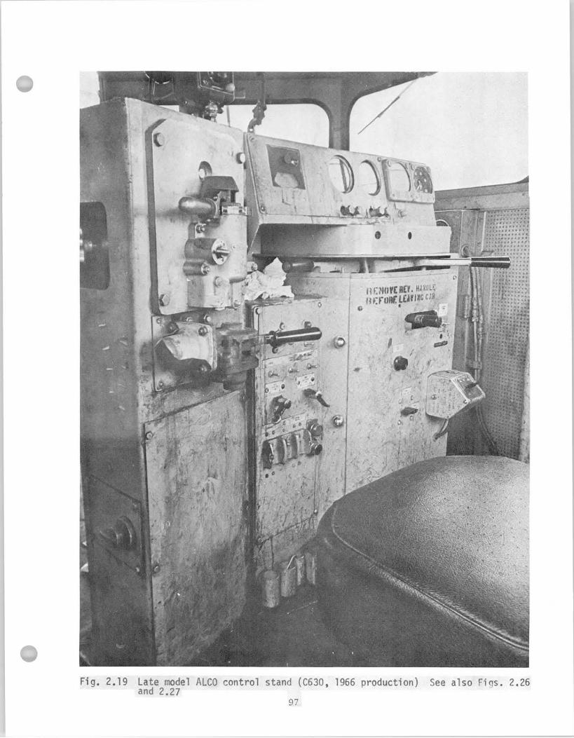
use as a f u t u r e standard. Only a schematic drawing was a v a i l a b l e
( F i g . 2.20). The drawing i l l u s t r a t e s t h a t the PAR c o n t r o l l e r was
adopted by CNR. The c o n t r o l stand conta ins more d i a l gauges than
usua l . An a i r f l o w meter and a cy l inder- brake- pipe pressure gauge a r e
added. Diameter o f the c i r c u l a r d i a l faces i s 4 1/2" un i fo rm ly except
f o r the a i r f l o w gauge which has a square window. Switches, push but tons
and i n d i c a t o r l i g h t s seem t o be grouped f u n c t i o n a l l y . For example,
engine run swi tch, f u e l pump switch, and generator f i e l d swi tch a r e
l o c a t e d nex t t o each o the r o r l i g h t switches and dimmer c o n t r o l a re
p laced i n a row. Canadian Nat ional has issued orders f o r locomotives
s p e c i f y i n g the new cab design.
F ig . 2.21 shows a m o d i f i c a t i o n o f GE's e a r l i e r th ree- lever con t ro l
s tand i n s t a l l e d i n a U25 locomotive. On t h i s vers ion the a i r horn i s
operated by p u l l i n g a cha in w i t h the r i g h t hand, the speedometer i s
d i f f e r e n t from t h a t shown i n F ig . 2.12, and there i s some m o d i f i c a t i o n
i n the arrangement o f switches. Some t y p i c a l m o d i f i c a t i o n o f the two
1 ever GE c o n t r o l stand a r e shown i n F ig . 2.22 vs F ig . 2.13. There are
t h r e e pressure gauges on t h i s stand, l i g h t switches, and i n d i c a t o r
l i g h t s are added, the p o s i t i o n o f f r o n t head l igh t sw i tch has been moved
t o the r i g h t s ide f rom the l e f t . I n another m o d i f i c a t i o n o f the two- lever
console, F ig . 2.23, the speedometer i s b u i l t i n t o t h e c o n t r o l stand, brake
pressure gauges are loca ted below the load meter and speedometer, the
se lec tor- reverser handle has a unique shape as a combination o f d iscs
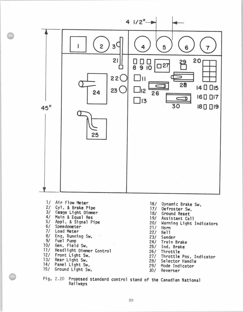
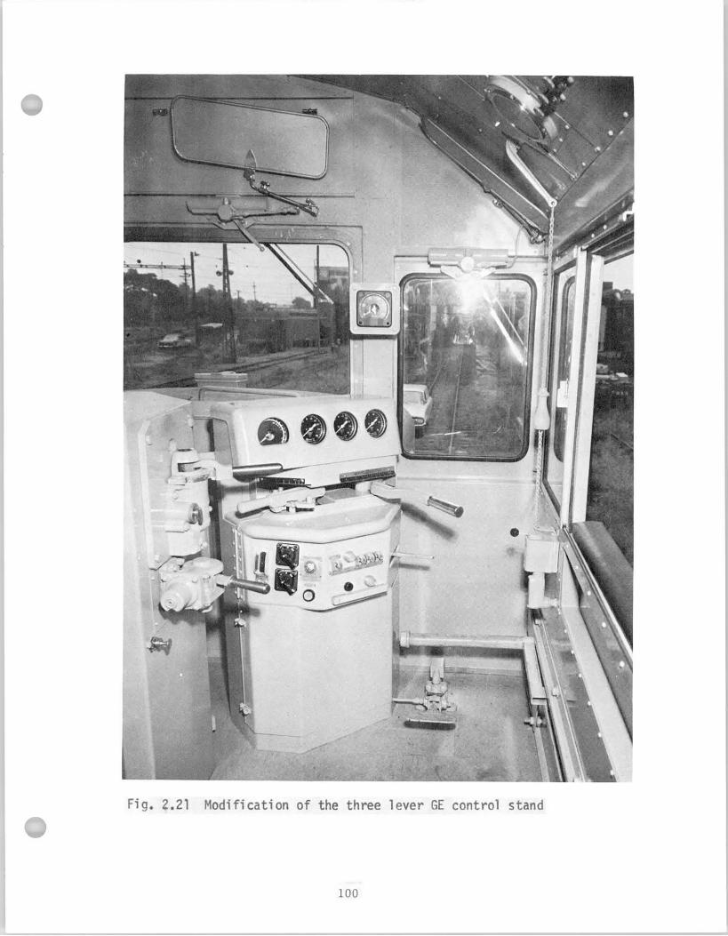
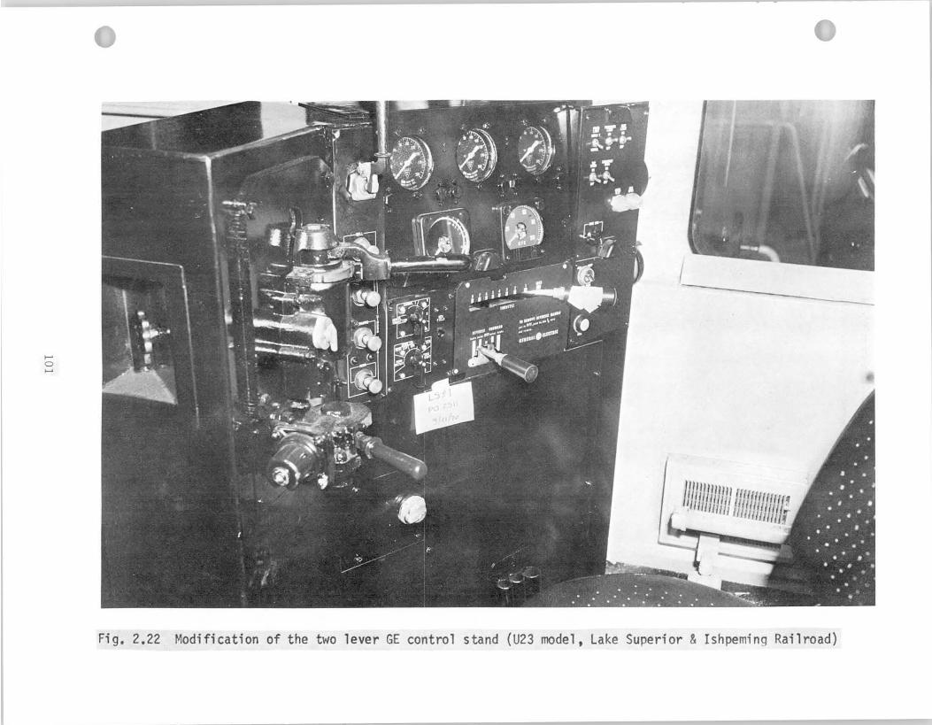
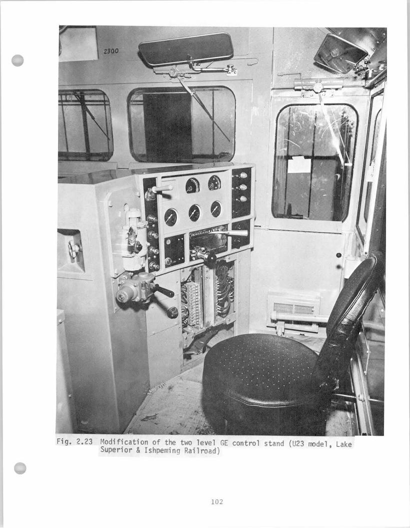
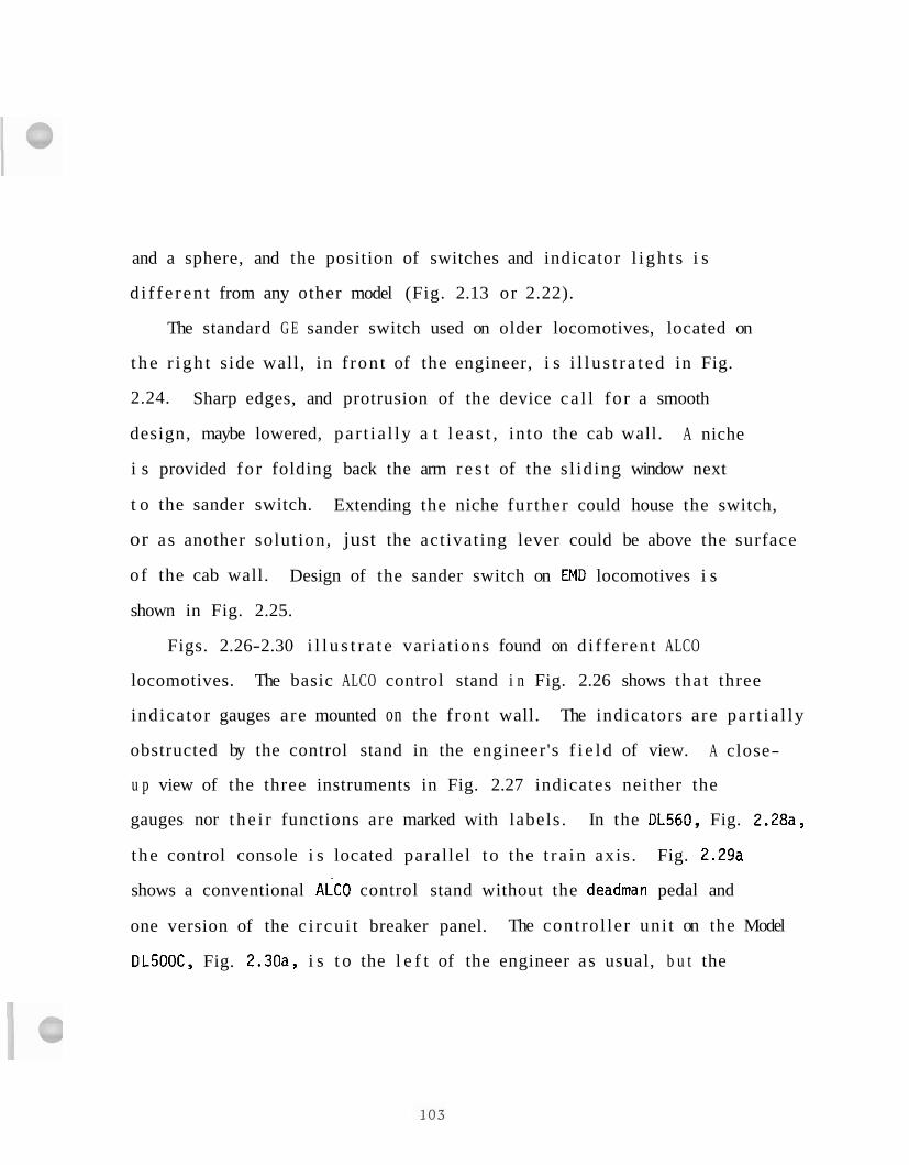
and a sphere, and the position of switches and indicator l i gh t s i s
d i f f e r en t from any other model (Fig. 2.13 or 2.22).
The standard G E sander switch used on older locomotives, located on
t h e r i gh t side wall, in f ron t of the engineer, i s i l l u s t r a t ed in Fig.
2.24. Sharp edges, and protrusion of the device ca l l fo r a smooth
design, maybe lowered, par t ia l ly a t l e a s t , in to the cab wall. A niche
i s provided for folding back the arm r e s t of the s l iding window next
t o the sander switch. Extending the niche fur ther could house the switch,
or as another solution, just the activating lever could be above the surface
of the cab wall. Design of the sander switch on EMD locomotives i s
shown in Fig. 2.25.
Figs. 2.26-2.30 i l l u s t r a t e variations found on d i f fe ren t ALCO
locomotives. The basic ALCO control stand i n Fig. 2.26 shows tha t three
indicator gauges are mounted on the f ront wall. The indicators are par t ia l ly
obstructed by the control stand in the engineer's f i e l d of view. A close-
u p view of the three instruments in Fig. 2.27 indicates neither the
gauges nor t he i r functions are marked with labels. In the DL560, Fig. 2.28a,
t he control console i s located parallel to the t r a in axis . Fig. 2.29a
shows a conventional ALCO control stand without the deadman pedal and
one version of the c i r cu i t breaker panel. The control ler uni t on the Model
DL500C, Fig. 2.30a, i s t o the l e f t of the engineer as usual, b u t the
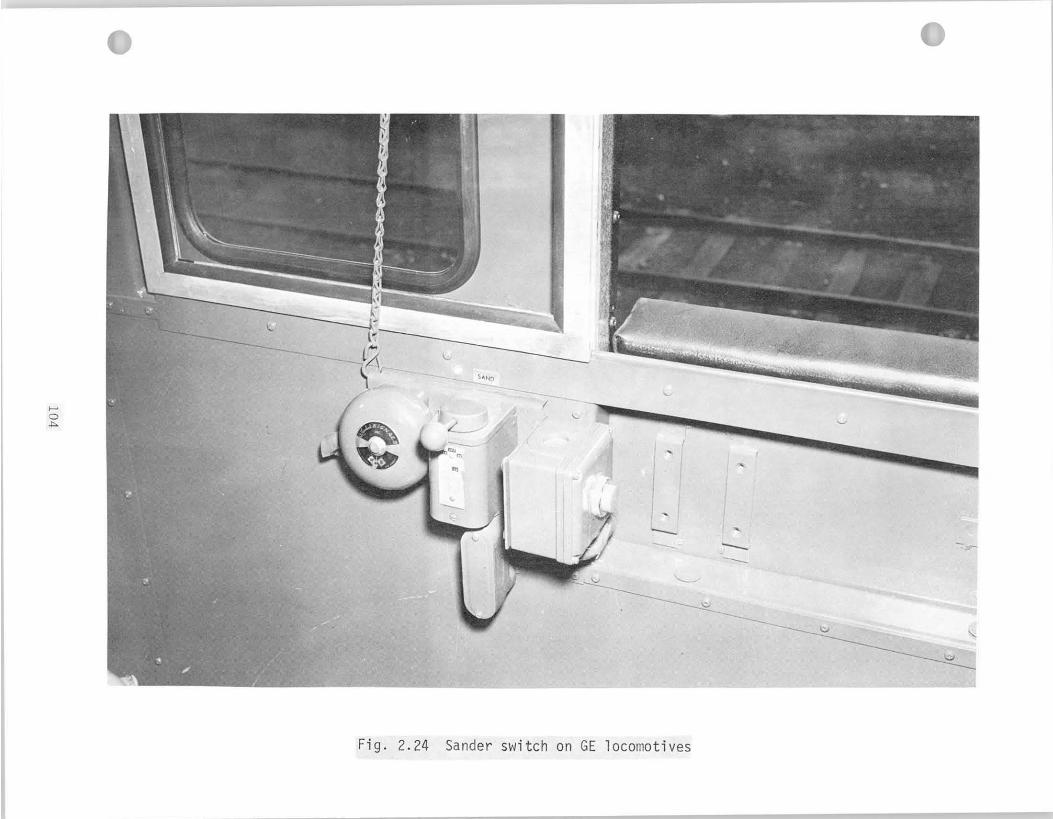
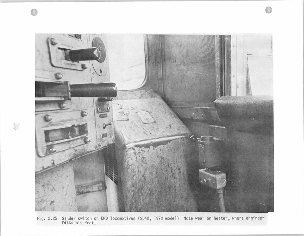
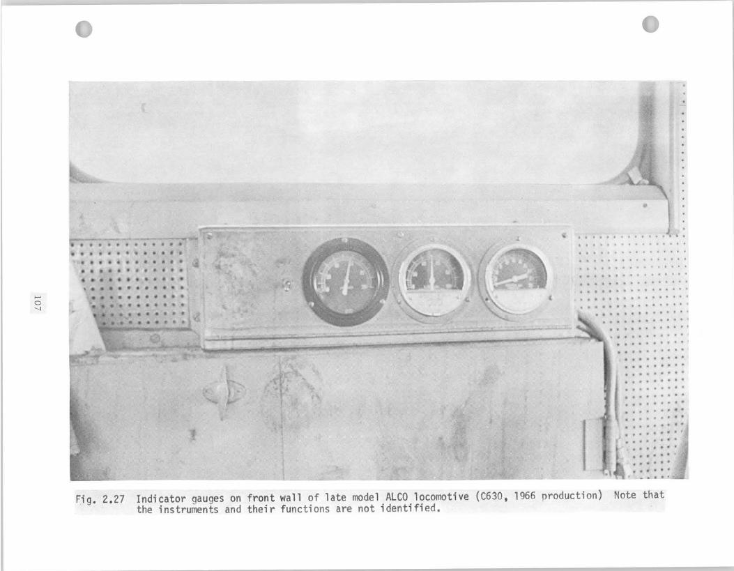
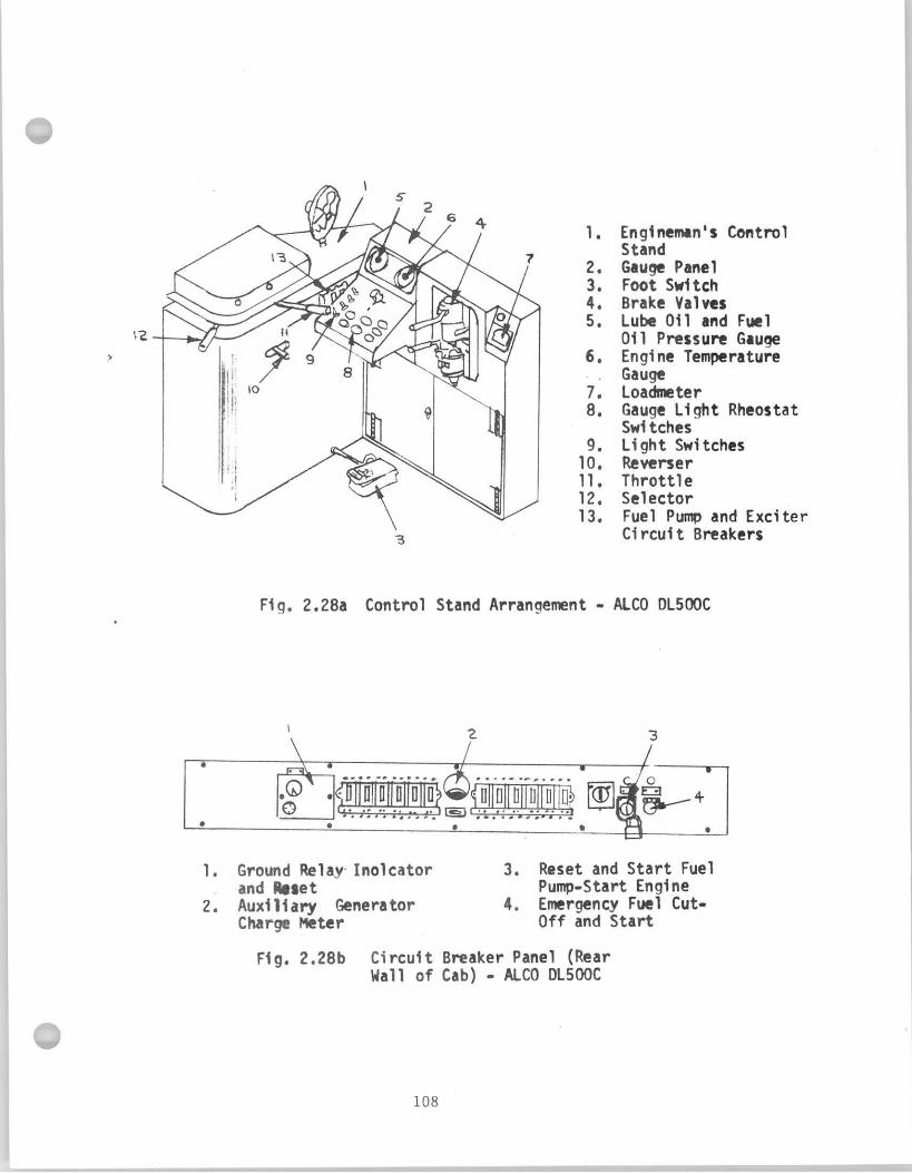
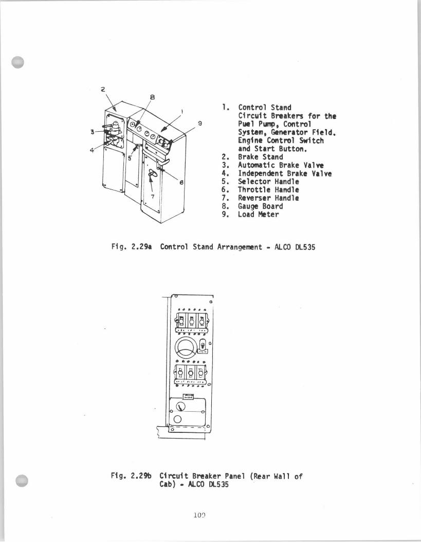
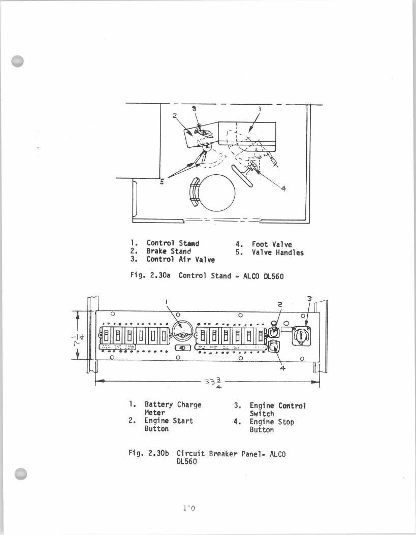
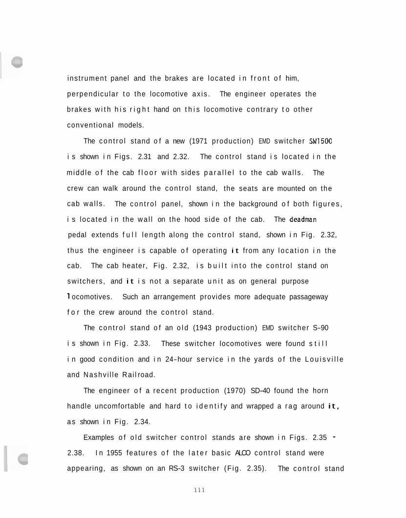
i ns t rument panel and the brakes are loca ted i n f r o n t o f him,
perpend icu la r t o the locomotive ax i s . The engineer operates the
brakes w i t h h i s r i g h t hand on t h i s locomotive con t ra ry t o o ther
convent ional models.
The c o n t r o l stand o f a new (1971 product ion) EMD swi tcher SW1500
i s shown i n F igs. 2.31 and 2.32. The con t ro l stand i s loca ted i n the
m idd le o f the cab f l o o r w i t h sides p a r a l l e l t o the cab wa l l s . The
crew can walk around the con t ro l stand, the seats are mounted on the
cab wa l l s . The c o n t r o l panel, shown i n the background o f both f i g u r e s ,
i s loca ted i n the w a l l on the hood s ide o f the cab. The deadman
pedal extends f u l l l eng th along the c o n t r o l stand, shown i n F ig. 2.32,
t hus the engineer i s capable o f operat ing i t from any l o c a t i o n i n the
cab. The cab heater, F ig . 2.32, i s b u i l t i n t o the con t ro l stand on
swi tchers , and i t i s no t a separate u n i t as on general purpose
1 ocomotives. Such an arrangement provides more adequate passageway
f o r the crew around the c o n t r o l stand.
The c o n t r o l stand o f an o l d (1943 product ion) EMD swi tcher S-90
i s shown i n F ig . 2.33. These swi tcher locomotives were found s t i l l
i n good cond i t i on and i n 24-hour serv ice i n the yards o f the L o u i s v i l l e
and Nashv i l l e Ra i l road.
The engineer o f a recent product ion (1970) SD-40 found the horn
handle uncomfortable and hard t o i d e n t i f y and wrapped a r a g around it,
a s shown i n F ig . 2.34.
Examples o f o l d swi tcher con t ro l stands are shown i n F igs. 2.35 - 2.38. I n 1955 fea tures o f the l a t e r basic ALCO con t ro l stand were
appearing, as shown on an RS-3 swi tcher (F ig . 2.35). The c o n t r o l stand
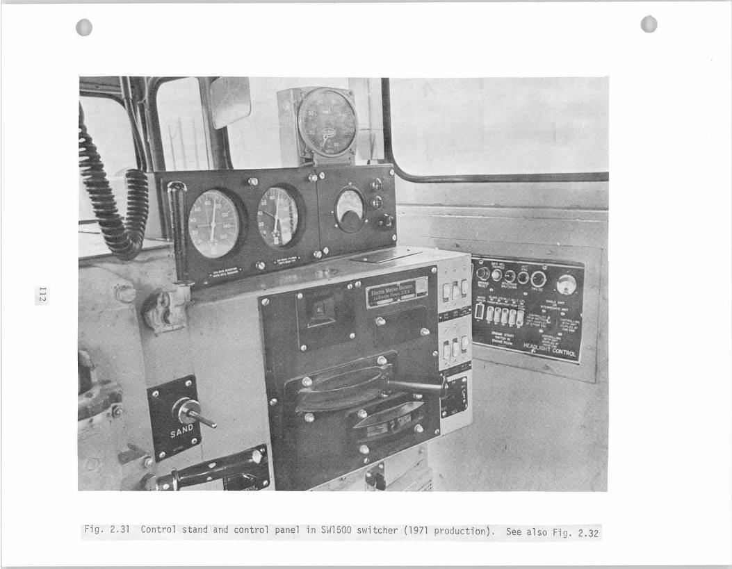
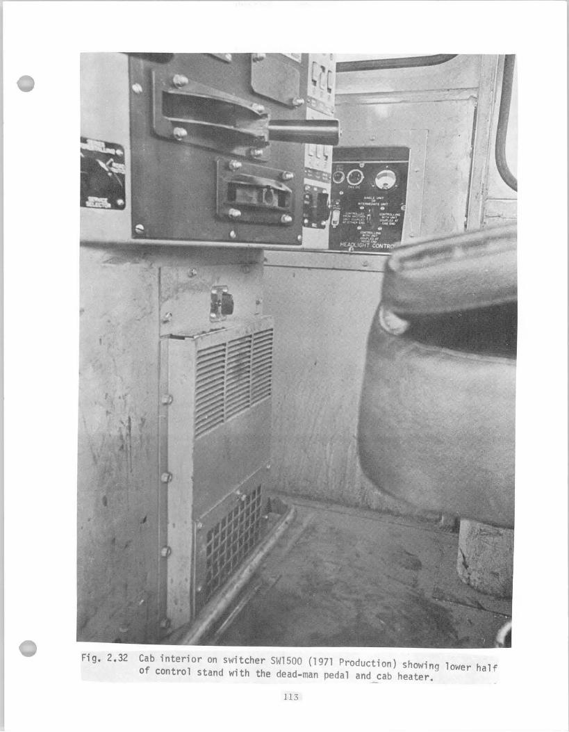
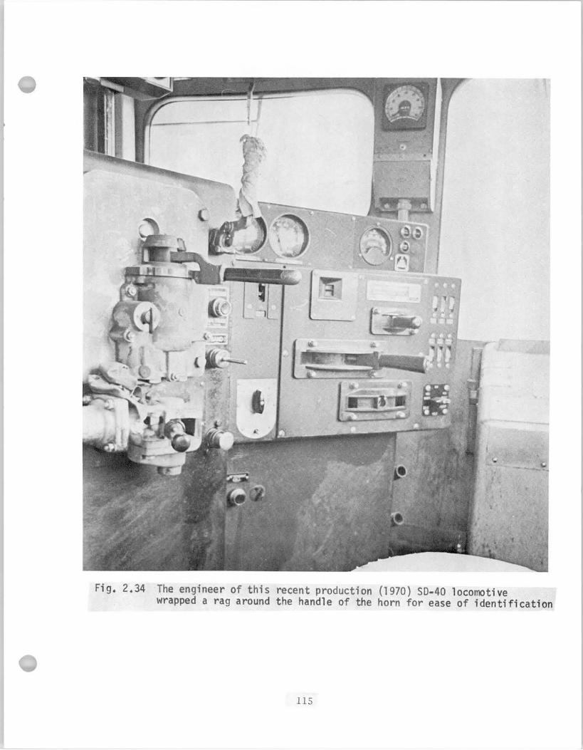
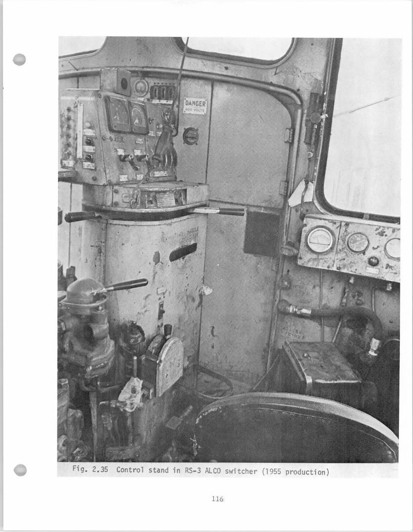
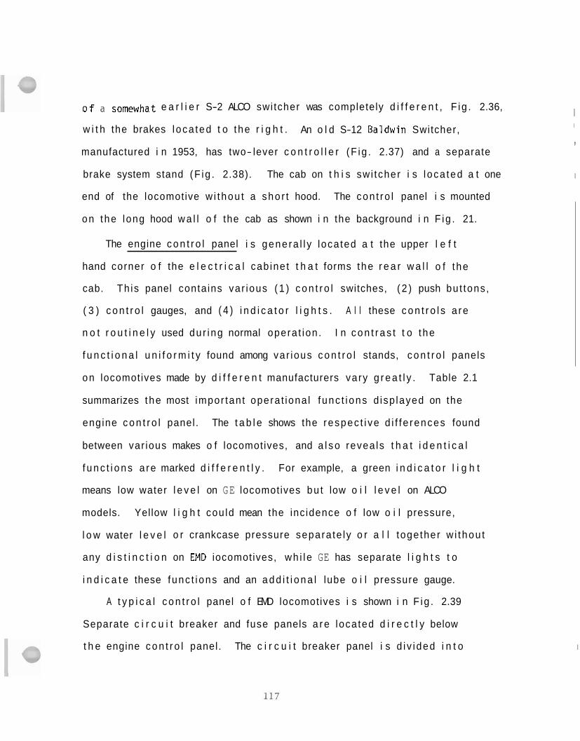
on locomotives made by d i f f e r e n t manufacturers vary g r e a t l y . Table 2.1
summarizes the most impor tan t opera t iona l f unc t i ons d isp layed on the
engine c o n t r o l panel. The t a b l e shows the respec t i ve d i f f e rences found
o f a somewhat e a r l i e r S-2 ALCO swi tcher was completely d i f f e r e n t , F ig . 2.36,
w i t h the brakes l oca ted t o t he r i g h t . An o l d S-12 Baldwin Switcher,
manufactured i n 1953, has two- lever c o n t r o l l e r (F ig . 2.37) and a separate
brake system stand (F ig . 2.38). The cab on t h i s sw i tcher i s l oca ted a t one
end of the locomotive w i thou t a sho r t hood. The con t ro l panel i s mounted
between var ious makes o f locomotives, and a l s o revea ls t h a t i d e n t i c a l
f u n c t i o n s a re marked d i f f e r e n t l y . For example, a green i n d i c a t o r l i g h t
means low water l e v e l on GE locomotives bu t low o i l l e v e l on ALCO
models. Yellow l i g h t cou ld mean the inc idence o f low o i l pressure,
l o w water l e v e l o r crankcase pressure separa te ly o r a l l toge ther w i thou t
any d i s t i n c t i o n on
on the long hood w a l l o f the cab as shown i n the background i n F ig . 21.
The engine c o n t r o l panel i s gene ra l l y loca ted a t the upper l e f t
hand corner o f the e l e c t r i c a l cab ine t t h a t forms the r e a r w a l l o f t he
cab. Th is panel conta ins var ious ( 1 ) c o n t r o l switches, ( 2 ) push bu t tons ,
( 3 ) c o n t r o l gauges, and ( 4 ) i n d i c a t o r l i g h t s . A l l these c o n t r o l s a re
n o t r o u t i n e l y used du r i ng normal opera t ion . I n c o n t r a s t t o t he
f u n c t i o n a l u n i f o r m i t y found among var ious c o n t r o l stands, c o n t r o l panels
EM0 iocomotives, wh i l e GE has separate l i g h t s t o
i n d i c a t e these func t i ons and an a d d i t i o n a l lube o i l pressure gauge.
A t y p i c a l c o n t r o l panel o f EMD locomotives i s shown i n F ig . 2.39
Separate c i r c u i t breaker and fuse panels a r e loca ted d i r e c t l y below
t h e engine c o n t r o l panel. The c i r c u i t breaker panel i s d i v i ded i n t o
;' I
,
I
I
I
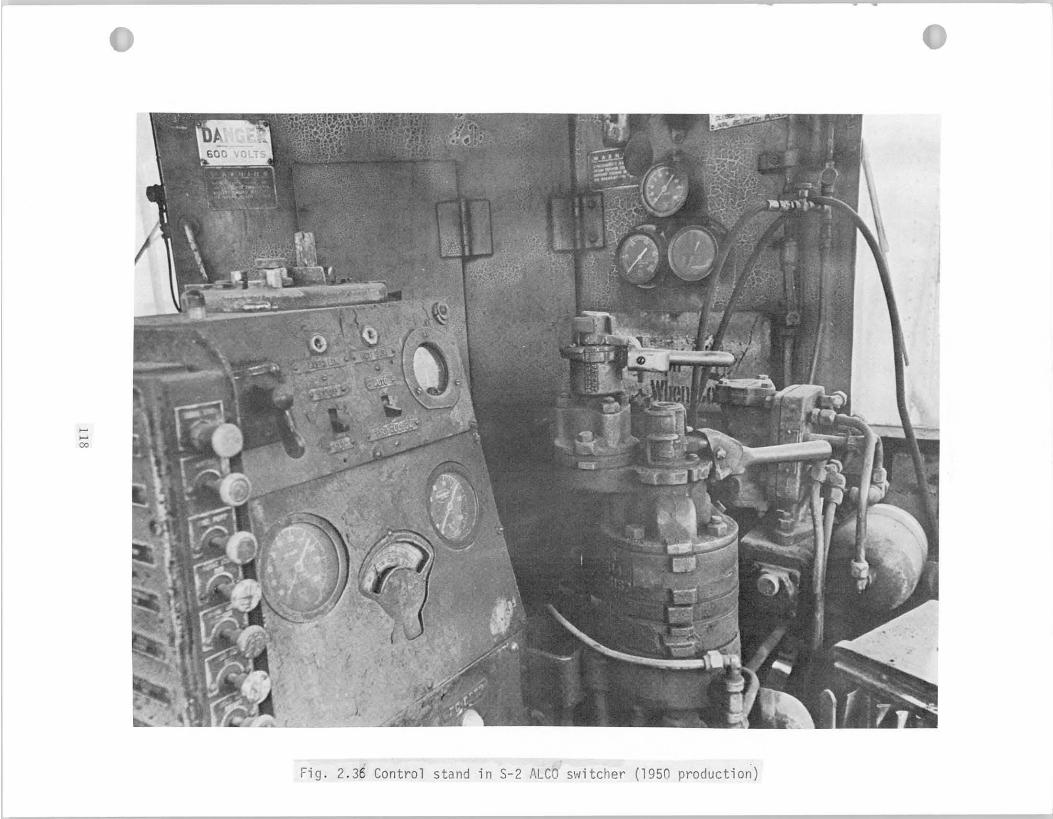
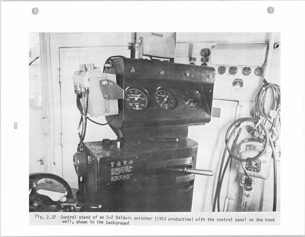
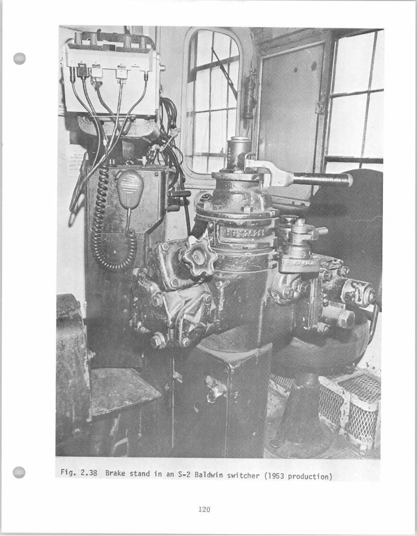
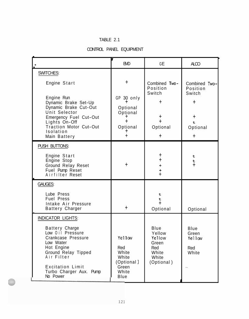
TABLE 2.1
CONTROL PANEL EQUIPMENT . * I EMD G E ALCO .-
SWITCHES:
Engine S t a r t + Combined Two- Combined Two- P o s i t i o n P o s i t i o n Switch Switch
Engine Run GP 30 o n l y Dynamic Brake Set-Up + + + Dynamic Brake Cut-Out Opt ional U n i t Se lec to r Opt ional Emergency Fuel Cut-Out + + + L i g h t s On-Off + + t Trac t i on Motor Cut-Out Opt ional Opt ional Opt ional I s o l a t i o n + Main B a t t e r y + + +
PUSH BUTTONS:
Engine S t a r t + t Engine Stop + t Ground Relay Reset + + + Fuel Pump Reset + A i r f i l t e r Reset + .
GAUGES:
Lube Press t Fuel Press t
In take A i r Pressure + Ba t te ry Charger + Opt ional Opt ional -
INDICATOR LIGHTS:
Ba t te ry Charge Blue Blue Low O i l Pressure Yellow Green Crankcase Pressure Ye1 1 ow Ye1 low Ye1 1 ow Low Water Green Hot Engine Red Red Red Ground Relay Tipped White White White A i r F i l t e r White White
(Opt ional ) (Opt ional ) E x c i t a t i o n L i m i t Green ~- Turbo Charger Aux. Pump White No Power Blue
1
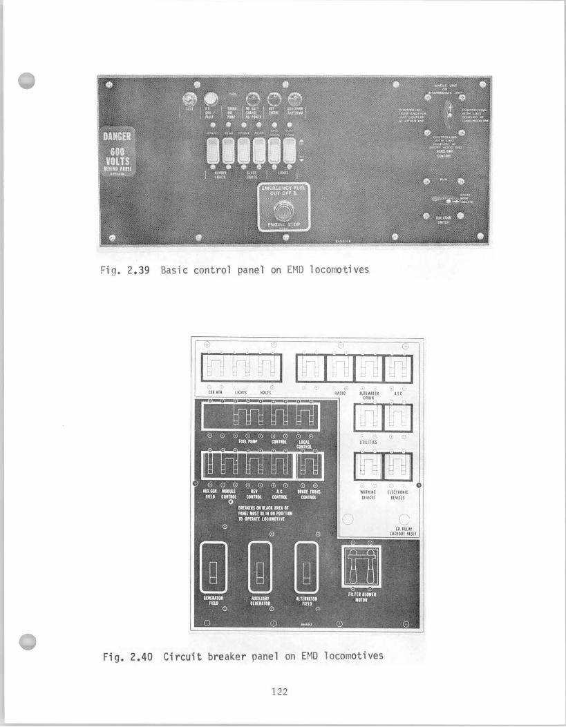
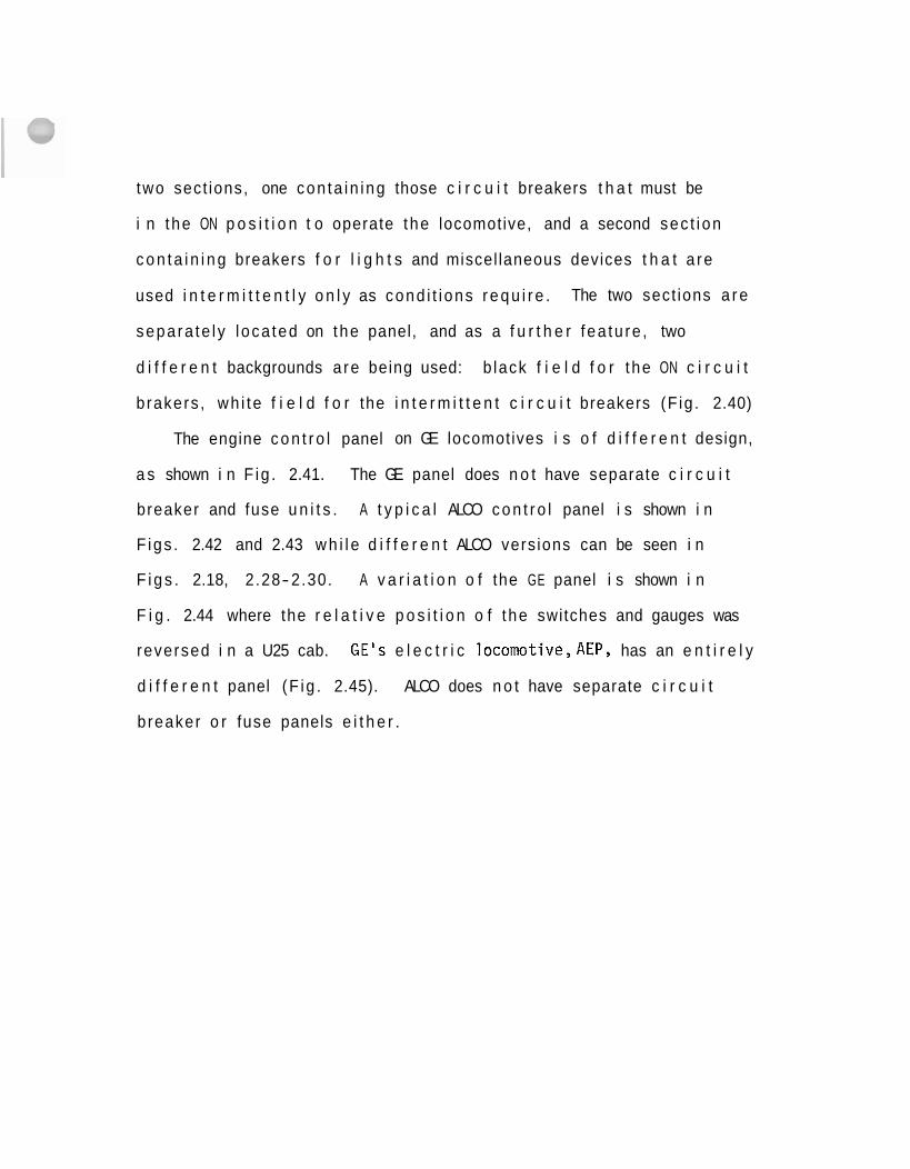
two sect ions, one con ta in ing those c i r c u i t breakers t h a t must be
i n t he ON p o s i t i o n t o operate t he locomotive, and a second sec t i on
c o n t a i n i n g breakers f o r l i g h t s and miscel laneous devices t h a t a re
used i n t e r m i t t e n t l y o n l y as cond i t i ons r e q u i r e . The two sect ions a r e
sepa ra te l y l oca ted on the panel, and as a f u r t h e r f ea tu re , two
d i f f e r e n t backgrounds a re being used: b lack f i e l d f o r t he ON c i r c u i t
b rakers , wh i te f i e l d f o r the i n t e r m i t t e n t c i r c u i t breakers (F ig . 2.40)
The engine c o n t r o l panel on GE locomotives i s o f d i f f e r e n t design,
a s shown i n F ig . 2.41. The GE panel does n o t have separate c i r c u i t
breaker and fuse u n i t s . A t y p i c a l ALCO c o n t r o l panel i s shown i n
F igs . 2.42 and 2.43 w h i l e d i f f e r e n t ALCO vers ions can be seen i n
F i g s . 2.18, 2.28-2.30. A v a r i a t i o n o f the GE panel i s shown i n
F i g . 2.44 where the r e l a t i v e p o s i t i o n o f t he switches and gauges was
reversed i n a U25 cab. GE's e l e c t r i c locomotive,AEP, has an e n t i r e l y
d i f f e r e n t panel (F ig . 2.45). ALCO does n o t have separate c i r c u i t
b reaker o r fuse panels e i t h e r .
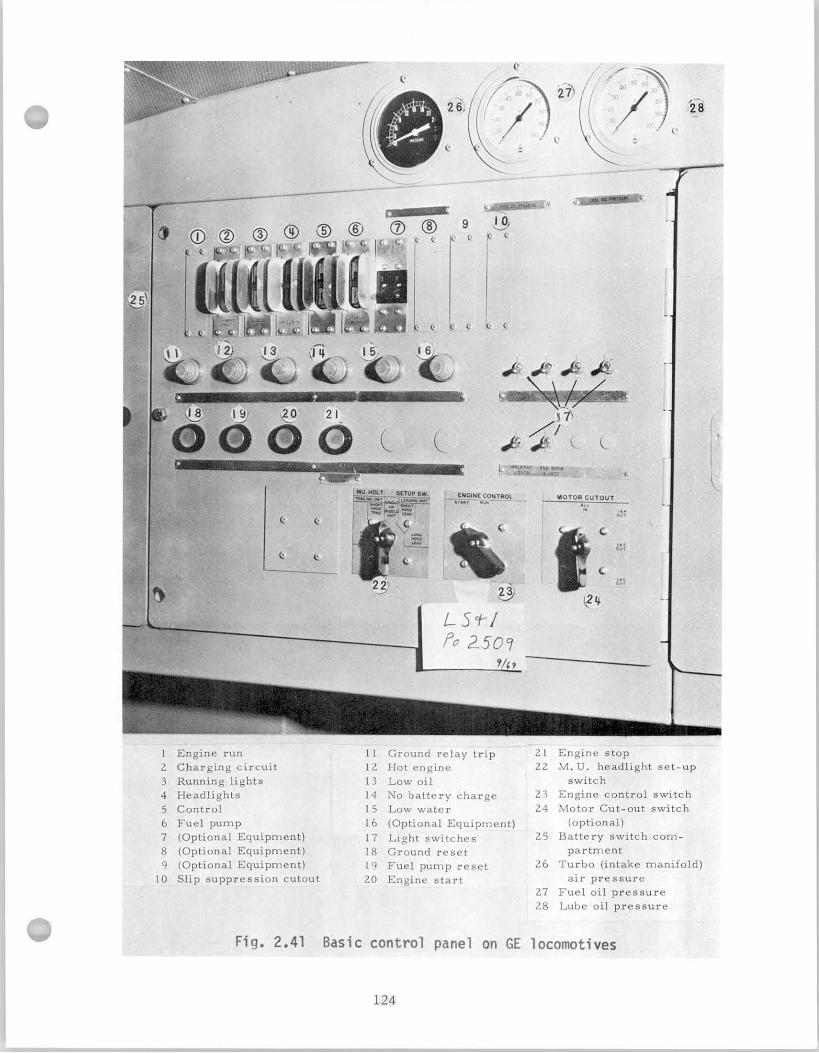
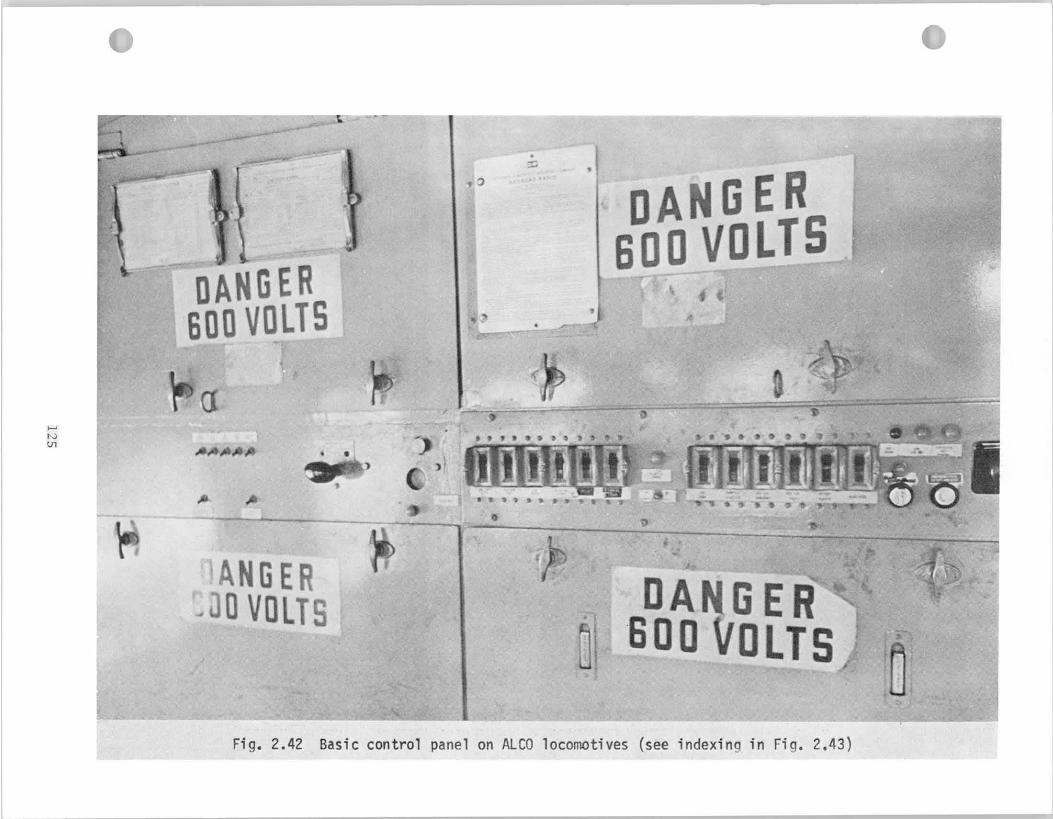
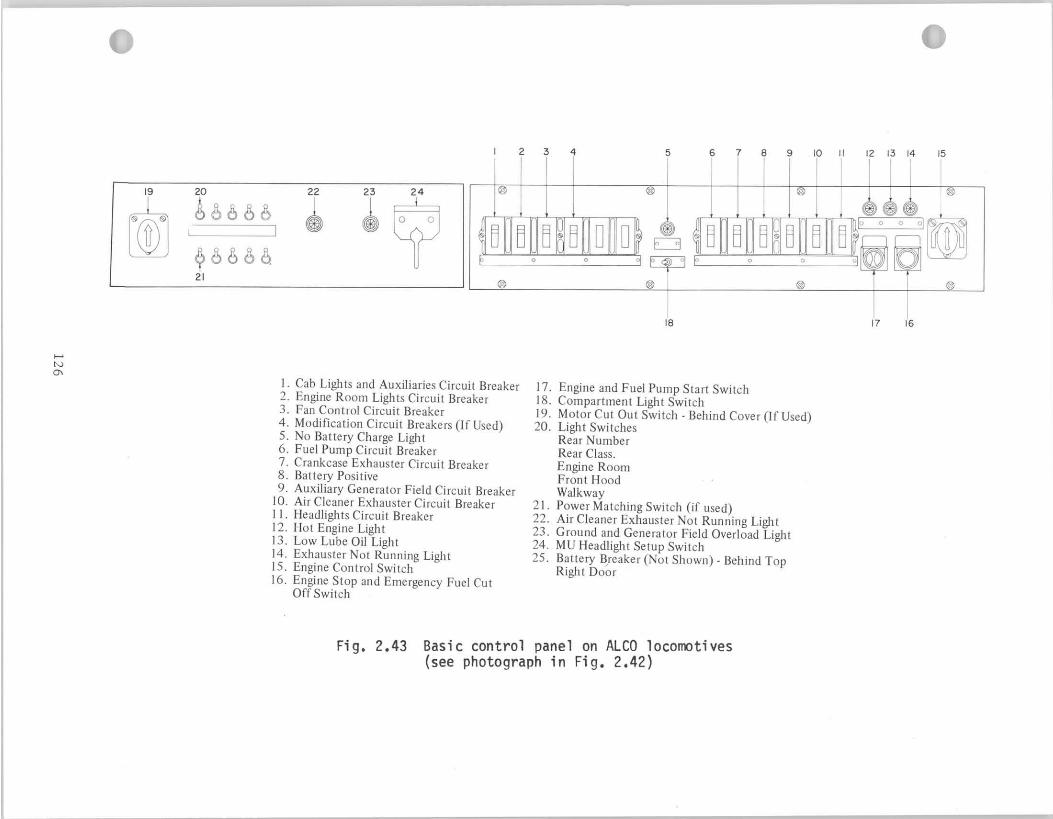
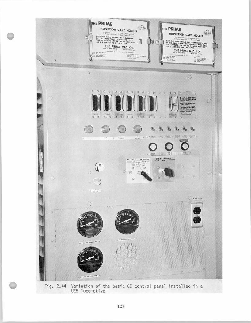
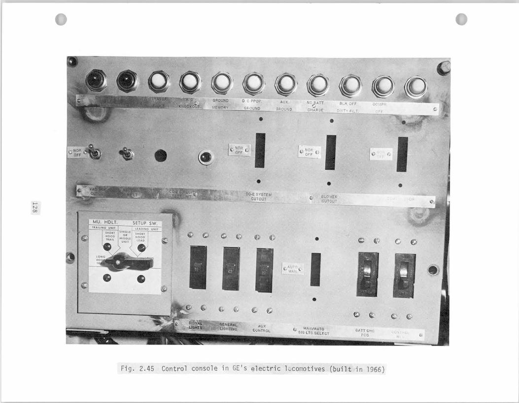
2 .3 Recommendations on Human Factors Desiqn of Contro ls
Two poss ib le approaches a re conceivable t o improve design o f
engine c o n t r o l s from the human f a c t o r s p o i n t o f view.
( 1 ) The f i r s t o f the two p o s s i b i l i t i e s concentrates on modi-
f i c a t i o n o f t he present c o n t r o l stand t o s u i t t he human operator
more s a t i s f a c t o r i l y and t o reduce p o s s i b i l i t y o f mistakes and mis-
i n t e r p r e t a t i o n o f i n d i c a t o r s . Such an approach has been taken by the
American Assoc ia t ion o f Rai l roads by e s t a b l i s h i n g recommendations f o r
a n improved standard c o n t r o l stand. The major manufacturers f o l 1 ow
t h i s l i n e o f ac t i on , as evidenced by the i n t r o d u c t i o n o f the new
i n t e r l o c k i n g EMD c o n t r o l l e r o r by GE i n developing and adapt ing an
AAR standard c o n t r o l console. Canadian Nat ional Railways a l s o
adapted the AAR standard. No d r a s t i c departures seem t o be planned
f rom the c l a s s i c basic design which has been i n use du r i ng
the l a s t decade. This approach has the advantages t h a t
no major changes a re requ i red i n t he present manufactur ing techniques
and t h a t i n t r o d u c t i o n o f the improved c o n t r o l console i s easy s ince
i t resembles prev ious designs c l o s e l y and, t he re fo re , locomot ive
engineers a re ab le t o operate t he locomotive immediately w i thou t any
t r a n s i t i o n a l compl icat ions o r need f o r spec ia l i n s t r u c t i o n s and t r a i n i n g .
However, such an approach has the disadvantages t h a t the mod i f i ca t i ons
c o n s t i t u t e improvements only , and the bes t poss ib le s o l u t i o n f rom the
human f a c t o r s engineer ing p o i n t o f view i s no t necessa r i l y achieved.
( 2 ) A second approach would be the cons t ruc t i on o f an e n t i r e l y
new design, w i t h l i t t l e or no regard t o t r ad i t i on , i n order t o develop
an ideal control system t o s u i t the operator optimally. In development
o f the control system, the nature, function, type and access ib i l i ty
of visual displays, controls , auditory displays, must be determined
a s a f i r s t step. Controls and displays which a r e t o be used most often
must be given f i r s t p r io r i ty as t o location on the control console.
Controls should be mounted fo r e f f i c i en t selection and manipulation
and in proper re la t ion t o the display they a f fec t . Controls t o be
used simultaneously require special consideration i n respect t o
operational convenience ( fo r example, positioning of the automatic and
independent brakes and the i r corresponding pressure gauges, or selector
and reverser) . Size of the instrument panel depends primarily upon the
normal arm reach of the human operator. In general, convenient arm
reach i s w i t h i n 28" from the respective shoulder When the
panel space needed to locate a l l controls exceeds a w i d t h of 44", a
f l a t surface, segmented wrap-around console i s recommended so a s t o
place a l l controls w i t h i n the reach of the seated operator. The to ta l
required le f t- to- r igh t viewing angle must not exceed 190°, however, t h i s
angle should be reduced wherever possible through appropriate control
d isplay layout. (93) Introduction of automatic control devices and in-cab
signal displaying systems would especially lend themselves t o be
incorporated i n t o a new type of control console. Such control systems
could not be used t o t h e i r f u l l advantage as add-on devices t o the
present controls. The displays and actuating controls must be designed
t o correspond t o human performance charac te r i s t i cs in order t o achieve - ; ~
/-
f u l l e f fec t iveness . (29 )
For f u r t h e r improvement o f the present designs o f c o n t r o l stands,
i t i s recommended t h a t the r a d i o and the remote con t ro l u n i t be b u i l t
i n t o the AAR standard c o n t r o l . Mounting o f these devices on the t o p
o f the con t ro l stand i s unacceptable because they obs t ruc t the eng ineer 's
f i e l d of view, t h e i r w i r i n g hangs loose and sharp edges, mounting
screws and brackets present unnecessary danger f o r the opera t ing
personnel. A l l d i a l i n d i c a t o r s should be o f the same s ize , c i r c u l a r
i n shape, w i t h the opera t ing p o s i t i o n o f the po in te rs p r e f e r a b l y i n
t h e 9 o ' c l o c k pos i t i on . Standardizat ion o f switches, push but tons
and i n d i c a t o r l i g h t s i s a l so recommended. Thei r l o c a t i o n should be
grouped func t i ona l l y .
Standardizat ion o f the c o n t r o l panel and engine s t a r t i n g procedure
i s a l s o recommended. Comparative study o f the c o n t r o l panels, as
discussed prev ious ly , shows t h a t s i g n i f i c a n t v a r i a t i o n s e x i s t between
t h e var ious locomotive models, and i d e n t i c a l i n d i c a t o r s a re p resen t l y
used f o r mon i to r ing d i f f e r e n t funct ions.
The speedometer i s n o t b u i l t i n t o the AAR standard stand. I n the
l a t e s t vers ion o f the Canadian Nat ional Railways cab design the speedometer
i s loca ted c e n t r a l l y above t h e f r o n t cab windows so t h a t i t i s v i s i b l e
t o a l l occupants of the cab. The meter face w i l l be arranged so as t o
a v o i d p a r a l l a x e r ro rs . This a p p l i c a t i o n i s i n an experimental stage on l y .
On e x i s t i n g models, the l a r g e housing o f the inst rument obs t ruc ts the engineer 's
fo rward view f requent ly , when mounted on the frame o f the f r o n t window.
Inco rpo ra t i on o f the speedometer i n t o the inst rument group on the AAR
standard seems t o be advantageous.
3. ATMOSPHERIC ENVIRONMENT I N LOCOMOTIVE CABS
3.1 Review o f L i t e r a t u r e on Cab Heat ing and V e n t i l a t i o n
Regulat ion o f the mic ro- c l imate i n t he cab i s essen t i a l f o r the
we l l - be ing o f t he locomot ive engineer. The cond i t i ons i n s i d e the
cab a re g r e a t l y in f luenced by the ou ts ide atmospheric cond i t i ons
because r a i l r o a d operat ions f r e q u e n t l y r e q u i r e t h a t the engineer open
h i s windows f o r extended per iods o f t ime. A i r c o n d i t i o n i n g has
l i m i t e d advantages under such cond i t ions . However, i t i s essen t i a l
t h a t t he cab be equipped w i t h good heat ing and d r a f t - f r e e v e n t i l a t i o n
system which the engineer can r e g u l a t e accord ing t o h i s own preference.
I n w in te r , cab temperature must be a t l e a s t 5g°F, o r poss ib l y 64-68OF.
To achieve even temperature d i s t r i b u t i o n , the use o f fans i s recommended. (49 1
The r a t e o f a i r exchange i n the cab must be a t l e a s t 1060 cu. f t / h o u r
and the h ighes t permiss ib le a i r v e l o c i t y i s recommended t o be 6.25 f t / s e c .
i n w in te r , 8.25 f t / s e c . i n the summer. A s l i g h t overpressure i s des i rab le
because i t prevents dus t and exhaust gases f rom e n t e r i n g the cab.
The I n t e r n a t i o n a l Union o f Rai l roads U . I C . ) recommends t h a t t he
a i r f l o w en te r t he cab through f i l t e r s and through the heat ing element,
and t h a t the a i r f l o w r a t e be ad jus tab le . A d r a f t f r e e c i r c u l a t i o n
p a t t e r n must be es tab l i shed i n t he cab by proper design o f the a i r o u t l e t s .
The heat ing system must be capable o f sus ta in ing 64-68'F, the minimum
pe rm iss ib le temperature i s 59°F i n t he cab. The heaters should be
p r e f e r a b l y equipped w i t h fans i n order t o p rov ide adequate heat ing when
t h e locomotive i s n o t i n motion. I n summer, a i r c o n d i t i o n i n g i s s t r o n g l y
recommended f o r high-speed opera t ion . When the ou ts ide temperature exceeds rl
86OF, t he i n s i d e o f t he cab must be 6- l l ° F below ou ts ide temperature.
The recommended value o f a i r exchange i s 1060 cu . f t /hour i n t he cab
w i t h an a i r v e l o c i t y o f 0.3-0.5 f t / s e c . i n w in te r , and 1.65 f t / s e c . i n
sumner. A s l i g h t overpressure i s recommended i n t he cab. (155)
Ample cab heat ing improves the general comfort o f the crew as i t
obv ia tes the necess i ty o f s h u t t i n g a l l windows t o ho ld a reasonable
work ing temperature i n c o l d weather. The p r o v i s i o n o f two heaters, one
a t the f o o t o f each d r i v i n g p o s i t i o n , i s t o be recommended i n t h i s
respec t . The heat i s l o c a l i z e d where i t i s most needed and can r i s e .
A s i n g l e heater a t t he r e a r o f t he cab can be most u n s a t i s f a c t o r y i n
t h i s respec t because the ou tpu t has t o be h igher than would otherwise
b e requ i red and the f a n must be o f s u f f i c i e n t capac i t y t o d i s t r i b u t e
t h e heat, o r t he engineman w i l l tend t o leave the d r i v i n g p o s i t i o n t o
s tand by i t . (36)
V e n t i l a t i o n problems become i n c r e a s i n g l y d i f f i c u l t w i t h t he increased
speeds o f modern locomotives. (15') Fresh a i r supply cannot be prov ided
any more through leakage o r by opening the windows. The a i r exchange
f a c i l i t y must be an i n t e g r a l p a r t o f the heat ing system. I ns ide
temperature i n the cab, which must always be viewed w i t h respec t t o t he
o u t s i d e temperature, i s a very impor tan t f a c t o r i n the we l l - be ing o f t he
engineer and has s i g n i f i c a n t e f f e c t s on h i s performance, e s p e c i a l l y on
v i g i l a n c e . I n 1969-70 the German Federal Railways experimented w i t h a new
cab v e n t i l a t i o n system. An i l l u s t r a t i o n o f t he German p r i n c i p l e s o f cab
a i r f l o w a re shown i n F ig . 3.1. The ou ts ide a i r en ters t he cab w a l l on the
f r o n t s i de o f the f l o o r l e v e l through a i r f i l t e r s . The a i r en ters t h e cab ~ 1
A
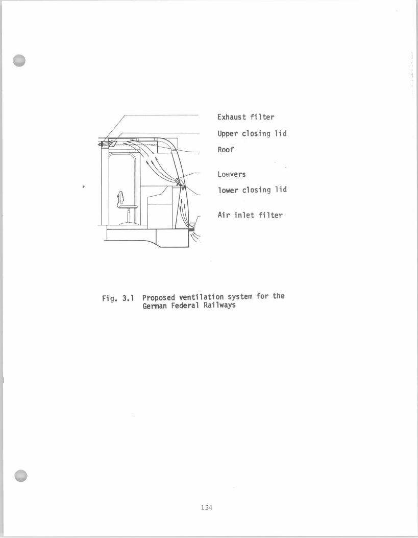
above the top o f the con t ro l desk through louvers which regu la te volume
and f l o w d i r e c t i o n and i t i s exhausted under the r o o f through ad jus tab le
l ouve rs . While the system was tes ted and evaluated i n p rac t i ce , the
engineers were n o t informed about the i n s t a l l a t i o n o f the new system
i n many cases and consequently d i d n o t a d j u s t i t adequately. I t was
a l s o found t h a t even by opening the louvers f u l l y the h ighes t a i r f l o w
v e l o c i t y was about 3 f t / s e c a t a d is tance o f 16" from the o u t l e t , which
was n o t s a t i s f a c t o r y on ho t days. Therefore, add i t i ona l improvements
were necessary. D i f f i c u l t y was found on the German Railways w i t h t h e
cab f l o o r i n s u l a t i o n . Even on the most recent e l e c t r i c locomotives
t h e f l o o r was uncomfortably c o l d du r ing the w in te r , e s p e c i a l l y i n the
a rea under the con t ro l desk, where the ope ra to r ' s f e e t were. Add i t i ona l
i n s u l a t i o n was necessary as w e l l as attempts t o improve the door and
window seals. The authors po in ted out t h a t good i n s u l a t i o n i s needed
around pipes lead ing i n t o the cab. These measures had no t been evaluated
b y the t ime o f p u b l i c a t i o n o f the paper (December, 1970). According
t o another German repo r t , summer v e n t i l a t i o n i s n o t a s i g n i f i c a n t problem
i n c i t y t r a n s i t cars; an a i r i n l e t on the r o o f and open windows are
adequate and do n o t expose the operator t o excess d r a f t . (122)
On the Po l i sh Railways some models o f e l e c t r i c locomotives do n o t
have c i r c u l a t i n g fans i n the cab. (79) Engineers o f these locomotives
complain about the l a c k o f s u f f i c i e n t v e n t i l a t i o n dur ing summer. However,
some o f t h e i r d i e s e l - e l e c t r i c locomotives have c i r c u l a t i n g fans: one
under the c o n t r o l desk, another under the roo f . The basic parameters o f
atmospheric cond i t ions i n the cab were a l s o studied: temperature, humidity,
a i r v e l o c i t y , and comfor t index dur ing w in te r and summer operat ions.
The c l i m a t i c cond i t ions i n the cab dur ing both w in te r and summer
were found t o be near the extreme l i m i t s of comfor t f o r e f f e c t i v e human
performance. The study showed t h a t good i n s u l a t i o n aga ins t c o l d i s
e s p e c i a l l y important i n the f l o o r and the f r o n t wa l l o f the cab and
t h a t an ad jus tab le heater i s needed c lose t o the eng ineer 's f e e t . The
s i z e o f t h e heaters should be designed t o correspond t o the heat l oss
r a t e o f the cab. The amount o f a i r contaminants Was a lso measured i n s i d e
t h e cab. Traces o f carbon oxides, lead and a c r o l e i n were observed both
i n summer and w in ter , b u t the concentrat ion l e v e l s d i d n o t exceed
recommended p u b l i c hea l th l i m i t s .
The Associat ion o f American Rai l roads had an i n v e s t i g a t i o n conducted
t o compare, i n terms o f c l i n i c a l and phys io log i ca l assessment, a group
o f 210 locomotive repairmen exposed t o d i e s e l exhaust w i t h a c o n t r o l
group o f 154 r a i l r o a d workers, matched f o r age, body s ize , past
extrapulmonary medical h i s t o r y and i n comparable j o b s ta tus b u t n o t having
t h e l e a s t occupat ional contac t w i t h d iese l exhaust products. (') Three
d i f f e r e n t engine houses were studied; the examined locomotive repairmen
who spent an average o f ten years on the j o b d i d n o t show any s i g n i f i c a n t
d i f f e r e n c e i n pulmonary f u n c t i o n performance from the c o n t r o l group.
A i r samples o f the environmental s tud ies i n two engine houses revealed
l e v e l s o f exposure t o several known cons t i t uen ts o f d iese l exhaust which
were w i t h i n the t o l e r a b l e l i m i t s o f these substances considered as separate
agents. The i n v e s t i g a t i o n , however, d i d f i n d a h igh frequency o f r e s p i r a t o r y
complaints, physical examination abnormal i t ies and decreased pulmonary

f u n c t i o n and performance i n c i g a r e t t e smokers compared t o non-smokers
r ega rd le s s of occupation.
3.2 Heating and Ventilation on Domestic Locomotives
EMD designs the thermal environment i n the locomotive cab with an
outside temperature of -30°F which i s based on the average Median of
Extremes north of the 45th Parallel in the United States. Cab
temperature a t t h i s outside temperature must be no less than 50°F
based on an AAR recommendation which s t ipu la tes :
"New locomotive cabs shall be provided w i . t h heating arrangements
tha t will maintain therein a temperature of not less than 50°F
taken a t approximately the center of the cab and based under
normal winter conditions above the 45th Parallel of the North
American Continent with normal running condition of the locomotive
with doors and windows closed."
The temperature gradient, i . e . the difference between outside and inside
temperature, taken a t shoulder height for a seated occupant along the
transverse center plane of the cab i s maintained to be as uniform as
possible showing no decline near the steel sidewalls. Based on t e s t
r e s u l t s , the forced convective character is t ics and dilution caused
by in f i l t r a t i on on a moving locomotive balance against the f r ee convective
charac te r i s t ics of a stationary locomotive, EMD found no difference in
t h e cab t o ambient a i r A T in a moving locomotive (40rniles/hr) vs.
a stationary loco'motive.
A hot water heating system i s standard equipment on EMD locomotives,
consist ing of a blower heater mounted in front of the engineer and a
blower heater mounted on the inboard side of the door in f ront of the brakeman.
Each heater has a three-speed fan control switch. In le t a i r i s drawn
i n t o the heater near the top and a i r i s discharged a t f loor level
toward the rear of the cab. Cab temperature will improve w i t h
regard t o a stationary locomotive when the u n i t i s under load a t
elevated t h r o t t l e notches and the heaters are i n proper working
condition ( i . e . , cores are n o t plugged).
The temperature dis t r ibut ion inside the cab i s shown i n Fig, 3.2.
According to the data in Fig. 3.2, the maximum re la t ive difference i s
93°F above outside temperature w i t h regular heaters, and i t i s
measured a t the engineer's side. Auxiliary heaters, i f ins ta l led , can
r a i s e the temperature u p to 103°F and provide a more uniform heat
d i s t r ibu t ion across the cab. The temperature dis t r ibut ion i s d i f fe ren t
i n a moving locomotive, as shown i n Fig. 3.3. However, the re la t ive
difference between inside and outside temperature i s not disadvantageously
affected.
About 80% of a l l locomotives bu i l t by EMD a r e equipped with the
standard hot water heaters. Two additional options a r e also available
w i t h the basic heaters: ( 1 ) sidewall convectors, and (2) an e l e c t r i c
c o i l supplement. The purpose of the sidewall convectors i s t o provide
a thermal screen between a cab occupant and the s teel sidewall t o negate
t he ch i l l ing e f fec t of radiant heat loss from the occupant t o the side-
wall . The average temperature r i s e achieved with sidewall convector
supplements i s 20°F giving a 105°F increase on a stationary locomotive
a t id le . The purpose of the e l ec t r i c coil supplement i s only t o improve
the cab-to-outside temperature difference. I t i s improved by 24°F using
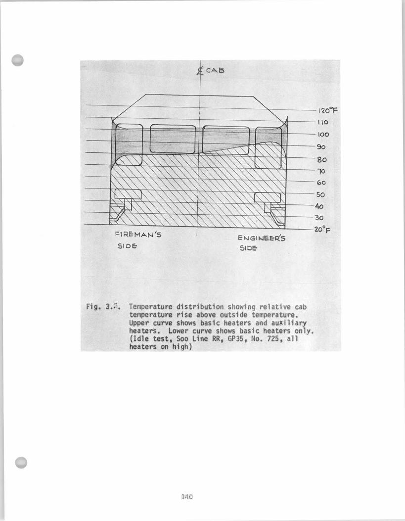
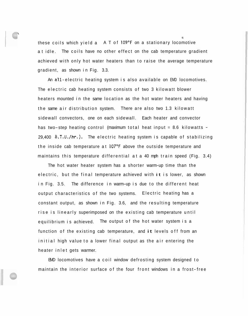
\
these c o i l s which y i e l d a A T o f 10g°F on a s t a t i o n a r y locomotive
a t i d l e . The c o i l s have no o ther e f f e c t on the cab temperature grad ien t
achieved w i t h o n l y h o t water heaters than t o r a i s e the average temperature
g rad ien t , as shown i n F ig . 3.3.
An a1 1 - e l e c t r i c heat ing system i s a l s o a v a i l a b l e on EMD locomotives.
The e l e c t r i c cab heat ing system cons is ts o f two 3 k i l o w a t t blower
heaters mounted i n the same l o c a t i o n as the h o t water heaters and having
t h e same a i r d i s t r i b u t i o n system. There a r e a l s o two 1.3 k i l o w a t t
s i dewa l l convectors, one on each s idewal l . Each heater and convector
has two-step heat ing con t ro l (maximum t o t a l heat i n p u t = 8.6 k i l o w a t t s -
29,400 B.T.U./hr.). The e l e c t r i c heat ing system i s capable o f s t a b i l i z i n g
t h e i n s i d e cab temperature a t 107OF above the ou ts ide temperature and
main ta ins t h i s temperature d i f f e r e n t i a l a t a 40 mph t r a i n speed (Fig. 3.4)
The h o t water heater system has a shor te r warm-up t ime than the
e l e c t r i c , b u t the f i n a l temperature achieved w i t h i t i s lower, as shown
i n F ig . 3.5. The d i f fe rence i n warm-up i s due t o the d i f f e r e n t heat
o u t p u t c h a r a c t e r i s t i c s o f the two systems. E l e c t r i c heat ing has a
cons tant output , as shown i n F ig . 3.6, and the r e s u l t i n g temperature
r i s e i s l i n e a r l y superimposed on the e x i s t i n g cab temperature u n t i l
e q u i l i b r i u m i s achieved. The output o f the h o t water system i s a
func t i on o f the e x i s t i n g cab temperature, and i t l e v e l s o f f from an
i n i t i a l h igh v a l u e t o a lower f i n a l ou tpu t as t h e a i r en te r i ng the
hea te r i n l e t gets warmer.
EMD locomotives have a c o i l window d e f r o s t i n g system designed t o
ma in ta in the i n t e r i o r sur face o f the four f r o n t windows i n a f r o s t - f r e e
..
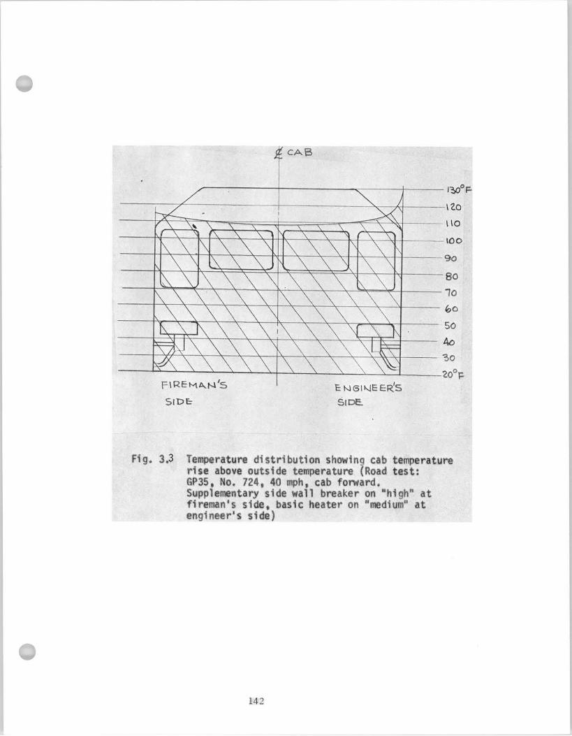
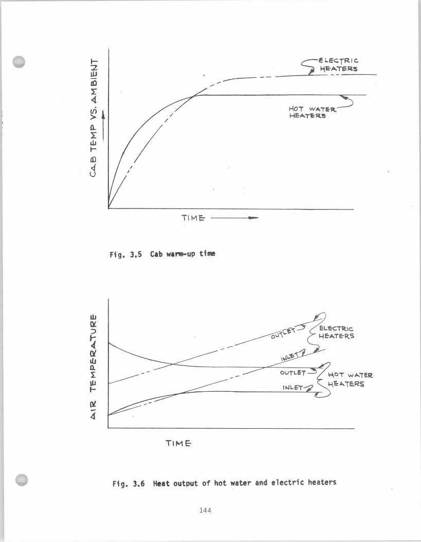
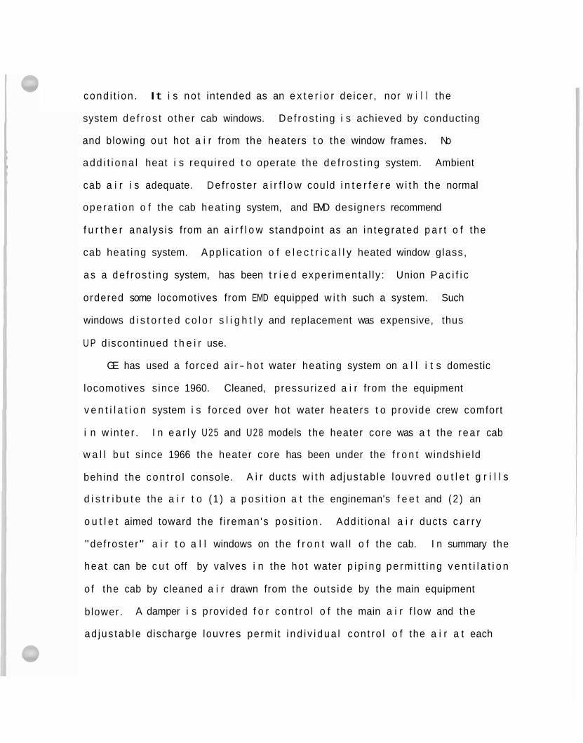
cond i t i on . It i s no t intended as an e x t e r i o r de icer , nor w i l l the
system d e f r o s t o ther cab windows. De f ros t i ng i s achieved by conduct ing
and blowing ou t hot a i r from the heaters t o the window frames. No
a d d i t i o n a l heat i s requ i red t o operate the d e f r o s t i n g system. Ambient
cab a i r i s adequate. Def ros ter a i r f l o w could i n t e r f e r e w i t h the normal
ope ra t i on o f the cab heat ing system, and EMD designers recommend
f u r t h e r ana lys is from an a i r f l o w standpoint as an i n teg ra ted p a r t o f the
cab heat ing system. App l i ca t i on o f e l e c t r i c a l l y heated window glass,
a s a d e f r o s t i n g system, has been t r i e d exper imenta l l y : Union P a c i f i c
ordered some locomotives from EMD equipped w i t h such a system. Such
windows d i s t o r t e d c o l o r s l i g h t l y and replacement was expensive, thus
U P d iscont inued t h e i r use.
GE has used a fo rced a i r - h o t water heat ing system on a l l i t s domestic
locomotives s ince 1960. Cleaned, pressur ized a i r f rom the equipment
v e n t i l a t i o n system i s fo rced over hot water heaters t o p rov ide crew comfort
i n w in te r . I n e a r l y U25 and U28 models the heater core was a t the r e a r cab
w a l l bu t s ince 1966 the heater core has been under the f r o n t windshie ld
behind the c o n t r o l console. A i r ducts w i t h ad jus tab le louvred o u t l e t g r i l l s
d i s t r i b u t e the a i r t o (1 ) a p o s i t i o n a t the engineman's f e e t and ( 2 ) an
o u t l e t aimed toward the f i reman 's pos i t i on . Add i t iona l a i r ducts c a r r y
"de f ros ter" a i r t o a l l windows on the f r o n t wa l l o f the cab. I n summary the
hea t can be c u t off by valves i n the ho t water p i p i n g p e r m i t t i n g v e n t i l a t i o n
o f the cab by cleaned a i r drawn from the outs ide by the main equipment
b lower. A damper i s prov ided f o r c o n t r o l o f the main a i r f l o w and the
ad jus tab le discharge louvres permi t i n d i v i d u a l con t ro l o f the a i r a t each
o p e r a t i n g p o s i t i o n . Supplemental e l e c t r i c heat ing can be and has been
prov ided i n some spec ia l a p p l i c a t i o n s such as the 1972 b u i l t U30C's f o r
t h e Union P a c i f i c Ra i l r oad Company.
Santa Fe has s t a r t e d experiment ing w i t h cab a i r c o n d i t i o n i n g systems.
Three u n i t s have been i n s t a l l e d so f a r on Santa Fe locomotives, and
f u r t h e r t e s t s a re scheduled f o r t he summer, 1972. The u n i t s a re
mounted on the top o f the cab, a i r i s r e c i r c u l a t e d and attempted t o
b e kept a t 80°F w i t h a r e l a t i v e humid i ty o f 50%. While t he re i s no
d i f fe rence i n i n t e r n a l cab cond i t i ons i n a moving vs. s t a t i o n a r y u n i t
f r o m a heat ing s tandpoint , t he re i s a d i f f e r e n c e from the s tandpo in t
o f a i r cond i t i on ing . Convection i n designing a i r c o n d i t i o n i n g i s l e s s
impor tan t than f o r heat ing, due t o about 20°F temperature d i f f e r e n c e
o n l y between i n s i d e and ou ts ide cond i t ions . However, i n f i l t r a t i o n
becomes ve ry impor tan t when cons ider ing a i r cond i t i on ing due t o the
l a r g e l a t e n t c o o l i n g loads created by the i n f i l t r a t e d ho t a i r . The
c o o l i n g capac i t y o f t he u n i t must be 30,000 B.T.U./hr i n o rder t o ma in ta in
t h e prescr ibed cab cond i t i ons o f 80°F a t 50 percent r e l a t i v e humid i ty
i n t he h igh ou ts ide temperature and humid i ty cond i t i ons encountered
i n t he South and Southeast. A i r d i s t r i b u t i o n must be such t h a t t he cab
occupants w i l l n o t be exposed t o c h i l l i n g d r a f t s , y e t cooled a i r w i l l
w ipe h o t i n t e r i o r surfaces t o a l l e v i a t e d i scomfo r t i ng r a d i a n t heat t o
t h e i n d i v i d u a l s occupying the cab. The locomotive cab a i r cond i t i one r
i s t h e r m o s t a t i c a l l y c o n t r o l l e d by means o f an ad jus tab le c o n t r o l loca ted
i n s i d e the a i r c o n d i t i o n i n g u n i t i n such a manner t h a t i t i s a v a i l a b l e
f o r adjustment by maintenance personnel on ly . This i s necess i ta ted by
cons tan t tampering by se rv i ce and opera t ing personnel.
/-*,
Improvement of heat ing and e l i m i n a t i o n o f d r a f t s c o n s t i t u t e a
s i g n i f i c a n t area i n development o f a standard cab by Canadian Nat ional
Rai lways. CNR has worked o u t recommendations f o r improved i n s u l a t i o n
i n s i d e and around the cab door, i n t he f l o o r and the r o o f , i n s i d e the
w a l l s and around the f r o n t corner posts (CNR P r o j e c t No. 7131, drawings
15-19). A f u l l - s c a l e mock-up i s now completed and one locomot ive has been
m o d i f i e d t o t e s t heat ing, de f ros t i ng , i n s u l a t i o n , and acous t ic t reatment .
The f i r s t purchase orders s p e c i f y i n g the new cab have been issued.
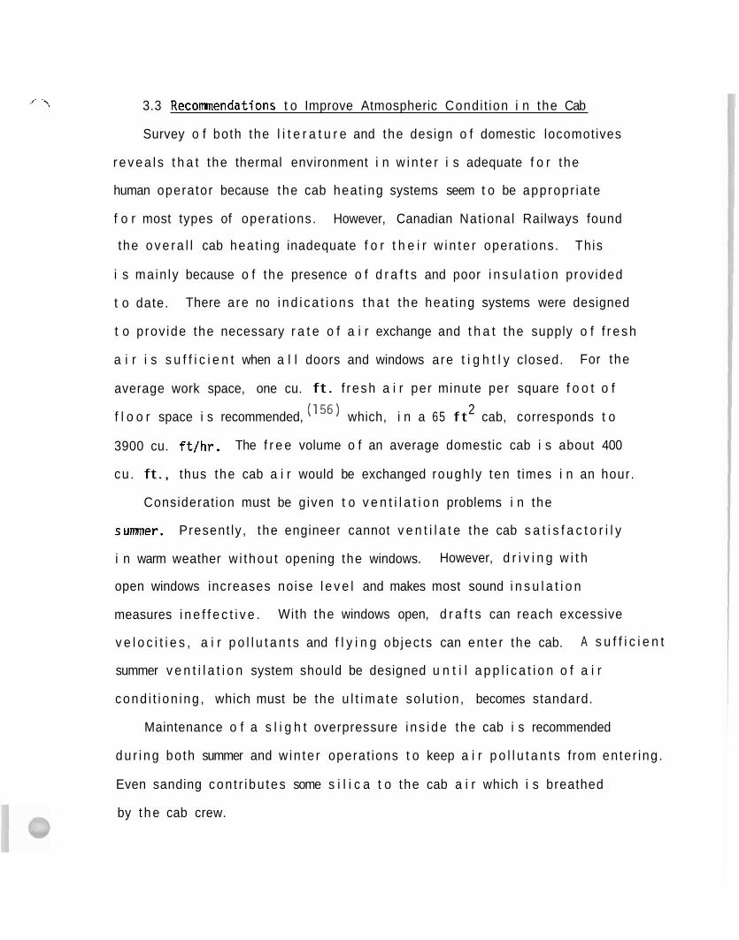
3.3 Reconanendations t o Improve Atmospheric Condi t ion i n the Cab
Survey o f both the l i t e r a t u r e and the design o f domestic locomotives
r e v e a l s t h a t the thermal environment i n w i n t e r i s adequate f o r the
human operator because the cab heat ing systems seem t o be appropr ia te
f o r most types of operat ions. However, Canadian Nat ional Railways found
the o v e r a l l cab heat ing inadequate f o r t h e i r w i n t e r operat ions. This
i s ma in ly because o f the presence o f d r a f t s and poor i n s u l a t i o n prov ided
t o date. There are no i n d i c a t i o n s t h a t the heat ing systems were designed
t o p rov ide the necessary r a t e o f a i r exchange and t h a t the supply o f f r e s h
a i r i s s u f f i c i e n t when a l l doors and windows are t i g h t l y closed. For the
average work space, one cu. ft. f resh a i r per minute per square f o o t o f
2 f l o o r space i s recommended, which, i n a 65 f t cab, corresponds t o
3900 cu. f t / h r . The f r e e volume o f an average domestic cab i s about 400
cu . ft., thus the cab a i r would be exchanged rough ly ten t imes i n an hour.
Considerat ion must be g iven t o v e n t i l a t i o n problems i n the
sumner. Present ly , the engineer cannot v e n t i l a t e the cab s a t i s f a c t o r i l y
i n warm weather w i thou t opening the windows. However, d r i v i n g w i t h
open windows increases noise l e v e l and makes most sound i n s u l a t i o n
measures i n e f f e c t i v e . With the windows open, d r a f t s can reach excessive
v e l o c i t i e s , a i r p o l l u t a n t s and f l y i n g ob jec ts can en te r the cab. A s u f f i c i e n t
summer v e n t i l a t i o n system should be designed u n t i l a p p l i c a t i o n o f a i r
cond i t i on ing , which must be the u l t i m a t e so lu t ion , becomes standard.
Maintenance o f a s l i g h t overpressure i n s i d e the cab i s recommended
d u r i n g bo th summer and w in te r operat ions t o keep a i r p o l l u t a n t s from enter ing .
Even sanding con t r i bu tes some s i l i c a t o the cab a i r which i s breathed
by t h e cab crew.
.x-i
Presently, the a i r brakes a r e vented inside the cab. This procedure
i s the source of the loudest noise in the cab and also s t i r s u p a
cloud of dust i n the cab. The brakes should vent outside the cab, b u t
brake act ivat ion sounds must not be completely eliminated from the cab,
because the engineer uses the sounds a s feedback fo r brake adjustment.
A t present, EMD makes available an a i r brake arrangement which vents the
automatic service and independent quick release exhaust ports outside of
t h e cab. However, t o date only one ra i l road specified t h i s braking
method.
4. NOISE AND VIBRATION I N LOCOMOTIVE CABS
4.1 Survey o f the L i t e r a t u r e
Noise: Analyses o f no ise problems i n locomotive cabs can be
d i v i d e d i n t o f o u r d i s t i n c t areas o f i n t e r e s t : (1 ) sound l e v e l i n s i d e
the cab, ( 2 ) sound l e v e l ou ts ide the cab, (3 ) no ise sources and t rans-
m i t t e r s , and (4 ) hear ing damage and a u d i t o r y physio logy r e l a t e d t o
1 ocomotive opera t ion .
Measurements and s tud ies o f i n s i d e and ou ts ide locomot ive noises
e s t a b l i s h the l e v e l o f sound pressure t o which the engineer i s exposed.
Ana l ys i s o f t he sources and t r a n s m i t t e r s o f no ise po in t s o u t poss ib le
means t o reduce sound l e v e l . (37) Studies concerning hear ing damage due
t o locomot ive noise show i f hear ing p r o t e c t i o n devices should be used
o n c e r t a i n locomotives o r i n var ious r a i l r o a d occupat ions.
A recen t domestic s tudy measured the sound environment as perceived
b y the crew members i n locomotive cabs. Both db(A) l e v e l s and
f requency band ana l ys i s were obta ined on an ALCO Model AGP-20-MSC
locomot ive o f t he Long I s l a n d Ra i l r oad i n commuting se rv i ce w i t h 45 mph
average speed, and on a t w i n p a i r o f EMD SD-45 locomotives o f t he S t .
Louis-San Francisco Railway i n f r e i g h t t r a i n opera t ion w i t h 60 mph
average speed. The study found t h a t t he pr imary source o f no ise i n t he
cab i s t he engine and t h a t wheel no ise i s l ess ob t rus ive . The cab
n o i s e averaged 90 db(A) on bo th locomotives. The no ise l e v e l increased
t o 93-98 db(A) when the horn was sounded (135 times/hour i n commuter
se rv i ce , 40 t imeslhour i n f r e i g h t se rv i ce ) . The octave band ana l ys i s
es tab l i shed t h a t engine noise cons i s t s o f most ly low frequency components,
r-\
and t h a t the a i r brakes produce very annoying h igh frequency sound
For the German Federal Railways, Zbora lsk i c a r r i e d o u t extensive
(158,159,160,161) no ise i n v e s t i g a t i o n over a pe r iod o f years. In one
o f the papers the i n t e l l i g i b i l i t y o f acoust ica l s i gna ls i n the noise
environment o f sw i tch ing locomotive was inves t iga ted . The i n f l uence
o f the frequency spectrum o f noise and s igna ls , masking e f f e c t s ,
c learness o f s y l l a b l e s and sentences on a u d i b i l i t y o f vo ice
comnunications was analyzed. Sound i n s u l a t i o n techniques used on the
German V60 swi tcher t o reduce noise i n the eng ineer 's cab are descr ibed.
A noise l e v e l between 85 t o 95 phon i s suggested t o be an upper l i m i t
i n cabs w i t h open windows, f o r i n t e l l i g i b i l i t y o f speech. The
measurements i n d i c a t e t h a t the h ighes t sound l e v e l values va r ied between
6 8 t o 84 phons from i d l e t o f u l l load c o n d i t i o n o f the engine. (161)
D e t a i l s o f the c o r r e c t technique o f no ise measurement a re described
separa te ly . (I5') Noise was measured i n the cab o f two d iese l locomotives
w i t h closed windows a t i d l e , h a l f t h r o t t l e , and f u l l t h r o t t l e and a t
6 0 mph speed. Octave band ana lys is o f the cab noise revealed t h a t
i n t e n s i t y of sounds i n the 50-100Hz range i s very high, b u t t h i s f a c t
does n o t show up i n measurements w i t h the db(A) scale because o f the cu t-
o f f f i l t e r i n g c h a r a c t e r i s t i c s o f the db(A) standard. The d i f f e r e n c e i s
sometimes as much as 32 db. Noise on the locomotive i s produced by the
combustion process i n the engine, by exhaust and a i r in take, by the a i r
compressor, coo l i ng f a n and the r o l l i n g motion on the whee l- ra i l i n t e r f a c e
Noise l e v e l s i n o the r d iese l locomotives o f the German Railways were
found t o be near the th resho ld f o r producing permanent hear ing l oss dur ing
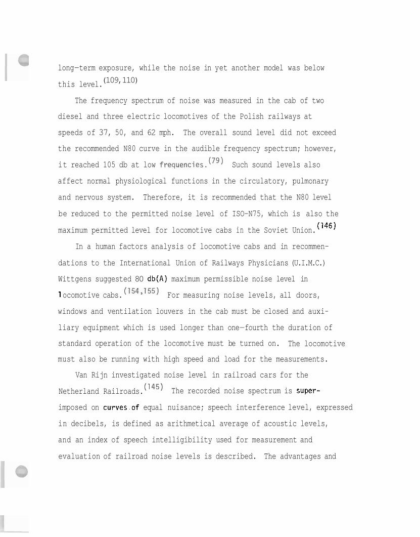
long-term exposure, while the noise in yet another model was below
(109,110) this level.
The frequency spectrum of noise was measured in the cab of two
diesel and three electric locomotives of the Polish railways at
speeds of 37, 50, and 62 mph. The overall sound level did not exceed
the recommended N80 curve in the audible frequency spectrum; however,
it reached 105 db at low frequencies.(79) Such sound levels also
affect normal physiological functions in the circulatory, pulmonary
and nervous system. Therefore, it is recommended that the N80 level
be reduced to the permitted noise level of ISO-N75, which is also the
maximum permitted level for locomotive cabs in the Soviet Union. (146)
In a human factors analysis of locomotive cabs and in recommen-
dations to the International Union of Railways Physicians (U.I.M.C.)
Wittgens suggested 80 db(A) maximum permissible noise level in
1 ocomotive cabs. (1543155) For measuring noise levels, all doors,
windows and ventilation louvers in the cab must be closed and auxi-
liary equipment which is used longer than one-fourth the duration of
standard operation of the locomotive must be turned on. The locomotive
must also be running with high speed and load for the measurements.
Van Rijn investigated noise level in railroad cars for the
Netherland Railroads. The recorded noise spectrum is super-
imposed on curves.of equal nuisance; speech interference level, expressed
in decibels, is defined as arithmetical average of acoustic levels,
and an index of speech intelligibility used for measurement and
evaluation of railroad noise levels is described. The advantages and
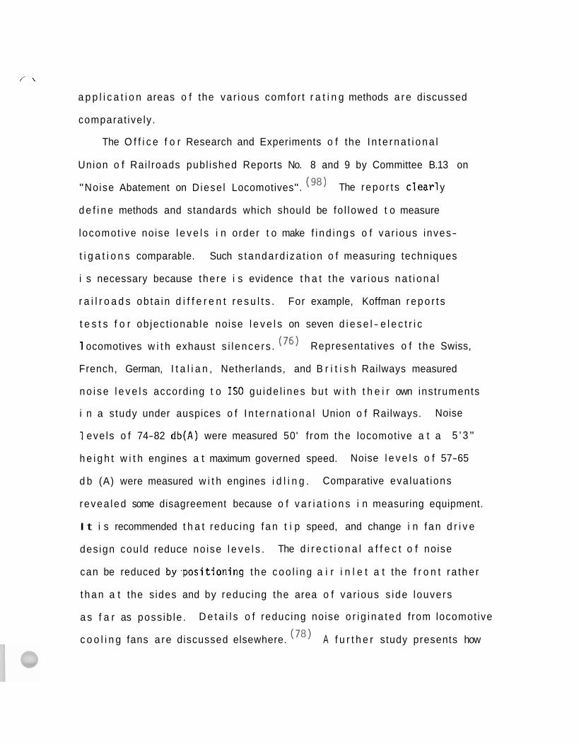
,'- \ a p p l i c a t i o n areas o f the var ious comfor t r a t i n g methods a r e discussed
comparat ive ly .
The O f f i c e f o r Research and Experiments o f the I n t e r n a t i o n a l
Union o f Rai l roads publ ished Reports No. 8 and 9 by Committee B.13 on
"Noise Abatement on D iese l Locomotives". (98) The repo r t s c l ea r1 y
d e f i n e methods and standards which should be fo l lowed t o measure
locomot ive noise l e v e l s i n order t o make f i n d i n g s o f var ious inves-
t i g a t i o n s comparable. Such s tanda rd i za t i on o f measuring techniques
i s necessary because the re i s evidence t h a t t he var ious n a t i o n a l
r a i l r o a d s ob ta in d i f f e r e n t r e s u l t s . For example, Koffman r e p o r t s
t e s t s f o r ob jec t ionab le noise l e v e l s on seven d i e s e l - e l e c t r i c
1 ocomotives w i t h exhaust s i l ence rs . (76) Representat ives o f t he Swiss,
French, German, I t a l i a n , Netherlands, and B r i t i s h Railways measured
n o i s e l e v e l s accord ing t o IS0 gu ide l i nes bu t w i t h t h e i r own inst ruments
i n a s tudy under auspices o f I n t e r n a t i o n a l Union o f Railways. Noise
1 eve ls o f 74-82 db(A) were measured 50' f rom the locomotive a t a 5 ' 3 "
h e i g h t w i t h engines a t maximum governed speed. Noise l e v e l s o f 57-65
d b (A) were measured w i t h engines i d l i n g . Comparative eva lua t ions
revea led some disagreement because o f v a r i a t i o n s i n measuring equipment.
I t i s recommended t h a t reducing f a n t i p speed, and change i n f a n d r i v e
des ign cou ld reduce no ise l e v e l s . The d i r e c t i o n a l a f f e c t o f no ise
can be reduced b y . p o s i t i o n i n g the c o o l i n g a i r i n l e t a t the f r o n t ra the r
t h a n a t the s ides and by reducing the area o f var ious s ide louvers
a s f a r as poss ib le . D e t a i l s o f reducing noise o r i g i n a t e d f rom locomot ive
c o o l i n g fans a re discussed elsewhere. (78) A f u r t h e r study presents how
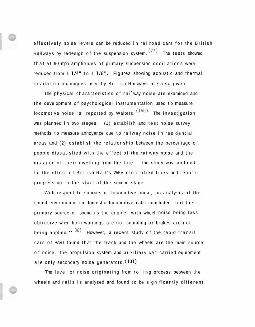
e f f e c t i v e l y no ise l e v e l s can be reduced i n r a i l r o a d cars f o r t he B r i t i s h
Rai lways by redesign o f the suspension system. ( 77 ) The t e s t s showed
t h a t a t 90 mph ampl i tudes o f pr imary suspension o s c i l l a t i o n s were
reduced f rom - + 1/4" t o - + 1/8". F igures showing acous t ic and thermal
i n s u l a t i o n techniques used by B r i t i s h Railways a re a l s o given.
The phys ica l c h a r a c t e r i s t i c s o f r a i 1 way noise a re examined and
t h e development o f psychologica l ins t rumenta t ion used t o measure
locomot ive no ise i s repor ted by Walters. (150) The i n v e s t i g a t i o n
was planned i n two stages: (1) e s t a b l i s h and t e s t no ise survey
methods t o measure annoyance due t o r a i l w a y noise i n r e s i d e n t i a l
areas and (2 ) e s t a b l i s h the r e l a t i o n s h i p between the percentage o f
people d i s s a t i s f i e d w i t h t he e f f e c t o f t he r a i l w a y noise and the
d i s t a n c e o f t h e i r d w e l l i n g from the l i n e . The study was conf ined
t o t he e f f e c t o f B r i t i s h R a i l ' s 25KV e l e c t r i f i e d l i n e s and r e p o r t s
progress up t o the s t a r t o f t he second stage.
With respec t t o sources o f locomot ive noise, an ana l ys i s o f t he
sound environment i n domestic locomotive cabs concluded t h a t t he
p r imary source o f sound i s the engine, w i t h wheel no ise being l e s s
o b t r u s i v e when horn warnings a re n o t sounding o r brakes a re n o t
b e i n g appl ied." 36) However, a recent study o f the r a p i d t r a n s i t
c a r s o f BART found t h a t the t r a c k and the wheels a re the main source
o f noise, the propu ls ion system and a u x i l i a r y ca r- ca r r i ed equipment
a r e o n l y secondary noise genera tors . (101)
The l e v e l o f no ise o r i g i n a t i n g from r o l l i n g process between the
wheels and r a i l s i s analyzed and found t o be s i g n i f i c a n t l y d i f f e r e n t
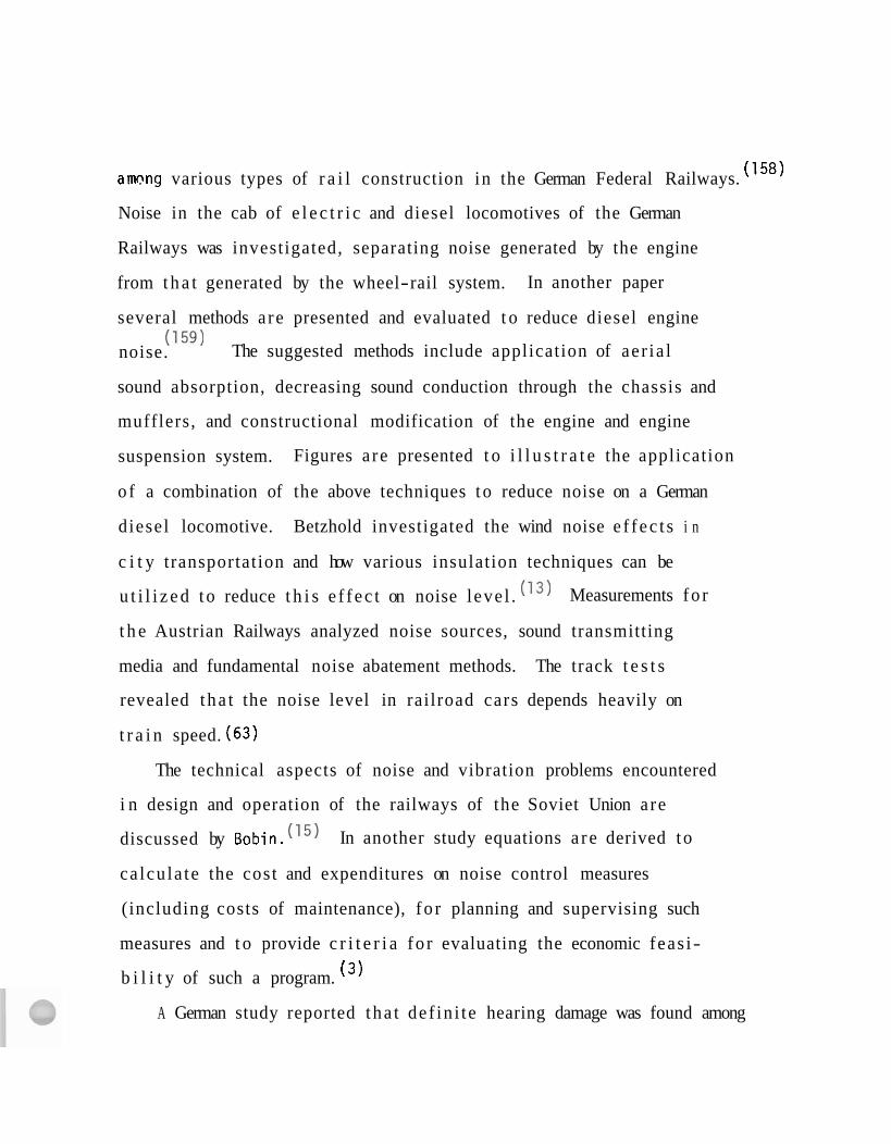
ammg various types of r a i l construction in the German Federal Railways. (158)
Noise in the cab of e l e c t r i c and diesel locomotives of the German
Railways was investigated, separating noise generated by the engine
from t h a t generated by the wheel-rail system. In another paper
several methods a re presented and evaluated t o reduce diesel engine
(I5') noise. The suggested methods include application of ae r ia l
sound absorption, decreasing sound conduction through the chassis and
mufflers, and constructional modification of the engine and engine
suspension system. Figures a re presented t o i l l u s t r a t e the application
o f a combination of the above techniques t o reduce noise on a German
diesel locomotive. Betzhold investigated the wind noise e f f ec t s i n
c i t y transportation and how various insulation techniques can be
u t i l i z e d t o reduce t h i s e f f ec t on noise leve l . ( I 3 ) Measurements fo r
t h e Austrian Railways analyzed noise sources, sound transmitting
media and fundamental noise abatement methods. The track t e s t s
revealed t ha t the noise level in rai lroad cars depends heavily on
t r a i n speed. (63)
The technical aspects of noise and vibration problems encountered
i n design and operation of the railways of the Soviet Union a re
discussed by Bobin. ( I5 ) In another study equations a r e derived to
ca lcu la te the cost and expenditures on noise control measures
( including costs of maintenance), f o r planning and supervising such
measures and t o provide c r i t e r i a fo r evaluating the economic feas i-
b i l i t y of such a program. (3 )
A German study reported t ha t def in i te hearing damage was found among
1 ,198 r a i l r o a d workers. Two separate age groups were d i f f e r e n t i a t e d
i n the i n v e s t i g a t i o n : workers under 35 years o f age, and those above
t h a t age. Hearing damage was found t o be i ncu r red much more r a p i d l y
among the o lde r than the young i n d i v i d u a l s . The o l d e r group su f fe red
hea r ing l oss as e a r l y as s i x years a f t e r exposure, wh i l e the same
l e v e l s o f hear ing l oss were reached i n 10 t o 15 years o f exposure
i n t h e younger group. It i s deduced from the f i n d i n g s t h a t o l d e r
people should be excluded from high-noise working cond i t ions . Minimum
hear ing th resho ld curves are drawn, arranged i n age groups up t o 50
yea rs t o i l l u s t r a t e the p o i n t . The f i n d i n g s are r e l a t e d t o cond i t i ons
t h a t apply i n the change-over from steam t o d iese l engine operat ion.
Noise exposure o f d iese l engine repairmen i n a s e r v i c i n g shop
showed t h a t no ise s t ress i s caused most ly by s tay ing i n t h e engine
room where the motor i s running slow o r i d l e . ( ' l o ) The study con-
c luded t h a t i n d i v i d u a l hear ing p r o t e c t i o n devices must be worn i n
o r d e r t o reduce noise l e v e l s below r i s k range and t o prevent the
development o f permanent hear ing damage.
I n an American study, h igh noise l e v e l s have been observed i n
r a i l r o a d cabooses which make r a d i o communication d i f f i c u l t , endanger
hear ing, and genera l l y degrade working cond i t ions f o r the crew. (151)
The paper discusses var ious methods used t o reduce noise l e v e l s from
a Speech In te r fe rence Level (SIL) o f 82.5 db t o SIL o f 68.6 db. The
n o i s e spectrum f i n a l l y achieved compares favorab ly w i t h no ise i n the
f i r s t - c l a s s cab in o f l a r g e commercial j e t a i r l i n e r s . The r e l a t i v e
importance o f v i b r a t i o n i n s u l a t i o n , s t r u c t u r a l damping and acoust ic
absorption techniques a s noise reduction measures i s discussed.
Techniques of equipping hearing protection devices w i t h an individual
bu i l t - in warning radio transmitter were investigated fo r the German
Railroads. (84) The transmitter was t o be used simultaneously with
hearing protection devices on track laying equipment i n high noise
l eve l s . Various models were evaluated t o f ind an ergonomically
optimal weight d i s t r ibu t ion . Problems were experienced w i t h good
f i xa t i on and even dis t r ibut ion of weight on the sku l l .
Vibration: In general, comfort levels of a person exposed t o
v ibrat ion a r e expressed on a plot of maximum tolerable acceleration
a s a function of vibration frequency. The acceleration required t o
induce a given level of sensation in the body changes markedly with
frequency, being a minimum ( i .e . , the body i s most sens i t ive) a t
frequencies between 2 and 20 (and par t icular ly around 4-6)Hz . Discomfort
i s caused by resonance and muscular s t ra in of large segments of body
masses, such a s the various organs. Man t r i e s t o overcome discomfort
by tightening the appropriate body muscles which brings on fatigue.
A t lower frequencies the body reacts a s a single mass, and the comfort
level depends primarily on the r a t e of acceleration. A t higher frequencies,
between 20 and 30Hz , the head resonates, par t icular ly on a s i t t i n g
person, w i t h consequent deterioration of visual acui ty in addition t o
physical discomfort. A t these higher frequencies comfort i s proportional
t o maximum vibration velocity. Of course, position of the person
( s i t t i n g or standing) and direction o f vibration (ve r t i ca l , t ransverse,
o r horizontal ) are a1 so important factors : resonance of various body
/7
i- \
parts in a standing person a re somewhat more damped than fo r a
seated person under vert ical vibratory loads, and a standing man i s
considerably more s table t o l a te ra l vibrations than his seated
counterpart . (27,931
The f i r s t vibration s tudies , concerning application t o the r a i l -
roads and passenger comfort, were published ear ly in 1935 and 1940
b u t a r e s t i l l quoted frequently. (25y26) A n AAR report uses generalized
vibrat ion tolerance data fo r rai lroad application. ( 5 ) In t h i s report
and a l so in a Bri t ish study(*) vehicle r iding qua l i t i es a re deduced
from accelerometer recordings. Vertical and horizontal vibration
s e n s i t i v i t i e s of the human body a re separated t o determine riding
comfort levels fo r British Railways. In another study, low frequency
vibrat ions were measured fo r the Brit ish Railways from p o i n t of view
o f passengers' comfort a s reported a t the 13th Congress of the
International Union of Railroad Physicians (U. I.M.C.). (123) No
v ibrat ion component was found under 1 Hz. I t was a lso pointed out
t h a t discomforting vibration conditions can be s ign i f ican t ly modified
by increasing the distance between the car axles.
Vibration levels i n the cab of two types of diesel and three types
o f e l e c t r i c locomotives of the Polish Railways were measured in the
frequency range of 31.5 Hz t o 4000 Hz. (79) The experiments established
t h a t the acceleration level increases with increased t ra in speed from
2 37 mph t o 62 mph. Accelerations between 0.5-1.6 m/sec (0.05-.163g) were
found, which a re well within the recommended values for human exposure,
a s shown in Fig. 4.4, b u t s t i l l above the acceleration level of 2
0.8m/sec
(0.0829) permitted above 30 Hz in the Soviet Union for cabs on new
locomotives.(97) Due consideration must be given to the fact that
the human body is relatively unaffected by vibration above lOHz,
while it is most sensitive to low frequency accelerations between 2
and 6Hz.
For the Japanese National Railways a large number of measurements
of vertical accelerations were taken on the floor of six New Toraido
Line cars, just above the truck centers. (88389y144) The lateral
and vertical accelerations were both found to rise almost linearly
with speed averaging about 0.129 at 150 mph, between the frequencies
of one and two HZ.
Hanes summarized vibration problems for the U. S. Urban Mass
Transportation Administration. (54) The report lists a number of
references pertaining to passenger comfort conditions. Another
domestic report also contains an extensive list of references on
the vibrational comfort 1 imits in high-speed ground transportation. (28)
A recent study investigated limits of acceleration levels and found
comfortable 0.11-0.159 for longitudinal, 0.06-0.229 for lateral
acceleration^.(^') These levels are, however, suggested for review
in future application because they are about 0.10g lower than those
accepted by automobile users.
Various comfort indeces have been devised to express human
comfort or discomfort during vibration. A TRW Inc. report summarizes
the indeces for application in steel-wheel-on-steel-rail systems with
speeds in the 200-300 mph range. The threshold of comfort 1 imits / \
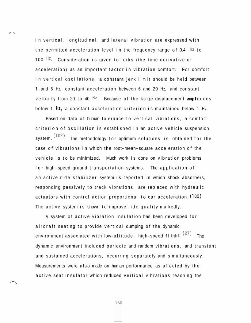
/-\
i n v e r t i c a l , l o n g i t u d i n a l , and l a t e r a l v i b r a t i o n a re expressed w i t h
t h e permi t ted acce le ra t i on l e v e l i n the frequency range o f 0.4 Hz t o
100 Hz. Considerat ion i s g iven t o j e r k s ( the t ime d e r i v a t i v e o f
a c c e l e r a t i o n ) as an impor tan t f a c t o r i n v i b r a t i o n comfor t . For comfor t
i n v e r t i c a l o s c i l l a t i o n s , a constant j e r k l i m i t should be he ld between
1 and 6 Hz, constant acce le ra t i on between 6 and 20 Hz, and constant
v e l o c i t y f rom 20 t o 40 Hz. Because o f t he l a r g e displacement amp1 i t udes
below 1 Hz, a constant a c c e l e r a t i o n c r i t e r i o n i s maintained below 1 Hz.
Based on data o f human to le rance t o v e r t i c a l v i b r a t i o n s , a comfor t
c r i t e r i o n o f o s c i l l a t i o n i s es tab l i shed i n an a c t i v e v e h i c l e suspension
system. ( l o 2 ) The methodology f o r optimum s o l u t i o n s i s obta ined f o r t he
case o f v i b r a t i o n s i n which the root-mean-square a c c e l e r a t i o n o f t he
v e h i c l e i s t o be minimized. Much work i s done on v i b r a t i o n problems
f o r high-speed ground t r a n s p o r t a t i o n systems. The a p p l i c a t i o n o f
a n a c t i v e r i d e s t a b i l i z e r system i s repor ted i n which shock absorbers,
responding pass i ve l y t o t r a c k v i b r a t i o n s , a re replaced w i t h hyd rau l i c
a c t u a t o r s w i t h c o n t r o l a c t i o n p ropo r t i ona l t o ca r acce le ra t i on . (100)
The a c t i v e system i s shown t o improve r i d e q u a l i t y markedly.
A system o f a c t i v e v i b r a t i o n i n s u l a t i o n has been developed f o r
a i r c r a f t sea t i ng t o p rov ide v e r t i c a l dumping o f t he dynamic
environment associated w i t h low-a1 t i t u d e , high-speed f l igh t . (27) The
dynamic environment inc luded p e r i o d i c and random v i b r a t i o n s , and t r a n s i e n t
and susta ined acce le ra t ions , occur r ing separa te ly and s imul taneously .
Measurements were a l s o made on human performance as a f f e c t e d by the
a c t i v e seat i n s u l a t o r which reduced v e r t i c a l v i b r a t i o n s reaching the ,'-\
t o r s o t o comfor table l e v e l s b u t r e s u l t e d i n r e l a t i v e motion between
t h e man and the c o n t r o l s and instruments. No s i g n i f i c a n t d i f f e r e n c e
was found i n t r a c k i n g e r r o r r e s u l t s when the i s o l a t i o n system was
employed, a1 though the sub jec t i ve comfor t l e v e l was g r e a t l y improved.
The system can be t a i l o r e d t o meet a v a r i e t y o f environmental and
i s o l a t i o n requirements o the r than those associated w i t h a i r c r a f t ,
f o r example as suggested i n t he paper, suspension systems o f o f f -
the- road veh i c les and high-speed t r a i n s .
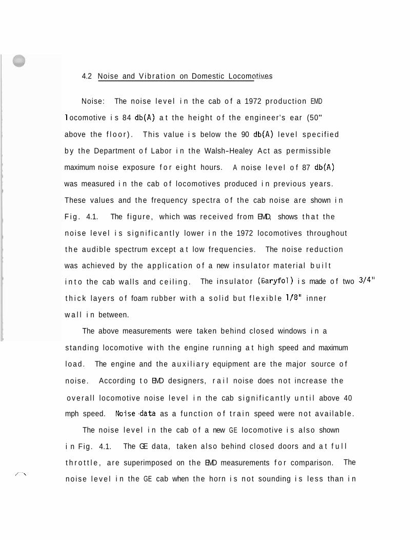
4.2 Noise and V i b r a t i o n on Domestic Locomotives -
Noise: The noise l e v e l i n t he cab o f a 1972 produc t ion EMD
1 ocomotive i s 84 db(A) a t t he he igh t o f t he eng ineer 's ear (50"
above the f l o o r ) . Th is va lue i s below the 90 db(A) l e v e l s p e c i f i e d
b y the Department o f Labor i n t he Walsh-Healey Ac t as permiss ib le
maximum no ise exposure f o r e i g h t hours. A noise l e v e l o f 87 db(A)
was measured i n the cab o f locomotives produced i n prev ious years.
These values and the frequency spectra o f t he cab noise a re shown i n
F i g . 4.1. The f i g u r e , which was rece ived f rom EMD, shows t h a t t he
n o i s e l e v e l i s s i g n i f i c a n t l y lower i n t he 1972 locomotives throughout
t h e aud ib le spectrum except a t low f requencies. The noise reduc t i on
was achieved by the a p p l i c a t i o n o f a new i n s u l a t o r ma te r i a l b u i l t
i n t o the cab w a l l s and c e i l i n g . The i n s u l a t o r ( 6 a r y f o l ) i s made o f two 3/4"
t h i c k l aye rs o f foam rubber w i t h a s o l i d b u t f l e x i b l e 1/8" i nne r
w a l l i n between.
The above measurements were taken behind c losed windows i n a
s tand ing locomotive w i t h t he engine runn ing a t h igh speed and maximum
l o a d . The engine and the a u x i l i a r y equipment a re t he major source o f
no ise . According t o EMD designers, r a i l no ise does n o t increase t h e
o v e r a l l locomot ive noise l e v e l i n the cab s i g n i f i c a n t l y u n t i l above 40
mph speed. Noise.data as a f u n c t i o n o f t r a i n speed were n o t a v a i l a b l e .
The noise l e v e l i n the cab o f a new GE locomot ive i s a l s o shown
i n F ig . 4.1. The GE data, taken a l s o behind c losed doors and a t f u l l
t h r o t t l e , a r e superimposed on the EMD measurements f o r comparison. The
n o i s e l e v e l i n the GE cab when the horn i s n o t sounding i s l e s s than i n ,*-\
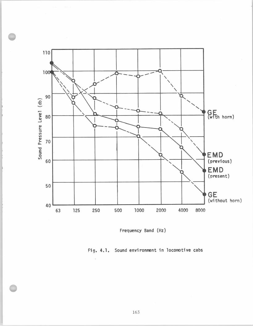
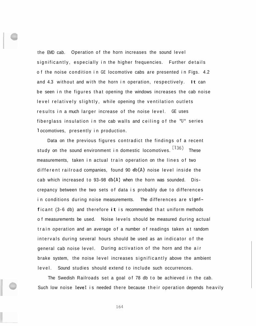
the EMD cab. Operat ion o f the horn increases the sound l e v e l
s i g n i f i c a n t l y , e s p e c i a l l y i n the h igher frequencies. Fur ther d e t a i l s
o f the noise c o n d i t i o n i n GE locomotive cabs are presented i n Figs. 4.2
and 4.3 w i thou t and w i t h the horn i n operat ion, respec t i ve l y . I t can
be seen i n the f i g u r e s t h a t opening the windows increases the cab no ise
l e v e l r e l a t i v e l y s l i g h t l y , wh i l e opening the v e n t i l a t i o n o u t l e t s
r e s u l t s i n a much l a r g e r increase o f the noise l e v e l . GE uses
f i b e r g l a s s i n s u l a t i o n i n the cab w a l l s and c e i l i n g o f the "U" se r ies
1 ocomotives, p resen t l y i n product ion.
Data on the prev ious f i g u r e s c o n t r a d i c t the f i n d i n g s o f a recent
s tudy on the sound environment i n domestic locomotives. 36) These
measurements, taken i n ac tua l t r a i n opera t ion on the l i n e s o f two
d i f f e r e n t r a i l r o a d companies, found 90 db(A) noise l e v e l i n s i d e the
cab which increased t o 93-98 db(A) when the horn was sounded. Dis-
crepancy between the two sets o f data i s probably due t o d i f f e rences
i n cond i t ions du r ing noise measurements. The d i f f e rences a r e s i g n i -
f i c a n t (3-6 db) and the re fo re i t i s recommended t h a t un i fo rm methods
o f measurements be used. Noise l e v e l s should be measured du r ing ac tua l
t r a i n opera t ion and an average o f a number o f readings taken a t random
i n t e r v a l s du r ing several hours should be used as an i n d i c a t o r o f the
general cab no ise l e v e l . Dur ing a c t i v a t i o n o f the horn and the a i r
brake system, the noise l e v e l increases s i g n i f i c a n t l y above the ambient
l e v e l . Sound studies should extend t o i nc lude such occurrences.
The Swedish Rai l roads se t a goal o f 78 db t o be achieved i n the cab.
Such low noise l e v e l i s needed the re because t h e i r opera t ion depends h e a v i l y
I
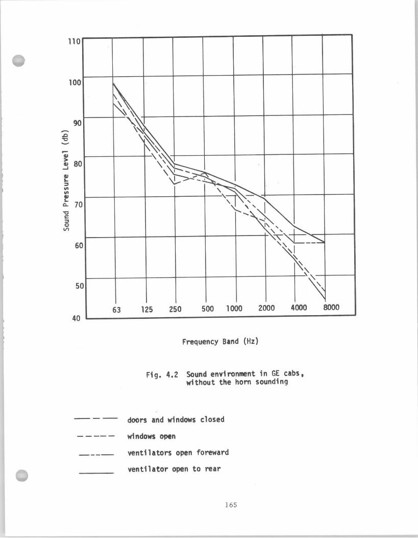
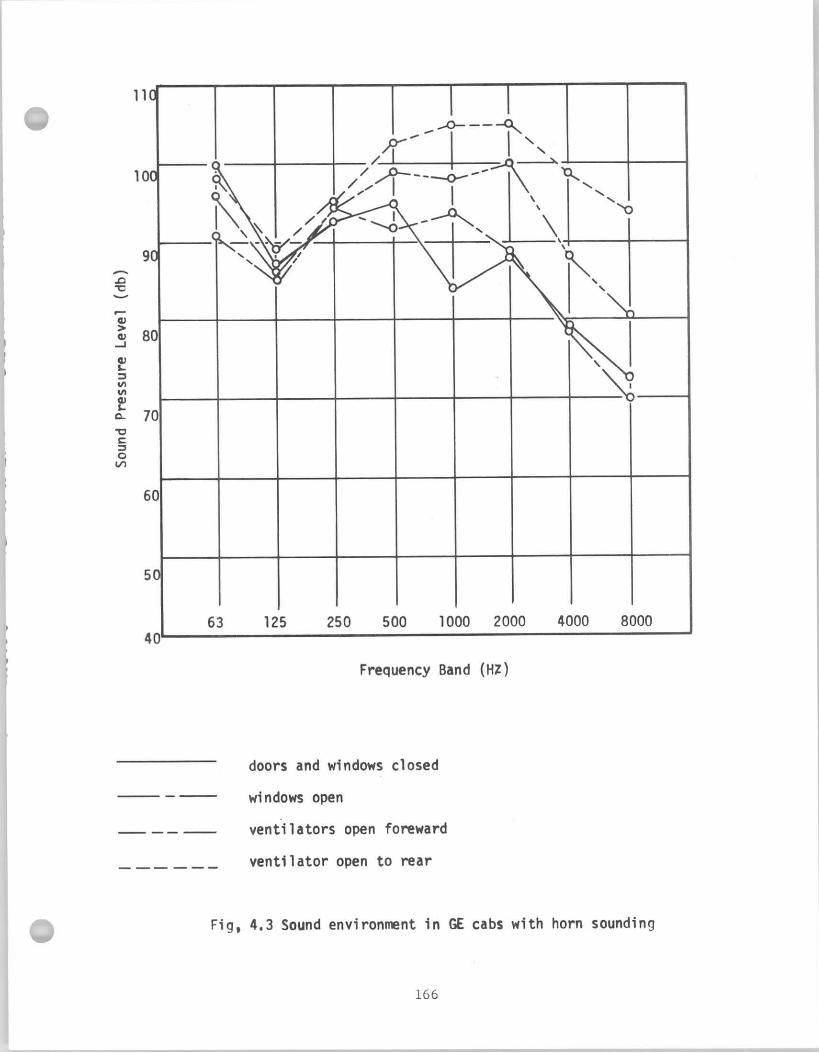
o n voice communication. In order t o i so la te the cab from the noise
sources, they plan t o construct a separate cab box which will be
mounted on the locomotive chassis as an independent uni t . EMD
considers prac t ica l i ty of construction questionable a t t h i s time for
American locomotives.
Vibration: EMD locomotives are designed t o sa t i s fy a s e t of
vibration standards, which were established by the company. Velocity
o f the vibration must n o t exceed 0.25 in/sec in the middle of the
f l o o r , and 0.20 in/sec on the f loor a t the location of the engineer's
s e a t in the frequency range between 10-100 Hz. These data are super-
imposed on the graphs of human vibration tolerance, taken from Hillborn
(383 62) and reproduced i n Fig. 4.4. The figures shows tha t the EMD
vibration standard i s in the vicini ty of the unpleasant and annoying l imi t
o f exposure to vibration. The 0.20 in/sec velocity l imi t even crosses
t h i s curve and exceeds i t above 30 Hz frequencies. The measurements
a r e taken in a standing locomotive with the engine running. EMD designers
maintain t ha t r a i l generated vibrations are attenuated by the locomotive
suspension system and do not a f fec t the operator s ignif icant ly .
In the Soviet Union the recommended l imit for vibration i s 0.80 2
m/sec
(0.0829) above 30 Hz ( 9 7 ) on the f loor of the locomotive. This l imi t
i s also shown in Fig. 4.4. I t can be seen tha t the Soviet recommendation
coincides with t h e curve of unpleasant sensation a t 30 Hz and tha t i t
i s identical with the EMD measures, though EMD standard i s expressed i n
terms of vibration velocity as a c r i te r ion .
On G E locomotives, the vibration a t the sea t attachment locations on
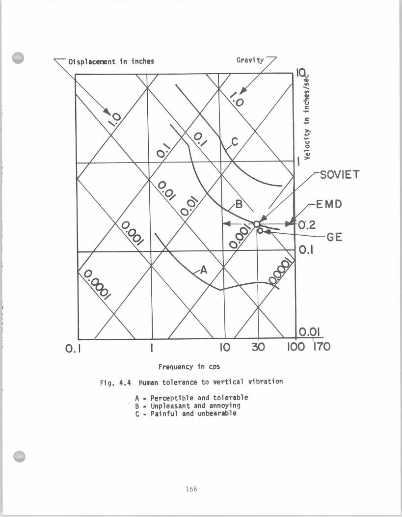
each side of the cab i s 0.089 a t 35Hz ve r t i ca l l y , and 0.019 in each
o f two horizontal d i rect ions . The G E value i s a l so shown in Fig. 4.4.
The G E value i s located between the threshold of "perceptible and tolerable"
sensations and the l im i t of "unpleasant and annoying" vibration.
EMD locomotives undergo vibration tes t ing before release by the
manufacturer. Longitudinal and transverse measurements a re not
included i n this program. This t es t ing i s part of the company's qual i ty
evaluation program and i s aimed primarily t o detect possible manufacturing
f a u l t s . In 10% of to ta l EMD locomotive production, the vibration tes t ing
i s extended t o f i ve points on the locomotive and i t i s planned t h a t a 13
locat ion qual i ty control program, measuring locomotive vibrations, will
be introduced i n the near future.
Since the human body i s most affected by vibrations lower than
10 Hz frequency, the range of measurements should be extended t o include
frequencies between 1-10 Hz. Furthermore, the above indicated values
2 o f 0.20-0.25 in/sec or 0.08 m/sec are in the v ic in i ty of the threshold
o f unpleasant and annoying sensations, a s indicated in Fig. 4.4.
Vibration reduction of the sea t cannot be considered adequate
i n the standing position and p u t s his elbow on the window ledge. There-
f o r e , fur ther investigations a re needed to determine riding charac te r i s t i cs
of locomotives.
For equipment operators, exposed to vibration, the Military Standards
specify levels of whole body vibration along a l l three axes in terms of
I
acceleration permitted for various lengths of time. ( 9 2 ) ~ o t only are
tolerance 1 imits defined, but the proficiency 1 imits of the individual
exposed to vibration are also established. Where comfort is to be
maintained, the acceleration values must be no greater than 3.15 times
1 ess than the proficiency limits. The upper limit of such comfort
specification corresponds to the vibration criteria used by EM0 and
the Soviet literature for permissible levels at the floor of locomotive
cabs.
4.3 Recommendations
Noise: A recent f i e l d i n v e s t i g a t i o n o f no ise i n locomot ive cabs
found s i g n i f i c a n t l y h igher noise l e v e l s than those obta ined f rom the
manufacturers. The d i f f e r e n c e s can be p a r t i a l l y a t t r i b u t e d t o d i f f e rences
i n ope ra t i ng cond i t i ons . The f i e l d s tudy measured the noise on locomotives
i n opera t ion w i t h 45 and 60 mph speed, w h i l e the noise data o f t he
manufacturers were c o l l e c t e d i n s tanding locomotives w i t h the engine
runn ing on ly . However, the d i f f e rences p o i n t o u t t he need f o r conduct ing
a comprehensive noise s tudy on the sound environment i n locomot ive cabs.
Track cond i t i ons , t r a i n speed, and engine loads should be used as parameters
t o descr ibe noise cond i t i ons i n the cab. I f the study found the no ise
l e v e l on c e r t a i n models t o be excess ive ly high, capable o f producing
hea r ing damage, o r above the l i m i t s p e c i f i e d by law, t he engineers on such
locomot ives should be requ i red t o wear hear ing p r o t e c t i o n devices. There
a r e devices manufactured which a t tenuate undesi rable i n d u s t r i a l noises,
b u t do n o t h inder speech communication ( f o r example, GE "Peacekeeper"). Such
devices cou ld advantageously be used i n the r a i l r o a d i n d u s t r y .
Noise, generated by spec ia l sources, should a l s o be analyzed as poss ib le
means t o reduce cab sound l e v e l . Present ly the a i r brake system
ven ts i n the cab, and t h i s procedure i s a major source o f annoying
noise. The brakes should vent ou ts ide the cab. However, i t i s des i rab le
n o t t o e l i m i n a t e b rak ing noises complete ly f rom the cab because the
engineer uses the sound as feedback f o r brake adjustments.
Another major source o f no ise i s t he horn. It i s conceivable t h a t
b y proper design and p o s i t i o n i n g o f t he horn, w i t h cons idera t ion t o
d i r e c t i v i t y o f sound waves, t he engineer cou ld be protected. I t i s known
t h a t obstac les i n d i r e c t i o n o f wave propagat ion cas t sound shadows. High
A
frequency sounds (whose wavelength i s shorter than width of the
obstacle) a r e general 1 y attenuated i n the shadow zone. (93) Barriers
based on t h i s principle a r e sometimes used for control of high f re-
quency noise.
In future production, additional sound insulation techniques
could be used t o attenuate noise entering the cab through the walls,
roof , and f loo r . On EMD locomotives, sound insulating material
i s placed in the e l ec t r i c cabinet as another measure of noise
reduction.
Noise problems must not be separated from venti lat ion problems
because noise reduction techniques cannot be f u l l y effect ive as long
a s the windows are kept open during summer operations. In such a
case , the noise sources must be modified t o reduce the level of noise
which enters the locomotive cab.
Vibration: Adequate measurements to describe the vibrational
environment in the locomotive cab are lacking. The c r i t e r i a used by
t h e manufacturers do not include low frequency vibrations in the range
where the human body i s most sensi t ive (1-10 Hz), and apply only t o
s t a t i c conditions when the locomotive i s not running a t high speeds
on the track.
The conditions of vibration, t o which the engineer i s exposed, should
be measured as a f i r s t step i n surveying the environmental conditions
i n the cab. The measurements should record vibration parameters in the
v e r t i c a l , transverse and longitudinal directions during actual t ra in
operations. Recordings, both on the f loor and on the sea t , should be taken +- \
a t var ious t r a i n speeds and under var ious t r a c k cond i t ions , which would
se rve as parameters f o r the v i b r a t i o n measurements. Jerks i n a l l th ree
d i r e c t i o n s s i g n i f i c a n t l y i n f l uence the comfor t o f t r a i n r i d e . Therefore,
t h e magnitude and occurrence o f j e r k s must a l so be determined. F i n a l l y ,
t h e r e s u l t s o f such a study must be compared w i t h es tab l ished human
comfor t and to le rance thresholds i n order t o e s t a b l i s h r i d i n g cond i t i ons
i n the locomotive cab, and i n order t o be ab le t o make recommendations
f o r improvement. B e t t e r r i d i n g comfor t cou ld be envisioned by improving:
( a ) seat design, us ing appropr ia te dampers, (b ) i n s t i t u t i n g an a c t i v e
damper system, and ( c ) i f necessary, making design changes i n the locomotive.
A c t i v e damping systems a r e being considered t o improve passenger comfort ;
t h e y should a l s o be considered f o r improving the ope ra to r ' s comfort .
5 . SEATING OF THE OPERATOR IN LOCOMOTIVE CABS
5.1 Review of the Li tera ture on Cab Seat Desiqn
The German, Swiss, and Japanese ra i l roads have developed seats
exclusively fo r use i n locomotive cabs. The sea t s were designed on
t he basis of selected anthropometric data and were intended to s a t i s fy
the unique human fac tors requirements of the locomotive engineer 's
j o b .
Beginning i n July 1969 the German Federal Railways developed an
idealized chair t o be a standard locomotive s ea t of the 70 ' s . (154) The
s e a t i s shown in Fig. 5.1. I t i s adjustable fo r e f fec t ive vibration
damping by varying the spring tension with a handwheel, which i s
ca l ib ra ted and marked fo r the individual ' s body weight. The back of
the sea t reclines. Reclining was considered t o be a desirable feature .
Frequently the engineer has t o spend several hours i n the cab waiting.
In order t o make these waiting periods useful in the medical sense,
t he reclining sea t back provides a more or l e s s comfortable laying
posit ion fo r relaxation. Fifteen seats of the above prototype model were
tes ted i n locomotive use fo r f i f t een months. A human fac tors questionnaire
was dis t r ibuted t o the engineers who used i t . The survey i n which
50% of 3000 questionnaires were returned revealed two drawbacks regarding
t h e new seat : (1 ) mounting the chair on the f loor with an 18" diameter
p l a t e i s unacceptable because i t severely l imi t s i t s positioning
p o s s i b i l i t i e s and ( 2 ) many engineers did n o t adjust the sea t optimally
t o t he i r individual body weight and anthropological dimensions because of
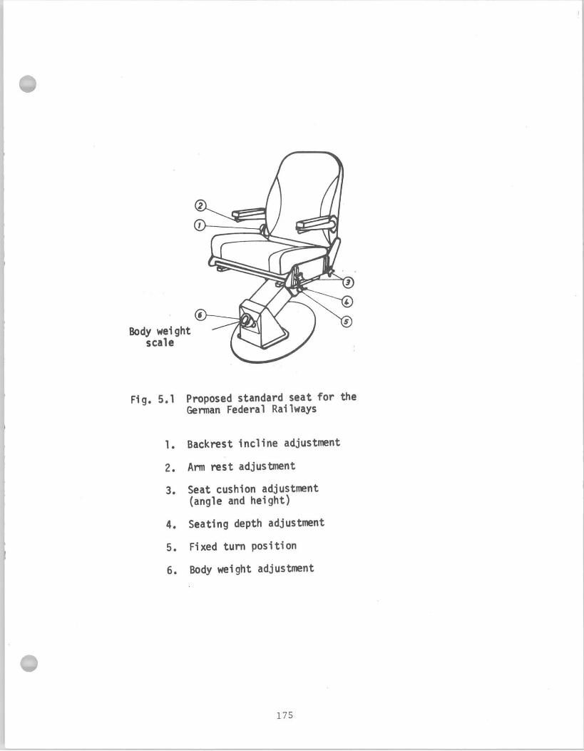
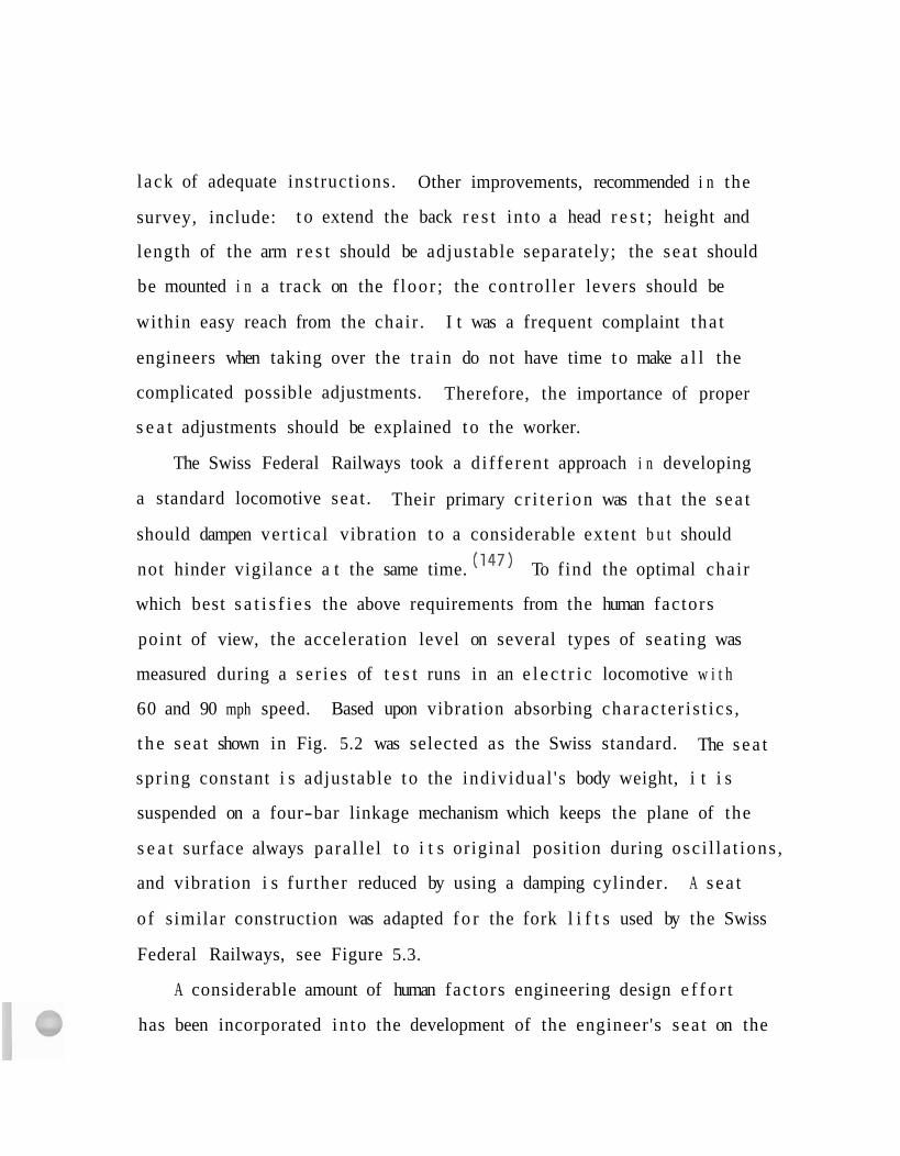
l ack of adequate instructions. Other improvements, recommended i n the
survey, include: t o extend the back r e s t in to a head r e s t ; height and
length of the arm r e s t should be adjustable separately; the sea t should
be mounted i n a track on the f loor ; the control ler levers should be
within easy reach from the chair . I t was a frequent complaint tha t
engineers when taking over the t ra in do not have time to make a l l the
complicated possible adjustments. Therefore, the importance of proper
s e a t adjustments should be explained to the worker.
The Swiss Federal Railways took a d i f fe ren t approach i n developing
a standard locomotive seat . Their primary c r i t e r i on was t ha t the s ea t
should dampen ver t ical vibration t o a considerable extent b u t should
not hinder vigilance a t the same time. (14') To find the optimal chair
which best s a t i s f i e s the above requirements from the human factors
point of view, the acceleration level on several types of seating was
measured during a se r ies of t e s t runs in an e l e c t r i c locomotive w i t h
60 and 90 mph speed. Based upon vibration absorbing charac te r i s t i cs ,
t h e sea t shown in Fig. 5.2 was selected as the Swiss standard. The s ea t
spr ing constant i s adjustable t o the individual ' s body weight, i t i s
suspended on a four-bar linkage mechanism which keeps the plane of the
s e a t surface always paral le l t o i t s original position during osc i l l a t ions ,
and vibration i s fur ther reduced by using a damping cylinder. A s ea t
o f similar construction was adapted f o r the fork l i f t s used by the Swiss
Federal Railways, see Figure 5.3.
A considerable amount of human factors engineering design e f f o r t
has been incorporated in to the development of the engineer's sea t on the
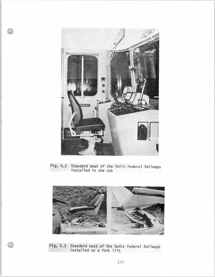
high speed Tokaido Line of the Japanese National Railways. The shell
shaped seating surface supports the body on both sides against transverse
vibration and makes an arm r e s t unnecessary. The back i s supported a t
f i v e points: a t both shoulder blades, a t the ischia on both s ides , and
a t the coccycx. The angle between the seating surface and the s ide of
the ilium i s 105 t o llOO. (49)
The International Union of Railways (U.I.C.) Series 3 of Code 625,
issued i n 1959, recommends tha t the seated position of the engineer
should be as high above the r a i l level as possible. In 1960, Series
4 was issued to cover the dr iver ' s seated position more adequately.
Adjustable footres ts and seats a r e recommended which a re comfortable
and collapsible t o permit the driver to operate standing as well as
s i t t i n g . Type 3 , Bo-Bo locomotive of the Southern Region, Bri t ish
Railways exemplifies the above principle. On t h i s locomotive the sea t
t i p s back t o give the engineer maximum freedom and permit standing
operation. (36)
Further recommendations have been proposed f o r good sea t
construction of international European stock. (18,31,148) A free knee
space of m i n i m u m 16" i s recommended i n f ron t of the sea t . Foot r e s t s
a r e necessary w i t h a suggested 15' slope, the i r surface area should be
about 16 x 20" w i t h rough f inish. The deadman pedal should be
incorporated into the foot r e s t . Seat height adjustment between 16"
t o 19" i s recommended w i t h a 5" recline of the seating surface. The
f ron t edge of the sea t cushion must be rounded. Depth of the sea t i s
t o be 16 to 20". The sea t should rotate b u t could be fixed i n any
p o s i t i o n . Height o f the backrest should be ad jus tab le and a v e n t i l a t i o n
opening should be prov ided i n t he lower p a r t . A backrest o f 16 1/2"
x 17 1/2" i s recommended w i t h a 5" t o 7' r e c l i n e . (155)
Factors o the r than body s i z e a re a l s o impor tan t t o p rov ide comfor t
f o r the seated person. For example, a major comfor t f a c t o r i s the
d i s t r i b u t i o n o f body weight i n the c h a i r . This d i s t r i b u t i o n i s af fected
b y the angle and the i n c l i n a t i o n o f the backrest and the seat sur face,
b y the arm r e s t , t he f o o t r e s t and by the d is tance from the f l o o r . A
German r e p o r t suggests t h a t i n good seat design an even d i s t r i b u t i o n
o f body weight must be incorporated. Local concent ra t ion o f pressure
causes aching spots. (49) The seat should be designed so t h a t a l l
l i m b s o f t he engineer extend t o the c o n t r o l s a t an opt imal angle and
a r e i n t he l e a s t t i resome p o s i t i o n when he operates h i s equipment.
Seat dimensions, based on European anthropometr ic data, a r e presented
b y Grandjean: (51) the seat he igh t i s recommended t o be 17.7 + 4.3" -
w i t h a 3" backward i n c l i n e o f the seat ing surface.
Anthropometr ic data on American r a i l r o a d personnel a re n o t
a v a i l a b l e . The seats o f American passenger cars a r e designed on the
b a s i s o f seated body dimension data c o l l e c t e d i n 1945. (64) Seat w id th
f o r passengers i n a recen t TRW Inc. (1970) r e p o r t , ( I 4 * ) quoted f rom
t h e same l i t e r a t u r e source, i s recommended t o be 20", back he igh t 28",
elbow he igh t 8.5"; h i p breadth 19.0", seat he igh t 16.9", shoulder
b readth 19". Another recen t American study (I2') concerning passenger
comfo r t recognizes the f a c t t h a t the d r i v e r ' s seat needs spec ia l des ign
i n r a p i d t r a n s p o r t b u t f a u l t i l y concludes t h a t i n t he design o f the ope ra to r ' s
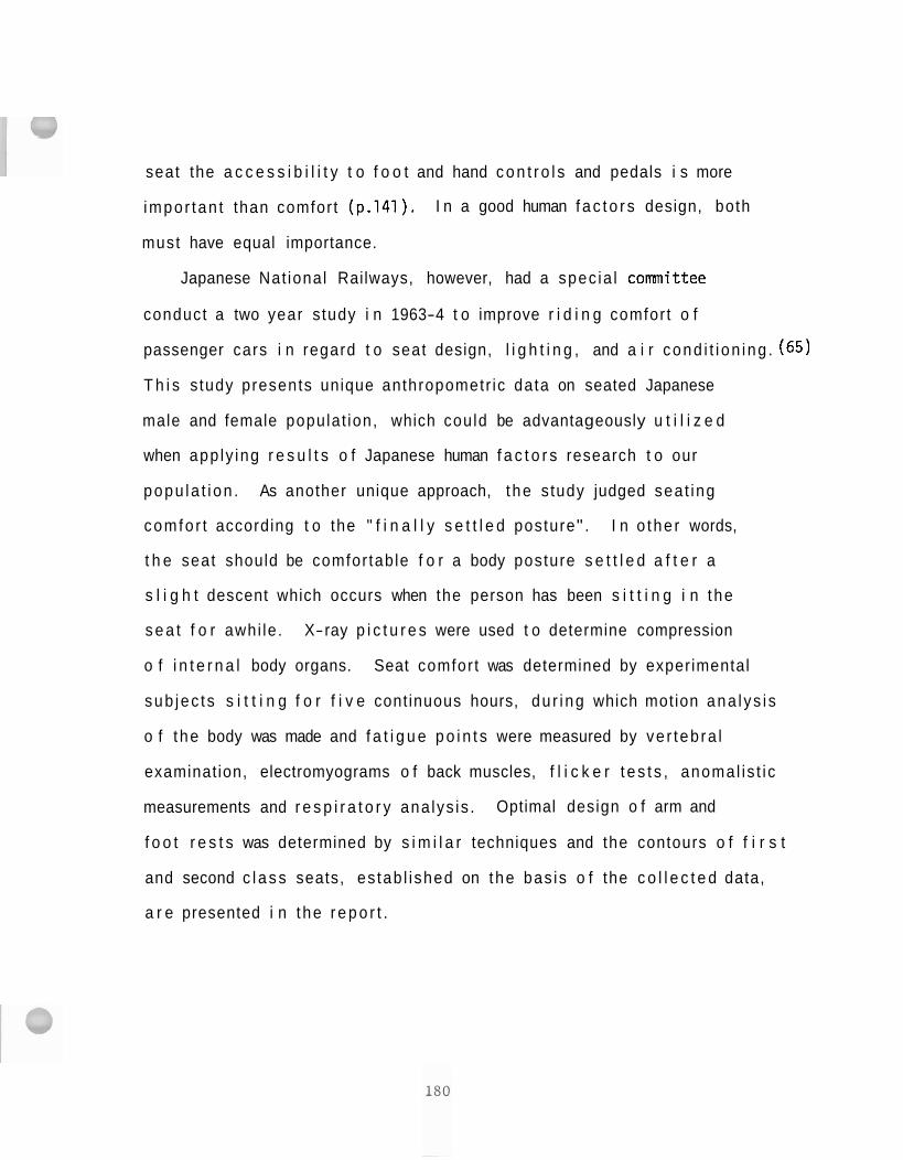
seat the a c c e s s i b i l i t y t o f o o t and hand c o n t r o l s and pedals i s more
impor tan t than comfor t (p.141). I n a good human f a c t o r s design, both
must have equal importance.
Japanese Nat ional Railways, however, had a spec ia l committee
conduct a two year s tudy i n 1963-4 t o improve r i d i n g comfor t o f
passenger cars i n regard t o seat design, l i g h t i n g , and a i r cond i t i on ing . (65)
T h i s s tudy presents unique anthropometr ic data on seated Japanese
male and female populat ion, which could be advantageously u t i l i z e d
when app ly ing r e s u l t s o f Japanese human f a c t o r s research t o our
popu la t i on . As another unique approach, t he s tudy judged seat ing
comfo r t according t o the " f i n a l l y s e t t l e d posture" . I n o the r words,
t h e seat should be comfor table f o r a body posture s e t t l e d a f t e r a
s l i g h t descent which occurs when the person has been s i t t i n g i n t he
s e a t f o r awhi le . X-ray p i c t u r e s were used t o determine compression
o f i n t e r n a l body organs. Seat comfor t was determined by experimental
sub jec t s s i t t i n g f o r f i v e cont inuous hours, du r i ng which motion ana l ys i s
o f t he body was made and f a t i g u e p o i n t s were measured by ve r teb ra l
examinat ion, electromyograms o f back muscles, f l i c k e r t e s t s , anomal is t i c
measurements and r e s p i r a t o r y ana lys is . Optimal design o f arm and
f o o t r e s t s was determined by s i m i l a r techniques and the contours o f f i r s t
and second c l a s s seats, es tab l i shed on the bas is o f the c o l l e c t e d data,
a r e presented i n t he r e p o r t .
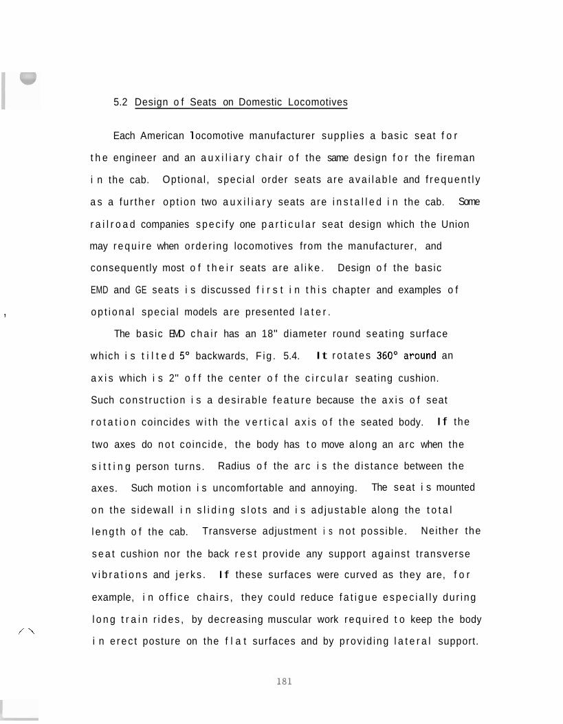
5.2 Design o f Seats on Domestic Locomotives
Each American 1 ocomotive manufacturer suppl ies a basic seat f o r
t h e engineer and an a u x i l i a r y c h a i r o f the same design f o r the f i reman
i n the cab. Opt ional , spec ia l order seats a re a v a i l a b l e and f r e q u e n t l y
a s a fu r the r op t i on two a u x i l i a r y seats a re i n s t a l l e d i n the cab. Some
r a i l r o a d companies s p e c i f y one p a r t i c u l a r seat design which the Union
may r e q u i r e when order ing locomotives from the manufacturer, and
consequently most o f t h e i r seats a re a l i k e . Design o f the basic
EMD and GE seats i s discussed f i r s t i n t h i s chapter and examples o f
o p t i o n a l spec ia l models a re presented l a t e r .
The basic EMD c h a i r has an 18" diameter round seat ing sur face
which i s t i l t e d 5' backwards, F ig . 5.4. It r o t a t e s 360°around an
a x i s which i s 2" o f f the center o f the c i r c u l a r seat ing cushion.
Such cons t ruc t i on i s a des i rab le f e a t u r e because the a x i s o f seat
r o t a t i o n coinc ides w i t h the v e r t i c a l a x i s o f t h e seated body. I f the
two axes do n o t co inc ide , the body has t o move a long an arc when the
s i t t i n g person tu rns . Radius o f the a rc i s t h e d is tance between the
axes. Such motion i s uncomfortable and annoying. The seat i s mounted
o n the s idewal l i n s l i d i n g s l o t s and i s ad jus tab le along the t o t a l
l e n g t h o f the cab. Transverse adjustment i s n o t possib le. Nei ther the
s e a t cushion nor the back r e s t prov ide any support aga ins t t ransverse
v i b r a t i o n s and j e r k s . I f these surfaces were curved as they are, f o r
example, i n o f f i c e cha i r s , they could reduce f a t i g u e e s p e c i a l l y du r ing
l o n g t r a i n r i d e s , by decreasing muscular work requ i red t o keep the body
i n e r e c t posture on the f l a t surfaces and by p rov id ing l a t e r a l support.
,
/-\
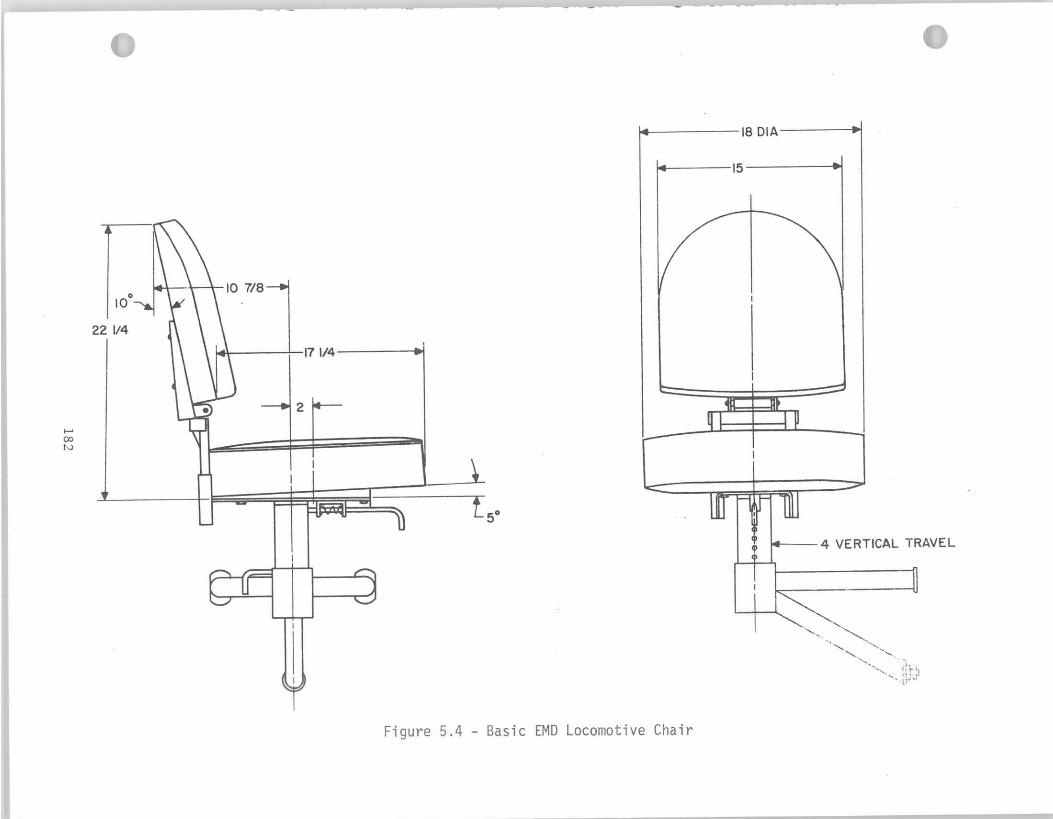
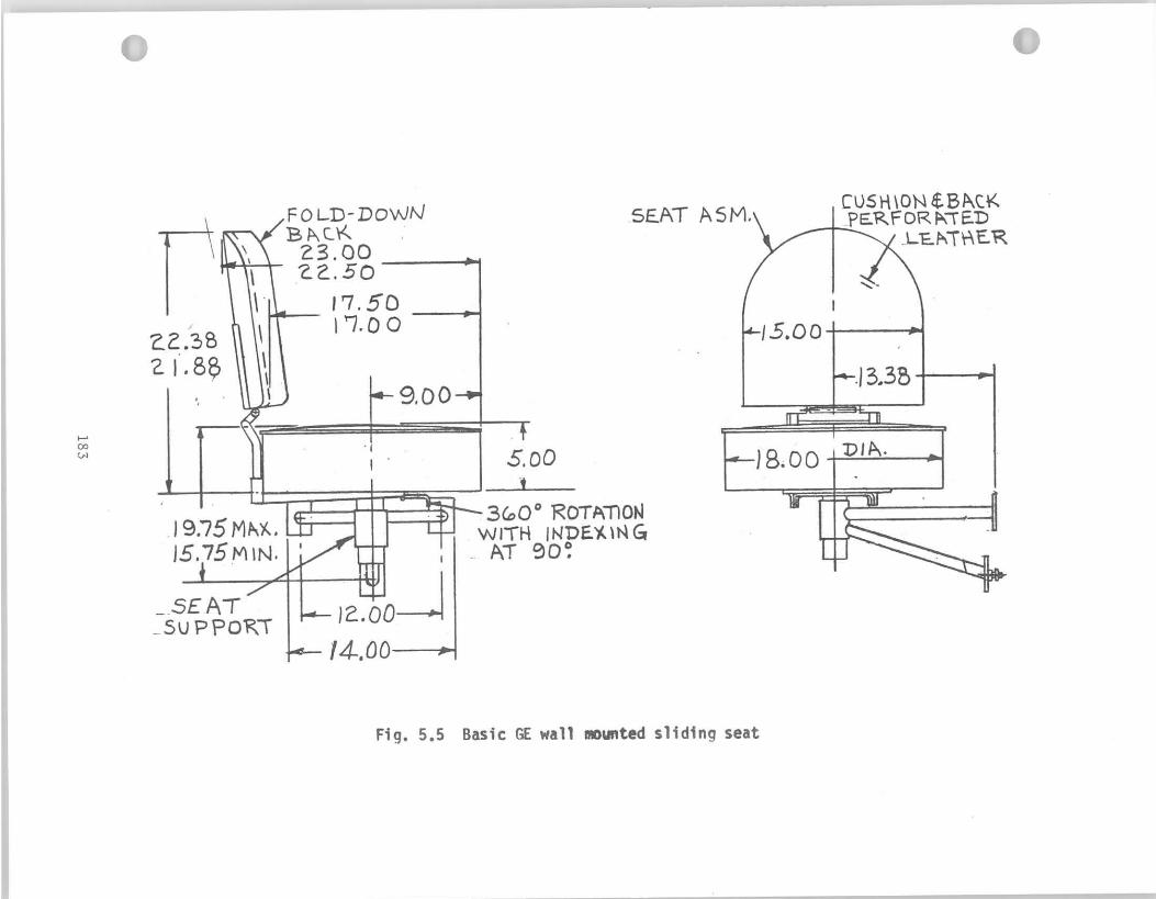
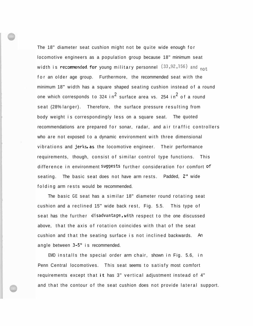
The 18" diameter seat cushion migh t n o t be q u i t e wide enough f o r
locomot ive engineers as a popu la t ion group because 18" minimum seat
w i d t h i s recommended.for young m i l i t a r y personnel (33,92,156) not
f o r an o l d e r age group. Furthermore, the recommended seat w i t h the
minimum 18" w id th has a square shaped sea t i ng cushion ins tead o f a round
2 2 one which corresponds t o 324 i n sur face area vs. 254 i n o f a round
s e a t (28% l a r g e r ) . Therefore, the sur face pressure r e s u l t i n g from
body weight i s correspondingly l e s s on a square seat. The quoted
recommendations a re prepared f o r sonar, radar , and a i r t r a f f i c c o n t r o l l e r s
who a r e n o t exposed t o a dynamic environment w i t h t h ree dimensional
v i b r a t i o n s and jerks,as the locomot ive engineer. The i r performance
requirements, though, c o n s i s t o f s i m i l a r c o n t r o l t ype func t i ons . Th i s
d i f f e r e n c e i n environment suggests f u r t h e r cons idera t ion f o r comfor t of
sea t ing . The bas ic sea t does n o t have arm r e s t s . Padded, 2" wide
f o l d i n g arm r e s t s would be recommended.
The bas ic GE sea t has a s i m i l a r 18" diameter round r o t a t i n g seat
cush ion and a r e c l i n e d 15" wide back r e s t , F ig . 5.5. Th is type o f
s e a t has the f u r t h e r disadvantage,with respec t t o t he one discussed
above, t h a t t he a x i s o f r o t a t i o n co inc ides w i t h t h a t o f t he seat
cushion and t h a t t he seat ing sur face i s n o t i n c l i n e d backwards. An
ang le between 3-5" i s recommended.
EMD i n s t a l l s t he spec ia l order arm c h a i r , shown i n F ig . 5.6, i n
Penn Central locomotives. Th i s seat seems t o s a t i s f y most comfor t
requirements except t h a t i t has 3" v e r t i c a l adjustment i ns tead o f 4"
and t h a t t he contour o f the seat cushion does n o t p rov ide l a t e r a l support .
Ad jus tab le arm r e s t s would be p re fe rab le . The seat prov ided by EMD
f o r Southern P a c i f i c , i n F ig . 5.7, has the necessary suppor t ing
con tou r o f t he seat cushion. V e r t i c a l adjustment o f t h i s seat i s 2 1/2"
o n l y . For Union P a c i f i c , EMD supp l ies the seat shown i n F ig . 5.8. The
h o r i z o n t a l p o s i t i o n o f t he seat cushion i s ad jus tab le 4" which s h i f t s
t h e a x i s o f r o t a t i o n and could be se t i n a comfor table p o s i t i o n . The
cushion does n o t p rov ide l a t e r a l support, and the v e r t i c a l adjustment
i s j u s t 3" . The backrest should be sho r te r extending from 5" t o 17"
above seat sur face l e v e l .
The basic GE sea t i s a v a i l a b l e w i t h arm r e s t s , as shown i n F ig . 5.9.
The a x i s o f r o t a t i o n i s s h i f t e d 1" back on t h i s ve rs ion which i s a
d e s i r a b l e f ea tu re . On c e r t a i n GE locomotives a 20" wide seat i s
i n s t a l l e d , as shown i n F igure 5.10, which has a 6' backward t i lt.
The seat contour does n o t support l a t e r a l l y , t he re a re no arm r e s t s
on t h i s model, and v e r t i c a l adjustment i s 3 114" on l y . A f l o o r
mounted GE seat model i s shown i n F ig . 5.11. This seat has 4" v e r t i c a l
cushion adjustment, i t i s 20 - + 114" wide, b u t no t contoured. V e r t i c a l
ad justment i s 3 112". The arm r e s t s a re shor t , 5 314" ins tead o f a
p r e f e r a b l e 10" .
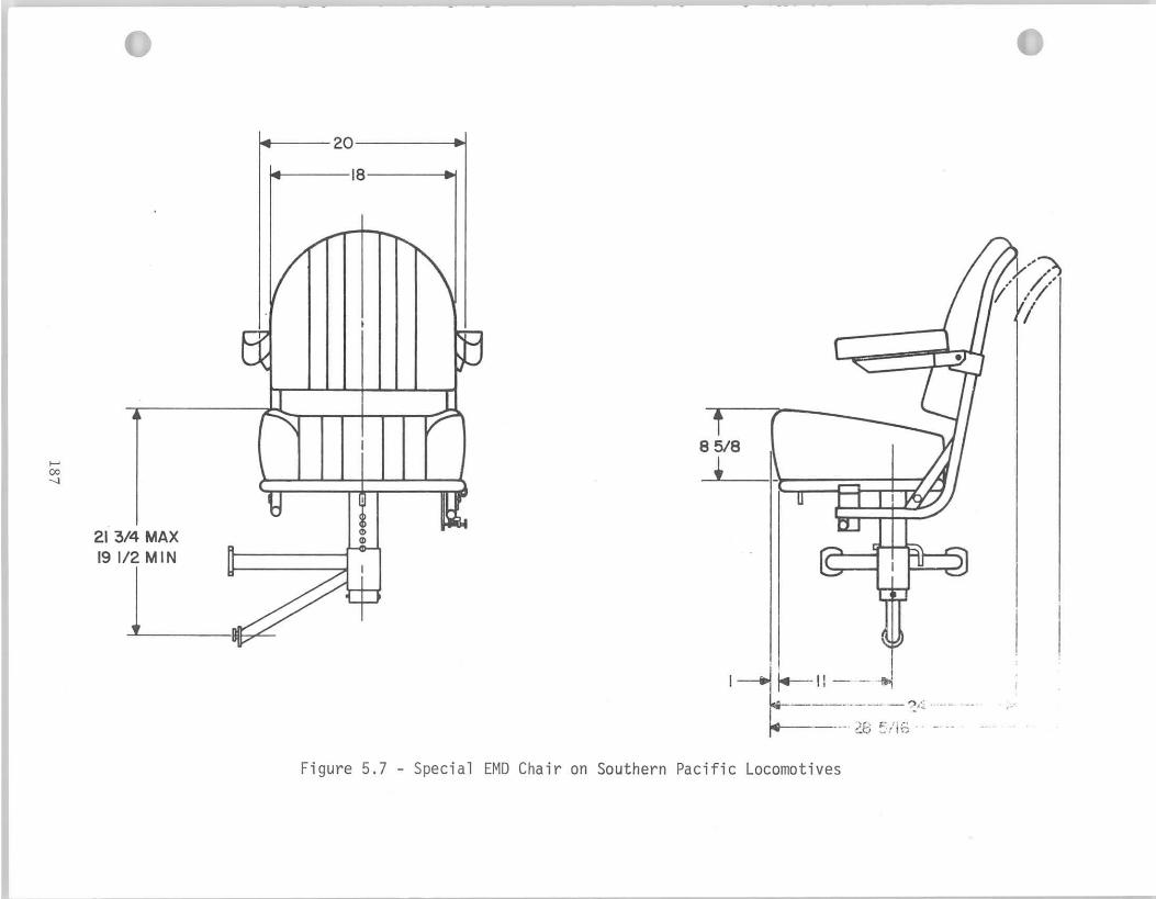
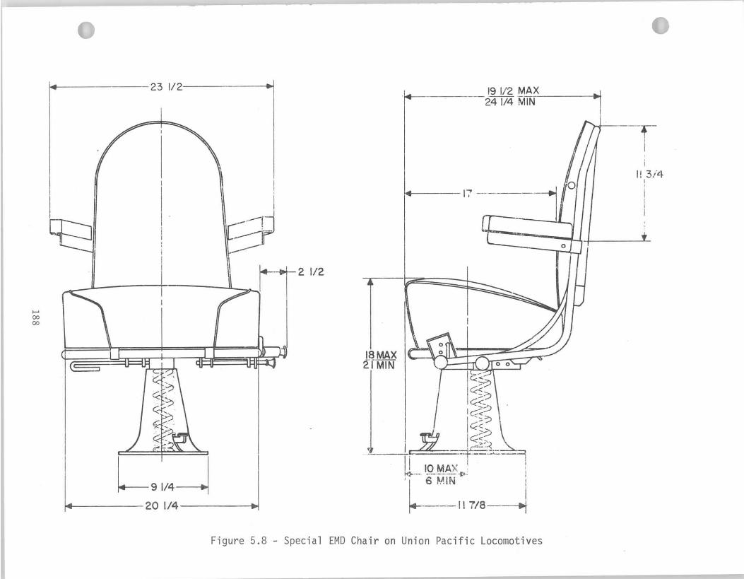
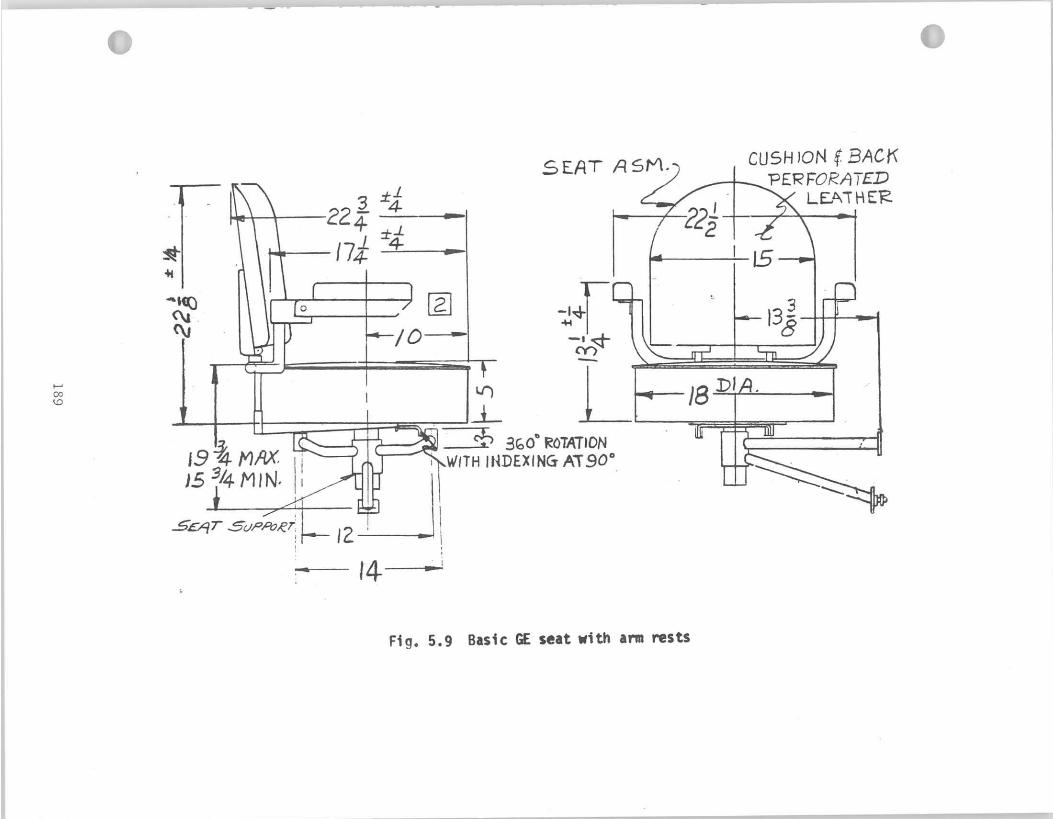
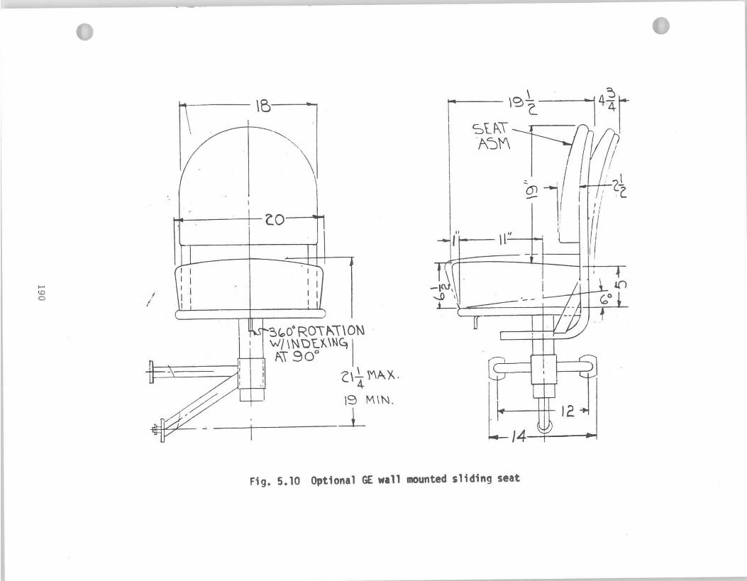
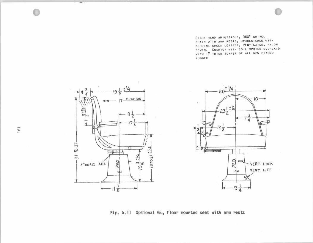
5.3 Recommendations on Seat Design
( 1 ) I t i s recommended as a f i r s t step f o r improving seating of the
1 ocomotive engineer, t h a t a be t te r design be adopted as standard instead
o f the present basic model. The models shown in Figs. 5.6 and 5.7 a r e
more sui table t o provide comfort and reduce fa t igue in a locomotive
cab environment than the presently used basic chair types.
( 2 ) Advantages found separately in d i f fe ren t models could be combined.
For example, horizontal adjustment of the back r e s t , a s shown in Fig. 5.8,
should be provided f o r a chair w i t h a contoured sea t cushion, resembling
t h e model in Fig. 5.7. Of course, 4" vert ical travel and folding
adjustable arm res t s a r e a l so recommended.
( 3 ) An appropriate foo t r e s t should be designed. A piece of pipe, a s
found on G E models, i s not adequate. EMD models do not have any foo t
r e s t , and the engineer has t o place his f e e t on the heater in f ron t of
t h e cha i r , i f he wants t o occupy a relaxed position (see Fig. 2.25).
Further investigation should determine, on the basis of an analysis
o f the control functions performed by the engineer on domestic type
control stands, whether the foot r e s t should be an integral par t
o f zhe sea t or a separate uni t on the f loor . An inclined f loor i n
f r o n t of the sea t i s another possible a l te rna t ive solution.
( 4 ) Based upon comparative evaluation of locomotive seats presently in
use and on an estimation of task and control functions required of the
engineer, the sea t shown in Fig. 5.12 i s recommended a s a f i r s t approach
i n designing a standard locomotive chair . The sea t was developed t o
a i d sonar operators and helps t o s t ab i l i z e the man's body a s the ship
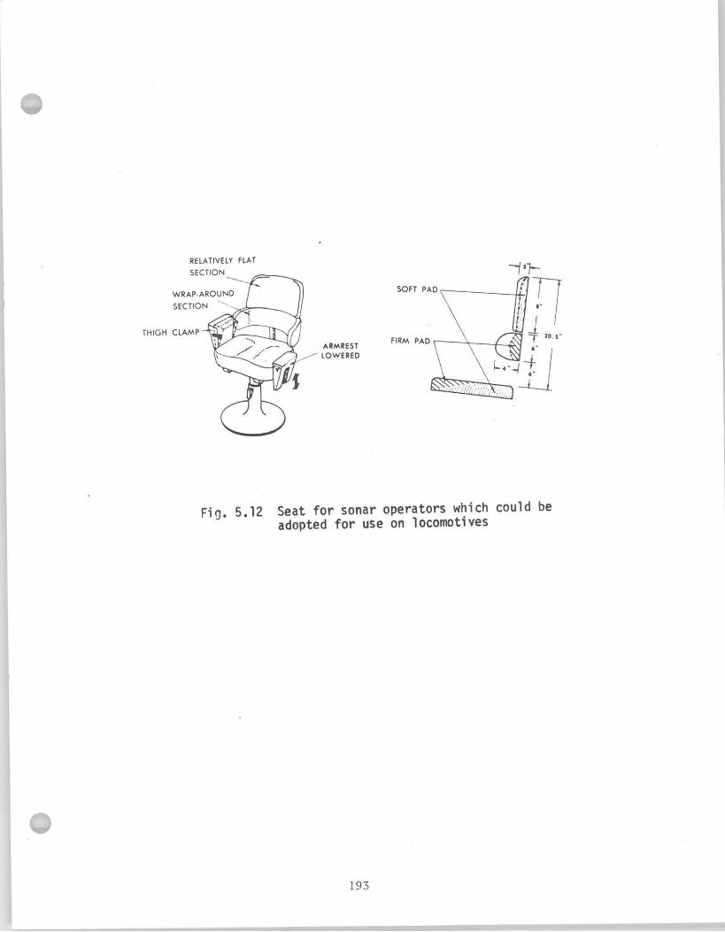
p i t c h e s and r o l l s i n medium t o heavy seas. The backrest prov ides
n o t o n l y more sur face area, bu t adds an a d d i t i o n a l curved sec t i on
abou t t he ope ra to r ' s lower r i b . The arm r e s t s p i v o t inward t o a c t as
a " t i g h t clamp". However f o r locomotive use, a d i f f e r e n t des ign f o r
t h e arm r e s t s i s recommended; the arm r e s t s should swivel outward,
s o t h a t they do no t r e s t r i c t the engineer i f he must leave the c h a i r .
( 5 ) As a f i n a l so lu t i on , a standard seat must be designed s p e c i f i c a l l y
f o r locomotive engineers. Th is new design must o p t i m a l l y s a t i s f y bo th
t h e work space requirements determined by need t o operate c o n t r o l s ,
e t c . , and the comfor t requirements of t he i n d i v i d u a l regard ing reduc t i on
o f v i b r a t i o n s and p r o v i d i n g l a t e r a l support. The methods and techniques
o f seat development have been descr ibed. ( 7 2 y 1 2 7 ) The research should
f i r s t determine the user populat ion, secondly e s t a b l i s h acceptable
s tandards o f reach and comfort , and t h i r d l y app ly these standards t o
a l l b u t the e x c e p t i o n a l l y l a r g e o r small members o f t he user popu la t ion
(upper 95 and lower 5 p e r c e n t i l e ) .
The user popu la t ion must be i d e n t i f i e d i n terms o f t he d i s t r i b u t i o n s
o f bo th he igh t and weight. The designers o f t he seat have f i r s t t o
i d e n t i f y c r i t i c a l body dimensions and then design a p ro to type model
i n which each dimension can be ad jus ted independent ly over a wide
range. I n such a p ro to type seat, the seat ing sur face, backrest , arm
r e s t s , and f o o t r e s t would be ad jus tab le independent ly o f each o the r .
The i n i t i a l s e t t i n g s o f t he c h a i r would be found by p l a c i n g i t i n a
locomot ive cab and a d j u s t i n g each dimension u n t i l a user o f average s i z e
can c a r r y o u t each o f t he eng ineer 's task func t i ons w i thou t d i f f i c u l t y and

discomfort. The optimum would be achieved by interrogation of the
subject . The f ina l dimensions will be determined on the basis of
t h e optimum for the average man and on the anthropometric data of
t h e user population.
Differences i n body s i ze and proportion among d i f fe ren t occupational
groups are common. Numerous factors contribute to the physical
differences, such as age, d i e t , health s ta tus , and physical ac t iv i ty .
There a lso appear to be select ive factors tending t o make cer ta in
occupational groups more homogeneous physically than would be expected
by chance. Some tasks require specif ic physical a b i l i t i e s (48) and
workers having t h i s a b i l i t y tend to be similar in physique; jobs may
require or a t t r a c t d i s t inc t ive personal i t ies , e t c .
Percentiles of anthropometric data provide a basis for estimating
the proportion of a group accommodated or inconvenienced by any specif ic
design. For example, t o provide f o r 95 percent of c iv i l i an population
i n respect to weight, a truck sea t should be designed for 215 pounds
per c iv i l i an dr iver , and 192 pounds per Army dr iver . A s ea t supporting
only 150 pounds per dr iver would be inadequate for some 70 percent of
c i v i l i a n s and 55 percent of soldiers.(33) Percentiles permit the
select ion and accurate use of t e s t subjects. A c r i t i c a l body dimension
o r physical a b i l i t y of a t e s t subject can be readily located as a
percent i le of the relevant population--provided, of course, tha t the
population i n question has been measured. Groups within the population
vary less than the population as a whole. The l imi t s of the 90 or 95
percent range must be determined by actual measurements of samples from
t h e group t o be accommodated. It cannot be au tomat i ca l l y assumed t h a t
t h e r e i s a s i m i l a r i t y o f any group o f operators t o o the r groups o r t o
t h e "general populat ion" .
Data are a v a i l a b l e t o cover the major m i l i t a r y and c i v i l i a n groups
f o r which equipment i s designed. I f any group o f intended users i s
l i k e l y t o d i f f e r from the ser ies i n respect t o age, sex, race, o r
occupat ion the spec ia l i zed data must be obtained through appropr ia te
sampling o f the group. Therefore, c e r t a i n anthropometr ic data must be
c o l l e c t e d on the locomotive engineers as a popu la t ion group. I t i s
a n t i c i p a t e d t h a t f o u r major body dimensions shown i n F ig. 5.13 would be
r e q u i r e d together w i t h body weight and he igh t data t o design a good
c h a i r . The minimum number i n the group should be 100, recommended by
amo on'^^), t o ob ta in s t a t i s t i c a l l y s i g n i f i c a n t data. By us ing he igh t
and weight data on l y and deducing o ther dimensions from these measurements,
one in t roduces a 20 percent e r r o r .
The t e s t subjects should n o t merely ho ld a comfortable pos i t i on ,
b u t should perform a l l necessary func t i ons f o r the du ra t i on o f an ac tua l
opera t ion . Many d i f f i c u l t i e s may be noted immediately b u t o thers
become apparent o n l y w i t h time. For example, a cramped space around the
knee i s t o l e r a b l e f o r several minutes, b u t over the course o f hours can
become no t merely uncomfortable bu t dangerous. Immobi l i t y o f the
lower legs over such per iods has caused blood c l o t s i n the c a l f ve ins.
The seat must be designed on the basis o f eva lua t ion o f the f o r e i g n
s e a t models and the domestic anthropometr ic data. Review o f the l i t e r a t u r e
shows t h a t several models o f good seat ing have been developed, such as the
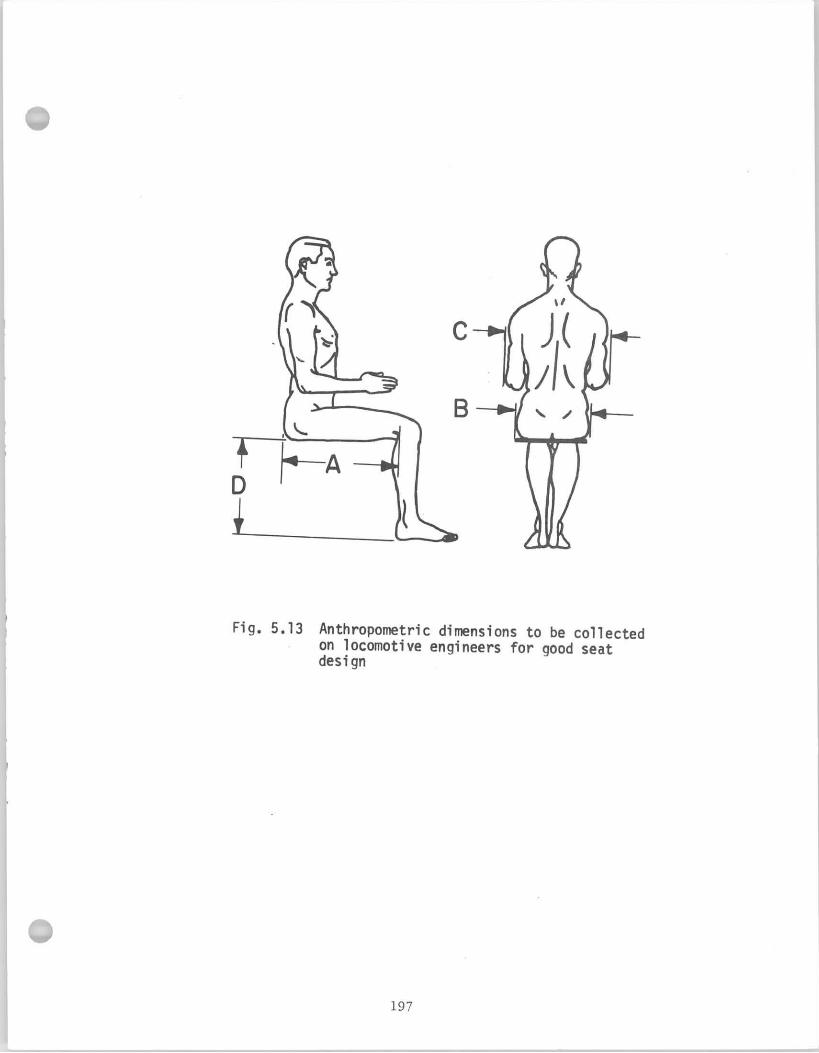

German Swiss and Japanese locomotive seats. (49,147,154) It would
be advantageous to test a sample of these models on the domestic
railroads and examine their advantages and disadvantages for American
use. Such experience could aid in developing the ideal standard seat.
As a final step, the seat should be intalled experimentally on
several locomotives and tested in use. The engineers should be
instructed on proper use and adjustments of the chair. Design
evaluation would be based on both interview with the users and on a
human factors questionnaire on seat comfort.
6. PHYSIOLOGY AND VIGILANCE REQUIREMENTS OF TRAIN DRIVING
6.1 Review o f t he L i t e r a t u r e
The problem o f decrease i n v i g i l a n c e and onset o f i na t ten t i veness
i n locomotive engineers has l e d t o the adopt ion i n r a i l r o a d operat ions
o f v i g i l a n c e devices which brake the t r a i n when the operator f a i l s t o
make c e r t a i n responses. Adequate performance o f the i r r e l e v a n t task
r e q u i r e d by the v i g i l a n c e device i s taken as evidence t h a t he i s
per forming the r e l e v a n t task e f f i c i e n t l y even though t a k i n g no o v e r t
a c t i o n i n t h a t respec t . These devices a re ex tens i ve l y used i n r a i l -
road ing t o t e s t the a t ten t iveness o f engineers.
Barwel l d i s t i ngu i shed two c lasses o f these devices on the bas is
o f t he na ture o f the i r r e l e v a n t response: (1 ) Continuous devices, as
exempl i f ied by the deadman pedal, r e q u i r e a cont inuous response; i n t h i s
case, depression o f the pedal, whereas (2 ) i n t e r m i t t e n t devices r e q u i r e
d i s c r e t e responses t o p rescr ibed s igna ls . (7 )
V ig i l ance o f locomotive engineers was found t o be s i g n i f i c a n t l y
i n f l uenced by (1 ) d u r a t i o n o f opera t ion ( e s p e c i a l l y du r i ng l ong i n t e r v a l s
between s igna l s o r bad v i s i b i l i t y ) , ( 2 ) c l ima te and monotonous cab
noise ( r e q u i r e s u i t a b l e cab design) , (3) i r r e g u l a r cyc les o f s h i f t
( s h i f t s begin and end a t a l l hours o f the day and n i g h t ) . ( l o ) I n r a i l r o a d
operat ions, v i g i l a n c e l a s t s o n l y f o r two t o f o u r hours w i t h o u t s imu la t i on
by the second d r i v e r . Independent d r i v i n g should n o t exceed th ree t o
f o u r hours. The i n d i v i d u a l ' s twenty- four hour rhythm o f s leep and
v i g i l a n c e i s broken i n t o i r r e g u l a r f r a c t i o n s and synchron iza t ion between
the b r a i n co r tex and autonomic nervous system, and hence body temperature,
pulse frequency and b lood pressure are found t o be d is tu rbed. These
f a c t o r s a re r e l a t e d t o mental b locks du r i ng opera t ion o f the t r a i n ,
wh ich may be tested, f o r example, du r i ng the second n i g h t o f d r i v i n g .
The engineer s t a r t s t he evening a l ready i n a t ropho t rop i c stage, which
i m p e r i l s h i s v i g i l a n c e . Based upon these t e s t s , i t i s poss ib le t o
es t ima te synchronizat ion o f autonomic rhythms w i t h t he c o r t i c a l
f u n c t i o n o f the man, as i t a f f e c t s v i g i l a n t d r i v i n g and t o make
suggest ions concerning opt imal c y c l i n g o f s h i f t work. (10)
Considerable research e f f o r t has been devoted by m i l i t a r y and
academic teams t o the understanding o f f a t i g u e and v i g i l a n c e , b u t
l i t t l e o f the r e s u l t s can be app l i ed d i r e c t l y t o r a i l w a y opera t ion
because locomot ive problems d i f f e r f rom those i n important respects.
Grant presents a summarizing rev iew o f f a t i g u e and v i g i l a n c e problems
i n r a i l r o a d operat ions. ( 5 2 ) The engineer 's a t ten t iveness v a r i e s and
tends t o dec l i ne a f t e r a pe r i od o f one t o t h ree hours o f un in te r rup ted
d r i v i n g . Railway engineers perform l i t t l e o r no heavy phys ica l work.
Therefore, i t i s n o t o f pr imary importance t o know the t o t a l amount
o f phys ica l energy expended du r i ng a r u n o r a s h i f t . I t i s more
app rop r i a te t o regard the man as a s k i l l e d in format ion-processor than
a s a t ransformer o f energy. One o f h i s main tasks i s t o take i n
i n fo rma t i on f rom the environment and t o decide whether and how t o ac t .
Soc ia l and o the r f a c t o r s such as mot iva t ion , o rgan iza t iona l r e s p o n s i b i l i t i e s ,
f a m i l y l i f e and even e a t i n g and d r i n k i n g hab i t s do i n f l u e n c e performance;
b u t these a re bes t t r e a t e d as the background t o behavior on the job.
As phys io log i ca l parameters o f the eng ineer 's performance, several
I
I -\
f a c t o r s have been inves t iga ted : v i g i l a n c e s k i 11 s a r e u s u a l l y categor ized
i n t o "moni tor ing" and " t rack ing" tasks. V ig i l ance requirements i n t r a i n
d r i v i n g present specia l cases o f each, and f u r t h e r demands which are n o t
measurable i n e i t h e r o f these terms. The t r a i n d r i v e r moves along a
f i x e d t r a c k and does n o t " s teer" the t r a i n , y e t h i s i n p u t cons is ts o f
a continuous and o f t e n r a p i d stream o f s igna ls , the c o l o r o r aspect of
which he must de tec t (mon i to r ing) . His o b j e c t i v e might be seen as
hav ing t o keep the needle o f h i s speedometer i n a steady p o s i t i o n
( t r a c k i n g ) . I n add i t i on , the d r i v e r has t o perceive abnormal, unexpected
events and cont ingencies on the t rack , such as obstacles, and t r a c k
maintenance personnel, p resent ing problems o f v i s u a l d i s c r i m i n a t i o n
and acu i t y . The problem i s t h a t the man i s p h y s i c a l l y n o t very ac t i ve ,
never theless h i s v i g i l a n c e performance de te r i o ra tes w i t h t ime spent on
t h e job . (52) Various attempts t o measure t h i s s t ress have been under-
taken and o f p a r t i c u l a r i n t e r e s t has been the method i n v o l v i n g the
biochemical ana lys is o f the metabo l i tes .
For most o f the t ime, once a c e r t a i n speed i s a t ta ined, h i s main
o b j e c t i v e i s t o do no th ing b u t watch f o r the r a r e except ion t o the
normal. Unreadiness t o a c t has been g iven as the main c h a r a c t e r i s t i c
o f the k i n d o f f a t i g u e as s ta ted by Grandjean: (50) "It i s contended
t h a t the f a t i g u e o f d r i v e r s ar ises , n o t from overload o f the human
system, b u t from underload o r monotony and boredom due t o i nac t i on ,
combined w i t h s t ress ." For tunate ly , the r a i l w a y s i t u a t i o n i s u n l i k e
t h e t y p i c a l radar watch s i t u a t i o n i n which there i s complete temporal
u n c e r t a i n t y about the appearance o f s ignals; t he re are p o s s i b i l i t i e s o f
control to reduce such uncertainty.
If underloading of the driver's information system is a factor in
the development of fatigue, it might appear that the "vigilance device"
at present in use would be sufficient to provide additional loading.
While this is no doubt a useful adjunct, it does not altogether overcome
the effect of adaptation to a monotonous environment. Vast stretches
o f unchanging landscape may present an additional problem. In addition
to the possibly monotonous environment outside, the conditions of heat,
noise, smell and vibrations inside the cab increase monotony. (52)
Neurophysiological investigations, for instance, have demonstrated
the existence of "micro-lapses" of attention or states of "micro-sleep",
which are not noticed by the person concerned. (53) As far as is known,
these lapses are of relatively brief duration, say, a few seconds. It
is more than likely that such attention-gaps are accompanied, or even
preceded a few seconds earlier, by some fine behavioral events. A
reduction in frequency of involuntary eye movements and of the palpebral
fissure (though not necessarily complete blinks) are possible clues
A comparative study assesses the effectiveness of four different
vigilance device^."^) A continuous response was required with a
deadman handle, and three forms of intermittent devices were used to
provide a secondary task, while the experimental subjects performed a
primary task resembling railway signal monitoring. The effectiveness of
the secondary tasks was assessed by noting the extent to which deterioration
i n their performance preceded deterioration on the primary task. The
intermittent devices provided (1) a buzzer signal at regular intervals, (2)
I
a u d i t o r y s i gna l s a t f i x e d i n t e r v a l s be fore p resenta t ion o f the pr imary
t ask , and (3 ) two d i f f e r e n t a u d i t o r y s i gna l s be fore the pr imary task,
i n d i c a t i n g i f a c t i o n was needed o r not . The r e s u l t s show t h a t as f a r
a s t he deadman pedal i s concerned, the tens ion i n t he pos tura l muscles
cannot be used as an i n d i c a t o r o f perceptual v i g i l a n c e . The r e s u l t s
f o r the i n t e r m i t t e n t devices i n d i c a t e t h a t performance on a u d i t o r y
m o n i t o r i n g tasks cannot be used as an i n d i c a t o r o f v i s u a l tasks, requ i red
i n r a i l r o a d operat ions. Thus, the v i g i l a n c e devices do n o t necessa r i l y
i n d i c a t e t he s t a t e o f a le r tness . However, t he r e s u l t s show a t the same
t ime, t h a t a v i g i l a n c e device can have an e f f e c t upon the course o f
performance change i n t he pr imary task: performance d e t e r i o r a t e d a t a
cons tan t r a t e w i t h t he a p p l i c a t i o n o f one o f the i n t e r m i t t e n t devices.
The study concludes t h a t c e r t a i n v i g i l a n c e devices, i n c l u d i n g the
deadman pedal, a re i n e f f e c t i v e as p r e d i c t o r s o f i na t ten t i veness , b u t
t h a t some o f them cou ld compensate i n some e x t e n t f o r t h i s inadequacy
b y reducing d e t e r i o r a t i o n r a t e i n performance. The evidence i n d i c a t e s
t h a t c l ose s c r u t i n y i s essen t i a l i n eva lua t i ng these devices.
The arrangement o f deadman equipment r e s t r i c t s t he d r i v e r ' s p o s i t i o n
i n many cases and can lead t o cramp and unnecessary f i d g e t i n g t o r e l i e v e
t h i s cond i t i on . A hand-button t o obv ia te t he cont inuous use o f t he
f o o t - t h r e a d l e could be in t roduced w i t h advantage. (36) The disadvantage
o f t he so- ca l led deadman's pedal i s discussed by Schwab: ( I z 5 ) when
t h e engineer i s seated and s t a r t s the t r a i n i t i s necessary f o r him t o
p ress down on t h i s metal pedal on the f l o o r w i t h h i s r i g h t f o o t and keep
t h i s pedal depressed u n t i l he b r ings the t r a i n t o a stop. I n the s tudy
of muscular fa t igue, i t i s well known tha t continuous contraction of
muscle produces fatigue ea r l i e r than a l te rna t ive contraction o f muscles.
Continual contraction of a muscle produces interference with the normal
blood circulat ing through the muscles and t h i s causes cramps, pain and,
sooner or l a t e r , makes i t necessary to pa r t i a l l y release the muscle.
In the case of foot pressure against a pedal, i t i s possible by rotat ing
t h e foot from side to side to release some of the continued contraction
t h a t causes disagreeable symptoms. However, t h i s makes the contact with
t h e pedal somewhat unstable and produces, in the mind of the operator,
a certain amount of concern and anxiety l e s t his foot s l i p off the
pedal during t h i s k i n d of movement and rotat ion. If his foot comes off
t h e pedal in such automatic types of brake control , emergency a i r will
be p u t on, stopping the t ra in suddenly. For operation where the
in te rva ls between s ta t ions are under 10 minutes, such as on subways, e t c . ,
i t i s not d i f f i c u l t t o maintain e f f i c i en t continuous pressure for t h i s
period of time, b u t i n the case of the single u n i t t r a ins the interval
of time between stops may be as long as 50 to 60 minutes. In the case
o f t h i s t r i p there was one uninterrupted run of 55 minutes. In e lder ly
subjects the vascular supply of the foot muscle may be sc le ro t ic and,
therefore , more sensi t ive to continuous pressure, in terfer ing with
normal c i rculat ion. Such individuals feel the cold more keenly i n t he i r
f e e t than younger.ones and in winter t h i s continual pressure in the presence
of a cold f loor , which i s inevitable i n cold winter weather, makes the
problem increasingly more complicated.
Improvement of the deadman control i s reported by combining i t with
I
automatic superv is ion o f v i g i l a n c e o f the engineer. ( l 3 ' ) This system
cons iderab ly increases sa fe ty o r r a i l r o a d operat ion, can be i n s t a l l e d
o n any k i n d o f t r a c t i o n veh ic le , and can be combined w i t h o ther sa fe ty
and p r o t e c t i v e devices.
I t i s recommended t h a t i n designing v i g i l a n c e devices, a sooth ing
sound should be used f o r the r o u t i n e s igna l and a loud warning f o r
emergency. (36) An a l e r t d r i v e r r a r e l y permi ts the l a t t e r t o f u n c t i o n
and should be spared i t s annoying c a l l .
Research was performed t o determine the e f f e c t o f an ex terna l
aud io s ignal on v i s u a l mon i to r ing performance and any associated
changes i n phys io log i ca l parameters o f the subjects. (85) The number
o f c o r r e c t de tec t ions , the number o f commissive e r r o r s , sk in temperature,
and s k i n res is tance were recorded throughout the experiment. A two-
way nested ana lys is o f var iance c o r r e l a t e d a p p l i c a t i o n o f the audio
s i g n a l t o v i g i l a n c e decrement. M u l t i p l e c o r r e l a t i o n analyses o f the
da ta i nd i ca ted a h igh degree o f complex i n t e r a c t i o n between the
p h y s i o l o g i c a l parameters measured and the v i g i l a n c e de tec t i on decrement.
The eng ineer 's workload was measured w i t h phys io log ica l techniques
i n high-speed e l e c t r i c locomotive opera t ion o f the Tokaido L ine i n
Japan. (56y57358,59) Heart r a t e (HR) was cont inuous ly recorded t o assess
nervous work load. However, HR i s g r e a t l y a f f e c t e d by muscular s t r a i n s
and heat stresses. Therefore, i n order t o obv ia te such e f f e c t s , o the r
measurements were a l s o taken: such as r e s p i r a t i o n , palmar s k i n
res i s tance (PSR) and myogram, f l i c k e r f u s i o n frequency and measured the
e x c r e t i o n of adrenal in , noradrenal in and s t e r o i d hormones i n the u r i n e .
The aim was t o determine whether there i s any func t i ona l r e l a t i o n
between the nervous s t r a i n requ i red i n performing a j o b and the
change i n the phys ica l phenomena. However, there being no o b j e c t i v e
measure t o i n d i c a t e the degree o f nervous s t r a i n , the on l y poss ib le
way o f asce r ta in ing t h i s r e l a t i o n s h i p was t o check i t w i t h empi r ica l
phenomena. Thus, measurements were taken o f the physical reac t i ons
(main ly HR and PSR) o f d r i v e r s o f a large- type bus, r u n under c e r t a i n
d r i v i n g cond i t i ons a t changing speeds,and were used i n determin ing
t h e above r e l a t i o n s : from the phys ica l phenomena the nervous s t r a i n
o f a motorman engaged i n high-speed t r a i n opera t ion on the New Tokaido
L i n e o f Japanese Nat ional Railways was appraised. The i n v e s t i g a t i o n
es tab l i shed t h a t the eng ineer 's nervous s t r a i n depends on the running
speed. The increase o f hear t r a t e , the decrease i n palmar sk in
res i s tance are a l s o found t o correspond t o the increase i n speed.
However, the phys ica l work load i s dependent n o t o n l y on speed, b u t
o n the road cond i t ions , p a r t i c u l a r l y the t r a f f i c volume and obstac les.
Phys io log ica l i nd i ces were success fu l l y used t o assess the s t ress
1 eve1 o f two occupational groups: i n t h i r t y engineers o f d iese l
locomot ives and i n t h i r t y d ispatchers a t s t a t i o n s w i t h heavy t r a f f i c
be fore , dur ing and a f t e r s h i f t . Stress was assessed according t o
t h e neurosensory demand, physical e f f o r t s , working cond i t ions and
work organ iza t ion . Rapid changes i n the cond i t ions , i n t e n s i v e d i r e c t
a c t i v i t y and the necess i ty f o r quick and var ious adapt ive reac t i ons
a f f e c t the organism, e s p e c i a l l y the nervous system and analysers, depending
on the t r a i n type and the s h i f t .
A
Fat igue was s tud ied by EEG, electro-dermograph (EDG), and by
e o s i nophi 1 count i n locomot ive engineers du r i ng t r a i n acce le ra t i ons
a f t e r long and exhaust ing runs as w e l l as a f t e r a day 's r e s t . (35)
Before the run, EEG was normal; immediately a f t e r it, the spontaneous
t r a c i n g showed a s l i g h t dysrhythmia, increased ampl i tude and inc idence
o f rhythm, slow response t o ex te rna l s t i m u l i , and exaggerated changes
caused by hyperpnea. EDG was rendered l a b i l e i n 75% o f t he examined
engineers, and was blocked i n 25% o f them. Eosinophi l count d imin ished
40-50% a f t e r a l ong run. From the r e s u l t s , i t can be concluded t h a t ,
i n s p i t e o f t he r e v e r s i b i l i t y o f t he f a t i g u e phenomena, EEG changes
may become permanent, and t h a t t he pa tho log ica l changes induced by
f a t i g u e a re dangerous i n view o f the h igh r e s p o n s i b i l i t y o f locomot ive
engineers. Recording e l e c t r i c a l b i o p o t e n t i a l s i n p ro fess ions l i k e these
may prov ide va luab le i n fo rma t i on .
Both phys io log i ca l parameters (coord ina t ion , c i r c u l a t i o n ) and
psycho log ica l f a c t o r s (memory, v i g i l ance , topographica l memory) were
i n v e s t i g a t e d i n 21 t r a f f i c c o n t r o l l e r s as signs o f overs t ress . (70)
The coo rd ina t i on t e s t s showed t h a t those f a c t o r s which can be c o n t r o l l e d
b y w i l l underwent i n s i g n i f i c a n t changes; t h i s was the case a1 so w i t h
t h e c i r c u l a t o r y t e s t s conducted w i t h t he sub jec t i n the s tanding p o s i t i o n .
T y p i c a l occupat ional ly- induced st resses were c l e a r l y r e f l e c t e d i n t he
psycho log ica l t e s t s . The r e s u l t s obta ined prov ided the bas is f o r a new
work program which was app l i ed w i t h s a t i s f a c t o r y r e s u l t s . L a n t i n i n v e s t i -
ga ted the e f f ec t s o f i r r e g u l a r s leeping pa t te rns and work scheduled on
performance o f locomot ive engineers. (82) Another s tudy emphasizes t h e
importance o f good human engineer ing design o f locomot ive cabs i n
reduc ing the o p e r a t o r ' s work load. ( I o 5 ) The e l e c t r i c a l and mechanical
a c t i v i t y o f t he h e a r t o f th ree work groups: t r a c k workers, sw i t ch ing
locomot ive engineers, and o f f i c e workers was i n v e s t i g a t e d f o r the Po l i sh
Rai lways. ( I 6 ) Age range o f each group v a r i e d between 45 t o 50 years,
w i t h 10 years o r more i n r a i l r o a d serv ice . EKG and po lycard iograph ic
measurements were taken. S y s t o l i c t ime i n t e r v a l s as w e l l as a r t e r i a l
w a l l e l a s t i c i t y were analyzed. The r e s u l t s do n o t revea l d i f f e rences
between the groups, except f o r t he t ime o f mechanical s y s t o l e which i s
found t o be s i g n i f i c a n t by longer i n the group o f t r a c k workers.
Another i n v e s t i g a t i o n i s repor ted which attempted t o f i n d a
c o r r e l a t i o n between hea r t - ra te o f locomot ive engineers and r a i l r o a d
operat ions. (12) I n t he case study o f an e l d e r l y r a i l r o a d engineer,
d r i v i n g passenger d i e s e l t r a i n s , several f a c t o r s were observed which
c o n t r i b u t e d t o f a t i g u e and bu i ld- up o f s t r e s s : (125)
- the l a c k o f a u d i t o r y s t i m u l i t h a t o r d i n a r i l y occurs w i t h the
presence o f a f i reman i n the cab;
- the dead man's pedal, which requ i res p o s i t i v e pressure w i t h t h e
f o o t aga ins t a sp r i ng and produces i n a normal person in tense muscular
f a t i g u e a f t e r a 10 minute i n t e r v a l . I n t h a t p a r t i c u l a r run, the l onges t
t i m e which the pedal had t o be kept pressed down was 55 minutes. There
was no way t o s h i f t t h i s pedal t o the o the r f o o t o r r e l i e v e i t by
hand c o n t r o l ;
- the b i cyc le- t ype seat on which the engineer s a t was n o t ad jus tab le
and tended, i f the engineer should f a i n t , t o throw him forward i n t o a ,-'.
slumped position w i t h h is fu l l weight on the safety pedal;
- a t night, there were a large number of disagreeable ref lect ions
from passing l i gh t s which entered the cab from the sides;
- i n addition t o close inspection of the track ahead, the engineer
had to watch speed zone l im i t s , an internal s e t of block signal l i gh t s
i n the cab, two a i r pressure gauges. These three d i s t rac t ions in his
peripheral f i e l d made at tent ion d i r ec t l y ahead more d i f f i c u l t .
Foret reviews the working and l iv ing conditions of locomotive
engineers in main l i ne t ra in operations. (45) The dai ly workload of
signalmen was investigated i n the Dutch Railways. The study measured
t h e energy expenditure of the signalman, included time and job
analyses, and measured force requirements t o operate switches. ( 1 7 )
Pulse frequency was continuously recorded, work tasks were analyzed
with multi-exposure photographs. Certain switches required excessive
fo rce t o operate. Short duration,peak work requirements amount t o
medium workload only, b u t summation of an eight-hour s h i f t corresponds
t o heavy physical labor. If more than 160 switching operations a re
required within an hour, duration of a s h i f t i s recommended t o be no
more than s i x hours. No difference between day s h i f t and night s h i f t
operations was found i n the individual ' s physiological response t o
t h e work1 oad . Prolonged driving and sleep deprivation change the pattern of
usual eye movements. ( 7 3 ) The study covered nine hours of driving
following normal sleep and again following 24 hours without sleep.
Eye movements were recorded a t s ix in te rva l s during driving. Eye h
movement pa t te rns s h i f t e d c lose r t o the car and t o the r i g h t o f the
road. Dispers ion o f eye movements a l so increased. Pu rsu i t eye
movements appear t o be a s e n s i t i v e index o f d r i v e r f a t i g u e .
A comparative study i nves t i ga ted changes i n c o l o r s e n s i t i v i t y
o f the engineer on no ise- in tens ive d iese l engines and on e l e c t r i c
r a p i d t r a n s i t motor coaches o f the B e r l i n c i t y r a i l w a y . (21 ) c o l o r
v i s i o n was n o t found t o be dependent on sound pressure l e v e l . However,
under cond i t i ons o f d i f f e r e n t working hours and simultaneous no ise
s t r e s s , the c o l o r v i s i o n was found t o be dependent. A f t e r a 12-hour
s h i f t i n the cab o f a d iese l locomotive w i t h h igh noise l e v e l , h igh
s t r e s s l e v e l cou ld c l e a r l y be observed, e s p e c i a l l y a f t e r n i g h t du ty .
The r e s u l t s suggest t h a t du ra t i on o f working hours should be l i m i t e d
f o r locomotive engineers i n o rder t o prevent any f a t i g u e and change
i n s e n s i t i v i t y w i t h regard t o c o l o r percept ion.
Color percept ion changes and could be a c o n t r i b u t i n g f a c t o r t o
acc idents . ( 7 5 ) S t a r t i n g from a concrete case, t h e paper describes
t h e a l t e r a t i o n and r e l a t e d func t i ons o f the eye. I t s r o l e i n every
day l i f e i s s i g n i f i c a n t i n i ndus t r y , i n t r a f f i c and i n the work o f
t h e o c u l i s t , i n connect ion w i t h examination o f c o l o r v i s i on . An
anomaloscope method ( inst rument f o r de tec t i on o f c o l o r b l indness) i s
described which i s simple, quick, and e l im ina tes t h e p o s s i b i l i t y o f
e r r o r s o r i g i n a t i n g from a l t e r a t i o n o f the eye. It would be necessary
t h a t d r i v e r s o f r a p i d t ranspor ta t i on systems should know the phenomenon
o f a l t e r a t i o n and dangers which i n c e r t a i n circumstances can o r i g i n a t e
b y t h a t . Nystagmus, observed i n locomotive engineers, used t o be considered
an occupat ional disease, as i s t he case w i t h the miner 's nystagmus
wh ich r e s u l t s f rom a constra ined p o s i t i o n working i n a t w i s t e d p o s i t i o n
o n one s ide o f t he body. (60y61 ) However, t he re a r e i n d i c a t i o n s t o
t h e con t ra ry and probably o the r uncleared forms o f nystagmus and the
p h y s i o l o g i c a l phenomenon o f o p t l o c i k i n e t i c nystagmus a re being confused.
I n coun t r i es where r a i l w a y boards prov ide f o r a regu la r superv is ion
o f h e a l t h as do the French State Railways, t he Swiss Federal Railways
and t h e German Federal Railways, no pa tho log i ca l changes have been
observed w i t h r a i l w a y men enough t o j u s t i f y t he assumption t h a t i t
i s an occupat ional disease.
Black reviewed the a p p l i c a b i l i t y of con tac t lenses i n t he r a i l r o a d
i n d u s t r y . ( I 5 ) The i n d u s t r y could be d i v i d e d i n t o f o u r main ca tegor ies
i n t h i s respec t : t he execut ive l e v e l , o f f i c e personnel, the maintenance
group, and the group a c t u a l l y i n t r anspo r t . It i s concluded t h a t con tac t
1 enses may n o t produce as good v i s u a l acui ' ty as spectacles, and cause
moments o f d iscomfor t no mat te r how many years t he lenses have been
worn. They have u t i l i t y i n t h a t they can be s u b s t i t u t e d f o r
spectac les, thus may be o f a i d t o morale. They have more value than
spec tac les i n case o f a few spec ia l eye problems.
There a r e at tempts t o consider occupat ional hazards i n t he locomot ive
eng inee r ' s job: poss ib le c o r r e l a t i o n was i n v e s t i g a t e d between the death
r a t e s o f p h y s i c a l l y a c t i v e and sedentary employees o f the r a i l r o a d
i ndustry . Another h e a l t h aspect, coronary h e a r t disease, was a l s o
i nvest iga ted i n se lec ted occupat ions o f domestic r a i l r o a d s i n r e l a t i o n t o
phys i ca l a c t i v i t y . (138)
6.2 Viqilance Devices on Domestic Locomotives and Recommendations
The dead man pedal is widely used on domestic locomotives as a
vigilance device. Its function is to brake the train in case the engineer
fails to operate the pedal within certain predetermined intervals. No
industry-wide standard exists to specify use, location and constructional
specifications of the device. Accordingly, locomotive manufacturers
furnish the dead man pedal in cabs as optional equipment, and many
different designs can be found in use. Some railroad companies do
not use dead man pedals at all. Where it is used, the location, size
and force requirements of the pedal vary greatly among the individual
railroads and the different models. However, a fairly universal trend
can be observed on new switcher locomotives: the pedal is made of
a long pipe extending along the full length of the control stand and
pivoted at the two ends. This construction gives mobility to the
engineer by permitting him to operate the pedal from any position in
the vicinity of the control stand. (See Fig. 2.32).
The proposed standard control stands of AAR and Canadian National
Railways do not specify design criteria for the dead man pedal. The
size, location and force requirement must meet the operator's body
dimensions and should not need excessive physical energy expenditure
to operate.
Further research in the area of vigilance devices is essentially
needed. As a first step, it must be determined what physiological
measures should be used in future systems. Past and present experience
with dead man pedal-type vigilance devices indicates that a muscular
r?
response requiring considerable physical e f f o r t i s not desirable,
could be ea s i l y circumvented, and does not exclude the poss ib i l i ty
o f continued act ivat ion i n case of an accident. Application of a
hand-operated vigilance device could be an acceptable a1 ternat ive .
However, a completely new concept presently under consideration,
such a s building physiological transducers in to the engineer 's chair
t o monitor cer ta in body functions, could be the optimal f ina l solution.
Certain types of seat transducers have been in use for several years
and have been found unsatisfactory by some ca r r i e r s . Less expensive
measures, such a s sensors or tradit ional- type activation devices bu i l t
i n t o the t h r o t t l e and/or brake lever , could possibly a l so be used
advantageously.
BIBLIOGRAPHY
1 . Abe, S., Optimal allocation and optimal long-range investment policy of safety devices in railways, Tokvo Railwav Technical Research Instruction-Ouarterl v Re~ort, 1964, 5, 46-9.
2. Acord, F. D., Modern locomotive and freight car design, Proqressive Railroading, 1971, 31-8.
3. Afonina, 0. A., The economics of noise control (in Russian), Masinostroitel , 1969, 5, 33-4.
4. Alston, L. L., Birkby, R. B., Developments in train control on British railways, Paper presented to Institution of Railway Signal Engineers, London (October 13, 1971), Railway Gazette, 1971 .
5. Association of American Railroads - American Railway Engineers Association, Joint Committee on Relations Between Track and Equipment, Passenger ride comfort on curved track, Area Bull etin , 1954, 51.
6. Association of American Railroads, AAR roposed standard diesel locomotivecontrol stand, Report of Committee on E P . ectrical Equipment-Rolling Stock, Docket No.EE-30,19-21. Updated in AAR Circular No. DV1768, May 22, 1972.
7. Barwell, F. T., Safety and automation on electric and diesel motor power units, Bull. Int. Rly. Congr. Ass., 1962, 39, 952-70.
8. Batchelor, G. H., Determination of vehicle riding properties, Four part article published in Railway Gazette, Part I, July 20, 69-72; Part 11, July 27, 97-100; Part 111, August 3, 129-131, Part IV, August 10, 158-160,164, 1962.
9. Battigelli, M. C. et al., Environmental and clinical investigation of workmen exposed to diesel exhaust in railroad engine houses, Industrial Medicine, 1964, 33, 121-4.
10. Bena, E., Noskova, M., and Poche, V. , Use of body temperature, biorhythms, pulse frequency, blood pressure, and Achi 1 les tendon threshold for evaluation of the dearee of visilance during train, driving, (in German ~roceeiings of a "Symposium on Ergonomics in Machine Design, I 1 6, Geneva, 1969., 1 , 291-300. -
11. Berry, J. C., Colbeck, L., Some problems associated with the man-machine interface for driving high speed railway trains, Int. Symposium on Man-Machine Systems, 1969, 2, Transport Systems and Vehicle Control IEEE #69C58-MMS.
12. Bestwater, G., H. John, R. Timm, The problems of interpreting heart-rate measurements in engine drivers (in German), 4th International Congress on Ergonomics, Strassbourg, France, 1968.
13. Betzhold, C., Effect of air sound attenuation on inside noise of railcars (in German), Glasers Annalen, 1963, 4, 207-10.
14. Black, B. J., Contact lenses and the railroad industry, Industrial Medicine and Suraerv, 1965, 632-35.
15. Bobin, E. V., Reduction of industrial vibration in railroad transportation (in Russian), Edition Transport, Moscow, 1967.
16. Bolechowski, F., and I. Gustowska, Simultaneous examinations of heart electrical and mechanical activitv of em~lovees of the polish state railways working in line cbnstructioi and shunting operations (in German), Verkehrsmedizin und Ihre Grenzgebiete, 1970, 17/8-9, 366-75.
17. Bosman, J., G. 0. Jansen, and J. K. T. Oudenaller, Examinations of the work burden of a sianalman of the sianal box Zwoll e Post 111 (in German), ~erkehrsmedizin und Ihre ~renzaebiete, 1970, 17/8-9, 353-365.
18. Braitsch, H., The seat-car comes finally; the seating and standing compartment in rapid transit cars (in German), Verkehr und Technik, 1970, 113-17.
19. British Standard, Specification for electric lamps for railway signalling, 1960, #469.
20. Broschmann, D., Some comments concerning the form perception of stop lights, (in German), Verkehrsmedizin und Ihre Grenzgebiete, 1970, 17/6, 260-70.
21. Broschmann, D., and U. Harms, On changes in the color vision of the staff of railroad locomotives in relation to working hours and type of vehicle, (in German), Verkehrsmedizin und Ihre Grenzgebiete, 1970, 17, 387-91.
22. Buck, L., Errors in perception of railway signals, Ergonomics, 1963, 6, 181-92.
I
l
36. Diesel Railway Traction, Driver's Cab, 1963, 17, 274-80.
37. Dietrich, C. W. et al., High Speed Ground Transportation: Noise Sources, Bolt Beranek and Newman, Inc., Cambridge, Massachusetts, 1968, 52.
38. Dunlap, J. W., Utility of human engineering as applied to vehicle design, SAE Trans., 1968, 76, 154.
39. Eck, H. C., The Modern Locomotive Handbook, Railway Fuel and Operating Officers Association, Chicago, Illinois, 1972.
40. Engineer, Diesel electric locomotive control , 1964, 217, 452-3
41. Engineer, Locomotive driver's safety device, 1964, 218, 925.
42. Engineer, Standardising locomotive driving controls in France, 1965, 220, 320-1.
43. En ineer, Hand signal misinterpreted, Stechford Rail Collision k 1 9 6 8 , 225, 836.
44. Fischer, K., Radio-telephone for railroads and local traffic (in German), Glasers Annalen, 1970, 94, 387-93.
45. Foret, J., The working and living conditions of mainline train drivers (in French), 4th International Congress on Ergonomics, Strassbourg, France, 1968.
46. Fukushima, H., and M. Tsuchiya, All transistorized cab signalling system (in Japanese with English summary), Nat Tech Report, 1963, 9, 481-90.
47. Gebhard, J. W., Acceleration and comfort in public ground transportation; U. S. Government Research and ~evelo~ment Reports, Abstract PB 190 402.
48. Gibson, J. D., Railway training and education - permanent way instruction, Brit. Tech. Ind., 1968, 157-62.
49. Gorlitz, F., The driver's position on railway locomotives as an example of a workplace of particular significance for occupational health in transport (in German), Arbei tsmedizin-Sozialmedizi n-Arbei t- shygiene, 1970, 5/6, 135-8.
50. Grandjean, E., Fatigue (in German), Etude de la Fatigue, Union Internationale des Services Medicaux des Chemins de Fer, Brussels, 1965, 174-89. ,-\
51. Grandjean, E., Physiological Work Posture (in German), Ott: Thun and Munich, 1967.
52. Grant, J . Sharp. Concepts of fatigue and vigilance in relation to railway operation, Ergonomics, 1971, 14, 111-18.
53. Haider, M., Vigilance performance, vigilance lapses, and their neurophysiological correlation (in German), Etude de la Fatigue, Internationale des Services Medicaux des Chemins de Fer, Brussels, 1965, 279-86.
54. Hanes, R. M., Human Sensitivity to Whole-Body Vibration in Urban Transportation Systems: A Literature Review, John Hopkins University Applied Physics Lab., 1970, TRD-43, TPR 004, PE 192 257.
55. Hartwig, H., Development of railroad medicine in Germany (in German), Verkehrsmedizin und Ihre Grenzgebiete, 1960, 16, 435-58.
56. Hashimoto, K., et al., A study of the physiological loading of a large- type bus operation., Report of the Institute for Railway Labour Science, 1962, 15, 39.
57. Hashimoto, K., et al., Physiological strain and fatigue of the high speed electric car's operation on the New Tokaido line, Report of the Institute for Railway Labour Science, 1964, 16, 1.
58. Hashimoto, K., Estimation of the driver's workload in high speed electric car operation, Japanese National Railways, Tokyo, Japan, 1964.
59. Hashimoto, K., Estimation of the driver's workload in high-speed electric car operation on the new Tokaido line in Japan, Proceedings of Second International Congress on Ergonomics, Taylor and Francis, London, 1964, 464-69.
60. Heinsius, E., Optical problems in the man-machine system (in German), Arztliche Dienst DB, 1963, 24, 325.
61. Heinsius, E., The railroad nystagmus - a physiological henomenon, (in German), Verkehrsmedizin und Ihre Grenzgeb~ete, 1970, f7/8-9, 402-4.
62. Hillborn, E. H., Handbook of Engineering Psychology, Tad, Inc. Cambridge, Massachusetts, 1965.
63. Hirschwehr, E., G. Urbanek, Noise investigations of railroad vehicles (in German), Glasers Annalen, 1967, 91, 12-20.
64. Hooten, W. A., A Survey in Seating, Heywood-Wakefield Company, Gardner, Massachusetts, 1945.
65. Hoshi, A., Ergonomic improvement of railcar seats, Japanese Railway Engineering, 1965, 3, 22-25.
66. Howes, 0. M., Railway operator states his signalling needs, Engineer, 1969, 227, 87.
67. Hughes Aircraft Company, Literature Survey on the Command Control of High-Speed Ground Oriented Transportation System, PB 170561, 1966.
68. Hurley, F. J., Railroad Research Field Testing Program, Progress Report No. 1, Melpar, Inc., Falls Church, Va., 1968, 215.
69. International Railway Journal, Equipment for the seventies, 1969, 29-43.
70. Ioanid, C. et a1 . , Occupational, physiological, and psychological investigations on traffic controllers at a railway marshalling yard (in Rumanian), Igiena, 1969, 18/11, 663-9.
71. Jane's World Railways, Train control project, London, 1970-71, 31 7.
72. Jones. J. C.. Methods and results of seatina research in ~randjean, E: (ed), Sitting Posture, ~aylor-and Francis, London, 1969.
73. Kaluger, N. A., Driver eye-movement patterns under conditions of prolonged driving and sleep deprivation, Report, Department of Industrial Engineering, Ohio State University, Columbus, Ohio, 1969.
74. Keller, B., Safety first - 1980 model, Progressive Railroading, 1969, 35-6.
75. Kettesy, A., The changeability of the colour-sense and its consequences to traffic accidents (in German), Verkehrsmedizin und Ihre Grenzgebiete, 1970, 1718-9, 392-401.
76. Koffman, J. L., Assessment of lbcomotivc nolse, Gas & Oil Power, 1965, 61, 72-5.
77. Koffman, J. L., Comfort qualities of pullman coaches, Railway Gazette, 1967, 123, 17-20.
78. Koffman, J. L., and Jeffs, D. C., Reducing noise from locomotive cooling fans, Railway Gazette, 1969, 123, 229-32.
79. Kopszyk-Myszion, T., and H. Surewicz-Szewczyk, Sanitary aspects of the working place on motive power units (in German), Verkehrsmedizin und Ihre Grenzgebiete, 1970, 1711, 10-19.
80. Krasovskiy, G. A., Automation in railroad operations, Avtomatika,
81. Kup, W., and Lessing, C., Significance in transportation medicine of differential noise susceptibility as related to age in diesel engineers (in German), Verkehrsmedizin und Ihre Grenzgebiete, 1966 13, 147-60.
82. Lantin, G., Sleep and irregular work schedules in train drivers (in French), 4th International Congress on Ergonomics, Strassbourg, France, 1968.
83. Lindberg, V., J. I. McNabb, Reflectorized bulb improves crossing signal, Railway Signalling and Communications, 1967, 60, 28-30.
84. Mannchen, K., Problems of equipping the hearing protecting devices of workers on noise intensive permanent way engines of the German Railways with an individual radio warning device (in German), Verkehrsmedizin und Ihre Grenzgebiete, 1970, 1712, 51 -7.
85. Marshal 1 , W. S., The effect of an external audio signal on vigilance performance and physiological parameters, U. S. Government Research and Development Reports (Report No. AD-709-088).
86. Masaki, H. and H. Tanaka, Visual range of signal lights, Railway Tech Research Inst - Quarterly Report, 1963, 4, 67-71.
87. Mashhour, M., The effect of motion on attention in man-machine systems, International Review of Applied Psychology, 1969, 1812, 111 -18.
88. Matsudaira, T., Safety and ride-comfort of high-speed railway cars, Quarterly Report, Japan National Railway, Special Issue, 1960, 13-19.
89. Matsudiara, T., Dynamics of high speed rolling stock, Quarterly Report of the Japanese National Railways, Special Issue on the New Tokaido Line, 1964.
90. Mechanical Power, French Railways' Type 68,000 Locomotives, 1963, 59, 255-7.
91. Menkes, L. C., How tone signals can be used in controls, Railway Signaling and Comnunications, 1966, 59, 36, 40-3.
92. Military Standard 1472A, Human engineering design criteria for military systems, equipment, and facilities, 1971.
93. Morgan, C. T. (ed), Human Engineering Guide to Equipment Design, New York, McGraw-Hill, 1963.
94. National Transportation Safety Board Signals and Operating Rules as Causal Factors in Train Accidents, Report No. NTSB-RSS-71-3, Washington, 0. C., 1971.
95. Nock, 0. S., Signalling from the driver's point of view, Railway Magazine, 1969, 11 5, 263-7.
96. Nouvion, F. F., Design of new motive power for ease of driving and maintenance, Conference on Performance of Electrical Railways, Inst. Elect. Eng. Conf., Publ. No. 50, Pt. 1, London, 1968, 298-344.
97. Nowakowski, B., Zasady higiency pracy w przemysle (in Polish), Warsaw, 1963.
98. O.R.E. Committee, Reports No. 8 and 9, Noise abatement on diesel 1 ocomotives, Office for Research and Experiments, International Union of Railways, Oudenoord 8, Utrecht, Holland.
99. Ogilry, H. H., Automatic train control, Control, 1966, 231-33.
100. Osbon, W. O., and T. H. Putman, Engineering Design Study of Active Ride Stabilizer for the Department of Transportation's High-Speed' Test Cars, Westinghouse Research Labs, Pittsburgh, Pa, 1969, PB 185 008.
101. Parsons-Brinckerhoff-Tudor-Bechtel , Acoustics Studies, 1968, PB 179 353.
102. Paul, Igor L. and Erich K. Bender, Active Vibration Isolation and Active Vehicle Suspension, Massachusetts Institute of Technology, Cambridge, Massachusetts, 1966, PB 173 648.
103. Penn Central Post, 250 times stronger than safety glass, 1972, 7.
104. Perczel, J., Body posture of drivers of city transit vehicles (in German), Proceedings of Second International Congress on Ergonomics, Taylor and Francis, London, 1964, 371-6.
105. Perczel, J., Reduction of the locomotive engineer's work load by means of a new cab design conception (in French), Travail Humain, 1966, 29, 157.
106. Pfannkuch, H., Illumination equipment of the electric multi-unit train (in German), Elektrische Bahnen, 1969, 40, 265-9.
107. Pfeiffer, G., The effect of scattering light in windscreens upon the perception of objects on the roadway (in German), Zeitschrift fur Verkehrssicherheit, 1970, 1 2 , 132-9.
108. Pinkepank, J. A., Diesel Spotter's Guide, Kalmback Publishing Company, Milwaukee, Wisconsin, 1967.
109. Prohl, G., and U. Sauer, Examination of noise stress on diesel engines V 180 and V 200 (in German), Verkehrsmedizin und Ihre Grenzgebiete, 1970, 1718-9, 405-17.
110. Prohl, G., and U. Sauer, Examination of noise stress on diesel engine attendants (in German), Verkehrsmedizin und Ihre Grenzge- biete, 1970, 17/10, 423-7.
111. Railway Age, Burlington installs new wayside and cab signaling, 1954, 136, 54-6.
112. Railway Gazette, Personnel performance appraisals, 1957, 107, 274-6.
113. Railway Gazette, Cab signalling and radio-telephony in marshalling yards, 1964, 120, 403-4.
114. Railway Gazette, British railways signalbox to control 28 route- miles, 1964, 120, 811-14.
115. Railway Gazette, Power signalbox at Rugby, 1965, 121, 27-31.
116. Railway Gazette, BR train control makes progress, November, 1971.
117. Railway Gazette International, Metcalfe patent EBC/5 fail safe electro pneumatic brake, 1971, 19.
118. Railway Signaling and Communications, Pushbutton console for CTC, 1959, 52, 17-20.
119. Railway Signaling and Communications, Individual radios carried by crewen can aid yard work, 1964, 57, 25-6.
120. Railway Systems Control, Change proposed for signal rule, 1970, 28, 24-5.
121. Robinson, J. E. et al., Field maintenance interface between human engineering and maintainability engineering, Human Factors, 1970, 12, 253-9.
122. Scholz, W., Human factors design of rapid transit trains (in German), Aerztl iche Oienst, 1970, 31 , 154-1 55.
123. Scholz, W., Proceedings o f t he X I I I t h Congress o f I n t e r n a t i o n a l Union o f Railway Physicians (UIMC) ( i n German), A e r z t l i c h e Dienst , 1970, 31, 147-50.
124. Schuh, E., Design and i n t e r i o r equipment o f ca r o f urban r a p i d t r a n s i t system i n Munich, West Germany ( i n German), E l e k t r i s c h e Bahnen, 1969, 40, 271-4.
125. Schwab, R. S., Factors i n f a t i g u e and s t ress i n the opera t ion o f high-speed passenger r a i l w a y cars w i t h o n l y one d r i v e r present, Ergonomics, 1957, 1, 84-90.
126. Secretary of Transpor tat ion, T h i r d Report on the High Speed Ground Transpor ta t ion Ac t o f 1965, 1965, PB 185 702.
127. Searle, J. A. , The cab mock-up method o f determin ing the l a y o u t o f commercial v e h i c l e cabs, Motor I ndus t r y Research AssociaJii~ Automotive Research Pub l ica t ions , 1969/6 L ind ley , England.
128. Shunichi , Abe, Optimal a l l o c a t i o n and opt imal long- range investment pol i c y o f safety devices i n ra i lways , Q u a r t e r l y Reports, 1964, 5 (1 ) , 46-9.
129. Solomon, K. e t a l . , Journal o f Urban Transpor ta t ion Corporat ion: Passenger Psychological Dynamics, 1968, PB 188 886.
130. Smith. W. T.. Z i r k e l , P. R . , Con f i qu ra t i on and Technical C h a r a c t e r i s t i c s
131. S te ine r , B., Automatic s a f e t y and v i g i l a n c e c o n t r o l system f o r r a i l r o a d locomotives and motor coaches, AIEE, 1962, 81, 173-6.
132. Su lk in , M. A., e t a1 . , F r o n t i e r s o f Technology Study: Volume I, .- North American Rockwell Corporat ion, 1968, PB 178 270.
133. Sul k i n , M. A. e t a1 . , F r o n t i e r s o f Technology Study: Volume I 1 1 - Implementation, Nor th American Rockwell Corporat ion, 1968, PB 178 272.
134.' Suzuki, S. e t a l . , Human engineer ing research on t h e c e n t r a l i z e d t r a f f i c c o n t r o l systems, Japanese Journal o f Ergonomics, 1969, 514, 257-65.
135. SysteMed, Inc. , A s tudy o f human f a c t o r s a f f e c t i n g the s a f e t y o f r a i l r o a d operat ions, Contract DOT-FR-00004, 1970.
1 36. Systems Consultants , Inc. , The sound environment i n locomotive cabs, Addendum t o Report No. FRA-RP-71-1, 1971 PB 202 669.
137. Taylor , H. L . e t a l . , Death r a t e s among phys ica l ly a c t i v e and sedentary employees of t h e r a i l r o a d indus t ry , American Journal of Public Health, 1962, 52, 1697-707.
138. Taylor, H . L . , Coronary h e a r t d i sease i n se l ec t ed occupations of American r a i l r o a d s i n r e l a t i o n t o physical a c t i v i t y , C i rcu la t ion , 1969, 40, 1202.
139. Thorley, G . F. and G . 0. B . Clarke, Work study and i t s app l i ca t ion t o motive power a c t i v i t i e s , J . Ins tn . Loco. Eng., 1961-62, 51, 256- 328.
140. Thorley, W . G . F., Traf f ic- or ien ted t r a i n i n g f o r locomotive engineers , J . Ins tn . Loco. Eng., 1968-69, 58, 305-84.
141. Trogneux, M , Cauchois, G . , C h a r a c t e r i s t i c s and development of luminous r a i l r o a d s i g n a l s f o r day and n ight ( i n French), Soc. Francaise des E l e c t r i c i e n s - Bull . , 1962, 3 , 417-30.
142. TRW, High Speed Rail Systems: High Speed Ground Transportat ion Systems Engineering Study, 1970, PB 192 506.
143. Uhl, K. W . , Analysis and physiological eva lua t ion of t echn ica l ly a t t a i n a b l e f l a s h forms of t r a f f i c s i g n a l s with a point l i g h t source ( i n German), S c i e n t i f i c and Technical Aerospace Reports N O . N70-10177.
144. Urabe. S.. and Y . Nomura. Evaluation of t r a i n r id inq comfort under 'various dece le ra t ions , Railway Technical ~ e s e a r c h Ins t ruc t ion - Quarter ly Report, 1964, 5 , 28-34.
145. Van Ri jn , W . , Contr ibut ion toward evalua t ion of acous t i c comfort i n rai lway passenger s tock , In terna t ional Railway Congress Association - Monthly Bu l l e t in , 1966, 43, 1357-72.
146. Volkov, A . M . , At tenuat ion of noise and v ib ra t ion in r o l l i n g s tock ( i n Russian) , Vses. i zda t . -po l ig r . obedinenie, Moscow, 1961.
147. Von S e r a t i , A . , Design of t h e d r i v e r ' s s e a t on locomotives and fork l i f t s of t h e Swiss Federal Railways ( i n German), Ergonomics, 1969, 12 , 262-68.
148. Wainwright, D . , BR's new sea t ing sc ience , Modern Railways, 1969, 401 - 3 .
149. Waller, J . A . , The r o l e of alcohol i n f a t a l c o l l i s i o n s with t r a i n s , Northwest Medicine, 1968, 852-56.
, \
Walters, D., Annoyance due to railway noise in residential areas, Architectural Psychology, RIBA Publications, London, 1970, 56-61.
Warnaka, G. E., Interior noise reduction in rail vehicles, m, Paper 69, Vibr-64 for meeting of Mar 30-Apr 2 1969, 8.
Wassilewa, W., Nervous and sensory strain in the activity of engine drivers and station inspectors, Proceedings of a Symposium on Ergonomics in Machine Design jointly organised by the Czechoslovak Medical Society J. E. Purkyne and ILO, Prague, 1967, ILO, Geneva, 1969, 1 , 405-10.
Wiksten, C. L., Signals in rails given to motorman, Railway Signaling and Communications, 1967, 60, .l3-17.
Wittgens, H., The engineer's cab on railroad locomotives: human factors and work physiological aspects (in German), Aerztliche Dienst, 1970, 31, 150-4.
Wittgens, H., Optimization of the engineer's cab on railroad locomotives (in German), Ausarbeitung des Internationalen Verbandes des Bahnaerztliche Dienste, Int. Union of Railways, 1970.
Woodson, W. E. and D. W. Conover, Human Engineering Guide for Equipment Designers, University of California Press, 1970.
Zavyalov, 6. A. Control computer on railways, "man-machine" system, Proceedings of the 2nd International Conference, ISA, Menton, France, 1969, 2, 243-9.
Zboralski , D., Permissible noise levels in vehicle construction and operation (in German), Bundesbahn, 1957, 31, 486-501.
Zboralski, D., Noise intensity and sound sensitivity in railroad noise (in German), Eisenbahntechnische Rundschau, 1960, 9, 165-76.
Zboralski, D., Reduction of diesel engine noise on locomotives (in German), Motortechnische Zeifschrift, 1960, 21, 271-5.
Zboralski, D., Audibility of acoustic signals on switcher diesel locomotives (in German), Glasers Annalen, 1961, 85, 359-67.


