Embed Size (px)
Citation preview
1

2
DOE 2016/NRCan 2019 Efficiency GuidelinesHPS DOE Compliant Products Features & Benefits Specifications & Accessories Part Number Guide Selection TablesPerformance DataTermination DetailsEnclosure Dimensional Drawings Enclosure Mounting Kits Enclosure Wall Mounting DimensionsEnclosure Ceiling Mounting DimensionsElectrical Schematics & Connection DrawingsAnti-Vibration Pads & Vibration Isolator Kits Altitude Derating Factor
Improved Efficiency For A Greener TomorrowTransformers have been and remain an essential part of our electrical infrastructure. Everywhere we look there is a transformer supplying power to industrial, commercial, or residential applications.
Improving the energy efficiency of new transformers is a primary goal for both the U.S. Department of Energy (DOE) and Natural Resources Canada (NRCan). New and more stringent energy efficiency regulations are in effect in North America.• The USA change occurred January 1st, 2016• Canada has aligned with the USA effective April 30th, 2019
(preceded in Ontario January 1st, 2018)
HPS proudly supports the new regulations and the environmental benefits resulting from using higher efficiency transformers.
3.03.0additional additional acres of forest acres of forest in one yearin one year
408408gallons ofgallons ofgasoline consumedgasoline consumed
3,8933,893pounds of pounds of coal burnedcoal burned
1.31.3tons of waste tons of waste sent to the sent to the landfilllandfill
*Estimated savings based on a pre TP-1 upgrade and a mix of energy sources. Calculations derived from www.epa.gov/cleanenergy/energy-resources/calculator.html
Environmental Benefits of Increased Energy EfficiencyUpgrading one 1000 kVA transformer at 5kV to a new DOE 2016/NRCan 2019 design translates to one of the following environmental benefits*:
TABLE OF CONTENTS335678
14 1516202122232425
3
3,8933,893pounds of pounds of coal burnedcoal burned
1.31.3tons of waste tons of waste sent to the sent to the landfilllandfill
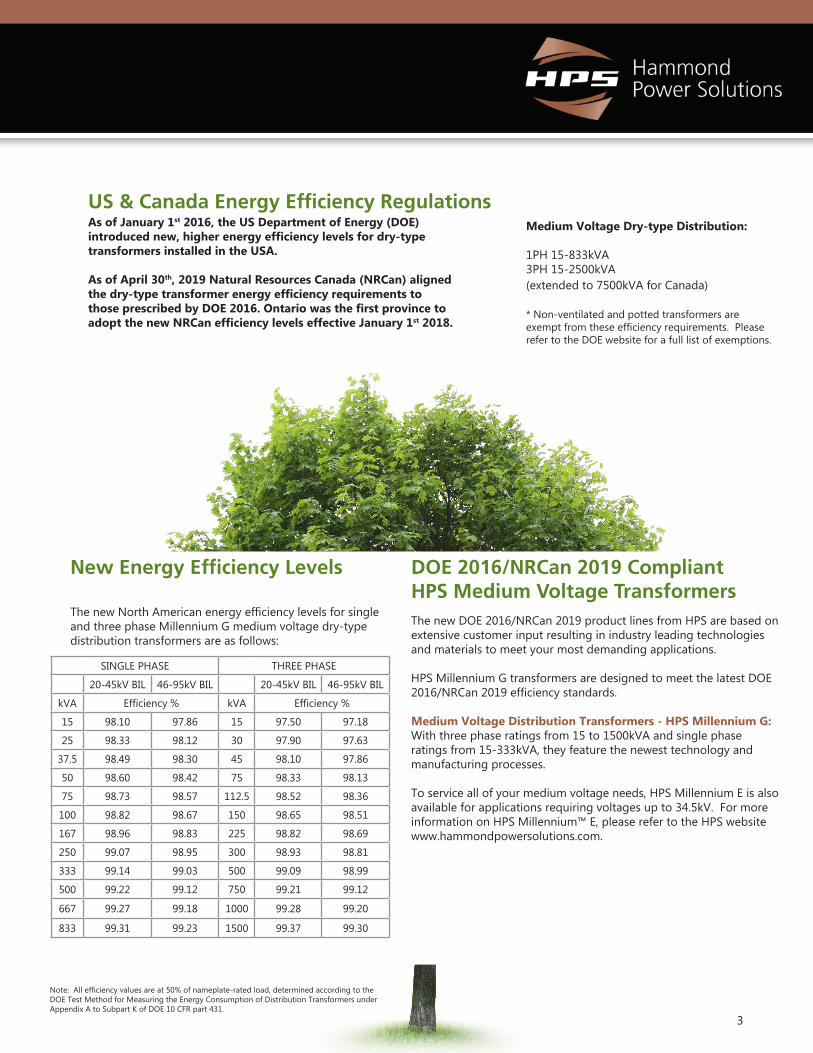
As of January 1st 2016, the US Department of Energy (DOE) introduced new, higher energy efficiency levels for dry-type transformers installed in the USA.
As of April 30th, 2019 Natural Resources Canada (NRCan) aligned the dry-type transformer energy efficiency requirements to those prescribed by DOE 2016. Ontario was the first province to adopt the new NRCan efficiency levels effective January 1st 2018.
Medium Voltage Dry-type Distribution:
1PH 15-833kVA3PH 15-2500kVA (extended to 7500kVA for Canada)
* Non-ventilated and potted transformers are exempt from these efficiency requirements. Please refer to the DOE website for a full list of exemptions.
US & Canada Energy Efficiency Regulations
New Energy Efficiency Levels
The new North American energy efficiency levels for single and three phase Millennium G medium voltage dry-type distribution transformers are as follows:
SINGLE PHASE THREE PHASE
20-45kV BIL 46-95kV BIL 20-45kV BIL 46-95kV BIL
kVA Efficiency % kVA Efficiency %
15 98.10 97.86 15 97.50 97.18
25 98.33 98.12 30 97.90 97.63
37.5 98.49 98.30 45 98.10 97.86
50 98.60 98.42 75 98.33 98.13
75 98.73 98.57 112.5 98.52 98.36
100 98.82 98.67 150 98.65 98.51
167 98.96 98.83 225 98.82 98.69
250 99.07 98.95 300 98.93 98.81
333 99.14 99.03 500 99.09 98.99
500 99.22 99.12 750 99.21 99.12
667 99.27 99.18 1000 99.28 99.20
833 99.31 99.23 1500 99.37 99.30
Note: All efficiency values are at 50% of nameplate-rated load, determined according to the DOE Test Method for Measuring the Energy Consumption of Distribution Transformers under Appendix A to Subpart K of DOE 10 CFR part 431.
DOE 2016/NRCan 2019 Compliant HPS Medium Voltage TransformersThe new DOE 2016/NRCan 2019 product lines from HPS are based on extensive customer input resulting in industry leading technologies and materials to meet your most demanding applications.
HPS Millennium G transformers are designed to meet the latest DOE 2016/NRCan 2019 efficiency standards.
Medium Voltage Distribution Transformers - HPS Millennium G: With three phase ratings from 15 to 1500kVA and single phase ratings from 15-333kVA, they feature the newest technology and manufacturing processes.
To service all of your medium voltage needs, HPS Millennium E is also available for applications requiring voltages up to 34.5kV. For more information on HPS Millennium™ E, please refer to the HPS website www.hammondpowersolutions.com.

4
HPS MILLENNIUM™ G
APPLICATIONS
Hammond Power Solutions Inc. (HPS) is the industry leading manufacturer of standard and custom dry-type transformers in North America. Every HPS product is built with the quality and dependability you count on.
HPS Millennium™ medium voltage distribution transformers are designed for many demanding and diverse applications, while minimizing both installation and maintenance costs. Coils are precision wound with copper or aluminum conductors with a full vacuum-pressure impregnation (VPI) insulation system.
HPS Millennium™ G is suitable for any commercial, industrial, or renewable energy application. They can be offered for a variety of environmental conditions and built to meet the most onerous duty.
• Industrial• Commercial• Renewable
Energy
HPS ONLINE TOOLSHPS offers many different tools to assist you in the selection of a HPS Transformer, these include an Energy Efficiency Calculator, a Current Calculator and a comprehensive Website.
Efficiency CalculatorCalculate the energy consumption (kWh), energy costs, and energy dollar savings using HPS energy efficient distribution transformers within a selected application profile. www.hammondpowersolutions.com/hps-toolbox
Current CalculatorCalculates the Amps, Volts or kVA of a transformer.www.hammondpowersolutions.com/hps-toolbox
HPS WebsiteOur HPS website has useful information to assist you when selecting and installing a transformer. These include a competitor cross reference tool, installation manuals, typical specifications, and warranty information.www.hammondpowersolutions.com/hps-toolbox
Wall mounting brackets(limited to lower kVA ratings and may
require optional hardware)
Standard type 3R enclosure drip shield
Expanded neutral bar for multiple customer connections
5
Core & Coil Construction: • Manufactured from quality non-aging, cold rolled grain
oriented, silicon steel laminations• Cores are precision cut to close tolerances which
eliminates burrs and improves performance• Core is coated to resist oxidation• Precision wound with copper or aluminum conductors
that are electrically balanced to minimize axial forces during short-circuit conditions
• Wire or foil conductors for optimum performance for the application
• Robust interface between core & coils for better short circuit performance
• Front accessible separate high and low voltage terminals with connectors suitable for either copper or aluminum cables.
Conductor material: Copper or AluminumTemperature rise: 150ºC typical (low rise options available)Insulation system: 200ºC or 220ºC
FEATURES BENEFITS• Meets the minimum efficiency standards mandated in
DOE 10 CFR Part 431 (levels as of Jan. 1st 2016), NRCan 2019 SOR/2018-201 (effective April 30th, 2019), resulting in increased dollar savings and positive societal/environmental payback
• Designed for indoor or outdoor applications • VPI windings are mechanically durable for the most
demanding environments • Minimal maintenance required beyond removing surface
contaminants, such as dust• Ease of installation• Excellent resistance to short circuits• Self-extinguishing in the unlikely event of fire• Environmentally friendly
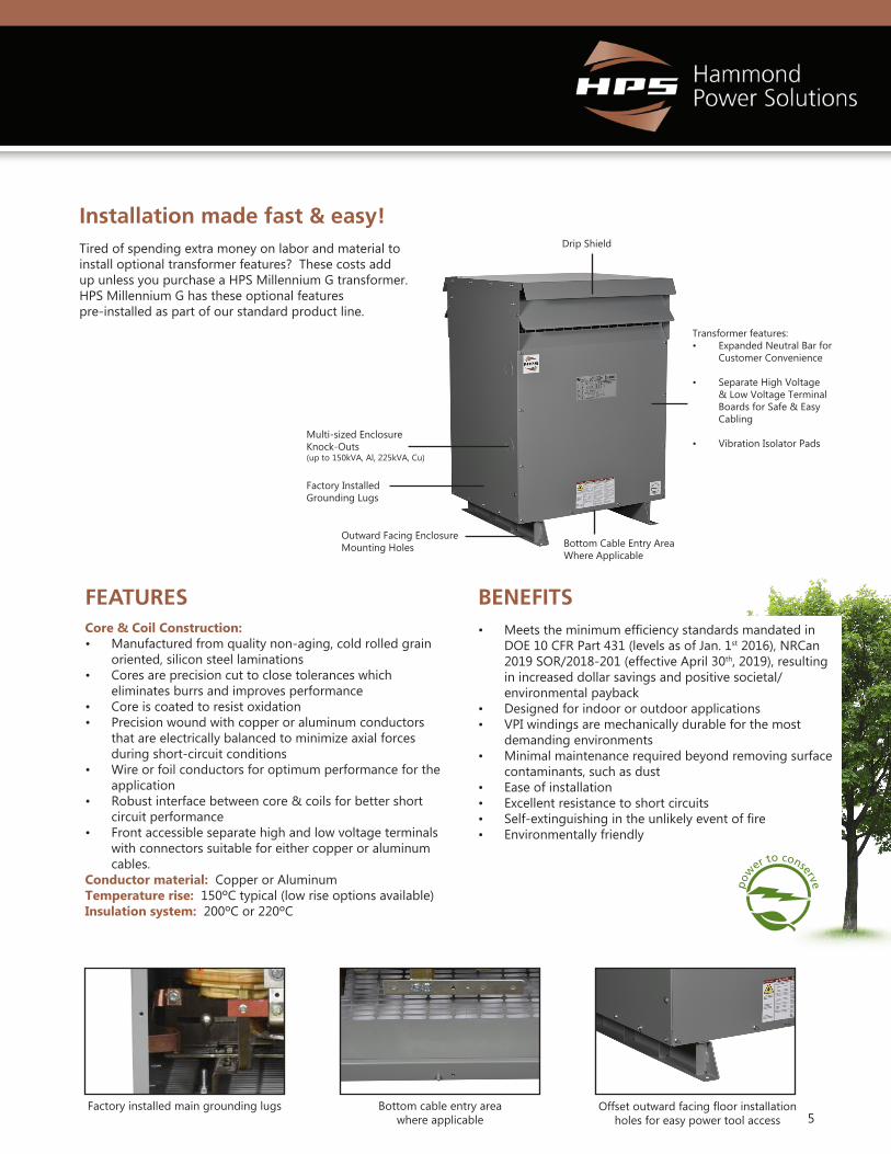
Outward Facing Enclosure Mounting Holes
Drip Shield
Bottom cable entry area where applicable
Transformer features:• Expanded Neutral Bar for
Customer Convenience
• Separate High Voltage & Low Voltage Terminal Boards for Safe & Easy Cabling
• Vibration Isolator Pads Multi-sized Enclosure Knock-Outs (up to 150kVA, Al, 225kVA, Cu)
Installation made fast & easy!Tired of spending extra money on labor and material to install optional transformer features? These costs add up unless you purchase a HPS Millennium G transformer. HPS Millennium G has these optional features pre-installed as part of our standard product line.
Bottom Cable Entry Area Where Applicable
Factory Installed Grounding Lugs
Offset outward facing floor installation holes for easy power tool access
Factory installed main grounding lugs
6
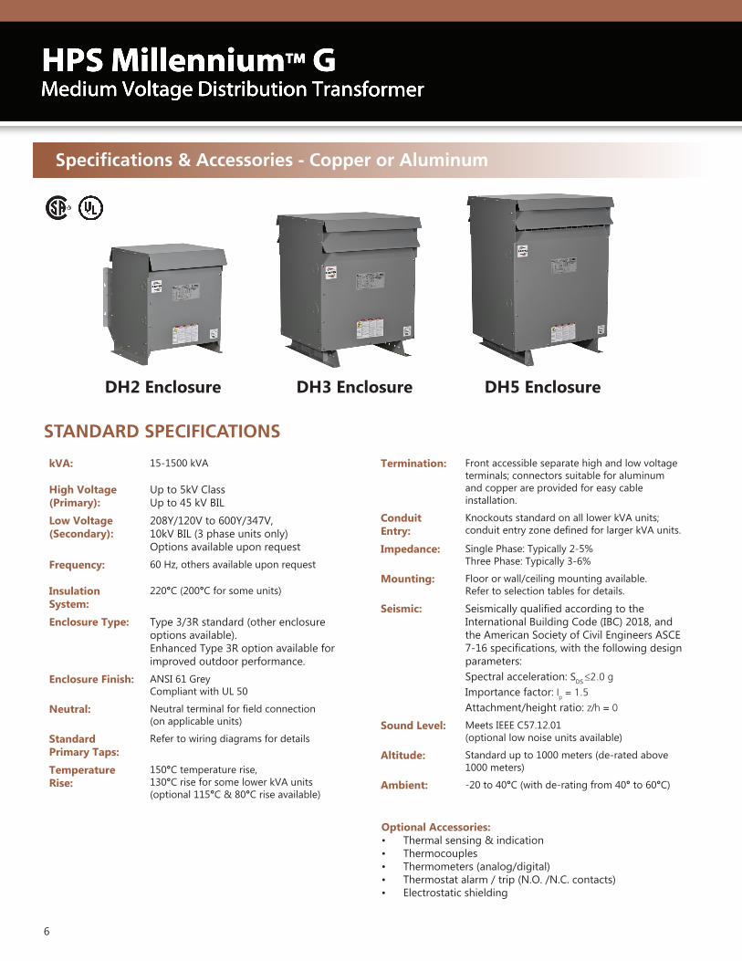
Specifications & Accessories - Copper or Aluminum
DH3 Enclosure DH5 EnclosureDH2 Enclosure
kVA: 15-1500 kVA
High Voltage (Primary):
Up to 5kV Class Up to 45 kV BIL
Low Voltage (Secondary):
208Y/120V to 600Y/347V, 10kV BIL (3 phase units only)Options available upon request
Frequency: 60 Hz, others available upon request
Insulation System:
220°C (200°C for some units)
Enclosure Type: Type 3/3R standard (other enclosure options available).Enhanced Type 3R option available for improved outdoor performance.
Enclosure Finish: ANSI 61 GreyCompliant with UL 50
Neutral: Neutral terminal for field connection (on applicable units)
Standard Primary Taps:
Refer to wiring diagrams for details
Temperature Rise:
150°C temperature rise,130°C rise for some lower kVA units (optional 115°C & 80°C rise available)
Optional Accessories: • Thermal sensing & indication• Thermocouples• Thermometers (analog/digital)• Thermostat alarm / trip (N.O. /N.C. contacts)• Electrostatic shielding
STANDARD SPECIFICATIONS
Termination: Front accessible separate high and low voltage terminals; connectors suitable for aluminum and copper are provided for easy cable installation.
Conduit Entry:
Knockouts standard on all lower kVA units; conduit entry zone defined for larger kVA units.
Impedance: Single Phase: Typically 2-5%Three Phase: Typically 3-6%
Mounting: Floor or wall/ceiling mounting available. Refer to selection tables for details.
Seismic: Seismically qualified according to the International Building Code (IBC) 2018, and the American Society of Civil Engineers ASCE 7-16 specifications, with the following design parameters: Spectral acceleration: SDS ≤2.0 g Importance factor: Ip = 1.5 Attachment/height ratio: z/h = 0
Sound Level: Meets IEEE C57.12.01(optional low noise units available)
Altitude: Standard up to 1000 meters (de-rated above 1000 meters)
Ambient: -20 to 40°C (with de-rating from 40° to 60°C)
7
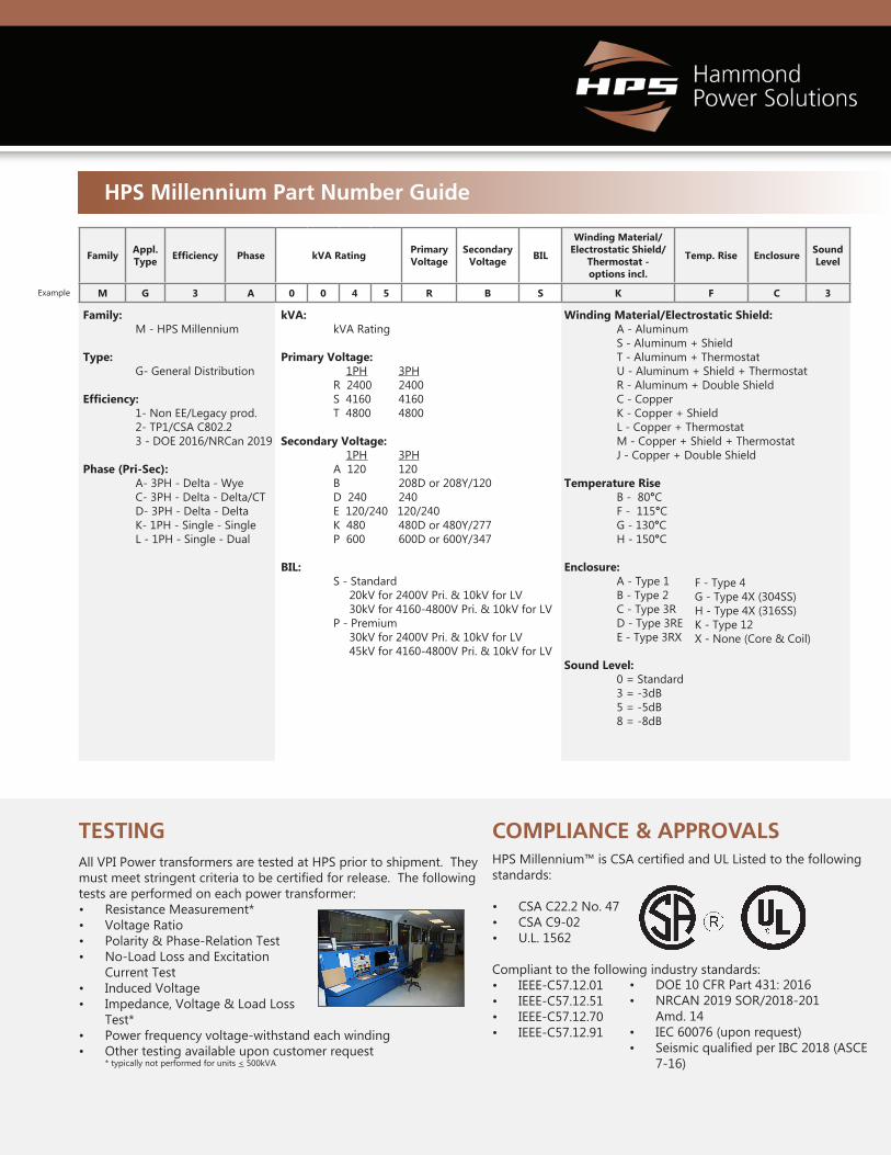
Family Appl.Type Efficiency Phase kVA Rating Primary
VoltageSecondary
Voltage BIL
Winding Material/Electrostatic Shield/
Thermostat - options incl.
Temp. Rise Enclosure Sound Level
M G 3 A 0 0 4 5 R B S K F C 3
Family: M - HPS Millennium
Type: G- General Distribution
Efficiency: 1- Non EE/Legacy prod. 2- TP1/CSA C802.2 3 - DOE 2016/NRCan 2019
Phase (Pri-Sec): A- 3PH - Delta - Wye C- 3PH - Delta - Delta/CT D- 3PH - Delta - Delta K- 1PH - Single - Single L - 1PH - Single - Dual
kVA: kVA Rating
Primary Voltage: 1PH 3PH R 2400 2400 S 4160 4160 T 4800 4800
Secondary Voltage: 1PH 3PH A 120 120 B 208D or 208Y/120 D 240 240 E 120/240 120/240 K 480 480D or 480Y/277 P 600 600D or 600Y/347
BIL: S - Standard 20kV for 2400V Pri. & 10kV for LV 30kV for 4160-4800V Pri. & 10kV for LV P - Premium 30kV for 2400V Pri. & 10kV for LV 45kV for 4160-4800V Pri. & 10kV for LV
Winding Material/Electrostatic Shield: A - Aluminum S - Aluminum + Shield T - Aluminum + Thermostat U - Aluminum + Shield + Thermostat R - Aluminum + Double Shield C - Copper K - Copper + Shield L - Copper + Thermostat M - Copper + Shield + Thermostat J - Copper + Double Shield
Temperature Rise B - 80°C F - 115°C G - 130°C H - 150°C
Enclosure: A - Type 1 B - Type 2 C - Type 3R D - Type 3RE E - Type 3RX Sound Level: 0 = Standard 3 = -3dB 5 = -5dB 8 = -8dB
Example
HPS Millennium Part Number Guide
TESTINGAll VPI Power transformers are tested at HPS prior to shipment. They must meet stringent criteria to be certified for release. The following tests are performed on each power transformer:• Resistance Measurement*• Voltage Ratio• Polarity & Phase-Relation Test• No-Load Loss and Excitation
Current Test• Induced Voltage• Impedance, Voltage & Load Loss
Test*• Power frequency voltage-withstand each winding• Other testing available upon customer request * typically not performed for units < 500kVA
COMPLIANCE & APPROVALSHPS Millennium™ is CSA certified and UL Listed to the following standards:
• CSA C22.2 No. 47• CSA C9-02• U.L. 1562
Compliant to the following industry standards:• IEEE-C57.12.01• IEEE-C57.12.51• IEEE-C57.12.70• IEEE-C57.12.91
• DOE 10 CFR Part 431: 2016• NRCAN 2019 SOR/2018-201
Amd. 14• IEC 60076 (upon request)• Seismic qualified per IBC 2018 (ASCE
7-16)
F - Type 4G - Type 4X (304SS)H - Type 4X (316SS)K - Type 12X - None (Core & Coil)
8 Data subject to change without notice.
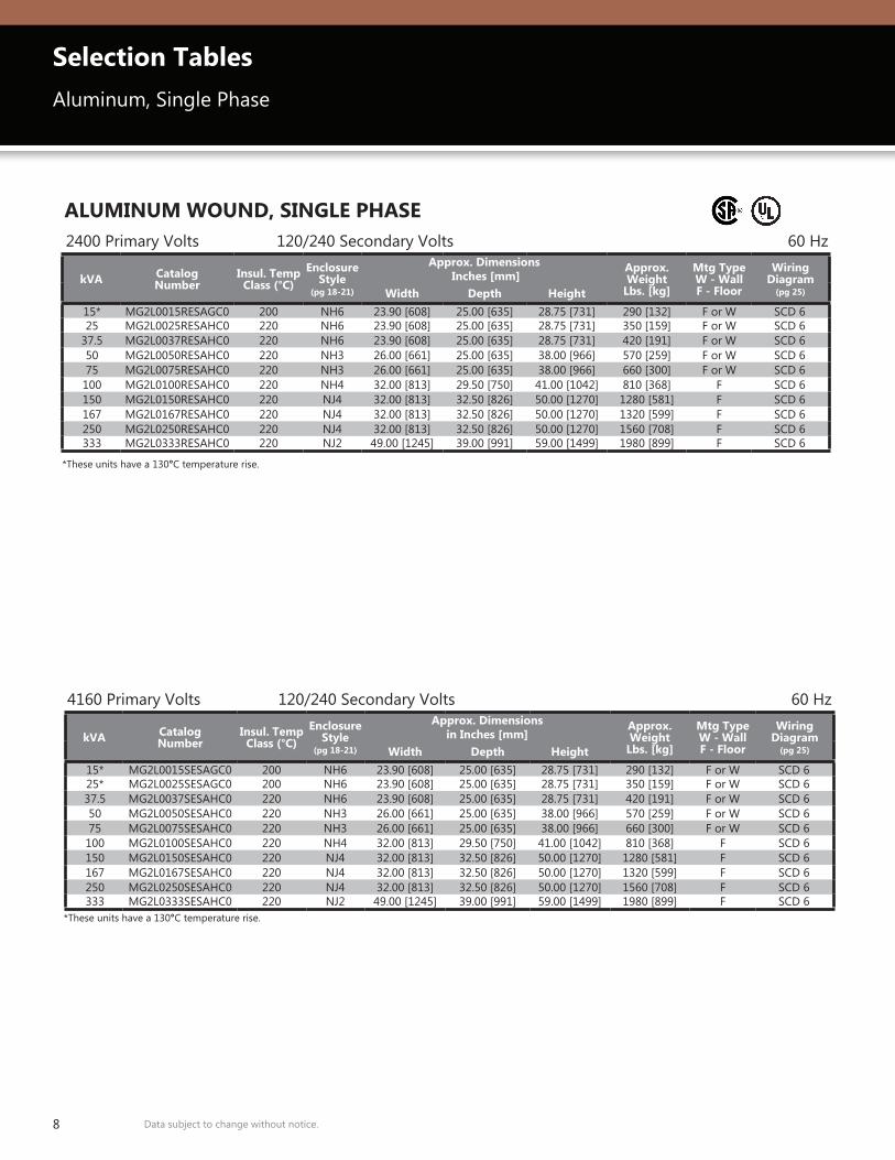
Selection TablesAluminum, Single Phase
ALUMINUM WOUND, SINGLE PHASE2400 Primary Volts 120/240 Secondary Volts 60 Hz
kVA Catalog Number
Insul. Temp Class (°C)
EnclosureStyle
(pg 18-21)
Approx. Dimensions Inches [mm]
Approx. Weight
Lbs. [kg]
Mtg TypeW - WallF - Floor
Wiring Diagram
(pg 25)Width Depth Height15* MG2L0015RESAGC0 200 NH6 23.90 [608] 25.00 [635] 28.75 [731] 290 [132] F or W SCD 625 MG2L0025RESAHC0 220 NH6 23.90 [608] 25.00 [635] 28.75 [731] 350 [159] F or W SCD 6
37.5 MG2L0037RESAHC0 220 NH6 23.90 [608] 25.00 [635] 28.75 [731] 420 [191] F or W SCD 650 MG2L0050RESAHC0 220 NH3 26.00 [661] 25.00 [635] 38.00 [966] 570 [259] F or W SCD 675 MG2L0075RESAHC0 220 NH3 26.00 [661] 25.00 [635] 38.00 [966] 660 [300] F or W SCD 6100 MG2L0100RESAHC0 220 NH4 32.00 [813] 29.50 [750] 41.00 [1042] 810 [368] F SCD 6150 MG2L0150RESAHC0 220 NJ4 32.00 [813] 32.50 [826] 50.00 [1270] 1280 [581] F SCD 6167 MG2L0167RESAHC0 220 NJ4 32.00 [813] 32.50 [826] 50.00 [1270] 1320 [599] F SCD 6250 MG2L0250RESAHC0 220 NJ4 32.00 [813] 32.50 [826] 50.00 [1270] 1560 [708] F SCD 6333 MG2L0333RESAHC0 220 NJ2 49.00 [1245] 39.00 [991] 59.00 [1499] 1980 [899] F SCD 6
4160 Primary Volts 120/240 Secondary Volts 60 Hz
*These units have a 130°C temperature rise.
*These units have a 130°C temperature rise.
kVA Catalog Number
Insul. Temp Class (°C)
EnclosureStyle
(pg 18-21)
Approx. Dimensions in Inches [mm]
Approx. Weight
Lbs. [kg]
Mtg TypeW - WallF - Floor
Wiring Diagram
(pg 25)Width Depth Height15* MG2L0015SESAGC0 200 NH6 23.90 [608] 25.00 [635] 28.75 [731] 290 [132] F or W SCD 625* MG2L0025SESAGC0 200 NH6 23.90 [608] 25.00 [635] 28.75 [731] 350 [159] F or W SCD 637.5 MG2L0037SESAHC0 220 NH6 23.90 [608] 25.00 [635] 28.75 [731] 420 [191] F or W SCD 650 MG2L0050SESAHC0 220 NH3 26.00 [661] 25.00 [635] 38.00 [966] 570 [259] F or W SCD 675 MG2L0075SESAHC0 220 NH3 26.00 [661] 25.00 [635] 38.00 [966] 660 [300] F or W SCD 6100 MG2L0100SESAHC0 220 NH4 32.00 [813] 29.50 [750] 41.00 [1042] 810 [368] F SCD 6150 MG2L0150SESAHC0 220 NJ4 32.00 [813] 32.50 [826] 50.00 [1270] 1280 [581] F SCD 6167 MG2L0167SESAHC0 220 NJ4 32.00 [813] 32.50 [826] 50.00 [1270] 1320 [599] F SCD 6250 MG2L0250SESAHC0 220 NJ4 32.00 [813] 32.50 [826] 50.00 [1270] 1560 [708] F SCD 6333 MG2L0333SESAHC0 220 NJ2 49.00 [1245] 39.00 [991] 59.00 [1499] 1980 [899] F SCD 6
9Data subject to change without notice.
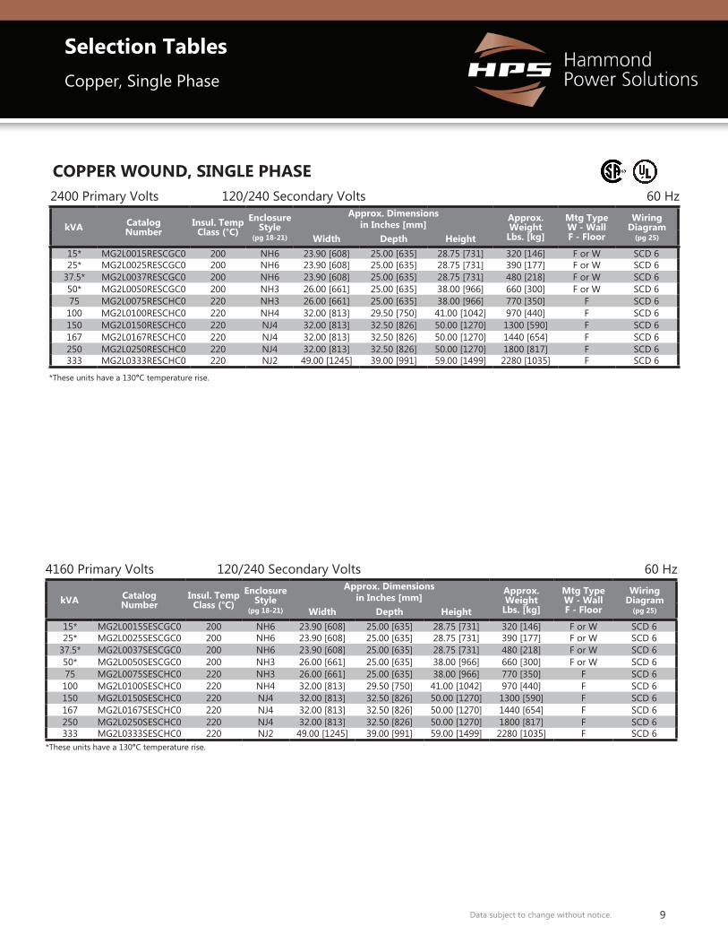
Selection TablesCopper, Single Phase
COPPER WOUND, SINGLE PHASE2400 Primary Volts 120/240 Secondary Volts 60 Hz
4160 Primary Volts 120/240 Secondary Volts 60 Hz
*These units have a 130°C temperature rise.
*These units have a 130°C temperature rise.
kVA Catalog Number
Insul. Temp Class (°C)
EnclosureStyle
(pg 18-21)
Approx. Dimensions in Inches [mm]
Approx. Weight
Lbs. [kg]
Mtg TypeW - WallF - Floor
Wiring Diagram
(pg 25)Width Depth Height15* MG2L0015RESCGC0 200 NH6 23.90 [608] 25.00 [635] 28.75 [731] 320 [146] F or W SCD 625* MG2L0025RESCGC0 200 NH6 23.90 [608] 25.00 [635] 28.75 [731] 390 [177] F or W SCD 6
37.5* MG2L0037RESCGC0 200 NH6 23.90 [608] 25.00 [635] 28.75 [731] 480 [218] F or W SCD 650* MG2L0050RESCGC0 200 NH3 26.00 [661] 25.00 [635] 38.00 [966] 660 [300] F or W SCD 675 MG2L0075RESCHC0 220 NH3 26.00 [661] 25.00 [635] 38.00 [966] 770 [350] F SCD 6100 MG2L0100RESCHC0 220 NH4 32.00 [813] 29.50 [750] 41.00 [1042] 970 [440] F SCD 6150 MG2L0150RESCHC0 220 NJ4 32.00 [813] 32.50 [826] 50.00 [1270] 1300 [590] F SCD 6167 MG2L0167RESCHC0 220 NJ4 32.00 [813] 32.50 [826] 50.00 [1270] 1440 [654] F SCD 6250 MG2L0250RESCHC0 220 NJ4 32.00 [813] 32.50 [826] 50.00 [1270] 1800 [817] F SCD 6333 MG2L0333RESCHC0 220 NJ2 49.00 [1245] 39.00 [991] 59.00 [1499] 2280 [1035] F SCD 6
kVA Catalog Number
Insul. Temp Class (°C)
EnclosureStyle
(pg 18-21)
Approx. Dimensions in Inches [mm]
Approx. Weight
Lbs. [kg]
Mtg TypeW - WallF - Floor
Wiring Diagram
(pg 25)Width Depth Height15* MG2L0015SESCGC0 200 NH6 23.90 [608] 25.00 [635] 28.75 [731] 320 [146] F or W SCD 625* MG2L0025SESCGC0 200 NH6 23.90 [608] 25.00 [635] 28.75 [731] 390 [177] F or W SCD 6
37.5* MG2L0037SESCGC0 200 NH6 23.90 [608] 25.00 [635] 28.75 [731] 480 [218] F or W SCD 650* MG2L0050SESCGC0 200 NH3 26.00 [661] 25.00 [635] 38.00 [966] 660 [300] F or W SCD 675 MG2L0075SESCHC0 220 NH3 26.00 [661] 25.00 [635] 38.00 [966] 770 [350] F SCD 6100 MG2L0100SESCHC0 220 NH4 32.00 [813] 29.50 [750] 41.00 [1042] 970 [440] F SCD 6150 MG2L0150SESCHC0 220 NJ4 32.00 [813] 32.50 [826] 50.00 [1270] 1300 [590] F SCD 6167 MG2L0167SESCHC0 220 NJ4 32.00 [813] 32.50 [826] 50.00 [1270] 1440 [654] F SCD 6250 MG2L0250SESCHC0 220 NJ4 32.00 [813] 32.50 [826] 50.00 [1270] 1800 [817] F SCD 6333 MG2L0333SESCHC0 220 NJ2 49.00 [1245] 39.00 [991] 59.00 [1499] 2280 [1035] F SCD 6
10 Data subject to change without notice.
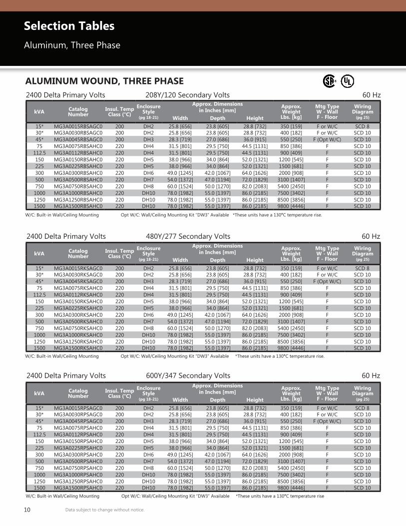
ALUMINUM WOUND, THREE PHASE2400 Delta Primary Volts 208Y/120 Secondary Volts 60 Hz
2400 Delta Primary Volts 480Y/277 Secondary Volts 60 Hz
W/C: Built-in Wall/Ceiling Mounting Opt W/C: Wall/Ceiling Mounting Kit “DW3” Available *These units have a 130°C temperature rise.
W/C: Built-in Wall/Ceiling Mounting Opt W/C: Wall/Ceiling Mounting Kit “DW3” Available *These units have a 130°C temperature rise.
2400 Delta Primary Volts 600Y/347 Secondary Volts 60 Hz
W/C: Built-in Wall/Ceiling Mounting Opt W/C: Wall/Ceiling Mounting Kit “DW3” Available *These units have a 130°C temperature rise
Selection TablesAluminum, Three Phase
kVA Catalog Number
Insul. Temp Class (°C)
EnclosureStyle
(pg 18-21)
Approx. Dimensions in Inches [mm]
Approx. Weight
Lbs. [kg]
Mtg TypeW - WallF - Floor
Wiring Diagram
(pg 25)Width Depth Height15* MG3A0015RBSAGC0 200 DH2 25.8 [656] 23.8 [605] 28.8 [732] 350 [159] F or W/C SCD 830* MG3A0030RBSAGC0 200 DH2 25.8 [656] 23.8 [605] 28.8 [732] 400 [182] F or W/C SCD 1045* MG3A0045RBSAGC0 200 DH3 28.3 [719] 27.0 [686] 36.0 [915] 550 [250] F (Opt W/C) SCD 1075 MG3A0075RBSAHC0 220 DH4 31.5 [801] 29.5 [750] 44.5 [1131] 850 [386] F SCD 10
112.5 MG3A0112RBSAHC0 220 DH4 31.5 [801] 29.5 [750] 44.5 [1131] 900 [409] F SCD 10150 MG3A0150RBSAHC0 220 DH5 38.0 [966] 34.0 [864] 52.0 [1321] 1200 [545] F SCD 10225 MG3A0225RBSAHC0 220 DH5 38.0 [966] 34.0 [864] 52.0 [1321] 1500 [681] F SCD 10300 MG3A0300RBSAHC0 220 DH6 49.0 [1245] 42.0 [1067] 64.0 [1626] 2000 [908] F SCD 10500 MG3A0500RBSAHC0 220 DH7 54.0 [1372] 47.0 [1194] 72.0 [1829] 3100 [1407] F SCD 10750 MG3A0750RBSAHC0 220 DH8 60.0 [1524] 50.0 [1270] 82.0 [2083] 5400 [2450] F SCD 101000 MG3A1000RBSAHC0 220 DH10 78.0 [1982] 55.0 [1397] 86.0 [2185] 7500 [3402] F SCD 101250 MG3A1250RBSAHC0 220 DH10 78.0 [1982] 55.0 [1397] 86.0 [2185] 8500 [3856] F SCD 101500 MG3A1500RBSAHC0 220 DH10 78.0 [1982] 55.0 [1397] 86.0 [2185] 9800 [4446] F SCD 10
kVA Catalog Number
Insul. Temp Class (°C)
EnclosureStyle
(pg 18-21)
Approx. Dimensions in Inches [mm]
Approx. Weight
Lbs. [kg]
Mtg TypeW - WallF - Floor
Wiring Diagram
(pg 25)Width Depth Height15* MG3A0015RKSAGC0 200 DH2 25.8 [656] 23.8 [605] 28.8 [732] 350 [159] F or W/C SCD 830* MG3A0030RKSAGC0 200 DH2 25.8 [656] 23.8 [605] 28.8 [732] 400 [182] F or W/C SCD 1045* MG3A0045RKSAGC0 200 DH3 28.3 [719] 27.0 [686] 36.0 [915] 550 [250] F (Opt W/C) SCD 1075 MG3A0075RKSAHC0 220 DH4 31.5 [801] 29.5 [750] 44.5 [1131] 850 [386] F SCD 10
112.5 MG3A0112RKSAHC0 220 DH4 31.5 [801] 29.5 [750] 44.5 [1131] 900 [409] F SCD 10150 MG3A0150RKSAHC0 220 DH5 38.0 [966] 34.0 [864] 52.0 [1321] 1200 [545] F SCD 10225 MG3A0225RKSAHC0 220 DH5 38.0 [966] 34.0 [864] 52.0 [1321] 1500 [681] F SCD 10300 MG3A0300RKSAHC0 220 DH6 49.0 [1245] 42.0 [1067] 64.0 [1626] 2000 [908] F SCD 10500 MG3A0500RKSAHC0 220 DH7 54.0 [1372] 47.0 [1194] 72.0 [1829] 3100 [1407] F SCD 10750 MG3A0750RKSAHC0 220 DH8 60.0 [1524] 50.0 [1270] 82.0 [2083] 5400 [2450] F SCD 101000 MG3A1000RKSAHC0 220 DH10 78.0 [1982] 55.0 [1397] 86.0 [2185] 7500 [3402] F SCD 101250 MG3A1250RKSAHC0 220 DH10 78.0 [1982] 55.0 [1397] 86.0 [2185] 8500 [3856] F SCD 101500 MG3A1500RKSAHC0 220 DH10 78.0 [1982] 55.0 [1397] 86.0 [2185] 9800 [4446] F SCD 10
kVA Catalog Number
Insul. Temp Class (°C)
EnclosureStyle
(pg 18-21)
Approx. Dimensions in Inches [mm]
Approx. Weight
Lbs. [kg]
Mtg TypeW - WallF - Floor
Wiring Diagram
(pg 25)Width Depth Height15* MG3A0015RPSAGC0 200 DH2 25.8 [656] 23.8 [605] 28.8 [732] 350 [159] F or W/C SCD 830* MG3A0030RPSAGC0 200 DH2 25.8 [656] 23.8 [605] 28.8 [732] 400 [182] F or W/C SCD 1045* MG3A0045RPSAGC0 200 DH3 28.3 [719] 27.0 [686] 36.0 [915] 550 [250] F (Opt W/C) SCD 1075 MG3A0075RPSAHC0 220 DH4 31.5 [801] 29.5 [750] 44.5 [1131] 850 [386] F SCD 10
112.5 MG3A0112RPSAHC0 220 DH4 31.5 [801] 29.5 [750] 44.5 [1131] 900 [409] F SCD 10150 MG3A0150RPSAHC0 220 DH5 38.0 [966] 34.0 [864] 52.0 [1321] 1200 [545] F SCD 10225 MG3A0225RPSAHC0 220 DH5 38.0 [966] 34.0 [864] 52.0 [1321] 1500 [681] F SCD 10300 MG3A0300RPSAHC0 220 DH6 49.0 [1245] 42.0 [1067] 64.0 [1626] 2000 [908] F SCD 10500 MG3A0500RPSAHC0 220 DH7 54.0 [1372] 47.0 [1194] 72.0 [1829] 3100 [1407] F SCD 10750 MG3A0750RPSAHC0 220 DH8 60.0 [1524] 50.0 [1270] 82.0 [2083] 5400 [2450] F SCD 101000 MG3A1000RPSAHC0 220 DH10 78.0 [1982] 55.0 [1397] 86.0 [2185] 7500 [3402] F SCD 101250 MG3A1250RPSAHC0 220 DH10 78.0 [1982] 55.0 [1397] 86.0 [2185] 8500 [3856] F SCD 101500 MG3A1500RPSAHC0 220 DH10 78.0 [1982] 55.0 [1397] 86.0 [2185] 9800 [4446] F SCD 10
11Data subject to change without notice.
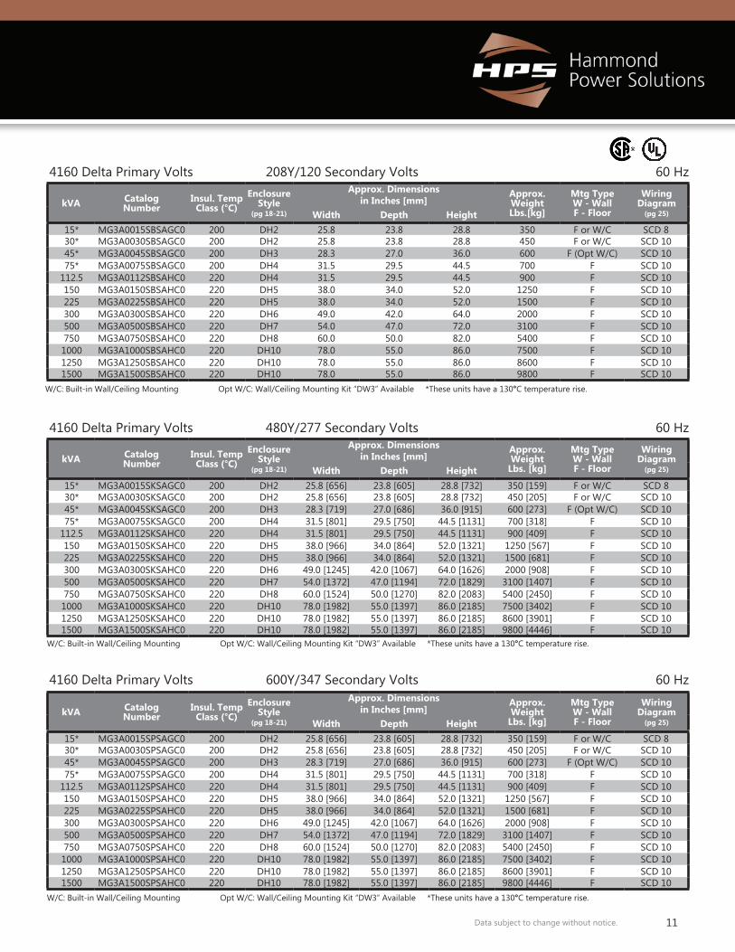
4160 Delta Primary Volts 208Y/120 Secondary Volts 60 Hz
W/C: Built-in Wall/Ceiling Mounting Opt W/C: Wall/Ceiling Mounting Kit “DW3” Available *These units have a 130°C temperature rise.
4160 Delta Primary Volts 480Y/277 Secondary Volts 60 Hz
W/C: Built-in Wall/Ceiling Mounting Opt W/C: Wall/Ceiling Mounting Kit “DW3” Available *These units have a 130°C temperature rise.
4160 Delta Primary Volts 600Y/347 Secondary Volts 60 Hz
W/C: Built-in Wall/Ceiling Mounting Opt W/C: Wall/Ceiling Mounting Kit “DW3” Available *These units have a 130°C temperature rise.
kVA Catalog Number
Insul. Temp Class (°C)
EnclosureStyle
(pg 18-21)
Approx. Dimensions in Inches [mm]
Approx. Weight Lbs.[kg]
Mtg TypeW - WallF - Floor
Wiring Diagram
(pg 25)Width Depth Height15* MG3A0015SBSAGC0 200 DH2 25.8 23.8 28.8 350 F or W/C SCD 830* MG3A0030SBSAGC0 200 DH2 25.8 23.8 28.8 450 F or W/C SCD 1045* MG3A0045SBSAGC0 200 DH3 28.3 27.0 36.0 600 F (Opt W/C) SCD 1075* MG3A0075SBSAGC0 200 DH4 31.5 29.5 44.5 700 F SCD 10
112.5 MG3A0112SBSAHC0 220 DH4 31.5 29.5 44.5 900 F SCD 10150 MG3A0150SBSAHC0 220 DH5 38.0 34.0 52.0 1250 F SCD 10225 MG3A0225SBSAHC0 220 DH5 38.0 34.0 52.0 1500 F SCD 10300 MG3A0300SBSAHC0 220 DH6 49.0 42.0 64.0 2000 F SCD 10500 MG3A0500SBSAHC0 220 DH7 54.0 47.0 72.0 3100 F SCD 10750 MG3A0750SBSAHC0 220 DH8 60.0 50.0 82.0 5400 F SCD 101000 MG3A1000SBSAHC0 220 DH10 78.0 55.0 86.0 7500 F SCD 101250 MG3A1250SBSAHC0 220 DH10 78.0 55.0 86.0 8600 F SCD 101500 MG3A1500SBSAHC0 220 DH10 78.0 55.0 86.0 9800 F SCD 10
kVA Catalog Number
Insul. Temp Class (°C)
EnclosureStyle
(pg 18-21)
Approx. Dimensions in Inches [mm]
Approx. Weight
Lbs. [kg]
Mtg TypeW - WallF - Floor
Wiring Diagram
(pg 25)Width Depth Height15* MG3A0015SKSAGC0 200 DH2 25.8 [656] 23.8 [605] 28.8 [732] 350 [159] F or W/C SCD 830* MG3A0030SKSAGC0 200 DH2 25.8 [656] 23.8 [605] 28.8 [732] 450 [205] F or W/C SCD 1045* MG3A0045SKSAGC0 200 DH3 28.3 [719] 27.0 [686] 36.0 [915] 600 [273] F (Opt W/C) SCD 1075* MG3A0075SKSAGC0 200 DH4 31.5 [801] 29.5 [750] 44.5 [1131] 700 [318] F SCD 10
112.5 MG3A0112SKSAHC0 220 DH4 31.5 [801] 29.5 [750] 44.5 [1131] 900 [409] F SCD 10150 MG3A0150SKSAHC0 220 DH5 38.0 [966] 34.0 [864] 52.0 [1321] 1250 [567] F SCD 10225 MG3A0225SKSAHC0 220 DH5 38.0 [966] 34.0 [864] 52.0 [1321] 1500 [681] F SCD 10300 MG3A0300SKSAHC0 220 DH6 49.0 [1245] 42.0 [1067] 64.0 [1626] 2000 [908] F SCD 10500 MG3A0500SKSAHC0 220 DH7 54.0 [1372] 47.0 [1194] 72.0 [1829] 3100 [1407] F SCD 10750 MG3A0750SKSAHC0 220 DH8 60.0 [1524] 50.0 [1270] 82.0 [2083] 5400 [2450] F SCD 101000 MG3A1000SKSAHC0 220 DH10 78.0 [1982] 55.0 [1397] 86.0 [2185] 7500 [3402] F SCD 101250 MG3A1250SKSAHC0 220 DH10 78.0 [1982] 55.0 [1397] 86.0 [2185] 8600 [3901] F SCD 101500 MG3A1500SKSAHC0 220 DH10 78.0 [1982] 55.0 [1397] 86.0 [2185] 9800 [4446] F SCD 10
kVA Catalog Number
Insul. Temp Class (°C)
EnclosureStyle
(pg 18-21)
Approx. Dimensions in Inches [mm]
Approx. Weight
Lbs. [kg]
Mtg TypeW - WallF - Floor
Wiring Diagram
(pg 25)Width Depth Height15* MG3A0015SPSAGC0 200 DH2 25.8 [656] 23.8 [605] 28.8 [732] 350 [159] F or W/C SCD 830* MG3A0030SPSAGC0 200 DH2 25.8 [656] 23.8 [605] 28.8 [732] 450 [205] F or W/C SCD 1045* MG3A0045SPSAGC0 200 DH3 28.3 [719] 27.0 [686] 36.0 [915] 600 [273] F (Opt W/C) SCD 1075* MG3A0075SPSAGC0 200 DH4 31.5 [801] 29.5 [750] 44.5 [1131] 700 [318] F SCD 10
112.5 MG3A0112SPSAHC0 220 DH4 31.5 [801] 29.5 [750] 44.5 [1131] 900 [409] F SCD 10150 MG3A0150SPSAHC0 220 DH5 38.0 [966] 34.0 [864] 52.0 [1321] 1250 [567] F SCD 10225 MG3A0225SPSAHC0 220 DH5 38.0 [966] 34.0 [864] 52.0 [1321] 1500 [681] F SCD 10300 MG3A0300SPSAHC0 220 DH6 49.0 [1245] 42.0 [1067] 64.0 [1626] 2000 [908] F SCD 10500 MG3A0500SPSAHC0 220 DH7 54.0 [1372] 47.0 [1194] 72.0 [1829] 3100 [1407] F SCD 10750 MG3A0750SPSAHC0 220 DH8 60.0 [1524] 50.0 [1270] 82.0 [2083] 5400 [2450] F SCD 101000 MG3A1000SPSAHC0 220 DH10 78.0 [1982] 55.0 [1397] 86.0 [2185] 7500 [3402] F SCD 101250 MG3A1250SPSAHC0 220 DH10 78.0 [1982] 55.0 [1397] 86.0 [2185] 8600 [3901] F SCD 101500 MG3A1500SPSAHC0 220 DH10 78.0 [1982] 55.0 [1397] 86.0 [2185] 9800 [4446] F SCD 10
12 Data subject to change without notice.
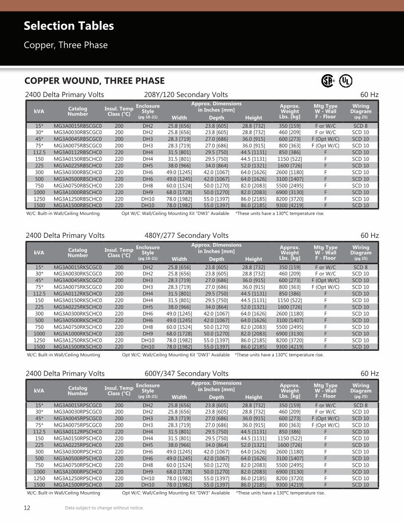
COPPER WOUND, THREE PHASE2400 Delta Primary Volts 208Y/120 Secondary Volts 60 Hz
2400 Delta Primary Volts 480Y/277 Secondary Volts 60 Hz
W/C: Built-in Wall/Ceiling Mounting Opt W/C: Wall/Ceiling Mounting Kit “DW3” Available *These units have a 130°C temperature rise.
W/C: Built-in Wall/Ceiling Mounting Opt W/C: Wall/Ceiling Mounting Kit “DW3” Available *These units have a 130°C temperature rise.
2400 Delta Primary Volts 600Y/347 Secondary Volts 60 Hz
W/C: Built-in Wall/Ceiling Mounting Opt W/C: Wall/Ceiling Mounting Kit “DW3” Available *These units have a 130°C temperature rise.
Selection TablesCopper, Three Phase
kVA Catalog Number
Insul. Temp Class (°C)
EnclosureStyle
(pg 18-21)
Approx. Dimensions in Inches [mm]
Approx. Weight
Lbs. [kg]
Mtg TypeW - WallF - Floor
Wiring Diagram
(pg 25)Width Depth Height15* MG3A0015RBSCGC0 200 DH2 25.8 [656] 23.8 [605] 28.8 [732] 350 [159] F or W/C SCD 830* MG3A0030RBSCGC0 200 DH2 25.8 [656] 23.8 [605] 28.8 [732] 460 [209] F or W/C SCD 1045* MG3A0045RBSCGC0 200 DH3 28.3 [719] 27.0 [686] 36.0 [915] 600 [273] F (Opt W/C) SCD 1075* MG3A0075RBSCGC0 200 DH3 28.3 [719] 27.0 [686] 36.0 [915] 800 [363] F (Opt W/C) SCD 10
112.5 MG3A0112RBSCHC0 220 DH4 31.5 [801] 29.5 [750] 44.5 [1131] 850 [386] F SCD 10150 MG3A0150RBSCHC0 220 DH4 31.5 [801] 29.5 [750] 44.5 [1131] 1150 [522] F SCD 10225 MG3A0225RBSCHC0 220 DH5 38.0 [966] 34.0 [864] 52.0 [1321] 1600 [726] F SCD 10300 MG3A0300RBSCHC0 220 DH6 49.0 [1245] 42.0 [1067] 64.0 [1626] 2600 [1180] F SCD 10500 MG3A0500RBSCHC0 220 DH6 49.0 [1245] 42.0 [1067] 64.0 [1626] 3100 [1407] F SCD 10750 MG3A0750RBSCHC0 220 DH8 60.0 [1524] 50.0 [1270] 82.0 [2083] 5500 [2495] F SCD 101000 MG3A1000RBSCHC0 220 DH9 68.0 [1728] 50.0 [1270] 82.0 [2083] 6900 [3130] F SCD 101250 MG3A1250RBSCHC0 220 DH10 78.0 [1982] 55.0 [1397] 86.0 [2185] 8200 [3720] F SCD 101500 MG3A1500RBSCHC0 220 DH10 78.0 [1982] 55.0 [1397] 86.0 [2185] 9300 [4219] F SCD 10
kVA Catalog Number
Insul. Temp Class (°C)
EnclosureStyle
(pg 18-21)
Approx. Dimensions in Inches [mm]
Approx. Weight
Lbs. [kg]
Mtg TypeW - WallF - Floor
Wiring Diagram
(pg 25)Width Depth Height15* MG3A0015RKSCGC0 200 DH2 25.8 [656] 23.8 [605] 28.8 [732] 350 [159] F or W/C SCD 830* MG3A0030RKSCGC0 200 DH2 25.8 [656] 23.8 [605] 28.8 [732] 460 [209] F or W/C SCD 1045* MG3A0045RKSCGC0 200 DH3 28.3 [719] 27.0 [686] 36.0 [915] 600 [273] F (Opt W/C) SCD 1075* MG3A0075RKSCGC0 200 DH3 28.3 [719] 27.0 [686] 36.0 [915] 800 [363] F (Opt W/C) SCD 10
112.5 MG3A0112RKSCHC0 220 DH4 31.5 [801] 29.5 [750] 44.5 [1131] 850 [386] F SCD 10150 MG3A0150RKSCHC0 220 DH4 31.5 [801] 29.5 [750] 44.5 [1131] 1150 [522] F SCD 10225 MG3A0225RKSCHC0 220 DH5 38.0 [966] 34.0 [864] 52.0 [1321] 1600 [726] F SCD 10300 MG3A0300RKSCHC0 220 DH6 49.0 [1245] 42.0 [1067] 64.0 [1626] 2600 [1180] F SCD 10500 MG3A0500RKSCHC0 220 DH6 49.0 [1245] 42.0 [1067] 64.0 [1626] 3100 [1407] F SCD 10750 MG3A0750RKSCHC0 220 DH8 60.0 [1524] 50.0 [1270] 82.0 [2083] 5500 [2495] F SCD 101000 MG3A1000RKSCHC0 220 DH9 68.0 [1728] 50.0 [1270] 82.0 [2083] 6900 [3130] F SCD 101250 MG3A1250RKSCHC0 220 DH10 78.0 [1982] 55.0 [1397] 86.0 [2185] 8200 [3720] F SCD 101500 MG3A1500RKSCHC0 220 DH10 78.0 [1982] 55.0 [1397] 86.0 [2185] 9300 [4219] F SCD 10
kVA Catalog Number
Insul. Temp Class (°C)
EnclosureStyle
(pg 18-21)
Approx. Dimensions in Inches [mm]
Approx. Weight
Lbs. [kg]
Mtg TypeW - WallF - Floor
Wiring Diagram
(pg 25)Width Depth Height15* MG3A0015RPSCGC0 200 DH2 25.8 [656] 23.8 [605] 28.8 [732] 350 [159] F or W/C SCD 830* MG3A0030RPSCGC0 200 DH2 25.8 [656] 23.8 [605] 28.8 [732] 460 [209] F or W/C SCD 1045* MG3A0045RPSCGC0 200 DH3 28.3 [719] 27.0 [686] 36.0 [915] 600 [273] F (Opt W/C) SCD 1075* MG3A0075RPSCGC0 200 DH3 28.3 [719] 27.0 [686] 36.0 [915] 800 [363] F (Opt W/C) SCD 10
112.5 MG3A0112RPSCHC0 220 DH4 31.5 [801] 29.5 [750] 44.5 [1131] 850 [386] F SCD 10150 MG3A0150RPSCHC0 220 DH4 31.5 [801] 29.5 [750] 44.5 [1131] 1150 [522] F SCD 10225 MG3A0225RPSCHC0 220 DH5 38.0 [966] 34.0 [864] 52.0 [1321] 1600 [726] F SCD 10300 MG3A0300RPSCHC0 220 DH6 49.0 [1245] 42.0 [1067] 64.0 [1626] 2600 [1180] F SCD 10500 MG3A0500RPSCHC0 220 DH6 49.0 [1245] 42.0 [1067] 64.0 [1626] 3100 [1407] F SCD 10750 MG3A0750RPSCHC0 220 DH8 60.0 [1524] 50.0 [1270] 82.0 [2083] 5500 [2495] F SCD 101000 MG3A1000RPSCHC0 220 DH9 68.0 [1728] 50.0 [1270] 82.0 [2083] 6900 [3130] F SCD 101250 MG3A1250RPSCHC0 220 DH10 78.0 [1982] 55.0 [1397] 86.0 [2185] 8200 [3720] F SCD 101500 MG3A1500RPSCHC0 220 DH10 78.0 [1982] 55.0 [1397] 86.0 [2185] 9300 [4219] F SCD 10
13Data subject to change without notice.
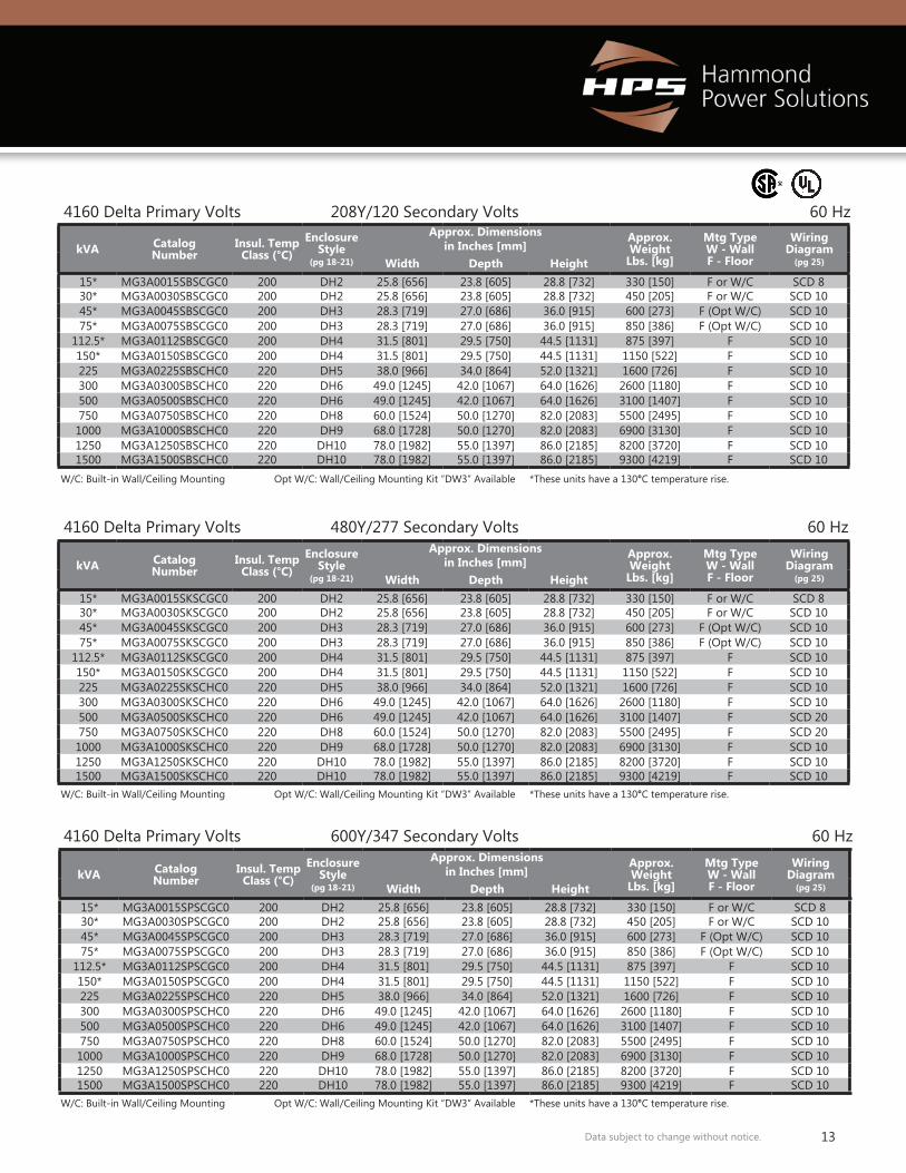
4160 Delta Primary Volts 208Y/120 Secondary Volts 60 Hz
W/C: Built-in Wall/Ceiling Mounting Opt W/C: Wall/Ceiling Mounting Kit “DW3” Available *These units have a 130°C temperature rise.
4160 Delta Primary Volts 480Y/277 Secondary Volts 60 Hz
W/C: Built-in Wall/Ceiling Mounting Opt W/C: Wall/Ceiling Mounting Kit “DW3” Available *These units have a 130°C temperature rise.
4160 Delta Primary Volts 600Y/347 Secondary Volts 60 Hz
W/C: Built-in Wall/Ceiling Mounting Opt W/C: Wall/Ceiling Mounting Kit “DW3” Available *These units have a 130°C temperature rise.
kVA Catalog Number
Insul. Temp Class (°C)
EnclosureStyle
(pg 18-21)
Approx. Dimensions in Inches [mm]
Approx. Weight
Lbs. [kg]
Mtg TypeW - WallF - Floor
Wiring Diagram
(pg 25)Width Depth Height15* MG3A0015SBSCGC0 200 DH2 25.8 [656] 23.8 [605] 28.8 [732] 330 [150] F or W/C SCD 830* MG3A0030SBSCGC0 200 DH2 25.8 [656] 23.8 [605] 28.8 [732] 450 [205] F or W/C SCD 1045* MG3A0045SBSCGC0 200 DH3 28.3 [719] 27.0 [686] 36.0 [915] 600 [273] F (Opt W/C) SCD 1075* MG3A0075SBSCGC0 200 DH3 28.3 [719] 27.0 [686] 36.0 [915] 850 [386] F (Opt W/C) SCD 10
112.5* MG3A0112SBSCGC0 200 DH4 31.5 [801] 29.5 [750] 44.5 [1131] 875 [397] F SCD 10150* MG3A0150SBSCGC0 200 DH4 31.5 [801] 29.5 [750] 44.5 [1131] 1150 [522] F SCD 10225 MG3A0225SBSCHC0 220 DH5 38.0 [966] 34.0 [864] 52.0 [1321] 1600 [726] F SCD 10300 MG3A0300SBSCHC0 220 DH6 49.0 [1245] 42.0 [1067] 64.0 [1626] 2600 [1180] F SCD 10500 MG3A0500SBSCHC0 220 DH6 49.0 [1245] 42.0 [1067] 64.0 [1626] 3100 [1407] F SCD 10750 MG3A0750SBSCHC0 220 DH8 60.0 [1524] 50.0 [1270] 82.0 [2083] 5500 [2495] F SCD 101000 MG3A1000SBSCHC0 220 DH9 68.0 [1728] 50.0 [1270] 82.0 [2083] 6900 [3130] F SCD 101250 MG3A1250SBSCHC0 220 DH10 78.0 [1982] 55.0 [1397] 86.0 [2185] 8200 [3720] F SCD 101500 MG3A1500SBSCHC0 220 DH10 78.0 [1982] 55.0 [1397] 86.0 [2185] 9300 [4219] F SCD 10
kVA Catalog Number
Insul. Temp Class (°C)
EnclosureStyle
(pg 18-21)
Approx. Dimensions in Inches [mm]
Approx. Weight
Lbs. [kg]
Mtg TypeW - WallF - Floor
Wiring Diagram
(pg 25)Width Depth Height15* MG3A0015SKSCGC0 200 DH2 25.8 [656] 23.8 [605] 28.8 [732] 330 [150] F or W/C SCD 830* MG3A0030SKSCGC0 200 DH2 25.8 [656] 23.8 [605] 28.8 [732] 450 [205] F or W/C SCD 1045* MG3A0045SKSCGC0 200 DH3 28.3 [719] 27.0 [686] 36.0 [915] 600 [273] F (Opt W/C) SCD 1075* MG3A0075SKSCGC0 200 DH3 28.3 [719] 27.0 [686] 36.0 [915] 850 [386] F (Opt W/C) SCD 10
112.5* MG3A0112SKSCGC0 200 DH4 31.5 [801] 29.5 [750] 44.5 [1131] 875 [397] F SCD 10150* MG3A0150SKSCGC0 200 DH4 31.5 [801] 29.5 [750] 44.5 [1131] 1150 [522] F SCD 10225 MG3A0225SKSCHC0 220 DH5 38.0 [966] 34.0 [864] 52.0 [1321] 1600 [726] F SCD 10300 MG3A0300SKSCHC0 220 DH6 49.0 [1245] 42.0 [1067] 64.0 [1626] 2600 [1180] F SCD 10500 MG3A0500SKSCHC0 220 DH6 49.0 [1245] 42.0 [1067] 64.0 [1626] 3100 [1407] F SCD 20750 MG3A0750SKSCHC0 220 DH8 60.0 [1524] 50.0 [1270] 82.0 [2083] 5500 [2495] F SCD 201000 MG3A1000SKSCHC0 220 DH9 68.0 [1728] 50.0 [1270] 82.0 [2083] 6900 [3130] F SCD 101250 MG3A1250SKSCHC0 220 DH10 78.0 [1982] 55.0 [1397] 86.0 [2185] 8200 [3720] F SCD 101500 MG3A1500SKSCHC0 220 DH10 78.0 [1982] 55.0 [1397] 86.0 [2185] 9300 [4219] F SCD 10
kVA Catalog Number
Insul. Temp Class (°C)
EnclosureStyle
(pg 18-21)
Approx. Dimensions in Inches [mm]
Approx. Weight
Lbs. [kg]
Mtg TypeW - WallF - Floor
Wiring Diagram
(pg 25)Width Depth Height15* MG3A0015SPSCGC0 200 DH2 25.8 [656] 23.8 [605] 28.8 [732] 330 [150] F or W/C SCD 830* MG3A0030SPSCGC0 200 DH2 25.8 [656] 23.8 [605] 28.8 [732] 450 [205] F or W/C SCD 1045* MG3A0045SPSCGC0 200 DH3 28.3 [719] 27.0 [686] 36.0 [915] 600 [273] F (Opt W/C) SCD 1075* MG3A0075SPSCGC0 200 DH3 28.3 [719] 27.0 [686] 36.0 [915] 850 [386] F (Opt W/C) SCD 10
112.5* MG3A0112SPSCGC0 200 DH4 31.5 [801] 29.5 [750] 44.5 [1131] 875 [397] F SCD 10150* MG3A0150SPSCGC0 200 DH4 31.5 [801] 29.5 [750] 44.5 [1131] 1150 [522] F SCD 10225 MG3A0225SPSCHC0 220 DH5 38.0 [966] 34.0 [864] 52.0 [1321] 1600 [726] F SCD 10300 MG3A0300SPSCHC0 220 DH6 49.0 [1245] 42.0 [1067] 64.0 [1626] 2600 [1180] F SCD 10500 MG3A0500SPSCHC0 220 DH6 49.0 [1245] 42.0 [1067] 64.0 [1626] 3100 [1407] F SCD 10750 MG3A0750SPSCHC0 220 DH8 60.0 [1524] 50.0 [1270] 82.0 [2083] 5500 [2495] F SCD 101000 MG3A1000SPSCHC0 220 DH9 68.0 [1728] 50.0 [1270] 82.0 [2083] 6900 [3130] F SCD 101250 MG3A1250SPSCHC0 220 DH10 78.0 [1982] 55.0 [1397] 86.0 [2185] 8200 [3720] F SCD 101500 MG3A1500SPSCHC0 220 DH10 78.0 [1982] 55.0 [1397] 86.0 [2185] 9300 [4219] F SCD 10
14 Data subject to change without notice.
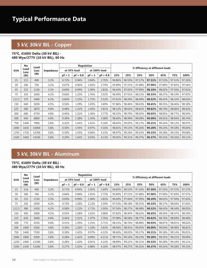
Typical Performance Data
5 kV, 30kV BIL - Copper
75ºC, 4160V Delta (30 kV BIL) - 480 Wye/277V (10 kV BIL), 60 Hz
kVA
No Load Loss(W)
Load Loss (W)
Impedance
Regulation% Efficiency at different loads
at 35% load at 100% load
pf = 1 pf = 0.8 pf = 1 pf = 0.8 15% 25% 35% 50% 65% 75% 100%
15 115 400 3.2% 0.72% 0.94% 2.06% 2.70% 94.86% 96.55% 97.17% 97.51% 97.55% 97.51% 97.26%
30 180 740 3.2% 0.67% 0.96% 1.92% 2.74% 95.89% 97.21% 97.68% 97.90% 97.89% 97.82% 97.56%
45 215 1150 3.3% 0.69% 0.99% 1.99% 2.83% 96.64% 97.65% 97.99% 98.10% 98.02% 97.93% 97.61%
75 320 1650 4.2% 0.60% 1.23% 1.76% 3.52% 96.99% 97.91% 98.22% 98.33% 98.27% 98.19% 97.92%
112.5 370 2460 4.2% 0.60% 1.23% 1.75% 3.52% 97.61% 98.29% 98.49% 98.52% 98.42% 98.32% 98.02%
150 440 3030 4.5% 0.56% 1.29% 1.65% 3.69% 97.86% 98.46% 98.63% 98.65% 98.55% 98.46% 98.18%
225 580 3870 4.8% 0.48% 1.32% 1.45% 3.81% 98.12% 98.65% 98.81% 98.82% 98.74% 98.66% 98.42%
300 680 4750 4.8% 0.45% 1.31% 1.36% 3.77% 98.33% 98.79% 98.92% 98.93% 98.85% 98.77% 98.54%
500 940 6800 4.8% 0.39% 1.28% 1.19% 3.68% 98.60% 98.99% 99.09% 99.09% 99.01% 98.94% 98.74%
750 1400 7960 5.8% 0.32% 1.44% 1.01% 4.16% 98.65% 99.05% 99.17% 99.21% 99.16% 99.12% 98.97%
1000 1630 10000 5.8% 0.30% 1.44% 0.97% 4.16% 98.81% 99.15% 99.26% 99.28% 99.23% 99.18% 99.04%
1250 1720 12200 5.8% 0.30% 1.43% 0.96% 4.15% 98.97% 99.26% 99.33% 99.33% 99.28% 99.23% 99.08%
1500 1900 14100 5.8% 0.29% 1.43% 0.93% 4.13% 99.05% 99.31% 99.37% 99.37% 99.31% 99.26% 99.11%
5 kV, 30kV BIL - Aluminum
75ºC, 4160V Delta (30 kV BIL) - 480 Wye/277V (10 kV BIL), 60 Hz
kVA
No Load Loss(W)
Load Loss (W)
Impedance
Regulation% Efficiency at different loads
at 35% load at 100% load
pf = 1 pf = 0.8 pf = 1 pf = 0.8 15% 25% 35% 50% 65% 75% 100%
15 116 400 3.2% 0.71% 0.94% 2.05% 2.69% 94.82% 96.52% 97.16% 97.50% 97.55% 97.51% 97.27%
30 180 740 3.2% 0.66% 0.96% 1.91% 2.73% 95.89% 97.21% 97.68% 97.90% 97.90% 97.83% 97.57%
45 215 1150 3.3% 0.69% 0.99% 1.98% 2.82% 96.64% 97.66% 97.99% 98.10% 98.03% 97.94% 97.62%
75 250 2030 4.2% 0.73% 1.26% 2.12% 3.59% 97.53% 98.18% 98.35% 98.33% 98.17% 98.04% 97.65%
112.5 380 2420 4.2% 0.58% 1.22% 1.71% 3.50% 97.56% 98.27% 98.48% 98.52% 98.43% 98.34% 98.05%
150 450 3000 4.5% 0.55% 1.28% 1.62% 3.68% 97.82% 98.44% 98.62% 98.65% 98.56% 98.47% 98.19%
225 630 3660 4.8% 0.46% 1.31% 1.37% 3.76% 97.98% 98.58% 98.77% 98.82% 98.76% 98.69% 98.48%
300 770 4350 4.8% 0.41% 1.29% 1.25% 3.71% 98.15% 98.70% 98.88% 98.93% 98.87% 98.81% 98.62%
500 1060 6260 4.8% 0.36% 1.26% 1.10% 3.63% 98.46% 98.91% 99.05% 99.09% 99.04% 98.98% 98.81%
750 1460 7550 5.8% 0.30% 1.42% 0.97% 4.12% 98.60% 99.03% 99.17% 99.21% 99.18% 99.14% 99.01%
1000 1800 9200 5.8% 0.28% 1.42% 0.90% 4.11% 98.71% 99.10% 99.23% 99.28% 99.25% 99.21% 99.09%
1250 1900 11590 5.8% 0.28% 1.42% 0.91% 4.12% 98.89% 99.21% 99.31% 99.33% 99.28% 99.24% 99.11%
1500 2100 13200 5.8% 0.27% 1.42% 0.88% 4.10% 98.97% 99.27% 99.35% 99.37% 99.32% 99.28% 99.15%
15Data subject to change without notice.
kVA
No Load Loss(W)
Load Loss (W)
Impedance
Regulation% Efficiency at different loads
at 35% load at 100% load
pf = 1 pf = 0.8 pf = 1 pf = 0.8 15% 25% 35% 50% 65% 75% 100%
15 115 400 3.2% 0.72% 0.94% 2.06% 2.70% 94.86% 96.55% 97.17% 97.51% 97.55% 97.51% 97.26%
30 180 740 3.2% 0.67% 0.96% 1.92% 2.74% 95.89% 97.21% 97.68% 97.90% 97.89% 97.82% 97.56%
45 215 1150 3.3% 0.69% 0.99% 1.99% 2.83% 96.64% 97.65% 97.99% 98.10% 98.02% 97.93% 97.61%
75 320 1650 4.2% 0.60% 1.23% 1.76% 3.52% 96.99% 97.91% 98.22% 98.33% 98.27% 98.19% 97.92%
112.5 370 2460 4.2% 0.60% 1.23% 1.75% 3.52% 97.61% 98.29% 98.49% 98.52% 98.42% 98.32% 98.02%
150 440 3030 4.5% 0.56% 1.29% 1.65% 3.69% 97.86% 98.46% 98.63% 98.65% 98.55% 98.46% 98.18%
225 580 3870 4.8% 0.48% 1.32% 1.45% 3.81% 98.12% 98.65% 98.81% 98.82% 98.74% 98.66% 98.42%
300 680 4750 4.8% 0.45% 1.31% 1.36% 3.77% 98.33% 98.79% 98.92% 98.93% 98.85% 98.77% 98.54%
500 940 6800 4.8% 0.39% 1.28% 1.19% 3.68% 98.60% 98.99% 99.09% 99.09% 99.01% 98.94% 98.74%
750 1400 7960 5.8% 0.32% 1.44% 1.01% 4.16% 98.65% 99.05% 99.17% 99.21% 99.16% 99.12% 98.97%
1000 1630 10000 5.8% 0.30% 1.44% 0.97% 4.16% 98.81% 99.15% 99.26% 99.28% 99.23% 99.18% 99.04%
1250 1720 12200 5.8% 0.30% 1.43% 0.96% 4.15% 98.97% 99.26% 99.33% 99.33% 99.28% 99.23% 99.08%
1500 1900 14100 5.8% 0.29% 1.43% 0.93% 4.13% 99.05% 99.31% 99.37% 99.37% 99.31% 99.26% 99.11%
kVA
No Load Loss(W)
Load Loss (W)
Impedance
Regulation% Efficiency at different loads
at 35% load at 100% load
pf = 1 pf = 0.8 pf = 1 pf = 0.8 15% 25% 35% 50% 65% 75% 100%
15 116 400 3.2% 0.71% 0.94% 2.05% 2.69% 94.82% 96.52% 97.16% 97.50% 97.55% 97.51% 97.27%
30 180 740 3.2% 0.66% 0.96% 1.91% 2.73% 95.89% 97.21% 97.68% 97.90% 97.90% 97.83% 97.57%
45 215 1150 3.3% 0.69% 0.99% 1.98% 2.82% 96.64% 97.66% 97.99% 98.10% 98.03% 97.94% 97.62%
75 250 2030 4.2% 0.73% 1.26% 2.12% 3.59% 97.53% 98.18% 98.35% 98.33% 98.17% 98.04% 97.65%
112.5 380 2420 4.2% 0.58% 1.22% 1.71% 3.50% 97.56% 98.27% 98.48% 98.52% 98.43% 98.34% 98.05%
150 450 3000 4.5% 0.55% 1.28% 1.62% 3.68% 97.82% 98.44% 98.62% 98.65% 98.56% 98.47% 98.19%
225 630 3660 4.8% 0.46% 1.31% 1.37% 3.76% 97.98% 98.58% 98.77% 98.82% 98.76% 98.69% 98.48%
300 770 4350 4.8% 0.41% 1.29% 1.25% 3.71% 98.15% 98.70% 98.88% 98.93% 98.87% 98.81% 98.62%
500 1060 6260 4.8% 0.36% 1.26% 1.10% 3.63% 98.46% 98.91% 99.05% 99.09% 99.04% 98.98% 98.81%
750 1460 7550 5.8% 0.30% 1.42% 0.97% 4.12% 98.60% 99.03% 99.17% 99.21% 99.18% 99.14% 99.01%
1000 1800 9200 5.8% 0.28% 1.42% 0.90% 4.11% 98.71% 99.10% 99.23% 99.28% 99.25% 99.21% 99.09%
1250 1900 11590 5.8% 0.28% 1.42% 0.91% 4.12% 98.89% 99.21% 99.31% 99.33% 99.28% 99.24% 99.11%
1500 2100 13200 5.8% 0.27% 1.42% 0.88% 4.10% 98.97% 99.27% 99.35% 99.37% 99.32% 99.28% 99.15%
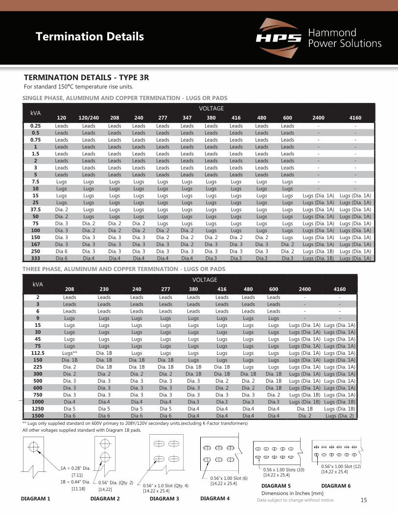
TERMINATION DETAILS - TYPE 3R
THREE PHASE, ALUMINUM AND COPPER TERMINATION - LUGS OR PADS
SINGLE PHASE, ALUMINUM AND COPPER TERMINATION - LUGS OR PADS
For standard 150°C temperature rise units.
Termination Details
kVAVOLTAGE
120 120/240 208 240 277 347 380 416 480 600 2400 41600.25 Leads Leads Leads Leads Leads Leads Leads Leads Leads Leads - -0.5 Leads Leads Leads Leads Leads Leads Leads Leads Leads Leads - -
0.75 Leads Leads Leads Leads Leads Leads Leads Leads Leads Leads - -1 Leads Leads Leads Leads Leads Leads Leads Leads Leads Leads - -
1.5 Leads Leads Leads Leads Leads Leads Leads Leads Leads Leads - -2 Leads Leads Leads Leads Leads Leads Leads Leads Leads Leads - -3 Leads Leads Leads Leads Leads Leads Leads Leads Leads Leads - -5 Leads Leads Leads Leads Leads Leads Leads Leads Leads Leads - -
7.5 Lugs Lugs Lugs Lugs Lugs Lugs Lugs Lugs Lugs Lugs - -10 Lugs Lugs Lugs Lugs Lugs Lugs Lugs Lugs Lugs Lugs - -15 Lugs Lugs Lugs Lugs Lugs Lugs Lugs Lugs Lugs Lugs Lugs (Dia. 1A) Lugs (Dia. 1A)25 Lugs Lugs Lugs Lugs Lugs Lugs Lugs Lugs Lugs Lugs Lugs (Dia. 1A) Lugs (Dia. 1A)
37.5 Dia. 2 Lugs Lugs Lugs Lugs Lugs Lugs Lugs Lugs Lugs Lugs (Dia. 1A) Lugs (Dia. 1A)50 Dia. 2 Lugs Lugs Lugs Lugs Lugs Lugs Lugs Lugs Lugs Lugs (Dia. 1A) Lugs (Dia. 1A)75 Dia. 3 Dia. 2 Dia. 2 Dia. 2 Lugs Lugs Lugs Lugs Lugs Lugs Lugs (Dia. 1A) Lugs (Dia. 1A)
100 Dia. 3 Dia. 2 Dia. 2 Dia. 2 Dia. 2 Dia. 2 Lugs Lugs Lugs Lugs Lugs (Dia. 1A) Lugs (Dia. 1A)150 Dia. 3 Dia. 3 Dia. 3 Dia. 3 Dia. 2 Dia. 2 Dia. 2 Dia. 2 Dia. 2 Lugs Lugs (Dia. 1A) Lugs (Dia. 1A)167 Dia. 3 Dia. 3 Dia. 3 Dia. 3 Dia. 3 Dia. 2 Dia. 3 Dia. 3 Dia. 3 Dia. 2 Lugs (Dia. 1A) Lugs (Dia. 1A)250 Dia 6 Dia. 3 Dia. 3 Dia. 3 Dia. 3 Dia. 3 Dia. 3 Dia. 3 Dia. 3 Dia. 2 Lugs (Dia. 1B) Lugs (Dia. 1A)333 Dia 6 Dia.4 Dia.4 Dia.4 Dia.4 Dia.4 Dia.3 Dia.3 Dia.3 Dia.3 Lugs (Dia. 1B) Lugs (Dia. 1A)
kVAVOLTAGE
208 230 240 277 380 416 480 600 2400 41602 Leads Leads Leads Leads Leads Leads Leads Leads - -3 Leads Leads Leads Leads Leads Leads Leads Leads - -6 Leads Leads Leads Leads Leads Leads Leads Leads - -9 Lugs Lugs Lugs Lugs Lugs Lugs Lugs Lugs - -
15 Lugs Lugs Lugs Lugs Lugs Lugs Lugs Lugs Lugs (Dia. 1A) Lugs (Dia. 1A)30 Lugs Lugs Lugs Lugs Lugs Lugs Lugs Lugs Lugs (Dia. 1A) Lugs (Dia. 1A)45 Lugs Lugs Lugs Lugs Lugs Lugs Lugs Lugs Lugs (Dia. 1A) Lugs (Dia. 1A)75 Lugs Lugs Lugs Lugs Lugs Lugs Lugs Lugs Lugs (Dia. 1A) Lugs (Dia. 1A)
112.5 Lugs** Dia. 1B Lugs Lugs Lugs Lugs Lugs Lugs Lugs (Dia. 1A) Lugs (Dia. 1A)150 Dia. 1B Dia. 1B Dia. 1B Dia. 1B Lugs Lugs Lugs Lugs Lugs (Dia. 1A) Lugs (Dia. 1A)225 Dia. 2 Dia. 1B Dia. 1B Dia. 1B Dia. 1B Dia. 1B Lugs Lugs Lugs (Dia. 1A) Lugs (Dia. 1A)300 Dia. 2 Dia. 2 Dia. 2 Dia. 2 Dia. 1B Dia. 1B Dia. 1B Dia. 1B Lugs (Dia. 1A) Lugs (Dia. 1A)500 Dia. 3 Dia. 3 Dia. 3 Dia. 3 Dia. 3 Dia. 2 Dia. 2 Dia. 1B Lugs (Dia. 1A) Lugs (Dia. 1A)600 Dia. 3 Dia. 3 Dia. 3 Dia. 3 Dia. 3 Dia. 2 Dia. 2 Dia. 1B Lugs (Dia. 1A) Lugs (Dia. 1A)750 Dia. 3 Dia. 3 Dia. 3 Dia. 3 Dia. 3 Dia. 3 Dia. 3 Dia. 2 Lugs (Dia. 1B) Lugs (Dia. 1A)
1000 Dia.4 Dia.4 Dia.4 Dia.4 Dia.3 Dia.3 Dia.3 Dia.3 Lugs (Dia. 1B) Lugs (Dia. 1B)1250 Dia 5 Dia 5 Dia 5 Dia 5 Dia.4 Dia.4 Dia.4 Dia.4 Dia. 1B Lugs (Dia. 1B)1500 Dia 6 Dia 6 Dia 6 Dia 6 Dia.4 Dia.4 Dia.4 Dia.4 Dia. 2 Lugs (Dia. 2)
0.56”x 1.00 Slot (6)[14.22 x 25.4]
0.56 x 1.00 Slots (10)[14.22 x 25.4])
0.56”x 1.00 Slot (12)[14.22 x 25.4]
1A = 0.28” Dia. [7.11]1B = 0.44” Dia. [11.18]
DIAGRAM 1
0.56” x 1.0 Slot (Qty. 4)[14.22 x 25.4]
DIAGRAM 3DIAGRAM 2
0.56” Dia. (Qty. 2)[14.22]
** Lugs only supplied standard on 600V primary to 208Y/120V secondary units.(excluding K-Factor transformers) All other voltages supplied standard with Diagram 1B pads.
DIAGRAM 4
DIAGRAM 5 DIAGRAM 6Dimensions in Inches [mm]
16 Data subject to change without notice.
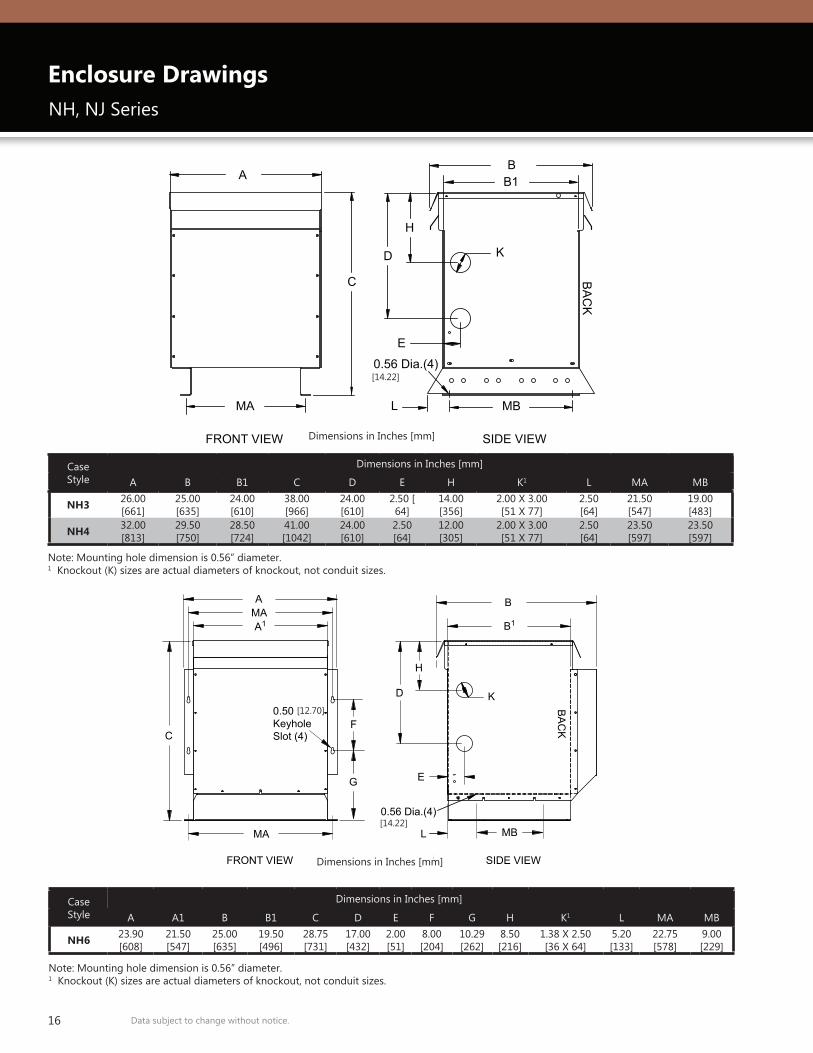
Enclosure Drawings
Case Style
Dimensions in Inches [mm]
A B B1 C D E H K1 L MA MB
NH3 26.00 [661]
25.00 [635]
24.00 [610]
38.00 [966]
24.00 [610]
2.50 [64]
14.00 [356]
2.00 X 3.00 [51 X 77]
2.50 [64]
21.50 [547]
19.00 [483]
NH4 32.00 [813]
29.50 [750]
28.50 [724]
41.00 [1042]
24.00 [610]
2.50 [64]
12.00 [305]
2.00 X 3.00 [51 X 77]
2.50 [64]
23.50 [597]
23.50 [597]
Case Style
Dimensions in Inches [mm]
A A1 B B1 C D E F G H K1 L MA MB
NH6 23.90 [608]
21.50[547]
25.00[635]
19.50 [496]
28.75 [731]
17.00[432]
2.00[51]
8.00 [204]
10.29[262]
8.50[216]
1.38 X 2.50[36 X 64]
5.20[133]
22.75 [578]
9.00 [229]
FRONT VIEW SIDE VIEW
F
BMAA
A1
MA
B1
D
H
MB
E
C
K
L
0.56 Dia.(4)
0.50KeyholeSlot (4)
BA
CK
All Dimensions in Inches
G
MA
FRONT VIEW SIDE VIEW
A
C
D
H
K
B1
MB L
E
0.56 Dia.(4)
B
BA
CK
All Dimensions in Inches
NH, NJ Series
Note: Mounting hole dimension is 0.56” diameter.1 Knockout (K) sizes are actual diameters of knockout, not conduit sizes.
Note: Mounting hole dimension is 0.56” diameter.1 Knockout (K) sizes are actual diameters of knockout, not conduit sizes.
[14.22]
[12.70]
[14.22]
Dimensions in Inches [mm]
Dimensions in Inches [mm]
17Data subject to change without notice.
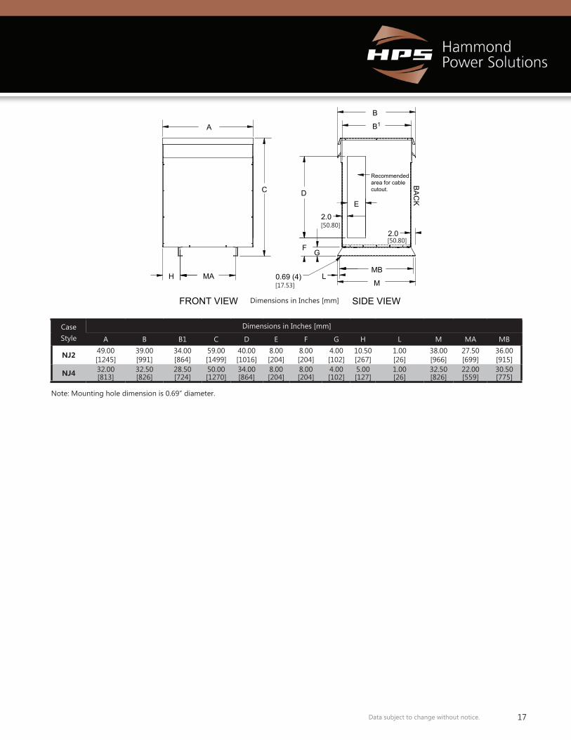
Case Style
Dimensions in Inches [mm]
A B B1 C D E F G H L M MA MB
NJ2 49.00[1245]
39.00[991]
34.00[864]
59.00[1499]
40.00[1016]
8.00[204]
8.00[204]
4.00[102]
10.50[267]
1.00[26]
38.00[966]
27.50[699]
36.00[915]
NJ4 32.00[813]
32.50[826]
28.50[724]
50.00[1270]
34.00[864]
8.00[204]
8.00[204]
4.00[102]
5.00[127]
1.00[26]
32.50[826]
22.00[559]
30.50[775]
FRONT VIEW SIDE VIEW All Dimensions in Inches
H MA 0.69 (4)
A
M
MBL
FG
2.0
E
2.0
C D
B1
B
Recommended area for cable cutout.
BA
CK
Note: Mounting hole dimension is 0.69” diameter.
[50.80]
[50.80]
[17.53]
Dimensions in Inches [mm]
18 Data subject to change without notice.
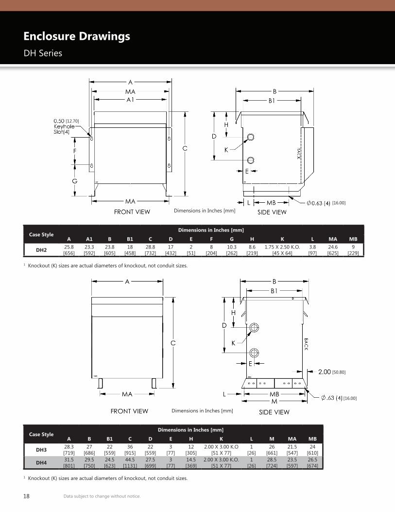
Case StyleDimensions in Inches [mm]
A A1 B B1 C D E F G H K L MA MB
DH2 25.8[656]
23.3[592]
23.8[605]
18[458]
28.8[732]
17[432]
2[51]
8[204]
10.3[262]
8.6[219]
1.75 X 2.50 K.O.[45 X 64]
3.8[97]
24.6[625]
9[229]
Case StyleDimensions in Inches [mm]
A B B1 C D E H K L M MA MB
DH3 28.3[719]
27[686]
22[559]
36[915]
22[559]
3[77]
12[305]
2.00 X 3.00 K.O[51 X 77]
1[26]
26[661]
21.5[547]
24[610]
DH4 31.5[801]
29.5[750]
24.5[623]
44.5[1131]
27.5[699]
3[77]
14.5[369]
2.00 X 3.00 K.O.[51 X 77]
1[26]
28.5[724]
23.5[597]
26.5[674]
1 Knockout (K) sizes are actual diameters of knockout, not conduit sizes.
1 Knockout (K) sizes are actual diameters of knockout, not conduit sizes.
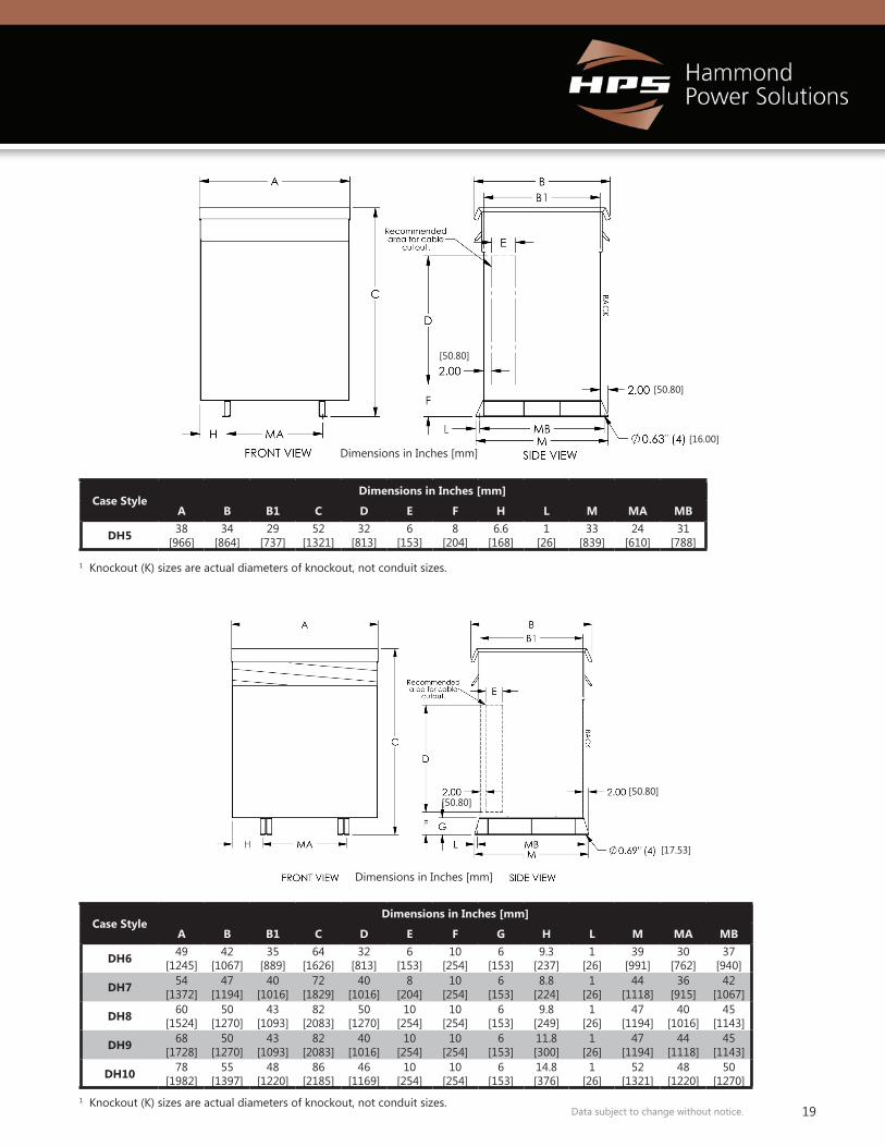
Enclosure DrawingsDH Series
[12.70]
[16.00]
[16.00]
[50.80]
Dimensions in Inches [mm]
Dimensions in Inches [mm]
19Data subject to change without notice.
Case StyleDimensions in Inches [mm]
A A1 B B1 C D E F G H K L MA MB
DH2 25.8[656]
23.3[592]
23.8[605]
18[458]
28.8[732]
17[432]
2[51]
8[204]
10.3[262]
8.6[219]
1.75 X 2.50 K.O.[45 X 64]
3.8[97]
24.6[625]
9[229]
Case StyleDimensions in Inches [mm]
A B B1 C D E H K L M MA MB
DH3 28.3[719]
27[686]
22[559]
36[915]
22[559]
3[77]
12[305]
2.00 X 3.00 K.O[51 X 77]
1[26]
26[661]
21.5[547]
24[610]
DH4 31.5[801]
29.5[750]
24.5[623]
44.5[1131]
27.5[699]
3[77]
14.5[369]
2.00 X 3.00 K.O.[51 X 77]
1[26]
28.5[724]
23.5[597]
26.5[674]
Case StyleDimensions in Inches [mm]
A B B1 C D E F H L M MA MB
DH5 38[966]
34[864]
29[737]
52[1321]
32[813]
6[153]
8[204]
6.6[168]
1[26]
33[839]
24[610]
31[788]
Case StyleDimensions in Inches [mm]
A B B1 C D E F G H L M MA MB
DH6 49[1245]
42[1067]
35[889]
64[1626]
32[813]
6[153]
10[254]
6[153]
9.3[237]
1[26]
39[991]
30[762]
37[940]
DH7 54[1372]
47[1194]
40[1016]
72[1829]
40[1016]
8[204]
10[254]
6[153]
8.8[224]
1[26]
44[1118]
36[915]
42[1067]
DH8 60[1524]
50[1270]
43[1093]
82[2083]
50[1270]
10[254]
10[254]
6[153]
9.8[249]
1[26]
47[1194]
40[1016]
45[1143]
DH9 68[1728]
50[1270]
43[1093]
82[2083]
40[1016]
10[254]
10[254]
6[153]
11.8[300]
1[26]
47[1194]
44[1118]
45[1143]
DH10 78[1982]
55[1397]
48[1220]
86[2185]
46[1169]
10[254]
10[254]
6[153]
14.8[376]
1[26]
52[1321]
48[1220]
50[1270]
1 Knockout (K) sizes are actual diameters of knockout, not conduit sizes.
1 Knockout (K) sizes are actual diameters of knockout, not conduit sizes.
[50.80][50.80]
[17.53]
[50.80]
[50.80]
[16.00]Dimensions in Inches [mm]
Dimensions in Inches [mm]
20 Data subject to change without notice.
If wall and/or ceiling mounting is desired for a transformer, optional mounting kits can be ordered separately. These mounting kits are NOT available for all enclosure case styles. Therefore, it is important that you confirm your enclosure case style, then use the selection table to the right to determine if A) a mounting kit is available and B) determine the correct HPS “Mounting Kit” part number that you must order. One kit is required for each transformer.
Note: Some of the mounting kits can be used for both wall and ceiling mount, while others are for wall mounting only. The table indicates which mounting methods are available for each kit. The NW2 and DW3 wall/ceiling mounting kit also includes a drip plate.
The NW2 and DW3 wall/ceiling mounting kit is only designed for units up to 800 pounds (341 kg) maximum.
ENCLOSURE MOUNTING KITS Enclosure Case Style
Wall Mount Available
Ceiling Mount
Available
HPS Mounting Kit
P/N
DH2 Yes Yes DH2DP
DH3 Yes Yes DW3
DH4 No No N/A
DH5 No No N/A
DH6 No No N/A
DH7 No No N/A
DH8 No No N/A
DH9 No No N/A
DH10 No No N/A
NJ2 No No N/A
NJ4 No No N/A
NH3 Yes Yes NW2
NH4 No No N/A
NH6 Yes Yes NH6DP
If it is intended to wall and/or ceiling mount an enclosure that does not have a wall/ceiling mount kit available, considerations must be made to mechanically support the transformer safely and to install per the local building code. A drip plate must be provided beneath the enclosure per UL 1562 and CSA C22.2 No. 47.
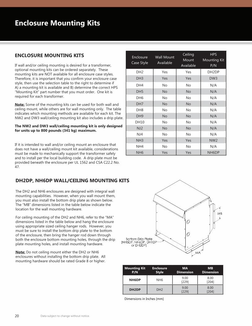
Enclosure Mounting Kits
The DH2 and NH6 enclosures are designed with integral wall mounting capabilities. However, when you wall mount them, you must also install the bottom drip plate as shown below. The “MB” dimensions listed in the table below indicate the location for the wall mounting hardware.
For ceiling mounting of the DH2 and NH6, refer to the “MA” dimensions listed in the table below and hang the enclosure using appropriate sized ceiling hanger rods. However, you must be sure to install the bottom drip plate to the bottom of the enclosure, then bring the hanger rod down through both the enclosure bottom mounting holes, through the drip plate mounting holes, and install mounting hardware.
Note: Do not ceiling mount either the DH2 or NH6 enclosures without installing the bottom drip plate. All mounting hardware should be rated Grade 8 or higher.
Mounting Kit P/N
Enclosure Style
MA Dimension
MB Dimension
NH6DP NH6 9.00[229]
8.00[204]
DH2DP DH2 9.00[229]
8.00[204]
DH2DP, NH6DP WALL/CEILING MOUNTING KITS
Dimensions in Inches [mm]
21Data subject to change without notice.
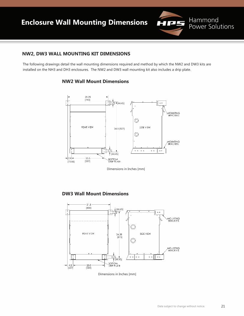
The following drawings detail the wall mounting dimensions required and method by which the NW2 and DW3 kits are installed on the NH3 and DH3 enclosures. The NW2 and DW3 wall mounting kit also includes a drip plate.
NW2, DW3 WALL MOUNTING KIT DIMENSIONS
NW2 Wall Mount Dimensions
DW3 Wall Mount Dimensions
Enclosure Wall Mounting Dimensions
[927]
[44.45]
[44.45][743]
[597][73.66]
[800]
[584][107]
[44.45]
[873]
[44.45]
Dimensions in Inches [mm]
Dimensions in Inches [mm]
22 Data subject to change without notice.
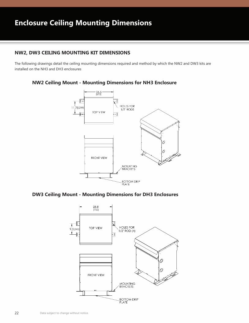
The following drawings detail the ceiling mounting dimensions required and method by which the NW2 and DW3 kits are installed on the NH3 and DH3 enclosures
NW2, DW3 CEILING MOUNTING KIT DIMENSIONS
NW2 Ceiling Mount - Mounting Dimensions for NH3 Enclosure
DW3 Ceiling Mount - Mounting Dimensions for DH3 Enclosures
Enclosure Ceiling Mounting Dimensions
[673]
[299]
[732]
[241]
23Data subject to change without notice.
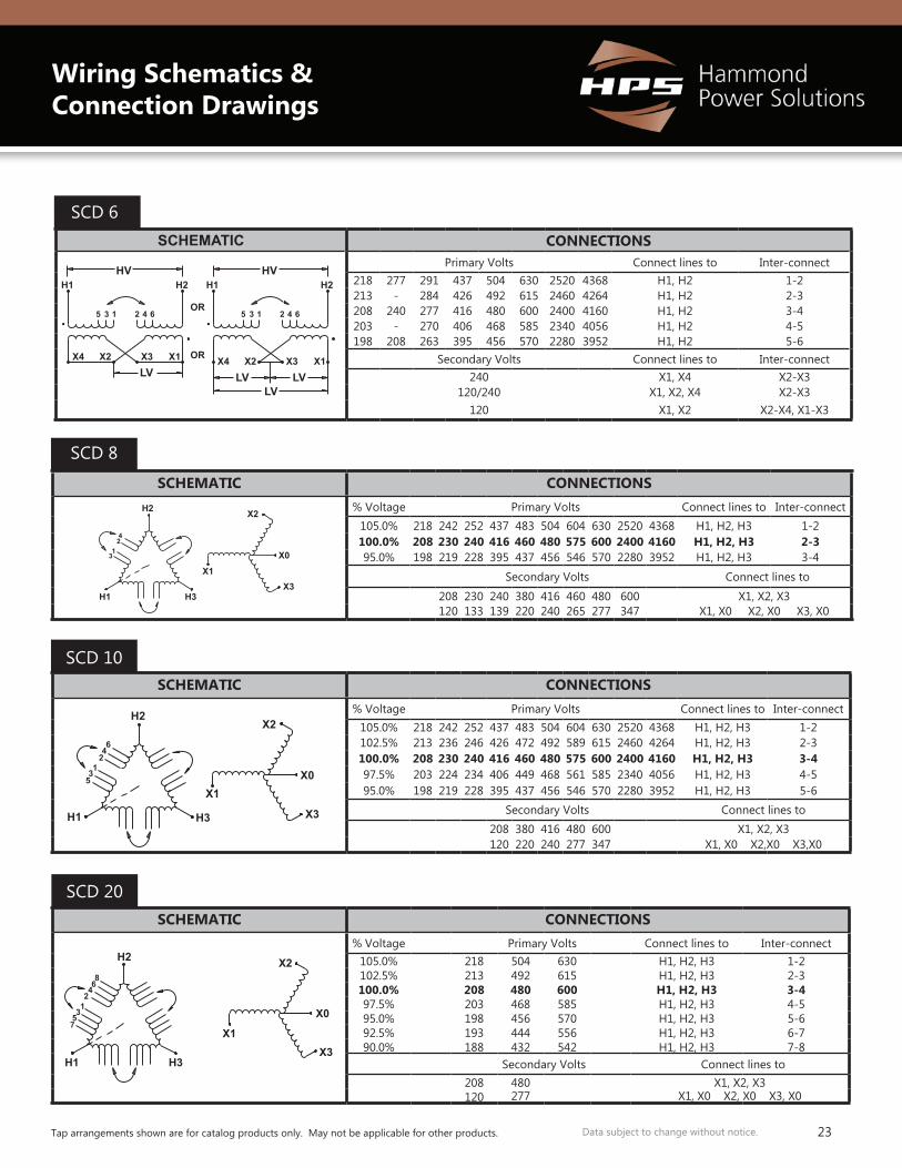
SCHEMATIC CONNECTIONS% Voltage Primary Volts Connect lines to Inter-connect
105.0% 218 242 252 437 483 504 604 630 2520 4368 H1, H2, H3 1-2100.0% 208 230 240 416 460 480 575 600 2400 4160 H1, H2, H3 2-395.0% 198 219 228 395 437 456 546 570 2280 3952 H1, H2, H3 3-4
Secondary Volts Connect lines to
208 230 240 380 416 460 480 600 X1, X2, X3120 133 139 220 240 265 277 347 X1, X0 X2, X0 X3, X0
H2 X2
X0
X3H3H1
X1
42
13
SCD 8
SCHEMATIC CONNECTIONS% Voltage Primary Volts Connect lines to Inter-connect
105.0% 218 242 252 437 483 504 604 630 2520 4368 H1, H2, H3 1-2102.5% 213 236 246 426 472 492 589 615 2460 4264 H1, H2, H3 2-3100.0% 208 230 240 416 460 480 575 600 2400 4160 H1, H2, H3 3-497.5% 203 224 234 406 449 468 561 585 2340 4056 H1, H2, H3 4-595.0% 198 219 228 395 437 456 546 570 2280 3952 H1, H2, H3 5-6
Secondary Volts Connect lines to208 380 416 480 600 X1, X2, X3120 220 240 277 347 X1, X0 X2,X0 X3,X0
H2
H1 H3
X0X1
X2
X3
64
213
5
SCD 10
SCHEMATIC CONNECTIONS% Voltage Primary Volts Connect lines to Inter-connect
105.0% 218 504 630 H1, H2, H3 1-2102.5% 213 492 615 H1, H2, H3 2-3100.0% 208 480 600 H1, H2, H3 3-497.5% 203 468 585 H1, H2, H3 4-595.0% 198 456 570 H1, H2, H3 5-692.5% 193 444 556 H1, H2, H3 6-790.0% 188 432 542 H1, H2, H3 7-8
Secondary Volts Connect lines to208 480 X1, X2, X3120 277 X1, X0 X2, X0 X3, X0
X2H2
H1 H3
X1X3
X0
86
42
357
1
SCD 20
HV HV H1 H2 H1 H2
OR
OR
6 4 2 1 3 5 6 4 2 1 3 5
X4 X1 X3 X2 X4 X1 X3 X2 LV LV LV
LV
SCHEMATIC CONNECTIONSPrimary Volts Connect lines to Inter-connect
218 277 291 437 504 630 2520 4368 H1, H2 1-2213 - 284 426 492 615 2460 4264 H1, H2 2-3208 240 277 416 480 600 2400 4160 H1, H2 3-4203 - 270 406 468 585 2340 4056 H1, H2 4-5198 208 263 395 456 570 2280 3952 H1, H2 5-6
Secondary Volts Connect lines to Inter-connect240 X1, X4 X2-X3
120/240 X1, X2, X4 X2-X3120 X1, X2 X2-X4, X1-X3
SCD 6
Wiring Schematics & Connection Drawings
Tap arrangements shown are for catalog products only. May not be applicable for other products.
24 Data subject to change without notice.
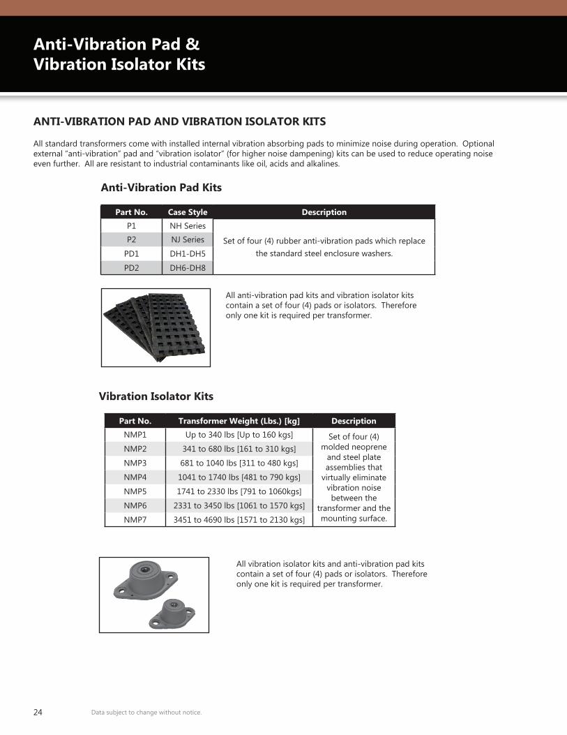
All standard transformers come with installed internal vibration absorbing pads to minimize noise during operation. Optional external “anti-vibration” pad and “vibration isolator” (for higher noise dampening) kits can be used to reduce operating noise even further. All are resistant to industrial contaminants like oil, acids and alkalines.
ANTI-VIBRATION PAD AND VIBRATION ISOLATOR KITS
Part No. Case Style Description
P1 NH Series
Set of four (4) rubber anti-vibration pads which replace the standard steel enclosure washers.
P2 NJ Series
PD1 DH1-DH5
PD2 DH6-DH8
All anti-vibration pad kits and vibration isolator kits contain a set of four (4) pads or isolators. Therefore only one kit is required per transformer.
All vibration isolator kits and anti-vibration pad kits contain a set of four (4) pads or isolators. Therefore only one kit is required per transformer.
Anti-Vibration Pad Kits
Vibration Isolator Kits
Anti-Vibration Pad & Vibration Isolator Kits
Part No. Transformer Weight (Lbs.) [kg] Description
NMP1 Up to 340 lbs [Up to 160 kgs] Set of four (4) molded neoprene
and steel plate assemblies that
virtually eliminate vibration noise between the
transformer and the mounting surface.
NMP2 341 to 680 lbs [161 to 310 kgs]
NMP3 681 to 1040 lbs [311 to 480 kgs]
NMP4 1041 to 1740 lbs [481 to 790 kgs]
NMP5 1741 to 2330 lbs [791 to 1060kgs]
NMP6 2331 to 3450 lbs [1061 to 1570 kgs]
NMP7 3451 to 4690 lbs [1571 to 2130 kgs]
25Data subject to change without notice.
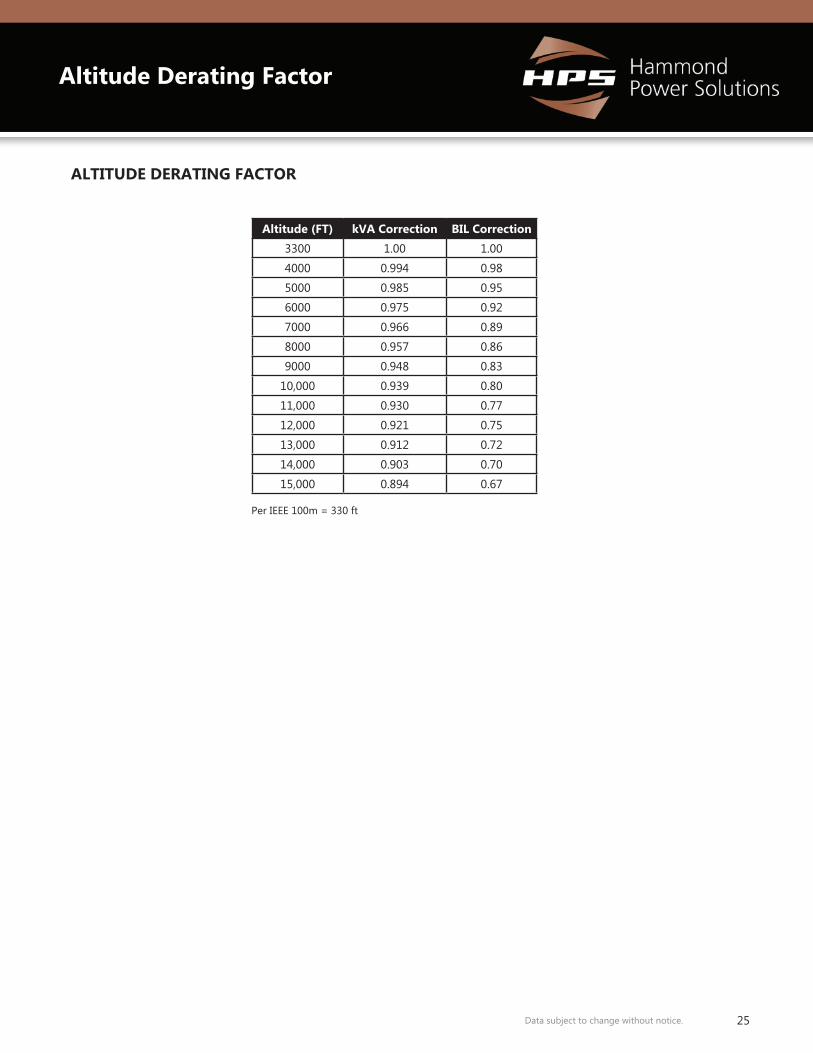
Altitude (FT) kVA Correction BIL Correction
3300 1.00 1.00
4000 0.994 0.98
5000 0.985 0.95
6000 0.975 0.92
7000 0.966 0.89
8000 0.957 0.86
9000 0.948 0.83
10,000 0.939 0.80
11,000 0.930 0.77
12,000 0.921 0.75
13,000 0.912 0.72
14,000 0.903 0.70
15,000 0.894 0.67
ALTITUDE DERATING FACTOR
Per IEEE 100m = 330 ft
Altitude Derating Factor
26 Data subject to change without notice.
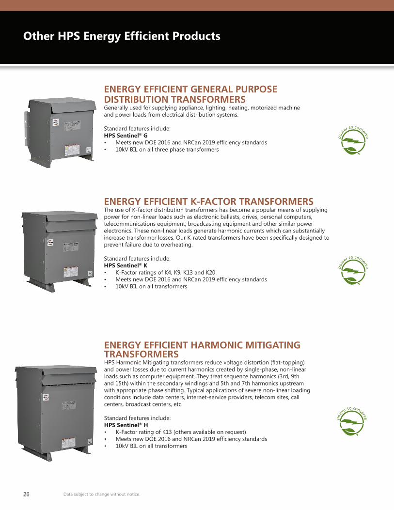
Other HPS Energy Efficient Products
ENERGY EFFICIENT K-FACTOR TRANSFORMERSThe use of K-factor distribution transformers has become a popular means of supplying power for non-linear loads such as electronic ballasts, drives, personal computers, telecommunications equipment, broadcasting equipment and other similar power electronics. These non-linear loads generate harmonic currents which can substantially increase transformer losses. Our K-rated transformers have been specifically designed to prevent failure due to overheating. Standard features include: HPS Sentinel® K• K-Factor ratings of K4, K9, K13 and K20• Meets new DOE 2016 and NRCan 2019 efficiency standards• 10kV BIL on all transformers
ENERGY EFFICIENT GENERAL PURPOSE DISTRIBUTION TRANSFORMERSGenerally used for supplying appliance, lighting, heating, motorized machine and power loads from electrical distribution systems. Standard features include: HPS Sentinel® G• Meets new DOE 2016 and NRCan 2019 efficiency standards• 10kV BIL on all three phase transformers
ENERGY EFFICIENT HARMONIC MITIGATING TRANSFORMERSHPS Harmonic Mitigating transformers reduce voltage distortion (flat-topping) and power losses due to current harmonics created by single-phase, non-linear loads such as computer equipment. They treat sequence harmonics (3rd, 9th and 15th) within the secondary windings and 5th and 7th harmonics upstream with appropriate phase shifting. Typical applications of severe non-linear loading conditions include data centers, internet-service providers, telecom sites, call centers, broadcast centers, etc. Standard features include: HPS Sentinel® H• K-Factor rating of K13 (others available on request)• Meets new DOE 2016 and NRCan 2019 efficiency standards• 10kV BIL on all transformers
27Data subject to change without notice.
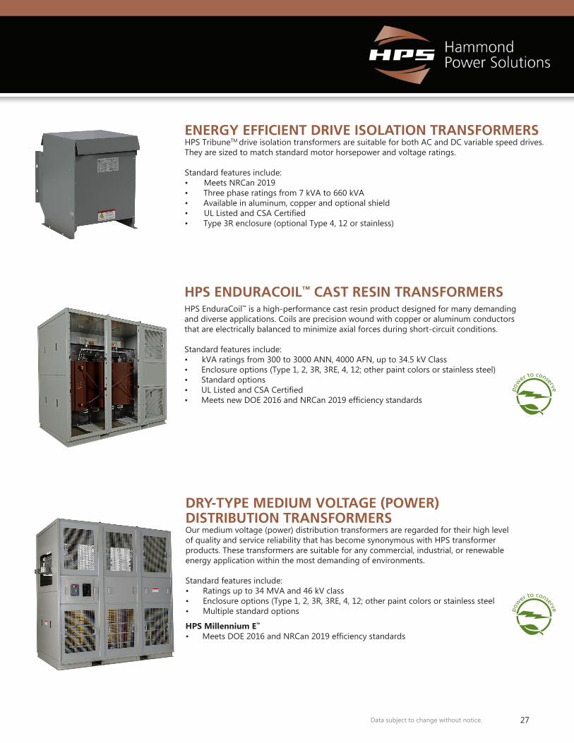
DRY-TYPE MEDIUM VOLTAGE (POWER) DISTRIBUTION TRANSFORMERSOur medium voltage (power) distribution transformers are regarded for their high level of quality and service reliability that has become synonymous with HPS transformer products. These transformers are suitable for any commercial, industrial, or renewable energy application within the most demanding of environments.
Standard features include:• Ratings up to 34 MVA and 46 kV class• Enclosure options (Type 1, 2, 3R, 3RE, 4, 12; other paint colors or stainless steel• Multiple standard options
HPS Millennium E™
• Meets DOE 2016 and NRCan 2019 efficiency standards
HPS ENDURACOIL™ CAST RESIN TRANSFORMERSHPS EnduraCoil™ is a high-performance cast resin product designed for many demanding and diverse applications. Coils are precision wound with copper or aluminum conductors that are electrically balanced to minimize axial forces during short-circuit conditions.
Standard features include:• kVA ratings from 300 to 3000 ANN, 4000 AFN, up to 34.5 kV Class• Enclosure options (Type 1, 2, 3R, 3RE, 4, 12; other paint colors or stainless steel)• Standard options• UL Listed and CSA Certified• Meets new DOE 2016 and NRCan 2019 efficiency standards
ENERGY EFFICIENT DRIVE ISOLATION TRANSFORMERSHPS TribuneTM drive isolation transformers are suitable for both AC and DC variable speed drives. They are sized to match standard motor horsepower and voltage ratings.
Standard features include:• Meets NRCan 2019 • Three phase ratings from 7 kVA to 660 kVA • Available in aluminum, copper and optional shield• UL Listed and CSA Certified• Type 3R enclosure (optional Type 4, 12 or stainless)

MILGMED15June 2021
www.hammondpowersolutions.com
EUROPE
MEXICO
CANADA UNITED STATES
EMEA (Sales Office)Hammond Power Solutions SpATel: +49 (152) [email protected]
UNITED STATESHammond Power Solutions1100 Lake StreetBaraboo, Wisconsin 53913-2866Tel: (608) 356-3921Fax: (608) 355-7623Toll Free: [email protected]
CANADAHammond Power Solutions595 Southgate DriveGuelph, Ontario N1G 3W6Tel: (519) 822-2441Fax: (519) 822-9701Toll Free: [email protected]
ASIAHammond Power Solutions Pvt. Ltd. D. No. 5-2/222/IP/B, II-Floor, Icon PlazaAllwyn X-Roads, Miyapur, Hyderabad 500 049Tel: [email protected]
MEXICOHammond Power SolutionsAv. No. 800, Parque Industrial Guadalupe Guadalupe, NL, Mexico, C.P. 67190. Tel: (819) [email protected]
ASIA


