Embed Size (px)
Citation preview
UNLV Retrospective Theses & Dissertations
1-1-2007
Graphic frameworks for managing component oriented graphic Graphic frameworks for managing component oriented graphic
systems systems
Deepa Uppala University of Nevada, Las Vegas
Follow this and additional works at: https://digitalscholarship.unlv.edu/rtds
Repository Citation Repository Citation Uppala, Deepa, "Graphic frameworks for managing component oriented graphic systems" (2007). UNLV Retrospective Theses & Dissertations. 2328. http://dx.doi.org/10.25669/vma6-n039
This Thesis is protected by copyright and/or related rights. It has been brought to you by Digital Scholarship@UNLV with permission from the rights-holder(s). You are free to use this Thesis in any way that is permitted by the copyright and related rights legislation that applies to your use. For other uses you need to obtain permission from the rights-holder(s) directly, unless additional rights are indicated by a Creative Commons license in the record and/or on the work itself. This Thesis has been accepted for inclusion in UNLV Retrospective Theses & Dissertations by an authorized administrator of Digital Scholarship@UNLV. For more information, please contact [email protected].
GRAPHIC FRAMEWORKS FOR MANAGING COMPONENT ORIENTED
GRAPHIC SYSTEMS
by
Deepa Uppala
Bachelor of Computer Science and Engineering Jawaharlal Nehru Technological University
2002
A thesis submitted in partial fulfillment of the requirement for the
Master of Science Degree in Computer Science School of Computer Science
Howard R. Hughes College of Engineering
Graduate College University of Nevada, Las Vegas
May 2008

UMI Number: 1456377
INFORMATION TO USERS
The quality of this reproduction is dependent upon the quality of the copy submitted. Broken or indistinct print, colored or poor quality illustrations and photographs, print bleed-through, substandard margins, and improper alignment can adversely affect reproduction.
In the unlikely event that the author did not send a complete manuscript and there are missing pages, these will be noted. Also, if unauthorized copyright material had to be removed, a note will indicate the deletion.
UMIUMI Microform 1456377
Copyright 2008 by ProQuest LLC.
All rights reserved. This microform edition is protected against
unauthorized copying under Title 17, United States Code.
ProQuest LLC 789 E. Eisenhower Parkway
PC Box 1346 Ann Arbor, Ml 48106-1346

UNiyUNIVERSITY OF NEVADA LAS VEGAS
Thesis ApprovalThe Graduate College University of Nevada, Las Vegas
FEBRUARY 2 1 S T ________ ,2 0 0 8
The Thesis prepared by
DEEPA UPPALA
E n tit le d
GRAPHIC FRAMEWORKS FOR MANAGING COMPONENT ORIENTED GRAPHIC SYSTEMS
is approved in partial fulfillment of the requirements for the degree of
MASTER OF SCIENCE IN COMPUTER SCIENCE
ination Committee Chair
Dean o f the Graduate College
Examination Committee M ember
E xam in/tion C om m ittee hAfimber
Graduate C o f t ^ Faculty Representative
11
ABSTRACT
Graphic Frameworks for Managing Component Oriented Graphic Systems
by
Deepa Uppala
Dr. Yoohwan Kim, Examination Committee Chair Assistant Professor of Computer Science
University of Nevada, Las Vegas
Computing power and network bandwidth has increased dramatically over the past
decade. However the design and implementation of complex software remain expensive
and error-prone. It is hard to build correct, portable, efficient and inexpensive
applications from scratch. Object oriented application frameworks are a promising
technology for reifying proven software design and implementation in order to reduce the
cost and improve the quality.
A framework is a reusable, semi-complete application that can be specialized to
produce custom applications. A graphic framework is a reusable, semi-completed
application useful for the development of the graphic applications such as CAD
applications. This thesis presents a model graphic framework. It uses traditional graphic
principles such as display file concepts to generate frameworks. It implements object
oriented patterns such as inheritance polymorphism etc. to reuse the graphic framework
for the object oriented graphic applications.
Ill
This thesis suggests eomponent teehnology sueh as Mierosoft COM teehnology to
make the frameworks effeetive. The thesis identifies the advantage of Component
Oriented Teehnology over Objeet Oriented Teehnology. The proeedure for development
of a Component is complex. Even the el lent proeedure for using the eomponent is also
eomplex. This thesis presents a model proeedure for the development of a simple beeper
component and its client program to demonstrate the complexity of the component
technology.
The thesis adopts some of the existing pattern frames to make the implementation
graphie eomponents simple. It also presents some techniques to make the client
procedures for using a eomponent simple.
The advantages of the model graphie frameworks presented in this thesis are as
follows:
1. The Graphic application developer ean develop Graphic Components (graphic
COM objects) like simple C++ objeets using the frameworks.
2. The elient who uses these components for the development of the graphie
applications can use these components (COM object) like simple C++ objeets.
That means the components (COM objects) behave like simple C++ objects for
development and for usage but they are COM objects.
The models presented in this thesis ean be views in two layers. The first layers foeus
on increasing the degree of reusability of graphic objects to minimize cost. In this
connection the model is tested by implementing PCB (Printed circuit board) Graphic
IV
Application for representing several graphic elements of different types minimizing
the number of component. This enables graphic applications run on lower-end systems.
The second layers try to implement graphic COM components like simple C++
objects. Abstract COM object framework is created and several graphic COM objects are
created for testing this model. Client side wrapper component is also implemented and
tested for using complex graphic COM object like simple C++ objects.
Chapter three and five will presents detailed description of these models. Output
Screen of graphic Applications is presented in Appendix B.
TABLE OF CONTENTS
ABSTRACT................................................................................................................................. iii
LIST OF FIGURES...................................................................................................................viii
LIST OF TABLES........................................................................................................................ix
ACKNOWLEDGEMENTS.......................................................................... x
CHAPTER 1 INTRODUCTION.................................................................................................11.1 Objectives............................................................................................................................ 11.2 Previous research................................................................................................................21.3 Pattern language for graphic and CAD frameworks.....................................................41.4 Overview and contributions of our work........................................................................ 91.5 Application area in the thesis.......................................................................................... 101.6 Outline of the thesis..........................................................................................................10
CHAPTER 2 REQUIREMENTS OF IDEAL GRAPHIC FRAMEWORKS AND FRAMEWORK SAMPLES.......................................................................................................12
2.1 Framework samples..........................................................................................................122.2 Requirements o f ideal graphic frameworks.................................................................. 16
CHAPTER 3 OBJECT ORIENTED GRAPHIC FRAMEWORKS.................................... 213.1 Segment tab le ................................................................................................................... 223.2 Graphic instructions and vector graphic display files ................................................ 233.3 Display file interpreter.....................................................................................................243.4 Building graphic frameworks with vector graphic display files................................ 263.5 Advanced concepts in development of object oriented graphic Frameworks 263.6 Implementation and sample code.................................................................................. 28
CHAPTER 4 PROCEDURE FOR DEVELOPING THE COM OBJECTS...................... 354.1 Microsoft application on COM/OLE technology........................................................ 364.2 COM vs. C++ object reuse............................................................................................. 374.3 Procedures in creating and managing the COM server.............................................. 374.4 Implementation issues of COM objects........................................................................ 41
VI
CHAPTER 5 FRAMEWORKS FOR GRAPHIC COMPONENTS................................... 465.1 Architecture of the abstract component framework....................................................455.2 Implementation and code.................................................................................................505.3 Component wrapper or helper object.................................................... 545.4 Architecture of a component wrapper framework....................................................... 565.5 Implementation of wrapper and code ..............................................................585.6 Observations on results of these graphic component frameworks............................64
CHAPTER 6 ARCHITECTURE OF COMPONENT-BASED GRAPHIC FRAMEWORK FOR BUILDING GRAPHICAL APPLICATIONS................................. 66
6.1 Requirements and the development issues................................................................... 666.2 A brief description of software design..........................................................................67
CHAPTER 7 CONCLUSION AND FUTURE W ORK........................................................ 727.1 Review of the work................................... 727.2 Discussion and analysis of results................................................................................. 737.3 Quality and metrics.......................................................................................................... 757.4 Scope for further research............................................... 78
APPENDIX A PROCEDURES TO CREATE A COM SERVER AND CLIENT 79A.l Steps to create a simple beeper COM object...............................................................79A.2 Directory structure.......................................................................................................... 80A.3 Creating the server application......................................................................................80A.4 Registering the server.....................................................................................................96A.5 Creating the client application.......................................................................................97A.6 Observation.....................................................................................................................101A.7 COM exercise to aggregate a COM object................................................................ 104
APPENDIX B TYPICAL GRAPHIC APPLICATION SCREEN SHOTS......................107B.l A Three dimensional graphic system.................................................................... .....107B.2 A COM-based graphic application to manage a P C B ..............................................113
BIBLIOGRAPHY.....................................................................................................................119
VITA............................................................................................................................................122
VII
LIST OF FIGURES
Figure 2.1 Framework in U M L .................................................................................................13Figure 2.2 Structure o f hello-world applet with Java frameworks.......................................13Figure 2.3 Class diagram of hello world class.........................................................................14Figure 2.4 MFC based VC++ Windows’s application...........................................................15Figure 3.1 Typical components o f a model graphic framework with display-file concepts 20Figure 3.2 Model vector graphic display-file structure......................................................... 24Figure 3.3 Structure o f flyweight object framework............................................................. 27Figure 3.4 Declaration o f generic graphic element in C++ implementing display file
concepts.................................................................................................................... 30Figure 3.5 Declaration of function library to manage geometry of graphic components of
PCB board.................................................................................................................33Figure 3.6 Implementation of typical function to manage geometry of graphic
components of PCB board......................................................................................34Figure 5.1 Abstract component frameworks.......................................................................... 45Figure 5.2 Structure o f abstract component framework........................................................46Figure 5.3 C++ class describing the structure o f abstract component................................. 48Figure 5.4 C++ class describing declaring a graphic COM object using abstract
component................................................................................................................53Figure 5.5 Typical component wrapper framework...............................................................55Figure 5.6 Structure o f component wrapper framework....................................................... 57Figure 5.7 C++ class describing declaring a wrapper object for using abstract component
....................................................................................................................................59Figure 5.8 C++ code segment describing the client code for wrapper class...................... 61Figure 5.9 C++ code segment describing component wrapper passing client message to
component................................................................................................................63Figure 6.1 Structure o f COM based CAD framework........................................................... 68Figure 6.2 Structure o f a graphic component {for example Weldsymbol}........................ 69Figure 6.3 Structure o f a wrapper component (for example Weldsymbol}........................70Figure 6.4 Structure o f subsystems of CAD framework....................................................... 71Figure B .l A graphic application using three dimensional object oriented graphic
framework............................................................................................................... 107Figure B.2 A COM based graphic application using component graphic frameworks for
managing components of a PCB board .............................................................. 113Figure B.3 A COM based graphic application using component graphic frameworks for
editing the components of a PCB board.............................................................114
Vlll
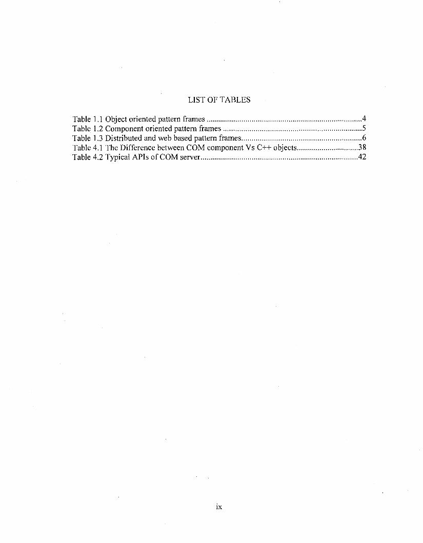
LIST OF TABLES
Table 1.1 Object oriented pattern fram es.................................................................................. 4Table 1.2 Component oriented pattern fram es..........................................................................5Table 1.3 Distributed and web based pattern frames................................................................6Table 4.1 The Difference between COM component Vs C++ objects................................ 38Table 4.2 Typical APIs of COM server................................................................................... 42
IX

ACKNOWLEDGEMENTS
I would like to acknowledge the immense assistance and moral support provided by
my advisor, Dr. Yoohwan Kim during the course of my masters program at the
University of Nevada, Las Vegas. The guidance provided by him in steering this research
project from concept to completion has been invaluable.
1 would like to thank Dr. Ajoy K Datta, Dr. Taghva and Dr. Mei Yang for their direct
and indirect support throughout this investigation.
It is important to mention the moral support of my immediate family including my
parents, Mrs. Padmaja and Mr. U.D.Naidu, my sister Mrs. Divya. They were available for
me at all times. But for their constant motivation, it would have been impossible for me
to get this far in life.
I would like to acknowledge the help of my friends whose help and advice has always
been an invaluable source of motivation for me.
Finally I would like to thank the Department of Computer Science at the University
of Nevada, Las Vegas for giving me an opportunity to pursue my masters’ degree.
X
CHAPTER 1
INTRODUCTION
1.1 Objectives
Today’s trend in software industry is to release reusable components and frameworks
suiting requirements of a group of clients [10]. These components can be configured as
per the specific requirement of the client for building applications. As the software
components and frameworks are used at different levels and in different environments,
the components and frameworks should get adjusted to these requirements.
The challenge is in providing generic and high degree configurable frameworks [4].
The objective of this work is to provide solutions to recurring problems in building high
quality Graphic/CAD Frameworks [14] that increase quality, decrease cost, complexity
and development cycle time in support of objectives of software engineering. A group of
pattern-frames are suggested for building object-oriented graphic frameworks and for the
development of component-based graphic frameworks.
These techniques are adopted and typical framework models are evolved in the
present thesis. The Object-oriented programming [17] using C++ and COM/OLE
technologies [24] [12] is used to demonstrate the models evolved in this work. The
Microsoft Middleware integration frameworks [4], such as MFC and ATE [28] are also
used for the illustrations. However these models are not specific to Microsoft
technologies and can be adopted in other similar technologies.
The proposed models enable domain experts to build high quality graphic and CAD
application components for managing the behavior of graphic elements with minimal cost
suiting the requirements of any engineering applications. They provide techniques to
increase modularity, reusability, extensibility, inversion of control, and simple and easy
client procedures. Typical procedures for using these frameworks are also presented in
this thesis.
1.2 Previous research
This thesis uses the existing pattern-frames from the past work. They are divided into
three sections, namely, object-oriented pattern-frames, component-oriented pattern-
frames, and distributed and web-based pattern-frames [21]. The object-oriented
frameworks [21] address the problems and solutions for in managing behavior of graphic
elements in CAD/Graphic applications. Some o f these pattern-frames use traditional
display file concepts. The component-based pattern-frames provide suggestions for
building graphic COM objects. The third group of pattern-frames, namely, distributed
and web-based pattern-frames provide solutions for managing web-based and distributed
CAD systems. In this thesis, we use the first two types of pattern-frames. However, the
results in this thesis can be extended further using the type o f pattern-frames to provide
web based and distributed CAD/graphic solutions.
This thesis is based on the previous research work by [21]. In his thesis, “Pattern
languages for graphic and CAD frameworks”, he presented about sixteen pattern-frames
for providing solutions. Some of them are used in this thesis. This research work
identifies typical problems in evolving Graphic/CAD frameworks. In this work, the
pattern approach is adopted to provide solutions. Sixteen typical common design and
implementation issues are identified and they are classified into three groups depending
on nature of the issues. These are also referred as pattern-frames. These pattem-frames
form a pattern language, useful for the development of Graphic and CAD frameworks. A
brief description these pattern-frames are presented below.
1. Object oriented framework
These are based on simple object-oriented patterns. They make lightweight
frameworks. They provide solutions for under-engineering problems for developing
frameworks.
2. Component oriented frameworks
These frameworks are based on component technology. All are black box
frameworks. They provide solutions for building component-based application
frameworks
3. Distributed and web based frameworks
These are useful for building frameworks for supporting typical distributed and web-
based application requirements
The catalog of frameworks listed above form a pattern language for building
frameworks. Some of the frameworks are more general in the sense that they are
applicable in other domains. But a few frameworks such as Map Object frameworks are
specific to Graphic, CAD and GIS systems [8]. The pattern language presented in this
thesis will start its journey from a simple function country to a complex component
world.
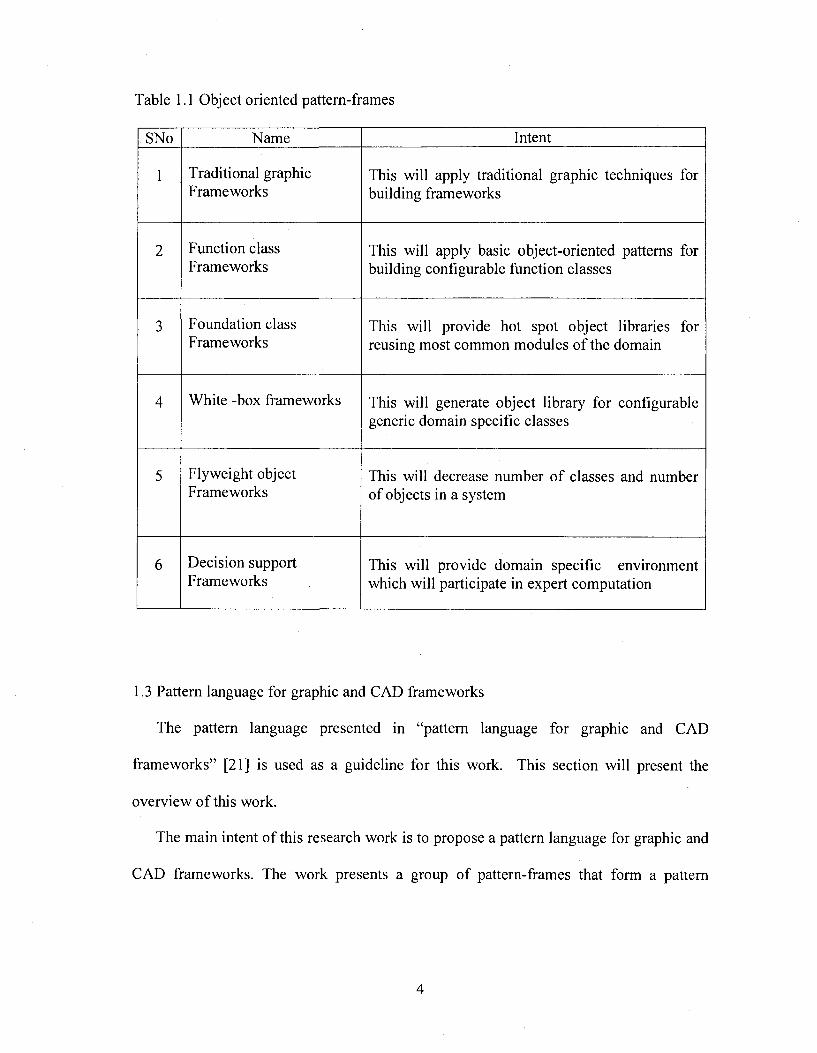
Table 1.1 Object oriented pattern-frames
SNo Name Intent
1 Traditional graphic Frameworks
This will apply traditional graphic techniques for building frameworks
2 Function class Frameworks
This will apply basic object-oriented patterns for building configurable function classes
3 Foundation class Frameworks
This will provide hot spot object libraries for reusing most common modules of the domain
4 White -box frameworks This will generate object library for configurable generic domain specific classes
5 Flyweight object Frameworks
This will decrease number of classes and number of objects in a system
6 Decision support Frameworks
This will provide domain specific environment which will participate in expert computation
1.3 Pattern language for graphic and CAD frameworks
The pattern language presented in “pattern language for graphic and CAD
frameworks” [21] is used as a guideline for this work. This section will present the
overview o f this work.
The main intent of this research work is to propose a pattern language for graphic and
CAD frameworks. The work presents a group of pattern-frames that form a pattern
language for evolving graphic and CAD frameworks. The following procedure is
suggested to select pattern-frames of this work. [21].
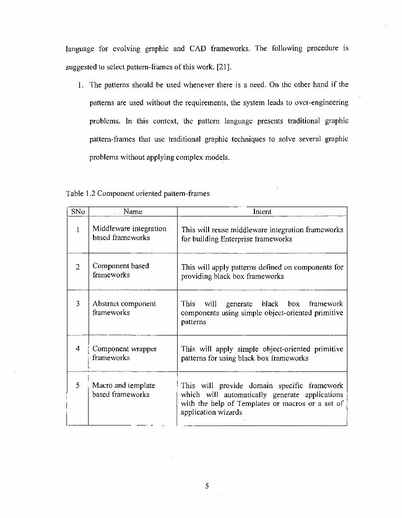
1. The patterns should be used whenever there is a need. On the other hand if the
patterns are used without the requirements, the system leads to over-engineering
problems. In this context, the pattern language presents traditional graphic
pattern-frames that use traditional graphic techniques to solve several graphic
problems without applying complex models.
Table 1.2 Component oriented pattern-frames
SNo Name Intent
1 Middleware integration based frameworks
This will reuse middleware integration frameworks for building Enterprise frameworks
2 Component based frameworks
This will apply patterns defined on components for providing black box frameworks
3 Abstract component frameworks
This will generate black box framework components using simple object-oriented primitive patterns
4 Component wrapper frameworks
This will apply simple object-oriented primitive patterns for using black box frameworks
5 Macro and template based frameworks
This will provide domain specific framework which will automatically generate applications with the help of Templates or macros or a set of application wizards
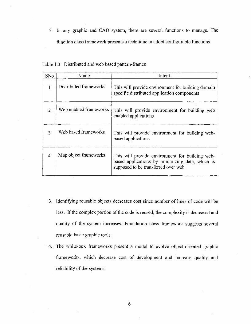
2. In any graphic and CAD system, there are several functions to manage. The
function class framework presents a technique to adopt configurable functions.
Table 1.3 Distributed and web based pattern-frames
SNo Name Intent
1 Distributed frameworks This will provide environment for building domain specific distributed application components
2 Web enabled frameworks This will provide environment for building web enabled applications
3 Web based frameworks This will provide environment for building web- based applications
4 Map object frameworks This will provide environment for building web- based applications by minimizing data, which is supposed to be transferred over web.
3. Identifying reusable objects decreases cost since number of lines of code will be
less. If the complex portion of the code is reused, the complexity is decreased and
quality of the system increases. Foundation class framework suggests several
reusable basic graphic tools.
4. The white-box frameworks present a model to evolve object-oriented graphic
frameworks, which decrease cost of development and increase quality and
reliability of the systems.

5. Some graphic applications such as Debugger driver tool for PCB discussed in the
thesis need to manage several graphic components. In sueh eases, the Ply-weight
pattern-frame model is applicable.
6. The graphic systems like Debugger driver tool should participate in decision
making. The domain expert provides the rules for decision making. Sueh systems
should follow decision support framework patterns.
7. To convert simple object-oriented framework into eomponent technology,
middleware integration framework pattern is useful.
8. Component based framework, presents a model pattern-frame for graphic
frameworks that use eomponent technology.
9. Abstract component framework presents a pattern-frame to simplify the
eomponent development proeedure.
10. Component wrapper pattern-frame presents a model to simplify the elient
proeedure by providing simple objeet view to a complex component.
11. The macro and template based graphic patterns are useful to create wizards that
enable client to use complex procedures in creating and managing the code.
12. The document driven pattern-frame is used to build document driven graphic
environment.
13. Distributed framework model is used to make graphic frameworks to be
distributed across the network.
14. The Web-enabled framework model is used to make graphic frameworks Web
enabled.

15. The Web-based frameworks help in building Web-based graphic systems. They
are useful for GIS applications.
16. The map-object pattern frame addresses the solutions for managing huge GIS data
over Web.
All the above sixteen pattem-frames form a pattern language for building graphic and
CAD frameworks. These pattern frames are classified into three groups as follow:
Object-oriented frameworks
1. Traditional graphic frameworks
2. Function class framework
3. Foundation class frameworks
4. White-box frameworks
5. Flyweight object framework
6. Decision support frameworks
Component-oriented frameworks
1. Middleware integration based framework
2. Component based frameworks
3. Abstract component frameworks
4. Component wrapper frameworks
5. Macros and Template based frameworks
6. Document driven frameworks
Distributed & web-based frameworks
1. Distributed frameworks
2. Web-enabled frameworks
3. Web-bàsed frameworks
4. Map-object based frameworks
This thesis used some of the object-oriented pattern frames and component-oriented
frameworks to provide the solutions.
1.4 Overview and contributions of our work
A framework is a reusable, semi-complete application that can be specialized to
produce custom applications [4]. A graphic framework is a reusable, semi-completed
application useful for the development of the graphic applications such as CAD
applications. This thesis presents a model graphic framework. It uses traditional graphic
principles such as “display file” concepts to generate frameworks. It implements object-
oriented patterns such as inheritance polymorphism etc. to reuse the graphic framework
for the object-oriented graphic applications. However the procedure for development of
a Component is complex. Even the client procedure for using the component is also
complex. This thesis presents a model procedure for the development of a simple beeper
component and its client program to demonstrate the complexity of the component
technology.
This thesis suggests using a component technology such as Microsoft COM
technology [26] to make the frameworks effective. It identifies the advantages of the
component-oriented technology over the object-oriented technology. It adopts some of
the existing pattem-frames to make the implementation of graphic components simple. It
also presents some techniques to make the client procedures for using a component
simple.
The advantages of the model graphic frameworks presented in this thesis are as
follows;
1. The graphic application developer can develop graphic components (graphic
COM objects) like simple C++ objects using the frameworks.
2. The client who uses these components for the development of the graphic
applications can use these components (COM object) like simple C++ objects.
In other words, this research enables the components (COM objects) to behave like
simple C++ objects for development and usage.
1.5 Application area in the thesis
Although we base this research on many graphic components, the objective of the
graphic frameworks presented in this thesis is not for managing GUI (graphical user
interface). Instead, we intend to use the framework for managing the behavior of graphic
elements of Graphic/CAD applications such as resistors and other electronic components
of a printed circuit board or for annotations and dimension symbols of a CAD drawing.
It can be used for managing flowchart symbols, UML components or drawing elements
such as line, rectangle etc. in their respective applications. Both two dimensional and
three dimensional graphic systems can use these frameworks with some limitations which
are discussed in the last chapter.
1.6 Outline of the thesis
This thesis presents the requirements of object-oriented graphic/CAD applications
and component technology (such as Microsoft COM technology) based graphic
frameworks. In the Chapter 2, sample graphic framework models are presented. A set of
functions used for the development of this framework are listed. Chapter 3 presents the
10
procedures required for the development of graphic frameworks and techniques for
managing behavior o f graphic elements in object-oriented technology using C++. In
Chapter 4, the problems in development of COM components and the differences
between a COM object and a C++ object are presented. A sample procedure for building
and using a Beeper COM component is presented in Appendix A. It is presented to
demonstrate the complexity of the COM component development. However, the Beeper
object is not a graphic element. Chapter 5 presents a graphic framework for the
development of graphic COM components. It also presents frameworks for making the
client procedures simple. Finally, a model graphic framework for the development of
COM-based graphic/CAD applications is presented in Chapter 6. A set of interfaces and
subsystems of the proposed system are presented. Chapter 7 presents the conclusions and
the scope for further research. Appendix B presents sample screenshots o f graphic
applications developed using our frameworks.
11
CHAPTER 2
REQUIREMENTS OF IDEAL GRAPHIC FRAMEWORKS
AND FRAMEWORK SAMPLES
This chapter presents samples of typical frameworks. One of those samples is
Mierosoft Document View Architecture that manages the GUI for the applications with
the help of a set of Wizards and MFC classes. We also present the requirements of an
ideal graphic framework. These requirements are evolved after studying several graphic
applications in the market sueh as Intergraph CAD products such as Smart sketch,
CARIS GIS graphic component for managing graphic behavior o f GIS (Geographic
Information System) applications.
2.1 Framework samples
This section will present typical framework samples starting from a simple “hello
world” application using Java frameworks. Figure 2.1 presents the UML [18] building
block for representing a framework.
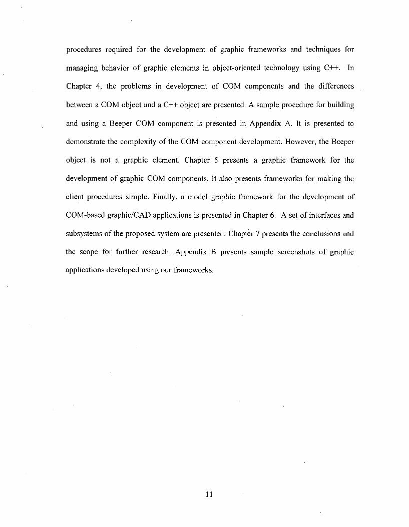
Consider a hello world program in Java. An example ean be implemented using Java
Applet. The Java Applet is a part of Java framework. This in turn depends on AWT and
Java language frameworks. Figure 2.2 represents a hello world component structure in
UML using Java frameworks [16].
12
Framework name
Figure 2.1 Frameworks in UML
I Hello-World
AWT
Figure 2.2 Structure of hello-world Applet with Java frameworks
From the diagram in Figure 2.2, it can be observed that hello-world Applet depends
on Java Applet. The HTML client or Java frame which includes the hello-world Applet
gets hello-world Interface through the Java Applet. Messages from the client application
will invoke the Java Applet that in turn sends the messages to the hello-world Applet.
For displaying the “hello-world” message the hello-world Applet implementation again
13
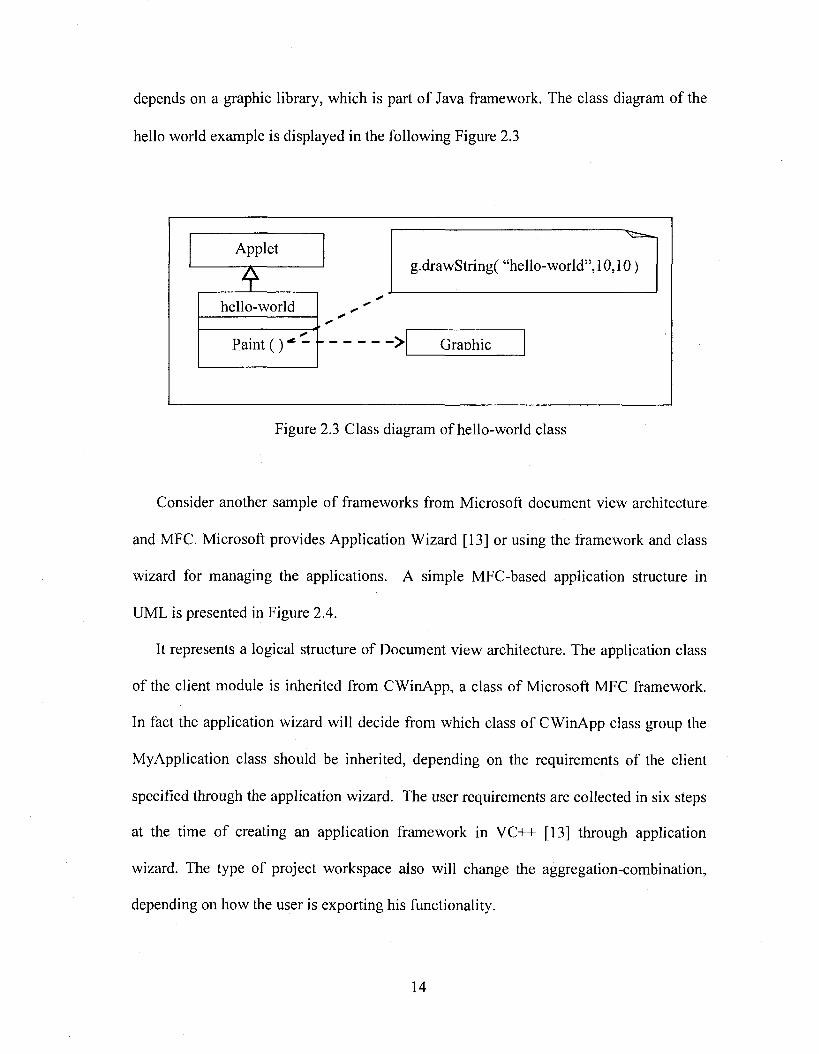
depends on a graphic library, which is part of Java framework. The class diagram of the
hello world example is displayed in the following Figure 2.3
Granhic
Applet
hello-world
Paint ( )
g.drawString( “hello-world”, 10,10 )
Figure 2.3 Class diagram of hello-world class
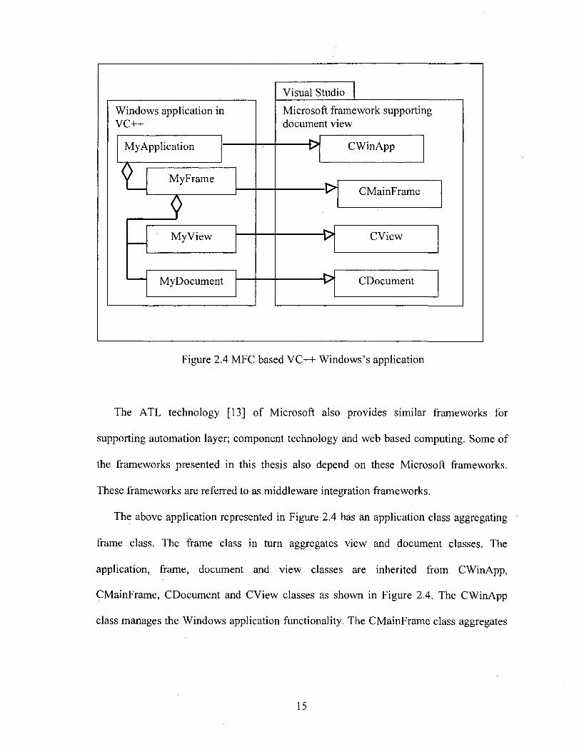
Consider another sample of frameworks from Microsoft document view architecture
and MFC. Microsoft provides Application Wizard [13] or using the framework and class
wizard for managing the applications. A simple MFC-based application structure in
UML is presented in Figure 2.4.
It represents a logical structure of Document view architecture. The application class
of the client module is inherited from CWinApp, a class of Microsoft MFC framework.
In fact the application wizard will decide from which class o f CWinApp class group the
MyApplication class should be inherited, depending on the requirements of the client
specified through the application wizard. The user requirements are collected in six steps
at the time of creating an application framework in VC++ [13] through application
wizard. The type of project workspace also will change the aggregation-combination,
depending on how the user is exporting his functionality.
14
Windows application in VC++
MyApplication
II MyFrame
My View
MyDocument
Visual Studio
Microsoft framework supporting document view
CWinApp
CMainFrame
CView
CDocument
Figure 2.4 MFC based VC++ Windows’s application
The ATL technology [13] of Microsoft also provides similar frameworks for
supporting automation layer; component technology and web based computing. Some of
the frameworks presented in this thesis also depend on these Microsoft frameworks.
These frameworks are referred to as middleware integration frameworks.
The above application represented in Figure 2.4 has an application class aggregating
frame class. The frame class in turn aggregates view and document classes. The
application, frame, document and view classes are inherited from CWinApp,
CMainFrame, CDocument and CView classes as shown in Figure 2.4. The CWinApp
class manages the Windows application functionality. The CMainFrame class aggregates
15
a set of view and document objects. The view manages device context. It can also
manage GUI required functionality.
In addition to creating a Windows-based application with automatic code generation
and aggregation with MFC framework, Microsoft frameworks also support class wizard
for managing client applications [13]. The message maps are managed through this class
wizard. The resource sub-system helps user in building Menu items, Tool bars, Dialog
boxes and Accelerator keys. They also support simple graphic primitives through CDC
class, which is an abstract class. CClientDC is a sub class of CDC that can be instantiated
from any class inherited from CWin class. This rule is automatically imposed by making
CWin pointer, which is an argument for constructor of CClientDC class.
The OLE framework is also integrated to Visual studio [13] such that a simple object-
oriented programmer also can use OLE features in these applications. The requirements
for such facilities are also collected through the application wizard by asking the user,
whether the application is an OLE server or OLE container etc.
At present the Visual studio is released in the form of .NET Studio . The .NET Studio
has several additional features such as multiple language support, Web based distributed
and object management facilities using SOAP (Simple Object Access protocol). The
information about visual studio is found at http://msdn2.microsoft.com/en-
us/vstudio/default.aspx.
2.2 Requirements o f ideal graphic frameworks
The following steps are followed for extracting the requirements for graphic
frameworks.
16
1. Requirements, design and implementation issues of graphic, CAD, and CIS
applications which are from different application domains, are studied carefully.
2. Requirements for reusable graphic modules (Graphic Frameworks) are obtained
by generalizing these graphic application requirements and design.
Requirements of graphic applications for drafting, CAD for electronics, civil and
mechanical engineering, and GIS are studied in detailed as part of this work. The pattem-
frames suggested for CAD frameworks are implemented for building graphic
frameworks. These graphic frameworks can be reused for building high quality, cost
effective and simple graphic applications for complex requirements.
These graphic frameworks are classified into two groups as per the nature of
applications. They are object-oriented and component-oriented graphic frameworks.
The object-oriented frameworks are targeted to manage and export the behavior of
reusable graphic modules. They focus on generalization o f graphic modules to increase
level o f reuse. These frameworks will decrease the complexity of the applications. They
will positively affect the cost, quality, and the schedule of implementation.
The component-oriented frameworks are targeted towards scalability and
encapsulation, and support of new features such as OLE. Some of them address
problems in the development of components and usage o f components. Main objective of
these frameworks is to develop and use complex components like simple Objects.
Requirements of object-oriented graphic /CAD frameworks;
1. Designing domain independent generic graphic sub-systems: A generic graphic
subsystem which can manage requirements of any domain is required. This will
17
enable the same graphic subsystem useful for managing graphic components of
different application domains.
2. Designing sub-systems for managing generic environment: A graphic subsystem
should support scalable and configurable graphic environment. One can identify
several reusable foundation classes to support graphic subsystems. These sub
systems simplify the implementation of complex graphic components.
3. Designing configurable sub-systems for managing graphic component behavior:
A graphic sub-system should support configurable graphic components. They
enable reuse of the generic behavior of graphic components. They will decrease
the development cost and complexity of a graphic component.
4. Designing sub-system for managing graphic objects.' A graphic system should
provide a facility to manage a huge number of graphic objects even on a lower
end system by optimizing the storage. Such sub-systems are essential for
managing graphic objects of GIS and PCB applications [7] where the size of the
graphic objects is larger.
Requirements of component-oriented graphic frameworks: The Component
technology such as COM technology of Microsoft has several advantages over simple
object-oriented technology. But the procedure for the development of a COM object is
complex. Even the procedure followed by the client to use a COM component is also
complex. These issues are discussed in the chapter 4. The component-based graphic
framework should have the following features for building component-based graphic
applications. [22]
18
1. Support for building complex graphie components using simple object-oriented
techniques.
2. Support for building subsystems to provide simple object view for complex
graphic components. This will enable a simple object-oriented client to create and
use complex object like simple C++ objects.
3. Support for integrating graphic components with middleware frameworks like
OLE, ATL. This will facilitate features like participation in compound
documents, support for OLE operations such as Cut & Past, Drag & Drop, and In-
place Activation etc.
This thesis presents a model object-oriented framework and also component based
graphic framework to address such requirements. The main feature of the work in this
thesis is making the development procedure of a graphic COM object simple. The client
procedure to use the complex component becomes simple. This is done by encapsulating
the COM procedures and reusing the COM object management procedures using simple
object-oriented patterns such as inheritance and polymorphism. These are not supported
in Microsoft COM object.
19
CHAPTER 3
OBJECT ORIENTED GRAPHIC FRAMEWORKS
Object-oriented frameworks use simple object-oriented patterns for building
frameworks. They make lightweight frameworks. They provide solutions for under
engineering problems for the development of frameworks. These frameworks are
developed using traditional graphic concepts [26] such as display file and segment
concepts.
Graphic/CAD applications
Application specific graphic component libraries
r 1 r
Graphic instructions Segment table
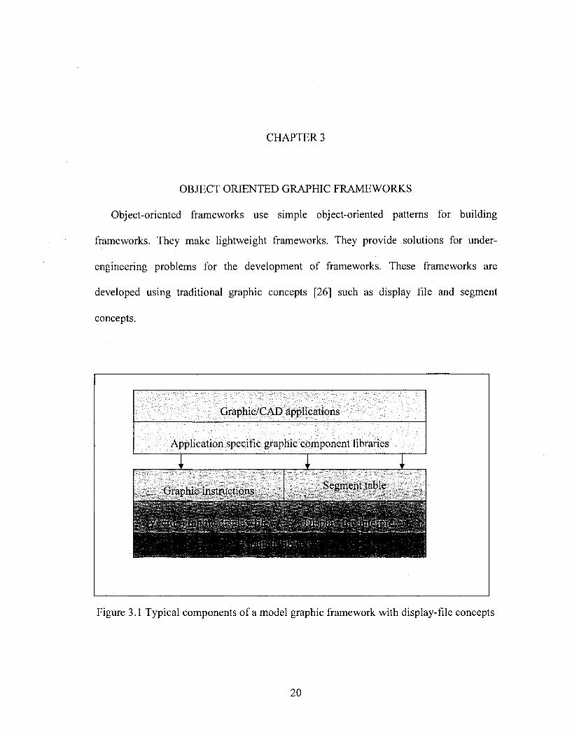
Figure 3.1 Typical components of a model graphic framework with display-file concepts
20
Figure: 3.1 presents’ typical components of a model graphic framework using
traditional graphic display file concepts. The model has the following major core
components [21].
1. Segment table
2. Graphic instructions
3. Vector graphic display file
4. Display file interpreter
Using these one can build an application specific component library. This framework
will depend on a powerful graphic library supported by the compiler or vendor. C++
provides several graphic primitive libraries, while MFC provides powerful graphic
environment for building frameworks. JDK also provides graphic libraries for Java for
building Java-based frameworks. The quality o f the framework depends on the graphic
library support in addition to the capability o f the framework.
3.1 Segment table
The display file for general-purpose interactive graphics software is divided into a set
of segments such that each segment corresponds to a component of the overall display
file. For example, in a building-graphies information system each civil engineering
building element is treated as a segment. Windows, doors, racks etc, which are known as
civil engineering building elements, are stored in the display file as graphic-segments.
Sets o f attributes are associated with each segment. All these attributes of segments are
stored in a segment-table.
Consider the information that must be associated with each segment and how the
information might be organized. Each segment is given a unique name so that it can be
21

referred with it. Perform operations, on segments such as changing the visibility of
segment, require some way to distinguish that segment from all other segments. The
display file segment must know which display file instructions belong to it. This may be
determined by knowing where the display file instructions for that segment begin and
how many of them are there in its specific display file. Each segment needs some way of
associating its display file position information and its attribute information with its
name. The display file and its attributes can be organized in a tabular form as indicated
below:
1. Segment name
2. Segment starting address in the display file
3. Segment size i.e. number of instructions in the display file
4. Segment visibility i.e. on or off
5. Segment transformation parameters i.e. scaling, translation, rotation around x,y,z
axes
6. Segment reference point that is useful for transformations
7. Segment transparency (on or off) useful for hidden line and surface elimination
Segmentation can be achieved through a set of procedures to create, open, close and
transform a segment. This thesis implements all these required procedures for managing
a three dimensional object-oriented graphic framework.
Typical user user-routines developed to handle segments are Create-segment (n),
Close-segment (n), Append-segment (n) , Set-segment-visibility (n, I) , Rotate-segment
(n, ax, ay, az) , Translate-segment (n, tx, ty, tz), Set-segment-reference-point (n, x, y, z),
Scale-segment (n, sx, jy, sz) ,Show-segment (n), Delete-segment (n) where « is a segment
22
name, x, y, z are coordinates, I is visibility, tx, ty, tz are transformation parameters , sx, sy,
sz are scaling parameters and ax, ay, az are rotation parameters
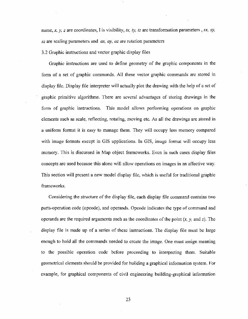
3.2 Graphic instructions and vector graphic display files
Graphic instructions are used to define geometry of the graphic components in the
form of a set of graphic commands. All these vector graphic commands are stored in
display file. Display file interpreter will actually plot the drawing with the help of a set of
graphic primitive algorithms. There are several advantages of storing drawings in the
form of graphic instructions. This model allows performing operations on graphic
elements such as scale, reflecting, rotating, moving etc. As all the drawings are stored in
a uniform format it is easy to manage them. They will occupy less memory compared
with image formats except in GIS applications. In GIS, image format will occupy less
memory. This is discussed in Map object frameworks. Even in such cases display files
concepts are used because this alone will allow operations on images in an affective way.
This section will present a new model display file, which is useful for traditional graphic
frameworks.
Considering the structure of the display file, each display file command contains two
parts-operation code (opcode), and operands. Opcode indicates the type of command and
operands are the required arguments such as the coordinates of the point {x, y, and z). The
display file is made up of a series of these instructions. The display file must be large
enough to hold all the commands needed to create the image. One must assign meaning
to the possible operation code before proceeding to interpreting them. Suitable
geometrical elements should be provided for building a graphical information system. For
example, for graphical components of civil engineering building-graphical information
23
system, typical geometrical elements like point, line, circle, arc and polygon can be
considered. Typical general attributes of a simple display file instruction, are type of the
geometrical element, its color and y, z coordinates. The instruction is interpreted by
invoking the required vector generator. The vector generators of special geometrical
elements may need more information than what is available in the main display file. This
information is also in the form of graphic-commands, stored in a separate display file. For
example all the instructions for plotting a polygon are in the polygon display file. Each
vector generator of this type has its own interpreter for the interpretation o f these
commands. The starting-address and size of these instructions are the needed attributes,
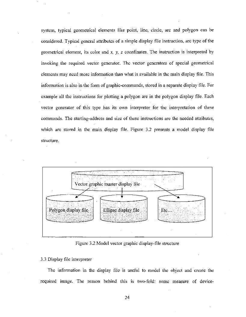
which are stored in the main display file. Figure 3.2 presents a model display file
structure.
Vector graphic master display file
1 r
Polygon display file Ellipse display file Etc...
Figure 3.2 Model vector graphic display-file structure
3.3 Display file interpreter
The information in the display file is useful to model the object and create the
required image. The reason behind this is two-fold: some measure of device
24
independence is achieved, and it is easy to perform image transformation by changing the
position and orientation of the required image. The display file contains the information
necessary to construct the required image. The information can be in the form of
instructions such as “move the pen”, “draw a line”, and “plot the required polygon”.
Saving instructions o f this kind usually take much less storage than saving the picture
itself. Each instruction indicates an action for the display device. A display file interpreter
is used to convert these instructions into actual images. The display file interpreter serves
as an interface between the graphics program and the display device. The display file
instruction may be actually stored in a file either for a display layer or for transfer to
another machine. Such files of imaging instruction are sometimes called “metafiles”
Typical vector-generating algorithms developed as part of this Three dimensional graphic
framework are do-line3d (Ic, be, z, y, z), do-point3d(lc x, y, z), do-sphere(lc, ex, cy, cz, r),
do-circle3d(lc, ex, cy, cz, r, ax, ay, az), doarc3d(lc, cx, cy, cz, r, sa, ea, ax, ay, az), do-
poly (Ic, sadd, size) where Ic is the line foreground color, cz,cy,cz are the coordinates,
sa,ea are the starting and the ending angles, ax, ay, az are the angles of inclination along
X, y, and z axes respectively, and r is the radius.
These functions are used by the display file interpreter while converting the display
file instructions into the required picture on the display device. This process of generating
image makes the graphics software independent of the nature of the display device and
graphic application.
Whatever may be the way of storing and plotting the required images; it requires
some tools for interaction with the graphics system. Typical graphic instructions for
building-graphies information system developed in this framework are M ove3d (x, y, z),
25
Line3d(x,y,z), Line3d(lc,x,y,z) ,Point3d (lc,x,y,z), Arc3d(lc,x,y,z,r,sa,ea,ax,ay,az),
Circle 3 d(lc, x,y, z, r, ax, ay, az)
3.4 Building graphic frameworks with vector graphic display files
It is observed that the display files enable graphic developer to generate graphic
structures that work for more than one application. Graphic user can build domain
specific libraries over the existing graphic model as shown in Figure 3.1. This will
enable commencing with building graphic frameworks. Such systems are used in GIS
(Geographical Information System) [21]. Generating images for huge graphic data
available in the display file is very common in GIS. The segment tables are known as
named layers in GIS. The GIS graphic data is divided into a set of layers. One can
perform operations such as making visibility on/off on each named layer of GIS graphic
data.
3.5 Advanced concepts in development of object oriented graphic frameworks
The graphic applications such as managing a PCB (printed circuit board) graphically
for electronic applications need to manage several graphic components. The number of
components is so large that we can not create the same number of objects as the number
o f graphic elements in the PCB. The elements of a PCB can be grouped into typically a
hundred different types. Using some pattem-frames designed for graphic applications we
can manage more number of graphic objects with less number of objects than in the
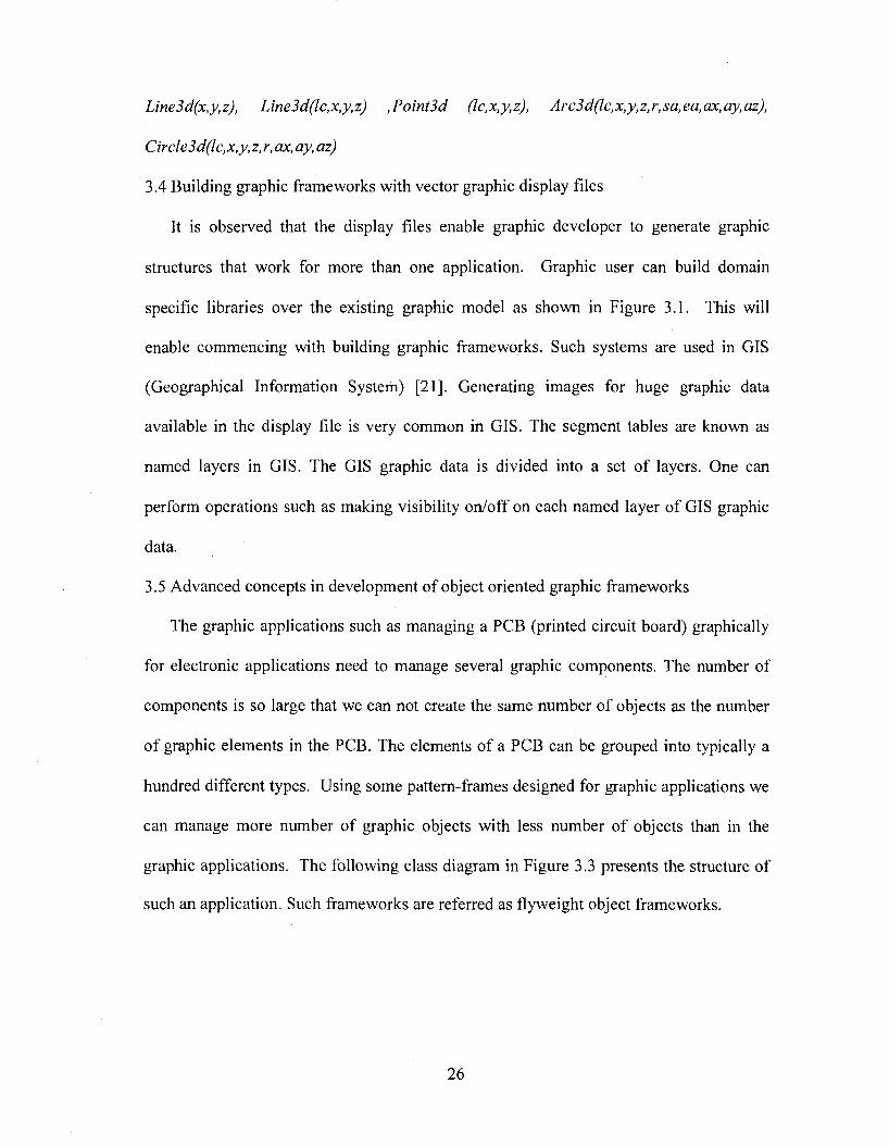
graphic applications. The following class diagram in Figure 3.3 presents the structure of
such an application. Such frameworks are referred as flyweight object frameworks.
26
Generic graphic objectinterfaces
---------Geometricinterfaces
Client
Geometriclibrary
Display file sub-system
< Geometric implementation >
<Generic graphic object Implementation >
Flyweight graphic object
Attributes
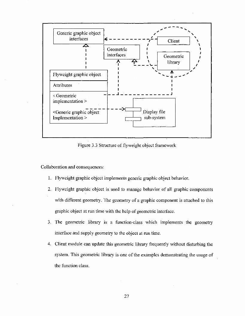
Figure 3.3 Structure of flyweight object framework
Collaboration and consequences:
1. Flyweight graphic object implements generic graphic object behavior.
2. Flyweight graphic object is used to manage behavior of all graphic components
with different geometry. The geometry of a graphic component is attached to this
graphic object at run time with the help of geometric interface.
3. The geometric library is a function-class which implements the geometry
interface and supply geometry to the object at run time.
4. Client module can update this geometric library frequently without disturbing the
system. This geometric library is one of the examples demonstrating the usage of
the function class.
27
3.6 Implementation and sample code:
The flyweight object model is well suited for applications like simulating a PCB. The
requirements of such applications were already presented earlier in this thesis. The PCB
will manage several graphic components with a single graphic object. The following
example is reusing the white-box frameworks for implementing the flyweight object
framework.
The components in this model are:
1. Generic graphic classes, which will implement display, file concepts for
managing any graphic element with specified behavior. This class is an abstract
class as it has some unknown requirements in it. It will support multiple
behaviors. This is weight box framework example given in previous section.
2. A class, namely, component class is designed to attach behavior of graphic
component as per its requirement. This is a flyweight graphic component.
3. A group of application specific functions support behavior of typical components.
These functions attach graphics to the component class. This can use a function
class framework.
The above model is used to change the component behavior dynamically with the
help of display files and function classes. The component class will exhibit its
behavior whenever user changes the type of the component. The component can be
changed into desired shapes using the function SetType that is implemented by
Graphic Element class. User can attach his own geometry to the framework.
All the object-oriented framework patterns discussed in earlier sections are used
in this model including the traditional graphic frameworks.
2 8
It should be noted that the interfaces are also defined inside the class. They will be
separated if the model uses component oriented technology. These concepts are
discussed in the next chapter.
The following code blocks represent three modules.
1. Graphic class to implement display files and generic graphic behavior; this is a
combination of traditional graphic frameworks and white-box Framework. This is
an abstract class
2. A component class, which is a flyweight class; this depends on white-box
frameworks and traditional graphic frameworks. This can be used to manage
several graphic objects, and depends on function class framework that manages
geometry of the functions.
3. The geometric function library; this will be managed with function class.
It can be observed that the component class implements only one method that is the
Design method. User can design typical shapes of the component using at this method
using the framework. Sample implementation for designing the shape of a PCB
component is listed. For each function Graphic Element is the argument like CDC for
OnDraw function for Microsoft Document View Architecture. This graphic element
provide framework interface for using the features of framework.
Observations:
The number of objects also can be decreased with the help o f the above model. Such
behavior is useful for managing a large number of graphic components. For example
consider a PCB that has thousands of graphic components, it is possible to manage all the
PCB components using a single object by storing additional information of PCB
29
component in a database. Such applications increase performance of the system. This
model allows graphic frameworks to run even on lower end systems.
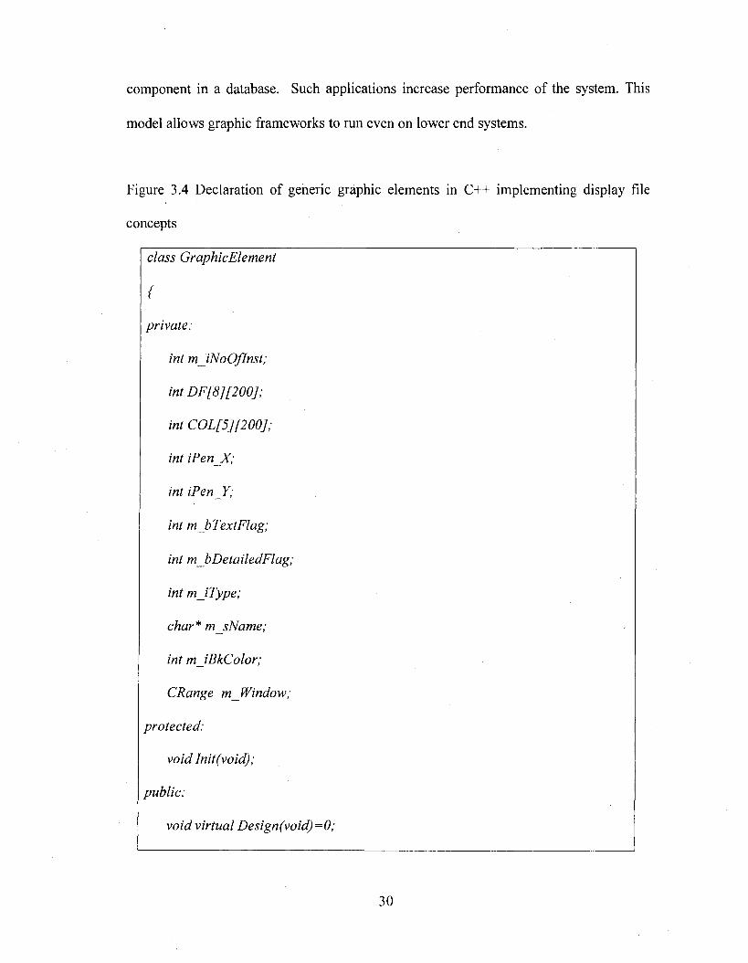
Figure 3.4 Declaration of generic graphic elements in C++ implementing display file
concepts
class Graphic Element
{
private:
int mJNoOflnst;
int DF[8][200];
int COL[5][200];
int iPen X;
int iPen Y;
int m bTextFlag;
int mJbDetailedFlag;
int m JType;
char* m_sName;
int m JBkColor;
CRange m Window;
protected:
void Init(void);
public:
void virtual Design(void)=0;
30
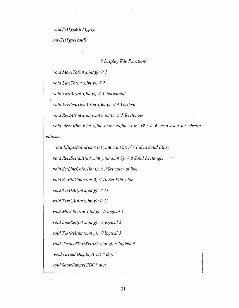
void SetType(int type);
int GetType(void);
/ / Display File Functions
void MoveTo(int x,inty); / /1
voidLineTo(int x,inty); / / 2
void TextAt(int x, int y); / / 2 horizontal
void VerticalTextAt(int x,int y); / / 4 Vertical
void RectAt(int x, inty, int a, int b); / / 5 Rectangle
void ArcAt(int x,int y,in t sa,int ea,int rl,in t r2); / / 6 used even fo r circles
ellipses
void EllipseSolid(int x, int y, int a, int b); / / 7 Filled Solid Ellise
void RectSolidA tftnt x, int y, int a, int b); / / 8 Solid Rectangle
void SetLineColor(int i); / / 9 Set color o f line
void SetFillColor(int i); / / 10 Set FillColor
void TextlAt(int x,int y); / / I I
void Text2At(int x,int y); / / 12
void MoveRel(int x, int y); / / logical I
void LineRel(int x ,in ty); //log ica l 2
void TextRel(int X , in ty); //log ica l 2
void VerticalTextRel(int x, int y); / / logical 4
void virtual Display(CDC* dc);
void ShowRange(CDC* dc);
31
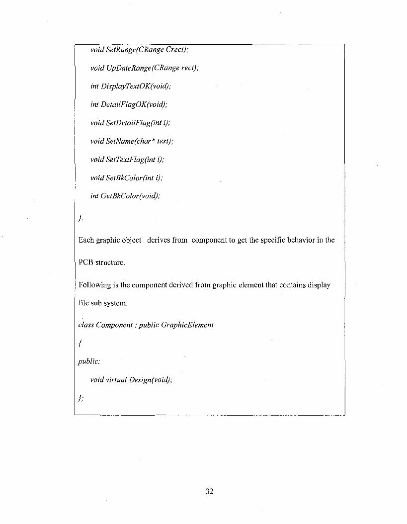
void SetRange(CRange Greet);
void UpDateRange(CRange rect);
int DisplayTextOK(void);
int DetailFlagOK(void);
void SetDetailFlag(int i);
voidSetName(char* text);
void SetTextFlag(int i);
void SetBkColor(int i);
int GetBkColor(void);
} ;
Each graphic object derives from component to get the specific behavior in the
PCB structure.
Following is the component derived from graphic element that contains display
file sub system.
class Component : public GraphicElement
{
public:
void virtual Design(void);
};
32
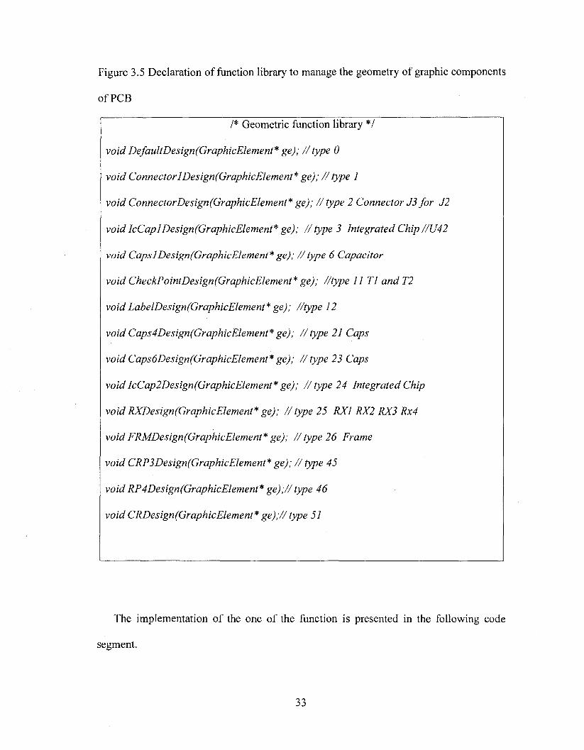
Figure 3.5 Declaration of function library to manage the geometry of graphic components
of PCB
/* Geometric function library */
void DefaultDesign(GraphicElement* ge); / / type 0
void Connector 1 Design(GraphicElement* ge); / / type 1
void ConnectorDesign(GraphicElement* ge); / / type 2 Connector J2 fo r J2
void IcCaplDesign(GraphicElement* ge); //typ e 3 Integrated C hip//U 42
void Caps!Design(GraphicEIement* ge); / / type 6 Capacitor
void CheckPointDesign(GraphicElement* ge); //type II TI and T2
void LabelDesign(GraphicElement* ge); //type 12
void Caps4Design(GraphicElement* ge); //typ e 21 Caps
void Caps6Design(GraphicElement* ge); //ty p e 23 Caps
void IcCap2Design(GraphicElement* ge); / / type 24 Integrated Chip
void RXDesign(GraphicElement* ge); / / type 25 RXI RX2 RX3 Rx4
void FRMDesign(GraphicElement* ge); / / type 26 Frame
void CRP3Design(GraphicElement* ge); / / type 45
void RP4Design(GraphicElement* ge);// type 46
void CRDesign(GraphicElement* ge);// type 51
The implementation of the one of the function is presented in the following code
segment.
33
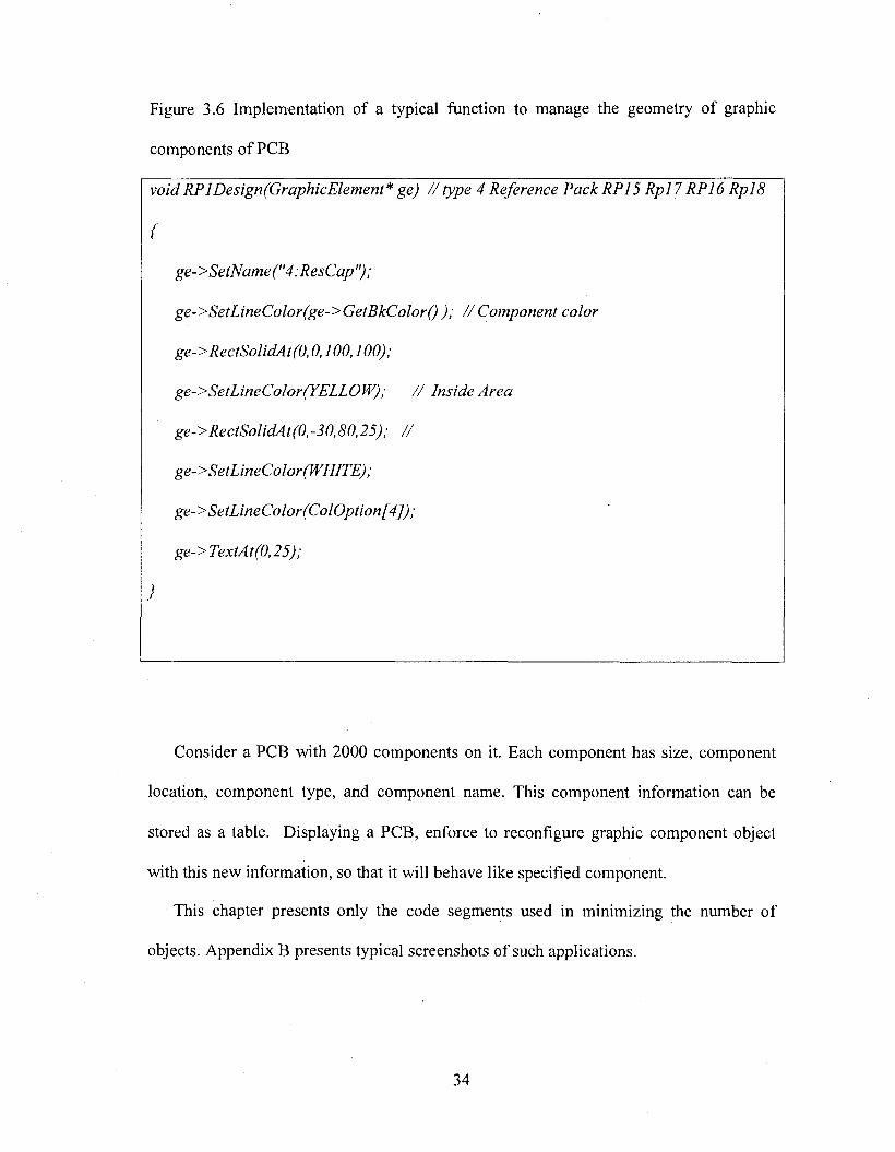
Figure 3.6 Implementation of a typical function to manage the geometry of graphic
components of PCB
voidRPlDesign(GraphicElement* ge) //ty p e 4 Reference Pack RP15 Rpl 7 RP16 R p l8
{
ge->SetName("4:ResCap");
ge->SetLineColor(ge->GetBkColor() ); / / Component color
ge->RectSolidAt(0,0,100,100);
ge->SetLineColor(YELLOW); / / Inside Area
ge->RectSolidAt(0,-30,80,25); / /
ge->SetLineColor(WHlTE) ;
ge->SetLineColor(ColOption[4]);
ge-> TextAt(0,25);
}
Consider a PCB with 2000 components on it. Each component has size, component
location, component type, and component name. This component information can be
stored as a table. Displaying a PCB, enforce to reconfigure graphic component object
with this new information, so that it will behave like specified component.
This chapter presents only the code segments used in minimizing the number of
objects. Appendix B presents typical screenshots of such applications.
34
CHAPTER 4
PROCEDURE FOR DEVELOPING THE COM OBJECTS
The COM object is also known as Windows object. The Windows technology of
Microsoft is developed over the COM/OLE technology. These technologies support
development o f user-friendly components. Though the development is costly, services
offered to the client are demanding such components. The revolution in the computer
hardware configuration has become an added advantage to this technology. This
technology is in use from 1995 [12] [24].
Before 1995 Microsoft Visual development environment required support tools for
the development o f the COM components. VC++ version 2.0 started supporting the
development of COM applications natively. Using this one can develop COM
components. VC++ 2.0 did not support automation layer directly. For building
automation layer developers needed to write an IDE (Interface Description Language)
and ODE (Object Description Language) script for describing the objects and interfaces,
which built automation layer. This process was very complicated. This situation has been
improved with VC++ 6.0, which has sufficient tools for building COM-based application
modules.
35
4.1 Microsoft application on COM/OLE technology
Microsoft Word, Access, Excel and PowerPoint are the best examples of applications
developed on COM /OLE technology. The Word document is known as compound
document as it contains elements, which belong to several applications. The In-place
activation o f the OLE objects in Word documents created a new revolution in the
document applications. Unlike old WordStar and PageMaker, the Microsoft word
document can contain pictures, excel sheets, etc., in its native format. These inserted
elements can be edited within the Word application itself whenever necessary. This
process is known as In-place Activation. The process of linking OLE objects into a
component document is known as Object Linking and Embedding (OLE). If the inserted
object is linked from an external file, it is known as object linking, and if it is copied on
to the compound document, this is known as embedding.
These Container server concepts were released to the developer in 1995-96. The
Visual C++ Version 2.0 allowed a developer to create an OLE Server and OLE container
applications. The OLE Server application is a server, which can be inserted in any OLE
container like Microsoft Word. The OLE container is an application, which can contain
OLE objects. The application can become both container and server at a time. The
Microsoft Word is both container and server, whereas the Paintbrush is just a server, not
a container.
All these are becoming possible because of COM/OLE technology by Microsoft.
COM is a Windows object. OLE is an environment built on COM technology. OLE
defines a set of interfaces using which a component document can communicate with an
unknown foreign object. For making our COM objects participate in OLE operation we
36
need to support required interfaces defined by OLE. Such objects which implement OLE
interfaces are known as OLE enable objects (in short ‘olable’).
All those facilities attracted the developers in 1995 - 2000 period and changed the
market trends. The cut and past, object linking and embedding, and drag and drop
operations are required even in CAD systems for offering better services. The only
problem was that the environment was costly and complex. Although Microsoft was
using the technology, the development technology was not fully available to software
development industry between 1995 and 1998. Now COM technology is providing full-
fledged technical support for the development of component-based components and
applications.
4.2 COM vs. C++ object reuse
COM components allow developing better servers than with simple C++ objects in
spite that COM is costly. Although COM is also based on object-oriented technology, the
COM is treated as a separate technology as the management of the components is entirely
different. The following table shows the difference between COM and C++ object [13]
[23].
4.3 Procedures in creating and managing the COM server
COM server implements a set of API functions for managing the COM objects. This
manages object count, which records the number of components, released from the
server. Some of the API functions will establish a session with the operating system.
Using these APIs, the operating system gets the information such as whether the server is
in use or not. One of the major API functions is to establish a session between the server
and the client using the system registry data. The server will create the COM object
37
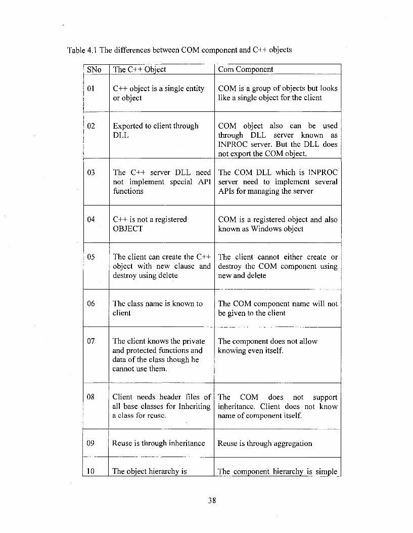
Table 4.1 The differences between COM component and C++ objects
SNo The C++ Object Com Component
01 C++ object is a single entity or object
COM is a group of objects but looks like a single object for the client
02 Exported to client through DLL
COM object also can be used through DLL server known as INPROC server. But the DLL does not export the COM object.
03 The C++ server DLL need not implement special API functions
The COM DLL which is INPROC server need to implement several APIs for managing the server
04 C++ is not a registered OBJECT
COM is a registered object and also known as Windows object
05 The client can create the C++ object with new clause and destroy using delete
The client cannot either create or destroy the COM component using new and delete
06 The class name is known to client
The COM component name will not be given to the client
07 The client knows the private and protected functions and data of the class though he cannot use them.
The component does not allow knowing even itself.
08 Client needs header files of all base classes for Inheriting a class for reuse.
The COM does not support inheritance. Client does not know name of component itself.
09 Reuse is through inheritance Reuse is through aggregation
10 The object hierarchy is The component hierarchy is simple
38
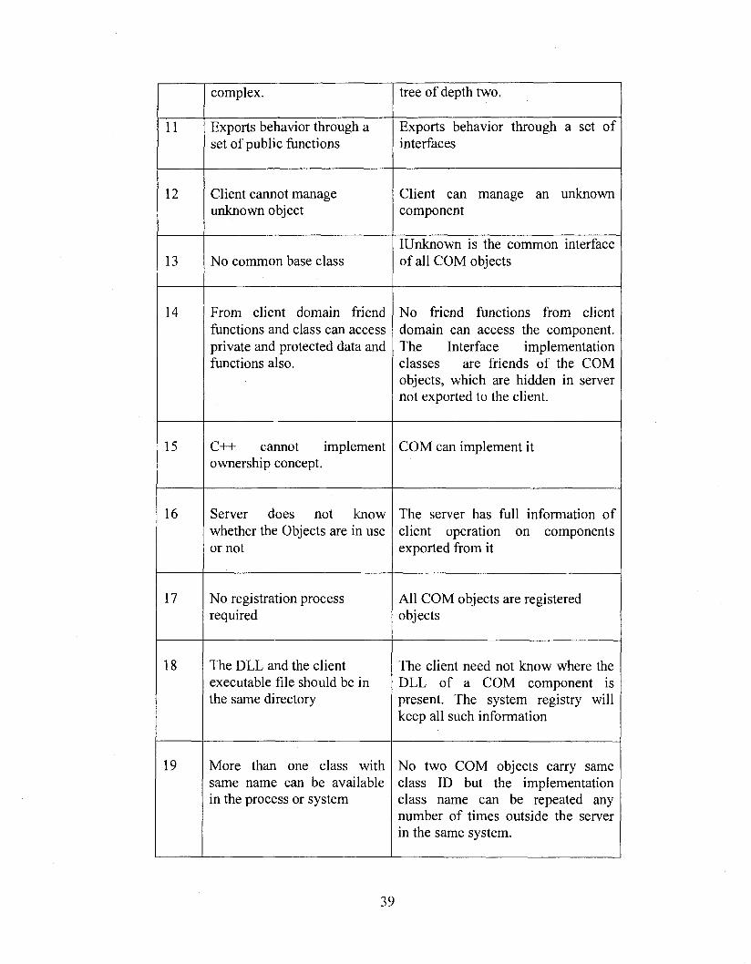
complex. tree of depth two.
11 Exports behavior through a set of public functions
Exports behavior through a set of interfaces
12 Client cannot manage unknown object
Client can manage an unknown component
13 No common base classIUnknown is the common interface of all COM objects
14 From client domain friend functions and class can access private and protected data and functions also.
No friend functions from client domain can access the component. The Interface implementation classes are friends of the COM objects, which are hidden in server not exported to the client.
15 C++ cannot implement ownership concept.
COM can implement it
16 Server does not know whether the Objects are in use or not
The server has full information of client operation on components exported from it
17 No registration process required
All COM objects are registered objects
18 The DLL and the client executable file should be in the same directory
The client need not know where the DLL of a COM component is present. The system registry will keep all such information
19 More than one class with same name can be available in the process or system
No two COM objects carry same class ID but the implementation class name can be repeated any number of times outside the server in the same system.
39
20 Modules are tightly coupled. Even a simple change in class header forces the client to build the application
Modules are loosely coupled. Even if the COM object name itself changes, the client need not be compiled. So long as interfaces are not disturbed client application will not get effected.
21 No version management for object
Component can maintain a version number
Required for the client and releases its IUnknown interface to the client. The client
communicates with the server through the interfaces of the components. The procedure of
creating a COM object is a complex cycle. The client requests the COMDLL for creation
of a COM object. The client refers the COM object with its class ID.
1. The COMDLL requests the operating system. The operating system APIs search
the registry for the server information of the COM object.
2. In case the COM is a registered object, the operating system will provide the DLL
server information, which is in the system registry.
3. The operating system loads the required DLL. The operating system
communicates with the server using an API requesting the COM object.
4. The server passes the call to the Class Factory Object. The class factory creates
the object and updates the server information.
5. The operating system APIs return the pointer to IUnknown interface of the COM
object to the client.
40

6. The client queries this required interfaces from the IUnknown interface of the
COM component.
7. The moment the client releases all the interfaces of the COM object, the COM
object will be deleted on its own.
8. The server gets unloaded if it is not in use.
9. The client locks the server to keep it available in the memory.
10. The servers need to implement the following APIs shown in the following table
for exporting the COM object.
4.4 Implementation issues of COM objects
COM object servers are o f three types.
1. INPROC SERVER
2. LOCAL SERVER
3. REMOTE SERVER
IN PR O C server is a DLL server that runs from the same processes o f the application.
LOCAL server provides proxy through which both COM server application and client
applications communicate with each other from different processes on the same system.
R EM O TE server provides a proxy to provide two processes communicate with each other
from different systems. This server is also known as D C O M server. Appendix A presents a
procedure for the implementation o f a simple beeper COM object through an INPROC
server. N ote that this object is no t an element o f a graphic framework. This example is
presented just to demonstrate the complexity o f the COM object procedures both for creating
a simple COM object and for using an existing COM object.
41

Table 4.2 Typical APIs of COM server
SNo Function Description
01
DUGetClassObject
This is a system API. Used to communicate with Operating system for creating COM objects
02 DllCanUnl oadNow This is a system API. Used to communicate with Operating system for informing the status
03 ServerGetNumberOfObjects Returns number of COM objects released from the server
04 ServerGetNumberO/Locks Returns number of locks of the server
05 ServerlncrementNumberOfObjects Increment number of objects. This is called from class factory of the COM objects.
06Server IncrementNumberOfLocks This will increment the
number o f Locks
07 Server DecrementNumberOfObjects Decrements number of objects. This is called from the COM object destructor
08 Server DecrementNumberOfLocks This will decrease number of locks of the server
42

Frameworks for graphic COM objects presented in this thesis simplify this procedure,
which is an important contribution of this thesis. It also encapsulates the server and client
management procedures of a COM object. This enables the graphic application developer
to develop a COM-based graphic system using object-oriented development methods
such as inheritance and polymorphism.
43
CHAPTER 5
FRAMEWORKS FOR GRAPHIC COMPONENTS
The intent of the abstract component frameworks is to generate black box framework
components using simple object-oriented primitive patterns.
The abstract component framework is also a component-based framework. However,
it enables a C++ developer to develop components without much knowledge about the
Component technology. The component pattern management procedure is reused in
abstract component frameworks. Mainly this presents a simple mechanism to generate
components by applying simple object-oriented patterns. In this model both the object-
oriented patterns as well as the component patterns are adopted for reuse. The following
Figure 5.1 shows the block diagram of an abstract component framework model.
The abstract component framework is a generic component, which will implement all
reusable component management code required along with reusable domain specific
behavior, which is common to all components of the group. This will implement all
component patterns, which can be shared by all components o f the group. This
component is named as abstract component as it is not a full-fledged component. It is an
abstract class, i.e., it cannot be instantiated. But derived classes of this abstract
component, by implementing pure virtual function, will become full-fledged components.
In other words, this abstract component will become enterprise component by
configuring it to the requirement of a specific object. As the component patterns are
44
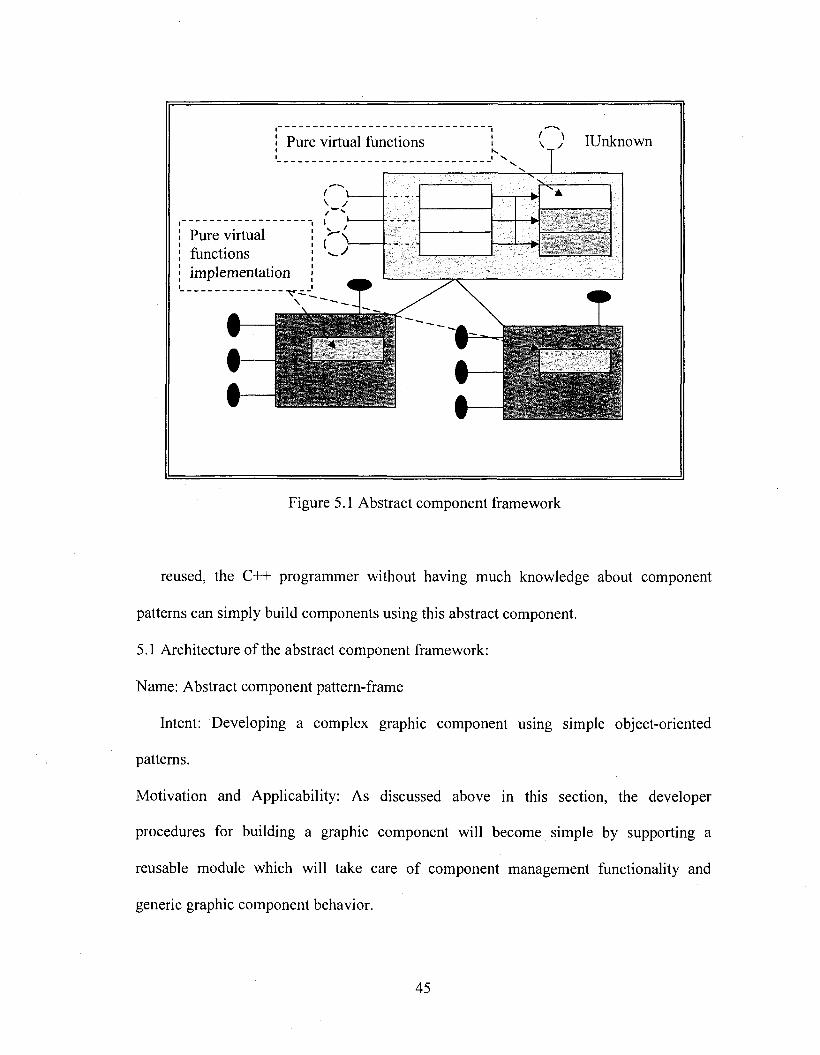
IUnknownPure virtual functions
Pure virtualfunctionsimplementation
Figure 5.1 Abstract component framework
reused, the C++ programmer without having much knowledge about component
patterns can simply build components using this abstract component.
5.1 Architecture of the abstract component framework:
Name: Abstract component pattern-frame
Intent: Developing a complex graphic component using simple object-oriented
patterns.
Motivation and Applicability: As discussed above in this section, the developer
procedures for building a graphic component will become simple by supporting a
reusable module which will take care of component management functionality and
generic graphic component behavior.
45
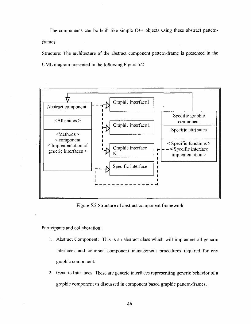
The components can be built like simple C++ objects using these abstract pattem-
frames.
Structure: The architecture of the abstract component pattern-frame is presented in the
UML diagram presented in the following Figure 5.2
Abstract component
<Attributes >
<Methods >< component
< Implementation of generic interfaces >
!-(> Graphic interface 1
Graphic interface i
i>Graphic interface N
i>Specific interface
Specific graphic component
Specific attributes
< Specific functions > - < Specific interface
implementation >
Figure 5.2 Structure of abstract component framework
Participants and collaboration:
1. Abstract Component: This is an abstract class which will implement all generic
interfaces and common component management procedures required for any
graphic component.
2. Generic Interfaces: These are generic interfaces representing generic behavior of a
graphic component as discussed in component based graphic pattern-frame s.
46
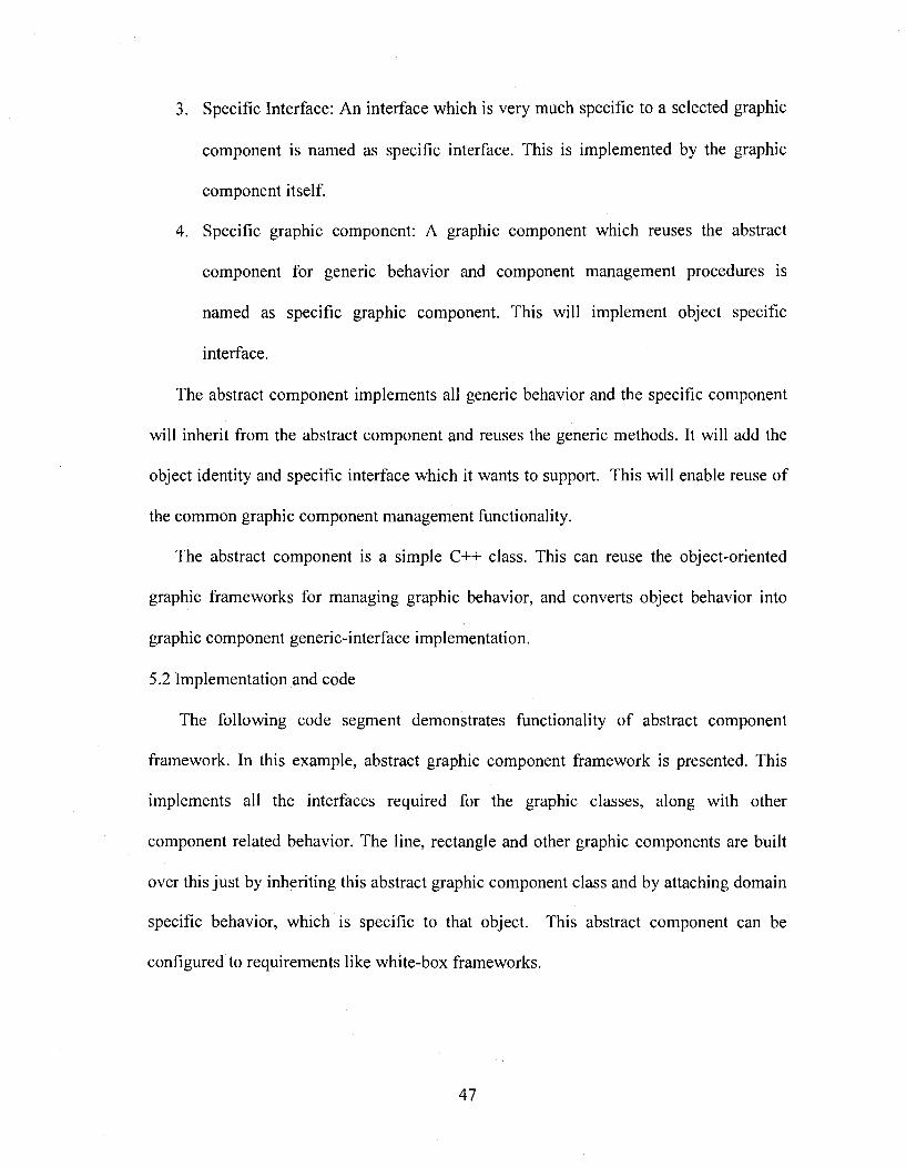
3. Specific Interface: An interface which is very much specific to a selected graphic
component is named as specific interface. This is implemented by the graphic
component itself.
4. Specific graphic component: A graphic component which reuses the abstract
component for generic behavior and component management procedures is
named as specific graphic component. This will implement object specific
interface.
The abstract component implements all generic behavior and the specific component
will inherit from the abstract component and reuses the generic methods. It will add the
object identity and specific interface which it wants to support. This will enable reuse of
the common graphic component management functionality.
The abstract component is a simple C++ class. This can reuse the object-oriented
graphic frameworks for managing graphic behavior, and converts object behavior into
graphic component generic-interface implementation.
5.2 Implementation and code
The following code segment demonstrates functionality of abstract component
framework. In this example, abstract graphic component framework is presented. This
implements all the interfaces required for the graphic classes, along with other
component related behavior. The line, rectangle and other graphic components are built
over this just by inheriting this abstract graphic component class and by attaching domain
specific behavior, which is specific to that object. This abstract component can be
configured to requirements like white-box frameworks.
47
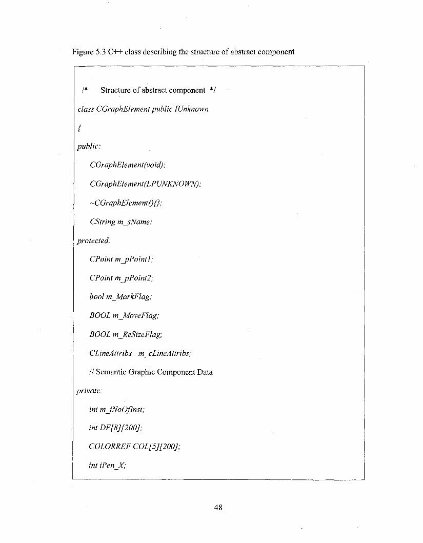
Figure 5.3 C++ class describing the structure of abstract component
/* Structure of abstract component */
class CGraphElement public IUnknown
{
public:
CGraphElement(void);
CGraphElement (LPUNKNOWN);
~C GraphElementQ {} ;
CString m_sName;
protected:
CPoint m_pPointI;
CPoint m_pPoint2;
bool m_MarkFlag;
BOOL m_MoveFlag;
BOOL mJieSizeFlag;
CLineAttribs m cLineAttribs;
// Semantic Graphic Component Data
private:
int m JNoOflnst;
in tD F [8][200];
COLORREF COL[5][200];
int iPen_X;
48
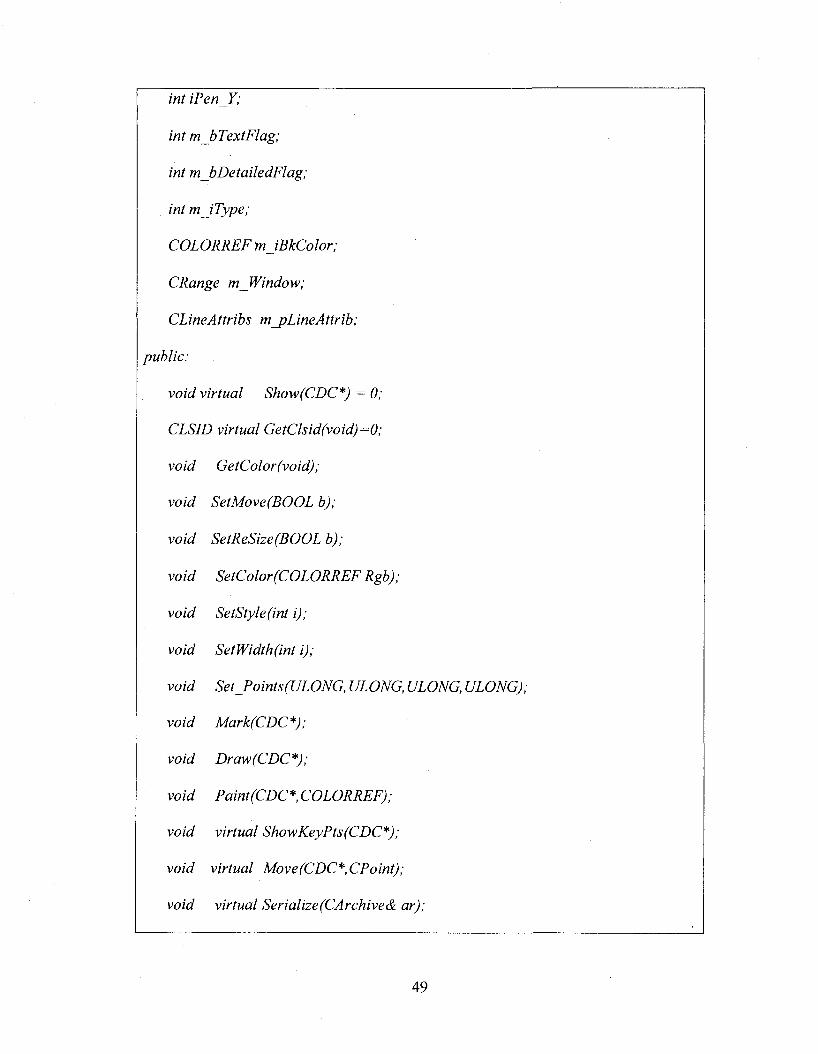
int iPen Y;
int mJbTextFlag;
int m bDetailedFlag;
int m JType;
COLORRFFtnJBkColor;
CRange m_Window;
CLineAttribs m_pLineAttrib;
public:
void virtual Show(CDC*) = 0;
CLSID virtual GetClsid(void)=^0;
void GetColor(void);
void SetMove(BOOL b);
void SetReSize(BOOL b);
void SetColor(COLORRFF Rgb);
void SetStyle(int i);
void SetWidth(int i);
void Set Points(ULONG, ULONG, ULONG, ULONG);
void Mark(CDC*);
void Draw(CDC*);
void Paint (GDC*COLORRFF);
void virtual ShowKeyPts(CDC*);
void virtual Move (GDC*,CPoint);
void virtual Serialize (GAr chive & ar);
49
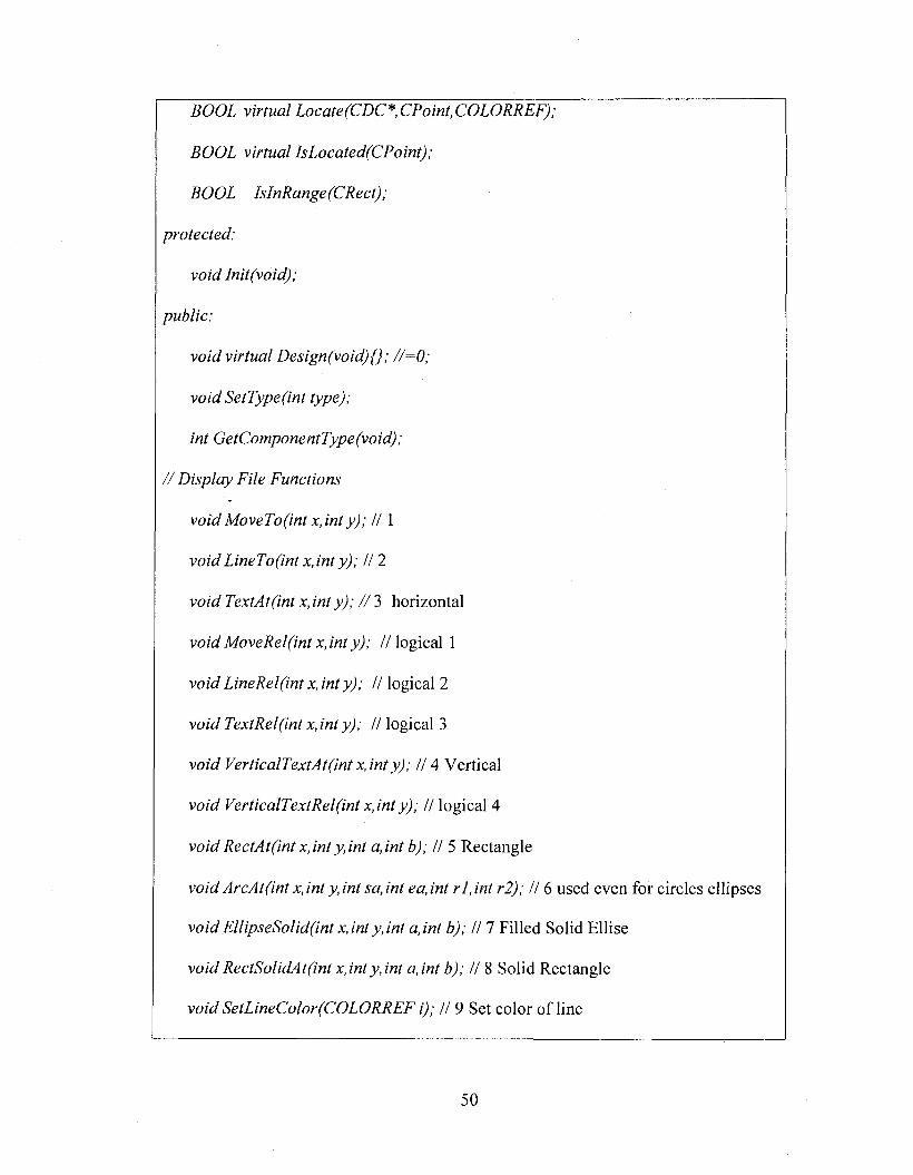
BOOL virtual Locate (CDC*,CP oint,COLORREF);
BOOL virtual IsLocated(CPoint);
BOOL IsInRange(CRect);
protected;
void lnit(void);
public;
void virtual Design(void){); //=0;
void SetType(int type);
int GetComponentType(void);
/ / Display File Functions
void MoveTo(int X, inty); //1
void LineTo(int x,inty); // 2
void TextAt(int x, int y); / / 3 horizontal
voidM oveRel(intX,inty); //logical 1
void Line Re I (int x, int y); // logical 2
void TextRel(int x,inty); // logical 3
void VerticalTextAt(int x,inty); // 4 Vertical
void VerticalTextRel(int x,inty); // logical 4
void RectAt(int x,inty,int a,int b); // 5 Rectangle
void ArcAt(int x, int y, int sa, int ea, int r l, int r2); // 6 used even for circles ellipses
voidFllipseSolid(int x,inty,int a,int b); II 7 Filled Solid Ellise
void RectSolidAt(int x,int y, int a, int b); // 8 Solid Rectangle
void SetLineColor(COLORRFF i); // 9 Set color of line
50
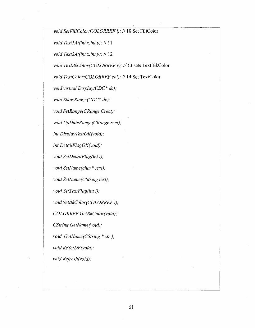
void SetFillColor(COLORREF i); H 10 Set FillColor
void Text 1 At (int X, int y); H 11
void Text2At(int x,int y); H 12
void TextBkColor(COLORREF r); //13 sets Text BkColor
void TextColor(COLORREF col); H 14 Set TextColor
void virtual Display(CDC* de);
void Show Range (CDC* de);
void SetRange(CRange Crect);
void UpDateRange(CRange rect);
int DisplayTextOK(void);
int DetailFlagOK(void) ;
void SetDetailFlag(int i);
v o id SetName(char* text);
void SetName (CString text);
void SetTextFlag(int i);
void SetBkColor(COLORREF i);
COLORREF GetBkColor(void);
CString GetName(void);
void GetName(CString * str );
void ReSetDF(void);
void Refresh(void) ;
51
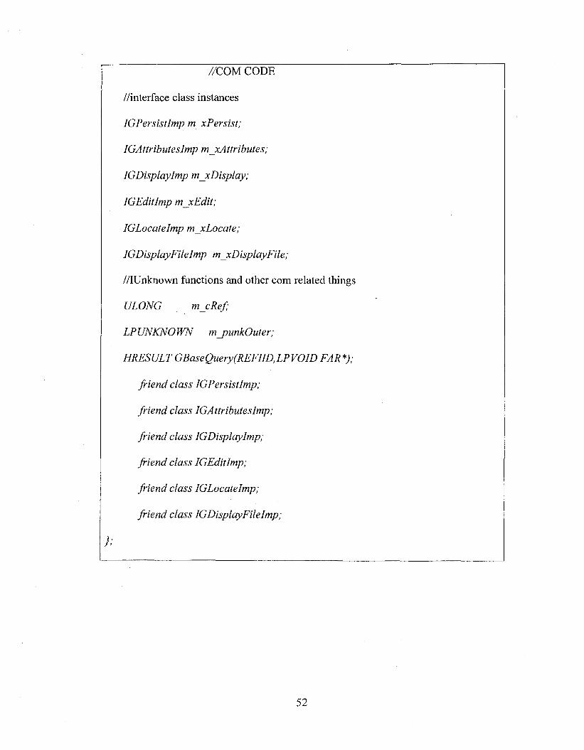
//COM CODE
//interface class instances
IGPersistImp m xPersist;
IGAttributeslmp m_xAttributes;
IGDisplaylmp m_xDisplay;
IGEditlmp mjcEdit;
IGLocateImp m xLocate;
JGDisplayFilelmp m xDisplayFile;
//IUnknown functions and other com related things
ULONG m cR ef;
LPUNKNOWN m _punkOuter;
HRESULT GBaseQuery(REFIlD,LPV01D FAR *);
friend class IGPersistImp;
friend class IGAttributesImp;
friend class IGDisplaylmp;
friend class IGEditlmp;
friend class IGLocateImp;
friend class IGDisplayFileImp;
};
52
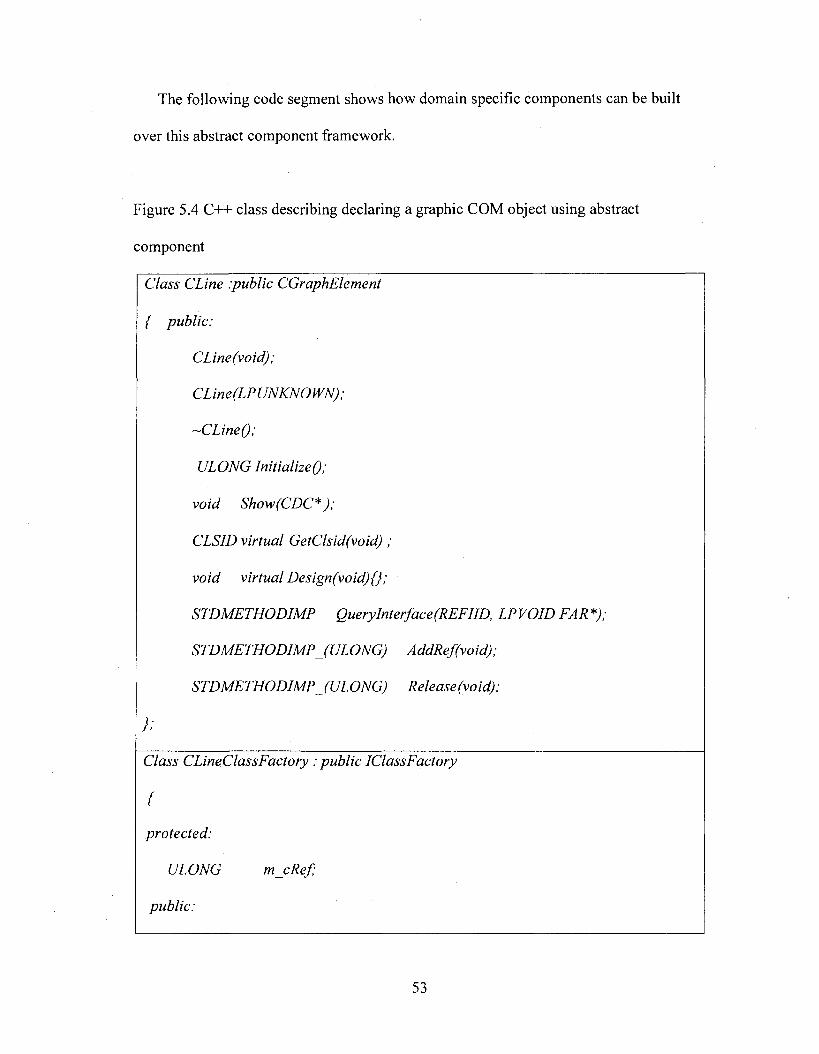
The following code segment shows how domain specific components can be built
over this abstract component framework.
Figure 5.4 C++ class describing declaring a graphic COM object using abstract
component
Class CLine .public CGraphElement
{ public:
CLine(void);
-CLineQ;
UIOVG/mVWizeO,
void Show (GDC* );
CLSID virtual GetClsid(void) ;
void virtual Design(void){};
STDMETHODIMP QueryInterface(REFIID, LPVOID FAR *);
STDMETHODIMP (ULONG) AddRef(void);
STDMETHODIMP JU LO N G ) Release (void);
}:
Class CLineClassFactory ; public IClassFactory
{
protected:
ULONG m cR ef;
public:
53
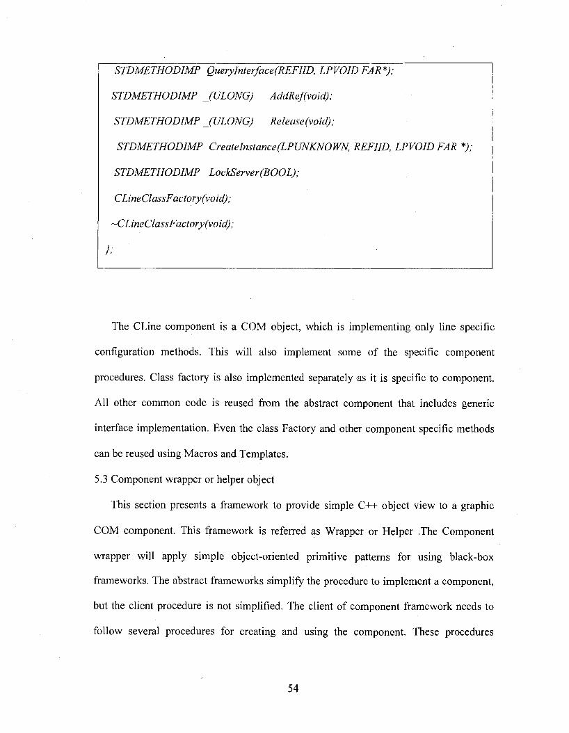
STDMETHODIMP QueryInterface(REFIID, LPVOID FAR *);
STDMETHODIMP JU LO N G ) AddReJvoid);
STDMETHODIMP (ULONG) Release (void);
STDMETHODIMP Createlnstance(LPUNKNOWN, REFIID, LPVOID FAR *);
STDMETHODIMP LockServer(BOOL);
CLineClassFactory (void);
-CLineClassFactory (void);
}:
The CLine component is a COM object, which is implementing only line specific
configuration methods. This will also implement some of the specific component
procedures. Class factory is also implemented separately as it is specific to component.
All other common code is reused from the abstract component that includes generic
interface implementation. Even the class Factory and other component specific methods
can be reused using Macros and Templates.
5.3 Component wrapper or helper object
This section presents a framework to provide simple C++ object view to a graphic
COM component. This framework is referred as Wrapper or Helper .The Component
wrapper will apply simple object-oriented primitive patterns for using black-box
frameworks. The abstract frameworks simplify the procedure to implement a component,
but the client procedure is not simplified. The client of component framework needs to
follow several procedures for creating and using the component. These procedures
54
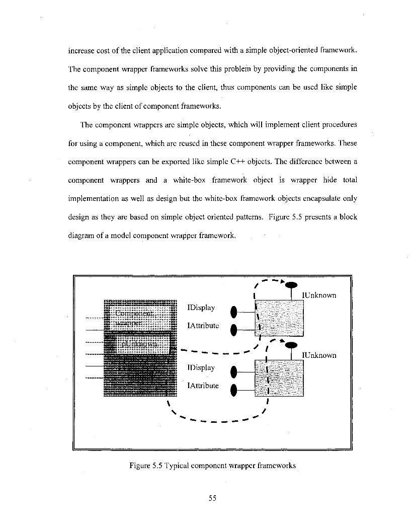
increase cost of the client application compared with a simple object-oriented framework.
The component wrapper frameworks solve this problem by providing the components in
the same way as simple objects to the client, thus components can be used like simple
objects by the client of component frameworks.
The component wrappers are simple objects, which will implement client procedures
for using a component, which are reused in these component wrapper frameworks. These
component wrappers can be exported like simple C++ objects. The difference between a
component wrappers and a white-box framework object is wrapper hide total
implementation as well as design but the white-box framework objects encapsulate only
design as they are based on simple object oriented patterns. Figure 5.5 presents a block
diagram of a model component wrapper framework.
iv L _ -_ tiipLIDisplay
lAttribute \t
/ / i-
Unknown
IDisplay ^
lAttribute A
CT Unknown
Figure 5.5 Typical component wrapper frameworks
55
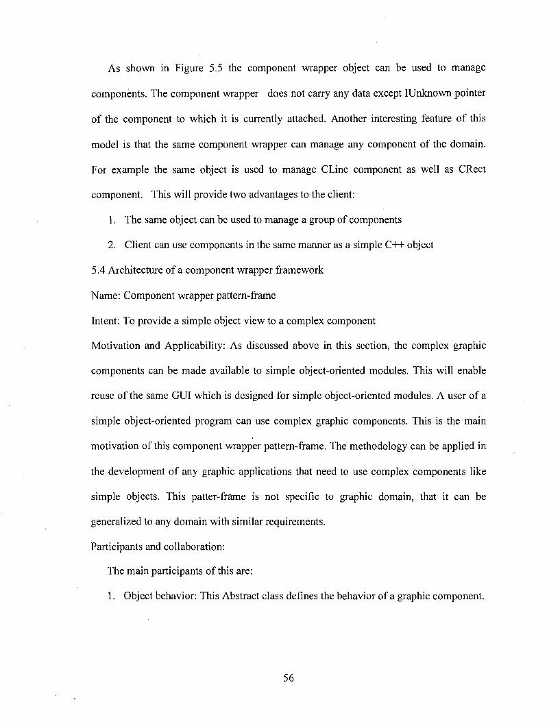
As shown in Figure 5.5 the eomponent wrapper objeet can be used to manage
eomponents. The component wrapper does not earry any data exeept IUnknown pointer
of the eomponent to whieh it is eurrently attaehed. Another interesting feature o f this
model is that the same eomponent wrapper ean manage any eomponent of the domain.
For example the same objeet is used to manage CLine eomponent as well as CReet
eomponent. This will provide two advantages to the elient:
1. The same objeet ean be used to manage a group of components
2. Client can use components in the same manner as a simple C++ object
5.4 Architecture o f a eomponent wrapper framework
Name: Component wrapper pattern-frame
Intent: To provide a simple objeet view to a eomplex eomponent
Motivation and Applieability: As diseussed above in this seetion, the eomplex graphie
components can be made available to simple objeet-oriented modules. This will enable
reuse of the same GUI whieh is designed for simple objeet-oriented modules. A user of a
simple objeet-oriented program ean use eomplex graphie components. This is the main
motivation of this component wrapper pattern-frame. The methodology can be applied in
the development o f any graphie applieations that need to use eomplex eomponents like
simple objects. This patter-frame is not speeifie to graphie domain, that it can be
generalized to any domain with similar requirements.
Participants and collaboration:
The main participants of this are:
1. Objeet behavior: This Abstraet elass defines the behavior of a graphie eomponent.
56
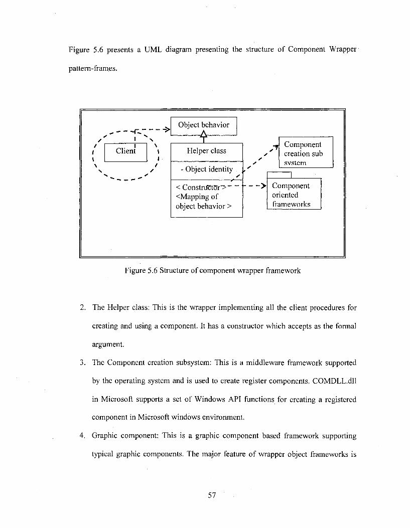
Figure 5.6 presents a UML diagram presenting the structure of Component Wrapper
pattem-frames.
■T̂ -------- ">I
Client
Object behavior
1 ----------Helper class
- Object identity ^
< ConstrdCt5r'> ' <Mapping of object behavior >
Component creation sub svstem
> Componentorientedframeworks
Figure 5.6 Structure of component wrapper framework
2. The Helper class: This is the wrapper implementing all the client procedures for
creating and using a component. It has a constructor which accepts as the formal
argument.
3. The Component creation subsystem: This is a middleware framework supported
by the operating system and is used to create register components. COMDLL.dll
in Microsoft supports a set of Windows API functions for creating a registered
component in Microsoft windows environment.
4. Graphic component: This is a graphic component based framework supporting
typical graphic components. The major feature o f wrapper object frameworks is
57
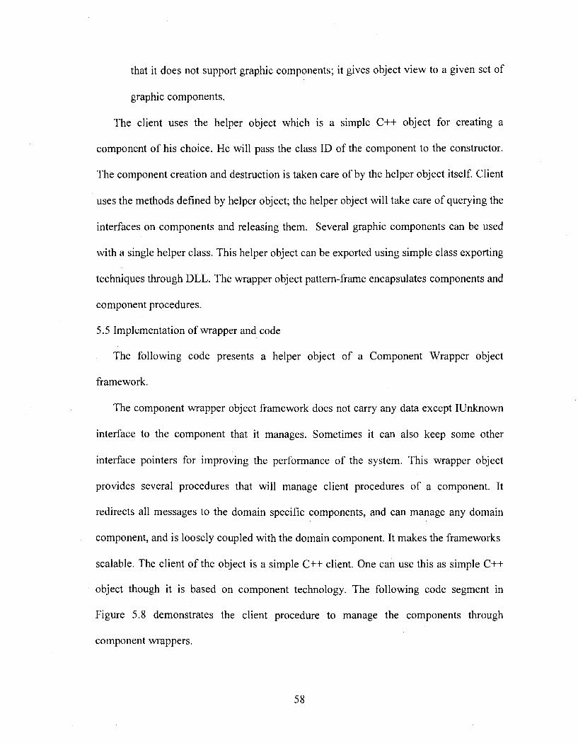
that it does not support graphic components; it gives object view to a given set of
graphic components.
The client uses the helper object which is a simple C++ object for creating a
component of his choice. He will pass the class ID of the component to the constructor.
The component creation and destruction is taken care of by the helper object itself. Client
uses the methods defined by helper object; the helper object will take care of querying the
interfaces on components and releasing them. Several graphic components can be used
with a single helper class. This helper object can be exported using simple class exporting
techniques through DLL. The wrapper object pattern-frame encapsulates components and
component procedures.
5.5 Implementation of wrapper and code
The following code presents a helper object of a Component Wrapper object
framework.
The component wrapper object framework does not carry any data except IUnknown
interface to the component that it manages. Sometimes it can also keep some other
interface pointers for improving the performance of the system. This wrapper object
provides several procedures that will manage client procedures of a component. It
redirects all messages to the domain specific components, and can manage any domain
component, and is loosely coupled with the domain component. It makes the frameworks
scalable. The client o f the object is a simple C++ client. One can use this as simple C++
object though it is based on component technology. The following code segment in
Figure 5.8 demonstrates the client procedure to manage the components through
component wrappers.
58
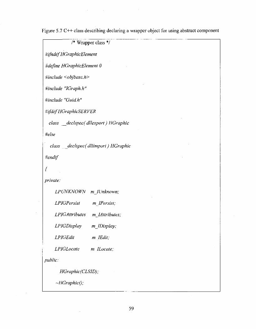
Figure 5.7 C++ class describing declaring a wrapper object for using abstract component
/* Wrapper class */
#ifndef HGraphicElement
Mefine HGraphicElement 0
#include <objbase.h>
#include "IGraph.h"
#include "Guid.h"
mfdefHGraphicSER VER
class declspec( dllexport ) HGraphic
#else
class declspec( dllim port) HGraphic
#endif
{
private:
LPUNKNOWN mJUnknown;
LPIGPersist m lP ersist;
LPIGAttributes mJAttributes;
LPIGDisplay m ID isplay;
LPIGEdit m IE dit;
LPIGLocate m ILocate;
public:
HGraphic (CLSID) ;
-HGraphicQ;
59
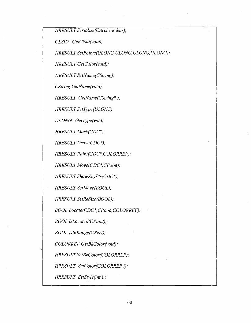
HRESULT Serialize (CArchive &ar);
GefC/jzWfvozX);
HRESULT SetPoints(ULONG, ULONG, ULONG, ULONG);
HRESULT GetColor(void);
HRESULT SetName (CString) ;
CString GetName (void);
GefA/aTMe/Œ/rmg*;,
HRESULT SetType (ULONG);
ULONG GetType(void);
HRESULT Mark(C DC*);
HRESUL T Draw (CDC *);
HRESULT Paint(CDC *, COLORREF);
HRESULT M ove(CDC* CPoint);
HRESULT ShowKeyPts(CDC*);
HRESULT SetMove(BOOL);
HRESULT SetReSize(BOOL);
BOOL Locate(CDC* CPoint,COLORREF);
BOOL IsLocated(CPoint);
BOOL IsInRange(CRect);
COLORREF GetBkColor(void);
HRESULT SetBkColor (COLORREF);
HRESULT SetColor(COLORREF i);
HRESULT SetStyle(int i);
60
Figure 5.8 C++ code segment describing the client code for wrapper class
/* Instantiation of component wrapper in Constructor class */
class CHGPClientView : public CView
{
HGraphic* m Graph;
I* Constructor and destructor of client */
CHGPClientView; .CHGPClientViewQ
{
m Graph = new HGraphic (CLSIDjCComp);
}
CHGPClientView; ;~CHGPClientView()
{
delete mjGraph;
}
I* Using component through component wrapper from client */
void CHGPClientView::OnDraw(CDC*pDC)
61
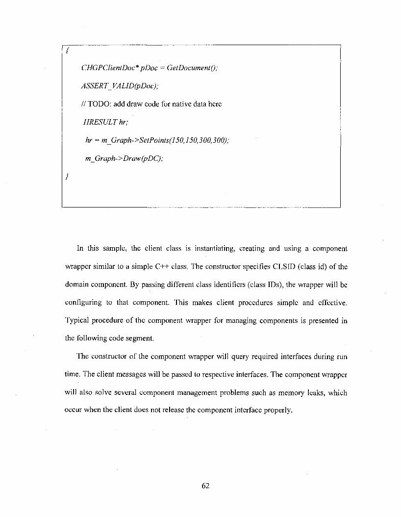
{
CHGPClientDoc* pD oc = Get Document ();
ASSERT_VALID(pDoc);
// TODO; add draw code for native data here
HRESULT hr;
hr = m_Graph->SetPoints(l50,150,300,300);
m_Graph->Draw (pDC);
}
In this sample, the client class is instantiating, creating and using a component
wrapper similar to a simple C++ class. The constructor specifies CLSID (class id) of the
domain component. By passing different class identifiers (class IDs), the wrapper will be
configuring to that component. This makes client procedures simple and effective.
Typical procedure o f the component wrapper for managing components is presented in
the following code segment.
The constructor of the component wrapper will query required interfaces during run
time. The client messages will be passed to respective interfaces. The component wrapper
will also solve several component management problems such as memory leaks, which
occur when the client does not release the component interface properly.
62
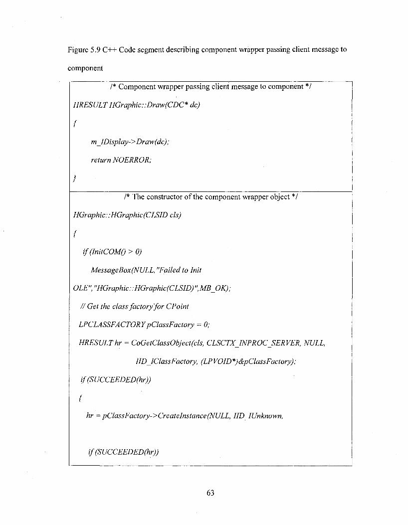
Figure 5.9 C++ Code segment describing component wrapper passing client message to
component
/* Component wrapper passing client message to component */
HRESULT HGraphic:: Draw (CDC* dc)
(
m IDisplay-> Draw(dc) ;
return NOERROR;
}
!* The constructor of the component wrapper object *!
HGraphic:; HGraphic (CLSID els)
(
MessageBox(NULL, "Failed to Init
OLE", "HGraphic::HGraphic(CLSlD) ",MB_OK);
// Get the class factory fo r CPoint
LPCLASSFACTORY pClassFactory = 0;
HRESULT hr = CoGetClassObject(cls, CLSCTX INPROC SERVER, NULL,
IlD IClassFactory, (LPVOID*)&pClassFactory);
if(SUCCEEDED(hr))
{
hr = pClassFactory->CreateInstance(NULL, IID IUnknown,
i f (SUCCEEDED(hr))
63
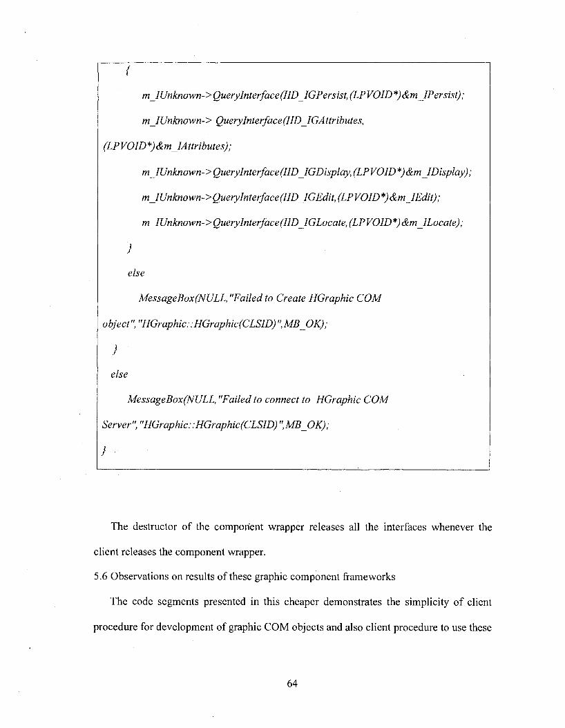
{
m_IUnknown->Querylnterface(IlD_IGPersist,(LPVOID*)&mjlPersist);
m_IUnknown-> Querylnterface(llD_lGAttributes,
(LP VOID *)&m_IA ttributes);
mJUnknown->QueryInterface(IID IGDisplay, (LPVOID*)&m IDisplay);
m_IUnknown->QueryInterface(IID_IGEdit, (LPVOID*) &m_IEdit);
m_IUnknown->QueryInterface(IID IGLocate,(LPVOID*)&m_ILocate);
}
else
MessageBox(NULL, "Failed to Create HGraphic COM
}
else
MessageBox(NULL, "Failed to connect to HGraphic COM
Server", "HGraphic;;HGraphic(CLSID)",MB_OK);
}
The destructor of the component wrapper releases all the interfaces whenever the
client releases the component wrapper.
5.6 Observations on results of these graphic component frameworks
The code segments presented in this cheaper demonstrates the simplicity of client
procedure for development of graphic COM objects and also client procedure to use these
64
objects. As a client uses simple C++ object to mange complex COM objects the
applications complexity can be decreased substantially. Although client is using simple
C++ object in reality he is creating a complex COM object and also managing all COM
client procedures by using these component graphic frameworks presented in this
chapter. These frameworks are developed using the pattem-frames suggested by “pattern
language for CAD/graphic frameworks” [21]. The design and implementation of the
frameworks is the contribution of this thesis. Appendix B presents the screenshots to
demonstrate the output o f the applications developed using these frameworks.
65
CHAPTER 6
ARCHITECTURE OF COMPONENT-BASED GRAPHIC FRAMEWORKS FOR
BUILDING GRAPHIC APPLICATIONS
This chapter presents a Component-based graphic application structure. Typical
interfaces and sub-systems are also identified and presented in this chapter. While chapter
five presented the frameworks and procedures for managing graphic COM objects, this
chapter presents the model graphic framework architecture for building component-based
graphic applications.
6.1. Requirements and the development issues
1. The framework should implement all supporting subsystems such as:
• A Persistence subsystem, for saving all the components
• A Display subsystem, for displaying all the components
• A Translation subsystem, for translating the components into other formats
• A Command subsystem, for placing the components on the screen
• An Editing subsystem for editing the components
• An automation subsystem for exporting functionality to other applications like
VB
• Association subsystem
• Dimension subsystem
2. The framework should support generic behavior of a component
66
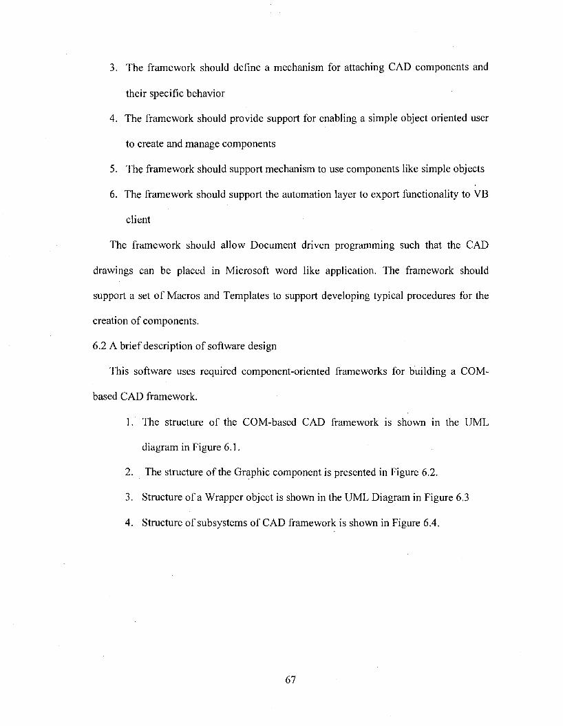
3. The framework should define a mechanism for attaching CAD components and
their specific behavior
4. The framework should provide support for enabling a simple object oriented user
to create and manage components
5. The framework should support mechanism to use components like simple objects
6 . The framework should support the automation layer to export functionality to VB
client
The framework should allow Document driven programming such that the CAD
drawings can be placed in Microsoft word like application. The framework should
support a set o f Macros and Templates to support developing typical procedures for the
creation of components.
6.2 A brief description of software design
This software uses required component-oriented frameworks for building a COM-
based CAD framework.
1. The structure of the COM-based CAD framework is shown in the UML
diagram in Figure 6.1.
2. The structure o f the Graphic component is presented in Figure 6.2.
3. Structure of a Wrapper object is shown in the UML Diagram in Figure 6.3
4. Structure of subsystems of CAD framework is shown in Figure 6.4.
67
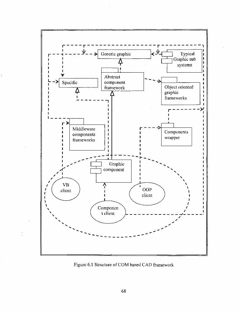
Typical Graphic sub
systems
- >
r>I----------Middleware
componentsframeworks
Graphiccomponent
VBclient OOP
client
Componen t client
Specific
Generic graphic
Componentswrapper
Abstractcomponentframework Object oriented
graphicframeworks
Figure 6.1 Structure of COM based CAD framework
68
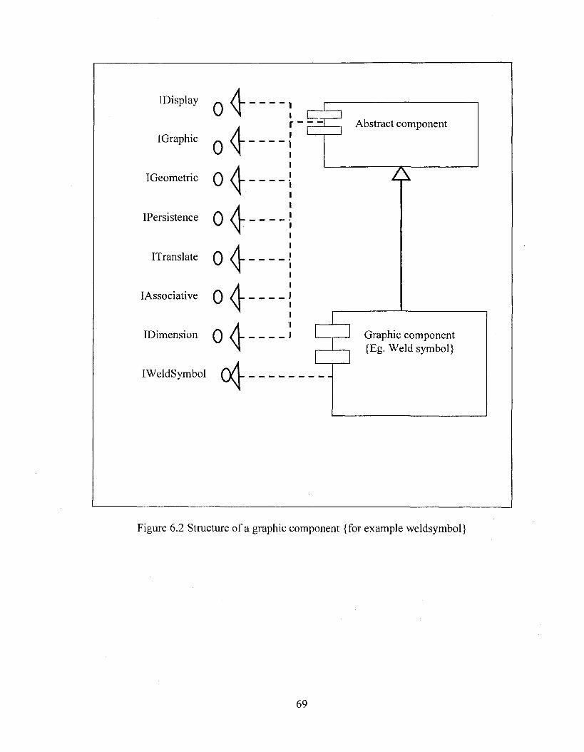
IDisplay
IGraphic
IGeometric
IPersistence
ITranslate
lAssociative
IDimension
IWeldSymbol
0 4" '
o4 "'o<l—0
0<j—
0<j—o<]—
4 -
Abstract component
Graphic component {Eg. Weld symbol}
Figure 6.2 Structure of a graphic component {for example weldsymbol}
69
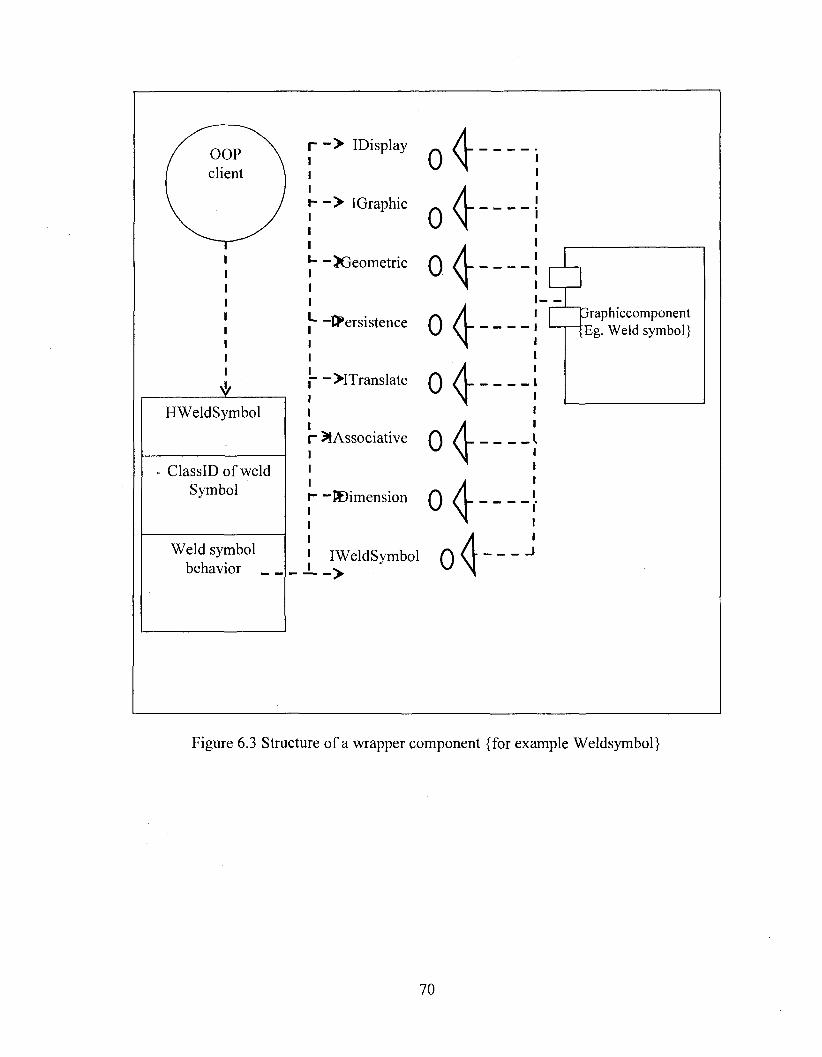
OOPclient
HWeldSymbol
ClassID of weld Symbol
Weld symbol behavior _
I— > IDisplayIIII— > IGraphie
“ Xjeometrie
!— ^PersistenceII
I— >ITranslateII
r ̂ Associative I I II— ^Dimension
IWeldSymbol — '— >
o4
o4
o fo fo f
0 <J
jraphiccom ponent Eg. Weld symbol}
_ _ _ _ _ _ _ _ _ I
Figure 6.3 Structure of a wrapper component {for example Weldsymbol}
70
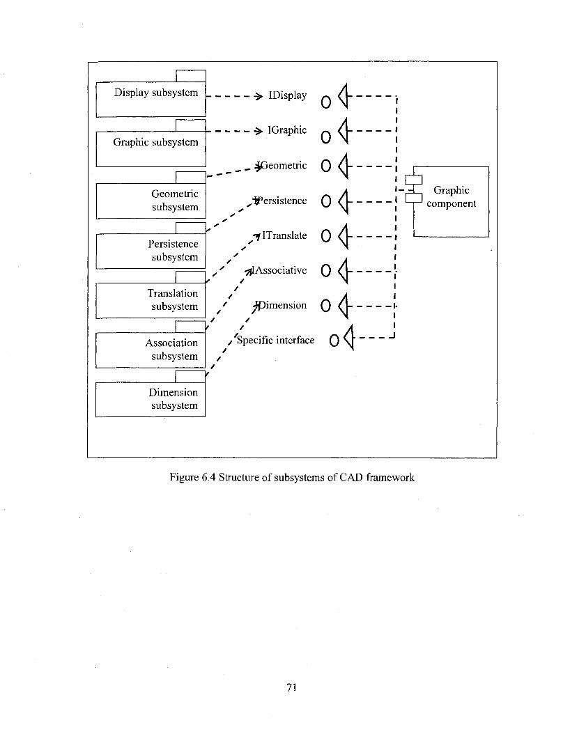
Display subsystem
Graphie subsystem
------------ > IDisplay
IGraphie
__ _ ;^eom etrie
Geometricsubsystem
Persistencesubsystem
Translationsubsystem
Associationsubsystem
Dimensionsubsystem
////// /
//
^^Persistence
-7 ITranslate
■ÿjlAssoeiative
/ ^ im ension /
/
/^Specific interface
o4o40 4
0 4
0 4
0 4
0 4
o4
- , -t I Graphic component
_ _ _ _ _ _ _ _ _ I
Figure 6.4 Structure of subsystems of CAD framework
71
CHAPTER 7
CONCLUSION AND FUTURE WORK
7.1 Review of the work
The thesis presents models for building Component-based graphic frameworks. These
are used for building graphic applications such a three dimensional graphic system or a
printed circuit board (PCB) simulator. The pattern language presented in the thesis
namely “Patter language for graphic/CAD frameworks “is used for providing some of the
solutions. This work starts its journey from a simple objeet-oriented technology using
C++ to complex component world.
The objeet-oriented frameworks build lightweight frameworks. They are used to
convert existing object oriented models into frameworks. Some of the objeet-oriented
frameworks are using domain specific functionality to build frameworks. These
frameworks provide techniques for increasing modularity. Typical applications are
developed and presented to prove the models.
The Debug driver board is an application, which is used for finding faulty component
of a Printed Circuit Board (PCB). A graphic framework using object oriented framework
concepts is developed for providing solutions for Debug driver board application. This
framework enables users to manage hundreds of electronic components. This application
runs on lower end system.
72
This thesis identifies the differences between the object-oriented graphic frameworks
and Component-based graphic frameworks. The procedure for developing a simple
beeper component is presented to demonstrate the complexity of the COM technology.
This thesis presents solutions for managing components in an effective way. Abstract
component frameworks and Component Wrapper frameworks are presented in this
connection. These models enable a simple C++ developer to build complex graphic
COM objects using proposed frameworks. It also enables the client to use the complex
graphic COM objects like simple C++ objects without disturbing the nature of the COM
objects and supporting all COM object rules and procedures.
Finally the thesis presents screenshots of typical graphic applications developed using
these frameworks.
7.2 Discussion and analysis of results
It was observed that these frameworks decrease the cost and complexity of the
applications.
The pattern-frames can be viewed in three major layers. The first layer mainly
focuses on solutions for managing and reusing behavior of graphic objects and systems.
These models support common reusable classes and function library. Unlike the MFC
and Java, The presented models focus on configurable models. This model enables huge
applications to run on low-end systems.
The second layer focuses mainly on porting object-oriented graphic frameworks into
new technology. Solutions for the problems pertaining to development and managements
of graphic components are provided. Techniques for providing component technology to
simple object-oriented user are evolved. In this connection a model namely the object-
73
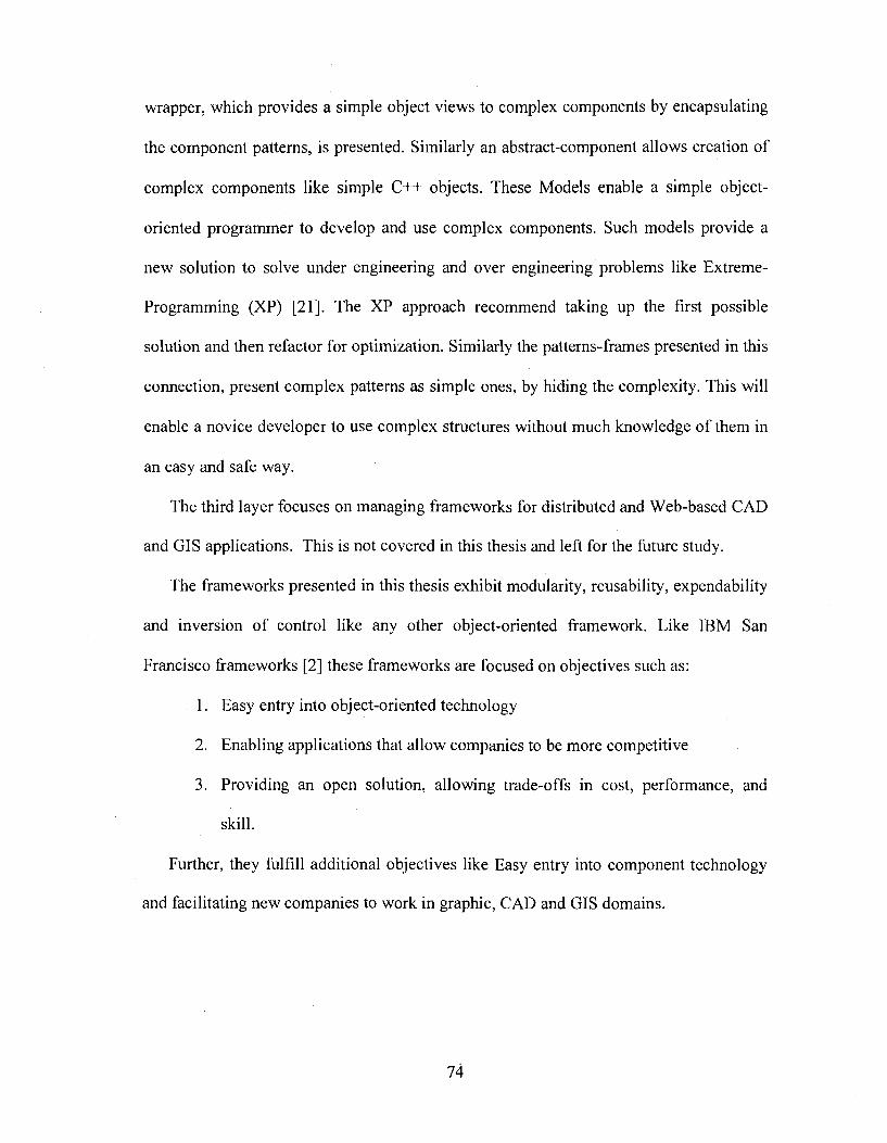
wrapper, which provides a simple object views to complex components by encapsulating
the component patterns, is presented. Similarly an abstract-component allows creation of
complex components like simple C++ objects. These Models enable a simple object-
oriented programmer to develop and use complex components. Such models provide a
new solution to solve under engineering and over engineering problems like Extreme-
Programming (XP) [21]. The XP approach recommend taking up the first possible
solution and then refactor for optimization. Similarly the patterns-frames presented in this
connection, present complex patterns as simple ones, by hiding the complexity. This will
enable a novice developer to use complex structures without much knowledge of them in
an easy and safe way.
The third layer focuses on managing frameworks for distributed and Web-based CAD
and CIS applications. This is not covered in this thesis and left for the future study.
The frameworks presented in this thesis exhibit modularity, reusability, expendability
and inversion o f control like any other object-oriented framework. Like IBM San
Francisco frameworks [2] these frameworks are focused on objectives such as:
1. Easy entry into object-oriented technology
2. Enabling applications that allow companies to be more competitive
3. Providing an open solution, allowing trade-offs in cost, performance, and
skill.
Further, they fulfill additional objectives like Easy entry into component technology
and facilitating new companies to work in graphic, CAD and CIS domains.
74
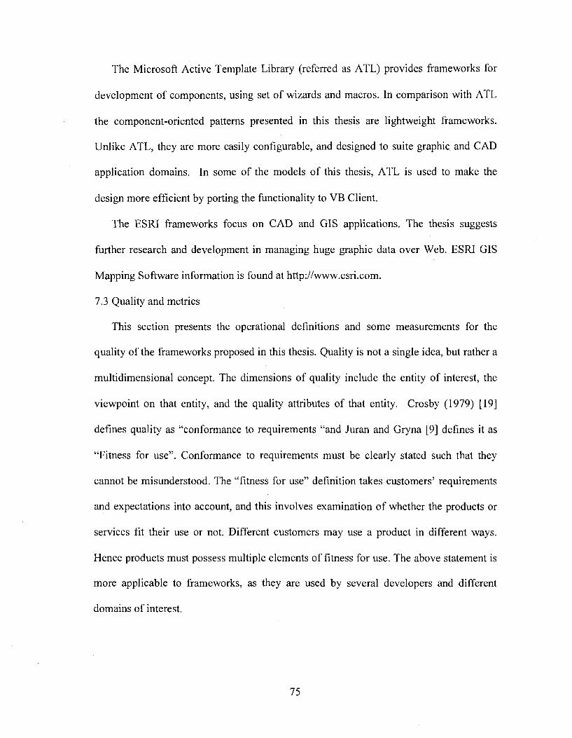
The Microsoft Active Template Library (referred as ATT) provides frameworks for
development of components, using set of wizards and macros. In comparison with ATT
the component-oriented patterns presented in this thesis are lightweight frameworks.
Unlike ATT, they are more easily configurable, and designed to suite graphic and CAD
application domains. In some of the models of this thesis, ATT is used to make the
design more efficient by porting the functionality to VB Client.
The ESRI frameworks focus on CAD and CIS applications. The thesis suggests
further research and development in managing huge graphic data over Web. ESRI CIS
Mapping Software information is found at http://www.esri.com.
7.3 Quality and metrics
This section presents the operational definitions and some measurements for the
quality of the frameworks proposed in this thesis. Quality is not a single idea, but rather a
multidimensional concept. The dimensions of quality include the entity of interest, the
viewpoint on that entity, and the quality attributes of that entity. Crosby (1979) [19]
defines quality as “conformance to requirements “and Juran and Gryna [9] defines it as
“Fitness for use”. Conformance to requirements must be clearly stated such that they
cannot be misunderstood. The “fitness for use” definition takes customers’ requirements
and expectations into account, and this involves examination of whether the products or
services fit their use or not. Different customers may use a product in different ways.
Hence products must possess multiple elements of fitness for use. The above statement is
more applicable to frameworks, as they are used by several developers and different
domains of interest.
75
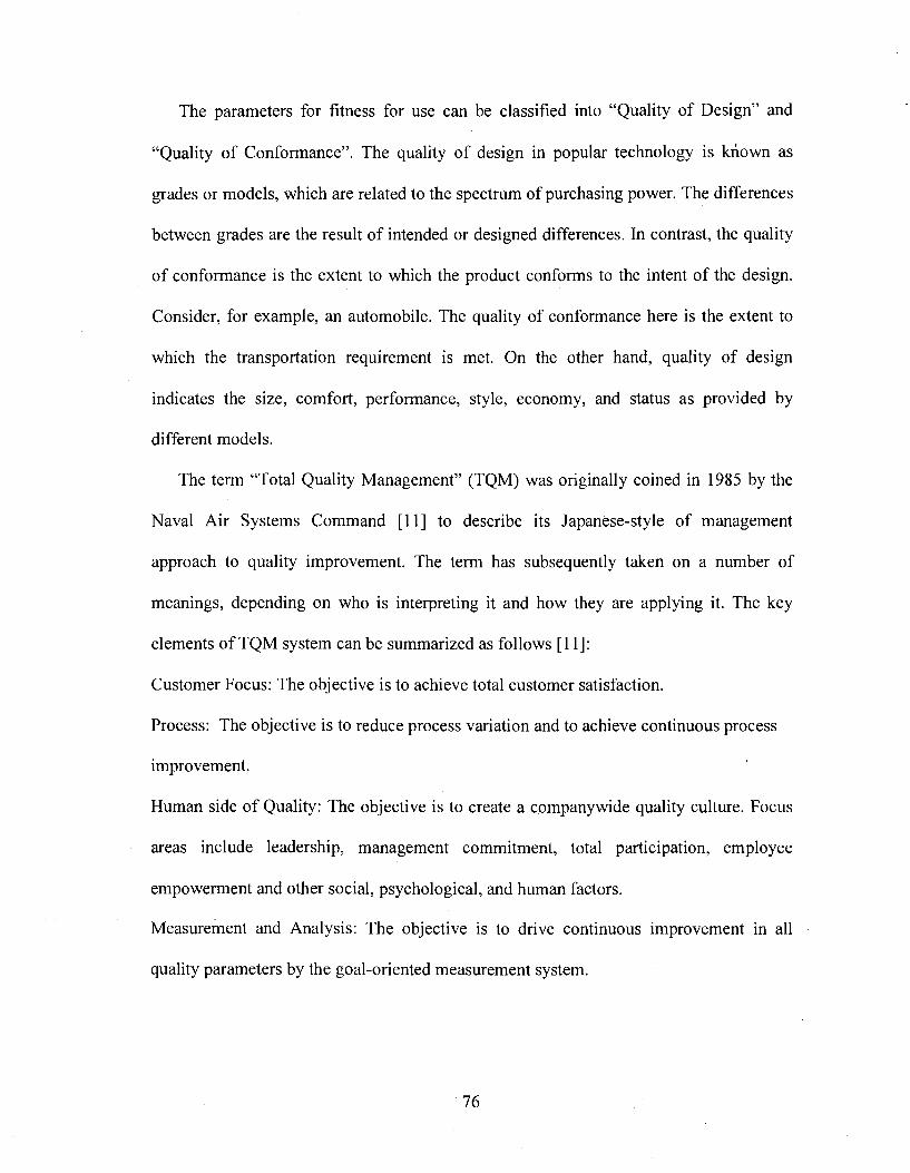
The parameters for fitness for use ean be elassified into “Quality of Design” and
“Quality of Conformanee”. The quality of design in popular teehnology is known as
grades or models, which are related to the speetrum of purehasing power. The differenees
between grades are the result of intended or designed differences. In contrast, the quality
o f conformance is the extent to which the product conforms to the intent of the design.
Consider, for example, an automobile. The quality of conformance here is the extent to
which the transportation requirement is met. On the other hand, quality of design
indicates the size, comfort, performance, style, economy, and status as provided by
different models.
The term “Total Quality Management” (TQM) was originally coined in 1985 by the
Naval Air Systems Command [11] to describe its Japanese-style of management
approach to quality improvement. The term has subsequently taken on a number of
meanings, depending on who is interpreting it and how they are applying it. The key
elements o f TQM system can be summarized as follows [11]:
Customer Focus: The objective is to achieve total customer satisfaction.
Process: The objective is to reduce process variation and to achieve continuous process
improvement.
Human side of Quality: The objective is to create a company wide quality culture. Focus
areas include leadership, management commitment, total participation, employee
empowerment and other social, psychological, and human factors.
Measurement and Analysis: The objective is to drive continuous improvement in all
quality parameters by the goal-oriented measurement system.
76
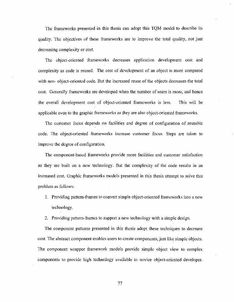
The frameworks presented in this thesis can adopt this TQM model to describe its
quality. The objectives of these frameworks are to improve the total quality, not just
decreasing complexity or cost.
The object-oriented frameworks decreases application development cost and
complexity as code is reused. The cost of development of an object is more compared
with non- object-oriented code. But the increased reuse o f the objects decreases the total
cost. Generally frameworks are developed when the number of users is more, and hence
the overall development cost of object-oriented frameworks is less. This will be
applicable even to the graphic frameworks as they are also object-oriented frameworks.
The customer focus depends on facilities and degree o f configuration o f reusable
code. The object-oriented frameworks increase customer focus. Steps are taken to
improve the degree of configuration.
The component-based frameworks provide more facilities and customer satisfaction
as they are built on a new technology. But the complexity of the code results in an
increased cost. Graphic frameworks models presented in this thesis attempt to solve this
problem as follows;
1. Providing pattem-frames to convert simple object-oriented frameworks into a new
technology.
2. Providing pattern-frames to support a new technology with a simple design.
The component patterns presented in this thesis adopt these techniques to decrease
cost. The abstract component enables users to create components, just like simple objects.
The component wrapper framework models provide simple object view to complex
components to provide high technology available to novice object-oriented developer.
77
These concepts will improve the quality of the graphic applications developed on these
frameworks.
7.4 Scope for further research
This work can be extended to providing solutions for the distributed and web based
graphic applications. Some of the concepts used to improve the frameworks such as
abstract component and wrapper object (or helper object) can be applied in different
domains for producing new design patterns for managing the components.
78
APPENDIX A
PROCEDURES TO CREATE A COM SERVER AND CLIENT
This appendix presents a procedure to create a simple COM object, Beeper. It uses all
component patterns and COM object concepts. It uses the DLL (Dynamic Link Library)
concepts. This server is known as INPROC server. It uses VC++ console application for
building client.
This example is presented to demonstrate the COM object management procedures.
The Beeper is not a graphic component. But the same procedures are required for
building a graphic COM object. The frameworks presented in this thesis simplify these
procedures by reusing the COM procedures used in the graphic COM objects. The
framework presented in this thesis is useful only for the graphic COM object. But
development of the similar frameworks to manage COM objects of respective domains is
possible [29] [12].
A. I Steps to create a simple beeper COM object
The following procedures and rules are required to generate a simple Beeper COM
object in VC++.
1. Create a directory structure
79
2. Create the server applieation and implement all COM proeedures required for
building a COM objeet.
3. Register the server. In this eonneetion we need to generate the GUID (globally
Unique ID) for the Beeper COM objeet.
4. Create the elient applieation and implement all COM proeedures required for
using COM objeet
A.2 Direetory strueture:
Create the following direetories under C:\MYCOM\
1. SERVER: This earries the implementation of our COM objeet.
2. CLIENT: This earries a simple client applieation where our COM objeet is
ealled.
3. DOCUMENT : All the doeuments related to the implementation will go into this.
4. BIN: All outputs of both server and client sueh as *.exe , server.dll ete. should go
into this.
5. INCLUDE: Entire eommon include files that are shard between the client and the
server should go into this.
6. REGISTER: The MyCom.reg file that will register our COM objeet and all its
interfaces into the registry should go into this directory.
A.3. Creating the server applieation:
The following steps ereate COM object server
1. Create a new projeet workspace as Dynamie Link Library
2. Create the following files in the SERVER direetory and inelude in the project.
3. BEEP.CPP, SERVER.CPP, GUID.CPP and SERVER.DEF
8 0
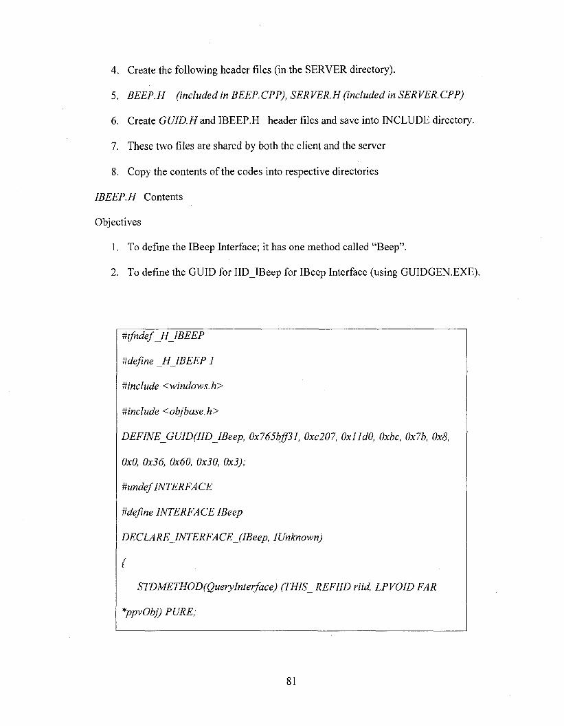
4. Create the following header files (in the SERVER directory).
5. BEEP. H (included in BEEP. CPP), SER VER. H (included in SER VER. CPP)
6. Create GUID.E[ and IBEEP.El header files and save into INCLUDE directory.
7. These two files are shared by both the client and the server
8. Copy the contents of the codes into respective directories
IBEEP.H Contents
Objectives
1. To define the IBeep Interface; it has one method called “Beep”.
2. To define the GUID for IID IBeep for IBeep Interface (using GUIDGEN.EXE).
mfndef H JBEEP
Mefine _H IBEEP 1
Minclude <windows.h>
#include <objbase.h>
DEFlNE_GUlD(IlDJBeep. 0x765bfjf31, 0xc207, OxJJdO, Oxbc, 0x7b, 0x8,
0x0, 0x36, 0x60, 0x30, 0x3);
#undef INTERFACE
Mefine INTERFACE IBeep
DECLARE INTERFA CE (IBeep, IUnknown)
{
STDMETHOD(Querylnterface) (THIS REFIID riid, I P VOID FAR
*ppvObj) PURE;
81
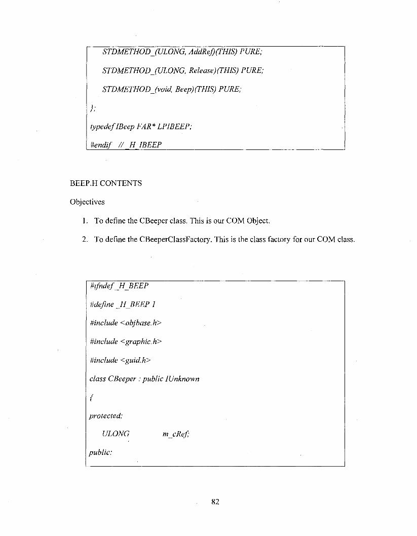
STDMETHODJULONG, AddReJ)(THlS) PURE;
STDMETHODJULONG, Release)(PHIS) PURE;
}:
typedef IBeep FAR * LPIBEEP;
Uendif / / H IBEEP____________________________
BEEP.H CONTENTS
Objectives
1. To define the CBeeper class. This is our COM Object.
2. To define the CBeeperClassFactory. This is the class factory for our COM class.
m fndefH _B E E P
Mefine H BEEP I
^include <objbase.h>
^include <graphic.h>
#include <guid.h>
class CBeeper : public IUnknown
{
protected:
ULONG mjcRef;
public:
8 2
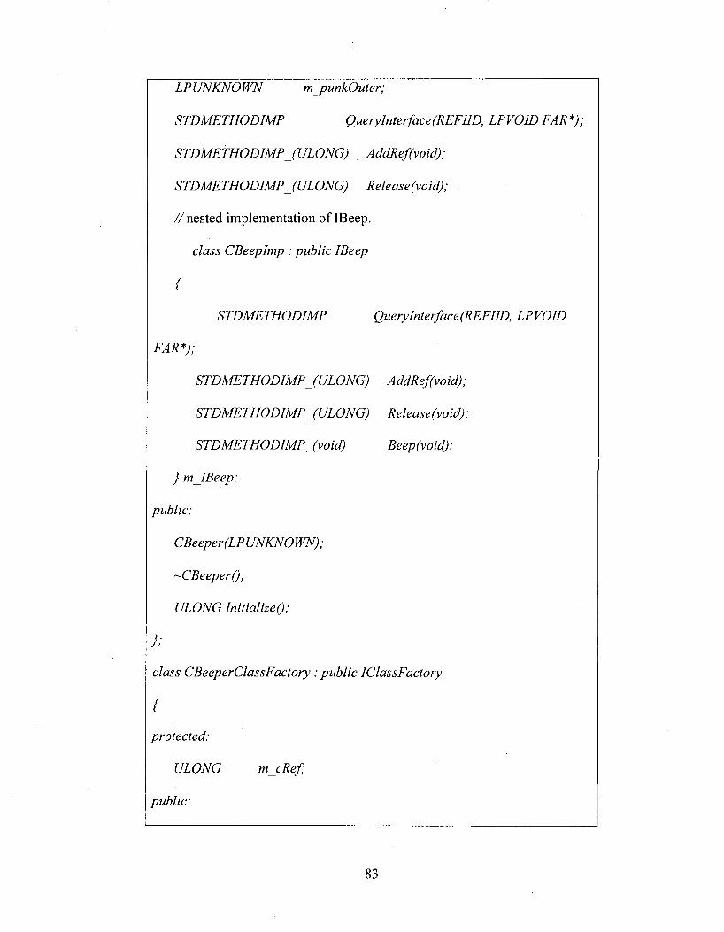
LPUNKNOWN m _punkOuter;
STDMETHODIMP Querylnterface(REFllD, LPVOID FAR *);
//nested implementation of IBeep.
class CBeepImp : public IBeep
{
STDMETHODIMP QueryInterface(REFIID, LPVOID
} m IBeep;
public:
-CBeeperQ;
ULONG InitializeQ;
} ;
class CBeeperClassFactory : public IClassFactory
{
protected:
ULONG m e Ref;
public:
83
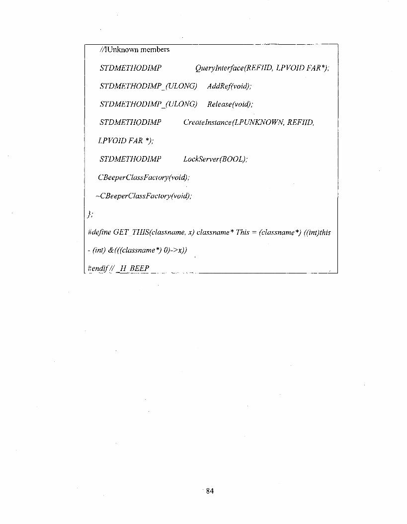
//IUnknown members
STDMETHODIMP QueryInterface(REFIID, LPVOID FAR*);
STDMETHODIMPJULONG) AddRef(void);
STDMETHODIMP JU LO N G ) Release (void);
STDMETHODIMP Createlnstance(LPUNKNOWN, REFIID,
LPVOID FAR *);
STDMETHODIMP LockServer(BOOL);
CBeeper Class Factory (void);
~CBeeperClassFactory(void);
};
Mefine GET_THIS(classname, x) classname* This = (classname*) ((int)this
- (int) &(((classname*) 0)->x))
#endif// H BEEP___________________________________
84
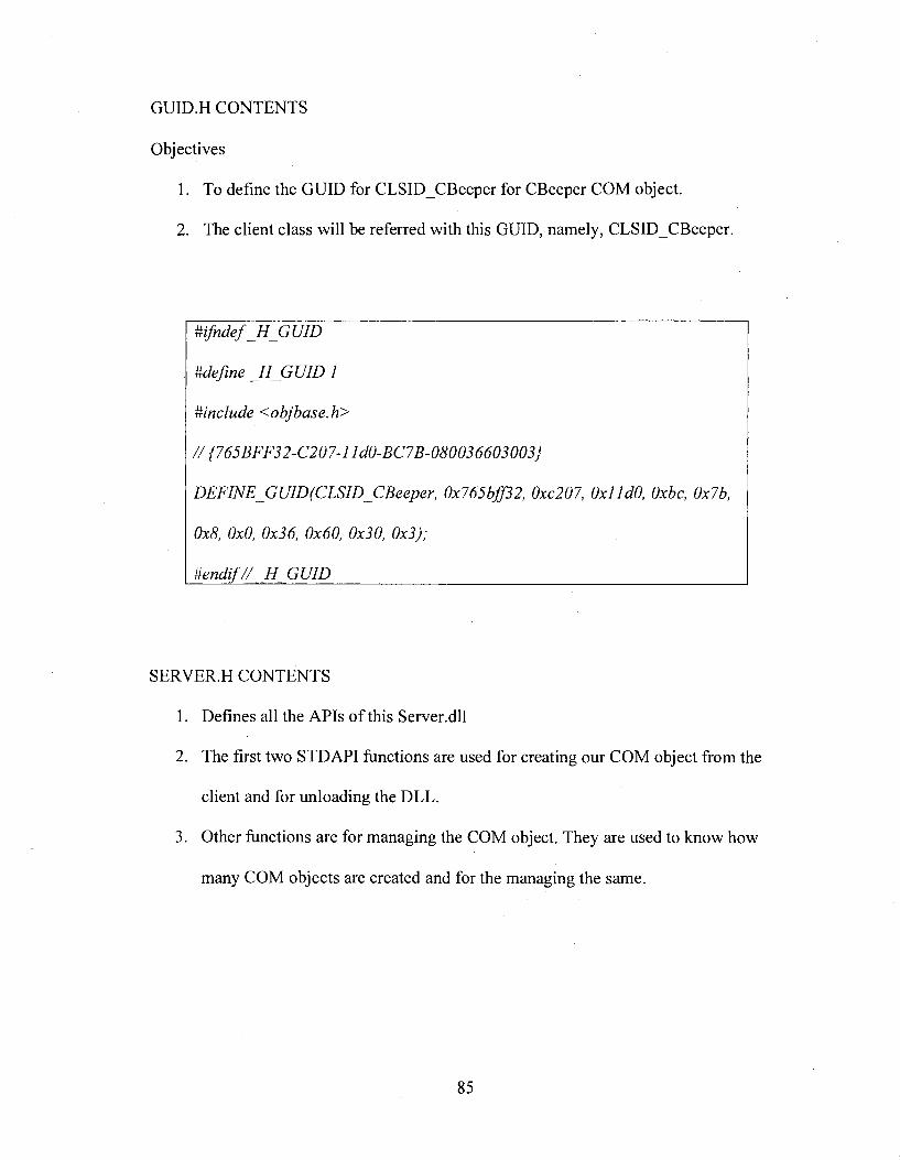
GUID.H CONTENTS
Objectives
1. To define the GUID for CLSID CBeeper for CBeeper COM object.
2. The client class will be referred with this GUID, namely, CLSID CBeeper.
#include <objbase.h>
th;76J2^2, (kc207, tk/falO, 0x76,
0x8, 0x0, 0x36, 0x60, 0x30, 0x3);
#endif// H GUID__________________________________________________
SERVER.H CONTENTS
1. Defines all the APIs o f this Server.dll
2. The first two STD API functions are used for creating our COM object from the
client and for unloading the DLL.
3. Other functions are for managing the COM object. They are used to know how
many COM objects are created and for the managing the same.
85
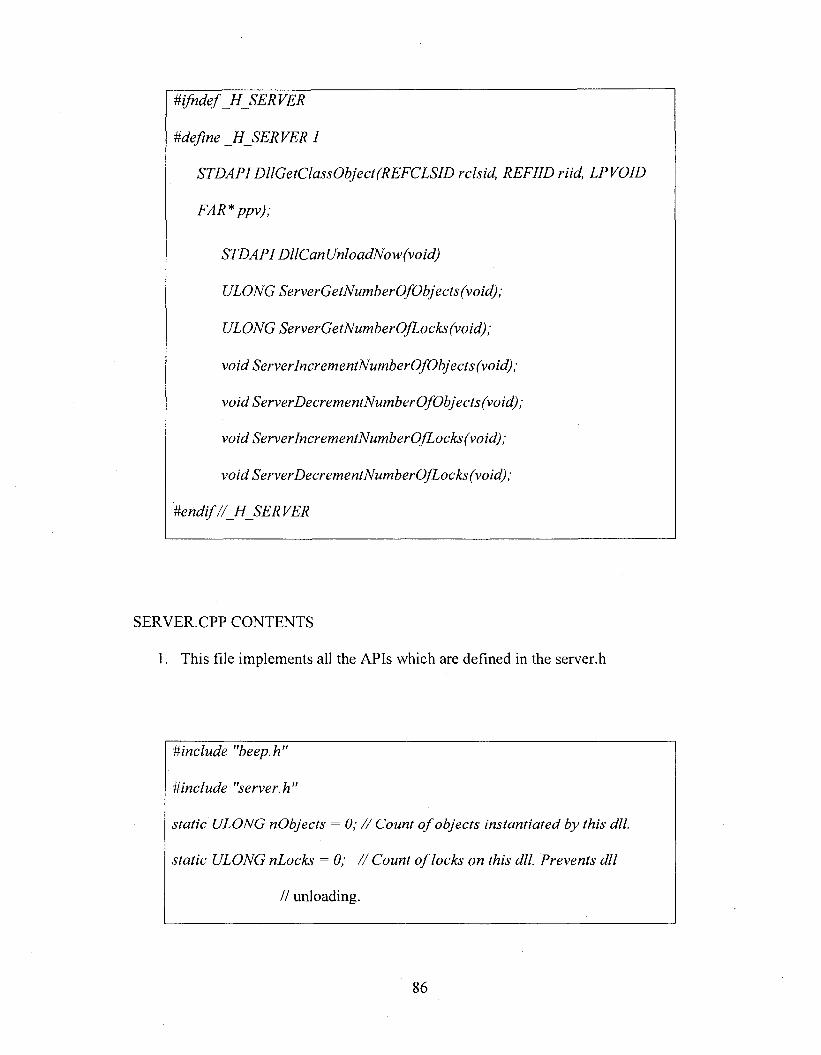
Mfndef J IJ E R V E R
Mefine _H_SERVER 1
STDAPlDllGetClassObject(REFCLSlD rclsid, REFIID riid, LPVOID
FAR* ppv);
STDAPl DllCanUnloadNow(void)
ULONG ServerGetNumberOfObjects(void);
ULONG ServerGetNumberOfLocks(void);
void ServerIncrementNumberOfObjects(void);
void ServerDecrementNumberOfObjects(void);
void ServerIncrementNumberOfLocks(void);
void Server Deer ementNumberOfLocks (void);
SERVER.CPP CONTENTS
1. This file implements all the APIs which are defined in the server.h
#include "beep.h"
#include "server.h"
static ULONG nObjects = 0; / / Count o f objects instantiated by this dll.
static ULONG nLocks = 0; / / Count o f locks on this dll. Prevents dll
// unloading.
86
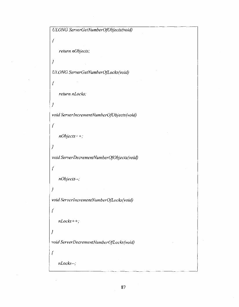
ULONG ServerGetNumberOfObjects(void)
{
return nObjects;
}
ULONG ServerGetNumberOjLocks(void)
{
return nLocks;
}
void Server IncrementNumberOfObjects (void)
{
nObjects++;
}
void ServerDecrementNumberOfObjects(void)
{
nObjects—;
}
void ServerlncrementNumberOfLocks(void)
{
nLocks++;
}
void ServerDecrementNumberOfLocks(void)
{
nLocks—;
87
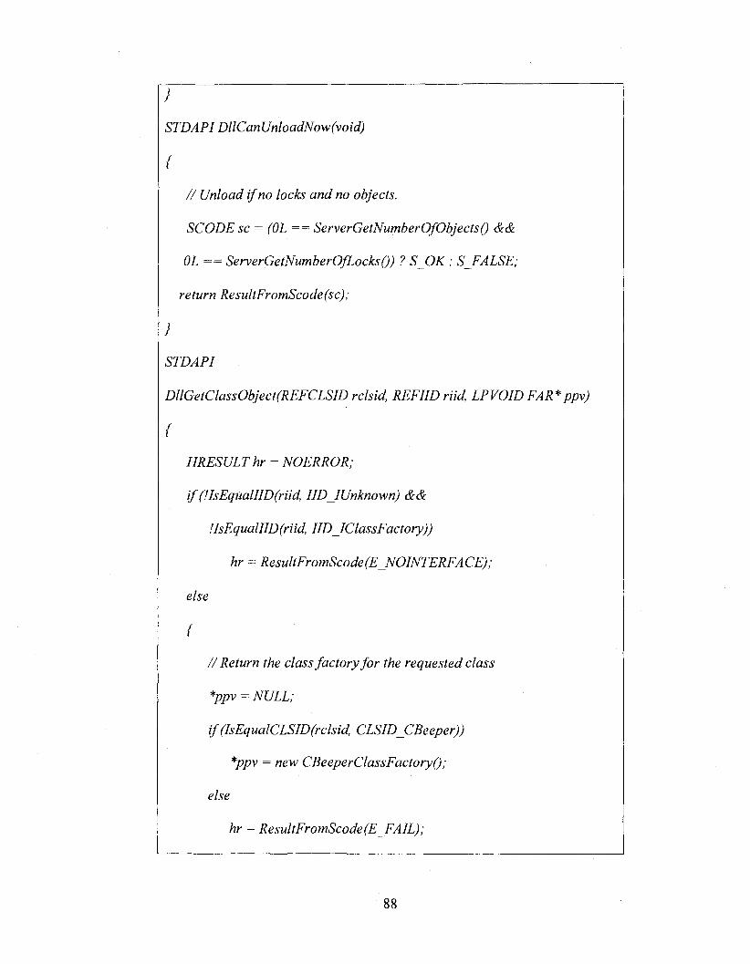
}
STDAPl DllCanUnloadNow(void)
{
/ / Unload if no locks and no objects.
SCODE sc = (OL == ServerGetNumberOfObjectsQ &&
OL == ServerGetNumberOfLocksQ) ? S_OK : S_EALSE;
return ResultEromScode(sc);
}
STDAPl
DllGetClassObject(REFCLSlD rclsid, REFIID riid, LPVOID FAR*ppv)
{
HRESULT hr = NOERROR;
i f (!IsEqualIID(riid, IID IUnknown) c&cè
UsEqualllD(riid, IID IClassFactory))
hr = ResultEromScode(E_NOINTEREACE);
else
{
/ / Return the class factory fo r the requested class
*ppv = NULL;
if (IsEqualCLSID(rclsid, CLSID CBeeper))
*ppv = new CBeeperClassFactoryO;
else
hr = ResultFromScode(E FAIL);
88
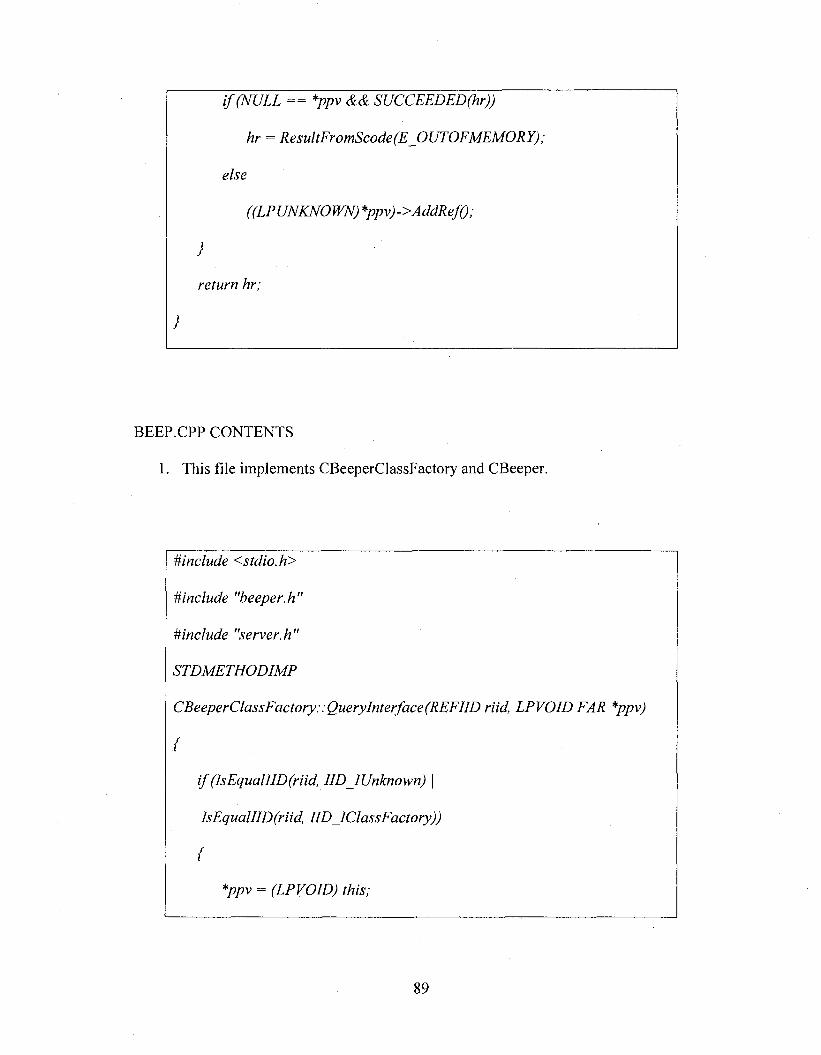
i f (NULL == *ppv && SUCCEEDED(hr))
hr = ResultFromScode(E_OUTOFMEMORY);
else
}
return hr;
BEEP.CPP CONTENTS
1. This file implements CBeeperClassFactory and CBeeper.
#include <stdio.h>
Mnclude "beeper.h”
^include "server.h"
STDMETHODIMP
CBeeperClassFactory::QueryInterface(REFIID riid, LPVOID FAR *ppv)
(
i f (IsEqualIID(riid, IID IUnknown) \ |
IsEqualIID(riid, IID IClassFactory))
(
*ppv = (LPVOID) this;
89
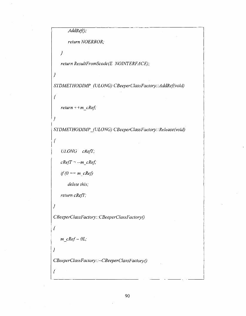
AddRefO;
return NOERROR;
}
return ResultFromScode(E_N01NTERFACE);
}
STDMETHODIMPJULONG) CBeeperClassFactory::AddRef(void)
{
return ++m_cRef;
}
STDMETHODIMP (ULONG) CBeeperClassFactory::Release(void)
{
ULONG cRefP;
cRefP = —m cR ef;
i f (0 == m cReJ)
delete this;
return cRefP;
}
CBeeperClassFactory::CBeeperClassFactory()
{
m _cRef= OL;
}
CBeeperClassFactory::~CBeeperClassFactory()
{
90
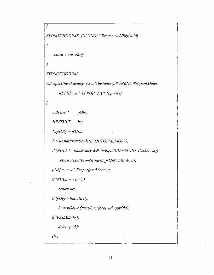
}
STDMETHODIMPJULONG) CBeeper::AddRef(void)
{
return ++m_cRef;
}
STDMETHODIMP
CBeeperClassFactory: :CreateInstance(LPUNKNOWN punkOuter,
REFIIDriid, LPVOID FAR *ppvObj)
{
CBeeper* pObj;
HRESULT hr;
*ppvObj = NULL;
hr=Resul tFromScode(E_0 UTOFMEMOR Y) ;
i f (NULL != punkOuter && !IsEqualIID(riid, IIDJUnknown))
return ResultFromScode(E NOINTERFACE);
pO bj = new CBeeper (punkOuter);
i f (NULL = = pO bj)
return hr;
if (pObj-> InitializeQ)
hr = pO bj-> QueryInt e rf ace (r ad, ppvObj);
if (FAILED(hr))
delete pO bj;
else
91
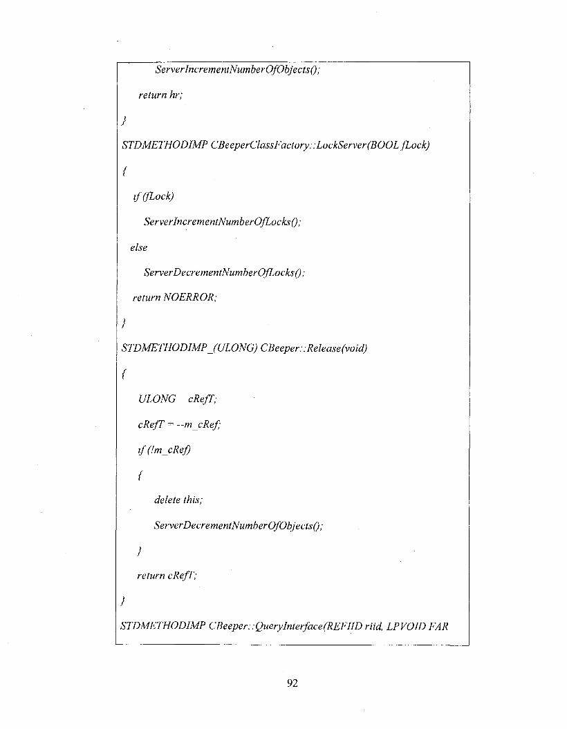
ServerlncrementNumberOfObjectsQ;
return hr;
}
STDMETHODIMP CBeeperClassFactory::LockServer(BOOL fLock)
{
if (fLock)
ServerIncrementNumberOfLocks();
else
ServerDecrementNumberOfLocks() ;
return NOERROR;
}
STDMETHODIMP (ULONG) CBeeper::Release(void)
{
cRefT = —m cR ef;
i f (Im cR ef)
{
delete this;
ServerDecrementNumberOfObjects();
}
return cRefT;
}
STDMETHODIMP CBeeper: : QueryInterface(REFIID riid, LPVOID FAR
92
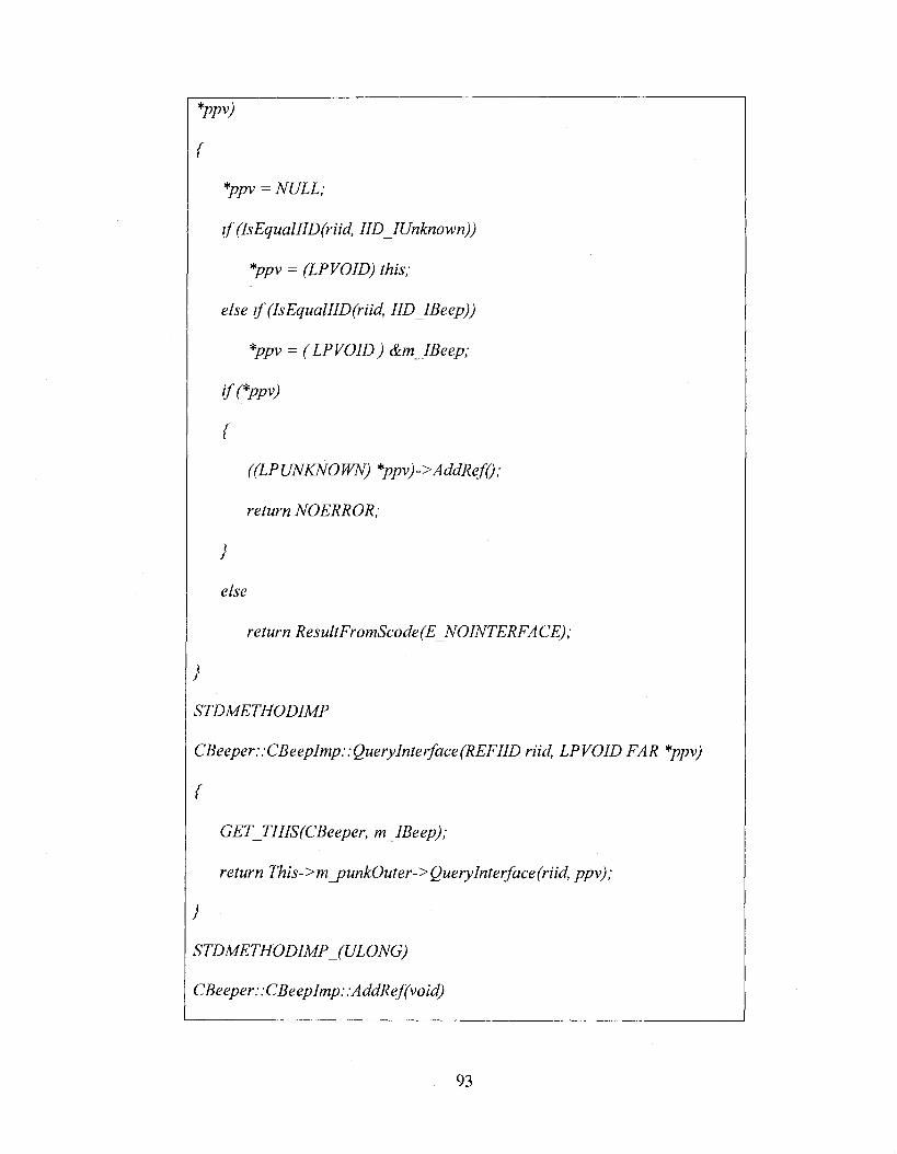
*ppv)
{
*ppv = NULL;
if (IsEqualIID(riid, IIDJUnknown))
*ppv = (LPVOID) this;
else if (IsEqualIID(riid, IID IBeep))
*ppv = ( LPVOID) &m IBeep;
i/TTwy)
{
return NO ERROR;
}
else
return ResultFromScode(E NOINTERFACE);
}
STDMETHODIMP
CBeeper::CBeepImp::QueryInterface(REFIID riid, LPVOID FAR *ppv)
{
GET_THIS(CBeeper, m IBeep);
return This->m _punkOuter-> Query Interface (riid, ppv);
}
STDMETHODIMPJULONG)
CBeeper : :CBeepImp: :AddRef(void)
93
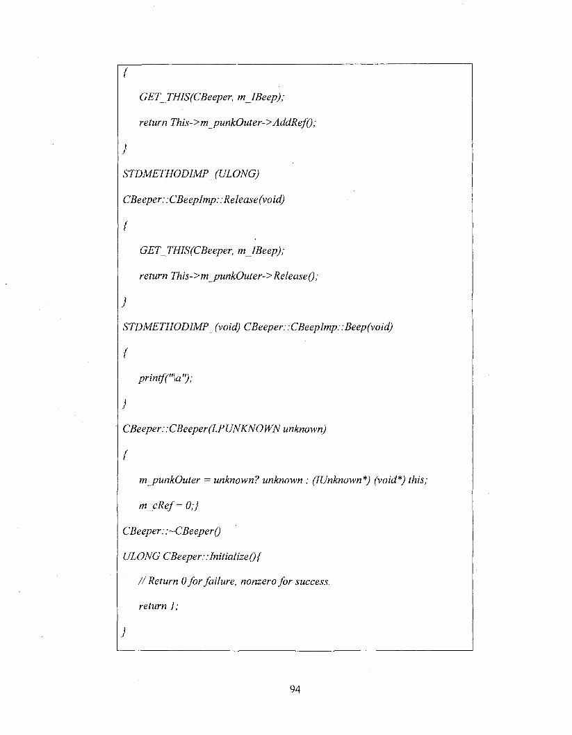
{
GET_THlS(CBeeper, m lBeep);
return This->m_punkOuter->AddRef();
}
STDMETHODIMPJULONG)
CBeeper; .CBeepImp: :Release(void)
(
GET_THIS(CBeeper, m IBeep);
return This->m_punkOuter->Release();
}
STDMETHODIMP (void) CBeeper: . CBeepImp::Beep(void)
{
printfC'W ):
}
CBeeper: : CBeeper(LP UNKNO WN unknown)
{
m_punkOuter = unknown? unknown : (IUnknown*) (void*) this;
m _cRef= 0;}
CBeeper : :~CBeeper()
ULONG CBeeper::Initialize(){
/ / Return 0 fo r failure, nonzero fo r success,
return 1;
}
94
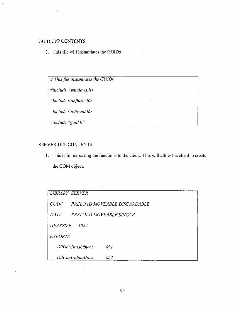
GUID.CPP CONTENTS
1. This file will instantiates the GUIDs
/ / This file instantiates the GUIDs
#include <windows.h>
Uinclude <objbase.h>
#include <initguid.h>
Uinclude “guid.h”______________
SERVER.DEF CONTENTS
1. This is for exporting the functions to the client. This will allow the client to create
the COM object.
LIBRARY SERVER
CODE PRELOAD MOVEABLE DISCARDABLE
DA TA PRELOAD MOVEABLE SINGLE
HEAP SIZE 1024
EXPORTS
DllGetClassObject @7
DllCanUnloadNow (%2
95
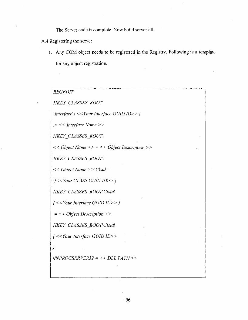
The Server code is complete. Now build server.dll
A.4 Registering the server
1. Any COM object needs to be registered in the Registry. Following is a template
for any object registration.
REGEDIT
H K E Y C LA SSE SR O O T
\lnterface\{ <<Your Interface GUID I D » }
= < < Interface Name > >
<< Object Name >> = << Object Description »
HKEY_CLASSES_ROOD
« Object Name » \ C l s i d =
7 D » ;
HKEY CLASSES_ROODClsid\
{ « Y o u r Interface GUID I D » }
= << Object Description »
HKEY_CLASSES_ROODClsid\
{ « Y o u r Interface GUID I D »
}
MNPROCSERVER32 = << DLL P A T H »
96
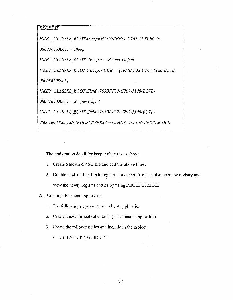
REGEDIT
HKEY CLASSES ROOTMnterface\(765BFF31 -C207-11dO-BC7B-
0,̂0036603003; =HKEY_CLASSES_ROODCBeeper = Beeper Object
HKEY_CLASSES_ROOT\CBeeper\Clsid = {765BFF32-C207-IId0-BC7B-
0&0036603003;
HKEY_CLASSES_ROODClsid\(765BFF32-C207-IIdO-BC7B-
080036603003} = Beeper Object
HKEY_CLASSES_ROOT\Clsid\{765BFF32-C207-lldO-BC7B-
080036603003}\1NPROCSERVER32 = C:\MYCOM\BIN\SERVER.DLL
The registration detail for beeper object is as above.
1. Create SERVER.REG file and add the above lines.
2. Double click on this file to register the object. You can also open the registry and
view the newly register entries by using REGEDT32.EXE
A.5 Creating the client application
1. The following steps create our client application
2. Create a new project (client.mak) as Console application.
3. Create the following files and include in the project.
• CLIENT.CPP, GUID.CPP
97
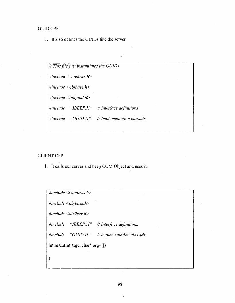
GUID.CPP
1. It also defines the GUIDs like the server
//T h is file ju st instantiates the GUIDs
Hinclude <windows.h>
Hinclude <objbase.h>
Uinclude <initguid.h>
mnclude “IBEEP.H” //Interface definitions
Mnclude “GUID.H” //Implementation classids
CLIENT.CPP
I . It calls our server and beep COM Object and uses it.
#include <windows.h>
Mnclude <objbase.h>
Mnclude <ole2ver.h>
Mnclude “IBEEP.H” //Interface definitions
Mnclude “GUID.H” / / Implementation classids
int main(int argc, char* argv[])
{
98
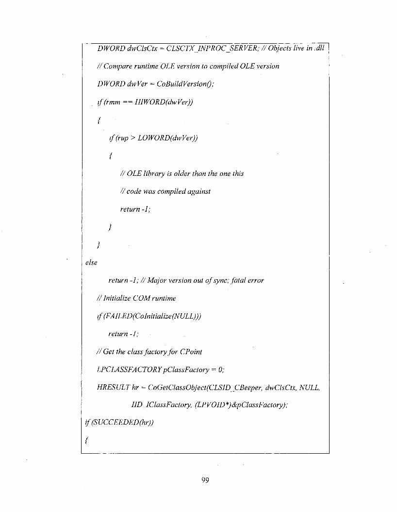
/% 06/ecr.y /zve m <7//
/ / Compare runtime OLE version to compiled OLE version
DWORD dwVer = CoBuildVersionQ;
i f (rmm == HlWORD(dwVer))
{
i f (rup > LOWORD(dwVer))
{
/ / OLE library is older than the one this
/ / code was compiled against
return -1;
}
}
else
return -1; //M ajor version out o f sync; fa ta l error
/ / Initialize COM runtime
i f (FA lLED(Coln itialize (NULL)))
return -1;
/ / Get the class factory fo r CPoint
LPCLASSFACTORY pClass Factory = 0;
HRESULT hr = CoGetClassObject(CLSlD_CBeeper, dwClsCtx, NULL,
llD lClassFactory, (LPVOID *)&pClassFactory);
{
99
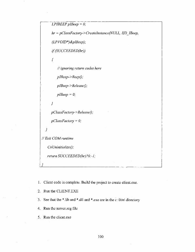
LPIBEEP plBeep = 0;
hr = pClassFactory->Createlnstance(NULL, llDJfBeep,
(LPVOID*) &plBeep);
if(SUCCEEDED(hr))
{
/ / ignoring return codes here
pIBeep->Beep();
pIBeep-> Release ();
pIBeep = 0;
}
pClassFactory-> Release ();
pClassFactory = 0;
}
//E x it COM runtime
Co Uninitialize();
return SUCCEEDED(hr)?0:-l;
I____________
1. Client code is complete. Build the project to create client.exe.
2. Run the CLIENT.EXE
3. See that the *.lib and *.dll and *.exe are in the c:\bin\ directory
4. Run the server.reg file
5. Run the client.exe
100
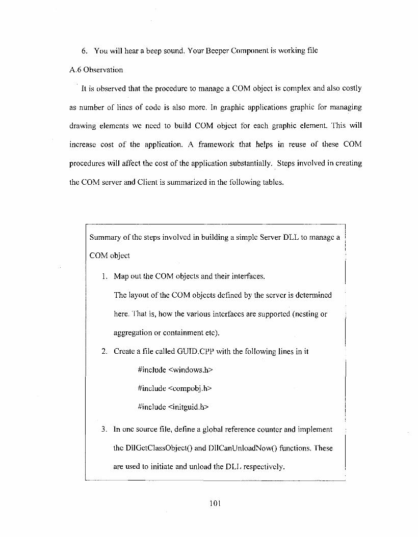
6 . You will hear a beep sound. Your Beeper Component is working file
A .6 Observation
It is observed that the procedure to manage a COM object is complex and also costly
as number of lines of code is also more. In graphic applications graphic for managing
drawing elements we need to build COM object for each graphic element. This will
increase cost o f the application. A framework that helps in reuse of these COM
procedures will affect the cost of the application substantially. Steps involved in creating
the COM server and Client is summarized in the following tables.
Summary of the steps involved in building a simple Server DLL to manage a
COM object
1. Map out the COM objects and their interfaces.
The layout of the COM objects defined by the server is determined
here. That is, how the various interfaces are supported (nesting or
aggregation or containment etc).
2. Create a file called GUID.CPP with the following lines in it
#include <windows.h>
#include <compobj.h>
#include <initguid.h>
3. In one source file, define a global reference counter and implement
the DllGetClassObjectO and DllCanUnloadNow() functions. These
are used to initiate and unload the DLL respectively.
101
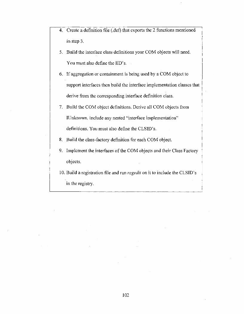
4. Create a definition file (.del) that exports the 2 functions mentioned
in step 3.
5. Build the interface class definitions your COM objects will need.
You must also define the IID’s.
6 . If aggregation or containment is being used by a COM object to
support interfaces then build the interface implementation classes that
derive from the corresponding interface definition class.
7. Build the COM object definitions. Derive all COM objects from
IUnknown. Include any nested “interface implementation”
definitions. You must also define the CLSID’s.
8 . Build the class-factory definition for each COM object.
9. Implement the interfaces o f the COM objects and their Class Factory
objects.
10. Build a registration file and run regedit on it to include the CLSID’s
in the registry.
102
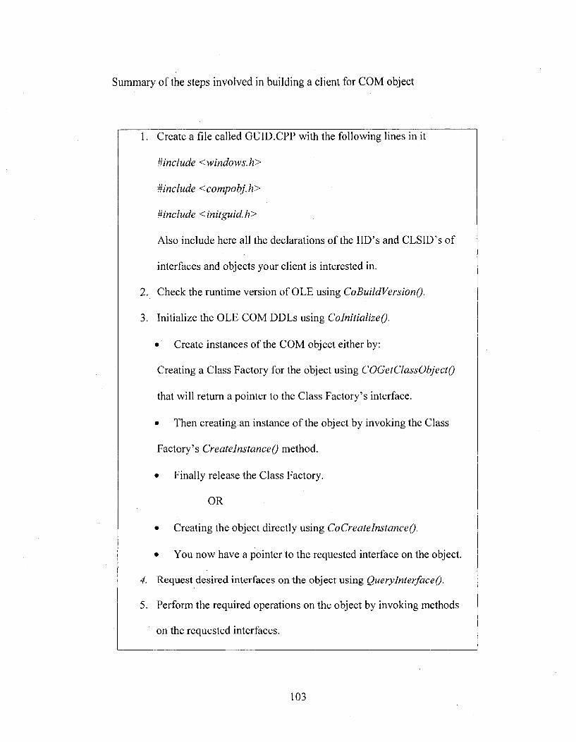
Summary of the steps involved in building a client for COM object
1. Create a file called GUID.CPP with the following lines in it
Mnclude <windows.h>
Mnclude <compobj.h>
Mnclude <initguid.h>
Also include here all the declarations of the IID’s and CLSID’s of
interfaces and objects your client is interested in.
2. Check the runtime version of OLE using CoBuildVersionQ.
3. Initialize the OLE COM DDLs using ColnitializeQ.
• Create instances of the COM object either by:
Creating a Class Factory for the object using COGetClassObjectQ
that will return a pointer to the Class Factory’s interface.
• Then creating an instance of the object by invoking the Class
Factory’s CreatelnstanceQ method.
• Finally release the Class Factory.
OR
• Creating the object directly using CoCreatelnstanceQ.
• You now have a pointer to the requested interface on the object.
4. Request desired interfaces on the object using QueryInterfaceQ.
5. Perform the required operations on the object by invoking methods
on the requested interfaces.
103
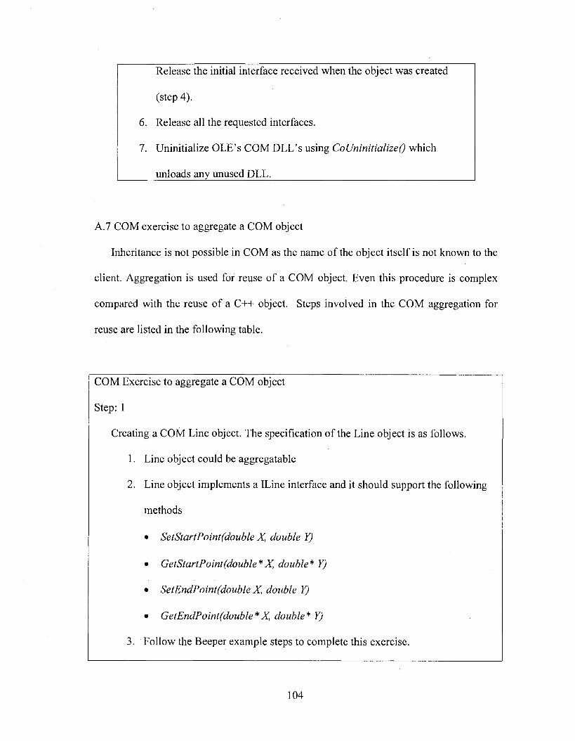
Release the initial interface received when the object was created
(step 4).
6 . Release all the requested interfaces.
7. Uninitialize OLE’s COM DLL’s using CoUninitialize() which
unloads any unused DLL.___________________________________
A.7 COM exercise to aggregate a COM object
Inheritance is not possible in COM as the name of the object itself is not known to the
client. Aggregation is used for reuse of a COM object. Even this procedure is complex
compared with the reuse of a C++ object. Steps involved in the COM aggregation for
reuse are listed in the following table.
COM Exercise to aggregate a COM object
Step: I
Creating a COM Line object. The specification of the Line object is as follows.
1. Line object could be aggregatable
2. Line object implements a ILine interface and it should support the following
methods
• SetStartPoint(double X, double Y)
• GetStartPoint(double*X, double* YJ
• SetEndPoint(double X, double Y)
• GetEndPoint(double*X, double* Y)
3. Follow the Beeper example steps to complete this exercise.
104
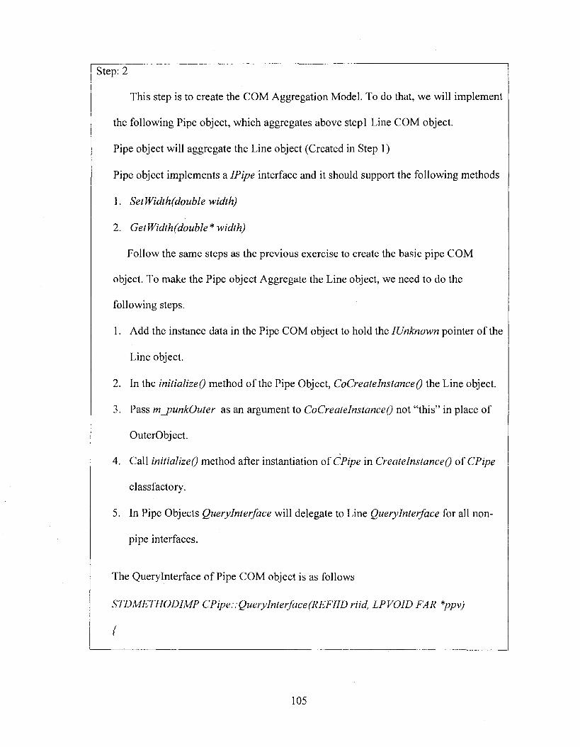
Step: 2
This step is to create the COM Aggregation Model. To do that, we will implement
the following Pipe object, which aggregates above step! Line COM object.
Pipe object will aggregate the Line object (Created in Step 1)
Pipe object implements a IPipe interface and it should support the following methods
1. SetWidth(double width)
2. GetWidth(double * width)
Follow the same steps as the previous exercise to create the basic pipe COM
object. To make the Pipe object Aggregate the Line object, we need to do the
following steps.
1. Add the instance data in the Pipe COM object to hold the IUnknown pointer of the
Line object.
2. In the initializeQ method o f the Pipe Object, CoCreatelnstanceQ the Line object.
3. Pass m_punkOuter as an argument to CoCrga/g/«Va«ce(9 not “this” in place of
OuterObject.
4. Call initializeQ method after instantiation of CPipe in CreatelnstanceQ of CPipe
classfactory.
5. In Pipe Objects Querylnterface will delegate to Line Querylnterface for all non
pipe interfaces.
The Querylnterface o f Pipe COM object is as follows
STDMETHODIMP CPipe::QueryInterface(REFIID riid, LPVOID FAR *ppv)
{
105
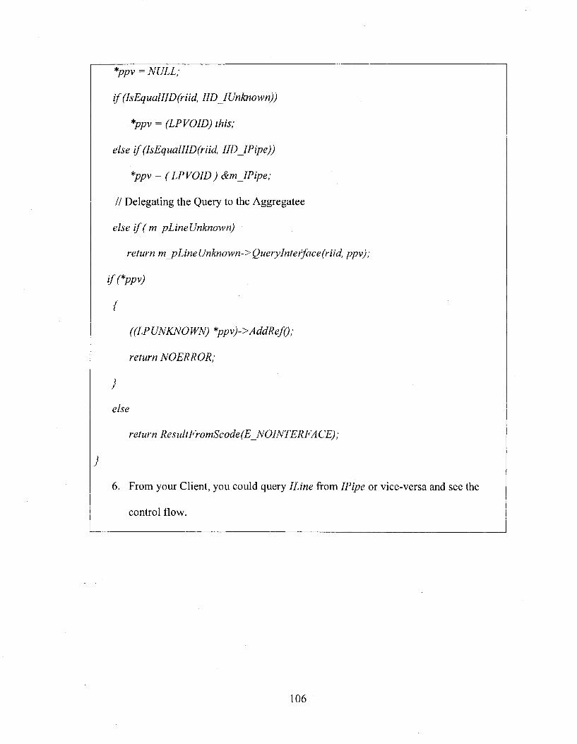
*ppv = NULL;
if (lsEqualllD(riid, IID IUnknown))
*ppv = (LPVOID) this;
else if (IsEqualIID(riid, IID IPipe))
*ppv = ( LPVOID) &m IPipe;
H Delegating the Query to the Aggregatee
else if (mjpLineUnknown)
return m _pLineUnknown-> Querylnterface (riid, ppv);
{
("(If LWÆV0IFA9
return NOERROR;
}
else
return ResultFromScode(E_NOINTERFACE);
}
6 . From your Client, you could query ILine from IPipe or vice-versa and see the
control flow.
106
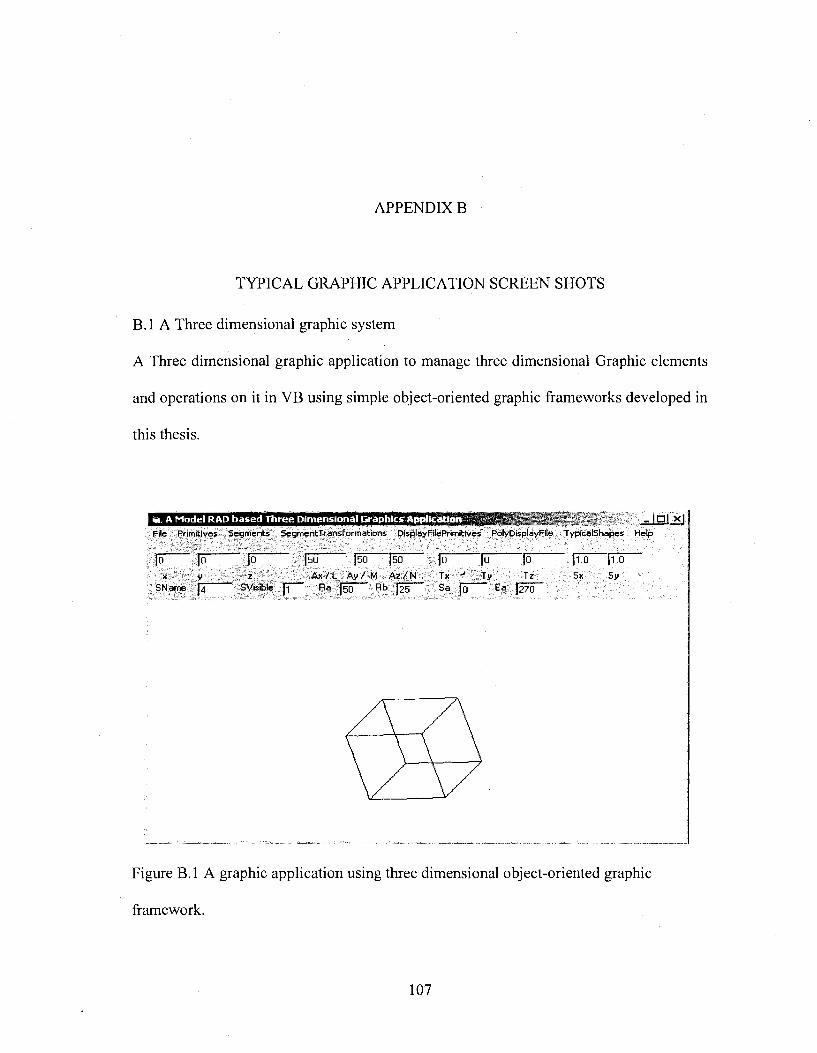
APPENDIX B
TYPICAL GRAPHIC APPLICATION SCREEN SHOTS
B.l A Three dimensional graphic system
A Three dimensional graphic application to manage three dimensional Graphic elements
and operations on it in VB using simple object-oriented graphic frameworks developed in
this thesis.
A Model RAD based Three Dimensional Graphics Application dal xjFile Primitives S egm en ts Segm entTransForm atlons DisplayFllePrimltlves PolyDlsplayFlle TyplcalShapes Help
■ |5 (ÔIÔ
S N a m e [ J "
(so [ s o ( s o z A x / L A y / M A z / N
S V is ib le [ ï R a (5 0 R b [2 5 S a [q E a (270
joT x
foT y
(To (ToSx Sy
Figure B.l A graphic application using three dimensional object-oriented graphic
framework.
107
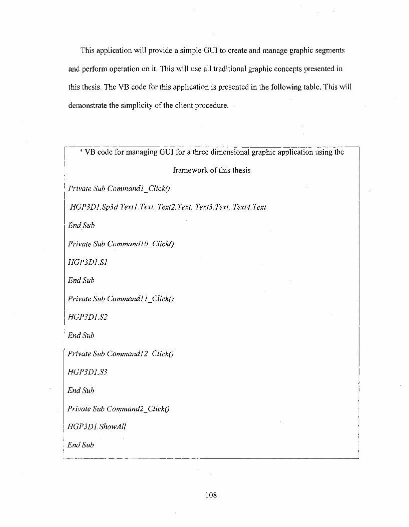
This application will provide a simple GUI to create and manage graphic segments
and perform operation on it. This will use all traditional graphic concepts presented in
this thesis. The VB code for this application is presented in the following table. This will
demonstrate the simplicity of the client procedure.
‘ VB code for managing GUI for a three dimensional graphic application using the
framework of this thesis
Private Sub Command 1 _Click()
H GP3Dl.Sp3dTextl.Text, Text2.Text, Text3.Text, Text4.Text
End Sub
Private Sub Commandl 0_Click()
HGP3D1.S1
End Sub
Private Sub Commandl 1 ClickQ
HGP3D1.S2
End Sub
Private Sub Commandl 2 ClickQ
HGP3D1.S3
End Sub
Private Sub Command2 ClickQ
HGP3Dl.ShowAll
End Sub
108
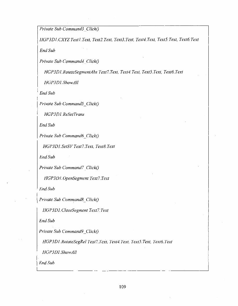
Private Sub Commands ClickQ
77Gf3D7.C%yZTe%r7.% 7e%r2Te%r, 7g%r3.Tg%f TgxrJ.% Texr6.Tg%r
End Sub
Private Sub Command4 ClickQ
HGP3Dl.RoteteSegmentAbsText7.Text, Text4.Text, Text5.Text, Textô.Text
HGPSDl.ShowAll
End Sub
Private Sub CommandsjClickQ
HGP3D1. ReSetTrans
End Sub
Private Sub Commandé ClickQ
HGPSDl.SetSV Text7. Text, TextS. Text
End Sub
Private Sub Command7 ClickQ
HGPSDl.OpenSegment Text7.Text
End Sub
Private Sub Commands JClickQ
HGP3D1 .CloseSegment Text7.Text
End Sub
Private Sub Command9 ClickQ
HGPSDl.RotateSegRel Text7.Text, Text4.Text, TextS.Text, Textô.Text
HGPSDl.ShowAll
End Sub
109
Private Sub Arc3D_Click(lndex As Integer)
H GP3Dl.Arc3D 1, Text 1.Text, Text2.Text, Text3.Text, Text4.Text, TextS.Text,
Textô.Text, TextM.Text, Textlô.Text, Text 17.Text
End Sub
Private Sub Circle3d_Click(Index As Integer)
H G P3D l.C ircle3d 1, Textl.Text, Text2.Text, Text3.Text, Text4.Text, TextS.Text,
Textô. Text, Textl 4. Text
End Sub
Private Sub ClearScrean_Click(Index As Integer)
HGP3D1. ClearScreen
End Sub
Private Sub CloseSegment_Click(Index As Integer)
HGP3D1.CloseSegment Text7.Text
End Sub
Private Sub CXYZ_Click(Index As Integer)
HGP3D1.CXYZ Textl.Text, Text2.Text, TextS.Text, Text4.Text, TextS.Text, Textô.Text
End Sub
Private Sub Exit_Click(Index As Integer)
End
End Sub
Private Sub Form ResizeQ
HGP3D1.Height = Forml.Height
HGP3D1. Width = Forml. Width
110
End Sub
Private Sub OpenSegment_Click(lndex As Integer)
HGP3D1 .OpenSegment Textl.Text
End Sub
Private Sub RotateAx_Click(Index As Integer)
HGP3DI.RoteteSegmentAbs I, Text4.Text, TextS.Text, Textô.Text
HGPSDI.RoteteSegmentAbs 2, Text4.Text, TextS.Text, Textô.Text
HGPSDl.RoteteSegmentAbs 3, Text4.Text, TextS.Text, Textô.Text
HGPSDI.SetSV I, I
HGPSDI.SetSV 3, I
HGP3DI.ShowSegment I
HGP 3D I .ShowSegment 2
HGP 3D I .ShowSegment 3
End Sub
Private Sub SetSegmentVisibility_Click(Index As Integer)
HGP3DI.SetSV Text?. Text, TextS. Text
End Sub
Private Sub ShapeOI_Click(Index As Integer)
HGP3DI.SI
End Sub
Private Sub Shape02_Click(Index As Integer)
HGP3DI.S2
111
End Sub
Private Sub Shape3_Click(lndex As Integer)
HGP3D1.S3
End Sub
Private Sub Show Axes _Click(lndex As Integer)
HGP 3D I.Show Ax
End Sub
Private Sub ShowSegment_Click(Index As Integer)
HGP 3D I .ShowSegment Textl.Text
End Sub
Private Sub Spear_Click(Index As Integer)
HGP3Dl.Spear3D I, Textl.Text, Text2.Text, Textl.Text, TextM.Text
End Sub
Private Sub SRotateAbs_Click(Index As Integer)
HGP3DI.RoteteSegmentAbs Textl.Text, Text4.Text, TextS.Text, Textô.Text
HGPSDI.Show
End Sub
Private Sub SRotateRel_Click(Index As Integer)
HGPSDI.RotateSegRel Textl.Text, TextQ.Text, Text 10.Text, Text 11 .Text
HGP 3 Dl.Show
End Sub
112
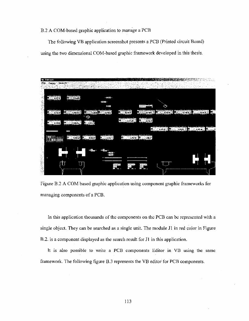
B.2 A COM-based graphic application to manage a PCB
The following VB application screenshot presents a PCB (Printed circuit Board)
using the two dimensional COM-based graphic framework developed in this thesis.
File Pages Search
049-Ubl
t is: n U47U 5 2 u ^ a r r - U 4 b
f USB 1V - Ü 5 7U f i S ' V U 6 3ÜB6
U 5 4U S b
ii . U G 2 ^ # = . .U 61 U 5 9 r r u e ?
Figure B.2 A COM based graphic application using component graphic frameworks for
managing components of a PCB.
In this application thousands of the components on the PCB can be represented with a
single object. They can be searched as a single unit. The module J1 in red color in Figure
B.2. is a component displayed as the search result for J1 in this application.
It is also possible to write a PCB components Editor in VB using the same
framework. The following figure B.3 represents the VB editor for PCB components.
113
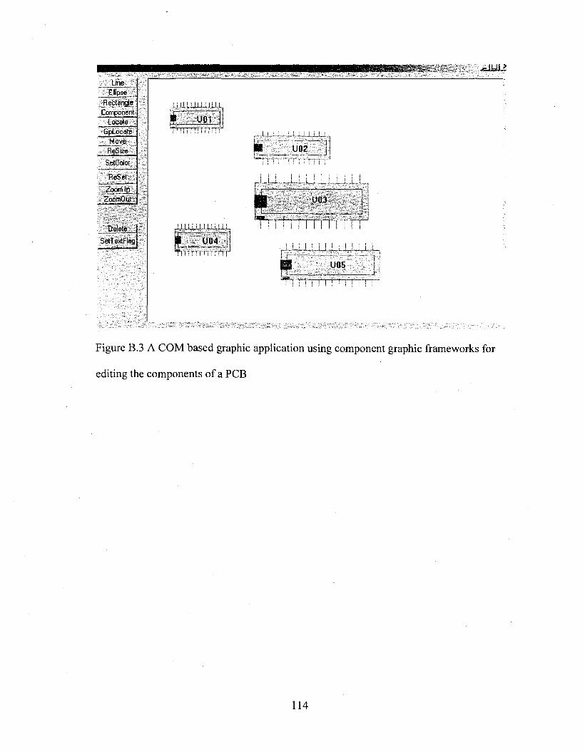
LineEllipse
R ectangleComponent
LocateG pLoeate
MoveReSize
SetColot
R eS et
Zoom InZoomOut
Delete
SetTextFlag
,ii,!i.w,iii m
I U01TiiiTiTiTfrrn
i.l 1,11,1,1.111,U.I I,
U04
U02
III i III r
iI i.i I I I I I I I I I
U05
T r r ^
Figure B.3 A COM based graphic application using component graphic frameworks for
editing the components of a PCB
114
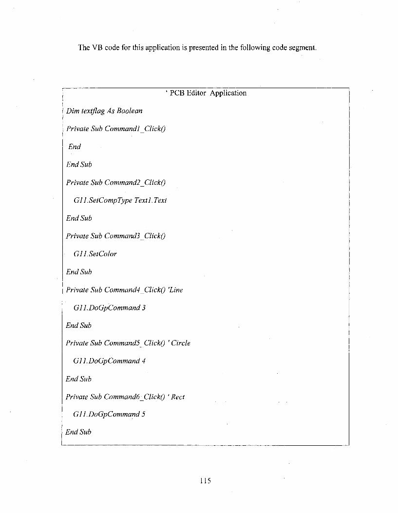
The VB code for this application is presented in the following code segment.
‘ PCB Editor Application
Dim textflag As Boolean
Private Sub Commandl ClickQ
End
End Sub
Private Sub Command2 jClickQ
G1 LSetCompType TextLText
End Sub
Private Sub Commands ClickQ
G1 LSetColor
End Sub
Private Sub Command4 ClickQ 'Line
C l l.DoCpCom m and 3
End Sub
Private Sub Commands JClickQ ' Circle
C l l.DoCpCommand 4
End Sub
Private Sub Commandô ClickQ ' Rect
C l 1 .DoCpCommand 5
End Sub
115
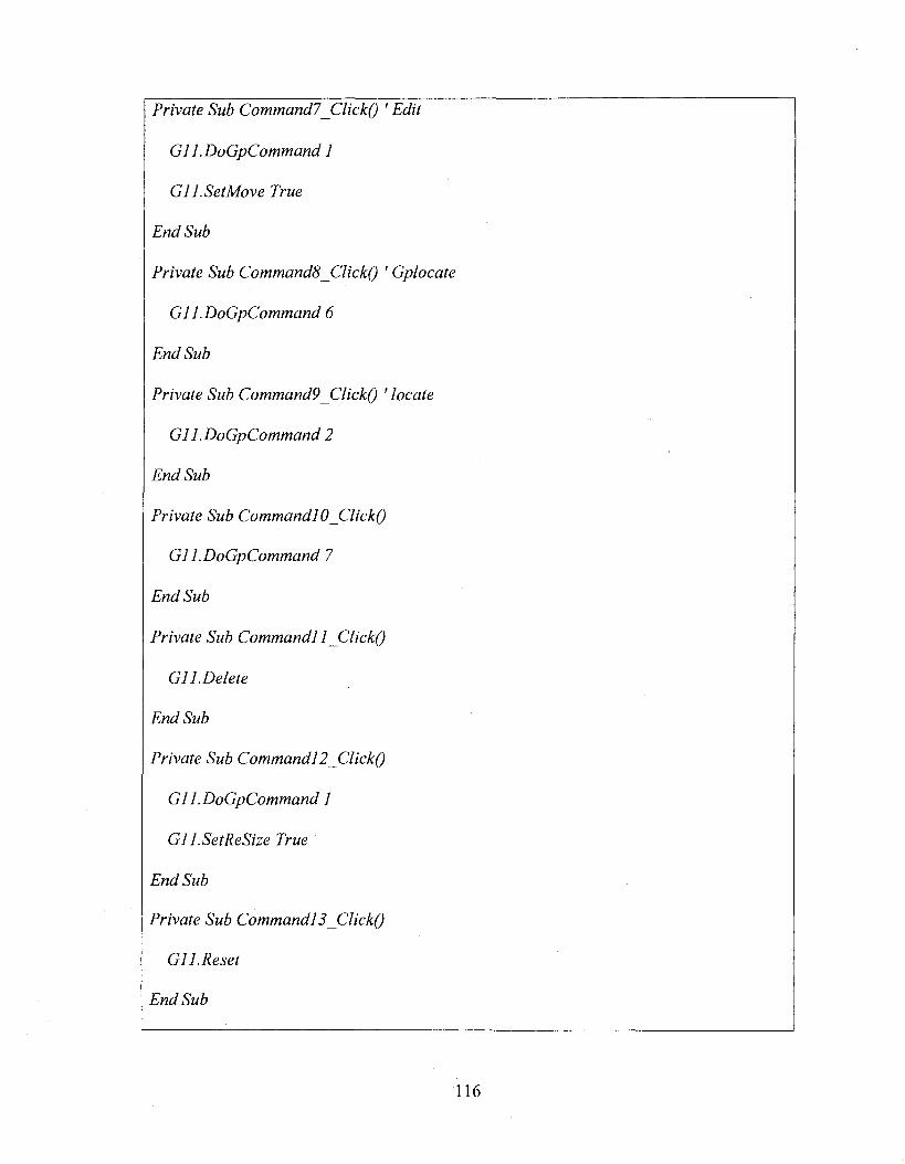
Private Sub Commandl_Click() ' Edit
C l 1 .DoCpCommand 1
C ll.SetM ove True
End Sub
Private Sub Commands ClickQ ' Cplocate
C l 1 .DoCpCommand 6
End Sub
Private Sub Command9 ClickQ ' locate
C l 1 .DoCpCommand 2
End Sub
Private Sub Commandl 0 ClickQ
C l 1 .DoCpCommand 7
End Sub
Private Sub Commandl 1 jClickQ
C l 1. Delete
End Sub
Private Sub Commandl 2 ClickQ
C l 1 .DoCpCommand 1
C l l.SetReSize True
End Sub
Private Sub Commandl 2 ClickQ
C l 1. Reset
End Sub
116
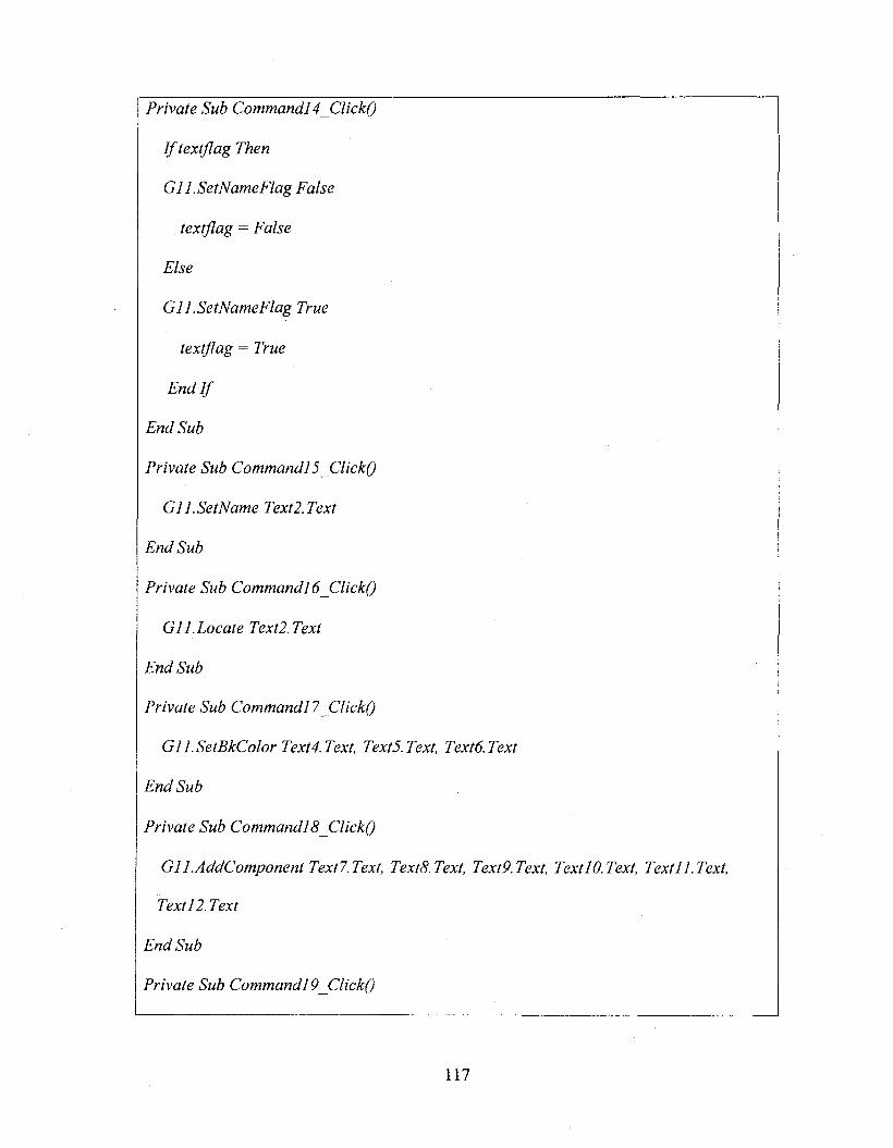
Private Sub Commandl 4 ClickQ
I f textflag Then
C l l.SetNameFlag False
textflag = False
Else
C l l.SetNameFlag True
textflag = True
End If
End Sub
Private Sub Commandl 5 ClickQ
C lI.SetN am e Text2.Text
End Sub
Private Sub Commandl 6 ClickQ
C l I.Locate Text2.Text
End Sub
Private Sub Commandl? ClickQ
C ll.SetB kC olor Text4.Text, TextS.Text, Textô.Text
End Sub
Private Sub Commandl 8_ClickQ
ClI.AddCom ponent Textl.Text, TextS.Text, TextP.Text, TextlO.Text, Text 11.Text,
Text 12.Text
End Sub
Private Sub Commandl 9 ClickQ
117
G ll.Z oom ln 5, 7
End Sub
Private Sub Command20 ClickQ
G ll.Zoom O ut 5, 7
End Sub
118
BIBLIOGRAPHY
[1] Geographic Information Systems, An introduction, 3/E by Bernhardsen.
[2] K.A.Bohrer “Architecture of the San Francisco Frameworks”, 1998.
[3] Johnson, R. E. and B. Foote “Designing Reusable Classes”, 1998
[4] Mohamed Fay ad and Douglas C Schmidt “Special Issue on Object-Oriented
Application Frameworks”, Vol. 40, No. 10, October 1997.
[5] Doreen L. Galli, Distributed Operating Systems, Prentice Hall, 2000.
[6] Erich Gamma, Richard Helm, Ralph Johnson and John Vlissides “Elements of
Reusable object oriented software”, 1994.
[7] Hari “COM Applications for Real time Electrical Engineering Applications”,
International Conference at IEEE Bangalore.
[8] Ian Heywood, Steve Carver “Introduction to Geographical Information Systems, a
2/E”.
[9] Juran, Joseph M.; Frank M. Gryna “Jurans Quality Control Handbook. Mcgraw-
Hill”, 1955.
[10] E-A Karisson (ed): Software reuse - A Holistic Approach, John Wiley & Sons,
1995.
[11] Stepen H.Khan “Metrix and Models in software Quality Engineering”, Pearson
Education India, 1995.
[12] Brockschmidt, Kraig. Inside OLE, 2nd edition, Microsoft Press, 1995
119
[13] D, Krug]inski: “Inside Visual C++, Microsoft Press 1995.
[14] Graphic Concepts for Computer Aided Design (2nd Edition) by Richard M
Lueptow, 2007.
[15] S. Meyers: Effective C++ - 50 Specific Ways to improve Your Programs and
Design, Addison-Wesley 1992.
[16] Patrick Naughton and Herbert Schildt “Complete Reference”.
[17] O. Nierstrasz (ed.) European Conference on “Object Oriented Programming”
Proceedings of 7th European Conference July 1993 Germany.
[18] James J Odell, Martin Fowler “Advanced 0 0 Analysis and Design Using UML”.
[19] Crosby, Philip “Quality is Free. New York: McGraw-Hill”, 1979.
[20] Jason Pritchard, PH.D., COM and CORBA Side by Side, Addison-Wesley
Longman, Inc., 1999.
[21] Hari Ramakrishna “Pattern languages for Graphic/CAD frameworks”, A Ph.D
Thesis, Osmania University.2003-2006.
[22] Hari Ramakrishna, “COM based CAD” Proceedings o f International AMSE
Conference on Moduling, Simmulation and communication, July 1999 at Jaipure,
India.
[23] Hari RamaKrishna “COM as new Object Oriented Technology”, Proceedings of
CSI conference, 2000.
[24] Rogerson “Inside COM Microsoft Press”, 1997.
[25] Paul Visokey, Comparison of COM and COBRA, 2000.
120
[26] Newman,W.S and Sproul, R.S (1981), “Principles of interactive computer
graphics”, McGraw-Hill International, Second edition.
[27] Douglas C. Schmidt, "Applying Design Patterns and Frameworks to Develop
Object-Oriented Communication Software," Handbook of Programming
Languages}, Volume I, edited by Peter Salus, MacMillan Computer Publishing,
1997.
[28] Fach, P.W. “Design reuse through frameworks and patterns”.
[29] COM Specifications Microsoft 1995.
[30] Microsoft Visual C++ Programming with MFC, 1995.
[31] Douglas C Schmidt “Special Issue on Patterns and Pattern Languages, Vol. 39”
1996.
121
VITA
Graduate College University of Nevada, Las Vegas
Deepa Uppala
Home Address2000 Walnut Ave #H108 Fremont, CA 94538
Degrees:Baehelor of Computer Science and Engineering, 2002 Jawaharlal Nehru Technological University, India
Thesis Title: Graphical Frameworks for Managing Component Oriented Graphic Systems.
Thesis Examination Committee:Chairperson, Dr. Yoohwan Kim, Ph.D.Committee Member, Dr. Kazem Taghva, Ph.D.Committee Member, Dr. Mei Yang, Ph.D.Graduate Faculty Representative, Dr. Ajoy K Datta, Ph.D.
122


![[Graphic Medicine] Rhetorics of the Visual: Graphic Medicine, Comics and its Affordances](https://img.dokumen.tips/doc/110x75/6361766940b666b8ec0ded6a/graphic-medicine-rhetorics-of-the-visual-graphic-medicine-comics-and-its-affordances.jpg)


