Embed Size (px)
Citation preview
121INTEGRATION OF GEOLOGIC FRAMEWORKSNew Mexico Geological Society Guidebook, 58th Field Conference, Geology of the Jemez Mountains Region II, 2007, p.
INTRODUCTION
The Pajarito Plateau, located on the eastern slopes of the Jemez Mountains, is the subject of numerous ongoing subsurface flow and transport studies that investigate the natural character of the regional groundwater systems. Studies to protect and monitor groundwater quality began at Los Alamos National Laboratory (LANL) in 1949. Beginning in 1998, site characterization work was expanded to include installation of more than 25 regional and intermediate-zone wells. Data from these new wells were com-bined with existing data to create a geologic framework that pro-vides better control on the computational meshes used for flow and transport modeling studies. Ongoing investigations continue to collect stratigraphic, lithologic and geophysical data; iden-tify and characterize perched water zones; collect water quality and water-level data; collect moisture and contaminant profiles through the vadose zone; perform in-situ hydrogeologic tests in wells; and characterize the mineralogy and geochemistry of key hydrogeologic units (Broxton and Vaniman, 2005). A synopsis of these studies, presented in LANL (2005), describes representative conceptual and computational hydrogeologic models that are con-sistent with available data. A key goal of the conceptual and com-putational hydrogeologic models is to develop a better understand-ing of how contaminants released during Laboratory operations are transported through the thick unsaturated zone to the regional aquifer (VZJ, 2005). The results of the monitoring and modeling activities are being used to evaluate ground water travel times and flow directions, assess risks associated with ground water contam-ination, and guide selection of remedial alternatives.
The LANL modeling approach for building computational meshes utilizes flexible strategies necessitated by evolving com-plexity and continual assessments on parameter uncertainty and model predictions. Computational meshes generally evolve from relatively simple large regions, to smaller focus areas with added
detail and resolution that often provide insightful feedback to regional scale models. The modeling process involves the inte-gration of a site conceptual model, characterization data, a com-putational mesh, computational hydrogeologic model, and eval-uation of results. The process is usually iterative, allowing the conceptual model, computational mesh, and the computational hydrogeologic model to be adjusted at any stage of the process in response to evolving conceptual models, new data, or changing program requirements.
In this paper, we describe two computer codes developed at LANL. These codes work together to provide the needed flexibil-ity, consistency, and sophistication to allow simulation of a vari-ety of subsurface flow and transport processes at various spatial scales and levels of complexity. The first computer code, LaGriT (LaGriT, 2007), is used to create computational meshes that are used by the second computer code, FEHM (Finite Element Heat and Mass transfer). FEHM is a porous flow and transport simula-tor that allows simulations in both the vadose zone and saturated zone (Zyvoloski et al., 1997). FEHM solves an extensive suite of equations for complex multiphase flow and reactive trans-port in porous and fractured media, and is able to incorporate complex hydrostratigraphy. The LaGriT grid generation soft-ware is an integrated package for all the mesh generation and setup for FEHM input and output, including import of geologic frameworks, mesh optimization and refinement, post processing, evaluation tools, and data interpolation. LaGriT is also used to generate initial and boundary conditions for FEHM simulations that are mapped directly onto the computational mesh. At any step in the process, greater numerical resolution can be added to a particular subregion, new boundary conditions can be prescribed, or new attributes can be incorporated. This approach insures that the steps taken are reproducible and traceable, and that modifi-cations to any step in the process can be accomplished quickly. The main purpose of this paper is to describe how computational
INTEGRATION OF GEOLOGIC FRAMEWORKS IN MESHING AND SETUP OF COMPUTATIONAL HYDROGEOLOGIC MODELS,
PAJARITO PLATEAU, NEW MEXICO
TERRY A. MILLER, VELIMIR V. VESSELINOV, PHILIP H. STAUFFER, KAY H. BIRDSELL, AND CARL W. GABLELos Alamos National Laboratory, Mail Stop T003, P.O. Box 1663, Los Alamos, NM 87545, [email protected]
ABSTRACT — Los Alamos National Laboratory has an extensive program devoted to understanding groundwater flow and trans-port of chemicals beneath the Pajarito Plateau. One goal of this program is to develop an integrated and comprehensive model-ing approach that allows rapid creation of computational hydrogeologic models that represent sections of the Pajarito Plateau. These models are used to simulate complex physical processes involving subsurface movement of water, air, and chemicals over a wide range of spatial scales. Model integration requires converting geologic frameworks, based on geologic data, into computational meshes that accurately reflect the subsurface geology and hydrostratigraphy. The computational hydrogeologic models that represent a given volume of the Plateau are then built onto the computational meshes. In this paper we describe how our modeling approach converts information from large geologic databases into computational meshes and finally into computational hydrogeologic models. Our approach maintains the geometry and topology of the geologic frameworks while optimizing the computational mesh to ensure accurate and efficient simulations. Our methodology for computational mesh development allows rapid updates as new site characterization data become available. Additionally, we discuss methods used to quickly modify the region of interest and mesh resolution in response to program requirements and the evolving needs of simulation scientists. Finally, we present two studies that demonstrate the integrated meshing and modeling set-up process: chromium transport in the Mortandad Canyon area and high explosives transport in the vicinity of Technical Area 16 (TA-16), at LANL
122 MILLER, VESSELINOV, STAUFFER, BIRDSELL, & GABLE
hydrogeologic models are built from computational meshes that are based on geologic frameworks.
INTEGRATED MESHING AND MODELING OVERVIEW
The geologic units of the Pajarito Plateau are the basis for any geologic frameworks that are created. Different geologic frameworks can be created from the same geologic database depending on the conceptual model chosen to fill in areas where no geologic data are available. Geologic frameworks serve as a basis for defining the distributions of hydrogeologic properties in hydrogeologic frameworks. In cases where geologic units have similar hydrogeologic properties, two or more geologic units are combined into a single hydrostratigraphic unit. Hydrogeologic frameworks are updated as new geologic and hydrogeologic measurements become available. Broxton & Vaniman (2005, Fig. 4) gave an example of a recent geologic to hydrogeologic correla-tion that is used in many LANL flow and transport simulations.
The geology of the chosen framework is mapped onto the computational mesh using interpolation algorithms in LaGriT. The geologic framework consists of a three-dimensional set of volumes representing the geologic structure as discrete hydro-stratigraphic units. The interpolation algorithms determine in which volume each mesh node is located, and then assign a number associated with that geologic unit. Different frameworks use various strategies to represent these volumes and LaGriT has been written to import these in various formats; such as horizon surfaces from StrataWorks (Halliburton, 2007), Environmental Systems Research Institute’s (ESRI, 2005) products, and three-dimensional volumetric models such as EarthVision (Dynamic Graphics, 2005).
The computational mesh is designed to capture the essential features of the geologic framework. The mesh design is typically a tradeoff between mesh size (number of nodes and elements) and the level of detail represented by the mesh. A mesh with more nodes will capture more detail but will require more CPU time and computer memory. Computer memory limits on our most advanced systems currently limit analysis to meshes with less than 1 million nodes. A mesh with fewer nodes uses less CPU time, but geometric details may be lost. The LaGriT software allows many different methods of node distribution in order to find a distribution that yields a mesh with the desired level of geologic detail. Geologic units with large volumes or regions that are far from the area of interest are captured with larger mesh spacing, while thin or highly angled units of the framework are delineated with finer mesh spacing. Other considerations in representing the geology with a computational mesh include geometries that lack symmetry, have a wide range of length scales, or may contain very thin layers that must be preserved as continuous layers.
Meshes are also restricted by the numerical constraints imposed by the physics used in the simulation codes. Some codes can solve problems only on orthogonal, uniformly spaced meshes (also called regular structured meshes). Others use meshes with special adaptive refinement strategies that reduce mesh spacing to resolve complex geometries (usually unstructured meshes). Both low-resolution and high-resolution meshes may represent
geologic interfaces well. However, a high-resolution mesh may be required to resolve concentration gradients when solving con-taminant transport problems because smaller elements can more accurately represent steep gradients. By ensuring that constraints such as a positive definite coefficient matrix of geometric area coefficients are satisfied, LaGriT maintains compatibility with FEHM and other finite-volume flow and transport codes.
The final step of our modeling approach involves the setup of the computational mesh and its properties for use in simulat-ing subsurface processes. Because LaGriT has evolved in tandem with FEHM, it writes many of the mesh description files in for-mats compatible with FEHM. Using the final mesh definitions, LaGriT writes input files for FEHM that provide the mesh geom-etry and topology, the geologic properties of the mesh, nodal vol-umes, boundary lists, and other mesh-based information needed to set up a given simulation.
MORTANDAD CANYON AND TA-16 CASE STUDIES
Introduction
Mortandad Canyon has been the subject of numerous monitor-ing and modeling studies over the past several decades. Since the 1950s, LANL contaminants have been released to the canyon with treated effluent from liquid waste treatment facilities. In addition, a power plant releasing a chromium-based corrosion inhibitor into Sandia Canyon from 1956 to 1972 is thought to be the primary source for chromium contamination detected in the regional aquifer (LANL, 2006). The goal of the numerical models presented here (Fig. 1) is to determine the principal path-ways of contaminant transport below the ground surface. These pathways are controlled by the canyon-floor alluvial aquifer, a thick vadose zone (which includes intermediate perched zones of water saturation), and the regional aquifer (Broxton and Vani-man, 2005; Birdsell et al., 2005). The Mortandad Canyon model was recently expanded to include Sandia and Los Alamos Can-yons to identify potential pathways of chromium contamination detected in monitoring wells R-28 in Mortandad Canyon and R-11 in lower Sandia Canyon.
TA-16 is located near the southwestern LANL boundary. This site is near an area where a predominant portion of regional aqui-fer recharge occurs along the flanks of the Sierra de los Valles. The numerical model for this site represents the vadose zone and the regional aquifer. Contaminants have been detected in allu-vial ground water and in a deep intermediate perched zone (at well R-25). Though this model domain is confined to the imme-diate vicinity of TA-16, the small-scale model is coupled with the larger LANL site-scale regional aquifer model. The primary objective is to identify potential pathways of contaminant trans-port in the subsurface. The primary contaminants of concern are high explosives.
Geologic framework
Available geologic frameworks for the model region are the first consideration for constructing a mesh. The geologic frame-

123INTEGRATION OF GEOLOGIC FRAMEWORKS
work used in LANL studies (LANL, 2005) was built using a StrataModel volumetric model (Carey et al., 1999). The most recent geologic framework represents a major upgrade that pro-vides a fresh analysis of the entire geologic database and con-tains new data, including 39 new wells for the deeper units. The geologic conceptual model is revised so that the younger Tschi-coma Formation extends farther east and deeper under the central portion of LANL and may abut younger Cerros del Rio basalts in the central portion of the laboratory. The main portion of the pumiceous Puye Formation is now considered separate from the Puye fanglomerates through which well R-25 passes. This latest version of the geologic framework is available as high-resolution ArcInfo elevation grids, but is too large to capture within a single high-resolution volumetric format (Cole et al., 2006). Mortandad Canyon geologic framework
The LANL EarthVision framework for the Mortandad Canyon area is generated from the ArcInfo set of surfaces (Cole et al., 2006). It was chosen for this study because it includes the neigh-boring Sandia and Los Alamos canyons, and it provides consis-
tency with other LANL studies using the geologic framework. EarthVision also provides an efficient algorithm for mapping geologic units onto the computational mesh.
TA-16 geologic framework
Current investigations at TA-16 use the updated geologic framework for the Pajarito Plateau (Cole et al., 2006). This frame-work is captured by the computational mesh and is propagated through the numerical simulations. The easy-to-use EarthVision format is not available for the area of TA-16, so the full set of ArcInfo surfaces for the Pajarito Plateau are used instead.
Construction of computational mesh
Mortandad Canyon computational mesh
The dimensions of the computational mesh needed for flow and transport simulations at a given site depend on understanding the relationships between hydrogeology, contaminant release his-tory, and site specific details such as locations of monitoring wells
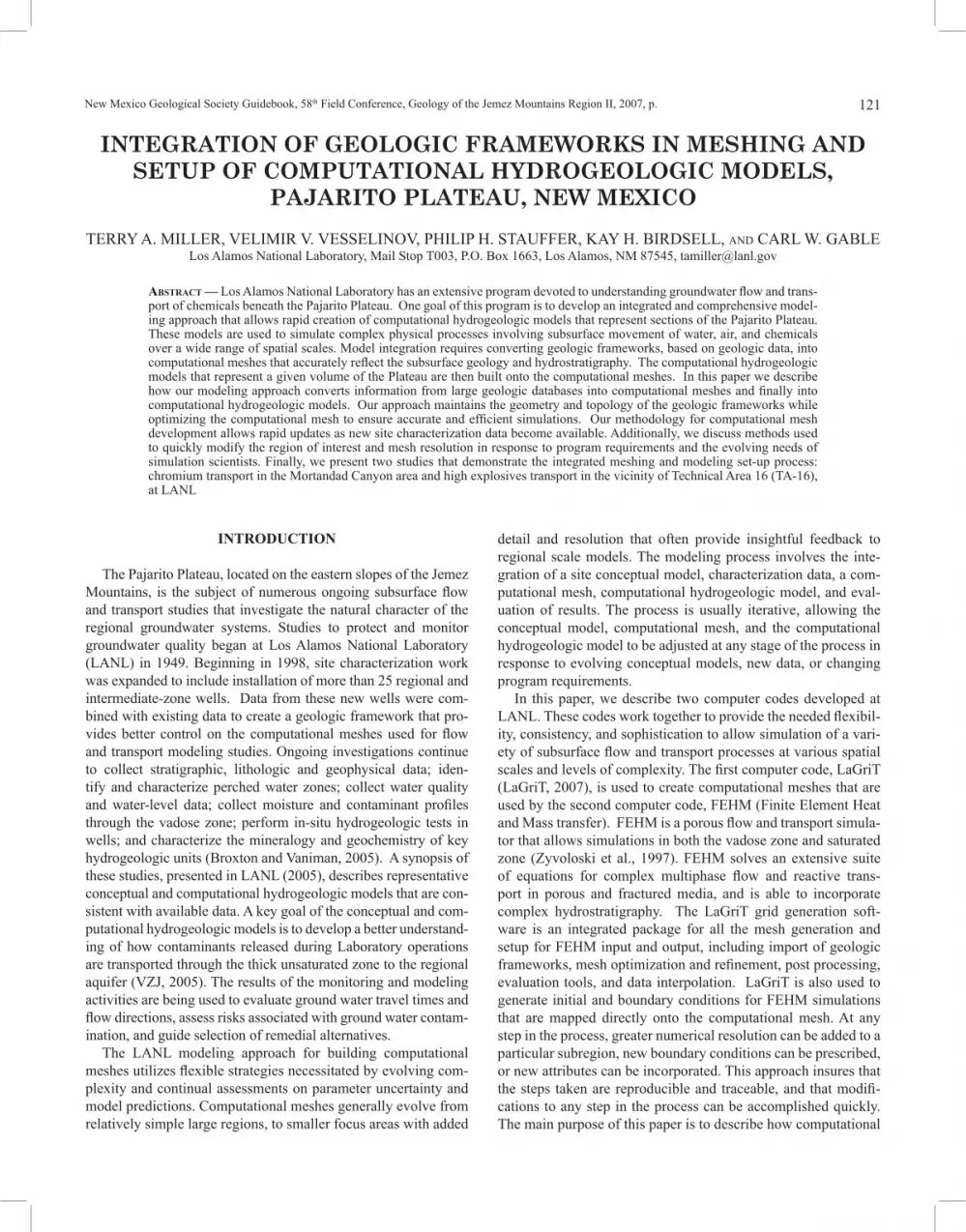
FIGURE 1. Image of high resolution region of the Mortandad Canyon mesh, view from southeast looking west up Mortandad, Sandia, and Los Alamos Canyons. The high-resolution region is located near the confluence of Mortandad and Ten Site Canyons. Inset shows model location within LANL boundary.

124 MILLER, VESSELINOV, STAUFFER, BIRDSELL, & GABLE
and water supply wells. Also important are lessons learned from simulations of other local sites. The process is iterative, and for the Mortandad Canyon study, simulations using an initial compu-tational mesh were used to investigate contaminants released into Mortandad Canyon. However, due to interest in chromium con-taminant source locations found outside of Mortandad Canyon, the mesh was expanded north to include Sandia Canyon and Los Alamos Canyon.
In the simulations of chromium migration, flow paths are pri-marily focused along Mortandad Canyon and the lower half of Sandia Canyon. The lateral extent of the computational mesh was chosen to remain within the EarthVision geologic framework, while including important data locations such as monitoring well LAOI(A)-1.1 to the north in Los Alamos Canyon and water supply well PM-1 to the east near NM-4 in Sandia Canyon. The resulting computational mesh extends from UTM NAD83 coor-dinates 495000, 537750 meters at the lower left corner to 503000, 542000 meters at the upper right corner in the New Mexico State coordinate system. The mesh bottom is truncated at the bottom by a horizontal surface with elevation of 1124 m and at the top by the ground surface with a maximum elevation of 2324 m.
Because of size limitations, the edges of the mesh use a low resolution that telescopes inward and parallel to the canyons towards the primary areas of interest - the confluence of Mortan-dad and Ten Site Canyons and a portion of Sandia Canyon (Fig. 1). Field studies investigated potential contaminant pathways and have identified the confluence of Mortandad and Ten Site can-yons as a potential entry point of the contaminants in the subsur-face (LANL, 2006). A close-up view of the mesh (Fig. 1) shows the final spacing and selected well locations in the vicinity of the canyon confluence. The outside perimeter of the mesh has 250 m horizontal spacing; the node spacing decreases inward toward Mortandad Canyon to 125 m and 62.5 m. The primary region of interest around Sandia and Mortandad Canyons are refined to 62.5 m and 31.25 m spacing. The canyon bottoms surround-ing the confluence of Mortandad and Ten Site Canyons have the highest resolution with 15.62 m spacing. The vertical spacing within the mesh reduces in the same manner starting with 200 m at the perimeter and decreasing by halves to the high-resolution region with 12.5 m vertical spacing.
The mesh refinement is performed with LaGriT using the octree mesh refinement (OMR) algorithm (Trease et al., 1996). The octree method maintains the orthogonal orientation of mesh elements necessary for FEHM particle tracking simulations by bisecting hexahedral elements along three orthogonal planes. The result is a single element that is broken into eight equal-sized hexahedral elements. This simple mesh-refinement strategy pro-vides sufficient resolution and mesh size to model a variety of scenarios to understand and define future modeling activities. The simple, structured mesh is a trade-off with a more complicated, unstructured mesh refinement that can better resolve complex geologic shapes and possible effects of nonaligned flow fields in some numerical models (Douglass et al., 2001).
As models are evaluated, the mesh can be modified to suit specific studies. For example, some proposed studies involve
the movement of intermediate perched groundwater that is often observed beneath wet canyons within the Puye Formation and the Cerros del Rio basalt (Robinson et al., 2005; Birdsell et al., 2005). Resolving details of the locations of such perched ground-water can be improved by refining the mesh along the interfaces and within the Puye Formation and Cerros del Rio basalt. The region outside these areas of interest can have coarse spacing or be removed to enable a greater number of nodes to capture thin perching layers. Through careful mesh-refinement strategies, the computational mesh can capture perched groundwater thick-nesses to approximately 1 m.
After a mesh with a chosen spacing has been created, the geo-logic framework is mapped onto the mesh nodes. In the Mor-tandad Canyon study, mesh nodes were imported into the Earth-Vision geologic framework and each point was located within an EarthVision volume representing the shape of geologic units. EarthVision defines these volumes internally as intersecting sur-faces that define the bottom and top for each volume. For places where a lava flow is intercalated with a sedimentary sequence, the sedimentary unit is divided to accommodate the lava flow. The number of geometric volumes is therefore greater than the total number of geologic units that are represented. The final compu-tational mesh contains approximately 6.1 x 10⁵ mesh nodes.
EarthVision allows three-dimensional viewing of the geologic units, thus enabling comparisons of the resulting mesh geology to the source geologic framework. For example, during inspec-tion of the mesh representation of hydrostratigraphic units, the Tschicoma unit north of the focus area was truncated due to large mesh spacing. To remedy this, the regions selected for refinement were extended farther west to better capture a continuous unit and to maintain the rounded lobe shape of this formation, which was deemed to be a potentially important hydrogeologic control. Figure 2 shows the Tschicoma mesh elements as captured by the first attempt (a, b) and the improved spacing choices (c, d). In this way, the mesh is checked and corrected to insure all relevant units are represented comparable to the source geologic framework.
TA-16 numerical mesh
The TA-16 flow and transport simulations use a subset of the LANL site-scale regional aquifer model mesh as described in LANL (2005, Appendix 4-D). To simplify modeling, it is desir-able that the lateral boundaries of the TA-16 mesh be coincident with element boundaries in the LANL site-scale regional mesh (Keating et al., 2003). This simplifies the task of interpolating quantities (head, flux) from the site-scale flow and transport cal-culations onto the boundaries of the TA-16 model and makes it easier to embed the high resolution TA-16 mesh into the coarser site-scale mesh. Owing to issues related to numerical accuracy and constraints in the FEHM particle tracking algorithms, the horizontal resolution of the site-scale mesh is used; however, the vertical spacing of nodes is modified to a structured mesh arrangement at elevations within the expected particle path zone. The particle tracking area consists of mesh spacing 62.5 m wide and 6.25 m high from an elevation 1575 to 1900 m. The resulting

125INTEGRATION OF GEOLOGIC FRAMEWORKS
orthogonal mesh is not valid for particle tracking everywhere, but it is valid for particle tracking within the volume where particles are transported.
For TA-16, mapping of the geologic framework onto this mesh is more complicated than for the Mortandad Canyon studies using the EarthVision framework. The Pajarito Plateau geologic frame-work used for this study consists of 58 top and bottom surfaces of 50 ft resolution. Each pair of surfaces is combined, resulting in 16 stratigraphic layers and 12 flow bodies internal to a strati-graphic layer (Cole et al., 2006). To locate a mesh node relative to these framework surfaces, the top and bottom surfaces for each geologic unit need to be stacked and connected into volumes. The result is a set of volumes formed by the stratigraphic layers and
internal flow bodies. Consistency of the geologic framework is maintained by searching each stratigraphic volume in order from bottom to top, followed by a search through the internal flow bodies from bottom to top. In this manner each node in the com-putational mesh is mapped to a unique hydrostratigraphic unit.
The resulting mesh with assigned geologic properties is evalu-ated to ensure that the geometry represented by the hydrostrati-graphic units in the computational mesh is consistent with the geologic framework. Evaluation of the ArcInfo geologic frame-work with a three-dimensional viewer is not possible, so the mesh is compared to structural contour maps as documented in Cole et al. (2006). For example, a vertical column of mesh nodes is selected nearest the location of borehole R-25 (Fig. 3). The
FIGURE 2. Images from the Mortandad Canyon model showing mesh elements within the Tschicoma Formation geologic volume from Cole et al. (2006). Mesh with sparse mesh spacing in version a) and b) and mesh with higher resolution in c) and d). The top views show the unit’s lateral extents, and the bottom views show the unit in three-dimensions looking west. Mesh a) has three levels of refinement from edge lengths of 250 to 62.5 m. Mesh c) has five levels starting at 250 m and reducing by half each level to the smallest edge length of 15.625 m.

126 MILLER, VESSELINOV, STAUFFER, BIRDSELL, & GABLE
mesh node identified as the top of the pumiceous Puye unit is at elevation 1718 m, whereas the geologic framework report gives the top as 1720 m. This 2-meter difference is within the vertical mesh spacing of 6.25 m. The mesh units are also checked against well data used to build the geologic framework. The borehole depth data reported by Cole et al. (2006, table C-2) indicate a pumiceous Puye thickness of 21.95 m that compares well with the mesh thickness for this unit of 25 m. These comparisons show that the computational mesh has sufficient resolution to capture the geologic units described by the geologic framework.
In the final step the mesh is truncated above the water table, removing all geologic units located above the Puye Formation and reducing the mesh size to approximately 2.4 x 10⁵ nodes.
Setup for process model
Mortandad Canyon setup
Once the computational mesh is evaluated, various other char-acteristics are extracted to aid in setting initial conditions, bound-ary conditions, material properties, and other model attributes.
For example, the nodes along each of the four sides, the bottom nodes, and nodes along the top of the mesh are identified and written as separate lists; these are imported into FEHM and used to set boundary conditions. The nodes for each geologic unit are written to lists that FEHM imports and uses to set hydrogeologic properties. The computational mesh geometry and topology are written in files used by FEHM. As a last step before the simu-lations can be run, features such as wells are mapped to corre-sponding mesh nodes. Each computational mesh is thoroughly documented to ensure that all data are accurate and that the mesh can be recreated in the future.
TA-16 setup
In addition to the normal FEHM setup files that include all mesh and geologic definitions, the mesh nodes closest to well screens are located and written to files, together with their asso-ciated node number, material property, and coordinate location so that model results can be compared to field data collected at observation wells. These mesh nodes are found by giving each well screen a radial volume and using the LaGriT interpolation routines to find a mesh node located inside each screen volume.
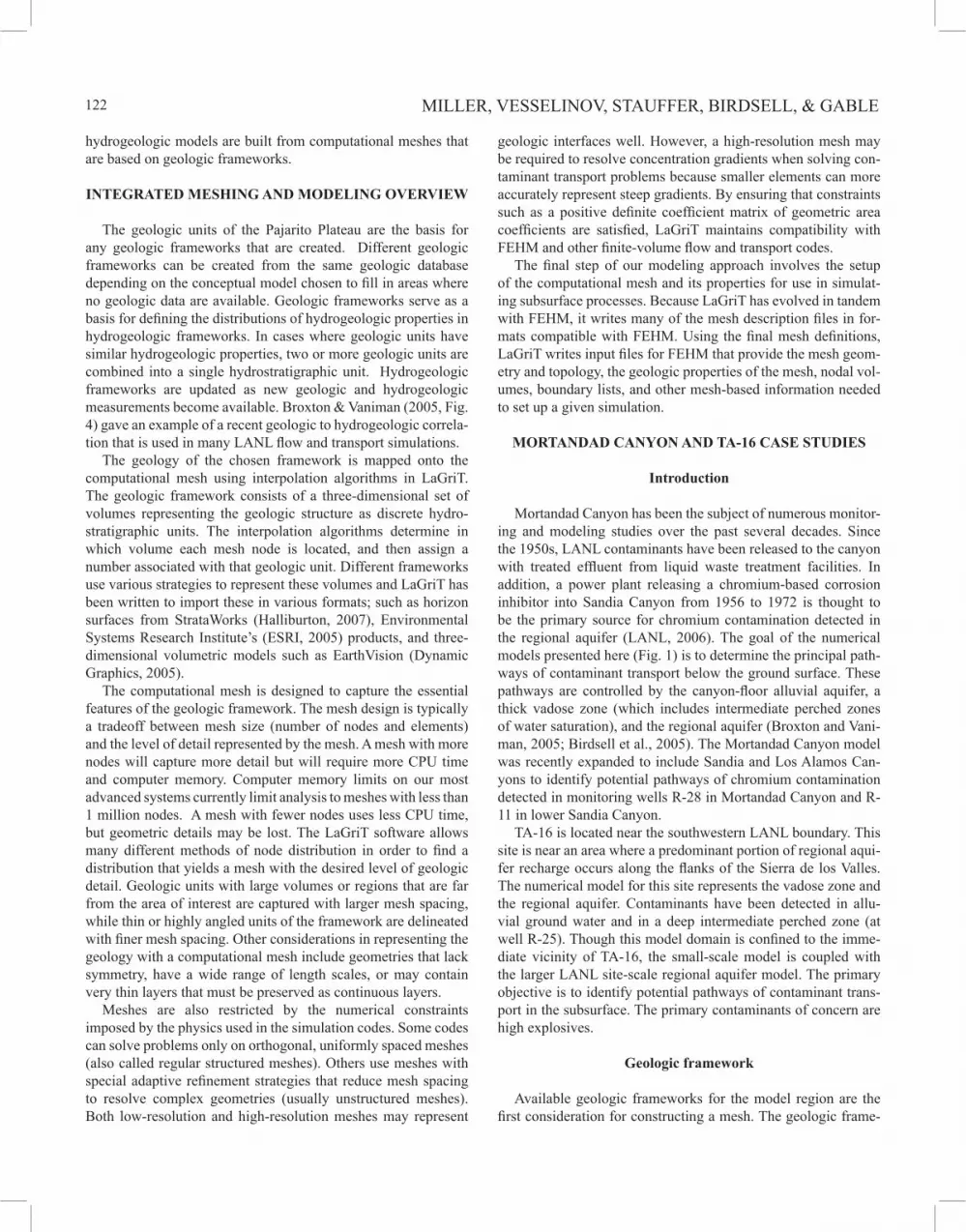
FIGURE 3. The TA-16 computational mesh truncated at the water table and colored by the geologic model units from Cole et al. (2006). a) first version mesh with a single level of refinement throughout the mesh resulting in 240,005 nodes. b) mesh with selected areas of high resolution based on plume results and the location of well R-25. The total number of mesh nodes is 563,937.

127INTEGRATION OF GEOLOGIC FRAMEWORKS
For mesh spacing that fails to find a node within a screen, the nearest vertical node is used.
Interpolation is also used to map hydraulic head data onto the mesh nodes. This study uses two alternative interpretations of water table surfaces based on existing water-level data. Lateral hydraulic gradients at the water table in the vicinity of TA-16 are relatively high when compared to those beneath the rest of LANL. In particular, hydraulic head data from the well screens at R-25 can be interpreted in different ways to define the eleva-tion of the regional water table (Broxton et al., 2002). For each of these interpretations, and for each x, y location in the mesh, head values are interpolated linearly onto the mesh nodes.
Flow and transport simulations using this first version com-putational mesh were used to target areas for further refinement. By confining the volume of increased resolution to chosen wells within observed plume boundaries, the mesh size is kept within a desired number of nodes, but it is detailed enough to accurately represent well screen positions. Figure 3a shows the original low resolution mesh while Figure 3b shows the high resolution mesh with refinement within the zone of the particle paths and observed contaminant data. The high-resolution mesh (Fig. 3b) begins with the same 125 m spacing as the first mesh. A box-shaped region just outside the plume area is refined laterally to 62.5 m, then a large region where potential contaminant plumes might occur in the regional aquifer is identified and refined to have the smallest spacing at 31.25 x 6.25 m2. A smaller plume region is refined again to 15.62 x 3.12 m2. Finally, the area immediately surround-ing well R-25 is selected for refinements down to 1.953 x 0.39 m2 spacing. (Fig. 3, well R-25 detail). Through careful selection of coarse and fine resolution spacing the mesh size is kept at a reasonable size of approximately 5.6 x 10⁵ nodes with sufficient detail to accurately model plume growth within the area of inter-est.
SUMMARY
Mortandad Canyon discussion
The flow and transport simulations at this site will help to identify regions of likely chromium transport pathways within the large-scale Mortandad Canyon domain (Fig. 1) to be refined while other regions may be represented adequately with coarse spacing. This will allow further refinement confined to the chosen volume without increasing the mesh size. Choices for higher-resolution regions may include the alluvial volume along the canyon bottoms and intermediate perched zones within the Puye Formation and the underlying Cerros del Rio basalt. The mesh refinement to represent perched conditions can be used to inves-tigate three-dimensional transient flow conditions to determine the nature of perched water bodies beneath the canyon. Though perched systems less than 1 m thick are difficult to capture explic-itly in large-scale models, mesh refinement used in conjunction with a numerical approach available in FEHM that defines a per-meability reduction factor along the interface at a perching layer (Robinson et al., 2005) makes such studies feasible.
TA-16 results Refinement in the region where potential contaminant plumes
might occur in the regional aquifer near R-25 is generated for both interpretations of the water table. As expected, resolution near wells is adequate for studies encompassing large regions, but for near-field studies finer resolution near the modeled wells will allow a better representation of aquifer heterogeneity and more realistic simulations of the groundwater velocity field (Vesseli-nov et al., 2002).
The refined numerical mesh gives much improved resolution in the vicinity of the boreholes, and this will improve the ability of simulations to match data from these wells. The results will give insights into differences in simulation results obtained between using the mesh to capture geometry, and using new FEHM codes that simulate embedded wells without changes to the computa-tional mesh (Pawar and Zyvoloski, 2006).
Continued improvement of geologic frameworks and asso-ciated computational meshes will lead to better computational hydrogeologic models. Better computational hydrogeologic models further increase the understanding of contaminant migra-tion in the subsurface of the Pajarito Plateau. This iterative pro-cess depends on continued interaction between the field geologist, geologic framework modelers, hydrogeologists, mesh specialists and numerical modelers.
ACKNOWLEDGMENTS
We thank David Broxton and Hari Viswanathan for their reviews. We also thank David Broxton and Greg Cole for all their support and important insights into the geology and hydrogeo-logic frameworks for the Pajarito Plateau.
REFERENCES
Birdsell, K.H., Newman, B.D., Broxton, D.E., and Robinson, B.A., Conceptual models of vadose zone flow and transport beneath the Pajarito Plateau, Los Alamos, New Mexico: Vadose Zone Journal, v. 4, p. 620-636.
Broxton, D.E., and Vaniman, D.T., 2005, Geologic framework of a groundwater system on the margin of a rift basin, Pajarito Plateau, north-central New Mexico: Vadose Zone Journal, v. 4, p. 522-550.
Broxton, D., Warren, R., Longmeir, P., Gilkeson, R., Johnson, S., Rogers, D., Stone, W., Newman, B., Everett, B., Vaniman, D., McLinn, S., Skalski, J., and Larssen, D., 2002, Characterization Well R-25 completion report: Los Alamos National Laboratory, Manuscript, LA-13909-MS.
Carey, B., Cole, G., Lewis, C., Tsai, F., Warren, R., and WoldeGabriel, G., 1999, Revised site-wide geologic model for Los Alamos National Laboratory: Los Alamos National Laboratory, Report LA-UR-00-2056.
Cole, J., Carey, W., Burnette, L., and Miller, T., 2006, The 2005 three-dimen-sional, geologic model of the Pajarito Plateau: Los Alamos National Labora-tory, Report LA-UR-06-3060.
Douglass, R., Carey, G., White, D., Hansen, G., Kallinderis, Y., and Weatherill, N., 2001, Current views on grid generation: summaries of a panel discus-sion: Los Alamos National Laboratory, Report LA-UR-01-3945
Dynamic Graphics Inc., 2005, Website describing the EarthVision software: <http://www.dgi.com/earthvision/index.shtml>(accessed on March 13th, 2007).
ESRI, 2005, GIS and Mapping Software: <http://www.esri.com> (accessed on March 13th, 2007).
Halliburton, 2007, Homepage for the StrataWorks software: <http://www.halli-

128 MILLER, VESSELINOV, STAUFFER, BIRDSELL, & GABLE
burton.com/ps/Default.aspx?navid=219&pageid=883&prodid=PRN%3a%3aJ3FXB2KSY> (accessed on March 13th, 2007).
Keating, E. H., Vesselinov, V. V., Kwicklis, E., and Lu, Z., 2003, Coupling basin- and local-scale inverse models of the Española Basin: Groundwater, v. 41, p. 200-211.
LANL, 2005, Los Alamos National Laboratory’s hydrogeologic studies of the Pajarito Plateau: a synthesis of hydrogeologic work-plan activities (1998-2004): Los Alamos National Laboratory, Manuscript LA-14263-MS.
LANL, 2006, Interim measures investigation report for chromium contamination in groundwater: Los Alamos National Laboratory, Report LA-UR-06-8372.
LaGriT, 2007, Los Alamos Grid Toolbox, <http://lagrit.lanl.gov> (accessed on March 13th, 2007).
Pawar, R.J., and Zyvoloski, G.A., 2006, A novel method to couple wellbore flow to reservoir flow: in Binning, P.J., Engesgaard, P.K., Dahle, H.K., Pinder, F., and Gray, W.G., eds., Proceedings of the XVI International Conference on Computational Methods in Water Resources, Copenhagen, Denmark, June, 2006.
Robinson, B.A., Broxton, D.E., and Vaniman, D.T., 2005, Observations and mod-eling of deep perched water beneath the Pajarito Plateau: Vadose Zone Jour-nal, v. 4, p. 637-652.
Trease, H., George, D., Gable, C.W., Fowler, J., Kuprat, A., and Khamyaseh, A., 1996. The X3D grid generation system, in Soni, B.K. , Thompson, J.F., Hausser, H., and Eiseman, P.R. eds., Numerical grid generation system in computational fluid dynamics and related fields: Mississippi State Univer-sity, p. 1129.
Vesselinov, V.V., Keating, E.H., and Zyvoloski, G.A., 2002, Analysis of model sensitivity and predictive uncertainty of capture zones in the Espanola basin regional aquifer, northern New Mexico: IAHS-AISH Publication; no.277, p.508-514.
VZJ, 2005, Special section on Los Alamos National Laboratory: Vadose Zone Journal, v. 4, p. 453-818.
Zyvoloski, G.A., Robinson, B.A., Dash, Z.V., and Trease, L.L., 1997, Summary of the models and methods for the FEHM application-a finite-element heat-and mass-transfer code: Los Alamos National Laboratory, Manuscript LA-13307-MS.


