Embed Size (px)
Citation preview

User Guide General
Ver 1 Publ. no. 571 702 001 - part 1
Geodimeter® CU & 600 CU

Modifications resulting from technical developments may be in the interest of our customers. Illustrations and specifications are therefore not binding, and are subject to change without prior notice.
Trademarks and Copyright
© Copyright 2001, Trimble Navigation Limited. All rights reserved. Elta, GPS Total Station, Geodimeter, and Terramodel are trademarks of Trimble Navigation Limited registered in the United States Patent and Trademark Office. The Triangle and Globe logo, Trimble, Autolock, Tracklight, eSurveying, Integrated Surveying, RoadLink, Trimble Geomatics Office, Trimble Link, Trimble Survey Controller, TSC1 are trademarks of Trimble Navigation Limited. All other trademarks are the property of their respective owners.
1:th Edition
Printed in Sweden 02.01 Publ. no. 571 702 001 - part 1, Novum Grafiska AB

Table of Contents
Welcome to Geodimeter® CU Control unit
Comments about this manual .................................... BGlossary of terms used with Geodimeter CU ........... B
1 Introduction
Unpacking & Inspection ...............................................1-2Inspection................................................................... 1-2
The Control unit ...........................................................1-4Detachable control unit .............................................. 1-4Assigned control units................................................ 1-5Additional control units ............................................. 1-5
The Display..................................................................1-6Instrument settings ..................................................... 1-7User-defined display tables........................................ 1-10Key functions ............................................................. 1-10Alpha character keying in (numeric control unit)...... 1-22Alpha mode key (alphanumeric control unit) ............ 1-23How to use the alphanumeric keys
(alphanumeric control unit).............................. 1-23Lower case key (alphanumeric control unit) ............. 1-24Shift key (alphanumeric control unit) ........................ 1-24Space bar key (alphanumeric control unit) ................ 1-25Servo control keys
(numeric and alphanumeric control units) ....... 1-25Continue key .............................................................. 1-26Temporary horizontal angle key (only in Program 0) 1-26
Table of Contents
2 Memory Units
Introduction ..................................................................2-2
Unit description ............................................................2-2Unit capacity .............................................................. 2-2Program 54 – File Transfer ........................................ 2-3Edit............................................................................. 2-3
Setting up Internal memory as an active memory device.........................................2-3Info messages............................................................. 2-6Data Communication ................................................. 2-6
Setting up CU as an active memory device.................2-7
3 Memory Structure
Introduction ..................................................................3-1
Memory Structure ........................................................3-1
4 Data Communication
Introduction ..................................................................4-2
Data transfer ................................................................4-2Control unit Personal Computer ................................ 4-2
Program 54 – File transfer ...........................................4-3
Serial Communication..................................................4-7Description of the command instructions .................. 4-8Geodimeter Language (Geo/L) syntax structure........ 4-10Protocol ...................................................................... 4-12Directory .................................................................... 4-13Kill ............................................................................. 4-14Load ........................................................................... 4-15Memory...................................................................... 4-16

Table of Contents
Mode .......................................................................... 4-17Output ........................................................................ 4-18Position ...................................................................... 4-19Read ........................................................................... 4-21Trig............................................................................. 4-24Write .......................................................................... 4-25
5 Pre-Measurement
Office Setup .................................................................5-2Connecting the external battery to the control unit.... 5-2Turn on power............................................................ 5-2
Pre-Settings .................................................................5-4Set unit (e.g metres, feet, grads, degrees etc)............. 5-5Set time & date........................................................... 5-8
Special Settings ...........................................................5-13Create & Select display tables ................................... 5-13Create & Select o new display ................................... 5-14Number of decimals................................................... 5-18Switches ..................................................................... 5-20Standard Measure....................................................... 5-23Select type of language .............................................. 5-24
Test Measurements .....................................................5-25Measurement of Collimation & Tilt of
Horizontal Axis ................................................ 5-26Tracker Coll – Calibration of the tracker
(only for Trimble System 5600)....................... 5-32Instrument test............................................................ 5-34
Table of Contents
6 Start Procedure
Start Procedure............................................................6-2Field Setup ................................................................. 6-2Startup ........................................................................ 6-3Calibration of the dual-axis compensator with servo 6-4Calibration of the dual-axis compensator
without servo.................................................... 6-5Pre-setting of Temp., Press, Humidity,
Offset & HAref ................................................ 6-7Station data
(Instr. Height, Signal Height, Stn. Coord.)....... 6-10Coordinate System..................................................... 6-15
7 Carrying Out A Measurement
Distance & Angle Measurement ..................................7-2Standard measurement (STD Mode) ......................... 7-2
Two-face standard measurement (C1/C2) ..........7-5Fast standard mode .................................................... 7-9D-bar measurement (D-bar Mode)............................. 7-10D-bar two-face measurement (C1/C2)....................... 7-13Collecting detail & Tacheometry (TRK-Mode)......... 7-18Setting Out (TRK Mode) ........................................... 7-22Setting Out using pre-calc. bearing & horizontal
distances SHA &SHD...................................... 7-23Setting Out using coordinates .................................... 7-27Measuring Differences Robotic Surveying
(only servo) ...................................................... 7-34
8 Direct Reflex (only DR 200+)
In general.....................................................................8-2Standard deviation ..................................................... 8-2

Table of Contents
Distance interval ........................................................ 8-2Weak signal ................................................................ 8-2
Menu 7.........................................................................8-3Standard deviation ..................................................... 8-3Distance interval ........................................................ 8-5
STD..............................................................................8-6Problems to reach the S_Dev..................................... 8-7
Menu 7.4......................................................................8-9Point laser (option)..................................................... 8-9
Menu 7.5......................................................................8-9Weak signal ................................................................ 8-9
9 Surveying methods
In general (only servo) .................................................9-2Conventional surveying with servo ........................... 9-2Autolock (only servo) ................................................ 9-3Remote surveying ...................................................... 9-3Robotic Surveying (only servo) ................................. 9-3
Conventional surveying with Autolock (only servo) .....9-4Important information when measuring with high
accuracy (and using the instrument’s Tracker) 9-4How to work with Autolock ...................................... 9-5Aiming ....................................................................... 9-6
Remote surveying........................................................9-8Important info when measuring with high accuracy.. 9-8Equipment .................................................................. 9-8Radio communication ................................................ 9-9
How to work with remote surveying...................9-9Activation of the RPU................................................ 9-12

Table of Contents
Aim, measure, Register.............................................. 9-13
Robotic Surveying (only servo)....................................9-14Important information when measuring with high
accuracy (and using the instrument’s Tracker) 9-14Equipment .................................................................. 9-15Radio communication ................................................ 9-15How to work with robotic surveying ......................... 9-15Search Window .......................................................... 9-17Activation of the RPU................................................ 9-19Aim & Measure.......................................................... 9-21
Establishing contact from a detached control unit .......9-23
Switch to measurement towards an ordinary prism.....9-24
Switch back to robotic surveying .................................9-25
Search functions in robotic surveying ..........................9-27Automatic: on (in Autolock or Robotic mode) .......... 9-28Adv.lock: on (only in Robotic mode)......................... 9-28RMT600TS: on (only in Robotic mode and with
RMT600TS)..................................................... 9-29
Eccentric Point.............................................................9-29The RPU Menu .......................................................... 9-33
10 Important Pages
ASCII Table ............................................................... 10-2
General measurement hints ........................................10-4Backup of memory..................................................... 10-4Reboot the keyboard unit ........................................... 10-4Collimation errors ...................................................... 10-6Tilt axis ...................................................................... 10-6How to combine labels 26, 27, 28 and 29.................. 10-6
Table of Contents
Fetch Station data (MNU 33)..................................... 10-7How to set out using Autolock™ (only servo) .......... 10-7Measuring towards corners using Autolock .............. 10-8How to check what is installed in your keyboard unit.10-8Temporary Horizontal Angle in P0............................ 10-9Description of Label 23 ............................................. 10-9Info Codes.................................................................. 10-11
11 Angle Measurement System
Overview......................................................................11-3
The Angle Measuring Technique .................................11-3Dual Axis Compensator............................................. 11-3Correction for Collimation Errors.............................. 11-4Correction for Trunnion Axis Tilt.............................. 11-4Calculation of the Horizontal Angle .......................... 11-5Calculation of the Vertical Angle............................... 11-5
Single-Face Angle Measurement ................................11-6
Two-Face Angle Measurement....................................11-6
12 Distance Measurement System
Overview......................................................................12-3
Distance Measurement................................................12-3Standard measurement (STD Mode) ......................... 12-4Fast standard measurement (STD mode)................... 12-5Switch between Fast Standard and
Standard Measurement Mode .......................... 12-5Precision measurement (D-bar) ................................. 12-5Tracking measurement (Setting Out) ......................... 12-6Measurement towards moving targets ....................... 12-7Long Range Measurements........................................ 12-7
Table of Contents
Target Data On/Off .................................................... 12-8Automatic control of signal level............................... 12-9Measurement beam width .......................................... 12-9Measurement range.................................................... 12-9Accuracy .................................................................... 12-10Important information when measuring with high
accuracy ........................................................... 12-10
R.O.E (Remote Object Elevation)................................12-10Different combinations of Instrument Height (IH) &
Signal Height (SH)........................................... 12-12
UTM Scale Factor Corrected Distances ......................12-14UTM Example ........................................................... 12-15
13 Tracklight®
Activation of Tracklight............................................. 13-2
Overview......................................................................13-3How to activate Tracklight......................................... 13-4
14 Servo
Servo controls..............................................................14-2Servo control keys...................................................... 14-2
15 Tracker (only for servo instruments)
Overview......................................................................15-3
Tracker operation.........................................................15-3Search Criteria (OPTIONAL for Autolock™)........... 15-3Lock on target ............................................................ 15-4
Controlling the tracker (OPTIONAL for Autolock) ........15-5Window control.......................................................... 15-5Search control ............................................................ 15-7
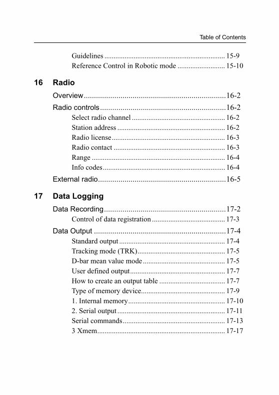
Table of Contents
Guidelines .................................................................. 15-9Reference Control in Robotic mode .......................... 15-10
16 Radio
Overview......................................................................16-2
Radio controls..............................................................16-2Select radio channel ................................................... 16-2Station address ........................................................... 16-2Radio license.............................................................. 16-3Radio contact ............................................................. 16-3Range ......................................................................... 16-4Info codes................................................................... 16-4
External radio...............................................................16-5
17 Data Logging
Data Recording............................................................17-2Control of data registration ........................................ 17-3
Data Output .................................................................17-4Standard output .......................................................... 17-4Tracking mode (TRK)................................................ 17-5D-bar mean value mode ............................................. 17-5User defined output.................................................... 17-7How to create an output table .................................... 17-7Type of memory device.............................................. 17-91. Internal memory..................................................... 17-102. Serial output ........................................................... 17-11Serial commands........................................................ 17-133 Xmem...................................................................... 17-17
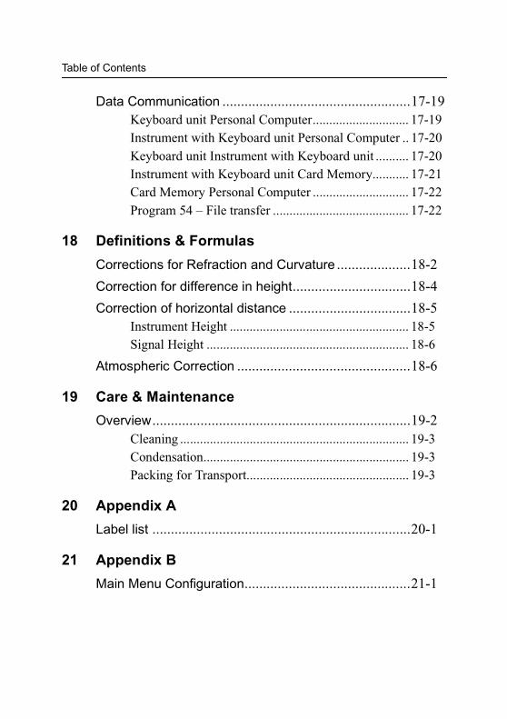
Table of Contents
Data Communication ...................................................17-19Keyboard unit Personal Computer............................. 17-19Instrument with Keyboard unit Personal Computer .. 17-20Keyboard unit Instrument with Keyboard unit .......... 17-20Instrument with Keyboard unit Card Memory........... 17-21Card Memory Personal Computer ............................. 17-22Program 54 – File transfer ......................................... 17-22
18 Definitions & Formulas
Corrections for Refraction and Curvature ....................18-2
Correction for difference in height................................18-4
Correction of horizontal distance .................................18-5Instrument Height ...................................................... 18-5Signal Height ............................................................. 18-6
Atmospheric Correction ...............................................18-6
19 Care & Maintenance
Overview......................................................................19-2Cleaning ..................................................................... 19-3Condensation.............................................................. 19-3Packing for Transport................................................. 19-3
20 Appendix A
Label list ......................................................................20-1
21 Appendix B
Main Menu Configuration.............................................21-1

Welcome to Geodimeter® CU Control unit
Spectra Precision AB, now Trimble AB, has since the release of Geodimeter System 400 presented a large number of inventions within the surveying field; the tracklight, the alpha-numeric keyboard, servo, one-person total station etc.
In 1994 Geotronics introduced the first flexible total station, Geodimeter System 600, which made it possible for the user to physically tailor his or her total station to his/her needs. In 1998 Spectra Precision AB introduce Geodimeter System 600 Pro which include a number of technical improvements such as a faster CPU and faster and smoother servo positioning.
The first introduction in 2000 was the Geodimeter 600 ATS. An instrument that can also be used for machine control.
To improve productivity of the Geodimeter System 600 even further, a new Direct Reflex and servo driven model, DR200+, was launched the same year.
The system includes, of course, all the features that are typical for Geodimeter, such as servo-assisted drive (optional), numeric or alpha-numeric control units (keyboards), tracklight, tracker (optional), radio side cover (optional) and RS-232C communication.
- A - Geodimeter CU & 600 CU General

Comments about this manual
If you or your colleagues have any comments on this manual, we would be grateful to hear from you. Please write to:
Trimble AB
Technical InformationBox 64SE-182 11 DANDERYDSweden
Or send an e-mail to: [email protected]
Glossary of terms used with Geodimeter CU
Area File: A file in a Geodimeter CU memory device that holds known coordinates (Pno, N, E etc.) or Roadline data.
A/M-key: Aim/Measure button. Initiates a measurement and controls search and remote measurements.
D: Accurate measurement with mean value calc.
dH & dV: These values represents the collimation errors. When performing D-bar measurements in two faces these errors are blanked out and do not affect the accuracy of the measurement (HA, VA). If the values differs a lot from 0 it is recommended that you perform a test measurement (MNU5), see page 5-25.
Geodimeter CU & 600 CU General - B -
Free Station: Also known as Resection. Location of the total station by measuring distance and/or angles to 2 or up to 8 points.
FSTD: Fast Standard measurement, with A/M.
IH: Instrument height over the point.
Job File: A file in a Geodimeter CU memory device that holds data collected in the field. This file can consist of any data.
Logon: Entering Job file and memory unit when designing an U.D.S with program 40.
Offset: Length offset to measured slope distance.
Prism const: The prism’s length offset from the0-constant.
Ref. Obj: Reference Object, also back sight.
REG-key: The register key. This stores data in the data collector.
RMT: Remote Measuring Target. The special prism used when performing robotics surveying (or remote surveying with auto lock), i.e.carrying out one-person measurements.
R.O.E: Remote Object Elevation. See page 12-10.
RPU: Remote Positioning Unit. The rod half of the system when performing remote or robotic surveying.
SH: Signal height.
STD: Standard measurement, with A/M.
- C - Geodimeter CU & 600 CU General

TRK: Tracking measurement, automatic and continuous measurement.
U.D.S.: User Defined Sequence. A program designed by the user determining what is collected, its order of collection and how it is displayed on the screen.
SH
dELE
ELE
IH Point to set out
Geodimeter CU & 600 CU General - D -

C H A P T E R
1
1IntroductionUnpacking & Inspection ....................................................... 1-2Inspection........................................................................ 1-2
The Control unit ................................................................... 1-4Detachable control unit ................................................... 1-4Assigned control units..................................................... 1-5Additional control units.................................................... 1-5The Display ..................................................................... 1-6Display illumination ......................................................... 1-8Contrast and Viewing Angle............................................ 1-8Reticle illumination .......................................................... 1-9User-defined display tables........................................... 1-10Key functions ................................................................ 1-10Alpha character keying in (numeric control unit)........... 1-22Alpha mode key (alphanumeric control unit)................. 1-23Servo control keys (numeric and alphanumeric control units) ............................................................................. 1-25

1 Introduction
Unpacking & Inspection
Before we begin to describe the operating procedure of your Geodimeter instrument, it is first necessary to acquaint yourself with the equipment received:
• Instrument Unit• Transport case• Tribrach• Rain cover• Sight marks (stick-on)• ASCII Table (stick-on)• User Manuals• Tool kit
Note – Some equipment is market dependent
Inspection
Inspect the shipping container. If it is received in poor condition, examine the equipment for visible damage. If damage is found, immediately notify the carrier and the Trimble sales representative. Keep the container and packing material for the carrier’s inspection.
Figure 1.1 Geodimeter CU alphanumeric control unit.
1-2 Geodimeter CU & 600 CU General
Unpacking & Inspection
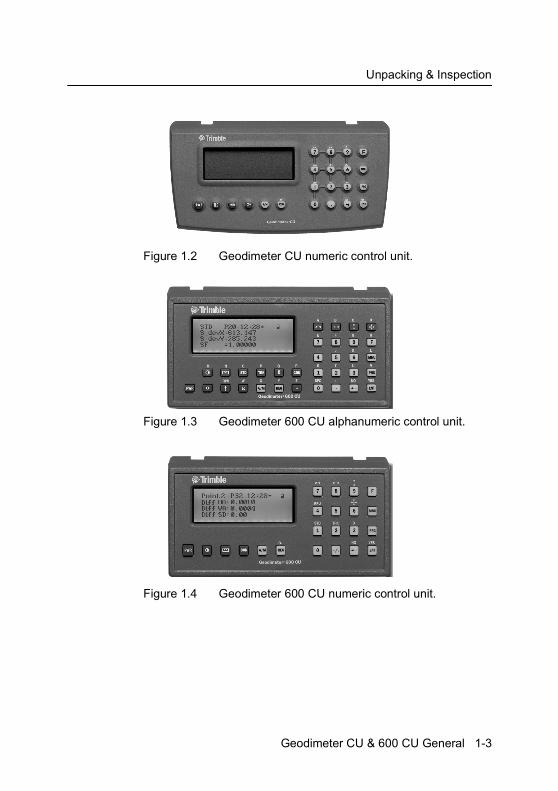
Figure 1.2 Geodimeter CU numeric control unit.
Figure 1.3 Geodimeter 600 CU alphanumeric control unit.
Figure 1.4 Geodimeter 600 CU numeric control unit.
Geodimeter CU & 600 CU General 1-3

1 Introduction
The Control unit
The CU is available in two different versions; a numeric and an alphanumeric one.
The alphanumeric control unit simplifies the entering of point codes and basic editing by having all alpha characters on separate keys. You can, however, also enter alpha characters with the numeric control unit, but this needs extra key presses.
The control units are ergonomically and logically designed. The alphanumeric control unit consists of 33 keys: the numerals 0-9, letters A-Z, and control keys. The control keys comprise the choice of functions 0-126, choice of menu, choice of program and choice of measurement mode, together with clear and enter functions etc.see figure 1.1.
The numeric control unit consists off 22 keys, see figure 1.2.
The control unit is more than just a keyboard, it also contains the internal memory as well as any of the softwares that are available.
Detachable control unit
The control unit is detachable and this makes it very easy for the user to transfer data. Simply detach the control unit after a survey and bring it to the office (it’s very handy and fits in a normal size pocket). Attach the control unit to a computer using the multi functional cable. Run Program 54 or Geotool to transfer data between the units.
Note – The control unit should not be attached/detached when the instruments is switched on.
1-4 Geodimeter CU & 600 CU General
The Control unit
Assigned control units
In a surveying team each member can have his/her own control unit with his/her own setups, software and internal memory. This means that any operator can attach his/her assigned control unit it any Trimble System 5600 and get it to work with His/her specific U.D.S’s and setups.
Additional control units
With System 5600 you can work with two control units attached at the same time: one at the back of the instrument that serves as a master control unit and one at the front that serves as a slave unit.
Having two control units attached at the same time can be useful having in mind that they also contain internal memories.
The control unit at the front can also be very useful when measuring in two faces when you want to keep control of the point to measure in face 2.
Geodimeter CU & 600 CU General 1-5
1 Introduction
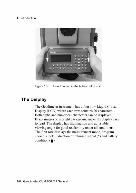
Figure 1.5 How to attach/detach the control unit.
The Display
The Geodimeter instrument has a four-row Liquid Crystal Display (LCD) where each row contains 20 characters. Both alpha and numerical characters can be displayed. Black images on a bright background make the display easy to read. The display has illumination and adjustable viewing angle for good readability under all conditions. The first row displays the measurement mode, program choice, clock, indication of returned signal (*) and battery condition ( ).
1-6 Geodimeter CU & 600 CU General

The Display
Figure 1.6 Geodimeter CU and 600 CU display
If an offset or a prism offset has been set this will be indicated by (!) between the hour and the minute in the clock. Instruments with an alpha-numeric keyboard also display if alpha mode α, shift (^) or lower case (1) is activated. The second to fourth rows display the respective labels and values of measurement. Each display table consist of a series of “pages” which can be “turned” with the ENT-key.
Instrument settings
By pressing MNU, 1, 3 you can set the following:
• Display illumination• Reticle illumination• Contrast and viewing angle• Reflected Signal volume
Press the corresponding key below “Sel” to select what to set. Use the corresponding key right below ”Exit” to return to the main menu.
1 3MNU
Geodimeter CU & 600 CU General 1-7
1 Introduction
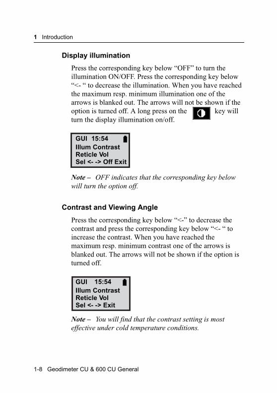
Display illumination
Press the corresponding key below “OFF” to turn the illumination ON/OFF. Press the corresponding key below “<- “ to decrease the illumination. When you have reached the maximum resp. minimum illumination one of the arrows is blanked out. The arrows will not be shown if the option is turned off. A long press on the key will turn the display illumination on/off.
Note – OFF indicates that the corresponding key below will turn the option off.
Contrast and Viewing Angle
Press the corresponding key below “<-” to decrease the contrast and press the corresponding key below “<- “ to increase the contrast. When you have reached the maximum resp. minimum contrast one of the arrows is blanked out. The arrows will not be shown if the option is turned off.
Note – You will find that the contrast setting is most effective under cold temperature conditions.
GUIIllum ContrastReticle VolSel <- -> Off Exit
15:54
GUIIllum ContrastReticle VolSel <- -> Exit
15:54
1-8 Geodimeter CU & 600 CU General
The Display
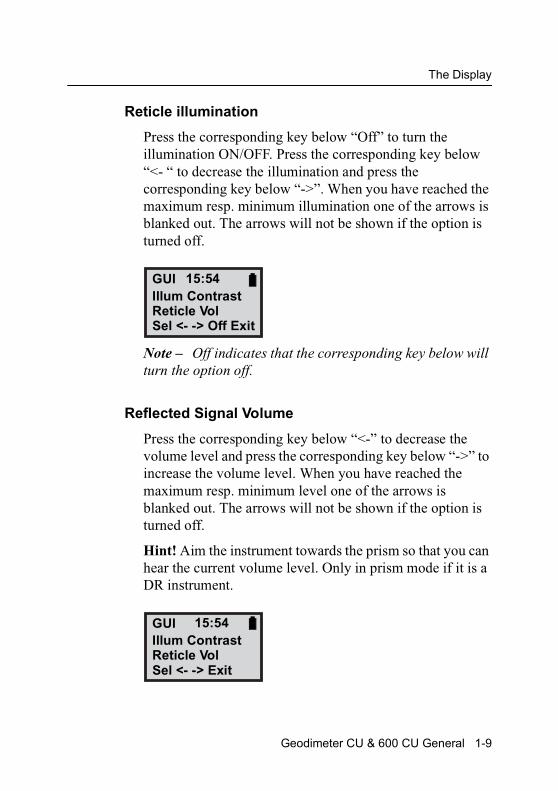
Reticle illumination
Press the corresponding key below “Off” to turn the illumination ON/OFF. Press the corresponding key below “<- “ to decrease the illumination and press the corresponding key below “->”. When you have reached the maximum resp. minimum illumination one of the arrows is blanked out. The arrows will not be shown if the option is turned off.
Note – Off indicates that the corresponding key below will turn the option off.
Reflected Signal Volume
Press the corresponding key below “<-” to decrease the volume level and press the corresponding key below “->” to increase the volume level. When you have reached the maximum resp. minimum level one of the arrows is blanked out. The arrows will not be shown if the option is turned off.
Hint! Aim the instrument towards the prism so that you can hear the current volume level. Only in prism mode if it is a DR instrument.
GUIIllum ContrastReticle VolSel <- -> Off Exit
15:54
GUIIllum ContrastReticle VolSel <- -> Exit
15:54
Geodimeter CU & 600 CU General 1-9
1 Introduction
User-defined display tables
With the “Config Display” application it is possible to define your own display table, if the existing table does not fulfil your needs during the execution of a special survey application.
For further information refer to page 1-7. All labels in the System can be displayed.
Key functions
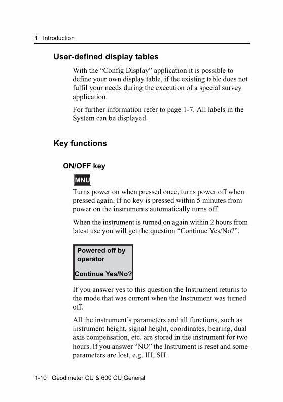
ON/OFF key
Turns power on when pressed once, turns power off when pressed again. If no key is pressed within 5 minutes from power on the instruments automatically turns off.
When the instrument is turned on again within 2 hours from latest use you will get the question “Continue Yes/No?”.
If you answer yes to this question the Instrument returns to the mode that was current when the Instrument was turned off.
All the instrument’s parameters and all functions, such as instrument height, signal height, coordinates, bearing, dual axis compensation, etc. are stored in the instrument for two hours. If you answer “NO” the Instrument is reset and some parameters are lost, e.g. IH, SH.
MNU
Powered off byoperator
Continue Yes/No?
1-10 Geodimeter CU & 600 CU General

The Display
Batlow Total Station
If batlow occurs no measurements can be carried out. The next time (within 2 hours) the instrument is turned on you will be prompted “Powered off by battery low?”. Answer yes to return to the mode that was current before battery low. Note that no measurements can be carried out before replacing the drained battery or connecting an external battery to the instrument.
Battery condition
You can see the current of the connected battery at the end of the first row in the display. As the battery becomes drained the battery symbol will change from full to empty. Note that this function depends on the battery condition and on the charging method and should only be regarded as a coarse indication.
Function keys/Labels
The data stored under labels can be viewed or altered by the operator. In some cases the data also influence the system. Changing the data in the time label will, for instance, set the system real time clock. However, just calling up a label, viewing the data and restoring without any editing will not influence the system at all. Data stored under labels can be retrieved by the F (Function) key or in the U.D.S (User Defined Sequences) (additional software).
A complete list of functions and labels can be found in Appendix A.
Example: How to store a point number (Pno).
Turn on the instrument, press the function key, the following will be displayed.
Geodimeter CU & 600 CU General 1-11
1 Introduction
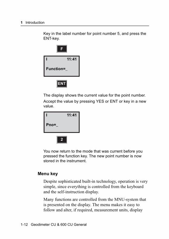
Key in the label number for point number 5, and press the ENT-key.
The display shows the current value for the point number.
Accept the value by pressing YES or ENT or key in a new value.
You now return to the mode that was current before you pressed the function key. The new point number is now stored in the instrument.
Menu key
Despite sophisticated built-in technology, operation is very simple, since everything is controlled from the keyboard and the self-instruction display.
Many functions are controlled from the MNU-system that is presented on the display. The menu makes it easy to follow and alter, if required, measurement units, display
F
I
Function=_
ENT
11:41
I
Pno=_
2
11:41
1-12 Geodimeter CU & 600 CU General
The Display
tables, coordinates, correction factors etc. The main menu configuration can be seen in Appendix B.
How to store the factor for atmospheric correction (PPM).
Example:
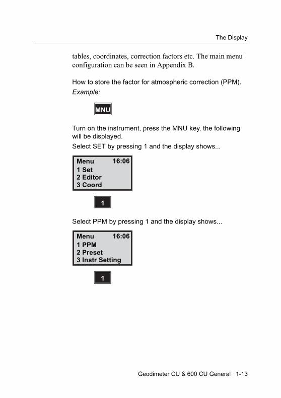
Turn on the instrument, press the MNU key, the following will be displayed.
Select SET by pressing 1 and the display shows...
Select PPM by pressing 1 and the display shows...
MNU
Menu1 Set2 Editor3 Coord
1
16:06
Menu1 PPM2 Preset3 Instr Setting
1
16:06
Geodimeter CU & 600 CU General 1-13

1 Introduction
Key in the present value for temperature e.g + 20C. Press ENT…
Key in the present value for air pressure e.g 760mm/Hg. Press ENT…
Key in Relative Humidity. Default is 60%. (If you have chosen Wet Temperature from MNU6.5 this will be shown instead).
Note – This menu is shown only if the switch “PPM Adv.” is enabled in MNU6.1
SetTemp = 20.0
ENT
16:06
SetPress = 760.00
ENT
16:06
SetRelHum = 60.0
ENT
16:06
1-14 Geodimeter CU & 600 CU General
The Display
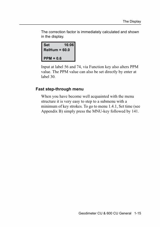
The correction factor is immediately calculated and shown in the display.
Input at label 56 and 74, via Function key also alters PPM value. The PPM value can also be set directly by enter at label 30.
Fast step-through menu
When you have become well acquainted with the menu structure it is very easy to step to a submenu with a minimum of key strokes. To go to menu 1.4.1, Set time (see Appendix B) simply press the MNU-key followed by 141.
SetRelHum = 60.0
PPM = 0.6
16:06
Geodimeter CU & 600 CU General 1-15
1 Introduction
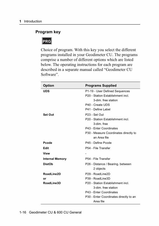
Program key
Choice of program. With this key you select the different programs installed in your Geodimeter CU. The programs comprise a number of different options which are listed below. The operating instructions for each program are described in a separate manual called “Geodimeter CU Software”.
Option Programs Supplied
UDS P1-19 - User Defined Sequences
P20 - Station Establishment incl.
3-dim. free station
P40 - Create UDS
P41 - Define Label
Set Out P23 - Set Out
P20 - Station Establishment incl.
3-dim. free
P43 - Enter Coordinates
P30 - Measure Coordinates directly to
an Area file
Pcode P45 - Define Pcode
Edit P54 - File Transfer
View -
Internal Memory P54 - File Transfer
DistOb P26 - Distance / Bearing. between
2 objects
RoadLine2D
or
RoadLine3D
P29 - RoadLine2D
P39 - RoadLine3D
P20 - Station Establishment incl.
3-dim. free station
P43 - Enter Coordinates
P30 - Enter Coordinates directly to an
Area file
PRG
1-16 Geodimeter CU & 600 CU General

The Display
Z/IZ P21 - Ground/Inst. Elevation
P43 - Enter Coordinates
RefLine P24 - Reference Line
P20 - Station Establishment incl.
3-dim. free station
P43 - Enter Coordinates
P30 - Enter Coordinates directly to an
Area file
Ang. Meas. P22 - Angle Measurement (only for
servo instruments)
Station Establishment P20 - Station Establishment incl.
3-dim. free station
Area Calc. P25 - Area & Volume Calculation
MCF P27 - Moving Coordinates Forward
Obstructed Point P28 - Obstructed Point
Measure Coord. P30 - Measure Coordinates directly to
an Area file.
Angle Meas.+ P32 - Angle Measurement +
CoGo P61 - CoGo
Athletics P60 - Athletics
Option Programs Supplied
Geodimeter CU & 600 CU General 1-17
1 Introduction
Choose program
There are two ways to choose a program:
1. Short press
With a short press on the program key you get the following display:
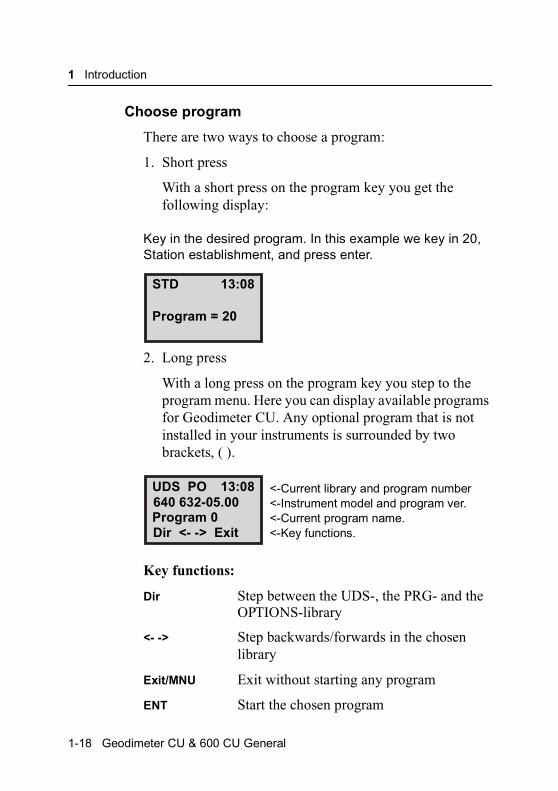
Key in the desired program. In this example we key in 20, Station establishment, and press enter.
2. Long press
With a long press on the program key you step to the program menu. Here you can display available programs for Geodimeter CU. Any optional program that is not installed in your instruments is surrounded by two brackets, ( ).
Key functions:
Dir Step between the UDS-, the PRG- and the OPTIONS-library
<- -> Step backwards/forwards in the chosen library
Exit/MNU Exit without starting any program
ENT Start the chosen program
STD
Program = 20
13:08
UDS PO
Program 0
13:08640 632-05.00
Dir <- -> Exit
<-Current library and program number<-Instrument model and program ver.<-Current program name.<-Key functions.
1-18 Geodimeter CU & 600 CU General

The Display
Configuration menu
By choosing a program with a long press, you will also have the chance to configure the chosen program in most cases. See more about how to configure programs in the “Geodimeter CU Software” manual.
Enter key
Activates keyboard operations and turns display table pages, a switch of face or a compensator initiation.
Clear key
For correction of keyed in but not entered errors and to break a search routine.
Standard mode key
Choice of Standard Mode. This key activates the Standard Measuring Mode. The instrument automatically assumes the STD mode after going through the Start-up Procedure. Standard Mode is described in detail on page 12-14 and in the “yellow pages”, page 12-4, see also Fast Standard mode on page 7-9 and page 12-5.
ENT
←←←←
STD or STD 1
Geodimeter CU & 600 CU General 1-19
1 Introduction
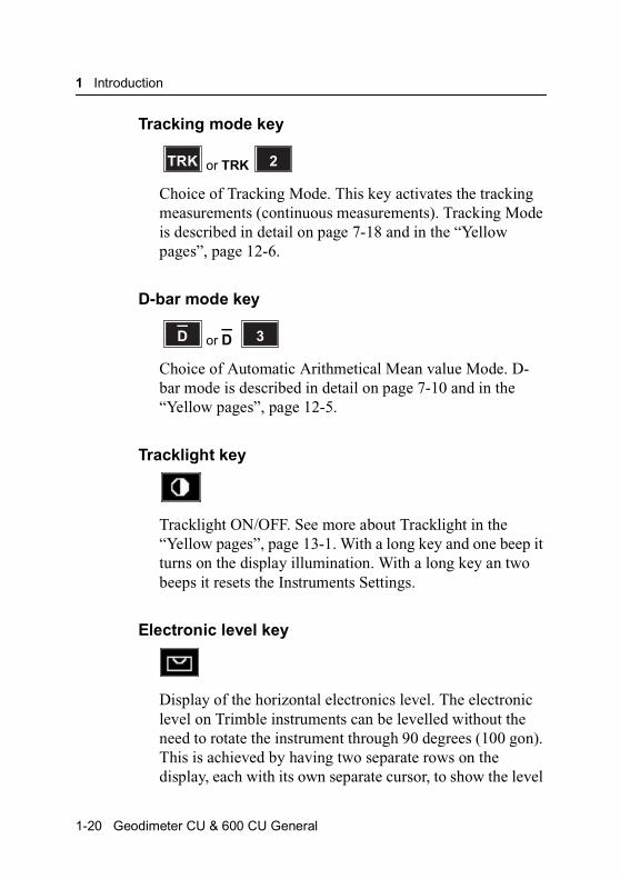
Tracking mode key
Choice of Tracking Mode. This key activates the tracking measurements (continuous measurements). Tracking Mode is described in detail on page 7-18 and in the “Yellow pages”, page 12-6.
D-bar mode key
Choice of Automatic Arithmetical Mean value Mode. D-bar mode is described in detail on page 7-10 and in the “Yellow pages”, page 12-5.
Tracklight key
Tracklight ON/OFF. See more about Tracklight in the “Yellow pages”, page 13-1. With a long key and one beep it turns on the display illumination. With a long key an two beeps it resets the Instruments Settings.
Electronic level key
Display of the horizontal electronics level. The electronic level on Trimble instruments can be levelled without the need to rotate the instrument through 90 degrees (100 gon). This is achieved by having two separate rows on the display, each with its own separate cursor, to show the level
TRK or TRK 2
D or D 3
1-20 Geodimeter CU & 600 CU General
The Display
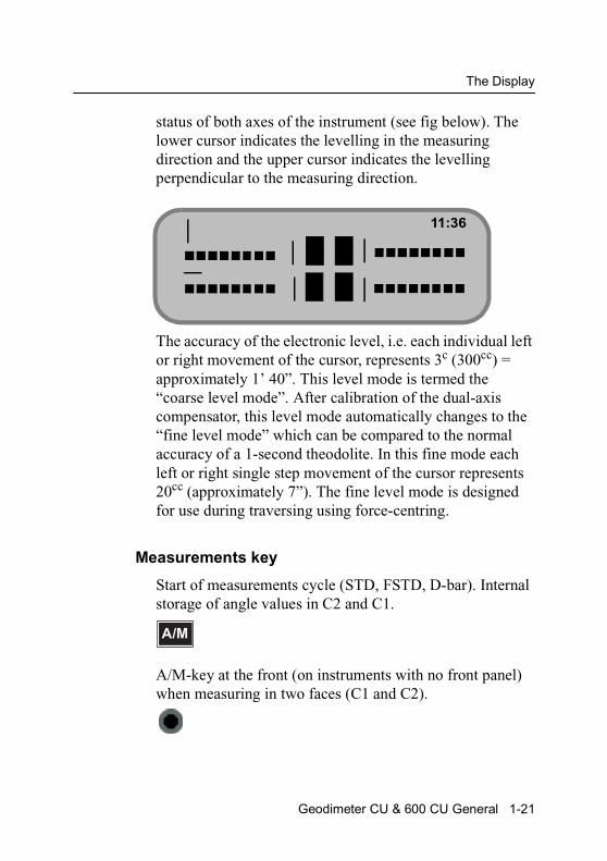
status of both axes of the instrument (see fig below). The lower cursor indicates the levelling in the measuring direction and the upper cursor indicates the levelling perpendicular to the measuring direction.
The accuracy of the electronic level, i.e. each individual left or right movement of the cursor, represents 3c (300cc) = approximately 1’ 40”. This level mode is termed the “coarse level mode”. After calibration of the dual-axis compensator, this level mode automatically changes to the “fine level mode” which can be compared to the normal accuracy of a 1-second theodolite. In this fine mode each left or right single step movement of the cursor represents 20cc (approximately 7”). The fine level mode is designed for use during traversing using force-centring.
Measurements key
Start of measurements cycle (STD, FSTD, D-bar). Internal storage of angle values in C2 and C1.
A/M-key at the front (on instruments with no front panel) when measuring in two faces (C1 and C2).
11:36
A/M
Geodimeter CU & 600 CU General 1-21
1 Introduction
Registration key
For registration of measurement values. (In FSTD working with UDS this key both measures and registrates with a single press.
Alpha character keying in (numeric control unit)
It is also possible to enter alpha characters in instruments with the numeric control unit. This is done by pressing the REG-key/ASCII-key. If alpha characters are to be used in the middle of an numeric point number or point code title, exit from and re-entry into the alpha mode is achieved by pressing the REG/ASCII key. Follow the example bellow.
The instrument also gives you the opportunity to select special characters for different languages. This can be done via Menu 6.6. A complete list of values for different characters for different languages is shown on page 10-2.
Example: Alphanumeric input using the ASCII table
The point number to be keyed in is 12 MH 66 which is the field notation for Point Number 12, which happens to be a manhole with a 66 cd diameter cover.
Press F5 and ENT. PNO is seen on the display. Key in 12 Press the REG-key/Alpha-key- ASCII is seen on the display. Key in 77 72 = MH. Press once again the REG/Alpha key. Then key in 66. Finalize the keying in by pressing the ENT key. This ASCII possibility can of course be used with other functions – e.g. Operator, Project, etc., etc. – in fact all functions except the labels
REG
REGαααα
1-22 Geodimeter CU & 600 CU General
The Display
which are directly connected with measured and calculated survey values.
Alpha mode key (alphanumeric control unit)
For activation / deactivation of the Alpha Mode. When the Alpha mode is activated, it is indicated by an (a) symbol in the right-hand corner of the display.
Note – It is also possible to enter alpha characters in instruments with a numeric control unit, see page 1-22.
How to use the alphanumeric keys (alphanumeric control unit)
α
↑
Lc
CON
The numerical keys can be used both for ordinary numerals and letter. To use the letters as indicated on each key, first press key αααα the keyboard is now locked for letters, and this is indicated by an (α) symbol in the upper right hand corner of the display. To enter a particular numerical character in combination with an alpha character, press the key ↑↑↑↑. A (^) symbol in the upper right-hand corner of the display window indicates that the shift key is activated. For small
αααα
αααα
↑↑↑↑
Lc
CON
Geodimeter CU & 600 CU General 1-23
1 Introduction
letters, press Shift,↑↑↑↑ directly followed by “Lower Case”, Lc.
The figure (1) in the upper right-hand corner of the display window will appear immediately indicating lower case mode. To return to numerical keys, press key αααα.
The instrument also gives you the opportunity to select special characters (not shown on the keyboard). The special characters differ between languages. Language is changed via Menu 66. These special characters are displayed in the bottom row in groups of five. To step between the different characters press keys ↑↑↑↑ and CON .
The characters are entered by first pressing shift and then the corresponding key below the character.
Lower case key (alphanumeric control unit)
Lower case is used together with the Shift key, ↑↑↑↑ to be able to use the alphanumeric keyboard with lower case letters. This is indicated by the figure “1” in the right hand corner of the display.
Lc
Shift, ↑
Shift key (alphanumeric control unit)
Shift key. For entering a numeric value when the keyboard is set in alpha mode, or vice versa and to answer NO to questions shown in the display. When the shift key is
Lc
↑↑↑↑
↑↑↑↑
1-24 Geodimeter CU & 600 CU General

The Display
activated, this is indicated by a ^ , sign in the right-hand corner of the display.
Space bar key (alphanumeric control unit)
Activated when selecting the alpha mode.
Servo control keys (numeric and alphanumeric control units)
When measuring in two faces, this key is used for switching between C1 and C2.
Key for horizontal positioning. A short press of this key results in a horizontal positioning. A short press of this key results in a horizontal positioning to the set HA Ref value. A long press of this key results in a 180 /200 Gon horizontal rotation from the instrument’s current direction.
Key for vertical positioning.
Note – when setting out:
– If you press this key without measured distance ELE=the height at the theoretical set out point.
SPC 0
or 7
8or
or 9
Geodimeter CU & 600 CU General 1-25
1 Introduction
– If you press this key with measured distance ELE=the height at the measured set out point.
– If you press this key longer than 1 sec. With measured distance ELE=the height at the theoretical set out point.
Key for both horizontal and vertical positioning.
Continue key
Continue key. With a press on this key you can leave the editor if you are working with an alphanumeric keyboard. In some of the internal software, this key can be used for exit the program.
Together with the PWR-key, this key reboots the keyboard unit, see page 10-4.
Temporary horizontal angle key (only in Program 0)
The temporary horizontal angle feature in program 0 can be useful if you want to turn the instrument without affecting the original HA. This function is called HA_L, Horizontal Angle from a Line, and results in an extra line in the display showing HA_L=0.0000. You activate the HA_L function by pressing key 5 in Program 0. Reset HA_L by pressing key 5 again. Exit HA_L with a long press on key 5.
Note – this function only works in Program 0.
or 6
CON
5 or 5
1-26 Geodimeter CU & 600 CU General
C H A P T E R
2
2Memory UnitsIntroduction .......................................................................... 2-2
Unit description .................................................................... 2-2Unit capacity ................................................................... 2-2Program 54 – File Transfer ............................................. 2-3Edit.................................................................................. 2-3
Setting up Internal memory as an active memory device .... 2-3Info messages................................................................. 2-6Data Communication ...................................................... 2-6
Setting up CU as an active memory device ......................... 2-7
2 Memory Units
Introduction
Geodimeter CU includes an internal memory for data storage. When there is a need of more memory capacity, Trimble offers an external memory unit, card memory. This unit can be connected to the instrument during the survey work and/or when finished the measuring operations. This part of the manual will describe the internal memory.
Note – As a safety measure always backup your memory to protect yourself from memory loss. It is easily done with Program 54 which enables you to transfer Job. and Area-files between different units. See, Chapter 4, Data Communication for more information.
Unit description
Geodimeter CU are equipped with an internal memory for the storage of raw data, point information and calculated coordinate data. The memory volume is completely self supportive and can be used separately without the need of having other external memory devices connected. The total memory capacity can be enhanced by connecting a external memory device, card memory.
Unit capacity
The internal memory of Geodimeter CU has a capacity of appr. up to 8.000 points if storing of only Pno, HA, VA and SD. Data can be stored in an unlimited number of files. All Field Data=survey point information plus angles, distances and calculated coordinates, are stored in a Job File an all Know Data=survey site control point and traverse point
2-2 Geodimeter CU & 600 CU General
Setting up Internal memory as an active memory device
coordinates and elevations are stored in an Area File as described in part 1, Memory Structure.
Program 54 – File Transfer
Program No 54 is included with Internal Memory. This program is designed for transferring Job-, Area- and U.D.S-files between different units. Internal transfer is also possible within each unit. See Chapter 4, Data Communication for more information about data transfer and program 54.
Edit
With the program Edit installed in the Geodimeter CU it is possible to view and change data that been collected and stored in the internal memory. Edit is described in part 4, Software.
Setting up Internal memory as an active memory device
When you are using most of the programs to your Geodimeter CU you will be prompted to select an active memory device in which you can registrate your measurements. If you wish to setup the internal memory as an active memory device outside any program the following steps must be taken.
Geodimeter CU & 600 CU General 2-3
2 Memory Units
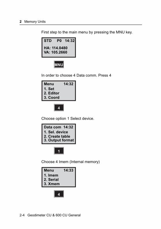
First step to the main menu by pressing the MNU key.
In order to choose 4 Data comm. Press 4
Choose option 1 Select device.
Choose 4 Imem (Internal memory)
STD P0 14:32
HA: 114.0480VA: 105.2660
MNU
Menu 14:321. Set2. Editor3. Coord
4
Data com 14:321. Sel. device2. Create table
1
3. Output format
Menu 14:331. Imem2. Serial3. Xmem
4
2-4 Geodimeter CU & 600 CU General

Setting up Internal memory as an active memory device
Press YES to continue or No to interrupt.
Select output table number (0-5 depending on instrument) and then press ENT.
Control of the output can be done by pressing the REG key of the instrument (REG key?) or continues (Slave?). Choose REG by REG key? answering YES or press NO to be able to choose Slave.
Imem 14:33
Imem ON?
YES
Imem 14:33
Table no=
ENT
Imem 14:33
REG key?
Geodimeter CU & 600 CU General 2-5
2 Memory Units
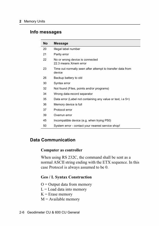
Info messages
Data Communication
Computer as controller
When using RS 232C, the command shall be sent as a normal ASCII string ending with the ETX sequence. In this case Protocol is always assumed to be 0.
Geo / L Syntax Construction
O = Output data from memoryL = Load data into memoryK = Erase memoryM = Available memory
No Message
20 Illegal label number
21 Parity error
22 No or wrong device is connected 22.3 means Xmem error
23 Time out normally seen after attempt to transfer data from device
26 Backup battery to old
30 Syntax error
32 Not found (Files, points and/or programs)
34 Wrong data-record separator
35 Data error (Label not containing any value or text, i.e 5=)
36 Memory device is full
37 Protocol error
39 Overrun error
45 Incompatible device (e.g. when trying P50)
50 System error - contact your nearest service shop!
2-6 Geodimeter CU & 600 CU General
Setting up CU as an active memory device
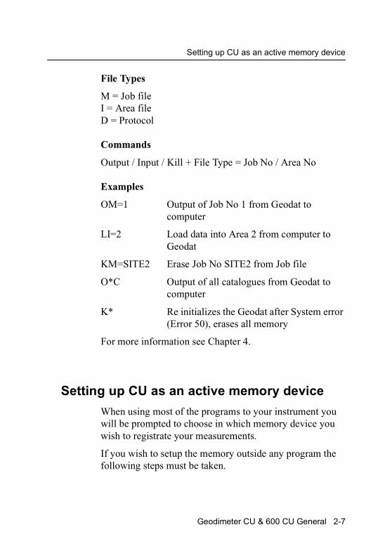
File Types
M = Job fileI = Area fileD = Protocol
Commands
Output / Input / Kill + File Type = Job No / Area No
Examples
OM=1 Output of Job No 1 from Geodat to computer
LI=2 Load data into Area 2 from computer to Geodat
KM=SITE2 Erase Job No SITE2 from Job file
O*C Output of all catalogues from Geodat to computer
K* Re initializes the Geodat after System error (Error 50), erases all memory
For more information see Chapter 4.
Setting up CU as an active memory device
When using most of the programs to your instrument you will be prompted to choose in which memory device you wish to registrate your measurements.
If you wish to setup the memory outside any program the following steps must be taken.
Geodimeter CU & 600 CU General 2-7

2 Memory Units
Connect the Geodimeter CU to the instrument and place it in the Theodolite Mode by going through the start procedure, P0.
You begin with calling upon the main menu. Press MNU
In order to choose 4 Data comm. Press 4.
Choose option 1 Select device. Press 1.
STD P0 14:32HA: 114.0480VA: 105.2660
MNU
Menu 14:321 Set2 Editor3 Coord
4
Data com 14:321. Sel. device2. Create table
1
3. Output format
2-8 Geodimeter CU & 600 CU General
Setting up CU as an active memory device
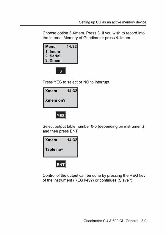
Choose option 3 Xmem. Press 3. If you wish to record into the Internal Memory of Geodimeter press 4. Imem.
Press YES to select or NO to interrupt.
Select output table number 0-5 (depending on instrument) and then press ENT.
Control of the output can be done by pressing the REG key of the instrument (REG key?) or continues (Slave?).
Menu 14:321. Imem2. Serial3. Xmem
3
Xmem 14:32
Xmem on?
YES
Xmem 14:32
Table no=
ENT
Geodimeter CU & 600 CU General 2-9

2 Memory Units
Choose REG by pressing YES or press NO to be able to choose Slave.
Xmem 14:32
REG key?
2-10 Geodimeter CU & 600 CU General
C H A P T E R
3
3Memory StructureIntroduction
This part will describe how the memory is structured and what happens when data is stored and collected from the memory.
Memory Structure
The memory structure of all Geodimeter memory units makes it is easy to check and identify the stored data after registration.
The memory is divided in two separate files which are called Job- and Area-file. Both these files are fully flexible according to number and size. The only limit is the total storing capacity available in the memory.
The memory can be used to store two types of data: survey measurements (Job-files) and know coordinates (Area-files). These Job- and Area-files consist of separate expansive memories which means that they can e updated individually at any time without affecting other Job- and Area-files. The total number of files is limited only to the total capacity of the memory. The more raw data stored in
3 Memory Structure
Job-files, the less known coordinate and elevation data that can be stored in Area-files and vice versa.
Job files
In order to permit later identification of Job files, they are given a numeric, alpha or alphanumeric title by the user. All survey data are stored in a Job file. Even field calculated coordinate and elevation data are stored in these files. When complete, these files can be transferred separately to a computer while the unfinished files can remain in Geodat/Geodimeter Internal Memory.
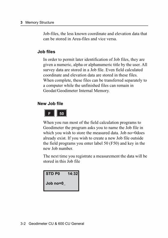
New Job file
When you run most of the field calculation programs to Geodimeter the program asks you to name the Job file in which you wish to store the measured data. Job no=0does already exist. If you wish to create a new Job file outside the field programs you enter label 50 (F50) and key in the new Job number.
The next time you registrate a measurement the data will be stored in this Job file
.
F 50
STD P0 14:32
Job no=0_
3-2 Geodimeter CU & 600 CU General

Memory Structure
Area files
Know coordinates and elevations can be stored by manual keying in (P43), or by transfer from computer.
Area-files, which are used during setting out survey, can be accessed by giving the name/number of the file in which the set out data is stored.By doing this, the search for the point is limited to just that particular file. Several different Areafiles can be prepared in advance of the survey job e.g. surbeyors often know that they will be working in more than one single area during the course of a week. All know data for particular sites can therefore be stored in different Area files. This is especially advantageous if several points have the same numbers. Area no=0 does already exist.
Edit file
Any Area- or Job-file can be edited with the program Edit. With this program you can view and change the contents of the file after registration.
AREA No
2
3
JOB No
2
AB
8
Free memory space
Geodimeter CU & 600 CU General 3-3
3 Memory Structure
This is how the memory is structured. The more data that is stored in the Area file the more the Job file will be “pushed down in the memory” and the more the free memory space will decrease.
In the above example the three files 2, AB and 8 represent different survey jobs.
It is possible to continue in an existing Job file. If you return to the survey site to update the job 2 the new data will be appended on the old file and the files AB and 8 will be “pushed a little further down”.
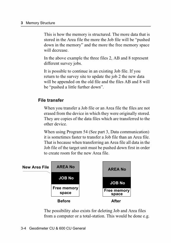
File transfer
When you transfer a Job file or an Area file the files are not erased from the device in which they were originally stored. They are copies of the data files which are transferred to the other device.
When using Program 54 (See part 3, Data communication) it is sometimes faster to transfer a Job file than an Area file. That is because when transferring an Area file all data in the Job file of the target unit must be pushed down first in order to create room for the new Area file.
The possibility also exists for deleting Job and Area files from a computer or a total-station. This would be done e.g.
JOB No
Free memoryspace
AREA NoNew Area File
Before
JOB No
Free memoryspace
AREA No
After
3-4 Geodimeter CU & 600 CU General
Memory Structure
to create more room in the Geodimeter Memory Device, see Data Communication, Chapter 4.
The operation should be carried out only after a successful transfer to a computer or another device.
Geodimeter CU & 600 CU General 3-5

3 Memory Structure
3-6 Geodimeter CU & 600 CU General

C H A P T E R
4
4Data CommunicationData transfer ........................................................................ 4-2Control unit Personal Computer...................................... 4-2
Program 54 – File transfer ................................................... 4-3
Serial Communication .......................................................... 4-7Description of the command instructions ........................ 4-8Geodimeter Language (Geo/L) syntax structure........... 4-10Protocol......................................................................... 4-12Directory........................................................................ 4-13Kill ................................................................................. 4-14Load .............................................................................. 4-15Memory ......................................................................... 4-16Mode ............................................................................. 4-17Output ........................................................................... 4-18Position ......................................................................... 4-19Read ............................................................................. 4-21Trig ................................................................................ 4-24Write.............................................................................. 4-25
Status description .............................................................. 4-26
4 Data Communication
Introduction
Geodimeter CU can be connected to an instrument. There is also possible to connect a computer to the CU directly. The data can thereafter be edited or used e.g. in a CAD-program.
This part of the manual will describe how to connect the control unit and how to transfer the data.
Data transfer
Any Geodimeter CU can be connected to an external device via a built in serial interface. This part of the manual will describe how to transfer data from and to the Geodimeter CU.
Control unit Personal Computer
Connect the Control unit and the computer to a charger via the cable 571 136 874/876. Instead of a charger you can connect a battery via the cable 571 136 754 and turn on both units. There are two ways to transfer data between these units:
1. with Program 54
Enter program 54 at the control unit and choose (From Imem, To serial) to transfer files from the control unit to the computer or choose (From serial, To Imem) to transfer files in the other direction. In the second case the transfer is initiated by copying the file from the computer to the communication port. See more about program 54 on page 4-3.
4-2 Geodimeter CU & 600 CU General

Program 54 – File transfer
2. with RS-232 commands
By sending the appropriate commands from the computer you can transfer data between the control unit and computer. Look at page 4-12 for more information about serial communication.
Program 54 – File transfer
Connect the two units with the appropriate cable and switch them on. The instructions below describes how to transfer files from the Control unit to the Station unit’s internal memory:
Operation at the source unit
Choose program 54
Choose from which device you want to transfer files. In this example we choose 2 Imem.
Here you can choose what type of file you want to transfer:
1. A jobfile 2. A areafile or 3 A U.D.S-file. In this example we choose 1. A jobfile.
PRG 54
54
From 16:12
2. Imem3. Serial
2
Geodimeter CU & 600 CU General 4-3
4 Data Communication
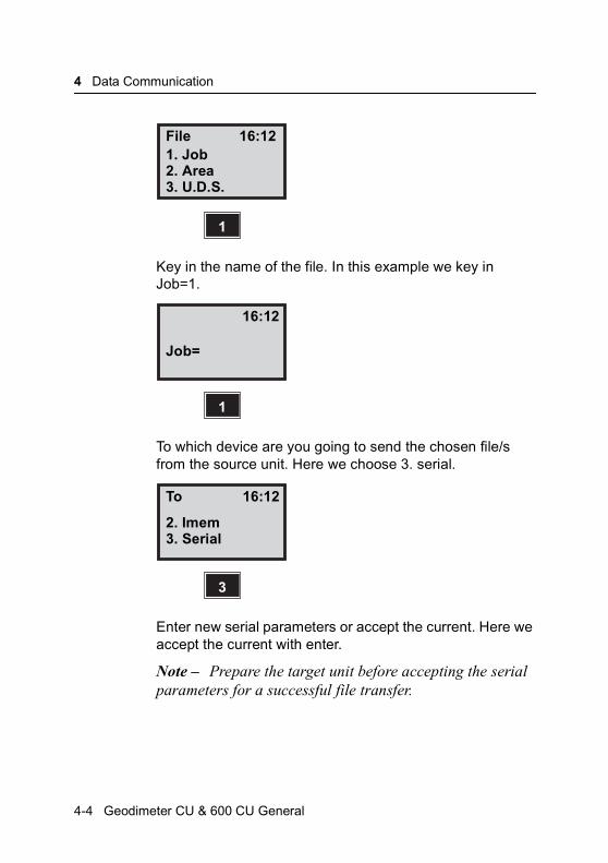
Key in the name of the file. In this example we key in Job=1.
To which device are you going to send the chosen file/s from the source unit. Here we choose 3. serial.
Enter new serial parameters or accept the current. Here we accept the current with enter.
Note – Prepare the target unit before accepting the serial parameters for a successful file transfer.
File 16:121. Job2. Area
1
3. U.D.S.
16:12
Job=
1
To 16:12
2. Imem
3
3. Serial
4-4 Geodimeter CU & 600 CU General

Program 54 – File transfer
The file/s are sent via the cable and the display shows. “Wait” during the transfer and you will then exit program 54.
Note – If info 19 appears during a file transfer that means that the file transfer was not successful. In that case you should run the file transfer again and look for where it fails, that is when info 35 (Data error) will show. Then check your file for any errors and if possible correct them with the editor.
Operation at the target unit
Chose program 54
From which device are you going to send files to the target unit. In this case it is 3. Serial.
Enter the serial parameters which must be same as the serial parameters at the source unit.
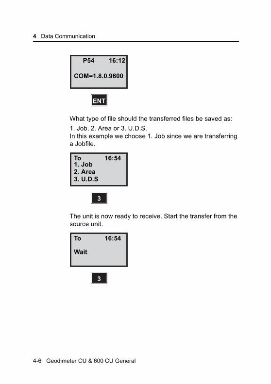
In this example we accept the current with ENT.
P54 16:54
3
Wait
54
From 16:12
2. Imem3. Serial
3
Geodimeter CU & 600 CU General 4-5
4 Data Communication
What type of file should the transferred files be saved as:
1. Job, 2. Area or 3. U.D.S. In this example we choose 1. Job since we are transferring a Jobfile.
The unit is now ready to receive. Start the transfer from the source unit.
P54 16:12
COM=1.8.0.9600
ENT
To 16:541. Job2. Area
3
3. U.D.S
To 16:54
Wait
3
4-6 Geodimeter CU & 600 CU General

Serial Communication
Serial Communication
This part of the manual describes the communication language that is used when the Geodimeter CU is communicating with a personal computer.
Geodimeter CU & 600 CU General 4-7
4 Data Communication
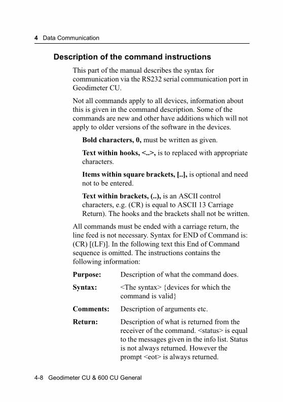
Description of the command instructions
This part of the manual describes the syntax for communication via the RS232 serial communication port in Geodimeter CU.
Not all commands apply to all devices, information about this is given in the command description. Some of the commands are new and other have additions which will not apply to older versions of the software in the devices.
Bold characters, 0, must be written as given.
Text within hooks, <..>, is to replaced with appropriate characters.
Items within square brackets, [..], is optional and need not to be entered.
Text within brackets, (..), is an ASCII control characters, e.g. (CR) is equal to ASCII 13 Carriage Return). The hooks and the brackets shall not be written.
All commands must be ended with a carriage return, the line feed is not necessary. Syntax for END of Command is: (CR) [(LF)]. In the following text this End of Command sequence is omitted. The instructions contains the following information:
Purpose: Description of what the command does.
Syntax: <The syntax> {devices for which the command is valid}
Comments: Description of arguments etc.
Return: Description of what is returned from the receiver of the command. <status> is equal to the messages given in the info list. Status is not always returned. However the prompt <eot> is always returned.
4-8 Geodimeter CU & 600 CU General
Serial Communication
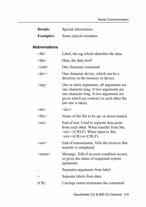
Details: Special information.
Examples: Some typical examples.
Abbreviations
<lbl> Label, the tag which identifies the data.
<dta> Data, the data itself
<cmd> One character command
<dev> One character device, which can be a directory in the memory or device.
<arg> One or more arguments, all arguments are one character long. If two arguments are one character long. It two arguments are given which are contrary to each other the last one is taken.
<dir> <dev>
<file> Name of the file to be up- or down-loaded.
<etx> End of text. Used to separate data posts from each other. When transfer from Stn, <etx>=(CRLF). When input to Stn, <etx>=(CR) or (CRLF).
<eot> End of transmission. Tells the receiver that transfer is completed.
<status> Message. Tells if an error condition occurs, or gives the status of requested system parameter.
, Separates arguments from label.
= Separate labels from data.
(CR) Carriage return terminates the command.
Geodimeter CU & 600 CU General 4-9
4 Data Communication
(LF) Line feed.
Devices
Stn Station unit
CU Control unit
Gdt Geodat
Arguments
‘I’ The Area directory
‘M’ The Job directory
‘U’ The U.D.S program directory
‘*’ All directory (Geodat)
Geodimeter Language (Geo/L) syntax structure
The Geodimeter language is developed in order to create a standard for communication between devices in Geodimeter Systems. The basic Geodimeter data structure is data tagged with a label.
<lbl>=<dta>
e.g. 7=254.3496 Horizontal angle 254.3496
From this is the language developed by addition of commands and arguments in order to be able to direct data to and from a destination.
<cmd><dev><arg>...,<labl>=<dta>(CR)[(LF)]
e.g. WG, 67=24572.358 Setout coordinate North set to 24572.358
4-10 Geodimeter CU & 600 CU General
Serial Communication
Command types
There are two types of commands, one that requests data from the device, and on that sends data to set the device. Common for both types is that <eot> always is sent when the command is executed and the system is ready for a new command.
Sender: <complete command>(CR)
Receiver: [<status><etx>]<lbl>=<dta><etx>]…<eot>
The status consists of 1 to 3 digits and is recognized in that no equal sign (=) is found before <etx>. A request type command always gives a response with status and/or data posts. While a set type command only responses with status when an error condition occurs. The meaning of the status number is equal to the normal messages given in the info list.
When file are transferred:
Sender: <cmd><dir>=<file>(CR)[(LF)]
Sender or receiver:<lbl>=<dta><etx>-
<lbl>=<dta><etx><eot>
Commands when starting up the communication
Break <alt><b>to start the Geodimeter
PV, 20 to start compenstor calibration
PV,21 to switch off the Geodimeter
Geodimeter CU & 600 CU General 4-11

4 Data Communication
Return signals from the Geodimeter
@ the compensator is displayed
! Geodimeter awaits answer, Y(es) or N(o).
Protocol
Standard protocol for Station unit, Control unit and Geodat
Station unit From program 582-04
Control unit From program 588-01
Geodat From program 594-01
Set Meaning
Baud rate (F78): 9600
Parity (F78): 0 None
Character length: (F78): 8 8 bits
Stop bits (F78): 1 1 bit
Time Out: - 10 sec
Software flow control:
- Always on (Geodat)
Xon character: - DC1(17)
Xoff - DC2 (19)
End of transmission
F(79): 62 >
4-12 Geodimeter CU & 600 CU General
Serial Communication
Directory
Purpose: List of file catalogue in memory.
Syntax: O<dir>C {Stn, Gdt, CU}
Comments: <dir>Is the dir argument. ‘I’, ‘M’, ‘U’ and ‘*’ are used. If <dir> is set to ‘*’ the file catalogue for all directories is output.
Return: <lbl>=<file><etx>
-
-
<lbl>=<dta><etx>
<eot>
or
<status><etx>
<eot>
Examples:
OMC File catalogue of all Job files in the JOB-directory.
O*C File catalogue off all files in the memory.
Geodimeter CU & 600 CU General 4-13
4 Data Communication
Kill
Purpose: Delete files in memory.
Syntax: K<dir>[=<file>}] {Stn, Gdt, CU}
Comments: <dir>Valid directories for all devices are M, I and U. For Geodat is also D valid. If the file is omitted all files in the directory will be deleted. If the directory is given a wildcard * the entire memory will be deleted.
<file>The file entry is the name of the specific file to be deleted.
Return: <eot>
or
<status><etx>
<eot>
Examples:
K* Delete entire memory.
KI Delete all area files.
KM=LOT Delete JOB named LOT.
4-14 Geodimeter CU & 600 CU General
Serial Communication
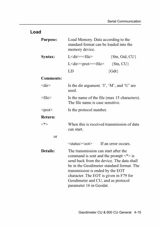
Load
Purpose: Load Memory. Data according to the standard format can be loaded into the memory device.
Syntax: L<dir>=<file> {Stn, Gtd, CU}
L<dir><prot>=<file> {Stn, CU}
LD {Gdt}
Comments:
<dir> Is the dir argument. ‘I’, ‘M’, and ‘U’ are used.
<file> Is the name of the file (max 15 characters). The file name is case sensitive.
<prot> Is the protocol number.
Return:
<*> When this is received transmission of data can start.
or
<status><eot> If an error occurs.
Details: The transmission can start after the command is sent and the prompt <*> is send back from the device. The data shall be in the Geodimeter standard format. The transmission is ended by the EOT character. The EOT is given in F79 for Geodimeter and CU, and as protocol parameter 16 in Geodat.
Geodimeter CU & 600 CU General 4-15

4 Data Communication
Examples:
LI=LOT6 The area file LOT6 is created and can be loaded when the prompt * is received from the device.
LU=15 U.D.S program 15 will be loaded into GDM or CU.
LD Loads the protocol file into Geodat.
Memory
Purpose: Check for free memory.
Syntax: M[G] {Stn, Gdt}
M[R] {CU}
Return: <number of bytes left><etx>
<eot>
or
<status><etx>
<eot>
Examples:
Command Return
M 31654 Bytes left in memory
MG 31654
4-16 Geodimeter CU & 600 CU General
Serial Communication
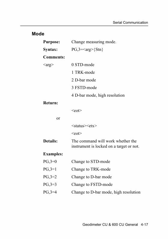
Mode
Purpose: Change measuring mode.
Syntax: PG,3=<arg>{Stn}
Comments:
<arg> 0 STD-mode
1 TRK-mode
2 D-bar mode
3 FSTD-mode
4 D-bar mode, high resolution
Return:
<eot>
or
<status><etx>
<eot>
Details: The command will work whether the instrument is locked on a target or not.
Examples:
PG,3=0 Change to STD-mode
PG,3=1 Change to TRK-mode
PG,3=2 Change to D-bar mode
PG,3=3 Change to FSTD-mode
PG,3=4 Change to D-bar mode, high resolution
Geodimeter CU & 600 CU General 4-17
4 Data Communication
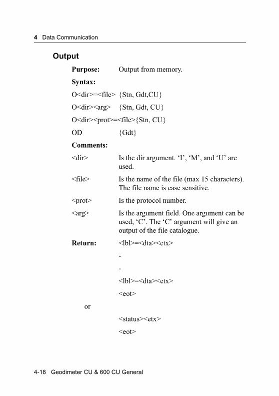
Output
Purpose: Output from memory.
Syntax:
O<dir>=<file> {Stn, Gdt,CU}
O<dir><arg> {Stn, Gdt, CU}
O<dir><prot>=<file>{Stn, CU}
OD {Gdt}
Comments:
<dir> Is the dir argument. ‘I’, ‘M’, and ‘U’ are used.
<file> Is the name of the file (max 15 characters). The file name is case sensitive.
<prot> Is the protocol number.
<arg> Is the argument field. One argument can be used, ‘C’. The ‘C’ argument will give an output of the file catalogue.
Return: <lbl>=<dta><etx>
-
-
<lbl>=<dta><etx>
<eot>
or
<status><etx>
<eot>
4-18 Geodimeter CU & 600 CU General
Serial Communication
Examples:
OM=A45 Job file A45 is send out.
OU=3 U.D.S program no 3 is output.
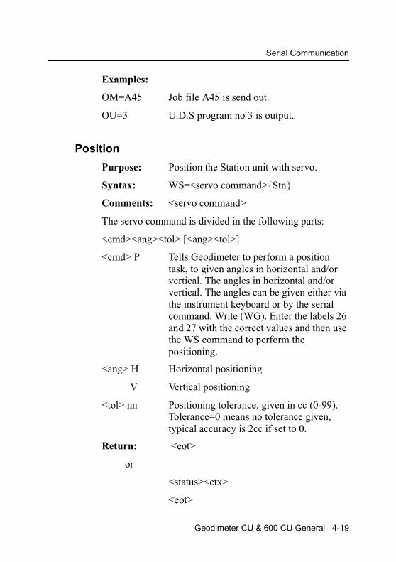
Position
Purpose: Position the Station unit with servo.
Syntax: WS=<servo command>{Stn}
Comments: <servo command>
The servo command is divided in the following parts:
<cmd><ang><tol> [<ang><tol>]
<cmd> P Tells Geodimeter to perform a position task, to given angles in horizontal and/or vertical. The angles in horizontal and/or vertical. The angles can be given either via the instrument keyboard or by the serial command. Write (WG). Enter the labels 26 and 27 with the correct values and then use the WS command to perform the positioning.
<ang> H Horizontal positioning
V Vertical positioning
<tol> nn Positioning tolerance, given in cc (0-99). Tolerance=0 means no tolerance given, typical accuracy is 2cc if set to 0.
Return: <eot>
or
<status><etx>
<eot>
Geodimeter CU & 600 CU General 4-19
4 Data Communication
Examples:
WS=Pho5V10 Position horizontal with 5cc accuracy and vertical with 10cc accuracy.
WS=PH01 Position horizontal with 1cc accuracy.
WS=PV15 Position vertical with 15cc accuracy.
4-20 Geodimeter CU & 600 CU General
Serial Communication
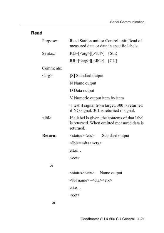
Read
Purpose: Read Station unit or Control unit. Read of measured data or data in specific labels.
Syntax: RG=[<arg>][,<lbl>] {Stn}
RR=[<arg>][,<lbl>] {CU}
Comments:
<arg> [S] Standard output
N Name output
D Data output
V Numeric output item by item
T test if signal from target. 300 is returned if NO signal. 301 is returned if signal.
<lbl> If a label is given, the contents of that label is returned. When omitted measured data is returned.
Return: <status><etx> Standard output
<lbl>=<dta><etx>
e.t.c…
<eot>
or
<status><etx> Name output
<lbl name>=<dta><etx>
e.t.c…
<eot>
or
Geodimeter CU & 600 CU General 4-21

4 Data Communication
<status><etx> Data output
<dta><etx>
e.t.c…
<eot>
or
<status><etx> Numeric output
<lbl><etx>
<dta><etx>
e.t.c…
<eot>
or
<status><etx> Message or
<eot> Meas signal test
or
<lbl><dta> Specific label
<eot>
or
<lbl name><dta><etx>Specific label with name
<eot>
or
<dta><etx>Specific label only data
<eot>
or
4-22 Geodimeter CU & 600 CU General

Serial Communication
<lbl><etx>Specific label numeric
<dta><etx>
Details: When read of measure data, the output is dependent on how the computer table in the Geodimeter is set. See Geodimeter User Manual for detailed information.
Examples
Command Return Command Return
RG 0 RGN,5 Pno=104
7=10.2345
8=101.1005 RGN 0
9=145.324 HA=10.2345
RGD 0 VA=101.1005
10.2345 SD=145.324
101.1005 RGV 0
145.324 7
10.2345
RGT 301 8
101.1005
RG,5 5=104 9
145.324
Geodimeter CU & 600 CU General 4-23
4 Data Communication
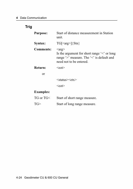
Trig
Purpose: Start of distance measurement in Station unit.
Syntax: TG[<arg>]{Stn}
Comments: <arg>Is the argument for short range ‘<’ or long range ‘>’ measure. The ‘<’ is default and need not to be entered.
Return: <eot>
or
<status><etx>
<eot>
Examples:
TG or TG< Start of short range measure.
TG> Start of long range measure.
4-24 Geodimeter CU & 600 CU General
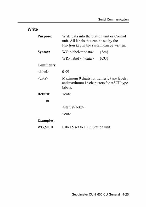
Serial Communication
Write
Purpose: Write data into the Station unit or Control unit. All labels that can be set by the function key in the system can be written.
Syntax: WG,<label>=<data> {Stn}
WR,<label>=>data> {CU}
Comments:
<label> 0-99
<data> Maximum 9 digits for numeric type labels, and maximum 16 characters for ASCII type labels.
Return: <eot>
or
<status><etx>
<eot>
Examples:
WG,5=10 Label 5 set to 10 in Station unit.
Geodimeter CU & 600 CU General 4-25
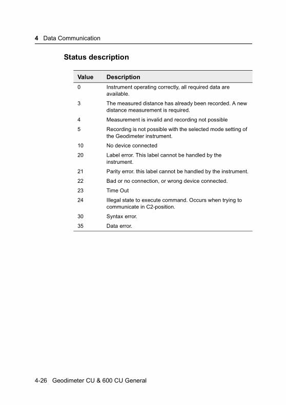
4 Data Communication
Status description
Value Description
0 Instrument operating correctly, all required data are available.
3 The measured distance has already been recorded. A new distance measurement is required.
4 Measurement is invalid and recording not possible
5 Recording is not possible with the selected mode setting of the Geodimeter instrument.
10 No device connected
20 Label error. This label cannot be handled by the instrument.
21 Parity error. this label cannot be handled by the instrument.
22 Bad or no connection, or wrong device connected.
23 Time Out
24 Illegal state to execute command. Occurs when trying to communicate in C2-position.
30 Syntax error.
35 Data error.
4-26 Geodimeter CU & 600 CU General
C H A P T E R
5
5Pre-MeasurementOffice Setup ......................................................................... 5-2Connecting the external battery to the control unit ......... 5-2Turn on power ................................................................. 5-2
Pre-Settings ......................................................................... 5-4Set unit (e.g metres, feet, grads, degrees etc)................ 5-5Set time & date ............................................................... 5-8
Special Settings ................................................................. 5-13Create & Select display tables ...................................... 5-13Create & Select o new display ...................................... 5-14Number of decimals ...................................................... 5-18Switches........................................................................ 5-20Standard Measure ........................................................ 5-23Select type of language ................................................ 5-24
Test Measurements............................................................ 5-25Measurement of Collimation & Tilt of Horizontal Axis ... 5-26Tracker Coll – Calibration of the tracker (only for Trimble System 5600)................................................................ 5-32Instrument test .............................................................. 5-34
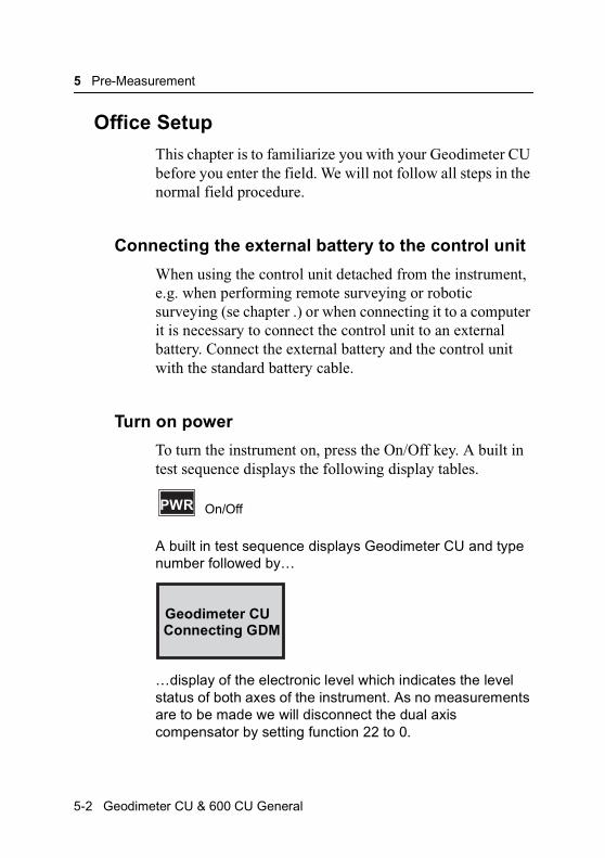
5 Pre-Measurement
Office Setup
This chapter is to familiarize you with your Geodimeter CU before you enter the field. We will not follow all steps in the normal field procedure.
Connecting the external battery to the control unit
When using the control unit detached from the instrument, e.g. when performing remote surveying or robotic surveying (se chapter .) or when connecting it to a computer it is necessary to connect the control unit to an external battery. Connect the external battery and the control unit with the standard battery cable.
Turn on power
To turn the instrument on, press the On/Off key. A built in test sequence displays the following display tables.
A built in test sequence displays Geodimeter CU and type number followed by…
…display of the electronic level which indicates the level status of both axes of the instrument. As no measurements are to be made we will disconnect the dual axis compensator by setting function 22 to 0.
PWR On/Off
Geodimeter CUConnecting GDM
5-2 Geodimeter CU & 600 CU General
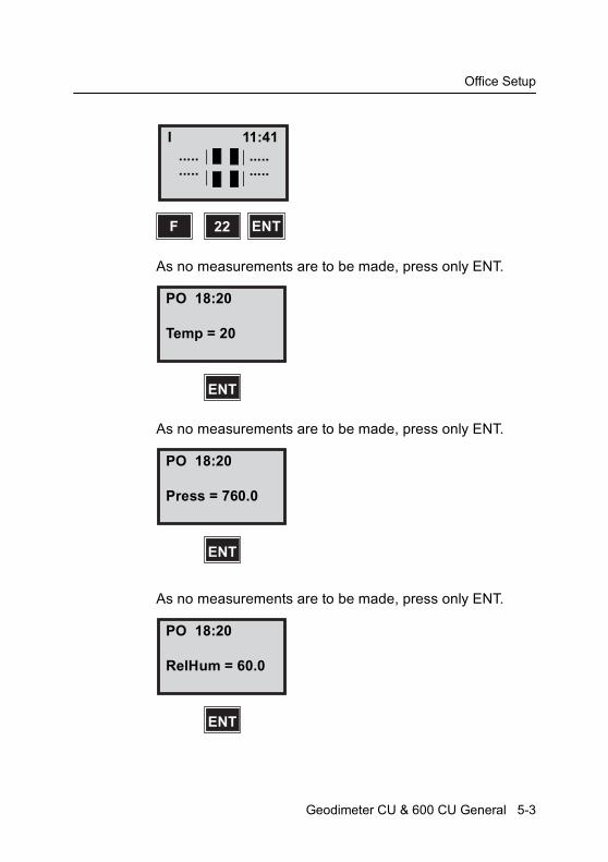
Office Setup
As no measurements are to be made, press only ENT.
As no measurements are to be made, press only ENT.
As no measurements are to be made, press only ENT.
22F ENT
I.....
11:41
...............
PO 18:20
Temp = 20
ENT
PO 18:20
Press = 760.0
ENT
PO 18:20
RelHum = 60.0
ENT
Geodimeter CU & 600 CU General 5-3

5 Pre-Measurement
Note – This menu is shown only if “PPM Adv.” is activated in MNU6.1
As no measurements are to be made, press only ENT.
As no measurements are to be made, press only ENT.
Here you come automatically to the Standard Measurement mode. As no measurements are going to be made at the moment, we will continue with the Pre-Setting routine.
Pre-Settings
In this exercise you will need to access Appendix B at time to time to look at the main menu configuration. The subject Settings can be divided into three different categories:
PO 18:20
Offset = 0.000
ENT
PO 18:20
HA: 192.8225HAref =
ENT
STD PO 18:20HA: 192.8230VA: 91.7880
5-4 Geodimeter CU & 600 CU General
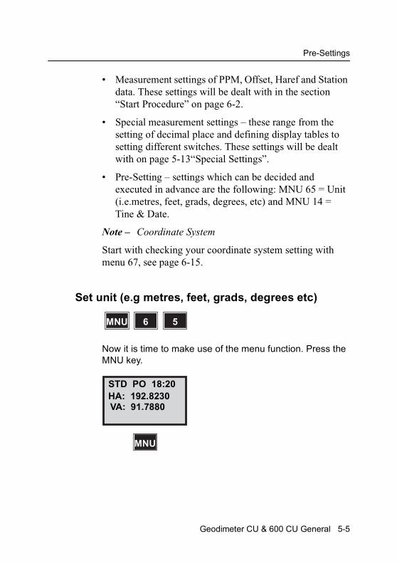
Pre-Settings
• Measurement settings of PPM, Offset, Haref and Station data. These settings will be dealt with in the section “Start Procedure” on page 6-2.
• Special measurement settings – these range from the setting of decimal place and defining display tables to setting different switches. These settings will be dealt with on page 5-13“Special Settings”.
• Pre-Setting – settings which can be decided and executed in advance are the following: MNU 65 = Unit (i.e.metres, feet, grads, degrees, etc) and MNU 14 = Tine & Date.
Note – Coordinate System
Start with checking your coordinate system setting with menu 67, see page 6-15.
Set unit (e.g metres, feet, grads, degrees etc)
Now it is time to make use of the menu function. Press the MNU key.
MNU 56
STD PO 18:20HA: 192.8230VA: 91.7880
MNU
Geodimeter CU & 600 CU General 5-5
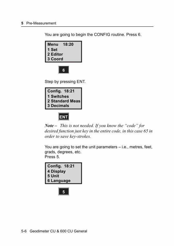
5 Pre-Measurement
You are going to begin the CONFIG routine. Press 6.
Step by pressing ENT.
Note – This is not needed. If you know the “code” for desired function just key in the entire code, in this case 65 in order to save key-strokes.
You are going to set the unit parameters – i.e., metres, feet, grads, degrees, etc. Press 5.
Menu 18:201 Set2 Editor3 Coord
6
Config. 18:211 Switches2 Standard Meas3 Decimals
ENT
Config. 18:214 Display5 Unit6 Language
5
5-6 Geodimeter CU & 600 CU General
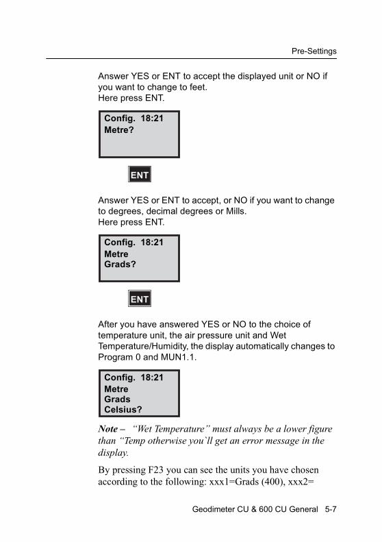
Pre-Settings
Answer YES or ENT to accept the displayed unit or NO if you want to change to feet. Here press ENT.
Answer YES or ENT to accept, or NO if you want to change to degrees, decimal degrees or Mills.Here press ENT.
After you have answered YES or NO to the choice of temperature unit, the air pressure unit and Wet Temperature/Humidity, the display automatically changes to Program 0 and MUN1.1.
Note – “Wet Temperature” must always be a lower figure than “Temp otherwise you`ll get an error message in the display.
By pressing F23 you can see the units you have chosen according to the following: xxx1=Grads (400), xxx2=
Config. 18:21Metre?
ENT
Config. 18:21MetreGrads?
ENT
Config. 18:21MetreGradsCelsius?
Geodimeter CU & 600 CU General 5-7

5 Pre-Measurement
Degrees (360, min, sec), xxx3=Decimal Degrees (360), xxx4=Mills (6400), xx1x=Meter, xx2x=Feet, x1xx=Celsius, x2xx=Fahrenheit, 1xxx=mbar, 2xxx=mmHg, 3xxx= inchHg, 4xxx=hPa.
Example: F23 shows ´3121´ means that inchHg, Celsius, Feet and grads have been choosen.
Set time & date
Now it is time to make use of the MNU function. Press MNU key.
You are going to begin the SET routine, Press 1.
MNU 41
STD PO 18:24HA: 192.8230VA: 91.7880
MNU
Menu 18:241 Set2 Editor3 Coord
1
5-8 Geodimeter CU & 600 CU General

Pre-Settings
Step by pressing ENT or 4 directly.
You are going to set the clock, Press 4.
You wish to calibrate the clock. Press 1.
Note – Time and date can also be set by using function 52 (F52) and function 51 (F51).
Set 18:241 PPM2 R.O.E3 Instr Setting
ENT
Set 18:244 Clock
4
Time 18:241 Set time2 Time system
1
Geodimeter CU & 600 CU General 5-9
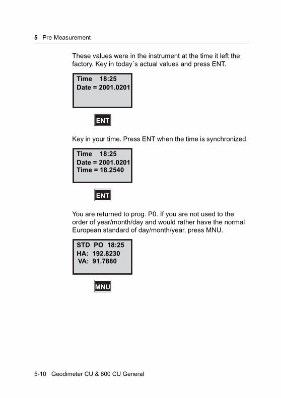
5 Pre-Measurement
These values were in the instrument at the time it left the factory. Key in today´s actual values and press ENT.
Key in your time. Press ENT when the time is synchronized.
You are returned to prog. P0. If you are not used to the order of year/month/day and would rather have the normal European standard of day/month/year, press MNU.
Time 18:25Date = 2001.0201
ENT
Time 18:25Date = 2001.0201Time = 18.2540
ENT
STD PO 18:25HA: 192.8230VA: 91.7880
MNU
5-10 Geodimeter CU & 600 CU General
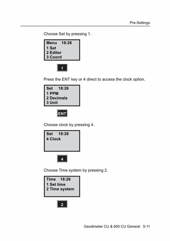
Pre-Settings
Choose Set by pressing 1.
Press the ENT key or 4 direct to access the clock option.
Choose clock by pressing 4.
Choose Time system by pressing 2.
Menu 18:261 Set2 Editor3 Coord
1
Set 18:261 PPM2 Decimals3 Unit
ENT
Set 18:264 Clock
4
Time 18:261 Set time2 Time system
2
Geodimeter CU & 600 CU General 5-11

5 Pre-Measurement
Here you are able to select which type of date system you want – e.g Numerical? 12h mm-dd-yyyy or 24h mm-dd-yyyy and also if you want to change to dd-mm-yyyy. Let´s press YES or ENT for Numerical.
You are returned to the Standard mode program 0 (P0).
You have now completed the pre-settings, which normally don´t have to be changed.
Note – Check after serviceIf the instrument has been delivered for service you should check time & date as these parameters might have been changed.
Time 18:20Numerical ?
ENT
STD PO 18:20HA: 192.8230VA: 91.7880
5-12 Geodimeter CU & 600 CU General

Special Settings
Special Settings
The special measurement settings range from defining display tables, setting decimal place and setting different switches such as: Targ. Test, Pcode and Info ack.
Create & Select display tables
Various display combinations can be created by the operator. However, we consider the following 3 tables as standards and we have chosen them to be the default.
Table 0 (Standard)
STD PO 9:22HA:VA:SD:
ENT
HA:Horizontal AngleVA:Vertical AngleAD:Slope Distance
STD PO 9:22HA:HD:VD:
ENT
HA:Horizontal AngleHD:Horizontal DistanceVD:Vertical Distance
STD PO 9:22N:E:ELE:
N:NorthingE:EastingELE:Elevation
Geodimeter CU & 600 CU General 5-13

5 Pre-Measurement
Other settings can be made with the help of the main menu using MNU 64 and option No. 2, Create Display e.g MNU 642.
There are 5 tables available /Tables 1-5). Table 0 is standard and cannot be change (see above). 16 different pages can be defined in each table or 48 using only one table. 3 rows can be specified on each page.
Create & Select o new display
To give you an idea as to how this works, let us take a look at our standard table 0. After measuring the distance the following will be displayed:
Page 1
Page 2
MNU 46
STD PO 9:22HA:VA:SD:
ENT
STD PO 9:22HA:HD:VD:
ENT
5-14 Geodimeter CU & 600 CU General
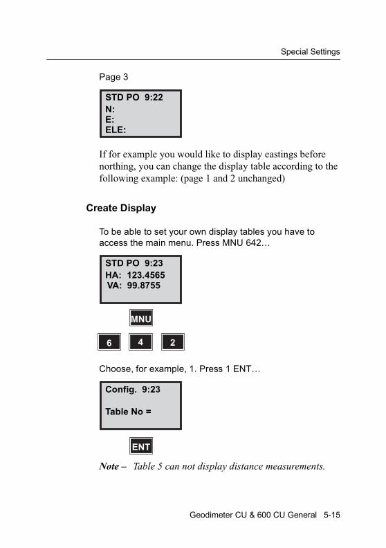
Special Settings
Page 3
If for example you would like to display eastings before northing, you can change the display table according to the following example: (page 1 and 2 unchanged)
Create Display
To be able to set your own display tables you have to access the main menu. Press MNU 642…
Choose, for example, 1. Press 1 ENT…
Note – Table 5 can not display distance measurements.
STD PO 9:22N:E:ELE:
STD PO 9:23HA: 123.4565VA: 99.8755
MNU
6 4 2
Config. 9:23
Table No =
ENT
Geodimeter CU & 600 CU General 5-15
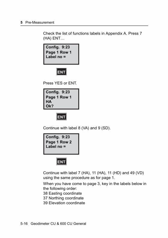
5 Pre-Measurement
Check the list of functions labels in Appendix A. Press 7 (HA) ENT…
Press YES or ENT.
Continue with label 8 (VA) and 9 (SD).
Continue with label 7 (HA), 11 (HA), 11 (HD) and 49 (VD) using the same procedure as for page 1.
When you have come to page 3, key in the labels below in the following order:38 Easting coordinate37 Northing coordinate39 Elevation coordinate
Config. 9:23Page 1 Row 1Label no =
ENT
Config. 9:23Page 1 Row 1HAOk?
ENT
Config. 9:23Page 1 Row 2Label no =
ENT
5-16 Geodimeter CU & 600 CU General
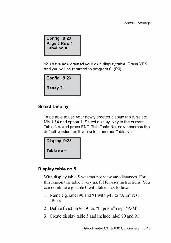
Special Settings
You have now created your own display table. Press YES and you will be returned to program 0. (P0).
Select Display
To be able to use your newly created display table, select MNU 64 and option 1. Select display. Key in the current Table No. and press ENT. This Table No. now becomes the default version, until you select another Table No.
Display table no 5
With display table 5 you can not view any distances. For this reason this table I very useful for user instructions. You can combine e.g. table 0 with table 5 as follows:
1. Name e.g. label 90 and 91 with p41 to ”Aim” resp. “Press”
2. Define function 90, 91 as “to prism” resp. “A/M”
3. Create display table 5 and include label 90 and 91
Config. 9:23Page 2 Row 1Label no =
Config. 9:23
Ready ?
Display 9:23
Table no =
Geodimeter CU & 600 CU General 5-17
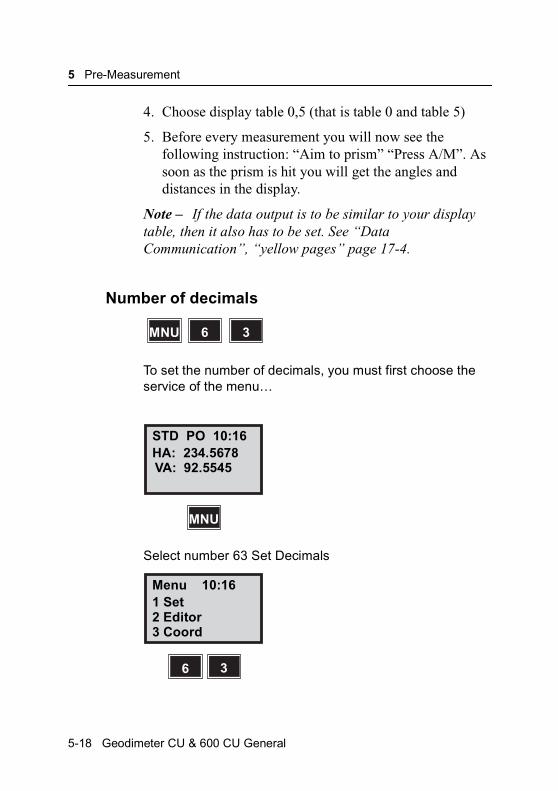
5 Pre-Measurement
4. Choose display table 0,5 (that is table 0 and table 5)
5. Before every measurement you will now see the following instruction: “Aim to prism” “Press A/M”. As soon as the prism is hit you will get the angles and distances in the display.
Note – If the data output is to be similar to your display table, then it also has to be set. See “Data Communication”, “yellow pages” page 17-4.
Number of decimals
To set the number of decimals, you must first choose the service of the menu…
Select number 63 Set Decimals
MNU 36
STD PO 10:16HA: 234.5678VA: 92.5545
MNU
Menu 10:161 Set2 Editor3 Coord
6 3
5-18 Geodimeter CU & 600 CU General

Special Settings
In this example, let us change the number of decimals in, for example, the HA = label No 7.
Note – A complete list of functions and labels can be found in App.A.
We assume that you want to work only with 2 decimal places in this example…
Note – When TRK-mode is active some labels will only work with 2 decimals even if they are set to more decimals by the user.
You are now returned to the standard (STD) mode. To change other labels, choose the menu and repeat.
Config. 10:16No of decimalsLabel no =_
7 ENT
Config. 10:16No of decimalsHA = 4Change to =_
2 ENT
STD PO 10:16HA: 234.56VA: 92.5545
Geodimeter CU & 600 CU General 5-19
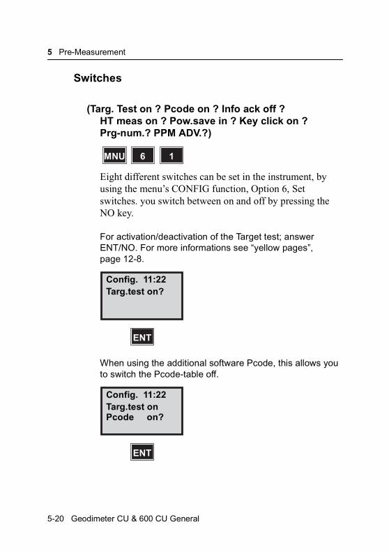
5 Pre-Measurement
Switches
(Targ. Test on ? Pcode on ? Info ack off ? HT meas on ? Pow.save in ? Key click on ?Prg-num.? PPM ADV.?)
Eight different switches can be set in the instrument, by using the menu’s CONFIG function, Option 6, Set switches. you switch between on and off by pressing the NO key.
For activation/deactivation of the Target test; answer ENT/NO. For more informations see “yellow pages”, page 12-8.
When using the additional software Pcode, this allows you to switch the Pcode-table off.
MNU 16
Config. 11:22Targ.test on?
ENT
Config. 11:22Targ.test onPcode on?
ENT
5-20 Geodimeter CU & 600 CU General

Special Settings
If you want to confirm any info message that may appear switch this label on. Any info message will then be followed by “Press any key”. The display returns to normal after 3s.
If the station height has been established in e.g. P20 (Station Establishment) you can be entering menu 61 from P0 choose whether to include the station height or not.
Note – HT_meas will not be displayed if the station has been established.
The distance meter can be set in power save, which means that the distance meter is only active during distance measurement given. This is indicated in the display with an “s”. (only in STD and D-bar).
Config. 11:22Targ.test onPcode onInfo ack. on?
ENT
Config. 11:22HT_meas on?
ENT
Config. 11:22HT_meas onPow. save on?
ENT
Geodimeter CU & 600 CU General 5-21

5 Pre-Measurement
Set keyclick on to hear a clicking sound every time you press a key.
If Prg-num is on, the current program number will be stored first in the jobfile when you start a program (P20-P29).
Enabling PPM Adv. Means that you base the PPM correction factor also on user defined wet temperature or humidity. Select alternative using MNU65, Units. If disabled the system uses a standard humidity of 60% for the PPM calculation.
Note – the Target Test is created for your safety. It prevents you from storing an old distance with new angle values. When the target test is set to off, there is a risk of this, if you forget to measure a distance when measuring the following points.
Config. 11:22HT_meas onPow. save onKey click on?
ENT
Config. 11:22Prg_num on?
ENT
Config. 11:22Prg_num onPPM Adv. on?
5-22 Geodimeter CU & 600 CU General
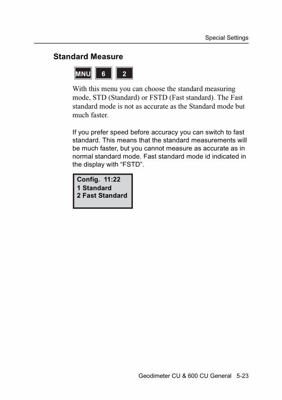
Special Settings
Standard Measure
With this menu you can choose the standard measuring mode, STD (Standard) or FSTD (Fast standard). The Fast standard mode is not as accurate as the Standard mode but much faster.
If you prefer speed before accuracy you can switch to fast standard. This means that the standard measurements will be much faster, but you cannot measure as accurate as in normal standard mode. Fast standard mode id indicated in the display with “FSTD”.
MNU 26
Config. 11:221 Standard2 Fast Standard
Geodimeter CU & 600 CU General 5-23
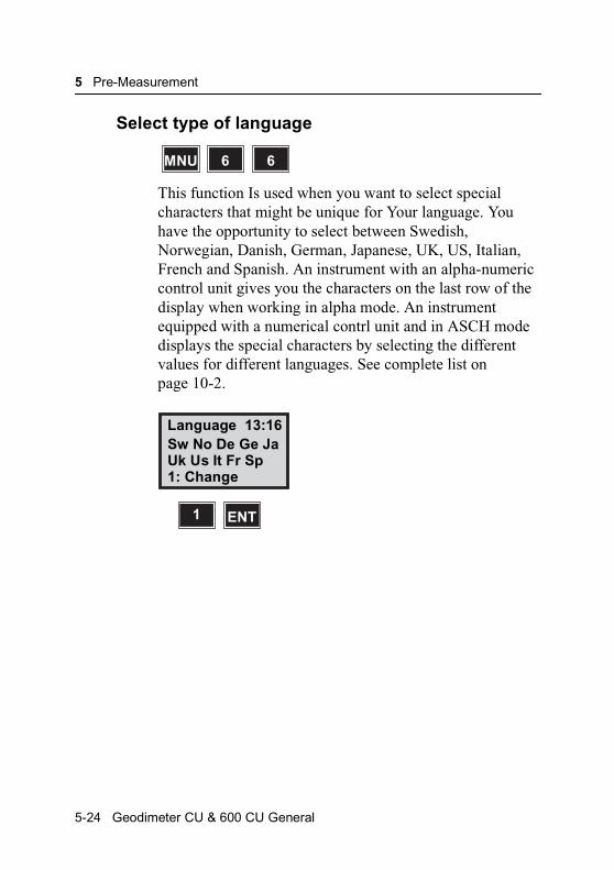
5 Pre-Measurement
Select type of language
This function Is used when you want to select special characters that might be unique for Your language. You have the opportunity to select between Swedish, Norwegian, Danish, German, Japanese, UK, US, Italian, French and Spanish. An instrument with an alpha-numeric control unit gives you the characters on the last row of the display when working in alpha mode. An instrument equipped with a numerical contrl unit and in ASCH mode displays the special characters by selecting the different values for different languages. See complete list on page 10-2.
MNU 66
Language 13:16Sw No De Ge JaUk Us It Fr Sp1: Change
ENT1
5-24 Geodimeter CU & 600 CU General
Test Measurements
Test Measurements
When the instrument arrives at your office, the horizontal and vertical collimation and horizontal axis error correction factors have been measured and stored in the memory of the instrument. These correction factors will allow you to measure as accurately in one face as you can in two faces. The instrument will correct, fully automatically, all horizontal and vertical angles there are measured in one face only.
Note – Test measurements should be carried out regularly, particularly when measuring during high temperature variations and where high accuracy is demanded in on face.
Note – Trimble System 5600 and 3600 can be equipped with one or two keyboard units. Test measurements should be made with the same keyboard configuration as will be used during measurement to achieve maximum measurement accuracy.
A limit of 0.02gon is set to the Collimation and horizontal axis tilt correction factors. If the measured collimation and tilt of the horizontal axis correction factors prove to be greater than this limit the instrument gives the operator a warning and will not accept the correction. The instrument should then be mechanically adjusted at the nearest Trimble service shop.
MNU 5 TEST
Geodimeter CU & 600 CU General 5-25
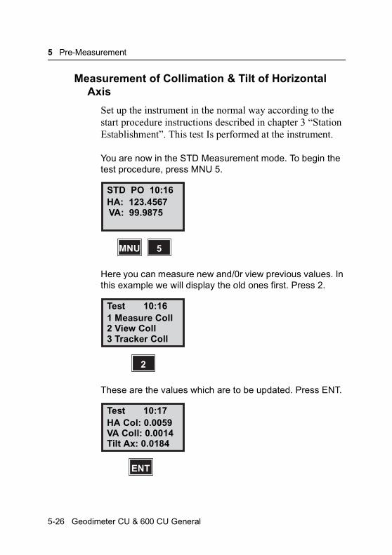
5 Pre-Measurement
Measurement of Collimation & Tilt of Horizontal Axis
Set up the instrument in the normal way according to the start procedure instructions described in chapter 3 “Station Establishment”. This test Is performed at the instrument.
You are now in the STD Measurement mode. To begin the test procedure, press MNU 5.
Here you can measure new and/0r view previous values. In this example we will display the old ones first. Press 2.
These are the values which are to be updated. Press ENT.
STD PO 10:16HA: 123.4567VA: 99.9875
5MNU
Test 10:161 Measure Coll2 View Coll3 Tracker Coll
2
Test 10:17HA Col: 0.0059VA Coll: 0.0014Tilt Ax: 0.0184
ENT
5-26 Geodimeter CU & 600 CU General
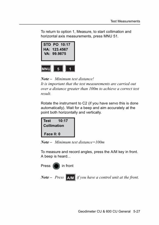
Test Measurements
To return to option 1, Measure, to start collimation and horizontal axis measurements, press MNU 51.
Note – Minimum test distance!It is important that the test measurements are carried out over a distance greater than 100m to achieve a correct test result.
Rotate the instrument to C2 (if you have servo this is done automatically). Wait for a beep and aim accurately at the point both horizontally and vertically.
Note – Minimum test distance=100m
To measure and record angles, press the A/M key in front. A beep is heard...
Press in front
Note – Press if you have a control unit at the front.
STD PO 10:17HA: 123.4567VA: 99.9875
5MNU 1
Test 10:17Collimation
Face II: 0
A/M
Geodimeter CU & 600 CU General 5-27

5 Pre-Measurement
Make at least two sightings to the point (the more the better), approaching from different directions, and then press A/M in front...
Press in front
Note – The same number of sightings must be made in both C2 and C1.
Rotate the instrument to C1 position* and aim at the point.
*Servo: Rotate the instrument to C1 position by depressing the A/M key in front for approx 2 sec. and aim at the point.
Press in front
Note – Press if you have a control unit at the front.
Aim accurately at the point both horizontally and vertically, press A/M.
??
Test 10:18CollimationFace II: 2Face I: 0
A/M C1:I
5-28 Geodimeter CU & 600 CU General

Test Measurements
Make the second aiming, press A/M.
The second C1 angle measurement and indication of completion are very quickly shown on the display.
The display shows correction factors. Answer YES (ENT) or NO to the question Store? These values do not have to be zero in order for the instrument to be OK.
Note – If you are not to sure about the accuracy of the displayed values, due to sighting errors for instance, you should answer No to the question Store? And repeat the measurements.
If you answered YES (ENT), the question for measurement of the tilt of the horiz. Axis appears. Press YES (ENT).
Test 10:18CollimationFace II: 2Face I: 1
A/M C1:II
Test 10:19HA Col: -0.0075VA Col: 0.0017Store?
ENT
Test 10:20
Tiltaxis?
ENT
Geodimeter CU & 600 CU General 5-29
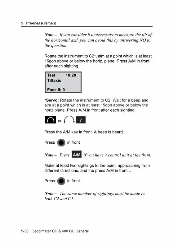
5 Pre-Measurement
Note – If you consider it unnecessary to measure the tilt of the horizontal axil, you can avoid this by answering NO to the question.
Rotate the instrument to C2*, aim at a point which is at least 15gon above or below the horiz. plane. Press A/M in front after each sighting.
*Servo: Rotate the instrument to C2. Wait for a beep and aim at a point which is at least 15gon above or below the horiz.plane. Press A/M in front after each sighting.
Press the A/M key in front. A beep is heard…
Press in front
Note – Press if you have a control unit at the front.
Make at least two sightings to the point, approaching from different directions, and the press A/M in front...
Press in front
Note – The same number of sightings must be made in both C2 and C1.
Test 10:20Tiltaxis
Face II: 0
7or
A/M
5-30 Geodimeter CU & 600 CU General

Test Measurements
Rotate the instrument to C1 position* and aim at the point.
*Servo: Rotate the instrument to C1 position by depressing the A/M key in front for approx 2 sec.
Press in front
Note – Press if you have a control unit at the front.
Aim at the point, press A/M.
Make the second aiming, press A/M.
The second C1angle measurement and indication of completion are very quickly shown on the display.
If satisfactory, answer YES or ENT. Press ENT.
??
Test 10:21TiltaxisFace II: 2Face I: 0
A/M
Test 10:21TiltaxisFace II: 2Face I: 1
A/M
Test 10:22Tiltax: 0.0150
Store?
ENT
Geodimeter CU & 600 CU General 5-31
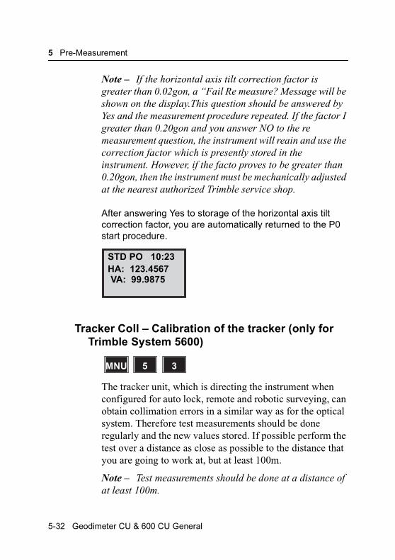
5 Pre-Measurement
Note – If the horizontal axis tilt correction factor is greater than 0.02gon, a “Fail Re measure? Message will be shown on the display.This question should be answered by Yes and the measurement procedure repeated. If the factor I greater than 0.20gon and you answer NO to the re measurement question, the instrument will reain and use the correction factor which is presently stored in the instrument. However, if the facto proves to be greater than 0.20gon, then the instrument must be mechanically adjusted at the nearest authorized Trimble service shop.
After answering Yes to storage of the horizontal axis tilt correction factor, you are automatically returned to the P0 start procedure.
Tracker Coll – Calibration of the tracker (only for Trimble System 5600)
The tracker unit, which is directing the instrument when configured for auto lock, remote and robotic surveying, can obtain collimation errors in a similar way as for the optical system. Therefore test measurements should be done regularly and the new values stored. If possible perform the test over a distance as close as possible to the distance that you are going to work at, but at least 100m.
Note – Test measurements should be done at a distance of at least 100m.
STD PO 10:23HA: 123.4567VA: 99.9875
MNU 35
5-32 Geodimeter CU & 600 CU General

Test Measurements
It is important that the RMT is held very still during the test (it is recommended to use a tripod) and that it is clear sight without any obstructing traffic. Calibration is initiated Menu 53. The instrument is calibrated with respect to Horizontal and Vertical collimation errors. These collimation errors can be stored and used to correct the measured points. The measured values are in effect until a new Test Measurement is done.
Switch on the RMT and aim the instrument towards the RMT. Enter menu 5 and start the Tracker calibration by pressing 3.
Note – The compensator has to be initiated during this routine.
Press the YES or ENT to perform the calibration or press NO to cancel it.
Test 19:121 Measure2 View current3 Tracker Coll
3
Test 19:12+
Test tracker?
ENT
Geodimeter CU & 600 CU General 5-33
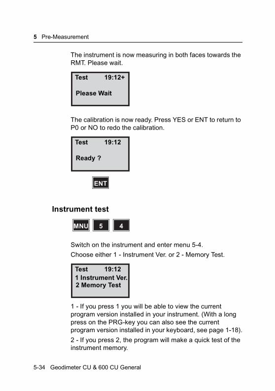
5 Pre-Measurement
The instrument is now measuring in both faces towards the RMT. Please wait.
The calibration is now ready. Press YES or ENT to return to P0 or NO to redo the calibration.
Instrument test
Switch on the instrument and enter menu 5-4.
Choose either 1 - Instrument Ver. or 2 - Memory Test.
1 - If you press 1 you will be able to view the current program version installed in your instrument. (With a long press on the PRG-key you can also see the current program version installed in your keyboard, see page 1-18).
2 - If you press 2, the program will make a quick test of the instrument memory.
Test 19:12+
Please Wait
Test 19:12
Ready ?
ENT
MNU 45
Test 19:121 Instrument Ver.2 Memory Test
5-34 Geodimeter CU & 600 CU General

C H A P T E R
6
6Start ProcedureStart Procedure .................................................................... 6-2Field Setup...................................................................... 6-2Startup ............................................................................ 6-3Calibration of the dual-axis compensator with servo ...... 6-4Calibration of the dual-axis compensator without servo . 6-5Pre-setting of Temp., Press, Humidity, Offset & HAref .... 6-7Station data (Instr. Height, Signal Height, Stn. Coord.). 6-10Coordinate System ....................................................... 6-15
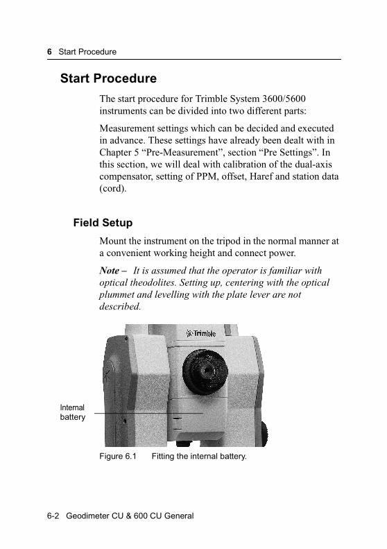
6 Start Procedure
Start Procedure
The start procedure for Trimble System 3600/5600 instruments can be divided into two different parts:
Measurement settings which can be decided and executed in advance. These settings have already been dealt with in Chapter 5 “Pre-Measurement”, section “Pre Settings”. In this section, we will deal with calibration of the dual-axis compensator, setting of PPM, offset, Haref and station data (cord).
Field Setup
Mount the instrument on the tripod in the normal manner at a convenient working height and connect power.
Note – It is assumed that the operator is familiar with optical theodolites. Setting up, centering with the optical plummet and levelling with the plate lever are not described.
Figure 6.1 Fitting the internal battery.
Internalbattery
6-2 Geodimeter CU & 600 CU General

Start Procedure
Figure 6.2 Connecting the external battery.
Startup
• Switch on the instrument and place the display of the instrument parallel to two of the foot screws of the tribrach.
• Level the instrument by first rotating the foot screws in the normal theodolite levelling manner – i.e, equal and opposite to each other.
Rule: The lower bubble will follow the direction of the left thumb.
• When the cursor is in the correct position you adjust the upper bubble with the third foot screw, without rotating the instrument. Clockwise rotation of the screw will move the cursor to the right. Levelling must be within 6C, otherwise a warning signal will be given after attempting to calibrate the compensator. The electronic level at this stage is in the “coarse mode” (see fig 3.3). “Fine mode” is achieved after calibration of the dual-axis compensator.
Geodimeter CU & 600 CU General 6-3

6 Start Procedure
At intervals during measurement you can view the electronic levelling bubble whenever you wish, simply by pressing the level symbol key. See more about the electronic level key on page 1-20.
Figure 6.3 Display when level appears thus “coarse mode”
Calibration of the dual-axis compensator with servo
This should be done to get full accuracy of the systems inherent intelligence.
The instrument is levelled. Start compensator calibration by pressing A/M-or ENT-key.
A beep is heard and the display will changed to...
Note – Disconnect the compensator by setting function 22=0.
11:36
I
A/M
14:04
6-4 Geodimeter CU & 600 CU General

Start Procedure
The instrument automatically turns 200 gon (180°) away from you. After a few seconds a beep is heard and the instrument turns back and the display will change to...
...program 0. The appearance of P0 indicates that the instrument is sufficiently well levelled and that the compensator is now engaged. It also means that the electronic level is in the “fine mode” in which each individual left or right movement of the cursor represents 20CC.
Calibration of the dual-axis compensator without servo
This should be done to get full accuracy of the systems inherent intelligence.
The instrument is levelled. Start compensator calibration by pressing A/M-or ENT-key.
Comp init
Wait
P0 14:05
Temp = 20.0
I 14:04
Geodimeter CU & 600 CU General 6-5

6 Start Procedure
A beep is heard. Wait for a double beep after approx. 6-8 sec and the display will change to…
Note – Disconnect the compensator by setting function 22=0.
Turn the instrument 200 gon (180°) and the display will change to…
…when the instrument is within 1 gon of a 200 gon rotation.
A beep is heard and the display will change to…
Wait for a double beep after approx. 6-8 sec. The display will automatically change to…
….program 0. The appearance of P0 indicates that the instrument is sufficiently well levelled and that the compensator is now engaged. It also means that the
Comp init
Turn: 200–>
Comp init
Press A/M
A/M
Comp init
Wait
6-6 Geodimeter CU & 600 CU General
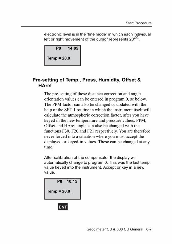
Start Procedure
electronic level is in the “fine mode” in which each individual left or right movement of the cursor represents 20CC.
Pre-setting of Temp., Press, Humidity, Offset & HAref
The pre-setting of these distance correction and angle orientation values can be entered in program 0, se below. The PPM factor can also be changed or updated with the help of the SET 1 routine in which the instrument itself will calculate the atmospheric correction factor, after you have keyed in the new temperature and pressure values. PPM, Offset and HAref angle can also be changed with the functions F30, F20 and F21 respectively. You are therefore never forced into a situation where you must accept the displayed or keyed-in values. These can be changed at any time.
After calibration of the compensator the display will automatically change to program 0. This was the last temp. value keyed into the instrument. Accept or key in a new value.
P0 14:05
Temp = 20.0
P0 10:15
Temp = 20.0_
ENT
Geodimeter CU & 600 CU General 6-7

6 Start Procedure
Accept or key in a new value for pressure.
Key in Relative Humidity in %. (If you have chosen Wet Temperature in MNU6.5 this will be shown instead.)
Note – This menu is shown only if “PPM Adv.” is activated in MNU6.1
Key in the distance correction offset or accept zero value (Default value= 0). See also prism constant, Chapter 10.
P0 10:16
Press = 760.0_
ENT
P0 10:16
RelHum = 60.0_
ENT
P0 10:16
Offset = 0.000_
ENT
6-8 Geodimeter CU & 600 CU General
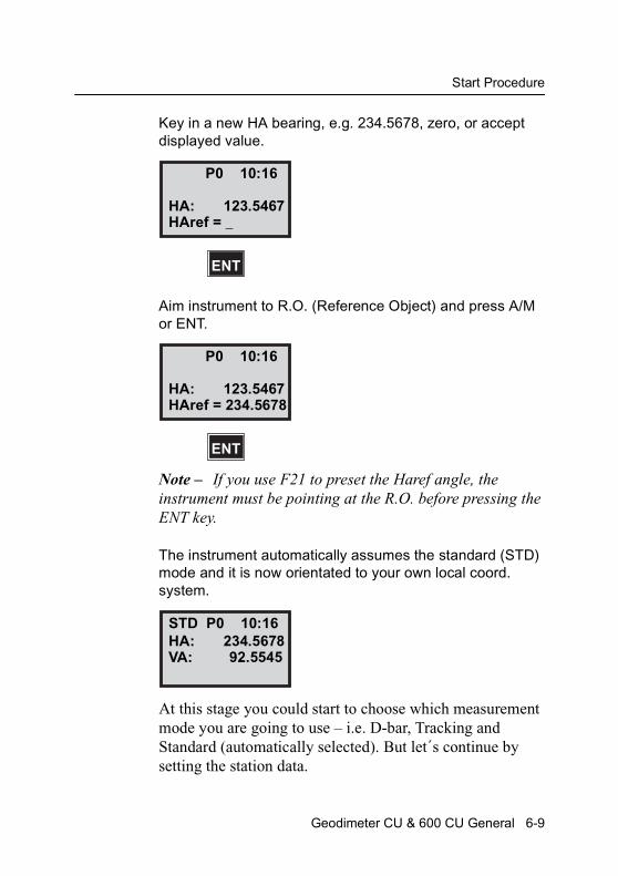
Start Procedure
Key in a new HA bearing, e.g. 234.5678, zero, or accept displayed value.
Aim instrument to R.O. (Reference Object) and press A/M or ENT.
Note – If you use F21 to preset the Haref angle, the instrument must be pointing at the R.O. before pressing the ENT key.
The instrument automatically assumes the standard (STD) mode and it is now orientated to your own local coord. system.
At this stage you could start to choose which measurement mode you are going to use – i.e. D-bar, Tracking and Standard (automatically selected). But let´s continue by setting the station data.
P0 10:16
HA: 123.5467
ENT
HAref = _
P0 10:16
HA: 123.5467
ENT
HAref = 234.5678
STD P0 10:16HA: 234.5678VA: 92.5545
Geodimeter CU & 600 CU General 6-9
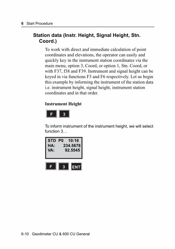
6 Start Procedure
Station data (Instr. Height, Signal Height, Stn. Coord.)
To work with direct and immediate calculation of point coordinates and elevations, the operator can easily and quickly key in the instrument station coordinates via the main menu, option 3, Coord, or option 1, Stn. Coord, or with F37, f38 and F39. Instrument and signal height can be keyed in via functions F3 and F6 respectively. Let us begin this example by informing the instrument of the station data i.e. instrument height, signal height, instrument station coordinates and in that order.
Instrument Height
To inform instrument of the instrument height, we will select function 3…
F 3
STD P0 10:16HA: 234.5678VA: 92.5545
F 3 ENT
6-10 Geodimeter CU & 600 CU General
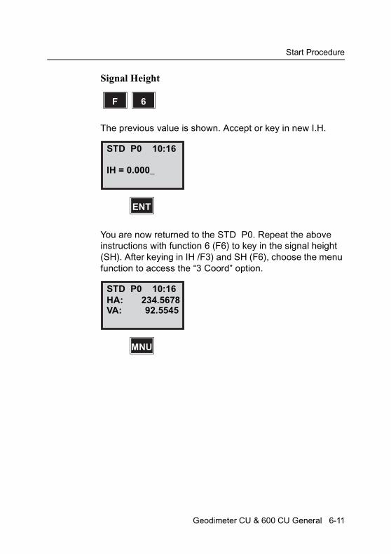
Start Procedure
Signal Height
The previous value is shown. Accept or key in new I.H.
You are now returned to the STD P0. Repeat the above instructions with function 6 (F6) to key in the signal height (SH). After keying in IH /F3) and SH (F6), choose the menu function to access the “3 Coord” option.
F 6
STD P0 10:16
IH = 0.000_
ENT
STD P0 10:16HA: 234.5678VA: 92.5545
MNU
Geodimeter CU & 600 CU General 6-11
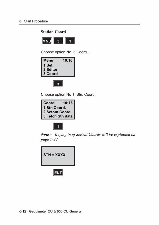
6 Start Procedure
Station Coord
Choose option No. 3 Coord…
Choose option No 1. Stn. Coord.
Note – Keying in of SetOut Coords will be explained on page 7-22.
MNU 13
Menu 10:161 Set2 Editor3 Coord
3
Coord 10:161 Stn Coord.2 Setout Coord.3 Fetch Stn data
1
STN = XXXX
ENT
6-12 Geodimeter CU & 600 CU General
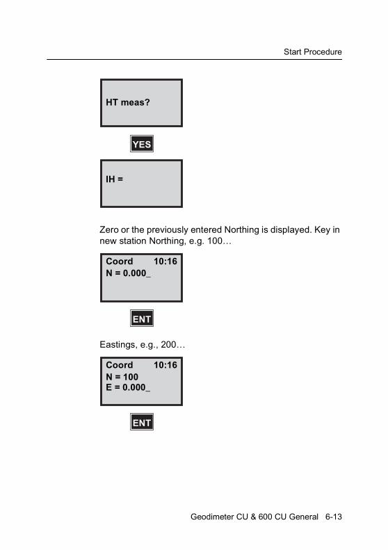
Start Procedure
Zero or the previously entered Northing is displayed. Key in new station Northing, e.g. 100…
Eastings, e.g., 200…
HT meas?
YES
IH =
Coord 10:16N = 0.000_
ENT
Coord 10:16N = 100E = 0.000_
ENT
Geodimeter CU & 600 CU General 6-13
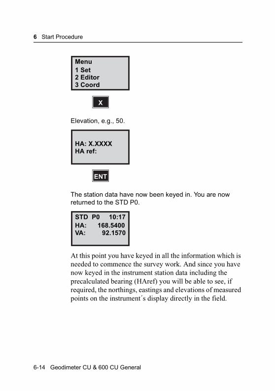
6 Start Procedure
Elevation, e.g., 50.
The station data have now been keyed in. You are now returned to the STD P0.
At this point you have keyed in all the information which is needed to commence the survey work. And since you have now keyed in the instrument station data including the precalculated bearing (HAref) you will be able to see, if required, the northings, eastings and elevations of measured points on the instrument´s display directly in the field.
Menu1 Set2 Editor3 Coord
X
HA: X.XXXXHA ref:
ENT
STD P0 10:17HA: 168.5400VA: 92.1570
6-14 Geodimeter CU & 600 CU General
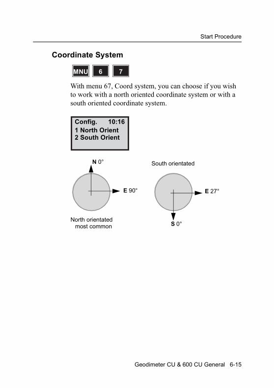
Start Procedure
Coordinate System
With menu 67, Coord system, you can choose if you wish to work with a north oriented coordinate system or with a south oriented coordinate system.
MNU 76
Config. 10:161 North Orient2 South Orient
N 0°
E 90° E 27°
S 0°
South orientated
North orientatedmost common
Geodimeter CU & 600 CU General 6-15
6 Start Procedure
6-16 Geodimeter CU & 600 CU General
C H A P T E R
7
7Carrying Out A MeasurementDistance & Angle Measurement........................................... 7-2Standard measurement (STD Mode).............................. 7-2Fast standard mode ........................................................ 7-9D-bar measurement (D-bar Mode)................................ 7-10D-bar two-face measurement (C1/C2).......................... 7-13Collecting detail & Tacheometry (TRK-Mode)............... 7-18Setting Out (TRK Mode) ............................................... 7-22Measuring Differences Robotic Surveying (only servo) 7-34

7 Carrying Out A Measurement
Distance & Angle Measurement
Standard measurement (STD Mode)
This measurement mode is normally used during control surveys – e.g., small tachometric exercises, survey point accuracy control, etc. Measurement time for each point takes 3.5 sec.
The instrument carries out the measurement and display in PO of horizontal and vertical angles and slope distance (HA, VA & SD) with the possibility of also display horizontal distance and difference in height (HD & VD) and the northings, eastings and elevation of the point by pressing the ENT-key twice.
1 STDSTD or
7-2 Geodimeter CU & 600 CU General
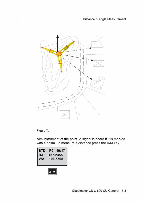
Distance & Angle Measurement
Figure 7.1
Aim instrument at the point. A signal is heard if it is marked with a prism. To measure a distance press the A/M key.
STD P0 10:17HA: 137.2355VA: 106.5505
A/M
Geodimeter CU & 600 CU General 7-3
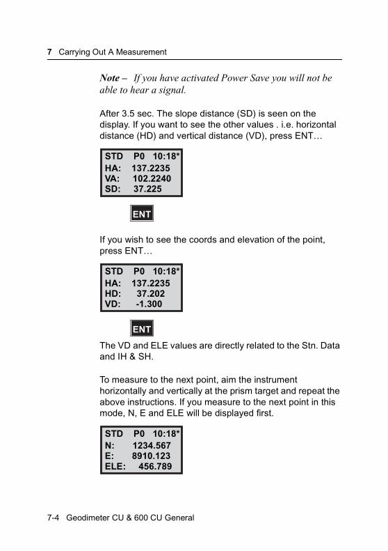
7 Carrying Out A Measurement
Note – If you have activated Power Save you will not be able to hear a signal.
After 3.5 sec. The slope distance (SD) is seen on the display. If you want to see the other values . i.e. horizontal distance (HD) and vertical distance (VD), press ENT…
If you wish to see the coords and elevation of the point, press ENT…
The VD and ELE values are directly related to the Stn. Data and IH & SH.
To measure to the next point, aim the instrument horizontally and vertically at the prism target and repeat the above instructions. If you measure to the next point in this mode, N, E and ELE will be displayed first.
STD P0 10:18*HA: 137.2235VA: 102.2240SD: 37.225
ENT
STD P0 10:18*HA: 137.2235HD: 37.202VD: -1.300
ENT
STD P0 10:18*N: 1234.567E: 8910.123ELE: 456.789
7-4 Geodimeter CU & 600 CU General
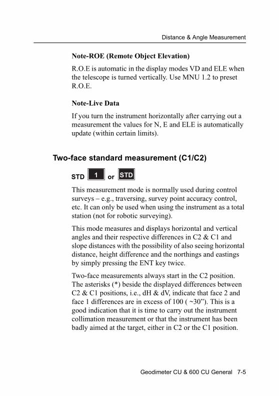
Distance & Angle Measurement
Note-ROE (Remote Object Elevation)
R.O.E is automatic in the display modes VD and ELE when the telescope is turned vertically. Use MNU 1.2 to preset R.O.E.
Note-Live Data
If you turn the instrument horizontally after carrying out a measurement the values for N, E and ELE is automatically update (within certain limits).
Two-face standard measurement (C1/C2)
This measurement mode is normally used during control surveys – e.g., traversing, survey point accuracy control, etc. It can only be used when using the instrument as a total station (not for robotic surveying).
This mode measures and displays horizontal and vertical angles and their respective differences in C2 & C1 and slope distances with the possibility of also seeing horizontal distance, height difference and the northings and eastings by simply pressing the ENT key twice.
Two-face measurements always start in the C2 position. The asterisks (*) beside the displayed differences between C2 & C1 positions, i.e., dH & dV, indicate that face 2 and face 1 differences are in excess of 100 ( ~30”). This is a good indication that it is time to carry out the instrument collimation measurement or that the instrument has been badly aimed at the target, either in C2 or the C1 position.
1 STDSTD or
Geodimeter CU & 600 CU General 7-5
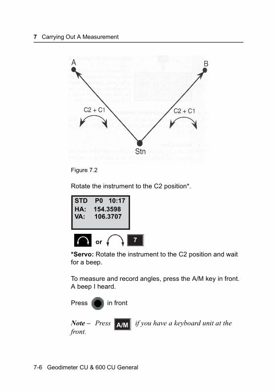
7 Carrying Out A Measurement
Figure 7.2
Rotate the instrument to the C2 position*.
*Servo: Rotate the instrument to the C2 position and wait for a beep.
To measure and record angles, press the A/M key in front. A beep I heard.
Press in front
Note – Press if you have a keyboard unit at the front.
STD P0 10:17HA: 154.3598VA: 106.3707
7or
A/M
7-6 Geodimeter CU & 600 CU General
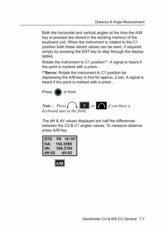
Distance & Angle Measurement
Both the horizontal and vertical angles at the time the A/M key is pressed are stored in the working memory of the keyboard unit. When the instrument is rotated to the C1 position both these stored values can be seen, if required, simply by pressing the ENT key to step through the display tables.
Rotate the instrument to C1 position**. A signal is heard if the point is marked with a prism…
**Servo: Rotate the instrument to C1 position be depressing the A/M key in frint for approx. 2 sec. A signal is heard if the point is marked with a prism...
Press in front
Note – Press or if you have a keyboard unit at the front.
The dH & dV values displayed are half the differences between the C2 & C1 angles values. To measure distance press A/M key.
7
STD P0 10:18*HA: 154.3599VA: 106.3704
A/M
dH:02 dV:02
Geodimeter CU & 600 CU General 7-7
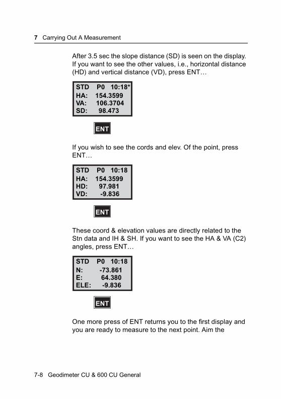
7 Carrying Out A Measurement
After 3.5 sec the slope distance (SD) is seen on the display. If you want to see the other values, i.e., horizontal distance (HD) and vertical distance (VD), press ENT…
If you wish to see the cords and elev. Of the point, press ENT…
These coord & elevation values are directly related to the Stn data and IH & SH. If you want to see the HA & VA (C2) angles, press ENT…
One more press of ENT returns you to the first display and you are ready to measure to the next point. Aim the
STD P0 10:18*HA: 154.3599VA: 106.3704
ENT
SD: 98.473
STD P0 10:18HA: 154.3599HD: 97.981
ENT
VD: -9.836
STD P0 10:18N: -73.861E: 64.380
ENT
ELE: -9.836
7-8 Geodimeter CU & 600 CU General

Distance & Angle Measurement
instrument horizontally and vertically at the prism target and repeat the above instructions.
Note – The R.O.E feature also operates in this two face STD measurement mode exactly the same as in the once face STD measurement mode.
Fast standard mode
In those cases when faster measurements are preferred before high accuracy, you can choose the Fast mode that speeds up the measuring time in standard mode. The measuring time will now only be approx. 1.3 sec instead of 3.5 sec in normal standard mode and with 2 decimals in Tracking mode.
The fast standard mode is indicated in the display by “FSTD”.
You switch between fast standard mode an normal standard mode in menu 62, Standard Measure (see Chapter 5). The measurement procedure is identical to the standard mode, see page 7-2 to page 7-5.
STD P0 10:18HAII: 354.3581VAII: 293.6284
FSTD P0 10:18HA: 154.3581VA: 106.6284
MNU 62
Geodimeter CU & 600 CU General 7-9
7 Carrying Out A Measurement
Special function in U.D.S. (P1-P19)
When working in FSTD and U.D.S. you can measure and registrate with a single key press on the REG-key. You can of course measure with the A/M-key as usual and then registrate with the REG-key.
D-bar measurement (D-bar Mode)
This measurement mode is similar to the one face STD mode, the major difference being that distance measurement is carried out in an automatically repeated measurement cycle. The arithmetic mean value is automatically calculated, thus resulting in a greater degree of accuracy being achieved.
The instrument measures and displays horizontal and vertical angles and slope distances, you can also display horizontal distance and difference in height, and the northings, eastings and elevation of the point by pressing the ENT key twice.
The R.O.E function is similar to the once face STD mode. However, there is one major difference. The instrument must be told when distance measurement is to be stopped; this is done quite simply by pressing the A/M key. After 99 measurements the operation is stopped automatically.
3 Dor_
D
7-10 Geodimeter CU & 600 CU General
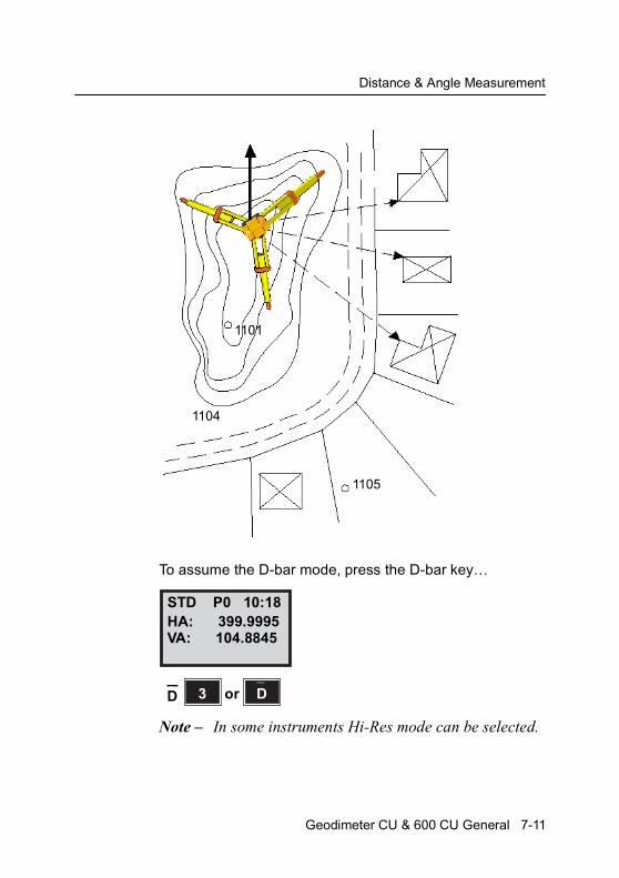
Distance & Angle Measurement
To assume the D-bar mode, press the D-bar key…
Note – In some instruments Hi-Res mode can be selected.
1101
1104
1105
STD P0 10:18HA: 399.9995VA: 104.8845
3 Dor_
D
Geodimeter CU & 600 CU General 7-11
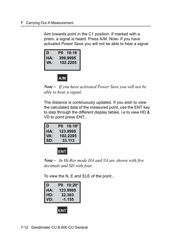
7 Carrying Out A Measurement
Aim towards point in the C1 position. If marked with a prism, a signal is heard. Press A/M. Note- If you have activated Power Save you will not be able to hear a signal.
Note – If you have activated Power Save you will not be able to hear a signal.
The distance is continuously updated. If you wish to view the calculated data of the measured point, use the ENT key to step through the different display tables, i.e to view HD & VD to point press ENT...
Note – In Hi-Res mode HA and VA are shown with five decimals and SD with four.
To view the N, E and ELE of the point...
D P0 10:19HA: 399.9995VA: 102.2205
A/M
D P0 10:19*HA: 123.9995VA: 102.2205
ENT
SD: 33.113
D P0 10:20*HA: 123.9995HD: 32.363
ENT
VD: -1.155
7-12 Geodimeter CU & 600 CU General

Distance & Angle Measurement
If you measure to the next point with the display in this mode, N, E and ELE of the point will be displayed first.
Note – The amount of time you allow the instrument to measure and update the distance is completely up to you. However, under normal clear visibility conditions, the distance resolution will normally stabilize after approx.10-15 sec.
D-bar two-face measurement (C1/C2)
This measurement mode is used during control surveys – e.g., traversing, survey point accuracy control etc. I.e. when you need high accuracy.
The distance measurement is carried out in a repeated measurement cycle thus resulting in a greater degree of distance accuracy, and the mean horizontal and vertical angles of all measurements made in both C2 and c1 positions are automatically calculated and presented on the display.
Note – Automatic arithmetic mean value of both angles and distance.
The instrument measures and displays mean horizontal and vertical angles as well as angular differences between both faces, and slope distance. You can also display horizontal distance, height difference and the northings, eastings and elevation of the point by pressing the ENT key twice.
D P0 10:20*N: 5143.113E: 2008.156
ENT
ELE: 187.554
Geodimeter CU & 600 CU General 7-13

7 Carrying Out A Measurement
Collimation and horizontal axis tilt errors are fully compensated and operator error is minimized.
Figure 7.3
To assume the D-bar mode, press the D-bar key…..
Rotate the instrument to the c2 position*. Wait for a beep and aim at the first point.
STD P0 10:17HA: 154.3605VA: 106.7301
3 Dor_
D
D P0 10:19HA: 154.3605VA: 106.7301
7-14 Geodimeter CU & 600 CU General
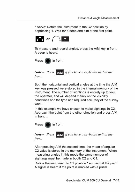
Distance & Angle Measurement
* Servo: Rotate the instrument to the C2 position by depressing 1. Wait for a beep and aim at the first point.
To measure and record angles, press the A/M key in front. A beep is heard.
Press in front
Note – Press if you have a keyboard unit at the front.
Both the horizontal and vertical angles at the time the A/M key was pressed were stored in the internal memory of the instrument. The number of sightings is entirely up to you, the operator, and will depend mainly on the visibility conditions and the type and required accuracy of the survey work.
In this example we have chosen to make sightings in C2. Approach the point from the other direction and press A/M in front…
Press in front
Note – Press if you have a keyboard unit at the front.
After pressing A/M the second time, the mean of angular C2 value is stored in the memory of the instrument. When measuring angles in this mode the same number of sightings must be made in booth C2 and C1.
Rotate the instrument to C1 position * and aim at the point. A signal is heard if the point is marked with a prism…
7or
A/M
A/M
Geodimeter CU & 600 CU General 7-15
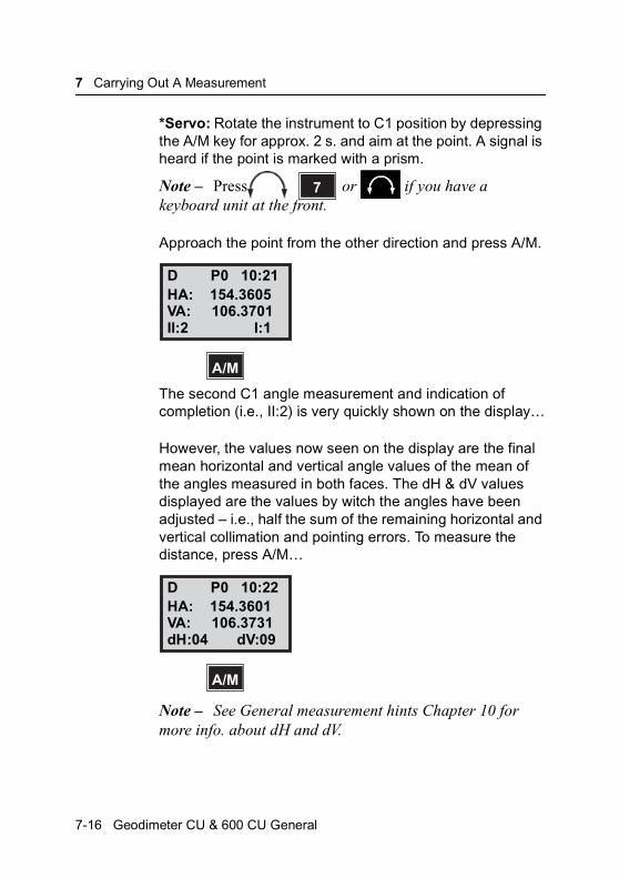
7 Carrying Out A Measurement
*Servo: Rotate the instrument to C1 position by depressing the A/M key for approx. 2 s. and aim at the point. A signal is heard if the point is marked with a prism.
Note – Press or if you have a keyboard unit at the front.
Approach the point from the other direction and press A/M.
The second C1 angle measurement and indication of completion (i.e., II:2) is very quickly shown on the display…
However, the values now seen on the display are the final mean horizontal and vertical angle values of the mean of the angles measured in both faces. The dH & dV values displayed are the values by witch the angles have been adjusted – i.e., half the sum of the remaining horizontal and vertical collimation and pointing errors. To measure the distance, press A/M…
Note – See General measurement hints Chapter 10 for more info. about dH and dV.
7
D P0 10:21HA: 154.3605VA: 106.3701
A/M
II:2 I:1
D P0 10:22HA: 154.3601VA: 106.3731
A/M
dH:04 dV:09
7-16 Geodimeter CU & 600 CU General

Distance & Angle Measurement
Distance is continually measured and updated while mean angular values are frozen.
To view the HD and VD to the point, press ENT.
To view the N, E and ELE of the point…
If you measure to the next point with the display in this mode, N, E and ELE of the point will be displayed first. If you want to see the HA & VA (C2) angles press ENT…
D P0 10:21*HA: 154.3601VA: 106.3731
ENT
SD: 98.472
D P0 10:21*HA: 154.3601HD: 97.979
ENT
VD: -9.840
D P0 10:21*N: -73.861E: 64.378
ENT
ELE: -9.840
Geodimeter CU & 600 CU General 7-17

7 Carrying Out A Measurement
If you want to see the HA & VA (C1) angles press ENT.
Collecting detail & Tacheometry (TRK-Mode)
This measurement mode is normally used during both large and small topographic exercises. The TRK mode is fully automatic. All measured values will be updated 0.4 sec. after making contact with the prism. No keys have to be pressed between measurements. It is worth pointing out that battery power consumption is a little higher in this measurement mode compared to the execution of tacheometry in STD mode R.O.E is automatic in this measurement mode. Note that as measurements are started automatically, there is a slight risk that measurements are made when the instrument is badly pointed towards the prism.
D P0 10:21*HAII: 354.3597VAII: 293.6278
ENT
D P0 10:21*HAI: 154.3605VAI: 106.3741
TRK2 orTRK
7-18 Geodimeter CU & 600 CU General

Distance & Angle Measurement
To engage tracking mode, press TRK key…
STD P0 10:17HA: 165.2355VA: 106.5505
TRK2 orTRK
Geodimeter CU & 600 CU General 7-19

7 Carrying Out A Measurement
Aim towards the point. Distance measurement starts automatically and there is no need to press A/M.
HD & VD appear on the display. To view cords, and height of point, press ENT...
To view HA, VA & SD to the point, press ENT…
If you measure to the next point with the display in this mode, N, E and ELE of the point will be displayed first
Note – R.O.E is automatic in the display modes VD & ELE when the telescope is turned vertically.
TRK P0 10:17HA: 165.2355VA: 106.5505
TRK P0 10:17*HA: 159.8700HD: 104.36VD: -8.508
ENT
TRK P0 10:17*N: 1234.567E: 9101.112ELE: 31.415
ENT
TRK P0 10:17*HA: 159.8710VA: 105.1785SD: 104.71
7-20 Geodimeter CU & 600 CU General

Distance & Angle Measurement
Figure 7.4 Setting Out using TRK mode
Geodimeter CU & 600 CU General 7-21
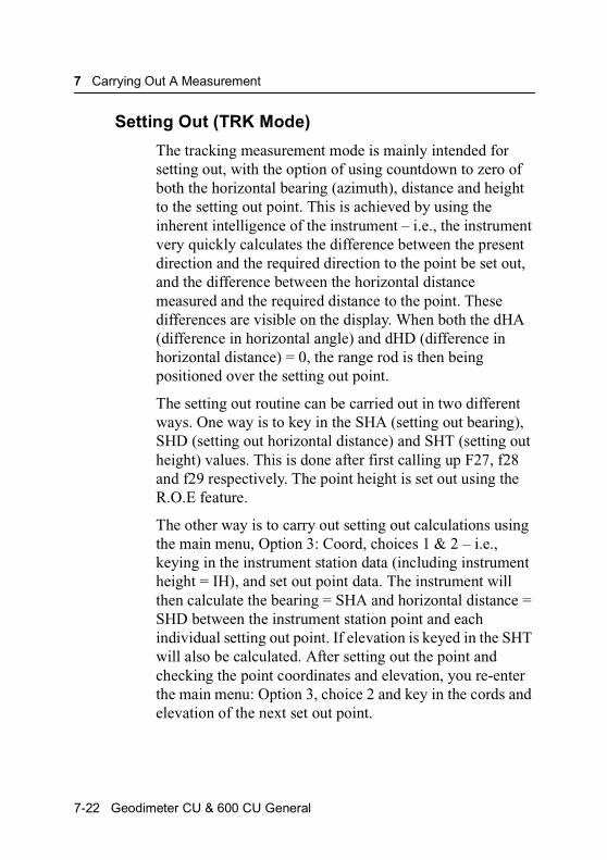
7 Carrying Out A Measurement
Setting Out (TRK Mode)
The tracking measurement mode is mainly intended for setting out, with the option of using countdown to zero of both the horizontal bearing (azimuth), distance and height to the setting out point. This is achieved by using the inherent intelligence of the instrument – i.e., the instrument very quickly calculates the difference between the present direction and the required direction to the point be set out, and the difference between the horizontal distance measured and the required distance to the point. These differences are visible on the display. When both the dHA (difference in horizontal angle) and dHD (difference in horizontal distance) = 0, the range rod is then being positioned over the setting out point.
The setting out routine can be carried out in two different ways. One way is to key in the SHA (setting out bearing), SHD (setting out horizontal distance) and SHT (setting out height) values. This is done after first calling up F27, f28 and f29 respectively. The point height is set out using the R.O.E feature.
The other way is to carry out setting out calculations using the main menu, Option 3: Coord, choices 1 & 2 – i.e., keying in the instrument station data (including instrument height = IH), and set out point data. The instrument will then calculate the bearing = SHA and horizontal distance = SHD between the instrument station point and each individual setting out point. If elevation is keyed in the SHT will also be calculated. After setting out the point and checking the point coordinates and elevation, you re-enter the main menu: Option 3, choice 2 and key in the cords and elevation of the next set out point.
7-22 Geodimeter CU & 600 CU General

Distance & Angle Measurement
The following pages will give examples of setting out, first in the normal way (keying in SHA, SHD and SHT) and then by using the main menu: Option 3, choices 1 & 2.
Setting Out using pre-calc. bearing & horizontal distances SHA &SHD
To engage tracking mode, press thr TRK-key.
To key in setting out bearing, press F27 (F27 = SHA).
Note – F27 = SHA
STD P0 10:17HA: 33.7965VA: 109.3960
TRK2 orTRK
TRK P0 10:17*HA: 33.7965VA: 109.3960
F 27
Geodimeter CU & 600 CU General 7-23

7 Carrying Out A Measurement
Key in the bearing to setting out point for example, 88.9515, then ENT.
To key in horizontal distance to setting out point press F28 (F28=SHD).
Note – F28 = SHD
Key in horizontal distance to setting out point, for example 104.324 and press ENT.
If you wish to carry out 3 dimensional point setting out, key in the setting out height with F29 = SHT.
HA and dHA appear. Rotate instrument*, until it displays approx. 0.0000 opposite dHA – i.e., it is pointing in the direction of the first setting out point. HA is the calculated
TRK P0 10:17*SHA =88.9515
ENT
TRK P0 10:17*HA: 33.7965dHA: 55.1550
F 28
TRK P0 10:17*
SHD =104.324
ENT
7-24 Geodimeter CU & 600 CU General
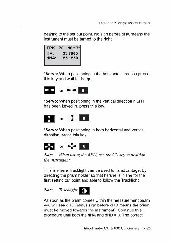
Distance & Angle Measurement
bearing to the set out point. No sign before dHA means the instrument must be turned to the right.
*Servo: When positioning in the horizontal direction press this key and wait for beep.
*Servo: When positioning in the vertical direction if SHT has been keyed in, press this key.
*Servo: When positioning in both horizontal and vertical direction, press this key.
Note – When using the RPU, use the CL-key to position the instrument.
This is where Tracklight can be used to its advantage, by directing the prism holder so that he/she is in line for the first setting out point and able to follow the Tracklight.
Note – Tracklight
As soon as the prism comes within the measurement beam you will see dHD (minus sign before dHD means the prism must be moved towards the instrument). Continue this procedure until both the dHA and dHD = 0. The correct
TRK P0 10:17*HA: 33.7965dHA: 55.1550
X 8or
X 9or
X 6or
Geodimeter CU & 600 CU General 7-25
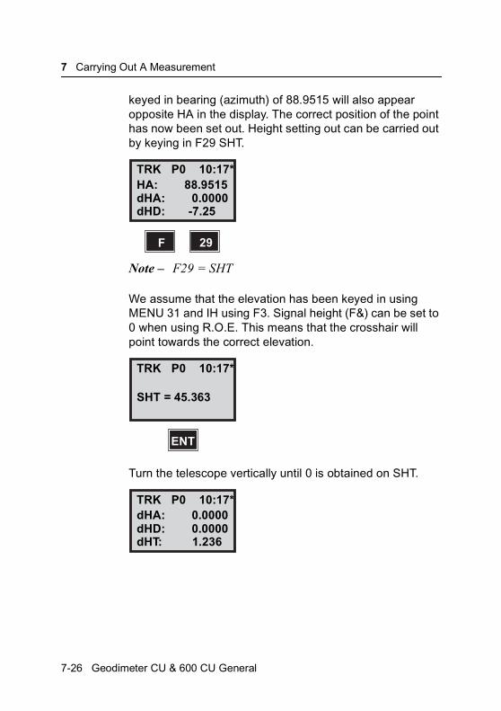
7 Carrying Out A Measurement
keyed in bearing (azimuth) of 88.9515 will also appear opposite HA in the display. The correct position of the point has now been set out. Height setting out can be carried out by keying in F29 SHT.
Note – F29 = SHT
We assume that the elevation has been keyed in using MENU 31 and IH using F3. Signal height (F&) can be set to 0 when using R.O.E. This means that the crosshair will point towards the correct elevation.
Turn the telescope vertically until 0 is obtained on SHT.
TRK P0 10:17*HA: 88.9515dHA: 0.0000dHD: -7.25
F 29
TRK P0 10:17*
SHT = 45.363
ENT
TRK P0 10:17*dHA: 0.0000dHD: 0.0000dHT: 1.236
7-26 Geodimeter CU & 600 CU General
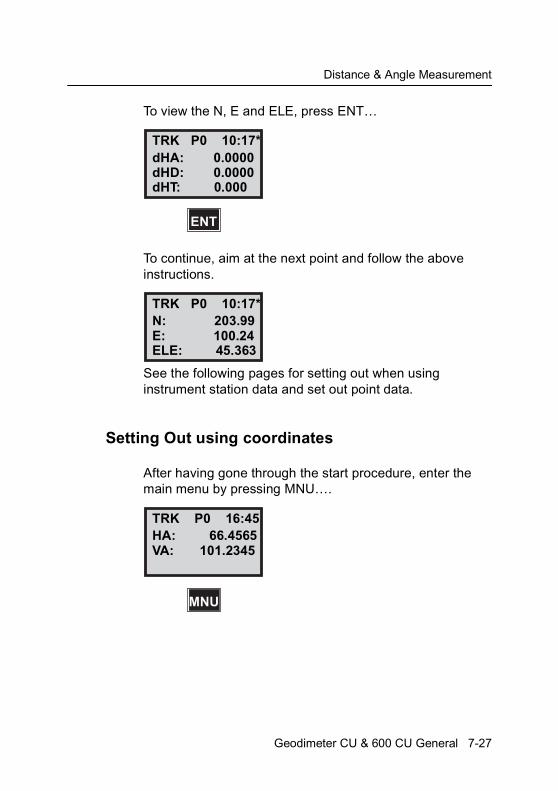
Distance & Angle Measurement
To view the N, E and ELE, press ENT…
To continue, aim at the next point and follow the above instructions.
See the following pages for setting out when using instrument station data and set out point data.
Setting Out using coordinates
After having gone through the start procedure, enter the main menu by pressing MNU….
TRK P0 10:17*dHA: 0.0000dHD: 0.0000dHT: 0.000
ENT
TRK P0 10:17*N: 203.99E: 100.24ELE: 45.363
TRK P0 16:45HA: 66.4565VA: 101.2345
MNU
Geodimeter CU & 600 CU General 7-27
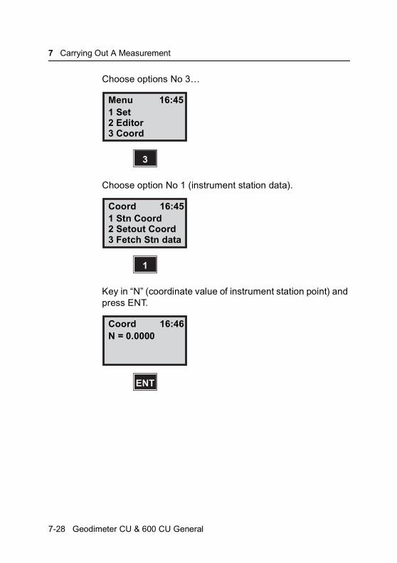
7 Carrying Out A Measurement
Choose options No 3…
Choose option No 1 (instrument station data).
Key in “N” (coordinate value of instrument station point) and press ENT.
Menu 16:451 Set2 Editor3 Coord
3
Coord 16:451 Stn Coord2 Setout Coord3 Fetch Stn data
1
Coord 16:46N = 0.0000
ENT
7-28 Geodimeter CU & 600 CU General
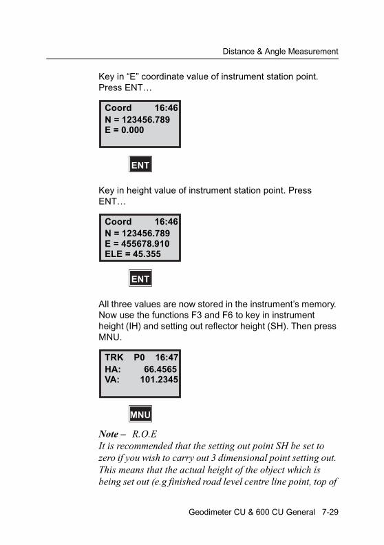
Distance & Angle Measurement
Key in “E” coordinate value of instrument station point. Press ENT…
Key in height value of instrument station point. Press ENT…
All three values are now stored in the instrument’s memory. Now use the functions F3 and F6 to key in instrument height (IH) and setting out reflector height (SH). Then press MNU.
Note – R.O.EIt is recommended that the setting out point SH be set to zero if you wish to carry out 3 dimensional point setting out. This means that the actual height of the object which is being set out (e.g finished road level centre line point, top of
Coord 16:46N = 123456.789E = 0.000
ENT
Coord 16:46N = 123456.789E = 455678.910
ENT
ELE = 45.355
TRK P0 16:47HA: 66.4565VA: 101.2345
MNU
Geodimeter CU & 600 CU General 7-29
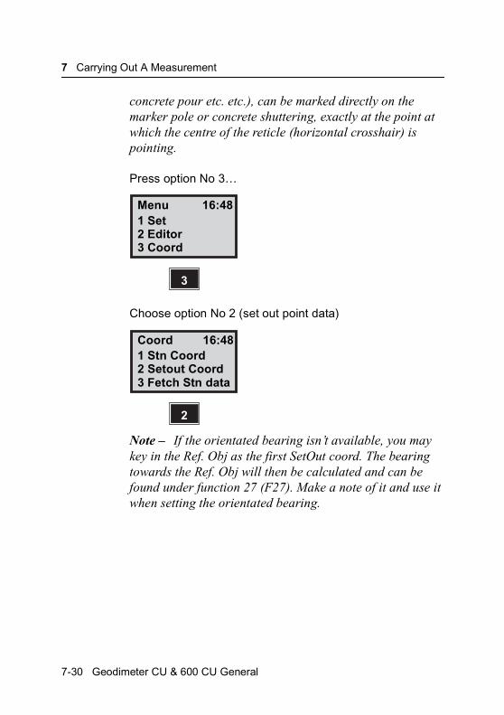
7 Carrying Out A Measurement
concrete pour etc. etc.), can be marked directly on the marker pole or concrete shuttering, exactly at the point at which the centre of the reticle (horizontal crosshair) is pointing.
Press option No 3…
Choose option No 2 (set out point data)
Note – If the orientated bearing isn’t available, you may key in the Ref. Obj as the first SetOut coord. The bearing towards the Ref. Obj will then be calculated and can be found under function 27 (F27). Make a note of it and use it when setting the orientated bearing.
Menu 16:481 Set2 Editor3 Coord
3
Coord 16:481 Stn Coord2 Setout Coord3 Fetch Stn data
2
7-30 Geodimeter CU & 600 CU General
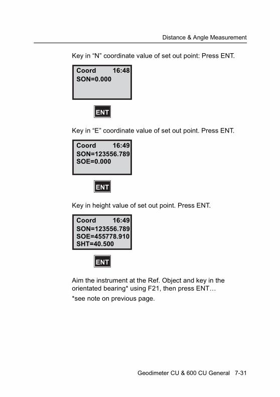
Distance & Angle Measurement
Key in “N” coordinate value of set out point: Press ENT.
Key in “E” coordinate value of set out point. Press ENT.
Key in height value of set out point. Press ENT.
Aim the instrument at the Ref. Object and key in the orientated bearing* using F21, then press ENT…
*see note on previous page.
Coord 16:48SON=0.000
ENT
Coord 16:49SON=123556.789SOE=0.000
ENT
Coord 16:49SON=123556.789SOE=455778.910
ENT
SHT=40.500
Geodimeter CU & 600 CU General 7-31
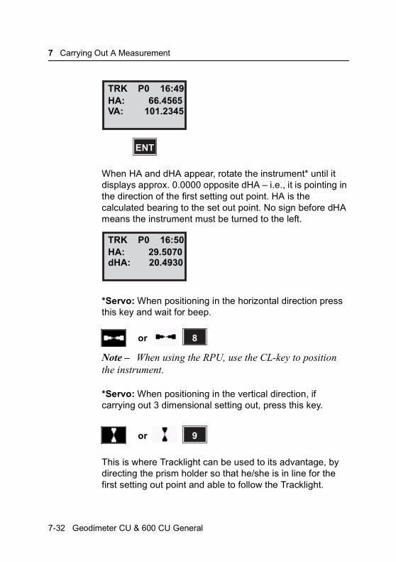
7 Carrying Out A Measurement
When HA and dHA appear, rotate the instrument* until it displays approx. 0.0000 opposite dHA – i.e., it is pointing in the direction of the first setting out point. HA is the calculated bearing to the set out point. No sign before dHA means the instrument must be turned to the left.
*Servo: When positioning in the horizontal direction press this key and wait for beep.
Note – When using the RPU, use the CL-key to position the instrument.
*Servo: When positioning in the vertical direction, if carrying out 3 dimensional setting out, press this key.
This is where Tracklight can be used to its advantage, by directing the prism holder so that he/she is in line for the first setting out point and able to follow the Tracklight.
TRK P0 16:49HA: 66.4565VA: 101.2345
ENT
TRK P0 16:50HA: 29.5070dHA: 20.4930
X 8or
X 9or
7-32 Geodimeter CU & 600 CU General

Distance & Angle Measurement
Note – Tracklight
As soon as the prism comes within the measurement beam you will see dHD (minus sign before dHD means the prism must be moved towards the instrument).
Continue this procedure until both the dHA and DHD = 0. The correct keyed in bearing (azimuth) of 50.000 will also appear opposite HA in the display. The correct position of the point has now been set out.
By pressing the ENT key at this stage you can check the accuracy of the set out point by checking the HD, VD, N, E and Elevation.
50.0000 is the correct bearing to the point and 141.42 is the correct distance. Now for the Height, press ENT.
Elevation of the point to be set out is 40.500. Turn telescope upwards until it shows this value.
X
TRK P0 16:51*HA: 50.000dHA: 0.0000
ENT
dHD: 2.03
TRK P0 16:52*HA: 50.0000HA: 141.142
ENT
VD: 0.000
Geodimeter CU & 600 CU General 7-33

7 Carrying Out A Measurement
You are now realy to set out the next point. Press MNU, choose Option 3, choice No 2, SetOut Coord and repeat the above instructions.
Measuring Differences Robotic Surveying (only servo)
Important information when measuring with high accuracy and using the instrument’s tracker
To active the highest accuracy when measuring distances shorter than 200 meters and using the Tracker unit you need to be aware of the following:
If you use a large reflector like the Super Prism (Part no. 571 125 021), reflections from the Tracker unit may have influence on the measured distance. The error can vary from 0 to 3 mm. If you use the Miniature Prism (Part no 571 126 060) this error doesn’t occur.
STD.mode measurement
When carrying out a STD-mode measurement in robotic surveying the measurement procedure is a little bit different from the total station; when pressing the A/M_key for a measurement the servo is first fine adjusting the instrument towards the target, the RMT. After that the measurement is initiated. The distance measurement is made during about 4 sec. Under that time the arithmetic mean value of a large number of angle measurements is also calculated and
TRK P0 16:52*N: 123556.78E: 45778.91ELE: 40.500
7-34 Geodimeter CU & 600 CU General

Distance & Angle Measurement
presented thus eliminating an effect of any instability of the RMT during the measurement and resulting in higher accuracy.
D-mode measurement
When carrying out a D-mode measurement in robotic surveying the servo is first fine adjusting the instrument towards the target. Each single measurement of distance and angles is made in the same way as in STD-mode measurement and a continuously updated arithmetic mean value of the repeated measurement for both angles and distance are calculated. This is an improvement compared with the servo-assisted surveying where only the arithmetic value for distance is calculated.
TRK-mode measurement
When carrying out measurements in TRK-mode the servo is set to follow the moving target and very fast measurements can be carried out, but then without fine adjusting the instrument towards the target before the measurements when e.g. setting out. Whenever higher accuracy is demanded the operator can easily switch between the different measurement modes.
Geodimeter CU & 600 CU General 7-35
7 Carrying Out A Measurement
7-36 Geodimeter CU & 600 CU General
C H A P T E R
8
8Direct Reflex (only DR 200+)In general ............................................................................. 8-2
Menu 7 ................................................................................. 8-3Standard deviation .......................................................... 8-2Distance interval ............................................................. 8-2
STD...................................................................................... 8-6Problems to reach the S_Dev ......................................... 8-7
Menu 7.4 .............................................................................. 8-9Point laser (option).......................................................... 8-9
Menu 7.5 .............................................................................. 8-9Weak signal .................................................................... 8-2
8 Direct Reflex (only DR 200+)
In general
Direct reflex measurement requires an instrument with long range because different materials have different reflector qualities. A white surface yields about 90% reflection, while a black surface yields only 5%. So the range is greatly reduced when you measure against a black surface.
Standard deviation
This means that a requested accuracy can be keyed in. During the measurement the operator will be able to see the “count down” towards the keyed-in value. If the requested value is not achieved, the distance measurement can be stopped and the achieved standard deviation will be displayed.
Distance interval
The distance interval makes it possible to select the measurement interval. The user can change these default values. If the object to be measured is more than 200 meters away, the value can be changed to 300 or 400 meters, for example. Another way to use this function is when the user wants to measure a small object at, for example 50 meters, and there is building 150 meters behind the object. To avoid a result from the reflective building you can set the values from 2 to 100 meters.
Weak signal
When the signal becomes to weak, the instrument will not present a result because the accuracy will not be within the
8-2 Geodimeter CU & 600 CU General
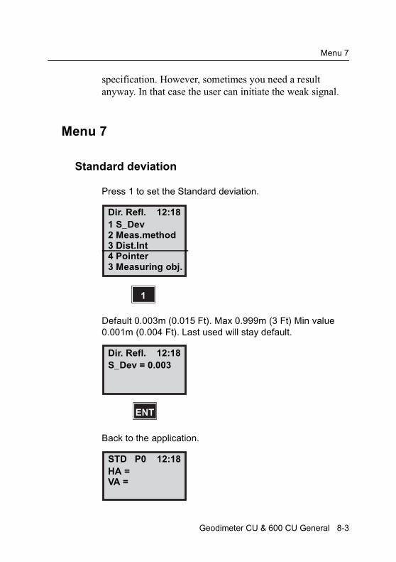
Menu 7
specification. However, sometimes you need a result anyway. In that case the user can initiate the weak signal.
Menu 7
Standard deviation
Press 1 to set the Standard deviation.
Default 0.003m (0.015 Ft). Max 0.999m (3 Ft) Min value 0.001m (0.004 Ft). Last used will stay default.
Back to the application.
Dir. Refl. 12:181 S_Dev2 Meas.method3 Dist.Int
1
4 Pointer3 Measuring obj.
Dir. Refl. 12:18S_Dev = 0.003
ENT
STD P0 12:18HA =VA =
Geodimeter CU & 600 CU General 8-3
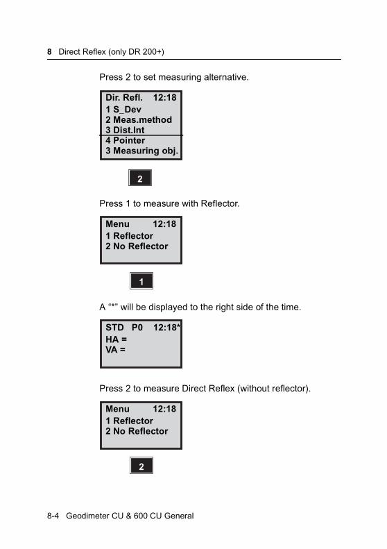
8 Direct Reflex (only DR 200+)
Press 2 to set measuring alternative.
Press 1 to measure with Reflector.
A “*” will be displayed to the right side of the time.
Press 2 to measure Direct Reflex (without reflector).
Dir. Refl. 12:181 S_Dev2 Meas.method3 Dist.Int
2
4 Pointer3 Measuring obj.
Menu 12:181 Reflector2 No Reflector
1
STD P0 12:18*HA =VA =
Menu 12:181 Reflector2 No Reflector
2
8-4 Geodimeter CU & 600 CU General
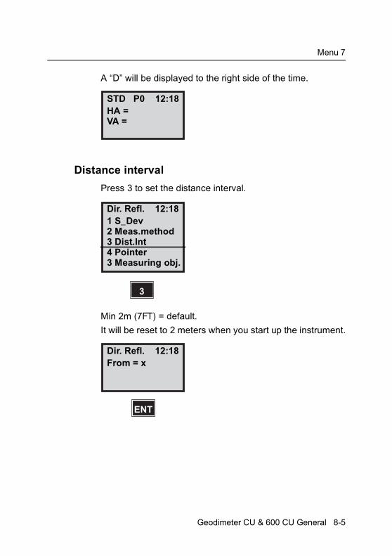
Menu 7
A “D” will be displayed to the right side of the time.
Distance interval
Press 3 to set the distance interval.
Min 2m (7FT) = default.
It will be reset to 2 meters when you start up the instrument.
STD P0 12:18HA =VA =
Dir. Refl. 12:181 S_Dev2 Meas.method3 Dist.Int
3
4 Pointer3 Measuring obj.
Dir. Refl. 12:18From = x
ENT
Geodimeter CU & 600 CU General 8-5

8 Direct Reflex (only DR 200+)
200m (656Ft) = default.It will be reset to 200 meters when you start up the instrument.
Back to the application
The last used alternative will be default next time you start up the instrument.
STD
Press 2 to measure without reflector.
Dir. Refl. 12:18To = x
ENT
To = xxx
STD P0 12:18HA =VA =
STD P0 12:18DHA =VA =
A/M
8-6 Geodimeter CU & 600 CU General
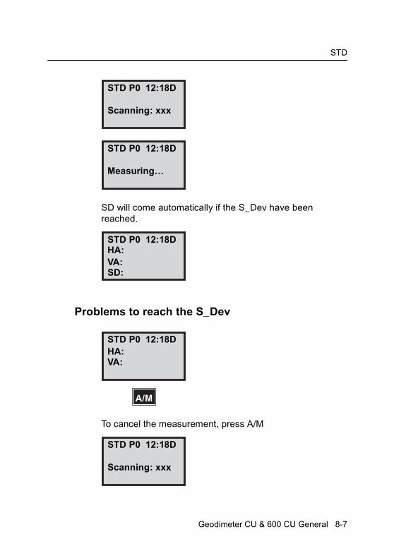
STD
SD will come automatically if the S_Dev have been reached.
Problems to reach the S_Dev
To cancel the measurement, press A/M
STD P0 12:18D
Scanning: xxx
STD P0 12:18D
Measuring…
STD P0 12:18D
VA:HA:
SD:
STD P0 12:18DHA:VA:
A/M
STD P0 12:18D
Scanning: xxx
Geodimeter CU & 600 CU General 8-7
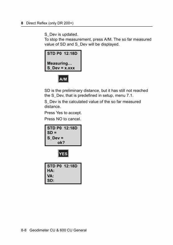
8 Direct Reflex (only DR 200+)
S_Dev is updated.To stop the measurement, press A/M. The so far measured value of SD and S_Dev will be displayed.
SD is the preliminary distance, but it has still not reached the S_Dev, that is predefined in setup, menu 7.1.
S_Dev is the calculated value of the so far measured distance.
Press Yes to accept.
Press NO to cancel.
STD P0 12:18D
Measuring…
A/M
S_Dev = x.xxx
STD P0 12:18D
S_Dev =
YES
SD =
ok?
STD P0 12:18D
VA:HA:
SD:
8-8 Geodimeter CU & 600 CU General
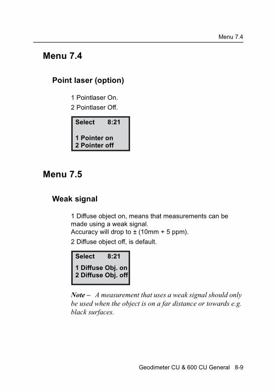
Menu 7.4
Menu 7.4
Point laser (option)
1 Pointlaser On.
2 Pointlaser Off.
Menu 7.5
Weak signal
1 Diffuse object on, means that measurements can be made using a weak signal. Accuracy will drop to ± (10mm + 5 ppm).
2 Diffuse object off, is default.
Note – A measurement that uses a weak signal should only be used when the object is on a far distance or towards e.g. black surfaces.
Select 8:21
1 Pointer on2 Pointer off
Select 8:21
1 Diffuse Obj. on2 Diffuse Obj. off
Geodimeter CU & 600 CU General 8-9

8 Direct Reflex (only DR 200+)
8-10 Geodimeter CU & 600 CU General

C H A P T E R
9
9Surveying methodsIn general (only servo) ......................................................... 9-2Conventional surveying with servo ................................. 9-2Autolock (only servo) ...................................................... 9-3Remote surveying ........................................................... 9-3Robotic Surveying (only servo) ....................................... 9-3
Conventional surveying with Autolock (only servo).............. 9-4Important information when measuring with high accuracy (and using the instrument’s Tracker)............................... 9-4How to work with Autolock .............................................. 9-5Aiming ............................................................................. 9-6
Remote surveying ................................................................ 9-8Important info when measuring with high accuracy ........ 9-8How to work with remote surveying ................................ 9-9Activation of the RPU.................................................... 9-12Aim, measure, Register ................................................ 9-13
Robotic Surveying (only servo) .......................................... 9-14Important information when measuring with high accuracy (and using the instrument’s Tracker)............................. 9-14How to work with robotic surveying............................... 9-15Search Window............................................................. 9-17Activation of the RPU.................................................... 9-19Aim & Measure ............................................................. 9-21Establishing contact from a detached control unit ........ 9-23Switch to measurement towards an ordinary prism ...... 9-24Switch back to robotic surveying................................... 9-25Search functions in robotic surveying ........................... 9-27
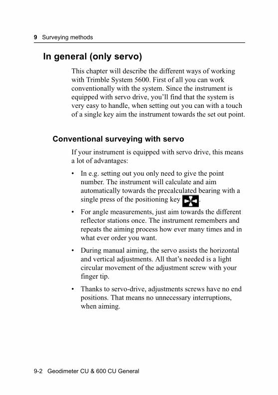
9 Surveying methods
In general (only servo)
This chapter will describe the different ways of working with Trimble System 5600. First of all you can work conventionally with the system. Since the instrument is equipped with servo drive, you’ll find that the system is very easy to handle, when setting out you can with a touch of a single key aim the instrument towards the set out point.
Conventional surveying with servo
If your instrument is equipped with servo drive, this means a lot of advantages:
• In e.g. setting out you only need to give the point number. The instrument will calculate and aim automatically towards the precalculated bearing with a single press of the positioning key .
• For angle measurements, just aim towards the different reflector stations once. The instrument remembers and repeats the aiming process how ever many times and in what ever order you want.
• During manual aiming, the servo assists the horizontal and vertical adjustments. All that’s needed is a light circular movement of the adjustment screw with your finger tip.
• Thanks to servo-drive, adjustments screws have no end positions. That means no unnecessary interruptions, when aiming.
9-2 Geodimeter CU & 600 CU General
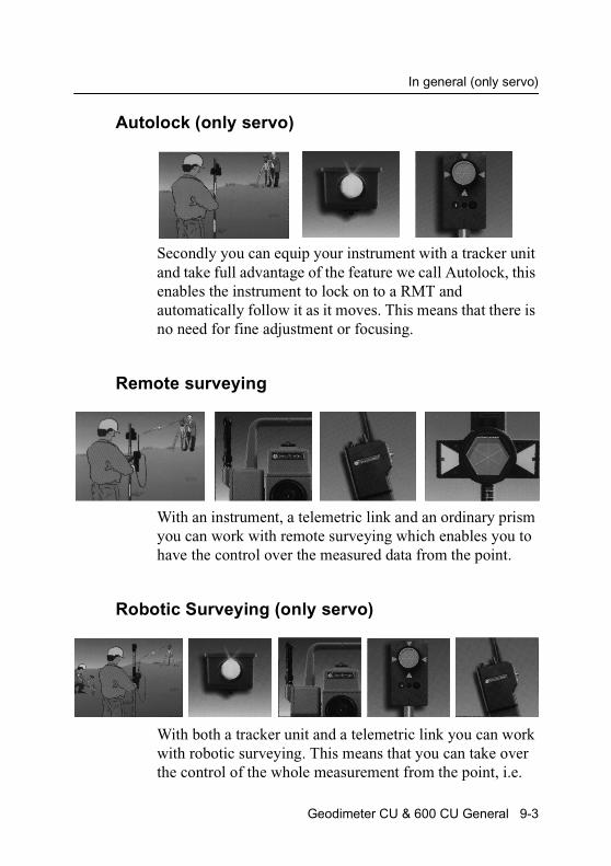
In general (only servo)
Autolock (only servo)
Secondly you can equip your instrument with a tracker unit and take full advantage of the feature we call Autolock, this enables the instrument to lock on to a RMT and automatically follow it as it moves. This means that there is no need for fine adjustment or focusing.
Remote surveying
With an instrument, a telemetric link and an ordinary prism you can work with remote surveying which enables you to have the control over the measured data from the point.
Robotic Surveying (only servo)
With both a tracker unit and a telemetric link you can work with robotic surveying. This means that you can take over the control of the whole measurement from the point, i.e.
Geodimeter CU & 600 CU General 9-3
9 Surveying methods
you have a one-person system. On the following pages we will describe the different measuring techniques with Trimble System 5600.
Conventional surveying with Autolock (only servo)
With the feature Autolock™, you do no longer have fine adjust or focus, since this is taken care of by the system.
• To upgrade a base unit to Autolock™, you’ll only need to add a Tracker unit and a RMT target. It is also possible to measure in a conventional way without Autolock™ using an ordinary reflector.
• When setting out, you’ll only need to supply a pre-stored point and the system will calculate the necessary data for setting out. Then, position the instrument with the positioning key. When the rodman, guided by the built-in Tracklight enters the Tracker’s field of view (2.5m/100m), the instrument locks onto the RMT automatically. You’re now able to fully concentrate on the information in the display (radial/right angle offset) and direct the rodman to the setting out point.
Important information when measuring with high accuracy (and using the instrument’s Tracker)
To achieve the highest accuracy when measuring distances shorter than 200 meters and using the Tracker unit you need to be aware of the following:
Always use the Miniature Prism (Part no. 571 126 060) mounted on your RMT. If you use a large reflector like the Super Prism (Part no. 571 125 021), reflections from the
9-4 Geodimeter CU & 600 CU General

Conventional surveying with Autolock (only servo)
Tracker unit may have influence on the measured distance. The error can vary from 0 to 3 mm. This error doesn’t occur using the Miniature Prism.
How to work with Autolock
First switch on your instrument and make the necessary setup; activate compensator, enter PPM-parameters etc.
First press the “RPU”-button on the instrument.
Choose 1. Autolock.
STD P0 16:12HA: 72.0000VA: 90.0000
4 ↑↑↑↑or RPU
RPU 16:121 Autolock <-2 Manual
1
RPU
Geodimeter CU & 600 CU General 9-5
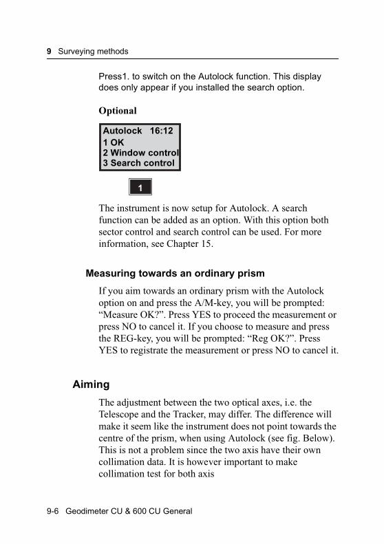
9 Surveying methods
Press1. to switch on the Autolock function. This display does only appear if you installed the search option.
Optional
The instrument is now setup for Autolock. A search function can be added as an option. With this option both sector control and search control can be used. For more information, see Chapter 15.
Measuring towards an ordinary prism
If you aim towards an ordinary prism with the Autolock option on and press the A/M-key, you will be prompted: “Measure OK?”. Press YES to proceed the measurement or press NO to cancel it. If you choose to measure and press the REG-key, you will be prompted: “Reg OK?”. Press YES to registrate the measurement or press NO to cancel it.
Aiming
The adjustment between the two optical axes, i.e. the Telescope and the Tracker, may differ. The difference will make it seem like the instrument does not point towards the centre of the prism, when using Autolock (see fig. Below). This is not a problem since the two axis have their own collimation data. It is however important to make collimation test for both axis
Autolock 16:121 OK2 Window control
1
3 Search control
9-6 Geodimeter CU & 600 CU General
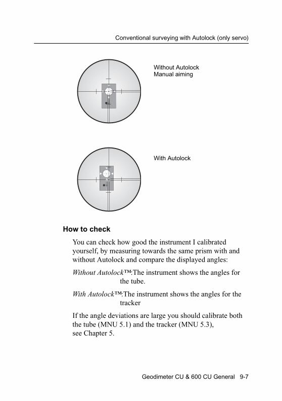
Conventional surveying with Autolock (only servo)
How to check
You can check how good the instrument I calibrated yourself, by measuring towards the same prism with and without Autolock and compare the displayed angles:
Without Autolock™:The instrument shows the angles for the tube.
With Autolock™:The instrument shows the angles for the tracker
If the angle deviations are large you should calibrate both the tube (MNU 5.1) and the tracker (MNU 5.3), see Chapter 5.
Without AutolockManual aiming
With Autolock
Geodimeter CU & 600 CU General 9-7

9 Surveying methods
Remote surveying
Remote surveying means the instrument operator’s job is to aim the instrument toward the reflector. The most experienced member of the survey crew is out at the measuring point taking care of the qualified work of checking, coding, registering etc.
Remote surveying gives you the ability to access the information where it’s most needed. Because it’s out at the measuring point itself you most often discover how to achieve the best results.
Important info when measuring with high accuracy
To achieve the highest accuracy when measuring distances shorter than 200 meters and having the Tracker unit installed on your instrument you need to be aware of the following.
If you use a large reflector like the Super Prism (Part no. 571 125 021) or the Tiltable Reflector (Part No. 571 126 110) you need to cover the tracker aperture before you measure the distance. Otherwise reflections from the Tracker unit may have influence on the measured distance. The error can vary from 0 to 3 mm. If you use a Miniature Prism (Part no. 571 126 060 or 571 126 100) this error doesn’t occur.
Equipment
To be able to work with remote surveying you’ll need a control unit at the point. You will also need to equip your instrument with a radio side cover (see chapter 1.1) and to
9-8 Geodimeter CU & 600 CU General
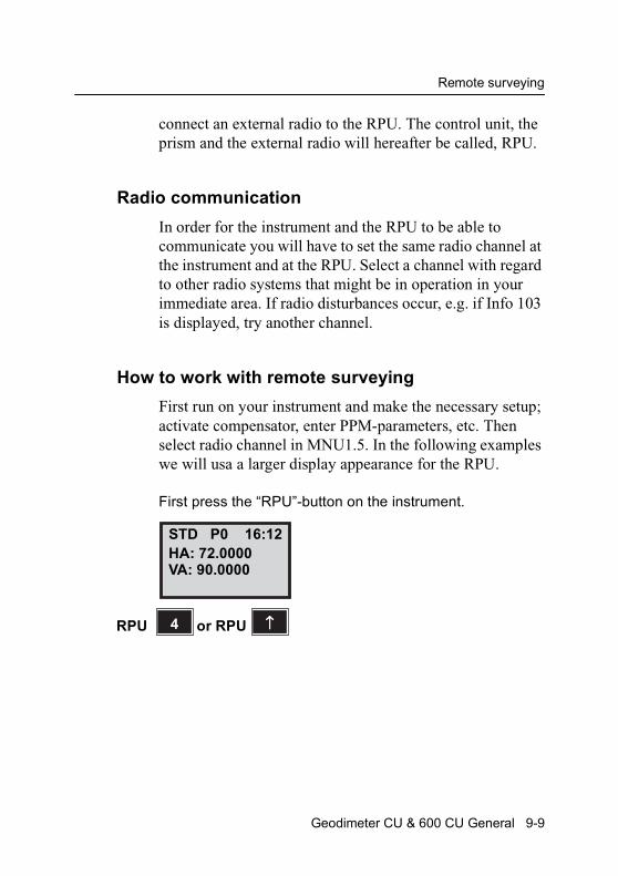
Remote surveying
connect an external radio to the RPU. The control unit, the prism and the external radio will hereafter be called, RPU.
Radio communication
In order for the instrument and the RPU to be able to communicate you will have to set the same radio channel at the instrument and at the RPU. Select a channel with regard to other radio systems that might be in operation in your immediate area. If radio disturbances occur, e.g. if Info 103 is displayed, try another channel.
How to work with remote surveying
First run on your instrument and make the necessary setup; activate compensator, enter PPM-parameters, etc. Then select radio channel in MNU1.5. In the following examples we will usa a larger display appearance for the RPU.
First press the “RPU”-button on the instrument.
STD P0 16:12HA: 72.0000VA: 90.0000
4 ↑↑↑↑or RPURPU
Geodimeter CU & 600 CU General 9-9
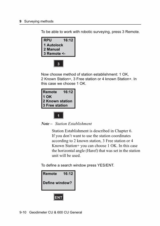
9 Surveying methods
To be able to work with robotic surveying, press 3 Remote.
Now choose method of station establishment: 1 OK, 2 Known Station+, 3 Free station or 4 known Station+. In this case we choose 1 OK.
Note – Station Establishment
Station Establishment is described in Chapter 6. If you don’t want to use the station coordinates according to 2 known station, 3 Free station or 4 Known Station+ you can choose 1 OK. In this case the horizontal angle (Haref) that was set in the station unit will be used.
To define a search window press YES/ENT.
RPU 16:121 Autolock2 Manual
3
3 Remote <-
Remote 16:121 OK2 Known station
1
3 Free station
Remote 16:12
Define window?
ENT
9-10 Geodimeter CU & 600 CU General
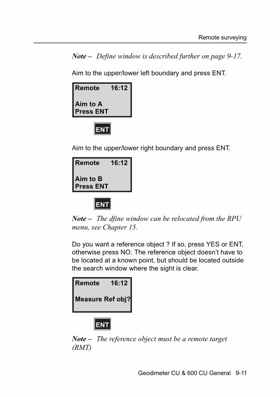
Remote surveying
Note – Define window is described further on page 9-17.
Aim to the upper/lower left boundary and press ENT.
Aim to the upper/lower right boundary and press ENT.
Note – The dfine window can be relocated from the RPU menu, see Chapter 15.
Do you want a reference object ? If so, press YES or ENT, otherwise press NO. The reference object doesn’t have to be located at a known point, but should be located outside the search window where the sight is clear.
Note – The reference object must be a remote target (RMT)
Remote 16:12
Aim to A
ENT
Press ENT
Remote 16:12
Aim to B
ENT
Press ENT
Remote 16:12
Measure Ref obj?
ENT
Geodimeter CU & 600 CU General 9-11
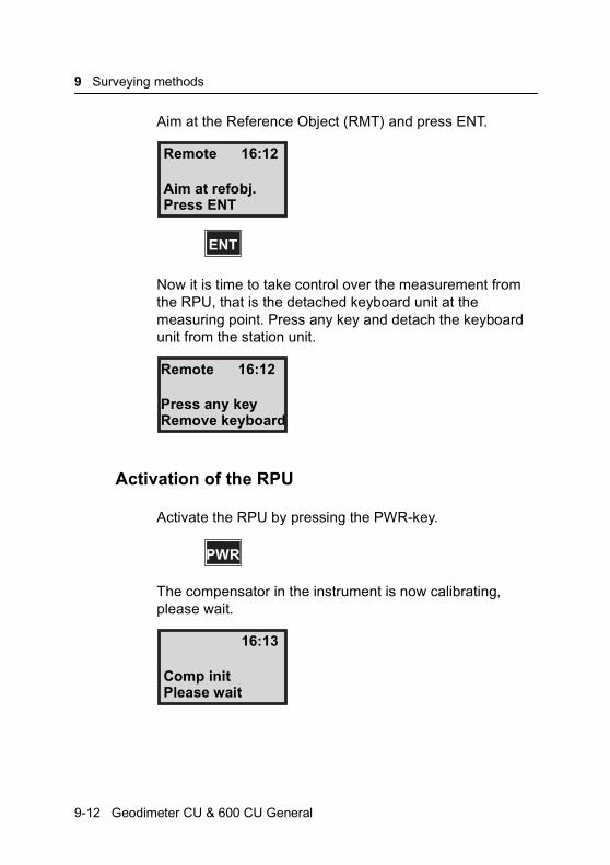
9 Surveying methods
Aim at the Reference Object (RMT) and press ENT.
Now it is time to take control over the measurement from the RPU, that is the detached keyboard unit at the measuring point. Press any key and detach the keyboard unit from the station unit.
Activation of the RPU
Activate the RPU by pressing the PWR-key.
The compensator in the instrument is now calibrating, please wait.
Remote 16:12
Aim at refobj.
ENT
Press ENT
Remote 16:12
Press any keyRemove keyboard
PWR
16:13
Comp initPlease wait
9-12 Geodimeter CU & 600 CU General

Remote surveying
When calibration is ready you will step to program 0, where you enter the PPM values, temp, pressure, offset and Haref.
The display now switches to Standard Measurement mode. You are now in control over the measurement from the RPU. In the upper right display corner you can see the battery status of the battery connected to the station unit and the function of the A/M-key (see Chapter 15).
Aim, measure, Register
When the station unit operator has aimed towards the prism, the RPU is ready to take a measurement. This is indicated with a*. Press the A/M key to start measuring.
16:13
Temp =
ENT
STD P0 16:13 Am
VA: 91.7880HA: 192.8230
STD P0 16:13*+aM
VA: 92.5545
A/M
HA: 234.5678
Geodimeter CU & 600 CU General 9-13
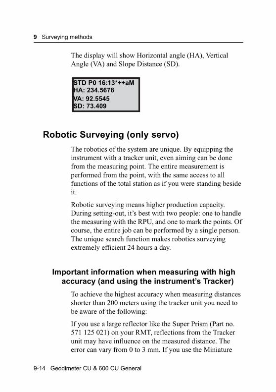
9 Surveying methods
The display will show Horizontal angle (HA), Vertical Angle (VA) and Slope Distance (SD).
Robotic Surveying (only servo)
The robotics of the system are unique. By equipping the instrument with a tracker unit, even aiming can be done from the measuring point. The entire measurement is performed from the point, with the same access to all functions of the total station as if you were standing beside it.
Robotic surveying means higher production capacity. During setting-out, it’s best with two people: one to handle the measuring with the RPU, and one to mark the points. Of course, the entire job can be performed by a single person. The unique search function makes robotics surveying extremely efficient 24 hours a day.
Important information when measuring with high accuracy (and using the instrument’s Tracker)
To achieve the highest accuracy when measuring distances shorter than 200 meters using the tracker unit you need to be aware of the following:
If you use a large reflector like the Super Prism (Part no. 571 125 021) on your RMT, reflections from the Tracker unit may have influence on the measured distance. The error can vary from 0 to 3 mm. If you use the Miniature
STD P0 16:13*++aM
VA: 92.5545HA: 234.5678
SD: 73.409
9-14 Geodimeter CU & 600 CU General

Robotic Surveying (only servo)
Prism (Part no. 571 126 060) instead this error doesn’t occur.
Equipment
To be able to work with robotic surveying you’ll only need one control unit, which you after station establishment etc. disconnect from the instrument and bring to the point. You will also need to equip your instrument with a radio side cover (see Chapter 1), a tracker unit, a RMT (Remote Target) and an external radio connected to the keyboard unit. The keyboard unit, the RMT and the external radio will hereafter be called, RPU.
Radio communication
In order for the instrument and the RPU to be able to communicate you will have to set the same radio channel at the instrument and at the RPU. Select a channel with regards to other radio systems that might be in operation in your immediate area. If radio disturbances occur, e.g. if Info 103 is displayed, try another channel.
How to work with robotic surveying
First turn on your instrument and make the necessary setup; activate compensator, enter PPM-parameters, perform station establishment etc. Then select radio channel in MNU1.5. In the following examples we will use a larger display appearance for the RPU.
Geodimeter CU & 600 CU General 9-15
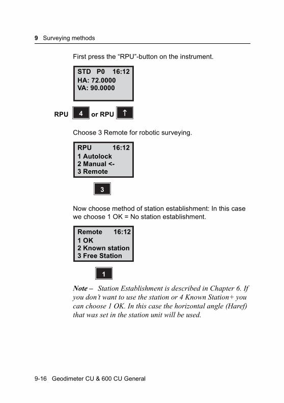
9 Surveying methods
First press the “RPU”-button on the instrument.
Choose 3 Remote for robotic surveying.
Now choose method of station establishment: In this case we choose 1 OK = No station establishment.
Note – Station Establishment is described in Chapter 6. If you don’t want to use the station or 4 Known Station+ you can choose 1 OK. In this case the horizontal angle (Haref) that was set in the station unit will be used.
STD P0 16:12HA: 72.0000VA: 90.0000
4 ↑↑↑↑or RPURPU
RPU 16:121 Autolock2 Manual <-3 Remote
3
Remote 16:121 OK2 Known station3 Free Station
1
9-16 Geodimeter CU & 600 CU General

Robotic Surveying (only servo)
Figure 9.1 Set window. The sector window can be defined as described above.
Search Window
When Station Establishment has been carried out or 1. OK is selected the display will show “Define windows?”. Define
A left boundry
B right boundry
or
B
BA
A
Window Window
Geodimeter CU & 600 CU General 9-17

9 Surveying methods
window gives you the possibility to set a window in which the instrument will search for the RPU. This will decrease the search time and will make you more efficient (it takes 10-12 sec for the instrument to search the complete circle). In this example we will show you how to use the function, answer YES.
Aim to the upper/lower left boundary and press ENT.
Aim to the upper/lower right boundary and press ENT.
Note – Define windowThe window can be relocated from the RPU menu, see Chapter 15.
Remote 16:12
Define window?
YES
Remote 16:12
Aim to APress ENT
ENT
Remote 16:12
Aim to BPress ENT
ENT
9-18 Geodimeter CU & 600 CU General
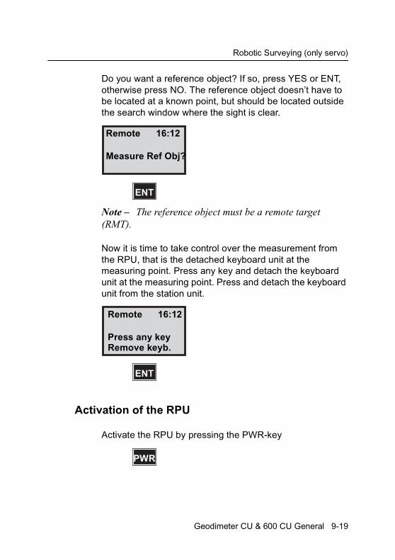
Robotic Surveying (only servo)
Do you want a reference object? If so, press YES or ENT, otherwise press NO. The reference object doesn’t have to be located at a known point, but should be located outside the search window where the sight is clear.
Note – The reference object must be a remote target (RMT).
Now it is time to take control over the measurement from the RPU, that is the detached keyboard unit at the measuring point. Press any key and detach the keyboard unit at the measuring point. Press and detach the keyboard unit from the station unit.
Activation of the RPU
Activate the RPU by pressing the PWR-key
Remote 16:12
Measure Ref Obj?
ENT
Remote 16:12
Press any keyRemove keyb.
ENT
PWR
Geodimeter CU & 600 CU General 9-19
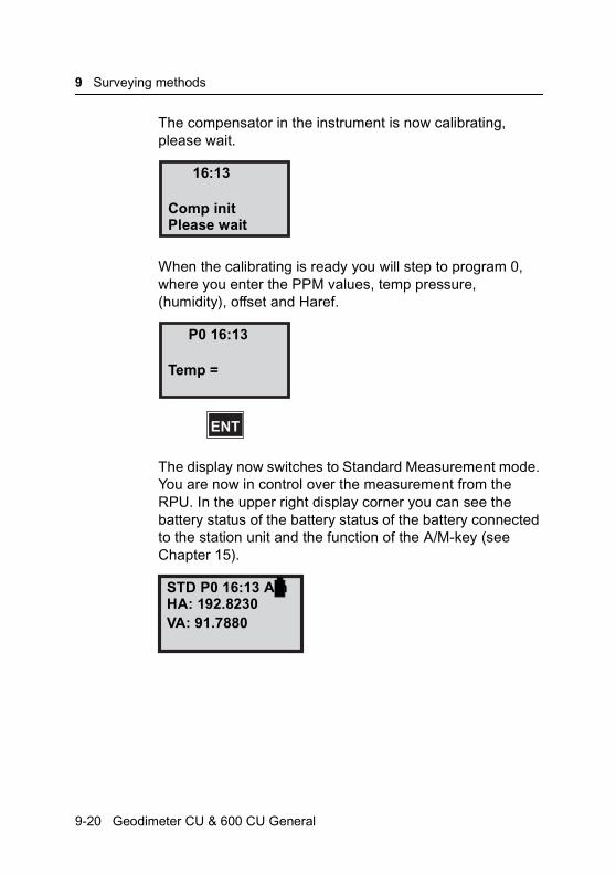
9 Surveying methods
The compensator in the instrument is now calibrating, please wait.
When the calibrating is ready you will step to program 0, where you enter the PPM values, temp pressure, (humidity), offset and Haref.
The display now switches to Standard Measurement mode. You are now in control over the measurement from the RPU. In the upper right display corner you can see the battery status of the battery status of the battery connected to the station unit and the function of the A/M-key (see Chapter 15).
16:13
Comp initPlease wait
P0 16:13
Temp =
ENT
STD P0 16:13 Am
VA: 91.7880HA: 192.8230
9-20 Geodimeter CU & 600 CU General
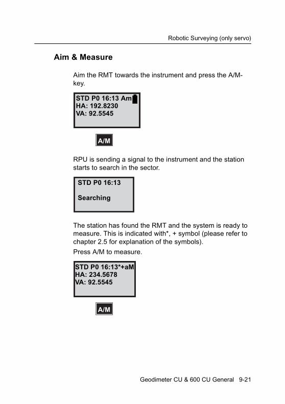
Robotic Surveying (only servo)
Aim & Measure
Aim the RMT towards the instrument and press the A/M-key.
RPU is sending a signal to the instrument and the station starts to search in the sector.
The station has found the RMT and the system is ready to measure. This is indicated with*, + symbol (please refer to chapter 2.5 for explanation of the symbols).
Press A/M to measure.
STD P0 16:13 Am
A/M
HA: 192.8230VA: 92.5545
STD P0 16:13
Searching
STD P0 16:13*+aM
A/M
HA: 234.5678VA: 92.5545
Geodimeter CU & 600 CU General 9-21
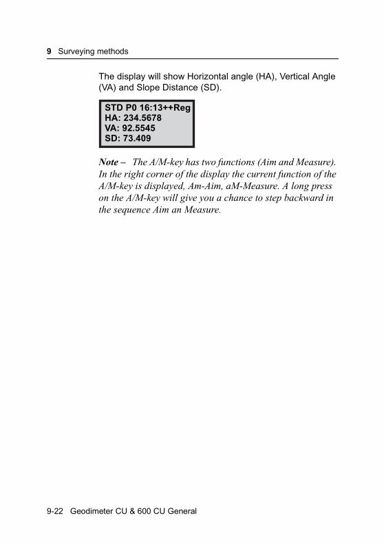
9 Surveying methods
The display will show Horizontal angle (HA), Vertical Angle (VA) and Slope Distance (SD).
Note – The A/M-key has two functions (Aim and Measure). In the right corner of the display the current function of the A/M-key is displayed, Am-Aim, aM-Measure. A long press on the A/M-key will give you a chance to step backward in the sequence Aim an Measure.
STD P0 16:13++RegHA: 234.5678VA: 92.5545SD: 73.409
9-22 Geodimeter CU & 600 CU General
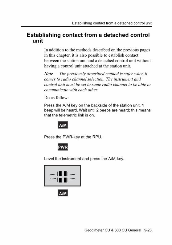
Establishing contact from a detached control unit
Establishing contact from a detached control unit
In addition to the methods described on the previous pages in this chapter, it is also possible to establish contact between the station unit and a detached control unit without having a control unit attached at the station unit.
Note – The previously described method is safer when it comes to radio channel selection. The instrument and control unit must be set to same radio channel to be able to communicate with each other.
Do as follow:
Press the A/M key on the backside of the station unit. 1 beep will be heard. Wait until 2 beeps are heard; this means that the telemetric link is on.
Press the PWR-key at the RPU.
Level the instrument and press the A/M-key.
A/M
PWR
A/M
..........
.....
.....
Geodimeter CU & 600 CU General 9-23
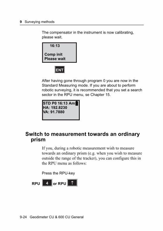
9 Surveying methods
The compensator in the instrument is now calibrating, please wait.
After having gone through program 0 you are now in the Standard Measuring mode. If you are about to perform robotic surveying, it is recommended that you set a search sector in the RPU menu, se Chapter 15.
Switch to measurement towards an ordinary prism
If you, during a robotic measurement wish to measure towards an ordinary prism (e.g. when you wish to measure outside the range of the tracker), you can configure this in the RPU menu as follows:
Press the RPU-key
16:13
ENT
Comp initPlease wait
STD P0 16:13 AmHA: 192.8230VA: 91.7880
4 ↑↑↑↑or RPURPU
9-24 Geodimeter CU & 600 CU General

Switch back to robotic surveying
Press 2 Manual
Press 2 to disconnect the Autolock™ function.
You are now able to measure towards an ordinary prism.
Switch back to robotic surveying
If you wish to switch back to robotic surveying from measuring towards an ordinary prism, do as follows:
Press the RPU-key
16:13
2
2 Manual3 Local
1 Robotic
Manual 16:13
2
2 Autolock off <-1 Autolock on
4 ↑↑↑↑or RPURPU
Geodimeter CU & 600 CU General 9-25
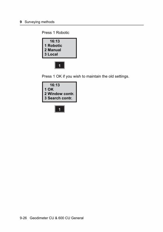
9 Surveying methods
Press 1 Robotic
Press 1 OK if you wish to maintain the old settings.
16:13
1
2 Manual3 Local
1 Robotic
16:13
1
2 Window contr.3 Search contr.
1 OK
9-26 Geodimeter CU & 600 CU General
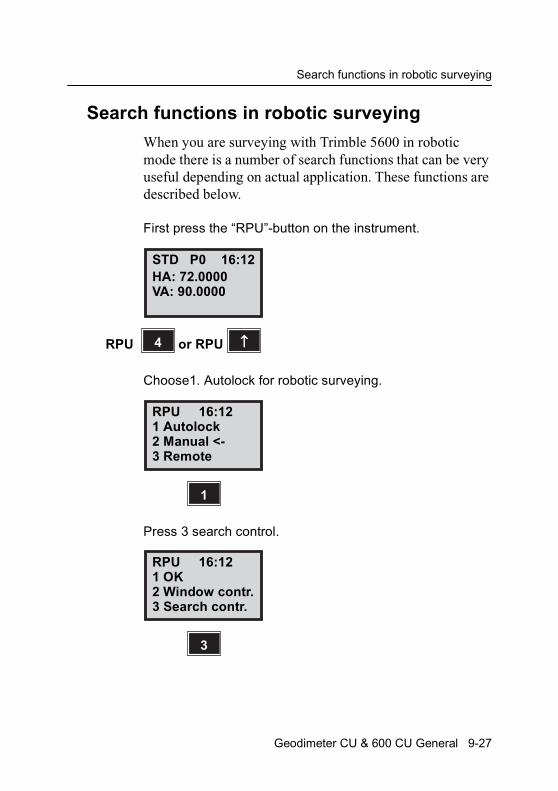
Search functions in robotic surveying
Search functions in robotic surveying
When you are surveying with Trimble 5600 in robotic mode there is a number of search functions that can be very useful depending on actual application. These functions are described below.
First press the “RPU”-button on the instrument.
Choose1. Autolock for robotic surveying.
Press 3 search control.
STD P0 16:12HA: 72.0000VA: 90.0000
4 ↑↑↑↑or RPURPU
RPU 16:12
1
2 Manual <-3 Remote
1 Autolock
RPU 16:12
3
2 Window contr.3 Search contr.
1 OK
Geodimeter CU & 600 CU General 9-27
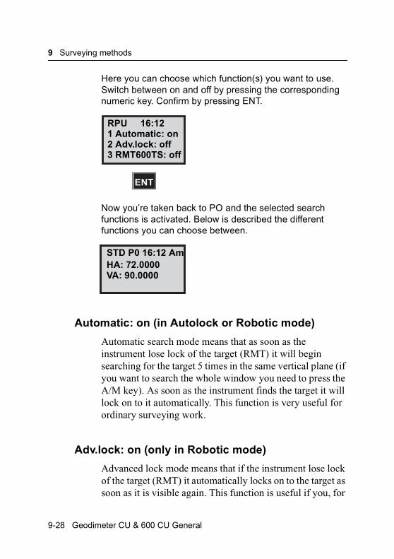
9 Surveying methods
Here you can choose which function(s) you want to use. Switch between on and off by pressing the corresponding numeric key. Confirm by pressing ENT.
Now you’re taken back to PO and the selected search functions is activated. Below is described the different functions you can choose between.
Automatic: on (in Autolock or Robotic mode)
Automatic search mode means that as soon as the instrument lose lock of the target (RMT) it will begin searching for the target 5 times in the same vertical plane (if you want to search the whole window you need to press the A/M key). As soon as the instrument finds the target it will lock on to it automatically. This function is very useful for ordinary surveying work.
Adv.lock: on (only in Robotic mode)
Advanced lock mode means that if the instrument lose lock of the target (RMT) it automatically locks on to the target as soon as it is visible again. This function is useful if you, for
RPU 16:12
ENT
2 Adv.lock: off3 RMT600TS: off
1 Automatic: on
STD P0 16:12 AmHA: 72.0000VA: 90.0000
9-28 Geodimeter CU & 600 CU General
Eccentric Point
example, are measuring in heavy traffic with cars temporarily blocking the measuring beam. This way you save time since the instrument usually (see “Search mode conflict” below) doesn’t start searching each time the measuring beam is being blocked.
Warning – When this switch is activated there is a risk that the instrument could lock on to a window etc. if the tracker signal should come as a reflex from RMT. After a normal search the instrument always locks on to the strongest tracker signal which, in every case, comes directly from the RMT itself.
RMT600TS: on (only in Robotic mode and with RMT600TS)
Sometimes it can be useful to let the instrument lock on to the RMT600TS without the RMT’s vertical sensor being active. This is useful if you must extend the range pole it isn’t possible for you to aim RMT600TS vertically towards the instrument.
Note – Search mode conflict
If both Automatic and Adv.lock are set to ‘on’ there is a conflict. In most cases the instrument will start searching for the RMT after a beam break.
Eccentric Point
Sometimes it is difficult to locate the prism at the point to be measured. This can be solved by considering the point as an eccentric point. Locate the prism at a known distance from the eccentric point, see figure 9.2. Works in STD, FSTD (not TRK or D-bar). Available in P0-P19.
Geodimeter CU & 600 CU General 9-29
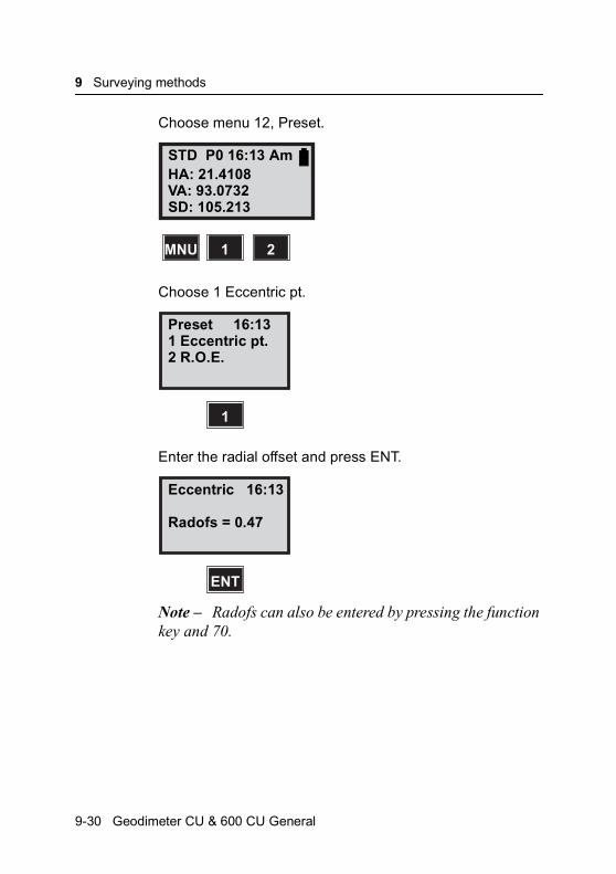
9 Surveying methods
Choose menu 12, Preset.
Choose 1 Eccentric pt.
Enter the radial offset and press ENT.
Note – Radofs can also be entered by pressing the function key and 70.
STD P0 16:13 AmHA: 21.4108VA: 93.0732
1 2MNU
SD: 105.213
Preset 16:13
1
2 R.O.E.1 Eccentric pt.
Eccentric 16:13
ENT
Radofs = 0.47
9-30 Geodimeter CU & 600 CU General

Eccentric Point
Enter the right angle offset and press ENT.
Note – RT.ofs can also be entered by pressing the function key and 71.
Are the offset values OK. If so press YES, otherwise press NO.
The values are now updated with the offset you’ve entered. The new point will get the same height as the measured point. The next point will be measured without the offset if you do not enter menu 121 again.
Eccentric 16:13
ENT
RT.ofs = 0.795
Eccentric 16:13
YES
RT.ofs = 0.795Radofs = 0.47
OK?
STD P0 16:13 AmHA: 21.8643VA: 93.0968SD: 105.619
Geodimeter CU & 600 CU General 9-31
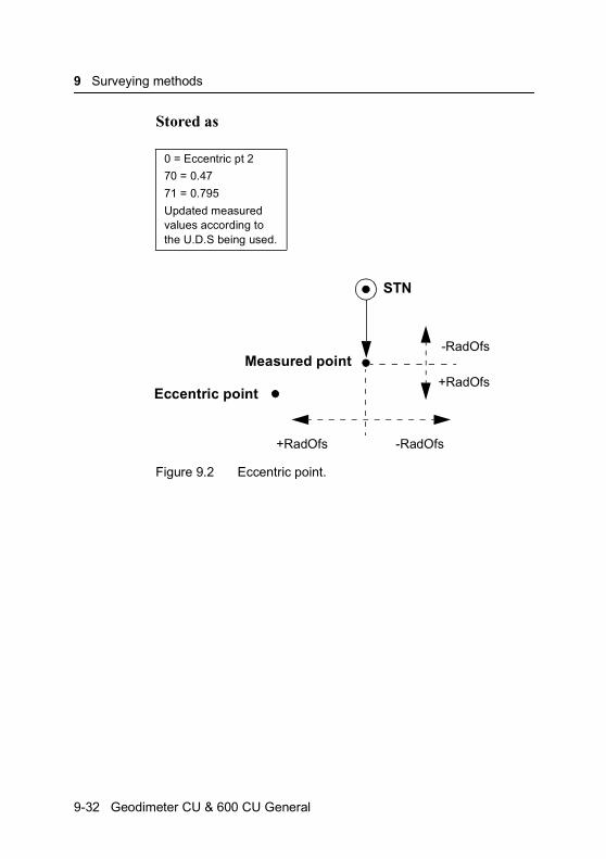
9 Surveying methods
Stored as
Figure 9.2 Eccentric point.
0 = Eccentric pt 2
70 = 0.47
71 = 0.795
Updated measured values according to the U.D.S being used.
STN
-RadOfs
+RadOfs
-RadOfs+RadOfs
Measured point
Eccentric point
9-32 Geodimeter CU & 600 CU General
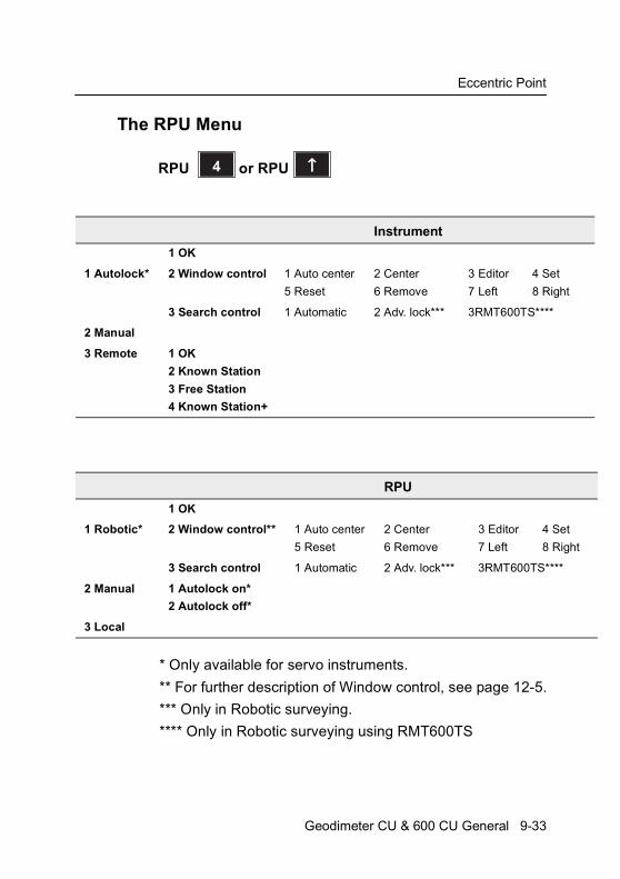
Eccentric Point
t
t
ight
The RPU Menu
* Only available for servo instruments.
** For further description of Window control, see page 12-5.
*** Only in Robotic surveying.
**** Only in Robotic surveying using RMT600TS
Instrument
1 OK
1 Autolock* 2 Window control 1 Auto center
5 Reset
2 Center
6 Remove
3 Editor
7 Left
4 Set
8 Righ
3 Search control 1 Automatic 2 Adv. lock*** 3RMT600TS****
2 Manual
3 Remote 1 OK
2 Known Station
3 Free Station
4 Known Station+
RPU
1 OK
1 Robotic* 2 Window control** 1 Auto center
5 Reset
2 Center
6 Remove
3 Editor
7 Left
4 Se
8 R
3 Search control 1 Automatic 2 Adv. lock*** 3RMT600TS****
2 Manual 1 Autolock on*
2 Autolock off*
3 Local
4 ↑↑↑↑or RPURPU
Geodimeter CU & 600 CU General 9-33

9 Surveying methods
9-34 Geodimeter CU & 600 CU General
C H A P T E R
10
10Important PagesASCII Table ........................................................................ 10-2
General measurement hints............................................... 10-4
Info Codes.........................................................................10-11
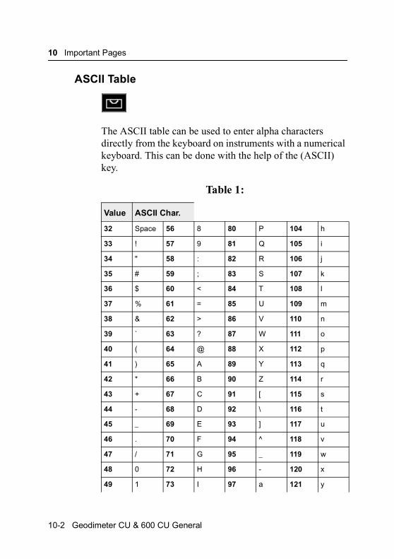
10 Important Pages
ASCII Table
The ASCII table can be used to enter alpha characters directly from the keyboard on instruments with a numerical keyboard. This can be done with the help of the (ASCII) key.
Table 1:
Value ASCII Char.
32 Space 56 8 80 P 104 h
33 ! 57 9 81 Q 105 i
34 " 58 : 82 R 106 j
35 # 59 ; 83 S 107 k
36 $ 60 < 84 T 108 l
37 % 61 = 85 U 109 m
38 & 62 > 86 V 110 n
39 ` 63 ? 87 W 111 o
40 ( 64 @ 88 X 112 p
41 ) 65 A 89 Y 113 q
42 * 66 B 90 Z 114 r
43 + 67 C 91 [ 115 s
44 - 68 D 92 \ 116 t
45 _ 69 E 93 ] 117 u
46 . 70 F 94 ^ 118 v
47 / 71 G 95 _ 119 w
48 0 72 H 96 - 120 x
49 1 73 I 97 a 121 y
10-2 Geodimeter CU & 600 CU General
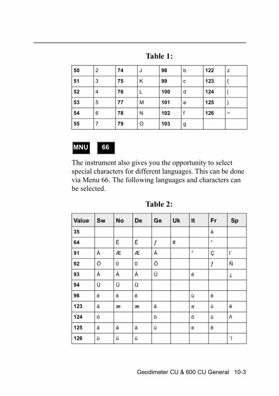
The instrument also gives you the opportunity to select special characters for different languages. This can be done via Menu 66. The following languages and characters can be selected.
50 2 74 J 98 b 122 z
51 3 75 K 99 c 123 {
52 4 76 L 100 d 124 |
53 5 77 M 101 e 125 }
54 6 78 N 102 f 126 ~
55 7 79 O 103 g
Table 2:
Value Sw No De Ge Uk It Fr Sp
35 à
64 É É ƒ # °
91 Ä Æ Æ Ä ° Ç l´
92 Ö 0 0 Ö ƒ Ñ
93 Å Å Å Ü é ¿
94 Ü Ü Ü
96 é é é ù é
123 ä æ æ ä a ù ë
124 ö ö õ ù ñ
125 å å å ü e ë
126 ü ü ü `l
Table 1:
MNU 66
Geodimeter CU & 600 CU General 10-3
10 Important Pages
General measurement hints
Backup of memory
As a safety measure always backup your memory to protect yourself from memory loss. Ensure that your data can be found in more files than one and I if possible in more than one place.
Backup is easily done with Program 54 which enables you to transfer Job- and Area-files between the different Trimble units or to a PC, see “Geodimeter CU software” for more information. You can also use the PC-program Geotool, ask your local dealer for a demonstration.
Reboot the keyboard unit
Measurements will be stored in the memory of the keyboard unit attached to the instrument. The data system is designed to max. security with write protection of the data memory and a backup of the working area of the programs. If a lock up or an error of the program should occur which cannot be resolved by just av restart of the instrument, there is a new reboot action available:
1. Disconnect the keyboard unit from the instrument and connect it to an external battery.
2. Start the keyboard unit by keeping the and key depressed at the same time.
3. In the display will 2 options be available.
4. Choose 2. Reboot and a reboot will occur.
Note – in this case all functions will be reset and all self-made U.D.S. will be lost.
CON
PWR
10-4 Geodimeter CU & 600 CU General
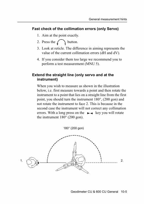
General measurement hints
Fast check of the collimation errors (only Servo)
1. Aim at the point exactly.
2. Press the button.
3. Look at reticle. The difference in aiming represents the value of the current collimation errors (dH and dV).
4. If you consider them too large we recommend you to perform a test measurement (MNU 5).
Extend the straight line (only servo and at the instrument)
When you wish to measure as shown in the illustration below, i.e. first measure towards a point and then rotate the instrument to a point that lies on a straight line from the first point, you should turn the instrument 180°, (200 gon) and not rotate the instrument to face 2. This is because in the second case the instrument will not correct any collimation errors. With a long press on the key you will rotate the instrument 180° (200 gon).
180° (200 gon)
1. 2.
Geodimeter CU & 600 CU General 10-5
10 Important Pages
Collimation errors
The instrument will automatically correct the measured angles for both horizontal and vertical collimation errors as well as for trunnion axis errors by using pre-measured values. By carrying out a test procedure, see chapter 2, you can update these values for the actual conditions. We recommend you to do this regulary especially when measuring during high temperature variations and where high accuracy is demanded in one face.
Test measurements should be carried out with the keyboard configuration current for the measurement.
Tilt axis
When measuring towards a point, the instrument will correct the measured angles as described above. If you tilt the telescope up/downwards you will find that the horizontal angle will change, this is an illustration of tilt axis and two-axis level compensator correction, which both are dependent of the vertical angle. However if you point the telescope to a vertical level string you will find that the horizontal angle will remain constant.
How to combine labels 26, 27, 28 and 29
1. Positioning of HA and VA
If you wish to aim at a point when you know HA and VA you should use label 26 and 27.
2. Set out points with bearing and distance if you know the bearing and the distance to a point you should use label 27 and 28. With label 29 you can also set out the height.
10-6 Geodimeter CU & 600 CU General
General measurement hints
Note – Do not use label 26 for positioning the height of the point. Use instead label 29 and let the instrument calculate the VA.
3. Set out points with known coordinates if the station is established (via program 20 or menu 3) you can use label 67 and 68. With label 69 you can also set out the height.
Note – If you use label 67, 68 or 69, this will also have effect on label 27 and 28.
4. Set out points in height with the servo control key to position the height use the button. If the distance has not yet been measured, the instrument will be positioned in height based on the theoretical distance. If the distance has been measured the instrument will be positioned in height to the measured point, i.e. the height will always be correct even if you do not aim exactly at the correct point.
Fetch Station data (MNU 33)
If you have established a station with program 20 and the station coordinates I somehow destroyed (e.g. with an overriding U.D.S. containing station, IH, Refobj.), you can retrieve the original station coordinates with menu 3.3.
Note – This does not work if label 21 has been changed.
How to set out using Autolock™ (only servo)
1. Switch on Tracklight.
2. Select the point to set out.
3. Aim the instrument towards the point by pressing .
Geodimeter CU & 600 CU General 10-7
10 Important Pages
4. The prism holder looks for the white light from Tracklight without aiming the RMT towards the instrument.
5. When the prism holder is inside the white light, he/she turns the RMT towards the instrument.
6. At the prism, choose the display page that shows Radofs and RT.ofs and guide the prism holder to the right set out point.
Measuring towards corners using Autolock
1. Choose FSTD, STD or D-bar.
2. Aim towards the RMT, press A/M and you will get frozen display values.
3. Turn the RMT away from the instrument.
4. Press the CON-key.
5. Aim the instrument towards the corner.
6. Press the REG-key to registrate the measurement
How to check what is installed in your keyboard unit.
1. Make a long press on your PRG key.
2. Now you are in the UDS library. Press the corresponding key below DIR.
3. Now you are in the PRG library. Press the corresponding key below DIR.
10-8 Geodimeter CU & 600 CU General
General measurement hints
4. Now you can see the options installed in your keyboard unit. Step between the installed options with the corresponding keys below the arrows(-and-).
Temporary Horizontal Angle in P0
The temporary horizontal angle feature in Program 0 can be useful if you want to turn the instrument without affecting the original HA. This function is called HA-L, Horizontal Angle form a Line, and results in an extra line in the display showing HA-L=o.oooo. You activate the HA_L function by pressing key 5. Reset HA_L by pressing key 5 again. Exit HA_L with a long press on key 5. Note that this function only works in Program 0.
Description of Label 23
Label 23 can be used in an U.D.S. to log which units that where current during the measurement.
Note – You cannot change the value of this label with F 23, you must instead use MNU 6.5.
Geodimeter CU & 600 CU General 10-9
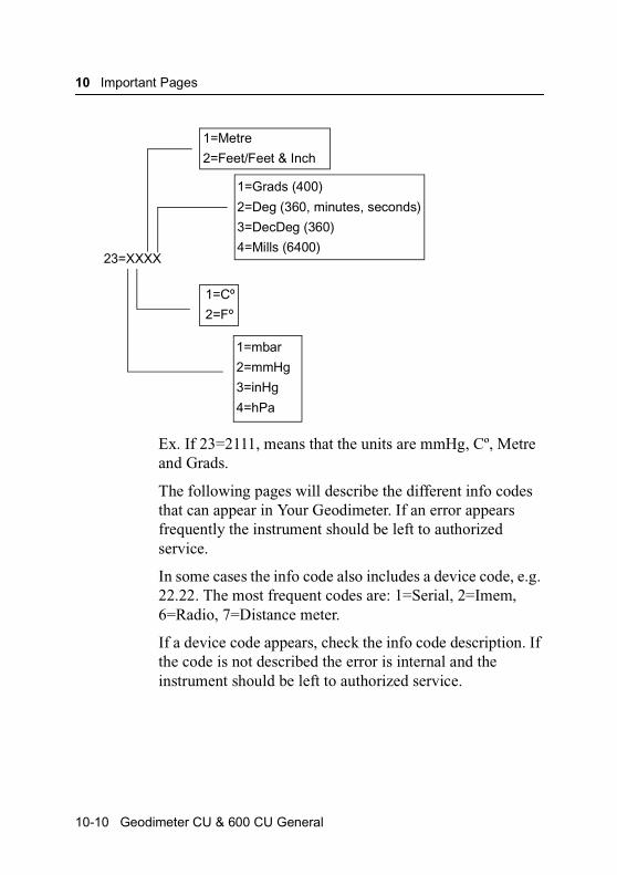
10 Important Pages
Ex. If 23=2111, means that the units are mmHg, Cº, Metre and Grads.
The following pages will describe the different info codes that can appear in Your Geodimeter. If an error appears frequently the instrument should be left to authorized service.
In some cases the info code also includes a device code, e.g. 22.22. The most frequent codes are: 1=Serial, 2=Imem, 6=Radio, 7=Distance meter.
If a device code appears, check the info code description. If the code is not described the error is internal and the instrument should be left to authorized service.
1=Metre
2=Feet/Feet & Inch
1=Grads (400)
2=Deg (360, minutes, seconds)
3=DecDeg (360)
4=Mills (6400)23=XXXX
1=Cº
2=Fº
1=mbar
2=mmHg
3=inHg
4=hPa
10-10 Geodimeter CU & 600 CU General
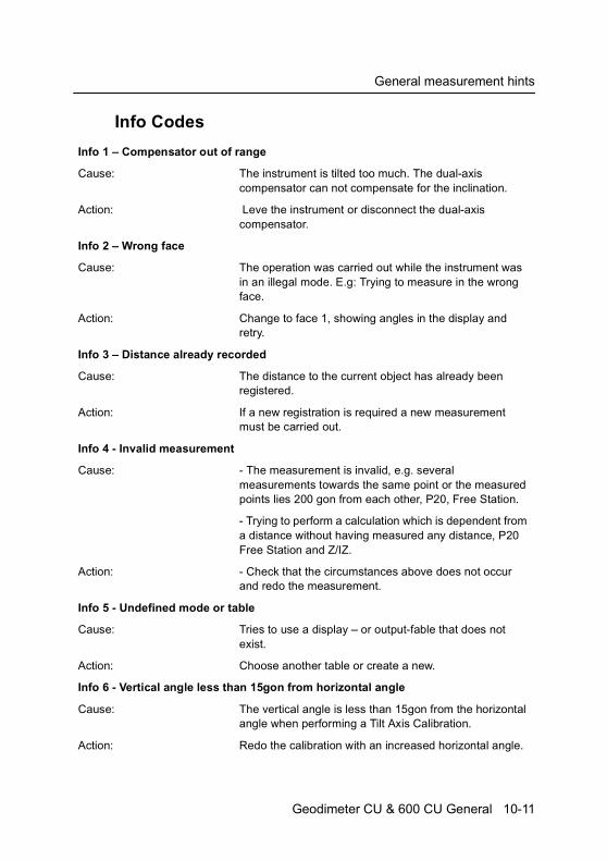
General measurement hints
Info Codes
Info 1 – Compensator out of range
Cause: The instrument is tilted too much. The dual-axis compensator can not compensate for the inclination.
Action: Leve the instrument or disconnect the dual-axis compensator.
Info 2 – Wrong face
Cause: The operation was carried out while the instrument was in an illegal mode. E.g: Trying to measure in the wrong face.
Action: Change to face 1, showing angles in the display and retry.
Info 3 – Distance already recorded
Cause: The distance to the current object has already been registered.
Action: If a new registration is required a new measurement must be carried out.
Info 4 - Invalid measurement
Cause: - The measurement is invalid, e.g. several measurements towards the same point or the measured points lies 200 gon from each other, P20, Free Station.
- Trying to perform a calculation which is dependent from a distance without having measured any distance, P20 Free Station and Z/IZ.
Action: - Check that the circumstances above does not occur and redo the measurement.
Info 5 - Undefined mode or table
Cause: Tries to use a display – or output-fable that does not exist.
Action: Choose another table or create a new.
Info 6 - Vertical angle less than 15gon from horizontal angle
Cause: The vertical angle is less than 15gon from the horizontal angle when performing a Tilt Axis Calibration.
Action: Redo the calibration with an increased horizontal angle.
Geodimeter CU & 600 CU General 10-11
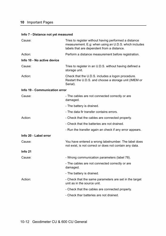
10 Important Pages
Info 7 - Distance not yet measured
Cause: Tries to register without having performed a distance measurement. E.g: when using an U.D.S. which includes labels that are dependent from a distance.
Action: Perform a distance measurement before registration.
Info 10 - No active device
Cause: Tries to register in an U.D.S. without having defined a storage unit.
Action: Check that the U.D.S. includes a logon procedure. Restart the U.D.S. and choose a storage unit (IMEM or Serial).
Info 19 - Communication error
Cause: - The cables are not connected correctly or are damaged.
- The battery is drained.
- The data fir transfer contains errors.
Action: - Check that the cables are connected properly.
- Check that the batteries are not drained.
- Run the transfer again an check if any error appears.
Info 20 - Label error
Cause: You have entered a wrong labelnumber. The label does not exist, is not correct or does not contain any data.
Info 21
Cause: - Wrong communication parameters (label 78).
- The cables are not connected correctly or are damaged.
- The battery is drained.
Action: - Check that the same parameters are set in the target unit as in the source unit.
- Check that the cables are connected properly.
- Check thar batteries are not drained.
10-12 Geodimeter CU & 600 CU General
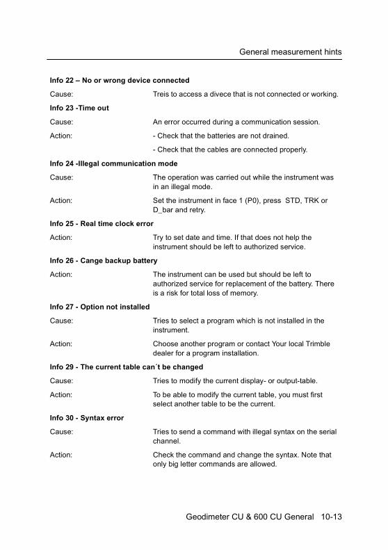
General measurement hints
Info 22 – No or wrong device connected
Cause: Treis to access a divece that is not connected or working.
Info 23 -Time out
Cause: An error occurred during a communication session.
Action: - Check that the batteries are not drained.
- Check that the cables are connected properly.
Info 24 -Illegal communication mode
Cause: The operation was carried out while the instrument was in an illegal mode.
Action: Set the instrument in face 1 (P0), press STD, TRK or D_bar and retry.
Info 25 - Real time clock error
Action: Try to set date and time. If that does not help the instrument should be left to authorized service.
Info 26 - Cange backup battery
Action: The instrument can be used but should be left to authorized service for replacement of the battery. There is a risk for total loss of memory.
Info 27 - Option not installed
Cause: Tries to select a program which is not installed in the instrument.
Action: Choose another program or contact Your local Trimble dealer for a program installation.
Info 29 - The current table can´t be changed
Cause: Tries to modify the current display- or output-table.
Action: To be able to modify the current table, you must first select another table to be the current.
Info 30 - Syntax error
Cause: Tries to send a command with illegal syntax on the serial channel.
Action: Check the command and change the syntax. Note that only big letter commands are allowed.
Geodimeter CU & 600 CU General 10-13
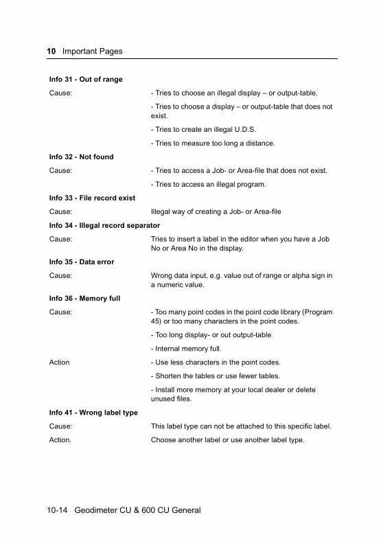
10 Important Pages
Info 31 - Out of range
Cause: - Tries to choose an illegal display – or output-table.
- Tries to choose a display – or output-table that does not exist.
- Tries to create an illegal U.D.S.
- Tries to measure too long a distance.
Info 32 - Not found
Cause: - Tries to access a Job- or Area-file that does not exist.
- Tries to access an illegal program.
Info 33 - File record exist
Cause: Illegal way of creating a Job- or Area-file
Info 34 - Illegal record separator
Cause: Tries to insert a label in the editor when you have a Job No or Area No in the display.
Info 35 - Data error
Cause: Wrong data input, e.g. value out of range or alpha sign in a numeric value.
Info 36 - Memory full
Cause: - Too many point codes in the point code library (Program 45) or too many characters in the point codes.
- Too long display- or out output-table
- Internal memory full.
Action - Use less characters in the point codes.
- Shorten the tables or use fewer tables.
- Install more memory at your local dealer or delete unused files.
Info 41 - Wrong label type
Cause: This label type can not be attached to this specific label.
Action. Choose another label or use another label type.
10-14 Geodimeter CU & 600 CU General

General measurement hints
Info 42 - U.D.S. program memory full
Action: Delete unnesed U.D.S. programs or shorten the programs.
Info 43 - Calculation error
Action: Redo the procedure.
Info 44 - Not enough data for calculation
Cause: The program needs more points för the calculation, P20, Free Station.
Action: Measure more points and redo the calculation.
Info 46 - GDM power error
Cause: RPU can not switch on GDM
Action: Redo the procedure. If the error appears again leave the instrument toauthorixed service.
Info 47 - U.D.S. call stack error
Cause: You have used call in too many steps (max 4 steps).
Action: Check the U.D.S´s and decrease the number of calls.
Info 48 - No or wrong station establishment
Cause: - The station lebels has been changed since the station was established.
- The station is not established.
Action: Perform a station establishment. If using a RPU and if the station has been established earlier, fetch station data with menu 33.
Info 49 - RPU not logged on to GDM
Cause: Tries to perform an operation that demands a RPU.
Action: Logon the PRU to the GDM and redo the operation.
Info 51 - Memory lost
Action: Reboot the instrument /see page 10-4). If that does not help leave theinstrument to authorized service.
Info 54 - Info 54 Memory lost
Action: Reboot the instrument (see page 10-4). If that does not help, leave the instrument to authorized service.
Geodimeter CU & 600 CU General 10-15
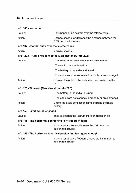
10 Important Pages
Info 103 - No carrier
Cause: Disturbance or no contact over the telemetry link.
Action Change channel or decrease the distance between the RPU and the instrument.
Info 107- Channel busy over the telemetry link
Action: Change channel.
Info 122.6 - Radio not connected (Can also show info 22.6)
Cause: - The radio Is not connected to the geodimeter.
- The radio is not switched on.
- The battery in the radio is drained.
- The cables are not connected properly or are damaged.
Action: Connect the radio to the instrument and switch on the radio.
Info 123 - Time out (Can also show info 23.6)
Cause: - The battery in the radio I drained.
- The cables are not connected properly or are damaged.
Action: Check the cable connections and examine the radio battery.
Info 153 - Limit switch engaged
Cause: Tries to position the instrument to an illegal angle.
Info 155 - The horizontal positioning is not good enough
Action: If this appears frequently leave the instrument to authorized service.
Info 156 - The horizontal & vertical positioning isn’t good enough
Action: If this error appears frequently leave the instrument to authorized service.
10-16 Geodimeter CU & 600 CU General

General measurement hints
Info 158 - Can not find the target
Cause: - The aiming from the RPU is bad.
- The measuring distance is too long.
-The measuring beam was obstructed.
Action: Try to aim the RPU towards the Station more accurate and remove any obstructing object. If possible try to reduce the measuring distance.
Info 161 - The target is lost
Cause: - The aiming from the RPU is bad.
- The measuring beam is obstructed.
- The target was moved too fast.
Action: Try to aim the RPU towards tge Station more accureate and remove any obstructing object. If not in tracking mode, it is important to hold the target still while measuring.
Info 162 - Syntax error (see Info 30)
Info 166 - No measuring signal from prism
Cause: The distance meter in the instrument or the prism is obstructed.
Action: Remove any obstructing object from the instrument and the prism.
Info 167 - Collimation error too large
Cause: The collimation error during a test measurement was too large.
Action: Increase the measuring distance. It is important to keep the RPU held still during the measurement. If the error does not disappear leave the instrument to uthorized service.
Info 174.7 - Distance mearuement error
Action: Redo measurement.
Geodimeter CU & 600 CU General 10-17
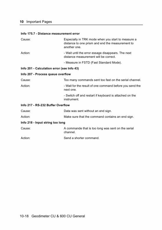
10 Important Pages
Info 175.7 - Distance measurement error
Cause: Especially in TRK mode when you start to measure a distance to one prism and end the measurement to another one.
Action: - Wait until the error essage disappears. The next distance measurement will be correct.
- Measure in FSTD (Fast Standard Mode).
Info 201 - Calculation error (see Info 43)
Info 207 - Process queue overflow
Cause: Too many commands sent too fast on the serial channel.
Action: - Wait for the result of one command before you send the next one.
- Switch off and restart if keyboard is attached on the instrument.
Info 217 - RS-232 Buffer Overflow
Cause: Data was sent without an end sign.
Action: Make sure that the command contains an end sign.
Info 218 - Input string too long
Cause: A commande that is too long was sent on the serial channel.
Action: Send a shorter command.
10-18 Geodimeter CU & 600 CU General

C H A P T E R
11
11Angle Measurement SystemOverview .............................................................................11-3
The Angle Measuring Technique.........................................11-3Dual Axis Compensator .................................................11-3Correction for Collimation Errors....................................11-4Correction for Trunnion Axis Tilt.....................................11-4Calculation of the Horizontal Angle................................11-5Calculation of the Vertical Angle ....................................11-5
Single-Face Angle Measurement........................................11-6
Two-Face Angle Measurement ...........................................11-6

11 Angle Measurement System
Figure 11.1 The Angle Measurement System
Automatic correctionfor deviation in relationto the plumb axis
Automatic correctionfor trunnion axis tilt
Automatic correctionfor collimation error
11-2 Geodimeter CU & 600 CU General
Overview
Overview
The Trimble System 5600 and 3600 meets all demands for efficient and accurate angle measurement. It also allows you to choose the measuring method with which you feel most comfortable. The angle measurement system gives you full compensation for the following:
• Automatic correction for angle sensor errors.
• Automatic correction for collimation error and trunnion Axis tilt.
• Automatic correction for tracker collimation error.
• Arithmetic averaging for elimination of pointing errors.
The Angle Measuring Technique
One of the strong features of the design of Trimble System 5600 is its electronic angle measurement system, which eliminates the angle errors that normally occur in conventional theodolites. The principle of measurement is based on reading an integrated signal over the whole surface of the angle sensor and producing a mean angular value. In this way, inaccuracies due to eccentricity and graduation are eliminated.
Dual Axis Compensator
The instrument is also equipped with a dual axis compensator which will automatically correct both horizontal and vertical angles for any deviations in the plumb line. The system warns immediately of any alterations in excess of ±10c (6’).
Geodimeter CU & 600 CU General 11-3
11 Angle Measurement System
Correction for Collimation Errors
By carrying out a simple pre-measurement test procedure both horizontal and vertical collimation of the instrument can be quickly measured and stored. All angles measured thereafter are automatically corrected. These collimation correction factors remain in the internal memory until they are measured again.
Correction for Trunnion Axis Tilt
During the same pre-measurement test procedure, it is also possible to measure and store angular imperfections of the horizontal tilt axis relative to the horizontal axis. This stored correction factor is applied automatically to all measured horizontal angles.
When should these tests be carried out?
1. After transport where hard handling may have occurred.
2. When the temperature differs by > 10 C from the previous application.
3. If you have changed the keyboard unit configuration since the latest calibration.(You can use one, two or none key board unit).
4. Immediately prior to high precision angle measurement.
How are these tests carried out?
See ”Test Measurements”, Chapter 5, page 5-23.
11-4 Geodimeter CU & 600 CU General
The Angle Measuring Technique
Calculation of the Horizontal Angle
The formula below is used to calculate the horizontal angle:
HA = Has + Eh * 1 / sin v +Yh * 1 /tan v + U * 1 / tan v
(sin v = collimation tan v =levelling tan v=horizontal axis)
HAs = Horizontal angle measured by the electronic sensor.
Eh = Horizontal collimation error.
Yh = Levelling error at right angle to the telescope, corrected by the automatic level compensator.
U = Horizontal axis error.
Calculation of the Vertical Angle
The formula below is used to calculate the vertical angle:
V = Vs + Ev + Yv
Vs = Vertical angle measured by the electronic sensor.
Ev = Vertical collimation error.
Yv = Deviation in the vertical axis, measured by the automatic level compensator.
Geodimeter CU & 600 CU General 11-5

11 Angle Measurement System
Single-Face Angle Measurement
The above described features admits efficient and accurate angle measurement in a single face, since the instruments errors are automatically corrected with constants which are stored during the test measurement.
During Single Face angular measurements, with the compensator engaged and pre-measurement and storage of collimation and tilt axis errors have been executed, each displayed angle will be compensated for the following:
• Horizontal and vertical circle graduation and eccentricity errors.
• Plumb line deviation errors.
• Horizontal and vertical collimation errors.
• Tilt axis errors.
It is worth mentioning that human error sources such as telescope sighting (these errors can be almost nullified by measuring in two faces) and imperfections in the optical plummet of the tribrach still remain.
Two-Face Angle Measurement
The instrument can be used in exactly the same manner as a conventional theodolite, i.e. in both the left and right face. These two-face situations will hereafter be referred to as Circle 1 and Circle 2 positions. Two face measurements can be used for legal reasons, or when additional concern of accuracy and documenations is demanded.
When measuring in STD-mode you measure and store each angle value of the two faces and get a display value of the total collimation and sighting error.
11-6 Geodimeter CU & 600 CU General

Two-Face Angle Measurement
When measuring in D-bar mode you can decrease the sighting error by repeating measurements and mean value calculation of each sighting. The number of repeated sightings can be chosen depending on the current measuring conditions. The final mean value calculated angles are displayed and stored in this mode. Angle values for each face are also available.
Geodimeter CU & 600 CU General 11-7
11 Angle Measurement System
11-8 Geodimeter CU & 600 CU General

C H A P T E R
12
12Distance Measurement SystemOverview ............................................................................ 12-3Distance Measurement ................................................. 12-3Standard measurement (STD Mode)............................ 12-4Fast standard measurement (STD mode) .................... 12-5Precision measurement (D-bar).................................... 12-5Tracking measurement (Setting Out) ............................ 12-6Measurement towards moving targets.......................... 12-7Long Range Measurements.......................................... 12-7Target Data On/Off ........................................................ 12-8Automatic control of signal level ................................... 12-9Measurement beam width............................................. 12-9Measurement range...................................................... 12-9Accuracy .......................................................................... 12-10Important information when measuring with high accuracy... 12-10
R.O.E (Remote Object Elevation) .................................... 12-10
UTM Scale Factor Corrected Distances........................... 12-14
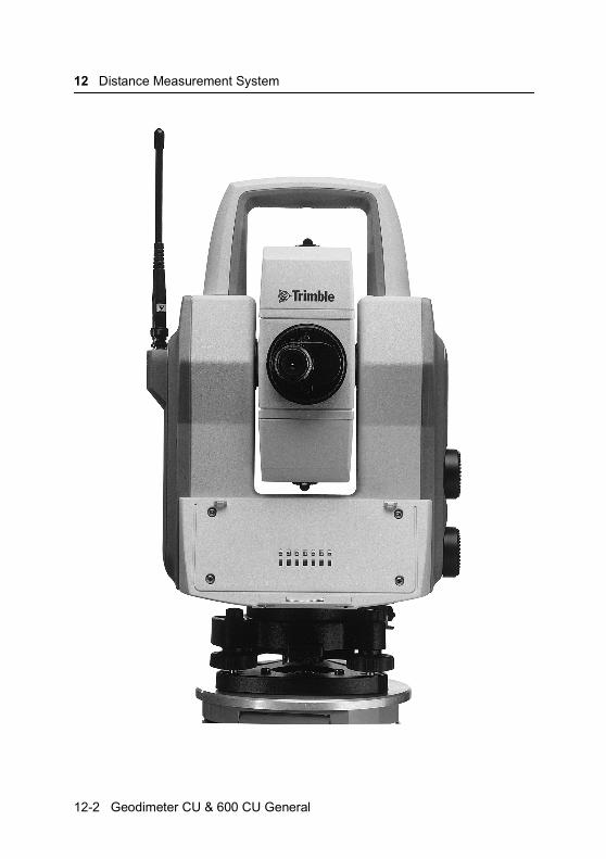
12 Distance Measurement System
12-2 Geodimeter CU & 600 CU General
Overview
Overview
The distance module of Trimble System 5600 and 3600 operates within the infrared area of the electromagnetic spectrum. It transmits an infrared light beam. The reflected light beam is received by the instrument and, with the help of a comparator, the phase delay between transmitted an received signal is measured. The time measurement of the phase delay is converted an displayed as a distance with mm accuracy on the four-line LCD.
Note – When taking measurements with servo instruments and having the Tracker installed there may be a distance error if you use large prisms. See page 12-10 for further information!
Distance Measurement
The internal function of the distance measurement module can be varied depending on the nature of the particular survey application in question. There are four methods of distance measurement
Standard measurements towards stationary targets (standard mode)
Fast measurements towards stationary targets (fast standard mode)
Precision measurements towards stationary targets (arithmetical mean value D-bar mode)
Measurements towards moving targets (tracking mode) e.g setting out or hydrographic surveying. Also functions as
STD
STD
D
TRK
Geodimeter CU & 600 CU General 12-3
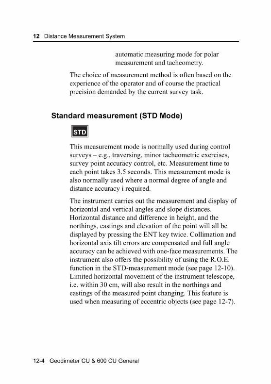
12 Distance Measurement System
automatic measuring mode for polar measurement and tacheometry.
The choice of measurement method is often based on the experience of the operator and of course the practical precision demanded by the current survey task.
Standard measurement (STD Mode)
This measurement mode is normally used during control surveys – e.g., traversing, minor tacheometric exercises, survey point accuracy control, etc. Measurement time to each point takes 3.5 seconds. This measurement mode is also normally used where a normal degree of angle and distance accuracy i required.
The instrument carries out the measurement and display of horizontal and vertical angles and slope distances. Horizontal distance and difference in height, and the northings, eastings and elevation of the point will all be displayed by pressing the ENT key twice. Collimation and horizontal axis tilt errors are compensated and full angle accuracy can be achieved with one-face measurements. The instrument also offers the possibility of using the R.O.E. function in the STD-measurement mode (see page 12-10). Limited horizontal movement of the instrument telescope, i.e. within 30 cm, will also result in the northings and eastings of the measured point changing. This feature is used when measuring of eccentric objects (see page 12-7).
STD
12-4 Geodimeter CU & 600 CU General

Distance Measurement
Fast standard measurement (STD mode)
This measurement mode is used when the object is stationary but the demands on precision are low. The measurement time is very short, approx. 1.3 seconds.
The measurement is performed in the same way as the standard measurement.
Switch between Fast Standard and Standard Measurement Mode
You can configure the STD-key to work in Standard- or Fast Standard mode in menu 62.
Precision measurement (D-bar)
This measurement mode is normally used during control surveys – e.g., traversing, minor tacheometric exercises, survey point accuracy control, etc. Measurement time to each point takes 3.5 seconds. This measurement mode is similar to the one-face STD mode, the major difference being that distance measurement is carried out in a repeated measurement cycle thus resulting in higher accuracy.
The instrument carries out the measurement and display of horizontal and vertical angles and slope distances. Horizontal distance and difference in height, and the northings, eastings and elevation of the point will all be
STD
MNU 26
D
Geodimeter CU & 600 CU General 12-5
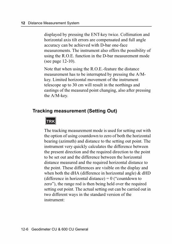
12 Distance Measurement System
displayed by pressing the ENT-key twice. Collimation and horizontal axis tilt errors are compensated and full angle accuracy can be achieved with D-bar one-face measurements. The instrument also offers the possibility of using the R.O.E. function in the D-bar measurement mode (see page 12-10).
Note that when using the R.O.E.-feature the distance measurement has to be interrupted by pressing the A/M-key. Limited horizontal movement of the instrument telescope up to 30 cm will result in the northings and eastings of the measured point changing, also after pressing the A/M-key.
Tracking measurement (Setting Out)
The tracking measurement mode is used for setting out with the option of using countdown to zero of both the horizontal bearing (azimuth) and distance to the setting out point. The instrument very quickly calculates the difference between the present direction and the required direction to the point to be set out and the difference between the horizontal distance measured and the required horizontal distance to the point. These differences are visible on the display and when both the dHA (difference in horizontal angle) & dHD (difference in horizontal distance) = 0 (“countdown to zero”), the range rod is then being held over the required setting out point. The actual setting out can be carried out in two different ways in the standard version of the instrument:
TRK
12-6 Geodimeter CU & 600 CU General
Distance Measurement
• Keying in of bearings (SHA), distances (SHD) and height (SHT) to the points, after first calling up F27 (SHA), F28 (SHD) and F29 (SHT) respectively.
• Keying in of instrument station data (including instrument height =IH) and set out point data by using the main menu, Option 3, Coord, choices 1 and 2. The instrument will then calculate the bearing (SHA), the horizontal distances (SHD) and each individual keyed in setting out point. After setting out the point and checking the point coordinates and elevation, you re-enter the main menu and key in the coords and elevation of the next setting out point. For more information see page 7-26.
Measurement towards moving targets
The TRK mode is fully automatic. All measured values will be updated 0,4 sec. after making contact with the prism. No keys have to be pressed between measurements. It is worth pointing out that battery power consumption is a little higher in this measurement mode compared to the execution of tacheometry in STD-mode. R.O.E is automatic in this measurement mode.
Long Range Measurements
If you have the Long or Medium Range option installed in your instrument you can enable/disable a special function called “Long Range” by accessing MNU 16. If Long Range
MNU 13
MNU 61
Geodimeter CU & 600 CU General 12-7

12 Distance Measurement System
is enabled you will see the “Long Range” text in the display every time you press the A/M button in STD or D-bar mode.If you are unsure whether you have the option installed you can check that by making a long press on the PRG-key.In the first row you will find the characters “LR” or “MR” if you have the options installed.
Target Data On/Off
This allows measuring to points over which the prism range pole cannot be placed – eg., in a corner or at the centre of a large tree. In such a case the instrument can be redirected to the correct point after distance measurement. The offset distance from the inaccessible point is limited to +/-30cm or 50mgon rotation of the instrument for distances within 400mg. This limit allows you to calculate and record the coordinates and elevation of the correct point – i.e. the eccentric point. For distances in excess of 400m the offset limit is proportional to the distance to the point – e.g. at a distance of 1200m, the instrument can be re-directed to the correct point up to offset distance of 90 cm.
Figure 12.1 Measuring against eccentric point.
This +/-30 cm or 50mgon limit can be deactivated by using the main menu CONFIG function, Option 1, Config
12-8 Geodimeter CU & 600 CU General

Distance Measurement
Switches, Target Data Test OFF mode. The default (standard) setting of this switch will always be ON when the instrument is first turned on.
Warning – The target Data Test is created for your safety. It prevents you from storing an old distance with new angle values. When Target Data Test is set to Off that risk will occur, if you forget to measure a distance when measuring the following points.
Automatic control of signal level
The Geodimeter instruments have an automatic signal control which adjusts the measurement signal level for the optimal value of each distance measured.
Measurement beam width
The infrared measurement beam has a width of 16 cm/100m (~6inch/300 feet) (1.6 mrad). The wide measurement beam simplifies considerably both target/prism acquisition and setting out exercises.
Measurement range
The Geodimeter instruments have an range capability of 0.2m to 3500m (depending on the type of instrument) with only one prism in normal weather conditions (Standard clear).
Geodimeter CU & 600 CU General 12-9
12 Distance Measurement System
Accuracy
Since the Geodimeter instruments are constantly improved we refer to the Technical Specifications sheets for the up-to-date accuracy figures of the respective models.
Important information when measuring with high accuracy
To achieve the highest accuracy when measuring distances shorter than 200 meters and having the Tracker unit installed on your instrument you need to be aware of the following:
I you use a large reflector like the Super Prism (Part no. 571 125 021) or the Tiltable Reflector (Part No. 571 126 110) you need to cover the tracker aperture before you measure the distance. Otherwise reflections from the Tracker unit may have influence on the measured distance. The error can vary from 0 to 3 mm. If you use a Miniature Prism (Part no. 571 126 060 or 571 126 100) this error does not occur.
R.O.E (Remote Object Elevation)
The R.O.E. measurement function is used to measure heights of objects where it is not practical or impossible to place a reflector. In order to measure the height of an object, an initial distance measurement is carried out to a reflector held at a point which is in the same vertical plane as the point to be measured. Once the distance has been measured, the height can be measured to any point which lies within the same vertical plane as the point´s location. The height is calculated from the horizontal distance measured and the
12-10 Geodimeter CU & 600 CU General
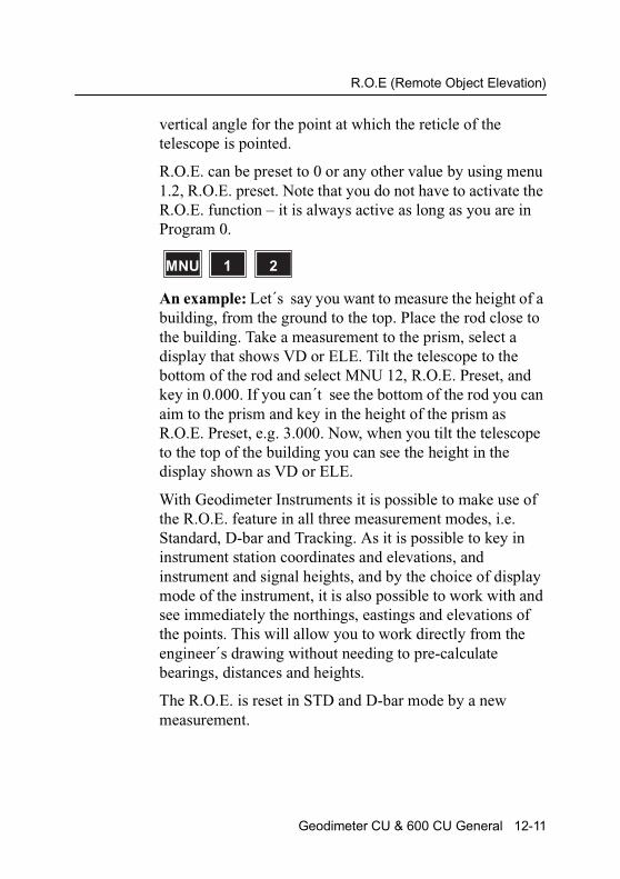
R.O.E (Remote Object Elevation)
vertical angle for the point at which the reticle of the telescope is pointed.
R.O.E. can be preset to 0 or any other value by using menu 1.2, R.O.E. preset. Note that you do not have to activate the R.O.E. function – it is always active as long as you are in Program 0.
An example: Let´s say you want to measure the height of a building, from the ground to the top. Place the rod close to the building. Take a measurement to the prism, select a display that shows VD or ELE. Tilt the telescope to the bottom of the rod and select MNU 12, R.O.E. Preset, and key in 0.000. If you can´t see the bottom of the rod you can aim to the prism and key in the height of the prism as R.O.E. Preset, e.g. 3.000. Now, when you tilt the telescope to the top of the building you can see the height in the display shown as VD or ELE.
With Geodimeter Instruments it is possible to make use of the R.O.E. feature in all three measurement modes, i.e. Standard, D-bar and Tracking. As it is possible to key in instrument station coordinates and elevations, and instrument and signal heights, and by the choice of display mode of the instrument, it is also possible to work with and see immediately the northings, eastings and elevations of the points. This will allow you to work directly from the engineer´s drawing without needing to pre-calculate bearings, distances and heights.
The R.O.E. is reset in STD and D-bar mode by a new measurement.
MNU 21
Geodimeter CU & 600 CU General 12-11

12 Distance Measurement System
Different combinations of Instrument Height (IH) & Signal Height (SH)
It is important to know what the different combinations of instrument and signal heights will produce in the form of displayed results.
1. If you do not key in either instrument or signal height, the vertical distance (VD) shown on the display is the difference between the horizontal of the instrument and the point at which the telescope reticle centre is pointing.
Figure 12.2
2. If you key in the height of the instrument (IH) and the height of the survey point over which the instrument is placed, and set the signal height (SH) of the target to 0, the vertical distance (VD) shown on the display is the difference in height between the station ground point and the point at which the telescope reticle centre is pointing.
The VD value, obtained by changing display page, shows the absolute height. This is the method which should be used when setting out heights directly from the engineer´s drawing, for example.
12-12 Geodimeter CU & 600 CU General
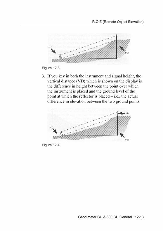
R.O.E (Remote Object Elevation)
Figure 12.3
3. If you key in both the instrument and signal height, the vertical distance (VD) which is shown on the display is the difference in height between the point over which the instrument is placed and the ground level of the point at which the reflector is placed – i.e., the actual difference in elevation between the two ground points.
Figure 12.4
Geodimeter CU & 600 CU General 12-13
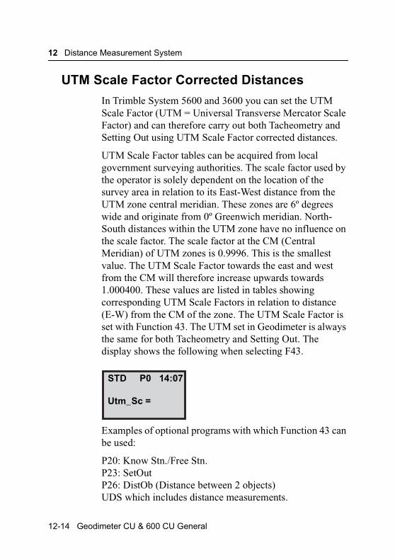
12 Distance Measurement System
UTM Scale Factor Corrected Distances
In Trimble System 5600 and 3600 you can set the UTM Scale Factor (UTM = Universal Transverse Mercator Scale Factor) and can therefore carry out both Tacheometry and Setting Out using UTM Scale Factor corrected distances.
UTM Scale Factor tables can be acquired from local government surveying authorities. The scale factor used by the operator is solely dependent on the location of the survey area in relation to its East-West distance from the UTM zone central meridian. These zones are 6º degrees wide and originate from 0º Greenwich meridian. North-South distances within the UTM zone have no influence on the scale factor. The scale factor at the CM (Central Meridian) of UTM zones is 0.9996. This is the smallest value. The UTM Scale Factor towards the east and west from the CM will therefore increase upwards towards 1.000400. These values are listed in tables showing corresponding UTM Scale Factors in relation to distance (E-W) from the CM of the zone. The UTM Scale Factor is set with Function 43. The UTM set in Geodimeter is always the same for both Tacheometry and Setting Out. The display shows the following when selecting F43.
Examples of optional programs with which Function 43 can be used:
P20: Know Stn./Free Stn.P23: SetOutP26: DistOb (Distance between 2 objects)UDS which includes distance measurements.
STD P0 14:07
Utm_Sc =
12-14 Geodimeter CU & 600 CU General

UTM Scale Factor Corrected Distances
UTM Example
The UTM coord. distance is represented by the line AB (see sketch below). The measured horizontal distance CD on the Geoid must therefore be reduced to AB, with the UTM scale factor for example 0.999723. This is simply done by multiplying CD (the horizontal distance) with your scale factor. This routine will be carried out automatically when keying in a UTM Scale Factor using Function 43.
Figure 12.5 UTM Scale Factor.
F 34
Geodimeter CU & 600 CU General 12-15
12 Distance Measurement System
12-16 Geodimeter CU & 600 CU General

C H A P T E R
13
13Tracklight®Overview ............................................................................ 13-3How to activate Tracklight ............................................. 13-4
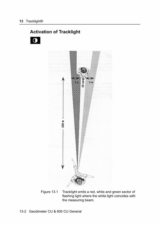
13 Tracklight®
Activation of Tracklight
Figure 13.1 Tracklight emits a red, white and green sector of flashing light where the white light coincides with the measuring beam.
13-2 Geodimeter CU & 600 CU General
Overview
Overview
Tracklight is a visible guide light which enables the staffman to set himself on the correct bearing. It consists of a flashing three coloured light, each colour lying within its own lateral projection sector. If the staffman is to the left of the measuring beam, he will observe a green flashing light; if to the right, a red flashing light; if on-line with the measuring beam of the instrument, a white flashing light.
The frequency of the flash will increase by 100% as soon as the light beam strikes the reflector, which will confirm for the staff – man that he/she is holding the rod in the correct position. Once the staffman is on-line, the distance will immediately appear on the display. Tracklight also provides the operator with an excellent facility for clearing sight lines and for working during the hours of darkness.
From the figure on previous page, it can be seen that the instrument measuring beam width at 100 m is 15 cm. The width of the tracklight beam at the same distance is 10 m.
The tracklight unit slides onto the underside of the measuring unit (see fig figure 13.2) and it is activated from the keyboard.
Geodimeter CU & 600 CU General 13-3

13 Tracklight®
Figure 13.2 The Tracklight unit slides onto the underside of the measuring unit.
How to activate Tracklight
Tracklight is activated from the keyboard by pressing on the keyboard unit.
Tracklight
13-4 Geodimeter CU & 600 CU General
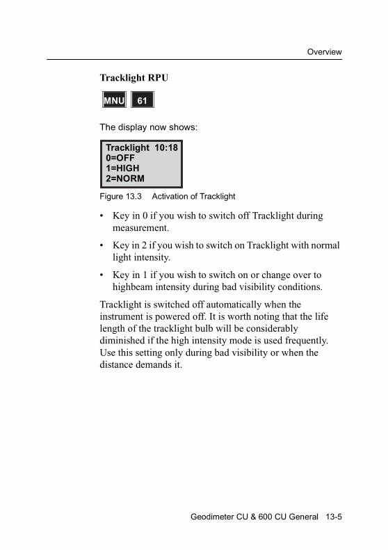
Overview
Tracklight RPU
The display now shows:
Figure 13.3 Activation of Tracklight
• Key in 0 if you wish to switch off Tracklight during measurement.
• Key in 2 if you wish to switch on Tracklight with normal light intensity.
• Key in 1 if you wish to switch on or change over to highbeam intensity during bad visibility conditions.
Tracklight is switched off automatically when the instrument is powered off. It is worth noting that the life length of the tracklight bulb will be considerably diminished if the high intensity mode is used frequently. Use this setting only during bad visibility or when the distance demands it.
MNU 61
Tracklight 10:180=OFF1=HIGH2=NORM
Geodimeter CU & 600 CU General 13-5

13 Tracklight®
13-6 Geodimeter CU & 600 CU General

C H A P T E R
14
14ServoServo controls .................................................................... 14-2Servo control keys ........................................................ 14-2
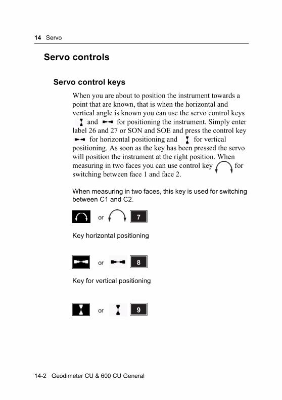
14 Servo
Servo controls
Servo control keys
When you are about to position the instrument towards a point that are known, that is when the horizontal and vertical angle is known you can use the servo control keys
and for positioning the instrument. Simply enter label 26 and 27 or SON and SOE and press the control key
for horizontal positioning and for vertical positioning. As soon as the key has been pressed the servo will position the instrument at the right position. When measuring in two faces you can use control key for switching between face 1 and face 2.
When measuring in two faces, this key is used for switching between C1 and C2.
Key horizontal positioning
Key for vertical positioning
7or
X 8or
X 9or
14-2 Geodimeter CU & 600 CU General

Servo controls
Key for horizontal and vertical positioning
This key is used for switching between C1 and C2 when measuring in two faces. It is available on instruments with no keyboard unit attached at the front. A long press on this key switches the face.
X 6or
Geodimeter CU & 600 CU General 14-3

14 Servo
14-4 Geodimeter CU & 600 CU General
C H A P T E R
15
15Tracker (only for servo instruments)Overview ............................................................................ 15-3
Tracker operation ............................................................... 15-3
Search Criteria (OPTIONAL for Autolock™) ...................... 15-3
Lock on target .................................................................... 15-4
Controlling the tracker (OPTIONAL for Autolock) .............. 15-5
Window control................................................................... 15-5
Search control .................................................................... 15-7
Guidelines .......................................................................... 15-9
Reference Control in Robotic mode................................. 15-10

15 Tracker (only for servo instruments)
Figure 15.1 The Geodimeter System 600 Tracking function.
200 00 m2or
50 acres
15-2 Geodimeter CU & 600 CU General
Overview
Overview
Trimble System 5600 can be equipped with a Tracker unit which is needed when using the system for robotic surveying or when performing conventional surveying with Autolock™ .
The tracker has control over the instrument’s servos and aims the instrument correctly towards the target, which in these cases must be an RMT (Remote Target). An automatic search function is optional.
Tracker operation
Search Criteria (OPTIONAL for Autolock™)
It is possible to let the tracker make a search for the target, e.g. when measuring in dark or in heavy shrubbery where the sight is not so good or when having lost contact with the prism during a measurement.
The search is either started manually by pressing the A/M key or automatically in TRK-mode (if you have switched TRK Search ON):
The tracker seeks for the target in the following order:
1. ±30 degrees horizontally around the point at which the instrument is pointing.
2. In a three-dimensional search window*
Geodimeter CU & 600 CU General 15-3

15 Tracker (only for servo instruments)
*If no search window is set the search will be carried out 360 degrees around the instrument and ±15 degrees vertically.
Note – If no target is found after the search Info 158 will be displayed. Reaim the RMT towards the instrument and press the A/M-key to start the search procedure.
Use the key to cancel the search.
Lock on target
When the instrument is locked on the RMT this is indicated by a + on the display. When moving the RMT, still visible for the instrument, the instrument will automatically follow.
If losing contact with the instrument in STD-, FSTD or D-mode
If the instrument loose visible contact with the RMT, Info 161 (Target lost) will be displayed. Aim the RMT towards the instrument and press the A/M-key to start searching (optional) or use the servo controls to regain contact. The function “Advanced lock” can also be used in these measurement modes (see page 15-7 for further explanation).
If losing contact with the instrument in TRK-mode
If the instrument loose visible contact with the RMT, Info 161 (Target lost) will be displayed. Use the servo controls to regain contact.
With the search option:The tracker can be set to automatically start to seek for the RMT in the search window. The instrument searches
NO
15-4 Geodimeter CU & 600 CU General

Controlling the tracker (OPTIONAL for Autolock)
through the whole search window, both horizontally and vertically. If the target isn’t found the text “Target lost” appears. Press the A/M-key (optional) or use the servo controls to regain contact if you have changed the position much. The function “Advanced lock” can also be used in this measurement mode (see page 12-6).
Controlling the tracker (OPTIONAL for Autolock)
To speed up the search routine, you can set a “window” in which the instrument should seek for the target. When setting up the instrument for remote or robotic surveying you automatically will be prompted to set a search window, but when performing conventional surveying with Autolock, you must enter the RPU menu and chose Window control to do the same.
Window control
You can change the search window by choosing the RPU menu, 1 Autolock and 2 Window control. There are 8 different options on this menu:
1. Auto center – to enable/disable the automatic centering function when the instrument loses contact with the RMT.
2. Center – to manually change the center of the current search window to the position where the instrument is pointing (also in height).
3. Editor – to manually key in the window boundaries:
4 ↑↑↑↑or RPURPU
Geodimeter CU & 600 CU General 15-5
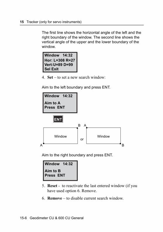
15 Tracker (only for servo instruments)
The first line shows the horizontal angle of the left and the right boundary of the window. The second line shows the vertical angle of the upper and the lower boundary of the window.
4. Set – to set a new search window:
Aim to the left boundary and press ENT.
Aim to the right boundary and press ENT.
5. Reset - to reactivate the last entered window (if you have used option 6. Remove.
6. Remove – to disable current search window.
Window 14:32Hor: L=308 R=27Vert:U=89 D=99Sel Exit
Window 14:32
Aim to APress ENT
ENT
WindowWindow
B
B
A
A
or
Window 14:32
Aim to BPress ENT
15-6 Geodimeter CU & 600 CU General
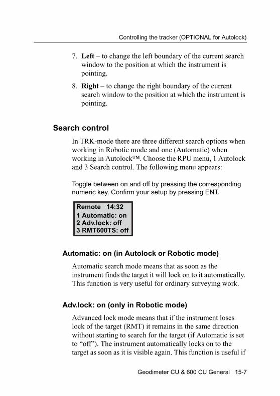
Controlling the tracker (OPTIONAL for Autolock)
7. Left – to change the left boundary of the current search window to the position at which the instrument is pointing.
8. Right – to change the right boundary of the current search window to the position at which the instrument is pointing.
Search control
In TRK-mode there are three different search options when working in Robotic mode and one (Automatic) when working in Autolock™. Choose the RPU menu, 1 Autolock and 3 Search control. The following menu appears:
Toggle between on and off by pressing the corresponding numeric key. Confirm your setup by pressing ENT.
Automatic: on (in Autolock or Robotic mode)
Automatic search mode means that as soon as the instrument finds the target it will lock on to it automatically. This function is very useful for ordinary surveying work.
Adv.lock: on (only in Robotic mode)
Advanced lock mode means that if the instrument loses lock of the target (RMT) it remains in the same direction without starting to search for the target (if Automatic is set to “off”). The instrument automatically locks on to the target as soon as it is visible again. This function is useful if
Remote 14:321 Automatic: on2 Adv.lock: off3 RMT600TS: off
Geodimeter CU & 600 CU General 15-7

15 Tracker (only for servo instruments)
you, for example, are measuring in heavy traffic with cars temporarily blocking the measuring in heavy traffic with cars temporarily blocking the measuring beam. This way you save time since the instrument doesn’t start searching each time the measuring beam is being blocked.
Warning – When this switch is activated there is a risk that the instrument could lock on to a window etc. if the tracker signal should come as a reflex from the RMT. After a normal search the instrument always locks on to the strongest tracker signal which, in every case, comes directly from the RMT itself.
RMT600TS: on (only in Robotic mode and with RMT600TS)
Sometimes it can be useful to let the instrument lock on to the RMT600TS without the RMT’s vertical sensor being active. This is useful if you must extend the range pole so it isn’t possible for you to aim RMT600TS vertically towards the instrument.
Note – Search mode conflict
If both Automatic and Adv.lock are set to ‘on’ there is a conflict. In most cases the instrument will start searching for the RMT after a beam break..
Search routine
Press A/M and the instrument will first start to search 30 degrees horizontally around the last point, considered that the point is inside the search window. There after the instrument will start to search inside the window in the way illustrated below.
A/M
15-8 Geodimeter CU & 600 CU General

Controlling the tracker (OPTIONAL for Autolock)
Figure 15.2 Search routine.
Note – Use the key to cancel search.
Guidelines
Some functions are unique when you use the tracker. The system guides you through the measurement by a number of indicators on the display:
Measurement information
* the instrument has contact with the prism.
+ the tracker has locked on the target.
++ the tracker has locked on the target and the angle values are frozen (STD, FSTD and D-bar modes).
T the tracker is activated. (If search option is installed Am will be seen instead).
STD 12:46* +Am
Geodimeter CU & 600 CU General 15-9
15 Tracker (only for servo instruments)
A/M-key (optional for Autolock™, standard for Robotic)
Am – If you press the A/M key at this moment, the tracker will start searching.
Am – If you press the A/M key at this moment, you will initiate a measurement.
Along press on the A/M-key will change between the two modes.
Reference Control in Robotic mode
and
When setting up the instrument for robotic surveying (see Chapter 9) you can define a reference object which is marked with a remote target. By doing this you can eliminate angular errors caused by tripod turning. By using errors caused by tripod turning.
By using RPU menu 14 you can, whenever you want during the survey in robotic mode, check the reference object bearing and automatically compare the measured bearing with the original and if you want adjust it.
A/M
4 ↑↑↑↑or RPURPU
41111
15-10 Geodimeter CU & 600 CU General
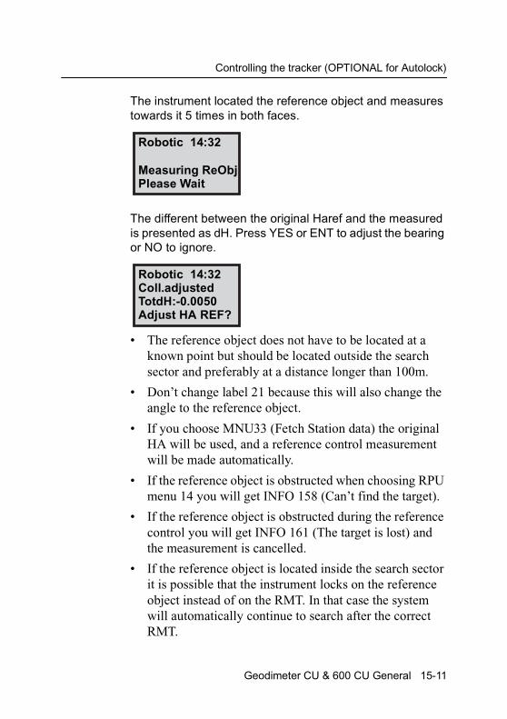
Controlling the tracker (OPTIONAL for Autolock)
The instrument located the reference object and measures towards it 5 times in both faces.
The different between the original Haref and the measured is presented as dH. Press YES or ENT to adjust the bearing or NO to ignore.
• The reference object does not have to be located at a known point but should be located outside the search sector and preferably at a distance longer than 100m.
• Don’t change label 21 because this will also change the angle to the reference object.
• If you choose MNU33 (Fetch Station data) the original HA will be used, and a reference control measurement will be made automatically.
• If the reference object is obstructed when choosing RPU menu 14 you will get INFO 158 (Can’t find the target).
• If the reference object is obstructed during the reference control you will get INFO 161 (The target is lost) and the measurement is cancelled.
• If the reference object is located inside the search sector it is possible that the instrument locks on the reference object instead of on the RMT. In that case the system will automatically continue to search after the correct RMT.
Robotic 14:32
Measuring ReObjPlease Wait
Robotic 14:32Coll.adjustedTotdH:-0.0050Adjust HA REF?
Geodimeter CU & 600 CU General 15-11
15 Tracker (only for servo instruments)
15-12 Geodimeter CU & 600 CU General
C H A P T E R
16
16RadioOverview ............................................................................ 16-2Radio controls ............................................................... 16-2Select radio channel ..................................................... 16-2Station address ............................................................. 16-2Radio license ................................................................ 16-3Radio contact ................................................................ 16-3Range ........................................................................... 16-4Info codes ..................................................................... 16-4
External radio ..................................................................... 16-5

16 Radio
Overview
To be able to communicate between the instrument and the RPU the instrument must be equipped with a radio side cover and the keyboard unit must be connected to an external radio. The radio side cover consists of a built in radio and an antenna.
Radio controls
Select radio channel
The radio channel is selected from menu 15. Up to 12 channels can be used depending on how many are supplied or permitted by authorities in each country. Select a channel using the <-(arrow) key when the keyboard unit is detached and connected to the external radio, this radio will automatically get the same channel as the instrument. The range of different channels makes it possible to work with more than one Trimble System 5600 at a working site. It is though important that each system has its own radio channel so that not any disturbances will occur.
Station address
If disturbances occur on the radio channel from other systems in the same area, try to change channel. If that does not help the instrument and the RPU can be given an unique address. Choose menu 15, Radio with the keyboard unit attached to the instrument. Here you are prompted to enter a station address and a remote address between 0 and 99.
MNU 51
16-2 Geodimeter CU & 600 CU General
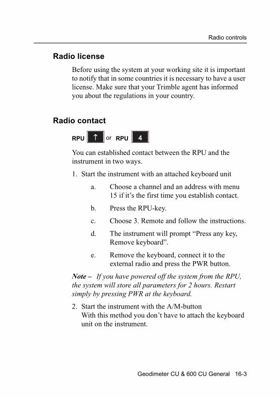
Radio controls
Radio license
Before using the system at your working site it is important to notify that in some countries it is necessary to have a user license. Make sure that your Trimble agent has informed you about the regulations in your country.
Radio contact
You can established contact between the RPU and the instrument in two ways.
1. Start the instrument with an attached keyboard unit
a. Choose a channel and an address with menu 15 if it’s the first time you establish contact.
b. Press the RPU-key.
c. Choose 3. Remote and follow the instructions.
d. The instrument will prompt “Press any key, Remove keyboard”.
e. Remove the keyboard, connect it to the external radio and press the PWR button.
Note – If you have powered off the system from the RPU, the system will store all parameters for 2 hours. Restart simply by pressing PWR at the keyboard.
2. Start the instrument with the A/M-buttonWith this method you don’t have to attach the keyboard unit on the instrument.
4↑↑↑↑RPU or RPU
Geodimeter CU & 600 CU General 16-3
16 Radio
a. Press the A/M button on the backside of the station unit, one beep will be heard.
b. 2 beeps will be heard when the radio is on.
c. Press the PWR button at the detached keyboard unit.
Note – To be able to establish contact between the instrument and RPU by using method 2, you must have established contact using method 1 at least once before, since the external radio must get the correct radio channel from the instrument.
Range
The actual range in which the radio can work is depending on the conditions. Other radios that may be in operation in your area can decrease the range as well as when working in an area with many reflection object.
Info codes
If the radio contact between the RPU and the instrument can not be established info code 103 will be displayed. If this appear, first check that both units are switched on and setup properly, that no other radio is working on the same channel, then restart both unit and retry. If still no radio contact can be established, contact your local Trimble Service shop for support.
If the radio contact between the RPU and the instrument is disturbed e.g. by another radio info code 30 or 107 may be displayed. If this appear, try to change channel.
Note – If the radio battery is in a bad condition when you start the system from RPU, the system might need to be
16-4 Geodimeter CU & 600 CU General

External radio
restarted, i.e. station establishment etc. might have to be done again.
External radio
The external radio is connected to the keyboard unit with the system cable. The PWR button on the radio unit is not necessary to use since the keyboard unit automatically turns the radio unit on at startup. If you connect the keyboard unit to the wrong connector on the radio, the keyboard unit automatically obtains local mode.
Figure 16.1 External radio – top view
Figure 16.2 External radio – left view
Note – The radio battery must be disconnected from the radio before connecting the charger.
Power LED
Power button
Antenna
Connector för Fast battery charger
Geodimeter CU & 600 CU General 16-5

16 Radio
Figure 16.3 External radio – right view
A B
Connector for external battery
Connector for keyboard unit
16-6 Geodimeter CU & 600 CU General

C H A P T E R
17
17Data LoggingData Recording .................................................................. 17-2Control of data registration............................................ 17-3
Data Output........................................................................ 17-4Standard output ............................................................ 17-4User defined output....................................................... 17-7How to create an output table ....................................... 17-7Type of memory device................................................. 17-91. Internal memory ...................................................... 17-102. Serial output.............................................................17-113 Xmem....................................................................... 17-17
Data Communication........................................................ 17-19Keyboard unit Personal Computer.............................. 17-19Instrument with Keyboard unit Personal Computer .... 17-20Keyboard unit Instrument with Keyboard unit ............. 17-20Instrument with Keyboard unit Card Memory.............. 17-21Card Memory Personal Computer .............................. 17-22Program 54 – File transfer .......................................... 17-22

17 Data Logging
Data Recording
The recording of data is based on the general system of labels and label numbers which describe the different data items. The systems has 109 different labels, which all can be registered as separate items directly from the keyboard of the instrument, or they can be recorded using the User Definable Sequences available in the additional software (UDS).
Angle registration can be carried out during both single and double face measurements.
The angle values are measured in face II by pressing the A/M-key and can then be displayed and recorded in the face I position. In this case angle recording is carried out under separate labels for face angle recording is carried out under separate labels for face I and face II. Instrument data can be recorded according to Table 17.1 (see below).
Data is always stored in the keyboard units are attached.
17-2 Geodimeter CU & 600 CU General
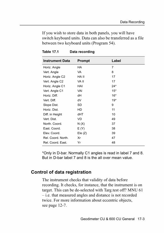
Data Recording
If you wish to store data in both panels, you will have switch keyboard units. Data can also be transferred as a file between two keyboard units (Program 54).
*Only in D-bar. Normally C1 angles is read in label 7 and 8. But in D-bar label 7 and 8 is the all over mean value.
Control of data registration
The instrument checks that validity of data before recording. It checks, for instance, that the instrument is on target. This can be de-selected with Targ.test off? MNU 61 – i.e. that measured angles and distance is not recorded twice. For more information about eccentric objects, see page 12-7.
Table 17.1 Data recording
Instrument Data Prompt Label
Horiz. Angle
Vert. Angle
Horiz. Angle C2
Vert. Angle C2
Horiz. Angle C1
Vert. Angle C1
Horiz. Diff.
Vert. Diff.
Slope Dist.
Horiz. Dist.
Diff. in Height
Vert. Dist.
North. Coord.
East. Coord.
Elev. Coord.
Rel. Coord. North.
Rel. Coord. East.
HA
VA
HA II
VA II
HAI
VAI
dH
dV
SD
HD
dHT
VD
N (X)
E (Y)
Ele (Z)
Xr
Yr
7
8
17
17
24*
15*
16*
19*
9
11
10
49
37
38
39
47
48
Geodimeter CU & 600 CU General 17-3
17 Data Logging
Data Output
A standard table for output is set for each measurement mode of the instrument. If a different output is required, 5 additional output tables can be specified by the user directly from the keyboard. This is done with MNU 42, Create table function.
The choice of the type of recording device that shall be used for the transfer of the data – e.g. Internal memory on the instrument of Serial for direct transfer via the tribrach contact to and from a computer – is done with MNU 41, Select device function.
Different output tables or the same one can be activated for more than one device simultaneously.
Note – A complete list of Function and lables can be found in Appendix A.
Standard output
Output of measured data can be set completely independently of the displayed data. The standard output tables have been set for recording horizontal angle, vertical angle and slope distance for the different measuring modes. If output of other data is required, special output tables can be set by the operator. The standard output, Table 0 (see Table 17.2, page 17-5), is adapted to the function of the different modes of measurement, while a User Defined Table 1, 2, 3, 4 and 5 will be independent of choice of mode.
MNU 4
17-4 Geodimeter CU & 600 CU General
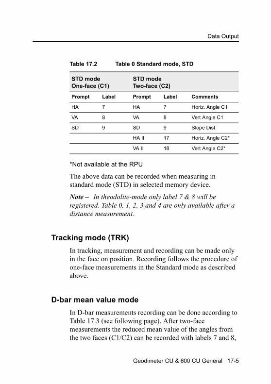
Data Output
*Not available at the RPU
The above data can be recorded when measuring in standard mode (STD) in selected memory device.
Note – In theodolite-mode only label 7 & 8 will be registered. Table 0, 1, 2, 3 and 4 are only available after a distance measurement.
Tracking mode (TRK)
In tracking, measurement and recording can be made only in the face on position. Recording follows the procedure of one-face measurements in the Standard mode as described above.
D-bar mean value mode
In D-bar measurements recording can be done according to Table 17.3 (see following page). After two-face measurements the reduced mean value of the angles from the two faces (C1/C2) can be recorded with labels 7 and 8,
Table 17.2 Table 0 Standard mode, STD
STD modeOne-face (C1)
STD modeTwo-face (C2)
Prompt Label Prompt Label Comments
HA 7 HA 7 Horiz. Angle C1
VA 8 VA 8 Vert Angle C1
SD 9 SD 9 Slope Dist.
HA II 17 Horiz. Angle C2*
VA II 18 Vert Angle C2*
Geodimeter CU & 600 CU General 17-5

17 Data Logging
the mean angular value for angles C1 are recorded with labels 24 and 25, and the mean angular value for angles in C2 are recorded with labels 17 and 18. A mean value of the slope distance (SD) will also be recorded with label 9.
*Only at the instrument
Table 17.3 Table 0, D-bar
D-bar modeOne-face (C1)
D-bar modeTwo-face (C2)
Prompt Label Prompt Label Comments
HA 7 Horiz. Angle C1
VA 8 Vert Angle C1
SD 9 Slope Dist. Mean value
HA 7 Mean value of angle sightings, corrected for difference between C2 and C1.*
VA 8
HA II 17 Mean value for sighting in face 2 (C2).*
VA II 18 -”-
HA I 24 Mean value for sightings in face 1 (C1).*
VA I 25 -”-
SD 9 Slope distance mean value
17-6 Geodimeter CU & 600 CU General
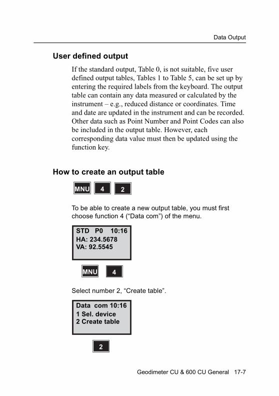
Data Output
User defined output
If the standard output, Table 0, is not suitable, five user defined output tables, Tables 1 to Table 5, can be set up by entering the required labels from the keyboard. The output table can contain any data measured or calculated by the instrument – e.g., reduced distance or coordinates. Time and date are updated in the instrument and can be recorded. Other data such as Point Number and Point Codes can also be included in the output table. However, each corresponding data value must then be updated using the function key.
How to create an output table
To be able to create a new output table, you must first choose function 4 (“Data com”) of the menu.
Select number 2, “Create table”.
MNU 4 2
STD P0 10:16HA: 234.5678VA: 92.5545
MNU 4
Data com 10:161 Sel. device2 Create table
2
Geodimeter CU & 600 CU General 17-7
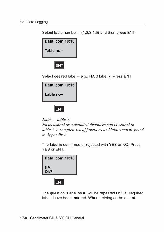
17 Data Logging
Select table number = (1,2,3,4,5) and then press ENT
Select desired label – e.g., HA 0 label 7. Press ENT
Note – Table 5!No measured or calculated distances can be stored in table 5. A complete list of functions and lables can be found in Appendix A.
The label is confirmed or rejected with YES or NO. Press YES or ENT.
The question “Label no =” will be repeated until all required labels have been entered. When arriving at the end of
Data com 10:16
Table no=
ENT
Data com 10:16
Lable no=
ENT
Data com 10:16
HA
ENT
Ok?
17-8 Geodimeter CU & 600 CU General
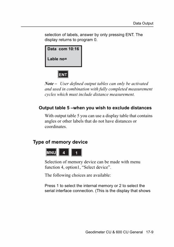
Data Output
selection of labels, answer by only pressing ENT. The display returns to program 0.
Note – User defined output tables can only be activated and used in combination with fully completed measurement cycles which must include distance measurement.
Output table 5 –when you wish to exclude distances
With output table 5 you can use a display table that contains angles or other labels that do not have distances or coordinates.
Type of memory device
Selection of memory device can be made with menu function 4, option1, “Select device”.
The following choices are available:
Press 1 to select the internal memory or 2 to select the serial interface connection. (This is the display that shows
Data com 10:16
Lable no=
ENT
MNU 4 1
Geodimeter CU & 600 CU General 17-9
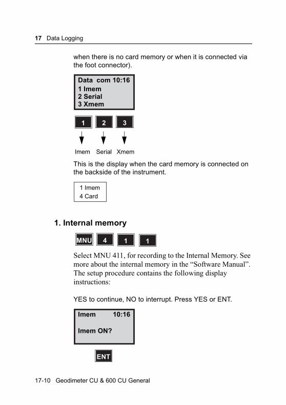
17 Data Logging
when there is no card memory or when it is connected via the foot connector).
This is the display when the card memory is connected on the backside of the instrument.
1. Internal memory
Select MNU 411, for recording to the Internal Memory. See more about the internal memory in the “Software Manual”. The setup procedure contains the following display instructions:
YES to continue, NO to interrupt. Press YES or ENT.
Data com 10:161 Imem2 Serial
1 2 3
3 Xmem
Imem Serial Xmem
1 Imem4 Card
MNU 4 1 1
Imem 10:16
Imem ON?
ENT
17-10 Geodimeter CU & 600 CU General
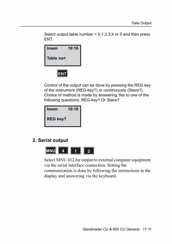
Data Output
Select output table number = 0,1,2,3,4 or 5 and then press ENT.
Control of the output can be done by pressing the REG key of the instrument (REG-key?) or continuously (Slave?). Choice of method is made by answering Yes to one of the following questions: REG-key? Or Slave?
2. Serial output
Select MNU 412 for output to external computer equipment via the serial interface connection. Setting the communication is done by following the instructions in the display and answering via the keyboard.
Imem 10:16
Table no=
ENT
Imem 10:16
REG key?
MNU 4 1 2
Geodimeter CU & 600 CU General 17-11
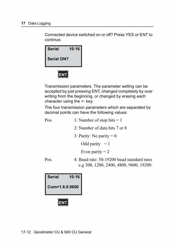
17 Data Logging
Connected device switched on or off? Press YES or ENT to continue.
Transmission parameters. The parameter setting can be accepted by just pressing ENT, changed completely by over writing from the beginning, or changed by erasing each character using the <- key.
The four transmission parameters which are separated by decimal points can have the following values:
Pos. 1: Number of stop bits = 1
2: Number of data bits 7 or 8
3: Parity: No parity = 0
Odd parity = 1
Even parity = 2
Pos. 4: Baud rate: 50-19200 baud standard rates e.g 300, 1200, 2400, 4800, 9600, 19200.
Serial 10:16
Serial ON?
ENT
Serial 10:16
Com=1.8.0.9600
ENT
17-12 Geodimeter CU & 600 CU General
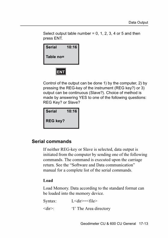
Data Output
Select output table number = 0, 1, 2, 3, 4 or 5 and then press ENT.
Control of the output can be done 1) by the computer, 2) by pressing the REG-key of the instrument (REG key?) or 3) output can be continuous (Slave?). Choice of method is made by answering YES to one of the following questions: REG Key? or Slave?
Serial commands
If neither REG-key or Slave is selected, data output is initiated from the computer by sending one of the following commands. The command is executed upon the carriage return. See the “Software and Data communication” manual for a complete list of the serial commands.
Load
Load Memory. Data according to the standard format can be loaded into the memory device.
Syntax: L<dir>=<file>
<dir>: ‘I’ The Area directory
Serial 10:16
Table no=
ENT
Serial 10:16
REG key?
Geodimeter CU & 600 CU General 17-13
17 Data Logging
‘M’ The Job directory
‘U’ The U.D.S. program directory
<file>: Is the name of the file (max 15 characters). The file name is case sensitive.
Output
Output from memory
Syntax: 0<dir>=<file>
0<dir><arg>
<dir>: ‘I’ The Area directory
‘M’ The Job directory
‘U’ The U.D.S. program directory
<file>: Is the name of the file (max 15 characters). The file name is case sensitive.
<arg>: ‘C’ Output of the file catalog
Read
Read instrument of measured data or data in specific labels
Syntax: RG=[<arg>][,<lbl>]
<arg>: [S] Standard output
N Name output
D Data output
V Numeric output item by item
T Test if signal from target. 300 is returned if no signal. 301 is returned if signal.
17-14 Geodimeter CU & 600 CU General
Data Output
Trig
Start of distance measurement in instrument.
Syntax: TG[<arg>]
<arg>: ‘<’ This is default and need not to be entered.
Write
Write data into instrument. All labels that can be set by the function key in the system can be written.
Syntax: WG,<label>=<data>
<label>: 0-109
<data>: Maximum 9 digits for numeric type labels and maximum 16 characters for ASCII type labels.
When “REG-Key” is selected data corresponding to the actual output table will be transmitted when the REG-key is pressed.
The “Slave”-mode setting means that data are automatically transmitted every time an instrument measurement is completed without needing to press the REG-key.
Hardware connection serial (RS-232/V24)
Use the multi functional cable (Part no 571 202 188/216) together with the computer adapter (Part no 571 202 204) to
Geodimeter CU & 600 CU General 17-15

17 Data Logging
connect the Keyboard unit to a computer via the external battery (Part no 571 202 194) or power supply.
Output format
The standard format of data from the interface is:
<Label>=<data>CRLF
Table 17.4 Computer connection configuration
Pin Signal
2
3
7
8
Data in (RXD)
Data out (txd)
Ground (BATT-)
12 V (BATT+)
Table 17.5 Status Description
Value Description
0 Instrument operating correctly, all required data are available.
3 The measured distance has already been recorded. A new distance measurement is required.
4 Measurement is invalid and recording not possible.
5 Recording is not possible with the selected mode setting of the Geodimeter instrument.
20 Lable error. This lable cannot be handled by the instrument.
21 Parity error in transferred data (between Geodimeter and interface).
22 Bad or no connection, or wrong device connected.
23 Time Out
30 Syntax error
35 Data error
17-16 Geodimeter CU & 600 CU General

Data Output
Status
Status is a numeric value, transmitted before measurement data, and distance those values which are about to be transmitted. This status values is non-zero if an error is detected. See Table 17.5 for status description.
End of Transmission
The end of transmission, EOT, character is set in label 79, where the equivalent ASCII number is set. (Default is 62, e.g “>”). If set to 0 no EOT will be sent.
3 Xmem
Select MNU 413 for output to the Geotronics card memory if it is attached to the panel on the back of the instrument. The setup procedure contains the following display instructions:
YES to continue, NO to interrupt. Press YES or ENT.
Select output table number=0,1,2,3,4 or 5 and then press ENT.
MNU 4 1 3
Xmem 10:16
Xmem ON?
ENT
Geodimeter CU & 600 CU General 17-17

17 Data Logging
Control of the output can be done by pressing the REG key of the instrument (REG key?) or continuously (Slave?). Choice of method is made by answering YES or ENT to one of the questions.
Xmem 10:16
Tabel no=
ENT
Xmem 10:16
REG key?
ENT
17-18 Geodimeter CU & 600 CU General

Data Communication
Data Communication
Geodimeter CU can be connected to an external device via built in serial interface (RS-232) as described on the previous pages. This part of the manual will describe how to transfer data from and to the Trimble System instruments.
Keyboard unit Personal Computer
Connect the Keyboard unit and the computer to a battery via the multi functional cable 571 202 188/216 and the computer adapter 571 202 204 and turn on both units. There are two ways to transfer data between these units:
1. Program 54 (not for Card Memory-PC)
Enter program 54 at the Keyboard unit and choose (From Imem, To Serial) to transfer files in the other direction. In the second case the transfer is initiated by copying the file from the computer to the communication port. See more about program 54 on page 17-22.
2. RS-232 commands
By sending the appropriate commands from the computer you can transfer data between the Keyboard unit and computer. Look at page 17-13 for a list of serial commands
Geodimeter CU & 600 CU General 17-19

17 Data Logging
or see the Geodimeter Software & Data communication manual for further information.
Instrument with Keyboard unit Personal Computer
Connect the instrument tribrach contact and the computer to a battery via the multi functional cable 571 202 188/216 and the computer adapter 571 202 204 and turn on both units. Then follow the Keyboard unit-Personal Computer instructions for file transfer between the two units.
Keyboard unit Instrument with Keyboard unit
Connect the instruments tribrach contact and the Keyboard unit via the cables 571 202 188/216. Turn on both units and enter program 54. First choose (From Serial, To Imem) at the unit that are to receive data then choose (From Imem,
17-20 Geodimeter CU & 600 CU General
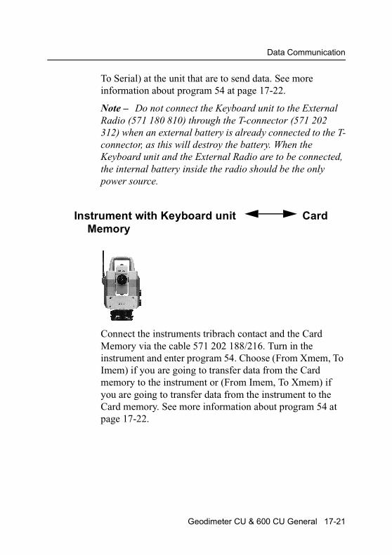
Data Communication
To Serial) at the unit that are to send data. See more information about program 54 at page 17-22.
Note – Do not connect the Keyboard unit to the External Radio (571 180 810) through the T-connector (571 202 312) when an external battery is already connected to the T-connector, as this will destroy the battery. When the Keyboard unit and the External Radio are to be connected, the internal battery inside the radio should be the only power source.
Instrument with Keyboard unit Card Memory
Connect the instruments tribrach contact and the Card Memory via the cable 571 202 188/216. Turn in the instrument and enter program 54. Choose (From Xmem, To Imem) if you are going to transfer data from the Card memory to the instrument or (From Imem, To Xmem) if you are going to transfer data from the instrument to the Card memory. See more information about program 54 at page 17-22.
Geodimeter CU & 600 CU General 17-21

17 Data Logging
Card Memory Personal Computer
Connect the Card Memory and the computer to at battery via the multi functional cable 571 202 188/216 and the computer adapter 571 202 204 and turn on the computer. There is one ways to transfer data between these units:
RS-232 commands
By sending the appropriate commands from the computer you can transfer data between the card Memory and computer. Look at page 17-13 for a list of serial commands or see the Geodimeter Software & Data communication manual for further information.
Program 54 – File transfer
Connect the two units with the appropriate cable and switch them on. The instructions below describes how to transfer files from the Keyboard unit to the keyboard unit attached on the instrument.
PRG 54
17-22 Geodimeter CU & 600 CU General
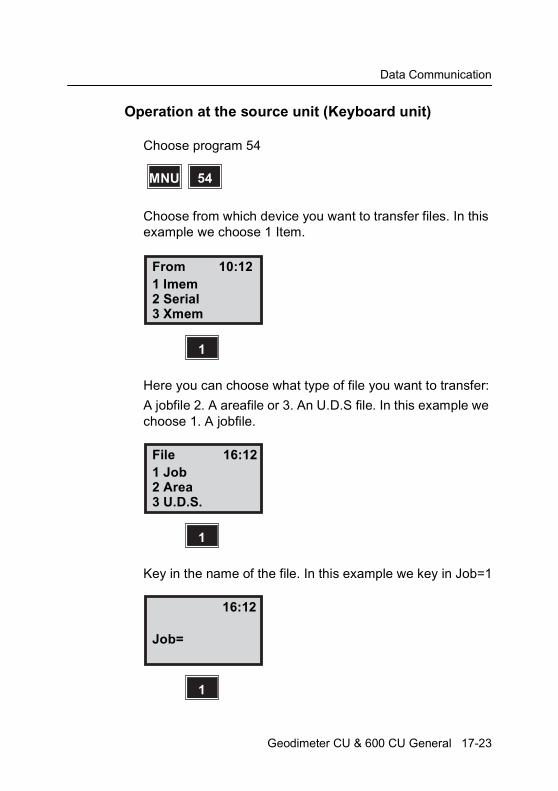
Data Communication
Operation at the source unit (Keyboard unit)
Choose program 54
Choose from which device you want to transfer files. In this example we choose 1 Item.
Here you can choose what type of file you want to transfer:
A jobfile 2. A areafile or 3. An U.D.S file. In this example we choose 1. A jobfile.
Key in the name of the file. In this example we key in Job=1
MNU 54
From 10:121 Imem
1
2 Serial3 Xmem
File 16:121 Job
1
2 Area3 U.D.S.
16:12
1
Job=
Geodimeter CU & 600 CU General 17-23
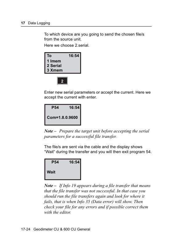
17 Data Logging
To which device are you going to send the chosen file/s from the source unit.
Here we choose 2.serial.
Enter new serial parameters or accept the current. Here we accept the current with enter.
Note – Prepare the target unit before accepting the serial parameters for a successful file transfer.
The file/s are sent via the cable and the display shows “Wait” during the transfer and you will then exit program 54.
Note – If Info 19 appears during a file transfer that means that the file transfer was not successful. In that case you should run the file transfers again and look for where it fails, that is when Info 35 (Data error) will show. Then check your file for any errors and if possible correct them with the editor.
To 16:541 Imem
2
2 Serial3 Xmem
P54 16:54
Com=1.8.0.9600
P54 16:54
Wait
17-24 Geodimeter CU & 600 CU General
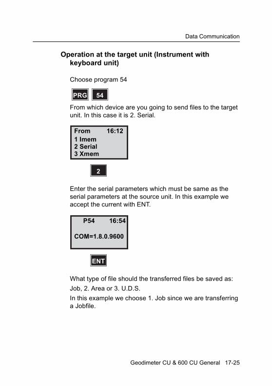
Data Communication
Operation at the target unit (Instrument with keyboard unit)
Choose program 54
From which device are you going to send files to the target unit. In this case it is 2. Serial.
Enter the serial parameters which must be same as the serial parameters at the source unit. In this example we accept the current with ENT.
What type of file should the transferred files be saved as:
Job, 2. Area or 3. U.D.S.
In this example we choose 1. Job since we are transferring a Jobfile.
PRG 54
From 16:121 Imem
2
2 Serial3 Xmem
P54 16:54
ENT
COM=1.8.0.9600
Geodimeter CU & 600 CU General 17-25

17 Data Logging
The unit is now ready to receive the transferred files. Now you should start the transfer from the source unit.
To 16:541 Job
1
2 Area3 U.D.S.
To 16:54
1
Wait
17-26 Geodimeter CU & 600 CU General

C H A P T E R
18
18Definitions & FormulasCorrections for Refraction and Curvature .......................... 18-2
Correction for difference in height ...................................... 18-4
Correction of horizontal distance........................................ 18-5
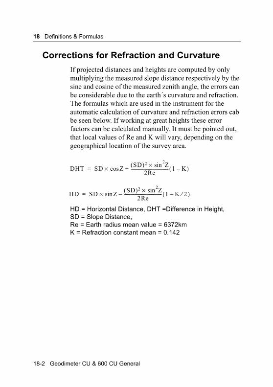
18 Definitions & Formulas
Corrections for Refraction and Curvature
If projected distances and heights are computed by only multiplying the measured slope distance respectively by the sine and cosine of the measured zenith angle, the errors can be considerable due to the earth´s curvature and refraction. The formulas which are used in the instrument for the automatic calculation of curvature and refraction errors cab be seen below. If working at great heights these error factors can be calculated manually. It must be pointed out, that local values of Re and K will vary, depending on the geographical location of the survey area.
HD = Horizontal Distance, DHT =Difference in Height,SD = Slope Distance, Re = Earth radius mean value = 6372kmK = Refraction constant mean = 0.142
DHT SD ZcosSD( )2 Z2sin×
2Re-----------------------------------+× 1 K–( )=
HD SD ZsinSD( )2 Z2sin×
2Re-----------------------------------–× 1 K 2⁄–( )=
18-2 Geodimeter CU & 600 CU General
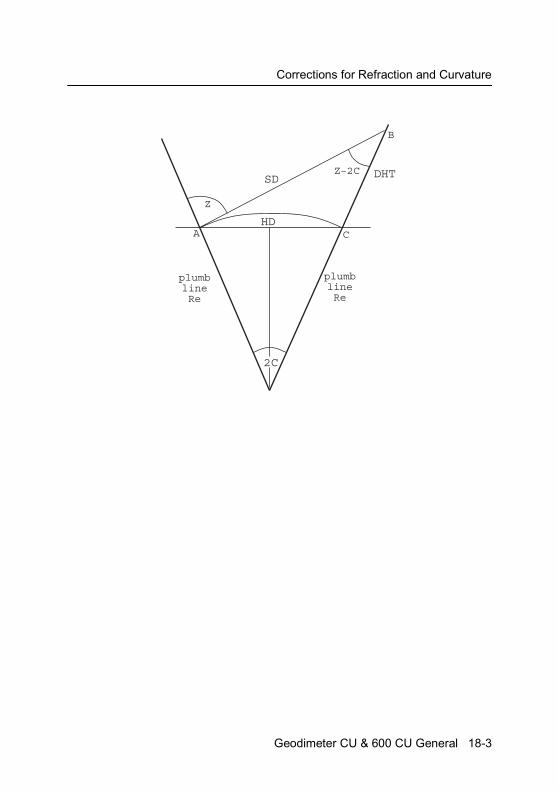
Corrections for Refraction and Curvature
Z
HD
SD
2C
DHTZ–2C
plumb lineRe
plumb lineRe
A
B
C
Geodimeter CU & 600 CU General 18-3

18 Definitions & Formulas
Correction for difference in height
Case 1: Slope distance has not been corrected when displayed or recorded.
Case 2: If different values of K and /or Re are used, adjust accordingly to the formula´s standard values, which can be seen on the previous page; these values can normally be obtained from the local Ordnance Land Survey Authorities.
Example Correction for the difference in height when close to the horizontal plane.
Curve 1 represents the earth´s curvature. Curve 3 is the correction for refraction as a function of slope distance. Curve 2 is the resultant correction to be applied to the height obtained by multiplying the slope distance by cos z. This correction changes relatively slowly in relation to the deviation from the horizontal plane. At 20g (Z=80), the corrections will have decreased 10%.
—20
—10
0
10
20
30
40
50
60
70
100 500300 700 900 1100
1
2
3
Slope Distance
Correction (mm)
18-4 Geodimeter CU & 600 CU General
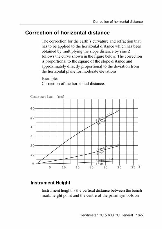
Correction of horizontal distance
Correction of horizontal distance
The correction for the earth´s curvature and refraction that has to be applied to the horizontal distance which has been obtained by multiplying the slope distance by sine Z follows the curve shown in the figure below. The correction is proportional to the square of the slope distance and approximately directly proportional to the deviation from the horizontal plane for moderate elevations.
Example:Correction of the horizontal distance.
Instrument Height
Instrument height is the vertical distance between the bench mark/height point and the centre of the prism symbols on
10
20
30
40
50
60
05 10 15 20 25 30 35
Slope
Dist.
=
1000m
Slope Di
st. =
500m
Slope Dist. =
200mg
Correction (mm)
Geodimeter CU & 600 CU General 18-5
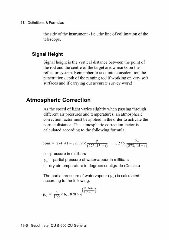
18 Definitions & Formulas
the side of the instrument - i.e., the line of collimation of the telescope.
Signal Height
Signal height is the vertical distance between the point of the rod and the centre of the target arrow marks on the reflector system. Remember to take into consideration the penetration depth of the ranging rod if working on very soft surfaces and if carrying out accurate survey work!
Atmospheric Correction
As the speed of light varies slightly when passing through different air pressures and temperatures, an atmospheric correction factor must be applied in the order to activate the correct distance. This atmospheric correction factor is calculated according to the following formula:
p = pressure in millibars
= partial pressure of watervapour in millibars
t = dry air temperature in degrees centigrade (Celsius)
The partial pressure of watervapour ( ) is calculated according to the following.
ppm 274 41, 79 39, p273 15 t+,( )
------------------------------ 11 27,pw
273 15 t+,( )------------------------------×+×–=
pw
pw
pwh
100--------- 6 1078, e
17 269xt,237 3 t+,-----------------------
××=
18-6 Geodimeter CU & 600 CU General

Atmospheric Correction
OR
p = pressure in millibars
= partial pressure of watervapour in millibars
t = dry air temperature in degrees centigrade (Celsius)
t’ = wet temperature in degrees centigrade (Celsius)
h = relative humidity in %
Geodimeter System 600 calculates and corrects for this automatically. Please ensure that the instrument is working with the correct units, MNU 65, Unit.
Examples:To show the significance of the different units used for calculating the ppm factor let´s take a look at the following:
At 20ºC dry air temperature 0.1 ppm corresponds to an approximate change of:
• dry temperature: 0.1ºC • air pressure: 0.3 mbar • relative humidity: 10% • wet temperature: 1.3ºC
At 40ºC dry air temperature 0.1 ppm corresponds to an approximate change of:
• dry temperature: 0.1ºC • air pressure: 0.3 mbar • relative humidity: 4% • wet temperature: 0.8ºC
As shown in the first example above relative humidity has quit a small influence on the ppm factor. It‘s much more important to be precise when it comes to dry temperature
pw 6 1078, e17 269, t′×237 3 t ′+,
---------------------------
× 0 000662, p t t′–( )×–=
pw
Geodimeter CU & 600 CU General 18-7
18 Definitions & Formulas
and air pressure. In hot regions relative humidity becomes more important, though.
18-8 Geodimeter CU & 600 CU General

C H A P T E R
19
19Care & MaintenanceOverview ............................................................................ 19-2
Cleaning............................................................................. 19-3
Condensation ..................................................................... 19-3
Packing for Transport ......................................................... 19-3
Warranty............................................................................. 19-3
Service ............................................................................... 19-4
19 Care & Maintenance
Overview
Geodimeter System 600 is designed and tested to witstand field conditions, but like all other precision instruments, it requires care and maintenance.
• Avoid rough jolts and careless treatment.
• Keep lenses and reflectors clean. Always use lens paper or other material intended for cleaning optics.
• Don´t carry the instrument is not being used, keep it protected in an upright position, preferably in its transport case.
• Don´t carry the instrument while mounted on the tripod in order to avoid damage to the tribach screws.
• Servo instruments only: Do not rotate the instrument by the handle. This may have an affect on the HA ref. How much it effects the value depends on the quality of the tribach and the tripod. Use instead the servo controls to rotate the instrument.
• Don´t carry the instrument by the telescope barrel. Use the handle.
• When you need exremely good measurement precision, make sure the instrument has adapted to the surrounding temperature. Great variations of instrument temperature could affect the precision.
Warning – Geodimeter System 600 is designed to withstand normal electromagnetic disturbance from the environment. However, the instrument contains circuits sensitiv to static electricity and the instrument cover must not be removed by unauthorized personnel. If the instrument cover has been opened by an unauthorized person, the function of the instrument is not guaranteed and the instrument warranty becomes invalid.
19-2 Geodimeter CU & 600 CU General

Overview
Cleaning
Caution must be exercised when the instrument is cleaned, especially when sand and dust are to be removed from lenses and reflectors. Never use coarse or dirty cloth or hard paper. Anti-static lens paper, cotton wad or lens brush are recommended. Never use strong detergents such as benzine or thinner on instrument or case.
Condensation
After survey in moist weather the instrument should be taken ondoors, the transport case opened and the instrument removed. It should then be left to dry naturally. It is recommended that condensation which forms on lenses should be allowed to evaporate naturally.
Packing for Transport
The instrument should always be transported in its transport case, which should be locked.
For shipment to a service shop, the names of the sender and reciever should always be specified clearly on the transport case.
When sending this instrument for repair, or for other service work, a note descriebing fault, symptoms or requested service should always be enclosed in the transport case.
Warranty
Spectra Precision AB guarantees that the Geodimeter instrument has been inspected and tested before delivery. The length of the warranty is stated in the Warranty Condidtions.
Geodimeter CU & 600 CU General 19-3
19 Care & Maintenance
All enquiries regarding the warranty should be directed to the local Geodimeter representative.
Service
We recommend that you, once a year , leave the instrument to an authorized Geodimeter service workshop for service. This is to guarantee that the specified accuracies are maintained. Note that there are no user servicable parts inside the instrument. Always leave the instrument to your dealer or authorized service workshop if any should occur.
19-4 Geodimeter CU & 600 CU General
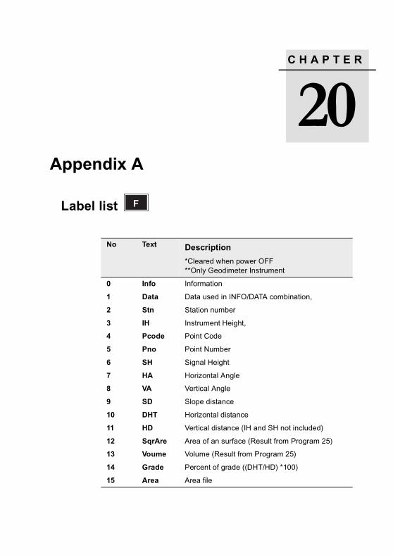
C H A P T E R
20
20Appendix ALabel list
No Text Description
*Cleared when power OFF**Only Geodimeter Instrument
0 Info Information
1 Data Data used in INFO/DATA combination,
2 Stn Station number
3 IH Instrument Height,
4 Pcode Point Code
5 Pno Point Number
6 SH Signal Height
7 HA Horizontal Angle
8 VA Vertical Angle
9 SD Slope distance
10 DHT Horizontal distance
11 HD Vertical distance (IH and SH not included)
12 SqrAre Area of an surface (Result from Program 25)
13 Voume Volume (Result from Program 25)
14 Grade Percent of grade ((DHT/HD) *100)
15 Area Area file
F
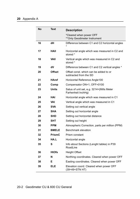
20 Appendix A
16 dH Difference between C1 and C2 horizontal angles *
17 HAII Horizontal angle which was measured in C2 and stored *
18 VAII Vertical angle which was measured in C2 and stored *
19 dV Difference between C1 and C2 vertical angles *
20 Offset Offset const. which can be added to or subtracted from the SD
21 HAref Horizontal Reference Angle100
22 Comp Compensator ON=1, OFF=0100
23 Units Satus of unit set, e.g. 3214=(Mills Meter Farhenheit InchHg)
24 HAI Horizontal angle which was measured in C1
25 VAI Vertical angle which was measured in C1
26 SVA Setting out vertical angle
27 SHA Setting out horizontal angle
28 SHD Setting out horizontal distance
29 SHT Setting out height
30 PPM Atmospheric Correction, parts per million (PPM)
31 BMELE Benchmark elevation
32 PrismC Prism constant
34 HA.L Horizontal angle
35 S Info about Sections (Lenght tables) in P39 RoadLine
36 HtOfs Height Offset
37 N Northing coordinates. Cleared when power OFF
38 E Easting coordinates. Cleared when power OFF
39 ELE Elevation coord. Cleared when power OFF (39=49+STN HT)
No Text Description
*Cleared when power OFF**Only Geodimeter Instrument
20-2 Geodimeter CU & 600 CU General

Label list
40 dN Relative to stored X (N) coord of set out point (P23)
41 dE Relative to stored Y (E) coord of set out point (P23)
42 dELE Relative to stored Z (ELE) coord of set out point (P23)
43 UTMSC Universal Transverse Mercator Scale Factor
44 Slope Slope inclination
45 dHA Correction value of the calculated bearing in Program 20
46 S_dev Standard deviation
47 Nr Rel. North Coorde.
48 Er Rel. East Coorde.
49 VD Vertical distance (IH and SH inluded) (49=10+3-6)
50 JOBNo Job No file for storage of raw and calculated data
51 Date Date
52 Time Time
53 Operat Operator identification
54 Proj Project identification
55 Inst.No Instrument Number
56 Temp Temperature
57 Blank Empty row in UDS´s where it is convenient to have a blank line
58 Ea rad Earth Radius
59 Refrac Refraction
60 ShotID Shot Identity
61 Activ Activity Code
62 RefObj Reference Object
63 Diam Diameter
64 Radius Radius
No Text Description
*Cleared when power OFF**Only Geodimeter Instrument
Geodimeter CU & 600 CU General 20-3
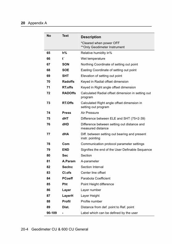
20 Appendix A
65 h% Relative humidity in%
66 t´ Wet temperature
67 SON Northing Coordinate of setting out point
68 SOE Easting Coordinate of setting out point
69 SHT Elevation of setting out point
70 Radoffs Keyed in Radial offset dimension
71 RT.offs Keyed in Right angle offset dimension
72 RADOffs Calculated Radial offset dimension in setting out program
73 RT.Offs Calculated Right angle offset dimension in setting out program
74 Press Air Pressure
75 dHT Difference between ELE and SHT (75=2-39)
76 dHD Difference between setting out distance and measured distance
77 dHA Diff. between setting out bearing and present instr. pointing
78 Com Communication protocol parameter settings
79 END Signifies the end of the User Definable Sequence
80 Sec Section
81 A.Param A-parameter
82 SecInc Section Interval
83 Cl.ofs Center line offset
84 PCoeff Parabola Coefficient
85 Pht Point Height difference
86 Layer Layer number
87 LayerH Layer Height
88 Profil Profile number
89 Dist. Distance from def. point to Ref. point
90-109 - Label which can be defined by the user
No Text Description
*Cleared when power OFF**Only Geodimeter Instrument
20-4 Geodimeter CU & 600 CU General
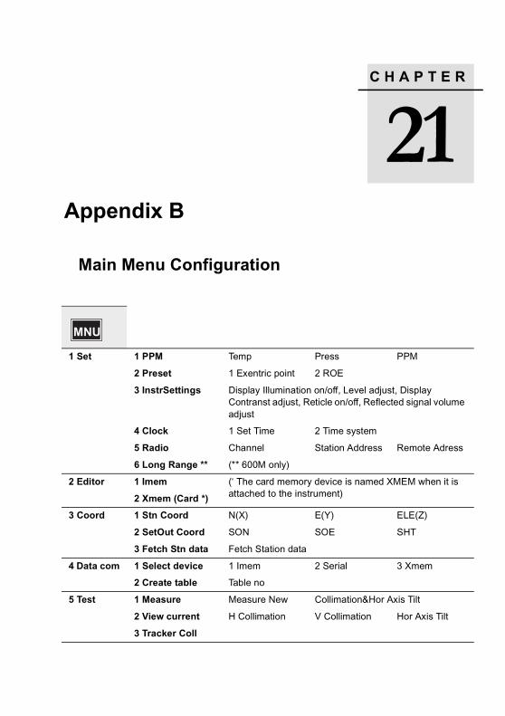
C H A P T E R
21
e
s
21Appendix B
Main Menu Configuration
1 Set 1 PPM Temp Press PPM
2 Preset 1 Exentric point 2 ROE
3 InstrSettings Display Illumination on/off, Level adjust, Display Contranst adjust, Reticle on/off, Reflected signal volumadjust
4 Clock 1 Set Time 2 Time system
5 Radio Channel Station Address Remote Adres
6 Long Range ** (** 600M only)
2 Editor 1 Imem (‘ The card memory device is named XMEM when it isattached to the instrument)2 Xmem (Card *)
3 Coord 1 Stn Coord N(X) E(Y) ELE(Z)
2 SetOut Coord SON SOE SHT
3 Fetch Stn data Fetch Station data
4 Data com 1 Select device 1 Imem 2 Serial 3 Xmem
2 Create table Table no
5 Test 1 Measure Measure New Collimation&Hor Axis Tilt
2 View current H Collimation V Collimation Hor Axis Tilt
3 Tracker Coll
MNU

21 Appendix B
s
d
ay
.
6 Config 1 Switches Targ. test on/off, Pcode on/off, Info ack. on/off, HT meaon/off, Power save on/off, Key click on/off, Prg_num on/off, PPM Adv on/off, Job/Mem on/off, Show Stn. on/off, Confirm on/off
2 Standard Meas. 1 Standard 2 fast Standar
3 Decimals No of decimals Label no
4 Display 1 Select display 2 Create displ
5 Unit Metre, Feet, Feet/Inches, Grads, Degrees, DevDeg,Mills, Celsius, Fahr, mBar, mmHg, InHg, hPa
6 Language Sw, No, De, Ge, Ja, Uk, Us, It, Fr, Sp
7 Coord System 1 North orient. 2 South orient
8 Prism const Prism constant
MNU
21-2 Geodimeter CU & 600 CU General


