Embed Size (px)
Citation preview
/ Perfect Charging / Perfect Welding / Solar Energy
42,0426,0222,EN 006-14072016
Fronius Energy Package
Operating InstructionsGrid-connected inverterEN

2
EN
Dear reader,
Introduction Thank you for the trust you have placed in our company and congratulations on buying this high-quality Fronius product. These instructions will help you familiarise yourself with the product. Reading the instructions carefully will enable you to learn about the many different features it has to offer. This will allow you to make full use of its advantages.
Please also note the safety rules to ensure greater safety when using the product. Careful handling of the product will repay you with years of safe and reliable operation. These are essential prerequisites for excellent results.
Explanation of safety symbols
If you see any of the symbols depicted in the "Safety rules" chapter, special care is re-quired.
DANGER! Indicates immediate and real danger. If it is not avoided, death or se-rious injury will result.
WARNING! Indicates a potentially dangerous situation. Death or serious injury may result if appropriate precautions are not taken.
CAUTION! Indicates a situation where damage or injury could occur. If it is not avoided, minor injury and/or damage to property may result.
NOTE! Indicates a risk of flawed results and possible damage to the equipment.
IMPORTANT! Indicates tips for correct operation and other particularly useful information. It does not indicate a potentially damaging or dangerous situation.
3

4

EN
Contents
Safety rules ................................................................................................................................................ 9General ................................................................................................................................................. 9Environmental conditions...................................................................................................................... 9Qualified service engineers................................................................................................................... 10Noise emission values .......................................................................................................................... 10EMC measures ..................................................................................................................................... 10Disposal ................................................................................................................................................ 10Copyright............................................................................................................................................... 11Data protection...................................................................................................................................... 11
General information 13
Fronius Symo Hybrid ................................................................................................................................. 15Device concept ..................................................................................................................................... 15Proper use ............................................................................................................................................ 16Warning notices on the device.............................................................................................................. 16
Fronius Solar Battery ................................................................................................................................. 18Device concept ..................................................................................................................................... 18Proper use ............................................................................................................................................ 18Warning notices on the device.............................................................................................................. 19
The various operating modes .................................................................................................................... 21Operating modes – Explanation of symbols ......................................................................................... 21Operating mode: Inverter ...................................................................................................................... 21Operating mode: Inverter plus battery .................................................................................................. 22Operating mode: Inverter plus battery and emergency power function ................................................ 22
Operation 25
Data communication .................................................................................................................................. 27Data communication area ..................................................................................................................... 27General ................................................................................................................................................. 27Controls, connections and indicators on the system monitoring unit .................................................... 28
Fronius Hybrid inverter............................................................................................................................... 31Controls and indicators ......................................................................................................................... 31Display .................................................................................................................................................. 32
Fronius Solar Battery ................................................................................................................................. 33Battery management module................................................................................................................ 33Battery module...................................................................................................................................... 33Display .................................................................................................................................................. 33Display types......................................................................................................................................... 34Data converter connections .................................................................................................................. 37Data converter controls and indicators ................................................................................................. 37Data converter LED displays ................................................................................................................ 37
Navigation at the menu level...................................................................................................................... 39Activate display backlighting ................................................................................................................. 39Automatic deactivation of display backlighting / choose 'NOW' menu item .......................................... 39Open menu level................................................................................................................................... 39Values displayed under the NOW menu item....................................................................................... 39Values displayed under the LOG menu item ........................................................................................ 40
Menu items in the Set-up menu ................................................................................................................. 41Standby................................................................................................................................................. 41Relays ................................................................................................................................................... 41Energy Manager(under Relay menu item)............................................................................................ 42Time / Date .......................................................................................................................................... 43Display settings..................................................................................................................................... 43Energy yield .......................................................................................................................................... 44Fan........................................................................................................................................................ 45
SETUP menu item ..................................................................................................................................... 46Initial setting .......................................................................................................................................... 46Software updates .................................................................................................................................. 46
5
Navigating the SETUP menu item ........................................................................................................ 46Setting entries on the Setup menu, general.......................................................................................... 47Application example: Setting the time................................................................................................... 47
The INFO menu item ................................................................................................................................. 49Measured values................................................................................................................................... 49PSS status ............................................................................................................................................ 49Grid status............................................................................................................................................. 49Device information ................................................................................................................................ 49Version.................................................................................................................................................. 50
Switching the key lock on and off............................................................................................................... 52General ................................................................................................................................................. 52Switching the key lock on and off.......................................................................................................... 52
The Basic menu ......................................................................................................................................... 53Access the Basic menu......................................................................................................................... 53Items on the Basic menu ...................................................................................................................... 53
Fronius system monitoring 55
General ...................................................................................................................................................... 57General remarks ................................................................................................................................... 57Prerequisites for operation.................................................................................................................... 57
Calculating data volumes........................................................................................................................... 58General ................................................................................................................................................. 58Calculating data volumes...................................................................................................................... 58
General information for the network administrator ..................................................................................... 60Prerequisites ......................................................................................................................................... 60General firewall settings........................................................................................................................ 60Using Fronius Solar.web and sending service messages .................................................................... 61
Installing Fronius system monitoring – Overview....................................................................................... 62Safety.................................................................................................................................................... 62Using for the first time ........................................................................................................................... 62Information to help you work through the Solar Web wizard ................................................................ 64Testing emergency power mode........................................................................................................... 64
Connecting to Fronius system monitoring via a web browser.................................................................... 65General remarks ................................................................................................................................... 65Prerequisites ......................................................................................................................................... 65Establishing a connection to Fronius system monitoring via a web browser ........................................ 65
Connecting to Fronius system monitoring established via the Internet and Fronius Solar.web................. 66General remarks ................................................................................................................................... 66Functional description ........................................................................................................................... 66Prerequisites ........................................................................................................................................ 66Accessing Fronius system monitoring data via the Internet and Fronius Solar.web............................. 66
Current data, services and settings offered by Fronius system monitoring 67
The Fronius system monitoring web page ................................................................................................. 69Fronius system monitoring web page – Overview ................................................................................ 69The Settings menu................................................................................................................................ 69Additional setting options ...................................................................................................................... 70
Services – System information .................................................................................................................. 71System information ............................................................................................................................... 71
Services – Network diagnostics ................................................................................................................. 73Network diagnostics.............................................................................................................................. 73
Services – Firmware update ...................................................................................................................... 74General ................................................................................................................................................. 74Searching for updates automatically..................................................................................................... 74Searching for updates manually ........................................................................................................... 75Updating the firmware via the Web....................................................................................................... 75Updating the firmware via a LAN .......................................................................................................... 75
Services – Starting the wizard ................................................................................................................... 77Starting the wizard ................................................................................................................................ 77
Settings – General ..................................................................................................................................... 78General ................................................................................................................................................. 78
Settings – Passwords ................................................................................................................................ 79
6
EN
General remarks ................................................................................................................................... 79Passwords ............................................................................................................................................ 79
Settings – Network..................................................................................................................................... 81General remarks ................................................................................................................................... 81Network................................................................................................................................................. 81
Settings – Fronius Solar.web ..................................................................................................................... 85Fronius Solar.web ................................................................................................................................. 85
Settings – Service messages..................................................................................................................... 87General remarks ................................................................................................................................... 87Service messages................................................................................................................................. 87
Settings – IO mapping ............................................................................................................................... 89General ................................................................................................................................................. 89
Settings - load management ...................................................................................................................... 90Load management ................................................................................................................................ 90
Settings – Push Service............................................................................................................................. 91Push Service......................................................................................................................................... 91Further information about the push service function............................................................................. 92
Settings – Modbus ..................................................................................................................................... 93General remarks ................................................................................................................................... 93Further information about the Modbus function .................................................................................... 93Exporting data via Modbus ................................................................................................................... 93Restricting control ................................................................................................................................. 94Saving or discarding changes............................................................................................................... 95
Settings – Energy Manager ....................................................................................................................... 96General ................................................................................................................................................. 96Energy Manager examples ................................................................................................................... 96Battery management............................................................................................................................. 98Example of reserve battery capacity..................................................................................................... 99
Settings – System overview....................................................................................................................... 100System overview................................................................................................................................... 100Fronius Smart Meter ............................................................................................................................. 101
Settings – EVU Editor ............................................................................................................................... 103General remarks ................................................................................................................................... 103PSC editor – Ripple control signal receiver .......................................................................................... 103Connection example ............................................................................................................................. 104"PSC editor - AUS - Demand Response Modes (DRM)" ...................................................................... 105EVU Editor – Dynamic power reduction................................................................................................ 105EVU Editor – Control priorities .............................................................................................................. 107EVU Editor – Batterie Ladung [Battery charging].................................................................................. 107Dynamic power regulation with several inverters.................................................................................. 108
Settings – Battery....................................................................................................................................... 110Battery................................................................................................................................................... 110
Troubleshooting and maintenance 111
Fronius Symo Hybrid ................................................................................................................................. 113Displaying status codes ........................................................................................................................ 113Total failure of the display ..................................................................................................................... 113Status codes – Class 1 ......................................................................................................................... 113Status codes – Class 3 ......................................................................................................................... 114Status codes – Class 4 ......................................................................................................................... 115Status codes – Class 5 ......................................................................................................................... 116Status codes – Class 6 ......................................................................................................................... 118Status codes – Class 7 ......................................................................................................................... 118Status codes – Class 9 ......................................................................................................................... 119Class 10 - 12 status codes.................................................................................................................... 120Customer service .................................................................................................................................. 120Operation in dusty environments .......................................................................................................... 120
Fronius Solar Battery ................................................................................................................................. 121Status code display............................................................................................................................... 121Error messages – Battery management module .................................................................................. 121Error message – Data converter........................................................................................................... 121Undefined operating statuses ............................................................................................................... 122
7

Appendix 123
Technical data............................................................................................................................................ 125System monitoring ................................................................................................................................ 127Explanation of footnotes ....................................................................................................................... 127Applicable standards and guidelines .................................................................................................... 127
Warranty terms and conditions, and disposal ............................................................................................ 129Fronius manufacturer's warranty .......................................................................................................... 129Disposal ................................................................................................................................................ 129
8

EN
Safety rules
General
Environmental conditions
The device is manufactured using state-of-the-art technology and according to recognised safety standards. If used incorrectly or misused, however, it can cause:- injury or death to the operator or a third party,- damage to the device and other material assets belonging to the operator,- inefficient operation of the device.All persons involved in commissioning, maintaining and servicing the device must- be suitably qualified,- have knowledge of and experience in dealing with electrical installations
and- read and follow these operating instructions carefully.The operating instructions must always be at hand wherever the device is be-ing used. In addition to the operating instructions, attention must also be paid to any generally applicable and local regulations regarding accident preven-tion and environmental protection.All safety and danger notices on the device - must be in a legible state, - must not be damaged, - must not be removed,- must not be covered, pasted or painted over.The terminals can reach high temperatures.Only operate the device when all protection devices are fully functional. If the protection devices are not fully functional, there is a risk of- injury or death to the operator or a third party,- damage to the device and other material assets belonging to the operator,- inefficient operation of the device.Any safety devices that are not functioning properly must be repaired by a suit-ably qualified engineer before the device is switched on.Never bypass or disable protection devices.For the location of the safety and danger notices on the device, refer to the "General" section in the operating instructions for the device.Before switching on the device, rectify any faults that could compromise safe-ty.This is for your personal safety!
Operation or storage of the device outside the stipulated area will be deemed as "not in accordance with the intended purpose". The manufacturer shall not be held liable for any damage arising from such usage.For exact information on permitted environmental conditions, please refer to the "Technical data" in the operating instructions.
9
Qualified service engineers
Noise emission values
EMC measures
Disposal
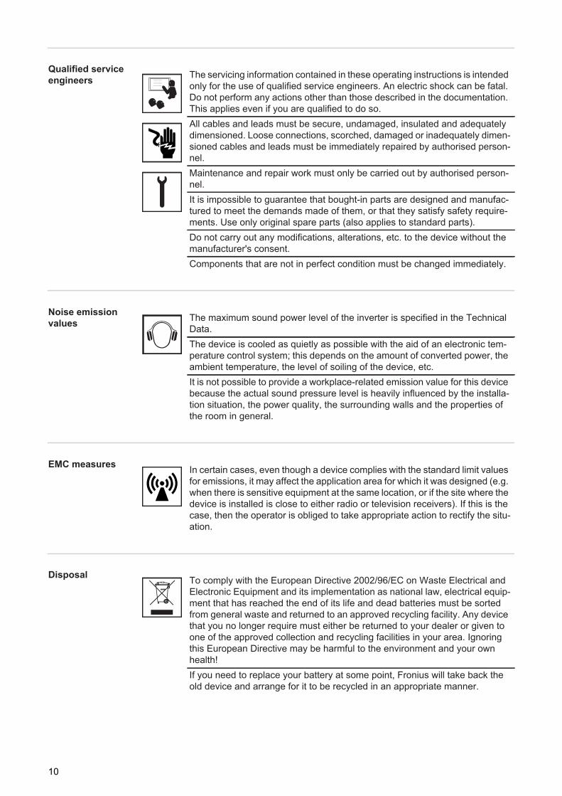
The servicing information contained in these operating instructions is intended only for the use of qualified service engineers. An electric shock can be fatal. Do not perform any actions other than those described in the documentation. This applies even if you are qualified to do so.All cables and leads must be secure, undamaged, insulated and adequately dimensioned. Loose connections, scorched, damaged or inadequately dimen-sioned cables and leads must be immediately repaired by authorised person-nel.Maintenance and repair work must only be carried out by authorised person-nel.It is impossible to guarantee that bought-in parts are designed and manufac-tured to meet the demands made of them, or that they satisfy safety require-ments. Use only original spare parts (also applies to standard parts).Do not carry out any modifications, alterations, etc. to the device without the manufacturer's consent.Components that are not in perfect condition must be changed immediately.
The maximum sound power level of the inverter is specified in the Technical Data.The device is cooled as quietly as possible with the aid of an electronic tem-perature control system; this depends on the amount of converted power, the ambient temperature, the level of soiling of the device, etc.It is not possible to provide a workplace-related emission value for this device because the actual sound pressure level is heavily influenced by the installa-tion situation, the power quality, the surrounding walls and the properties of the room in general.
In certain cases, even though a device complies with the standard limit values for emissions, it may affect the application area for which it was designed (e.g. when there is sensitive equipment at the same location, or if the site where the device is installed is close to either radio or television receivers). If this is the case, then the operator is obliged to take appropriate action to rectify the situ-ation.
To comply with the European Directive 2002/96/EC on Waste Electrical and Electronic Equipment and its implementation as national law, electrical equip-ment that has reached the end of its life and dead batteries must be sorted from general waste and returned to an approved recycling facility. Any device that you no longer require must either be returned to your dealer or given to one of the approved collection and recycling facilities in your area. Ignoring this European Directive may be harmful to the environment and your own health!If you need to replace your battery at some point, Fronius will take back the old device and arrange for it to be recycled in an appropriate manner.
10
EN
Copyright
Data protection
Copyright of these operating instructions remains with the manufacturer.The text and illustrations are all technically correct at the time of printing. We reserve the right to make changes. The contents of the operating instructions shall not provide the basis for any claims whatsoever on the part of the pur-chaser. If you have any suggestions for improvement, or can point out any mistakes that you have found in the instructions, we will be most grateful for your comments.
The user is responsible for the safekeeping of any changes made to the fac-tory settings. The manufacturer accepts no liability for any deleted personal settings.
11

12

General information

EN
Fronius Symo Hybrid
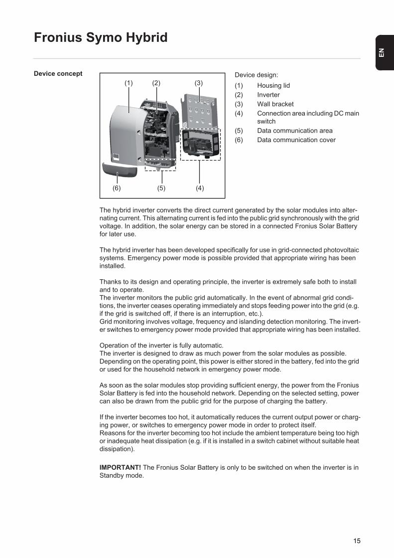
Device concept Device design:(1) Housing lid(2) Inverter(3) Wall bracket(4) Connection area including DC main
switch(5) Data communication area(6) Data communication cover
The hybrid inverter converts the direct current generated by the solar modules into alter-nating current. This alternating current is fed into the public grid synchronously with the grid voltage. In addition, the solar energy can be stored in a connected Fronius Solar Battery for later use.
The hybrid inverter has been developed specifically for use in grid-connected photovoltaic systems. Emergency power mode is possible provided that appropriate wiring has been installed.
Thanks to its design and operating principle, the inverter is extremely safe both to install and to operate.The inverter monitors the public grid automatically. In the event of abnormal grid condi-tions, the inverter ceases operating immediately and stops feeding power into the grid (e.g. if the grid is switched off, if there is an interruption, etc.). Grid monitoring involves voltage, frequency and islanding detection monitoring. The invert-er switches to emergency power mode provided that appropriate wiring has been installed.
Operation of the inverter is fully automatic.The inverter is designed to draw as much power from the solar modules as possible.Depending on the operating point, this power is either stored in the battery, fed into the grid or used for the household network in emergency power mode.
As soon as the solar modules stop providing sufficient energy, the power from the Fronius Solar Battery is fed into the household network. Depending on the selected setting, power can also be drawn from the public grid for the purpose of charging the battery.
If the inverter becomes too hot, it automatically reduces the current output power or charg-ing power, or switches to emergency power mode in order to protect itself.Reasons for the inverter becoming too hot include the ambient temperature being too high or inadequate heat dissipation (e.g. if it is installed in a switch cabinet without suitable heat dissipation).
(1) (2) (3)
(4)(5)(6)
IMPORTANT! The Fronius Solar Battery is only to be switched on when the inverter is in Standby mode.
15
Proper use The solar inverter is exclusively intended for charging a Fronius Solar Battery with direct current from solar modules, or for converting this direct current into alternating current and feeding it into the public grid or the household network in emergency power mode.The following actions constitute improper use:- Any use above and beyond this purpose- Making any modifications to the inverter that have not been expressly approved by
Fronius- Installing components that are not distributed or expressly approved by Fronius- Operating the device with a battery that has not been approved by Fronius- Operating the equipment with an energy meter that has not been approved by Fronius
Fronius shall not be liable for any damage resulting from such action.No warranty claims will be entertained.
Proper use also includes:- Carefully studying and obeying the installation and operating instructions- performing all stipulated inspection and maintenance work
When designing the photovoltaic system, ensure that all of its components are operated within their permitted operating ranges at all times.
Observe all the measures recommended by the solar module manufacturer to ensure that the solar module retains its properties in the long term.
Observe the stipulations of the power supply company concerning energy fed into the grid, emergency power mode and the operation of storage systems.
The Fronius Symo Hybrid is a grid-connected inverter with an emergency power function – it is not a stand-alone inverter. The following restrictions must therefore be observed in emergency power mode:- Emergency power mode may amount to max. 15% of the normal inverter operating
time- Emergency power mode must be in operation for (at least) 1500 hours
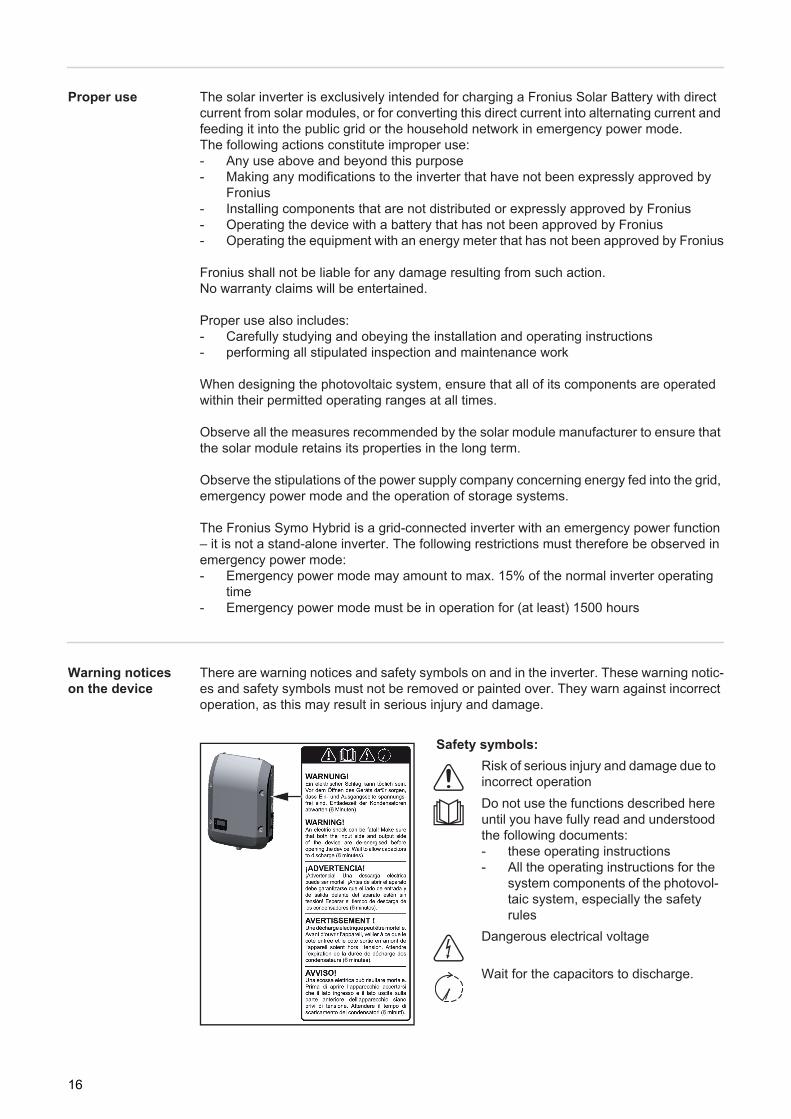
Warning notices on the device
There are warning notices and safety symbols on and in the inverter. These warning notic-es and safety symbols must not be removed or painted over. They warn against incorrect operation, as this may result in serious injury and damage.
Safety symbols:Risk of serious injury and damage due to incorrect operationDo not use the functions described here until you have fully read and understood the following documents:- these operating instructions- All the operating instructions for the
system components of the photovol-taic system, especially the safety rules
Dangerous electrical voltage
Wait for the capacitors to discharge.
6
6
6
6
6
16

EN
Text of the warning notices:
WARNING!An electric shock can be fatal. Make sure that both the input side and output side of the device are de-energised before opening the device. Wait for the capacitors to discharge (6 minutes).
17
Fronius Solar Battery
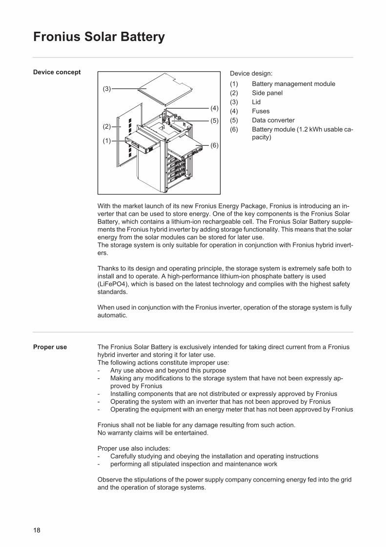
Device concept Device design:(1) Battery management module(2) Side panel(3) Lid(4) Fuses(5) Data converter(6) Battery module (1.2 kWh usable ca-
pacity)
With the market launch of its new Fronius Energy Package, Fronius is introducing an in-verter that can be used to store energy. One of the key components is the Fronius Solar Battery, which contains a lithium-ion rechargeable cell. The Fronius Solar Battery supple-ments the Fronius hybrid inverter by adding storage functionality. This means that the solar energy from the solar modules can be stored for later use. The storage system is only suitable for operation in conjunction with Fronius hybrid invert-ers.
Thanks to its design and operating principle, the storage system is extremely safe both to install and to operate. A high-performance lithium-ion phosphate battery is used (LiFePO4), which is based on the latest technology and complies with the highest safety standards.
When used in conjunction with the Fronius inverter, operation of the storage system is fully automatic.
Proper use The Fronius Solar Battery is exclusively intended for taking direct current from a Fronius hybrid inverter and storing it for later use.The following actions constitute improper use:- Any use above and beyond this purpose- Making any modifications to the storage system that have not been expressly ap-
proved by Fronius- Installing components that are not distributed or expressly approved by Fronius- Operating the system with an inverter that has not been approved by Fronius- Operating the equipment with an energy meter that has not been approved by Fronius
Fronius shall not be liable for any damage resulting from such action.No warranty claims will be entertained.
Proper use also includes:- Carefully studying and obeying the installation and operating instructions- performing all stipulated inspection and maintenance work
Observe the stipulations of the power supply company concerning energy fed into the grid and the operation of storage systems.
(1)
(2)
(3)
(4)
(5)
(6)
18
EN
Warning notices on the device
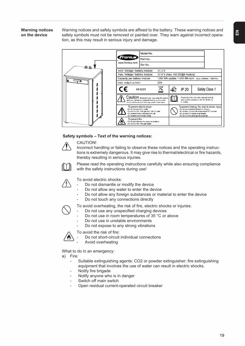
Warning notices and safety symbols are affixed to the battery. These warning notices and safety symbols must not be removed or painted over. They warn against incorrect opera-tion, as this may result in serious injury and damage.
What to do in an emergency:a) Fire:
- Suitable extinguishing agents: CO2 or powder extinguisher; fire extinguishing equipment that involves the use of water can result in electric shocks.
- Notify fire brigade- Notify anyone who is in danger- Switch off main switch- Open residual current-operated circuit breaker
Safety symbols – Text of the warning notices:CAUTION!Incorrect handling or failing to observe these notices and the operating instruc-tions is extremely dangerous. It may give rise to thermal/electrical or fire hazards, thereby resulting in serious injuries.Please read the operating instructions carefully while also ensuring compliance with the safety instructions during use!
To avoid electric shocks:- Do not dismantle or modify the device- Do not allow any water to enter the device- Do not allow any foreign substances or material to enter the device - Do not touch any connections directlyTo avoid overheating, the risk of fire, electric shocks or injuries:- Do not use any unspecified charging devices- Do not use in room temperatures of 35 °C or above- Do not use in unstable environments- Do not expose to any strong vibrationsTo avoid the risk of fire:- Do not short-circuit individual connections- Avoid overheating
19

b) Flooding: - Switch off main switch- Open residual current-operated circuit breaker- Protect system from water, pump water away
c) Undefined operating status (see also section titled "Undefined operating statuses" on page 122): - Ensure adequate ventilation. - Switch off main switch- Open residual current-operated circuit breaker
20

EN
The various operating modes
Operating modes – Explanation of symbols
Operating mode: Inverter
The Fronius hybrid inverter can be used purely as an inverter without a battery connected to it.
Solar moduleGenerates direct current
Inverter – Fronius hybridConverts the direct current into alternating current and charges the battery. Thanks to the built-in system monitoring function, the inverter can be inte-grated into a network using WLAN technology. Battery – Fronius Solar BatteryConnected to the inverter on the DC side and used to store electrical ener-gy
Photovoltaic system consumersThe consumers connected to the PV system (single or three-phase)
Meter – Fronius Smart MeterFor optimum energy management. You can have the meter installed in a switch cabinet by your electrical installer. Emergency power functionThe inverter is delivered ready for supplying emergency power. However, the electrical installer must set up the emergency power function in the switch cabinet. In emergency power mode, the PV system operates as a stand-alone island.Grid
21

Operating mode: Inverter plus bat-tery
To ensure fault-free regulation, parallel operation of several Fronius Energy Packages is not permitted.
To maximise self-consumption of the energy provided by your PV system, you can use a Fronius Solar Battery to act as a storage system. The Fronius Solar Battery is connected to the inverter on the DC side. As a result, there is no need for multiple current conversion processes, leading to greater efficiency.
Operating mode: Inverter plus bat-tery and emer-gency power function
To ensure fault-free regulation, parallel operation of several Fronius Energy Packages is not permitted.
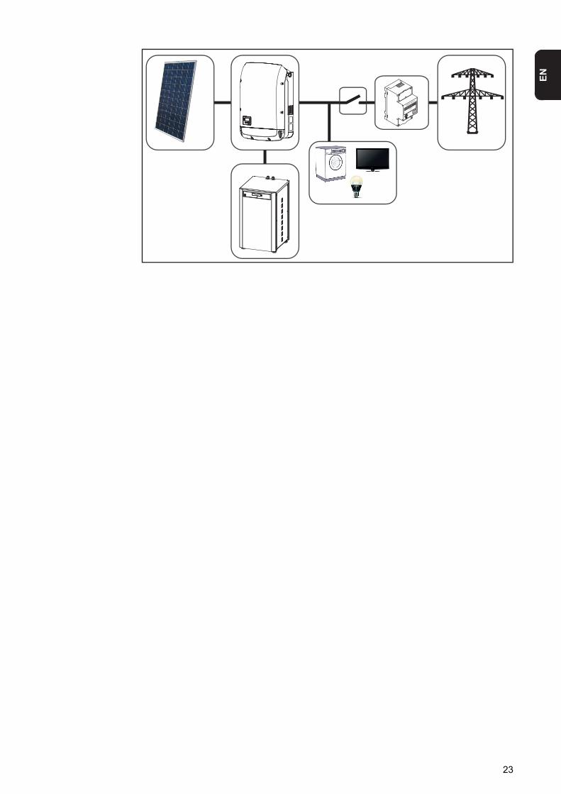
When the hybrid PV system is equipped with all the available features, the inverter can:- Feed energy into the grid- Supply the devices that are connected to the PV system with power in the event of a
power failure - Use any excess energy to charge the Fronius Solar Battery
IMPORTANT! In emergency power mode, an increased nominal frequency is used in or-der to avoid parallel operation with other generators.
22
EN
23

24

Operation

EN
Data communication
Data communica-tion area
General The inverter is fitted with the WLAN-enabled system monitoring and energy management unit (Fronius Datamanager) as standard.Various functions are included with the Fronius system monitoring, such as:- Dedicated web page displaying current data and a wide range of settings- Option of connecting directly to Fronius Solar.web- Automatic sending of service messages by SMS or e-mail in the event of a fault - Internet connection via WLAN or LAN- Ability to control the inverter load by specifying power limit values, minimum or maxi-
mum running times or target running times- Ability to control the inverter via Modbus (TCP)- Ability to assign control priorities- Ability to control the inverter by means of connected meters (Fronius Smart Meter)- Ability to control the inverter via a ripple control signal receiver (e.g. by specifying the
reactive power or effective power) - Dynamic power reduction, taking self-consumption into account- Ability to control battery charging in line with the control targets set- Ability to control emergency power mode
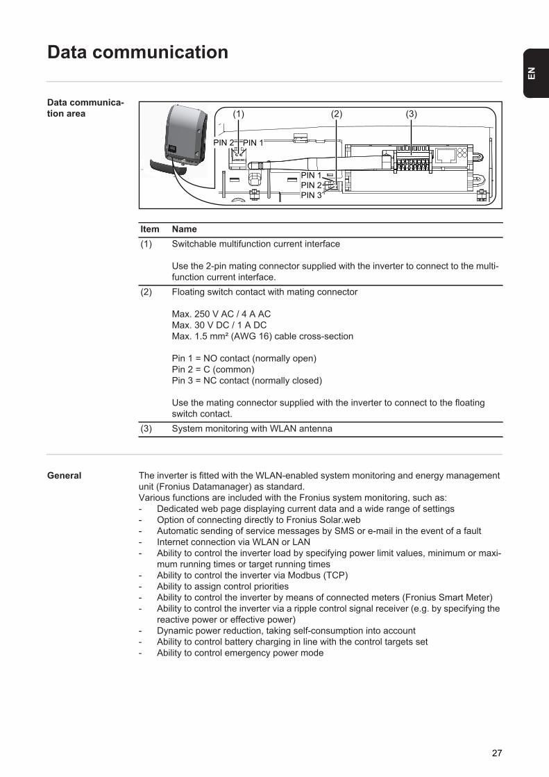
Item Name(1) Switchable multifunction current interface
Use the 2-pin mating connector supplied with the inverter to connect to the multi-function current interface.
(2) Floating switch contact with mating connector
Max. 250 V AC / 4 A ACMax. 30 V DC / 1 A DCMax. 1.5 mm² (AWG 16) cable cross-section
Pin 1 = NO contact (normally open)Pin 2 = C (common)Pin 3 = NC contact (normally closed)
Use the mating connector supplied with the inverter to connect to the floating switch contact.
(3) System monitoring with WLAN antenna
(1) (2)
PIN 1PIN 2
PIN 1PIN 2PIN 3
(3)
27
Controls, connec-tions and indica-tors on the system monitor-ing unit
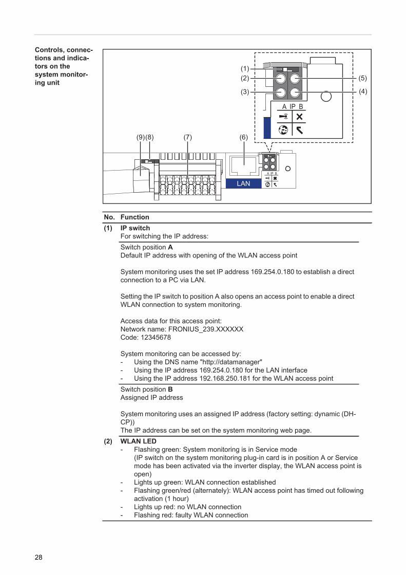
No. Function(1) IP switch
For switching the IP address:Switch position ADefault IP address with opening of the WLAN access point
System monitoring uses the set IP address 169.254.0.180 to establish a direct connection to a PC via LAN.
Setting the IP switch to position A also opens an access point to enable a direct WLAN connection to system monitoring.
Access data for this access point:Network name: FRONIUS_239.XXXXXXCode: 12345678
System monitoring can be accessed by:- Using the DNS name "http://datamanager"- Using the IP address 169.254.0.180 for the LAN interface- Using the IP address 192.168.250.181 for the WLAN access pointSwitch position BAssigned IP address
System monitoring uses an assigned IP address (factory setting: dynamic (DH-CP)) The IP address can be set on the system monitoring web page.
(2) WLAN LED- Flashing green: System monitoring is in Service mode
(IP switch on the system monitoring plug-in card is in position A or Service mode has been activated via the inverter display, the WLAN access point is open)
- Lights up green: WLAN connection established- Flashing green/red (alternately): WLAN access point has timed out following
activation (1 hour)- Lights up red: no WLAN connection- Flashing red: faulty WLAN connection
(5)(1)
(6)(7)(8)(9)
(4)
(2)
(3)
LAN
28
EN
(3) Solar.web connection LED- Lights up green: Fronius Solar.web connection established- Lights up red: Fronius Solar.web connection is required but has not been es-
tablished- Not lit: no Fronius Solar.web connection is required or the option for sending
data to Fronius Solar.web has been deactivated(4) Supply LED
- Lights up green: internal communication system is providing an adequate pow-er supply; system monitoring is ready for use
- Not lit: no power is being supplied by the internal communication system- Flashing red: update in progress
IMPORTANT! Never interrupt the power supply while an update is in progress.- Lights up red: update failed
(5) Connection LED- Lights up green: good connection within the internal communication system- Lights up red: connection within the internal communication system has been
interrupted(6) LAN connection
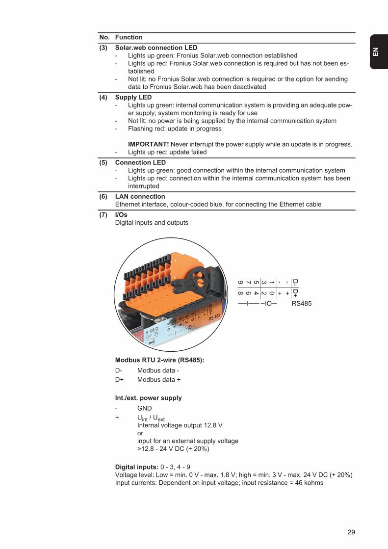
Ethernet interface, colour-coded blue, for connecting the Ethernet cable(7) I/Os
Digital inputs and outputs
Modbus RTU 2-wire (RS485):D- Modbus data -D+ Modbus data +
Int./ext. power supply- GND+ Uint / Uext
Internal voltage output 12.8 Vorinput for an external supply voltage >12.8 - 24 V DC (+ 20%)
Digital inputs: 0 - 3, 4 - 9Voltage level: Low = min. 0 V - max. 1.8 V; high = min. 3 V - max. 24 V DC (+ 20%)Input currents: Dependent on input voltage; input resistance = 46 kohms
No. Function
D---13579
D+++02468
I IO RS485
29
Digital outputs: 0 - 3Switching capacity when power is supplied by the system monitoring plug-in card: 3.2 W in total for all 4 digital outputs
Switching capacity when power is supplied by an external power supply delivering min. 12.8 - max. 24 V DC (+ 20%), connected to Uint / Uext and GND: 1 A, 12.8 - 24 V DC (depending on external power supply) for each digital output
The connection to the I/Os is established via the mating connector supplied.(8) Antenna socket
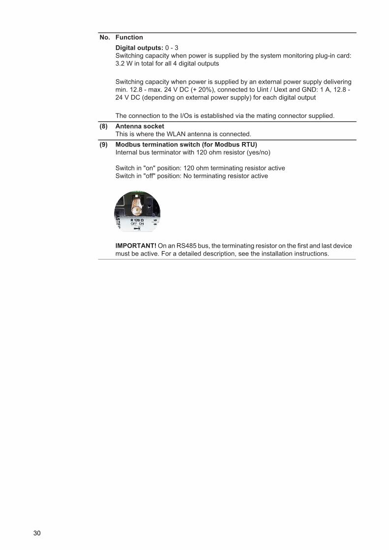
This is where the WLAN antenna is connected.(9) Modbus termination switch (for Modbus RTU)
Internal bus terminator with 120 ohm resistor (yes/no)
Switch in "on" position: 120 ohm terminating resistor activeSwitch in "off" position: No terminating resistor active
IMPORTANT! On an RS485 bus, the terminating resistor on the first and last device must be active. For a detailed description, see the installation instructions.
No. Function
30
EN
Fronius Hybrid inverter
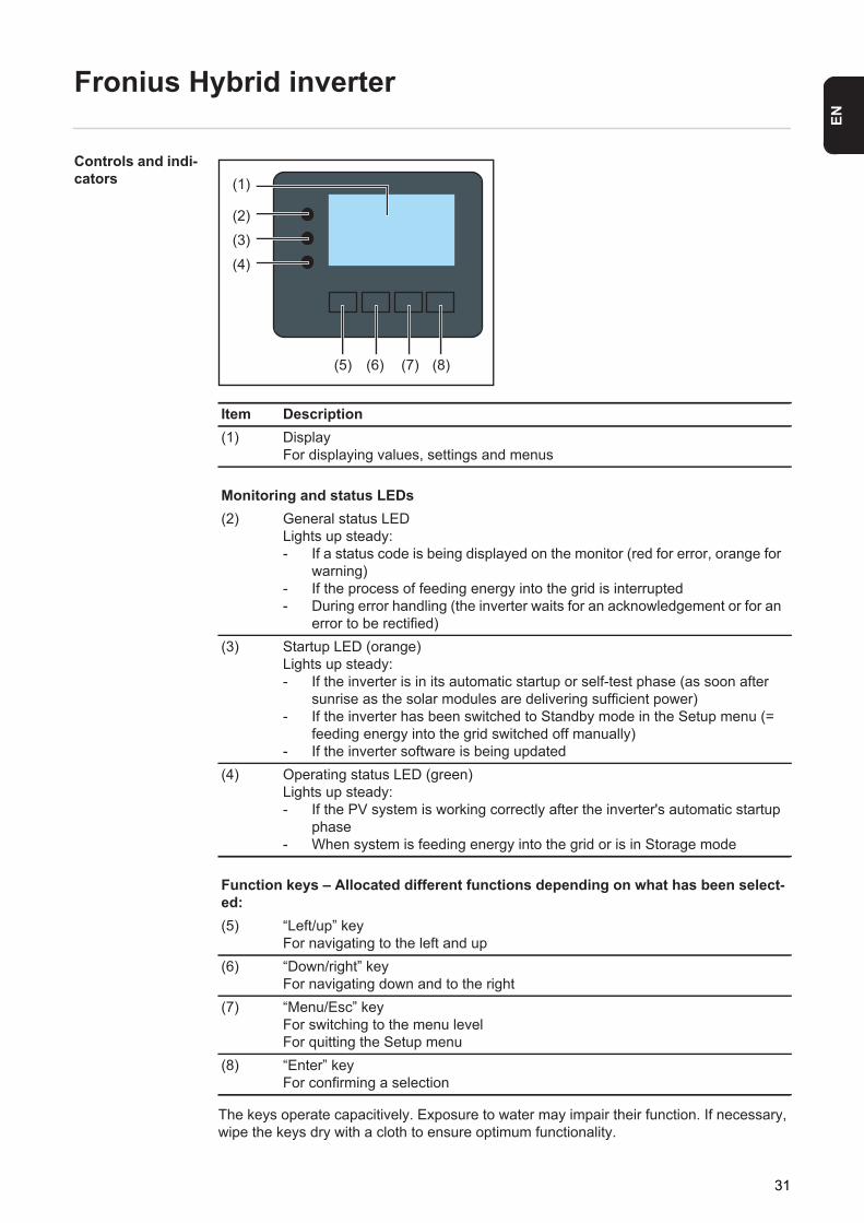
Controls and indi-cators
The keys operate capacitively. Exposure to water may impair their function. If necessary, wipe the keys dry with a cloth to ensure optimum functionality.
Item Description(1) Display
For displaying values, settings and menus
Monitoring and status LEDs(2) General status LED
Lights up steady: - If a status code is being displayed on the monitor (red for error, orange for
warning)- If the process of feeding energy into the grid is interrupted- During error handling (the inverter waits for an acknowledgement or for an
error to be rectified)(3) Startup LED (orange)
Lights up steady:- If the inverter is in its automatic startup or self-test phase (as soon after
sunrise as the solar modules are delivering sufficient power)- If the inverter has been switched to Standby mode in the Setup menu (=
feeding energy into the grid switched off manually)- If the inverter software is being updated
(4) Operating status LED (green)Lights up steady: - If the PV system is working correctly after the inverter's automatic startup
phase- When system is feeding energy into the grid or is in Storage mode
Function keys – Allocated different functions depending on what has been select-ed:(5) “Left/up” key
For navigating to the left and up(6) “Down/right” key
For navigating down and to the right(7) “Menu/Esc” key
For switching to the menu levelFor quitting the Setup menu
(8) “Enter” keyFor confirming a selection
(1)
(2)
(3)
(4)
(5) (6) (7) (8)
31
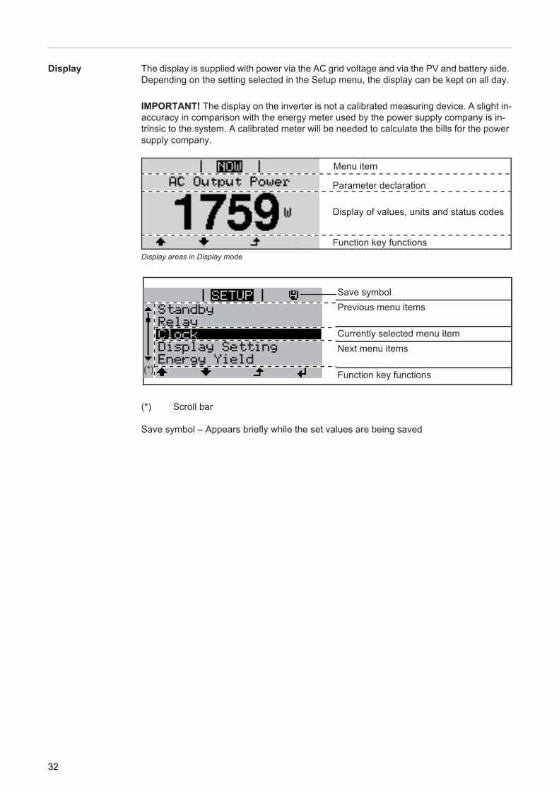
Display The display is supplied with power via the AC grid voltage and via the PV and battery side. Depending on the setting selected in the Setup menu, the display can be kept on all day.
Display areas in Display mode
(*) Scroll bar
Save symbol – Appears briefly while the set values are being saved
IMPORTANT! The display on the inverter is not a calibrated measuring device. A slight in-accuracy in comparison with the energy meter used by the power supply company is in-trinsic to the system. A calibrated meter will be needed to calculate the bills for the power supply company.
Save symbolPrevious menu items
Currently selected menu itemNext menu items
Function key functions
Function key functions
Menu item
Parameter declaration
Display of values, units and status codes
StandbyRelayClockDisplay SettingEnergy Yield
(*)
32
EN
Fronius Solar Battery
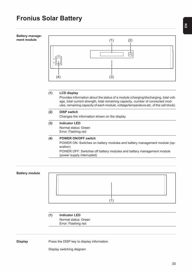
Battery manage-ment module
(1) LCD display Provides information about the status of a module (charging/discharging, total volt-age, total current strength, total remaining capacity, number of connected mod-ules, remaining capacity of each module, voltage/temperature etc. of the cell block)
(2) DISP switch Changes the information shown on the display
(3) Indicator LED Normal status: GreenError: Flashing red
(4) POWER ON/OFF switch POWER ON: Switches on battery modules and battery management module (op-eration) POWER OFF: Switches off battery modules and battery management module (power supply interrupted)
Battery module
(1) Indicator LED Normal status: GreenError: Flashing red
Display Press the DISP key to display information.
Display switching diagram
(1)
(3)(4)
(2)
(1)
33
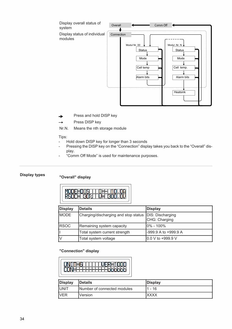
Tips:- Hold down DISP key for longer than 3 seconds- Pressing the DISP key on the “Connection” display takes you back to the “Overall” dis-
play.- “Comm Off Mode” is used for maintenance purposes.
Display types
Display overall status of systemDisplay status of individual modules
Press and hold DISP key
Press DISP keyNr.N. Means the nth storage module
Overall
Connection
Modul Nr. 00 Modul .Nr. N
Status
Mode
Cell temp
Status
Mode
Cell temp.
Alarm bits Alarm bits
Heatsink
"Overall" display
Display Details DisplayMODE Charging/discharging and stop status DIS: Discharging
CHG: ChargingRSOC Remaining system capacity 0% - 100%I Total system current strength -999.9 A to +999.9 AV Total system voltage 0.0 V to +999.9 V
"Connection" display
Display Details DisplayUNIT Number of connected modules 1 - 16VER Version XXXX
34
EN
CON Status of connected modules In the above example, there are 6 connected modules (no. 00 - no. 05).
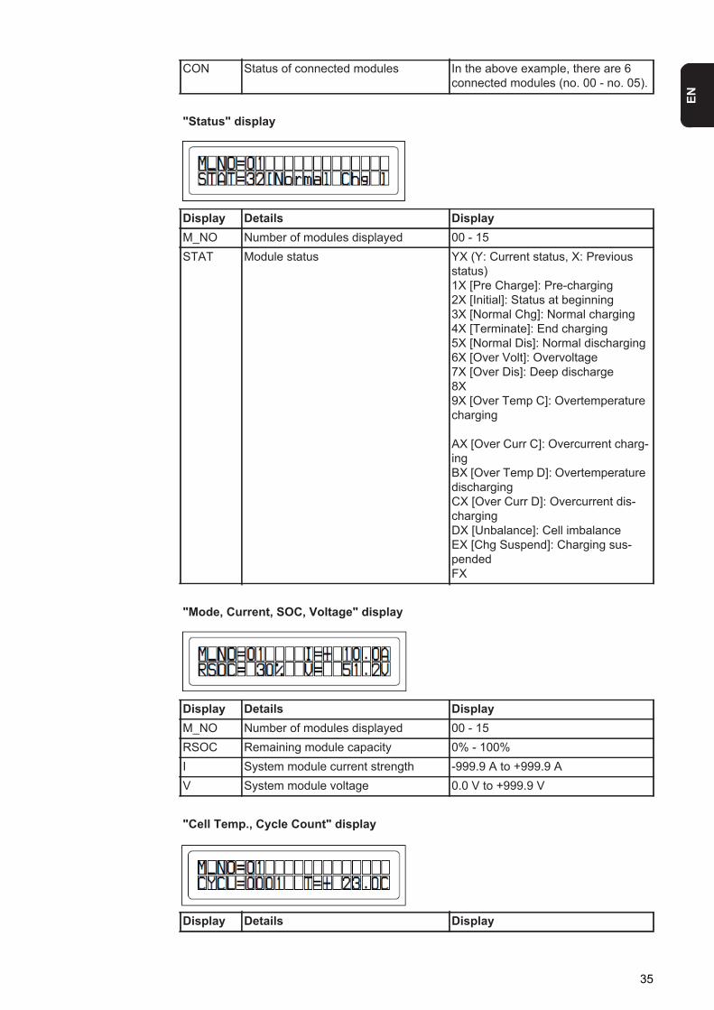
"Status" display
Display Details DisplayM_NO Number of modules displayed 00 - 15STAT Module status YX (Y: Current status, X: Previous
status)1X [Pre Charge]: Pre-charging2X [Initial]: Status at beginning3X [Normal Chg]: Normal charging4X [Terminate]: End charging5X [Normal Dis]: Normal discharging6X [Over Volt]: Overvoltage7X [Over Dis]: Deep discharge8X9X [Over Temp C]: Overtemperature charging
AX [Over Curr C]: Overcurrent charg-ingBX [Over Temp D]: Overtemperature dischargingCX [Over Curr D]: Overcurrent dis-chargingDX [Unbalance]: Cell imbalanceEX [Chg Suspend]: Charging sus-pendedFX
"Mode, Current, SOC, Voltage" display
Display Details DisplayM_NO Number of modules displayed 00 - 15RSOC Remaining module capacity 0% - 100%I System module current strength -999.9 A to +999.9 AV System module voltage 0.0 V to +999.9 V
"Cell Temp., Cycle Count" display
Display Details Display
35
M_NO Number of modules displayed 00 - 15CYCL Number of cycles 0000 - 9999T Average temperature of all cells -99.9 °C to +99.9 °C
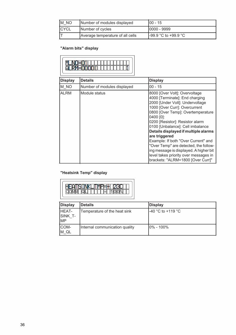
"Alarm bits" display
Display Details DisplayM_NO Number of modules displayed 00 - 15ALRM Module status 8000 [Over Volt]: Overvoltage
4000 [Terminate]: End charging2000 [Under Volt]: Undervoltage1000 [Over Curr]: Overcurrent0800 [Over Temp]: Overtemperature0400 [0]:0200 [Resistor]: Resistor alarm0100 [Unbalance]: Cell imbalanceDetails displayed if multiple alarms are triggeredExample: If both "Over Current" and "Over Temp" are detected, the follow-ing message is displayed. A higher bit level takes priority over messages in brackets: "ALRM=1800 [Over Curr]"
"Heatsink Temp" display
Display Details DisplayHEAT-SINK_T-MP
Temperature of the heat sink -40 °C to +119 °C
COM-M_QL
Internal communication quality 0% - 100%
36
EN
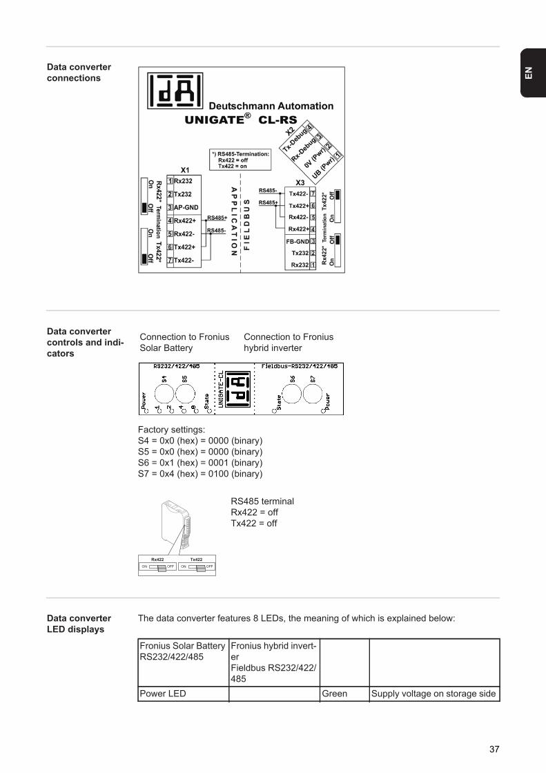
Data converter connections
Data converter controls and indi-cators
Factory settings:S4 = 0x0 (hex) = 0000 (binary)S5 = 0x0 (hex) = 0000 (binary)S6 = 0x1 (hex) = 0001 (binary)S7 = 0x4 (hex) = 0100 (binary)
Data converter LED displays
The data converter features 8 LEDs, the meaning of which is explained below:
Connection to Fronius Solar Battery
Connection to Fronius hybrid inverter
RS485 terminalRx422 = offTx422 = off
Fronius Solar BatteryRS232/422/485
Fronius hybrid invert-erFieldbus RS232/422/485
Power LED Green Supply voltage on storage side
37
"Power" LED(Fronius Solar Battery)This LED is connected directly to the supply voltage of the 1st serial interface (electrical isolation is optionally available for this supply).
"1/2/4/8 (Error No / Selected ID)" LEDIf these 4 LEDs and the "State" LED all light up steady red at the same time, the error num-ber is indicated in binary format in accordance with the table in the "Troubleshooting" sec-tion.
"State" LED(Fronius Solar Battery)
"State" LED (Fronius hybrid inverter)
"Power" LED (Fronius hybrid inverter)This LED is connected directly to the supply voltage of the interface.
LED 1/2/4/8 (Error No / Selected ID)
Green General gateway error
State LED Red/green General gateway errorState LED Red/green Inverter interface statePower LED Green Inverter supply voltage
Lights up green Status OKFlashing green Status OKFlashing green/red Status OKLights up red General gateway error (see "Error No." LEDs)Flashing red Data converter is in configuration/test mode
Lights up green Initialised and startedFlashing green InitialisedFlashing green/red -Lights up red General bus error (system error 10)Flashing red Starts to flash straight after "BusStart" -> Initialisation failed
Starts to flash during actual operation -> Data error
38
EN
Navigation at the menu level
Activate display backlighting
Press any key
The display backlighting is activated.
There is an option under 'Display Settings' in the SETUP menu to set the display back-lighting so that it is on all the time or off all the time.
Automatic deacti-vation of display backlighting / choose 'NOW' menu item
If no key is pressed for 2 minutes,- the display backlighting switches off automatically and the inverter goes to the 'NOW'
menu item (assuming the display backlighting is set to automatic).- The selection of the 'NOW' menu item can happen from any position on the menu level
with the exception of the item 'Standby' on the Setup menu.- The amount of energy currently fed in is displayed.
Open menu level
The menu items- NOW displays real-time values- LOG data recorded today, during the current calendar year and since the inverter was
first commissioned- GRAPH Day characteristic displays a plot showing the power output during the day.
The time axis is scaled automatically. Press the 'Back' key to close the display- SETUP Setup menu- INFO Information about the device and the software
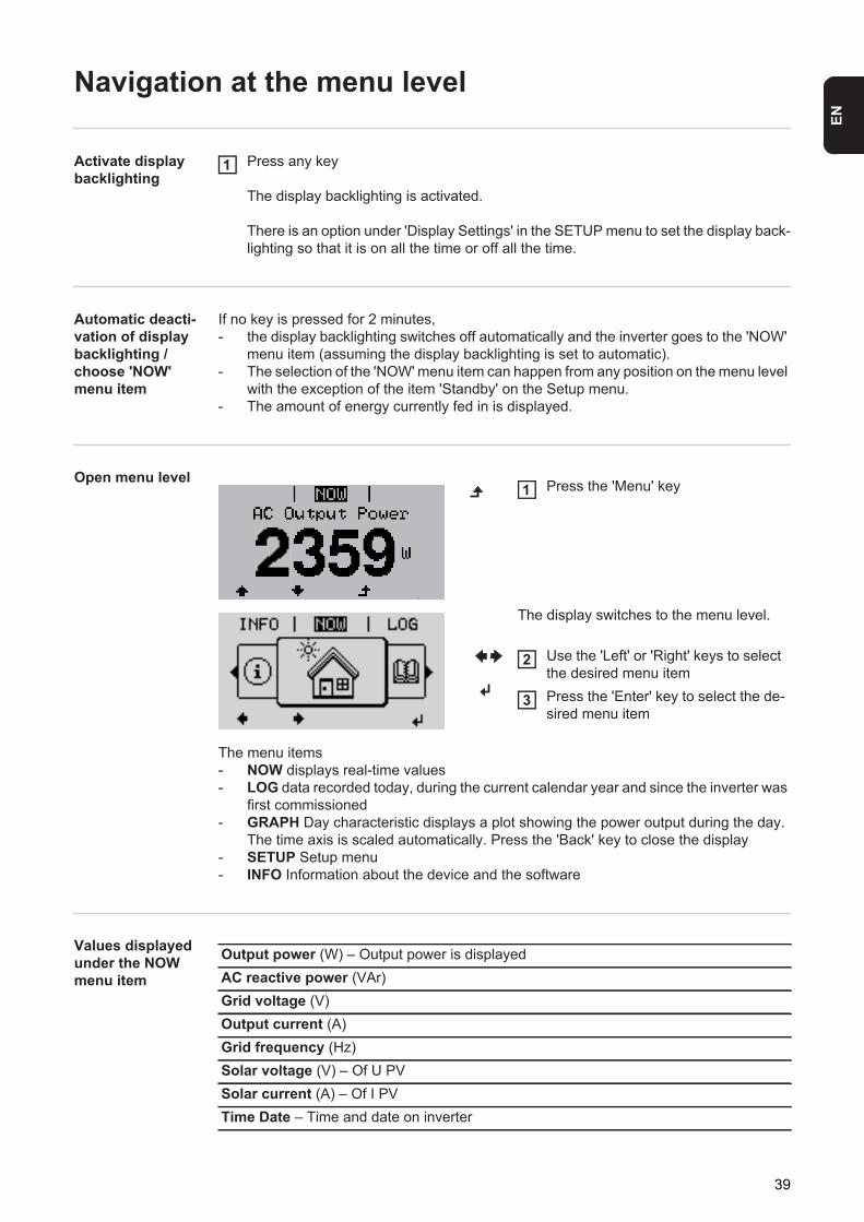
Values displayed under the NOW menu item
1
Press the 'Menu' key
The display switches to the menu level.
Use the 'Left' or 'Right' keys to select the desired menu itemPress the 'Enter' key to select the de-sired menu item
1
2
3
Output power (W) – Output power is displayedAC reactive power (VAr)Grid voltage (V)Output current (A)Grid frequency (Hz)Solar voltage (V) – Of U PVSolar current (A) – Of I PVTime Date – Time and date on inverter
39

Values displayed under the LOG menu item
Energy fed in (kWh / MWh)Energy delivered by the inverter over the period in question
There may be discrepancies compared with values displayed on other measuring instru-ments because of differences in measuring methods. As far as the billing of the energy fed in is concerned, the only binding display values are those produced by the calibrated measuring instrument provided by the utility company.Max. output power (W)Largest amount of energy delivered by the inverter during the period in question YieldAmount of money earned during the period in question (currency and conversion factor can be selected in the Setup menu)
Like the "Energy fed in" figure, the yield figure may also exhibit discrepancies compared with other measured values.
The "Setup menu" section explains how to select a currency and charge rate. The factory setting depends on the respective country setup.Max. grid voltage (V) Highest grid voltage measured during the period in questionMaximum solar voltage (V) Highest solar module voltage measured during the period in questionOperating hoursLength of time the inverter has been working (HH:MM)
IMPORTANT! In order for the day and year values to be displayed correctly, the time must be set accurately.Alternative operating hoursOperating time of the inverter (HH:MM) in alternative mode (emergency power mode).
40
EN
Menu items in the Set-up menu
Standby Manual activation / deactivation of Standby mode
- No energy is fed into the grid.- The Startup LED will show steady orange.- In Standby mode, no other menu item at menu level can be accessed or adjusted.- The automatic switchover into the 'NOW' display mode after 2 minutes of keyboard in-
activity does not occur.- Standby mode can only be terminated manually by pressing the 'Enter' key.- Feeding energy into the grid can be resumed at any time (deactivate 'Standby').
Switching off Standby mode (manually switching off feeding energy into the grid):
Select the 'Standby' itemPress the 'Enter' key
'STANDBY' and 'ENTER' appear alternately on the display.Standby mode is now active.The Startup LED shows steady orange.
Resuming feeding energy into the grid:
'STANDBY' and 'ENTER' appear alternately on the display when in Standby mode.
Press the 'Enter' key to resume feeding energy into the grid
The 'Standby' menu item is displayed.At the same time, the inverter enters the startup phase.The operating state LED shows steady green when feeding energy into the grid has been resumed.
Relays Activate relay, relay settings, relay test
* these are only shown if the 'E-Manager' function has been activated under 'Relay mode'.
12
1
Setting range Relay mode / Relay test / Switch-on point* / Switch-off point*
Relay modefor selecting the different functions of the floating switch contact in the data communica-tion area:- Alarm function- Active output- Energy Manager
Setting range ALL / Permanent / OFF / ON / E-ManagerFactory setting ALL
Alarm function:Permanent / ALL:
Switch the floating switch contact for permanent and temporary ser-vice codes (e.g. brief interruption to energy being fed into the grid, a service code occurs a certain number of times a day - can be adjusted in the 'BASIC' menu)
41
Energy Manager(under Relay menu item)
The “Energy Manager” function can be used to activate the floating switch contact in such a way that it functions as an actuator.Thus, a consumer that is connected to the floating switch contact can be controlled by specifying a switch-on or switch-off point that depends on the feed-in power.
The floating switch contact is automatically switched off:- If the inverter is not feeding any power into the grid- If the inverter is manually switched to Standby mode- If the effective power is set to < 10% of the nominal output
To deactivate the “Energy Manager” function, select a different function and press the “En-ter” key.
Notes on setting up the switch-on and switch-off pointsThe interface of the energy management relay always uses the output power of the inverter as a reference point, although this will not necessarily match what is generated by the PV system in the case of the hybrid system.If the difference between the switch-on and switch-off points is too small, or if there are fluc-tuations in effective power, the result may be multiple switching cyclesTo avoid frequent switching on and off, the difference between the switch-on and switch-off points should be at least 100 - 200 W.
When choosing the switch-off point, the power consumption of the connected consumer should be taken into account.
When choosing the switch-on point, the weather conditions and anticipated insolation should also be taken into account.
Active output:ON: The floating NO contact is on all the time the inverter is in operation
(as long as the display is not dark or is displaying something).OFF: The floating NO contact is off.Energy Manager:E-Manager: Further details on the 'Energy Manager' function may be found in the
"Energy Manager" section.Relay testFunction test to determine whether the floating switch contact switchesSwitch-on point (only if 'Energy Manager' function is activated)for setting the effective power limit beyond which the floating switch contact is switched on
Factory setting 1000 WSetting range Switch-off point - max. nominal output of inverter / W / kWSwitch-off point (only if 'Energy Manager' function is activated)for setting the effective power limit beyond which the floating switch contact is switched off
Factory setting 500Setting range 0 - Switch-on point / W / kW
To activate the “Energy Manager” function, select “E-Manager” and press the “Enter” key.When the “Energy Manager” function is running, the “Energy Manager” symbol will ap-pear in the top left corner of the display:
When the floating NO contact is off (open contact)
When the floating NO contact is on (closed contact)
42
EN
Application exampleSwitch-on point = 2000 W, switch-off point = 1800 W
If the inverter is outputting 2000 W or above, then the floating switch contact on the inverter is switched on.If the inverter output falls to below 1800 W, the floating switch contact is switched off.
Possible applications:Operating a heat pump or an air-conditioning system using as much self-generated power as possible
Time / Date Set the time, date and automatic changeover between summer and winter time
Set timeSet the time (hh:mm:ss or hh:mm am/pm – depending on the setting for the time display format)
Set dateSet the date (dd.mm.yyyy or mm/dd/yyyy - depending on the setting for the date display format)
Summer/winter timeActivate/deactivate automatic changeover between summer and winter time
IMPORTANT! The time and date must be set accurately in order for the day and year val-ues and for the day characteristic to be displayed correctly.
Display settings
LanguageSet language for display
Setting range Set time / Set date / Time display format / Date display format / Summer/winter time
Time display formatFor specifying the time display format
Setting range 12hrs / 24hrsFactory setting Depends on country setup
Date display formatFor specifying the date display format
Setting range mm/dd/yyyy / dd.mm.yyFactory setting Depends on country setup
Setting range on / offFactory setting on
Setting range Language / Night mode / Contrast / Illumination
Setting range German, English, French, Dutch, Italian, Spanish, Czech, Slo-vak, etc.
43
Night modeDATCOM night mode; controls DATCOM and display operation during the night or when the DC voltage is insufficient
ContrastSet the contrast on the display
Since the contrast is temperature-dependent, it may be necessary to adjust the setting un-der the “Contrast” menu item when the environmental conditions change.
IlluminationInitial setting for display illumination
The “Illumination” menu item only relates to the display backlighting.
Energy yield Setting- of the currency- of the feed-in tariff
Setting range AUTO / ON / OFFFactory setting OFF
AUTO: DATCOM mode is always in effect whenever Fronius system monitoring is active.The display remains dark during the night, but can be activated by pressing any key.
ON: DATCOM mode is always in effect. The inverter supplies 12 V continuously to power the Fronius Solar Net. The display is always active.
IMPORTANT! If DATCOM night mode is set to ON or AUTO when there are Fronius Solar Net components connected, then the inverter's current con-sumption during the night will increase to around 7 W.
OFF: IMPORTANT! If a battery has been connected to the system and activated, Night mode must not be set to OFF.
DATCOM will not run at night, the inverter will not need any AC current in order to supply power to the internal communication system.The display is switched off during the night and the Fronius system monitor-ing datalogger is not available.
Setting range 0 - 10 Factory setting 5
Setting range AUTO / ON / OFF Factory setting AUTO
AUTO: The display backlighting is activated by pressing any key. If no key is pressed for 2 minutes, the display backlighting will go off again.
ON: The display backlighting remains permanently on when the inverter is active.OFF: The display backlighting is permanently switched off.
Setting range Currency / Feed-in tariff
44
EN
Fan To check that the fan is working correctly
- Use the 'Up' and 'Down' keys to select the desired fan- Testing of the selected fan is initiated by clicking 'Enter'. - The fan will continue to run until the operator exits the menu by pressing 'Esc'.
CurrencySet the currency
Setting range 3 characters, A-ZFeed-in tariffSet the remuneration rate for energy fed into the grid
Setting range 2 digits, 3 decimal placesFactory setting (depends on country setup)
Setting range Test fan #1 / Test fan #2 (depending on the device)
45
SETUP menu item
Initial setting The inverter is pre-configured and ready to use. There is no need to enter any initial set-tings before using it to feed energy into the grid, as this is a fully-automated process.
The SETUP menu item allows the initial settings of the inverter to be changed easily to bring it in line, as closely as possible, with the preferences and requirements of the user.
Software updates
Navigating the SETUP menu item
NOTE! As a result of software updates, you may find that your device has certain functions that are not described in these operating instructions, or vice versa. Cer-tain illustrations may also differ slightly from the actual controls on your device, but these controls function in exactly the same way.
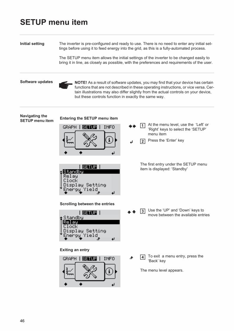
Entering the SETUP menu itemAt the menu level, use the ‘Left’ or ’Right’ keys to select the ‘SETUP’ menu itemPress the ‘Enter’ key
The first entry under the SETUP menu item is displayed: ‘Standby'
Scrolling between the entriesUse the ‘UP’ and ‘Down’ keys to move between the available entries
Exiting an entryTo exit a menu entry, press the ‘Back’ key
The menu level appears.
GRAPH 1
2
Relay
StandbyRelayClockDisplay SettingEnergy Yield
Relay
StandbyRelayClockDisplay SettingEnergy Yield
3
GRAPH 4
46
EN
If no key is pressed for 2 minutes: - The inverter switches from wherever it is on the menu level back to the ‘NOW’ display
mode (exeption: ‘Standby’ Setup menu item).- The display backlighting goes out.- The amount of energy currently being fed in is displayed.
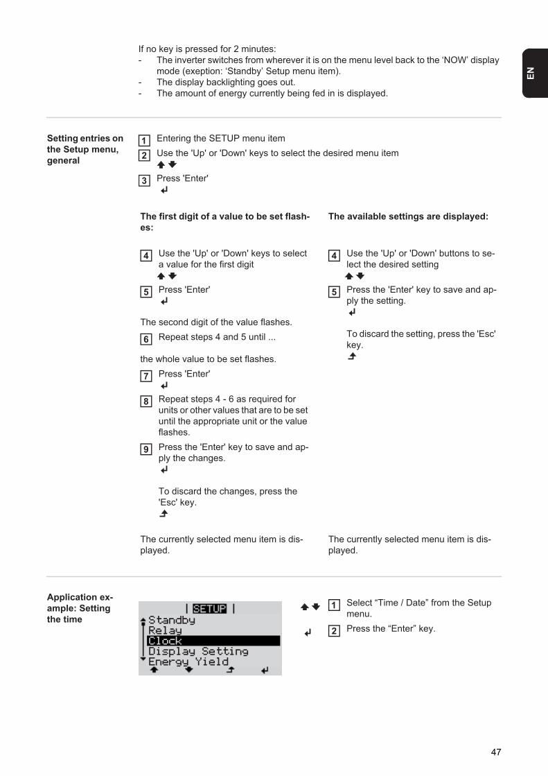
Setting entries on the Setup menu, general
Entering the SETUP menu itemUse the 'Up' or 'Down' keys to select the desired menu item
Press 'Enter'
Application ex-ample: Setting the time
The first digit of a value to be set flash-es:
The available settings are displayed:
Use the 'Up' or 'Down' keys to select a value for the first digit
Press 'Enter'
The second digit of the value flashes.Repeat steps 4 and 5 until ...
the whole value to be set flashes.
Use the 'Up' or 'Down' buttons to se-lect the desired setting
Press the 'Enter' key to save and ap-ply the setting.
To discard the setting, press the 'Esc' key.
Press 'Enter'
Repeat steps 4 - 6 as required for units or other values that are to be set until the appropriate unit or the value flashes.Press the 'Enter' key to save and ap-ply the changes.
To discard the changes, press the 'Esc' key.
The currently selected menu item is dis-played.
The currently selected menu item is dis-played.
12
3
4
5
6
4
5
7
8
9
Select “Time / Date” from the Setup menu.Press the “Enter” key.
Relay
StandbyRelayClockDisplay SettingEnergy Yield
1
2
47
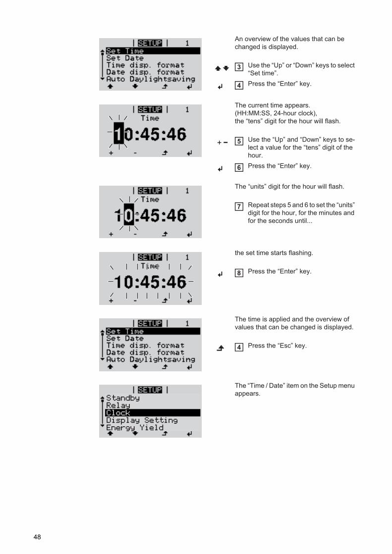
An overview of the values that can be changed is displayed.
Use the “Up” or “Down” keys to select “Set time”.Press the “Enter” key.
The current time appears. (HH:MM:SS, 24-hour clock), the “tens” digit for the hour will flash.
Use the “Up” and “Down” keys to se-lect a value for the “tens” digit of the hour.Press the “Enter” key.
The “units” digit for the hour will flash.
Repeat steps 5 and 6 to set the “units” digit for the hour, for the minutes and for the seconds until...
the set time starts flashing.
Press the “Enter” key.
The time is applied and the overview of values that can be changed is displayed.
Press the “Esc” key.
The “Time / Date” item on the Setup menu appears.
3
4
5
6
7
8
4
Relay
StandbyRelayClockDisplay SettingEnergy Yield
48
EN
The INFO menu item
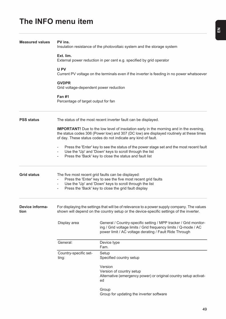
Measured values PV ins.Insulation resistance of the photovoltaic system and the storage system
Ext. lim.External power reduction in per cent e.g. specified by grid operator
U PVCurrent PV voltage on the terminals even if the inverter is feeding in no power whatsoever
GVDPRGrid voltage-dependent power reduction
Fan #1Percentage of target output for fan
PSS status The status of the most recent inverter fault can be displayed.
IMPORTANT! Due to the low level of insolation early in the morning and in the evening, the status codes 306 (Power low) and 307 (DC low) are displayed routinely at these times of day. These status codes do not indicate any kind of fault.
- Press the 'Enter' key to see the status of the power stage set and the most recent fault- Use the 'Up' and 'Down' keys to scroll through the list- Press the 'Back' key to close the status and fault list
Grid status The five most recent grid faults can be displayed:- Press the 'Enter' key to see the five most recent grid faults- Use the 'Up' and 'Down' keys to scroll through the list- Press the 'Back' key to close the grid fault display
Device informa-tion
For displaying the settings that will be of relevance to a power supply company. The values shown will depend on the country setup or the device-specific settings of the inverter.
Display area General / Country-specific setting / MPP tracker / Grid monitor-ing / Grid voltage limits / Grid frequency limits / Q-mode / AC power limit / AC voltage derating / Fault Ride Through
General: Device typeFam.
Country-specific set-ting:
SetupSpecified country setup
VersionVersion of country setupAlternative (emergency power) or original country setup activat-ed
GroupGroup for updating the inverter software
49
Version Displays the version and serial numbers of the PC boards in the inverter (e.g. for service purposes)
MPP Tracker: PV TrackerGrid monitoring: GMTi
Start-up time of inverter in s
GMTrreconnection time in s following a grid fault
ULLMean grid voltage over 10 minutes in V
LLTripTrip time for long-term voltage monitoring
Grid voltage limits: UILmaxUpper inner grid voltage in V
UILminLower inner grid voltage in V
Grid frequency limits: FILmaxUpper inner grid frequency in Hz
FILminLower inner grid frequency in Hz
Q-mode: Current cos phi power factor setting(e.g. Constant Cos(phi) / Constant Q / Q(U) characteristic / etc.)
AC power limit: Max. P ACManual power reduction
AC voltage derating: StatusON / OFF – Voltage-dependent power reduction
GVDPReThreshold at which the voltage-dependent power reduction be-gins
GVDPRvReduction gradient used to reduce the power, e.g.: 10% per volt above the GVDPRe threshold
MessageActivates the sending of an info message via Fronius Solar Net
Fault Ride Through: Status – Default setting: OFFIf the function is activated, the inverter does not switch off im-mediately in the event of a short-term AC voltage dip (outside of the limits specified by the grid supplier), but instead continues to feed in power for a defined period.
DB min – Default setting: 90%"Dead Band Minimum" setting in per cent
DB max - Default setting: 120%"Dead Band Maximum" setting in per cent
k-Fac. - Default setting: 0
50

EN
Display area Display / Display Software / Integrity Checksum / Memory Card / Memory Card #1 / Power Stage / Power Stage Software / EMI Filter / Power Stage #3 / Power Stage #4
51
Switching the key lock on and off
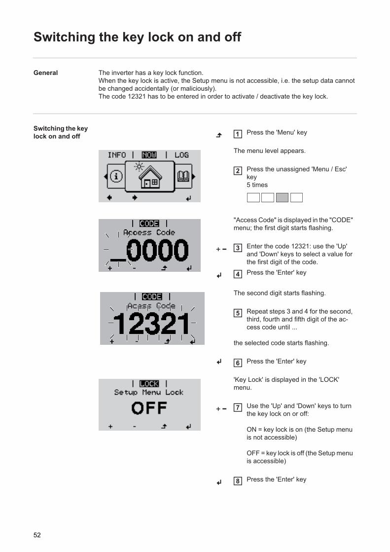
General The inverter has a key lock function.When the key lock is active, the Setup menu is not accessible, i.e. the setup data cannot be changed accidentally (or maliciously).The code 12321 has to be entered in order to activate / deactivate the key lock.
Switching the key lock on and off Press the 'Menu' key
The menu level appears.
Press the unassigned 'Menu / Esc' key 5 times
"Access Code" is displayed in the "CODE" menu; the first digit starts flashing.
Enter the code 12321: use the 'Up' and 'Down' keys to select a value for the first digit of the code.Press the 'Enter' key
The second digit starts flashing.
Repeat steps 3 and 4 for the second, third, fourth and fifth digit of the ac-cess code until ...
the selected code starts flashing.
Press the 'Enter' key
'Key Lock' is displayed in the 'LOCK' menu.
Use the 'Up' and 'Down' keys to turn the key lock on or off:
ON = key lock is on (the Setup menu is not accessible)
OFF = key lock is off (the Setup menu is accessible)
Press the 'Enter' key
1
2
3
4
Acess Code5
6
7
8
52
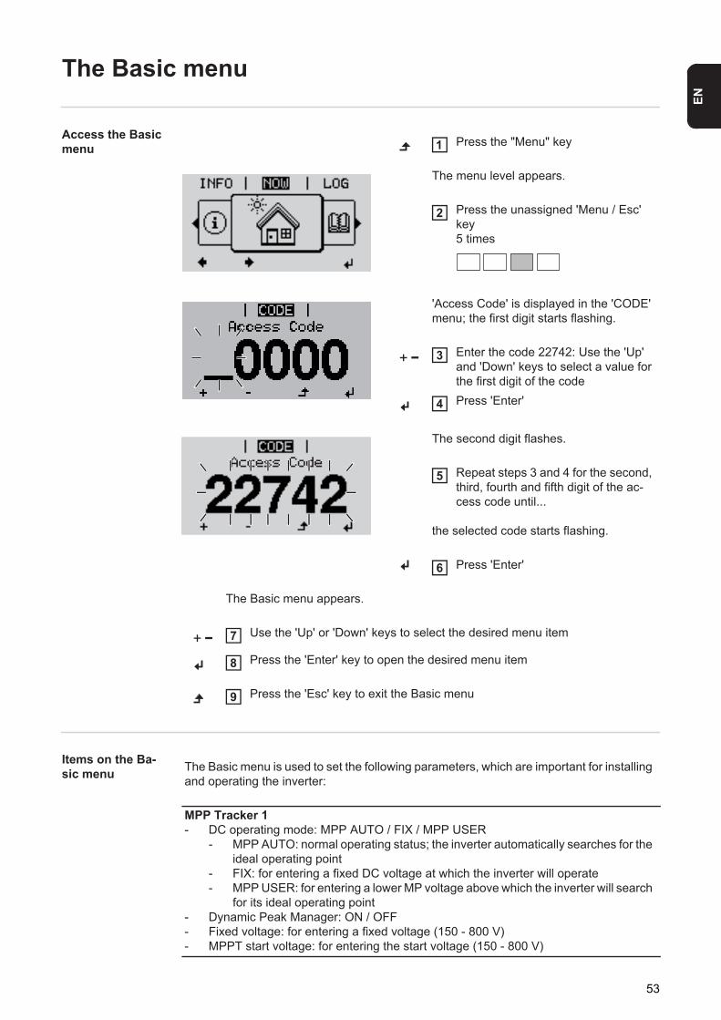
EN
The Basic menu
Access the Basic menu
Items on the Ba-sic menu
Press the "Menu" key
The menu level appears.
Press the unassigned 'Menu / Esc' key 5 times
'Access Code' is displayed in the 'CODE' menu; the first digit starts flashing.
Enter the code 22742: Use the 'Up' and 'Down' keys to select a value for the first digit of the codePress 'Enter'
The second digit flashes.
Repeat steps 3 and 4 for the second, third, fourth and fifth digit of the ac-cess code until...
the selected code starts flashing.
Press 'Enter'
The Basic menu appears.
Use the 'Up' or 'Down' keys to select the desired menu item
Press the 'Enter' key to open the desired menu item
Press the 'Esc' key to exit the Basic menu
1
2
3
4
Access Code5
6
7
8
9
The Basic menu is used to set the following parameters, which are important for installing and operating the inverter:
MPP Tracker 1- DC operating mode: MPP AUTO / FIX / MPP USER
- MPP AUTO: normal operating status; the inverter automatically searches for the ideal operating point
- FIX: for entering a fixed DC voltage at which the inverter will operate- MPP USER: for entering a lower MP voltage above which the inverter will search
for its ideal operating point- Dynamic Peak Manager: ON / OFF- Fixed voltage: for entering a fixed voltage (150 - 800 V)- MPPT start voltage: for entering the start voltage (150 - 800 V)
53
Input signal- How it works: Ext Sig. / S0-Meter / OFF
Only with the Ext Sig. function selected:- Triggering method: Warning (warning shown on display) / Ext. Stop (inverter
switches off)- Connection type: N/C (normally closed contact) / N/O (normally open contact)
SMS / relay- Event delay
For entering the time delay after which an SMS is sent or the relay is to switch900 - 86,400 seconds
- Event counter:For entering the number of events that lead to signalling: 10 - 255
Insulation setting- Insulation warning: ON / OFF- Threshold warning: for entering a threshold that leads to a warning- Insulation fault: ON / OFF- Threshold fault: for entering a threshold that leads to a fault- Both the PV system and the Fronius Solar Battery are monitored.Temperature warningFor activating/deactivating the overtemperature warning for each eventON / OFFTOTAL ResetUnder the LOG menu item, this setting resets the max. and min. voltage values and the max. power of feeding in to zero.Once the values have been reset, this action cannot be undone.
To reset the values to zero, press the "Enter" key."CONFIRM" is displayed.Press "Enter" again.The values are reset and the menu is displayed.
54
Fronius system monitoring

EN
General
General remarks The Fronius system monitoring feature is a networked datalogger that manages to com-bine the functions of the Fronius Com Card, the Fronius Datalogger Web, the Fronius Pow-er Control Card and the Fronius Modbus Card on a single plug-in card. The Fronius system monitoring web page offers a rapid overview of the photovoltaic sys-tem.It can be accessed via a web browser when there is a direct connection or – if configured to support an indirect connection – over the Internet.Fronius system monitoring is easy to configure and provides automatic alerts. Alerts can be sent via SMS or e-mail.
If the feature is used in conjunction with Fronius Solar.web, current data and archive data can be accessed for a particular photovoltaic system via the Internet or the Fronius So-lar.web App without the need for any laborious configuration work. Fronius system moni-toring automatically sends the data to Fronius Solar.web.
Prerequisites for operation
So that data can be exchanged smoothly over the Internet, you must have a suitable Inter-net connection:- For wired Internet solutions, Fronius recommends a download speed of at least 512
kbit/s and a minimum upload speed of 256 kbit/s.
- For solutions that rely on mobile Internet services, Fronius recommends 3G transmis-sion as a minimum, plus a reliable signal.
Even if these specifications are adhered to, there is still no guarantee that everything will run smoothly.High error rates during transmission, variable reception conditions or transmission drop-outs can all have a detrimental effect on the online functionality of Fronius system monitor-ing.Fronius recommends testing any connections that meet the minimum requirements locally.
57
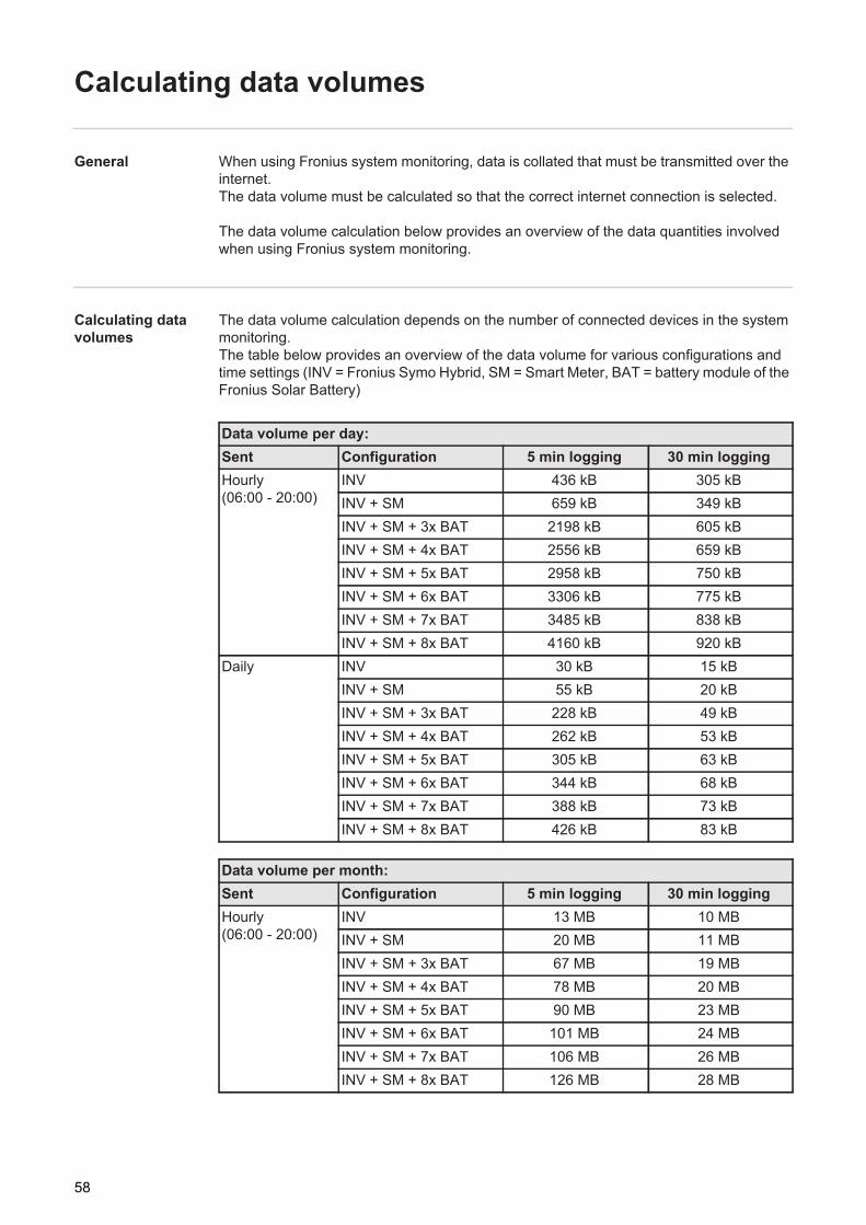
Calculating data volumes
General When using Fronius system monitoring, data is collated that must be transmitted over the internet.The data volume must be calculated so that the correct internet connection is selected.
The data volume calculation below provides an overview of the data quantities involved when using Fronius system monitoring.
Calculating data volumes
The data volume calculation depends on the number of connected devices in the system monitoring.The table below provides an overview of the data volume for various configurations and time settings (INV = Fronius Symo Hybrid, SM = Smart Meter, BAT = battery module of the Fronius Solar Battery)
Data volume per day:Sent Configuration 5 min logging 30 min loggingHourly(06:00 - 20:00)
INV 436 kB 305 kBINV + SM 659 kB 349 kBINV + SM + 3x BAT 2198 kB 605 kBINV + SM + 4x BAT 2556 kB 659 kBINV + SM + 5x BAT 2958 kB 750 kBINV + SM + 6x BAT 3306 kB 775 kBINV + SM + 7x BAT 3485 kB 838 kBINV + SM + 8x BAT 4160 kB 920 kB
Daily INV 30 kB 15 kBINV + SM 55 kB 20 kBINV + SM + 3x BAT 228 kB 49 kBINV + SM + 4x BAT 262 kB 53 kBINV + SM + 5x BAT 305 kB 63 kBINV + SM + 6x BAT 344 kB 68 kBINV + SM + 7x BAT 388 kB 73 kBINV + SM + 8x BAT 426 kB 83 kB
Data volume per month:Sent Configuration 5 min logging 30 min loggingHourly(06:00 - 20:00)
INV 13 MB 10 MBINV + SM 20 MB 11 MBINV + SM + 3x BAT 67 MB 19 MBINV + SM + 4x BAT 78 MB 20 MBINV + SM + 5x BAT 90 MB 23 MBINV + SM + 6x BAT 101 MB 24 MBINV + SM + 7x BAT 106 MB 26 MBINV + SM + 8x BAT 126 MB 28 MB
58
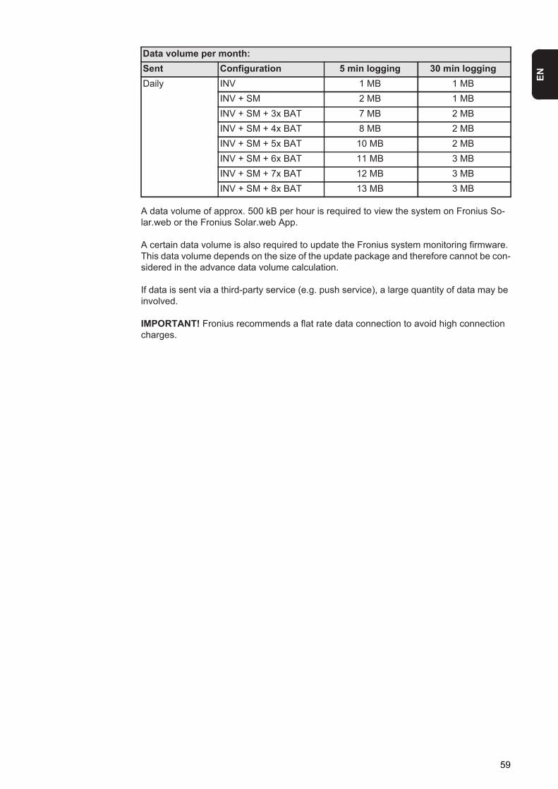
EN
A data volume of approx. 500 kB per hour is required to view the system on Fronius So-lar.web or the Fronius Solar.web App.
A certain data volume is also required to update the Fronius system monitoring firmware. This data volume depends on the size of the update package and therefore cannot be con-sidered in the advance data volume calculation.
If data is sent via a third-party service (e.g. push service), a large quantity of data may be involved.
IMPORTANT! Fronius recommends a flat rate data connection to avoid high connection charges.
Daily INV 1 MB 1 MBINV + SM 2 MB 1 MBINV + SM + 3x BAT 7 MB 2 MBINV + SM + 4x BAT 8 MB 2 MBINV + SM + 5x BAT 10 MB 2 MBINV + SM + 6x BAT 11 MB 3 MBINV + SM + 7x BAT 12 MB 3 MBINV + SM + 8x BAT 13 MB 3 MB
Data volume per month:Sent Configuration 5 min logging 30 min logging
59
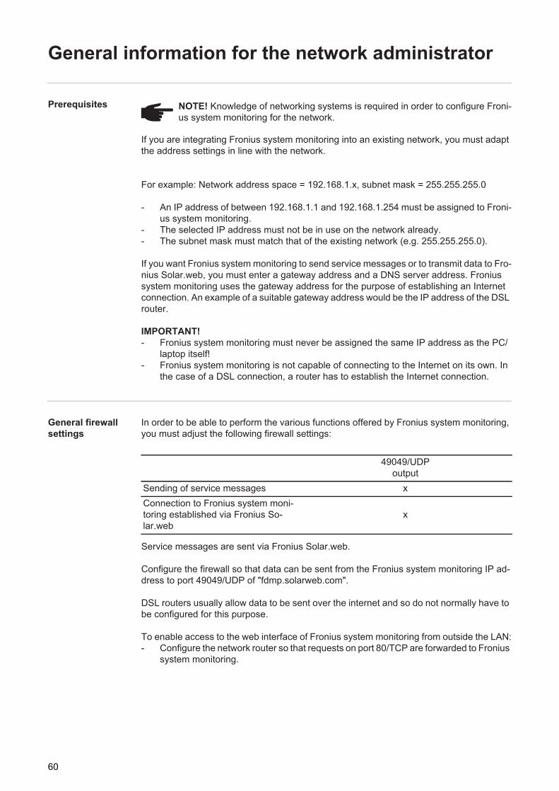
General information for the network administrator
Prerequisites
If you are integrating Fronius system monitoring into an existing network, you must adapt the address settings in line with the network.
For example: Network address space = 192.168.1.x, subnet mask = 255.255.255.0
- An IP address of between 192.168.1.1 and 192.168.1.254 must be assigned to Froni-us system monitoring.
- The selected IP address must not be in use on the network already.- The subnet mask must match that of the existing network (e.g. 255.255.255.0).
If you want Fronius system monitoring to send service messages or to transmit data to Fro-nius Solar.web, you must enter a gateway address and a DNS server address. Fronius system monitoring uses the gateway address for the purpose of establishing an Internet connection. An example of a suitable gateway address would be the IP address of the DSL router.
IMPORTANT!- Fronius system monitoring must never be assigned the same IP address as the PC/
laptop itself!- Fronius system monitoring is not capable of connecting to the Internet on its own. In
the case of a DSL connection, a router has to establish the Internet connection.
General firewall settings
In order to be able to perform the various functions offered by Fronius system monitoring, you must adjust the following firewall settings:
Service messages are sent via Fronius Solar.web.
Configure the firewall so that data can be sent from the Fronius system monitoring IP ad-dress to port 49049/UDP of "fdmp.solarweb.com".
DSL routers usually allow data to be sent over the internet and so do not normally have to be configured for this purpose.
To enable access to the web interface of Fronius system monitoring from outside the LAN:- Configure the network router so that requests on port 80/TCP are forwarded to Fronius
system monitoring.
NOTE! Knowledge of networking systems is required in order to configure Froni-us system monitoring for the network.
49049/UDP output
Sending of service messages xConnection to Fronius system moni-toring established via Fronius So-lar.web
x
60

EN
Using Fronius So-lar.web and send-ing service messages
An Internet connection is required if you want to use Fronius Solar.web or to send service messages.
Fronius system monitoring is not capable of connecting to the Internet on its own. In the case of a DSL connection, a router has to establish the Internet connection.
61
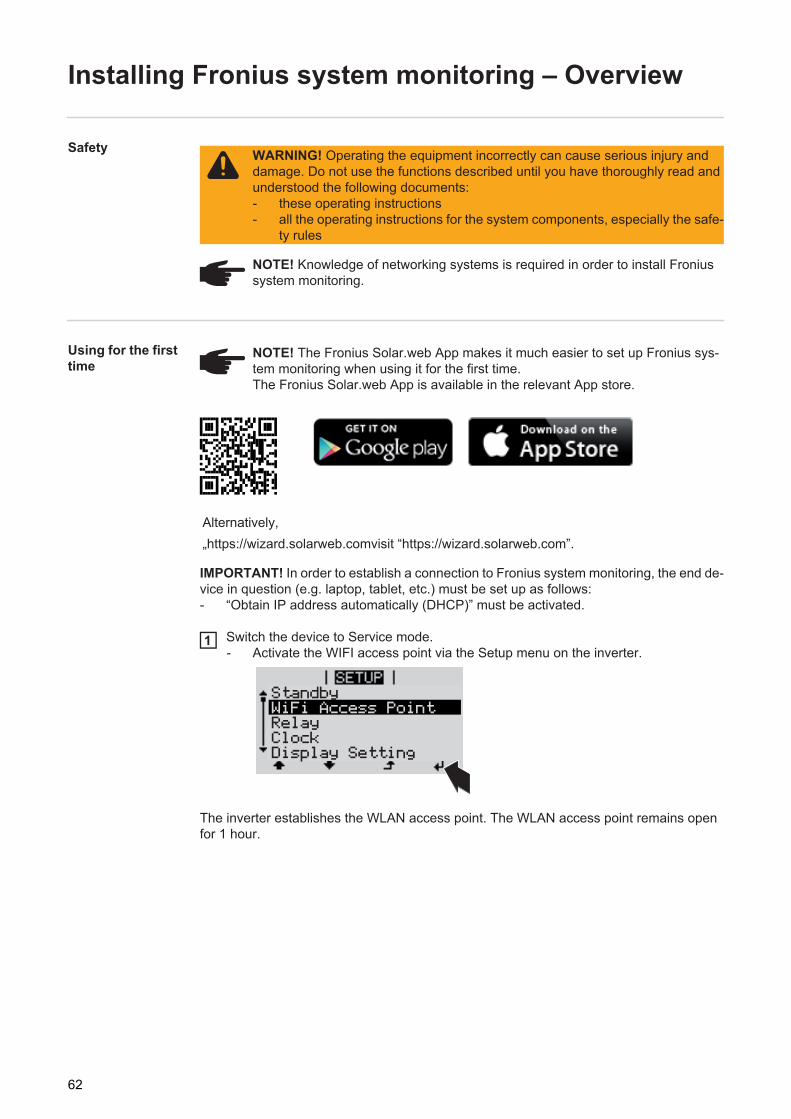
Installing Fronius system monitoring – Overview
Safety
Using for the first time
IMPORTANT! In order to establish a connection to Fronius system monitoring, the end de-vice in question (e.g. laptop, tablet, etc.) must be set up as follows:- “Obtain IP address automatically (DHCP)” must be activated.
Switch the device to Service mode.- Activate the WIFI access point via the Setup menu on the inverter.
The inverter establishes the WLAN access point. The WLAN access point remains open for 1 hour.
WARNING! Operating the equipment incorrectly can cause serious injury and damage. Do not use the functions described until you have thoroughly read and understood the following documents:- these operating instructions- all the operating instructions for the system components, especially the safe-
ty rules
NOTE! Knowledge of networking systems is required in order to install Fronius system monitoring.
NOTE! The Fronius Solar.web App makes it much easier to set up Fronius sys-tem monitoring when using it for the first time.The Fronius Solar.web App is available in the relevant App store.
Alternatively,„https://wizard.solarweb.comvisit “https://wizard.solarweb.com”.
1
Relay
StandbyWiFi Access PointRelayClockDisplay Setting
62
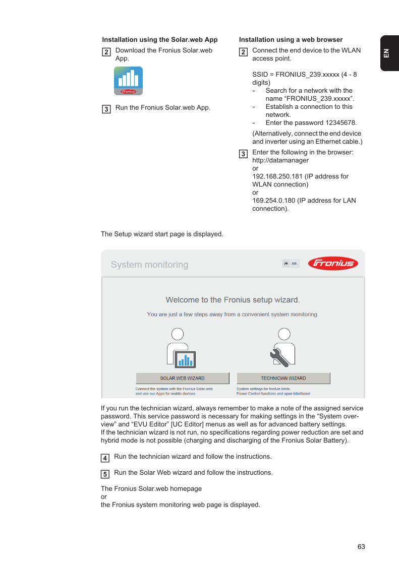
EN
The Setup wizard start page is displayed.
If you run the technician wizard, always remember to make a note of the assigned service password. This service password is necessary for making settings in the “System over-view” and “EVU Editor” [UC Editor] menus as well as for advanced battery settings.If the technician wizard is not run, no specifications regarding power reduction are set and hybrid mode is not possible (charging and discharging of the Fronius Solar Battery).
Run the technician wizard and follow the instructions.
Run the Solar Web wizard and follow the instructions.
The Fronius Solar.web homepageorthe Fronius system monitoring web page is displayed.
Installation using the Solar.web App Installation using a web browserDownload the Fronius Solar.web App.
Run the Fronius Solar.web App.
Connect the end device to the WLAN access point.
SSID = FRONIUS_239.xxxxx (4 - 8 digits)- Search for a network with the
name “FRONIUS_239.xxxxx”.- Establish a connection to this
network.- Enter the password 12345678.(Alternatively, connect the end device and inverter using an Ethernet cable.)Enter the following in the browser:http://datamanageror192.168.250.181 (IP address for WLAN connection)or169.254.0.180 (IP address for LAN connection).
2
3
2
3
4
5
63
Information to help you work through the Solar Web wizard
The solar web wizard consists of 5 steps:
1. GeneralGeneral system data (e.g. system name) is entered here
2. Service passwordEnter (and make a note of) the service password
3. IO assignmentSettings for the IO interface are entered (see also General for IO assignment on page 89)
4. System overviewSettings for the entire PV system are entered (see also System overview on page 100)
5. Dynamic powerSettings for dynamic power reduction are entered (see also EVU Editor – Dynamic power reduction on page 105)
Once you have worked your way through the Solar Web wizard, an automatic process is triggered to calibrate all the components. This involves charging the Fronius Solar Battery fully. After that, the system automatically starts in the set operating mode.This calibration charging process is also performed automatically during actual operation after a number of charging and discharging cycles. When this calibration charge is per-formed depends on a number of different factors, such as the average state of charge or the energy throughput through the battery. The time can therefore vary depending on the time of year as well.
If the "permit battery charging from PSC grid" setting is deactivated, this calibration charg-ing process relies exclusively on energy from the photovoltaic system when operating un-der normal conditions. Depending on the insolation conditions and size of the systems concerned, the charging process can take a very long time.If the "permit battery charging from PSC grid" setting is activated, the calibration charging process is performed by drawing a constant current from the photovoltaic system and PSC grid.
IMPORTANT! The automatic process for fully charging the battery may result in energy be-ing drawn from the PSC grid. The process can take several hours and cannot be aborted.
Testing emergen-cy power mode
Emergency power mode should be tested once it has been installed and set up for the first time. A battery state of charge of over 30% is recommended when in test mode.
NOTE! During grid-connected operation, the inverter recognises and stores the direction of phase rotation in the household network. If the inverter is immediately operated in emergency power mode without first establishing a grid connection, no information is available regarding the direction of rotation. The inverter will feed in power with a default direction of rotation, which can lead to faults in three-phase consumption in the household network.
64
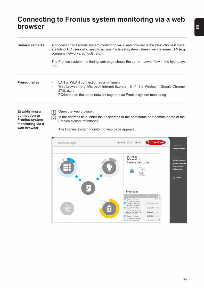
EN
Connecting to Fronius system monitoring via a web browser
General remarks A connection to Fronius system monitoring via a web browser is the ideal choice if there are lots of PC users who need to access the latest system values over the same LAN (e.g. company networks, schools, etc.).
The Fronius system monitoring web page shows the current power flow in the hybrid sys-tem.
Prerequisites - LAN or WLAN connection as a minimum- Web browser (e.g. Microsoft Internet Explorer IE >/= 9.0, Firefox 4, Google Chrome
27.0, etc.)- PC/laptop on the same network segment as Fronius system monitoring
Establishing a connection to Fronius system monitoring via a web browser
Open the web browser.In the address field, enter the IP address or the host name and domain name of the Fronius system monitoring.
The Fronius system monitoring web page appears.
12
65
Connecting to Fronius system monitoring estab-lished via the Internet and Fronius Solar.web
General remarks Archive and current data for a photovoltaic system can be accessed from anywhere in the world (provided that you have Internet access) by setting up a connection to Fronius sys-tem monitoring via the Internet and Fronius Solar.web.With this setup, you can also invite other users to view the photovoltaic system data as guests and you can compare several systems with one another.
Functional de-scription
Fronius system monitoring is connected to the Internet (e.g. via a DSL router). Fronius sys-tem monitoring logs into Fronius Solar.web at regular intervals and sends the saved data on a daily basis.Fronius Solar.web can actively make contact with Fronius system monitoring, e.g. for the purpose of displaying up-to-date data.
Prerequisites - Internet access- Web browser
IMPORTANT! Fronius system monitoring is not capable of connecting to the Internet on its own. In the case of a DSL connection, a router has to establish the Internet con-nection.
- The photovoltaic system must be registered with Fronius Solar.web.
- Current data can only be accessed in Fronius Solar.web if “Send actual data to Froni-us Solar.web” is set to “Yes” under “Fronius Solar.web” in the settings for Fronius sys-tem monitoring.
- In order for archive data to be accessed in Fronius Solar.web, “Send archive data to Fronius Solar.web” must be set to “daily” or “hourly” for Fronius system monitoring.
Accessing Froni-us system moni-toring data via the Internet and Fro-nius Solar.web
To use Fronius Solar.web for the purpose of accessing current data and archive data re-corded by Fronius system monitoring, proceed as follows:
Start Fronius Solar.web: http://www.solarweb.com
For detailed information on Fronius Solar.web, see the online help system.
1
66

Current data, services and settings offered by Fronius system monitor-
ing

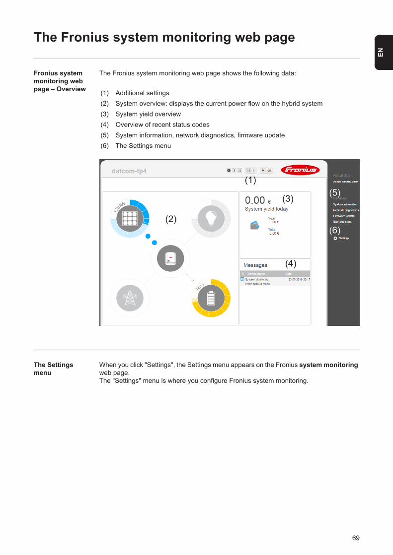
EN
The Fronius system monitoring web page
Fronius system monitoring web page – Overview
The Fronius system monitoring web page shows the following data:
The Settings menu
When you click "Settings", the Settings menu appears on the Fronius system monitoring web page.The "Settings" menu is where you configure Fronius system monitoring.
(1) Additional settings(2) System overview: displays the current power flow on the hybrid system(3) System yield overview(4) Overview of recent status codes(5) System information, network diagnostics, firmware update(6) The Settings menu
(1)(5)
(3)
(6)(2)
(4)
69
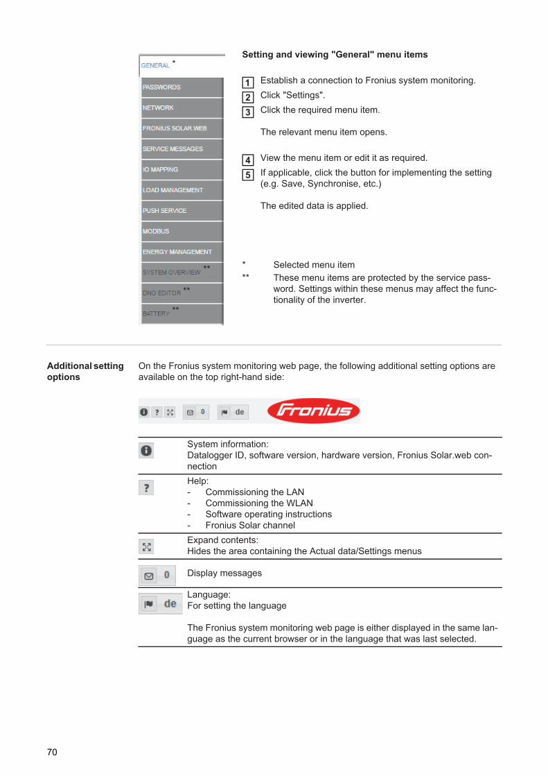
Additional setting options
On the Fronius system monitoring web page, the following additional setting options are available on the top right-hand side:
Setting and viewing "General" menu items
Establish a connection to Fronius system monitoring.Click "Settings".Click the required menu item.
The relevant menu item opens.
View the menu item or edit it as required.If applicable, click the button for implementing the setting (e.g. Save, Synchronise, etc.)
The edited data is applied.
* Selected menu item** These menu items are protected by the service pass-
word. Settings within these menus may affect the func-tionality of the inverter.
*
**
**
**
123
45
System information:Datalogger ID, software version, hardware version, Fronius Solar.web con-nectionHelp:- Commissioning the LAN- Commissioning the WLAN- Software operating instructions- Fronius Solar channelExpand contents:Hides the area containing the Actual data/Settings menus
Display messages
Language:For setting the language
The Fronius system monitoring web page is either displayed in the same lan-guage as the current browser or in the language that was last selected.
70
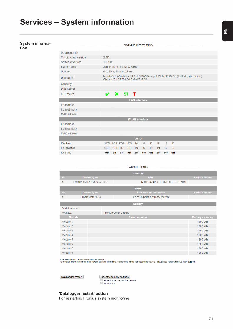
EN
Services – System information
System informa-tion
'Datalogger restart' buttonFor restarting Fronius system monitoring
71

'Reset to factory settings' button
'All settings except for the network' optionFor resetting Fronius system monitoring to the factory settings.The network settings and all the items protected by the service user (PSC editor, meter settings and the service password) are retained.
'All settings' optionFor resetting Fronius system monitoring and the network settings to the factory settings.All the items protected by the service user (PSC editor, meter settings and the service password) are retained.
IMPORTANT! If Fronius system monitoring is reset to the factory settings, it is essential to check the time and date settings.
72
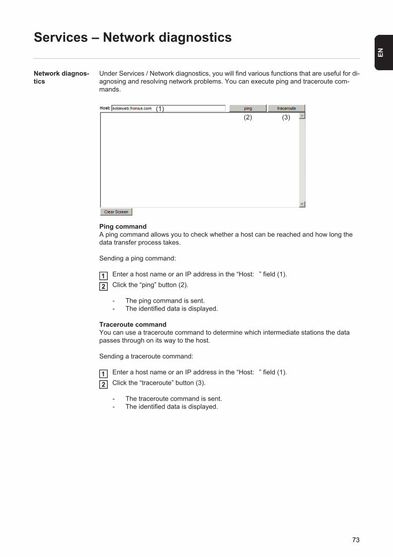
EN
Services – Network diagnostics
Network diagnos-tics
Under Services / Network diagnostics, you will find various functions that are useful for di-agnosing and resolving network problems. You can execute ping and traceroute com-mands.
Ping commandA ping command allows you to check whether a host can be reached and how long the data transfer process takes.
Sending a ping command:
Enter a host name or an IP address in the “Host:�” field (1).Click the “ping” button (2).
- The ping command is sent.- The identified data is displayed.
Traceroute commandYou can use a traceroute command to determine which intermediate stations the data passes through on its way to the host.
Sending a traceroute command:
Enter a host name or an IP address in the “Host:�” field (1).Click the “traceroute” button (3).
- The traceroute command is sent.- The identified data is displayed.
(1)(2) (3)
12
12
73
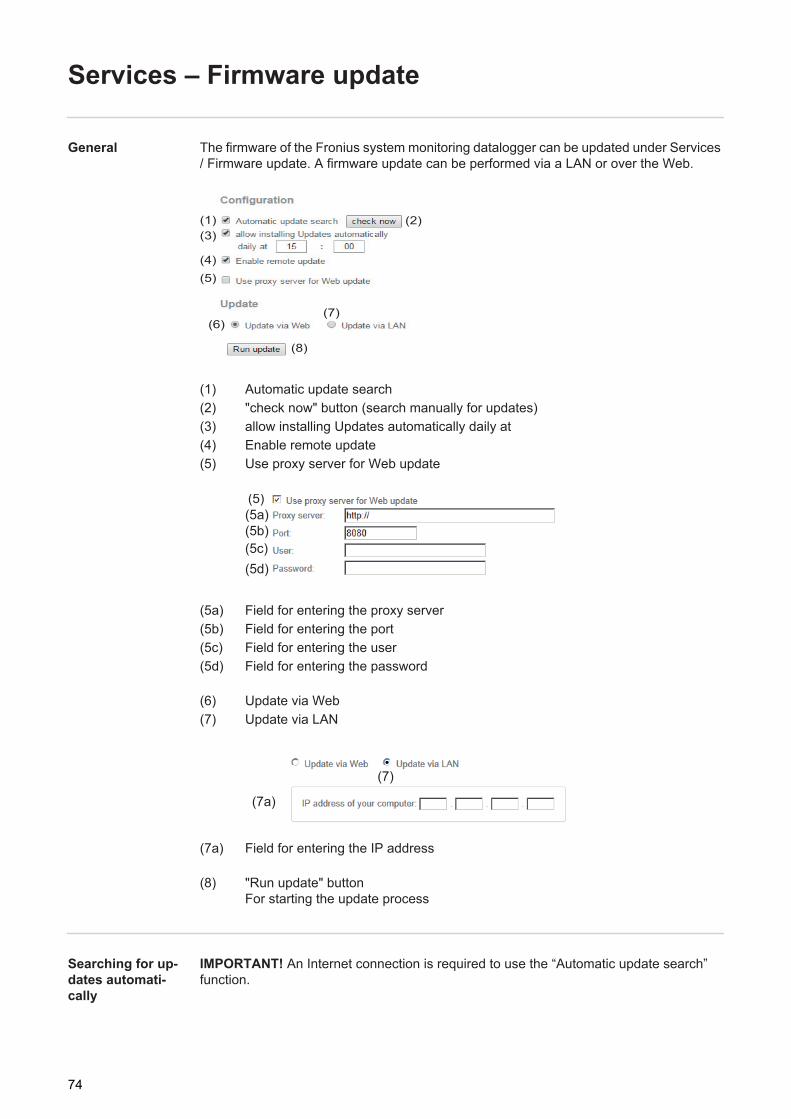
Services – Firmware update
General The firmware of the Fronius system monitoring datalogger can be updated under Services / Firmware update. A firmware update can be performed via a LAN or over the Web.
(1) Automatic update search(2) "check now" button (search manually for updates)(3) allow installing Updates automatically daily at(4) Enable remote update(5) Use proxy server for Web update
(5a) Field for entering the proxy server(5b) Field for entering the port(5c) Field for entering the user(5d) Field for entering the password
(6) Update via Web(7) Update via LAN
(7a) Field for entering the IP address
(8) "Run update" buttonFor starting the update process
Searching for up-dates automati-cally
IMPORTANT! An Internet connection is required to use the “Automatic update search” function.
(2)(1)
(4)(5)
(3)
(6)(7)
(8)
(5)(5a)(5b)(5c)(5d)
(7)
(7a)
74
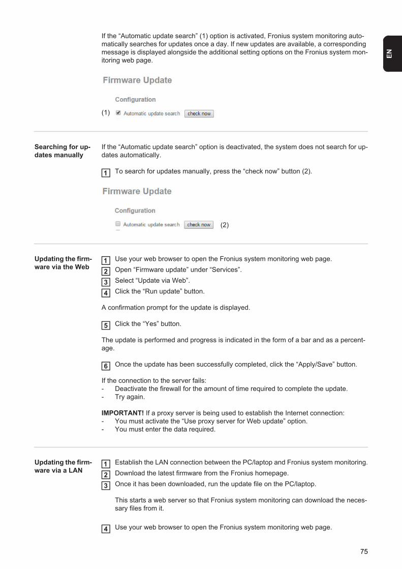
EN
If the “Automatic update search” (1) option is activated, Fronius system monitoring auto-matically searches for updates once a day. If new updates are available, a corresponding message is displayed alongside the additional setting options on the Fronius system mon-itoring web page.
Searching for up-dates manually
If the “Automatic update search” option is deactivated, the system does not search for up-dates automatically.
To search for updates manually, press the “check now” button (2).
Updating the firm-ware via the Web
Use your web browser to open the Fronius system monitoring web page.Open “Firmware update” under “Services”.Select “Update via Web”.Click the “Run update” button.
A confirmation prompt for the update is displayed.
Click the “Yes” button.
The update is performed and progress is indicated in the form of a bar and as a percent-age.
Once the update has been successfully completed, click the “Apply/Save” button.
If the connection to the server fails:- Deactivate the firewall for the amount of time required to complete the update.- Try again.
IMPORTANT! If a proxy server is being used to establish the Internet connection:- You must activate the “Use proxy server for Web update” option.- You must enter the data required.
Updating the firm-ware via a LAN
Establish the LAN connection between the PC/laptop and Fronius system monitoring.Download the latest firmware from the Fronius homepage.Once it has been downloaded, run the update file on the PC/laptop.
This starts a web server so that Fronius system monitoring can download the neces-sary files from it.
Use your web browser to open the Fronius system monitoring web page.
(1)
1
(2)
1234
5
6
123
4
75
Open “Firmware update” under “Services”.Select “Update via LAN”.Enter the IP address of the PC/laptop.Click the “Run update” button.
A confirmation prompt for the update is displayed.
Click the “Yes” button.
The update is performed and progress is indicated in the form of a bar and as a percent-age.
Once the update has been successfully completed, click the “Apply/Save” button.
The “Supply LED” lights up steady green again to indicate that the update process is com-plete.
If the connection to the server fails:- Deactivate the firewall for the amount of time required to complete the update.- Try again.
5678
9
10
76
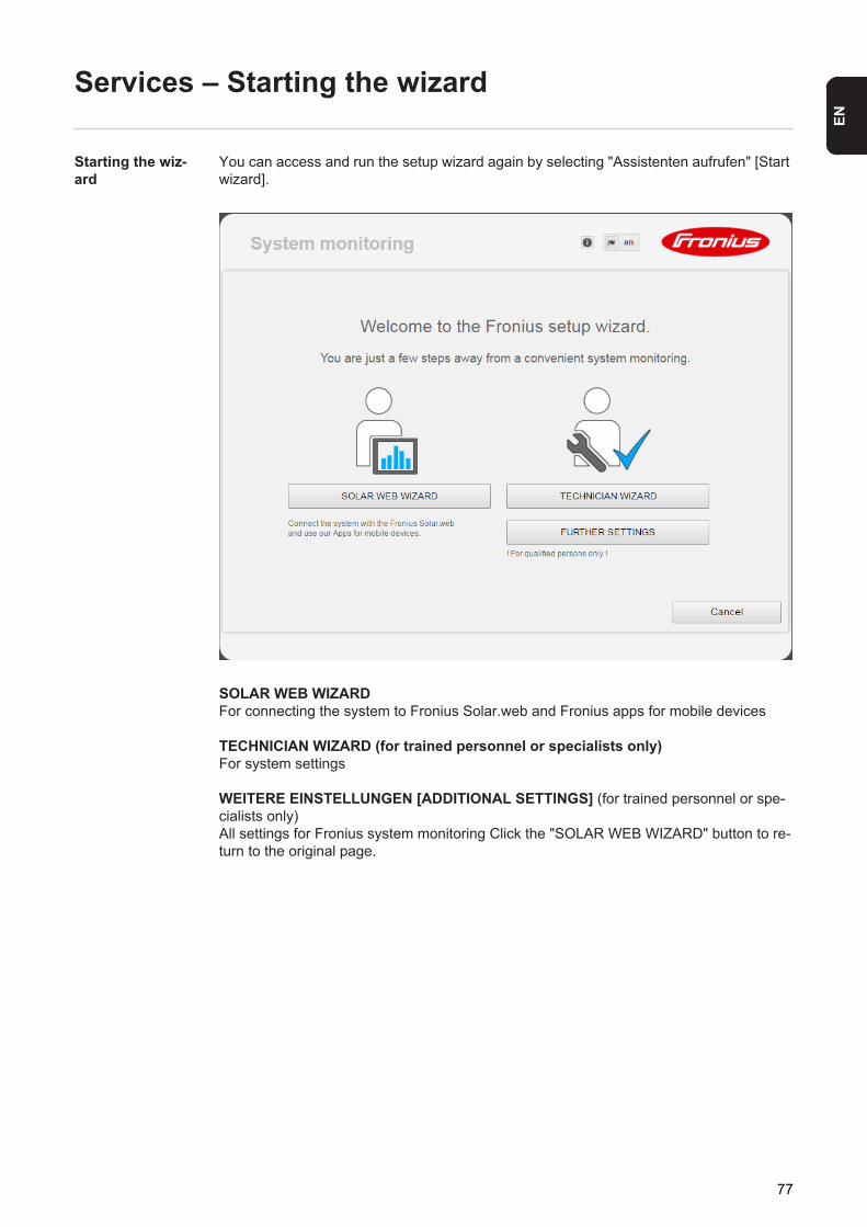
EN
Services – Starting the wizard
Starting the wiz-ard
You can access and run the setup wizard again by selecting "Assistenten aufrufen" [Start wizard].
SOLAR WEB WIZARDFor connecting the system to Fronius Solar.web and Fronius apps for mobile devices
TECHNICIAN WIZARD (for trained personnel or specialists only)For system settings
WEITERE EINSTELLUNGEN [ADDITIONAL SETTINGS] (for trained personnel or spe-cialists only)All settings for Fronius system monitoring Click the "SOLAR WEB WIZARD" button to re-turn to the original page.
77
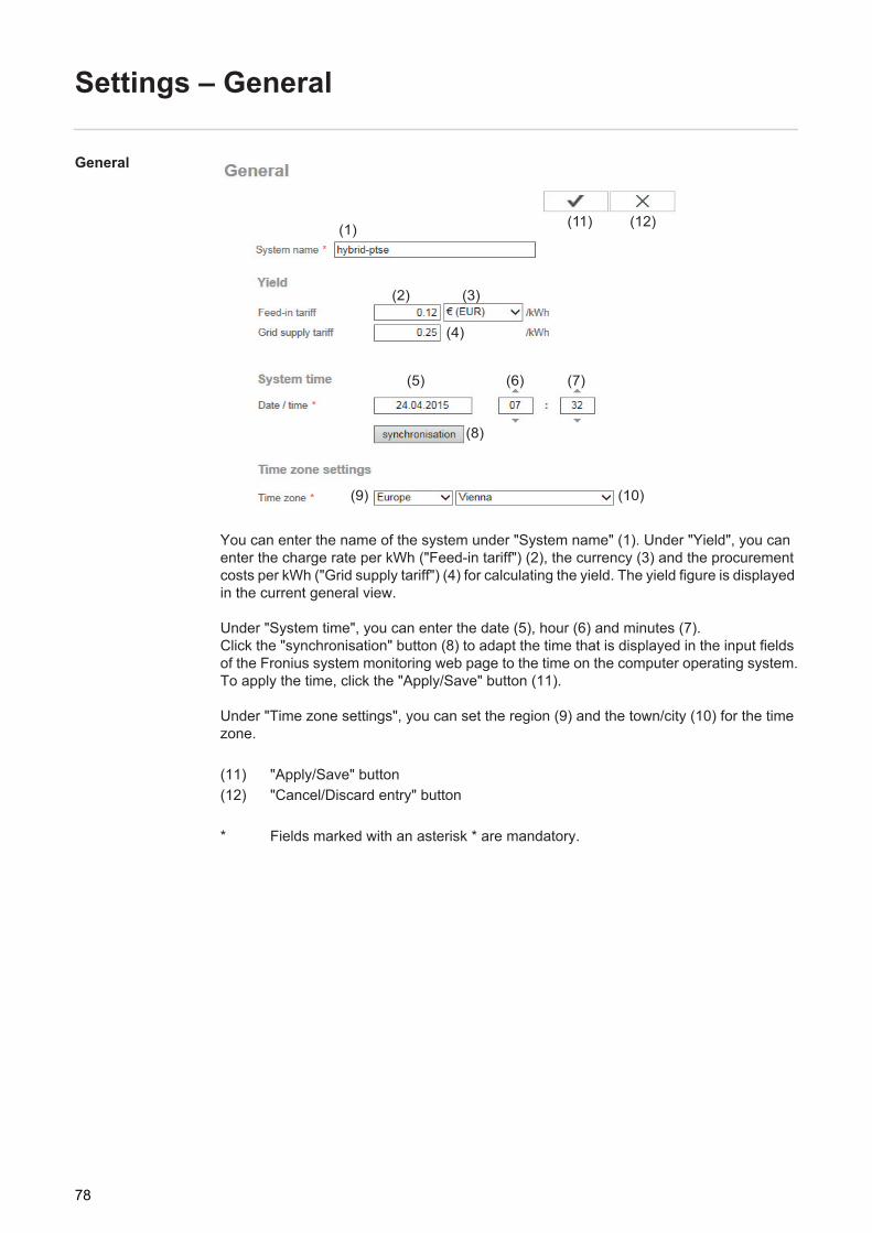
Settings – General
General
You can enter the name of the system under "System name" (1). Under "Yield", you can enter the charge rate per kWh ("Feed-in tariff") (2), the currency (3) and the procurement costs per kWh ("Grid supply tariff") (4) for calculating the yield. The yield figure is displayed in the current general view.
Under "System time", you can enter the date (5), hour (6) and minutes (7). Click the "synchronisation" button (8) to adapt the time that is displayed in the input fields of the Fronius system monitoring web page to the time on the computer operating system.To apply the time, click the "Apply/Save" button (11).
Under "Time zone settings", you can set the region (9) and the town/city (10) for the time zone.
(11) "Apply/Save" button(12) "Cancel/Discard entry" button
* Fields marked with an asterisk * are mandatory.
(2) (3)
(4)
(5) (6) (7)
(8)
(9) (10)
(12)(11)(1)
78
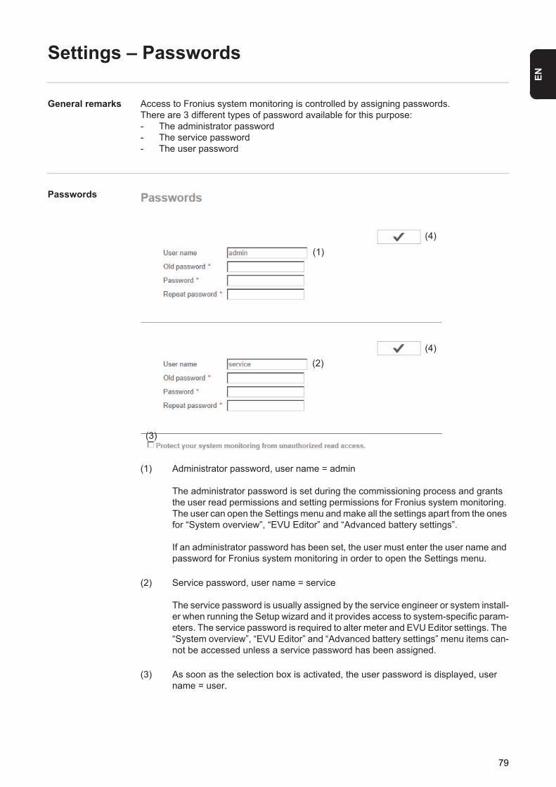
EN
Settings – Passwords
General remarks Access to Fronius system monitoring is controlled by assigning passwords.There are 3 different types of password available for this purpose:- The administrator password- The service password- The user password
Passwords
(1) Administrator password, user name = admin
The administrator password is set during the commissioning process and grants the user read permissions and setting permissions for Fronius system monitoring. The user can open the Settings menu and make all the settings apart from the ones for “System overview”, “EVU Editor” and “Advanced battery settings”.
If an administrator password has been set, the user must enter the user name and password for Fronius system monitoring in order to open the Settings menu.
(2) Service password, user name = service
The service password is usually assigned by the service engineer or system install-er when running the Setup wizard and it provides access to system-specific param-eters. The service password is required to alter meter and EVU Editor settings. The “System overview”, “EVU Editor” and “Advanced battery settings” menu items can-not be accessed unless a service password has been assigned.
(3) As soon as the selection box is activated, the user password is displayed, user name = user.
(1)
(2)
(3)
(4)
(4)
79
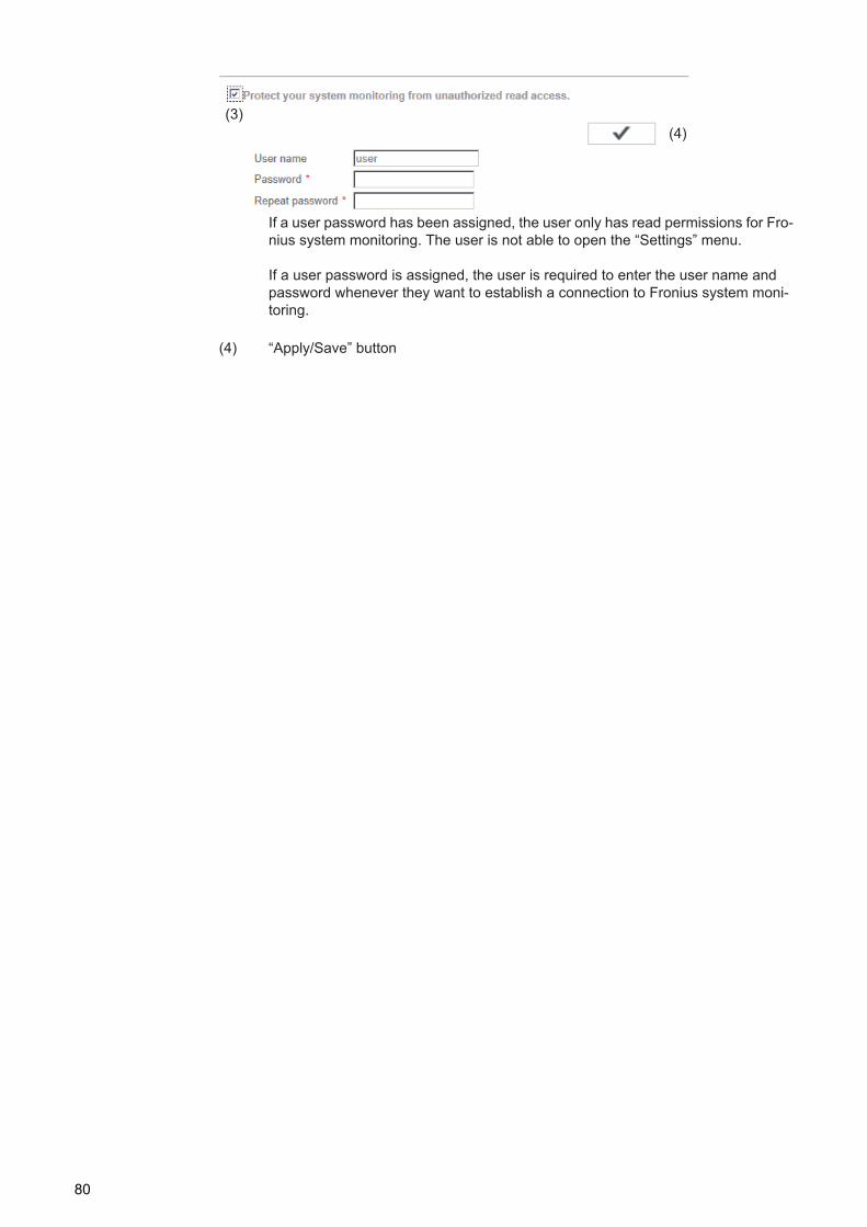
If a user password has been assigned, the user only has read permissions for Fro-nius system monitoring. The user is not able to open the “Settings” menu.
If a user password is assigned, the user is required to enter the user name and password whenever they want to establish a connection to Fronius system moni-toring.
(4) “Apply/Save” button
(3)(4)
80
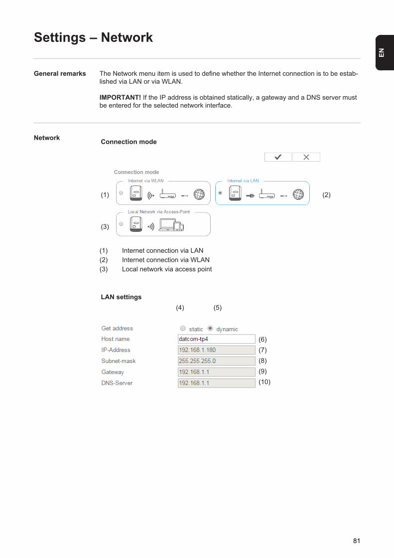
EN
Settings – Network
General remarks The Network menu item is used to define whether the Internet connection is to be estab-lished via LAN or via WLAN.
IMPORTANT! If the IP address is obtained statically, a gateway and a DNS server must be entered for the selected network interface.
Network
(1) Internet connection via LAN(2) Internet connection via WLAN(3) Local network via access point
Connection mode
(1) (2)
(3)
LAN settings(4) (5)
(6)(7)(8)(9)(10)
81
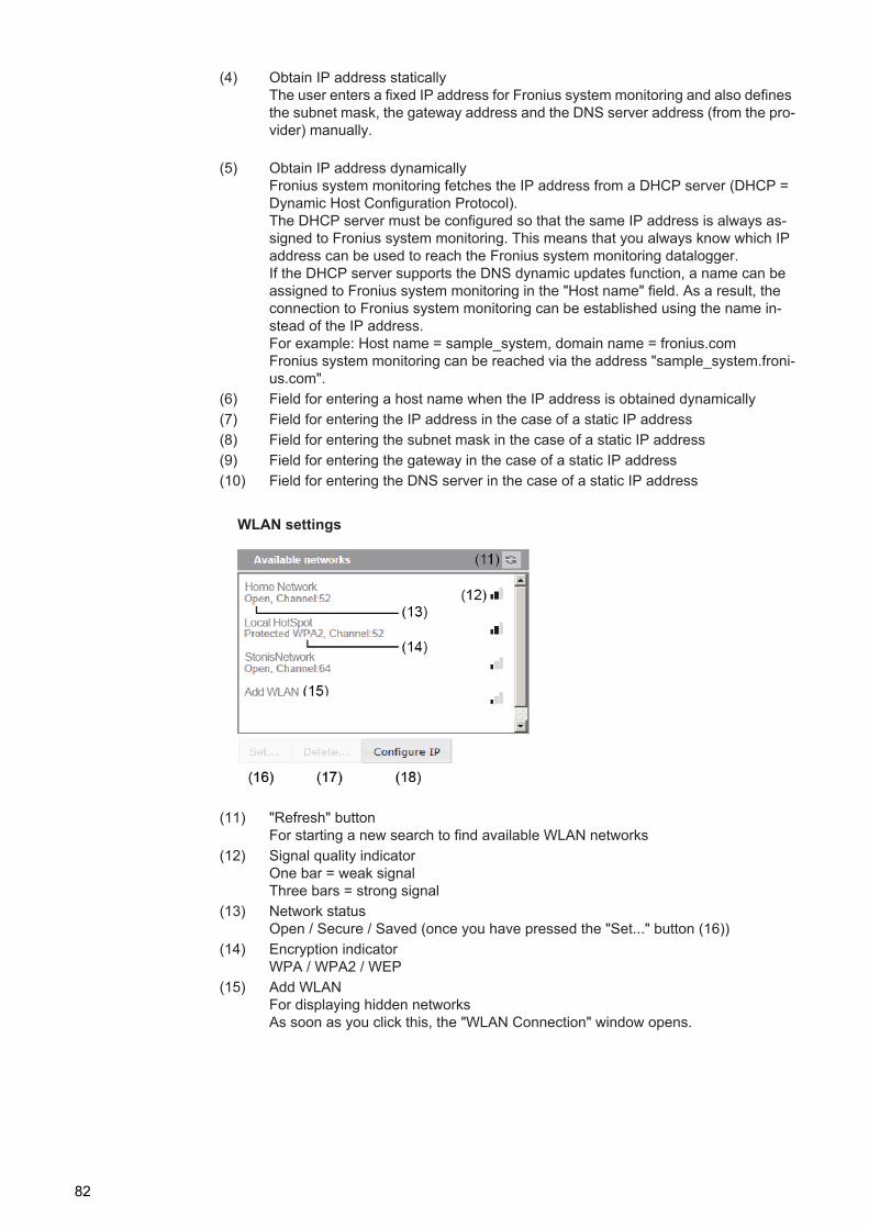
(4) Obtain IP address staticallyThe user enters a fixed IP address for Fronius system monitoring and also defines the subnet mask, the gateway address and the DNS server address (from the pro-vider) manually.
(5) Obtain IP address dynamicallyFronius system monitoring fetches the IP address from a DHCP server (DHCP = Dynamic Host Configuration Protocol).The DHCP server must be configured so that the same IP address is always as-signed to Fronius system monitoring. This means that you always know which IP address can be used to reach the Fronius system monitoring datalogger.If the DHCP server supports the DNS dynamic updates function, a name can be assigned to Fronius system monitoring in the "Host name" field. As a result, the connection to Fronius system monitoring can be established using the name in-stead of the IP address.For example: Host name = sample_system, domain name = fronius.comFronius system monitoring can be reached via the address "sample_system.froni-us.com".
(6) Field for entering a host name when the IP address is obtained dynamically(7) Field for entering the IP address in the case of a static IP address(8) Field for entering the subnet mask in the case of a static IP address(9) Field for entering the gateway in the case of a static IP address(10) Field for entering the DNS server in the case of a static IP address
(11) "Refresh" buttonFor starting a new search to find available WLAN networks
(12) Signal quality indicatorOne bar = weak signalThree bars = strong signal
(13) Network statusOpen / Secure / Saved (once you have pressed the "Set..." button (16))
(14) Encryption indicatorWPA / WPA2 / WEP
(15) Add WLANFor displaying hidden networksAs soon as you click this, the "WLAN Connection" window opens.
WLAN settings
82
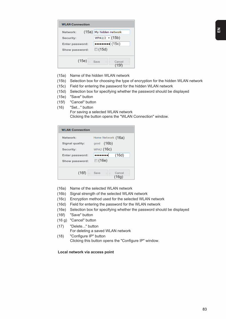
EN
(15a) Name of the hidden WLAN network(15b) Selection box for choosing the type of encryption for the hidden WLAN network(15c) Field for entering the password for the hidden WLAN network(15d) Selection box for specifying whether the password should be displayed(15e) "Save" button(15f) "Cancel" button(16) "Set..." button
For saving a selected WLAN networkClicking the button opens the "WLAN Connection" window.
(16a) Name of the selected WLAN network(16b) Signal strength of the selected WLAN network(16c) Encryption method used for the selected WLAN network(16d) Field for entering the password for the WLAN network(16e) Selection box for specifying whether the password should be displayed(16f) "Save" button(16 g) "Cancel" button(17) "Delete..." button
For deleting a saved WLAN network(18) "Configure IP" button
Clicking this button opens the "Configure IP" window.
(15b)(15c)
(15d)
(15e)
Network:
Security:
Enter password:
Show password:
Connection
Save Cancel
(15a)
(15f)
Local network via access point
(16a)(16b)(16c)
(16d)(16e)
(16f)(16g)
Network:
Signal quality:
Security:
Enter password:
Show password:
Connection
good
Save Cancel
83
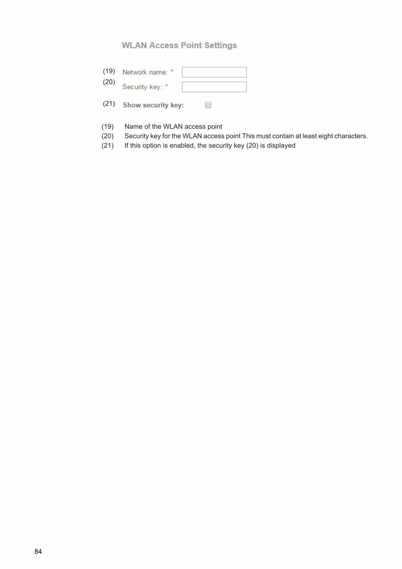
(19) Name of the WLAN access point(20) Security key for the WLAN access point This must contain at least eight characters.(21) If this option is enabled, the security key (20) is displayed
(19)(20)
(21)
84
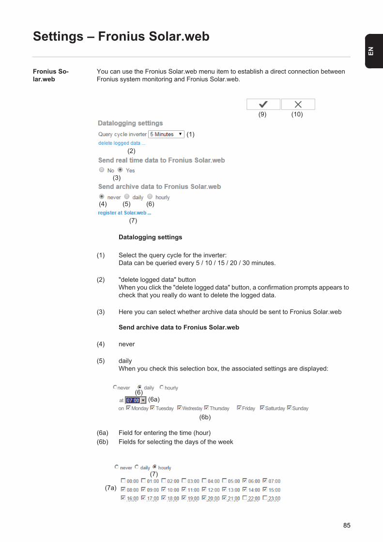
EN
Settings – Fronius Solar.web
Fronius So-lar.web
You can use the Fronius Solar.web menu item to establish a direct connection between Fronius system monitoring and Fronius Solar.web.
Datalogging settings
(1) Select the query cycle for the inverter:Data can be queried every 5 / 10 / 15 / 20 / 30 minutes.
(2) "delete logged data" buttonWhen you click the "delete logged data" button, a confirmation prompts appears to check that you really do want to delete the logged data.
(3) Here you can select whether archive data should be sent to Fronius Solar.web
Send archive data to Fronius Solar.web
(4) never
(5) dailyWhen you check this selection box, the associated settings are displayed:
(6a) Field for entering the time (hour)(6b) Fields for selecting the days of the week
(1)
(2)
(3)
(4) (5) (6)
(10)
(7)
(9)
(6)(6a)
(6b)
never daily hourly
aton Monday Tuesday Wednesday Thursday Friday Satturday Sunday
(7)
(7a)
85

(7) hourlyWhen you check this selection box, the associated settings are displayed:
(7a) Fields for selecting the time (hour)
(8) "register at Solar.web" buttonClicking this button opens the Fronius Solar.web homepage and any data of rele-vance to Fronius Solar.web is sent automatically at the same time.
(9) "Apply/Save" button(10) "Cancel/Discard entry" button
86
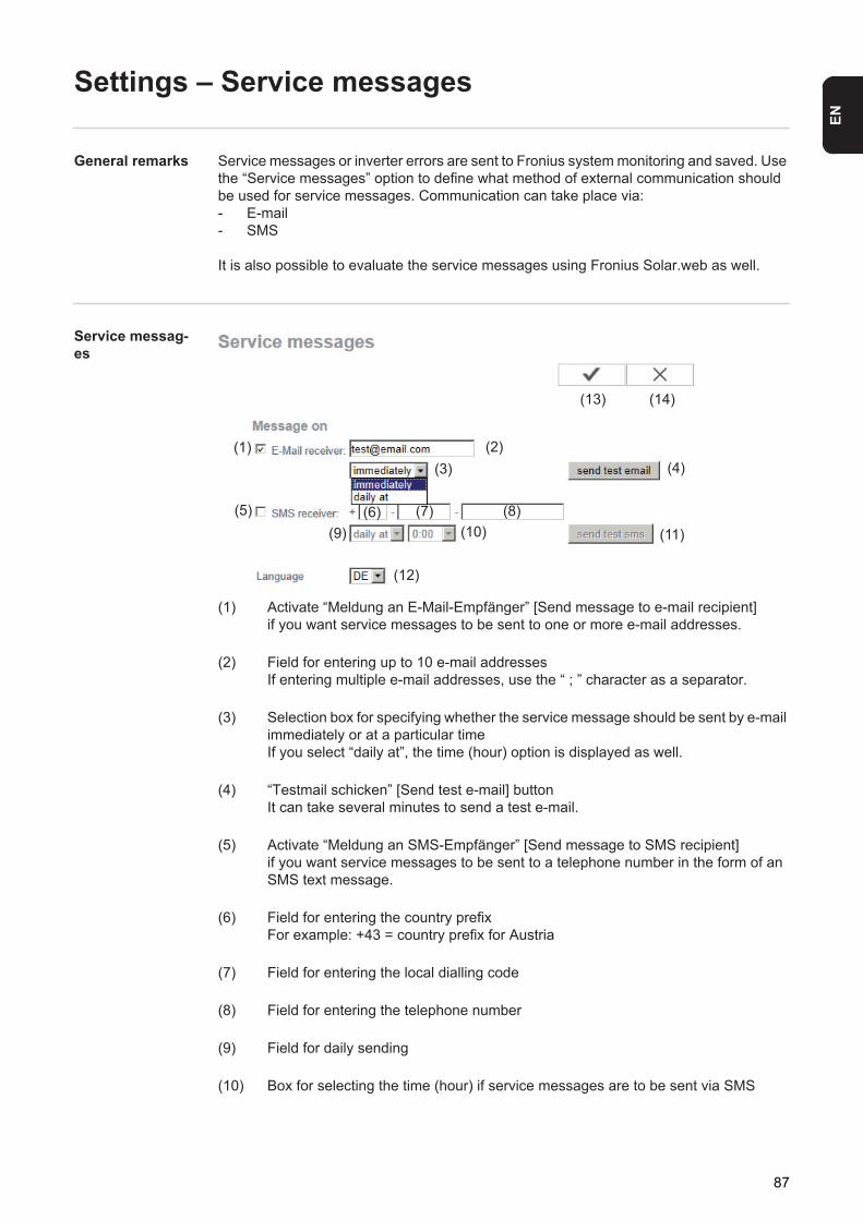
EN
Settings – Service messages
General remarks Service messages or inverter errors are sent to Fronius system monitoring and saved. Use the “Service messages” option to define what method of external communication should be used for service messages. Communication can take place via:- E-mail- SMS
It is also possible to evaluate the service messages using Fronius Solar.web as well.
Service messag-es
(1) Activate “Meldung an E-Mail-Empfänger” [Send message to e-mail recipient]if you want service messages to be sent to one or more e-mail addresses.
(2) Field for entering up to 10 e-mail addressesIf entering multiple e-mail addresses, use the “ ; ” character as a separator.
(3) Selection box for specifying whether the service message should be sent by e-mail immediately or at a particular timeIf you select “daily at”, the time (hour) option is displayed as well.
(4) “Testmail schicken” [Send test e-mail] buttonIt can take several minutes to send a test e-mail.
(5) Activate “Meldung an SMS-Empfänger” [Send message to SMS recipient]if you want service messages to be sent to a telephone number in the form of an SMS text message.
(6) Field for entering the country prefixFor example: +43 = country prefix for Austria
(7) Field for entering the local dialling code
(8) Field for entering the telephone number
(9) Field for daily sending
(10) Box for selecting the time (hour) if service messages are to be sent via SMS
(1) (2)(3) (4)
(5) (6) (7) (8)(9) (11)(10)
(14)(13)
(12)
87

(11) “Schaltfläche Test-SMS” [Send test SMS] buttonIt can take several minutes to send a test SMS.
(12) Box for selecting the language in which the service message is to be sent
(13) “Apply/Save” button
(14) “Cancel/Discard entry” button
88
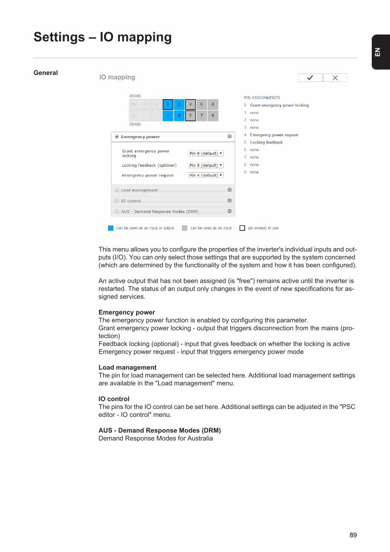
EN
Settings – IO mapping
General
This menu allows you to configure the properties of the inverter's individual inputs and out-puts (I/O). You can only select those settings that are supported by the system concerned (which are determined by the functionality of the system and how it has been configured).
An active output that has not been assigned (is "free") remains active until the inverter is restarted. The status of an output only changes in the event of new specifications for as-signed services.
Emergency powerThe emergency power function is enabled by configuring this parameter.Grant emergency power locking - output that triggers disconnection from the mains (pro-tection)Feedback locking (optional) - input that gives feedback on whether the locking is activeEmergency power request - input that triggers emergency power mode
Load managementThe pin for load management can be selected here. Additional load management settings are available in the "Load management" menu.
IO controlThe pins for the IO control can be set here. Additional settings can be adjusted in the "PSC editor - IO control" menu.
AUS - Demand Response Modes (DRM)Demand Response Modes for Australia
89
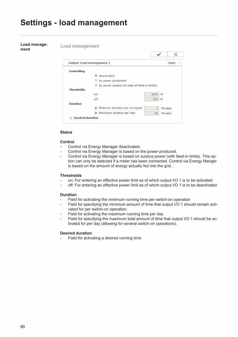
Settings - load management
Load manage-ment
Status
Control- Control via Energy Manager deactivated.- Control via Energy Manager is based on the power produced.- Control via Energy Manager is based on surplus power (with feed-in limits). This op-
tion can only be selected if a meter has been connected. Control via Energy Manger is based on the amount of energy actually fed into the grid.
Thresholds- on: For entering an effective power limit as of which output I/O 1 is to be activated- off: For entering an effective power limit as of which output I/O 1 is to be deactivated
Duration- Field for activating the minimum running time per switch-on operation- Field for specifying the minimum amount of time that output I/O 1 should remain acti-
vated for per switch-on operation.- Field for activating the maximum running time per day- Field for specifying the maximum total amount of time that output I/O 1 should be ac-
tivated for per day (allowing for several switch-on operations).
Desired duration- Field for activating a desired running time
90
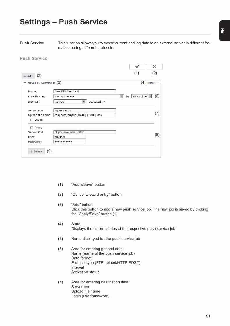
EN
Settings – Push Service
Push Service This function allows you to export current and log data to an external server in different for-mats or using different protocols.
(1) “Apply/Save” button
(2) “Cancel/Discard entry” button
(3) “Add” buttonClick this button to add a new push service job. The new job is saved by clicking the “Apply/Save” button (1).
(4) StateDisplays the current status of the respective push service job
(5) Name displayed for the push service job
(6) Area for entering general data: Name (name of the push service job)Data formatProtocol type (FTP upload/HTTP POST)IntervalActivation status
(7) Area for entering destination data:Server portUpload file nameLogin (user/password)
(1) (2)(3)
(4)(5)
(6)
(7)
(8)
(9)
91
(8) Area for entering proxy data:Server portUserPassword
(9) “Delete” buttonClick this button to delete the selected push service job.
Further informa-tion about the push service function
For further information about the push service function, please see the following operating instructions:
http://www.fronius.com/QR-link/4204102152
42,0410,2152 Fronius Push Service
92
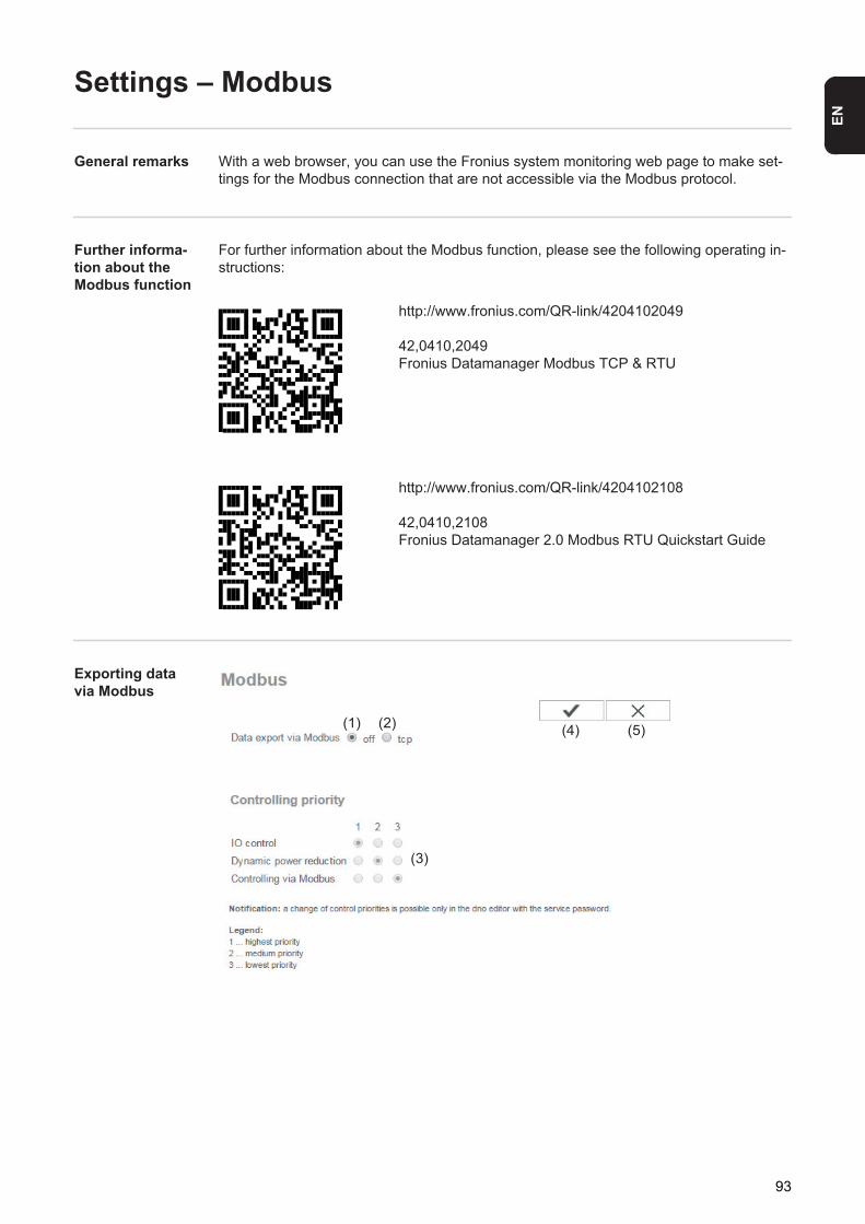
EN
Settings – Modbus
General remarks With a web browser, you can use the Fronius system monitoring web page to make set-tings for the Modbus connection that are not accessible via the Modbus protocol.
Further informa-tion about the Modbus function
For further information about the Modbus function, please see the following operating in-structions:
Exporting data via Modbus
http://www.fronius.com/QR-link/4204102049
42,0410,2049 Fronius Datamanager Modbus TCP & RTU
http://www.fronius.com/QR-link/4204102108
42,0410,2108 Fronius Datamanager 2.0 Modbus RTU Quickstart Guide
(1) (2)
(3)
(4) (5)
93
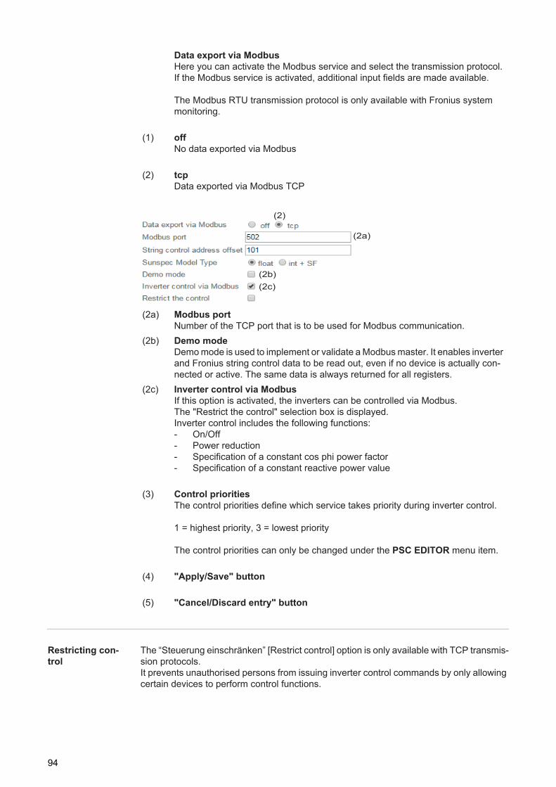
Restricting con-trol
The “Steuerung einschränken” [Restrict control] option is only available with TCP transmis-sion protocols.It prevents unauthorised persons from issuing inverter control commands by only allowing certain devices to perform control functions.
Data export via ModbusHere you can activate the Modbus service and select the transmission protocol.If the Modbus service is activated, additional input fields are made available.
The Modbus RTU transmission protocol is only available with Fronius system monitoring.
(1) offNo data exported via Modbus
(2) tcpData exported via Modbus TCP
(2a) Modbus portNumber of the TCP port that is to be used for Modbus communication.
(2b) Demo modeDemo mode is used to implement or validate a Modbus master. It enables inverter and Fronius string control data to be read out, even if no device is actually con-nected or active. The same data is always returned for all registers.
(2c) Inverter control via ModbusIf this option is activated, the inverters can be controlled via Modbus.The "Restrict the control" selection box is displayed.Inverter control includes the following functions:- On/Off- Power reduction- Specification of a constant cos phi power factor- Specification of a constant reactive power value
(3) Control prioritiesThe control priorities define which service takes priority during inverter control.
1 = highest priority, 3 = lowest priority
The control priorities can only be changed under the PSC EDITOR menu item.
(4) "Apply/Save" button
(5) "Cancel/Discard entry" button
(2)
(2a)
(2b)(2c)
94
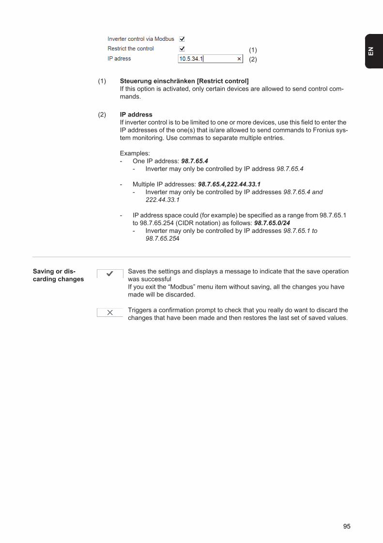
EN
Saving or dis-carding changes
Saves the settings and displays a message to indicate that the save operation was successfulIf you exit the “Modbus” menu item without saving, all the changes you have made will be discarded.
Triggers a confirmation prompt to check that you really do want to discard the changes that have been made and then restores the last set of saved values.
(1) Steuerung einschränken [Restrict control]If this option is activated, only certain devices are allowed to send control com-mands.
(2) IP addressIf inverter control is to be limited to one or more devices, use this field to enter the IP addresses of the one(s) that is/are allowed to send commands to Fronius sys-tem monitoring. Use commas to separate multiple entries.
Examples:- One IP address: 98.7.65.4
- Inverter may only be controlled by IP address 98.7.65.4
- Multiple IP addresses: 98.7.65.4,222.44.33.1- Inverter may only be controlled by IP addresses 98.7.65.4 and
222.44.33.1
- IP address space could (for example) be specified as a range from 98.7.65.1 to 98.7.65.254 (CIDR notation) as follows: 98.7.65.0/24- Inverter may only be controlled by IP addresses 98.7.65.1 to
98.7.65.254
(1)(2)
95
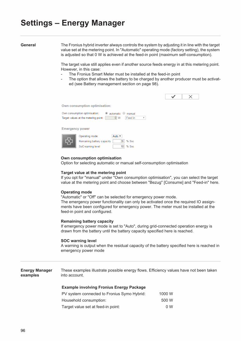
Settings – Energy Manager
General The Fronius hybrid inverter always controls the system by adjusting it in line with the target value set at the metering point. In "Automatic" operating mode (factory setting), the system is adjusted so that 0 W is achieved at the feed-in point (maximum self-consumption).
The target value still applies even if another source feeds energy in at this metering point. However, in this case:- The Fronius Smart Meter must be installed at the feed-in point- The option that allows the battery to be charged by another producer must be activat-
ed (see Battery management section on page 98).
Own consumption optimisationOption for selecting automatic or manual self-consumption optimisation
Target value at the metering point If you opt for "manual" under "Own consumption optimisation", you can select the target value at the metering point and choose between "Bezug" [Consume] and "Feed-in" here.
Operating mode"Automatic" or "Off" can be selected for emergency power mode.The emergency power functionality can only be activated once the required IO assign-ments have been configured for emergency power. The meter must be installed at the feed-in point and configured.
Remaining battery capacityIf emergency power mode is set to "Auto", during grid-connected operation energy is drawn from the battery until the battery capacity specified here is reached.
SOC warning levelA warning is output when the residual capacity of the battery specified here is reached in emergency power mode
Energy Manager examples
These examples illustrate possible energy flows. Efficiency values have not been taken into account.
Example involving Fronius Energy PackagePV system connected to Fronius Symo Hybrid: 1000 WHousehold consumption: 500 WTarget value set at feed-in point: 0 W
96
EN
Energy fed into Fronius Solar Battery: 500 WPower output (AC) by inverter: 500 WEnergy fed into the public grid: 0 W
Example involving Fronius Energy Package plus a second producer within the homePV system connected to Fronius Symo Hybrid: 1000 WSecond producer on home network: 2000 WHousehold consumption: 500 WTarget value set at feed-in point: 0 W
Energy fed into Fronius Solar Battery: 2500 WPower consumed (AC) by inverter: 1500 WEnergy fed into the public grid: 0 W
Example involving Fronius Energy Package without photovoltaics but with a sec-ond producer within the homeSecond producer on home network: 2000 WHousehold consumption: 500 WTarget value set at feed-in point: 0 W
Energy fed into Fronius Solar Battery: 1500 WPower consumed (AC) by inverter: 1500 WEnergy fed into the public grid: 0 W
Example involving Fronius Energy Package plus a second producer within the home (with AC max. limiting)PV system connected to Fronius Symo Hybrid: 1000 WSecond producer on home network: 2000 WHousehold consumption: 500 WTarget value set at feed-in point: 0 WMax. AC power consumption limited to: 1000 W
Energy fed into Fronius Solar Battery: 2000 WPower consumed (AC) by inverter: 1000 WEnergy fed into the public grid: 500 W
97
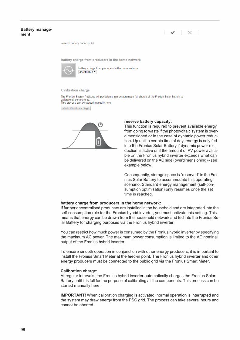
Battery manage-ment
battery charge from producers in the home network:If further decentralised producers are installed in the household and are integrated into the self-consumption rule for the Fronius hybrid inverter, you must activate this setting. This means that energy can be drawn from the household network and fed into the Fronius So-lar Battery for charging purposes via the Fronius hybrid inverter.
You can restrict how much power is consumed by the Fronius hybrid inverter by specifying the maximum AC power. The maximum power consumption is limited to the AC nominal output of the Fronius hybrid inverter.
To ensure smooth operation in conjunction with other energy producers, it is important to install the Fronius Smart Meter at the feed-in point. The Fronius hybrid inverter and other energy producers must be connected to the public grid via the Fronius Smart Meter.
Calibration charge:At regular intervals, the Fronius hybrid inverter automatically charges the Fronius Solar Battery until it is full for the purpose of calibrating all the components. This process can be started manually here.
IMPORTANT! When calibration charging is activated, normal operation is interrupted and the system may draw energy from the PSC grid. The process can take several hours and cannot be aborted.
reserve battery capacity:This function is required to prevent available energy from going to waste if the photovoltaic system is over-dimensioned or in the case of dynamic power reduc-tion. Up until a certain time of day, energy is only fed into the Fronius Solar Battery if dynamic power re-duction is active or if the amount of PV power availa-ble on the Fronius hybrid inverter exceeds what can be delivered on the AC side (overdimensioning) - see example below.
Consequently, storage space is "reserved" in the Fro-nius Solar Battery to accommodate this operating scenario. Standard energy management (self-con-sumption optimisation) only resumes once the set time is reached.
98

EN
Once calibration is complete, the system automatically reverts to the operating mode that was set originally.This calibration charging process is also performed automatically during actual operation after a number of charging and discharging cycles.
If the "permit battery charging from PSC grid" setting is deactivated, this calibration charg-ing process relies exclusively on energy from the photovoltaic system. Depending on the insolation conditions and size of the systems concerned, the charging process can take a very long time.If the "permit battery charging from PSC grid" setting is activated, the calibration charging process is performed by drawing a constant current from the photovoltaic system and PSC grid.
Example of re-serve battery ca-pacity
Example 1 - dynamic power regulation is active:
Actual state:- Symo Hybrid 5.0-3-S- PV output = 5 kWp- Max. grid power feed 60% (3 kW)- Fronius Solar Battery 6.0- Reserve battery capacity: unrestricted charge from 14:00
System behaviour at 11:00 (5 kW PV output):- Household network consumption = 1 kW- Grid power feed = 3 kW- Battery charge = 1 kW
System behaviour at 15:00 (5 kW PV output):- Household network consumption = 1 kW- Grid power feed = 0.8 kW- Battery charge = 3.2 kW (nominal charging power for the Fronius Solar Battery 6.0)
Example 2 - more PV power is available on the Fronius Symo Hybrid than can be re-leased on the AC side (= overdimensioning)
Actual state:- Symo Hybrid 5.0-3-S- PV output = 8 kWp- Fronius Solar Battery 6.0- Reserve battery capacity: unrestricted charge from 14:00
System behaviour at 11:00 (7 kW PV output):- Household network consumption = 1 kW- Grid power feed = 5 kW- Battery charge = 1 kW
System behaviour at 15:00 (7 kW PV output):- Household network consumption = 1 kW- Grid power feed = 2.8 kW- Battery charge = 3.2 kW (nominal charging power for the Fronius Solar Battery 6.0)
99
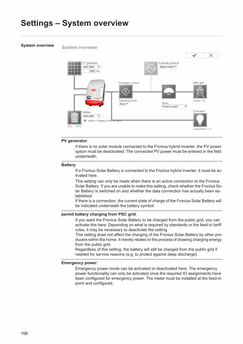
Settings – System overview
System overview
PV generator:If there is no solar module connected to the Fronius hybrid inverter, the PV power option must be deactivated. The connected PV power must be entered in the field underneath.
Battery:If a Fronius Solar Battery is connected to the Fronius hybrid inverter, it must be ac-tivated here.This setting can only be made when there is an active connection to the Fronius Solar Battery. If you are unable to make this setting, check whether the Fronius So-lar Battery is switched on and whether the data connection has actually been es-tablished.If there is a connection, the current state of charge of the Fronius Solar Battery will be indicated underneath the battery symbol.
permit battery charging from PSC grid:If you want the Fronius Solar Battery to be charged from the public grid, you can activate this here. Depending on what is required by standards or the feed-in tariff rules, it may be necessary to deactivate the setting.This setting does not affect the charging of the Fronius Solar Battery by other pro-ducers within the home. It merely relates to the process of drawing charging energy from the public grid.Regardless of this setting, the battery will still be charged from the public grid if needed for service reasons (e.g. to protect against deep discharge).
Emergency power:Emergency power mode can be activated or deactivated here. The emergency power functionality can only be activated once the required IO assignments have been configured for emergency power. The meter must be installed at the feed-in point and configured.
100
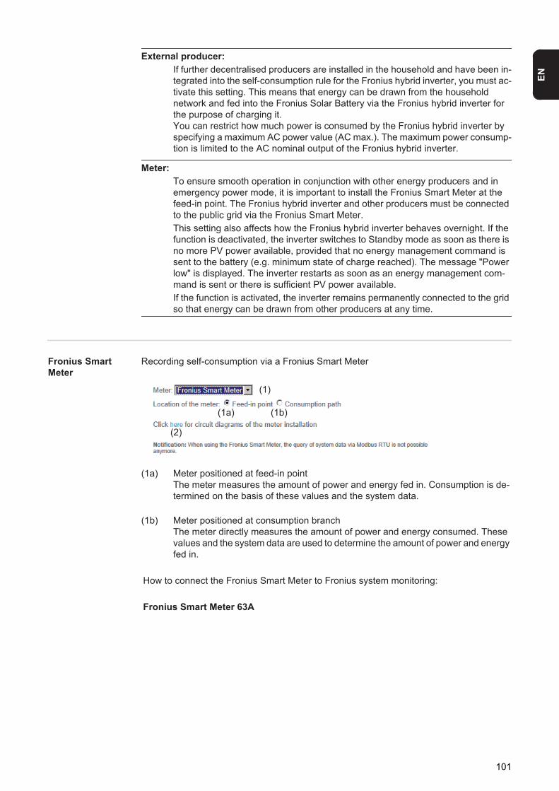
EN
External producer:If further decentralised producers are installed in the household and have been in-tegrated into the self-consumption rule for the Fronius hybrid inverter, you must ac-tivate this setting. This means that energy can be drawn from the household network and fed into the Fronius Solar Battery via the Fronius hybrid inverter for the purpose of charging it.You can restrict how much power is consumed by the Fronius hybrid inverter by specifying a maximum AC power value (AC max.). The maximum power consump-tion is limited to the AC nominal output of the Fronius hybrid inverter.
Meter:To ensure smooth operation in conjunction with other energy producers and in emergency power mode, it is important to install the Fronius Smart Meter at the feed-in point. The Fronius hybrid inverter and other producers must be connected to the public grid via the Fronius Smart Meter.This setting also affects how the Fronius hybrid inverter behaves overnight. If the function is deactivated, the inverter switches to Standby mode as soon as there is no more PV power available, provided that no energy management command is sent to the battery (e.g. minimum state of charge reached). The message "Power low" is displayed. The inverter restarts as soon as an energy management com-mand is sent or there is sufficient PV power available.If the function is activated, the inverter remains permanently connected to the grid so that energy can be drawn from other producers at any time.
Fronius Smart Meter
Recording self-consumption via a Fronius Smart Meter
(1a) Meter positioned at feed-in pointThe meter measures the amount of power and energy fed in. Consumption is de-termined on the basis of these values and the system data.
(1b) Meter positioned at consumption branchThe meter directly measures the amount of power and energy consumed. These values and the system data are used to determine the amount of power and energy fed in.
(1)
(2)
(1a) (1b)
How to connect the Fronius Smart Meter to Fronius system monitoring:
Fronius Smart Meter 63A
101
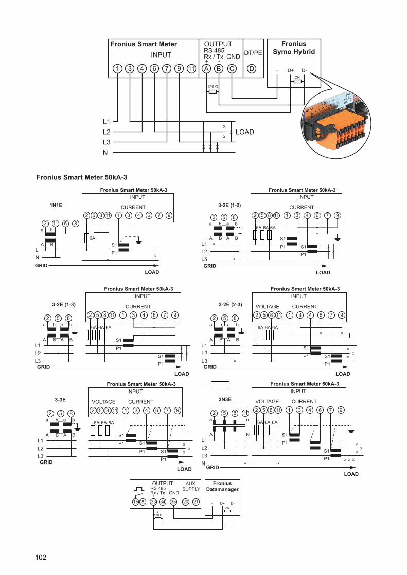
Fronius Smart Meter 50kA-3
Fronius Smart MeterINPUT
L1L2L3N
OUTPUTRS 485Rx / Tx GND DT/PE
1 A B C D3 4 6 7 9 11
LOAD
X X X
X
XX
+ -
Fronius Symo Hybrid
120 Ω
ON
D+ D--
3-2E (1-2)INPUT
CURRENT
L1L2L3
1852852 3 4 6 7 911
X
XX
S1
a b a b
A B A B
P1 S1
P1
Fronius Smart Meter 50kA-3
LOADGRID
6A 6A 6A
3N3E CURRENT
L1L2L3N
1852852 3 4 6 7 911
X
XX
S1
a n
A N
P1
S1
P1
11
X X X
Fronius Smart Meter 50kA-3
VOLTAGE
INPUT
LOADGRID
6A 6A 6A
Fronius Smart Meter 50kA-3
1N1EINPUT
CURRENT
LN
1852852
3 4 6 7 91111
LOADGRID
X
S1
a b
A B
P1
6A
3-2E (2-3)
L1L2L3
852a b a b
A B A B
INPUT
CURRENTVOLTAGE1852 3 4 6 7 911
X
XX
6A 6A 6A
S1
P1
P1
S1
Fronius Smart Meter 50kA-3
LOADGRID
3-2E (1-3)INPUT
CURRENT
L1L2L3
1852852 3 4 6 7 911
X
XX
6A 6A 6A
S1
a b a b
A B A B
P1
S1
P1
Fronius Smart Meter 50kA-3
LOADGRID
3-3E
L1L2L3
852a b a b
A B A B
INPUT
CURRENTVOLTAGE1852 3 4 6 7 911
X
XX
S1
P1 S1
P1
P1
S1
Fronius Smart Meter 50kA-3
LOADGRID
6A 6A 6A
OUTPUTRS 485Rx / Tx GND
AUX.SUPPLY
21203534332915+ -
Fronius Datamanager
120 Ω
ON
D+ D--
*
102

EN
Settings – EVU Editor
General remarks Use the “EVU Editor” menu item to make the settings that are of relevance to a utility com-pany.You can set an effective power limit in % and/or a power factor limit.
IMPORTANT! Settings under the “EVU Editor” menu item are only to be made by trained and qualified personnel!
The service password must be entered in order to access the “EVU Editor” menu item.
PSC editor – Rip-ple control signal receiver
PSC editor – The factory settings for effective power are 100%, 60%, 30% and 0%.The settings can be changed at any time.
(1) Rule activation
(2) Input pattern (assignment of individual I/Os)1 click = white2 clicks = blue3 x clicks = grey
(3) Effective powerActivate it first and then enter the required effective power value in %.
(1) (2)(3) (4) (5) (6) (7)
(10)
(8)
(9)
(12)(11)
103
(4) cos phi power factorActivate it first, enter the required power factor and then complete the process by selecting "ind" or "cap".
ind = inductivecap = capacitive
(5) PSC output (feedback output) When the rule is enabled, output I/O 0 is activated (e.g. for operating a signalling device).
(6) excluded invertersEnter the numbers of the inverters that are to be excluded from the rule. If entering multiple inverters, use commas to separate them.
(7) Deleting/adding a rule+ = add a new rule- = delete the currently selected rule
(8) Key to colours
(9) "Import" buttonClick this to import rules in *.fpc format.
The "Import" button only works with certain browsers, e.g. it is supported by Firefox and Google Chrome.
(10) "Export" buttonClick this to save the rules separately in *.fpc format.
(11) "Apply/Save" button
(12) "Cancel/Discard entry" button
Connection ex-ample
(1) Ripple control signal receiver with 3 relays, for effective power limiting(2) Ripple control signal receiver with 3 relays, for power factor limiting(3) Fronius system monitoring I/Os(4) Consumers (e.g. signal lamp, signal relay)
NOTE! You can use the web browser's print function to create a PDF record of the settings that you have made under the "PSC editor" menu item or to print these settings out (e.g. in the form of a commissioning record).
104
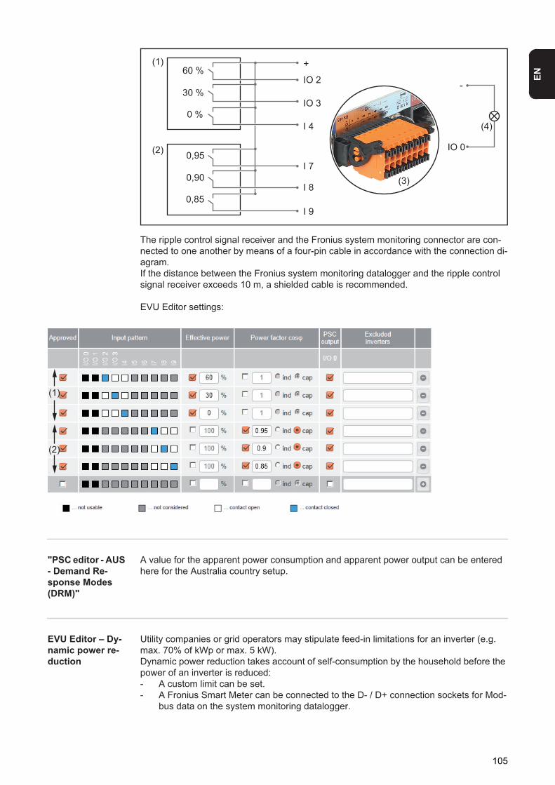
EN
The ripple control signal receiver and the Fronius system monitoring connector are con-nected to one another by means of a four-pin cable in accordance with the connection di-agram.If the distance between the Fronius system monitoring datalogger and the ripple control signal receiver exceeds 10 m, a shielded cable is recommended.
EVU Editor settings:
"PSC editor - AUS - Demand Re-sponse Modes (DRM)"
A value for the apparent power consumption and apparent power output can be entered here for the Australia country setup.
EVU Editor – Dy-namic power re-duction
Utility companies or grid operators may stipulate feed-in limitations for an inverter (e.g. max. 70% of kWp or max. 5 kW). Dynamic power reduction takes account of self-consumption by the household before the power of an inverter is reduced:- A custom limit can be set.- A Fronius Smart Meter can be connected to the D- / D+ connection sockets for Mod-
bus data on the system monitoring datalogger.
60 %
30 %
0 %
0,95
0,90
0,85
(1)
(2)
(4)
+
-IO 2
IO 3
I 4
I 7
I 8
I 9
IO 0
(3)
(1)
(2)
105

With the Fronius Symo Hybrid, any PV power that is not allowed to be fed into the grid is used to charge the Fronius Solar Battery instead so that it does not go to waste. Dynamic power reduction is only activated if the battery is full or cannot be charged for some other reason.
Leistungslimit [Power limit]This allows you to define the maximum output power of the photovoltaic system.
(1) No limitThe photovoltaic system converts all the available PV energy.
(2) Dynamic power reduction limit for entire systemThe entire photovoltaic system is limited in accordance with a set power limit.
(3) Field for entering the total DC system power in WpThis value serves as a reference for the rule and also for failures (e.g. a meter fail-ure).
(4) Field for entering the max. power in W or %
If no meter has been selected under the “Meter” menu item:Max. power produced by the entire system
If “Fronius Smart Meter” has been selected under the “Meter” menu item:Max. grid power feed
(5) Box for selecting % or W
(6) “Apply/Save” button
(7) “Cancel/Discard entry” button
(1) (2)
(3)
(6) (7)
(4) (5)
Example: Dynamic power reduction(efficiency values have not been taken into account)PV system connected to Fronius Symo Hy-brid:
5000 W
Household consumption: 1000 WMax. grid power feed: 60% =
3000 W
Power at grid feed-in point: 3000 WPower at inverter output: 4000 WEnergy fed into Fronius Solar Battery: 1000 W
106
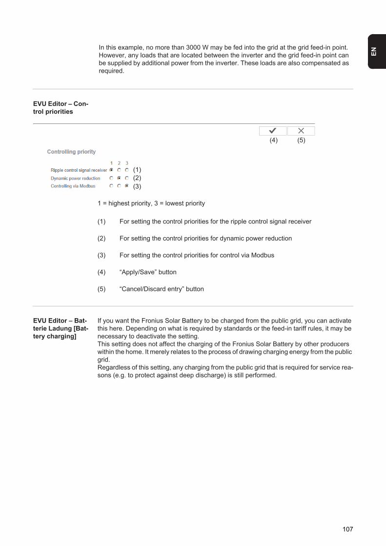
EN
EVU Editor – Con-trol priorities
1 = highest priority, 3 = lowest priority
(1) For setting the control priorities for the ripple control signal receiver
(2) For setting the control priorities for dynamic power reduction
(3) For setting the control priorities for control via Modbus
(4) “Apply/Save” button
(5) “Cancel/Discard entry” button
EVU Editor – Bat-terie Ladung [Bat-tery charging]
If you want the Fronius Solar Battery to be charged from the public grid, you can activate this here. Depending on what is required by standards or the feed-in tariff rules, it may be necessary to deactivate the setting.This setting does not affect the charging of the Fronius Solar Battery by other producers within the home. It merely relates to the process of drawing charging energy from the public grid.Regardless of this setting, any charging from the public grid that is required for service rea-sons (e.g. to protect against deep discharge) is still performed.
In this example, no more than 3000 W may be fed into the grid at the grid feed-in point. However, any loads that are located between the inverter and the grid feed-in point can be supplied by additional power from the inverter. These loads are also compensated as required.
(1)(2)(3)
(4) (5)
107
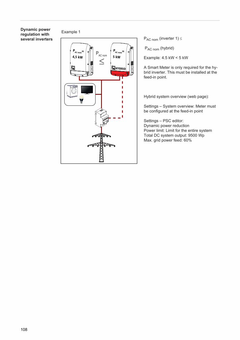
Dynamic power regulation with several inverters
Example 1PAC nom (inverter 1)
PAC nom (hybrid)
Example: 4.5 kW < 5 kW
A Smart Meter is only required for the hy-brid inverter. This must be installed at the feed-in point.
Hybrid system overview (web page):
Settings – System overview: Meter must be configured at the feed-in point
Settings – PSC editor: Dynamic power reductionPower limit: Limit for the entire systemTotal DC system output: 9500 WpMax. grid power feed: 60%
HYBRID
PAC nom=
5 kW
PAC nom=
4,5 kWPAC nom
≤
108
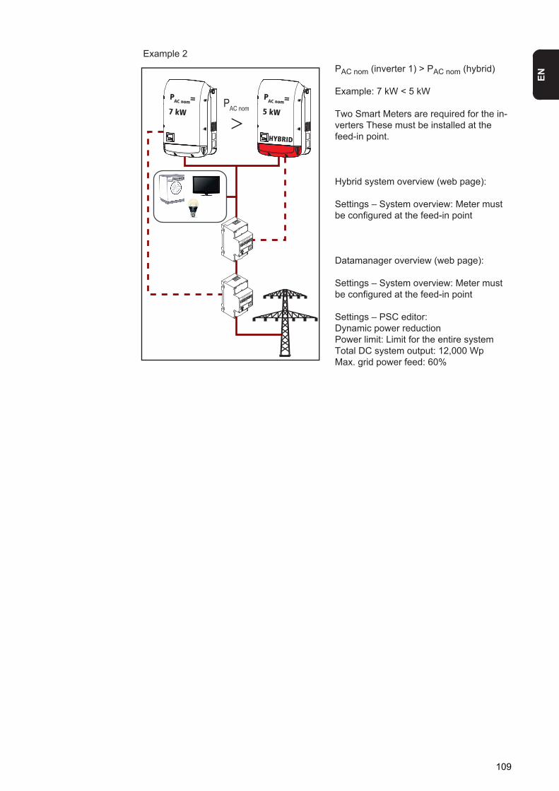
EN
Example 2PAC nom (inverter 1) > PAC nom (hybrid)
Example: 7 kW < 5 kW
Two Smart Meters are required for the in-verters These must be installed at the feed-in point.
Hybrid system overview (web page):
Settings – System overview: Meter must be configured at the feed-in point
Datamanager overview (web page):
Settings – System overview: Meter must be configured at the feed-in point
Settings – PSC editor: Dynamic power reductionPower limit: Limit for the entire systemTotal DC system output: 12,000 WpMax. grid power feed: 60%
HYBRID
PAC nom=
5 kW
PAC nom=
7 kWPAC nom
>
109
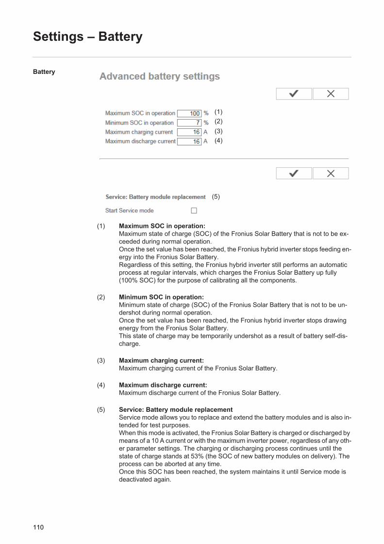
Settings – Battery
Battery
(1) Maximum SOC in operation:Maximum state of charge (SOC) of the Fronius Solar Battery that is not to be ex-ceeded during normal operation.Once the set value has been reached, the Fronius hybrid inverter stops feeding en-ergy into the Fronius Solar Battery.Regardless of this setting, the Fronius hybrid inverter still performs an automatic process at regular intervals, which charges the Fronius Solar Battery up fully (100% SOC) for the purpose of calibrating all the components.
(2) Minimum SOC in operation:Minimum state of charge (SOC) of the Fronius Solar Battery that is not to be un-dershot during normal operation.Once the set value has been reached, the Fronius hybrid inverter stops drawing energy from the Fronius Solar Battery.This state of charge may be temporarily undershot as a result of battery self-dis-charge.
(3) Maximum charging current:Maximum charging current of the Fronius Solar Battery.
(4) Maximum discharge current:Maximum discharge current of the Fronius Solar Battery.
(5) Service: Battery module replacementService mode allows you to replace and extend the battery modules and is also in-tended for test purposes.When this mode is activated, the Fronius Solar Battery is charged or discharged by means of a 10 A current or with the maximum inverter power, regardless of any oth-er parameter settings. The charging or discharging process continues until the state of charge stands at 53% (the SOC of new battery modules on delivery). The process can be aborted at any time.Once this SOC has been reached, the system maintains it until Service mode is deactivated again.
(5)
(1)(2)(3)(4)
110
Troubleshooting and maintenance

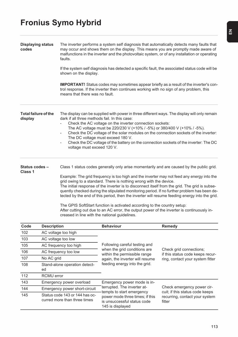
EN
Fronius Symo Hybrid
Displaying status codes
The inverter performs a system self diagnosis that automatically detects many faults that may occur and shows them on the display. This means you are promptly made aware of malfunctions in the inverter and the photovoltaic system, or of any installation or operating faults.
If the system self diagnosis has detected a specific fault, the associated status code will be shown on the display.
Total failure of the display
The display can be supplied with power in three different ways. The display will only remain dark if all three methods fail. In this case:- Check the AC voltage on the inverter connection sockets:
The AC voltage must be 220/230 V (+10% / -5%) or 380/400 V (+10% / -5%).- Check the DC voltage of the solar modules on the connection sockets of the inverter:
The DC voltage must exceed 180 V.- Check the DC voltage of the battery on the connection sockets of the inverter: The DC
voltage must exceed 120 V.
Status codes – Class 1
Class 1 status codes generally only arise momentarily and are caused by the public grid.
Example: The grid frequency is too high and the inverter may not feed any energy into the grid owing to a standard. There is nothing wrong with the device.The initial response of the inverter is to disconnect itself from the grid. The grid is subse-quently checked during the stipulated monitoring period. If no further problem has been de-tected by the end of this period, then the inverter will resume feeding energy into the grid.
The GPIS SoftStart function is activated according to the country setup:After cutting out due to an AC error, the output power of the inverter is continuously in-creased in line with the national guidelines.
IMPORTANT! Status codes may sometimes appear briefly as a result of the inverter's con-trol response. If the inverter then continues working with no sign of any problem, this means that there was no fault.
Code Description Behaviour Remedy102 AC voltage too high
Following careful testing and when the grid conditions are within the permissible range again, the inverter will resume feeding energy into the grid.
Check grid connections;if this status code keeps recur-ring, contact your system fitter
103 AC voltage too low105 AC frequency too high106 AC frequency too low107 No AC grid108 Stand-alone operation detect-
ed112 RCMU error143 Emergency power overload Emergency power mode is in-
terrupted. The inverter at-tempts to start emergency power mode three times; if this is unsuccessful status code 145 is displayed
Check emergency power cir-cuit; if this status code keeps recurring, contact your system fitter
144 Emergency power short-circuit145 Status code 143 or 144 has oc-
curred more than three times
113
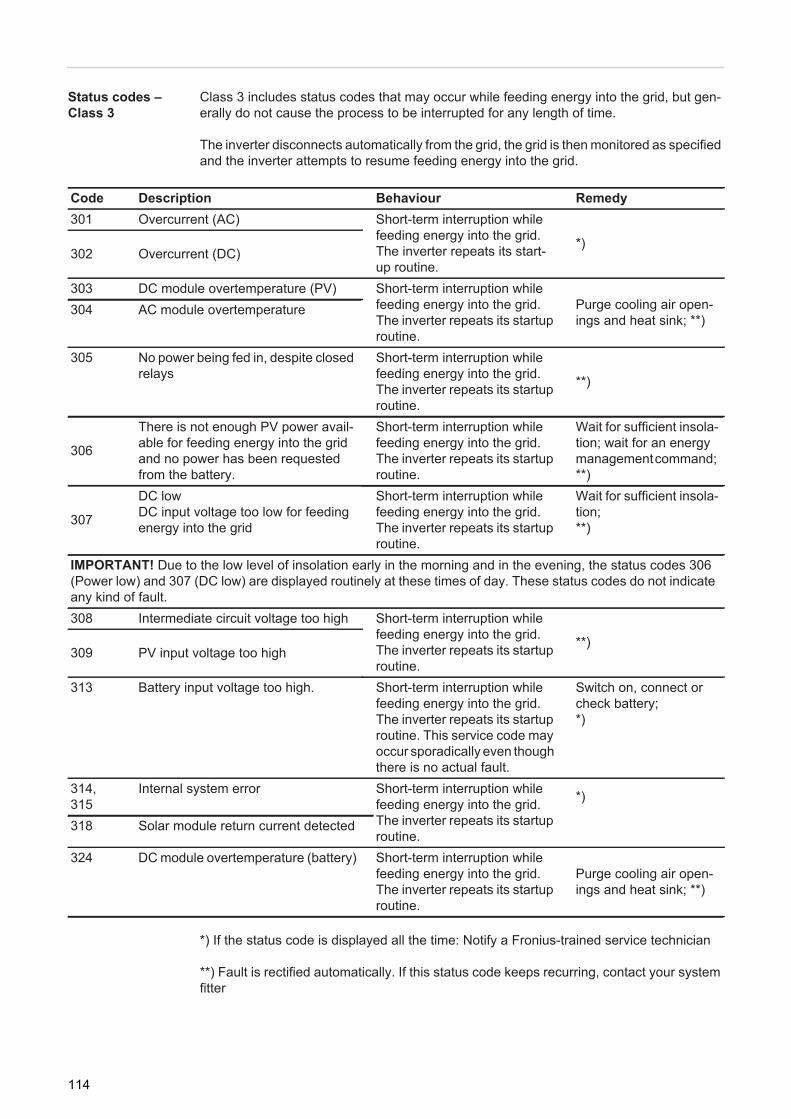
Status codes – Class 3
Class 3 includes status codes that may occur while feeding energy into the grid, but gen-erally do not cause the process to be interrupted for any length of time.
The inverter disconnects automatically from the grid, the grid is then monitored as specified and the inverter attempts to resume feeding energy into the grid.
*) If the status code is displayed all the time: Notify a Fronius-trained service technician
**) Fault is rectified automatically. If this status code keeps recurring, contact your system fitter
Code Description Behaviour Remedy301 Overcurrent (AC) Short-term interruption while
feeding energy into the grid. The inverter repeats its start-up routine.
*)302 Overcurrent (DC)
303 DC module overtemperature (PV) Short-term interruption while feeding energy into the grid.The inverter repeats its startup routine.
Purge cooling air open-ings and heat sink; **)
304 AC module overtemperature
305 No power being fed in, despite closed relays
Short-term interruption while feeding energy into the grid.The inverter repeats its startup routine.
**)
306
There is not enough PV power avail-able for feeding energy into the grid and no power has been requested from the battery.
Short-term interruption while feeding energy into the grid.The inverter repeats its startup routine.
Wait for sufficient insola-tion; wait for an energy management command; **)
307
DC lowDC input voltage too low for feeding energy into the grid
Short-term interruption while feeding energy into the grid.The inverter repeats its startup routine.
Wait for sufficient insola-tion; **)
IMPORTANT! Due to the low level of insolation early in the morning and in the evening, the status codes 306 (Power low) and 307 (DC low) are displayed routinely at these times of day. These status codes do not indicate any kind of fault.308 Intermediate circuit voltage too high Short-term interruption while
feeding energy into the grid.The inverter repeats its startup routine.
**)309 PV input voltage too high
313 Battery input voltage too high. Short-term interruption while feeding energy into the grid.The inverter repeats its startup routine. This service code may occur sporadically even though there is no actual fault.
Switch on, connect or check battery;*)
314,315
Internal system error Short-term interruption while feeding energy into the grid.The inverter repeats its startup routine.
*)
318 Solar module return current detected
324 DC module overtemperature (battery) Short-term interruption while feeding energy into the grid.The inverter repeats its startup routine.
Purge cooling air open-ings and heat sink; **)
114
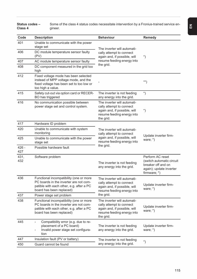
EN
Status codes – Class 4
Some of the class 4 status codes necessitate intervention by a Fronius-trained service en-gineer.
Code Description Behaviour Remedy401 Unable to communicate with the power
stage set The inverter will automati-cally attempt to connect again and, if possible, will resume feeding energy into the grid.
*)406 DC module temperature sensor faulty
(PV)407 AC module temperature sensor faulty408 DC component measured in the grid too
high412 Fixed voltage mode has been selected
instead of MPP voltage mode, and the fixed voltage has been set to too low or too high a value.
- **)
415 Safety cut-out via option card or RECER-BO has triggered
The inverter is not feeding any energy into the grid.
*)
416 No communication possible between power stage set and control system.
The inverter will automati-cally attempt to connect again and, if possible, will resume feeding energy into the grid.
*)
417 Hardware ID problem
The inverter will automati-cally attempt to connect again and, if possible, will resume feeding energy into the grid.
Update inverter firm-ware; *)
420 Unable to communicate with system monitoring
425 Unable to communicate with the power stage set
426 - 427
Possible hardware fault
431,432
Software problem
The inverter is not feeding any energy into the grid.
Perform AC reset (switch automatic circuit breaker off and on again); update inverter firmware; *)
436 Functional incompatibility (one or more PC boards in the inverter are not com-patible with each other, e.g. after a PC board has been replaced)
The inverter will automati-cally attempt to connect again and, if possible, will resume feeding energy into the grid.
Update inverter firm-ware; *)
437 Power stage set problem438 Functional incompatibility (one or more
PC boards in the inverter are not com-patible with each other, e.g. after a PC board has been replaced)
The inverter will automati-cally attempt to connect again and, if possible, will resume feeding energy into the grid.
Update inverter firm-ware; *)
445 - Compatibility error (e.g. due to re-placement of a PC board)
- Invalid power stage set configura-tion
The inverter is not feeding any energy into the grid.
Update inverter firm-ware; *)
447 Insulation fault (PV or battery) The inverter is not feeding any energy into the grid. *)
450 Guard cannot be found
115
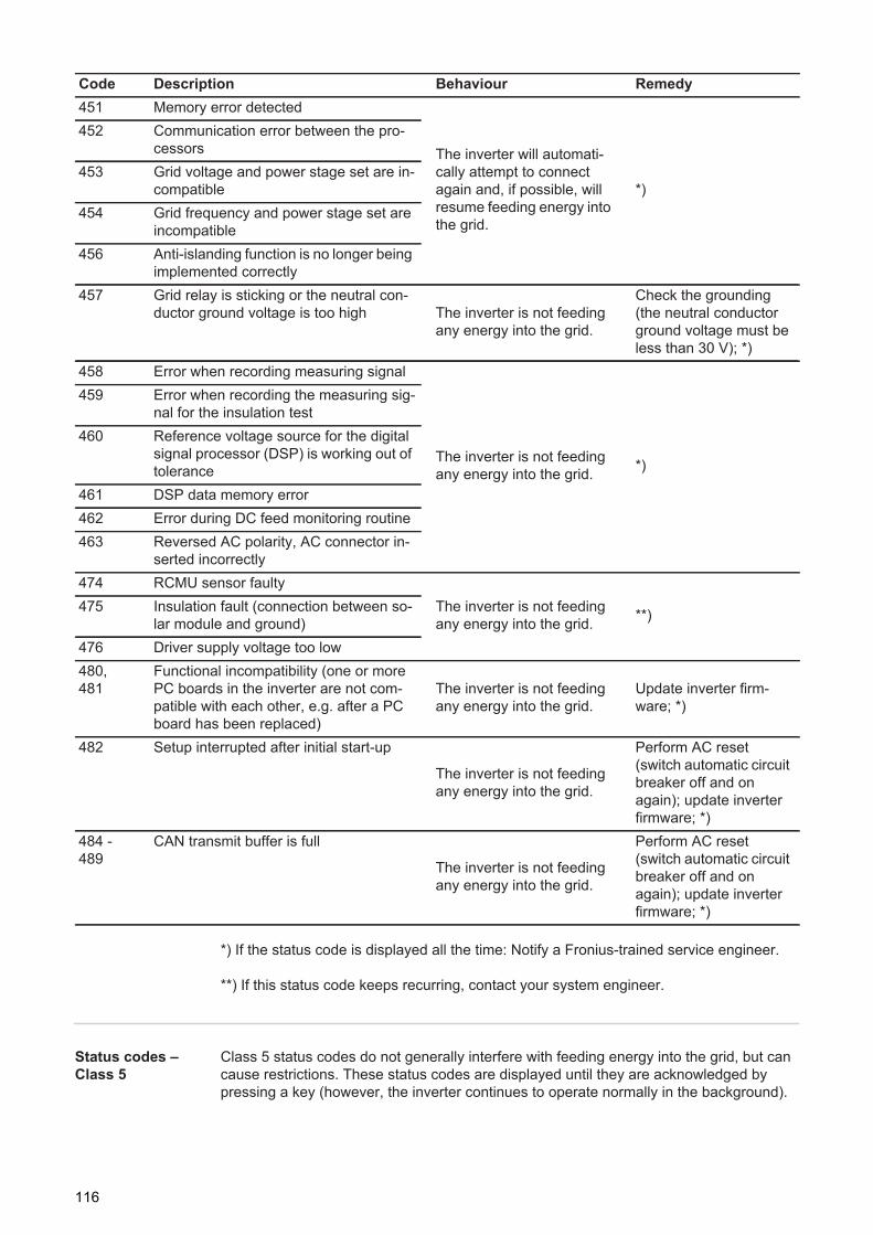
*) If the status code is displayed all the time: Notify a Fronius-trained service engineer.
**) If this status code keeps recurring, contact your system engineer.
Status codes – Class 5
Class 5 status codes do not generally interfere with feeding energy into the grid, but can cause restrictions. These status codes are displayed until they are acknowledged by pressing a key (however, the inverter continues to operate normally in the background).
451 Memory error detected
The inverter will automati-cally attempt to connect again and, if possible, will resume feeding energy into the grid.
*)
452 Communication error between the pro-cessors
453 Grid voltage and power stage set are in-compatible
454 Grid frequency and power stage set are incompatible
456 Anti-islanding function is no longer being implemented correctly
457 Grid relay is sticking or the neutral con-ductor ground voltage is too high The inverter is not feeding
any energy into the grid.
Check the grounding (the neutral conductor ground voltage must be less than 30 V); *)
458 Error when recording measuring signal
The inverter is not feeding any energy into the grid. *)
459 Error when recording the measuring sig-nal for the insulation test
460 Reference voltage source for the digital signal processor (DSP) is working out of tolerance
461 DSP data memory error462 Error during DC feed monitoring routine463 Reversed AC polarity, AC connector in-
serted incorrectly474 RCMU sensor faulty
The inverter is not feeding any energy into the grid. **)475 Insulation fault (connection between so-
lar module and ground)476 Driver supply voltage too low480,481
Functional incompatibility (one or more PC boards in the inverter are not com-patible with each other, e.g. after a PC board has been replaced)
The inverter is not feeding any energy into the grid.
Update inverter firm-ware; *)
482 Setup interrupted after initial start-up
The inverter is not feeding any energy into the grid.
Perform AC reset (switch automatic circuit breaker off and on again); update inverter firmware; *)
484 - 489
CAN transmit buffer is full
The inverter is not feeding any energy into the grid.
Perform AC reset (switch automatic circuit breaker off and on again); update inverter firmware; *)
Code Description Behaviour Remedy
116
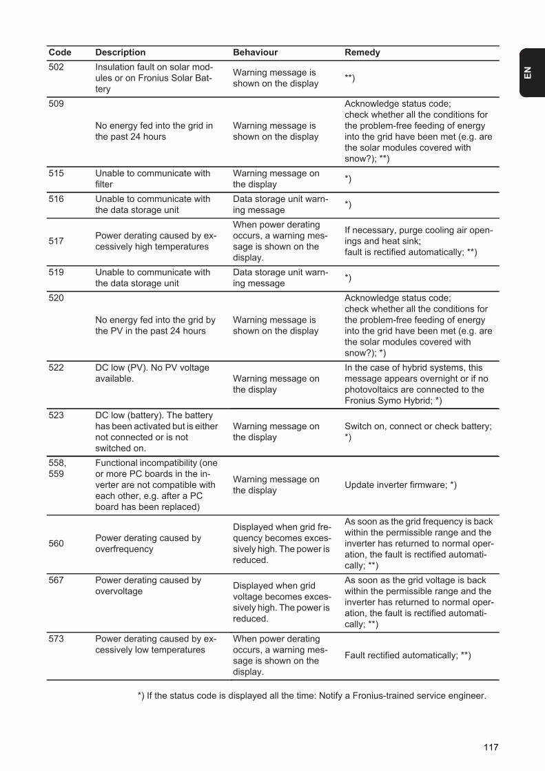
EN
*) If the status code is displayed all the time: Notify a Fronius-trained service engineer.
Code Description Behaviour Remedy502 Insulation fault on solar mod-
ules or on Fronius Solar Bat-tery
Warning message is shown on the display **)
509
No energy fed into the grid in the past 24 hours
Warning message is shown on the display
Acknowledge status code;check whether all the conditions for the problem-free feeding of energy into the grid have been met (e.g. are the solar modules covered with snow?); **)
515 Unable to communicate with filter
Warning message on the display *)
516 Unable to communicate with the data storage unit
Data storage unit warn-ing message *)
517 Power derating caused by ex-cessively high temperatures
When power derating occurs, a warning mes-sage is shown on the display.
If necessary, purge cooling air open-ings and heat sink;fault is rectified automatically; **)
519 Unable to communicate with the data storage unit
Data storage unit warn-ing message *)
520
No energy fed into the grid by the PV in the past 24 hours
Warning message is shown on the display
Acknowledge status code;check whether all the conditions for the problem-free feeding of energy into the grid have been met (e.g. are the solar modules covered with snow?); *)
522 DC low (PV). No PV voltage available. Warning message on
the display
In the case of hybrid systems, this message appears overnight or if no photovoltaics are connected to the Fronius Symo Hybrid; *)
523 DC low (battery). The battery has been activated but is either not connected or is not switched on.
Warning message on the display
Switch on, connect or check battery;*)
558,559
Functional incompatibility (one or more PC boards in the in-verter are not compatible with each other, e.g. after a PC board has been replaced)
Warning message on the display Update inverter firmware; *)
560 Power derating caused by overfrequency
Displayed when grid fre-quency becomes exces-sively high. The power is reduced.
As soon as the grid frequency is back within the permissible range and the inverter has returned to normal oper-ation, the fault is rectified automati-cally; **)
567 Power derating caused by overvoltage Displayed when grid
voltage becomes exces-sively high. The power is reduced.
As soon as the grid voltage is back within the permissible range and the inverter has returned to normal oper-ation, the fault is rectified automati-cally; **)
573 Power derating caused by ex-cessively low temperatures
When power derating occurs, a warning mes-sage is shown on the display.
Fault rectified automatically; **)
117
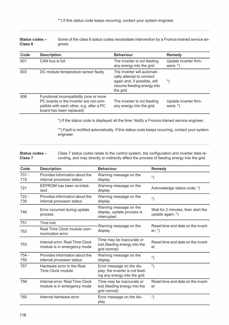
**) If this status code keeps recurring, contact your system engineer.
Status codes – Class 6
Some of the class 6 status codes necessitate intervention by a Fronius-trained service en-gineer.
*) If the status code is displayed all the time: Notify a Fronius-trained service engineer.
**) Fault is rectified automatically. If this status code keeps recurring, contact your system engineer.
Status codes – Class 7
Class 7 status codes relate to the control system, the configuration and inverter data re-cording, and may directly or indirectly affect the process of feeding energy into the grid.
Code Description Behaviour Remedy601 CAN bus is full The inverter is not feeding
any energy into the grid.Update inverter firm-ware; *)
603 DC module temperature sensor faulty The inverter will automati-cally attempt to connect again and, if possible, will resume feeding energy into the grid.
*)
608 Functional incompatibility (one or more PC boards in the inverter are not com-patible with each other, e.g. after a PC board has been replaced)
The inverter is not feeding any energy into the grid.
Update inverter firm-ware; *)
Code Description Behaviour Remedy701 - 715
Provides information about the internal processor status
Warning message on the display *)
721 EEPROM has been re-initial-ised
Warning message on the display Acknowledge status code; *)
722 - 730
Provides information about the internal processor status
Warning message on the display *)
746 Error occurred during update process
Warning message on the display, update process is interrupted
Wait for 2 minutes, then start the update again; *)
751 Time lostWarning message on the display
Reset time and date on the invert-er; *)752 Real Time Clock module com-
munication error
753 Internal error: Real Time Clock module is in emergency mode
Time may be inaccurate or lost (feeding energy into the grid normal)
Reset time and date on the invert-er
754 - 755
Provides information about the internal processor status
Warning message on the display *)
757 Hardware error in the Real Time Clock module
Error message on the dis-play; the inverter is not feed-ing any energy into the grid
*)
758 Internal error: Real Time Clock module is in emergency mode
Time may be inaccurate or lost (feeding energy into the grid normal)
Reset time and date on the invert-er
760 Internal hardware error Error message on the dis-play
*)
118
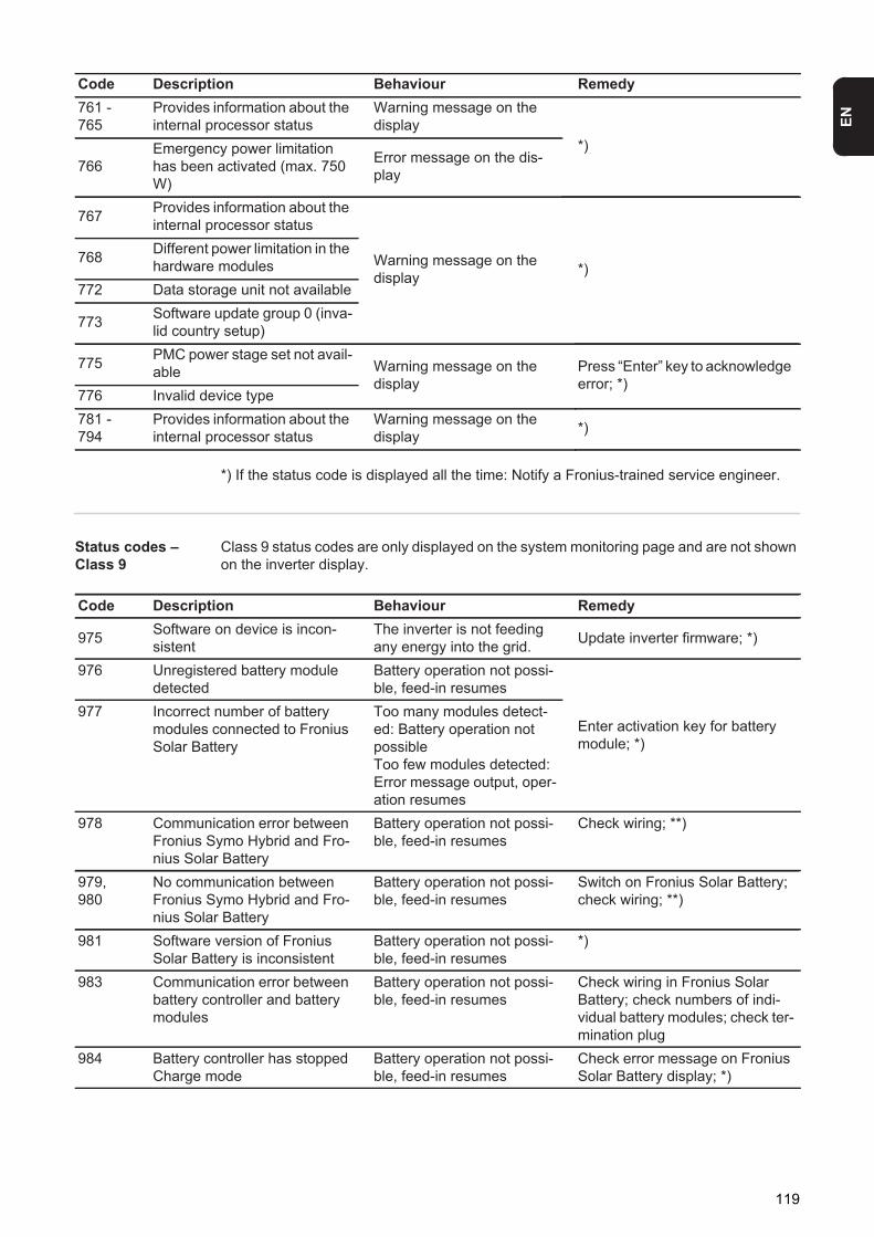
EN
*) If the status code is displayed all the time: Notify a Fronius-trained service engineer.
Status codes – Class 9
Class 9 status codes are only displayed on the system monitoring page and are not shown on the inverter display.
761 - 765
Provides information about the internal processor status
Warning message on the display
*)766
Emergency power limitation has been activated (max. 750 W)
Error message on the dis-play
767 Provides information about the internal processor status
Warning message on the display *)
768 Different power limitation in the hardware modules
772 Data storage unit not available
773 Software update group 0 (inva-lid country setup)
775 PMC power stage set not avail-able Warning message on the
displayPress “Enter” key to acknowledge error; *)
776 Invalid device type781 - 794
Provides information about the internal processor status
Warning message on the display *)
Code Description Behaviour Remedy
Code Description Behaviour Remedy
975 Software on device is incon-sistent
The inverter is not feeding any energy into the grid. Update inverter firmware; *)
976 Unregistered battery module detected
Battery operation not possi-ble, feed-in resumes
Enter activation key for battery module; *)
977 Incorrect number of battery modules connected to Fronius Solar Battery
Too many modules detect-ed: Battery operation not possibleToo few modules detected: Error message output, oper-ation resumes
978 Communication error between Fronius Symo Hybrid and Fro-nius Solar Battery
Battery operation not possi-ble, feed-in resumes
Check wiring; **)
979,980
No communication between Fronius Symo Hybrid and Fro-nius Solar Battery
Battery operation not possi-ble, feed-in resumes
Switch on Fronius Solar Battery; check wiring; **)
981 Software version of Fronius Solar Battery is inconsistent
Battery operation not possi-ble, feed-in resumes
*)
983 Communication error between battery controller and battery modules
Battery operation not possi-ble, feed-in resumes
Check wiring in Fronius Solar Battery; check numbers of indi-vidual battery modules; check ter-mination plug
984 Battery controller has stopped Charge mode
Battery operation not possi-ble, feed-in resumes
Check error message on Fronius Solar Battery display; *)
119
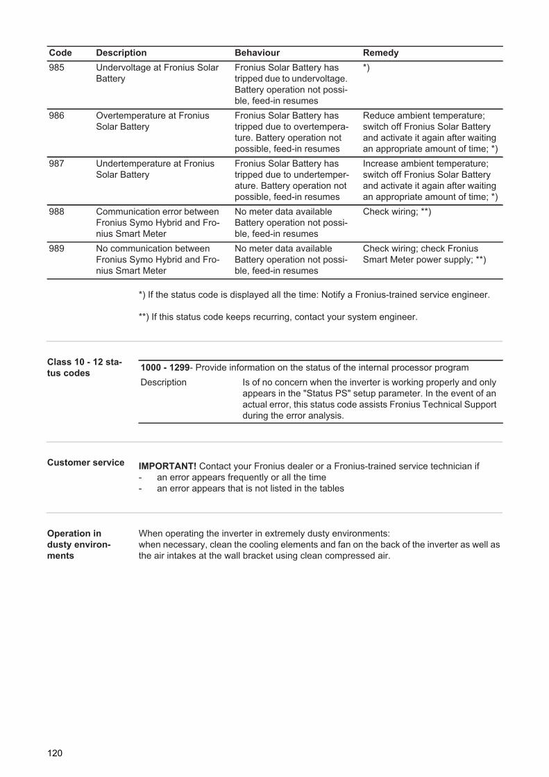
*) If the status code is displayed all the time: Notify a Fronius-trained service engineer.
**) If this status code keeps recurring, contact your system engineer.
Class 10 - 12 sta-tus codes
Customer service
Operation in dusty environ-ments
When operating the inverter in extremely dusty environments:when necessary, clean the cooling elements and fan on the back of the inverter as well as the air intakes at the wall bracket using clean compressed air.
985 Undervoltage at Fronius Solar Battery
Fronius Solar Battery has tripped due to undervoltage. Battery operation not possi-ble, feed-in resumes
*)
986 Overtemperature at Fronius Solar Battery
Fronius Solar Battery has tripped due to overtempera-ture. Battery operation not possible, feed-in resumes
Reduce ambient temperature; switch off Fronius Solar Battery and activate it again after waiting an appropriate amount of time; *)
987 Undertemperature at Fronius Solar Battery
Fronius Solar Battery has tripped due to undertemper-ature. Battery operation not possible, feed-in resumes
Increase ambient temperature; switch off Fronius Solar Battery and activate it again after waiting an appropriate amount of time; *)
988 Communication error between Fronius Symo Hybrid and Fro-nius Smart Meter
No meter data availableBattery operation not possi-ble, feed-in resumes
Check wiring; **)
989 No communication between Fronius Symo Hybrid and Fro-nius Smart Meter
No meter data availableBattery operation not possi-ble, feed-in resumes
Check wiring; check Fronius Smart Meter power supply; **)
Code Description Behaviour Remedy
1000 - 1299- Provide information on the status of the internal processor programDescription Is of no concern when the inverter is working properly and only
appears in the "Status PS" setup parameter. In the event of an actual error, this status code assists Fronius Technical Support during the error analysis.
IMPORTANT! Contact your Fronius dealer or a Fronius-trained service technician if- an error appears frequently or all the time- an error appears that is not listed in the tables
120
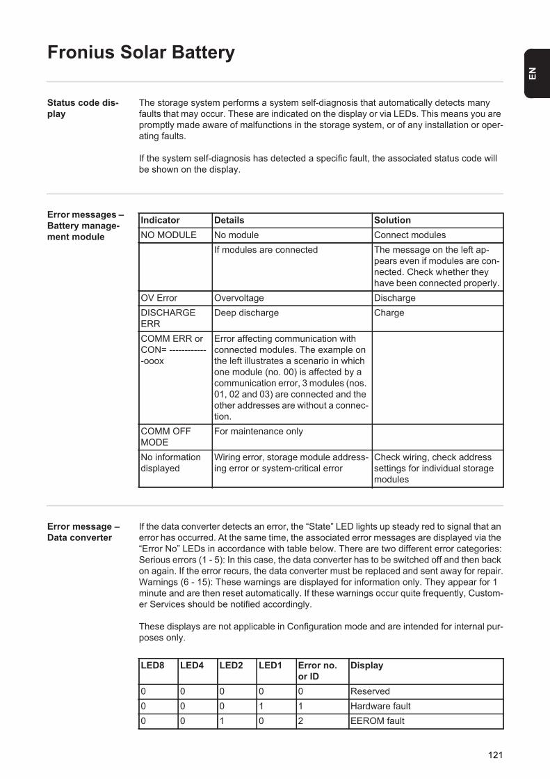
EN
Fronius Solar Battery
Status code dis-play
The storage system performs a system self-diagnosis that automatically detects many faults that may occur. These are indicated on the display or via LEDs. This means you are promptly made aware of malfunctions in the storage system, or of any installation or oper-ating faults.
If the system self-diagnosis has detected a specific fault, the associated status code will be shown on the display.
Error messages – Battery manage-ment module
Error message – Data converter
If the data converter detects an error, the “State” LED lights up steady red to signal that an error has occurred. At the same time, the associated error messages are displayed via the “Error No” LEDs in accordance with table below. There are two different error categories:Serious errors (1 - 5): In this case, the data converter has to be switched off and then back on again. If the error recurs, the data converter must be replaced and sent away for repair.Warnings (6 - 15): These warnings are displayed for information only. They appear for 1 minute and are then reset automatically. If these warnings occur quite frequently, Custom-er Services should be notified accordingly.
These displays are not applicable in Configuration mode and are intended for internal pur-poses only.
Indicator Details SolutionNO MODULE No module Connect modules
If modules are connected The message on the left ap-pears even if modules are con-nected. Check whether they have been connected properly.
OV Error Overvoltage DischargeDISCHARGE ERR
Deep discharge Charge
COMM ERR or CON= -------------ooox
Error affecting communication with connected modules. The example on the left illustrates a scenario in which one module (no. 00) is affected by a communication error, 3 modules (nos. 01, 02 and 03) are connected and the other addresses are without a connec-tion.
COMM OFF MODE
For maintenance only
No information displayed
Wiring error, storage module address-ing error or system-critical error
Check wiring, check address settings for individual storage modules
LED8 LED4 LED2 LED1 Error no. or ID
Display
0 0 0 0 0 Reserved0 0 0 1 1 Hardware fault0 0 1 0 2 EEROM fault
121
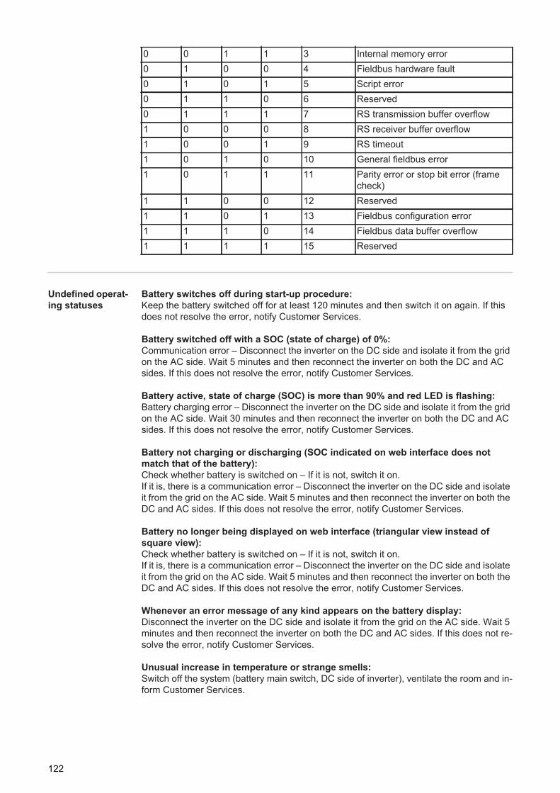
Undefined operat-ing statuses
Battery switches off during start-up procedure:Keep the battery switched off for at least 120 minutes and then switch it on again. If this does not resolve the error, notify Customer Services.
Battery switched off with a SOC (state of charge) of 0%:Communication error – Disconnect the inverter on the DC side and isolate it from the grid on the AC side. Wait 5 minutes and then reconnect the inverter on both the DC and AC sides. If this does not resolve the error, notify Customer Services.
Battery active, state of charge (SOC) is more than 90% and red LED is flashing:Battery charging error – Disconnect the inverter on the DC side and isolate it from the grid on the AC side. Wait 30 minutes and then reconnect the inverter on both the DC and AC sides. If this does not resolve the error, notify Customer Services.
Battery not charging or discharging (SOC indicated on web interface does not match that of the battery):Check whether battery is switched on – If it is not, switch it on. If it is, there is a communication error – Disconnect the inverter on the DC side and isolate it from the grid on the AC side. Wait 5 minutes and then reconnect the inverter on both the DC and AC sides. If this does not resolve the error, notify Customer Services.
Battery no longer being displayed on web interface (triangular view instead of square view):Check whether battery is switched on – If it is not, switch it on. If it is, there is a communication error – Disconnect the inverter on the DC side and isolate it from the grid on the AC side. Wait 5 minutes and then reconnect the inverter on both the DC and AC sides. If this does not resolve the error, notify Customer Services.
Whenever an error message of any kind appears on the battery display:Disconnect the inverter on the DC side and isolate it from the grid on the AC side. Wait 5 minutes and then reconnect the inverter on both the DC and AC sides. If this does not re-solve the error, notify Customer Services.
Unusual increase in temperature or strange smells:Switch off the system (battery main switch, DC side of inverter), ventilate the room and in-form Customer Services.
0 0 1 1 3 Internal memory error0 1 0 0 4 Fieldbus hardware fault0 1 0 1 5 Script error0 1 1 0 6 Reserved0 1 1 1 7 RS transmission buffer overflow1 0 0 0 8 RS receiver buffer overflow1 0 0 1 9 RS timeout1 0 1 0 10 General fieldbus error1 0 1 1 11 Parity error or stop bit error (frame
check)1 1 0 0 12 Reserved1 1 0 1 13 Fieldbus configuration error1 1 1 0 14 Fieldbus data buffer overflow1 1 1 1 15 Reserved
122

Appendix

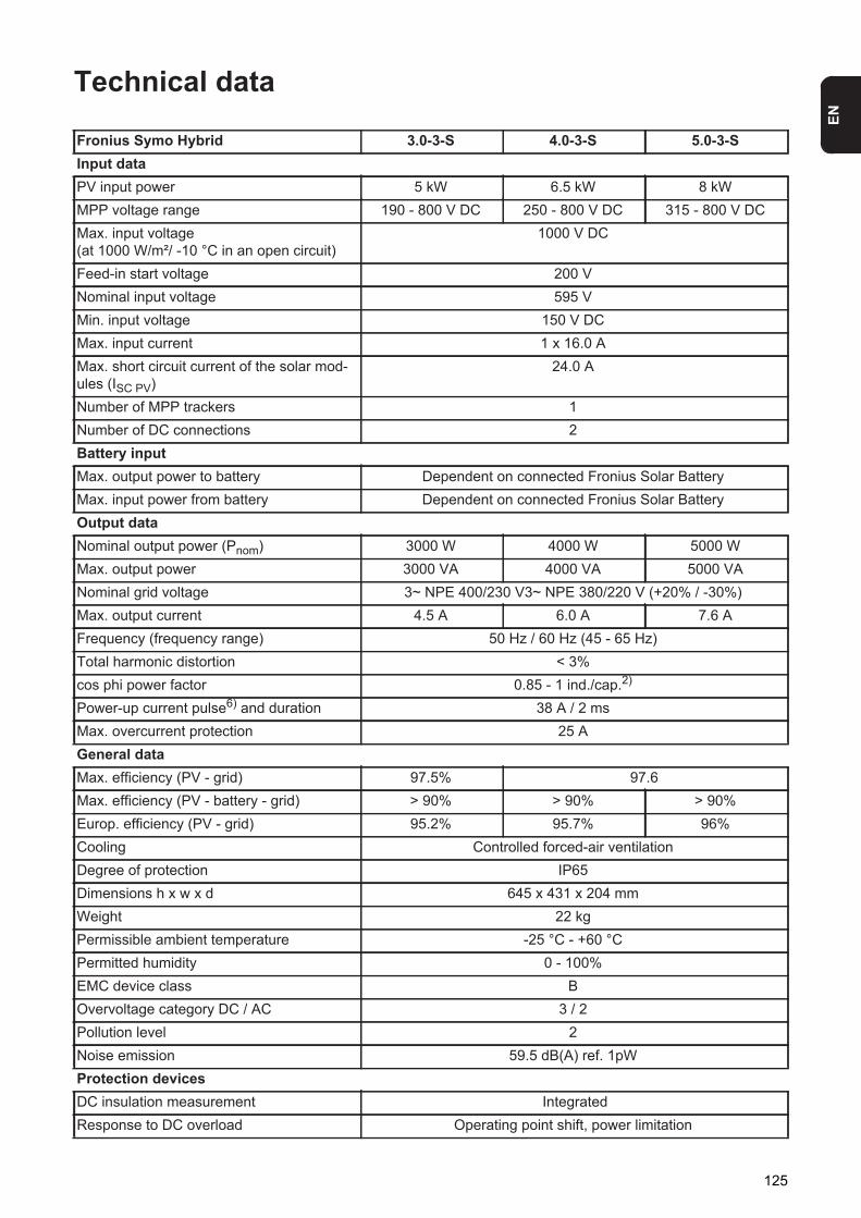
EN
Technical data
Fronius Symo Hybrid 3.0-3-S 4.0-3-S 5.0-3-SInput dataPV input power 5 kW 6.5 kW 8 kWMPP voltage range 190 - 800 V DC 250 - 800 V DC 315 - 800 V DCMax. input voltage(at 1000 W/m²/ -10 °C in an open circuit)
1000 V DC
Feed-in start voltage 200 VNominal input voltage 595 VMin. input voltage 150 V DCMax. input current 1 x 16.0 AMax. short circuit current of the solar mod-ules (ISC PV)
24.0 A
Number of MPP trackers 1Number of DC connections 2Battery inputMax. output power to battery Dependent on connected Fronius Solar BatteryMax. input power from battery Dependent on connected Fronius Solar BatteryOutput dataNominal output power (Pnom) 3000 W 4000 W 5000 WMax. output power 3000 VA 4000 VA 5000 VANominal grid voltage 3~ NPE 400/230 V3~ NPE 380/220 V (+20% / -30%)Max. output current 4.5 A 6.0 A 7.6 AFrequency (frequency range) 50 Hz / 60 Hz (45 - 65 Hz)Total harmonic distortion < 3%cos phi power factor 0.85 - 1 ind./cap.2)
Power-up current pulse6) and duration 38 A / 2 msMax. overcurrent protection 25 AGeneral dataMax. efficiency (PV - grid) 97.5% 97.6Max. efficiency (PV - battery - grid) > 90% > 90% > 90%Europ. efficiency (PV - grid) 95.2% 95.7% 96%Cooling Controlled forced-air ventilationDegree of protection IP65Dimensions h x w x d 645 x 431 x 204 mmWeight 22 kgPermissible ambient temperature -25 °C - +60 °CPermitted humidity 0 - 100%EMC device class BOvervoltage category DC / AC 3 / 2Pollution level 2Noise emission 59.5 dB(A) ref. 1pWProtection devicesDC insulation measurement IntegratedResponse to DC overload Operating point shift, power limitation
125
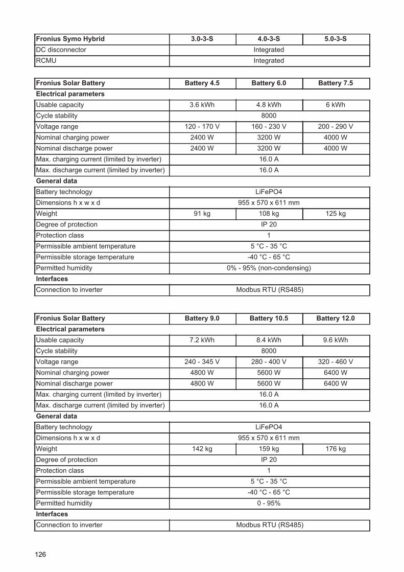
DC disconnector IntegratedRCMU Integrated
Fronius Symo Hybrid 3.0-3-S 4.0-3-S 5.0-3-S
Fronius Solar Battery Battery 4.5 Battery 6.0 Battery 7.5Electrical parametersUsable capacity 3.6 kWh 4.8 kWh 6 kWhCycle stability 8000Voltage range 120 - 170 V 160 - 230 V 200 - 290 VNominal charging power 2400 W 3200 W 4000 WNominal discharge power 2400 W 3200 W 4000 WMax. charging current (limited by inverter) 16.0 AMax. discharge current (limited by inverter) 16.0 AGeneral dataBattery technology LiFePO4Dimensions h x w x d 955 x 570 x 611 mmWeight 91 kg 108 kg 125 kgDegree of protection IP 20Protection class 1Permissible ambient temperature 5 °C - 35 °CPermissible storage temperature -40 °C - 65 °CPermitted humidity 0% - 95% (non-condensing)InterfacesConnection to inverter Modbus RTU (RS485)
Fronius Solar Battery Battery 9.0 Battery 10.5 Battery 12.0Electrical parametersUsable capacity 7.2 kWh 8.4 kWh 9.6 kWhCycle stability 8000Voltage range 240 - 345 V 280 - 400 V 320 - 460 VNominal charging power 4800 W 5600 W 6400 WNominal discharge power 4800 W 5600 W 6400 WMax. charging current (limited by inverter) 16.0 AMax. discharge current (limited by inverter) 16.0 AGeneral dataBattery technology LiFePO4Dimensions h x w x d 955 x 570 x 611 mmWeight 142 kg 159 kg 176 kgDegree of protection IP 20Protection class 1Permissible ambient temperature 5 °C - 35 °CPermissible storage temperature -40 °C - 65 °CPermitted humidity 0 - 95%InterfacesConnection to inverter Modbus RTU (RS485)
126
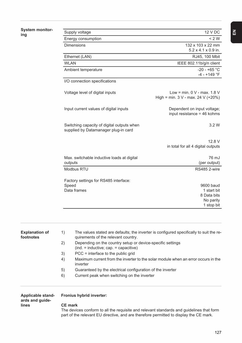
EN
System monitor-ing
Explanation of footnotes
1) The values stated are defaults; the inverter is configured specifically to suit the re-quirements of the relevant country.
2) Depending on the country setup or device-specific settings(ind. = inductive; cap. = capacitive)
3) PCC = interface to the public grid4) Maximum current from the inverter to the solar module when an error occurs in the
inverter5) Guaranteed by the electrical configuration of the inverter6) Current peak when switching on the inverter
Applicable stand-ards and guide-lines
Fronius hybrid inverter:
CE markThe devices conform to all the requisite and relevant standards and guidelines that form part of the relevant EU directive, and are therefore permitted to display the CE mark.
Supply voltage 12 V DCEnergy consumption < 2 WDimensions 132 x 103 x 22 mm
5.2 x 4.1 x 0.9 in.Ethernet (LAN) RJ45, 100 MbitWLAN IEEE 802.11b/g/n clientAmbient temperature -20 - +65 °C
-4 - +149 °FI/O connection specifications
Voltage level of digital inputs Low = min. 0 V - max. 1.8 VHigh = min. 3 V - max. 24 V (+20%)
Input current values of digital inputs Dependent on input voltage;input resistance = 46 kohms
Switching capacity of digital outputs when supplied by Datamanager plug-in card
3.2 W
12.8 Vin total for all 4 digital outputs
Max. switchable inductive loads at digital outputs
76 mJ(per output)
Modbus RTU RS485 2-wire
Factory settings for RS485 interface:SpeedData frames
9600 baud1 start bit
8 Data bitsNo parity1 stop bit
127
Emergency power operationThis version of the hybrid inverter is only intended for use in grid connected photovoltaic systems. A device update is required from the manufacturer in order to generate power in-dependently of the public grid. As well as providing functional enhancements for the hard-ware and software, this update also includes relevant user documentation.The hybrid inverter is delivered ready for supplying emergency power.
Power outageThe standard measurement and safety procedures integrated into the inverter ensure that in the event of a power outage, the feed-in of energy is immediately interrupted (e.g. switch-off by the energy supplier or damage to lines).
Fronius Solar Battery:- IEC/EN 62133- EN 50178 (1997)- EN 61000-6-2:2005- EN 61000-6-3:2007 + A1:2011- EN 62208- EN 62311:2008- FCC Part 15 Subpart B:2012 Class B- IEC 60730-1 (Fourth Edition) 2010 (H.7, H.11.12, H.27.1.2)- UN 38.3- 60730-1 2011 (H.7, H.11.12, H.27.1.2)
128
EN
Warranty terms and conditions, and disposal
Fronius manufac-turer's warranty
Detailed, country-specific warranty terms are available on the internet: www.fronius.com/solar/warranty
To obtain the full warranty period for your newly installed Fronius inverter or storage sys-tem, please register at: www.solarweb.com.
Disposal If you need to replace your inverter or your battery at some point, Fronius will take back the old device and arrange for it to be recycled in an appropriate manner.
129

Fronius Worldwide - www.fronius.com/addresses
Under http://www.fronius.com/addresses you will find all addresses of our sales branches and partner firms!
Fronius International GmbH4600 Wels, Froniusplatz 1, AustriaE-Mail: [email protected]://www.fronius.com
Fronius USA LLC Solar Electronics Division6797 Fronius Drive, Portage, IN 46368E-Mail: [email protected]://www.fronius-usa.com