Embed Size (px)
Citation preview
Vol. 6, No. 11, Special Issue on Advances in Quality of Service Management, December 2007
From formal specifications to QoS monitors
Sebastien Saudrais, IRISA France, Triskell Project, [email protected] Barais, IRISA France, Triskell Project, [email protected] Duchien, INRIA France, ADAM Project,[email protected] Plouzeau, IRISA France, Triskell Project, [email protected]
In the domain of soft real-time application design, the gap between component-specification models and the implementations often implies that the implementationscannot fully take advantage of the specification models. To limit this gap, this paperproposes an approach to generate a QoS monitor from the timed behavior specifi-cation. To support this approach, we rely on two different component models: onefocused on formal description and the other on practical implementation. Those mod-els are interconnected by model transformation, using a Model-Driven Engineeringstyle.
aThis work was funded by ARTIST2, the Network of Excellence on Embedded SystemsDesign
1 INTRODUCTION
Recently, hopes that modeling could take an important role in the software engi-neering process have been refuelled by so-called MDE (Model-Driven Engineering)initiatives, most prominently advanced by IBM with EMF, the OMG (Object Man-agement Group) with the MDA or by Microsoft with Software Factories. The under-lying idea is to promote models to be the primary artifacts of software development,making executable code a pure derivative. According to this development paradigm,software is generated with the aid of suitable transformations from a compact de-scription (the model) that is more easily read and maintained by humans than anyother form of software specification in use today.
In the soft-real time domain, the industry is interested in abstract componentmodels to build systems. Such models improve the reusability of software modulesbecause they provide three main features [8] for designing soft real time applications:(1) a composition model that provides operators able to compose existent libraries ofcomponents, (2) an abstraction level for defining components and connectors withonly precise and yet abstract properties of the components, (3) a set of analysistools to validate architectural descriptions. To enable an architectural analysis, thespecification activity must add a time information within the component interfacespecification. Nevertheless, even though the real-time system community and thesoftware engineering community use the component paradigm, the details are notnecessarily the same. Consequently, although standards such as AUTOSAR [3] and
Cite this document as follows: Sebastien Saudrais, Olivier Barais, Laurence Duchien: Fromformal specifications to QoS monitors, in Journal of Object Technology, vol. 6, no. 11,Special Issue on Advances in Quality of Service Management, December 2007, pages 7–24,http://www.jot.fm/issues/issues 2007 12/article1
FROM FORMAL SPECIFICATIONS TO QOS MONITORS
sysML [14], for real-time systems, or UML 2.0 [15], for software engineering, promotethe concept of component, there is not currently any component model designed tospecify a real-time application by assembling components with a clear semantic anda clear mapping with a real-time framework such as Giotto [9] or Simulink [6].
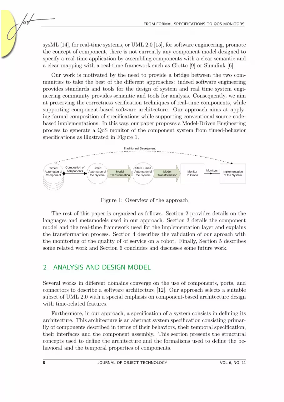
Our work is motivated by the need to provide a bridge between the two com-munities to take the best of the different approaches: indeed software engineeringprovides standards and tools for the design of system and real time system engi-neering community provides semantic and tools for analysis. Consequently, we aimat preserving the correctness verification techniques of real-time components, whilesupporting component-based software architecture. Our approach aims at apply-ing formal composition of specifications while supporting conventional source-code-based implementations. In this way, our paper proposes a Model-Driven Engineeringprocess to generate a QoS monitor of the component system from timed-behaviorspecifications as illustrated in Figure 1.
Timed Automaton of Component
Timed Automaton of Component
Timed Automaton of Component
Timed Automaton of Component
Timed Automaton of the System
State Timed Automaton of the System
MonitorIn Giotto
ModelTransformation
ModelTransformation
Compostion of components Implementation
of the SystemMonitors
Traditionnal Develpment
Figure 1: Overview of the approach
The rest of this paper is organized as follows. Section 2 provides details on thelanguages and metamodels used in our approach. Section 3 details the componentmodel and the real-time framework used for the implementation layer and explainsthe transformation process. Section 4 describes the validation of our aproach withthe monitoring of the quality of of service on a robot. Finally, Section 5 describessome related work and Section 6 concludes and discusses some future work.
2 ANALYSIS AND DESIGN MODEL
Several works in different domains converge on the use of components, ports, andconnectors to describe a software architecture [12]. Our approach selects a suitablesubset of UML 2.0 with a special emphasis on component-based architecture designwith time-related features.
Furthermore, in our approach, a specification of a system consists in defining itsarchitecture. This architecture is an abstract system specification consisting primar-ily of components described in terms of their behaviors, their temporal specification,their interfaces and the component assembly. This section presents the structuralconcepts used to define the architecture and the formalisms used to define the be-havioral and the temporal properties of components.
8 JOURNAL OF OBJECT TECHNOLOGY VOL 6, NO. 11
2 ANALYSIS AND DESIGN MODEL
Structural elements of the component model
The structural part of our component model is heavily inspired from the UML 2.0architecture diagram. Nevertheless, contrary to UML 2.0, we define an abstractmodel with fewer concepts to limit the complexity of the language that the archi-tect has to manipulate and to remove all the semantic variation points existing inUML 2.0.
Consequently, in our component model, a component provides services and mayrequire some services from other components. Services can only be accessed throughexplicitly declared ports. A port is a binding point on a component that defines twosets of interfaces : provided and required.
Our component model distinguishes two kinds of components: primitives whichwill contain the code, and composites which are only used as a mechanism to dealwith a group of components as a whole, while potentially hiding some of the featuresof the subcomponents. A primitive component can be seen as a basic buildingblock in the component assembly. Our component model does not impose any limiton the levels of composition. The model thus provides two mechanisms to definethe architecture of an application: connector between ports of components, andencapsulation of a group of components into a composite. A connector associatesa component’s port with a port located on another component. Two ports can bebound with each other only if the interfaces required by one port are provided by theother and vice versa. The services provided and required by the child componentsof a composite component are accessible through delegated ports, which are the onlyentry points of a composite component. A delegated port of a composite componentis connected to only one child component port.
The behavioral part
With the interface and method definitions, a component declares structural elementsabout provided and required services. the behavioral part of the component modeladds information about the behavior of a component. The behavior specificationdefines the component’s interactions with its environment. This behavior is de-clared by a timed automaton [2] describing the sequences of messages that may beexchanged between the component and its environment with timed properties.
A timed automaton is an automaton extended with clocks, which are a set ofvariables increasing uniformly with time. We only consider deterministic timedautomaton. Formally a timed automaton is defined as followed :
Definition 1. (Timed Automaton)
A timed automaton is a tuple A =< S,X,L, T, ι > where :
• S is a finite set of locations,
VOL 6, NO. 11 JOURNAL OF OBJECT TECHNOLOGY 9
FROM FORMAL SPECIFICATIONS TO QOS MONITORS
1
AudioPlayer
IAPoutsound
void launch()void sound()
DecoderIDinsound
IDoutsound
void launch()void sound() void
getSound()
ExtractionIEinsound
void getSound()
Source
ISread IEread
void Read()
void Read()ISlaunch
IElaunch
void launch()
void launch()
Launchvoid launch()
S0idle
S1launched
?launch
S2waiting
!start;x:=0
S3receipt
?getSound;x<4;x:=0
S4working
x=0;y:=0
!Sound;y<2
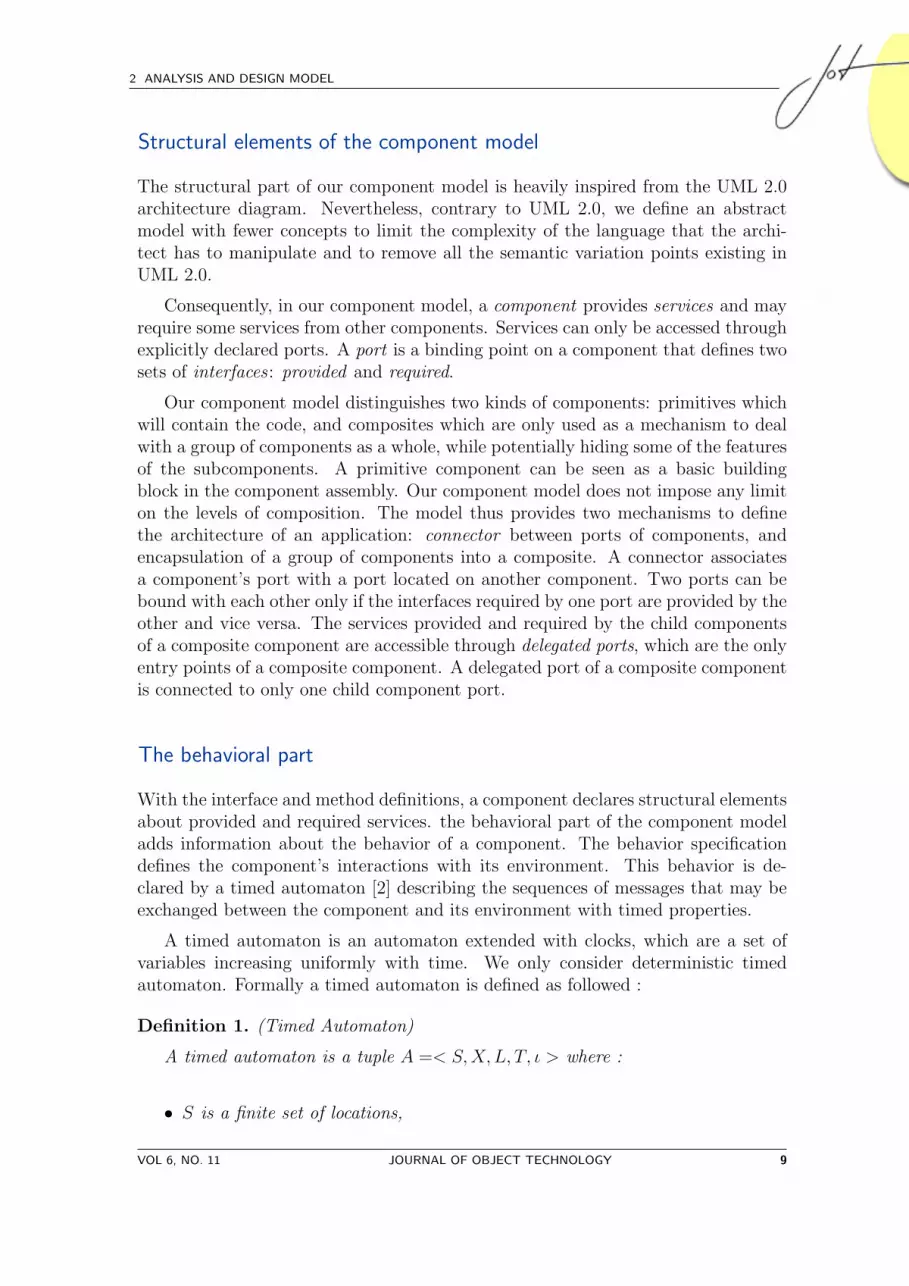
Figure 2: Example of an audio player component
• X is a finite set of clocks. To each clock, we assign a valuation v ∈ V ,v(x) ∈ R+ for each x ∈ X.
• L is a finite state of labels,
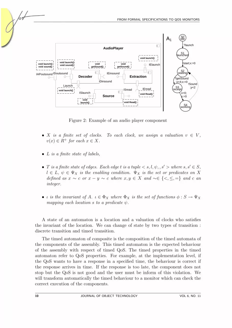
• T is a finite state of edges. Each edge t is a tuple < s, l, ψ, , s′ > where s, s′ ∈ S,l ∈ L, ψ ∈ ΨX is the enabling condition. ΨX is the set or predicates on Xdefined as x ∼ c or x − y ∼ c where x, y ∈ X and ∼∈ {<,≤,=} and c aninteger.
• ι is the invariant of A. ι ∈ ΦX where ΦX is the set of functions φ : S → ΨX
mapping each location s to a predicate ψ.
A state of an automaton is a location and a valuation of clocks who satisfiesthe invariant of the location. We can change of state by two types of transition :discrete transition and timed transition.
The timed automaton of composite is the composition of the timed automata ofthe components of the assembly. This timed automaton is the expected behaviourof the assembly with respect of timed QoS. The timed properties in the timedautomaton refer to QoS properties. For example, at the implementation level, ifthe QoS wants to have a response in a specified time, the behaviour is correct ifthe response arrives in time. If the response is too late, the component does notstop but the QoS is not good and the user must be inform of this violation. Wewill transform automatically the timed behaviour to a monitor which can check thecorrect execution of the components.
10 JOURNAL OF OBJECT TECHNOLOGY VOL 6, NO. 11

3 A MODEL ORIENTED APPROACH FOR CODE GENERATION
Example
Fig. 2 illustrates the model with an example of component AudioPlayer. TheAudioPlayer component provides an IAPoutsound interface that contains methodslaunch and sound. It is composed of 3 components: Decoder, Extraction andSource. The left side shows the structural representation of the component inUML 2.0. The right side of Fig. 2 shows an timed automaton A1 describing allpossible behaviors of the Decoder1. In this automaton A1, we have two clocks: xand y. The first one is used for representing the response time of ?getSound who hasto be received less than each 4 units of time. The second clock is used for modellingthe execution time of the transformation of ?getSound into !sound which takes lessthan 2 units of time.
3 A MODEL ORIENTED APPROACH FOR CODE GENERATION
From the component-based software architecture representation, our approach gen-erates a QoS monitor based on the Giotto framework [9]. This section presents theGiotto framework. We also discuss the choice of a model transformation approach togenerate the code from the specification to the implementation. Finally, we providedetails on the transformation of an architecture specification with time constraintsto the Giotto Framework.
The Giotto abstractions
Giotto is a real-time framework for embedded control systems running on possiblydistributed platforms. A Giotto program explicitly specifies the exact real-timeinteraction of software components with the physical world. The Giotto compilerautomatically generates timing code that ensures the specified behavior on a givenplatform. The Giotto model is based on four main concepts:
• ports,
• tasks,
• drivers,
• and modes.
In Giotto, all communication are performed through ports. Giotto defines fivekinds of ports. Two kinds of port (Sensor - Actuator) manage the input and theoutput interactions with the hardware layer. Two others kinds of port (Input -Output) manage the interactions with the software layer. They are used to exchange
1In Fig. 2, in order to simplify the automaton, we only represent the receipt of message for a method call andthe send of message for a method receipt.
VOL 6, NO. 11 JOURNAL OF OBJECT TECHNOLOGY 11
FROM FORMAL SPECIFICATIONS TO QOS MONITORS
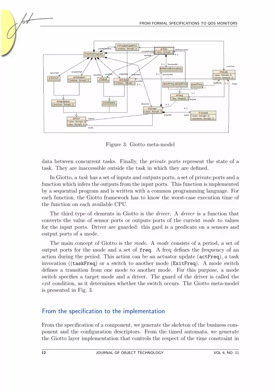
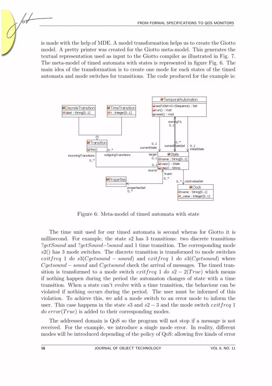
Figure 3: Giotto meta-model
data between concurrent tasks. Finally, the private ports represent the state of atask. They are inaccessible outside the task in which they are defined.
In Giotto, a task has a set of inputs and outputs ports, a set of private ports and afunction which infers the outputs from the input ports. This function is implementedby a sequential program and is written with a common programming language. Foreach function, the Giotto framework has to know the worst-case execution time ofthe function on each available CPU.
The third type of elements in Giotto is the driver. A driver is a function thatconverts the value of sensor ports or outputs ports of the current mode to valuesfor the input ports. Driver are guarded: this gard is a predicate on a sensors andoutput ports of a mode.
The main concept of Giotto is the mode. A mode consists of a period, a set ofoutput ports for the mode and a set of freq. A freq defines the frequency of anaction during the period. This action can be an actuator update (actFreq), a taskinvocation ((taskFreq) or a switch to another mode (ExitFreq). A mode switchdefines a transition from one mode to another mode. For this purpose, a modeswitch specifies a target mode and a driver. The guard of the driver is called theexit condition, as it determines whether the switch occurs. The Giotto meta-modelis presented in Fig. 3.
From the specification to the implementation
From the specification of a component, we generate the skeleton of the business com-ponent and the configuration descriptors. From the timed automata, we generatethe Giotto layer implementation that controls the respect of the time constraint in
12 JOURNAL OF OBJECT TECHNOLOGY VOL 6, NO. 11
3 A MODEL ORIENTED APPROACH FOR CODE GENERATION
the architecture of the architecture. Indeed, Giotto separates the system’s behaviourfrom its implementation. Then we have three levels in the implementation archi-tecture: functional, time interaction and platform. In the functional level, we findbusiness components generated from the specification of services and the abstractimplementation. In the time interaction level, we find the Giotto layer generatedfrom the timed automata and the time constraints. Finally, in the platform level,we find the specification of the platforms as the topology of CPUs and networks andthe performance. Choosing a MDE approach has two main benefits for the QoS.The time interaction is decoupled from the functionalities. The framework improvesthe separation of concerns. Moreover, the generative approach improves the pro-ductivity of the development process. To define a MDE approach, we use Kermetaa model oriented language. It allows the design of the different meta-model of thegenerative process and the implementation of the transformation itself.
Kermeta: a model oriented language Kermeta2 is an open source meta-modeling language developed by the Triskell team at IRISA. It has been designedas an extension to the EMOF [16]. Kermeta extends EMOF with an action lan-guage that allows specifying semantics and behavior of meta-models. The actionlanguage is imperative and object-oriented. It is used to provide an implementationof operations defined in meta-models. A more detailed description of the languageis presented in [13]. The Kermeta action language has been specifically designed toprocess models. It includes both Object-Oriented (OO) features and model-specificfeatures. Kermeta includes traditional OO static typing, multiple inheritance andbehavior redefinition/selection with a late binding semantics.
To implement the transformation process between our component model andthe Giotto, we have chosen Kermeta for four reasons. First, it gives a graphicaland textual representation for designing the different meta-models identified in theprocess. Second, the language allows implementing a composition semantic in thecomponent model by adding the algorithm in the body of the operations definedin the component metamodel. Third, Kermeta is suitable for model processing. Italso includes specific concepts such as opposite properties (i.e. associations) andhandling of object containment. In addition to this, convenient constructions of theObject Constraint Language (OCL), such as closures (e.g. each, collect, select), arealso available in Kermeta. Finally, Kermeta tools are compatible with the EclipseModeling Framework (EMF) which allows us to use Eclipse tools to edit, store, andvisualize models. This second argument is more technical than scientific, but it isvery interesting to tool quickly the different meta-model defined in the approach.
Generating the Giotto layer The assembly of components at the specificationlevel gives a timed automaton describing the behaviour of the complete system.We will transform this automaton to Giotto to monitor the implementation of thecomponents. If a component does not have a correct behaviour, Giotto can inform
2http://www.kermeta.org
VOL 6, NO. 11 JOURNAL OF OBJECT TECHNOLOGY 13

FROM FORMAL SPECIFICATIONS TO QOS MONITORS
the user that the level of QoS is no longer correct. The real components are developedby traditionnal methods and must only inform Giotto of the arrival of messages.
The first step of the transformation is to transform the timed automaton to adiscrete time automaton. The discrete automaton is an automaton with discretetime. Each modification of time will be explain on the transitions. From the au-tomaton A1, we will create the automaton A2 as illustrated in Fig. 4. The secondautomaton represents the states of the first automaton with discrete and time tran-sitions. For the example, locations s0 and s1 have only discrete transitions. Thetwo clocks are reinitialized before being used so no timed transitions are used beforetheir initialization. Each timed transition increases the time unit by 1 so for thestate wait, which must hold no more than four units of time, it is transformed tofour states.
S0idle
S1launched?launch
S2waiting
x=0
!start
S2waiting
x=1
1
S3receipt
?getSound
?getSound
S2waiting
x=2
1
S4workingy=0;x=0
?getSound
S2waiting
x=3
1
?getSound
!Sound
S4workingy=1;x=1
1 !Sound
S0idle
S1launched
?launch
S2waiting
!start;x:=0
S3receipt
?getSound;x<4;x:=0
S4working
x=0;y:=0
!Sound;y<2
A1 A2
Figure 4: Transformation of automata
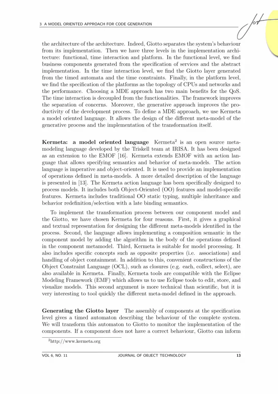
Then the discrete automaton is transform to a simulation automaton. A sim-ulation automaton represents what must be received within a unit of time. He isconstruction by finding special paths in the discrete automaton. The paths are cycleor path finishing with a timed transition. The final automaton is presented by theautomaton A3 of the Fig. 5.
The second step of the transformation is to produce the Giotto code. This step
14 JOURNAL OF OBJECT TECHNOLOGY VOL 6, NO. 11
3 A MODEL ORIENTED APPROACH FOR CODE GENERATION
A3
?launch!start
?getSound,!sound
s0
s2
s3
?getSound
s2-1
1
!Sound
?getSound
s2-2 s2-3
1
1
?getSound?getSound
Figure 5: Simulation automaton
VOL 6, NO. 11 JOURNAL OF OBJECT TECHNOLOGY 15
FROM FORMAL SPECIFICATIONS TO QOS MONITORS
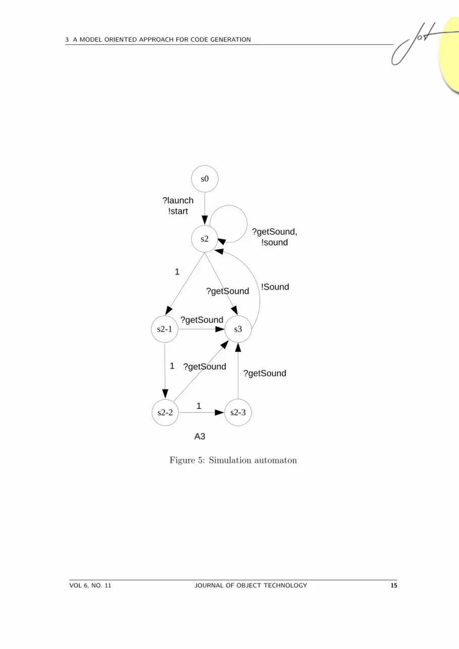
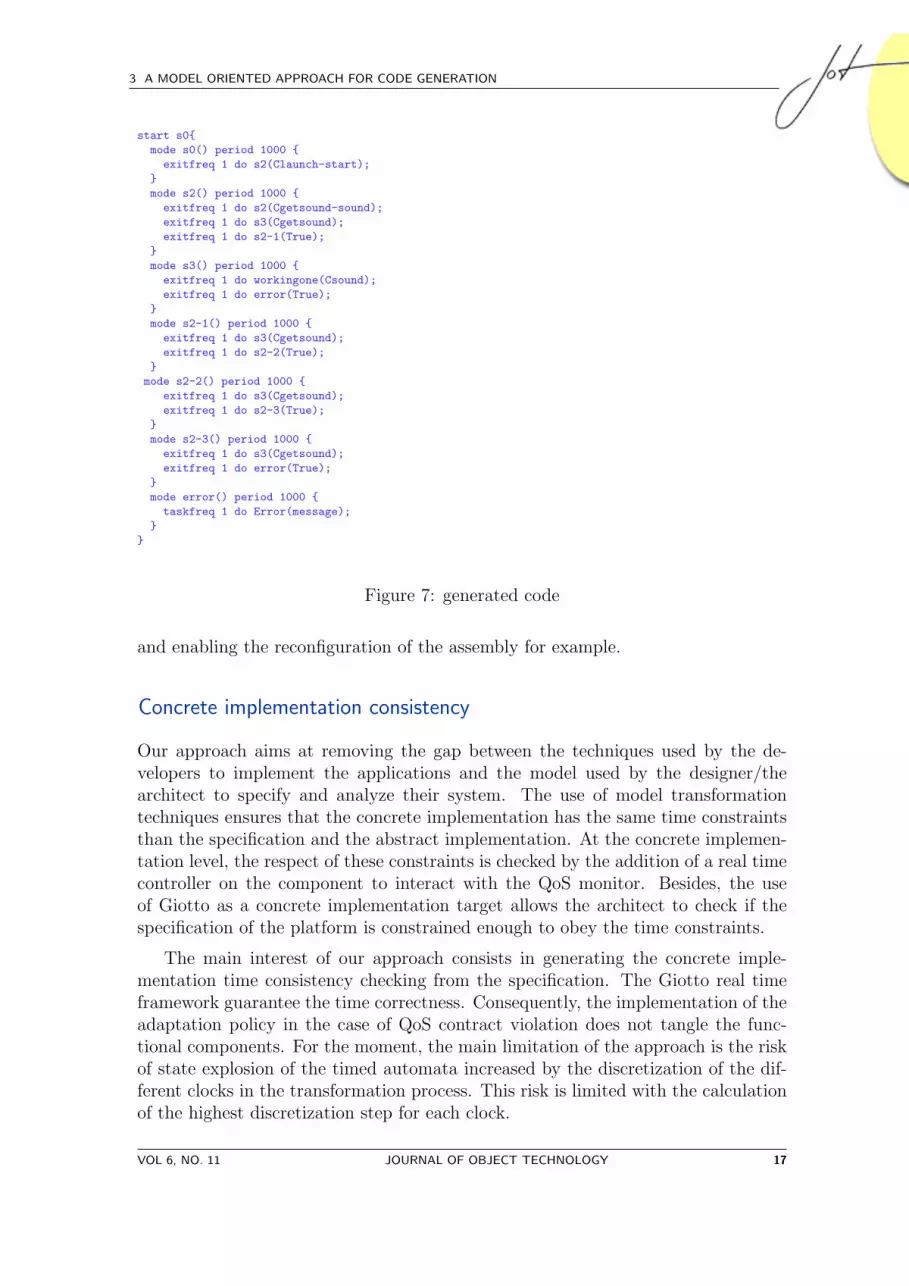
is made with the help of MDE. A model transformation helps us to create the Giottomodel. A pretty printer was created for the Giotto meta-model. This generates thetextual representation used as input to the Giotto compiler as illustrated in Fig. 7.The meta-model of timed automata with states is represented in figure Fig. 6. Themain idea of the transformation is to create one mode for each states of the timedautomata and mode switches for transitions. The code produced for the example is:
Figure 6: Meta-model of timed automata with state
The time unit used for our timed automata is second wheras for Giotto it ismillisecond. For example, the state s2 has 3 transitions: two discrete transitions?getSound and ?getSound−!sound and 1 time transition. The corresponding modes2() has 3 mode switches. The discrete transition is transformed to mode switchesexitfreq 1 do s3(Cgetsound − sound) and exitfreq 1 do s3(Cgetsound) whereCgetsound− sound and Cgetsound check the arrival of messages. The timed tran-sition is transformed to a mode switch exitfreq 1 do s2 − 2(True) which meansif nothing happen during the period the automaton changes of state with a timetransition. When a state can’t evolve with a time transition, the behaviour can beviolated if nothing occurs during the period. The user must be informed of thisviolation. To achieve this, we add a mode switch to an error mode to inform theuser. This case happens in the state s3 and s2− 3 and the mode switch exitfreq 1do error(True) is added to their corresponding modes.
The addressed domain is QoS so the program will not stop if a message is notreceived. For the example, we introduce a single mode error. In reality, differentmodes will be introduced depending of the policy of QoS: allowing five kinds of error
16 JOURNAL OF OBJECT TECHNOLOGY VOL 6, NO. 11
3 A MODEL ORIENTED APPROACH FOR CODE GENERATION
start s0{
mode s0() period 1000 {
exitfreq 1 do s2(Claunch-start);
}
mode s2() period 1000 {
exitfreq 1 do s2(Cgetsound-sound);
exitfreq 1 do s3(Cgetsound);
exitfreq 1 do s2-1(True);
}
mode s3() period 1000 {
exitfreq 1 do workingone(Csound);
exitfreq 1 do error(True);
}
mode s2-1() period 1000 {
exitfreq 1 do s3(Cgetsound);
exitfreq 1 do s2-2(True);
}
mode s2-2() period 1000 {
exitfreq 1 do s3(Cgetsound);
exitfreq 1 do s2-3(True);
}
mode s2-3() period 1000 {
exitfreq 1 do s3(Cgetsound);
exitfreq 1 do error(True);
}
mode error() period 1000 {
taskfreq 1 do Error(message);
}
}
Figure 7: generated code
and enabling the reconfiguration of the assembly for example.
Concrete implementation consistency
Our approach aims at removing the gap between the techniques used by the de-velopers to implement the applications and the model used by the designer/thearchitect to specify and analyze their system. The use of model transformationtechniques ensures that the concrete implementation has the same time constraintsthan the specification and the abstract implementation. At the concrete implemen-tation level, the respect of these constraints is checked by the addition of a real timecontroller on the component to interact with the QoS monitor. Besides, the useof Giotto as a concrete implementation target allows the architect to check if thespecification of the platform is constrained enough to obey the time constraints.
The main interest of our approach consists in generating the concrete imple-mentation time consistency checking from the specification. The Giotto real timeframework guarantee the time correctness. Consequently, the implementation of theadaptation policy in the case of QoS contract violation does not tangle the func-tional components. For the moment, the main limitation of the approach is the riskof state explosion of the timed automata increased by the discretization of the dif-ferent clocks in the transformation process. This risk is limited with the calculationof the highest discretization step for each clock.
VOL 6, NO. 11 JOURNAL OF OBJECT TECHNOLOGY 17
FROM FORMAL SPECIFICATIONS TO QOS MONITORS
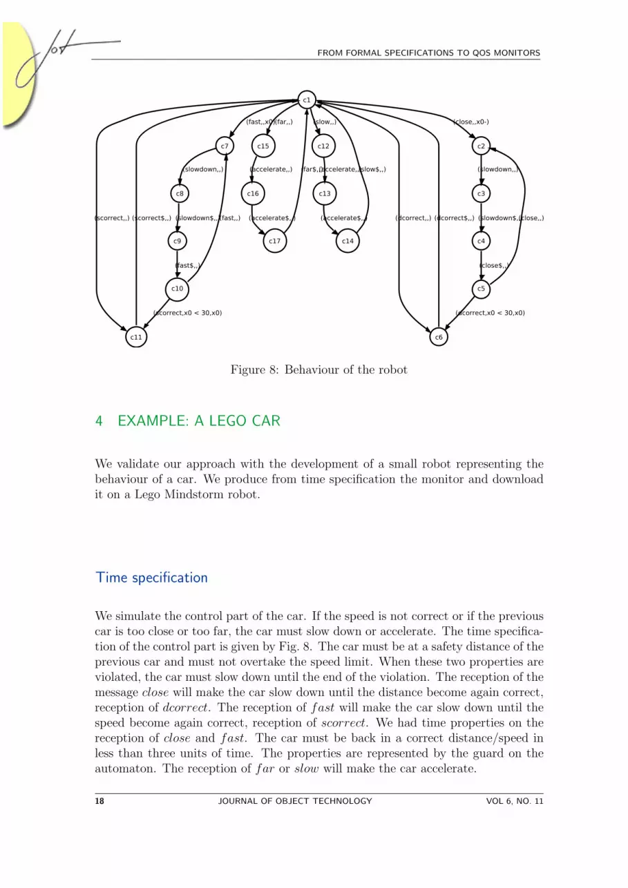
Figure 8: Behaviour of the robot
4 EXAMPLE: A LEGO CAR
We validate our approach with the development of a small robot representing thebehaviour of a car. We produce from time specification the monitor and downloadit on a Lego Mindstorm robot.
Time specification
We simulate the control part of the car. If the speed is not correct or if the previouscar is too close or too far, the car must slow down or accelerate. The time specifica-tion of the control part is given by Fig. 8. The car must be at a safety distance of theprevious car and must not overtake the speed limit. When these two properties areviolated, the car must slow down until the end of the violation. The reception of themessage close will make the car slow down until the distance become again correct,reception of dcorrect. The reception of fast will make the car slow down until thespeed become again correct, reception of scorrect. We had time properties on thereception of close and fast. The car must be back in a correct distance/speed inless than three units of time. The properties are represented by the guard on theautomaton. The reception of far or slow will make the car accelerate.
18 JOURNAL OF OBJECT TECHNOLOGY VOL 6, NO. 11
5 RELATED WORK
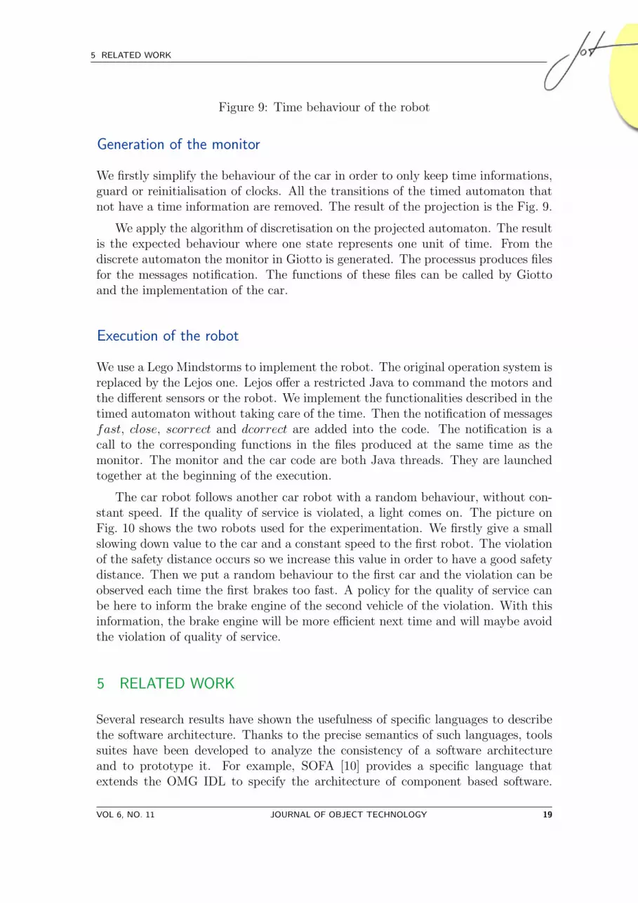
Figure 9: Time behaviour of the robot
Generation of the monitor
We firstly simplify the behaviour of the car in order to only keep time informations,guard or reinitialisation of clocks. All the transitions of the timed automaton thatnot have a time information are removed. The result of the projection is the Fig. 9.
We apply the algorithm of discretisation on the projected automaton. The resultis the expected behaviour where one state represents one unit of time. From thediscrete automaton the monitor in Giotto is generated. The processus produces filesfor the messages notification. The functions of these files can be called by Giottoand the implementation of the car.
Execution of the robot
We use a Lego Mindstorms to implement the robot. The original operation system isreplaced by the Lejos one. Lejos offer a restricted Java to command the motors andthe different sensors or the robot. We implement the functionalities described in thetimed automaton without taking care of the time. Then the notification of messagesfast, close, scorrect and dcorrect are added into the code. The notification is acall to the corresponding functions in the files produced at the same time as themonitor. The monitor and the car code are both Java threads. They are launchedtogether at the beginning of the execution.
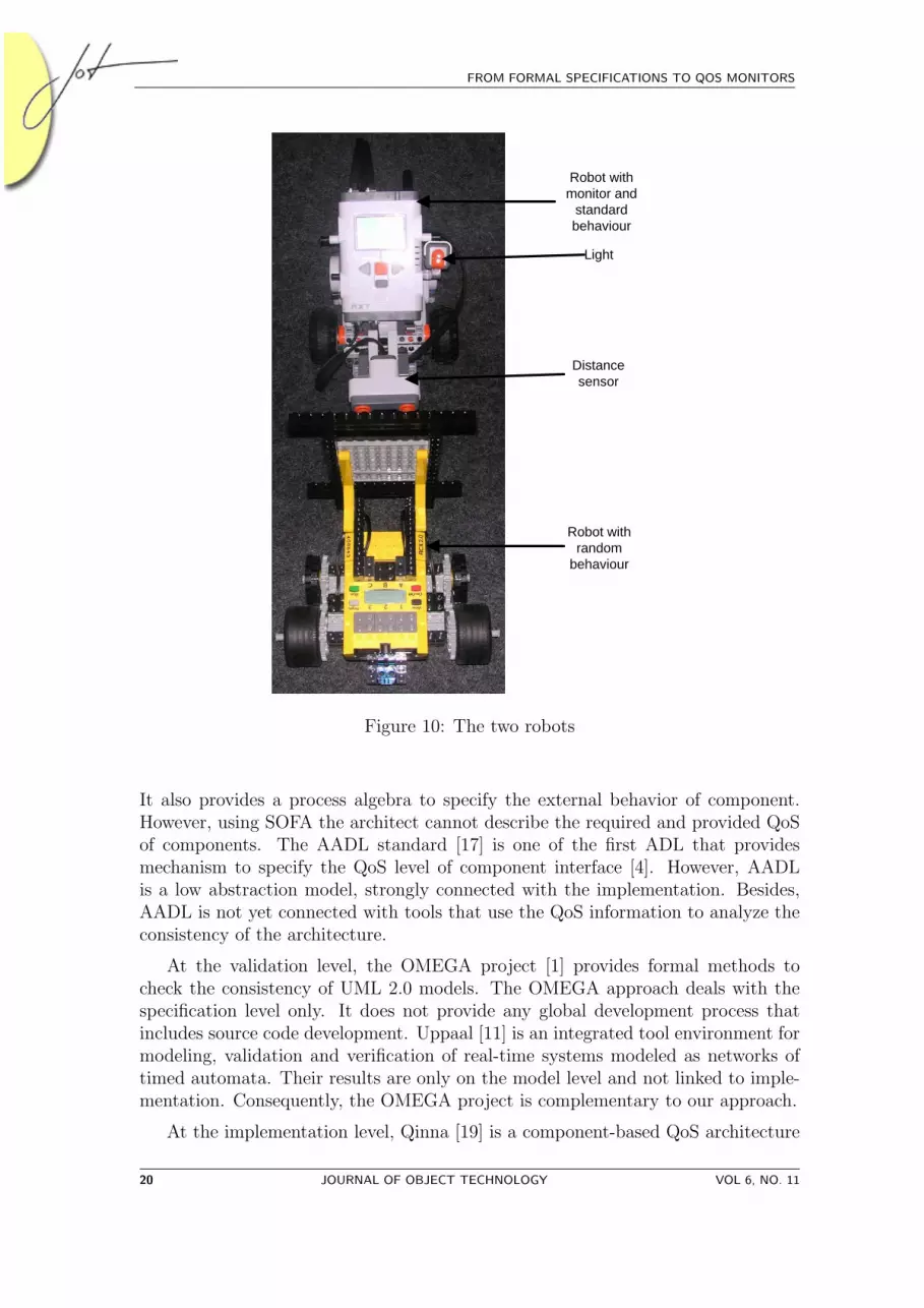
The car robot follows another car robot with a random behaviour, without con-stant speed. If the quality of service is violated, a light comes on. The picture onFig. 10 shows the two robots used for the experimentation. We firstly give a smallslowing down value to the car and a constant speed to the first robot. The violationof the safety distance occurs so we increase this value in order to have a good safetydistance. Then we put a random behaviour to the first car and the violation can beobserved each time the first brakes too fast. A policy for the quality of service canbe here to inform the brake engine of the second vehicle of the violation. With thisinformation, the brake engine will be more efficient next time and will maybe avoidthe violation of quality of service.
5 RELATED WORK
Several research results have shown the usefulness of specific languages to describethe software architecture. Thanks to the precise semantics of such languages, toolssuites have been developed to analyze the consistency of a software architectureand to prototype it. For example, SOFA [10] provides a specific language thatextends the OMG IDL to specify the architecture of component based software.
VOL 6, NO. 11 JOURNAL OF OBJECT TECHNOLOGY 19
FROM FORMAL SPECIFICATIONS TO QOS MONITORS
Robot with random
behaviour
Distance sensor
Light
Robot with monitor and
standard behaviour
Figure 10: The two robots
It also provides a process algebra to specify the external behavior of component.However, using SOFA the architect cannot describe the required and provided QoSof components. The AADL standard [17] is one of the first ADL that providesmechanism to specify the QoS level of component interface [4]. However, AADLis a low abstraction model, strongly connected with the implementation. Besides,AADL is not yet connected with tools that use the QoS information to analyze theconsistency of the architecture.
At the validation level, the OMEGA project [1] provides formal methods tocheck the consistency of UML 2.0 models. The OMEGA approach deals with thespecification level only. It does not provide any global development process thatincludes source code development. Uppaal [11] is an integrated tool environment formodeling, validation and verification of real-time systems modeled as networks oftimed automata. Their results are only on the model level and not linked to imple-mentation. Consequently, the OMEGA project is complementary to our approach.
At the implementation level, Qinna [19] is a component-based QoS architecture
20 JOURNAL OF OBJECT TECHNOLOGY VOL 6, NO. 11
6 CONCLUSION AND PERSPECTIVES
for open system. They integrate QoS on their architecture but they don’t integrateQoS specification in their model. Chan et al. proposed a model-oriented frameworkfor monitoring at runtime extra-functional properties[5]. They address probabilistictemporal properties. Their monitoring is made at runtime by checking constraintswritten in PCTL. They also make a .NET-based implementation of their framework.The SeCSE[18] project aim to create methods, tools and techniques for systemsintegrators and service providers. It will integrate tools and techniques to providea SeCSE development environment. Their approach is service-based and they takecare of QoS but they target only web-services.
6 CONCLUSION AND PERSPECTIVES
Correctly designing and implementing a real-time system is usually an error-pronetask. Indeed the gap between the specification model and the implementation
model. This paper is a step toward bridging this gap. It proposes a unifiedapproach to design and to implement component based systems. This approachaims at assisting architects in the design and in the implementation of soft-real-timesystems by providing a set of tools that generate the QoS monitors from the speci-fication of those systems using a Model Driven Engineering style. This approach isbased on an extended UML 2.0 standard to design the services provided by compo-nent, to specify the component and to give a first abstract implementation of thesystems. It clearly separates the functional level, the timing interaction level at theimplementation level.
We are currently working on a proof of correctness for the transformation pro-cess. This proof must ensure that the composition mechanism, at the concreteimplementation level, is valid with respect to the composition mechanism at theabstract level. This is needed to preserve the results gained by validation at theabstract implementation phase.
Finally, we intend to test our approach in the context of the HRC componentmodel provided in the SPEEDS project [7].
References
[1] Webpage of the OMEGA IST project. http://www-omega.imag.fr/.
[2] R. Alur and D.L. Dill. A theory of timed automata. Theor. Comput. Sci.,126(2):183–235, 1994.
[3] AUTOSAR partners. AUTomotive Open System ARchitecture, August 2005.Version 1.5 light version.
[4] A. Beugnard, J-M. Jezequel, N. Plouzeau, and D. Watkins. Making componentscontract aware. Computer, 32(7):38–45, 1999.
VOL 6, NO. 11 JOURNAL OF OBJECT TECHNOLOGY 21
FROM FORMAL SPECIFICATIONS TO QOS MONITORS
[5] K. Chan, I. Poernomo, H. W. Schmidt, and J. Jayaputera. A model-oriented framework for runtime monitoring of nonfunctional properties. InQoSA/SOQUA, volume 3712 of Lecture Notes in Computer Science, pages 38–52. Springer, 2005.
[6] J. B. Dabney and T. L. Harman. Mastering SIMULINK. Prentice Hall PTR,Upper Saddle River, NJ, USA, 1997.
[7] W. Damm, A. Votintseva, A. Metzner, B. Josko, T. Peikenkamp, and E. Bde.Boosting re-use of embedded automotive applications through rich components.In FIT’05 Foundations of Interface Technologies. Elsevier Science, August 2005.
[8] D. Garlan and M. Shaw. An introduction to software architecture. In V. Ambri-ola and G. Tortora, editors, Advances in Software Engineering and KnowledgeEngineering, volume 1, pages 1–40. World Scientific Publishing Company, 1993.
[9] T.A. Henzinger, C.M. Kirsch, and B. Horowitz. Giotto: A time-triggered lan-guage for embedded programming. Proceedings of the IEEE, 91(1):84–99, Jan-uary 2003.
[10] T. Kalibera and P. Tuma. Distributed component system based on architec-ture description: The sofa experience. In On the Move to Meaningful InternetSystems - DOA, CoopIS and ODBASE, pages 981–994, London, UK, October2002. Springer-Verlag. ISBN: 3-540-00106-9.
[11] Kim G. Larsen, Paul Pettersson, and Wang Yi. Uppaal in a Nutshell. Int.Journal on Software Tools for Technology Transfer, 1(1–2):134–152, October1997.
[12] N. Medvidovic and R. N. Taylor. A classification and comparison framework forsoftware architecture description languages. In IEEE Transactions on SoftwareEngineering, volume 26, page 23, January 2000.
[13] P-A. Muller, F. Fleurey, and J-M. Jezequel. Weaving executability into object-oriented meta-languages. In Lionel C. Briand and Clay Williams, editors,MoDELS, volume 3713 of Lecture Notes in Computer Science, pages 264–278.Springer, 2005.
[14] OMG. Systems modeling language (sysml) specification. May 2006.
[15] Object Management Group OMG. Unified Modeling Language: Superstructure,August 2003. Version 2.0.
[16] Object Management Group OMG. Meta-Object Facility (MOF) Specification,2005. Version 2.0.
[17] As-2 Embedded Computing Systems Committee SAE. Architecture Analysis& Design Language (AADL). SAE Standards no AS5506, November 2004.
22 JOURNAL OF OBJECT TECHNOLOGY VOL 6, NO. 11
6 CONCLUSION AND PERSPECTIVES
[18] P. Sawyer, J. Hutchison, J. Walkerdine, and I. Sommerville. Faceted servicespecification. In Proceedings of Workshop on Service-Oriented Computing Re-quirements (SOCCER), August 2005.
[19] J.C. Tournier, J.P. Babau, and V. Olive. Qinna, a component-based QoS ar-chitecture. In G.T. Heineman, I.Crnkovic, H.W. Schmidt, J.A. Stafford, C.A.Szyperski, and K.C. Wallnau, editors, CBSE, volume 3489 of Lecture Notes inComputer Science, pages 107–122. Springer, 2005.
ABOUT THE AUTHORS
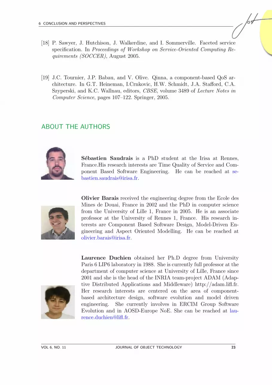
Sebastien Saudrais is a PhD student at the Irisa at Rennes,France.His research interests are Time Quality of Service and Com-ponent Based Software Engineering. He can be reached at [email protected].
Olivier Barais received the engineering degree from the Ecole desMines de Douai, France in 2002 and the PhD in computer sciencefrom the University of Lille 1, France in 2005. He is an associateprofessor at the University of Rennes 1, France. His research in-terests are Component Based Software Design, Model-Driven En-gineering and Aspect Oriented Modelling. He can be reached [email protected].
Laurence Duchien obtained her Ph.D degree from UniversityParis 6 LIP6 laboratory in 1988. She is currently full professor at thedepartment of computer science at University of Lille, France since2001 and she is the head of the INRIA team-project ADAM (Adap-tive Distributed Applications and Middleware) http://adam.lifl.fr.Her research interests are centered on the area of component-based architecture design, software evolution and model drivenengineering. She currently involves in ERCIM Group SoftwareEvolution and in AOSD-Europe NoE. She can be reached at [email protected].
VOL 6, NO. 11 JOURNAL OF OBJECT TECHNOLOGY 23

FROM FORMAL SPECIFICATIONS TO QOS MONITORS
Noel Plouzeau is an associate professor of Computer Science at theRennes 1 University. His research topics currently include softwarecomponents, model-driven design processes, management of perfor-mance and quantitative aspects in component-based applications.He can be reached at [email protected].
24 JOURNAL OF OBJECT TECHNOLOGY VOL 6, NO. 11


