Embed Size (px)
Citation preview

Formation and stability of lanthanum oxide thin ®lmsdeposited from b-diketonate precursor
Minna Nieminen*, Matti Putkonen, Lauri NiinistoÈLaboratory of Inorganic and Analytical Chemistry, Helsinki University of Technology, P.O. Box 6100, FIN-02015 Espoo, Finland
Received 18 November 2000; accepted 15 January 2001
Abstract
Lanthanum oxide thin ®lm deposition by atomic layer epitaxy (ALE) was studied at 180±4258C on soda-lime glass and
Si(1 0 0) substrates using a b-diketonate type precursor La(thd)3 and ozone. The chemical constituents of the ®lms were
analyzed by TOF-ERDA, RBS and FTIR while XRD and AFM were used to determine the crystallinity and surface
morphology. Films grown below 2758C were amorphous La2O2CO3, while at deposition temperatures above 3008C XRD
patterns indicated that cubic La2O3 phase was formed. All the ®lms were transparent and uniform with only small thickness
variations. Carbonate type impurity was found in all ®lms, but the carbon content of the ®lms decreased with growth
temperature being 3 at.% in ®lms grown above 4008C. Hexagonal La2O3 was obtained when the ®lms grown on silicon
substrates were annealed at 8008C or above in a nitrogen ¯ow. The as-deposited cubic and annealed hexagonal La2O3 ®lms
were found to be chemically unstable in ambient air since a transformation to monoclinic LaO(OH) and hexagonal La(OH)3
was detected, respectively. # 2001 Elsevier Science B.V. All rights reserved.
Keywords: Lanthanum oxide; Thin ®lm; ALE deposition; b-Diketonate
1. Introduction
In spite of the high application potential of lantha-
num oxide thin ®lms, only a few studies have been
made to prepare them. La2O3 ®lms have been depos-
ited by different physical thin ®lm growth methods
such as electron-beam evaporation [1], pulsed-laser
evaporation [2] and vacuum evaporation [3,4]. Oxida-
tion of lanthanum overlayers has also been used to
prepare lanthanum oxide ®lms [5,6]. The spray meth-
ods [7±9] have been attempted as well, but to the best
of our knowledge only three articles concerning the
CVD growth of La2O3 have been published [10±12].
Lanthanum oxide thin ®lms are reported to be
mechanically stable [3], possess high electrical break-
down ®eld strengths [1,4,8] and dielectric constants
[1]. La2O3 thin ®lms are also optically transparent
over a wide wavelength range from ultraviolet to
infrared [3,8,12]. The potential applications of
La2O3 thin ®lms include dielectric layers in device
applications [1] and protective [13] or optical [8]
coatings. Recently, it has been reported that La2O3
thin ®lms can also be used as coating layers in order to
improve the CO2-sensing characteristics of SnO2 thick
®lm gas sensors [14].
It appears that the growth of good quality La2O3
®lms has not been demonstrated by the CVD method
[10±12]. The main problem seems to be the relatively
large carbon residue in the ®lms. The deposition of
lanthanum oxide ®lms from La(thd)3 and water at
Applied Surface Science 174 (2001) 155±165
* Corresponding author. Tel.: �358-9-451-2605;
fax: �358-9-462-373.
E-mail address: [email protected] (M. Nieminen).
0169-4332/01/$ ± see front matter # 2001 Elsevier Science B.V. All rights reserved.
PII: S 0 1 6 9 - 4 3 3 2 ( 0 1 ) 0 0 1 4 9 - 0

5708C resulted in poorly crystalline, pale brown ®lms
[10]. Lanthanum oxide carbonate ®lms were obtained
when the growth of the ®lms was carried out at 9008Cby a modi®ed CVD process from La(acac)3 dissolved
in butanol [11]. At lower deposition temperatures,
amorphous or poorly crystallized phases were found
[11]. Amorphous, transparent ®lms were obtained
from La(thd)3 by PECVD method in an oxygen
plasma at 4008C, but a carbon content of 1.6 wt.%
was still observed [12]. It is dif®cult to compare the
quality of ®lms between different studies since the
actual chemical composition of the ®lms was analyzed
only in the PECVD study. According to XRD results,
crystalline La2O3 ®lms (monoclinic [9] or hexagonal
[7]) were obtained only when the deposition tempera-
ture was above 5008C, whereas lower deposition
temperatures led to poorly crystallized or amorphous
®lms. A postannealing in oxygen at 8008C for 6 h was
needed to obtain crystalline, hexagonal La2O3 ®lm
[8]. Only in two articles the chemical stability of
lanthanum oxide ®lms has been discussed. Suzuki
et al. [7] reported that when hexagonal La2O3 ®lms
were left in air, they reacted with CO2 and with time an
increasing amount of La2(CO3)3 was observed by
XRD. In the work done by De Asha et al. [6] lantha-
num oxide ®lms were found to adsorb water in dis-
sociative fashion, leading to extensive surface
hydroxylation.
Atomic layer epitaxy (ALE) [15,16] also known as
atomic layer deposition (ALD) or atomic layer CVD
(ALCVD), is a surface controlled growth technique
where the substrate surface is alternately exposed to
the vaporized reactant pulses. The precursor pulses are
separated by inert purge gas pulses to eliminate gas-
phase reactions and remove reaction products. In an
ideal case, one monolayer (or a distinct fraction of it)
of the ®rst reactant is chemisorbed on the substrate and
this layer reacts with the second precursor pulsed onto
the substrate, resulting in the formation of a solid ®lm.
The ®lm thickness can be controlled by repeating this
reaction cycle.
Our interest to grow La2O3 thin ®lms is two-fold.
Firstly, lanthanum oxide has many attractive proper-
ties for applications and since a successful deposition
of La2O3 by CVD has not been reported, this moti-
vated us to exploit the possibilities of ALE. The
second reason for the present study stems from desire
to obtain more knowledge of the La2O3 growth
process in order to better understand the more com-
plex growth of lanthanum-containing ternary oxides
by ALE, such as LaNiO3, LaCoO3 and LaMnO3, where
La(thd)3 has also been used as a precursor [17±19].
2. Experimental
Film depositions were carried out with a commer-
cial ¯ow-type F-120 atomic layer epitaxy (ALE)
reactor [16,20] manufactured by ASM Microchemis-
try Ltd. The reactant source materials were alternately
introduced into the reactor while nitrogen with a
purity of >99.999% (Schmidlin UHPN N2 generator)
was used as a carrier and purging gas. The source
material for lanthanum was La(thd)3 (thd � 2,2,6,6-
tetramethyl-3,5-heptanedione) which was synthesized
from 99.99% La2O3 by the method described by
Eisentraut and Sievers [21] and puri®ed by sublima-
tion. Thermal behavior of the La(thd)3 precursor has
been studied earlier in connection with LaNiO3
deposition [17]. In this study La(thd)3 was evaporated
from an open glass crucible held at 1708C. Ozone
generated from oxygen gas (99.999%) in an ozone
generator (Fischer model 502) was used as oxidizing
reactant. The ®lm deposition took place at a reduced
pressure of 2±3 mbar in the temperature range of 180±
4258C. The effects of the precursor pulsing times and
the purging time between the reactant pulses on the
®lm growth were studied as well. Soda lime glass
(5 cm� 5 cm) and (1 0 0) silicon were used as sub-
strates.
The thicknesses of the ®lms were evaluated by
®tting the transmittance and re¯ectance spectra [22]
measured with a Hitachi U-2000 double beam spectro-
photometer in a region of 190±1100 nm for silicon
substrates and 370±1100 nm for soda lime glass.
Thickness measurements were veri®ed by pro®lome-
try (Sloan Dektak 3030ST from Veeco Instruments).
The steps were etched by 1 M hydrochloric acid.
A few selected thin ®lm samples were heat-treated
in a rapid thermal annealing furnace PEO 601 (ATV
Technologie GmbH, Germany). The annealing proce-
dure was carried out in nitrogen atmosphere during
0.5±3 h at 600, 800, 900 or 9508C. Also few annealing
experiments were done in air or oxygen atmosphere at
900 or 9508C in a tube furnace. The crystal structure
and crystallite orientation of the as-deposited and
156 M. Nieminen et al. / Applied Surface Science 174 (2001) 155±165

annealed ®lms was determined by X-ray diffraction
measurements with a Philips powder diffractometer
MPD 1880 using Cu Ka radiation. The surface mor-
phology of the ®lms was examined by a Nanoscope III
atomic force microscope (Digital Instruments) using a
scanning area of 2 mm� 2 mm. Samples were mea-
sured in tapping mode (TM) and a scanning frequency
of 1±2 Hz was used. Roughness values were calcu-
lated as root mean square values (RMS).
Two complementary ion beam techniques, Ruther-
ford backscattering spectrometry (RBS) and time-of-
¯ight elastic recoil spectrometry (TOF-ERDA) were
used at the Accelerator Laboratory of the University of
Helsinki to determine the ®lm composition and stoi-
chiometry. Both techniques yielded information about
concentrations and depth pro®les of the main compo-
nents in the ®lms. By combining the results of these
two methods, multiple scattering effects of heavy ions
in the sample and telescopes could be minimized for
TOF-ERDA. The results obtained were consistent
within experimental accuracy.
The RBS experiments were carried out with 4He�
ions from the 2.5 MV Van de Graaff accelerator
working at 2.0 MeV. A scattering angle of 1708 was
used. The ®lm thicknesses together with the lantha-
num and heavier impurity concentrations are readily
revealed by the RBS spectra, while the amount of
oxygen and lighter impurities such as carbon and
hydrogen are obtained more accurately from the
TOF-ERDA analysis. A beam of 197Au9� ions at
48 MeV for TOF-ERDA was obtained from a 5 MV
tandem accelerator EGP-10-II. The sample surface
was tilted 208 and recoils were detected at 408 with
respect to the incoming beam. In TOF-ERDA ele-
ments with different masses were separated by mea-
suring the velocity and energy for each detected recoil.
After identi®cation of the recoil mass, the elemental
velocity spectrum was converted to energy spectrum.
Depth pro®les were deduced for each element by
using known geometry, scattering cross-sections and
parameterized stopping powers [23].
Structural information of the ®lms was obtained
from Fourier transform infrared (FTIR) spectra. The
transmission spectra of the ®lms were obtained using a
Nicolet Magna-750 Fourier transform infrared spec-
trometer equipped with a deuterated-triglycine-sulfate
(DTGS) detector. The substrate contribution was sub-
tracted from the measured sample spectra.
3. Results and discussion
3.1. In¯uence of deposition parameters
The dependence of the growth rate on the growth
temperature is presented in Fig. 1. The pulse durations
of La(thd)3 and O3 were 0.8 and 2 s, respectively. Up
to 2258C the growth rate increases with temperature.
In the temperature region from 225 to 2758C a con-
stant growth rate of 0.36 AÊ per cycle at both substrates
was obtained. When the temperature was raised above
2758C the growth rate increased with temperature.
Since the ®lms were uniform without a notable thick-
ness pro®le within the substrate length of 10 cm also
in these higher temperatures a CVD-type growth could
be excluded. When the deposition temperature was
raised above 4258C a CVD-type growth was observed
and the deposition was no longer feasible. All the ®lms
grown at different deposition temperatures on soda
lime glass substrates were highly transparent in the
wavelength region of 370±1100 nm.
In order to verify the self-controlled nature of the
®lm growth, the effect of source and purge pulse
durations on the ®lm growth rate at 2508C were
studied. The dependence of the growth rate on O3
pulse (La(thd)3 0.8 s) and La(thd)3 pulse (O3 2.0 s) is
presented in Fig. 2. The saturation of the growth rate at
a constant level is achieved when the ozone pulse
duration is longer than 1 s. The ®lm growth rate was
found to be independent of the La(thd)3 pulse duration
between 0.5 and 1.5 s, con®rming that the growth is
self-controlled. The purge gas pulse durations (0.8±
3 s) had no effect on the growth rate. The narrow
plateau between 225 and 2758C where the ®lm growth
is independent of temperature, precursor pulse and
purge times is an indication of an ALE-window [16].
The dependence of the ®lm thickness on the number
of reaction cycles at 2508C is shown in Fig. 3. A linear
relation with growth rate of 0.36 AÊ per cycle is
obtained. In order to prove the controlled growth of
the ®lms also above ALE window, the dependence of
the ®lm thickness on the reaction cycles was studied at
350 and 3758C (Fig. 3). It was found out that the
thicknesses of the ®lms grown above the ALE window
can be controlled by the number of deposition cycles.
When La(thd)3 pulse time at higher deposition tem-
peratures was varied between 0.8±1.5 s no marked
difference on the ®lm growth was observed.
M. Nieminen et al. / Applied Surface Science 174 (2001) 155±165 157

Fig. 1. Dependence of the growth rate on the deposition temperature. Pulse durations were 0.8 s for La(thd)3 and 2 s for O3. Growth rate of
0.36 AÊ per cycle was obtained between 225±2758C. Dotted line represent the carbon content of the ®lms measured by TOF-ERDA.
Fig. 2. Dependence of the growth rate at 2508C on the O3 and La(thd)3 pulse durations.
158 M. Nieminen et al. / Applied Surface Science 174 (2001) 155±165

ALE method has also been used for controlled
depositions onto porous, high surface area substrates
in order to get information of the growth mechanisms
of different processes. These studies give also some
insight into the ALE thin ®lm depositions on ¯at
substrates, but it should be noted that different deposi-
tion conditions such as pressure and surface composi-
tion may affect results. In ALE depositions onto
porous SiO2, decomposition of La(thd)3 has been
reported to start at temperatures higher than 3008C[24,25], which is in accordance with our results. In the
recent study of Kukli et al. [26] a controlled ALE
growth of lanthanum sul®de ®lms from La(thd)3 and
H2S was found at temperature region of 360±4108C.
They reported that only above 4508C decomposition
of the precursor and uncontrolled CVD-type growth
was detected. We believe that the increased thin ®lm
growth rate at higher deposition temperatures is
caused by a partial decomposition of the lanthanum
precursor and not by different surface reaction path-
ways, for instance. By analogy with Y(thd)3 as
revealed by a mass-spectrometric study [27,28], the
La(thd)3 may lose in the gas phase one or two of its
three ligands which makes it possible that the density
of surface coverage by the precursor and consequently
the growth rate increases. Therefore, we believe that
La(thd)3 is only partially decomposing and a surface
controlled growth mechanism is still valid also at
higher deposition temperatures, in La2O3 case up to
4258C. Recently, a similar phenomenon was detected
in the ALE growth of Y2O3 thin ®lms [29].
3.2. Characterization of as-grown ®lms
X-ray diffraction (XRD) measurements made
immediately after deposition on ®lms grown on both
substrates revealed that ®lms deposited below 3008Cwere amorphous. At 3008C, the XRD pattern showed
only one weak peak (d � 3:27 AÊ ) which is the (2 2 2)
re¯ection of the cubic La2O3 [30,31], see Fig. 4. The
®lms grown at 3258C were cubic, polycrystalline
La2O3 with the (2 2 2) re¯ection as the strongest peak.
When the deposition temperature was raised to 3508Cand above, the XRD patterns indicate that the ®lms
Fig. 3. Dependence of the ®lm thickness on the number of cycles at 250, 350 and 3758C. The pulse durations for La(thd)3 and O3 were 0.8 and
2 s, respectively. The reproducibility was tested with two samples at 3758C using 1750 cycles.
M. Nieminen et al. / Applied Surface Science 174 (2001) 155±165 159

have a preferred (1 0 0) orientation since the (4 0 0)
re¯ection is very intense compared with the few
additional peaks, namely (2 2 2), (4 4 0), (6 1 1) and
(6 2 2), in the XRD pattern, see also Fig. 5. Changing
the substrate type at 300±4258C appeared to impose
no difference in the texture of the ®lms. These results
are in agreement with our previous experiments [18].
In the literature cubic (low temperature modi®cation)
La2O3 phase is reported to exist below �4008C while
hexagonal (low temperature modi®cation) La2O3 exist
between �400 and 20408C [32].
Stoichiometry and impurity residues of the ®lms
deposited on silicon substrates at various temperatures
were quantitatively determined by TOF-ERDA and
RBS. No impurities other than carbon and hydrogen
were detected. The carbon content of the ®lms was
dependent on the deposition temperature (Fig. 1). In
every case, carbon levels were distributed evenly
throughout the ®lm. All the ®lms grown at different
temperatures contained less than 1 at.% of hydrogen
in the bulk of the ®lms. The atomic composition of
®lms grown at temperatures between 225±2758C was
Fig. 4. XRD patterns of cubic La2O3 ®lms deposited at 300, 325 and 3508C on amorphous soda lime glass. Miller indices of cubic La2O3 are
given.
Fig. 5. (a) XRD pattern of ®lm grown at 3508C on silicon substrate; (b) same ®lm after storage of few weeks. Miller indices of cubic La2O3
and monoclinic LaO(OH) are given. The re¯ections of LaO(OH) are marked with asterisk.
160 M. Nieminen et al. / Applied Surface Science 174 (2001) 155±165
about 22 at.% La, 66 at.% O and 11.5 at.% C, which is
nearly the same as in La2O2CO3 phase. In the thermo-
analytical literature La2O2CO3 phase is reported to
be stable during dynamic heating under vacuum con-
ditions from �300 to �5008C, above which its
decomposition to oxide begins [33]. The carbon con-
tent (8±10 at.%) of ®lms grown between 300±3258Cis not enough for the ®lms to be La2O2CO3 phase.
Furthermore, XRD patterns indicate that cubic La2O3
is formed between 300±3258C. Therefore, we believe
that these ®lms are most likely a mixture of La2O3 and
La2O2CO3. Films deposited between temperatures of
350±4258C were very similar to each other. The ®lms
contained around 3 at.% carbon as an impurity and the
La to O ratio in these ®lms was 0.48, when the
stoichiometric ratio is 0.67, indicating an excess of
oxygen in the ®lms. The in¯uence of deposition
temperature on the ®lm composition is summarized
in Fig. 6.
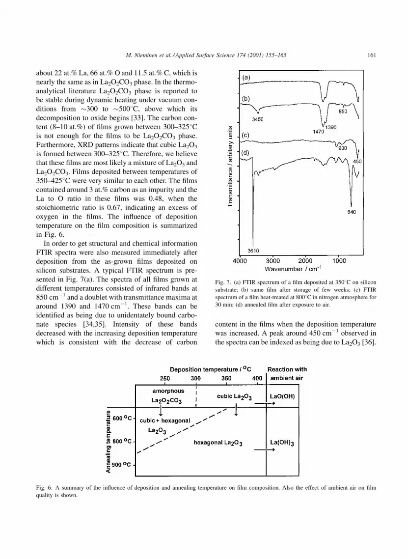
In order to get structural and chemical information
FTIR spectra were also measured immediately after
deposition from the as-grown ®lms deposited on
silicon substrates. A typical FTIR spectrum is pre-
sented in Fig. 7(a). The spectra of all ®lms grown at
different temperatures consisted of infrared bands at
850 cmÿ1 and a doublet with transmittance maxima at
around 1390 and 1470 cmÿ1. These bands can be
identi®ed as being due to unidentately bound carbo-
nate species [34,35]. Intensity of these bands
decreased with the increasing deposition temperature
which is consistent with the decrease of carbon
content in the ®lms when the deposition temperature
was increased. A peak around 450 cmÿ1 observed in
the spectra can be indexed as being due to La2O3 [36].
Fig. 6. A summary of the in¯uence of deposition and annealing temperature on ®lm composition. Also the effect of ambient air on ®lm
quality is shown.
Fig. 7. (a) FTIR spectrum of a ®lm deposited at 3508C on silicon
substrate; (b) same ®lm after storage of few weeks; (c) FTIR
spectrum of a ®lm heat-treated at 8008C in nitrogen atmosphere for
30 min; (d) annealed ®lm after exposure to air.
M. Nieminen et al. / Applied Surface Science 174 (2001) 155±165 161

FTIR results suggests that carbon is mainly present as
carbonate type impurity in the ®lms, which explains
also the oxygen excess and resulting deviation from an
ideal stoichiometry as observed by TOF-ERDA mea-
surements. In the CVD studies of metal b-diketonates,
element-type carbon has been observed, but in our
case the use of strong oxidizer is believed to convert it
to carbonate. A similar type of oxygen excess in
connection with the carbon content was found in
ALE grown Y2O3 ®lms as well [29].
AFM images were recorded for two types of ®lm
series (Table 1). First the dependence of surface
roughness on ®lm thickness was studied and images
were collected from ®lms whose thickness varied
from 71 to 303 nm when grown at 2508C on silicon
and soda lime glass substrates. A very small increase
of roughness as a function of thickness was detected
on ®lms grown on silicon. The roughness values were
of the same order of magnitude for ®lms grown on
both substrates, viz. 1.2 nm. In the second series of
AFM samples, a comparison was made between ®lms
grown at different temperatures. As a representative
example, an AFM image of ®lm grown at 3508C is
presented in Fig. 8. A small increase of roughness was
detected as the deposition temperature increased.
AFM images were recorded also for ®lms stored in
a desiccator over a several months, but no differences
were detected compared to the as-deposited ones.
Table 1
Roughness as a function of ®lm thickness and deposition temperature on silicon substrates
Temperature
(8C)
Thickness
(nm)
Number of
cycles
RMS value for films
on Si(1 0 0) (nm)
RMS value for films
on soda lime (nm)
200 75 3000 0.6
250 71 2000 0.7 1.2
350 75 1160 1.1
250 142 4000 1.1 1.4
250 303 9000 1.2 1.2
Fig. 8. TM-AFM image of a 75 nm thick ®lm deposited on silicon at 3508C. Image size: 2mm� 2 mm. Depth scale: 20 nm from black to
white.
162 M. Nieminen et al. / Applied Surface Science 174 (2001) 155±165

3.3. The chemical stability of as-grown ®lms
During the storage of ®lms it was noticed that the
crystalline ®lms obtained at deposition temperatures
above 3258C are chemically unstable. The outlook of
the ®lms appeared to be the same since no difference
in the interference colors of the ®lms was observed.
However, a peak caused by hydroxyl group stretching
[34] in LaO(OH) around 3450 cmÿ1 appeared in the
IR spectra of ®lms stored for a few days in a desic-
cator, see Fig. 7(b). At the same time XRD patterns
revealed that the intensity of (4 0 0) re¯ection of cubic
La2O3 was slowly decreasing and (0 0 1), (0 0 2) and
(1 2 0) re¯ections of the monoclinic LaO(OH) phase
[37] were appearing (Fig. 5). These results indicate
that the cubic La2O3 ®lms are absorbing water from
the air, leading to at least partial transformation to
lanthanum oxide hydroxide. If the ®lms were kept in
air the phenomenon was enhanced.
Also, TOF-ERD analyses indicated that the ®lms
are absorbing water from the air. When the ®lms
grown at 3508C or above were measured after a
few days of storage in a desiccator, the hydrogen
content was found to be very high on the surface of
the ®lms, even 20 at.%. However, only after several
weeks of storage the hydrogen content in the bulk of
the ®lm was increased to the same level. Films grown
at 3758C and 4008C were measured after weeks of
storage in a desiccator, and an atomic composition of
about 22 at.% La, 21 at.% H, 54 at.% O (and 3 at.% C)
was detected. This is quite close to the atomic com-
position of LaO(OH) which contains 25, 25 and
50 at.% of La, H and O, respectively. According to
IR spectra, XRD patterns and TOF-ERD analyses, the
®lms grown at deposition temperatures below 3508Cseemed to remain unchanged during storage.
FTIR spectra revealed also that there was no change
in the carbonate group bands of ®lms stored for few
days in a desiccator compared to the as-deposited
®lms. Therefore, carbonate type impurity in the ®lms
is believed to be caused by the precursor and not by the
atmosphere during storage.
3.4. Composition and chemical stability of annealed
®lms
The amorphous ®lms deposited at 2508C and crys-
talline ®lms grown at 3508C on silicon substrates were
annealed at different temperatures in nitrogen atmo-
sphere. The extent and character of crystallization was
dependent on the deposition and annealing tempera-
tures. At annealing temperature of 6008C a mixture of
cubic and hexagonal La2O3 was obtained in both
cases. At 8008C the ®lm grown at 3508C crystallized
as hexagonal La2O3 with a preferred (1 0 1) orienta-
tion (Fig. 9(a)) while the amorphous ®lm crystallized
Fig. 9. (a) XRD pattern of ®lm grown at 3508C and annealed at 8008C in nitrogen atmosphere for 30 min. All the diffraction peaks can be
identi®ed as hexagonal La2O3. (b) Same annealed ®lm after exposure to air for a few days. The XRD pattern consists only of the diffraction
peaks of hexagonal La(OH)3.
M. Nieminen et al. / Applied Surface Science 174 (2001) 155±165 163

as a mixture of cubic and hexagonal lanthanum oxide.
If the annealing time was increased from 30 min to 3 h
also small peaks of La2O2CO3 were seen in the XRD
pattern of a ®lm grown at 2508C and annealed at
8008C. Only after increasing the annealing tempera-
ture to over 9008C the hexagonal La2O3 phase was
obtained from amorphous ®lm. However, if annealing
time was increased to over 30 min also lanthanum
oxide carbonate crystallized together with hexagonal
lanthanum oxide. Changing the annealing temperature
from 800 to 9508C did not have an in¯uence on the
crystallization of ®lms grown at 3508C. Annealing in
nitrogen did not change the appearance of the ®lms,
either. A summary of the in¯uence of annealing
temperature on ®lm composition is shown in Fig. 6.
IR spectrum of ®lm deposited at 3508C and
annealed at 8008C is seen in Fig. 7(c). The carbonate
group peaks disappeared completely when the anneal-
ing temperature was 8008C for ®lm grown at 3508Cand 9008C for ®lm grown at 2508C. At the same time,
peaks at around 900 cmÿ1 were appearing in the
spectrum. These are the combination bands of La-O
streching vibrational modes [34]. The peak at around
450 cmÿ1 can be indexed as infrared peak of La2O3
[36]. The new peak appearing around 1070 cmÿ1 is
due to oxidized silicon.
The annealed ®lms containing hexagonal lantha-
num oxide reacted very quickly with air. Only after a
few hour exposure to air two peaks at 3600 and
640 cmÿ1 were detected in IR spectrum, see
Fig. 7(d). The intensity of these peaks increased
steadily with time. The peaks can be assigned to
the OH stretching and La-OH bending modes of the
La(OH)3 phase [38]. Also, after prolonged time, car-
bonate group bands appeared in the spectrum, indicat-
ing that ®lm was also reacting with carbon dioxide in
air. The formation of La(OH)3 phase was obvious
from the XRD patterns as well, see Fig. 9(b). After
a few days the X-ray diffraction peaks corresponding
to hexagonal La2O3 phase completely disappeared and
the hexagonal La(OH)3 pattern [39] was the only
observable one. During the same time the quality of
the annealed ®lms greatly changed. First the ®lms
became opaque in color and then after prolonged time
the ®lms started to peel off from the silicon substrate.
TOF-ERD analysis of a ®lm grown at 2508C and
annealed at 9508C gave after a storage for few days
an atomic composition of 15 at.% La, 51 at.% O,
32 at.% H and 1.6 at.% C indicating also the formation
of La(OH)3 phase. Simultaneously, the carbon content
of the annealed ®lms was reduced, according to IR
analysis, from 11.4 to 1.6 at.% as expected.
Besides the annealing temperature, the annealing
atmosphere had an in¯uence on the ®nal state of the
material (1 0 1) oriented hexagonal La2O3 thin ®lms
were obtained when the ®lms were annealed in oxygen
atmosphere at 900±9508C. When the ®lms were heat-
treated in air the ®lms crystallized as a lanthanum
oxide carbonate phase. Therefore, it can be concluded
that relatively high temperatures and a CO2-free atmo-
sphere are needed to yield a pure hexagonal lantha-
num oxide thin ®lm.
The chemical unstability of the La2O3 ®lms in
ambient air is consistent with the results obtained
for La2O3 powder material [38]. The rare earth ses-
quioxides (RE2O3, RE � element of atomic number
57±71) are known to be basic and tend to absorb water
vapor and carbon dioxide from the atmosphere. The
order of basicity decreases with increasing atomic
number; lanthanum sesquioxide being the most basic
and therefore the most unstable one of them. Bernal
et al. [38] have studied the reactivity of La2O3 powder
material with CO2 and H2O. In their study, it was
found out that hexagonal La2O3 reacted very quickly
with ambient air forming La(OH)3 after less than 24 h
of exposure. Carbonate group bands were also seen in
the IR spectra, but the XRD pattern consisted only of
La(OH)3 phase.
4. Conclusions
In this study, it has been shown that thin ®lms of
La2O3 can be grown on soda lime and silicon sub-
strates at a relatively low temperature of 4258C and
even below this. The deposition temperature had a
marked in¯uence on the composition of the ®lms. The
®lms grown below 2758C were amorphous, and the
structural and chemical analysis revealed that the ®lms
contained mostly chemically stable La2O2CO3 phase.
When the deposition temperature was raised to 3008Cor above, the XRD patterns of the ®lms clearly
indicated that a cubic La2O3 phase was formed. At
the highest deposition temperature of 4258C the ®lms
contained 3 at.% of carbon, which is much less than
the carbon content in ®lms grown by CVD methods,
164 M. Nieminen et al. / Applied Surface Science 174 (2001) 155±165

however. The infrared measurements revealed that the
carbon impurity of the ®lms was in the form of
carbonate. Similar type carbonate group impurity
has recently been found in ALE grown Y2O3 thin
®lms [29], where the amount of carbonate is much
smaller than in La2O3 ®lms, however.
The ®lms grown at 3508C or above were chemically
unstable in ambient air, and according to chemical
analysis as well as IR and XRD measurements a
transformation from cubic La2O3 to monoclinic
LaO(OH) was observed. A hexagonal (1 0 1) oriented
La2O3 phase was obtained when the ®lms were
annealed at 8008C or above in a nitrogen atmosphere.
However, the annealed ®lms were chemically even
more unstable than as-deposited crystalline ®lms, and
a rather quick transformation from hexagonal La2O3
to hexagonal La(OH)3 was observed.
Acknowledgements
The authors wish to thank Dr. Eero Rauhala for
RBS measurements and Mr. Timo Sajavaara for TOF-
ERD analysis. Furthermore, we wish to express our
gratitude to Mr. Jaakko NiinistoÈ for AFM measure-
ments. The authors are grateful to Professor P. Hau-
tojaÈrvi, Laboratory of Physics, for providing facilities
for AFM measurements.
References
[1] T. Mahalingam, M. Radhakrishnan, C. Balasubramanian,
Thin Solid Films 78 (1981) 229.
[2] V.D. Kushkov, A.M. Zaslavskii, A.V. Zverlin, A.V. Melnikov,
J. Mater. Sci. Lett. 10 (1991) 1111.
[3] G. Hass, J.B. Ramsey, R. Thun, J. Opt. Soc. Am. 49 (1959)
116.
[4] A. Singh, Thin Solid Films 105 (1983) 163.
[5] A.M. De Asha, R.M. Nix, Surf. Sci. 322 (1995) 41.
[6] A.M. De Asha, J.T.S. Critchley, R.M. Nix, Surf. Sci. 405
(1998) 201.
[7] M. Suzuki, M. Kagawa, Y. Syono, T. Hirai, J. Cryst. Growth
112 (1991) 621.
[8] Y.-M. Gao, P. Wu, K. Dwight, A. Wold, J. Solid State Chem.
90 (1991) 228.
[9] S. Wang, W. Wang, Y. Qian, Thin Solid Films 372 (2000) 50.
[10] Y. Shiokawa, R. Amano, A. Nomura, M. Yagi, J. Radioanal.
Nucl. Chem. 152 (1991) 373.
[11] M.V. CabanÄas, C.V. Ragel, F. Conde, J.M. GonzaÂlez-Calbet,
M. Vallet-RegõÂ, Solid State Ionics 101±103 (1997) 191.
[12] A. Weber, H. Suhr, Mod. Phys. Lett. B 3 (1989) 1001.
[13] G. Bonnet, M. Lachkar, J.P. Laprin, J.C. Colson, Solid State
Ionics 72 (1994) 344.
[14] D.H. Kim, J.Y. Yoon, H.C. Park, K.H. Kim, Sens. Actuators B
62 (2000) 61.
[15] L. NiinistoÈ, M. Ritala, M. LeskelaÈ, Mater. Sci. Eng. B 41
(1996) 23.
[16] T. Suntola, Thin Solid Films 216 (1992) 84.
[17] H. Seim, H. MoÈlsaÈ, M. Nieminen, H. FjellvaÊg, L. NiinistoÈ, J.
Mater. Chem. 7 (1997) 449.
[18] H. Seim, M. Nieminen, L. NiinistoÈ, H. FjellvaÊg, L.-S.
Johansson, Appl. Surf. Sci. 112 (1997) 243.
[19] O. Nilsen, M. Peussa, H. FjellvaÊg, L. NiinistoÈ, A. Kjekshus, J.
Mater. Chem. 9 (1999) 1781.
[20] T. Suntola, A. Pakkala, S. Lindfors, (1983) US Patent
4,413,033.
[21] K.J. Eisentraut, R.E. Sievers, J. Am. Chem. Soc. 87 (1965)
5256.
[22] M. Ylilammi, T. Ranta-aho, Thin Solid Films 232 (1993) 56.
[23] J.F. Ziegler, J.P. Biersack, U. Littmark, The Stopping and
Range of Ions in Solids, Pergamon Press, New York, 1985.
[24] S. Haukka, T. Suntola, Interface Sci. 5 (1997) 119.
[25] S. Haukka, E.-L. Lakomaa, T. Suntola, in: A. Dabrowski
(Ed.), Studies in Surface Science and Catalysis, Vol. 120,
Elsevier, Amsterdam, 1999, p. 715.
[26] K. Kukli, H. Heikkinen, E. NykaÈnen, L. NiinistoÈ, J. Alloys
Compd. 275-277 (1998) 10.
[27] G.V. Girichev, N.I. Giricheva, N.V. Belova, A.R. Kaul, N.-P.
Kuz'mina, O. Yu, Gorbenko, Zh. Neorg. Khim. 38 (1993)
342.
[28] G.V. Girichev, N.I. Giricheva, N.V. Belova, A.R. Kaul, N.-P.
Kuz'mina, O. Yu, Russ. J. Inorg. Chem. 38 (1993) 320 (in
English).
[29] M. Putkonen, L.-S. Johansson, T. Sajavaara, L. NiinistoÈ,
Chem. Vap. Deposition 7 (2001) 44.
[30] J. Felsche, Naturwissenschaften 56 (1969) 212.
[31] Joint Committee on Powder Diffraction Standards, Card 22-
369.
[32] L. Eyring, in: K.A. Gschneider Jr., L. Eyring (Eds.),
Handbook on the Physics and Chemistry of Rare Earths,
Vol. 3, North-Holland, Amsterdam, 1979 (Chapter 27).
[33] M. LeskelaÈ, L. NiinistoÈ, in: K.A. Gschneider Jr., L. Eyring
(Eds.), Handbook on the Physics and Chemistry of Rare
Earths, Vol. 8, Elsevier, Amsterdam, 1986 (Chapter 56).
[34] B. Klingenberg, M.A. Vannice, Chem. Mater. 8 (1996) 2755.
[35] M.P. Rosynek, D.T. Magnuson, J. Catal. 48 (1977) 417.
[36] F. PetruÇ, A. Muck, Z. Chem. 6 (1966) 386.
[37] Joint Committee on Powder Diffraction Standards, Card 19-
656.
[38] S. Bernal, J.A. Diaz, R. Garcia, J.M. Rodriquez-Izquierdo, J.
Mater. Sci. 20 (1985) 537.
[39] Joint Committee on Powder Diffraction Standards, Card 6-
585.
M. Nieminen et al. / Applied Surface Science 174 (2001) 155±165 165