Embed Size (px)
Citation preview
Evaluation of spatter particles, metal vapour jets,and depressions considering in�uence of laserincident angle on melt pool behaviourKotaro Tsubouchi ( [email protected] )
Kanazawa University: Kanazawa DaigakuTatsuaki Furumoto
Kana-zawa UniversityMitsugu Yamaguchi
Kana-zawa UniversityAtsushi Ezura
Kana-zawa UniversityShinnosuke Yamada
Daido Steel Co., Ltd., Higashisakura 1-chome 1-10Mototsugu Osaki
Daido Steel Co., Ltd., Higashisakura 1-chome 1-10Kenji Sugiyama
Daido Steel Co., Ltd., Higashisakura 1-chome 1-10
Research Article
Keywords: Additive manufacturing, Powder bed fusion, In-process monitoring, Laser incident angle, Meltpool, Spatter particle
Posted Date: October 27th, 2021
DOI: https://doi.org/10.21203/rs.3.rs-1017930/v1
License: This work is licensed under a Creative Commons Attribution 4.0 International License. Read Full License
Evaluation of spatter particles, metal vapour jets, and depressions considering
influence of laser incident angle on melt pool behaviour
Kotaro Tsubouchi1 ・ Tatsuaki Furumoto2 ・ Mitsugu Yamaguchi2 ・ Atsushi Ezura2 ・ Shinnosuke Yamada3 ・
Mototsugu Osaki3 ・ Kenji Sugiyama3
Abstract Building of practical parts involves the application of metal-based laser powder bed fusion using a laser beam
(PBF-LB/M) owing to its high-precision manufacturing. However, the quality of the built parts obtained via the
PBF-LB/M processes varies with the building conditions, and a thorough understanding of the building mechanism
has not been achieved owing to the complex and interrelated process parameters involved. The incident angle of
the laser beam, which changes on the platform during the laser beam scan owing to the designed three-dimensional
data, is among the principal parameters that affects the building aspects. In this study, the melt pool in the single-
track formation during the PBF-LB/M processes was visualised using a high-speed camera, and the influence of
the laser incident angle on the ejection characteristics of spatter particles formed around the laser-irradiated area
was investigated. Consequently, the spatter particles and metal vapour jet behaviour varied with the laser incident
angle. There was a reduction in number of spatter particles owing to the origin of the incident direction being from
behind the laser irradiation area. In addition, the laser incident angle also affected the melt pool morphology be-
cause of the depression in the melting. Furthermore, the burial depth of the pores varied with the laser incident
angle, and is related to the depth of the depression during the melt pool formation.
Keywords: Additive manufacturing, Powder bed fusion, In-process monitoring, Laser incident angle, Melt pool, Spatter
particle
1. Introduction
Additive manufacturing (AM) is defined as the “pro-cess of joining materials to fabricate objects from
three-dimensional model data, usually layer upon layer,
as opposed to subtractive manufacturing methodolo-
gies” as per the International Committee of the Amer-
ican Society for Testing Materials (ASTM) [1]. AM
enables the building of topologically optimised and in-
tegrated composite parts according to digital 3D design
data [2]. In particular, metal-based powder bed fusion
using a laser beam (PBF-LB/M), which is one such
AM technique, is expected to be applied to mechanical
parts, such as a customised part with a lattice structure
[3], a highly functional mould with conformal cooling
channels [4], and a functionally graded part [5]. How-
ever, this technique suffers from the lack of fusion and
the formation of defects during layer building because
of the stochastic arrangement of the deposited powder
on the bed and the continuous fluctuation of laser-pow-
der interaction, respectively [6]. In addition, the quan-
tity of building conditions renders the process of clari-
fying the building phenomena difficult.
The principal parameters for the laser scan strategy
in PBF-LB/M are the laser power, laser scan speed [7],
beam diameter [8], and powder layer thickness [9],
which are used to calculate the specific energy density.
Moreover, these process parameters change the micro-
structure and mechanical properties of the built parts
[10]. In addition, various factors, such as hatching
pitch and preheating temperature, are intricately in-
volved.
Visualisation of the laser irradiation area appears to
be promising as an effective means of clarifying the
building phenomenon. This enables an understanding
of the ejection phenomena of spatter particles and
metal vapour jets from the melt pool during laser irra-
diation. Spatter particles deteriorate the surface char-
acteristics and directly affect the quality of the built
parts [11]. In addition, when large spatter particles are
embedded in the component, the mechanical properties
deteriorate [12]. Further, ejected fine particles in metal
Kotaro Tsubouchi
1 Graduate School of Natural Science and Technology, Kanazawa
University, Kakuma-machi, Kanazawa, Ishikawa 920-1192, Ja-
pan 2 Advanced Manufacturing Technology Institute (AMTI), Kana-
zawa University, Kakuma-machi, Kanazawa, Ishikawa 920-
1192, Japan 3 Daido Steel Co., Ltd., Higashisakura 1-chome 1-10, Higashi,
Nagoya, Aichi 461-8581, Japan
vapour jets cause beam ejection and absorption [13],
while reduced beam quality causes ball effects on the
surface of the built structure, deteriorating its proper-
ties as well [14]. Studies on laser welding have shown
that the penetration depth becomes shallower owing to
metal vapour jets [15]. Therefore, understanding the
influence of process parameters on the ejecting phe-
nomena of spatter particles and metal vapour jets is
crucial. It has been revealed that these ejecting phe-
nomena depend on major process parameters such as
laser power and laser scan speed [16]. Further, atmos-
pheric pressure has been proven to be one of the pa-
rameters affecting spattering phenomena [17].
However, the laser incident angle is also an im-
portant process parameter that changes depending on
the building position in the PBF-LB/M machine in
commercial AM equipment. Previous studies have
shown the microstructure changes depending on the la-
ser incident angle do not influence the mechanical
properties, and an inclined laser beam reduces the spe-
cific energy of the irradiated area and increases the sur-
face roughness [18]. However, the effect of the laser
incident angle on the ejecting phenomenon is unclear.
In addition, these studies targeted the current PBF-
LB/M machine, and thus, the range of investigations of
the laser incident angle must be expanded to meet the
demand for larger machine sizes in the future.
Therefore, in this study, the melt pool in the single-
track formation during the PBF-LB/M process was vis-
ualised using a high-speed camera, and the effect of the
laser incident angle on the ejection behaviour of the
spatter particles formed around the laser irradiation
area was investigated. The cross-section of the single-
track structure was observed through an optical micro-
scope, and the melt pool was evaluated to reveal the
thermal aspects during the PBF-LB/M process. How-
ever, pores remaining in the parts fabricated by the
PBF-LB/M process are detrimental to the fatigue prop-
erties [19]. Consequently, the pores formed inside the
single-track structure and the keyhole shape at the end
point were investigated using X-ray computed tomog-
raphy (CT). Thus, the above ejecting phenomena, al-
loyed area size, pore formation, and keyhole shape
were comprehensively considered, and subsequently,
the melt pool morphology during laser irradiation was
inferred.
2. Materials and methods
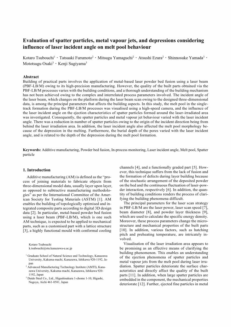
A schematic of the experimental setup is shown in Fig.
1. The experiment was performed using a simplified form
of the PBF-LB/M equipment composed of a building
platform, a continuous-wave Yb fibre laser with Gaussian
relative intensity (IPG Photonics Co., Ltd.: YLR - 300 -
AC - Y11), a high-speed camera with a pixel matrix of
512×384 at a frame rate of 30000 fps (Photron Co., Ltd.:
Fastcam Mini AX200), and a linear stage (GHC Hill-
stome Co., Ltd.: GHR25). Further, quartz glass windows
were provided on the upper and side surfaces of the build-
ing platform for the irradiation of the laser beam from the
upper surface and the observation of metal powder mor-
phology from the side surface, respectively. The oxygen
level inside the building platform was maintained at
0.1 %, owing to filling with nitrogen gas, and controlled
using an oximeter (Toray Engineering Co., Ltd: RF - 400).
The Yb: fibre laser was focused onto a powder bed using
a condenser with a focal length of 250 mm (Sigma Koki
Co., Ltd.: SLSQ - 25–250P). Further, a high-speed cam-
era was set perpendicular to the laser irradiation direction
to observe the laser-irradiated area on the powder bed at
the same height via the side quartz window. An optical
filter (Sigma Koki Co., Ltd.: YL - 500P - Y1) was used
to protect the image sensor of the high-speed camera from
the scattered laser beam.
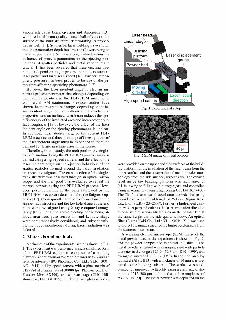
A scanning electron microscope (SEM) image of the
metal powder used in the experiment is shown in Fig. 2,
and the powder composition is shown in Table 1. The
metal powder supplied was maraging steel with particle
diameter in the range of 21.0 - 52.3 μm (D10 - D90), and
average diameter of 33.3 μm (D50). In addition, an alloy
tool steel (AISI: H13) with a thickness of 10 mm was pre-
pared as the building substrate. The surface was sand-
blasted for improved wettability using a grain size distri-
bution of 212–300 μm, and it had a surface roughness of
Ra 2.6 µm [20]. The metal powder was deposited on the
Fig. 1 Experimental setup
Fig. 2 SEM image of metal powder
High-speed camera
Linear stage
Powder bed
Building
platform
Laser head
Laser scan
direction
Moving
direction
Laser displacement
gauge
50 μm
substrate with a levelling blade, and the powder thickness
was confirmed using a laser displacement gauge
(Keyence Corp., LK - 080).
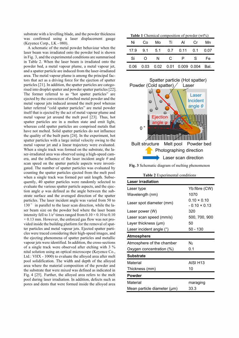
A schematic of the metal powder behaviour when the
laser beam was irradiated onto the powder bed is shown
in Fig. 3, and the experimental conditions are summarised
in Table 2. When the laser beam is irradiated onto the
powder bed, a metal vapour plume, a metal vapour jet,
and a spatter particle are induced from the laser-irradiated
area. The metal vapour plume is among the principal fac-
tors that act as a driving force for the ejection of spatter
particles [21]. In addition, the spatter particles are catego-
rised into droplet spatter and powder spatter particles [22].
The former referred to as “hot spatter particles” are ejected by the convection of melted metal powder and the
metal vapour jets induced around the melt pool whereas
latter referred “cold spatter particles” are metal powder itself that is ejected by the act of metal vapour plume and
metal vapour jet around the melt pool [23]. Thus, hot
spatter particles are in a molten state and emit light,
whereas cold spatter particles are comprised metals that
have not melted. Solid spatter particles do not influence
the quality of the built parts [24]. In the experiment, hot
spatter particles with a large initial velocity owing to the
metal vapour jet and a linear trajectory were evaluated.
When a single track was formed on the substrate, the la-
ser-irradiated area was observed using a high-speed cam-
era, and the influence of the laser incident angle θ and
scan speed on the spatter particle aspects were investi-
gated. The number of spatter particles was evaluated by
counting the spatter particles ejected from the melt pool
when a single track was formed per unit length. Subse-
quently, 40 spatter particles were randomly selected to
evaluate the various spatter particle aspects, and the ejec-
tion angle φ was defined as the angle between the sub-
strate surface and the averaged direction of the spatter
particles. The laser incident angle was varied from 50 to
130 °in parallel to the laser scan direction, while the la-
ser beam size on the powder bed where the laser beam
intensity fell to 1/e2 times ranged from 0.10 × 0.10 to 0.10
× 0.13 mm. However, the enforced gas flow was not pro-
vided inside the building platform for the removal of spat-
ter particles and metal vapour jets. Ejected spatter parti-
cles were traced considering their high-speed images, and
the ejecting phenomena of spatter particles and metallic
vapour jets were identified. In addition, the cross-sections
of a single track were observed after etching with 3 %
nital solution using an optical microscope (Keyence Co.,
Ltd.: VHX - 1000) to evaluate the alloyed area after melt
pool solidification. The width and depth of the alloyed
area where the material composition of the powder and
the substrate that were mixed was defined as indicated in
Fig. 4 [25]. Further, the alloyed area refers to the melt
pool during laser irradiation. In addition, defects such as
pores and dents that were formed inside the alloyed area
Table 1 Chemical composition of powder (wt%)
Ni Co Mo Ti Al Cr Mn
17.9 9.1 5.1 0.7 0.11 0.1 0.07
Si O N C P S Fe
0.06 0.03 0.02 0.01 0.009 0.004 Bal.
Fig. 3 Schematic diagram of melting phenomenon
Table 2 Experimental conditions
Laser irradiation
Laser type Yb:fibre (CW)
Wavelength (nm) 1070
Laser spot diameter (mm) 0.10 × 0.10
- 0.10 × 0.13
Laser power (W) 320
Laser scan speed (mm/s) 500, 700, 900
Layer thickness (μm) 50
Laser incident angle (°) 50 - 130
Atmosphere
Atmosphere of the chamber N2
Oxygen concentration (%) 0.1
Substrate
Material AISI H13
Thickness (mm) 10
Powder
Material maraging
Mean particle diameter (μm) 33.3
Powder bed
Powder (Cold spatter)Spatter particle (Hot spatter)
Built structure
Laser scan direction
Melt pool
Photographing direction
Ejection
angle φ
Laser
0 °
Laser
Incident
angle θ
were analysed using X-ray CT inspection equipment (Ni-
kon Co., Ltd.: MCT225). The specimen for the analysis
was prepared by cutting off the substrate, including a sin-
gle track with a thickness of 600 µm, using a wire electric
discharge machine (Sodick Co., Ltd.: AQ325L).
3. Results
3.1 Spattering phenomena of spatter particles and metal
vapour jets
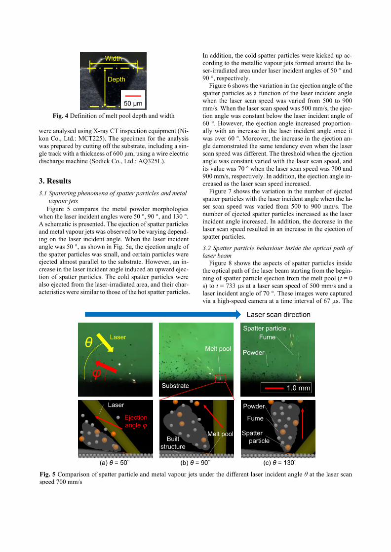
Figure 5 compares the metal powder morphologies
when the laser incident angles were 50 °, 90 °, and 130 °.
A schematic is presented. The ejection of spatter particles
and metal vapour jets was observed to be varying depend-
ing on the laser incident angle. When the laser incident
angle was 50 °, as shown in Fig. 5a, the ejection angle of
the spatter particles was small, and certain particles were
ejected almost parallel to the substrate. However, an in-
crease in the laser incident angle induced an upward ejec-
tion of spatter particles. The cold spatter particles were
also ejected from the laser-irradiated area, and their char-
acteristics were similar to those of the hot spatter particles.
In addition, the cold spatter particles were kicked up ac-
cording to the metallic vapour jets formed around the la-
ser-irradiated area under laser incident angles of 50 ° and
90 °, respectively.
Figure 6 shows the variation in the ejection angle of the
spatter particles as a function of the laser incident angle
when the laser scan speed was varied from 500 to 900
mm/s. When the laser scan speed was 500 mm/s, the ejec-
tion angle was constant below the laser incident angle of
60 °. However, the ejection angle increased proportion-
ally with an increase in the laser incident angle once it
was over 60 °. Moreover, the increase in the ejection an-
gle demonstrated the same tendency even when the laser
scan speed was different. The threshold when the ejection
angle was constant varied with the laser scan speed, and
its value was 70 ° when the laser scan speed was 700 and
900 mm/s, respectively. In addition, the ejection angle in-
creased as the laser scan speed increased.
Figure 7 shows the variation in the number of ejected
spatter particles with the laser incident angle when the la-
ser scan speed was varied from 500 to 900 mm/s. The
number of ejected spatter particles increased as the laser
incident angle increased. In addition, the decrease in the
laser scan speed resulted in an increase in the ejection of
spatter particles.
3.2 Spatter particle behaviour inside the optical path of
laser beam
Figure 8 shows the aspects of spatter particles inside
the optical path of the laser beam starting from the begin-
ning of spatter particle ejection from the melt pool (t = 0
s) to t = 733 µs at a laser scan speed of 500 mm/s and a
laser incident angle of 70 °. These images were captured
via a high-speed camera at a time interval of 67 µs. The
Fig. 4 Definition of melt pool depth and width
Width
Depth
50 μm
Fig. 5 Comparison of spatter particle and metal vapour jets under the different laser incident angle θ at the laser scan speed 700 mm/s
(a) θ = 50° (b) θ = 90° (c) θ = 130°
Laser
Ejection
angle φSpatter
particle
Powder
Melt poolBuilt
structure
Fume
θ
φ
Laser
Laser scan direction
Spatter particle
Substrate
Powder
Fume
1.0 mm
Melt pool
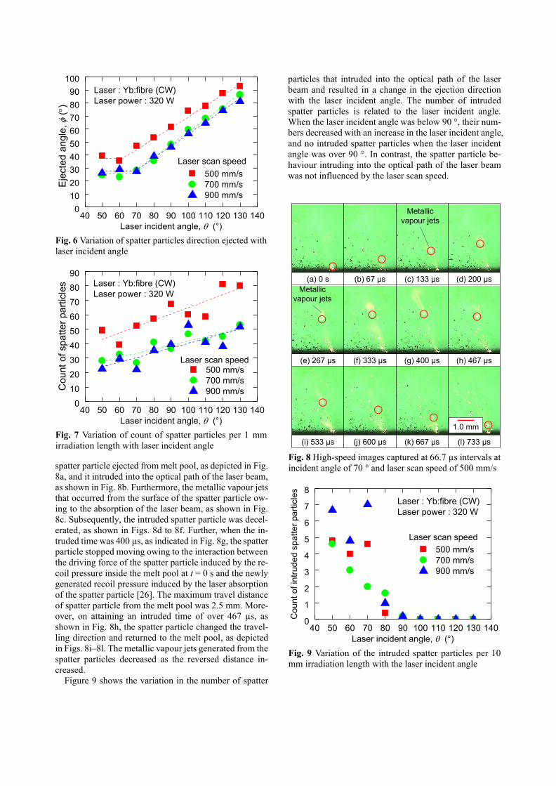
spatter particle ejected from melt pool, as depicted in Fig.
8a, and it intruded into the optical path of the laser beam,
as shown in Fig. 8b. Furthermore, the metallic vapour jets
that occurred from the surface of the spatter particle ow-
ing to the absorption of the laser beam, as shown in Fig.
8c. Subsequently, the intruded spatter particle was decel-
erated, as shown in Figs. 8d to 8f. Further, when the in-
truded time was 400 µs, as indicated in Fig. 8g, the spatter
particle stopped moving owing to the interaction between
the driving force of the spatter particle induced by the re-
coil pressure inside the melt pool at t = 0 s and the newly
generated recoil pressure induced by the laser absorption
of the spatter particle [26]. The maximum travel distance
of spatter particle from the melt pool was 2.5 mm. More-
over, on attaining an intruded time of over 467 µs, as
shown in Fig. 8h, the spatter particle changed the travel-
ling direction and returned to the melt pool, as depicted
in Figs. 8i–8l. The metallic vapour jets generated from the
spatter particles decreased as the reversed distance in-
creased.
Figure 9 shows the variation in the number of spatter
particles that intruded into the optical path of the laser
beam and resulted in a change in the ejection direction
with the laser incident angle. The number of intruded
spatter particles is related to the laser incident angle.
When the laser incident angle was below 90 °, their num-
bers decreased with an increase in the laser incident angle,
and no intruded spatter particles when the laser incident
angle was over 90 °. In contrast, the spatter particle be-
haviour intruding into the optical path of the laser beam
was not influenced by the laser scan speed.
Fig. 8 High-speed images captured at 66.7 µs intervals at incident angle of 70 ° and laser scan speed of 500 mm/s
Fig. 9 Variation of the intruded spatter particles per 10 mm irradiation length with the laser incident angle
1.0 mm
(a) 0 s (b) 67 µs (c) 133 µs (d) 200 µs
(e) 267 µs (f) 333 µs (g) 400 µs (h) 467 µs
(i) 533 µs (j) 600 µs (k) 667 µs (l) 733 µs
Metallic
vapour jets
Metallic
vapour jets
40 50 60 70 80 90 100 110 120 130 1400
1
2
3
4
5
6
7
8
Laser : Yb:fibre (CW)
Laser power : 320 W
500 mm/s
700 mm/s
900 mm/s
Co
unt
of in
trud
ed
sp
atte
r part
icle
s
Laser incident angle, (°)
Laser scan speed
Fig. 6 Variation of spatter particles direction ejected with laser incident angle
Fig. 7 Variation of count of spatter particles per 1 mm irradiation length with laser incident angle
40 50 60 70 80 90 100 110 120 130 1400
10
20
30
40
50
60
70
80
90
100
Laser : Yb:fibre (CW)
Laser power : 320 W
500 mm/s
700 mm/s
900 mm/s
Eje
cte
d a
ngle
,
()
Laser incident angle, (°)
Laser scan speed
40 50 60 70 80 90 100 110 120 130 1400
10
20
30
40
50
60
70
80
90Laser : Yb:fibre (CW)
Laser power : 320 W
500 mm/s
700 mm/s
900 mm/sCo
unt
of sp
atte
r p
art
icle
s
Laser incident angle, (°)
Laser scan speed
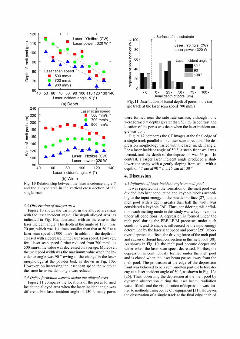
3.3 Observation of alloyed area
Figure 10 shows the variation in the alloyed area size
with the laser incident angle. The depth alloyed area, as
indicated in Fig. 10a, decreased with an increase in the
laser incident angle. The depth at the angle of 130 ° was
70 μm, which was 1.4 times smaller than that at 50 ° at a
laser scan speed of 900 mm/s. In addition, the depth in-
creased with a decrease in the laser scan speed. However,
for a laser scan speed further reduced from 700 mm/s to
500 mm/s, the value was decreased on average. Moreover,
the melt pool width was the maximum value when the in-
cidence angle was 90 ° owing to the change in the laser
morphology at the powder bed, as shown in Fig. 10b.
However, on increasing the laser scan speed the width at
the same laser incident angle was reduced.
3.4 Defect formation aspects inside the alloyed area
Figure 11 compares the locations of the pores formed
inside the alloyed area when the laser incident angle was
different. For laser incident angle of 130 °, many pores
were formed near the substrate surface, although none
were formed at depths greater than 50 μm. In contrast, the location of the pores was deep when the laser incident an-
gle was 50 °.
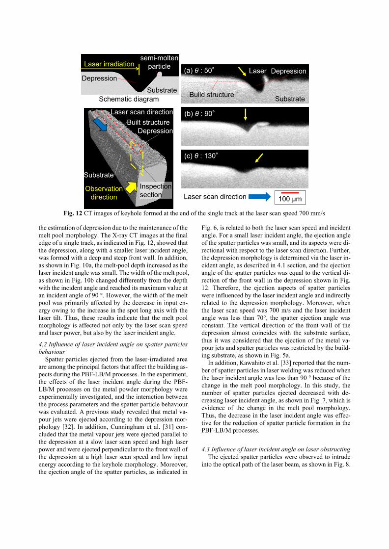
Figure 12 compares the CT images at the final edge of
a single track parallel to the laser scan direction. The de-
pression morphology varied with the laser incident angle.
For a laser incident angle of 50 °, a steep front wall was
formed, and the depth of the depression was 63 µm. In
contrast, a larger laser incident angle produced a shal-
lower concavity with a gently sloping front wall, with a
depth of 47 µm at 90 ° and 26 µm at 130 °.
4. Discussion
4.1 Influence of laser incident angle on melt pool
It was reported that the formation of the melt pool was
divided into heat conduction and keyhole modes accord-
ing to the input energy to the powder surface [27], and a
melt pool with a depth greater than half the width was
considered a keyhole [28]. Thus, considering this defini-
tion, each melting mode in this study was a keyhole mode
under all conditions. A depression is formed under the
melt pool during the PBF-LB/M processes under such
conditions, and its shape is influenced by the input energy
determined by the laser scan speed and power [29]. More-
over, depression affects the driving force of the melt pool
and causes different heat convection in the melt pool [30].
As shown in Fig. 10, the melt pool became deeper and
wider when the laser scan speed decreased. Further, the
depression is continuously formed under the melt pool
and is closed when the laser beam passes away from the
melt pool. The protrusion at the edge of the depression
front was believed to be a semi-molten particle before de-
cay at a laser incident angle of 50 °, as shown in Fig. 12a
[26]. Thus, observing the depression at the melt pool by
dynamic observation during the laser beam irradiation
was difficult, and the visualisation of depression was lim-
ited to methods using X-ray CT equipment [31]. However,
the observation of a single track at the final edge enabled
(a) Depth
(b) Width
Fig. 10 Relationship between the laser incidence angle θ and the alloyed area in the vertical cross-section of the single track
40 50 60 70 80 90 100 110 120 130 14060
70
80
90
100
110
120
Laser : Yb:fibre (CW)
Laser power : 320 W
500 mm/s
700 mm/s
900 mm/s
Dep
th o
f m
elt p
oo
l (µ
m)
Laser incident angle, (°)
Laser scan speed
40 60 80 100 120 14080
100
120
140
160
180
200
220
240
Laser : Yb:fibre (CW)
Laser power : 320 W
500 mm/s
700 mm/s
900 mm/s
Wid
th o
f m
elt p
ool (µ
m)
Laser incident angle, (°)
Laser scan speed
- 0 0 - 25 - 50 - 75 - 100 -0
20
40
60
80
100Surface of the substrate
Laser : Yb:fibre (CW)
Laser power : 320 W
Pro
po
rtio
n o
f p
ore
lo
ca
tio
n (
%)
Burial depth of pore (µm)
50 °
90 °
130 °
Laser incident angle
Fig. 11 Distribution of burial depth of pores in the sin-gle track at the laser scan speed 700 mm/s
the estimation of depression due to the maintenance of the
melt pool morphology. The X-ray CT images at the final
edge of a single track, as indicated in Fig. 12, showed that
the depression, along with a smaller laser incident angle,
was formed with a deep and steep front wall. In addition,
as shown in Fig. 10a, the melt-pool depth increased as the
laser incident angle was small. The width of the melt pool,
as shown in Fig. 10b changed differently from the depth
with the incident angle and reached its maximum value at
an incident angle of 90 °. However, the width of the melt
pool was primarily affected by the decrease in input en-
ergy owing to the increase in the spot long axis with the
laser tilt. Thus, these results indicate that the melt pool
morphology is affected not only by the laser scan speed
and laser power, but also by the laser incident angle.
4.2 Influence of laser incident angle on spatter particles
behaviour
Spatter particles ejected from the laser-irradiated area
are among the principal factors that affect the building as-
pects during the PBF-LB/M processes. In the experiment,
the effects of the laser incident angle during the PBF-
LB/M processes on the metal powder morphology were
experimentally investigated, and the interaction between
the process parameters and the spatter particle behaviour
was evaluated. A previous study revealed that metal va-
pour jets were ejected according to the depression mor-
phology [32]. In addition, Cunningham et al. [31] con-
cluded that the metal vapour jets were ejected parallel to
the depression at a slow laser scan speed and high laser
power and were ejected perpendicular to the front wall of
the depression at a high laser scan speed and low input
energy according to the keyhole morphology. Moreover,
the ejection angle of the spatter particles, as indicated in
Fig. 6, is related to both the laser scan speed and incident
angle. For a small laser incident angle, the ejection angle
of the spatter particles was small, and its aspects were di-
rectional with respect to the laser scan direction. Further,
the depression morphology is determined via the laser in-
cident angle, as described in 4.1 section, and the ejection
angle of the spatter particles was equal to the vertical di-
rection of the front wall in the depression shown in Fig.
12. Therefore, the ejection aspects of spatter particles
were influenced by the laser incident angle and indirectly
related to the depression morphology. Moreover, when
the laser scan speed was 700 m/s and the laser incident
angle was less than 70°, the spatter ejection angle was
constant. The vertical direction of the front wall of the
depression almost coincides with the substrate surface,
thus it was considered that the ejection of the metal va-
pour jets and spatter particles was restricted by the build-
ing substrate, as shown in Fig. 5a.
In addition, Kawahito et al. [33] reported that the num-
ber of spatter particles in laser welding was reduced when
the laser incident angle was less than 90 ° because of the
change in the melt pool morphology. In this study, the
number of spatter particles ejected decreased with de-
creasing laser incident angle, as shown in Fig. 7, which is
evidence of the change in the melt pool morphology.
Thus, the decrease in the laser incident angle was effec-
tive for the reduction of spatter particle formation in the
PBF-LB/M processes.
4.3 Influence of laser incident angle on laser obstructing
The ejected spatter particles were observed to intrude
into the optical path of the laser beam, as shown in Fig. 8.
Fig. 12 CT images of keyhole formed at the end of the single track at the laser scan speed 700 mm/s
100 μmLaser scan direction
Depression
Build structureSubstrate
(a) θ : 50°
(c) θ : 130°
Laser
(b) θ : 90°
Substrate
Built structure
Inspection
section
Depression
Observation
direction
Laser scan direction
Schematic diagram
Laser irradiation
Depression
Substrate
semi-molten
particle
As shown in Fig. 9, the number of intruded spatter parti-
cles decreased with a decrease in the laser incident angle,
although the spatter particles did not intrude into the laser
optical path when the laser incident angle was above 90 °. Further, the ejection of the spatter particles was restricted
by the substrate when the incident angle was small, as
shown in Fig. 5a, and they entered the laser optical path
more easily than in Fig. 5b and c.
The dynamic observation of the laser-irradiated area
indicated that the intruded spatter particles generated the
metal vapour jets by absorbing the laser beam, resulting
in the obstruction of the laser beam reaching the powder
surface. It has been reported that fine particles (metal va-
pour jets) are generated when the plasma atom collides
with each other [14], and the metal vapour jets generated
from the laser-irradiated area absorbed 4.3 % of the fibre
laser beam [34]. Therefore, it is necessary to establish a
laser scan strategy wherein the spatter particles and metal
vapour jets do not intrude into the laser optical path. In
commercial PBF-LB/M equipment, the inert gas gener-
ally circulates inside the building chamber to eliminate
the spatter particles and metal vapour jets from the optical
path of the laser beam, and the ejection aspects of spatter
particles affect their scatterable distance [35]. Therefore,
the inert gas flow inside the building chamber must be
considered in addition to the laser scan strategy, includ-
ing the laser incident angle, to achieve a uniform building
with quality assurance.
4.4 Influence of laser incident angle on defects
Depressions in the melt pool are also associated with
the occurrence of pores. The maximum depth of the re-
sidual pores shown in Fig. 11 increased with decreasing
laser incident angle. Zhao et al. [36] have shown via di-
rect observation of the melt pool using megahertz X-ray
imaging that pores were generated by the collapse of the
melt pool and separation of the pointed end. In addition,
Ng et al. [37] reported that the formation of pores de-
pended on the melt pool morphology and the driving
forces that induced the control of their motion. The pores
were solidified at a deep position under the condition of
deep depression. Consequently, it is considered that the
difference in the melt pool morphology depending on the
laser incident angle affected the pore formation. There-
fore, the laser incident angle was proven to be an im-
portant factor in determining the defects in the built part.
5. Conclusions
In this study, simplified PBF-LB/M equipment was
utilised to build a single track to experimentally inves-
tigate the influence of the laser incident angle on the
melt pool morphology and the spatter particle behav-
iour. The melt pool during the PBF-LB/M process was
visualised using a high-speed camera, and the cross-
section of the single track was observed using an opti-
cal microscope and X-ray CT equipment. The primary
results obtained are as follows:
(1) The depression shape formed at the edge of a single
track varied with the laser incident angle. The eval-
uation of the depressions suggested that the melt
pool morphology changed with the laser incident
angle. Thus, the ejection aspects of spatter particles,
melt pool morphology, and pore formation were
found to be related to depression in the melt pool.
(2) The ejection aspects of the spatter particles varied
with the laser incident angle, and the ejection angle
decreased with decreasing laser incident angle.
Further, the ejection angle of the spatter particles
coincided with the vertical direction of the front
wall of the depression. For incident angle less than
70°, the spatter particle ejection was restricted by
the substrate.
(3) Spatter particles entering the laser optical path and
obstructing the irradiation were generated owing to
the restriction of ejection by the substrate.
(4) Pores remained at deeper positions with decreasing
incident angle, and they were related to the depth
of the depression during the melt pool formation.
In the commercial PBF-LB/M equipment, the inert
gas circulates inside the building chamber to eliminate
the spatter particles and metal vapour jets from the op-
tical path of the laser beam, and the galvano mirror is
placed above the centre position of the building plat-
form to reach the laser beam at each position. Conse-
quently, the laser incident angle at the building plat-
form varies with the equipment configuration, and the
building aspect differs according to its configuration.
Therefore, to establish a laser scan strategy for a high-
quality building, the evaluation of melt pool behaviour
using commercial PBF-LB/M equipment is needed in
future work. The mechanical properties of the built
structure were not evaluated in this study. An investi-
gation of the effect of the laser incident angle on the
quality of the product, such as tensile strength and
hardness, is required.
Authors' contributions TK: Conducted the in-process
monitoring, evaluated the obtained data, organised all
data, and wrote the manuscript. FT: Proposed the ex-
periment and evaluation method to reveal the effect of
the laser incident angle on melting phenomena, con-
ducted the In-process monitoring, and evaluated the
obtained data. YM: Evaluated the cross-section of a
single track using an optical microscope. EA: Evaluated
depression at the final edge of a single track using X-
ray CT. YS, OM and SK: Supplied the metal powder
and evaluated the obtained data.
Data availability Not applicable.
Code availability Not applicable.
Declarations
Ethics approval Not applicable.
Consent to participate Not applicable.
Consent for publication Not applicable.
Conflict of interest The authors declare no competing
interest.
References
1. ASTM F2792-10e1 (2012) Standard terminology for
additive manufacturing technologies, Annual book of
ASTM Standard, ASTM International, Pennsylvania
671-673.
2. Vayre B, Vignat F, Villeneuve F (2012) Designing for
Additive Manufacturing. Proc CIRP 3:632-637.
https://doi.org/10.1016/j.procir.2012.07.108
3. Plessis AD, Yadroitsava I, Yadroitsav I (2018)
Ti6Al4V lightweight lattice structures manufactured
by laser powder bed fusion for load-bearing applica-
tions. Opt Laser Technol 108:521-528.
https://doi.org/10.1016/j.optlastec.2018.07.050
4.Tan C, Wang D, Ma W, Chan Y, Chen S, Yang Y, Zhou
K (2020) Design and additive manufacturing of novel
conformal cooling molds. Mater Des 196:109147.
https://doi.org/10.1016/j.matdes.2020.109147
5. Nadimpalli VK, Dahmen T, Valente EH, Mohanty S,
Pedersen DB (2019) Multi-material additive manufac-
turing of steels using laser powder bed fusion. Eur Soc
Precis Eng Nanotechnol:240-243.
6. Bayat M, Thanki A, Mohanty S, Witvrouw A, Yang S,
Thorborg J, Tiedje NS, Hattel JH (2019) Keyhole-in-
duced porosities in Laser-based Powder Bed Fusion
(L-PBF) of Ti6Al4V: High-fidelity modelling and ex-
perimental validation. Addit Manuf 30: 100835.
https://doi.org/10.1016/j.addma.2019.100835
7. Bertoli US, Wolfer AJ, Matthews MJ, Delplanque JR,
Schoenung JM (2017) On the limitations of Volumet-
ric Energy Density as a design parameter for Selective
Laser Melting. Mater Des 113 (5):331-340.
https://doi.org/10.1016/j.matdes.2016.10.037
8. Metelkova J, Kinds Y, Kempen K, Formanoir C,
Witvrouw A, Hooreweder BV (2018) On the influence
of la-ser defocusing in Selective Laser Melting of 316L.
Addit Manuf 23:161-169.
https://doi.org/10.1016/j.addma.2018.08.006
9. Qiu C, Panwisawas C, Ward M, Basoalto HC, Brooks
JW, Attallah MM (2015) On the role of melt flow into
the surface structure and porosity development during
selective laser melting. Acta Mater 96 (1):72-79.
https://doi.org/10.1016/j.actamat.2015.06.004
10. Gu DD, Meiners W, Wissenbach K, Poprawe R
(2012) Laser additive manufacturing of metallic com-
ponents: materials, processes and mechanisms. Int Ma-
ter Rev 57 (3):133-164.
https://doi.org/10.1179/1743280411Y.0000000014
11. Sato N, Seto N, Shimizu T, Nakano S (2017) Real-
time Observation of Melting Behaviour in Selective
Laser Melting of Metals. Mater Japan 56 (12):695–698.
12. Wang D, Yang Y, Liu R, Xiao D, Sun J (2013) Study
on the designing rules and processability of porous
structure based on selective laser melting (SLM). J Ma-
ter Process Technol 213 10:1734–1742.
https://doi.org/10.1016/j.jmatprotec.2013.05.001
13. Arai T (2013) Fundamental Engineering Science for
Laser Materials Processing. Maruzen Publishing
Co.,Ltd., Tokyo
14. Ladewig A, Schlick G, Fisser M, Schulze V, Glatzel
U (2016) Influence of the shielding gas flow on the re-
moval of process by-products in the selective laser
melting process. Addit Manuf 10:1-9.
https://doi.org/10.1016/j.addma.2016.01.004
15. Miyazaki Y, Katayama S (2013) Influence of Laser-
Induced Plume on Penetration in Laser Welding, Q J
Jpn Weld Soc 31 (2):119–125.
https://doi.org/10.2207/qjjws.31.119
16. Bidare P, Bitharas I, Ward RM, Attallah MM, Moore
AJ (2018) Fluid and particle dynamics in laser powder
bed fusion. Acta Mater 142 (1):107-120.
https://doi.org/10.1016/j.actamat.2017.09.051
17. Matthews MJ, Guss G, Khairallah SA, Rubenchik
AM, Depond PJ, King WE (2016) Denudation of metal
powder layers in laser powder bed fusion processes.
Acta Mater 114 (1):33-42.
https://doi.org/10.1016/j.actamat.2016.05.017
18. Sendino S, Gardon M, Lartategui F, Martinez S,
Lamikiz A (2020) The Effect of the Laser Incidence
Angle in the Surface of L-PBF Processed Parts. Coat
10 (11):1024.
https://doi.org/10.3390/coatings10111024
19. Leuders S, Thöne, M, Riemer A, Niendorf T, Tröster
T, Richard HA, Maier HJ (2013) On the mechanical
behaviour of titanium alloy TiAl6V4 manufactured by
selective laser melting: Fatigue resistance and crack
growth performance. Int J Fatigue 48:300–307.
https://doi.org/10.1016/j.ijfatigue.2012.11.011
20. Furumoto T, Egashira K, Oishi K, Abe S, Yamagu-
chi M, Hashimoto Y, Koyano T, Hosokawa A (2021)
Experimental investigation into the spatter particle be-
haviour of maraging steel during selective laser melt-
ing. J Adv Mech Des Syst Manuf
15(4):JAMSDM0039.
https://doi.org/10.1299/jamdsm.2021jamdsm0039
21. Guo Q, Zhao C, Escano LI, Young Z, Xiong L, Fezzaa
K, Everhart W, Brown B, Sun T, Chen L (2018) Tran-
sient dynamics of powder spattering in laser powder
bed fusion additive manufacturing process revealed by
in-situ high-speed high-energy x-ray imaging. Acta
Mater 151:169–180.
https://doi.org/10.1016/j.actamat.2018.03.036
22. Liu Y, Yang Y, Mai S, Wang D, Song C (2015) In-
vestigation into spatter behaviour during selective laser
melting of AISI 316L stainless steel powder. Mater
Des 87(15):797–806.
https://doi.org/10.1016/j.matdes.2015.08.086
23. Andani MT, Dehghani R, Ravari MRK, Mirzaeifar R,
Ni J (2017) Spatter formation in selective laser melting
process using multi-laser technology. Mater Des
131(5):460-469.
https://doi.org/10.1016/j.matdes.2017.06.040
24. Wang D, Wu S, Fu F, Mai S, Yang Y, Liu Y, Song C
(2017) Mechanisms and characteristics of spatter gen-
eration in SLM processing and its effect on the proper-
ties. Mater Des 117(5):121-130.
https://doi.org/10.1016/j.matdes.2016.12.060
25. Furumoto T, Ueda T, Kobayashi N, Yassin A, Ho-
sokawa A, Abe S (2009) Study on laser consol-idation
of metal powder with Yb:fiber laser—Evaluation of
line consolidation structure. J Mater Process Technol
209(18-19):5973-5980.
https://doi.org/10.1016/j.jmatprotec.2009.07.017
26. Khairallah SA, Anderson AT, Rubenchik A, King
WE (2016) Laser powder-bed fusion additive manu-
facturing: Physics of complex melt flow and formation
mechanisms of pores, spatter, and denudation zones.
Acta Mater 108(15):36-45.
https://doi.org/10.1016/j.actamat.2016.02.014
27. Steen WM, Mazumder J (2010) Laser material pro-
cessing,4th edn. Springer, London
https://doi.org/10.1007/978-1-84996-062-5
28. King WE, Barth HD, Castillo VM, Gallegos GF,
Gibbs JW, Hahn DE, Kamath C, Rubenchik AM
(2014) Observation of keyhole-mode laser melting in
laser powder-bed fusion additive manufacturing. J Ma-
ter Process Technol 214(12):2915–2925.
https://doi.org/10.1016/j.jmatprotec.2014.06.005
29. Ly S, Rubenchik AM, Khairallah SA, Guss G, Mat-
thews MJ (2017) Metal vapor micro-jet controls mate-
rial redistribution in laser powder bed fusion additive
manufacturing. Sci Rep 7:4085
https://doi.org/10.1038/s41598-017-04237-z
30. Gao M, Kawahito Y, Kajii S (2017) Observation and
understanding in laserwelding of pure titanium at sub-
atmospheric pressure. Opt Express 25(12):13539-
13548
https://doi.org/10.1364/OE.25.013539
31. Cunningham R, Zhao C, Parab N, Kantzos C, Pauza
J, Fezzaa K, Sun T, Rollett AD (2019) Keyhole thresh-
old and morphology in laser melting revealed by ultra-
high-speed x-ray imaging distribution on the powder
bed during selective laser melting. Science
363(6429):849-852.
https://doi.org/10.1126/science.aav4687
32. Young ZA, Guo Q, Parab ND, Zhao C, Qu M, Escano
LI, Fezzaa K, Everhart W, Sun T, Chen L (2020) Types
of spatter and their features and formation mechanisms
in laser powder bed fusion additive manufacturing pro-
cess. Addit Manuf 36:101438.
https://doi.org/10.1016/j.addma.2020.101438
33. Kawahito Y, Nakada K, Uemura Y, Mizutani M,
Nishimoto K, Kawakami H, Katayama S (2018) Rela-
tionship between melt flows based on three-dimen-
sional X-ray transmission in-situ observation and spat-
ter reduction by angle of incidence and defocus dis-
tancing distance in high-power laser welding of stain-
less steel. Weld Int 32(7):485-496.
https://doi.org/10.1080/01431161.2017.1346887
34. Kawahito Y, Kinoshita K, Matsumoto N, Mizutani M,
Katayama S (2007) Interaction between laser beam and
plasma/plume induced in welding of stainless steel
with ultra-high power density fiber laser. Q J Jpn Weld
Soc 25 (3):461-467.
https://doi.org/10.2207/qjjws.25.461
35. Anwar AB, Pham QC (2018) Study of the spatter dis-
tribution on the powder bed during selective laser melt-
ing. Addit Manuf 22:86-97.
https://doi.org/10.1016/j.addma.2018.04.036
36. Zhao C, Parab ND, Li X, Fezzaa K, Tan W, Rollett
AD, Sun T (2020) Critical instability at moving key-
hole tip generates porosity in laser melting. Science
370(6520):1080-1086.
https://doi.org/10.1126/science.abd1587
37. Ng GKL, Jarfors AEW, Bi G, Zheng HY (2009) Po-
rosity formation and gas bubble retention in laser metal
deposition. Appl Phys A 97:641.
https://doi.org/10.1007/s00339-009-5266