Embed Size (px)
Citation preview

Electrical Machines IIWeek 3: Transformer Tests and voltage regulation
Determination of Equivalent Circuit Parameters
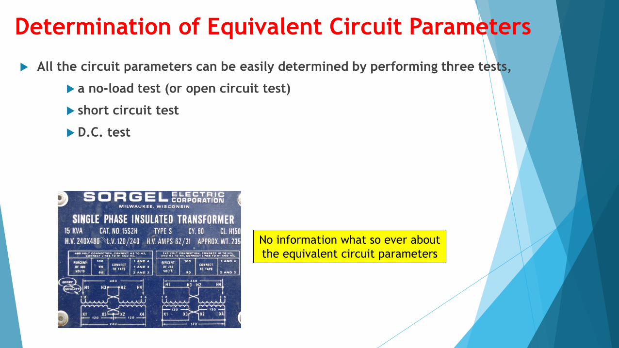
All the circuit parameters can be easily determined by performing three tests,
a no-load test (or open circuit test)
short circuit test
D.C. test
No information what so ever about
the equivalent circuit parameters
1-Open circuit (no load) test
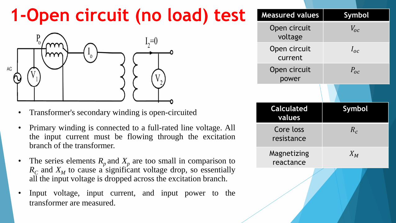
• Transformer's secondary winding is open-circuited
• Primary winding is connected to a full-rated line voltage. Allthe input current must be flowing through the excitationbranch of the transformer.
• The series elements Rp and Xp are too small in comparison toRC and XM to cause a significant voltage drop, so essentiallyall the input voltage is dropped across the excitation branch.
• Input voltage, input current, and input power to the
transformer are measured.
Measured values Symbol
Open circuit
voltage
𝑉𝑜𝑐
Open circuit
current
𝐼𝑜𝑐
Open circuit
power
𝑃𝑜𝑐
Calculated
values
Symbol
Core loss
resistance
𝑅𝑐
Magnetizing
reactance
𝑋𝑀
1-Open circuit (no load) test Measured values Symbol
Open circuit
voltage
𝑉𝑜𝑐
Open circuit
current
𝐼𝑜𝑐
Open circuit
power
𝑃𝑜𝑐
Calculated
values
Symbol
Core loss
resistance
𝑅𝑐
Magnetizing
reactance
𝑋𝑀
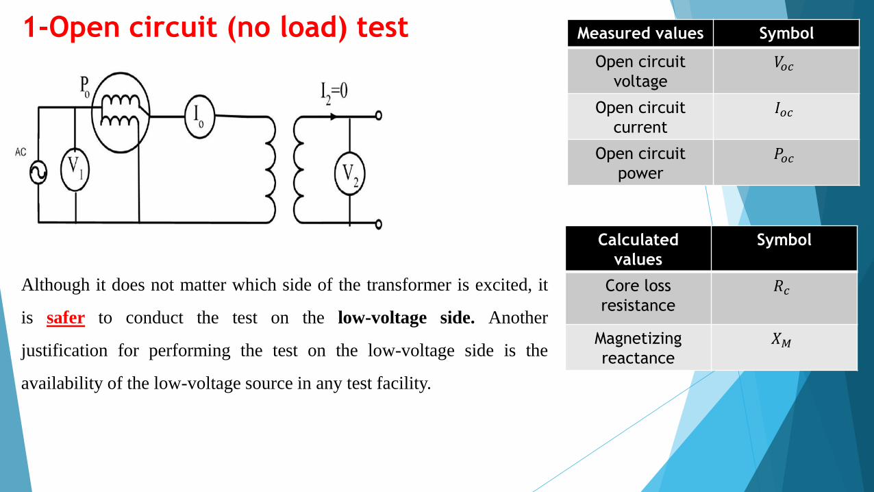
Although it does not matter which side of the transformer is excited, it
is safer to conduct the test on the low-voltage side. Another
justification for performing the test on the low-voltage side is the
availability of the low-voltage source in any test facility.
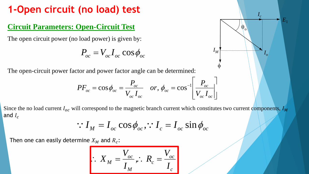
Circuit Parameters: Open-Circuit Test
ococococ IVP cos
ococ
ococ
ococ
ocococ
IV
Por
IV
PPF 1cos,cos
ococcococM IIII sin,cos
The open circuit power (no load power) is given by:
The open-circuit power factor and power factor angle can be determined:
1-Open circuit (no load) test
Since the no load current 𝐼𝑜𝑐 will correspond to the magnetic branch current which constitutes two current components, 𝐼𝑀and 𝐼𝑐
Then one can easily determine 𝑋𝑀 and 𝑅𝑐:
c
occ
M
ocM
I
VR
I
VX ,
Io
Ic
IM
E1
qo
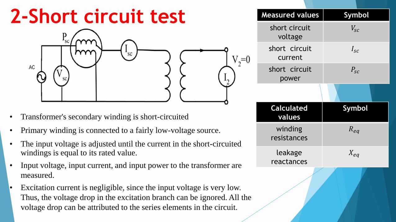
2-Short circuit test
• Transformer's secondary winding is short-circuited
• Primary winding is connected to a fairly low-voltage source.
• The input voltage is adjusted until the current in the short-circuited windings is equal to its rated value.
• Input voltage, input current, and input power to the transformer are
measured.
• Excitation current is negligible, since the input voltage is very low.
Thus, the voltage drop in the excitation branch can be ignored. All the
voltage drop can be attributed to the series elements in the circuit.
Measured values Symbol
short circuit
voltage
𝑉𝑠𝑐
short circuit
current
𝐼𝑠𝑐
short circuit
power
𝑃𝑠𝑐
Calculated
values
Symbol
winding
resistances
𝑅𝑒𝑞
leakage
reactances
𝑋𝑒𝑞
2-Short circuit test Measured values Symbol
short circuit
voltage
𝑉𝑠𝑐
short circuit
current
𝐼𝑠𝑐
short circuit
power
𝑃𝑠𝑐
Calculated
values
Symbol
winding
resistances
𝑅𝑒𝑞
leakage
reactances
𝑋𝑒𝑞
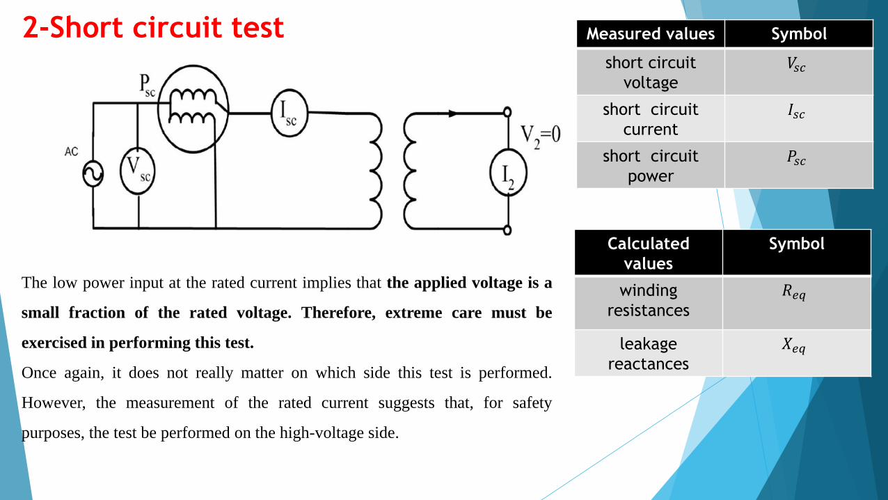
The low power input at the rated current implies that the applied voltage is a
small fraction of the rated voltage. Therefore, extreme care must be
exercised in performing this test.
Once again, it does not really matter on which side this test is performed.
However, the measurement of the rated current suggests that, for safety
purposes, the test be performed on the high-voltage side.
22
eqeqsc XRZ
2
2
sc
sceqsc
scscsc
I
PRR
RIP
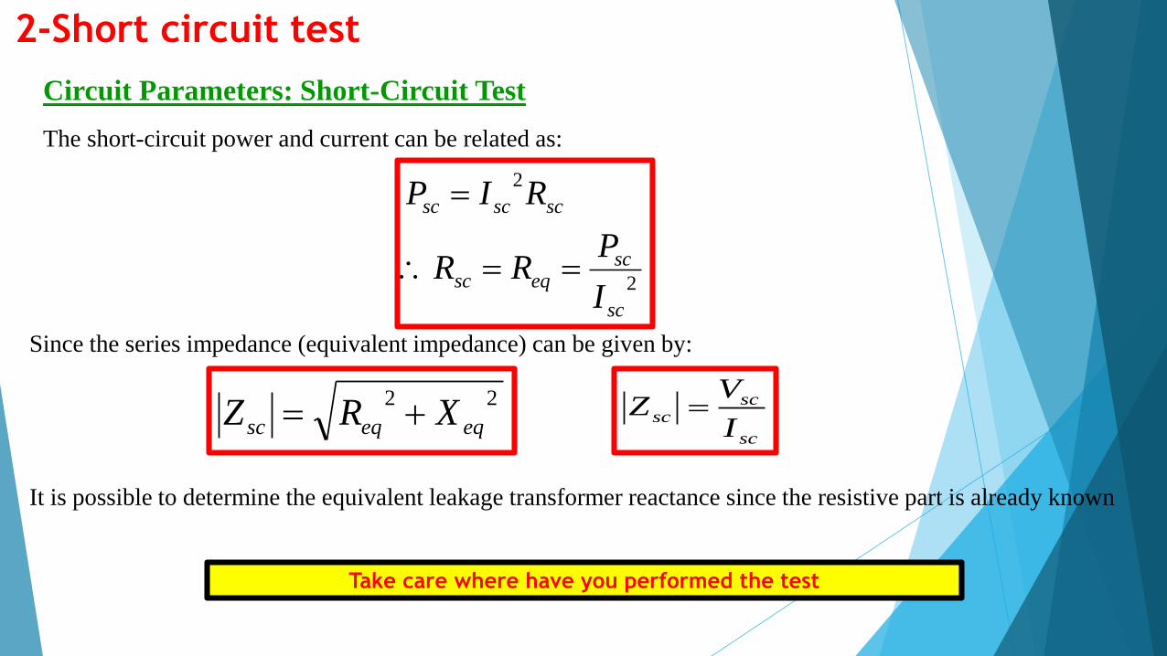
The short-circuit power and current can be related as:
Since the series impedance (equivalent impedance) can be given by:
It is possible to determine the equivalent leakage transformer reactance since the resistive part is already known
2-Short circuit test
Circuit Parameters: Short-Circuit Test
Take care where have you performed the test
sc
scsc
I
VZ
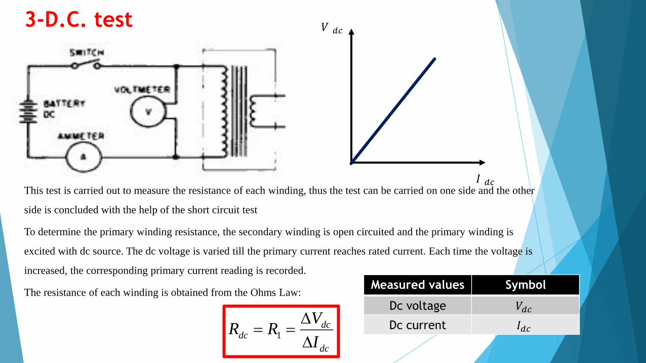
3-D.C. test
This test is carried out to measure the resistance of each winding, thus the test can be carried on one side and the other
side is concluded with the help of the short circuit test
To determine the primary winding resistance, the secondary winding is open circuited and the primary winding is
excited with dc source. The dc voltage is varied till the primary current reaches rated current. Each time the voltage is
increased, the corresponding primary current reading is recorded.
The resistance of each winding is obtained from the Ohms Law:
dc
dcdc
I
VRR
1
𝑉 𝑑𝑐
𝐼 𝑑𝑐
Measured values Symbol
Dc voltage 𝑉𝑑𝑐
Dc current 𝐼𝑑𝑐
100
100
loadfullV
loadfullVloadnoV
loadfullV
loadfullVloadnoVgulationReVoltage%
p
pp
s
ss
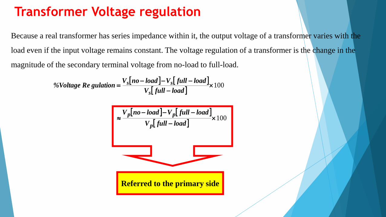
Because a real transformer has series impedance within it, the output voltage of a transformer varies with the
load even if the input voltage remains constant. The voltage regulation of a transformer is the change in the
magnitude of the secondary terminal voltage from no-load to full-load.
Referred to the primary side
Transformer Voltage regulation


