Embed Size (px)
Citation preview
Electrical Machines and Power Electronic Drives for Wind Turbine Applications
Nikola Milivojevic, Student Member, IEEE, Igor Stamenkovic, Student Member, IEEE,
Nigel Schofield, Member, IEEE, and Ali Emadi, Senior Member, IEEE
Abstract—This paper presents a review of different solutions for small wind turbines of the order 2-50kW, designed for wind energy harvesting applications. Because the power characteristic of wind turbines is not linear, there are several topologies and control strategies for maximizing machine output power. In addition, the efficiency of the entire system depends on the type of the electrical machine that is used. The development of new designs of electromagnetic machine exhibiting good power density within a low cost constraint, coupled with appropriate power electronic control strategies, can improve overall system efficiencies.
I. INTRODUCTION
Wind generation of electrical energy is one of the most promising future energy resources due to its sustainable nature and very low net carbon impact. The scavenging of small amounts of wind energy, but on a large volume scale, could yield a significant contribution to global energy usage. Consequently, there are many new possibilities for custom generator design that suit a myriad of different applications. For example, battery chargers for sailboats and small cabins use generators with rated power of up to 400W, while electric machines of 3 to 15kW are needed to feed homes and loads in isolated areas such as telecommunication towers. On the other hand, small commercial operations are supplied with wind turbines that can generate up to 100 kW [1].
According to the US Department of Energy, small wind turbines could operate effectively in most rural areas of the United States today, this equating to about 60% of the country land area and with enough wind for small turbines to generate substation electric power. In 2001, the US small wind turbine industry reached $20M in sales, which amounts to approximately 13,400 turbines. In addition, economic trends shows that small wind turbines could contribute up to 3% (50 GW) of US electric supply by 2020 [1].
The ongoing challenges introduced by the use of small wind turbines include both economical and technological aspects. The price is fairly high and potential users face obstacles in financing, permitting, and installing small wind energy systems. In addition, the overall system is still struggling to improve its reliability and efficiency. One research approach consists of the development of more efficient control strategies for already mature technologies that include conventional radial and axial flux electrical machines [2, 3].
On the other hand, a more innovative approach is to design completely new electrical machine topologies that are tailor made for the direct drive applications in wind power generation [4, 5]. This is a vast research area, as the machine
design techniques and control algorithms do not rely on known analytical models, which is the case with more conventional electrical machines and drive technologies.
II. WIND TURBINE CHARACTERISTICS AND MAXIMUM POWER POINT TRACKING ALGORITHMS
Wind turbines are generally characterized by two parameters: tip speed ratio (λ) and power coefficient (Cp). Tip speed ratio is defined as:
v
wR ⋅=λ (1)
where R stands for length of the blade, w is rotational speed of rotor, and v presents wind linear velocity.
Total harvested power of a wind turbine (Ptotal), in terms of power coefficient(Cp), can be calculated as:
)(21 32 λπρ ptotal CvRP ⋅⋅⋅⋅= (2)
where ρ is the global air density at the turbine. The power coefficient (Cp) depends on the specific design of the wind turbine and its orientation to the wind direction, having a theoretical maximum value of 0.593, the Betz limit [6]. For a particular wind turbine the power coefficient, Cp, basically depends on the tip speed ratio, λ, and the blade pitch angle, i.e. the angle between the surface of the blades and wind direction [6].
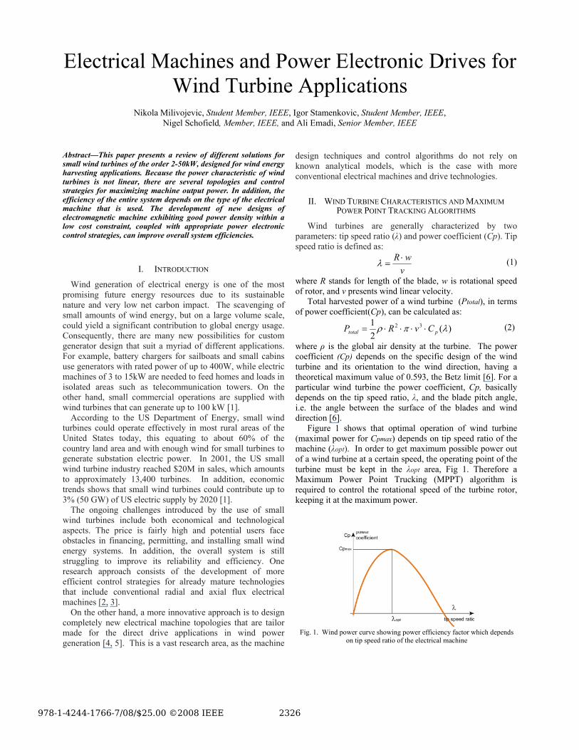
Figure 1 shows that optimal operation of wind turbine (maximal power for Cpmax) depends on tip speed ratio of the machine (λopt). In order to get maximum possible power out of a wind turbine at a certain speed, the operating point of the turbine must be kept in the λopt area, Fig 1. Therefore a Maximum Power Point Trucking (MPPT) algorithm is required to control the rotational speed of the turbine rotor, keeping it at the maximum power.
Fig. 1. Wind power curve showing power efficiency factor which depends
on tip speed ratio of the electrical machine
III. DIFFERENT TOPOLOGIES OF A SMALL WIND TURBINE SYSTEMS
Usually two different electrical generators are used for
Small Wind Turbine applications: induction generator and Brushless DC (BLDC) generator, because they do not need complex control to generate energy and are inexpensive.
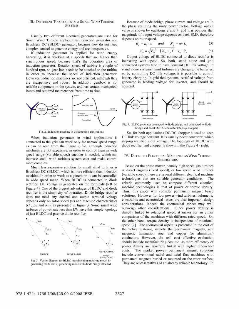
If induction generator is applied for wind energy harvesting, it is working at a speeds that are higher than synchronous speed, because that’s the operation area of induction generator. Rotation speed of turbine is couple of hundred rpm, so gear-box needs to be attached to the turbine in order to increase the speed of induction generator. However, induction machines are not efficient, although they are inexpensive and robust. In addition, gearbox is not reliable component in the system, and has certain mechanical losses and required maintenance from time to time.
When induction generator in wind applications is connected to the grid can work only for narrow speed range, as can be seen from the Figure 2. So, although induction machines are not expensive, in order to control them in wide speed range (variable speed) encoder is needed, which can increase small wind turbines system cost and make control more complex.
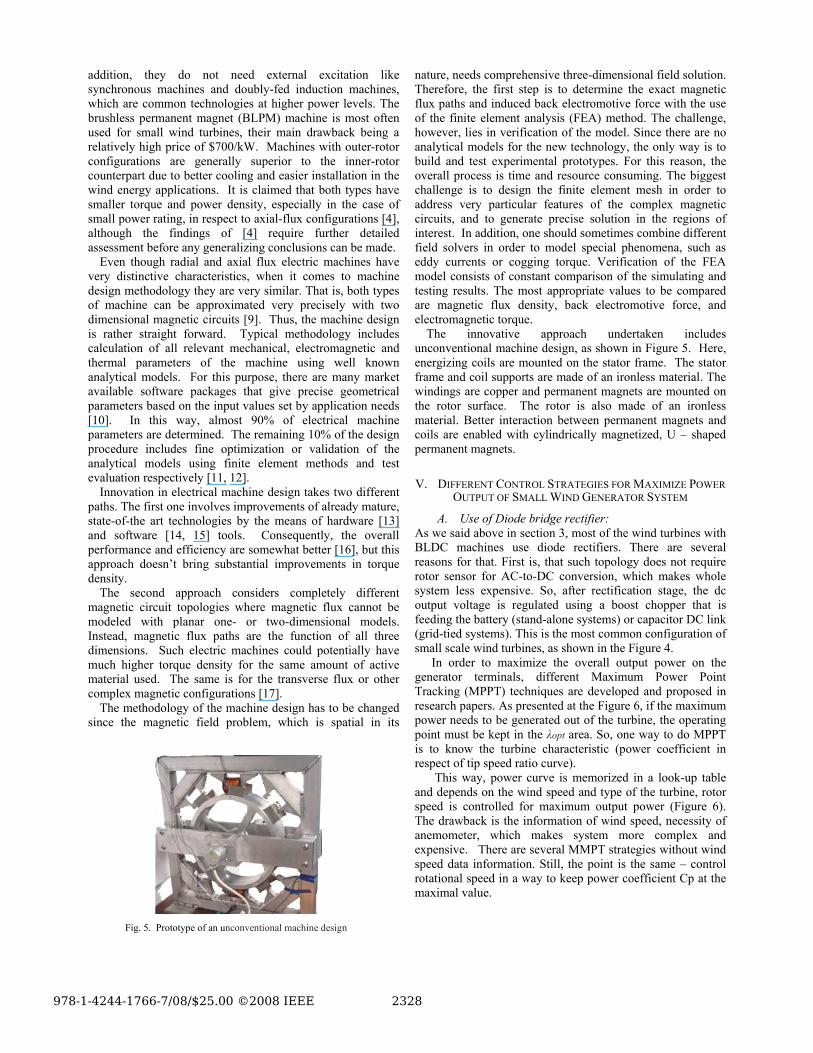
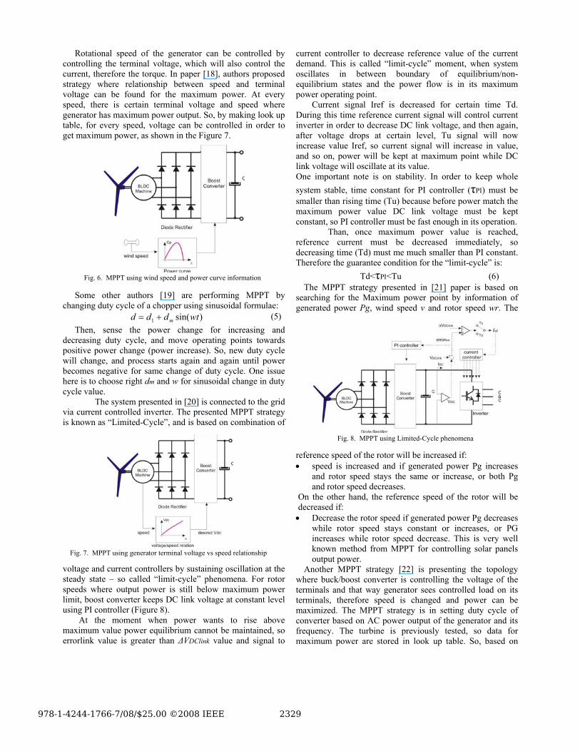
Much less expensive solution for small wind turbines is Brushless DC (BLDC), which is more efficient than induction machine. In order to work as a generator, it can be controlled in wide speed range. When BLDC is connected to diode rectifier, DC voltage is generated on the terminals (left on Figure 4). One of the biggest advantages of BLDC and diode rectifier is the simplicity of operation. Diode bridge rectifier does not need any control and output terminal voltage depends only on rotor speed (w) and machine characteristics (kt , La and Ra), as presented in figure 3. Some small wind turbines of power rate less than kW have this simple topology of just BLDC and passive diode rectifier.
Because of diode bridge, phase current and voltage are in the phase resulting the unity power factor. Voltage output value is shown by equations 3 and 4, and it is obvious that magnitude of output voltage depends on back EMF, therefore depends on rotor speed.
aata LwXandwkE ⋅=⋅= (3)
( ) aaaaaa RiiXEV ⋅−⋅−= 22 (4) Output voltage of BLDC connected to diode rectifier is
increasing with speed. So, both, stand alone and grid connected systems tend to have constant DC link voltage. In stand alone systems, wind turbines are charging the batteries, so by controlling DC link voltage, it is possible to control battery charging. In grid tied systems, rectified voltage from generator is feeding voltage for inverter, and should be constant.
So, for both applications DC/DC chopper is used to keep DC link voltage constant. It is usually boost converter, which step-up rectified input voltage. The topology of BLDC with diode rectifier and chopper is shown in the Figure 4 - right.
IV. DIFFERENT ELECTRICAL MACHINES AS WIND TURBINE GENERATORS
Based on the prime mover, namely high speed gas turbines or diesel engines (fixed speed), or low speed wind turbines (variable speed), there are several different electrical machine technologies that are suitable generator candidates. The criteria commonly used to compare different electrical machine technologies is that of power or torque density. Thus, this paper will consider permanent magnet based solutions. However, for low power wind turbines, volumetric constraints and economical issues are also important design considerations. Indeed, the economical aspect may well outweigh other considerations. Since power density is directly linked to rotational speed, it makes for an unfair comparison of the machines with different rated speed. On the other hand, torque density is independent of rotational speed [2]. The economical aspect is presented in the cost of the active material, namely the permanent magnets, soft magnetic lamination steel and copper (or aluminum) conductors. However, the real cost effective evaluation should include manufacturing cost too, as more efficiency or power density are generally linked with higher production costs. The market proven permanent magnet solutions include conventional radial and axial flux machines with permanent magnets buried or mounted on the rotor surface. They are representatives of an already reliable technology. In
Fig. 3. Vector diagram for BLDC machine in a) motoring mode, b) generating mode and c) generating mode with diode bridge attached
Fig. 2. Induction machine in wind turbine applications
Fig. 4. BLDC generator connected to diode bridge, and connected to diode
bridge and boost DC/DC converter (step-up chopper)
addition, they do not need external excitation like synchronous machines and doubly-fed induction machines, which are common technologies at higher power levels. The brushless permanent magnet (BLPM) machine is most often used for small wind turbines, their main drawback being a relatively high price of $700/kW. Machines with outer-rotor configurations are generally superior to the inner-rotor counterpart due to better cooling and easier installation in the wind energy applications. It is claimed that both types have smaller torque and power density, especially in the case of small power rating, in respect to axial-flux configurations [4], although the findings of [4] require further detailed assessment before any generalizing conclusions can be made.
Even though radial and axial flux electric machines have very distinctive characteristics, when it comes to machine design methodology they are very similar. That is, both types of machine can be approximated very precisely with two dimensional magnetic circuits [9]. Thus, the machine design is rather straight forward. Typical methodology includes calculation of all relevant mechanical, electromagnetic and thermal parameters of the machine using well known analytical models. For this purpose, there are many market available software packages that give precise geometrical parameters based on the input values set by application needs [10]. In this way, almost 90% of electrical machine parameters are determined. The remaining 10% of the design procedure includes fine optimization or validation of the analytical models using finite element methods and test evaluation respectively [11, 12].
Innovation in electrical machine design takes two different paths. The first one involves improvements of already mature, state-of-the art technologies by the means of hardware [13] and software [14, 15] tools. Consequently, the overall performance and efficiency are somewhat better [16], but this approach doesn’t bring substantial improvements in torque density.
The second approach considers completely different magnetic circuit topologies where magnetic flux cannot be modeled with planar one- or two-dimensional models. Instead, magnetic flux paths are the function of all three dimensions. Such electric machines could potentially have much higher torque density for the same amount of active material used. The same is for the transverse flux or other complex magnetic configurations [17].
The methodology of the machine design has to be changed since the magnetic field problem, which is spatial in its
nature, needs comprehensive three-dimensional field solution. Therefore, the first step is to determine the exact magnetic flux paths and induced back electromotive force with the use of the finite element analysis (FEA) method. The challenge, however, lies in verification of the model. Since there are no analytical models for the new technology, the only way is to build and test experimental prototypes. For this reason, the overall process is time and resource consuming. The biggest challenge is to design the finite element mesh in order to address very particular features of the complex magnetic circuits, and to generate precise solution in the regions of interest. In addition, one should sometimes combine different field solvers in order to model special phenomena, such as eddy currents or cogging torque. Verification of the FEA model consists of constant comparison of the simulating and testing results. The most appropriate values to be compared are magnetic flux density, back electromotive force, and electromagnetic torque.
The innovative approach undertaken includes unconventional machine design, as shown in Figure 5. Here, energizing coils are mounted on the stator frame. The stator frame and coil supports are made of an ironless material. The windings are copper and permanent magnets are mounted on the rotor surface. The rotor is also made of an ironless material. Better interaction between permanent magnets and coils are enabled with cylindrically magnetized, U – shaped permanent magnets.
V. DIFFERENT CONTROL STRATEGIES FOR MAXIMIZE POWER OUTPUT OF SMALL WIND GENERATOR SYSTEM
A. Use of Diode bridge rectifier: As we said above in section 3, most of the wind turbines with BLDC machines use diode rectifiers. There are several reasons for that. First is, that such topology does not require rotor sensor for AC-to-DC conversion, which makes whole system less expensive. So, after rectification stage, the dc output voltage is regulated using a boost chopper that is feeding the battery (stand-alone systems) or capacitor DC link (grid-tied systems). This is the most common configuration of small scale wind turbines, as shown in the Figure 4.
In order to maximize the overall output power on the generator terminals, different Maximum Power Point Tracking (MPPT) techniques are developed and proposed in research papers. As presented at the Figure 6, if the maximum power needs to be generated out of the turbine, the operating point must be kept in the λopt area. So, one way to do MPPT is to know the turbine characteristic (power coefficient in respect of tip speed ratio curve).
This way, power curve is memorized in a look-up table and depends on the wind speed and type of the turbine, rotor speed is controlled for maximum output power (Figure 6). The drawback is the information of wind speed, necessity of anemometer, which makes system more complex and expensive. There are several MMPT strategies without wind speed data information. Still, the point is the same – control rotational speed in a way to keep power coefficient Cp at the maximal value.
Fig. 5. Prototype of an unconventional machine design
Rotational speed of the generator can be controlled by controlling the terminal voltage, which will also control the current, therefore the torque. In paper [18], authors proposed strategy where relationship between speed and terminal voltage can be found for the maximum power. At every speed, there is certain terminal voltage and speed where generator has maximum power output. So, by making look up table, for every speed, voltage can be controlled in order to get maximum power, as shown in the Figure 7.
Some other authors [19] are performing MPPT by changing duty cycle of a chopper using sinusoidal formulae:
)sin(1 wtddd m+= (5) Then, sense the power change for increasing and
decreasing duty cycle, and move operating points towards positive power change (power increase). So, new duty cycle will change, and process starts again and again until power becomes negative for same change of duty cycle. One issue here is to choose right dm and w for sinusoidal change in duty cycle value.
The system presented in [20] is connected to the grid via current controlled inverter. The presented MPPT strategy is known as “Limited-Cycle”, and is based on combination of
voltage and current controllers by sustaining oscillation at the steady state – so called “limit-cycle” phenomena. For rotor speeds where output power is still below maximum power limit, boost converter keeps DC link voltage at constant level using PI controller (Figure 8). At the moment when power wants to rise above maximum value power equilibrium cannot be maintained, so errorlink value is greater than ΔVDClink value and signal to
current controller to decrease reference value of the current demand. This is called “limit-cycle” moment, when system oscillates in between boundary of equilibrium/non-equilibrium states and the power flow is in its maximum power operating point. Current signal Iref is decreased for certain time Td. During this time reference current signal will control current inverter in order to decrease DC link voltage, and then again, after voltage drops at certain level, Tu signal will now increase value Iref, so current signal will increase in value, and so on, power will be kept at maximum point while DC link voltage will oscillate at its value. One important note is on stability. In order to keep whole system stable, time constant for PI controller (τPI) must be smaller than rising time (Tu) because before power match the maximum power value DC link voltage must be kept constant, so PI controller must be fast enough in its operation. Than, once maximum power value is reached, reference current must be decreased immediately, so decreasing time (Td) must me much smaller than PI constant. Therefore the guarantee condition for the “limit-cycle” is:
Td<τPI<Tu (6) The MPPT strategy presented in [21] paper is based on
searching for the Maximum power point by information of generated power Pg, wind speed v and rotor speed wr. The
reference speed of the rotor will be increased if: • speed is increased and if generated power Pg increases
and rotor speed stays the same or increase, or both Pg and rotor speed decreases.
On the other hand, the reference speed of the rotor will be decreased if: • Decrease the rotor speed if generated power Pg decreases
while rotor speed stays constant or increases, or PG increases while rotor speed decrease. This is very well known method from MPPT for controlling solar panels output power.
Another MPPT strategy [22] is presenting the topology where buck/boost converter is controlling the voltage of the terminals and that way generator sees controlled load on its terminals, therefore speed is changed and power can be maximized. The MPPT strategy is in setting duty cycle of converter based on AC power output of the generator and its frequency. The turbine is previously tested, so data for maximum power are stored in look up table. So, based on
Fig. 6. MPPT using wind speed and power curve information
Fig. 7. MPPT using generator terminal voltage vs speed relationship
Fig. 8. MPPT using Limited-Cycle phenomena
measured AC power, it is easy to get rotor speed from maximum power curve diagram. PID regulator is used for speed control, and this way speed is controlled in according to maximum power point output of the generator.
In a case wind turbine is connected to the grid, there are couples of solutions how Current Controlled Inverter (CCI) can be controlled in order to achieve MPPT. For the topology presented on the Figure 9, one solution [23] is to make look up table of maximum power output vs dc link voltage. This is so called “Mapping technique”, where values are determined by testing and mapped into look up table, and used later. So, inverter input operating voltage value is determined based on the “mapped” output power got from look up table.
There are two controlling loops: one for power mapping and other one for stator frequency derivative, which corrects sensitivity of DC voltage got from look up table, and alleviate fluctuations on reference voltage value. Therefore, PD controller uses stator frequency (for sensitivity purposes) and maximum output power from look up table to determine optimal operating DC voltage for CCI by controlling the
modulation index of PWM inverter. The advantage is that only information required is look up table of Pdc vs Vdc. B. Use of PWM Rectifier: The wide use of AC/DC converters for different applications has made a significant impact in their development. There are two main categories of these converters: line commutated (low-switching frequency) and forced commutated (high-switching frequency) [24]. In order to implement any of the two mentioned MPPT algorithms PWM active rectifiers are required. High switching frequency converters consist of controlled switching devices (IGBTs, MOSFETs, or GTOs), and can
actively change the waveform of input current and effective voltage, reducing harmonics and influencing the overall power quality.
Active rectifiers are the best candidate for small wind turbine applications. The only drawback is the necessity to use sensors, which than slightly increase the cost of the entire system. Still, if the overall efficiency of the wind turbine system can be improved and the power capacity of generator can be extended by 20-30%, than the controlled active rectifier unit would present a cost-effective solution.
Figure 7 shows a fully controlled single phase Full-bridge PWM rectifier used to control DC voltage Vd. In order to work as a rectifier, rectifier output voltage must be greater than RMS input voltage (Vd>Erms). Also, the rectifier should be controlled to work as bipolar PWM, where T1 and T4 are turned on, and T2 and T3 are off in one part of switching sequence; in the next one, T1 and T4 are off, while T2 and T3 are conducting. There is no way T1 and T4 or T2 and T3 can be in different switching states.
If T1 and T4 are turned on, and T2 and T3 are off, the voltage on the capacitor is Vd=Vs, therefore in the other part of the cycle when T2 and T3 are on, and T1 and T4 are off voltage on the capacitor is: Vd=-Vs. In addition, the voltage on the inductor VL (voltage on generator’s winding) is then:
ss
L VtEdtdi
LtV ±== )()( (8)
When T1 and T4 are on Vs is equal to Vd, and on another part of switching period (while T2 and T3 are on) Vs is equal to –Vd, as explained before. In conclusion, the value of the input current can be controlled depending on the switching pattern of the PWM rectifier.
Figure 10 presents typical control strategy for active PWM rectifier, where Voltage controller keeps the capacitor voltage level constant by controlling the amount of power required. Thus, the current amplitude is set as a reference for current controller. The current signal reference is the same phase and frequency as the generated voltage. So, fast current controller can achieve high power factor by choosing proper switching patterns [25].
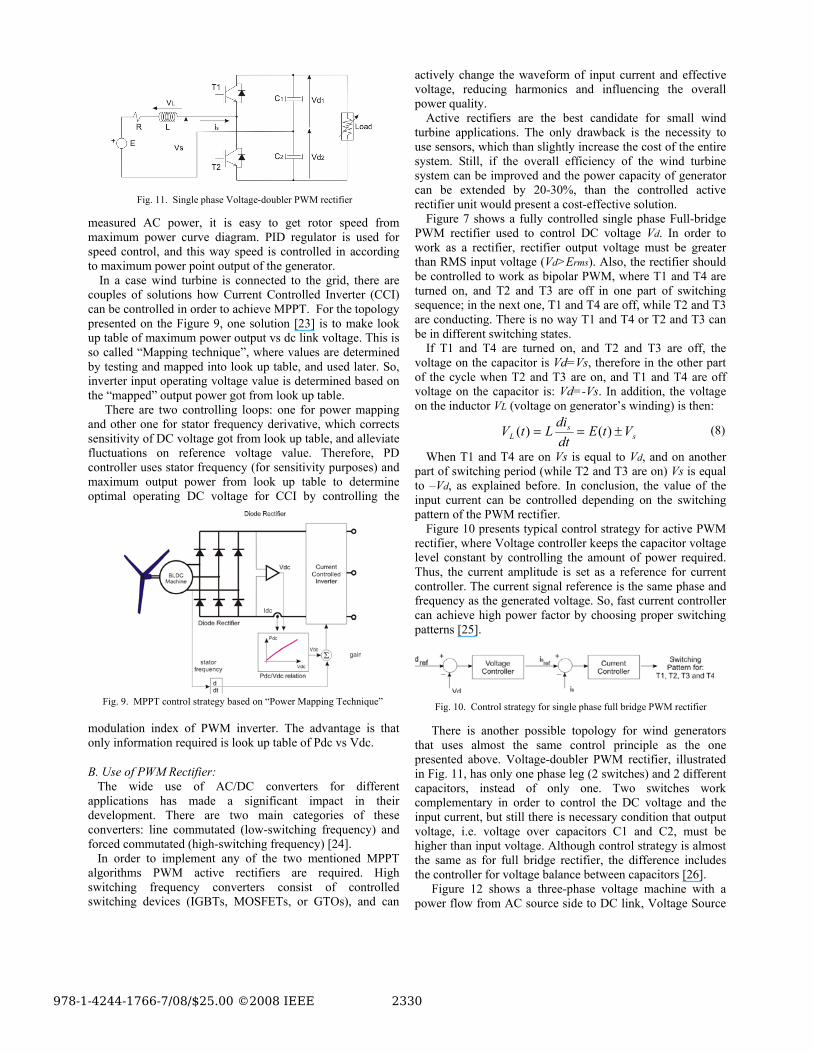
There is another possible topology for wind generators that uses almost the same control principle as the one presented above. Voltage-doubler PWM rectifier, illustrated in Fig. 11, has only one phase leg (2 switches) and 2 different capacitors, instead of only one. Two switches work complementary in order to control the DC voltage and the input current, but still there is necessary condition that output voltage, i.e. voltage over capacitors C1 and C2, must be higher than input voltage. Although control strategy is almost the same as for full bridge rectifier, the difference includes the controller for voltage balance between capacitors [26].
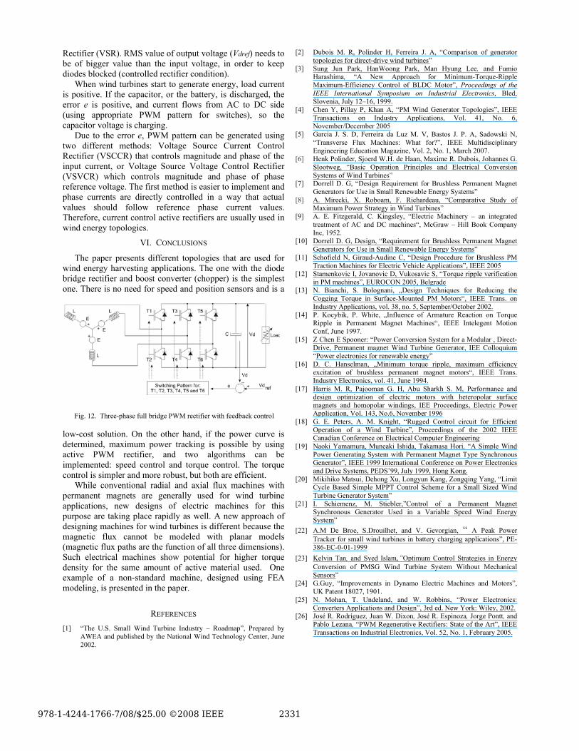
Figure 12 shows a three-phase voltage machine with a power flow from AC source side to DC link, Voltage Source
Fig. 9. MPPT control strategy based on “Power Mapping Technique”
Fig. 11. Single phase Voltage-doubler PWM rectifier
Fig. 10. Control strategy for single phase full bridge PWM rectifier
Rectifier (VSR). RMS value of output voltage (Vdref) needs to be of bigger value than the input voltage, in order to keep diodes blocked (controlled rectifier condition).
When wind turbines start to generate energy, load current is positive. If the capacitor, or the battery, is discharged, the error e is positive, and current flows from AC to DC side (using appropriate PWM pattern for switches), so the capacitor voltage is charging.
Due to the error e, PWM pattern can be generated using two different methods: Voltage Source Current Control Rectifier (VSCCR) that controls magnitude and phase of the input current, or Voltage Source Voltage Control Rectifier (VSVCR) which controls magnitude and phase of phase reference voltage. The first method is easier to implement and phase currents are directly controlled in a way that actual values should follow reference phase current values. Therefore, current control active rectifiers are usually used in wind energy topologies.
VI. CONCLUSIONS
The paper presents different topologies that are used for wind energy harvesting applications. The one with the diode bridge rectifier and boost converter (chopper) is the simplest one. There is no need for speed and position sensors and is a
low-cost solution. On the other hand, if the power curve is determined, maximum power tracking is possible by using active PWM rectifier, and two algorithms can be implemented: speed control and torque control. The torque control is simpler and more robust, but both are efficient.
While conventional radial and axial flux machines with permanent magnets are generally used for wind turbine applications, new designs of electric machines for this purpose are taking place rapidly as well. A new approach of designing machines for wind turbines is different because the magnetic flux cannot be modeled with planar models (magnetic flux paths are the function of all three dimensions). Such electrical machines show potential for higher torque density for the same amount of active material used. One example of a non-standard machine, designed using FEA modeling, is presented in the paper.
REFERENCES [1] “The U.S. Small Wind Turbine Industry – Roadmap”, Prepared by
AWEA and published by the National Wind Technology Center, June 2002.
[2] Dubois M. R, Polinder H, Ferreira J. A, “Comparison of generator topologies for direct-drive wind turbines”
[3] Sung Jun Park, HanWoong Park, Man Hyung Lee, and Fumio Harashima, “A New Approach for Minimum-Torque-Ripple Maximum-Efficiency Control of BLDC Motor”, Proceedings of the IEEE International Symposium on Industrial Electronics, Bled, Slovenia, July 12–16, 1999.
[4] Chen Y, Pillay P, Khan A, “PM Wind Generator Topologies”, IEEE Transactions on Industry Applications, Vol. 41, No. 6, November/December 2005
[5] Garcia J. S. D, Ferreira da Luz M. V, Bastos J. P. A, Sadowski N, “Transverse Flux Machines: What for?”, IEEE Multidisciplinary Engineering Education Magazine, Vol. 2, No. 1, March 2007.
[6] Henk Polinder, Sjoerd W.H. de Haan, Maxime R. Dubois, Johannes G. Slootweg, “Basic Operation Principles and Electrical Conversion Systems of Wind Turbines”
[7] Dorrell D. G, “Design Requirement for Brushless Permanent Magnet Generators for Use in Small Renewable Energy Systems”
[8] A. Mirecki, X. Roboam, F. Richardeau, “Comparative Study of Maximum Power Strategy in Wind Turbines”
[9] A. E. Fitzgerald, C. Kingsley, “Electric Machinery – an integrated treatment of AC and DC machines“, McGraw – Hill Book Company Inc, 1952.
[10] Dorrell D. G, Design, “Requirement for Brushless Permanent Magnet Generators for Use in Small Renewable Energy Systems”
[11] Schofield N, Giraud-Audine C, “Design Procedure for Brushless PM Traction Machines for Electric Vehicle Applications”, IEEE 2005
[12] Stamenkovic I, Jovanovic D, Vukosavic S, “Torque ripple verification in PM machines”, EUROCON 2005, Belgrade
[13] N. Bianchi, S. Bolognani, „Design Techniques for Reducing the Cogging Torque in Surface-Mounted PM Motors“, IEEE Trans. on Industry Applications, vol. 38, no. 5, September/October 2002.
[14] P. Kocybik, P. White, „Influence of Armature Reaction on Torque Ripple in Permanent Magnet Machines“, IEEE Intelegent Motion Conf, June 1997.
[15] Z Chen E Spooner: “Power Conversion System for a Modular , Direct-Drive, Permanent magnet Wind Turbine Generator, IEE Colloquium “Power electronics for renewable energy”
[16] D. C. Hanselman, „Minimum torque ripple, maximum efficiency excitation of brushless permanent magnet motors“, IEEE Trans. Industry Electronics, vol. 41, June 1994.
[17] Harris M. R, Pajooman G. H, Abu Sharkh S. M, Performance and design optimization of electric motors with heteropolar surface magnets and homopolar windings, IEE Proceedings, Electric Power Application, Vol. 143, No.6, November 1996
[18] G. E. Peters, A. M. Knight, “Rugged Control circuit for Efficient Operation of a Wind Turbine”, Proceedings of the 2002 IEEE Canadian Conference on Electrical Computer Engineering
[19] Naoki Yamamura, Muneaki Ishida, Takamasa Hori, “A Simple Wind Power Generating System with Permanent Magnet Type Synchronous Generator”, IEEE 1999 International Conference on Power Electronics and Drive Systems, PEDS’99, July 1999, Hong Kong.
[20] Mikihiko Matsui, Dehong Xu, Longyun Kang, Zongqing Yang, “Limit Cycle Based Simple MPPT Control Scheme for a Small Sized Wind Turbine Generator System”
[21] I. Schiemenz, M. Stiebler,”Control of a Permanent Magnet Synchronous Generator Used in a Variable Speed Wind Energy System”
[22] A.M De Broe, S.Drouilhet, and V. Gevorgian, “ A Peak Power Tracker for small wind turbines in battery charging applications”, PE-386-EC-0-01-1999
[23] Kelvin Tan, and Syed Islam,”Optimum Control Strategies in Energy Conversion of PMSG Wind Turbine System Without Mechanical Sensors”
[24] G.Guy, “Improvements in Dynamo Electric Machines and Motors”, UK Patent 18027, 1901.
[25] N. Mohan, T. Undeland, and W. Robbins, “Power Electronics: Converters Applications and Design”, 3rd ed. New York: Wiley, 2002.
[26] José R. Rodríguez, Juan W. Dixon, José R. Espinoza, Jorge Pontt, and Pablo Lezana, “PWM Regenerative Rectifiers: State of the Art”, IEEE Transactions on Industrial Electronics, Vol. 52, No. 1, February 2005.
Fig. 12. Three-phase full bridge PWM rectifier with feedback control


