Embed Size (px)
Citation preview
Electncally ConductiveStructured Polymer Blends
FInal Report
US - Israel CDR Program
Grant #HRN-5544-G-OO-2066-00
MANAGEMENT FINAL REPORT
Covenng Penod October 1993 to September 1996
Submitted to the OffIce of the SCience AdvIsor
U S Agency for InternatIonal Development
ELECTRICALLY CONDUCTIVESTRUCTURED POLYMER BLENDS
Pnnclpal InvestIgator M Narkls
Grantee InstItution Technion - Israel Institute of Technology
Haifa, Israel
Collaborator M KozlowskI
Institution Polymark - Research, Development and Consulting Center
Wroclaw, Poland
PrOject Number C12 - 097
Grant Number HRN-5544-G-OO-2066-00
A I D Grant Project OffIcer DaVId Mullenex
Project DuratIon October 1993 to September 1996
•
This report reflects the opinions and the recommendations of ItS authors only It
does not necessarily reflect the opinions of the Technion, Israel Institute of
Technology, or of the Technion R&D Foundation, LTD The Technion R&D
Foundation, LTD IS not legally responsible for the data and the conclusions
presented, and the report does not constitute a directive or a recommendation of the
Foundation
Copynght (C) 1998 by R Tchoudakov, 0 Breuer, M Narkls, A Siegmann and M
Kozlowski, CDR and the Technion Research and Development Foundation, LTD
2
"
Electrically Conductive Structured Polymer Blends
M Narkls and A Siegmann
Israel
and
M Kozlowski
Poland
This final report reflects the collaborative research efforts both, In Poland and In
Israel The two teams have maintained close collaboration throughout the three
project years, aiming at the complementary efforts The Polish's team extended
VISitS to Israel have greatly contnbuted to both, analyzing the data produced and
outlining and updating future objectives In addition, expenmental techniques and
methods were compared and exchanged
The report was prepared In two main sections, the Israeli and the Pohsh one
follows
3
Table of Contents
tm-
1 Israeli contnbutlon 5
1 1 Executive Summary 5
1 2 Research objectives 7
1 3 Methods and results 7
1 4 Impact, Relevance and Technology Transfer 13
1 5 Project ActIVIties/outputs 14
1 6 Project productivity 16
1 7 Future work 16
1 8 literature cited 16
1 9 Copies of published papers 18
2 Polish contnbutlon 19
2 1 Executive Summary 20
22 Research objectives 21
23 Methods and results 21
24 Impact, Relevance and Technology Transfer 30
25 Project Activities/outputs 31
26 Project productiVity 32
27 Future work 32
28 Literature cited 32
29 Copies of published papers 33
4
Electrically Conductive Structured Polymer Blends
M Narkls, R Tchoudakov, 0 Breuer and A Siegmann
Departments of Chemical and Matenals Englneenng
Technion - Israel Institute of Technology
Haifa, Israel 32000
Executive Summary
Polymer blends are presently being In the forefront of polymer sCience and
technology and their further developments are only limited by creativity and
Imagination Their applications are as both, structural and/or functional matenals
Electncally conductive matenals are of increasing Industnal Interest Smart
blending namely, structunng of Immiscible polymer blends containing a conductive
filler, leads to conductive systems of unique structure and properties and of
sCientific and technical Interest
The present project was deSigned to develop model systems, uSing conventional
polymer processing methods and commodity polymers, and to better understand
the general rules controlling the structure and properties of electncally conductive
ImmIsCible blends The structure and conductivIty of numerous blends consisting of
a senes of ImmiSCible polymer pairs and a conductive carbon black (CB), which
were prepared by different routs, were Investigated The polymer pairs were
selected based on their thermodynamiC properties and melt blended with CB The
effects of matnx compOSition, Ie, type of polymers and their relative content, and
CB loading on the blends morphology and electncal conductivity were investIgated
The use of proper blend compOSition enabled to attain conductivity at very low CB
content, an order of magnitude lower than that estimated by the classical
percolation theones This could be achieved through the formation of a co
continuous matnx phase morphology and the preferential location of the CB
partIcles In the dispersed phase or at the Interphase area The control the
compOSition of the systems and their thermodynamiC and kinetiC charactenstlcs and
the selection of a proper processing method enables one to deSign low CB content
electncally conductive blends
5

The proJect's results and conclusions were presented In international conferences
and published In sCIentIfic Journals The results were of great Interest and
Importance as the development and the understanding of conductive blends are
concerned Moreover, the project's results are qUite general and can be further
applied to other systems and for different applicatIons All goals were accomplished
including also training of SCientists and engineers, know-how and technology
transfer and a fruitful International collaboratIon Both, the project and the
collaboratIon are scheduled to contInue
It IS our pleasure to acknowledge the financial support of the project by the CDR
program
6
Research Objectives
The technology of polymer blends for structural and functional applications IS
rapidly developing Electrically conductive plastics have become of great Interest,
especIally for the electronic Industry The demand for conductive plastics Increases
as the electronic Industry IS becoming larger and more sophisticated Polymer
blends seem to be the optimal solution for the production of conductive plastiCS
Therefore the sCience and technology of these blends IS of great Importance and
will continue to be In the foreseen future Structured electrically conductive blends
are Innovative In nature and combine modern approaches of polymer phySICS,
polymer phySical chemistry and polymer engineering These type of blends enable
to tailor make systems exhIbiting desired optimal properties, through the detailed
preferred distribution of the dispersed conductive filler In a designed multi-phase
polymer morphology
The overall objective of the project was to develop model compounds of electrically
1..0nductlve Immiscible blends having unique electric/dielectric properties and stable
structures towards conventional thermoplastIc melt processing operations ThiS
research tOPiC IS at the forefront of polymer sCience and technology, as eVident by
the recent literature publications [1 - 10J The present project has contnbuted
SIgnificantly to the state-of-art In the area, to better understanding the general rules
controlling the structure and properties of electrically conductive ImmiscIble polymer
blends and to the advancement of their technology and appltcatlons Its contnbutlon
IS not limited to conductive systems but rather general to the field of polymer blends
Methods and Results
To develop the understanding and general rules of the composition - processmg
structure and behavior relationships of electrically conductive ImmIscIble polymer
blends several, different In nature matenal systems were selected to be blended
wIth a conductIve grade of carbon black (CB) The selection was based on
thermodynamic and kinetIC conSiderations, uSing commodIty polymers The
processing methods used were all based on conventional processing eqUipment
7
The processing - structure - conductivity relationships for the vanous selected
systems were investigated
Expenmental
Matenals
Polypropylene (PP) - VC15-15P, Neste, Finland (Tm=173 C)
Copolyamlde (Ny) - Nylon 6/69, EMS, SWitzerland (Tm=132 C)
HIPS - Galrrene HT 88-5, Carmel Olefrns, Israel
LLDPE - Dowlex NG 5056 and Dowlex 2552E, Dow Chemicals
SIS - QUintac 3421 (14% PS), Japan
Carbon Black (CB) - KetJenblack EC, Akzo Nobel Chemicals
Blends Preparation
All blends were prepared by melt mixing the dry blended CB and polymer
components In a Brabender Plastograph eqUipped with a 50 cm3 cell, at the typIcal
processIng temperature of the polymer components, for 15 minutes The resulting
blends were subsequently compressIon molded to obtain 3 mm thick plaques
Alternatively, selected systems were InjectIon molded, uSing an Arburg 220/150
moldIng machrne combIned wIth a standard ASTM mold
Charactenzatlon
The resistivity measunng method of CB loaded polymers and blends depended on
the sample geometry Compression molded samples were cut Into 5 cm In diameter
dIscs Their volume resistIVIty was measured (DIN 53596) usrng a Keithley
Electrometer 614 and a high voltage supplier For samples with low level resistivity
a Sorensen power supply, model ORO 60-1,5 was used Injection molded bars
were measured accordrng to ASTM 0991, known as the "four pOint method"
The blends phase morphology was studied by both optical microscopy and
electron microscopy An Olympus optical microscope was used to observe
8
mlcrotomed samples A Jeol JSM 5400 scanning electron microscope (SEM) was
employed to Investigate freeze-fractured and mlcrotomed surfaces
The rheologIcal behavior of the studied systems was Investigated uSing a capIllary
rheometer coupled with an Instron testIng machine, equIpped with a capillary 2"
long and 0 05" In diameter The rheometer was operated at temperatures Identical
to those used for the processing
Results and DIScussion
Polypropylene/Polyamlde/CB Blends
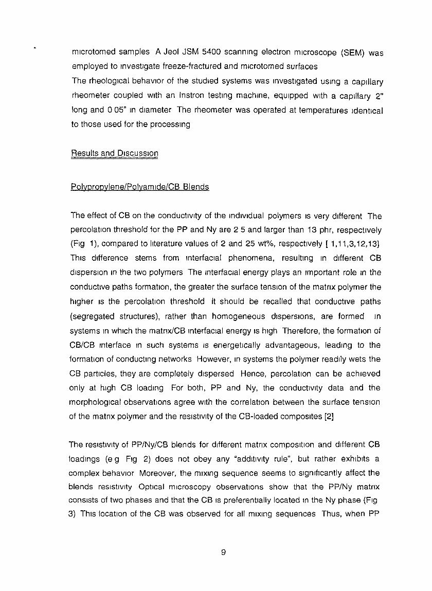
The effect of CB on the conductivIty of the individual polymers IS very different The
percolation threshold for the PP and Ny are 2 5 and larger than 13 phr, respectively
(Fig 1), compared to literature values of 2 and 25 wt%, respectively [ 1,11,3,12,13]
This difference stems from interfacial phenomena, resulting In different CB
dIspersIon In the two polymers The InterfacIal energy plays an Important role In the
conductive paths formation, the greater the surface tension of the matnx polymer the
higher IS the percolation threshold It should be recalled that conductive paths
(segregated structures), rather than homogeneous dispersions, are formed In
systems In which the matnx/CB Interfacial energy IS high Therefore, the formation of
CB/CB Interface In such systems IS energetically advantageous, leading to the
formation of conducting networks However, In systems the polymer readily wets the
CB particles, they are completely dispersed Hence, percolation can be achieved
only at high CB loading For both, PP and Ny, the conductIvity data and the
morphological observations agree with the correlation between the surface tension
of the matnx polymer and the resIstivIty of the CB-Ioaded composites [2]
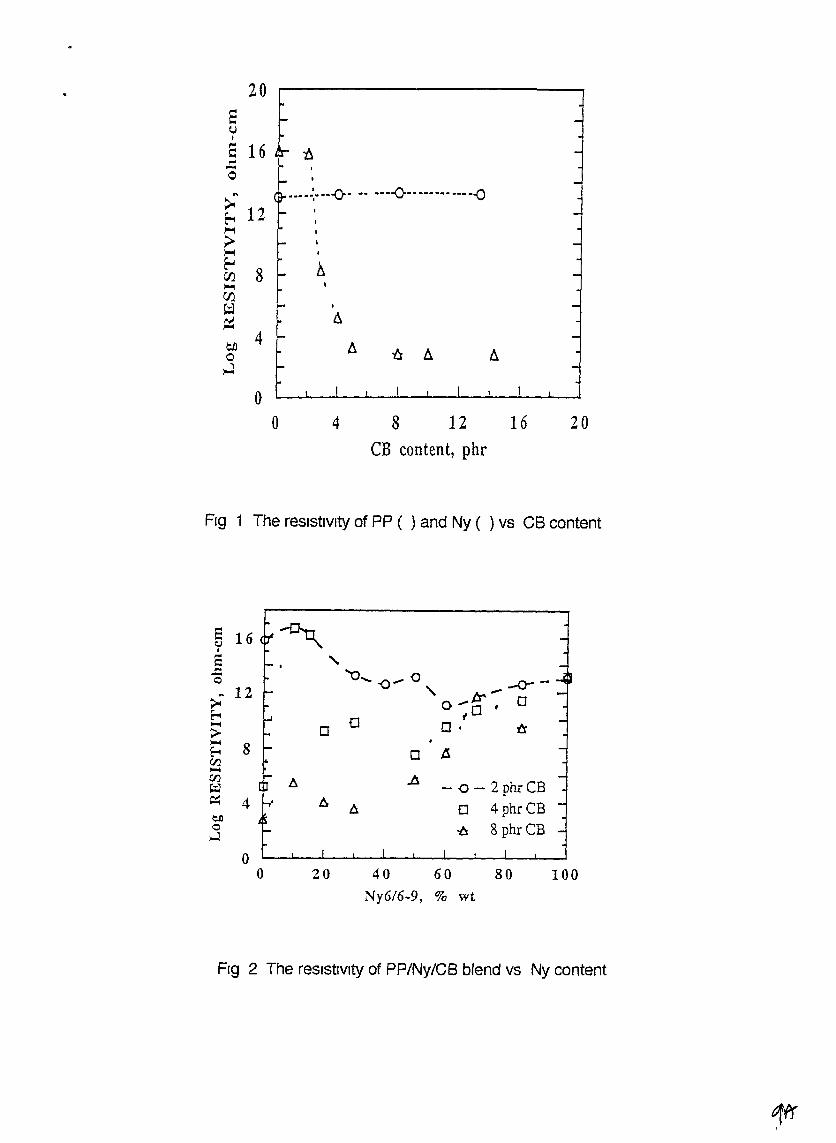
The resistivity of PP/Ny/CB blends for different matnx compOSition and different CB
loadings (e g Fig 2) does not obey any "additivity rule", but rather exhibits a
complex behavior Moreover, the mixIng sequence seems to significantly affect the
blends resistivity Optical microscopy observations show that the PP/Ny matrix
consists of two phases and that the CB IS preferentially located In the Ny phase (Fig
3) ThiS location of the CB was observed for all mixing sequences Thus, when PP
9
20
I
t::.
.---~----o- -- ----0-------------<)
s~I
S 16 n,..-o
oo 4 8 12 16
CB content, phr20
FIg 1 The resistIVIty of PP ( ) and Ny ( ) vs CB content
e 16 ~e.J•,..
"c:- '0_ -0- 0-0 -0- -
> 12 '\ o _tr - 00'
~ a f~
0 o· a;>~ 8E-t 0 IS.en~
en~ A
- 0 - 2 phrCBt::;J~ 4 6 tJ. a 4 phr CBen0 -6 8 phr CB.J
00 20 40 60 80 100
Ny616.9, % wt
Fig 2 The resistIvIty of PP/Ny/CB blend vs Ny content
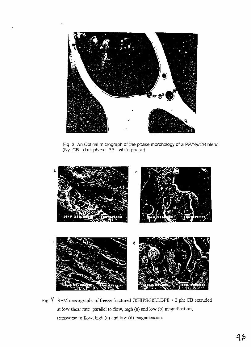
Fig 3 An OptIcal micrograph of the phase morphology of a PP/Ny/CB blend(Ny+CB - dark phase PP - whIte phase)
a c
b d
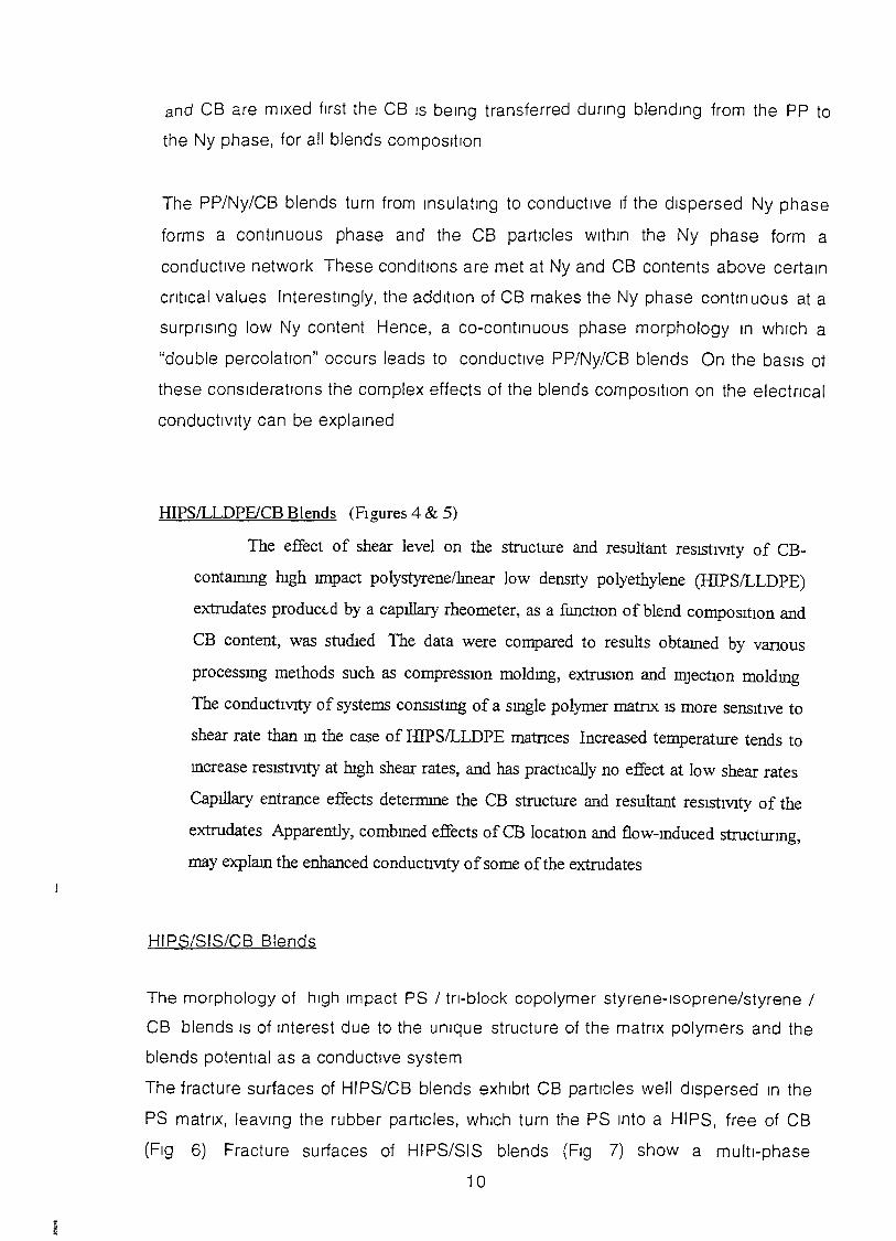
FIg ~ SEM nncrographs of freeze-fractured 70HIPS/30LLDPE + 2 phr CB extruded
at low shear rate parallel to flow, rugh (a) and low (b) rnagmficatIon,
transverse to flow, rugh (c) and low (d) rnagruficatlOll.
and CB are mixed first the CB IS being transferred dunng blending from the PP to
the Ny phase, for all blends composition
The PP/Ny/CB blends turn from insulating to conductive If the dispersed Ny phase
forms a continuous phase and the CB particles within the Ny phase form a
conductive network These conditions are met at Ny and CB contents above certain
cntlcal values Interestingly, the addition of CB makes the Ny phase continuous at a
surpnslng low Ny content Hence, a co-continuous phase morphology In which a
"double percolation" occurs leads to conductive PP/Ny/CB blends On the baSIS ot
these conSiderations the complex effects of the blends composition on the electncal
conductivity can be explained
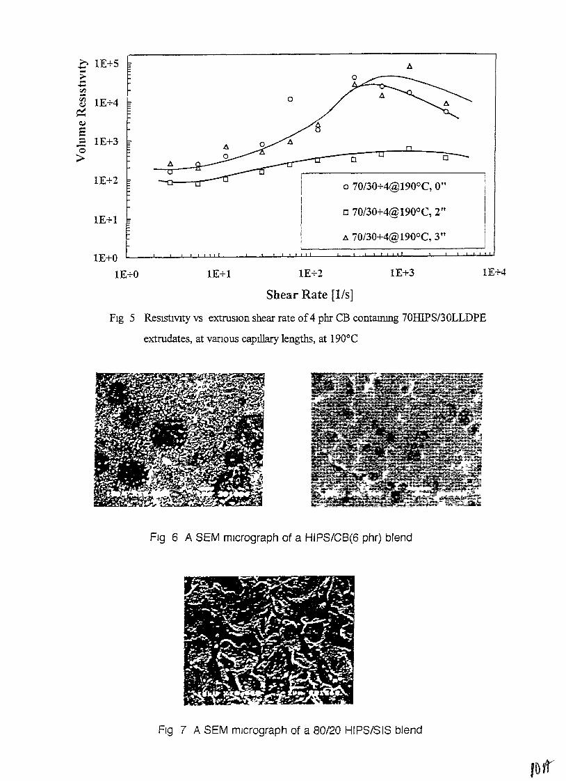
HIPS/LLDPEICB Blends (FIgures 4 & 5)
The effect of shear level on the structure and resultant resIStIVIty of CB
contammg lugh lll1pact polystyrene/lmear low density polyethylene CIllPSILLDPE)
extrudates product-d by a capillary rheometer, as a functIOn of blend composItIOn and
CB content, was studIed The data were compared to results obtamed by vanous
processmg methods such as compreSSIOn moldmg, extruSIOn and mJectlOn moldmg
The conductIVIty of systems cOllSIStmg of a smgle polymer matnx IS more sensitive to
shear rate than m the case of lllPSILLDPE matnces Increased temperature tends to
mcrease resIStIVIty at hIgh shear rates, and has practIcally no effect at low shear rates
Capillary entrance effects determme the CB structure and resultant resIStIVIty of the
extrudates Apparently, combmed effects of CB locatIon and flow-mduced structurmg,
may explam the enhanced conductIVIty of some ofthe extrudates
HIPS/SIS/CB Blends
The morphology of high Impact PS / tn-block copolymer styrene-Isoprene/styrene /
CB blends IS of Interest due to the unique structure of the matnx polymers and the
blends potential as a conductive system
The fracture surfaces of HIPS/CB blends exhibit CB particles well dispersed In the
PS matnx, leaVing the rubber particles, which turn the PS Into a HIPS, free of CB
(Fig 6) Fracture surfaces of HIPS/SIS blends (Fig 7) show a multi-phase
10
1E+4
o
1E+3
oo
o 70/30+4@190°C, 0"
o 70/30+4@190oC, 2"
A 70/30+4@190°C, 3"
1E+2lE+1
o
e
--';A;:;"-_~~0 6
~ I ------------,
--0 I
III!
1E+l
1E+2
1E+0
lE+O
f lE+S ~
~ lE+40:::Q.l
E...e 1E+3o>
Shear Rate [1/s]
FIg 5 ReSlStIVIty vs extruslOn shear rate of4 phr CB contammg 70HIPS/30LLDPE
extrudates, at varIOUS capillary lengths, at 190°C
Fig 6 A SEM mIcrograph of a HIPS/CB(6 phr) blend
FIg 7 A SEM micrograph of a 80/20 HIPS/SIS blend
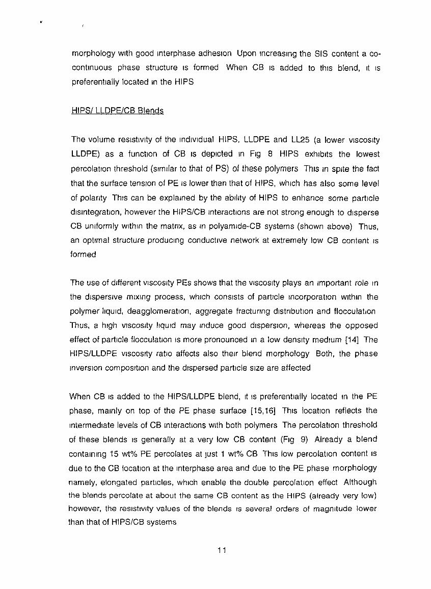
morphology with good Interphase adhesion Upon Increasing the SIS content a co
continuous phase structure IS formed When CB IS added to this blend, It IS
preferentially located In the HIPS
HIPSI LLDPE/CB Blends
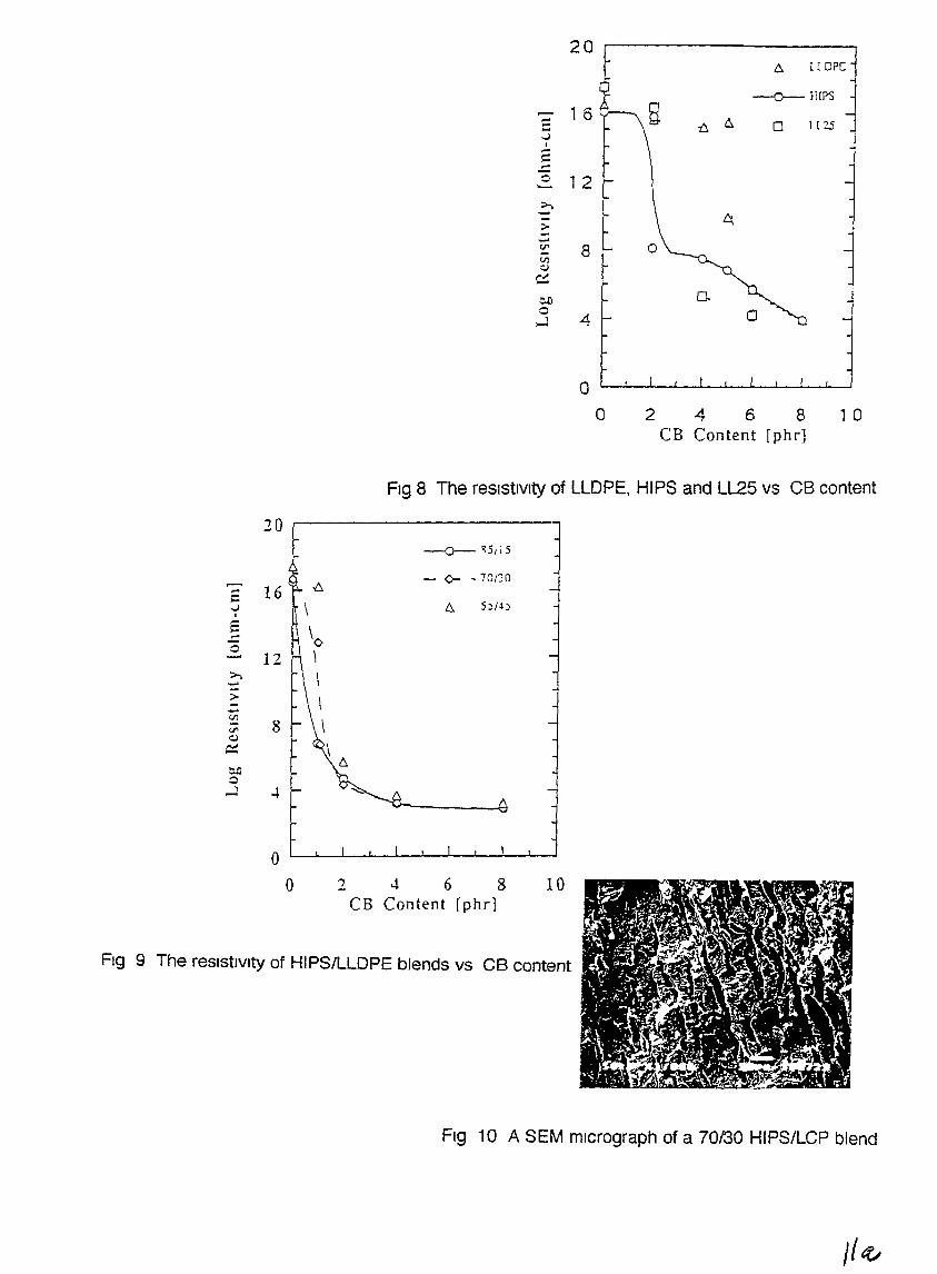
The volume resistivity of the mdlvldual HIPS, LLDPE and LL25 (a lower VISCOSity
LLDPE) as a function of CB IS depicted In Fig 8 HIPS exhibIts the lowest
percolation threshold (sImilar to that of PS) of these polymers This In spite the fact
that the surface tensIon of PE IS lower than that of HIPS, which has also some level
of polanty This can be explained by the ability of HIPS to enhance some particle
disintegration, however the HIPS/CB Interactions are not strong enough to disperse
CB uniformly wlthm the matnx, as m polyamlde-CB systems (shown above) Thus,
an optImal structure producmg conductive network at extremely low CB content IS
formed
The use of different VISCOSity PEs shows that the VISCOSity plays an Important role In
the dispersive mixing process, whIch consists of particle Incorporation Within the
polymer liqUid, deagglomeratlon, aggregate fractunng dlstnbutlon and flocculation
Thus, a hIgh VISCOSity liquid may Induce good dispersIon, whereas the opposed
effect of particle flocculatIon IS more pronounced In a low denSity medIum [14] The
HIPS/LLDPE VISCOSity ratio affects also their blend morphology Both, the phase
inverSIon compositIon and the dispersed partIcle size are affected
When CB IS added to the HIPS/LLDPE blend, It IS preferentially located In the PE
phase, mainly on top of the PE phase surface [15,16] This locatIon reflects the
Intermediate levels of CB Interactions With both polymers The percolation threshold
of these blends IS generally at a very low CB content (FIg 9) Already a blend
containing 15 wt% PE percolates at Just 1 wt% CB This low percolation content IS
due to the CB location at the mterphase area and due to the PE phase morphology
namely, elongated particles, which enable the double percolation effect Although
the blends percolate at about the same CB content as the HIPS (already very low)
however, the resIstivIty values of the blends IS several orders of magnitude lower
than that of HIPS/CB systems
11
206 I ( ope
-O--HlPS.--. 1 6:: -t.. 6 0 1(25
,..)I-:::
.::::0 1 2--...
>; I-;>-.....rJ' 8 0til::J
c:::eJl D-o
41-o
o 246 8CB Content [phr]
1 0
Fig 8 The resIstIvIty of LLDPE, HIPS and LL25 vs CB content
20---0- ~5115
- 0- - 70IJO.......16-:::
\ 6 5~/~~,..)I
E '0-0......... 12 \>; \.....;>-
\-CJl
8 \rJ'::J,...
\- 6e.G0
...J -+ "'"
Fig 9 The resistIVIty of HIPSIlLDPE blends vs CB content
10246 8CB Content rphd
oL-....l....-.....l--J-..---L-.L_l..--..L...-l--l----J
o
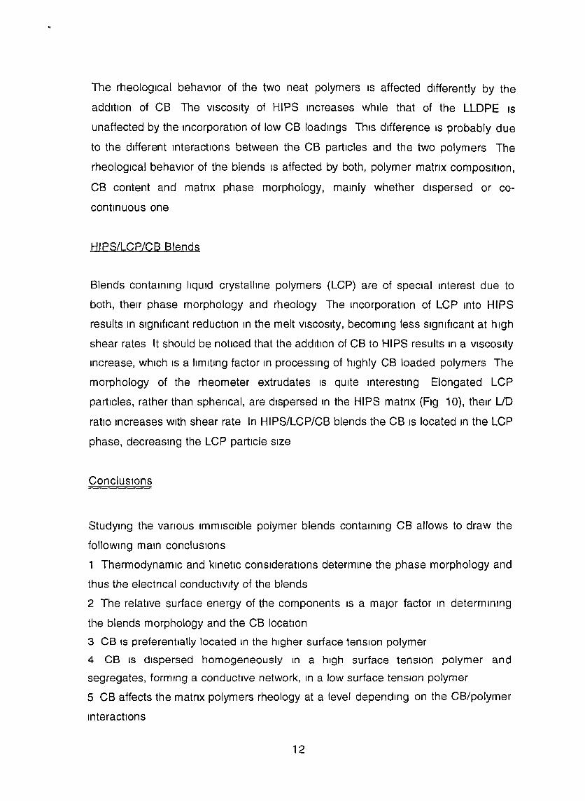
FIg 10 A SEM mIcrograph of a 70130 HIPS/LCP blend
J/~
The rheological behavior of the two neat polymers IS affected differently by the
addition of CB The VISCOSity of HIPS Increases while that of the LLDPE IS
unaffected by the Incorporation of low CB loadings This difference IS probably due
to the different interactions between the CB partIcles and the two polymers The
rheological behaVior of the blends IS affected by both, polymer matnx compOSition,
CB content and matnx phase morphology, mainly whether dispersed or co
continuous one
HIPS/LCP/CB Blends
Blends containIng liqUid crystalline polymers (LCP) are of speCial Interest due to
both, theIr phase morphology and rheology The incorporation of LCP Into HIPS
results In Significant reduction In the melt VISCOSity, becoming less slgnrflcant at high
shear rates It should be noticed that the addition of CB to HIPS results In a VISCOSity
Increase, which IS a limiting factor In processing of highly CB loaded polymers The
morphology of the rheometer extrudates IS qUite Interesting Elongated LCP
partIcles, rather than sphencal, are dispersed In the HIPS matnx (Fig 10), their LID
ratio Increases with shear rate In HIPS/LCP/CB blends the CB IS located In the LCP
phase, decreaSing the LCP particle size
ConclUSions
StudYing the vanous ImmIsCible polymer blends contalnrng CB allows to draw the
follOWing main conclUSions
1 ThermodynamiC and kinetiC conSiderations determine the phase morphology and
thus the electrical conductIvIty of the blends
2 The relative surface energy of the components IS a major factor In determining
the blends morphology and the CB location
3 CB IS preferentially located In the higher surface tension polymer
4 CB IS dispersed homogeneously In a high surface tension polymer and
segregates, formIng a conductIve network, In a low surface tensIon polymer
5 CB affects the matrix polymers rheology at a level depending on the CB/polymer
InteractIons
12
6 Electncal conductivity In low CB content blends IS attained In blends fUlfilling the
following conditions CB IS located In or on the dispersed phase, the dispersed
phase forms a continuous structure, the CB content IS higher than the cntlcal
content required for percolation In the dispersed phase
7 Co-continuous morphologies enable the blends to percolate at low CB content
8 The processing method and conditions affect the blends morphology and their
conductivity
These general maIn conclusIons may serve as gUIde-lines for the taIlor-makIng of
economically and technologically feaSible electncally conductive blends, based on
commodity polymers Moreover, they may be used to design vanous functional
blends other than conductIve ones
Impact, Relevance and Technology transfer
The field of electncally conductive plastics, electrostatic dissipating (EDS) and anti
static (AS) matenals, has recently been developed tremendously WhIle It was In Its
Infancy stage In 1992, when our R&D proposal was submitted, It IS now a
developed field and a variety of commercIal matenals with various levels of
SOphIstication IS available Nevertheless, there IS st,II room for new, unique
matenals, which Will be developed by SCientists having a good background In
polymer sCience and engineering, In the general field of conductIve plastics and
most Importantly those who understand the need In ESD and AS matenals of the
electronic Industry and are creative and have good Imagination Along these lines It
IS clear that our approach of studying electrically conductive Immiscible polymer
blends has proven Itself A new area, relevant to ESD and As matenals, focuses on
polymer systems containing Intnnslcally conductive polymers, such as polyantlme
and polypyrolle The Israeli team has been already active In thiS field since 1995
and able to produce several interesting SCientifiC publications and also results
haVing a commercIal potential The Polish team IS exploring opportunities to enter
thiS new field With the background gained through the AID project, the Polish team
has now excellent skills for execution of a project related to Intnnslcally conductive
plastiCS The relations of the two teams are excellent and Include mutual VISitS and
frequent e mall correspondence The Polish sCientists are Informed that the Israeli
13
team wIll gladly participate In a new project focusing on mtnnslcally conductive
plastics and will bnng to the project ItS expertise gained since 1995
Poland IS well known as a country making signifIcant steps to become a developed
country In general and specifically also In plastics, carbon black and compounds
thereof It IS anticipated that the know-how gamed based on the AID project may
contnbute to the relevant Industnal development progress provIding that sUItable
contacts are established In Israel, the AID project has seNed as a partial basIs for a
new project of developing electncally conductIve composites which has the
potential to matenallze Into an Industnal project The In-depth understandIng
gained coupled with recent market studies are presently serving to work out new
Ideas for collaboration with local Industry
PrOject Activities/Outputs
Conference Presentations
1 M Narkls, R Tchoudakov and A Siegmann, "Electrically Conductive
Polymer Blends Containing Low Concentration Carbon Black", 2nd Intern
Conf on Carbon Black, Mulhous (1993)
2 A Siegmann, D Benderly, M Narkls, R Tchoudakov and 0 Breuer,
"Structunng Phenomena In ReInforced/Filled Immiscible Polymer Blends",
The Eur Phys Soc Conf, Eindhoven (1994)
3 R Tchoudakov, 0 Breuer, M Narkls and A Siegmann, "Conductive Polymer
Blends", ANTEC'95, Boston (1995)
4 M Narkls, T Tchoudakov, 0 Breuer and A Siegmann, "ConductiVIty and
Morphology of Immiscible Polymer Blends with Low Carbon Black Loading",
IUPAC Intern Symp on Polymer Morphology and Electncal Properties,
Lodge (1995)
14
5 a Breuer, R Tchoudakov, M Narkls and A Siegmann, "Segregated
Structures In Electrically Conductive Immiscible Polymer Blends", The 24th
Israel Polymer and Plastics Cont , Tel AVIV (1995)
6 R Tchoudakov, a Breuer, M Narkls and A Siegmann,
"Conductivity/Morphology Relationship In Immiscible Polymer Blends
HIPS/SIS/Carbon Black", ANTEC'97, Canada (1997)
7 a Breuer, R Tchoudakov, Y Haba, Y Nachmlas, M Narkls, A Siegmann,
M Zllberman and G Tltelman, "Electrically Conductive Polymer Blends", The
8th Matenals Eng Conf, Beer Sheva (1997)
8 R Tchoudakov, M Narkls and A Siegmann, "Conductivity - Morphology
Relationship In Immiscible Polymer Blends of the HIPS/SIS/CB Type", The
26th Israel Polymer and PlastiCS Soc Conf, Tel AVIV (1997)
Publications
1 "Conductive Polymer Blends with Low Carbon Black Loading
Polypropylene/Polyamide", R Tchoudakov, a Breuer, M Narkls and A
Siegmann, Polym Eng SCI, 36, 1336 (1996)
2 "Conductive Polymer Blends with Low Carbon Black Loading
Polypropylene/Polycarbonate", R Tchoudakov, a Breuer, M Narkls and A
Stegmann, Polym Networks Blends, 6, 1 (1996)
3 "Segregated Structures In Carbon Black - Containing Immiscible Blends
HIPS/LLDPE Systems, 0 Breuer, R Tchoudakov, M Narkls and A
Siegmann J Appl Polym SCI, 64, 1097 (1997)
4 "Conductive Polymer Blends with Low Carbon Black Loading High Impact
Polystyrene/Thermoplastic Elastomer (Styrene-Isoprene-Styrene)", R
Tchoudakov, M Narkls and A Siegmann, Polym Eng SCI, 37, 1928 (1997)
15
Training
The program enabled to train a new ImmIgrant from RussIa and a several graduate
students
PrOject Productivity
The project has accomplished, In our opinion, all goals Included In the research
proposal for the present grant
Future Work
The project has lead already to further studIes of various ImmiscIble blend systems,
Including electrically conductIve systems It has expanded to systems containing
IntrinsIcally conductIve polymers rather than Just carbon black Research proposal
were submitted to the Israel MInistry of SCience and to the German-Israel BI
National SCience Foundation (GIF) The collaboration With the Polish partner Will
continue, dependIng on available support
Literature Cited
1 B Wessling, SynthetiC Metals, 41-43, 1057 (1991)
2 F Carmona, The ElectriC Properties of Carbon Black FIlled Polymers, The
2nd Int Conf on Carbon Black, Mulhouse, 1993
3 K Mlyakasa, K Watanable, E JOJlma, A AIda, M Sumrta and K Ishikawa, J
Mater SCI, 17, 1610 (1982)
4 J R Jurado, C Moure, P Duran, M ROdriguez, A LInares and J L Acosta, J
Mater SCI, 26, 4022 (1991)
5 M G Siswanto, N Pengbo, H Neubacher and L C Burton, Rubber Chem
Technol , 61, 269 (1988)
6 R D Sherman L M Middleman and S M Jacobs, Polym Eng SCI, 23, 36
(1983)
7 A Medaha, Rubber Chem Technol I 59, 432 (1986)
8 T M Amlnabhavl, P E CaSSidy and C M Thompson, Rubber Chem
Technol, 63, 451 (1990)
16
9 M Narkls, A Ram and Z Stein, Polm Eng SCI, 21, 1743 (1981)
10 W H Hess and V E ChiriCO, Rubber Chem Technol, 50, 301 (1977)
11 B Wessling, Kundstoffe, 76(10), 930 (1986)
12 G Geuskens, J L Glelens, 0 Geshef and R Deltour, Eur Polym J, 23, 993
(1987)
13 B L Lee, Polym Eng SCI, 32, 36 (1992)
14 Manas-Zloczower and Z Tadmor, MIxIng and Compounding of Polymers,
Hanser Pub, MunIch, 1994
15 R Tchoudakov, 0 Breuer, M Narkls and A Siegmann, Poly Networks
Blends, 6, 1 (1996)
16 R Tchoudakov, 0 Breuer. M Narkls and A SIegmann, Polym Eng SCI, 36,
1336 (1996)
17
j! .1
1
Conductive Polymer Blends With Low Carbon BlackLoadmg Polypropylene/Polyamide
R TCHOUDAKOV 0 BREUER and M NARKIS*
Department oj ChemLcal Engmeermg
and
A SIEGMANN
Department oj Matenals EngmeenngTechmon Israel Instttute oj Technology
Haifa 32000 Israel
The electncal reslstlVlty and morphology of polypropylene/nylon (PP/Ny) lmmlScible blends incorporated With carbon black (CB) were studIed CB was found to bepreferentIally located m the Ny phase or upon the Ny/PP mterface Blends With aco-contmuous phase morphology depIcted especially low resIstiVIty values due to a"double percolatIOn" effect The blend preparation sequence tends to affect thephase morphology thus mfluencmg the system s reSIstiVIty Polymer polanty andcrystallmity are Important factors determmmg the blend s morphology WhICh relates dIrectly to the electncal reSIstivIty obtamed
C
t(
npdfrIecpp
NPbtlpi\\trU
5t
t.tdllalatharartr
INTRODUCTION
One of the current goals of matenals research IS tocreate new matenals with propertIes tailored to a
partIcular apphcatIOn and to understand the phvsICalprocesses that determme the end propertIes Atpresent there IS a great need to produce polvmencmatenals With relatIvely hIgher conductlVlty than IScurrently avaIlable WithOUt compromIsmg the deSIrable mechanIcal and processmg propertIes
The conductIOn mechanIsm of polymer / conductlVefIller systems IS not yet fully estabhshed The effect ofthe polymer and fIller charactenstIcs on the conductIVIty of theIr mIXtures espeCIally the cntlcal compoSItIOn at WhIch a dramatic reSIstIvity change occurs1 e the msulatlVe-conductIve tranSItIon are of speCialmterest The common explanatIOn for such a drastICchange in the reSIStiVIty/fIller content curves IS related to the fIller mode of dIsperSIOn In the low content regIOn the fIller mcorporated m the form of smallparticles (aggregates or agglomerates) of dIfferentshapes IS homogeneously dlstnbuted m the msulatmg matnx where adjacent fuler partIcles are far apartWIth mcreasmg fIller content larger agglomerates ofthe fIller partIcles are formed m whICh partIcles are m"contact" At a certam cntlcal filler content the growmg agglomerates reach a size that makes large scale"contact" pOSSIble formmg a compact one two or
To whom correspondence should be addressed
three-dImenSIOnal network of the conductmg phaseWIthm the msulatmg matnx The fIrst appearance ofthe network results m a transition depicted by a drastIc decrease m the reSIstIVIty of the mIXture FollOWIng ,the mitial formation of the conductive network andupon the sharp tranSItIOn completIOn addItIonal fIllercauses the reSistiVIty of the mIXture to gradually further decrease because of a shght Improvement of theconductive network qUalIty More Important for theproduction of an optImIZed conductIve mIXture 1 ecompounds shoWing a drastic resistiVIty decrease at amimmal amount of fIller are the phySIcal and sometImes chemIcal factors determImng the formatIOn ofthe conductIve networks
The conductive network formatlOn IS currently explamed m terms of the percolatIon theory Lux (1) In
hIS recent extended reVIew depIcts a number of models that were proposed to explam the conductIVIty ofmIXtures on the baSIS of dIfferent factors such as volume fractIon of the conductIve phase the specUIc conductlVlty of the fIller partIcles the probabII1ty of thedevelopment of at least a one-dImenSIOnal conductIvenetwork and the mterfacial mteractIons at the boundary between the mdiVIdual fuler particles and the polymenc matnx Lux concludes that currently no eXIstmgmodel IS able to explam all of the dIfferent results ofexperimental studIes Furthermore no model IS ableto account for the extenSIve mfluence of dIfferent processmg methods on the percolatIOn process
ncClmi
thlinsa
rumtmtanpoldIe;Elcdetbet112Frc;40rutnetchcof t
},
tiesesLlaireontiesWe
I1336 POLYMER ENGINEERING AND SCIENCE, MAY 1996 Vol 36, No 10
BEST AVAILABLE COpy
POL
Conductwe Polymer Blends Wtth Low Carbon Black Loadmg Polypropylene / Polyamtde
phasence ofdras
lOWing1~ andJ fillerly furof t l
or L
re 1 e~e at asometlOn of
tlyex(1) in
fmodlVItyofas volIC con-of the
1uctlveJounde polyxlstmgults ofIS ablent pro
A new dynamIc mterfaclal theory of the sudden mcrease of conductIVIty m heterogeneous polymer systemS was recently developed by Wesslmg (2 3) HISmajor conc!uslOn IS that the conductIVIty mcreasephenomenon IS actually a "phase transItIon" the conductIve phase IS suddenly converted at least partIallytrom a fully dIspersed to a flocculated stage The cntlcal content at whIch thIS phase transitlOn occurs ISLrucrally dependent on the propertIes of the mterphase between a conductIve partIcle and the matnxpolymer molecules and the temperature as well
lnterestmg results are reported by Carmona (4) and\-lIyasaka et al (5) relatmg the surface tenslOn ofpolymers to the cnucal fuler concentratlOn of carbonblack (CB) m polymer compositlOns They concludedthat an excess energy due to the formatIon of CB/polymer mterfaces plays the most Important roleWhen thIS excess energy reaches a "ulllversal" valueIndependent of polymer used the CB partlcles coagulate formmg networks m the composIte They havesuggested that because of the CB surface propertIesthe cnucal carbon content correspondmg to the condUCtiVIty Jump IS related to the matnx polymer s polarity the hIgher the polanty of a gIven polymer thelarger the cntIcal content IS The main assumptlOn oftheir model IS that CB partIcles begm to coagulate atan iso-mterfacial energy state of the polymer whIch ISanalogous to the Iso-free volume state for the glasstranSluon temperatLre
Accordmg to Jurado et al (6) the percolation phenomenon observed for polypropylene samples at lowCB contents IS related to the wettmg behavior andmicrostructure of the PP matnx It was found also thatthe non percolatlve samples seem to show a tunnelling effect as a conductlOn mechalllsm and percolatIvesamples mamfest a metallIc behaVIor
The conductIon mechanIsm for CB loaded naturalrubber was studied (7-10) usmg current-voltagemeasurements and an electron spin resonancemethod for natural rubber compounds (7) The resultsare conSIstent With a model of electron-hoppmg transport With traps playmg a promment role the trapdlstnbutlOn dependmg on type of CB m the matrIxElastomer-CB surface mteractlOns were reviewed mdetail (11) and the eXIstence of a chemIcal lmkagebetween CB and typIcal rubbers was recognIZed Oonor12) studIed the dIstnbutlOn of CB m rubber by theFraunhofer dIffractIon method He found that under40 phr CB Isolated aggregates were dIstnbuted m therubber and at 40 phr they began to partially formnetworks ThIS CB content corresponds to the abruptchange of phySIcal propertIes mcludmg conductIVItyof the filled rubber
Many authors have reported the electncal properties of CB-fIlled polyethylene (PE) (13-15) It has beenestablIshed (13 14) that crosslmked compounds contalnmg mIXtures of two types of CB have shown goodcondUCtIvIty reproducIbIlIty and sWItchmg properties Segregated PE CB systems exhIbIt unusual electI1cal and dlelectncal propertIes With relatIvely hIgh
conductIVItIes at very low fIller loadmgs [025% to065% v/v CB) (15)
ConductlVlty of polymer blends contammg CB 1 ethree-component blends was mvesugated mamlv forblends of elastomers (16) The eXIstence (17) or absence (18) of CB mIgratIon WIthm the multI-phasedsystem dunng blendmg IS dIscussed m terms of theaffmlty of dIfferent elastomers for CB Less has beenreported on the conductiVIty of ImmISCIble polymerblends fIlled With CB The electncal conductlVlty III
addItIon to the parameters dIscussed above for smglepolymer/CB systems IS expected to depend on thenature of the polymers compnsmg the blends and onthe phase morphology of the systems ConductIVIty oflow denSIty polyethylene/natural rubber (LDPE/NR)blends loaded With CB (19) dId not vary monotonously as a functIon of the blends compositlOn AddltlOn ot only 10% LDPE to NR resulted m a sharp dropin the reSIstIVIty and the lowest value was obtamed for60%NR/40%LDPE blend contammg 4% to 10% CBprobably because of a speCIfIC structunng of the ImmISCIble three-component system The resisuVIty ofthese blends IS lower than the correspondmg values forthe indIVidual components at the same CB loadmg
A model PE/PS blend system fIlled With CB wasrecently studIed (20) It was noted that for CB m asemlcrystallme polymer (PE) the percolatlOn thresholdwas SIgnIficantly lower compared to an amorphousmatrIx (PS) ThIS could result from both the lowersurface tenSIOn of PE than that of PS and the hIgheractual CB content m the semlcrystallme PE because ofthe preferenual location of the CB partlcles m theamorphous phase The percolatIon threshold was reduced even more when CB was located m the mmorphase of a co-contmuous PE/PS blend A more mterestmg SItuatIon corresponds to a system m whIch theCB was selectively located at the mterface of a cocontmuous PE/PS blend In the latter two cases theconductIve phase network was contmuous With theactual CB content m that phase probably muchhIgher than the nommal content
Lee (21) has shown that the conductIvity of a fIlledpolymer system can be Improved by the addltlOn of asecond polymer of lower viSCOSIty The latter reducesthe melt VlSCOSIty of the matnx and consequently reduces the breakdown of the CB structure Honeycomb-lIke conductIve pathways through mcompatlbleplastIc/rubber blends at relatIvely low CB contentswere obtaIned because of preferentIal accumulatIOn ofCB m one phase (22)
SumIta et at (23) showed that for roller ffiL'<edHDPE /PMMA blends a maJontv of the CB was locatedm the mterfacial regIOn around the HDPE phasewhl1e for HDPE/PP blends the CB appeared mamlv III
the HDPE matnx ThIS preferentIal CB dlstnbutlonwas attnbuted to the mterfacial tenslOn and spreadmgcoeffICIents The resultmg hIgh electncal conductlVltyof these systems depends on the percolatIon of CBwithm the CB nch phase and on a degree of contmwtvof thIS phase known as the "double percolatlOn" concept It ~eems that these two factors do not prOVIde a
No 10 POLYMER ENGINEERING AND SCIENCE MAY 1996 Vol 36 No 10 BEST AVAILABLE COpy 1337
R Tchoudakov et al
complete explanatIOn for the preferential CB localIzatIOn In the mterfacIaI regIOn or in one polymer only
Presently CB loaded polypropylene /polyamldeblends WIth a low CB content were studied the InItialresults presented m (24) The effects of polyblend compOSitIOn blendmg procedure and the components nature on the compounds electnc conductIVIty andstructure were Investigated
EXPERIMENTAL
The polymers used to study the PP /Nylon/CBblends were polypropylene VC15-15P Neste FInland(Tm = 173°C) and copolyamlde 6169 EMS SWItzerland ThIS copolyamlde (Ny 616-9 - all random copolymer) IS umque m ItS relatIve low meltmg temperature (l32°C) and low degree of crystallmity bothvalues much lower than for conventIOnal polyamldesThe carbon black used m thIS study was KetjenblackEC Akzo WIth a surface area (N2 ) of 929 m21g and adIameter of 300 nm
PP/Ny blends containmg dIfferent loadmgs of CB(phr) were prepared by dry blendmg of polymer granules WIth CB m a blender followed by melt moong In aBrabender Plastograph (200°C 50 rpm) Ny was preVIously dned in a vacuum oven at 70°C overnIght Allblend ratIos descnbed relate to percentage by weIghtIn order to mvestlgate the mfluence of the blendmgprocedure on the properties of the blends threemodes of ingredient mcorporatIOn were studied addition of CB to the polymer blend (PP + Ny) + CB CBcompoundmg WIth PP followed by Ny additIOn (PP +CB) + Ny or CB compounding with Ny followed by PPadditIon (Ny + CB) + PP The resultIng blends weresubsequently compression molded at 200°C to obtam3 mm thick plaques
The volume reSistIvity of dIsc-shaped samples 5 cmm diameter was measured (DIN 53596) usmg aKeithley Electrometer 614 and a high 240A voltagesupply For samples with a low resistiVIty level a Sorensen power supply (model gRD 60-1 5) was usedSlIver or nIckel pamt was applIed to ensure contactbetween sample and electrodes namely to elImmatethe contact resistance
The blends phase morphology was studied using anOlympus optIcal microscope Samples -50 mm thickcut of the plaques usmg a microtome were placedbetween two glass shdes and observed usmg regularNomarsky or cross-polanzed optIcs Hot stage microscopy was used to observe structural changes mthe samples dunng heating up to meltIng followed bycoolmg to ambient temperature
The blends phase morphology was also studied usmg a Jeol 5400 scanrung electron mICroscope (SEM)Two types of surfaces of each sample were investIgated namely freeze fractured and mICrotomed surfaces The latter enables observatIOn of CB particlesm the dispersed phase by lookmg at sliced crosssectIOns
RESULTS AND DISCUSSION
IndIVIdual Polymers
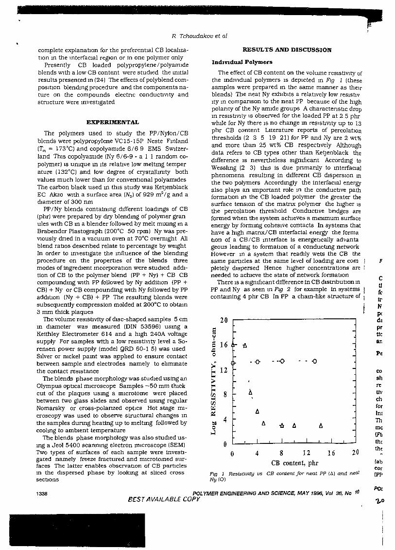
The effect of CB content on the volume resistiVIty ofthe mdlVIdual polymers IS depicted m Flg 1 (thesesamples were prepared m the same manner as theirblends) The neat Ny exhibits a relatIvely low reslstlvIty m companson to the neat PP because of the highpolanty of the Ny amide groups A charactenstIc dropIn reSistiVIty IS observed for the loaded PP at 2 5 phrwhIle for Ny there IS no change m resistiVIty up to 13phr CB content Literature reports of percolatIonthresholds (2 3 5 19 21) for PP and Ny are 2 wt%and more than 25 wt% CB respectIvely Althoughdata refers to CB types other than Ketjenblack thedIfference IS nevertheless SIgnIficant Accordmg toWesslmg (2 3) thiS is due pnmanly to mterfaCIalphenomena resultmg in dIfferent CB dIsperSIOn In
the two polymers Accordmgly the interfaCial energyalso plays an Important role m the conductive pathformatIOn m the CB loaded polymer the greater thesurface tenSIOn of the matrIx polymer the higher ISthe percolatIon threshold Conductive bndges areformed when the system achieves a mmlmum surfaceenergy by formmg coheSive contacts In systems thathave a high matnx/CB mterfacial energy the formabon of a CB/CB mterface is energetically advantageous leadmg to formatIOn of a conductmg networkHowever In a system that readily wets the CB thesame particles at the same level of loadmg are completely dispersed Hence higher concentrations areneeded to achieve the state of network formatIOn
There IS a SignIficant difference in CB mstributlOn In
PP and Ny as seen m FIg 2 for example in systems rcantaming 4 phr CB In PP a cham-like structure of I
20
eCJIe 16 -A.c0
~ 12--0 .•-0 - - ()
""";;.."""~
8 ~rJ1"""rJ1~ A~
OIl 4 A0 1:I A~
00 4 8 12 16 20
CB content, phr
Fig 1 Resistl.vtty us CB content for neat PP (Al and neatNy (0)
F
CtlfclrNIXdEprtJcan
Pc
coshreUvchforIntThme(F!I
thethe
labCOr(PP
1338 POLYMER ENGINEERING AND SCIENCE, MAY 1996, Vol 36, No 10BEST AVAILABLE COpy
POL

100
-
100
-
o
- <) - 4 phrCBa 8 phrCB
I
- <) - 2 phrCBa 4phrCB-I:J 8phrCB
I I
60 80 100
% wt
I
40
Ny6/69,
I
I
40 60 80Ny6/69, % wt
40 60 80Ny6/69, % wt
o
" -"0... -0'" 0 -0- _-l, tr'" 0 -
0-;:0o a 0 f:J.
o If,.
I
20
20
20
--iJ-,;::r' --0-----<
//
//
IT
o
oo
4
8
o
16
121-
§ 16 .,.-~
0-& - 0 - 2 phr CB5 16 If '0- -0" a 4phrCB -
'0 -I:J 8 phrCB -\ p--l\ I,. -
" I cr- -(J- I _
"- ...:tOJ)
j I-
oo
§"0
b
e'"§"0>0-Eo<...>
c ...Eo<rJj.....rJj{;<lQ::OJ)
0..J
a
1339
A local reSIstivity maxImum IS observed m the blendscontaInmg 4 phr CB upon the addition of 10% Nyfollowed by a reSIstIVIty decrease at an Ny content of20% The reSIstIVIty of the 4 phr CB content blendscontaInmg 20% to 70% Ny IS nearly constant and thengradually Increases up to the reSIstIVIty of Ny BlendscontamIng 8 phr CB behave m a SImIlar manner WIthlower resistiVIty values The (Ny + CBl + PP mixingprocedure results In speCImens of relatIvely highreSIStIVIty
F!g 3 ReStSttvlty vs Ny content U1 polymer blends WIth drJferent CB concentratwns a IPP + Ny} + CB b IPP + CB} +Ny c (Ny + CB) + PP
Conductwe Polymer Blends Wtth Low Carbon Black Loadmg Polypropylene/Polyamtde
FIg 2 SEM mu:rographs oj Ny a and PP b with 4 phr CB
CB agglomerates IS clearly observed whereas m Nythe CB at the same content is distnbuted more umformly _TIus demonstrates clearly the dIfference m theInteraction of CB partIcles with the PP or Ny matrixNy Is characterized by a very hIgh surface tensIOn andpolarity compared to that of PP (5) Both conductlVltydata and morphological observations agree WIth thepresently accepted notion regardmg the hIgh correlation between the surface tensIOn of the polymer matrixand the resistIvity of CB-Ioaded composItes (4)
Polymer Blend ConducuVlty
The reslstlVlty of PP/Ny/CB blends for dIfferent Nycontents of 2 4 and 8 phr CB IS depIcted m FIg 3 Itshould be noted that none of the blends shown has aresistivity that obeys any "addItivity rule" The reSIStiVity of the blends at a gIVen CB concentratIOnchanges WIth composItIOn m a rather complex mannerfor all CB loadmgs and all sequences of CB additIOnlnterestmgly a clear effect of the mIXing order IS seenThe (Ny + CBl + PP blends prepared by fIrst blendmgmolten Ny and CB followed by compoundmg WIth PP(Fig 3cl have the hIghest reSIStiVIty values relative tothose of blends of Identical compositIOns prepared bythe other two mIXmg procedures
The reSistIvity of blends WIth eIther 4 or 8 phr CB(above the percolatIOn threshold for PP) vanes WIth NyContent SimIlarly for the fIrst two mIXing procedures(PP + CBl + Ny and (PP + Ny) + CB (Ftgs 3a and 3b)
POLYMER ENGINEERING AND SCIENCE, MAY 1996, Vol 36 No 10
20
j:,
JlVlty of ~(these f
s their'~SIStlV- »
Ie hIgh tIC drop 15 phr ~
p to 13olatlon2 wt%
thoughck the:lmg toerfacialSion Inenerr;ty \'e rter toe;
.gher is 1-es are t" ~surface1ns that,forma-dvantaetwork:::B the fre com- 2
".:>ns areIon •utIOnln>ystemscture of
and neat
36, No 10
BEST AVAILABLE COpy
R Tchoudakov et al
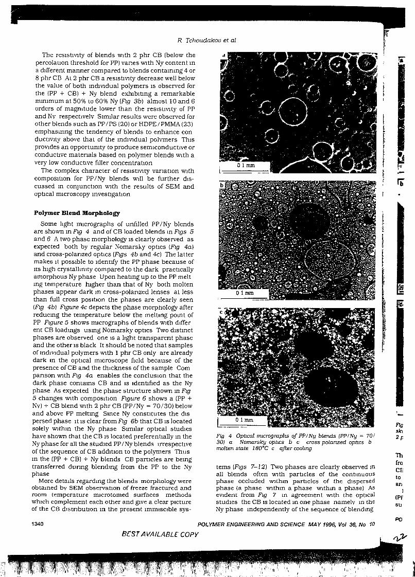
The reslstlVlty of blends WIth 2 phr CB (below thepercolatIOn threshold for PP) vanes With Ny content ma dIfferent manner compared to blends contammg 4 or8 phr CB At 2 phr CB a reslstlVlty decrease well belowthe value of both mdlvldual polymers IS observed forthe (PP + CB) + Ny blend exhlbltmg a remarkablemmlmum at 50% to 60% Ny (fig 3b) almost 10 and 6orders of magmtude lower than the resIstIVIty of PPand Ny respectIvely SImIlar results were observed forother blends such as PP/PS (20) or HDPE/PMMA (23)emphasiZmg the tendency of blends to enhance condUCtiVIty above that of the mdiVIdual polymers ThISprOVIdes an opportumty to produce semiconductIve orconductIve materIals based on polymer blends With avery low conductIve fIller concentratIOn
The complex character of reSIstIVIty VarIatIOn WithcomposItIOn for PP /Ny blends Will be further dIScussed m conjUnctIOn WIth the results of SEM andoptIcal mIcroscopy mvestigatIOn
Polymer Blend Morphology
Some lIght mIcrographs of unfIlled PP/Ny blendsare shown m fig 4 and of CB loaded blends m figs 5and 6 A two phase morphology IS clearly observed asexpected both by regular Nomarshy OptICS (fig 4a)and cross-polanzed optics (figs 4b and 4c) The lattermakes It pOSSIble to IdentIfy the PP phase because ofItS hIgh crystallImty compared to the dark practIcallyamorphous Ny phase Upon heatmg up to the PP meltmg temperature hIgher than that of Ny both moltenphases appear dark m cross-polanzed lenses at lessthan full cross pOSItIOn the phases are clearly seen(fig 4b) figure 4c depIcts the phase morphology afterreducmg the temperature below the meltmg pomt ofPP Frgure 5 shows mICrographs of blends With dIfferent CB loadmgs usmg Nomarsky optICS Two dIstmctphases are observed one IS a lIght transparent phaseand the other IS black It should be noted that samplesof mdiVIdual polymers With 1 phr CB only are alreadydark m the optical mIcroscope fIeld because of thepresence of CB and the thIckness of the sample Companson With fig 4a enables the conclUSIOn that thedark phase contams CB and IS IdentIfIed as the Nyphase As expected the phase structure shown m fig5 changes With compOSItIOn Frgure 6 shows a (PP +Nv) + CB blend WIth 2 phr CB (PP/Ny = 70/30) belowand above PP meltmg Smce Ny constItutes the dISpersed phase It IS clear from fig 6b that CB IS locatedsolely WIthm the Ny phase SImIlar optIcal studIeshave shown that the CB IS located preferentIally m theNy phase for all the studIed PP I Ny blends IrrespectIveof the sequence of CB addItIOn to the polymers Thusm the (PP + CB) + Ny blends CB partIcles are bemgtransferred dunng blendmg from the PP to the Nyphase
More detaIls regardmg the blends morphology wereobtamed bv SEM observatIOn of freeze fractured androom temperature mlcrotomed surfaces methodsWhICh complement each other and gIve a clear pIctureof the CB dIstnbutIOn m the present ImmISCIble sys-
Fig 4 Optical mlCrographs oj PP / Ny blends (PP/Ny = 70/30) a Nomarsky optlCS b c cross polanzed optics bmolten state iS0°C c qfter coolmg
terns (figs 7-12) Two phases are clearly observed III
all blends often With partIcles of the contmuousphase occluded Wlthm partIcles of the dIspersedphase (a phase Wlthm a phase Wlthm a phase) AseVIdent from Fig 7 m agreement Wlth the opticalstudIes the CB IS located m one phase nameIv m theNy phase mdependently of the sequence of blendmg
.-
FIgsin2p
ThfroCEtoan
IIPFsu
1340 POLYMER ENGINEERING AND SCIENCE MAY 1996, Vol 36, No 10
erST AlIA/LABLE COpy
I~II'~'"IIII1I
Conductwe Polymer Blends WIth Low Carbon Black Loadtng Polypropylene/PolyamIde
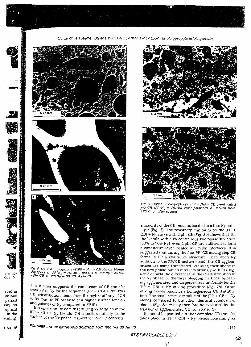
a maJonty of the CB remams located m a thm Ny outerlayer (FIg 8) The resistIVIty mmlmum on the {PP +CBl + Ny curve With 2 phr CB (FIg 3b) shows that forthe blends With a co contmuous two phase structure(50% to 70% Ny) even 2 phr CB are suffIcIent to forma conductive layer located at PP/Ny mterfaces It ISsuggested that dunng the first PP/CB mL'illlg step CBforms m PP a cham-lIke structure Then upon NyadditIOn to the PP/CB molten blend the CB agglomerates are bemg transferred retammg their shape mthe new phase which mteracts strongly With CB Flgure 7 depicts the differences m the CB dIstnbutlOn mthe Ny phase for the three blendmg methods appearmg agglomerated and dIspersed less umformlv for the(PP + CB) + Ny mIXmg procedure (FIg 7b) OthermLxmg modes result m a homogeneous CB dlstnbutlOn The small resistivity value of the {PP + CBl + Nyblends compared to the other Identical composltlOnblends (FIg 3a-c) may therefore be explamed bv thetransfer of agglomerated CB from PP to Ny
It should be pomted out that complete CB transfertakes place III {PP + CBl + Ny blends contammg as
Ftg 6 Opncal mlcrograph of a IFP + Ny) + CB blend wlth 2phr CB IFP1Ny = 70/30) cross polarized a molten state175°C b after cOO/Lng
Flg 5 OpttJ:al mlcrographs of (PP + Ny) + CB blends Nomarsky optics a ppiNy = 70130 1 phr CB b PPI Ny = 501502 phr CB c PPINy = 30170 4 phr CB
ThIs further supports the concluslOn of CB transferfrom PP to Ny for the sequence {PP + CBl + Ny ThiSCB redIstnbutlOn stems from the higher affImty of CB(0 Ny than to PP because of a hIgher surface tenslOnand polanty of Ny compared to PP (5l
It IS Important to note that dunng Ny addltlOn m theIPP + CBl + Ny blends CB transfers mltIally to thesurface of the Nv phase namely for low CB contents
4 = 701 fItlCS b '
rved mInuouspersed
lse) Asopticalm the
endmg
) No 10 PoLYMER ENGINEERING AND SCIENCE MAY 1996 Vol 36 No 10 1341
SfST AVAILABLE COpy
R Tchoudakov et al
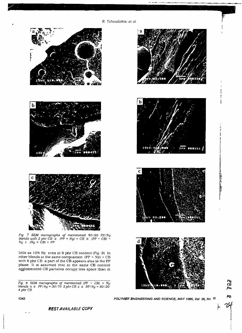
Fig 7 SEM mIcrographs oj mIcrotomed 50150 PPINyblends wIth 2 phr CB a (PP + Nyl + CB b (PP + CBl +Ny c (Ny + CBl + PP
lIttle as 10% Ny even at 8 phr CB content (Fl.g 9) Inother blends at the same compositIOn (PP + Ny) + CBWIth 8 phr CB a part of the CB appears also in the PPphase It IS assumed that at the same CB contentagglomerated CB partIcles occupy less space than m
Fig 8 SEM mICrographs qf mICrotomed (PP + CBl + Nyblends Q b PPINy = 30170 2phrCB c d PPINy = 801204 phr CB
1342
BESTAVAILABLE COpy
POLYMER ENGINEERING AND SCIENCE, MAY 1996, Vol 36, No 10
~~II
Conductwe Polymer Blends Wtth Low Carbon Black Loadmg Polypropylene I Polywmde
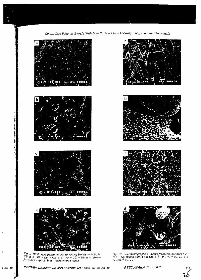
~tg 9 SEM mtcrographs of 90110 PP I Ny blends wtth 8 phr1; B a b IPP + Ny] + CB c d IPP + CB] + Ny a c freeze
ractured surface b d microtomed surface
Flg 10 SEM micrographs offreeze fractured surfaces IPP +CB] + Ny blends wtth 4 phr CB a b PPINy = 80120 c dPPINy = 90110
:1 No 10 PoLYMER ENGINEERING AND SCIENCE, MAY 1996 Vol 36 No 10 BEST AVAILABLE COpy
R Tchoudakov et al
,
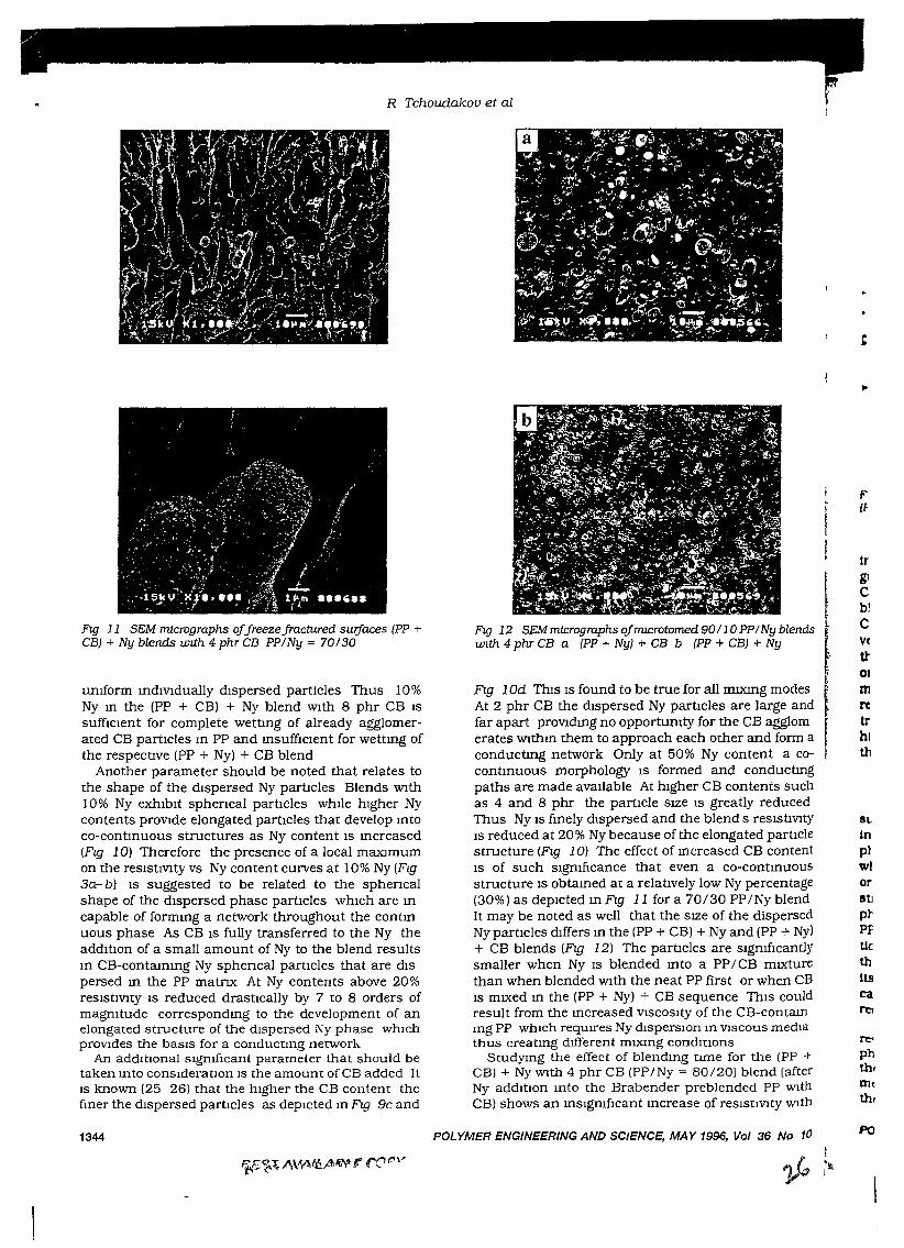
FIg 11 SEM micrographs qfJreezeJractured sUljaces (PP +CB) + Ny blends wuh 4 phr CB PPlNy = 70130
umform mdlVlduaIly dIspersed particles Thus 10%Ny m the (PP + CB) + Ny blend With 8 phr CB ISsuffICIent for complete wettmg of already agglomerated CB partIcles m PP and msufficient for wettmg ofthe respeCtIve (PP + Ny) + CB blend
Another parameter should be noted that relates tothe shape of the dIspersed Ny partIcles Blends With10% Ny exhIbIt sphencal partIcles whIle hIgher Nycontents proVIde elongated partIcles that develop mtoco-contmuous structures as Ny content IS mcreased(FIg 10) Therefore the presence of a local maxImumon the reSIstIVIty vs Ny content curves at 10% Ny (FIg3a-b) IS suggested to be related to the sphencalshape of the dIspersed phase partIcles whIch are mcapable of formmg a network throughout the contmuous phase As CB IS fully transferred to the Ny theaddItIon of a small amount of Ny to the blend resultsm CB-contammg Ny sphencal partIcles that are dISpersed m the PP matrIX At Ny contents above 20%reSIstIVIty IS reduced drastIcally by 7 to 8 orders ofmagmtude correspondmg to the development of anelongated structure of the dIspersed Ny phase whIchproVIdes the baSIS for a conductmg network
An addItJOnal sIgmfIcant parameter that should betaken mto consIderatIOn IS the amount ofCB added ItIS known (25 26) that the hIgher the CB content thefmer the dIspersed partIcles as depIcted m FIg 9c and
1344
FIg 12 SEM micrographs ojmtCTotomed 90110 PP1Ny blendswlth 4 phr CB a (PP + Ny) + CB b (PP + CB) + Ny
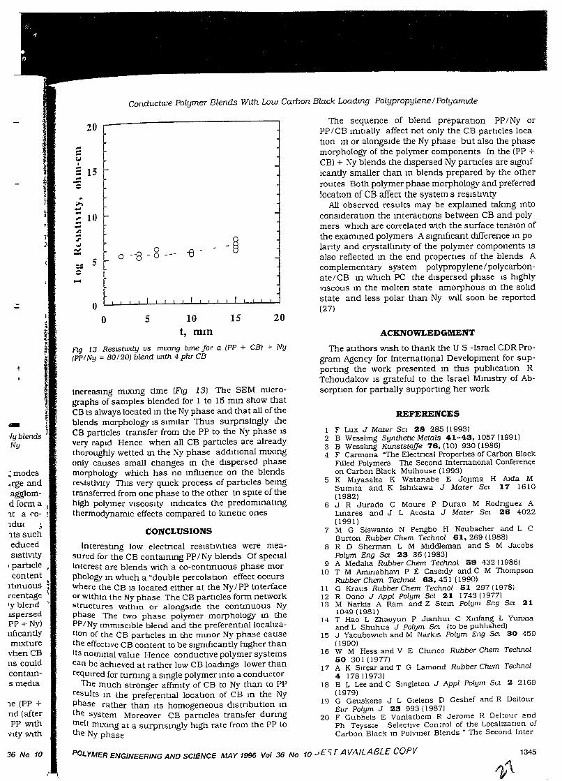
Ftg 10d ThIS IS found to be true for all moong modesAt 2 phr CB the dIspersed Ny partIcles are large andfar apart proVIdmg no opportumty for the CB agglomerates WIthm them to approach each other and form aconductmg network Only at 50% Ny content a cocontmuous morphology IS formed and conductmgpaths are made avaIlable At hIgher CB contents suchas 4 and 8 phr the partIcle SIZe IS greatly reducedThus Ny IS fmely dIspersed and the blend s reslstlVltyIS reduced at 20% Ny because of the elongated partIclestructure (Ftg 10) The effect of mcreased CB contentIS of such sIgmfIcance that even a co-contmuousstructure IS obtamed at a relatIvely low Ny percentage(30%) as depIcted m Ftg 11 for a 70/30 PP INy blendlt may be noted as well that the SIze of the dispersedNy partIcles dIffers m the (PP + CB) + Ny and (PP + Ny)+ CB blends (Ftg 12) The partIcles are sIgnIfIcantlysmaller when Ny IS blended mto a PP1CB mIXturethan when blended With the neat PP first or when CBIS mIXed m the (PP + Ny) + CB sequence ThIS couldresult from the mcreased VISCOSIty of the CB-contammg PP whIch reqUires Ny dIsperSIOn m VISCOUS medIathus creatmg dIfferent mIXlIlg condItJOns
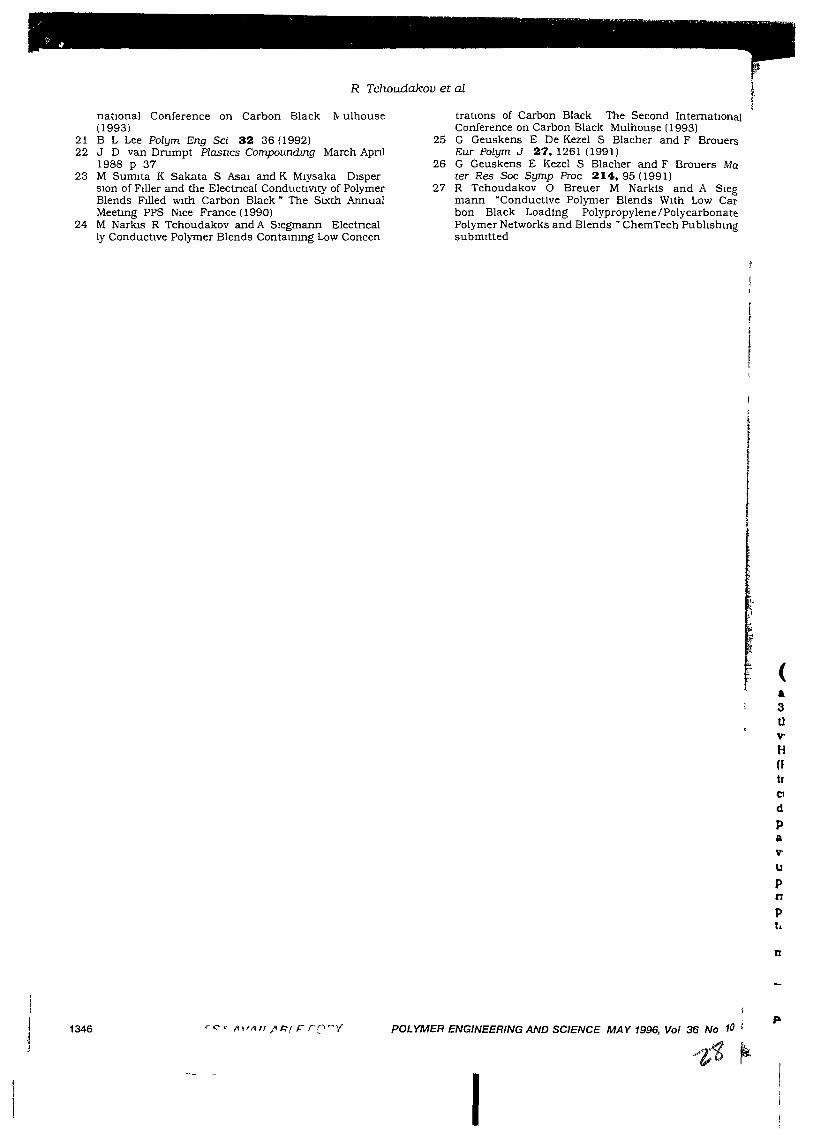
Studymg the effect of blendmg tIme for the (PP +CBl + Ny With 4 phr CB (PP/Ny = 80120) blend (afterNy addltJOn mto the Brabender preblended PP WithCB) shows an mSlgmficant mcrease of reSIstIVIty With
POLYMER ENGINEERING AND SCIENCE, MA Y 1996, Vol 36 No 10
r(f
IrgJCblCV(
UOf
mrctrhitl1
atInpiwior!ItptPFUcthItscaret
ConductIVe Polymer Blends Wtth Low Carbon Black Loadmg PolypropylenelPolyamtde
CONCLUSIONS
The sequence of blend preparatIOn PP INy orPP I CB ImtIally affect not only the CB partIcles locatIOn m or alongSIde the Ny phase but also the phasemorphology of the polymer components In the (PP +CB) + Ny blends the dIspersed Ny partIcles are sIgmfIcantly smaller than ill blends prepared by the otherroutes Both polymer phase morphology and preferredlocatIOn of CB affect the system s reslstlVlty
All observed results may be explamed takmg mtoconsIderatIOn the mteractIons between CB and polymers whIch are correlated with the surface tenSIOn ofthe exammed polymers A sIgmfIcant dIfference In polanty and crystallmity of the polymer components ISalso reflected m the end propertIes of the blends Acomplementary system polypropylene I polycarbonate/CB m whIch PC the dIspersed phase IS hIghlyVISCOUS In the molten state amorphous In the solIdstate and less polar than Ny WIll soon be reported(27)
1 F Lux J Mater SCI 28 285 (1993)2 B Wesslmg Synthet:tc Metals 41-43. 1057 (1991)3 B Wesslmg KunststoJfe 76. (10) 930 (1986)4 F Carmona "The Electncal Properties of Carbon Black
Filled Polymers The Second International Conferenceon Carbon Black Mulhouse (1993)
5 K Mlyasaka K Watanabe E JOJIma H Aida MSumlta and K Ishikawa J Mater SCI 17 1610(1982)
6 J R Jurado C Moure P Duran M Rodriguez ALmares and J L Acosta J Mater SCI 26 4022(1991)
7 M G Slswanto N Pengbo H Neubacher and L CBurton Rubber Chem Technol 61.269 (1988)
8 R D Sherman L M Middleman and S M JacobsPolym Eng SCI 23 36 (1983)
9 A Medalia Rubber Chem Technol 59 432 (1986)10 T M Ammabhavi P E Cassidy and C M Thompson
Rubber Chern Technol 63. 451 (1990)11 G Kraus Rubber Chem Technol 51 297 (1978)12 R Oono J Appl Polym Sci 21 1743 (1977)13 M Narkis A Ram and Z Stem Polym Eng SCI 21
1049 (1981)14 T Hao L Zhaoyun P JlanhUi C Xmfang L Yunxla
and L Shuhua J Polym SCI (to be published)15 J YacuboWlch and M NarklS Polym Eng SCI 30 459
(990)16 W M Hess and V E ChIrICO Rubber Chem Technol
50 301 (1977)17 A K Sircar and T G Lamond Rubber Chem Technol
4 178 (1973)18 B L Lee and C Smgleton J Appl Polym Su 2 2169
(1979)19 G Geuskens J L Glelens D Geshef and R Deltour
Eur Polym J 23 993 (1987)20 F Gubbels E Vanlathem R Jerome R Deltour and
Ph Teyssle Selective Control of the Local1zatlOn ofCarbon Black 10 Polymer Blends· The Second Inter
ACKNOWLEDGMENT
The authors WIsh to thank the US-Israel CDR Program Agency for International Development for supportIng the work presented m thIS publIcatIOn RTchoudakov IS grateful to the Israel MmIstry of AbsorptIon for partIally supporting her work
REFERENCES
20
-
-
-
I
15
I
5
I
oo
10t, mIn
fIg 13 ReslStwIty us mlXlTlg ttme for a (PP + CB) + Ny(PP/Ny = 80120) blend wIth 4 phr CB
Increasmg mlXlng time (Flg 13) The SEM micrographs of samples blended for 1 to 15 mm show thatCB Is always located m the Ny phase and that all of theblends morphology IS sImilar Thus surpnsingly theCB particles transfer from the PP to the Ny phase ISvery rapId Hence when all CB partIcles are alreadythoroughly wetted m the Ny phase addItIOnal mlXlngonly causes small changes m the dIspersed phasemorphology which has no mfluence on the blendsre.,lstlvity This very qUIck process of partIcles bemgtransferred from one phase to the other in spIte of thehigh polymer VISCOSIty mdIcates the predommatmgthermodynamic effects compared to kmetIc ones
InterestIng low electncal reSIstIVItIes were measured for the CB contammg PP INy blends Of specIalInterest are blends with a co-contmuous phase morphology In whIch a ~double percolatIOn effect occursWhere the CB IS located either at the Ny/PP Interfaceor wIthIn the Ny phase The CB partICles form networkstructures WIthIn or alongSide the contmuous Nyphase The two phase polymer morphology ill thePP/Ny ImmiSCible blend and the preferentIallocalIzalion of the CB partIcles m the mmor Ny phase causethe effective CB content to be sIgmflcantly hIgher thanIts nomInal value Hence conductIve polymer systemscan be achIeved at rather low CB loadmgs lower thanreqUired for turnmg a smgle polymer mto a conductor
The much stronger affmlty of CB to Ny than to PPresults m the preferentIal locatIOn of CB m the Nyphase rather than Its homogeneous dlstnbution Inthe system Moreover CB particles tran~fer dunngmelt mL'{mg at a surpnsmgly hIgh rate from the PP tothe Ny phase
20
,..~...I;JI...
15 '-......,..---~
~
• ...1
...10 '-,......
Jli ...
- ~J'
] j
:x: -"8 0 -e -0 - 0
5 f-1 :J)--....f
tri
I1~.. 1
vyblendsNy
~modes
.rge andagglomdforma I
lt a <'0- 1ldu( j
ltS sucheducedSIStiVIty
I partIcle.content
Itmuous ~rcentage tIy blend 'IspersedPP + Ny)uflCantlymIXture
vhen CBlIS couldcontams medIa
le (PP +nd (afterPP WIth
Vlty WIth
36 No 10 POLYMER ENGINEERING AND SCIENCE MAY 1996 Vol 36 No 10 JEe;; rAVAILABLE COpy 1345
I \
" ~ .., , .... , ~... .- - .. ,,, .. . ~. ..- .... "... -... .
C' .,
R Tchoudakov et al
natIOnal Conference on Carbon Black 1\ ulhouse(1993)
21 B L Lee Polym Eng Sci 32 36 (1992)22 J D van Drumpt Plastzes Compoundmg March Apnl
1988 p 3723 M Sumlta K Sakata S Asal and K Mlysaka Disper
slon of Filler and the Electncal ConductlVlty of PolymerBlends Filled WIth Carbon Black" The SIXth AnnualMeetmg PPS Nice France (1990)
24 M Narkis R Tchoudakov and A Siegmann Electncally Conductive Polymer Blends Contammg Low Concen
tratlOns of Carbon Black The Second InternatIOnalConference on Carbon Black Mulhouse (1993)
25 G Geuskens E De Kezel S Blacher and F BrouersEur Polym J 27,1261 (1991)
26 G Geuskens E Kezel S Blacher and F Brouers Mater Res Soc Symp Proc 214,95 (1991)
27 R Tchoudakov 0 Breuer M Narkis and A Slegmann ·Conductive Polymer Blends With Low Carbon Black Loading Polypropylene I PolycarbonatePolymer Networks and Blends" ChemTech Publlshmgsubmitted
(a3tlV'
HHtrC1
d
PaV'
upnpt.
u
1346 POLYMER ENGINEERING AND SCIENCE MAY 1996, Vol 36 No 10
I
Polym Nptwork" Bknds b (1) 1 8 (1')%)
Conduchve Polymer Blends wIth Low Carbon Black LoadIngPolypropylenefPolycarbonate
R Tchoudakov, 0 Breuer, and M NarkIs*
Dppartment of Chemiral El1gIl1Lermf, Terhmoll hr \( I In...111 lilt nf It (hnolol.y 1111I111 I.WOO /... ral I
A SIegmannDepartment of Materiab Engmeermg Terhmon l... ratl lll ... tltute of 1, (hnolnl.Y Ilarr I I.WOO I... r" I* To whom rorrespondence should be addre~~ed
Carbon black CB loaded IIlUIlISclble polypropylene! polycarbon
ate blends exhIbIt low re~lstIvltv values at low CB content:. CB Ib
preferentially located m the PC phase whIch IS dISpersed through
out the PP matn'C m the torm of numerous small partIcle:. encoun
tenng one another and formmg conductIve networks A
co contmuous structure IS not essentlalfor promotIng low reSIStiVIty
apparently the mterfacral properties of CB!polymer paIrS m
combmatIon WIth the polymers mdividual features polanty crys
talhmty VISCOSIty mfluence the blend morphology whIch m turn
affects the electncal reSIStIVIty
Keywords Blends Carbon Black Electncal ConductIVItyPolycarbonate Polypropylene
INTRODUCTION
Increasmg a ttentIon IS currentIy gIven to mcorpora tIonofcarbon black, CB, mto mcompatIble polymer blends Anumber of recent pubhcatIons deahng WIth such conductIve blends115 reported that theIr conductIVIty may bemuch hIgher than that of theIr mdlVldual constItuents atthe same CB loadIng, and that htgh levels of conductIVItymay be achteved at surpnsmgly low CB loadmgs As htghcontent of CB tends to dmumsh polymer mechan+calpropertIes, Increase polymer melt VlSCOSlty, and causeextreme dustIng, an opportumty to lower the fIlleramount IS advantageous 1
The enhancement of conductiVIty IS suggested to bedue to the formatIon ofhoneycomb-hke conductive pathways through the blend due to preferentIal accumulatIonof CB m one of the phases or at theIr mterface 1 MaInpomts of mterest are the CB locatIon m the studIed polymer blends and the correlatIon between theIr electncalconductiVIty and morphology The CB locatIon m theblend IS deterrmned by a combmatIOn of complex propertres mcludmg rmxmg procedure relatIve polymer VIS
COSIty and the polymer s abIlIty to wet and adherestrongly to the hIler
VarIOUs mIXIng sequences may be used when blendIng components together through masterbatchmg or SImultaneous rmxmg of all mgredlents 2-4 ThIS affects theblend morphology, the CB location, and the resultantblend conductIVIty CB may stay m the phase to whIch It
1181 9510196/$000+070
rF("T J\VAfLABl E COpy
IS mItIally added or may transfer from one phase toanother The transfer depends on the polarIty of thepolymer and Its afflmty to CB, resultmg In a preferentialCB location The domaIn SIze of the dIspersed phase ISstrongly affected by the manner m whIch the CB IS mtroduced mto the blend45 and by the rmxmg energy mput 5
The VISCOSIty of the components and the ratIo betweentheIr VISCOSIty values IS of great tmportance and affectsthe morphology generated dunng mIXIng, resultmg meIther a dIspersed phase or co-contInuous morphology 6
Increased CB content was found to reduce the SIze of thedIspersed phase 79 Thus, there IS a dIrect correlatIonbetween the rmxmg sequence and the resultant morphology, due to CB s tendency to mcrease the phase VISCOSIty
It IS well known that CB drastically reduces the electrIcal reSIstIvIty when added to a polymer matnx ThecntIcal amount of CB necessary to buJ1d up a conductivenetwork and, accordmgly, to make the matenal conductIve IS referred to as the percolatIon threshold 10 An addIbonal term IS the "double percolabon threshold",referrmg to percolatIon m mcompatIble p.:llymer blendsTills IS affected by the percolatIon of the CB In the fJ1lernch phase and by the structural contInUlty of thIS phasem the blend 10-13 Tills notIon IS further expanded to amultiple percolatIon theory m multI-phased blends 14
In the recent study,15 PPjNy blends of co-contInuousphase morphology exhtbIted appreCIable conductIVIty atlow CB content However, m tills case, CB content ISlower than the percolatIon threshold reqUIred for thedIspersed Ny phase, where It IS usually located m PPjNyblends PercolatIon In tills PPjNy blend was observed ata very low CB content, WIth the CB located alongSIde theNy contInuous phase It was also shown that the sequence of blend preparatIon, PP+Ny or PP+CB fIrst,affects not only the CB particles preferentIal locatIon, mor alongSIde the Ny phase, but also the two polymerphase morphology In the (PP+CB)+Ny blends the dISpersed Ny partIcles are sIgmfIcantly smaller than mblends prepared by the other routes Thus it was establIshed that both polymer phase morphology and CBlocatIon affect the systems reSIstIVIty
Presently, the behaVIOr ofPP blends WIth PC, less polarthan Ny, wIth low CB contents IS studied Morphologyand conductIVIty were determmed for blends of dIfferent
© ChemTec Pubhshmg
2
composItion and dIfferent sequences of mgredlent mcorporatIon
EXPERIMENTAL
The polymers used to study the conductIve blends ofPPIPC, were POlypropylene VC15-15P, Neste, FInland(Tm=173°C) and Polycarbonate Lexan 103-GE (T =149°C,Tm=225°C) All blend ratios descrIbed relate to ~ercentage by weIght Carbon black Ket.Jenblack EC by Akzo wasused In tlus study
Polyblends of PP wIth PC contammg 1-4 phr CB wereprepared by melt mlxmg m a Brabender PlastographequIpped WIth a 50 em3 cell The temperature of the mIXerwas Increased from 235 to 250°C With mcrease of the PCcontent In the blends due to dIfficulties m processmgblends WIth lugh PC content The mfluence of the blendmg procedure on the properties of the blends was mvesttgated by usmg three modes of mgredientsmcorporatIon addItIon of CB to the polymer blend,(PP+PC)+CB, CB compoundmg WIth PP followed by PCaddItion, (PP+CB)+PC, or CB compoundIng WIth PCfollowed by PP addItIon, (PC+CB)+PP Pnor to processmg the polymer granules were ground and PC was drIedat T=120°C The resul tIng blends were subsequently compreSSIOn molded at 240°C to obtam 3 rom tluck plaques
The volume reSIstIVIty of dIsc-shaped samples,S cm mdIameter, was measured accordmg to DIN 53596 usmg aKeIthley Electrometer 614 and a hIgh (240 A) VOltagesupply For samples WIth low level reSIStIVIty a Sorensenpower supply, model QRD 60-1,5 was used SlIver ornIckel pamt was used to ensure contact between sampleand electrodes, namely, to ehmmate the contact reSIStance All samples were of approXimately 3 rom thickness
The blends phase morphology was studIed USIng aJeol5400 scanrung electron IDlcroscope, SEM Two typesof surfaces of each sample were Investigated namely,freeze fractured and IDlcrotomed surfaces
Influence of mIXmg bme on blends reSIstIVIty wascarned out only for (PP+CB)+ PC blends In the follOWIngmanner PP was blended WIth CB m the Brabender for 6-7mmutes, then PC was gradually added to thIS IDlXturedunng 5 mmutes The 15 mmutes reqUIred for mIXIng allblend components together was measured upon complet]1"T of the PC addibon
RESULTS AND DISCUSSION
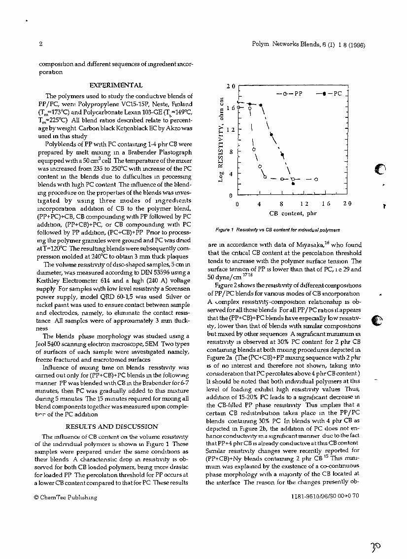
The Influence of CB content on the volume reSIstiVItyof the IndIVIdual polymers IS shown 10 FIgure 1 Thesesamples were prepared under the same condlhons astheIr blends A charactenstIc drop In reSIstIVIty IS observed for both CB loaded polymers, beIng more drashcfor loaded PP The percolation threshold for PP occurs ata lowerCB content compared to that for PC These results
© ChernTee PublIshIng
Polyrn Networks Blends, 6 (1) 1 8 (1996)
20
I- -o--PP -I-PC...<.J -------.:: 1 6 ~ \ \Cl
;;... 1 2 l- I \E- •-> roo \ \-E- O~ 8 I- -Cf.J \
,wc:: 0
\ ClOJ) 4 \.Cl
...:l 0- '0- -0l- e ~
0I I I I
0 4 8 12 16 20 tCB content, phr
Figure 1 Res/stNlty vs CB content for mdNldual polymers
are m accordance With data of :Mlyasaka,16 who foundthat the cntIcal CB content at the percolatIon thresholdtends to mcrease WIth the polymer surface tenSIOn Thesurface tenSIOn of PP IS lower than that of PC, Ie 29 and50 dynelem 1718
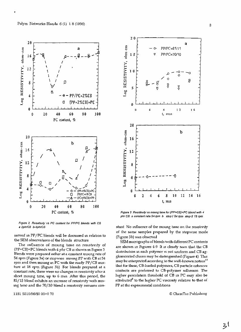
FIgure 2 shows the reSIstIVIty of dIfferent compOSItIonsof PPIPC blends for varIOUS modes of CB mcorporatIonA I..omplex reSIstiVIty-composItIon relatIonslup IS observed for all these blends For all PPI PC ratIos It appearsthat the (PP+CB)+PC blends have espeaally low resistIv- ~Ity, lower than that of blends WIth slIDllar compOSItIons .....but IDlxed by other sequences A sigruficant rnmtmum mreSIstiVIty IS observed at 30% PC content for 2 Phr CBcontammg blends at both mIXIng procedures depIcted mFIgure 2a (The (PC+CB)+PP mlXmg sequence WIth 2 phrIS of no Interest and therefore not shown, takmg mtoconslderatwn tha t PC percolates above 4 phr CB content )It should be noted that both mdiVIdual polymers at thIslevel of loadIng exhIbIt hIgh reSIstiVIty values Thus,addition of 15-20% PC leads to a SignIfIcant decrease Inthe CB-611ed PP phase reslshvlty TIns ImplIes that acertam CB redlstnbutIOn takes place In the PPI PCblends contallling 30% PC In blends WIth 4 phr CB asdepIcted 10 FIgure 2b, the addItion of PC does not en-hance conductiVity 10 a sIgmflcantmanner due to the factthat PP+4 phr CB IS already conductIve at thIS CB contentSimIlar reSIstIVIty changes were recently reported for(PP+CB)+Ny blends contammg 2 phr CB 15 TIns mmI-mum was explamed by the eXIstence of a co-contInuousphase morphology WIth a maJonty of the CB located atthe mterface The reason for the changes presently ob-
1181-9510/96/$000+070
"
Polym Networks Blends 6 (1) 1 8 (1996) 3
2 0 r-------------~20
E a :=f- <:i
e; ::I
16 7~ "'~ p___,Q__ ~,.,.,lE -
..c: 0
0 \ I - >->- 12
\ I F--&-< \ I >-.... ~;> - \ I....
\ I~
~ 8 JJ - CI.lI'JJ '01 w.... ~r:n -w a tlll
~0
4 - - ~ - PP/PC+2%CB ...l::.00 a (PP+2%CB)+PC,J
0 I I I I
0 20 40 60 80 100PC content, %
1 5 '-
1 0
5
o()
a- 0- PP/PC=8'i!l'i
'V PP/PC=70110
,D -0--00
/ 0~
~-8' 'V-'V
fj 'V'V
I I I I I I r I
4 II I 2 I 6
t, 111m
-
-
b
'-
4 l-- - - -0- - - - - - - -0
20
8 f-e;
E 16 ....=o
~ 12....>....~ 8....I'JJ~~
::.00 ->J
0 I I I I I I I
0 2 4 6 8 10 12 14 16t, mm
FIgure 3 Res/stNIty vs mD(Jng tIme for (PP+CB)+PC blend with 4phr CB a constant rate 54 rpm b step I 54 rpm step 1/ 18 rpm
10080
b
\
\
40 60PC content, %
20
}-
D / I
/ I1\ I
7g, ........ I /
--R a / ' d"' --0/ '0- - ...
- () - (I'P+4%CO)+pca pP/PC+4'7tCB
-t, - (pC+4%CO)+PP
4
OL....L....L...JL.-J......l-J.--'-.J....J..~l-l-~L...L....L...JL.-J.....1-J
o
20
16 --A
/12 /
8 /
Ee;I
a..c:o
FIgure 2 Res/stNlty vs PC content for PPIPC blends with CBa 2phrCB b-4phrCB
served m PPfPC blends will be dIscussed m relab.on tothe SEM observab.ons of the blends structure
The m£luence of mIXing time on resIstivIty of(PP+CB)+PC blends wIth 4 phr CB IS shown m FIgure 3Blends were prepared eIther at a constant mIxmg rate of54 rpm (FIgure 3a) or stepWIse mIXmg PP WIth CB at 54rpm and then nuxIng m PC With the ready PPI CB mIXture at 18 rpm (FIgure 3b) For blends prepared at aconstant rate, there were no changes m resishVIty after ashort ffilXmg hme, up to 6 mID After thIS perIod, the85/15 blend exhIbits an mcrease of reSIstIVIty WIth nuxmg tune and the 70/30 blend s resIstIvIty remams con-
stant No mfluence of the nuxmg tune on the reslshVItyof the same samples prepared by the stepWIse mode(FIgure 3b) was observed
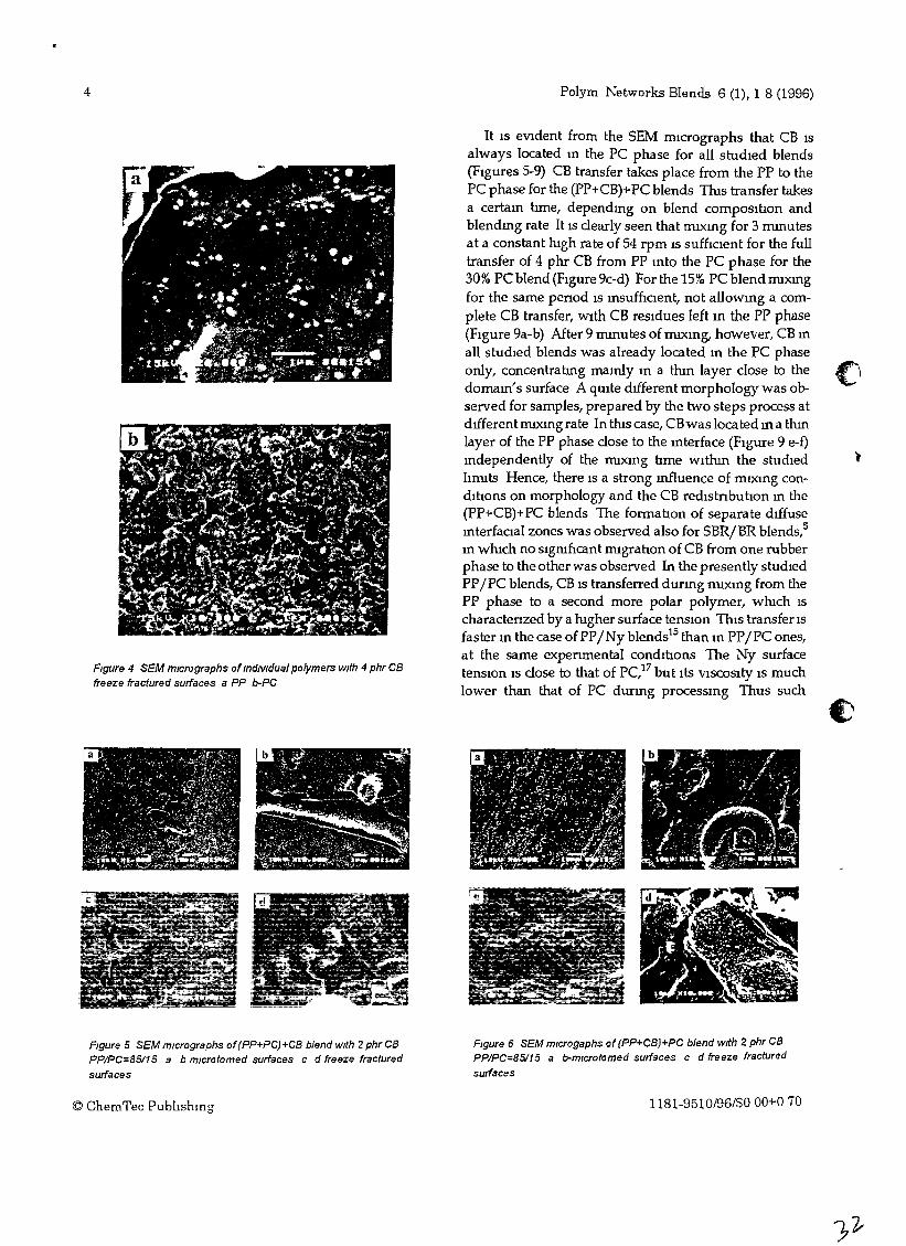
SEM mIcrographs of blends WIth dIfferent PC contentsare shown m FIgures 4-9 It IS clearly seen that the CBdIstnbution m each polymer is not uruform and CB agglomerated chams may be dIstinguIshed (FIgure 4) Tlusmay be mterpreted accordmg to the well-known nohonl9
that for these, CB-loaded polymers, CB partIcle coheSIvecontacts are preferred to CB-polymer adheSIOn ThehIgher percolatIOn threshold of CB m PC may also beattnbuted8 to the hIgher PC VISCOSIty relative to that ofPP at the experunental conditIons
1181 9510/96/$0 00+0 70 © ChemTec Publtshmg
4
Figure 4 SEM micrographs of individual polymers With 4 phr CBfreeze fractured surfaces a PP b-PC
Polym Networks Blends 6 (1), 1 8 (1996)
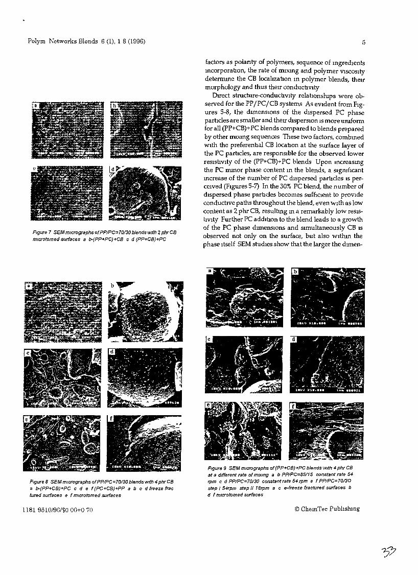
It is eVident from the SEM nucrographs that CB isalways located m the PC phase for all studied blends(Figures 5-9) CB transfer takes place from the PP to thePC phase for the (PP+CB)+PC blends Tlus transfer takesa certam hme, dependmg on blend composillon andblendmg rate It IS clearly seen that rruxmg for 3 mmutesat a constant mgh rate of 54 rpm IS suffiCient for the fulltransfer of 4 phr CB from PP mto the PC phase for the30% PC blend (FIgure 9c-d) For the 15% PC blend nuxmgfor the same penod is msuffIclent, not allowmg a complete CB transfer, wIth CB reSidues left In the PP phase(FIgure 9a-b) After 9 mmutes of rruxmg, however, CB mall studied blends was already located m the PC phaseonly, concentratlng mamly matron layer close to thedomam's surface A qUite dIfferent morphology was observed for samples, prepared by the two steps process atdIfferentffilXlngrate In this case, CBwas locatedma thInlayer of the PP phase close to the mterface (FIgure 9 e-f)mdependently of the nuxmg hme wlthm the studiedhnuts Hence, there is a strong mfluence of mV<lng condillons on morphology and the CB redistnbullon m the(PP+CB)+PC blends The fonnahon of separate dIffusemterfacial zones was observed also for SBR/BR blends,Sm which no sigruficant nugrallon of CB from one rubberphase to the other was observed In the presently studIedPPIPC blends, CB is transferred durmg nuxmg from thePP phase to a second more polar polymer, which ischaractenzed by a higher surface tenSIOn Tlus transfer isfaster m the case ofPPINy biendsis than m PPIPC ones,at the same expenmental condihons The Ny surfacetenSIOn IS close to that of PC,I7 but its ViSCOSIty is muchlower than that of PC durmg processmg Thus such
Figure 5 SEM mIcrographs of (PP+PC)+CB blend with 2 phr CBPPIPC=85/15 a b mlcrotomed surfaces c d freeze fractured
surfaces
© ChemTec Publlshmg
Figure 6 SEM mlcrogaphs of (PP+CB)+PC blend with 2 phr CBPP/PC=85/15 a b-mlcrotomed surfaces c d freeze fractured
surfaces
1181-9510/96/$000+070
Polym Networks Blends 6 (1), 1 8 (1996) 5
FIgure 7 SEM micrographs ofPP/PC=70/30 blends wrth 2phr C8mlcroromed surfaces a b-(PP+PC)+CB c d (PP+CB)+PC
factors as polanty of polymers, sequence of IngredIentsmcorporatlon, the rate of nuxmg and polymer VISCOSItydetermme the CB localtzatlon In polymer blends, theumorphology and thus therr conductIVity
Drrect structure-conductlvlty relatlonsrups were observed for the PP jPCjCB systems As eVIdent from FIgures 5-8, the dtrnenSlOns of the dIspersed PC phasepartlcles are smaller and theu dlsperslOn IS more uruformfor all (PP+CB)+PC blends compared to blends preparedby other nuxmg sequences These two factors, combInedwIth the preferentlal CB locatlon at the surface layer ofthe PC parhcles, are responsIble for the observed lowerresIstIvIty of the (PP+CB)+PC blends Upon mcreasmgthe PC mInor phase content In the blends, a sigruficantIncrease of the number of PC dIspersed partIcles IS perceIved (FIgures 5-7) In the 30% PC blend, the number ofdIspersed phase partIcles becomes sufftclent to provIdeconductive paths throughout the blend, even wIth as lowcontent as 2 phr CB, resultmg In a remarkably low reSIStIVIty Further PC additlon to the blend leads to a growthof the PC phase dtrnenSlOns and SImultaneously CB ISobserved not only on the surface, but also Withtn thephase Itself SEM studIes show that the larger the dtrnen-
FIgure 9 SEM mIcrographs of (PP+CB)+PC blends WIth 4 phr CBat a dIfferent rate of mIxing a b PP/PC=85/15 constant rate 54rpm c d PP/PC=70130 constant rate 54 rpm e f PP/PC=70130step I 54rpm step /I 18rpm ace-freeze fractured surfaces bd f mlcrotomed surfaces
Figure 8 SEM mIcrographs ofPP/PC=70/30 blends wrth 4 phr CBa b-(PP+CB)+PC c d e f (PC+CB)+PP abc d freeze fractured surfaces e f mlcrotomed surfaces
1181 9510/96/$000+070 © ChemTec Publtshmg
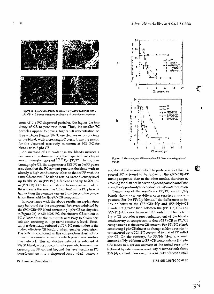
6 Polym Networks Blends, 6 (1), 1 8 (1996)
c20
20
-0
--<>-pp~-Ny&69
- !3 - (Pp)701NyJO--+- (Pp)5OJNySO
.. (P!')301Ny70
-o--pp-{3-PC- « - PP701PC30- -A- (PP70)IPC30
• (pP50)IPC50
4 8 12 16Ol content, pbr
4 8 12 16CB content, phr
x-~--_K
I\
..... lfl... ,",\" ...
oD
Do
20 r------------,
§ 16'0
a
b
20 ,..-----------.....
e"
slgruflcant nse m reslStIVlty The partIcle SIZe of the diSpersed PC IS found to be lugher m the (pC+CB)+PPffilXlng sequence than m the other modes, therefore In
creasmg the distance between adjacent partIcles and lowenng the opportumty for conductIve network formatIon
Campanson of the results for PPIPC and PPINyblends shows a certa111 difference 111 reslStIVlty vs composItIon For the PPINy blends,15 the dIfferences 111 behaVIOr between the (PP+CB)+ Ny and (PP+ Ny)+CBblends are greater than between the (PP+CB)+PC and(PP+PC)+CB ones Increased PC content m blends With2 phr CB proVldes a great enhancement of the blend sconduchvlty m companson to that of PPICB or PC/CBcomposItIons at the same CB content For PPIPC blendscontammg 4 phr CB almost no change m blend reslsuVltyIS measured up to 50% PC compared to that of PP With 4phr CB On the contrary, for PPINy blends, a smallamount of Ny additIon to PP/CB composItIons (4-8 phrCB) leads to a certam mcrease of the ImtIal reslshvltyfollowed by a decrease In resistIvity of blends With above20% Ny content However, the resistIvity of these blends
FIJure 11 ResIStivity vs CB content for PP blends with Ny(a) andPC(b)
Figure 10 SEM micrographs of50150 (PP+CB)+PC blends with 2
phr CB a b freeze fractured surfaces c d mlcrotomed surfaces
slOns of the PC dIspersed partIcles, the higher the tendency of CB to penetrate them Thus, the smaller PCparhcles appear to have a lugher CB concentratIon ontheIr surfaces (Figure 10) These changes m morphologyof the blend, With mcreasmg PC content, are the reasonfor the observed reslstIVlty ffilmmum at 30% PC forblends With 2 phr CB
An mcrease of CB content m the blends mduces adecrease m the dlmenslOns of the dispersed partIcles, aswas prevlOusly reported 57815 For PPIPC blends, contammg4phrCB, thedlsperslOnof15% PC m the PP phaseIS so nne, that the PC content prOVides the blend With analready a lugh conduchVlty, close to that of PP With thesame CB content The blend retams Its conductIVlty levelup to 50% PC m (PP+PC)+CB blends and up to 70% PCm (PP+CB)+PC blends It should be emphaSIZed that forthese blends the effective CB content m the PC phase IShigher than the nommal one and It IS beyond the percolatIon threshold for the PCjCB composItIon
In accordance With the above results, an explanatIonmay be found for the exceptIonal behaVIOr exhibited bythe (PC+CB)+ PP blend contaming -1 phr CB (as depictedIn Figure 2b) At 80-100% PC, the effectIve CB content In
PC IS lower than the minImum necessary to obtain percolahon resulting In high blend reslshvlty levels ReslshVlty IS drastIcally reduced at 70% PC content due to thehigher eftecuve CB loading wluch enables percolatIonThe 30% PP contained In thiS composItIon does not diminish the essentIal structure wluch prOVides cl. conductIve network This conductIve network IS retained atSO/50 blend, where co-continuity preVaIls, however, In
creasmg the PP content beyond tlus level results m PCtransformatIon mto d dispersed form, which causes a
© ChemTec PublIshmg 1181 9510/96/$000+070
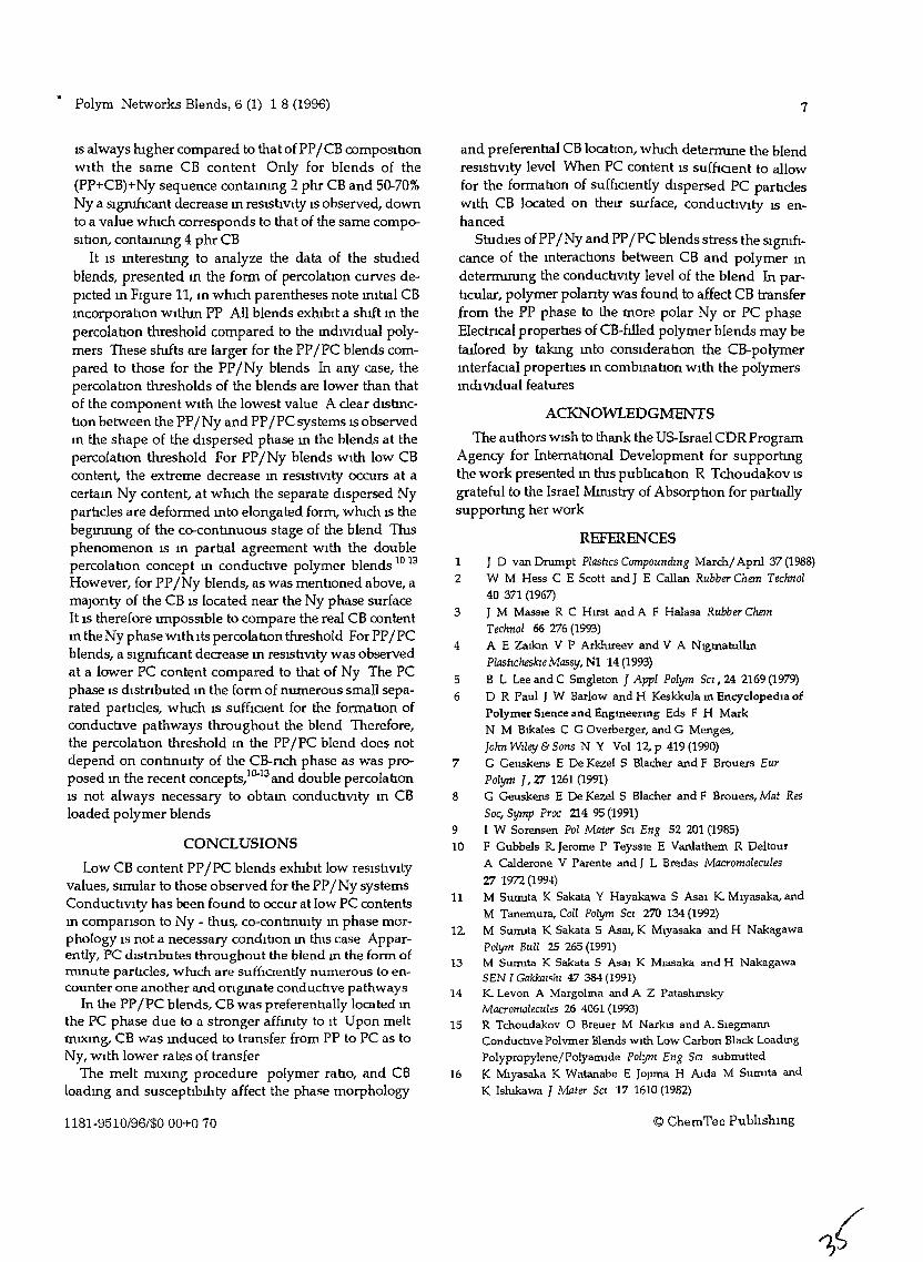
.. Polym Networks Blends, 6 (1) 1 8 (1996)
IS always htgher compared to that of PPI CB composllJonwith the same CB content Only for blends of the(PP+CB)+Ny sequence contaInIng 2 phr CB and 50-70%Nya slgruflcant decrease In resistivIty IS observed, downto a value whIch corresponds to that of the same composItion, contammg 4 phr CB
It IS InterestIng to analyze the data of the studIedblends, presented In the form of percolation curves depIcted In FIgure 11, In whIch parentheses note lrutIal CBIncorporation WIthIn PP All blends exhtblt a shtft In thepercolanon threshold compared to the mdlvldual polymers These shIfts are larger for the PPIPC blends compared to those for the PPINy blends In any case, thepercolahon thresholds of the blends are lower than thatof the component WIth the lowest value A clear dIShnCtion between the PPINy and PPIPC systems IS observedIn the shape of the dIspersed phase In the blends at thepercolation threshold For PPINy blends WIth low CBcontent, the extreme decrease In reSIstivity occurs at acertaIn Ny content, at which the separate dIspersed Nyparhcles are deformed Into elongated form, whtch IS thebegmrung of the co-contInUOUS stage of the blend ThIsphenomenon IS In parbal agreement WIth the doublepercolation concept In conducbve polymer blends 10 13However, for PPINy blends, as was menboned above, amaJonty of the CB IS located near the Ny phase surfaceIt IS therefore lffipossible to compare the real CB contentIn the Ny phase wIth Its percolabon threshold For PPIPCblends, a sigruncant decrease In reslshVlty was observedat a lower PC content compared to that of Ny The PCphase IS dIstnbuted In the form of numerous small separated parbcles, whtch IS suffloent for the fonnalJon ofconduchve pathways throughout the blend Therefore,the percolabon threshold In the PPIPC blend does notdepend on continUIty of the CB-nch phase as was proposed In the recent concepts,10-13and double percolalJonIS not always necessary to obtaIn conducbvlty In CBloaded polymer blends
CONCLUSIONS
Low CB content PPIPC blends exhtblt low reSIstiVItyvalues, sIIDllar to those observed for the PPINy systemsConductivIty has been found to occur at low PC contentsm companson to Ny - thus, co-conlJnuity m phase morphology IS not a necessary condlhon m thiS case Apparently, PC dIstnbutes throughout the blend m the fonn ofmInute partIcles, wluch are suffICIently numerous to encounter one another and ongmate conductIve pathways
In the PPIPC blends, CB was preferentially located mthe PC phase due to a stronger afftruty to It Upon meltmIXIng, CB was mduced to transfer from PP to PC as toNy, WIth lower rates of transfer
The melt IDlXIng procedure polymer ratio, and CBloadmg and susceptibIlIty affect the phase morphology
1181-9510/96/$000+070
7
and preferential CB location, whtch deterIDIne the blendreSIstivity level When PC content IS suffioent to allowfor the formabon of sufnclently dIspersed PC particlesWIth CB located on theIr surface, conductIVIty IS enhanced
StudIes of PPINy and PPIPC blends stress the Signilicance of the mteracbons between CB and polymer Indetermtrung the conductiVlty level of the blend In particular, polymer polanty Was found to affect CB transferfrom the PP phase to the more polar Ny or PC phaseElectncal propernes of CB-ftlled polymer blends may betauored by takmg Into conSIderatIon the CB-polymerInterfaCIal properties m combInation WIth the polymersmdIVldual features
ACKNOWLEDGMENTS
The authors WIsh to thank the US-Israel CDR ProgramAgency for International Development for supporhngthe work presented In thts pubhcabon R Tchoudakov ISgrateful to the Israel Muustry of Absorphon for parhallysupporhng her work
REFERENCES
1 J D van Drumpt Plashcs CompoundIng Marchi Apnl 37 (1988)
2 W M Hess C E Scott and J E Callan Rubber Chern Technol40 371 (1967)
3 J M MaSSIe R C Hrrst and A F Halasa Rubber ChernTechnol 66 276 (1993)
4 A E Zatkm V P Arklureev and V A N19matulbnPlashcheslaeMassy, N1 14 (1993)
5 B L Lee and C Smgleton J Appl Polym SCI, 24 2169 (1979)
6 D R Paul J W Barlow and H Keskkula m EncyclopedIa of
Polymer Slence and Engmeenng Eds F H MarkN M Btkales C G Overberger, and G Menges,John Wiley & Sons N Y Voll2,p 419(1990)
7 G Geuskens E De Kezel S Blacher and F Brouers EurPolym J, 27 1261 (1991)
8 G Geuskens E De Kezel S Blacher and F Brouers, Mat ResSoc, Symp Proc 214 95 (1991)
9 I W Sorensen Pol Mater SCI Eng 52 201 (1985)
10 F Gubbels R. Jerome P Teyssle E Vanlathem R DeltourA Calderone V Parente and J L Bredas Macromolecules27 1972 (1994)
11 M SUIDlla K Sakata Y Hayakawa S Asal K Mlyasaka, andM Tanemura, Coil Polym SCI 270 134 (1992)
12. M Sunuta K Sakata S Asat, K Mlyasaka and H NakagawaPolym Bull 25 265 (1991)
13 M Sunuta K Sakata S Asal K Mlasaka and H NakagawaSEN I Gakkaz<hl 47 384 (1991)
14 K. Levon A Margolma and A Z PatashmskyMacromolecules 26 4061 (1993)
15 R Tchoudakov 0 Breuer M NarklS and A. SIegmannConductIve Polvmer Blends WIth Low Carbon Black LoadmgPolypropylene/Polyanude Polym Eng Sa subIDltted
16 K Mlyasaka K Watanabe E JOJIma H AIda M Sumita andK Islukawa J Mater Sa 17 1610 (1982)
© ChemTec PublIshmg

8
17 I Nansawa In Strengrth of Polymer Materials (Russ)
Moscow Clrlmya 1987 p 84
© ChemTec Pubhshmg
Polym Networks Blends, 6 (1), 1 8 (1996)
18 D W Van Krevelen In PropertIes of Polymers 3rd ed,J hf'1}/er 1990
19 B WL~1>lmg, Kunststoffe 76(10) 930 (1986)
Recezved Apn123, 1995, Accepted May 23,1995
1181-9510/96/$000+070
Segregated Structures in Carbon Black-ContainingImmiscible Polymer Blends: HIPS/LLDPE Systems
o BREUER,l R TCHOUDAKOV,l M NARKIS,l A SIEGMANN 2
Departments of 'Chemlcal Engmeerlng and 2Matenals Englneenng Technion-Israel Institute of Technology,Haifa 32000, Israel
Recewed 16 September 1996, accepted 18 October 1996
ABSTRACT The structure/electncal resIstlVIty relatIOnshIp m CB loaded ImmISCIbleHIPS/LLDPE blends was studIed Effects ofCB content and locatIOn, dIspersed polymerphase SIze and shape, dIspersed phase VISCOSIty, and processmg procedures were exammed The elongated dIspersed phase m CB-contammg blends IS essentlal for promotmgconductlVIty m formulatIons prepared by melt mlXlng and compreSSIOn moldmg However, the same formulatIOns proved hIghly reSIstIve when mJectIOn-molded, due toonentatIOn and exceSSIve sheanng © 1997 John WIley & Sons Inc J Appl Polym SCI 641097-1106 1997
INTRODUCTION
Polymer blends assume an lIDportant role m CBfilled polymer systems due to the tendency of thefiller to accumulate preferentIally m certam reglOns Wlthm the multI-phase matnx I Tlus mduces the formatIOn of segregated structureswhereupon CB may form a network,2 enhancmgthe electncal conductIVIty and reducmg the mtIcal CB content essentIal for percolatIOn The practlCal advantages of low CB loadmgs m terms ofprocessmg, cost, and mechanIcal propertIes areapparent3
4, however, the compleXIty mtroducedby multI-phase polymer systems, theIr structureand propertIes, demands an m-depth understandmg of the behaVior ofsuch systems and addItIonalcautIon m matenal deSIgn
The fact that matenal propertIes as well as processmg parameters mfluence the electncal conductIVIty has already been estabhshed m CBfilled one-component matnces Polymer propertIes such as surface tenSIOn, VISCOSIty, and degreeof crystalhruty are to be conSIdered m addItIOn tothe prOceSSIng condItIons as factors determInmgthe resultIng conductIVIty level 5-8
Correspondence to M Narkls© 1997 John WIley & Sons Inc eee 0021 8995/97/061097 10
Some ImIDlscIble polymer blend systems havealready been studled,9-I3 Yleldmg the followmggeneral results
• CB locates preferentIally Wltlun the phase Inwluch It has a lugher percolatIon threshold,bemg usually the polymer of hIgher surfacetenSIOn value ThIS effect IS so SIgnIficantthat occaSIOnally mIgratIOn of CB from onephase to another may be observed dunngmelt mlXlng when the filler IS mltlally mcorporated WlthIn the polymer oflower polanty
• The phase morphology and CB locatIOn deterIDlne the blend reSIstIVity level The double percolatIon concept, reqUInng contmUItyfor the CB network, has been Introduced andfound necessary to obtam conductIVity m CBloaded polymer blends
• The percolatlon threshold and reSIstIVIty values ofthe blend are lower than those depIctedfor the correspondmg CB-filled mdIVIdualpolymers
In thIS study a hIgh-Impact polystyrene/hnearlow-denSIty polyethylene (HIPS/LLDPE) systemwas mvestIgated ThIS constItutes a typIcal ImmISCIble polymer blend In whIch the former com-
1097
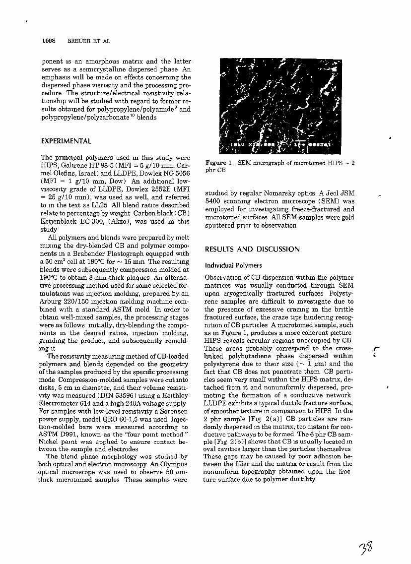
1098 BREUER ET AL
ponent IS an amorphous matnx and the latterserves as a semlcrystallme dIspersed phase AnemphasIs WIll be made on effects concernmg thedIspersed phase VlSCOSlty and the processmg procedure The structureIelectncal resIstivIty relatlOnshlp WIll be studIed wIth regard to former results obtamed for polypropylene/polyamlde 9 andpolypropylene/polycarbonate 10 blends
EXPERIMENTAL
The pnnclpal polymers used m thIs study wereHIPS, Galirene HT 88-5 (MFI =: 5 gl10 mm, Carmel Olefins, Israel) and LLDPE, Dowlex NG 5056(MFI =: 1 gl10 mm, Dow) An addItional lowVlSCOSlty grade of LLDPE, Dowlex 2552E (MFI=: 25 gl10 mm), was used as well, and referredto m the text as LL25 All blend ratIOS descnbedrelate to percentage by weIght Carbon black (CB )KetJenblack EC-300, (Akzo) , was used m thIsstudy
All polymers and blends were prepared by meltmlXlng the dry-blended CB and polymer components m a Brabender Plastograph eqmpped WItha 50 cm3 cell at 190°C for - 15 mm The resultmgblends were subsequently compreSSIOn molded at190°C to obtam 3-mm-thlck plaques An alternative processmg method used for some selected formulatlOns was mJection moldmg, prepared by anArburg 220/150 mJection moldmg machme combmed WIth a standard ASTM mold In order toobtam well-miXed samples, the processmg stageswere as follows mitially, dry-blendmg the components m the deSIred ratios, mJection moldmg,gnndmg the product, and subsequently remoldmglt
The reslstiVlty measunng method of CB-Ioadedpolymers and blends depended on the geometryofthe samples produced by the specIfic processmgmode CompresslOn-molded samples were cut mtodIsks, 5 cm m dIameter, and their volume reSIstiVIty was measured (DIN 53596) usmg a KeIthleyElectrometer 614 and a hIgh 240A voltage supplyFor samples WIth low-level reslstlVlty a Sorensenpower supply, model QRD 60-1,5 was used InJectIOn-molded bars were measured accordmg toASTM D991, known as the "four pomt method"NIckel pamt was apphed to ensure contact between the sample and electrodes
The blend phase morphology was studIed byboth optIcal and electron mIcroscopy An Olympusoptical mIcroscope was used to observe 50 j.lmthIck microtomed samples These samples were
FIgure 1 SEM mICrograph of mlcrotomed HIPS + 2phrCB
studIed by regular Nomarsky optICS A 3eol 3SM5400 scannmg electron mIcroscope (SEM) wasemployed for mvestigatmg freeze-fractured andmicrotomed surfaces All SEM samples were goldsputtered pnor to observatIOn
RESULTS AND DISCUSSION
IndiVidual Polymers
ObservatlOn of CB dIsperslOn withm the polymermatnces was usually conducted through SEMupon cryogemcally fractured surfaces Polystyrene samples are dIfficult to mvestigate due tothe presence of exceSSIve crazmg m the bnttlefractured surface, the craze tips hmdenng recogmtlOn ofCB partIcles A microtomed sample, suchas m FIgure 1, produces a more coherent pIctureHIPS reveals CIrcular regIOns unoccupIed by CBThese areas probably correspond to the crosslinked polybutadiene phase dIspersed Wlthmpolystyrene due to theIr SIze (- 1 j.lm) and thefact that CB does not penetrate them CB partIcles seem very small withm the HIPS matnx, detached from It and nonumformly dIspersed, promotmg the formatlOn of a conductive networkLLDPE exhIbIts a typIcal ductIle fracture surface,of smoother texture m companson to HIPS In the2 phr sample [FIg 2(a)] CB particles are randomly dIspersed m the matnx, too dIstant for conductive pathways to be formed The 6 phr CB sample [FIg 2(b)] shows that CB IS usually located moval caVIties larger than the partIcles themselvesThese gaps may be caused by poor adheSIOn between the filler and the matnx or result from thenonumform topography obtamed upon the fracture surface due to polymer ductihty
r....
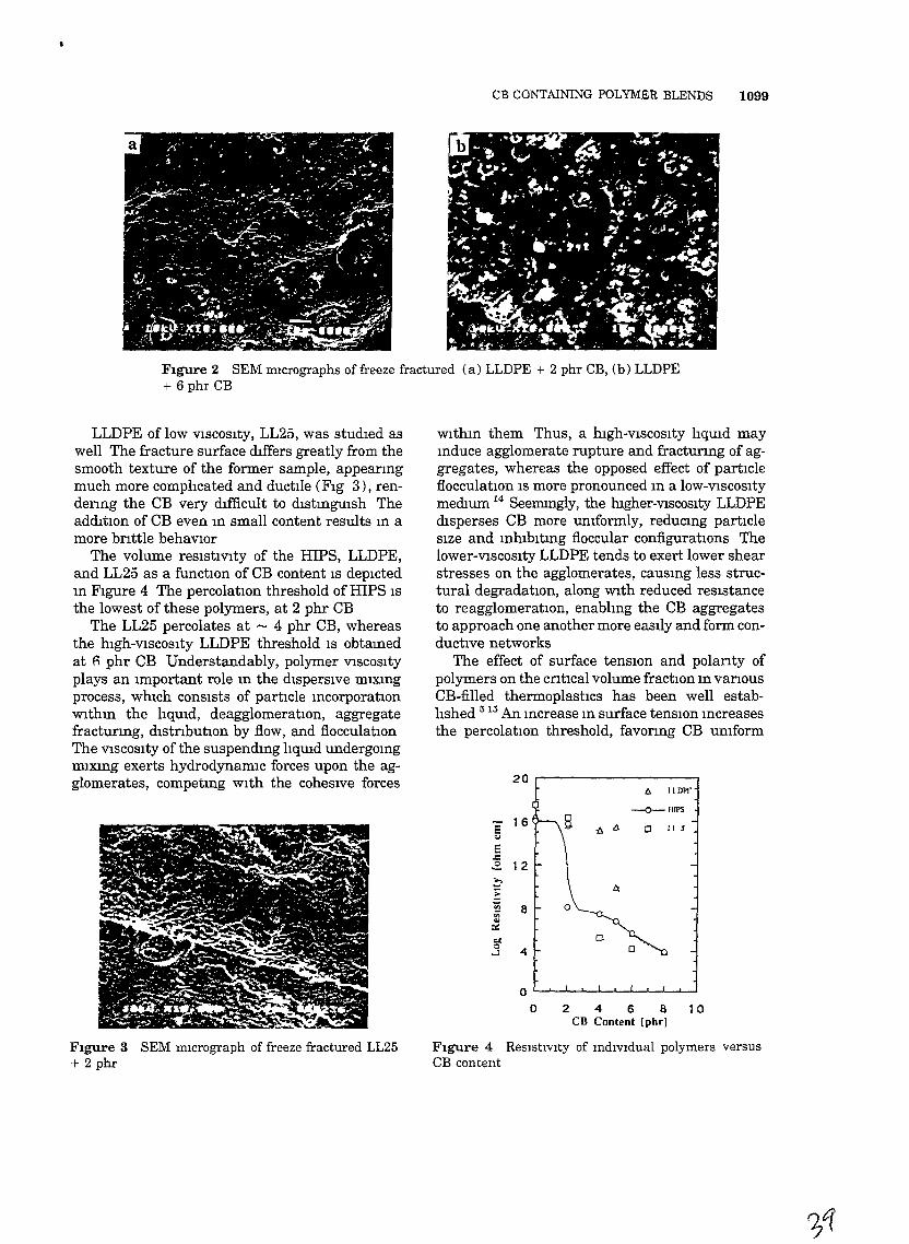
CB CONTAINING POLYMER BLENDS 1099
FIgure 2 SEM mIcrographs offreeze fractured (a) LLDPE + 2 phr CB, (b) LLDPE+ 6 phr CB
0'--'---'"--,--'--'--'--'---'---'---1
o 2 4 6 8 10CB Content [phr)
wlthm them Thus, a hIgh-VISCOSIty lIqUId maymduce agglomerate rupture and fractunng of aggregates, whereas the opposed effect of partIcleflocculatIOn IS more pronounced m a lOW-VISCOSItymedIUm 14 SeemIngly, the hIgher-VIscosIty LLDPEdIsperses CB more umformly, reducmg partIcleSIze and mhlbltmg floccular configuratIOns Thelower-VIscosIty LLDPE tends to exert lower shearstresses on the agglomerates, causmg less structural degradation, along With reduced reSIstanceto reagglomeratIOn, enablmg the CB aggregatesto approach one another more easlly and form conductive networks
The effect of surface tenSIOn and polanty ofpolymers on the cntIcal volume fractIOn m vanousCB-filled thermoplastICS has been well establIshed 5 15 .An mcrease In surface tenSIOn Increasesthe percolatIOn threshold, favonng CB umform
o
I:> llDPr
-O--IIlPS
ill:> 0 lIS
20
E 16<.I
E.l:2- 12
t'EVi 8iii...0::..,0
4-l
LLDPE of low VISCOSIty, LL25, was studIed aswell The fracture surface dIffers greatly from thesmooth texture of the former sample, appeanngmuch more complIcated and ductIle (FIg 3), rendenng the CB very dIfficult to dlstmgUIsh TheaddItIOn of CB even m small content results m amore bnttle behavIOr
The volume resIstiVIty of the HIPS, LLDPE,and LL25 as a function of CB content IS depIctedm FIgure 4 The percolatIOn threshold of HIPS ISthe lowest of these polymers, at 2 phr CB
The LL25 percolates at - 4 phr CB, whereasthe hIgh-VISCOSIty LLDPE threshold IS obtamedat fi phr CB Understandably, polymer VISCOSItyplays an Important role m the dIspersIve IDlXmgprocess, WhICh consIsts of partIcle mcorporatIOnWIthm the lIqUId, deagglomeratIOn, aggregatefractunng, dlstnbutIOn by flow, and flocculationThe VISCOSIty of the suspendmg lIqUId undergomgmlxmg exerts hydrodynamIC forces upon the agglomerates, competmg WIth the coheSIve forces
FIgure 3 SEM mIcrograph of freeze fractured LL25+ 2 phr
FIgure 4 ResIstlvity of mdividual polymers versusCB content
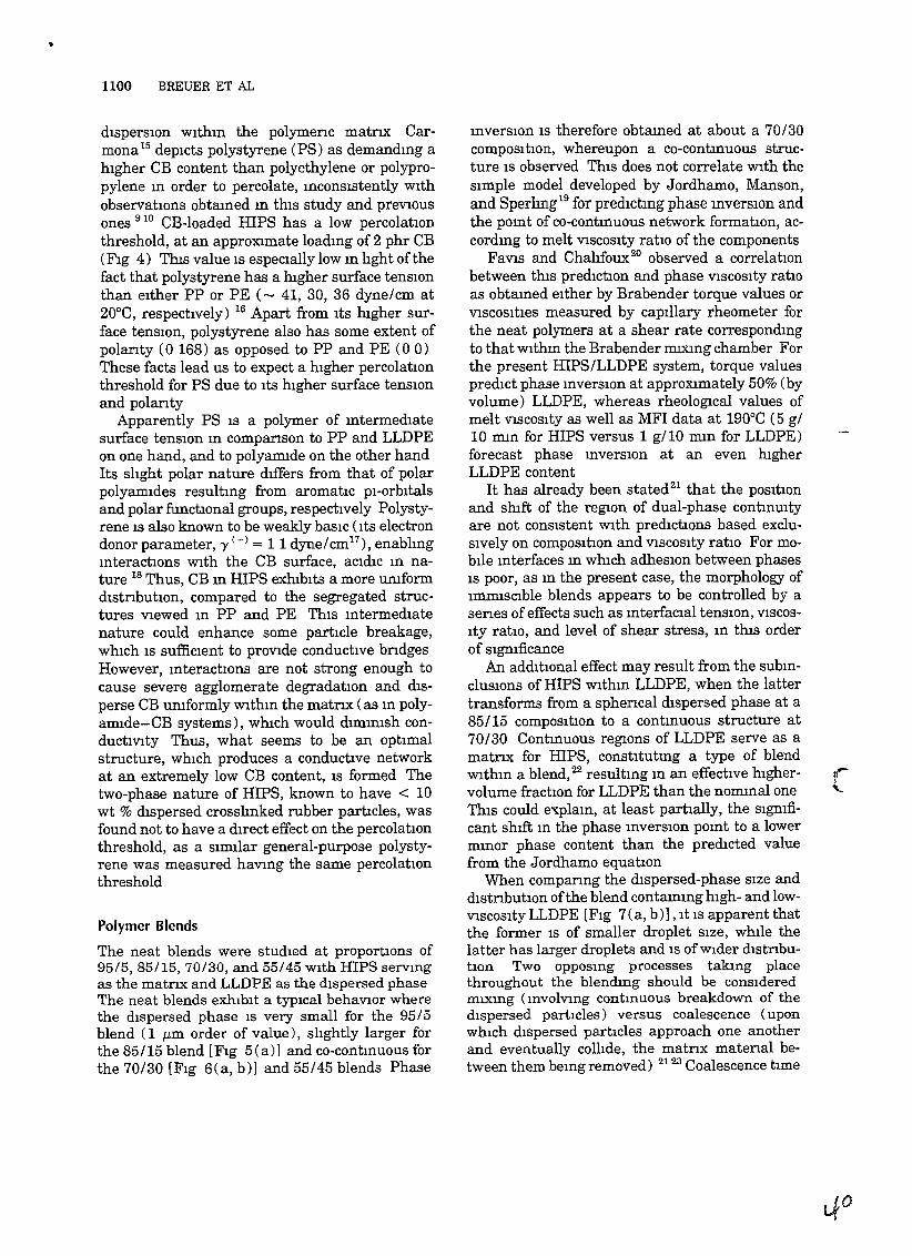
•
1100 BREUER ET AL
dIsperSIOn wlthm the polymenc matnx Carmona 15 depIcts polystyrene (PS) as demandmg ahIgher CB content than polyethylene or polypropylene m order to percolate, mconsistently WIthobservatIOns obtaIned m thIS study and preVIOUSones 910 CB-Ioaded mps has a low percolatIOnthreshold, at an approXimate loadmg of 2 phr CB(FIg 4) ThIs value IS especIally low m hght ofthefact that polystyrene has a hIgher surface tensIOnthan eIther PP or PE (- 41, 30, 36 dyne/cm at20°C, respectively) 16 Apart from ItS hIgher surface tenSIOn, polystyrene also has some extent ofpolanty (0 168) as opposed to PP and PE (0 0)These facts lead us to expect a hIgher percolatIOnthreshold for PS due to ItS hIgher surface tenSIOnand polanty
Apparently PS IS a polymer of mtermedlatesurface tenSIOn m companson to PP and LLDPEon one hand, and to polyamIde on the other handIts shght polar nature dIffers from that of polarpolyamldes resultmg from aromatic pI-orbItalsand polar functional groups, respectively Polystyrene IS also known to be weakly baSIC (ItS electrondonor parameter, 'Y (-) = 11 dyne/cmI7
), enablmgmteractIons With the CB surface, aCIdIc m nature 18 Thus, CB m HIPS exhIbIts a more urnformdlstnbutIOn, compared to the segregated structures VIewed m PP and PE ThIS mtermedlatenature could enhance some partIcle breakage,whIch IS suffiCIent to prOVide conductive bndgesHowever, mteractIOns are not strong enough tocause severe agglomerate degradatIOn and dIsperse CB umformly WithIn the matnx (as m polyamlde-CB systems), whIch would dlffilmsh condUCtiVIty Thus, what seems to be an optimalstructure, whIch produces a conductive networkat an extremely low CB content, IS formed Thetwo-phase nature of HIPS, known to have < 10wt % dIspersed crosshnked rubber partIcles, wasfound not to have a dIrect effect on the percolatIOnthreshold, as a SImIlar general-purpose polystyrene was measured haVIng the same percolatIOnthreshold
Polymer Blends
The neat blends were studIed at proportIOns of95/5,85/15,70/30, and 55/45 WIth HIPS servmgas the matnx and LLDPE as the dIspersed phaseThe neat blends exhIbIt a typIcal behaVIOr wherethe dIspersed phase IS very small for the 95/5blend (1 f-Lm order of value), slIghtly larger forthe 85/15 blend [FIg 5(a)] and co-contmuous forthe 70/30 [FIg 6(a, b)] and 55/45 blends Phase
mversIOn IS therefore obtamed at about a 70/30compOSItIOn, whereupon a co-contmuous structure IS observed ThIS does not correlate With theSImple model developed by Jordhamo, Manson,and Sperhng19 for predIctmg phase mverSIOn andthe pomt of co-contmuous network formatIOn, accordmg to melt VISCOSIty ratio of the components
FaVIs and Chahfoux20 observed a correlationbetween thIs predICtIOn and phase VISCOSIty ratIOas obtaIned eIther by Brabender torque values orVISCOSIties measured by capIllary rheometer forthe neat polymers at a shear rate correspondIngto that Withm the Brabender moong chamber Forthe present HIPS/LLDPE system, torque valuespredIct phase mverSIOn at apprOXimately 50% (byvolume) LLDPE, whereas rheolOgIcal values ofmelt VISCOSIty as well as MFI data at 190°C (5 g/10 mm for HIPS versus 1 g/10 mm for LLDPE)forecast phase mverSIOn at an even hIgherLLDPE content
It has already been stated21 that the pOSItIOnand shIft of the regIon of dual-phase contmUltyare not conSIstent With predIctions based excluSIVely on compOSItIOn and VISCOSIty ratio For mobIle mterfaces m whIch adheSIOn between phasesIS poor, as m the present case, the morphology ofImmISCIble blends appears to be controlled by asenes of effects such as mterfaclal tenSIOn, VISCOSIty ratio, and level of shear stress, m thIs orderof SIgnIficance
An addItIOnal effect may result from the submclusIOns of HIPS wlthm LLDPE, when the lattertransforms from a sphencal dIspersed phase at a85/15 compOSItion to a contmuous structure at70/30 Contmuous regIons of LLDPE serve as amatrIX for HIPS, constItutmg a type of blendWIthm a blend,22 resultmg m an effectIve hlghervolume fractIOn for LLDPE than the nOmInal oneThIS could e,,<plaIn, at least partIally, the sIgmficant shIft m the phase mverSIOn pomt to a lowermmor phase content than the predIcted valuefrom the Jordhamo equatIOn
When companng the dIspersed-phase SIze anddIstnbutIon ofthe blend contammg hlgh- and lowVISCOSIty LLDPE [FIg 7(a, b)] , It IS apparent thatthe former IS of smaller droplet SIze, whIle thelatter has larger droplets and IS of Wider dIstnbutIon Two opposmg processes takmg placethroughout the blendmg should be conSIderedmuong (mvolvmg contmuous breakdown of thedIspersed partIcles) versus coalescence (uponwhIch dIspersed particles approach one anotherand eventually collIde, the matnx matenal between them bemg removed) 2123 Coalescence time
~....,"-
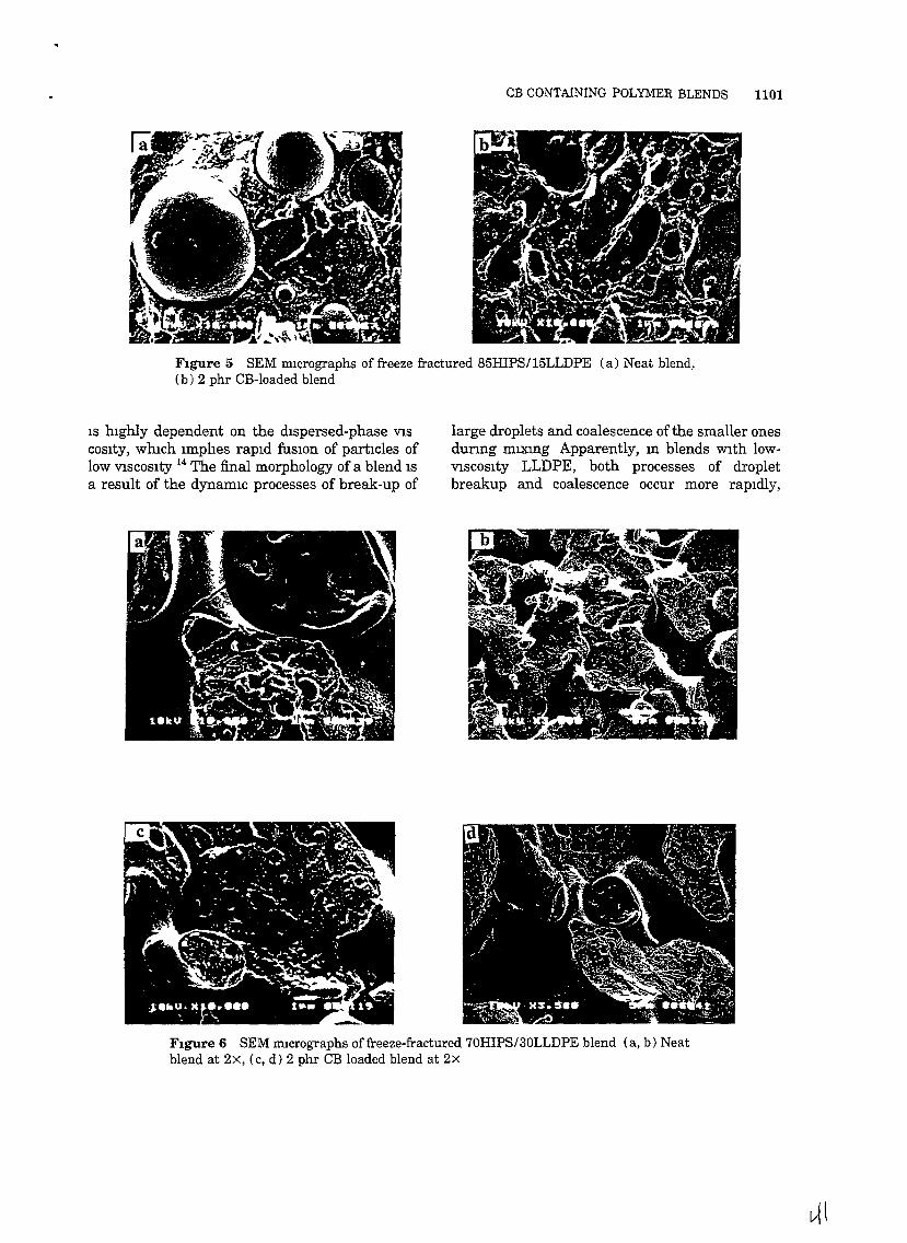
CB CONTAINING POLYMER BLENDS 1101
Figure 5 SEM mIcrographs of freeze fractured 85HIPS/15LLDPE (a) Neat blend,(b) 2 phr CB-loaded blend
IS hIghly dependent on the dIspersed-phase VISCOSlty, whIch lmphes rapId fuSIOn of partIcles oflow VISCOSIty 14 The final morphology of a blend ISa result of the dynamIc processes of break-up of
large droplets and coalescence ofthe smaller onesdunng mlXIDg Apparently, In blends wIth lowVISCOSIty LLDPE, both processes of dropletbreakup and coalescence occur more rapIdly,
Figure 6 SEM mIcrographs offreeze-fractured 70HIPS/30LLDPE blend (a, b) Neatblend at 2x, (c, d) 2 phr CB loaded blend at 2x
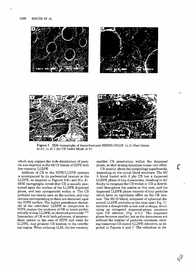
1102 BREUER ET AL
FIgure 7 SEM mIcrographs of freeze-fractured 85HIPS/15LL25 (a, b) Neat blendsat 2x, (c, d) 1 phr CB loaded blend, at 2x
whIch may explaIn the wIde dlstnbutlOn of part1
cle SIze depIcted In the 85/15 blends offfiPS wIthlOW-VISCOSIty LLDPE
AddItIon of CB to the HIPS/LLDPE systemsIS accompamed by ItS preferentIal locatIOn In theLLDPE, as depIcted In FIgures 5(b) and B(c, d)SEM mIcrographs reveal that CB IS usually pOSItIOned upon the surface of the LLDPE dIspersedphase, and less Incorporated WIthIn It The CBpartIcles are clearly seen on the surface, and tmycaVItIes correspondmg to them are statIOned uponthe HIPS surface The hIgher percolatIOn threshold of the IndIVIdual LLDPE In companson toHIPS Imphes the tendency of CB to locate preferentially WIthIn LLDPE, as observed prevIously 910
InteractIOn ofCB WIth both polymers, ofIntermedlate nature In the case of HIPS and weak forLLDPE, may promote CB location In the InterfaCIal regIOn When utIhzIng LL25, the low VISCOSIty
enables CB penetratIon WIthIn the dIspersedphase, so that mIXIng dynaIDlcs comes Into effect
CB usually alters the morphology sIgmficantly,dependIng on the ImtIal blend structure The 95/5 blend loaded WIth 2 phr CB has a dIspersedLLDPE phase of tIny dImensIOns, resultIng In dIfficulty to recogmze the CB WIthIn It CB IS dlstnbuted throughout the matnx In thIS case, and thedIspersed LLDPE phase conSIsts of tIny partIcleswhIch have no SIgnIficant effect on the CB locatIOn The 85/15 blend, composed of sphencal dISpersed LLDPE partIcles In the neat case (FIg 7)exhIbIts a change both In SIze and In shape, developmg an elongated dIspersed-phase structureupon CB addItion [FIg 5(b)] The dIspersedphase becomes smaller, but as the dImenSIOns arereduced the number of partIcles Increases, creatIng numerous CB-coated LLDPE cylInders, as deplCted In FIgures 5 and 7 The reductIOn In dIS
[
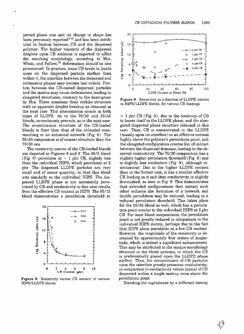
CB CONTAINING POLYMER BLENDS 1103
o
20 40 60 80 100LLDPE Content m Blend [%]
-0-0 pbr CB
0- 1 pbr CB
-tJ. 2 pbr CB
./ 0 4 pbrCB
""6. 0 .,/ _. 8 phr CB
ct-.. ........... tJ. -- : _
'i--i-- .... ---
20
e 16u•E
..c:
.2. 12
0>.:l 8'"Vi<l!
I":
Oll 40-l
00
FIgure 9 ReSIstIvIty as a functIOn of LLDPE contentm HIPS/LLDPE blends, for VarIOUS CB loadmgs
< 1 phr CB (FIg 8), due to the tendency of CBto locate Itself m the LLDPE phase, and the elongated dIspersed phase structure obtamed m thIScase Thus, CB IS concentrated m the LLDPE(maInly upon ItS mterface) m an effectIve contenthIghly above the polymer's percolatIOn pomt, andthe elongated configuratIOn creates lOCI of contactbetween the dIspersed domams, leadmg to the observed conductIVIty The 70/30 compOSItIon has ashghtly hIgher percolatIOn threshold (FIg 8) andIS slIghtly less conductIve (FIg 9), although cocontmuous Due to the hIgher LLDPE contentthan m the former case, It has a smaller effectIveCB loadmg m It and thus conductIVIty IS slIghtlydImInIshed, as seen m FIg 9 ThIS demonstratesthat extended configuratIons that contact eachother enhance the formatIon of a network anddouble percolatIon may be realIzed, leadmg to areduced percolatIOn threshold ThIS takes placefor the 55/45 blend as well, whIch has a percolatIon pomt SImIlar to the mdlvldual HIPS at 2 phrCB For most blend compOSItions, the percolatIOnpomt IS not greatly reduced m companson to themdlvldual HIPS matnx, perhaps due to the factthat HIPS alone percolates at a low CB contentHowever, the magnItude of the reSIstiVIty IS decreased by approXimately four orders of magnItude, whIch IS mdeed a SIgnIficant enhancementThIS may be attnbuted to the umque morphologyobtaIned In the blend systems, In whIch the CBIS preferentlally placed upon the LLDPE phasesurface Thus, the concentratIOn of CB partIclesupon the Interface greatly promotes conductIVIty,In companson to conductiVIty values typIcal of CBdIspersed WIthIn a SIngle matnx, even above thepercolatIOn POInt
Blendmg the mgredlents by a dIfferent mIXIng
10
0'--'--'--'--'--L....JL.-lL....Jl...-.J'-.--J
o
--0- ~II1S
e -<>- 70/3016
" 6- 55145
E.c.::. 12>,
::~
8iii...0::
ODQ
...1 4
20 r------------,
persed phase SIze and ItS change m shape hasbeen preVIOusly reported 9
10 and has been attnbuted to fnctIon between CB and the dIspersedpolymer The hIgher VISCOSIty of the dIsperseddroplets upon CB addItIOn IS expected to affectthe resultmg morphology, accordmg to Mm,WhIte, and Fellers,24 deformatIOn should be lesspronounced In practIce, smce CB tends to locatemore on the dIspersed partIcle surface thanwlthm It, the mterface between the dIspersed andcontmuous phases may become less mobIle FnctIon between the CB-coated dIspersed partIclesand the matnx may cause deformatIOn leadmg toelongated structures, contrary to the descnptIOnby Mm These mamtam theIr rodhke structurewIth no apparent droplet breakup as obtamed mthe neat case ThIs phenomenon occurs m bothtypes of LLDPE As to the 70/30 and 55/45blends, co-contmUlty preVaIls, as m the neat caseThe co-contmuous structure of the CB-Ioadedblends IS finer than that of the unloaded ones,resultmg m an enhanced network (FIg 6) The55/45 composItIon IS of coarser structure than the70/30 one
The resIstIVIty curves of the CB-Ioaded blendsare depIcted m FIgures 8 and 9 The 95/5 blend(FIg 9) percolates at - 1 phr CB, slIghtly lessthan the mdiVIdual HIPS, whIch percolates at 2phr The dIspersed LLDPE partIcles are verysmall and of mmor quantIty, so that thIs blendacts SImIlarly to the mdiVIdual HIPS The dIspersed LLDPE phase IS not necessanly penetrated by CB and conductIVIty m thIS case resultsfrom the effectIve CB content m HIPS The 85/15blend demonstrates a percolatIon threshold at
2 4 6 8CB Conlen' [phrj
FIgure 8 ReSIstIvIty versus CB content of varIOUSHIPS/LLDPE blends

1104 BREUER ET AL
20
S'" 16
-v
<5 0 -0-- OphrCB
..c <> I phrCB -~12 >-\ / --t!. 2phrCB
~...0 4phrCB
~8 \ 0- /
til
iii'" t:J. /" "-bll 4 0 t:r- ,./'0
..:I 0
0 I I I
0 20 40 60 80 100LL25 Content ID blend [%]
FIgure 11 ReSIstIvIty as a functIOn of LL25 contentm HIPS/LL25 blends, for vanous CB loadmgs
between the dIrectIOns parallel and transverse toflow WIthIn the CB-Ioaded 85/15 HIPS/LLDPEblend [FIg 12(a, b)], the dIspersed PE phase becomes hIghly extended, obtaImng cylmdncalstructures of relatively low dIameter (- 1 /-tm)and WIdely dIstnbuted lengths of a few illlcronsCB IS located withm the dIspersed phase, more sothan for the former processmg method, m whIchCB was upon the mterface The 70/30 formulations are relatively SImIlar (FIg 13), however,structures are more co-contmuous m the dIrectionparallel to flow and the dIspersed phase IS ofirregular, rather than CIrcular, cross-section
MorpholOgical observations prOVIde some mSIght as to why mJectIon-molded samples are msulabve The hIgh onentatlOn ofthe dIspersed phaseWIthm the matnx causes an orderly sequence ofcylIndncal structures, however, these hardlycome mto contact In the case of Brabender mIXmg, extended structures were observed as well,but these were randomly onented, overlappmg toprOVIde a well-establIshed conductive networkEven the 70/30 blend, WIth a slIght tendency toward co-contmUIty m the dIrection parallel toflow, IS msufficiently contmuous CB penetratesthe dIspersed phase m mJectIOn-molded samplesmore thoroughly than m the Brabender mIxedones, presumably due to the SIgnIficantly hIghshear rates mvolved m the mJectIon moldmg process followed by rapId sohdificatIOn m the moldThIS may constitute an addItIOnal reason for thehIgher CB contents reqUIred for percolation, andthe correspondIng hIgher reSIstiVIty values
The hIgher shear rate exerCIsed In Injectionmoldmg defimtely has an effect on agglomeratedegradatIOn and destructIon of chamhke tendenCIes-thIS IS apparent by the fact that the 8 phr
10
o L....-J--I.--L--I.-.....---l--J--J....-,---'
o
20
S-0-- 85115
16
'" -0- 70/30e ,
..c\~ 12
~\
~ \til
8 I>0;
'" C\"bll \0
0...:l 4""'"¢
Processmg Effects
InJectIOn-molded samples were tested for morphology and reSIstiVIty data The samples conSIsted of HIPS + 8 phr CB, 85 HIPS/IS LLDPE+ 4 phr CB, and 70 HIPS/30 LLDPE + 4 phrCB The electncal reSIstiVIty ofthese samples wasmeasured by the four pomt method (specIfiedabove) and was proved to be relatively hIgh(above 108 ohm!cm) even for samples that were oflow reSIstivIty by the former compresslon-moldmgprocessmg method
SEM mIcrographs of HIPS/LLDPE + CBblends depIct, as expected, SIgnIficant dIfferences
sequence does not practically produce dIfferent reSIStiVIty values or morphology, as descnbed elsewhere 9-11 Upon mcorporatmg CB mto HIPS pnorto LLDPE addItIOn, results were mdistIngUIshable from the standard method used
HIPS/LLDPE blends m whICh lOW-VISCOSItyLLDPE IS used generally exhJ.blt a behaVIor SImIlar to the one descnbed above (FIg 10) CB tendsto penetrate the LLDPE phase more m thIS case,due to ItS lower VISCOSIty The lower percolationvalues exhIbIted for all blend ratIOS stems fromthe lower percolatIOn pomt of the lower-VIscosItyLLDPE No umque morphology was obtamed,however, coarsenmg of the dIspersed phase dueto the accelerated coalescence has led to a moregradual formatIOn of a co-contmuous structureThus, a hIgher dIspersed-phase content resultmgm a 70/30 composItIon IS necessary to obtamlower reSIstIVIty m thIS case (FIg 11)
2 4 6 8CB Content [phr]
FIgure 10 ResIstlvIty versus CB content of vanousHIPS/LL25 blends
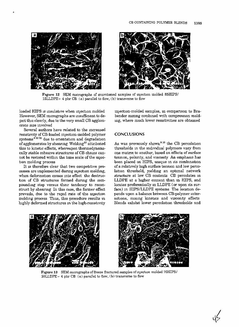
CB CONTAINING POLYMER BLENDS 1105
FIgure 12 SEM IIl1crographs of mlCrotomed samples of InjectIOn molded 85HIPSI15LLDPE+ 4 phr CB (a) parallel to flow, (b) transverse to flow
loaded HIPS IS InsulatIve when InjectIOn moldedHowever, SEM mIcrographs are msufficlent to depIct thIS clearly, due to the very small eB agglomerate SIze Involved
Several authors have related to the mcreasedresIstIVIty of CB-loaded mJectIon-molded polymersystems42526 due to onentatIon and degradatIOnofagglomerates by sheanng Weblmg27 attnbutedthIs to kmetIc effects, whereupon thermodynamIcally stable coheSIve structures of CB chams cannot be restored Wlthm the tIme scale of the InJectIon moldIng process
It IS therefore clear that two competItIve processes are Implemented dunng mJectIOn moldmg,when deformatIOn comes mto effect the destructIon of CB structures formed dunng the compoundmg step versus theIr tendency to reconstruct by sheanng In thIs case, the former effectpreVaIls, due to the rapId rate of the mJectIOnmoldmg process Thus, thIs procedure results mhIghly deformed structures m the hIgh-reSIstIVIty
mJectlOn-molded samples, m companson to Brabender mlXlng combmed WIth compreSSIOn moldIng, where much lower reSIstIVItIes are obtaIned
CONCLUSIONS
As was prevIOusly shown910 the CB percolatIOn
thresholds m the mdIVIdual polymers vary fromone matnx to another, based on effects of surfacetenSIOn, polanty, and VISCOSIty An emphasIs hasbeen placed on IDPS, umque m ItS combmatIonof a relatIvely hIgh surface tenSIOn and low percolatIon threshold, yreldmg an optImal networkstructure at low CB contents CB percolates mLLDPE at a hIgher content than In HIPS, andlocates preferentially m LLDPE (or upon ItS surface) m HIPS/LLDPE systems The locatIOn depends upon a balance between eB-polymer mteractIOns, mlXlng kmetIcs and VISCOSIty effectsBlends exhIbIt lower percolatIon thresholds and
FIgure 13 SEM mIcrographs offreeze fractured samples ofmJectIOn molded 70HIPS/30LLDPE+ 4 phr CB (a) parallel to flow, (b) transverse to flow
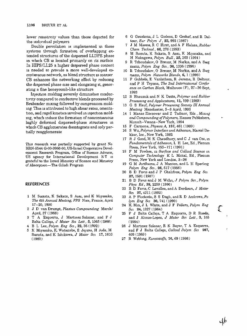
1106 BREUER ET AL
lower resIstIvIty values than those depIcted forthe IndIVIdual polymers
Double percolatIOn IS Implemented In thesesystems through formatIon of overlappIng extended structures of the dIspersed LLDPE phaseIn whIch CB IS located pnmanly on ItS surfaceIn HIPS/LL25 a hIgher dIspersed phase contentIS needed to proVIde a more well-developed cocontInUOUS network, as blend structure IS coarserCB enhances the networkmg effect by redUCIngthe dIspersed phase SIze and elongatmg It, generatmg a fine honeycomb-lIke structure
InjectIOn moldmg severely dlmIlllshes conductIVIty compared to conductIve blends processed byBrabender mIXIng followed by compreSSIOn moldIng ThIS IS attnbuted to mgh shear rates, onentabon, and rapId kInetICS Involved m InjectIOn moldmg, wmch Induce the formatIOn of noncontInUOUSmghly deformed dIspersed-phase structures InwhIch CB agglomerates dIsmtegrate and only partIally reagglomerate
ThIS research was partIally supported by grant NoHRN-5544 G-OO-2066-00, US-Israel CooperatIVe Development Research Program, Office of SCIence AdVIsor,US agency for InternatIOnal Development R T ISgrateful to the Israel MInIstry of SCIence and MInIstryof AbsorptIon-The GIladI Program
REFERENCES
1 M Sumlta, K Sakata, S Asar, and K Mryasaka,The 6th Annual Meetmg, PPS NIce, France, Apnl17-20,1990
2 J D van Drumpt, Plast~cs Compoundmg MarchiApnl, 37 (1988)
3 T A Ezquerra, J Martmez Salazar, and F JBalta Calleja, J Mater Scz Lett, 5, 1065 (1986)
4 B L Lee, Polym Eng Sc~, 32, 36 (1992)5 K Miyasaka, K Watanabe, E JOJIma, H AIda, M
Sunuta, and K IshIkawa, J Mater Scz 17,1610(1982)
6 G Geuskens, J L Glelens, D Geshef, and R Deltour, Eur Polym J, 23, 993 (1987)
7 J M MaSSIe, R C HIrst, and A F Halasa, RubberChem Technol, 66, 276 (1993)
8 M Sumlta, K Sakata, S Asar, K Mlyasaka, andH Nakagawa, Polym Bull, 25, 265 (1991)
9 R Tchoudakov,O Breuer, M Narbs, and A Slegmann, Polym Eng Scz, 36, 1336 (1996)
10 R Tchoudakov, 0 Breuer, M Narbs, and A Slegmann, Polym Networks Blends, 6, 1 (1996)
11 F Gubbels, E Vanlathem, R Jerome, R Deltour,and P H Teyssle, The 2nd Internatzonal Conference on Carbon Black, Mulhouse (F), 27-30 Sept,1993
12 S Bhaumlk and N K Datta, Polymer and RubberProcesszng and Applzcatwns, 11, 199 (1989)
13 G S Hauf, Polymer Processzng Soczety IX AnnualMeetzng Manchester, 5-8 Apnl, 1993
14 I Manas Zloczower and Z Tadmor, Eds, Mzxzngand Compoundzng ofPolymers, Hanser PublIshers,MUnIch-VIenna-New York, 1994
15 F Carmona, Physzca A, 157, 461 (1989)16 S Wu, Polymer Interface and Adheswn, Marcel De
kker, Inc, New York, 198217 R J Good, M K Chaudhury, and C J van Oss, m
Fundamentals ofAdhes~on, L H Lee, Ed , PlenumPress, New York, 153-171 (1991)
18 F M Fowkes, m Surface and Collozd Sczence mComputer Technology K L Mrttal, Ed, PlenumPress, New York and London, 3-26
19 G M Jordhamo, J A Manson, and L H SperlIngPolym Eng Scz, 26,517 (1986)
20 B D FaVIs and J P ChalIfoux, Polym Eng Scz27, 1591 (1987)
21 B D FaVIs and J M WIllIs, J Polym Scz, PolymPhys Ed, 28, 2259 ( 1990)
22 B D FaVIs, C Lavallee, and A Derdoun, J MaterSc~ 27,4211 (1992)
23 A P PiochockI, S S Dagh, and R D Andrews, Polym Eng Sc~ 30,741 (1990)
24 K Mm, J L WhIte, and J F Fellers, Polym EngSc~ 24, 1327 (1984)
25 F J Balta Calleja, T A Ezquerra, D R Rueda,and J Alonso-Lopez, J Mater SCl Lett, 3, 165(1984)
26 J Martmez Salazar, R K Bayer, T A Ezquerra,and F J Balta Calleja, Collotd Polym Sc~ 267,409 (1989)
27 B Weblmg, Kunststoffe, 76, 69 (1986)
(
)
/
Conductive Polymer Blends With Low Carbon BlackLoadmg High Impact Polystyreneffhermoplastlc
Elastomer (Styrene-Isoprene-Styrene)
R TCHOUDAKOV 0 BREUER and M NARKIS
Dept oj ChemICal Engmeenng
and
A SIEGMANN
Dept ojMatenals EngmeenngTechnwn-Israel Institute ojTechnology
Haifa 32000 Israel
Electncal resIstlVlty and morphology of hIgh lffipact polystyrene (HIPS)/styreneIsoprene-styrene copolymer (SIS)/carbon black (CB) blends were studied Conduchve CB parhcles locate preferenhally Wlthm the HIPS phase of the HIPS/SIS blendsThe blends studIed remam conducnve as long as HIPS mamtams a connnuousphase and the effecnve CB concentranon Wlthm HIPS surmounts Its percolanonthreshold Thus blends contammg 2 phr CB depIct sigruficant changes 11 resIsnvIty Wlth the HIPS/SIS composinon transformmg from msulahve to conductlveSIS/CB rmxtures exlubit an unusual behaVlor explamed by a phYSICal modelsuggested m thIS paper and extended to the HIPS/SIS/CB systems
)
INTRODUCTION
Polymer blends conslsnng of two ImmISCIble polymers and a thermoplasnc elastomer that contams
fragments Idenncal to the homopolymer chams are ofspecIfic mterest because of possIble companbilizanoneffects m these blends Thus the added block copolymer acts as an alloymg agent or a surfactant whIchcontnbutes to the stabilizanon of the mulnphasestructure (1 2) Numerous pubhcatlons concern themorphology and propemes of blends such as polystyrene (PS) Wlth Its copolymers (3-6) However almostnothmg IS reported on such blends loaded Wlth carbonblack (CB) Numerous pubhcahons concemmg elastomer/CB conduchve composinons reveal some fundamental parameters determmmg therr conducnVItylevel among them IS the CB-polymer mteractlon (710) For CB-Ioaded polymer blends the conductIVity IScontrolled by the CB content m the blend the blend smorphology and the CB locatIon Wlthm the blend(11-15) These elements are the key components ofthe double percolatIon concept (16-18) WhICh IS currently accepted as the background for understandmgthe behaVior of CB-filled mulhphase polymer systemsA thermoplastIc elastomer mlXed Wlth CB bemg apart of the multlphase conducnve system marnfests aparhcular behaVior of the blends conductlVlty (3 19)
owmg to the thermoplasnc elastomer mtrmsic mIcrostructure
The subject of thIs study IS the correlatIon betweenresIsnVIty and morphology ofCB-loaded compOSItIonsof a hIgh Impact PS (HIPS) and a tn-block copolymerstyrene-Isoprene-styrene (SIS)
EXPERIMENTAL
The polymers used m thIS study were the followmg
• HIPS Gahrene HT 88-5 MFI-4 5 Israel PetrochemIcal Industry
• SIS Qumtac 3421 MFI-Il 14% PS Japan and• CB Kegenblack EC-300 Akzo The Netherland
Sample preparahon procedure mcluded melt ffilX
mg for 15 rom at a speed of 50 rpm m a Brabenderplastograph at 190°C followed by a standard compreSSIon moldmg procedure at the same temperatureto obtam 3 rom-thIck plaques
The volume reSIstIVity of dIsk-shaped samples wasmeasured accordmg to DIN 53596 by techruques preVIously specIfied (11) The blend morphology wasstudIed usmg a Jeol 5400 scarmmg electron mIcroscope (SEM) Freeze-fractured and microtomed surfaces (both prepared m hqUld mtrogen) were mvestIgated
1928 POLYMER ENGINEERING AND SCIENCE, DECEMBER 1997, Vol 37, No 12
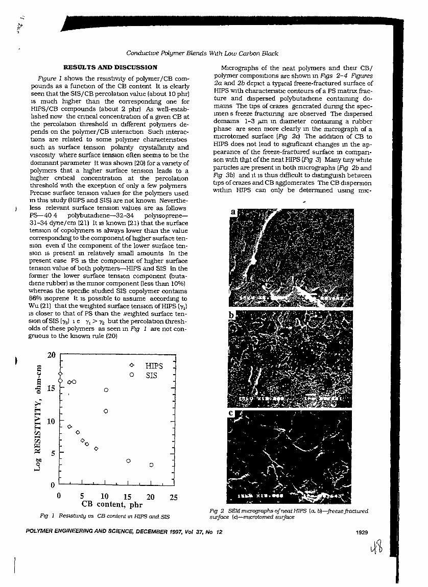
Conducuve Polymer Blends Wtth Low Carbon Black
POLYMER ENGINEERING AND SCIENCE, DECEMBER 1997, Vol 37, No 12 1929
MIcrographs of the neat polymers and therr CBjpolymer composItIons are shown m Figs 2-4 FIgures2a and 2b depIct a typICal freeze-fractured surface ofHIPS Wlth charactenstIc contours ofa PS matnx fracture and dIspersed polybutadlene contammg domams The tIps of crazes generated dunng the specImen s freeze fractunng are observed The dlsperseddomams 1-3 /Lm m dIameter contammg a rubberphase are seen more clearly m the ffilcrograph of amlcrotomed surface (Fig 2c) The addItIon of CB toHIPS does not lead to sigruficant changes m the appearance of the freeze-fractured surface m companson WIth t1:J.at of the neat HIPS (FIg 3) Many tlny whItepartlcles are present III both mIcrographs (Fig 2b andFig 3b) and It IS thus dIfficult to dIStlngUISh betweentIps ofcrazes and CB agglomerates The CB dIsperSIOnWlthm HIPS can only be determmed usmg nuc-
Fig 2 SEM mtcrographs qfneat HIPS (a. b)-freezefracturedsurface lc)-mlcrotomed surface
s ¢- HIPS~ 0 SISI
S ()O.c: 15 0Q
~~
~ 0~
> 10~
~ <>C/J 0~
C/J 00~
~ 5<>
Q!l 0Q 0
...:l
oo 5 10 15 20 25
CB content, phrFig 1 ReslSi:Jvlty us CB content m HIPS and SIS
20
RESULTS AND DISCUSSION
Figure 1 shows the resIstIVIty of polymerjCB compounds as a functIon of the CB content It IS clearlyseen that the SISjCB percolatIon value (about 10 phr)IS much hIgher than the correspondmg one forHIPSjCB compounds (about 2 phr) As well-establIshed now the cntIcal concentratIon of a gIVen CB atthe percolatIon threshold m dIfferent polymers depends on the polymerJCB mteractIon Such mteractIons are related to some polymer charactenstIossuch as surface tenSIOn polanty crystalhmty andVISCOSIty where surface tenSIOn often seems to be thedommant parameter It was shown (20) for a vanety ofpolymers that a hIgher surface tenSIOn leads to ahIgher cntIcal concentratIon at the percolatIonthreshold Wlth the exceptIon of only a few polymersPreCIse surface tenSIon values for the polymers usedm thIS study (HIPS and SIS) are not known Nevertheless relevant surface tenSIOn values are as followsP5-40 4 polybutadlene-32-34 polJ1soprene31-34 dyne/cm (21) It IS known (21) that the surfacetenSIOn of copolymers IS always lower than the valuecorrespondmg to the component ofmgher surface tenSIon even If the component of the lower surface tenSIOn IS present m relatIvely small amounts In thepresent case PS IS the component of mgher surfacetenSIOn value of both polymers-HIPS and SIS In theformer the lower surface tenSIon component (butadIene rubber) IS the mmor component neSS than 10%)whereas the specIfic studIed SIS copolymer contams86% Isoprene It IS pOSSIble to assume accordmg toWu (21) that the weIghted surface tenSIOn of HIPS b'l)IS closer to that of PS than the ..veighted surface tenSIon ofSIS (yzl 1 e 'YI > 'Y2 but the percolatIon thresholds of these polymers as seen m Fig 1 are not congruous to the known rule (20)
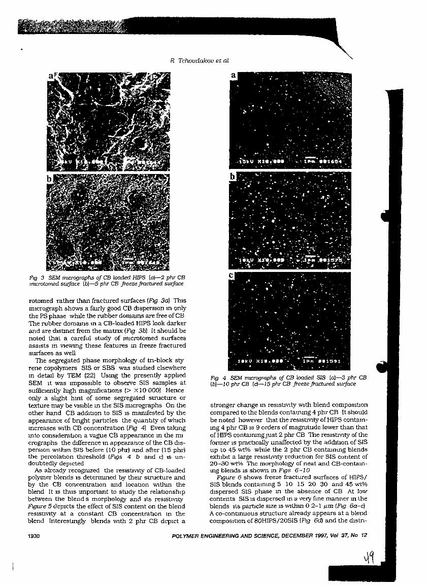
R Tchoudakov et aL
POLYMER ENGINEERING AND SCIENCE, DECEMBER 1997, Vol 37, No 12
Fig 4 SEM ml.Crographs oj CB loaded SIS (aj-3 phr CB(bl-lO phr CB (c)-IS phr CB jreezejractured suiface
stronger change In reSIstIVIty WIth blend composItioncompared to the blends contammg 4 phr CB It shouldbe noted however that the reSIStIVity of HIPS contamIng 4 phr CB IS 9 orders of magmtude lower than thatof HIPS contaInIngJust 2 phr CB The reSIStIVIty of theformer IS practIcally unaffected by the addItIon of SISup to 45 wt% whIle the 2 phr CB contammg blendsexhIbIt a large reSIstIVIty reductlon for SIS content of20-30 wt% The morphology of neat and CB-contammg blends IS shown m Figs 6-10
Figure 6 shows freeze fractured surfaces of HIPS/SIS blends contammg 5 10 15 20 30 and 45 wt%dIspersed SIS phase m the absence of CB At lowcontents SIS IS dIspersed m a very fme manner m theblends ItS partIcle SIZe IS WIthIn 0 2-1 p.m (Fig 6a-c)A co-contInuous structure already appears at a blendcomposItIon of 80HIPS/20SIS (FIg 6d) and the dIStn-
Fig 3 SEM ml.Crographs oj CB loaded HIPS (a)-2 phr CBml.Crotomed swface (b)-5 phr CB jreezejractured surJace
rotomed rather than fractured surfaces (FIg 3al TIusrmcrograph shows a farrly good CB disperslOn m onlythe PS phase whl1e the rubber domams are free ofCBThe rubber domams m a CB-Ioaded HIPS look darkerand are dIStmct from the matnx (FIg 3bl It should benoted that a careful study of rmcrotomed surfacesassIsts m VIewmg these features m freeze fracturedsurfaces as well
The segregated phase morphology of tn-block styrene copolymers SIS or SBS was studIed elsewherem detail by TEM (22) Usmg the presently apphedSEM It was ImpOSSIble to observe SIS samples atsufficIently mgh magrufIcations (> x 10 000) Henceonly a shght hInt of some segregated structure ortexture may be VIsIble In the SIS mIcrographs On theother hand CB addItion to SIS IS mamfested by theappearance of bnght parbcles the quantIty of whIchIncreases WIth CB concentration (FIg 4) Even takingInto consIderation a vague CB appearance In the mIcrographs the dIfference In appearance of the CB dISperSIOn WIthm SIS before (l0 phr) and after (15 phrlthe percolatlon threshold (Figs 4 b and cl IS undoubtedly depIcted
As already recogruzed the reslstlVIty of CB-Ioadedpolymer blends IS determmed by theIr structure andby the CB concentratlon and locatIon WIthm theblend It IS thus Important to study the relatIOnshIpbetween the blend s morphology and Its reSIstlVItyFIgure 5 depIcts the effect of SIS content on the blendreSIstIVIty at a constant CB concentratIon m theblend Interestingly blends WIth 2 phr CB depIct a
1930
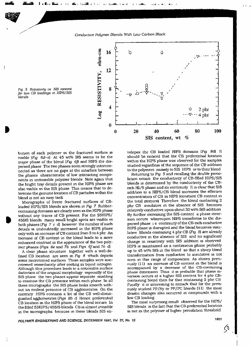
- ~ 1111- I II II1II1 IMllIIIIII Illj IIIJIU!JIliIIII IJJiliJ~ 1II1 __
!J Il IIJIl
ConductiVe Polymer Blends Wtth Low Carbon Black
5 16 '0 g~I
5..c::Q
>'12
~,
~,
;;...8
,F\g 5 ReslStlV!ty us SIS content
~
8I
~ ...0 0
" o~~"I
for two CB loadmgs m HIPS/SIS CJ:J.I
-V- .'Y. ;
blends -CJ:J.~
\J
~4
t:lJlQ~
"II- --- -"
""I
o 2phr---\J---4phr
oo 20 40 60 80
SIS content, wt %100
butlOn of each polymer m the fractured surface ISVisIble (FIg 6d-e) At 45 wt% SIS seems to be themajor phase of the blend (FIg 6j) and HIPS the dISpersed phase The two phases seem strongly mterconnected as there are no gaps at the mterface betweenthe phases charactensoc of low mteractlng components m ImIDlscible polymer blends Note agam thatthe bnght tlny details present m the HIPS phase arealso VisIble m the SIS phase ThIs means that to determme the genume locaoon of CB partlcles Wlthm theblend IS not an easy task
MICrographs of freeze fractured surfaces of CBloaded HIPS/SIS blends are shown m FIg 7 Rubbercontammg domams are clearly seen m the HIPS phaseWlthout any traces of CB present For the 55HIPS/45SIS blends many small bnght spots are ViSIble mboth phases (FIg 7 c d) however the number of suchdetails IS undoubtedly mcreased m the HIPS phaseonly Wlth an mcrease ofCB content from 2 to 4 phr Anincrease of CB content m the blend leads to a moreenhanced contrast m the appearance of the two polymer phases (FIgs 6e and 7b and FIgs 61and 7c d)
A clear phase structure together Wlth a well-defmed CB locaoon are seen m FIg 8 whIch depIctssome IDlcrotomed surfaces These samples were IDlCrotomed ImmedIately after coolmg m hqUld rntrogenAlthough tlus procedure leads to a notIceable surfacedlstortlon of the ongmal morphology espeCIally of theSIS phase the two phases appear separate enablmgto examme the CB presence Wlthm each phase In allthese mIcrographs the SIS phase looks smooth Wlthout an eVident presence of CB agglomerates On thecontrary HIPS contams a lot of the CB well-distlngUlshed agglomerates (FIgs Sb c) Hence preferenoalCB locaoon m the HIPS phase of the blend occurs Inthe filled 55HIPS/ 45SIS blends CB IS almost mVIsiblem the mICrographs because m these blends SIS en-
velopes the CB loaded HIPS domams (FIg Sd) Itshould be nooced that the CB preferentIal locatIonWlthm the HIPS phase was observed for the samplesstudIed regardless of the sequence of the CB addItIonto the polymers namely to SIS HIPS or to their blend
Returrnng to FIg 5 and recalhng the double percolatIon notIon the conductlVlty of CB-filled HIPS/SISblends IS determmed by the conductIVity of the CBnch HI?S phase and ItS COntlnUlty It IS clear that SISaddItIon to a HIPS/CB blend mcreases the effectIveconcentratIon of CB m HIPS (constant CB content mthe total rntXture) Therefore the blend contammg 2phr CB msulatIve m the absence of SIS becomesrelatIvely conductIve upon about 30 wt% SIS addioonBy further mcreasmg the SIS content a phase mverSlOn occurs whereupon HIPS transforms to the dISpersed phase Ie contInUlty of the CB-nch conductIveHIPS phase IS dIsrupted and the blend becomes msulaove Blends contammg 4 phr CB (FIg 5) are alreadyconducove m the absence of SIS and no sigruficantchange m reSIstIVity With SIS addItIon IS observedHIPS IS mamtamed as a contlnuous phase probablyup to 45 wt% SIS m the blend so that a sharp blendtransformatIon from conductIve to msulatIve IS notseen m thIS range of compOSItIon As shown preVIously (11) an mcrease of CB content m the blend ISaccomparned by a decrease of the CB-contammgphase dImenSIOn Thus It IS probable that phase mverSIOn occurs at a hIgher SIS content for 4 phr CBcontammg blend then for that contammg 2 phr CBFmally It IS mterestlng to remark that for the preViously studIed PP/Ny or PP/PC blends (11) the mostdrastIc changes also occurred m compounds With alow CB loadmg
The most surpnsmg result observed for the HIPS/SIS blends IS the fact that the CB preferentIal locatIonIS not m the polymer of hIgher percolatIon threshold
POLYMER ENGINEERING AND SCIENCE, DECEMBER 1997, Vol 37, No 12 1931
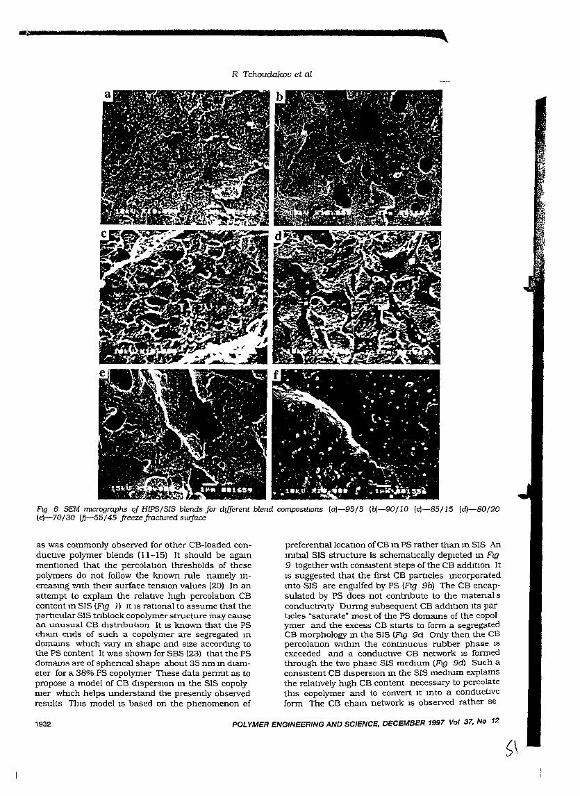
~,....._r"'9 7__'"
R Tchoudakov et al
FIg 6 SEM mlcrographs oj HIPS/SIS blends Jor different blend COmpOSltIOns (a)-95/5 (b)-901l0 (c)-85/15 (d}-BO/20(e)-70/30 (fl-55/45 freeze fractured surJace
POLYMER ENGINEERING AND SCIENCE, DECEMBER 1997 Vol 37, No 12
preferen1:J.allocatIon of CB In PS rather than In SIS AnIm1:J.al SIS structure is schematIcally depIcted In FIg9 together WIth conSIstent steps of the CB addItIon ItIS suggested that the first CB partlcles Incorporatedmto SIS are engulfed by PS (FIg 9b) The CB encapsulated by PS does not contnbute to the matenal sconduc1:J.V1ty Dunng subsequent CB addItIon ItS partIdes ~saturate"most of the PS domams of the copolymer and the excess CB starts to form a segregatedCB morphology In the SIS (FIg 9c) Only then the CBpercolatIon WIthm the contInuous rubber phase ISexceeded and a conductIve CB network IS formedthrough the two phase SIS medIUm (Fig 9d) Such aconSIstent CB dIsperSIOn In the SIS medIUm explamsthe relatIvely hIgh CB content necessa:ry to percolatethIS copolymer and to convert It Into a conductIveform The CB cham network IS observed rather se
as was commonly observed for other CB-Ioaded conduc1:J.ve polymer blends 01-15) It should be agaInmen1:J.oned that the percola1:J.on thresholds of thesepolymers do not follow the known rule namely IncreasIng WIth therr surface tenslOn values (20) In anattempt to explam the rela1:J.ve hIgh percolatIon CBcontent m SIS (FIg 1) It IS ra1:J.onal to assume that thepar1:J.cular SIS tnblock copolymer structure may causean unusual CB dlstnbutIon It IS known that the PScham ends of such a copolymer are segregated In
domams WhICh va:ry In shape and SIZe accordmg tothe PS content It was shown for SBS (23) that the PSdomams are of sphencal shape about 35 nm m dIameter for a 38% PS copolymer These data permIt as topropose a model of CB dIspersIOn In the SIS copolymer whIch helps understand the presently observedresults ThIS model IS based on the phenomenon of
1932
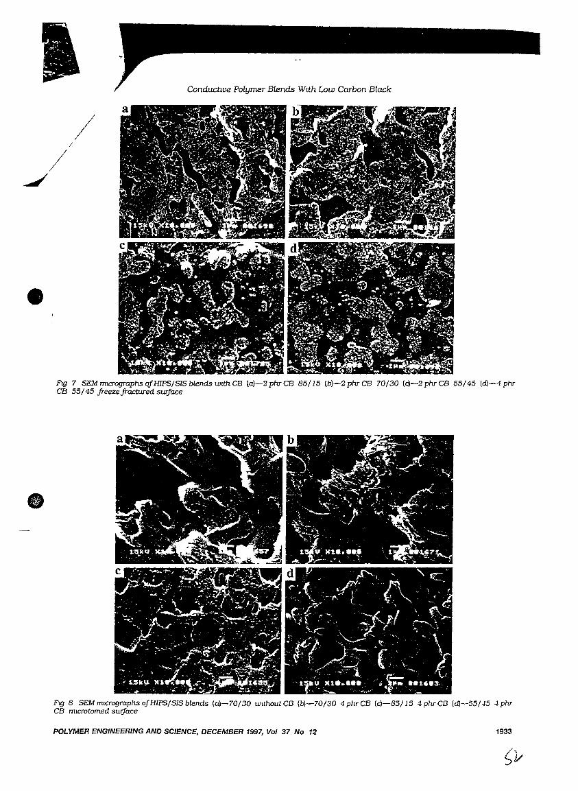
ConductLve Polymer Blends WIth Low Carbon Black
Fig 7 SEMmlcrographsojHIPS/SISblenclswlthCB (a)-2phrCB 85/15 (b)-2phrCB 70/30 (c)-2phrCB 55/45 (dJ-4phrCB 55/45 freezefractured swjace
Fig 8 SEMmlcrographsojHIPS/SISblends (a)-70/30 wlthoutCB (b)-70/30 4phrCB (c)-85/15 4phrCB (dJ-55/-45 4phrCB mlCrotomed surface
POLYMER ENGINEERING AND SCIENCE, DECEMBER 1997, Vol 37 No 12 1933
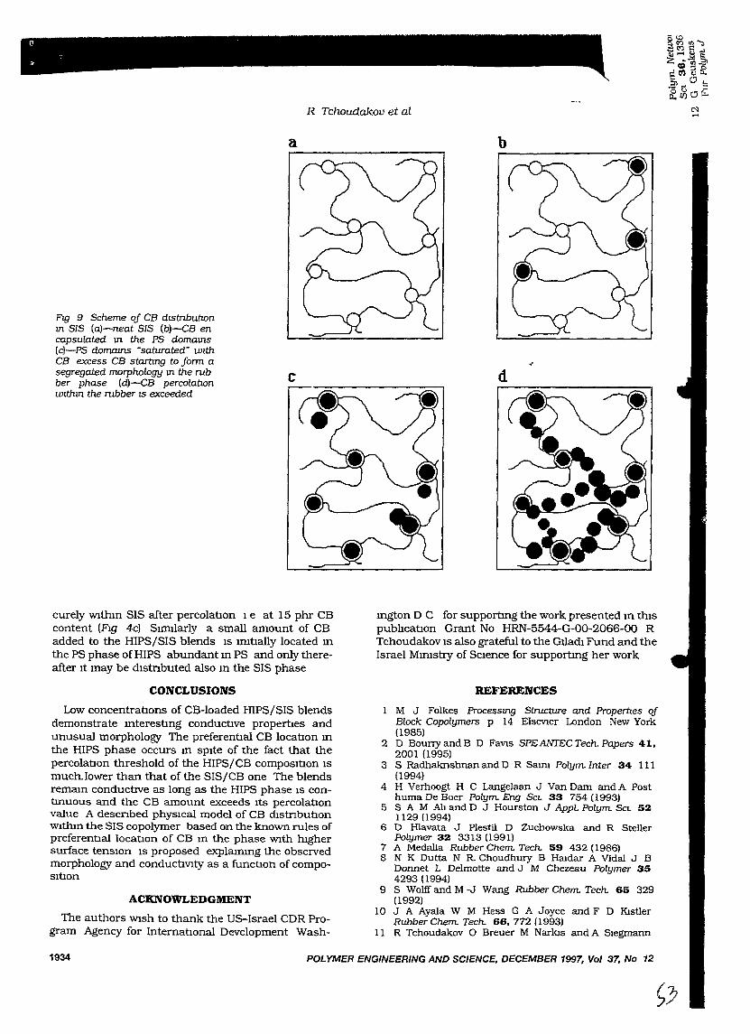
(J
"
R Tchoudakov et al
a b
POLYMER ENGINEERING AND SCIENCE, DECEMBER 1997, Vol 37, No 12
d
REFERENCES
Ington D C for supportIng the work presented In thISpubhcatIon Grant No HRN-5544-G-OO-2066-00 RTchoudakov IS also grateful to the Gl1adl Fund and theIsrael MIIDStry of SCIence for supportIng her work
M J Folkes Processmg Structure and Propemes ofBlock Copolymers p 14 ElseVler London New York(1985)
2 D Bouny and B D FaVls SPEANTEC Tech. Papers 41,2001 (1995)
3 S Radhaknshnan and D R Saml Polym Inter 34 III(1994)
4 H Verhoogt H C Langelaan J Van Dam and A Posthuma De Boer Polym Eng SCL 33 754 (1993)
5 SAM Ab and D J Hourston J Appl Polym SCL 521129 (1994)
6 D Hlavata J Plestil D Zuchowska and R StellerPolymer 32 3313 (1991)
7 A Medalla Rubber Chem Tech. 59 432 (1986)8 N K Dutta N R Choudhury B Hrodar A Vidal J B
Donnet L Delmotte and J M Chezeau Polymer 354293 (1994)
9 S Wolff and M -J Wang Rubber Chem Tech. 65 329(1992)
10 J A Ayala W M Hess G A Joyce and F D KistlerRubber Chem Tech. 66,772 (1993)
11 R Tchoudakov 0 Breuer M Narkls and A Slegmarm
c
Fig 9 Scheme of CB dlStnbuttonm SIS (a)-neat SIS (b)-GB encapsulated m the PS domams(c)-PS domams ·saturated" wlthCB excess CB starttng to form. asegregated morphology m the rubber phase (d)-GB percolattonwtthm the rubber IS exceeded
curely WlthIn SIS after percolatIon 1 e at 15 phr CBcontent (FIg 4c) SImIlarly a small amount of CBadded to the HIPS/SIS blends IS IIDtIally located Inthe PS phase of HIPS abundant In PS and only thereafter It may be dIstnbuted also In the SIS phase
CONCLUSIONS
Low concentratIons of CB-Ioaded HIPS/SIS blendsdemonstrate InterestIng conductIve propertIes andunusual morphology The preferentIal CB locatIon Inthe HIPS phase occurs In spIte of the fact that thepercolatIon threshold of the HIPS/CB compOSItIon ISmuch.lower than that of the SIS/CB one The blendsremam conductIve as long as the HIPS phase IS contInuous and the CB amount exceeds Its percolatIonvalue A descnbed phYSICal model of CB dIstnbutIonWithIn the SIS copolymer based on the known rules ofpreferentIal locatIon of CB In the phase Wlth hIghersurface tenSIOn IS proposed explaInmg the observedmorphology and conductIVIty as a functIon of compoSItIon
ACKNOWLEDGMENT
The authors Wlsh to thank the US-Israel CDR Program Agency for InternatIOnal Development Wash-
1934
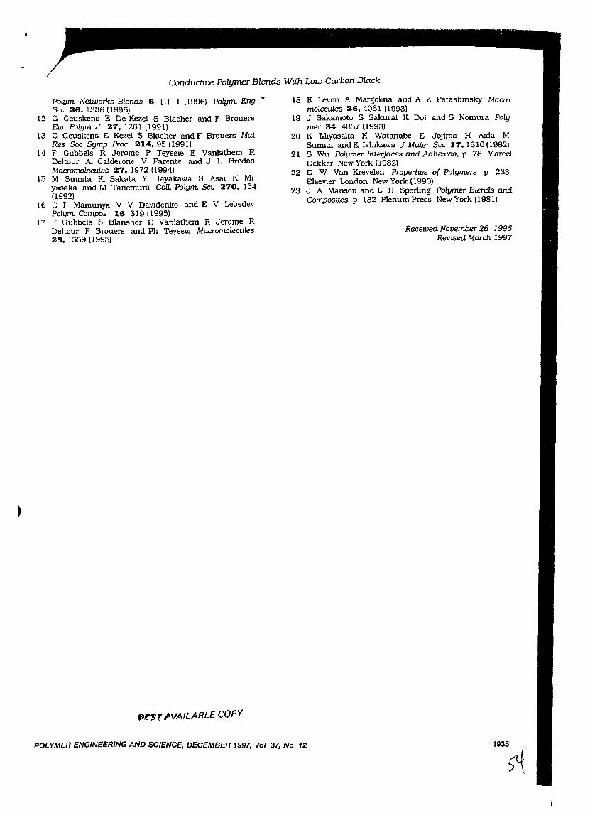
Conductive polymer Blends With Low Carbon Black
POLYMER ENGINEERING AND SCIENCE, DECEMBER 1997, Vol 37, No 12
Polym Networks Blends 6 (1) 1 (1996) polym Eng&t. 36, 1336 (1996)
12 G Geuskens E De Kezel S Blacher and F BrouersEur Polym J 27, 1261 (1991)
13 G Geuskens E Kezel S Blacher and F Brouers MatRes Soc Symp Proc 214,95 (1991)
14 F Gubbels R Jerome P Teyssle E vanlathem RDeltour A. Calderone V Parente and J L BredasMacromolecules 27, 1972 (1994)
15 M SUffilta K. Sakata Y Hayakawa S AsaJ K Mlyasaka and M Tanemura Coll. Polym Sct. 270, 134(1992)
16 E P Mamunya V V DaVldenko and E V LebedevPolym Compos 16 319 (1995)
17 F Gubbels S Blansher E Vanlathem R Jerome RDeltour F Brouers and Ph Teyssle Macromolecules28, 1559 (l995)
PIfST JVAILABLE COpy
18 K Levon A Margohna and A Z Patashmsky Macromolecules 26, 4061 (1993)
19 J Sakamoto S Sakurai K Doi and S Nomura Polymer 34 4837 (1993)
20 K Mlyasaka K Watanabe E JOJima H Aida MSumita and K IshIkawa J Mater Sct. 17, 1610 (1982)
21 S Wu Polymer Interfaces and AdhesIOn, p 78 MarcelDekker New York (1982)
22 D W Van Krevelen Properties of Polymers p 233ElseVier London New York (1990)
23 J A Manson and L H Sperhng Polymer Blends andComposaes p 132 Plenum Press New York (1981)
Recemed November 26 1996ReVISed March 1997
1935
;~
•
I CONDUCTIVITYIiMORPHOLOGY RELATIONSHIPS IN lLV1LvrrSCIBLE /)POLYMER BLENDS HIPS/SIS/CARBON BLACK -(/
R Tchoudakov, 0 Breuer and M Narkzs. Department ofChemlcal Engmeermg andA Szegmann, Department ofMatenals Engmeermg, Technzon - Israel Instztute ofTechnology
Halfa 32000, Israel
Abstract
The morphology and electncal resisuvity ofhtgh tmpact polystyrene (HIPS)/thermoplasticelastomer (SIS)/carbon black (CB) based blends werestudIed ConductIve CB-EC fine parucles locatepreferentIally WIthIn the HIPS phase of the HIPS/SISblends, whereas medIum thermal black large partIclesCB-MT do not demonstrate any preference to eItherphase The studted blends Wlth CB-EC remaInconductIve as long as HIPS maIntams a contInuousphase and the effectIve CB concentratIon Wlthtn HIPSsurmounts Its percolatIon threshold SIS/CB-ECmtXtures exIublt an unusual behaVIor explaIned by asuggested phySICal model wtuch IS extended to theHIPS/SIS/CB systems
IntroductIon
It IS generally known, that CB-Ioaded polymerblends often exInolt a tugher conductIVIty level thaneIther of the component polymers at the same low CBcontent. Thls phenomenon IS due to the preferentIal CBlocatIon WlthIn one of the phases and/or at themterfaces. resultIng 10 segregated phase structures ofthe blend leadtng to the double percolauon concept[l,2} Usually, block copolymers are added totmmlsclble polymer blends to functIon as alIOylOgagents or surfactants wtuch conmbute to thestabiltzauon of the multIphase structure [3} There arenumerous publtcatIons concerrung the morphology andpropertIes of blends such as' polystyrene (PS) With Itscopolymers However, almost nothmg IS reported onsuch blends loaded WIth carbon black (CB) especIallythe conductlve CBs In addttlon. utIltzauon of a blockcopolymer as the dIspersed phase withm a PS matnx ISalso uncommon Vanous publIcauons concernmgconductIve elastomer/CB COmpOSItIOnS revealfundamental parameters deternumng theIr conductivitylevel among them the CB-polymer mteractlon [451 Athermoplastic elastomer ffil'(ed WIth CB bemg a part ofthe muluphase conducuve systems shows a blendconductIVIty affected by the thermoplastIC elastomermtnnsiC ffilcrostructure [6,7} The subject of thIS studyIS the correlatIon between the morphology andreSIstIVIty of CB-loaded composItIons of a hIgh Impact
3766/ ANTEC 97/925
PS (HIPS) and a tn-block copolymer, styrene-Islprenestyrene, (SIS)
ExperlDlentaI
The polymers used 10 thiS study were HIPSGahrene HT 88-5 i\l1FI - 45 Carmel Oletin~ hraeland SIS Qumtac 3421, i\l1FI - II 14% PS Japan Thecarbon blacks were CB-EC Ketjenblack EC-300 AkzoNetherlands and CB-MT Thermal bla<.k N990Vanderbtlt. charactenzed by surfa<.e area (BEn 950and 9 m2/g and particle diameters - 30 and (285-500)nm correspondmgly
HIPS/SIS/CB blends contamIng 545 wt% SISand 0-4 phr CB were produced by melt mIXing In a
"Brabender plastograph at 190°C and ::,ubsequentlycompreSSIon moldmg Their volume resistivity Wal>
measured as preVIOusly reported [8] The blendmorphology was studied usmg a SEM leol 5400Freeze-fractured and ffilcrotomed surta<.es (bothprepared 10 lIqUId rutrogen) were investigated
Results and DISCUSSIon
The reslstmty of polymer/CB-EC compoundsas a functIon of the CB content IS presented In Fig laIt IS clearly seen that the SIS/CB percolation O<.<.urs at arather hIgh cntIcal CB concentratIon about (0 phrThis value IS much higher than the correspondtng valuefor HIPS/CB compounds. about 2 phr FIgure Ib depl('[sthe effect of SIS content on the blend re~l::,tlvttv at aconstant CB concentrauon 10 the blend Intere::,tmglyblends WIth 2 phr CB depict a ::,tronger c.hange Inres1sttvIVY WIth blend composltlon compared to theblends containIng 4 phr CB It should be notedhowever that the reSiStiVIty ot HIPS contalntng 4 phrCB IS 9 orders of magmtude lower than thdt at HIPScontaInIng Just 2 phr CB The re:>I:-t1vtty ot the tormerIS oracticaIly unaffected by the addltlon ot SIS up to 45wt% whtle the 2 phr CB contaInIng blends exhibit alarge reSIstIVIty reduction for SIS content of 20-30 wt%It IS weI! establtshed that the Critical conc.entratlon at agIVen CB at the percolation thre:-hold In dltterentpolymers depends on the polymer/CB In[t.ra<.tlon [91Such If1teraCtlon~ are related to ::,ome polvm",r
({>
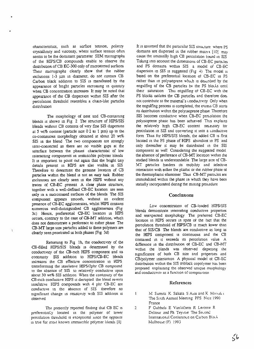
..
charactenstIcs, such as surface tensIOn, polarItycrystallImty and VISCOSIty, where surface tensIOn oftenseems to be the donunant parameter SEM nucrographsof the HIPS/CB compounds enable to observe thed1stnbutIOn of CB EC-300 only of nucrotomed surfacesTheIr nucrographs clearly show that the rubbermclusIOns 1-3 ~m In dIameter, do not contam CBCarbon black addItIon to SIS IS mamfested by theappearance of bnght partIcles mcreasmg m quantItywhen CB concentratIon mcreases It may be noted thatappearance of the CB dIsperSIOn wIthIn SIS after thepercolatIon threshold resembles a cham-lIke paruclesdistrIbutlon
The morphology of neat and CB-contaIrungblends IS shown In FIg 2 The structure of HIPS/SISblends WIthout CB conSIsts of very fine SIS dIsperSIOnat 5 wt% content (partlcle SIze 0 2 to I ~m) up to theco-contlnuous morphology obtamed at about 20 wt%SIS m the blend The two components are stronglymter-connected as there are no VISIble gaps at themterface between the phases charactenstIc of lowmteractlng components m lffiffilscible polymer blendsIt IS Important to pomt out agaIn that the bnght tInydetaIls present In HIPS are also VISIble. In SISTherefore to deternune the genume locatIon of CBpartlcles WIthIn the blend IS not an easy task Rubbermcluslons are clearly seen 10 the HIPS WIthout anytraces of CB-EC present A clear phase structure,together WIth a well-defmed CB-EC location are seenonly In a nucrotomed surfaces of the blends The SIScomponent appears smooth, WIthout an eVIdentpresence of CB-EC agglomerates, WhIlst HIPS contaInSnumerous well-d1stIngUlshed CB agglomerates (FIg3c) Hence, preferentlal CB-EC location 10 HIPSoccurs, contrary to the case of CB-MT addItion, WhIChdoes not demonstrate a preference to eIther phase TheCB-MT large SIze partlcles added to these polymers areclearly seen penetrated m both phases (Fig 3d)
Returmng to FIg lb, the condUCtIVIty of theCB-filled HIPS/SIS blends IS deternuned by thecOndUCtiVIty of the CB-nch HJPS component and ItSCOntinUIty SIS addItIon to HIPS/CB-EC blendsmcreases the CB effective concentration In HIPStransforrmng the InsulatIve HIPS/2phr CB compoundin the absence of SIS to relatIvely conductIve uponabout 30 wt% SIS addIUon When the contmulty of theCB-nch conductIve HIPS IS disrupted the blend revertsmsulative HIPS compounds WIth 4 phr CB-EC areconductive In the absence of SIS therefore nosIgmficant change In reSIstIVIty With SIS additIOn ISobserved
The presently reported findmg that CB EC IS
preferentIally located In the polymer of lowerpercolation thre~hold IS excepuonal ~mce the oppositeIS true for mo~t known IImrusclble polymer blends [8]
It IS assumed that the particular SIS strUl.. ture where PSdomaInS are dIspersed m the rubber matrIX [10] maycause the unusually high CB percolatIOn tound In SISTakmg mto account the dimenSIOns of CB-EC partH.. lesand PS domams withm SIS a model of CB-ECdisperSIOn In SIS IS suggested (Fig 4) The model ISbased on the preferentIal locatIOn ot CB-EC In PSrather than tn polyisoprene whll.h IS de::'l.nbed by theengulfing of the CB particles bv the PS blod.s untdtheir saturatIon ThiS engulfing ot CB-EC with thePS blocks Isolates the CB partIcle~ and theretore doe~
not contnbute to the materIal's l.ondul.tlVlty Only whenthe engulfing process IS completed, the exce~s CB startsItS dIstnbutIon wIth10 the polyisoprene phase TheretoreSIS becomes conductIve when CB-EC perl.OlatIOn thepolyisoprene phase has been achieved ThiS explainSthe relatively hIgh CB-EC content nel.e::.sary torpercolation 10 SIS and convertIng It tnto a l.onductlveform Thus for HIPS/SIS blends, the added CB IS firstlocated tn the PS phase of HIPS abundant In PS andonly thereafter It may be dlstnbuted In the SIScomponent as well ConSiderIng the suggested modelthe absence of preference of CB-MT locatIOn wlthtn thestudIed blends IS understandable The large Size of CBMT partIcles hmders ItS mobilIty and selective1OteractIon WIth eIther the plastIC or the rubber phase otthe thermoplastIC elastomer Thus CB-MT pamdes arelffiffiobllIzed WIthIn the phase 10 WhICh they have beenInItIally mcorporated dunng the mIx10g prol.edure
ConclUSIOns
Low concentratIOn of CB-Ioaded HIPS/SISblends demonstrate interesting conductive propertiesand unexpected morphology The preterred CB-EClocatIon In HIPS occurs 10 spite ot the tact that thepercolatIon threshold of HIPS/CB IS much lower thanthat of SIS/CB The blends are conductive as long asthe HIPS component IS continuous and the CBcontamed 1U It exceeds ltS percolation value AdIfference In the dlstnbutlOn ot CB-EC and CB-t..nwithm the blends was observed depictIng thesIgmficance of both CB size and properties andCB/polymer interactIOn A phySical model ot CB-ECdIstnbutlon wlthtn the SIS tnblock copolymer ha~ beenproposed explalnmg the observed umque morphologyand conductlvltv as a function of compo~JtlOn
References
M Sumlta K Sakata S A~al and K MIV~Jk. 1
The Smh Annual MeetIng PPS Nice 1990France
2 F Gubbels E Vanlathem R Lerome RDeltour and Ph Tey~sle The Sel.OndInternatlonJI Conterenl.e on Cal bon Bl.ld..Mulhou~e (F) 1993
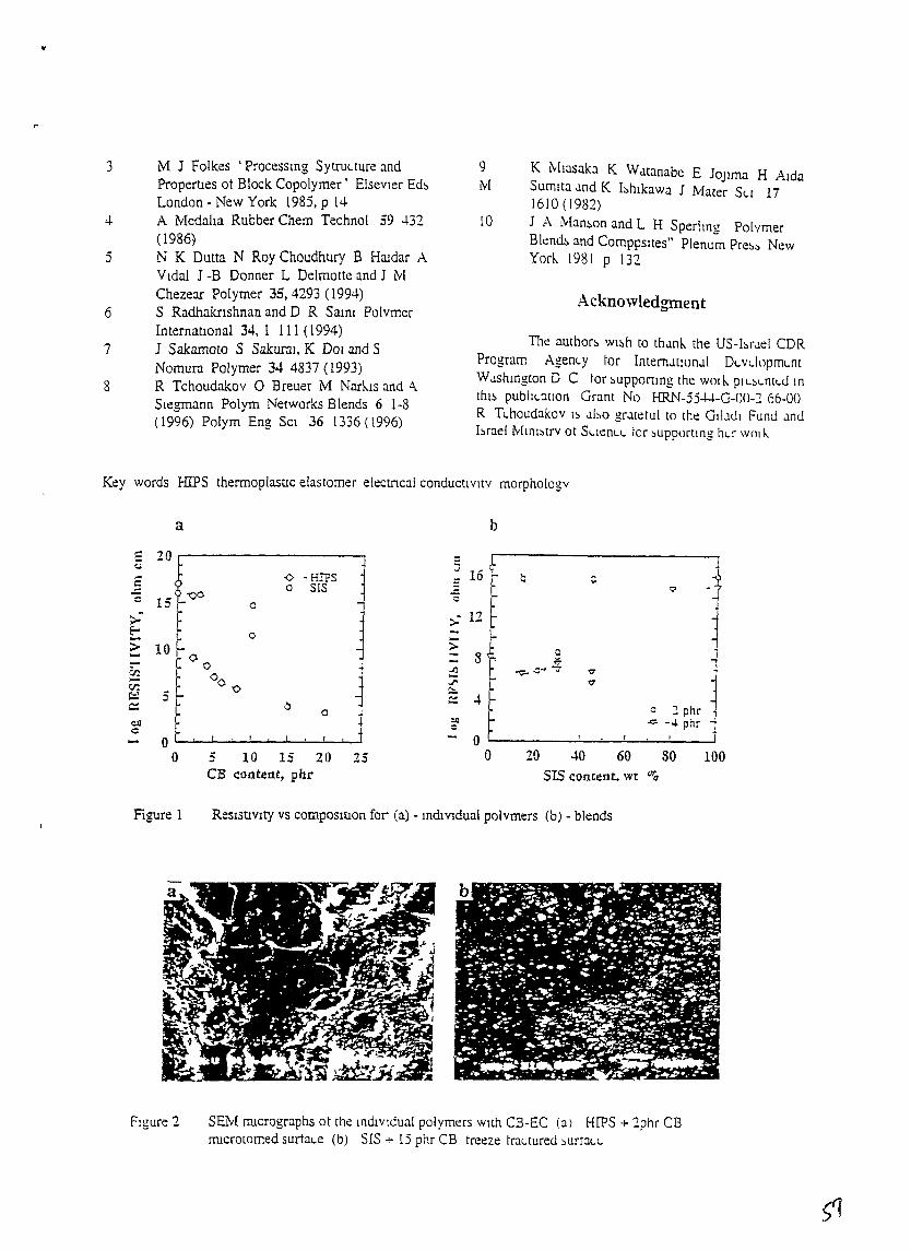
3
4
5
6
7
8
M J Folkes 'Processmg Sytru<.ture andPropertIes ot Block Copolymer' ElsevIer Ed~
London ... New York 1985, p 14A Medalla Rubber Chern Technol 59 -1-32(1986)N K Dutta N Roy Choudhury B Hllidar AVIdal J -B Donner L Delmotte and J MChezear Polymer 35,4293 (1994)S Radhaknshnan and D R Saim PolymerInternatIonal 34, 1 111 (1994)J Sakamoto S SakuraI, K DOl and SNomura Polymer 34 4837 (1993)R Tchoudakov 0 Breuer M Nark.Is and A.Siegmann Polym Networks Blends 6 1-8(1996) Polym Eng SCI 36 1336 (1996)
9 K Mlasaka K Wtltanabe E JOJlma H AIdaM Sumlta tlnd K I~hlkawa J Mater S<.l 17
J610 (J982)
[0 J A Man~on and L H Sperlmg PolymerBlend~ and Comppsltes" Plenum Pre~~ NewYork 1981 p 131
Acknowledgment
The author~ wI~h to thtlnk the US-brJel CDRProgram Agen<.y ror InternJtlOnJI DLVL.loprnt... nt
WJshlngton D C tor ~upport1ng the WOtI-. PtL.~L.ntt..J Inthl~ publt<':ltlon Grant No HRN-55+-l.-G-OO-2 66-00R TL.houdakov t~ .lbo gr..ltetu[ to the Gil.llli Funll .lnllhrae! Mml~trv at SL.len<.L. tor ~upportlng hL[ WOl h.
Key words HIPS thermoplastIc elastomer electrIcal conductivity morphology
a b,.. 20,..
:;16 '
<:oJ
:: -<> - HIPS Q c: 0 SIS ?f-"CO - ~c 15 0
;>0- -;: 12 ~
t 0 - I--> 10 - ;::.. ;::- ~oo 8 i't~~ jzc:-
~ -v- ~ ... "7c:n°0 I-- ..r "7c:n -0 - Co:.\;:l 5f-
~ 4c:: 0 c ::. phr0~ ~ .;:;:. - ... phre.ll ~
~c0- 0
0 5 10 15 20 .,- 0 20 40 60 80 100_:J
CB content, phr SIS content. wt %
Figure 1 ResIstlVlty vs COmpOSItIOn for (a) - mdIVIdual polvmers (b) - blends
Figure 2 SEM n:ucrographs ot the mdlVldual polymers with CB-EC (al HIPS + 2phr C8n:ucrotomed surtaLe (b) SIS + i5 phr CB treeze tra<.tured ~urt:l<.1...
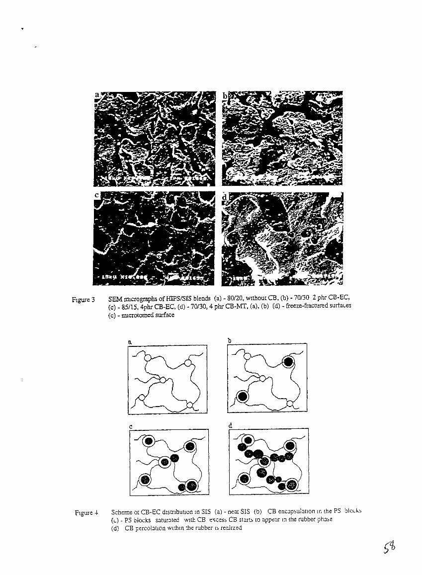
..
FIgure 3 SEM IDlcrographs of HIPSISIS blends (a) - 80/20, WIthout CB, (b) - 70/30 2 phr CB-EC,(c) - 85115, 4phr CB-EC, (d) - 70/30, 4 phr CB-MT, (a), (b) (d) - freeze-fractured surta<.es(c) - nucrotomed surface
a
FIgure -+ Scheme at CB-EC dIstnbutlOn In SIS (a) - neat SIS (b) CB encap~ulatIon In the PS blod..~(t..) - PS blocks saturated wIth CB e'(ces~ CB start;, to appeor In the rubber pha~e
Cd) CB percolatIOn wlmlO the rubber l~ reahzed
"r
Researc~ Development and Consultmg Center POLYMAK
FINAL REPORTCovenng Penod September 1993 - September 1996
ELECTRICALLY CONDUCTlVE
STRUCTURED POLYMER BLENDS
M Kozlowskt and A Kozlowska
The report IS a collaborative research betweenthe POLYMAK, Wroc1aw and the TECHNION, Hatfa
under Grant No HRN-5544-G-OO-2066-00US-Israel CooperatIve Development Research Program
November 1996
ExecutIve Summary
Polymers have been wIdely known as hIghly electroreslstlve matenals TheIrconductIVIty IS m the range of 1013 - 1016 [0 cm], therefore plastics are used aselectrIcal msulators m numerous applIcatIons In order to make plastIC matenalsconductIve, electrIcally conductIve components may be admIXed Usually thereare fillers lIke metal powders, flakes or fibers, carbon blacks and carbon fibersRecently mtnnslCally conductIve polymers, hke polyamhne, polyacetylene,polyphenylene and polypyrolle, have focused conSIderable mterest amongresearchers For practIcal reason the most wIdely used filler IS still carbon black(CB), as much cheaper and lIghter than metallIc partIclesDependmg on a filler content m a composIte, one obtams the msulatmg, antIstatICor electncally conductIve matenals At partIcular CB-Ievel the famtlIar msulatorto-conductor tranSItiOn occurs The clasSIcal percolatIon esttmates a cnticalvolume fractiOn at 0 156 Such hIgh degree of loadmg bnngs about detenoratiOnof mechamcal propertIes and mcrease m the melt VISCOSIty of plastICS Thus,searchmg for a compromIse of the conductIVIty level and mechamcal propertIes,hIghly sophIstIcated phase structures have been recently generated, atmmg todevelop a network ofthe conductIve pathways through the matenalOur goal was to develop the model compounds of IncompatIble polymer blendshavmg unIque electrIc/dIelectrIc and stable structures towards melt processmgUpon our three-years study the preparatiOn condItIons for hIghly conductIvepolymer compOSItes WIth a low carbon black content have been defined DIfferentpolymer grades and blends of vIrgm polymers m dIverSIty of ratIOS, drfferent CBgrades and CB-content, as well as mIXmg technology were among the factorsstudIed, as far as the mfluence on the conductIVIty level and morphology ISconcernedWe concluded that a detaIled descnptIOn of the mIXmg hIstOry (shear stress,reSIdence tIme) IS reqUIred for polymer blendmg, bemg equally lffiportant for theresulted morphology, lIke the chemIcal structure and ratIO of the componentsGeneratIon of a dIsperse. stratIfied, or co-contmuous morphology has beenperformed In a controlled manner The mterpenetratmg-type blends and alloyshave been proved as the most useful for electrIcally conductIve plastIC matenalsSIgmficant reductIon of a filler content was achIeved resultmg from Its selectIvelocatIOn m one of the phases, or at mterfaceOur results, pubhshed In mternatIonal Journals and presented at InternatIOnalconferences, have been accepted WIth mterest by the sCIentl'fic communIty,addmg Its ovro value to a contemporary state-of-the-art
POSSIble applications of such mu1tIcomponent polymer systems mclude theelectncally conductIve/dISSIpative matenals for- packagmg foIls, foames, tapes,- antIstatic floormg and carpetbackmgs,- tubmg and ventIlatIon ducts m mmmg mdustry, petrochemIcal plants, hOSPItals,- antistatic clothmg, hoses,- semIcon cables,- EMlIRFI shIeldmg
-20-
Research Objectives
Research performed under the grant has been focused on the followmgObjectIves- Methods of structurmg incompatIble polymer blends- Method for determmation of the mverSIon pomt based on the electnc/dielectncbehaVIOr of mcompatIble blends,- Carbon black dlstnbutIon between the phases and at the mterface,- Fmdmg conclUSIons of general character for other mcompatlble polymer blends,- Advancmg the SCIentIfic and technologICal levels m the field of structuredpolymer blends and conductive plastIC matenals by establIshmg soundmfrastructure m Poland
The objectives ofour research have been among the most mtensively mvestigatedrecent years, smce polymer blends exhIbIt hIghest dynamiCS of therr consumptIonamong other polymenc matenals Nevertheless, there remam sttll many openquestIOns, as far as therr Structuflzatton and electncal conductiVIty IS concernedSeverallaboratones have been mvolved m a sundar approach to ours - findmg apOSSibly low percolatIOn level for the electncally conductive plasttc compositesby a preferentIal locatIon of the conductIve filler m one of the phases, or atmterface [1-10] Our research has added Its own value to a contemporary stateot:.the art, findmg place among the frontiers of SCIence Innovative aspects of ourresearch constitute the model of a morphology evolutIOn under disperSive mlXmgand apphcatlOn of the multiple percolatIon concept to the electncally conductIvepolymer blends, contammg a semlcrystalhne polymer as one of the components
Methods and Results
MatenalsCommerCIal grade polystyrene (PS) from ZCh OSWleCIm (Poland) and SlX
grades of low denSity polyethylene (LDPE) from ZCh Blachowma (Poland), aswell as (ethylene-vmyl acetate) copolymer (EVA) Rlbolene from Entmont,(styrene-butadiene-styrene) tn-block copolymer (SBS) from Shell and hqUldcrystallme polymer (LCP) Rodrun LC 3000 from Untttka Ltd were used m thestudyPartIally hydrogenated poly(styrene-b-Isoprene) dl-block copolymer KratonG1701 from Shell ChemIcals was added as a compatlbthzer
EIght dtfferent grades of electncally conductIve carbon black were supplIedby Akzo Nobel ChemIcals (the Netherlands), Cabot Co (USA) and Degussa AG(Germany) All the grades have been declared as hIghly conductIve The mostImportant parameters whIch mfluence the CB-electroconducttvIty have beenmcluded m Table I The surface area, measured by lodme- or mtrogen-adsorptIOnIS a total sum of external- and mternal surface areas of the basIC carbon partIclesm the pnmary aggregates The tendency to aggregatIOn IS charactenzed by thestructure of carbon black, measured by DI-Butyl-Phtalate (DBP)-absorptlOn Theoxygen-contammg organIC groups formed at the CB-surface so called "volatIles",act ~ d barner for the electron-tunellmg effect, hence decreasmg conductIVIty
-1')/-
Table 1 Charactenstics of the carbon black grades
CB code CB grade DBP lOD DensIty VolatIles Janzen'smlll00g mglg gil % 0("
AKZONobelKetJenblack
1 EC-600JD 490 1077 107 06 252 EC-300J 327 752 134 07 37
Cabot3 Vulcan P 115 175 322 1 0 984 Elftex 160 89 37 436 - 1235 Vulcan XC72 171 284 278 1 5 68
Degussa6 PnntexXE2 367 1,107 150 o1 337 PrmtexL6 123 - 120 1 2 928 Pnntex L 118 - 200 08 96
Blends PreparatIonPolymer components were mIxed WIth carbon black usmg the Brabender
PlastI-Corder mixmg umt ComposIte plaques of approxImately 1 rom thIcknesswere compressIon molded under pressure of 12 MFa for 5 mmutes
Segregated blends were prepared by thorough mIXmg of the powderycomponents and subsequent compreSSIOn moldmg under the same condItIOns, asused for the melt-mixed blends
Samples for the electrIcal resIstIvIty and mechanIcal strength measurementswere cut out from the plaques
MeasurementsVolume resIstIvIty p and surface resIstIvIty Ps was estlIDated accordmg to
ASTM D257 We used the three-electrode electrometer arrangement for the DCmeasurements of InSUlatIOn reSIstance The apparatus used was KeIthley 617KeIthley 6512, 2000 MultImeter or Meratromc V 641 dependmg on thereSIstivIty range SImIlarly, the voltage level was 100 V or 1 1 V The sampleswere AI-coated by evaporation pnor the measurements
RheologIcal measurements were performed WIth the capIllary rheometertype MCR 3210 The capIllary used was of dIameter d = 1 27 rom and length todIameter ratIO Lid = 40 The Rabmowitch correctIon was applIed, whereas theBagley correctIOn was neglected because ofthe hIgh Lid ratIOThe rheologIcal charactenzation of polymers and CB-composites was alsoperformed usmg Rheometncs RDSII dynamIC spectrometer ThIS IS a controlledstram mstrument m WhIch the sample IS subjected to shear deformations betweentwo concentrIc surfaces The sample was subjected to OSCIllatory or steadymotIOns, usmg plate-plate geometry of 25 nun dIameter In dynamIC expenmentsthe shear stram resultant shear stress and phase angle between those wereresolvedThe dynamIC stram sweep mode expenments, performed at frequency of 1 0 radlsand tor strams rangmg from 03 to 300% proVided the strams for WhiCh the
- 22-
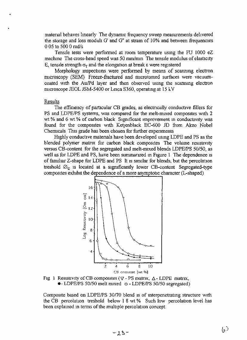
matenal behaves lmearly The dynamIC frequency sweep measurements dehveredthe storage and loss modulI Gf and G" at stram of 10% and between frequencIeso05 to 500 0 rad/s
Tensl1e tests were performed at room temperature usmg the FU 1000 eZmachme The cross-head speed was 50 mmlmm The tensIle modulus of elastiCItyE, tenSIle strength crr and the elongation at break E were regIstered
Morphology mspectIons were performed by means of scannmg electronmIcroscopy (SEM) Freeze-fractured and microtomed surfaces were vacuumcoated WIth the AulPd layer and then observed usmg the scanmng electronmICroscope lEOL lSM-5400 or Leica S360, operatmg at 15 kV
ResultsThe effiCIency of partIcular CB grades, as electncally conductIve fillers for
PS and LDPEIPS systems, was compared for the melt-mIxed composItes WIth 2wt % and 6 wt % of carbon black Slgmficant improvement m conductIVIty wasfound for the composItes WIth Ketjenblack EC-600 JD from Akzo NobelChemIcals ThIS grade has been chosen for further expenments
HIghly conductIve matenals have been developed usmg LDPE and PS as theblended polymer matrIx for carbon black composItes The volume reSIstIvItyversus CB-content for the segregated and melt-mIxed blends LDPEIPS 50/50, aswell as for LDPE and PS, have been summanzed m FIgure 1 The dependence ISof famI1tar Z-shape for LDPE and PS It IS stmilar for blends, but the percolatlOntreshold 0 c IS located at a sIgmficantly lower CB-content Segregated-typecomposItes exhIbIt the dependence of a more asymptotic character (L-shaped)
16
§ 14
8[2, 12
CE; 10~Vl<lJ
e::: 800
..36
4
2 4 6
•
8 10
el3 conLent [wt %]
FIg 1 ReSIstIvIty of CB composItes (\1- PS matrIX, I:i. - LDPE matrIX,.- LDPEIPS 50/50 melt mIxed 0 - LDPEIPS 50/50 segregated)
ComposIte based on LDPEIPS 30170 blend is of mterpenetratmg structure WIththe CB percolatIOn treshold below I 8 wt % Such low percolation level hasbeen explamed m terms of the multIple percolatIOn concept
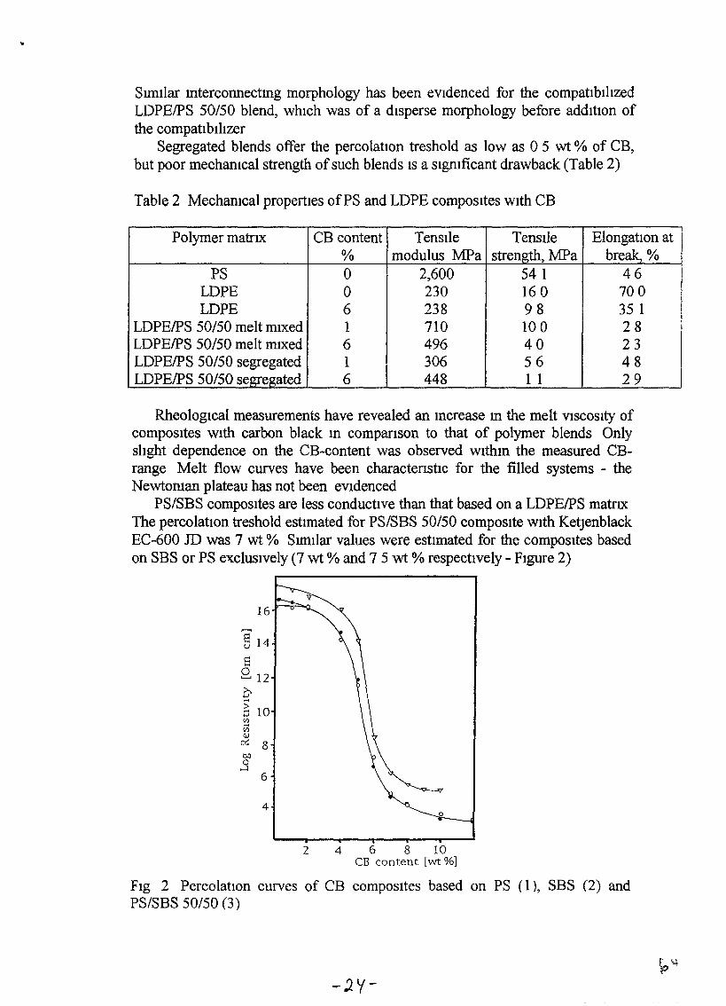
Sundar mterconnectmg morphology has been eVIdenced for the compatIbIhzedLDPEIPS 50/50 blend, whIch was of a dIsperse morphology before addItIon ofthe compatIbIhzer
Segregated blends offer the percolatlOn treshold as low as 05 wt % of CB,but poor mechanIcal strength of such blends IS a sIgmficant drawback (Table 2)
Table 2 MechanIcal propertIes ofPS and LDPE compoSItes WIth CB
Polymer matrIx CB content Tenstle Tensl1e ElongatIOn at% modulus MFa strength, :MFa break, %
PS 0 2,600 54 1 46LDPE 0 230 160 700LDPE 6 238 98 35 1
LDPEIPS 50/50 melt mIxed 1 710 100 28LDPEIPS 50/50 melt mIXed 6 496 40 23LDPEIPS 50/50 segregated 1 306 56 48LDPEIPS 50/50 segregated 6 448 1 1 29
RheologIcal measurements have revealed an mcrease m the melt VISCOSIty ofcompoSItes WIth carbon black m comparIson to that of polymer blends OnlyslIght dependence on the CB-content was observed withm the measured CBrange Melt flow curves have been charactenstIc for the filled systems - theNewtoman plateau has not been eVIdenced
PS/SBS compoSItes are less conductIve than that based on a LDPEIPS matrIXThe percolatIon treshold estImated for PS/SBS SO/50 composIte WIth KetjenblackEC-600 JD was 7 wt % SImIlar values were estImated for the composItes basedon SBS or PS exclUSIvely (7 wt % and 7 5 wt % respectIvely - FIgure 2)
16
§ 14
El8 12q510:2VlQ)
0::: 8eoo
.....J
6
4o
2 4 6 8 10CB content [wt %]
FIg 2 PercolatIOn curves of CB compOSItes based on PS (I), SBS (2) andPS/SBS 50/50 (3)
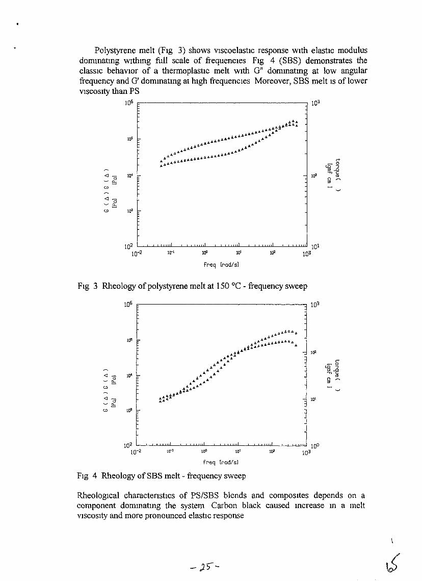
1lJ2
Polystyrene melt (FIg 3) shows vIscoelastIc response wIth elastIc modulusdommatmg wlthmg full scale of frequencIes FIg 4 (SBS) demonstrates theclassIc behaVIOr of a thermoplastic melt WIth Gil dommatmg at low angularfrequency and G' dommatmg at hIgh frequencIes Moreover, SBS melt IS of lowerVISCOSIty than PS
106
~
.. ~
~- Jo~s
102 L...-....L.....JL.-L1-U.Ll.L.-...l-JL.-L1.u..u.L.-...l-JL.-L1.J.1.U.L.-...l-JL...L..L.J.1.U.L.-...l-JL...L..L-l..ll1I 10110-2 lO-1 100 1Ql 1lJ2 103
freq [rad/sl
FIg 3 Rheology of polystyrene melt at 150 °C - frequency sweep
106 c----------------------, 103
<T~ 0
{O """J3..a-nC
(1)n ......3
Ill-I'---'--''-'-l..J.1.U.l--I...l-J-J....l..uJ..I..l--1...l-J'-'-l..LLU'L-..1...1-.J1-W..J.1.U.L.-...1-.JL.-L1..1..U-1l 100
100 10' 1lJ2 103
freq [rad/sl
FIg 4 Rheology ofSBS melt - frequency sweep
RheologIcal charactenstics of PS/SBS blends and composItes depends on acomponent dommatmg the system Carbon black caused mcrease m a meltVISCOSIty and more pronounced elastic response
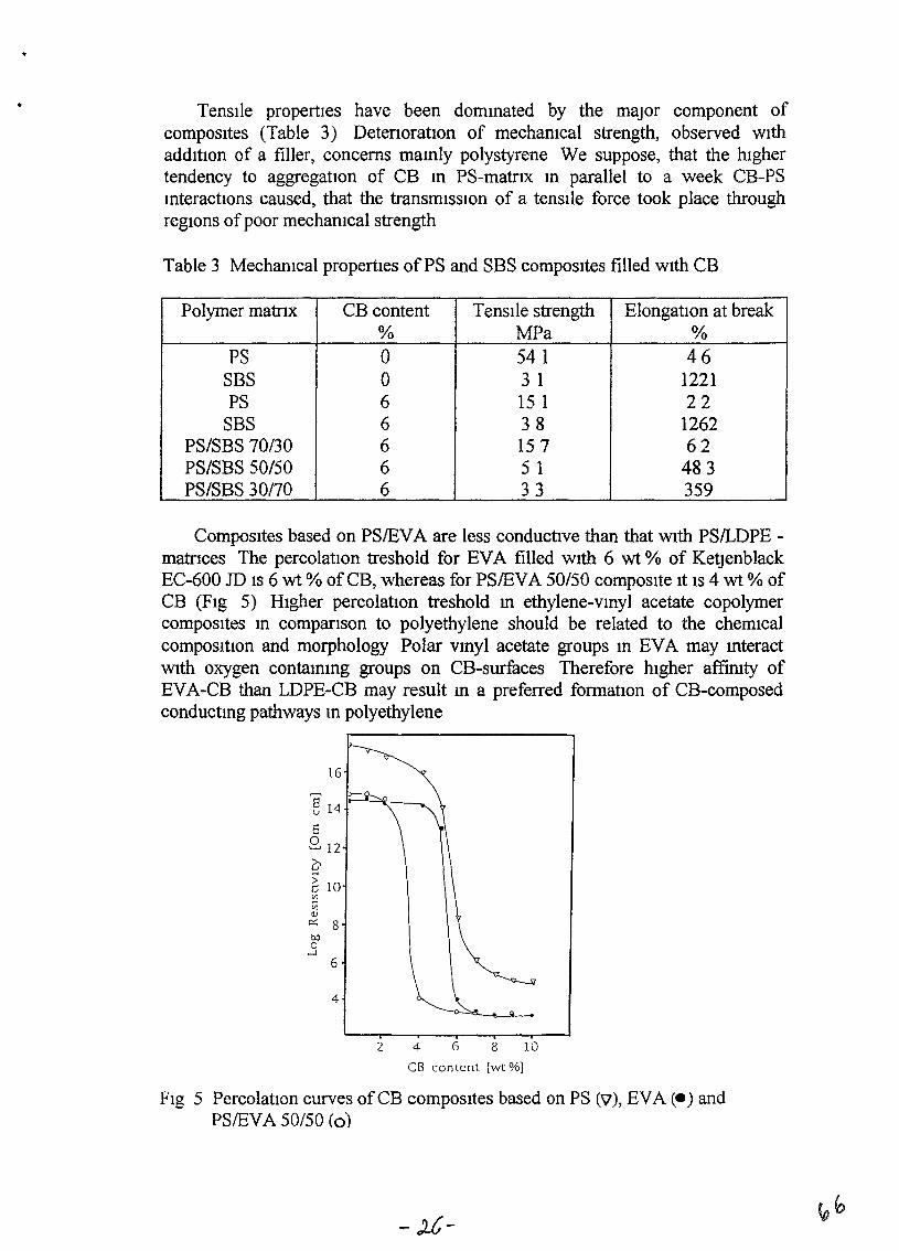
TenSIle propertIes have been dommated by the major component ofcomposItes (Table 3) DetenoratlOn of mechamcal strength, observed wIthaddItIon of a filler, concerns mamly polystyrene We suppose, that the hIghertendency to aggregatIOn of CB m PS-matnx m parallel to a week CB-PSmteractions caused, that the transmISSIon of a tenSIle force took place throughregIOns of poor mechamcal strength
Table 3 Mechamcal propertIes ofPS and SBS composItes filled WIth CB
Polymer matrIX CB content Tensl1e strength ElongatIOn at break% MFa %
PS 0 54 1 46SBS 0 3 I 1221PS 6 15 1 22
SBS 6 38 1262PS/SBS 70/30 6 157 62PS/SBS 50/50 6 5 1 483PS/SBS 30170 6 33 359
CompoSItes based on PS/EVA are less conductIve than that WIth PSILDPE matrIces The percolatIon treshold for EVA filled WIth 6 wt % of KetJenblackEC-600 JD IS 6 wt % ofCB, whereas for PS/EVA SO/50 composIte It IS 4 wt % ofCB (FIg 5) HIgher percolatIOn treshold rn ethylene-vrnyl acetate copolymercomposItes m comparIson to polyethylene should be related to the chemIcalcomposItIon and morphology Polar vmyl acetate groups m EVA may mteractWIth oxygen contammg groups on CB-surfaces Therefore hIgher affimty ofEVA-CB than LDPE-CB may result m a preferred formatIOn of CB-composedconductmg pathways m polyethylene
16
§ 14 I"-"-~-
6.Q, 12
qIi 10~V)
IlJc::: 800o
....J
6
4
2 4 6 8 10
CB content [wt %]
FIg 5 PercolatIOn curves of CB composItes based on PS (\7), EYA (e) andPS/EVA 50/50 (0)
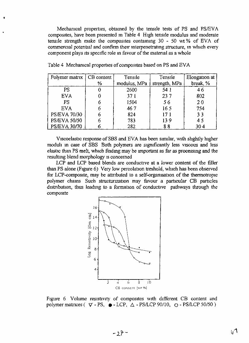
,
Mechamcal propertIes, obtamed by the tensIle tests of PS and PS/EVAcompOSItes, have been presented m Table 4 HIgh tensIle modulus and moderatetensIle strength make the compOSItes contammg 30 - 50 wt % of BVA ofcommercIal potentIal and confirm their InterpenetratIng structure, In WhICh everycomponent plays Its specIfic role m favour of the matenal as a whole
Table 4 MechanIcal properties ofcompOSItes based on PS and EVA
Polymer matrIx CB content TensIle TensIle ElongatlOn at% modulus, MPa strength, MPa break, %
PS 0 2600 54 1 46EVA 0 37 I 237 802PS 6 1504 56 20
EVA 6 467 165 754PSIEVA 70/30 6 824 17 1 33PS/EVA 50/50 6 783 139 45PS/EVA30nO 6 282 88 304
VIscoelastIc response of SBS and BVA has been SImIlar, WIth slIghtly hIghermodulI m case of SBS Both polymers are sIgmficantly less VISCOUS and lesselastIC than PS melt, WhICh findmg may be Important as far as processmg and theresultmg blend morphology IS concerned
LCP and LCP based blends are conductIve at a lower content of the fillerthan PS alone (FIgure 6) Very low percolatIOn treshold, whIch has been observedfor LCP-composIte, may be attrIbuted to a self-orgamsatIOn of the thermotropICpolymer chams Such structunzatlOn may favour a partIcular CB partIclesdistributlOn, thus leadmg to a formatIOn of conductIve pathways through thecompOSIte
~
16
§ 14
S2 12C6 10:3Vlv
c:r; 8CD0
--l
6
4
2 4 6 8 10
Cl3 content [wt %]
FIgure 6 Volume reSIstiVIty of compOSItes WIth dIfferent CB content andpolymer matrIces ( 'V - PS, • - LCP, 6. - PS/LCP 90/10, 0 - PS/LCP 50/50)
-1.r-
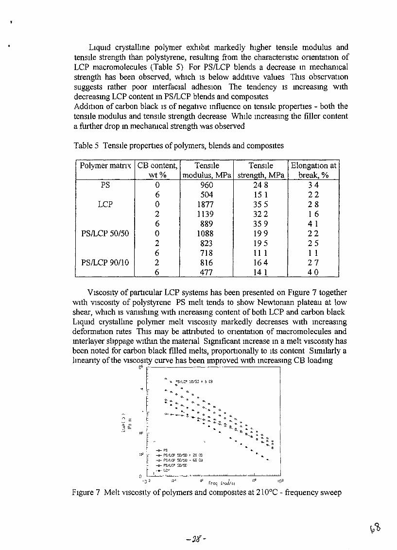
LIqUId crystallme polymer exhIbIt markedly hIgher tensIle modulus andtenstle strength than polystyrene, resultmg from the charactenstic onentatIOn ofLCP macromolecules (Table 5) For PSILCP blends a decrease m mechanIcalstrength has been observed, which IS below addItive values ThIS observatIOnsuggests rather poor mterfacIaI adheSIOn The tendency IS mcreasmg WIthdecreasmg LCP content m PSILCP blends and compositesAddItIOn of carbon black IS of negative mfluence on tenSIle propertIes - both thetensIle modulus and tensl1e strength decrease WhIle mcreasmg the filler contenta further drop m mechamcal strength was observed
Table 5 TensIle propertIes of polymers, blends and compOSItes
Polymer matrIX CB content, TensIle TensIle ElongatIOn atwt% modulus, MFa strength, MFa break, %
PS 0 960 248 346 504 15 1 22
LCP 0 1877 355 282 1139 322 166 889 359 41
PSILCP 50/50 0 1088 199 222 823 195 256 718 11 1 1 1
PSILCP 90/10 2 816 164 276 477 14 1 40
VISCOSIty of partIcular LCP systems has been presented on FIgure 7 togetherWIth VISCOSIty of polystyrene PS melt tends to show Newtoman plateau at lowshear, whIch IS vamshmg WIth mcreasmg content of both LCP and carbon blackLIqUId crystallme polymer melt VISCOSIty markedly decreases WIth mcreasmgdeformatIOn rates ThIS may be attrIbuted to onentatIOn of macromolecules andmterlayer slIppage withm the matenal SIgmficant mcrease m a melt VISCOSIty hasbeen noted for carbon black filled melts, proportIOnally to Its content S1ffillarly almeanty of the VISCOSIty curve has been lffiproved WIth mcreasmg CB loadmg
06 .,....--------------,
'" ... PSI LCP 50/50 + 6 CB...
10'
10'
'0 2
__ PS
-<>- PSlLCP 50/50 t 2% C9__ PS/LCP 50/50 t 6% CB
-v- PS/LCP 50/50-+- LCO
I
0' Ifrcg [rad/sl
10'
FIgure 7 Melt VISCOSIty of polymers and compOSItes at 210°C - frequency sweep
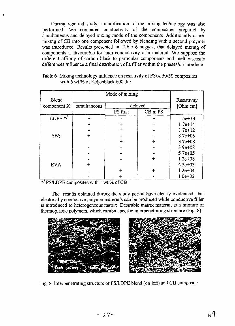
Durmg reported study a modIficatIOn of the mIxmg technology was alsoperformed We compared conductIVIty of the compOSItes prepared bysImultaneous and delayed mIxmg mode of the components AddItIOnally a premIxmg of CB mto one component followed by blendmg WIth a second polymerwas mtroduced Results presented m Table 6 suggest that delayed mIXmg ofcomponents IS favourable for hIgh conductIvIty of a matenal We suppose thedIfferent affimty of carbon black to partIcular components and melt VISCOSItydIfferences Influence a final dIstrIbutIon ofa filler withm the phases/on mterface
Table 6 MIXmg technology mfluence on reSIstIVIty ofPSIX 50/50 compOSItesWIth 6 wt % ofKetJenblack 600-JD
PSILDPE compOSItes WIth I wt ~ ofCB
Mode ofmIxmgBlend ReSIstIVIty
component X SImultaneous delayed [Ohmcm]PS first CBmPS
LDPE */ + - - 15e+13- + + 17e+14- + - 17e+12
SBS + - - 87e+06- + + 37e+08- + - 39e+08
- - - 5 7e+05- - + 12e+08
EVA + - - 45e+03- + + 12e+04- + - 10e+02
*/ 0
The results obtamed dunng the study penod have clearly eVIdenced, thatelectrIcally conductIve polymer matenals can be produced whIle conductIve fillerIS mtroduced to heterogeneous matrIX DeSIrable matrIX matenails a mIXture ofthermoplastIC polymers, whIch exhIbIt speCIfic mterpenetratmg structure (FIg 8)
FIg 8 Interpenetratmg structure ot PSILDPE blend (on left) and CB composite
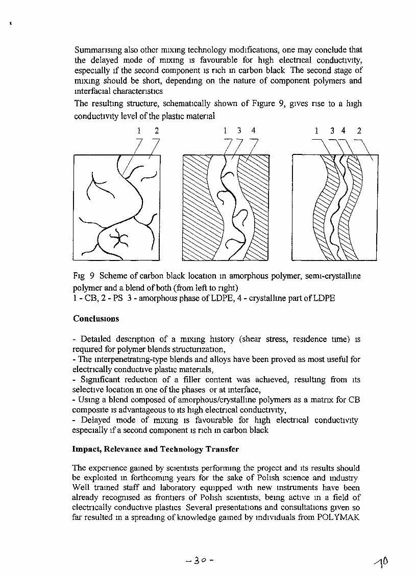
Summansmg also other mIxmg technology modlficatlOns, one may conclude thatthe delayed mode of muong IS favourable for hIgh electncal conductiVIty,especIally If the second component IS nch m carbon black The second stage ofmIxmg should be short, dependmg on the nature of component polymers andmterfacial characterIstics
The resultmg structure, schematIcally shown of FIgure 9, gIves fIse to a hIgh
conducttvity level of the plastic matenal
12 134 1342
FIg 9 Scheme of carbon black locatIon m amorphous polymer, semi-crystallme
polymer and a blend ofboth (from left to nght)1 - CB, 2 - PS 3 - amorphous phase ofLDPE, 4 - crystalhne part ofLDPE
ConclUSIOns
- DetaIled descnption of a mIXIng hIstOry (shear stress, reSIdence tune) ISrequITed for polymer blends StructurizatlOn,- The Interpenetratmg-type blends and alloys have been proved as most useful forelectrIcally conductIve plastIC matenals,- SIgmficant reduction of a filler content was achIeved, resultIng from Itsselective 10catlOn m one of the phases or at mterface,- USIng a blend composed of amorphous/crystallme polymers as a matnx for CBcompOSIte IS advantageous to ItS hIgh electrICal conductIVIty,- Delayed mode of mIXmg IS favourable for hIgh electrIcal conducttvityespeCIally Ifa second component IS nch In carbon black
Impact, Relevance and Technology Transfer
The expenence gamed by SCIentIsts perfonmng the prOject and ItS results shouldbe explOIted m forthcommg years for the sake of Poltsh SCIence and mdustryWell tramed staff and laboratory eqUIpped WIth new mStruments have beenalready recogmsed as frontIers of Poltsh SCIentISts, bemg actlve m a field ofelectrIcally conductIve plastics Several presentatIons and consultatIons gIven sofar resulted m a spreadmg of knowledge gamed by mdlvlduals from POLYMAK
-30-
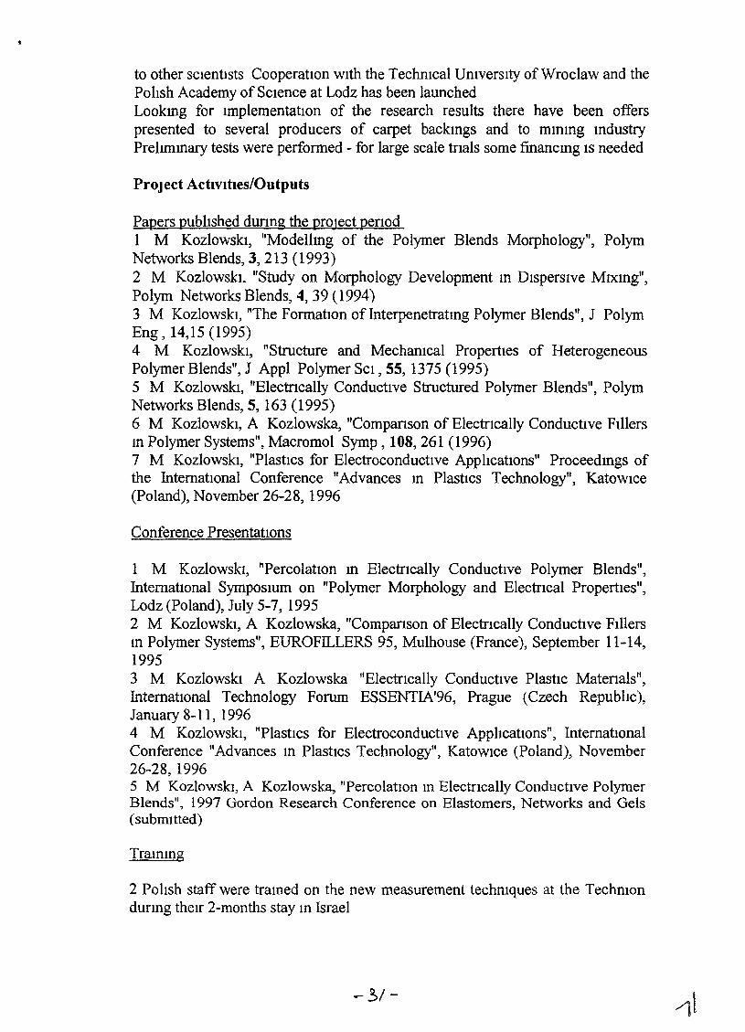
to other sCIentists Cooperation WIth the TechnIcal UmversIty ofWroc1aw and thePohsh Academy of SCIence at Lodz has been launchedLookmg for ImplementatIon of the research results there have been offerspresented to several producers of carpet backIngs and to mmmg IndustryPrelImmary tests were performed - for large scale tnals some financmg IS needed
PrOject ActivIties/Outputs
Papers publIshed dUrIng the project penodI M KozlowskI, "Modellmg of the Polymer Blends Morphology", PolymNetworks Blends, 3, 213 (1993)2 M KozlowskI. "Study on Morphology Development In DIsperSIve MIxmg",Polym Networks Blends, 4, 39 (1994)3 M KozlowskI, "The Formation of Interpenetratmg Polymer Blends", J PolymEng, 14,15 (1995)4 M KozlowskI, "Structure and Mechamcal PropertIes of HeterogeneousPolymer Blends", J Appl Polymer SCI, 55, 1375 (1995)5 M KozlowskI, "ElectrIcally ConductIve Structured Polymer Blends", PolymNetworks Blends, 5, 163 (1995)6 M KozlowskI, A Kozlowska, "Companson of Electncally ConductIve FIllersm Polymer Systems", Macromol Symp, 108,261 (1996)7 M KozlowskI, "Plastics for Electroconductive ApplIcations" Proceedmgs ofthe InternatIOnal Conference "Advances m PlastIcs Technology", KatOWIce(Poland), November 26-28, 1996
Conference PresentatIOns
1 M KozlowskI, "PercolatIOn m ElectrIcally Conductive Polymer Blends",InternatIonal Symposmm on "Polymer Morphology and ElectrIcal Properties",Lodz (Poland), July 5-7, 19952 M KozlowskI, A Kozlowska, "ComparIson of ElectrIcally Conductive FIllersm Polymer Systems", EUROFILLERS 95, Mulhouse (France), September 11-14,19953 M KozlowskI A Kozlowska "ElectrIcally ConductIve Plastic Matenals",InternatIOnal Technology Forum ESSENTIA'96, Prague (Czech Repubhc),January 8-11, 19964 M KozlowskI, "Plastics for ElectroconductIve ApphcatIons", InternationalConference "Advances m Plastics Technology", KatOWIce (Poland), November26-28, 19965 M KozlowskI, A Kozlowska, "Percolation m Electncally ConductIve PolymerBlends", 1997 Gordon Research Conference on Elastomers, Networks and Gels(submItted)
Trammg
2 PolIsh staff were tramed on the new measurement techmques at the Techmondunng theIr 2-months stay m Israel
-3/-
PrOject ProductIvity
The project dId accomplIsh, In our opmIOn, all of the goals proposed In ourapplIcatIOn
Future Work
The project should be contInued The recommended research dIrectIon IS on"Electncally Conductive Structured Polymer Blends Compnsmg IntnnslcallyConductive Polymers'! We are ready to perform such research for the US AIDAddItIOnally, respective proposal to the NatIOnal CounCIl for SCIentIfic Research,(Poland) IS under preparatIon
Literature Cited
1 R Tchoudakov, 0 Breuer, M NarkIs and A SIegmann, Polym NetworksBlends, 6, 1 (1996)2 M Sumlta, K Sakata, Y Hayakawa, S ASal, K Mlyasaka and M Tanemura,COllOId Polym SCI, 270, 134 (1992)3 K Levon, A Margohna and A Z Patashmsky, Macromolecules 26, 4061(1993)4 F Gubbels, R, Jerome, Ph Teyssle, E Vanlathem, R Deltour, A Calderone,V Parente and J L Bredas, Macromolecules 27, 1972 (1994)5 C KIason, D H McQueen, J Kubat, Macromol Symp, 108,247 (1996)6 C Ojeda and J L Acosta, Rev Plast Modern, 422, 186 (1991)7 Y FUJIkura, M Kawaral and F OzakI, Polymer J , 21,609 (1989)8 A Abo-Hashem, H M Saad and A H Ashor, Plast Rubb Comp Proc Appl,21 125 (1994)9 K I1da J SKIm, S Nakamura and G Sawa, IEEE Trans Electr Insul, 27,391 (1992)10 J K Jeszka, A Tracz, M Kryszewskl, Synth Met, 64, 203 (1994)
- 32-
Polym Networks Blends 3 (4), 213-220 (1993)
ModeIlmg of the Polymer Blends Morphology
M KozlowskIRDCC Polymak' Trentowsloego 21 PL 52430 Wroclaw Poland
213
polymer parrs appeared to be UIUrUSClbie ThIS resultsfrom the thermodynamICS of nuxmg of the macromolecular components The baSIC rule govemmg IDlS
ability IS a negatIve free energy of rruxmg ~GlU at a
gIVen set of temperature and pressure (T and P respectIvely) and at spea.6.cmolecularweight of the polymercomponents
where bHm - heat of nuxmg, ~lU - entropy ofnuxmgThe entropy term for long-eham molecules IS usu
ally low because of the restncted amount of therr
pOSSible conftguratlons It follows that a value of mm.15 deCISIve for mequahty tiG < 0
m 5Accordmg to Huggms and Flory the heat ofnuxmg
15 proportlonal to the blnary mteractIon parameterXu The negabve value of X
12promotes a mutual solu
tIon of the components - m other words, the attractlveforces between nuxed polymers - X
12- are larger than
forces between macromolecules of the same kmd (Xuor XZJ.) nus IS a case of strong speafrc mteractlons(lOmc bonds, hydrogen bonds, etc), the strength ofwluch 15 mversely proporbonal to the dIstance of thebond actIve centers In general the attracb.ve forces area functlon of the bonds densIty, e g they are related tothe mterfaClal area The attractlve forces and the chfferences of chenucal potenbal of the components onboth SIdes of the mterface can be cOnSldered a thermodynarruc dnvmg force of nuxmg The OppOSIte aremterfaaal tensIon, densIty dllferences,low mobility ofmacromolecules because of lugh VlSCOSIty of polymermelts and the melts elasbaty The compehbon of thetendenaes promoang or counteractmg the polymernuxmg process can be expressed by a dJifuSlVity factor The self-dJ.ffuslOn coef.6.aent m polymers IS lowFor example m the system polYVInyl ch1ondejpolycaprolactam the dJifuslOn constant IS only oflO 9 m j sat 90 C 6 The tmckness ofa mterface would mcrease ca10).tID per dayr Accordmg to Elmendorp7 the chffuslOnwill promote homogemzabon of the misable polymerblends only when the SIze IS reduced to the order of 10run DlscusslOn of the polymer systems behaVlor m
Jj
1
Llterature reVIew on morphology modelhng m polymer blends has
been proVlded Thermodynamlcs 15 of hmlted apphcability because
of non equilibnum character of the polymer IXUXlItg process - more
relevant 15 hydrodynamlcs The IIUXmg machmery desIgn and VlS
coelastlC propertles of components are of SpeaflC tmportance for
antlapahon of polymer blends morphology
Types of mlXmg m dtfferent kmd of processmg machmery have
been dlscussed and flow mechanlSm studIes reVIewed. Pnnaples of
flow predIctlon was presented based on the assumptlon that poly
mer mlXmg process 15 predOmInantly of dlSpersIve character VlS
coelastlC and mterfaclal characterl5hcs of mIXed polymers are
among the ma.Jor factors whtch allow coarse quantlfIcatlOn m mod
ellmg the heterogeneous systems morphology
Keywords Blend HydrodynamICS InterfaCIal TenSIonMicrorheology, M15cibility, Moong, Stress, Stnleture V15COSIty
INTRODUCTION
Polymer alloys and blends (PAB) constItute a speaal group of plashcs wluch shows the average growthratel:wI.ce as lugh as that ofall plastIcs I The reason forsuch a lugh chfference 15 UIUque opportumty to obtamalmost an unlmuted spectrum of the matenal properhes by blendmg the polymer components, wluch 15much sunpler and less expen51ve than synthes15 ofnew polymers ThIS opportumty has resulted fromrecent progress made by saentlSts m understandmgthe rules goverrung the technology of polymer nuxmg In fact, it 15 posSlble to offer plastIcs of "tal!ormade" morphology and propemes The mterest mdesignmg the lughly sophIStIcated mulhcomponentpolymer systems can be measured, e g by over 20,000papers on tlus tOpIC pubhshed every year, speaalIUPAC proJects2 and conferences3 and by the creabonof tlus Journal Itself The state ofart on PAB's has beenreViewed recently by Utraclo. • Pnor to the Wscussionof dJiferent aspects of polymer blendIng the mostImportant terms have been defmed m Table 1
POLYrv!ER-POLYMER :MISCIBILITY
The ongmalldea of obtammg the appropnate propertles by blendmg two misable polymers of complementary charactenstics became less attracbve as most
11819510/')3/$070+000
~G =~H -T~Sm m. m [1]
214
terms of the equilibnum thermodynamIcs needs totake Into account the tIme factor At least In the earlystages of a nuxmg process, the polymer pcurs, clasSIned as eIther nusable or unnusable pcurs, form heterogeneous blends As a consequence ofa usually longbme needed to aclueve the thermodynanuc equilibnum, most of the morphologIes observed In polymerblends are of a nonequilibnum state Therefore everydISCUSSIon on polymer blends/alloys should stnctlyspeafy the charactenstIcs of the mIXed components,pressure, temperature and a whole lustory of the system manufactunng In order to Improve the blendmgeffraency one should try to Increase the mobility ofmacromolecules by compoundmg the polymers In amolten state or In a solutIon under Intense nuxmg
UTERATURE REVIEW ON POLYMER MIXING
The nuxmg technolOgIes and machInery have beenWIdely dIscussed &-1& In the course of the blendmg process one polymer IS dISpersed In the other DIverseIDlXIng categones spea.6.ed In Table 1 partIapate, to avarymg degree, In numerous types of the structures ofdeSIred SIZe, deSIgned as dISperse- or Interconnectedtype, the dIsperSIve nuxmg IS all-Important ThIs category of nuxmg IS determmated by the stress level In a
19-20melt When stratIbed morphology IS generated, thedommate type IS the lammar mIxm~ determInedmamly by the stram hIStory of a melt 2122 The mIxmgprocesses are performed In commonly used batch orcontInuous mIXers There are numerous papers on thestudy of the nuxmg mechanISm and on a modellmg ofthe flow and nuxmg In processIng eqUIpment Anunderstandmg of the mIXIng mechanISm IS of hIghpractIcal value as a baSIS for the InventIon of moreefnaent machInery It Involves expenments enablmgobservatIons of a flow In real mIXers by means ofchfferentwmdows, tracers and other "tncky" methodsaccordmg to the InventIon of the researchers
Modellmg aImS to prechct the ultunate flow patterns WIthIn the IIUXlI1g chamber For thIS purpose onemust solve a set of equatIons of motron for the flowbetween the nuxmg elements receIVll1g the pressureand veloaty nelds The method of SImulatIon applIesthe Reynolds hydrodynanuc lubncatron theory As arule the coordInate system IS placed m the rotor whIchIS assumed to be statronary whereas the mIxmg chamber IS conSIdered rotatmg It has been mentroned thateven If the detaIled modellmg of a flow IS oblamedWIth extenSive computatronal efforts the calculallons
© Chern fcc Publt-.hmg
Polym Networks Blends 3 (4) 213220 (1993)
are lImIted to the relativelySImple conngurahonsWithnumerous SImplillcatIons The SImulated flow patterns have to be conSIdered as apprOXImatIons of realstreamhnes
DISCUSSIng the processIng eqUIpment used forpreparation of the polymer blends and alloys, theroll-nulls and Internal mIXers are worth menhonmgamong batch mIXers Both are of the dISperSIve mIXIDgtype workmg With hrgh efnaency Roll-nulls as pIOneers In the thermoplastics proceSSIng obtamed numerous treatments of the flow analysIS Among themore realISticare these ofVlachopoulos etaI ,23.24 TokItaand Whrte,2S and Takserman-Krozer et al 26 InternalmIXers can be assumed as a next step m the progressof a nuxmg eqUIpment ImItatIng a roll-mill actIon bythe double-flIghted rotors, but In a closed chamberThey produce hIgher shear rates allOWIng faster proceSSIng ConSIdermg the efforts and achIevements bothm modelImg and In the mIxmg mechanISm stuches the
f T dm 411.27"9 Wlu 14.30,31groups 0 a or, tel and Manas -Zloczower31.33 should be mentIoned
Contmuous mIXers are commonly represented bythe SIngle and twIn screw extruders, SIngle and twm
shaft mIXers and by corotatmg dIsc processors TheSIngle screw extruders are good extensIve mIXers butof poor dIspersIve action The explanation of tlus hasbeen found from the modelImg results obtamed byManas-Zloczower and Tadmor~e concept of Passage DIStnbutIon FunctIon3S revealed that most ofpolymermelt partIcles does not pass through the onlyhIgh shear regron of the extruder, I e the clearancebetween the screw flIght and the barrel To enhancethe dIspersIve charactenstIcs of the SIngle screw extruders screws With speaal nuxmg sectIons, barrelsWIth pms, etc 36 were developed Among the fundamental studIes on modelImg of these machrnes agam
~ 3& El 39that of Tadmor et al , Wlute et aI, and emansshould be mentioned
The tWIn screw extruders are co- or counter-rotatm~ partIally or fully mtermeslung Often eqUIppedWIth a vanety of nuxmg and kneadmg elements, thescrews yIeld hIgh shear stresses and prOVIde bothlammar and dIsperSIVe mIxmg 1"''''41 TIle flow mechanIsm studIes have been descnbed by Schenkel 41
Kaplan and Tadmor,<l and Janssen 44 Flow modellmgperformed for twm screw maclunes has been reported
~6 n6~by Tadmor et al , WhIte and co-workers Amongpractrcal conclUSions lhe kakage flow role 111 the mIX-
1181 ')'j 1Of') Yl>() 70+0 DO
Polym Networks Blends 3 (4) 213 220 (1993)
Table 1 DefinitIOns
215
POLYMER BLEND (PBL)MISCIBLE POLYMER BLEND
COMPATIBLE POLYMER BLEND
IMMISCIBLE POLYMER BLENDPOLYMER ALLOY (PAL)
COMPATIBILIZATIONMORPHOLOGY
TEXTURELAMINAR MIXING
DISPERSIVE MIXING
DISTRIBUTIVE MIXING
mIXture of at least two homo- or copolymersPBL whose components are mutually mIXed down to the molecular level
popular term mdtcabng commercmlly attractIve PBL usually homogeneous to the eye
but lmmlSClblePBL exlulllbng at least two phases under any condItionsunnusable PBL wIth stablhzed morphology often generated through modtflcatlOn of mterfaCJalpropertIes
process of the mterfaCJal adhesIon promotion resultmg m stabuIZatlon of PBL morphologyphase structure of polymer blend
spatIal dlStnbuQon of the dISpersed phase (supradomam morphology)process of the domams deformatIon m a flow fIeld resultmg m the mterfaclal area mcreasebut WIthout reductIon m domam sIZe (other terms exterlSlve mIXmg, blendtng)process of the dISpersed domams breakmg down under the stress fIeld Dommatmg at earlystage of mIXmg, determmated by the domams SIZe and shape (also called. IntensIve nuxmg)process of domams spatIal dlStnbuhon and dtsaggregahon generated durmg earher stagesof nuxmg (also exterlSlve nuxmg)
[2]
mg effraency was underhnedThe corotabng cbsk compounder IS an example of
49recently mvented processmg machme Its compactconstruchon COnsISts of two cbsks rotabng m a wellfitted barrel By connechon of mdIVldual chambers ma vanety ofsenal/parallel combmalJ.ons the processorof deSIred lammar/ cbspersIve nuxmg mtenslty can bedeSIgned The nuxmg mechanISm m tlus kmd of processor was mvesugated by DaVld so
PIDNcwrnSOFMODRLmG
Summanzmg the above reVlew one can observethat m every kmd of a mIXer a speafic combmalJ.on ofall nuxmg modes, hsted m Table 1, IS reahzed DIversemtensIty of partIcular components brmgs about a dUferent cbspersIOn state of the mIXture Polymer nuxmgprocesses are of cbspersIVe character, dommated bythe stress level Therefore, a speaal attenbon IS gIvento the zone of stress generalJ.on both m a study of themlXmg mecharusm and m modelling of the processItself It would not be reasonable to attam a lugh stresslevel needed for acluevmg reductIon m SIZe of thecbspersed component Wlthm whole matenal m a mIXmg chamber because of !ugh energy demand and thepolymer thermo- and mechano-destrucbon dangerInstead, the nuxers are deSIgned WIth small hIgh stressregxons These are clearances between the rotor tIp orthe screw flIght and the barrel In between succeedmgpassages through tIght clearances the matenal IStransported to other mlXer regIOns where It undergoespredommantly the lanunar and dIstnbubve ffiIXIDg
Another Important fmdmg IS the key role of ran-
1181 9510/93/$070+0 00
dorruzauon for the mlXmg efnC1ency ErwmSIpro
duced eVldence that Ifa blended matenallS reonentedN-lJ.mes, the mterfaaal area ratIo IS
~ =~(~rwhere A, A. - the final and the lnltIal area, respechvely,y - total shear stram (y =yt)
ThIS explams the mgh effmency ofstalJ.cnuxers andthe cbslJ.nct Improvement of dISperSlve achon If therruxmg sectIons are added to the screw extruders
From the reVlewed papers one can extract otherconcluslOns
• there IS a mgh compleXIty of the rruxmg process,leadmg to the neceSSIty of randonuzaoon of thefactors mfluenang the mlXIDg efnaency
• the process descnptIon should use dIstnbubonfunchons referrmg to the parhcular elementsthroughout the mIXed volume Among thesethere are funchons descnbmg the composllJ.ondIstnbutIon, stram/stress neld, temperatureand reSIdence lJ.me dlstnbulJ.on, and, resullJ.ngfrom the mlXmg process, the cbspersed phaseSIze dIstnbubon However such complete descnptlOn of the processmg hIStOry of every partIcle reachmg the shapmg dIe and the entIrehIStory of a melt leavmg the maclune, by mtegratlon of the partIcular contnbutlOns IS too dIff1cult For thIS reason mean values of tl1e factorsmfluenang the blendmg process have beenWIdely used
Another compleXIty IS brouljht about by the three-
(0 Chern I ee PubhshInb
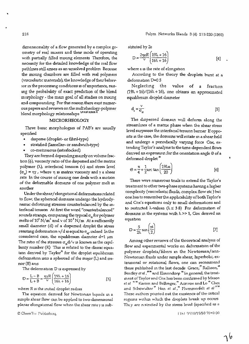
"
216 Polym Networks Blends 3 (4) 213-220 (1993)
[3J
where E 15 the rate of elongabonAccordIng to the theory the droplets burst at a
deformabon 0=0 5
Neglectmg the value of a fractIOn(19A. +16)/(16;\" +16), one obtams an apprOXImatedeqUJ.hbnum droplet dIameter
[4]
[5]
[6]
stItuted by 2s
= 211ER (19;\" + 16)o v 16;\.. +16
The dIspersed domam wIll deform along thestreamlmes of a matnx phase when the shear stresslevel surpasses the mterfaoal tensIon bamer IfoppoSIte 15 the case, the domams will rotate m a shear neldand undergo a penodIcally varymg force Cox, extendIng Taylor's analySIS to the tIme-dependent flowsdenved an expreSSIOn for the onentatlOn angle e ofadeformed droplet M
1t 1 (19A.K)e=4+2arctanl~
There wer~ numerous tnals to extend the Taylor'streatment to other two-phase systems havmg a htghercompleXity (VIScoelastIc flUIds, complex flow etc) butone has to remember the apphcability ofboth Taylor'sand Cox's equatIons only to small deformabons andto restncted A.-values (Iv S; 3 8) For deformatIon ofdomams m the systems WIth A.» 1, Cox denved anequabon
o =2.. sm (1t) [7]
2;\.. 2
Among other reVlews of the theoretIcal analySIS offlow and experLmental works on deformabon of thepolymer droplets/fIbers In the Newtoroan/nonNewtoruan flUIds under SImple shear, htperbohc, extenslOnal or rotabonal flows, one can recommendthose publIshed m the last decade Grace,71 Ralhson,M
Bentley et al ,4990 and Elmendorp 60 In general, the treatment of Taylor and Cox has been conf=ed by Mason
~~ ~ ~
et al Karam and Bellinger, Acnvos and Lo ChOland Schowct.lter"" Han et al,96 Flurrunerfelt et al
9794
These authors pomted out tlle eXistence of the cnl:tcalreglOns w1thm whtch the droplets break up occursTheyare rt.slncted by lhe stress level (speoflcd as a
chmenslOnahty of a flow generated by a complex geometry of real rruxers and theIr mode of operabngWIth parbally filled nuxmg elements Therefore, thenecessIty for the detaIled knowledge of the real flowpathlmes still anses as an unsolved problem Becausethe IIUX1l1g chambers are filled With real polymers(VIScoelasbc matenals), the knowledge of theIr behavIor m the processmg conchb.ons IS of Importance, raISmg the probability of exact predIcb.on of the blendmorphology - the mam goal of all studIes on nuxmgand compoundIng For tlus reason there eXISt numerous papers andreVlews on the melt rheology-polymerblend morphology relabonshIps 1.914.1519,20,52 31
rv1ICRORHEOLOGY
wee basIc morphologies of PAB's are usuallyspea.f:r.ed
• dIsperse (droplet- or frbnl-type)• strabfred (lamellar- or sandWich-type)• co-contInuous (mterlocked)They are formed dependIngmamly onvolume frac
bon (~), VISCOSIty ratIo of the dIspersed and the matrIxpolymer (/..), mterfaoal tenSIon (v) and stress level(0"12) = rrY, where II IS matrIx VISCOSIty and 1 a shearrate In the course of nuxmg one deals With a mobonof the deformable domams of one polymer melt m
anotherUnder the shear/ elongatIonal deformabons related
to flow, the sphencal domams undergo the hydrodynamlC deformmg stresses counterbalanced by the mterfaoal tensIon At frrst the word "counterbalanced"sounds strange, comparmg the typIcal 0" for polymer
4 2 2 12meltsofl0 N/m andvoflO N/m Atasu..ffi.oentlysmall dIameter (d) of a dIspersed droplet the stressres15bng deformatIon v/ d 15 equal to 0"12' mdeed In theconsIdered case, the equilibnum dIameter d=l ).l.ll1
The rabo of the stresses O"12d/v 15 known as the capIl
lanty number (K) ThIS 15 related to the claSSIC equabon denved by Taylor31 for the droplet equthbnumdeformabon mto a spheroId of the major (L) and mI
nor (B) aXISThe deformatIOn D 1S expressed by
D = L - B = mR (19A. + 16)L + B v 16A. + 16
where R 1S the uubal droplet ramusThe equatIOn denved for Newtoruan lIqUids m a
slll1ple shear flow can be applIed to two-dtmensIOnalplanar elongatIOnal flow when the shear rate y 1S sub-
© ChemTtt Pubbshlnb 11 h I ')'j 10/')'3/$070+0 00
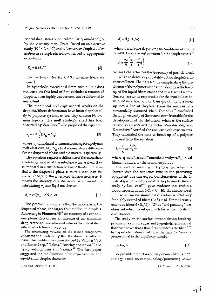
Polym Networks Blends 3 (4) 213-220 (1993) 217
cnhcal shear stress or cnhcal capillanty number KJ orby the VlSCOSIty raho Grace
77based on an extensIve
study (10-6 < ;.. < 10) on the Newtoruan droplets defor
mahon m a slIDple shear flow, denved an appropnateexpressIOn
where v. - mterfaaal tensIon accountIng for a polymermelt elasb.aty, Nu' NJl - fust normal stress dIfferencefor the dIspersed phase and he matnx, respechvely
The equahon regards a dIfference of the extra shearstresses generated at the mterface when a shear flowIS lIDposed m a dIspersIOn of elashc flUlds It followsthat 1f the dISpersed phase 15 more elashc than thematrIx (ANI> 0) the mterfaaal tenSIOn mcreases Itmeans the stability of a dIsperSIOn 15 enhanced BysubstItuhng v. mto Eq 5 one denves
He has found that for A. < 3 8 no more fIbers are
formedIn hyperbolIc extensional flows such a hnut does
not eXISt As tlus kmd of flow excludes a rotahon ofdroplets, even lughly VISCOUS ones can be deformed toany extent
The theorehcal and expenmental results on thedroplets/fIbers deformahon have hnuted applIcabilIty to polymer systems m case they concern Newtoman lIqUids The melt elashaty effect has beenobserved by Van Oene2ll who proposed the equahon
[l1J
[12J
[13]
[14]
where ~ 15 a factor dependIng on condIhons ofa value50-200 A more recent equahon for the droplet SIZe 15 101
2v (K a" Jd =- ~+ci• 11 Y f
where f charactenzes the frequency of partIcle breakup, a°15 a coalescence probability of two droplets after
thelI' collisIOn The next feature complIcatmg the predIctIOn of the polymerblends morphology 15 the breakup of the lIqmd £tbers embedded m a VISCOUS matnxSurface tensIon 15 responSIble for the 1n5tabilihes developed on a nber and on thel! growth Up to a breakup mto a lIne of droplets From the analys15 of asmusoidally dIStorted 6.ber, TomotIka
IIllconcluded
that lugh VISCOSIty of the matrIx IS unfavorable for thedevelopment of the dIStortIon, whereas the surfacetenSlon 15 an acceleratIng factor Vander Vegt andElmendorp100 venned the analys15 With expenmentsThey calculated the tlIDe to break up of a polymerftlament from the equahon
1 08Rt =-In--
b q a
where q - coef£taent ofTomobka's analysIS, R. -lnIhalftlament radIus, a - dlStorhon amplItude
The pracb.cal mearung of Eq 13 15 that when tb
IS
shorter than the reSidence tlIDe m the processmgeqmpment one can expect transformatIon of the frbrJ.1ar-type morphology mto the droplet-mode Recent
al &7,.,9 th thmstudy by Le et al gave eVidence at WI abroad VISCOSIty ratIos 001 < ;.. < 10, the 6.bnlar breakup mechamsm Via smusOldal dIstortIon 15 valId onlyfor mghly extended frbers (L/B) > 15 For moderatelyextended fibers 6 «L/B) < 15 the "end pmchmg" wasobserved wmch develops much faster than RayleIghdIsturbances
The study on the surface tenslOn dnven break upprocess m a SImple shear and hyperbohc extenslOnalflow has shown that a flow field stabilizes the fiber ",11lt
In hyperbohc extenslOnal flow the tIme for break 15
proporbonal to the capillanty number
For pOSSIble predIctIOn of the polymer blends marphology based on compoundIng/processmg conm-
[8]
[9J
[10]
K= =0 16;"~&
Rv =v+-(N -N)• 6 u 12
d =v/(cr - AN /12)• 12 1
The pracb.cal meanmg 15 that the more elashc thedISpersed phase, the larger the equilibnum dropletsAccordmg to Flummerfelt the elastIaty of a contmuous phase also causes an mcrease of the mmImumdropletSlZe and an enhanced value of the cnhca1shearrate at wluch break up occurs
The mcreasmg volume of the rrunor componentenhances the probability that the domaInS will coalesce The problem has been studIed by Van der Vegt
d Elm d 100 T L. 62 101an en orp, 01<..1ta, Fortelny and Kovar andLyngaae-J0rgenson and Valenza 10" The rust papersuggested the mochf1catIon of an expresslOn for theequilibnum droplet dIameter
1181 9510/93/$070+0 00 (0 Ch( m I I ( Publishll1b
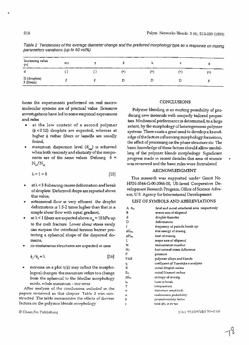
218 Polym Networks Blends 3 (4), 213-220 (1993)
Table 2 TendencIes of the average diameter change and the preferred morphology type as a response on mlxmgparameters vanatlons (up to 50 vol%)
Increasmg value0'12 y 15 A. v ~(+)
d () () (+) (+) (+) (+)
D (droplets) F F D D D FF (flbers)
• extrema on a plot T1(~) may reflect the morphologtcal changes the maXImum refers to a changefrom the sphencal to the &bnllar morphologymode, wlule mnumum - vIce versa
After analySIS of the conclUSIOns mcluded In thepapers reVIewed m thIs chapter Table 2 was constructed The table surnmanzes the effects of dIVersefactors on the polymer blends morphology
• at A. <3 8 shearmg causes deformanon and breakof droplets Deformed drops are reported abovetlus value,
• extensIonal flow IS very efnaent the dropletdeformatlon IS 1 5-2 b.mes lugher than that m aSlmple shear flow Wlth equal gradIent,
• at A. < 1 nbers are expected above 0"12 = 10 kPa up
to the melt fracture Lower shear stress rarelycan surpass the mterfaaal tensIon barner protectlng a sphencal shape of the dIspersed domams,
• co-contlnuous structures are expected m case
tlOns the expenments performed on real macro
molecular systems are of praroca1 value ExtensIvemvestlgatlons have led to some emplOca1 expreSSIonsand rules
• at the low content of a second polymer(~ < 0 12) droplets are expected, whereas atlugher ~ rather 6.bers or lamella are usuallyfound,
• maxunum dIsperslOn level (dJl\lA) IS acluevedwhen both VlSCOSlty and elasnaty of the components are of the same values Defuung 8 =
Nll/N12
fmal and IIUtJal mterfaoal area respectwelymmor axIS of ellipSOId
droplet diameterdeformallonfrequency of parl1de break up
free energy of mlXmg
heat of mlXmg
major axIS of ellIpSOidreorientatIOn numberfust normal stress dIfferencepressurepolymer alloys and blends
coeffioent of Tomotlka S analysISmltlal droplet radiUS
mitlal ft.lament radIUS
entropy of mlXmg
tune to breaktemperaturedIStortion arnplttudLcoalescence probablhtyproporllonahty factorlotal ShL u stnm
A Ao
B
dDfAGrn
M-Irn
LNN1P
PABqR
Ro~m
tb
T
CONCLUSIONS
Polymer blendmg 18 an exaang pOSSIbility of produang new matenals Wlth umquely f:al1ored propertles Mechamcal performance IS determmed, to a largeextent, by the morphology of heterogeneous polymersystems There eXISts a great need to develop a knowledge of the factors mfluenang morphologyformatlon,the effect ofprocessmg on the phase structure etc ThebaSlc knowledge of these factors should allow modelhng of the polymer blends morphology Slgro.Ucantprogress made m recent decades tlus area of saencewas reVIewed and the baslC rules were formulated
AKCNOWLEDGMENT
ThIs research was supported unde.. Grant NoHRN-5544-G-00-2066-00, US-Israel Cooperahve Development Research Program, Office ofSaence AdVIsor, U S Agency for InternatlOnal Development
liST OF SYMBOLS AND ABBREVIATIONS
a
a.
[l
y
[15]
[16]
1..=1=8
© Chern rec Pubhshln~ 11 hi')') 1O/g'3/$O 70 to 00
Polym Networks Blends, 3 (4) 213-220 (1993)
y shear rate
Ii elastlaty ratIo
(; rate of elongatlOn
TJ melt VISCOSIty
o onentatlon angle
1C capillanty number
ICc cnucal capillanty number
" VISCOSity rahov mterfaaal tensIon
0'12 shear stress
~ volume fraction
X mteractlon parameter
REFERENCES
1 L A. Utrackl In Polymer Alloys and Blends HanserPublIshers, MUIUch (1989)
2 Melt Rheolor;y and Comltant Morpholor;y of PolyblendsA P Plochockl (coord) Blends Contauunl; Core-Shell
Impact ModIfiers C B Bucknal and M Kozlowski(co-coord)
3 NRCC/IMRI SymposIums Polyblends smce 1980 (armual)Boucherville Canada TU/IOPT CllIlferences PolymerModificatton smce 1972 (bIannual), TU Wroelaw Poland,European SymposIums Polymer Blends Bruges (1984.)
Strasbourg (1987) Cambndge (1990) Capn (1993)
4 L A UtrackJ. Polym Networks Blends 1 61 (1991)
5 P J Flory m Pnnaples of Polymer ChemIStry CornellLondon (1953)
6 F B Khambatta F Warner, T Russel and R S StemJ Polym SCI, Phys Ed 14 1391 (1976)
7 P H M EJ.emans J G M GlSbergen and HEM MeIjerm Integration of Fundamental Polymer SCIence andTechnolor;y, Eds P J Lemstra and L A KlemtjensElsem.er Appl SCI London (1988)
8 Z Tadmor and C G Gogos PnnClples of PolymerProcesSInt;, VViley New York (1979)
9 L A Utrackl and B D FaVIS m Handbook of PolymerSCIence and Technolor;y vol 4 Ed N P CherernlSmoffMarcel Dekker New York and Basel (1989)
10 J M OtUno and R Chel1a,. Polym Eng Sa 23 357 (1983)
11 J Manas-Zloczower A. Nu and Z Tadmor Rubber ChernTechnol 55 1250 (1987)
12 Z Tadmor m Integranon of Fundamental Polymer SCienceand TechnoIor;y Eds LA Klemtjens and P J LemstraElsem.er Appl SCI New York (1986)
13 B DaVId MlXlng StudIes In Polymer ProcesSIng Ph 0ThesIS Technzon HaIfa Israel (1991)
14 J L WhIte and K Mm Makromol Chern MacromolSymp 16 19 (1988)
15 T Pakula J GrebowIcz and M Kl')szewski Polzmery 23
425 (1978)
16 J SWletoslawski J Morawlec and T Pakula m PolymerBlends Eds E Martuscelll R Palumbo and M KryszewsklPltmum Press New York md London (1980)
17 T Pakula Poltrmer Bull 3 415 (1980)
18 R A Strasser and L ErWIn Adv Polym Techno! 4 17
1181 9510/93/$070+000
219
(1984)
19 A P PiochockI,. Polym Eng Sa 22 6]8 (1983)
20 H Van Oene J CoIL Interface Sa 40 448 (1972)
21 J M Ottmo W E Ranz and C W Macosco Chern EngSa. 14 'OTT (1979)
22 Z. Tadmor and G Lldor Polym Eng Sa 16 450 (1976)
23 C KIpanssides and J VIachopoulos IbId 16 712 (1976)
24 J VIachopoulos and A N Hrymak ilnd 20 725 (1980)
25 N Toklta and J L WhIte J Appl Polym Sa 10 1011
(1966)
26 R. Takserman-Krozer, G Schenkel, and GEhrmann, RheolActa, 14, 1066 (1975)
27 C G Gogos Z. Tadmor 0 M Kalyon P Hold andJ A Blesenberger Chern Eng Progr 33 June (1987)
28 B DaVId, T Sapu A Nu, and Z Tadmor Int Polym Proc3 155 (1990)
29 Z. Tadmor A. Nu and B DaVid m Report on Scale up ofInternal MIxers Dept Chem Eng TechnIIlIl Hatfa Israel(1988)
30 K MID Adv Polym Technol 7 243 (1987)
31 J L Wlute J K Kmt W Szydlowskt and K. Mm, PolymCompOSItes 9 368 (1988)
32 J J Cheng and J Manas-Zloczower Polym Eng Sa, 29
701 1059 (1988)33 JJ Cheng and J Manas-Zloczower Int Polym Pmc 3,
178 (1990)
34 J Manas-Zloczower and Z Tadmor, Adv Plast Technol3 213 (1983)
35 Z Tadmor AIChE J 34 1943 (1988)
36 M Ko.JowskI,. R Steller and J Plglowskt Pollmery,29,257 (1984)
37 Z. Tadmor and J Klem m EngIneenn~ PnnClples ofPiastIcatm5 Extrusion Remhold New York (1970)
38 R. Brzoskowskt J L. WhIte W Szydlowski- N Nal<aJuma,.and K. Mm Int Polym Proc, 1 134 (1988)
39 P H M Elemans Doctoral DISSertatIon TechnischeUmverSllal Emdhoven Netherlands (1989)
40 J L Wlute W SzydlowskI,. K Mm and M Kmt AdvPolym Technol 7 295 (1987)
41 C Rauwendall m Polymer ExtruSion, Hanser PublIshersNew York (1986)
42 G Schenkel In Kunststoffe-Extruder Techmk, HanserPublIshers MUNch (1963)
43 A Kaplan and Z Tadmor Polym Eng SCI 14, 58 (1974)
44 L P B M Janssen R W Hollander M W Spoon and
J M 5nuth AIChE J 2S 345 (1979)
45 Z Tacimor E. Broyer and C Gutfmger PoZym Eng Sa14, 660 (1974)
46 W SzydlowskI and J L WIute Adv Polym Technol 7177 (1987)
47 W SzydlowskI R Brzoskowsk\ and J L WhIte In!
Polym Pmc 1 2r:t7 (1988)
48 M Kun W SzydlowskI J L WIute and K Mm AdvPolym Technol 9 1:>7 (1%9)
49 Z Tldmor P Hold and I Vdbalm~ Plasl En!, 20 Nov34 DLC (1979)
50 B DaVId Int Polym Prot 1 3/\ (1988)
([) Chun rGG Publtslllng
220
Sl L Erwm Polym Eng SCI 18 S12 738 1044 (1978)
52 C D Han m Mulhphase Flow m Polymer Processmr;
AcademIc Press New York (1981)
53 M KozlowskI m LIqUId Crystal Polymers and LCP BasedBlends Eds D Aoerno and F P La Mantla ChemTec
Publtshzng, Toronto (1993)
54 A P Plochock~ S S Dagh.. and R. D Andrews PolymEng Sa 30,741 (1990)
55 Ph Teyssle, Makromol Chem, Macromol Symp, 22, 83
(1988)
56 J M WilllS and B D Favzs Polyrn Eng Sa, 28, 1416(1988)
57 L DOrazIo C Mancarella, E Martusc~ A. CasaleA. FilippI,. and F Speroru J Mater Sa. 21,989 (1986)
58 G N Avergepoulos F C WeISSert, P H BIddISon andG G A Bolun, Rubber Chern Technol, 49 93 (1974)
59 H P Schrezber and A Olgum Polym Eng SCI, 23 129
(1983)
60 J J Elmendorp Polym Eng Sa 26 418 (1986)
61 B D FavlS and JP O1ahfoux, Polym Eng Sa., 27 1591
(1987)
62 N Tolota, Rubber Chern Technol, SO, 292 (1977)63 S Wu Polym Eng Sa, 27 335 (1987)
64 M V Tsebrenko G P Dantlova, and A Ya. MalkmJ Non-Newt FLUId Meeh. 31 1 (1989)
65 K. Mm J L Wlute and J F Fellers Polym Eng SCI 24
1327(1984)
66 D Hetkens and W Barentsen Polymer 18, 69 (1977)
67 A P PIechockI,. 5 5 DaglJ,. J E. Curry, and J Stanta,
Polym Eng Set 29,617 (1989)
68 J Fortelny, E. Navratzlova and J Kovar Angew MakromolChem,l88 195 (1991)
69 A Cohen and J R Schroeder J RheoL,34 685 (1990)
70 J Forte1ny and J Kovar Europ Polym J 28 85 (1992)
Polym CompOSites, 9,119 (1988)
71 W Berger H W Kammer and C Kummerlowe MakromolChem Suppl, 8 101 (1984)
72 J Lyngaae-J0rgenson and K. Sondergaard Polym EngSCI 27 344 351 (1987)
73 L A Utrackl and P Sammut Polym Eng SCI, 28 1405(1988)
74 R. Konmgsveld, Polym Networks Blends 1 117 (1991)
75 F P La Mantla P L Magagnuu and U PedrettI, PolymNetworks Blends 2 13 (1992)
76 J Forte1ny R. Rosenberg, and J Kovar Polym NetworksBlends 3 35 (1993)
77 H P Grace Chem Eng Commun 14 225 (1982)
78 L A Utrackl m Recent Trends In Polymers and TheIrComposItes Dept SCI. Technol Gov IndIa New Dellu
© ChemTcc Publ1shmg
Polym Networks Blends 3 (4) 213220 (1993)
(1987)
79 D Graebhng, R. Muller and J F Palterne Macromol 26320(1993)
80 A K. Gupta and K. R Snruvason JAppl. Polym SCI 46167 (1993)
81 G J Taylor Proc Roy Soc London A146 501 (1934)
82 S Torza R. G Cox, and S G Mason, J CollOid InterfaceSCI 38,395 (1972)
83 E Bartram H L GoldsIIUth and 5 G Mason Rheol
Acta 14 776 (1975)
84 R. G Cox, J FlUId Meeh., 37 601 (1969)
85 A Acnvos and T S La, J FluldMech, 86, 641 (1978)
86 E J Hmch and A Acnvos, J fluId Mec1t. 98, 305
(1980)
87 H A. Stene, B J Bentley and L G Leal, J FlUId Mech173 131 (1986)
88 J M Rallison, Ann Rev FluId Mech. 16 45 (1984)
89 B J Bentley and L G Leal, J FlUId Mech., 167, 219 241
(1986)
90 5 L Goren and M Gottheb J flUId Mec1t., 120, 245
(1982)
91 F D Rumschezdt and 5 G Mason J CollOId Interface SCI16,238 (1961)
92 5 Torza. R. G Cox and S G Mason J CollOId InterfaceSCI 38,395 (1972)
93 T Mtkaml R. G Cox, and 5 G Mason Int J MultlphaseFlaw 2 113 (1975)
94 H Karam and J C Bellmger Ind Eng Fundam., 7 576
(1968)
95 5 J ChOI and W R Schowalter Phys FlUid 18,420
(1975)
96 H B ChID and C D Han J Rheol 23, 557 (1979) 24
1 (1980)
97 R W Flummerfelt, J CollOid Interface Set 76 33 (1980)
98 W K. Lee and R W Flummerfelt Int J Multlphase Flaw7 363 385 (1981)
99 R W Flummerfelt Ind Eng Chern. Fundam. 11 312
(1972)
100 A K. Vav der Vegt and J J Elmendorp m Inter;rahon of
Fundamental Polymer SCIence and Technolog,Eds L A Klemgens and P J Lemstra Elsevzer Appl SCINew Yark (1Q86)
101 J Fortelny and K. Kovar, Europ Polym J 2S 317
(1989)
102 J Lyngaae-J0rgenson and L Valenza Makromol ChemMacramol Symp 3S 43 (1990)
103 S Tomob.ka Proc Roy Soc London AlSO 332 (1935)
104 D V Khakhar and J M Ottmo Int J Multlphase Flaw13 71 (1987)
ReCeIved May 6 1993 Accepted September 30 1993
11 b 1 9510/93/$0 70+0 (1()
,J::....-
THE FORMATION OF lNTERPENETRATlNG
POLYMER BLENDS
M KozlowskI
RDCC POLYMAK Wroclaw Poland
ABSTRACT
Formation of the thermoplastic blends of co-continuous morphology has
been dIscussed, the dynamIc character of tlus process bemg stressed lnter
penetratmg polymer blends represent the mtermedlate stage of a
multicomponent polymer system dunng dIspersIve mIxmg The time for
reachmg such a state of heterogeneIty and Its stabIlIty depend on the
vIscoelastic charactenstics of the component polymers their ratIO m a blend
mterfacial tensiOn and rruxmg parameters The role of particular factors
mfluencmg the fonnation of mterpenetratmg polymer blends h1S been
presented for the LDPEIPS system
Because of the dynamIc character of the evolutiOn of polymer blend
morphology upon rruxmg, the processmg hIStOry specIficatiOns should
accompany every morphology presentatIOn
KEYWORDS
Polymer blend, morphology, mterfacial tensIOn, shear stress processmg
history
Vol 14 No 1 1995 The FomwtlOn of1ntelpLnuratlllg Polymer BlwdsAI A.ozlow~",
JOIIII/((/ 0) Poll II/( 1 1 1/t-,lIll (I 1/;.."
~A
~
INTRODUCTION
Polymer blends (FB) are by and large multIphase systems maJ.nly for
thermodynanuc reasons They have already been exhaustlvely discussed
/1-4/ Among other factors mfluencmg the final phase state of1
macromolecular components, the rheologIcal propertles and mterfaclal
behaViOur of PBs have been mentlOned /4-8/
ExtensIVe studIes have been camed out on the mfluence of partIcular
factors on the blend morphology These studIes have mtensrlied dunng
recent decades, when the econorruc advantages of polymer blendmg over a
search for new monomers and (co)polymers has been proved SImIlarly, the
concept WhICh prevlOusly prevaIled of seekmg the rrusclble polymer pans of
complementary propertIes faIled because of the ranty of such paJ.rs The last
twenty years could aptly be called "the age of heterogeneous polymer
blends" Owmg to the enormous efforts of many researchers, often sImply
"fans" of polyblend structunzatlOn, there already eXISts the SCIence of
polymer blend morphology based mamly on extensIve expenmental
expenence, well-proven rules and theoretical consideratlOns It IS ImpoSSIble
to mentlOn all the SCIentIsts who have contnbuted to the present "state of the
art" but I feel I must mentIon at least a few leaders m the field (WIth
apologIes to all those not mentlOnedl) Among the paperslbooks to WhICh I
would hke to refer are those of L A UtrackI /2/ A P PlochockI /6/, J L
White /9/, S Wu /10/, B D Favis /111, E Martuscelh /3/, F P La Mantla
/12/ J Lyngaae-Jorgensen /13/, Ph Teyssle /14/ and M Kryszewskl /3/
The background knowledge willch already ehlsts makes possIble to a
great extent the desIgn and creatIon of the morphology requued Polymer
blends of "tallor made" morphology and properues are already commercially
produced and WIdely used Usually three kinds of morphology are specIfied
• disperse (droplet- or fiber-type)
• stratlfied (sandWlch- or lamellar-type),
• co-contmuous (mterlocked)
Disperse type morphology IS revealed m rubber-toughened plastIcs or
fiber-remforced compoSItes /15-17/ Larrunar morphology IS developed m
systems of controlled barner properties for diverse permeants /18/ Co
contmuous morphology transfers the early Idea of the coexistence of two
polymers wIth preservatIOn of advantageous charactensllCS of both of them
As e>-..amples the conductIve blends tIme-release medlcmes and Ion
selectIve membranes can be mentIOned /19 22/
The partlcular type of morphology WIll be generated dunng mlhmg
dependmg on the nature of the blend components their volume fractIOn the
ratIO of the VIscoelastIc propertIes and the processmg hIstOry /23-30/
Adequate relatIOnshIps have been relatively well known m particular as far
as dIsperse morphology IS concerned Numerous papers have reported hO\1
to promote the generatIOn of droplets/fibers of recommended shape b) the
proper chOlce of a dIsperse phase content the ratIO of ItS VISCOSIty to that of
a matn>-.. (A.), the sUltable stress level and flow field It IS pOSSible to
mfluence the SIze of dIsperse domams either by matchmg the abo\e
parameters or by changmg the ratIO of the melt elastiCity of the disperse to
the matnx phase (8) /5,7 1031,32/ A number of researchers concluded that
the lowest scale SIze of dIspersed domams and the lowest mi"\.mg energy
mput were stated when the melt ViSCOSities were the same Compatlblhzers
(1 e emulslfymg agents which decrease the mterfaciaJ tenSiOn) e"\.ert a
partIcular mfluence on the domam SIze /15/
Co-contmuous structures have only recently begun to receive more
attention Tills term is usually related to mterpenetratmg polymer networks
(IPNs) lPNs are polymer systems obtamed m a specific manner by
polymensatIon/crosslmkmg of at least one polymer m the presence of the
other /33,34/ For the thermoplastic blends of co-contmuous morphology the
term "mterpentratmg polymer blends" (IPB) has been proposed The IPB s
SIze scale 1S two orders of magrutude hIgher than that of the IPN /3)/
EqUlllbnum thermodynam1cs allow thiS kmd of structure to be predIcted b\
consldenng the dynamICS of phase separatIOn By controlled (high) depth of
quenchmg co-contmuous morphology can be generated by the spmodal
decompOSItIon mecharusm, even at very low concentratiOns of a dispersed
phase (01 < 0 15) The structure of the phases that evolve by the
superpos1tlOn of the sme waves of composItIon fluctuatiOn IS charactenzed
II
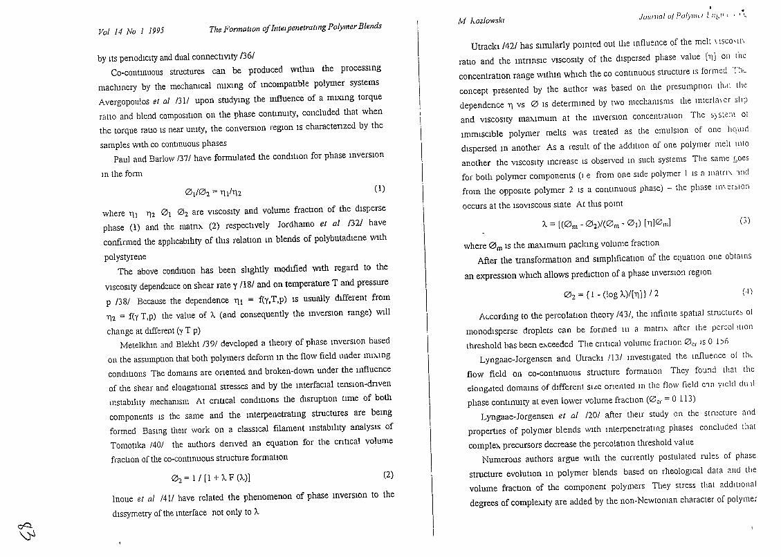
Vol 14 No 1 1995 The FormatIOn ofIntelpenetratmg Polymer Blends M J...ozlowskl•
JOll11l01 0/ POIYlIlLi L /1&/1 l I 1\
Inoue et al /411 have related the phenomenon of phase mverslOn to the
dlssymetry of the mterface not only to A.
by Its penodlclty and dual connectlVlty 1361
Co-contllluous structures can be produced wlthm the processmg
machmery by the mechamcal mlxmg of mcompallble polymer systems
Avergopoulos et al 131/ upon studymg the mfluence of a mlxmg torque
ratio and blend composItion on the phase contmUlty, concluded that when
the torque rauo IS near umty, the converSlOn reglOn IS charactenzed by the
samples wIth co contllluous phases
Paul and Barlow /37/ have formulated the condition for phase mverSlOn
III the form
where 111 112 0 1 O2 are VISCOSity and volume fraCllon of the disperse
phase (1) and the matm. (2) respectively Jordhamo et al /32/ have
confirmed the apphcablhty of thIS relatIon m blends of polybutadlene With
polystyrene
The above condition has been shghtly modIfied With regard to the
VISCOSity dependence on shear rate y 1181 and on temperature T and pressure
p /38/ Because the dependence 111 = f(Y,T,p) IS usually dIfferent from
112 = fey T,p) the value of A. (and consequently the mverSiOn range) Will
change at dIfferent (y T p)
Metelkhlll and Blekht /39/ developed a theory of phase mverSiOn based
on the assumptlOn that both polymers deform m the flow field under mlxmg
condluons The domams are onented and broken-down under the mfluence
of the shear and elongatIOnal stresses and by the mterfaclal tensIOn-dnven
mstablhty mechamsm At cnucal condluons the dlsrupuon tlme of both
components IS the same and the mterpenetratmg structures are bemg
formed Basmg theIr work on a claSSical filament mstabIltty analysIs of
Tomottka /40/ the authors denved an equatIOn for the cntIcal volume
fracuon of the co-contmuous structure formatiOn
where 0 m IS the maXImum packmg volume fractIOn
After the transformation and slmphficauon of the equation one obtainS
an e>'''PresslOn which allows prediction of a phase mverslOn regIOn
(-l )
(3 )
O 2 = {l - (log A.)/[11)} /2
A. = [(0m - O2)/(0m - 0 1) [l1]0ml
ALcordmg to the percolatIOn theory /43/, the Infimte spatial structure~ 01
monodisperse droplets can be formed In a matnx after the percolllion
threshold has been exceeded The cntlcal volume fraction 0 cr IS 0 1)6
Lyngaae-Jorgensen and UtrackI /13/ Illvestlgated the mfluence ot thl
flow field on co-contmuous structure formatIOn They found that the
elongdted domaInS of different SILe onented In the flow field Cll1 Ylcld du Ii
phase contmUlty at even lower volume fractlon (0cr = 0 113)
Lyngaae-Jorgensen et al /20/ after their study on the structure and
properties of polymer blends WIth 1l1terpenetratmg phases concluded that
complex precursors decrease the percolatiOn threshold value
Numerous authors argue with the currently postulated rules of phase
structure evolutIOn m polymer blends based on rheological data and the
volume fractIon of the component polymers They stress that addltlOnal
degrees of comple>.1ty are added by the non-Newtol11an character of polymer
Utrackl/421 has sllllilarly pomted out the mfluence of the melt \ 15CO'll\
ratio and the mtnnsiC VISCOSity of the dispersed phase value [11] on the
concentratIOn range wlthll1 which the co contmuous structure IS formed Thl..
concept presented by the author was based on the presumption thell the
dependence 11 vs 0 IS determmed by two mechamsms the Interla\ er sit p
and VISCOSity maximum at the mverSlon concentration The S) stem ot
ImmiSCible polymer melts was treated as the emulSIOn of one ItClUld
dispersed m another As a result of the additIOn of one polymer melt Illto
another the VISCOSIty mcrease IS observed III such systems The same ;oes
for both polymer components (I e from one Side polymer 1 IS a main, lI1d
from the opposite polymer 2 IS a contmuous phase) - the phase 111\ er~lon
occurs at the ISOVISCOUS state At thiS POlllt
(2)
(1)0 1/02 = 111/112
O2 =1/ [1 + A. F (A.)]
oQ.
~
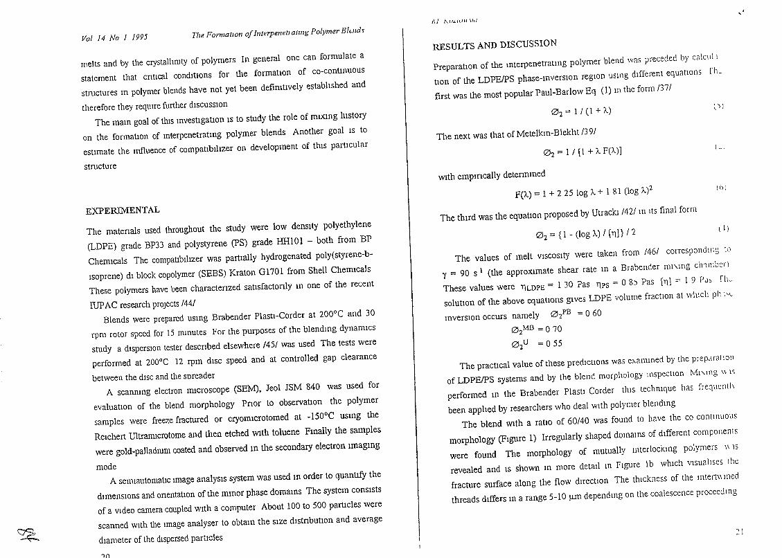
Vol 14 No 1 1995 The Forolatlon ofInterpenetlGtmg Polymer Blwdv1\ 1 A.U"/<I\I \/,/ "
RESULTS AND DISCUSSION
PreparatlOn of the mterpenetratmg polymer blend was preceded by calculi
tlon of the LDPEIPS phase-mverslOn regIOn usmg different equations rh~
first was the most popular Paul-Barlow Eq (1) m the form /37/
21
The values of melt VISCOSity were taken from /46/ corresponding ll'
y = 90 s I (the apprOXImate shear rate m a Brabender ml'\Ing clnmbcr)
These values were TlLDPE = 1 30 Pas Tips = 08) Pas [Tl) = 1 9 PJ, rh~
solutlOn of the above equatlons gIves LDPE volume fractIOn at whICh ph l';C
mverSlOn occurs namely 0 2PB = 060
0 2MB = 0 70
0 2U = 055
The pracUcal value of these predictions was e>..ammed by the prepcH3110Il
of LDPEIPS systems and by the blend morphology ll1SpectlOn MI'..lng \\ IS
performed m the Brabender Plastl Corder thiS techmque has frequenl\\
been apphed by researchers who deal With polymer blendll1g
The blend WIth a ratIO of 60/40 was found to have the co continUOUS
morphology (FIgure 1) Irregularly shaped domams of different components
were found The morphology of mutually mterlocktng polymers \\ 1S
revealed and IS shown m more detml III FIgure lb which visualises the
fracture surface along the flow duectlOn The thickness of the mtert\\ lIled
threads differs 111 a range 5-10 /lm dependmg on the coalescence proceeding
~
melts and by the crystallImty of polymers In general one can formulate a
statement that cntlcal conmu.ons for the formatlOn of co-continUOUS
structures III polymer blends have not yet been defimtlvely established and
therefore they reqUIre further discussion
The mam goal of this mvestlgatlon IS to study the role of mlxmg hIStOry
on the formatIOn of mterpenetratmg polymer blends Another goal IS to
estimate the Influence of compa1lblhzer on development of thiS particular
structure
EXPERIMENTAL
The matenals used throughout the study were low denSIty polyethylene
(LDPE) grade BP33 and polystyrene (PS) grade BRIOI - both from BP
Chenucals The cOmpatlblhzer was pamally hydrogenated poly(styrene-b
Isoprene) dl block copolymer (SEBS) Kraton GI701 from Shell Chenucals
These polymers have been charactenzed satlsfactonly III one of the recent
IUPAC research projects /44/
Blends were prepared usmg Brabender Plastl-Corder at 200a C and 30
rpm rotor speed for 15 nunutes For the purposes of the blendmg dynamiCs
study a disperSIOn tester descnbed elsewhere /45/ was used The tests were
performed at 200°C 12 rpm dISC speed and at controlled gap clearance
between the dISC and the soreader
A scanmng electron nucroscope (SEM), Jeol JSM 840 was used for
evaluatIOn of the blend morphology Pnor to observatIon the polymer
samples were freeze fractured or cryomlcrotomed at -I50aC usmg the
ReIchert UltraIDlcrotome and then etched Wlth toluene Fmally the samples
were gold-palladmm coated and observed m the secondary electron Imagmg
mode
A semlautomauc Image analySIS system was used m order to quantIfY the
dlmenslOns and onentatlOn of the nunor phase domams The system conSIsts
of a Video camera coupled WIth a computer About 100 to 500 partlcles were
scanned with the Image analyser to obtam the SIze dIstnbutlOn and average
diameter of the dispersed particles
'1(\
O2 = 1/ (1 + A.)
The next was that of Metelkm-Blekht /39/
O2 = 1 / [1 +A.F(A.)l
wIth empmcaUy determmed
F(A.) = 1 + 225 log A. + 1 81 (log A.)2
The tlurd was the equation proposed by Utrackt /42/ In ItS final form
02 = {I - (log A.) / [TI]} /2
Pi
( .1
()I
( I)
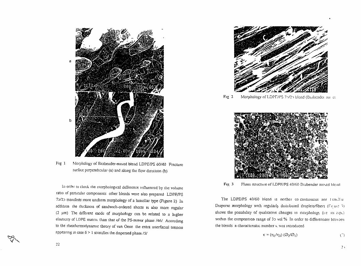
a
b
FIg 1 Morphology of Brabender-ml>..ed blend LDPEfPS 60/40 Fracture
surface perpendIcular (a) and along the flow dIrectIOn (b)
Fig 2 tnl CI
The LDPEIPS 40/60 blend IS neither co contl11UOLtS nor 11l11lJIll
Disperse morphology with regularl) dlstilbuted droplets/fibers (rl~ til c ~)
shows the possIbIlIty of qualItatIve changes In morpholog) (1 e I(S!I pc)
wlthm the compOSItIOn range of 3'.;) vol % In order to differentIate bc(\\ cell
the blends a charactenstlc number "- was mtroduced
~"
In order to check. the morphologIcal dIfference 11111uenced by the volume
ratIo of partIcular components other blends were also prepared LDPEIPS
7)/2) mamfests more umform morphology of a lamellar type (FIgure 2) In
addItIOn the thIckness of sandwIch-ordered sheets IS also more regular
(211m) The dIfferent mode of morphology can be related to a hIgher
elastICIty of LDPE matnx than that of the PS-m111or phase /46/ Accordmg
to the rheothermodynamlc theory of van Gene the extra mterfaclal tenSIOn
appeanng In case 6 > I stratLfies the dIspersed phase /5/
22
Fig 3 Phase structure of LDPEIPS 40/60 Brabender mI\.cd blend
K == ('Ill/'Il2) (02/0 1) n
2 ,
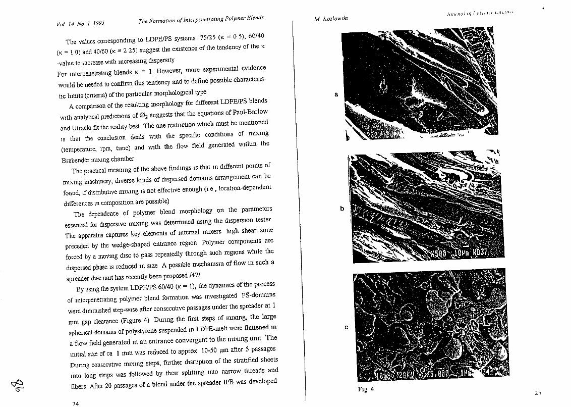
Vol 14 lVo 1 1995 The Fomwtlon 0/IntLi pwetralmg Polymer Hlelld~ M Aozlow~kl101////<110/ , O/lll/li L/lI.,//lll
~
The values correspondmg to LDPEIPS systems 75/25 (K = 0 5), 60/40
(K = 1 0) and 40/60 (K = 2 25) suggest the eXlstence of the tendency of the K
-value to mcrease wIth mcreasmg dispersity
For mterpenetratmg blends K = 1 However, more expenmental eVIdence
would be needed to confirm tlus tendency and to define possible charactens
tic limIts (cntena) of the particular morphological type
A companson of the resulting morphology for dlfferent LDPEIPS blends
WIth analytlcal predIctions of O2 suggests that the equatiOns of Paul-Barlow
and Utracki fit the realIty best The one restnctiOn which must be mentiOned
IS that the conclusiOn deals With the specIfic condItIons of mI>..mg
(temperature, rpm, time) and WIth the flow field generated withm the
Brabender mIhmg chamber
The practIcal meanmg of the above findmgs IS that m dIfferent pomts of
mI>-mg machmery, dIverse lands of dIspersed domams arrangement can be
found, If dIstnbutIve nu>..mg IS not effectIve enough (1 e, locatIOn-dependent
dIfferences m compOSItion are possIble)
The dependence of polymer blend morphology on the parameters
essential for dIspersIve mIxmg was deternuned usmg the dIspersIOn tester
The apparatus captures key elements of mtemal mIxers hIgh shear zone
preceded by the wedge-shaped entrance regiOn Polymer components are
forced by a movmg diSC to pass repeatedly through such regiOns whIle the
dIspersed phase IS reduced m SIze A pOSSible mechamsm of flow m such a
spreader dISC umt has recently been proposed 147/
By usmg the system LDPEIPS 60/40 (K =1), the dynanucs of the process
of mterpenetratmg polymer blend formatIOn was mvestIgated PS-domams
were dimimshed step-wIse after consecutive passages under the spreader at 1
mm gap clearance (FIgure 4) Dunng the first steps of ffiIxmg, the large
sphencal domams of polystyrene suspended m LDPE-me1t were flattened m
a flow field generated m an entrance convergent to the mlXl11g umt The
lllltIal SIze of ca 1 mm was reduced to approx 10-50 J.UU after 5 passages
Dunng consecutive nuXlng steps, further disruptIOn of tlle stratIfied sheets
mto long stnps was followed by theIr sphttmg mto narrow threads and
fibers After 20 passages of a blend under the spreader IPB was developed
?4
a
b
c
'X"":t ~ :}"'" ~. ,.,,~~'.,'" .;1'\...r."1:}\..?/..•• , ?:;;;:.li?:'::~~4~•• • jli ~~. r • • ..14 ''':\ ' ' ~""',. '\.11 '\ ~>-~
'\ ,"-I ../'" • .;:s~.'" :'·'t....;.;;'''''';., '.\ '-.., \\ ...~"~.' ',:.~,,;~:'~ :', ..... ,.:::::/<. -'..,.:~';,:.;. ~ ~ .. ~,. ~. 1-':m:,W'~:'!'" ....):J ,j\.~r.l;·.'J ' . '.. " ,.".. ~. .... ,~; <,' :~
.. T' .~,..~.: " ••~::',: .. ~.. "-"iII"~·:,···~.. e.l\t~itl(
:':;.,: ,. Jj' , -"'" r""--::' \.,I!~~~:.~.~~ t,!t!'\~~., .~~~;:~~;.".%' ~. . .,. r ·1.•, ' 'lfb.~. '" ~;'·t~· "
! ~ ,lJ-" ..:;'\-:".':,\1 .. '\:t"''' "';'r:;'"i'o;;'~;'~ ~" "~." '. _ •.>.-,....;1 . (" ..~ \..."..•••.••t-.~ . ',C \ _,'.' to:. "~. (" ,-i,~ ~ '> ,ij~.,.-"':t··lt. '.., •. ~ ...,
. ~ 'it .~: -il' '.\i.~, J:."i .• ~'I,;,I.~iI<:.~~ ,.'. Jr''''\,. '.;:.. :"'~ • , . ' .... '." '.'i'~'..,~.~r';~;;?>:{ ",*
. "....; ! ", ",'. '..1 .. ,;:'" l" .;1," .. I.f,'·c" ,.',.r .' ~~'~""t~" .".~.. ~ . .;. .•r ~ }d~'-f;'J: ~
" I ~t~ .. , ~r...... _ ~ 'J""~ ~ .. r .i ~\'~ .... ~~:-i.,,'
..1 ~ ,'1 I l f~'~ l • .r t' ~ & • -t"
~~ r.,·,. ", ""',;;'<' (t':!JJJ',,,,,:\;,f' ,j~,~ I"'¥:<'" "1",'" i f ,I ..... " .. t.. t 1I.j." il.:~~, 0' ,"
'~.' '. ..~'- ....... :.J' \ 'If." •. ",",. \'1 "''''''f{;''', ~:._ ,"':~,~ : ..."-;~.:' ~ _.' ';1·- \,l;:<'!;!:s:l" ''\j ,..;,--:'....~ ~ ...
• ~ .. ' ••. \." .. l. :~,t' \i?l:,Il.,: t"l,-. !("\.j'l'r: 'it.
",""~, :;;:.~ •. ? ~(!. .> ".' ... "'?'"" ..' ..".'~'_. '" . 1<',
• ". ",,",.,,'" ~ '.,' ",..;""~'"., . , . . ""';.:.'l' l,',-':."·,;r.:,'.\.'.,"J·1f,,,.....:~':{). ,:"1-;'", • " '. ,,,,;,.,.,.;,,' ,,','0- "t
.. ',.-~ ~ <r .'YJ, '.f " --rf'~ ,,.,,r,.... .: ~ \. .I-~' -:... • • '~' ...~ t '\
/~,.>~,' l."~~=,).,1"; . «'VtJ.· ''''t'*".\\ ....-.-, . Mf:t.... l
:.:,\ J'~\0rt.~·;,:v~~.~~·~, 1,5 j 000".•,.;;;1 V It; ~?;tl
Flg 42.,
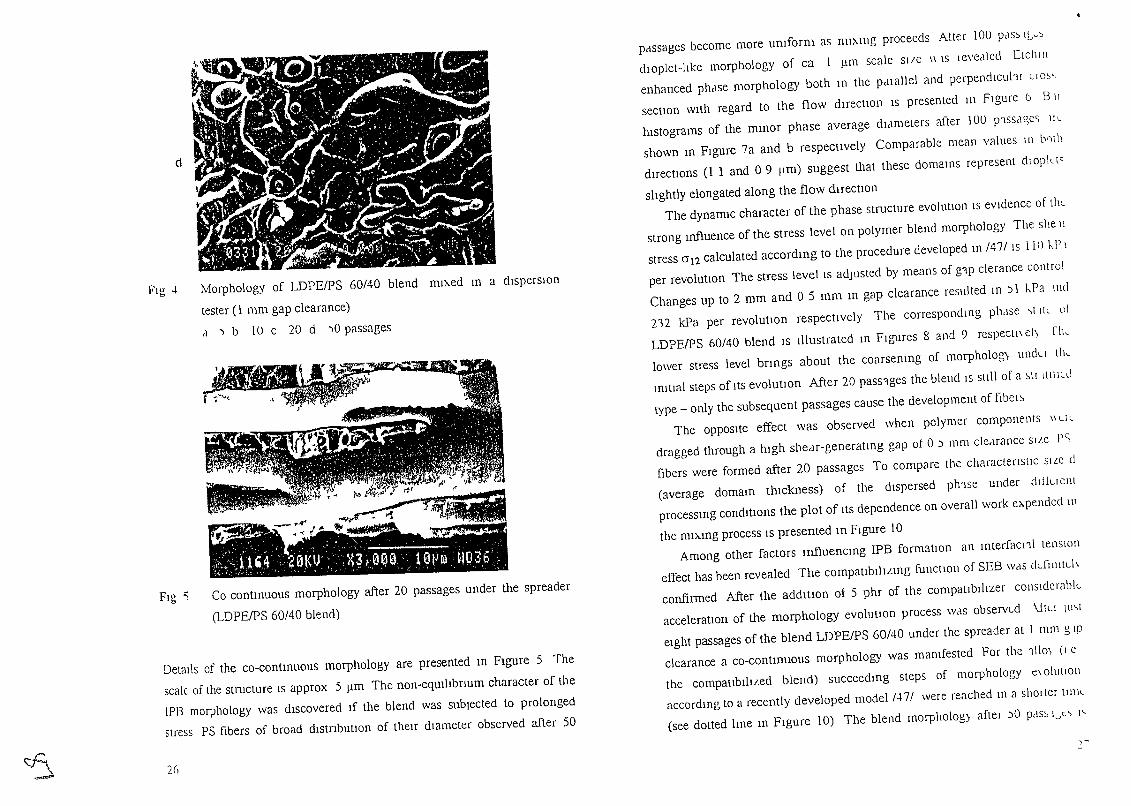
2()
Fig "i Co contmuous morphology after 20 passages under the spreader
(LDPEIPS 60/40 blend)
FIg 4 Morphology of LDPEIPS 60/40 blend mlAed m a disperSIOn
lester (1 mm gap clearance)
cI ) b 10 c 20 d )0 passages
1-
pelssagcs become more umform as nm,111g proceeds Alter IOU PdS~ Ibv::'
dloplet-ltke morphology of ca I 11m scale Sl/C \\ 1S Ievedled [tclllll
enhanced phdse morphology both m the pdlallel and perpendlcuhr uo~,
sectlOn WIth regard to the flow dHectlOn IS presented 111 FIgure 6 B II
hIstograms of the mmor phase average didmeters after 100 p'lSsdge<; III
shown m FIgure 7a and b respectIvely Comparable mean values 111 brllll
directlOns (1 1 and 09 11m) suggest that these domams represent dlOpkt<
shghtly elongated along the flow dIrectlOn
The dynamIC character of the phase structure evolutIOn IS eVIdence of thl.
strong mfluence of the stress level on polymer blend morphology The she II
stress 012 calculated accordmg to the procedure developed In /47/ IS I III 1-,1' 1
per revolutron The stress level IS adjusted by means of g1p derance cont rol
Changes up to 2 mm and 0 5 mm m gap clearance resulted m ) 1 hPa me!
212 kPa per revolutIOn respectIvely The corresponclIng phdse \!lll 01
LDPEIPS 60/40 blend IS Illustrated lfi FIgures 8 and 9 reSpeCII\ el) rile
lower stress level bnngs about the coarsemng of morpholog" undu tlk
mitral steps of ItS evolutlOn After 20 pass1ges the blend IS stIli of a ~1l Illllul
type - only the subsequent passages cause the development of fibel~
The OppOSIte effect was observed when polymer components \\ l.ll
dragged through a hIgh shedr-generatmg gap ot 0 ) mm cleMance siLe PC;
fibers were formed after 20 passages To compare the charactenstlc SlLe d
(average domam thIckness) of the dIspersed ph'lse under chlluel\t
processmg condItions the plot of ItS dependence on overall work eApendec\ III
the DUAmg process IS presented m FIgure 10
Among other factors mfluencmg IPB formation an rnterfacl'll tensIon
effect has been revealed The compaublhLmg functIOn of SEB WelS ckfillltl.h
confirmed After the addltlOn of 5 phr of the compatrbIhzer conslderahk
acceleratlOn of the morphology evolutron process was observed \itL! Ill\!
eIght passages of the blend LDPEIPS 60/40 under the spreader at I 111111 g lp
clearance a co-contmuous morphology was mamfested For the '1110) (I e
the compahblhLed blend) succeedmg steps of morphology t:\ olutlon
accordIng to a recently developed model /47/ were reached In a sholter 1II1\l.
(see dotted lme m FIgure 10) The blend morpholog) after )0 pclS~ IJ" l'
/II' -, - '-.-.~
~;",' ;. ,.-'," ~~v,
;{,:;', 11'i4 ': ~0-tdJ";, :X~~~ ~I03,6 .{'. " : ...,'., > .' 'r".·.· ~'. , ,
d
Details of the co-contmuous morphology are presented m FIgure 5 The
scale. of the structure IS approx 5 11m The non-eqUlhbnum character of the
IPB morphology was dIscovered If the blend was subjected to prolonged
stress PS fibers of broad dlstnbutron of theIr dIameter observed after 50
~
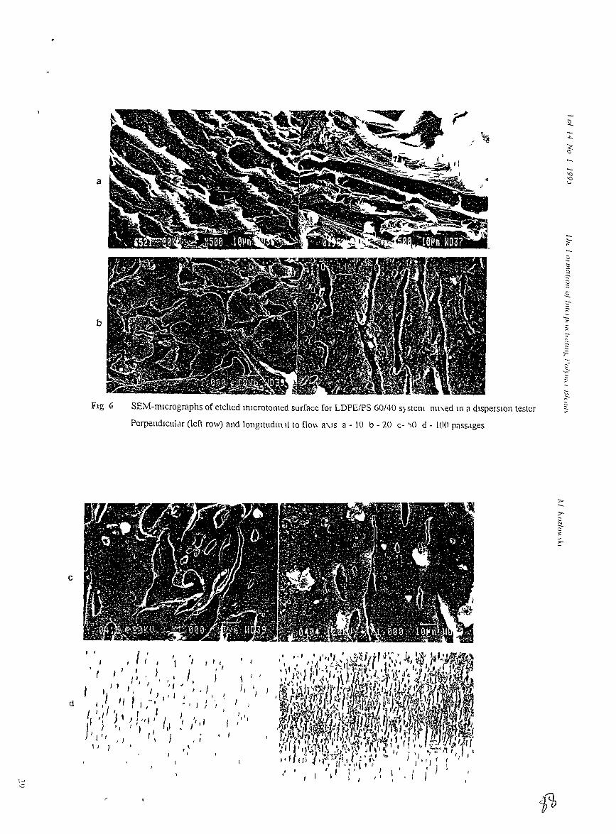
a
b
SEM-rmcrographs of etched InlCrotomed surface for LDPEIPS 60/40 s;stel1l I1lI"ed III a disperSion tester
Perpendlculclr (left row) and longnudlllll to no\" a\.ls a - 10 b - 20 c- "10 d - lOO pass<lges
c
i. ,
, I r, I
,/ ,
'/
, 1I
I
t/ I r'I
I ,
I )JI' J
I I •
I I I I I I I I I 4 I, J
I J } , I I j "I( -. II I ' I I I I'I I,
I r • , f'I .! J'): III' IJ
t •I ' J ,It I I I }
I I J I \
" I
d
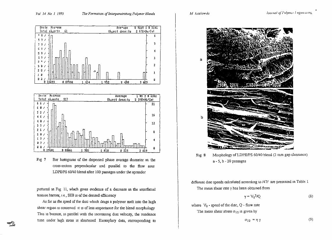
Vol 14 No 1 1995 The FormatIOn ofInterpenetratmg Polymer Blends M AozloWfkl Jowl/cd ofl'olyl1lu } Ilgl/H LII/lt-,
Morphology ofLDPEIPS 60/40 blend (2 mm gap clearance)
a - 5, b - 20 passages
Fig 8
a
Bar lustograms of the dIspersed phase average dIameter m the
cross-sectlOn perpendIcular and parallel to the flow aIXS
LDPEIPS 60/40 blend after 100 passages under the spreader
Un I ts I'll eNns - ---~---~erage 1 e:; ± Il 634.1Total ohJects 317 ObJect density 2 39EHJ6/~z
66"Il n.. F216 II I
::~1It~ t16
I I b
12331
261 lnlllllUIIL 51 r1 II n l- S2 II I
13/111111111111l111itTillllhTiUIIL ---fLIL lh r 49 7 I
II II I '1"""""'1"""""'1"""""'1"""""'1"""""'1' IlB 296B1
FIg 7
I Unl~S Hl c"'on5 Illle",,,ge Il 9220 ± II 513::iotal ohJe~t~ 61 OhJect densl ty 2 67Et@b/C'IZ
Q S I 6991
7 9 I 5
6 9 I4
591-l 9 I 33 Q I
3 i! I 2
2 a I
1 ~r n n n 11 :1g a I
Ii 6/!i311 1 952I
3 1l2, IIB 33693 1 414 2 495
~
pIctured In FIg 11, wluch gIves eVIdence of a decrease m the InterfaCial
tensIOn barner, 1 e , SEB IS of the desIred efficIency
As far as the speed of the dISC WhICh drags a polymer melt mto the hIgh
shear regIOn IS concerned It IS of less Importance for the blend morphology
ThIS IS because, m parallel With the Increasing dISC velocIty, the resIdence
tlme under lugh stress IS shortened Exemplary data, correspondmg to
dIfferent dISC speeds calculated accordmg to /47/ are presented In Table 1
The mean shear rate y has been obtained from
y = V 02/Q (8)
where Vo - speed of the dISC, Q - flow rate
The mean shear stress al2 IS gIven by
a12 = TlY (9)
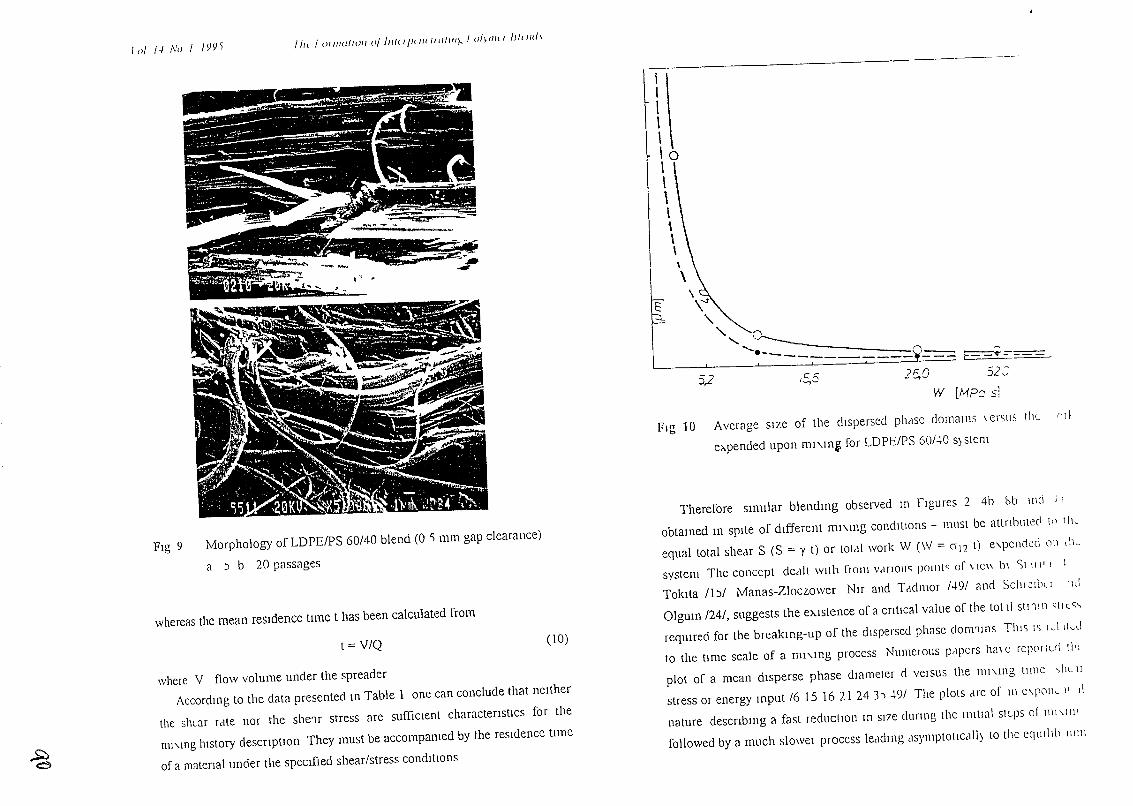
J 01 1.1 No 1 IYY'i l!r, I O/IIW{WII 0/ II/Il'l'il/l 1It/111I)., I (}/~lIlil /)1<1/(1,
where V flow volume under the spreader
Accordmg to the data presented m Table lone can conclude that neither
the shear relte nor the she'lr stress are suffiCient charactenstlcs for the
111l\.ll1g history descnptiOn They must be accompamed by the resldencc tunc
of a matenal under the specified shear/stress conditions
whereas the mean residence time t has been calculated from
52:25,0/5,55.2
Therefore similar blendmg observed In figures 2 4b Sb mel ) I
obtamed 111 spite of different ml"\.l\lg conditIons - must be attnb\ltec\ \1' Ilk
equal total shear S (S = Y t) or totdl work W (W = 012 t) e\.pCIlc\Cc\ C1l1 dl~
system The concept cleelll With flOill VelrlOtlS POllltS of \, lC\\ b\ St 11/ 1 I I
Toklta /b/ Manas-Zloczower Nlr and Teldmor 1"'91 and SChI2\bu lId
Olgum /24/, suggests the ehlstence of a cntlcal value of the tot II SlI 1\ n q 1'- '"
reqUIred for the breakmg-up of the dispersed phase clom11l1S Tim IS Ivllk,1
to the time scale of a ml"\.mg process Numelo\ls pelpCrS h(1\ C rqwIlvl th
plot of a mean disperse phase dIameter d versus the ll11"\.lI1g tlIllC ,hL 1I
stress or energy mput 16151621243) 491 The plots ene of 1Il C\.POlk 11 II
nature descnbmg a fast reduction 111 SI7e dUring the l111tlal steps of 1ll1\.lll'
followed by a much slowel process leadIng clsymptOlICelllj to thc cqllillb 1111ll
\ \10I\1\\\\,\
\--..rE \
\.~ ~--" ''"'' 'i_ -===~~
....... ----'!--- r-'._------~, -,
W [11?c 51
FIg 10 Average size of the dispersed ph'lSC e10mm I1S \ erS\ls thL "I}
e>..pended upon ml"\.1l1~ for LDPE/PS 60/40 SJstem
(10)t =V/Q
Morphology of LDPEIPS 60/40 blend (0 'i mm gap clearance)
a ) b 20 passages
Fig 9
~
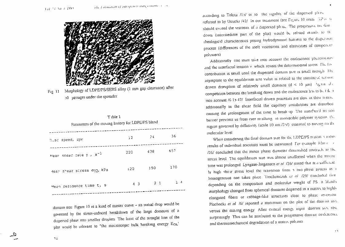
loj 1-1 \0 I j YY) fJJt. J OllllUllOIi UJ lUll/Jll/Hl' IUIIl, j UI\1I1t II
---------------------------------------------------------
---------------------------------------------------------
---------------------------------------------------------
dLCOldll1g to TokJtcl Ibl 01 to the lJglcllti of the dlsper~ed ph I'~
referred to by Utrclckl I·UI In OUI tre,llment (see rlburt- 10 unll~ l-.P I" I,
should e,Lced the VISCOSlti of d dispersed ph l~t- The pro~le~~I\L OIL Thll\
down (Il1termedwte part of the plot) \\ould bt- rehted m uuh tll th
rheologic'll charactensllcs posmg hydrodynamic belrnel s to the dl>pU'1lJil
process (differences of the melt viscosities and elastiCIties of COmpl)lk 11 1
polymers)
AdditIOnally one must tal-.e II1tO dccount the coale~cencc phLllOll1lill)l\
,md the mterfacwl tensIOn v which resists the detormcltlOnal stress fllL I I"
contnbutlOn IS smdll until the dispersed dom,un Sl/e IS smdll enollt:.h I hl
asymptote to the eqUlhbnum size vdlue IS reldted to the ll1terJacl,t! LLll'-'\,'!1
dnven dismptiOn of relatively small domaIns (d < 10 ~lm) \1:, Illl ill
compeutiOn between the breakmg down and the cOdlescence 111~ to bt- t lh. II
mto account 16 \) 471 InterfaCial drIven proces~es are slo\\ In thell IlltUIL
additiOnally m the shear field the caplllary mstabIllties are disturbed
causmg the prolongatiOn of the tlIue to break up The ll1terhcl11 tel ~IOIl
barlJer prevents liS [rom ever re Ichmg m ImmISCible polymer S)stell1~ tiL
regIOn governed by dlffuslVlt) (scale 10 nml3')/) essential to ml'.mg 011 thl
molecular level
When consldenng the final dOl11dm SILe fOI thL LDPC/PS S\ stem \ 111011"
results of mdlvldual sCientists must be mcntIoned ror e'.,IIIlple i\ II 11 (
1261 concluded that the nunO! phase dldmeter dllnllll~hed Illvel~L" to tilL
stress level The eqUlhbnum SIze WdS almost undffected when the ml'.ll1c.
tIme was prolonged Lyngaae-Jorgensen el al /261 stated thdt at cl ~ufllLlLllt
Iy 111gh c;he Ir stress level the II nnsltlon from 1 two phlse system 10 1
homogeneous one t,lkes pldce Trochl1l1ClUk L/ at /291 concludld 11111
dependmg on the composillon and molecular weight of PS a blLnd ~
morphology changed from sphencal domams dispersed m a matn, to hlghh
elongated fibers or cabbage-hke stmctUles close to phase 111\ er~IOIl
Plochockl et at 161 reported d milllmUI11 on the plot of the c101111l11 Sill
versus the mi>.mg enelgy After CillICdl enelg) mput d01l11111 ~I/L rO\l
surpnsmgly ThiS can be attnbuted to the pIOgresslve dom un cOl!cslellLL
and thermomechamcal degradatIOn of a matll, poh mel
36
1 d
170
657
24
2 1
150
438
12
4 3
120
220
T lble 1
Parameters of the ml>.mg history for LDPE/PS blend
domam size Figure 10 IS a kmd of master curve - ItS Imtial drop would be
governed by the stress-mduced breakdown of the large domams of a
dispersed phase mto smaller droplets The limit of the straight line of the
plot would be lelevant to "the macroscopic bulk breakmg energy Em,'
Mea~ resldence time t, S
JIear srear scress al2, kPa
D_sc speed, rprr
"'lear snear race y , s-l
Fig 11 Morphology of LDPEIPS/SEBS alloy (l mm gap clearance) after
)0 passages under the spreader
~"..S;;}..- \..(
I')
Vol 14 No 1 1995 1he 1 anl/atlOl/ oj Il/tLipu/( Oatil/I:{ 1'alyl1lLl fjlLlld\
~
A possIble reason for the ambIgUIty of these and other ambIguous
statements publIshed wlthm the last few decades could be the dIfferent
processmg hIstory of particular samples From FIgure 10 It IS ObVIOUS that,
dependmg on the mIXIng parameters (al2, resIdence tIme) applIed by
mdlVldual researchers, the morphology detalls can be sIgmficantly dIfferent,
even 1f the blendIng preparatlon was performed carefully and accordmg to
the best state-of-the-art m every case
Therefore, arbitrary statements lIke "Polymers A and B form
mterpenetratmg (or any other) structures at the range of compositlOn x/y"
should be aVOIded It IS essenual that partlcular condItIons of mIxmg should
accompany every such statement
SummanzIng the above dISCUSSIOn the necessity for a detailed
descnptIOn of the mode and condltlons of polymer blendmg preparatIOn
must be stressed since thiS IS cruCIal for the blend morphology and therefore
for the end use propertIes of the blends
CONCLUSIONS
• QUIte dIfferent morpholOgies can be produced for LDPEIPS systems
WIthIn tlIe compoSlnon range of 35 wt %, 1f stnctly defined rmxmg
condInons are used
• Use of the companbllIzer causes the mterpenetratmg structure to be
produced faster and to be more stable
• The charactenstlc number K has been mtroduced m order to
dIfferentlate/predict the dispefSlty level
• Fme disperslOns of one component m the other can be produced even at
the compOSition range for which the mterpenetratmg polymer blends
are expected
• The key factor for tlIe morphology generated dunng the mlxmg process
IS the processmg hIstory compnsmg the stress level and the reSIdence
tlme, 1 e the work expended whIle mIxmg
• A detaIled descnption of the rmxmg hIstory IS essentlal for polymer
1(;
blends/alloys preparatlon, and IS Just as Important as the type and
compositlon of the components
ACKNOWLEDGEMENTS
ThIs research was supported under Grant No HRN 5544 G-00-2066 00
US-Israel CooperatIve Development Research Program Office of SCience
AdVisor, U S Agency for InternatIOnal Development
REFERENCES
P S Hope and M J Folkes (Eds) Polymel Blends and 4l1ovs
Chapman and Hall, London (1993)
2 LA Utrackl, m Polymer Blends and Alloys Thermodynamics and
Rheology Hanser PublIshers New York (1990)
3 M KryszewskI, A Galeskl and E Martuscelh (Eds) Polymer Blend5
Processmg Morphology and Properties Vol 2 Plenum Press New
York (1984)
4 R Komngsveld, Polym Networks Blends 1 117 (1991)
5 H van Oene, J Coli Interface SCI 40 448 (1972)
6 A P PlochockI, S S Dagh and R D Andrews Polym Eng SCI 30
741 (1990)
7 M Kozlowski, Polym Networks Blends 3 213 (1993)
8 S -Q Wang and Q Sill Macromolecules 26 1091 (1993)
9 J L White and K Kim, Makromol Chem Macromol Symp 16 19
(1988)
10 S Wu Polym Eng SCI 30 753 (1990)
11 B D Favls Makromol Chem Macromol Symp 56 143 (1992)
12 F P La Mantla, F Canghalosl U Pedretti and A Roggero Ew
Polym J 29,671 (1993)
13 J Lyngaae-Jorgensen and L A Utrackl Makromol Chem Macromol
Symp 48/49, 189 (1991)
17
Vol 14 No 1 1995 ill! !'ormaluJII oj InIUjiUlUtalllli:,!'o!ymu lJluu/l It / f...UZ/(JH II.I
~
14 Ph Teyssle Maklomol Chem Macromol Symp 22 83 (1988)
b N Toklta, Rubbel Chem Technol 50 292 (1977)
16 I Fortelny and J Kovar Eur Polym J 28 85 (1992)
17 M Kozlowski m Processmg and PropertIes of LIqUId Crystallme
Polymers and LCP Based Blends (D ACierno and F P La Mantia,
Eds), ChemTec Pubhshmg, Toronto (1993)
18 D BlglO and W Stry, Polym Eng SCI 30, 153 (1990)
19 J S MIles and A Zurek Po/ym Eng SCI 28 796 (1988)
20 J Lyngaae-Jorgensen A Kuta, K Veno Poulsen and K Sondergaard
Polym Networks Blends 3 1 (1993)
21 A P Plochocki S S Dagh J E Curry and J Stanta, Polym Eng SCI
29 617 (1989)
22 M Sunuta, K Sakata, S ASal and K Mlyasaka Polym Bull 25, 265
(1991)
13 B K KIm Y M Lee and H K Jeong, Polymer 34,2075 (1993)
24 H P Schreiber and A Olgum Polym Eng SCI 23, 129 (1983)
2) B Pukanszky J Polym Eng 12, 1 (1993)
26 J Lyngaae-Jorgensen and K Sondergaard, Polym Eng ScI 27, 344,
3) 1 (1987)
27 B DaVId M Kozlowski and Z Tadmor, Po/ym Eng SCI 33, 227
(993)
28 K Mm J Wlute and J F Fellers Polym Eng SCI 24 1327 (1984)
29 R Wycisk W M Trocrumczuk and J Matys, EUI Polym J 26 535
(1990)
30 J Lyngaae-Jorgensen K Sondergaard L A Utrackl and A 'v dlenLa
Polym Networks Blends 3, 167 (1993)
31 G N Avergopoulos F C Weissert PH Biddison and G G A Bohm
Rubber Chem Technol 49,93 (1976)
32 G M Jordhamo, J A Manson and L H Sperlmg, Polym Eng SCI 26,
507 (1986)
33 M Narkls, Y Talmon and M Sl1verstem, Polymer 26, 1359 (1985)
34 A N Gent, G L Lm and M Mazurek, J Polym SCI Part B Polym
Phys 32,249 (1994)
"0
35 PH M Elemans J G M Gisbergen and HEM Meijer In InlL I do
tlOnshlp of Fundamental Polymel SCience alld fechnology (D J
Lemstra and L A K1emtJens Eds) ElseVier Appl SCI London
(1988)
36 S Reich, Phys Letters 114A 90 (1986)
37 D R Paul and J W Barlow, J lv/acronlol SCI Rev Macromol
Chem Cl8 109 (1980)
38 M Kozlowski P-21 Networks 90 Symp Jemsalem (1990)
39 V I Metelkm and V S Blekht KoUold Zh 46 476 (1984)
40 S Tomotlka P,OC Roya/ Soc (London) AlSO 322 (193))
41 T Inoue, T Ouglzawa and M Mlyasaka In CUll ent I 0PlC~ lJ1
Polymer SCIence (R M Ottenbnte L A Utrackl and T Inoue Eds)
Hanser Pubhshers, Mumch (1987)
42 LA Utrackl J Rheol 35, 1615 (1991)
43 L L Chapoy, J Chern Phys 84 1530 (1986)
44 A P Plochockl (Coord) Melt Rheology and COlllltant MOl phology oj
Polyblends (IUPAC W P 4 2 1 project)
45 R K Chohan, B DaVid A Nlr and Z Tadmor Int Polvlll PIOC 2
13 (1987)
46 M KozlOWSki, 9th Conference on Polymel Modification Polal1lc1
(1989)
47 M Kozlowski Po/ym NetwOlks Blends 4 39 (1994)
48 J M Stanta, Twns Soc Rheol 16 339 (1972)
49 J Manas-Zloczower, A Nlr and Z Tadmor Rubbel Chen! TLChnoi
5':; 1250 (1987)
19
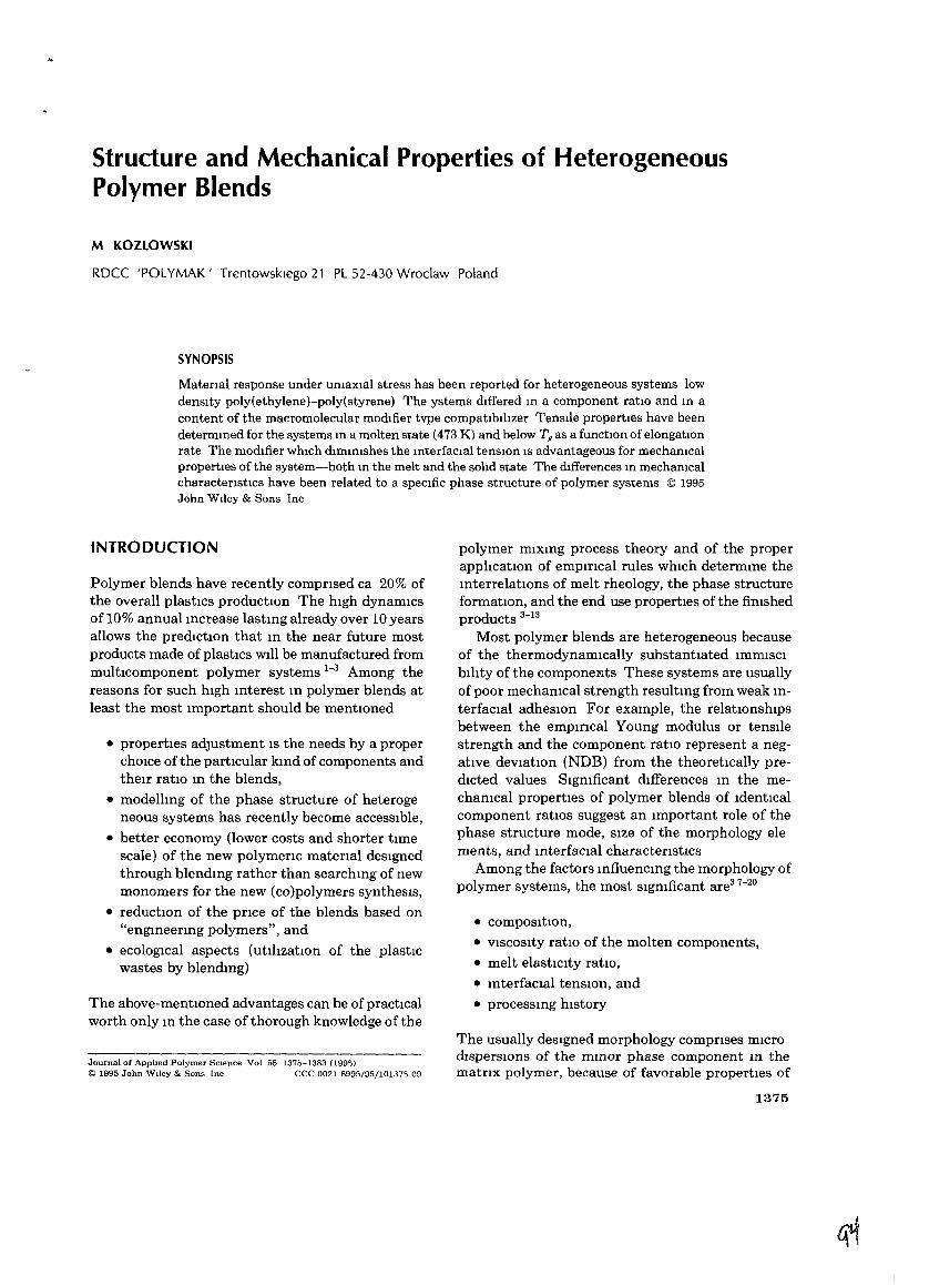
Structure and Mechanical Properties of HeterogeneousPolymer Blends
M KOZLOWSKI
RDCC 'POLYMAK' Trentowsklego 21 PL 52-430 Wroclaw Poland
SYNOPSIS
Matenal response under umaxial stress has been reported for heterogeneous systems lowdensity poly(ethylene)-poly(styrene) The ystems differed m a component ratiO and m acontent of the macromolecular modifier tvpe compatlbihzer Tensile properties have beendetermmed for the systems m a molten state (473 K) and below Tg as a functiOn ofelongatiOnrate The modifier whIch dlmmishes the mterfaclal tenSIOn IS advantageous for mechamcalproperties of the system-both m the melt and the solid state The differences m mechamcalcharactenstlcs have been related to a specific phase structure of polymer systems © 1995John Wtley & Sons Inc
INTRODUCTION
Polymer blends have recently comprIsed ca 20% ofthe overall plastics productIOn The high dynamiCsof 10% annual mcrease lastmg already over 10 yearsallows the prediCtIOn that m the near future mostproducts made of plastics Will be manufactured frommulticomponent polymer systems i-3 Among thereasons for such high mterest m polymer blends atleast the most important should be mentIOned
• properties adjustment is the needs by a properchOice of the particular kmd of components andtheu ratIO m the blends,
• modellmg of the phase structure of heterogeneous systems has recently become accessible,
• better economy (lower costs and shorter timescale) of the new polymerIC material deSignedthrough blendmg rather than searchmg of newmonomers for the new (co)polymers syntheSiS,
• reductIOn of the price of the blends based on"engmeermg polymers", and
• ecologiCal aspects (utihzatiOn of the plasticwastes by blendmg)
The above-mentIOned advantages can be of practicalworth only m the case of thorough knowledge of the
Journal of Apphed Polymer SCIence Vol 55 1375-1383 (199')© 1995 John W,ley & Sons Inc CCC 0021 8995/95/10137') 09
polymer mixmg process theory and of the properapphcatIOn of empirIcal rules whiCh determme themterrelatIOns of melt rheology, the phase structureformatIOn, and the end use properties of the fimshedproducts 3-i3
Most polymer blends are heterogeneous becauseof the thermodynamiCally substantiated immiSCibihty of the components These systems are usuallyof poor mechamcal strength resultmg from weak mterfacial adheSiOn For example, the relatIOnshipsbetween the empmcal Young modulus or tensilestrength and the component ratIO represent a negative deViatiOn (NDB) from the theoretically predicted values Sigmficant dIfferences m the mechamcal properties of polymer blends of identicalcomponent ratiOS suggest an important role of thephase structure mode, Size of the morphology elements, and mterfacial characterIstIcs
Among the factors mfluencmg the morphology ofpolymer systems, the most sigmficant are37
-20
• compOSition,• VISCOSity ratIO of the molten components,
• melt elastiCity ratIO,
• mterfacial tenSiOn, and
• processmg history
The usually deSIgned morphology comprIses microdIsperSIOns of the mmor phase component m thematnx polymer, because of favorable properties of
1375
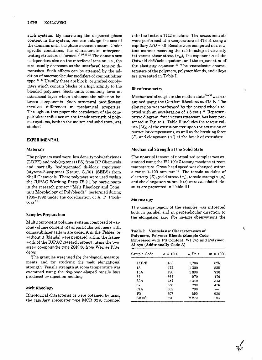
1376 KOZLOWSKI
such systems By mcreasmg the dIspersed phasecontent m the system, one can enlarge the SIze ofthe domams until the phase mverSIOn occurs UnderspecIfic condItIOns, the characterIstic mterpenetratmg structure IS formed 15 1621 22 The domam SIzeIS dependent also on the mterfaclal tensIOn, 1e , theSIze usually decreases as the mterfaclal tensIOn dImmlshes Such effects can be attamed by the additIOn of macromolecular modifiers of compatIblhzertype 23-31 Usually these are block or grafted copolymers WhICh contam blocks of a hIgh affimty to theblended polymers Such umts commonly form anmterfaclal layer whIch enhances the adheSIOn between components Such structural modificatlOnmvolves dlfferences m mechamcal propertIesThroughout thIS paper the correlatlOn of the compatIblhzer mfluence on the tensIle strength of polymer systems, both m the molten and solId state, wasstudIed
EXPERIMENTAL
Materials
The polymers used were low denslty poly(ethylene)(LDPE) and poly(styrene) (PS) from BP ChemIcalsand partlally hydrogenated dI-block copolymer(styrene-b-Isoprene) Kraton G1701 (SEBS) fromShell ChemIcals These polymers were used wlthmthe IUPAC Workmg Party IV 21 by particIpantsm the research project "Melt Rheology and Comitant Morphology of Polyblends," performed durmg1985-1992 under the coordinatIOn of A P PlochOCkI 32
Samples PreparatIOn
MultIcomponent polymer systems composed ofvarIOUS volume content (4)) of partIcular polymers WIthcompatlblhzer (alloys are coded A m the Tables) orWIthout It (blends) were prepared wlthm the framework of the IUPAC research proJect, usmg the twoscrew compounder type ZSK 30 from Werner Pflelderer
The granules were used for rheolOgical measurements and for studymg the melt elongatIOnalstrength TenSIle strength at room temperature wasexammed usmg the dog-bone-shaped tensIle barsproduced by mJectIOn moldmg
Melt Rheology
RheologIcal characterIstics were obtamed by usmgthe capIllary rheometer type MCR 3210 mounted
mto the Instron 1122 machme The measurementswere performed at a temperature of 473 K usmg acapIllary LID = 40 Results were computed m a routme manner recelvmg the relatlOnship of VISCOSIty(1]) versus shear stress (1112), the exponent n of theOstwald deWaele equatIOn, and the exponent m ofthe elastiCIty equatiOn 33 The VIscoelastic characterIstics ofthe polymers, polymer blends, and alloysare presented m Table I
Rheotensometry
Mechamcal strength m the molten state34-36 was exammed usmg the Gottfert Rheotens at 473 K TheelongatlOn was performed by the cogged wheels rotated WIth an acceleratiOn of 15 em S-2 Representative dIagram force versus extenSIOn has been presented m FIgure 1 Table II mcludes the torque values (Md) of the extrusIOmeter upon the extruSiOn ofpartIcular compOSItions, as well as the breakmg force(F) and elongatiOn (.1l) at the break of extrudate
Mechamcal Strength at the Solid State
The umaxlal tenSIOn of normalIzed samples was exammed usmg the FU 100eZ testmg machme at roomtemperature Cross head speed was changed wlthma range 1-100 mm mm-1 The tenSIle modulus ofelastiCIty (E), YIeld stress (l1y ), tenSIle strength (ITr )
and the elongatiOn at break (e) were calculated Results are presented m Table III
Microscopy
The damage regIOn of the samples was mspectedboth m parallel and m perpendicular directiOn tothe elongatIOn aXlS For m-aXlS observatlOns the
Table I VIscoelastIc CharacterIstIcs ofPolymers, Polymer Blends (Sample CodeExpressed WIth PS Content, Wt (%) and PolymerAlloys (AddItionally Code A)
Sample Code n X 1000 11, Pa s m X 1000
LDPE 453 1,780 62515 472 1320 55515A 498 1390 72633 367 970 47633A 457 1340 54367 356 780 47667A 302 790PS 307 590 636SEBS 370 2270 194
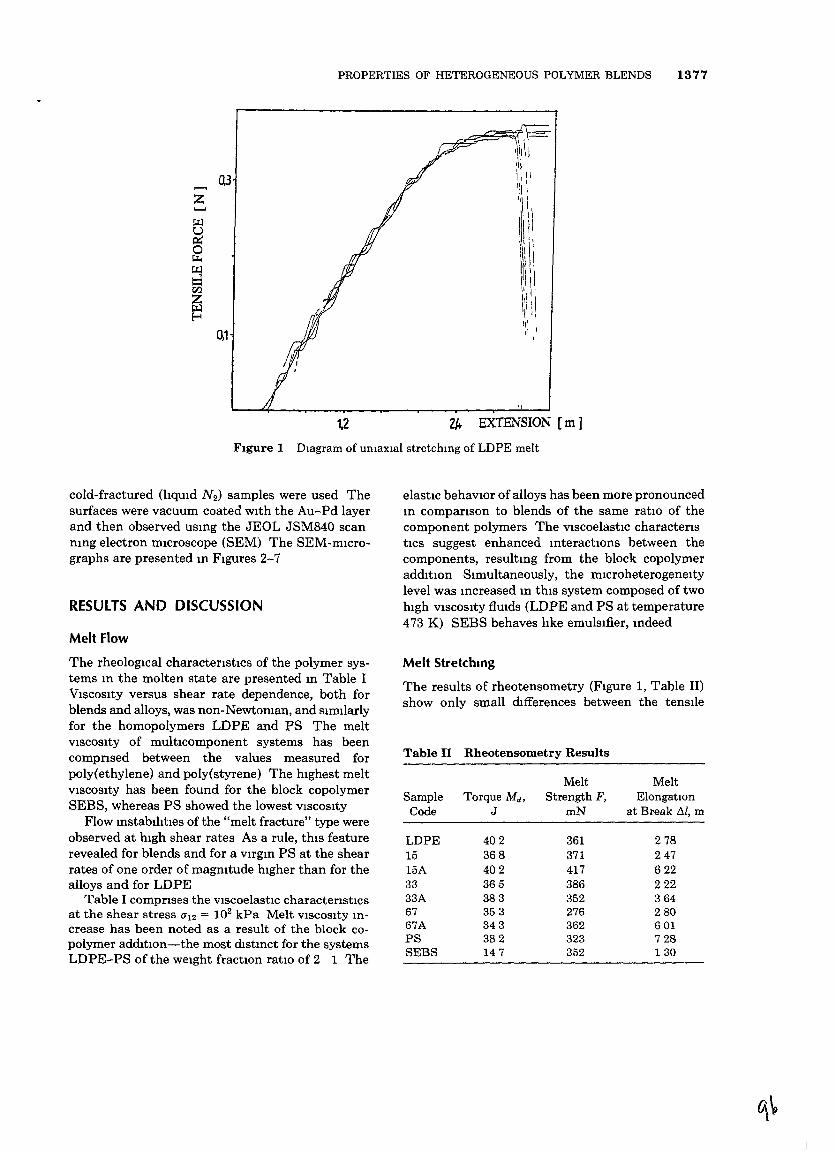
PROPERTIES OF HETEROGENEOUS POLYMER BLENDS 1377
"2/+ EXTENSION [m]1,2
r-~t=-~,II\I-111
IhQ3 \,11
...... I:, \z 1\\\
~ 1\ 1\
~III
0 ~Ii~
~ 11\1
CI.l 1,1 \
~ \11,111'1E-< 'II,'
0,1 " 1
FIgure 1 Diagram of umaxial stretchmg of LDPE melt
cold-fractured (hqUld N 2 ) samples were used Thesurfaces were vacuum coated wIth the Au-Pd layerand then observed usmg the JEOL JSM840 scanmng electron mIcroscope (SEM) The SEM-mlCrographs are presented m FIgures 2-7
RESULTS AND DISCUSSION
Melt Flow
elastic behaviOr ofalloys has been more pronouncedm companson to blends of the same ratio of thecomponent polymers The VIscoelastiC characteristIcs suggest enhanced mteractlOns between thecomponents, resultmg from the block copolymeraddItion SImultaneously, the microheterogeneitylevel was mcreased m thIS system composed of twohIgh VISCOSIty flUIds (LDPE and PS at temperature473 K) SEBS behaves hke emulsIfier, mdeed
The rheologlCal charactenstics of the polymer systems m the molten state are presented m Table IVISCOSIty versus shear rate dependence, both forblends and alloys, was non-Newtoman, and sImIlarlyfor the homopolymers LDPE and PS The meltVISCOSIty of multlComponent systems has beencompnsed between the values measured forpoly(ethylene) and poly(styrene) The hIghest meltVISCOSIty has been found for the block copolymerSEBS, whereas PS showed the lowest VISCOSIty
Flow mstablhtIes of the "melt fracture" type wereobserved at hIgh shear rates As a rule, thIS featurerevealed for blends and for a VIrgm PS at the shearrates of one order of magnItude hIgher than for thealloys and for LDPE
Table I comprIses the ViscoelastiC characterIsticsat the shear stress (ji2 = 102kPa Melt VISCOSity mcrease has been noted as a result of the block copolymer adffitIOn-the most mstmct for the systemsLDPE-PS of the weIght fractIOn ratIO of 2 1 The
Melt Stretchmg
The results of rheotensometry (FIgure 1, Table II)show only small dIfferences between the tensl1e
Table II Rheotensometry Results
Melt MeltSample Torque M d , Strength F, ElongatiOn
Code J mN at Break /11, m
LDPE 402 361 27815 368 371 24715A 402 417 62233 365 386 22233A 383 352 36467 353 276 28067A 343 362 601PS 382 323 728SEBS 147 352 130
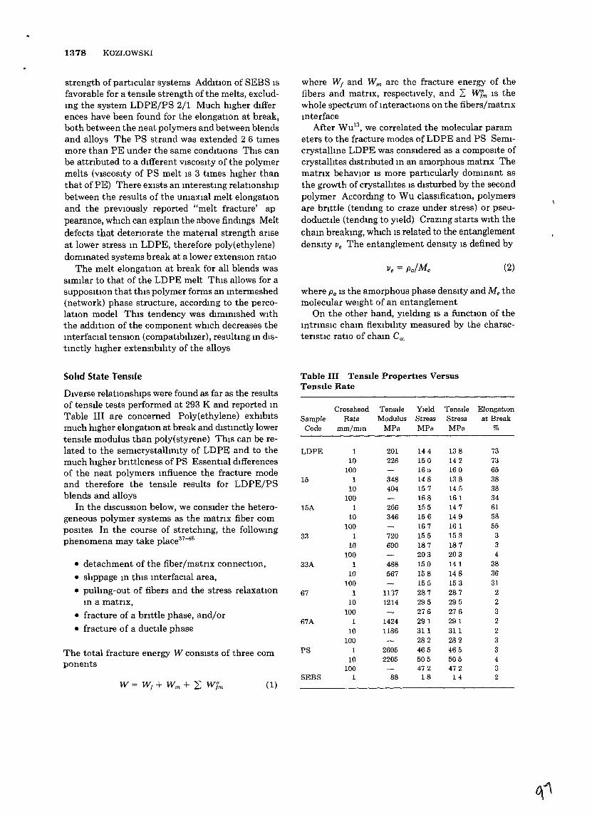
1378 KOZLOWSKI
strength of partIcular systems AddItIOn of SEBS isfavorable for a tensIle strength of the melts, excludmg the system LDPE/PS 2/1 Much higher differences have been found for the elongation at break,both between the neat polymers and between blendsand alloys The PS strand was extended 2 6 timesmore than PE under the same conditions This canbe attnbuted to a dIfferent VISCOSIty of the polymermelts (VISCOSIty of PS melt is 3 times higher thanthat of PE) There eXists an mterestmg relatIOnshipbetween the results of the umaxial melt elongatIOnand the previOusly reported "melt fracture' appearance, WhiCh can explam the above findmgs Meltdefects that deteriOrate the matenal strength anseat lower stress m LDPE, therefore poly(ethylene)dommated systems break at a lower extensiOn ratiO
The melt elongatiOn at break for all blends wassimilar to that of the LDPE melt This allows for aSupposition that this polymer forms an mtermeshed(network) phase structure, accordmg to the percolation model This tendency was dimmished wIththe addItion of the component which decreases themterfacial tensiOn (compatibilIzer), resultmg m distmctly hIgher extensIbIhty of the alloys
where WI and Wm are the fracture energy of thefibers and matnx, respectively, and L: Wim is thewhole spectrum of mteractiOns on the fibers/matrIxmterface
After WUi3, we correlated the molecular parameters to the fracture modes of LDPE and PS Semicrystallme LDPE was consIdered as a composIte ofcrystalhtes wstnbuted m an amorphous matrIX Thematnx behaviOr IS more particularly dommant asthe growth of crystallites IS dIsturbed by the secondpolymer Accordmg to Wu classificatiOn, polymersare bnttle (tendmg to craze under stress) or pseudoductl1e (tendmg to yIeld) Crazmg starts wIth thecham breakmg, which IS related to the entanglementdensity Ve The entanglement densIty is defined by
(2)
where Po is the amorphous phase density and Me themolecular weight of an entanglement
On the other hand, yieldmg is a functiOn of themtnnsiC cham flexibihty measured by the charactenstic ratIO of cham eeL
Solid State Tensile
The total fracture energy W conSists of three components
• detachment of the fiber/matnx connectIOn,• slippage m thIS mterfacial area,• pullmg-out of fibers and the stress relaxatiOn
In a matnx,
• fracture of a bnttle phase, and/or
• fracture of a ductile phase
DIverse relatiOnships were found as far as the resultsof tensIle tests performed at 293 K and reported mTable III are concerned Poly(ethylene) exhIbItsmuch lugher elongatIOn at break and mstmctly lowertensIle modulus than poly(styrene) ThIS can be related to the semicrystalhmty of LDPE and to themuch hIgher bnttleness of PS Essential dIfferencesof the neat polymers mfluence the fracture modeand therefore the tensile results for LDPE/PSblends and alloys
In the dIscussiOn below, we consider the heterogeneous polymer systems as the matnx fiber composites In the course of stretchmg, the followmgphenomena may take place37-48
Table III TensIle PropertIes VersusTensIle Rate
Crosshead TensIle YIeld TensIle ElongatIonSample Rate Modulus Stress Stress at Break
Code mm/mm MPa MPa MPa %
LDPE 1 201 144 138 7310 226 150 142 73
100 161) 160 6515 1 348 148 138 38
10 404 157 145 38100 168 161 34
15A 1 266 155 147 6110 346 156 149 58
100 167 161 5533 1 720 155 153 3
10 690 187 187 3100 203 203 4
33A 1 488 150 141 3810 567 158 148 36
100 155 153 3167 1 1117 287 287 2
10 1214 295 295 2100 276 276 3
67A 1 1424 291 291 210 1186 311 311 2
100 282 282 3PS 1 2695 465 465 3
10 2205 505 505 4100 472 472 3
SEBS 1 88 18 14 2(1)W = W f + Wm + 2: W fm
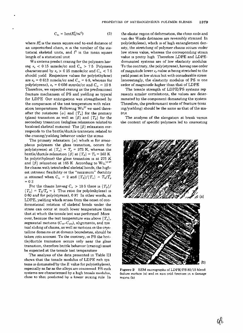
PROPERTIES OF HETEROGENEOUS POLYMER BLENDS 1379
(3)
where R~ IS the mean square end to-end dIstance ofan unperturbed chaIn, n IS the number of the statistical skeletal umts, and [2 IS the mean squarelength of a statIstIcal umt
Wu cntena predIct crazIng for the polymers havIng Ve < 0 15 mmole/cc and Coo > 7 5 Polymerscharactenzed by Ve > 0 15 mmole/cc and Coo < 75should YIeld Respective values for poly(ethylene)are Ve '= 0613 mmole/cc and Coo '= 68, whereas forpoly(styrene), Ve '= 0056 mmole/cc and Coo '= 108Therefore, we expected craZIng as the predomInantfracture mechamsm of PS and YIeldIng as typIcalfor LDPE Our antiCIpatIOn was strengthened bythe companson of the test temperature WIth relaxatIOn temperatures FolloWIng WU37 we used thereafter the notatIOns {a} and {T,,} for the prImary(glass) tranSItion as well as {is} and {Tp} for thesecondary tranSItion (subglass relaxatIon related tolocalized skeletal motIOns) The {,S} relaxation corresponds to the bnttle/ductIle tranSItIOn related tothe crazIng/YieldIng behaVIOr under the stress
The pnmary relaxatIOn {a} whIch IS for amorphous polymers the glass tranSItIOn, occurs forpoly(styrene) at {T,,} = Tg = 373 K, whereas thebnttle/ductlle relaxatIOn {,S} at {Til} '= Tb '= 363 KIn poly(ethylene) the glass tranSItion IS at 275 Kand {,S} relaxatIOn at 165 K AccordIng to WU/337
for chaIns WIth tetrahedral skeletal bonds, the hIghest IntrInSIC fleXIbIlity or the "maXImum" ductilItyIS attaIned when Ccx- = 2 and {TIl}/{T,,} = Tb/Tg
= 03For the chaIns haVIng CCf > 105 there IS {TIl }/
{T,,} = Tb/Tg '= 1 ThIs ratIO for poly(ethylene) IS060 and for poly(styrene), 097 In other words, InLDPE, yIeldIng whIch anses from the onset of conformational rotatIOn of skeletal bonds under thestress can occur at much lower temperature thanthat at whIch the tenSIle test was performed Moreover, because the test temperature was above {T"Lsegmental motIOns (ClO-CIOO), alIgnments, and mutual slIdIng of chaIns, as well as motIOns m the crystallIne domaInS or at domam boundanes, should betaken mto account To the contrary, m PS the brIttle/ductile tranSItIOn occurs only near the glasstranSItion, therefore bnttle behaVIOr (crazmg) mustbe expected at the tenSIle test temperature
The analySIS of the data presented In Table IIIshows that the tenSIle modulus of LDPE nch systerns IS domInated by the E value for poly(ethylene),espeCially as far as the alloys are concerned PS-nchsystems are characterIzed by a high tenSIle modulus,close to that predIcted by a lmear mixmg rule In
the elastic region of deformatIOn, the cham cods andvan der Waals dIstances are reverSIbly stramed Inpoly(ethylene), whIch IS of hIgh entanglement denSIty, the stretchIng of polymer chaInS occurs underlow stress value, whereas the correspondIng straInvalue IS pretty hIgh Therefore LDPE and LDPEdommated systems are of low elastiCIty modulusTo the contrary, the poly(styrene), havmg one orderofmagmtude lower ve-value IS bemg stretched to theYield POInt at low stram but WIth conSIderable stressInterestmgly, the elastiCIty modulus of PS IS oneorder of magmtude hIgher than that of LDPE
The tenSIle strength of LDPE/PS systems represents SImIlar correlatIOns, the values are determmated by the component dommatmg the systemTherefore, the predommant mode of fracture (crazmg/yleldmg) should be the same as that of the matnx
The analYSIS of the elongatIOn at break versusthe content of speCIfic polymers led to mterestmg
(b)
FIgure 2 SEM mIcrographs of LDPE/PS 85/15 blendfallure surface (a) and In aXlS cold fracture In a damagereglOn (b)
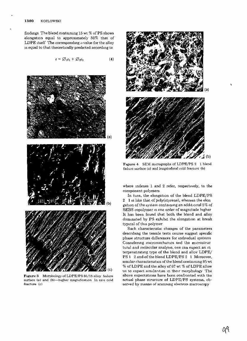
1380 KOZLOWSKI
FIgure 3 Morphology of LDPE/PS 85/15 alloy faIluresurface (a) and (b)-hIgher magmficatlOn In aXIS coldfracture (c)
(a)
FIgure 4 SEM mIcrographs of LDPE/PS 2 1 blendfaIlure surface (a) and longltudmal cold fracture (b)
where mdexes 1 and 2 refer, respectively, to thecomponent polymers
In turn, the elongatIOn of the blend LDPE/PS2 1 IS hke that of poly(styrene), whereas the elongatIon of the system conta1Omg an addItional 5% ofSEBS copolymer IS one order of magmtude hIgherIt has been found that both the blend and alloydommated by PS exhIbIt the elongation at breaktypIcal of thIS polymer
Such charactenstIc changes of the parametersdescnb10g the tenSIle tests course suggest speCIficphase structure dIfferences for mdlVldual systemsConsidermg mlcromechamcs and the mlCrostructural and molecular analysIs, one can expect an mterpenetratmg type of the blend and allov LDPE/PS 1 2 and of the blend LDPE/PS 2 1 Moreover,SImIlar charactenstlcs of the blend contammg 85 wt% of LDPE and the alloy of 67 wt % of LDPE allowus to expect SimilantIes 10 theIr morphology Theabove expectatIOns have been confronted wIth theactual phase structure of LDPEjPS systems, observed by means of scanmng electron mIcroscopy
(4)
(a)
(b)
findmgs The blend contammg 15 wt % of PS showselongatlOn equal to approxImately 50% that ofLDPE Itself The correspondmg E-value for the alloyIS equal to that theoretically predIcted accordmg to
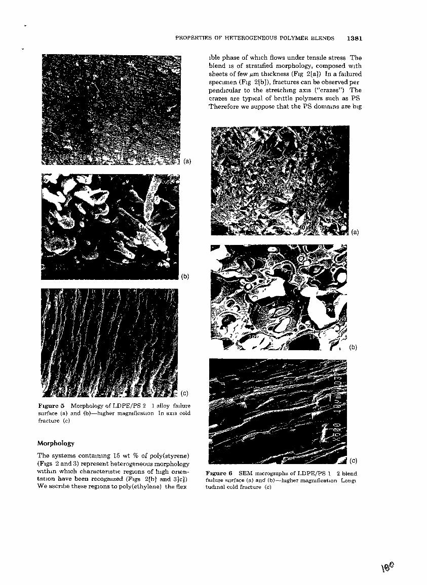
PROPERTIES OF HETEROGENEOUS POLYMER BLENDS 1381
(a)
Ible phase of whIch flows under tensIle stress Theblend IS of stratIfied morphology, composed wIthsheets of few /lm thIckness (FIg 2[aJ) In a falluredspeCImen (FIg 2[b]), fractures can be observed perpendicular to the stretchmg aXIS ("crazes") Thecrazes are typIcal of bnttle polymers such as PSTherefore we suppose that the PS domams are bIg
FIgure 6 SEM mICrographs of LDPE/PS 1 2 blendfailure surface (a) and (b}-hlgher magmficatlOn Longltudmal cold fracture (c)
(a)
(b)
FIgure 5 Morphology of LDPE/PS 2 1 alloy failuresurface (a) and (b)-higher magmficatlOn In aXIs coldfracture (c)
Morphology
The systems contammg 15 wt % of poly(styrene)(FIgS 2 and 3) represent heterogeneous morphologywithm whIch charactenstIc regIOns of hIgh onentatIOn have been recogmzed (FIgS 2[b] and 3]c])We ascnbe these regIOns to poly(ethylene) the flex
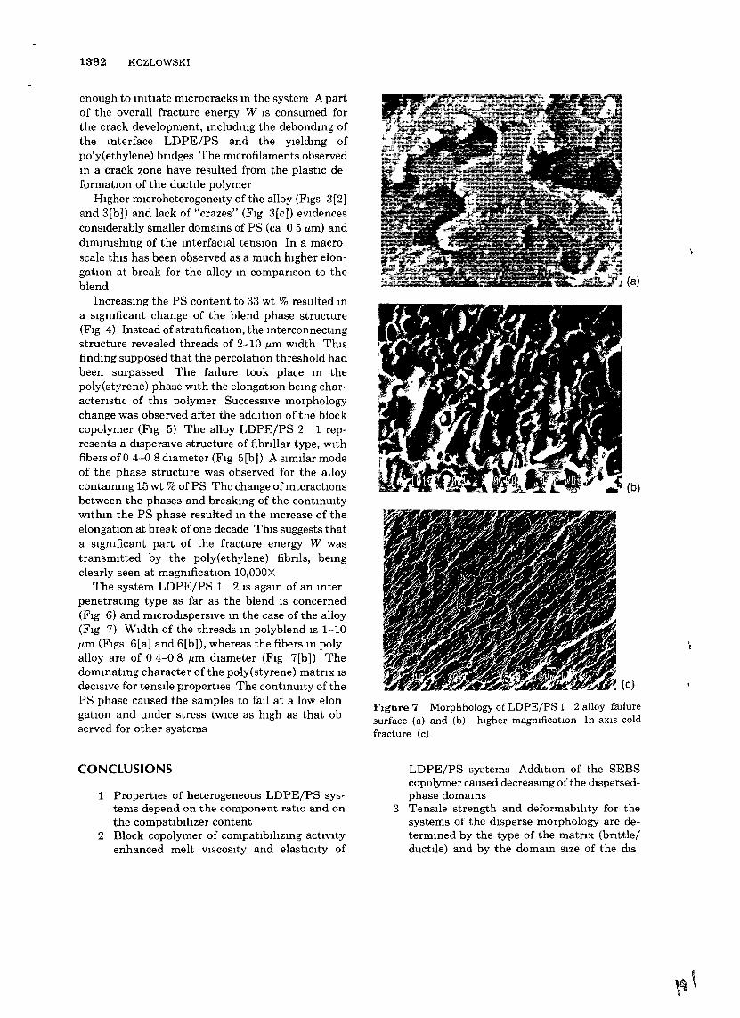
13'82 KOZLOWSKI
enough to ImtIate mIcrocracks m the sy"ltem A partof the overall fracture energy W IS consumed forthe crack development, mcludmg the debondmg ofthe mterface LDPE/PS and the yIeldmg ofpoly(ethylene) bndges The microfilaments observedm a crack zone have resulted from the plastIc deformatIOn of the ductile polymer
HIgher microheterogeneity of the alloy (FIgS 3(2)and 3[b}) and lack of "crazes" (FIg 3[c}) eVidencesconsIderably smaller domams of PS (ca 05 ,urn) anddimimshmg of the mterfacial tenSIOn In a macroscale this has been observed as a much hIgher elongatIOn at break for the alloy m companson to theblend
Increasmg the PS content to 33 wt % resulted ma sIgmficant change of the blend phase structure(FIg 4) Instead of stratificatIOn, the mterconnectmgstructure revealed threads of 2-10 ,urn wIdth ThIsfindmg supposed that the percolatIOn threshold hadbeen surpassed The failure took place m thepoly(styrene) phase wIth the elongatIOn bemg charactenstIc of thIS polymer SuccessIve morphologychange was observed after the addItion of the blockcopolymer (FIg 5) The alloy LDPE/PS 2 1 represents a dIspersIve structure of fibnllar type, withfibers of 0 4-0 8 dIameter (FIg 5[b}) A sImilar modeof the phase structure was observed for the alloycontammg 15 wt % of PS The change of mteractIOnsbetween the phases and breakmg of the contmUitywithm the PS phase resulted m the mcrease of theelongatIOn at break of one decade ThIS suggests thata sIgmficant part of the fracture energy W wastransmItted by the poly(ethylene) fibnls, bemgclearly seen at magmficatIOn 10,000X
The system LDPE/PS 1 2 IS agam of an mterpenetratmg type as far as the blend IS concerned(Fig 6) and microdispersive m the case of the alloy(FIg 7) WIdth of the threads m polyblend IS 1-10,urn (FIgs 6[a] and 6[b)), whereas the fibers m polyalloy are of 04-08 ,urn dIameter (FIg 7[b]) Thedommatmg character ofthe poly(styrene) matnx ISdeCISIve for tenSIle properties The contmUity of thePS phase caused the samples to fail at a low elongatIon and under stress tWIce as hIgh as that observed for other systems
CONCLUSIONS
1 PropertIes of heterogeneous LDPEjPS Sy5terns depend on the component ratIO and onthe compatIbIhzer content
2 Block copolymer of compatIbIhzmg actiVItyenhanced melt VISCOSIty and elasticIty of
FIgure 7 Morphhology of LDPE/PS 1 2 alloy fatluresurface (a) and (b)-hIgher magmficatIOn In aXIS coldfracture (c)
LDPEjPS systems AddItion of the SEBScopolymer caused decreasmg of the mspersedphase domams
3 TenSIle strength and deformabIhty for thesystems of the dIsperse morphology are determmed by the type of the matrIX (brIttlejductile) and by the domam SIze of the dIS
PROPERTIES OF HETEROGENEOUS POLYMER BLENDS 1383
persed phase In case of mterpenetratmg typemorphology, the polymer systems fall by thebrIttle/ductIle mode dependmg on the component of the lowest crazmg/yIeldmg stress
ThIS research was supported under Grant No HRN 5544G 00 2066 00, US Israel Cooperative Development Research Program, Office of SCIence AdvIsor U S Agencyfor InternatiOnal Development The author IS mdebted toIUPAC W P IV 2 1 for the samples supphed PartIculargratItude goes to J E Curry of Werner & PfleIderer CorpRamsey, New Jersey USA for hIS gUidance m the blendsand alloys preparatIOn
REFERENCES
1 L A Utrackl Polymer Alloys and Blends HanserPubhshers MUnIch,1989
2 G Allen Polymer 26, 1284 (1985)3 L A Utrackl Polym Netu,orks Blends 1,61 (1991)4 A P Plochockl, Polym Eng SCt 23,618 (1983)5 H Van Oene J Collmd Set 40,448 (1972)6 G I Taylor Proc Roy Soc A146, 501 (1932)7 B DavId M KozlowskI and Z Tadmor Pol:J,m Eng
Sct 33, 227 (1993)8 N Toklta Rubber Chem Technol 50,292 (1977)9 A Y Malkm A V Baranov M E Vlculencova
L N Prokhorova, and V I Slvetskll Intern PolymProcess 8,99 (1993)
10 M Kodama, Polym Eng SCt 33, 1141 (1993)11 J Furukawa J Appl Polym SCt 51,187 (1994)12 B D Favls Makromol Chem Macromol Symp 56,
143 (1992)13 S Wu Polym Eng SCt 30,753 (1990)14 R Komngsveld, Polym Networks Blends 1, 117
(1991)15 J Lyngaae Jorgensen and L A Utrackl Makromol
Chem Macromol Symp 48/49, 189 (1991)16 M KozlowskI Polym Networks Blends 3,213 (1993)17 F P LaMantia, Matenals Eng 2, 351 (1991)18 J Kolank F Ledmcky, and M Pegoraro Polym
Networks Blends 3, 147 (1993)19 H H Wmter Makromol Chem Macromol Symp
69, 177 (1993)20 B Pukanszky J Polym Eng 12, 1 (1993)21 I S Miles and A Zurek Polym Eng SCt 28, 796
(1988)22 M KozlowskI, 10th Polymer Networks Group Meetmg
NETWORKS 90 Jerusalem May 21-25 199023 A Valenza F P LaMantia G B Demma V Romano
and D ACIerno Polym Networks Blends 1 71 (1991)
24 M YoshIda, J J Ma, K Mm, J L WhIte, and R PQUIrk, Polym Eng SCt 30, 30 (1990)
25 A P Plochockl S S Dagh and R D Andrews PolymEng SCt 30, 741 (1990)
26 GRIess, Makromol Chem Macromol Symp 69,177 (1993)
27 R Holstl Mlettmen, J Seppala and 0 T Ikkala,Polym Eng SCt 32,868 (1992)
28 F P LaMantIa, Adv Polym Teehnol 12,47 (1993)29 C T Maa and F C Cheng, J Appl Polym SCt 49,
913 (1993)30 P Sakellanou, G C Eastmond, and I SMIles,
Polymer 34, 3037 (1993)31 K Sondergaard, A Valenza, and J Lyngaae Jorgen
sen, Polym Networks Blends 2, 159 (1992)32 M J Doyle, F Langauche, A P Plochockl H Schuh,
and L A Utrackl Melt Rheology and ComltantMorphology of Polyblends" IUPAC W P IV 2 1summary report 1992, prepared for pubhcatlOn
33 M KozlowskI Proc of the Conference' Recent Progress m Polymer Processmg 'Czestochowa November 11 1985
34 J J Lmster and J MeIssner Makromol Chem 190,599 (1989)
35 L A Utrackl and P Sammut Polym NetworksBlends 2, 85 (1992)
36 D J Groves Plast Rubber Process Appl 11,1(1989)37 S Wu J Appl Polym SCt 46,619 (1992)38 B Lauke, J Polym Eng 11,103 (1992)39 A Pavan and L Mercante Makromol Chem Mac
romol Symp 48/49, 211 (1991)40 I M Ward and D W Hadley, An Introductton to the
M echamcal Properttes of Solid Polymers J W Wdey,ChIchester, 1993
41 G S Slh Advanced Composttes m Engmeenng Technologws S A Paipetis and T P PhlhpPldes EdsAMATEC Publ Athens 1991
42 M C M van der Sanden H E H MeIjer and T ATervoort Polymer 34,2961 (1993)
43 E J Kramer and L L Berger, Adv Polym SCt 91/92,1(1990)
44 H H Kausch, Makromol Chem Macromol Symp48/49, 155 (1991)
45 M C M van der Sanden and H E H Meller, Makromol Chem Macromol Symp 75,115 (1993)
46 F C Chang and L H Chu J Appl Polym Set 44,1615 (1992)
47 N Mohammadl A Klem, and L H Sperhng Macromolecules 26, 1019 (1993)
48 A N Gent G L LlU and M Mazurek J PolvmSa Polym Phys 32,249 (1994)
Recewed Apnl12 1994Accepted August 18 1994
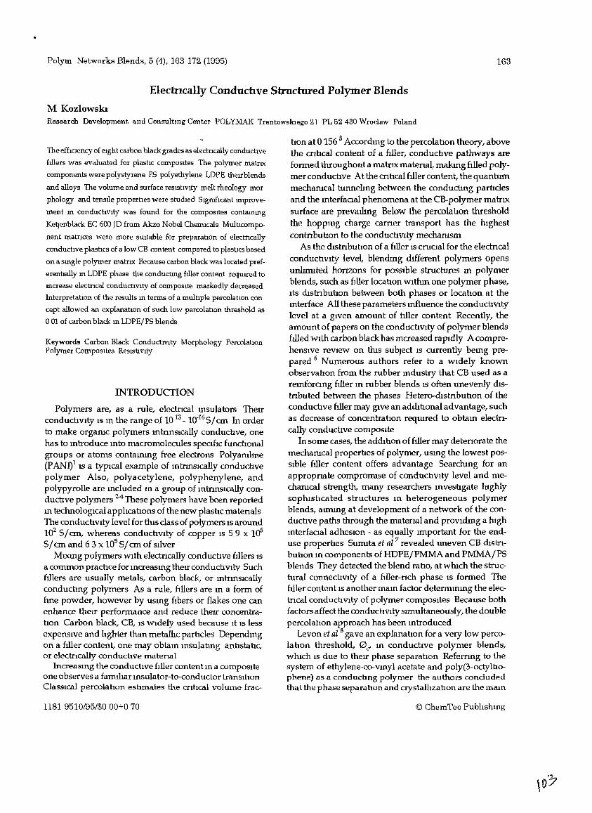
Polym Networks Blends, 5 (4), 163 172 (1995)
ElectrIcally Conduchve Structured Polymer Blends
M KozlowskIResearch Development and Consultmg Center POLYMAK TrentowskIego 21 PL 52430 Wroclaw Poland
163
The effICIency of eIght carbon black grades as electrIcally conductIve
fillers was evaluated for plastIc compOSItes The polymer matrIX
components were polystyrene PS polyethylene LDPE therrblends
and alloys The volume and surface reSIstIVIty melt rheology mor
phology and tensue propertles were studIed 5IgrufIcant Improve
ment m conductIVity was found for the compOSItes contammg
Ket:Jenblack EC 600 JD from Akzo Nobel ChemIcals MultIcompo
nent matnces were more SUitable for preparatIon of electncally
conductIve plastIcs of a low CB content compared to plastIes based
on a smgle polymer matrIX Because carbon black was located pref
erentIally m LDPE phase the conductmg filler content requrred to
mcrease electncal conductIVIty of compOSIte markedly decreased
Interpretatlon of the results m terms of a mulhple percolatIon con
cept allowed an explanatIon of such low percolatlon threshold as
001 of carbon black ill LDPEjPS blends
Keywords Carbon Black ConductiVIty Morphology PercolatIonPolymer CompOSItes ReSIstiVIty
INTRODUCTION
Polymers are, as a rule, electrIcal msulators TheIrconduchvlty IS m the range of 10 13 - mo16 5I em In orderto make orgaruc polymers mmnslcally conducbve, onehas to mtroduce mto macromolecules speoflc funcbonalgroups or atoms contammg free electrons Polyamlme(PAN!)1 IS a typIcal example of mmnsically conduchvepolymer Also, polyacetylene, polvphenylene, andpolypyrolle are mduded m a group of mmnslcally conduchve polymers 2-4 These polymers have been reportedm technologICal apphcahons of the new plashc matenalsThe conduchVlty level for thIs class of polymers IS around102 51em, whereas conduchvlty of copper IS 59 X 10551em and 6 3 x 10⁵ 51cm of SlIver
M.txmg polymers WIth electncally conduchve fIllers ISa common prachce for mcreasmg therr conductIVIty Suchflliers are usually metals, carbon black, or mmnsicallyconductmg polymers As a rule, ti.llers are m a fonn offme powder, however by usmg fIbers or flakes one canenhance therr perfonnance and reduce therr concentration Carbon black, CB, IS WIdely used because It IS lessexpenSIve and lIghter than metallIc parhdes Dependmgon a filler content, one may obtam msulatmg anhstahc,or electrIcally conductIve materIal
IncreaSIng the conduchve filler cantent m a composlteone observes a famIlIar Insulator-to-conductor tranSItIonClaSSIcal percolatIon estImates the cntIcal volume frac-
1181 9510/95/$0 00+0 70
han at 0156 5 Accordmg to the percolahon theory, abovethe cnucal content of a fIller, conducbve pathways arefonned throughout a matrIX matenal, makmg fIlled polymer conduchve At the crlhcal fIller content, the quantummecharucal tunnelIng between the conductmg parbclesand the mterfaoal phenomena at the CB-polymer matrIXsurface are prevathng Below the percolahon thresholdthe hoppmg charge carner transport has the mghestcontnbutIon to the conductIVIty mecharusm
As the dIstnbuhon of a filler IS cructal for the elecmcalconduchvlty level, blendmg dIfferent polymers opensunhmIted honzons for pOSSIble struchlres m polymerblends, such as filler locahon WIthIn one polymer phase,ItS dIstnbuhon between both phases or locahon at themterface All these parameters mfluence the conduchVltylevel at a gIven amount of tiller content Recently, theamount of papers on the conduchvlty of polymer blendsfllied WIth carbon black has mcreased rapIdly A comprehenSIve reVIew on thIs subject IS currently bemg prepared 6 Numerous authors refer to a WIdely knownobservatIon from the rubber mdustry that CB used as aremforong filler m rubber blends IS often unevenly dIStrIbuted between the phases Hetero-dIstnbuhon of theconduchve filler may gIVe an addItIonal advantage, suchas decrease of concentratIon reqUIred to obtam electrIcally conductIve compOSIte
In some cases, the addItIon of filler may detenorate themecharucal propertIes of polymer, usmg the lowest posSIble filler content offers advantage Searchtng for anappropnate comproffilse of conductIVIty level and mecharucal strength, many researchers mvesbgate hIghlysophIstIcated structures m heterogeneous polymerblends, alffilllg at development of a network of the conductive paths through the matenal and provldmg a highmterfacial adheSIOn - as equally Important for the enduse properhes SUffilta et al 7 revealed uneven CB dIStnbubon m components of HDPE/PMMA and PMMAjP5blends They detected the blend raho, at wmch the structural connectIVIty of a filler-nch phase IS fonned TheWIer content IS another mam factor detenrunmg the electncal conductIVIty of polymer compOSItes Because bothfactors affect the conductIVIty sImultaneously, the doublepercolatIon approach has been mtroduced
Levan et al 8 gave an explanatIon for a very low percolatIon threshold, 0c' m conduchve polymer blends,whIch IS due to theIr phase separatIon Referrmg to thesystem of ethylene-co-vmyl acetate and poly(3-octylbophene) as a conducbng polymer the authors concludedthat the phase separatIon and crystallIzatIon are the mam
© ChemTec Publtshmg
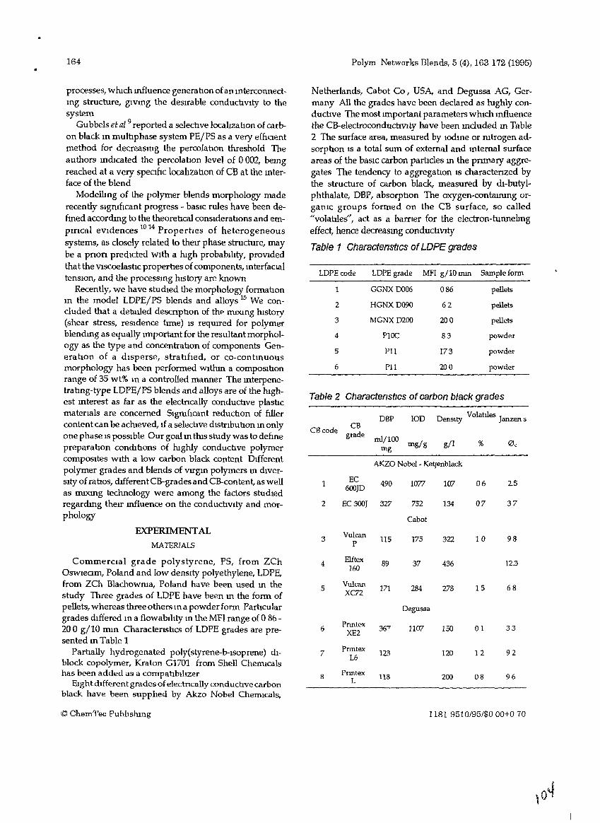
164 Polym Networks Blends, 5 (4), 163 172 (1995)
Table 2 CharactenstIcs of carbon black grades
LDPE code LDPEgrade MFI g/lOnun Sample form
1 GGNXD006 086 pellets
2 HGNXD090 62 pellets
3 MGNXD200 200 pellets
4 PIOC 83 powder
5 Pll 173 powder
6 Pll 200 powder
Degussa
6Pnntex 36'7 1107 ISO 01 33
XE2
7Prmtex 123 120 12 92
L6
8Prmtex
118 200 08 96L
1181 9510/95/$000+070
Netherlands, Cabot Co, USA, and Degussa AG, Germany All the grades have been declared as lughly conductIve The most Important parameters whIch Influencethe CB-electroconducuVlty have been mcluded m Table2 The surface area, measured by Iodme or mtrogen adsorption IS a total sum of external and mternal surfaceareas of the baSIC carbon paruc1es m the pnmary aggregates The tendency to aggregauon 15 charactenzed bythe structure of carbon black, measured by dl-butylphthalate, DBP, absorptIon The oxygen-contalIUng orgamc groups formed on the CB surface, so called"volahles", act as a barner for the electron-tunnehngeffect, hence decreasmg conducuV1ty
Table 1 Characteristics of LOPE grades
25
98
68
37
12.3
%
06
07
10
15
gil
278
107
436
322
134
D Volahles Jensity anzen sDBP laD
mljl00 mg/gmg
AKZO Nobel- Keqenblack
1 EC 490 1077600JD
2 EC 300T 327 752
Cabot
3Vulcan
115 175P
4Elftex 89 37160
5Vulcan 171 284xcn
CBCBcode grade
EXPERIMENTAL
MATERIALS
CommerCial grade polystyrene, PS, from ZChOswieam, Poland and low denSIty polyethylene, LDPE,from ZCh Blachowma, Poland have been used m thestudy Three grades of LDPE have been m the form ofpellets, whereas three others In a powder form PartIculargrades dIffered In a flowabIhty In the MFI range of 0 86 200 gllO rom Charactensucs of LDPE grades are presented m Table 1
PartIally hydrogenated poly(styrene-b-lsoprene) dIblock copolymer, Kraton G1701 from Shell ChemIcalshas been added as a compatIblhzer
EIght dIfferent grades ofelectncally conductive carbonblack have been supphed by Akzo Nobel ChemIcals,
processes, wluch mfluence generatIon ofan mterconnectmg structure, glYmg the desIrable conductIvIty to thesystem
Gubbels et aZ 9 reported a selectIve locahzahon of carbon black m multIphase system PEIPS as a very efftCIentmethod for decreasmg the percolatIon threshold Theauthors mdicated the percolatIon level of 0002, bemgreached at a very spectftc locahzahon of CB at the mterface of the blend
Modelling of the polymer blends morphology maderecently sigruft.cant progress - basIc rules have been defmed accordmg to the theoreucal conSIderatIons and empIneal eVIdences 10 14 PropertIes of heterogeneoussystems, as closely related to theIr phase struct1tre, maybe a pnon predIcted WIth a lugh probabIhty, proVldedthat the ViscoelastIc propertIes of components, mterfaClaltenSIOn, and the processmg lustory are known
Recently, we have studIed the morphology formahonm the model LDPE/PS blends and alloys 15 We concluded that a detailed descnptIon of thp nUXIng htstory(shear stress, reSIdence hme) IS requrred for polymerblendmg as equally Important for the resultant morphology as the type and concentrahon of components GeneratIon of a dIsperse, stratifIed, or co-contInuousmorphology has been performed Withm a composihonrange of 35 wt% In a controlled manner The mterpenetratmg-type LDPE/PS blends and alloys are of the htghest mterest as far as the electncally conducuve plasllcmatenals are concerned SignIftcant reductIon of ftllercontent can be aclueved, If a selecuve dIstnbuhon m onlyone phase IS pOSSIble Our goal m thts study was to deftnepreparatIon condluons of lughly conducuve polymercompOSItes WIth a low carbon black content DIfferentpolymer grades and blends of vrrgm polymers m dIverSIty of ratIos, duferentCB-grades and CB-content,aswellas IIUXmg technology were among the factors studIedregardmg therr mfluence on the conductIVlty and morphology
© ChemTec Pubhshmg
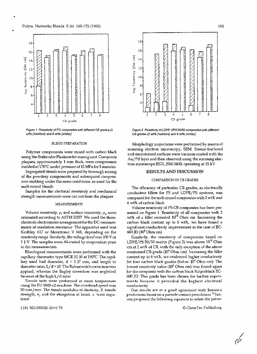
.. Polym Networks Blends 5 (4) 163-172 (1995) 165
18
16~
~ l4 f cCJZ; cl% r=
E 14 ~'"'~2 12~?c~-- 10
Vl
~Vi..;
.<: 8 . '-
-".9
6
4
2 3 4 5
CB grade
6 7 8
18
16
E 14-'"'E2- 12?c~ 10Vi:;;" 8OJ)0-J
6
{
2 3 4- ::>
ell grade
8
Figure 1 Res/stNity ofPS composites with different CB grades (2wt"A> (hatched) and 6 wt% (white))
BLEND PREPARAnON
Polymer components were mIXed wIth carbon blackusmg the Brabender PlastIcordermIXIng urnt ComposIteplaques, approxlffiately 1 mm thIck, were compresslOnmolded at 170°C under pressure of 12 MFa for 5 mIDutes
Segregated blends were prepared by thorough ffilXffigof the powdery components and subsequent compresSlOn moldmg under the same condlhons as used for themelt-mIXed blends
Samples for the electncal reslshvlly and mecharucalstrength measurements were cut out from the plaques
MEASUREMENTS
Volume resIstIvIty, p, and surface resIstIVIty, p... wereeshmated accordmg to ASTM D257 We used the threeelectrode electrometer arrangement for the DC-measurements of msulatIon resIstance The apparatus used wasKeIthley 617 or Meratroruc V 641, dependmg on theresIstIvIty range Smularly, the voltage level was 100 Vor1 1 V The samples were AI-coated by evaporatIon pnorto the measurements
RheologIcal measurements were performed WIth thecapIllary rheometer type MCR 32 10 at 190°C The capIllary used had dIameter, d = 1 27 mm, and length todiameter ratIo, L/ d = 40 The Rabmowltch correctIon wasapphed, whereas the Bagley correctIon was neglectedbecause of the hIgh L/d ratIo
TensIle tests were performed at room temperatureusmg the FU 1000 eZ machine The crosshead speed was50 mm/mm The tenSIle modulus of elastICIty, E tensIlestrength, crr and the elongation at break E were regIStered
1181 9510/95/$000+070
Figure 2 Res/stNity ofLDPE 11PS 50150 composites With differentCB grades (2 wt"A> (hatched) and 6 wt"A> (white))
Morphology InspectIons were performed by means ofscanrung electron ffilcroscopy, SEM Freeze-fracturedand ffilcrotomed surfaces were vacuum-coated WIth theAu/Pd layer and then observed usmg the scaruung electron ffilcroscope JEOL JSM-5400, operahng at 15 kV
RESULTS AND DISCUSSION
COMPARISON OF CB GRADES
The effIClency of partIcular CB grades, as electncallyconductIve ftllers for PS and LDPE/PS systems, wascompared for the melt-ffilxed compOSItes WIth 2 wt% and6 wt% of carbon black
Volume reSIstIVIty of PS-CB compOSItes has been presented on FIgure 1 ReSIstIVIty of all compOSItes With 2wt% of a filler exceeded 1015 Ohm em Increasmg thecarbon black content up to 6 wt%, we have found aslgruftcant conductIVIty Improvement m the case of EC600 JD (108 Ohm em)
SImtlarly, the reSIstIVIty of compOSItes based onLDPE/PS 50/50 matrIX (FIgure 2) was above 1015 Ohmem at 2 wt% of CB, WIth the only exceptIon of the abovementIoned CB--grade (lOb Ohm em) Increasmg the ftllercontent up to 6 wt%, we eVIdenced hIgher conductIVItyfor four carbon black grades (below 104 Ohm cm) Thelowest reSIstIVIty value (10) Ohm cm) was found agamfor the compOSIte WIth the carbon black Kegenblack EC600 JD ThIS grade has been chosen for further expenments because It prOVIded the hIghest electrIcalconductIVIty
Our results are 10 a good agreement WIth Janzen spredIctIons based on a partIcle contact percolatIon It'Janzen proposed the follow1Og equahon to relate the perco-
© ChemTec Pubh&hmg
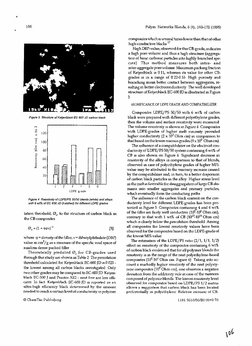
•
166
FIgure 3 Structure ofKef]enblack EC 600 JD carbon black
N
0J20
"E 100u
E2- 80~
5 60'"Vi~c.: 40
20
LOPE grade
Figure 4 ResIstIVIty of LDPEIPS 50150 blends (WhIte) and alloyswith 6 wt"Ai ofEC 600 JD (hatched) for different LDPE grades
labon threshold, 0", to the structure of carbon black mthe CB-composltes
(1]
where <p= densIty of the ftller, v = dlbutylphthalate (DBP)value m cm31g as a measure of the speClflc VOId space ofrandom dense packed fIller
TheoretIcally predIcted 0 c for CB-grades usedthrough tms study are shown In Table 2 The percolationthreshold calculated for Ke~enblackEC-600 JD IS 0 025 the lowest among all carbon blacks mvesbgated Onlytwo other grades may be compared to EC-600 JD Kel:Jenblack EC-300 J and Pnntex XE2 - next ftve are less effICIent In fact Kel:Jenblack EC-600 JD IS reported as anultra-mgh effIC1ency black determmed by the amountneeded to reach a certaIn level of conductiVIty In polymer
© ChemTec PublIshmg
Polym Networks Blends, 5 (4), 163-172 (1995)
composItes wmch IS several bmes lower than that ofothermgh-conducove blacks 17
HIgh DBP-value, observed for tms CB-grade, mdicatesa mgh pore volume and thus a mgh structure (aggregabon of baSIC carbaruc particles mta mghly branched speCIes) ThIS method measures both mtra- andmter-aggregate pore volume Maxnnum packmg fracoonof KetJenblack IS 0 11, whereas Its value for other CBgrades IS m a range of 0 22-0 33 HIgh porosIty andbranchmg mean better contact between aggregates, resultIng m better electroconducbvlty The well developedstructure of KeIJenblack EC-600 JD IS tllustrated m FIgure3
SIGNIFICANCE OF LOPE GRADE AND COMPATIBILIZER
ComposItes LDPE/PS 50/50 With 6 wt% of carbonblack were prepared WIth dIfferent polyethylene grades,then the volume and surface resIsovlty were measuredThe volume reSIStiVIty IS shown In FIgure 4 CompOSItesWIth LDPE-grades of hIgher melt VISCOSIty prOVIdedhIgher conduchvlty (2 x 1~ Ohm cm) In companson tothat based on the lower-VIscous grades (9 x 10³ Ohm em)
The mfluence of a compabblhzer on the electrIcal conduchvlty of LDPE/PS 50/50 system contammg 6 wt% ofCB IS also shown on FIgure 4 SlgrufIcant decrease mreslsbvlty of the alloys In companson to that of blends,observed m case of polyethylene grades of mgher MFIvalue may be attnbuted to the VISCOSIty mcrease causedby the compahblltzer and, In turn, to a better dlsperslOnof carbon black parbcles m the alloy HIgher stress levelm the melhs favorable for dlsaggregabon oflarge CB-domams mto smaller aggregates and pnmary parhcles,wmch eventually form the conduchng paths
The mfluence of the carbon black content on the conduchVlty level for dIfferent LDPE-grades has been presented m FIgure 5 CompOSItes contammg 4 and 6 wt%of the fdler are farrly well conducbve (1~-1<fOhm em),contrary to that WIth 1 wt% of CB (1013_1016 Ohm em)wmch IS clearly below the percolahon threshold Amongall compOSItes the lowest reslsbvlty values have beenobserved for the compOSItes based on the LOPE-grade ofthe lowest MFI-value
The estnnabon of the LDPEjPS raho (2/1, lit 112)effect on reSlShVlty ot the compOSItes contalmng 6 wt%of carbon black eVIdenced that for all polymer blends thereSistIVIty IS m the range of the neat polyethylene-basedcompOSItes (102-10" Ohm em FIgure 6) Takmg mto account a markedly hIgher resIsbVIty of the neat polystyrene compOSItes (108 Ohm em), one observes a negativedeVIatIon from the addIhvlty rule m case of the matrICescomposed of polymer blends The lowest reSIstIVIty levelobserved for compOSItes based on LDPE/PS 1/2 matrlXallows a suggestIOn that carbon black has been locatedpreferenttally In polyethylene Relative mcrease of CB-
1181 9510/95/$000+070
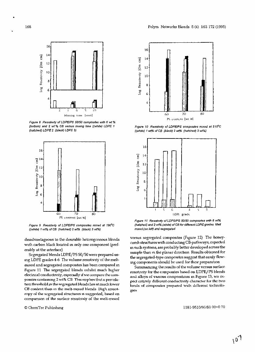
•
168 Polym Networks Blends 5 (4) 163 172 (1995)
p,> lonlcnl [wt l6]
Figure 10 ReSistIVIty of LDPEIPS composites mixed at 210°C(white) 1 wt"A; of CB (black) 2 wt"A; (hatched) 3 wt"A;}
1616
e 14u e 14
/
E 12u
2. E
02. 12
105 f- lOVl >:;:; 8
c;
'"Vl
0<: iii
Ol) '" 8
.3 60<:
Ol)0 6....l
44
MIXing tllm 11111111
Figure 8 ReSistiVity of LDPEIPS 50150 composites wIth 6 wt %(bottom) and 2 wt % CB versus mlxmg tIme (White) LOPE 1(hatched) LDPE 2 (black) LDPE 3)
~~~~::::
~"- r;::"-
~"-
"- :'.
60 70 80
6.-- .--
~
.-- ......
t7J (~ I~ .,., [l
1
e 14u
6 -I
I DPI grad..
Figure 11 ResistIVity of LDPSIPS 50150 composites With 6 wt"A;(hatched) and 2 wt"A; (whIte) of CB for different LDPE grades Meltmixed (on left) and segregated
E2. 12
oE 10
'"Vi~ 800
..3 6
6..-
4
r-
:;/
I~(j
J/
~
E 122.
f'1O>l:l
'"~ 8e::Ol)
.3 6
Figure 9 ReSistIVity of LDPEIPS composItes mixed at 190°C(white) 1 wt% of CB (hatched) 2 wt"A; (black) 3 wt"A;)
4
60 70 80PS lontent Iwt %)
dIsadvantageous to the desrrable heterogeneous blendsWIth carbon black located m only one component (preferably at the mterface)
Segregated blends LDPE/PS SO/50 were prepared usmg LDPE grades 4-6 The volume reslshvlty of the meltnuxed and segregated composItes has been compared mFIgure 11 The segregated blends exhIbIt much htgherelectncal conductivIty, especmlly Ifwe compare the compOSItes contammg 2 wt% CB ThJ.s lffiphes that a percolahan threshold m the segregated blends hes atmuch lowerCB content than m the melt-nuxed blends HIgh amsotropy of the segregated structures IS suggested, based oncomparlSon of the surface reslshVlty of the melt-ffilxed
© ChemTec Pubhshmg
versus segregated compOSItes (Ftgure 12) The honeycomb structures WIth conduchng CB-pathways, expectedm such systems, are probably better developed across thesample than m the planar duechon Results obtamed forthe segregated-type compOSItes suggest that eastly flowmg components should be used for therr preparahon
Summanzmg the results of the volume versus surfacereslshvlty for the compOSItes based on LDPEjPS blendsand alloys of vanous composlnons m FIgure 13, we expect ennrely dtfferent conduchVlty character for the twokmds of compOSItes prepared WIth dIfferent technologIes
1181.9510/95/$000+070
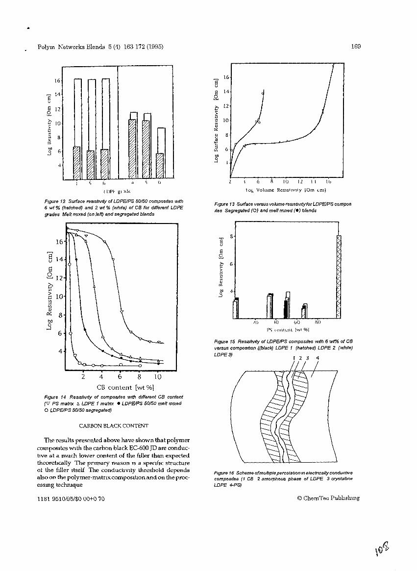
..
Polym Networks Blends 5 (4) 163 172 (1995) 169
16
e 14
u
e 12.9.
f- lO>Wl<?
Vi 8<U
c.::1>0
60-'
-+
~ h
1Dl'f gllLk
8'16
u
a 14.9.
0 125:;1l<? 10Vi<lJ0::
<U 8u~...:l 6'"1>0
.3
2 6 8 10 12 1\ lb
lol, Volume ReSIstIvity 10m Lm)
Figure 12 Surface resistiVity of LOPEIPS 50/50 composites with6 wt % (hatched) and 2 wt % (white) of CB for different LOPEgrades Melt mixed (on left) and segregated blends
Figure 13 Surface versus volume reslsftvltyforLOPEIPS composItes Segregated (0) and melt mixed (e) blends
Figure 16 Scheme ofmultiplepercolation In electrIcally conductIVecomposites (1 CB 2 amorphous phase of LDPE 3 crystallmeLOPE 4-PS)
/
4
so
I 2 3
10 bO
1'') <ontcnt IWI %1}()
8au
8.9.o 6
~VI
Vi<U
e:t:
1>0 4.3
Figure 15 ReslSftvlty ofLDPEIPS composrtes wrth 6 wt"AI of CBversus compostfton ((black) LOPE 1 (hatched) LOPE 2 (white)
LOPE 3)
CARBON BLACK CONTENT
2 4 6 8 10
CB content [wt %1Figure 14 ResistiVity of composItes With different CB content(V PS matrix I:!. LOPE 1 matrix e LOPEIPS 50150 melt mixedo LOPEIPS 50/50 segregated)
The results presented above have shown that polymercomposites With the carbon black EC-600 JD are conductive at a much lower content of the ftller than expectedtheoretically The pnmary reason is a speaftc structureot the WIer itself The conductivity threshold dependsalso on the polymer-matnx compOSition and on the processmg techmque
1181 9510/95/$000+070 © ChemTec Publlshmg
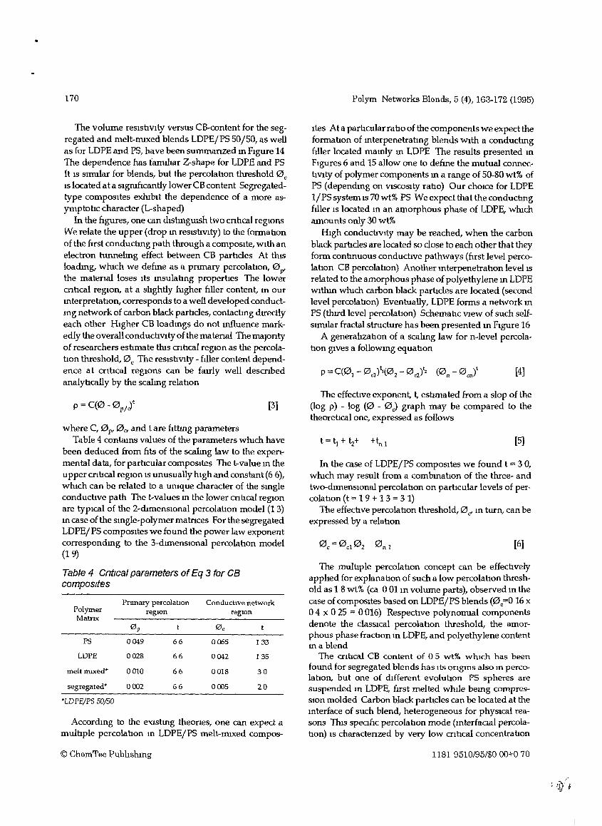
170 Polym Networks Blends, 5 (4), 163-172 (1995)
The effechve exponent, t, estImated from a slop of the(log p) - log (0 - 0.,) graph may be compared to thetheoretIcal one, expressed as follows
[5]
[6]
In the case of LDPEjPS compOSItes we found t = 3 0,wmch may result from a combmahon of the three- andtwa-dImenSIonal percolahon on parhcular levels of percolatIon (t = 1 9 + 1 3 = 3 1)
The effechve percolahon threshold, 0c' m turn, can beexpressed by a relahon
ltes At a parbcular rabo of the components we expect theformabon of mterpenetrabng blends WIth a conduchngfiller located mamly m LDPE The results presented mFIgures 6 and 15 allow one to define the mutual connechVlty of polymer components m a range of 50--80 wt% ofPS (dependmg on VISCOSIty rabo) Our chOIce for LOPEl/PSsystemis 70wt% PS Weexpectthattheconducnngftiler IS located m an amorphous phase of LOPE, wmchamounts only 30 wt%
HIgh conducbvlty may be reached, when the carbonblack parbcles are located so close to each other that theyform contmuous conduchve pathways (frrst level percalahon CB percolahon) Another mterpenetrahon level ISrelated to the amorphous phase of polyethylene m LOPEWithm wmch carbon black parhdes are located (secondlevel percolahon) Eventually, LOPE forms a network mPS (thrrd level percolahon) Schemabc View of such selfslffi11ar fractal structure has been presented m Figure 16
A generahzahon of a scalmg law for n-Ievel percolahon gIves a followmg equahan
The multIple percolatIon concept can be effecbvelyapphed for explanahon of such a low percolahon threshold as 1 8 wt% (ca 001 m volume parts), observed m thecase of compOSItes based on LOPEjPS blends (0c=0 16 x04 x 0 25 = 0016) RespectIve polynoffilal componentsdenote the claSSICal percolation threshold, the amorphous phase fraction m LDPE, and polyethylene contentma blend
The cnhcal CB content of 0 5 wt% wluch has beenfound for segregated blends has Its ongms also m perealaban, but one of dIfferent evolutIon PS spheres aresuspended m LDPE, frrst melted whl1e bemg compresSIon molded Carbon black particles can be located at themterface of such blend, heterogeneous for phySIcal reasons ThIS speCIfIC percolabon mode (mterfaaal percolabon) IS charactenzed by very low cntIcal concentrabon
[3]
where C, 0 p, 0 CT and tare fithng parametersTable 4 contams values of the parameters wmch have
been deduced from fits of the scalmg law to the expenmental data, forpartlcuiarcomposites The t-value m theupper cnbcal reglOn IS unusually hIgh and constant (66),wmch can be related to a uruque character of the smgleconduchve path The t-values m the lower cntlcal regiOnare typIcal of the 2-dImensl0nal percolahon model (1 3)m case of the smgle-polymermatnces For the segregatedLOPE/PS compOSItes we found the power law exponentcorrespondmg to the 3-dImenslOnal percolahon model(19)
The volume reslshvlty versus CB-content for the segregated and melt-ffilxed blends LOPE/PS 50/50, as wellas for LDPE and PS, have been summanzed m FIgure 14The dependence has fanuhar Z-shape for LDPE and PSIt IS slffillar for blends, but the percolahon threshold 0 cIS located ata slgmncantly 10werCB content Segregatedtype composItes exmblt the dependence of a more asymptohc character (L-shaped)
In the fIgures, one can dlstmgUlsh two cnbcal regIonsWe relate the upper (drop m reslSbvlty) to the formabonof the frrst conducnng path through a composIte, WIth anelectron tunnelmg effect between CB parhdes At thisloadmg, wmch we defme as a pnmary percolahon, 0p'the matenalloses ItS msulabng properhes The lowercnhcal regIon, at a shghtly mgher hIler content, m ourmterpretahon, corresponds to a well developed conductmg network of carbon black parhdes, contactmg drrectlyeach other HIgher CB loadmgs do not mfluence markedly the overall conduchVlty of the matenal The maJontyof researchers esbmate this cnhcal region as the percolahon threshold, 0 c The reslshVlty - hIler content dependence at CrItical regiOns can be fauly well descnbedanalyhcally by the scalmg relahon
Pnmary percolation Conduchve networkPolymer reglOn regIonMatrIX
0 p 0 0
PS 0049 66 0065 133
LOPE 0028 66 0042 135
meltmlXed* 0010 66 0018 30
segregated* 0002 66 0005 20
*LDPEjPS 50/50
Table 4 Cntrcal parameters ofEq 3 for CBcomposItes
Accordmg to the eXlstmg theones, one can expect amulhple percolahon m LDPE/PS melt-miXed compos-
© ChemTec Pubhshmg 1181 9510/95/$000+070
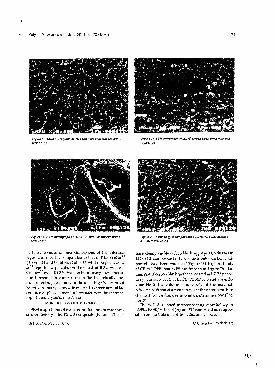
•
Polym Networks Blends 5 (4) 163 172 (1995)
FIgure 17 SEM mIcrograph ofPS carbon black composite with 6wf'/6 ofCa
FIgure 19 SEM mIcrograph ofLOPEIPS 50150 composIte wIth 6
wt% ofCa
of fIller, because ot rrucrodlmenSlOn1> of the mterfacelayer Our result IS comparable to that of Klason et aZ 20
(0 5 vol %) and Gubbels et a1 9 (0 -! wt %) Kryszewskl etal l1 reported a percolatIOn threshold of a2% whereasChapoy22 even a02% Such extraordmary low percolatIon threshold m companson to the theoretIcally predIcted value, one may obtam m hIghly onentedheterogeneous systems WIth molecular dImenSIons of theconductive phase ( metallIc' crystals, nematIc thermotropIC lIqUId crystals, mterfaces)
MORPHOLOGY OF THE COMPOSITES
SEM mspectIons allowed us for the straIght eVIdencesof morphology The PS-CB compOSIte (FIgure 17) con-
1181 9510/9'5/$000+070
171
FIgure 18 SEM micrograph ofLOPE carbon black composite with6wt% ca
FIgure 20 Morphology ofcompatlblllZed LOPEIPS 50150 composIte with 6 wf'Ai of CB
tams clearly VISIble carbon black aggregates, whereas mLDPE-CB compOSItes faIrly well dIstnbuted carbon blackpartIcles have been eVidenced (FIgure 18) Higher affmItyof CB to LDPE than to PS can be seen m FIgure 19 - themaJonty of carbon black has been located m LDPE phaseLarge domams of PS m LDPE/PS 50/50 blend are unfavourable to the volume conductIVity ot the matenalAfter the addItIon of a compahblhzer the phase structurechanged from a dIsperse mto mterpenetratIng one (FIgure 20)
The well developed mterconnectIng morphology mLDPE/PS 30/70 blend (Figure 21 ) confIrmed our suppoSItion on multIple percolatIon, dIscussed above
© ChemTec Pub1J.shmg
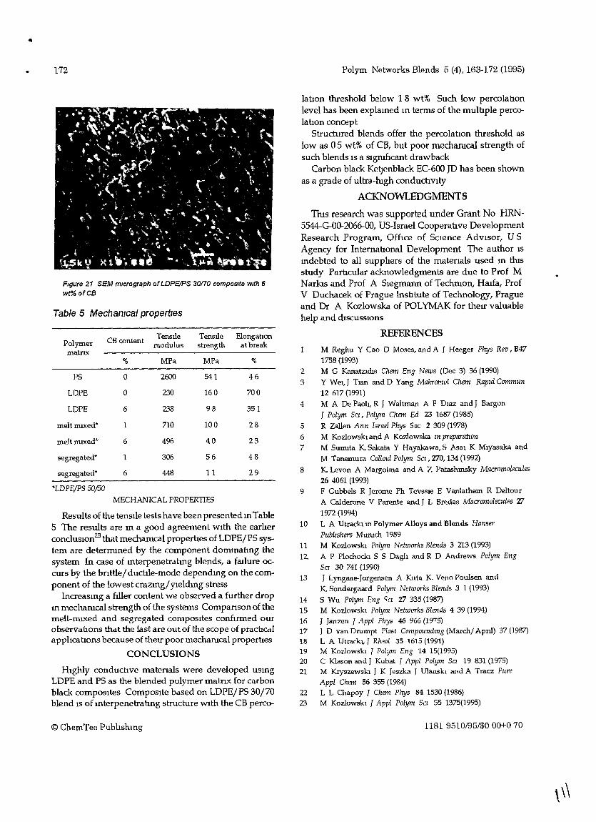
172
Figure 21 SEEM micrograph ofLDPEIPS 30170 composite with 6wt% ofca
Table 5 Mechamcal propertIes
CB c:ontentTensue Tensue ElongatIon
Polymer modulus strength at breakmatrIX
% MPa MPa %
PS a 2600 541 46
LDPE a 230 160 700
LDPE 6 238 98 351
melt mIXed' 1 710 100 28
melt mIXed' 6 496 40 23
segregated' 1 306 56 48
segregated' 6 448 11 29
*WPE/PS 50/50
MECHANICAL PROPERTIES
Results of the tenstle tests have been presented In Table5 The results are In a good agreement wIth the earherconduslOn23 that mechamcal properties of LDPE/PS system are detenmned by the component donunatlng thesystem In case of Interpenetrdtmg blends, a fallure occurs by the bnttle/ ductlle-mode dependIng on the component of the lowest crazIng/yIeldIng stress
IncreaSIng a fuler content we observed a further dropIn mechamcal strength of the systems Companson of themelt-nuxed and segregated composItes conflfmed ourobservahons that the last are out of the scope of prachCdIapphcations because of therr poor mechamcal properties
CONCLUSIONS
HIghly conductive matenals were developed usmgLDPE and PS as the blended polymer matnx for carbonblack compOSItes CompOSIte based on LDPE/PS 30/70blend IS of mterpenetrating structure WIth the CB perco-
© ChemTec Pubhshmg
Polym Networks Blends 5 (4), 163-172 (1995)
lation threshold below 1 8 wt% Such low percolationlevel has been explaIned m terms of the multiple percolation concept
Strucmred blends offer the percolation threshold aslow as 0 5 wt% of CB, but poor mecharucal strength ofsuch blends IS a slgmflcant drawback
Carbon black Kel:jenblack EC-600 JD has been shownas a grade of ultra-rugh conduchv1ty
ACKNOWLEDGMENTS
'I1us resparch was supported under Grant No HRN5544-G-OO-2066-00, US-Israel Cooperative DevelopmentResearch Program, OffIce of SCIence AdVIsor, USAgency for Internatlonal Development The author 1SIndebted to all supphers of the matenals used m tillsstudy Particular acknowledgments are due to Prof MNarkJ.s and Prof A SIegmann of Techmon, Haifa, ProfV Duchacek of Prague Institute of Technology, Pragueand Dr A Kozlowska of POLYMAK for thelf valuablehelp and dlscusslOns
REFERENCES
M Reghu Y Cao D Moses, and A J Heeger Phys Rev, 5471758 (1993)
2 M G Kanatzuhs Chern Eng News (Dec: 3) 36 (1990)
3 Y WeI,J TllU\ and D Yang Makromol Chern RapId Commun12 617 (1991)
4 M A De Paoh, R J WaltInan A F Dlaz and J BargonJ Polym SCI, Polym Chern Ed 23 1687 (1985)
5 R Zallen Ann Israel Phys Soc 2 309 (1978)
6 M KozlowskI and A Kozlowska In preparatIon7 M SumIta K Sakata Y Hayakawa, S Asal K Miyasaka and
M Tanemura COllOId Polym SCI, 270, 134 (1992)
8 K Levon A Margolma and A Z PatashInsky Macromolecules26 4061 (1993)
9 F Gubbels R Jerome Ph Tevssle E Vanlathem R DeltourA Calderone V Parente and J L Bredas Macromolecules 27
1972 (1994)10 L A Utracki ill Polymer Alloys and Blends Hanser
PublIshers Muruch 198911 M KozlowskI Polym Networks Blends 3 213 (1993)
12. A P Piochocki S S Dagh and R D Andrews Polym EngSet 30 741 (1990)
13 J Lyngaae-Jorgensen A Kuta K Veno Poulsen andK Sondergaard Polym Networks Blends 3 1 (1993)
14 S Wu Polym Eng 'le! 27 335 (1987)15 M KozlowskI Polym Networks Blends 4 39 (1994)
16 J Janzen J Appl Phys 46 966 (19'75)17 J D van Drumpt Plas! Compoundzng (Marchi Aprl1) 37 (1987)18 L A Utrackl, J Rheol 35 1615 (1991)19 M KozlowskI J Polym Eng 14 15(1995)20 C Klason and J Kubat J Appl Polyrn Set 19 831 (1975)21 M Kryszewski J K Jeszka J Ulanski and A Tracz Pure
Appl Chern 56 355 (1984)22 L L Chapoy J Chern Phys 84 1530 (1986)23 M KozlowskI J Appl Polym Set 55 1375(1995)
1181 9510/95/$0 00+070
26
c
•
Macromol 5ymp 108,261-268 (1996)
COMPARISON OF ELECTRlCALLY CONDUCTIVE FILLERS IN POLYMER
SYSTEMS
Marek KozlowskI and Anna Kozlowska
Research, Development and ConsultIng Center POLYMAK
Trentowsloego 21 PL 52430 Wroclaw Poland
Abstract A comparative evaluatIOn ofdifferent carbon black grades was
perfonned for oolymer composItes whose matnces were composed of a
smgle polymer or polymer blend. The electncal reSistIVity rheological
properties tensile strength and morphology were evaluated The hIghest
conductiVity level was measured for the composites Wlth Ket]enblacJ... EC
600 JD from Akzo Nobel
IN1RODUCTION
It has been known that polymers are as a rule electncal lOSulators A common prac\lce for
mcreasmg the conductiVIty of plastics IS blendmg of the orgaruc polymers \VIth electrlcalh
conductive fillers Widely used filler IS carbon black (CB) as much cheaper and hghter than
metalliC particles (Refs 1-4) Carbon black Itself IS a semi conductive matenal havlOg an
mtnnslc reSiStiVity of 0 01 0 I [n cm) CB IS avaIlable m a powder or pellets fonn rangIng
m size from 100 Jlm to a few mlhmeters The pellets are of luerarchlcal structure being
composed of the agglomerates (typically 10 - 100 JlID 10 size) which In turn contalU the
pnmary aggregates of a few mIcrometers diameter The aggregates COnsISt of carboOlC
particles (30 100 nanometer In Size) which are composed of a few thousand carbon
crystalhtes (Refs 5 6)
Dependmg on a filler content III a composite one obtalOS the msulatIllg antlstatlc or
electncally conductive matenals At particular CB level the famlhar msulator to conductor
transItIOn occurs A conductive network IS bemg formed from the pnmary aggregates The
clasSIcal percolatIon estImates a cnhcal volume fractlOn at 0156 (Ref 7) Howe\cr th<
producers of electncally conductive CB grades declare much lower percolatwn level abO\ L
wlueh the conductive pathways are fanned through a matm: polymer The Improved grades
offer tWlce as much effiCiency Tlus IS of great Importance because a high degree of loadIng
bnngs about detenoratton of the mechaOlcal properties and Increase In the melt V1SeOSIl\
IIf
;1
1
I
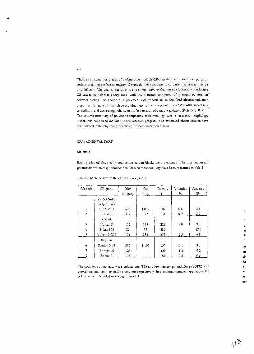
•
Thcft. C\.ISt numCfOus bndt.~ of carbo!\ bhcl which ddkr In thclr SILe ~lructure poroSity
surface area and surface chemistry Obvlouslv the conductiVity of particular grades may be
al,o dlf1uLlll ThL boal ot our ,tud\ "l~ 'I LOlllp'Ifatlve cvaluallon 01 electncally conductlvc
CB l,rades In pohmer composltcs wllh the matnces composed of a smgle polymer or·
pohmer blends The chOice of a polvmer IS of Importance to the final electroconductlve
propel1les In general the electroconducllvlty of a compound mcreases WIth mcreasmg•
Cf\StalllnJt] and decreasmg pol ant] or surface tension of a matnx polymer (Refs 5 6 8 9)
The volume reSlstl\ It] of pol) mer composites melt rheology tenstle tests and morphology
InSpeClions have been Included In the research program The estimated charactenstlcs have
been related to the phYSical properties of respective carbon blacks
EXPERIMENTAL PART
Matenals
Eight grades of electncally conducllve carbon blacl-s were evaluated The most Important
parameters which ma~ mfluence the CB electTOconduct!vlty have been presented ll\ Tab I
Tab 1 Charactensllcs ofthL carbon blacl.. brJdcs
CB code CB gradL 081' 100 Oenslt] VolJllles Jan7Cns
mIll 00, mIll. L/I % 0"
\h.ZO l\obcl
hetJenblack
1 EC 600JD 490 1077 107 06 25
2 EC 300J 327 752 134 07 37
Cabot
3 Vulcan P 115 175 322 10 98
4 Elfte>. 160 89 37 436 123
~ Vulc'ln XC72 171 284 278 15 68
Degussa
6 Pnnte\. XE2 367 I 107 150 01 33
7 Pnntc'X L6 123 120 12 92
8 Pnnte\.L 118 200 08 96
Thc polymer components \\ere polystyrene cPS) and low denSity polyethylene (LOPE) - anamorphous and semi cn stallIne pol~ mer respectively In a mult!component type matrlX the
pol\~ners "ere blended III a "eight ratio I 1
1
a
n
fc
P
or
de
M
pIof
of
car
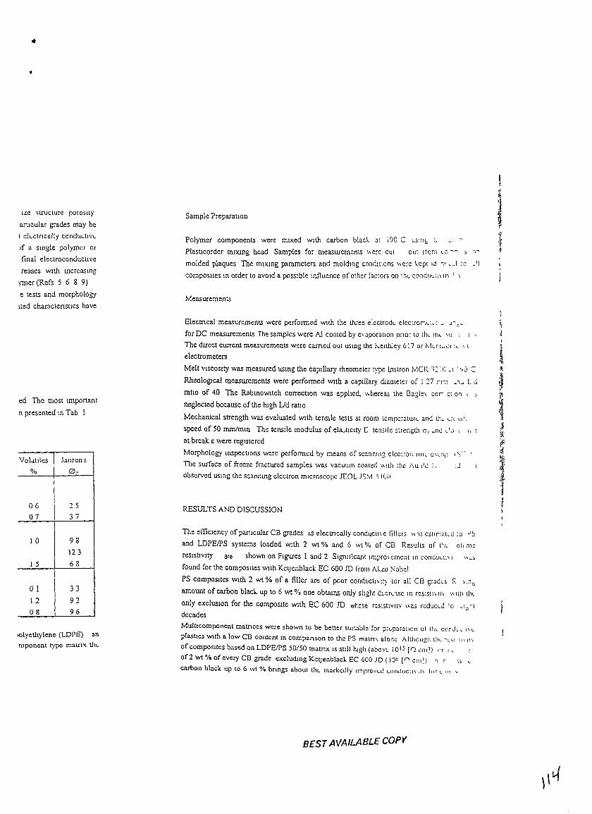
•
ILe ~tructure porosity
articular grades may be
t ckctfically cOllduLlivL
Jf a Single polymer or
final electroconductlve
reases WIth mcreaslng
yrner (Refs 5 6 8 9)
e tests and morphology
(ted charactenstlcs have
ed The most Important
n presented m Tab I
VolJ.llles Ja1l7cn s
% 0~
06 25
07 37
10 98123
1 5 68
o I 33
12 92
08 96
lQlyethylene (LDPE) anmponent type matrix th"
Sample Preparation
Polymer components were mixed WIth carbon blacl- at 190 C USlllb L ..
P[astlcorder mDung head Samples for measurements \cere cut out Irom e0 -" , '>"
molded plaques The mlxmg parameters and moldmg conditions \cere I-ept 10 '1' c_\ 10 _'I
composites In order to aVOId a possIble mfluence of other factors on thL condUcll\ It\ I \
Measurements
Electncal measurements were performed WIth the Wee electrodL clcctrorKl-r _ u .. ~-
for DC measurements The samples were AJ coated by e\ aporallon pnor to IhL ilK 'lJ I I'
The dueet current measurements were eamed oul uslog the h.elthley 617 or t-.!lr 1~0r I_ \ t
electrometers
Melt VISCOSity was measured usmg the capillary rheometer type !nstron MCR ,~[O _t 1'10 C
RheologIcal measurements were performed WIth a capillary dlametcr of I 27 r\11 _'1u L d
ratio of 40 The RabmoWltch correctIOn was applied, \\hereas thc Bagle\ cor- Cl 0'1 \ "
neglected because of the high Lid ratio
Mechanical strength was evaluated WIth tenslle tests at room tcmpcratuf" and th_ u, ,,'\
speed of 50 rom/mm The tenstle modulus of ela,tlclty [ tensIle strength cr r _nc.l L'O I Il 1
at break E were registered
Morphology mspeclions wcrc performcd by means of scanmng clcclroll nlle 0''-0,' ,"~ i
The surface of freeze fractured samples was vacuum coaled" jlh the I\U I'd I) IJ
observed uSing the scanmng clcctron microscope ICOL J<;M '; 1(,0
RESULTS AND DISCUSSION
The effiCiency of particular CB grades as elccmcally conductl\c tillers \\'IS cSlIr1at-d 10 ,):,
and LDPEIPS systems loaded WIth 2 wt % and 6 wt % of CB Results of t'll. 01\ m~
reSistiVIty are shown on Figures 1 and 2 Significant ImprO\CmClll In condUlll\ I ,,",
found for the composites WIth KetJenblack EC 600 ill from AI-LO Nobel
PS composItes WIth 2 wt % of a fitler are of poor conducll~ll) tor nil CB gradLs R '111~
amount of carbon black. up to 6 wt % one obtains only slIght dLcrL 'lSe In reSISlI\ It\ \\ lIb till.
only exclUSIOn for the composite WIth EC 600 ill whose reSIstivity \\as reducLd 'c _1=11
decades
Multlcomponent matnces were shown to be better SUitable for prLparallon 01 thl corJl _ 1\ lplastics Wlth a low CB content III companson to the PS matn, alone Although thL rl\l 11\ '1\
of composites based on LDPEIPS 50150 matnx IS sldl hJgh (abovL 10 1S ['2 cm]) nr I l
of2 wt % ofevery CB grade excludmg Keljenblael.. EC 600 JD (10" [n cm]) n n "lcarbon black up to 6 wt % bnngs about thL markedly Improved LnnduCl1\ 11\ I", L 111 ,
BEST AVAILABLE COpy
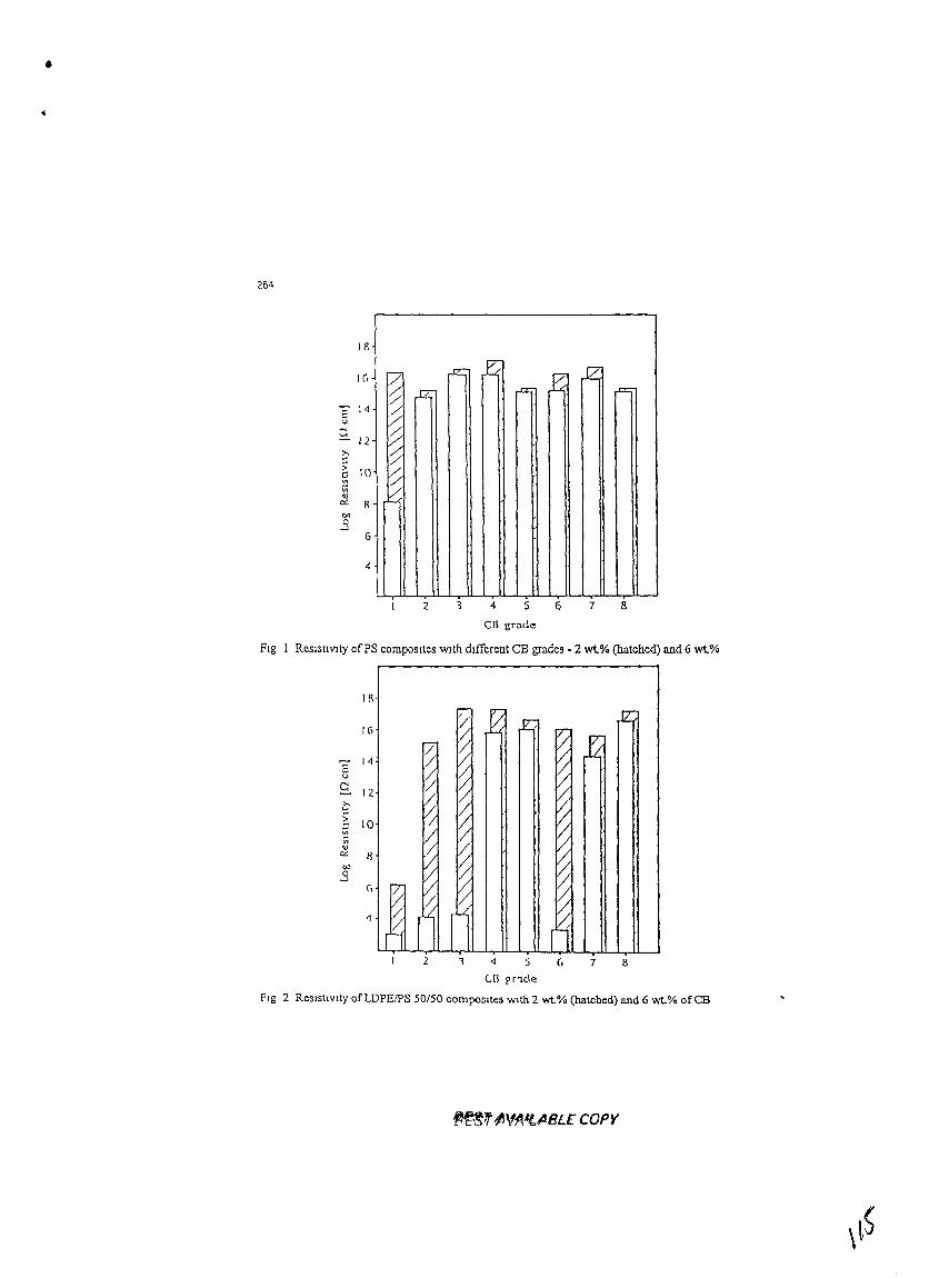
•
264
'7 ,JZ:;..t< ,e JZ:: ,.rz; .= ..=
1/~r::
) r:::::~
4
1/\
6
c;;c: I(
'"iii<J
or: Rt>Il
S
:: 14U
'""....12
2 4 5 6 7 8
en grade
Fig 1 ReslsuVlty ofPS composites With dtfferent CB grades· 2 wt% (hatched) and 6 wt%
1/\
16
E 14u
S. 12C:;-
100'"iii'"~ 8
""0..J
(,
1
2 i 4 5 G 7 1\Cll !,nde
Fig 2 ReSIStIVIty ofLDPEIPS 50150 composites Wlth 2 wt% (hatched) and 6 wt.% ofca
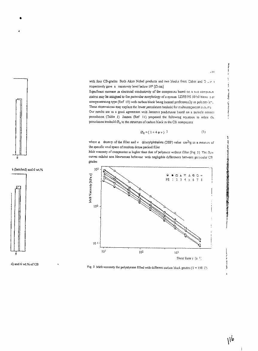
•
JI1
With four CB-grades Both Akzo Nobel products and two blacks from Cabot and l) _ J~ 1
respectively gave a resistivity level below 104 (n cm}
Sigruficant Increase UI electncal conductivity of the composites based on a 1\\ 0 com;xJn~n
matnx may be asSIgned to the parncular morphology of a system LDPEipS 50 /)0 blend S 01interpenetrating type (Ref !O) Wlth carbon black bemg located preferentially In po/) elm Icn~
These observations may explam the lower percolation treshold for multlcomponent sist~ms
Our results are ill a good agreement Wlth Janzen s predJctlons based on a particle contact
percolatIOn (Table 1) Janzen (Ref II) proposed the followmg equatIOn to relate the
percolatlon treshold 0 c to the structure ofcarbon black lD the CB compoSites
0 c =( 1 + 4 q> v) 1 (1)
8
where q> density of the filler and v dJbutylphthalate (DBP) value cm3/g as a measur~ of
the specific vOld space of random dense packed filler
Melt VISCOSity of composites IS hIgher than that of polymers Wlthout filler (F1l; 3) Thc flo\;
curves exlllbit non Newtoruan behavIOr Wlth negligible differences between particular CB
grades
IOJ
Shear Rate y [s I J
10210 1
10 I
101
~ 0 a 0 ,l. 'V 6- 00..,...'" PS 1 2 3 4 6 7 S:g, )
~0u!!I>~
~10°
lIIJ
8
'0 (hatched) and 6 wt%
d) and 6 wt% ofCBFig 3 Melt VISCOSity for polystyrene filled Wlth dIfferent carbon black. grades (T = 190 C)
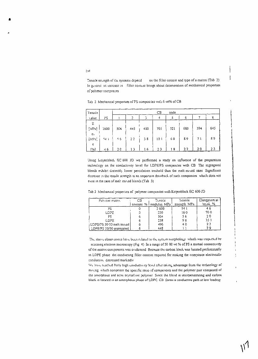
•If
206
Tensile stre.-ngth of tht.. systems depend on the filler content and type of a matnx (Tab 2)
In gLneral an Increase In fillcr conte.-nt bnngs about detenoratlon of mechamcal properties
of polymer composlles
Tab 2 Mechamcal propemes ofPS compoSItes With 6 wt% ofCB
Tensile CB code
\ alue PS I 2 3 4 5 6 7 8
E
[lvfPa] 2600 504 445 480 705 521 680 594 645
Or
[Ml'a] "4\ " 6 22 38 101 60 89 7 I 89
€
I[%1 46 20 1 3 16 23 I 8 22 20 23
USlDg hetJenblad. EC 600 JD we performed a study on tnfluence of the preparatIOn
technology on the conductiVity level for LDPEIPS composites With CB The segregated
blends e-Jublt distinctly lower percolatlon treshold than the melt mn.ed ones Sigruficant
decrease In the tensile strength IS an Important drawback of such composttes which does not
e\.lst In the case of melt ml\.ed blends (Tab 3)
Tab 3 Mechanical properties of polymer composites Wlth KetJenblack EC 60010
1'011 mer matn, cn Tt..nsde 1 ensile elongatIOn atcontent % modulus MPa strength lvfPa brt..ak %
PS 0 2600 54 I 46LOPE 0 230 160 700
PS 6 50-1 56 20LOPE 6 238 98 35 1
LDPEIPS 50'50 melt ml>.ed 6 -196 40 23LDPErpS 50/50 sel!regated 6 448 11 29
ThL abo\ L obsen allons ha\ t.. bt..t..1\ rLlalt..d to tht.. ~) St<..111 1110rphoiobY which was mspt..clt..d by
scaruung electron microscopy (Fig 4) In a range of 5080 WI % ofPS a mutual connectivity
of the matm: components was eVidenced Because the carbon black was located preferentially
10 LDPE phase the conductlng filler content required for making the composite electncallv
conducuvt.. decreased markedly
W<.. hl\<" rt..acht..d fllrly high t..onduC11\ Ity lcv<..l aftt..r taklIlb advantage from the technology of
ml\.lOg \~hlch compnses the speCific ratio of components and the polymer pUlr composed of
the amorphous and semi crystalline polymer Since the blend IS IIlterpenetratmg and carbon
blad.. IS located m an amorphous phase ofLDPC CB forms a conducllve path at low loadmg
I
\I
I
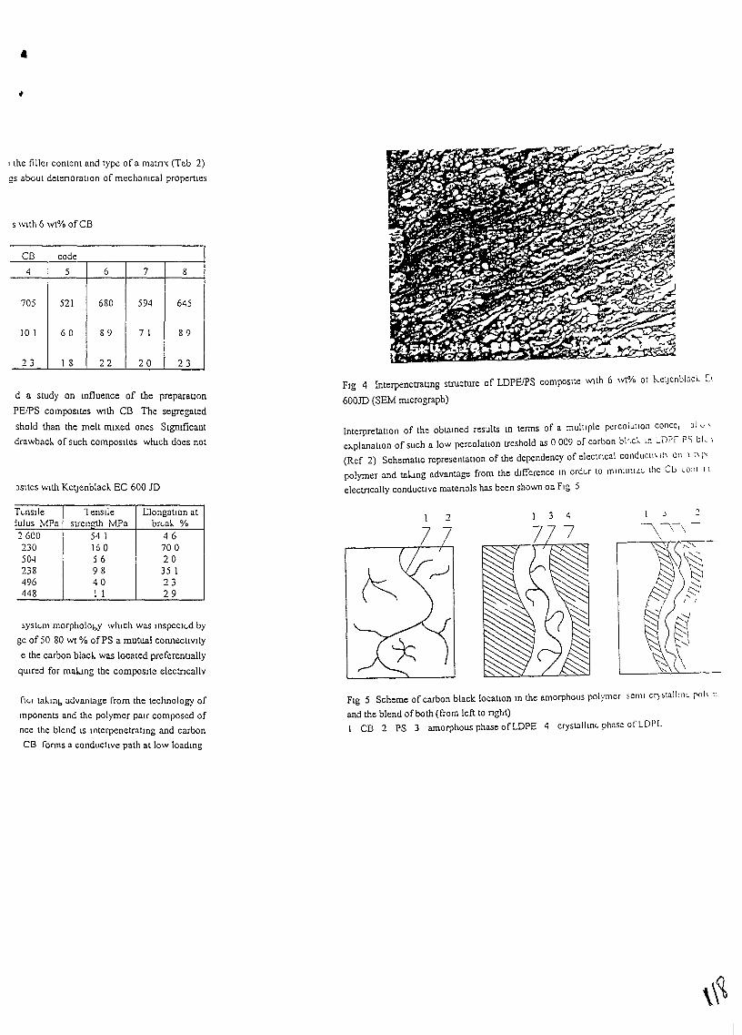
•
I the filler conlent and type of a matm: (Tab 2)
gs about detenoratlon of mechanIcal properties
s with 6 wt% ofCS
CB code
4 5 6 7 8
705 521 680 594 645
101 60 89 71 89
23 18 22 20 23
d n study on mfluence of the preparatIOn
PEIPS composItes with CS The segregated
shold than the melt mIxed ones Slgruficant
drawbad. of such composItes wruch does not
)Sltes Wlth Ketjenblacl EC 600 JD
FIg 4 Interpenetratmg structure of LDPEIPS composite With 6 \Vl% ot hetJcnblach [I
600lD (SEM nucrograpb)
Interpretation of the obtaIned results In terms of a multiple pcrcol"tlon concc, 31 v ,
explanatIOn of such a low percolatIon treshold as 0009 of carbon bhch In LOP, PS hie 1
(Ref 2) Schematic representatIon of the dependency of electncal conducll\ It\ 011 1 I\~""
polymer and taLmg advantage from the difference In order lO mlnJl11lL~ the Cb Lonl I I
eleetncally conductIve matenals has been shown OD FIg 5
T<.nsJle 1enslle elongatIon atJuJus MPa strength MFa br<.ak. %2600 54 1 46230 160 70050-1 56 20238 98 35 1496 40 23448 II 29
~yst<.m morpholobY WlllCh was Inspect<.d by
ge of 50 80 Wi % ofPS a mutual connectIVIty
e the carbon blacl was located preferentially
qUlred for malJng the composite electncallv
3 4
I~
t§t:::,1
::::.:-I I
ft~r tak.mb advantage [rom the technology o[
mponents and the polymer patr composed of
nee the blend IS Interpenetrating and carbon
CB [onns a conducttve palh at low loadIng
FIg 5 Scheme of carbon black location In the amorphous polymer semi er)stalltn~ [Xlh 11
and the blend of both (from left to nght)I CB 2 PS 3 amorphous phase ofLDPE 4 erystalltn<. phase of LDI'L
•
268
CONCLUSIONS
KelJenblack EC 600 JD IS a carbon black extremely sUitable for electroconducuve
applications In polymer systems
Elecmcal behavIOr of electroconductlve carbon blacks IS directly related to their physical
propertlcs e g surfacc area structure and to the surface chemiStry
MultlcomponcnI heterogeneous polymer matnces may form particular morphology bemg
highly sUitable for conductive composites
~CKNOWLEDGEMENTS
TIus research was supported under Grant No HRN-5544-G-OO-2066 00 US-Israel
Cooperative Development Research Program Office of SCience AdVisor US Agency for
International Development
REFERENCES
1 J Yacubovlch, M Narlus L Bengulgut Polym Eng SCI 30 459 (1990)
2 M Kozlowsl..l Polym Networks Blends S 163 (1995)
3 M Sumlta k Sakata, S Asal K Miyasaka H. Nakagawa, Polym Bull 2S 265 (1991)
4 K H MobiUS Kunststolfe 78 53 (1988)
5 Tecnnzcal Bulletrn on Polymer AdditiVes Keljenb/ack EC AKZO Chemicals (1992)
6 J D van Drump!, Plasl Compoundmg (March/Apnl) 37 (1987)
7 R ZaBen Ann Israel Phys Soc 2 309 (1978)
8 k Mnasal..a K Watanabe E JOJlma, H AIda, M Surnlla and K Islukawa J Mater
SCI 17 1610 (1982)
9 F Carmona Proc of the Second International Conference on Carbon Black, Mulhouse
27 30 Sepl 1993 213 (1993)
10 M KozlowskI J Polym Eng 14 15 (1995)
11 J Janzen J Appl Ph)s 46 966 (1975)
rI
,
J.
,


