Embed Size (px)
Citation preview

1
FLUID COMPONENTS, INC.

2
FLUID COMPONENTS, INC.
PRODUCT INDEX
GAGES - Section 1 Page 4
1½” to 2½” Dry Utility Pressure Gages1½” to 2½” Glycerine Filled Pressure Gages4” S.S. Case Glycerine Filled Pressure Gages 2½” to 6” All Stainless Steel Pressure Gages6” All Stainless Steel Test GagesGage Protection & Snubbers
5-67-8
9-1011-12
1314
TEST POINTS & HOSE ASSEMBLIES - Section 2 Page 15
Test Point Plugs and ProbesJIC Hose CouplingsHydra-Test Flexible Hose AssembliesHydra-Test End Fittings
16-17181819
Dynamic Fluid Components, Inc. present their range of products for the hydraulic, pneumatic, process, petro chemical and other allied industries.
Products detailed in this catalog include pressure, vacuum and compound gages, test instruments, test points and probes, valves and hydraulic reservoir accessories.
The Dynamic Fluid Components warehouses, located in West Union, SC and Ceres, CA, offer most of the catalog products from stock. Their extensive network of distributors and representatives are ready to serve you.
For immediate attention please call:
TOLL FREE 1-800-988-1276 TELEPHONE 1-864-638-5544 FAX 1-864-638-0005 EMAIL [email protected] ADDRESS http://www.dynamicfc.com

3
FLUID COMPONENTS, INC.
HYDRAULIC VALVES - Section 3 Page 20
2 and 3-Way High Pressure Ball ValvesLocking Handle KitsCarbon Steel Check ValvesFlow Control ValvesNeedle ValvesHigh Pressure Needle Valves
21-222324
25-2627-28
29
PRODUCT INDEX
RESERVOIR ACCESSORIES - Section 4 Page 30
Screw on BreathersFilter Filler Breathers
3132
Dynamic Fluid Components, Inc.P.O. Box 100 • 2810 Blue Ridge Blvd • West Union, South Carolina 29696 • 1-864-638-5544

4
FLUID COMPONENTS, INC. Section 1
General Specifi cations for Standard Pressure GagesThe maximum working pressures of standard gages should not exceed 75% of full scale for constant pressure applica-tions, or 66% of full scale for pulsating pressures.
Normal overpressures allowed are 1.25 times FSV for ranges up to 1,000 psi; 1.15 times FSV for ranges between 1,000 and 10,000 psi; 1.10 times FSV for higher pressures.
Glycerine is used as standard in most Dynamic fi lled gages.
Neither glycerine nor silicone should be used in applications involving oxygen, chlorine, nitric acid, hy-drogen peroxide or other oxidizing agents.
Dynamic fi lled gages include a dual relief valve/blowout disc for operating safety.
Dial face includes black (psi) and red (bar) scales or black (psi) and red (kPa) scales.
Table of ContentsProductSeries CDS Dry Gages.......................................................................................................... 5-6Series CF Filled Gages ......................................................................................................... 7-8Series PDLC Filled Low Cost Gages..................................................................................... 9Series CF 4 Inch Filled Gages............................................................................................... 10Series PDSS Stainless Steel Gages ..................................................................................... 11-12Series PDTG Test Gages ...................................................................................................... 13Gauge Protection & Snubbers ............................................................................................... 14
Page No.
PRESSURE GAGES

5
FLUID COMPONENTS, INC. 1 ½ to 4 Inch
• Steel Case - CDS Series• Phospher Bronze Bourdon Tube• Vacuum to 10,000 PSI Range • Dual Scale PSI & BAR (KPA referenced)• Accuracy ± 1.6% FSD• Temperature Range -40º to 180º F• Built in Snubber• Bronze Connection
INSTALLATION DATA
Ordering Example: CDS - 1 P - 140 A
ModelCDS dry
steel case
Size*4 - 1 ½” dia. 5 - 2” dia. 1 - 2 ½ “ dia.
TypeP - PressureV - Vacuum C - Compound
Range002 - 30”Hg - 30 psi000 - 30”Hg - 0 psi001 - 15 psi002 - 30 psi004 - 60 psi007 - 100 psi010 - 160 psi015 - 200 psi020 - 300 psi040 - 600 psi
070 - 1000 psi100 - 1500 psi140 - 2000 psi210 - 3000 psi280 - 4000 psi350 - 5000 psi420 - 6000 psi700 - 10,000 psi
StyleA - stemD - ctr. back
*Note: 1 ½ inch dia. limited to 5000 psi
Port Sizes 1 ½”.....1/8 npt standard 2 - 2 ½”.....1/4 npt standard
1/8 npt avail. w/min. order add -8N to end of part no.
CDS Dry Gages
Stem & Center Back Mount
Certain sizes and pressure ranges may be subject to minimum order quantity
Size A B C D E1 1/2 1.62 .90 2.26 1.50 .95
2 2.00 1.08 2.81 1.80 1.062 1/2 2.45 1.05 3.22 1.75 1.03

6
FLUID COMPONENTS, INC.
INSTALLATION DATA
Ordering Example: CDS - 1 P - 140 B
ModelCDS dry
steel case
Size4 - 1 ½” dia.5 - 2” dia.1 - 2 ½” dia.
TypeP - PressureV - VacuumC - Compound
Range002 -30”Hg - 30 psi000 - 30”Hg - 0 psi001 - 15 psi002 - 30 psi004 - 60 psi007 - 100 psi010 - 160 psi015 - 200 psi020 - 300 psi040 - 600 psi
070 - 1000 psi100 - 1500 psi140 - 2000 psi210 - 3000 psi280 - 4000 psi350 - 5000 psi420 - 6000 psi700 - 10,000 psi
StyleB - panel clampE - fl ange
• Steel Case• Phospher Bronze Bourdon Tube• Vacuum to 10,000 PSI Range • Dual Scale PSI & BAR (KPA referenced)• Accuracy ± 1.6% FSD• Temperature Range -40º to 180º F• Built in Snubber• Bronze Connection
CDS Dry Gages 2 and 2 ½ Inch
Style EStyle B
Panel Clamp & Panel Flange Mount
*Note: 1 ½ inch dia. limited to 5000 psi
Port Sizes 1 ½”.....1/8 npt standard 2 - 4”.....1/4 npt standard
1/8 npt avail. w/min. order add -8N to end of part no.
Certain sizes and pressure ranges may be subject to minimum order quantity
Size A B C D E F G H J1 1/2 1.81 - 1.75 1.80 1.61 - - .18 1.03
2 2.25 .20 1.75 2.28 2.05 2.45 2.80 .21 1.152 1/2 2.68 .20 1.75 3.14 2.40 2.85 3.29 .247 1.17

7
FLUID COMPONENTS, INC.CF Series
1 ½ - 2 and 2 ½ InchGlycerine Filled
• Stainless Steel Case & Bezel• Phospher Bronze Bourdon Tube• Vacuum to 10,000 PSI Range • Dual Scale PSI & BAR (KPA referenced)• Accuracy ± 1.6% FSD• Temperature Range -40º to 180º F• Bronze Connection
INSTALLATION DATA
Ordering Example: CF - 1 P - 004 - A
ModelCF Designation for glycerine fi lled gages
Size 1 - 2 ½ dia. 5 - 2 dia.*4 - 1 ½ dia.
TypeC - compoundV - vacuumP - pressure
Range002 - 30” Hg -30psi 000 - 30” Hg - 0psi001 - 15 psi002 - 30 psi004 - 60 psi007 - 100 psi010 - 160 psi015 - 200 psi020 - 300 psi040 - 600 psi
070 - 1000 psi100 - 1500 psi140 - 2000 psi210 - 3000 psi280 - 4000 psi350 - 5000 psi420 - 6000 psi700 - 10,000 psi
StyleA - stemB - panel clampD - ctr. backE - panel fl ange
Port Sizes for 2” and 2 1/2” are 1/4 NPTSpecial sizes subject to minimum order qty.
*Note: 1½ inch available only as a center back mount port size - 1/8 NPT. Limited to 5000 PSI.
Size A B C D E F G H1 1/2 1.58 1.98 1.02 2.47 2.30 - - .20
2 1.98 2.21 1.19 3.05 2.28 2.40 2.76 .242 1/2 2.40 2.25 1.18 3.45 3.18 2.90 3.42 .25

8
FLUID COMPONENTS, INC.CF Series
2 ½ Inch with SAE Swivel
• Stainless Steel Case & Bezel• Phospher Bronze Bourdon Tube• Vacuum to 10,000 PSI Range • Dual Scale PSI & BAR (KPA referenced)• Accuracy ± 1.6% FSD• Temperature Range -40º to 180º F• SAE 7/16-20 Bronze Connection
INSTALLATION DATA
Ordering Example: CF - 1 P - 004 - A - SAE
ModelCFDesignation for glycerine fi lled gage
Size1 - 2 ½ dia.
TypeC - compoundV - vacuumP - pressure
Range002 - 30” Hg -30psi 000 - 30” Hg - 0psi001 - 15 psi002 - 30 psi004 - 60 psi007 - 100 psi010 - 160 psi015 - 200 psi020 - 300 psi040 - 600 psi
070 - 1000 psi100 - 1500 psi140 - 2000 psi210 - 3000 psi280 - 4000 psi350 - 5000 psi420 - 6000 psi700 - 10,000 psi
StyleA - stem
Port7/16-20 SAE

9
FLUID COMPONENTS, INC.PDLC Series
Glycerine Filled4 Inch
• Stainless Steel Case & Bezel• Phospher Bronze Bourdon Tube• Up to 10,000 PSI Range • Dual Scale PSI & Bar (KPA referenced)• Accuracy ± 2% FSD• Temperature Range -40º to 180º F• Bronze connection• Stem, Center Back & Panel Clamp
INSTALLATION DATA
Ordering Example: PDLC - 2 P - 070 - A
ModelDesigna-tion for low cost 4 inch gages
Size2 - 4” dia.
TypeP - pressure
Range001 - 15 psi002 - 30 psi004 - 60 psi007 - 100 psi010 - 160 psi015 - 200 psi020 - 300 psi040 - 600 psi070 - 1000 psi
070 - 1000 psi100 - 1500 psi140 - 2000 psi210 - 3000 psi280 - 4000 psi350 - 5000 psi420 - 6000 psi700 - 10,000 psi
StyleA - stemB - panel clampD - ctr. back
All Connections 1/4” NPT
LOW COST
4 INCH GAGE
Style A Style D Style B
10
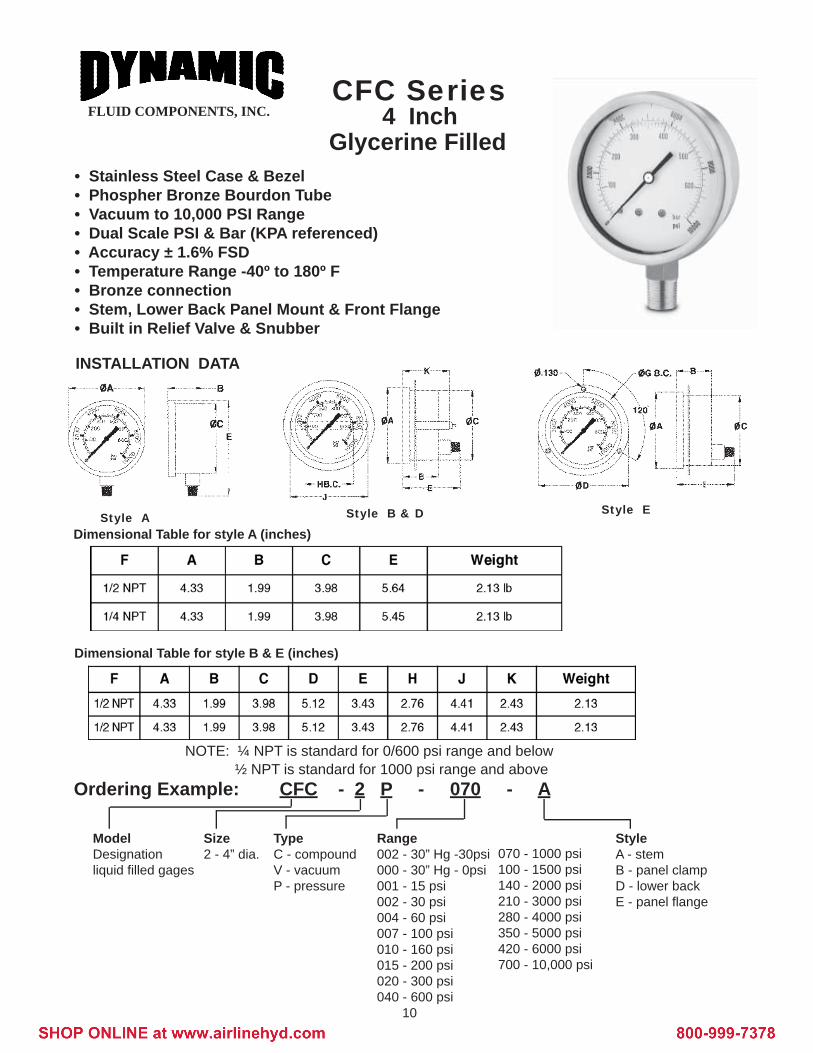
FLUID COMPONENTS, INC.CFC Series
4 InchGlycerine Filled
• Stainless Steel Case & Bezel• Phospher Bronze Bourdon Tube• Vacuum to 10,000 PSI Range • Dual Scale PSI & Bar (KPA referenced)• Accuracy ± 1.6% FSD• Temperature Range -40º to 180º F• Bronze connection• Stem, Lower Back Panel Mount & Front Flange• Built in Relief Valve & Snubber
INSTALLATION DATA
Dimensional Table for style A (inches)
Dimensional Table for style B & E (inches)
Ordering Example: CFC - 2 P - 070 - A
NOTE: ¼ NPT is standard for 0/600 psi range and below½ NPT is standard for 1000 psi range and above
ModelDesignationliquid fi lled gages
Size2 - 4” dia.
StyleA - stemB - panel clampD - lower backE - panel fl ange
TypeC - compoundV - vacuumP - pressure
Range002 - 30” Hg -30psi 000 - 30” Hg - 0psi001 - 15 psi002 - 30 psi004 - 60 psi007 - 100 psi010 - 160 psi015 - 200 psi020 - 300 psi040 - 600 psi
070 - 1000 psi100 - 1500 psi140 - 2000 psi210 - 3000 psi280 - 4000 psi350 - 5000 psi420 - 6000 psi700 - 10,000 psi
Style A Style B & D Style E

11
FLUID COMPONENTS, INC.
PDSS Series2 ½”Stainless Steel Liquid Filled & Dry
• 304 SS Case • 316 SS Connection• 316 SS Bourdon Tube• Vacuum to 30,000 psi• Dual Scale PSI & BAR• Accuracy ± 1.6%
Ordering Example: PDSS - 1 P - 010 - A - 001
ModelDesignation for all stainlesssteel gages
Size1 - 2½ “
TypeC - compoundV - vacuumP - pressure
Range002 - 30” Hg -30psi 000 - 30” Hg - 0psi001 - 15 psi002 - 30 psi004 - 60 psi007 - 100 psi010 - 160 psi015 - 200 psi020 - 300 psi040 - 600 psi
070 - 1000 psi100 - 1500 psi140 - 2000 psi210 - 3000 psi280 - 4000 psi350 - 5000 psi420 - 6000 psi700 - 10,000 psi800 - 15,000 psi
StyleA - stemB - panel clampD - ctr. backE - panel fl ange
Options001 - Glycerine fi lled002 - Dry
• Ambient Temperature -13º F to 150º F• Process Temperature max. + 750ºF• Liquid Filled & Dry
Size A B C D E F G H1 1/2 1.58 1.98 1.02 2.47 2.30 - - .20
2 1.98 2.21 1.19 3.05 2.28 2.40 2.76 .242 1/2 2.40 2.25 1.18 3.45 3.18 2.90 3.42 .25
INSTALLATION DATA

12
FLUID COMPONENTS, INC.
PDSS Series
• 304 SS Case • 316 SS Connection• 316 SS Bourdon Tube• Vacuum to 30,000 psi• Dual Scale PSI & KPA• Accuracy ± 1.0%
• Ambient Temperature -13º F to 150º F• Process Temperature max. + 750ºF• Liquid Filled & Dry
Dimensions - 4 & 6” Dry Model Installations Shown
Ordering Example: PDSS - 2 P - 010 - A - 001
ModelDesignation for all stainlesssteel gages
Size2 - 4 “3 - 6”
TypeC - compoundV - vacuumP - pressure
Range002 - 30” Hg -30psi 000 - 30” Hg - 0psi001 - 15 psi002 - 30 psi004 - 60 psi007 - 100 psi010 - 160 psi015 - 200 psi020 - 300 psi040 - 600 psi070 - 1000 psi
100 - 1500 psi140 - 2000 psi210 - 3000 psi280 - 4000 psi350 - 5000 psi420 - 6000 psi700 - 10,000 psi800 - 15,000 psi 900 - 20,000 psi950 - 30,000 psi
StyleA - stemB - panel clampD - lower backE - panel fl ange
Options001 - Glycerine fi lled002 - Dry
Note: 4” gages 600 psi and below are ¼” NPT. 1000 psi and above are ½” NPT 6” gages ½” NPT standard
Style A Style B&D Style E
Size4”6”
Range0-30,000 psi0-30,000 psi
F¼or½
½
a.57.65
b1.992.11
b¹2.152.26
c.61.61
c¹.77.77
d4.416.54
d¹3.985.91
D5.127.48
E4.576.89
h3.434.65
h¹2.053.35
ch.67.67
Weight2.42 lbs.4.95 lbs.
Style A
Styles B, D & ESize4”6”6”
Range0-30,000 psiTo 1,000 psi
1500-30,000 psi
F¼or½
½½
a.57.65.65
a¹.83.83.83
a².79.98.98
b1.992.112.11
d4.416.546.54
d¹3.985.915.91
D5.127.487.48
E4.576.896.89
e1.362.091.36
h¹---
3.353.35
P3.393.503.50
T1.631.771.77
V2.764.174.17
Z4.416.106.10
ch.67.67.67
Weight2.42 lbs.4.95 lbs.4.95 lbs.
120°
4 and 6” Stainless Steel Liquid Filled & Dry

13
FLUID COMPONENTS, INC.PDTG Test Gages
6” DryStem & Panel Mount
• Accuracy ±0.50 FSV• 304 SS Case• SS Bourdon Tube• Adjustable Pointer is Micrometer Knife Type• Reinforced Movement is AISI 316• Maximum Working Pressure 75% FSV• Temperature Range 60ºF to 150ºF• 6” Size• Mirrored Dial
INSTALLATION DATA
Ordering Example: PDTG - 3 P - 010 - A - 01
ModelDesignationfor PDTG test gage
Size3 - 6 inch
TypeC - CompoundV - VacuumP - Pressure
Range002 - 30” Hg -30psi 000 - 30” Hg - 0psi001 - 15 psi002 - 30 psi004 - 60 psi007 - 100 psi010 - 160 psi015 - 200 psi020 - 300 psi040 - 600 psi
070 - 1000 psi100 - 1500 psi140 - 2000 psi210 - 3000 psi280 - 4000 psi420 - 6000 psi700 - 10,000 psi800 - 15,000 psi 900 - 20,000 psi
StyleA - StemB - Panel Mount (special order only)
Options01 - Shatterproof lens02 - ¼ NPT connection
¼ NPT connection is standardCertifi cate of Calibration Available

14
FLUID COMPONENTS, INC.Pressure Gage Accessories
By fi tting a snubber, a pressure gage is protected from harmful pressuresurges and pulsations which would otherwise overload the gage mechanism
MODEL PDD-4 The ¼ NPT snubber has a helically formed oilway with a small orifi ce through which fl uid must pass to reach the gage. This provides a high resistance to smooth out surges and pulses, yet allows rapid responses and steady gage readings.
Model No. A B C D E F G Material Rated PressurePDD - 4 ¼NPT .52 .94 .20 .71 .43 .55 Steel 10,000 PSI
Gage Snubbers
Gage Protectors
Dynamic recommends the use of our Buna N rubber housinggage protector. This saves damage to the gage should it bedropped or bumbed.
Order by Part Number: GP40N

15
FLUID COMPONENTS, INC.
Section 2TEST POINT PLUGS AND PROBES
The need for preventative maintenance of hydraulic systems in general has added to the use of test points throughout the system. This need is answered by the installation of a range of test points, plugs and probes, which can be connected under full system pressure to 6000 psi. Where the in-troduction of test points is needed, and the hydraulic system uses fl exible hydraulic hoses, Dynamic has a range of Hydra-Test hose couplings fi tted with test points. For full product data consult the following pages.
Table of Contents
Product
Series FTP Test Point Plugs & Probes ......................................................................................21
Series GP Gage Protector .........................................................................................................21
Series HSP Interchangeable Test Points & Plugs .....................................................................22
Series HSP Hydra Test Hose Couplings ...................................................................................23
Series DHA Remote Test Point Plug Hose Assemblies ....................................................... 23-24
Page No.
General Information

16
FLUID COMPONENTS, INC.
• Dynamic Special Design• Connects Under Full Pressure• Rated at 6000 PSI• All Steel Construction• Buna Seals are Standard
Test Point Plugs (Standard Dynamic Model)
MODELFTP02NFTP04NFTP04S
Test Point ProbesDynamic Standard Probe Model FPPO4N
PROBESDynamic probes are designed to connect directly to the test point plug. When fi tted with the desired pressure gage, the system pressure is released into the gage bourdon tube as the probe opens the test point valve. It can be connected or disconnected under pressure. This provides a precise means to monitor system pressure without turning the system off to test. See page 3 for 2½” pressure gage data.
For complete model with a liquid fi lled gage add the Model No. to the plug model number. i.e. FPP04N-CF1P-210A is a plug assembly fi tted with 0/3000 psi stem gage.
GAGE PROTECTORSDynamic recommends the use of a gage protector Buna N rubber housing when using a test point probe. This saves damage to the gage should it be dropped or bumped during the test proceedings. Order by model number GP-40N.See photo above.
AThread1/8 NPT1/4 NPT
7/16-20 SAE
BInches
0.39.056.036
CInches
1.811.871.81
DInches
----
.71
EInches
0.750.820.75
Max. TorqueIn Lbs.
180180180
WeightLbs..15.17.17
Seal Kit*Buna-N *VitonSK115-N SK115SK115-N SK115SK115-N SK115
*Special Order Only
Test Point Plugs
Dynamic Test point plugs and probes are designed to monitor hydraulic system conditions without system shutdown to connect the pressure gage.These test plugs are fi tted as a “standard” into the mobile or industrialapplication where eventual system monitoring is required.

17
FLUID COMPONENTS, INC.D1620 Series
Test Piont ConectorsM16 x 2.0
Note: Model No. does not include gage. Dimensions include 2½” dia. gage. See page 22 for gage protection data.
*Special Order Only
Model Form MaxImum PSI Ch. J GD1620-01-18-NPT C 5800 .67 .37 18-NPTD1620-01-14-NPT C 9000 .67 .55 14-NPTD1620-01-04-SAE F 9000 .67 .43 04-SAED1620-01-06-SAE F 9000 .75 .47 06-SAED1620-01-08-SAE F 9000 .87 .55 08-SAED1620-01-M10X1 E 9000 .67 .33 M10X1D1620-01-M12x1.5 E 9000 .67 .47 M12x1.5D1620-01-M14x1.5 E 9000 .75 .47 M14x1.5D1620-01-M16x1.5 E 9000 .87 .47 M16x1.5D1620-01-18-BSPP E 9000 .67 .32 18-BSPPD1620-01-14-BSPP E 9000 .75 .47 14-BSPPD1620-01-38-BSPP E 9000 .87 .47 38-BSPP
• Connects Under Full Pressure• Rated at 9000 PSI• All Steel Construction• Buna Seals are Standard
Form C Form E Form F
DGA1620 SeriesTest Point Probe
M16 x 2.0

18
FLUID COMPONENTS, INC.Hydra-Test J.I.C. Hose Couplings
• 6,000 PSI Working Pressure• Fitted with Hydra-Test Point Plug• Can be Used With Direct or Remote Test Probes• For J.I.C. 37º Hose Sizes: 7/16” - 1.7/8” UNF• Can be Connected and Disconnected at Full System Pressure
Install Hydra-Test J.I.C. Hose Couplings between the female swivel nut of the fl exible hose and the fi xed male connection. The integral Test Point may be used with Dynamic Test Probes or Test Kits to obtain random pressure and temperature checks during servicing or fault fi nding. The Fluid Sampling Probe is also compatible.
All probes may be connected and disconnected at full system pres-sure without fl uid loss or ingress of dirt.
Model No.HSP1040-4
HSP1040-5
HSP1040-6
HSP1040-8
HSP1040-10
HSP1040-12
HSP1040-16
HSP1040-20
HSP1040-24
U.N.F7/16”-20
1/2”-20
9/16”-18
3/4”-16
7/8”-14
1 1/16”-12
1 5/16”-12
1 5/8”-12
1 7/8”-12
IN2.01
2.01
2.01
2.01
2.14
2.14
2.30
2.61
2.98
MM51.18
51.18
51.18
51.18
54.36
54.36
58.33
66.33
75.87
IN1.00
1.00
1.01
1.11
1.23
1.31
1.36
0.96
1.08
MM25.40
25.50
25.70
28.30
31.30
33.30
34.60
24.30
27.50
IN1.22
1.30
1.36
1.33
1.51
1.64
1.72
1.77
1.89
MM30.95
33.13
33.91
33.73
38.45
41.59
43.73
45.00
48.00
IN.56
.62
.69
.87
1.00
1.25
1.50
2.05
2.20
MM14.28
15.87
17.46
22.22
25.40
31.75
38.10
52.00
56.00
IN1.12
1.12
1.12
1.12
1.37
1.37
1.69
2.00
2.22
LBS.29
.31
.33
.35
.55
.66
.95
1.71
1.98
Kg.13
.14
.15
.16
.25
.30
.43
.78
.90
*Nitrile
SK114N
*Viton
SK114V
MM28.57
28.57
28.57
28.57
34.92
34.92
42.86
50.80
56.34
A B C D E F Weight Seal Kit
Hydra-Test Flexible Hose AssembliesThe DHA series fl exible hose series is available fi tted with a pressure gage. The assembly is for use with Dynamic Test Plugs, Pipe Couplings and Standpipe adaptors. Together they facilitate pressure readings on a random basis throughout a hydraulic system. Probes may be connected or disconnected with the system at full working pressure without loss of oil or ingress of dirt. Use of Hydra-Test saves the installation of multiple pipework and gages.
DHA - FTP - 12 - 4F
Designation for DynamicHose Assem-
EndFitting
see codes on next page
Hose Lengthin inches
see Table 1
EndFitting
see codes on next page
ORDERING EXAMPLE: Hose Lengths (IN)122436486072
Please specify in inches if other lengths are required
Table 1
If you require a gage assembled to the hose assembly, please add the gage number to the end of the part number.
*Special Order Only

19
FLUID COMPONENTS, INC.
Hydra-Test End Fittings
Code FTPCode HSP Code 4F Code 4MCode 2M
Code 7/16F Code 9/16F
.
•Optional End Fitttings •Up to 6000 PSI Working Pressure
7/16 SAE9/16 SAE
37º
7/16 SAE9/16 SAE
Code 7/16MCode 9/16M
Code 9/16C
M16x1.5M14x1.5M12x1.5
Code M16Code M14Code M12
Code HSP-90 Code FTP-90
•Choice of Hose Lengths•Steel Components Passivated
Code 6MSPCode 8MSPCode 4NSP
37º

20
FLUID COMPONENTS, INC.
Section 3
HYDRAULIC VALVES
A range of new products have been added and inventoried for immediate delivery from our South Carolina and California warehouse. The new products include High and Low Pressure Ball Valves ¼ thru 2 inch port sizes. Also included is our Hard and Soft Seat Check Valves.
Table of Contents
Product Page No.
Series GE2 High Pressure Ball Valves ......................................................................................26
Series GE3 High Pressure Ball Valves ......................................................................................27
Ball Valve Locking Handles .......................................................................................................30
Series HSP Hard Seat Check Valves ........................................................................................31
Series VU Soft Seat Check Valves ............................................................................................31
Flow Control and Needle Valves ......................................................................................... 32-36
General Information
21
FLUID COMPONENTS, INC.
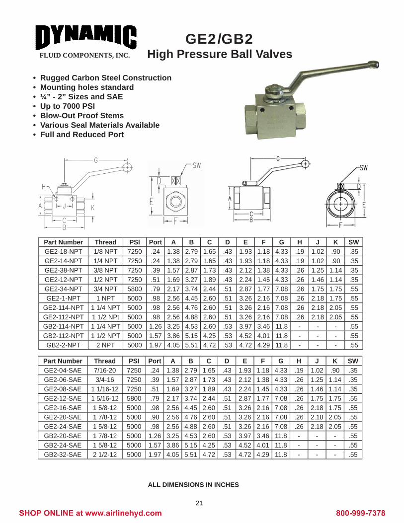
ALL DIMENSIONS IN INCHES
GE2/GB2High Pressure Ball Valves
• Rugged Carbon Steel Construction• Mounting holes standard • ¼” - 2” Sizes and SAE• Up to 7000 PSI• Blow-Out Proof Stems• Various Seal Materials Available• Full and Reduced Port
Part Number Thread PSI Port A B C D E F G H J K SWGE2-18-NPT 1/8 NPT 7250 .24 1.38 2.79 1.65 .43 1.93 1.18 4.33 .19 1.02 .90 .35GE2-14-NPT 1/4 NPT 7250 .24 1.38 2.79 1.65 .43 1.93 1.18 4.33 .19 1.02 .90 .35GE2-38-NPT 3/8 NPT 7250 .39 1.57 2.87 1.73 .43 2.12 1.38 4.33 .26 1.25 1.14 .35GE2-12-NPT 1/2 NPT 7250 .51 1.69 3.27 1.89 .43 2.24 1.45 4.33 .26 1.46 1.14 .35GE2-34-NPT 3/4 NPT 5800 .79 2.17 3.74 2.44 .51 2.87 1.77 7.08 .26 1.75 1.75 .55GE2-1-NPT 1 NPT 5000 .98 2.56 4.45 2.60 .51 3.26 2.16 7.08 .26 2.18 1.75 .55
GE2-114-NPT 1 1/4 NPT 5000 .98 2.56 4.76 2.60 .51 3.26 2.16 7.08 .26 2.18 2.05 .55GE2-112-NPT 1 1/2 NPt 5000 .98 2.56 4.88 2.60 .51 3.26 2.16 7.08 .26 2.18 2.05 .55GB2-114-NPT 1 1/4 NPT 5000 1.26 3.25 4.53 2.60 .53 3.97 3.46 11.8 - - - .55GB2-112-NPT 1 1/2 NPT 5000 1.57 3.86 5.15 4.25 .53 4.52 4.01 11.8 - - - .55GB2-2-NPT 2 NPT 5000 1.97 4.05 5.51 4.72 .53 4.72 4.29 11.8 - - - .55
Part Number Thread PSI Port A B C D E F G H J K SWGE2-04-SAE 7/16-20 7250 .24 1.38 2.79 1.65 .43 1.93 1.18 4.33 .19 1.02 .90 .35GE2-06-SAE 3/4-16 7250 .39 1.57 2.87 1.73 .43 2.12 1.38 4.33 .26 1.25 1.14 .35GE2-08-SAE 1 1/16-12 7250 .51 1.69 3.27 1.89 .43 2.24 1.45 4.33 .26 1.46 1.14 .35GE2-12-SAE 1 5/16-12 5800 .79 2.17 3.74 2.44 .51 2.87 1.77 7.08 .26 1.75 1.75 .55GE2-16-SAE 1 5/8-12 5000 .98 2.56 4.45 2.60 .51 3.26 2.16 7.08 .26 2.18 1.75 .55GE2-20-SAE 1 7/8-12 5000 .98 2.56 4.76 2.60 .51 3.26 2.16 7.08 .26 2.18 2.05 .55GE2-24-SAE 1 5/8-12 5000 .98 2.56 4.88 2.60 .51 3.26 2.16 7.08 .26 2.18 2.05 .55GB2-20-SAE 1 7/8-12 5000 1.26 3.25 4.53 2.60 .53 3.97 3.46 11.8 - - - .55GB2-24-SAE 1 5/8-12 5000 1.57 3.86 5.15 4.25 .53 4.52 4.01 11.8 - - - .55GB2-32-SAE 2 1/2-12 5000 1.97 4.05 5.51 4.72 .53 4.72 4.29 11.8 - - - .55

22
FLUID COMPONENTS, INC.
ALL DIMENSIONS IN INCHES “L” PORT STANDARD, “T” PORT AVAILABLE. MINIMUM QTY. MAY APPLY
GE3/GB33 - Way
High Pressure Ball Valves• Rugged Carbon Steel Construction• ¼” - 2” Sizes• Up to 4500 PSI• Blow-Out Proof Stems• Full and Reduced Port• NPT and SAE Threads Available
Part Number Thread PSI Port A B C D E F G H J K SWGE2-18-NPT 1/8 NPT 7250 .24 1.38 2.79 1.65 .43 1.93 1.18 4.33 .19 1.02 .90 .35GE2-14-NPT 1/4 NPT 7250 .24 1.38 2.79 1.65 .43 1.93 1.18 4.33 .19 1.02 .90 .35GE2-38-NPT 3/8 NPT 7250 .39 1.57 2.87 1.73 .43 2.12 1.38 4.33 .26 1.25 1.14 .35GE2-12-NPT 1/2 NPT 7250 .51 1.69 3.27 1.89 .43 2.24 1.45 4.33 .26 1.46 1.14 .35GE2-34-NPT 3/4 NPT 5800 .79 2.17 3.74 2.44 .51 2.87 1.77 7.08 .26 1.75 1.75 .55GE2-1-NPT 1 NPT 5000 .98 2.56 4.45 2.60 .51 3.26 2.16 7.08 .26 2.18 1.75 .55
GE2-114-NPT 1 1/4 NPT 5000 .98 2.56 4.76 2.60 .51 3.26 2.16 7.08 .26 2.18 2.05 .55GE2-112-NPT 1 1/2 NPt 5000 .98 2.56 4.88 2.60 .51 3.26 2.16 7.08 .26 2.18 2.05 .55GB2-114-NPT 1 1/4 NPT 5000 1.26 3.25 4.53 2.60 .53 3.97 3.46 11.8 - - - .55GB2-112-NPT 1 1/2 NPT 5000 1.57 3.86 5.15 4.25 .53 4.52 4.01 11.8 - - - .55GB2-2-NPT 2 NPT 5000 1.97 4.05 5.51 4.72 .53 4.72 4.29 11.8 - - - .55
Part Number Thread PSI Port A B C D E F G H J K SWGE2-04-SAE 7/16-20 7250 .24 1.38 2.79 1.65 .43 1.93 1.18 4.33 .19 1.02 .90 .35GE2-06-SAE 3/4-16 7250 .39 1.57 2.87 1.73 .43 2.12 1.38 4.33 .26 1.25 1.14 .35GE2-08-SAE 1 1/16-12 7250 .51 1.69 3.27 1.89 .43 2.24 1.45 4.33 .26 1.46 1.14 .35GE2-12-SAE 1 5/16-12 5800 .79 2.17 3.74 2.44 .51 2.87 1.77 7.08 .26 1.75 1.75 .55GE2-16-SAE 1 5/8-12 5000 .98 2.56 4.45 2.60 .51 3.26 2.16 7.08 .26 2.18 1.75 .55GE2-20-SAE 1 7/8-12 5000 .98 2.56 4.76 2.60 .51 3.26 2.16 7.08 .26 2.18 2.05 .55GE2-24-SAE 1 5/8-12 5000 .98 2.56 4.88 2.60 .51 3.26 2.16 7.08 .26 2.18 2.05 .55GB2-20-SAE 1 7/8-12 5000 1.26 3.25 4.53 2.60 .53 3.97 3.46 11.8 - - - .55GB2-24-SAE 1 5/8-12 5000 1.57 3.86 5.15 4.25 .53 4.52 4.01 11.8 - - - .55GB2-32-SAE 2 1/2-12 5000 1.97 4.05 5.51 4.72 .53 4.72 4.29 11.8 - - - .55
23
FLUID COMPONENTS, INC.
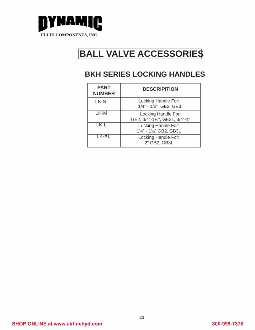
BALL VALVE ACCESSORIES
BKH SERIES LOCKING HANDLESPART
NUMBER LK-S
LK-M
LK-L
LK-XL
DESCRIPITION
Locking Handle For: 1/4” - 1/2” GE2, GE3
Locking Handle For:GE2, 3/4”-1½”, GE3L, 3/4”-1”
Locking Handle For:1¼” - 1½” GB2, GB3L Locking Handle For:
2” GB2, GB3L

24
FLUID COMPONENTS, INC.CHECK VALVESHard & Soft Seat
Model HSP - Hard Seat
Model VU - Soft Seat
Ordering Example: VU - 14F - 7
Dynamic DesignationVU - Soft Seat Model
Size - NPT 14F - 1/4 38F - 3/8 12F - 1/2 34F - 3/4 1F - 1114F - 1¼112F - 1½ 2F - 2
Cracking7 - 7 psi70 - 70 psi
MODEL
HSP-1000-2-5 or 65HSP-1000-3-5 or 65HSP-1000-4-5 or 65HSP-1000-6-5 or 65HSP-1000-8-5 or 65HSP-1000-10-5 or 65HSP-1000-12-5 or 65HSP-1001-4-5 or 65HSP-1001-6-5 or 65HSP-1001-8-5 or 65HSP-1001-12-5 or 65HSP-1001-16-5 or 65HSP-1001-20-5 or 65HSP-1001-24-5 or 65
ASize
1/4 NPT3/8 NPT1/2 NPT3/4 NPT1 NPT
1¼ NPT1½ NPT
7/16-20 SAE9/16-20 SAE3/4-16 SAE
1 1/6-12 SAE1 5/16-12 SAE1 5/8-12 SAE1 7/8-12 SAE
BInches2.442.873.504.255.125.565.562.562.913.744.295.005.205.20
CInches.87.951.141.501.692.402.56.87.941.181.501.812.412.56
Rated Flowgpm61018303650606101830365060
WeightLbs.
.35 .44 .771.542.436.957.28 .35 .44 .771.542.436.957.28
MODEL
VU-14F-7VU-38F-7VU-12F-7VU-34F-7VU-1F-7VU-114F-7VU-112F-7VU-2F-7
1/43/81/23/411¼1½2
THREADSIZE-NPT
A
1.962.362.763.383.935.125.315.91
B
.74
.901.061.382.161.972.562.95
RATEDPRESSURE10,000 psi10,000 psi7350 psi7350 psi7350 psi4410 psi4410 psi4410 psi
Rated Pressure: Sizes 2 thru 8 - 5000 psi Sizes 10 thru 24 - 3000 psi
NPT
SAE
5 lb or 65 lb Cracking Pressure Available
7 lb or 70 lb Cracking Pressure Available
Carbon Steel Construction
A (NPT female threadboth ends)
25
FLUID COMPONENTS, INC.
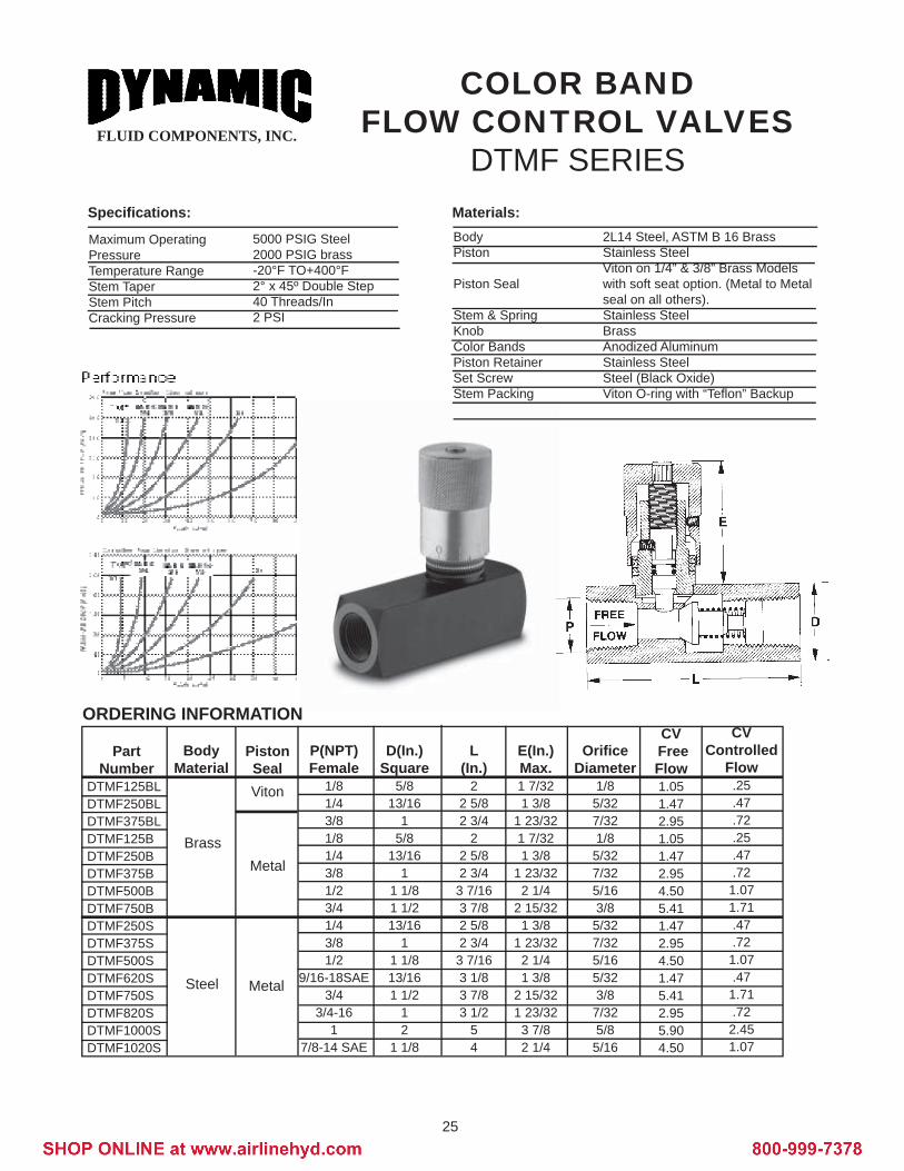
Maximum OperatingPressureTemperature RangeStem TaperStem PitchCracking Pressure
5000 PSIG Steel2000 PSIG brass-20°F TO+400°F2° x 45º Double Step40 Threads/In 2 PSI
Specifi cations: Materials:BodyPiston
Piston Seal
Stem & SpringKnobColor BandsPiston RetainerSet ScrewStem Packing
2L14 Steel, ASTM B 16 BrassStainless SteelViton on 1/4” & 3/8” Brass Modelswith soft seat option. (Metal to Metalseal on all others).Stainless Steel Brass Anodized AluminumStainless SteelSteel (Black Oxide)Viton O-ring with “Tefl on” Backup
ORDERING INFORMATION
P(NPT)Female
1/81/43/81/81/43/81/23/41/43/81/2
9/16-18SAE3/4
3/4-161
7/8-14 SAE
D(In.)Square
5/813/16
1 5/8
13/161
1 1/81 1/213/16
1 1 1/813/161 1/2
1 2
1 1/8
L(In.)
22 5/82 3/4
22 5/82 3/43 7/163 7/82 5/82 3/43 7/163 1/83 7/83 1/2
54
Orifi ceDiameter
1/85/327/321/85/327/325/163/85/327/325/165/323/87/325/85/16
CV Free Flow1.051.472.951.051.472.954.505.411.472.954.501.475.412.955.904.50
E(In.)Max.1 7/321 3/8
1 23/321 7/321 3/8
1 23/322 1/4
2 15/321 3/8
1 23/322 1/41 3/8
2 15/321 23/32
3 7/82 1/4
PartNumber
DTMF125BLDTMF250BLDTMF375BLDTMF125BDTMF250BDTMF375BDTMF500BDTMF750BDTMF250SDTMF375SDTMF500SDTMF620SDTMF750SDTMF820SDTMF1000SDTMF1020S
Body Material
Brass
Steel
PistonSealViton
Metal
Metal
CV Controlled
Flow.25.47.72.25.47.721.071.71.47.721.07.471.71.722.451.07
COLOR BAND FLOW CONTROL VALVES
DTMF SERIES

26
FLUID COMPONENTS, INC.
Maximum OperatingPressureTemperature RangeStem TaperStem Pitch
5000 PSIG Steel2000 PSIG brass-20°F TO+212°F8°40 threads/In (1/8”-1/2”)24 threads/In (3/4, 1”)
Specifi cations: Materials:Body
StemKnob
ChamberLock NutStem PackingPiston AssemblyBall & SpringCheck PlugSet Screw & Chamber
2L14 Steel, ASTM B 16 Brassor 303 Stainless SteelStainless Steel or BrassAluminum (1/8”-1/2”)Brass (3/4”-1”)Steel (zinc plated)BrassViton O-ring with Telfl on BackupStainless Steel w/Viton O-ringStainless Steel Steel or BrassSteel
FLOW CONTROL VALVESDKLF SERIES
ORDERING INFORMATION
P(NPT)Female
1/81/43/81/23/41
1/81/43/81/23/41/81/43/81/23/41/4
D(In.)Square
11/167/8
1 1/161 5/161 5/81 7/811/167/8
1 1/161 5/161 5/811/167/8
1 1/161 5/161 5/81/8
L(In.)1 3/42 3/82 3/4
3 3/163 9/163 9/161 3/42 3/82 3/4
3 3/163 9/161 3/42 3/82 3/4
3 3/163 9/162 3/8
Orifi ceDiameter
.156
.156
.265
.281
.343
.343
.156
.156
.265
.281
.343
.156
.156
.265
.281
.343
.156
CV Free Flow
.32
.701.141.742.912.91.32.70
1.141.742.91.32.70
1.141.742.90.70
E(In.)Max.1 1/41 1/41 3/81 3/81 7/81 7/81 1/41 1/41 3/81 3/81 7/81 1/41 1/41 3/81 3/81 7/81 1/4
PartNumber
DKLF125BDKLF250BDKLF375BDKLF500BDKLF750BDKLF1000B
Body Material
Brass
Steel
303 SS
CheckStyle
Piston
SteelBall
Check
Piston
SteelBall
Check
CV Controlled
Flow.23.44.90
1.322.022.02.23.44.90
1.322.02.23.44.90
1.322.02.44
CrackingPressure
(PSI)10785221173131173138
G(In.)9/325/1611/323/8
15/3215/329/325/1611/323/8
15/329/325/1611/323/8
15/325/16

27
FLUID COMPONENTS, INC.
ORDERING INFORMATIONP(NPT)Female
1/81/43/81/23/41/81/43/81/23/41/8
D(In.)Hex11/167/81 1/161 5/161 5/811/167/81 1/161 5/161 5/811/16
L(In.)
1 1/222 1/42 21/3231 1/222 1/42 21/3231 1/2
Orifi ceDiameter
.156
.156
.265
.281
.343
.156
.156
.265
.281
.343
.156
CV.25.39.931.122.00.25.39.931.122.00.25
E(In.)Max.1 1/41 1/41 3/81 3/81 7/81 1/41 1/41 3/81 3/81 7/81 1/4
PartNumberDKLN125BDKLN250BDKLN375BDKLN500BDKLN750BDKLN125SDKLN250SDKLN375SDKLN500SDKLN750SDKLN125SS
Body Material
Brass
Steel
Stainless
Maximum OperatingPressureTemperature RangeStem TaperStem Pitch
5000 PSIG Steel2000 PSIG brass-20°F TO+212°F8°40 threads/In (1/8”-1/2”)24 threads/In (3/4, 1”)
Specifi cations: Materials:12L14 Steel, ASTM B 16 Brassor 316 Stainless SteelStainless Steel or BrassAluminum (1/8”-1/2”)Brass (3/4”-1”)Steel (zinc plated)BrassViton O-ring with Tefl on Backup
Body
StemKnob
ChamberLock NutStem Packing
NEEDLE VALVESDKLN SERIES

28
FLUID COMPONENTS, INC.
Maximum OperatingPressureTemperature RangeStem TaperStem Pitch
5000 PSIG Steel2000 PSIG brass-20°F TO+400°F2° x 45º Double Step40 threads/In
Specifi cations: Materials:12L14 Steel or ASTM B 16 BrassStainless Steel Brass Anodized AluminumSteelViton O-ring with Tefl on Backup
BodyStemKnobColor BandsSet ScrewStem Packing
COLOR BANDNEEDLE VALVES
DTMN SERIES
ORDERING INFORMATIONP(NPT)Female
1/81/43/81/21/43/81/23/41
D(In.)Hex
5/813/16
11 1/813/16
11 1/81 1/2
2
L(In.)
1 1/222 1/22 5/822 1/22 5/83 1/44 1/4
Orifi ceDiameter
1/85/327/325/165/327/325/163/85/8
CV.25.47.721.07.47.721.071.712.45
E(In.)Max.1 7/321 3/8
1 23/322 1/21 3/8
1 23/322 1/4
2 15/323 7/8
PartNumberDTMN125BDTMN250BDTMN375BDTMN500BDTMN250SDTMN375SDTMN500SDTMN750SDTMN1000S
Body Material
Brass
Steel
29
FLUID COMPONENTS, INC.
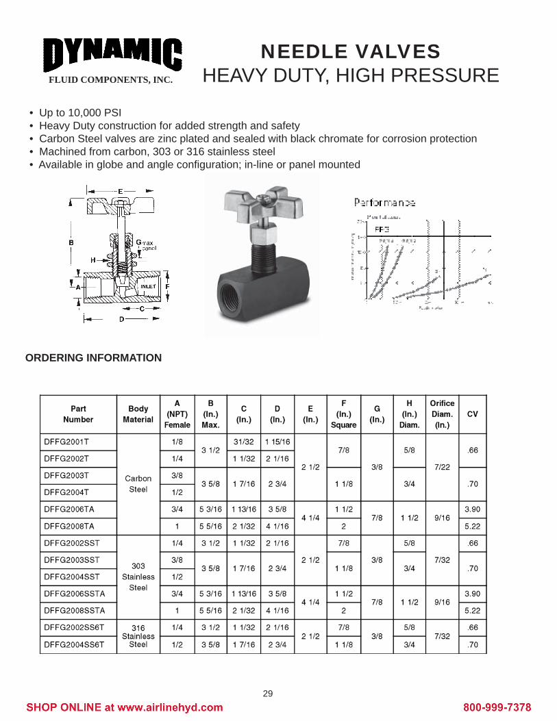
NEEDLE VALVESHEAVY DUTY, HIGH PRESSURE
• Up to 10,000 PSI • Heavy Duty construction for added strength and safety• Carbon Steel valves are zinc plated and sealed with black chromate for corrosion protection• Machined from carbon, 303 or 316 stainless steel• Available in globe and angle confi guration; in-line or panel mounted
ORDERING INFORMATION

30
FLUID COMPONENTS, INC.
Section 4
RESERVOIR ACCESSORIES
The limited range of competitively produced quality accessory products are detailed in the followingpages. These hydraulic reservoir accessories are available from stock for immediate supply.
Table of Contents
Product Page No.
DB Series Breathers ..................................................................................................................38
DFB Series Filter Filler Breathers ..............................................................................................39

31
FLUID COMPONENTS, INC.Screw-On TypeAir Breathers
CHROME PLATED STEEL• 1/4 to 1 Inch NPT• Steel Model• 40 Micron Breather
Model
DB40-04
DB40-06
DB40-08
DB40-12
DB40-16
Flow cfm
10
10
10
25
25
NPT
1/4
3/8
1/2
3/4
1
40
40
40
40
40
A
1.85
1.85
2.54
3.13
3.13
MicronB
1.60
1.70
1.88
2.00
2.11
C
.50
.50
.68
.82
.90
D
.30
.30
.29
.35
.42
CH
.63
.75
.95
1.12
1.35

32
FLUID COMPONENTS, INC.Filter Filler Breathers
• Chrome Plated Cap• 40 Micron Breather• 3½” & 6” Basket Length• Lockable Options• Plastic Basket Standard
Ordering Example: DFB 40 - 03 - L
MODELDesignation
for Filter Breathers
AIR FILTRATION40 - 40 micron standard
CAP DIA.03 - 3½”06 - 6”
OPTIONSL - LockableMB - Metal Basket
STYLEDFB
A2.95
B1.97
C1.97
D1.97
* Consult Factory for ordering caps or baskets only

33
FLUID COMPONENTS, INC.
METRIC CONVERSIONS
PRESSURESCommon catalog PRESSURES and corresponding value in bar, kilopascals and kilograms per square inch.
PSI
0.511.25251015202530354050607080901001251501752002502753003504005006007501000150019002200
Bar
0.0340.0690.0860.1380.3450.6991.0341.3791.72420.692.4132.7583.4484.1374.8275.5166.2066.8958.61910.34312.06613.79017.23818.96120.68524.13327.58034.47541.37051.71368.950103.425131.005151.690
kPa
3.446.898.6213.7934.4869.85103.43137.90172.38206.85241.33275.80344.75413.70482.65551.60620.55689.50861.881034.251206.631379.001723.751896.132068.502413.252758.003447.504137.005171.256895.0010342.5013100.5015169.00
kg/cm²
0.03520.07030.08790.14060.35150.70301.05451.40601.75002.10902.46052.81203.51504.21804.92105.62406.32707.03008.787510.545012.302514.060017.575019.332521.090024.605028.120035.150042.180052.725070.3000105.4500133.5700154.6600
COMMON EQUIVALENTSCommon English Unit and how to obtain the International Organization ofStandardization (ISO) equivalent unit.
English Unit
Gallon (U.S. liquid)Foot³OuncePoundInchFootPSIGInches of WaterInches of MercuryPSIGInches of WaterInches of MercuryStd. cubic feet/hour(SCFH)Gallons/minute (GPM)
Multiply by
3.7850.0283228.350.453625.400.30480.068950.002490.033866.8950.2493.3860.00786
3.785
To Obtain ISO Unit
liter (l)meter³ (m)gram (g)kilogram (kg)millimeter (mm)meter (m)barbarbarkilopascal (kPa)kilopascal (kPa)kilopascal (kPa)cubic decimeternormalized/sec (dm³/s)liters/minute (l/min)
COMMON EQUIVALENTSCommon catalog ORIFICE sizes and ISO equivalents in mm.
Inches
3/64 (.0469)1/16 (.0625)5/64 (.0781)3/32 (.0937)1/8 (.1250)5/32 (.1562)11/64 (.1719)3/16 (.1875)7/32 (.2187)1/4 (.2500)9/32 (.2812)5/16 (.3125)
mm
1.191.591.982.383.183.974.374.765.556.357.147.94
Inches
7/16 (.4375)1/2 (.5000)5/8 (.6250)11/16(.6875)3/4 (.7500)1 (1.000)1 1/8 (1.125)1 1/4 (1.250)1 1/2 (1.500)1 3/4 (1.750)2 (2.000)3 (3.000)
mm
11.1112.7015.8817.4619.0525.4028.5831.7538.1044.4550.8076.20
SUGGESTED PRODUCT COMPATIBILTY GUIDEBronzeacetoneacetylenealcoholbeerbenzinebenzolbordeaux mixturebutane
Steelacetoneacetylenealcoholammonium carbonateammonium hydroxide
316 Stainless Steelacetic acidacetic anhydridealumsaluminum sulfateammoniableach liquors
butanolbutyric acidcalcium chloridecalcium hydroxidecarbon dioxode (dry)caseinchloroformcoal gas
ammonium phosphatebenzinebenzolbenzyl alcoholbutanebutanol
butanecalcium bisulfi tecarbon disulfi dechromic acidcitric acidcopper sulfate
cuprous oxidedextrineethersethyl acetateethyl celluloseethyleneethylene dibromideethylene dichloride
calcium hydroxidecarbon bisulfi decarbon dioxide (dry)chloroformcoal gascottonseed oilcreosole (crude)
ferric nitrateferric sulfatehydrocynaic acidhydrogenhydrogen peroxidelactic acid
ethylene glycoleucalyptolformaldehydefreongallic acidgas, illuminatinggasolineglucose
ethersgasoline (refi ned)glucoseglycerinederosenemagnesium hydroxide
loxnitric acid (pure)nitrous acidnitrous oxideoxygenphosphoric acid
glycerinekerosenelacquerslysolmagnesium sulfatemethyl salicylatenaphthanickel acetate
magnesiium sulfatemercurymethyl chloridepitric acid (dry)potassium chloridepotassium cyanidepotassium sulfate
photographic solutionspickling solutionspitric acidpotassium permangante
oil (lubricating)oil (refi ned)oxygenparaffi npotassium chlorideprestoneproxylinsalicylic acid
sodium carbonatesodium hydroxidesodium nitratesodium sulfatesodium sulfi desodium sulfi tesulfur dioxide (dry)
silver nitratesodium cyanidesodium peroxidesodium phospatesulfur dioxidesulfurous acid
sea watertanning liquorstoluenewaterwhiskey
sulfur dioxide (dry)sulfuric (concentrated to 75%)toluenevegetable oils
vinegarvegatable oilswines
34
FLUID COMPONENTS, INC.
CALL 1-800-988-1276FROM ANYWHERE
IN THE U.S.
FLUID COMPONENTS, INC.
TERMS AND CONDITIONS
PAYMENT TERMSNet 30 days. Automatic C.O.D. after 60 days without prior notifi cation, FOB West Union, SC.
WARRANTYSeller warrants the items sold hereunder shall be free from defects in materials or workmanship for a period of one (1) year from the date of shipment. This warranty comprises the entire warranty pertaining to items provided here-under. Seller makes no other warranty, guarantee or representation of any kind. If the buyer disassembles, repairs or modifi es the unit in any way warranty is no longer valid. All returns must be accompanied by our Return Authori-zation Form. Dynamic Fluid Components, Inc. is not responsible for material returned without authorization.
RETURNED GOODSDynamic Fluid Components, Inc. reserves the right to accept material back at our discretion. All returns must be accompanied by our Return Authorization Form. Dynamic Fluid Components, Inc. is not responsible for material returned without authorization. Material may be returned for credit less a 25% restocking fee with an order of equal value or less a 50% restocking fee without an order of equal value provided materials is in saleable condition and freight is pre-paid. All returns for restock must be accompanied by a copy of the original Invoice, otherwise items are assumed to have been purchased at the maximum discount and credit is issued accordingly.
CREDIT ISSUE POLICYCredit balances can be offered by material purchase only. Cash payments are not allowed. Dynamic Fluid Compo-nents, Inc. reserves the right to assess a restocking fee on all items returned for credit.
PRICINGSubject to change without prior notifi cation.
SPECIAL ORDERSSpecial orders are noncancellable.
CONDITIONSDynamic Fluid Components, Inc. must have a copy of your sales tax exemption certifi cate on fi le. Any discrepancies in either billing or shipping must be reported within 30 days from receipt of order. The carrier must be contracted if package is damaged when received and goods must be kept with original packaging for inspection by the carrier.


![Airline] Figftte - DigitalOcean](https://img.dokumen.tips/doc/110x75/631ef92517cd32be4e0475a5/airline-figftte-digitalocean.jpg)


