Embed Size (px)
Citation preview

CAT.E24B
Clamp Cylinder
Cla
mp
Cy
lind
er
Akihabara UDX 15F, 4-14-1, Sotokanda, Chiyoda-ku, Tokyo 101-0021, JAPANPhone: 03-5207-8249 Fax: 03-5298-5362URL http://www.smcworld.com© 2008 SMC Corporation All Rights Reserved
Specifications are subject to change without prior notice and any obligation on the part of the manufacturer.
1st printing LT printing MR 13500DN Printed in Japan.D-DN
This catalog is printed on recycled paper with concern for the global environment.
∗ Addition of series C(L)KQ.∗ Addition of series MK2T/MK2/MK. MR
Record of changes
B edition
Series CKZTSeries CLKZ1R
Power Clamp Cylinder
Series CKZ2NPower Clamp Cylinder
Series CK1Clamp Cylinder
Clamp Cylinder with LockSeries CLK2
Series C(L)KQG/Series C(L)KQP
Pin Clamp Cylinder
Rotary Clamp CylinderSeries MK2T
New
New

The cylinder is secured easily by clevis mounting.Two types of clevis widths are standardized.
Built-in speed controller With air cushion at retracted end Coil scraper (spatter proof) is a
standard feature. Magnetic field resistant auto
switches are mountable. The piping position can be
selected arbitrarily.
Series CK1 ø40, ø50, ø63
Clamp Cylinder
Clamp Cylinder with Lock
Series CLK2 ø32, ø40, ø50, ø63
Remains clamped when air supply pressure drops or residual pressure is released.
For Asia
LOCK
B
A
LOCK
Retraction lock
Features 1

Series C(L)KQG/C(L)KQP ø50
Pin Clamp Cylinder
Rotary Clamp Cylinder
Series MK2T/MK2/MK ø12, ø16, ø20, ø25 ø32, ø40, ø50, ø63
Simultaneous rotation and clamping
60
90
Body shape: D type
40
70
Body shape: U, K, M type
Clamping Height
Positioning and clamping can be done simultaneously! Determine the appropriate height for the
workpiece in progress, and cut down on interference with the body!
55 varieties of guide pins 4 types of body shapes Lock mechanism types
can also be selected
ø12, ø16 available for MK series only.
Double Guide TypeSeries MK2Tø20, ø25, ø32, ø40, ø50, ø63
Heavy Duty TypeSeries MK2ø20, ø25, ø32, ø40ø50, ø63
StandardSeries MKø12, ø16, ø20, ø25ø32, ø40, ø50, ø63
Workpiece
Guide pin
Clamp arm
ClampClamp
For Asia
Fo
r A
sia
CK
1C
LK
2C
(L)K
Q
MK
2T/M
K2/
MK
For
Nort
h A
merica
CK
Z2N
CK
ZT
For
Euro
pe
CL
KZ
1R
For
Fra
nce
Specia
l
CK
/M(D
)UK
A
Features 2

Series CKZ2N ø50, ø63, ø80
Conforming to the New NAAMS Standards (North American Automotive Metric Standards)
138 arm styles are available. Spatter proof, Water resistant
Manual toggle release point
Lub-retainer
Piston
Rounded cover design reducesweld spatter accumulation.
Elliptical designfor space saving
Power Clamp CylinderFor North America
CoverEquivalent to UL94standard VO:Flame resistant
Proximity cassette installationand removal easily accomplished
by unfastening a single bolt
Simple arm opening anglechanges.
Cylinder disassembly is not necessary.The arm opening angle can be changedby replacing the stopper bolt.
Hexagon socket head cover cap screw
Lub-retainer on pistonis standard.
Highly protective seal design is less effected by poor air quality.
• Power clamp cylinder with metal cover• Power clamp cylinder front mounting type• Unclamped opening angle 15° kit
(for change of angle)
Made to Order(Details → Refer to page 179 and 180.)
Features 3

Each size has 3 arm styles. Spatter proof, Water resistant
Series CKZT ø40, ø50, ø63, ø80
Power Clamp Cylinder
Series CLKZ1R ø40, ø50, ø57
Power Clamp Cylinder
Conforming to the CNOMO Standard Constant Clamping force regardless of workpiece thickness The workpiece can be held even when there is no
compressed air supply. Unclamp side end lock Unclamp side rubber bumper
For Europe
For France
Hexagon socket head cover cap screw
Proximity cassette installationand removal easily accomplished
by unfastening a single bolt
Simple arm opening anglechanges.
Cylinder disassembly is not necessary.The arm opening angle can be changedby replacing the stopper bolt.
Rounded cover design reducesweld spatter accumulation.
Manual toggle release point
CoverEquivalent to UL94standard VO:Flame resistant
Elliptical design for space saving
Lub-retainer
Piston
Lub-retainer on piston is standard.Highly protective seal design is less effected by poor air quality.
Made to Order(Details → Refer to page 204 to 206.)
• Power clamp cylinder with metal cover• Power clamp cylinder with angle adjustment• Power clamp cylinder with manually operated handle• Power clamp cylinder with pneumatic sensor• Unclamped opening angle 15° kit
(for change of angle)
Fo
r A
sia
CK
1C
LK
2C
(L)K
Q
MK
2T/M
K2/
MK
For
Nort
h A
merica
CK
Z2N
CK
ZT
For
Euro
pe
CL
KZ
1R
For
Fra
nce
Specia
l
CK
/M(D
)UK
A
Features 4

Other Clamp CylinderSpecial
Pin Clamp Cylinder(Compact body type)
Series CKU
Pin Shift Cylinder
Series CKQR
Plate Clamp Cylinder
Series M(D)UKAClamp Cylinder
Series CKGV
Pin Shift Cylinder
Series CKZP
Features 5

I N D E X
Clamp Cylinder
Clamp Cylinder with Lock
Pin Clamp Cylinder
Rotary Clamp Cylinder
Related Equipment (For Piping Equipment)
P.227KR-W2KRMKQBH/DL/L/LL
P.240AS-W2AS
ASVAS
ASAS
FittingsFR One-touch FittingsFR One-touch Fittings ManifoldBrass One-touch FittingsSelf Align Fittings
Speed ControllerSpeed Controller with One-touch FittingsSpeed Controller: Standard TypeIn-line TypeSpeed Exhaust ControllerSpeed Controller with One-touch Fitting, Elbow Type (Metal Body) Speed Controller Adjustable by Flat Head ScrewdriverTamper Proof Speed Controller
TubingFR Soft Nylon TubingFR Double Layer TubingFR Double Layer Polyurethane TubingDouble Layer Tube StripperMulti-tube Holder
CK1
CLK2
MK2T/MK2/MK
CKZ2N
CKZT
CLKZ1R
P.1
P.25
P.53
P.109
P.155
P.183
P.209
P.219
For Asia
For Asia
For Asia
For Asia
Power Clamp CylinderConforming to the New NAAMS Standard
For North America
Power Clamp CylinderConforming to the CNOMO Standard
Other Clamp Cylinder
For Europe
For France
P.225
CKU, CKQR, M(D)UKACKGV, CKZP
Special
Power Clamp Cylinder
P.248TRSTRBTRBUTKSTM
C(L)KQG/C(L)KQP
Fo
r A
sia
CK
1C
LK
2C
(L)K
Q
MK
2T/M
K2/
MK
For
Nort
h A
merica
CK
Z2N
CK
ZT
For
Euro
pe
CL
KZ
1R
For
Fra
nce
Specia
l
CK
/M(D
)UK
A
Front matter 1


Series CK1Clamp Cylinder
Clevis width 16.5 mm/19.5 mm
Built-in speed controller
With air cushion
Magnetic field resistant auto switches are mountable.
SeriesBore size
(mm)Stroke(mm)
Clevis width(mm)
CK1 series
CKG1 series
CKP1 series
Options
A: 16.5 mmB: 19.5 mm
50
75
100
125
150
40
50
63
Rod endbracket
Singleknucklejoint
Doubleknuckle joint
Limit switch mounting base
Dog fitting
Foot
Pedestal
Basic type
Built-in standard magnet type(applicable to magnetic fieldresistant auto switches)
Built-in strong magnet type(applicable to magnetic fieldresistant auto switches)
Variations
CK
1C
LK
2C
(L)K
Q
MK
2T/M
K2/
MK
CK
Z2N
CK
ZT
CL
KZ
1RC
K
/M(D
)UK
A
Fo
r A
sia
For
Nort
h A
merica
For
Euro
pe
For
Fra
nce
Specia
l
1

The auto switch mounting and the piping position are available in three-way directions.The auto switch mounting position can be altered. Also, piping is possible in three-way directions regardless of the auto switch mounting position.
Series CKG1Series CKG1[Built-in
standard magnet]
Series CKP1Series CKP1[Built-in
strong magnet]
Magnetic field resistant auto switches are mountable. [CKG1 series / Built-in standard magnet] … D-P4DWSC, D-P4DWSE, D-P4DWL/Z (AC magnetic field)
[CKP1 series / Built-in strong magnet] … D-P79WSE, D-P74L/Z (DC/AC magnetic fields)
Magnetic field resistantauto switch
Switch mounting rod
Switch mounting bracket
Standard mounting position for the auto switch (switch mounting rod)
Piping port Piping port
Piping port
2

How to OrderCKP1
Built-in standard magnet typewith magnetic field resistant
auto switch
Built-in strong magnet typewith magnetic field resistant
auto switch
CKG1A Y100
CKP1
50
50A Y100 P79WSE
P4DWSC
AB
16.5 mm19.5 mm
Clevis width
405063
40 mm50 mm63 mm
Bore size
405063
Cylinder stroke (mm)50, 75, 100, 125, 15050, 75, 100, 125, 15050, 75, 100, 125, 150
None
End bracket
IIAY
YA
NilSingle knuckle joint (M6 without tap)Single knuckle joint (M6 with tap)Double knuckle joint (M6 without tap)Double knuckle joint (M6 with tap)
Note 1) IA and YA are equivalent to the conventional models.Note 2) Knuckle pin, cotter pin and flat washer are provided
as a standard for Y and YA.
Number of auto switches
Sn
Nil 2 pcs.1 pc.“n” pcs.
Auto switch
P
NilWithout auto switch (built-in magnet)Without switch mounting rod
Without auto switch (built-in magnet)With switch mounting rod
∗ Select applicable auto switch models from the table below.
1) Built-in standard (strong) magnet type without auto switch and switch mounting rod
Symbol for the auto switch type is "Nil" as shown below.CKG1: (Example) CKG1A50-50YCKP1: (Example) CKP1A50-50Y
2) Built-in standard (strong) magnet type without auto switch, with switch mounting rod
Symbol for the auto switch type is "P" as shown below.CKG1: (Example) CKG1A50-50Y-PCKP1: (Example) CKP1A50-50Y-P
Built-in Standard (Strong) Magnet Cylinder Part No.
Note 1) When the dog bracket is selected, choose the rod end bracket IA or YA (M6 with tap).
Note 2) Clevis width B (19.5 mm) is not available with mounting base K.
NilBDL
K Note 2)
OptionNoneLimit switch mounting baseDog fitting Note 1)
FootPedestal (for 75, 100, 150 strokes only)
Thread typeNilTN
Rc1/4NPT1/4
Clamp Cylinder with Magnetic Field Resistant Auto Switch (Rod Mounting Style)
ø40, ø50, ø63Series CKG1/CKP1
Note 1) PLC: Programmable Logic ControllerNote 2) There are other applicable auto switches other than the listed above. For details, refer to page 13.Note 3) Refer to page 14 when ordering the auto switch mouting bracket assembly or switch mounting rod assembly.
D-P4DWSC
D-P4DWSE
D-P4DWL
D-P4DWZ
D-P79WSE
D-P74L
D-P74Z
TypeApplicablecylinder series
Auto switchmodel
Applicablemagnetic field
AC magnetic field(Single-phaseAC welding
magnetic field)
DC / ACmagnetic field
Loadvoltage
24 VDC
24 VDC
24 VDC100 VAC
Relay,PLC Note 1)
Applicableload
Applicable Magnetic Field Resistant Auto Switches (Refer to page 104 through to 108 for detailed auto switch specifications.)
Electrical entry
Pre-wired connector
Grommet
Pre-wired connector
Grommet
Indicatorlight
2-colordisplay
2-colordisplay
1-colordisplay
2-wire(3–4)
2-wire(1–4)
2-wire
2-wire(1–4)
2-wire
Wiring(Pin no in use)
Solid stateswitch
Reed switch
CKG1 series
CKP1 series
Lead wirelength
0.3 m
3 m
5 m
0.3 m
3 m
5 m
CKG1
CK
1C
LK
2C
(L)K
Q
Fo
r A
sia
For
Nort
h A
merica
For
Euro
pe
For
Fra
nce
Specia
l
MK
2T/M
K2/
MK
CK
Z2N
CK
ZT
CL
KZ
1RC
K
/M(D
)UK
A
3

CKG1
CKP1
40 50 63
Standard Stroke
40, 50, 63 50, 75, 100, 125, 150
Bore size (mm) Standard stroke (mm)
Theoretical Output
Operat-ing
direc-tion
Operating pressure (MPa)
Unit: N
40
50
63
20
20
20
Boresize(mm)
Rodsize(mm)
Pistonarea
(mm2)
OUT
IN
OUT
IN
OUT
IN
1260
943
1960
1650
3120
2800
0.40.3 0.5 0.6
Specifications
Clevis width16.5 mm
19.5 mm
CKG1A/CKP1A series
CKG1B/CKP1B series
Bore size (mm)
Fluid
Proof pressure
Maximum operating pressure
Minimum operating pressure
Ambient and fluid temperature
Piston speed
Cushion Note 1)
Speed controller
Lubrication
Stroke length tolerance
Mounting Note 2)
Air
1.5 MPa
1.0 MPa
0.05 MPa
–10°C to +60°C50 to 500 mm/s
Unclamped side (head end): With air cushion
Equipped on both ends
Non-lube
Double clevis
Note 1) With cushion on both ends are available as Made to Order. For details, refer to page 20, Made to Order 4 . Ordering example CKG1A50-100Y-P4DWSC -X1515
Note 2) Clevis pin, Cotter pin, Flat washer are equipped as a standard. With cushion on both ends
+1.00
End Bracket / Options
IIA
Y
YA
BDL
K
CKA-Y04
CKA-YA04
CKA-K075
CKA-K100
CKA-K150
CKB-I04
CKB-IA04
CK-B04
CK-D04
CK-L04
CKB-Y04
CKB-YA04
—
—
—
Single knuckle joint
Double knuckle joint(Knuckle pin, Cotter pin, Flat washer are equipped as a standard.)
M6 without tap
M6 with tap
M6 without tap
M6 with tap
Limit switch mounting base
Dog fitting
Foot
Pedestal
Symbol DescriptionParts no.
CKG1A/CKP1A series CKG1B/CKP1B series
For 75 stroke
For 100 stroke
For 150 stroke
Weight (Basic weight includes the switch mounting rod. At 0 stroke)
0.75
0.11
0.77
0.11
0.97
0.12
1.03
0.12
0.20
0.34
0.22
0.12
0.24
2.2
1.18
0.14
1.34
0.14
CKG1 cylinder
CKP1 cylinder
Basic weight
Additional weight per 25 mm stroke
Basic weight
Additional weight per 25 mm stroke
Single knuckle joint
Double knuckle joint (Knuckle pin, Cotter pin, Flat washer are equipped as a standard.)
Limit switch mounting base
Dog fitting
Foot
Pedestal
Bore size (mm) 40 50 63
Unit: kg
Calculation • Basic weight ……… 0.97 (ø50) • Double knuckle joint…0.34 (Y)Example) CKG150-100Y-P • Additional weight … 0.12/25 mm
• Cylinder stroke …… 100 mm 0.97 + 0.12 x 100/25 + 0.34 = 1.79 kg
504
377
784
660
1250
1120
378
283
588
495
934
840
630
472
980
825
1560
1400
756
566
1180
990
1870
1680
4
Series CK1

Bore size (mm) Order no. ContentsCK1A40-PSCK1A50-PSCK1A63-PS
405063
Replacement Parts: Seal Kit
Set of nos. above 29, 30, 31.
Note 1) Seal kits are the same as the CKG1/CKP1.Note 2) The seal kit does not come with a grease pack,
so please order it separately.Grease pack part no.: GR-S-005 (compatible with all sizes)Please order 2 pieces exceeding 100 strokes.
Construction
Component Parts
Rod coverTube coverPistonPiston rodBushingCushion valveSpeed controller valveSnap ringClevis bushingHexagon socket head plugPinCotter pinFlat washerCushion seal retainerMagnetSwitch mounting rodAuto switch mounting bracket
Aluminum alloyAluminum alloyAluminum alloyCarbon steelCopper alloy
Aluminum alloyAluminum alloy
Spring steelOil-impregnated sintered alloy
Carbon steelCarbon steel
Low carbon steel wire rodRolled steelRolled steel
—Carbon steel
Aluminum alloy
1111112324122111—
ChromatedHard anodized
ChromatedHard chrome plated
Rc 1/4
Zinc chromated
Zinc chromated
123456789
1011121314151617
No. Description Material Qty Note
Rod coverTube coverPistonPiston rodBushingCushion valveSpeed controller valveRetaining ringMagnet holderClevis bushingHexagon socket head plugPinCotter pinFlat washerCushion seal retainerMagnetSwitch mounting rod
Aluminum alloyAluminum alloyAluminum alloyCarbon steelCopper alloy
Aluminum alloyAluminum alloy
Spring steelAluminum alloy
Oil-impregnated sintered alloyCarbon steelCarbon steel
Low carbon steel wire rodRolled steelRolled steel
—Carbon steel
11111123124122111
ChromatedHard anodized
ChromatedHard chrome plated
Chromated
Rc 1/4
Zinc chromated
Zinc chromated
123456789
1011121314151617
Component PartsNo. Description Material Qty Note
CKP140, 50, 63 Built-in strong magnet type / With magnetic field resistant auto switch
CKG140, 50, 63 Built-in standard magnet type / With magnetic field resistant auto switch
Magnetic field resistant auto switch
Hexagon socket head button screw
Switch mounting spacerWear ringCushion sealCushion valve sealSpeed controller valve sealCoil scraperPiston gasketRod sealPiston sealTube gasket
—Steel wire
Steel wire
Steel wire
Aluminum alloyResin
UrethaneNBRNBR
Phosphor bronzeNBRNBRNBRNBR
—2
2111211111
M4 x 0.7 x 12 L
M4 x 0.7 x 8 L
M3 x 0.5 x 14 L
1819
20
21
22232425262728293031
No. Description Material Qty Note
2 pcs.per
switch2 pcs.
perswitch
Auto switch mounting bracketMagnetic field resistant auto switch
Hexagon socket head button screw
Switch mounting spacerWear ringCushion sealCushion valve sealSpeed controller valve sealCoil scraperRod sealPiston sealTube gasket
Aluminum alloy—
Steel wire
Steel wire
Steel wire
Aluminum alloyResin
UrethaneNBRNBR
Phosphor bronzeNBRNBRNBR
——2
211121111
M4 x 0.7 x 12 L
M4 x 0.7 x 8 L
M3 x 0.5 x 16 L
181920
21
22
232425262728293031
No. Description Material Qty Note
2 pcs.per
switch2 pcs.
perswitch
5
Hexagon socket head cap screw
Hexagon socket head cap screw
Hexagon socket head cap screw
Hexagon socket head cap screw
!3 !1 !2o
i @6u @0
@2
@1 !9!8 @7 @9r t q w @8 e !5 #0 @3 !4 @4#1 !0y@5 !6!7 !5#0
ø40
!4!2 !3!0
i
@7
u
@2 !9 !8 @3 @8 @9r t q w#1 o !6 e#0 @4 !5 @5 @1y @6 !1!7
CK
1C
LK
2C
(L)K
Q
MK
2T/M
K2/
MK
Fo
r A
sia
For
Nort
h A
merica
For
Euro
pe
For
Fra
nce
Specia
l
CK
Z2N
CK
ZT
CL
KZ
1RC
K
/M(D
)UK
A
5
Clamp Cylinder Series CK1

Dimensions
CKG140, 50, 63 Built-in standard magnet type / With magnetic field resistant auto switch (D-P4DWS type)
CKP140, 50, 63 Built-in strong magnet type / With magnetic field resistant auto switch (D-P79WSE type)
405063
FSymbol
Bore size
44
55
69
52
60
74
47
58
72
52
49
49
65
58
58
5
5.5
5.5
90
80
80
202
192
192
44.5
50.5
57.5
øIA øIB N S W Z ZZ Hs
405063
Symbol
Bore size
44
55
69
52
60
74
47
58
72
52
49
49
55
58
58
5
5.5
5.5
45.5
51
58.5
F øIA øIB N S W Hs
Unit: mm
Unit: mm
40
W 45° 45°
FR15
30
ø38
97
40
ø30
14
17 10 10
52 S + Stroke
10
N
3
øIB
35
øIA
ø20
57
4-M6Threaddepth 2
45°
Speed controller valveTop width across flats 3
M16 x 1.5
3-Rc1/4 3-Rc1/4
Width across flats 17
192 + Stroke
80 + Stroke
Cushion valve Top width across flats 3(Tube cover side only)
F
40
W
45°
45°
R15
30
ø38
97
40
ø30
14
17 10 10
52
10
N
3
øIB
35
øIA
ø20
57
4-M6Threaddepth 12
M16 x 1.5
Width across flats 17
Speed controller valveTop width across flats 3
3-Rc1/43-Rc1/4
S + Stroke
ZZ + Stroke
Z + Stroke
45°
Cushion valve Top width across flats 3(Tube cover side only)
≈ Hs
≈ Hs
Clevis widthCKG1A: 16.5CKG1B: 19.5
+0.30
+0.40
Shaft: ø12Hole: ø12
–0.050d9–0.093
+0.027H8 0
Clevis widthCKP1A: 16.5CKP1B: 19.5
+0.30
+0.40
Shaft: ø12Hole: ø12
–0.050d9–0.093
+0.027H8 0
6
Series CK1

How to Order
Without magnet
Built-in standardmagnet type
AB
16.5 mm19.5 mm
Clevis width
405063
40 mm50 mm63 mm
Bore size
Thread type
405063
Cylinder stroke (mm)50, 75, 100, 125, 15050, 75, 100, 125, 15050, 75, 100, 125, 150
None
End bracket
IIAY
YA
NilSingle knuckle joint (M6 without tap)Single knuckle joint (M6 with tap)Double knuckle joint (M6 without tap)Double knuckle joint (M6 with tap)
NilBDL
K Note 2)
OptionNoneLimit switch mounting baseDog fitting Note 1)
FootPedestal (for 75, 100, 150 strokes only)
Magnetic Field Resistant Auto Switch D-P4DW Type / Band Mounting Compliant
Please order the switch mounting bracket, auto switch and built-in standard magnet clamp cylinder individually.Refer to the table below for auto switch mounting bracket part numbers.
How to OrderExample case q Built-in standard magnet cylinder:
CKG1A50-50Y ... 1Example case w Magnetic field resistant auto switch:
D-P4DWSC ... 2Example case e Switch mounting bracket:
BA8-050 ... 2Note 1) Please order the same quantity for the switch mounting bracket and the
magnetic field resistant auto switch respectively. Note 2) Band mounting for the magnetic field resistant auto switch D-P79WS type,
D-P74 type is not applicable.
Ordering Example
Auto switch mounting part no. Applicable auto switch Applicable clamp cylinder
BA8-040
BA8-050
BA8-063
D-P4DWSC
D-P4DWSE
D-P4DWL/Z
CKG140CKG150CKG163
Auto switchmodel
D-P4DWSC
D-P4DWSE
D-P4DWL
D-P4DWZ
Applicablemagnetic field
AC magnetic field(Single-phaseAC welding
magnetic field)
Loadvoltage
24 VDCRelay,
PLC Note 1)
Applicableload
Applicable Magnetic Field Resistant Auto Switches
Electrical entry
Pre-wired connector
Grommet
Indicatorlight
2-colordisplay
2-wire(3–4)
2-wire(1–4)
2-wire
Wiring(Pin no in use)Type
Solid stateswitch
Applicablecylinder series
CKG1 series
Lead wirelength
0.3 m
3 m
5 m
Standard type auto switch is mountable for the built-in standard magnet type. For details, please refer to “Made to Order” on page 15. Also, please note that the standard type auto switch cannot be used under the magnetic field resistant environment.
Caution
Note 1) PLC: Programmable Logic ControllerNote 2) There are other applicable auto switches other than the listed above. For details, refer to page 13.
Band mounting of the magnetic field resistant auto switch (D-P4DW type) to the built-in standard magnet clamp cylinder (the CKG1 series) is possible by ordering the switch mounting bracket and the auto switch individually.
CK1 TNA Y100
CKG1A TN
50
Y10050
Note 1) When the dog fitting is selected, choose the rod end bracket IA or YA (M6 with tap).
Note 2) Clevis width B (19.5 mm) is not available with mounting base K.
Note 1) IA and YA are equivalent to the conventional models.Note 2) Knuckle pin, cotter pin and flat washer are provided as a
standard for Y and YA.
NilTN
Rc1/4NPT1/4
For how to order auto switch/switch mounting bracket, refer to below.
Clamp Cylinder : Basic Type / Built-in Standard Magnet TypeMagnetic Field Resistant Auto Switch (Band Mounting Style)
ø40, ø50, ø63Series CK1/CKG1
CK
1C
LK
2C
(L)K
Q
MK
2T/M
K2/
MK
CK
Z2N
CK
ZT
Fo
r A
sia
For
Nort
h A
merica
For
Euro
pe
For
Fra
nce
Specia
l
CL
KZ
1RC
K
/M(D
)UK
A
7

Clevis width16.5 mm
19.5 mm
CK1A/CKG1A series
CK1B/CKG1B series
Bore size (mm)
Fluid
Proof pressure
Maximum operating pressure
Minimum operating pressure
Ambient and fluid temperature
Piston speed
Cushion Note 1)
Speed controller
Lubrication
Stroke length tolerance
Mounting Note 2)
40 6350Air
1.5 MPa
1.0 MPa
0.05 MPa
50 to 500 mm/s
Unclamped side (head end): With air cushion
Equipped on both ends
Non-lube
Double clevis
Without auto switch: –10°C to +70°CWith auto switch: –10 to +60°C
Note 1) With cushion on both ends are available as Made to Order. For details, refer to page 20, Made to Order 4 .Ordering example CKG1A50-100Y -X1515
Note 2) Clevis pin, Cotter pin, Flat washer are equipped as a standard. With cushion on both ends
+1.00
Theoretical Output
Operating pressure (MPa)
Unit: N
Boresize
40
50
63
(mm)
Rodsize
20
20
20
(mm)
Pistonarea
(mm2)
Operat-ing
direc-tion
OUT
IN
OUT
IN
OUT
IN
1260
943
1960
1650
3120
2800
0.40.3 0.5 0.6
504
377
784
660
1250
1120
378
283
588
495
934
840
630
472
980
825
1560
1400
756
566
1180
990
1870
1680
Standard Stroke
40, 50, 63 50, 75, 100, 125, 150
Bore size (mm) Standard stroke (mm)
End Bracket / Options
Weight
0.73
0.10
0.95
0.11
0.20
0.34
0.22
0.12
0.24
2.2
1.16
0.13Cylinder
Basic weight
Additional weight per 25 mm stroke
Single knuckle joint
Double knuckle joint (Knuckle pin, Cotter pin, Flat washer are equipped as a standard.)
Limit switch mounting base
Dog fitting
Foot
Pedestal
Bore size (mm) 40 50 63Unit: kg
Calculation • Basic weight ……… 0.95 (ø50) • Double knuckle joint…0.34 (Y)Example) CK1G50-100Y • Additional weight … 0.11/25 mm
• Cylinder stroke …… 100 mm 0.95 + 0.11 x 100/25 + 0.34 = 1.73 kg
Specifications
IIA
Y
YA
BDL
K
CKA-Y04
CKA-YA04
CKA-K075
CKA-K100
CKA-K150
CKB-I04
CKB-IA04
CK-B04
CK-D04
CK-L04
CKB-Y04
CKB-YA04
—
—
—
Single knuckle joint
Double knuckle joint(Knuckle pin, Cotter pin, Flat washer are equipped as a standard.)
M6 without tap
M6 with tap
M6 without tap
M6 with tap
Limit switch mounting base
Dog fitting
Foot
Pedestal
Symbol DescriptionPart no.
CK1A/CKG1A series CK1B/CKG1B series
For 75 stroke
For 100 stroke
For 150 stroke
8
Series CK1

Note) The seal kit does not come with a grease pack, so please order it separately.Grease pack part no.: GR-S-005 (compatible with all sizes)Please order 2 pieces exceeding 100 strokes.
Construction
Rod cover
Tube cover
Piston
Piston rod
Bushing
Cushion valve
Speed controller valve
Snap ring
Clevis bushing
Hexagon socket head plug
Pin
Cotter pin
Flat washer
Cushion seal retainer
Wear ring
Cushion seal
Cushion valve seal
Speed controller valve seal
Coil scraper
Rod seal
Piston seal
Tube gasket
Piston gasket
Magnet
Aluminum alloy
Aluminum alloy
Aluminum alloy
Carbon steel
Copper alloy
Aluminum alloy
Aluminum alloy
Spring steel
Oil-impregnated sintered alloy
Carbon steel
Carbon steel
Low carbon steel wire rod
Rolled steel
Rolled steel
Resin
Urethane
NBR
NBR
Phosphor bronze
NBR
NBR
NBR
NBR
—
1
1
1
1
1
1
2
3
2
4
1
2
2
1
1
1
1
2
1
1
1
1
1
—
Chromated
Hard anodized
Chromated
Hard chrome plated
Rc 1/4
Zinc chromated
For CKG1
1
2
3
4
5
6
7
8
9
10
11
12
13
14
15
16
17
18
19
20
21
22
23
24
Component PartsNo. Description Material Qty Note
CK140, 50, 63 Basic type / CKG140, 50, 63 Built-in standard magnet type
Bore size (mm) Order no. Contents
CK1A40-PS
CK1A50-PS
CK1A63-PS
405063
Replacement Parts: Seal Kit
Set of nos. above 20, 21, 22.
ø40
@1 @4
r !9 @0 t q @2 w @3 e @4 @1 !5 !4 !6 y !7 !0i
o
!3
!1
!2
u !8
CK
1C
LK
2
Fo
r A
sia
For
Nort
h A
merica
For
Euro
pe
For
Fra
nce
Specia
l
C(L
)KQ
MK
2T/M
K2/
MK
CK
Z2N
CK
ZT
CL
KZ
1RC
K
/M(D
)UK
A
9
Clamp Cylinder Series CK1

Dimensions
CK140, 50, 63 / Basic typeCKG140, 50, 63 / Built-in standard magnet type
CKG140, 50, 63 / Example: Built-in standard magnet type + Magnetic field resistant auto switchD-P4DW type (Band mounting)
405063
Symbol
Bore size
44
55
69
52
60
74
47
58
72
52
49
49
55
58
58
5
5.5
5.5
Unit: mm
Unit: mm
F øIA øIB N S W
405063
HsSymbol
Bore size
43
48
55
46
51.5
58.5
45°36°33°
Ht θ
Clevis widthCK1A: 16.5CK1B: 19.5
+0.30
+0.40
Shaft: ø12Hole: ø12
–0.050d9–0.093
+0.027H8 0
M16 x 1.5
3-Rc1/4
3-Rc1/4
52 N S + Stroke
17 10 10
14
30
3
W 10
ø20
Width across flats 17
97
192 + Stroke
80 + Stroke
ø38
R15
ø30
øIA
øIB
35
Cushion valve Top width across flats 3(Tube cover side only)
45°
F
45°
Speed controller valveTop width across flats 3
45°
ø40
4-M6Thread
depth 12
40
57
32 4
12
θ°
θ°
≈ Ht
≈ Hs
10
Series CK1

End Bracket
Single knuckle joint
Option
Limit switch mounting base/Dog fitting
Material: Cast iron
Part no. Rod end bracket symbol Applicable clamp cylinder
CKB-I04CKB-IA04
CK1A seriesCK1B series
I (M6 without tap)
IA (M6 with tap)
Note 1) Spring pin is attached to the single knuckle joint as a standard.Note 2) The conventional model is equivelant to the component part no CKB-IA04
(rod end bracket symbol IA).
Pin
Material: Carbon steel
Material: Rolled steel
Note 1) Limit switch mounting base and dog fitting can be repositioned by removing the hexagon socket head cap screw.
Note 2) When ordering the limit switch base and the dog bracket individually, a spring washer for the mounting bolt (hexagon socket head cap screw) will be attached as a standard.
Part no. Name Applicable clamp cylinder
CK-B04CK-D04
Option symbol
BD
CK1A seriesCK1B series
Limit switch mounting base
Dog fitting
Part no. Application
CK-P04 Knuckle pinClevis pin
Note) Cotter pin and flat washer are provided as a standard.
Double knuckle joint
Material: Cast iron
Unit: mm
Y (M6 without tap)
YA (M6 with tap)
Y (M6 without tap)
YA (M6 with tap)
16.5+0.30
19.5+0.40
Part no. Rod end bracket symbol Applicable clamp cylinderACKA-Y04
CKA-YA04CKB-Y04
CKB-YA04
CK1A series
CK1B series
Note 1) Knuckle pin, cotter pin, flat washer and spring pin are attached to the double knuckle joint as a standard.
Note 2) The conventional model is equivelant to the component part no CKA-YA04, CKB-YA04 (rod end bracket symbol YA).
ø40
1758.75
75
1745
20
30
97
45°
50
30.2
60
4.5
42.5
1520
4-M5 x 0.8
44
57
2-ø3
ø12
–0.0
50d9
–0.0
93
When you attach a dog fitting, be sure to use a knuckle joint, M6 with tap (rod end bracket symbol IA or YA). The dog fitting cannot be attached to the knuckle joint, M6 without tap (rod end bracket symbol I or Y).
Limit switch mounting base
Dog fitting
15
17
19
ø30
Press-fit spring pin
2-M6 thread depth 11 (for IA type)
ø3 x 38 L
ø12 +0.027H8 0
25
60
45
15
17
20
2-M6 thread depth 11 (for IA type)
19.5
–0.2
–0.5
57 A
20
40
60
45
15
33
17
20
2-M6 thread depth 11 (for YA type)
17 ø30
19
15
20
Press-fit spring pin
ø3 x 38 L
2-M6 thread depth 11 (for YA type)
Shaft: ø12 –0.050d9–0.093
Hole: ø12 +0.027H8 0
CK
1C
LK
2C
(L)K
Q
Fo
r A
sia
For
Nort
h A
merica
For
Euro
pe
For
Fra
nce
Specia
l
MK
2T/M
K2/
MK
CK
Z2N
CK
ZT
CL
KZ
1RC
K
/M(D
)UK
A
11
Clamp Cylinder Series CK1

Option
Foot
Pedestal
Material: Rolled steel
Material: Rolled steel
Unit: mm
Note) The CK1B series (clevis width 19.5 mm) is not available with pedestal.
Part no.
CKA-K075
CKA-K100
CKA-K150
KZ
222
232
267
KY
35
45
70
KX
132
142
167
KS
70
90
140
KL2
75
75
85
KL1
167
177
202
Optionsymbol
K
KC
0
0
10
Kθ40 50
KZZ63
362
397
482
Applicableclamp cylinder
CK1A40-75YCK1A50-75YCK1A63-75Y
CK1A40-100YCK1A50-100YCK1A63-100Y
CK1A40-150YCK1A50-150YCK1A63-150Y
69° 59'
83° 58'
108° 55'
Note 1) A spring washer for the mounting bolt (hexagon socket head cap screw) will be attached as a standard for the foot bracket.
Note 2) When mounting the cylinder, use both the foot and clevis pin. Please avoid using the foot by itself as this may result in damage.
Part no.Applicable
clamp cylinder
CK-L04 CK1A seriesCK1B series
Optionsymbol
L
45
60
ø40
49
6
12 60
48
ø9
57
34
16
5030
1580
95
KZZ
KL2
KY
KS
3545
KL1
15KX25
5
50KC
KZ
Kθ
Foot
Clevis pin
Pedestal
12
Series CK1

B
5
32A
≈ Hs
BA 432
≈ Hs
Auto Switch Proper Mounting Position and Its Mounting Height for Stroke End Detection
Rod mountingD-P4DW type
Note) The above drawing is the mounting example for the D-P4DWS type.
Note 1) The mounting position should be referred for reference only for the auto switch mounting position at the stroke end detection. Adjust the auto switch after confirming the operation to set actually.
Note 2) A/B dimensions are the distance from the standard position (above drawing) to the end surface of the auto switch.
Note 3) The auto switch mounitng position is temporarily set at the time of shipping from our factory. Change it to the desired position in accordance to your facility.
Auto Switch Mounting Position and Its Height: Rod Mounting Style Unit: mm
Auto switch model
D-P4DW
D-P79WSED-P74
Symbol
AB
HsAB
Hs
Auto switch set value and its height
ø63
4.5
27.5
58.5
0
26
58
ø50
4.5
27.5
51
0
26
51
ø40
8
20.5
45.5
5.5
27.5
46
Minimum Stroke for Auto Switch MountingUnit: mm
Auto switch model
D-P4DWD-P79WSED-P74
1 pc.
50
2 pcs.
50
Unit: mm
Auto switch model
Rod mounting
Band mounting
Rod mounting
Bore size
D-P4DW
D-P79WSED-P74
4
5
8
404
5
9
504.5
5.5
9.5
63
Operation Range
D-P7 type
Note) The above drawing is the mounting example for the D-P79WSE type.
Band mountingD-P4DW type
Note) The above drawing is the switch band mounting example for the D-P4DWS type.
Note 1) The mounting position should be referred for reference only for the auto switch mounting position at the stroke end detection. Adjust the auto switch after confirming the operation to set actually.
Note 2) A/B dimensions are the distance from the standard position (above drawing) to the end surface of the auto switch.
Note 3) As for D-P4DW type, band mounting style, the switch mounting bracket and the auto switch have to be ordered separately. For details, refer to page 7.
Auto Switch Mounting Position and Its Height:Band Mounting Style / D-P4DW Type Unit: mm
Auto switch model
D-P4DW
Symbol
AB
HsHtθ
Auto switch set value and its height
ø63
4.5
27.5
55
58.5
33°
ø50
4.5
27.5
48
51.5
36°
ø40
8
20.5
43
46
45°
B≈ Ht
≈ Hs
A 32 4
12
θ°
θ°
Besides the models listed in “How to Order,” the following auto switches are applicable.∗ For magnetic field resistant 2-color indication solid state switches, auto switches with pre-wired connector (D-P4DWDPC type)
are also available.Refer to “Best Pneumatics” catalog.
CK
1C
LK
2C
(L)K
Q
MK
2T/M
K2/
MK
Fo
r A
sia
For
Nort
h A
merica
For
Euro
pe
For
Fra
nce
Specia
l
CK
Z2N
CK
ZT
CL
KZ
1RC
K
/M(D
)UK
A
13
Clamp Cylinder Series CK1

Auto Switch Mounting Bracket / Part No.
Switch mounting rod assembly / Auto switch mounting bracket assembly
CKP40-R050CKP40-R075CKP40-R100CKP40-R125CKP40-R150
CKG40-R050
CKG40-R075
CKG40-R100
CKG40-R125
CKG40-R150
Applicable clamp cylinderApplicable series Part no.
CKP140-50
CKP140-75
CKP140-100
CKP140-125
CKP140-150
CKG140-150CKG150-150/CKP150-150CKG163-150/CKP163-150
CKG140-50CKG150-50/CKP150-50CKG163-50/CKP163-50
CKG140-75CKG150-75/CKP150-75CKG163-75/CKP163-75
CKG140-100CKG150-100/CKP150-100CKG163-100/CKP163-100
CKG140-125CKG150-125/CKP150-125CKG163-125/CKP163-125
Dedicated toCKP140
series
CKG140/50/63 series
CKP150/63 series
Common
Applicablecylinder series
CKG1 series
Applicableauto switch
Auto switch mounting bracket part no.
635040
BK1T-040D-P4DWSCD-P4DWSED-P4DWL/Z
CKP1 series BAP1T-040D-P79WSED-P74L/Z
Auto switchmounting bracket
part no.Applicable auto switch Applicable clamp cylinder
BA8-040
BA8-050
BA8-063
D-P4DWSCD-P4DWSED-P4DWL/Z
CKG140CKG150CKG163
Switch Mounting Rod Assembly / Part No.
Auto Switch Mounting Bracket Assembly / Part No.
Auto switch mounting
bracket assembly
Swtich mounting rod
assembly
Collar
Switch mounting rod Hexagon socket head cap screw(M3 tightening torque: 0.5 to 0.7 N m)
Auto switch
Hexagon socket head cap screw(M4 tightening torque: 1.0 to 1.2 N m)
Auto switch mounting bracket
Hexagon socketbutton head screw(M4 tighteningtorque: 1.0 to 1.2 N m)
Auto Switch Mounting Bracket (Band Mounting) / Part No.
Auto switch mounting bracket (Band mounting)
Auto switch mounting band
Round headPhillips screw
(M4 tightening torque:1.0 to 1.2 N·m)
Auto switch mounting bracket D
Round headPhillips screw(M3 tightening torque:0.5 to 0.7 N·m)
Round headPhillips screw(M4 tightening torque:1.0 to 1.2 N·m)
Spring washer
Auto switch mounting bracket B
Auto switch
14
Series CK1

24.5
10.5
16.5
≈ Hs
≈ Hs
Band Mounting Style / Standard Auto Switch
The built-in standard magnet clamp cylinder / the CKG1 series can be attached to the band mounting style / standard auto switch as shown below.
1
The standard auto switch cannot be used in a magnetic field environment.For information on our cylinders that can be fitted with a magnetic field resistant auto switch, please refer to page 3.
Caution
As for the precautions on the auto switches, product specifications, refer to the general catalog (Best Pneumatics) or individual catalog.
Caution
D-A93/M9B
D-B54
Mounting Allowable Auto Switch: Band Mounting / Standard Auto Switch
Auto Switch Mounting Position and Its Height for Stroke End Detection
Minimum Stroke for Auto Switch Mounting Unit: mm
Note 1) The mounting position should be referred for reference only for the auto switch mounting position at the stroke end detection. Adjust the auto switch after confirming the operation to set actually.
Note 2)A/B dimensions are the distance from the standard position (above drawing) to the end surface of the auto switch.
Note 3) The auto switch mounitng position is temporarily set at the time of shipping from our factory. Change it to the de-sired position in accordance to your facility.
Auto Switch Mounting Position and Its Height Unit: mm
Autoswitch
D-A93
D-M9BD-M9BW
D-B54
Symbol
ABHsABHsABHs
Auto switch set value and its heightø63
7.530.547 11.534.547 2
25 50.5
ø50 7.530.540 11.534.540 2
25 43.5
ø4011 23.534.515 27.534.5 5.518 38
Autoswitch
D-M9BD-M9BWD-B54
D-A93
1 pc. 2 pcs.(Different surfaces)
50
50
50
50
50
75
2 pcs.(Same surface)
Applicablecylinder series
Applicableload
Lead wire length (m)
Relay,PLC
—
TypeLoad voltageWiring
(Output)
—
5 (Z)
3 (L)
100 V100 V200 V
0.5 (Nil)Auto switch modelBand mountingDC AC
12 V24 V2-wire
Indicatorlight
Yes
Electricalentry
GrommetReed switchCKG1 series
Note 1) Lead wire length symbol 0.5 m ................ Nil (Example) M9BW 1 m ................ M (Example) M9BWM 3 m ................ L (Example) M9BWL 5 m ................ Z (Example) M9BWZ
Note 2) Auto switches marked with “” are produced upon receipt of order.Note 3) PLC: Programmable Logic Controller
Unit: mm
Auto switchmodel
8 3.5 5.510
8 4
6.510
Bore size
D-A93D-M9BD-M9BWD-B54
40 50 9 4 711
63
Operating Range
∗ Since this is a guideline including hysteresis, not meant to be guaran-teed. (Assuming approximately ±30% dispersion.) There may be the case it will vary substantially depending on an ambient environment.
Auto switch
Note)
qBMA2-040wBJ3-1
Note)
qBMA2-050wBJ3-1
Note)
qBMA2-063wBJ3-1
BA-04 BA-05
Auto switch mounting bracket part no.
D-A93D-M9BD-M9BWD-B54
Auto Switch Mounting Bracket Assembly / Part No.
40 50
BA-06
63
Note) Two kinds of auto switch mounting brackets are required.
33
12
A
8.5
22 BA
B
—
—
1 (M)—
A93
B54
M9BM9BW
—5 V12 V24 V2-wireYesGrommet
Solid stateswitch
Series CK1Made to OrderPlease contact SMC for detailed dimensions, specifications and lead times.
CK G 1 Enter the standard model no.
2 pcs.1 pc.
NilS
Number of auto switchesWithout auto switch
Note) Select applicable auto switch models from the table below.
Nil
Auto switch type: Band mounting style / Standard auto switchBuilt-instandard magnet
Built-instandard magnet
M9BW
CK
1C
LK
2C
(L)K
Q
MK
2T/M
K2/
MK
CK
Z2N
CK
ZT
CL
KZ
1RC
K
/M(D
)UK
A
Fo
r A
sia
For
Nort
h A
merica
For
Euro
pe
For
Fra
nce
Specia
l
15

Dimensions
CKGA32 Series / With Magnetic Field Resistant Auto Switch D-P4DW Type (Band Mounting Style)2Band mounting of the magnetic field resistant auto switch (D-P4DW type) to the built-in standard magnet clamp cylinder (the CKGA32 series) is possible by ordering the auto switch mounting bracket and the auto switch separately.
Specifications12 mm CKGA32 seriesClevis width
Note) Clevis pin, cotter pin and flat washer are provided as a standard.
Air
1.5 MPa
1.0 MPa
0.05 MPa
–10°C to +60°C50 to 500 mm/s
With air cushion on both ends
Non-lube
Double clevis
Fluid
Proof pressure
Maximum operating pressure
Minimum operating pressure
Ambient and fluid temperature
Piston speed
Cushion
Lubrication
Stroke length tolerance
Mounting Note)
+1.0 0
CK G A 32 100 Y
Built-in standard magnet
Clevis width: 12 mm
Bore size: 32 mm
P4DWSCP4DWSEP4DWLP4DWZ
BA8-032
Applicable auto switch Auto switch mounting bracket part no.
Built-in standard magnet typewith magnetic field resistant
auto switch
NoneSingle knuckle joint (without tap)Double knuckle joint (without tap)
NilIY
End bracket
Note) Knuckle pin, cotter pin and flat washer are provided as a standard for Y.
Cylinder stroke (mm)50, 75, 100, 125, 150
∗ Please contact SMC for details of the CKGA32 series.
45°45°m
ax. 26.5
41.2
26
Speed controller valve Cushion valve
12
12
432
2034 + Stroke
70 + Stroke55
137 + Stroke
5612
9.5
25
ø28
R12
ø12
4
4
28
20
ø40
26
5
Width across flats 36
M10 x 1.25
3-Rc 1/83-Rc 1/8
Double knuckle jointSingle knuckle joint
24
13
C7
18
36
48
24
12–0
.1–0
.3
13
24
C7
30
48
36
26
12
41.2
+0.
5+0.
2
≈ 41.5
≈ 38
12 +0.5+0.2
ø10 +0.022H8 0
ø3 x 22 LPress-fit spring pin Press-fit spring pin
ø3 x 22 LHole: ø10 +0.022H8 0
Shaft: ø10 –0.040d9–0.076
Hole: ø10 +0.022H8 0
Shaft: ø10 –0.040d9–0.076
16
Series CK1

CKGA80, 100 / CKPA80, 100 Series / With Magnet Field Resistant Auto Switch (Rod Mounting Style)3
P4DWSCCK G A 80 YBuilt-in standard magnet type with
magnetic field resistant auto switch
Specifications28 mm CKGA/CKPA seriesClevis width
Note) Clevis pin, cotter pin and flat washer are provided as a standard.
Air
1.5 MPa
1.0 MPa
0.05 MPa
–10°C to +60°C50 to 500 mm/s
With air cushion on both ends
Equipped on both ends
Non-lube
Double clevis
Fluid
Proof pressure
Maximum operating pressure
Minimum operating pressure
Ambient and fluid temperature
Piston speed
Cushion
Speed controller
Lubrication
Stroke length tolerance
Mounting Note)
+1.0 0
Built-in Standard (Strong) Magnet Cylinder Part No.1) Built-in standard (strong) magnet type without auto switch and switch
mounting rod
Symbol for the auto switch type is "Nil" as shown below.CKGA: (Example) CKGA80-50YCKPA: (Example) CKPA80-50Y
2) Built-in standard (strong) magnet type without auto switch, with switch mounting rod
Symbol for the auto switch type is "P" as shown below.CKGA: (Example) CKGA80-50Y-PCKPA: (Example) CKPA80-50Y-P
Built-in standard magnet
Built-in strong magnet
Clevis width: 28 mm
100
P79WSECK P A 80 Y
2 pcs.1 pc.
NilS
Number of auto switches
Built-in strong magnet type withmagnetic field resistant auto switch 100
80 mm100 mm
80100
Bore size
50, 75, 100, 125, 15050, 75, 100, 125, 150
80100
Cylinder stroke (mm)
Note) Knuckle pin, cotter pin and flat washer are provided as a standard for Y.
NoneDouble knuckle joint (with tap)
NilY
End bracket
Nil
P
P4DWSCP4DWSEP4DWLP4DWZ
P79WSEP74LP74Z
Without auto switch (Built-in magnet)Without switch mounting rod
Without auto switch (Built-in magnet)With switch mounting rod
D-P4DWSCD-P4DWSED-P4DWLD-P4DWZ
D-P79WSED-P74LD-P74Z
CKGA series
CKPA series
Auto switch
CK
1C
LK
2C
(L)K
Q
MK
2T/M
K2/
MK
CK
Z2N
CK
ZT
CL
KZ
1RC
K
/M(D
)UK
A
Fo
r A
sia
For
Nort
h A
merica
For
Euro
pe
For
Fra
nce
Specia
l
17
Clamp Cylinder Series CK1

CKGA80, 100 / CKPA80, 100 Series / With Magnetic Field Resistant Auto Switch (Rod Mounting Style) 3
Dimensions
CKGA80 Built-in standard magnet type / with magnetic field resistant auto switch (D-P4DWS type)
CKPA80 Built-in strong magnet type / with magnetic field resistant auto switch (D-P79WSE type)
Double knuckle joint
Shaft: ø18Hole: ø18 +0.027
0–0.050–0.093
28+
0.5
+0.
1
17
24
3447
75 55
2-M6 Thread depth 6
21
71
90
ø36
33
34
2-M6 Thread depth 6 ø3 x 38 LPress-fit spring pin
17Speed controller valveTop width across flats 3
≈ 64.5
45°
5575
ø62
ø44
45°
Cushion valveTop width across flats 3
Thread depth 15
4-M6 28 +0.5+0.1
Speed controller valveTop width across flats 3
45°
5575
ø62
ø44
45°
Cushion valveTop width across flats 3
Thread depth 15
4-M6
28 +0.5+0.1
1111
ø46
Shaft: ø18Hole: ø18
27
ø25
110
258 + Stroke
30
60
50
R20
ø95
129 + Stroke
1510
3554 + Stroke
1040
60
SMC
Width across flats 85
Width across flats 22 +0.027 0
–0.050–0.093
SMC
M20 x 1.5
3-Rc 3/8 3-Rc 3/8
ø46
27
ø25
11
110
258 + Stroke
1130
60
50
R20
ø95
129 + Stroke
1510
3554 + Stroke
1040
60
Width across flats 85
Width across flats 22
M20 x 1.5
3-Rc 3/8 3-Rc 3/8
Shaft: ø18Hole: ø18 +0.027
0–0.050–0.093
max. 58 m
ax. 5
8
max. 58 m
ax. 5
8
≈ 64.5
18
Series CK1

∗ Please contact SMC for details of the CKGA/CKPA series.
≈ 72.5
85
61
max. 65 m
ax. 6
5
45° 45°
Thread depth 12
4 x M6
Speed controller needleTop width across flats 4
Cushion valveTop width across flats 4
Double knuckle joint
4 x M6Thread depth12
28 +0.5+0.1
Speed controller needleTop width across flats 4
45° 45°
≈ 72.5
max. 65
Cushion valveTop width across flats 4
max
. 65
61
85
85 61
90
70
25
24
48
ø38
37
32 17
Press-fit spring pinø5 x 40 L
2 x M6 Thread depth 6
CKGA100 Built-in standard magnet type / with magnetic field resistant auto switch (D-P4DWS type)
CKPA100 Built-in strong magnet type / with magnetic field resistant auto switch (D-P79WSE type)
101310
ø52
R24
259 + Stroke
ø11
2
50
ø30
129 + Stroke
56 + Stroke
SM
C
SM
C
Width across flats 100
3 x Rc 3/8
M24 x 1.5
3 x Rc 3/8
30
63
43 1027
34
14
110
56
10 13
ø52
R24
259 + Stroke
110
ø11
2
50
ø30
129 + Stroke
27
30
56
43 10
63 56 + Stroke 34
1410
Width across flats 100
3 x Rc 3/8
M24 x 1.5
3 x Rc 3/8
ø44
ø44
Shaft: ø18 –0.050–0.093
Hole: ø18 +0.027 0
Shaft: ø18Hole: ø18
+0.027 0
–0.050–0.093
28+
0.5
+0.
1
Shaft: ø18 –0.050–0.093
Hole: ø18+0.027 0
28+0.5+0.1
Width across flats 24
Width across flats 24
CK
1C
LK
2C
(L)K
Q
MK
2T/M
K2/
MK
CK
Z2N
CK
ZT
CL
KZ
1RC
K
/M(D
)UK
A
Fo
r A
sia
For
Nort
h A
merica
For
Euro
pe
For
Fra
nce
Specia
l
19
Clamp Cylinder Series CK1

CK140, 50, 63 Series / With Cushion on Both Ends4 -X1515Symbol
Built-in standard magnet type withmagnetic field resistant auto switch
Basic type
Built-in strong magnet type withmagnetic field resistant auto switch
The specifications and the dimensions other than the cushion are the same as the standard products. For the respective specifications and the dimensions, please refer to page 3 to 6 for the CKG1/CKP1 series, and page 7 to 10 for the CK1 series.
Clamp cylinder with cushion on both ends (with cushion on clamped / unclamped side)
Caution
X1515CK1 Enter the standard model no.
X1515Enter the standard model no.
X1515Enter the standard model no.
CKG1
CKP1With cushion on both ends
The air cushion is integrated in the unclamped side (head end) only for the standard type CK1 / CKG1 / CKP1 series, bore size 40, 50 and 63. When an air cushion is required on both ends, it is available as a made-to-order -X1515.
20
Series CK1

Series CK1Specific Product Precautions 1Be sure to read this before handling.Refer to pages 222 and 223 for Safety Instructions and “Precautions for Handling Pneumatic Devices” (M-03-E3A).
Adjustment range: 180°
Marking
Adjustment range: 180°
Marking
“S” marking
“C” marking
Speed controller valve in the rod end Speed controller valve in the head end
Max. speed positionMax. speed position
Left-side portMax. speed position
Left-side portMax. speed positionMin. speed position
Min. speed position
1. Do not remove the retaining ring that fixes the speed controller valve and cushion valve. It is also unsafe to remove it once and then reattach it. Without the retaining ring, the valve may be ejected when air pressure is supplied causing a serious hazard.Even if it is reattached, there remains the possibility that it may be unsecured, resulting in danger.
Danger
Note 1) The figure shows the max. speed position when piping to the upper or right- side port (viewed from the front side of the rod cover).
Note 2) When piping to the left-side port, the max. speed position will be at the same angle, but on the opposite side.
θ
θ θ
θ
Tube coverMax. speed position position marked with an “I”
Rod coverMax. speed position position marked with an “I”
Cushion AdjustmentThe CK1 series has an integrated air cushion in the head end. The cushion is pre-adjusted at the time of shipping. However, please re-adjust the cushion valve in the tube cover, depending on an operating speed and a load before use.The diameter of throttle will be smaller when the cushion valve is turned clockwise, resulting in stronger cushion reaction.Shown below is the fully open state, although the cushion valve can rotate 360 degrees.The adjustment range is about 225 degrees from the fully open state. The range between 225 and 360 degrees is the fully closed state.
Speed Controller AdjustmentThe CK1 series integrates the speed controller (exhaust restrictor) in the rod and head end. The cushion is pre-adjusted at the time of shipping. However, please re-adjust the speed controller valve (marked "S" on the rod cover) in each cover, depending on an operating speed and load before using.If the speed controller valve is open all the way (max. speed position), rotating it in either direction—to the right or to the left—will cause a reduction in speed. Please note that the speed controller valve can be rotated to the right or left any number of times. However, the adjustment range is limited, and 180 degrees from the max. speed position (directly opposite) is the min. speed position.
Cushion valve in the head end
Adjustment range: 225°
Fully closed state(Non-adjustment range)
Fully openstate
Fully closed state
Marking
CK
1C
LK
2C
(L)K
Q
MK
2T/M
K2/
MK
CK
Z2N
CK
ZT
CL
KZ
1RC
K
/M(D
)UK
A
Fo
r A
sia
For
Nort
h A
merica
For
Euro
pe
For
Fra
nce
Specia
l
21

Series CK1Specific Product Precautions 2Be sure to read this before handling.Refer to pages 222 and 223 for Safety Instructions and “Precautions for Handling Pneumatic Devices” (M-03-E3A).
Piping Port Location ChangeWhen the piping port location is changed, carefully follow the instructions as detailed below.
1. Do not leave out the component parts when the piping port location is changed. Even if one of the component parts is not replaced, malfunc-tion may occur, resulting in dangerous operation.
2. To prevent air leakage, re-wind the pipe tape and fit into the changed location when the piping port lo-cation is changed.
Warning
Switch Mounting Rod Location ChangeThe switch mounting rod is mountable in 3-way direc-tions. Please be careful to the following things when the switch mounting rod is changed.
1. Mount all the component parts to the changed loca-tion.Even if one of the component parts is kept away, the switch detection error, etc may occur. (Switch mounting rod, Spacer with switch, Hexagon socket head button bolt)
2. After the switch mounting rod location is changed, please be sure to check there is no interference with other parts before using.
Warning
Piping Port / Switch Mounting Rod Location Change
Auto Switch Mounting Bracket Assembly / Part No. Applicable
cylinder series
CKG1 series
Applicable auto switch
Auto switch mounting bracket part no.
635040
BK1T-040D-P4DWSCD-P4DWSED-P4DWL/Z
CKP1 series BAP1T-040D-P79WSED-P74L/Z
Switch Mounting Rod Assembly / Part No.
CKP40-R050CKP40-R075CKP40-R100CKP40-R125CKP40-R150
CKG40-R050
CKG40-R075
CKG40-R100
CKG40-R125
CKG40-R150
Applicable clamp cylinderApplicable series Part no.
CKP140-50CKP140-75CKP140-100CKP140-125CKP140-150
CKG140-150CKG150-150/CKP150-150CKG163-150/CKP163-150
CKG140-50CKG150-50/CKP150-50CKG163-50/CKP163-50CKG140-75CKG150-75/CKP150-75CKG163-75/CKP163-75
CKG140-100CKG150-100/CKP150-100CKG163-100/CKP163-100CKG140-125CKG150-125/CKP150-125CKG163-125/CKP163-125
Dedicated toCKP140
series
CKG140/50/63 series
CKP150/63series
Common
Switch mounting rod standard mounting location changed
Switch mounting rod standard mounting location changed
Switch mounting rod standard mounting location
Standard piping port location
Piping port(plugged)
Piping port(plugged)
Piping port(plugged)
Piping port(plugged)
Piping port(plugged)
Piping port(plugged)
Standard piping port location
Switch mounting
rod assembly
Switch mounting rodmounting tap (3 locations)
Plugged(Rc1/4tighteningtorque:15.8 to20.1 N m)
Collar
Hexagon socket head button bolt(M4 tightening torque: 1.0 to 1.2 N m)
Plugged
Switch mounting rod
Hexagon socket head cap screw(M4 tightening torque: 1.0 to 1.2 N m)
Hexagon socket head cap screw(M3 tightening torque: 0.5 to 0.7 N m)
Auto switch
Auto switch mounting bracket
Auto switch mounting
bracket assembly
Standard piping port location
Switch mounting rodmounting tap (3 locations)
22

Series CK1Specific Product Precautions 3Be sure to read this before handling.Refer to pages 222 and 223 for Safety Instructions and “Precautions for Handling Pneumatic Devices” (M-03-E3A).
Handling
Magnetic field resistant auto switches D-P79WSE/D-P74 type are specifically for use with magnetic field resistant cylinders and are not compatible with gener-al auto switches or cylinders. Magnetic field resistant cylinders are labeled as follows.
Mounting1. The minimum stroke for mounting magnetic field
resistant auto switches is 50 mm.2. In order to fully use the capacity of magnetic field
resistant auto switches, strictly observe the follow-ing precautions.1) Do not allow the magnetic field to occur when the cylinder
piston is moving.2) When a welding cable or welding gun electrodes are near
the cylinder, change the auto switch position to fall within the operational ranges shown in the graphs on page 24, or move the welding cable away from the cylinder.
3) Cannot be used in an environment where welding cables surround the cylinder.
4) Please consult with SMC when a welding cable and weld-ing gun electrodes (something energized with secondary current) are near multiple switches.
3. In an environment where spatter directly hits the lead wire, cover the lead wire with protective tub-ing. Use protective tubing with a bore size of ø8 or more that has excellent heat resistance and flexibil-ity.
4. Be careful not to drop objects, make dents, or apply excessive impact force when handling.
5. When operating two or more parallel and closely positioned cylinders with magnetic field resistant auto switches, separate the auto switches from other cylinder tubes by an additional 30 mm or more.
6. Avoid wiring in a manner in which repeated bend-ing stress or tension is applied to lead wires.
7. Please consult with SMC regarding use in an envir-onment with constant water and coolant splashing.
8. Please be careful of the mounting direction of the magnetic field resistant auto switch D-P79WSE type.Be sure to face the molded surface with soft-resin to the switch mounting bracket side for mounting. (Please refer to page 13 for mounting example and page 106 for soft-resin mold surface.)
Wiring/Current and Voltage1. Always connect the auto switch to the power supply
after the load has been connected.2. Series connection
When auto switches are connected in series as shown below:Note that the voltage drop due to the internal resistance of the LED increases.
Magnetic field resistant cylinder with built-in magnet(For use with auto switch D-P7 type)
Load
CK
1C
LK
2C
(L)K
Q
MK
2T/M
K2/
MK
CK
Z2N
CK
ZT
CL
KZ
1RC
K
/M(D
)UK
A
Fo
r A
sia
For
Nort
h A
merica
For
Euro
pe
For
Fra
nce
Specia
l
23

Series CK1Specific Product Precautions 4Be sure to read this before handling.Refer to pages 222 and 223 for Safety Instructions and “Precautions for Handling Pneumatic Devices” (M-03-E3A).
Safety Distance from Side of Auto Switch
Safety Distance from Top of Auto Switch
0 5000 10000 15000 20000
10
20
30
40
50
Welding current (A)
Saf
ety
dist
ance
(m
m)
l1
Dangerous range
Operational range
0 5000 10000 15000 20000
10
20
30
40
50
Welding current (A)
Saf
ety
dist
ance
(m
m)
l2
Operational range
0 5000 10000 15000 20000
10
20
30
40
50
Welding current (A)
Saf
ety
dist
ance
(m
m)
l2
Operational range
0 5000 10000 15000 20000
10
20
30
40
50
Welding current (A)
Saf
ety
dist
ance
(m
m)
l1
Dangerous range
Operational range
l1
l2
l1
l1
l1
l2
l2l2
Data: Magnetic Field Resistant Reed Switch (D-P79WSE type, D-P74 type) Safety Distance
Dangerous range
24

Series CLK2Clamp Cylinder with Lock
Body is shortened while maintaining the mounting interchangeability with the existing series (CLK1).
Improved workability
Total length reduced by 2 mm
With a cover configuration eliminating protruding valve
Total length reduced by 2 mm
With a cover configuration eliminating protruding valves
NewCLK2
Maintains a clamped or unclamped state when air supply pressure drops or residual pressure is released.
Magnetic field resistant auto switches are mountable.With air cushion (head end)ø32 to ø63 introduced to series2 series, 4 sizes and 3 clevis widths have been standardized.Widely applicable to different types of equipment
Cushionvalve Plug
ConventionalCLK1
ConventionalCLK1
Series
CLK2Gseries
CLK2Pseries
Bore size(mm)
32
40
50 63
40
50 63
Band
Rod,Band
Rod
Stroke(mm)
50
75
100
125
150
Clevis width(mm)
12
16.5
16.5 19.5
16.5
16.5 19.5
Built-in standard magnet typeApplicable to magnetic field resistant auto switches D-P4DW
Built-in strong magnet typeApplicable to magnetic field resistant auto switches D-P7
Switchmounting
CK
1C
LK
2C
(L)K
Q
MK
2T/M
K2/
MK
CK
Z2N
CK
ZT
CL
KZ
1RC
K
/M(D
)UK
A
Fo
r A
sia
For
Nort
h A
merica
For
Euro
pe
For
Fra
nce
Specia
l
25

<Example>Holding a clamped statePrevents work piece slippage and dropping due to work piece weight.
Holding an unclamped statePrevents dislocation of home position due to weight of clamp arm.
Clamp Cylinder with Lock Series CLK2
Series CK1 clamp cylinder (without lock)
Extension locking
LOCK
B
A
LOCK
Bore size
ø40
ø50
ø63
Extended DimensionE
34
38.5
42
(mm)
Extension locking
LOCK
Locked state Unlocked state Unlocked state
Supply Exhaust
By-pass piping
Un-locked
Operation
Retraction locking
LOCK
A
B
LOCK
Retraction lockingOperating Principle
Retraction locking
ECK1
CLK2
When compressed air is completely exhausted from the unclamping port, the lock ring is tilted by the spring force, thereby locking the piston rod.
When compressed air is supplied to the unclamp-ing port, the lock ring stands up perpendicular to the piston rod and the lock is released. Then, the piston rod is retracted.
Air can be supplied to or exhausted from the cylin-der head end by providing by-pass piping.
Can be locked at any position within the entire stroke.Locking is possible at any desired position.Able to easily accommodate changes in work piece thickness.
A selection of retraction locking andextension locking is possible.
Compact lock mechanism minimizes extension of length dimension.Series CLK2 clamp cylinder with lock
(piston retracted)
Extension port
Retraction port
Unlocked ExhaustSupply
Operation
Retraction port
Locked
LOCK
Exhaust Supply
(piston extended)Extension port
26

Retraction locking
Clamp cylinder with lock Cylinder with lock (Series CN)
B
A
LOCK
SOL.C SOL.B SOL.A
W
LOCKExtension locking
Piping is not required for unlocking.Since a dedicated solenoid valve is not required for unlocking,reduction of initial costs and replacement of existing equipmentcan be easily accomplished.
Able to maintain an unlocked stateAssembly and maintenance simplified
The auto switch mounting and the piping position are available in three-way directions.The auto switch mounting position can be altered. Also, piping is possible in three-way directions regardless of the auto switch mounting position.Note) For port/bypass mounting positions, refer to page 29 and 35.
Piping port
By-pass piping
Piping port
Collar
Switch mounting rod
Hexagon socket head cap screw(M3 tightening torque: 0.5 to 0.7 N·m)
Auto switch
Switch mounting bracket
Switch mounting
bracket assemblyHexagon socket head cap screw
(M4 tightening torque: 1.0 to 1.2 N·m)
Hexagon socketbutton head screw(M4 tighteningtorque: 1.0 to 1.2 N·m)
Switchmounting rod
assembly(Collar)
∗ Only used for ø63
Standard mounting position for the auto switch (switch mounting rod)
Piping portPiping port
CK
1C
LK
2C
(L)K
Q
MK
2T/M
K2/
MK
CK
Z2N
CK
ZT
CL
KZ
1RC
K
/M(D
)UK
A
Fo
r A
sia
For
Nort
h A
merica
For
Euro
pe
For
Fra
nce
Specia
l
27

How to Order
Clamp Cylinder with Lock with Magnetic Field Resistant Auto Switch Rod Mounting
ø40, ø50, ø63Series CLK2G/CLK2P
CLK2G 50Built-in standardmagnet typewith magnetic fieldresistant auto switch
Clevis width405063
40 mm50 mm63 mm
Bore size
Cylinder stroke50, 75, 100, 125, 150
A Y100 P4DWSC
CLK2P 50Built-in strongmagnet typewith magnetic fieldresistant auto switch
A Y
B
B100 P79WSE
None
End bracket
IIAY
YA
NilSingle knuckle joint (M6 without tap)Single knuckle joint (M6 with tap)Double knuckle joint (M6 without tap)Double knuckle joint (M6 with tap)
Note) Pin (for knuckle), cotter pin and flat washer are provided as a standard for Y and YA.
NilBDL
K Note 2)
OptionNoneLimit switch mounting baseDog fitting Note 1)
FootPedestal (for 75, 100, 150 strokes only)
Note 1) When the dog bracket is selected, choose the rod end bracket IA or YA (M6 with tap).
Note 2) Clevis width 19.5 mm is not available with mounting base K.
Note 1) PLC: Programmable Logic ControllerNote 2) There are other applicable auto switches other than the listed above. For details, refer to page 43.Note 3) Refer to page 44 when ordering the auto switch mounting bracket assembly or switch mounting rod assembly.
P4DWSC
P4DWSE
P4DWL
P4DWZ
P79WSE
P74L
P74Z
Auto switchmodel
Applicablemagnetic field
AC magnetic field(Single-phaseAC welding
magnetic field)
DC / ACmagnetic field
Loadvoltage
24 VDC
24 VDC
24 VDC100 VAC
Relay,PLC Note 1)
Applicableload
Applicable Magnetic Field Resistant Auto Switches (Refer to page 104 through to 108 for detailed auto switch specifications.)
Electrical entry
Pre-wired connector
Grommet
Pre-wired connector
Grommet
Indicatorlight
2-colordisplay
2-colordisplay
1-colordisplay
2-wire(3–4)2-wire(1–4)
2-wire
2-wire(1–4)
2-wire
Wiring(Pin no. in use)
Type
Solid stateswitch
Reed switch
Applicablecylinder series
CLK2G series
CLK2P series
Lead wirelength
0.3 m
3 m
5 m
0.3 m
3 m
5 m
Port/By-pass piping position∗ Refer to page 29.
BF
Retraction lockingExtension locking
Locking direction
Number of auto switches
Sn
Nil 2 pcs.1 pc.“n” pcs. (n = 3, 4, 5···n)
Auto switch
P
Nil
Auto switchmodel
Without auto switch,Without switch mounting rod
Without auto switch,With switch mounting rod
With auto switch,With switch mounting rod
Note) Select applicable auto switch models from the table below.
LR
Nil TopLeftRight
Note 1) Viewed from the rod end.Note 2) When the auto switch D-P79WSE is
mounted, by-pass piping and a switch mounting rod cannot be place at the same position.
Switch mounting rod position
1) Built-in standard (strong) magnet type with-out auto switch and switch mounting rod
Symbol for the auto switch type is "Nil" as shown below.CLK2G: (Example) CLK2GA50-50YCLK2P: (Example) CLK2PA50-50Y
2) Built-in standard (strong) magnet type with-out auto switch, with switch mounting rod
Symbol for the auto switch type is "P" as shown below.CLK2G: (Example) CLK2GA50-50Y-PCLK2P: (Example) CLK2PA50-50Y-P
Built-in Standard (Strong) Magnet Cylinder Part No.
AB
16.5 mm19.5 mm
ø40, ø50, ø63ø50, ø63
NilTN
RcNPT
Port type
CLK2P
CLK2G
28

Standard Stroke
Bore sizeActionFluidProof pressureMaximum operating pressureMinimum operating pressureLocking actionLocking pressureLocking direction
Lock application
Ambient and fluid temperature
LubricationPiston speedStroke length toleranceCushionMounting
Lock holding force N Note 1)
(Max. static load)
Double acting, Single rodAir
1.5 MPa1.0 MPa0.2 MPa
Spring locking0.05 MPa
One direction (Retraction, Extension)0.5 MPa or equivalent
Drop prevention, Position holdingWithout auto switch: –10°C to 70°CWith auto switch : –10°C to 60°C
Non-lube50 to 500 mm/s
+1.0/0Retraction direction (Head end): With air cushion
Double clevis Note 2)
40
629 982 1559
50 63
Note 1) Be sure to comply with guidelines in page 49 when selecting cylinders. Note 2) Pin (for clevis), cotter pin, flat washer are equipped as standard.
Clevis widthø40, ø50, ø63ø50, ø63
16.5 mm19.5 mm
Retractionlocking type
Extensionlocking type
Bore size (mm)40, 50, 63
Standard stroke (mm)50, 75, 100, 125, 150
Theoretical Output
Rod size(mm)
Piston area(mm2)
Operatingdirection
Bore size(mm)
40
50
63
16
20
20
OUTIN
OUTIN
OUTIN
126010601960165031202800
0.3378318588495934840
0.4 504 424 784 66012501120
0.5 630 530 980 82515601400
0.6 756 6361180 99018701680
Operating pressure (MPa)Unit: N
Accessories (Options)
Description
IIA
BDL
K
Y
YA
Single knuckle jointM6 without tapM6 with tap
M6 without tap
M6 with tap
CLK-I04CLK-IA04
CKB-I04CKB-IA04
CKB-Y04
CKB-YA04
CLK-Y04
CLK-YA04
CKA-Y04
CKA-YA04
CK-B04CK-D04CK-L04
CKA-K075CKA-K100CKA-K150
———
Limit switch mounting baseDog fitting
Foot
PedestalFor 75 strokeFor 100 strokeFor 150 stroke
Double knuckle joint (knucklepin, cotter pin, flat washer are equipped as a standard.)
Parts no.
CLK2GA/CLK2PAseries
CLK2GB/CLK2PBseries
50, 63 50, 6340
Weight (Basic weight is for a 0 mm stroke.)
Unit: kg
Symbol
CLK2P
CLK2G
For specifications with auto switches, refer topages 43 and 44.
• Minimum Stroke for Auto Switch Mounting• Auto Switch Proper Mounting Position (for
Stroke End Detection) and its Mounting Height
• Operating Range• Auto Switch Mounting Bracket/Part No.
Clamp Cylinder with Lock Specifications
Bore size (mm)Cylinderbasic weight
Single knuckle joint
Limit switch mounting baseDog fittingFootPedestal
CLK2G seriesCLK2P seriesAdditional weight per 25 mm stroke
63B: 1.96 F: 2.02B: 2.06 F: 2.08
0.13
50B: 1.48 F: 1.54B: 1.49 F: 1.55
0.110.20
0.34
0.220.120.242.04
40B: 1.05 F: 1.11B: 1.12 F: 1.18
0.080.25
0.36
Note) The above values do not include the weight of the auto switch and auto switch mounting bracket. CalculationExample) CLK2PB50-100Y-B
• Basic weight ··· 1.49 (ø50)• Additional weight ··· 0.11/25 mm• Cylinder stroke ··· 100 mm
• Double knuckle joint ··· 0.34 (Y)1.49 + 0.11 x 100 / 25 + 0.34 = 2.27 kg
Double knuckle joint (Pin, cotter pin, flat washer are included.)
Sym
bol
Port/By-pass Piping PositionLocking direction
B: Retractionlocking
F: Extensionlocking
Symbol
Nil
2
3
4
5
6
—
—
—
By-passpiping
position
By-passpipingon left
By-passpiping
on right
By-passpipingon left
By-passpiping
on right
By-passpipingon top
By-passpipingon top
Portposition
Portontop
Portonleft
Porton
right
Portontop
Portonleft
Porton
right
Port By-pass piping
CK
1C
LK
2C
(L)K
Q
MK
2T/M
K2/
MK
CK
Z2N
CK
ZT
CL
KZ
1RC
K
/M(D
)UK
A
Fo
r A
sia
For
Nort
h A
merica
For
Euro
pe
For
Fra
nce
Specia
l
29
Series CLK2G/CLK2PClamp Cylinder with Lock With Magnetic Field Resistant Auto Switch

30
No.123456789101112131415161718192021222324
Rod coverCoverTube coverPistonCushion ringPiston rodBushingPivotLock ringDust coverDust coverBrake springRetainer plateHexagon socket head cap screw
Hexagon socket head cap screw
Hexagon socket head cap screw
Round head Phillips screwCushion valvePlugRetaining ringClevis bushingHexagon socket head plugPinCotter pin
Description
Component PartsMaterial
Aluminum alloyAluminum alloyAluminum alloyAluminum alloy
Copper alloyCarbon steelCopper alloyCarbon steelCarbon steel
Stainless steelStainless steel
Steel wireAluminum alloy
Chrome molybdenum steel
Chrome molybdenum steel
Chrome molybdenum steel
Chrome molybdenum steel
Aluminum alloyAluminum alloy
Spring steelOil-impregnated sintered alloy
Carbon steelCarbon steel
Low carbon steel wire rod
NoteHard anodizedHard anodizedHard anodized
Chromatedø40 only
Hard chrome plated
Heat treated, Electroless nickel plated
Zinc chromated
Zinc chromatedAnodized, Extension locking only
Nickel platedNickel platedNickel platedNickel plated
Rc1/4, 5 pcs. of extension locking
Zinc chromated
Qty111111111112141111122
4(5)12
No.252627282930313233343536373839404142434445464748
Flat washerCushion seal retainerMagnetSwitch mounting rodAuto switch mounting bracketMagnetic field resistant auto switch
Hexagon socket head button screw
Hexagon socket head cap screw
Hexagon socket head cap screw
Switch mounting spacerWear ringCushion sealCushion valve sealPlug gasketCoil scraperPiston gasketRod sealPiston sealTube gasketLock ring sealO-ringFR one-touch fittingSpatter coverFR double layer tube
Description MaterialRolled steelRolled steel
—Carbon steel
Aluminum alloy—
Chrome molybdenum steel
Chrome molybdenum steel
Chrome molybdenum steel
Aluminum alloyResin
UrethaneNBRNBR
Phosphor bronzeNBRNBRNBRNBRNBRNBR
NoteZinc chromatedZinc chromated
Zinc chromated
2 pcs. for ø63
2 pcs. for ø40
Extension locking onlyExtension locking onlyExtension locking only
Nickel plated, M4 x 0.7 x 12 LNickel plated, M4 x 0.7 x 8 LNickel plated, M3 x 0.5 x 14 L
Qty2111——2
1(2)1111112
1(2)111221
2 pcs. perswitch
2 pcs. perswitch
t
ø40
ø40
t
#3 @9#0!4
@4@3@5@1
@2#7 !8 #4 #1 !9
#8
@0@8#2r$0 #5 #6$2@6@7!3 $5!5!0!6!2 $3u$1#9y
!7 e$6 $4 !1 oiw q$7 $8
#3 @9#0!4
@4@3@5@1
#2#7 !8 #4 !9 @0#8#1 @8 @2r$0 #6 #5$2@6@7$5!5!0!6!2 $3u$1#9y
!7 e!1 $4oiw q
Construction: CLK2G40/50/63Built-in Standard Magnet Type / With Magnetic Field Resistant Auto Switch (D-P4DW type)
Retraction locking (B)
Extension locking (F)
Series CLK2G/CLK2P

No.
1
2
3
4
5
6
7
8
9
10
11
12
13
14
15
16
17
18
19
20
21
22
23
24
Rod cover
Cover
Tube cover
Piston
Piston rod
Bushing
Pivot
Lock ring
Dust cover
Dust cover
Brake spring
Retainer plate
Hexagon socket head cap screw
Hexagon socket head cap screw
Hexagon socket head cap screw
Round head Phillips screw
Cushion valve
Plug
Retaining ring
Magnet holder
Clevis bushing
Hexagon socket head plug
Pin
Cotter pin
Description
Component PartsMaterial
Aluminum alloy
Aluminum alloy
Aluminum alloy
Aluminum alloy
Carbon steel
Copper alloy
Carbon steel
Carbon steel
Stainless steel
Stainless steel
Steel wire
Aluminum alloy
Chrome molybdenum steel
Chrome molybdenum steel
Chrome molybdenum steel
Chrome molybdenum steel
Aluminum alloy
Aluminum alloy
Spring steel
Aluminum alloy
Oil-impregnated sintered alloy
Carbon steel
Carbon steel
Low carbon steel wire rod
Note
Hard anodized
Hard anodized
Hard anodized
Chromated
Hard chrome plated
Heat treated, Electroless nickel plated
Zinc chromated
Zinc chromated
Anodized, Extension locking only
Nickel plated
Nickel plated
Nickel plated
Nickel plated
Chromated
Rc1/4, 5 pcs. of extension locking
Zinc chromated
Qty
1
1
1
1
1
1
1
1
1
1
2
1
4
1
1
1
1
1
2
1
2
4(5)
1
2
No.
25
26
27
28
29
30
31
32
33
34
35
36
37
38
39
40
41
42
43
44
45
46
47
Flat washer
Cushion seal retainer
Magnet
Switch mounting rod
Auto switch mounting bracket
Magnetic field resistant auto switch
Hexagon socket head button screw
Hexagon socket head cap screw
Hexagon socket head cap screw
Switch mounting spacer
Wear ring
Cushion seal
Cushion valve seal
Plug gasket
Coil scraper
Rod seal
Piston seal
Tube gasket
Lock ring seal
O-ring
FR one-touch fitting
Spatter cover
FR double layer tube
Description Material
Rolled steel
Rolled steel
—
Carbon steel
Aluminum alloy
—
Chrome molybdenum steel
Chrome molybdenum steel
Chrome molybdenum steel
Aluminum alloy
Resin
Urethane
NBR
NBR
Phosphor bronze
NBR
NBR
NBR
NBR
NBR
Note
Zinc chromated
Zinc chromated
Zinc chromated
2 pcs. for ø63
Extension locking only
Extension locking only
Extension locking only
Nickel plated, M4 x 0.7 x 12 L
Black zinc chromated, M4 x 0.7 x 8 L
Black zinc chromated, M3 x 0.5 x 16 L
Qty
2
1
1
1
—
—
2
1(2)
1
1
1
1
1
2
1
1
1
1
2
2
1
2 pcs. perswitch
2 pcs. perswitch
@7@0 #5 #6$1@6r
!6 iu e
!2
$5 !0$3
$4!4!5o!1
w
$2
q
y$0#9t
$6 $7
!6 e
@7@0 #6 #5$1@6r
!0
$4!4o!5!1
$3iuw
$2
q
y$0#9t
@2#7 !7 #4 @8 !8
#8
!9#1 #2
#7 !7 #4 @8 !8 !9#8 @2#1 #2
#3 @9#0!3
@4@3@5@1
#3!3 @9#0
@4@3@5@1
Construction: CLK2P40/50/63Built-in Strong Magnet Type / With Magnetic Field Resistant Auto Switch (D-P7 type)
Retraction locking (B)
Extension locking (F)
Series CLK2G/CLK2PClamp Cylinder with LockWith Magnetic Field Resistant Auto Switch
CK
1C
LK
2C
(L)K
Q
MK
2T/M
K2/
MK
CK
Z2N
CK
ZT
CL
KZ
1RC
K
/M(D
)UK
A
Fo
r A
sia
For
Nort
h A
merica
For
Euro
pe
For
Fra
nce
Specia
l
31

32
Bore size
SymbolBX
56
64
74
BY
54
64
74
D
16
20
20
F
44
55
69
GA
77
78.5
82
IA
47
58
72
K
14
17
17
L
55
58
58
N
86
87.5
91
T
57
60
67
Hs
45.5
51
58.5
WA
12.5
14
19
NA
59
59.5
61
Z
114
118.5
122
W
5
5.5
5.5
ZZ
226
230.5
234
M
M12 x 1.5
M16 x 1.5
M16 x 1.5
MA
M4 x 7
M4 x 7
M5 x 7
40
50
63
(mm)
Bore size
SymbolBX
56
64
74
BY
54
64
74
D
16
20
20
F
44
55
69
GA
77
78.5
82
IA
47
58
72
K
14
17
17
L
55
58
58
N
86
87.5
91
W
5
5.5
5.5
Hs
45.5
51
58.5
WA
12.5
14
19
NA
51.5
52.5
53.5
Z
114
118.5
122
ZZ
226
230.5
234
M
M12 x 1.5
M16 x 1.5
M16 x 1.5
MA
M4 x 7
M4 x 7
M5 x 7
40
50
63
(mm)
Note) Refer to page 41 and 42 for Accessories.
Note) Refer to page 41 and 42 for Accessories.
≈ Hs
CLK2GB: 19.5CLK2GA: 16.5
40
57
40
BY
BX
Clevis width
4 x M6 x 12
NA
WA
Dust coverMA
F
45°
Cushion valve Top width across flats 3(Tube cover side only)
52
øD
ø30
ZZ + Stroke
97
36
R15
Z + Stroke
2713
35
øIA
GA
310
1017
14
N L + Stroke
W10
3 x Rc1/4Retraction port
Width across flats 44
Width across flats K
Hole: ø12H8Shaft: ø12d9
M
3 x Rc1/4Extension port
≈ Hs
T
40
57
40
BY
BX
Clevis width
4 x M6 x 12
F
45°
Cushion valve Top width across flats 3(Tube cover side only)
WA
NA
MA Dust cover
3 x Rc1/4Retraction port
2 x Rc1/4Extension port
30
GA
3
10
1017
14
N52 L + Stroke
W10
øD
ø30
ZZ + Stroke
97
36
R15
Z + Stroke
27
1335
øIA
Width across flats 44
Width across flats K
M
+0.30
+0.40
CLK2GB: 19.5CLK2GA: 16.5 +0.3
0+0.4
0
–0.050–0.093
+0.0270
Hole: ø12H8Shaft: ø12d9 –0.050
–0.093
+0.0270
Dimensions: CLK2G40/50/63Built-in Standard Magnet Type / With Magnetic Field Resistant Solid State Switch (D-P4DW type)
Retraction locking (B)
Extension locking (F)
Series CLK2G/CLK2P

CK
1C
LK
2C
(L)K
Q
MK
2T/M
K2/
MK
CK
Z2N
CK
ZT
CL
KZ
1RC
K
/M(D
)UK
A
Fo
r A
sia
For
Nort
h A
merica
For
Euro
pe
For
Fra
nce
Specia
l
33
Bore size
SymbolBX
56
64
74
BY
54
64
74
D
16
20
20
F
44
55
69
GA
77
78.5
82
IA
47
58
72
K
14
17
17
L
65
58
58
N
86
87.5
91
NA
59
59.5
61
T
57
60
67
Hs
46
51
57.5
WA
12.5
14
19
Z
124
118.5
122
W
5
5.5
5.5
ZZ
236
230.5
234
M
M12 x 1.5
M16 x 1.5
M16 x 1.5
MA
M4 x 7
M4 x 7
M5 x 7
40
50
63
(mm)
Bore size
SymbolBX
56
64
74
BY
54
64
74
D
16
20
20
F
44
55
69
GA
77
78.5
82
IA
47
58
72
K
14
17
17
L
65
58
58
N
86
87.5
91
W
5
5.5
5.5
NA
51.5
52.5
53.5
Hs
46
51
57.5
WA
12.5
14
19
Z
124
118.5
122
ZZ
236
230.5
234
M
M12 x 1.5
M16 x 1.5
M16 x 1.5
MA
M4 x 7
M4 x 7
M5 x 7
40
50
63
(mm)
Note) Refer to page 41 and 42 for Accessories.
Note) Refer to page 41 and 42 for Accessories.
F
45°
Cushion valve Top width across flats 3(Tube cover side only)
≈ Hs
T
40
57
40
BY
BX
Clevis width
4 x M6 x 12
WA
NA
MA Dust cover
3 x Rc1/4Retraction port
2 x Rc1/4Extension port
30
øD
ø30
ZZ + Stroke
97
36
R15
Z + Stroke
27
1335
øIA
GA
3
10
1017
14
N52
L + Stroke
W
10
Width across flats 44
Width across flats K
M
≈ Hs
BX
40
57
40
BY
Clevis width
4 x M6 x 12
NA
WA
Dust coverMA
F
45°
Cushion valve Top width across flats 3(Tube cover side only)
Z + Stroke
øD
ø30
ZZ + Stroke
97
36
R15
2713
35
øIA
GA
310
1017
14
N52
L + Stroke
W10
Width across flats 44
Width across flats K
3 x Rc1/4Retraction portM
3 x Rc1/4Extension port
CLK2PB: 19.5CLK2PA: 16.5 +0.3
0+0.4
0
Hole: ø12H8Shaft: ø12d9 –0.050
–0.093
+0.0270
CLK2PB: 19.5CLK2PA: 16.5 +0.3
0+0.4
0
Hole: ø12H8Shaft: ø12d9 –0.050
–0.093
+0.0270
Dimensions: CLK2P40/50/63Built-in Strong Magnet Type / With Magnetic Field Resistant Reed Switch (D-P7 type)
Retraction locking (B)
Extension locking (F)
Series CLK2G/CLK2PClamp Cylinder with LockWith Magnetic Field Resistant Auto Switch

Magnetic Field Resistant Auto Switch D-P4DW Type / Band Mounting CompliantBand mounting of the magnetic field resistant auto switch (D-P4DW type) to the built-in standard magnet clamp cylinder (the CLK2G32 to 63 series) is possible by ordering the auto switch mounting bracket and the auto switch individually.
How to Order
CLK2 50Without magnet
A
B
12.5 mm16.5 mm19.5 mm
ø32ø40, ø50, ø63ø50, ø63
Clevis width
32405063
32 mm40 mm50 mm63 mm
Bore size
Port type
Cylinder stroke50, 75, 100, 125, 150
A Y100
CLK2 50Built-in standardmagnet type AG Y
B
B100
None
End bracket
IIAY
YA
NilSingle knuckle joint (M6 without tap)Single knuckle joint (M6 with tap)Double knuckle joint (M6 without tap)Double knuckle joint (M6 with tap)
Note 1) IA and YA are not available for ø32.Note 2) Conventional products for ø40, 50, 63 are
equivalent to IA and YANote 3) Knuckle pin, cotter pin and flat washer are
provided as a standard for Y and YA.
For how to order auto switch/ auto switch mounting bracket, refer to below.
NilBDL
K Note 3)
OptionNoneLimit switch mounting baseDog fitting Note 2)
FootPedestal (for 75, 100, 150 strokes only)
Note 1) Option is not available for ø32.Note 2) When the dog fitting is selected, choose the
rod end bracket IA or YA (M6 with tap).Note 3) Clevis width 19.5 mm is not available with
mounting base K.
BF
Retraction lockingExtension locking
Locking direction
Built-in standard magnet Port/By-pass piping position∗ Refer to page 35.Nil
TNRcNPT
ø32, ø40, ø50, ø63Series CLK2Clamp Cylinder with Lock
Please order the auto switch mounting bracket, auto switch and built-in standard magnet clamp cylinder individually.Refer to the below table for auto switch mounting bracket part numbers.
How to OrderExample case q Built-in standard magnet cylinder:
CLK2GA50-50Y-B ····· 1Example case w Magnetic field resistant auto switch:
D-P4DWSC ····· 2Example case e Auto switch mounting bracket:
BA8-050 ····· 2
Note 1) Please order the same quantity for the auto switch mounting bracket and the magnetic field resistant auto switch respectively.
Note 2) Band mounting for the magnetic field resistant auto switch D-P79WSE type, D-P74 type is not applicable.
Ordering Example for CLK2G32 to 63
Note) Refer to page 44 for mounting brackets.
Auto switchcomponent part no. Applicable auto switch Applicable clamp cylinder
with lockBA8-032BA8-040BA8-050BA8-063
D-P4DWSCD-P4DWSED-P4DWL/Z
CLK2G32CLK2G40CLK2G50CLK2G63
Applicable Magnetic Field Resistant Auto Switches (Refer to page 104 through to 108 for detailed auto switch specifications.)
Auto switchmodel
P4DWSC
P4DWSE
P4DWL
P4DWZ
Applicablemagnetic field
AC magnetic field(Single-phaseAC welding
magnetic field)
Loadvoltage
24 VDCRelay,
PLC Note 1)
ApplicableloadElectrical entry
Pre-wired connector
Grommet
Indicatorlight
2-colordisplay
2-wire(3–4)
2-wire(1–4)
2-wire
Wiring(Pin no. in use)Type
Solid stateswitch
Applicablecylinder series
CLK2G series
Lead wirelength
0.3 m
3 m
5 m
Note 1) PLC: Programmable Logic ControllerNote 2) There are other applicable auto switches other than the listed above. For details, refer to page 43.
34

Retractionlocking type
Symbol
Extensionlocking type
Clamp Cylinder with Lock Specifications
Bore sizeActionFluidProof pressureMaximum operating pressureMinimum operating pressureLocking actionLocking pressureLocking directionLock holding force N Note 1)
(Max. static load)Lock application
Ambient and fluid temperature
LubricationPiston speedStroke length toleranceCushionMounting
Double acting, Single rodAir
1.5 MPa1.0 MPa0.2 MPa
Spring locking0.05 MPa
One direction (Retraction, Extension)0.5 MPa or equivalent
Drop prevention, Position holdingWithout auto switch: –10°C to 70°CWith auto switch : –10°C to 60°C
Non-lube50 to 500 mm/s
+1.0/0Retraction direction (Head end): With air cushion
Double clevis Note 2)
1559
63
982
50
629
40
402
32
Note 1) Be sure to comply with guidelines in page 49 when selecting cylinders. Note 2) Pin (for clevis), cotter pin, flat washer are equipped as a standard.
Clevis widthø32ø40, ø50, ø63ø50, ø63
12 mm16.5 mm19.5 mm
Weight (Basic weight is for a 0 mm stroke.)
CalculationExample) CLK2B50-100Y-B
• Basic weight ··· 1.48 (ø50)• Additional weight ··· 0.11/25 mm• Cylinder stroke ··· 100 mm
• Double knuckle joint ··· 0.34 (Y)1.48 + 0.11 x 100 / 25 + 0.34 = 2.26 kg
Bore size (mm)Cylinderbasic weightSingle knuckle joint
Limit switch mounting baseDog fittingFootPedestal
CLK2 seriesAdditional weight per 25 mm stroke
63B: 1.96 F: 2.02
0.13
50B: 1.48 F: 1.54
0.110.20
0.34
32B: 0.51 F: 0.54
0.080.25
0.17
————
0.220.120.242.04
40B: 1.05 F: 1.11
0.080.25
0.36
Unit: kg
Double knuckle joint (Pin, cotter pin, flat washer are included.)
Theoretical Output
Rod size(mm)
Piston area(mm2)
Operatingdirection
Bore size(mm)
32
40
50
63
12
16
20
20
OUTIN
OUTIN
OUTIN
OUTIN
804 691126010601960165031202800
0.3241207378318588495934840
0.4 322 276 504 424 784 66012501120
0.5 402 346 630 530 980 82515601400
0.6 482 415 756 6361180 99018701680
Operating pressure (MPa)Unit: N
Accessories (Options)
Description
IIA
BDL
K
Y
YA
Single knuckle jointM6 without tapM6 with tap
M6 without tap
M6 with tap
CKB-I04CKB-IA04
CLK-I04CLK-IA04
CKA-Y04
CKA-YA04
CKB-Y04
CKB-YA04
CLK-Y04
CLK-YA04
CK-B04CK-D04CK-L04
———
Limit switch mounting baseDog fitting
Foot
PedestalFor 75 strokeFor 100 strokeFor 150 stroke
Double knuckle joint (knuckle pin, cotter pin, flat washer are equipped as a standard.)
Parts no.CLK2A Series CLK2B Series
40 50, 6350, 6332CLK-I03
——————
—
—
CKA-K075CKA-K100CKA-K150
CLK-Y03
35
Standard Stroke
Bore size (mm)32, 40, 50, 63
Standard stroke (mm)50, 75, 100, 125, 150
Port/By-pass Piping PositionLocking direction
B: Retractionlocking
F: Extensionlocking
Symbol
Nil
2
3
4
5
6
—
—
—
By-passpiping
position
By-passpipingon left
By-passpiping
on right
By-passpipingon left
By-passpiping
on right
By-passpipingon top
By-passpipingon top
Portposition
Portontop
Portonleft
Porton
right
Portontop
Portonleft
Porton
right
Port By-pass piping
For specifications with auto switches, refer topages 43 and 44.
• Minimum Stroke for Auto Switch Mounting• Auto Switch Proper Mounting Position (for
Stroke End Detection) and its Mounting Height
• Operating Range• Auto Switch Mounting Bracket/Part No.
CK
1C
LK
2C
(L)K
Q
MK
2T/M
K2/
MK
CK
Z2N
CK
ZT
CL
KZ
1RC
K
/M(D
)UK
A
Fo
r A
sia
For
Nort
h A
merica
For
Euro
pe
For
Fra
nce
Specia
l
35
Clamp Cylinder with Lock Series CLK2

No.
1
2
3
4
5
6
7
8
9
10
11
12
13
14
15
16
17
18
Rod cover
Cover
Cylinder tube
Head cover
Piston
Piston rod
Bushing
Pivot
Lock ring
Dust cover
Brake spring
Hexagon socket head cap screw
Hexagon socket head cap screw
Hexagon socket head cap screw
Round head Phillips screw
Cushion valve
Plug
Clevis bushing
Description
Component PartsMaterial
Aluminum alloy
Aluminum alloy
Aluminum alloy
Aluminum alloy
Aluminum alloy
Carbon steel
Copper alloy
Carbon steel
Carbon steel
Stainless steel
Steel wire
Chrome molybdenum steel
Chrome molybdenum steel
Chrome molybdenum steel
Chrome molybdenum steel
Free-cutting brass
Free-cutting brass
Oil-impregnated sintered alloy
Note
Hard anodized
Hard anodized
Hard anodized
Chromated
Chromated
Hard chrome plated
Heat treated, Electroless nickel plated
Zinc chromated
Zinc chromated
Nickel plated
Nickel plated
Nickel plated
Nickel plated
Electroless nickel plated
Qty
1
1
1
1
1
1
1
1
1
2
2
4
1
1
1
1
1
2
No.
19
20
21
22
23
24
25
26
27
28
29
30
31
32
33
34
35
36
Hexagon socket head plug
Pin
Cotter pin
Flat washer
Magnet
Wear ring
Cushion seal
Cushion valve seal
Plug seal
Coil scraper
Rod seal
Piston seal
Tube gasket
Lock ring seal
O-ring
FR one-touch fitting
Spatter cover
FR double layer tube
Description Material
Carbon steel
Carbon steel
Low carbon steel wire rod
Rolled steel
—
Resin
NBR
NBR
NBR
Phosphor bronze
NBR
NBR
NBR
NBR
NBR
Note
Rc1/8, 5 pcs. of extension locking
Zinc chromated
Zinc chromated
CLK2GA32 only
Extension locking only
Extension locking only
Extension locking only
Qty
4(5)
1
2
2
1
1
1
1
1
1
2
1
2
1
1
2
2
1
@3
!5
t@8 #3
#2
@5#1 #0@9 @4!4!3!1!0
oi
u
y
r
ew q@2@1@0
!2
!8
@7@6 !7!6 !9
@7@6 !7!6 !9
!5
@3t
#6#5 #4
o !1@8 #3
i
@5#1 #0@9 @4!3!4!0
#2
u
y
r
ew q@2@1@0
!2
!8
Construction: CLK2A32 Without Magnet / CLK2GA32 Built-in Standard Magnet Type
Retraction locking (B)
Extension locking (F)
36
Series CLK2

No.
1
2
3
4
5
6
7
8
9
10
11
12
13
14
15
16
17
18
19
20
21
Rod cover
Cover
Tube cover
Piston
Cushion ring
Piston rod
Bushing
Pivot
Lock ring
Dust cover
Dust cover
Brake spring
Retainer plate
Hexagon socket head cap screw
Hexagon socket head cap screw
Hexagon socket head cap screw
Round head Phillips screw
Cushion valve
Plug
Retaining ring
Clevis bushing
Description
Component PartsMaterial
Aluminum alloy
Aluminum alloy
Aluminum alloy
Aluminum alloy
Copper alloy
Carbon steel
Copper alloy
Carbon steel
Carbon steel
Stainless steel
Stainless steel
Steel wire
Aluminum alloy
Chrome molybdenum steel
Chrome molybdenum steel
Chrome molybdenum steel
Chrome molybdenum steel
Aluminum alloy
Aluminum alloy
Spring steel
Oil-impregnated sintered alloy
Note
Hard anodized
Hard anodized
Hard anodized
Chromated
ø40 only
Hard chrome plated
Heat treated, Electroless nickel plated
Zinc chromated
Zinc chromated
Anodized, Extension locking only
Nickel plated
Nickel plated
Nickel plated
Nickel plated
Qty
1
1
1
1
1
1
1
1
1
1
1
2
1
4
1
1
1
1
1
2
2
No.
22
23
24
25
26
27
28
29
30
31
32
33
34
35
36
37
38
39
40
41
Hexagon socket head plug
Pin
Cotter pin
Flat washer
Cushion seal retainer
Magnet
Wear ring
Cushion seal
Cushion valve seal
Plug gasket
Coil scraper
Piston gasket
Rod seal
Piston seal
Tube gasket
Lock ring seal
O-ring
FR one-touch fitting
Spatter cover
FR double layer tube
Description Material
Carbon steel
Carbon steel
Low carbon steel wire rod
Rolled steel
Rolled steel
—
Resin
Urethane
NBR
NBR
Phosphor bronze
NBR
NBR
NBR
NBR
NBR
NBR
Note
Rc1/4, 5 pcs. of extension locking
Zinc chromated
Zinc chromated
Zinc chromated
CLK2G only
2 pcs. for ø40
Extension locking only
Extension locking only
Extension locking only
Qty
4(5)
1
2
2
1
1
1
1
1
1
1
1(2)
2
1
1
1
1
2
2
1
ø40
!9 @0#1 @2!8#0
!7
!0
e!1
#8!6!5!2
#7oiw
@7#3 @6 @9@8#5r#6
q
u#4#2y!4
@4@3@5@1 t
!4
@4@3@5@1
@2 !9 @0#1!8 #0
!7
!0
e
!3
#9 #7
#8!6!5!2
!1 oiw
@7#3 @6 @9@8#5r#6
q
u#4#2y
$0 $1
ø40
t
Construction: CLK240/50/63 Without Magnet / CLK2G40/50/63 Built-in Standard Magnet Type
Retraction locking (B)
Extension locking (F)
CK
1C
LK
2C
(L)K
Q
MK
2T/M
K2/
MK
CK
Z2N
CK
ZT
CL
KZ
1RC
K
/M(D
)UK
A
Fo
r A
sia
For
Nort
h A
merica
For
Euro
pe
For
Fra
nce
Specia
l
37
Clamp Cylinder with Lock Series CLK2

45°
Head end cushion valve
26
102 + Stroke
169 + Stroke
34 + Stroke
12
1026
ø12
9.5
56
12 534 12
206025
ø40
6
55
R12
3 x Rc1/8Retraction port 3 x Rc1/8
Extension port
+0.0220
Shaft: ø10d9Hole: ø10H8
–0.040–0.076
Width across flats 10 Width across
flats 36
M10 x 1.25
+0.0220
Shaft: ø10d9Hole: ø10H8
–0.040–0.076
26
102 + Stroke
169 + Stroke
34 + Stroke
19
12
1026
ø12
9.5
56
12 534 12
206025
ø40
6
55
R12
Width across flats 10
Width across flats 36
M10 x 1.2545°
Head end cushion valve
3111
393 x Rc1/8Retraction port
Dust cover
M3 x 6
2 x Rc1/8Extension port
11
47
47
41.2
26
12 +0.5+0.2
47
49
47
41.2
26
12 +0.5+0.2
Note) Refer to page 41 and 42 for Accessories.
Note) Refer to page 41 and 42 for Accessories.
Dust cover
M3 x 6
Dimensions: CLK2A32 Without Magnet / CLK2GA32 Built-in Standard Magnet Type
Retraction locking (B)
Extension locking (F)
38
Series CLK2

NA
WA
MA
F
45°
Cushion valve Top width across flats 3(Tube cover side only)
GA
310
1017
14
N52 L + Stroke
W
10øD
ø30
ZZ + Stroke
97
36
R15
Z + Stroke
2713
35
øIA
Width across flats 44
Width across flats K
+0.0270
Shaft: ø12d9Hole: ø12H8
–0.050–0.093
3 x Rc1/4Retraction portM
3 x Rc1/4Extension port
40
57
40
BY
BX
4 x M6 x 12
Clevis widthCLK2GA: 16.5CLK2GB: 19.5
+0.30
+0.40
WA
NA
MADust cover
3 x Rc1/4Retraction port
2 x Rc1/4Extension port
Cushion valve Top width across flats 3(Tube cover side only)
F
45°
+0.0270
Shaft: ø12d9Hole: ø12H8
–0.050–0.093
3
30
GA10
1017
14
L + Stroke
W
10
øD
ø30
ZZ + Stroke
97
36
R15
Z + Stroke27
1335
øIA
Width across flats 44
Width across flats K
M
N52
T
40
57
40
BY
BX
4 x M6 x 12
Clevis widthCLK2GA: 16.5CLK2GB: 19.5
+0.30
+0.40
Bore size
SymbolBX
56
64
74
BY
54
64
74
D
16
20
20
F
44
55
69
GA
77
78.5
82
IA
47
58
72
K
14
17
17
L
55
58
58
N
86
87.5
91
T
57
60
67
WA
12.5
14
19
NA
59
59.5
61
Z
114
118.5
122
W
5
5.5
5.5
ZZ
226
230.5
234
M
M12 x 1.5
M16 x 1.5
M16 x 1.5
MA
M4 x 7
M4 x 7
M5 x 7
40
50
63
Note) Refer to page 41 and 42 for Accessories.
(mm)
Bore size
Note) Refer to page 41 and 42 for Accessories.
SymbolBX
56
64
74
BY
54
64
74
D
16
20
20
F
44
55
69
GA
77
78.5
82
IA
47
58
72
K
14
17
17
L
55
58
58
N
86
87.5
91
W
5
5.5
5.5
NA
51.5
52.5
53.5
WA
12.5
14
19
Z
114
118.5
122
M
M12 x 1.5
M16 x 1.5
M16 x 1.5
MA
M4 x 7
M4 x 7
M5 x 7
40
50
63
(mm)
ZZ
226
230.5
234
Dimensions: CLK240/50/63 Without Magnet / CLK2G40/50/63 Built-in Standard Magnet Type
Retraction locking (B)
Extension locking (F)
CK
1C
LK
2C
(L)K
Q
MK
2T/M
K2/
MK
CK
Z2N
CK
ZT
CL
KZ
1RC
K
/M(D
)UK
A
Fo
r A
sia
For
Nort
h A
merica
For
Euro
pe
For
Fra
nce
Specia
l
39
Clamp Cylinder with Lock Series CLK2

Dimensions: CLK1GA32 Example:Built-in Standard Magnet Type + Magnetic Field Resistant Auto Switch D-P4DW Type (Band mounting)
Dimensions: CLK1G40/50/63 Example:Built-in Standard Magnet Type + Magnetic Field Resistant Auto Switch D-P4DW Type (Band mounting)
Bore size
SymbolHs
43
48
55
Ht
46
51.5
58.5
θ
45° 36° 33°
40
50
63
(mm)
≈ Ht
≈ Hs
θ°θ°
45°45°
≈ 38
≈ 41.5
12
432
12
32 4
40
Series CLK2

Series CLK2Accessories
Single Knuckle Joint
CLK-I03
For ø32 For ø32
For ø40, ø50, ø63 For ø40, ø50, ø63
Double Knuckle Joint
CLK-Y03
C7
24
1330
1226
41.2
48
36
26
Shaft: ø10d9
Press-fit spring pin hole
–0.040–0.076
Hole: ø10H8
ø3 x 22 lø3 x 22 l
+0.0220
+0.
5+
0.2
Part no. Rod end bracket symbol
I (M6 without tap)
IA (M6 with tap)
I (M6 without tap)
IA (M6 with tap)
Applicable clamp cylinder
CLK2A40 seriesCLK2B40 series
CLK2A50 to 63 seriesCLK2B50 to 63 series
CLK-I04
CLK-IA04
CKB-I04
CKB-IA04
Part no.
10
12
D L
41.2
57
Applicable clamp cylinder
CLK2A32 series
CLK240 to 63 series
CDP-2
CK-P04
–0.040–0.076–0.050–0.093
Pin (for Clevis/Double Knuckle Joint)
Part no. Rod end bracket symbol
Y (M6 without tap)
YA (M6 with tap)
Y (M6 without tap)
YA (M6 with tap)
Y (M6 without tap)
YA (M6 with tap)
Applicable clamp cylinder
CLK2A40 series
CLK2A50 to 63 series
CLK2B50 to 63 series
CLK-Y04
CLK-YA04
CKA-Y04
CKA-YA04
CKB-Y04
CKB-YA04
20
17 ø30
15
20
17
35
1545
60
2 x M6 thread depth 11 (for YA type)
40
19
20
2 x M6 thread depth 11 (for YA type)
A
L4 4
18
Press-fit spring pin holeø3 x 38 l
Shaft: ø12d9 –0.050–0.093
øD
d92 x ø3
Hole: ø12H8 +0.0270
Note) The conventional model (the CLK1 series) is equivalent to the component part no. CLK-IA04, CKB-IA04 (rod end bracket symbol IA).
Note) Cotter pin and flat washer are provided as a standard.
20
17 ø30
15
20
17
15
4560
2 x M6 thread depth 11 (for IA type)
19 Press-fit spring pin holeø3 x 38 l
25
20
2 x M6 thread depth 11 (for IA type)
19.5
–0.2
–0.5
ø12H8+0.027
0
Press-fit spring pin hole
ø10H8 +0.0220
C7
48
36
18
2424
13
12–0
.1–0
.3
16.5
19.5
A
+0.30
+0.40
Note 1) Pin (for knuckle), cotter pin and flat washer are attached to the double knuckle joint as a standard.
Note 2) The conventional model (the CLK1 series) is equivalent to the component part no. CLK-YA04, CKA-YA04, CKB-YA04 (rod end bracket symbol YA).
CK
1C
LK
2C
(L)K
Q
MK
2T/M
K2/
MK
CK
Z2N
CK
ZT
CL
KZ
1RC
K
/M(D
)UK
A
Fo
r A
sia
For
Nort
h A
merica
For
Euro
pe
For
Fra
nce
Specia
l
41

PedestalKZZ
KL2KS
KY
KQ 3545
95
8015
5030
KL15
KX 152550KCKZ57
34
16
17Auto switch mounting bracket
75
58.75
45°
ø40
4517
9730
20
604.
51520
50
30.2
42.5
4 x M5
Dog fitting
Series CLK2Accessories
Limit Switch Mounting Base/Dog Fitting
When you attach a dog fitting, be sure to use a knuckle joint, M6 with tap (rod end bracket symbol IA or YA). The dog fitting cannot be attached to the knuckle joint, M6 without tap (rod end bracket symbol I or Y).
Note 1) Limit switch mounting base and dog fitting can be repositioned by removing the hexagon socket head cap screw.
Note 2) When ordering the limit switch base and the dog bracket individually, a spring washer for the mounting bolt (hexagon socket head cap screw) will be attached as a standard.
Part no. Name Applicable clamp cylinder
CK-B04CK-D04
Option symbol
BD
CLK2A40 to 63 seriesCLK2B40 to 63 series
Limit switch mounting base
Dog fitting
Foot
Type Applicable cylinder
CLK2A40-75Y, CLK2A50-75Y, CLK2A63-75Y
CLK2A40-100Y, CLK2A50-100Y, CLK2A63-100Y
CLK2A40-150Y, CLK2A50-150Y, CLK2A63-150Y
CKA-K075
CKA-K100
CKA-K150
KL1
167
177
202
KL2
75
75
85
KX
132
142
167
KZ
222
232
267
KY
35
45
70
KS
70
90
140
KC
0
0
10
50
400.5
435.5
520.5
63
404
439
524
40
396 (406)
431 (441)
516 (526)
KQ
69° 59'
83° 58'
108° 55'
KZZ
Bore size
Note) Mounting bolts (hexagon socket head cap screws) and spring washers are attached to the foot as standard.
Part no. Applicable clamp cylinder
CK-L04 CLK2A40 to 63 seriesCLK2B40 to 63 series
Optionsymbol
L
Note) ( ) denotes the dimensions for CLK2PA40.
49
6
12 60
48
ø9
45
60
40
42

Besides the models listed in “How to Order,” the following auto switches are applicable.∗ For magnetic field resistant 2-color indication solid state switches,
auto switches with pre-wired connector (D-P4DWDPC type) are also available.Refer to “Best Pneumatics” catalog.
Auto Switch Proper Mounting Position (for Stroke End Detection) and Its Mounting Height
Rod mountingD-P4DW type
Note) The above drawing is the auto switch rod mounting example for the D-P4DWS type.
Unit: mm
Auto switch model
Rod mounting
Band mounting
Rod mounting
—
4.5
—
4
5
8
4
5
9
Bore size
D-P4DW
D-P79WSED-P74
32 40 50
4.5
5.5
9.5
63
Operating Range
Note) The above drawing is the auto switch rod mounting example for the D-P79WSE type.
Band mountingD-P4DW type
Note) The above drawing is the auto switch band mounting example for the D-P4DWS type.
∗ Since this is a guideline including hysteresis, not meant to be guaranteed. (Assuming approximately ±30% dispersion.)There may be the case it will vary substantially depending on an ambient environment.
D-P7 type
B
A
12
≈ Ht
≈ Hs
θ°θ°
32 4
B
532A
≈ Hs
B432A
≈ Hs
Auto Switch Mounting Position and Its Height: Rod Mounting Unit: mm
Auto switchmodel
D-P4DW
D-P79WSED-P74
Symbol
ABHsABHs
Auto switch set value and its height
63
4.5
27.5
58.5
0
26
58
50
4.5
27.5
51
0
26
51
40
8
20.5
45.5
5.5
27.5
46
Note 1) The mounting position should be referred for reference only for the auto switch mounting position at the stroke end detection. Adjust the auto switch after confirming the operation to set actually.
Note 2) A/B dimensions are the distance from the standard position (above drawing) to the end surface of the auto switch.
Note 3) The auto switch mounting position is temporarily set at the time of shipping from our factory. Change it to the desired position in accordance to your facility.
Auto Switch Mounting Position and Its Height: Band Mounting / D-P4DW Type Unit: mm
Auto switchmodel
D-P4DW
Symbol
ABHsHtθ
Auto switch set value and its height
50
4.5
27.5
48
51.5
36°
63
4.5
27.5
55
58.5
33°
40
8
20.5
43
46
45°
32
0
27.5
38
41.5
45°Note 1) The mounting position should be referred for reference only for the
auto switch mounting position at the stroke end detection. Adjust the auto switch after confirming the operation to set actually.
Note 2) A/B dimensions are the distance from the standard position (above drawing) to the end surface of the auto switch.
Note 3) As for the D-P4DW type, band mounting style, the auto switch mounting bracket and the auto switch have to be ordered separately. For details, refer to page 34.
CK
1C
LK
2C
(L)K
Q
MK
2T/M
K2/
MK
CK
Z2N
CK
ZT
CL
KZ
1RC
K
/M(D
)UK
A
Fo
r A
sia
For
Nort
h A
merica
For
Euro
pe
For
Fra
nce
Specia
l
43
Clamp Cylinder with Lock Series CLK2

Auto Switch Mounting Bracket / Part No.
Switch Mounting Rod Assembly / Part No.
CLKG40-R050
CLKG40-R075
CLKG40-R100
CLKG40-R125
CLKG40-R150
CLKP40-R050
CLKP40-R075
CLKP40-R100
CLKP40-R125
CLKP40-R150
CLKG50-R050
CLKG50-R075
CLKG50-R100
CLKG50-R125
CLKG50-R150
CKG40-R050
CKG40-R075
CKG40-R100
CKG40-R125
CKG40-R150
Applicable clamp cylinderApplicable series Part no.
CLK2G40-50
CLK2G40-75
CLK2G40-100
CLK2G40-125
CLK2G40-150
CLK2P40-50
CLK2P40-75
CLK2P40-100
CLK2P40-125
CLK2P40-150
CLK2G50-50/CLK2P50-50
CLK2G50-75/CLK2P50-75
CLK2G50-100/CLK2P50-100
CLK2G50-125/CLK2P50-125
CLK2G50-150/CLK2P50-150
CLK2G63-50/CLK2P63-50
CLK2G63-75/CLK2P63-75
CLK2G63-100/CLK2P63-100
CLK2G63-125/CLK2P63-125
CLK2G63-150/CLK2P63-150
Dedicated toCLK2G40series
Dedicated toCLK2P40series
CLK2G50seriesCLK2P50series
Common
CLK2G63seriesCLK2P63series
Common
Auto Switch Mounting Bracket Assembly / Part No.Applicablecylinder series
CLK2G series
Applicableauto switch
Auto switch mounting bracket part no.
635040
D-P4DWSCD-P4DWSED-P4DWL/Z
CLK2P series
BK1T-040
BAP1T-040D-P79WSED-P74L/Z
Switch mounting rod assembly / Auto switch mounting bracket assembly
Auto switch Mounting Bracket (Band Mounting) / Part No.
Mountingbracketpart no.
Applicable auto switch Clamp cylinder withapplicable lock
BA8-032
BA8-040
BA8-050
BA8-063
D-P4DWSCD-P4DWSED-P4DWL/Z
CLK2G32CLK2G40CLK2G50CLK2G63
Auto switch mounting bracket (Band mounting)
(Collar)∗ Used for ø63 only
Switch
mounting rod
assembly Hexagon socket
button head screw(M4 tighteningtorque: 1.0 to 1.2 N m)
Hexagon socket head cap screw(M4 tightening torque: 1.0 to 1.2 N m)
Auto switch mounting
bracket assemblyAuto switch mounting bracket
Auto switch
Hexagon socket head cap screw(M3 tightening torque: 0.5 to 0.7 N m)
Switch mounting rod
Collar
Auto switch mounting band
Round headPhillips screw
(M4 tightening torque:1.0 to 1.2 N·m)
Auto switch mountingbracket D
Round headPhillips screw(M3 tightening torque:0.5 to 0.7 N·m)
Round headPhillips screw(M4 tightening torque:1.0 to 1.2 N·m)
Spring washer
Auto switch mountingbracket B
Auto switch
44
Series CLK2

Minimum Stroke for Auto Switch Mounting Unit: mm
Autoswitch
D-M9BD-M9BWD-B54
D-A93
1 pc. 2 pcs.(Different surfaces)
50
50
50
50
50
75
2 pcs.(Same surface)
As for the precautions on the auto switches and product specifications, refer to the general catalog (Best Pneumatics) or individual catalog.
Caution
D-A93/M9B(W)
D-B54
Mounting Allowable Auto Switch: Band Mounting / Standard Auto Switch
Applicablecylinder series
Applicableload
Lead wire length (m)
Relay,PLC
—
TypeLoad voltage
Wiring(Output)
—
5(Z)
3(L)
100 V100 V200 V
0.5(Nil)
Auto switch model
Band mountingDC AC
12 V24 V2-wire
Indicatorlight
Yes
Electricalentry
GrommetReed switch
CLK2Gseries
Note 1) Lead wire length symbol 0.5 m ................ Nil M9BW 1 m ................ M M9BWM 3 m ................ L M9BWL 5 m ................ Z M9BWZ
Note 2) Auto switches marked with “” are produced upon receipt of order.Note 3) PLC: Programmable Logic Controller
Auto Switch Proper Mounting Position for Stroke End Detection and Its Height
Auto Switch Mounting Position and Its Height Unit: mm
Autoswitch
D-M9BD-M9BW
D-B54
D-A93
Symbol
AB
HsAB
HsAB
Hs
Auto switch set value and its height50
7.530.540 11.534.540 2
25 43.5
63 7.530.547 11.534.547 2
25 50.5
4011 23.534.515 27.534.5 5.518 38
32 3 30.530 7 34.530
0 25 33.5
BA
24.5
33
12
≈ Hs
BA
10.5
16.5
8.5
22≈ Hs
—
—
1(M)
—
A93
B54
M9BM9BW
—5 V12 V24 V2-wireYesGrommet
Solid stateswitch
Series CLK2Made to Order 1Please contact SMC for detailed dimensions, specifications and lead times.
Band Mounting / Standard Auto Switch
The built-in standard magnet clamp cylinder / the CLK2G series can be attached to the band mounting / standard auto switch as shown below.
1
The standard auto switch cannot be used in a magnetic field environment.For information on our cylinders that can be fitted with a magnetic field resistant auto switch, please refer to page 34.
Caution
CLK2 G Enter the standard model no.Built-instandard magnet
2 pcs.1 pc.
NilS
Number of auto switches
Without auto switchNote) Select applicable auto switch models from the below table.
Nil
Auto switch type: Band mounting / Standard auto switchBuilt-in standard magnet
M9BW
Note 1) The mounting position should be referred for reference only for the auto switch mounting position at the stroke end detection. Adjust the auto switch after confirming the operation to set actually.
Note 2) A/B dimensions are the distance from the standard position (above drawing) to the end surface of the auto switch.
Note 3) The auto switch mounting position is temporarily set at the time of shipping from our factory. Change it to the desired position in accordance to your facility.
Unit: mm
Auto switchmodel
8459
8 3.5 5.510
8 4
6.510
Bore size
D-A93D-M9BD-M9BWD-B54
32 40 50 9 4 711
63
Operating Range
∗ Since this is a guideline including hysteresis, not meant to be guar-anteed. (Assuming approximately ±30% dispersion.)There may be the case it will vary substantially depending on an ambient environment.
Auto switch
Note) Note) Note) Note)
qBMA2-032wBJ3-1
qBMA2-040wBJ3-1
qBMA2-050wBJ3-1
qBMA2-063wBJ3-1
BA-32 BA-04 BA-05
Mounting bracket part no.
D-A93D-M9BD-M9BWD-B54
32
Auto Switch Mounting Bracket Assembly / Part No.
40 50
BA-06
63
Note) Two kinds of mounting brackets are required.
CK
1C
LK
2C
(L)K
Q
MK
2T/M
K2/
MK
CK
Z2N
CK
ZT
CL
KZ
1RC
K
/M(D
)UK
A
Fo
r A
sia
For
Nort
h A
merica
For
Euro
pe
For
Fra
nce
Specia
l
45

Series CLK2Made to Order 2Please contact SMC for detailed dimensions, specifications and lead times.
Unlock-port Separate Piping Type 2
Built-in standard magnet type with magnetic field resistant auto switch (D-P4DW type)
CLK2G A 50 100 Y B 2 L X1604P4DWSC
Clevis width: 16.5 mm
40 mm50 mm63 mm
405063
Bore size
50, 75, 100, 125, 150
Cylinder stroke
NoneDouble knuckle joint (M6 without tap)Double knuckle joint (M6 with tap)
NilY
YA
End bracket
Retraction lockingExtension locking
BF
Locking direction
Note 1) Unlock-port cannot be placed on the top of the cylinder when the retraction locking type is selected.
Note 2) The cylinder actuating port is mounted on the top of the cylinder at the time of shipment from the factory.Although the position of the cylinder actuating port can be changed from [top] to [left or right] in the extension locking type by changing the plug position, it cannot be changed from [top] in the retraction locking type.
Position(Viewed from rod side)
Top
Left
Right
Locking directionRetraction locking
—
Extension lockingSymbol
Nil
2
3
Unlock-port position
TopLeftRight
NilLR
Switch mounting rod position
2 pcs.1 pc.“n” pcs. (n = 3, 4, 5···n)
NilSn
Number of auto switches
Without auto switch,Without switch mounting rod
Without auto switch,With switch mounting rod
With auto switch,With switch mounting rod
Nil
Auto switchmodel
P
Auto switch
Unlock-port separate piping
Note) Pin (for knuckle), cotter pin and flat washer are provided as a standard for Y and YA.
∗ Please contact SMC representatives for details about piping the unlock-port separately.
3-position valves (closed center) can be used by piping the unlock- port separately.
Symbol
Unlock-port
Cylinderretractionport
Cylinderextensionport
Unlock-port
Cylinderretractionport
Cylinderextensionport
Retractionlocking type
Extensionlocking type
Note 1) PLC: Programmable Logic ControllerNote 2) There are other applicable auto switches other than the listed above. For details, refer to page 43.Note 3) Refer to page 44 when ordering the auto switch mounting bracket assembly or switch mounting rod assembly.
Type
P4DWSC
P4DWSE
P4DWL
P4DWZ
Auto switchmodel
Applicablemagnetic field
AC magnetic field(Single-phaseAC welding
magnetic field)
Loadvoltage
24 VDCRelay,
PLC Note 1)
Applicableload
Applicable Magnetic Field Resistant Auto Switches (Refer to page 104 through to 108 for detailed auto switch specifications.)
Electrical entry
Pre-wired connector
Grommet
Indicatorlight
2-colordisplay
2-wire(3–4)2-wire(1–4)
2-wire
Wiring(Pin no. in use)
Solid stateswitch
Applicablecylinder series
CLK2G series
Lead wirelength
0.3 m
3 m
5 m
46

Bore size
SymbolBX
566474
BY
546474
D
162020
F
445569
GA
77 78.582
IA
475872
K
141717
L
555858
N
86 87.591
T
576067
Hs
45.551 58.5
WA
12.514 19
NA
59 59.561
Z
114 118.5122
W
5 5.55.5
ZZ
226 230.5234
M
M12 x 1.5M16 x 1.5M16 x 1.5
MA
M4 x 7M4 x 7M5 x 7
405063
(mm)
Bore size
SymbolBX
566474
BY
546474
D
162020
F
445569
GA
77 78.582
IA
475872
K
141717
L
555858
N
86 87.591
W
5 5.55.5
Hs
45.551 58.5
WA
12.514 19
NA
51.552.553.5
Z
114 118.5122
ZZ
226 230.5234
M
M12 x 1.5M16 x 1.5M16 x 1.5
MA
M4 x 7M4 x 7M5 x 7
405063
(mm)
Dimensions: CLK2G40/50/63-X1604 / With Magnetic Field Resistant Solid State Switch (D-P4DW type)
Retraction locking (B)
Extension locking (F)
øD
ø30
ZZ + Stroke
97
36
R15
Z + Stroke27
1335
øIA
GA
310
1017
14
N52 L + Stroke
W10
3 x Rc1/4Retraction port
Width across flats 44
Width across flats K
Shaft: ø12H8Hole: ø12d9
M
3 x Rc1/4Extension port
NAW
A
Dust cover
MA
Rc1/4 Unlock-portUnlocked when pressured
Rc1/4 Unlock-portUnlocked when pressured
Rc1/4Retraction port
F
45°
Cushion valve Top width across flats 3(Tube cover side only)
≈ Hs
40
57
40
BY
BX
Clevis widthCLK2GA: 16.5CLK2GB: 19.5
4 x M6 x 12
≈ Hs
40
57
40
BY
BX
4 x M6 x 12
WA
NA
MA
Dust cover
3 x Rc1/4 Unlock-portUnlocked when pressured
3 x Rc1/4Retraction port
F
45°
Cushion valve Top width across flats 3(Tube cover side only)
30
GA
3
10
1017
14
N52 L + Stroke
W10
øD
ø30
ZZ + Stroke
97
36
R15
Z + Stroke27
1335
øIA
Width across flats 44
Width across flats K
M
3 x Rc1/4Extension port
+0.30
+0.40
Clevis widthCLK2GA: 16.5CLK2GB: 19.5
+0.30
+0.40
–0.050–0.093+0.027+0
Shaft: ø12H8Hole: ø12d9 –0.050
–0.093+0.027+0
CK
1C
LK
2C
(L)K
Q
MK
2T/M
K2/
MK
CK
Z2N
CK
ZT
CL
KZ
1RC
K
/M(D
)UK
A
Fo
r A
sia
For
Nort
h A
merica
For
Euro
pe
For
Fra
nce
Specia
l
47
Clamp Cylinder with Lock Series CLK2

Marking Fully closed state(Non-adjustment range)
Adjustment range: 225°
Cushion valve in the head end
Fully closed stateFully opened state
Cushion AdjustmentThe CLK2 series has an integrated air cushion in the head end. The cushion is pre-adjusted at the time of shipping. However, please re-adjust the cushion valve in the tube cover, depending on operating speed and load before use.The diameter of throttle will be smaller when the cushion valve is turned clockwise, resulting in stronger cushion reaction.Shown below is the fully opened state, although the cushion valve can rotate 360 degrees.The adjustment range is about 225 degrees from the fully opened state. The range between 225 and 360 degrees is the fully closed state.
Cushion Adjustment
Series CLK2Specific Product Precautions 1Be sure to read this before handling.Refer to pages 222 and 223 for Safety Instructions and “Precautions for Handling Pneumatic Devices” (M-03-E3A).
48

Series CLK2Specific Product Precautions 2Be sure to read this before handling.Refer to pages 222 and 223 for Safety Instructions and “Precautions for Handling Pneumatic Devices” (M-03-E3A).
1. Do not use 3 position valves.The lock may be released due to the inflow of the unlocking pressure. When 3-position valves are used, please use the un-lock-port separate-piping type shown on page 46 and 47.
2. Install speed controllers for meter-out control.Malfunction may occur if meter-in control is used or speed controllers are not used.
3. Be careful of reverse exhaust pressure flow from a common exhaust type manifold.Since the lock may be released due to reverse exhaust pres-sure flow, use an individual exhaust type manifold or single type valve.
Selection
Warning
Pneumatic Circuits
Warning
1. When shipped from the factory, an unlocked condi-tion is maintained by the unlocking bolt. Be sure to remove this bolt before operating. (The unlocking bolt can be stored in tap A after it is removed.)Since the unlocking bolt is required to maintain the unlocked condition during maintenance, pay attention not to lose it. Step 1) With no air pressure in the cylinder, retraction locking
operates when the piston rod is retracted, and exten-sion locking operates when it is extended.
Step 2) Remove the dust proof cover 1.Step 3) Supply air pressure of 0.2 MPa or more to port 2 in the
figure below.Step 4) Remove the unlocking bolt 3 using a hexagon wrench.
Preparing for Operation
Warning
1. Be sure to connect the load to the rod end with the cylinder in an unlocked condition.If this is done when in a locked condition, it may cause dam-age to the lock mechanism.
Mounting
Caution
Preparing for Operation
2. Adjust the speed controller and the retraction side air cushion.If there is excessive impact or collision noise at the stroke end, the connection may become loose and cause damage to ma-chinery.
3. Before restarting operation from the locked posi-tion, be sure to restore air pressure to the B port in the figure below.It is very dangerous to apply pressure to the A port with the B port in an unpressurized state, because the cylinder will move suddenly when unlocked.
Warning
A
B
Retractionlocking type
Extensionlocking type
B
A
1. Since the holding force (max. static load) indicates a cylinder’s ability to hold a static load without be-ing affected by vibration or impact, max. load (workpiece weight) should be 50% or less of the holding force (max. static force).
2. Do not perform intermediate stops while the cylin-der is operating. This cylinder is designed to lock inadvertent movement in the static condition. If the locking mechanism is used to stop the cylinder at an intermediate position during operation, the cylin-der or unlocking mechanism may fail or the product's service life may be significantly shorten.
3. Select the correct locking position, as this cylinder does not generate holding force opposite to the locking direction.The extension locking type does not generate holding force in the cylinder’s retracting direction, and the retraction locking type does not generate holding force in the cylinder's extend-ing direction.
4. Even when locked, there may be stroke movement of maximum 1 mm in the locking direction due to external forces such as the weight of the work piece.Even when locked, if air pressure drops, stroke movement of maximum 1 mm may be generated in the locking direction of the lock mechanism due to external forces such as the work piece weight.
5. When locked, do not apply impact loads, strong vi-bration or rotational force, etc.This will lead to lock mechanism damage, reduced service life, malfunction of unlocked condition etc.
Extension locking typeRetraction locking type
1 2
3
A
13
2A
CK
1C
LK
2C
(L)K
Q
MK
2T/M
K2/
MK
CK
Z2N
CK
ZT
CL
KZ
1RC
K
/M(D
)UK
A
Fo
r A
sia
For
Nort
h A
merica
For
Euro
pe
For
Fra
nce
Specia
l
49

Series CLK2Specific Product Precautions 3Be sure to read this before handling.Refer to pages 222 and 223 for Safety Instructions and “Precautions for Handling Pneumatic Devices” (M-03-E3A).
1. Piping port position, switch mounting rod position, and by-pass piping position can be selected by the part number. However, if there is an error in order-ing and changes to the positions are required, please note the following.a. Move all the parts that are aligned in a straight line in
the stroke direction by 90° or 180° around the circum-ference of the cylinder.Never move parts in the stroke direction, as this will cause malfunction.
b. Do not operate with any parts removed. When the cy-linder is operated with any part removed, malfunction will occur and it is very dangerous.
c. Although fittings with sealant are used for pipe fittings and plugs, wind them with pipe tape to prevent air leakage when reassembling after position changes.
Piping Port / Switch Mounting Rod (by-pass piping) Position Change
Warning
1. In order to maintain good performance, use with clean unlubricated air.If lubricated air, compressor oil or drainage, etc., enters the cylinder, there is a danger of sharply reducing the locking per-formance.
2. Do not apply grease to the piston rod.There is a danger of sharply reducing the locking perfor-mance.
3. Never disassemble the lock unit.It contains a heavy duty spring which is dangerous. There is also a danger of reducing the locking performance.
2. When the locking mechanism is to be used again, be sure to remove the unlocking bolt.The locking mechanism will not work when the unlocking bolt is screwed in. Remove the unlocking bolt following the steps shown in the section on preparing for operation.
Maintenance
Caution
1. To maintain an unlocked condition, be sure to fol-low the steps shown below.Step 1) After carefully confirming safety, operate a switching
valve (solenoid valve, etc.) so that retraction locking operates when the piston rod is retracted, and exten-sion locking operates when it is extended. Further-more, air pressure of 0.2 MPa or more is required when this is done.
Step 2) Remove the dust proof cover.Step 3) Screw in the accessory unlocking bolt (hexagon sock-
et headcap screw (ø32: M3 x 5 l, ø40: M4 x 6 l, ø50: M4 x 6 l, ø63: M5 x 6 l).
Maintaining an Unlocked Condition
Warning
Extension locking typeRetraction locking type
Unlocking bolt
Dust cover
Unlocking bolt
Dust cover
Top
Left Right
By-passpiping
Piping portCollar
Switch mounting rod
Hexagon socket head cap screw(M3 tightening torque: 0.5 to 0.7 N m)
Auto switch
Auto switch mounting bracket
Auto switch mounting
bracket assemblyHexagon socket head cap screw(M4 tightening torque: 1.0 to 1.2 N m)
Hexagon socket head button bolt(M4 tightening torque: 1.0 to 1.2 N m)
Switchmounting rod
assembly
(Collar)∗ Only used for ø63
50

Handling
Magnetic field resistant auto switches D-P79WSE/D-P74 type are specifically for use with magnetic field resistant cylinders and are not compatible with gener-al auto switches or cylinders. Magnetic field resistant cylinders are labeled as follows.
Mounting1. The minimum stroke for mounting magnetic field
resistant auto switches is 50 mm.2. In order to fully use the capacity of magnetic field
resistant auto switches, strictly observe the follow-ing precautions.1) Do not allow the magnetic field to occur when the cylinder
piston is moving.2) When a welding cable or welding gun electrodes are near
the cylinder, change the auto switch position to fall within the operational ranges shown in the graphs on Back page 6, or move the welding cable away from the cylinder.
3) Cannot be used in an environment where welding cables surround the cylinder.
4) Please consult with SMC when a welding cable and weld-ing gun electrodes (something energized with secondary current) are near multiple switches.
3. In an environment where spatter directly hits the lead wire, cover the lead wire with protective tub-ing. Use protective tubing with a bore size of ø8 or more that has excellent heat resistance and flexibil-ity.
4. Be careful not to drop objects, make dents, or apply excessive impact force when handling.
5. When built-in strong magnet type cylinders are closely positioned to each other, please pay atten-tion to the following items. 1) When more than 2 pcs. cylinders with general purpose auto
switches are juxtaposed, leave the distance of 40 mm or more between the cylinder tubes.
2) Separate a reed magnetic field resistant auto switch from the tube surface of a closely mounted built-in strong mag-net type cylinder by 30 mm or more.
3) When a built-in strong magnet type cylinder and a cylinder with a general-purpose auto switch are closely positioned, separate the cylinder tubes 50 mm or more.
4) Separate a general-purpose auto switch from the tube sur-face of a closely mounted built-in strong magnet cylinder by 50 mm or more away.
6. Avoid wiring in a manner in which repeated bend-ing stress or tension is applied to lead wires.
7. Please consult with SMC regarding use in an envir-onment with constant water and coolant splashing.
8. Please be careful of the mounting direction of the magnetic field resistant auto switch D-P79WSE type.Be sure to face the molded surface with soft-resin to the auto switch mounting bracket side for mounting. (Please refer to page 43 for mounting example and page 106 for soft-resin mold surface.)
Wiring/Current and Voltage1. Always connect the auto switch to the power supply
after the load has been connected.2. Series connection
When auto switches are connected in series as shown below:Note that the voltage drop due to the internal resistance of the LED increases.
Magnetic field resistant cylinder with built-in magnet(For use with auto switch D-P7 type)
Load
Series CLK2Specific Product Precautions 4Be sure to read this before handling.Refer to pages 222 and 223 for Safety Instructions and “Precautions for Handling Pneumatic Devices” (M-03-E3A).
CK
1C
LK
2C
(L)K
Q
MK
2T/M
K2/
MK
CK
Z2N
CK
ZT
CL
KZ
1RC
K
/M(D
)UK
A
Fo
r A
sia
For
Nort
h A
merica
For
Euro
pe
For
Fra
nce
Specia
l
51

Series CLK2Specific Product Precautions 5Be sure to read this before handling.Refer to pages 222 and 223 for Safety Instructions and “Precautions for Handling Pneumatic Devices” (M-03-E3A).
Safety Distance from Side of Auto Switch
Safety Distance from Top of Auto Switch
0 5000 10000 15000 20000
10
20
30
40
50
Welding current (A)
Saf
ety
dist
ance
(m
m)
l1
0 5000 10000 15000 20000
10
20
30
40
50
Welding current (A)
Saf
ety
dist
ance
(m
m)
l2
0 5000 10000 15000 20000
10
20
30
40
50
Welding current (A)
Saf
ety
dist
ance
(m
m)
l2
Dangerous range
0 5000 10000 15000 20000
10
20
30
40
50
Welding current (A)
Saf
ety
dist
ance
(m
m)
l1
l1
l2
l1
l1
l1
l2
l2l2
Data: Magnetic Field Resistant Reed Switch (D-P79WSE type, D-P74 type) Safety Distance
Operational range
Dangerous range
Operational range
Dangerous range
Operational range
Operational range
52

Series C(L)KQG/C(L)KQPPin Clamp Cylinder
Adjustable height for clamping a workpiece reduces interference with the body!
55 types of guide pinsCompatible with a broad range ofworkpiece configurations Applicable Guide Pin Diameter
Applicable holediameter of workpiece
17.5 17.7 17.8
For ø18
17.9 18.0
Guide pin diameter (mm)
Round type, Diamond type
19.5 19.8
For ø20
19.7 19.9 20.0 24.5 24.7 24.8
For ø25
24.9 25.0 29.5 29.7 29.8
For ø30
29.9 30.0
Round typeDiamond type
Applicable holediameter of workpiece
Guide pin shape
Guide pin shape
12.5 12.7 12.8
For ø13
12.9 13.0
Guide pin diameter (mm)
For ø15
Round type
14.814.5 14.7 14.9 15.0 15.5 15.7 15.8
For ø16
15.9 16.0Round type
Round type
Guide pin diameter
Diamond type
Guide pin diameter
Positioning and
clamping at one time!
60
90
Body shape: D type40
70
Body shape: U, K, M type∗∗ See page 54 for further details.
Clamping HeightWorkpiece
Guide pin
Clamp arm
ClampClamp
CK
1C
LK
2C
(L)K
Q
MK
2T/M
K2/
MK
CK
Z2N
CK
ZT
CL
KZ
1RC
K
/M(D
)UK
A
Fo
r A
sia
For
Nort
h A
merica
For
Euro
pe
For
Fra
nce
Specia
l
53

4 body types for a broad range of installation conditions
4 body types for a broad range of installation conditions
U seriesMounting tap : 2 x M10 x 1.5
Pin hole : 2 x ø8H7
K seriesMounting tap : 2 x M10 x 1.5
Pin hole : 2 x ø10H7
M seriesMounting tap : 2 x M12 x 1.75
Pin hole : 2 x ø10H7
D seriesMounting tap : 4 x M10 x 1.5
Pin hole : 2 x ø8H7
Mounting tap
Pin hole
Optional locking mechanismis available.Optional locking mechanismis available.
Workpiece
Clamp arm
The clamping heightcan be held even if the air supply is shut off.
Workpiece
Locking mechanism
LOCK
A total shim height of 3 mm consists of 2 shims with a thickness of 1 mm eachand 2 shims with a thickness of 0.5 mm each. (assembled before shipping)
Precision adjustment of clampingheight is possible by choosingthe with-shim type.[Adjustment range: 0.5 to 3 mm]
Precision adjustment of clampingheight is possible by choosingthe with-shim type.[Adjustment range: 0.5 to 3 mm]
Shim
54

K
M
D
U
Pin Clamp Cylinder Mounting VariationsSeries C(L)KQG/C(L)KQP
A
B
A
B
C
D
E
F
C
D
E
F
P.76
P.86
P.56
P.66
Series MountingBody shapesymbol
Dimen-sion
Mounting hole (tap, pinhole) arrangement
Mounting surface (viewed from top)Port locationSymbol
C(L)KQG(Built-in standard
magnet)
C(L)KQP(Built-in strong
magnet)
Mounting tap: 4 x M10 x 1.5Pin hole: 2 x ø8H7
Mounting tap: 2 x M10 x 1.5Pin hole: 2 x ø8H7
Mounting tap: 2 x M10 x 1.5Pin hole: 2 x ø10H7
Mounting tap: 2 x M12 x 1.75Pin hole: 2 x ø10H7
66
Taps are parallel.
: Mounting tap : Pin hole
Taps diagonal(top right and bottom left)
Taps diagonal(top right andbottom left)
Taps diagonal(top left andbottom right)
Taps diagonal(top right andbottom left)
Taps diagonal(top left andbottom right)
: Mounting tap : Pin hole
: Mounting tap : Pin hole
: Mounting tap : Pin hole
Mounting surface
Mounting surface
Mounting surface
Port
Port
Mounting surface
Port
Mounting surface with the taps diagonal (top right and bottom left)
Mounting surface with the taps diagonal (top left and bottom right)
Port
Mounting surface with the taps diagonal (top right and bottom left)
Mounting surface with the taps diagonal (top left and bottom right)
Port
Mounting surface with the taps diagonal (top left and bottom right)
Mounting surface with the taps diagonal (top right and bottom left)
Port
Mounting surface with the taps diagonal (top left and bottom right)
Mounting surface with the taps diagonal (top right and bottom left)
Port
Mounting surface with the taps diagonal (top right and bottom left)
Mounting surface with the taps diagonal (top left and bottom right)
Port
Mounting surface with the taps diagonal (top right and bottom left)
Mounting surface with the taps diagonal (top left and bottom right)
Port
Mounting surface with the taps diagonal (top left and bottom right)
Mounting surface with the taps diagonal (top right and bottom left)
Port
Mounting surface with the taps diagonal (top left and bottom right)
Mounting surface with the taps diagonal (top right and bottom left)
Port
Port
CK
1C
LK
2C
(L)K
Q
MK
2T/M
K2/
MK
CK
Z2N
CK
ZT
CL
KZ
1RC
K
/M(D
)UK
A
Fo
r A
sia
For
Nort
h A
merica
For
Euro
pe
For
Fra
nce
Specia
l
55

Series CKQ D/CLKQ DGP
GP
Pin Clamp Cylinder D series
Clamp arm position (clockwise viewed from top)
A
B
C
D
Clamp arm Guide pin
Same direction as port
90° from port
180° from port
270° from port
Clamp arm Guide pin
Clamp arm
Guide pinPort
Clamp arm Guide pin
Port
Port Port
Round type Diamond type
KQGBuilt-in standard magnet
With magnetic fieldresistant auto switch
KQP
C
CBuilt-in strong magnet
With magnetic fieldresistant auto switch
With lock on the clamp side
LNil Without lock
With lock
Body shape
D
Dimen-sion
MountingMounting hole (tap, pin hole) arrangement
Mountingsurface (viewedfrom top)
Mounting surface(Two facing sides)
66
Mounting tap: 4 x M10 x 1.5Pin hole: 2 x ø8H7
50 50 mm
Bore size
Port thread type
TNTF
Nil RcNPT
G
RD
Round typeDiamond type∗
Guide pin shape
∗ Diamond type guide pindiameter is ø17.5 or more.
Number of auto switches
SNil 2 pcs.
1 pc. (Unclamp side)
∗ The D-P4/P7 type is different-surface mounting. (Refer to page 96.)
Auto switch type
NilWithout auto switch(Built-in magnet)
∗ For applicable auto switch models,refer to page 57.
∗ Auto switches are included, (but not assembled).
Shim
SNil Without shims
With 3 mm shims∗
∗ When a model includes shims, two 1 mm shims and two 0.5 mm shims are attached.
Clamping height (Refer to the below figure.)
LH
LOW type (60 mm)HIGH type (90 mm)
Clamping height
LOW type HIGH typeGuide pin diameter
Table 1. Guide Pin Diameter
Guide pin diameterApplicable hole diameter of workpieceGuide pin shape Round type
For ø15 For ø16For ø1312.5 12.7 12.8 12.9 13.0 14.5 14.7 14.8 14.9 15.0 15.5 15.7 15.8 15.9 16.0
Symbol 125 127 128 129 130 145 147 148 149 150 155 157 158 159 160
Guide pin diameterApplicable hole diameter of workpieceGuide pin shape Round type, Diamond type
For ø20 For ø25For ø1817.5 17.7 17.8 17.9 18.0 19.5 19.7 19.8 19.9 20.0 24.5 24.7 24.8 24.9 25.0
Symbol 175 177 178 179 180 195 197 198 199 200 245 247 248 249 250
For ø3029.5 29.7 29.8 29.9 30.0295 297 298 299 300
Mounting surface (viewed from top)
A
B
Port locationSymbol
Port
Mounting surface
Port
∗ For guide pin diameter, refer to Table 1 below.
D A 50 177 R A L P4DWSC
D A 50 198 R A L P79WSE
60
90
: Mounting tap: Pin hole
Mounting surface
How to Order
56

Table 2. Applicable Auto Switches / For detailed specifications about an auto switch for itself, refer to page 104 through to 108.
Note 1) PLC: Programmable Logic ControllerNote 2) There are other applicable auto switches other than the listed above. For details, refer to page 95.
D-P4DWSC
D-P4DWSE
D-P4DWL
D-P4DWZ
D-P79WSE
D-P74L
D-P74Z
TypeApplicablecylinder series
Auto switchmodel
Applicablemagnetic field
Electrical entry
AC magnetic field(Single-phaseAC welding
magnetic field)
DC/ACmagnetic field
Indicatorlight
Loadvoltage
2-wire(3–4)
2-wire(1–4)
2-wire
2-wire(1–4)
2-wire
24 VDC
24 VDC
24 VDC100 VAC
Relay,PLC Note 1)
Applicableload
Grommet
2-colordisplay
2-colordisplay
1-colordisplay
Wiring(Pin no inuse)
Solid stateswitch
Reed switch
C(L)KQG series
C(L)KQP series
Lead wirelength
0.3 m
3 m
5 m
0.3 m
3 m
5 m
Pre-wired connector
Grommet
Pre-wired connector
CK
1C
LK
2C
(L)K
Q
MK
2T/M
K2/
MK
CK
Z2N
CK
ZT
CL
KZ
1RC
K
/M(D
)UK
A
Fo
r A
sia
For
Nort
h A
merica
For
Euro
pe
For
Fra
nce
Specia
l
57
Pin Clamp Cylinder Series CKQ D/CLKQ DGP
GP

Basic Specifications
ActionBore size (mm)FluidMinimum operating pressureAmbient and fluid temperatureCushionLubricationPiston speed (Clamp speed)Port size (Cylinder port)
Double acting50Air
–10 to 60°C (No freezing)None
Non-lube50 to 150 mm/sec1/4 (Rc, NPT, G)
CLKQ (With lock): 0.15 MPa∗CKQ: 0.1 MPa
Lock Specifications
Locking actionUnlocking pressureLock starting pressureLocking directionPort size (Lock release port)
Holding force (N) (Maximum static load)
Spring locking (Exhaust locking)0.2 MPa or more0.05 MPa or less
Lock at extended direction (Clamp holding)1/8 (Rc, NPT, G)
982
Maintenance Parts
Kit No.
CQ2B50-PS
ContentPiston sealRod sealTube gasket
Weight
Clamp Specifications
Guide pindiameter
Operating pressure (MPa)
ø12.5 to ø13.0
ø14.5 to ø30.0
ø12.5 to ø13.0
ø14.5 to ø30.0
Model
CKQ
CLKQ
164.9
164.9
82.4
82.4
329.8
329.8
247.3
247.3
494.7
494.7
412.2
412.2
659.6
659.6
577.1
577.1
824.5
824.5
742.0
742.0
989.4
989.4
906.9
906.9
—
1154.3
—
—
1319.2
—
—
1484.1
—
1.661.661.671.711.721.781.82
ø12.5 to 13.0ø14.5 to 15.0ø15.5 to 16.0ø17.5 to 18.0ø19.5 to 20.0ø24.5 to 25.0ø29.5 to 30.0
Model
Guide pindiameter (mm)
Without lock With lock
1.831.831.831.881.891.982.02
C(L)KQ D
2.182.182.182.222.232.292.33
2.342.342.352.42.412.52.54
L H L H
Replacement Parts: Seal Kit
Unit: kg
(N)
Clamp Specifications
Clamp stroke
Clamp armGuide pin shape
Without shims With shims10 to 13 mm
1 pc.Round type, Diamond type
∗ Refer to the below “Clamp Specifications” and Selection regarding detailed specifications of the clamping force, etc.
∗ Diamond type guide pin diameter is ø17.5 or more.
10 mm
∗ Minimum operating pressure is 0.2 MPa when cylinder part and locking part use the same piping.
Proof Pressure/Maximum Operating Pressure
Guide pin diameterø12.5 to ø13.0ø14.5 to ø30.0
Proof pressure1.0 MPa1.5 MPa
Max. operating pressure0.7 MPa1.0 MPa
Kit No.
GR-S-010
Content
Grease 10 g
Replacement Parts: Grease Pack
∗ Consult SMC when replacing the actuating cylinders.
Note 1) Lock holding force of the CLKQ is 982 N. Design the circuit such that the lock holding force is taken into consideration when the operating pressure exceeds 0.75 MPa.The operating pressure should be not greater than the lock holding force as it may cause wear-ing out and/or damage of the locking part and shorten lock life and may lead to possible failure if applied with a load larger than the lock holding force.
Note 2) It takes approximately 0.3 seconds for the cylinder to operate to generate clamping force from an unclamping state (when no speed controller is installed). Design circuit taking into consider-ation the time before the clamping force is generated.
Note 3) Determine the clamping force according to the strength of the workpiece. It can be damaged if the clamping force is too large.
0.2 0.3 0.4 0.5 0.6 0.7 0.8 0.9 1.0
Note 1)1236.7
Note 1)1401.6
Note 1)1071.8
GP
∗ Consult SMC for maintenance service. Seal kit for maintenance of the CLKQ series is not available.G
P
GP
GP
58
Series CKQ D/CLKQ DGP
GP

#1
!3
!2
q
t
!6
#0
@9
@8
@7
@6
@5@4
@3
@2
@1
@0
!9
!5
!4
!1
!0
o
u
i
r
e w
Enlargeddrawing ofshim part CKQGD50-RLS
Clamping height: LOW typeWith shims
!7
!8
CKQGD50-RHSClamping height: HIGH type
With shims
Enlargeddrawing ofshim part
!7
!8
CKQGD50-RHClamping height: HIGH type
Without shims
!6
t
y
Description MaterialNo.
1
2
3
4
5
6
7
8
9
10
11
12
13
14
15
16
Aluminum alloy
Stainless steel
Structural steel
Stainless steel
Structural steel
Aluminum alloy
Structural steel
Structural steel
Stainless steel
Tough pitch copper
Structural steel
Stainless steel
Stainless steel
Tool steel
Stainless steel
Structural steel
Note
Component Parts Component Parts
Body
Guide pin
Clamp arm
Seat
Guide tube
Ring
Pin A
Pin B
Cover assembly
Spatter cover
Hexagon bolt
Hexagon socket head cap screw
Spring washer
Parallel pin
Cotter pin
Hexagon socket head set screw
Description MaterialNo.
17
18
19
20
21
22
23
24
25
26
27
28
29
30
31
Stainless steel
Stainless steel
Aluminum alloy
Aluminum alloy
Structural steel
Aluminum alloy
Tool steel
Lead-bronze casted
—
Resin
NBR
NBR
NBR
Bronze
PET
Note
Shim A
Shim B
Cylinder tube
Piston
Piston rod
Collar
Retaining ring
Bushing
Magnet
Wear ring
Piston seal
Rod seal
Tube gasket
Coil scraper
Seal
t = 1 mm
t = 0.5 mm
CKQGDA50∗ The below figures indicate the CKQGDA50-RAL.
Construction
CK
1C
LK
2C
(L)K
Q
MK
2T/M
K2/
MK
CK
Z2N
CK
ZT
CL
KZ
1RC
K
/M(D
)UK
A
Fo
r A
sia
For
Nort
h A
merica
For
Euro
pe
For
Fra
nce
Specia
l
59
Pin Clamp Cylinder Series CKQ D/CLKQ DGP
GP

60
Section A-A
@3
CLKQGD50-RHSClamping height: HIGH type
With shims
Enlargeddrawing ofshim part
!7
!8
Enlargeddrawing ofshim part CLKQGD50-RLS
Clamping height: LOW typeWith shims
!7
!8
CLKQGD50-RHClamping height: HIGH type
Without shims
!6
t
y
A
A
#0#1
$8
!3
!2
q
@9
@0
@2
@1
#8
$5
$6
@8
$4
$2
$2
$0
#9
$6
@7
@6
@5
#4
#3
$7 #7
@4
$3
!9
$1
#5
#2
#6
!0
i
o
!5
u
!4
w
t
!1
!6
r
e
Description MaterialNo.
1
2
3
4
5
6
7
8
9
10
11
12
13
14
15
16
Aluminum alloy
Stainless steel
Structural steel
Stainless steel
Structural steel
Aluminum alloy
Structural steel
Structural steel
Stainless steel
Tough pitch copper
Structural steel
Stainless steel
Stainless steel
Tool steel
Stainless steel
Structural steel
Note
Component Parts Component Parts Component Parts
Body
Guide pin
Clamp arm
Seat
Guide tube
Ring
Pin A
Pin B
Cover assembly
Spatter cover
Hexagon boltHexagon socket headcap screw
Spring washer
Parallel pin
Cotter pinHexagon socket headset screw
Description MaterialNo.
17
18
19
20
21
22
23
24
25
26
27
28
29
30
31
32
Stainless steel
Stainless steel
Aluminum alloy
Aluminum alloy
Aluminum alloy
Tool steel
Steel wire
Aluminum alloy
Structural steel
Stainless steel
Structural steel
Structural steel
Steel strip
Structural steel
Structural steel
Aluminum alloy
Note
Shim A
Shim B
Cylinder tube
Lock body
Intermediate collar
Lock ring
Brake spring
Collar
Piston rod
Lever
Pivot pin
Pivot key
Dust cover
Dust cover holding bolt
Unit holding bolt
Piston
t = 1 mm
t = 0.5 mm
Description MaterialNo.
33
34
35
36
37
38
39
40
41
42
43
44
45
46
47
48
Lead-bronze casted
Tool steel
—
Resin
NBR
NBR
NBR
NBR
NBR
NBR
NBR
Structural steel
Tool steel
Stainless steel
Bronze
PET
Note
Bushing
Retaining ring
Magnet
Wear ring
Rod seal A
Rod seal B
Rod seal C
Piston seal A
Piston seal B
Tube gasket
ScraperHex. socket counter-sunk head screw
Spring pin
Parallel pin
Coil scraper
Seal
CLKQGDA50∗ The below figures indicate
the CLKQGDA50-RAL.
Construction
Series CKQ D/CLKQ DGP
GP

CK
1C
LK
2C
(L)K
Q
MK
2T/M
K2/
MK
CK
Z2N
CK
ZT
CL
KZ
1RC
K
/M(D
)UK
A
Fo
r A
sia
For
Nort
h A
merica
For
Euro
pe
For
Fra
nce
Specia
l
61
Description MaterialNo.
1
2
3
4
5
6
7
8
9
10
11
12
13
14
15
16
Aluminum alloy
Stainless steel
Structural steel
Stainless steel
Structural steel
Aluminum alloy
Structural steel
Structural steel
Stainless steel
Tough pitch copper
Structural steel
Stainless steel
Stainless steel
Tool steel
Stainless steel
Structural steel
Note
Component Parts Component Parts
Body
Guide pin
Clamp arm
Seat
Guide tube
Ring
Pin A
Pin B
Cover assembly
Spatter cover
Hexagon bolt
Hexagon socket head cap screw
Spring washer
Parallel pin
Cotter pin
Hexagon socket head set screw
CKQPDA50
Description MaterialNo.
17
18
19
20
21
22
23
24
25
26
27
28
29
30
31
32
Stainless steel
Stainless steel
Aluminum alloy
Aluminum alloy
Stainless steel
Aluminum alloy
Aluminum alloy
Tool steel
Lead-bronze casted
—
Resin
NBR
NBR
NBR
Bronze
PET
Note
Shim A
Shim B
Cylinder tube
Piston
Piston rod
Collar
Magnet holder
Retaining ring
Bushing
Magnet
Wear ring
Piston seal
Rod seal
Tube gasket
Coil scraper
Seal
t = 1 mm
t = 0.5 mm
∗ The below figures indicate the CKQPDA50-RAL.
#1
!3
!2
q
CKQPD50-RHSClamping height: HIGH type
With shims
Enlargeddrawing ofshim part
!8
!7
Enlargeddrawing ofshim part CKQPD50-RLS
Clamping height: LOW typeWith shims
!8
!7
CKQPD50-RHClamping height: HIGH type
Without shims
!6 y
t
@0
@3
t
!6
#1
@5
@9
@8
@7
@6#0
@4
@2
@1
!9
!5
!4
!1
!0 o
u
i
r
e
w
Pin Clamp Cylinder Series CKQ D/CLKQ DGP
GP
Construction

62
Section A-A
@3
CLKQPD50-RHSClamping height: HIGH type
With shims
Enlargeddrawing ofshim part
!8
!7
CLKQPD50-RHClamping height: HIGH type
Without shims
!6 y
t
Enlargeddrawing ofshim part CLKQPD50-RLS
Clamping height: LOW typeWith shims
!8
!7
A
A
#1
$9
!3
!2
q
#0
@9
#2
@2
@1
@7
$6
@8
$0
$7
#9
@5
#8
@4
$2
#6
#3
o
!5
u
!4
w
@0
$7
$5
$3
$3
$1
@6
#5
#4
$8
$4
!9
#7
!0
i
t
!1
!6
r
eCLKQPDA50
Description MaterialNo.
1
2
3
4
5
6
7
8
9
10
11
12
13
14
15
16
17
Aluminum alloy
Stainless steel
Structural steel
Stainless steel
Structural steel
Aluminum alloy
Structural steel
Structural steel
Stainless steel
Tough pitch copper
Structural steel
Stainless steel
Stainless steel
Tool steel
Stainless steel
Structural steel
Stainless steel
Note
Component Parts Component Parts Component Parts
Body
Guide pin
Clamp arm
Seat
Guide tube
Ring
Pin A
Pin B
Cover assembly
Spatter cover
Hexagon boltHexagon socket headcap screw
Spring washer
Parallel pin
Cotter pinHexagon socket headset screw
Shim A
Description MaterialNo.
18
19
20
21
22
23
24
25
26
27
28
29
30
31
32
33
34
Stainless steel
Aluminum alloy
Aluminum alloy
Aluminum alloy
Tool steel
Steel wire
Aluminum alloy
Stainless steel
Stainless steel
Structural steel
Structural steel
Steel strip
Structural steel
Structural steel
Aluminum alloy
Aluminum alloy
Lead-bronze casted
Note
Shim B
Cylinder tube
Lock body
Intermediate collar
Lock ring
Brake spring
Collar
Piston rod
Lever
Pivot pin
Pivot key
Dust cover
Dust cover holding bolt
Unit holding bolt
Piston
Magnet holder
Bushing
t = 0.5 mm
Description MaterialNo.
35
36
37
38
39
40
41
42
43
44
45
46
47
48
49
Tool steel
—
Resin
NBR
NBR
NBR
NBR
NBR
NBR
NBR
Structural steel
Tool steel
Stainless steel
Bronze
PET
Note
Retaining ring
Magnet
Wear ring
Rod seal A
Rod seal B
Rod seal C
Piston seal A
Piston seal B
Tube gasket
ScraperHex. socket counter-sunk head screw
Spring pin
Parallel pin
Coil scraper
Seal
∗ The below figures indicate the CLKQPDA50-RAL.
t = 1 mm
Construction
Series CKQ D/CLKQ DGP
GP

(66)
38
38
C
33±0.05 33±0.05
3333
(66)
72
K
10.5
øD
(L)
ø65(Guide tube O.D.)
G6
5177
67.5
10.5
64
PHead end cylinder port
(Port on the unclamp side)
PRod end cylinder port
(Port on the clamp side)
9
10(C
lam
p st
roke
)
øZ
71
32
H(S
ame
mea
sure
men
ton
2 s
ides
)
40 [Dimension between M10]40±0.05 [Dimension between ø8](Same measurement on 2 sides)
2 sides x 2 x ø8H7Depth 13
2 sides x 4 x M10 x 1.5Depth 15
40 (
Sam
em
easu
rem
ent
on 2
sid
es)
(21)
(6)
33
t =
1 m
m x
2t =
0.5
mm
x 2
With shims(Clamping height: LOW type)
EE
120°
120°
W W
SRSR
(Guide pin dia.: ø17.5 or more)
Diamond typeRound type
Guide pin shape
0 ød–0.050 ød–0.05
(51)
(6)
33
With shims(Clamping height: HIGH type)
t =
1 m
m x
2t =
0.5
mm
x 2
216
G(L
)
HClamping height: LOW type
(Sam
e m
easu
rem
ent
on 2
sid
es)
PNil
Rc1/4TN
NPT1/4TF
G1/4
—
—
—
W
ø36
ø36
ø36
øZ
4
5
5.5
SR
Withoutshims60±0.05
Withshims
60Withoutshims60±0.05
Withshims
60Withoutshims60±0.05
Withshims
60
Withoutshims90±0.05
Withshims
90Withoutshims90±0.05
Withshims
90Withoutshims90±0.05
Withshims
90
LOWtype
HIGHtype
HøD
6
7
7
33
34
34
HIGHtype
LOWtype
LKC GEød
ø13
ø15
ø16
9
11
11
ø30
ø30
ø30
ø12.5ø12.7ø12.8ø12.9ø13.0ø14.5ø14.7ø14.8ø14.9ø15.0ø15.5ø15.7ø15.8ø15.9ø16.0
≈10≈9≈8≈8≈7≈9≈8≈8≈7≈7
≈10≈9≈8≈8≈7
204.5
205.5
205.5
234.5
235.5
235.5
Hole
diame
terof
workp
iece
6
7
7
9
W
ø40
ø40
ø47
ø47
øZ
6
7
9.5
11
SR
Withoutshims60±0.05
Withshims
60Withoutshims60±0.05
Withshims
60Withoutshims60±0.05
Withshims
60Withoutshims60±0.05
Withshims
60
Withoutshims90±0.05
Withshims
90Withoutshims90±0.05
Withshims
90Withoutshims90±0.05
Withshims
90Withoutshims90±0.05
Withshims
90
LOWtype
HIGHtype
HøD
7
8
8
8
37
39
39
39
HIGHtype
LOWtype
LKC GEød
ø18
ø20
ø25
ø30
12
13
16
18
ø35
ø35
ø40
ø40
ø17.5ø17.7ø17.8ø17.9ø18.0ø19.5ø19.7ø19.8ø19.9ø20.0ø24.5ø24.7ø24.8ø24.9ø25.0ø29.5ø29.7ø29.8ø29.9ø30.0
≈10≈9≈8≈8≈7
≈10≈9≈8≈8≈7
≈10≈9≈8≈8≈7
≈10≈9≈8≈8≈7
208.5
210.5
210.5
210.5
238.5
240.5
240.5
240.5
Hole
diame
terof
workp
iece
CK
1C
LK
2C
(L)K
Q
MK
2T/M
K2/
MK
CK
Z2N
CK
ZT
CL
KZ
1RC
K
/M(D
)UK
A
Fo
r A
sia
For
Nort
h A
merica
For
Euro
pe
For
Fra
nce
Specia
l
63
CKQ DA50(CKQ DB50 The angle of the cylinder port location against the mounting surface is 90°.)∗ Refer to “How to Order” on page 56 for relationship between the
mounting surface and a port location.∗ The below figures indicate the CKQ DA50-RAH.
GP
GP
GP
Dimensions
Pin Clamp Cylinder Series CKQ D/CLKQ DGP
GP

(66)
72 (66)
33±0.0533±0.05
38
38C
K
3333
Clamping height: LOW type
216
H(S
ame
mea
sure
men
ton
2 s
ides
)
G(L
)
Round type
Guide pin shape
EE
120°
120°
W W
SR0 ød–0.05 SR0 ød–0.05
With shims(Clamping height: LOW type)
With shims(Clamping height: HIGH type)
(21)
(6)
33
(51)
(6)
33
t = 1
mm
x 2
t = 0
.5 m
m x
2
t = 1
mm
x 2
t = 0
.5 m
m x
2
64
10.5
47
13
G6
5177
(L)
102.
5
øD
ø65(Guide tube O.D.)
Extension locking
LOCK
P1
Lock release port(Unlocked when pressurized)
PRod end cylinder port
(Port on the clamp side)
PHead end cylinder port
(Port on the unclamp side)
10(C
lam
p st
roke
)
H(S
ame
mea
sure
men
ton
2 s
ides
)
9
øZ
40 (
Sam
em
easu
rem
ent
on 2
sid
es) 40 [Dimension between M10]
40±0.05 [Dimension between ø8](Same measurement on 2 sides)
71
32
2 sides x 2 x ø8H7Depth 13
2 sides x 4 x M10 x 1.5Depth 15 (Guide pin dia.:
ø17.5 or more)
Diamond type
PNil
Rc1/4TN
NPT1/4TF
G1/4
P1
NilRc1/8
TNNPT1/8
TFG1/8
—
—
—
W
ø36
ø36
ø36
øZ
4
5
5.5
SR
Withoutshims60±0.05
Withshims
60Withoutshims60±0.05
Withshims
60Withoutshims60±0.05
Withshims
60
Withoutshims90±0.05
Withshims
90Withoutshims90±0.05
Withshims
90Withoutshims90±0.05
Withshims
90
LOWtype
HIGHtype
HøD
6
7
7
33
34
34
HIGHtype
LOWtype
LKC GEød
ø13
ø15
ø16
9
11
11
ø30
ø30
ø30
ø12.5ø12.7ø12.8ø12.9ø13.0ø14.5ø14.7ø14.8ø14.9ø15.0ø15.5ø15.7ø15.8ø15.9ø16.0
≈10≈9≈8≈8≈7≈9≈8≈8≈7≈7
≈10≈9≈8≈8≈7
239.5
240.5
240.5
269.5
270.5
270.5
6
7
7
9
W
ø40
ø40
ø47
ø47
øZ
6
7
9.5
11
SR
Withoutshims60±0.05
Withshims
60Withoutshims60±0.05
Withshims
60Withoutshims60±0.05
Withshims
60Withoutshims60±0.05
Withshims
60
Withoutshims90±0.05
Withshims
90Withoutshims90±0.05
Withshims
90Withoutshims90±0.05
Withshims
90Withoutshims90±0.05
Withshims
90
LOWtype
HIGHtype
HøD
7
8
8
8
37
39
39
39
HIGHtype
LOWtype
LKC GEød
ø18
ø20
ø25
ø30
12
13
16
18
ø35
ø35
ø40
ø40
ø17.5ø17.7ø17.8ø17.9ø18.0ø19.5ø19.7ø19.8ø19.9ø20.0ø24.5ø24.7ø24.8ø24.9ø25.0ø29.5ø29.7ø29.8ø29.9ø30.0
≈10≈9≈8≈8≈7
≈10≈9≈8≈8≈7
≈10≈9≈8≈8≈7
≈10≈9≈8≈8≈7
243.5
245.5
245.5
245.5
273.5
275.5
275.5
275.5
Hole
diame
terof
workp
iece
Hole
diame
terof
workp
iece
64
CLKQ DA50(CLKQ DB50 The angle of the cylinder port location against the mounting surface is 90°.)∗ Refer to “How to Order” on page 56 for relationship between the
mounting surface and a port location.∗ The below figures indicate the CLKQ DA50-RAH.
GP
GP
Dimensions
GP
Series CKQ D/CLKQ DGP
GP

CK
1C
LK
2C
(L)K
Q
MK
2T/M
K2/
MK
CK
Z2N
CK
ZT
CL
KZ
1RC
K
/M(D
)UK
A
Fo
r A
sia
For
Nort
h A
merica
For
Euro
pe
For
Fra
nce
Specia
l
65

Clamp arm position (clockwise viewed from top)
A
B
C
D
Round type Diamond type
KQG
KQP
C
CWith lock on the clamp side
LNil Without lock
With lock
50 50 mm
Bore size
Port thread type
TNTF
Nil RcNPT
G
RD
Round typeDiamond type∗
Guide pin shape
∗ Diamond type guide pindiameter is ø17.5 or more.
Number of auto switches
SNil 2 pcs.
1 pc. (Unclamp side)
∗ The D-P4/P7 type is different-surface mounting. (Refer to page 96.)
Auto switch type
NilWithout auto switch(Built-in magnet)
∗ For applicable auto switch models,refer to page 67.
∗ Auto switches are included, (but not assembled).
Shim
SNil Without shims
With 3 mm shims∗
∗ When a model includes shims, two 1 mm shims and two 0.5 mm shims are attached.
Clamping height (Refer to the below figure.)
LH
LOW type (40 mm)HIGH type (70 mm)
Clamping height
LOW type HIGH typeGuide pin diameter
Table 1. Guide Pin Diameter
Guide pin diameterApplicable hole diameter of workpieceGuide pin shape Round type
For ø15 For ø16For ø1312.5 12.7 12.8 12.9 13.0 14.5 14.7 14.8 14.9 15.0 15.5 15.7 15.8 15.9 16.0
Symbol 125 127 128 129 130 145 147 148 149 150 155 157 158 159 160
Guide pin diameterApplicable hole diameter of workpieceGuide pin shape Round type, Diamond type
For ø20 For ø25For ø1817.5 17.7 17.8 17.9 18.0 19.5 19.7 19.8 19.9 20.0 24.5 24.7 24.8 24.9 25.0
Symbol 175 177 178 179 180 195 197 198 199 200 245 247 248 249 250
For ø3029.5 29.7 29.8 29.9 30.0295 297 298 299 300
Mounting surface (viewed from top)
A
B
Port locationSymbol
Port
Mounting surface
Port
Body shape
∗ For guide pin diameter, refer to Table 1 below.
AU 50 177 R A L P4DWSC
AU 50 198 R A L P79WSE
40
70
U series
Series CKQ U/CLKQ UGP
GP
Pin Clamp Cylinder
U
Dimen-sion
MountingMounting hole (tap, pin hole) arrangement
Mountingsurface (viewedfrom top)
Mounting surface(Two facing sides)
Symbol
66
Mounting tap: 2 x M10 x 1.5Pin hole: 2 x ø8H7
: Mounting tap: Pin hole
Clamp arm Guide pin
Same direction as port
90° from port
180° from port
270° from port
Clamp arm Guide pin
Clamp arm
Guide pinPort
Clamp arm Guide pin
Port
Port Port
Mounting surface
Built-in standard magnetWith magnetic field
resistant auto switch
Built-in strong magnetWith magnetic field
resistant auto switch
How to Order
66

Table 2. Applicable Auto Switches / For detailed specifications about an auto switch for itself, refer to page 104 through to 108.
Note 1) PLC: Programmable Logic ControllerNote 2) There are other applicable auto switches other than the listed above. For details, refer to page 95.
D-P4DWSC
D-P4DWSE
D-P4DWL
D-P4DWZ
D-P79WSE
D-P74L
D-P74Z
TypeApplicablecylinder series
Auto switchmodel
Applicablemagnetic field
Electrical entry
AC magnetic field(Single-phaseAC welding
magnetic field)
DC/ACmagnetic field
Indicatorlight
Loadvoltage
2-wire(3–4)
2-wire(1–4)
2-wire
2-wire(1–4)
2-wire
24 VDC
24 VDC
24 VDC100 VAC
Relay,PLC Note 1)
Applicableload
Grommet
2-colordisplay
2-colordisplay
1-colordisplay
Wiring(Pin no inuse)
Solid stateswitch
Reed switch
C(L)KQG series
C(L)KQP series
Lead wirelength
0.3 m
3 m
5 m
0.3 m
3 m
5 m
Pre-wired connector
Grommet
Pre-wired connector
Pin Clamp Cylinder Series CKQ U/CLKQ UGP
GP
CK
1C
LK
2C
(L)K
Q
MK
2T/M
K2/
MK
CK
Z2N
CK
ZT
CL
KZ
1RC
K
/M(D
)UK
A
Fo
r A
sia
For
Nort
h A
merica
For
Euro
pe
For
Fra
nce
Specia
l
67

68
Basic Specifications
ActionBore size (mm)FluidMinimum operating pressureAmbient and fluid temperatureCushionLubricationPiston speed (Clamp speed)Port size (Cylinder port)
Double acting50Air
–10 to 60°C (No freezing)None
Non-lube50 to 150 mm/sec1/4 (Rc, NPT, G)
CLKQ (With lock): 0.15 MPa∗CKQ: 0.1 MPa
Maintenance Parts
Kit No.
CQ2B50-PS
ContentPiston sealRod sealTube gasket
Clamp Specifications
Operating pressure (MPa)
ø12.5 to ø13.0
ø14.5 to ø30.0
ø12.5 to ø13.0
ø14.5 to ø30.0
164.9
164.9
82.4
82.4
329.8
329.8
247.3
247.3
494.7
494.7
412.2
412.2
659.6
659.6
577.1
577.1
824.5
824.5
742.0
742.0
989.4
989.4
906.9
906.9
—
1154.3
—
—
1319.2
—
—
1484.1
—
Replacement Parts: Seal Kit(N)
∗ Minimum operating pressure is 0.2 MPa when cylinder part and locking part use the same piping.
Proof Pressure/Maximum Operating Pressure
Guide pin diameterø12.5 to ø13.0ø14.5 to ø30.0
Proof pressure1.0 MPa1.5 MPa
Max. operating pressure0.7 MPa1.0 MPa
Kit No.
GR-S-010
Content
Grease 10 g
Replacement Parts: Grease Pack
∗ Consult SMC when replacing the actuating cylinders.
Note 1) Lock holding force of the CLKQ is 982 N. Design the circuit such that the lock holding force is taken into consideration when the operating pressure exceeds 0.75 MPa.The operating pressure should be not greater than the lock holding force as it may cause wear-ing out and/or damage of the locking part and shorten lock life and may lead to possible failure if applied with a load larger than the lock holding force.
Note 2) It takes approximately 0.3 seconds for the cylinder to operate to generate clamping force from an unclamping state (when no speed controller is installed). Design circuit taking into consider-ation the time before the clamping force is generated.
Note 3) Determine the clamping force according to the strength of the workpiece. It can be damaged if the clamping force is too large.
0.2 0.3 0.4 0.5 0.6 0.7 0.8 0.9 1.0
Note 1)1236.7
Note 1)1401.6
Guide pindiameter
Model
CKQ
CLKQ
GP
GP Note 1)
1071.8
Weight
1.671.671.681.721.731.791.83
ø12.5 to 13.0ø14.5 to 15.0ø15.5 to 16.0ø17.5 to 18.0ø19.5 to 20.0ø24.5 to 25.0ø29.5 to 30.0
Model
Guide pindiameter (mm)
Without lock With lock
1.841.841.851.91.9122.04
C(L)KQ U
2.192.192.192.242.242.32.35
2.362.362.362.412.422.512.55
L H L H
Unit: kgGP
Lock Specifications
Locking actionUnlocking pressureLock starting pressureLocking directionPort size (Lock release port)
Holding force (N) (Maximum static load)
Spring locking (Exhaust locking)0.2 MPa or more0.05 MPa or less
Lock at extended direction (Clamp holding)1/8 (Rc, NPT, G)
982
Clamp Specifications
Clamp stroke
Clamp armGuide pin shape
Without shims With shims10 to 13 mm
1 pc.Round type, Diamond type
∗ Refer to the below “Clamp Specifications” and Selection regarding detailed specifications of the clamping force, etc.
∗ Diamond type guide pin diameter is ø17.5 or more.
10 mm
∗ Consult SMC for maintenance service. Seal kit for maintenance of the CLKQ series is not available.G
P
Series CKQ U/CLKQ UGP
GP

CK
1C
LK
2C
(L)K
Q
MK
2T/M
K2/
MK
CK
Z2N
CK
ZT
CL
KZ
1RC
K
/M(D
)UK
A
Fo
r A
sia
For
Nort
h A
merica
For
Euro
pe
For
Fra
nce
Specia
l
69
t
!6
#0
@9
@8
@7
@6
@5@4
@3
@2
@1
@0
!9
!5
!4
!1
!0
o
u
i
r
e w
CKQGU50-RLSClamping height: LOW type
With shims
!7
!8
CKQGU50-RHSClamping height: HIGH type
With shims
Enlargeddrawing ofshim part
Enlargeddrawing ofshim part
!7
!8
CKQGU50-RHClamping height: HIGH type
Without shims
!6
t
y
#1
!3
!2
q
CKQGUA50
Description MaterialNo.
1
2
3
4
5
6
7
8
9
10
11
12
13
14
15
16
Aluminum alloy
Stainless steel
Structural steel
Stainless steel
Structural steel
Aluminum alloy
Structural steel
Structural steel
Stainless steel
Tough pitch copper
Structural steel
Stainless steel
Stainless steel
Tool steel
Stainless steel
Structural steel
Note
Component Parts Component Parts
Body
Guide pin
Clamp arm
Seat
Guide tube
Ring
Pin A
Pin B
Cover assembly
Spatter cover
Hexagon bolt
Hexagon socket head cap screw
Spring washer
Parallel pin
Cotter pin
Hexagon socket head set screw
Description MaterialNo.
17
18
19
20
21
22
23
24
25
26
27
28
29
30
31
Stainless steel
Stainless steel
Aluminum alloy
Aluminum alloy
Structural steel
Aluminum alloy
Tool steel
Lead-bronze casted
—
Resin
NBR
NBR
NBR
Bronze
PET
Note
Shim A
Shim B
Cylinder tube
Piston
Piston rod
Collar
Retaining ring
Bushing
Magnet
Wear ring
Piston seal
Rod seal
Tube gasket
Coil scraper
Seal
t = 1 mm
t = 0.5 mm
∗ The below figures indicate the CKQGUA50-RAL.
Pin Clamp Cylinder Series CKQ U/CLKQ UGP
GP
Construction

70
Section A-A
@3
A
A
@0
@2
@1
#8
$5
$6
@8
$4
$2
$2
$0
#9
$6
@7
@6
@5
#4
#3
$7 #7
@4
$3
!9
$1
#5
#2
#6
!0
i
o
!5
u
!4
w
t
!1
!6
r
e
#0
@9
!3
!2
#1
$8
q
CLKQGU50-RHSClamping height: HIGH type
With shims
Enlargeddrawing ofshim part
!7
!8
Enlargeddrawing ofshim part CLKQGU50-RLS
Clamping height: LOW typeWith shims
!7
!8
CLKQGU50-RHClamping height: HIGH type
Without shims
!6
t
y
CLKQGUA50
Description MaterialNo.
1
2
3
4
5
6
7
8
9
10
11
12
13
14
15
16
Aluminum alloy
Stainless steel
Structural steel
Stainless steel
Structural steel
Aluminum alloy
Structural steel
Structural steel
Stainless steel
Tough pitch copper
Structural steel
Stainless steel
Stainless steel
Tool steel
Stainless steel
Structural steel
Note
Component Parts Component Parts Component Parts
Body
Guide pin
Clamp arm
Seat
Guide tube
Ring
Pin A
Pin B
Cover assembly
Spatter cover
Hexagon boltHexagon socket headcap screw
Spring washer
Parallel pin
Cotter pinHexagon socket headset screw
Description MaterialNo.
17
18
19
20
21
22
23
24
25
26
27
28
29
30
31
32
Stainless steel
Stainless steel
Aluminum alloy
Aluminum alloy
Aluminum alloy
Tool steel
Steel wire
Aluminum alloy
Structural steel
Stainless steel
Structural steel
Structural steel
Steel strip
Structural steel
Structural steel
Aluminum alloy
Note
Shim A
Shim B
Cylinder tube
Lock body
Intermediate collar
Lock ring
Brake spring
Collar
Piston rod
Lever
Pivot pin
Pivot key
Dust cover
Dust cover holding bolt
Unit holding bolt
Piston
t = 1 mm
t = 0.5 mm
Description MaterialNo.
33
34
35
36
37
38
39
40
41
42
43
44
45
46
47
48
Lead-bronze casted
Tool steel
—
Resin
NBR
NBR
NBR
NBR
NBR
NBR
NBR
Structural steel
Tool steel
Stainless steel
Bronze
PET
Note
Bushing
Retaining ring
Magnet
Wear ring
Rod seal A
Rod seal B
Rod seal C
Piston seal A
Piston seal B
Tube gasket
ScraperHex. socket counter-sunk head screw
Spring pin
Parallel pin
Coil scraper
Seal
∗ The below figures indicate the CLKQGUA50-RAL.
Series CKQ U/CLKQ UGP
GP
Construction

CK
1C
LK
2C
(L)K
Q
MK
2T/M
K2/
MK
CK
Z2N
CK
ZT
CL
KZ
1RC
K
/M(D
)UK
A
Fo
r A
sia
For
Nort
h A
merica
For
Euro
pe
For
Fra
nce
Specia
l
71
CKQPU50-RHSClamping height: HIGH type
With shims
Enlargeddrawing ofshim part
!8
!7
CKQPU50-RLSClamping height: LOW type
With shims
!8
!7
CKQPU50-RHClamping height: HIGH type
Without shims
!6 y
t
@0
@3
t
!6
#1
@5
@9
@8
@7
@6#0
@4
@2
@1
!9
!5
!4
!1
!0 o
u
i
r
e
w
#1
!3
!2
q
CKQPUA50
Description MaterialNo.
1
2
3
4
5
6
7
8
9
10
11
12
13
14
15
16
Aluminum alloy
Stainless steel
Structural steel
Stainless steel
Structural steel
Aluminum alloy
Structural steel
Structural steel
Stainless steel
Tough pitch copper
Structural steel
Stainless steel
Stainless steel
Tool steel
Stainless steel
Structural steel
Note
Component Parts Component Parts
Body
Guide pin
Clamp arm
Seat
Guide tube
Ring
Pin A
Pin B
Cover assembly
Spatter cover
Hexagon bolt
Hexagon socket head cap screw
Spring washer
Parallel pin
Cotter pin
Hexagon socket head set screw
Description MaterialNo.
17
18
19
20
21
22
23
24
25
26
27
28
29
30
31
32
Stainless steel
Stainless steel
Aluminum alloy
Aluminum alloy
Stainless steel
Aluminum alloy
Aluminum alloy
Tool steel
Lead-bronze casted
—
Resin
NBR
NBR
NBR
Bronze
PET
Note
Shim A
Shim B
Cylinder tube
Piston
Piston rod
Collar
Magnet holder
Retaining ring
Bushing
Magnet
Wear ring
Piston seal
Rod seal
Tube gasket
Coil scraper
Seal
t = 1 mm
t = 0.5 mm
∗ The below figures indicate the CKQPUA50-RAL.
Construction
Pin Clamp Cylinder Series CKQ U/CLKQ UGP
GP
Enlargeddrawing ofshim part

72
Section A-A
@3
A
A#2
@2
@1
@7
$6
@8
$0
$7
#9
@5
#8
@4
$2
#6
#3
o
!5
u
!4
w
@0
$7
$5
$3
$3
$1
@6
#5
#4
$8
$4
!9
#7
!0
i
t
!1
!6
r
e
#0
@9
q
#1
$9
!3
!2
CLKQPU50-RHSClamping height: HIGH type
With shims
Enlargeddrawing ofshim part
!8
!7
CLKQPU50-RHClamping height: HIGH type
Without shims
!6 y
t
Enlargeddrawing ofshim part CLKQPU50-RLS
Clamping height: LOW typeWith shims
!8
!7
CLKQPUA50
MaterialNo.
1
2
3
4
5
6
7
8
9
10
11
12
13
14
15
16
17
Aluminum alloy
Stainless steel
Structural steel
Stainless steel
Structural steel
Aluminum alloy
Structural steel
Structural steel
Stainless steel
Tough pitch copper
Structural steel
Stainless steel
Stainless steel
Tool steel
Stainless steel
Structural steel
Stainless steel
Note
Component Parts Component Parts Component Parts
Body
Guide pin
Clamp arm
Seat
Guide tube
Ring
Pin A
Pin B
Cover assembly
Spatter cover
Hexagon boltHexagon socket headcap screw
Spring washer
Parallel pin
Cotter pinHexagon socket headset screw
Shim A
MaterialNo.
18
19
20
21
22
23
24
25
26
27
28
29
30
31
32
33
34
Stainless steel
Aluminum alloy
Aluminum alloy
Aluminum alloy
Tool steel
Steel wire
Aluminum alloy
Stainless steel
Stainless steel
Structural steel
Structural steel
Steel strip
Structural steel
Structural steel
Aluminum alloy
Aluminum alloy
Lead-bronze casted
Note
Shim B
Cylinder tube
Lock body
Intermediate collar
Lock ring
Brake spring
Collar
Piston rod
Lever
Pivot pin
Pivot key
Dust cover
Dust cover holding bolt
Unit holding bolt
Piston
Magnet holder
Bushing
t = 0.5 mm
MaterialNo.
35
36
37
38
39
40
41
42
43
44
45
46
47
48
49
Tool steel
—
Resin
NBR
NBR
NBR
NBR
NBR
NBR
NBR
Structural steel
Tool steel
Stainless steel
Bronze
PET
Note
Retaining ring
Magnet
Wear ring
Rod seal A
Rod seal B
Rod seal C
Piston seal A
Piston seal B
Tube gasket
ScraperHex. socket counter-sunk head screw
Spring pin
Parallel pin
Coil scraper
Seal
∗ The below figures indicate the CLKQPUA50-RAL.
Description Description Description
Series CKQ U/CLKQ UGP
GP
Construction
t = 1 mm

(66)
38
38
C
33±0.05 33±0.05
(66)
72
K
3333
Clamping height: LOW type
216
G(L
)
With shims(Clamping height: LOW type)
(21)
(6)
33
t = 1
mm
x 2
t = 0
.5 m
m x
2(Guide pin dia.: ø17.5 or more)
Diamond typeRound type
Guide pin shape
EE
120°
120°
W W
SR0 ød–0.05 SR0 ød–0.05
With shims(Clamping height: HIGH type)
(51)
(6)
33
t = 1
mm
x 2
t = 0
.5 m
m x
2
64
ø65(Guide tube O.D.)
øD
6G
5177
67.5
(L)
10.5
10.5
PRod end cylinder port
(Port on the clamp side)
PHead end cylinder port
(Port on the unclamp side)
40 [Dimension between M10]40±0.05 [Dimension between ø8](Same measurement on 2 sides)
øZ
10(C
lam
p st
roke
)9
71
32
40 [D
imen
sion
bet
wee
n M
10]
40±0
.05
[Dim
ensi
on b
etw
een
ø8]
(Sam
e m
easu
rem
ent o
n 2
side
s)
H(S
ame
mea
sure
men
ton
2 s
ides
)
2 sides x 2 x ø8H7Depth 13
2 sides x 2 x M10 x 1.5Depth 15
H(S
ame
mea
sure
men
ton
2 s
ides
)
PNil
Rc1/4TN
NPT1/4TF
G1/4
CKQ UA50(CKQ UB50 The angle of the cylinder port location against the mounting surface is 90°.)∗ Refer to “How to Order” on page 66 for relationship between the
mounting surface and a port location.∗ The below figures indicate the CKQ UA50-RAH.
GP
GP
Dimensions
—
—
—
W
ø36
ø36
ø36
øZ
4
5
5.5
SR
Withoutshims40±0.05
Withshims
40Withoutshims40±0.05
Withshims
40Withoutshims40±0.05
Withshims
40
Withoutshims70±0.05
Withshims
70Withoutshims70±0.05
Withshims
70Withoutshims70±0.05
Withshims
70
LOWtype
HIGHtype
HøD
6
7
7
33
34
34
HIGHtype
LOWtype
LKC GEød
ø13
ø15
ø16
9
11
11
ø30
ø30
ø30
ø12.5ø12.7ø12.8ø12.9ø13.0ø14.5ø14.7ø14.8ø14.9ø15.0ø15.5ø15.7ø15.8ø15.9ø16.0
≈10≈9≈8≈8≈7≈9≈8≈8≈7≈7
≈10≈9≈8≈8≈7
204.5
205.5
205.5
234.5
235.5
235.5
6
7
7
9
W
ø40
ø40
ø47
ø47
øZ
6
7
9.5
11
SR
Withoutshims40±0.05
Withshims
40Withoutshims40±0.05
Withshims
40Withoutshims40±0.05
Withshims
40Withoutshims40±0.05
Withshims
40
Withoutshims70±0.05
Withshims
70Withoutshims70±0.05
Withshims
70Withoutshims70±0.05
Withshims
70Withoutshims70±0.05
Withshims
70
LOWtype
HIGHtype
HøD
7
8
8
8
37
39
39
39
HIGHtype
LOWtype
LKC GEød
ø18
ø20
ø25
ø30
12
13
16
18
ø35
ø35
ø40
ø40
ø17.5ø17.7ø17.8ø17.9ø18.0ø19.5ø19.7ø19.8ø19.9ø20.0ø24.5ø24.7ø24.8ø24.9ø25.0ø29.5ø29.7ø29.8ø29.9ø30.0
≈10≈9≈8≈8≈7
≈10≈9≈8≈8≈7
≈10≈9≈8≈8≈7
≈10≈9≈8≈8≈7
208.5
210.5
210.5
210.5
238.5
240.5
240.5
240.5
GP
Hole
diame
terof
workp
iece
Hole
diame
terof
workp
iece
Pin Clamp Cylinder Series CKQ U/CLKQ UGP
GP
CK
1C
LK
2C
(L)K
Q
MK
2T/M
K2/
MK
CK
Z2N
CK
ZT
CL
KZ
1RC
K
/M(D
)UK
A
Fo
r A
sia
For
Nort
h A
merica
For
Euro
pe
For
Fra
nce
Specia
l
73

(66)
72 (66)
33±0.0533±0.05
38
38C
K
3333
Extension locking
LOCK
Clamping height: LOW type
216
G(L
)
(Guide pin dia.: ø17.5 or more)
Diamond typeRound type
Guide pin shape
SR0 ød–0.05 SR0 ød–0.05
120°
120°
EE
W W
With shims(Clamping height: LOW type)
With shims(Clamping height: HIGH type)
t = 1
mm
x 2
t = 0
.5 m
m x
2
t = 1
mm
x 2
t = 0
.5 m
m x
2
(51)
(6)
33
(21)
(6)
33
40 [D
imen
sion
bet
wee
n M
10]
40±0
.05
[Dim
ensi
on b
etw
een
ø8]
(Sam
e m
easu
rem
ent o
n 2
side
s)
40 [Dimension between M10]40±0.05 [Dimension between ø8](Same measurement on 2 sides)
10(C
lam
p st
roke
)9
øZ
71
32
2 sides x 2 x M10 x 1.5Depth 15
2 sides x 2 x ø8H7Depth 13
10.5
47
13
G6
5177
(L)
102.
5
øD
ø65(Guide tube O.D.)
64
P1
Lock release port(Unlocked when pressurized)
PRod end cylinder port
(Port on the clamp side)
PHead end cylinder port
(Port on the unclamp side)
H(S
ame
mea
sure
men
ton
2 s
ides
)
H(S
ame
mea
sure
men
ton
2 s
ides
)
PNil
Rc1/4TN
NPT1/4TF
G1/4
P1
NilRc1/8
TNNPT1/8
TFG1/8
—
—
—
W
ø36
ø36
ø36
øZ
4
5
5.5
SR
Withoutshims40±0.05
Withshims
40Withoutshims40±0.05
Withshims
40Withoutshims40±0.05
Withshims
40
Withoutshims70±0.05
Withshims
70Withoutshims70±0.05
Withshims
70Withoutshims70±0.05
Withshims
70
LOWtype
HIGHtype
HøD
6
7
7
33
34
34
HIGHtype
LOWtype
LKC GEød
ø13
ø15
ø16
9
11
11
ø30
ø30
ø30
ø12.5ø12.7ø12.8ø12.9ø13.0ø14.5ø14.7ø14.8ø14.9ø15.0ø15.5ø15.7ø15.8ø15.9ø16.0
≈10≈9≈8≈8≈7≈9≈8≈8≈7≈7
≈10≈9≈8≈8≈7
239.5
240.5
240.5
269.5
270.5
270.5
6
7
7
9
W
ø40
ø40
ø47
ø47
øZ
6
7
9.5
11
SR
Withoutshims40±0.05
Withshims
40Withoutshims40±0.05
Withshims
40Withoutshims40±0.05
Withshims
40Withoutshims40±0.05
Withshims
40
Withoutshims70±0.05
Withshims
70Withoutshims70±0.05
Withshims
70Withoutshims70±0.05
Withshims
70Withoutshims70±0.05
Withshims
70
LOWtype
HIGHtype
HøD
7
8
8
8
37
39
39
39
HIGHtype
LOWtype
LKC GEød
ø18
ø20
ø25
ø30
12
13
16
18
ø35
ø35
ø40
ø40
ø17.5ø17.7ø17.8ø17.9ø18.0ø19.5ø19.7ø19.8ø19.9ø20.0ø24.5ø24.7ø24.8ø24.9ø25.0ø29.5ø29.7ø29.8ø29.9ø30.0
≈10≈9≈8≈8≈7
≈10≈9≈8≈8≈7
≈10≈9≈8≈8≈7
≈10≈9≈8≈8≈7
243.5
245.5
245.5
245.5
273.5
275.5
275.5
275.5
CLKQ UA50(CLKQ UB50 The angle of the cylinder port location against the mounting surface is 90°.)∗ Refer to “How to Order” on page 66 for relationship between the
mounting surface and a port location.∗ The below figures indicate the CLKQ UA50-RAH.G
P
GP
GP
Dimensions
Hole
diame
terof
workp
iece
Hole
diame
terof
workp
iece
Series CKQ U/CLKQ UGP
GP
74

CK
1C
LK
2C
(L)K
Q
MK
2T/M
K2/
MK
CK
Z2N
CK
ZT
CL
KZ
1RC
K
/M(D
)UK
A
Fo
r A
sia
For
Nort
h A
merica
For
Euro
pe
For
Fra
nce
Specia
l
75

Round type Diamond type
KQG
KQP
C
CWith lock on the clamp side
LNil Without lock
With lock
Body shape
K
Dimen-sion Mounting
Mounting hole (tap, pin hole)arrangement
Mountingsurface (viewedfrom top)
Mounting surface(Two facing sides)
Symbol
66
Mounting tap: 2 x M10 x 1.5Pin hole: 2 x ø10H7
50 50 mm
Bore size
Port thread type
TNTF
Nil RcNPT
G
RD
Round typeDiamond type∗
Guide pin shape
∗ Diamond type guide pindiameter is ø17.5 or more.
Number of auto switches
SNil 2 pcs.
1 pc. (Unclamp side)
∗ The D-P4/P7 type is different-surface mounting. (Refer to page 96.)
Auto switch type
NilWithout auto switch(Built-in magnet)
∗ For applicable auto switch models,refer to page 77.
∗ Auto switches are included, (but not assembled).
Shim
SNil Without shims
With 3 mm shims∗
∗ When a model includes shims, two 1 mm shims and two 0.5 mm shims are attached.
Clamping height (Refer to the below figure.)
LH
LOW type (40 mm)HIGH type (70 mm)
Clamping height
LOW type HIGH typeGuide pin diameter
Table 1. Guide Pin Diameter
Guide pin diameterApplicable hole diameter of workpieceGuide pin shape Round type
For ø15 For ø16For ø1312.5 12.7 12.8 12.9 13.0 14.5 14.7 14.8 14.9 15.0 15.5 15.7 15.8 15.9 16.0
Symbol 125 127 128 129 130 145 147 148 149 150 155 157 158 159 160
Guide pin diameterApplicable hole diameter of workpieceGuide pin shape Round type, Diamond type
For ø20 For ø25For ø1817.5 17.7 17.8 17.9 18.0 19.5 19.7 19.8 19.9 20.0 24.5 24.7 24.8 24.9 25.0
Symbol 175 177 178 179 180 195 197 198 199 200 245 247 248 249 250
For ø3029.5 29.7 29.8 29.9 30.0295 297 298 299 300
Clamp arm position (clockwise viewed from top)
A
B
C
D
Mounting surface (viewed from top)
Port
∗ For guide pin diameter, refer to Table 1 below.
K C 50 177 R A L P4DWSC
K C 50 198 R A L P79WSE
40
70
K series
Series CKQ K/CLKQ KGP
GP
Pin Clamp Cylinder
Built-in standard magnetWith magnetic field
resistant auto switch
Built-in strong magnetWith magnetic field
resistant auto switch
How to Order
Clamp arm Guide pin
Same direction as port
90° from port
180° from port
270° from port
Clamp arm Guide pin
Clamp arm
Guide pinPort
Clamp arm Guide pin
Port
Port Port
: Mounting tap: Pin hole
C
D
Port locationSymbol
Port
PortE
F
Port locationSymbol
Port
Mounting surface with the taps diagonal (top right and bottom left)
Mounting surface with the taps diagonal (top left and bottom right)
Mounting surface with the taps diagonal (top right and bottom left)
Mounting surface with the taps diagonal (top left and bottom right)
Mounting surface with the taps diagonal (top left and bottom right)
Mounting surface with the taps diagonal (top right and bottom left)
Mounting surface with the taps diagonal (top left and bottom right)
Mounting surface with the taps diagonal (top right and bottom left)
76

Table 2. Applicable Auto Switches / For detailed specifications about an auto switch for itself, refer to page 104 through to 108.
Note 1) PLC: Programmable Logic ControllerNote 2) There are other applicable auto switches other than the listed above. For details, refer to page 95.
D-P4DWSC
D-P4DWSE
D-P4DWL
D-P4DWZ
D-P79WSE
D-P74L
D-P74Z
TypeApplicablecylinder series
Auto switchmodel
Applicablemagnetic field
Electrical entry
AC magnetic field(Single-phaseAC welding
magnetic field)
DC/ACmagnetic field
Indicatorlight
Loadvoltage
2-wire(3–4)
2-wire(1–4)
2-wire
2-wire(1–4)
2-wire
24 VDC
24 VDC
24 VDC100 VAC
Relay,PLC Note 1)
Applicableload
Grommet
2-colordisplay
2-colordisplay
1-colordisplay
Wiring(Pin no inuse)
Solid stateswitch
Reed switch
C(L)KQG series
C(L)KQP series
Lead wirelength
0.3 m
3 m
5 m
0.3 m
3 m
5 m
Pre-wired connector
Grommet
Pre-wired connector
Pin Clamp Cylinder Series CKQ K/CLKQ KGP
GP
CK
1C
LK
2C
(L)K
Q
MK
2T/M
K2/
MK
CK
Z2N
CK
ZT
CL
KZ
1RC
K
/M(D
)UK
A
Fo
r A
sia
For
Nort
h A
merica
For
Euro
pe
For
Fra
nce
Specia
l
77

78
Proof Pressure/Maximum Operating Pressure
Guide pin diameterø12.5 to ø13.0ø14.5 to ø30.0
Proof pressure1.0 MPa1.5 MPa
Max. operating pressure0.7 MPa1.0 MPa
Basic Specifications
ActionBore size (mm)FluidMinimum operating pressureAmbient and fluid temperatureCushionLubricationPiston speed (Clamp speed)Port size (Cylinder port)
Double acting50Air
–10 to 60°C (No freezing)None
Non-lube50 to 150 mm/sec1/4 (Rc, NPT, G)
CLKQ (With lock): 0.15 MPa∗CKQ: 0.1 MPa
Lock Specifications
Locking actionUnlocking pressureLock starting pressureLocking directionPort size (Lock release port)
Holding force (N) (Maximum static load)
Spring locking (Exhaust locking)0.2 MPa or more0.05 MPa or less
Lock at extended direction (Clamp holding)1/8 (Rc, NPT, G)
982
∗ Minimum operating pressure is 0.2 MPa when cylinder part and locking part use the same piping.
Clamp Specifications
Clamp stroke
Clamp armGuide pin shape
Without shims With shims10 to 13 mm
1 pc.Round type, Diamond type
∗ Refer to the below “Clamp Specifications” and Selection regarding detailed specifications of the clamping force, etc.
∗ Diamond type guide pin diameter is ø17.5 or more.
10 mm
Maintenance Parts
Kit No.
CQ2B50-PS
ContentPiston sealRod sealTube gasket
Weight
Clamp Specifications
Operating pressure (MPa)
ø12.5 to ø13.0
ø14.5 to ø30.0
ø12.5 to ø13.0
ø14.5 to ø30.0
164.9
164.9
82.4
82.4
329.8
329.8
247.3
247.3
494.7
494.7
412.2
412.2
659.6
659.6
577.1
577.1
824.5
824.5
742.0
742.0
989.4
989.4
906.9
906.9
—
1154.3
—
—
1319.2
—
—
1484.1
—
1.671.671.681.721.731.791.83
ø12.5 to 13.0ø14.5 to 15.0ø15.5 to 16.0ø17.5 to 18.0ø19.5 to 20.0ø24.5 to 25.0ø29.5 to 30.0
Model
Guide pindiameter (mm)
Without lock With lock
1.841.841.841.891.91.992.03
C(L)KQ K
2.192.192.192.232.242.32.34
2.352.352.362.412.422.512.55
L H L H
Replacement Parts: Seal Kit
Unit: kg
(N)
Kit No.
GR-S-010
Content
Grease 10 g
Replacement Parts: Grease Pack
∗ Consult SMC when replacing the actuating cylinders.
Note 1) Lock holding force of the CLKQ is 982 N. Design the circuit such that the lock holding force is taken into consideration when the operating pressure exceeds 0.75 MPa.The operating pressure should be not greater than the lock holding force as it may cause wear-ing out and/or damage of the locking part and shorten lock life and may lead to possible failure if applied with a load larger than the lock holding force.
Note 2) It takes approximately 0.3 seconds for the cylinder to operate to generate clamping force from an unclamping state (when no speed controller is installed). Design circuit taking into consider-ation the time before the clamping force is generated.
Note 3) Determine the clamping force according to the strength of the workpiece. It can be damaged if the clamping force is too large.
0.2 0.3 0.4 0.5 0.6 0.7 0.8 0.9 1.0
Note 1)1236.7
Note 1)1401.6
Note 1)1071.8
GP
Guide pindiameter
Model
CKQ
CLKQ
GP
GP
∗ Consult SMC for maintenance service. Seal kit for maintenance of the CLKQ series is not available.G
P
Series CKQ K/CLKQ KGP
GP

CK
1C
LK
2C
(L)K
Q
MK
2T/M
K2/
MK
CK
Z2N
CK
ZT
CL
KZ
1RC
K
/M(D
)UK
A
Fo
r A
sia
For
Nort
h A
merica
For
Euro
pe
For
Fra
nce
Specia
l
79
t
!6
#0
@9
@8
@7
@6
@5@4
@3
@2
@1
@0
!9
!5
!4
!1
!0
o
u
i
r
e w
CKQGK50-RLSClamping height: LOW type
With shims
!7
!8
CKQGK50-RHSClamping height: HIGH type
With shims
Enlargeddrawing ofshim part
Enlargeddrawing ofshim part
!7
!8
CKQGK50-RHClamping height: HIGH type
Without shims
!6
t
y
!3
!2
#1
q
CKQGKC50
Description MaterialNo.
1
2
3
4
5
6
7
8
9
10
11
12
13
14
15
16
Aluminum alloy
Stainless steel
Structural steel
Stainless steel
Structural steel
Aluminum alloy
Structural steel
Structural steel
Stainless steel
Tough pitch copper
Structural steel
Stainless steel
Stainless steel
Tool steel
Stainless steel
Structural steel
Note
Component Parts Component Parts
Body
Guide pin
Clamp arm
Seat
Guide tube
Ring
Pin A
Pin B
Cover assembly
Spatter cover
Hexagon bolt
Hexagon socket head cap screw
Spring washer
Parallel pin
Cotter pin
Hexagon socket head set screw
Description MaterialNo.
17
18
19
20
21
22
23
24
25
26
27
28
29
30
31
Stainless steel
Stainless steel
Aluminum alloy
Aluminum alloy
Structural steel
Aluminum alloy
Tool steel
Lead-bronze casted
—
Resin
NBR
NBR
NBR
Bronze
PET
Note
Shim A
Shim B
Cylinder tube
Piston
Piston rod
Collar
Retaining ring
Bushing
Magnet
Wear ring
Piston seal
Rod seal
Tube gasket
Coil scraper
Seal
t = 1 mm
t = 0.5 mm
∗ The below figures indicate the CKQGKC50-RAL.
Pin Clamp Cylinder Series CKQ K/CLKQ KGP
GP
Construction

80
Section A-A
@3
A
A
@0
@2
@1
#8
$5
$6
@8
$4
$2
$2
$0
#9
$6
@7
@6
@5
#4
#3
$7 #7
@4
$3
!9
$1
#5
#2
#6
!0
i
o
!5
u
!4
w
t
!1
!6
r
e
#0
@9
#1
$8
q
!3
!2
CLKQGK50-RHClamping height: HIGH type
Without shims
!6
t
y
CLKQGK50-RHSClamping height: HIGH type
With shims
Enlargeddrawing ofshim part
Enlargeddrawing ofshim part
!7
!8
!7
!8
CLKQGK50-RLSClamping height: LOW type
With shims
CLKQGKC50
Description MaterialNo.
1
2
3
4
5
6
7
8
9
10
11
12
13
14
15
16
Aluminum alloy
Stainless steel
Structural steel
Stainless steel
Structural steel
Aluminum alloy
Structural steel
Structural steel
Stainless steel
Tough pitch copper
Structural steel
Stainless steel
Stainless steel
Tool steel
Stainless steel
Structural steel
Note
Component Parts Component Parts Component Parts
Body
Guide pin
Clamp arm
Seat
Guide tube
Ring
Pin A
Pin B
Cover assembly
Spatter cover
Hexagon boltHexagon socket headcap screw
Spring washer
Parallel pin
Cotter pinHexagon socket headset screw
Description MaterialNo.
17
18
19
20
21
22
23
24
25
26
27
28
29
30
31
32
Stainless steel
Stainless steel
Aluminum alloy
Aluminum alloy
Aluminum alloy
Tool steel
Steel wire
Aluminum alloy
Structural steel
Stainless steel
Structural steel
Structural steel
Steel strip
Structural steel
Structural steel
Aluminum alloy
Note
Shim A
Shim B
Cylinder tube
Lock body
Intermediate collar
Lock ring
Brake spring
Collar
Piston rod
Lever
Pivot pin
Pivot key
Dust cover
Dust cover holding bolt
Unit holding bolt
Piston
t = 1 mm
t = 0.5 mm
Description MaterialNo.
33
34
35
36
37
38
39
40
41
42
43
44
45
46
47
48
Lead-bronze casted
Tool steel
—
Resin
NBR
NBR
NBR
NBR
NBR
NBR
NBR
Structural steel
Tool steel
Stainless steel
Bronze
PET
Note
Bushing
Retaining ring
Magnet
Wear ring
Rod seal A
Rod seal B
Rod seal C
Piston seal A
Piston seal B
Tube gasket
ScraperHex. socket counter-sunk head screw
Spring pin
Parallel pin
Coil scraper
Seal
∗ The below figures indicate the CLKQGKC50-RAL.
Construction
Series CKQ K/CLKQ KGP
GP

CK
1C
LK
2C
(L)K
Q
MK
2T/M
K2/
MK
CK
Z2N
CK
ZT
CL
KZ
1RC
K
/M(D
)UK
A
Fo
r A
sia
For
Nort
h A
merica
For
Euro
pe
For
Fra
nce
Specia
l
81
CKQPK50-RHSClamping height: HIGH type
With shims
Enlargeddrawing ofshim part
Enlargeddrawing ofshim part
!8
!7
CKQPK50-RLSClamping height: LOW type
With shims
!8
!7
CKQPK50-RHClamping height: HIGH type
Without shims
!6 y
t
@0
@3
t
!6
#1
@5
@9
@8
@7
@6#0
@4
@2
@1
!9
!5
!4
!1
!0 o
u
i
r
e
w
!3
!2
#1
q
CKQPKC50
Description MaterialNo.
1
2
3
4
5
6
7
8
9
10
11
12
13
14
15
16
Aluminum alloy
Stainless steel
Structural steel
Stainless steel
Structural steel
Aluminum alloy
Structural steel
Structural steel
Stainless steel
Tough pitch copper
Structural steel
Stainless steel
Stainless steel
Tool steel
Stainless steel
Structural steel
Note
Component Parts Component Parts
Body
Guide pin
Clamp arm
Seat
Guide tube
Ring
Pin A
Pin B
Cover assembly
Spatter cover
Hexagon bolt
Hexagon socket head cap screw
Spring washer
Parallel pin
Cotter pin
Hexagon socket head set screw
Description MaterialNo.
17
18
19
20
21
22
23
24
25
26
27
28
29
30
31
32
Stainless steel
Stainless steel
Aluminum alloy
Aluminum alloy
Stainless steel
Aluminum alloy
Aluminum alloy
Tool steel
Lead-bronze casted
—
Resin
NBR
NBR
NBR
Bronze
PET
Note
Shim A
Shim B
Cylinder tube
Piston
Piston rod
Collar
Magnet holder
Retaining ring
Bushing
Magnet
Wear ring
Piston seal
Rod seal
Tube gasket
Coil scraper
Seal
t = 1 mm
t = 0.5 mm
∗ The below figures indicate the CKQPKC50-RAL.
Pin Clamp Cylinder Series CKQ K/CLKQ KGP
GP
Construction

82
Section A-A
@3
A
A#2
@2
@1
@7
$6
@8
$0
$7
#9
@5
#8
@4
$2
#6
#3
o
!5
u
!4
w
@0
$7
$5
$3
$3
$1
@6
#5
#4
$8
$4
!9
#7
!0
i
t
!1
!6
r
e
!3
!2
q
#1
$9
#0
@9
CLKQPK50-RHClamping height: HIGH type
Without shims
!6 y
t
CLKQPK50-RHSClamping height: HIGH type
With shims
Enlargeddrawing ofshim part
Enlargeddrawing ofshim part
!8
!7
CLKQPK50-RLSClamping height: LOW type
With shims
!8
!7
CLKQPKC50
MaterialNo.
1
2
3
4
5
6
7
8
9
10
11
12
13
14
15
16
17
Aluminum alloy
Stainless steel
Structural steel
Stainless steel
Structural steel
Aluminum alloy
Structural steel
Structural steel
Stainless steel
Tough pitch copper
Structural steel
Stainless steel
Stainless steel
Tool steel
Stainless steel
Structural steel
Stainless steel
Note
Component Parts Component Parts Component Parts
Body
Guide pin
Clamp arm
Seat
Guide tube
Ring
Pin A
Pin B
Cover assembly
Spatter cover
Hexagon boltHexagon socket headcap screw
Spring washer
Parallel pin
Cotter pinHexagon socket headset screw
Shim A
MaterialNo.
18
19
20
21
22
23
24
25
26
27
28
29
30
31
32
33
34
Stainless steel
Aluminum alloy
Aluminum alloy
Aluminum alloy
Tool steel
Steel wire
Aluminum alloy
Stainless steel
Stainless steel
Structural steel
Structural steel
Steel strip
Structural steel
Structural steel
Aluminum alloy
Aluminum alloy
Lead-bronze casted
Note
Shim B
Cylinder tube
Lock body
Intermediate collar
Lock ring
Brake spring
Collar
Piston rod
Lever
Pivot pin
Pivot key
Dust cover
Dust cover holding bolt
Unit holding bolt
Piston
Magnet holder
Bushing
t = 0.5 mm
MaterialNo.
35
36
37
38
39
40
41
42
43
44
45
46
47
48
49
Tool steel
—
Resin
NBR
NBR
NBR
NBR
NBR
NBR
NBR
Structural steel
Tool steel
Stainless steel
Bronze
PET
Note
Retaining ring
Magnet
Wear ring
Rod seal A
Rod seal B
Rod seal C
Piston seal A
Piston seal B
Tube gasket
ScraperHex. socket counter-sunk head screw
Spring pin
Parallel pin
Coil scraper
Seal
t = 1 mm
∗ The below figures indicate the CLKQPKC50-RAL.
Description Description Description
Construction
Series CKQ K/CLKQ KGP
GP

(66)
3838
C33±0.05 33±0.05
(66)
72
K
3333
Clamping height: LOW type
216
G(L
)
EE
W W
(Guide pin dia.: ø17.5 or more)
Diamond typeRound type
Guide pin shape
SR0 ød–0.05SR0 ød–0.05
120°
120°
(21)
(6)
33
(51)
(6)
33
t = 1
mm
x 2
t = 0
.5 m
m x
2
With shims(Clamping height: HIGH type)
With shims(Clamping height: LOW type)
t = 1
mm
x 2
t = 0
.5 m
m x
2
30 [Dimension between M10]30±0.05 [Dimension between ø10](Same measurement on 2 sides)
øZ
10(C
lam
p st
roke
)9
71
32
2 sides x 2 x ø10H7Depth 11
2 sides x 2 x M10 x 1.5Depth 15
64
ø65(Guide tube O.D.)
øD
6G
5177
67.5
(L)
10.5
10.5
PRod end
cylinder port(Port on the clamp side)
PHead end
cylinder port(Port on the unclamp side)
H(S
ame
mea
sure
men
ton
2 s
ides
)
H(S
ame
mea
sure
men
ton
2 s
ides
)45
[Dim
ensi
on b
etw
een
M10
]45
±0.0
5 [D
imen
sion
bet
wee
n ø
10]
(Sam
e m
easu
rem
ent o
n 2
side
s)
PNil
Rc1/4TN
NPT1/4TF
G1/4
CKQ KC50(CKQ KD50 Relationship between the mounting surface and a port location is .)
(CKQ KE50 Relationship between the mounting surface and a port location is .)
(CKQ KF50 Relationship between the mounting surface and a port location is .)∗ Refer to “How to Order” on page 76 for relationship between the mounting
surface and a port location.∗ The below figures indicate the CKQ KC50-RAH.G
P
GP
GP
GP
GP
—
—
—
W
ø36
ø36
ø36
øZ
4
5
5.5
SR
Withoutshims40±0.05
Withshims
40Withoutshims40±0.05
Withshims
40Withoutshims40±0.05
Withshims
40
Withoutshims70±0.05
Withshims
70Withoutshims70±0.05
Withshims
70Withoutshims70±0.05
Withshims
70
LOWtype
HIGHtype
HøD
6
7
7
33
34
34
HIGHtype
LOWtype
LKC GEød
ø13
ø15
ø16
9
11
11
ø30
ø30
ø30
ø12.5ø12.7ø12.8ø12.9ø13.0ø14.5ø14.7ø14.8ø14.9ø15.0ø15.5ø15.7ø15.8ø15.9ø16.0
≈10≈9≈8≈8≈7≈9≈8≈8≈7≈7
≈10≈9≈8≈8≈7
204.5
205.5
205.5
234.5
235.5
235.5
6
7
7
9
W
ø40
ø40
ø47
ø47
øZ
6
7
9.5
11
SR
Withoutshims40±0.05
Withshims
40Withoutshims40±0.05
Withshims
40Withoutshims40±0.05
Withshims
40Withoutshims40±0.05
Withshims
40
Withoutshims70±0.05
Withshims
70Withoutshims70±0.05
Withshims
70Withoutshims70±0.05
Withshims
70Withoutshims70±0.05
Withshims
70
LOWtype
HIGHtype
HøD
7
8
8
8
37
39
39
39
HIGHtype
LOWtype
LKC GEød
ø18
ø20
ø25
ø30
12
13
16
18
ø35
ø35
ø40
ø40
ø17.5ø17.7ø17.8ø17.9ø18.0ø19.5ø19.7ø19.8ø19.9ø20.0ø24.5ø24.7ø24.8ø24.9ø25.0ø29.5ø29.7ø29.8ø29.9ø30.0
≈10≈9≈8≈8≈7
≈10≈9≈8≈8≈7
≈10≈9≈8≈8≈7
≈10≈9≈8≈8≈7
208.5
210.5
210.5
210.5
238.5
240.5
240.5
240.5
Hole
diame
terof
workp
iece
Hole
diame
terof
workp
iece
Pin Clamp Cylinder Series CKQ K/CLKQ KGP
GP
Dimensions
CK
1C
LK
2C
(L)K
Q
MK
2T/M
K2/
MK
CK
Z2N
CK
ZT
CL
KZ
1RC
K
/M(D
)UK
A
Fo
r A
sia
For
Nort
h A
merica
For
Euro
pe
For
Fra
nce
Specia
l
83

(66)
72 (66)
33±0.0533±0.05
3838C
K
3333
Extension locking
LOCK
Clamping height: LOW type
216
G(L
)
(Guide pin dia.: ø17.5 or more)
Diamond typeRound type
Guide pin shape
W W
120°
120°
EE
SR0 ød–0.05SR0 ød–0.05
With shims(Clamping height: HIGH type)
With shims(Clamping height: LOW type)
(21)
(6)
33
(51)
(6)
33
t = 1
mm
x 2
t = 0
.5 m
m x
2
t = 1
mm
x 2
t = 0
.5 m
m x
2
30 [Dimension between M10]30±0.05 [Dimension between ø10](Same measurement on 2 sides)
45 [D
imen
sion
bet
wee
n M
10]
45±0
.05
[Dim
ensi
on b
etw
een
ø10
](S
ame
mea
sure
men
t on
2 si
des)
71
32
10(C
lam
p st
roke
)9
øZ
2 sides x 2 x M10 x 1.5Depth 15
2 sides x 2 x ø10H7Depth 11
10.5
47
13
G6
5177
(L)
102.
5
øD
ø65(Guide tube O.D.)
64
P1
Lock release port(Unlocked when pressurized)
PRod end
cylinder port(Port on the clamp side)
PHead end
cylinder port(Port on the unclamp side)
H(S
ame
mea
sure
men
ton
2 s
ides
)
H(S
ame
mea
sure
men
ton
2 s
ides
)
PNil
Rc1/4TN
NPT1/4TF
G1/4
P1
NilRc1/8
TNNPT1/8
TFG1/8
CLKQ KC50(CLKQ KD50 Relationship between the mounting surface and a port location is .)
(CLKQ KE50 Relationship between the mounting surface and a port location is .)
(CLKQ KF50 Relationship between the mounting surface and a port location is .)∗ Refer to “How to Order” on page 76 for relationship between the mounting
surface and a port location.∗ The below figures indicate the CLKQ KC50-RAH.
GP
GP
GP
GP
—
—
—
W
ø36
ø36
ø36
øZ
4
5
5.5
SR
Withoutshims40±0.05
Withshims
40Withoutshims40±0.05
Withshims
40Withoutshims40±0.05
Withshims
40
Withoutshims70±0.05
Withshims
70Withoutshims70±0.05
Withshims
70Withoutshims70±0.05
Withshims
70
LOWtype
HIGHtype
HøD
6
7
7
33
34
34
HIGHtype
LOWtype
LKC GEød
ø13
ø15
ø16
9
11
11
ø30
ø30
ø30
ø12.5ø12.7ø12.8ø12.9ø13.0ø14.5ø14.7ø14.8ø14.9ø15.0ø15.5ø15.7ø15.8ø15.9ø16.0
≈10≈9≈8≈8≈7≈9≈8≈8≈7≈7
≈10≈9≈8≈8≈7
239.5
240.5
240.5
269.5
270.5
270.5
6
7
7
9
W
ø40
ø40
ø47
ø47
øZ
6
7
9.5
11
SR
Withoutshims40±0.05
Withshims
40Withoutshims40±0.05
Withshims
40Withoutshims40±0.05
Withshims
40Withoutshims40±0.05
Withshims
40
Withoutshims70±0.05
Withshims
70Withoutshims70±0.05
Withshims
70Withoutshims70±0.05
Withshims
70Withoutshims70±0.05
Withshims
70
LOWtype
HIGHtype
HøD
7
8
8
8
37
39
39
39
HIGHtype
LOWtype
LKC GEød
ø18
ø20
ø25
ø30
12
13
16
18
ø35
ø35
ø40
ø40
ø17.5ø17.7ø17.8ø17.9ø18.0ø19.5ø19.7ø19.8ø19.9ø20.0ø24.5ø24.7ø24.8ø24.9ø25.0ø29.5ø29.7ø29.8ø29.9ø30.0
≈10≈9≈8≈8≈7
≈10≈9≈8≈8≈7
≈10≈9≈8≈8≈7
≈10≈9≈8≈8≈7
243.5
245.5
245.5
245.5
273.5
275.5
275.5
275.5
GP
Hole
diame
terof
workp
iece
Hole
diame
terof
workp
iece
Series CKQ K/CLKQ KGP
GP
Dimensions
84

CK
1C
LK
2C
(L)K
Q
MK
2T/M
K2/
MK
CK
Z2N
CK
ZT
CL
KZ
1RC
K
/M(D
)UK
A
Fo
r A
sia
For
Nort
h A
merica
For
Euro
pe
For
Fra
nce
Specia
l
85

Round type Diamond type
KQG
KQP
C
CWith lock on the clamp side
LNil Without lock
With lock
Body shape
50 50 mm
Bore size
Port thread type
TNTF
Nil RcNPT
G
RD
Round typeDiamond type∗
Guide pin shape
∗ Diamond type guide pindiameter is ø17.5 or more.
Number of auto switches
SNil 2 pcs.
1 pc. (Unclamp side)
∗ The D-P4/P7 type is different-surface mounting. (Refer to page 96)
Auto switch type
NilWithout auto switch(Built-in magnet)
∗ For applicable auto switch models,refer to page 87.
∗ Auto switches are included, (but not assembled).
Shim
SNil Without shims
With 3 mm shims∗
∗ When a model includes shims, two 1 mm shims and two 0.5 mm shims are attached.
Clamping height (Refer to the below figure.)
LH
LOW type (40 mm)HIGH type (70 mm)
Clamping height
LOW type HIGH typeGuide pin diameter
Table 1. Guide Pin Diameter
Guide pin diameterApplicable hole diameter of workpieceGuide pin shape Round type
For ø15 For ø16For ø1312.5 12.7 12.8 12.9 13.0 14.5 14.7 14.8 14.9 15.0 15.5 15.7 15.8 15.9 16.0
Symbol 125 127 128 129 130 145 147 148 149 150 155 157 158 159 160
Guide pin diameterApplicable hole diameter of workpieceGuide pin shape Round type, Diamond type
For ø20 For ø25For ø1817.5 17.7 17.8 17.9 18.0 19.5 19.7 19.8 19.9 20.0 24.5 24.7 24.8 24.9 25.0
Symbol 175 177 178 179 180 195 197 198 199 200 245 247 248 249 250
For ø3029.5 29.7 29.8 29.9 30.0295 297 298 299 300
M
Dimen-sion Mounting
Mounting hole (tap, pin hole)arrangement
Mountingsurface (viewedfrom top)
Mounting surface(Two facing sides)
Symbol
66
Mounting tap: 2 x M12 x 1.75Pin hole: 2 x ø10H7
: Mounting tap: Pin hole
Clamp arm position (clockwise viewed from top)
A
B
C
D
Clamp arm Guide pin
Same direction as port
90° from port
180° from port
270° from port
Clamp arm Guide pin
Clamp arm
Guide pinPort
Clamp arm Guide pin
Port
Port Port
Mounting surface (viewed from top)
C
D
Port locationSymbol
Port
PortE
F
Port locationSymbol
Port
Port
Mounting surface with the taps diagonal (top right and bottom left)
Mounting surface with the taps diagonal (top left and bottom right)
Mounting surface with the taps diagonal (top right and bottom left)
Mounting surface with the taps diagonal (top left and bottom right)
Mounting surface with the taps diagonal (top left and bottom right)
Mounting surface with the taps diagonal (top right and bottom left)
Mounting surface with the taps diagonal (top left and bottom right)
Mounting surface with the taps diagonal (top right and bottom left)
Series CKQ M/CLKQ MGP
GP
Pin Clamp Cylinder
∗ For guide pin diameter, refer to Table 1 below.
M C 50 177 R A L P4DWSC
M C 50 198 R A L P79WSE
40
70
M series
Built-in standard magnetWith magnetic field
resistant auto switch
Built-in strong magnetWith magnetic field
resistant auto switch
86

Table 2. Applicable Auto Switches / For detailed specifications about an auto switch for itself, refer to page 104 through to 108.
Note 1) PLC: Programmable Logic ControllerNote 2) There are other applicable auto switches other than the listed above. For details, refer to page 95.
D-P4DWSC
D-P4DWSE
D-P4DWL
D-P4DWZ
D-P79WSE
D-P74L
D-P74Z
TypeApplicablecylinder series
Auto switchmodel
Applicablemagnetic field
Electrical entry
AC magnetic field(Single-phaseAC welding
magnetic field)
DC/ACmagnetic field
Indicatorlight
Loadvoltage
2-wire(3–4)
2-wire(1–4)
2-wire
2-wire(1–4)
2-wire
24 VDC
24 VDC
24 VDC100 VAC
Relay,PLC Note 1)
Applicableload
Grommet
2-colordisplay
2-colordisplay
1-colordisplay
Wiring(Pin no inuse)
Solid stateswitch
Reed switch
C(L)KQG series
C(L)KQP series
Lead wirelength
0.3 m
3 m
5 m
0.3 m
3 m
5 m
Pre-wired connector
Grommet
Pre-wired connector
Pin Clamp Cylinder Series CKQ M/CLKQ MGP
GP
CK
1C
LK
2C
(L)K
Q
MK
2T/M
K2/
MK
CK
Z2N
CK
ZT
CL
KZ
1RC
K
/M(D
)UK
A
Fo
r A
sia
For
Nort
h A
merica
For
Euro
pe
For
Fra
nce
Specia
l
87

88
Proof Pressure/Maximum Operating Pressure
Guide pin diameterø12.5 to ø13.0ø14.5 to ø30.0
Proof pressure1.0 MPa1.5 MPa
Max. operating pressure0.7 MPa1.0 MPa
Maintenance Parts
Kit No.
CQ2B50-PS
ContentPiston sealRod sealTube gasket
Clamp Specifications
Operating pressure (MPa)
ø12.5 to ø13.0
ø14.5 to ø30.0
ø12.5 to ø13.0
ø14.5 to ø30.0
164.9
164.9
82.4
82.4
329.8
329.8
247.3
247.3
494.7
494.7
412.2
412.2
659.6
659.6
577.1
577.1
824.5
824.5
742.0
742.0
989.4
989.4
906.9
906.9
—
1154.3
—
—
1319.2
—
—
1484.1
—
1.671.671.671.721.721.781.83
ø12.5 to 13.0ø14.5 to 15.0ø15.5 to 16.0ø17.5 to 18.0ø19.5 to 20.0ø24.5 to 25.0ø29.5 to 30.0
Model
Guide pindiameter (mm)
Without lock With lock
1.841.841.841.891.91.992.03
C(L)KQ M
2.182.182.192.232.242.32.34
2.352.352.362.412.422.512.55
L H L H
Replacement Parts: Seal Kit
Unit: kg
(N)
Kit No.
GR-S-010
Content
Grease 10 g
Replacement Parts: Grease Pack
∗ Consult SMC when replacing the actuating cylinders.
Note 1) Lock holding force of the CLKQ is 982 N. Design the circuit such that the lock holding force is taken into consideration when the operating pressure exceeds 0.75 MPa.The operating pressure should be not greater than the lock holding force as it may cause wear-ing out and/or damage of the locking part and shorten lock life and may lead to possible failure if applied with a load larger than the lock holding force.
Note 2) It takes approximately 0.3 seconds for the cylinder to operate to generate clamping force from an unclamping state (when no speed controller is installed). Design circuit taking into consider-ation the time before the clamping force is generated.
Note 3) Determine the clamping force according to the strength of the workpiece. It can be damaged if the clamping force is too large.
0.2 0.3 0.4 0.5 0.6 0.7 0.8 0.9 1.0
Note 1)1236.7
Note 1)1401.6
Note 1)1071.8
GP
Guide pindiameterModel
CKQ
CLKQ
GP
GP
Basic Specifications
ActionBore size (mm)FluidMinimum operating pressureAmbient and fluid temperatureCushionLubricationPiston speed (Clamp speed)Port size (Cylinder port)
Double acting50Air
–10 to 60°C (No freezing)None
Non-lube50 to 150 mm/sec1/4 (Rc, NPT, G)
CLKQ (With lock): 0.15 MPa∗CKQ: 0.1 MPa
Lock Specifications
Locking actionUnlocking pressureLock starting pressureLocking directionPort size (Lock release port)
Holding force (N) (Maximum static load)
Spring locking (Exhaust locking)0.2 MPa or more0.05 MPa or less
Lock at extended direction (Clamp holding)1/8 (Rc, NPT, G)
982
∗ Minimum operating pressure is 0.2 MPa when cylinder part and locking part use the same piping.
Clamp Specifications
Clamp stroke
Clamp armGuide pin shape
Without shims With shims10 to 13 mm
1 pc.Round type, Diamond type
∗ Refer to the below “Clamp Specifications” and Selection regarding detailed specifications of the clamping force, etc.
∗ Diamond type guide pin diameter is ø17.5 or more.
10 mm
Weight
∗ Consult SMC for maintenance service. Seal kit for maintenance of the CLKQ series is not available.G
P
Series CKQ M/CLKQ MGP
GP

CK
1C
LK
2C
(L)K
Q
MK
2T/M
K2/
MK
CK
Z2N
CK
ZT
CL
KZ
1RC
K
/M(D
)UK
A
Fo
r A
sia
For
Nort
h A
merica
For
Euro
pe
For
Fra
nce
Specia
l
89
t
!6
#0
@9
@8
@7
@6
@5@4
@3
@2
@1
@0
!9
!5
!4
!1
!0
o
u
i
r
e w
CKQGM50-RLSClamping height: LOW type
With shims
!7
!8
CKQGM50-RHSClamping height: HIGH type
With shims
Enlargeddrawing ofshim part
Enlargeddrawing ofshim part
!7
!8
CKQGM50-RHClamping height: HIGH type
Without shims
!6
t
y
!3
!2
#1
q
CKQGMC50
Description MaterialNo.
1
2
3
4
5
6
7
8
9
10
11
12
13
14
15
16
Aluminum alloy
Stainless steel
Structural steel
Stainless steel
Structural steel
Aluminum alloy
Structural steel
Structural steel
Stainless steel
Tough pitch copper
Structural steel
Stainless steel
Stainless steel
Tool steel
Stainless steel
Structural steel
Note
Component Parts Component Parts
Body
Guide pin
Clamp arm
Seat
Guide tube
Ring
Pin A
Pin B
Cover assembly
Spatter cover
Hexagon bolt
Hexagon socket head cap screw
Spring washer
Parallel pin
Cotter pin
Hexagon socket head set screw
Description MaterialNo.
17
18
19
20
21
22
23
24
25
26
27
28
29
30
31
Stainless steel
Stainless steel
Aluminum alloy
Aluminum alloy
Structural steel
Aluminum alloy
Tool steel
Lead-bronze casted
—
Resin
NBR
NBR
NBR
Bronze
PET
Note
Shim A
Shim B
Cylinder tube
Piston
Piston rod
Collar
Retaining ring
Bushing
Magnet
Wear ring
Piston seal
Rod seal
Tube gasket
Coil scraper
Seal
t = 1 mm
t = 0.5 mm
∗ The below figures indicate the CKQGMC50-RAL.
Pin Clamp Cylinder Series CKQ M/CLKQ MGP
GP
Construction

90
Section A-A
@3
A
A
@0
@2
@1
#8
$5
$6
@8
$4
$2
$2
$0
#9
$6
@7
@6
@5
#4
#3
$7 #7
@4
$3
!9
$1
#5
#2
#6
!0
i
o
!5
u
!4
w
t
!1
!6
r
e
#0
@9
!3
!2
#1
$8
q
CLKQGM50-RHClamping height: HIGH type
Without shims
!6
t
y
CLKQGM50-RHSClamping height: HIGH type
With shims
Enlargeddrawing ofshim part
Enlargeddrawing ofshim part CLKQGM50-RLS
Clamping height: LOW typeWith shims
!7
!8
!7
!8
CLKQGMC50
Description MaterialNo.
1
2
3
4
5
6
7
8
9
10
11
12
13
14
15
16
Aluminum alloy
Stainless steel
Structural steel
Stainless steel
Structural steel
Aluminum alloy
Structural steel
Structural steel
Stainless steel
Tough pitch copper
Structural steel
Stainless steel
Stainless steel
Tool steel
Stainless steel
Structural steel
Note
Component Parts Component Parts Component Parts
Body
Guide pin
Clamp arm
Seat
Guide tube
Ring
Pin A
Pin B
Cover assembly
Spatter cover
Hexagon boltHexagon socket headcap screw
Spring washer
Parallel pin
Cotter pinHexagon socket headset screw
Description MaterialNo.
17
18
19
20
21
22
23
24
25
26
27
28
29
30
31
32
Stainless steel
Stainless steel
Aluminum alloy
Aluminum alloy
Aluminum alloy
Tool steel
Steel wire
Aluminum alloy
Structural steel
Stainless steel
Structural steel
Structural steel
Steel strip
Structural steel
Structural steel
Aluminum alloy
Note
Shim A
Shim B
Cylinder tube
Lock body
Intermediate collar
Lock ring
Brake spring
Collar
Piston rod
Lever
Pivot pin
Pivot key
Dust cover
Dust cover holding bolt
Unit holding bolt
Piston
t = 1 mm
t = 0.5 mm
Description MaterialNo.
33
34
35
36
37
38
39
40
41
42
43
44
45
46
47
48
Lead-bronze casted
Tool steel
—
Resin
NBR
NBR
NBR
NBR
NBR
NBR
NBR
Structural steel
Tool steel
Stainless steel
Bronze
PET
Note
Bushing
Retaining ring
Magnet
Wear ring
Rod seal A
Rod seal B
Rod seal C
Piston seal A
Piston seal B
Tube gasket
ScraperHex. socket counter-sunk head screw
Spring pin
Parallel pin
Coil scraper
Seal
∗ The below figures indicate the CLKQGMC50-RAL.
Construction
Series CKQ M/CLKQ MGP
GP

CK
1C
LK
2C
(L)K
Q
MK
2T/M
K2/
MK
CK
Z2N
CK
ZT
CL
KZ
1RC
K
/M(D
)UK
A
Fo
r A
sia
For
Nort
h A
merica
For
Euro
pe
For
Fra
nce
Specia
l
91
CKQPM50-RHSClamping height: HIGH type
With shims
Enlargeddrawing ofshim part
Enlargeddrawing ofshim part
!8
!7
CKQPM50-RLSClamping height: LOW type
With shims
!8
!7
CKQPM50-RHClamping height: HIGH type
Without shims
!6 y
t
@0
@3
t
!6
#1
@5
@9
@8
@7
@6#0
@4
@2
@1
!9
!5
!4
!1
!0 o
u
i
r
e
w
!3
!2
#1
q
CKQPMC50
Description MaterialNo.
1
2
3
4
5
6
7
8
9
10
11
12
13
14
15
16
Aluminum alloy
Stainless steel
Structural steel
Stainless steel
Structural steel
Aluminum alloy
Structural steel
Structural steel
Stainless steel
Tough pitch copper
Structural steel
Stainless steel
Stainless steel
Tool steel
Stainless steel
Structural steel
Note
Component Parts Component Parts
Body
Guide pin
Clamp arm
Seat
Guide tube
Ring
Pin A
Pin B
Cover assembly
Spatter cover
Hexagon bolt
Hexagon socket head cap screw
Spring washer
Parallel pin
Cotter pin
Hexagon socket head set screw
Description MaterialNo.
17
18
19
20
21
22
23
24
25
26
27
28
29
30
31
32
Stainless steel
Stainless steel
Aluminum alloy
Aluminum alloy
Stainless steel
Aluminum alloy
Aluminum alloy
Tool steel
Lead-bronze casted
—
Resin
NBR
NBR
NBR
Bronze
PET
Note
Shim A
Shim B
Cylinder tube
Piston
Piston rod
Collar
Magnet holder
Retaining ring
Bushing
Magnet
Wear ring
Piston seal
Rod seal
Tube gasket
Coil scraper
Seal
t = 1 mm
t = 0.5 mm
∗ The below figures indicate the CKQPMC50-RAL.
Pin Clamp Cylinder Series CKQ M/CLKQ MGP
GP
Construction

92
Section A-A
@3
A
A#2
@2
@1
@7
$6
@8
$0
$7
#9
@5
#8
@4
$2
#6
#3
o
!5
u
!4
w
@0
$7
$5
$3
$3
$1
@6
#5
#4
$8
$4
!9
#7
!0
i
t
!1
!6
r
e
q
#1
$9
#0
@9
!3
!2
CLKQPM50-RHClamping height: HIGH type
Without shims
!6 y
t
CLKQPM50-RHSClamping height: HIGH type
With shims
Enlargeddrawing ofshim part
Enlargeddrawing ofshim part
!8
!7
!8
!7
CLKQPM50-RLSClamping height: LOW type
With shims
CLKQPMC50
MaterialNo.
1
2
3
4
5
6
7
8
9
10
11
12
13
14
15
16
17
Aluminum alloy
Stainless steel
Structural steel
Stainless steel
Structural steel
Aluminum alloy
Structural steel
Structural steel
Stainless steel
Tough pitch copper
Structural steel
Stainless steel
Stainless steel
Tool steel
Stainless steel
Structural steel
Stainless steel
Note
Component Parts Component Parts Component Parts
Body
Guide pin
Clamp arm
Seat
Guide tube
Ring
Pin A
Pin B
Cover assembly
Spatter cover
Hexagon boltHexagon socket headcap screw
Spring washer
Parallel pin
Cotter pinHexagon socket headset screw
Shim A
MaterialNo.
18
19
20
21
22
23
24
25
26
27
28
29
30
31
32
33
34
Stainless steel
Aluminum alloy
Aluminum alloy
Aluminum alloy
Tool steel
Steel wire
Aluminum alloy
Stainless steel
Stainless steel
Structural steel
Structural steel
Steel strip
Structural steel
Structural steel
Aluminum alloy
Aluminum alloy
Lead-bronze casted
Note
Shim B
Cylinder tube
Lock body
Intermediate collar
Lock ring
Brake spring
Collar
Piston rod
Lever
Pivot pin
Pivot key
Dust cover
Dust cover holding bolt
Unit holding bolt
Piston
Magnet holder
Bushing
t = 0.5 mm
MaterialNo.
35
36
37
38
39
40
41
42
43
44
45
46
47
48
49
Tool steel
—
Resin
NBR
NBR
NBR
NBR
NBR
NBR
NBR
Structural steel
Tool steel
Stainless steel
Bronze
PET
Note
Retaining ring
Magnet
Wear ring
Rod seal A
Rod seal B
Rod seal C
Piston seal A
Piston seal B
Tube gasket
ScraperHex. socket counter-sunk head screw
Spring pin
Parallel pin
Coil scraper
Seal
t = 1 mm
∗ The below figures indicate the CLKQPMC50-RAL.
Description Description Description
Construction
Series CKQ M/CLKQ MGP
GP

(66)
3838
33±0.05 33±0.05
(66)
72
K
C
3333
Clamping height: LOW type
216
G(L
)
EE
W W
(Guide pin dia.: ø17.5 or more)
Diamond typeRound type
Guide pin shape
SR0 ød–0.05SR0 ød–0.05
120°
120°
(21)
(6)
33
(51)
(6)
33
t = 1
mm
x 2
t = 0
.5 m
m x
2
With shims(Clamping height: HIGH type)
With shims(Clamping height: LOW type)
t = 1
mm
x 2
t = 0
.5 m
m x
2
45 [D
imen
sion
bet
wee
n M
12]
45±0
.05
[Dim
ensi
on b
etw
een
ø10
](S
ame
mea
sure
men
t on
2 si
des)
30 [Dimension between M12]30±0.05 [Dimension between ø10](Same measurement on 2 sides)
øZ
10(C
lam
p st
roke
)9
71
32
2 sides x 2 x ø10H7Depth 11
2 sides x 2 x M12 x 1.75Depth 13
64
ø65(Guide tube O.D.)
øD
6G
5177
67.5
(L)
10.5
10.5
PRod end
cylinder port(Port on the clamp side)
PHead end
cylinder port(Port on the unclamp side)
H(S
ame
mea
sure
men
ton
2 s
ides
)
H(S
ame
mea
sure
men
ton
2 s
ides
)
PNil
Rc1/4TN
NPT1/4TF
G1/4
CKQ MC50(CKQ MD50 Relationship between the mounting surface and a port location is .)
(CKQ ME50 Relationship between the mounting surface and a port location is .)
(CKQ MF50 Relationship between the mounting surface and a port location is .)∗ Refer to “How to Order” on page 86 for relationship between the mounting
surface and a port location.∗ The below figures indicate the CKQ MC50-RAH.G
P
GP
GP
GP
GP
—
—
—
W
ø36
ø36
ø36
øZ
4
5
5.5
SR
Withoutshims40±0.05
Withshims
40Withoutshims40±0.05
Withshims
40Withoutshims40±0.05
Withshims
40
Withoutshims70±0.05
Withshims
70Withoutshims70±0.05
Withshims
70Withoutshims70±0.05
Withshims
70
LOWtype
HIGHtype
HøD
6
7
7
33
34
34
HIGHtype
LOWtype
LKC GEød
ø13
ø15
ø16
9
11
11
ø30
ø30
ø30
ø12.5ø12.7ø12.8ø12.9ø13.0ø14.5ø14.7ø14.8ø14.9ø15.0ø15.5ø15.7ø15.8ø15.9ø16.0
≈10≈9≈8≈8≈7≈9≈8≈8≈7≈7
≈10≈9≈8≈8≈7
204.5
205.5
205.5
234.5
235.5
235.5
6
7
7
9
W
ø40
ø40
ø47
ø47
øZ
6
7
9.5
11
SR
Withoutshims40±0.05
Withshims
40Withoutshims40±0.05
Withshims
40Withoutshims40±0.05
Withshims
40Withoutshims40±0.05
Withshims
40
Withoutshims70±0.05
Withshims
70Withoutshims70±0.05
Withshims
70Withoutshims70±0.05
Withshims
70Withoutshims70±0.05
Withshims
70
LOWtype
HIGHtype
HøD
7
8
8
8
37
39
39
39
HIGHtype
LOWtype
LKC GEød
ø18
ø20
ø25
ø30
12
13
16
18
ø35
ø35
ø40
ø40
ø17.5ø17.7ø17.8ø17.9ø18.0ø19.5ø19.7ø19.8ø19.9ø20.0ø24.5ø24.7ø24.8ø24.9ø25.0ø29.5ø29.7ø29.8ø29.9ø30.0
≈10≈9≈8≈8≈7
≈10≈9≈8≈8≈7
≈10≈9≈8≈8≈7
≈10≈9≈8≈8≈7
208.5
210.5
210.5
210.5
238.5
240.5
240.5
240.5
Dimensions
Hole
diame
terof
workp
iece
Hole
diame
terof
workp
iece
Pin Clamp Cylinder Series CKQ M/CLKQ MGP
GP
CK
1C
LK
2C
(L)K
Q
MK
2T/M
K2/
MK
CK
Z2N
CK
ZT
CL
KZ
1RC
K
/M(D
)UK
A
Fo
r A
sia
For
Nort
h A
merica
For
Euro
pe
For
Fra
nce
Specia
l
93

(66)
72 (66)
33±0.0533±0.05
3838C
K
3333
Extension locking
LOCK
45 [D
imen
sion
bet
wee
n M
12]
45±0
.05
[Dim
ensi
on b
etw
een
ø10
](S
ame
mea
sure
men
t on
2 si
des)
30 [Dimension between M12]30±0.05 [Dimension between ø10](Same measurement on 2 sides)
71
32
10(C
lam
p st
roke
)9
øZ
2 sides x 2 x ø10H7Depth 11
2 sides x 2 x M12 x 1.75Depth 13
10.5
47
13
G6
5177
(L)
102.
5
øD
ø65(Guide tube O.D.)
64
P1
Lock release port(Unlocked when pressurized)
PRod end
cylinder port(Port on the clamp side)
PHead end
cylinder port(Port on the unclamp side)
216
G(L
)
Clamping height: LOW type
EE
120°
120°
W W
(Guide pin dia.: ø17.5 or more)
Diamond typeRound type
Guide pin shape
SR0 ød–0.05SRSR
With shims(Clamping height: HIGH type)
With shims(Clamping height: LOW type)
(21)
(6)
33
(51)
(6)
33
t = 1
mm
x 2
t = 0
.5 m
m x
2
t = 1
mm
x 2
t = 0
.5 m
m x
2
H(S
ame
mea
sure
men
ton
2 s
ides
)
H(S
ame
mea
sure
men
ton
2 s
ides
)
0 ød–0.05
PNil
Rc1/4TN
NPT1/4TF
G1/4
P1
NilRc1/8
TNNPT1/8
TFG1/8
CLKQ MC50(CLKQ MD50 Relationship between the mounting surface and a port location is .)
(CLKQ ME50 Relationship between the mounting surface and a port location is .)
(CLKQ MF50 Relationship between the mounting surface and a port location is .)∗ Refer to “How to Order” on page 86 for relationship between the mounting
surface and a port location.∗ The below figures indicate the CLKQ MC50-RAH.
GP
GP
GP
GP
—
—
—
W
ø36
ø36
ø36
øZ
4
5
5.5
SR
Withoutshims40±0.05
Withshims
40Withoutshims40±0.05
Withshims
40Withoutshims40±0.05
Withshims
40
Withoutshims70±0.05
Withshims
70Withoutshims70±0.05
Withshims
70Withoutshims70±0.05
Withshims
70
LOWtype
HIGHtype
HøD
6
7
7
33
34
34
HIGHtype
LOWtype
LKC GEød
ø13
ø15
ø16
9
11
11
ø30
ø30
ø30
ø12.5ø12.7ø12.8ø12.9ø13.0ø14.5ø14.7ø14.8ø14.9ø15.0ø15.5ø15.7ø15.8ø15.9ø16.0
≈10≈9≈8≈8≈7≈9≈8≈8≈7≈7
≈10≈9≈8≈8≈7
239.5
240.5
240.5
269.5
270.5
270.5
6
7
7
9
W
ø40
ø40
ø47
ø47
øZ
6
7
9.5
11
SR
Withoutshims40±0.05
Withshims
40Withoutshims40±0.05
Withshims
40Withoutshims40±0.05
Withshims
40Withoutshims40±0.05
Withshims
40
Withoutshims70±0.05
Withshims
70Withoutshims70±0.05
Withshims
70Withoutshims70±0.05
Withshims
70Withoutshims70±0.05
Withshims
70
LOWtype
HIGHtype
HøD
7
8
8
8
37
39
39
39
HIGHtype
LOWtype
LKC GEød
ø18
ø20
ø25
ø30
12
13
16
18
ø35
ø35
ø40
ø40
ø17.5ø17.7ø17.8ø17.9ø18.0ø19.5ø19.7ø19.8ø19.9ø20.0ø24.5ø24.7ø24.8ø24.9ø25.0ø29.5ø29.7ø29.8ø29.9ø30.0
≈10≈9≈8≈8≈7
≈10≈9≈8≈8≈7
≈10≈9≈8≈8≈7
≈10≈9≈8≈8≈7
243.5
245.5
245.5
245.5
273.5
275.5
275.5
275.5
GP
Hole
diame
terof
workp
iece
Hole
diame
terof
workp
iece
Series CKQ M/CLKQ MGP
GP
Dimensions
94

Besides the models listed in “How to Order,” the following auto switches are applicable.∗ For magnetic field resistant 2-color indication solid state switches, auto switches with pre-wired connector (D-P4DWDPC type)
are also available.Refer to “Best Pneumatics” catalog.
CK
1C
LK
2C
(L)K
Q
MK
2T/M
K2/
MK
CK
Z2N
CK
ZT
CL
KZ
1RC
K
/M(D
)UK
A
Fo
r A
sia
For
Nort
h A
merica
For
Euro
pe
For
Fra
nce
Specia
l
95
Magnetic fieldresistant auto switch
Auto switch mounting screwHexagon socket head cap screw
M3 x 0.5 x 14 L
Auto switch mounting screwHexagon socket head cap screw
With switch, M3 x 0.5 x 14 L
Auto switch mounting bracket
Auto switch mounting nut
Auto switch mounting screwHexagon socket head cap screw
M3 x 0.5 x 14 L
Auto switch mounting screwHexagon socket head cap screw
With switch, M3 x 0.5 x 14 L
Magnetic fieldresistant auto switch
Auto switch mounting bracket
Auto switch mounting nut
For D-P4DW, D-P7 and P79WSE models1. Mount the auto switch mounting bracket onto the auto switch
mounting nut by tightening bracket fixing screw lightly through the mounting hole on the top of bracket.
2. Insert the auto switch mounting bracket assembly (bracket + nut) into the mounting groove and set it at the auto switch mounting position.
3. Push the auto switch mounting screw lightly into the auto switch through the mounting hole to secure.
4. After reconfirming the detecting position, tighten the auto switch mounting screw to secure the auto switch mounting bracket and the auto switch. (Tightening torque should be 0.5 to 0.7 N·m.) (See Fig. 1 and Fig. 2.)
∗ Be aware that the D-P79WSE should be installed in the speci-fied direction shown when installed to the auto switch mounting bracket. Be sure to mount it so that the soft resin mold surface is in contact with the auto switch mounting bracket. (See Fig. 2.)
Auto switchmounting bracketpart number
Items and number of each item
BQP1T-050
• Switch mounting bracket x 1• Switch mounting nut x 1• Hexagon socket head cap screw x 2• Hexagon socket head cap screw x 2 (with switch)
Figure 1
Figure 2
Auto Switch Mounting
Pin Clamp Cylinder Series CKQ /CLKQ GP
GP

96
A 742——
B A——
5.540.5
17 or more52 or more
——
——
20.5 or more55.5 or more
BCKQGCLKQGCKQPCLKQP
Model
EnvironmentMounting Rail mounting
Welding
D-P4DWSED-P4DWSCD-P4DWLD-P4DWZ
D-P74LD-P74ZD-P79WSE
Auto Switch Proper Mounting Height
D-P4DWSED-P4DWSCD-P4DWLD-P4DWZ
D-P74LD-P74ZD-P79WSE
≈U
Model
EnvironmentMounting Rail mounting
Welding
C(L)KQGC(L)KQP
50—
—50
Rail mounting type (Different-surface mounting)
[CKQG] [CLKQG]• Applicable auto switch: D-P4DW
[CKQP] [CLKQP]• Applicable auto switch: D-P74/D-P79WSE
Operating rangeAuto switch modelCylinder model
D-P4DWSD-P4DWD-P74D-P79WSE
C(L)KQG
C(L)KQP
6.5
10
Operating Range
∗ Since this is a guideline including hysteresis, not meant to be guaranteed. (Assuming approximately ±30% dispersion.)There may be the case it will vary substantially depending on an ambient environment.
Auto Switch Proper Mounting Position and Its Mounting Height
Auto Switch Proper Mounting Position
Note) Adjust the auto switch after confirming the operation to set actually.
≈ U≈ U
B
A
B
A
A
B
≈ U ≈ U
A
B
Series CKQ /CLKQ GP
GP

1. There is a possibility of dangerous sudden ac-tion by cylinders if sliding parts of machinery are twisted due to external forces, etc.In such cases, human injury may occur; e.g., by catching hands or feet in the machinery, or damage to the machinery it-self may occur. Therefore, the machine should be adjusted to operate smoothly and designed to avoid such dangers.
2. A protective cover is recommended to mini-mize the risk of personal injury.If a stationary object and moving parts of a cylinder are in close proximity, personal injury may occur. Design the struc-ture to avoid contact with the human body.
3. Securely tighten all stationary parts and con-nected parts so that they will not become loose.Especially when a cylinder operates with high frequency or is installed where there is a lot of vibration, ensure that all parts remain secure.
4. Design the equipment so that the maximum theoretical force is not applied to the cylinder.If the cylinder becomes damaged there is a danger of human injury and or equipment damage.
5. Select the mounting base by taking into con-sideration its rigidity because the cylinder ap-plies a large amount of force.Otherwise there is a danger of human injury and or equipment damage.
6. Consider the possibility of a decrease in circuit pressure when power is turned off.If the cylinder is used for a clamping application there is a danger of the workpiece being released since the circuit pres-sure decreases when the power is turned off. Install safety equipment to prevent human injury and damage to machine and or equipment. The same consideration should be given for hanging or lift applications to prevent dropping of a work-piece.
7. Consider a possible loss of power source.Measures should be taken to protect against bodily injury and equipment damage in the event that there is a loss of power to equipment controlled by pneumatics, electricity, or hydraul-ics.
8. Consider emergency stops.Design so that human injury and/or damage to machinery and equipment will not be caused when machinery is stopped by a safety device under abnormal conditions, a power outage or a manual emergency stop.
9. Consider the action when operation is restar-ted after an emergency stop or abnormal stop.Design the machinery so that human injury or equipment damage will not occur upon restart of operation.When the cylinder has to be reset at the starting position, in-stall manual safely equipment.
10. Intermediate stopIn the case of 3-position closed center of a valve, it is difficult to make a piston stop at the required position as accurately and precisely as with hydraulic pressure due to compressibility of air.Furthermore, since valves and cylinders, etc. are not guaran-teed for zero air leakage, it may not be possible to hold a stopped position for an extended period of time. Contact SMC in the case it is necessary to hold a stopped position for an extended period. Do not intermediately stop the CLKQ cylin-der during a locking operation because it will shorten the life of the cylinder.
Design
Warning
Selection
1. Confirm the specifications.The products featured in this catalog are designed for use in industrial compressed air systems. If the products are used in conditions where pressure and/or temperature are outside the range of specifications, damage and/or malfunctions may oc-cur. Do not use in these conditions. (Refer to the specifica-tions.)Consult SMC if you use a fluid other than compressed air.
2. Do not use for applications other than clamping.Since the cylinder performs both positioning and clamping simultaneously, any other application may cause an accident or damage to the cylinder.
3. Do not modify the cylinder.Do not modify the cylinder because it may cause damage to it, shorten the protect life, and or cause an accident.
4. The following table shows the maximum thick-ness of workpieces that be clamped.
Workpieces to be clamped should not be thicker than those shown in the table.
5. Clamp only the flat side of a workpiece.6. If a workpiece is transferred three dimension-
ally and at high speed by a robot after it is clamped, the work weight must be 1/10 or less of the theoretical thrust (clamping force), or stoppers should be installed as a preventive measure for the movement of the workpiece.
7. Do not clamp without setting the workpiece on a work surface.If the clamp arm makes contact with the seat surface without clamping a workpiece, the surface flatness condition of the seat surface and the clamp arm (the clamping surface) will be adversely effected.
8. Do not apply an impact load, strong vibrations or rotating force to the product.Since the cylinder is composed of precisely manufactured parts, they may be damaged and the life may be shortened if a strong impact load, strong vibration or rotating force are applied.
Warning
CKQGCLKQGCKQPCLKQP
Without shims10 mm10 mm10 mm10 mm
Model With shims10 to 13 mm10 to 13 mm10 to 13 mm10 to 13 mm
Series CKQ /CLKQ Specific Product Precautions 1Be sure to read this before handling.
GP
GP
CK
1C
LK
2C
(L)K
Q
MK
2T/M
K2/
MK
CK
Z2N
CK
ZT
CL
KZ
1RC
K
/M(D
)UK
A
Fo
r A
sia
For
Nort
h A
merica
For
Euro
pe
For
Fra
nce
Specia
l
97

[For the CLKQG/P series only]
9. Do not use for intermediate cylinder stops.This cylinder is designed to lock in a clamped condition to prevent unwanted movement. Do not perform any intermediate stops while the cylinder is operating, since it will shorten the product life.
10. Select the correct locking position since this cylinder does not generate a holding force opposite to the locking direction.The forwarded lock type (F type) clamp does not generate a holding force in the opposite direction (clamping direction). In addition the locking direction can not be changed.
11. Even when locked, there may be a stroke movement of approximately 1 mm in the locking direction due to external forces, such as the weight of the workpiece.Even when locked, if air pressure drops, a stroke movement of approximately 1 mm may occur in the locking direction. This is caused by external forces, such as, the workpiece weight due to the general characteristics of the locking mechanism.
Warning
1. To adjust the cylinder speed, attach a speed controller and begin to adjust the speed by setting it to a low speed first. Gradually increase the set speed till the required speed is reached.
Caution
Selection
Applicable Guide Pin DiameterGuide pin diameter (mm)
Model
Round type
12.5 12.7 12.8 12.9 13.0 14.5 14.7 14.8 14.9 15.0 15.5 15.7 15.8 15.9 16.0
For ø13 For ø15 For ø16
Guide pin diameter (mm)Model
Round type, Diamond type
17.5 17.7 17.8 17.9 18.0 19.5 19.7 19.8 19.9 20.0 24.5 24.7 24.8 24.9 25.0 29.5 29.7 29.8 29.9 30.0
For ø18 For ø20 For ø25 For ø30
Clamping Force (N)
CKQGCKQPCLKQGCLKQP
Guide pin diameter(mm)
ø12.5 to ø13.0ø14.5 to ø30.0ø12.5 to ø13.0ø14.5 to ø30.0
Operating pressure (MPa)0.2
164.9164.9 82.4 82.4
0.3329.8329.8247.3247.3
0.4494.7494.7412.2412.2
0.5659.6659.6577.1577.1
0.6824.5824.5742.0742.0
0.7989.4989.4906.9906.9
0.8
Note 1)
0.9
Note 1)
1.01154
—1071.8
—
1319 —
1236.7 —
1484 —
1401.6—
Note 1)
Model
Note 1) When designing a circuit with an operating pressure that exceeds 0.75 MPa, consider the holding force of the lock since the holding force for the CLKQG/P lock is 982 N. The cylinder should be used below the maximum theoretical holding force because damage, shortening of life, and or an accident may occur due to friction in the lock section or damage from a load which exceeds the lock holding force.
Note 2) Design a circuit taking into consideration that it takes approximately 0.3 seconds from the time an unclamped cylinder starts to operate to the time that the clamping force is generated.
Note 3) Take into consideration the durability of a workpiece because it may be damaged if the clamping force is too great.
Applicable holediameter of workpieceGuide pin shape
Applicable holediameter of workpieceGuide pin shape
Series CKQ /CLKQ Specific Product Precautions 2Be sure to read this before handling.
GP
GP
98

7) It is possible to use the pneumatic circuit shown below. However, unlock the cylinder before operating. Also, unlock the cylinder first before operating the cylinder in any direc-tion.In the event that unlocking is initially delayed, it will cause product damage and drastic shortening of product life. It is also highly dangerous because there is possibility of the cylinder lurching at high speed. The cylinder must be un-locked before operating it in free direction, as well.
8) When the pneumatic circuit indicated below is used, please remember that the work displacement at the locked posi-tion of the cylinder to the direction that the stroke advances may be a large degree.Depending on the piping length and the exhaust time, the activation of the locking function may be delayed, resulting in a large degree of work displacement in the direction of the advancing stroke.
1. Do not use the cylinder until it is confirmed that the equipment is operating correctly.
After installation, maintenance or replacement, connect the compressed air or electricity and verify that the installation is correct by performing appropriate function and/or leakage tests.
2. Do not dent the cylinder tube or the guide pin parts.Slight deformation will cause a malfunction since the tube I.D. is manufactured with a tight tolerance. Excessive impact will cause damage to the guide pin because it is heat treated.
3. Prevent any foreign materials, such as machin-ing chips, from entering into internal cylinder from the air supply port.When the mounting holes for the cylinder are made, machined chips may enter the cylinder from the air supply port if the cy-linder is left near the installation site. Prevent the machining chips from entering into the cylinder.
4. The opening part of a guide pin should not face in the same direction as oncoming spatter.If the spatter enters the cylinder from the opening part of the guide pin, it will shorten the product life and cause a malfunc-tion.
CautionMounting
Recommended pneumatic circuit
2. Recommended pneumatic circuit for the CLKQG/P series1) Do not use a 3-positioning valve (double check valve, ex-
haust center or pressure center types) for any application because the lock may fail due to unlocking pressure.
2) Install speed controllers for meter-out control.If it used in meter-in control, it may result in malfunction.
3) Be careful of reverse exhaust pressure flow from a com-mon exhaust type manifold.Since the lock may be released due to reverse exhaust pressure flow, use an individual exhaust type manifold or single type valve.
4) Branch off of the compressed air piping for the lock unit be-tween the cylinder and the speed controller.Branching off of another part may shorten the product life.
5) Construct piping so that the piping length from the bran-ched point to the lock unit is short. If it is long, unlocking may not function well, and it may shorten product life of the lock.
6) SMC recommends a 2-position double solenoid valve is used.
Warning1. Recommended pneumatic circuit for the
CKQG/P seriesThe following is an example of a basic meter-out control cir-cuit for operating a cylinder using an air filter, a regulator, a solenoid valve and a speed controller.
Pneumatic Circuit
Recommended pneumatic circuit
Series CKQ /CLKQ Specific Product Precautions 3Be sure to read this before handling.
GP
GP
B
A
W
)(
)(
)(
)(
B
A
W
)(
)(
CK
1C
LK
2C
(L)K
Q
MK
2T/M
K2/
MK
CK
Z2N
CK
ZT
CL
KZ
1RC
K
/M(D
)UK
A
Fo
r A
sia
For
Nort
h A
merica
For
Euro
pe
For
Fra
nce
Specia
l
99

5. Consider the welding point of the guide pin when determining the direction of the clamp arm setting.The clamp arm will be damaged if clamping is performed at the welded point of the guide pin. Therefore, set the clamping direction as illustrated below, so that the welded point is not effected by clamping.
6. When assembling and adjusting the product, begin the task by applying pressure only to the unlocking port (for the CLKQG/P series only).
7. When attaching a cylinder to the equipment, use the tightening torque specified in the below table.
8. Check the auto switch operation when the product is used where welding is performed.
9. When installing a cylinder with an auto switch, secure enough space on the bottom side of the cylinder providing the minimum bending radius for the lead wire to permit better servi-ceability (such as replacement of groove mounting auto switches).
10. Operating manualInstall the products and operate them only after reading the operating manual carefully and understanding its contents. Also, keep the manual where it can be referred to as neces-sary.
1. Before pipingBefore piping, it should be thoroughly blown out with air (flush-ing) or washed to remove chips, cutting oil and other debris from inside the pipe.
2. Wrapping of pipe tapeWhen screwing piping or fittings into ports, ensure that chips from the pipe threads or sealing material do not get inside the piping. Also, when the pipe tape is used, leave 1.5 to 2 thread ridges exposed at the end of the threads.
3. Piping length should be short.If the piping to the cylinder is too long, the volume of water va-por in the internal tubing increases beyond that of the internal cylinder due to the generation of water vapor by adiabatic ex-pansion. Since the water vapor stays inside of the tubing with-out being released into the air, repeated operation results in the generation of water. Grease in the cylinder is drained out as it flows away with the water. This action lowers the smooth-ness in the cylinder, resulting in air leakage due to worn out seals, and or malfunction due to increased friction resistance. Please do the following to prevent this problem:1) Tubing from a solenoid valve to a cylinder should be as
short as possible to assure the evacuation of the generated water vapor into the air.As a guide, the air capacity in the cylinder, which when converted to atmospheric pressure x 0.7 should be ≥70% of the piped tubing capacity.
2) Pipe a speed exhaust controller ASV and a quick exhaust valve to a cylinder to exhaust the exhaust pressure directly to the air.
3) Piping port should face downward so that the generated moisture inside tubing does not easily return to the cylin-der.
Caution CautionMounting Piping
Winding direction
Pipe tapeExpose approx. 2 threads
Thread size
M10
M12
Tightening torque (N·m)
20 to 25
35 to 42
Welded point
Welded point
Clamp arm
Clamping direction
Guide pin
Series CKQ /CLKQ Specific Product Precautions 4Be sure to read this before handling.
GP
GP
100

1. If spatter enters the cylinder body, remove it by first detaching the covers. Do not scratch or make dents on the sliding parts of the pis-ton rod by striking it with other objects or grasping them with other objects. Since the outside diameter of a piston rod is manufactured with a tight tolerance, even a slight deformation can cause an operation malfunction.Any scratches and dents on the sliding parts of the piston rod can cause damage to the seals, resulting in air leakage.
2. To release the cover, insert a flat head screw-driver in the notch on the cover and apply force.If a finger is used to remove the cover, the edge of the cover’s notch may injure the finger.
Caution
3. Drain flushingRemove drainage from air filters regularly. (Refer to the specifications.)
1. Lubrication for the CKQG/P cylinderThe cylinder is lubricated at the factory, and can be used with-out further lubrication.In the event that lubricant is used, install a lubricator in the cir-cuit and use Class 1 turbine oil (without additives) ISO VG32. A malfunction can occur due to loss of the original lubricant if lubrication is stopped in the future. Therefore, once lubrication is applied, it must be used continuously.
2. Lubrication for the CLKQG/P cylinderDo not lubricate because it may considerably lower the lock-ing performance.
CautionLubrication
Maintenance
Handling
Magnetic field resistant auto switches D-P79WSE/D-P74 type are specifically for use with magnetic field resistant cylinders and are not compatible with gener-al auto switches or cylinders. Magnetic field resistant cylinders are labeled as follows.
Mounting1. In order to fully use the capacity of magnetic field
resistant auto switches, strictly observe the follow-ing precautions.1) Do not allow the magnetic field to occur when the cylinder
piston is moving.2) When a welding cable or welding gun electrodes are near
the cylinder, change the auto switch position to fall within the operational ranges shown in the graphs on the back of page 102, or move the welding cable away from the cylin-der.
3) Cannot be used in an environment where welding cables surround the cylinder.
4) Consult SMC when a welding cable and welding gun elec-trodes (something energized with secondary current) are near multiple switches.
2. In an environment where spatter directly hits the lead wire, cover the lead wire with protective tub-ing. Use protective tubing I.D. ø8 or more that has excellent heat resistance and flexibility.
Magnetic field resistant cylinder with built-in magnet(For use with auto switch D-P7 type)
Contact CapacityNever operate a load that exceeds the maximum contact capacity of the auto switch.
Series CKQ /CLKQ Specific Product Precautions 5Be sure to read this before handling.Refer to the back of pages 222 and 223 for Safety Instructions and “Precautions for Handling Pneumatic Devices” (M-03-E3A).
GP
GP
Cover (4 sides)
Flat head screwdriver
CK
1C
LK
2C
(L)K
Q
MK
2T/M
K2/
MK
CK
Z2N
CK
ZT
CL
KZ
1RC
K
/M(D
)UK
A
Fo
r A
sia
For
Nort
h A
merica
For
Euro
pe
For
Fra
nce
Specia
l
101

Series CKQ /CLKQ Specific Product Precautions 6Be sure to read this before handling.Refer to the back of pages 222 and 223 for Safety Instructions and “Precautions for Handling Pneumatic Devices” (M-03-E3A).
GP
GP
Safety Distance from Side of Auto Switch
Safety Distance from Top of Auto Switch
Data: Magnetic Field Resistant Reed Switch (D-P79WSE type, D-P74 type) Safety Distance
0
10
20
30
40
50
60
70
80
0 5000 10000 15000 20000
Welding current (A)
Saf
ety
dist
ance
(m
m)
Dangerous range
l1
0
10
20
30
40
50
60
70
80
0 5000 10000 15000 20000
Welding current (A)
Saf
ety
dist
ance
(m
m)
Dangerous range
l1
0
10
20
30
40
50
60
70
80
0 5000 10000 15000 20000
Welding current (A)
Saf
ety
dist
ance
(m
m)
Dangerous range
l2
l2
l2
l1
l2
l1l1
l1
l2
0
10
20
30
40
50
60
70
80
0 5000 10000 15000 20000
Welding current (A)
Saf
ety
dist
ance
(m
m)
Dangerous range
l2
Operable range
Operable range
Operable range
Operable range
102

1. Do not unlock when an external force, such as a load or spring force is being applied.This is very dangerous because the cylinder will move sud-denly. Take the following steps.1) Restore the air pressure in the B line of the pneumatic cir-
cuit to operating pressure. Once restored, gradually let the air pressure drop.
2) If air pressure cannot be used, prevent cylinder movement with a lifting device such as a jack, then release the lock.
2. After all safety precautions have been con-firmed, perform the manual release by follow-ing the steps shown below.Carefully confirm that no one is inside the load movement range, that there is no danger even if the load moves suddenly, etc.
1) Remove the dust cover.2) Insert a flat head screwdriver on the rod end of the manual
unlocking lever as shown in the figure above, and lightly push the screwdriver in the direction of the arrow (rod end) to unlock.
WarningOperation
How to unlock manually
Dust cover
Securing bolt for the dust coverFlat head screwdriver
Unlocking lever
Lock ring
Head endRod end
Locking direction
Series CKQ /CLKQ Specific Product Precautions 7Be sure to read this before handling.
GP
GP
CK
1C
LK
2C
(L)K
Q
MK
2T/M
K2/
MK
CK
Z2N
CK
ZT
CL
KZ
1RC
K
/M(D
)UK
A
Fo
r A
sia
For
Nort
h A
merica
For
Euro
pe
For
Fra
nce
Specia
l
103

GrommetAuto Switch Specifications
It is possible to use in an en-vironment which generates a magnetic field disturbance (AC magnetic field).
The optimum operating posi-tion can be determined by the color of the light. (Red → Green ← Red)
PrecautionsCaution
For single-phase AC welding machinesNot applicable for DC inverter welding machines (including rectifying type) and or condenser type welding.
OFF
ON
D-P4DWSC
D-P4DWSE
Indicator light/Display method
Auto Switch Internal Circuit
PLC: Programmable Logic Controller
Auto switch model
Applicable load
Load voltage
Load current
Internal voltage drop
Leakage current
Operating time
Indicator light
Standards
24 VDC relay, PLC
24 VDC (20 to 28 VDC)
6 to 40 mA or less
5 V or less
1 mA or less at 24 VDC
40 ms or less
CE marking
Operating position······Red LED illuminates when turned ON.Optimum operating position······Green LED illuminates when turned ON.
D-P4DWS (With indicator light)D-P4DWSC D-P4DWSE
• Lead wire — Oilproof heavy-duty vinyl cable, ø6, 0.5 mm2, 2 cores, 300 mm• Impact resistance — Switch: 1000 m/s2, Connector: 300 m/s2
• Insulation resistance — 50 MΩ or more at 500 VDC Mega (between lead wire and case)• Withstand voltage — 1000 VAC for 1 minute (between lead wire and case)• Ambient temperature — –10 to 60°C• Enclosure — IEC60529 standard IP67, JIS 0920 waterproof construction
Magnetic Field Resistance
Dimensions
If the current of the AC welding machine is 16000 A or lower, the switch can be used, even if the distance between the welding conductor (gun cable) and the cylinder or auto switch is 0 mm.Please contact SMC when the AC welding current exceeds 16000 A.
Connector pin
Unit: mm
13
30032 4
9.2
8.8
ø6
6
6
120
ø14
44
Most sensitive position
D-P4DW (DC24V)SMC
Connector size M12
2 x ø3.5 mounting hole
Indicator light
Heat shrink tube Note)
43
2 1
Note) D-P4DWSC = “SC 3-4”, D-P4DWSE = “SE 1-4”
Weight Unit: g
Auto switch model35 35
D-P4DWSC D-P4DWSE
Magnetic Field Resistant 2-Color Indication Solid State SwitchD-P4DWSC/D-P4DWSE(Lead wire connection: Pre-wired connector)
NO.3 (OUT ±)
NO.4 (OUT )
NO.1 (OUT ±)
NO.4 (OUT )
±
±
Sw
itch
mai
n ci
rcui
tS
witc
hm
ain
circ
uit
Operating range
RedIndication
Green Red
Optimum operating position
For details about certified products conforming to international standards, visit us at www.smcworld.com.
104

Auto Switch Specifications
It is possible to use in an en-vironment which generates a magnetic field disturbance (AC magnetic field).
The optimum operating posi-tion can be determined by the color of the light. (Red → Green ← Red)
Grommet
PrecautionsCaution
For single-phase AC welding machinesNot applicable for DC inverter welding machines (including rectifying type) and or condenser type welding.
OFF
ON
D-P4DWL/Z
Indicator light/Display method
Auto Switch Internal Circuit
PLC: Programmable Logic Controller
Auto switch model
Applicable load
Load voltage
Load current
Internal voltage drop
Leakage current
Operating time
Indicator light
Standards
24 VDC relay, PLC
24 VDC (20 to 28 VDC)
6 to 40 mA or less
5 V or less
1 mA or less at 24 VDC
40 ms or less
CE marking
Operating position······Red LED illuminates when turned ON.Optimum operating position······Green LED illuminates when turned ON.
D-P4DWL/Z (With indicator light)D-P4DWL D-P4DWZ
• Lead wire — Oilproof heavy-duty vinyl cable, ø6, 0.5 mm2, 2 cores (brown, blue), D-P4DWL: 3 m, D-P4DWZ: 5 m
• Impact resistance — 1000 m/s2
• Insulation resistance — 50 MΩ or more at 500 VDC Mega (between lead wire and case)• Withstand voltage — 1000 VAC for 1 minute (between lead wire and case)• Ambient temperature — –10 to 60°C• Enclosure — IEC60529 standard IP67, JIS 0920 waterproof construction
Magnetic Field Resistance
Dimensions
If the current of the AC welding machine is 16000 A or lower, the switch can be used, even if the distance between the welding conductor (gun cable) and the cylinder or auto switch is 0 mm.Please contact SMC when the AC welding current exceeds 16000 A.
Unit: mm
3000 (5000)
ø6
13
32 4
9.2
8.8
6
61
20
D-P4DW (DC24V0SMC
2 x ø3.5 mounting hole
Indicator light
Most sensitive position
Weight
Auto switch model
0.5
3
5
Unit: g
Lead wire length(m)
D-P4DW—
150
244
Magnetic Field Resistant 2-Color Indication Solid State SwitchD-P4DWL/Z
OUT (±) Brown
OUT ( ) Blue±
Sw
itch
mai
n ci
rcui
t
Optimum operating position
Operating range
RedIndication
Green Red
For details about certified products conforming to international standards, visit us at www.smcworld.com.
CK
1C
LK
2C
(L)K
Q
MK
2T/M
K2/
MK
CK
Z2N
CK
ZT
CL
KZ
1RC
K
/M(D
)UK
A
Fo
r A
sia
For
Nort
h A
merica
For
Euro
pe
For
Fra
nce
Specia
l
105

Auto Switch SpecificationsGrommet
PrecautionsCaution
Cylinder with a strong integrated magnet must be used.
Auto Switch Internal Circuit
Auto switch model
Applicable load
Load voltage
Load current range
Contact protection circuit
Internal voltage drop
Indicator light
PLC
24 VDC
8 to 20 mA
Built-in
6 V or less
Operating position······Red LED illuminates when turned ON.Optimum operating position······Green LED illuminates when turned ON.
D-P79WSE
Dimensions Unit: mm
• Lead wire — Oilproof, fire resistant heavy-duty vinyl cable, ø6, 0.75 mm2, 2 cores (300 mm)• Impact resistance — 300 m/s2
• Insulation resistance — 50 MΩ or more at 500 VDC Mega (between lead wire and case)• Withstand voltage — 1000 VAC for 1 minute (between lead wire and case)• Ambient temperature — –10 to 60°C• Enclosure — IEC60529 standard IP67, waterproof (JIS C0920), oilproof construction
44
ø6
16
14.6
300532
5
4
20
Most sensitive position
Indicator light
Heat shrink tube Note)
SM
C
Note) D-P79WSE = “SE 1 4-”
2 x ø3.4 through
2 x 2 x ø6
MADE
IN JA
PAN
DC
24V
D-P7
9W
Counterbore depth 2.4
D-P79WSE
Connector size M12
ø14
Soft resin mold surface(Mounting surface for the auto switch mounting bracket side)
Connector pin
43
2 1
CautionPlease be careful of the mounting direction.The soft resin mold surface must be directed to the auto switch mounting bracket side.
D-P79WSE
Indicator light/Display method
NO.1 (+)Choke coil
Lead switch
NO.4 (–)
Zener diode
LED
OFF
ON
Standards CE marking
PLC: Programmable Logic Controller
Weight
Auto switch model
Unit: g
D-P79WSE100
The optimum operating posi-tion can be determined by the color of the light. (Red → Green ← Red)
Magnetic Field Resistant 2-Color Indication Reed SwitchD-P79WSE(Lead wire connection: Pre-wired connector)
For details about certified products conforming to international standards, visit us at www.smcworld.com.
Ligh
t circ
uit
Optimum operating position
Operating range
RedIndication
Green Red
106

Grommet
PrecautionsCaution
Cylinder with a strong integrated magnet must be used.
D-P74L/ZAuto Switch Internal Circuit
• Lead wire — Oilproof, fire resistant heavy-duty vinyl cable, ø6.8, 0.75 mm2, 2 cores (Brown, Blue),D-P74L: 3 m, D-P74Z: 5 m
• Impact resistance — 300 m/s2
• Insulation resistance — 50 MΩ or more at 500 VDC Mega (between lead wire and case)• Withstand voltage — 1000 VAC for 1 minute (between lead wire and case)• Ambient temperature — –10 to 60°C• Enclosure — IEC60529 standard IP67, waterproof (JIS C0920), oilproof construction∗ Indicate “L” for 3 m lead wire and “Z” for 5 m lead wire at the end of an auto switch part number.Note) Under 5 mA, the visuality of an indicator light is worsen. Furthermore, although it could be
impossible to recognize it under 2.5 mA, but there would be no problem only with 1 mA or more in terms of the contact output.
Dimensions
Surge absorber
Leadswitch
Chokecoil
Resistor
LED
Zener diode
Brown(+)
Blue(–)
Auto switch model
Electrical entry
Application
Load voltage
Max. load voltage/Load current range
Contact protection circuit
Internal voltage drop (internal resistance)
Leakage current
Indicator light
Standards
Grommet
Relay, PLC
Built-in
2.4 V or less
0
Red LED illuminates when turned ON.
CE marking
D-P74L/Z (With indicator light)D-P74L D-P74Z
24 VDC
5 to 40 mA
100 VDC
5 to 20 mA
Unit: mm
ø6.
8
13.6
532
16
20
4
5
Indicator light
2 x 2 x ø6
Counterbore depth 2.4
2 x ø3.4 through
Most sensitive position
SM
C
PLC: Programmable Logic Controller
Weight Unit: g
Auto switch model
3
5
189
320
D-P74
Lead wire length(m)
Magnetic Field Resistant Reed SwitchD-P74L/D-P74Z
For details about certified products conforming to international standards, visit us at www.smcworld.com.Auto Switch Specifications
CK
1C
LK
2C
(L)K
Q
MK
2T/M
K2/
MK
CK
Z2N
CK
ZT
CL
KZ
1RC
K
/M(D
)UK
A
Fo
r A
sia
For
Nort
h A
merica
For
Euro
pe
For
Fra
nce
Specia
l
107

Grommet
PrecautionsCaution
Cylinder with a strong integrated magnet must be used.
D-P74-376Auto Switch Internal Circuit
Dimensions
Auto switch model
Electrical entry
Application
Load voltage
Max. load voltage/Load current range
Contact protection circuit
Internal voltage drop (internal resistance)
Leakage current
Operating time
Indicator light
Standards
Grommet
Relay, PLC
24 VDC
5 to 20 mA
Built-in
2 V or less
0
1.2 ms
Red LED illuminates when turned ON.
CE marking
PLC: Programmable Logic Controller
D-P74-376 (With indicator light)D-P74-376
Unit: mm
500
ø6
20
4
44.5
16
532
5
13.6
Most sensitive position
Indicator light
Counterbore depth 2.4
2 x 2 x ø6
SM
C
2 x ø3.4 through
Chokecoil
Leadswitch
LED
LED
Surge absorber
NO.3 (±) NO.4 (±)
Connector pin
43
2 1
Connector size M12
ø14
Weight Unit: g
Auto switch model60
D-P74-376
Magnetic Field Resistant Reed SwitchD-P74-376
Auto Switch SpecificationsFor details about certified products conforming to international standards, visit us at www.smcworld.com.
• Lead wire — Oilproof, fire resistant heavy-duty vinyl cable, ø6, 0.5 mm2, 2 cores, 0.5 m• Impact resistance — 300 m/s2
• Insulation resistance — 50 MΩ or more at 500 VDC Mega (between lead wire and case)• Withstand voltage — 1000 VAC for 1 minute (between lead wire and case)• Ambient temperature — –10 to 60°C• Enclosure — IEC60529 standard IP67, waterproof (JIS C0920), oilproof constructionNote) Under 5 mA, the visuality of an indicator light is worsen. Furthermore, although it could be
impossible to recognize it under 2.5 mA, but there would be no problem only with 1 mA or more in terms of the contact output.
108

Series MK2T/MK2/MKRotary Clamp Cylinders
3 times the allowable moment of inertia∗ Comparison with our MK2 seriesø32, ø40
10-4
10-3
10-2
10-1
50 100 200Piston speed [mm/s]
Allo
wab
le m
omen
t of i
nert
ia [k
g·m
2 ]
Standard arm
MK (Standard)
MK2 (Heavy duty type)
MK2T (Double guide type)
Improved non-rotating accuracy and rotation angle!(Series MK2T)
Rotation mechanism uses 2 guide rollers.
Double Guide TypeSeries MK2Tø20, ø25, ø32, ø40, ø50, ø63
Heavy Duty TypeSeries MK2ø20, ø25, ø32, ø40ø50, ø63
StandardSeries MKø12, ø16, ø20, ø25ø32, ø40, ø50, ø63
Interchangeable mounting pitch(MK, MK2)
Small auto switches mountable on 4 surfaces ∗ Bore size ø20, ø25
Guide roller
Piston rod
Rod cover
Horizontal mounting possibleHorizontal mounting possible
P.112
P.120
P.130
Non-rotating accuracy: ±0.9°⇒±0.5°(Clamp part)
Rotation angle: 90°±10°⇒90°±5°∗ Values for ø32, ø40. Comparison with our MK2 series
Rotation mechanism
CK
1C
LK
2C
(L)K
Q
MK
2T/M
K2/
MK
CK
Z2N
CK
ZT
CL
KZ
1RC
K
/M(D
)UK
A
Fo
r A
sia
For
Nort
h A
merica
For
Euro
pe
For
Fra
nce
Specia
l
109

Ι (Moment of inertia)
Series MK/MK2/MK2TModel Selection
SeriesItem
Max. piston speed Note) [mm/s]
Non-rotationg accuracy(Clamp part)
200
180
±1.4°
±1.2°
ø12, ø16
ø20, ø25
ø32 to ø63
ø12
ø16
ø20, ø25
ø32, ø40
ø50, ø63
±1.2°
±0.9°
±0.7°
90°±10°
Not allowed
200
MK MK2 MK2T
—
200
—
—
—
—
—
±1.0°
±0.5°
±0.5°
90°±5°
Allowed
Note) “Maximum piston speed” indicates the maximum speed possible when employing a standard arm.
Rotation angle Rotation angle
During unclamping(Extension end)
Counterclockwise
During unclamping(Extension end)
Clockwise
øDArm: Ι1
Arm weight: m1
Clamp jig: Ι2
Clamp jig weight: m2
Example) Find the moment of inertia of the arm.
Find the moment of inertia of the clamp jig.
(Calculation example) Cylinder bore size ø32 A = 0.07 m, B = 0.02 m, S = 0.012 m, L = 0.045 m, D = 0.02 m m1 = 0.16 kg, m2 = 0.15 kg
Find the actual moment of inertia.Ι = Ι1 + Ι2 = (1.6 + 3.0) x 10–4 = 4.6 x 10⁻⁴ kg·m2
Calculation Example (ø32, clamp stroke 10 mm)
AB
L
S
Ι1 = m1 · + m1 · – SA2 + B2
12A2
Ι1 = 0.16 x + 0.16 x = 1.6 x 10⁻⁴ kg·m2– 0.0120.072 + 0.022
12
2
0.072
Ι2 = 0.15 x + 0.15 x 0.0452 = 3.0 x 10⁻⁴ kg·m20.022
8
Ι2 = m2 · + m2 · L2D2
8
1.0 x 10⁻¹
1.0 x 10⁻²
1.0 x 10⁻³
4.6 x 10⁻⁴
1.0 x 10⁻⁴
10 100
MK
MK2
MK2T
120 200
Bore size ø32, ø40
Maximum piston speed [mm/s]
Allo
wab
le m
omen
t of i
nter
tia [k
g·m
2 ]
1000
[Actual calculation example]
SeriesMKMK2
Max. piston speed120 mm/s200 mm/s
Average piston speed Note 1)
75 mm/s125 mm/s
Stroke total
25 mm
Stroke time Note 2)
0.35 sec.0.2 sec.
Note 1) Average piston speed = Maximum piston speed ÷ 1.6.Note 2) Please use the stroke speeds indicated above.
During clamping (Retraction end)Non-rotating accuracy
2
Rotation angle
Horizontal mounting
110

Moment of Intertia
Maximum piston speed [mm/s]
Allo
wab
le m
omen
t of i
nter
tia [k
g·m
2 ]
ø20, ø25
10–5
10–4
10–3
10–2
10–1
50 100 200
MK
MK2
MK2T
ø20, ø25 Standard arm single unit
Maximum piston speed [mm/s]
Allo
wab
le m
omen
t of i
nter
tia [k
g·m
2 ]
ø50, ø63
10–4
10–3
10–2
10–1
50 100 200
MK
MK2
MK2T
ø50, ø63 Standard arm single unit
Maximum piston speed [mm/s]
Allo
wab
le m
omen
t of i
nter
tia [k
g·m
2 ]
ø12, ø16
10–6
10–5
10–4
10–3
50 100 200
MK
ø12 Standard arm single unit
ø16 Standard arm single unit
Maximum piston speed [mm/s]
Allo
wab
le m
omen
t of i
nter
tia [k
g·m
2 ]
ø32, ø40
10–4
10–3
10–2
10–1
50 100 200
MK
MK2
MK2T
ø32, ø40 Standard arm single unit
Note) Maximum piston speed is equivalent to approximately 1.6x the average piston speed. (Rough indication)
CK
1C
LK
2C
(L)K
Q
MK
2T/M
K2/
MK
CK
Z2N
CK
ZT
CL
KZ
1RC
K
/M(D
)UK
A
Fo
r A
sia
For
Nort
h A
merica
For
Euro
pe
For
Fra
nce
Specia
l
111
Model Selection

Rotary Clamp Cylinder: Standard
ø12, ø16, ø20, ø25, ø32, ø40, ø50, ø63
How to Order
Series MK
M—
Body Option Manufacturable RangeBore size
ø12, ø16ø20 to ø63
Nil
F—
N
MF—
FN—
MK 10Rotary clamp cylinderStandard
Number of auto switches
R20A
NilS
2 pcs.1 pc.
F
Auto switch type
∗ For applicable auto switch models, refer to the below table.
Nil Without auto switch (Built-in magnet)
Body optionNilMFN
Standard (Female thread)Rod end width across flats ∗
With boss on head end ∗
With arm
Rotary direction(Unclamp → Clamp)
ClockwiseCounterclockwise
RL
Bore size12162025
12 mm16 mm20 mm25 mm
32405063
32 mm40 mm50 mm63 mm
Clamp strokeApplicable bore size
ø12 to ø40ø12 to ø63ø50 to ø63
Clamp stroke10 mm20 mm50 mm
Symbol102050
Mounting bracketApplicable bore size (mm)Mounting
Through-hole/Both endstapped common (Standard)Both ends tappedThrough-holeHead end flange
Symbol
B ø12, ø16
ø20 to ø63ABG
∗ Lead wire length symbols: 0.5 m ·········· Nil (Example) M9NW1 m ·········· M (Example) M9NWM3 m ·········· L (Example) M9NWL5 m ·········· Z (Example) M9NWZ
None ·········· N (Example) J79CN
∗ Solid state switches marked with “” are produced upon receipt of order.∗∗ For D-P4DW, ø40 to ø63 are available.∗∗ Only D-P4DW type is assembled at the time of shipment.
∗ Regarding body option manufacturable range, refer to the below table.
∗ Head end flange is equipped with a boss mounting. Be sure to specify body option “F”.
M9BW
M threadRc
NPTG
ø12 to ø25
ø32 to ø63
Port thread type
Nil
TNTF
∗ Since there are other applicable auto switches than listed, refer to page 129 for details.∗ For details about auto switches with pre-wired connector, refer to “Best Pneumatics” catalog.∗ When mounting models D-M9(V), M9W(V), M9A(V), and A9(V) with between ø32 and ø50 on sides other than the port side, please order a switch mounting bracket
separately as per the instructions on page 128.∗ Auto switches are included, (but not assembled).
Made to Order(Refer to page113 and 151.)
Applicable Auto Switches/Refer to page 140 through to 150 for further information on auto switches.
Type Special functionElectrical
entryWiring
(Output)
Load voltage Lead wire length (m)0.5(Nil)
3(L)
5(Z)
None(N)
Applicableload
Pre-wiredconnector
1(M)
Auto switch model
Perpendicular In-lineDC AC
ø20 to ø63ø12, ø16 ø20 to ø63ø12, ø165 V,12 V
12 V
5 V,12 V12 V5 V,12 V12 V
5 V, 12 V—
—
———
————————
—
IC circuit
—
IC circuit
—
IC circuit
—IC circuit
—
————
——
—
M9NVM9PVM9BV
M9NWVM9PWVM9BWVM9NAVM9PAVM9BAV
——
J79C
——
M9NM9PM9B—
M9NWM9PWM9BWM9NAM9PAM9BA
F79FP4DW∗∗
Diagnostic indication(2-color indication)
Water resistant(2-color indication)
Yes
Connector
Grommet
Grommet
24 V —Relay,PLC
3-wire (NPN)3-wire (PNP)
2-wire
3-wire (NPN)3-wire (PNP)
2-wire3-wire (NPN)3-wire (PNP)
2-wire4-wire
2-wire (No polarity)
—
Relay,PLC
—
200 V100 V
100 V or less—
24 V or less—
24 V
—3-wire
(NPN equivalent)
2-wireNoYesNoYes
YesGrommet
Connector
Grommet
5V
—12 V
5 V, 12 V12 V
5 V, 12 V—Diagnostic indication
(2-color indication)
Diagnostic output(2-color indication)
Magnetic field resistant(2-color indication)
—
———
—
—
———
—
—
——————
IC circuit
—
IC circuit—
IC circuit—
—
——————
A96V
A93VA90V
A96
A93A90———
—
———
A72
A73CA80CA79W
— A72H
Indica
tor lig
ht
Ree
d s
wit
chS
olid
sta
te s
wit
ch
112

XB6 Head resistant cylinder (150°C)Symbol Description
Made to Order(For details, refer to page 151.)
During unclamping(Extension end)80° to 100°(90°±10°)L type
During unclamping(Extension end)
80° to 100°(90°±10°)R type
Clamp part
During clamping (Retraction end)
Non-rotating accuracy±0.7° to 1.4°
Rotary Angle
Bore size (mm)1216202532405063
Part no.MK-A012MK-A016
MK-A020
MK-A032
MK-A050
Accessories
Clamp bolt,Hexagon sockethead cap screw,Hexagon nut,Spring washer
Option/Arm
ActionRotation angle Note 1)
Rotary direction Note 2)
Rotary stroke (mm)Clamp stroke (mm)Theoretical clamp force (N) Note 3)
FluidProof pressureOperating pressure range
Ambient and fluid temperature
LubricationPiping port sizeMountingCushionStroke length tolerancePiston speedNon-rotating accuracy (Clamp part) Note 1)
Bore size (mm)Double acting
90° ±10°Clockwise, Counterclockwise
Air1.5 MPa
0.1 to 1 MPaWithout auto switch: –10 to 70°C (No freezing)
With auto switch: –10 to 60°C (No freezing)Non-lube
Rubber bumper
50 to 200 mm/s
12 16 20 25 32 40 50
7.5 9.5 15 1910, 20 20, 50
63
40 75 100 185 300
Through-hole/Bothends tapped common Both ends tapped, Through-hole, Head end flange
525 825
±1.4° ±1.2° ±0.9° ±0.7°
M5 x 0.8
1400
+0.6–0.4
Rc1/8, NPT1/8, G1/8 Rc1/4, NPT1/4, G1/4
Note 1) Refer to “Rotary Angle” figure.Note 2) Direction of rotation viewed from the rod end when the piston rod is retracting.Note 3) At 0.5 MPa.
Specifications
Note) Theoretical output (N) = Pressure (MPa) x Piston area (cm2) x 100 Operating directionR: Rod end (Clamp)H: Head end (Unclamp)
Bore size(mm)
12
16
20
25
32
40
50
63
Rod size(mm)
Operatingdirection
6
8
12
12
16
16
20
20
RHRHRHRHRHRHRHRH
Piston area(cm2)
0.8 1.1 1.5
2 2 3
3.7 4.9
6 8
10.512.516.519.628 31.2
0.324 33 45 60
60.8 90.2112 149 182 243 319 380 502 596 851 948
0.5 40 55 75 100 100 149 185 245 300 400 525 625 825 98014001560
0.7 56 77 105 140 139 208 258 341 418 557 731 8701149136519502172
1.0 80 110 150 200 200 298 370 490 600 800105012501648196128013121
Operating pressure (MPa)
Unit: N
Theoretical Output
Clamp stroke(mm)102050
Bore size (mm)
Unit: g
127087—
16100123—
20250290—
25280320—
32500525—
40595640—
50—
11001350
63—
15201805
Weight/Through-hole Mounting
Bore size (mm)Both ends tappedRod end width across flatsWith boss on head endWith armHead end flange(including mounting bolt)
Unit: g
Calculation: (Example) MKG20-10RFN• Standard calculation: MKB20-10R• Extra weight calculation: Both ends tapped
Head end flangeWith boss on head endWith arm
250 g6 g
133 g2 g
100 g491 g
12———13—
16———32—
20 6 10 2100133
25 7 10 3100153
32 7 21 5200166
40 6 21 7200198
50 7 46 13350345
63 17 46 25350531
Additional Weight
Bore size (mm)202532405063
Part no.MK-F020MK-F025MK-F032MK-F040MK-F050MK-F063
Accessories
Centering location ring,Set pin,Bolt for cylinderbody
Mounting Bracket/Flange
CK
1C
LK
2C
(L)K
Q
MK
2T/M
K2/
MK
CK
Z2N
CK
ZT
CL
KZ
1RC
K
/M(D
)UK
A
Fo
r A
sia
For
Nort
h A
merica
For
Euro
pe
For
Fra
nce
Specia
l
113
Rotary Clamp Cylinder: Standard Series MK

No.12345
6
7891011121314
Description MaterialAluminum alloyAluminum alloyAluminum alloy
Copper bearing materialStainless steelStainless steelCarbon steel
UrethaneCopper alloy
Stainless steel—
Chromium molybdenum steelSpring steel
Stainless steelCarbon tool steel
NoteHard anodizedHard anodized
ø32 to ø63 onlyNitrided
ø12 to ø25 Nitridedø32 to ø63 Heated, Nickel plated
ø20 to ø32 onlyExcept ø12, ø16
Sharp end section: 90°
Used at ø12, ø16, ø32 to ø63
Rod coverCylinder tubePistonBushingGuide pin
Piston rod
BumperRing nutScraper pressureMagnetHexagon socket head set screwRound R-type retaining ringParallel pinC-type retaining ring
Component PartsNo.15161718192021
22
232425262728
Description MaterialRolled steel
Chromium molybdenum steelRolled steel
Chromium molybdenum steelHard steel
Aluminum alloyRolled steel
Aluminum alloyPhosphor bronze
NBRNBRNBRNBR
Chromiummolybdenum steel
Note
Except ø12, ø16Except ø12, ø16
ø12, ø16 only
Except ø12, ø16
ArmClamp boltHexagon nutHexagon socket head cap screwSpring washerCentering location ringFlangeHexagon socket head cap screw
Spacer for switch typeCoil scraperPiston sealGasketRod sealO-ring
Component Parts
ø20, ø25: 2ø32 to ø63: 4
Qty.
Replacement Parts: Seal Kitø12
MK-12-PSø16
MK-16-PSø20 to ø32
Not able to disassembleSet of nos. above @4 @5 @6 @7 @8
ø40MK-40-PS
ø50MK-50-PS
ø63MK-63-PS
Bore size (mm)Kit no.Content
∗ Seal kit includes @4 to @8. Order the seal kit, based on each bore size (except ø20 to ø32).
Name plate
@3
@7 r i !1 t q @6 u !0 @5 w ey !2 @4 o
!6
!7
!5
!8
!9
@8
!4@1 @2
@0
y
!3
Construction
MK12, 16 MK20, 25
MK32
MK40 to 63
With arm (N)
Rod end width across flats (M)
With boss on head end (F)
Head end flange (G)
114
Series MK

115
Note) Maximum piston speed (mm/s)
Mom
ent o
f ine
rtia
(kg
·m2 )
Operatingrange
Operatingrange
MK50/63
MK32/40
MK20/25
MK12/16
MK50/63
MK32/40
MK20/25
MK16
Cylinder model C D8 8 8 8
10
9
10.5
7
6.511.5
10.5
50 60 50 60 75 85 75 85 85 95 75 85 95130100130
Mounting bolt sizeM3 x 50 LM3 x 60 LM3 x 50 LM3 x 60 LM5 x 75 LM5 x 85 LM5 x 75 LM5 x 85 LM5 x 85 LM5 x 95 LM5 x 75 LM5 x 85 LM6 x 95 LM6 x 130 LM8 x 100 LM8 x 130 L
MKB12-10MKB12-20MKB16-10MKB16-20MKB20-10MKB20-20MKB25-10MKB25-20MKB32-10MKB32-20MKB40-10MKB40-20MKB50-20MKB50-50MKB63-20MKB63-50
Precautions
Clamp Arm Mounting
Precautions for Designing and Mounting Arms
1. Use a clamp arm that is available as an option.To fabricate a clamp arm, make sure that the allowable bending moment and the inertial moment will be within the specified range.If a clamp arm that exceeds the specified value is installed, the internal mechanism in the cylinder could become damaged.
Caution
Ensuring Safety1. If one side of the piston is pressurized by sup-
plying air with the clamp arm attached, the piston will move vertically while the clamp arm rotates. This operation could be hazardous to personnel, as their hands or feet could get caught by the clamp arm, or could lead to equipment damage. Therefore, it is important to secure as a danger zone a cylindrical area with the length of the clamp arm as its radius, and the stroke plus 20 mm as its height.
Installation and Adjustment/Clamp Arm Removal and Reinstallation
1. During the removal or reinstallation of the clamp arm, make sure to use a wrench or a vise to secure the clamp arm before remov-ing or tightening the bolt.This is to prevent the bolt tightening torque from being applied to the piston rod, which could damage the cylinder’s internal mechanism.
Mounting Bolt for MKB
Note) Be sure to use a flat washer to mount ø12 and ø16 cylinders via through-holes.
When arms are to be made separately, their length and weight should be within the following range.
1. Allowable bending momentUse the arm length and operating pressure within Graph (1) for allowable bending mo-ment loaded piston rod.
2. Moment of inertiaWhen the arm is long and heavy, damage of internal parts may be caused due to iner-tia. Use the inertia moment and cylinder speed within Graph (2) based on arm require-ments.
Graph (1)
Graph (2)
When arm length is 8 cm, pressure should be less thanMK20/25: 0.45 MPaMK32/40: 0.55 MPaMK50/63: 0.8 MPa.
When arm’s moment of inertia is 3 x 10⁻⁴ kg·m2, cylinder speed should be less thanMK20/25: 65 mm/sMK32/40: 150 mm/s.For calculating moment of inertia, refer to page 110, 111, 154.Note) Maximum piston speed is equivalent to
approximately 1.6x the average piston speed. (Rough indication)
• To attach and detach the arm to and from the piston rod, fix the arm with a wrench or vise and then tighten the bolt.(If an excessive force is applied in the rotary direction, it may bring about the damage to the internal mechanism.)Refer to the following table for the tightening torque for mounting.
Bore size (mm)1216
20, 2532, 4050, 63
Proper tightening torque0.4 to 0.6 2 to 2.4
4 to 6 8 to 1014 to 16
(N·m)
Be sure to read this before handling.Refer to pages 222 and 223 for Safety In-structions and “Precautions for Handling Pneumatic Devices” (M-03-E3A) for Com-mon Precautions.
Arm
leng
th l
(cm
)
Operating pressure (MPa)
Hexagon wrenchkey
Arm
Wrench
Mounting bolt
Mounting: Mounting bolt for through-hole type is available.Ordering: Add the word “MKB” to the mounting bolt size.Example) M5 x 75 L (MKB)
Flatwasher
CK
1C
LK
2C
(L)K
Q
MK
2T/M
K2/
MK
CK
Z2N
CK
ZT
CL
KZ
1RC
K
/M(D
)UK
A
Fo
r A
sia
For
Nort
h A
merica
For
Euro
pe
For
Fra
nce
Specia
l
Rotary Clamp Cylinder: Standard Series MK

U
3
Q + 2 x Clamp stroke
4
3 5.5
R + Clamp stroke
S
øO
h9
ø12
2 x M5 x 0.8(Piping port)
8 to 18
E F25
K
A
LB
C
–0.110–0.2
2 x ø5.5 through2 x 2 x ø9 counterbore depth 7
M8 x 1.25Effective thread depth 11
K
L
R + Clamp stroke(Basic)
1010
M6 x 1.0
Auto switchMinimum bending radiusof lead wire 10
E effective thread depth F2 x 4 x M4 x 0.7Effective depth 7
2 x M5 x 0.8
4 x
ø3.
5
Flat washer4 pcs.
35.5 + Clamp stroke
48 + 2 x Clamp stroke2 x 4 x ø6.5Counterbore depth 4
R thread
M + Clamp stroke
øB
D
øG
H9
øH
C
A
N
S
O PQ
Model
MKB20MKB25
A36
40
B46.8
52
C36
40
E49
54.5
F25.5
28.5
K L Oh9 Q72.5
73.5
R62
63
S31
32
U4
5
0–0.052
0–0.052
20
23
13.5
16
±0.15
±0.15
±0.15
±0.15
7.5
8
Note) Dimension when the rod is extended is to be added to clamp stroke plus rotary stroke.
(mm)
A B C D E F G H25
29
32
38
15.5
20
5
7
M3 x 0.5
M5 x 0.8
5.5
6.5
11h9
14h9
6
8
MKB12MKB16
Model0
–0.043
0–0.043
(mm)
Model M18.5
21.5
N 8
11
O29
36
P20
25
Q4
5
RM3 x 0.5
M4 x 0.7
S 8
11
MKB12-NMKB16-N
(mm)
Through-hole (Basic): MKB
Both ends tapped: MKA
ø12
ø20, ø25
ø16
With arm: MK -N1216
Dimensions: ø12, ø16, ø20, ø25
2 x ø3.3 depth 3+0.15+0.05
116
Series MK
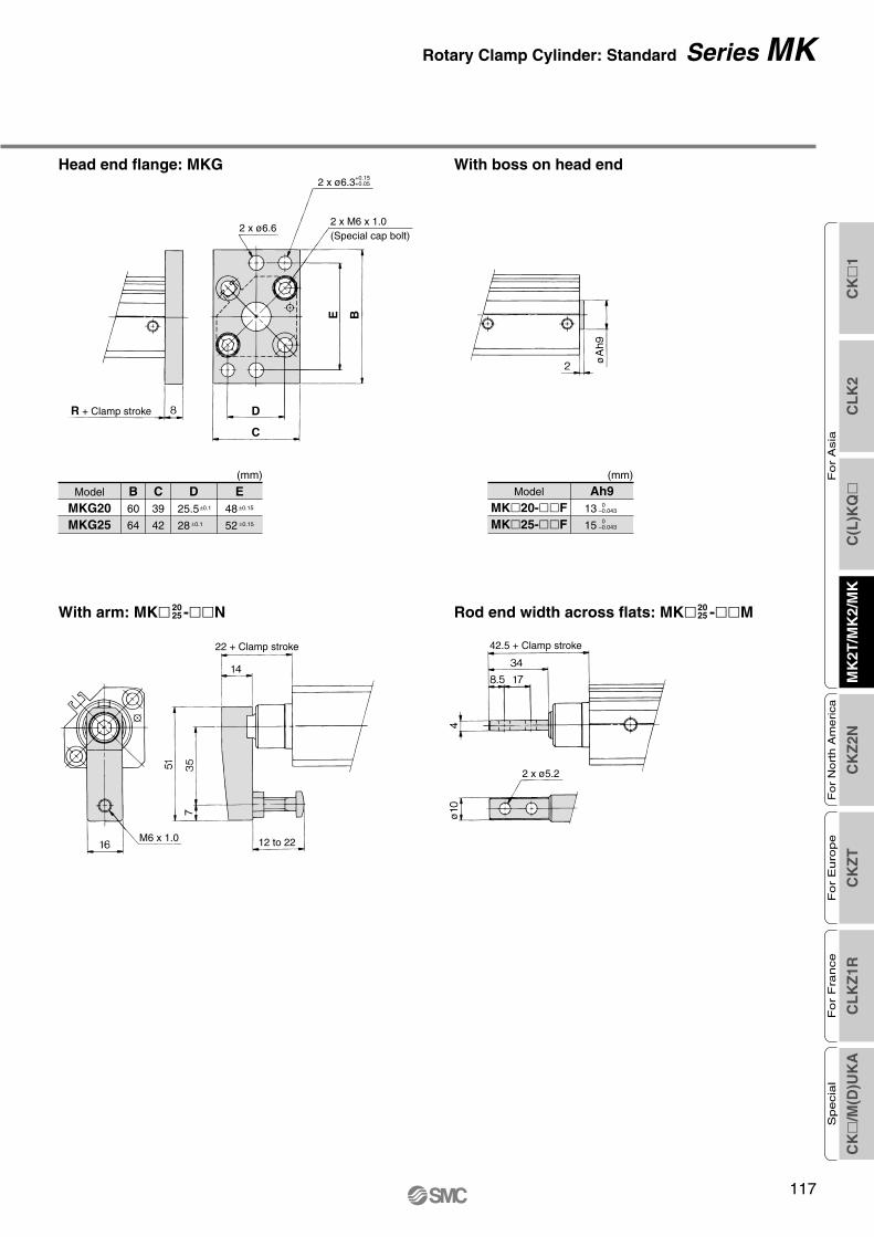
ø
ø
Model
MKG20MKG25
B60
64
C39
42
D E±0.1
±0.1
25.5
28
±0.15
±0.15
48
52
(mm)
Model
MK20-FMK25-F
Ah90
–0.043
0–0.043
13
15
(mm)
12 to 22
R + Clamp stroke
+0.152 x ø6.3+0.05
(Special cap bolt)2 x M6 x 1.0
2 x ø6.6
42.5 + Clamp stroke
D
C
E B
Head end flange: MKG With boss on head end
Rod end width across flats: MK -M2025With arm: MK -N20
25
22 + Clamp stroke
2 x ø5.2
M6 x 1.0C
K
1C
LK
2C
(L)K
Q
MK
2T/M
K2/
MK
CK
Z2N
CK
ZT
CL
KZ
1RC
K
/M(D
)UK
A
Fo
r A
sia
For
Nort
h A
merica
For
Euro
pe
For
Fra
nce
Specia
l
117
Rotary Clamp Cylinder: Standard Series MK

Model
MKAMKA50MKA63
AM6 x 1.0
M8 x 1.25
M10 x 1.5
B10
14
18
3240
Note 1) Above figures are for the D-M9, M9W, M9A, A9.Note 2) Dimension when the rod is extended is to be added to clamp stroke plus rotary stroke.
Dimensions: ø32, ø40, ø50, ø63
(mm)
(mm)
MKB32MKB40MKB50MKB63
45
52
64
77
60
69
86
103
34
40
50
60
M6 x 10
M8 x 1.25
M10 x 1.5
10
14
18
5.5
5.5
6.6
9
9 depth 7
9 depth 7
11 depth 8
14 depth 10.5
M10 x 1.5
M10 x 1.5
M12 x 1.75
M12 x 1.75
12
12
15
15
14
14
19
19
4.5
5
7
7
71.5
65
76.5
80
37
29.5
34
35
7.5
8
10.5
10.5
16
16
20
20
3
3
3.5
3.5
6.5
6.5
7.5
7.5
–0.1–0.2
–0.1–0.2
–0.1–0.2
–0.1–0.2
14
14
17
17
0–0.062
0–0.062
30
30
37
48
0–0.062
0–0.062
±0.15
±0.15
20
24
30
35
±0.15
±0.15
±0.15
±0.15
7
7
8
9
±0.15
±0.15
93.5
94.5
112
115
A B C D M NG H I J K L O P Q R S T UV
TN— TFX Yh9 ZModel
Rc1/8
Rc1/8
Rc1/4
Rc1/4
NPT1/8
NPT1/8
NPT1/4
NPT1/4
G1/8
G1/8
G1/4
G1/4
K
L
(ø3.3)TS
Q + 2 x Clamp stroke
R + Clamp stroke
øU
Z
øY
h9
5.5
X
Minimum lead wire bending radius 10
Auto switch
2 x V
K
CO
P
L
A
øB
I thread effective depth J
2 x 4 x øH counterbore
4 x øG through
2 x ø3.3 depth 3+0.15+0.05
DC
R + Clamp stroke(Basic)
Through-hole (Basic): MKB
Both ends tapped: MKA
Series MK
118

GC H
+0.152 x ø6.3+0.05
F + Clamp strokeC + Clamp stroke
2 x øG
øB
A
D
F E
Model
MKG32MKG40MKG50MKG63
A8
8
9
9
B 65
72
89
108
C48
54
67
80
F5.5
5.5
6.6
9
D E GM6 x 1.0
M6 x 1.0
M8 x 1.25
M10 x 1.5
±0.1
±0.1
34
40
50
60
±0.1
±0.1
±0.15
±0.15
56
62
76
92
±0.15
±0.15
Model
MK32-FMK40-FMK -F
Ah90
–0.052
0–0.052
0–0.062
21
28
355063
A18
18
22
22
B67
67
88
88
C20
20
22
22
D45
45
65
65
F35.5
43
53
52.5
G
15 to 25
30 to 40
Model
MK32-NMK40-NMK50-NMK63-N
HM8 x 1.25
M8 x 1.25
M10 x 1.5
M10 x 1.5
A6
6
8
8
B14
14
18
18
C53.5
61
77
76.5
D36
36
46
46
E18
18
23
23
F 9
9
11.5
11.5
G6.2
6.2
8.2
8.2
Model
MK32-MMK40-MMK50-MMK63-M
(mm) (mm)
(mm) (mm)
Head end flange: MKG With boss on head end
With arm Rod end width across flats
Rotary Clamp Cylinder: Standard Series MK
4 x G (Special cap bolt)
4 x øFR + Clamp strokeE B
B D
øA
h9
D
CA
A
CK
1C
LK
2C
(L)K
Q
MK
2T/M
K2/
MK
CK
Z2N
CK
ZT
CL
KZ
1RC
K
/M(D
)UK
A
Fo
r A
sia
For
Nort
h A
merica
For
Euro
pe
For
Fra
nce
Specia
l
119

Rotary Clamp Cylinder: Heavy Duty Type
ø20, ø25, ø32, ø40, ø50, ø63Series MK2
MK2 10Rotary clamp cylinderHeavy duty type
Number of auto switches
R20B
NilS
2 pcs.1 pc.
F
Auto switch type
∗ For applicable auto switch models, refer to the below table.
Nil Without auto switch (Built-in magnet)
Body optionNilFN
Standard (Female thread)With boss on head endWith arm
Rotary direction(Unclamp → Clamp)
ClockwiseCounterclockwise
RL
Bore size202532
20 mm25 mm32 mm
405063
40 mm50 mm63 mm
Clamp strokeClamp stroke
10 mm20 mm50 mm
Applicable bore sizeø20 to ø40ø20 to ø63ø50 to ø63
Symbol102050
Mounting bracketThrough-hole/Both ends tapped common (Standard)Head end flange
BG
M9BW
M threadRc
NPTG
ø20, ø25
ø32 to ø63
Port thread type
Nil
TNTF
∗ Head end flange is equipped with a boss mounting. Be sure to specify body option “F”.
Applicable Auto Switches/Refer to page 140 through to 150 for further information on auto switches.
—
Relay,PLC
—
200 V100 V
100 V or less—
24 V or less—
24 V
—3-wire
(NPN equivalent)
2-wireNoYesNoYes
Yes
Connector
5 V
—12 V
5 V, 12 V12 V
5 V, 12 V—
—
———
—
—
———
—
—
——————
IC circuit
—
IC circuit—
IC circuit—
—
——————
A96V
A72A93VA90VA73CA80CA79W
A96
A72HA93A90———Grommet
Type Special function Electricalentry
Wiring(Output)
Load voltage
DC AC
Lead wire length (m)0.5(Nil)
3(L)
5(Z)
None(N)
Applicableload
Pre-wiredconnector
1(M)
Auto switch model
PerpendicularIn-line
ø40 to ø63ø20 to ø32
Yes
Connector
3-wire (NPN)3-wire (PNP)
2-wire
3-wire (NPN)3-wire (PNP)
2-wire3-wire (NPN)3-wire (PNP)
2-wire4-wire
2-wire (No polarity)
24 V —Relay,PLC
P4DW∗∗—
5 V,12 V
12 V
5 V,12 V12 V5 V,12 V12 V
5 V, 12 V—
—
———
————————
—
IC circuit
—
IC circuit
—
IC circuit
—IC circuit
—
————
——
M9NVM9PVM9BVJ79C
M9NWVM9PWVM9BWVM9NAVM9PAVM9BAV
——
M9NM9PM9B
—M9NWM9PWM9BWM9NAM9PAM9BAF79F
How to Order
Diagnostic indication(2-color indication)
Water resistant(2-color indication)
Grommet
Grommet
Grommet
Diagnostic indication(2-color indication)
Diagnostic output(2-color indication)
Magnetic field resistant(2-color indication)
Indica
tor lig
ht
Ree
d s
wit
chS
olid
sta
te s
wit
ch
∗ Lead wire length symbols: 0.5 m ·········· Nil (Example) M9NW1 m ·········· M (Example) M9NWM3 m ·········· L (Example) M9NWL5 m ·········· Z (Example) M9NWZ
None ·········· N (Example) J79CN
∗ Solid state switches marked with “” are produced upon receipt of order.∗∗ For D-P4DW, ø40 to ø63 are available.∗∗ Only D-P4DW type is assembled at the time of shipment.
∗ Since there are other applicable auto switches than listed, refer to page 129 for details.∗ For details about auto switches with pre-wired connector, refer to “Best Pneumatics” catalog.∗ When mounting models D-M9(V), M9W(V), M9A(V), and A9(V) with between ø32 and ø50 on sides other than the port side, please order a switch mounting bracket
separately as per the instructions on page 128.∗ Auto switches are included, (but not assembled).
120

CK
1C
LK
2C
(L)K
Q
MK
2T/M
K2/
MK
CK
Z2N
CK
ZT
CL
KZ
1RC
K
/M(D
)UK
A
Fo
r A
sia
For
Nort
h A
merica
For
Euro
pe
For
Fra
nce
Specia
l
121
During unclamping(Extension end)80° to 100°(90°±10°)L type
During unclamping(Extension end)
80° to 100°(90°±10°)R type
Clamp part
During clamping (Retraction end)
Non-rotating accuracy±0.7° to 1.2°
Bore size (mm)202532405063
Part no.MK2-F020MK2-F025MK2-F032MK2-F040MK2-F050MK2-F063
Accessories
Centering location ring,Set pin,Bolt for cylinderbody
Mounting Bracket/Flange
Bore size (mm)202532405063
Part no.
MK-A020
MK-A032
MK-A050
Accessories
Clamp bolt,Hexagon sockethead cap screw,Hexagon nut,Spring washer
Option/Arm
Action
Rotation angle Note 1)
Rotary direction Note 2)
Rotary stroke (mm)
Clamp stroke (mm)
Theoretical clamp force (N) Note 3)
Fluid
Proof pressure
Operating pressure range
Ambient and fluid temperature
Lubrication
Piping port size
Mounting
Cushion
Stroke length tolerance
Piston speed
Non-rotating accuracy (Clamp part)
Bore size (mm)
Double acting
90° ±10°Clockwise, Counterclockwise
Air
1.5 MPa
0.1 to 1 MPa
Without auto switch: –10 to 70°C (No freezing)
With auto switch: –10 to 60°C (No freezing)
Non-lube
Through-hole/Both ends tapped common, Head end flange
Rubber bumper
50 to 200 mm/s
20 25 32 40 50 63
9.5 15 19
20, 5010, 20
100 185 300 525 825 1400
±1.2° ±0.9° ±0.7°
M5 x 0.8
+0.6–0.4
Rc1/8, NPT1/8, G1/8 Rc1/4, NPT1/4, G1/4
Note 1) Refer to “Rotary Angle” figure.Note 2) Direction of rotation viewed from the rod end when the piston rod is retracting.Note 3) At 0.5 MPa.
Specifications
Note) Theoretical output (N) = Pressure (MPa) x Piston area (cm2) x 100 Operating directionR: Rod end (Clamp)H: Head end (Unclamp)
Bore size(mm)
20
25
32
40
50
63
Rod size(mm)
Operatingdirection
12
12
16
16
20
20
R
H
R
H
R
H
R
H
R
H
R
H
Piston area(cm2)
2
3
3.7
4.9
6
8
10.5
12.5
16.5
19.6
28
31.2
0.3
60.8
90.2
112
149
182
243
319
380
502
596
851
948
0.5
100
149
185
245
300
400
525
625
825
980
1400
1560
0.7
139
208
258
341
418
557
731
870
1149
1365
1950
2172
1.0
200
298
370
490
600
800
1050
1250
1648
1961
2801
3121
Operating pressure (MPa)
Unit: N
Theoretical Output
Clamp stroke(mm) 20
260
300
—
25295
335
—
32353
555
—
40635
680
—
50—
1170
1420
63
—
1620
1890
102050
Bore size (mm)
Unit: g
Weight/Through-hole Mounting
20 2
100
133
25 3
100
153
32 5
200
166
40 7
200
198
50 13
350
345
63 25
350
531
Bore size (mm)
With boss on head end
With arm
Head end flange (including mounting bolt)
Unit: g
Additional Weight
Calculation: (Example) MK2G20-10RFN• Standard calculation: MK2B20-10R• Extra weight calculation: Head end flange
With boss on head endWith arm
260 g133 g
2 g100 g495 g
Rotary Angle
Rotary Clamp Cylinder: Heavy Duty Type Series MK2

122
!6
!7
!5
!8
!9
!4
No.12345
6
789101112131415
DescriptionRod coverCylinder tubePistonBushingGuide pin
Piston rod
BumperRing nutScraper pressureMagnetHexagon socket head set screwRound R-type retaining ringName plateC-type retaining ringArm
MaterialAluminum alloyAluminum alloyAluminum alloy
Copper bearing materialStainless steelStainless steelCarbon steel
UrethaneCopper alloy
Stainless steel—
Chromium molybdenum steelSpring steelAluminum
Carbon tool steelRolled steel
Note
ø32 to ø63 onlyNitrided
ø20, ø25 Nitridedø32 to ø63 Heated, Nickel plated
ø20 to ø32 only
Sharp end section: 90°
ø40 to ø63 only
Component PartsNo.161718192021
22
2324252627282930
DescriptionClamp boltHexagon nutHexagon socket head cap screwSpring washerCentering location ringFlangeHexagon socket head cap screwO-ringCoil scraperPiston sealGasketRod sealParallel pinWear ringBumper B
MaterialChromium molybdenum steel
Rolled steelChromium molybdenum steel
Hard steelAluminum alloy
Rolled steel
NBRPhosphor bronze
NBRNBRNBR
Stainless steelResin
Urethane
Chromiummolybdenum steel
Note
Component Parts
Qty.ø20, ø25: 2ø32 to ø63: 4
Replacement Parts: Seal Kit20 25
Not able to disassemble32 40
MK2-40-PS50
MK2-50-PS63
MK2-63-PSBore size (mm)
Kit no.Content
∗ Seal kit includes @3 to @7. Order the seal kit, based on each bore size.
Set of nos. above @3 @4 @5 @6 @7
MK220, 25 With arm (N)
MK232 With boss on head end (F)
MK240 to 63 Head end flange (G)
Series MK2
Construction
y !2 @4 o @7 r i !1 t q @6 u !0 @5 w e
@3
!3 @9 #0
@0
@1 @2
@8

CK
1C
LK
2C
(L)K
Q
MK
2T/M
K2/
MK
CK
Z2N
CK
ZT
CL
KZ
1RC
K
/M(D
)UK
A
Fo
r A
sia
For
Nort
h A
merica
For
Euro
pe
For
Fra
nce
Specia
l
123
Arm
Wrench
Hexagon wrenchkey
Operating pressure (MPa)0.1 0.2 0.4 0.6 1
0.45 0.55 0.8
2
4
6
8
10
20MK250/63
MK232/40
MK220/25
Operatingrange
Arm
leng
th l
(cm
)
Precautions for Designing and Mounting Arms
Clamp Arm Mounting1. Use a clamp arm that is available as an option.
To fabricate a clamp arm, make sure that the allowable bending moment and the inertial moment will be within the specified range.If a clamp arm that exceeds the specified value is installed, the internal mechanism in the cylinder could become damaged.
Caution
Ensuring Safety1. If one side of the piston is pressurized by sup-
plying air with the clamp arm attached, the piston will move vertically while the clamp arm rotates. This operation could be hazardous to personnel, as their hands or feet could get caught by the clamp arm, or could lead to equipment damage. Therefore, it is important to secure as a danger zone a cylindrical area with the length of the clamp arm as its radius, and the stroke plus 20 mm as its height.
Installation and Adjustment/Clamp Arm Removal and Reinstallation
1. During the removal or reinstallation of the clamp arm, make sure to use a wrench or a vise to secure the clamp arm before remov-ing or tightening the bolt.This is to prevent the bolt tightening torque from being applied to the piston rod, which could damage the cylinder’s internal mechanism.
Mounting Bolt for MK2BMounting: Mounting bolt for through-hole type is available.Ordering: Add the word “MK2B” to the mounting bolt size.Example) M5 x 75 L (MK2B)
When arms are to be made separately, their length and weight should be within the following range.
1. Allowable bending momentUse the arm length and operating pressure within Graph (1) for allowable bending mo-ment loaded piston rod.
2. Moment of inertiaWhen the arm is long and heavy, damage of internal parts may be caused due to iner-tia. Use the inertia moment and cylinder speed within Graph (2) based on arm require-ments.
Graph (1)
Graph (2)
When arm length is 8 cm, pressure should be less thanMK220/25: 0.45 MPaMK232/40: 0.55 MPaMK250/63: 0.8 MPa.
When arm’s moment of inertia is 5 x 10⁻³ kg·m2, cylinder speed should be less thanMK232/40: 66 mm/sMK250/63: 120 mm/s.For calculating moment of inertia, refer to page 110, 111, 154.Note) Maximum piston speed is equivalent to
approximately 1.6x the average piston speed. (Rough indication)
• To attach and detach the arm to and from the piston rod, fix the arm with a wrench or vise and then tighten the bolt.(If an excessive force is applied in the rotary direction, it may bring about the damage to the internal mechanism.)Refer to the following table for the tightening torque for mounting.
Cylinder model C
8.5
10.5
10
6
10.510.5
9
D 75 85 80 90 90100 80 90105135105135
Mounting bolt sizeM5 x 75 LM5 x 85 LM5 x 80 LM5 x 90 LM5 x 90 LM5 x 100 LM5 x 80 LM5 x 90 LM6 x 105 LM6 x 135 LM8 x 105 LM8 x 135 L
MK2B20-10MK2B20-20MK2B25-10MK2B25-20MK2B32-10MK2B32-20MK2B40-10MK2B40-20MK2B50-20MK2B50-50MK2B63-20MK2B63-50
l
Note) Be sure to use a flat washer to mount cylinders via through-holes.
Note) Maximum piston speed (mm/s)
10–4
10–3
10–2
2
4
6
2
4
6
2
3 MK250/63
MK232/40
MK220/25
Mom
ent o
f ine
rtia
(kg
·m2 )
50 100 20066 120
Bore size (mm)20, 2532, 4050, 63
Proper tightening torque4 to 6
8 to 1014 to 16
(N·m)
PrecautionsBe sure to read this before handling.Refer to pages 222 and 223 for Safety In-structions and “Precautions for Handling Pneumatic Devices” (M-03-E3A) for Com-mon Precautions.
Mounting bolt
Flatwasher
Operatingrange
Rotary Clamp Cylinder: Heavy Duty Type Series MK2

F
G
L
3
I + 2 x Clamp stroke
4
3 5.5(ø5.
5)
J + Clamp stroke
K
17
øH
h9
ø12
M6 x 1
2 x M5 x 0.8
D E25
F
A
G
BC
–0.110–0.2
2 x ø5.5 through2 x 2 x ø9 counterbore depth 7
M8 x 1.25Effective thread depth 11
Dimensions: ø20, ø25
Through-hole/Both Ends Tapped Common (Standard)
Note) Dimension when the rod is extended is to be added to clamp stroke plus rotary stroke.
(mm)
Model
MK2B20MK2B25
A36
40
B46.8
52
C36
40
D49
54.5
E25.5
28.5
I75.5
78.5
J62.5
65.5
K31
32
L4
5
F G±0.15
±0.15
13.5
16
±0.15
±0.15
7.5
8
øHh90
–0.052
0–0.052
20
23
Head End FlangeModel
MK2G20MK2G25
A60
64
B39
42
C D±0.1
±0.1
25.5
28
±0.15
±0.15
48
52
(mm)
With Boss on Head End
Model
MK220-FMK225-F
øAh90
–0.043
0–0.043
13
15
(mm)
12 to 22
2 x M6 x 1 (Special cap bolt)
+0.152 x ø6.3+0.05
2 x ø6.6
M6 x 1.0
24.5 + Clamp stroke
J + Clamp stroke
With arm
CB
D A
øA
h9
Series MK2
2 x ø3.3 depth 3+0.15+0.05
124

Note) The below figures illustrate auto switches D-M9, M9W, M9A, and A9.
Through-hole/Both Ends Tapped Common (Standard)
Note 1) The cylinder rod is retracted.Note 2) Rotary direction is viewed from the rod end when the piston rod is retracting.Note 3) Dimension when the rod is extended is to be added to clamp stroke plus rotary stroke.
(mm)
MK2B32MK2B40MK2B50MK2B63
45
52
64
77
60
69
86
103
34
40
50
60
54
61
73
86
31.5
35
41
47.5
5.5
5.5
6.6
9
12
12
15
15
9 depth 7
9 depth 7
11 depth 8
14 depth 10.5
14
14
17
17
–0.1–0.2
–0.1–0.2
–0.1–0.2
–0.1–0.2
M10 x 1.5
M10 x 1.5
M12 x 1.75
M12 x 1.75
M6 x 1.0
M6 x 1.0
M8 x 1.25
M10 x 1.5
±0.15
±0.15
±0.15
±0.15
20
24
30
35
±0.15
±0.15
±0.15
±0.15
7
7
8
9
17
17
22
28.5
14
14
19
19
4.5
5
7
7
101.5
102.5
122
125
76
70
81.5
85
37
29.5
34
35
7.5
8
10.5
10.5
16
16
20
20
30
30
37
48
0–0.062
0–0.062
0–0.062
0–0.062
3
3
3.5
3.5
6.5
6.5
7.5
7.5
Rc1/8
Rc1/8
Rc1/4
Rc1/4
NPT1/8
NPT1/8
NPT1/4
NPT1/4
G1/8
G1/8
G1/4
G1/4
Model A B C E F øG JøHD I MK L N O P Q R S T øU X øYh9 ZV
TN TF—
With Arm (mm)
Model
MK232-NMK240-NMK250-NMK263-N
GA18
18
22
22
B67
67
88
88
C20
20
22
22
D45
45
65
65
E39
46
58
57.5
F
15 to 25
30 to 40
Head End Flange (mm)
Model
MK2G32MK2G40MK2G50MK2G63
A8
8
9
9
øF5.5
5.5
6.6
9
GM8 x 1.25
M8 x 1.25
M10 x 1.5
M10 x 1.5
M6 x 1.0
M6 x 1.0
M8 x 1.25
M10 x 1.5
B 65
72
89
108
C48
54
67
80
D E±0.1
±0.1
34
40
50
60
±0.1
±0.1
±0.15
±0.15
56
62
76
92
±0.15
±0.15
(mm)
Model
MK232-FMK240-FMK2 -F
øAh90
–0.052
0–0.052
0–0.062
21
28
35
CO
P
L
D
K
A
C
øB
K
L
2 x 4 x N
Z X
Q + 2 x Clamp stroke
S T
R + Clamp stroke
øY
h9
øU
5.5
2 x 4 x øHcounterbore
4 x øG through
I thread length J
2 x ø3.3 depth 3+0.15+0.05
(ø3.3)
Minimum bending radius of lead wire 10
Auto switch2 x 4 x M
2 x V
Dimensions: ø32, ø40, ø50, ø63
4 x G (Special cap bolt)
4 x øF
+0.152 x ø6.3+0.05
DC
CG F
E B
B D
R + Clamp stroke
E + Clamp stroke
5063
With Boss on Head End
øA
h9
Rotary Clamp Cylinder: Heavy Duty Type Series MK2
CK
1C
LK
2C
(L)K
Q
MK
2T/M
K2/
MK
CK
Z2N
CK
ZT
CL
KZ
1RC
K
/M(D
)UK
A
Fo
r A
sia
For
Nort
h A
merica
For
Euro
pe
For
Fra
nce
Specia
l
125

126
≈≈
Auto Switch Proper Mounting Position (Detection at Stroke End) and its Mounting Height
ø12 ø16
a) b)
When mounted
a) b)
When mounted
D-M9VD-M9WVD-M9AVLD-A9V
D-M9D-M9WD-M9ALD-A9
Note 1) ( ): D-A93Note 2) Size W is suitable for mounting models D-M9, D-M9W, D-M9AL, and D-A9.Note 3) When setting an auto switch, confirm the operation and adjust its mounting position.
Applicable Cylinders: MK Series
Auto Switch Mounting Height (mm)
12
16
D-A9VD-M9VD-M9WVD-M9AVL
Bore size
Auto switchmodel
Hs19
21
Hs17
19
Auto Switch Proper Mounting Position (mm)
12
16
BA W
1.5 (4)
2 (4.5)
BA W
0
0
7.5
8
4.5
4
11.5
12
5.5
6
D-A9D-A9V
Bore size
Auto switchmodel
D-M9/M9VD-M9W/M9WVD-M9AL/M9AVL
Series MK/MK2

BA
ø20, ø25D-M9D-M9VD-M9WD-M9WVD-M9ALD-M9AVLD-A9D-A9V
ø32 to ø63 ø20, ø25 ø32 to ø63
Auto switchmodel
Bore size
3.5
4.5
10
3.5
5
10
4
6.5
9.5
4
5.5
9.5
4
6.5
9.5
5
6.5
11.5
20 25 32 40 50 63
D-A9/A9V
D-M9/M9VD-M9W/M9WVD-M9AL/M9AVL
(mm)
∗ Since this is a guideline in-cluding hysteresis, not meant to be guaranteed. (Assuming approximately ±30% dispersion.) There may be the case it will vary substantially de-pending on an ambient en-vironment.
∗ Figures for models D-M9(V), M9W(V), M9A(V)L, and A9(V) with ø12 or ø16 (MK), or ø32 or more (MK, MK2) indicate the operating range when using the existing auto switch-mounting groove, without using auto switch mounting bracket BQ2-012.
Operating Range
5.5 5 6 6 6 6.5
D-F7/J79D-F7V/J79CD-F7W/F7WVD-J79WD-F79F/F7BALD-F7BAVL/F7NTL
— — — 5 5 5 D-P4DWL
12 12 12 11 10 12
13 13 13 14 14 16
D-A7/A80D-A7H/A80HD-A73C/A80CD-A79W
Auto switchmodel
Bore size
2
3.5
6
2.5
4
7.5
3.5
5
10
3.5
6
10
4
5.5
9.5
4
5
9.5
4
6
9.5
5
6.5
11.5
12 16 20 25 32 40 50 63
D-M9W/M9WVD-M9AL/M9AVLD-A9/A9V
D-M9/M9V
(mm)
— — 5.5 5 6 6 6 6.5
D-F7/J79D-F7V/J79CD-F7W/F7WVD-J79WD-F79F/F7BALD-F7BAVL/F7NTL
— — — — — 5 5 5 D-P4DWL
— — 12 12 12 11 10 12
— — 13 13 13 14 14 16
D-A7/A80D-A7H/A80HD-A73C/A80CD-A79W
D-F7/J79D-F7VD-J79CD-F7W/J79WD-F7WVD-F7BAL/F7BAVLD-F79F/F7NTLD-A7/A80D-A73C/A80CD-A7H/A80HD-A79WD-P4DWL
MK MK2
Auto Switch Proper Mounting Position (Detection at Stroke End) and its Mounting Height
Applicable Cylinders: MK, MK2 Series
Rotary Clamp Cylinder Series MK/MK2
Auto Switch Proper Mounting PositionApplicable Cylinders: MK Series
Note) When setting an auto switch, confirm the operation and adjust its mounting position.
D-A73D-A80
A26
26.5
31.5
22.5
27
27.5
B 3.5
4
5
7.5
10.5
13.5
A30
30.5
35.5
26.5
31
31.5
B 7.5
8
9
11.5
14.5
17.5
D-A72/A7HD-A80H/A73CD-A80C/F7/F79FD-J79/F7V/J79CD-F7BA/F7WD-J79W/F7WV
D-A79WD-A9D-A9V
D-M9D-M9VD-M9WVD-M9WD-M9ALD-M9AVL
D-P4DWL
Auto switchmodel
20
25
32
40
50
63
A—
—
—
19.5
24
24.5
B—
—
—
4.5
7.5
10.5
A26
26.5
30
21
25.5
26
B 3.5
4
3.5
6
9
12
A29
29.5
33
24
28.5
29
A34
34.5
38
29
33.5
34
B 6.5
7
6.5
9
12
15
B11.5
12
11.5
14
17
20
A28.5
29
32.5
23.5
28
28.5
B6
6.5
6
8.5
11.5
14.5
Bore size
D-F7NTL
Auto Switch Proper Mounting PositionApplicable Cylinders: MK2 Series
Note) When setting an auto switch, confirm the operation and adjust its mounting position.
D-A73D-A80
A30
31
36
27
31
31.5
B8
10
13
16
19.5
22.5
D-A79WD-F7NTLD-A9D-A9V
D-M9D-M9VD-M9WD-M9WVD-M9ALD-M9AVL
D-P4DWL
Auto switchmodel
20
25
32
40
50
63
A—
—
—
20
24
24.5
B—
—
—
9
12.5
15.5
A26
27
30.5
21.5
25.5
26
B4
6
7.5
10.5
14
17
A29
30
33.5
24.5
28.5
29
A34
34.5
38
29
33.5
34
B7
9
10.5
13.5
17
20
B12
14
15.5
18.5
22
25
A28.5
29.5
33
24
28
28.5
B 6.5
8.5
10
13
16.5
19.5
Bore size
D-A72/A7HD-A80H/A73CD-A80C/F7/F79FD-J79/F7V/J79CD-F7BA/F7WD-J79W/F7WV
A26
27
32
23
27
27.5
B4
6
9
12
15.5
18.5C
K
1C
LK
2C
(L)K
Q
MK
2T/M
K2/
MK
CK
Z2N
CK
ZT
CL
KZ
1RC
K
/M(D
)UK
A
Fo
r A
sia
For
Nort
h A
merica
For
Euro
pe
For
Fra
nce
Specia
l
127

[Mounting screws set made of stainless steel]The set of stainless steel mounting screws (with nuts) described below is available and can be used depending on the operating environment. (Please order the auto switch spacer BQ-2, since it is not included.)The “D-F7BAL/F7BAVL” switch is set on the cylinder with the stainless steel screws above when shipped.When only a switch is shipped independently, “BBA2” screw set is attached.
Bore size (mm)Auto switch model
20 25 32 40 50 63D-F7/J79D-F7VD-J79CD-F7W/J79WD-F7WVD-F7BAL/F7BAVLD-F79F/F7NTLD-A7/A80D-A73C/A80CD-A7H/A80HD-A79WD-P4DWL
BQ-1
— BQP1-050
BQ-2
Note 1) For ø32 to ø50 of each cylinder series, when mounting compact auto switches on one of the three sides other than the port side (above A, B, C side) in the figure above, a separate auto switch mounting bracket is necessary as shown in the table above, so please order one separately from the cylinder.(The same is true when mounting compact auto switches with the auto switch mounting rail, not using the compact auto switch mounting groove, for diameters ø63 to ø100.)Example MKA32-10R-M9BW ····· 1 unit BQ-2 ····· 2 pcs. BQ2-012 ····· 2 pcs.
Note 2) When the cylinder is shipped, an auto switch mounting bracket and auto switch are included in the shipment.
Set screw (not used)
Set screw (not used)
D-M9D-M9VD-M9WD-M9WVD-M9ALD-M9AVLD-A9D-A9V
Auto switchmounting
surface
Auto switchmodel
Bore size (mm)
Auto switch mounting surface
Port side
qBQ-2wBQ2-012Two types of auto switch mounting bracket are used as a set.
No auto switch mountingbracket necessary.
No auto switch mountingbracket necessary.
No autoswitchmountingbracketnecessary.
A, B, C side
qBQ-1wBQ2-012Two types of auto switch mounting bracket are used as a set.
Only on auto switch mounting rail side
Auto switch mounting surface
A, B, C side
Auto switch mounting surface
Port, A, B, C side
Auto switch mounting surface
ø12, ø16 ø20, ø25 ø32, ø40, ø50 ø63Port side
B
C A
q
w
q
w
C
B
A
Port side
A
B
C
Port side
Note 4) When mounting D-M9A(V)L anywhere other than the port side of ø32, ø40, ø50, please order auto switch mounting brackets BQ2-012S, BQ-2, and the stainless steel screw set BBA2 separately.
Auto Switch Mounting Bracket/Part No.
Series MK/MK2
Note 3) When the cylinder is shipped, an auto switch mounting bracket and auto switch are included in the shipment. However, ø40 to ø63 with the D-P4DWL are assembled at the time of shipment.
Auto Switch Mounting Bracket Weight
Weight (g)
1.5
1.5
5
16
Mounting bracket part no.
BQ-1
BQ-2
BQ2-012
BQP1-050
Auto switch mounting screw
Auto switch mounting nut (Square nut)
Auto switch mounting nut (Convex type)
M3 x 0.5 x 8 l
M3 x 0.5 x 10 l
M3 x 0.5
M3 x 0.5
1
1
1
1
BQ-1
BQ-2
BQ-1
BQ-2
D-A7D-A8D-F7D-J7
Note) When using BQ-1, BBA2 may be used by itself.When using BQ-2, BQ-2 and BBA2 should be used together as a set, and used in combination with the auto switch spacer (black resin material) and stainless steel screws.
Detailed Contents of Stainless Steel Mounting Screw Set
Partno.
BBA2
Applicable autoswitch mountingbracket part no.
Applicableauto switch
Content
Description Size Qty.
128

∗ With pre-wired connector is available for solid state switches, too. For details, refer to “Best Pneumatics” catalog.∗ Normally closed (NC = b contact), solid state switch (D-F9G/F9H type) are also available. For details, refer to “Best Pneumatics” catalog.
Type Model FeaturesElectrical entry
D-F7NV, F7PV, F7BV
D-F7NWV, F7BWV
D-F7BAVL
D-F79, F7P, J79
D-F79W, F7PW, J79W
D-F7BAL
D-F7NTL
D-P5DWL
D-A73
D-A80
D-A73H, A76H
D-A80H
—
Diagnostic indication (2-color indication)
Water resistant
—
Diagnostic indication (2-color indication)
Water resistant (2-color indication)
With timer
Magnetic field resistant
—
Without indicator light
—
Without indicator light
Applicable bore size
ø20 to ø63
ø40 to ø63
ø20 to ø63
Grommet (Perpendicular)
Grommet (In-line)
Grommet (Perpendicular)
Grommet (In-line)
Reed switch
Solid state switch
Other than the models listed in “How to Order”, the following auto switches are applicable.For detailed specifications, refer to “Best Pneumatics” catalog.
CK
1C
LK
2C
(L)K
Q
MK
2T/M
K2/
MK
CK
Z2N
CK
ZT
CL
KZ
1RC
K
/M(D
)UK
A
Fo
r A
sia
For
Nort
h A
merica
For
Euro
pe
For
Fra
nce
Specia
l
129
Rotary Clamp Cylinder Series MK/MK2

∗ Since there are other applicable auto switches than listed, refer to page 137 for details.∗ For details about auto switches with pre-wired connector, refer to “Best Pneumatics” catalog.∗ Auto switches are included, (but not assembled).
Applicable Auto Switches/Refer to page 140 through to 150 for further information on auto switches.
∗ Solid state switches marked with “” are produced upon receipt of order.∗∗ For D-P4DW, ø40 to ø63 are available.∗∗ Only D-P4DW type is assembled at the time of shipment.
∗ Lead wire length symbols: 0.5 m ·········· Nil (Example) M9NW1 m ·········· M (Example) M9NWM3 m ·········· L (Example) M9NWL5 m ·········· Z (Example) M9NWZ
None ·········· N (Example) J79CN
Rotary Clamp Cylinder: Double Guide Type
ø20, ø25, ø32, ø40, ø50, ø63Series MK2T
How to Order
MK2T 10Rotary clamp cylinderDouble guide type Number of auto switches
R20B
NilS
2 pcs.1 pc.
N
Auto switch type
∗ For applicable auto switch models, refer to the below table.
∗ Arms are included when shipped, (but not assembled).
∗ Mounting bracket is included, (but not assembled). Nil Without auto switch (Built-in magnet)
Body optionNilN
Standard (Female thread)With arm
Rotary direction(Unclamp → Clamp)
Bore size202532
20 mm25 mm32 mm
405063
40 mm50 mm63 mm
Clamp strokeClamp stroke
10 mm20 mm50 mm
Applicable bore sizeø20 to ø40ø20 to ø63ø50 to ø63
Symbol102050
Mounting bracketThrough-hole/Both ends tapped common (Standard)Head end flange
BG
M9BW
M threadRc
NPTG
ø20, ø25
ø32 to ø63
Cylinder port
Nil
TNTF
Made to Order(Refer to page 131 and 151.)
ClockwiseCounterclockwise
RL
Type Special functionElectrical
entryWiring
(Output)
Load voltage
DC AC
Lead wire length (m)0.5(Nil)
3(L)
5(Z)
None(N)
Applicableload
Pre-wiredconnector
1(M)
Auto switch model
Perpendicular In-lineø32 to ø63ø20, ø25ø32 to ø63ø20, ø25
NoYesNoYes
YesGrommet
Connector
Grommet
—
200 V100 V
100 V or less—
24 V or less—
3-wire(NPN equivalent)
2-wire24 V
——
Relay,PLC
5 V
—12 V
5 V, 12 V12 V
5 V, 12 V—
—
———
—
—
———
—
—
——————
IC circuit
—
IC circuit—
IC circuit—
—
——————Diagnostic indication
(2-color indication)
A96V
A93VA90V
A96
A93A90———
—
———
A72
A73CA80CA79W
A72H
5 V,12 V
12 V
5 V,12 V12 V5 V,12 V12 V
5 V, 12 V—
—
———
————————
—
IC circuit
—
IC circuit
—
IC circuit
—IC circuit
—
————
——
Diagnostic indication(2-color indication)
Water resistant(2-color indication)
Diagnostic output(2-color indication)
Magnetic field resistant(2-color indication)
M9NVM9PVM9BV
M9NWVM9PWVM9BWVM9NAVM9PAVM9BAV
——
M9NM9PM9B
—M9NWM9PWM9BWM9NAM9PAM9BA
J79C
F79FP4DW∗∗
——
—
Yes
Connector
Grommet
Grommet
3-wire (NPN)3-wire (PNP)
2-wire
3-wire (NPN)3-wire (PNP)
2-wire3-wire (NPN)3-wire (PNP)
2-wire4-wire
2-wire (No polarity)
24 V —Relay,PLC
—
Indic
ator
light
Ree
d s
wit
chS
olid
sta
te s
wit
ch
130

CK
1C
LK
2C
(L)K
Q
MK
2T/M
K2/
MK
CK
Z2N
CK
ZT
CL
KZ
1RC
K
/M(D
)UK
A
Fo
r A
sia
For
Nort
h A
merica
For
Euro
pe
For
Fra
nce
Specia
l
131
During unclamping(Extension end)85° to 95°(90°±5°)L type
During unclamping(Extension end)
85° to 95°(90°±5°)R type
Clamp part
During clamping (Retraction end)
Non-rotating accuracy±0.5° to 1.0°
Bore size (mm)202532405063
Accessories
Hexagon sockethead cap screw
Mounting Bracket/Flange
Bore size (mm)202532405063
CQS-F020CQS-F025MK2T-F032MK2T-F040MK2T-F050MK2T-F063
MK-A020
MK-A032
MK-A050MK2T-A063
Accessories
Clamp bolt,Hexagon sockethead cap screw,Hexagon nut,Spring washer
Option/Arm
Action
Rotation angle Note 1)
Rotary direction Note 2)
Rotary stroke (mm)
Clamp stroke (mm)
Theoretical clamp force (N) Note 3)
Fluid
Proof pressure
Operating pressure range
Ambient and fluid temperature
Lubrication
Piping port size
Mounting
Cushion
Stroke length tolerance
Piston speed
Non-rotating accuracy (Clamp part)
Bore size (mm)
Double acting
90° ±5°Clockwise, Counterclockwise
Air
1.5 MPa
0.1 to 1 MPa
Without auto switch: –10 to 70°C (No freezing)
With auto switch: –10 to 60°C (No freezing)
Non-lube
Through-hole/Both ends tapped common, Head end flange
Rubber bumper
50 to 200 mm/s
20 25 32 40 50 63
19 3329
20, 5010, 20
100 185 300 525 825 1300
±1.0° ±0.5°
M5 x 0.8
+1.00
Rc1/8, NPT1/8, G1/8 Rc1/4, NPT1/4, G1/4
Note 1) Refer to “Rotary Angle” figure.Note 2) Direction of rotation viewed from the rod end when the piston rod is retracting.Note 3) At 0.5 MPa.
Specifications
Bore size(mm)
20
25
32
40
50
63
Rod size(mm)
Operatingdirection
12
12
16
16
20
25
R
H
R
H
R
H
R
H
R
H
R
H
Piston area(cm2)
2
3
3.7
4.9
6
8
10.5
12.5
16.5
19.6
26
31.2
0.3
60.8
90.2
112
149
182
243
319
380
502
596
780
948
0.5
100
149
185
245
300
400
525
625
825
980
1300
1560
0.7
139
208
258
341
418
557
731
870
1149
1365
1820
2172
1.0
200
298
370
490
600
800
1050
1250
1648
1961
2600
3121
Operating pressure (MPa)
Unit: N
Theoretical Output
Clamp stroke(mm) 20
367
433
—
25448
520
—
32806
914
—
401008
1127
—
50—
2049
2672
63—
2609
3354
102050
Bore size (mm)
Unit: g
Weight/Through-hole Mounting
20100
133
25100
153
32200
166
40 200
198
50350
345
63600
531
Bore size (mm)
With arm
Head end flange (including mounting bolt)
Unit: g
Additional Weight
X1859 With head end pin holeSymbol Description
Made to Order(For details, refer to page 151.)
Rotary Angle
Note) Theoretical output (N) = Pressure (MPa) x Piston area (cm2) x 100 Operating directionR: Rod end (Clamp)H: Head end (Unclamp)
Calculation: (Example) MK2TG20-10RN• Standard calculation: MK2TB20-10R• Extra weight calculation: Head end flange
With arm
367 g133 g100 g600 g
Part no.
Part no.
Rotary Clamp Cylinder: Double Guide Type Series MK2T

No.123
4
5
6
7
8
9101112
DescriptionRod coverCylinder tubePiston
Bushing
Guide shaft
Guide roller
Retaining ring
Piston rod
BumperSeal retainerMagnetKey
MaterialStructural steelAluminum alloyAluminum alloy
Oil-impregnated sintered alloyBronze castedStainless steelStructural steelStructural steel
Steel for special applications
Stainless steelStructural steel
UrethaneAluminum alloy
—Structural steel
Note
ø20, 25ø32 to 63ø20, 25
ø32 to 63
ø20, 25ø32 to 63ø20, 25
ø32 to 63
Component PartsNo.13141516171819202122232425
26
DescriptionArmClamp boltHexagon nutHexagon socket head cap screwSpring washerFlangeGasketCoil scraperPiston sealRod sealWear ringBottom plateRetaining ringHexagon socket head cap screw (with SW)WasherHexagon socket head cap screw
MaterialStructural steelStructural steelStructural steelStructural steel
Steel wireStructural steel
NBRBronzeNBRNBRResin
Aluminum alloySteel for special applications
Note
Structural steel
Stainless steelStructural steel
ø25, ø32 only
Component Parts
Replacement Parts: Seal Kit20
MK2T20-PS25
MK2T25-PS32
MK2T32-PS40
MK2T40-PS50
MK2T50-PS63
MK2T63-PSBore size (mm)
Kit no.Content
∗ Seal kit includes !9, @0, @1, @2. Order the seal kit, based on each bore size.
Set of nos. above !99 @0 @1 @2
MK2T20 to 63
In case of clamp stroke 50 mm
Head end flange (G)With arm (N)
!8
!6
@4!9 @5
!4
!5
!3
!7
!6
oe@3@1!1otyuwqr!9@2@5
@6
!0!2@0i
Series MK2T
Construction
132

CK
1C
LK
2C
(L)K
Q
MK
2T/M
K2/
MK
CK
Z2N
CK
ZT
CL
KZ
1RC
K
/M(D
)UK
A
Fo
r A
sia
For
Nort
h A
merica
For
Euro
pe
For
Fra
nce
Specia
l
133
Arm
Wrench
Mounting bolt
Flatwasher
Hexagonwrenchkey
Operating pressure (MPa)0.1 0.2 0.4 0.6 1
0.45 0.55 0.8
2
4
6
8
10
20MK2T50/63
MK2T32/40
MK2T20/25
Operatingrange
Arm
leng
th l
(cm
)
Precautions for Designing and Mounting Arms
Mounting: Mounting bolt for through-hole type is available.Ordering: Add the word “MK2TB” to the mounting bolt size.Example) M5 x 115 L (MK2TB) 4 pcs.
Mounting Bolt for MK2TB
When arms are to be made separately, their length and weight should be within the following range.
1. Allowable bending momentUse the arm length and operating pressure within Graph (1) for allowable bending mo-ment loaded piston rod.
2. Moment of inertiaWhen the arm is long and heavy, damage of internal parts may be caused due to iner-tia. Use the inertia moment and cylinder speed within Graph (2) based on arm require-ments.
Graph (1)
When arm length is 8 cm, pressure should be less thanMK2T20/25: 0.45 MPaMK2T32/40: 0.55 MPaMK2T50/63: 0.8 MPa.
When arm’s moment of inertia is 1 x 10⁻² kg·m2, cylinder speed should be less thanMK2T32/40: 85 mm/sMK2T50/63: 140 mm/s.For calculating moment of inertia, refer to page 110, 111, 154.Note) Maximum piston speed is equivalent to
approximately 1.6x the average piston speed. (Rough indication)
• To attach and detach the arm to and from the piston rod, fix the arm with a wrench or vise and then tighten the bolt.(If an excessive force is applied in the rotary direction, it may bring about the damage to the internal mechanism.)Refer to the following table for the tightening torque for mounting.
Cylinder model C11 11 8.5 8.511.511.5 7.5 7.513.510 13 14
D115135115135145165145165185245185250
Mounting bolt sizeM5 x 115 LM5 x 135 LM5 x 115 LM5 x 135 LM5 x 145 LM5 x 165 LM5 x 145 LM5 x 165 LM6 x 185 LM6 x 245 LM8 x 185 LM8 x 250 L
MK2TB20-10MK2TB20-20MK2TB25-10MK2TB25-20MK2TB32-10MK2TB32-20MK2TB40-10MK2TB40-20MK2TB50-20MK2TB50-50MK2TB63-20MK2TB63-50
l
Bore size (mm)20, 2532, 40
5063
Proper tightening torque4 to 6
8 to 1014 to 16
106 to 127
(N·m)
Graph (2)
Note) Maximum piston speed (mm/s)
10–4
10–3
10–2
10–1
Mom
ent o
f ine
rtia
(kg
·m2
)
50 100 20014085
MK2T50/63
MK2T32/40
MK2T20/25
Operatingrange
Precautions
Clamp Arm Mounting1. Use a clamp arm that is available as an option.
To fabricate a clamp arm, make sure that the allowable bending moment and the inertial moment will be within the specified range.If a clamp arm that exceeds the specified value is installed, the internal mechanism in the cylinder could become damaged.
Caution
Ensuring Safety1. If one side of the piston is pressurized by sup-
plying air with the clamp arm attached, the piston will move vertically while the clamp arm rotates. This operation could be hazardous to personnel, as their hands or feet could get caught by the clamp arm, or could lead to equipment damage. Therefore, it is important to secure as a danger zone a cylindrical area with the length of the clamp arm as its radius, and the stroke plus 20 mm as its height.
Installation and Adjustment/Clamp Arm Removal and Reinstallation
1. During the removal or reinstallation of the clamp arm, make sure to use a wrench or a vise to secure the clamp arm before remov-ing or tightening the bolt.This is to prevent the bolt tightening torque from being applied to the piston rod, which could damage the cylinder’s internal mechanism.
Be sure to read this before handling.Refer to pages 222 and 223 or Safety In-structions and “Precautions for Handling Pneumatic Devices” (M-03-E3A) for Com-mon Precautions.
Note) Be sure to use a flat washer to mount cylinders via through-holes.
Rotary Clamp Cylinder: Double Guide Type Series MK2T

Dimensions: ø20, ø25
Head End FlangeModel
MK2TG20MK2TG25
A60
64
B39
42
C48
52
(mm)
Through-hole/Both Ends Tapped Common (Standard) (mm)
Clamp stroke 20 mmClamp stroke 10 mmBore size
36
40
47
52
25.5
28
116.5
119
110.5
113
59
59
A øB CQ R S
136.5
139
130.5
133
69
69
Q R S2025
17.5
14
51 357
1611 to 22
M6 x 1.0
ø12
4.5
QR
5.5S
1717
2 x M5 x 0.8
2 x 4 x M6 x 1.0
AC
10 –0.07–0.15
10–0
.07
–0.1
5
øB
CA
M8 x 1.25Thread length 11 4 x ø5.4 through
2 x 4 x ø9 counterbore depth 7
C8 B
A
2 x ø6.6
Series MK2T
134

BE
DC
A
4 x øF
F
EA
B D10
C G
K
QR
ST
NN
øU
2 x 4 x M thread 2 x V
A C D
øB
O
PACD
4 x øG through
2 x 4 x øH counterbore depth
I thread length J
Dimensions: ø32, ø40, ø50, ø63
With Arm (mm)
GM8 x 1.25
M8 x 1.25
M10 x 1.5
M10 x 1.5
A18
18
22
32
B67
67
88
91
C20
20
22
32
D45
45
65
65
E21.5
21
29.5
34.5
F15 to 25
15 to 25
20 to 40
20 to 40
Head End Flange (mm)
Model
MK2TG32MK2TG40MK2TG50MK2TG63
A8
8
9
9
øF5.5
5.5
6.6
9
B 65
72
89
108
C48
54
67
80
D E34
40
50
60
56
62
76
92
Model
MK2T32-NMK2T40-NMK2T50-NMK2T63-N
Through-hole/Both Ends Tapped Common (Standard) (mm)
45
52
64
77
60
69
86
103
34
40
50
60
5.5
5.5
6.6
9
9 depth 7
9 depth 7
11 depth 8
14 depth 10.5
M10 x 1.5
M10 x 1.5
M12 x 1.75
M16 x 2
M6 x 1.0
M6 x 1.0
M8 x 1.25
M10 x 1.5
12
12
15
21
N
14
14
19
19
17
17
22
28.5
4.5
5
7
7
16
16
20
25
Rc1/8
Rc1/8
Rc1/4
Rc1/4
NPT1/8
NPT1/8
NPT1/4
NPT1/4
G1/8
G1/8
G1/4
G1/4
Nil TN TFV
A øB C D G H I J
6
6
7
8
K M
14
14
17
22 –0.07–0.15
–0.07–0.15
–0.07–0.15
–0.07–0.1532
405063
Bore size O P øU
148
151.5
—
—
140
144
—
—
74
75
—
—
7.5
8
—
—
Q R S T168
171.5
191
192
160
164
179
182
84
85
91.5
93
7.5
8
12.5
10.5
Q R S T—
—
254.5
256
—
—
242.5
246
—
—
121.5
123
—
—
14
15
Q R S T32405063
Bore sizeClamp stroke 50 mmClamp stroke 20 mmClamp stroke 10 mm
Rotary Clamp Cylinder: Double Guide Type Series MK2T
CK
1C
LK
2C
(L)K
Q
MK
2T/M
K2/
MK
CK
Z2N
CK
ZT
CL
KZ
1RC
K
/M(D
)UK
A
Fo
r A
sia
For
Nort
h A
merica
For
Euro
pe
For
Fra
nce
Specia
l
135

Operating Range (Dimensions) (mm)
Operating Range
D-A7/A80D-A7H/A80HD-A73C/A80C
Auto switch modelBore size
20
5.5 5.5 6.5 5.5 6.5 6.5
3 3.5 4.5 4.5 5 5
— — 6 6 6 6.5
25 32 40 50 63
D-F7/J79D-F7V/F79F/J79CD-F7W/F7WVD-F79F/F7BAL/F7BAVL/F7NTL
D-M9W/M9WVD-M9AL/M9AVL
D-M9/M9V
—
——
—
——
9.5
6 —
11.5
7 5
11
7 5
13.5
9.5 5
D-A79WD-P4DWL
9 9.5 9 9.5 9.5 11 D-A9/A9V
∗ Since this is a guideline including hysteresis, not meant to be guaranteed. (Assuming approximately ±30% dispersion.) There may be the case it will vary substantially depending on an ambient en-vironment.
∗ Figures for models D-M9(V), M9W(V), M9A(V)L, and A9(V) with ø32 or more indicate the operating range when using the existing auto switch-mounting groove, without using auto switch mounting bracket (BQ2-012).
Other than the models listed in “How to Order”, the following auto switches are applicable.For detailed specifications, refer to “Best Pneumatics” catalog.
Type Model FeaturesElectrical entryD-F7NV, F7PV, F7BVD-F7NWV, F7BWVD-F7BAVLD-F79, F7P, J79D-F79W, F7PW, J79WD-F7BALD-F7NTLD-P5DWLD-A73D-A80D-A73H, A76HD-A80H
—Diagnostic indication (2-color indication)
Water resistant—
Diagnostic indication (2-color indication)Water resistant (2-color indication)
With timerMagnetic field resistant
—Without indicator light
—Without indicator light
Applicable bore size
ø20 to ø63
ø40 to ø63
ø20 to ø63
Grommet (Perpendicular)
Grommet (In-line)
Grommet (Perpendicular)
Grommet (In-line)Reed switch
Solid state switch
∗ With pre-wired connector is available for solid state switches, too. For details, refer to “Best Pneumatics” catalog.∗ Normally closed (NC = b contact), solid state switch (D-F9G/F9H type) are also available. For details, refer to “Best Pneumatics” catalog.
ø20 to ø63 ø32 to ø63B
A
Auto switch (Rail mounting)B
A
Auto switch (Direct mounting)D-M9D-M9VD-M9WD-M9WVD-M9ALD-M9AVLD-A9D-A9V
Mounting Rail mounting Direct mounting
Model
MK2T20MK2T25MK2T32MK2T40MK2T50-20stMK2T50-50stMK2T63-20stMK2T63-50st
D-A7D-A8
A——
73 (73.5)74 (74.5)89.5 (90)
119.5 (120)91.5 (92)
121.5 (122)
B——
10.5 (11)13 (13.5)18.5 (19)22 (22.5)19.5 (20)23.5 (24)
A——
73.5 74.590
120 92
122
B——
11 13.519 22.520 24
A——
70.5 71.587
117 89
119
B——8
10.516 19.517 21
A———70
85.5115.5 87.5117.5
B———9
14.518 15.519.5
A 60.5
61 76 77
92.5122.5 94.5124.5
B9
11 13.516 21.525 22.526.5
A 56.5
57 72 73
88.5118.5 90.5120.5
B5 7
9.512 17.521 18.522.5
A63
63.5 78.5 79.5
95 125
97 127
B11.513.516 18.524 27.525 29
D-A7H/A80HD-A73C/A80CD-F7/F79F/J79D-F7V/J79CD-F7BA/F7WD-J79W/F7WV
D-A79W D-P4DWL D-A9D-A9V
D-M9D-M9VD-M9WD-M9WVD-M9ALD-M9AVL
D-F7NTL
∗ ( ): D-A72Note) When setting an auto switch, confirm the operation and adjust its mounting position.
136
Series MK2T
Auto Switch Proper Mounting Position (Detection at Stroke End)
D-F7/J79D-F7VD-J79CD-F7W/J79WD-F7WVD-F7BAL/F7BAVLD-F79F/F7NTLD-A7/A80D-A73C/A80CD-A7H/A80HD-A79WD-P4DWL

Note 4) When mounting D-M9A(V)L anywhere other than the port side of ø32, ø40, ø50, please order auto switch mounting brackets BQ2-012S, BQ-2, and the stainless steel screw set BBA2 separately.
[Mounting screws set made of stainless steel]The set of stainless steel mounting screws (with nuts) described below is available and can be used depending on the operating environment. (Please order the auto switch spacer BQ-2, since it is not included.)“D-F7BAL/F7BAVL” switch is set on the cylinder with the stainless steel screws above when shipped.When only a switch is shipped independently, “BBA2” screws are attached.
Auto Switch Mounting Bracket/Part No.
Note 3) When the cylinder is shipped, an auto switch mounting bracket and auto switch are included in the shipment. However, ø40 to ø63 D-P4DWL are assembled at the time of shipment.
Bore size (mm)Auto switch model
32 40 50 63D-F7/J79D-F7VD-J79CD-F7W/J79WD-F7WVD-F7BAL/F7BAVLD-F79F/F7NTLD-A7/A80D-A73C/A80CD-A7H/A80HD-A79WD-P4DWL — BQP1-050
BQ-2
Note 1) For ø32 to ø50 of each cylinder series, when mounting compact auto switches on one of the three sides other than the port side (above A, B, C side) in the figure above, a separate auto switch mounting bracket is necessary as shown in the table above, so please order one separately from the cylinder.(The same is true when mounting compact auto switches with the auto switch mounting rail, not using the compact auto switch mounting groove, for diameters ø63.)Example MK2TB32-10R-M9BW ····· 1 unit BQ-2 ····· 2 pcs. BQ2-012 ····· 2 pcs.
Note 2) When the cylinder is shipped, an auto switch mounting bracket and auto switch are included in the shipment.
D-M9D-M9VD-M9WD-M9WVD-M9ALD-M9AVLD-A9D-A9V
Auto switchmounting
surface
Auto switchmodel
Bore size (mm)
Auto switch mounting surface
Port side
qBQ-2wBQ2-012Two types of auto switch mounting bracket are used as a set.
No auto switch mountingbracket necessary.
No auto switch mountingbracket necessary.
No auto switch mountingbracket necessary.
A, B, C side
Auto switch mounting surface
A, B, C side
Auto switch mounting surface
Port, A, B, C side
ø20, ø25 ø32, ø40, ø50 ø63
A
B
C
Port side
C
B
A
Port side
Set screw (not used)
q
w
Port side
B
C A
Rotary Clamp Cylinder: Double Guide Type Series MK2T
Auto Switch Mounting Bracket Weight
Weight (g)
1.5
1.5
5
16
Mounting bracket part no.
BQ-1
BQ-2
BQ2-012
BQP1-050
Auto switch mounting screw
Auto switch mounting nut (Square nut)
Auto switch mounting nut (Convex type)
M3 x 0.5 x 8 l
M3 x 0.5 x 10 l
M3 x 0.5
M3 x 0.5
1
1
1
1
BQ-1
BQ-2
BQ-1
BQ-2
D-A7D-A8D-F7D-J7
Note 5) When using BQ-1, BBA2 may be used by itself.When using BQ-2, BQ-2 and BBA2 should be used together as a set, and used in combination with the auto switch spacer (black resin material) and stainless steel screws.
Detailed Contents of Stainless Steel Mounting Screw SetPartno.
BBA2
Applicable autoswitch mountingbracket part no.
Applicableauto switch
Content
Description Size Qty.
CK
1C
LK
2C
(L)K
Q
MK
2T/M
K2/
MK
CK
Z2N
CK
ZT
CL
KZ
1RC
K
/M(D
)UK
A
Fo
r A
sia
For
Nort
h A
merica
For
Euro
pe
For
Fra
nce
Specia
l
137

Series MK/MK2/MK2TAuto Switch Specifications
Specifications
∗ Lead wire length Switch connection side 0.5 mLoad connection side 0.5 m
Part no.
Load voltage
Max. load current
CD-P11
100 VAC
25 mA
200 VAC
12.5 mA
CD-P12
24 VDC
50 mA
Auto Switch Common Specifications
Type
Leakage current
Operating time
Impact resistance
Insulation resistance
Withstand voltage
Ambient temperature
Enclosure
Reed switch
None
1.2 ms
300 m/s2
50 MΩ or more at 500 VDC Mega (between lead wire and case)
–10 to 60°CIEC60529 standard IP67
Solid state switch
3-wire: 100 µA or less 2-wire: 0.8 mA or less
1 ms or less ∗2)
1000 m/s2
1500 VAC for 1 minute (between lead wire and case) ∗1) 1000 VAC for 1 minute (between lead wire and case)
Lead Wire Length
Lead wire length indication
(Example)
LM
0.5 m
3 m1 m
5 mZ
Nil
Lead wire length
LD-M9BW
(Example)
Flexible specification
61D-F79F-
Contact Protection Box: CD-P11/CD-P12<Applicable switch model> Internal Circuit
Dimensions
Connection
CD-P11
CD-P12
Note 4) Tolerance of Lead Wire LengthLead wire length Tolerance
0.5 m
1 m
3 m
5 m
± 15 mm
± 30 mm
± 90 mm
± 150 mm
Lead Wire Part No. with Connector (applicable to connector type only)
D-LC05
D-LC30
D-LC50
Model Lead wire length
0.5 m
3.0 m
5.0 m
Note 1) Applicable auto switch with 5 m lead wire “Z”Solid state switch: Manufactured upon receipt of order as standard.
Note 2) To designate solid state switch with flexible specifications, add “-61” after the lead wire length. Flexible cable is used for the D-M9(V), D-M9W(V), D-M9A(V), D-M9A(V) as standard. There is no need to place the suffix -61 to the end of part number.
Note 3) 1 m (M): D-M9W(V), M9A(V)L
∗1) For connector type D-A73C and A80C, 1000 VAC for 1 minute (between lead wire and case).∗2) Except solid state switch with timer D-F7NTL, and magnetic field resistant 2-color indication solid state switch D-P4DWL.
D-A9/A9V, A7(H)(C), A80(H)(C), A79W typeThe above auto switch type does not have a built-in contact protection circuit.q Where the operation load is an inductive load.w Where the wiring length to load is greater than 5 m. e Where the load voltage is 100/200 VAC.
Therefore, use a contact protection box with the switch for any of the above cases:The contact life may be shortened (due to permanent energizing conditions).(Where the load voltage is 110 VAC)When the load voltage is increased by more than 10% to the rating of applicable auto switches (except D-A73C/A80C/A79W) above, use a contact protection box (CD-P11) to reduce the upper limit of the load current by 10% so that it can be set within the range of the load current range, 110 VAC.
To connect a switch unit to a contact protection box, connect the lead wire from the side of the contact protection box marked SWITCH to the leadwire coming out of the switch unit. Keep the switch as close as possible to the contact protection box, with a lead wire length of no more than 1 meter.
Surge absorberChoke
coil
OUT Brown
OUT Blue
OUT (+)Brown
OUT (–)Blue
Choke coil
Zener diode
138

Auto SwitchConnections and Examples
Basic Wiring
Solid state 3-wire, NPN
• Sink input specification3-wire, NPN
2-wire
• Source input specification3-wire, PNP
2-wire 2-wire
Solid state 3-wire, PNP
Connect according to the applicable PLC input specifications, since the connection method will vary depending on the PLC input specifications.
(Power supplies for switch and load are separate.)
Load
Example of AND (Serial) and OR (Parallel) Connection
Example of Connection to PLC (Programmable Logic Controller)
(Solid state)2-wire(Reed)
Switch main circuit
Brown
BlackLoad
Brown
Black
Blue
Load
Brown
Black
Blue
Load
Brown
Blue
Load
Brown
Blue
Indicator light protectivecircuitetc.
Brown
Blue
Load
Brown
BlueLoad
Switch main circuit
Switch main circuit
Switch main circuit
Switch main circuit
Indicator light protectivecircuitetc.
Blue
Switch
InputBlack
COM
Brown
Blue
Switch
Input
Blue COM
Brown
Switch
InputBlack
PLC internal circuitCOM
Brown
Blue
PLC internal circuit
PLC internal circuit
PLC internal circuit
Switch
InputBlue
COMBrown
• 3-wireOR connection for NPN output
2-wire with 2-switch AND connection 2-wire with 2-switch OR connection
AND connection for NPN output(using relays)
AND connection for NPN output(performed with switches only)
The indicator lights will illuminate when both switches are turned ON.
Switch 1
Switch 2
Load
BrownBlackBlue
BrownBlackBlue
Switch 1
Brown
Switch 2
BlackBlue
Relay
Relay
BrownBlackBlue
Load
Relay contact
Switch 1
Brown
Switch 2
BlackBlue
Load
BrownBlackBlue
Switch 1
Switch 2
Brown
Blue
Brown
Blue
LoadSwitch 1
Switch 2
Brown
Blue
Brown
Blue
Load
(Solid state) (Reed)When two switches are con-nected in series, a load may malfunction because the load voltage will decrease when in the ON state.The indicator lights will illu-minate if both of the switches are in the ON state.
When two switches are connected in par-allel, a malfunction may occur because the load voltage will increase when in the OFF state.
Because there is no current leakage, the load voltage will not in-crease when turned OFF. However, depend-ing on the number of switches in the ON state, the indicator lights may sometimes dim or not light because of the dispersion and reduc-tion of the current flow-ing to the switches.
Power supply ResidualLoad voltage at ON = voltage – voltage x 2 pcs.
= 24 V - 4 V x 2 pcs.= 16 V
Example: Power supply is 24 VDC. Internal voltage drop in switch is 4 V.
Load voltage at OFF = Leakage current x 2 pcs. x Load impedance= 1 mA x 2 pcs. x 3 kΩ= 6 V
Example: Load impedance is 3 kΩ.Leakage current from switch is 1 mA.
CK
1C
LK
2C
(L)K
Q
MK
2T/M
K2/
MK
CK
Z2N
CK
ZT
CL
KZ
1RC
K
/M(D
)UK
A
Fo
r A
sia
For
Nort
h A
merica
For
Euro
pe
For
Fra
nce
Specia
l
139

ø2.
72
22(24.5)
2.8 4.5
4
10( ): D-A93
Indicator lightD-A90 type comes without indicator light.
Most sensitive position
Slotted set screwM2.5 x 4 l
4
9.1
5.1
ø2.7
10
4.5
Most sensitive position
2
22
6
Indicator lightD-A90 type comes without indicator light.
Slotted set screw
M2.5 x 4 l
Grommet PLC: Programmable Logic Controller
D-A90(V) (Without indicator light)Auto switch model
Applicable load
Load voltage
Maximum load current
Contact protection circuit
Internal resistance
Standards
D-A93(V)/D-A96(V) (With indicator light)Auto switch model
Applicable load
Load voltage
Contact protection circuit
Indicator light
Standards
Load current range and max. load current
Internal resistance
Lead wiresD-A90(V)/D-A93(V) — Oilproof heavy-duty vinyl cable: ø2.7, 0.18 mm2 x 2 cores (Brown, Blue), 0.5 mD-A96(V) — Oilproof heavy-duty vinyl cable: ø2.7, 0.15 mm2 x 3 cores (Brown, Black, Blue), 0.5 m
Note 1) Refer to page 138 for reed switch common specifications.Note 2) Refer to page 138 for lead wire lengths.Note 3) Under 5 mA, the visuality of an indicator light is worsen. Furthermore, although it could be
impossible to recognize it under 2.5 mA, but there would be no problem only with 1 mA or more in terms of the contact output.
D-A90/D-A90V
IC circuit, Relay, PLC
24 VAC/DC or less
50 mA
None
1 Ω or less (including lead wire length of 3 m)
CE marking
48 VAC/DC or less
40 mA
100 VAC/DC or less
20 mA
D-A93/D-A93V
Relay, PLC
24 VDC
5 to 40 mA
None
D-A93 — 2.4 V or less (to 20 mA)/3 V or less (to 40 mA)D-A93V — 2.7 V or less
Red LED illuminates when turned ON.
CE marking
100 VAC
5 to 20 mA
D-A96/D-A96V
IC circuit
4 to 8 VDC
20 mA
0.8 V or less
Note) q In a case where the operation load is an inductive load.
w In a case where the wiring load is greater than 5 m.
e In a case where the load voltage is 100 VAC.
Use the auto switch with a contact protection box in any of the above mentioned cases. (For details about the contact protection box, refer to page 138.)
Fix the auto switch with the existing screw installed on the switch body. The auto switch may be damaged if a screw other than the one supplied is used.
PrecautionsCaution
Model
Lead wire length(m)
0.5
3
D-A90
6
30
D-A90V
6
30
D-A93
6
30
D-A93V
6
30
D-A96
8
41
D-A96V
8
41
(g)
Weight
Auto Switch Internal Circuit
D-A90(V)
D-A93(V)
D-A96(V)
DimensionsD-A90/D-A93/D-A96
Note 3)
D-A90V/D-A93V/D-A96V
Unit: mm
Reed Switch: Direct Mounting StyleD-A90(V)/D-A93(V)/D-A96(V)
Auto Switch SpecificationsFor details about certified products conforming to international standards, visit us at www.smcworld.com.
Contact protection box
CD-P11
CD-P12
OUT (±)Brown
OUT (±)Blue
Ree
d sw
itch
Blue
LED diode
Resistor
Zener diode
BrownContact protection box
CD-P11
CD-P12
OUT (+)Brown
OUT (–)Blue
Ree
d sw
itch
LED diode
Resistor
Reverse current prevention diode
OUTBlack
DC (+)Brown
DC (–)Blue
Load
Ree
d sw
itch
(+)
(–)
DC powersupply
140

Auto Switch Specifications
Dimensions
GrommetElectrical entry direction: Perpendicular
Reed Switch: Rail Mounting StyleD-A72
Weight
Auto switch model
0.5
3
10
47
D-A72
Unit: g
Unit: mm
Lead wire length(m)
PLC: Programmable Logic Controller
Auto Switch Internal CircuitD-A72
Note) For D-A72, be sure to use the contact protection box. (For details about the contact protection box, refer to page 138).
D-A7 (With indicator light)Auto switch model
Applicable load
Load voltage
Load current range Note 3)
Contact protection circuit
Internal resistance
Indicator light
Standards
D-A72
Relay, PLC
200 VAC
5 to 10 mA
None
2.4 V or less
Red LED illuminates when turned ON.
CE marking
8.5 Most sensitive position
8
14
64
22
Indicator lightø3.2
6.2
3
ø3.4
11.7
Lead wires — Oilproof heavy-duty vinyl cable: ø3.4, 0.2 mm2 x 2 cores (Brown, Blue), 0.5 mNote 1) Refer to page 138 for reed switch common specifications.Note 2) Refer to page 138 for lead wire lengths.Note 3) Under 5 mA, the visuality of an indicator light is worsen. Furthermore, although it could be
impossible to recognize it under 2.5 mA, but there would be no problem only with 1 mA or more in terms of the contact output.
Blue
LED diode
Resistor
Zener diode
Brown
OUTBlue
OUTBrownChoke
coil
Contact protection boxCD-P11
Surge absorber
Ree
d sw
itch
CK
1C
LK
2C
(L)K
Q
MK
2T/M
K2/
MK
CK
Z2N
CK
ZT
CL
KZ
1RC
K
/M(D
)UK
A
Fo
r A
sia
For
Nort
h A
merica
For
Euro
pe
For
Fra
nce
Specia
l
141

Auto Switch Internal CircuitD-A72H
Weight
Dimensions
Auto switch model
0.5
3
10
47
D-A72H
D-A72H
Unit: g
GrommetElectrical entry direction: In-line
Lead wire length(m)
PLC: Programmable Logic Controller
Lead wires — Oilproof heavy-duty vinyl cable: 0.2 mm2 x 2 cores (Brown, Blue), 0.5 mNote 1) Refer to page 138 for reed switch common specifications.Note 2) Refer to page 138 for lead wire lengths.Note 3) Under 5 mA, the visuality of an indicator light is worsen. Furthermore, although it could be
impossible to recognize it under 2.5 mA, but there would be no problem only with 1 mA or more in terms of the contact output.
Note) For D-A72H, be sure to use the contact protection box. (For details about the contact protection box, refer to page 138.)
D-A72H (With indicator light)Auto switch model
Applicable load
Load voltage
Maximum load current and Load current range Note 3)
Contact protection circuit
Internal resistance
Indicator light
Standards
D-A72H
Relay, PLC
200 VAC
5 to 10 mA
None
2.4 V or less
Red LED illuminates when turned ON.
CE marking
2
ø3.
4
22
8.5 Most sensitive position
15
74
8
Indicator light
ø3.2
SMC
6.2
3.3
10.2
Unit: mm
Auto Switch Specifications
Reed Switch: Rail Mounting StyleD-A72H
Blue
LED diode
Resistor
Zener diode
Brown
OUTBlue
OUTBrownChoke
coil
Contact protection boxCD-P11
Surge absorber
Ree
d sw
itch
142

Indicator light
Lead wire withconnector
D-A80C type comes without indicator light.
Most sensitive position
Tightening ring
Sleeve
Connector
Auto Switch Internal Circuit
D-A73C
D-A80C
Dimensions
Weight Unit: g
Unit: mm
Precautions1. Confirm that the connector is appropriate-
ly tightened. If tightened insufficiently, the waterproof performance will deteriorate.
2. For how to handle a connector, refer to the below figures.
Caution
Auto switch model
0.5
3
5
12
54
84
12
54
84
D-A73C D-A80C
Lead wire length(m)
D-A73C (With indicator light)
PLC: Programmable Logic Controller
Auto switch model
Applicable load
Load voltage
Load voltage Note 4)
Contact protection circuit
Internal resistance
Indicator light
Standards
D-A73C
Relay, PLC
24 VDC
5 to 40 mA
None
2.4 V or less
Red LED illuminates when turned ON.
CE marking
D-A80C
Relay, IC circuit, PLC
50 mA
None
1 Ω or less (including lead wire length of 3 m)
CE marking
D-A80C (Without indicator light)Auto switch model
Applicable load
Load voltage
Maximum load current
Contact protection circuit
Internal resistance
Standards
24 VAC/DC
Connector
Note) q In a case where the operation load is an inductive load.
w In a case where the wiring load is greater than 5 m.
Use the auto switch with a contact protection box in any of the above mentioned cases. (For details about the contact protection box, refer to page 138.)
How to Insert the Connector
Turn the connector so it faces in the direction shown in the figure, and after inserting it until the sleeve hits the auto switch, screw on the tightening ring.(Do not screw it on using pliers or other tools.)
Reed Switch: Rail Mounting StyleD-A73C/D-A80C
Auto Switch Specifications
For details about certified products conforming to international standards, visit us at www.smcworld.com.
Lead wires — Oilproof heavy-duty vinyl cable: 3.4 mm2 x 2 cores (Brown, Blue), 0.5 mNote 1) Refer to page 138 for reed switch common specifications.Note 2) Refer to page 138 for lead wire lengths.Note 3) Lead wire with connector may be shipped attached to the switch.Note 4) Under 5 mA, the visuality of an indicator light is worsen. Furthermore, although it could be
impossible to recognize it under 2.5 mA, but there would be no problem only with 1 mA or more in terms of the contact output.
LED diode
Resistor
Zener diode
Brown
BlueOUT (–)Blue
OUT (+)BrownChoke
coil
Contact protection boxCD-P11
Zener diode
Ree
d sw
itch
Ree
d sw
itch OUT (+)
Brown
OUT (–)Blue
Contact protection box
CD-P11
CD-P12
CK
1C
LK
2C
(L)K
Q
MK
2T/M
K2/
MK
CK
Z2N
CK
ZT
CL
KZ
1RC
K
/M(D
)UK
A
Fo
r A
sia
For
Nort
h A
merica
For
Euro
pe
For
Fra
nce
Specia
l
143

1.8
36.
2
14
ø3.4
11.5 Most sensitive position
15
74
8
23.5
Indicator light
ø3.2
Operatingrange
Optimum operatingposition
DisplayRed Green Red
Auto Switch Internal Circuit
D-A79W
Weight
Dimensions
Unit: g
Unit: mm
Grommet The optimum operating
position can be determined by the color of the light. (Red → Green ← Red)
Indicator light / Display method
Auto switch model
0.5
3
11
53
D-A79W
Lead wire length(m)
D-A79W (With indicator light)
PLC: Programmable Logic Controller
Auto switch model
Applicable load
Load voltage
Load current range Note 3)
Contact protection circuit
Internal voltage drop
D-A79W
Relay, PLC
24 VDC
5 to 40 mA
None
4 V or less
CE marking
Lead wires — Oilproof heavy-duty vinyl cable: ø3.4, 0.2 mm2 x 2 cores (Brown, Blue), 0.5 mNote 1) Refer to page 138 for reed switch common specifications.Note 2) Refer to page 138 for lead wire lengths.Note 3) Under 5 mA, the visuality of an indicator light is worsen. Furthermore, although it could be
impossible to recognize it under 2.5 mA, but there would be no problem only with 1 mA or more in terms of the contact output.
Standards
Indicator light
Auto Switch Specifications
For details about certified products conforming to international standards, visit us at www.smcworld.com.
2-Color Indication Reed Switch: Rail Mounting StyleD-A79W
Operating position .......... Red LED illuminates.Optimum operating position .......... Green LED illuminates.
Reverse flowprevent diode
Reed switch
LED
OUT (+)Brown
OUT (–)Blue
Switc
h m
ain
circ
uit
Note) q In a case where the operation load is an inductive load.
w In a case where the wiring load is greater than 5 m.
Use the auto switch with a contact protection box in any of the above mentioned cases. (For details about the contact protection box, refer to page 138.)
144

Grommet PLC: Programmable Logic Controller
Auto switch model
Electrical entry direction
Wiring type
Output type
Applicable load
Power supply voltage
Current consumption
Load voltage
Load current
Internal voltage drop
Leakage current
Indicator light
Standards
D-M9NVD-M9N D-M9B D-M9BV
2-wire
—
24 VDC relay, PLC
—
—
24 VDC (10 to 28 VDC)
2.5 to 40 mA
4 V or less
0.8 mA or less
D-M9PVD-M9P
Red LED illuminates when turned ON.
CE marking
3-wire
IC circuit, Relay, PLC
5, 12, 24 VDC (4.5 to 28 V)
10 mA or less
40 mA or less
0.8 V or less at 10 mA (2 V or less at 40 mA)
100 µA or less at 24 VDC
In-line Perpendicular In-line Perpendicular In-line Perpendicular
NPN PNP
28 VDC or less —
D-M9(V) (With indicator light)
Lead wires — Oilproof heavy-duty vinyl cable: ø2.7 x 3.2 ellipse D-M9B(V) 0.15 mm2 x 2 coresD-M9N(V), D-M9P(V) 0.15 mm2 x 3 cores
Note 1) Refer to page 138 for solid state switch common specifications.Note 2) Refer to page 138 for lead wire lengths.
Dimensions
D-M9
D-M9V
M2.5 x 4 lSlotted set screw
Indicator light
2.7
22
2.6
4
2.8
3.2
6 Most sensitive position
4
2.6
9.5
2.7
4.62
20
M2.5 x 4 l
2.8
83.2
4
Indicator lightSlotted set screw
6 Most sensitive position
PrecautionsCaution
Fix the switch with appropriate screw installed on the switch body. If using other screws, the switch may be damaged. Unit: mm
Auto Switch SpecificationsFor details about certified products conforming to international standards, visit us at www.smcworld.com.
Solid State Switch: Direct Mounting StyleD-M9N(V)/D-M9P(V)/D-M9B(V)
Weight
Auto switch model
0.5
3
5
D-M9N(V) 8
41
68
D-M9P(V) 8
41
68
D-M9B(V) 7
38
63
Unit: g
Lead wire length(m)
2-wire load current is reduced (2.5 to 40 mA).
Flexibility is 1.5 times greater than the conventional model (SMC comparison).
Using flexible cable as standard spec.
Sw
itch
mai
n ci
rcui
tS
witc
h m
ain
circ
uit
Sw
itch
mai
n ci
rcui
t
Auto Switch Internal CircuitD-M9N(V)
D-M9B(V)
D-M9P(V)
DC (+)Brown
OUTBlack
DC (–)Blue
DC (+)Brown
OUTBlack
DC (–)Blue
OUT (+)Brown
OUT (–)Blue
CK
1C
LK
2C
(L)K
Q
MK
2T/M
K2/
MK
CK
Z2N
CK
ZT
CL
KZ
1RC
K
/M(D
)UK
A
Fo
r A
sia
For
Nort
h A
merica
For
Euro
pe
For
Fra
nce
Specia
l
145

Indicator light
mounting hole
Most sensi-tive position
Auto Switch Internal Circuit
D-J79C
Weight
Dimensions
Auto switch model
0.5
3
5
13
52
83
D-J79C
Unit: g
Unit: mm
Connector
Lead wire length(m)
D-J79C (With indicator light)
PLC: Programmable Logic Controller
Auto switch model
Wiring type
Output type
Applicable load
Power supply voltage
Current consumption
Load voltage
Load current
Internal voltage drop
Leakage current
Indicator light
Standards
D-J79C2-wire
—
24 VDC Relay, PLC
—
—
24 VDC (10 to 28 VDC)
5 to 40 mA
4 V or less
0.8 mA or less at 24 VDC
Red LED illuminates when ON.
CE marking
Lead wires — Oilproof heavy-duty vinyl cable: ø3.4, 0.2 mm2 x 2 cores (Brown, Blue), 0.5 mNote 1) Refer to page 138 for solid state switch common specifications.Note 2) Refer to page 138 for lead wire lengths.Note 3) The lead wire with connector may be attached to the auto switch at the time of shipping.
OUT (+)Brown
OUT (–)Blue
1. Confirm that the connector is appro-priately tightened. If tightened insuffi-ciently, the waterproof performance will deteriorate.
2. For how to handle a connector, refer to the below figure.
PrecautionsCaution
How to Insert the Connector
Auto Switch SpecificationsFor details about certified products conforming to international standards, visit us at www.smcworld.com.
Solid State Switch: Rail Mounting StyleD-J79C
Sw
itch
mai
n ci
rcui
t
Turn the connector so it faces in the direction shown in the figure, and after inserting it until the sleeve hits the auto switch, screw on the tightening ring.(Do not screw it on using pliers or other tools.)
Tightening ring
Sleeve
Connector
146

PrecautionsCaution
Fix the switch with appropriate screw installed on the switch body. If using other screws, the switch may be damaged.
Unit: mmDimensions
Grommet PLC: Programmable Logic Controller
Auto switch model
Electrical entry direction
Wiring type
Output type
Applicable load
Power supply voltage
Current consumption
Load voltage
Load current
Internal voltage drop
Leakage current
Indicator light
Standards
D-M9NWVD-M9NW D-M9BW D-M9BWV
2-wire
—
24 VDC relay, PLC
—
—
24 VDC (10 to 28 VDC)
2.5 to 40 mA
4 V or less
0.8 mA or less
D-M9PWVD-M9PW
Operating position .......... Red LED illuminates.Optimum operating position .......... Green LED illuminates.
3-wire
IC circuit, Relay, PLC
5, 12, 24 VDC (4.5 to 28 V)
10 mA or less
40 mA or less
0.8 V or less at 10 mA (2 V or less at 40 mA)
100 µA or less at 24 VDC
CE marking
In-line Perpendicular In-line Perpendicular In-line Perpendicular
NPN PNP
28 VDC or less —
D-M9W(V) (With indicator light)
Lead wires — Oilproof flexible heavy-duty vinyl cable: ø2.7 x 3.2 ellipse D-M9BW(V) 0.15 mm2 x 2 coresD-M9NW(V), D-M9PW(V) 0.15 mm2 x 3 cores
Note 1) Refer to page 138 for solid state switch common specifications.Note 2) Refer to page 138 for lead wire lengths.
D-M9W
D-M9WV
M2.5 x 4 lSlotted set screw
Indicator light
2.7
22
2.6
4
2.8
3.2
6 Most sensitive position
4
2.6
9.5
M2.5 x 4 lIndicator light
Slotted set screw
2.8
4.6
4
20
28
3.2
6 Most sensitive position
2.7
D-M9NW(V)
D-M9BW(V)
D-M9PW(V)
OUTBlack
DC (+)Brown
DC (–)Blue
DC (+)Brown
OUTBlack
DC (–)Blue
OUT (+)Brown
OUT (–)Blue
Indicator light / Display method
Auto Switch Internal Circuit
ON
OFFOperatingrange
Optimum operatingposition
DisplayRed Green Red
Auto Switch SpecificationsFor details about certified products conforming to international standards, visit us at www.smcworld.com.
2-Color Indication Solid State Switch: Direct Mounting StyleD-M9NW(V)/D-M9PW(V)/D-M9BW(V)
Weight Unit: g
Auto switch model
0.5
1
3
5
D-M9NW(V)8
14
41
68
D-M9PW(V)8
14
41
68
D-M9BW(V)7
13
38
63
Lead wire length(m)
2-wire load current is reduced (2.5 to 40 mA).
Flexibility is 1.5 times greater than the conventional model (SMC comparison).
Using flexible cable as standard spec. The optimum operating position can
be determined by the color of the light. (Red → Green ← Red)
Sw
itch
mai
n ci
rcui
tS
witc
h m
ain
circ
uit
Sw
itch
mai
n ci
rcui
t
CK
1C
LK
2C
(L)K
Q
MK
2T/M
K2/
MK
CK
Z2N
CK
ZT
CL
KZ
1RC
K
/M(D
)UK
A
Fo
r A
sia
For
Nort
h A
merica
For
Euro
pe
For
Fra
nce
Specia
l
147

Weight Unit: g
Auto switch model
0.5
1
3
5
D-M9NA(V)8
14
41
68
D-M9PA(V)8
14
41
68
D-M9BA(V)7
13
38
63
Lead wire length(m)
Grommet PLC: Programmable Logic Controller
Auto switch model
Electrical entry direction
Wiring type
Output type
Applicable load
Power supply voltage
Current consumption
Load voltage
Load current
Internal voltage drop
Leakage current
Indicator light
Standards
D-M9NAVD-M9NA D-M9BA D-M9BAV
2-wire
—
24 VDC relay, PLC
—
—
24 VDC (10 to 28 VDC)
2.5 to 40 mA
4 V or less
0.8 mA or less
D-M9PAVD-M9PA
Operating position .......... Red LED illuminates.Optimum operating position .......... Green LED illuminates.
CE marking
3-wire
IC circuit, Relay, PLC
5, 12, 24 VDC (4.5 to 28 V)
10 mA or less
40 mA or less
0.8 V or less at 10 mA (2 V or less at 40 mA)
100 µA or less at 24 VDC
In-line Perpendicular In-line Perpendicular In-line Perpendicular
NPN PNP
28 VDC or less —
D-M9A(V) (With indicator light)
Lead wires — Oilproof flexible heavy-duty vinyl cable: ø2.7 x 3.2 ellipse D-M9BA(V) 0.15 mm2 x 2 coresD-M9NA(V), D-M9PA(V) 0.15 mm2 x 3 cores
Note 1) Refer to page 138 for solid state switch common specifications.Note 2) Refer to page 138 for lead wire lengths.
Water (coolant) resistant type 2-wire load current is reduced (2.5 to
40 mA). Using flexible cable as standard spec. The optimum operating position can
be determined by the color of the light. (Red → Green ← Red)
2.7
6
2.6
9.3
Most sensitive position
4
SMC
22
3.2
4.6
2.8
4
28
M2.5 x 4 l
Slotted set screwIndicator light
4
0.2
3
SMC4
2.8
24 2.7
Indicator light
M2.5 x 4 l
Slotted set screw
Dimensions
D-M9A
D-M9AV
Unit: mm
6
3.2
Most sensitive position
PrecautionsCaution
D-M9NA(V)
D-M9BA(V)
D-M9PA(V)
OUTBlack
DC (+)Brown
DC (–)Blue
DC (+)Brown
OUTBlack
DC (–)Blue
OUT (+)Brown
OUT (–)Blue
Indicator light / Display method
Auto Switch Internal Circuit
ON
OFFOperatingrange
Optimum operatingposition
DisplayRed Green Red
Water Resistant 2-Color Indication Solid State Switch: Direct Mounting StyleD-M9NA(V)/D-M9PA(V)/D-M9BA(V)
Auto Switch Specifications
Fix the switch with appropriate screw installed on the switch body. If using other screws, the switch may be damaged.
Sw
itch
mai
n ci
rcui
tS
witc
h m
ain
circ
uit
Sw
itch
mai
n ci
rcui
t
148

Indicator light
Most sensitive position
ø3.
4
ø3.2 Mounting hole
Weight
Auto switch model
0.5
3
5
13
56
90
D-F79F
Unit: g
Grommet
Lead wire length(m)
PLC: Programmable Logic Controller
Since the output signal can be detected in an unsteady detecting area, the difference of detecting position can be confirmed by the side of PLC (Programmable Logic Controller).
The optimum operating position can be determined by the color of the light. (Red → Green ← Red)
D-F79F (With indicator light)Auto switch model
Wiring type
Output type
Diagnostic output type
Applicable load
Power supply voltage
Current consumption
Load voltage
Load current
Internal voltage drop
Leakage current
Indicator light
Standards
D-F79F
4-wire
NPN
Normal operation
IC circuit, Relay, PLC
5, 12, 24 VDC (4.5 to 28 VDC)
10 mA or less
28 VDC or less
50 mA or less at the total amount of normal output and diagnostic output
1.5 V or less (0.8 V or less at 5 mA)
100 µA or less at 24 VDC
Lead wires — Oilproof heavy-duty vinyl cable: ø3.4, 0.2 mm2 x 4 cores (Brown, Black, Orange, Blue), 0.5 mNote 1) Refer to page 138 for solid state switch common specifications.Note 2) Refer to page 138 for lead wire lengths.
CE marking
2-Color Indication with Diagnostic Output Solid State Switch: Rail Mounting StyleD-F79F
Auto Switch SpecificationsFor details about certified products conforming to international standards, visit us at www.smcworld.com.
Operating position .......... Red LED illuminates.Optimum operating position .......... Green LED illuminates.
Diagnostic Output Operation
The diagnostic output is de-tected when detecting posi-tion remains at unsteady area only, not available at the optimum operating posi-tion, that is to say, diagnos-tic signal can be output only when the detecting position is far from the suitable posi-tion.
Indicator light
OUT(Normal output)
Diagnosis OUT(Diagnostic output)
Red Green Red Red
Dimensions Unit: mm
Auto Switch Internal Circuit
OUT (Normal output)Black
DC (+)Brown
DC (–)Blue
Diagnosis OUT(Diagnostic output)OrangeS
witc
h m
ain
circ
uit
CK
1C
LK
2C
(L)K
Q
MK
2T/M
K2/
MK
CK
Z2N
CK
ZT
CL
KZ
1RC
K
/M(D
)UK
A
Fo
r A
sia
For
Nort
h A
merica
For
Euro
pe
For
Fra
nce
Specia
l
149

It is possible to use in an environment which generates a magnetic field disturbance (AC magnetic field).
The optimum operating position can be determined by the color of the light. (Red → Green ← Red)
Grommet
PrecautionsCaution
For single-phase AC welding machinesNot applicable for DC inverter welding machines (including rectifying type) and or condenser type welding.
Optimum operatingposition
Operatingrange OFF
ON
DisplayRed Green Red
D-P4DWL/Z
Indicator light / Display method
Auto Switch Internal Circuit
PLC: Programmable Logic Controller
24 VDC relay, PLC
24 VDC (20 to 28 VDC)
6 to 40 mA or less
5 V or less
1 mA or less at 24 VDC
40 ms or less
Operating position······Red LED illuminates when turned ON.Optimum operating position······Green LED illuminates when turned ON.
D-P4DWL/Z (With indicator light)D-P4DWL D-P4DWZ
Lead wires — Oilproof heavy-duty vinyl cable: ø6, 0.5 mm2 x 2 cores (Brown, Blue)D-P4DWL: 3 m, D-P4DWZ: 5 m
Note 1) Refer to page 138 for solid state switch common specifications.Note 2) Refer to page 138 for lead wire lengths.
Magnetic Field Resistance
Dimensions
If the current of the AC welding machine is 16000 A or lower, the switch can be used, even if the distance between the welding conductor (gun cable) and the cylinder or auto switch is 0 mm.Please contact SMC when the AC welding current exceeds 16000 A.
Unit: mm
OUT (±)Brown
ø6
13
32 4
9.2
8.8
6
61
20
D-P4DW (DC24V)SMC
2 x 3.5 mounting hole
Indicator light
Most sensitive position
CE marking
Weight
Auto switch model
0.5
3
5
Unit: g
Lead wire length(m)
D-P4DW
—
150
244
Magnetic Field Resistant 2-Color Indication Solid State SwitchD-P4DWL/Z
Auto Switch SpecificationsFor details about certified products conforming to international standards, visit us at www.smcworld.com.
Auto switch model
Applicable load
Load voltage
Load current
Internal voltage drop
Leakage current
Operating time
Indicator light
Standards
OUT ( )Blue
±
Sw
itch
mai
n ci
rcui
t
150

L
K
Head end pin holeø3.3 depth 3+0.15
+0.05
Heat Resistant Cylinder (–10 to 150°C) XB61
Series MK/MK2TMade to Order
Symbol
Air cylinder which changed the seal material and grease, so that it could be used even at higher temperature up to 150°C from –10°C.
XB6
Heat resistant cylinder
With head end pin hole
MK series standard model no.
How to Order
With Head End Pin Hole X18592Symbol
X1859MK2T series standard model no.
How to Order
SpecificationsApplicable series MK
Same as standard product
Heat resistant grease
Fluoro rubber
–10 to 150°CAmbient temperature range
Seal material
Grease
Specifications other than above and external dimensions
SpecificationsApplicable series MK2T
Same as standard product
ø32, ø40, ø50, ø63Bore size
Specifications other than above
PrecautionsWarning
Note 1) Operate without lubrication from a pneu-matic system lubricator.
Note 2) Please contact SMC for details on the maintenance intervals for this cylinder, which differs from those of the standard cylinder.
Note 3) In principle, it is impossible to make built-in magnet type and/or with auto switch. Please contact SMC for availability with auto switch and/or heat resistant cylinder with heat resistant auto switch.
Note 4) Piston speed is ranged from 50 to 200 mm/s.
∗ Dimensions other than above are same as basic type.
9 ±0.15
8 ±0.15
7 ±0.15
7 ±0.15
L
35 ±0.15
30 ±0.15
6350
24 ±0.15
20 ±0.15
K
4032
Bore size(mm)
Dimensions
Be aware that smoking cigarettes, etc. after your hands have come into contact with the grease used in this cylinder can create a gas that is hazardous to humans.
CK
1C
LK
2C
(L)K
Q
MK
2T/M
K2/
MK
CK
Z2N
CK
ZT
CL
KZ
1RC
K
/M(D
)UK
A
Fo
r A
sia
For
Nort
h A
merica
For
Euro
pe
For
Fra
nce
Specia
l
151

Fig. (1)
Hexagon wrenchSpanner
Arm
Series MK/MK2/MK2TSpecific Product Precautions 1Be sure to read this before handling.Refer to pages 222 and 223 for Safety Instructions and “Precautions for Handling Pneumatic Devices” (M-03-E3A) for Common Precautions.
Speed Adjustment
Warning1. Make sure to connect a speed controller to
the cylinder and adjust it so that the cylinder speed will be within a range of 50 to 200 mm/s.If a clamp arm other than the available option is used, make sure to select an appropriate arm after calculating the inertial moment of the arm.To operate a speed controller, make sure that the valve is fully closed, and gradually open the valve to adjust the speed.
Fig. (2)
Operating Environment
Clamp Arm Removal and Reinstallation
Warning1. To remove and reinstall the arm on the piston
rod, instead of securing the cylinder body, use a wrench to secure the arm to loosen or to tighten the bolt (Fig. (1)).An excessive amount of rotational force will be applied to the piston rod if the bolt is tightened by securing the cylinder body, which could damage the internal parts.To fabricate an arm, make sure to machine a detect portion that corresponds to the parallel section at the rod end.
Warning1. Do not use the cylinder under following en-
vironments:1) An area in which fluids such as cutting oil splash on the pis-
ton rod.2) An area in which foreign matter such as particles, cutting
chips, dust, or spatter is present.3) An area in which the ambient temperature exceeds the oper-
ating range.4) An area exposed to direct sunlight.5) An environment that poses the risk of corrosion.
Mounting Arms for Width Across Flats (MK Only)
Warning1. When installing the arm for the parallel sec-
tion at the rod end, the strength of the piston rod might be insufficient depending on the direction in which the arm is installed. There-fore, make sure to install the arm in the direc -tion indicated in Figure A. (Fig. (2))
152

Series MK/MK2/MK2TSpecific Product Precautions 2Be sure to read this before handling.Refer to pages 222 and 223 for Safety Instructions and “Precautions for Handling Pneumatic Devices” (M-03-E3A) for Common Precautions.
Operating Environment
Warning1. A cylinder could malfunction or the non-rotating accuracy could be affected if a rotational force is
applied to the piston rod. Therefore, observe the particulars given below before operating the cy-linder.1) Make sure to mount the cylinder vertically (Fig. (3)). (MK, MK2 only)2) Do not absolutely perform any work (such as clamping or acting as a stopper, etc.) in the rotary direction (Fig. (4)).3) To clamp, make sure to do so within the clamp stroke (straight-line stroke) range (Fig. (5)).4) Make sure that the clamping surface of the workpiece is perpendicular to the cylinder's axial line (Fig. (6)).5) Do not operate the cylinder in such a way that an external force causes the workpiece to move while being clamped (Fig. (7)).6) Furthermore, do not operate the cylinder in an application in which a rotational force will be applied to the piston rod.
1) Do not operate the cylinder horizontally.
(MK, MK2 only)
2) Do not perform any work in the rotary direction.
3) Do not clamp during the rotary stroke.
4) Do not clamp on a slanted surface. 5) Make sure that the workpiece does not move during clamping.
Fig. (3)
Fig. (5)
Fig. (4)
Rotary stroke
Clamp stroke
Rotary stroke
Fig. (6) Fig. (7)
CK
1C
LK
2C
(L)K
Q
MK
2T/M
K2/
MK
CK
Z2N
CK
ZT
CL
KZ
1RC
K
/M(D
)UK
A
Fo
r A
sia
For
Nort
h A
merica
For
Euro
pe
For
Fra
nce
Specia
l
153

Magnetic substance(Steel plate, etc.)
Magnetic substance(Steel plate, etc.)
Series MK/MK2/MK2TSpecific Product Precautions 3Be sure to read this before handling.Refer to pages 222 and 223 for Safety Instructions and “Precautions for Handling Pneumatic Devices” (M-03-E3A) for Common Precautions.
• When a magnetic substrate surrounds the cylinder as shown in the figure below (including when the magnetic substrate is only on one side of the cylinder), the movement of the auto switch may become unstable, so please contact SMC.
• If welding cables or welding gun electrodes are in the vicinity of the cylinder, the magnets in the cylinder could be affected by the exter-nal magnetic fields. (Contact SMC if the welding amperage exceeds 16000 A.) If the source of strong magnetism comes in contact with the cylinder or an auto switch, make sure to install the cylinder away from the source of the magnetism.If the cylinder is to be used in an environment in which spatter will come in direct contact with the lead wires, cover the lead wires with a protective tube. For the protective tube, use a tube I.D. ø7 or more, which excels in heat resistance and flexibility.Contact SMC if an inverter welder or a DC welder will be used.
Ι = m1· + m2·a12
3a22
3
Ι = m·a2
12
Ι = m·a2
12
Ι = m1· + m2· 4a12 + b2
124a22 + b2
12
Ι = m·a2 + b2
12
Ι = m1· + m2·a22 + Ka12
3
k = m2·2r2
5
Calculation of Moment of Inertia
Mounting With Magnetic Field Resistant Auto Switch D-P4DWL
1. Thin shaftPosition of rotational axis: Vertical to the bar and through the end
4. Thin rectangular plate (Rectangular parallelopiped)Position of rotational axis: Vertical to the plate and through the end
2. Thin shaftPosition of rotational axis: Perpendicular to the shaft through the center of gravity
5. Thin rectangular plate (Rectangular parallelopiped)Position of rotational axis: Through the center of gravity and vertical to the plate (Same as also thick rectangular plate)
3. Thin rectangular plate (Rectangular parallelopiped)Position of rotational axis: Parallel to side b through the center of gravity
6. Load at the end of lever arm
Ι: Moment of inertia (kg·m2) m: Load mass (kg)
a
154

New
Series CKZ2N
Power Clamp CylinderConforming to the New NAAMS Standard
Compliant
CK
1C
LK
2C
(L)K
Q
MK
2T/M
K2/
MK
CK
Z2N
CK
ZT
CL
KZ
1RC
K
/M(D
)UK
A
Fo
r A
sia
For
Nort
h A
merica
For
Euro
pe
For
Fra
nce
Specia
l
155

∗ For additional formats, please log on to the SMC web site www.smcusa.com and click on the E-Tech icon.
Software
CATIA
UNIGRAPHICS
FIDES
AUTO CAD
SOLID WORKS
3D CAD Series Variations
Series
Bore size (mm)
Arm opening angle
Switch
Port thread type
ø63Equivalent
ø50Equivalent
ø80Equivalent
30°, 45°, 60°, 75°90°, 105°, 120°, 135°
TURCK/P&F
G/NPT
CKZ2N
Arm
External stopper
Toggle link mechanismMaintains secure and powerful support.
Proximity switchBoth TURCK and P&F switches are available.
SealPrevents the infiltration of spatter, dust and other contaminants.
Fulcrum stopperCoordinates with the external stopper and forms the toggle mechanism.
Seal (Equivalent to UL94 standard VO Flame resistant)Prevents the infiltration of spatter, dust and other contaminants.
BumperReduces the effects of impact from unclamping the cylinder.
156

Series CKZ2NModel Selection
1 Common precautions for each size1) Use air filtered through a 5-µm-element filter.2) Before piping is connected to the slim-line power clamp cylinder it should be thoroughly flushed with air.3) Only use the clamp arm in our catalog. Do not weld an arm to the cylinder.4) Make sure to use a speed controller and adjust it to more than 1sec. when changing from clamping to unclamping (or vice versa).
ProcedureA) Place the workpiece, supply air at clamp side without installing clamping block, operate the clamp arm to the end of clamp.B) Under the above conditions, adjust shim so that the space between the workpiece and the clamping block is about 0 mm.
Theoretically there is no clamping force for holding a workpiece under this condition.C) In order to generate clamping force from the state described in step B, insert additional shim. The thickness of the shim differs
depending on the arm length and pressure, so please refer to the graph on page 158 as a guide. About 10% error may occur due to the difference in tolerance of the power clamp cylinder body.
2 Slim-line power clamp cylinder mountingWhen clamping by using clamping force onlyExample)
Mounting process
Workpiece setting Air supplyOperate to theend of clamp
Shim adjustmentB
A
Install a blockat clamp side
Shim adjustmentC
Block contact adjustment(clamp side)
Clamp arm
Cylinder
Shim
Shim
Clamping block
Workpiece receptacle side block
Unclampingcylinder port
Clampingcylinder port
CK
1C
LK
2C
(L)K
Q
MK
2T/M
K2/
MK
CK
Z2N
CK
ZT
CL
KZ
1RC
K
/M(D
)UK
A
Fo
r A
sia
For
Nort
h A
merica
For
Euro
pe
For
Fra
nce
Specia
l
157

158
ø50
Cla
mpi
ng fo
rce
(N)
Arm length L: 150 mm
Shim thickness (mm)(Ex. Recommended shim thickness)
(Ex. Recommended shim thickness)
0.5
0.05
0.02 0.04 0.06
0.1 0.15 0.2 0.25 0.3 0.350
0
2000
1500
1000
500
0
500
400
300
200
100
0
Cla
mpi
ng fo
rce
(lbf)
Arm length L: 6 in
Shim thickness (in)
1 1.5 2 3 4 5 6 7 8 9
0.7 MPa
Peak clamping force position
0.5 MPa0.3 MPa
Arm length LA
Peak clamping force position
0.7 MPa0.5 MPa
0.3 MPa
2 Slim-line power clamp cylinder mounting
Note) When a shim that exceeds the clamping force peak plotted on the graph is inserted, the self-locking mechanism doesn’t work.Insert a shim with appropriate thickness.
Relation between shim thickness and clamping force
∗ Arm length “L” indicates the distance between the clamp arm shaft and the clamping position.For distance “A” between knock positioning pinhole and clamp arm shaft, refer to the Table 1.
CKZ2N50CKZ2N63CKZ2N80
5
10
15
AModel
Table 1
Model Selection

ø63
Cla
mpi
ng fo
rce
(N)
Arm length L: 200 mm
Shim thickness (mm)(Ex. Recommended shim thickness)
0
4000
3000
2000
1000
01 2 3 4 5 6 7 8 9
0.7 MPa0.5 MPa
0.3 MPa
ø80
Cla
mpi
ng fo
rce
(N)
Arm length L: 250 mm
Shim thickness (mm)(Ex. Recommended shim thickness)
0
7000
6000
5000
4000
3000
2000
1000
01 2 2.5 3 3.5 4 5 6 7 8 9
0.7 MPa
0.5 MPa0.3 MPa
Cla
mpi
ng fo
rce
(lbf)
Arm length L: 8 in
0
800
600
400
200
00.05 0.1 0.15 0.2 0.25 0.3 0.35
0.7 MPa0.5 MPa
0.3 MPa
Shim thickness (in)
(Ex. Recommended shim thickness)
0.04 0.08 0.12
Cla
mpi
ng fo
rce
(lbf)
Arm length L: 10 in
0
1600
1400
1200
1000
800
600
400
200
00.05 0.1 0.15 0.2 0.25 0.3 0.35
Shim thickness (in)
(Ex. Recommended shim thickness)
0.04 0.10 0.14
0.7 MPa
0.5 MPa0.3 MPa
2 Slim-line power clamp cylinder mounting
CK
1C
LK
2C
(L)K
Q
MK
2T/M
K2/
MK
CK
Z2N
CK
ZT
CL
KZ
1RC
K
/M(D
)UK
A
Fo
r A
sia
For
Nort
h A
merica
For
Euro
pe
For
Fra
nce
Specia
l
159
Model Selection

160
2 Slim-line power clamp cylinder mountingWhen using a hard stop
ProcedureA) Supply air at clamp side without installation of upper hard stop, and operate the clamp arm to the end of clamp.B) Under the above conditions, adjust shim q so that the space between the upper hard stop and the lower hard stop is about 0
mm. Theoretically there is no clamping force to the lower hard stop under this condition.C) In order to generate clamping force from the state described in step B, insert additional shim. The thickness of the shim differs
depending on the arm length and pressure, so please refer to the graph on pages 158 and 159 as a guide. About 10% error may occur due to the difference in tolerance of the power clamp cylinder body.
D) Under the state described in step C, adjust shim w so there is contact between the clamping block and the workpiece.
PrecautionWhen using the side guide to the clamp arm to prevent lateral motion, make sure not to apply a lateral load or galling to the clamp arm.
Mounting process
When using the side guide
Air supplyHard stop
set
A
Operate to theend of clamp
Shim adjustmentB
Install theupper hard
stop
Shim adjustmentShim adjustmentC
Upper hardstop contactadjustment
Workpiecesetting
D
Block contactadjustment(clamp side)
Clamp arm
Clamp arm
Shim q
Shim q
Shim w
Cylinder
Clamping block
Hard stop section A
Upper hard stop
Unclampingcylinder port
Clampingcylinder port
Arm length L(Distance to a hard stop)
Section A
Upper hard stop
Lowerhard stop
Clamp arm
Side guide
Model Selection

W
L
θ
Fulcrum
Max
imum
cla
mpi
ng fo
rce
(N)
Relation between clamp arm length and maximum clamping force(operating pressure 0.5 MPa)
Arm length L (mm)
450400
10000
9000
8000
7000
6000
5000
4000
3000
2000
1000
0350300250200150100500
ø63
ø50
ø80
L
G
W2
W1
Fulcrum
Max
imum
cla
mpi
ng fo
rce
(lbf)
Relation between clamp arm length and maximum clamping force(operating pressure 0.5 MPa)
Arm length L (in)
ø63
ø80
1000
500
1500
2000
2500
0 5 10 15 200
ø50
3 Clamp armUse the clamp arm in the catalog.
The length of the clamp arm “L” should be the length given below or less.
Allowable load for clamp arm endRefer to the graph on page 162 for parts weight of the arm.Note) The value shows parts weight only, it does not include arm weight.
Single-side-arm type (R/L)Use within the allowable arm end load range according to the distance “L” from the fulcrum to the mounting tool’s center position and the arm opening angle “θ”.
Two-side-arm type (D)Consider the weight of allowable arm end load according to the center position “G” of each arm end load (W1 + W2), the distance “L” to the fulcrum and the arm opening angle “θ”.Use within the allowable range of (W1 + W2), in this case.
CKZ2N50CKZ2N63CKZ2N80
150 mm
300 mm
400 mm
Arm length LModel
Relation between clamp arm length and clamping force
CK
1C
LK
2C
(L)K
Q
MK
2T/M
K2/
MK
CK
Z2N
CK
ZT
CL
KZ
1RC
K
/M(D
)UK
A
Fo
r A
sia
For
Nort
h A
merica
For
Euro
pe
For
Fra
nce
Specia
l
161
Model Selection

Dis
tanc
e fr
om p
ivot
poi
nt (
mm
)
Load capacity (N)D
ista
nce
from
piv
ot p
oint
(in
ches
)Load capacity (pounds)
6.0
5.5
5.0
4.5
4.0
3.5
3.0
2.5
2.00 1 2 3 4 5 6 7 8 9 10 11 12 13
3 Clamp arm
ø50
Dis
tanc
e fr
om p
ivot
poi
nt (
mm
)
Load capacity (N)
ø80
Dis
tanc
e fr
om p
ivot
poi
nt (
mm
)
Load capacity (N)
Dis
tanc
e fr
om p
ivot
poi
nt (
inch
es)
Load capacity (pounds)
Dis
tanc
e fr
om p
ivot
poi
nt (
inch
es)
Load capacity (pounds)
ø63
12.0
11.0
10.0
9.0
8.0
7.0
6.0
5.0
4.00 1 2 3 4 5 6 7 8 9 10 11 12 13 14 15 16 17 18
17.0
16.0
15.0
14.0
13.0
12.0
11.0
10.0
9.0
8.0
7.0
6.00 2 4 6 8 10 12 14 16 18 20 22 24 26 28 30
30°45°60°75°
90°105°120°135°
Arm opening angle θ
150
140
130
120
110
100
90
80
70
60
500 5 10 15 20 25 30 35 40 45 50 55 60
300
280
260
240
220
200
180
160
140
120
1000 5 10 15 20 25 30 35 40 45 50 55 60 65 70 75 80
400
380
360
340
320
300
280
260
240
220
200
180
160
1400 5 10 15 20 25 30 3540 45 50 55 60 6570 75 80 85 90 95100 105 110115 120125 130135
162
Model Selection

CK
1C
LK
2C
(L)K
Q
MK
2T/M
K2/
MK
CK
Z2N
CK
ZT
CL
KZ
1RC
K
/M(D
)UK
A
Fo
r A
sia
For
Nort
h A
merica
For
Euro
pe
For
Fra
nce
Specia
l
163
Space at manual release
Leave a space for wiring a proximity switch.
Leave a space in order to release by hitting with a plastic hammer.
150Min.
4 Space in designLeave a space in the below position.
Model Selection

164
A
Dog
120
Angle display
Stopperbolt
Seal washer
Angle display
Dog
5 Arm opening angle change8 types of arm opening angles (unclamping angles) 30°, 45°, 60°, 75°, 90°, 105°, 120° and 135° are available for each standard size.
Arm opening angle change procedure1) Make sure to completely exhaust the air in the cylinder.2) Remove the switch cassette
3) Remove the dog of the “A”part, and mount a different dog for other angles using the tightening torque below. (Confirm the direction of the angle display.) Then mount the switch cassette using the tightening torque below.
4) Remove the stopper bolt of the head cover, and mount a different stopper bolt for other angles using the tightening torque below. (Confirm the direction of the angle display.)
506380506380
Dog
Switchcassette
3.0 to 4.0
3.0 to 4.0
3.0 to 4.0
5.0 to 7.0
5.0 to 7.0
5.0 to 7.0
27 to 35
27 to 35
27 to 35
44 to 62
44 to 62
44 to 62
Tightening torque
N·m lbf · inDescription
Bore size(mm)
Stopperbolt
506380
130 to 150
160 to 200
480 to 520
1150 to 1327
1416 to 1770
4248 to 4600
Tightening torque
N·m lbf · inDescription
Bore size(mm)
Model Selection

How to Order
CKZ2NPower clamp cylinder
conforming to thenew NAAMS standard
63 TF 120 R T
Bore size506380
Equivalent to 50 mmEquivalent to 63 mmEquivalent to 80 mm
Cylinder portNilTF
NPTG
Switch typeTP
TURCKP&F
Arm opening angle3045607590
105120135
30°45°60°75°90°
105°120°135°
Arm mounting positionR
RightL
LeftD
Both sides
Clamp Cylinder (Without Arm)
CKZ
Arm code(Refer to page 167 and 171 through to 178.)
63 A002Bore size
Arm
506380
Equivalent to 50 mmEquivalent to 63 mmEquivalent to 80 mm
ø50, ø63, ø80Series CKZ2NPower Clamp CylinderConforming to the New NAAMS Standard
CK
1C
LK
2C
(L)K
Q
MK
2T/M
K2/
MK
CK
Z2N
CK
ZT
CL
KZ
1RC
K
/M(D
)UK
A
Fo
r A
sia
For
Nort
h A
merica
For
Euro
pe
For
Fra
nce
Specia
l
165

166
Cylinder Specifications
Wiring Diagram
Weight (Cylinder Without Arm)
Double acting
Air
1.2 MPa (174 psi)
0.8 MPa (116 psi)
0.3 MPa (44 psi)
–10 to 60°C (14 to 140°F)
1.0 second to clamp, 1.0 second to unclamp
Clamping side: None Unclamping side: Rubber bumper
Bore size (mm)
Action
Fluid
Proof pressure
Max. operating pressure
Min. operating pressure
Ambient and fluid temperature
Min. operating time
Cushion
50 60 80
Switch Specifications
Note) Switch specifications are corresponding to manufacturer’s technical information.
2 mm ±10%
10 to 30 VDC
N.O., PNP
150 mA
30 Hz
PBT-GP30
2 mm ±10%
10 to 30 VDC
N.O., PNP
100 mA
25 Hz
PA6, PBT
Green
Clamping side: Red Unclamping side: Yellow
Green
Clamping side: Red Unclamping side: Yellow
Manufacturer
Operating range
Supply voltage
Output
Continuous load current
Response frequency
Housing material
Voltage indication
Output indication
TURCK P&F
Unit: kg (lbs)
Bore size(mm)
50
63
80
Armposition
Arm angle
R/L
D
R/L
D
R/L
D
30°
5.21 (11.46)
5.27 (11.54)
7.37 (16.21)
7.47 (16.36)
17.20 (37.84)
17.42 (38.15)
45°
5.19 (11.42)
5.25 (11.50)
7.34 (16.15)
7.44 (16.29)
17.13 (37.69)
17.35 (38.00)
60°
5.17 (11.37)
5.23 (11.45)
7.31 (16.08)
7.41 (16.23)
17.07 (37.55)
17.29 (37.87)
75°
5.15 (11.33)
5.21 (11.46)
7.28 (16.02)
7.38 (16.16)
17.00 (37.40)
17.21 (37.69)
90°
5.12 (11.26)
5.18 (11.34)
7.24 (15.93)
7.34 (16.07)
16.93 (37.25)
17.15 (37.56)
105°
5.09 (11.20)
5.15 (11.28)
7.21 (15.86)
7.31 (16.01)
16.86 (37.09)
17.08 (37.41)
120°
5.07 (11.15)
5.13 (11.23)
7.18 (15.80)
7.28 (15.94)
16.80 (36.96)
17.02 (37.27)
135°
5.06 (11.13)
5.12 (11.21)
7.16 (15.75)
7.26 (15.90)
16.76 (36.87)
16.98 (37.19)
Black
S2 Lood
S1 Lood
(–)
(+)Brown
White
Blue
2
3
1
4
Note) Both TURCK and P&F are common.
Series CKZ2N

Part Number (Arm)
Boresize
SMC PartNumber
CKZ-50A001CKZ-50A002CKZ-50A003CKZ-50A004CKZ-50A005CKZ-50A006CKZ-50A007CKZ-50A008CKZ-50A009CKZ-50A010CKZ-50A011CKZ-50A012CKZ-50A013CKZ-50A014CKZ-50A015CKZ-50A016CKZ-50A017CKZ-50A018CKZ-50A019CKZ-50A020CKZ-50A021CKZ-50A022CKZ-50A023CKZ-50A024CKZ-50A025CKZ-50A026CKZ-50A027CKZ-63A001CKZ-63A002CKZ-63A003CKZ-63A004CKZ-63A005CKZ-63A006CKZ-63A007CKZ-63A008CKZ-63A009CKZ-63A010CKZ-63A011
A001
A002
A003
A004
A005
A006
A007
A008
A009
A010
A011
A012
A013
A014
A015
A016
A017
A018
A019
A020
A021
A022
A023
A024
A025
A026
A027
A001
A002
A003
A004
A005
A006
A007
A008
A009
A010
A011
ACA201M
ACA202M
ACA203M
ACA206M
ACA207M
ACA208M
ACA211M
ACA212M
ACA213M
ACA216M
ACA217M
ACA218M
ACA221M
ACA222M
ACA223M
ACA226M
ACA227M
ACA228M
ACA236M
ACA237M
ACA238M
ACA246M
ACA247M
ACA248M
ACA256M
ACA257M
ACA258M
ACA001M
ACA002M
ACA003M
ACA004M
ACA005M
ACA006M
ACA007M
ACA008M
ACA009M
ACA010M
ACA011M
CodeNAAMS Ref No.
50
63
Boresize
SMC PartNumber
CKZ-63A012CKZ-63A013CKZ-63A014CKZ-63A015CKZ-63A016CKZ-63A017CKZ-63A018CKZ-63A019CKZ-63A020CKZ-63A021CKZ-63A022CKZ-63A023CKZ-63A024CKZ-63A025CKZ-63A026CKZ-63A027CKZ-63A028CKZ-63A029CKZ-63A030CKZ-63A031CKZ-63A032CKZ-63A033CKZ-63A034CKZ-63A035CKZ-63A036CKZ-63A037CKZ-63A038CKZ-63A039CKZ-63A040CKZ-63A041CKZ-63A042CKZ-63A043CKZ-63A044CKZ-63A045CKZ-63A046CKZ-63A047CKZ-63A048
A012
A013
A014
A015
A016
A017
A018
A019
A020
A021
A022
A023
A024
A025
A026
A027
A028
A029
A030
A031
A032
A033
A034
A035
A036
A037
A038
A039
A040
A041
A042
A043
A044
A045
A046
A047
A048
ACA012M
ACA013M
ACA014M
ACA015M
ACA016M
ACA017M
ACA018M
ACA019M
ACA020M
ACA021M
ACA022M
ACA023M
ACA024M
ACA025M
ACA026M
ACA027M
ACA028M
ACA029M
ACA030M
ACA031M
ACA032M
ACA033M
ACA034M
ACA035M
ACA036M
ACA037M
ACA038M
ACA039M
ACA040M
ACA041M
ACA042M
ACA043M
ACA044M
ACA045M
ACA046M
ACA047M
ACA048M
CodeNAAMS Ref No.
63
Boresize
SMC PartNumber
CKZ-80A001CKZ-80A002CKZ-80A003CKZ-80A004CKZ-80A005CKZ-80A006CKZ-80A007CKZ-80A008CKZ-80A009CKZ-80A010CKZ-80A011CKZ-80A012CKZ-80A013CKZ-80A014CKZ-80A015CKZ-80A016CKZ-80A017CKZ-80A018CKZ-80A019CKZ-80A020CKZ-80A021CKZ-80A022CKZ-80A023CKZ-80A024CKZ-80A025CKZ-80A026CKZ-80A027CKZ-80A028CKZ-80A029CKZ-80A030CKZ-80A031CKZ-80A032CKZ-80A033CKZ-80A034CKZ-80A035CKZ-80A036CKZ-80A037
A001
A002
A003
A004
A005
A006
A007
A008
A009
A010
A011
A012
A013
A014
A015
A016
A017
A018
A019
A020
A021
A022
A023
A024
A025
A026
A027
A028
A029
A030
A031
A032
A033
A034
A035
A036
A037
ACA100M
ACA101M
ACA102M
ACA103M
ACA104M
ACA105M
ACA106M
ACA107M
ACA108M
ACA110M
ACA111M
ACA112M
ACA113M
ACA114M
ACA115M
ACA116M
ACA117M
ACA118M
ACA120M
ACA121M
ACA122M
ACA123M
ACA124M
ACA125M
ACA126M
ACA127M
ACA128M
ACA130M
ACA131M
ACA132M
ACA133M
ACA134M
ACA135M
ACA136M
ACA137M
ACA138M
ACA140M
CodeNAAMS Ref No.
80
Boresize
SMC PartNumber
CKZ-80A038CKZ-80A039CKZ-80A040CKZ-80A041CKZ-80A042CKZ-80A043CKZ-80A044CKZ-80A045CKZ-80A046CKZ-80A047CKZ-80A048CKZ-80A049CKZ-80A050CKZ-80A051CKZ-80A052CKZ-80A053CKZ-80A054CKZ-80A055CKZ-80A056CKZ-80A057CKZ-80A058CKZ-80A059CKZ-80A060CKZ-80A061CKZ-80A062CKZ-80A063CKZ-80A064CKZ-80A065CKZ-80A066CKZ-80A067CKZ-80A068CKZ-80A069CKZ-80A070CKZ-80A071CKZ-80A072
A038
A039
A040
A041
A042
A043
A044
A045
A046
A047
A048
A049
A050
A051
A052
A053
A054
A055
A056
A057
A058
A059
A060
A061
A062
A063
A064
A065
A066
A067
A068
A069
A070
A071
A072
ACA141M
ACA142M
ACA143M
ACA144M
ACA145M
ACA146M
ACA147M
ACA148M
ACA150M
ACA151M
ACA152M
ACA153M
ACA154M
ACA155M
ACA156M
ACA157M
ACA158M
ACA160M
ACA161M
ACA162M
ACA163M
ACA164M
ACA165M
ACA166M
ACA167M
ACA168M
ACA170M
ACA171M
ACA172M
ACA173M
ACA174M
ACA175M
ACA176M
ACA177M
ACA178M
CodeNAAMS Ref No.
80
CK
1C
LK
2C
(L)K
Q
MK
2T/M
K2/
MK
CK
Z2N
CK
ZT
CL
KZ
1RC
K
/M(D
)UK
A
Fo
r A
sia
For
Nort
h A
merica
For
Euro
pe
For
Fra
nce
Specia
l
167
Series CKZ2NPower Clamp CylinderConforming to the New NAAMS Standard

168
Construction
Table 1
30°45°60°75°90°
105°120°135°
CodeOpening angle
H
G
F
E
D
C
B
At Top cover!3 Spacer!4 Short head cap screw
Replaceable Kits List
Switch cassette
Kits for changingopening angle of arm
Top cover kits
50
63
80
50
63
80
e Switch holdery Proximity switchu Parallel pini Sheet gasket!2 Cover cap screw
q Switch actuatoro Spring washer!0 Socket head cap screw
w Stopper boltw Bumper!1 Seal washer
q Switch actuatoro Spring washer!0 Socket head cap screw
w Stopper boltr Bumper!1 Seal washer
q Switch actuatoro Spring washer!0 Socket head cap screw
w Stopper boltr Bumper!1 Seal washer
CKZN-D080CKZN-B080
CKZN-D063CKZN-B063
CKZN-D050CKZN-B050
ContentsKit no.Bore size (mm)Description
CKZ1N-S050 TP
Note 1)
CKZ1N-S063 TP
Note 1)
CKZ1N-S080 TP
Note 1)
CKZN-K050 Note 2)
CKZN-B050 Note 2)
CKZN-D050 Note 2)
CKZN-B063 Note 2)
CKZN-D063 Note 2)
CKZN-K063 Note 2)
CKZN-B080 Note 2)
CKZN-D080 Note 2)
CKZN-K080 Note 2)
506380
CKZ2N-T050
CKZ2N-T063
CKZ2N-T080
Switch actuator
Stopper bolt
Switch holder
Bumper
Top cover
Proximity switch
Parallel pin
Sheet gasket
Spring washer
Socket head cap screw
Seal washer
Cover cap screw
Spacer
Short head cap screw
q
w
e
r
t
y
u
i
o
!0
!1
!2
!3
!4
Note 1) T = TURCK, P = P&FNote 2) Please specify the opening angle by the
code in Table 1.
t
u!0oqe!2yi
w r!1
A-A
A
!4 !3
A
Series CKZ2N

Allowable Locking Moment
Maximum Clamping Moment
Cylinder Stroke
Bore size (mm)Allowable locking moment
N·m
800
1500
2500
lbf · in
7080
13274
22124
50
63
80
Unit: (mm)
Angle
Bore size
50
63
80
30°
31.1
34.1
47.3
45°
38.9
42.5
59.4
60°
46.4
50.5
71.1
75°
54.1
58.6
83.2
90°
61.9
66.8
95.7
105°
69.6
74.7
108.0
120°
76.4
81.5
119.1
135°
81.3
86.3
127.3
∗ The moment when the clamp arm is locked at the time of air release in the clamped state.
50
63
80
100
300
560
885
2655
4956
130
350
720
1150
3097
6372
160
400
880
1416
3540
7788
190
450
1040
1681
3982
9204
220
500
1200
1947
4425
10619
250
550
1360
2212
4867
12035
Bore size (mm)
Max. clamping force
N·m
0.3 MPa
Ibf · in N·m
0.4 MPa
Ibf · in N·m
0.5 MPa
Ibf · in N·m
0.6 MPa
Ibf · in N·m
0.7 MPa
Ibf · in N·m
0.8 MPa
Ibf · in
Series CKZ2NPower Clamp CylinderConforming to the New NAAMS Standard
CK
1C
LK
2C
(L)K
Q
MK
2T/M
K2/
MK
CK
Z2N
CK
ZT
CL
KZ
1RC
K
/M(D
)UK
A
Fo
r A
sia
For
Nort
h A
merica
For
Euro
pe
For
Fra
nce
Specia
l
169

170
Release point
PD
±0.0
5P
B±0
.02
LA
±0.1
LB
L
B
E
PA±0.02 PC±0.05
2 x 2 x øPH7
Depth D
2 x 2 x MMDepth J
2 x 2 x NPT 1/4G
RD
RC (Left arm)
RA (Dual arm)
RB (Right arm)
Socketset screw
RR
R
GB
GC
N
GA
XC
XB
XA
C
RW
Pivot point with square flats Nh9
Dimensions
Bore size(mm)
506380
B
(mm)
95
112
154
C
48
54
76
D
12
15
12
E
13.7
16.6
19.6
GA
134.3
141.2
185.8
GB
138.5
147.5
199
GC
93
90.5
137.5
J
12
12
18
L
376.7
395.6
530.9
LA
149.5
158.5
214
LB
78.4
78
113.7
MM
M8 x 1.25
M10 x 1.5
M12 x 1.75
N
19
22
30
P
8
10
12
Bore size(mm)
506380
PA
45
55
70
PB
45
45
75
PC
5
10
15
PD
40
55
65
R
45
52
70
RA
88
104
140
RB
20
25
32
RC
20
25
32
RD
45
50
68
RR
48
54
76
W
78.4
78
113.7
XA
141.8
154.4
197.3
XB
137.3
150.4
192.8
XC
92.8
105.3
148.3
Series CKZ2N

CK
1C
LK
2C
(L)K
Q
MK
2T/M
K2/
MK
CK
Z2N
CK
ZT
CL
KZ
1RC
K
/M(D
)UK
A
Fo
r A
sia
For
Nort
h A
merica
For
Euro
pe
For
Fra
nce
Specia
l
171
53±0
.05
R45 33
19
R25
19
ø6.5
1810
R6
20±0
.03
AM6 x 1.0
30±0.02530±0.025
20±0
.03
10
3
R45
50±0
.05
25±0
.05
I
B
D
F
A
C
E
G
H19
R25
19
ø6.5
18
10
R6
ø11through
ø8F7through
+0.028+0.013
M6 x 1.0
30±0.02530±0.025
20±0
.03
10
3
R45
50±0
.05
25±0
.05
I
B
D
F
A
C
E
G
H
19
R25
19
ø6.5
18
10
R6
ø9 through
ø6F7through
+0.022+0.010
M6 x 1.0
B
D
30±0.02530±0.025
A
C
EF
G
I
20±0
.03
10
H
15±0
.03
15±0
.03
30319
R25
ø6.5
19
18
10
R6
ø11through
ø8F7 through+0.028+0.013
M6 x 1.0
1620
±0.0
3
18R6
32
R25
ø6.5
19
19
M6 x 1.0
10
A
B
D
30±0.02530±0.025
A
C
EF
G
I
20±0
.03
10
H
15±0
.03
15±0
.03
30319
R25
ø6.5
19
18
10
R6
ø9 through
ø6F7 through+0.022+0.010
M6 x 1.0
Dimensions
Arm / ø50Straight-Plain 20 mm Offset-Plain
25 mm Offset-Machined
25 mm Offset-Machined
Straight-Machined
Straight-Machined
Part no.
CKZ-50A004CKZ-50A005CKZ-50A006
NAAMScode
ACA206MACA207MACA208M
A
80.0110.0140.0
B
65.0 95.0125.0
C
50.0 80.0110.0
D
—65.095.0
E
—50.080.0
F
——
65.0
G
——
50.0
H
90.0120.0150.0
I
65.0 95.0125.0
Weightkg (lbs)0.5 (1.10)0.6 (1.32)0.7 (1.54)
Part no.
CKZ-50A019CKZ-50A020CKZ-50A021
NAAMScode
ACA236MACA237MACA238M
A
80.0110.0140.0
B
65.0 95.0125.0
C
50.0 80.0110.0
D
—65.095.0
E
—50.080.0
F
——
65.0
G
——
50.0
H
90.0120.0150.0
I
65.0 95.0125.0
Weightkg (lbs)0.5 (1.10)0.6 (1.32)0.7 (1.54)
Part no.
CKZ-50A022CKZ-50A023CKZ-50A024
NAAMScode
ACA246MACA247MACA248M
A
80.0110.0140.0
B
65.0 95.0125.0
C
50.0 80.0110.0
D
—65.095.0
E
—50.080.0
F
——
65.0
G
——
50.0
H
90.0120.0150.0
I
56.0 86.0116.0
Weightkg (lbs)0.5 (1.10)0.6 (1.32)0.7 (1.54)
Part no.
CKZ-50A010CKZ-50A011CKZ-50A012
NAAMScode
ACA216MACA217MACA218M
A
80.0110.0140.0
B
65.0 95.0125.0
C
50.0 80.0110.0
D
—65.095.0
E
—50.080.0
F
——
65.0
G
——
50.0
H
90.0120.0150.0
I
56.0 86.0116.0
Weightkg (lbs)0.5 (1.10)0.6 (1.32)0.7 (1.54)
Part no.CKZ-50A001CKZ-50A002CKZ-50A003
NAAMS codeACA201MACA202MACA203M
A 90.0120.0150.0
Weight kg (lbs)0.6 (1.32)0.7 (1.54)0.9 (1.98)
Part no.CKZ-50A007CKZ-50A008CKZ-50A009
NAAMS codeACA211MACA212MACA213M
A 90.0120.0150.0
Weight kg (lbs)0.7 (1.54)0.8 (1.76)1.0 (2.20)
Series CKZ2NPower Clamp CylinderConforming to the New NAAMS Standard

172
B
D
30±0.02530±0.025
F
1
1
I
R25
A
C
E
G 20±0
.03
10
R6
10
75±0
.05
J25
±0.0
5
H
19
R25
ø6.5
19
18
ø9 through
ø6F7 through+0.022+0.010
M6 x 1.0
45°
B
D
30±0.02530±0.025
F
I
R25
A
C
E
G 20±0
.03
10
75±0
.05
J
25±0
.05
H
19
R25
ø6.5
19
ø11 through
ø8F7 through+0.028+0.013
M6 x 1.0
45°
1
1
R6
10
18
1
1
R25
BA
78±0
.05
33
19
R25
ø6.5
1918
10
R6
20±0
.03
M6 x 1.0
45°
Dimensions
50 mm Offset-Machined 50 mm Offset-Machined
Part no.
CKZ-50A016CKZ-50A017CKZ-50A018
NAAMScode
ACA226MACA227MACA228M
A
80.0110.0140.0
B
65.0 95.0125.0
C
50.0 80.0110.0
D
—65.095.0
E
—50.080.0
F
——
65.0
G
——
50.0
H
90.0120.0150.0
I J
60.0 90.0120.0
56.0 86.0116.0
Weightkg (lbs)0.6 (1.32)0.7 (1.54)0.8 (1.76)
Part no.CKZ-50A013CKZ-50A014CKZ-50A015
NAAMS codeACA221MACA222MACA223M
A B 90.0120.0150.0
55.0 85.0115.0
Weight kg (lbs)0.8 (1.76)0.9 (1.98)1.1 (2.42)
Part no.
CKZ-50A025CKZ-50A026CKZ-50A027
NAAMScode
ACA256MACA257MACA258M
A
80.0110.0140.0
B
65.0 95.0125.0
C
50.0 80.0110.0
D
—65.095.0
E
—50.080.0
F
——
65.0
G
——
50.0
H
90.0120.0150.0
I J
60.0 90.0120.0
56.0 86.0116.0
Weightkg (lbs)0.6 (1.32)0.7 (1.54)0.8 (1.76)
45 mm Offset-Plain
Series CKZ2N

CK
1C
LK
2C
(L)K
Q
MK
2T/M
K2/
MK
CK
Z2N
CK
ZT
CL
KZ
1RC
K
/M(D
)UK
A
Fo
r A
sia
For
Nort
h A
merica
For
Euro
pe
For
Fra
nce
Specia
l
173
1925
±0.0
338
A
2012.5
R7
22
R27
22
ø8.5
M8 x 1.25
25±0
.03
R7
R50
57±0
.05
37
A
2012
.5
22
22
R27
ø8.5
M8 x 1.25
30±0.025 30±0.025 30±0.025 30±0.025 30±0.025 30±0.025
Q
AB
C
J
D
K
E
L
F
M
G
N
H
O
I
R28
25±0
.03
12.5
P
433
15±0
.03
18±0
.03
22
20
R7
12.5
ø8.5
22
ø11 throughø8F7 through+0.028
+0.013
M8 x 1.25
12.5
R27
30±0.025 30±0.025 30±0.025 30±0.025 30±0.025 30±0.025
30±0
.05
25±0
.03
AB
CD
FE
HG
IJ
KL
MN
O
PQ
55±0
.05
3
R50
ø8.5
22
R7
22
20
12.5
ø8F7 through
+0.028+0.013
M8 x 1.25
ø11 through
Dimensions
Arm / ø63Straight-Plain 20 mm Offset-Plain
Straight-Machined 25 mm Offset-Machined
Part no.CKZ-63A013CKZ-63A014CKZ-63A015CKZ-63A016CKZ-63A017CKZ-63A018
NAAMS codeACA013MACA014MACA015MACA016MACA017MACA018M
A135.0165.0195.0225.0255.0285.0
Weight kg (lbs)1.4 (3.09)1.6 (3.53)1.8 (3.97)2.0 (4.41)2.2 (4.85)2.4 (5.29)
Part no.CKZ-63A001CKZ-63A002CKZ-63A003CKZ-63A004CKZ-63A005CKZ-63A006
NAAMS codeACA001MACA002MACA003MACA004MACA005MACA006M
A135.0165.0195.0225.0255.0285.0
Weight kg (lbs)1.2 (2.64)1.4 (3.09)1.6 (3.53)1.8 (3.97)2.1 (4.63)2.3 (5.07)
Part no.
CKZ-63A007CKZ-63A008CKZ-63A009CKZ-63A010CKZ-63A011CKZ-63A012
NAAMScode
ACA007MACA008MACA009MACA010MACA011MACA012M
A
125.0155.0185.0215.0245.0275.0
B
110.0140.0170.0200.0230.0260.0
C
95.0125.0155.0185.0215.0245.0
D
80.0110.0140.0170.0200.0230.0
E
65.0 95.0125.0155.0185.0215.0
F
— 80.0110.0140.0170.0200.0
G
— 65.0 95.0125.0155.0185.0
H
——
80.0110.0140.0170.0
I
——
65.0 95.0125.0155.0
Part no.
CKZ-63A007CKZ-63A008CKZ-63A009CKZ-63A010CKZ-63A011CKZ-63A012
NAAMScode
ACA007MACA008MACA009MACA010MACA011MACA012M
KJ
———
65.0 95.0125.0
———
80.0110.0140.0
L
————
80.0110.0
M
————
65.095.0
N
—————
80.0
O
—————
65.0
P
135.0165.0195.0225.0255.0285.0
Q
85.0115.0145.0175.0205.0235.0
Weightkg (lbs)1.0 (2.20)1.2 (2.64)1.4 (3.09)1.5 (3.31)1.7 (3.75)1.9 (4.19)
Part no.
CKZ-63A019CKZ-63A020CKZ-63A021CKZ-63A022CKZ-63A023CKZ-63A024
NAAMScode
ACA019MACA020MACA021MACA022MACA023MACA024M
A
125.0155.0185.0215.0245.0275.0
B
110.0140.0170.0200.0230.0260.0
C
95.0125.0155.0185.0215.0245.0
D
80.0110.0140.0170.0200.0230.0
E
65.0 95.0125.0155.0185.0215.0
F
— 80.0110.0140.0170.0200.0
G
— 65.0 95.0125.0155.0185.0
H
——
80.0110.0140.0170.0
I
——
65.0 95.0125.0155.0
Series CKZ2NPower Clamp CylinderConforming to the New NAAMS Standard
Part no.
CKZ-63A019CKZ-63A020CKZ-63A021CKZ-63A022CKZ-63A023CKZ-63A024
NAAMScode
ACA019MACA020MACA021MACA022MACA023MACA024M
K
———
65.0 95.0125.0
J
———
80.0110.0140.0
L
————
80.0110.0
M
————
65.095.0
N
—————
80.0
O
—————
65.0
P
135.0165.0195.0225.0255.0285.0
Q
85.0115.0145.0175.0205.0235.0
Weightkg (lbs)1.3 (2.86)1.5 (3.31)1.6 (3.53)1.7 (3.75)1.9 (4.19)2.1 (4.63)

174
152±
0.0512
2.7
R38 37
A
1
1
20
22
ø8.5
22
M8 x 1.25
25±0
.03
R28
12.5
R7
AB
CD
F
PQ R
E
HG
IJ
KL
MN
O
12.5
45°R38
22
2220
ø8F7 through+0.028+0.013
ø11 through
M8 x 1.25
R7
1
1
12.5 ø8.5
30±0.025 30±0.025 30±0.025 30±0.025 30±0.025 30±0.025
R28
25±0
.03
100±
0.05
30±0
.05
3
PQ
R38
ø8.5
12.5
4.4
M8 x 1.25
R7
120.
8
2220
22A
BC
DE
F
HG
IJ
KL
MN
Oø11 through
ø8F7 through
+0.028+0.013
30±0.025 30±0.025 30±0.025 30±0.025 30±0.025 30±0.025
25±0
.03
150±
0.05
30±0
.05
112
.5
R281
102±
0.05
25±0
.03
R7
R28
45°R38
AB
M8 x 1.25
ø8.512
.5
20
22
22
37
1
1
Dimensions
65 mm Offset-Plain115 mm Offset-Plain
70 mm Offset-Machined 120 mm Offset-Machined
Part no.CKZ-63A037CKZ-63A038CKZ-63A039CKZ-63A040CKZ-63A041CKZ-63A042
NAAMS codeACA037MACA038MACA039MACA040MACA041MACA042M
A135.0165.0195.0225.0255.0285.0
Weight kg (lbs)2.1 (4.63)2.3 (5.07)2.5 (5.51)2.7 (5.96)2.9 (6.40)3.1 (6.84)
Part no.CKZ-63A025CKZ-63A026CKZ-63A027CKZ-63A028CKZ-63A029CKZ-63A030
NAAMS codeACA025MACA026MACA027MACA028MACA029MACA030M
B 81.3111.3141.3171.3201.3231.3
A135.0165.0195.0225.0255.0285.0
Weight kg (lbs)1.7 (3.75)1.9 (4.19)2.1 (4.63)2.3 (5.07)2.5 (5.51)2.7 (5.96)
Part no.
CKZ-63A031CKZ-63A032CKZ-63A033CKZ-63A034CKZ-63A035CKZ-63A036
NAAMScode
ACA031MACA032MACA033MACA034MACA035MACA036M
A
125.0155.0185.0215.0245.0275.0
B
110.0140.0170.0200.0230.0260.0
C
95.0125.0155.0185.0215.0245.0
D
80.0110.0140.0170.0200.0230.0
E
65.0 95.0125.0155.0185.0215.0
F
— 80.0110.0140.0170.0200.0
G
— 65.0 95.0125.0155.0185.0
H
——
80.0110.0140.0170.0
I
——
65.0 95.0125.0155.0
J
———
80.0110.0140.0
Part no.
CKZ-63A031CKZ-63A032CKZ-63A033CKZ-63A034CKZ-63A035CKZ-63A036
NAAMScode
ACA031MACA032MACA033MACA034MACA035MACA036M
K
———
65.0 95.0125.0
L
————
80.0110.0
M
————
65.095.0
N
—————
80.0
O
—————
65.0
P
135.0165.0195.0225.0255.0285.0
Q
85.0115.0145.0175.0205.0235.0
R
84.0114.0144.0174.0204.0234.0
Weightkg (lbs)
1.4 (3.09)1.6 (3.53)1.8 (3.97)1.9 (4.19)2.1 (4.63)2.3 (5.07)
Part no.
CKZ-63A043CKZ-63A044CKZ-63A045CKZ-63A046CKZ-63A047CKZ-63A048
NAAMScode
ACA043MACA044MACA045MACA046MACA047MACA048M
A
125.0155.0185.0215.0245.0275.0
B
110.0140.0170.0200.0230.0260.0
C
95.0125.0155.0185.0215.0245.0
D
80.0110.0140.0170.0200.0230.0
E
65.0 95.0125.0155.0185.0215.0
F
— 80.0110.0140.0170.0200.0
G
— 65.0 95.0125.0155.0185.0
H
——
80.0110.0140.0170.0
I
——
65.0 95.0125.0155.0
J
———
80.0110.0140.0
Part no.
CKZ-63A043CKZ-63A044CKZ-63A045CKZ-63A046CKZ-63A047CKZ-63A048
NAAMScode
ACA043MACA044MACA045MACA046MACA047MACA048M
K
———
65.0 95.0125.0
L
————
80.0110.0
M
————
65.095.0
N
—————
80.0
O
—————
65.0
P
135.0165.0195.0225.0255.0285.0
Q
85.0115.0145.0175.0205.0235.0
Weightkg (lbs)
1.8 (3.97)2.0 (4.41)2.1 (4.63)2.3 (5.07)2.5 (5.51)2.6 (5.73)
Series CKZ2N

CK
1C
LK
2C
(L)K
Q
MK
2T/M
K2/
MK
CK
Z2N
CK
ZT
CL
KZ
1RC
K
/M(D
)UK
A
Fo
r A
sia
For
Nort
h A
merica
For
Euro
pe
For
Fra
nce
Specia
l
175
62±0
.05
42
M10 x 1.5
30
30
R37
R40
R9
16
ø10.5
26
32±0
.03
A
2532
±0.0
3
R37
50
A
ø10.5
30
30
M10 x 1.5
1626R9
Dimensions
Part no.
CKZ-80A001CKZ-80A002CKZ-80A003CKZ-80A004CKZ-80A005CKZ-80A006CKZ-80A007CKZ-80A008CKZ-80A009
NAAMS codeACA100MACA101MACA102MACA103MACA104MACA105MACA106MACA107MACA108M
A155.0185.0215.0245.0275.0305.0335.0365.0395.0
Weight kg (lbs)
2.3 (5.07)2.7 (5.96)3.0 (6.62)3.4 (7.50)3.8 (8.38)4.2 (9.27)4.5 (9.93)4.9 (10.81)5.3 (11.69)
Part no.
CKZ-80A019CKZ-80A020CKZ-80A021CKZ-80A022CKZ-80A023CKZ-80A024CKZ-80A025CKZ-80A026CKZ-80A027
NAAMS codeACA120MACA121MACA122MACA123MACA124MACA125MACA126MACA127MACA128M
A155.0185.0215.0245.0275.0305.0335.0365.0395.0
Weight kg (lbs)
2.4 (5.29)2.7 (5.96)3.0 (6.62)3.3 (7.28)3.6 (7.94)3.9 (8.60)4.2 (9.27)4.6 (10.15)4.9 (10.81)
Arm / ø80Straight-Plain
20 mm Offset-Plain
Series CKZ2NPower Clamp CylinderConforming to the New NAAMS Standard

176
32±0
.03
20±0
.03
24±0
.03
AB
CD
EF
GHI
JK
LM
NO
PQ
RS
TU 16
5.8
44
2616R9
R37
30 30
ø10.5
ø8F7 through+0.028+0.013
ø11 throughM10 x 1.530±0.025 30±0.025 30±0.025 30±0.025 30±0.025 30±0.025 30±0.025 30±0.025 30±0.025
WV
AB
CD
EF
GHI
JK
MN
OP
QR
ST
U
L
W
535
±0.0
5
60±0
.05
R60
30
R37ø10.5
30
ø8F7 through+0.028+0.013
ø11 through
M10 x 1.5
16
V
30±0.025 30±0.025 30±0.025 30±0.025 30±0.025 30±0.025 30±0.025 30±0.025 30±0.025
32±0
.03
R926
16
Dimensions
Straight-Machined
Part no.
CKZ-80A028CKZ-80A029CKZ-80A030CKZ-80A031CKZ-80A032CKZ-80A033CKZ-80A034CKZ-80A035CKZ-80A036
NAAMScode
ACA130MACA131MACA132MACA133MACA134MACA135MACA136MACA137MACA138M
A B C D E F G H I J K L M N O P Q R S T U V W
145.0175.0205.0235.0265.0295.0325.0355.0385.0
130.0160.0190.0220.0250.0280.0310.0340.0370.0
115.0145.0175.0205.0235.0265.0295.0325.0355.0
100.0130.0160.0190.0220.0250.0280.0310.0340.0
85.0115.0145.0175.0205.0235.0265.0295.0325.0
—100.0130.0160.0190.0220.0250.0280.0310.0
— 85.0115.0145.0175.0205.0235.0265.0295.0
——
100.0130.0160.0190.0220.0250.0280.0
——
85.0115.0145.0175.0205.0235.0265.0
———
100.0130.0160.0190.0220.0250.0
———
85.0115.0145.0175.0205.0235.0
————
100.0130.0160.0190.0220.0
————
85.0115.0145.0175.0205.0
—————
100.0130.0160.0190.0
—————
85.0115.0145.0175.0
——————
100.0130.0160.0
——————
85.0115.0145.0
———————
100.0130.0
———————
85.0115.0
————————
100.0
————————
85.0
155.0185.0215.0245.0275.0305.0335.0365.0395.0
85.0115.0145.0175.0205.0235.0265.0295.0325.0
Weightkg (lbs)
2.1 (4.63)2.3 (5.07)2.6 (5.73)2.8 (6.18)3.0 (6.62)3.2 (7.06)3.5 (7.72)3.8 (8.38)4.0 (8.83)
Part no.
CKZ-80A010CKZ-80A011CKZ-80A012CKZ-80A013CKZ-80A014CKZ-80A015CKZ-80A016CKZ-80A017CKZ-80A018
NAAMScode
ACA110MACA111MACA112MACA113MACA114MACA115MACA116MACA117MACA118M
A B C D E F G H I J K L M N O P Q R S T U V W
145.0175.0205.0235.0265.0295.0325.0355.0385.0
130.0160.0190.0220.0250.0280.0310.0340.0370.0
115.0145.0175.0205.0235.0265.0295.0325.0355.0
100.0130.0160.0190.0220.0250.0280.0310.0340.0
85.0115.0145.0175.0205.0235.0265.0295.0325.0
—100.0130.0160.0190.0220.0250.0280.0310.0
— 85.0115.0145.0175.0205.0235.0265.0295.0
——
100.0130.0160.0190.0220.0250.0280.0
——
85.0115.0145.0175.0205.0235.0265.0
———
100.0130.0160.0190.0220.0250.0
———
85.0115.0145.0175.0205.0235.0
————
100.0130.0160.0190.0220.0
————
85.0115.0145.0175.0205.0
—————
100.0130.0160.0190.0
—————
85.0115.0145.0175.0
——————
100.0130.0160.0
——————
85.0115.0145.0
———————
100.0130.0
———————
85.0115.0
————————
100.0
————————
85.0
155.0185.0215.0245.0275.0305.0335.0365.0395.0
85.0115.0145.0175.0205.0235.0265.0295.0325.0
Weightkg (lbs)
2.1 (4.63)2.4 (5.29)2.7 (5.96)3.0 (6.62)3.3 (7.28)3.6 (7.94)3.9 (8.60)4.2 (9.27)4.5 (9.93)
25 mm Offset-Machined
Series CKZ2N

CK
1C
LK
2C
(L)K
Q
MK
2T/M
K2/
MK
CK
Z2N
CK
ZT
CL
KZ
1RC
K
/M(D
)UK
A
Fo
r A
sia
For
Nort
h A
merica
For
Euro
pe
For
Fra
nce
Specia
l
177
B
45°R40
157 ±
0.05
42
A
30
ø10.5
R37
30
M10 x 1.5
16
1
1
26
R9
32±0
.03
B
32±0
.03
45° R40
107±
0.05
42
A
30
30R37
ø10.5
M10 x 1.5
26
1
1
R9
16
Dimensions
65 mm Offset-Plain
Part no.
CKZ-80A037CKZ-80A038CKZ-80A039CKZ-80A040CKZ-80A041CKZ-80A042CKZ-80A043CKZ-80A044CKZ-80A045
NAAMS codeACA140MACA141MACA142MACA143MACA144MACA145MACA146MACA147MACA148M
B113.0143.0173.0203.0233.0263.0293.0323.0353.0
A155.0185.0215.0245.0275.0305.0335.0365.0395.0
Weight kg (lbs)
2.7 (5.96)3.0 (6.62)3.3 (7.28)3.6 (7.94)3.9 (8.60)4.2 (9.27)4.5 (9.93)4.8 (10.59)5.1 (11.25)
Part no.
CKZ-80A055CKZ-80A056CKZ-80A057CKZ-80A058CKZ-80A059CKZ-80A060CKZ-80A061CKZ-80A062CKZ-80A063
NAAMS codeACA160MACA161MACA162MACA163MACA164MACA165MACA166MACA167MACA168M
B 64.0 94.0124.0154.0184.0214.0244.0274.0304.0
A155.0185.0215.0245.0275.0305.0335.0365.0395.0
Weight kg (lbs)
3.0 (6.62)3.3 (7.28)3.6 (7.94)3.9 (8.60)4.2 (9.27)4.5 (9.93)4.8 (10.59)5.2 (11.47)5.5 (12.14)
115 mm Offset-Plain
Series CKZ2NPower Clamp CylinderConforming to the New NAAMS Standard

178
K
MN
OP
QR
ST
U
L
AB
CD
EF
GH
IJ
R40
45°
105±
0.05
5
16
VW
X
30
30
1
1R9
16
ø11 through
ø8F7 through+0.028+0.013
M10 x 1.5
ø10.5
26
R37
30±0.025 30±0.025 30±0.025 30±0.025 30±0.025 30±0.025 30±0.025 30±0.025 30±0.025
32±0
.03
35±0
.05
K
MN
OP
QR
ST
U
L
AB
C
VW
X
DE
FG
HI
J
R4045°
5
1615
5±0.
05
116
1
30
R37
30
ø11 through
ø8F7 through+0.028+0.013
M10 x 1.5
35±0
.05 32
±0.0
330±0.025 30±0.025 30±0.025 30±0.025 30±0.025 30±0.025 30±0.025 30±0.025 30±0.025
R9
26
ø10.5
Dimensions
70 mm Offset-Machined
120 mm Offset-Machined
Part no.
CKZ-80A046CKZ-80A047CKZ-80A048CKZ-80A049CKZ-80A050CKZ-80A051CKZ-80A052CKZ-80A053CKZ-80A054
NAAMScode
ACA150MACA151MACA152MACA153MACA154MACA155MACA156MACA157MACA158M
A
145.0175.0205.0235.0265.0295.0325.0355.0385.0
B
130.0160.0190.0220.0250.0280.0310.0340.0370.0
C
115.0145.0175.0205.0235.0265.0295.0325.0355.0
D
100.0130.0160.0190.0220.0250.0280.0310.0340.0
E
85.0115.0145.0175.0205.0235.0265.0295.0325.0
F
—100.0130.0160.0190.0220.0250.0280.0310.0
G
— 85.0115.0145.0175.0205.0235.0265.0295.0
H
——
100.0130.0160.0190.0220.0250.0280.0
I
——
85.0115.0145.0175.0205.0235.0265.0
J
———
100.0130.0160.0190.0220.0250.0
K
———
85.0115.0145.0175.0205.0235.0
L
————
100.0130.0160.0190.0220.0
M
————
85.0115.0145.0175.0205.0
N
—————
100.0130.0160.0190.0
O
—————
85.0115.0145.0175.0
P
——————
100.0130.0160.0
Q
——————
85.0115.0145.0
R
———————
100.0130.0
S
———————
85.0115.0
T
————————
100.0
U
————————
85.0
V
155.0185.0215.0245.0275.0305.0335.0365.0395.0
W
115.0145.0175.0205.0235.0265.0295.0325.0355.0
X
85.0115.0145.0175.0205.0235.0265.0295.0325.0
Weightkg (lbs)
2.4 (5.29)2.6 (5.73)2.8 (6.18)3.1 (6.84)3.3 (7.28)3.5 (7.72)3.8 (8.38)4.0 (8.83)4.3 (9.49)
Part no.
CKZ-80A064CKZ-80A065CKZ-80A066CKZ-80A067CKZ-80A068CKZ-80A069CKZ-80A070CKZ-80A071CKZ-80A072
NAAMScode
ACA170MACA171MACA172MACA173MACA174MACA175MACA176MACA177MACA178M
A
145.0175.0205.0235.0265.0295.0325.0355.0385.0
B
130.0160.0190.0220.0250.0280.0310.0340.0370.0
C
115.0145.0175.0205.0235.0265.0295.0325.0355.0
D
100.0130.0160.0190.0220.0250.0280.0310.0340.0
E
85.0115.0145.0175.0205.0235.0265.0295.0325.0
F
—100.0130.0160.0190.0220.0250.0280.0310.0
G
— 85.0115.0145.0175.0205.0235.0265.0295.0
H
——
100.0130.0160.0190.0220.0250.0280.0
I
——
85.0115.0145.0175.0205.0235.0265.0
J
———
100.0130.0160.0190.0220.0250.0
K
———
85.0115.0145.0175.0205.0235.0
L
————
100.0130.0160.0190.0220.0
M
————
85.0115.0145.0175.0205.0
N
—————
100.0130.0160.0190.0
O
—————
85.0115.0145.0175.0
P
——————
100.0130.0160.0
Q
——————
85.0115.0145.0
R
———————
100.0130.0
S
———————
85.0115.0
T
————————
100.0
U
————————
85.0
V
155.0185.0215.0245.0275.0305.0335.0365.0395.0
W
85.0115.0145.0175.0205.0235.0265.0295.0325.0
X
65.0 95.0125.0155.0185.0215.0245.0275.0305.0
Weightkg (lbs)
2.7 (5.96)2.9 (6.40)3.2 (7.06)3.4 (7.50)3.6 (7.94)3.9 (8.60)4.1 (9.05)4.4 (9.71)4.6(10.15)
Series CKZ2N

Series CKZ2NMade to Order 1Contact SMC for detailed dimensions, specifications and delivery.
Power clamp cylinder with metal cover1
Manual toggle releaseThe toggle link mechanism can be released easily by opening the metal cover and hitting the portion of the protrusion by using of plas-tic hammer (hammer made of soft material), etc.
• Applicable modelCKZ2N50, 63, 80
• Applicable to Arc-melting-resistant line• In addition to the existing rubber cover type, Opening/closing metal cover type is
available for releasing part of the toggle construction.
Cylinder SpecificationsBore size (mm) 50 63 80
Angle
Cushion
Maximum operating pressure
Ambient and fluid temperature
Minimum operating time
30°, 45°, 60°, 75°, 90°, 105°, 120°, 135°
Unclamping side: Rubber bumper
0.8 MPa (116 psi)
–10 to 60°C (14 to 140°F)
1.0 sec. to clamp, 1.0 sec. to unclamp
Metal cover
Protrusion
Power clamp cylinder front mounting type2
• Applicable modelCKZ2N50, 63, 80
• Applicable to front mounting type conforming to the new NAAMS.
Mounting surface
Cylinder SpecificationsBore size (mm) 50 63 80
Angle
Cushion
Maximum operating pressure
Ambient and fluid temperature
Minimum operating time
30°, 45°, 60°, 75°, 90°, 105°, 120°, 135°
Unclamping side: Rubber bumper
0.8 MPa (116 psi)
–10 to 60°C (14 to 140°F)
1.0 sec. to clamp, 1.0 sec. to unclamp
CK
1C
LK
2C
(L)K
Q
MK
2T/M
K2/
MK
CK
Z2N
CK
ZT
CL
KZ
1RC
K
/M(D
)UK
A
Fo
r A
sia
For
Nort
h A
merica
For
Euro
pe
For
Fra
nce
Specia
l
179

Series CKZ2NMade to Order 2Contact SMC for detailed dimensions, specifications and delivery.
Unclamped opening angle 15° kit (for change of angle)3
• Applicable modelCKZ2N50, 63, 80
• In addition to the standard unclamped opening angle, 15° specification is available.• Unclamped opening angle can be changed to 15° without disassembling the toggle
construction.
Cylinder SpecificationsBore size (mm) 50 63 80
Angle
Cushion
Maximum operating pressure
Ambient and fluid temperature
Minimum operating time
15°
Unclamping side: Rubber bumper
0.8 MPa (116 psi)
–10 to 60°C (14 to 140°F)
1.0 sec. to clamp, 1.0 sec. to unclamp
180

506380506380506380506380
5.0 to 7.05.0 to 7.05.0 to 7.03.0 to 4.03.0 to 4.03.0 to 4.0130 to 150160 to 200480 to 5202.5 to 3.02.5 to 3.03.0 to 5.0
Bore size(mm)
Tightening torque Description
Switch cassette kit
Switch actuator kit
Stopper bolt kit
Top cover kit
N·m44 to 6244 to 6244 to 6227 to 3527 to 3527 to 35
1150 to 13271416 to 17704248 to 4600
22 to 2722 to 2727 to 44
Ibf · in
Release Point
506380
12 to 1515 to 2018 to 24
Bore size (mm)Tightening torque
N·m
106 to 133133 to 177159 to 212
Ibf · in
Series CKZ2NSpecific Product PrecautionsBe sure to read this before handling. Refer to pages 222 and 223 for Safety Instructions and “Precautions for Handling Pneumatic Devices” (M-03-E3A) for Actuator Precautions.
1. Manual toggle releaseThe toggle link mechanism can be released easily by hitting the portion of round shaped projection on the cover by using of plastic hammer (hammer made of soft material), etc.Please be sure to perform manual toggle release after safety has been confirmed because the clamp arm can suddenly move up during manual release.
2. Do not disassemble the power clamp.No special maintenance is necessary because the power clamp has a fully enclosed design to protect the clamp against welding spatter, and also the power clamp has a contamination resistant construction. So, please do not disassemble the power clamp except changing replaceable parts as there is a possibility of deterioration of the clamp performance.
3. Tightening torque of spare partsPlease make sure to tighten spare parts recommended in ac-cordance with the following torque show in the table.
4. Clamp Arm Tightening Torque
(1) Please make sure that the switch cassette is tightly secured to the body when it has been replaced with a new one.
(2) Please make sure that the switch actuator is mounted so that the stamped side is secured as shown below if replacing.
Note:
CK
1C
LK
2C
(L)K
Q
MK
2T/M
K2/
MK
CK
Z2N
CK
ZT
CL
KZ
1RC
K
/M(D
)UK
A
Fo
r A
sia
For
Nort
h A
merica
For
Euro
pe
For
Fra
nce
Specia
l
181

182

New
Series CKZTPower Clamp Cylinder
CK
1C
LK
2C
(L)K
Q
MK
2T/M
K2/
MK
CK
Z2N
CK
ZT
CL
KZ
1RC
K
/M(D
)UK
A
Fo
r A
sia
For
Nort
h A
merica
For
Euro
pe
For
Fra
nce
Specia
l
183

∗ For additional formats, please log on to the SMC web site www.smcusa.com and click on the E-Tech icon.
Software
CATIA
UNIGRAPHICS
FIDES
AUTO CAD
SOLID WORKS
3D CAD Series Variations
Series
Bore size (mm)
Arm opening angle
Switch
Port thread type
ø50Equivalentø40 ø63
Equivalent
30°, 45°, 60°, 75°90°, 105°, 120°, 135°
TURCK/P&F
G/NPT
ø80Equivalent
CKZT
External stopper
Toggle link mechanismMaintains secure and powerful support.
Proximity switchBoth TURCK and P&F switches are available.
Fulcrum stopperCoordinates with the external stopper and forms the toggle mechanism.
Seal (Equivalent to UL94 standard VO Flame resistant)Prevents the infiltration of spatter, dust and other contaminants.
BumperReduces the effects of impact from unclamping the cylinder.
SealPrevents the infiltration of spatter, dust and other contaminants.
ArmStandard
184

Series CKZTModel Selection
1 Common precautions for each size1) Use air filtered through a 5-µm-element filter.2) Before piping is connected to the slim-line power clamp cylinder it should be thoroughly flushed with air.3) Only use the clamp arm in our catalog. Do not weld an arm to the cylinder.4) Make sure to use a speed controller and adjust it to more than 1sec. when changing from clamping to unclamping (or vice versa).
ProcedureA) Place the workpiece, supply air at clamp side without installing clamping block, operate the clamp arm to the end of clamp.B) Under the above conditions, adjust shim so that the space between the workpiece and the clamping block is about 0 mm.
Theoretically there is no clamping force for holding a workpiece under this condition.C) In order to generate clamping force from the state described in step B, insert additional shim. The thickness of the shim differs
depending on the arm length and pressure, so please refer to the graph on pages 186 and 187 as a guide. About 10% error may occur due to the difference in tolerance of the power clamp cylinder body.
2 Slim-line power clamp cylinder mountingWhen clamping by using clamping force onlyExample)
Mounting process
Clamp armCylinder
Shim
Shim
Clamping block
Workpiece receptacle side block
Unclampingcylinder port
Clampingcylinder port
Workpiece setting Air supplyOperate to theend of clamp
Shim adjustmentB
A
Install a blockat clamp side
Shim adjustmentC
Block contact adjustment(clamp side)
CK
1C
LK
2C
(L)K
Q
MK
2T/M
K2/
MK
CK
Z2N
CK
ZT
CL
KZ
1RC
K
/M(D
)UK
A
Fo
r A
sia
For
Nort
h A
merica
For
Euro
pe
For
Fra
nce
Specia
l
185

186
ø40
Cla
mpi
ng fo
rce
(N)
Arm length L: 100 mm
Shim thickness (mm)(Ex. Recommended shim thickness)
0.50 1 1.5 2 3 4 5 6 7 8 9
0.7 MPa0.5 MPa
0.3 MPa
2000
1500
1000
500
0
Peak clamping force position
Cla
mpi
ng fo
rce
(lbf)
Arm length L: 4 in
Shim thickness (in)
(Ex. Recommended shim thickness)
0 0.05
0.040.02 0.06
0.1 0.15 0.2 0.25 0.3 0.35
500
400
300
200
100
0
Arm length LA
0.7 MPa0.5 MPa
0.3 MPa
Peak clamping force position
ø50
Cla
mpi
ng fo
rce
(N)
Arm length L: 150 mm
Shim thickness (mm)(Ex. Recommended shim thickness)
0.50 1 1.5 2 3 4 5 6 7 8 9
0.7 MPa
0.5 MPa 0.3 MPa
2000
1500
1000
500
0
Cla
mpi
ng fo
rce
(lbf)
Arm length L: 6 in
Shim thickness (in)
(Ex. Recommended shim thickness)
0 0.05
0.040.02 0.06
0.1 0.15 0.2 0.25 0.3 0.35
500
400
300
200
100
0
0.7 MPa
0.5 MPa 0.3 MPa
2 Slim-line power clamp cylinder mounting
Note) When a shim that exceeds the clamping force peak plotted on the graph is inserted, the self-locking mechanism doesn’t work.Insert a shim with appropriate thickness. ∗ Arm length “L” indicates the distance between the
clamp arm shaft and the clamping position.For distance “A” between knock positioning pinhole and clamp arm shaft, refer to the Table 1.
Relation between shim thickness and clamping force
CKZT40CKZT50CKZT63CKZT80
0
5
10
15
AModel
Table 1
Model Selection

ø63
Cla
mpi
ng fo
rce
(N)
Arm length L: 200 mm
Shim thickness (mm)(Ex. Recommended shim thickness)
0 1 2 3 4 5 6 7 8 9
4000
3000
2000
1000
0
Cla
mpi
ng fo
rce
(lbf)
0 0.05 0.1 0.15 0.2 0.25 0.3 0.35
800
600
400
200
0
ø80
Cla
mpi
ng fo
rce
(N)
Arm length L: 250 mm
Shim thickness (mm)(Ex. Recommended shim thickness)
0 1 2 2.5 3.53 4 5 6 7 8 9
0.7MPa
7000
6000
5000
4000
3000
2000
1000
0
0.5 MPa 0.3 MPa
Arm length L: 8 in
Shim thickness (in)
(Ex. Recommended shim thickness)
0.080.04 0.12
Cla
mpi
ng fo
rce
(lbf)
0 0.05 0.1 0.15 0.2 0.25 0.3 0.35
1600140012001000800600400200
0
Arm length L: 10 in
Shim thickness (in)
(Ex. Recommended shim thickness)
0.140.04 0.10
0.7 MPa
0.5 MPa 0.3 MPa
0.7MPa0.5 MPa 0.3 MPa
2 Slim-line power clamp cylinder mounting
Model Selection
CK
1C
LK
2C
(L)K
Q
MK
2T/M
K2/
MK
CK
Z2N
CK
ZT
CL
KZ
1RC
K
/M(D
)UK
A
Fo
r A
sia
For
Nort
h A
merica
For
Euro
pe
For
Fra
nce
Specia
l
187

2 Slim-line power clamp cylinder mountingWhen using a hard stop
Clamp arm
Shim q
Hard stop section A
Section A
Upper hard stop
Lowerhard stop
ProcedureA) Supply air at clamp side without installation of upper hard stop, and operate the clamp arm to the end of clamp.B) Under the above conditions, adjust shim q so that the space between the upper hard stop and the lower hard stop is about 0
mm. Theoretically there is no clamping force to the lower hard stop under this condition.C) In order to generate clamping force from the state described in step B, insert additional shim. The thickness of the shim differs
depending on the arm length and pressure, so please refer to the graph on pages 186 and 187 as a guide. About 10% error may occur due to the difference in tolerance of the power clamp cylinder body.
D) Under the state described in step C, adjust shim w so there is contact between the clamping block and the workpiece.
PrecautionsWhen using the side guide to the clamp arm to prevent lateral motion, make sure not to apply a lateral load or galling to the clamp arm.
When using the side guide
Arm length L(Distance to a hard stop)
D
Clamp arm
Shim q
Upper hard stop Clamping block
Shim w
Unclampingcylinder port
Clampingcylinder port
Cylinder
Clamp arm
Side guide
Mounting process
Air supplyHard stop
set
A
Operate to theend of clamp
Shim adjustmentB
Install theupper hard
stop
Shim adjustmentShim adjustmentC
Upper hardstop contactadjustment
Workpiecesetting
Block contactadjustment(clamp side)
188
Model Selection

CK
1C
LK
2C
(L)K
Q
MK
2T/M
K2/
MK
CK
Z2N
CK
ZT
CL
KZ
1RC
K
/M(D
)UK
A
Fo
r A
sia
For
Nort
h A
merica
For
Euro
pe
For
Fra
nce
Specia
l
189
Relation between clamp arm length and clamping force
θ
W
LFulcrum
Max
imum
cla
mpi
ng fo
rce
(N)
Relation between clamp arm length and maximum clamping force(operating pressure 0.5 MPa)
Arm length L (mm)
450400350300250200150100500
ø63
ø50
ø80
Max
imum
cla
mpi
ng fo
rce
(lbf)
Relation between clamp arm length and maximum clamping force(operating pressure 0.5 MPa)
Arm length L (in)
ø63
ø80
1000
500
1500
2000
2500
0 5 10 15 200
ø50
ø40
ø40
10000
9000
8000
7000
6000
5000
4000
3000
2000
1000
0
3 Clamp armUse the clamp arm in the catalog.
The length of the clamp arm “L” should be the length given below or less.
Allowable load for clamp arm endRefer to the graph on pages 190 and 191 for parts weight of the arm.
Use within the allowable arm end load range according to the distance “L” from the fulcrum to the mounting tool’s center position and the arm opening angle “θ”.
CKZT40CKZT50CKZT63CKZT80
150 mm
150 mm
300 mm
400 mm
Arm length LModel
Model Selection

3 Clamp arm
190
Model SelectionD
ista
nce
from
piv
ot p
oint
(m
m)
Dis
tanc
e fr
om p
ivot
poi
nt (
inch
es)
Load capacity (pounds)
ø40
ø63
Dis
tanc
e fr
om p
ivot
poi
nt (
inch
es)
Load capacity (pounds)
Dis
tanc
e fr
om p
ivot
poi
nt (
inch
es)
Load capacity (pounds)
ø50
30°45°60°75°
90°105°120°135°
Arm opening angle θ
Load capacity (N)
Dis
tanc
e fr
om p
ivot
poi
nt (
mm
)
Load capacity (N)
Dis
tanc
e fr
om p
ivot
poi
nt (
mm
)
Load capacity (N)
6.0
5.5
5.0
4.5
4.0
3.5
3.0
2.5
2.00 1 2 3 4 5 6 7 8 9 10 11 12 13
12.0
11.0
10.0
9.0
8.0
7.0
6.0
5.0
4.00 1 2 3 4 5 6 7 8 9 10 11 12 13 14 15 16 17 18
8.0
7.0
6.0
5.0
4.0
3.0
2.0
1.0
00 1 2 3 4 5 6 70 5 10 15 20 25 30
200
0
20
40
60
80
100
120
140
160
180
200
180
160
140
120
100
800 5 10 15 20 25 30 35 40 45 50 55 60
300
280
260
240
220
200
180
160
140
120
1000 5 10 15 20 25 30 35 40 45 50 55 60 65 70 75 80

CK
1C
LK
2C
(L)K
Q
MK
2T/M
K2/
MK
CK
Z2N
CK
ZT
CL
KZ
1RC
K
/M(D
)UK
A
Fo
r A
sia
For
Nort
h A
merica
For
Euro
pe
For
Fra
nce
Specia
l
Model Selection
Leave a space in order to release by hitting with a plastic hammer.
Space at manual release
Leave a space for wiring a proximity switch.
150Min.
4 Space in designLeave a space in the below position.
3 Clamp arm
ø80
191
Dis
tanc
e fr
om p
ivot
poi
nt (
mm
)
Load capacity (N)
30°45°60°75°
90°105°120°135°
Arm opening angle θ
Dis
tanc
e fr
om p
ivot
poi
nt (
inch
es)
Load capacity (pounds)
17.0
16.0
15.0
14.0
13.0
12.0
11.0
10.0
9.0
8.0
7.0
6.00 2 4 6 8 10 12 14 16 18 20 22 24 26 28 30
400
380
360
340
320
300
280
260
240
220
200
180
160
1400 5 10 15 20 25 30 3540 45 50 55 60 6570 75 80 85 90 95100 105 110115 120125 130 135

How to Order
Power Clamp Cylinder
ø40, ø50, ø63, ø80Series CKZT
CKZTClamp Cylinder (Without Arm)
Power clamp cylinderEuropean type
63 TN 120 T
Bore size40506380
ø40ø50ø63ø80
Cylinder portNilTN
GNPT
Arm mounting position3045607590
105120135
30°45°60°75°90°
105°120°135°
Switch typeTP
TURCKP&F
CKZTClamp Arm (40)
Power clamp cylinderEuropean type
40 A015 C S
Bore size40 ø40
OffsetA015A045
Offset 15Offset 45
∗ For A015, S type only
Mounting hole
S∗B
D1
68
D2
7 10.2
H1620
øD1
H
øD2
Arm position
R
Right
C
Center
L
Left
H
øD1
øD2
H
øD1
øD2
Symbol
192

CK
1C
LK
2C
(L)K
Q
MK
2T/M
K2/
MK
CK
Z2N
CK
ZT
CL
KZ
1RC
K
/M(D
)UK
A
Fo
r A
sia
For
Nort
h A
merica
For
Euro
pe
For
Fra
nce
Specia
l
193
CKZTClamp Cylinder (50, 63, 80)
Power clamp cylinderEuropean type
63 A015 C S
Bore size506380
ø50ø63ø80
OffsetA015A045
Offset 15Offset 45
Mounting hole
SB
D1
68
D2
9 10.2
Arm position
R
Right
C
Center
L
Left
øD1 øD2
øD1 øD2
øD1 øD2
Symbol
How to Order
Power Clamp Cylinder Series CKZT

194
Cylinder Specifications
Wiring Diagram
Weight (Cylinder Without Arm)
Black
S2 Lood
S1 Lood
(–)
(+)Brown
White
Blue
2
3
1
4
Double acting
Air
1.2 MPa (174 psi)
0.8 MPa (116 psi)
0.3 MPa (44 psi)
–10 to 60°C (14 to 140°F)
1.0 second to clamp, 1.0 second to unclamp
Clamping side: None Unclamping side: Rubber bumper
Bore size (mm)
Action
Fluid
Proof pressure
Max. operating pressure
Min. operating pressure
Ambient and fluid temperature
Min. operating time
Cushion
40 50 63 80
Switch Specifications
Note) Switch specifications are corresponding to manufacturer’s technical information.
Note) Both TURCK and P&F are common.
2 mm ± 10%
10 to 30 VDC
N.O., PNP
150 mA
30 Hz
PBT-GP30
2 mm ± 10%
10 to 30 VDC
N.O., PNP
100 mA
25 Hz
PA6, PBT
Green
Clamping side: Red Unclamping side: Yellow
Green
Clamping side: Red Unclamping side: Yellow
Manufacturer
Operating range
Supply voltage
Output
Continuous load current
Response frequency
Housing material
Voltage indication
Output indication
TURCK P&F
Unit: kg (lbs)
Bore size(mm)
40
50
63
80
30°
Arm angle
1.57 (3.45)
5.21 (11.46)
7.37 (16.21)
17.20 (37.84)
45°
1.57 (3.45)
5.19 (11.42)
7.34 (16.15)
17.13 (37.69)
60°
1.57 (3.45)
5.17 (11.37)
7.31 (16.08)
17.07 (37.55)
75°
1.57 (3.45)
5.15 (11.33)
7.28 (16.02)
17.00 (37.40)
90°
1.56 (3.43)
5.12 (11.26)
7.24 (15.93)
16.93 (37.25)
105°
1.56 (3.43)
5.09 (11.20)
7.21 (15.86)
16.86 (37.09)
120°
1.56 (3.43)
5.07 (11.15)
7.18 (15.80)
16.80 (36.96)
135°
1.56 (3.43)
5.06 (11.13)
7.16 (15.75)
16.76 (36.87)
Series CKZT
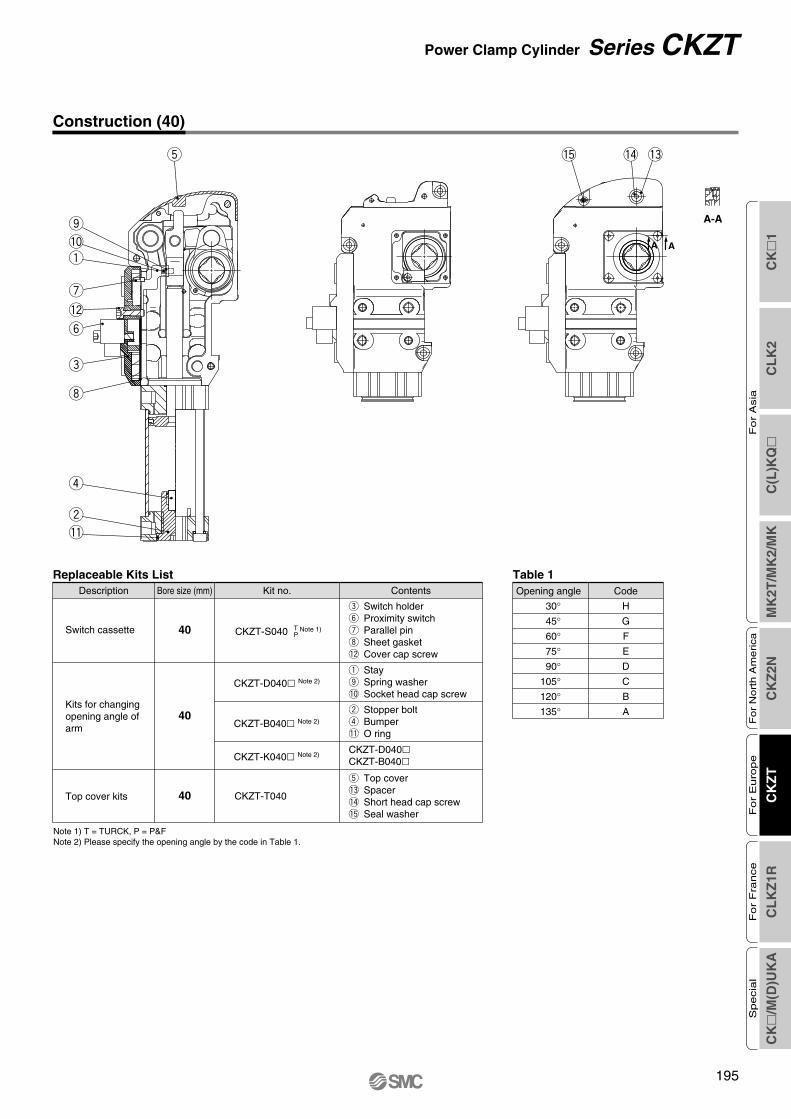
CK
1C
LK
2C
(L)K
Q
MK
2T/M
K2/
MK
CK
Z2N
CK
ZT
CL
KZ
1RC
K
/M(D
)UK
A
Fo
r A
sia
For
Nort
h A
merica
For
Euro
pe
For
Fra
nce
Specia
l
195
Construction (40)
t
!2
u
!0
o
q
e
y
i
w
r
!1
A-A
A A
!3!5 !4
Replaceable Kits List
40 CKZT-T040
CKZT-K040 Note 2)CKZT-D040CKZT-B040
t Top cover!3 Spacer!4 Short head cap screw!5 Seal washer
40
CKZT-D040 Note 2)
40 CKZT-S040 Note 1)
q Stayo Spring washer!0 Socket head cap screw
e Switch holdery Proximity switchu Parallel pini Sheet gasket!2 Cover cap screw
ContentsKit no.Bore size (mm)Description
CKZT-B040 Note 2)
w Stopper boltr Bumper!1 O ring
TPSwitch cassette
Kits for changingopening angle of arm
Top cover kits
Table 1
30°45°60°75°90°
105°120°135°
CodeOpening angle
H
G
F
E
D
C
B
A
Note 1) T = TURCK, P = P&FNote 2) Please specify the opening angle by the code in Table 1.
Power Clamp Cylinder Series CKZT

196
Construction (50, 63, 80)
!3!4
A-AA A
Table 1
30°45°60°75°90°
105°120°135°
CodeOpening angle
H
G
F
E
D
C
B
A
t Top cover!3 Spacer!4 Short head cap screw
Replaceable Kits List
Switch cassette
Kits for changingopening angle of arm
Top cover kits
50
63
80
50
63
80
e Switch holdery Proximity switchu Parallel pini Sheet gasket!2 Cover cap screw
q Switch actuatoro Spring washer!0 Socket head cap screw
w Stopper boltr Bumper!1 Seal washer
q Switch actuatoro Spring washer!0 Socket head cap screw
w Stopper boltr Bumper!1 Seal washer
q Switch actuatoro Spring washer!0 Socket head cap screw
w Stopper boltr Bumper!1 Seal washer
CKZ1N-D080CKZN-B080
CKZ1N-D063CKZN-B063
CKZ1N-D050CKZN-B050
ContentsKit no.Bore size (mm)Description
CKZ1N-S050 TP
Note 1)
CKZ1N-S063 TP
Note 1)
CKZ1N-S080 TP
Note 1)
CKZN-K050 Note 2)
CKZN-B050 Note 2)
CKZN-D050 Note 2)
CKZN-B063 Note 2)
CKZN-D063 Note 2)
CKZN-K063 Note 2)
CKZN-B080 Note 2)
CKZN-D080 Note 2)
CKZN-K080 Note 2)
50
63
80
CKZ2N-T050
CKZ2N-T063
CKZ2N-T080
t
!2
u!0oqe
yi
wr!1
Note 1) T = TURCK, P = P&FNote 2) Please specify the opening angle by the code in Table 1.
Series CKZT

CK
1C
LK
2C
(L)K
Q
MK
2T/M
K2/
MK
CK
Z2N
CK
ZT
CL
KZ
1RC
K
/M(D
)UK
A
Fo
r A
sia
For
Nort
h A
merica
For
Euro
pe
For
Fra
nce
Specia
l
197
Allowable Locking Moment
Maximum Clamping Moment
Cylinder Stroke
∗ The moment when the clamp arm is locked at the time of air release in the clamped state.
Bore size (mm)Allowable locking moment
N·m
380
800
1500
2500
lbf · in
3363
7080
13274
22124
40
50
63
80
Unit: (mm)
Angle
Bore size
40
50
63
80
30°
26.8
31.1
34.1
47.3
45°
33.3
38.9
42.5
59.4
60°
39.6
46.4
50.5
71.1
75°
45.9
54.1
58.6
83.2
90°
52.3
61.9
66.8
95.7
105°
58.4
69.6
74.7
108.0
120°
63.6
76.4
81.5
119.1
135°
67.3
81.3
86.3
127.3
40
50
63
80
Bore size (mm)
Max. clamping force
35
100
300
560
N·m
0.3 MPa
310
885
2655
4956
Ibf · in
76
130
350
720
N·m
0.4 MPa
673
1150
3097
6372
Ibf · in
118
160
400
880
N·m
0.5 MPa
1044
1416
3540
7788
Ibf · in
154
190
450
1040
N·m
0.6 MPa
1363
1681
3982
9204
Ibf · in
178
220
500
1200
N·m
0.7 MPa
1575
1947
4425
10619
Ibf · in
194
250
550
1360
N·m
0.8 MPa
1717
2212
4867
12035
Ibf · in
Power Clamp Cylinder Series CKZT

198
2 x 2 x ø6 H7 depth 8
2 x 2 x M6 x 1.0 depth 10M6 x 1.0 depth 10
52
35±0.02
35±0.02
25±0
.05
+0.
140
0
38.5
±0.0
525
±0.0
2
106
265.
9
60
202835
83
115
110.5
R80
52
99.4
96.8
44.5
33
54
NPT 1/8G
NPT 1/8G
3.5
47±0
.05
45±0
.1
25±0
.1
0
8N
9 -0.
043
2 x ø6 H7 depth 10
16h9
Release point
12±0.05
Dimensions (Clamp Cylinder Without Arm)
CKZT40
Series CKZT

CK
1C
LK
2C
(L)K
Q
MK
2T/M
K2/
MK
CK
Z2N
CK
ZT
CL
KZ
1RC
K
/M(D
)UK
A
Fo
r A
sia
For
Nort
h A
merica
For
Euro
pe
For
Fra
nce
Specia
l
199
XC
XB
RW
LB
PD
±0.0
5
NB
±0.0
5
VD
±0.0
5
VC
±0.1
VB
±0.1
PB
±0.0
2+0.
1 K
0
LA
±0.1
L
E
B
2 x 2 x øP H7 depth D2 x øV H7 depth I
2 x 2 x MM depth J
XA
NA±0.02 NC
PA±0.02 PC±0.05
RB
GA
GB
R
RR
RA
GC
2 x NPT 1/4G
2 x NPT 1/4G
4 x NN depth S
VA±0.02
C
VE
VF
Release point
Nh9
N
Hexagon sockethead plug
Dimensions (Clamp Cylinder Without Arm)
CKZT50, 63, 80
Bore size(mm)
506380
C D E GA GB GC I J K L LA LB MM N NA NB NC NN PB
(mm)
95
112
154
48
54
76
12
12
13
13.7
16.6
19.6
134.3
141.2
185.8
138.5
147.5
199
93
90.5
137.5
10
10
12
12
12
18
55
55
80
376.4
395.6
530.9
149.5
158.5
214
78.4
78
113.7
M10 x 1.5
M10 x 1.5
M12 x 1.75
19
22
30
13
13
21
36.5
36.5
50
10.3
15.8
20.8
M8 x 1.25
M8 x 1.25
M10 x 1.5
10
10
12
Bore size(mm)
506380
XCPA PB PC PD R RA RB RR S V VA VB VC VD VE VF W XA XB
50
50
70
45
45
75
10
10
15
55
55
65
45
52
70
68
78
108
45
50
68
48
54
76
11
11
15
8
8
8
30
30
50
32
32
50
63.5
63.5
90
71.5
71.5
96.5
12
12
12
3.5
3.5
3.5
78.4
78
113.7
141.8
154.4
197.3
137.3
150.4
192.8
92.8
105.3
148.3
Power Clamp Cylinder Series CKZT

200
33 54
23
0
16-0
.1
31
22±0
.115
±0.2
117
16
48
(7) 20±0.2
20±0.02 90±0.1
2 x ø6H7 through
2 x ø7 through
Center type
Left type
Right type
2 x øD1H7 through
2 x øD2 through
34
20
44
48 68
28±0
.115
±0.2
19
144
65
(9) 30±0.2
30±0.02 105±0.1
Center type
Left type
Right type
Dimensions (Clamp Arm: Offset 15)
ø40
ø50
WeightCKZT40-A015CSCKZT40-A015RSCKZT40-A015LS
0.49 (1.08)0.51 (1.12)0.51 (1.12)
CKZT40 A015 C S
CRL
CenterRightLeft
Arm position
Weight
kg (lbs)
kg (lbs)CKZT50-A015CSCKZT50-A015CBCKZT50-A015RSCKZT50-A015RBCKZT50-A015LSCKZT50-A015LB
0.79 (1.74)0.78 (1.72)0.90 (1.98)0.89 (1.96)0.90 (1.98)0.89 (1.96)
CKZT50 A015 CArm position
CRL
CenterRightLeft
S
Mounting hole
SB
D1
68
D2
9 10.2
Symbol
How to Order
How to Order
Series CKZT

CK
1C
LK
2C
(L)K
Q
MK
2T/M
K2/
MK
CK
Z2N
CK
ZT
CL
KZ
1RC
K
/M(D
)UK
A
Fo
r A
sia
For
Nort
h A
merica
For
Euro
pe
For
Fra
nce
Specia
l
201
2 x øD1H7 through
2 x øD2 through
37
47
20
54 78
28±0
.115
±0.2
144
22
65
(9) 30±0.2
30±0.02 105±0.1
Right type
Center type
Left type
2 x øD1H7 through
2 x øD2 through
76 108
50.5
2563
35±0
.120
±0.2
179
30
64
(9) 30±0.2
30±0.02 140±0.1
Center type
Left type
Right type
ø63
ø80
WeightCKZT80-A015CSCKZT80-A015CBCKZT80-A015RSCKZT80-A015RBCKZT80-A015LSCKZT80-A015LB
2.17 (4.78)2.16 (4.76)2.21 (4.87)2.19 (4.83)2.21 (4.87)2.19 (4.83)
CKZT80 A015 CArm position
CRL
CenterRightLeft
S
Mounting hole
SB
D1
68
D2
9 10.2
Symbol
Weight
kg (lbs)
kg (lbs)CKZT63-A015CSCKZT63-A015CBCKZT63-A015RSCKZT63-A015RBCKZT63-A015LSCKZT63-A015LB
1.02 (2.25)1.01 (2.23)1.10 (2.43)1.08 (2.38)1.10 (2.43)1.08 (2.38)
CKZT63 A015 CArm position
CRL
CenterRightLeft
S
Mounting hole
SB
D1
68
D2
9 10.2
Symbol
How to Order
How to Order
Dimensions (Clamp Arm: Offset 15)
Power Clamp Cylinder Series CKZT

202
34
20
44
48 68
28±0
.145
±0.2
18
144
65
30±0.2
30±0.02 105±0.1
Center type
Left type
Right type
2 x øD1H7 through
2 x øD2 through
(9)
33 54
2333
22±0
.145
±0.2
140
16
72
30±0.02
30±0.02 100±0.1
Center type
Left type
Right type
2 x øD1H7 through
2 x øD2 through (10)
0
H-0
.1ø40
ø50
Weight CKZT50-A045CSCKZT50-A045CBCKZT50-A045RSCKZT50-A045RBCKZT50-A045LSCKZT50-A045LB
0.93 (2.05)0.92 (2.03)1.02 (2.25)1.01 (2.23)1.02 (2.25)1.01 (2.23)
CKZT50 A045 CArm position
CRL
CenterRightLeft
S
Mounting hole
SB
D1
68
Symbol D2
9 10.2
Weight
kg (lbs)
kg (lbs)CKZT40-A045CSCKZT40-A045CBCKZT40-A045RSCKZT40-A045RBCKZT40-A045LSCKZT40-A045LB
0.63 (1.39)0.64 (1.41)0.64 (1.41)0.66 (1.46)0.64 (1.41)0.66 (1.46)
CKZT40 A045 CArm position
CRL
CenterRightLeft
S
Mounting hole
SB
D1
68
Symbol D2
7 10.2
H1620
How to Order
How to Order
Series CKZT
Dimensions (Clamp Arm: Offset 45)

CK
1C
LK
2C
(L)K
Q
MK
2T/M
K2/
MK
CK
Z2N
CK
ZT
CL
KZ
1RC
K
/M(D
)UK
A
Fo
r A
sia
For
Nort
h A
merica
For
Euro
pe
For
Fra
nce
Specia
l
203
37
47
20
54 78
28±0
.145
±0.2
144
22
64
30±0.2
30±0.02 105±0.1
Center type
Left type
Right type
2 x øD1H7 through
2 x øD2 through (9)
76 108
50.5
2563
35±0
.145
±0.2
179
30
64
30±0.2
30±0.02 140±0.1
Center type
Left type
Right type
2 x øD1H7 through
2 x øD2 through(9)
ø63
ø80
WeightCKZT80-A045CSCKZT80-A045CBCKZT80-A045RSCKZT80-A045RBCKZT80-A045LSCKZT80-A045LB
2.46 (5.42)2.44 (5.38)2.61 (5.75)2.59 (5.71)2.61 (5.75)2.59 (5.71)
CKZT80 A045 CArm position
CRL
CenterRightLeft
S
Mounting hole
SB
D1
68
D2
9 10.2
Symbol
Weight
kg (lbs)
kg (lbs)CKZT63-A045CSCKZT63-A045CBCKZT63-A045RSCKZT63-A045RBCKZT63-A045LSCKZT63-A045LB
1.19 (2.62)1.18 (2.60)1.25 (2.76)1.23 (2.71)1.25 (2.76)1.23 (2.71)
How to Order
CKZT63 A045 CArm position
CRL
CenterRightLeft
S
Mounting hole
SB
D1
68
D2
9 10.2
Symbol
How to Order
Power Clamp Cylinder Series CKZT
Dimensions (Clamp Arm: Offset 45)

Series CKZTMade to Order 1Contact SMC for detailed dimensions, specifications and delivery.
Power clamp cylinder with metal cover1
Manual toggle releaseThe toggle link mechanism can be released easily by opening the metal cover and hitting the portion of the protrusion by using of plas-tic hammer (hammer made of soft material), etc.
• Applicable modelCKZT40, 50, 63, 80
• Applicable to Arc-melting-resistant line• In addition to the existing rubber cover type, Opening/closing metal cover type is
available for releasing part of the toggle construction.
Cylinder SpecificationsBore size (mm) 50 63 80
Angle
Cushion
Maximum operating pressure
Ambient and fluid temperature
Minimum operating time
30°, 45°, 60°, 75°, 90°, 105°, 120°, 135°
Unclamping side: Rubber bumper
0.8 MPa (116 psi)
–10 to 60°C (14 to 140°F)
1.0 sec. to clamp, 1.0 sec. to unclamp
Metal cover
Protrusion
Power clamp cylinder with angle adjustment2
• Applicable modelCKZT40, 50, 63, 80
• Unclamped opening angle can be adjusted by one process. (no need to adjust the proximity switch)
• Adjustable range: 30° to 135°• With angle scale
Cylinder SpecificationsBore size (mm) 5040 63 80
Angle
Cushion
Maximum operating pressure
Ambient and fluid temperature
Minimum operating time
30° to 135°
Unclamping side: Rubber bumper
0.8 MPa (116 psi)
–10 to 60°C (14 to 140°F)
1.0 sec. to clamp, 1.0 sec. to unclamp
Angle adjustment bolt
Angle scale
204

Power clamp cylinder with manually operated handle3
• Applicable modelCKZT50, 63, 80
• Applicable to equipment requiring manual clamps.• Handle unit R/L is replaceable. • Self-weight drop prevention when unclamping
Cylinder SpecificationsBore size (mm) 50 63 80
Angle
Cushion
Maximum operating pressure
Ambient and fluid temperature
Minimum operating time
30°, 45°, 60°,75°, 90°, 105°
30°, 45°, 60°, 75°,90°, 105°, 120°
Unclamping side: Rubber bumper
0.8 MPa (116 psi)
–10 to 60°C (14 to 140°F)
1.0 sec. to clamp, 1.0 sec. to unclamp
Pneumatic sensor
Power clamp cylinder with pneumatic sensor4
• Applicable modelCKZT50, 63, 80
• Applicable to all air circuit equipment.• Built-in mechanical valve. Position detection is possible at clamping or unclamping
according to the signal received from the mechanical valve.
Clamping Unclamping
ClampingWith cover removed
Unclamping
Clamping output signal pressure port
Signal pressure supply port
Unclamping output signal pressure port
Mechanical valve
Series CKZTMade to Order 2Contact SMC for detailed dimensions, specifications and delivery.
Cylinder SpecificationsBore size (mm) 50 63 80
Angle
Cushion
Maximum operating pressure
Ambient and fluid temperature
Minimum operating time
30°, 45°, 60°, 75°, 90°, 105°, 120°, 135°
Unclamping side: Rubber bumper
0.8 MPa (116 psi)
–10 to 60°C (14 to 140°F)
1.0 sec. to clamp, 1.0 sec. to unclamp
CK
1C
LK
2C
(L)K
Q
MK
2T/M
K2/
MK
CK
Z2N
CK
ZT
CL
KZ
1RC
K
/M(D
)UK
A
Fo
r A
sia
For
Nort
h A
merica
For
Euro
pe
For
Fra
nce
Specia
l
205

Unclamped opening angle 15° kit (for change of angle)5
• Applicable modelCKZT40, 50, 63, 80
• In addition to the standard unclamped opening angle, 15° specification is available.• Unclamped opening angle can be changed to 15° without disassembling the toggle
construction.
Cylinder SpecificationsBore size (mm) 50 63 80
Angle
Cushion
Maximum operating pressure
Ambient and fluid temperature
Minimum operating time
15°
Unclamping side: Rubber bumper
0.8 MPa (116 psi)
–10 to 60°C (14 to 140°F)
1.0 sec. to clamp, 1.0 sec. to unclamp
Series CKZTMade to Order 3Contact SMC for detailed dimensions, specifications and delivery.
206

1. Manual toggle releaseThe toggle link mechanism can be released easily by hitting the portion of round shaped projection on the cover by using of plastic hammer (hammer made of soft material), etc.Please be sure to perform manual toggle release after safety has been confirmed because the clamp arm can suddenly move up during manual release.
2. Do not disassemble the power clampNo special maintenance is necessary because the power clamp has a fully enclosed design to protect the clamp against welding spatter, and also the power clamp has a contamination resistant construction. So, please do not disassemble the pow-er clamp except changing replaceable parts as there is a possi-bility of deterioration of the clamp performance.
3. Tightening torque of spare partsPlease make sure to tighten spare parts recommended in ac-cordance with the following torque shown in the table.
40506380
Bore size (mm)Tightening torque
40506380405063804050638040506380
3.0 to 4.05.0 to 7.05.0 to 7.05.0 to 7.01.5 to 2.03.0 to 4.03.0 to 4.03.0 to 4.0
12.5 to 17.0130 to 150160 to 200480 to 5201.5 to 2.02.5 to 3.02.5 to 3.03.0 to 5.0
Bore size(mm)
Tightening torque Description
Switch cassette kit
Switch bracket kit
Stopper bolt kit
Top cover kit
N·m27 to 3544 to 6244 to 6244 to 6213 to 1827 to 3527 to 3527 to 35
110 to 1501150 to 13271416 to 17704248 to 4600
13 to 1822 to 2722 to 2727 to 44
Ibf · in
Series CKZTSpecific Product PrecautionsBe sure to read this before handling. Refer to pages 222 and 223 for Safety Instructions and “Precautions for Handling Pneumatic Devices” (M-03-E3A) for Actuator Precautions.
Note: (1) Please make sure that the switch cassette is tightly se-cured to the body when it has been replaced with a new one.
(2) Please make sure that the dog is mounted so that the stamped side is secured as shown below if replacing.
4. Clamp Arm Tightening Torque
6 to 912 to 1515 to 2018 to 24
N·m53 to 80
106 to 133133 to 177159 to 212
Ibf · in
CK
1C
LK
2C
(L)K
Q
MK
2T/M
K2/
MK
CK
Z2N
CK
ZT
CL
KZ
1RC
K
/M(D
)UK
A
Fo
r A
sia
For
Nort
h A
merica
For
Euro
pe
For
Fra
nce
Specia
l
207

208

Series CLKZ1R
Power Clamp CylinderConforming to the CNOMO Standard
CK
1C
LK
2C
(L)K
Q
MK
2T/M
K2/
MK
CK
Z2N
CK
ZT
CL
KZ
1RC
K
/M(D
)UK
A
Fo
r A
sia
For
Nort
h A
merica
For
Euro
pe
For
Fra
nce
Specia
l
209

Height (mm)
Cla
mpi
ng fo
rce
(N)
CLKZ1R200
0
500
1000
1500
2000
2500
3000
3500
–10.0 –8.0 –6.0 –4.0 –2.0 0.0 2.0 4.0
0.7 MPa
0.5 MPa
0.3 MPa
CLKZ1R110
Cla
mpi
ng fo
rce
(N)
Height (mm)
–10.0 –8.0 –6.0 –4.0 –2.0 0.0 2.0 4.00
250
500
750
1000
1250
1500
1750
2000
0.7 MPa
0.5 MPa
0.3 MPa
CLKZ1R040
Height (mm)
Cla
mpi
ng fo
rce
(N)
0100200300400500600700800900
1000
–10.0 –8.0 –6.0 –4.0 –2.0 0.0 2.0 4.0
0.7 MPa
0.5 MPa
0.3 MPa
CLKZ1R200
Cla
mpi
ng fo
rce
(N)
Height (mm)
0
500
1000
1500
2000
2500
3000
3500
–10.0 –8.0 –6.0 –4.0 –2.0 0.0 2.0 4.0
0.7 MPa
0.5 MPa
0.3 MPa
CLKZ1R110
Cla
mpi
ng fo
rce
(N)
Height (mm)
0
250
500
750
1000
1250
1500
1750
2000
–10.0 –8.0 –6.0 –4.0 –2.0 0.0 2.0 4.0
0.7 MPa
0.5 MPa
0.3 MPa
040
Cla
mpi
ng fo
rce
(N)
Height (mm)
0
200
400
600
800
1000
–10.0 –8.0 –6.0 –4.0 –2.0 0.0 2.0 4.0
0.7 MPa
0.5 MPa
0.3 MPa
100 mm
0 mm
–
+
Clamping Force (measured at a position 100 mm from the fulcrum)
The work piece can be held with a constant clamping force regardless of its height. (–4 to +2 mm)
The work piece can be clamped at a constant holding force regardless of its height. (–4 to +2 mm)
The clamping force that remains when the air supply is cut off after clamping at a given pressure. (measured at a position 100 mm from the fulcrum)Holding Force
210

CLKZ1RPower clamp cylinder
conforming to theCNOMO standard
040 N
Category
X1121A
FluidOperating pressure rangeProof pressureOperating temperature rangePort sizeCushionArm angleOperating time (at supply pressure of 0.5 MPa)Clamping force (at supply pressure of 0.5 MPa)Holding force (at supply pressure of 0.5 MPa)Max. allowable load (at supply pressure of 0.5 MPa)Max. allowable moment of inertia (at supply pressure of 0.5 MPa)Unclamp side locking forceWeight (including short arm)
CategoryAir (Non-lube)0.3 to 0.7 MPa
1.05 MPa–10°C to +70°C
G1/8Unclamp side rubber bumper
105 (Standard) / 15°, 30°, 45°, 60°, 75°, 90° (Option)Clamp: 0.5 s Unclamp: 0.5 s
110 N·m or more82.5 N·m or more
1.3 N·m0.02 kg·m2
5.5 N·m or more3.6 kg
200 N·m or more150 N·m or more
1.9 N·m0.03 kg·m2
10 N·m or more5.9 kg
40 N·m or more30 N·m or more
0.9 N·m0.01 kg·m2
2 N·m or more1.7 kg
040 110 200
Rated operating distance SNReproducibilityHysteresisApplicable applied voltageSupply voltageVoltage dropOutput functionMinimum operating currentMaximum operating currentResidual currentNominal temperature of applicationAmbient temperatureDegree of protectionProtection against excess current(short circuit) or overloadsProtection against polarity inversions
1.5 (mm) ± 10% 0.1 (mm)
0.1 (mm) H 1 (mm)DC24 (V)
DC10 to 30 (V) 5 (V)
Normally Open2.5 (mA)100 (mA)
0.6 (mA)25 (°C)
–10 (°C) Ta 70 (°C)IP67
Non polarized
Withoutarm
Cylinder Part No.
Cylinder Specifications
Switch Specifications
How to Order
OptionSymbol
NilX1121AX1121BX1121CX1121DX1121EX1121F
Arm angle105°15°30°45°60°75°90°
040110200
40daN type110daN type200daN type
0–5°
Proximity SwitchCategory
040
110/200
∗ With 2 mounting screws
Proximity switch part no.
D-NF001
D-NF002
Sw
itch
mai
n ci
rcui
t
Load2 OUT ( )
4 OUT ( )
Powersupply
Load
1 OUT ( ) Common
The detector is equipped with a protection system guaranteeing itscorrect operation in spite of an excess current of 2xle (200 mA) for 100 µs.
Unclamp(Green)
Clamp(Yellow)
Power Clamp CylinderConforming to the CNOMO Standard
Series CLKZ1R
211
CK
1C
LK
2C
(L)K
Q
MK
2T/M
K2/
MK
CK
Z2N
CK
ZT
CL
KZ
1RC
K
/M(D
)UK
A
Fo
r A
sia
For
Nort
h A
merica
For
Euro
pe
For
Fra
nce
Specia
l

212
Series CLKZ1R
CLKZ1R040-N 1 dimension projection
Mounting Pin (2 pcs.)
20
20 ± 0.1
25
ø8.
5
M8 x 1.25
ø14
h60 –0.0
11(
)
17
81.5
14
36
28
47
Inductive proximity sensor
D-NF001
G1/8Unclamp side
G1/8Clamp side
F
F
27.5
15 ±
0.1
25 ±
0.0
1
207
27.525 ± 0.01
1266.5
67.5
15
13.5
37
(60)
(65)
(32.
5)
105°
2 x ø14H7+0.018
0( )
12 ± 0.1
26
G1/8 (Plug)
Unclamp side
G1/8 (Plug)
Clamp side
Dimensions

CK
1C
LK
2C
(L)K
Q
MK
2T/M
K2/
MK
CK
Z2N
CK
ZT
CL
KZ
1RC
K
/M(D
)UK
A
Fo
r A
sia
For
Nort
h A
merica
For
Euro
pe
For
Fra
nce
Specia
l
213
Series CLKZ1RPower Clamp CylinderConforming to the CNOMO Standard
Dimensions
CLKZ1R110-N 1 dimension projection
Mounting Pin (2 pcs.)
17
20
28 ± 0.1
33
M8 x 1.25
ø8.
5
ø14
h60 –0.0
11(
)
16 ± 0.1
40
G1/8 (Plug)
Unclamp side
G1/8 (Plug)
Clamp side
86
23.5
12.5
78
37.528 ± 0.01
55 ±
0.0
137
.5
25 ±
0.1
(55)
47
(68)
251
20
105°
(61)
2 x ø14H7+0.018
0( )
9816
40
42
62
D-NF002
Inductive proximity sensor
G1/8Unclamp side
G1/8Clamp side
F
F

214
Series CLKZ1R
Dimensions
1 dimension projectionCLKZ1R200-N
Mounting Pin (2 pcs.)
17
20
28 ± 0.1
33
M8 x 1.25
ø8.
5
ø14
h60 –0.0
11(
)
16 ± 0.1
50
G1/8 (Plug)
Unclamp side
G1/8 (Plug)
Clamp side
100
23.5
17.5
78
37.528 ± 0.01
55 ±
0.0
137
.5
25 ±
0.1
(60)
58
(82)
280
25
105°
(74)
2 x ø14H7+0.018
0( )
113
16
50
55
85
G1/8
D-NF002Inductive proximity sensor
Unclamp side
G1/8
Clamp side
F
F

Series CLKZ1RPower Clamp CylinderConforming to the CNOMO Standard
Adapter For mounting example, refer to page 217.
CKZR-A040R CKZR-A040L
CKZR-A110R CKZR-A110L
Category
040110/200
Right-handed type
CKZR-A040R
CKZR-A110R
Left-handed type
CKZR-A040L
CKZR-A110L
Section A-ASection A-A
∗ 2 mounting pins∗ Select long arm when using an adapter.
1 dimension projection
2 x M5 x 0.8 depth 9
12 ±
0.1
19 ± 0.1 108
20.5
52 52 6
2 x M5 x 0.8 depth 912
± 0
.1
19 ± 0.1 108
20.5
52 52
6
54
131.5
10
50
12.5
25 ±
0.0
1
12.5
25 ± 0.01
25 ± 0.01
C22
80
C20
38
4 x ø14H7+0.018
0( )
54
131.5
10
50
12.5
25 ±
0.0
1
12.525 ± 0.01
25 ± 0.01
C22
80
C20
38
4 x ø14H7+0.018
0( )
C24
12.5
28 ±
0.0
1
44122
12.5
55 ± 0.01
28 ± 0.01
C50
55 ±
0.0
1
80
158
211
14
4 x ø14H7+0.018
0( )
2 x M6 x 1.0
15 18
3
2 x ø6.2
2 x M6 x 1.0
15 18
3
2 x ø6.2
A A
16 ±
0.1 82 82
28.5
13 ± 0.113 ± 0.1
8
187
AA
16 ±
0.1
82 82
28.5
13 ± 0.113 ± 0.1
8
187
12.5
28 ±
0.0
1
44122
12.5
55 ± 0.01
28 ± 0.01
C24 C50
55 ±
0.0
1
80
158
211
14
4 x ø14H7+0.018
0( )
CK
1C
LK
2C
(L)K
Q
MK
2T/M
K2/
MK
CK
Z2N
CK
ZT
CL
KZ
1RC
K
/M(D
)UK
A
Fo
r A
sia
For
Nort
h A
merica
For
Euro
pe
For
Fra
nce
Specia
l
215

216
Series CLKZ1R
Mounting Pin
CKZR-P040
∗ Quantity: 2 pcs. for each
Category
040110/200
Mounting pin part no.
CKZR-P040
CKZR-P110
Arm
CKZR-Y040 CKZR-Y110 SN
CKZR-P110
CKZR-Y200 -ASN
Mounting Pin (2 pcs.) Mounting Pin (2 pcs.)
( ): In case of CKZR-Y200N-A
Category
040110200
Short arm
CKZR-Y040
Long arm
CKZR-Y110S
CKZR-Y200S-A
CKZR-Y110N
CKZR-Y200N-A
1 dimension projection
1 dimension projection
For mounting example, refer to page 217.
∗ Select long arm when using an adapter.
17 17
M8 x 1.25
ø8.
5
20
28 ± 0.1
33
ø14
h60 –0.0
11(
)
M8 x 1.25
ø8.
5
20
20 ± 0.1
25
ø14
h60 –0.0
11(
)
47
28
26
62
4241
14
ø12
61(89)
68(96)
Bolt
M6 x 1 x 25 L
20
15
65
60
Bolt
M5 x 0.8 x 25 L
10
ø8
( ): In case of CKZR-Y110N
46
85
55
82(110)
16
74(102)
ø12
25
Bolt
M8 x 1.25 x 32 L

CK
1C
LK
2C
(L)K
Q
MK
2T/M
K2/
MK
CK
Z2N
CK
ZT
CL
KZ
1RC
K
/M(D
)UK
A
Fo
r A
sia
For
Nort
h A
merica
For
Euro
pe
For
Fra
nce
Specia
l
217
Adapter/Arm Mounting Example
CLKZ1R040-N
CLKZ1R110-N
CLKZ1R200-N
1 dimension projection
47
12 ± 0.1
6216 ± 0.1
8516 ± 0.1
47
12 ± 0.1
6216 ± 0.1
8516 ± 0.1
105°
(R73)
65 60
32.5
66.5
25 ±
0.0
127
.5
65
25 ± 0.0127.5
15 ± 0.1Arm
CKZR-Y040
AdapterCKZR-A040R
D-NF001
Inductive proximitysensor
2 x ø14H7+0.018
0( )
15
(R111)
105°
20
96 89
55
106
28 ±
0.0
165
.5
105
55 ± 0.0137.5
25 ± 0.1
CKZR-A110RAdapter
Arm
CKZR-Y110N
D-NF002
Inductive proximitysensor
2 x ø14H7+0.018
0( )
(R125)
105°
25
110
102
60
106
28 ±
0.0
165
.5
105
55 ± 0.0137.5
25 ± 0.1
AdapterCKZR-A110R
CKZR-Y200N-A
Arm
D-NF002
Inductive proximitysensor
2 x ø14H7+0.018
0( )
(R125)
105°
110
102
25 ± 0.1 60
25
105
106
65.5
28 ±
0.0
1
55 ± 0.01 37.5
CKZR-Y200N-AArm
CKZR-A110LAdapter
D-NF002
Inductive proximitysensor
2 x ø14H7+0.018
0( )
(R111)
9689
25 ± 0.1 55
20
10510
6
65.5
28 ±
0.0
155 ± 0.01 37.5
Adapter
CKZR-A110L
CKZR-Y110N
Arm
D-NF002
Inductive proximitysensor
2 x ø14H7+0.018
0( )
105°
2 x ø14H7
105°
6560
15 ± 0.1
32.5
(R73)
65
66.5
27.5
25 ±
0.0
1
25 ± 0.01 27.5
ArmCKZR-Y040
AdapterCKZR-A040L
D-NF001
Inductive proximitysensor
+0.0180( )
15
Series CLKZ1RPower Clamp CylinderConforming to the CNOMO Standard

Series CLKZ1RSpecific Product PrecautionsBe sure to read this before handling. Refer to pages 222 and 223 for Safety Instructions and “Precautions for Handling Pneumatic Devices” (M-03-E3A) for Actuator Precautions.
When equipment is removed, confirm the safety process. Cut the supply pressure for this equipment and exhaust all residual com-pressed air in the system.Do not release the lock manually by using an external force such as a load and spring force. The cylinder could move suddenly, which could be very dangerous.
How to release the lock on the clamp sideOpen the dustproof cover at the upper part of the port on the clamping side.Insert a hexagon wrench and flip up the manual unlocking lever.
How to release the lock on the unclamp sideMove the dial of the head cover to the FREE position with a flat-head screwdriver.
Note) At the time of shipment from the factory, the locking mecha-nism on the unclamp side is not engaged. When that mech-anism is used, change the dial to the LOCK position.
1) Be sure to supply air pressure to the clamp side port before re-starting the cylinder from the clamping position.Pressurizing to the unclamp side port without applying air pres-sure to the clamp side port will release the lock and cause the cylinder to move suddenly, which could be very dangerous.
Warning WarningPreparation for Operation
1) Do not use a 3-position valve.This valve could unexpectedly supply air pressure, which would release the lock.
2) Mount the speed controller so as to provide meter-out control.Using the speed controller as a meter-in could cause operating failure.
3) Be careful not to allow a reverse flow of exhaust pressure from a common exhaust-type valve manifold.A reverse flow of exhaust pressure could release the lock. Use an independent exhaust-type valve manifold or independent valve.
CautionPneumatic Circuit
How to Release the Lock Manually
Unclampside port
Clampside port
Manual unlocking lever
Dustproof cover
218

Other Clamp CylindersProduct Lineup
Pin Clamp Cylinder (Compact body type): Series CKU
Features: Compact flat-body spring-extended clamp cylinder.Best suited for applications that install multiple cylinders in a confined space for car line switching, etc. Applicable to magnetic field resistant solid state switch.Special order ··· ø32/ø50 (Applicable to cylinders with lock.)
ø32 Equivalent
12
0.7 MPa
Rubber bumper
ø50 Equivalent
15
Bore size
Maximum operating pressure
Operating stroke (mm)
Cushion
Pin-Shift Cylinder: Series CKQR
Features: Best suited for basic pin-shift applications.Extended end deflection accuracy: ±0.1 mm or less. (at no load)Non-rotating mechanism/Built-in metal rod scraperAvailable in 4 mounting directions (three sides and bottom).Two bore sizes of rod end can be selected according to the model.(Rod end bore size ··· ø25/ø40)Built-in compact proximity switch for position detection. (Extended end/retracted end)
ø630.7 MPa
25 or 50
Bore size
Maximum operating pressure
Stroke (mm)
Plate Clamp Cylinder: Series M(D)UKA
Features: Compact flat-body clamp cylinder.Built-in metal rod scraper.Applicable to magnetic field resistant solid-state switches.Applicable to cylinders with lock as special. (Ø50 only)Applicable to bore sizes 32 and 40 as special.
ø50 Equivalent ø63 Equivalent
0.7 MPa
50, 75, 100, 125, 150
Rubber bumper
Bore size
Maximum operating pressure
Stroke (mm)
Cushion
CK
1C
LK
2C
(L)K
Q
MK
2T/M
K2/
MK
CK
Z2N
CK
ZT
CL
KZ
1RC
K
/M(D
)UK
A
Fo
r A
sia
For
Nort
h A
merica
For
Euro
pe
For
Fra
nce
Specia
l
219

Other Clamp Cylinders
Pin-Shift Cylinder: Series CKZP
Features: Non-rotating rod type pin-shift cylinderExtended end deflection accuracy: 0.05 mm or lessRod non-rotating accuracy: ±1.0 degree or lessAvailable in 3 directions for mounting and 2 directions for piping.The piston position can be detected accurately because of a proximity switch.Built-in metal rod scraper prevents adhesion of spatter.
ø400.8 MPa
40
Rubber bumper
ø63 EquivalentBore size
Maximum operating pressure
Stroke (mm)
Cushion
Clamp Cylinder: Series CKGV
Features: Clamp cylinder with built-in the toggle mechanismMountable on both sidesTwo arm opening/closing angles at unclamped side can be selected.Arm opening/closing angle at unclamping side can be adjusted by stroke adjustment by an adjusting screw.Applicable to magnetic field resistant solid state switchSelectable for safety mechanism. (Maximum thrust is generated only at clamping to prevent nipping.)
ø32 ø50 ø63 ø801.0 MPa
Head side rubber bumper
Type 90° ··· 45° to 90° Adjustable
Type 135° ··· 105° to135° Adjustable
Bore size
Maximum operating pressure
Cushion
Arm opening/closing angle
220

221

Safety InstructionsThese safety instructions are intended to prevent hazardous situations and/or equipment damage. These instructions indicate the level of potential hazard with the labels of “Caution,” “Warning” or “Danger.” They are all important notes for safety and must be followed in addition to International Standards (ISO/IEC), Japan Industrial Standards (JIS)∗1) and other safety regulations∗2).∗ 1) ISO 4414: Pneumatic fluid power – General rules relating to systems.
ISO 4413: Hydraulic fluid power – General rules relating to systems.IEC 60204-1: Safety of machinery – Electrical equipment of machines. (Part 1: General requirements)ISO 10218-1992: Manipulating industrial robots -Safety.JIS B 8370: General rules for pneumatic equipment.JIS B 8361: General rules for hydraulic equipment. JIS B 9960-1: Safety of machinery – Electrical equipment of machines. (Part 1: General requirements)JIS B 8433-1993: Manipulating industrial robots - Safety. etc.
∗ 2) Labor Safety and Sanitation Law, etc.
1. The compatibility of the product is the responsibility of the person who designs the equipment or decides its specifications. Since the product specified here is used under various operating conditions, its compatibility with specific equipment must be decided by the person who designs the equipment or decides its specifications based on necessary analysis and test results. The expected performance and safety assurance of the equipment will be the responsibility of the person who has determined its compatibility with the product. This person should also continuously review all specifications of the product referring to its latest catalog information, with a view to giving due consideration to any possibility of equipment failure when configuring the equipment.
2. Only personnel with appropriate training should operate machinery and equipment.The product specified here may become unsafe if handled incorrectly. The assembly, operation and maintenance of machines or equipment including our products must be performed by an operator who is appropriately trained and experienced.
3. Do not service or attempt to remove product and machinery/equipment until safety is confirmed.1. The inspection and maintenance of machinery/equipment should only be performed after measures to prevent falling or
runaway of the driven objects have been confirmed.
2. When the product is to be removed, confirm that the safety measures as mentioned above are implemented and the power from any appropriate source is cut, and read and understand the specific product precautions of all relevant products carefully.
3. Before machinery/equipment is restarted, take measures to prevent unexpected operation and malfunction.
4. Contact SMC beforehand and take special consideration of safety measures if the product is to be used in any of the following conditions. 1. Conditions and environments outside of the given specifications, or use outdoors or in a place exposed to direct sunlight.
2. Installation on equipment in conjunction with atomic energy, railways, air navigation, space, shipping, vehicles, military, medical treatment, combustion and recreation, or equipment in contact with food and beverages, emergency stop circuits, clutch and brake circuits in press applications, safety equipment or other applications unsuitable for the standard specifications described in the product catalog.
3. An application which could have negative effects on people, property, or animals requiring special safety analysis.
4. Use in an interlock circuit, which requires the provision of double interlock for possible failure by using a mechanical pro tective function, and periodical checks to confirm proper operation.
Warning
Caution: Operator error could result in injury or equipment damage.
Danger : In extreme conditions, there is a possibility of serious injury or loss of life.
Warning: Operator error could result in serious injury or loss of life.
222

Safety Instructions
Limited Warranty and Disclaimer/Compliance Requirements The product used is subject to the following “Limited Warranty and Disclaimer” and “Compliance Requirements”. Read and accept them before using the product.
The product is provided for use in manufacturing industries.The product herein described is basically provided for peaceful use in manufacturing industries. If considering using the product in other industries, consult SMC beforehand and exchange specifications or a contract if necessary. If anything is unclear, contact your nearest sales branch.
Caution
Limited Warranty and Disclaimer
1. The warranty period of the product is 1 year in service or 1.5 years after the product is deliv-ered.∗3)
Also, the product may have specified durability, running distance or replacement parts. Please consult your nearest sales branch.
2. For any failure or damage reported within the warranty period which is clearly our responsibility, a replacement product or necessary parts will be provided. This limited warranty applies only to our product independently, and not to any other damage incurred due to the failure of the product.
3. Prior to using SMC products, please read and understand the warranty terms and disclaimers noted in the specified catalog for the particular products.∗ 3) Vacuum pads are excluded from this 1 year warranty.
A vacuum pad is a consumable part, so it is warranted for a year after it is delivered. Also, even within the warranty period, the wear of a product due to the use of the vacuum pad or failure due to the deterioration of rubber material are not covered by the limited warranty.
Compliance RequirementsWhen the product is exported, strictly follow the laws required by the Ministry of Economy, Trade and Industry (Foreign Exchange and Foreign Trade Control Law).
223

224

Flame Resistant (Equivalent to UL-94 Standard V-0) Double Layer Tubing Application: spot welding
Can be used in a spatter-prone environment such as when found spot welding.
Inner tubing
TRB: Nylon 12TRBU: PolyurethaneOuter layer
TRB: PVC(Equivalent to UL-94 Standard V-0)
TRBU: Polyolefin(Equivalent to UL-94 standard V-0)
∗ Not flame-resistant equipment.
FR One-touch Fittings
FR One-touch Fittings Manifold
Brass One-touch Fittings
Self-align Fittings
FR Soft Nylon Tubing
FR Double Layer Tubing
FR Double Layer Polyurethane Tubing
Double Layer Tube Stripper
Multi-tube Holder
P.227
P.232
P.234
P.236
P.248
P.250
P.252
P.254
P.254
KR-W2
KRM
KQB
H, DL, L, LL
Speed Controller with One-touch Fitting
Speed Exhaust Controller
Tamper Proof Speed Controller ∗
P.240
P.242
P.243
P.244
P.246
P.247
AS-W2
AS
ASV
AS
AS
AS
TRS
TRB
TRBU
TKS
TM
Speed Controller: Standard TypeIn-line Type
Speed Controller with One-touch Fitting, Elbow Type (Metal Body)
Speed Controller Adjustable by Flat Head Screwdriver ∗
Tu
bin
gR
elat
edP
rod
uct
sS
pee
d C
on
tro
ller
Fit
tin
gs
Related Products(Piping Equipment)
Tu
bin
gS
pee
d C
on
tro
ller
Fit
tin
gs
225
Spatter Proof

226

Applicable tubing O.D.: Metric size Connection thread: R, Rc
Flame Resistant (Equivalent to UL-94 Standard V-0) FR One-touch Fittings
Series KR-W2
Tubing material
Tubing O.D.
FR double layer, FR soft nylon
ø6, ø8, ø10, ø12
Applicable Tubing
Fluid
Operating pressure range Note 2)
Proof pressure
Ambient and fluid temperature
Thread
Seal on the threads (Standard)
Air, Water Note 1)
–100 kPa to 1 MPa
3 MPa
–5 to 60°C (Water: 0 to 60°C) (No freezing)
JIS B 0203 (Taper thread for piping)
JIS B 0205 (Metric fine thread)
With sealant
Mounting section
Nut section
Note 1) The surge pressure must be under the maximum operating pressure.Note 2) Please avoid using in a vacuum holding application such as a leak tester, since there is leakage.
Specifications
Chuck
Accepts FR soft nylon.Large retaining force.Chuck bites tube and collet increases retaining force.
Can be used for a wide range of pressures from a low vacuum up to a pressure of 1.0 MPaThe use of a special profile ensures sealing and reduces resistance when the tube is inserted.
Light force for removalWhen the fitting is removed from the tube, the chuck and collet are released, thus preventing them from biting into the tube excessively.
Effective when piping in a confined space.The body and the threaded portion can rotate.(for positioning to some extent)
Seal
Stud
Release button (White)
O-ring
Body (White type)
Tube
Prevention of tube releasing unconformity due to inside intrusions or adhesion of the spatter. For cover, refer to page 230.
Cover (Option)
Pipe tape is not necessary.
With thread seal
Collet
Guide
PAT. PEND
Spatter Proof
Tu
bin
gS
pee
d C
on
tro
ller
Fit
tin
gs
227

Flame Resistant (Equivalentto UL-94 Standard V-0) Series KR-W2FR One-touch Fittings
KRH06-01SW2KRH06-02SW2KRH06-03SW2KRH08-01SW2KRH08-02SW2KRH08-03SW2KRH10-01SW2KRH10-02SW2KRH10-03SW2KRH10-04SW2KRH12-02SW2KRH12-03SW2KRH12-04SW2
6
8
10
12
1 8
1 4
1 8
1 4
1 8
1 4
3 8
3 8
3 8
1 4
3 8
1 2
1 2
R
R
R
R
R
R
R
R
R
R
R
R
R
Applicable tubingO.D. (mm)
Connectionthread
Model
Use to pipe in the same direction from female thread.Most general style.
Male Connector KRH-W2Use to pipe in 45° angle direction from female thread.Model in-between of male connector and male elbow.
45° Male Elbow KRK-W2
Use to pipe at right angles to female thread.Most general style.
Male Elbow KRL-W2
KRK06-01SW2KRK06-02SW2KRK06-03SW2KRK08-01SW2KRK08-02SW2KRK08-03SW2KRK10-01SW2KRK10-02SW2KRK10-03SW2KRK10-04SW2KRK12-02SW2KRK12-03SW2KRK12-04SW2
6
8
10
12
Applicable tubingO.D. (mm)
Connectionthread
Model
1 8
1 4
1 8
3 8
3 8
1 4
1 8
3 8
1 4
3 8
1 2
1 2
1 4
R
R
R
R
R
R
R
R
R
R
R
R
R
Basically, it is used together with male elbow.Different point is that it is used for fittings to avoid from interfering with each other by making the piping two-level.
Extended Male Elbow KRW-W2
KRL06-01SW2KRL06-02SW2KRL06-03SW2KRL08-01SW2KRL08-02SW2KRL08-03SW2KRL10-01SW2KRL10-02SW2KRL10-03SW2KRL10-04SW2KRL12-02SW2KRL12-03SW2KRL12-04SW2
6
8
10
12
Applicable tubingO.D. (mm)
Connectionthread
Model
1 8
1 8
1 4
1 8
1 4
3 8
1 4
1 4
3 8
1 2
3 8
3 8
1 2
R
R
R
R
R
R
R
R
R
R
R
R
R
KRW06-01SW2KRW06-02SW2KRW06-03SW2KRW08-01SW2KRW08-02SW2KRW08-03SW2KRW10-02SW2KRW10-03SW2KRW10-04SW2KRW12-02SW2KRW12-03SW2KRW12-04SW2
6
8
10
12
Applicable tubingO.D. (mm)
Connectionthread
Model
1 8
1 4
1 8
3 8
3 8
1 4
3 8
1 4
3 8
1 2
1 2
1 4
R
R
R
R
R
R
R
R
R
R
R
R
Universal male elbow allows thread connection by using a socket wrench for confined spaces.
Universal Male Elbow KRV-W2
KRV06-01SW2KRV06-02SW2KRV08-01SW2KRV08-02SW2KRV08-03SW2KRV10-02SW2KRV10-03SW2KRV12-03SW2KRV12-04SW2
6
8
10
12
Applicable tubingO.D. (mm)
Connectionthread
Model
1 8
1 4
1 8
3 8
1 4
3 8
3 8
1 4
1 2
R
R
R
R
R
R
R
R
R
228

Flame Resistant (Equivalentto UL-94 Standard V-0) Series KR-W2FR One-touch Fittings
Use to branch line from female thread in both 90° directions.
Male Branch Tee KRT-W2
KRT06-01SW2KRT06-02SW2KRT06-03SW2KRT08-01SW2KRT08-02SW2KRT08-03SW2KRT10-01SW2KRT10-02SW2KRT10-03SW2KRT10-04SW2KRT12-02SW2KRT12-03SW2KRT12-04SW2
6
8
10
12
Applicable tubingO.D. (mm)
Connectionthread
Model
1 8
1 4
1 81 4
1 8
1 4
3 8
3 8
3 8
1 4
3 8
1 2
1 2
R
R
R
R
R
R
R
R
R
R
R
R
R
Use to branch line in the same direction from female thread.
Branch KRU-W2
Use to branch line in the same direction from female thread and in 90° direction.
Male Run Tee KRY-W2
KRY06-01SW2KRY06-02SW2KRY06-03SW2KRY08-01SW2KRY08-02SW2KRY08-03SW2KRY10-01SW2KRY10-02SW2KRY10-03SW2KRY10-04SW2KRY12-02SW2KRY12-03SW2KRY12-04SW2
6
8
10
12
Applicable tubingO.D. (mm)
Connectionthread
Model
1 8
1 8
1 4
1 8
1 4
3 8
1 4
1 4
3 8
1 2
3 8
3 8
1 2
R
R
R
R
R
R
R
R
R
R
R
R
R
KRU06-01SW2KRU06-02SW2KRU06-03SW2KRU08-01SW2KRU08-02SW2KRU08-03SW2KRU10-02SW2KRU10-03SW2KRU10-04SW2KRU12-02SW2KRU12-03SW2KRU12-04SW2
6
8
10
12
Applicable tubingO.D. (mm)
Connectionthread
Model
1 8
1 4
1 8
3 8
3 8
1 4
3 8
1 4
3 8
1 2
1 2
1 4
R
R
R
R
R
R
R
R
R
R
R
R
Use to connect tubes in the same direction.
Straight Union KRH-W2
KRH06-00W2KRH08-00W2KRH10-00W2KRH12-00W2
Applicable tubing O.D.(mm)
Model
68
1012
Use to connect tubes through a panel.
Bulkhead Union KRE-W2
KRE06-00W2KRE08-00W2KRE10-00W2KRE12-00W2
Applicable tubing O.D.(mm)
Model
68
1012
Use to connect tubes at right angles.
Union Elbow KRL-W2
KRL06-00W2KRL08-00W2KRL10-00W2KRL12-00W2
Applicable tubing O.D.(mm)
Model
68
1012
Tu
bin
gS
pee
d C
on
tro
ller
Fit
tin
gs
229

Flame Resistant (Equivalentto UL-94 Standard V-0) Series KR-W2FR One-touch Fittings
Use to connect tubes in both 90° directions.
Union Tee KRT-W2
KRT06-00W2KRT08-00W2KRT10-00W2KRT12-00W2
Applicable tubing O.D.(mm)
Model
681012
Use to plug unused one-touch fittings.
Plug KRP
Use to branch line in the same direction.
Union “Y” KRU-W2
KRU06-00W2KRU08-00W2KRU10-00W2KRU12-00W2
Applicable tubing O.D.(mm)
Model
681012
Use to size down one-touch fittings.
Plug-in Reducer KRR-W2
KRR06-08W2KRR06-10W2KRR08-10W2KRR08-12W2KRR10-12W2
Applicable tubingO.D. (mm)
Model
6
8
10
Applicablefitting size
810101212
Use to branch line in the same direction from one-touch fittings.
Plug-in “Y” KRU-W2
KRU06-99W2KRU08-99W2KRU10-99W2KRU12-99W2
Applicable tubingO.D. (mm)
ModelApplicablefitting size
68
1012
68
1012
KRP-06KRP-08KRP-10KRP-12
Applicable fitting size Model
68
1012
∗ Color: green
Prevention of tube releasing unconformity due to an inside intrusion or adhesion of the spatter.KR (Applicable tubing: FR soft nylon, FR double layer)
Spatter Cover 2 KR
KR-06C1KR-08C1KR-10C1KR-12C1
Applicable fitting size Model
68
1012
∗ Color: gray
Prevention of tube releasing unconformity due to an inside intrusion or adhesion of the spatter.KR (Applicable tubing: FR soft nylon)
Spatter Cover 1 KR
KR-06CKR-08CKR-10CKR-12C
Applicable fitting size Model
68
1012
∗ When tube insert parts are in line as KQU Union “Y”, use KR-C1.∗ Color: gray
Made to OrderKR Metal Type (Applicable tubing: FR double layer)
KR-06C2KR-08C2KR-10C2KR-12C2
Applicable fitting size Model
68
1012
230

Flame Resistant (Equivalentto UL-94 Standard V-0) Series KR-W2FR One-touch Fittings
Made to Order
Use to connect male thread and tube through a panel.
Bulkhead Female Union KRE-W2
KRE06-01W2KRE06-02W2KRE06-03W2KRE08-01W2KRE08-02W2KRE08-03W2KRE10-02W2KRE10-03W2KRE12-03W2KRE12-04W2
6
8
10
12
Applicable tubingO.D. (mm)
Connectionthread
Model
1 8
1 4
1 8
1 4
1 4
3 8
3 8
3 8
3 8
1 2
Rc
Rc
Rc
Rc
Rc
Rc
Rc
Rc
Rc
Rc
Use to change the tubing direction from a one-touch fitting by 90°.
Plug-in Elbow KRL-W2
KRL06-99W2KRL08-99W2KRL10-99W2KRL12-99W2
Applicable tubingO.D. (mm)
ModelApplicablefitting size
68
1012
68
1012
Use to change the tubing direction from a one-touch fitting by 90°. Applicable to 3 dimensional piping when used with a plug-in elbow.
Extended Plug-in Elbow KRW-W2
(Example) KRH06-02SW2-X2
Copper-free (Electroless Nickel Plated) X2
KRW06-99W2KRW08-99W2KRW10-99W2KRW12-99W2
Applicable tubingO.D. (mm)
ModelApplicablefitting size
68
1012
68
1012
Tu
bin
gS
pee
d C
on
tro
ller
Fit
tin
gs
231

Applicable tubing O.D.: Metric size Connection thread: Rc
Flame Resistant (Equivalent to UL-94 Standard V-0) FR One-touch Fittings Manifold
Series KRM
Construction
KRM11 KRM12
KRM11
KRM12
Compact piping possible. Manifold piping possible. Many varieties (8 types) are available. One-touch fittings give the most efficient operation.Cover (Option)
Fluid
Maximum operating pressure
Proof pressure
Ambient and fluid temperature
Thread
Model
Air, Water Note 1)
1 MPa
3 MPa
–5 to 60°C (Water: 0 to 60°C) (No freezing)
Note) The surge pressure must be under the maximum operating pressure.
Specifications
JIS B 0203(Taper thread for piping)
Hexagon socket headplug: 1 pc.
—
None
KRM12KRM11
Release button
(Green)Stud
Body
O-ringBody
Port B
Port A
Port B Port BSeal
Guide
Release button
(Green)
Port A
Port B
Chuck
Collet
Guide
Seal
Chuck
Collet
Model
Port A sizeNo. ofPort A
Porting
Port A Port BModel
KRM11
KRM12
One-touch fitting
One-touch fitting
One-touch fitting
Rc female thread
6, 10
6, 10
ø6 tube
ø8 tube
ø6 tube
ø8 tube
Port B size
ø10 tube
ø12 tube
Rc
Rc
1 4
3 8
Tubing material
Tubing O.D.
FR double layer, FR soft nylon
ø6, ø8, ø10, ø12
Applicable Tubing
Accessory
Spatter Proof
232

Flame Resistant (Equivalentto UL-94 Standard V-0) Series KRMFR One-touch Fittings Manifold
A
B
A
N x Applicable tubing O.D.
Spatter Cover 3 KRMCKRM11
KRM12
6
8
6
10
6
10
KRM12-06-02-6KRM12-06-02-10KRM12-08-03-6KRM12-08-03-10
No. ofPort A
Connectionthread
Model
3 8Rc
Applicabletubing O.D.
(mm)A
1 4Rc
6
A
8
10
B
12
6
10
6
10
KRM11-06-10-6KRM11-06-10-10KRM11-08-12-6KRM11-08-12-10
Applicable tubing O.D. (mm) No. ofPort A
Model Applicable tubing O.D.(mm)
Refer to KR-W2 on page 230 for spatter covers 1 and 2.
KRMC (Applicable tubing: FR soft nylon)
6
8
6
10
6
10
KRMC-06-6KRMC-06-10KRMC-08-6KRMC-08-10
N Model
Made to Order
(Example) KRM11-06-10-6-X2
Copper-free (Electroless Nickel Plated) X2
Tu
bin
gS
pee
d C
on
tro
ller
Fit
tin
gs
233

Applicable tubing O.D.: Metric size Connection thread: M5, R
Brass One-touch Fittings
Series KQB
q
y r e w q
w
e
r
u
i
o
t
Construction
No.
123456789
DescriptionRelease bushingGuideChuckSealMale connector bodyMale elbow bodyO-ringStopper ringStud
Stainless steel 304C3604
Stainless steel 304Special FKM
C3604C3771
Special FKMStainless steel 316
C3604
Material
Fluoro coated
Fluoro coated
Note
Note 3) Please consult with SMC regarding applicable tube separately.Note 4) Please avoid using in a vacuum holding application such as a leak tester, since there is leakage. Note 5) It is recommended that you use the inner sleeve in the following conditions:
• When using in an environment where the fluid temperature changes drastically.• When using at a high temperature.
Tubing material
Tubing O.D.
FEP, PFA, Nylon, Soft nylon Note 1), Polyurethane Note 2) Note 3), Polyolefin
ø4, ø6, ø8, ø10, ø12
Applicable Tubing
Fluid
Operating pressure range Note 1)
Proof pressure
Ambient and fluid temperature Note 2)
Lubricant
Seal on the threads
Air, Water
–100 kPa to 1 MPa
3 MPa
–5 to 150°C (No freezing)
Grease-free specification
With sealant
Note 1) For soft nylon tubing, water cannot be used.Note 2) The pulling strength of polyurethane tube is as follows. The pulling load of the tube used for verifying
the mounting of the tube within the fitting should be the values as shown or less in the table below. As reference, the thrust force occurring between the tube and the fitting at 0.8 MPa is shown on the table below.
Specifications
Pulling StrengthModel
Without inner sleeveWith inner sleeveø4
ø6
ø8
ø10
ø12
040204250403060408050806106510751008120812091210
18 18 18 19 20.520.523 23
24
24 24
TJ-0402TJ-0425TJ-0403TJ-0604TJ-0805TJ-0806TJ-1065TJ-1075
TJ-1208
TJ-1209TJ-1210
TU0425 50 N160 N
TU0604 80 N180 N
TU0805110 N250 N
TU1065140 N450 N
TU1208140 N500 N
Reference: Thrust Force Occurring at 0.8 MPaModelLoad
TU042510 N
TU060425 N
TU080540 N
TU106565 N
TU120890 N
Temperature ConditionsOperating tube
FEP tubing/TH seriesPFA tubing/TL series
Temperature80°C or more120°C or more
Tube size Tubing model (Material) Applicable
inner sleeve
Length(mm)
ModelTL
(PFA)TH
(FEP)
TUS(Soft poly-urethane)
TU(Poly-
urethane)ModelO.D.
Spatter Proof
234

Flame Resistant (Equivalentto UL-94 Standard V-0) Series KQBBrass One-touch Fittings
Male Connector KQBH
4
6
8
10
12
KQBH04-M5KQBH04-01SKQBH06-M5KQBH06-01SKQBH06-02SKQBH08-01SKQBH08-02SKQBH08-03SKQBH10-02SKQBH10-03SKQBH12-03SKQBH12-04S
Connectionthread Model
1 8
1 81 4
1 43 81 4
1 8
3 81 2
3 8
M5RM5RRRRRRRRR
Applicable tubingO.D. (mm)
Hexagon Socket Head Male Connector KQBS
Straight Union KQBHApplicable tubing O.D.
(mm)Model
4681012
KQBH04-00KQBH06-00KQBH08-00KQBH10-00KQBH12-00
Union Elbow KQBLApplicable tubing O.D.
(mm)Model
4681012
KQBL04-00KQBL06-00KQBL08-00KQBL10-00KQBL12-00
Union Tee KQBTApplicable tubing O.D.
(mm)Model
4681012
KQBT04-00KQBT06-00KQBT08-00KQBT10-00KQBT12-00
Union “Y” KQBUApplicable tubing O.D.
(mm)Model
4681012
KQBU04-00KQBU06-00KQBU08-00KQBU10-00KQBU12-00
Bulkhead Union KQBEApplicable tubing O.D.
(mm)Model
4681012
KQBE04-00KQBE06-00KQBE08-00KQBE10-00KQBE12-00
4
6
8
10
12
KQBS04-M5KQBS04-01SKQBS06-M5KQBS06-01SKQBS06-02SKQBS08-01SKQBS08-02SKQBS08-03SKQBS10-02SKQBS10-03SKQBS12-03SKQBS12-04S
Connectionthread Model
Applicable tubingO.D. (mm)
1 8
1 81 4
1 43 81 4
1 8
3 81 2
3 8
M5RM5RRRRRRRRR
Male Elbow KQBL
4
6
8
10
12
KQBL04-M5KQBL04-01SKQBL06-M5KQBL06-01SKQBL06-02SKQBL08-01SKQBL08-02SKQBL08-03SKQBL10-02SKQBL10-03SKQBL12-03SKQBL12-04S
Connectionthread Model
Applicable tubingO.D. (mm)
1 8
1 81 4
1 43 81 4
1 8
3 81 2
3 8
M5RM5RRRRRRRRR
Male Branch Tee KQBT
4
6
8
10
12
KQBT04-M5KQBT04-01SKQBT06-M5KQBT06-01SKQBT06-02SKQBT08-01SKQBT08-02SKQBT08-03SKQBT10-02SKQBT10-03SKQBT12-03SKQBT12-04S
Connectionthread Model
Applicable tubingO.D. (mm)
1 8
1 81 4
1 43 81 4
1 8
3 81 2
3 8
M5RM5RRRRRRRRR
Made to Order
Electroless Nickel Plated X2All brass parts are electroless nickel plated.
(Example) KQBH04-01S-X2
Electroless nickel plated
Tu
bin
gS
pee
d C
on
tro
ller
Fit
tin
gs
235

Applicable tubing O.D.: Metric size Connection thread: R, Rc
Self-align Fittings
Series H, DL, L, LL
Flared ridge ferrulePrevents accidental loss of ferrule when inserting tubing into the fitting body.
Hardened ridge ferrulePrevents breakage of ferrule when tightening nut.
Flared I.D.Provides low flow resistance inside the fitting.
Wide variety of styles and sizesTen styles and five tube O.D’s provide a wide range of fittings that will fit any application.
Flared I.D. can prevent the tubing from deforming inwards.
Tubing sliding prevented during installation.The tubing support mechanism gives a strong feeling when inserting tubing, and prevents tubing from sliding when screwing in the tubing.
Flared I.D.
Tubing support
Large holding force by metallic style Applicable for use on soft copper steel pipe(Not available for urethane tubing)
Ferrule
Body
Union nut
Tubing
PAT.
Body
Nut
Ferrul
C3604, C3771
C3604
C2700
Principal Parts Material
Applicable tubing material
Applicable tubing O.D.
Maximum operating pressure
Proof pressure
Fluid
Thread
Seal on the threads Note)
Nylon tubing, Soft nylon tubing, Soft copper tubing (C1220T-O)
ø4, ø6, ø8, ø10, ø12
1 MPa
10 MPa
Air
JIS B 0203 (Taper thread for piping)
JIS B 0205 (Metric fine thread)
None or with sealant
Mounting section
Nut section
Note) Male elbow, Male branch tee, Male run tee with seal is manufactured upon receipt of order. Suffix “S” to the end of part number if w/ seal is desired.
Applicable Tubing
Spatter Proof
236

Series H, DL, L, LLSelf-align Fittings
Use to pipe in the same direction from female thread.Most general style.
Male Connector H
H04-01H04-02H06-01H06-02H06-03H08-01H08-02H08-03H10-02H10-03H10-04H12-02H12-03H12-04
6
4
8
10
12
Applicable tubingO.D. (mm)
Connectionthread
Model
1 4
1 8
1 8
1 8
1 4
1 4
3 8
3 8
1 2
1 4
3 8
1 2
1 4
3 8
R
R
R
R
R
R
R
R
R
R
R
R
R
R
Use to pipe at right angles to female thread. Swiveled at any direction.
Swivel Elbow L
Use to pipe at right angles to female thread.Most general style.
Male Elbow DL
DL04-01DL04-02DL06-01DL06-02DL06-03DL08-01DL08-02DL08-03DL10-02DL10-03DL10-04DL12-02DL12-03DL12-04
6
4
8
10
12
Applicable tubingO.D. (mm)
Connectionthread
Model
1 4
1 8
1 8
1 8
1 4
1 4
3 8
3 8
1 2
1 4
3 8
1 2
1 4
3 8
R
R
R
R
R
R
R
R
R
R
R
R
R
R
Use to pipe at right angles to female thread. Swiveled at any direction. Solid piece moves fittings up from workpiece.
Swivel Extended Elbow LL
L04-01L04-02L06-01L06-02L06-03L08-01L08-02L08-03L10-02L10-03L10-04L12-02L12-03L12-04
6
4
8
10
12
Applicable tubingO.D. (mm)
Connectionthread
Model
1 4
1 8
1 8
1 8
1 4
1 4
3 8
3 8
1 2
1 4
3 8
1 2
1 4
3 8
R
R
R
R
R
R
R
R
R
R
R
R
R
R
LL04-01LL04-02LL06-01LL06-02LL06-03LL08-01LL08-02LL08-03LL10-02LL10-03LL10-04LL12-02LL12-03LL12-04
6
4
8
10
12
Applicable tubingO.D. (mm)
Connectionthread
Model
1 4
1 8
1 8
1 8
1 4
1 4
3 8
3 8
1 2
1 4
3 8
1 2
1 4
3 8
R
R
R
R
R
R
R
R
R
R
R
R
R
RT
ub
ing
Sp
eed
Co
ntr
olle
rF
itti
ng
s
237

Series H, DL, L, LLSelf-align Fittings
Use to branch line from female thread in both 90° directions.
Male Branch Tee DT
DT04-01DT04-02DT06-01DT06-02DT06-03DT08-01DT08-02DT08-03DT10-02DT10-03DT10-04DT12-02DT12-03DT12-04
6
4
8
10
12
Applicable tubingO.D. (mm)
Connectionthread
Model
1 4
1 8
1 8
1 8
1 4
1 4
3 8
3 8
1 2
1 4
3 8
1 2
1 4
3 8
R
R
R
R
R
R
R
R
R
R
R
R
R
R
Use to branch line in the same direction from female thread and in 90° direction.
Male Run Tee DY
DY04-01DY04-02DY06-01DY06-02DY06-03DY08-01DY08-02DY08-03DY10-02DY10-03DY10-04DY12-02DY12-03DY12-04
6
4
8
10
12
Applicable tubingO.D. (mm)
Connectionthread
Model
1 4
1 8
1 8
1 8
1 4
1 4
3 8
3 8
1 2
1 4
3 8
1 2
1 4
3 8
R
R
R
R
R
R
R
R
R
R
R
R
R
R
Use to connect tubing through a panel.
Bulkhead Union DE
DE04-00DE06-00DE08-00DE10-00DE12-00
Applicable tubing O.D.(mm)
Model
4681012
Use to plug unused self-align fittings.
Plug DP
DP-04DP-06DP-08DP-10DP-12
Applicable fitting (mm) Model
468
1012
Use to connect tubing in both 90° directions.
Union Tee DT
DT04-00DT06-00DT08-00DT10-00DT12-00
Applicable tubing O.D.(mm)
Model
468
1012
Use to pipe from male thread such as pressure gauge.
Female Connector DHF
DHF04-02DHF06-02DHF06-03DHF08-02DHF10-02DHF12-02
Applicable tubingO.D. (mm)
Connectionthread
Model
4
6
81012
1 4
1 4
3 8
1 4
1 4
1 4
Rc
Rc
Rc
Rc
Rc
Rc
Use to connect male thead and tubing through a panel.
Bulkhead Female Connector DEF
DEF06-02DEF08-03DEF10-03DEF12-03
Applicable tubingO.D. (mm)
Connectionthread
Model
68
1012
3 8
1 4
3 8
3 8
Rc
Rc
Rc
Rc
238

Self-align Fittings Series H, DL, L, LL
(Example) H06-02-X2
Copper-free (Electroless Nickel Plated) X2
Made to Order
Tu
bin
gS
pee
d C
on
tro
ller
Fit
tin
gs
239

Elbow Type Applicable tubing O.D.: Metric size Connection thread: R
Speed Controller with One-touch Fitting
Series AS-W2
Specifications
Note) Please note the maximum operating pressure of the tube (refer to pages 248, 250, 252 for details).
Fluid
Proof pressure
Max. operating pressure
Mini. operating pressure
Ambient and fluid temperature
Number of needle rotations
Applicable tubing material Note)
Air
1.5 MPa
1 MPa
0.1 MPa
–5 to 60°C (No freezing)
10 turns
FR double layer, FR soft nylon
Model
Elbow type
AS221F-01-W2
AS221F-02-W2
AS321F-02-W2
AS321F-03-W2
AS421F-04-W2
Port sizeApplicable tubing O.D. (mm) Applicable cylinder
bore size (mm)
R1/8
R1/4
R1/4
R3/8
R1/2
20, 25, 32
20, 25, 32, 40
40, 50, 63
40, 50, 63
63, 80, 100
6 8 10 12
Note 1) Meter-out and meter-in types can be visually differentiated by the lock nut. The lock nut on the meter-out type is electroless nickel plated, while the meter-in type is black zinc chromate plated.
Note 2) Marking is electroless nickel plated, provided as standard. (N specificaitons)
Elbow Type
22 0 01 06 W2AS 1F
Body size1/8, 1/4 standard3/8 standard1/2 standard
234
Elbow
Control type
With one-touch fitting
Meter-outMeter-in
01
R1/8R1/4R3/8R1/2
01020304
Port size
Metric sizeApplicable tubing O.D.
ø6ø8
ø10ø12
06081012
How to Order
Flame-resistant rubber is used for rubber portions.(Equivalent to UL-94 Standard V-0)
Spatter Proof
240

JIS Symbol
Elbow Type AS
Applicabletubing O.D.
(mm)
Connectionthread
8
10
12
6
R1/8
R1/4
R1/4
R3/8
R1/8
R1/4
R1/4
R3/8
R1/8
R1/4
R1/4
R3/8
R1/2
R1/4
R3/8
R1/2
Model
Meter-out
Elbow Type
Meter-in
AS2201F-01-06W2AS2201F-02-06W2AS3201F-02-06W2AS3201F-03-06W2AS2201F-01-08W2AS2201F-02-08W2AS3201F-02-08W2AS3201F-03-08W2AS2201F-01-10W2AS2201F-02-10W2AS3201F-02-10W2AS3201F-03-10W2AS4201F-04-10W2AS3201F-02-12W2AS3201F-03-12W2AS4201F-04-12W2
AS2211F-01-06W2AS2211F-02-06W2AS3211F-02-06W2AS3211F-03-06W2AS2211F-01-08W2AS2211F-02-08W2AS3211F-02-08W2AS3211F-03-08W2AS2211F-01-10W2AS2211F-02-10W2AS3211F-02-10W2AS3211F-03-10W2AS4211F-04-10W2AS3211F-02-12W2AS3211F-03-12W2AS4211F-04-12W2
Tu
bin
gS
pee
d C
on
tro
ller
Fit
tin
gs
241
Speed Controller with One-touch Fitting Series AS

In-line Type Applicable
tubing O.D.: Metric size Cylinder side Port size : M3 to 1/2
Speed Controller: Standard Type
Series AS
Body size12345
M3, M5 standard1/8, 1/4 standard3/8 standard1/2 standard1/2 standard
M5AS 1 000
Bore sizeBore size Applicable series
M3M501020304
M3 x 0.5M5 x 0.8
Rc1/8Rc1/4Rc3/8Rc1/2
AS1000AS1000AS2000
AS2000, 3000, 4000, 5000AS3000, 4000, 5000
AS4000, 5000
Thread type
NilMetric thread (M3, M5)
RcNPT
GNF
OptionH Note 1)
L Note 2)
Note 1) AS1000 is not applicable. Note 2) AS1000, AS2000 are not applicable.
High temperature (–5 to 80°C)Low temperature (–30 to 60°C)
Note) AS1000 with nipple: AS1000-M5-N
AccessoryDescription Part no. Applicable model
M-5N AS1000Nipple
Compact size saves space. Speed may be accurately controlled even at low speeds. Constant speed easily set. Retainer prevents an accidental loss of needle.
Note) ( ): Values for AS1000.
Air
1.5 MPa (1.05 MPa)
1 MPa (0.7 MPa)
0.05 MPa (0.1 MPa)
–5 to 60°C (No freezing)
8 turns (10 turns) Note))
Fluid
Proof pressure Note)
Max. operating pressure Note)
Min. operating pressure Note)
Ambient and fluid temperature
Number of needle rotations Note)
Specifications
AS1000-M3
AS1000-M5
AS2000-01
AS2000-02
AS3000-02
AS3000-03
AS4000-02
AS4000-03
AS4000-04
AS5000-02
AS5000-03
AS5000-04
Model Port sizeApplicable cylinder
bore size (mm)Effective area(mm2)
Effective area(mm2)
Flow rate(l/min (ANR))
Flow rate(l/min (ANR))
Weight(g)
M3 x 0.5
M5 x 0.8
1/8
1/4
1/4
3/8
1/4
3/8
1/2
1/4
3/8
1/2
20
90
340
340
810
810
1,670
1,670
1,670
2,840
4,270
4,270
0.3
1.4
5.2
5.2
12.3
12.3
25.5
25.5
25.5
44
66
66
20
80
250
250
810
810
1,670
1,670
1,670
2,840
4,270
4,270
0.3
1.2
3.8
3.8
12.3
12.3
25.5
25.5
25.5
44
66
66
4.7
33
90
115
130
124
221
214
205
242
233
224
2.5, 4, 6
6, 10, 16, 20, 25
Free flow Controlled flow
20, 25, 32, 40
32, 40, 50, 63
40, 50, 6380, 100
40, 50, 6380, 100
Model/Flow Rate and Effective Area
Note) Flow rate values are measured at 0.5 Mpa and 20°C.
JIS Symbol
How to Order
Spatter Proof
242

Elbow Type Applicable
tubing O.D.: Metric size Port size: 1/8 to 1/2Series ASV
JIS Symbol
Flame Resistant (Equivalent to UL-94 Standard V-0) Speed Exhaust Controller
ASV
With one-touch fitting
345
1/8 standard1/4 standard3/8 standard
Body size
Speed exhaust controller
06081012
ø6ø8
ø10ø12
Applicable tubing O.D.Metric size
01020304
1/81/43/81/2
Port size
X12 Lubricant: vaseline
Made to Order
NilCK
NoneWith spatter coverHexagonal lock nut
Option
∗ Option should be indicated in order of C and K.
3 01 06
Elbow
K1 0 F S
SealSymbol
SSeal
With sealApplicable model
ASV310F/410F/510F
ASV310F-01
ASV310F-02
ASV410F-01
ASV410F-02
ASV410F-03
ASV510F-02
ASV510F-03
ASV510F-04
R1/8
R1/4
R1/8
R1/4
R3/8
R1/4
R3/8
R1/2
4 6 8 10 12 5/32" 1/4" 5/16" 3/8" 1/2"
Applicable tubing O.D. (mm) Effective area (mm2)
IN → OUT OUT → EXH.
7
7
13.5
13.5
13.5
23
27
27
8
8
14
14
14
27
29
29
Model
ModelPort size
SpecificationsSeries
Fluid
Proof pressure
Max. operating pressure
Min. operating pressure
Ambient and fluid temperature
Number of needle rotations
Applicable tubing material Note)
Option
ASV310F/410F ASV510F
12 turns 15 turns
Nylon, Soft nylon, Polyurethane
With spatter cover, Hexagonal lock nut
Air
1.5 MPa
1 MPa
0.1 MPa
–5 to 60°C (No freezing)
Note) Use caution regarding the max. operating pressure when soft nylon or polyurethane tubing is used.
How to Order
Integration of a quick exhaust valve and an exhaust restrictor.Permits high-speed cylinder operation. The effective area is two times larger.
(In comparison with control by speed controller)Applicable model: ASV310F, ASV410F, ASV510F
Silencer and one-touch fittings are installed.
Brass parts are all electroless nickel plated.
Spatter Proof
Tu
bin
gS
pee
d C
on
tro
ller
Fit
tin
gs
243

Series ASFlame Resistant (Equivalent to UL-94 Standard V-0)
Speed Controller with One-touch FittingElbow Type (Metal Body)
Elbow Type Applicable
tubing O.D.: Metric size Cylinder side Port size : 1/8 to 1/2
Speed controller with one-touchfittings for metal body specifications
Uses flame resistant resin as standard. (UL standard V-0)
JIS Symbol
Fluid
Proof pressure
Max. operating pressure
Min. operating pressure
Ambient and fluid temperature
Number of needle rotations
Applicable tubing material Note 2)
Option
Air
1.5 MPa
1 MPa
0.1 MPa
–5 to 60°C (No freezing)
10 turns (8 turns Note 1))
Nylon, Soft nylon, Polyurethane
Hexagon lock nut, Electroless nickel plated Note 3)
Specifications
Tube size
With seal
ø4ø6ø8
ø10ø12
0406081012
Thread sizeM501020304
Model
Model Port sizeApplicable tubing O.D. Applicable
cylinderbore size (mm)
AS121-M5
AS221-01
AS221-02
AS321-03
AS421-04
M5 x 0.8
R
R
R
R
6, 10, 16, 20
20, 25, 32
20, 25, 32, 40
40, 50, 63
63, 80, 100
18
14
38
12
4 6 8 10 12
Control methodMeter-outMeter-in
0
With one-touch fitting
OptionNoneHexagonal lock nutElectroless nickel plated
NilKN
1
F S10 03 063 2ASSpeed controller
Elbow
M5 standard01, 02 standard03 standard04 standard
1234
Body size
M5 x 0.8 R R R R
18
14
38
12
Note 1) In case of M5 size, S (with seal) is not required.
Note 1) Meter-out and meter-in types can be visually differentiated by the lock nut. The lock nut on the meter-out type is electroless nickel plated, while the meter-in type is black zinc chromate plated.
Note 2) Marking is electroless nickel plated, provided as standard. (N specificaitons)
Meter-out and meter-in types can be visually differentiated by the lock nut.The lock nut on the meter-out type is electroless nickel plated while the meter-in type is black zinc chromate plated. Note 1) M5 sizeNote 2) Use caution regarding the max. operating pressure when soft nylon or polyurethane tubing is used.Note 3) Brass parts are all electroless nickel plated.
How to Order
∗ If more than one option is required, write option part numbers in the order of “K”, “N”.
Spatter Proof
244

Tu
bin
gS
pee
d C
on
tro
ller
Fit
tin
gs
245

Speed Controller Adjustable by Flat Head Screwdriver
Series AS20-D Elbow Type (Metal Body) Applicable
tubing O.D.: Metric size Cylinder side Port size : M5 to 1/2
01 SAS 2 0 0
Body size1234
M5 standard1/8,1/4 standard3/8 standard1/2 standard
2
Elbow
Control type01
D
Type adjustable by flat head screwdriver
Port sizeSymbol Cylinder side In the side of solenoid valve
M501020304
F01F02F03F04
U10/32N01N02N03N04
M5 x 0.8R1/8R1/4R3/8R1/2R1/8R1/4R3/8R1/2
10-32UNFNPT1/8NPT1/4NPT3/8NPT1/2
M5 x 0.8Rc1/8Rc1/4Rc3/8Rc1/2G1/8G1/4G3/8G1/2
10-32UNFNPT1/8NPT1/4NPT3/8NPT1/2
Meter-outMeter-in
JIS Symbol
Model/Specifications
1/410-32UNF
AS120-M5 AS120-U10/32 AS420-04AS320-03AS320-02AS220-02AS220-01
Port size
Applicable cylinder bore size (mm)
Fluid
Proof pressure
Max. operating pressure
Min. operating pressure
Ambient and fluid temperature
Number of needle rotations
Controlled flow(Free flow) Effective area (mm2)
1/8 1/4 3/8
32, 40, 50, 63
1/2
80, 10020, 25, 32, 406, 10, 16, 20, 25
Specifications Model
Air
1.5 MPa
1 MPa
0.1 MPa
–5 to 60°C (No freezing)
105
1.6
1700
26
920
14
460
7
230
3.5
M5 x 0.8
Flow rate (l/min (ANR))
10 turns8 turns
How to Order
With sealNote) In case that connecting port is either M5 or 10-32
UNF thread, it is not available with seal. With gasket is provided as standard.
Note 1) Flow rate values are measured at 0.5 MPa and 20°C.Note 2) Meter-out and meter-in types can be visually differentiated by the flow direction symbol on the resin
body. Note 3) Brass parts are all electroless nickel plated, provided as standard.
Spatter Proof
246

Tamper Proof Speed Controller
Series AS20-T Elbow Type (Metal Body) Applicable
tubing O.D.: Metric size Cylinder side Port size : M5 to 1/2
JIS Symbol
01 SAS 2 0 0
Body size
2
Elbow
Control type01
T
Port sizeSymbol Cylinder side In the side of solenoid valve
M501020304
F01F02F03F04
U10/32N01N02N03N04
M5 x 0.8R1/8R1/4R3/8R1/2R1/8R1/4R3/8R1/2
10-32UNFNPT1/8NPT1/4NPT3/8NPT1/2
M5 x 0.8Rc1/8Rc1/4Rc3/8Rc1/2G1/8G1/4G3/8G1/2
10-32UNFNPT1/8NPT1/4NPT3/8NPT1/2
Meter-outMeter-in
Model/Specifications
1/410-32UNFPort size
Applicable cylinder bore size (mm)
Fluid
Proof pressure
Max. operating pressure
Min. operating pressure
Ambient and fluid temperature
Number of needle rotations
Flow rate (l/min (ANR))
Effective area (mm2)
1/8 1/4 3/8
32, 40, 50, 63
1/2
80, 10020, 25, 32, 406, 10, 16, 20, 25
AS120-M5 AS120-U10/32Specifications Model
Air
1.5 MPa
1 MPa
0.1 MPa
–5 to 60°C (No freezing)
10 turns8 turns
105
1.6
1700
26
920
14
460
7
230
3.5
M5 x 0.8
AS220-01 AS420-04AS320-03AS320-02AS220-02
Controlled flow(Free flow)
How to Order
1234
M5 standard1/8,1/4 standard3/8 standard1/2 standard
Tamper proof Note) Speed controller requires a special tool for
flow adjustment. Order separately with part number, AS-T-1.
With sealNote) When connecting port is either M5 or 10-32 UNF
thread, it is not available with seal. With gasket is provided as standard.
Note 1) Flow rate values are measured at 0.5 MPa and 20°C.Note 2) Meter-out and meter-in types can be visually differentiated by the flow direction symbol on the resin
body. Note 3) Brass parts are all electroless nickel plated, provided as standard.
Spatter Proof
Tu
bin
gS
pee
d C
on
tro
ller
Fit
tin
gs
247

Tubing size: Metric sizeSeries TRSFlame Resistant (Equivalent to UL-94 Standard V-0) FR Soft Nylon Tubing
Bur
st p
ress
ure
(MP
a)
Operating temperature (°C)
Other than TSR0603
Maximum operating pressure
ModelModel
Fluid Air, Water
1.2 MPa
Refer to the burst pressure characteristics curve.
32271917
–20 to +60°C, Water: 0 to 60°C (No freezing)
Flame resistant nylon (Equivalent to UL-94 standard V-0)
Max. operating pressure (at 20°C)Burst pressure
FR one-touch fitting KR-W2 seriesRecommended fitting
Minimum bending radius (mm)
Operating temperature
Material
TRS060363
TRS080585
TRS1065106.5
TRS1208128
Tubing O.D. (mm)
Tubing I.D. (mm)
White (W)
Red (R)
Blue (BU)
Green (G)
Black (B)
— 20 m roll — 100 m reel
Specifications
Burst Pressure Characteristics Curve and Operating Pressure
How to Order
100TRS1065 BLength per roll
Symbol Color
Tubing model
BWR
BUG
Black WhiteRedBlueGreen
Symbol Length
Color
20100
20 m roll100 m reel
Suitable for air and water piping in environments where sparks from spot welders, etc., may be a problem.Flame resistant tubing
Spatter Proof
248

20 m roll
TubingO.D.
TubingI.D. Color (Color symbol) Model
100 m reel
Black (B)
White (W)
Red (R)
Blue (BU)
Green (G)
Black (B)
White (W)
Red (R)
Blue (BU)
Green (G)
Black (B)
White (W)
Red (R)
Blue (BU)
Green (G)
Black (B)
White (W)
Red (R)
Blue (BU)
Green (G)
6
8
10
12
3
5
6.5
8
TubingO.D.
TubingI.D. Color (Color symbol) Model
Black (B)
White (W)
Red (R)
Blue (BU)
Green (G)
Black (B)
White (W)
Red (R)
Blue (BU)
Green (G)
Black (B)
White (W)
Red (R)
Blue (BU)
Green (G)
Black (B)
White (W)
Red (R)
Blue (BU)
Green (G)
6
8
10
12
3
5
6.5
8
TRS0603 Color symbol -100
TRS0805 Color symbol -100
TRS1065 Color symbol -100
TRS1208 Color symbol -100
TRS0603 Color symbol -20
TRS0805 Color symbol -20
TRS1065 Color symbol -20
TRS1208 Color symbol -20
Tu
bin
gS
pee
d C
on
tro
ller
Fit
tin
gs
249
Series TRSFlame Resistant (Equivalent to UL-94 Standard V-0)FR Soft Nylon Tubing

Series TRB Tubing size: Metric size
Flame Resistant (Equivalent to UL-94 Standard V-0) FR Double Layer Tubing
Bur
st p
ress
ure
(MP
a)
Operating temperature (°C)
Burst pressure TRB0604
Burst pressure (For other than TRB0604)Maximum operatingpressure (TRB0604)
Maximum operating pressure(For other than TRB0604)
100TRB1075 BLength per roll
Symbol Color
Tubing model
BWR
BUYG
Symbol Length
Color
20 20 m roll100 m reel100
BlackWhiteRedBlueYellowGreen
Inner tubing
Outer layer
Sectional view of FR double layer tubing
Burst Pressure Characteristics Curve and Operating Pressure
Related Accessories:Tubing StripperSeries TKSTubing outer layer peeling tool.
Refer to page 254 for more information.
ModelModel
45352815
TRB0604
41
TRB0806
61
TRB1075
7.51
TRB1209
91
6 8 10 12
Min. bending radius (mm)
Inner tubing I.D. (mm)
Inner tubing O.D. (mm)
Outer layer thickness (mm)
White (W)
Red (R)
Blue (BU)
Yellow (Y)
Black (B)
Green (G)
— 20 m roll — 100 m reel
SpecificationsFluid
Burst pressure
Recommended fitting
Max. operating pressure (at 20°C)
Air, Water
Refer to the burst pressure characteristics curve.
FR one-touch fitting KR-W2 series
1.0 MPa
–20 to +60°C(Water: 0 to 60°C) (No freezing)
Nylon 12
PVC (Equivalent to UL-94 Standard V-0)
Ambient and fluid temperature
MaterialInner tubing
Outer layer
Note) The color of all inner tubing is black.
Suitable for air and water piping in environments where sparks from spot welders, etc., may be a problem.Double layer design using flame resistant resin (equivalent to UL-94 Standard V-0) for outer layer.
How to Order
Note)
Ext
erna
l lay
er c
olor
Spatter Proof
250

20 m roll
InnertubingO.D.
Innertubing
I.D.
InnertubingO.D.
Innertubing
I.D.Color (Color symbol) Color (Color symbol)Model
100 m reel
Black (B)
White (W)
Red (R)
Blue (BU)
Yellow (Y)
Green (G)
Black (B)
White (W)
Red (R)
Blue (BU)
Yellow (Y)
Green (G)
Black (B)
White (W)
Red (R)
Blue (BU)
Yellow (Y)
Green (G)
Black (B)
White (W)
Red (R)
Blue (BU)
Yellow (Y)
Green (G)
6
8
10
12
4
6
7.5
9
Model
Black (B)
White (W)
Red (R)
Blue (BU)
Yellow (Y)
Green (G)
Black (B)
White (W)
Red (R)
Blue (BU)
Yellow (Y)
Green (G)
Black (B)
White (W)
Red (R)
Blue (BU)
Yellow (Y)
Green (G)
Black (B)
White (W)
Red (R)
Blue (BU)
Yellow (Y)
Green (G)
6
8
10
12
4
6
7.5
9
TRB0604 Color symbol -100
TRB0806 Color symbol -100
TRB1075 Color symbol -100
TRB1209 Color symbol -100
TRB0604 Color symbol -20
TRB0806 Color symbol -20
TRB1075 Color symbol -20
TRB1209 Color symbol -20
Tu
bin
gS
pee
d C
on
tro
ller
Fit
tin
gs
251
Series TRBFlame Resistant (Equivalent to UL-94 Standard V-0)FR Double Layer Tubing

Series TRBU Tubing size: Metric size
Flame Resistant (Equivalent to UL-94 Standard V-0) FR Double Layer Polyurethane Tubing
100TRBU1065 BLength per rollTubing model
Color
Inner tubing
Outer layer
Sectional view of FR double layer polyurethane tubing
Burst Pressure CharacteristicsCurve and Operating Pressure
5.0
4.0
3.0
2.0
1.0
0–20 0 20
Operating temperature (°C)
Bur
st p
ress
ure
(MP
a)
40 60
Related Accessories:Tubing StripperSeries TKSTubing outer layer peeling tool.
Refer to page 254 for more information.
SpecificationsFluid
Burst pressure
Recommended fitting
Max. operating pressure (at 20°C)
Air, Water
Refer to the burst pressure characteristics curve.
FR one-touch fitting KR-W2 series
0.8 MPa
–20 to +60°C(Water: 0 to 40°C) (No freezing)
Polyurethane
Polyolefin (Equivalent to UL-94 standard V-0)
Ambient and fluid temperature
MaterialInner tubing
Outer layer
Note) The color of all inner tubing is black.
ModelModel
35272015
TRBU0604 TRBU0805 TRBU1065 TRBU1208641
851
106.51
1281
Inner tubing O.D. (mm)
Inner tubing I.D. (mm)
Outer layer thickness (mm)
Black (B)
White (W)
Red (R)
Blue (BU)
Yellow (Y)
Green (G)
How to Order
Symbol Length20 20 m roll
100 m reel100
Symbol ColorBWR
BUYG
BlackWhiteRedBlueYellowGreen
Suitable for air and water piping in environments where sparks from spot welders, etc., may be a problem.Double layer design using flame resistant resin (equivalent to UL-94 Standard V-0) for outer layer.Inner tubing material: Polyurethane
Burst pressure
Max. operating pressure
— 20 m roll — 100 m reel
Note)
Ext
erna
l lay
er c
olor
Min. bending radius (mm)
Spatter Proof
252

20 m roll
TRBU0604 Color symbol -20
TRBU0805 Color symbol -20
TRBU1065 Color symbol -20
TRBU1208 Color symbol -20
Color (Color symbol) Model
100 m reel
Black (B)
White (W)
Red (R)
Blue (BU)
Yellow (Y)
Green (G)
Black (B)
White (W)
Red (R)
Blue (BU)
Yellow (Y)
Green (G)
Black (B)
White (W)
Red (R)
Blue (BU)
Yellow (Y)
Green (G)
Black (B)
White (W)
Red (R)
Blue (BU)
Yellow (Y)
Green (G)
6
8
10
12
4
5
6.5
8
TRBU0604 Color symbol -100
TRBU0805 Color symbol -100
TRBU1065 Color symbol -100
TRBU1208 Color symbol -100
Color (Color symbol) Model
Black (B)
White (W)
Red (R)
Blue (BU)
Yellow (Y)
Green (G)
Black (B)
White (W)
Red (R)
Blue (BU)
Yellow (Y)
Green (G)
Black (B)
White (W)
Red (R)
Blue (BU)
Yellow (Y)
Green (G)
Black (B)
White (W)
Red (R)
Blue (BU)
Yellow (Y)
Green (G)
6
8
10
12
4
5
6.5
8
InnertubingO.D.
Innertubing
I.D.
InnertubingO.D.
Innertubing
I.D.
253
Tu
bin
gS
pee
d C
on
tro
ller
Fit
tin
gs
Series TRBUFlame Resistant (Equivalent to UL-94 Standard V-0)FR Double Layer Polyurethane Tubing

Tubing Related ProductsRelated Products
Double Layer Tube Stripper Series TKSAllows easy stripping of the outer layer from double layer tubes.
Model
TKS-06TKS-08TKS-10TKS-12
Tip color
Orange
Yellow
Blue
Green
Applicable tubing ∗
TRB0604, TRBU0604
TRB0806, TRBU0805
TRB1075, TRBU1065
TRB1209, TRBU1208
∗ Inner tubing material/TRB: Nylon, TRBU: Polyurethane
Variations
Multi-tube Holder Series TMPossible to separate options depending on number of connection tubesUse of flame resistant resin (Equivalent to UL-94 standard V-0)
1. Cut the multi-tube holder depending on number of tubes to be connected.<Cutting method>Cut the groove for separation with side cutters.
2. Install the multi-tube holder to the equipment with cross-recessed head, countersunk tapping screw.
3. Lay the tube across the gripper and push on the tube.
4. For removing the tubes, pull up the tubes from the gripper.
How to Use
Caution
TM-04TM-06TM-08TM-10TM-12
468
1012
Model
6
12
8
No. of connectingtubes (Max.) Accessory
Cross recessed head countersunk tapping screw
Size (Nominal x Length) No. of tubings
4
2 x 6
2.6 x 8
3 x 8
Applicabletubing O.D.
(mm)
Model
254


CAT.E24B
Clamp Cylinder
Cla
mp
Cy
lind
er
Akihabara UDX 15F, 4-14-1, Sotokanda, Chiyoda-ku, Tokyo 101-0021, JAPANPhone: 03-5207-8249 Fax: 03-5298-5362URL http://www.smcworld.com© 2008 SMC Corporation All Rights Reserved
Specifications are subject to change without prior notice and any obligation on the part of the manufacturer.
1st printing LT printing MR 13500DN Printed in Japan.D-DN
This catalog is printed on recycled paper with concern for the global environment.
∗ Addition of series C(L)KQ.∗ Addition of series MK2T/MK2/MK. MR
Record of changes
B edition
Series CKZTSeries CLKZ1R
Power Clamp Cylinder
Series CKZ2NPower Clamp Cylinder
Series CK1Clamp Cylinder
Clamp Cylinder with LockSeries CLK2
Series C(L)KQG/Series C(L)KQP
Pin Clamp Cylinder
Rotary Clamp CylinderSeries MK2T
New
New


