Embed Size (px)
Citation preview

StdpC: A Modern Dynamic Clamp
Thomas Nowotny1, Attila Szűcs1,2, Reynaldo D. Pinto3, Allen I. Selverston1
1 Institute for Nonlinear Science, University of California San Diego, La Jolla CA 920930402, USA
2 Balaton Limnological Research Institute of the Hungarian Academy of Sciences, H8237 Tihany, Hungary
3 Instituto de Fisica da Universidade de Sao Paulo, CX. Postal 66318, 05315970, Sao Paulo, Brazil
Number of text pages: 28 (including all figures/ tables)Number of figures: 7Number of tables: 1
Corresponding author: Thomas Nowotny, Institute for Nonlinear Science, University of California San Diego, La Jolla CA 920930402, USA; Phone: 858 5346876, Fax: 858 5347664; Email: [email protected]
Article type: Research article
AbstractWith the advancement of computer technology many novel uses of dynamic clamp have become possible. We have added new features to our dynamic clamp software StdpC (“Spike timing dependent plasticity Clamp”) allowing such new applications while conserving the ease of use and installation of the popular earlier Dynclamp 2/4 package. Here, we introduce the new features of a waveform generator, freely programmable HodgkinHuxley conductances, learning synapses, graphic data displays, and a powerful scripting mechanism and discuss examples of experiments using these features. In the first example we built and ‘voltage clamped’ a conductance based model cell from a passive resistorcapacitor (RC) circuit using the dynamic clamp software to generate the voltagedependent currents. In the second example we coupled our new spike generator through a burst detection/ burst generation mechanism in a phase dependent way to a neuron in a central pattern generator and dissected the subtle interaction between neurons, which seems to implement an information transfer through intraburst spike patterns. In the third example, making use of the new plasticity mechanism for simulated synapses, we analyzed the effect of spike timing dependent plasticity (STDP) on synchronization revealing considerable enhancement of the entrainment of a postsynaptic neuron by a periodic spike train. These examples illustrate that with modern dynamic clamp software like StdpC, the dynamic clamp has developed beyond the mere introduction of artificial synapses or ionic conductances into neurons to a universal research tool, which might well become a standard instrument of modern electrophysiology.
IntroductionDuring the last decade, the dynamic clamp has become one of the most powerful techniques in cellular electrophysiology and in studies of biological neural networks. It consists of a data acquisition system, recording activity of an electrophysiological system, and software that computes an in principle arbitrarily complex function of this signal, issuing a response signal that is injected back into the electrophysiological system. Updating at high frequencies in the kHz range, the electrophysiological system interacts as if it was connected to whatever system is simulated in the software. This technique offers a wide range of applications such as realistic simulation and insertion of artificial voltagegated and/or synaptic conductances into biological neurons and construction of hybrid circuits of biological and artificial neurons. The dynamic clamp relies heavily on the computational power of modern computers and the flexibility of data acquisition systems.
Since the first implementations by Robinson and Kaway (1993) and Sharp et al. (1993a,b), it has been realized in various systems, ranging from analog circuits over software solutions using Windows , Real Time Linux or commercial data acquisition platforms , to dedicated DSP boards . Each of these implementations has its advantages and disadvantages. While the original software solutions ran, from the present viewpoint, on archaically slow computer hardware and had to deal with computational limitations, modern computer hardware is fast enough to sustain the necessary computations easily. The newer multitasking operating systems, however, bring new challenges in terms of disadvantageous interrupts and resulting glitches in the real time output. At any given time, many processes compete for the computation and memory resources of the computer leading to delays and corresponding artifacts in the dynamic clamp output. Realtime operating systems allow to assign a process full priority for the allocation of processing time to avoid these problems, but they are often complex to install (realtime linux) or expensive (realtime extensions to Labview). In terms of ease of installation, acquisition cost, and ease of use, the windows/Digidata 1200 based system DynClamp2/4 is still one of the best “off the shelf” solutions available. In this article we present an improved dynamic clamp software package “StdpC” that is based on the original DynClamp program and allows many new uses and additional functionality. The different uses of the dynamic clamp have, over time, become as varied as its implementations. Besides the original ideas of introducing additional membrane and synaptic conductances it has also been used to interface model neurons to a biological circuit , to replace biological neurons by electronic neurons or computer models , to simulate a multitude of background inputs into cells , to introduce plastic synaptic connections , and to build artificial feedforward neural networks from a single biological cell , to name but a few. See for a review. Here, we present how some of these applications can be realized with minimum effort using the StdpC software and give some additional examples of innovative uses for the dynamic clamp. After a brief discussion of the main improvements of the software, which include a waveform (spike/burst) generator with an interactive trigger mechanism, plasticity of synapses, graphical data displays, more flexibility, and a powerful scripting mechanism, we present three applications of the dynamic clamp that we have implemented with StdpC. In the first example we built a realistic neuron from a standard passive model cell by introducing the active membrane conductances with the dynamic clamp. The cell showed various realistic activity patterns depending on the combination of conductances we used. In a mimicked voltage clamp of the cell, we observed the exact equivalent of voltage clamp data from real cells. We use this experiment to assess the software and hardware performance of the system in terms
of average and maximal time steps. In a second application we used the new spike generator in StdpC to interact with and manipulate the pyloric CPG of the lobster. The third application is to use the plasticity of the artificial synapse simulated by the dynamic clamp in the investigation of the role of Spike Timing Dependent Plasticity (STDP) in synchronization.
Methods
Lobster and crab preparationsParts of the experiments were performed on neurons of the lobster stomatogastric ganglion. Here, we used identified neurons of the pyloric central pattern generator (CPG) of adult spiny lobsters (Panulirus interruptus). Prior to dissection, the animals were coldanesthetized by packing them in ice for 3040 minutes. Then, the entire stomatogastric nervous system containing the stomatogastric ganglion and the anterior centers was removed and pinned out in a Sylgard (Dow Corning, MI) lined Petri dish. The connective tissue sheath covering the stomatogastric ganglion (STG) was removed with fine forceps. Cell identification was performed by visual inspection of the membrane voltage waveforms of the neurons and comparing those with extracellular voltage traces recorded from identified output nerves. For the experiments involving lobsters, 17 animals were used. Another part of the experiments was performed on blue crabs (Callinectes sapidus). The preparation is essentially the same as in the lobster. We used 10 animals for this part of the experiments.
Aplysia preparationThe last group of experiments was conducted on Aplysia californica. The animals were anesthetized by an injection of isotonic MgCl2 solution equivalent to 50% of their body mass . The animal was then opened on the ventral side and the abdominal ganglion was taken out and pinned to a Sylgard (Dow Corning, MI) coated Petri dish. The ganglion was desheathed on the dorsal side with fine forceps after 5 min application of a few crystals of protease (Type XIV, Sigma), washing, and 30 min rest in a hypertonic Mg2+ solution.The experiments were conducted in a high Mg2+, low Ca2+ saline (330 mM NaCl, 10 mM KCl, 90 mM MgCl2, 20 mM MgSO4, 2 mM CaCl2 and 10 mM Hepes), which blocks synaptic interactions in a way that the neurons are effectively isolated. Overall, 27 animals were used in this series of experiments.
ElectrophysiolgyWe used sharp glass electrodes with ca. 10 MΩ resistance connected to intracellular amplifiers (AM Systems, Sequim, WA) used to pass the current calculated by the StdpC software and converted by a Digidata 1200 D/A converter (Molecular Devices,, Sunnyvale, CA) into the neuron and to record the membrane potential via an A/D converter (PCIMIO16E4, National Instruments, Austin, TX) and the DasyLab (DATALOG, a National Instruments subsidiary) data acquisition software, respectively.StdpC was run on two systems, a Pentium III, 450 MHz and a Pentium IV, 2.8 GHz, both using Microsoft Windows NT 4.0.
The dynamic clamp StdpC
Adaptive time step algorithmThe StdpC dynamic clamp software is based on the original algorithm by R. Pinto (DynClamp2/4) and uses a variable time step. At the beginning of the dynamic clamp update cycle, the current time is read from the realtime clock of the DigiData acquisition board. Then the time difference to the previous measurement is taken as the next time step of the dynamic clamp calculations. In this way, delays induced by interrupts and concurrent CPU usage in the multitasking environment of the Windows operating system are taken into account. While not being a realtime system, this adaptive time step algorithm allows for a very good performance of the dynamic clamp. It also allows for an automatic increase in update frequencies for better host computer systems. The update cycle always runs at the maximum speed that can be realized by the host computer system.
SynapsesElectrical synapses are described by Ohm’s equation, ( )postprepost VVgI e −= and
postpre II −= . Chemical synapses are described with a gating variable )(tS and a short
term depression function ( )th , which obey the differential equations ( ) ( )
( )pre
pre
11
VStSVS
dtdS
s ∞
∞
−−
=τ
and ( ) ( ) ( )( )thVhVdt
dhh
−= ∞ prepre
1τ . The steady state values are given by
( )
−=∞
slope
thprepre tanh
VVV
VS if thpre VV > and 0 otherwise. ( )
−+
=∞
h
h
VVV
aVh
slope,
th,prepre
exp1 and
( )
−+
−=
τ
τ
τττ
slope,
th,pre0pre
exp1V
VVaVh
. These differential equations are used in a simplified
integrated form within the dynamic clamp software corresponding to a standard exponential Euler algorithm.
HodgkinHuxley type conductancesHodgkin Huxley type conductances are described with the standard HodgkinHuxley
equations, )(),( mLmHHm
m VItVIdt
dVC +=− , ...),( 43 +−
+−
=K
Km
Na
NammHH R
EVnR
EVhmtVI , and
L
LmmL R
EVVI −=)( . These are integrated with an exponential Euler algorithm within the
dynamic clamp software. The software allows the definition and simultaneous integration of 6 currents with different parameters.
Builtin Waveform GeneratorThe waveform generator produces the output waveform of a spiking neuron from the input of spike times it . In short, the generator takes a predefined spike form, scales it with the user parameters for spike width and spike height and places it at each it . The sum of these template spikes is put out as the membrane potential of the artificial neuron. The output voltage is set to the predefined resting (constant) membrane potential between spikes. The four different ways to determine spike times are discussed in the main text. This module of the dynamic clamp software works independently from the ones computing synaptic currents or voltageactivated membrane currents. Hence, the spike generator can be used as an artificial neuron and it can be connected to biological neurons independently of and in addition to other simulated synaptic and membrane conductances. The spike generator can produce a wide variety of firing patterns and it can be programmed in a way that its output can depend on the response of the stimulated neuron.
Action potential and burst detectionFor many applications, a fixed period spike or burst generation of the voltage generator is too rigid. In many applications a more realistic interaction of the spike generator with the activity of neural systems is needed. To achieve a more realistic interaction, the spike or burst pattern of the spike generator can be triggered through a spike/burst detection algorithm. In particular, the user can specify a threshold, which, if crossed from above, will
trigger the spike pattern defined by the explicit spike times given interactively or by a list of patterns in a file. For robustness against noise the algorithm for spike/burst termination detection requires 10 points above followed by ten points below threshold before issuing the ‘burst termination detected’ signal. Burst detection is then suppressed until the output of the specified spiking pattern has completed. The main advantage of this algorithm is that the stimulation of the biological neuron depends on its preceding activity. Even if the neuron produces a firing pattern with nonperiodic interspike intervals or burst cycle periods, the dynamic clamp stimuli will arrive in the right phase and synchronized with the neuron’s activity.
STDPTwo different mechanisms for Spike Timing Dependent Plasticity (STDP) are implemented in the StdpC software.
a) The plasticity mechanism is based on the spike time of the pre and postsynaptic
neurons and a “plasticity function” ( )
−∆−
−∆±=∆∆
±±± τ
ττ
τ 00 texp
qtAtg , where
different parameters +A , −A and +τ , −τ can be used for 0>∆t , 0<∆t respectively.
b) The plasticity is described by differential equations implementing the phenomenological model of STDP in (Abarbanel et al., 2002). The corresponding differential equations are integrated with an Euler algorithm.
In both cases the final synaptic conductance is determined with a sigmoidal filter to avoid
physiologically unrealistic values,
−=
slope
midrawmax g
tanh gggg .
ScriptingWhile seemingly a small addition to the original software, the addition of a scripting ability to the dynamic clamp software StdpC is a significant step forward. The software allows one to set new values at predefined times during a run for almost all of its parameters. The experimenter can, therefore, fully automate his experiment by, for example, switching synapses on and off or adding and subtracting currents from a neuron at any given time. These protocols have a very simple form and can be shared between experimenters. It also allows new experimental paradigms, for example putting a defined fluctuation onto the synaptic conductance, or the synaptic timescale or any other parameter of synapses, their plasticity, ionic conductances, and the spike generator.

Graphical data displaysAnother addition in the new software are two graphical data displays that allow to display any of the input or output channels as well as smoothed versions thereof during runtime. These are very helpful tools for debugging the experimental setup and intended for this use. During experiments we recommend to switch the displays off for optimizing the performance of the dynamic clamp.
Implementation and interfaceThe StdpC software was implemented in C++ using Borland C++ Builder 5. It has a fully interactive graphical user interface. The controls have been distributed into several separate control panels for synapses, conductances, waveform generator, plasticity parameters and the builtin graphical display tools. This allows for maximal clarity for user interaction. The software can be downloaded free of charge for noncommercial applications from our website http://inls.ucsd.edu/~nowotny/dynclamp.html . The source code is available at this location as well such that experienced programmers can freely modify and rebuild the software for their own purposes.
ResultsThe new StdpC dynamic clamp software is based on the original DynClamp2/4 software and uses the same integration method and the same types of equations as the older version. In addition to the functionality of the original software we added a spike generator that can produce spike patterns in four different ways. It can generate periodic bursts specified on the graphical interface by spike times within the burst and the burst period or it can generate these bursts triggered by an external signal. Spikes can be emitted at arbitrary explicit spike times read from a file, or in externally triggered bursts of activity, whose internal structure is read from a file as well. The details of the spike generation and the external triggering mechanism are explained in the Methods.Another addition to the software is the plasticity of synapses. The type of plasticity can be specified either by an explicit plasticity function that determines an additive change to the synaptic conductance based on the spike times of the pre and postsynaptic neurons, or it can be determined using the phenomenological model of synaptic plasticity in . See methods for details.In addition to these major additions, we also included two displays in which the activity of input and output channels can be monitored online. While these are very useful for debugging the initial setup we discourage their use during experiments due to possible performance degradation in the dynamic clamp output.
Lastly, we also included a scripting mechanism into the new software. With this mechanism it is possible to manipulate virtually all relevant parameters of the system during dynamic clamp execution. Each line in the script file contains the time when to be activated, the name of a variable or property of the system, and a new value to be assigned to it. Through this mechanism, synapses can be switched on and off, all their properties can be changed at a given time, the spike generator can be manipulated, changing spike height or width or timing, and so on.To demonstrate the power and versatility of the dynamic clamp software StdpC we will now discuss some example applications from our research.
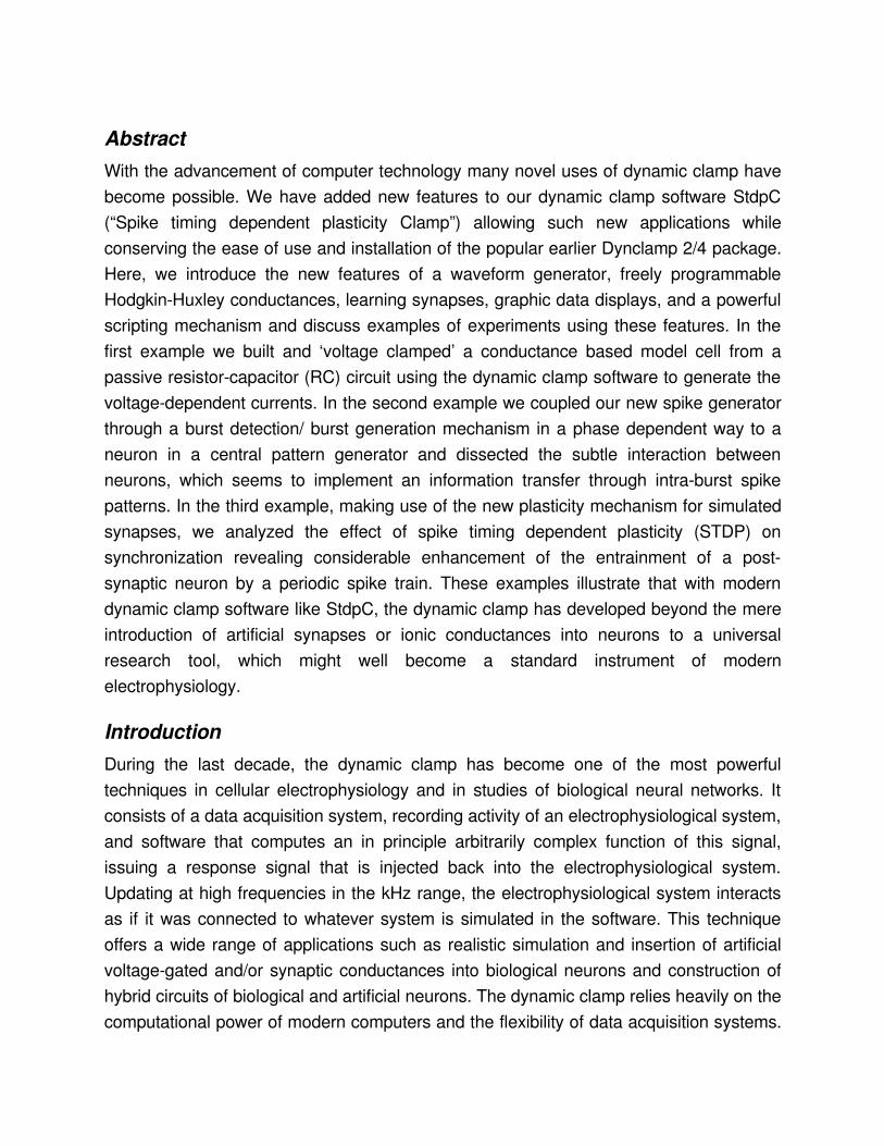
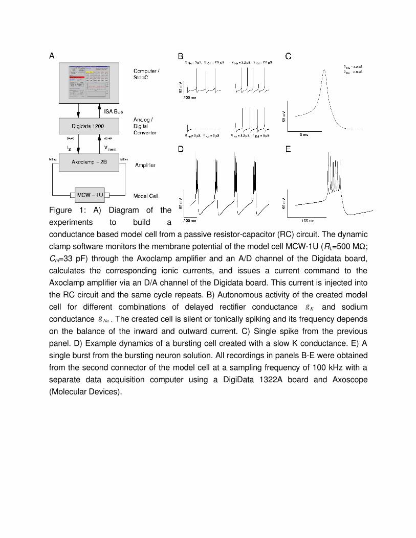
Creating an electronic model neuronIt has been demonstrated earlier that the dynamic clamp allows the experimenter to create a programmable electronic model neuron (EN) . Here, we describe the simple procedure for implementing this with StdpC and discuss the typically observed performance of our nonrealtime system. A single compartment HodgkinHuxley type neuron is a parallel circuit of the membrane capacitance Cm, the passive ohmic (leakage) resistance RL (both constants) and a set of voltagedependent resistors RNa, RK, etc., which are described by a set of differential equations . Hence, to build an electronic neuron model, we can generate a current waveform obeying the HHequations and feed this current into a physical resistorcapacitor (RC) circuit. Many of the commercially available intracellular amplifiers come equipped with model cells, which contain such RC circuits. In our experiments we used a MCW1U type model cell from Axon Instruments (RL=500 MΩ; Cm=33 pF). Using the model cell instead of integration within the software or injection of currents into a biological cell, we can test the performance of both the HHcurrent calculation by the dynamic clamp software and the digital to analog conversion hardware without interference from the activity and noise in a real neuron.In our dynamic clamp software the user can set up a maximum of 6 voltagegated conductances to describe ionic currents. Upon initiation of the dynamic clamp cycle, the software computes the HHcurrents and delivers a voltage command proportional to their algebraic sum to the analog (DA) output of the Digidata board. This command signal is then converted into an injected current by an intracellular amplifier. At the same time, the value of the membrane potential of the simulated neuron is monitored by the intracellular amplifier, fed back to an analog input of the Digidata board and used by the dynamic clamp software for calculating the HHcurrents in the next dynamic clamp cycle.
Fig. 1A summarizes the overall configuration of the system. The connections from the computer to the amplifier and back form a closed loop and provide a continuous feedback from the model cell to the computer.
Pacemaker spikingOur first test of the EN addressed the reproduction of spontaneous repetitive firing of a HodgkinHuxley type neuron. In the simplest case there are only a depolarizing Naconductance and a hyperpolarizing Kconductance. The concurrent activation/ inactivation of the two currents results in rhythmic generation of action potentials whenever their ratio is in the appropriate range. The activity patterns recorded from the EN using different values for gmax,Na, and gmax,K are shown in Fig. 1B. The spike generation fails if the conductances are not wellbalanced. The balance of inward and outward conductances also regulates the firing frequency. The amplitude of the action potentials, however, depends only slightly on the maximal conductances. Changing the voltagedependence and time constants of the two cooperating conductances leads to a variety of firing patterns and action potentials with different shape.The single spike recording in Fig. 1C illustrates the observed quality of current generation. The recording was obtained from the D/A output of the dynamic clamp DigiData 1200 board with a separate data acquisition system (Digidata 1322A) at 100 kHz. With large magnification, one can see discretization steps of about 50 µs corresponding to an average update rate of about 20 kHz. To quantify the average and worst case performance of the variable time step algorithm in the nonrealtime Windows operating system, we collected the time steps internally in the dynamic clamp software. With a 2.8 GHz Pentium IV processor we observed in a run of 3 million steps an average of 39.5 µs per time step with standard deviation 3.32 µs. The worst time step observed was 0.76 ms. From the small standard deviation one can deduce that such worst case events are very rare. For the purposes reported here, and for most physiology work, this performance can be sufficient. However, if exact time stepping is of the essence one should consider a more precise realtime system.
Generation of burst activityBursting neurons have voltagedependent conductances operating on largely different time scales. In many cases, a slowlyactivating outward potassium current is responsible for the termination of rapid spiking during the burst . One can easily add such a slow outward conductance to the previously described spiking HHmodel. The cooperative
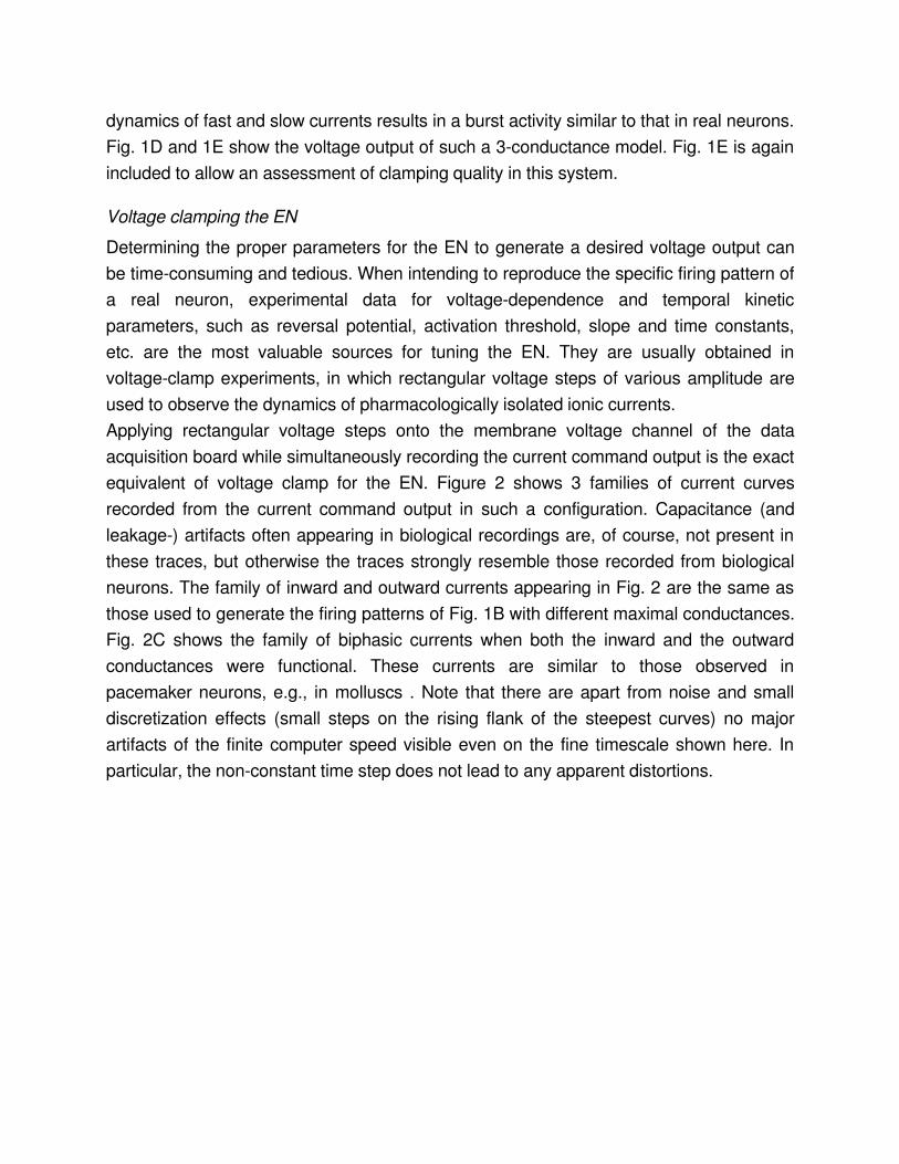
dynamics of fast and slow currents results in a burst activity similar to that in real neurons. Fig. 1D and 1E show the voltage output of such a 3conductance model. Fig. 1E is again included to allow an assessment of clamping quality in this system.
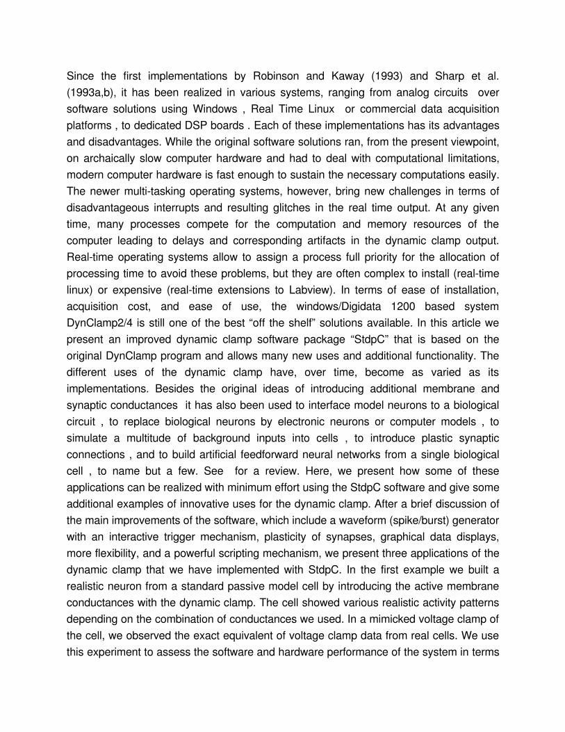
Voltage clamping the ENDetermining the proper parameters for the EN to generate a desired voltage output can be timeconsuming and tedious. When intending to reproduce the specific firing pattern of a real neuron, experimental data for voltagedependence and temporal kinetic parameters, such as reversal potential, activation threshold, slope and time constants, etc. are the most valuable sources for tuning the EN. They are usually obtained in voltageclamp experiments, in which rectangular voltage steps of various amplitude are used to observe the dynamics of pharmacologically isolated ionic currents.Applying rectangular voltage steps onto the membrane voltage channel of the data acquisition board while simultaneously recording the current command output is the exact equivalent of voltage clamp for the EN. Figure 2 shows 3 families of current curves recorded from the current command output in such a configuration. Capacitance (and leakage) artifacts often appearing in biological recordings are, of course, not present in these traces, but otherwise the traces strongly resemble those recorded from biological neurons. The family of inward and outward currents appearing in Fig. 2 are the same as those used to generate the firing patterns of Fig. 1B with different maximal conductances. Fig. 2C shows the family of biphasic currents when both the inward and the outward conductances were functional. These currents are similar to those observed in pacemaker neurons, e.g., in molluscs . Note that there are apart from noise and small discretization effects (small steps on the rising flank of the steepest curves) no major artifacts of the finite computer speed visible even on the fine timescale shown here. In particular, the nonconstant time step does not lead to any apparent distortions.
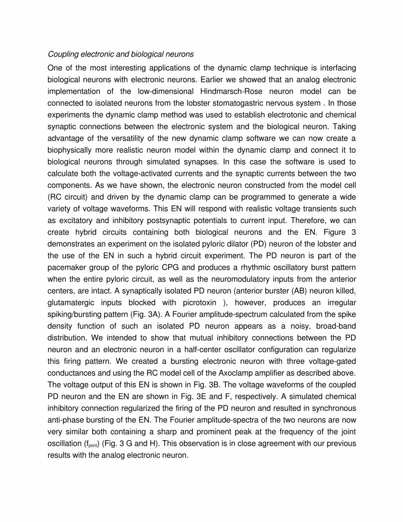
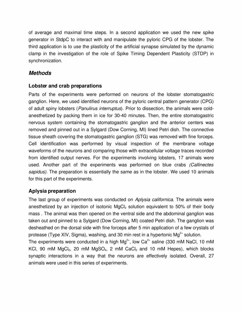
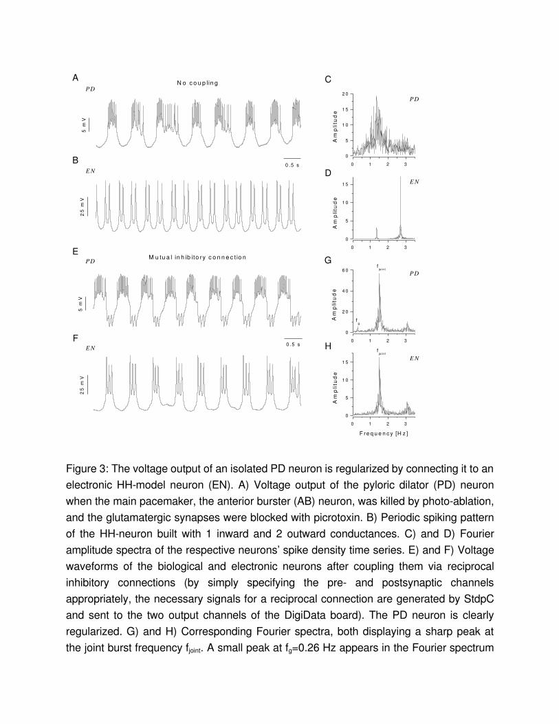
Coupling electronic and biological neuronsOne of the most interesting applications of the dynamic clamp technique is interfacing biological neurons with electronic neurons. Earlier we showed that an analog electronic implementation of the lowdimensional HindmarschRose neuron model can be connected to isolated neurons from the lobster stomatogastric nervous system . In those experiments the dynamic clamp method was used to establish electrotonic and chemical synaptic connections between the electronic system and the biological neuron. Taking advantage of the versatility of the new dynamic clamp software we can now create a biophysically more realistic neuron model within the dynamic clamp and connect it to biological neurons through simulated synapses. In this case the software is used to calculate both the voltageactivated currents and the synaptic currents between the two components. As we have shown, the electronic neuron constructed from the model cell (RC circuit) and driven by the dynamic clamp can be programmed to generate a wide variety of voltage waveforms. This EN will respond with realistic voltage transients such as excitatory and inhibitory postsynaptic potentials to current input. Therefore, we can create hybrid circuits containing both biological neurons and the EN. Figure 3 demonstrates an experiment on the isolated pyloric dilator (PD) neuron of the lobster and the use of the EN in such a hybrid circuit experiment. The PD neuron is part of the pacemaker group of the pyloric CPG and produces a rhythmic oscillatory burst pattern when the entire pyloric circuit, as well as the neuromodulatory inputs from the anterior centers, are intact. A synaptically isolated PD neuron (anterior burster (AB) neuron killed, glutamatergic inputs blocked with picrotoxin ), however, produces an irregular spiking/bursting pattern (Fig. 3A). A Fourier amplitudespectrum calculated from the spike density function of such an isolated PD neuron appears as a noisy, broadband distribution. We intended to show that mutual inhibitory connections between the PD neuron and an electronic neuron in a halfcenter oscillator configuration can regularize this firing pattern. We created a bursting electronic neuron with three voltagegated conductances and using the RC model cell of the Axoclamp amplifier as described above. The voltage output of this EN is shown in Fig. 3B. The voltage waveforms of the coupled PD neuron and the EN are shown in Fig. 3E and F, respectively. A simulated chemical inhibitory connection regularized the firing of the PD neuron and resulted in synchronous antiphase bursting of the EN. The Fourier amplitudespectra of the two neurons are now very similar both containing a sharp and prominent peak at the frequency of the joint oscillation (fjoint) (Fig. 3 G and H). This observation is in close agreement with our previous results with the analog electronic neuron.
Triggered (phasic) stimulation of bursting neurons
Pattern stimulation of the lobster PD neuronBursting neurons in the pyloric circuit of the crustacean stomatogastric nervous system are classical examples of neural oscillators. The pyloric neurons generate a robust and persistent motor pattern with stable phaserelationships between the neurons’ bursts. Our earlier experiments on these neurons showed that synaptic and neuromodulatory factors affect not only the overall burst pattern but also the temporal structure of spikes within the bursts of the individual neurons . The intrinsic cellular properties and the synaptic inputs act concurrently to shape the neurons’ intraburst spike dynamics. In fact, most pyloric neurons display remarkably stereotyped spike patterns in their bursts, such that they can be reliably identified from their spike time data alone. The dynamic clamp discussed here is an efficient technique to investigate synaptic modulation of such bursting neurons. The builtin waveform generator and the burst detection capability of the dynamic clamp program allow to deliver an arbitrary (prescribed) burst pattern to the selected pyloric neuron via a simulated chemical inhibitory connection. The timing (phasing) of the burst emission depends on the activity of the biological neuron, because the artificial bursts are triggered by the terminations of its bursts. The synaptic input is delivered to the biological neuron always in the right phase. Figure 4 shows an example of such experiments. Here, the pyloric dilator (PD) neuron was stimulated in a way resembling the natural phasic inhibition from the lateral pyloric (LP) neuron. In the pyloric network the LP is the only neuron delivering inhibitory postsynaptic potentials (IPSPs) to the pacemaker group. The inhibitory input from the LP has a strong impact not only on the burst timing of the PD neuron but also on the spike dynamics of the intraburst spikes. The phasic inhibition apparently regularizes the spike pattern of the PD neuron and it strongly contributes to the characteristic Vshaped ISI signature of the PD. The clustering of the ISI return map of the PD neuron indicates the occurrence of precisely replicated spike patterns in the bursts. In the example shown in Fig. 4 we first acquired 70 successive bursts of the PD neuron in the absence of stimuli and without the natural LPinhibition (synapse blocked by picrotoxin). At t=50 s we initiated the dynamic clamp cycle and began the stimulation with a single presynaptic spike. The presynaptic firing pattern was automatically changed after every 50th bursts in the PD neuron. The number of spikes within the presynaptic burst waveform as well as the ISI parameters were stored in an ASCII file, which was continuously read by the dynamic clamp program. The correct phasing of the stimulus delivery was achieved by monitoring the burst terminations in the postsynaptic PD neuron. Here, the trigger condition for the artificial burst emission was achieved whenever
the membrane potential of the PD fell below –56 mV, the predetermined threshold for the burst detection. The inhibitory currents injected into the PD neuron resulted in apparent IPSPs. To check whether the number of spikes in the presynaptic burst waveform had an impact on the intraburst spike dynamics of the PD neuron we created colorcoded ISI return maps for the burst patterns in response to the different stimuli. The number of spikes is indicated in these maps. As the return map analysis shows and similar to our observations in earlier experiments, a stronger inhibitory input results in a more regular ISI signature in the PD neuron. The clustering of the PD signature becomes more apparent with higher number of spikes in the incoming bursts.The example shown in this section demonstrates several advanced features of the dynamic clamp and how to set up the new software in order to obtain responsedependent and more natural stimulation of bursting neurons. The burst detection feature of the dynamic clamp can, of course, also be used to detect single spikes. The termination of action potentials of the neuron in question can serve as a trigger signal for the program in the same way as the falling edge of a burst waveform. Therefore, bursting and spiking neurons can equally be stimulated by the protocol we outlined above.
Applying information theory to the bursting patterns of STG neurons
In order to further analyze the stimulusdependent pattern of spikes of STG bursting neurons (as in the previous section and in ) we used our dynamic clamp program, and a STG preparation of blue crabs (Callinectes sapidus), to generate bursts containing random sequences of spikes after every burst of one of the two PD neurons. These bursts were again timed by the burst detection mechanism of StdpC to introduce phasic inhibition to the same PD neuron through a simulated chemical synapse, in a similar way as the LP neuron does in the intact preparation (the LP neuron was hyperpolarized during our experiments). A schematic diagram of the experiments is shown in Fig. 5A and B.The experimental protocol consisted of hyperpolarizing the biological LP neuron by injection of a negative DC current and then using the dynamic clamp to detect the hyperpolarization events in the PD neuron, to generate a random sequence of spikes, and to simulate an inhibitory synapse onto the PD neuron that delivered corresponding IPSPs in a phase given by a previously chosen time delay parameter. Long time series ( ~ 1 hour) of both the artificial neuron and the PD were simultaneously recorded for each tested value of the inhibitory burst phase. The data analysis consisted in detecting the
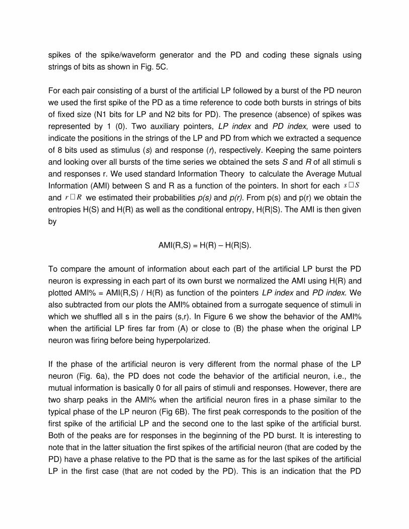
spikes of the spike/waveform generator and the PD and coding these signals using strings of bits as shown in Fig. 5C.
For each pair consisting of a burst of the artificial LP followed by a burst of the PD neuron we used the first spike of the PD as a time reference to code both bursts in strings of bits of fixed size (N1 bits for LP and N2 bits for PD). The presence (absence) of spikes was represented by 1 (0). Two auxiliary pointers, LP index and PD index, were used to indicate the positions in the strings of the LP and PD from which we extracted a sequence of 8 bits used as stimulus (s) and response (r), respectively. Keeping the same pointers and looking over all bursts of the time series we obtained the sets S and R of all stimuli s and responses r. We used standard Information Theory to calculate the Average Mutual Information (AMI) between S and R as a function of the pointers. In short for each Ss ∈
and Rr ∈ we estimated their probabilities p(s) and p(r). From p(s) and p(r) we obtain the entropies H(S) and H(R) as well as the conditional entropy, H(R|S). The AMI is then given by
AMI(R,S) = H(R) – H(R|S).
To compare the amount of information about each part of the artificial LP burst the PD neuron is expressing in each part of its own burst we normalized the AMI using H(R) and plotted AMI% = AMI(R,S) / H(R) as function of the pointers LP index and PD index. We also subtracted from our plots the AMI% obtained from a surrogate sequence of stimuli in which we shuffled all s in the pairs (s,r). In Figure 6 we show the behavior of the AMI% when the artificial LP fires far from (A) or close to (B) the phase when the original LP neuron was firing before being hyperpolarized.
If the phase of the artificial neuron is very different from the normal phase of the LP neuron (Fig. 6a), the PD does not code the behavior of the artificial neuron, i.e., the mutual information is basically 0 for all pairs of stimuli and responses. However, there are two sharp peaks in the AMI% when the artificial neuron fires in a phase similar to the typical phase of the LP neuron (Fig 6B). The first peak corresponds to the position of the first spike of the artificial LP and the second one to the last spike of the artificial burst. Both of the peaks are for responses in the beginning of the PD burst. It is interesting to note that in the latter situation the first spikes of the artificial neuron (that are coded by the PD) have a phase relative to the PD that is the same as for the last spikes of the artificial LP in the first case (that are not coded by the PD). This is an indication that the PD
neuron is tuned specifically to code in its ISIs the beginning and the end of a preceding inhibitory burst, if this burst happens in a time window that corresponds to the phase in which the biological LP is expected to fire.
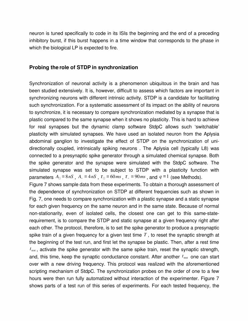
Probing the role of STDP in synchronization
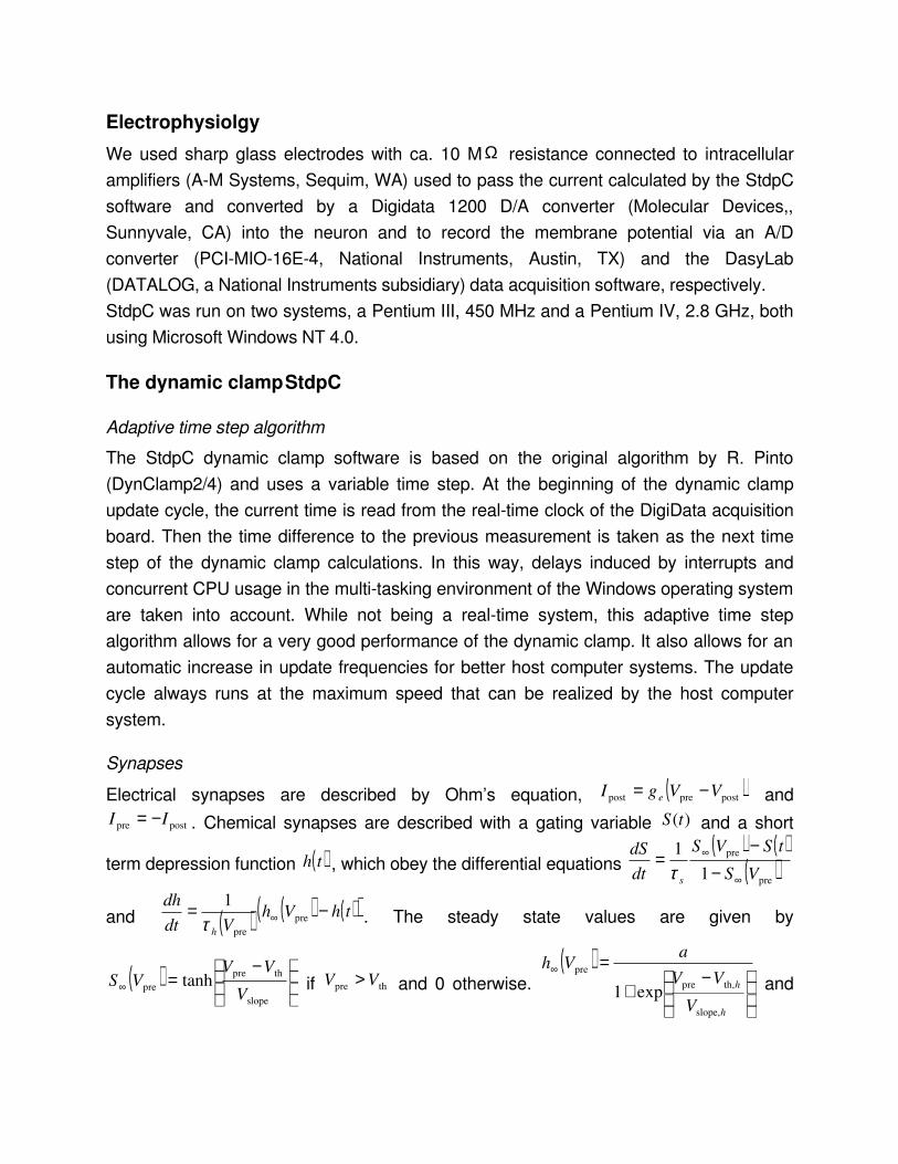
Synchronization of neuronal activity is a phenomenon ubiquitous in the brain and has been studied extensively. It is, however, difficult to assess which factors are important in synchronizing neurons with different intrinsic activity. STDP is a candidate for facilitating such synchronization. For a systematic assessment of its impact on the ability of neurons to synchronize, it is necessary to compare synchronization mediated by a synapse that is plastic compared to the same synapse when it shows no plasticity. This is hard to achieve for real synapses but the dynamic clamp software StdpC allows such ‘switchable’ plasticity with simulated synapses. We have used an isolated neuron from the Aplysia abdominal ganglion to investigate the effect of STDP on the synchronization of unidirectionally coupled, intrinsically spiking neurons . The Aplysia cell (typically L8) was connected to a presynaptic spike generator through a simulated chemical synapse. Both the spike generator and the synapse were simulated with the StdpC software. The simulated synapse was set to be subject to STDP with a plasticity function with parameters nSA 8=+ , nSA 4=− , ms60=+τ , ms90=−τ , and 1=q (see Methods).Figure 7 shows sample data from these experiments. To obtain a thorough assessment of the dependence of synchronization on STDP at different frequencies such as shown in Fig. 7, one needs to compare synchronization with a plastic synapse and a static synapse for each given frequency on the same neuron and in the same state. Because of normal nonstationarity, even of isolated cells, the closest one can get to this samestaterequirement, is to compare the STDP and static synapse at a given frequency right after each other. The protocol, therefore, is to set the spike generator to produce a presynaptic spike train of a given frequency for a given test time T , to reset the synaptic strength at the beginning of the test run, and first let the synapse be plastic. Then, after a rest time
restt , activate the spike generator with the same spike train, reset the synaptic strength, and, this time, keep the synaptic conductance constant. After another restt one can start over with a new driving frequency. This protocol was realized with the aforementioned scripting mechanism of StdpC. The synchronization probes on the order of one to a few hours were then run fully automatized without interaction of the experimenter. Figure 7 shows parts of a test run of this series of experiments. For each tested frequency, the

spike generator was turned on, the synapse made plastic and activated to couple the spike generator to the biological neuron for the test time T . As one can see from the growing excitatory postsynaptic potential (EPSP), the plasticity led to a moderate increase in synaptic conductance in this case. Then, the spike generator was automatically switched off, the synapse made static and the synaptic strength reset to its initial value. The process then repeats after a resting time. Table 1 shows an example script that implements such a trial.Figure 7 B and C summarize the observed synchronization between the presynaptic spike generator and the postsynaptic Aplysia neuron. The plateaus in the plot of the observed frequency ratio for the coupled system versus the pretrial frequency ratio correspond to 1:1 frequency synchronization. The plateau of 1:1 frequency synchronization is widened by a factor two through the action of STDP.
DiscussionThe dynamic clamp has now become a powerful and versatile research tool for a multitude of applications in electrophysiology. We have demonstrated a few novel applications of dynamic clamping in investigating and interacting with neural circuits which can effortlessly be implemented with our new dynamic clamp software StdpC. Whether creating a model neuron from a passive RC circuit, interacting with single neurons or circuits, or investigating functions of plasticity, the efforts can be focused on the experimental questions rather than technical issues. The advantages of the dynamic clamp software discussed here are many,
a) Ease of installation: The user only needs to download the executable and the hardware driver, copy the hardware driver, and start the program. From downloading to the first experiment literally takes only seconds.
b) Ease of use: The graphical interface and the documentation make the software extremely easy to use. No advanced computer or programming skills are required. The builtin data displays allow easy debugging of the experimental setup.The new option to save the settings of the clamp in setup files allows the user to keep their experimental protocols ready and load them during experimentation instantly.
c) Flexibility and functionality: In spite of the simple, predefined (and therefore seemingly inflexible) interface, the software offers a lot of practical functionality and flexibility.
1. The HodgkinHuxley conductances allow multifold interactions with neurons and, as shown here, even the creation of complete artificial conductance based neurons.
2. The synaptic elements allow the typical artificial synapse applications, but also advanced applications involving synaptic plasticity. The synaptic plasticity can be defined in very general ways, based on map models or a continuous dynamical systems approach .
3. The spike generator module allows manifold interactions with biological systems beyond the classical dynamic clamp applications. By the trigger mechanism from an external signal and the ability to read arbitrary spike sequences from files, many experimental protocols can be realized with ease. Apart from the interaction of bursts and the information theoretical analysis of these interactions in the STG demonstrated here, other protocols like the virtual networks in can be implemented with this functionality.
4. The advanced scripting capabilities, finally, allow full automatization of experimental protocols and flexibility of the software otherwise typically only expected from systems that require programming by the user.
In short, while other systems may be more rigorous in their real time performance and freely programmable for the advanced user the StdpC software remains the choice for readytogo dynamic clamp software with extensive functionality. While the dynamic clamp “is coming of age” it is not getting old. We have just released a new version (4) of our dynamic clamp software which can be downloaded and used free of charge for noncommercial applications at http://inls.ucsd.edu/~nowotny/dynclamp.html. We supply the precompiled binary for immediate use as well as a complete source code package that can be modified and rebuilt using Borland C++ Builder 5. While the current version is still exclusively for the DigiData 1200/1200A board, a port towards National Instruments boards is in preparation.
AcknowledgementsThis work was supported by the National Science Foundation under grants NSF PHY0097134 and NSF EIA0130708, by the National Institutes of Health under grants NIH R01 NS4011001A2 and RO1 NS050945, and by the Brazilian funding agencies CNPq and FAPESP. We thank Rafael Levi and Marcello Reyes for helpful discussions and comments on the manuscript.

A
Figure 1: A) Diagram of the experiments to build a conductance based model cell from a passive resistorcapacitor (RC) circuit. The dynamic clamp software monitors the membrane potential of the model cell MCW1U (RL=500 MΩ; Cm=33 pF) through the Axoclamp amplifier and an A/D channel of the Digidata board, calculates the corresponding ionic currents, and issues a current command to the Axoclamp amplifier via an D/A channel of the Digidata board. This current is injected into the RC circuit and the same cycle repeats. B) Autonomous activity of the created model cell for different combinations of delayed rectifier conductance Kg and sodium conductance Nag . The created cell is silent or tonically spiking and its frequency depends on the balance of the inward and outward current. C) Single spike from the previous panel. D) Example dynamics of a bursting cell created with a slow K conductance. E) A single burst from the bursting neuron solution. All recordings in panels BE were obtained from the second connector of the model cell at a sampling frequency of 100 kHz with a separate data acquisition computer using a DigiData 1322A board and Axoscope (Molecular Devices).
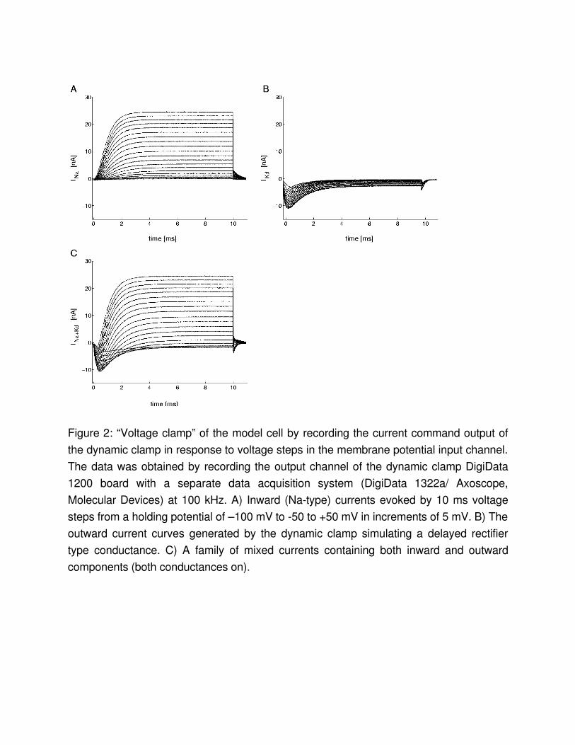
Figure 2: “Voltage clamp” of the model cell by recording the current command output of the dynamic clamp in response to voltage steps in the membrane potential input channel. The data was obtained by recording the output channel of the dynamic clamp DigiData 1200 board with a separate data acquisition system (DigiData 1322a/ Axoscope, Molecular Devices) at 100 kHz. A) Inward (Natype) currents evoked by 10 ms voltage steps from a holding potential of –100 mV to 50 to +50 mV in increments of 5 mV. B) The outward current curves generated by the dynamic clamp simulating a delayed rectifier type conductance. C) A family of mixed currents containing both inward and outward components (both conductances on).
0 1 2 30
5
1 0
1 5
0 1 2 30
5
1 0
1 5
2 0
0 1 2 30
2 0
4 0
6 0
0 1 2 30
5
1 0
1 5
0 .5 s
0 .5 s
5 m
V
E N
PD
25
mV
5 m
V2
5 m
VPD
E N
PD
E N
PD
E N
Am
plitu
de
Am
plitu
de
fjo in t
fjo in t
M u tu a l in h ib ito ry c o n n e c t io n
Am
plit
ude
N o c o u p lin g
fg
H
G
F
E
D
C
B
F re q u e n c y [H z ]
Am
plitu
de
A
Figure 3: The voltage output of an isolated PD neuron is regularized by connecting it to an electronic HHmodel neuron (EN). A) Voltage output of the pyloric dilator (PD) neuron when the main pacemaker, the anterior burster (AB) neuron, was killed by photoablation, and the glutamatergic synapses were blocked with picrotoxin. B) Periodic spiking pattern of the HHneuron built with 1 inward and 2 outward conductances. C) and D) Fourier amplitude spectra of the respective neurons’ spike density time series. E) and F) Voltage waveforms of the biological and electronic neurons after coupling them via reciprocal inhibitory connections (by simply specifying the pre and postsynaptic channels appropriately, the necessary signals for a reciprocal connection are generated by StdpC and sent to the two output channels of the DigiData board). The PD neuron is clearly regularized. G) and H) Corresponding Fourier spectra, both displaying a sharp peak at the joint burst frequency fjoint. A small peak at fg=0.26 Hz appears in the Fourier spectrum

of the PD neuron (G). This peak indicates the frequency modulation of the pyloric network by the ongoing gastric rhythm.
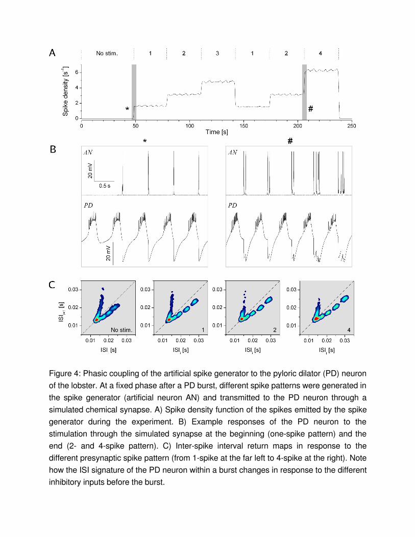
Figure 4: Phasic coupling of the artificial spike generator to the pyloric dilator (PD) neuron of the lobster. At a fixed phase after a PD burst, different spike patterns were generated in the spike generator (artificial neuron AN) and transmitted to the PD neuron through a simulated chemical synapse. A) Spike density function of the spikes emitted by the spike generator during the experiment. B) Example responses of the PD neuron to the stimulation through the simulated synapse at the beginning (onespike pattern) and the end (2 and 4spike pattern). C) Interspike interval return maps in response to the different presynaptic spike pattern (from 1spike at the far left to 4spike at the right). Note how the ISI signature of the PD neuron within a burst changes in response to the different inhibitory inputs before the burst.
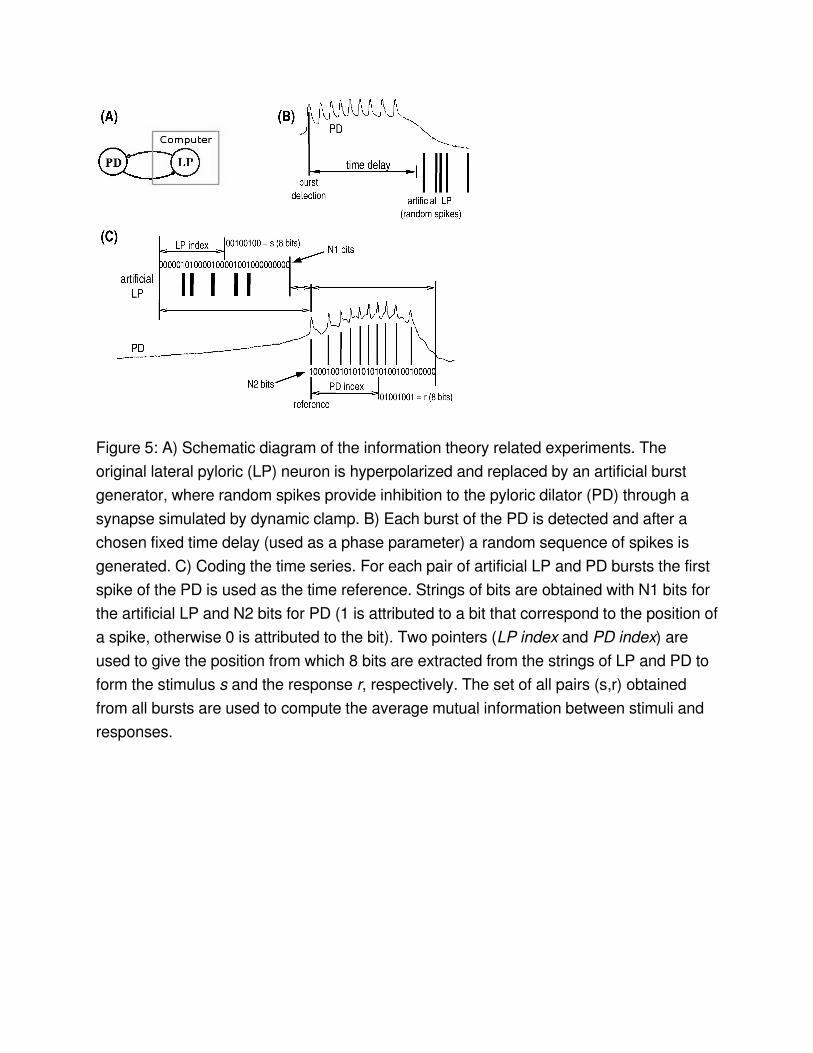
Figure 5: A) Schematic diagram of the information theory related experiments. The original lateral pyloric (LP) neuron is hyperpolarized and replaced by an artificial burst generator, where random spikes provide inhibition to the pyloric dilator (PD) through a synapse simulated by dynamic clamp. B) Each burst of the PD is detected and after a chosen fixed time delay (used as a phase parameter) a random sequence of spikes is generated. C) Coding the time series. For each pair of artificial LP and PD bursts the first spike of the PD is used as the time reference. Strings of bits are obtained with N1 bits for the artificial LP and N2 bits for PD (1 is attributed to a bit that correspond to the position of a spike, otherwise 0 is attributed to the bit). Two pointers (LP index and PD index) are used to give the position from which 8 bits are extracted from the strings of LP and PD to form the stimulus s and the response r, respectively. The set of all pairs (s,r) obtained from all bursts are used to compute the average mutual information between stimuli and responses.
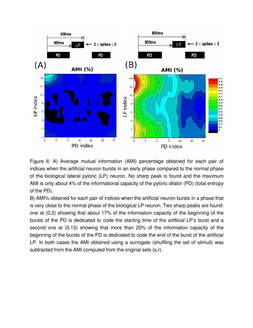
Figure 6: A) Average mutual information (AMI) percentage obtained for each pair of indices when the artificial neuron bursts in an early phase compared to the normal phase of the biological lateral pyloric (LP) neuron. No sharp peak is found and the maximum AMI is only about 4% of the informational capacity of the pyloric dilator (PD) (total entropy of the PD).B) AMI% obtained for each pair of indices when the artificial neuron bursts in a phase that is very close to the normal phase of the biological LP neuron. Two sharp peaks are found: one at (0,2) showing that about 17% of the information capacity of the beginning of the bursts of the PD is dedicated to code the starting time of the artificial LP’s burst and a second one at (0,13) showing that more than 20% of the information capacity of the beginning of the bursts of the PD is dedicated to code the end of the burst of the artificial LP. In both cases the AMI obtained using a surrogate (shuffling the set of stimuli) was subtracted from the AMI computed from the original sets (s,r).
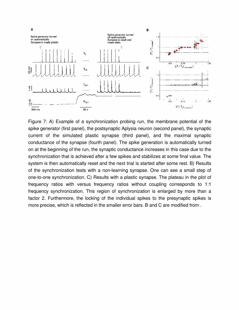
Figure 7: A) Example of a synchronization probing run, the membrane potential of the spike generator (first panel), the postsynaptic Aplysia neuron (second panel), the synaptic current of the simulated plastic synapse (third panel), and the maximal synaptic conductance of the synapse (fourth panel). The spike generation is automatically turned on at the beginning of the run, the synaptic conductance increases in this case due to the synchronization that is achieved after a few spikes and stabilizes at some final value. The system is then automatically reset and the next trial is started after some rest. B) Results of the synchronization tests with a nonlearning synapse. One can see a small step of onetoone synchronization. C) Results with a plastic synapse. The plateau in the plot of frequency ratios with versus frequency ratios without coupling corresponds to 1:1 frequency synchronization. This region of synchronization is enlarged by more than a factor 2. Furthermore, the locking of the individual spikes to the presynaptic spikes is more precise, which is reflected in the smaller error bars. B and C are modified from .
Time [s] Variable value Comment0 #_of_Spk 0 Spike generator off
20 #_of_Spk 1 Spike generation 1 spike/burst
20 period 200 ISI 200 ms
20 learning_on 1 learning mechanism on
20 Chem_0_G_s 0.5 Synapse reset to 0.5 nS
40 #_of_Spk 0 Spike generation off
60 #_of_Spk 1 Spike generation 1 spike/burst
65 learning_on 0 learning mechanism off
65 Chem_0_G_s 5.0 Synapse set to 5 nS
80 #_of_Spk 0 Spike generation off
… … … …
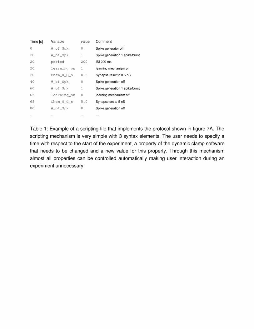
Table 1: Example of a scripting file that implements the protocol shown in figure 7A. The scripting mechanism is very simple with 3 syntax elements. The user needs to specify a time with respect to the start of the experiment, a property of the dynamic clamp software that needs to be changed and a new value for this property. Through this mechanism almost all properties can be controlled automatically making user interaction during an experiment unnecessary.


