Embed Size (px)
Citation preview
Chapter- two
Turbine
126/10/2022

General out line of the topic Introduction .
Classification of turbines.
Efficiencies and Velocity diagrams of turbine.
Specific speed and performance curves of turbines.
Cavitations in turbine.
Dynamic similarity and model testing.
Specification and selection criteria. 226/10/2022

• Hydropower Machines – Classification– Impulse, Momentum and Power of a Turbine
– Design Consideration for Hydraulic Machines
– Types of Turbines– Draft Tubes– Selection of Turbines, Units
26/10/2022 3

INTRODUCTION
426/10/2022
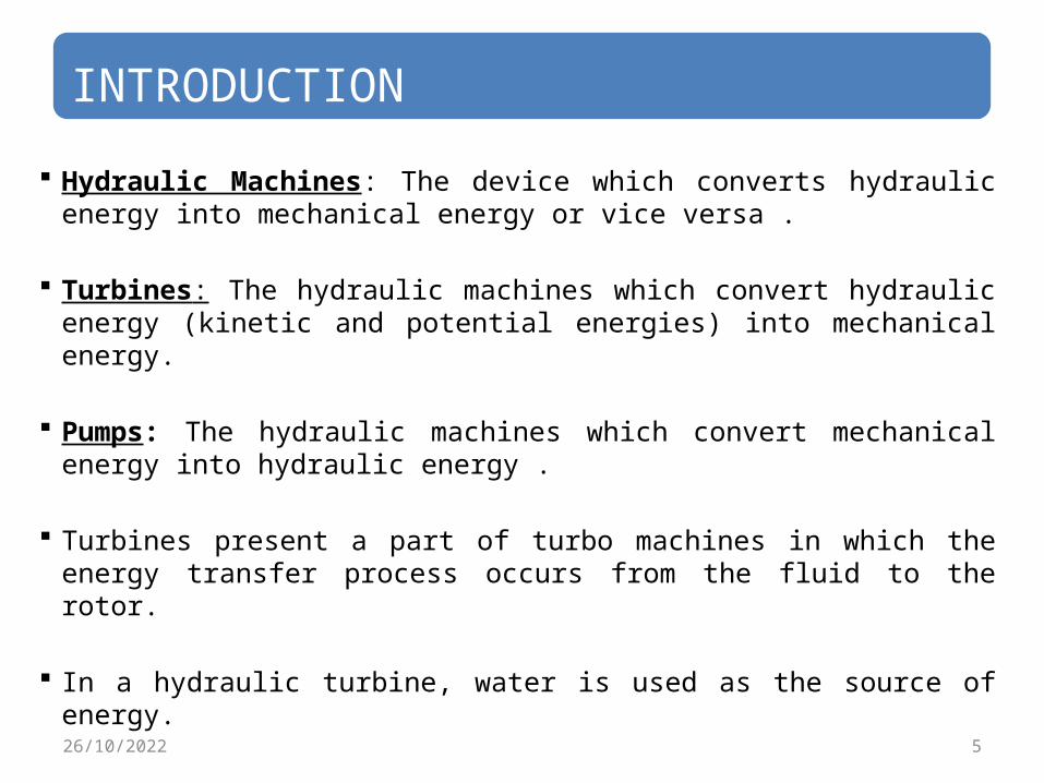
INTRODUCTION Hydraulic Machines: The device which converts hydraulic energy into mechanical energy or vice versa .
Turbines: The hydraulic machines which convert hydraulic energy (kinetic and potential energies) into mechanical energy.
Pumps: The hydraulic machines which convert mechanical energy into hydraulic energy .
Turbines present a part of turbo machines in which the energy transfer process occurs from the fluid to the rotor.
In a hydraulic turbine, water is used as the source of energy.
526/10/2022
626/10/2022

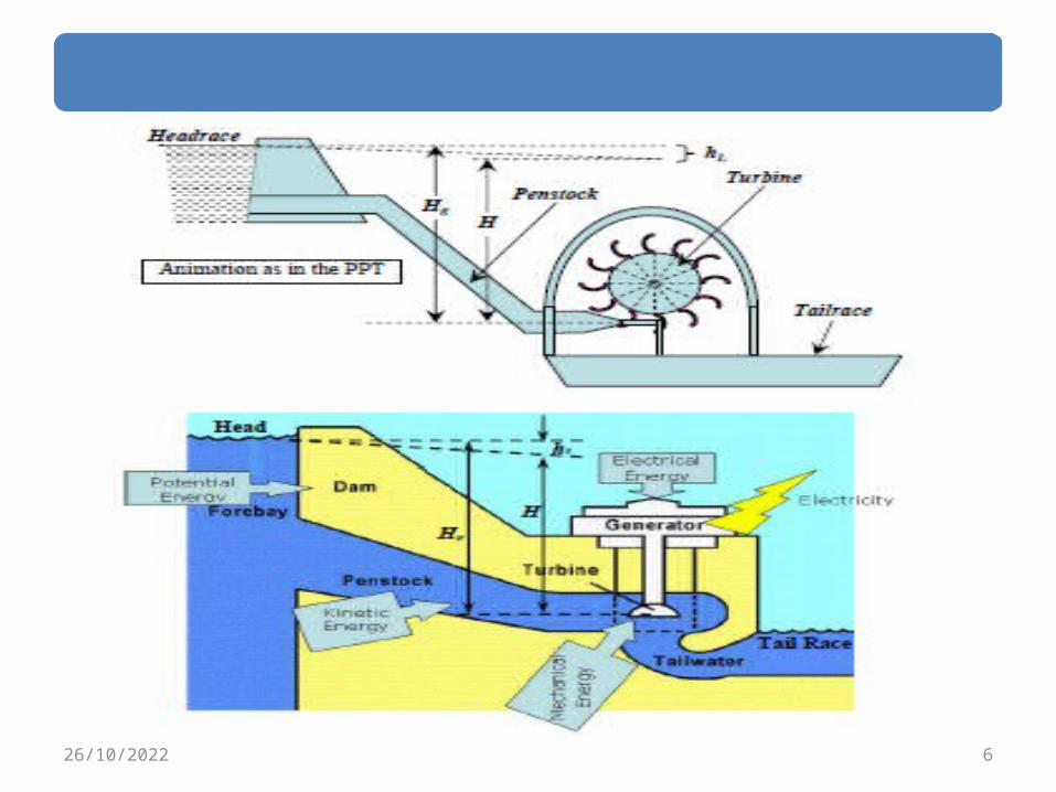
Into (con’t)It consists of the following:1. A Dam:- constructed across a river or a channel to store water. The reservoir is also known as Headrace.
2. Penstocks:- Pipes of large diameter which carry water under pressure from storage reservoir to the turbines. These pipes are usually made of steel or reinforced concrete.
3. Turbines:- having different types of vanes or buckets or blades mounted on a wheel called runner.
4. Tailrace:- This is channel carrying water away from the turbine after the water has worked on the turbines.
726/10/2022
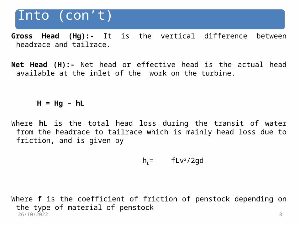
Into (con’t)Gross Head (Hg):- It is the vertical difference between headrace and tailrace.
Net Head (H):- Net head or effective head is the actual head available at the inlet of the work on the turbine.
H = Hg – hL Where hL is the total head loss during the transit of water from the headrace to tailrace which is mainly head loss due to friction, and is given by
hL= fLv2/2gd
Where f is the coefficient of friction of penstock depending on the type of material of penstock
826/10/2022
Classification of turbines
926/10/2022
Classification of turbines. Hydraulic turbines are classified in to various kinds according to 1. Action of water on blades.
2. Direction of flow through the runner.
3. Specific speed of the turbine.
4. The head of water available and,
5. The disposition of turbine shaft.1026/10/2022
Classification(con’t)1. According to action of water on
blades: According to the action of water on blades, the hydraulic turbines are classified in to
(I). Impulse turbine and
(II). Reaction turbines.1126/10/2022
Classification(con’t)Impulse turbine: An impulse turbine is one where pressure of the fluid flowing over the rotor is constant.
At atmospheric pressure, all the available potential energy has been completely used in producing kinetic energy which is utilized through a purely impulse effect to produce work at downstream channel (called the tail race).
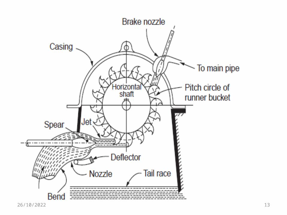
The most commonly used impulse turbine is the Pelton wheel.
1226/10/2022
1326/10/2022
Classification(con’t) Large units may have two or more jets impinging at different locations around the wheel.
Reaction turbine:
In reaction turbines only a part of the available energy of the water is converted into kinetic energy at the entrance to the runner, and a substantial part remains in the form of pressure energy.
The runner casing (called the scroll case) has to be completely airtight and filled with water throughout the operation of the turbine.
1426/10/2022

Classification(con’t)
The water enters the scroll case and moves into the runner through a series of guide vanes, called wicket gates.
The flow rate and its direction can be controlled by these adjustable gates.
After leaving the runner, the water enters a draft tube which delivers the flow to the tail race.
The Francis turbine and Kaplan turbine are the reaction turbines.
1526/10/2022

1626/10/2022

1726/10/2022
Classification(con’t)
(2). Direction of flow through the runner. Accordingly to the flow through the runner, turbines are classified in to
i. Radial flow turbine.
ii.Axial flow turbine.
iii.Mixed or diagonal flow.
iv.Tangential flow1826/10/2022
Classification(con’t)
Radial flow:
In radial flow the water enters the turbine in the radial direction and comes out of it also radially.
It may be inward flow turbine or outward flow turbine, depending on the whether the water flows inwardly or outwardly through the runner.
Example , Francis turbine
Axial flow:
The water flows parallel to the axis of the turbine.
Example , propeller turbine and Kaplan turbine.1926/10/2022
Classification(con’t)
Mixed or diagonal flow:
The water enters in to the turbine radially at the inlet circumstances and comes out axially at the exit.
Thus water changes its direction of flow while flowing over the runner vanes from radial to axial.
Francis turbine is an example of this type.
Tangential flow:
It is also known as peripheral flow type of turbines.
Example, pelton wheel.2026/10/2022
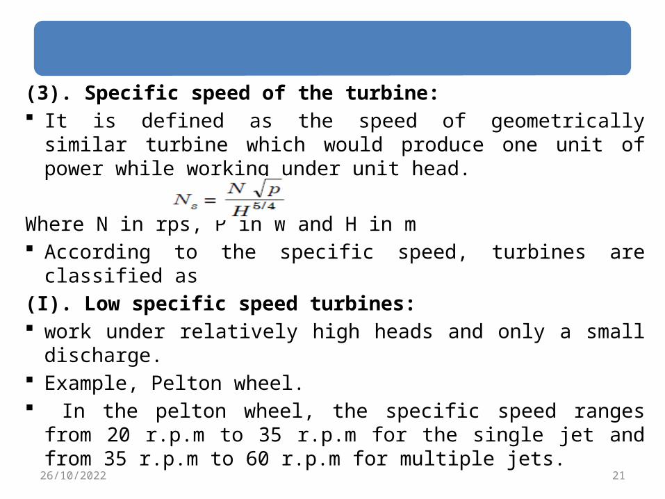
(3). Specific speed of the turbine: It is defined as the speed of geometrically similar turbine which would produce one unit of power while working under unit head.
Where N in rps, P in W and H in m According to the specific speed, turbines are classified as
(I). Low specific speed turbines: work under relatively high heads and only a small discharge.
Example, Pelton wheel. In the pelton wheel, the specific speed ranges from 20 r.p.m to 35 r.p.m for the single jet and from 35 r.p.m to 60 r.p.m for multiple jets.
2126/10/2022
Classification(con’t)
(II). Medium specific speed turbine:
The specific speed ranges from 60 r.p.m to 300 r.p.m.
Francis turbines are under this category.
(III). High specific speed turbines:
Work under relatively low head and high discharge.
The specific speed ranges from 300 r.p.m to 1000 r.p.m.
The examples are, propeller and Kaplan turbines.2226/10/2022
Classification(con’t)
(4). The head of water available: According to the head of the of the available water turbines are classified as
(I). Low head turbines: Turbines working of under a head of 3m to 50m.
The propeller turbine and Kaplan turbines are under this category.
(II).Medium head turbine: These turbines work between a head of 30m to 500m.
Francis turbine is an example of this type.2326/10/2022

Classification(con’t)
(III) High head turbine:
These turbines operate at or above 100m head. The pelton wheel is an example.
N.B: It is difficult to classify the turbines according to the head alone, this is because the given values of the turbine are overlapping to each other.
2426/10/2022

Fig. 2.1 classification of turbine2526/10/2022

Efficiencies of turbines
2626/10/2022
Efficiencies of turbines The head available for hydroelectric plant depends on the site conditions.
During the conveyance of water there are losses involved.
Depending on the considerations of input and output, the efficiencies can be classified as1. Hydraulic efficiency.2. Volumetric efficiency .3. Mechanical efficiency.4. Overall efficiency
2726/10/2022

2826/10/2022
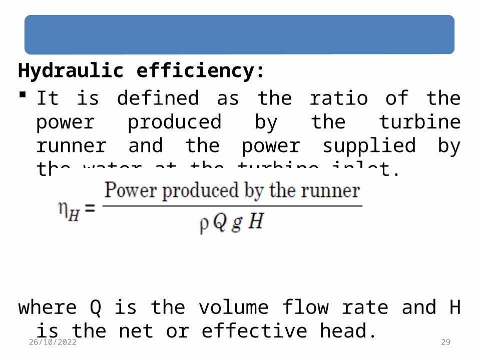
Hydraulic efficiency: It is defined as the ratio of the power produced by the turbine runner and the power supplied by the water at the turbine inlet.
where Q is the volume flow rate and H is the net or effective head.
2926/10/2022
Efficiencies of turbines(con’t) Power produced by the runner is calculated by the Euler turbine equation P = ρQ [u1 Vu1 – u2 Vu2].
This reflects the runner design effectiveness.
Since the power supplied is hydraulic, and the probable loss is between the striking jet and vane it is rightly called hydraulic efficiency.
3026/10/2022
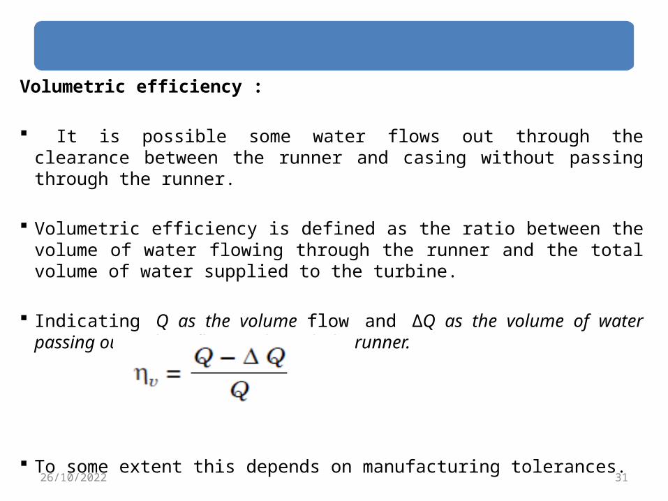
Volumetric efficiency :
It is possible some water flows out through the clearance between the runner and casing without passing through the runner.
Volumetric efficiency is defined as the ratio between the volume of water flowing through the runner and the total volume of water supplied to the turbine.
Indicating Q as the volume flow and ΔQ as the volume of water passing out without flowing through the runner.
To some extent this depends on manufacturing tolerances.3126/10/2022
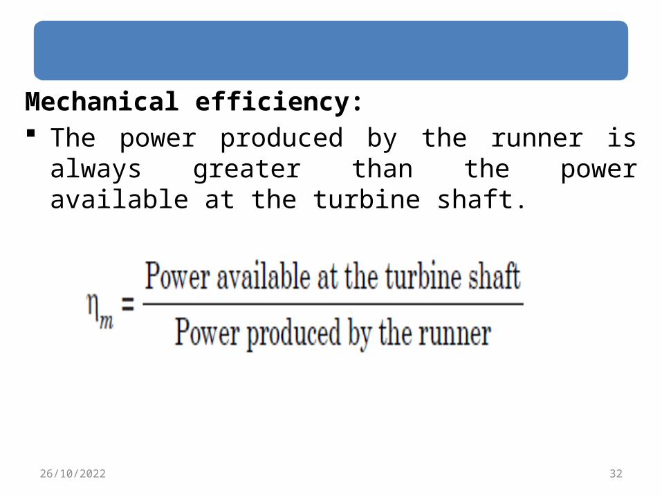
Mechanical efficiency: The power produced by the runner is always greater than the power available at the turbine shaft.
3226/10/2022
Efficiencies of turbines(con’t)
This depends on mechanical losses at the bearings, windage losses, on the slips and other mechanical problems that will create a loss of energy between the runner in the annular area between the nozzle and spear.
The amount of water reduces as the spear is pushed forward and vice-versa.
The shaft is purely mechanical and hence mechanical efficiency.
3326/10/2022
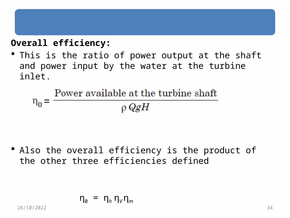
Overall efficiency: This is the ratio of power output at the shaft and power input by the water at the turbine inlet.
Also the overall efficiency is the product of the other three efficiencies defined
η0 = ηh ηV ηm3426/10/2022
Efficiencies of turbines(con’t) As this covers overall problems of losses in energy, it is known as overall efficiency.
This depends on both the hydraulic losses and the slips and other mechanical problems that will create a loss of energy between the jet power supplied and the power generated at the shaft available for coupling of the generator.
3526/10/2022
Euler turbine equation
3626/10/2022
Euler turbine equation The fluid velocity at the turbine entry and exit can have three components in the tangential, axial and radial directions of the rotor.
This means that the fluid momentum can have three components at the entry and exit.
This also means that the force exerted on the runner can have three components.
Out of these the tangential force only can cause the rotation of the runner and produce work
3726/10/2022

Euler turbine equation(con’t) The axial component produces a thrust in the axial direction, which is taken by suitable thrust bearings.
The radial component produces a bending of the shaft which is taken by the journal bearings.
Thus it is necessary to consider the tangential component for the determination of work done and power produced.
The work done or power produced by the tangential force equals the product of the mass flow, tangential force and the tangential velocity.
3826/10/2022
Euler turbine equation(con’t) As the tangential velocity varies with the radius, the work done also will be vary with the radius.
It is not easy to sum up this work.
The help of moment of momentum theorem is used for this purpose.
It states that the torque on the rotor equals the rate of change of moment of momentum of the fluid as it passes through the runner.
3926/10/2022
Euler turbine equation(con’t) Let u1 be the tangential velocity at entry and u2
be the tangential velocity at exit.
Let Vu1 be the tangential component of the absolute velocity of the fluid at inlet and let Vu2 be the tangential component of the absolute velocity of the fluid at exit.
Let r1 and r2 be the radii at inlet and exit.
4026/10/2022
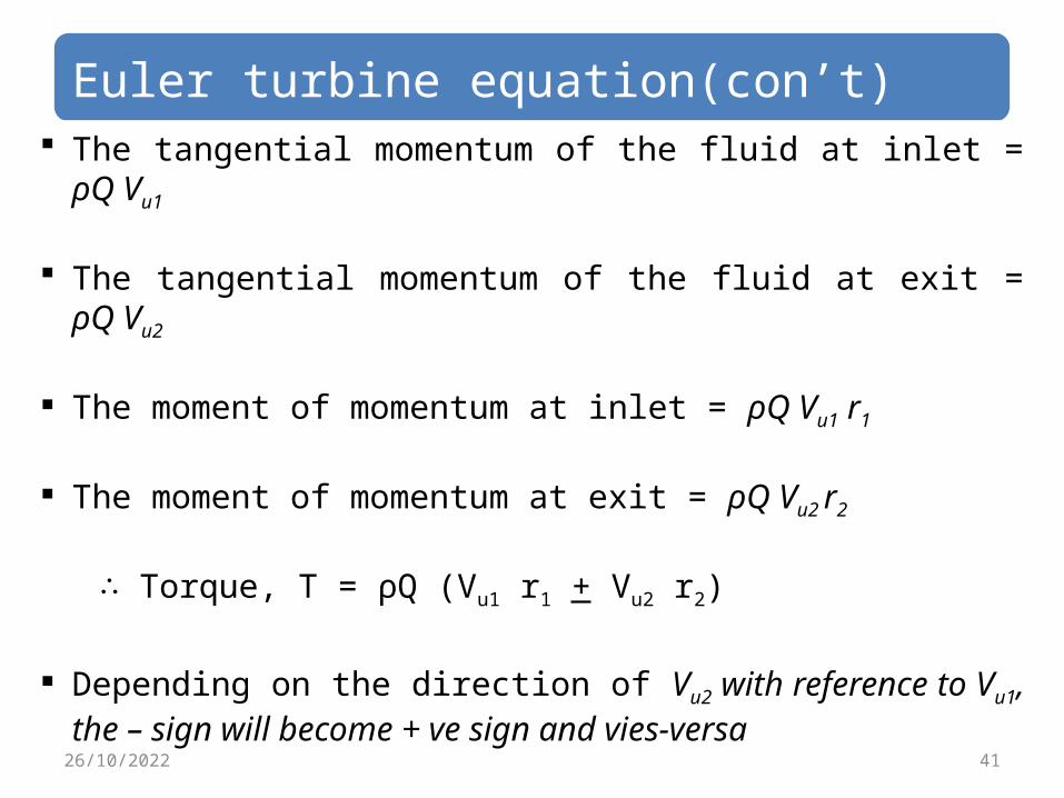
Euler turbine equation(con’t) The tangential momentum of the fluid at inlet =
ρQ Vu1
The tangential momentum of the fluid at exit = ρQ Vu2
The moment of momentum at inlet = ρQ Vu1 r1
The moment of momentum at exit = ρQ Vu2 r2
∴ Torque, T = ρQ (Vu1 r1 + Vu2 r2)
Depending on the direction of Vu2 with reference to Vu1, the – sign will become + ve sign and vies-versa
4126/10/2022
4226/10/2022
Pelton wheel turbine
4326/10/2022
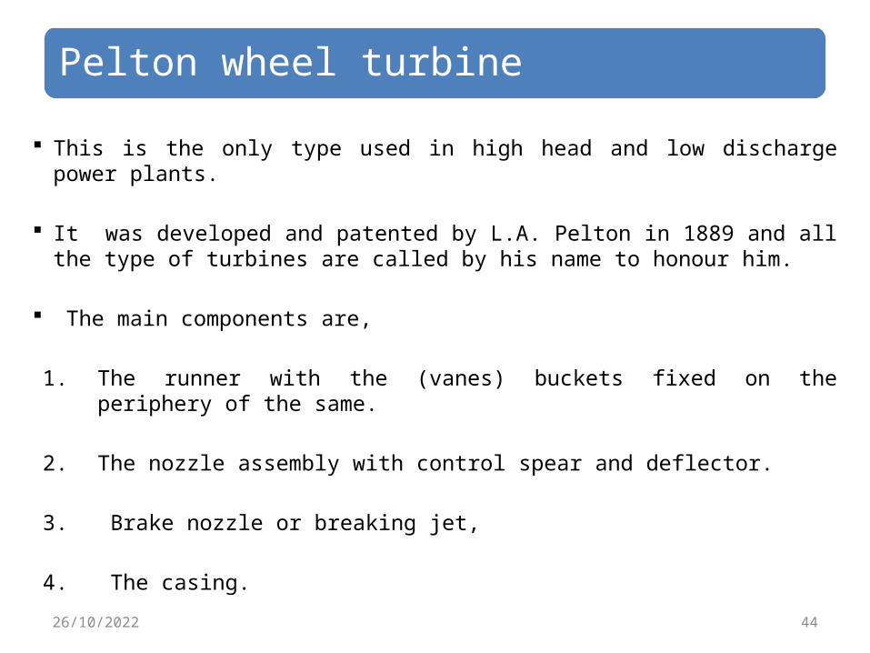
Pelton wheel turbine This is the only type used in high head and low discharge power plants.
It was developed and patented by L.A. Pelton in 1889 and all the type of turbines are called by his name to honour him.
The main components are,
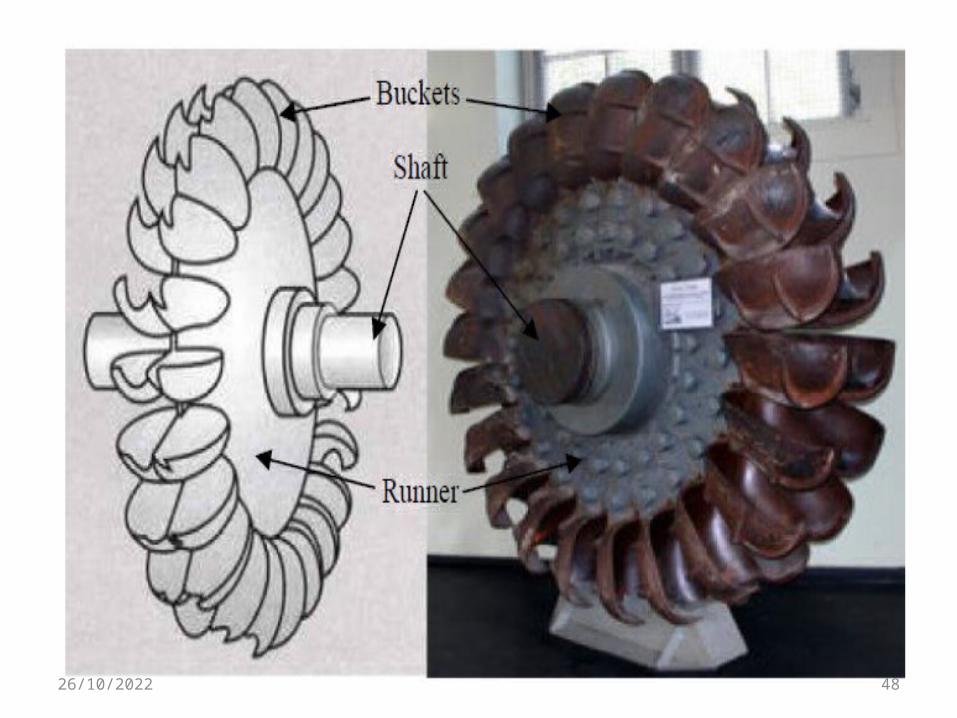
1. The runner with the (vanes) buckets fixed on the periphery of the same.
2. The nozzle assembly with control spear and deflector.
3. Brake nozzle or breaking jet,
4. The casing.4426/10/2022

4526/10/2022

4626/10/2022
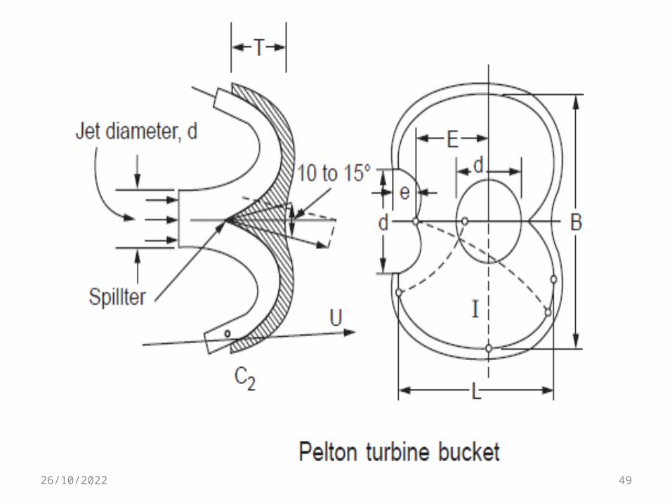
Pelton wheel turbine(con’t)Runner with buckets: Runner is a circular disk mounted on a shaft on the periphery of which a number of buckets are fixed equally spaced.
The buckets are made of cast –iron, cast -steel, bronze or stainless steel depending upon the head at the inlet of the turbine.
The water jet strikes the bucket on the splitter of the bucket and gets deflected through angle (ɑ) 160-1700 . 4726/10/2022
4826/10/2022
4926/10/2022

Equations are available to calculate the number of buckets on a wheel.
The number of buckets, Z, Z = (D/2d) + 15where D is the runner diameter and d is the jet
diameter.
5026/10/2022
Pelton wheel turbine(con’t)The nozzle assembly with control spear and deflector.
Water is brought to the hydroelectric plant site through large penstocks at the end of which there will be a nozzle, which converts the pressure energy completely into kinetic energy.
This will convert the liquid flow into a high-speed jet, which strikes the buckets or vanes mounted on the runner, which in-turn rotates the runner of the turbine.
The amount of water striking the vanes is controlled by the forward and backward motion of the spear.
As the water is flowing in the annular area between the nozzle opening and the spear, the flow gets reduced as the spear moves forward and vice-versa.
5126/10/2022

5226/10/2022
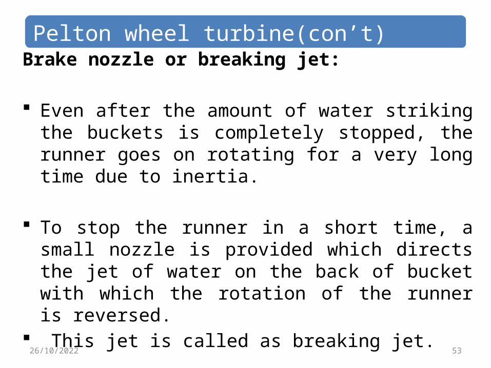
Pelton wheel turbine(con’t)Brake nozzle or breaking jet:
Even after the amount of water striking the buckets is completely stopped, the runner goes on rotating for a very long time due to inertia.
To stop the runner in a short time, a small nozzle is provided which directs the jet of water on the back of bucket with which the rotation of the runner is reversed.
This jet is called as breaking jet. 5326/10/2022
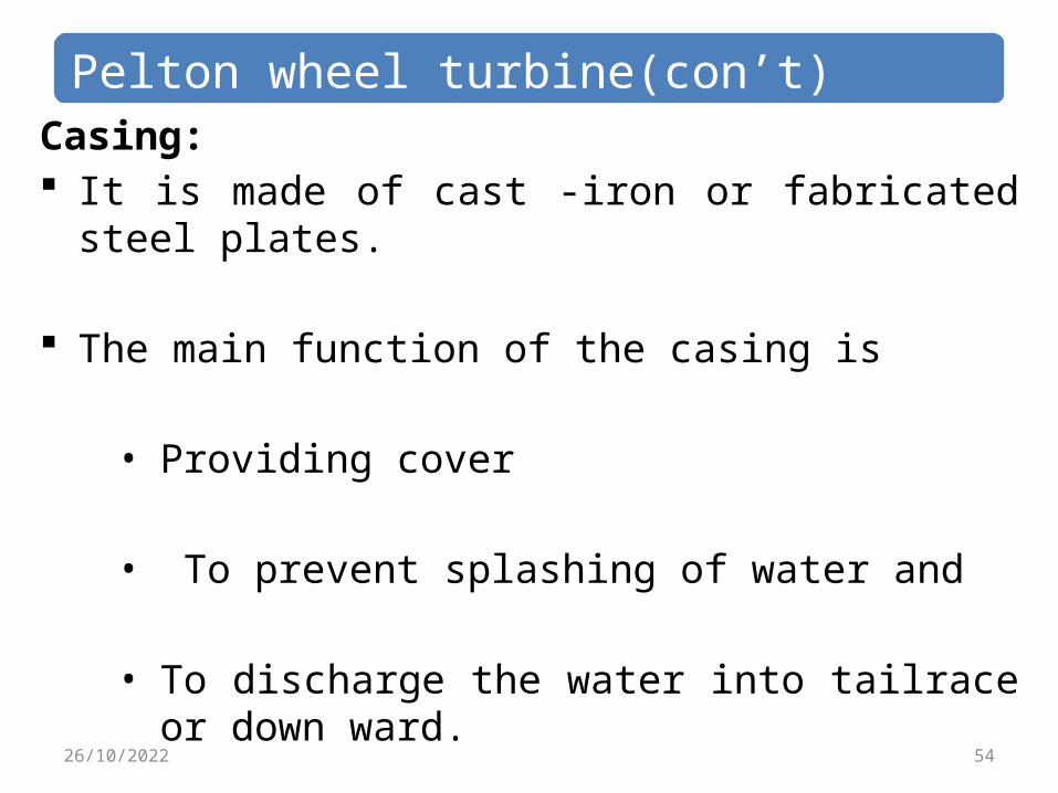
Pelton wheel turbine(con’t)Casing: It is made of cast -iron or fabricated steel plates.
The main function of the casing is
• Providing cover
• To prevent splashing of water and
• To discharge the water into tailrace or down ward.
5426/10/2022

Power Development
5526/10/2022
Power Development
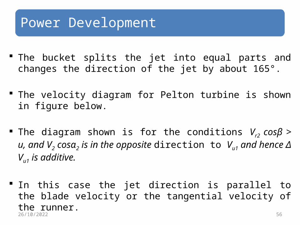
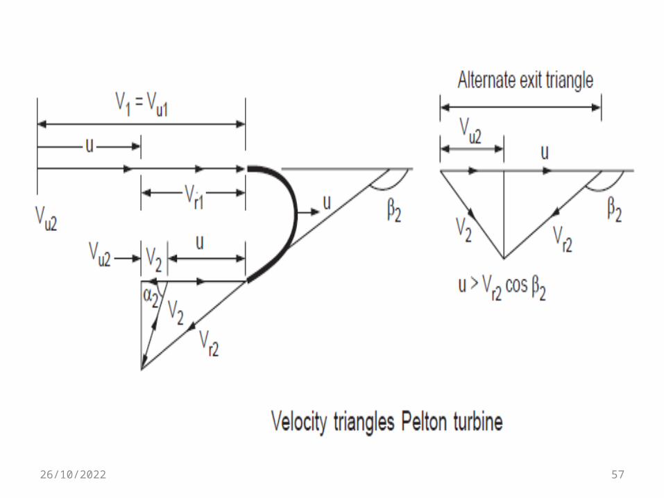
The bucket splits the jet into equal parts and changes the direction of the jet by about 165°.
The velocity diagram for Pelton turbine is shown in figure below.
The diagram shown is for the conditions Vr2 cosβ > u, and V2 cosα2 is in the opposite direction to Vu1 and hence Δ Vu1 is additive.
In this case the jet direction is parallel to the blade velocity or the tangential velocity of the runner.
5626/10/2022
5726/10/2022

Power Development(con’t) Hence Vu1 = V1 and Vr1 = V1 – u
In the ideal case Vr2 = Vr1. But due to friction Vr2 = k Vr1 and u2 = u1
Where k is friction constant.
F = ρQ (Vu1+Vu2 )
T= F.r= ρQ (Vu1+Vu2 ) r P= F.u= ρQ (Vu1+Vu2 ) u 5826/10/2022
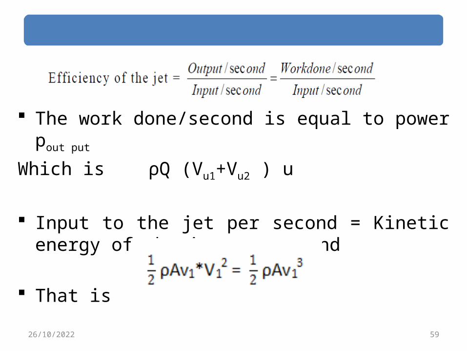
The work done/second is equal to power pout put
Which is ρQ (Vu1+Vu2 ) u
Input to the jet per second = Kinetic energy of the jet per second
That is 5926/10/2022

ηh =
Once the effective head of turbine entry is known V1 is fixed given by V1 = Cv (2gH)1/2.
For various values of u, the power developed and the hydraulic efficiency will be different.
In fact the out let triangle will be different from the one shown it u > Vr2 cosβ. In this case Vu2 will be in the same direction as Vu1 and hence the power equation will read as
P = ρQ (Vu1 – Vu2) u
6026/10/2022

Power Development(con’t) It is desirable to arrive at the optimum value of u for a given value of V1. There fore the hydraulic efficiency Equation can be modified by using the following relations.
Vu1 = V1, Vu2 = Vr2 cosβ2 – u = kVr1cosβ2 – u = k(V1 – u) cosβ2 – u
Therefore, Vu1 + Vu2 = V1 + k V1 cos β2 – u cosβ2 – u
= V1 (1 + k cos β2) – u(1 + k cos β2)
= (1 + k cosβ2) (V1 - u)
6126/10/2022
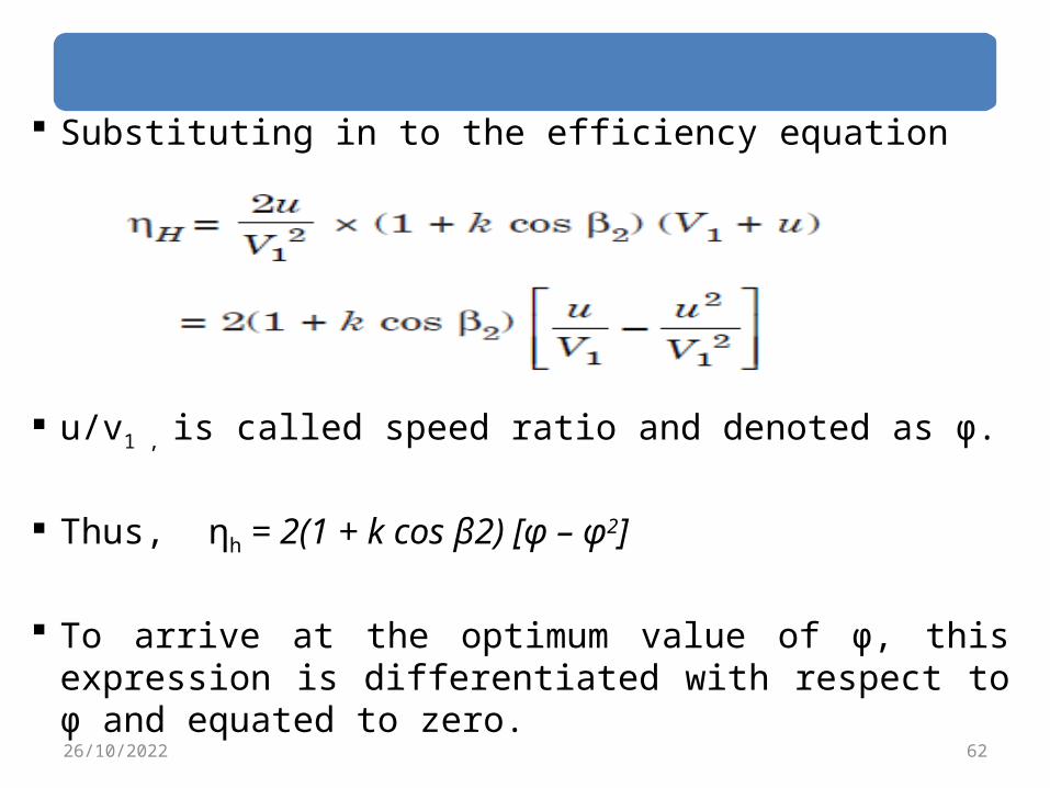
Substituting in to the efficiency equation
u/v1 , is called speed ratio and denoted as φ.
Thus, ηh = 2(1 + k cos β2) [φ – φ2]
To arrive at the optimum value of φ, this expression is differentiated with respect to φ and equated to zero.
6226/10/2022
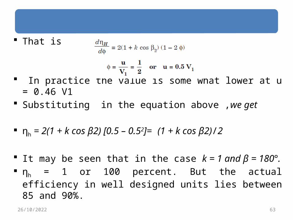
That is
In practice the value is some what lower at u = 0.46 V1
Substituting in the equation above ,we get
ηh = 2(1 + k cos β2) [0.5 – 0.52]= (1 + k cos β2)/2
It may be seen that in the case k = 1 and β = 180°. ηh = 1 or 100 percent. But the actual efficiency in well designed units lies between 85 and 90%.
6326/10/2022
Francis Turbines
6426/10/2022
Francis Turbines Francis turbine is a radial inward flow turbine.
It is the most popularly used one in the medium head range of 60 to 300 m.
Francis turbine was first developed as a purely radial flow turbine by James B. Francis, an American engineer in 1849.
But the design has gradually changed into a mixed flow turbine of today.
6526/10/2022

6626/10/2022
Francis Turbines(con’t)
The main components are,
I. The spiral casing.II. Guide vanes.III. Runner and,IV. Draft tube.
Most of the machines are of vertical shaft arrangement while some smaller units are of horizontal shaft type.
6726/10/2022
Francis Turbines(con’t)Spiral Casing: The spiral casing surrounds the runner completely.
Its area of cross section decreases gradually around the circumference.
This leads to uniform distribution of water all along the circumference of the runner.
Water from the penstock pipes enters the spiral casing and is distributed uniformly to the guide blades placed on the periphery of a circle.
The casing should be strong enough to withstand the high pressure.
6826/10/2022
Francis Turbines(con’t)Guide Blades: Water enters the runner through the guide blades along the circumference.
The number of guide blades are generally fewer than the number of blades in the runner.
These should also be not simple multiples of the runner blades.
The guide blades in addition to guiding the water at the proper direction serves two important functions.
6926/10/2022

Francis Turbines(con’t)The blade passages act as a nozzle. The water entering the guide blades are imparted a tangential velocity by the drop in pressure in the passage of the water through the blades.
Maintained a constant speed . The guide blades rest on pivoted on a ring and can be rotated by the rotation of the ring, whose movement is controlled by the governor.
In this way the area of blade passage is changed to vary the flow rate of water according to the load.
7026/10/2022

7126/10/2022
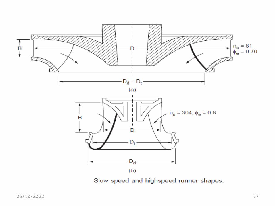
Francis Turbines(con’t)The Runner: The runner is circular disc and has the blades fixed on one side.
In high speed runners in which the blades are longer a circular band may be used around the blades to keep them in position.
The shape of the runner depends on the specific speed of the unit.
These are classified as• Slow runner.• Medium speed runner.• High speed runner and.• Very high speed runner.
7226/10/2022
7326/10/2022
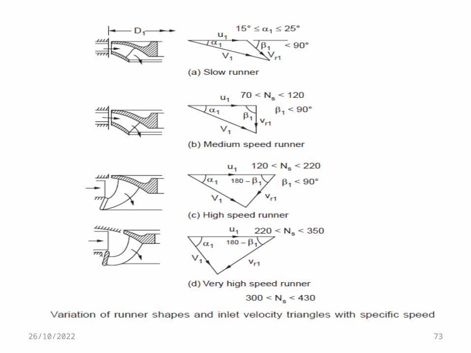
Francis Turbines(con’t) The development of mixed flow runners was necessitated by the limited power capacity of the purely radial flow runner.
A larger exit flow area is made possible by the change of shape from radial to axial flow shape.
This reduces the outlet velocity and thus increases efficiency.
As seen in the figure the velocity triangles are of different shape for different runners.
7426/10/2022
Francis Turbines(con’t) It is seen from the velocity triangles that the blade inlet angle β1 changes from acute to obtuse as the speed increases.
The guide vane outlet angle α1 also increases from about 15° to higher values as speed increases.
In all cases, the outlet angle of the blades are so designed that there is no whirl component of velocity at exit (Vu2 = 0) or absolute velocity at exit is minimum.
The runner blades are of doubly curved and are complex in shape. 7526/10/2022

Francis Turbines(con’t) These may be made separately using suitable dies and then welded to the rotor.
The height of the runner along the axial direction (may be called width also) depends upon the flow rate which depends on the head and power which are related to specific speed.
As specific speed increases the width also increase accordingly.
The runners change the direction and magnitude of the fluid velocity and in this process absorb the momentum from the fluid.
7626/10/2022
7726/10/2022
Francis Turbines(con’t)Draft Tube:
The turbines have to be installed a few meters above the flood water level to avoid inundation.
In the case of impulse turbines this does not lead to significant loss of head.
In the case of reaction turbines, the loss due to the installation at a higher level from the tailrace will be significant.
7826/10/2022
Francis Turbines(con’t) This loss is reduced by connecting a fully flowing diverging tube from the turbine outlet to be immersed in the tailrace at the tube outlet.
This reduces the pressure loss as the pressure at the turbine outlet will be below atmospheric due to the arrangement.
The loss in effective head is reduced by this arrangement.
Also because of the diverging section of the tube the kinetic energy is converted to pressure energy which adds to the effective head
7926/10/2022

8026/10/2022

Francis Turbines(con’t) The draft tube is used,
• To regain the lost static head due to higher level installation of the turbine and,
• To recover part of the kinetic energy that otherwise may be lost at the turbine outlet.
The head recovered by the draft tube will equal the sum of the height of the turbine exit above the tail water level and the difference between the kinetic head at the inlet and outlet of the tube less frictional loss in head.
Hd = H + (V12 – V2
2)/2g – hf8126/10/2022
Francis Turbines(con’t)where Hd is the gain in head, H is the height of turbine outlet above tail water level and hf is the frictional loss of head.
Different types of draft tubes are used as the location demands.
These are 1. Straight diverging tube.2. Bell mouthed tube and,3. Elbow shaped tubes of circular
exit or rectangular exit.8226/10/2022
Francis Turbines(con’t) Elbow types are used when the height of the turbine outlet from tailrace is small.
Bell mouthed type gives better recovery.
The divergence angle in the tubes should be less than 10°,to reduce separation loss.
The height of the draft tube will be decided on the basis of cavitation.
The efficiency of the draft tube in terms of recovery of the kinetic energy is defined us
η = (V12 – V2
2)/V21
where V1 is the velocity at tube inlet and V2 is the velocity at tube outlet.
8326/10/2022

8426/10/2022
Energy transfer and efficiency of Francis turbine
8526/10/2022

Energy transfer and efficiency of Francis turbine
A typical velocity diagrams at inlet and outlet are shown in the figure below.
Generally as flow rate is specified and the flow areas are known, it is directly possible to calculate Vf1 and Vf2. Hence these may be used as the basis in calculations.
By varying the widths at inlet and outlet suitably the flow velocity may be kept constant.
From Euler equation, power is given by P = ρQ(Vu1 u1 – Vu2 u2) 8626/10/2022

8726/10/2022
Energy transfer and efficiency(con’t) In all the turbines to minimise energy loss in the outlet the absolute velocity at outlet is minimised.
This is possible only if V2 = Vf2 and then Vu2 = 0. ∴ P = ρQVu1 u1
For unit flow rate, the energy transfered from fluid to rotor is given by
E1 = Vu1 u1
The energy available in the flow per kg is Ea = g Hwhere H is the effective head available. Hence the hydraulic efficiency is given by nh=Vu1 u1/gH =Vu1 u1/ Ea 8826/10/2022
Kaplan turbines
8926/10/2022
Kaplan turbine(con’t) Kaplan turbine is the popular axial flow turbines .
In the Kaplan turbines the blades are mounted in the boss in bearings and the blades are rotated according to the flow conditions by a servo-mechanism maintaining constant speed.
The Kaplan turbine is fitted with adjustable runner blades and both guide vanes and runner blades act simultaneously.
Thus Kaplan has high efficiency as part loads.
9026/10/2022

9126/10/2022
Kaplan turbine(con’t) There are many locations where large flows are available at low head.
In such a case the specific speed increases to a higher value.
In such situations axial flow turbines are gainfully employed.
The water from supply pipes enters the spiral casing as in the case of Francis turbine.
Guide blades direct the water into the chamber above the blades at the proper direction.
9226/10/2022
Kaplan turbine(con’t) The speed governor in this case acts on the guide blades and rotates them as per load requirements.
The flow rate is changed without any change in head.
The water directed by the guide blades enters the runner which has much fewer blades (3 to 10) than the Francis turbine.
The blades are also rotated by the governor to change the inlet blade angle as per the flow direction from the guide blades, so that entry is without shock. 9326/10/2022
Kaplan turbine(con’t) As the head is low, many times the draft tube may have to be elbow type.
The important dimensions are the diameter and the boss diameter (The outside diameter of a post which encompasses an insert )which will vary with the chosen speed.
At lower specific speeds the boss diameter may be higher.
The number of blades depends on the head available and varies from 3 to 10 for heads from 5 to 70 m.
9426/10/2022
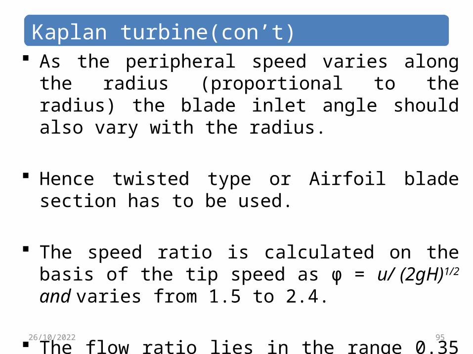
Kaplan turbine(con’t) As the peripheral speed varies along the radius (proportional to the radius) the blade inlet angle should also vary with the radius.
Hence twisted type or Airfoil blade section has to be used.
The speed ratio is calculated on the basis of the tip speed as φ = u/ (2gH)1/2 and varies from 1.5 to 2.4.
The flow ratio lies in the range 0.35 to 0.75.
9526/10/2022
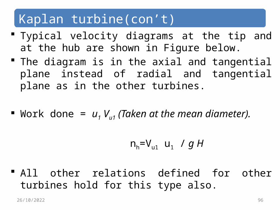
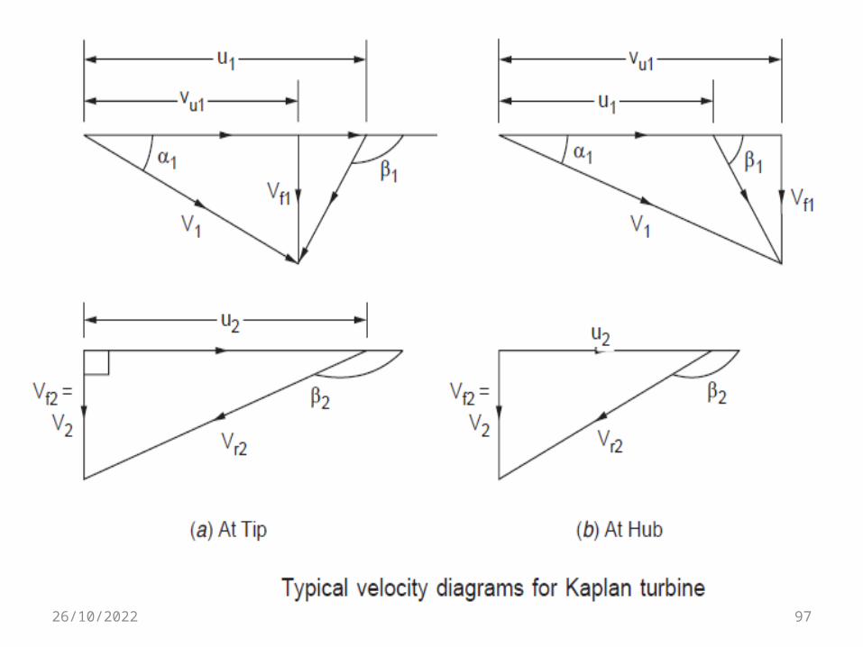
Kaplan turbine(con’t) Typical velocity diagrams at the tip and at the hub are shown in Figure below.
The diagram is in the axial and tangential plane instead of radial and tangential plane as in the other turbines.
Work done = u1 Vu1 (Taken at the mean diameter).
nh=Vu1 u1 / g H All other relations defined for other turbines hold for this type also.
9626/10/2022
9726/10/2022
Comparison of turbines
9826/10/2022

Comparison of pelton and Francis turbine
9926/10/2022
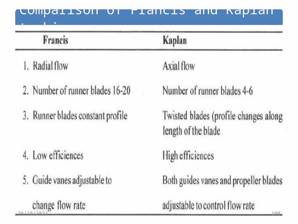
Comparison of Francis and Kaplan turbine
10026/10/2022
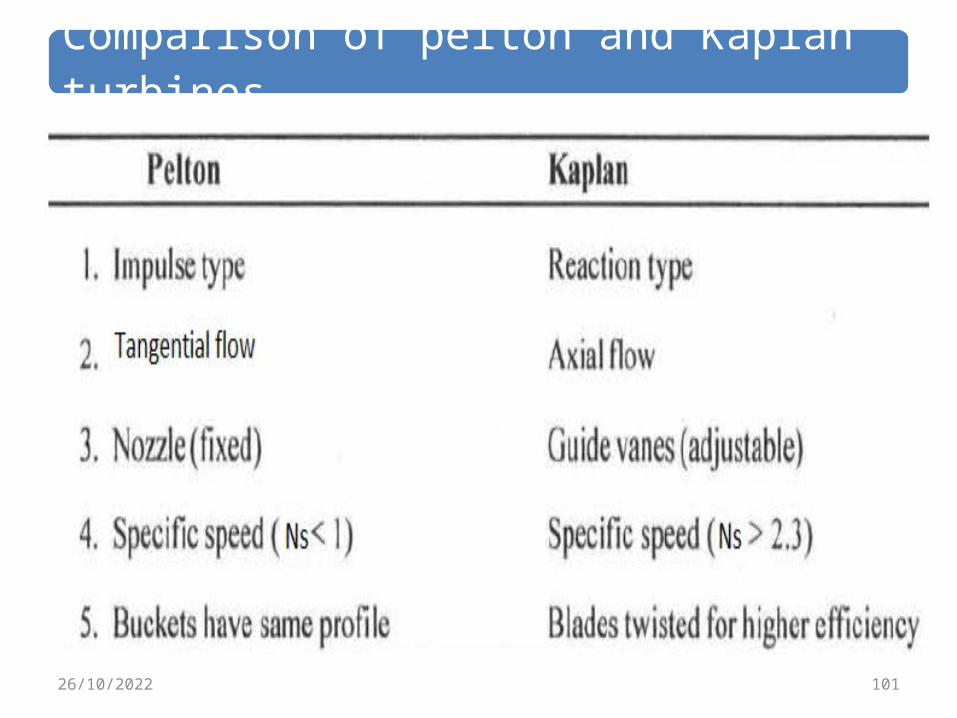
Comparison of pelton and Kaplan turbines
10126/10/2022
Specific speed and performance curves of turbines
10226/10/2022
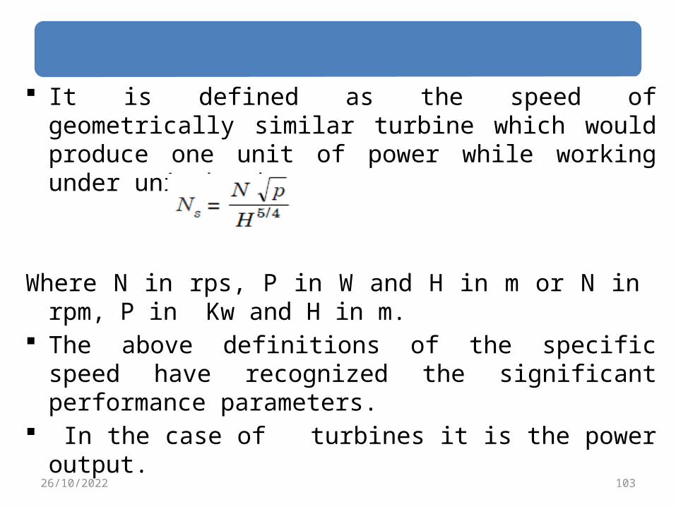
It is defined as the speed of geometrically similar turbine which would produce one unit of power while working under unit head.
Where N in rps, P in W and H in m or N in rpm, P in Kw and H in m.
The above definitions of the specific speed have recognized the significant performance parameters.
In the case of turbines it is the power output.
10326/10/2022

Specific speed and performance curves (con’t)
The values of N, H, & P in the expressions for the specific speed are those for normal operating condition (the design point), which would generally coincide with the optimum efficiency.
It can be noted that the specific speed is independent of the dimensions and therefore relates to shape rather than size.
Thus, all turbines of the same shape have the same specific speed.
The valve of specific speed is mainly used for selection of a suitable type of turbine for a particular site. 10426/10/2022
Specific speed and performance curves (con’t)
The performance of each turbine can be accomplished by its• Specific speed • Power produced • Efficiency • Head of the turbine • The speed ratio φ = u/ (2gH)1/2 .
10526/10/2022

10626/10/2022

10726/10/2022
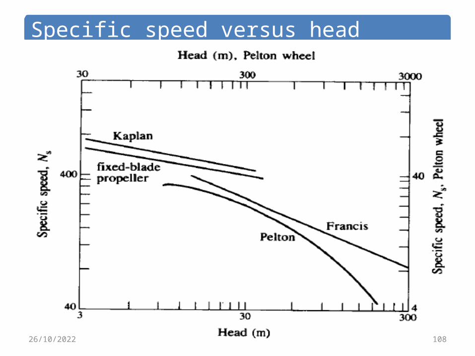
Specific speed versus head
10826/10/2022
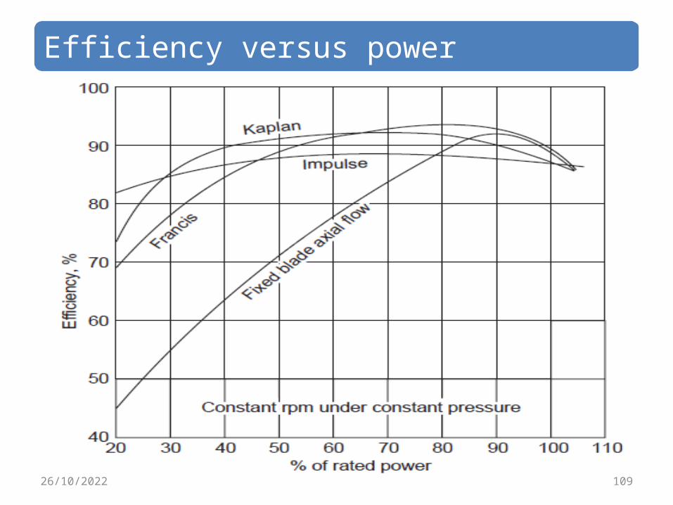
Efficiency versus power
10926/10/2022
Cavitations in turbine.
11026/10/2022

Cavitations in turbine(con’t) If at any point in the flow the pressure in the liquid is reduced to its vapour pressure, the liquid will then will boil at that point and bubbles of vapour will form.
As the fluid flows into a region of higher pressure the bubbles of vapour will suddenly condense or collapse.
This action produces very high dynamic pressure upon the adjacent solid walls and since the action is continuous and has a high frequency the material in that zone will be damaged.
11126/10/2022
Cavitations in turbine(con’t) Turbine runners are often severely damaged by such action.
The process is called cavitation and the damage is called cavitation damage.
In order to avoid cavitation, the absolute pressure at all points should be above the vapour pressure.
Cavitation can occur in the case of reaction turbines at the turbine exit or draft tube inlet where the pressure may be below atmospheric level 11226/10/2022
Cavitations in turbine(con’t) In addition to the damage to the runner cavitation results in undesirable vibration noise and loss of efficiency.
The flow will be disturbed from the design conditions.
In reaction turbines the most likely place for cavitation damage is the back sides of the runner blades near their trailing edge.
The critical factor in the installation of reaction turbines is the vertical distance from the runner to the tailrace level.
For high specific speed propeller units it may be desirable to place the runner at a level lower than the tailrace level.
11326/10/2022
Cavitations in turbine(con’t) To compare cavitation characteristics a cavitation parameter known as Thomas cavitation coefficient, σ, is used.
It is defined as σ = (ha-hr-z)/hwhere ha is the atmospheric head hr is the vapour pressure
head, z is the height of the runner outlet above tail race and h is the total operating head.
The minimum value of σ at which cavitation occurs is defined as critical cavitation factor σc.
Knowing σc the maximum value of z can be obtained as z = ha – hr – σc h 11426/10/2022

Cavitations in turbine(con’t) σc is found to be a function of specific speed. In the range of specific speeds for Francis turbine σc
varies from 0.1 to 0.64 and in the range of specific speeds for Kaplan turbine σc varies from 0.4 to 1.5.
The minimum pressure at the turbine outlet, h0 can be obtained as
h0 = ha – z – σc H There are a number of correlations available for the value of σc in terms of specific speed, obtained from experiments by Moody and Zowski.
The constants in the equations depends on the system used to calculate specific speed.
11526/10/2022

Cavitations in turbine(con’t) For Francis runners σc = 0.006 + 0.55 (Ns/444.6)1.8
For Kaplan runners σc = 0.1 + 0.3 [Ns/444.6]2.5
Other empirical correlations are Francis runners σc = 0.625(Ns/380.78)2
For Kaplan runners σc = 0.308 +1/6.82(Ns/380.78)2
11626/10/2022

Dynamic similarity and model testing
11726/10/2022
Dynamic similarity and model testing(con’t)
Hydraulic turbines are mainly used for power generation and because of this these are large and heavy.
The operating conditions in terms of available head and load fluctuation vary considerably.
In spite of sophisticated design methodology, it is found the designs have to be validated by actual testing.
In addition to the operation at the design conditions, the characteristics of operation under varying input- output conditions should be established.
11826/10/2022
Dynamic similarity and model testing(con’t) It is found almost impossible to test a full size unit under laboratory conditions.
In case of variation of the operation from design conditions, large units cannot be modified or scrapped easily.
The idea of similitude and model testing comes to the aid of the manufacturer.
In the case of these machines more than three variables affect the characteristics of the machine, (speed, flow rate, power, head available etc.)
11926/10/2022
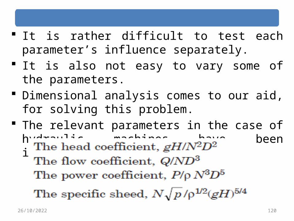
It is rather difficult to test each parameter’s influence separately.
It is also not easy to vary some of the parameters.
Dimensional analysis comes to our aid, for solving this problem.
The relevant parameters in the case of hydraulic machines have been identified.
12026/10/2022
Model and Prototype
12126/10/2022

Model and Prototype(con’t) It is found not desirable to rely completely on design calculations before manufacturing a large turbine unit.
It is necessary to obtain test results which will indicate the performance of the large unit.
This is done by testing a “homologous” or similar model of smaller size and predicting from the results the performance of large unit.
Similarity conditions are three fold namely geometric similarity, kinematic similarity and dynamic similarity.
Equal ratios of geometric dimensions leads to geometric similarity.
12226/10/2022

Model and Prototype(con’t) Similar flow pattern leads to kinematic similarity.
Similar dynamic conditions in terms of velocity, acceleration, forces etc. leads to dynamic similarity.
A model satisfying these conditions is called “Homologous” model.
In such case, it can be shown that specific speeds, head coefficients, flow coefficient and power coefficient will be identical between the model and the large machine called prototype.
12326/10/2022

Model and Prototype(con’t) It is also possible from these experiments to predict part load performance and operation at different head speed and flow conditions.
The ratio between linear dimensions is called scale.
For example an one eight scale model means that the linear dimensions of the model is 1/8 of the linear dimensions of the larger machine or the prototype.
For kinematic and dynamic similarity the flow directions and the blade angles should be equal. 12426/10/2022

Unit Quantities
12526/10/2022
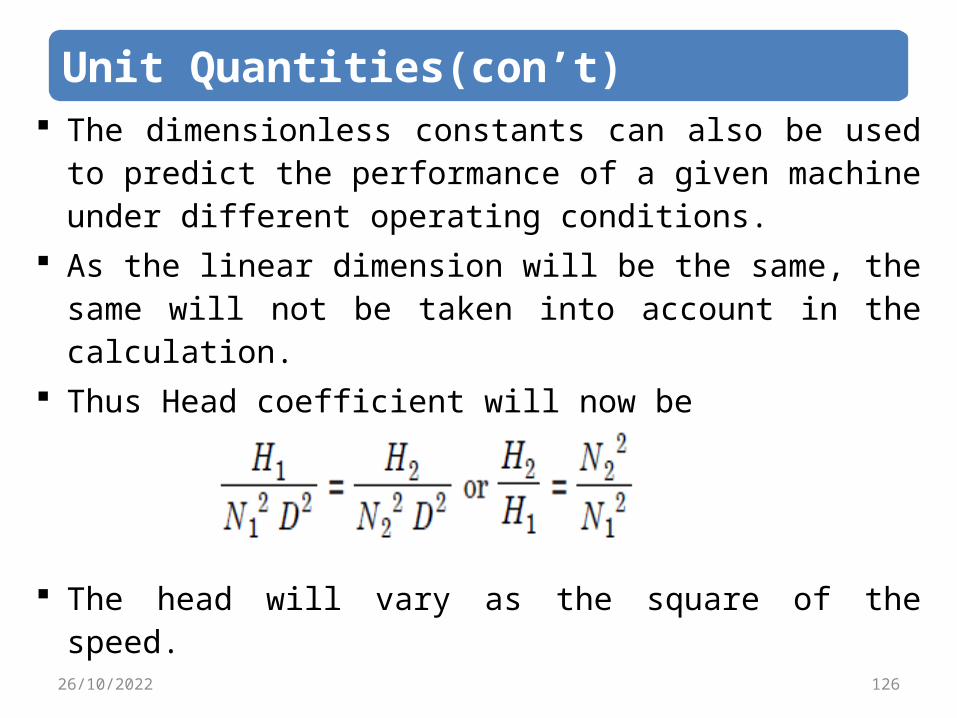
Unit Quantities(con’t) The dimensionless constants can also be used to predict the performance of a given machine under different operating conditions.
As the linear dimension will be the same, the same will not be taken into account in the calculation.
Thus Head coefficient will now be
The head will vary as the square of the speed.
12626/10/2022
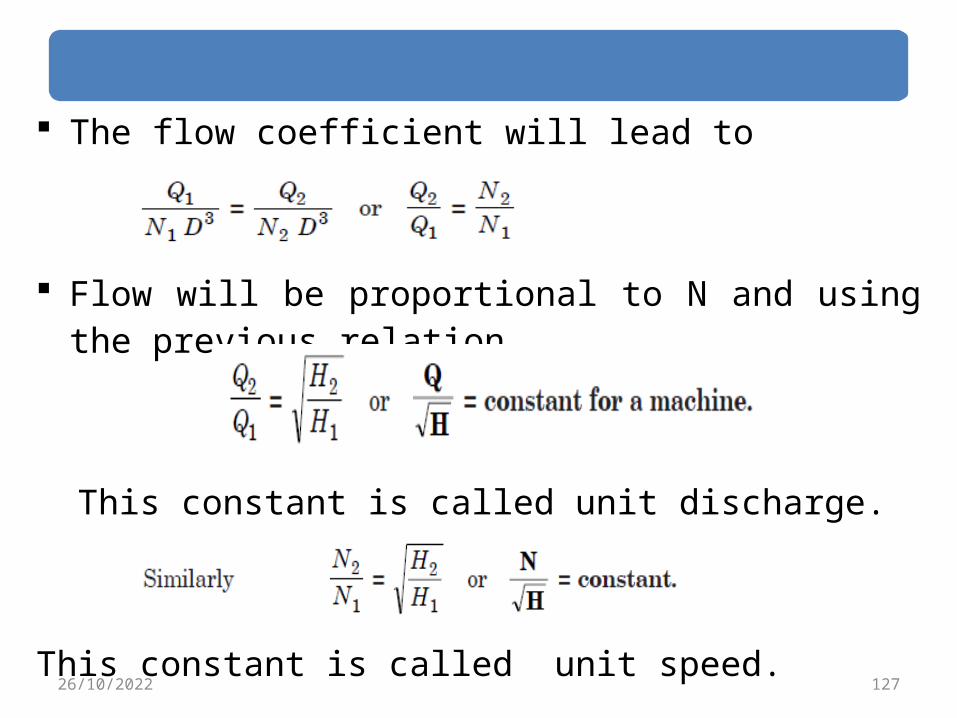
The flow coefficient will lead to
Flow will be proportional to N and using the previous relation
This constant is called unit discharge.
This constant is called unit speed.12726/10/2022
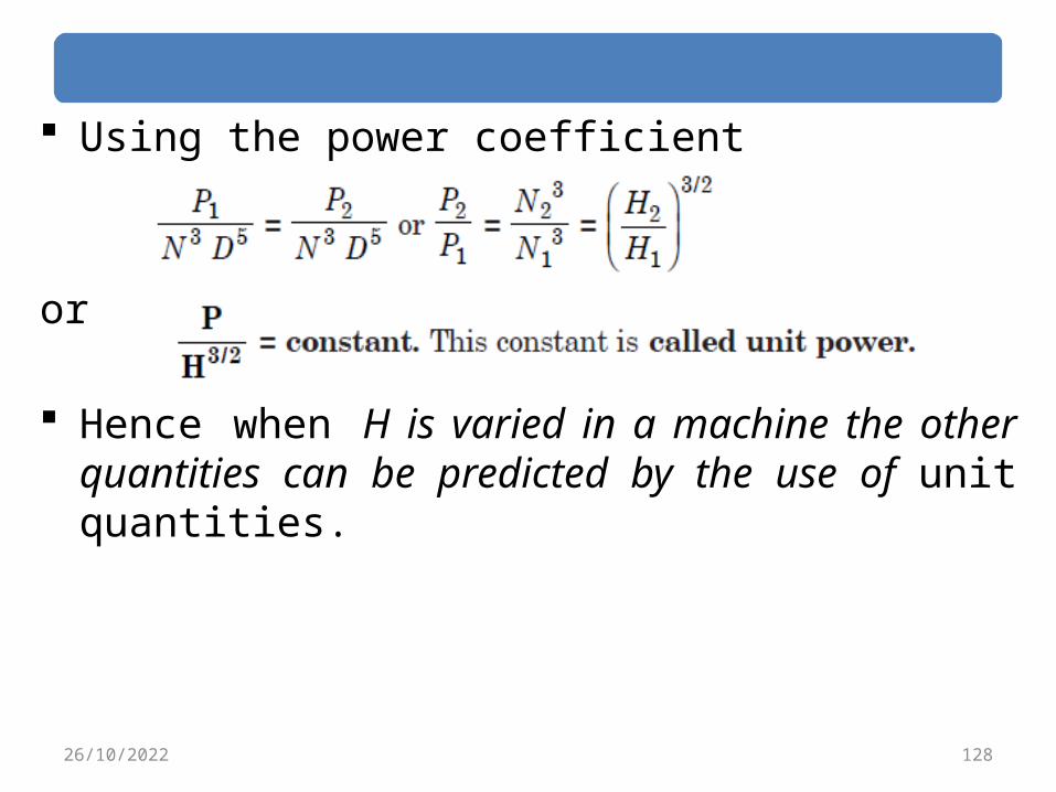
Using the power coefficient
or
Hence when H is varied in a machine the other quantities can be predicted by the use of unit quantities.
12826/10/2022

53
END
OFCHAPTER
TWO
26/10/2022 129


