Embed Size (px)
Citation preview

Dosimetric characterization of an image-guided stereotactic small animal irradiator
This article has been downloaded from IOPscience. Please scroll down to see the full text article.
2011 Phys. Med. Biol. 56 2585
(http://iopscience.iop.org/0031-9155/56/8/016)
Download details:
IP Address: 129.112.109.244
The article was downloaded on 29/03/2011 at 15:25
Please note that terms and conditions apply.
View the table of contents for this issue, or go to the journal homepage for more
Home Search Collections Journals About Contact us My IOPscience
IOP PUBLISHING PHYSICS IN MEDICINE AND BIOLOGY
Phys. Med. Biol. 56 (2011) 2585–2599 doi:10.1088/0031-9155/56/8/016
Dosimetric characterization of an image-guidedstereotactic small animal irradiator
R Pidikiti, S Stojadinovic, M Speiser, K H Song, F Hager, D Saha andT D Solberg1
Department of Radiation Oncology, University of Texas Southwestern Medical Center, Dallas,TX, USA
E-mail: [email protected]
Received 23 November 2010, in final form 2 March 2011Published 28 March 2011Online at stacks.iop.org/PMB/56/2585
AbstractSmall animal irradiation provides an important tool used by preclinical studiesto assess and optimize new treatment strategies such as stereotactic ablativeradiotherapy. Characterization of radiation beams that are clinically andgeometrically scaled for the small animal model is uniquely challengingfor orthovoltage energies and minute field sizes. The irradiator employsa commercial x-ray device (XRAD 320, Precision x-ray, Inc.) witha custom collimation system to produce 1–10 mm diameter beams anda 50 mm reference beam. Absolute calibrations were performed usingthe AAPM TG-61 methodology. Beam’s half-value layer (HVL) andtimer error were measured with an ionization chamber. Percent depthdose (PDD), output factors (OFs) and off-axis ratios were measured usingradiochromic film, a diode and a pinpoint ionization chamber at 19.76and 24.76 cm source-to-surface distance (SSD). PDD measurements werealso compared with Monte Carlo (MC) simulations. In-air and in-waterabsolute calibrations for the reference 50 mm diameter collimator at 19.76cm SSD were measured as 20.96 and 20.79 Gy min−1, respectively, agreeingwithin 0.8%. The HVL at 250 kVp and 15 mAs was measured to be0.45 mm Cu. The reference field PDD MC simulation results agreewith measured data within 3.5%. PDD data demonstrate typical increasedpenetration with increasing field size and SSD. For collimators larger than5 mm in diameter, OFs measured using film, an ion chamber and a diode werewithin 3% agreement.
1 Author to whom any correspondence should be addressed.
0031-9155/11/082585+15$33.00 © 2011 Institute of Physics and Engineering in Medicine Printed in the UK 2585
2586 R Pidikiti et al
1. Introduction
Modern radiotherapy combines advanced imaging technologies, computerized treatmentplanning systems and high-energy medical accelerators to optimize radiation dose to a targetvolume while effectively sparing the healthy tissue. Technological advances are now producingquantifiable improvements in treatment outcomes of patients treated with radiation therapy.Moreover, the technological progress is enabling a fundamental paradigm shift in the practiceof radiation therapy. The new paradigm is a departure from small doses traditionally deliveredover many weeks, i.e. conventionally-fractionated radiotherapy (CFRT), in favor of large,ablative doses delivered in a few fractions in 2 weeks or less. Stereotactic body radiationtherapy (SBRT), also referred to as stereotactic ablative radiotherapy (SAbR), utilizes a hypo-fractionated dose regimen where the total prescribed dose is delivered in five fractions orless (Blomgren et al 1995, Timmerman et al 2003). SBRT has shown the potential for adramatic clinical impact on the ability to achieve local control of cancer in multiple organsites (Timmerman et al 2003, 2007, Uematsu et al 2001, Rusthoven et al 2009b). Thissuccess, particularly evident in early stage lung cancer patients unfit for surgery, has allowedan absolute reduction in the rate of in-field recurrence on the order of 50% compared to CFRT(Cheung et al 2000, Qiao et al 2003). Additionally, 80–95% local control rates for stage Ilung cancer have been reported in multiple prospective studies (Hara et al 2006, Hiraoka andNagata 2004, Timmerman et al 2006, Xia et al 2006). In a national prospective trial, localcontrol in excess of 97% was reported for patients with inoperable stage I lung cancer treatedusing SBRT (Timmerman et al 2010). Similar success has been reported for SBRT of lungand liver metastases (Herfarth et al 2001, 2004, Rusthoven et al 2009a, 2009b). These ratesrival the best surgical series.
In the field of medical and molecular imaging, the trend of swift clinical implementationof technological innovation has been successfully followed by corresponding development ofsmall animal imaging systems. Every anatomical and functional imaging modality in humansis at present commercially available for small animal use as well. Small animal imagingsystems provide new insights on cancer detection and characterization and continue to have anoteworthy impact in the fundamental understanding of tumor kinetics, the effects of tumorgrowth on the local environment and response to therapies (Vallabhajosula 2007, Bahri et al2008, Wessels et al 2007). In contrast to sophisticated imaging systems, conformal therapyirradiation systems for small animals are uncommon and presently under development by justa few groups in North America. While there have been various approaches in design andimplementation, a common theme is to incorporate image guidance with conformal, smallfield radiotherapy to enable preclinical studies. Notable efforts in small animal irradiatordevelopment have been presented by research teams from Washington University School ofMedicine (Stojadinovic et al 2006, 2007, Kiehl et al 2008), Johns Hopkins University (Denget al 2007, Matinfar et al 2007, Matinfar et al 2009, Wong et al 2008), Stanford University(Bazalova et al 2009, Graves et al 2007, Motomura et al 2010, Zhou et al 2010), PrincessMargaret Hospital (Lindsay et al 2008, Lindsay et al 2009, Chow and Leung 2007, Clarksonet al 2011), University of Arkansas Medical Sciences (Moros et al 2009, Sharma et al 2009)and University of Texas Southwestern (Cho et al 2010, Saha et al 2010, Song et al 2010).
In this paper, we describe the dosimetric characterization of an image-guided small animalirradiator developed to facilitate preclinical studies of SBRT techniques at the University ofTexas Southwestern Medical Center. A preclinical SBRT micro-irradiator requires significantengineering and physics resources in order to successfully mimic the essential capabilities of anSBRT system. These essential capabilities include a high dose rate (∼10 Gy min−1), allowinghigh doses associated with SBRT to be delivered in a clinically-relevant time frame. The system

Small animal stereotactic irradiator 2587
(A) (B)
Figure 1. The tungsten–copper alloy collimation system: (A) collimator inserts; (B) an insertholder. The collimators are 25.4 mm thick with six standard collimator diameters: 1.0, 2.0, 3.5,5.0, 7.5 and 10.0 mm. The holder itself can also be used as a 20.0 mm diameter collimator. Inaddition, a reference 50.0 mm diameter collimator is used for calibration purposes and collimatorsof specific shape have been manufactured for specific applications. The collimation system ismounted into a bracket just beneath the x-ray tube.
must be capable of delivering appropriately-scaled radiation fields commensurate with smallanimal anatomy. Applications of these miniaturized radiation fields necessitate robust imageguidance and sub-millimeter target localization in order to effectively deliver a potentiallyablative dose while minimizing normal tissue toxicity. Our device meets these essentialrequirements, thus making SBRT technology accessible for small animals and providingradiation delivery in a manner analogous to that employed in clinical SBRT delivery.
2. Materials and methods
The irradiator consists of three main components: (1) a small field collimation system, (2)an image guidance system and (3) a commercial x-ray source (X-RAD 320, Precision x-rayInc., North Branford, CT) which provides a range of photon energies for both therapeutic andimaging applications.
2.1. Collimation system
The collimation assembly, shown in figure 1, consists of a disk-shaped collimator holder andinterchangeable collimators of various apertures. The collimators are 25.4 mm thick, whichprovides sufficient attenuation for minimizing transmitted radiation. The collimators are madeof a high density (14.7 g cm−3) tungsten and copper alloy and feature six standard collimatorapertures: 1.0, 2.0, 3.5, 5.0, 7.5 and 10.0 mm in diameter; additionally, collimators of a specificshape have been constructed for specific applications. The collimator holder itself, made ofbrass (8.4 g cm−3), can be used to produce a 20.0 mm diameter beam. The collimation systemis mounted into a bracket just beneath the x-ray tube. An additional reference collimator,made of brass with 50 mm diameter aperture, was used as the standard for absolute calibrationpurposes. Absolute calibration was conducted in accordance with the recommendations of theAmerican Association of Physicists in Medicine (AAPM) Task Group 61 (TG-61) (Ma et al2001).

2588 R Pidikiti et al
Figure 2. The x-ray image guidance system inside the irradiator enclosure.
2.2. Image-guidance system
The image guidance system (figure 2) consists of a motorized XY linear translation stage (XY-6060, Danaher Motion Inc., Washington, DC), a manual Z-directional stage (GDL, ParkerCompany, Cleveland, OH), a motion controller (R364, Linengineering, Santa Clara, CA), adigital imaging panel (PaxScan 1313, Varian Inc., Palo Alto, CA) and an animal platform.Image acquisition and animal positioning are performed under computer control. The PaxScan1313 panel is equipped with a cesium iodide (CsI) conversion screen and amorphous silicon(a-Si) receptor. The panel has an active area of 13 × 13 cm2 and supports two pixel matrices,1024 × 1024 (for a pixel pitch of 127 μm) and 512 × 512 (for a pixel pitch of 254 μm).The frame rate varies depending on the binning mode, e.g. up to 10 frames per second (fps)
Small animal stereotactic irradiator 2589
for 1024 × 1024 mode and 30 fps for the 512 × 512 mode. The animal support platformis made of a 2 mm acrylic sheet and has an attachment for isoflurane gas used for animalanesthesia. The characteristics of the image-guidance system are described in more detail inanother article (Song et al 2010).
2.3. X-ray system
The radiation source is a commercial x-ray device (XRAD 320) that employs the MXR-321x-ray tube (Comet AG, Liebefeld-Berne, Switzerland) to produce both imaging and treatmentbeams. The x-ray tube potential has a continuous span from 5 to 320 kVp, while the tube currentranges from 0.1 to 45 mA. This capability allows both diagnostic (30 kVp) and therapeutic(250 kVp) configurations. These therapeutic energies provide adequate penetration for smallanimal SBRT. Exposure times can be set from 0.1 to 99.9 min in 0.1 min increments. Asingle rectangular focal spot of 8 mm in largest dimension allows greater dose output requiredof high dose, small animal irradiation. The target consists of a tungsten anode with a 30◦
target angle; the tube has an inherent filtration of 3 mm beryllium. An integrated filter holderallows the user to add beam-conditioning filters to achieve desired half-value layer (HVL)specifications. To absorb additional low energy photons, the therapeutic beams described inthis manuscript contain an added 1.65 mm aluminum of beam filtration. The MXR-321 x-raytube is located inside the XRAD 320’s shielded enclosure. The enclosure is equipped with anadjustable specimen shelf, a 15 × 20 cm2 lead glass viewing window and a duct for accessorycables, including a gas anesthesia tube.
2.4. Beam quality and collimator transmission
As outlined by the TG-61 protocol, beam quality specification for orthovoltage energies isseparated in two main stages. The first is to obtain the air-kerma calibration factor NK from anational standards lab in terms of both tube potential and HVL. The second stage is to measurethe absorbed dose in the user’s beam. The air-kerma calibration coefficient for a PTWN31013 ionization chamber (PTW-New York Corporation, Hicksville, NY) was obtainedfor beam quality M250 from the Accredited Dosimetry Calibration Laboratory (ADCL) atthe University of Wisconsin. The HVL measurement was performed in-air using a 20 mmdiameter collimator with the calibrated chamber placed 50 cm from the collimator opening.As the irradiator is enclosed in shielding, 50 cm was also the maximum distance possible fornarrow beam geometry. Thin sheets of copper were used as the attenuating material.
The transmission through the collimator was measured in air, at 19.76 cm SSD, usinga PinPoint N31014 ionization chamber (PTW-New York Corporation, Hicksville, NY) bycomparing the central axis readings for a reference 50 mm diameter collimator to readings ofa totally blocked field.
2.5. Irradiator calibration
The absolute dose calibration of the irradiator was performed in accordance with therecommendations specified in the AAPM TG-61 protocol. Both in-air and in-water calibrationswere performed at a 19.76 cm source-to-surface distance (SSD) for the reference 50 mmdiameter collimator. The ADCL calibrated PTW N31013 ionization chamber was used tomeasure the (percent) depth dose in a water phantom, as the in-water calibration requires theknowledge of the PDD value at reference depth of 2 cm. The PDD data points were measuredfor 30 s exposure time at depths of 0–150 mm, using 1 mm increments for the first 10 mm andthen 5 mm steps for the remaining depths.

2590 R Pidikiti et al
An independent output verification of the irradiator was done using lithium fluoride TLDsprovided by the Radiation Dosimetry Services (MD Anderson Cancer Center, Huston, TX).TLD measurements were done in air, that is, on top of a 3 mm thick plastic platform, at thereference SSD of 19.76 cm. The one requirement was not to exceed 4 Gy since the TLDs’response to radiation would not be in the linear region to any further extent.
2.6. Beam characterization
A Monte Carlo (MC) model of the irradiator beam was generated and subsequently validatedusing larger field PDD measurements. The MXR-321 beam spectrum for 250 kVpwas calculated using the SpekCalc program described by Poludniowski and Evans (2007,Poludniowski 2007). The resulting energy spectrum, the custom beam collimation systemand experimental geometries were all subsequently modeled using the MCNPX program (LosAlamos National Laboratories, NM). All simulations were conducted to achieve estimatedstatistical errors of less than 2%.
The Hurter–Driffield (HD) curve, i.e. the sensitometric orthovoltage calibration curve,was established by exposing radiochromic films (Gafchromic EBT2, International SpecialtyProducts, Wayne, NJ) using the reference collimator to a known dose at the surface ofa 6 cm thick solid water block. In turn, the orthovoltage HD calibration curve for allcollimators was used to convert the measured optical densities to dose, i.e. to establishthe PDD behavior relative to field size. Generally an exposure time of 30 s was used forGafchromic EBT2 films placed between thin solid water slabs (Gammex RMI, Middleton,WI) at 19.76 and 24.76 cm SSD. The irradiated area was at least 5 mm from any film edgeto avoid optical density measurement artifacts observed near film edges (Butson et al 1998).The films were irradiated simultaneously perpendicular to beam’s direction. Starting fromtop to bottom, the solid water phantom consisted of eight 1 mm slabs, nine 2 mm slabs, one3 mm slab, four 5 mm slabs and six 10 mm slabs. This setup resulted in a total of 29 films.The measurement depths were corrected for the average film thickness of 0.29 mm.
All Gafchromic EBT2 film analysis was done 24 h after exposure. The films were scannedusing an Epson 1000 XL scanner (Epson America Inc., Long Beach, CA) in 48 bit red–green–blue (RGB) mode, 16 bits per color, at 150 dpi resolution and saved as tagged image fileformat (tiff) files. The scanned films were imported into and analyzed with a custom writtenMatLab R2010a (MathWorks, Natick, MA) code. Only the red channel data were used in theanalysis. The regions of interest selected at the central portion of the exposed films rangedfrom 20 × 20 pixels for 10 mm diameter collimator to 4 × 4 pixels for the smallest 1 mmdiameter collimator. The net optical density was computed as
netOD(D) = − log10
(Iexp(D) − Ibckg
Iunexp − Ibckg
)(1)
where Iexp(D) and Iunexp are the readings for the exposed and unexposed films, respectively,while Ibckg is the reading for an opaque film, that is, the zero light transmitted intensity value.Standard deviations in the net optical density were computed following Devic et al (2005):
σnetOD = 1
ln 10
√σ 2
unexp + σ 2bckg
(Iunexp − Ibckg)2+
σ 2exp + σ 2
bckg
(Iexp − Ibckg)2. (2)
The same experimental setup used for obtaining the PDD curves was used to obtain beamprofiles and off-axis ratios (OARs) and to characterize the penumbra. Beam profiles weremeasured in a solid water phantom at an SSD of 19.76 cm and at a depth of 1.46 cm. Thepenumbra, defined as the distance between the 80% and 20% isodose lines, is an important

Small animal stereotactic irradiator 2591
part for treatment planning considerations, especially for stereotactic situations when beamsare directed from several different directions to optimize treatment.
The output factors (OFs), i.e. total scatter factors, were measured using Gafchromic EBT2film at the surface of a 6 cm thick solid water slab. OFs relative to the reference 50 mm diametercollimator were determined by converting the measured optical densities to dose utilizing theorthovoltage calibration curve. For ‘larger’ collimator diameters, i.e. >5 mm, the OFs werealso measured in a water phantom using a PinPoint N31014 ionization chamber and an SFDstereotactic diode (IBA Dosimetry America, Bartlett, TN).
The output calibration of the irradiator may be influenced by the amount of time that is notaccounted for by the machine timer mechanism during the x-ray delivery, i.e. the end effect,and by the nonlinearity of beam intensity as the function of the tube current at constant tubevoltage. The end effect was assessed in a series of exposures in a water phantom by measuringthe charge collected by a PTW N31013 ionization chamber in the increments of 6 to 120 s.The 6 s increment is the shortest possible irradiator time increment. The data were analyzedusing the graphical extrapolation method for the ion chamber readings as a function of timersettings. The timer error is the zero exposure represented by the intercept of the regressionline on the time axis.
To determine beam intensity as a function of tube current, radiochromic films wereexposed at the surface of a solid water phantom using the reference collimator. These filmswere exposed at 250 kVp tube voltage for 24 s and varying tube currents from 1 to 15 mAs in1 mAs increments.
3. Results
3.1. Beam quality and collimator transmission
The HVL measurement was performed in-air utilizing a 20 mm diameter collimator with aPTW N31013 ionization chamber placed 50 cm from the collimator opening. The resultingHVL, at a tube potential of 250 kVp and tube current of 15 mAs, was measured to be0.45 mm Cu.
The transmission through the collimator, measured in air using a PinPoint N31014ionization chamber, was 0.7%.
3.2. Irradiator calibration
Absolute dose calibration was performed at 19.76 cm SSD using the reference 50 mm diametercollimator, following both in-air and in-water procedures of the AAPM TG-61 formalism. Theoutput of the system was also independently verified; the ratio of stated versus measured dosewas 1.01, using lithium fluoride TLD measurements read by the Radiation Dosimetry Services(MD Anderson Cancer Center, Huston, Texas). The in-air method resulted in a dose rate of20.96 Gy min−1, while the in-water calibration measurement at 2 cm depth calculated at thesurface yielded a dose rate of 20.79 Gy min−1, i.e. an agreement within 0.8%. Noticeably,the agreement between in-air and in-water calibrations is very dependent on an accurate PDDmeasurement. The PDD curve for the reference collimator was determined using the ADCLcalibrated PTW N31013 ionization chamber in a water phantom.
3.3. Beam characterization
The MC model of the irradiator beam was validated by cross-comparing the computed PDD forthe reference collimator to the corresponding measured PDDs using a calibrated ion chamber

2592 R Pidikiti et al
Figure 3. The percent depth dose (PDD) for the reference 50 mm diameter collimator measuredusing an ion chamber (IC) and an EBT2 Gafchromic film compared to Monte Carlo (MC)simulation. The average percent agreement calculated at 1 mm depth increments was 1.0%with largest outliers at 3.5% difference.
in a water phantom and a film in a solid water phantom. The PDDs from the various methodsagree remarkably well. The average percent agreement calculated at 1 mm depth incrementswas 1.0% with largest outliers at 3.5% difference (figure 3).
The sensitometric orthovoltage calibration curve, established by utilizing the referencecollimator to expose EBT2 films to a known dose at the surface of a 6 cm thick solid waterblock is shown in figure 4. The error bars in figure 4 correspond to the uncertainty associatedwith the film scans and represent two standard deviations or 95.4% confidence level.
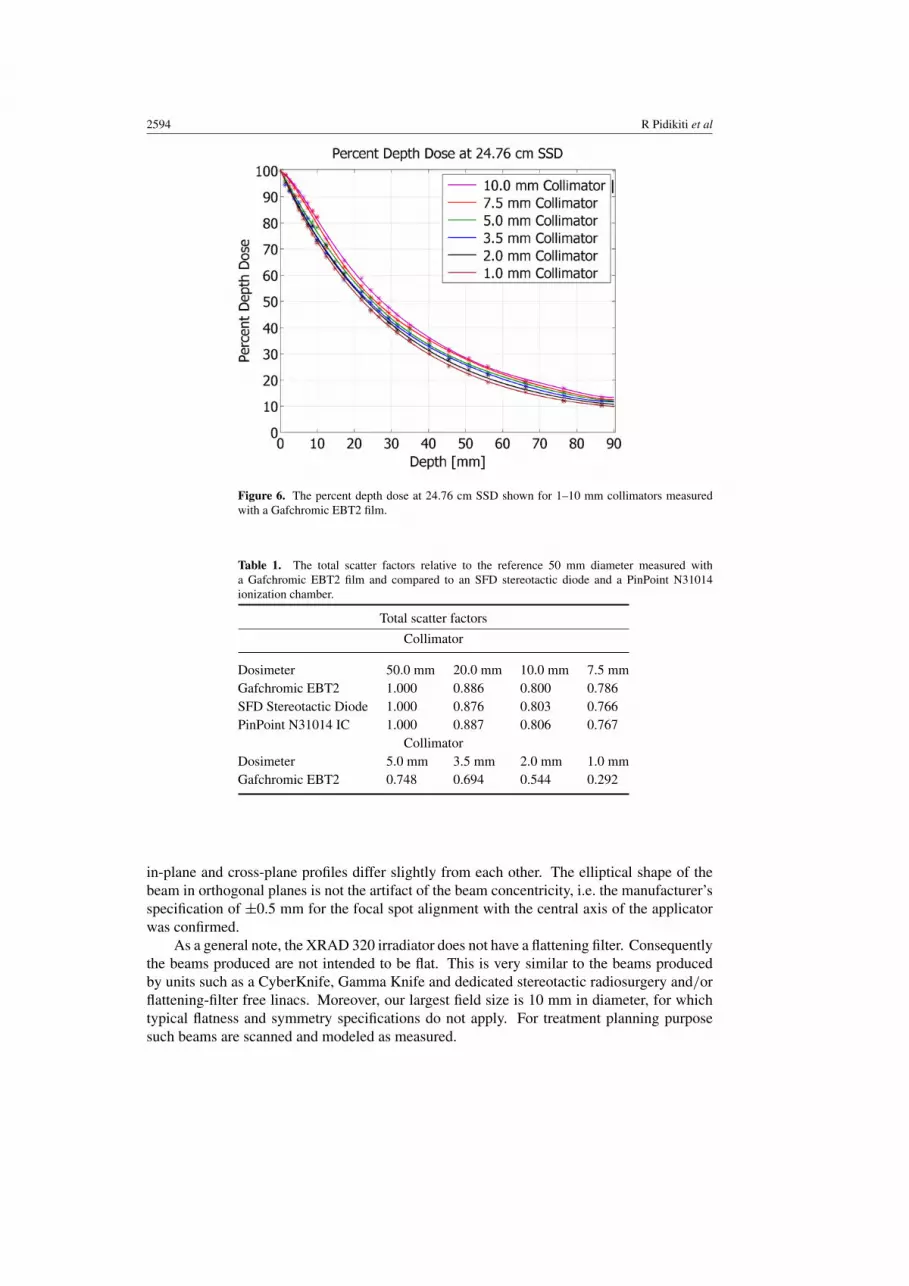
Depth dose characteristics, for example, 52.3% and 23.6% at depths of 22 and50 mm, respectively, for the 5 mm diameter collimator at 19.76 cm SSD, provide more thanadequate penetrations for targeting deep-seated targets in small animals, particularly whenusing multiple beam directions. As expected for orthovoltage energies, the maximum dosepoint is at the surface. The PDD data show the familiar relationship of increasing penetrationwith increasing field size as shown in figure 5. Likewise, the increase in SSD produced anincrease in PDD, apparent in the comparison of the PDDs at 19.76 cm SSD in figure 5 withthose at 24.76 cm shown in figure 6.
The total scatter factors for all collimators were measured with Gafchromic EBT2 film atthe surface of a solid water slab and compared to SFD stereotactic diode and PinPoint N31014ionization chamber measurements at the surface in a water phantom. The results, shown intable 1, are within 3% agreement for collimators greater than 5 mm in diameter. For smallercollimators, however, the detector size excluding the film is comparable to the collimatordiameter, rendering the measurements unreliable for these field sizes.
OARs were measured using Gafchromic EBT2 film in solid water. Measured penumbraare shown for a depth of 1.46 cm as a function of collimator diameter for 19.76 cm and24.76 cm SSD in table 2. Corresponding OARs at 1.46 cm depth are shown in figures 7

Small animal stereotactic irradiator 2593
Figure 4. The sensitometric orthovoltage calibration curve; the error bars show 95.4% confidencelevel.
Figure 5. The percent depth dose at 19.76 cm SSD shown for 1 to 10 mm collimators measuredwith a Gafchromic EBT2 film.
and 8. The intrinsic magnification factor of 1.44 for this setup is the ratio between source-to-detector distance (SDD = SSD + depth = 21.22 cm) and the source-to-collimator distance(SCD = 14.76 cm). The profiles in figures 7 and 8 reflect the divergence of the beam froma large asymmetric focal spot which creates a beam that is slightly elliptical in shape; thus,
2594 R Pidikiti et al
Figure 6. The percent depth dose at 24.76 cm SSD shown for 1–10 mm collimators measuredwith a Gafchromic EBT2 film.
Table 1. The total scatter factors relative to the reference 50 mm diameter measured witha Gafchromic EBT2 film and compared to an SFD stereotactic diode and a PinPoint N31014ionization chamber.
Total scatter factors
Collimator
Dosimeter 50.0 mm 20.0 mm 10.0 mm 7.5 mmGafchromic EBT2 1.000 0.886 0.800 0.786SFD Stereotactic Diode 1.000 0.876 0.803 0.766PinPoint N31014 IC 1.000 0.887 0.806 0.767
CollimatorDosimeter 5.0 mm 3.5 mm 2.0 mm 1.0 mmGafchromic EBT2 0.748 0.694 0.544 0.292
in-plane and cross-plane profiles differ slightly from each other. The elliptical shape of thebeam in orthogonal planes is not the artifact of the beam concentricity, i.e. the manufacturer’sspecification of ±0.5 mm for the focal spot alignment with the central axis of the applicatorwas confirmed.
As a general note, the XRAD 320 irradiator does not have a flattening filter. Consequentlythe beams produced are not intended to be flat. This is very similar to the beams producedby units such as a CyberKnife, Gamma Knife and dedicated stereotactic radiosurgery and/orflattening-filter free linacs. Moreover, our largest field size is 10 mm in diameter, for whichtypical flatness and symmetry specifications do not apply. For treatment planning purposesuch beams are scanned and modeled as measured.

Small animal stereotactic irradiator 2595
Figure 7. Off-axis ratio as a function of the distance along the x-axis.
Table 2. The 80−20% beam penumbra along the in-plane axis and the cross-plane axis at 1.46 cmdepth for 19.76 and 24.76 cm SSD.
Penumbra (mm) at 19.76 cm SSD
Collimator diameter (mm) In-plane, y axis Cross-plane, x axis
1.0 0.54 0.762.0 0.92 1.233.5 1.13 1.345.0 1.19 1.357.5 1.33 1.35
10.0 1.42 1.45Penumbra (mm) at 24.76 cm SSD
1.0 1.94 2.072.0 1.57 1.883.5 2.01 2.455.0 2.40 2.567.5 2.46 2.44
10.0 3.37 3.54
As a result of the time delay required to switch the beam ‘ON’ and ‘OFF’ in an x-rayunit, the timer typically does not accurately indicate the exposure time. Hence, it needs to becorrected by a small increment known as the timer error or the end effect. Using the graphicalextrapolation method, the end effect was determined to be 3 s as represented by the interceptof the regression line on the time axis in figure 9.
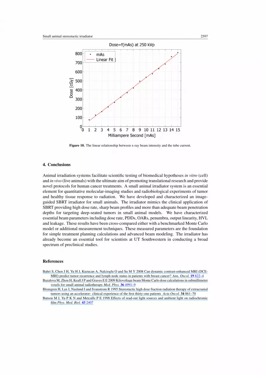
The beam intensity as a function of tube current at constant tube voltage produced ananticipated linear relationship as shown in figure 10. Consequently, doubling the current at

2596 R Pidikiti et al
Figure 8. Off-axis ratio as a function of the distance along the y-axis
Figure 9. The end effect of x-ray unit was determined graphically as the intercept of the regressionline on the time axis.
constant exposure time has the same effect as doubling the exposure time at constant tubecurrent. A high dose rate of over 20 Gy min−1 and minimum timer setting of 6 s would enableonly relatively coarse units of dose that can be delivered during experimental procedures. Theability to change mAs is essential to obtain finer dose increments.
Small animal stereotactic irradiator 2597
Figure 10. The linear relationship between x-ray beam intensity and the tube current.
4. Conclusions
Animal irradiation systems facilitate scientific testing of biomedical hypotheses in vitro (cell)and in vivo (live animals) with the ultimate aim of promoting translational research and providenovel protocols for human cancer treatments. A small animal irradiator system is an essentialelement for quantitative molecular-imaging studies and radiobiological experiments of tumorand healthy tissue response to radiation. We have developed and characterized an image-guided SBRT irradiator for small animals. The irradiator mimics the clinical application ofSBRT providing high dose rate, sharp beam profiles and more than adequate beam penetrationdepths for targeting deep-seated tumors in small animal models. We have characterizedessential beam parameters including dose rate, PDDs, OARs, penumbra, output linearity, HVLand leakage. These results have been cross-compared either with a benchmarked Monte Carlomodel or additional measurement techniques. These measured parameters are the foundationfor simple treatment planning calculations and advanced beam modeling. The irradiator hasalready become an essential tool for scientists at UT Southwestern in conducting a broadspectrum of preclinical studies.
References
Bahri S, Chen J H, Yu H J, Kuzucan A, Nalcioglu O and Su M Y 2008 Can dynamic contrast-enhanced MRI (DCE-MRI) predict tumor recurrence and lymph node status in patients with breast cancer? Ann. Oncol. 19 822–4
Bazalova M, Zhou H, Keall J P and Graves E E 2009 Kilovoltage beam Monte Carlo dose calculations in submillimetervoxels for small animal radiotherapy Med. Phys. 36 4991–9
Blomgren H, Lax I, Naslund I and Svanstrom R 1995 Stereotactic high dose fraction radiation therapy of extracranialtumors using an accelerator: clinical experience of the first thirty-one patients Acta Oncol. 34 861–70
Butson M J, Yu P K N and Metcalfe P E 1998 Effects of read-out light sources and ambient light on radiochromicfilm Phys. Med. Biol. 43 2407
2598 R Pidikiti et al
Cheung P C, Mackillop W J, Dixon P, Brundage M D, Youssef Y M and Zhou S 2000 Involved-field radiotherapyalone for early-stage non-small-cell lung cancer Int. J. Radiat. Oncol. Biol. Phys. 48 703–10
Cho J, Kodym R, Seliounine S, Richardson J A, Solberg T D and Story M D 2010 High dose-per-fraction irradiationof limited lung volumes using an image-guided, highly focused irradiator: simulating stereotactic bodyradiotherapy regimens in a small-animal model Int. J. Radiat. Oncol. Biol. Phys. 77 895–902
Chow J C L and Leung M K K 2007 Treatment planning for a small animal using Monte Carlo simulation Med.Phys. 34 4810–7
Clarkson R, Lindsay P E, Ansell S, Wilson G, Jelveh S, Hill R P and Jaffray D A 2011 Characterization of imagequality and image-guidance performance of a preclinical microirradiator Med. Phys. 38 845–56
Deng H, Kennedy C W, Armour E, Tryggestad E, Ford E, McNutt T, Jiang L and Wong J 2007 The small-animalradiation research platform (SARRP): dosimetry of a focused lens system Phys. Med. Biol. 52 2729–40
Devic S, Seuntjens J, Sham E, Podgorsak E B, Schmidtlein C R, Kirov A S and Soares C G 2005 Precise radiochromicfilm dosimetry using a flat-bed document scanner Med. Phys. 32 2245–53
Graves E E, Zhou H, Chatterjee R, Keall P J, Gambhir S S, Contag C H and Boyer A L 2007 Design and evaluationof a variable aperture collimator for conformal radiotherapy of small animals using a microCT scanner Med.Phys. 34 4359–67
Hara R, ltami J, Kondo T, Aruga T, Uno T, Sasano N, Ohnishi K, Kiyozuka M, Fuse M, Ito M, Naoi K and Kohno Y2006 Clinical outcomes of single-fraction stereotactic radiation therapy of lung tumors Cancer 106 1347–52
Herfarth K K, Debus J, Lohr F, Bahner M L, Rhein B, Fritz P, Hoss A, Schlegel W and Wannenmacher M F 2001Stereotactic single-dose radiation therapy of liver tumors: results of a phase I/II trial J. Clin. Oncol. 19 164–70
Herfarth K K, Debus J and Wannenmacher M 2004 Stereotactic radiation therapy of liver metastases: update of theinitial phase-I/II trial Front. Radiat. Ther. Oncol. 38 100–5
Hiraoka M and Nagata Y 2004 Stereotactic body radiation therapy for early-stage non-small-cell lung cancer: theJapanese experience Int. J. Clin. Oncol. 9 352–5
Kiehl E L, Stojadinovic S, Malinowski K T, Limbrick D, Jost S C, Garbow J R, Rubin J B, Deasy J O, Khullar D,Izaguirre E W, Parikh P J, Low D A and Hope A J 2008 Feasibility of small animal cranial irradiation with themicroRT system Med. Phys. 35 4735–43
Lindsay P, Ansell S, Jelveh S, Clarkson R, Wilson G, Hill R and Jaffray D 2009 TH-C-BRC-06: implementationof an image-guided system for conformal small animal irradiation: characterization, QA, and workflow Med.Phys. 36 2799
Lindsay P, Ansell S, Moseley D, Jelveh S, Hill R and Jaffray D 2008 SU-GG-J-70: development of an image-guidedconformal small animal irradiation platform Med. Phys. 35 2695
Ma C M, Coffey C W, DeWerd L A, Liu C, Nath R, Seltzer S M and Seuntjens J P 2001 AAPM protocol for 40–300kV x-ray beam dosimetry in radiotherapy and radiobiology Med. Phys. 28 868–93
Matinfar M, Ford E, Iordachita I, Wong J and Kazanzides P 2009 Image-guided small animal radiation researchplatform: calibration of treatment beam alignment Phys. Med. Biol. 54 891–905
Matinfar M, Gray O, Iordachita I, Kennedy C, Ford E, Wong J, Taylor R H and Kazanzides P 2007 Small animalradiation research platform: imaging, mechanics, control and calibration Med. Image Comput. Comput. Assist.Interv. 10 926–34
Moros E, Sharma S, Corry P, Chao M, Griffin R, Mihaylov I and Penagaricano J 2009 TU-C-BRD-03: an integratedrobotic-based irradiation system for small animal research Med. Phys. 36 2720
Motomura A R, Bazalova M, Hu Z, Keall P J and Graves E E 2010 Investigation of the effects of treatment planningvariables in small animal radiotherapy dose distributions Med. Phys. 37 590–9
Poludniowski G G 2007 Calculation of x-ray spectra emerging from an x-ray tube: part II. X-ray production andfiltration in x-ray targets Med. Phys. 34 2175–86
Poludniowski G G and Evans P M 2007 Calculation of x-ray spectra emerging from an x-ray tube: part I. Electronpenetration characteristics in x-ray targets Med. Phys. 34 2164–74
Qiao X, Tullgren O, Lax I, Sirzen F and Lewensohn R 2003 The role of radiotherapy in treatment of stage I non-smallcell lung cancer Lung Cancer 41 1–11
Rusthoven K E, Kavanagh B D, Burri S H, Chen C H, Cardenes H, Chidel M A, Pugh T J, Kane M, Gaspar L Eand Schefter T E 2009a Multi-institutional phase I/II trial of stereotactic body radiation therapy for lungmetastases J. Clin. Oncol. 27 1579–84
Rusthoven K E, Kavanagh B D, Cardenes H, Stieber V W, Burri S H, Feigenberg S J, Chidel M A, Pugh T J,Franklin W, Kane M, Gaspar L E and Schefter T E 2009b Multi-institutional phase I/II trial of stereotacticbody radiation therapy for liver metastases J. Clin. Oncol. 27 1572–8
Saha D, Watkins L, Yin Y, Thorpe P, Story M D, Song K H, Raghavan P, Timmerman R, Chen B, Minna J Dand Solberg T D 2010 An orthotopic lung tumor model for image-guided stereotactic microirradiation in ratsRadiat. Res. 174 62–71

Small animal stereotactic irradiator 2599
Sharma S, Webber J, Nathan K, Griffin R, Moros E and Corry P 2009 SU-FF-J-160: spatially fractionatedradiation therapy (GRID) on implanted tumors using a small animal conformal radiation therapy system Med.Phys. 36 2514
Song K H, Pidikiti R, Stojadinovic S, Speiser M, Seliounine S, Saha D and Solberg T D 2010 An x-ray image guidancesystem for small animal stereotactic irradiation Phys. Med. Biol. 55 7345–62
Stojadinovic S, Low D A, Hope A J, Vicic M, Deasy J O, Cui J, Khullar D, Parikh P J, Malinowski K T,Izaguirre E W, Mutic S and Grigsby P W 2007 MicroRT-small animal conformal irradiator Med.Phys. 34 4706–16
Stojadinovic S, Low D A, Vicic M, Mutic S, Deasy J O, Hope A J, Parikh P J and Grigsby P W 2006 Progress towarda microradiation therapy small animal conformal irradiator Med. Phys. 33 3834–45
Timmerman R, Paulus R, Galvin J, Michalski J, Straube W, Bradley J, Fakiris A, Bezjak A, Videtic G,Johnstone D, Fowler J, Gore E and Choy H 2010 Stereotactic body radiation therapy for inoperable earlystage lung cancer JAMA 303 1070–6
Timmerman R D, Kavanagh B D, Cho L C, Papiez L and Xing L 2007 Stereotactic body radiation therapy in multipleorgan sites J. Clin. Oncol. 25 947–52
Timmerman R, McGarry R, Yiannoutsos C, Papiez L, Tudor K, DeLuca J, Ewing M, Abdulrahman R,DesRosiers C, Williams M and Fletcher J 2006 Excessive toxicity when treating central tumors in a phase II studyof stereotactic body radiation therapy for medically inoperable early-stage lung cancer J. Clin. Oncol. 24 4833–9
Timmerman R, Papiez L, McGarry R, Likes L, DesRosiers C, Frost S and Williams M 2003 Extracranialstereotactic radioablation: results of a phase i study in medically inoperable stage I non-small cell lung cancerChest 124 1946–55
Uematsu M, Shioda A, Suda A, Fukui T, Ozeki Y, Hama Y, Wong J R and Kusano S 2001 Computed tomography-guided frameless stereotactic radiotherapy for stage i non-small cell lung cancer: a 5-year experience Int. J.Radiat. Oncol. Biol. Phys. 51 666–70
Vallabhajosula S 2007 18F-Labeled positron emission tomographic radiopharmaceuticals in oncology: an overviewof radiochemistry and mechanisms of tumor localization Semin. Nucl. Med. 37 400–19
Wessels J T, Busse A C, Mahrt J, Dullin C, Grabbe E and Mueller G A 2007 In vivo imaging in experimentalpreclinical tumor research—a review Cytometry A 71 542–9
Wong J 2008 High-resolution, small animal radiation research platform with x-ray tomographic guidance capabilitiesInt. J. Radiat. Oncol. Biol. Phys. 71 1591–9
Xia T, Li H, Sun Q, Wang Y, Fan N, Yu Y, Li P and Chang J Y 2006 Promising clinical outcome of stereotactic bodyradiation therapy for patients with inoperable stage I/II non-small-cell lung cancer Int. J. Radiat. Oncol. Biol.Phys. 66 117–25
Zhou H, Rodriguez M, van den Haak F, Nelson G, Jogani R, Xu J, Zhu X, Xian Y, Tran P T, Felsher D W,Keall P J and Graves E E 2010 Development of a micro-computed tomography-based image-guided conformalradiotherapy system for small animals Int. J. Radiat. Oncol. Biol. Phys. 78 297–305


![[The stereotactic body radiation therapy: initiation and clinical program]](https://img.dokumen.tips/doc/110x75/63505a1b8624f8c9710e73be/the-stereotactic-body-radiation-therapy-initiation-and-clinical-program.jpg)


