Embed Size (px)
Citation preview
Verification-Guided Soft Error Resilience
Sanjit A. SeshiaWenchao LiSubhasish Mitra
Electrical Engineering and Computer SciencesUniversity of California at Berkeley
Technical Report No. UCB/EECS-2006-118
http://www.eecs.berkeley.edu/Pubs/TechRpts/2006/EECS-2006-118.html
September 26, 2006

Copyright © 2006, by the author(s).All rights reserved.
Permission to make digital or hard copies of all or part of this work forpersonal or classroom use is granted without fee provided that copies arenot made or distributed for profit or commercial advantage and that copiesbear this notice and the full citation on the first page. To copy otherwise, torepublish, to post on servers or to redistribute to lists, requires prior specificpermission.
Verification-Guided Soft Error Resilience
Sanjit A. Seshia Wenchao LiDepartment of Electrical Engineering and Computer Sciences
University of California, BerkeleyBerkeley, CA 94720-1770
{sseshia,wenchao}@eecs.berkeley.eduSubhasish Mitra
Departments of Electrical Engineering and Computer ScienceStanford UniversityStanford, CA [email protected]
September 26, 2006
Abstract
Algorithmic techniques for formal verification can be used not just for bug-finding, but also to es-timate vulnerability to reliability problems and to reduce overheads of circuit mechanisms for errorresilience. We demonstrate this idea of verification-guided error resilience in the context of soft errors inlatches. We show how model checking can be used to identify latches in a circuit that must be protectedin order that the circuit satisfies a formal specification. Experimental results on a Verilog implementationof the ESA SpaceWire communication protocol indicate that the power overhead of soft error protectioncan be reduced by a factor of five using our approach, for a fairly comprehensive formal specification.
1 Introduction
Technology scaling to 65nm and below has caused reliability problems to become a dominant design chal-lenge. In fact, design today can be seen as a process of achieving a trade-off between performance, power,and reliability. Problems arise due to soft (transient) errors, aging, environmental and device parameter vari-ations, and aggressive deployment to reduce power and increase performance. In particular, soft errors canbe significant contributors to system-level silent data corruption and have been the subject of much recentresearch [6, 18].There is therefore a pressing need for error-resilient design as well as estimation of the system-level impactof circuit-level errors. For soft errors in latches and flip-flops, there are many protection techniques alreadyavailable; we point the reader to a recent papers [19, 18] for relevant references. However, circuit mecha-nisms for error resilience come at the price of increased power and area overheads, and possibly reducedperformance. As an example, we cite recent fault injection experiments on a microprocessor design [23].The authors report that protecting 60% of latches against soft errors sufficed to bring the chip-level softerror rate down to 9%. However, further bringing the error rate down to 0 incurred significant overheads,
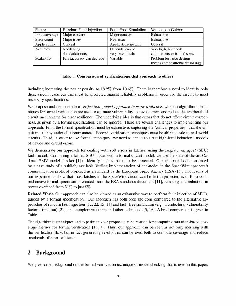
Factor Random Fault Injection Fault-Free Simulation Verification-GuidedInput coverage Major concern Major concern ExhaustiveError count Major issue Non-issue ExhaustiveApplicability General Application-specific GeneralAccuracy Needs long Depends; can be Very high, but needs
simulation runs very pessimistic comprehensive formal spec.Scalability Fair (accuracy can degrade) Variable Problem for large designs
(needs compositional reasoning)
Table 1: Comparison of verification-guided approach to others
including increasing the power penalty to 18.2% from 10.6%. There is therefore a need to identify onlythose circuit resources that must be protected against reliability problems in order for the circuit to meetnecessary specifications.We propose and demonstrate a verification-guided approach to error resilience, wherein algorithmic tech-niques for formal verification are used to estimate vulnerability to device errors and reduce the overheads ofcircuit mechanisms for error resilience. The underlying idea is that errors that do not affect circuit correct-ness, as given by a formal specification, can be ignored. There are several challenges to implementing ourapproach. First, the formal specification must be exhaustive, capturing the ‘critical properties” that the cir-cuit must obey under all circumstances. Second, verification techniques must be able to scale to real-worldcircuits. Third, in order to use formal techniques, we need to create accurate high-level behavioral modelsof device and circuit errors.We demonstrate our approach for dealing with soft errors in latches, using the single-event upset (SEU)fault model. Combining a formal SEU model with a formal circuit model, we use the state-of-the-art Ca-dence SMV model checker [1] to identify latches that must be protected. Our approach is demonstratedby a case study of a publicly available Verilog implementation of end-nodes in the SpaceWire spacecraftcommunication protocol proposed as a standard by the European Space Agency (ESA) [3]. The results ofour experiments show that most latches in the SpaceWire circuit can be left unprotected even for a com-prehensive formal specification created from the ESA standards document [11], resulting in a reduction inpower overhead from 51% to just 9%.Related Work. Our approach can also be viewed as an exhaustive way to perform fault injection of SEUs,guided by a formal specification. Our approach has both pros and cons compared to the alternative ap-proaches of random fault injection [12, 22, 15, 14] and fault-free simulation (e.g., architectural vulnerabilityfactor estimation) [21], and complements them and other techniques [5, 16]. A brief comparison is given inTable 1.The algorithmic techniques and experiments we propose can be re-used for computing mutation-based cov-erage metrics for formal verification [13, 7]. Thus, our approach can be seen as not only meshing withthe verification flow, but in fact generating results that can be used both to compute coverage and reduceoverheads of error resilience.
2 Background
We give some background on the formal verification technique of model checking that is used in this paper.
2
Model checking is the most highly automated formal verification technique available today. The techniqueencompasses algorithmic methods to exhaustively explore all circuit states that are reachable from the initialstates of operation. Model checking algorithms form the basis of many recent industry tools for assertion-based verification, sequential equivalence checking, and property checking. Further details may be found inthe book by Clarke et al. [10].Formal specifications can be provided in a variety of ways. For sequential equivalence checking, the specifi-cation is captured by a simpler version of the circuit that is considered correct; e.g., a simple, non-pipelinedprocessor can serve as a specification for a complex, pipelined, superscalar version. However, for arbitrarycontrol logic, ASICs, and whole systems, design requirements are often most easily captured as partial spec-ifications, and formalized using temporal logic. Temporal logic forms the basis for the recent IEEE standard1850 property specification language (PSL) [4].The experiments reported in this paper use Cadence SMV, a state-of-the-art model checker based on thetechnique of symbolic model checking [17]. Formal specifications for the main case study were written inlinear temporal logic [20, 10].
3 Approach
We describe our approach in this section, including the overall flow (Section 3.1), underlying formal notions(Section 3.2), and relation to coverage (Section 3.3).
3.1 Tool Flow
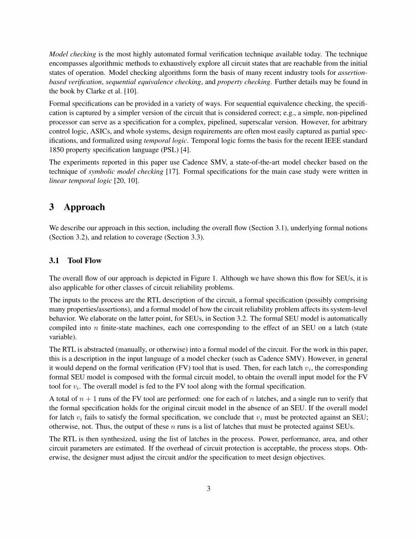
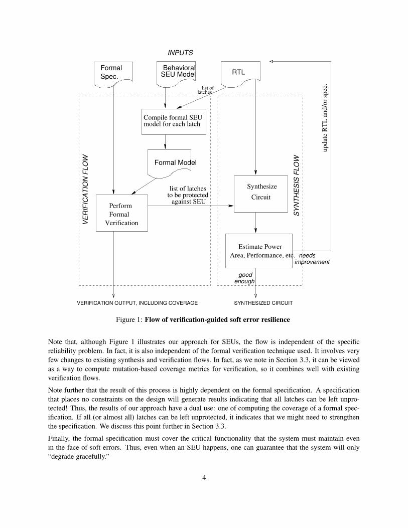
The overall flow of our approach is depicted in Figure 1. Although we have shown this flow for SEUs, it isalso applicable for other classes of circuit reliability problems.The inputs to the process are the RTL description of the circuit, a formal specification (possibly comprisingmany properties/assertions), and a formal model of how the circuit reliability problem affects its system-levelbehavior. We elaborate on the latter point, for SEUs, in Section 3.2. The formal SEU model is automaticallycompiled into n finite-state machines, each one corresponding to the effect of an SEU on a latch (statevariable).The RTL is abstracted (manually, or otherwise) into a formal model of the circuit. For the work in this paper,this is a description in the input language of a model checker (such as Cadence SMV). However, in generalit would depend on the formal verification (FV) tool that is used. Then, for each latch vi, the correspondingformal SEU model is composed with the formal circuit model, to obtain the overall input model for the FVtool for vi. The overall model is fed to the FV tool along with the formal specification.A total of n + 1 runs of the FV tool are performed: one for each of n latches, and a single run to verify thatthe formal specification holds for the original circuit model in the absence of an SEU. If the overall modelfor latch vi fails to satisfy the formal specification, we conclude that vi must be protected against an SEU;otherwise, not. Thus, the output of these n runs is a list of latches that must be protected against SEUs.The RTL is then synthesized, using the list of latches in the process. Power, performance, area, and othercircuit parameters are estimated. If the overhead of circuit protection is acceptable, the process stops. Oth-erwise, the designer must adjust the circuit and/or the specification to meet design objectives.
3
RTLBehavioralSEU Model
Formal Spec.
Formal Model
Compile formal SEUmodel for each latch
SynthesizeCircuit
list of latchesto be protected
against SEU
needsEstimate Power
Area, Performance, etc.
latcheslist of
SYNTHESIZED CIRCUIT
VerificationFormalPerform
VERI
FICA
TIO
N FL
OW
INPUTS
SYNT
HESI
S FL
OW
improvement
upda
te R
TL a
nd/o
r spe
c.
goodenough
VERIFICATION OUTPUT, INCLUDING COVERAGE
Figure 1: Flow of verification-guided soft error resilience
Note that, although Figure 1 illustrates our approach for SEUs, the flow is independent of the specificreliability problem. In fact, it is also independent of the formal verification technique used. It involves veryfew changes to existing synthesis and verification flows. In fact, as we note in Section 3.3, it can be viewedas a way to compute mutation-based coverage metrics for verification, so it combines well with existingverification flows.Note further that the result of this process is highly dependent on the formal specification. A specificationthat places no constraints on the design will generate results indicating that all latches can be left unpro-tected! Thus, the results of our approach have a dual use: one of computing the coverage of a formal spec-ification. If all (or almost all) latches can be left unprotected, it indicates that we might need to strengthenthe specification. We discuss this point further in Section 3.3.Finally, the formal specification must cover the critical functionality that the system must maintain evenin the face of soft errors. Thus, even when an SEU happens, one can guarantee that the system will only“degrade gracefully.”
4
3.2 Formal Model
As is standard in formal verification, a sequential circuit is formally modeled as a triple (V, δ, S0), where V
is the set of state variables (latches or state-holding elements) {v1, v2, . . . , vn}, δ is the transition relationof the system defining how the system evolves over time, and S0 is a Boolean formula over V denoting theset of initial states in which the circuit can begin operation. The transition relation specifies, for each statevariable vi, how its value in the next cycle v′
iis obtained. Note that since δ is a relation, not just a function,
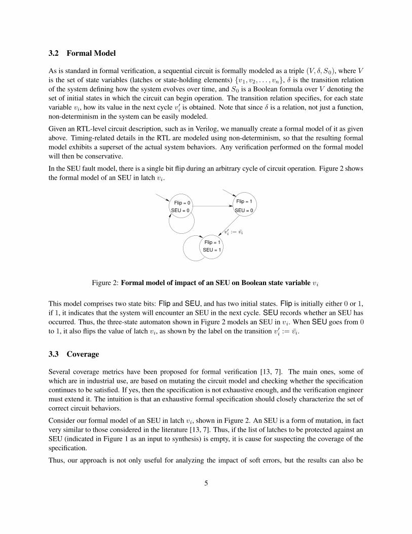
non-determinism in the system can be easily modeled.Given an RTL-level circuit description, such as in Verilog, we manually create a formal model of it as givenabove. Timing-related details in the RTL are modeled using non-determinism, so that the resulting formalmodel exhibits a superset of the actual system behaviors. Any verification performed on the formal modelwill then be conservative.In the SEU fault model, there is a single bit flip during an arbitrary cycle of circuit operation. Figure 2 showsthe formal model of an SEU in latch vi.
Flip = 0SEU = 0
SEU = 1Flip = 1
SEU = 0
Flip = 1
v′
i:= v̄i
Figure 2: Formal model of impact of an SEU on Boolean state variable vi
This model comprises two state bits: Flip and SEU, and has two initial states. Flip is initially either 0 or 1,if 1, it indicates that the system will encounter an SEU in the next cycle. SEU records whether an SEU hasoccurred. Thus, the three-state automaton shown in Figure 2 models an SEU in vi. When SEU goes from 0to 1, it also flips the value of latch vi, as shown by the label on the transition v ′
i:= v̄i.
3.3 Coverage
Several coverage metrics have been proposed for formal verification [13, 7]. The main ones, some ofwhich are in industrial use, are based on mutating the circuit model and checking whether the specificationcontinues to be satisfied. If yes, then the specification is not exhaustive enough, and the verification engineermust extend it. The intuition is that an exhaustive formal specification should closely characterize the set ofcorrect circuit behaviors.Consider our formal model of an SEU in latch vi, shown in Figure 2. An SEU is a form of mutation, in factvery similar to those considered in the literature [13, 7]. Thus, if the list of latches to be protected against anSEU (indicated in Figure 1 as an input to synthesis) is empty, it is cause for suspecting the coverage of thespecification.Thus, our approach is not only useful for analyzing the impact of soft errors, but the results can also be
5
re-used for computing coverage metrics. In fact, extending our approach beyond soft errors can help defineand compute new coverage metrics for formal verification.
4 Case Studies and Results
We have performed experiments with standard model checking benchmarks [2] as well as a large case studyusing third party-written Verilog.Our results on the model checking benchmarks are only briefly mentioned, as we are unsure how extensivethe formal specifications were. A subset of the benchmarks (“eijk” examples) were from sequential equiva-lence checking, where we were unable to find any latches that could be left unprotected. The reason is thatthe specification is too restrictive, requiring the outputs to be equal on all cycles. In fact, for such examples,latches could only be left unprotected if the next-state and output behavior of the circuit was independent ofthem, in which case they could be optimized away.The rest of this section describes our main case study, an implementation of a node in the SpaceWire net-work.
4.1 SpaceWire
SpaceWire [11] is a network for space applications composed of nodes and routers interconnected throughbi-directional high speed data links. According to the SpaceWire website hosted by the ESA, it has beenused in missions of the ESA as well as NASA and JAXA.The SpaceWire standard [11] describes 6 protocol levels – physical, signal, character, exchange, packet, andnetwork. In this paper, we are concerned with the exchange level that defines the protocol for link initial-ization, flow control, and link error detection and recovery (similar to the more widely known TransmissionControl Protocol, TCP). We downloaded a specific Verilog implementation of a SpaceWire end node fromopencores.org [3] which was not written by our group. The Verilog was manually translated into the inputlanguage for the Cadence SMV model checker. English language specifications from the standards docu-ment [11] were translated into formal specifications in linear temporal logic and inserted into the SMV fileas assertions to be checked. The Verilog (and the corresponding SMV model) had to be fixed in a few placesas a result of our initial experiments to formally verify it. All results discussed below are with respect to thisfixed SMV model.
4.1.1 Overview and Model
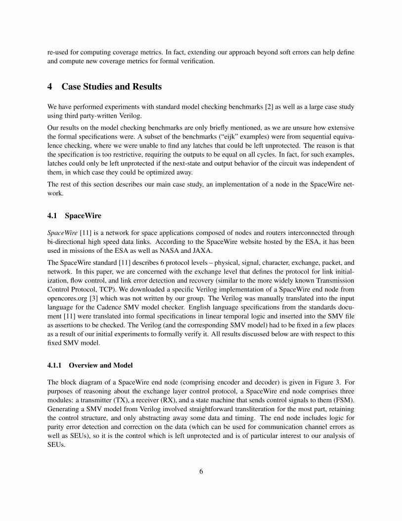
The block diagram of a SpaceWire end node (comprising encoder and decoder) is given in Figure 3. Forpurposes of reasoning about the exchange layer control protocol, a SpaceWire end node comprises threemodules: a transmitter (TX), a receiver (RX), and a state machine that sends control signals to them (FSM).Generating a SMV model from Verilog involved straightforward transliteration for the most part, retainingthe control structure, and only abstracting away some data and timing. The end node includes logic forparity error detection and correction on the data (which can be used for communication channel errors aswell as SEUs), so it is the control which is left unprotected and is of particular interest to our analysis ofSEUs.
6
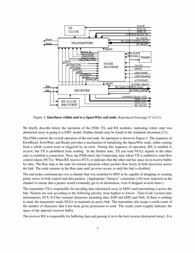
Figure 3: Interfaces within and to a SpaceWire end node. Reproduced from page 57 of [11].
We briefly describe below the operation of the FSM, TX, and RX modules, indicating where state wasabstracted away in going to a SMV model. Further details may be found in the standards document [11].The FSM controls the overall operation of the end node. Its operation is shown in Figure 4. The sequence ofErrorReset, ErrorWait, and Ready provides a mechanism of initializing the SpaceWire node, either comingfrom a whole system reset or triggered by an error. During this sequence of operation, RX is enabled toreceive, but TX is prohibited from sending. In the Started state, TX can send NULL signals to the otherend, to establish a connection. Next, the FSM enters the Connecting state where TX is enabled to send flowcontrol tokens (FCTs). When RX receives FCTs, it indicates that the other end has space in its receive bufferfor data. The Run state is the state for normal operation where packets flow freely in both directions acrossthe link. The node remains in the Run state until an error occurs or until the link is disabled.The end nodes communicate over a channel that was modeled in SMV to be capable of dropping or creatingparity errors in both control and data packets. (Appropriate “fairness” constraints [10] were imposed on thechannel to ensure that a packet would eventually get to its destination, even if dropped several times.)The transmitter TX is responsible for encoding data (abstracted away in SMV) and transmitting it across thelink. Packets are sent according to the following priority, from highest to lowest - Time-Code (system timeinformation), FCT, N-Char (normal characters including data, EOP and EEP) and Null. If there is nothingto send, the transmitter sends NULL to maintain an active link. The transmitter also keeps a credit count ofthe number of characters that it has been given permission to send. The credit count roughly indicates thespace of the opposite receiver buffer.The receiver RX is responsible for buffering data and passing it on to the host system (abstracted away). It is
7
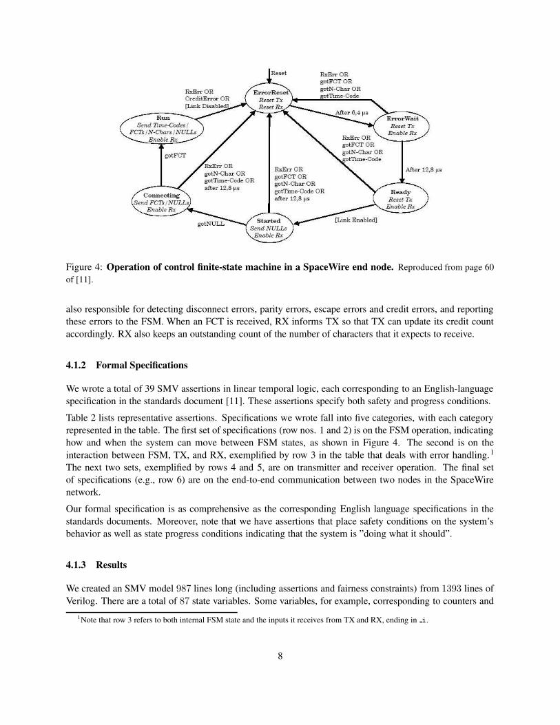
Figure 4: Operation of control finite-state machine in a SpaceWire end node. Reproduced from page 60of [11].
also responsible for detecting disconnect errors, parity errors, escape errors and credit errors, and reportingthese errors to the FSM. When an FCT is received, RX informs TX so that TX can update its credit countaccordingly. RX also keeps an outstanding count of the number of characters that it expects to receive.
4.1.2 Formal Specifications
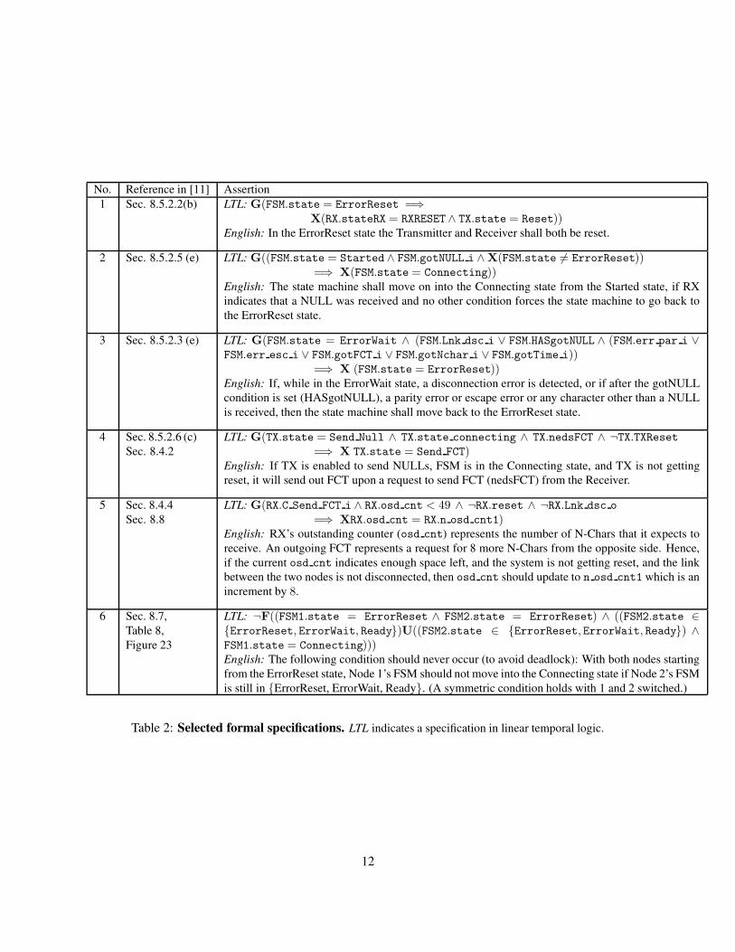
We wrote a total of 39 SMV assertions in linear temporal logic, each corresponding to an English-languagespecification in the standards document [11]. These assertions specify both safety and progress conditions.Table 2 lists representative assertions. Specifications we wrote fall into five categories, with each categoryrepresented in the table. The first set of specifications (row nos. 1 and 2) is on the FSM operation, indicatinghow and when the system can move between FSM states, as shown in Figure 4. The second is on theinteraction between FSM, TX, and RX, exemplified by row 3 in the table that deals with error handling.1
The next two sets, exemplified by rows 4 and 5, are on transmitter and receiver operation. The final setof specifications (e.g., row 6) are on the end-to-end communication between two nodes in the SpaceWirenetwork.Our formal specification is as comprehensive as the corresponding English language specifications in thestandards documents. Moreover, note that we have assertions that place safety conditions on the system’sbehavior as well as state progress conditions indicating that the system is ”doing what it should”.
4.1.3 Results
We created an SMV model 987 lines long (including assertions and fairness constraints) from 1393 lines ofVerilog. There are a total of 87 state variables. Some variables, for example, corresponding to counters and
1Note that row 3 refers to both internal FSM state and the inputs it receives from TX and RX, ending in i.
8
FSM state, can generate multiple latches in the synthesized circuit.Using the formal specifications created from the standards document, we found that all but 10 of these statevariables could be left unprotected.An example of a state variable that must be protected is FSM.state. On a bit flip, this can arbitrarily changethe state of the FSM, leading to failure of many assertions, including row 6 in Table 2.An example of a state variable that need not be protected is FSM.HASgotNULL which is an internal FSMflag that indicates that the end node has received a NULL. This flag is used widely in the FSM logic forerror handling, so it was initially somewhat surprising to us that an SEU in it allowed the end node tocontinue to satisfy all its assertions, including those dealing with errors. It turns out that the error handlinglogic references not just FSM.HASgotNULL but also another signal RX.gotNULL o from the receiver, thusproviding inherent robustness to SEUs.Our experiments were performed using a BDD-based version of the Cadence SMV model checker (withdynamic variable reordering turned on). For scalability, all categories of specifications except for the end-to-end assertions were verified on a model of a single node communicating with a channel that could generateany message (a conservative check). The total time for our SMV runs for these specifications was 278seconds with a maximum of 133 seconds for a single run (SMV caches results, thus optimizing overallrun-time). The end-to-end assertions were verified on a model comprising two nodes communicating over alossy channel. This experiment took much longer due to an explosion in the state space – 795 minutes witha maximum time of 76 minutes for a single run.Synopsys Design Compiler was used to generate the final circuit. Latches that did not map to any state vari-able in Verilog were protected or not based on a structural dependency analysis. Three power consumptionnumbers were then estimated: for the synthesized circuit without any SEU protection at all, with the BISERprotection [23] for all latches, and with BISER protection using our verification-guided classification. Thefollowing results were obtained:
Technique Power(mW) OverheadNo SEU protection 3.23 –SEU protection for all latches 4.85 51.0%Verification-guided SEU protection 3.52 9.1%
Thus, using a verification-guided approach one can obtain a 5X reduction in power overhead of protectingfrom SEUs using the BISER technique. We believe similar results can be obtained for other SEU protectionmethods as well, since the fraction of state variables to be protected is small.
5 Conclusions and Future Work
We have proposed a verification-guided approach to estimating and reducing the overheads of circuit mech-anisms for soft error resilience. Our approach has been demonstrated on a real case study of a third-partyVerilog implementation of a component of the ESA SpaceWire network with specifications covering thespecified behavior in the standards document [11]. The resulting power savings demonstrate the utility ofour approach.This paper has only taken a first step. Scalability of model checking (and formal verification, in general)is a concern. Encouragingly, we have only used the SMV model checker with its most basic optimiza-
9
tions, without either automated abstraction, compositional reasoning, or Boolean satisfiability (SAT) meth-ods [10, 8, 9]. Our approach can also be combined with complementary methods such as random faultinjection. Finally, our work has direct connections to the problem of computing coverage metrics for formalverification, which we plan to explore further.
Acknowledgments
Timothy Loo and Lynn Wang created the initial version of the SpaceWire SMV model. Spencer Chu helpedwith synthesis and power estimation. This research was supported in part by the MARCO Gigascale SystemsResearch Center.
References
[1] Cadence SMV model checker. http://www.kenmcmil.com/ smv.html.
[2] The TIP benchmarks. http://www.cs.chalmers.se/˜een/Tip/.
[3] SpaceWire Verilog. http://www.opencores.org/projects.cgi/ web/spacewire/overview, July 2005.
[4] IEEE P1850 - standard for PSL - property specification language. http://www.eda.org/ieee-1850/, URLcirca Sep.’06.
[5] H. Asadi and M. B. Tahoori. Soft error modeling and protection for sequential elements. In Proc. ofthe IEEE Intl. Symp. On Defect and Fault Tolerance in VLSI Systems (DFT), pages 463–471, October2005.
[6] R. C. Baumann. The impact of technology scaling on soft error rate performance and limits to theefficiency of error correction. In Proceedings of the International Electron Devices Meeting, pages329–332, 2002.
[7] Hana Chockler, Orna Kupferman, and Moshe Y. Vardi. Coverage metrics for formal verification. InProc. Correct Hardware Design and Verification Methods (CHARME), pages 111–125, 2003.
[8] Edmund M. Clarke, Armin Biere, Richard Raimi, and Yunshan Zhu. Bounded model checking usingsatisfiability solving. Formal Methods in System Design, 19(1):7–34, 2001.
[9] Edmund M. Clarke, Orna Grumberg, Somesh Jha, Yuan Lu, and Helmut Veith. Counterexample-guided abstraction refinement for symbolic model checking. Journal of the ACM, 50(5):752–794,2003.
[10] Edmund M. Clarke, Orna Grumberg, and Doron A. Peled. Model Checking. MIT Press, 2000.
[11] European Cooperation for Space Standardization. Space engineering – SpaceWire – links,nodes, routers, and networks (draft ECSS-E-50-12A). http://www.spacewire.esa.int/tech/spacewire/standards/, November 2002.
[12] K.K. Goswami, R. Iyer, and L.Y. Young. DEPEND: a simulation-based environment for system-leveldependability analysis. IEEE Trans. Computers, pages 60–74, Jan. 1997.
10
[13] Yatin Vasant Hoskote, Timothy Kam, Pei-Hsin Ho, and Xudong Zhao. Coverage estimation for sym-bolic model checking. In Design Automation Conference (DAC), pages 300–305, 1999.
[14] M.C. Hsueh, T.K. Tsai, and R.K. Iyer. Fault injection techniques and tools. IEEE Computer, pages75–82, April 1997.
[15] Ghani A. Kanawati, Nasser A. Kanawati, and Jacob A. Abraham. FERRARI: A flexible software-basedfault and error injection system. IEEE Trans. on Computers, 44(2):248–260, 1995.
[16] Smita Krishnaswamy, George F. Viamontes, Igor L. Markov, and John P. Hayes. Accurate reliablityevaluation and enhancement via probabilistic transfer matrices. In Proc. Design Automation and Testin Europe (DATE), pages 282–287, 2005.
[17] Kenneth L. McMillan. Symbolic Model Checking. Kluwer Academic Publishers, 1992.
[18] Subhasish Mitra, Tanay Karnik, Norbert Seifert, and Ming Zhang. Logic soft errors in sub-65nmtechnologies design and CAD challenges. In Proceedings of the 42nd Design Automation Conference(DAC), pages 2–4. ACM Press, 2005.
[19] M. Nicolaidis. Design for soft error mitigation. IEEE Trans. on Device and Materials Reliability,5(3):405–418, Sept. 2005.
[20] Amir Pnueli. The temporal logic of programs. In 18th Annual Symposium on Foundations of ComputerScience (FOCS), pages 46–57, 1977.
[21] S. S. Mukherjee et al. A systematic methodology to compute the architectural vulnerability factors fora high-performance microprocessor. In Proc. Int’l Symp. Microarchitecture (MICRO), pages 29–40,2003.
[22] Nicholas J. Wang, Justin Quek, Todd M. Rafacz, and Sanjay J. Patel. Characterizing the effects oftransient faults on a high-performance processor pipeline. In Proc. Int’l Conf. Dependable Systemsand Networks (DSN), pages 61–70. IEEE Press, 2004.
[23] M. Zhang, S. Mitra, T. M. Mak, N. Seifert, Q. Shi, K.S. Kim, N. Shanbhag, N. Wang, and S.J. Patel.Sequential element design with built-in soft error resilience. IEEE Transactions on VLSI, 2006.
11
No. Reference in [11] Assertion1 Sec. 8.5.2.2(b) LTL: G(FSM.state = ErrorReset =⇒
X(RX.stateRX = RXRESET∧ TX.state = Reset))English: In the ErrorReset state the Transmitter and Receiver shall both be reset.
2 Sec. 8.5.2.5 (e) LTL: G((FSM.state = Started∧ FSM.gotNULL i ∧X(FSM.state 6= ErrorReset))=⇒ X(FSM.state = Connecting))
English: The state machine shall move on into the Connecting state from the Started state, if RXindicates that a NULL was received and no other condition forces the state machine to go back tothe ErrorReset state.
3 Sec. 8.5.2.3 (e) LTL: G(FSM.state = ErrorWait ∧ (FSM.Lnk dsc i ∨ FSM.HASgotNULL ∧ (FSM.err par i ∨FSM.err esc i ∨ FSM.gotFCT i ∨ FSM.gotNchar i ∨ FSM.gotTime i))
=⇒ X (FSM.state = ErrorReset))English: If, while in the ErrorWait state, a disconnection error is detected, or if after the gotNULLcondition is set (HASgotNULL), a parity error or escape error or any character other than a NULLis received, then the state machine shall move back to the ErrorReset state.
4 Sec. 8.5.2.6 (c)Sec. 8.4.2
LTL: G(TX.state = Send Null ∧ TX.state connecting ∧ TX.nedsFCT ∧ ¬TX.TXReset=⇒ X TX.state = Send FCT)
English: If TX is enabled to send NULLs, FSM is in the Connecting state, and TX is not gettingreset, it will send out FCT upon a request to send FCT (nedsFCT) from the Receiver.
5 Sec. 8.4.4Sec. 8.8
LTL: G(RX.C Send FCT i ∧ RX.osd cnt < 49 ∧ ¬RX.reset ∧ ¬RX.Lnk dsc o
=⇒ XRX.osd cnt = RX.n osd cnt1)English: RX’s outstanding counter (osd cnt) represents the number of N-Chars that it expects toreceive. An outgoing FCT represents a request for 8 more N-Chars from the opposite side. Hence,if the current osd cnt indicates enough space left, and the system is not getting reset, and the linkbetween the two nodes is not disconnected, then osd cnt should update to n osd cnt1 which is anincrement by 8.
6 Sec. 8.7,Table 8,Figure 23
LTL: ¬F((FSM1.state = ErrorReset ∧ FSM2.state = ErrorReset) ∧ ((FSM2.state ∈{ErrorReset, ErrorWait, Ready})U((FSM2.state ∈ {ErrorReset, ErrorWait, Ready}) ∧FSM1.state = Connecting)))English: The following condition should never occur (to avoid deadlock): With both nodes startingfrom the ErrorReset state, Node 1’s FSM should not move into the Connecting state if Node 2’s FSMis still in {ErrorReset, ErrorWait, Ready}. (A symmetric condition holds with 1 and 2 switched.)
Table 2: Selected formal specifications. LTL indicates a specification in linear temporal logic.
12


