Embed Size (px)
Citation preview
CyberFactory#1 | www.cyberfactory-1.org
FoF Resilience State-of-the-Art Analysis – version 1.0
Date: 16.6.2021

State-of-the-Art on FoF Resilience Date: 16th June 2021
CyberFactory#1 | www.cyberfactory-1.org 2
Table of Contents Glossary ................................................................................................................................................. 4
1. Executive Summary ...................................................................................................................... 9
2. Human/machine access and trust management ...................................................................... 11
2.1. Overview ................................................................................................................................ 11 2.1.1. Traditional access control .............................................................................................. 12
2.1.2. Centralized access control ............................................................................................ 12 2.1.3. Access control in the cloud ............................................................................................ 13 2.1.4. Federated access control .............................................................................................. 13
2.2. Reference architectures ........................................................................................................ 14 2.3. Identity Standards .................................................................................................................. 18
2.3.1. OpenID Connect ............................................................................................................ 18 2.3.2. OAuth 2.0 ....................................................................................................................... 18 2.3.3. SAML 2.0 Connect ........................................................................................................ 19 2.3.4. XACML 3.0 .................................................................................................................... 20
2.4. Challenges in reference architecture ..................................................................................... 21 2.4.1. Threat categories ........................................................................................................... 23
2.5. Solution overview .................................................................................................................. 26
2.5.1. Description of the concept ............................................................................................. 26 2.5.2. Modern authentication methods .................................................................................... 29
2.6. Discussion ............................................................................................................................. 29 3. Robust machine learning ability ................................................................................................ 31
3.1. Motivation .............................................................................................................................. 31 3.2. Introduction ............................................................................................................................ 31
3.2.1. Adversarial Machine learning and Deep Learning ........................................................ 31 3.2.2. Defence mechanism ...................................................................................................... 38
3.3. Impact of FoF......................................................................................................................... 44 3.4. Discussion ............................................................................................................................. 45
4. Human/machine behaviour watch ............................................................................................. 47
4.1. Introduction ............................................................................................................................ 47 4.1.1. Static and dynamic anomaly analysis ........................................................................... 48 4.1.2. Visualization and anomaly detection ............................................................................. 49
4.2. Human watch ......................................................................................................................... 49 4.2.1. User Behaviour Analytics .............................................................................................. 49 4.2.2. Closed-circuit television system .................................................................................... 50 4.2.3. Speaker recognition system .......................................................................................... 50 4.2.4. Monitor the Human-Computer Interaction ..................................................................... 51
4.3. Component watch .................................................................................................................. 51 4.3.1. Robot anomaly detection ............................................................................................... 52
State-of-the-Art on FoF Resilience Date: 16th June 2021
CyberFactory#1 | www.cyberfactory-1.org 3
4.3.2. Hardware component watch .......................................................................................... 54 4.3.3. Software component watch ........................................................................................... 57
4.4. Process watch ....................................................................................................................... 62 4.4.1. PCI monitoring of process characteristics ..................................................................... 62
4.5. Network watch ....................................................................................................................... 64 4.5.1. Infrastructure Devices .................................................................................................... 64 4.5.2. Communication protocols .............................................................................................. 67 4.5.3. Network visualization ..................................................................................................... 71 4.5.4. Detection methods ......................................................................................................... 71 4.5.5. Wireless Traffic Analysis - Mobility ................................................................................ 80
4.6. Discussion ............................................................................................................................. 81 5. FoF Resilience ............................................................................................................................. 83
5.1. Overview ................................................................................................................................ 83 5.2. Factory transformations / Scenario Modelling ....................................................................... 84 5.3. Connected FoF ...................................................................................................................... 85
5.3.1 Device Management ...................................................................................................... 86 5.4. Decision Support Systems in FoF environment .................................................................... 88 5.5. Incident management / Autonomous adaptation ................................................................... 90 5.6. Recovery, reconfiguration and remediation ........................................................................... 93
5.6.1 Process and abilities of reconfiguration ................................................................................ 94 5.6.2 Reconfiguration in the Mobile Robotics Domain .................................................................. 96
5.7. Visualisation of data and other relevant inputs to FoF resilience ........................................ 100 5.8. Discussion ........................................................................................................................... 104
References ......................................................................................................................................... 106
Table of figures .................................................................................................................................. 115
State-of-the-Art on FoF Resilience Date: 16th June 2021
CyberFactory#1 | www.cyberfactory-1.org 4
Glossary 2FA Two-Factor Authentication
ABAC Attribute-Based Access Control
AD Active Directory
AE Auto Encoder
AGV Automated Guided Vehicle
AI Artificial Intelligence
ALE Analytic and Location Engine
AOI Area of Interest
APT Advanced Persistent Threat
AR Augmented Reality
ASM Action Selection Mechanism
ASyMTRe Automated Synthesis of Multi-robot Task solutions through software Reconfiguration
BDPA Backwards Pass Differentiable Approximation
CACAO Collaborative Automated Course of Action Operations
CAN Controller Area Network
CBM Condition-Based Maintenance
CCTV Closed-Circuit Television
CERT Computer Emergency Response Team
COTS Commercial-Off-The-Shelf
CPS Cyber-Physical Systems
CVSS Cyber Vulnerability Scoring System
DL Deep Learning
DRFF Deep Random Forest Fusion
State-of-the-Art on FoF Resilience Date: 16th June 2021
CyberFactory#1 | www.cyberfactory-1.org 5
DSS Decision Support System
E2E End-to-End
ECU Electric Control Unit
EER Equal Error Rate
EGMM Ensemble of Gaussian Mixture Models
EIS Executive Information System
EOT Expectation Over Transformation
ETE End-to-End
FGSM Fast Gradient Sign/Symbol Method
FoF Factory of the Future
FPGA Field-Programmable Gate Array
GAAM Goal-Action-Attribute Model
GDPR General Data Protection Regulation
GrIDS Graph-based IDS
GSS Group Support System
HIDS Host-based Intrusion Detection System
HMI Human-Machine Interface
HTM Hierarchical Temporal Memory
HTTP HyperText Transfer Protocol
IAM Identity and Access Management
ICMP Internet Control Message Protocol
ICS Industrial Control System
IDM Identity Management
IDP/IdP Identity Provider
IIoT Industrial Internet of Things
State-of-the-Art on FoF Resilience Date: 16th June 2021
CyberFactory#1 | www.cyberfactory-1.org 6
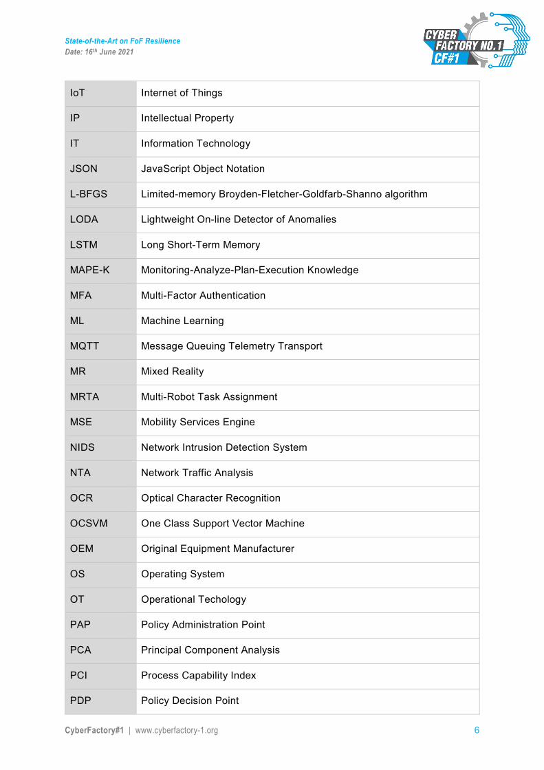
IoT Internet of Things
IP Intellectual Property
IT Information Technology
JSON JavaScript Object Notation
L-BFGS Limited-memory Broyden-Fletcher-Goldfarb-Shanno algorithm
LODA Lightweight On-line Detector of Anomalies
LSTM Long Short-Term Memory
MAPE-K Monitoring-Analyze-Plan-Execution Knowledge
MFA Multi-Factor Authentication
ML Machine Learning
MQTT Message Queuing Telemetry Transport
MR Mixed Reality
MRTA Multi-Robot Task Assignment
MSE Mobility Services Engine
NIDS Network Intrusion Detection System
NTA Network Traffic Analysis
OCR Optical Character Recognition
OCSVM One Class Support Vector Machine
OEM Original Equipment Manufacturer
OS Operating System
OT Operational Techology
PAP Policy Administration Point
PCA Principal Component Analysis
PCI Process Capability Index
PDP Policy Decision Point
State-of-the-Art on FoF Resilience Date: 16th June 2021
CyberFactory#1 | www.cyberfactory-1.org 7
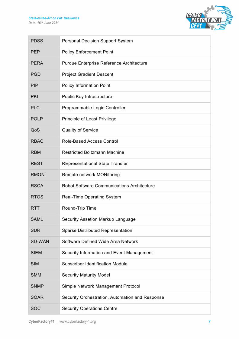
PDSS Personal Decision Support System
PEP Policy Enforcement Point
PERA Purdue Enterprise Reference Architecture
PGD Project Gradient Descent
PIP Policy Information Point
PKI Public Key Infrastructure
PLC Programmable Logic Controller
POLP Principle of Least Privilege
QoS Quality of Service
RBAC Role-Based Access Control
RBM Restricted Boltzmann Machine
REST REpresentational State Transfer
RMON Remote network MONitoring
RSCA Robot Software Communications Architecture
RTOS Real-Time Operating System
RTT Round-Trip Time
SAML Security Assetion Markup Language
SDR Sparse Distributed Representation
SD-WAN Software Defined Wide Area Network
SIEM Security Information and Event Management
SIM Subscriber Identification Module
SMM Security Maturity Model
SNMP Simple Network Management Protocol
SOAR Security Orchestration, Automation and Response
SOC Security Operations Centre
State-of-the-Art on FoF Resilience Date: 16th June 2021
CyberFactory#1 | www.cyberfactory-1.org 8
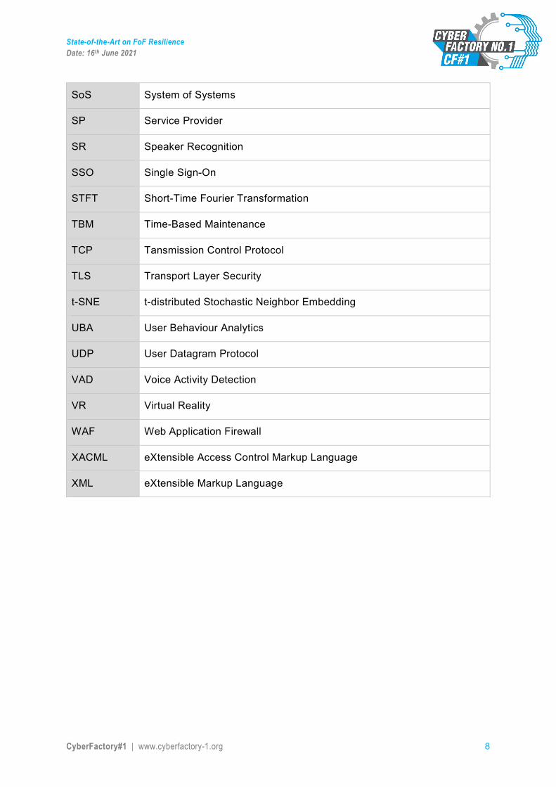
SoS System of Systems
SP Service Provider
SR Speaker Recognition
SSO Single Sign-On
STFT Short-Time Fourier Transformation
TBM Time-Based Maintenance
TCP Tansmission Control Protocol
TLS Transport Layer Security
t-SNE t-distributed Stochastic Neighbor Embedding
UBA User Behaviour Analytics
UDP User Datagram Protocol
VAD Voice Activity Detection
VR Virtual Reality
WAF Web Application Firewall
XACML eXtensible Access Control Markup Language
XML eXtensible Markup Language

State-of-the-Art on FoF Resilience Date: 16th June 2021
CyberFactory#1 | www.cyberfactory-1.org 9
1. Management Summary This document provides an overview on the state of the art for the Factories of the Future (FoF) resilience. It is created as state of the art analysis in the work package WP5 – FoF Dynamic Risk Management and Resilience of the ITEA project CyberFactory#11.
CyberFactory#1 aims at designing, developing, integrating and demonstrating a set of key enabling capabilities to foster optimisation and resilience of the Factories of the Future. It will address the needs of pilots from transportation, automotive, electronics and machine manufacturing industries around use cases such as statistical process control, real time asset tracking, distributed manufacturing and collaborative robotics. It will also propose preventive and reactive capabilities to address security and safety concerns to FoF like blended cyber-physical threats, manufacturing data theft or adversarial machine learning.
This document is structured along the four key enabling capabilities related to the resilience of the Factory of the Future that are considered to be vital in the future. They are the following:
• Human/machine access & trust management • Robust machine learning ability • Human/machine behaviour watch • Cyber resilience capability
The human/machine access & trust management can be considered to be a preventive topic that focuses on defining and assigning rights to FoF systems in order to grant and restrict rights to the users and devices.
The robust machine learning ability is another preventive topic, focusing on detecting any manipulation of manufacturing and product-embedded AI as well as protecting them from any manipulation attempts.
The human/machine behaviour watch focuses on real-time monitoring of the factory environment and its assets as well as people. The objective is to detect any anomalies on factory assets regardless of their origin, and to promote safety and security in the shop floor.
The cyber resilience capability focuses on the remediation and recovery of factory assets in case of a cyber-attack. The remediation and recovery functionalities can be either decision-aided or autonomous depending on the needs of the FoF.
Resilience in the Factory of the Future is significant due to the nature of modern manufacturing that is increasingly based on large supply chain networks with real-time information exchange as well as other Industry 4.0 characteristics such as the Industrial Internet of Things, cloud repositories and machine learning. As the ever-increasing digitalisation introduces new cyber threats, FoF operators need to identify and mitigate these threats, taking into account not only their own operations, but also all the other potential vulnerable parts of the entire manufacturing supply chain. By identifying the
1 https://www.cyberfactory-1.org

State-of-the-Art on FoF Resilience Date: 16th June 2021
CyberFactory#1 | www.cyberfactory-1.org 10
threats and vulnerabilities within the supply chain, they can strengthen the weakest links that can be production machines, connections, network devices or even employees. Strengthening the weakest links consists among others of assigning the necessary security policies and access rights and restrictions to users and devices, designing and developing protective measures to factory assets and its supporting technologies such as machine learning (ML) and artificial intelligence (AI), monitoring anomalies and other irregularities, training personnel to detect and perform mitigation actions, but also planning and practicing the remediation and recovery of factory assets in case of a cyber-attack. After all, it is not about whether a cyber-attack will happen, but when and especially how fast are we able to detect it.
Document structure
The document is divided into five main chapters:
Chapter 2 focuses on human/machine access control and trust management capabilities. The section begins with an overview to the different elements of access control and then describes the reference architectures used. Then the section describes the main identity standards before moving on to the challenges in the reference architecture. Finally the section provides an overview to the proposed CyberFactory#1 solution.
Chapter 3 describes the state-of-the-art on the robust machine learning ability. The section begins with the motivation and then introduces the key elements of the topic. The last section specifies the impacts of the ability to FoF.
Chapter 4 introduces the human/machines behaviour watch capability. After introduction the chapter describes the core elements of the human, component, process and network watch topics.
Chapter 5 presents the FoF resilience capability. The chapter begins with an overview to the topic followed by scenario modelling. The next section describes the connected FoF and its key element, device management. Then the chapter continues by describing the other elements and processes, i.e. decision support systems and incident management as well as recovery, reconfiguration and remediation. Finally the chapter describes visualisation of data and other relevant inputs to FoF resilience.
After each chapter there is a discussion section that comments on the findings, mentions any possible shortcomings and other development areas that the CyberFactory#1 project might be able to fulfil.
State-of-the-Art on FoF Resilience Date: 16th June 2021
CyberFactory#1 | www.cyberfactory-1.org 11
2. Human/machine access and trust management
2.1. Overview This task focuses on authorization, authentication and continuous trust management for assets and actors in the FoF environment. The task will investigate ways to integrate more dynamic trust management techniques to IAM, e.g., blockchains and object-based authentication. The developed enhanced IAM module must work in cloud environment, in IIoT environment with multiple devices and allow maintenance and management of roles in fast changing organizations. The IAM module allows the factory assets to be available for different users with different profiles, whilst at the same time protecting the assets against unauthorized access. For each access or transaction, there will be the correct level of security access and trust management.
What is IAM?
Identity and access management (IAM) means giving certain entities access to correct resources at the right time for the right reasons. In a FoF environment this means a huge number of devices must be given an identity and then they must be authenticated in real time. There are multiple tools and applications for managing identities and the permissions they should have.
Some identity and access management tools, terms and concepts:
• single sign-on (SSO): authentication process that lets users to login to many applications with single credentials
• multifactor authentication: user is required to provide multiple methods of authentication before getting access
• mandatory access control (MAC): system provides users with access based on information confidentiality and user clearance levels
• discretionary access control (DAC): data owners can define access permissions for specific users or user groups. This includes the use of an access-control list (ACL) that acts as a security policy
• role based access management (RBAC) and role management: only certain roles in an organization are given access in different parts of a system
• attribute based access management (ABAC): access is defined through attribute rules rather than roles
• identity governance: for defining, enforcing, reviewing and auditing IAM policies • IAM compliance: following for example GDPR or specific compliance requirements
such as in PCI DSS. The IAM lifecycle comprises different policies related to among others access rights, controls for access management, review and certification processes as well as documentation for audit.
• cloud identity management: managing identities from the cloud instead of on-prem • user activity monitoring: monitoring and tracking user behaviour on company
devices, networks and other IT-resources
State-of-the-Art on FoF Resilience Date: 16th June 2021
CyberFactory#1 | www.cyberfactory-1.org 12
• identity analytics: used for detecting unusual activity and for reducing possibilities for credential misuse
• identity reviews: periodical user access reviews to ensure that correct people have access to correct resources in the organisation
• user provisioning: the process of creating, giving right permissions, changing, disabling and deleting accounts
• access request management: the process of requesting and granting access to resources in the organisation
2.1.1. Traditional access control
The process of discovering different access control methods, both physical and logical, isn’t very straightforward in terms of the authorization process. This is mainly due to the evolution of identification, but also due to the new technologies that allow new kind of interactions, for example Optical Character Recognition (OCR), portable devices such as cards or mobile phones, biometrics, facial recognition, and Single Sign-On (SSO). Enforcement points and policy evaluation methods tend to be isolated elements (based on offline white list and blacklist loading, preloaded key based negotiations) or autonomously managed groups of enforcers (door and path management systems, centralized video surveillance, IT systems role management).
The centralization process performed in big environments has been mainly made in the operational room, by unifying the tasks and enlarging the scope that the security operator has on the table. IT standards and tools have eased the process by unifying communications and centralizing alarm systems. Also, there has been an integration of user databases that ease the provisioning of the security mechanisms.
The coexistence of different solutions oriented to the management of heterogeneous types of elements (physical and logical) has led to the existence of specific and distributed permission management. This means that authorization and access control policy live in proprietary solutions.
2.1.2. Centralized access control
In access control it is important to define a unique language for requesting access to a resource and for evaluating a request. Standards coming from the IT world, such as eXtensible Access Control Markup Language (XACML), points the way towards a decision-making environment where operations and resources are referenced with an abstraction layer, so different things can be treated equally.
The use of standard interfaces makes possible to set a central point of decision where this common abstraction language can be used to handle access control decisions, Permit or Deny, for a subject/object/verb request.
This authorization process goes over three steps:
• Generation of the request. It comes with three elements: o Subject. Detected user identification. o Object. Resource identification. Point of enforcement
State-of-the-Art on FoF Resilience Date: 16th June 2021
CyberFactory#1 | www.cyberfactory-1.org 13
o Verb. Action whose authorization is being evaluated. • Decoration of the request. Incorporation of the information the organization has
regarding the requester. o Role o Groups o Location o Status
• Evaluation of the request. The security policy determines whether access has to be granted and returns a Permit/Deny response
2.1.3. Access control in the cloud
The location of the decision point in a single service, offering a known interface for easy integration to any enforcement point, boost possibilities inside the organization. The centralized management of the entire infrastructure in a distributed multi-premise enterprise is the point where complex policy management can be fully exploited.
There are different ways of enabling the service to the organization:
• Centralized service offered in an internal cloud. A big organization can offer the authorization service as individual request/response petitions. Remotely located enforcers just depend on network connection to be able grant the access.
• Centralized master/delegation authorization servers. Instead of offering a single centralized service, servers are located in distributed locations as policy decision points but implementing the top-level security derived from the main server.
• External cloud implementation. The authorization server is built as a service that can be offered from an external cloud. The protocols and interfaces used are designed to be easily moved to commercial providers.
Cloud access control generally involves the use of Cloud Access Security Brokers (CASB) that are defined as cloud-hosted or on-premise software/hardware that act as intermediaries between users and cloud service providers.
2.1.4. Federated access control
Finally, there is the solution based on a federated network of authorization servers. Each organization needs a decision point that serves the actions to be applied by each of the enforcement points. The federation of multiple authorization servers allows establishing confidence relations to a user from a remote server that can have access granted without the need of provisioning it in the system, and this permission can be based on rules determined by its original organization.
The federation can be established at three levels:
• Identification federation. Remote servers recognize the identification element detected in the guest system.
• Information federation. Remote servers offer information to the requesting server about the user.
• Decision federation. Remote administrators include rules in the policy.
State-of-the-Art on FoF Resilience Date: 16th June 2021
CyberFactory#1 | www.cyberfactory-1.org 14
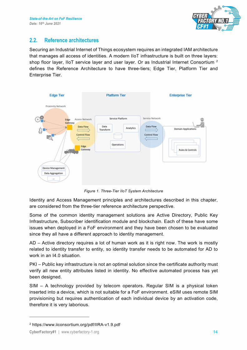
2.2. Reference architectures Securing an Industrial Internet of Things ecosystem requires an integrated IAM architecture that manages all access of identities. A modern IIoT infrastructure is built on three layers: shop floor layer, IIoT service layer and user layer. Or as Industrial Internet Consortium 2 defines the Reference Architecture to have three-tiers; Edge Tier, Platform Tier and Enterprise Tier.
Figure 1. Three-Tier IIoT System Architecture
Identity and Access Management principles and architectures described in this chapter, are considered from the three-tier reference architecture perspective.
Some of the common identity management solutions are Active Directory, Public Key Infrastructure, Subscriber identification module and blockchain. Each of these have some issues when deployed in a FoF environment and they have been chosen to be evaluated since they all have a different approach to identity management.
AD – Active directory requires a lot of human work as it is right now. The work is mostly related to identity transfer to entity, so identity transfer needs to be automated for AD to work in an I4.0 situation.
PKI – Public key infrastructure is not an optimal solution since the certificate authority must verify all new entity attributes listed in identity. No effective automated process has yet been designed.
SIM – A technology provided by telecom operators. Regular SIM is a physical token inserted into a device, which is not suitable for a FoF environment. eSIM uses remote SIM provisioning but requires authentication of each individual device by an activation code, therefore it is very laborious.
2 https://www.iiconsortium.org/pdf/IIRA-v1.9.pdf
State-of-the-Art on FoF Resilience Date: 16th June 2021
CyberFactory#1 | www.cyberfactory-1.org 15
Blockchain – Blockchain is a distributed database and is operated by a network of peers. The chain is temper resistant and blocks are timestamped, which makes blockchain a robust solution to record and secure data exchanges.
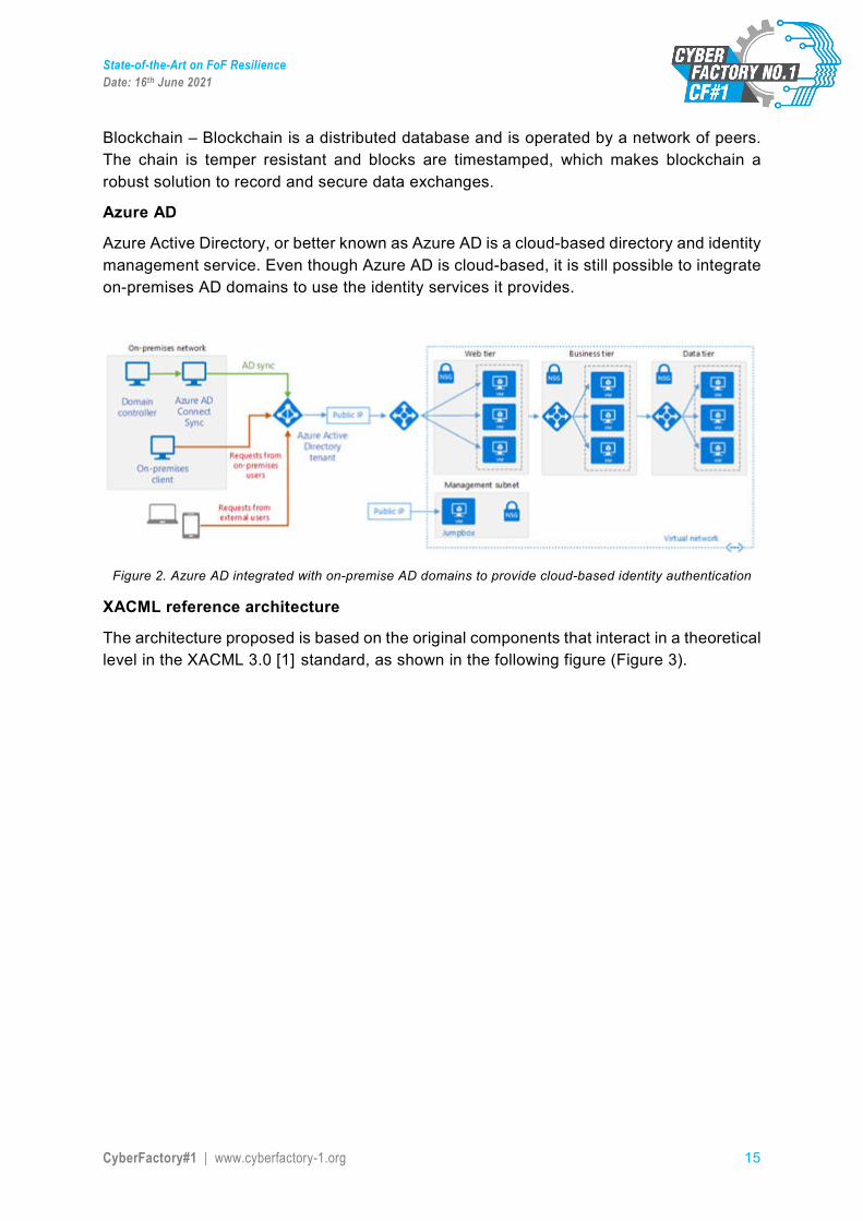
Azure AD
Azure Active Directory, or better known as Azure AD is a cloud-based directory and identity management service. Even though Azure AD is cloud-based, it is still possible to integrate on-premises AD domains to use the identity services it provides.
Figure 2. Azure AD integrated with on-premise AD domains to provide cloud-based identity authentication
XACML reference architecture
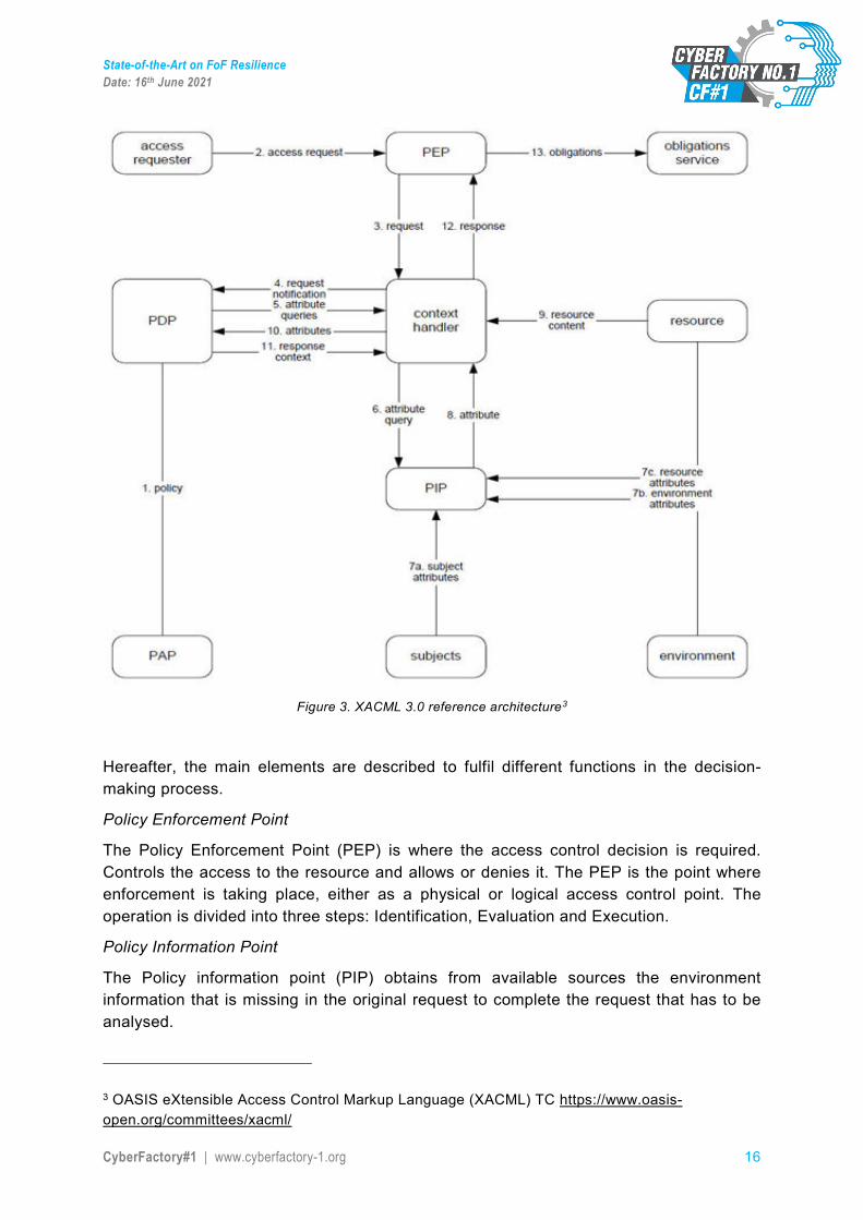
The architecture proposed is based on the original components that interact in a theoretical level in the XACML 3.0 [1] standard, as shown in the following figure (Figure 3).
State-of-the-Art on FoF Resilience Date: 16th June 2021
CyberFactory#1 | www.cyberfactory-1.org 16
Figure 3. XACML 3.0 reference architecture3
Hereafter, the main elements are described to fulfil different functions in the decision-making process.
Policy Enforcement Point
The Policy Enforcement Point (PEP) is where the access control decision is required. Controls the access to the resource and allows or denies it. The PEP is the point where enforcement is taking place, either as a physical or logical access control point. The operation is divided into three steps: Identification, Evaluation and Execution.
Policy Information Point
The Policy information point (PIP) obtains from available sources the environment information that is missing in the original request to complete the request that has to be analysed.
3 OASIS eXtensible Access Control Markup Language (XACML) TC https://www.oasis-open.org/committees/xacml/
State-of-the-Art on FoF Resilience Date: 16th June 2021
CyberFactory#1 | www.cyberfactory-1.org 17
When a user is identified in the PEP and asks for evaluation of the access requested the system is just sending three elements: requester id, action requested and resource. It is responsibility of the PDP to obtain all the environment information that will allow the correct decision making. This extra information decorates the request and allows a real informed decision making.
The authorization server obtains information in two steps:
• Locate end user by searching for the owner of the identification element that has been identified.
• Obtain the users additional information. The information can be located inside the organization or in remote storages.
Policy Decision Point
The Policy Decision Point (PDP) is where the decision is taken. Crosses the request with the policy to obtain the effect to be applied.
The decision the PEP is obtaining is calculated in the PDP. The PDP offers a public interface that receives the request from de enforcer. This request includes the user identification, the requested action and the resource affected by the request. After the processing, the PDP responds with a decision, this is, permit or deny.
The final decision includes the following steps:
• Locate the user capability. • Obtain environment information. • Generate request. • Evaluate request. • Return the decision.
Policy Administration Point
The Policy Administration Point (PAP) offers the interface for the security policy definition, where the security administrator can define the policy to be applied.
Policy
XACML defines a language for specifying which decision must be taken based on different available data. It has two main elements, a request, that collects the available information that define the situation where the access is requested, and the policy that defines what is authorized and what denied. Both have the format of XML structures. The policy is composed by rules and each rule has three parts: Decision, Target and Conditions.
Obligations and actions
Once a decision is made access is granted or denied based on the result, there might be some actions to be deployed after the evaluation process. In parallel the system has the possibility of developing more activities derived from the request. This can be applied both in case of acceptance or reject. After permitting access to a resource there can be a need of tracking or updating a counter (that could hypothetically affect to the next request). Denying access can lead to an external alert or updating a security record.
State-of-the-Art on FoF Resilience Date: 16th June 2021
CyberFactory#1 | www.cyberfactory-1.org 18
2.3. Identity Standards As IAM touches all corporate systems, data interfaces need to comply with standards to minimize customization effort and to provide streamlined way of providing access4. Any IAM reference architecture needs to support system interconnection and data interchange. Several organizations called standard bodies work in devising standards in this field, such as the OpenID foundation, IRFG. It is possible to enumerate three main standards to manage identity and access: OpenID connect (OIDC) 1.0, OAuth 2.0 and SAML 2.0. While OAuth 2.0 is a framework that controls authorization to a protected resources (ex: applications or files), while OpenID Connect and SAML are both industry standards for federated authentication. Therefore that means that OAuth 2.0 is used in fundamentally different situations than the other two standards (examples of which can be seen below), and can be used simultaneously with either OpenID Connect or SAML5.
2.3.1. OpenID Connect
OpenID is an open standard for authentication, promoted by the OpenID foundation, a non-profit organisation. OpenID Connect is built on the OAuth 2.0 protocol and uses an additional JSON Web Token (JWT), called an ID token, to standardize areas that OAuth 2.0 leaves up to choice, such as scopes and endpoint discovery. It is specifically focused on user authentication and is widely used to enable user logins on consumer websites and mobile apps.
2.3.2. OAuth 2.0
OAuth 2.0 [2] is the industry-standard protocol for authorization. OAuth 2.0 focuses on client developer simplicity while providing specific authorization flows for web applications, desktop applications, mobile phones, and living room devices. This specification and its extensions are being developed within the IETF OAuth Working Group.
The OAuth 2.0 authorization framework, described in RFC 6749, enables a third-party application to obtain limited access to an HTTP service, either on behalf of a resource owner by orchestrating an approval interaction between the resource owner and the HTTP service, or by allowing the third-party application to obtain access on its own behalf. This specification replaces and obsoletes the OAuth 1.0 protocol described in RFC 5849.
In the traditional client-server authentication model, the client requests an access-restricted resource (protected resource) on the server by authenticating with the server using the resource owner's credentials. In order to provide third-party applications access to restricted resources, the resource owner shares its credentials with the third party, which creates several problems and limitations. OAuth addresses these issues by introducing an authorization layer and separating the role of the client from that of the resource owner. In OAuth, the client requests access to resources controlled by the resource owner and
4 Cameron, Andrew, and Graham Williamson. "Introduction to IAM Architecture." IDPro Body of Knowledge 1.2 (2020). 5 https://www.okta.com/identity-101/whats-the-difference-between-oauth-openid-connect-and-saml/
State-of-the-Art on FoF Resilience Date: 16th June 2021
CyberFactory#1 | www.cyberfactory-1.org 19
hosted by the resource server and is issued a different set of credentials than those of the resource owner.
Instead of using the resource owner's credentials to access protected resources, the client obtains an access token, a string denoting a specific scope, lifetime, and other access attributes. Access tokens are issued to third-party clients by an authorization server with the approval of the resource owner. The client uses the access token to access the protected resources hosted by the resource server.
For example, an end-user (resource owner) can grant a printing service (client) access to her protected photos stored at a photo-sharing service (resource server), without sharing her username and password with the printing service. Instead, she authenticates directly with a server trusted by the photo-sharing service (authorization server), which issues the printing service delegation-specific credentials (access token)..
2.3.3. SAML 2.0 Connect
The Security Assertion Markup Language (SAML) [3], developed by the Security Services Technical Committee of OASIS, is an XML-oriented framework for transmitting user authentication, entitlement, and other attribute information online6. SAML standard defines a framework for exchanging security information between online business partners, allowing to make assertions regarding the identity, attributes, and entitlements of a subject (an entity that is often a human user) to other entities, such as a partner company or another enterprise application. This framework provides two federation partners to select and share identity attributes using a SAML assertion/message payload, on the condition that these attributes can be expressed in XML7. SAML assumes three key roles in any transaction Identity Provider (IDP/IdP), Service Provider (SP) and User8:
• Identity Provider (IDP/IdP) is a trusted organisation that authenticates and authorizes users. It issues security assertion tokens for authentication and authorization services.
• Service Provider (SP) is an organisation that provides Web and other services. A SP relies on a trusted IDP for authentication and authorization services. It acts on information encoded in assertion tokens to determine whether a user is to be allowed access to a resource or not.
6 N. Klingenstein, T. Hardjono, H. Lockhart, and S. Cantor. (2012) OASIS Security Services (SAML) TC. [Online]. Available: https: //www.oasis-open.org/committees/tc home.php?wg abbrev=security 7 Pingidentity.com. (2011) A standards-based mobile application idm architecture. [Online]. Available: http://www.enterprisemanagement360.com/wp-content/files mf/ white paper/exp final wp mobile-application-idm-arch-8-11-v4.pdf 8 Naik, Nitin, and Paul Jenkins. "Securing digital identities in the cloud by selecting an apposite Federated Identity Management from SAML, OAuth and OpenID Connect." 2017 11th International Conference on Research Challenges in Information Science (RCIS). IEEE, 2017.
State-of-the-Art on FoF Resilience Date: 16th June 2021
CyberFactory#1 | www.cyberfactory-1.org 20
• User is an entity that initiates a sequence of protocol messages and consumes the service provided by the SP. A user may be an application program that is requesting access to a resource.
The latest version of the SAML specifications is SAML 2.0, which describes the four components9:
• Assertions state how identities are represented.
• Protocols represent a sequence of XML messages designed to achieve a single goal.
• Bindings describe how protocol messages are transported over a lower-level protocol such as HTTP.
• Profiles combine a number of bindings to describe a solution for a use case.
2.3.4. XACML 3.0
EXtensible Access Control Markup Language (XACML) [1] is an OASIS standard that describes both a policy language and an access control decision request/response language (both written in XML). The policy language is used to describe general access control requirements, and has standard extension points for defining new functions, data types, combining logic, etc. The request/response language lets you form a query to ask whether or not a given action should be allowed and interpret the result. The response always includes an answer about whether the request should be allowed using one of four values: Permit, Deny, Indeterminate (an error occurred or some required value was missing, so a decision cannot be made) or Not Applicable (the request can't be answered by this service).
The typical setup is that someone wants to take some action on a resource. They will make a request to whatever actually protects that resource (like a file system or a web server), which is called a Policy Enforcement Point (PEP). The PEP will form a request based on the requester's attributes, the resource in question, the action, and other information pertaining to the request. The PEP will then send this request to a Policy Decision Point (PDP), which will look at the request and some policy that applies to the request and come up with an answer about whether access should be granted. That answer is returned to the PEP, which can then allow or deny access to the requester. Note that the PEP and PDP might both be contained within a single application or might be distributed across several servers. In addition to providing request/response and policy languages, XACML also provides the other pieces of this relationship, namely finding a policy that applies to a given request and evaluating the request against that policy to come up with a yes or no answer.
The current version of the protocol is XACML 3.0 Version.
9 C. Forster and N. Readshaw. (2008, April 29) Using SAML security tokens with microsoft web services enhancements: A standards-based approach enabled by tivoli federated identity managers. [Online]. Available: http://www.ibm.com/developerworks/tivoli/library/t-samlwse
State-of-the-Art on FoF Resilience Date: 16th June 2021
CyberFactory#1 | www.cyberfactory-1.org 21
Below the main advantages of the XACML protocol are described:
• Standard: By using a standard language means using something that has been reviewed by a large community of experts and users, it is not necessary to roll the system each time, nor to think about all the tricky issues involved in designing a new language. Plus, as XACML becomes more widely deployed, it will be easier to interoperate with other applications using the same standard language.
• Generic: This means that rather than trying to provide access control for a particular environment or a specific kind of resource, it can be used in any environment. One policy can be written which can then be used by many different kinds of applications, and when one common language is used, policy management becomes much easier.
• Distributed: This means that a policy can be written which in turn refers to other policies kept in arbitrary locations. The result is that rather than having to manage a single monolithic policy, different users or groups can manage sub-pieces of policies as appropriate, and XACML knows how to correctly combine the results from these different policies into one decision.
• Powerful: While there are many ways the base language can be extended, many environments will not need to do so. The standard language already supports a wide variety of data types, functions, and rules about combining the results of different policies. In addition to this, there are already standards groups working on extensions and profiles that will hook XACML into other standards like SAML and LDAP, which will increase the number of ways that XACML can be used.
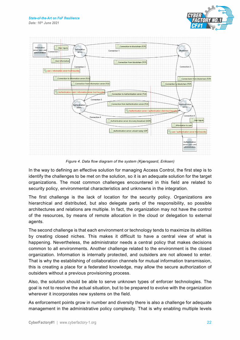
2.4. Challenges in reference architecture A data flow diagram can be used for analyzing different connections in the system. This is a good way to find threats to the system. The following example illustrates the data flow diagram used in identifying threats in a Blockchain-based identity and access management approach.10
10 Access Control for Industry 4.0 – Initial Trust with Blockchain; Kjærsgaard, Eriksen; 2018
State-of-the-Art on FoF Resilience Date: 16th June 2021
CyberFactory#1 | www.cyberfactory-1.org 22
Figure 4. Data flow diagram of the system (Kjærsgaard, Eriksen)
In the way to defining an effective solution for managing Access Control, the first step is to identify the challenges to be met on the solution, so it is an adequate solution for the target organizations. The most common challenges encountered in this field are related to security policy, environmental characteristics and unknowns in the integration.
The first challenge is the lack of location for the security policy. Organizations are hierarchical and distributed, but also delegate parts of the responsibility, so possible architectures and relations are multiple. In fact, the organization may not have the control of the resources, by means of remote allocation in the cloud or delegation to external agents.
The second challenge is that each environment or technology tends to maximize its abilities by creating closed niches. This makes it difficult to have a central view of what is happening. Nevertheless, the administrator needs a central policy that makes decisions common to all environments. Another challenge related to the environment is the closed organization. Information is internally protected, and outsiders are not allowed to enter. That is why the establishing of collaboration channels for mutual information transmission, this is creating a place for a federated knowledge, may allow the secure authorization of outsiders without a previous provisioning process.
Also, the solution should be able to serve unknown types of enforcer technologies. The goal is not to resolve the actual situation, but to be prepared to evolve with the organization wherever it incorporates new systems on the field.
As enforcement points grow in number and diversity there is also a challenge for adequate management in the administrative policy complexity. That is why enabling multiple levels
State-of-the-Art on FoF Resilience Date: 16th June 2021
CyberFactory#1 | www.cyberfactory-1.org 23
of authorization administrators, limited to responsibility areas should be a way of granting a fine security policy.
The last challenge is the unpredictability of the elements to integrate, which requires the use of open standards. The only way of setting ahead of integration difficulties is attaching to common agreements.
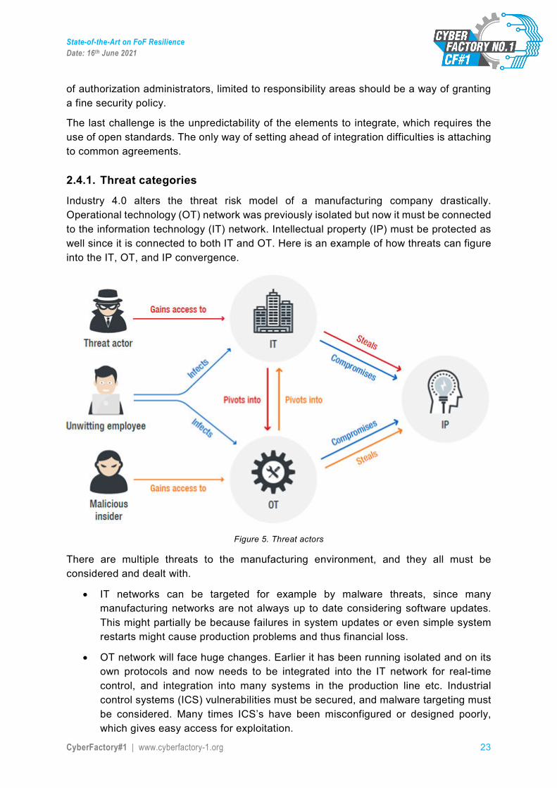
2.4.1. Threat categories
Industry 4.0 alters the threat risk model of a manufacturing company drastically. Operational technology (OT) network was previously isolated but now it must be connected to the information technology (IT) network. Intellectual property (IP) must be protected as well since it is connected to both IT and OT. Here is an example of how threats can figure into the IT, OT, and IP convergence.
Figure 5. Threat actors
There are multiple threats to the manufacturing environment, and they all must be considered and dealt with.
• IT networks can be targeted for example by malware threats, since many manufacturing networks are not always up to date considering software updates. This might partially be because failures in system updates or even simple system restarts might cause production problems and thus financial loss.
• OT network will face huge changes. Earlier it has been running isolated and on its own protocols and now needs to be integrated into the IT network for real-time control, and integration into many systems in the production line etc. Industrial control systems (ICS) vulnerabilities must be secured, and malware targeting must be considered. Many times ICS’s have been misconfigured or designed poorly, which gives easy access for exploitation.
State-of-the-Art on FoF Resilience Date: 16th June 2021
CyberFactory#1 | www.cyberfactory-1.org 24
• IP content (which can be product design, manufacturing processes or just any information) needs to be heavily guarded. Any kind of vulnerability in any of the connected networks can cause huge losses. IP must be protected by good training of employees and good configuration and design of networks.
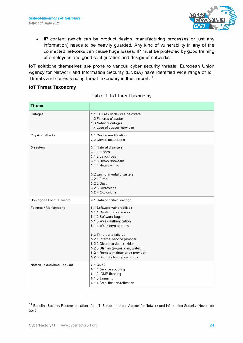
IoT solutions themselves are prone to various cyber security threats. European Union Agency for Network and Information Security (ENISA) have identified wide range of IoT Threats and corresponding threat taxonomy in their report.11
IoT Threat Taxonomy
Table 1. IoT threat taxonomy
Threat
Outages 1.1 Failures of devices/hardware 1.2 Failures of system 1.3 Network outages 1.4 Loss of support services
Physical attacks 2.1 Device modification 2.2 Device destruction
Disasters 3.1 Natural disasters 3.1.1 Floods 3.1.2 Landslides 3.1.3 Heavy snowfalls 3.1.4 Heavy winds 3.2 Environmental disasters 3.2.1 Fires 3.2.2 Dust 3.2.3 Corrosions 3.2.4 Explosions
Damages / Loss IT assets 4.1 Data sensitive leakage
Failures / Malfunctions 5.1 Software vulnerabilities 5.1.1 Configuration errors 5.1.2 Software bugs 5.1.3 Weak authentication 5.1.4 Weak cryptography 5.2 Third party failures 5.2.1 Internal service provider 5.2.2 Cloud service provider 5.2.3 Utilities (power, gas, water) 5.2.4 Remote maintenance provider 5.2.5 Security testing company
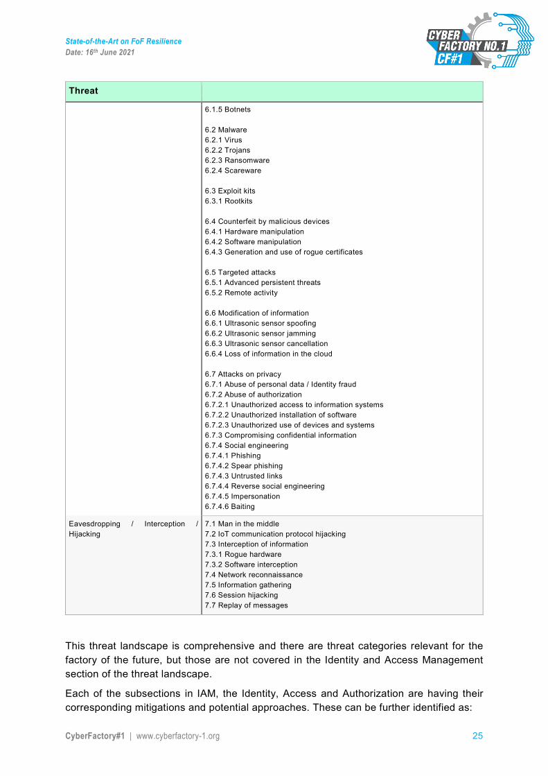
Nefarious activities / abuses 6.1 DDoS 6.1.1 Service spoofing 6.1.2 ICMP flooding 6.1.3 Jamming 6.1.4 Amplification/reflection
11 Baseline Security Recommendations for IoT, European Union Agency for Network and Information Security, November 2017.
State-of-the-Art on FoF Resilience Date: 16th June 2021
CyberFactory#1 | www.cyberfactory-1.org 25
Threat
6.1.5 Botnets 6.2 Malware 6.2.1 Virus 6.2.2 Trojans 6.2.3 Ransomware 6.2.4 Scareware 6.3 Exploit kits 6.3.1 Rootkits 6.4 Counterfeit by malicious devices 6.4.1 Hardware manipulation 6.4.2 Software manipulation 6.4.3 Generation and use of rogue certificates 6.5 Targeted attacks 6.5.1 Advanced persistent threats 6.5.2 Remote activity 6.6 Modification of information 6.6.1 Ultrasonic sensor spoofing 6.6.2 Ultrasonic sensor jamming 6.6.3 Ultrasonic sensor cancellation 6.6.4 Loss of information in the cloud 6.7 Attacks on privacy 6.7.1 Abuse of personal data / Identity fraud 6.7.2 Abuse of authorization 6.7.2.1 Unauthorized access to information systems 6.7.2.2 Unauthorized installation of software 6.7.2.3 Unauthorized use of devices and systems 6.7.3 Compromising confidential information 6.7.4 Social engineering 6.7.4.1 Phishing 6.7.4.2 Spear phishing 6.7.4.3 Untrusted links 6.7.4.4 Reverse social engineering 6.7.4.5 Impersonation 6.7.4.6 Baiting
Eavesdropping / Interception / Hijacking
7.1 Man in the middle 7.2 IoT communication protocol hijacking 7.3 Interception of information 7.3.1 Rogue hardware 7.3.2 Software interception 7.4 Network reconnaissance 7.5 Information gathering 7.6 Session hijacking 7.7 Replay of messages
This threat landscape is comprehensive and there are threat categories relevant for the factory of the future, but those are not covered in the Identity and Access Management section of the threat landscape.
Each of the subsections in IAM, the Identity, Access and Authorization are having their corresponding mitigations and potential approaches. These can be further identified as:
State-of-the-Art on FoF Resilience Date: 16th June 2021
CyberFactory#1 | www.cyberfactory-1.org 26
Authentication
• Design the authentication and authorisation schemes (unique per device) based on the system-level threat models
• Ensure change of the default passwords and usernames during the initial setup, and that weak passwords are not allowed
• Authentication mechanisms should consider using two-factor authentication (2FA) or multi-factor authentication (MFA)
• Authentication credentials shall be salted, hashed and/or encrypted • Protect against ‘brute force’ and/or other abusive login attempts • Ensure password reset mechanism is robust and does not supply an attacker with
information indicating a valid account.
Authorization
• Limit the actions allowed for a given system by implementing fine-grained authorisation mechanisms
• Use the principle of least privilege (POLP): applications must operate at the lowest privilege level possible
• Firmware should be designed to isolate privileged code, processes and data from portions of the firmware that do not need access to them.
Access control
• Data integrity and confidentiality must be enforced by access controls • Measures for tamper protection and detection - detection and reaction to hardware
tampering should not rely on network connectivity • Ensure that the device cannot be easily disassembled • Ensure that the data storage medium is encrypted at rest and cannot be easily
removed • Ensure that devices only feature the essential physical external ports (such as USB)
necessary for them to function • Ensure that the test/debug modes are secure
In Cyberfactory#1, the aim of the IAM approach is to address the identified threats in selected environment through reference architecture and later, with potential proof of concept demonstration.
2.5. Solution overview While traditional Identity and Access Management (IAM) solutions are typically addressing the IT environment, we in Cyberfactory#1, must also address the OT environment when designing the architectural approach for IAM.
2.5.1. Description of the concept
The IAM approach concept contains elements from enterprise usage, such as Azure AD, but also elements and best practices from network and Zero-Trust architectures.
State-of-the-Art on FoF Resilience Date: 16th June 2021
CyberFactory#1 | www.cyberfactory-1.org 27
Zero-Trust
Zero-trust architecture is originated from the thought that the principles in traditional security models are outdated as they typically trust the users and identities who are in the intranet. These principles are used in many of today’s environments such as MPLS flat networks (Multiprotocol Label Switching). For these traditional security principles, the “trust, but verify” could be right expression, whereas for Zero-Trust, it would be “never trust, always verify”. There are five main principles in Zero-Trust network12:
• The network is always assumed to be hostile. • External and internal threats exist on the network at all times. • Network locality is not sufficient for deciding trust in a network. • Every device, user, and network flow is authenticated and authorized. • Policies must be dynamic and calculated from as many sources of data as possible.
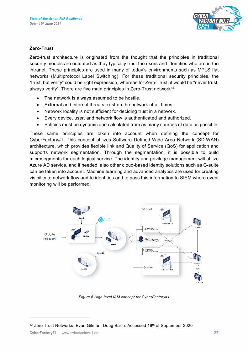
These same principles are taken into account when defining the concept for CyberFactory#1. This concept utilizes Software Defined Wide Area Network (SD-WAN) architecture, which provides flexible link and Quality of Service (QoS) for application and supports network segmentation. Through the segmentation, it is possible to build microsegments for each logical service. The identity and privilege management will utilize Azure AD service, and if needed, also other cloud-based identity solutions such as G-suite can be taken into account. Machine learning and advanced analytics are used for creating visibility to network flow and to identities and to pass this information to SIEM where event monitoring will be performed.
Figure 6 High-level IAM concept for CyberFactory#1
12 Zero Trust Networks; Evan Gilman, Doug Barth. Accessed 16th of September 2020

State-of-the-Art on FoF Resilience Date: 16th June 2021
CyberFactory#1 | www.cyberfactory-1.org 28
Figure 6 describes the proposed solution in high level. This solution is a holistic approach for integrating IAM and Identity management (IDM) events into SIEM for situational awareness. Each of the ‘location’ in diagram represents potential smart factory environment with its own characteristics and users. It is possible to have only one ‘location’, but the solution supports also connected factories through cloud-based controls.
Network design for ‘location’ is reflecting the requirements of the factory environment and are build utilizing SD-WAN technology. This allows network segmentation to separate logical environments inside the factories. Network segmentation is acting as one entity in access management as it can be used as a control to allow connection from known entities. Network management can be centralized for more holistic monitoring. The network traffic is being monitored and, with the support of machine learning algorithms, the behavioural characteristics of these events are provided to the SIEM.
User identities can be controlled in network segments and also in cloud environments through utilizing e.g. Azure AD. As a factory environment can contain both IT and OT systems, the access management should allow connections between the two. Machine learning and artificial intelligence can be used for creating user profiles and identifying potential changes or anomalies in these identities. These events and profiles are being used in SIEM for more advanced awareness. Role Based Access Control (RBAC) can be introduced to align the roles defined in the environment and corresponding access rights in the network. RBAC can be dynamic, which allows changes in the system without manual operation for individual segments. Other potential option would be to use Attribute Based Access Control (ABAC) for more fine-grained resolution. NIST Special Publication 800-162, Guide to Attribute Based Access Control (ABAC) 13 defines one potential challenge related RBAC, as “RBAC does not easily support multi-factor decisions (for example, decisions dependent on rank, organization, physical location,…) RBAC role assignments tend to be based upon more static organizational positions, presenting challenges in certain RBAC architectures where dynamic access control decisions are required.” This should be taken into account when designing the overall IAM architecture for the factory of the future. As environment and use cases are becoming more complex, the ABAC approach is being considered in this proposal. Some publication from NIST further defines ABAC as:
“Attribute Based Access Control (ABAC): A logical access control methodology where authorization to perform a set of operations is determined by evaluating attributes associated with the subject, object, requested operations, and, in some cases, environment conditions against policy, rules, or relationships that describe the allowable operations for a given set of attributes”
One potential challenge in the ABAC in large environments, is the added complexity provided its finer granularity and rule base.
13 Guide to Attribute Based Access Control (ABAC), Hu, Ferraiolo, Kuhn, et al. 2013
State-of-the-Art on FoF Resilience Date: 16th June 2021
CyberFactory#1 | www.cyberfactory-1.org 29
2.5.2. Modern authentication methods
Authentication methods or mechanisms are generally divided into two categories. Traditional authentication methods comprise basic username and password authentication, PIN (Personal Identification Number) code and token-based authentication while modern authentication mechanisms are mostly based on multifactor authentication (MFA). Multifactor authentication which is also sometimes referred to as two-factor authentication (2FA) is defined by NIST (National Institute of Standards and Technology) as follows:
“An authentication system that requires more than one distinct authentication factor for successful authentication. Multi-factor authentication can be performed using a multi-factor authenticator or by a combination of authenticators that provide different factors. The three authentication factors are something you know, something you have, and something you are.” 14
A typical example of multifactor authentication is payment by card, where you insert your chip card (“something you have”) into the card reader and type the PIN code (“something you know”) on the PIN-pad.
In addition to multifactor authentication, modern authentication methods include elements, i.e. protocols that aim to enhance the security of the networked environment, e.g. cloud-based resources. Some examples of these protocols are OAuth, SAML and WS-Federation that rely on token-based claims15. The advantage of the token is in the information that it contains, i.e. they specify what the user has or doesn’t have access to and they also a certain lifespan. Another advantage of tokens is that they can also be revoked, which in practice means better governance. Traditional and modern authentication methods can be compared to a mechanical key vs. a keycard. While the mechanical key is very reliable, it lacks the added-values or functionalities of the keycard that are among others (almost) real-time access management, monitoring and revocability. In addition tokens enhance the use of single sign-on (SSO), but also make it possible to execute conditional access based on the token information. This can mean e.g. limiting access based on the user device or user location, depending on the security policy of the organisation. In the cloud, tokens may also be used to govern access to individual resources.
2.6. Discussion Several potential IAM solutions were studied for the Factory of the Future reference solution and as the complexity of the environment requires scalability as well as adaptivity from the IAM, the proposed solution contains integrated elements from different approaches. The operational environment requires from IAM solution.
14 https://csrc.nist.gov/glossary/term/Multi_Factor_Authentication 15 https://www.kraftkennedy.com/modern-authentication-vs-basic-authentication/

State-of-the-Art on FoF Resilience Date: 16th June 2021
CyberFactory#1 | www.cyberfactory-1.org 30
• Scalability and ability to operate in a multi-user environment. It is possible that FoF is utilizing connected systems of systems and IAM must comply with the corresponding architecture.
• IAM solution must be cloud based with an ability to introduce dynamic based access controls. As the system of systems in FoF can contain several roles and various access privileges within the user space, the IAM solution should have finer grade of granularity in access definitions.
• IAM solution introduced in FoF must be integrated with the SIEM solution for more advanced situational awareness and with the support for potential Security Orchestration, Automation and Response (SOAR) functionality.
• IAM solution must be able to function with both IoT devices as well as with human users and identities
• The solution architecture must be able to operate in both IT and OT systems.
State-of-the-Art on FoF Resilience Date: 16th June 2021
CyberFactory#1 | www.cyberfactory-1.org 31
3. Robust machine learning ability This chapter gives an overview of the state of the art related to adversarial machine learning.
3.1. Motivation
In this section a motivation for the detection of adversarial attack is given.
Machine learning and deep learning achieved great success in various fields in recent years, its convenience and high accuracy changed the industrial systems. However, machine learning models often suffer from adversarial attacks. An adversarial attack is a specific attack, which can deceive the machine learning models, lead to false prediction or false classification. By adversarial, it means that counterproductive actors attempt to deceive the machine learning model to gain more profit or prove their skills. The attack can cause numerous damage to the factory of the future.
With the continuous development of research in machine learning, machine learning models are used in increasingly important environments or systems, and the application range of the models is constantly expanding. Today we only see single smart machines or robots in factories. In the future, we may find automated management in factories and even in entire companies. Today, self-driving cars are beginning to appear on the streets, and future “smart cities” may use a system based on machine learning to monitor energy, transportation, water resources, and other infrastructure throughout the region.
The adversarial attack is a major obstacle that machine learning systems have to overcome. Existing adversarial samples indicate that the model tends to rely on unreliable features to optimize performance. If the features are disturbed, it will cause misclassification and misprediction of the model, which may lead to disastrous consequences. The catastrophic consequences may be economic losses or even threats to personal safety.
The informal definition of adversarial examples: humans change the input so that the modified input can be misclassified by the machine learning system, even though the original input is correctly classified. This modified input is called the adversarial example.
3.2. Introduction This section gives an overview of general existing attacks and solutions for machine learning (ML) and deep learning (DL).
3.2.1. Adversarial Machine learning and Deep Learning
Adversarial samples are inputs that will cause errors in the machine learning model.
Szegedy et al. in ICLR2014 [4] proposed the concept of adversarial examples (Adversarial Examples), that is, the input samples formed by deliberately adding subtle interference in the data set. The input after the interference causes the model to give wrong predictions.
State-of-the-Art on FoF Resilience Date: 16th June 2021
CyberFactory#1 | www.cyberfactory-1.org 32
The research mentioned that in many cases, models with different structures trained on different subsets of the training set will misclassify the same adversarial sample, which means that the adversarial sample has become a blind spot in the training algorithm. Nguyen et al. [5] found that in the face of some samples that are completely unrecognizable by humans (Fooling Examples), deep learning models will classify them with a high degree of certainty. The vulnerability of deep learning to adversarial examples is not unique to deep learning. It is common in many models of machine learning.
There are already many methods for calculating adversarial examples. The survey by Akhtar et al. [6] summarized more than 12 methods of attack to deceive classification models. Furthermore, the researchers are currently investigating not only attacks on classification/recognition tasks in computer vision, but also attacks in other areas and directions This includes attacks on auto encoders and generative models, semantic segmentation, and object detection. In addition to understanding the space where adversarial examples exist in the digital domain, many studies understand adversarial examples added to the physical objects themselves in the real world. For example, Athalye et al. [7] showed that it is even possible to generate 3D-printed samples of real object adversarial to fool classifiers of deep neural network. Gu et al. [6] also discussed an interesting work that is disturbing the street signs to fool the neural network. The neural network recognizes the stop sign of the street sign as a speed limit.
In the digital world, most work focuses on generating disturbances that cause specific image inputs to be misclassified, but it has been proven that image-independent adversarial examples can be generated. Moosavi-Dezfooli et al. [8] showed that, given the target model and the data set, a single disturbance can be calculated, and when applied to any input, it can lead to high misclassifications. These are called Universal Adversarial Disturbance (UAP). Mopuri et al. demonstrated their algorithms (FFF [10], GDUAP [11]) to generate image-independent disturbances, which can deceive the target model without knowing the data distribution. They proved that their carefully designed perturbations can be transferred to three different computer vision tasks, including classification, depth estimation, and segmentation [38][39][40].
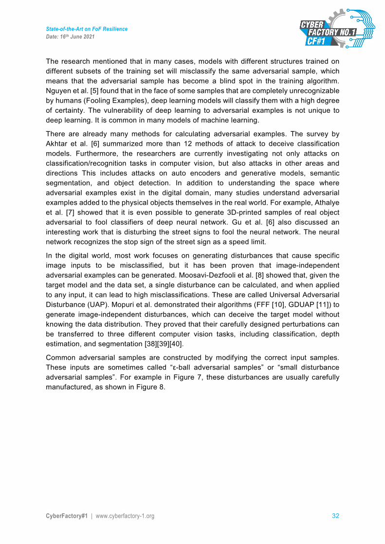
Common adversarial samples are constructed by modifying the correct input samples. These inputs are sometimes called “ε-ball adversarial samples” or “small disturbance adversarial samples”. For example in Figure 7, these disturbances are usually carefully manufactured, as shown in Figure 8.
State-of-the-Art on FoF Resilience Date: 16th June 2021
CyberFactory#1 | www.cyberfactory-1.org 33
Figure 7. Adversarial examples generated for AlexNet [12]
Regarding Figure 7 above, the picture on the left is a correctly predicted sample, the centre picture consists of the difference between correct image, and image predicted incorrectly magnified by 10x (values shifted by 128 and clamped), and the right picture is the adversarial example. All images in the right column are predicted to be an “ostrich, Struthio camelus”. Images are derived from [4].
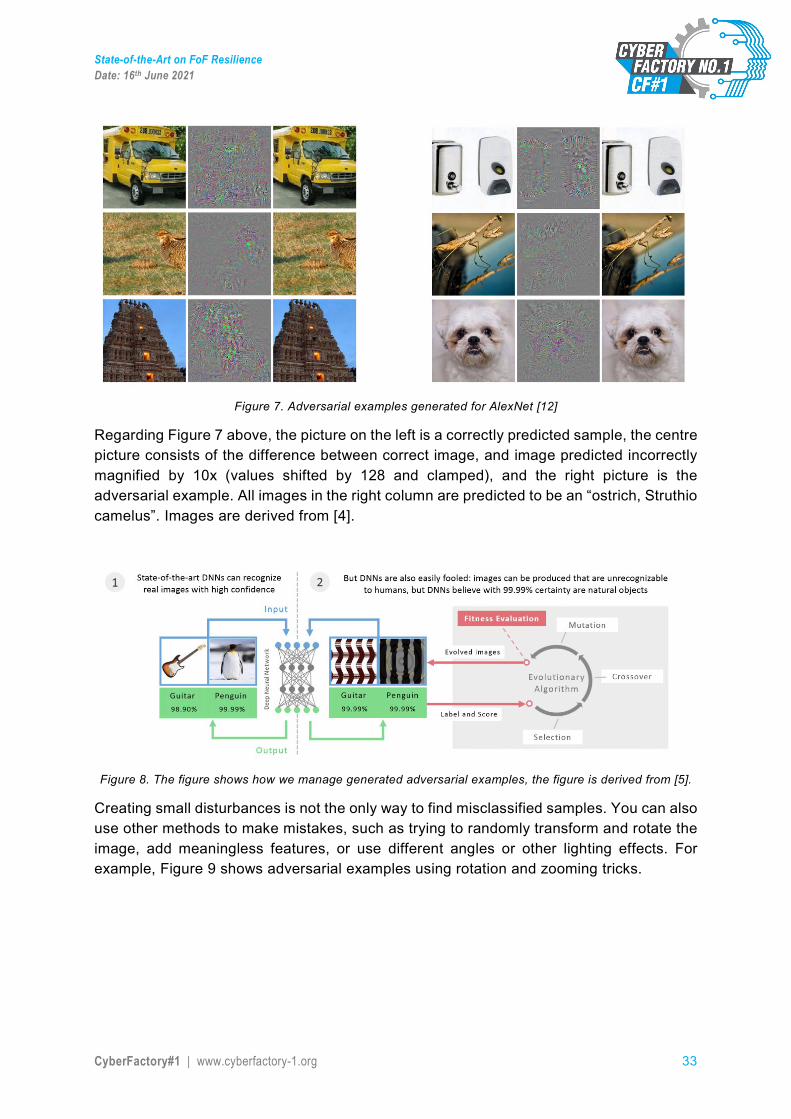
Figure 8. The figure shows how we manage generated adversarial examples, the figure is derived from [5].
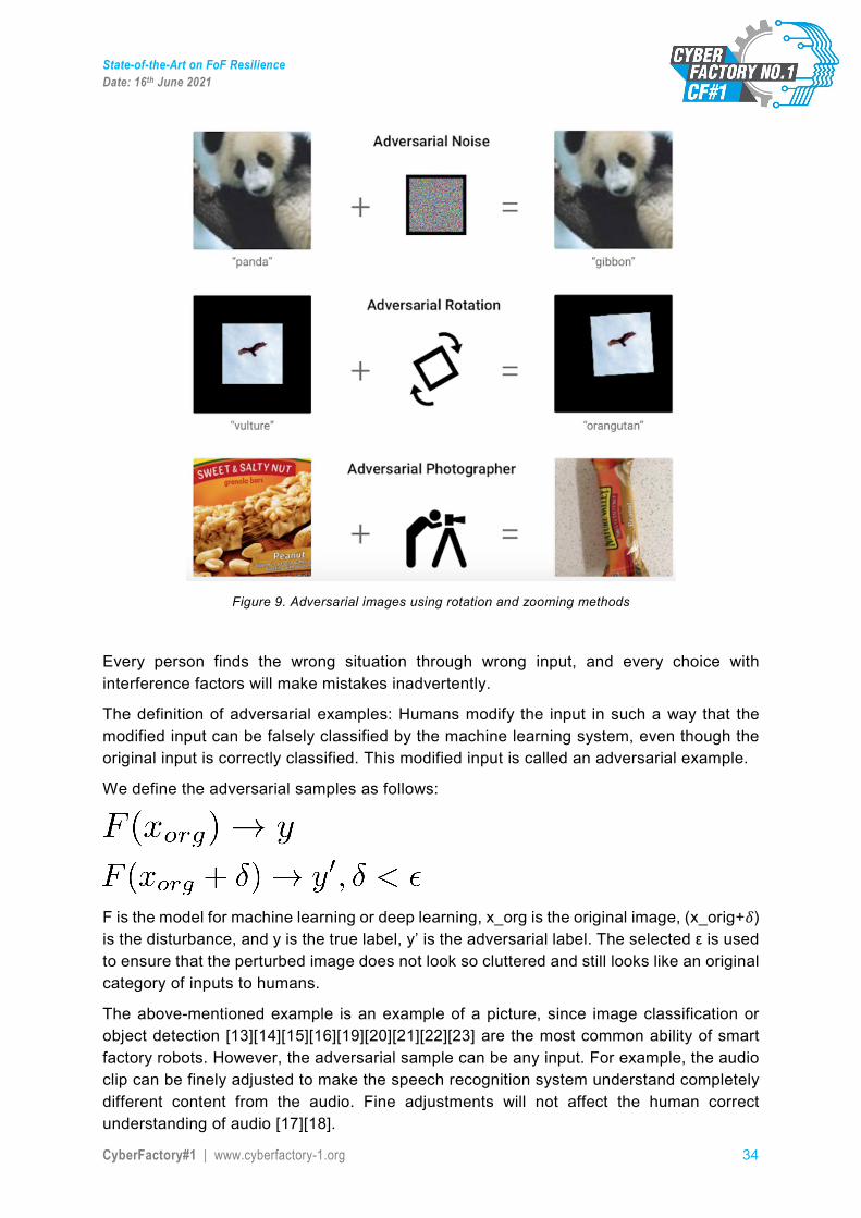
Creating small disturbances is not the only way to find misclassified samples. You can also use other methods to make mistakes, such as trying to randomly transform and rotate the image, add meaningless features, or use different angles or other lighting effects. For example, Figure 9 shows adversarial examples using rotation and zooming tricks.
State-of-the-Art on FoF Resilience Date: 16th June 2021
CyberFactory#1 | www.cyberfactory-1.org 34
Figure 9. Adversarial images using rotation and zooming methods
Every person finds the wrong situation through wrong input, and every choice with interference factors will make mistakes inadvertently.
The definition of adversarial examples: Humans modify the input in such a way that the modified input can be falsely classified by the machine learning system, even though the original input is correctly classified. This modified input is called an adversarial example.
We define the adversarial samples as follows:
F is the model for machine learning or deep learning, x_org is the original image, (x_orig+𝛿𝛿) is the disturbance, and y is the true label, y’ is the adversarial label. The selected ε is used to ensure that the perturbed image does not look so cluttered and still looks like an original category of inputs to humans.
The above-mentioned example is an example of a picture, since image classification or object detection [13][14][15][16][19][20][21][22][23] are the most common ability of smart factory robots. However, the adversarial sample can be any input. For example, the audio clip can be finely adjusted to make the speech recognition system understand completely different content from the audio. Fine adjustments will not affect the human correct understanding of audio [17][18].
State-of-the-Art on FoF Resilience Date: 16th June 2021
CyberFactory#1 | www.cyberfactory-1.org 35
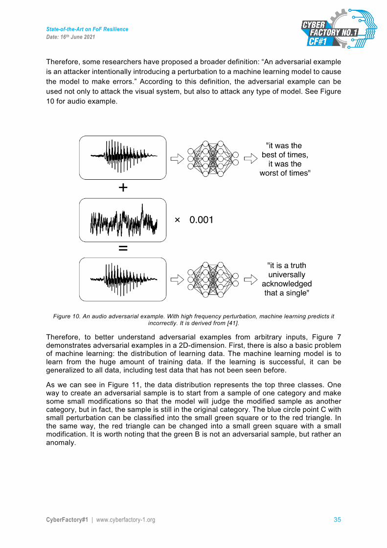
Therefore, some researchers have proposed a broader definition: “An adversarial example is an attacker intentionally introducing a perturbation to a machine learning model to cause the model to make errors.” According to this definition, the adversarial example can be used not only to attack the visual system, but also to attack any type of model. See Figure 10 for audio example.
Figure 10. An audio adversarial example. With high frequency perturbation, machine learning predicts it
incorrectly. It is derived from [41].
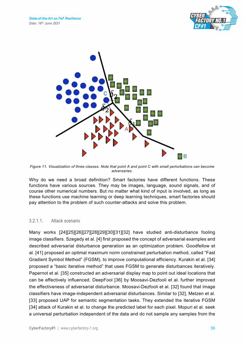
Therefore, to better understand adversarial examples from arbitrary inputs, Figure 7 demonstrates adversarial examples in a 2D-dimension. First, there is also a basic problem of machine learning: the distribution of learning data. The machine learning model is to learn from the huge amount of training data. If the learning is successful, it can be generalized to all data, including test data that has not been seen before.
As we can see in Figure 11, the data distribution represents the top three classes. One way to create an adversarial sample is to start from a sample of one category and make some small modifications so that the model will judge the modified sample as another category, but in fact, the sample is still in the original category. The blue circle point C with small perturbation can be classified into the small green square or to the red triangle. In the same way, the red triangle can be changed into a small green square with a small modification. It is worth noting that the green B is not an adversarial sample, but rather an anomaly.
State-of-the-Art on FoF Resilience Date: 16th June 2021
CyberFactory#1 | www.cyberfactory-1.org 36
Figure 11. Visualization of three classes. Note that point A and point C with small perturbations can become
adversaries.
Why do we need a broad definition? Smart factories have different functions. These functions have various sources. They may be images, language, sound signals, and of course other numerical numbers. But no matter what kind of input is involved, as long as these functions use machine learning or deep learning techniques, smart factories should pay attention to the problem of such counter-attacks and solve this problem.
3.2.1.1. Attack scenario
Many works [24][25][26][27][28][29][30][31][32] have studied anti-disturbance fooling image classifiers. Szegedy et al. [4] first proposed the concept of adversarial examples and described adversarial disturbance generation as an optimization problem. Goodfellow et al. [41] proposed an optimal maximum norm constrained perturbation method, called “Fast Gradient Symbol Method” (FGSM), to improve computational efficiency. Kurakin et al. [34] proposed a “basic iterative method” that uses FGSM to generate disturbances iteratively. Papernot et al. [35] constructed an adversarial display map to point out ideal locations that can be effectively influenced. DeepFool [36] by Moosavi-Dezfooli et al. further improved the effectiveness of adversarial disturbance. Moosavi-Dezfooli et al. [32] found that image classifiers have image-independent adversarial disturbances. Similar to [32], Metzen et al. [33] proposed UAP for semantic segmentation tasks. They extended the iterative FGSM [34] attack of Kurakin et al. to change the predicted label for each pixel. Mopuri et al. seek a universal perturbation independent of the data and do not sample any samples from the

State-of-the-Art on FoF Resilience Date: 16th June 2021
CyberFactory#1 | www.cyberfactory-1.org 37
data distribution. They proposed a new data-free target algorithm to generate general anti-disturbance, called FFF [10]. Their next work GDUAP [11] improved the effect of the attack and proved the effectiveness of their method on cross-computer vision tasks.
According to the attack model, we can divide the attachment into a black box attack and a white box attack.
In the black box attack scenario, the attacker does not know the algorithms and parameters used by the model, but can still interact with the deep model network. For example, you can enter any input to observe the output and assess the output.
In a white box attack situation, the attacker knows the algorithm used by the model and the parameters used by the algorithm. Given a network parameter, the white box attack is the most successful method, such as L-BFGS, FGSM.
We already know that machine learning models are susceptible to adversarial examples, so one may naturally worry about the impact of adversarial examples on the real world.
For example, suppose you are designing a self-driving car and you want it to recognize stop signs. When you know the anti-sample, you will be curious whether this will affect your car.
If you are designing a self-driving car that can recognize stop signs, you might want to know whether adversarial samples will cause the vehicle to not recognize stop signs correctly. It can be used to deceive self-driving cars so that they cannot recognize the stop signs on the road, thereby causing accidents. Also the face recognition automatic customs clearance system, which allows the suspect to leave the country easily, and even put a confrontation sample sticker on the chest to achieve camouflage. The adversarial attack will result in the artificial intelligence system being attacked and maliciously invaded, becoming a threat to the artificial intelligence system as an “Artificial Intelligence Virus”.
The more systems use the advantages of ML models in their decision support processes, the more important it is to consider how malicious actors could exploit these models and how the defence against these attacks could be designed. Besides, machine learning is used for increasingly sensitive tasks, as it is applied to data with more and more noise, resulting in the need to develop more robust algorithms against the worst possible situations. For a robust machine learning it must be considered mainly in the following situations:
• Learning in presence of atypical values, also called, outliers: In this case, learning techniques must be applied when the training data are strongly affected by noise. The more appropriate techniques are robust statistics, learning of lists, and attacks of data poisoning and watermarks.
• Adversarial examples: Is it widely known that the image classifiers of neural networks can be altered by image disturbances that cannot be detected by humans. In this case, it can be applied empiric defences against certain attacks (such as, Project Gradient Descent – PGD) or certifiable defences that produce a demonstrable solidity.
Moreover, it must be considered that in all cases the defence mechanisms will change the algorithms to make them more robust against attacks, but in general, their efficiency will also be lower. Analysing these effects must be taken into account when developing defensive measures.

State-of-the-Art on FoF Resilience Date: 16th June 2021
CyberFactory#1 | www.cyberfactory-1.org 38
3.2.2. Defence mechanism
This section gives an (relative general) state-of-the-art solution against adversarial attack.
In general terms, Robust Statistics consists of the study of learning in the presence of corrupt training data. Therefore, Robust Statistics investigates procedures that limit the impact of a small set of deviated (adversarial) training data. In this area, it is supposed that the main part of data is generated from a well-known model, but a small part comes from an unknown model (or adversarial model). There are several methods to make a procedure more robust. For this purpose, it is important to know the breakpoint, or the corruption level that the attacker needs to manipulate the procedure arbitrarily, as well as the influence function that measures the impact of the corruption on the procedure.
The robustness measures [46][47][48][49][50] can be used for evaluating the susceptibility of an existing system and provide alternatives that reduce or eliminate the vulnerability. Ideally, the best option would be to use a method with a high breakpoint and a limited influence function. In this way, these measures can be used to compare candidate procedures and design hypotheses procedures that are ideally robust against the corruption of training data.
In this area, several techniques can be applied, such as robust average estimation (basic technique), robust average estimation for Gaussian to medians, and robust average estimation with delimited moments via truncated average (technique closer to real world).
In this area, there are two types of defence for fighting the adversarial attacks, passive defence and proactive defence.
In most research, it is assumed that we consider a neuronal network.
3.2.2.1. Passive defence methods Shattering gradient
At first in the adversarial attack study, one approach was to somehow “obfuscate” the model gradient. The fact was that, if the model gradients are not very lineal, the attacks based on PGD would be difficult to carry out. Nevertheless, [6] demonstrated a general way to attack these models. This method was called Backwards Pass Differentiable Approximation – BDPA.
Stochastic gradient
Another approach was to make the gradients of the network random, for example, by eliminating random pixels or cutting images randomly. Even JPEG compression was considered as a defence. The idea was that, if the gradient is made random, then there is no deterministic direction for the progress of the PGD. Nevertheless, this defence could be avoided. The Expectation Over Transformation (EOT or RP2) attacks are designed for considering random data transformations. As expected, [42] demonstrates that the attacks based on EOT can avoid this defence.

State-of-the-Art on FoF Resilience Date: 16th June 2021
CyberFactory#1 | www.cyberfactory-1.org 39
In order to verify whether this method is effective, Carlini and Wagner [43] proposed an adaptive attack, which is to treat the defence method and neural network as a new large network to attack. A good passive defence method should have a higher adaptive attack value.
3.2.2.2. Pro-active defence methods
Adversarial training
Adversarial training is a method of defence against samples, first proposed by Ian J. Goodfellow in Explaining and Harnessing Adversarial Examples. The main idea is: in the model training process, the training samples are no longer just the original samples, but the original samples plus the adversarial samples, which is equivalent to adding the generated adversarial samples as new training samples to the training set. If you treat the same, then as the model is trained more and more, on the one hand, the accuracy of the original picture will increase, on the other hand, the robustness of the model to adversarial samples will also increase.
More specifically, adversarial training refers to the method of constructing adversarial samples and mixing adversarial samples and original samples to train the model during the training process of the model. In other words, during the training process of the model, adversarial attacks are performed on the model to improve the model's resistance and robustness to adversarial attacks.
Adversarial training (and integrated adversarial training) is indeed an effective method of defence against adversarial sample attacks, but it also has limitations. Adversarial training consists of continuously inputting new types of adversarial samples for training, in order to continuously improve the robustness of the model. To be effective, the method needs to use high-intensity adversarial examples, and the network architecture must have sufficient expressive power. No matter how many adversarial samples are added, there are new adversarial samples that can deceive the network.
Adversarial training execution
One of the main bottlenecks of the adversarial training is that it is quite slow. For example, the adversarial training in CIFAR-10 often takes several days and the adversarial training in ImageNet takes around several weeks regularly, unless huge computing resources are available. There are several suggestions for reducing the execution time of the adversarial training, nevertheless, they remain relatively inconclusive.
State-of-the-Art on FoF Resilience Date: 16th June 2021
CyberFactory#1 | www.cyberfactory-1.org 40
Previous training
Recently, several research groups have demonstrated that relatively naïve ways of incorporating more data can improve the robust accuracy. One of these methods is known as previous training, where a big amount of data is taken, such as ImageNet, and a robust model is trained beforehand. Afterward, the learned representation is taken, and after the size of the higher layer has been adjusted accordingly, it is refined by adversarial training with fewer cycles on CIFAR-10. This corresponds to the use of ImageNet for obtaining a good initialization of the representation. The [41] Article shows that using this technique can increase the robust accuracy in CIFAR-10 by up to 10%. It is known that the previous training is not helpful in terms of accuracy, but it seems to help significantly when obtaining a robust accuracy.
Semi-supervision
This technique requires access to a large set of unlabelled data (for example, Internet images). This data set is used for training purposes by assigning “pseudo-labels” to them by a non-robust classifier; afterwards, adversarial training interactions in the real data set are alternated with adversarial training in these pseudo-labelled data, but at a lower learning rate. The [42] Article shows that with this technique a better robust accuracy, about 5-10 %, can be achieved.
3.2.2.3. Proposed defence methods for smart factories
According to the above-mentioned method, we find that most methods are useful for a single model for deep learning. Hence, for a smart factory, we introduce our detection method against adversarial examples.
Here we propose a new defence method that can be applied to smart factories. Smart factories are very different because companies will use components and processes that are specific to their products. However, smart factories can still be distinguished by certain shared characteristics, which distinguish smart factories from traditional factories.
The method we propose can handle all types of input, which is especially relevant for a smart factory, since the manufacturing process of a smart factory is usually highly digitized and connected, and can perform extended functions beyond automation. The network connection enables the smart factory to use the data collected from the surrounding environment as a basis, and can react more autonomously, flexibly and adaptably to any changes that may occur inside and outside the factory. In other words, smart factories have background perception capabilities.
In the following, we present our main concept for the detection of adversarial examples during the classification period. The core idea goes back to our hypothesis that adversarial examples provoke a distinct behaviour of dense layer neuron activations, so that attacks become detectable. In the following we describe in detail how this idea can be extended and built upon.
In our most important proof-of-concept experiments, we consider the following threat model: The attacker performs evasive attacks and tries to alter the classification output of our neural network in a targeted way. For this purpose, the attacker uses various state-of-
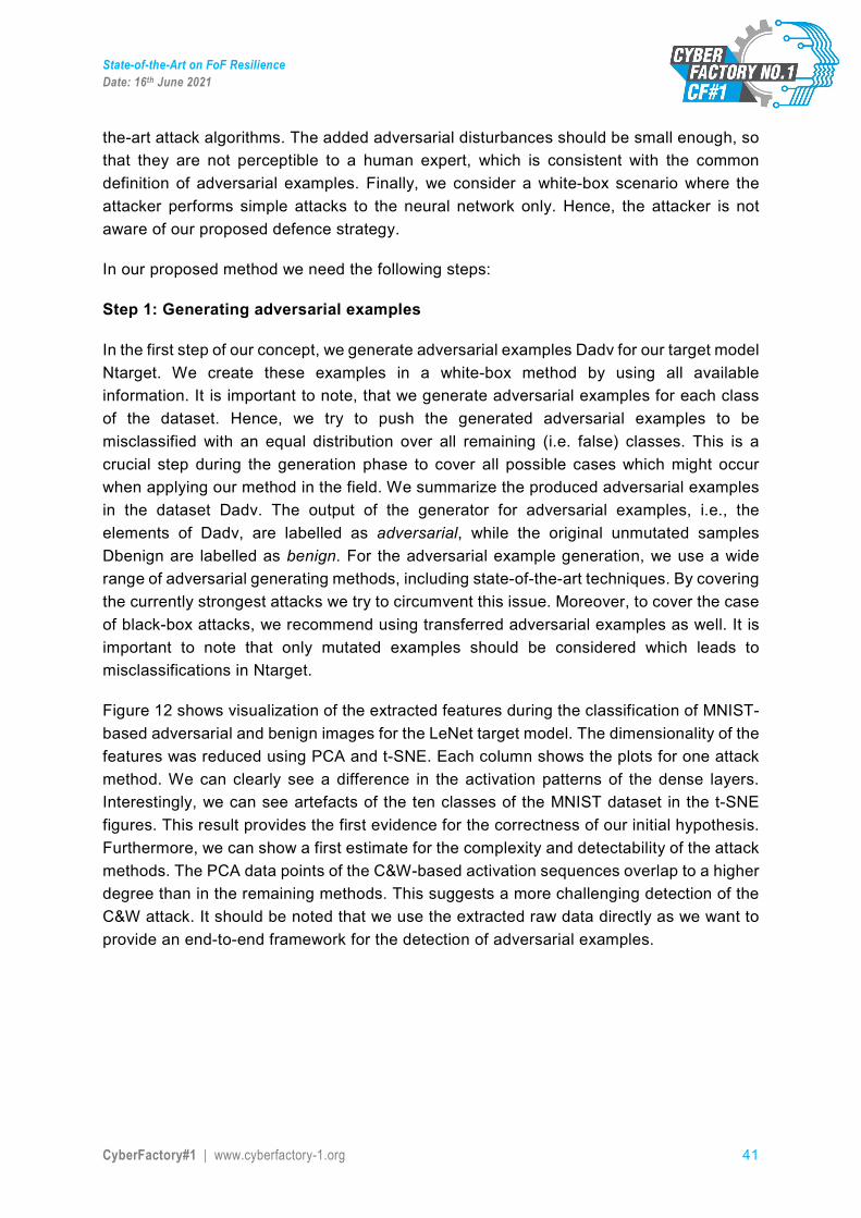
State-of-the-Art on FoF Resilience Date: 16th June 2021
CyberFactory#1 | www.cyberfactory-1.org 41
the-art attack algorithms. The added adversarial disturbances should be small enough, so that they are not perceptible to a human expert, which is consistent with the common definition of adversarial examples. Finally, we consider a white-box scenario where the attacker performs simple attacks to the neural network only. Hence, the attacker is not aware of our proposed defence strategy.
In our proposed method we need the following steps:
Step 1: Generating adversarial examples
In the first step of our concept, we generate adversarial examples Dadv for our target model Ntarget. We create these examples in a white-box method by using all available information. It is important to note, that we generate adversarial examples for each class of the dataset. Hence, we try to push the generated adversarial examples to be misclassified with an equal distribution over all remaining (i.e. false) classes. This is a crucial step during the generation phase to cover all possible cases which might occur when applying our method in the field. We summarize the produced adversarial examples in the dataset Dadv. The output of the generator for adversarial examples, i.e., the elements of Dadv, are labelled as adversarial, while the original unmutated samples Dbenign are labelled as benign. For the adversarial example generation, we use a wide range of adversarial generating methods, including state-of-the-art techniques. By covering the currently strongest attacks we try to circumvent this issue. Moreover, to cover the case of black-box attacks, we recommend using transferred adversarial examples as well. It is important to note that only mutated examples should be considered which leads to misclassifications in Ntarget.
Figure 12 shows visualization of the extracted features during the classification of MNIST-based adversarial and benign images for the LeNet target model. The dimensionality of the features was reduced using PCA and t-SNE. Each column shows the plots for one attack method. We can clearly see a difference in the activation patterns of the dense layers. Interestingly, we can see artefacts of the ten classes of the MNIST dataset in the t-SNE figures. This result provides the first evidence for the correctness of our initial hypothesis. Furthermore, we can show a first estimate for the complexity and detectability of the attack methods. The PCA data points of the C&W-based activation sequences overlap to a higher degree than in the remaining methods. This suggests a more challenging detection of the C&W attack. It should be noted that we use the extracted raw data directly as we want to provide an end-to-end framework for the detection of adversarial examples.
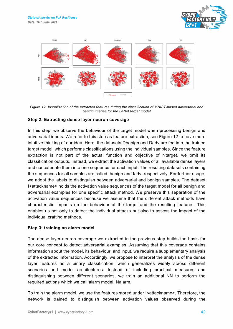
State-of-the-Art on FoF Resilience Date: 16th June 2021
CyberFactory#1 | www.cyberfactory-1.org 42
Figure 12. Visualization of the extracted features during the classification of MNIST-based adversarial and benign images for the LeNet target model
Step 2: Extracting dense layer neuron coverage
In this step, we observe the behaviour of the target model when processing benign and adversarial inputs. We refer to this step as feature extraction, see Figure 12 to have more intuitive thinking of our idea. Here, the datasets Dbenign and Dadv are fed into the trained target model, which performs classifications using the individual samples. Since the feature extraction is not part of the actual function and objective of Ntarget, we omit its classification outputs. Instead, we extract the activation values of all available dense layers and concatenate them into one sequence for each input. The resulting datasets containing the sequences for all samples are called Ibenign and Iadv, respectively. For further usage, we adopt the labels to distinguish between adversarial and benign samples. The dataset I<attackname> holds the activation value sequences of the target model for all benign and adversarial examples for one specific attack method. We preserve this separation of the activation value sequences because we assume that the different attack methods have characteristic impacts on the behaviour of the target and the resulting features. This enables us not only to detect the individual attacks but also to assess the impact of the individual crafting methods.
Step 3: training an alarm model
The dense-layer neuron coverage we extracted in the previous step builds the basis for our core concept to detect adversarial examples. Assuming that this coverage contains information about the model, its behaviour, and input, we require a supplementary analysis of the extracted information. Accordingly, we propose to interpret the analysis of the dense layer features as a binary classification, which generalizes widely across different scenarios and model architectures: Instead of including practical measures and distinguishing between different scenarios, we train an additional NN to perform the required actions which we call alarm model, Nalarm.
To train the alarm model, we use the features stored under I<attackname>. Therefore, the network is trained to distinguish between activation values observed during the
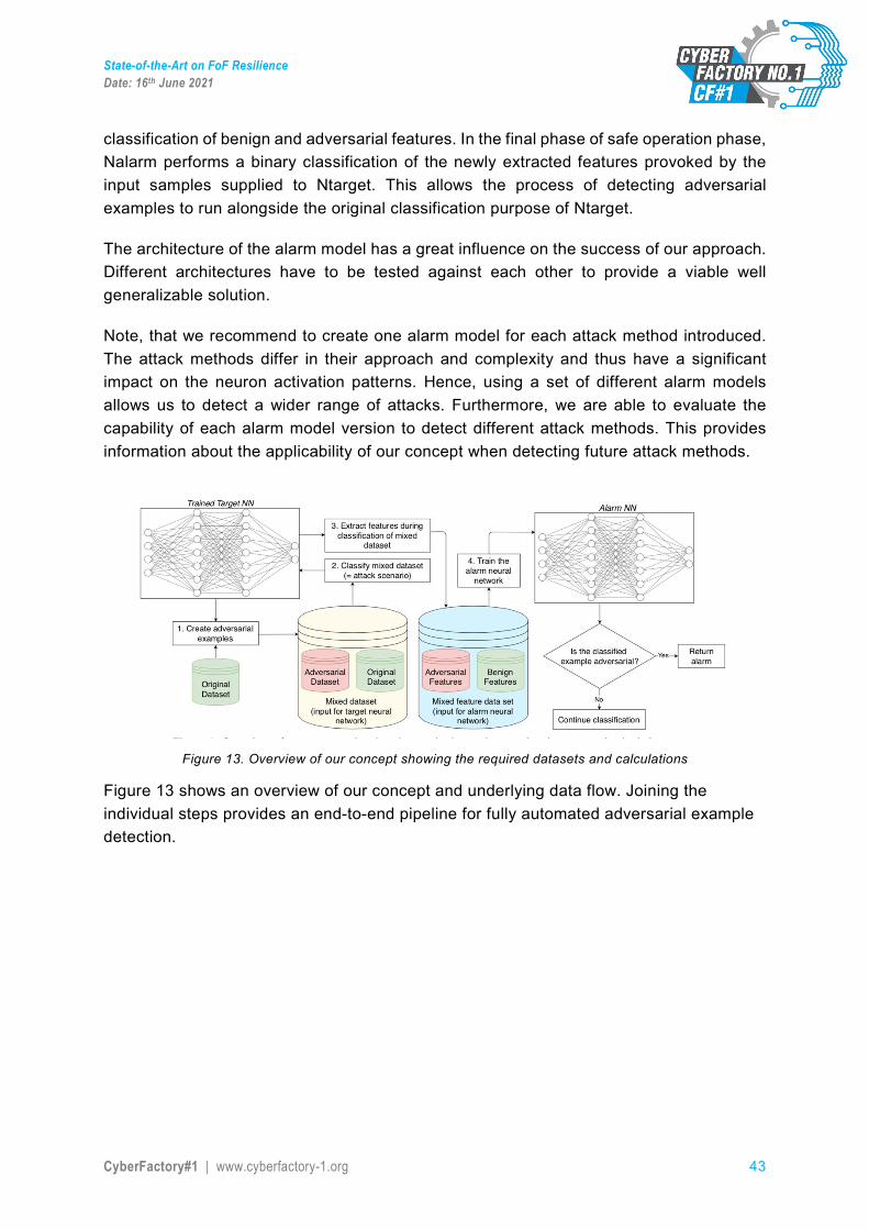
State-of-the-Art on FoF Resilience Date: 16th June 2021
CyberFactory#1 | www.cyberfactory-1.org 43
classification of benign and adversarial features. In the final phase of safe operation phase, Nalarm performs a binary classification of the newly extracted features provoked by the input samples supplied to Ntarget. This allows the process of detecting adversarial examples to run alongside the original classification purpose of Ntarget.
The architecture of the alarm model has a great influence on the success of our approach. Different architectures have to be tested against each other to provide a viable well generalizable solution.
Note, that we recommend to create one alarm model for each attack method introduced. The attack methods differ in their approach and complexity and thus have a significant impact on the neuron activation patterns. Hence, using a set of different alarm models allows us to detect a wider range of attacks. Furthermore, we are able to evaluate the capability of each alarm model version to detect different attack methods. This provides information about the applicability of our concept when detecting future attack methods.
Figure 13. Overview of our concept showing the required datasets and calculations
Figure 13 shows an overview of our concept and underlying data flow. Joining the individual steps provides an end-to-end pipeline for fully automated adversarial example detection.
State-of-the-Art on FoF Resilience Date: 16th June 2021
CyberFactory#1 | www.cyberfactory-1.org 44
Figure 14. A smart factory with alarm system
From Figure 14 we can clearly see how to apply the defence method against samples in the smart factory. The operation of the smart factory is controlled by data. The large number of data used by the smart factory includes the amount of raw materials stored, the production speed of the machine, the location of delivery, and more (depending on each industry). Big data allows smart factories to depict virtual scenes of physical operations, which are used to perform functions such as predicting results and making autonomous decisions. It can be seen that the data of smart factories can be of different types.
3.3. Impact of FoF Real-world attacks against machine learning algorithms are currently still on a low level. Some attackers use adversarial machine learning to make spam filtering less efficient. At the time of writing the report, no instances of using adversarial learning to take command of a service or system, as is possible in traditional cyberattacks using standard vulnerabilities in the code, were reported. When using traditional cyber vulnerability scoring systems (e.g. CVSS), machine learning attacks would usually receive a low or medium score.
However, as the use of machine learning increases in different areas, the importance of defending against adversarial machine learning will likely become more important. Only general guidelines are useful in this area, as the usage of machine learning has become more prevalent, and each system has different requirements for an attack to be successful and the effects that an attack has.
Vendors using machine learning in their products will have to make safe design decisions, and when a critical adversarial machine learning threat is detected, a security update (e.g. using specific anti-adversarial machine learning techniques) may be required. This will likely not be effective for all adversarial machine learning attacks. This also fits perfectly into typical patching processes that the industry already has.
Attackers using adversarial machine learning require access to the machine learning input that they aim to use for data poisoning. From an information security perspective, the usage
State-of-the-Art on FoF Resilience Date: 16th June 2021
CyberFactory#1 | www.cyberfactory-1.org 45
of traditional principles of least privilege and input disinfection are useful for making the environment more difficult to attack. This is not usable for all systems as e.g. sensor systems may use AI algorithms on sensor feeds. Many problems can also be mitigated by restricting physical access to critical areas, which makes sensor feeds more difficult to manipulate.
When a successful adversarial learning attack is detected, it is important to be able to quickly roll back the machine learning system to a previous (functional) configuration, to allow faster recovery from such an attack. The additional requirement of communicating with any partner organizations about the possible effects the attack may have is also critical.
Robust information security management practices with the ability to detect and reverse the effects of adversarial machine learning attacks are critical to a factory of the future, as is the need to understand the high level of interconnectedness both within the factory and with partner organizations. This enables the operator of such a system to successfully operate such a system in the challenging cybersecurity environment of the future. While most FoF environments may not require a specialized security manager for adversarial machine learning, many vendors using machine learning may have a need for it. Cybersecurity managers and experts will also need to handle this new threat as part of broader cybersecurity.
3.4. Discussion The Smart Factory of Industry 4.0 uses many methods of machine learning, and machine learning is very sensitive to the disturbance of the sample. In this project, we propose a solution that is suitable for different smart factories, which can ensure that in most cases, we can detect the adversarial sample and issue a warning.
The application of our method in a real-world scenario can be divided into two steps: the initialization and safe operation.
In the initialization phase, we create adversarial examples and perform the according steps for feature extraction. We have shown the importance of using different attack methods to create the adversarial examples. This ultimately leads to a group of alarm models, each capable of detecting adversarial examples created by one specific attack method.
In the second phase, during the safe operation of the target model, we continuously extract the features in the classification of new, unseen samples. The resulting activation sequences are fed to all available alarm models performing binary classifications. If the outputs of the alarm models indicate attacks, our framework triggers an alarm signal and a human expert is consulted to evaluate the current input. Here, the maintainer selects if one assumes an attack based on one or more alarm signals, majority votes, or all alarm models synchronously indicating such an event. This use-case-depended choice provides different levels of security.

State-of-the-Art on FoF Resilience Date: 16th June 2021
CyberFactory#1 | www.cyberfactory-1.org 46
In addition to the solutions we propose, a more thorough approach is, of course, that each enterprise should prepare for a large amount of necessary data, identify the type of data to be used and comply with each procedure (from collection and transfer to processing and storage). Correspondence also means recording all possible entry and exit points. For example, workers can use external storage devices such as USB flash drives to transport data from the office to the factory. Terminals may also enter and leave the factory for service. In addition to formulating security protocols for workers dealing with such scenarios, tools should also be used to ensure that these removable devices are clean and virus-free before they are connected or reconnected to factory systems.
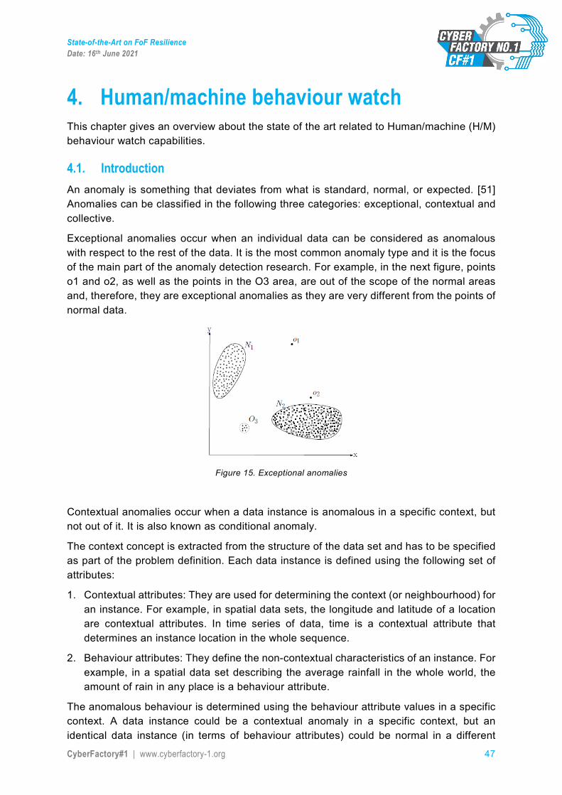
State-of-the-Art on FoF Resilience Date: 16th June 2021
CyberFactory#1 | www.cyberfactory-1.org 47
4. Human/machine behaviour watch This chapter gives an overview about the state of the art related to Human/machine (H/M) behaviour watch capabilities.
4.1. Introduction An anomaly is something that deviates from what is standard, normal, or expected. [51] Anomalies can be classified in the following three categories: exceptional, contextual and collective.
Exceptional anomalies occur when an individual data can be considered as anomalous with respect to the rest of the data. It is the most common anomaly type and it is the focus of the main part of the anomaly detection research. For example, in the next figure, points o1 and o2, as well as the points in the O3 area, are out of the scope of the normal areas and, therefore, they are exceptional anomalies as they are very different from the points of normal data.
Figure 15. Exceptional anomalies
Contextual anomalies occur when a data instance is anomalous in a specific context, but not out of it. It is also known as conditional anomaly.
The context concept is extracted from the structure of the data set and has to be specified as part of the problem definition. Each data instance is defined using the following set of attributes:
1. Contextual attributes: They are used for determining the context (or neighbourhood) for an instance. For example, in spatial data sets, the longitude and latitude of a location are contextual attributes. In time series of data, time is a contextual attribute that determines an instance location in the whole sequence.
2. Behaviour attributes: They define the non-contextual characteristics of an instance. For example, in a spatial data set describing the average rainfall in the whole world, the amount of rain in any place is a behaviour attribute.
The anomalous behaviour is determined using the behaviour attribute values in a specific context. A data instance could be a contextual anomaly in a specific context, but an identical data instance (in terms of behaviour attributes) could be normal in a different
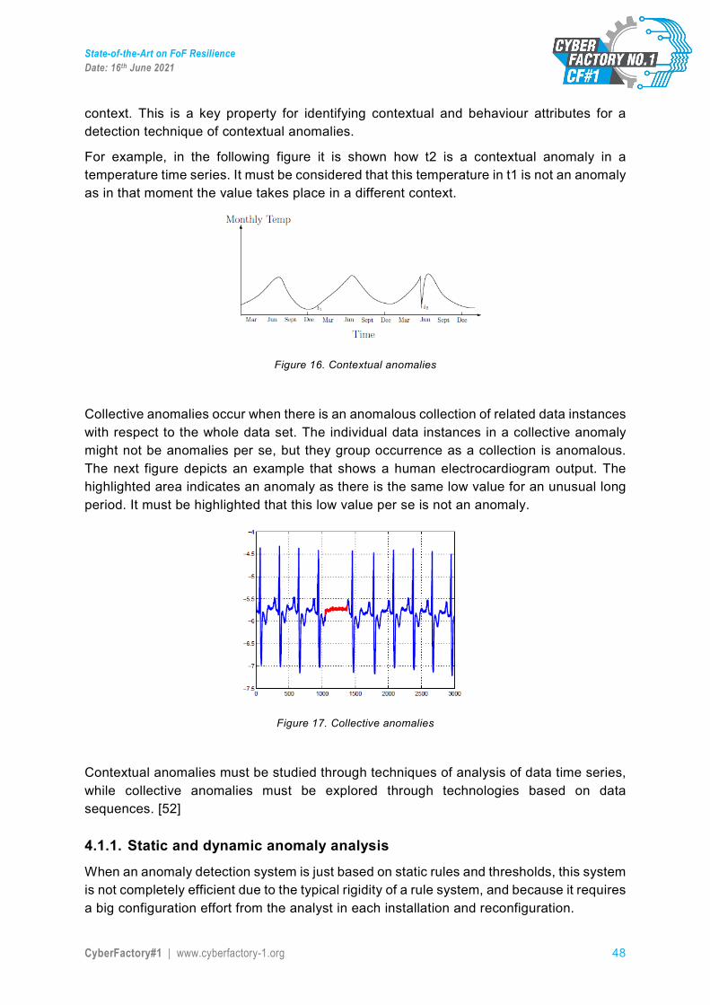
State-of-the-Art on FoF Resilience Date: 16th June 2021
CyberFactory#1 | www.cyberfactory-1.org 48
context. This is a key property for identifying contextual and behaviour attributes for a detection technique of contextual anomalies.
For example, in the following figure it is shown how t2 is a contextual anomaly in a temperature time series. It must be considered that this temperature in t1 is not an anomaly as in that moment the value takes place in a different context.
Figure 16. Contextual anomalies
Collective anomalies occur when there is an anomalous collection of related data instances with respect to the whole data set. The individual data instances in a collective anomaly might not be anomalies per se, but they group occurrence as a collection is anomalous. The next figure depicts an example that shows a human electrocardiogram output. The highlighted area indicates an anomaly as there is the same low value for an unusual long period. It must be highlighted that this low value per se is not an anomaly.
Figure 17. Collective anomalies
Contextual anomalies must be studied through techniques of analysis of data time series, while collective anomalies must be explored through technologies based on data sequences. [52]
4.1.1. Static and dynamic anomaly analysis
When an anomaly detection system is just based on static rules and thresholds, this system is not completely efficient due to the typical rigidity of a rule system, and because it requires a big configuration effort from the analyst in each installation and reconfiguration.
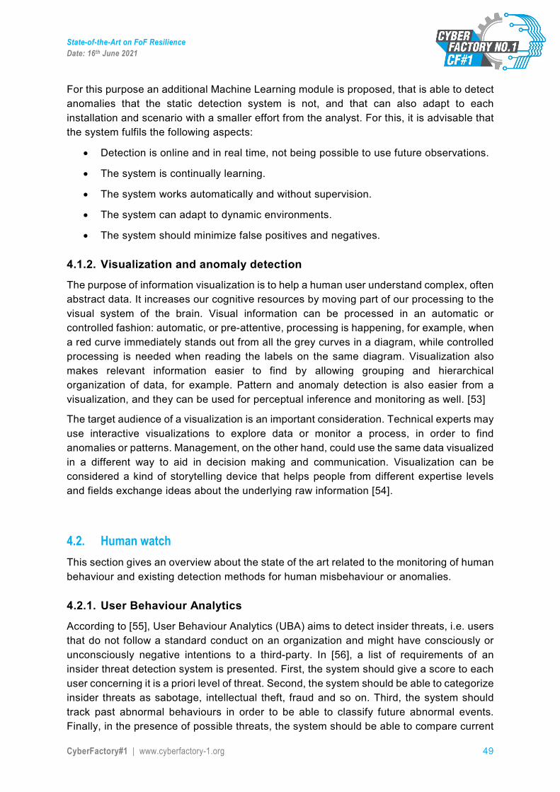
State-of-the-Art on FoF Resilience Date: 16th June 2021
CyberFactory#1 | www.cyberfactory-1.org 49
For this purpose an additional Machine Learning module is proposed, that is able to detect anomalies that the static detection system is not, and that can also adapt to each installation and scenario with a smaller effort from the analyst. For this, it is advisable that the system fulfils the following aspects:
• Detection is online and in real time, not being possible to use future observations.
• The system is continually learning.
• The system works automatically and without supervision.
• The system can adapt to dynamic environments.
• The system should minimize false positives and negatives.
4.1.2. Visualization and anomaly detection
The purpose of information visualization is to help a human user understand complex, often abstract data. It increases our cognitive resources by moving part of our processing to the visual system of the brain. Visual information can be processed in an automatic or controlled fashion: automatic, or pre-attentive, processing is happening, for example, when a red curve immediately stands out from all the grey curves in a diagram, while controlled processing is needed when reading the labels on the same diagram. Visualization also makes relevant information easier to find by allowing grouping and hierarchical organization of data, for example. Pattern and anomaly detection is also easier from a visualization, and they can be used for perceptual inference and monitoring as well. [53]
The target audience of a visualization is an important consideration. Technical experts may use interactive visualizations to explore data or monitor a process, in order to find anomalies or patterns. Management, on the other hand, could use the same data visualized in a different way to aid in decision making and communication. Visualization can be considered a kind of storytelling device that helps people from different expertise levels and fields exchange ideas about the underlying raw information [54].
4.2. Human watch This section gives an overview about the state of the art related to the monitoring of human behaviour and existing detection methods for human misbehaviour or anomalies.
4.2.1. User Behaviour Analytics
According to [55], User Behaviour Analytics (UBA) aims to detect insider threats, i.e. users that do not follow a standard conduct on an organization and might have consciously or unconsciously negative intentions to a third-party. In [56], a list of requirements of an insider threat detection system is presented. First, the system should give a score to each user concerning it is a priori level of threat. Second, the system should be able to categorize insider threats as sabotage, intellectual theft, fraud and so on. Third, the system should track past abnormal behaviours in order to be able to classify future abnormal events. Finally, in the presence of possible threats, the system should be able to compare current
State-of-the-Art on FoF Resilience Date: 16th June 2021
CyberFactory#1 | www.cyberfactory-1.org 50
and previous behaviour of users in that role and measure the deviation from what might be considered normal.
The goal of this section is to give an overview of insider threat systems that might be implemented in industrial applications. Nowadays, factories are very complex systems made of turbines, batteries, motors, storage devices, robots operating in automated assembly lines, etc. The damage of any of these components results in losses for the company, therefore detecting unusual and not authorized behaviour by the users is an essential step to diminish insider threats on a factory. Several technologies are at the disposal in the market: wearables, smartwatches and smartphones, which are already capable of performing activity recognition tasks. On the other hand, these are invasive technologies, i.e. the device or sensor must be attached or be close enough to the host in order to perform activity recognition. Therefore, in this section only technologies that are not invasive are considered and analyzed. Two main streams were identified: a closed-circuit television system, which is based on computer vision algorithms and a speaker recognition system, which is based on signal processing algorithms. At last, a system that monitors the interaction between the human and the machine might be also considered feasible to an industrial application, although no application examples have been found in the literature.
4.2.2. Closed-circuit television system
One of the most popular tools used to monitor human behaviour is through a Video Surveillance system, also known as Closed-circuit television (CCTV). Using this system, areas of interest (AOI) are monitored over large periods of time in order to ensure both the safety and security of the equipment. Data is available in large amounts, thus opening space for deep learning techniques. Most of the video surveillance applications have been modeled as anomaly detection problems owing to lack of availability of labeled data [57]. However, detecting anomalies is not an easy task, since a boundary between normal and abnormal behaviours is not easy to draw. Even, with domain knowledge, the lack of contextual information to support decisions might limit the capability of machine learning approaches [58]. Most of the video anomaly detection algorithms are classified according to the type of model and detection criteria, such as reconstruction based, spatiotemporal predictive models, and generative models [57]. Reconstruction based models, such as Auto Encoders (AE) or Principal Component Analysis (PCA) creates images representations that minimize the reconstruction error of training samples from the normal distribution. Spatiotemporal predictive models, such as Convolutional LSTM, process the video as a time series of frames. Such models are trained to minimize the prediction error on a sequence from the training series. Generative models generate samples from the training distribution. The goal is to minimize the reconstruction error and the dissimilarity between artificial generated data and training data. A more deep explanation of the current models and new challenges on video surveillance systems are discussed in [59].
4.2.3. Speaker recognition system
Another approach used to detect, and monitor users is by a speaker recognition (SR) system. The system analyzes speech signals collected from a microphone or an array of
State-of-the-Art on FoF Resilience Date: 16th June 2021
CyberFactory#1 | www.cyberfactory-1.org 51
microphones distributed over an AOI. Using speech signals, users are detected and identified. In case unauthorized users are present, the system detects an intruder and launches an alarm to the system administrator. Furthermore, using a SR system the dialogue of the users can be collected and analyzed. This is a step ahead, to a security system, since negative intentions to a third party could be detected on the spot and even before they really happen. On the other hand, speech analysis is hard not only due to the ambient noise but also the speech degradation increases over the distance travelled by the acoustic wave. In general, the results show that when the distance between the speaker and the microphone increases, recognition rates decrease and Equal Error Rate (EER) increases [60]. In general SR systems, the speech is preprocessed, and features are extracted on a frame basis. These features are related to physical or behavioural structures of the speaker. Furthermore, Voice Activity Detection (VAD) is also applied to remove the silent part of the speech signal [61]. Then features are normalized and filtered in order to remove distortions on the signal. Afterwards, the speaker is modelled using statistical techniques such as generative models, such as Gaussian mixture model or hidden Markov model [62] and discriminative models, such as support vector machines [63] or deep neural nets [64]. In the recognition phase, utterances are scored based on training speaker model. Finally, in the decision phase, scores are compared to a threshold to distinguish between authorized users and impostors, or to determine the matching level of a specific user in a speaker identification application [61].
4.2.4. Monitor the Human-Computer Interaction
Nowadays, factories are heavily computerized, i.e. In order to perform a task, the user and the computer agent must interact on different levels. During such an interaction, user-defined patterns are built over time and store [65]. Such data can appear in different forms, e.g. by analysing the interaction between the mouse and the keyboard, the several features can be extracted such as key down time, mouse acceleration, writing speed, time between keys, etc. Although perhaps subjective and user-dependent, such features compress key information regarding the interaction between the user and the machine. Such interaction is in our opinion extremely difficult to copy by external intruders, or unauthorized users. Although, this venue is not explored in the literature, we believe it could add an extra-layer of security and perhaps complement SR and CCTV systems.
4.3. Component watch This section gives an overview about the state of the art related to the monitoring of component behaviour and existing detection methods for component misbehaviour or anomalies. The section is divided into Hard- and Software components in order to provide a comprehensive view on existing monitoring capabilities inside each of the areas.
Machines and systems consist of various individual components. It will not be possible to monitor all of them. However, this is not desirable either. Only those components that have an important influence on the functionality, security or safety should be monitored. For example the tire pressure of an Automated Guided Vehicle (AGV) should be monitored,
State-of-the-Art on FoF Resilience Date: 16th June 2021
CyberFactory#1 | www.cyberfactory-1.org 52
because if it is too low, no further tasks can be executed. Therefore it is considered as a vital component.
Consequently, vital components must be identified in a first step. They can be subdivided in terms of hardware and software.
4.3.1. Robot anomaly detection
Unforeseen environment situations can be handled with tailored control algorithms. However, hardware or software failures lead to situations where the emergency mechanism halts the robot and there is no possibility to recover without human intervention.
Reliability and accuracy are critical for the robotic applications. Failures can be hardware or software related and include a vast range of causes: broken sensors, communication errors or mechanical wear to name a few.
No sufficient reliable methods exist which can early detect faults in collaborative environments for the general case in which the fault anomaly is unknown and the identification mechanism is running in real time.
4.3.1.1. Thresholds-based techniques
Robots often perform fault detection by setting thresholds on sensor data, which should not be exceeded. However, applying a threshold solely requires large amounts of data and does not take into account the dependencies between different data. Especially for robots, the acceptance of data depends on the configuration.
Stoustrup et al. [66] described a method for robot anomaly detection by setting thresholds on sensor data. However, simply applying thresholds requires large amounts of data to avoid false positives. These model based techniques vary from comparing the state estimates to the actual states and only accepting values below a predefined threshold.
4.3.1.2. Model-based techniques
Robot simulations are also useful to detect anomalies. These model-based techniques vary from comparing the state estimates to the actual states and only accepting values below a predefined threshold [67], over imprecise models accepting measured values within a specified bandwidth, to robot state estimation algorithms.
4.3.1.3. Drawbacks in the techniques
These approaches have drawbacks. On one hand simulations are approximations to the real systems. The more precise the model, the more expensive the computational evaluation of the criteria. On the other hand, using models implicitly defines the detectable faults. Only those errors can be detected.
4.3.1.4. Generic approach
Therefore the most generic approach is data-driven but it is difficult to generate and record fault data. Some faults are caused by hardware failures which are difficult to be emulated. The number of valid combinations is large, and not all the combinations are reproduced
State-of-the-Art on FoF Resilience Date: 16th June 2021
CyberFactory#1 | www.cyberfactory-1.org 53
during normal operation. The data space can consist of hundreds of dimensions depending on the robot. Several applications require the classifier to act as a detector rather as a classifier. The requirement is to detect whether the input is part or the data or unknown. Few publications deal with anomaly detection in high-dimensional when only positive samples are available. The literature establishes criteria for novelty detection defined by Markou and Singh [68]:
• Robustness and trade-off: maximizes the exclusion of novel samples • Generalization: void false positives • Adaptability: capable to add new information • Minimize complexity: applicable for online evaluation • Independence: handle varying dimensions and features • Parameter initialization: little input from user
4.3.1.5. Statistical methods
Statistical methods evaluate whether new data belongs to the same distribution as the training data. Statistical methods illustrated by Chandola et al. [69], Density estimations and Bayesian techniques described by Bishop [70] are especially difficult for high dimensional data.
4.3.1.6. Clustering algorithms
Lloyd describes clustering algorithms but they require data space knowledge [70]. For example, the number of categories of the data. More elaborated algorithms presented by Martinetz and Schulten [72] do not require such information but require many equally distributed data.
4.3.1.7. Support vector machine
Support vector machines used by Scholkopf et al. lead to an unmanageable number of support vectors [73]. Feedforward neural networks described by Huang et al. with a single layer or multiple layers of hidden nodes are only usable if examples of anomaly are available [74]. In robot anomaly detection, many of the dimensions cannot be compared with Euclidean distances. Zimek et al. [75] offers methods for outliers’ detection but requires outliers during training.
4.3.1.8. Genetic algorithms
Aggarwal and Yu [76] tackled both high dimensionality and single-class discrimination problems by genetic algorithms, which project data onto several lower-dimensional subspaces. The idea is promising but very time consuming especially if the robot is equipped with limited computational power.
Khalastchi et al. [77] have introduced another model-free approach to anomaly detection. They learn the distribution of measurements and control commands from the latest data history and use a similarity threshold on the Mahalanobis distance to evaluate whether new data points fit into that distribution. However, as this method is based on windows over the latest history, slinking appearance of errors, like wear, will not be detected.

State-of-the-Art on FoF Resilience Date: 16th June 2021
CyberFactory#1 | www.cyberfactory-1.org 54
Hornung et al. [78] propose a mechanism to detect unknown anomalies overcome these limitations but it requires a high frequency loop (1kHz) for the decision on whether the actual data represents a fault.
4.3.2. Hardware component watch In the course of Industrial Control Systems (ICS) lower-level hardware components (Purdue Enterprise Reference Architecture [79]: Level 0-2) utilized in manufacturing environments, processing plants and facilities are defined as ruggedized integrated systems meaning they are able to work under harsh environmental conditions. This type of hardware components are also referenced as field devices. The environmental requirements on field devices can generally be further defined as:
• Dusty Environments • High/Low Temperature Environments • Hazardous (e.g. Chemical) Environments • High/Low Humidity Environments • Electrical polluted Environments • Magnetically Environments • Mechanical Environments
In order to fulfil those requirements, industrial hardware components are typically built, tested and classified by hardware vendors and have to be selected by industrial integrators to meet the respective environmental conditions.
Hardware components typically found in these Purdue 0, 1 and 2 levels will be immediate sensors, actuators, programmable logic controllers (PLC), master servers, Human Machine Interfaces (HMI) and Historians. The sensors in this context monitor the physical process whereas the PLC is programmed to react when specific thresholds are reached by driving the actuators. The Historians act as the data store for ICS process data, master servers control and interact with several PLC systems and the HMI is the central component for displaying process states in graphical views.
On the higher levels (Purdue Enterprise Reference Architecture: Level 3-4) most likely hardware components similar to traditional IT-equipment can be found. This type of hardware components are also referenced as workstations and servers. The hardware themselves as they are further away from the harsh environment can be located in central datacentre rooms and therefore do not have to fulfil the harsh environmental requirements mentioned before. The environmental conditions to be met can furthermore be compared with these applicable to data centres.
Hardware components typically found in these Purdue 3 and 4 levels are Measurement Execution Systems for supporting operations and operational management systems representing the organizational business side.
Monitoring of hardware components is possible if specific sensors are integrated into the hardware devices and appliances in order to monitor e.g. hardware temperature or hardware resource utilization and availability through software solutions exporting health states of the hardware device. These are often proprietary software solutions implemented
State-of-the-Art on FoF Resilience Date: 16th June 2021
CyberFactory#1 | www.cyberfactory-1.org 55
by the hardware vendor. Standardization on the interface description for log extraction would be beneficial in order to make better use of the supplied methods.
The situation on monitoring the state of hardware components rely on software solutions keeping track of the hardware specification and configuration enriched with information linking those with context information on the location of the hardware device and the purpose and use of those components, so called Asset Inventory systems. In addition a lifecycle management process is required to replace outdated hardware components not maintained or under service contract anymore with updated components providing extended monitoring or log extraction features for behaviour analysis.
The literature research showed that there are very few publications to the topic of (hardware) component watch. Related work can be found in the field of fault detection which is the first step to process monitoring, in the field of predictive maintenance or in the field of machine condition monitoring. Predictive maintenance approaches are differentiated either to time-based maintenance (TBM) or condition based maintenance (CBM). [80] TBM is carried out at fixed intervals; it does not need real-time data from the actual components. CBM identifies the actual state of the monitored object and derives measures to be taken. This can either be done locally or remotely. Local monitoring is executed by local personnel e.g. an engineer or operator whereas remote monitoring requires a sensor network. [81]
Geithner and Bloch [82] stated that 99 % of rotating equipment failures are preceded by nonspecific conditions that indicates that a failure is going to happen. To detect these hardware failures different kinds of sensor types are commonly used e.g. temperature sensors, vibration sensors, pressure sensors or acoustic sensors. In the following, relevant work using the above mentioned sensors is presented. The following components were considered as vital components in the research:
• Bearings • Gearboxes • Motors • Electrical, hydraulic and pneumatic lines
Vibration sensor measures the physical acceleration experienced by an object due to inertial forces or mechanical excitation. The mechanical motion can be converted into an electrical signal by using piezoelectric, piezo resistive or capacitive technics [83]. There are different types of vibration, such as periodic vibration, harmonic vibration, polyharmonic vibration, auto oscillations and others. The vibrations can be distinguished mainly by their range of amplitudes and frequencies. Since a full machine has multiple potential origins of a vibration, it is difficult to isolate the vibration to one component. To overcome this difficulty the Fourier transform is used to convert a data series x(t) into a series of functions in the frequency domain. Since this technique is only applicable to linear data, Short-Time Fourier Transformation (STFT), invented by Dennis Gabor in 1946, is used. It converts one-dimensional data into multi-dimensional data allowing separating the signal in blocks of similar frequencies that occur at different instants. [84]
In an ongoing research Alimkhan [85] showed that it is possible to evaluate the technical condition of motors with a vibration sensor.

State-of-the-Art on FoF Resilience Date: 16th June 2021
CyberFactory#1 | www.cyberfactory-1.org 56
The sensing of acoustic emission (AE) is commonly used for gearboxes or bearings. The energy release in the form of elastic waves due to external or internal forces to an object are acoustic emissions. Compared to the frequency band of vibrations which typically is below 10 kHz, AE has frequencies between 50 kHz to 3 MHz. Since ambient noises are in the same frequency band as vibrations, they are susceptible to disturbances. In an AE analysis ambient noises do not interfere and therefor can be filtered. Sources of AE can be friction, material loss, cyclic fatigue, turbulence, cavitation, leakage and more. Compared to the normal AE of the component they indicate an occurring malfunction or anomaly. Wang et al. [86] used the STFT, wavelet transform and Hilbert-Huang transform to analyse acoustic data. They observed that the Hilbert-Huang transform method showed the best capacity to solve the problem of large noise interference in a gearbox.
There are several studies which combine acoustic and vibration emission to overcome the harsh environments in terms of interferences in which gearboxes usually are located. Li et al [87] combined both sensor types by using the Deep Random Forest Fusion (DRFF) technique. Their experiments may indicate that this approach improves fault diagnosis capabilities.
Blödt et al. [88] showed that by monitoring the stator current of an induction motor it is possible to detect bearing faults as it is possible by detecting it via monitoring noise, vibration and temperature. For this purpose they compared the results of a vibration sensor spectrum with the results of the stator current spectrum of a bearing with an inner race defect. It showed that the changed torque due to the defect resulted in a change of the stator current spectrum, therefore enabling the detection of faulty bearings.
The oil analysis and lubrication monitoring aims to detect if the oil has deteriorated to such a degree, that it loses its lubricity. Zhu et al. [89] conducted research on how to realize an online lubrication oil condition monitoring and remaining useful life prediction by using particle filtering technique and online sensors. In order to do so, they set up a degradation model considering the viscosity and dielectric constant and validated the approach within a simulation case study.
Thermographic analysis has the advantage of being non-invasive to the monitored system and providing a wide range of analysis. Nunez et al. [90] conducted a research to detect bearing failures in induction motors by using thermographic analysis. By managing ambient temperatures they detected bearing failures when the difference to the reference temperature exceeds 5° C. They come to the conclusion that even with a low-cost camera their proposed thermographic approach is able to detect bearing failures in realistic environments e.g. in an industrial facility.
The visual based condition monitoring is mainly used in railway systems. Karakose et al. [91] presented an approach to determine the condition of neighboured railways by using images of high resolution cameras. On these images edge and feature extraction methods are applied to be able to calculate proper distances between the rails from the recorded pixels. They managed to accurately detect shrinkages or expansions which eventually lead to failures.
The monitoring of the performance of a machine can be used to detect a malfunction. However the performance monitoring is dependent on a reproducible stable state of a
State-of-the-Art on FoF Resilience Date: 16th June 2021
CyberFactory#1 | www.cyberfactory-1.org 57
normal condition. Abnormality then can be observed if the monitored performance differs from the normal state. [81] Davies et al. [92] used the sensor data for trend monitoring. They plotted the data on a graph to detect an ongoing trend to critical values.
Zhang et al. [93] showed in a recent survey that machine learning and deep learning techniques are capable of detecting faults. However these techniques require a large dataset to be trained with.
During this research it showed that there are various approaches to determine the normal state of a component by acoustic, image, vibration, performance, electric current or temperature. Some approaches combine condition monitoring methods where it is possible to achieve a higher precision. However altogether they are delivering the state of normal behaviour to be compared with further states.
4.3.3. Software component watch
Software components can either be proprietary or non-proprietary operating system software (sometimes also referred as Firmware or Kernel) or user software. Whereas operating systems (OS) provide the interface and abstraction to the hardware components and maintain systems resources, the user software makes use of those abstractions and provide defined functionality to the users working on specific tasks.
4.3.3.1. Operating Systems
In the industrial environments (Purdue Enterprise Reference Architecture [79]: Level 0-2) where field devices are used a wide range of operating systems exist. Many field devices even do not run traditional operating systems. On simple embedded field devices like sensors usually bareback code directly installed on the microcontroller is in place in order to perform the limited and simple tasks of the respective device. However on more complex embedded field devices the vendors simplify the development in building their functionality on top of an operating system in order to have basic I/O interfaces and task scheduling functionality in place.
Nearly every of those field devices have real-time computing requirements meaning the operating system and its scheduling algorithms for I/O handling have to react within meaningful response times and not on best-effort basis in comparison to traditional IT equipment. Therefore the vendors have to guarantee a deterministic number of CPU cycles between computing actions and hardware interrupt handlers are kept to a minimum in order to make resources available when they are needed. The specific processing requirements enforce Real-Time Operating Systems (RTOS) to be utilized where it is unlikely to have a separation between the operating system und user software in order to further reduce the efficiency of system calls. The most common RTOS examples are QNX, VxWorks, Windows Embedded Compact and Embedded Linux.
The operating systems used in workstations and servers (Purdue Enterprise Reference Architecture [79]: Level 3-4) are mainly general purpose meaning the requirements on real-time efficiency are not needed in those devices. Mainly network services are being used and best-effort handling of supplied network communication is acceptable and sufficient in this environment. As long as the bandwidth on infrastructure devices and enough
State-of-the-Art on FoF Resilience Date: 16th June 2021
CyberFactory#1 | www.cyberfactory-1.org 58
computing power on endpoints are available the timely handling of instructions is ensured but it is not guaranteed in comparison to real time operation. Therefore the instruction handling and scheduling algorithms are optimized on throughput instead of low-latency. It is accepted that network packets could fail to transmit and react by resending them. The most common OS examples are Windows, Linux and Unix.
Monitoring of operating system logs is possible from a technical perspective as long as the vendor provides explicit interfaces to configure the log export functionality. Up to now, even if general purpose or well-known operating systems are utilized it is rather uncommon that the vendors provide the capability to configure log export functionality or activate them by default. This is even worse in embedded field devices in comparison to workstations and server systems. In order to fulfil the real-time requirements most vendors decline on including features not necessary to operate the device or drive the industrial process. This also includes write and export log functions because additional hardware resources are required in order to perform these activities and it could influence the industrial process. In the past different manufacturers did not even ask to include such functionality into the contract because in an air-gapped system this was not a cyber-risk and requirement at all.
Many Operating Systems utilized in industrial components were not patched or updated regularly because of the same reason of being on a reduced cyber risk surface in the past. There are systems in use already above the end of their lifecycle and not maintained anymore by the software vendors.
As since the third industrial revolution the industrial components get interconnected with IT equipment even more and distributed manufacturing and IoT will be ongoing trends in this development towards Industry 4.0 every manufacturer, industrial integrator and vendor are now in the situation to take the imposed risk into account.
4.3.3.2. User Software
Software components running on top of the operating system provide different functionality to the user in order to fulfil different tasks. These components make use of the abstraction provided by the operating system in utilizing defined interfaces to access and work with the hardware components in implementing the business logic and provide the software user an interface to interact with the business logic algorithms. More than one software solution can run in parallel and the operating system takes care on scheduling the tasks onto the processing units available. Complex software systems can be spread on different hardware components where every part of the software system takes over specific tasks in order to perform common transactions.
The separation of different software applications is achieved through address space separation inside the physical memory and the operating system in utilizing the central processing unit takes care of enforcing the separation. When a process or application wants to communicate to other applications in order to exchange data with them they have to request the operating system for permission. Policy rules can be established to restrict those communications.
Monitoring of user software can be achieved by extracting the log files written by the applications themselves. Most of the public available applications – independently of
State-of-the-Art on FoF Resilience Date: 16th June 2021
CyberFactory#1 | www.cyberfactory-1.org 59
proprietary or open source software – provide methods to write log files into specific file locations or send them directly over the network.
4.3.3.3. Virtualization
Virtualization is an ongoing trend in software computing. It enables the simulation of hard- or software objects through similar types by introducing additional abstraction layers. Utilizing this kind of technology different virtual devices or services can be created and executed independent of the actual device hardware or operating system they are running on as long as a similar abstraction layer is available on the respective device or OS.
Hardware virtualization is commonly used in data centre environments by utilizing an abstraction layer called hypervisor acting as a component taking care of different operating systems plus user software running in parallel on the same physical device and sharing the same hardware resources. Rather new trends in the virtualization area are container solutions where the abstraction layer called the container engine is located on top or as part of the operating system maintaining the different user applications running as part of and separated by the same operating system.
Each separation layer introduces an additional level of complexity and also a single point of failure by its own on individual hardware devices or operating systems whereas the abstraction layer itself is exchangeable so the software components running on top of it can also be executed on another abstraction layer next to the existing one or anywhere else located in another infrastructure, even in cloud environments.
Monitoring the virtualization behaviour can be achieved by extracting log files on the abstraction layer.
4.3.3.4. Machine Learning Software Component Behaviour Watch
Within the software component watch mentioned before, we might consider an exceptional case for a part of a software component that is controlled based on a Machine Learning algorithm. Here, it is important to distinguish that we are not looking at the component in general, but instead onto a specific part of it. This happens because if we are considering looking to the component in general we might see a certain anomaly behaviour which is caused by a misbehaviour of our specific software component, however we may also (a) not see it, because the misbehaviour is masked by a safety algorithm or just does not surfaces now (but we can probably do it later, or (b) we identified a misbehaviour which has nothing to do with our software component. Therefore, it is important to mention that the software component considered here is only the component part controlled by a machine learning algorithm, which might be a layer below from what is considered on the other sections regarding software component watch.
For the specific case of a machine learning based control system being part of a component, it is also important to monitor its behaviour to assure its safe operation (how ML-based components can be used safely in systems). More specifically, any system that incorporates ML-based components should be designed in a way that minimizes the ML-based component related errors, faults and failures.
State-of-the-Art on FoF Resilience Date: 16th June 2021
CyberFactory#1 | www.cyberfactory-1.org 60
Autonomous machine learning and artificial intelligence techniques have been applied to several decision-making and control problems in cyber-physical systems. The increasing complexity and connectivity of cyber-physical systems, the tight coupling between their cyber and physical components, and the inevitable involvement of human operators in their supervision and control has introduced significant challenges in ensuring system reliability and safety while maintaining the expected performance [94]. On the other hand, the probabilistic nature of machine learning algorithms sometimes conflicts with the safety culture adopted when developing safety-critical systems. The end-to-end (ETE) learning method of machine learning has proven to be so efficient that it can completely replace large software stacks [95]. However, since no control is imposed to the features that these algorithms use to make decisions, our understanding of the inner functioning of machine learning algorithms or their explanatory capacity is limited. Therefore, from a system perspective, they are viewed as black box components - making it hard to reason about safety. Furthermore, these algorithms also exhibit low robustness to input distribution shifts – a small perturbation on the inputs results on a drop of the outputs confidence. All of these can severely impact the safety of the system with integrated machine learning components.
At the system level, safety focuses on identifying and avoiding hazardous situations. The software architecture is a starting point for developing a safety strategy. Safety is a non-functional propriety of a software system that can highly influence its design. Therefore, in order to support safety design, some work has proposed architectural design patterns that can successfully or partially mitigate the machine learning challenges related with their probabilistic nature, large input space, and also sensitivity to distribution shifts.
SerbanError! Bookmark not defined. proposed and discuss three directions for future developments for software design, that allow faster integration and roll-out of machine learning technologies in safety critical systems:
a) Delegation of Safety Responsibility
This approach proposes to delegate safety responsibility to other components or wrap machine learning algorithms in envelopes, instead of implementing hard safety mechanisms for these algorithms (such as validating the output or implementing heterogeneous redundancy). These patterns can be compared to the thinker and doer human traits; where thinkers may adopt unsafe ideas, but doers will restrain them to safe implementations. Similar paradigms can be found in architectures for autonomous systems, where some components are responsible for decisions and others for execution. Simple safety mechanisms such as watchdogs or homogeneous redundancy will ensure safe deployment of machine learning algorithms. This delegation of responsibility, enables to increase the level of abstraction of executors, which makes adapting or designing new patterns easier.
b) Partial Rejection of Safety Responsibility
Machine learning algorithms outputs a probability distribution over a possible set of outcomes as well as their confidence score. This way, the system can decide to reject some output until is not confident enough (requiring a certain threshold of confidence). Enabling partial verification of the output and small values of heterogeneous redundancy, the testing scenarios could also be slightly simplified. Therefore, such systems can hold
State-of-the-Art on FoF Resilience Date: 16th June 2021
CyberFactory#1 | www.cyberfactory-1.org 61
partial safety responsibility design patterns in this class can be similar to partial n-self checking programming patterns, sanity checks or partial fault detection. This partial rejection enables to allow some uncertainty in a system, while imposing relatively low constraints on the machine learning algorithms used.
c) Fully Acceptance of Safety Responsibility
For the cases that is impossible to allow uncertainty in the system, safety will be balanced in order to decide for a less powerful algorithm for which necessary safety properties can be verified. In this case, since safety properties can be verified and the algorithms fit functional requirements, the safety patterns developed will be more similar to deterministic software. Therefore, software architecture will still play an important role in integrating such algorithms in safety critical systems. By accepting full responsibility, design space becomes closer to classic software components trough imposing strong requirements on the probabilistic algorithms used (thus removing uncertainty), which complicate achieving complex tasks.
To complement architectural software design, other authors have focused on defining general strategies for achieving safety across domains, in order to ensure a safe operation of a system with a machine learning based component.
Faria [96] and Varshney et al. [94][97] were the first ones to start to identify general strategies for safety of ML based systems. Both authors presented essentially similar categories for safety strategies: Inherently Safety Design, Safety Reserves, Safe Fail, Procedural Safeguards, and Assurance and Certification:
• Inherently Safety Design. Instead of controlling the hazards, inherently safe design is concerned with the exclusion of a potential hazard from the system. Varshney et al. [94][97] focus on the concept of achieving robustness against uncertainty of the training set not being present on the test distribution. They focused on the complexity of models and on the difficulty of understanding how they react to distribution shift. For this reason, safety strategies are based on adopting models that can be interpreted by people and excluding features that are not causally-related to the outcome. Interpretable models enable to capture biases on the data that can be later excluded and thereby avoid related harms. FariaError!
Bookmark not defined. also points interpretability as a strategy for inherent safety, stating that it supports humans foreseeing how machine learning algorithms will behave, especially in new situations not seen on training data. He also introduces redundant architectures to improve the dependability of systems, where a number of computing units calculates results in parallel, and a voter then compares the different results, deciding the final output based on the majority.
• Safety Reserves. In mechanical systems, a safety factor is a ratio between the maximal load that does not result in failure and the load for which the system was designed. Equivalently the safety margin is the difference between the two. Varshney et al [94][97] propose to introduce the safety factors and margins into the objective function of a machine learning algorithm, which the theoretical formulation can be found in the cited work.
State-of-the-Art on FoF Resilience Date: 16th June 2021
CyberFactory#1 | www.cyberfactory-1.org 62
• Safe Fail. The mail goal is to design systems that continue to operate safely when it fails its intended operation. In machine learning, when a model gives a prediction with low confidence, it is called the reject option. When a model selects the reject option, typically a human operator intervenes, evaluates the test sample, and provides a manual prediction [94][97]. This has special importance in supervised learning when areas of the input space 𝑋𝑋 have a low densityError! Bookmark not defined.. In this case, models can make a wrong prediction and still report a high confidence, so a safe fail mechanism is to always go for manual checking (complements the Partial Rejection of Safety Responsibility strategy).
• Procedural Safeguards. These strategies are related with measures beyond the ones designed into the core functionality of the system. Varshney et al. [94][97] present two direction applied in machine learning to increase safety within this category: user experience design and openness. User experience design is pointed to be used to guide non-specialists how to set up machine learning system properly and thereby increasing safety (i.e. best practices to define training dataset, setting up evaluation procedures, among others). On the other hand, openness relies on open source machine learning algorithms and also on open data sets. This way, safety hazards and potential harms can be discovered by the machine learning community.
• Assurance and Certification. Faria [96] additionally identifies assurance of machine learning algorithms as a strategy to accomplish safety. However, as mentioned before, machine learning relies on an inherent behavioural uncertainty, where the same algorithm can exhibit completely different outputs depending on the training data. Here, the author proposes additional research on this topic.
In general, using machine learning components within safety-critical systems poses numerous open challenges. The literature review presented here shows some first steps towards achieving standard strategies for safety of machine learning. Therefore, considerable research is still needed in order to define safety principles for assuring the safe incorporation of machine learning-based components.
4.4. Process watch This section gives an overview about the state of the art related to the monitoring of process behaviour and existing detection methods for process misbehaviour or anomalies.
4.4.1. PCI monitoring of process characteristics
To observe quality the processes and measure related parameters and characteristics, Victor E. Kane [98] introduced process capability indices (PCI) in 1986, which have been used in the industry ever since. PCI quantifies way whether measurements of product characteristics meet required assumptions. Therefore, the admissible values are specified by lower and upper specification limits 𝐿𝐿𝐿𝐿𝐿𝐿 & 𝑈𝑈𝐿𝐿𝐿𝐿 and the specification region 𝐿𝐿𝑆𝑆 = 𝑈𝑈𝐿𝐿𝐿𝐿 −𝐿𝐿𝐿𝐿𝐿𝐿. Observed values are assumed as normal distributed and described by their mean
State-of-the-Art on FoF Resilience Date: 16th June 2021
CyberFactory#1 | www.cyberfactory-1.org 63
value 𝜇𝜇, their standard deviation 𝜎𝜎 (�̅�𝑥, 𝑠𝑠 for measured date respectively) and the process range 𝑃𝑃𝑆𝑆 = 𝜇𝜇 − 3𝜎𝜎. [99]
According to de Felipe and Benedito [99] PCI can be distinguished in univariate and multivariate PCI’s. A univariate PCI corresponds to measurements of one single characteristic. For instance the 𝐶𝐶𝑝𝑝 = (𝑈𝑈𝐿𝐿𝐿𝐿 − 𝐿𝐿𝐿𝐿𝐿𝐿)/6𝜎𝜎 index describes whether the 𝑃𝑃𝑆𝑆 can be in the 𝐿𝐿𝑆𝑆 and therefore if the process can be capable. Because the 𝐶𝐶𝑝𝑝 does not mention the position of the mean value, also the 𝐶𝐶𝑃𝑃𝑈𝑈 = (𝑈𝑈𝐿𝐿𝐿𝐿 − 𝜇𝜇) 3𝜎𝜎⁄ , 𝐶𝐶𝑃𝑃𝐿𝐿 = (𝜇𝜇 − 𝐿𝐿𝐿𝐿𝐿𝐿) 3𝜎𝜎⁄ , 𝐶𝐶𝑝𝑝𝑝𝑝 =min(𝐶𝐶𝑃𝑃𝑈𝑈,𝐶𝐶𝑃𝑃𝐿𝐿) indices are introduced considering the distance between the specification boundaries and the mean. A 𝐶𝐶𝑝𝑝𝑝𝑝 bigger than 1 indicates a capable process. Industrial goals for the 𝐶𝐶𝑝𝑝𝑝𝑝 are at least 1.33, which e.g. limits the number of failure produced products to one of 15.152. [100] For more detailed analyses those PCI can be extended to 𝐶𝐶𝑝𝑝𝑝𝑝 =(min(𝑈𝑈𝐿𝐿𝐿𝐿 − 𝑇𝑇,𝑇𝑇 − 𝐿𝐿𝐿𝐿𝐿𝐿)) 3𝜎𝜎′⁄ and 𝐶𝐶𝑝𝑝𝑝𝑝𝑝𝑝 = (min(𝑈𝑈𝐿𝐿𝐿𝐿 − 𝜇𝜇, 𝜇𝜇 − 𝐿𝐿𝐿𝐿𝐿𝐿)) 3𝜎𝜎′⁄ which in addition to the mean value also consider the target value 𝑇𝑇 by a modified standard deviation 𝜎𝜎′ =�∑ (𝑥𝑥𝑖𝑖 − 𝑇𝑇)2𝑛𝑛
𝑖𝑖 (𝑛𝑛 − 1)⁄ .
In case of more than one observed characteristic the authors present that the corresponding univariate PCIs can be combined to multivariate PCIs. Such a multivariate version summarizes many univariate PCIs to a single value. In this respect the 𝐶𝐶𝑝𝑝, 𝐶𝐶𝑝𝑝𝑝𝑝 and 𝐶𝐶𝑝𝑝𝑝𝑝 values extends to multivariate the 𝑀𝑀𝐶𝐶𝑝𝑝, 𝑀𝑀𝐶𝐶𝑝𝑝𝑝𝑝 and 𝑀𝑀𝐶𝐶𝑝𝑝𝑝𝑝 values assuming a multinomial distribution.
The same authors use multivariate PCIs in the context of high complex processes in another paper [101]. Considering a hierarchically structured process, PCIs on deeper level are collectable by single multivariate PCIs on higher levels. On each level the multivariate PCI represents the status of all the corresponding deeper levels. For instance a 𝑀𝑀𝐶𝐶𝑝𝑝𝑝𝑝 < 1 on plant level indicates that one 𝑀𝑀𝐶𝐶𝑝𝑝𝑝𝑝 in a subprocess is also lower than one. Multivariate PCIs guide directly through the levels to problematic PCI so that not all univariate PCIs have to be checked. Note that multivariate PCI requires a cascade condition to ensure that they not shrink when they include more univariate PCIs.
De Felipe and Benedito also introduced the utility of PCIs for monitoring manufacturing processes. A measurement of respective PCIs over time allows a detection of bad trends in the data. If the 𝑃𝑃𝑆𝑆 seems to move out of the 𝐿𝐿𝑆𝑆, plant managers can react to this trend with early countermeasures. To avoid having to analyse all PCIs, the corresponding multivariate PCI can also be observed here.
Uni- and multivariate PCI are a well-established technique for process characteristic checking. Of course an analysis with PCI is only as efficient as the choice of characteristics. Even if they are limited to requirements, especially multivariate PCI have high utility in the manufacturing context. They give the possibility to handle a large amount of measured data and detect bad trends in it. Furthermore, data sets of different plants or production processes can be compared by multivariate PCI which makes them to a helpful tool for decision support [99].

State-of-the-Art on FoF Resilience Date: 16th June 2021
CyberFactory#1 | www.cyberfactory-1.org 64
4.5. Network watch This section gives an overview about the state of the art related to the monitoring of component behaviour and existing detection methods for network misbehaviour or anomalies.
4.5.1. Infrastructure Devices In this scenario, the system collects and stores logs from devices such as Firewalls and Web Application Firewalls (WAF), proxies or network servers. These logs are used for the monitoring of security events and incidents in the network. This way it is possible to detect anomalies, for example, in the number of connections between two systems, or in the amount of information bytes transmitted between them.
As mentioned before, the system consists, on the one hand, on a static anomaly detection system based on static rules and thresholds. And, on the other hand, the system adds a Machine Learning module that is able to detect anomalies that the static detection system is not. For this, it is advisable that the system fulfils the following aspects:
• Detection is online and in real time, not being possible to use future observations. • The system is continually learning. • The system works automatically and without supervision. • The system can adapt to dynamic environments. • The system should minimize false positives and negatives.
Attending to the system architecture, firstly there is a component that is installed in the client network and that collects logs from different services. This component is responsible for homogenizing these logs in a common format and applying a set of rules over the normalized logs to raise security alerts.
Then there is the ML component that aims at adding intelligence, in terms of machine learning, to the anomaly detection. Thus, it is also located in the client network. It will receive the homogenized log flow to raise security alerts that may have not been detected in the previous step.
Finally, there is a central component that might be located at Security Operation Centre (SOC) level and that receives the security alerts from the different static and dynamic client instances. From this component the analysts can monitor alerts and configure the client components.
Hereafter the most common techniques in the field of log analysis for the detection of security incidents and threats on computer networks are described.
4.5.1.1. Thresholding
Thresholding or the use of rules based on thresholds over the network traffic features is the application of limits, upper and lower, that allow detecting when an event stands out from the normal, that is, when it passes the limits.
This technique works well for monitoring static and sufficiently homogenized environments.

State-of-the-Art on FoF Resilience Date: 16th June 2021
CyberFactory#1 | www.cyberfactory-1.org 65
In environments where the monitored elements change frequently, or where the elements behave very differently among each other, a system based on this technique will have to choose between effectiveness and the cost of managing this complex configuration. If a simple configuration is chosen, with a reduced number of rules that represent the behaviour of all the elements, often the established thresholds will be below the optimal point for some elements, causing false alerts (false positives), or over the optimal point for some other elements, masking anomalies as if it was a normal behaviour (false negatives). In case of choosing the system effectiveness, the set of rules will grow proportionally to the number of elements or group of elements, as they require their own rule set for representing them. In this case also, changes in the network behaviour can require updates on the rules of the multiple affected elements.
In spite of its disadvantages, thresholding is a very extended technique, due to its low computational cost that allows to apply it in real time in embedded or constrained devices, such as firewalls.
4.5.1.2. Clustering
When applying Machine Learning for the anomaly detection in computer networks, the available amount of data for the analysis is almost unlimited, as network traffic is continuously being generated. Nevertheless, there is an important limitation: there are no labelled real data sets that are common to all the networks, and its elaboration is not practical. Due to this fact, supervised machine learning techniques, such as deep learning, are excluded. So, research in this field is focused on non-supervised classification methods, mainly clustering techniques.
Clustering algorithms take as input data sets with certain features, and group them depending on the similarity of the features. In this context, the similarity is called distance, since data is represented as points whose coordinates are their feature values. For anomaly detection, the most interesting is not the grouped data but the outliers that are the ones that apparently do not belong to any group. The outliers appear when their features do not concur with the ones of the normal network traffic that, due to its volume, form big groups or clusters. Although the efficiency of the clustering technique for network anomaly detection has been demonstrated in different research [102][103], it has been only applied to previously obtained data sets, and not to real time and constant data flows. This implies that the obtained results do not represent a real efficiency in real environments where the initial model can become rapidly obsolete.
Moreover, these algorithms have been applied over network traffic captures [104][105] where there are features such as the headers of the communication protocols or the connection duration. If the logs are very detailed, it affects the possibility of finding significant groups through clustering techniques. That is, it is easier that the anomalies get unnoticed among normal traffic, as they are observed with less level of detail.
Hierarchical Temporal Memory
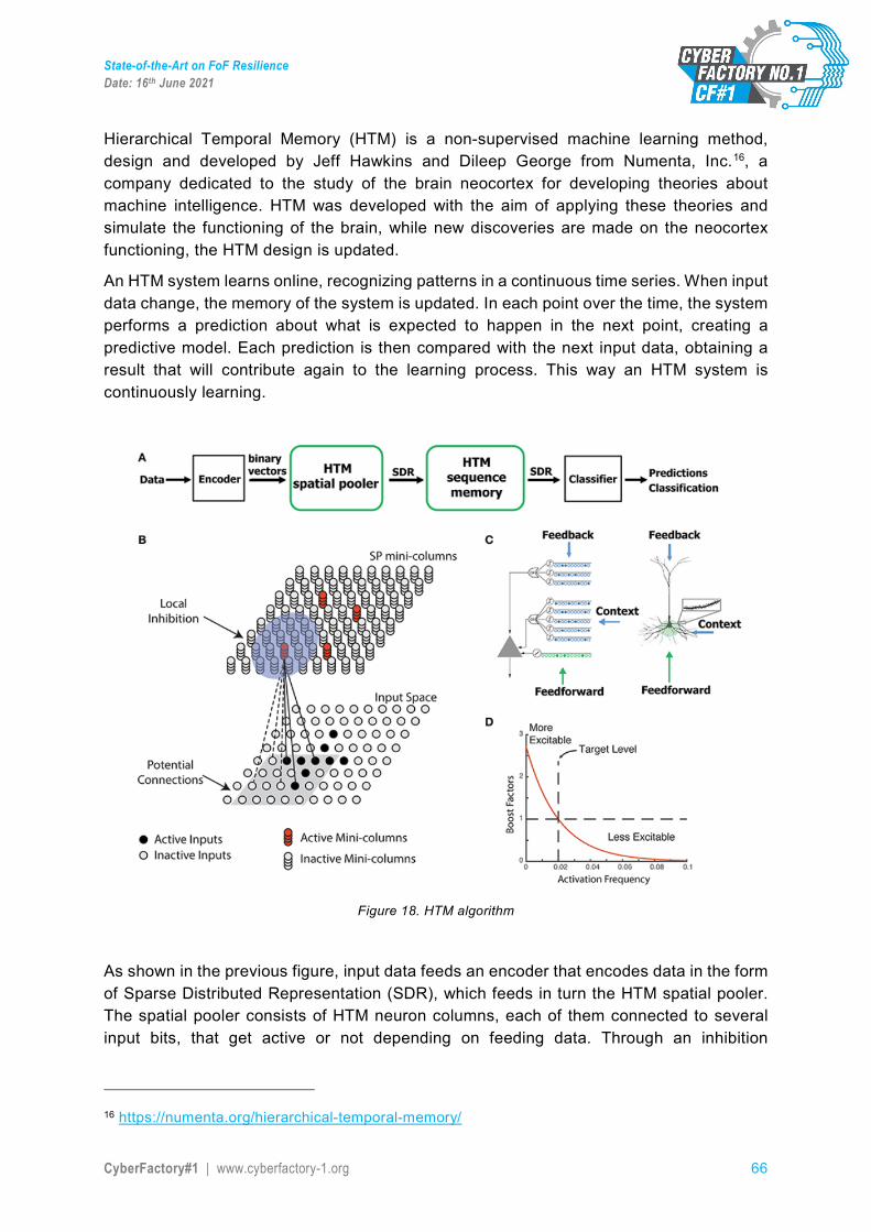
State-of-the-Art on FoF Resilience Date: 16th June 2021
CyberFactory#1 | www.cyberfactory-1.org 66
Hierarchical Temporal Memory (HTM) is a non-supervised machine learning method, design and developed by Jeff Hawkins and Dileep George from Numenta, Inc.16, a company dedicated to the study of the brain neocortex for developing theories about machine intelligence. HTM was developed with the aim of applying these theories and simulate the functioning of the brain, while new discoveries are made on the neocortex functioning, the HTM design is updated.
An HTM system learns online, recognizing patterns in a continuous time series. When input data change, the memory of the system is updated. In each point over the time, the system performs a prediction about what is expected to happen in the next point, creating a predictive model. Each prediction is then compared with the next input data, obtaining a result that will contribute again to the learning process. This way an HTM system is continuously learning.
Figure 18. HTM algorithm
As shown in the previous figure, input data feeds an encoder that encodes data in the form of Sparse Distributed Representation (SDR), which feeds in turn the HTM spatial pooler. The spatial pooler consists of HTM neuron columns, each of them connected to several input bits, that get active or not depending on feeding data. Through an inhibition
16 https://numenta.org/hierarchical-temporal-memory/
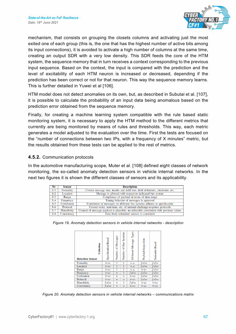
State-of-the-Art on FoF Resilience Date: 16th June 2021
CyberFactory#1 | www.cyberfactory-1.org 67
mechanism, that consists on grouping the closets columns and activating just the most exited one of each group (this is, the one that has the highest number of active bits among its input connections), it is avoided to activate a high number of columns at the same time, creating an output SDR with a very low density. This SDR feeds the core of the HTM system, the sequence memory that in turn receives a context corresponding to the previous input sequence. Based on the context, the input is compared with the prediction and the level of excitability of each HTM neuron is increased or decreased, depending if the prediction has been correct or not for that neuron. This way the sequence memory learns. This is further detailed in Yuwei et al [106].
HTM model does not detect anomalies on its own, but, as described in Subutai et al. [107], it is possible to calculate the probability of an input data being anomalous based on the prediction error obtained from the sequence memory.
Finally, for creating a machine learning system compatible with the rule based static monitoring system, it is necessary to apply the HTM method to the different metrics that currently are being monitored by means of rules and thresholds. This way, each metric generates a model adjusted to the evaluation over the time. First the tests are focused on the “number of connections between two IPs, with a frequency of X minutes” metric, but the results obtained from these tests can be applied to the rest of metrics.
4.5.2. Communication protocols In the automotive manufacturing scope, Muter et al. [108] defined eight classes of network monitoring, the so-called anomaly detection sensors in vehicle internal networks. In the next two figures it is shown the different classes of sensors and its applicability.
Figure 19. Anomaly detection sensors in vehicle internal networks - description
Figure 20. Anomaly detection sensors in vehicle internal networks – communications matrix
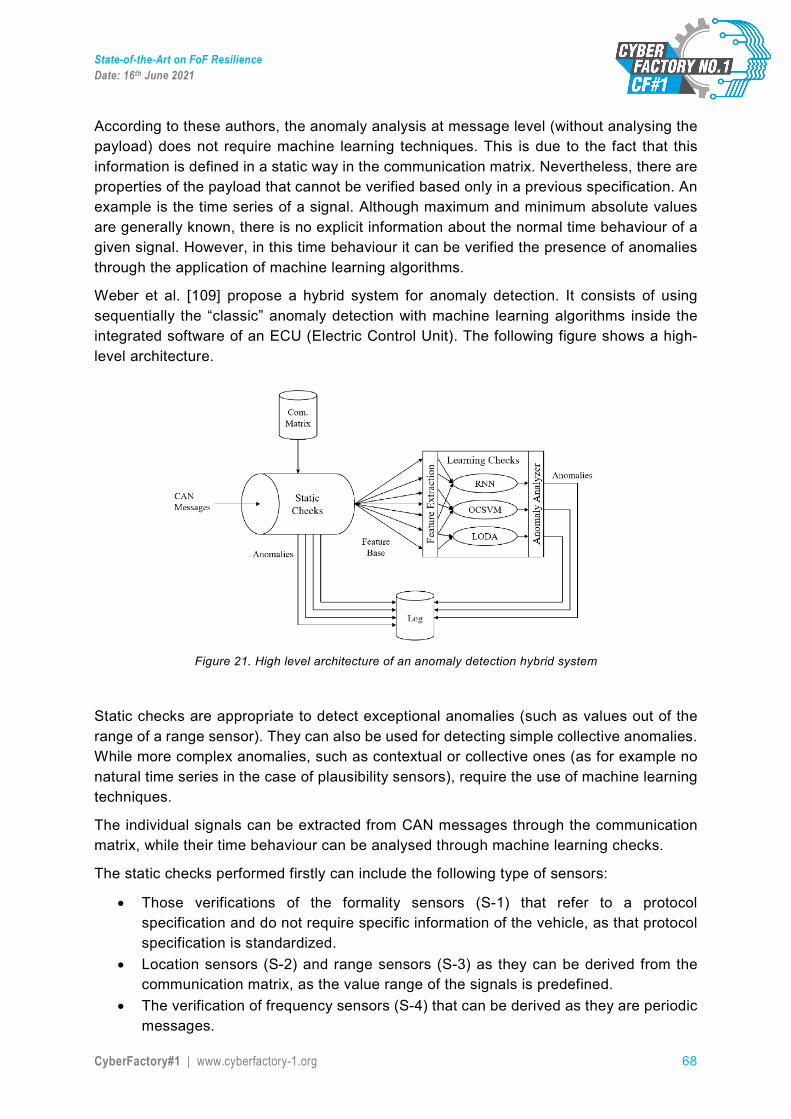
State-of-the-Art on FoF Resilience Date: 16th June 2021
CyberFactory#1 | www.cyberfactory-1.org 68
According to these authors, the anomaly analysis at message level (without analysing the payload) does not require machine learning techniques. This is due to the fact that this information is defined in a static way in the communication matrix. Nevertheless, there are properties of the payload that cannot be verified based only in a previous specification. An example is the time series of a signal. Although maximum and minimum absolute values are generally known, there is no explicit information about the normal time behaviour of a given signal. However, in this time behaviour it can be verified the presence of anomalies through the application of machine learning algorithms.
Weber et al. [109] propose a hybrid system for anomaly detection. It consists of using sequentially the “classic” anomaly detection with machine learning algorithms inside the integrated software of an ECU (Electric Control Unit). The following figure shows a high-level architecture.
Figure 21. High level architecture of an anomaly detection hybrid system
Static checks are appropriate to detect exceptional anomalies (such as values out of the range of a range sensor). They can also be used for detecting simple collective anomalies. While more complex anomalies, such as contextual or collective ones (as for example no natural time series in the case of plausibility sensors), require the use of machine learning techniques.
The individual signals can be extracted from CAN messages through the communication matrix, while their time behaviour can be analysed through machine learning checks.
The static checks performed firstly can include the following type of sensors:
• Those verifications of the formality sensors (S-1) that refer to a protocol specification and do not require specific information of the vehicle, as that protocol specification is standardized.
• Location sensors (S-2) and range sensors (S-3) as they can be derived from the communication matrix, as the value range of the signals is predefined.
• The verification of frequency sensors (S-4) that can be derived as they are periodic messages.
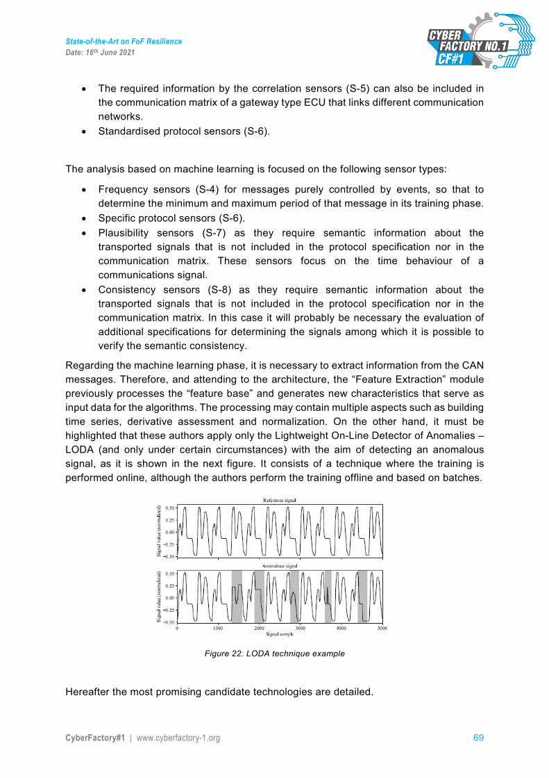
State-of-the-Art on FoF Resilience Date: 16th June 2021
CyberFactory#1 | www.cyberfactory-1.org 69
• The required information by the correlation sensors (S-5) can also be included in the communication matrix of a gateway type ECU that links different communication networks.
• Standardised protocol sensors (S-6).
The analysis based on machine learning is focused on the following sensor types:
• Frequency sensors (S-4) for messages purely controlled by events, so that to determine the minimum and maximum period of that message in its training phase.
• Specific protocol sensors (S-6). • Plausibility sensors (S-7) as they require semantic information about the
transported signals that is not included in the protocol specification nor in the communication matrix. These sensors focus on the time behaviour of a communications signal.
• Consistency sensors (S-8) as they require semantic information about the transported signals that is not included in the protocol specification nor in the communication matrix. In this case it will probably be necessary the evaluation of additional specifications for determining the signals among which it is possible to verify the semantic consistency.
Regarding the machine learning phase, it is necessary to extract information from the CAN messages. Therefore, and attending to the architecture, the “Feature Extraction” module previously processes the “feature base” and generates new characteristics that serve as input data for the algorithms. The processing may contain multiple aspects such as building time series, derivative assessment and normalization. On the other hand, it must be highlighted that these authors apply only the Lightweight On-Line Detector of Anomalies – LODA (and only under certain circumstances) with the aim of detecting an anomalous signal, as it is shown in the next figure. It consists of a technique where the training is performed online, although the authors perform the training offline and based on batches.
Figure 22. LODA technique example
Hereafter the most promising candidate technologies are detailed.

State-of-the-Art on FoF Resilience Date: 16th June 2021
CyberFactory#1 | www.cyberfactory-1.org 70
Ensemble of Gaussian Mixture Models (EGMM)
A classic approach for anomaly detection is to adjust a probabilistic model to the available data for estimating the density P(x) of each data point x. The data with low density is considered as anomalies. An approach for the density estimation is to adjust a Gaussian Mixture Model using the EM (Expectation – maximization) algorithm. Nevertheless, a unique GMM is not very robust and requires specifying the number of Gaussians k. For improving the robustness, a diverse set of models is generated varying the group number k, the EM initializations and the training in 15 data replicas [110]. On the other hand, it must be highlighted that this technique does not consider time sequences.
One Class Support Vector Machine (OCSVM)
One Class Support Vector Machines (OCSVM) improves the linear classifier by searching a better hyperplane than the one generated with a linear classifier. They can be applied with kernel functions for performing transformations to other spaces where it is possible to separate samples more efficiently. With these algorithms the distance from a point or sample to the decision limit determines its anomaly punctuation. On the other hand, it must be highlighted that this technique does not consider time sequences.
Isolation Forest (iForest)
Isolation Forest algorithm creates a random tree forest. It derives a punctuation based on the observation that the points or samples that are closer to the tree root are easier to separate from the rest of data and, thus, is more probable that they are anomalous. This method does not correctly behave when the anomalous points are closely grouped. For addressing this vulnerability, the Sparse-selection Criterion Isolation Forest (SCiForest) was developed. SCiForest divides the data points and characteristics in subgroups when building the tree. The isolation forest does not have parameters. On the other hand, it must be highlighted that this technique does not consider time sequences.
Restricted Boltzmann Machines (RBM)
This technique has been used by Kang and Kang [111] for performing the intrusion detection when analysing a vehicle internal network. The features represent the statistical behaviour of the network obtained from CAN packets. This technique was used to analyse only generic injection attacks.
Long short-term memory units (LSTM)
This technique has been used by Loukas et al. [112] for analysing diverse types of attacks such as DDoS, command injection and network malware. Besides, they tested LSTM against malware attacks for which the system had not been trained.
Classification based on k closer neighbors with diffuse approximation
Martinelli et al. [113] use this technique for distinguishing CAN messages legitimately generated by a human driver against the ones injected by an attack. They are based on the concept that the normal CAN messages are activated by the human action, and thus they can be modelled through diffuse techniques.
State-of-the-Art on FoF Resilience Date: 16th June 2021
CyberFactory#1 | www.cyberfactory-1.org 71
Lightweight On-Line Detector of Anomalies (LODA)
A set of weak detectors may lead to a strong anomaly detector with a same or better performance than the best existing methods. Lightweight On-Line Detector of Anomalies (LODA) is a particularly simple ensemble useful in domains where a big amount of samples in real time needs to be processed or in domains where the data flow is linked to the concept drift and the detector must be updated online.
Apart from being quick and accurate, LODA can also operate and update itself with missing data. LODA is, therefore, practical in domains with sensor measurement interruptions.
Besides, LODA can identify features where the analysed sample deviates from the majority. This capability is useful when the aim is to discover what has caused the anomaly. It must be highlighted that any of these positive properties increases the low time and space complexity of LODA.
On the other hand, it must be highlighted that this training technique is performed online.
Offline anomalies analysis with cloud technologies
Loukas et al. [112] propose performing the offline processing instead of in a robotic vehicle. In their research they compare two approaches, one based on Multilayer Perceptron (MLP) and the other one based on Recurrent Neural Networks (RNN) with Long Short-Term Memory (LSTM). And they have performed proofs of concept for denial of service attacks, command injection and malware.
4.5.3. Network visualization Visualization has long been used in general information technology settings to help us understand complex data. It can be used for data analysis and exploration as well as for communication purposes. The Factory of the Future (FoF) benefits from all established data visualization paradigms when dealing with, e.g., Big Data or Artificial Intelligence. Furthermore, the emerging use of Augmented, Virtual and Mixed Reality (AR, VR, MR) bring forth new visualization benefits to the FoF. Zhou et al. [114] present a detailed literature review on data visualization for Industry 4.0, broken down by industry sectors and visualization application scenarios.
As the FoF is more networked and intelligent than before, data transmission, sharing and analysis becomes more and more important. These developments come coupled with increased cyber security threats. Therefore, the FoF will benefit from using the traditional, more mature security visualization frameworks and applications. Shiravi et al. [115] provide a survey of visualizations for network security.
4.5.4. Detection methods
4.5.4.1. IDS and SIEM
IDS is a device or software application, an Intrusion Detection System that monitors a network (or a cyber-system) for malicious activity or policy violations. Any intrusion activity or violation is typically reported either to an administrator (that usually is a human person)
State-of-the-Art on FoF Resilience Date: 16th June 2021
CyberFactory#1 | www.cyberfactory-1.org 72
or collected centrally using a Security Information and Event Management (SIEM) automated system.
A SIEM system combines outputs from multiple sources and uses alarm filtering techniques to distinguish malicious activity from false alarms. A SIEM takes the advantages of a Security Manager. The manager appliances are high performance and powerful devices designed to run the solution platform. This is the main hardware unit of the development in charge of analysing all the information that flows through the different modules that make up the platform. Manager units are fully scalable in order to adapt to any network infrastructure.
IDS types range in scope from single computers to large networks. The most common classifications are network intrusion detection systems (NIDS) and host-based intrusion detection systems (HIDS).
Network intrusion detection systems (NIDS) are placed at a strategic point or points within the network to monitor traffic to and from all devices on the network. It performs an analysis of passing traffic on the entire subnet, and matches the traffic that is passed on the subnets to the library of known attacks. Once an attack is identified, or abnormal behaviour is sensed, the alert can be sent to the administrator.
A system that monitors important operating system files is an example of an HIDS, while a system that analyses incoming network traffic is an example of an NIDS. It is also possible to classify IDS by detection approach. The most well-known variants are signature-based detection (recognizing bad patterns, such as malware) and anomaly-based detection (detecting deviations from a model of "good" traffic, which often relies on machine learning). Another common variant is reputation-based detection (recognizing the potential threat according to the reputation scores).
Intrusion detection systems can also serve specific purposes by augmenting them with custom tools, such as using a honeypot to attract and characterize malicious traffic. Intrusion prevention systems are considered extensions of intrusion detection systems because they both monitor network traffic and/or system activities for malicious activity. The main differences are, unlike intrusion detection systems, intrusion prevention systems are placed in-line and are able to actively prevent or block intrusions that are detected.
Signature-based IDS refers to the detection of attacks by looking for specific patterns, such as byte sequences in network traffic, or known malicious instruction sequences used by malware. This terminology originates from anti-virus software, which refers to these detected patterns as signatures. Although signature-based IDS can easily detect known attacks, it is difficult to detect new attacks, for which no pattern is available.
4.5.4.2. IPS and a complete solution
Some IDS products have the ability to respond to detected intrusions. Systems with response capabilities are typically referred to as an Intrusion Prevention System or IPS. These systems are primarily focused on identifying possible incidents, logging information about them, and reporting attempts. In addition, organizations use IDPS for other purposes, such as identifying problems with security policies, documenting existing threats and deterring individuals from violating security policies. IPS have become a necessary addition
State-of-the-Art on FoF Resilience Date: 16th June 2021
CyberFactory#1 | www.cyberfactory-1.org 73
to the security infrastructure of nearly every organization which gives an enormous importance to have them present in a FoF infrastructure.
A complete cybersecurity solution should include a IPS/IDS system, which can be enabled to digest thousands of events per second, offering absolute visibility. To monitor, analyse and detect threats before they become attacks to offer resilience to the FoF. The cybersecurity solution IDS/IPS fully integrated in an ecosystem with Big Data-based framework and Cloud ready functionalities.
With the above in mind, it should be possible to obtain in Real Time all the information that is needed to control and analyse the network traffic displayed through visual, customizable and user friendly dashboards and metrics.
The complete solution should offer the possibility to control and the give the confidence to a Safety Industrial Network with the following enhancements that help to have the most control over what happens in the network:
• Capacity optimization and management, filtering thousand events per second. • Improved performance of Snort sensors thanks to pf_ring and pf_ring zero copy. • Sending events for mass treatment through Apache Kafka. • Optimized management of scalable security policies for thousands of probes, while
maintaining the power and flexibility of the previous version. • Creation of policies for segment specific security. • Improvement of probe monitoring: monitor dozens of parameters to optimize
performance.
All these new features should be incorporated into the unique solution: advanced multi-management, workflow security policies, centralized management, and so on.
A complete integrated solution should be managed on a Single Platform for All Events. With extraordinary rich and correlated information that provides real network and user knowledge in Real-Time.
A platform from which all tasks can simplify analysis and network monitoring thanks to a completely visual and friendly graphical interface.
• Personalized dashboards with filters and widgets: whether is needed technical information like analytics, or more oriented towards business strategies for Industry 4.0.
• Events are shown through metrics, heat maps, traffic flows. • Get periodic reports to choose from a number of defaults, or select the data to
analyse and make custom reports. • Fully schema less: clean, reusable and flexible data.
A cybersecurity solution that is the basis for a more comprehensive and powerful ecosystem. The backend that manages, monitors, stores, correlates and unifies the information received.
The solution should offer flexibility to implement the IPS System according to the FoF needs.
State-of-the-Art on FoF Resilience Date: 16th June 2021
CyberFactory#1 | www.cyberfactory-1.org 74
A complete IPS solution that can adapt to any scenario which grows according to the FoF needs.
• Commodity hardware and Cloud environments: Implements the solution in physical or virtual appliances as well as in Cloud environments: AWS and Open Stack.
• Advanced and integrated vision with other sources through its open API can assist in the development of the applications that enhance and complement the ecosystem.
• Under Open Source licenses: working to improve freedom, transparency and speed innovation.
A solution for any size network, from enterprise to fairs or events. The power of some IPS sensors, combined with the simplicity of integrated management systems, makes an ideal solution to meet the needs of a large corporation or a service provider.
4.5.4.3. AI role in the Detection methods
IDS can be also combined with other technologies to increase detection and prediction rates. Artificial Neural Network based IDS are capable of analysing huge volumes of data, in a smart way, due to the self-organizing structure that allows INS IDS to more efficiently recognize intrusion patterns. Neural networks assist IDS in predicting attacks by learning from mistakes; INN IDS help develop an early warning system, based on two layers. The first layer accepts single values, while the second layer takes the first's layers output as input; the cycle repeats and allows the system to automatically recognize new unforeseen patterns in the network. This system can average 99.9% detection and classification rate, based on research results of 24 network attacks, divided in four categories: DOS, Probe, Remote-to-Local, and user-to-root.
Anomaly-based intrusion detection systems were primarily introduced to detect unknown attacks, in part due to the rapid development of malware. The basic approach is to use machine learning to create a model of trustworthy activity, and then compare new behaviour against this model. Since these models can be trained according to the applications and hardware configurations, machine learning based methods have a better generalized property in comparison to traditional signature-based IDS. Although this approach enables the detection of previously unknown attacks, it may suffer from false positives: previously unknown legitimate activity may also be classified as malicious. Most of the existing IDSs suffer from the time-consuming during detection process that degrades the performance of IDSs. Efficient feature selection algorithm makes the classification process used in detection more reliable.
New types of what could be called anomaly-based intrusion detection systems are an evolution of the user behaviour analytics category. Also, to mention Network Traffic Analysis (NTA). In particular, NTA deals with malicious insiders as well as targeted external attacks that have compromised a user machine or account.
Some IDS/IPS AI aided can be found in the form of Intrusion probes. This becomes the best choice for Enterprise and Service Providers. Appliances are high performance IPS/IDS probes designed to bring a simple, scalable and flexible way to protect the network. It offers Active Cybersecurity: Protecting IT networks with Next Generation IPS
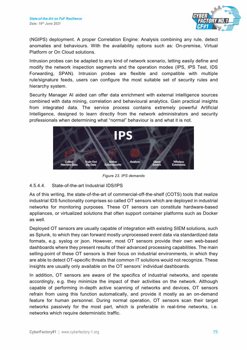
State-of-the-Art on FoF Resilience Date: 16th June 2021
CyberFactory#1 | www.cyberfactory-1.org 75
(NGIPS) deployment. A proper Correlation Engine: Analysis combining any rule, detect anomalies and behaviours. With the availability options such as: On-premise, Virtual Platform or On Cloud solutions.
Intrusion probes can be adapted to any kind of network scenario, letting easily define and modify the network inspection segments and the operation modes (IPS, IPS Test, IDS Forwarding, SPAN). Intrusion probes are flexible and compatible with multiple rule/signature feeds, users can configure the most suitable set of security rules and hierarchy system.
Security Manager AI aided can offer data enrichment with external intelligence sources combined with data mining, correlation and behavioural analytics. Gain practical insights from integrated data. The service process contains extremely powerful Artificial Intelligence, designed to learn directly from the network administrators and security professionals when determining what “normal” behaviour is and what it is not.
Figure 23. IPS demands
4.5.4.4. State-of-the-art Industrial IDS/IPS
As of this writing, the state-of-the-art of commercial-off-the-shelf (COTS) tools that realize industrial IDS functionality comprises so called OT sensors which are deployed in industrial networks for monitoring purposes. These OT sensors can constitute hardware-based appliances, or virtualized solutions that often support container platforms such as Docker as well.
Deployed OT sensors are usually capable of integration with existing SIEM solutions, such as Splunk, to which they can forward mostly unprocessed event data via standardized data formats, e.g. syslog or json. However, most OT sensors provide their own web-based dashboards where they present results of their advanced processing capabilities. The main selling-point of these OT sensors is their focus on industrial environments, in which they are able to detect OT-specific threats that common IT solutions would not recognize. These insights are usually only available on the OT sensors’ individual dashboards.
In addition, OT sensors are aware of the specifics of industrial networks, and operate accordingly, e.g. they minimize the impact of their activities on the network. Although capable of performing in-depth active scanning of networks and devices, OT sensors refrain from using this function automatically, and provide it mostly as an on-demand feature for human personnel. During normal operation, OT sensors scan their target networks passively for the most part, which is preferable in real-time networks, i.e. networks which require deterministic traffic.
State-of-the-Art on FoF Resilience Date: 16th June 2021
CyberFactory#1 | www.cyberfactory-1.org 76
Due to the passive nature of the scanning activities the amount of information and insights gathered about networks and assets can be dissatisfactory at the beginning. However, the information is enriched the longer the services run and the more date they are passively exposed to. The gathered data is used not only for threat detection, but also to detect and validate assets, and map network topologies. Both asset validation and network mapping are helpful tools for operators to identify and investigate deviations between a documented state of the plant, and its real one.
Internally, OT sensors may employ separate analysis engines for detecting malware as opposed to suspicious network activity. The most valuable capability of these engines however is the fact that they are tailored to OT environments. In some cases, these engines are trained with OT-specific threat intelligence by expert teams who gather it from the most recent OT threat landscape.
Examples of current OT sensors include Claroty17, Nozomi18, CyberX19, and Dragos.20
4.5.4.5. Open source IDS/IPS
In addition to described commercial OT sensors there are also open source development solutions available with similar functionality which will now be described and compared in more detail.
Snort
Snort [177] is an open source Network-Based Intrusion Detection and Prevention System. Developed by Sourcefire, Snort can analyze network traffic in real time with the help of a pre-determined set of rules. Each rule represents a vulnerability or attack. If a network packet matches at least one of the defined rules, an alert is sent to the system’s administrator and preventive actions are taken [178]. Snort can also be executed in three different modes, however they can be combined [179]. Sniffer Mode is capable of reading network packets and continuously display them on the console. Packet Logger Mode registers all network packets to the disk, organizing them by hierarchic. Lastly, NIDS Mode, the most complex of all three, can detect and analyze network traffic [180].
Suricata
Similarly to Snort, Suricata [181] is an open source Intrusion Detection and Prevention System. It was developed by Open Information Security Foundation (OISF). Suricata analyzes network traffic in real time and compares it with a set of extensive rules. Furthermore, it can identify complex attacks. An advantage of Suricata is its ability of multithreading, in other words, it is capable of processing multiple events simultaneously [182]. Suricata also implements its own programming language called Lua. Finally, it uses input formats such as YAML and output formats like JSON, which allows an easy integration with Elasticsearch and Kibana [180].
17 https://www.claroty.com 18 https://www.nozominetworks.com 19 https://cyberx-labs.com 20 https://www.dragos.com
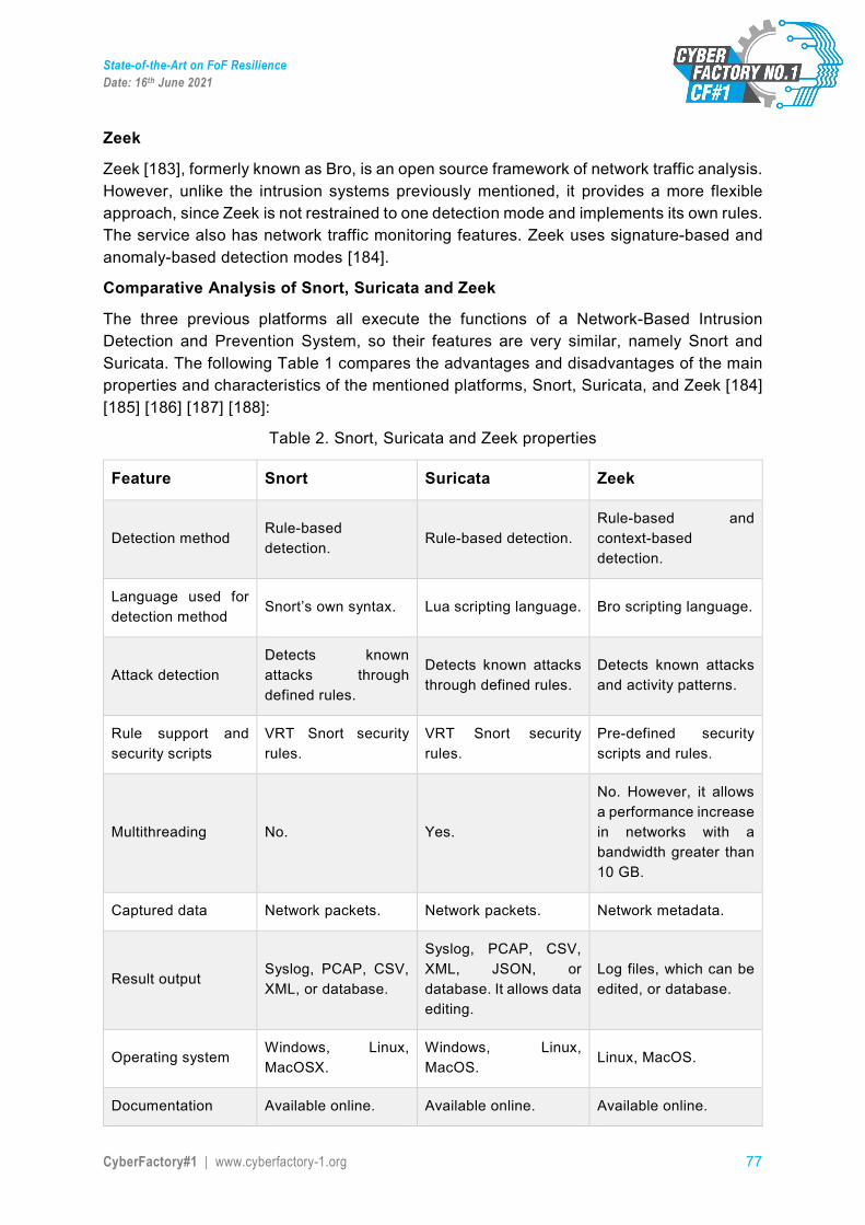
State-of-the-Art on FoF Resilience Date: 16th June 2021
CyberFactory#1 | www.cyberfactory-1.org 77
Zeek
Zeek [183], formerly known as Bro, is an open source framework of network traffic analysis. However, unlike the intrusion systems previously mentioned, it provides a more flexible approach, since Zeek is not restrained to one detection mode and implements its own rules. The service also has network traffic monitoring features. Zeek uses signature-based and anomaly-based detection modes [184].
Comparative Analysis of Snort, Suricata and Zeek
The three previous platforms all execute the functions of a Network-Based Intrusion Detection and Prevention System, so their features are very similar, namely Snort and Suricata. The following Table 1 compares the advantages and disadvantages of the main properties and characteristics of the mentioned platforms, Snort, Suricata, and Zeek [184] [185] [186] [187] [188]:
Table 2. Snort, Suricata and Zeek properties
Feature Snort Suricata Zeek
Detection method Rule-based detection.
Rule-based detection. Rule-based and context-based detection.
Language used for detection method
Snort’s own syntax. Lua scripting language. Bro scripting language.
Attack detection Detects known attacks through defined rules.
Detects known attacks through defined rules.
Detects known attacks and activity patterns.
Rule support and security scripts
VRT Snort security rules.
VRT Snort security rules.
Pre-defined security scripts and rules.
Multithreading No. Yes.
No. However, it allows a performance increase in networks with a bandwidth greater than 10 GB.
Captured data Network packets. Network packets. Network metadata.
Result output Syslog, PCAP, CSV, XML, or database.
Syslog, PCAP, CSV, XML, JSON, or database. It allows data editing.
Log files, which can be edited, or database.
Operating system Windows, Linux, MacOSX.
Windows, Linux, MacOS.
Linux, MacOS.
Documentation Available online. Available online. Available online.
State-of-the-Art on FoF Resilience Date: 16th June 2021
CyberFactory#1 | www.cyberfactory-1.org 78
As the previous table shows, Zeek is not capable of capturing and storing network packets, which is essential to monitor and study the network traffic and detect possible attacks. Snort or Suricata could capture all network packets and provide them to Zeek. This platform would, in turn, analyze and store the data received. However, given Suricata’s ability of multithreading, it ends up being a better option than Snort.
4.5.4.6. Active Network Monitoring
In order to carry out an effective management of the network and its security and in this way avoid that failures can occur or, if they happen, are quickly detectable, the concept of network monitoring arises, which allows us to notification of anomalies in the network in order to show us their behaviour by analysing and collecting traffic.
It is very important before implementing a monitoring scheme, delimit the spectrum on which to work, that is, what aspects will be monitored, such as: bandwidth utilization, CPU consumption, memory consumption, physical status of connections, type of traffic, alarms, services (web, mail, database, proxy), etc.
In the same way, the scope of the devices to be monitored must also be defined. These can be of several types: interconnection devices (routers, switches, hubs, firewalls), servers (web, mail, databases), administration (monitoring, logs, configuration) etc.
Network monitoring systems, in addition to their information bases or their information managers, are made up of at least two key elements: the NMS and the agents. The NMS (Network Monitoring System) is the management station that serves as an interface between the network administrator and the network management system.
The agents, or probes, are generally software (and sometimes hardware) modules resident in the devices to be managed or monitored and are what provide information to the management station about the state of the network.
We can distinguish two different points of view when approaching the process of monitoring a network. Both are different, although they complement each other:
4.5.4.7. Active monitoring techniques
It is done by injecting test packets into the network or by sending packets to certain applications measuring their response times. By introducing packets into the network, this technique therefore adds traffic to the network itself. It is commonly used to measure network performance and we can distinguish different active monitoring techniques:
• ICMP-based: used to diagnose network problems, detect packet losses and delays, measure RTT, or check host and network availability.
• Based on TCP: used for the measurement of the transfer rate or the diagnosis of problems at the application level.
• UDP-based: used to diagnose one-way packet loss or RTT measurement. • HTTPS, MQTT/TLS; data transfer techniques to be used for active
monitor/diagnose bulk data and related transfers e.g. IIoT / IoT devices or monitoring devices
State-of-the-Art on FoF Resilience Date: 16th June 2021
CyberFactory#1 | www.cyberfactory-1.org 79
4.5.4.8. Passive monitoring techniques
It is based on the collection and analysis of network traffic in order to obtain information. For this, various devices are used such as sniffers, routers, equipment with traffic analysis software or devices with support for SNMP, RMON or Netflow. Unlike active monitoring techniques, passive monitoring techniques do not add traffic to the network. Its use is usually focused on characterizing network traffic and accounting for its use. We can distinguish different passive monitoring techniques:
Based on remote requests
Using SNMP (Simple Network Management Protocol): used in order to obtain statistics on the use of bandwidth in network devices, for which it is required to have access to said devices. At the same time, this protocol generates packets called traps that indicate that an unusual event has occurred.
Traffic capture
By configuring a mirror port on a network device: it will make a copy of the traffic received on one port to another where the equipment that will perform the capture will be connected. By installing an intermediate device to capture traffic: it can be a computer with the capture software or another extra device.
Traffic analysis
Identifies the type of applications that are most used. It is implemented through the use of intermediate devices with an application capable of classifying traffic by application, source and destination IP addresses, source and destination ports, etc.
Flows
Identifies the type of traffic used on the network. The flows can be obtained from routers or through devices that are capable of capturing traffic and transforming them into flows. A flow is a set of packets with a common characteristic such as: Same source and destination IP, same source and destination TCP port, same type of application.
Active E2E security monitoring, which is carried out with Big Data techniques, is based on the adaptation and development of various high-speed network data processing techniques, streaming analysis over NetFlow protocols and virtualized OpenFlow networks and detection in real-time threat patterns and device isolation in industrial networks.
This is how E2E active monitoring and big data techniques receive network traffic as a fundamental input. When it comes to traffic, gathering information on network usage and device location is very important in multiple contexts: discovering security threats, ensuring compliance with network usage policy, detecting connectivity problems , learn about the use and behaviour of crowds, detect the transfer of areas, optimize routes and monetize your infrastructure.
Thanks to the information collected by the probes and sensors, it is possible to monitor the security status with an exhaustive and detailed analysis, allowing measures to be taken when detecting possible attacks against our technological infrastructure.
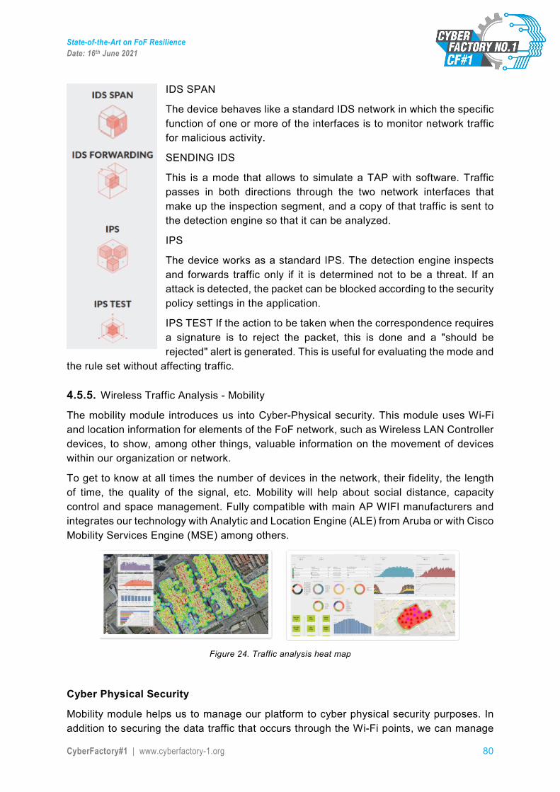
State-of-the-Art on FoF Resilience Date: 16th June 2021
CyberFactory#1 | www.cyberfactory-1.org 80
IDS SPAN
The device behaves like a standard IDS network in which the specific function of one or more of the interfaces is to monitor network traffic for malicious activity.
SENDING IDS
This is a mode that allows to simulate a TAP with software. Traffic passes in both directions through the two network interfaces that make up the inspection segment, and a copy of that traffic is sent to the detection engine so that it can be analyzed.
IPS
The device works as a standard IPS. The detection engine inspects and forwards traffic only if it is determined not to be a threat. If an attack is detected, the packet can be blocked according to the security policy settings in the application.
IPS TEST If the action to be taken when the correspondence requires a signature is to reject the packet, this is done and a "should be rejected" alert is generated. This is useful for evaluating the mode and
the rule set without affecting traffic.
4.5.5. Wireless Traffic Analysis - Mobility The mobility module introduces us into Cyber-Physical security. This module uses Wi-Fi and location information for elements of the FoF network, such as Wireless LAN Controller devices, to show, among other things, valuable information on the movement of devices within our organization or network.
To get to know at all times the number of devices in the network, their fidelity, the length of time, the quality of the signal, etc. Mobility will help about social distance, capacity control and space management. Fully compatible with main AP WIFI manufacturers and integrates our technology with Analytic and Location Engine (ALE) from Aruba or with Cisco Mobility Services Engine (MSE) among others.
Figure 24. Traffic analysis heat map
Cyber Physical Security
Mobility module helps us to manage our platform to cyber physical security purposes. In addition to securing the data traffic that occurs through the Wi-Fi points, we can manage
State-of-the-Art on FoF Resilience Date: 16th June 2021
CyberFactory#1 | www.cyberfactory-1.org 81
the mobility of users, social distancing and the restriction of areas. These functions are completely up-to-date and necessary for optimal management of our spaces.
Management Platform
The events generated by thousands of WIFI access points will reach a central point where they are collected, enriched, and stored by a real-time pipeline with scale-out capacity. If possible, to implement correlation rules with other modules or apps (Intrusion, Traffic, Monitoring, SIEM) will get the full control of the network.
Management platforms should also address the monitoring traffic from the network devices and compare the data with SIEM systems. These systems also should establish security audit / event activities, device management activities or address also device or its security updates. See also chapter 5.3.1 in the state-of-the-art.
Contextualization
Data is enriched with context without alteration based on existing data fields. This improves the decision-making and understanding processes. Additional data can come from external sources such as geolocation or reputation feeds, but also from other modules or Apps active in the platform.
Probe choices
The WIFI probes are kind of sensors which examine all Wi-Fi information (devices connected to the Wi-Fi, type of devices, bandwidth, etc.) from the network and sending that information to the WIFI platform. If possible deploy thousands of probes through the network and configure them to look after the specific information.
4.6. Discussion The analysis on existing capabilities and solutions for Human/Machine behaviour monitoring turned out that different areas have to be considered in order to monitor and detect all kinds of anomalies that may occur in the Factory 4.0 environment. In addition the linkages between those areas have to be analysed when building new manufacturing environments. It turned out that strong linkage exists between the components plus network area and the process area, e.g. a serious anomaly inside the component could result in process loss of availability or similar type of consequences. These dependencies have to be defined as early as possible in order to monitor the relevant parts of the process and supporting infrastructure.
The state of the art analysis identified great monitoring solutions available in the market for a long time but some of them mainly adjusted and targeted for IT environments. Since manufacturing and shop-floor environments were historically not connected to the respective IT environment the attack surface were reduced to minimum. After greater interconnection between both worlds is highly targeted in Factory 4.0, the analysed solutions may also be adapted to OT environments and vendors already started in doing that. As the goals on security and safety are rather different from the goals of the IT environment this may be a long way to go also taking in mind that the lifetime of manufacturing systems is measured in decades whereas IT systems will get renewed

State-of-the-Art on FoF Resilience Date: 16th June 2021
CyberFactory#1 | www.cyberfactory-1.org 82
already after several years. The digitalization moves forward on a daily basis but legacy systems still exist and have to be taken into account as well.
State-of-the-Art on FoF Resilience Date: 16th June 2021
CyberFactory#1 | www.cyberfactory-1.org 83
5. FoF Resilience 5.1. Overview Resilience is more than just recovering quickly from pressure. To be resilient is to be able to take “bitter circumstance in stride” and still “get the job done.” It might cost more or not be done as well had less (intentional or unintentional) adversity been present, but it will be done. Resilience is a superset of fault tolerance and very much related to autonomic computing notions of self-healing, self-configuring, self-organizing and self-protecting (Ref. Industrial Internet Reference Architecture (IIRA)) [116]. It is also possible to define resilience is the persistence of the service delivery that can justifiably be trusted [117]. Therefore, resilience in large manufacturing organizations is related to its ability of delivering their service (i.e. manufacturing of goods within the planned quality-defined parameter in a timely manner). Therefore, production resilience is considered to be the most important resilience factor in a manufacturing organization, as it is the main driver of their service.
Cyber resilience goes beyond risk management and tactical technical solutions, requiring a holistic view of systems and processes to prepare for the reality of cyber incidents, and these principles are applied in the FoF environment as well. The specifics of FoF environment add an additional layer of complexity to such operations. Connections in FoF environments span between systems and networks, but also across multiple organisations, requiring higher robustness and efficient handling of any significant incidents in the system. Failure to resolve incidents efficiently erode the trust between organisations.
This section gives an overview about the state of the art related to FoF resilience. The following text is referenced from CF#1 D2.4. SoS Design and Validation Plan. The key supporting capabilities to develop resilience are decision support for incident response and development of autonomous reconfiguration/remediation management capabilities. The ambition for FoF resilience is a system that is designed to care for its own safety and security, not only by being secured at a certain moment in time, but throughout evolutions, upgrades and learning processes. Therefore, the development of cyber-resilience capabilities in the FoF addresses the aspects from functional requirements point of view:
● Factory transformations: Various FoF scenarios from the functional point of different types of factory transformations are utilized for determination of the cyber-resilient operation requirements.
● Connected FoF: FoF systems have the ability to maintain constant and continuous connectivity to systems (like industrial control, IIoT, IT/OT) and other system assets on a continuous basis. Single networks may not provide sufficient reliability in critical manufacturing systems. In order to build resilient manufacturing systems, a seamless network failover is a relevant resilience capability.
● Decision support: The developed capabilities for incident response and autonomous reconfiguration / remediation management capabilities are addressed.
● Principles and patterns for dynamic reconfiguration are applied to maintain resilient and consistent operations in the FoF. Important input for the principles and patterns for dynamic reconfiguration are the safety case methodologies (for example
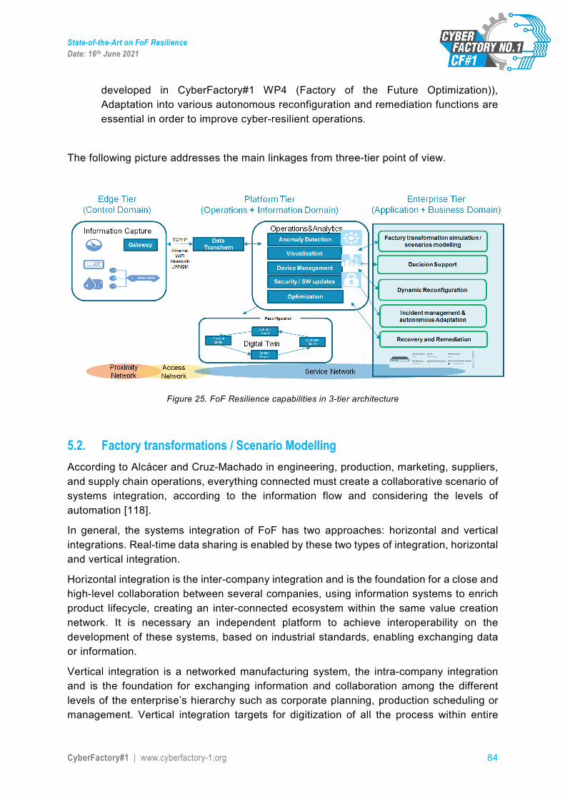
State-of-the-Art on FoF Resilience Date: 16th June 2021
CyberFactory#1 | www.cyberfactory-1.org 84
developed in CyberFactory#1 WP4 (Factory of the Future Optimization)), Adaptation into various autonomous reconfiguration and remediation functions are essential in order to improve cyber-resilient operations.
The following picture addresses the main linkages from three-tier point of view.
Figure 25. FoF Resilience capabilities in 3-tier architecture
5.2. Factory transformations / Scenario Modelling According to Alcácer and Cruz-Machado in engineering, production, marketing, suppliers, and supply chain operations, everything connected must create a collaborative scenario of systems integration, according to the information flow and considering the levels of automation [118].
In general, the systems integration of FoF has two approaches: horizontal and vertical integrations. Real-time data sharing is enabled by these two types of integration, horizontal and vertical integration.
Horizontal integration is the inter-company integration and is the foundation for a close and high-level collaboration between several companies, using information systems to enrich product lifecycle, creating an inter-connected ecosystem within the same value creation network. It is necessary an independent platform to achieve interoperability on the development of these systems, based on industrial standards, enabling exchanging data or information.
Vertical integration is a networked manufacturing system, the intra-company integration and is the foundation for exchanging information and collaboration among the different levels of the enterprise’s hierarchy such as corporate planning, production scheduling or management. Vertical integration targets for digitization of all the process within entire
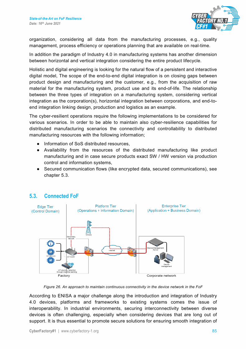
State-of-the-Art on FoF Resilience Date: 16th June 2021
CyberFactory#1 | www.cyberfactory-1.org 85
organization, considering all data from the manufacturing processes, e.g., quality management, process efficiency or operations planning that are available on real-time.
In addition the paradigm of Industry 4.0 in manufacturing systems has another dimension between horizontal and vertical integration considering the entire product lifecycle.
Holistic and digital engineering is looking for the natural flow of a persistent and interactive digital model, The scope of the end-to-end digital integration is on closing gaps between product design and manufacturing and the customer, e.g., from the acquisition of raw material for the manufacturing system, product use and its end-of-life. The relationship between the three types of integration on a manufacturing system, considering vertical integration as the corporation(s), horizontal integration between corporations, and end-to-end integration linking design, production and logistics as an example.
The cyber-resilient operations require the following implementations to be considered for various scenarios. In order to be able to maintain also cyber-resilience capabilities for distributed manufacturing scenarios the connectivity and controllability to distributed manufacturing resources with the following information;
● Information of SoS distributed resources, ● Availability from the resources of the distributed manufacturing like product
manufacturing and in case secure products exact SW / HW version via production control and information systems,
● Secured communication flows (like encrypted data, secured communications), see chapter 5.3.
5.3. Connected FoF
Figure 26. An approach to maintain continuous connectivity in the device network in the FoF
According to ENISA a major challenge along the introduction and integration of Industry 4.0 devices, platforms and frameworks to existing systems comes the issue of interoperability. In industrial environments, securing interconnectivity between diverse devices is often challenging, especially when considering devices that are long out of support. It is thus essential to promote secure solutions for ensuring smooth integration of
State-of-the-Art on FoF Resilience Date: 16th June 2021
CyberFactory#1 | www.cyberfactory-1.org 86
Industry 4.0 devices with legacy systems and among each other, e.g. gateways to ensure transparent communication in the case of different networking or other protocols [119]. To understand better the approaches for improving IoT security, Industrial Internet Consortium has published IoT Security Maturity Models, latest in May 2020 (SMM) [116].
5.3.1 Device Management
For Device Management the main principle is that only devices owned and managed, or approved and authorized, placed in the factory of the future should be connected to the networks and systems supporting the manufacturing services.
● The company should ensure that a process exists to approve and authorise connection of devices to the networks and systems supporting the manufacturing services.
● By default, only managed assets should be granted access ● Where this is not possible, the company should have a documented risk assessment
for the use of third-party assets, which may be granted with appropriate controls applied.
Device Registration – It should be known what devices are authorised to connect to networks and systems supporting your essential service.
● The company should have a register of all devices that are authorised to connect to the networks and systems supporting your essential service, and the use for which they are approved. This should include local and remote access by third parties or contractors.
● The company should have a process to ensure that this register is maintained and kept up-to-date.
● The company needs to ensure the process for identifying and authenticating portable and mobile devices is secure and the risk documented.
To be able to detect Unknown Devices, it should be possible to detect unknown devices connected to networks and systems supporting your essential service and to investigate such occurrences.
● The company should have automated mechanisms for the detection of unknown devices to generate an alert.
● Where automated mechanisms are not possible, the company should be operating regular, in accordance with the management system, manual checking processes to identify unknown devices.
Many smart devices have a lifetime of 15 years or more, and are often not easy to access and replace. As many use non-standard hardware and proprietary firmware. In embedded systems (such as sensors and pumps), standard computer security software can’t always be deployed. One way forward is to use device certificates and public key infrastructure (PKI) architectures. Implementing PKI into embedded systems secures the communication layer, creating a system that verifies the authenticity, configuration, and integrity of connected devices. This way, PKIs are ideal for large-scale security deployments that require a high level of security with minimal impact on performance.
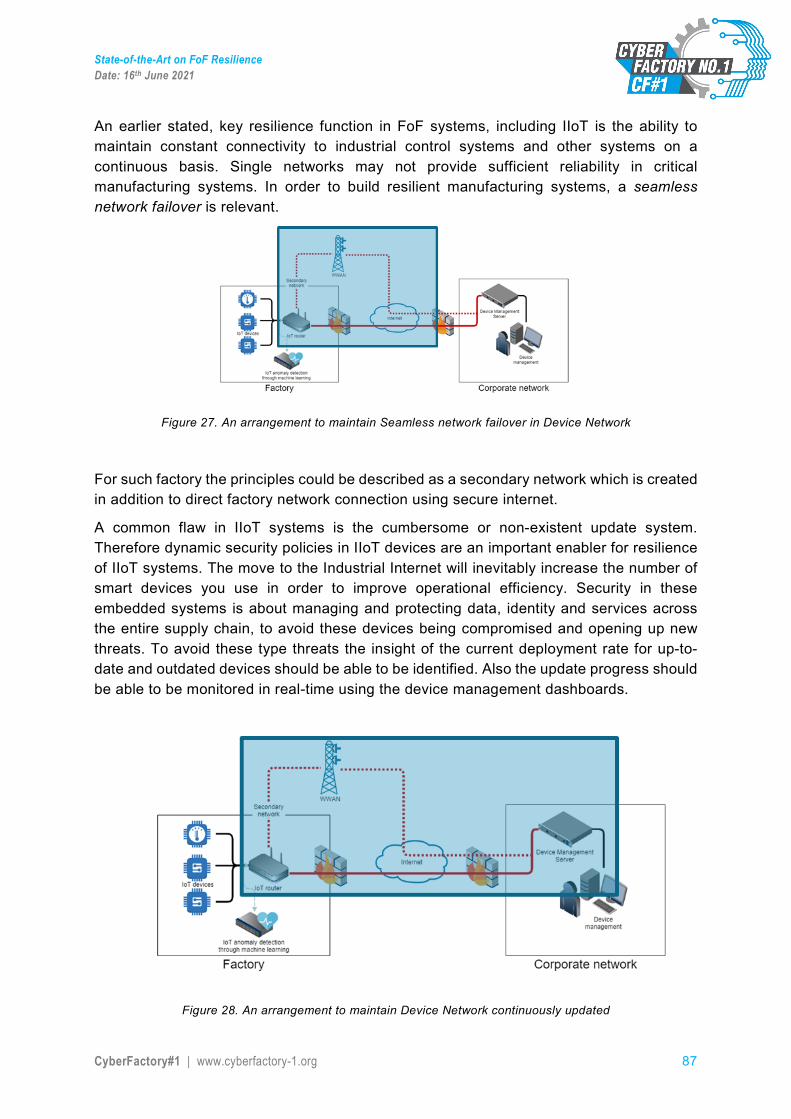
State-of-the-Art on FoF Resilience Date: 16th June 2021
CyberFactory#1 | www.cyberfactory-1.org 87
An earlier stated, key resilience function in FoF systems, including IIoT is the ability to maintain constant connectivity to industrial control systems and other systems on a continuous basis. Single networks may not provide sufficient reliability in critical manufacturing systems. In order to build resilient manufacturing systems, a seamless network failover is relevant.
Figure 27. An arrangement to maintain Seamless network failover in Device Network
For such factory the principles could be described as a secondary network which is created in addition to direct factory network connection using secure internet.
A common flaw in IIoT systems is the cumbersome or non-existent update system. Therefore dynamic security policies in IIoT devices are an important enabler for resilience of IIoT systems. The move to the Industrial Internet will inevitably increase the number of smart devices you use in order to improve operational efficiency. Security in these embedded systems is about managing and protecting data, identity and services across the entire supply chain, to avoid these devices being compromised and opening up new threats. To avoid these type threats the insight of the current deployment rate for up-to-date and outdated devices should be able to be identified. Also the update progress should be able to be monitored in real-time using the device management dashboards.
Figure 28. An arrangement to maintain Device Network continuously updated
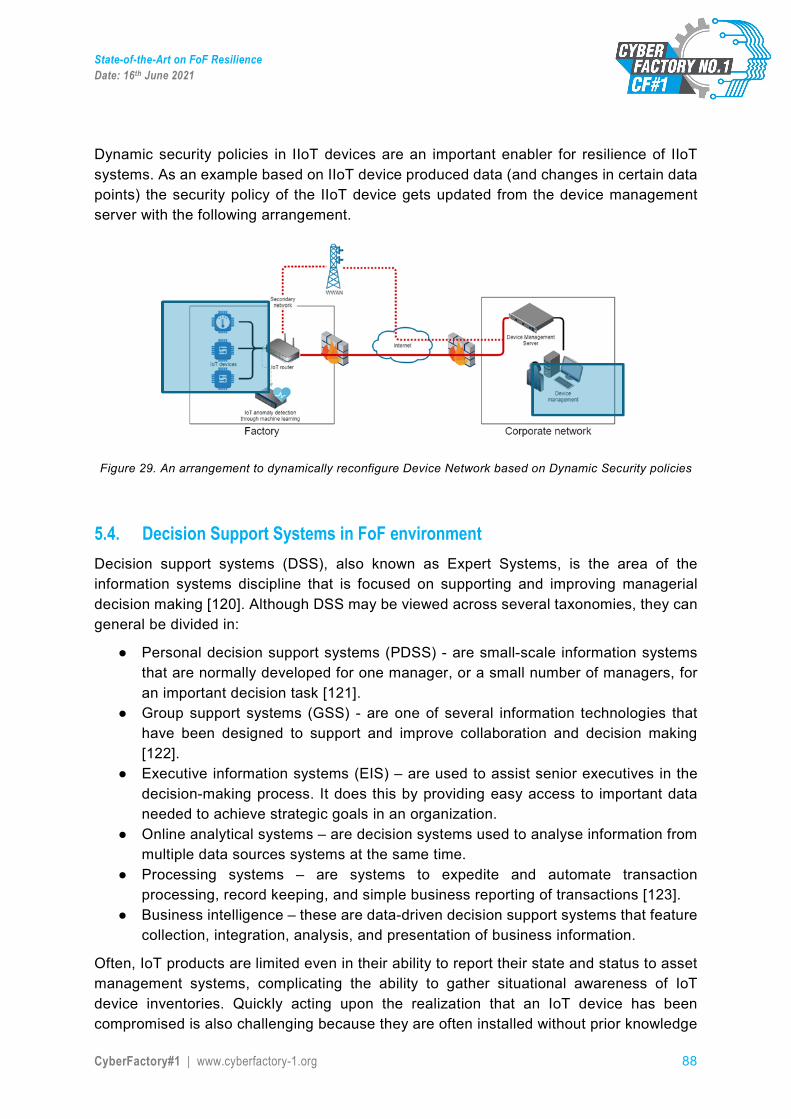
State-of-the-Art on FoF Resilience Date: 16th June 2021
CyberFactory#1 | www.cyberfactory-1.org 88
Dynamic security policies in IIoT devices are an important enabler for resilience of IIoT systems. As an example based on IIoT device produced data (and changes in certain data points) the security policy of the IIoT device gets updated from the device management server with the following arrangement.
Figure 29. An arrangement to dynamically reconfigure Device Network based on Dynamic Security policies
5.4. Decision Support Systems in FoF environment Decision support systems (DSS), also known as Expert Systems, is the area of the information systems discipline that is focused on supporting and improving managerial decision making [120]. Although DSS may be viewed across several taxonomies, they can general be divided in:
● Personal decision support systems (PDSS) - are small-scale information systems that are normally developed for one manager, or a small number of managers, for an important decision task [121].
● Group support systems (GSS) - are one of several information technologies that have been designed to support and improve collaboration and decision making [122].
● Executive information systems (EIS) – are used to assist senior executives in the decision-making process. It does this by providing easy access to important data needed to achieve strategic goals in an organization.
● Online analytical systems – are decision systems used to analyse information from multiple data sources systems at the same time.
● Processing systems – are systems to expedite and automate transaction processing, record keeping, and simple business reporting of transactions [123].
● Business intelligence – these are data-driven decision support systems that feature collection, integration, analysis, and presentation of business information.
Often, IoT products are limited even in their ability to report their state and status to asset management systems, complicating the ability to gather situational awareness of IoT device inventories. Quickly acting upon the realization that an IoT device has been compromised is also challenging because they are often installed without prior knowledge
State-of-the-Art on FoF Resilience Date: 16th June 2021
CyberFactory#1 | www.cyberfactory-1.org 89
of the information security department. A known problem, which is stated also in blog post “Automating the IoT incident response process” [124], is that the cybersecurity analysts are overwhelmed. The cybersecurity tools process massive amounts of data and a problem is that they also trigger huge amounts of false positives. This then needs to be handled by the analyst. As the amount of automated attacks is also rising all the time e.g. because of IoT devices, the manual analysis and response to incidents is not sufficient anymore. The Blog posts also raises the other known problem: managing cybersecurity incidents require deep expertise. The analyst needs to know the typical attack patterns in order to recognise it, quickly combine multiple pieces of data to determine if there is an incident and analyse the impacts of the response procedures.
In CyberFactory#1 Decision Support Systems are used to enhance incident response and autonomous reconfiguration / remediation management capabilities. One example of previous work in this area is described in An Expert System for Mitigation Actions [125]. The paper presents an ontology and Expert System based approach for assisting in mitigation of an advanced persistent threat (APT) attacks against critical infrastructures. The presented prototype, an advanced automated advisory system, is targeted, for example, at the Security Operations Centre (SOC) personnel who need assistance in their tasks. The Expert Systems aims at helping busy, possibly unmanned cybersecurity personnel, who also may lack experience of the particular threat at hands. Usually solving these complex cybersecurity attacks in critical infrastructures requires knowledge from multiple people working in different areas of expertise. For example, the cybersecurity expert working in SOC might not be aware what are the real effects of the attack, or real effects of the proposed mitigation action, without help of the process engineer and personnel on the factory floor.
The article also states, that at that time, the current incident management systems mainly just collect incident related information and handle it as a whole, but do not provide active assistance in mitigation. This needs more time and knowledge from the user, and gives more incentives to develop an automated system. The automated system should give general features if the threat, information about the system to be defended and suggestions how to mitigate the threat. More specifically it should gain information about the current situation, and based on the collected information provide SOC personnel solid, relevant, consistent and unambiguous advice.
Another example, CSAAES: An expert system for cyber security attack awareness [126] presents a design of Expert System, which can identify which type of attack is performed, their symptoms and ways to solve those attacks, meaning that it gives the countermeasures. The solution is targeted for all internet users. The Expert System consists of two components: knowledge base, which collects the information, and logical reasoned, which concludes new information based on the previous built knowledge base.
Both of these Expert Systems are rule-based, and perform listed actions if the premise is true.
State-of-the-Art on FoF Resilience Date: 16th June 2021
CyberFactory#1 | www.cyberfactory-1.org 90
Another aspect to be considered in DSS is the development of SOAR21 (Security Orchestration, Automation and Response). The idea is to establish a solution stack of compatible software programs that allow an organization to collect data about security threats from multiple sources and respond to low-level security events without human assistance.
The goal of using a SOAR stack is to improve the efficiency of physical and digital security operations. According to Gartner, it can be applied to compatible products and services that help define, prioritize, standardize and automate incident response functions.
According to Gartner, the three most important capabilities of SOAR technologies are:
• Threat and vulnerability management: These technologies support the remediation of vulnerabilities. They provide formalized workflow, reporting and collaboration capabilities
• Security incident response: These technologies support how an organization plans, manages, tracks and coordinates the response to a security incident.
• Security operations automation: These technologies support the automation and orchestration of workflows, processes, policy execution and reporting.
While both security information and event management (SIEM) and SOAR stacks aggregate relevant data from multiple sources, SOAR services integrate with a wider range of internal and external applications.
SOAR services can be used to augment in-house SIEM software. In the future, it is expected that as SIEM vendors begin to add SOAR capabilities to their services, the market for these two systems is expected to merge.
See more about IDS and SIEM systems from chapter 4.5.4.
5.5. Incident management / Autonomous adaptation In the aftermath of a security incident you need a quick response and accurate insight. With help of rapid incident response capability, the focus should be helping the FoF organisation to regain control of the factory systems and information promptly following a security incident.
Through a combination of evidence protection and forensically solid investigation, the aim is to;
● Determine how the breach occurred, by understanding the initial vector of attack and compromise.
● Determine the capabilities and activity of a threat actor, and the extent of infiltration. ● Identify (where possible) who may be responsible. ● Categorise what was taken and when, to enable you to understand the loss
21 https://www.gartner.com/en/information-technology/glossary/security-orchestration-automation-response-soar, https://www.infosecurityeurope.com/__novadocuments/580567?v=636897259610400000
State-of-the-Art on FoF Resilience Date: 16th June 2021
CyberFactory#1 | www.cyberfactory-1.org 91
This sets forth an approach the FoF is connected to incident management and response systems tightly. Sensors are deployed on the networks and managed by Security Operation Centre through a secure connection. These sensors are used by the intruder to perform live monitoring of unusual and potentially-malicious traffic, such as intrusion attempts, data modification and malware command and control traffic. Using secure systems and software developed in-house, the network traffic should be able to be analysed in real time, allowing to identify countermeasures to block malicious traffic while tracing the source.
Vulnerabilities in the security of networks and systems supporting essential manufacturing service should be also understood22.
Vulnerabilities should be identified by, but not be limited to, the use of:
● Penetration testing (e.g. as part of a secure development lifecycle). Penetration testing on OT systems must be done with extreme caution;
● Continuous security monitoring tools specifically tailored for OT systems supporting ● Essential services (e.g. passively scanning vulnerabilities of OT assets, tools
customised for proprietary OT vendors, detecting OT specific issues and protocol anomalies);
● Subscription to intelligence services or forums or information exchanges (e.g. CiSP, ICS-CERT);
● OEMs (Original Equipment Manufacturer), vendors or third-party information; ● Vulnerability or change records that could form part of an asset register (e.g. a roll
back change in a system causes a previously treated vulnerability to resurface).
Identified vulnerabilities should be used in risk assessments to ensure appropriate risk and threat scenarios are considered, to enable appropriate mitigations or compensating controls to be identified and applied.
The recent years have focused on developing specific incident management procedures for industrial environments, taking into account the special needs of industrial automation, air-gapped industrial control system environments, critical infrastructures, etc. Now that the factory environment is changing and these traditional OT environments are being combined with IoT and IT environments, the increased connectivity introduces a larger threat surface and additional attack vectors. The unique security requirements of IoT needs to be taken into account, also when building the security teams who respond to incidents. People need to understand the specific risks risen by IoT, and develop a respond plan to IoT-related security incidents.
The new problems that IoT introduces for incident management are e.g.:
● Lack of basic cyber hygiene, ● Lack of logging features, ● Lack of the ability to report their state and status to asset management systems, ● IoT devices may be installed without noticing the security department.
22 https://www.ofgem.gov.uk/system/files/docs/2020/04/riio2_cyber_resilience_guidelines.pdf, NIST 800-53 R4 – Appendix F: RA-5 Vulnerability Scanning
State-of-the-Art on FoF Resilience Date: 16th June 2021
CyberFactory#1 | www.cyberfactory-1.org 92
These affect e.g. when trying to build the situational awareness of device inventory and the whole environment, and makes it more difficult to realize if a specific IoT device has compromised the whole environment.
The Blog post [124] discusses approaches to automating incident response in context of IoT by integrating IoT and Security Orchestration, Automation and Response (SOAR) tools in order to enable efficient and effective incident response procedures for IoT. The orchestration tools facilitate the incident response teams work by integrating Security Information Event Management (SIEM) feeds with threat intelligence feeds, and automatically enriches data and enables more informed decision making. The Blog post also pointed out a workshop held 201523, which conducted that automated incident response seemed to be most mature when responding to Distributed Denial of Service (DDoS) and botnet attacks. These attack types are also the ones that IoT devices usually face.
IETF draft Collaborative Automated Course of Action Operations (CACAO) for Cyber Security24 describes the need for defining standardized language and associated protocols to capture and automate a collection of coordinated cyber security actions and responses. It points out that while senior security experts and researchers may be well aware of some specific attacks and how to respond to those, documenting and giving step by step actions and solutions would enable also the less experienced or junior security experts to react better and without that much involvement of senior staff. The course of actions should also be documented in a way that enables automated mitigation or remediation. This would not only allow security experts to respond more quickly and reduce the exposure from attack but it would also allow organisations to pre validate the course of actions and potentially simulate them, to understand better the overall cost, revenue loss, user experience, risks and liabilities.
ENISA’s Good Practice Guide for Incident Management25 (2010) is slightly aged but still a very valid and relevant guide when starting to build incident management principles for the organisation. Another relevant ENISA guide is Actionable Information for Security Incident Response26 (2014), which focuses on processing and exchanging information. The publication is focused for national and governmental CERTs, but it is also a relevant guide in incident response for organisations. Incident management procedures in critical infrastructures was studied in EU funded ECOSSIAN project, and results published in deliverable Threat mitigation and incident management in CI use cases of ECOSSIAN [127]. It has also focused on realistic threat mitigation procedures in a critical infrastructure environment, which has its own characteristics and requirements.
In context of CyberFactory#1, the aim is to find out how to combine the requirements rising from traditional ICS environments and new requirements coming from connected IoT devices to make a common incident management plan for Factories of the Future.
23 In 2015, the Internet Engineering Task Force (IETF) held the Conducting Attack Response at Internet Scale (CARIS) workshop 24 https://tools.ietf.org/html/draft-jordan-cacao-introduction-01 25 https://www.enisa.europa.eu/publications/good-practice-guide-for-incident-management 26 https://www.enisa.europa.eu/publications/actionable-information-for-security
State-of-the-Art on FoF Resilience Date: 16th June 2021
CyberFactory#1 | www.cyberfactory-1.org 93
5.6. Recovery, reconfiguration and remediation Reconfiguration presents the technical view of the process of changing an already developed and operatively used system in order to adapt it to new requirements, extend functionality, eliminate errors or improve quality characteristics [128].
Dynamic software architectures and specifically dynamic components have been identified as “challenging in terms of correctness, robustness, and efficiency” [129]. This is especially true for self-managing architecture since systems that are self-managed have to implement the initiation and selection of a change. Conversely, Endler [130] notes user-managed architectures usually exhibit ad-hoc change in which the initiation and selection occur external to the software, thus simplifying the development.
The occurrence of unpredicted side effects, patterns, oscillations or instabilities on a system wide-level is a known effect in large systems (such as FoF). This is also magnified by the complex internal dynamics of the interacting actors (humans and machines in physically-entangled systems) and by the external dynamics emerging from increasingly interconnection of the several organizations either in collaborative (ex: supply chain actors) or competitive environments (ex: manufacturing companies in the international markets). Therefore, the behaviour of CPSoS appears as inherently different from the sum of its parts. Indeed, CPSoS are complex systems they are made of “many intrications which make impossible the study of a part of it separately while neglecting its other components [131]. Even if some part of it is computable, it is mainly nondeterministic and unpredictable”. This is especially true when the system is exposed to the event of stochastic events which can potentially cause severe impacts in the system. These events can be internal, if it is originated by any component of the CPSoS (e.g.: equipment malfunction) or external (e.g. cyber-attack). Whilst autonomous systems are superficially slightly less efficient than systems which follow a central planning approach when everything goes according to plan, they are generally much more resilient to disturbances and unforeseeable events due to their ability to rapidly self-reconfigure to avoid unnecessary production downtime. In a centrally controlled system, the unforeseen outage of one machine may require human intervention to replan a production line, whilst in an autonomous system, production entities such as machines, conveyor systems and the products to be manufactured themselves would immediately renegotiate the production plan to circumvent the defunct machine. This means that from a wider perspective, because of their inherent resilience, autonomous systems are more efficient since processes need not stop because of individual subsystem outages.
The recovery of FOF, as following a SoS paradigm, needs to consider these factors:
● Timely awareness of the extent of the problems derived not only from the localized cause of the problem but also from the emergent behaviour
● Ability to self-reconfigure to recover ● Ability to not stop because of individual subsystem outages
State-of-the-Art on FoF Resilience Date: 16th June 2021
CyberFactory#1 | www.cyberfactory-1.org 94
5.6.1 Process and abilities of reconfiguration
One of the widely used process schemes for systems-of-systems (SoS) reconfiguration is the one of Bradbury et al. [132]. This scheme consists of four steps: initiation, selection, implementation and assessment. In the initiation step, the systems monitor themselves and their environment and are able to detect changes that require reconfiguration.
Considering a factory as an adaptive SoS example, where AGVs, machines and sometimes humans as well are collaborating to:
• Fulfil the requested transports from machines autonomously. • React onto the changes in the environment by adapting the configuration of member
systems and their interactions. • Collaborating with factory members (machines, MES, other robots) to fulfil shared
objectives at factory level.
In a heterogeneous fleet of AGVs one of the main challenges is the fulfilment of the multi-level goals of the systems. This means, that AGVs collaborate with each other and agreeing strategy optimally fulfilling partially contradicting goals. This behaviour imposes challenges such as:
• Fulfilling goals at the level of SoS (AGV fleet) and at the level of system (here AGV) • Agreeing on an optimal strategy to fulfill the selected goals. • Compromising on contradicting goals to fulfill the highest priority goal.(here is
fulfilling the requested transports)
Changing their interaction according to the availability of the AGVs in the factory. We defined a self-managing architecture as an architecture in which the entire change process occurs internally.
In such example, AGVs must be able to reconfigure by generating new strategy at run time according to the change they see either in their system or in their environment.
To initiate a reconfiguration, an event must be detected, e.g. a certain combination of states in the system or its environment. To define such events requires prior knowledge of the individual adaptation possibilities of the system. In a different approach of Butting et.al. [133], reconfiguration could also be initiated by instruction. Here, the environment (e.g. other systems in the system-of-systems) could intentionally start a reconfiguration.
In the example of our AGVs the change (Strategy generation) is initiated when (first step)
Anomaly reconfiguration request: Whenever a wrong behaviour is recognised in the SoS.
If Goals change: The goals can be changed either internally from the system or externally by other systems.
Factory or Machine requirements change: i.e. change in the number of transport requests or machine unavailability.
Context change (Map layout change, etc.): i.e. a hallway is blocked due to existence of an obstacle.
Robot Status change: i.e. AGV failure.
State-of-the-Art on FoF Resilience Date: 16th June 2021
CyberFactory#1 | www.cyberfactory-1.org 95
After successful initiation, a description of the initiation event is passed on, to provide the informational basis for the selection step. There are three levels of flexibility regarding the selection of new configurations in adaptive SoS:
1. Pre-defined Selection: Once we initiate a dynamic change, system choose a change operation based on a pre-defined selection made at design-time.
2. Constrained Selection from a Pre-defined Set: Once we initiate a dynamic change there is some choice in what configuration to use. For example, a set of configurations may be defined at design-time for a given situation or state. The system, upon reaching the situation, will select the appropriate configuration from the set.
3. Unconstrained Selection: Once we initiate a dynamic change there is an unconstrained choice regarding the appropriate change to make. Batista et. al. [134] on the other hand only distinguishes programmed and ad-hoc reconfiguration. Programmed reconfiguration can be assigned to the Constrained Selection and ad-hoc reconfiguration to the Unconstrained Selection with or without a pre-defined set of configurations.
The Predefined Selection is the simplest method to implement changes in a system. This allows production lines to change drills or adapt procedures by changing part drawings. The approaches presented in most papers can be assigned to the Constrained Selection with predefined set. The approach of Salehi et. al. [135] is called Action Selection Mechanism and is based on the GAAM (Goal-Action-Attribute Model). In GAAM, actions are selected in the decision model from the goals that are activated as a result of attributes. The Action Selection Mechanism (ASM) describes the connection between goals, actions and attributes. The approach of Mauro et. al. [136] follows the idea to change as few parameters as necessary in a system to avoid critical changes. The Monitoring-Analyze-Plan-Execution Knowledge (MAPE-K) [137] loop is used as a basis for the approach for Klös et.al. [138]. This adaptation process weights the individual parameters to calculate the impact of each parameter on the overall system performance. The approach published by Rosa et al. [139] describes a filter mechanism that selects rules defined at design time based on goals and a key performance indicator. The presented approaches of selection represent Constrained Selection mechanisms that can only be applied to certain types of systems. A general solution for Unconstrained Selection is currently not available.
The AGVs as our example has the possibility to change their behaviour and do the selection of architectural transformation by selecting the optimal strategy. With knowledge about the initiation event the systems can develop strategies to adapt the systems in order to meet the goals to be aware of the existing situation.
Once the selection is completed, the changes will be implemented into the system. If there are several different changes, there is the possibility of a loop for selection and implementation to integrate several changes after each other. In the thesis of Schneider [140], three approaches to implement a new service into a system at runtime are described. The aim of these approaches is the minimization of reconfiguration- and blackout-time of a service. Another idea is pursued by the state transfer approach. In the proposal of Esteller-Curto et. al. [141], REST (Representational State Transfer) is used to synchronize the services of a robot with a server. In the paper of Khare et. al. [142], an asynchronous
State-of-the-Art on FoF Resilience Date: 16th June 2021
CyberFactory#1 | www.cyberfactory-1.org 96
REST architecture style is presented. The architecture is able to start a data transfer if a change of a service is detected.
Finally, if implementation is done, the assessment will be performed. In the model described above, the system checks in the assessment step solely the successful implementation of the configuration change. But it is also possible to change the steps in their order. This way it can be directly determined whether an intended target configuration fulfils the given goals of the system. In this case, the reconfiguration would be implemented, else a new selection step could be initiated. The approach of Marmsoler et. al. [143] describes an assessment method based on mathematical rules. In order to apply the rules, the author uses the blackboard model, where different interim solutions are brought together on one board by different functions and thus lead to a common solution. In addition, it is also necessary to evaluate the safety properties of a new configuration. Léger et. al. [144] describes an algorithm which assesses the quality of a reconfiguration. In the paper of Priesterjahn et. al. [145], the safety properties of a reconfiguration are verified. To achieve this, every system member is extended with a risk manager that could block a reconfiguration in case of a risk for the system. In conclusion, the assessment evaluates if a new configuration is acceptable with respect to its risk, quality or influence into the system structure.
Upon the above mentioned circumstances AGVs must be able to properly react by adopting an optimal strategy which is operationalised by reconfiguration. Assessment of architecture after reconfiguration can evaluate the strategy and if it leads to a wrong behaviour, the reconfiguration loop will be once again initiated.
Systems can be reconfigured at different layers of its internal system structure. The papers Ruiz et. al. [146] and Lagger et. al. [147] describe the reconfiguration for Field Programmable Gate Arrays. The approach of Coker et. al. [148] presents the reconfiguration of the communication level which uses stochastic algorithms for network reconfiguration. Trapp et. al. [149] provides an approach which can also be applied in the field of communication reconfiguration. The author describes to replace failed sensor nodes with calculated combined sensor values of local and global sensors of other members. Following approaches in different domains and system levels will be described.
5.6.2 Reconfiguration in the Mobile Robotics Domain
Mobile robots like Automated Guided Vehicles (AGVs) are already handling parts of the logistics in modern factories, e.g. by delivering materials to machines and collecting products in warehouses. The factory environment of such a robot is subject to changes: paths in the factory may be temporarily blocked by static obstacles or human workers, the transportation needs of the factory strongly depend on the current configuration of machines, other robots may join or leave the fleet, the whole factory layout may change when new machines need to be installed etc.
Some of those changes may have negligible effect on the robot’s performance, other changes can lead to severe loss of performance (e.g. when a fleet of robots cannot handle a sudden increase in the number of transport tasks, which can lead to a shutdown of machines) or even prevent the robot to fulfil its job.
State-of-the-Art on FoF Resilience Date: 16th June 2021
CyberFactory#1 | www.cyberfactory-1.org 97
Dynamic reconfiguration can be used as a countermeasure of performance loss: it allows robots to react to changing situations and detect anomalies in the environment and to fulfil new assignments. Reconfiguration can be done on hardware level (commonly by using hardware plugins like used for Field Programmable Port Extender (FPGA) [150]) as well as on a software level.
5.6.2.1 Dynamic Hardware Reconfiguration
Nava et al. presented an approach on how to adapt a fleet of robots to a new or unforeseen situation, when the available processing capabilities of each robot is limited. The approach falls in the category of (automated) dynamic hardware reconfiguration and focuses on robots that need to process huge amount of video and image data: Based on a hybrid FPGA-enhanced processing architecture, powerful sensors and an ad hoc wireless communication system, collaboration between robots is used for avoiding bottlenecks in the fleet due to processing limitations. In the presented method, costly data processing can be done by several FPGAs in parallel and on demand. In application, the processing power of a single robot can be enhanced by using the resources of other robots. This re-allocation of hardware resources depends on the status of the robot and its context and the required tasks and is managed by the robot’s operating system [151].
Another FPGA-based architecture which allows dynamic hardware configuration of robots is presented by Paiz et al. [152] and Commuri et al. [153], focusing on application on mini-robot platforms. Examples for such mini-robot platforms that allow dynamic hardware reconfiguration and that are widely used for research in the area of robotics, are BeBot [154] and Khepera [155].
5.6.2.2 Dynamic Software Reconfiguration
In 2012, Dasgupta et al. introduced an approach for dynamic reconfiguration of a single modular robot [156]. The problem of finding an optimal reconfiguration of a robot consisting of multiple connected modules is formulated as constrained optimization problem and is solved with graph partitioning algorithms. In more detail, the approach is based on coalition game theory, which aims for finding the best coalition of modules while the costs for reconfiguration are minimized. However, this approach focuses on finding an optimal configuration of a single robot and does not consider a fleet of collaborative transport robots.
In 2001, the former telephone company GTE Internetworking Incorporated patented a system for dynamically reconfigure a wireless robot network [157]. In this approach, robots calculate a fitness level while fulfilling a task. The robot with the highest fitness shares its current setting of its control logic with all other robots, which can then adapt their own control logic.
Lee, Park, Han and Hong presented RSCA, a software architecture for a distributed robot platform that supports the dynamic reconfiguration of embedded software [158]. The architecture provides components that allow for three different types of dynamic reconfiguration: individual component reconfiguration, application reconfiguration and deployment time reconfiguration. With those capabilities, the robot is able to download, install, uninstall, start and stop new applications. The middleware is specifically tailored for
State-of-the-Art on FoF Resilience Date: 16th June 2021
CyberFactory#1 | www.cyberfactory-1.org 98
fitting the needs of a robot project called Ubiquitous Robotic Companion [159] (UCR) robot project, which aims for service robots that provide their services to users wherever and whenever needed.
Dynamic reconfiguration of robots is in the literature also considered for solving some Multi Robot Task Assignment (MRTA) problems. In MRTA problems, the challenge is to decide which robot of a group of robots should take over which task in order to achieve the overall objectives of the group. The problems vary, among others, in the assumptions on knowledge on tasks (e.g. Are all tasks known in advance or can new tasks appear?), complexity of tasks (e.g. Is each task consisting of a unique set of smaller tasks, each performable by a single robot independently? Do deadlines exist?), dependencies between robot schedules (e.g.: Does a robot need to fulfil a task before, after or simultaneous to another task?) and capabilities of robots (e.g.: Can robots re-assign tasks? Is it a homogeneous group of robots or is it a heterogeneous group?). For structuring the space of MTRA problems and for being able to link some subclasses of the problems to other research areas, Korsah et al. [160] introduced a taxonomy of MRTA problems based on previous work of Gerkey and Matarić [161]. We refer to the original papers for an introduction to the taxonomy. Some solutions to MRTA problems tackle dynamic reconfigurations directly (e.g. by providing means for task-reallocation or for adapting to new goals of the robots), some solutions provide alternatives for configurations a group of robots can apply.
In 2012, Liu and Shell presented a solution for a MRTA problem of the class ID [ST-SR-IA] that is considering dynamic reconfiguration of robots in terms of potential re-assignment of tasks and reaction to changing utilities of tasks. The utility captures the benefits and costs of tasks. The solution focuses on application for large fleets. A key idea is to divide the task allocation in two steps. The first step is partitioning the set of robots and tasks, such that subgroups of robots are assigned to subsets of tasks. The partitioning degree can be chosen, allowing to vary the level of (de-)centralization of the overall algorithm. The second step solves the task assignment problem in the smaller sub-classes. Either some existing solution for the MRTA problem can be used on such a sub-problem or the first step can be done again to further partition the problem into smaller problems. Each sub-problem can be solved independent of all other sub-problems, allowing to concurrently compute sub-solutions and hence speed up the algorithm runtime and reduce the amount of communication between robots. Re-assignment of tasks for optimization is possible, but does not inquire all robots to participate in the re-assignment, but only involves a selection of robots based on dependencies identified in the partitioning step. Simulative application of the algorithm indicates that the algorithm allows to significantly increase the efficiency of task allocation at the cost of only a small decrease in the quality of result. The approach allows dynamically changing utilities (e.g. because a previous estimation of a utility has to be corrected). An update in the utilities can trigger re-allocation on tasks and after a given threshold on utility updates, a global re-partitioning of the fleet of robots is performed. Although the algorithm can successfully deal with smooth utility change, it has problems with sudden changes in the utilities (like staircase utility functions, which might be the case if the utility for a task changes when completing another task). [162]
State-of-the-Art on FoF Resilience Date: 16th June 2021
CyberFactory#1 | www.cyberfactory-1.org 99
Gombalay, Wilcox and Shah introduce a centralized polynomial-time algorithm called Tercio for a MRTA problem of the class XD [SR-ST-TA] in which tasks are allocated with lower and upper temporal constraints and there are restrictions on robot’s proximity. The authors claim that the algorithm is in particular useful for factory environments, in which robots and humans interact. All tasks are known beforehand, but due to timing dependencies between tasks (e.g. a task can only be started the earliest 30min after completion of another task), not all details of tasks are known immediately in absolute numbers. Calculated schedules are using timeframes for starting a task instead of a fixed starting time in order to handle small disturbances and increase robustness of the solution. Spatial constraints are addressed by allowing a robot to block not only the area it needs for task completion for all other robots, but also areas in the near neighbourhood. Simulative experiments showed that the algorithm is able to calculate nearly optimal schedules for ten robots and 500 tasks within 20 seconds. The shown examples are considering groups that do not extensively move, but task fulfilment requires occupation of a location in the factory for a longer time (e.g. a robot shall paint a work piece). Constraints on robotics behaviour like battery depletion are not considered. [163]
Korsah et al. consider a XD [MT-SR-TA] problem with complete knowledge on all tasks to be assigned for a heterogeneous group of robots. Temporal constraints between tasks create cross-schedule dependencies of robots. The problem is formulated as a set-partitioning mixed-integer programming model, in which rewards for completed tasks, costs for travelled distance and costs for waiting periods of robots are encoded as weighted sum. The presented approach consists of two phases for task assignment and scheduling: planning and execution management. In the first phase, a routine with complete knowledge on tasks to be assigned calculates a solution for task assignment and scheduling. The calculation time is bounded by a given parameter and the quality of the solution is increasing with the allowed calculation time. The result is a schedule for each robot with defined starting times for tasks and waiting times between tasks for dealing with cross-schedule dependencies. The objective of the second phase is to increase the robustness of the solution of the first phase by taking potential deviations of expected execution time during the first phase and real execution time during operation into account. The schedule modifications depend on the selected mode and can vary from strictly obeying the initial schedule, add some waiting time when task fulfilment took less time than expected to communicate task fulfilment to other robots during runtime. The approach cannot deal with new appearing tasks or task reallocation or the need of robots to recharge its batteries. [164]
When facing tasks that were not known at design time, a fleet of robots may be unable to fulfil the task with its previously used behavioural patterns (e.g. various solutions of MRTA problems). In this case, the problem of finding a good reconfiguration is becoming harder, since it does no longer suffice to choose between hard-coded task fulfilment alternatives, but to re-combine possible robot behaviour for getting new choices for task fulfilment. In the setting of a heterogeneous fleet of robots, Tank and Parker presented a synthesis algorithm that allows such a re-combination of behavioural artefacts for finding new solution strategies [165]. The algorithm, called ASyMTRe (Automated Synthesis of Multi-robot Task solutions through software Reconfiguration), calculates not only which robot has to fulfil which part of a task, but also how this part should be done. A key idea of the paper is that
State-of-the-Art on FoF Resilience Date: 16th June 2021
CyberFactory#1 | www.cyberfactory-1.org 100
robots can provide services to other robots, e.g. a robot with an on-board camera for self-localizing can support a robot without self-localisation capabilities by providing required information. A similar idea was introduced e.g. used by Fikes and Nilsson [166].
Inspired by the biological process of natural selection involving mutations, crossover and selection, evolutionary algorithms and in particular the subclass of genetic algorithms are designed for enabling a system to come up with new solutions to optimization problems [167]. A review of the state of the art in the field of evolutionary robotics till 2003 is presented by Pratihar [168]. More recent findings include genetic algorithms for robots with access to cloud computing infrastructures [169], combination of genetic algorithms with neural network solutions [170] and genetic algorithms for path planning in complex [171] or dynamically changing environments [172].
5.7. Visualisation of data and other relevant inputs to FoF resilience Visualization in general is a particular method of interest being explored to aid the end users’ environment to enable more analysis that is effective. It is also used to increase the overall performance in user friendliness and interaction with the device. Visualization tools can be used to enhance accuracy, communication, and performance of the analyst’s process of identifying cyber-attacks with anomaly-based Intrusion Detection Systems (IDS). [173] In addition the support for supervised or semi-supervised learning is providing a method for enhancing machine learning results through examples.
IDS aim at detecting attacks against computer systems and networks or, in general, against information systems. It acquires knowledge about an information system in order to perform analysis on its security status. It is important to note that there are two general types of IDS: knowledge-based and behaviour-based. From the network point of view the most common classifications are network intrusion detection systems (NIDS) and host-based intrusion detection systems (HIDS), see more about these from chapter 4.5.4.1, where network monitoring aspects are more detailed described.
Knowledge-based IDS is often referred to as “misuse detection” or detection by appearance. A knowledge-based IDS is designed to collect network information and sift through the collected data for evidence of exploitation, command, and control. In the same fashion, behaviour-based IDS is also known as anomaly detection or detection by behaviour and its focus is on creating a model of usual behaviour for the information system being monitored while observing any deviation from the model for further investigation.
Some other IDS are signature-based, host-based, network-based, and graph-based. Signature-based IDS decides in advance what type of behaviour is undesirable according to the use of known set behaviours and detected intrusions.
Host-based was the first IDS ever designed to audit information provided by a mainframe. It performed its audit locally or on separate machines. A shift in computing from mainframe environments to distributed workstation networks was the cause for seeking better IDSs.
Distributed IDS (DIDS) that is the hybrid approach to using both network-based and host-based intrusion detection (ID) tools for a multi host environment.
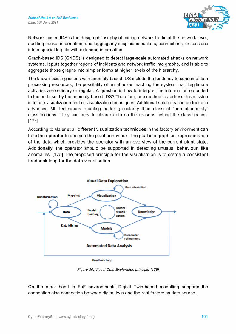
State-of-the-Art on FoF Resilience Date: 16th June 2021
CyberFactory#1 | www.cyberfactory-1.org 101
Network-based IDS is the design philosophy of mining network traffic at the network level, auditing packet information, and logging any suspicious packets, connections, or sessions into a special log file with extended information.
Graph-based IDS (GrIDS) is designed to detect large-scale automated attacks on network systems. It puts together reports of incidents and network traffic into graphs, and is able to aggregate those graphs into simpler forms at higher levels of the hierarchy.
The known existing issues with anomaly-based IDS include the tendency to consume data processing resources, the possibility of an attacker teaching the system that illegitimate activities are ordinary or regular. A question is how to interpret the information outputted to the end user by the anomaly-based IDS? Therefore, one method to address this mission is to use visualization and or visualization techniques. Additional solutions can be found in advanced ML techniques enabling better granularity than classical “normal/anomaly” classifications. They can provide clearer data on the reasons behind the classification. [174]
According to Maier et al. different visualization techniques in the factory environment can help the operator to analyse the plant behaviour. The goal is a graphical representation of the data which provides the operator with an overview of the current plant state. Additionally, the operator should be supported in detecting unusual behaviour, like anomalies. [175] The proposed principle for the visualisation is to create a consistent feedback loop for the data visualisation.
Figure 30. Visual Data Exploration principle (175)
On the other hand in FoF environments Digital Twin-based modelling supports the connection also connection between digital twin and the real factory as data source.
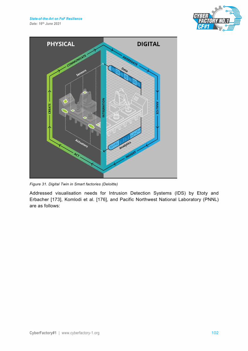
State-of-the-Art on FoF Resilience Date: 16th June 2021
CyberFactory#1 | www.cyberfactory-1.org 102
Figure 31. Digital Twin in Smart factories (Deloitte)
Addressed visualisation needs for Intrusion Detection Systems (IDS) by Etoty and Erbacher [173], Komlodi et al. [176], and Pacific Northwest National Laboratory (PNNL) are as follows:
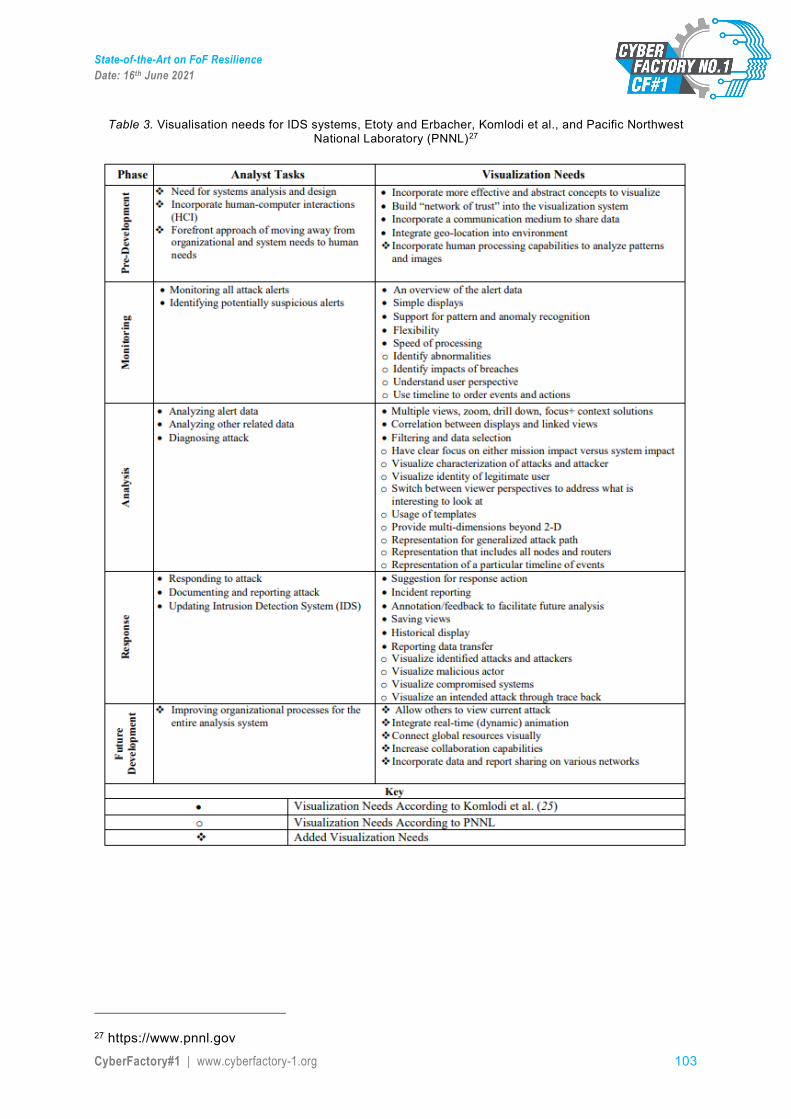
State-of-the-Art on FoF Resilience Date: 16th June 2021
CyberFactory#1 | www.cyberfactory-1.org 103
Table 3. Visualisation needs for IDS systems, Etoty and Erbacher, Komlodi et al., and Pacific Northwest National Laboratory (PNNL)27
27 https://www.pnnl.gov
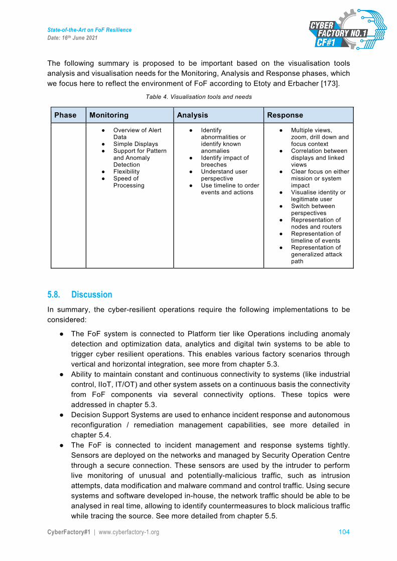
State-of-the-Art on FoF Resilience Date: 16th June 2021
CyberFactory#1 | www.cyberfactory-1.org 104
The following summary is proposed to be important based on the visualisation tools analysis and visualisation needs for the Monitoring, Analysis and Response phases, which we focus here to reflect the environment of FoF according to Etoty and Erbacher [173].
Table 4. Visualisation tools and needs
Phase Monitoring Analysis Response
● Overview of Alert Data
● Simple Displays ● Support for Pattern
and Anomaly Detection
● Flexibility ● Speed of
Processing
● Identify abnormalities or identify known anomalies
● Identify impact of breeches
● Understand user perspective
● Use timeline to order events and actions
● Multiple views, zoom, drill down and focus context
● Correlation between displays and linked views
● Clear focus on either mission or system impact
● Visualise identity or legitimate user
● Switch between perspectives
● Representation of nodes and routers
● Representation of timeline of events
● Representation of generalized attack path
5.8. Discussion In summary, the cyber-resilient operations require the following implementations to be considered:
● The FoF system is connected to Platform tier like Operations including anomaly detection and optimization data, analytics and digital twin systems to be able to trigger cyber resilient operations. This enables various factory scenarios through vertical and horizontal integration, see more from chapter 5.3.
● Ability to maintain constant and continuous connectivity to systems (like industrial control, IIoT, IT/OT) and other system assets on a continuous basis the connectivity from FoF components via several connectivity options. These topics were addressed in chapter 5.3.
● Decision Support Systems are used to enhance incident response and autonomous reconfiguration / remediation management capabilities, see more detailed in chapter 5.4.
● The FoF is connected to incident management and response systems tightly. Sensors are deployed on the networks and managed by Security Operation Centre through a secure connection. These sensors are used by the intruder to perform live monitoring of unusual and potentially-malicious traffic, such as intrusion attempts, data modification and malware command and control traffic. Using secure systems and software developed in-house, the network traffic should be able to be analysed in real time, allowing to identify countermeasures to block malicious traffic while tracing the source. See more detailed from chapter 5.5.

State-of-the-Art on FoF Resilience Date: 16th June 2021
CyberFactory#1 | www.cyberfactory-1.org 105
● For the system recovery from various incident scenarios alternative connections are established via the available connectivity alternatives in the FoF. This also enables potential dynamic reconfiguration of FoF resources for the recovery of incidents and disaster situations. See more detailed information from chapter 5.6.
● The information of FoF connectivity and status of the assets is created, alternatively saved via static and updated into dynamic dashboards combined with analytics data in relation to Cyber-resilient operations in the FoF. These features are enabled by using anomaly detection or situational awareness data. These topics were addressed in chapter 5.7.
State-of-the-Art on FoF Resilience Date: 16th June 2021
CyberFactory#1 | www.cyberfactory-1.org 106
References 1. OASIS eXtensible Access Control Markup Language (XACML) TC; https://www.oasis-
open.org/committees/xacml/ 2. The OAuth 2.0 Authorization Framework; https://tools.ietf.org/html/rfc6749 3. OASIS Security Services (SAML) TC; https://www.oasis-
open.org/committees/tc_home.php?wg_abbrev=security 4. Christian Szegedy. Wojciech Zaremba. Ilya Sutskever. Joan Bruna. Dumitru Erhan. Ian J.
Goodfellow and Rob Fergus. Intriguing properties of neural networks. In ICLR, 2014. 5. Nguyen A, Yosinski J, Clune J. Deep neural networks are easily fooled: High confidence
predictions for unrecognizable images [J]. 2015:427-436. 6. Akhtar N., Mian A. Threat of Adversarial Attacks on Deep Learning in Computer Vision: A
Survey [J]. IEEE Access, 2018. 7. Anish Athalye. Logan Engstrom. Andrew Ilyas and Kevin Kwok. Synthesizing robust adversarial
examples. 2018. 8. Seyed-Mohsen Moosavi-Dezfooli. Alhussein Fawzi. Omar Fawzi and Pascal Frossard.
Universal adversarial perturbations. The IEEE Conference on Computer Vision and Pattern Recognition (CVPR). 2017.
9. T. Gu, B. Dolan-Gavitt, S. Garg, BadNets: Identifying Vulnerabilities in the Machine Learning Model Supply Chain. arXiv preprint arXiv:1708.06733, 2017.
10. Konda Reddy Mopuri. Utsav Garg and R. Venkatesh Babu. Fast feature fool: A data independent approach to universal adversarial perturbations. In Proceedings of the British Machine Vision Conference (BMVC).2017.
11. Konda Reddy Mopuri. Aditya Ganeshan and R. Venkatesh Babu. Generalizable data-free objective for crafting universal adversarial perturbations. IEEE Transactions on Pattern Analysis & Machine Intelligence. vol. PP. no. 99. pp. 1–1. 2018.
12. A. Krizhevsky, I. Sutskever, and G. Hinton. ImageNet classification with deep convolutional neural networks. In NIPS, 2012.
13. P. Sermanet, D. Eigen, X. Zhang, M. Mathieu, R. Fergus, and Y. LeCun. Overfeat: Integrated recognition, localization and detection using convolutional networks. In ICLR, 2014.
14. R. Girshick, J. Donahue, T. Darrell, and J. Malik. Rich feature hierarchies for accurate object detection and semantic segmentation. In CVPR, 2014.
15. J. R. Uijlings, K. E. van de Sande, T. Gevers, and A. W. Smeulders. Selective search for object recognition. IJCV, 2013.
16. K. He, X. Zhang, S. Ren, and J. Sun. Spatial pyramid pooling in deep convolutional networks for visual recognition. In ECCV, 2014.
17. S. Gidaris and N. Komodakis. Object detection via a multi-region & semantic segmentation-aware cnn model. In ICCV, 2015.
18. R. Girshick. Fast R-CNN. In ICCV, 2015. 19. S. Ren, K. He, R. Girshick, and J. Sun. Faster R-CNN: Towards real-time object detection with
region proposal networks. In NIPS, 2015. 20. Dai, Jifeng, Yi Li, Kaiming He and Jian Sun. R-FCN: Object Detection via Region-based Fully
Convolutional Networks. In NIPS, 2016. 21. He, Kaiming, Georgia Gkioxari, Piotr Dollár and Ross B. Girshick. Mask R-CNN. 2017 IEEE
International Conference on Computer Vision (ICCV) (2017): 2980-2988. 22. Liu, Wei, Dragomir Anguelov, Dumitru Erhan, Christian Szegedy, Scott E. Reed, Cheng-Yang
Fu and Alexander C. Berg. SSD: Single Shot MultiBox Detector.” In ECCV, 2016. 23. Redmon, Joseph, Santosh Kumar Divvala, Ross B. Girshick and Ali Farhadi. You Only Look
Once: Unified, Real-Time Object Detection. 2016 IEEE Conference on Computer Vision and Pattern Recognition (CVPR) (2016): 779-788.
State-of-the-Art on FoF Resilience Date: 16th June 2021
CyberFactory#1 | www.cyberfactory-1.org 107
24. Jonathon Shlens Ian J. Goodfellow and Christian Szegedy. Explaining and harnessing adversarial examples. In ICLR, 2015.
25. Anh Mai Nguyen. Jason Yosinski. and Jeff Clune.Deep neural networks are easily fooled: High confidence predictions for unrecognizable images. In CVPR, 2015.
26. Alhussein Fawzi. Seyed-Mohsen Moosavi-Dezfooli. and Pascal Frossard. Robustness of classifiers: from adversarial to random noise. In NIPS, 2016.
27. Alhussein Fawzi. Omar Fawzi. and Pascal Frossard.Analysis of classifiers robustness to adversarial perturbations. Machine Learning. vol. 107. no. 3. pp. 481–508. 2018.
28. Alexey Kurakin. Ian J. Goodfellow. and Samy Bengio.Adversarial machine learning at scale. CoRR. vol.abs/1611.01236. 2016.
29. Nicolas Papernot. Patrick D. McDaniel. Somesh Jha. Matt Fredrikson. Z. Berkay Celik. and Ananthram Swami. The limitations of deep learning in adversarial settings. 2016 IEEE European Symposium on Security and Privacy (EuroSP). pp. 372–387. 2016.
30. Jiawei Su. Danilo Vasconcellos Vargas. and Kouichi Sakurai. One pixel attack for fooling deep neural networks. CoRR. vol. abs/1710.08864. 2017.
31. Nicholas Carlini and David A. Wagner. Towards evaluating the robustness of neural networks. 2017 IEEE Symposium on Security and Privacy (SP). pp. 39–57.2017.
32. Seyed-Mohsen Moosavi-Dezfooli. Alhussein Fawzi. and Pascal Frossard. Deepfool: A simple and accurate method to fool deep neural networks.in CVPR, 2016.
33. Jan Hendrik Metzen. Mummadi Chaithanya Kumar. Thomas Brox. and Volker Fischer. Universal adversarial perturbations against semantic image segmentation. In ICCV, 2017.
34. Alexey Kurakin. Ian J. Goodfellow. and Samy Bengio.Adversarial examples in the physical world. CoRR. vol. abs/1607.02533. 2016.
35. Nicolas Papernot, Patrick McDaniel, Somesh Jha, Matt Fredrikson, Z Berkay Celik, and Ananthram Swami. The limitations of deep learning in adversarial settings. In EuroS&P, 2016.
36. Seyed-Mohsen Moosavi-Dezfooli, Alhussein Fawzi, and Pascal Frossard. Deepfool: a simple and accurate method to fool deep neural networks. In CVPR, 2016.
37. Jiajun Lu. Hussein Sibai. and Evan Fabry. Adversarial examples that fool detectors. CoRR. vol.abs/1712.02494. 2017.
38. Cihang Xie. Jianyu Wang. Zhishuai Zhang. Yuyin Zhou. Lingxi Xie. and Alan L. Yuille. Adversarial examples for semantic segmentation and object detection. In ICCV, 2017.
39. Yuezun Li. Daniel Tian. Ming-Ching Chang. Xiao Bian. and Siwei Lyu. Robust adversarial perturbation on deep proposal-based models. In BMVC, 2018.
40. Yuezun Li. Xian Bian. and Siwei Lyu. Attacking object detectors via imperceptible patches on background. CoRR. vol. abs/1809.05966. 2018.
41. Ian Goodfellow. Nicolas Papernot. Sandy Huang. Rocky Duan. Pieter Abbeel. Jack Clark, 2017. Attacking Machine Learning with Adversarial Examples. Disponible en https://openai.com/blog/adversarial-example-research/
42. Anish Athalye, Nicholas Carlini, and David Wagner. Obfuscated gradients give a false sense of security: Circumventing defenses to adversarial examples. In International Conference on Machine Learning, pages 274–283, 2018.
43. Nicholas Carlini and David Wagner. Adversarial examples are not easily detected: Bypassing ten detection methods. In Proceedings of the 10th ACM Workshop on Artificial Intelligence and Security, pages 3–14. ACM, 2017.
44. Dan Hendrycks, Kimin Lee, and Mantas Mazeika. Using pre-training can improve model robustness and uncertainty. arXiv preprint arXiv:1901.09960, 2019.
45. Yair Carmon, Aditi Raghunathan, Ludwig Schmidt, Percy Liang, and John C Duchi. Unlabeled data improves adversarial robustness. arXiv preprint arXiv:1905.13736, 2019.
46. Guy Katz, Clark Barrett, David L Dill, Kyle Julian, and Mykel J Kochenderfer. Reluplex: An efficient smt solver for verifying deep neural networks. In International Conference on Computer Aided Verification, pages 97–117. Springer, 2017
State-of-the-Art on FoF Resilience Date: 16th June 2021
CyberFactory#1 | www.cyberfactory-1.org 108
47. Vincent Tjeng, Kai Y. Xiao, and Russ Tedrake. Evaluating robustness of neural networks with mixed integer programming. In International Conference on Learning Representations, 2019. URL https://openreview.net/forum?id=HyGIdiRqtm.
48. Eric Wong and Zico Kolter. Provable defenses against adversarial examples via the convex outer adversarial polytope. In International Conference on Machine Learning (ICML), pages 5283–5292, 2018.
49. Kai Y. Xiao, Vincent Tjeng, Nur Muhammad (Mahi) Shafiullah, and Aleksander Madry. Training for faster adversarial robustness verification via inducing reLU stability. In International Conference on Learning Representations, 2019. URL https://openreview.net/forum?id=BJfIVjAcKm.
50. Aditi Raghunathan, Jacob Steinhardt, and Percy S Liang. Semidefinite relaxations for certifying robustness to adversarial examples. In Advances in Neural Information Processing Systems, pages 10900–10910, 2018.
51. V. Chandola, A. Banerjee, and V. Kumar, "Anomaly detection: A survey," ACM computing surveys (CSUR), vol. 41
52. Loukas, G.; Vuong, T.; Heartfield, R.; Sakellari, G.; Yoon, Y.; Gan, D. Cloud-based cyber-physical intrusion detection for vehicles using Deep Learning. IEEE Access 2018, 6, 3491–3508.
53. Card S., Mackinlay J. & Shneiderman B. (1999) Readings in information visualization: using vision to think. Morgan Kaufmann Publishers, San Francisco, CA.
54. Latvala, O. M., Keränen, T., Noponen, S., Lehto, N., Sailio, M., Valta, M., & Olli, P. (2017, June). Visualizing network events in a muggle friendly way. In 2017 International Conference On Cyber Situational Awareness, Data Analytics And Assessment (Cyber SA) (pp. 1-4). IEEE.
55. Ahlm, Eric; Litan, Avivah (26 April 2016). "Market Trends: User and Entity Behavior Analytics Expand Their Market Reach". Gartner. Retrieved 15 July 2016.
56. P. A. Legg, O. Buckley, M. Goldsmith and S. Creese, "Automated Insider Threat Detection System Using User and Role-Based Profile Assessment," in IEEE Systems Journal, vol. 11, no. 2, pp. 503-512, June 2017, doi: 10.1109/JSYST.2015.2438442.
57. B Ravi Kiran, Dilip Mathew Thomas, and Ranjith Parakkal. An overview of deep learning-based methods for unsupervised and semi-supervised anomaly detection in videos. arXiv preprint arXiv:1801.03149, 2018.
58. Chen, Q. & Wu, R. & Ni, Y. & Huan, R. & Wang, Z. (2013). Research on human abnormal behavior detection and recognition in intelligent video surveillance. Journal of Computational Information Systems. 9. 289-296.
59. B Boghossian and J Black. The challenges of robust 24/7 video surveillance systems. 2005. 60. Q. Jin, R. Li, Q. Yang, K. Laskowski and T. Schultz, "Speaker identification with distant
microphone speech," 2010 IEEE International Conference on Acoustics, Speech and Signal Processing, Dallas, TX, 2010, pp. 4518-4521, doi: 10.1109/ICASSP.2010.5495590.
61. Nematollahi, Mohammad Ali. (2015). Distant Speaker Recognition An Overview. International Journal of Humanoid Robotics. 10.1142/S0219843615500322.
62. S. Nakagawa, W. Zhang and M. Takahashi, "Text-independent speaker recognition by combining speaker-specific GMM with speaker adapted syllable-based HMM," 2004 IEEE International Conference on Acoustics, Speech, and Signal Processing, Montreal, Que., 2004, pp. I-81, doi: 10.1109/ICASSP.2004.1325927.
63. R. Chakroun, L. B. Zouari, M. Frikha and A. Ben Hamida, "A hybrid system based on GMM-SVM for speaker identification," 2015 15th International Conference on Intelligent Systems Design and Applications (ISDA), Marrakech, 2015, pp. 654-658, doi: 10.1109/ISDA.2015.7489195.
64. N. N. An, N. Q. Thanh and Y. Liu, "Deep CNNs With Self-Attention for Speaker Identification," in IEEE Access, vol. 7, pp. 85327-85337, 2019, doi: 10.1109/ACCESS.2019.2917470.
State-of-the-Art on FoF Resilience Date: 16th June 2021
CyberFactory#1 | www.cyberfactory-1.org 109
65. Pimenta A., Carneiro D., Novais P., Neves J. (2013) Monitoring Mental Fatigue through the Analysis of Keyboard and Mouse Interaction Patterns. In: Pan JS., Polycarpou M.M., Woźniak M.,
66. J. Stoustrup, H. Niemann, and A. la Cour-Harbo, “Optimal Threshold Functions for Fault Detection and Isolation,” in Proc. American Control Conf. 2003, vol. 2, 2003, pp. 1782–1787.
67. R. Schneider and P. M. Frank, “Fuzzy Logic Based Threshold Adaption for Fault Detection in Robots,”
68. M. Markou and S. Singh, “Novelty Detection: A Review - Part 1: Statistical Approaches,” Signal Processing, vol. 83, pp. 2481–2497, 2003.
69. V. Chandola, A. Banerjee, and V. Kumar, “Anomaly Detection: A Survey,” ACM Computing Surveys, vol. 41, pp. 15:1–15:58, 2009.
70. C. M. Bishop, Pattern Recognition And Machine Learning, 1st ed. Springer, 2006. 71. S. P. Lloyd, “Least Sqares Quantization in PCM,” IEEE Trans. Information Theory, vol. 28, pp.
129–137, 1982. 72. T. Martinetz and K. Schulten, “A ”Neural-Gas” Network Learns Topologies,” Artificial Neural
Networks, vol. I, pp. 397–402, 1991. 73. Scholkopf, J. C. Platt, J. C. Shawe-Taylor, A. J. Smola, and R. C. Williamson, “Estimating the
Support of a High-Dimensional Distribution,” Neural Computation, vol. 13, pp. 1443–1471, 2001. 74. G.-B. Huang, Q.-Y. Zhu, and C.-K. Siew, “Exteme Learning Machine: Theory and Applications,”
Neurocomputing, vol. 70, pp. 489–501, 2006. 75. A. Zimek, E. Schubert, and H.-P. Kriegel, “A Survey on Unsupervised Outlier Detection in High-
Dimensional Numerical Data,” Statistical Analysis and Data Mining, vol. 5, pp. 363–387, 2012. 76. C. C. Aggarwal and P. S. Yu, “Outlier detection for high dimensional data,” in Proc. 2001 ACM
Int. Conf. Management of Data, 2001, pp. 37–46. 77. E. Khalastchi, M. Kalech, G. A. Kaminka, and R. Lin, “Online anomaly detection in unmanned
vehicles,” in Proc. of 10th Int. Joint Conf. Autonomous Agents and Multi-Agent Systems, 2011, pp. 115–122.
78. Hornung, R., et al. (2014). Model-free robot anomaly detection. In IEEE/RSJ international conference on intelligent robots and systems (IROS), Chicago.
79. Williams, T. J. (1994, Septmeber). The Purdue enterprise reference architecture, West Lafayette, Indiana.
80. Ahmad, R., & Kamaruddin, S. (2012). An overview of time-based and condition-based maintenance in industrial application. Computers & industrial engineering, 63(1), 135-149.
81. Nandi, A. K., & Ahmed, H. (2019). Introduction to Machine Condition Monitoring. 82. Geitner, F. K., & Bloch, H. P. (2012). Chapter 3—machinery component failure analysis. Machinery
failure analysis and troubleshooting 4th edn. Butterworth-Heinemann, Oxford, 87-293. 83. Ghemari, Z. (2018, October). Analysis and optimization of vibration sensor. In 2018 IEEE
International Conference on Smart Materials and Spectroscopy (SMS) (pp. 1-5). IEEE. 84. Correa, J. C. A. J., & Guzman, A. A. L. (2020). Mechanical Vibrations and Condition Monitoring.
Elsevier Science & Technology. 85. Alimkhan, Aisultan (2019, March). Vibration monitoring of motors. 86. Wang, M. (2012). Research on Fault Diagnosis of Gearbox Based on Acoustic Signal [D]. Southeast
University. 87. Li, C., Sanchez, R. V., Zurita, G., Cerrada, M., Cabrera, D., & Vásquez, R. E. (2016). Gearbox fault
diagnosis based on deep random forest fusion of acoustic and vibratory signals. Mechanical Systems and Signal Processing, 76, 283-293.
88. Blödt, M., Granjon, P., Raison, B., & Rostaing, G. (2008). Models for bearing damage detection in induction motors using stator current monitoring. IEEE transactions on industrial electronics, 55(4), 1813-1822.
89. Zhu, J., Yoon, J. M., He, D., Qu, Y., & Bechhoefer, E. (2013). Lubrication oil condition monitoring and remaining useful life prediction with particle filtering. International Journal of Prognostics and Health Management, 4, 124-138.
State-of-the-Art on FoF Resilience Date: 16th June 2021
CyberFactory#1 | www.cyberfactory-1.org 110
90. Nunez, J. A. R., Velazquez, L. M., Hernandez, L. A. M., Troncoso, R. J. R., & Osornio-Rios, R. A. (2016). Low-cost thermographic analysis for bearing fault detection on induction motors.
91. Karakose, M., Yaman, O., Baygin, M., Murat, K., & Akin, E. (2017). A new computer vision based method for rail track detection and fault diagnosis in railways. International Journal of Mechanical Engineering and Robotics Research, 6(1), 22-17.
92. Davies, A. edit. (2012). Handbook of Condition Monitoring: Techniques and Methodology. Springer Science & Business Media.
93. Zhang, S., Zhang, S., Wang, B., & Habetler, T. G. (2019). Machine Learning and Deep Learning Algorithms for Bearing Fault Diagnostics--A Comprehensive Review. arXiv preprint arXiv:1901.08247.
94. Varshney, K. R., & Alemzadeh, H. (2017). On the safety of machine learning: Cyber-physical systems, decision sciences, and data products. Big data, 5(3), 246-255.
95. Serban, A. C. (2019, March). Designing safety critical software systems to manage inherent uncertainty. In 2019 IEEE International Conference on Software Architecture Companion (ICSA-C) (pp. 246-249). IEEE.
96. Faria, J. M. (2018, February). Machine learning safety: An overview. In Proceedings of the 26th Safety-Critical Systems Symposium, York, UK.
97. Varshney, K. R. (2016, January). Engineering safety in machine learning. In 2016 Information Theory and Applications Workshop (ITA) (pp. 1-5). IEEE.
98. Victor E. Kane (1986) Process Capability Indices, Journal of Quality Technology, 18:1, 41-52, DOI: 10.1080/00224065.1986.11978984.
99. de-Felipe, D., Benedito, E. A review of univariate and multivariate process capability indices. Int J Adv Manuf Technol 92, 1687–1705 (2017). https://doi.org/10.1007/s00170-017-0273-6.
100. Best Practices: Capturing Design and Manufacturing Knowledge Early Improves Acquisition Outcomes GAO-02-701: Published: Jul 15, 2002. Publicly Released: Jul 15, 2002.
101. de-Felipe, D., Benedito, E. Monitoring high complex production processes using process capability indices. Int J Adv Manuf Technol 93, 1257–1267 (2017). https://doi.org/10.1007/s00170-017-0591-8
102. Iwan Syarif, Adam Prugel-Bennett, Gary Wills. Unsupervised clustering approach for network anomaly detection. 2012
103. Asif Iqbal Hajamydeen, Nur Izura Udzir, Ramlan Mahmod, Abdul Azim Abdul Ghani. An unsupervised heterogeneous log-based framework for anomaly detection. 2016
104. Pedro Casas, Johan Mazel, Philippe Owezarski. Coping with 0-Day Attacks through Unsupervised Network Intrusion Detection. 2014
105. Christopher R. Harshaw, Robert A. Bridges, Michael D. Iannacone, Joel W. Reed, John R. Goodfall. GraphPrints: Towards a Graph Analytic Method for Network Anomaly Detection. 2016
106. Yuwei Cui, Subutai Ahmad, Jeff Hawkins. Continuous Online Sequence Learning with an Unsupervised Neural Network Model. 2016
107. Subutai Ahmad, Alexander Lavin, Scott Purdy, Zuha Agha. Unsupervised real-time anomaly detection for streaming data. 2017
108. M. Muter, A. Groll, and F. C. Freiling, “A structured approach to anomaly detection for in-vehicle networks,” in Sixth International Conference on Information Assurance and Security (IAS), 2010. Piscataway, NJ: IEEE, 2010, pp. 92–98.
109. Marc Weber, Simon Klug, Eric Sax, Bastian Zimmer. Embedded Hybrid Anomaly Detection for Automotive CAN Communication. 9th European Congress on Embedded Real Time Software and Systems (ERTS 2018), Jan 2018, Toulouse, France. ffhal-01716805f
110. Z.-H. Zhou. Ensemble Methods: Foundations and Algorithms. Chapman and Hall/CRC, 2012 Pevný, T. Loda: Lightweight on-line detector of anomalies. Mach Learn 102, 275–304 (2016). https://doi.org/10.1007/s10994-015-5521-0
111. Kang, M.J.; Kang, J.W. Intrusion detection system using deep neural network for in-vehicle network security. PLoS ONE 2016, 11, e0155781.
State-of-the-Art on FoF Resilience Date: 16th June 2021
CyberFactory#1 | www.cyberfactory-1.org 111
112. Loukas, G.; Vuong, T.; Heartfield, R.; Sakellari, G.; Yoon, Y.; Gan, D. Cloud-based cyber-physical intrusion detection for vehicles using Deep Learning. IEEE Access 2018, 6, 3491–3508.
113. F. Martinelli, F. Mercaldo, V. Nardone, and A. Santone, “Car hacking identication through fuzzy logic algorithms,'' in Proc. IEEE Int. Conf. Fuzzy Syst. (FUZZ-IEEE), Jul. 2017, pp. 17.
114. Zhou, F., Lin, X., Liu, C., Zhao, Y., Xu, P., Ren, L., … & Ren, L. (2019). A survey of visualization for smart manufacturing. Journal of Visualization, 22(2), 419-435. https://doi.org/10.1007/s12650-018-0530-2
115. Shiravi, H., Shiravi, A., & Ghorbani, A. A. (2011). A survey of visualization systems for network security. IEEE Transactions on visualization and computer graphics, 18(8), 1313-1329. https://doi.org/10.1109/TVCG.2011.144
116. Industrial Internet Consortium; IoT security maturity model description and intended use https://www.iiconsortium.org/smm.htm, https://www.iiconsortium.org/IIC_PUB_G1_V1.80_2017-01-31.pdf
117. J.-C. Laprie, “From Dependability to Resilience,” in Dependable Systems and Networks (DSN 2008), 38th Annual IEEE/IFIP International Conference, 2008
118. V. Alcácer, V. Cruz-Machado / Engineering Science and Technology, an International Journal 22 (2019) 899–919 and J. Tupa, J. Simota, F. Steiner, Aspects of Risk Management Implementation for Industry 4.0, Procedia Manuf. 11 (2017) 1223–1230, https://doi.org/10.1016/ j.promfg.2017.07.248.
119. ENISA; Good Practices for Security of Internet of Things in the context of Smart Manufacturing https://www.enisa.europa.eu/publications/good-practices-for-security-of-iot/at_download/fullReport
120. Arnott, David et al. “An analysis of decision support systems research: preliminary results.” (2004).
121. Arnott D. (2008) Personal Decision Support Systems. In: Handbook on Decision Support Systems 2. International Handbooks Information System. Springer, Berlin, Heidelberg
122. Lewis L.F. (2010) Group Support Systems: Overview and Guided Tour. In: Kilgour D., Eden C. (eds) Handbook of Group Decision and Negotiation. Advances in Group Decision and Negotiation, vol 4. Springer, Dordrecht
123. Power, J. Daniel, (2002) Decision Support Systems: Concepts and Resources for Managers 124. Russell, B. Automating the IoT incident response process (2019)
https://www.embedded.com/automating-the-iot-incident-response-process/ 125. Karanta, I and Rautila, M. An Expert System for Mitigation Actions (2017),
https://www.fruct.org/publications/fruct20/files/Kar.pdf 126. Rani, C and Goel, S. CSAAES: An expert system for cyber security attack awareness
(2015), https://ieeexplore.ieee.org/document/7148381 127. Karanta, I. Threat mitigation and incident management in CI use cases of ECOSSIAN (2016) 128. J. Matevska, Rekonfiguration komponentenbasierter Softwaresysteme zur Laufzeit, 1st ed.
s.l.: Vieweg+Teubner (GWV), 2010 129. C. Szyperski. Component technology: what, where, and how? In Proc. ofthe 25th Int. Conf.
on Software Engineering (ICSE 2003), pages 684–693. IEEE Computer Society, 2003 130. M. Endler. A language for implementing generic dynamic reconfigurations of distributed
programs. In Proc. ofthe 12th Brazilian Symp. on Computer Networks (SBRC 12), pages 175–187, 1994
131. Fass D, Gechter, “Towards a Theory for Bio-Cyber Physical Systems Modelling”. LNCS - Digital Human Modeling and applications in Health, Safety, Ergonomics and Risk Management: Human Modelling (Part I) 2015
132. J.S. Bradbury, J.R. Cordy, J. Dingel, M. Wermelinger, A Survey of Self-Management in Dynamic Software Architecture Specifications, 1st ACM SIGSOFT workshop on Self-managed systems (2004) 28–33.
133. A. Butting, R. Heim, O. Kautz, J.O. Ringert, B. Rumpe, A. Wortmann, A Classification of Dynamic Reconfiguration in Component and Connector Architecture Description Languages, 2017. https://www.se-rwth.de/publications/A-Classification-of-Dynamic-Reconfiguration-in-Component-and-Connector-Architecture-Description-Languages.pdf (accessed 1 July 2020)
State-of-the-Art on FoF Resilience Date: 16th June 2021
CyberFactory#1 | www.cyberfactory-1.org 112
134. T. Batista, A. Joolia, G. Coulson, Managing Dynamic Reconfiguration in Component-Based Systems, 2nd European Workshop on Software Architecture (2005) 1–17. https://doi.org/10.1007/11494713_1.
135. M. Salehie, L. Tahvildari, Towards a Goal-Driven Approach to Action Selection in Self-Adaptive Software, Softw. Pract. Exper. (2012) 211–233. https://doi.org/10.1002/spe.1066.
136. J. Mauro, M. Nieke, C. Seidl, I.C. Yu, Context Aware Reconfiguration in Software Product Lines, Science of Computer Programming (2016) 41–48. https://doi.org/10.1145/2866614.2866620.
137. IBM, An Architectural Blueprint for Autonomic Computing., 2006. https://www-03.ibm.com/autonomic/pdfs/AC%20Blueprint%20White%20Paper%20V7.pdf (accessed 18 July 2019).
138. V. Klös, T. Göthel, S. Glesner, Runtime Management and Quantitative Evaluation of Changing System Goals in Complex Autonomous Systems, Journal of Systems and Software (2018) 314–327. https://doi.org/10.1016/j.jss.2018.06.076.
139. L. Rosa, L. Rodrigues, A. Lopes, M. Hiltunen, R. Schlichting, Self-Management of Adaptable Component-Based Applications, IEEE Transactions on Software Engineering 39 (2013) 403–421. https://doi.org/10.1109/TSE.2012.29.
140. E. Schneider, A Middleware Approach for Dynamic Real-Time Software Reconfiguration on Distributed Embedded Systems: Networking and Internet Architecture, 2004. https://tel.archives-ouvertes.fr/tel-00011926 (accessed 4 July 2020).
141. R. Esteller-Curto, E. Cervera, A.P. del Pobil, R. Marin, Proposal of a REST-Based Architecture Server to Control a Robot, 6th International Conference on Innovative Mobile and Internet Services in Ubiquitous Computing (2012) 708–710. https://doi.org/10.1109/IMIS.2012.130.
142. R. Khare, R.N. Taylor, Extending the Representational State Transfer (REST): Architectural Style for Decentralized Systems, International Conference on Software Engineering, Association for Computing Machinery (2004) 428–437. https://doi.org/10.1109/ICSE.2004.1317465.
143. D. Marmsoler, A Calculus for Dynamic Architectures, Science of Computer Programming (2019) 1–41. https://doi.org/10.1016/j.scico.2019.06.001.
144. M. Léger, T. Ledoux, T. Coupaye, Reliable Dynamic Reconfigurations in a Reflective Component Model, Proceedings of the 13th international conference on Component-Based Software Engineering (2010) 74–92. https://doi.org/10.1007/978-3-642-13238-4_5.
145. C. Priesterjahn, C. Heinzemann, W. Schafer, M. Tichy, Runtime safety analysis for safe reconfiguration, IEEE 10th International Conference on Industrial Informatics (2012) 1092–1097.
146. A. Ruiz, G. Juez, P. Schleiss, G. Weiss, A Safe Generic Adaptation Mechanism for Smart Cars, IEEE 26th International Symposium on Software Reliability Engineering (ISSRE) (2015) 161–171. https://doi.org/10.1109/ISSRE.2015.7381810.
147. A. Lagger, A. Upegui, E. Sanchez, I. Gonzalez, Self-Reconfigurable Pervasive Platform for Cryptographic Application, International Conference on Field Programmable Logic and Applications (2006) 1–4. https://doi.org/10.1109/FPL.2006.311312.
148. Z. Coker, D. Garlan, C. Le Goues, SASS: Self-Adaptation Using Stochastic Search, IEEE/ACM 10th International Symposium on Software Engineering for Adaptive and Self-Managing Systems (2015) 168–174. https://doi.org/10.1109/SEAMS.2015.16
149. M. Trapp, R. Adler, M. Förster, J. Junger, Runtime Adaptation in Safety-Critical Automotive Systems, 25th conference on IASTED International Multi-Conference: Software Engineering (2007) 308–315. https://doi.org/10.13140/2.1.1604.4480.
150. Horta, E. L., Lockwood, J. W., Taylor, D. E., & Parlour, D. (2002, June). Dynamic hardware plugins in an FPGA with partial run-time reconfiguration. In Proceedings of the 39th annual Design Automation Conference (pp. 343-348).
151. Nava, F., Sciuto, D., Santambrogio, M. D., Herbrechtsmeier, S., Porrmann, M., Witkowski, U., & Rueckert, U. (2011). Applying dynamic reconfiguration in the mobile robotics domain: A case study on computer vision algorithms. ACM Transactions on Reconfigurable Technology and Systems (TRETS), 4(3), 1-22.
152. Paiz, C., Chinapirom, T., Witkowski, U., & Porrmann, M. (2006, November). Dynamically reconfigurable hardware for autonomous mini-robots. In IECON 2006-32nd Annual Conference on IEEE Industrial Electronics (pp. 3981-3986). IEEE.
153. Commuri, S., Tadigotla, V., & Sliger, L. (2007). Task-based hardware reconfiguration in mobile robots using FPGAs. Journal of Intelligent and Robotic Systems, 49(2), 111-134.
State-of-the-Art on FoF Resilience Date: 16th June 2021
CyberFactory#1 | www.cyberfactory-1.org 113
154. Herbrechtsmeier, S., Witkowski, U., & Rückert, U. (2009, August). Bebot: A modular mobile miniature robot platform supporting hardware reconfiguration and multi-standard communication. In FIRA RoboWorld Congress (pp. 346-356). Springer, Berlin, Heidelberg.
155. Mondada, F., Franzi, E., & Guignard, A. (1999). The development of khepera. In Experiments with the Mini-Robot Khepera, Proceedings of the First International Khepera Workshop (No. CONF, pp. 7-14).
156. Dasgupta, P., Ufimtsev, V., Nelson, C. A., & Hossain, S. G. M. (2012, June). Dynamic reconfiguration in modular robots using graph partitioning-based coalitions. In AAMAS (pp. 121-128).
157. Popp, R. L., Montana, D. J., & Walters, J. B. (2001). U.S. Patent No. 6,266,577. Washington, DC: U.S. Patent and Trademark Office.
158. Lee, J., Park, J., Han, S., & Hong, S. (2004, December). RSCA: Middleware supporting dynamic reconfiguration of embedded software on the distributed URC robot platform. In The First International Conference on Ubiquitous Robots and Ambient Intelligence (ICURAI) (pp. 426-437).
159. Ha, Y. G., Sohn, J. C., Cho, Y. J., & Yoon, H. (2005). Towards a ubiquitous robotic companion: Design and implementation of ubiquitous robotic service framework. ETRI journal, 27(6), 666-676.
160. Korsah, G. A., Stentz, A., & Dias, M. B. (2013). A comprehensive taxonomy for multi-robot task allocation. The International Journal of Robotics Research, 32(12), 1495-1512.
161. Gerkey, B. P., & Matarić, M. J. (2004). A formal analysis and taxonomy of task allocation in multi-robot systems. The International journal of robotics research, 23(9), 939-954.
162. Liu, L., & Shell, D. A. (2012). Large-scale multi-robot task allocation via dynamic partitioning and distribution. Autonomous Robots, 33(3), 291-307.
163. Gombolay, M., Wilcox, R., & Shah, J. (2013). Fast scheduling of multi-robot teams with temporospatial constraints.
164. Korsah, G. A., Kannan, B., Browning, B., Stentz, A., & Dias, M. B. (2012, May). xBots: An approach to generating and executing optimal multi-robot plans with cross-schedule dependencies. In 2012 IEEE International Conference on Robotics and Automation (pp. 115-122). IEEE.
165. Tang, F., & Parker, L. E. (2005, April). Asymtre: Automated synthesis of multi-robot task solutions through software reconfiguration. In Proceedings of the 2005 IEEE international conference on robotics and automation (pp. 1501-1508). IEEE.
166. Fikes, R. E., & Nilsson, N. J. (1971). STRIPS: A new approach to the application of theorem proving to problem solving. Artificial intelligence, 2(3-4), 189-208.
167. Srinivas, M., & Patnaik, L. M. (1994). Genetic algorithms: A survey. computer, 27(6), 17-26. 168. Pratihar, D. K. (2003). Evolutionary robotics—A review. Sadhana, 28(6), 999-1009. 169. Rahman, A., Jin, J., Cricenti, A., Rahman, A., & Panda, M. (2017, December). Motion and
connectivity aware offloading in cloud robotics via genetic algorithm. In GLOBECOM 2017-2017 IEEE Global Communications Conference (pp. 1-6). IEEE.
170. KöKer, R. (2013). A genetic algorithm approach to a neural-network-based inverse kinematics solution of robotic manipulators based on error minimization. Information Sciences, 222, 528-543.
171. Abu-Dakka, F. J., Valero, F., Suñer, J. L., & Mata, V. (2015). A direct approach to solving trajectory planning problems using genetic algorithms with dynamics considerations in complex environments. Robotica, 33(3), 669-683.
172. Patle, B. K., Parhi, D. R. K., Jagadeesh, A., & Kashyap, S. K. (2018). Matrix-Binary Codes based Genetic Algorithm for path planning of mobile robot. Computers & Electrical Engineering, 67, 708-728.
173. Renée E. Etoty and Robert F. Erbacher (2014). A Survey of Visualization Tools Assessed for Anomaly-Based Intrusion Detection Analysis.https://apps.dtic.mil/sti/pdfs/ADA601590.pdf
174. Kauffman J., Müller K-R., Montavon G. (2020). Towards explaining anomalies: A deep Taylor decomposition of one-class models, https://doi.org/10.1016/j.patcog.2020.107198
175. Maier A., Tack T., Niggemann O. (2014). Visual Anomaly Detection in Product Plants. Lecture Notes in Electrical Engineering https://www.researchgate.net/publication/257364908_Visual_Anomaly_Detection_in_Production_Plants
176. Komlodi, A.; Goodall, J. R.; Lutters, W. G. An Information Visualization Framework for Intrusion Detection. In CHI'04 extended abstracts on Human factors in computing systems (p. 1743). ACM, April 2004.
State-of-the-Art on FoF Resilience Date: 16th June 2021
CyberFactory#1 | www.cyberfactory-1.org 114
177. Snort, “Snort,” Snort. [Online]. Available: https://www.snort.org/. [Accessed: 28-Feb-2020] 178. X. Hong, C. Hu, Z. Wang, G. Wang, and Y. Wan, “VisSRA : Visualizing Snort Rules and
Alerts,” 2012 Fourth Int. Conf. Comput. Intell. Commun. Networks, 2012. 179. Snort, “Users Manual 2.9.13,” Snort Proj., 2019. 180. E. Klein, “The Top 5 Open-Source NIDS Solutions,” logz.io, 2019. [Online]. Available:
https://logz.io/blog/5-open-source-nids/. [Accessed: 19-Apr-2020]. 181. Suricata, “Suricata,” Suricata. [Online]. Available: https://suricata-ids.org/. [Accessed: 02-
Mar-2020]. 182. Suricata, “Suricata - Features,” Suricata. [Online]. Available: https://suricata-
ids.org/features/. [Accessed: 02-Mar-2020]. 183. Zeek, “Zeek,” Zeek. [Online]. Available: https://www.zeek.org/. [Accessed: 02-Mar-2020]. 184. AT&T Cybersecurity, “Open Source IDS Tools: Comparing Suricata, Snort, Bro (Zeek),
Linux,” AT&T Cybersecurity, 2019. [Online]. Available: https://cybersecurity.att.com/blogs/security-essentials/open-source-intrusion-detection-tools-a-quick-overview. [Accessed: 05-May-2020].
185. Aaron, “Snort vs Suricata,” Tactical Flex, Inc., 2019. [Online]. Available: https://tacticalflex.zendesk.com/hc/en-us/articles/360010678893-Snort-vs-Suricata. [Accessed: 05-May-2020].
186. Snort, “Snort Documents,” Snort. [Online]. Available: https://www.snort.org/documents. [Accessed: 18-May-2020].
187. Suricata, “Suricata Docs,” Suricata. [Online]. Available: https://suricata-ids.org/docs/. [Accessed: 18-May-2020].
188. Zeek, “Zeek Manual,” Zeek. [Online]. Available: https://docs.zeek.org/en/master/. [Accessed: 18-May-2020].
State-of-the-Art on FoF Resilience Date: 16th June 2021
CyberFactory#1 | www.cyberfactory-1.org 115
Table of figures Figure 1. Three-Tier IIoT System Architecture .......................................................................... 14
Figure 2. Azure AD integrated with on-premise AD domains to provide cloud-based identity authentication ............................................................................................................................ 15
Figure 3. XACML 3.0 reference architecture ............................................................................... 16
Figure 4. Data flow diagram of the system ................................................................................. 22
Figure 5. Threat actors ............................................................................................................... 23
Figure 6 High-level IAM concept for CyberFactory#1 .................................................................. 27
Figure 7. Adversarial examples generated for AlexNet ............................................................... 33
Figure 8. The figure shows how we manage generated adversarial examples. ........................... 33
Figure 9. shows adversarial images using rotation and zooming methods .................................. 34
Figure 10. An audio adversarial example. .................................................................................. 35
Figure 11. Visualization of three classes.. .................................................................................. 36
Figure 12. Visualization of the extracted features during the classification of MNIST-based adversarial and benign images for the LeNet target model ......................................................... 42
Figure 13. Overview of our concept showing the required datasets and calculations .................. 43
Figure 14. A smart factory with alarm system ............................................................................. 44
Figure 15. Exceptional anomalies .............................................................................................. 47
Figure 16. Contextual anomalies ................................................................................................ 48
Figure 17. Collective anomalies ................................................................................................. 48
Figure 18. HTM algorithm .......................................................................................................... 66
Figure 19. Anomaly detection sensors in vehicle internal networks - description ......................... 67
Figure 20. Anomaly detection sensors in vehicle internal networks – communications matrix ..... 67
Figure 21. High level architecture of an anomaly detection hybrid system .................................. 68
Figure 22. LODA technique example .......................................................................................... 69
Figure 23. IPS demands ............................................................................................................ 75
Figure 24. Traffic analysis heat map .......................................................................................... 80
Figure 25. FoF Resilience capabilities in 3-tier architecture ........................................................ 84
Figure 26. An approach to maintain continuous connectivity in the device network in the FoF .... 85
Figure 27. An arrangement to maintain Seamless network failover in Device Network ................ 87
Figure 28. An arrangement to maintain Device Network continuously updated ........................... 87
Figure 29. An arrangement to dynamically reconfigure Device Network based on Dynamic Security policies ......................................................................................................................... 88
Figure 30. Visual Data Exploration principle (175) .................................................................... 101
Figure 31. Digital Twin in Smart factories (Deloitte) .................................................................. 102


