Embed Size (px)
Citation preview

Collaborative Spaces for Increased Traceability in
Knowledge-Intensive Document-Based Processes
A Thesis
Presented in Partial Fulfillment of the Requirements for The Degree of Master of
Science in the Graduate School of the Ohio State University
By
Greg Horvath, BSCSE
Graduate Program in Computer Science and Engineering
The Ohio State University
2009
Master‟s Examination Committee:
Dr. Rajiv Ramnath, Advisor
Dr. Jay Ramanathan, Co-Advisor
Dr. Bruce Weide

© Copyright by
Greg Horvath
2009
ii
Abstract
Today‟s spectrum of workflow to Computer Supported Cooperative Work
(CSCW) tools provide a continuum of support ranging from process-driven to ad-
hoc user interaction. Depending on the position within this continuum, tools
provide process visibility and traceability at the expense of flexibility. In this
thesis we present a document-centric collaborative process-management system
called MySight. Additionally, we provide a framework for knowledge-intensive
workflow enactment. Our framework is illustrated using critical and commonly
occurring processes in industry called the Architecture Design Review (ADR).
These processes review technological changes made to the installed Information
Technology (IT) architectures in order to ensure architecture stability as well as
to ensure the evolving requirements of the business are met. We illustrate how
the MySight system and framework support the contingencies of knowledge-
intensive and collaborative work in document-based processes‟ while still
maintaining the visibility and traceability needed to ensure processes control and
improvement.

iii
Dedication
Dedicated to my family.

iv
Acknowledgements
I would like to thank my advisors Rajiv Ramnath and Jay Ramanathan for
their support and friendship throughout the development of this thesis and my
graduate studies as a whole.
I would also like to thank Nationwide Insurance, CETI, and CERCS at
Georgia Tech for their part in influencing and funding this work.
Lastly, I would like to thank my parents for their unwavering support not
only in my graduate studies but in all of my endeavors.

v
Vita
2007.………..B.S. Computer Science and Engineering, The Ohio State University
Publications
Research Publications
“Document-Centric Collaborative Spaces for Increased Traceability in
Knowledge-Intensive Processes” in the Proceedings for the 2009
International Symposium on Collaborative Technologies and Systems
(Baltimore, MD, USA, May 18-22, 2009) CTS „09
Field of Study
Major Field: Computer and Information Science

vi
Table of Contents
ABSTRACT ........................................................................................................... II
DEDICATION ....................................................................................................... III
ACKNOWLEDGEMENTS ......................................................................................... IV
VITA .................................................................................................................... V
LIST OF TABLES .................................................................................................. IX
LIST OF FIGURES .................................................................................................. X
1.Thesis Organization and Problem Statement .................................................... 1
1.1 ORGANIZATION OF THIS THESIS ....................................................................... 1
1.2 WORKFLOW AND COMPUTER SUPPORTED COOPERATIVE WORK ENVIRONMENTS 2
1.3 AD-HOC WORKFLOW ...................................................................................... 3
1.3.1 Benefits and Shortcomings of Ad-Hoc Workflow ................................... 3
1.3.2 Ad-Hoc Workflow State of the Art .......................................................... 4
1.4 PRODUCTION WORKFLOW ............................................................................... 6
1.4.1 Production Workflow Terms and Definitions .......................................... 6
1.4.2 Benefits of Production Workflow ............................................................ 8
1.4.3 Shortcomings of Production Workflow ................................................. 11
1.4.4 Production Workflow State of the Art ................................................... 12
1.5 THE TRACEABILITY/FLEXIBILITY TRADE OFF AND APPROACHES TO BRIDGE THE
GAP .................................................................................................................. 13
1.5.1 The Flexible Workflow Engine Approach ............................................. 14
1.5.2 The Process Mining Approach ............................................................ 15
1.5.3 The Document-centric Approach ......................................................... 15
1.5.4 The MySight Approach ........................................................................ 16
2.Document Based Processes and Conceptual Overview of MySight ................ 17
2.1 DOCUMENT BASED PROCESSES .................................................................... 17
2.2 THE ARCHITECTURE DESIGN REVIEW PROCESS ............................................. 18
2.3 THE PRODUCTION WORKFLOW METAPHOR IN DOCUMENT BASED PROCESSES . 20
2.4 MYSIGHT CONCEPTUAL OVERVIEW ............................................................... 21
2.4.1 The MySight Document Meta Model ................................................... 21
2.5 RUNTIME BEHAVIOR AND PROCESS INSTANTIATION ......................................... 31
2.5.1 MySight User Interface ........................................................................ 31

vii
2.5.2 Security Model and User Management ............................................... 34
2.5.3 Process-Management and Execution Using MySight .......................... 38
2.6 MYSIGHT COGNITIVE WALKTHROUGH ............................................................ 48
2.7 MYSIGHT BENEFITS ...................................................................................... 52
3.Related Research ............................................................................................ 55
3.1 RESEARCH MOTIVATING FLEXIBLE AND TRACEABLE COLLABORATIVE SYSTEMS. 55
3.2 ACTIVITY MINING RESEARCH ......................................................................... 56
3.3 FLEXIBLE PRODUCTION WORKFLOW MODELS RESEARCH ................................ 57
3.4 DOCUMENT-CENTRIC APPLICATIONS AND WORKFLOW RESEARCH .................... 58
4.MySight System Design ................................................................................... 61
4.1 DESCRIPTION OF UTILIZED TECHNOLOGIES..................................................... 61
4.1.1 LINQ .................................................................................................... 61
4.1.2 Microsoft SQL Server Standard and Compact Editions ....................... 62
4.1.3 Visual Studio Tools for Office .............................................................. 63
4.1.4 Windows Presentation Foundation ...................................................... 63
4.1.5 Windows Services ............................................................................... 64
4.1.6 EZ Shell Extension .............................................................................. 64
4.2 HIGH LEVEL SYSTEM ARCHITECTURE ............................................................. 64
4.2.1 System Components ........................................................................... 66
4.2.2 MySight System Packages .................................................................. 70
4.3 MYSIGHT PROCESSING STRUCTURE AND DATA MODEL ................................... 71
4.3.1 MySight Processing Structure ............................................................. 72
4.3.2 MySight Data Model ............................................................................ 75
5.Implemented MySight Templates ..................................................................... 80
5.1 THE CETI CORE ARCHITECTURE TEMPLATE ................................................... 80
5.1.1 Core Architecture Template Documents............................................. 82
5.1.2 CETI Core Architecture Template Spaces ........................................... 84
5.1.3 CETI Core Architecture Template Conclusion ..................................... 86
5.2 THE ARCHITECTURE DESIGN REVIEW TEMPLATE ............................................ 87
5.2.1 Architecture Design Review Documents and Spaces ......................... 87
5.2.2 Architecture Design Review Template Conclusion .............................. 90
6.Conclusion and Future Work ........................................................................... 92
6.1 FUTURE WORK ............................................................................................ 92
6.1.1 Additional MySight Templates ............................................................. 92
6.1.2 Metrics Dashboard .............................................................................. 93
6.1.3 Additions to the Document Meta-Model............................................... 93
6.1.4 More Descriptive Process Viewer ........................................................ 94

viii
6.2 CONCLUSION ............................................................................................... 94
Bibliography ........................................................................................................ 96
ix
List of Tables
Table Page
5.1 Architecture Design Review Documents………………………….. 88
5.2 Architecture Design Review Spaces………………………………. 89

x
List of Figures
Section Figure Page
1.3 Figure 1. Workflow Process Diagram……………………………... 7
2.4.1 Figure 2. MySight Document Meta Model………………………… 22
2.4.1 Figure 3. MySight Template Manager…………………………….. 25
2.4.1 Figure 4. MySight Word Plugin……………………………………. 27
2.5.1 Figure 5. MySight Document Context Viewing…………………… 32
2.5.1 Figure 6. MySight Context Menu Shell Extensions……………… 33
2.5.2 Figure 7. MySight User Manager………………………………….. 36
2.5.2 Figure 8. Create User Dialog………………………………………. 37
2.5.3 Figure 9. MySight Process Manager………………………………. 39
2.5.3 Figure 10. MySight Create Process Instance Dialog…………… 40
2.5.3 Figure 11. MySight Process Participants Dialog…………………. 41
2.5.3 Figure 12. MySight Check Out Dialog…………………………….. 42
2.5.3 Figure 13. My Check Outs Dialog………………………………… 46
2.5.3 Figure 14. MySight Process Viewer……………………………….. 47
4.2 Figure 15. Distributed Client Application………………………….. 65
4.2.1 Figure 16. Client Components……………………………………... 66
4.2.2 Figure 17. MySight Package Diagram…………………………….. 71
4.3.1 Figure 18. MySight Processing Structure…………………………. 73

xi
4.3.2 Figure 19. MySight Data Model……………………………………. 75
5.1.2 Figure 20. CETI Core Architecture Template…………………….. 86
5.2.2 Figure 21. CETI TQA Document…………………………………… 91
1
Chapter 1
Thesis Organization and Problem Statement
1.1 Organization of This Thesis
Chapter 1 introduces the challenges of workflow traceability and
flexibility through a comparison of production and ad-hoc workflow
technologies.
Chapter 2 provides a conceptual overview of document-based
processes as well as a high level overview of MySight document-centric
framework and system function. This chapter concludes with a description of
the benefits of using MySight.
Chapter 3 surveys existing research in the areas of computer
supported cooperative work, process mining, and document-centric
applications.
Chapter 4 provides a detailed description of MySight implementation
including description of utilized technology, overall system architecture, and a
detailed description of the data model.
Chapter 5 provides descriptions of two MySight templates for
enterprise architecture management which were developed by the

2
Collaborative for Enterprise Transformation and Innovation (CETI) at Ohio
State.
Chapter 6 presents conclusions and future work.
1.2 Workflow and Computer Supported Cooperative Work Environments
Computer Supported Cooperative Work (CSCW) environments provide
technological support for humans involved in collaborative group
communication and work processes [1]. Environments such as these usually
fall into one of two camps in their attempt to facilitate collaborative work
processes among humans. The first of these is the situated work camp. This
school of thought attempts to equip users with tools that allow communication
and collaboration but take no active role in what work is to be done or how
work is routed [2]. A simple example of situated work is users collectively
editing a document by emailing it to each other. The email and office
productivity systems are simply facilitating the communication but take no
active role in determining what should be done to the document or who
should be sent the document. The second camp takes the opposite stance in
that it advocates the use of formal models to ensure work is completed in a
particular way [2]. This is to say that given the previous example, a computer
system would determine who can edit what parts of the document and in what
order users receive the document, based on a formally created definition of
process. These two extremes will be defined as ad-hoc workflow and
production workflow, respectively. In the following sections each type of

3
workflow is further described in terms of their benefits and shortcomings as
well as examples of state-of-the-art systems in each class.
1.3 Ad-Hoc Workflow
1.3.1 Benefits and Shortcomings of Ad-Hoc Workflow
Ad-hoc workflow is based on the notion of allowing workflow through
the facilitation of communication and knowledge transfer. Ad-hoc workflow
tools take very little to no responsibility for mandating how or what work is
done. Instead these tools rely on the users‟ tacit knowledge and their ability to
communicate to determine tasks and routing. Most ad-hoc workflow
technologies fall into the collaborative tools space, and provide data sharing
through shared repositories, real-time and non real-time messaging as well as
presence awareness. In these tools, work is performed by manually
communicating, posting and reviewing shared information. Users have the
ability to work in whatever activity sequence they choose, thus gaining
flexibility. However, traceability and all the benefits that come with it are lost
because the collaboration tools track very little information about the activities
that make changes to the shared information. While versioned repositories do
give some insights into what and when changes were made to information in
the repository, they usually do not provide sufficient interfaces to view this
information in the context of the work breakdown structure. E.g. Why and
how long before the work started, and what was the end goal of the checkout.
4
1.3.2 Ad-Hoc Workflow State of the Art
This section presents the state-of-the-art in commercial collaborative
technology. Microsoft Office SharePoint Services allows teams to work
together effectively, through its ability to create shared team spaces. These
team spaces allow for document creation, sharing and versioning, publishing
of task lists as well as information sharing through new WIKI and blog
features [3]. The tool can integrate with Microsoft Exchange email and
calendaring as well as Microsoft‟s Messaging server to give real time
presence awareness for users. Users also have the ability to integrate
documents and lists with Windows Workflow Foundation workflows to impose
production workflow processes on certain documents created. However most
sharing is still done by simply posting documents and information to shared
spaces. The tool also enables enterprise search for people, expertise and
business content. The tool is largely web based (but does map network drives
to shared spaces) and is heavily integrated with the Microsoft Office System.
Lotus Notes Collaboration Tools offer very similar services to Microsoft
Office SharePoint Services. Lotus Domino server provides email and
calendaring functions while Lotus Same Time offers Instant Messaging,
presence awareness and video conferencing. Shared collaboration spaces
are also available through the Lotus QuickR product. The spaces allow for

5
shared document repositories, WIKI, blogs, calendars, and discussion
forums. Lotus QuickR also allows access to its shared spaces through both
the Lotus Notes client and Microsoft Office [4].
Microsoft Office Groove also employs the idea of shared spaces. This
tool is slightly different from both SharePoint and Lotus because the space is
not hosted on enterprise server infrastructure. Instead this tool creates a
federated workspace among participants. This federated workspace
automatically synchronizes selected files and folders among workgroup
participants. The tool also allows for notifications on document changes as
well as shared message boards and calendars. The main advantage of this
tool is that it can operate across various subnets on the internet and does not
require domain level credentials thus allowing effective distributed
collaboration. It also allows for offline editing of documents [5].
Google Wave is a next generation web based communications
platform and designed to merge email, messaging, wiki and social networking
into one centralized platform. The tool is currently under development and is
intended to be released as an open source platform. The platform aims to
change the underlying metaphor for internet messaging and sharing from the
currently distributed send and receive model to a centrally hosted tree
structure of messages with users attached. This model allows for the
integration of multiple sources of information such as email, instant
messages, wiki‟s, blogs and media sharing sites into a single centralized point
otherwise known as a conversation or “wave”. With such a model

6
collaborative interactions from multiple sources can be aggregated effectively
lessening the pains of information overload. This technology also allows for
collaborative editing and viewing of document based content [6].
It is important to note that the state of the art really focuses the concept
of shared information repositories and spaces (although the exact model of
sharing may differ slightly). Another key feature to these tools is very tight
integration with other collaboration enabling products and word-processing
tools such as the Microsoft Office Suite.
1.4 Production Workflow
1.4.1 Production Workflow Terms and Definitions
Before diving into the benefits and shortcomings of production
workflow let us first give a more detailed description of the production
workflow model as well as some commonly used terms and definitions. The
Workflow Management Coalition [7] defines workflow as “The automation of a
business process, in whole or part, during which documents, information or
tasks are passed from one participant to another for action, according to a set
of procedural rules.” In a production workflow system these tasks and
procedural rules are defined in what is called a process definition. A
processes definition turn defined in [7] as “The representation of a business
process in a form which supports automated manipulation, such as modeling,
or enactment by a workflow management system. The process definition
consists of a network of activities and their relationships, criteria to indicate

7
the start and termination of the process, and information about the individual
activities, such as participants, associated IT applications and data, etc.” Key
to this definition are the terms „activity‟ and „relationship‟. Activities and their
relationships represent the atomic units of work and their sequencing in a
workflow process. Activities can be manual or automatic and are assigned to
resources (human or computer) [7]. Process definitions are often displayed
graphically as directed graphs with nodes that have different shapes, sizes,
and properties based on their activity type (see Figure 1, for example).
Figure 1. Workflow Process Diagram [8].

8
These definitions facilitate workflow enactment. When a workflow
process is to be executed, the production workflow system creates process
and activity instances. These instances represent a single enactment of a
process and activities, including their associated data. It is important to note
that each activity instance represents an independent thread of execution by
a role [7]. The precedence relationships between the activities define when a
particular activity will be executed after its predecessors have executed. The
point during the execution of a process where one activity completes and the
workflow engine passes control to the next activity which starts is called a
„transition‟ [7]. Thus, the process definition provides strict sequencing of the
order in which activities are executed and provides a way to track the exact
status of execution. The status includes what activities are completed, by
who, when and how long did each activity take. Application specific data may
also be bound to this status, such as what changes were made to the bound
workflow data. The ability to track process execution is defined in this thesis
as traceability.
1.4.2 Benefits of Production Workflow
There are two benefits of production workflow systems. The first is
efficiency [9]. Because production workflow systems impose a formal activity
model and strict sequencing on the work, they allow for increased efficiency
of routine processing through the elimination of unneeded activities and
9
discovery. The activity and precedence based model also enforces a
standardized method of work across the organization, thereby reducing
processing time and errors that may occur due to process discovery and
incorrect execution. The second benefit that production workflow provides is
traceability. Because process status is continually tracked and stored,
workflow participants can be held accountable for their work. A byproduct of
increased traceability is, the ability to better perform business process
reengineering through the active collection of performance metrics across all
process instances. These metrics can later be used to identify fault points,
bottlenecks, or even unneeded steps in the process [9]. A short example is
given which articulates these benefits.
Assume there is a process for requesting a new piece of desktop
software that involves submitting a request form to the department‟s software
controller. From here the controller seeks approval from management based
on the cost of the software item. After approval is finished the controller must
acquire licenses for the software and record them. Finally, the help desk is
dispatched to install the software.
First, let‟s look at execution of this process without workflow
automation. The coordinator must manually look up the approval level and
forward the request to the correct manager. This is time consuming and can
be error prone especially if different departments have different approval
policies. The software controller must also waste time by frequently polling
the managers to get status of the approval. After the approval step is
10
complete there is also no coordination on how and when the software can be
installed. In an attempt to keep the requestor happy one department‟s
software controller may allow the help desk to install the media while waiting
for a license request to process, while other departments‟ controllers may wait
for confirmation of the license agreement. Process discrepancies such as this
can leave the organization in a legally compromised situation.
Now let‟s see how workflow automation helps. If workflow automation
is used both the approval routing and process status checking can all be done
automatically, through lookups into various organizational data stores. This
not only improves efficiency directly, but also applies pressure to
management to get the request out of the pipeline as their time to process is
explicitly recorded and visible to others in the organization, including the
requestor. The licensing and installation phase can also be strictly controlled
by allowing the workflow system to generate the help desk ticket
automatically only after the license information has been entered by the
software controller. The final benefit comes from the ability of the processes‟
owners to extract the workflow data and analyze it to help with business
process reengineering. For example, analysis may reveal that request with
costs fewer than one-hundred dollars are approved at a rate of 98 percent
and usually take about three days to approve. During the reengineering
phase the process may be modified to allow for this request of this type to go
through without approval as the cost of waiting for the approval is more than
the savings provided by rejected requests.
11
1.4.3 Shortcomings of Production Workflow
While the advantages provided by production workflow are impressive,
they are not applicable for every type of process. One type of process is the
„collaborative or knowledge-intensive‟ process. The activities and precedence
relationships of these types of processes is highly dependent on the
requirements and input at various stages of the process. When executing
these processes users perform activities “oriented towards goals in which the
means of designing and attaining the goals are neither completely formalized
nor standardized. The actors therefore have a significant amount of autonomy
and are free to define their modalities of coordination and to adapt
themselves to emergent situations.” [10] For example, processes that have a
great number of contingencies that are based on some form of tacit or implicit
organizational knowledge are often not handled well by production workflow
systems. This is because in order to create the process definition, each
possible contingency must be explicitly modeled using supported workflow
process definition activities. There is also the problem of having to explicitly
capture and store all the knowledge needed by the workflow to make the
routing decisions. Another problem is many collaborative processes often
deal with extraordinary situations which arise by introduction of new and
unseen requirements. The constraints imposed on routing and execution by
production workflow systems are far too rigid to allow for this type of
dynamism. We define this ability to handle unforeseen situations as the

12
concept of flexibility. This concept has already been touched on during the
discussion of ad-hoc workflow.
1.4.4 Production Workflow State of the Art
Now that the concept of production workflow has been defined and
elaborated, we can look at examples of the state-of-the-art in commercial and
open source workflow systems.
The Workflow Management Coalition XML Process Definition
Language is the leading process definition language used today in over 80
known solutions to store and exchange process models. XPDL is a process
design format for storing the visual diagram and all design time attributes [11].
Developed by the Workflow Management Coalition, it represents the efforts to
bring interoperability to the chaotic world of workflow.
Windows Workflow Foundation is a generic workflow framework that
allows users to create workflows at the human business process level as well
as at the application UI control level. The framework comes with a
customizable workflow engine and a programming model as well as tools for
rapid workflow creation and deployment [12]. It is important to note that
Windows Workflow Foundation is not a full blown production workflow system
but rather the core tools and functionality needed to build workflows for many
different purposes. In spite of this, it still is based on the core production
workflow concepts of processes definitions, activities, and instances.
13
Oracle Workflow is a production workflow system that is integrated
directly into the oracle database system. It allows modeling, routing and
automation of business processes based on user defined rules [13]. It also
supports Java code integration for the embedding of custom business logic.
YAWL short for Yet Another Workflow Language is an open source
and active workflow research language. YAWL attempts to document and
integrate all workflow control flow patterns present in workflow theory as well
as implemented by commercial and research systems [14]. It is available for
both research purposes and as a production ready product. It is capable of
handling complex data transformations and integration with web services and
organizational resources. Descriptions of the various workflow patterns as
well as the vendors that implement them can be found at [15].
1.5 The Traceability/Flexibility Trade Off and Approaches to Bridge the
Gap
A closer look at the benefits and drawbacks of both production
workflow and collaborative workflow technologies yields insights into a very
interesting tradeoff. This tradeoff is traceability vs. flexibility. Traceability is the
consequence of enacting the activity and precedence model that a production
workflow system imposes. Increased process control and consequent
process improvement can be seen as direct result of increased traceability.
Flexibility, on the other hand, is the ability to violate the imposed pre-
determined workflow model in order to support unforeseen contingencies. In
14
the case of collaborative workflow tools, no explicit model is present so a
process can be infinitely flexible within the operational constraints of the tool.
The traceability/flexibility tradeoff leads directly to the key objectives for
the for the next generation of collaboration tools and technologies explored in
this thesis. This is the creation of dynamic workflow tools and methodologies
to support highly collaborative processes while maintaining traditional
production workflow traceability. Below we outline high-level descriptions of
previous approaches used to solve the traceability/flexibility problem followed
by the MySight approach proposed in this thesis. Further descriptions of each
of these approaches as well as other related research will be covered in
chapter three.
1.5.1 The Flexible Workflow Engine Approach
This approach is characterized by utilizing production workflow engines
with specific flexibility enhancements built in. Approaches such as this
attempt to identify types of process flexibility which will allow a workflow
system to respond to external environmental and process changes without a
complete workflow redesign [16]. Solutions for each type of flexibility employ
different mechanisms such as late binding of sub flows, or temporary
deviation from the workflow specification. The downfall of this approach is that
no workflow engine has been able to implement mechanisms to overcome all
identified workflow flexibility issues.

15
1.5.2 The Process Mining Approach
The process mining approach realizes that production workflow
template design is complicated, time consuming and often error prone due to
perceived process differences by different parties [17]. In light of these
difficulties these approaches attempt to extract process definitions from
various information repositories present in the organization such as ERP
systems or document repositories. By reconstructing workflow models from
historical data some traceability is achieved that enables process analysis
and redesign. This is to say that management can at least get a picture of
how has been performed and then use other methods in order to encourage
or discourage specific work practices. The mined data can also be used to
help create a formal workflow definition. The downside to this approach is that
real time benefits such as increased accountability are lost [17].
1.5.3 The Document-centric Approach
Document-centric workflow is centered on the fact that documents and
their inherent content either drive or define the workflow. The exact
mechanism in which workflow orchestration occurs can be drastically different
among document-centric applications. Some tools embed workflow data
directly into the document to allow distributed processing while others expose
programming models which allow a document to record workflow information
in response to actions taken on the document itself [18,19,20,21]. The
benefits of document-centric solutions are that they encapsulate both process

16
routing and data into a single source. The downside is that embedded
workflows and programming models become very complicated and suffer
from the same flexibility problems as a traditional production workflow engine.
1.5.4 The MySight Approach
The MySight objective is to ensure traceability and flexibility of
processes by integrating a flexible process model with the document content.
The model imposes no strict criteria for routing. Instead, MySight embeds
tools into the Windows Shell and Office Client which provides interfaces for
accessing document based content. These tools serve theee purposes; the
first is to allow access to content, the second is to track access changes (i.e.
state change is recorded), and the third is provide interfaces for viewing these
accesses. This active tracking and viewing functionality allows users to view
process changes in the context of the MySight document process model thus
providing production workflow traceability while maintaining the flexibility
needed to execute knowledge-intensive processes. The next chapter will
introduce document based processes as well as the conceptual model for
MySight‟s operation.
17
Chapter 2
Document Based Processes and Conceptual Overview of
MySight
2.1 Document Based Processes
To define what a document based-process is we must first define the
term document. While the concept of a document is rather intuitive a formal
definition is much harder to formulate. In the broadest sense a document is
anything that holds information for human consumption [22]. For the purposes
of this thesis and its discussion of the MySight system we will restrict this
definition to electronic documents, in particular Microsoft Office documents.
Document-based processes are collaborative processes that produce
a standard set of work products which are normally filled out during the
execution of the process. Each work product usually has a base template
version which outlines various requirements for content. During process
execution users check out the work product templates and make changes to
the parts relevant to their role in the processes. The status of the workflow at
any point during the process is defined by the content in the work products.
This is to say, that what has and has not been filled out determines how close
the process is to completion. Document-based processes are considered

18
collaborative knowledge-intensive processes because they require tacit
knowledge of the user to not only figure out what content to edit but also in
what order the content should be edited. A prime example of a document
based-process is The Architecture Design Review which will be described in
detail in the next section.
2.2 The Architecture Design Review Process
Architecture design reviews are critical and commonly occurring
processes in large organizations with a diverse number of different software
systems installed in their enterprise environment. These processes take place
during the design and development phases of a new enterprise software
system. An architecture design review ensures that the system to be
implemented not only fits into the existing environment, but that it also
consistent with the future vision for the technology architecture of the
organization. Such reviews not only ensure the stability of the enterprise
architecture as a whole, but also lower total cost of ownership by ensuring
that installed systems are designed to be both extensible and scalable to
meet evolving needs of the business.
The requirements of the Architecture Design Review process studied
in this thesis, as practiced by the Nationwide Insurance Company, requires
changes to operational systems to be reviewed and documented. This
process is performed by having technology experts collaboratively review and
edit documents containing the details of the implemented system and its

19
components. Thus all the documents related to affected components contain
critical information that relate not only to the immediate operational changes
proposed, but also to future enhancements that impact these components.
Thus, life-cycle traceability of decision-making related to components is
critical. Additionally, the routing of these documents as well as the specific
actions to perform are dependent on the requirements of the system being
implemented making this process a textbook example of knowledge intensive
collaborative process.
The core document template in the ADR process is called the
Technical Quality Assurance document or TQA. This TQA document contains
sections for each aspect of the architecture to be reviewed. Examples of
these sections are Data Model Review, Physical Architecture and Network
Review, Conceptual Model Review and Scalability Review. The content of
each of these sections is a checklist with qualitative questions as to whether
certain artifacts were present and reviewed. An example of a question for the
Physical Architecture and Network Review is “Is the physical architecture
diagram present?” This implies that a template for the physical architecture
diagram should exist somewhere and should be filled out and stored. Thus
the TQA and accompanying content templates situate the Architecture Design
Review firmly in the category of a document based process.
The question may arise as to why the Architecture Design Review
process cannot be modeled and executed with production workflow
technologies. The simple answer for this is that the TQA and its associated
20
document templates represent the maximum amount of information that can
be captured. The exact document templates that will be filled out will change
based on the requirements of a project. For example, suppose an
Architecture Design Review is started to review architectural changes made
for an application servicing a small number of users. This will be enacted
differently from the review for a new enterprise portal affecting numerous
front-end and backend components. In particular the scalability requirements
in the former case may be given very little attention or skipped completely
while for the latter it will be a crucial part of the large enterprise portal
Architecture Design Review. This is a perfect example of the need for
flexibility in this process. A production workflow implementation would in
essence have to model every way to transition through the document
template set. Since this is not feasible collaborative tools are used to facilitate
the process at the expense of traceability. This is the very problem that
MySight aims to solve.
2.3 The Production Workflow Metaphor in Document Based Processes
Recall the definitions presented in the description of production
workflow systems in chapter 1. These were process definition, activity and
process-instance. It is now possible to define document-based processes in
these terms.
Process Definition – The set of work product templates that may be
completed during the execution of a document-based process.

21
Activity – A group of related work products. MySight extends this
definition to allow sections of work product template documents to be
included in an activity.
Process Instance – The active collection of work product templates
and activities currently being worked on. The instance represents the copied
and modified work product templates as well as the accesses, content
changes and their precedence performed by all users in the process.
Thus, by grouping related work products and tracking modifications
most aspects of traceability can be retained while still allowing for the
flexibility needed to successfully execute the process.
2.4 MySight Conceptual Overview
At its core, the MySight system can be seen as a templated document
management system. The system allows process designers to create
templated sets of documents which can then be instantiated as concrete sets
of documents representing a process. Once a process is instantiated the
system actively manages and tracks access to the documents and sections
as well as provides interfaces for viewing process activity.
2.4.1 The MySight Document Meta Model
Templates are created according to the MySight document meta-
model (see Figure 2 below). This model allows document-based content to be
grouped together and operated on as a single entity. This grouping allows for

22
greater usability by allowing users to check-in and checkout relevant content
without having to manage a complex repository directory structure. In addition
to enhanced usability, the meta model gives context to check outs allowing for
process traces to be more descriptive than in traditional versioned document
management systems.
Figure 2. MySight Document Meta Model
The document meta model consists of four entities.
Template: The template entity is the top level of the MySight meta
model. It is based on the premise that a document based process has a set of
23
document content which is normally filled out during the execution of the
process. Thus the template becomes a container for all content which can be
arranged as documents, sections and/or spaces. When a template is
instantiated, users will have the ability to „checkout‟ these spaces, documents
and sections in order to perform their work. During process execution MySight
tracks changes to template check outs and provides interfaces to view
previous check out content and process history.
Document: A document is the core information carrying vessel in
MySight. All content in MySight is stored inside of documents. MySight has
the capability to store and access any file type as a document but is
specifically designed for Microsoft Word 2007 documents (.docx). Content
stored inside Microsoft Word 2007 documents can be broken into sections to
allow for more flexible manipulation of the document in the context of a
process.
Section: A section is a marked block of content inside a MySight word
document. Sections can be easily created with the MySight Microsoft Word
plug-in and can be checked out and worked on while leaving the rest of the
document free for other operations. This allows for added concurrency in the
MySight system as well as the ability to combine document content in more
meaningful ways.
Space: A space represents a well-defined piece of work and is
synonymous with the activity concept in production workflow system. Put
24
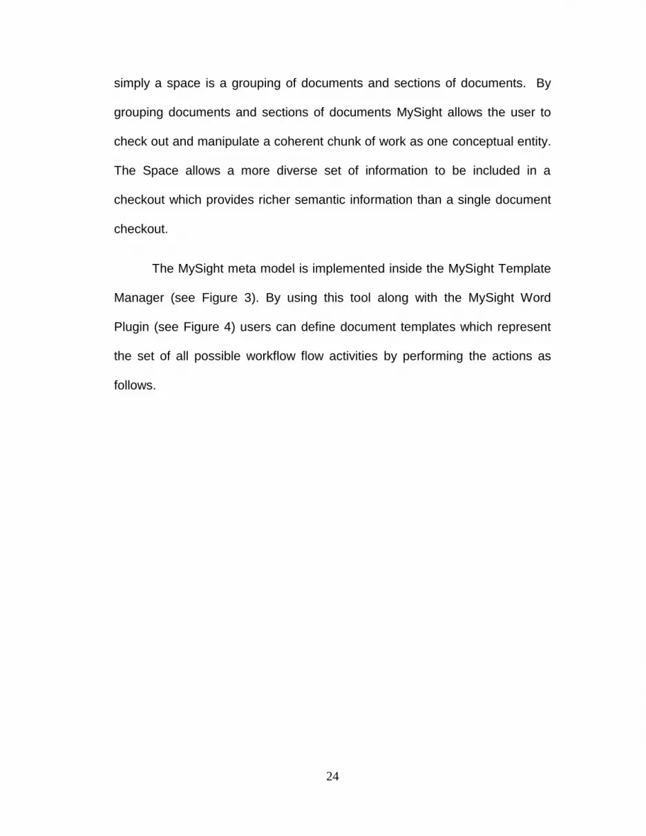
simply a space is a grouping of documents and sections of documents. By
grouping documents and sections of documents MySight allows the user to
check out and manipulate a coherent chunk of work as one conceptual entity.
The Space allows a more diverse set of information to be included in a
checkout which provides richer semantic information than a single document
checkout.
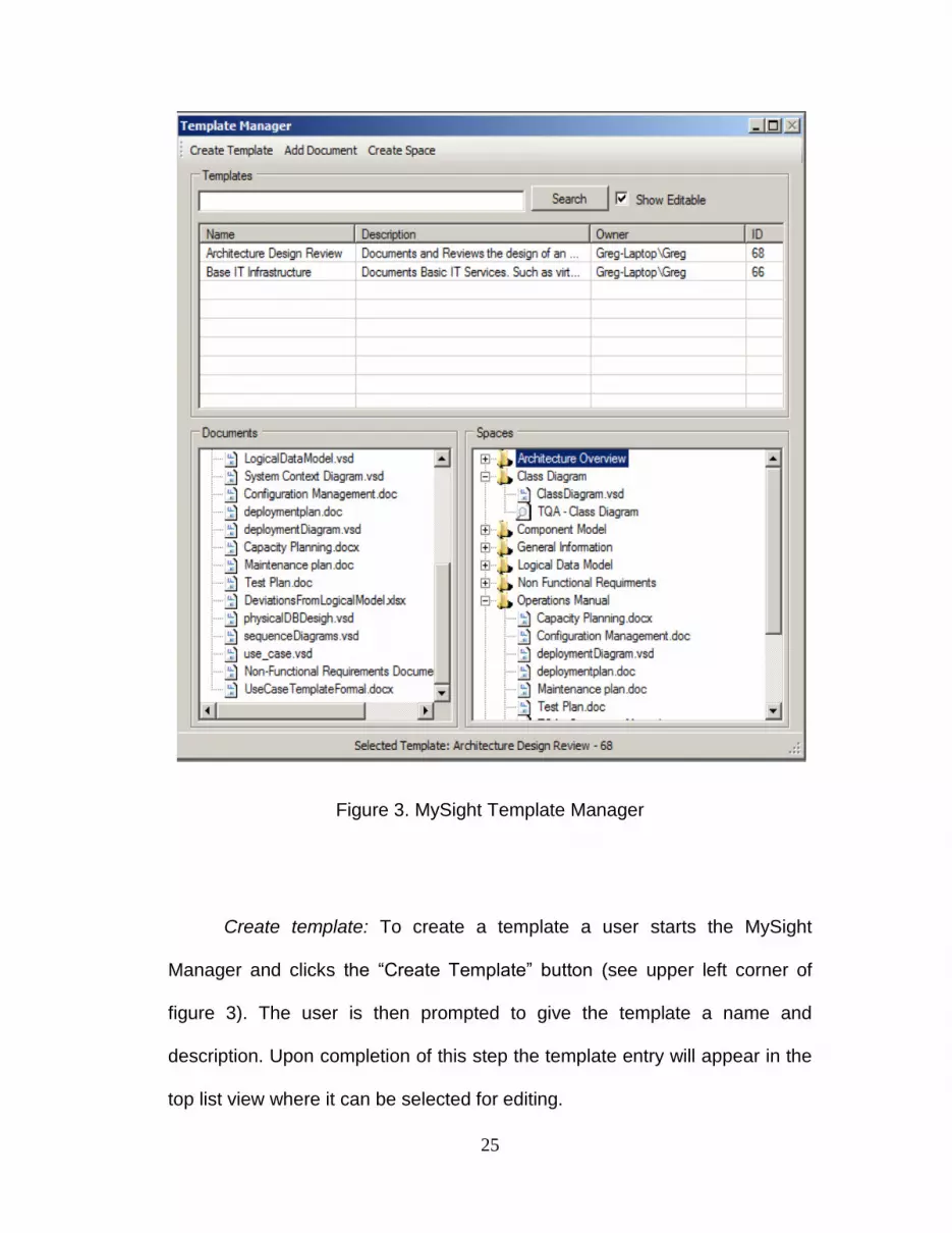
The MySight meta model is implemented inside the MySight Template
Manager (see Figure 3). By using this tool along with the MySight Word
Plugin (see Figure 4) users can define document templates which represent
the set of all possible workflow flow activities by performing the actions as
follows.
25
Figure 3. MySight Template Manager
Create template: To create a template a user starts the MySight
Manager and clicks the “Create Template” button (see upper left corner of
figure 3). The user is then prompted to give the template a name and
description. Upon completion of this step the template entry will appear in the
top list view where it can be selected for editing.

26
Create the set of document templates: The creation of the document
template is done with the Microsoft Word 2007 application. Documents are
created with appropriate instructions and place holders for needed content as
they would be for any normal document based process. The document
content should represent the maximum amount of information that would
need to be captured by the process. For example, if we were to create a
simple architecture design review template it would probably require a TQA
document, a document for general project information, use cases, class
diagram, logical data model, physical data model and a scalability document.
The TQA document would have place holders with value questions for each
of the documents present, even if there is a chance that information may not
be filled out in every process instance.
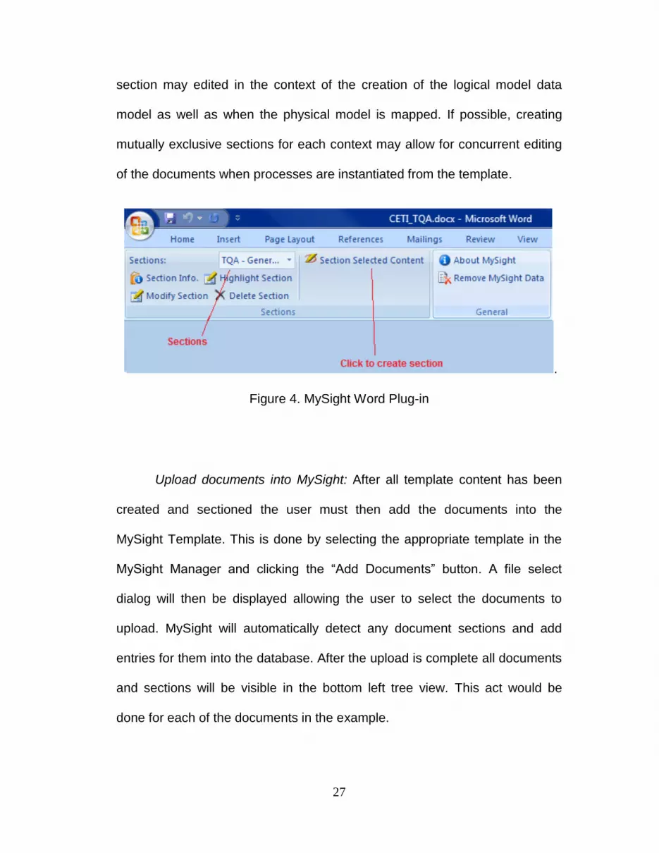
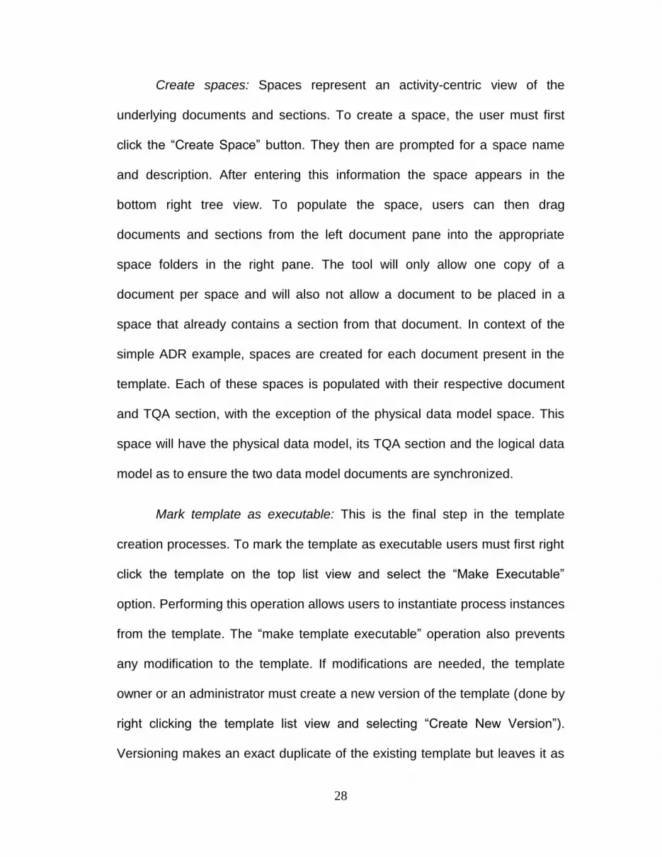
Partition documents into sections: Document partitioning is facilitated
through the MySight Word Plugin (see Figure 4). To do this, a user must open
one the previously created document templates in Microsoft Word, select the
appropriate content and then click the “Section Selected Content” Button on
the MySight Ribbon. Word then prompts for a name and description of the
section. After this information is entered, the section appears in the drop
down on the left. Users also have the option to highlight, view description,
delete, or resize section boundaries. In the above example, sections will be
created in the TQA document for each document present in the template.
It is important to remember that some documents may be edited in
multiple different contexts. For example, the logical data model and its TQA
27
section may edited in the context of the creation of the logical model data
model as well as when the physical model is mapped. If possible, creating
mutually exclusive sections for each context may allow for concurrent editing
of the documents when processes are instantiated from the template.
.
Figure 4. MySight Word Plug-in
Upload documents into MySight: After all template content has been
created and sectioned the user must then add the documents into the
MySight Template. This is done by selecting the appropriate template in the
MySight Manager and clicking the “Add Documents” button. A file select
dialog will then be displayed allowing the user to select the documents to
upload. MySight will automatically detect any document sections and add
entries for them into the database. After the upload is complete all documents
and sections will be visible in the bottom left tree view. This act would be
done for each of the documents in the example.
28
Create spaces: Spaces represent an activity-centric view of the
underlying documents and sections. To create a space, the user must first
click the “Create Space” button. They then are prompted for a space name
and description. After entering this information the space appears in the
bottom right tree view. To populate the space, users can then drag
documents and sections from the left document pane into the appropriate
space folders in the right pane. The tool will only allow one copy of a
document per space and will also not allow a document to be placed in a
space that already contains a section from that document. In context of the
simple ADR example, spaces are created for each document present in the
template. Each of these spaces is populated with their respective document
and TQA section, with the exception of the physical data model space. This
space will have the physical data model, its TQA section and the logical data
model as to ensure the two data model documents are synchronized.
Mark template as executable: This is the final step in the template
creation processes. To mark the template as executable users must first right
click the template on the top list view and select the “Make Executable”
option. Performing this operation allows users to instantiate process instances
from the template. The “make template executable” operation also prevents
any modification to the template. If modifications are needed, the template
owner or an administrator must create a new version of the template (done by
right clicking the template list view and selecting “Create New Version”).
Versioning makes an exact duplicate of the existing template but leaves it as

29
editable. The old version is archived so its instances can still generate
accurate process traces.
It is important to note that template structure plays a crucial role in
determining the benefits of the MySight system in the execution of document-
based processes. The structuring of content between documents as well as
the sectioning and grouping of content in spaces will determine the attainable
level of editing concurrency, as well as the detail and semantic information
provided in the work breakdown view of the processes.
For example, a template could be created with just documents and no
spaces or sections. Work would be performed by checking out needed
documents, editing them and checking them back in. If each document
represents a self-contained activity, the course grained concurrency would
not be an issue as each role would be responsible for a complete document.
The processes trace would also be informative because each document
represents the semantics of the activity. However, if this is not the case, and
documents are needed in several different processing contexts, this simple
template design would not work very well. Different roles would have to wait
for entire documents to be checked in before they could edit them, potentially
dead-locking the process. The processes trace would also be very scattered,
showing many concurrent check outs by each user with little information
about what exact activity they are working on.
30
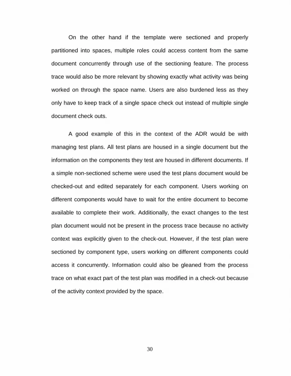
On the other hand if the template were sectioned and properly
partitioned into spaces, multiple roles could access content from the same
document concurrently through use of the sectioning feature. The process
trace would also be more relevant by showing exactly what activity was being
worked on through the space name. Users are also burdened less as they
only have to keep track of a single space check out instead of multiple single
document check outs.
A good example of this in the context of the ADR would be with
managing test plans. All test plans are housed in a single document but the
information on the components they test are housed in different documents. If
a simple non-sectioned scheme were used the test plans document would be
checked-out and edited separately for each component. Users working on
different components would have to wait for the entire document to become
available to complete their work. Additionally, the exact changes to the test
plan document would not be present in the process trace because no activity
context was explicitly given to the check-out. However, if the test plan were
sectioned by component type, users working on different components could
access it concurrently. Information could also be gleaned from the process
trace on what exact part of the test plan was modified in a check-out because
of the activity context provided by the space.
31
2.5 Runtime Behavior and Process Instantiation
The MySight system is designed not only to provide traceability to
document-based processes, but also to reduce the amount of information the
user must maintain while participating in such processes. To illustrate this we
start our discussion of runtime behavior with some comments about the UI
and then move onto the security model, and process-management.
2.5.1 MySight User Interface
The MySight user interface aims to simplify the users experience by
relieving users of the burden of managing the same document in multiple
locations. In a typical document based process a user editing a single or
series of documents would first have to locate the documents inside the
document repository. These repositories typically have a confusing,
unintuitive and sometimes arbitrary top down directory structure which the
user must navigate through using a web interface or mapped network drive.
Next, the user would have to check the documents out and copy them to a
location on their local disk. From here the user would perform the appropriate
editing on the documents. Often the user may need to view content of
previous changes which would force them to go back to the repository and
pull up a previous version of the document. Lastly, they would have to
identify all documents they have checked out of the repository, manually
navigate to their respective repository location and check them back in. While

32
these tasks may seem trivial, they can easily become an unnecessary time
sink especially if the repositories are very large and not well organized, as
well as if the user is frequently interrupted during their processing of the
documents.
MySight aims to ease the user‟s burden during document processing
by providing more intuitive process and activity based repository view, as well
as keeping track of local and remote document locations in order to provide
batch check in and check out. Users are also provided with the ability to view
previous versions of the document directly from the Microsoft Word
application (see Figure 5) thus saving them the burden of having to switch
applications and locate previous versions of the document. Additionally,
updates to content are made through the Office Suite which eliminates the
need for the user to deal with a external forms based UI for modifying content.
Figure 5. MySight Document Context Viewing
33
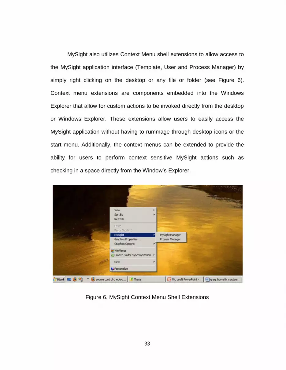
MySight also utilizes Context Menu shell extensions to allow access to
the MySight application interface (Template, User and Process Manager) by
simply right clicking on the desktop or any file or folder (see Figure 6).
Context menu extensions are components embedded into the Windows
Explorer that allow for custom actions to be invoked directly from the desktop
or Windows Explorer. These extensions allow users to easily access the
MySight application without having to rummage through desktop icons or the
start menu. Additionally, the context menus can be extended to provide the
ability for users to perform context sensitive MySight actions such as
checking in a space directly from the Window‟s Explorer.
Figure 6. MySight Context Menu Shell Extensions

34
2.5.2 Security Model and User Management
We begin our discussion of the MySight security model with the subject
of authentication. As MySight is meant to be an enterprise level collaboration
and document management tool, it utilizes Windows‟ domain credentials in
order to authenticate users. When MySight is started, it accesses the
Windows Network Credentials for the invoking user. These credentials are
then compared to a local user database maintained by MySight through the
“User Manager” interfaces. If a match is found, the application finishes
loading the user interface; if not, the application informs the user that they do
not have access to the system. In the event that no users are present in the
database, the system automatically creates an entry for the invoking user,
giving them admin privileges.
Access control in MySight is very coarse grained. The first level of
access control in MySight is enacted at install time. During the installation of
the MySight client, the installer provides two installation options, Full Install
and Process Participant Install. Process Participant Install sets flags in the
MySight configuration file so that only process-management interfaces get
loaded when MySight is executed. This in effect restricts these users from
accessing any of the template creation tools. The full install does not include
these flags, thus enabling the both template creation and process-
management interfaces. MySight also includes a command line utility called

35
“Create_MySightConfig” that can be used to reset these flags. However this
tool must be run by a user who who has access to the database credentials.
The second layer of access control is built into the MySight database.
This layer allows for users to be created as either a standard user or an
administrator. Administrators have full access (read/write) to all templates and
processes in the system. They also have the ability to create, delete and
update users.
Standard Users have full access only to things they own. Ownership of
an object (Templates and Process Instances) is gained by being the user who
creates that object or having an administrator assign a given object to a user.
In addition to owning a process instance, users can also be assigned to
process instances by the instance owner. Being assigned to an instance
allows a user to subscribe to notifications, view process progress, view and
check in/out documents for the process instance.
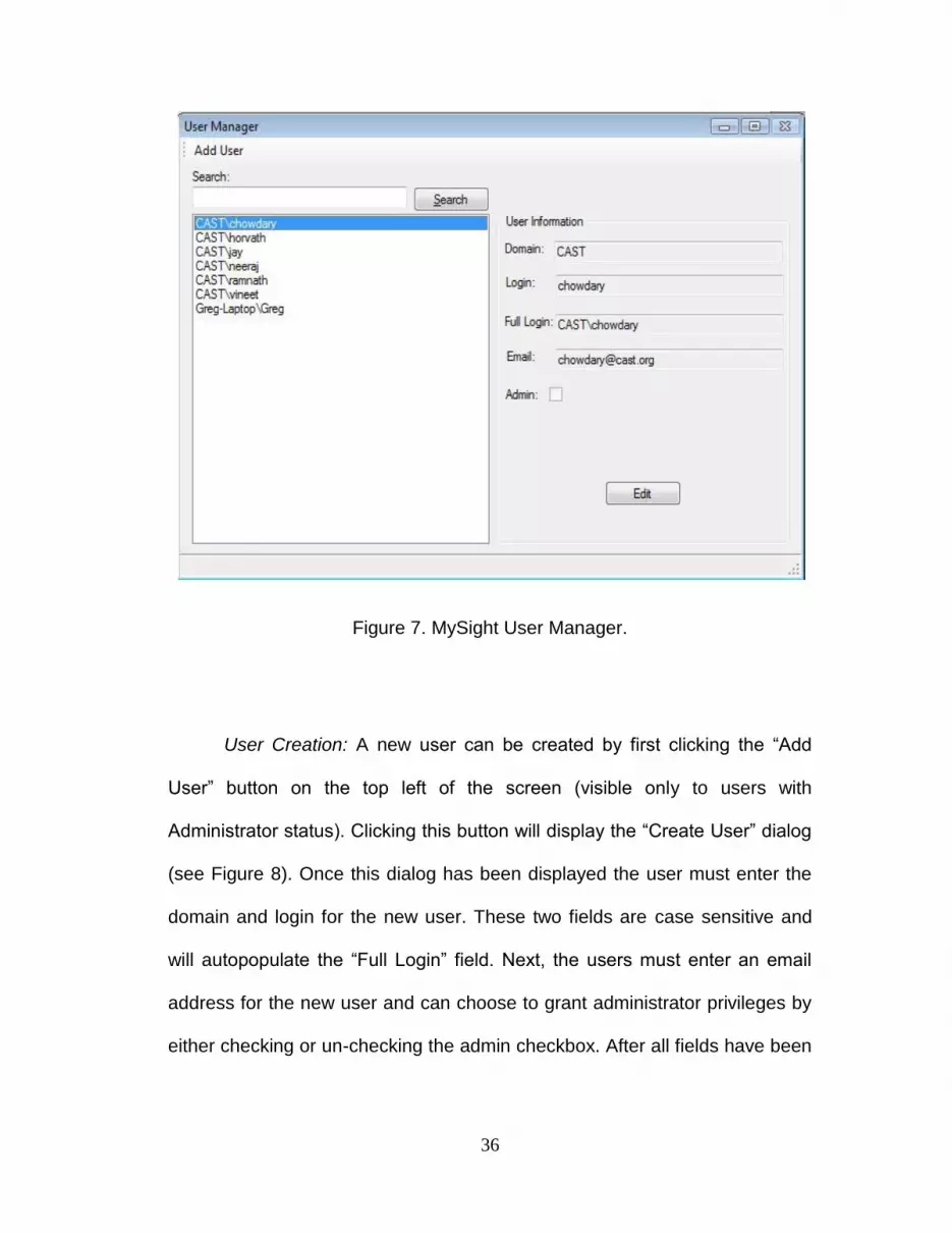
Here we present the User Manager (see Figure 7) interface and
procedures for the creation, deletion and modification of MySight users.
36
Figure 7. MySight User Manager.
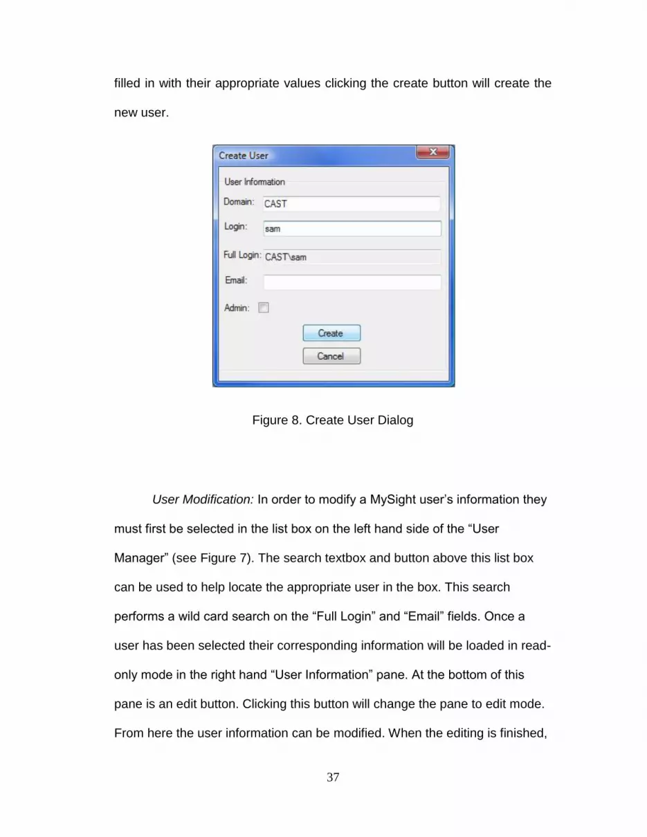
User Creation: A new user can be created by first clicking the “Add
User” button on the top left of the screen (visible only to users with
Administrator status). Clicking this button will display the “Create User” dialog
(see Figure 8). Once this dialog has been displayed the user must enter the
domain and login for the new user. These two fields are case sensitive and
will autopopulate the “Full Login” field. Next, the users must enter an email
address for the new user and can choose to grant administrator privileges by
either checking or un-checking the admin checkbox. After all fields have been
37
filled in with their appropriate values clicking the create button will create the
new user.
Figure 8. Create User Dialog
User Modification: In order to modify a MySight user‟s information they
must first be selected in the list box on the left hand side of the “User
Manager” (see Figure 7). The search textbox and button above this list box
can be used to help locate the appropriate user in the box. This search
performs a wild card search on the “Full Login” and “Email” fields. Once a
user has been selected their corresponding information will be loaded in read-
only mode in the right hand “User Information” pane. At the bottom of this
pane is an edit button. Clicking this button will change the pane to edit mode.
From here the user information can be modified. When the editing is finished,
38
clicking the “Save” button will update the MySight database and reload the
user‟s information in read-only mode.
User Deletion: A user can be deleted by right clicking their entry in the
list box on the left hand side of the “User Manager” (see Figure 7) and clicking
the “Delete User” button in the context menu. A deleted user‟s processes and
templates can only be modified by MySight administrator accounts.
2.5.3 Process-Management and Execution Using MySight
In this section we provide a general overview of how to accomplish
tasks crucial for the management and execution of a document based
process in the MySight system.
Process Instantiation: After a template has been created and marked
editable, users may begin executing instances of the processes. In order to
do this, the process manager (see Figure 9) must first be opened up. This can
be done by right clicking in the explorer and selecting “Process Manager”
from the MySight context menu.
39
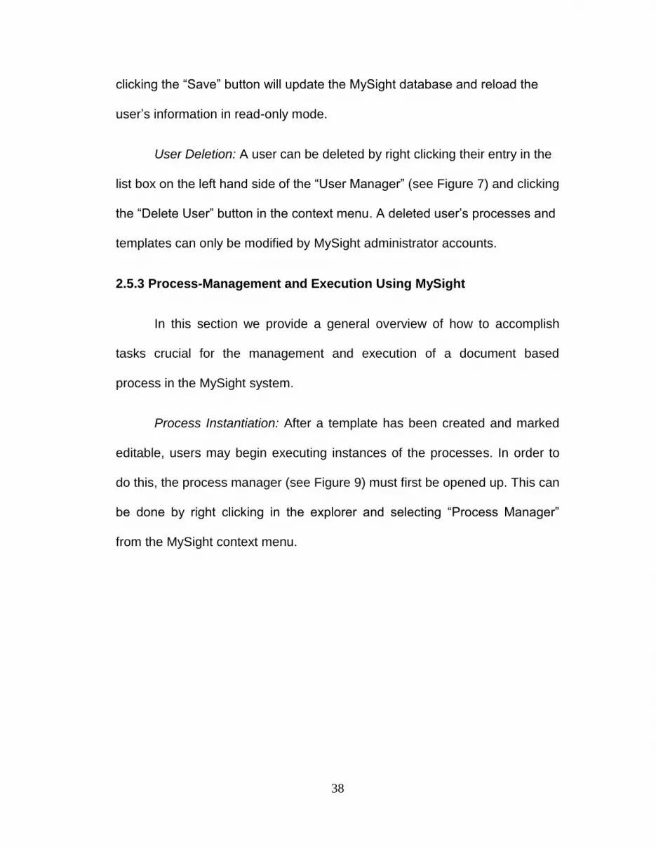
Figure 9. MySight Process Manager
After the process manager is visible, a process can be started by clicking the
“Start Process” button in the upper left hand corner of the form. Clicking this
button opens the “Create Process Instance” dialog (see Figure 10). To create
the process the user must provide a name and an optional description as well
as select the template which will be instantiated. Clicking “OK” creates the
process instance, which becomes visible in the process manager‟s main
screen.

40
Figure 10. MySight Create Process Instance Dialog
Assign Process Participants: Now that the process has been created
participants must be assigned. In order to assign participants the
creator/owner of the process must right click the process instance in the
Process Manager and select the “Assign Participants” button. Clicking this will
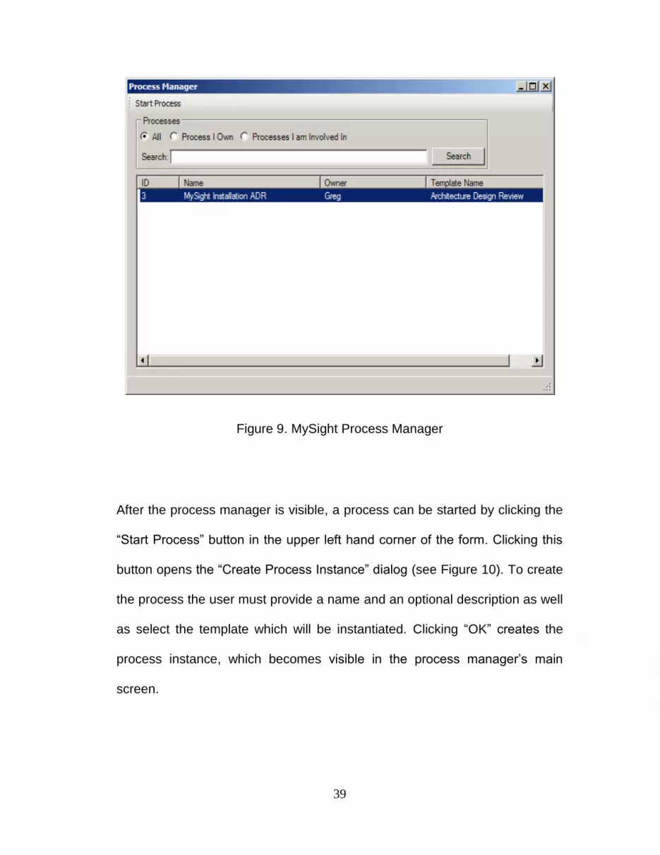
display the “Process Participants” dialog (see Figure 11). The “Process
41
Participants” dialog displays all MySight users who have not previously been
assigned to the process in the list box on the left hand side of the dialog. A
search box similar to the one in user management is also provided. The right
hand side contains all users who have been assigned to the process
instance. The process owner/creator can add a user to the process by
selecting them in the left list and clicking the “>>” button and remove them
from the process instance by selecting them in the right list and clicking the
“<<” button. When the process owner/creator is satisfied with their
assignments clicking “Save” will finalize the process participant list and close
the dialog.
Figure 11. MySight Process Participants Dialog
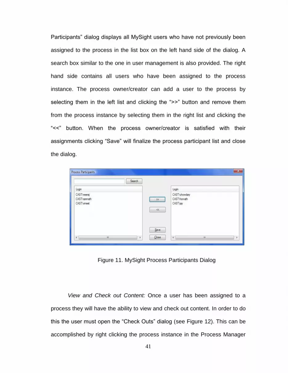
View and Check out Content: Once a user has been assigned to a
process they will have the ability to view and check out content. In order to do
this the user must open the “Check Outs” dialog (see Figure 12). This can be
accomplished by right clicking the process instance in the Process Manager

42
and selecting the “Check Outs” button. The “Check Outs” Dialog displays all
process documents, sections and spaces in the same fashion as the
“Template Manager”. Individual documents and their sections are displayed
on the left and the space hierarchies are displayed on the right. In addition to
this all content that is checked out will be highlighted in red. Right clicking on
a piece of content will display a menu which will allow three actions to be
taken.
Figure 12. MySight Check Out Dialog
1. “Check Out” will only be visible if a content entry is not currently
checked out. If the selected entry is a space, check-out will only be
available if all documents and sections contained within that space are
not checked-out by another user. If the entry is a document, the
43
“Check Out” menu item will only be available if all sections belonging to
the document are checked in. In the event that not all of the documents
sections are checked-in, users will have the option to check-out one or
many of the documents remaining sections.
Once “Check Out” is clicked, a folder select or file save dialog will
be displayed depending on whether the content is a “Space”. MySight
will save the content to the selected location and mark the content as
checked out in the database. Additionally, the MySight service running
on the local client will be notified of the check out and watches will be
put on the local version of the checked out content to ensure it is not
moved or deleted. If the checked out content was a space, it will be
saved in a folder structure. The main folder will have the space name
as seen in the “Check Out” dialog. Inside will be a documents and
sections folder containing the document and section content for the
space. In the case of a single document or section, the content will be
downloaded as the native file type, usually a .docx file. Once the
content has been checked out the user is free to modify it as they
would in any normal document based process. They will also be
provided with the context help discussed earlier (see Figure 5) when
editing documents in the Microsoft Word environment. When the user
is finished editing they can perform the check-in procedure discussed
below.

44
2. “Download” is very similar to check out with the exception that it does
not mark the content as checked out and does not have the local
MySight service register file watches. Instead, downloading allows
users to download and view the current version of the content without
having to acquire an exclusive lock. This can allow users to view
related content that they may find helpful in processing another check
out or just to gain extra information about the process contents. They
can also use “Download” to gain read-only access content that is
currently checked out by someone else. When a user is finished with
downloaded content they can simply delete it through the explorer.
3. “Subscribe to Notification” tells MySight to send the user an email
whenever the selected content is checked in. This allows users to be
notified when content they feel is important to their job is changed.
Check-In/Undo Check out of Content: Once a user has finished modifing
process content they must post it back to the shared repository so others
can view and manipulate it. MySight aims to simplify this process by
removing the burden of manually tracking document locations from the
user. Instead of uploading single documents back into MySight the user
simply has to open the “My Check Outs” dialog. This can be done by
clicking the “My Check Outs” (see Figure 13) button on the upper toolbar
of the “Check Out” dialog. This dialog displays a view of all check outs a
user has in a given process. Right clicking a check out entry displays a
context menu that allows the following actions.
45
1. “Check In” first displays a dialog to allow the user to enter any
check-in comments. After the user confirms the check in, MySight
uploads all content back into the database creating a new version.
This upload also merges sections back into their original
documents. A check-in status entry is also created to provide the
appropriate data for process viewing and audit. After the upload
and merge has completed successfully, MySight scans for
notifications on the content and sends emails out for any
notification subscriptions it finds. Lastly, the file watches and locks
are removed from the local copies. At this point the user is free to
move or delete the local copies.
2. “Undo Check Out” allows users to remove mistakenly checked out
content. Clicking this button will remove any record of the checkout
from the database and remove all file locks and watches from the
local content. After the operation completes the user is free to
delete or move the checked out content.

46
Figure 13. My Check Outs Dialog
View Process Work Breakdown: A process‟s work breakdown structure
can be visualized through the “Process Viewer” (see Figure 14). Users who
have been assigned to a process instance can access the process viewer by
right clicking the process instance in the “Process Manager” (see Figure 9)
and clicking the “Process Viewer” context menu button. Alternatively, the
“Process Viewer” can be accessed by clicking the “Process Viewer Button” at
the top of the “Check Outs” dialog (see Figure 12).

47
Figure 14. MySight Process Viewer
The “Process Viewer” allows visualization of process status and work
breakdown by showing users‟ checkouts over time. The left hand vertical
column displays each user who has participated in the process. Each
participant forms a horizontal swim lane which portrays their check outs over
time. Checkouts are displayed as a folder for space checkouts, a document
for document checkouts, and a document with a spy glass for a section
checkout. Content that has been checked out but not checked back in will
appear in red. Users can also view detail about a checkout by clicking on a

48
given checkouts icon. Doing this will display a popup with checkout
information on the top and a list of all previous checkouts for that content on
the bottom. Users also have the option to download content for any previous
checkout by clicking the checkout entry on the bottom list view and then
clicking the “Download” button. It is also important to note that the “Process
Viewer” window is not resizable. If the process trace becomes too large in the
horizontal or vertical direction the window will automatically display scroll bars
allowing the user to view hidden process information.
2.6 MySight Cognitive Walkthrough
We will now provide a high-level cognitive walkthrough of how the
MySight system will function during an Architecture Review process. This
section is meant to give context as to how the operation described for
“Process-management” would be used in a real situation to manage a
document based Architecture Design Review Process.
Our Architecture Design Review process contains the following five document
templates:
• A Software Design Review document which contains the UML model
for the new system.
• A Server Review document which contains information on which
servers the new application will be installed on as well as the load on those
servers.

49
• A Network Review Document which contains information on how the
new system will affect network load.
• A Best Practices and Expectations Document that contains information
on what is expected in each template document. It will be sectioned by
document template and will be read only. It is intended to provide guidelines
and expectations for the people filling out the various templates.
• A Technical Quality Assurance document can be thought of as a
summary document for the main process document templates. It contains a
section for each template present in the process. Each of these sections can
be thought of as a checklist to see if all of the documents expectations have
been met.
This process will contain three spaces - Software Design, Server
Review, and Network Review. Each space will contain the document
template, best practices and TQA section that correspond to its name. For
example the Software Design space will contain the Software Design Review
template mentioned above as well as the Software Design Best Practices and
Expectations Section, and the TQA Section for software design review. There
will also be four people participating in this review, a Senior Architect, network
architect, software engineer and a server administrator.
The process will be kicked off by the Senior Architect by performing the
steps for process creation and process participant assignment detailed in

50
section 2.5.3. After performing these assignments he will inform the users that
they have been assigned to the review.
Upon notification the software engineer checks out the Software
Design Review space. He first checks the best practices section for the
activity expectations. Next he opens the Software Design Review template (a
Microsoft Visio file) and adds the class diagram and data model specifications
to it. He then opens the TQA document section and marks that the project
contains a class diagram and data model. At this point his work is done and
he checks the space back in. Upon check-in MySight merges the document
changes into the repository, creates a checkout status entry which will be
visible in the process viewer, and sends all notifications that correspond to a
check-in for the Software Design Review Space.
The senior architect is curious about progress. He opens up the
process viewer application and sees that the software architect has finished
working on his parts, but the other two participants have not yet started. At
this point he can apply pressure where he sees fit to speed the other users
up. Alternately, the other users may have been waiting on the software
diagram. They could continually check for this Space to be checked in
through the “Process Viewer” or set up a notification.
We will assume that both of the other users set up notifications. Upon
receiving notification that the software design review space has been checked
in, they check out their spaces. While working on their respective spaces they

51
realize the need for information from the software design. Each user then
performs the procedure for downloading a read-only version of a space
outlined in section 2.5.3. Based on this information and a few quick emails to
the other participants they are able to fill out their subsequent documents and
check the space back. At this point the process is complete.
While this is an extremely simple example it demonstrates the ability of
the MySight system to articulate high level process information to managers
and participants alike. Managers can easily check on the status of any piece
of work in the processes without the need for manually polling their staff.
Participants are free to search the process and space repository by simply
right clicking and bringing up the “Check Out” and “Process Viewer” dialogs.
This eliminates the need to search through folder based repositories for
information. Additionally, participants can view the semantics of previous
check outs through the context viewing and downloading built into Word or by
downloading and viewing previous check-outs from the “Process Viewer”.
One can image how complex the management of the process and its
documents could get if the process template were expanded to include twenty
or thirty documents, and a very large TQA. Management would have to
manually poll repositories or users for status updates, each user would also
have to know the physical locations of each document they needed to work
on, and getting access to the TQA would be a nightmare without the
concurrent access provided by the document sectioning.

52
In fact the above process represents a very good methodology for
template design. By including a section, TQA participants can get process
information not only at a high level from the process viewer, but they can also
get a more detailed and functional view from the TQA sections. Additionally
management will get a high level document that can be presented for final
approval without the effort of having to manually compile several TQA results.
The idea of including a sectioned unified process and work product
expectations document is extremely useful for maintaining process control.
This document as a whole provides the organization with the knowledge
needed to standardize work product quality and facilitate training while its
sections allow process enactors to quickly verify that their work is of
satisfactory quality. Additionally, since all process information is in a single
document, documentation of new activities and process changes is as simple
adding or removing sections.
2.7 MySight Benefits
The MySight system provides numerous benefits to users and organizations
that are frequently executing and managing document based processes.
These include:
• Increased Traceability. Combining user data with space history
provides accurate and on demand process status. Spaces provide activity
context to documents that they contain thus yielding an audit trail for a
process instance. This audit trail can provide a clear and reliable picture of
53
process status similar to what you would get using production workflow
orchestration. Additionally, content changes at each step are tracked so a
clear picture of how decisions were arrived at can be ascertained with a little
digging through the process data and repositories. This is of great importance
to both management and process participants alike as both rely on this
information to perform their job. In ad-hoc systems, traceability is usually
maintained only at document level and often does not track contextual
changes. Also in such systems, mining and correlating single document
check-outs to workflow activities is time consuming and inaccurate.
• Enhanced Information Management. Because MySight manages the
physical locations of documents users no longer have to deal with the
complicated and unintuitive repository storage structures. Space based check
out and check-in allows users to manage semantically related documents as
a single entity thus eliminating the need for users to memorize the physical
location for each file they work on. Additionally, users also can browse and
view information based on project and space context allowing for quicker
retrieval of relevant information.
• Concurrent Check out based on sectioning of a Space allows multiple
users to check out and edit different sub parts of the same document
concurrently, thus increasing process throughput. In traditional systems, only
one user can check out and work on a particular document at a given time.
54
• Process Improvement. Because each process provides a clear audit
trail we also have the ability to do process mining by looking across all
instances of a particular process. This allows us to see changing
organizational and work patterns, as well as identify other process properties
that may be useful for reengineering. In traditional systems, this information is
very scattered and unreliable. Process mining would require considerably
more time and effort. With MySight, data mining across multiple completed
instances provides valuable process information that can be used to facilitate
process improvement. Examples include identification and elimination of
bottlenecks, identification of new or unused activities, or the creation of a
concrete process model.
• Perhaps the biggest gain of MySight is that it allows business users to
create workflows for collaborative processes with reduced developer
interaction. This is because process definition only requires users to be able
to create document templates through the use of their existing office suite and
associate them using the provided MySight interfaces.

55
Chapter 3
Related Research
W in several different areas relates to the ideas and concepts behind
MySight. This section begins by identifying research which motivates the
need for flexible workflow and CSCW systems like MySight. From there we
present a more detailed description of research in the three alternate
approaches to flexible and traceable collaborative workflow and CSCW
systems.
3.1 Research Motivating Flexible and Traceable Collaborative Systems
The need for flexible workflow and CSCW systems, which is a key
underpinning of the MySight system, has been presented in several
publications [23,2,24,25,26]. As far back as 1997 Amit Sheth realized the
need for tools which look beyond contemporary process automation to a more
“comprehensive notion of support for organizational processes” [23]. This
includes giving humans more insight into decision making activities for
computer-supported organizational processes and allowing such processes to
be flexible and adaptable, both of which are major drivers for the
requirements of the MySight system. Subsequent research by Carlsen et al.
also supports this idea of flexible workflow through a notion of “Adhocracies”.
56
“Adhocracies are characterized as organizations facing a complex and
dynamic environment, resulting in a chosen organizational form with
extensive use of „liaison devices‟, selective decentralization and coordination
by mutual adjustment” [24]. This work also articulates the distinction between
rigid “enterprise workflow” and “workgroup workflow” in which autonomous
workgroups must maintain some control over process definition. These ideas
fit very well into the context of this thesis. Document based processes like
the Architecture Design Review process fall into this dynamic “Adhocracy”
category by virtue of having process activities and participants dependent on
the project requirements. The only way to facilitate this dynamic relationship
is to give project teams the ability to group and execute activities freely.
MySight supports this requirement through its document meta-model which
does not mandate any strict routing of document content through the
organization.
3.2 Activity Mining Research
Providing traceability through the mining of enterprise information
repositories is another area of related work from which MySight draws
inspiration. In Van Der Aalst et al. [17] activity centric workflow models are
generated through the mining and correlating of data from transactional
systems. Organizational as well as activity centric work patterns have also
been extracted from both single user and enterprise email stores [27,28].
Other tools such as the one presented by Abeta et al. [29] attempt to extract

57
finer grain user workflow and tacit knowledge through the use of an
interactive context tracking help bubble.
While the context and application for each of the works above are
vastly different, they provide a valuable insight for the purposes of our work.
This insight is that working in a collaborative enterprise setting provides
process and organizational footprints from which we can extract valuable
knowledge. MySight attempts to explicitly track and provide access to this
knowledge by embedding interfaces for the generation and collection of
workflow data into everyday tools, thus facilitating traceability.
3.3 Flexible Production Workflow Models Research
There is an abundance of research into flexible formal models for
workflow orchestration. Mathias Weske [25] proposed a scheme for adapting
workflow models to allow users to intervene in workflow controlled activities
as well as to dynamically change models to promote flexibility. However, this
work only describes these processes at an abstract level and does not deal
with the complexities of maintaining model integrity such as providing
alternate data flows at both the executable and user interface level. A similar
idea of workflow as an interaction engine was also proposed by Jørgensen,
but again only at a conceptual level [26]. More recent research proposes the
idea of providing workflow flexibility as a service. This work starts by
proposing that there are multiple forms of workflow flexibility and that different
workflow languages and systems have the ability to handle a subset of these
58
forms of flexibility. It then proposes a novel idea based on Service Oriented
Architecture concepts, namely that workflow activities can be viewed as
service consumer which can request services from providers such as sub
processes, humans, and applications. In this manner, if a particular workflow
activity requires more flexibility than its executing engine allows, the activity
can then invoke the services of another entity (workflow engine, human or
application) which has the ability to handle the particular requirements for the
operation. Through this service mechanism, the work provides an account of
how multiple types of workflow flexibility can be achieved without the
development of one overarching workflow language. [30]. While this work is
very promising and does accurately identify the facets of traceability needed
for document-centric collaborative processes such as “flexibility by change”, it
ultimately requires too much overhead in service composition to truly support
knowledge workers executing collaborative processes such as Architecture
Design Reviews.
3.4 Document-centric Applications and Workflow Research
Document-centric workflow is centered on the fact that documents
either drive or define the workflow. Carbon et al. motivate a highly mobile and
distributed workflow system based on document passing. Workflow data will
be embedded or attached to each document and processed by workflow
engines that exist locally at each node [19]. Another document-centric
workflow system is called XFolders. XFolders is a lightweight workflow
system which uses an “office circulation envelope metaphor” to control the

59
routing of documents through organizations [18]. Each of these approaches to
document-centric workflow is different from our approach, though they both
incorporate the idea of documents driving workflow, a concept central in the
operation of MySight.
We can also draw parallels from work done in the areas of document-
centric applications. Applications in this area focus on extending documents
from simply being static content to being reactive and programmable objects
which can integrate with existing systems to support business activities.
Visual Studio Tools for Office (VSTO) is an example of this in the commercial
arena [31]. The VSTO architecture allows developers to embed .NET code
into the office environment at the application, document template, or
document level. This code can then be executed in response to Office
application and document events in order to support the business process.
The MySight architecture utilizes a VSTO application level plug-in to maintain
document sections.
An example of a document-centric system in the research arena is
Active Documents proposed by Dourish et al. [20]. Active documents allow
documents to include custom properties which can contain executable code.
By attaching these “active properties” to documents users can make a
document responsive to any number of situations [21]. One example is using
active properties to track document changes in the context of a loan approval
workflow [21]. In this study active properties were attached to the read and
write operations of a document. When these operations were executed the
60
document would analyze its changes and associate them with the
corresponding workflow processes providing the workflow with not only a
process trace but also a clear picture of the “content of the work” performed
[21]. This also bears some similarity to work done on “edit profiles” which
provide the current document editor with awareness to document changes
made by previous users [32]. In this study users indicated this information is
helpful when participating in collaborative authoring. The MySight system
aims to allow this type of workflow content traceability while additionally
providing an execution model for tracking process structure based on space
definitions. It allows business users to create and deploy processes such as a
loan approval without having to write a single line of code.
61
Chapter 4
MySight System Design
This chapter will cover the major design aspects of the MySight
system. The chapter will begin with a brief introduction to the used
technologies, followed by the high level architectural components and their
functions and will end with a detailed description the MySight processing
structure and data model.
4.1 Description of Utilized Technologies
This section provides a quick overview of technologies used by
MySight as well as their high level function in the system. More details of their
usage will be covered in the Architectural Description section.
4.1.1 LINQ
Language Integrated Query is a new addition to the .NET 3.5
framework [33]. This technology provides native query and data access
capabilities to .NET languages and bears many similarities to the idea of
object oriented databases as well as the active record software pattern
[34,35]. By providing a data definition, which can be automatically generated
by connecting to a Microsoft SQL database, LINQ is able to generate native
.NET objects that represent the backend data model. These objects allow

62
direct access to all related tables through properties. Any changes to an
object or its related properties are directly propagated to the databases. LINQ
also provides an integrated query engine for the .NET languages. This means
that SQL like queries can be written in native, syntax checked .NET
languages like C# and Visual Basic. The runtime system automatically
transfers these statements into SQL at runtime thus minimizing the time to
write and debug database queries. In MySight all data manipulation is
performed through LINQ.
4.1.2 Microsoft SQL Server Standard and Compact Editions
Microsoft SQL Server Standard Edition provides the database services
for the backend MySight database. It was chosen because of its compatibility
with LINQ1 . MySight will also work with Microsoft SQL Server Enterprise
Edition.
Microsoft SQL Server Compact Edition is a lightweight file based
version of SQL Server Standard and Enterprise [36]. It is intended to store
application data on mobile devices and is accessed directly through file
system mechanisms. MySight uses this technology to implement the local
check-outs database on the client machines. This technology was chosen for
the local database because it depends only on a few extra libraries being
1 Currently other databases such Oracle and MySQL do not have production quality LINQ bindings
written for them.

63
added to the installation directory on the client machine. Microsoft SQL
Standard and Enterprise editions require multiple management tools be
installed as well as the registration of the SQL database service.
4.1.3 Visual Studio Tools for Office
Visual Studio Tools for Office provides the ability to write custom plug-
ins and embed .NET code into documents at multiple levels. This technology
has already been described in the document-centric applications portion of
the related research chapter. MySight utilizes this technology to provide plug-
ins for sectioning documents during template creation as well as viewing
context during process execution.
4.1.4 Windows Presentation Foundation
Windows Presentation Foundation is considered a next generation
technology for Windows user interface (UI) development [37]. It includes not
only analogs to the standard Windows forms components but also 2D and 3D
drawing, vector graphics, animation and audio and video support. Windows
Presentation Foundation interfaces are defined in an XML based language
called XAML [38] and can be embedded into both web pages and rich client
applications. MySight utilizes Windows Presentation Foundation to implement
the complex drawing and form resizing operations in the process viewer. The
use of Windows Presentation Foundation ensures that future versions of

64
MySight will have the ability to display more complex types of process
visualizations than the currently implemented one.
4.1.5 Windows Services
Windows Services are persistent applications that run in the
background of the Windows operating systems and do not require user
interaction. They are similar to daemons in the Linux/Unix world. MySight
utilizes Windows Services to make sure that locally checked out documents
are not deleted or moved accidentally.
4.1.6 EZ Shell Extension
EZ Shell Extension is a proprietary tool for quickly and easily creating
Windows Shell Extensions in .NET [39]. This product provides a diverse set of
shell extensions, such as context menus, icon overlays, and explorer panes,
which can be written in managed .NET code such as C# or VB. This product
was chosen for MySight because it provided quick development for shell
extensions and came with a no royalty distribution license. Without this
product all MySight shell extensions would have had to be developed in
unmanaged C++ code and exposed to .NET and MySight runtime libraries
through the registration of COM interfaces. Such a task would have added
weeks to the development effort of MySight.
4.2 High Level System Architecture
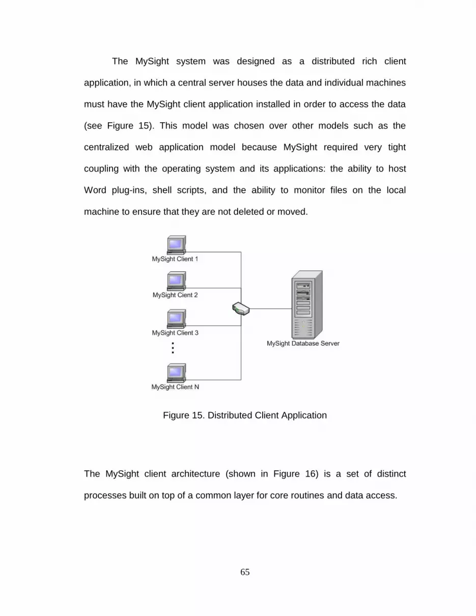
65
The MySight system was designed as a distributed rich client
application, in which a central server houses the data and individual machines
must have the MySight client application installed in order to access the data
(see Figure 15). This model was chosen over other models such as the
centralized web application model because MySight required very tight
coupling with the operating system and its applications: the ability to host
Word plug-ins, shell scripts, and the ability to monitor files on the local
machine to ensure that they are not deleted or moved.
Figure 15. Distributed Client Application
The MySight client architecture (shown in Figure 16) is a set of distinct
processes built on top of a common layer for core routines and data access.
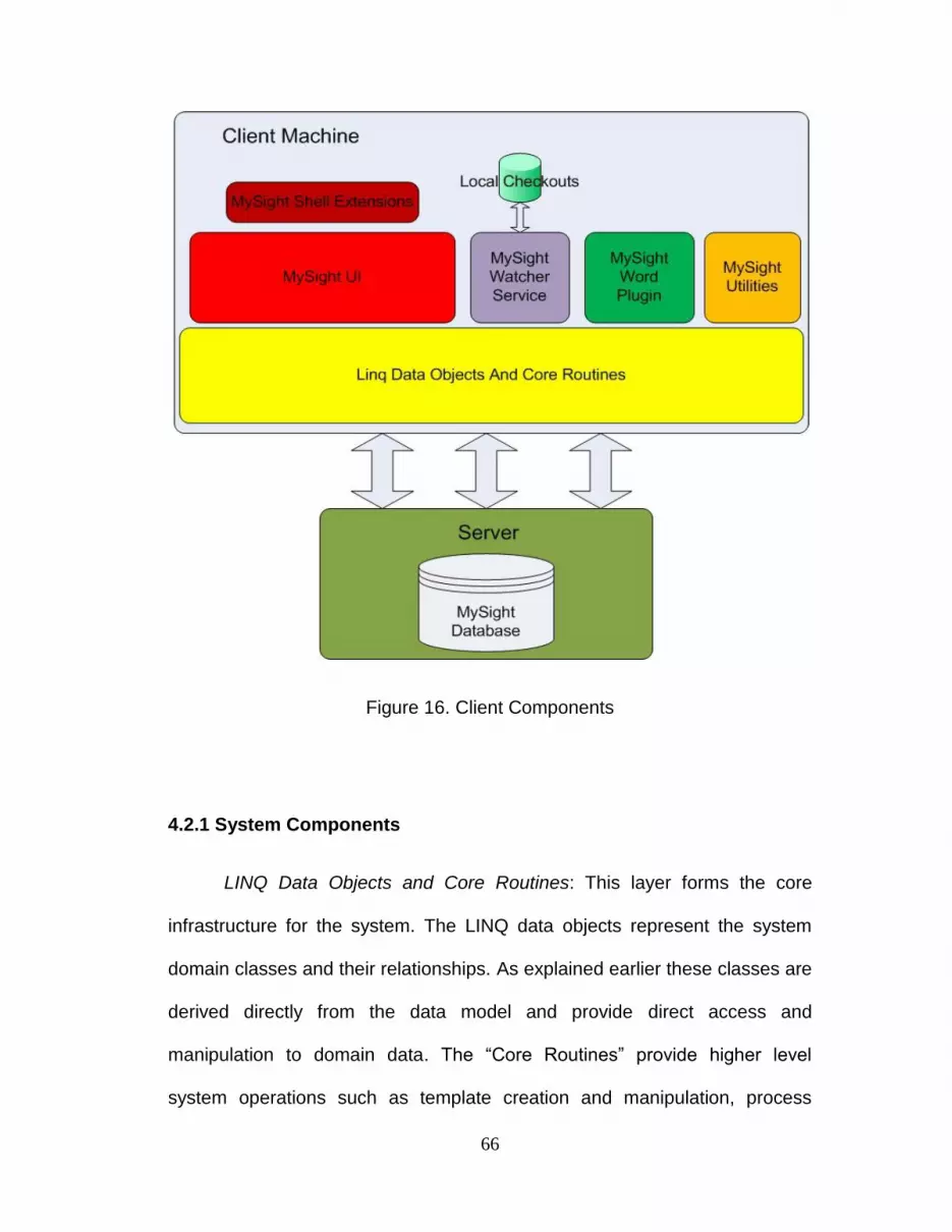
66
Figure 16. Client Components
4.2.1 System Components
LINQ Data Objects and Core Routines: This layer forms the core
infrastructure for the system. The LINQ data objects represent the system
domain classes and their relationships. As explained earlier these classes are
derived directly from the data model and provide direct access and
manipulation to domain data. The “Core Routines” provide higher level
system operations such as template creation and manipulation, process
67
check out, check-ins and downloading as well as security validation and
notification generation.
MySight UI: This component provides all of the forms based user
interface. They can be accessed by directly running MySightManager.exe or
can be invoked through the Shell Extension component. Once loaded, the UI
components first authenticates using the Application_Security.Authenticate()
method. After successfully authenticating the UI uses the LINQ data objects
to query and display relevant data to the user. Operations invoked on the data
then call the core routines for processing.
MySight Shell Extensions: This component provides extension to the
windows shell, namely the ability to bring up the MySight user interfaces by
simply right clicking on the desktop or folder, and selecting them from the
MySight context menu (see Figure 6). This component is registered with the
operating system upon installation using the “RegisterExtension.exe” present
in the MySight installation directory. This component also has direct access
to the “LINQ Data Objects and Core Routines” component and can optionally
be extended to provide direct operations that bypass the standard UI. One
example of this would be the ability to check-in data without bringing up the
“My Check Outs” form.
MySight Watcher Service: The MySight watcher service is a windows
service constantly running in the background. It is connected to a file based
SQL Compact Edition database. This database holds the local check out

68
information, i.e., the MySight ID of the content checked out and its local file
system location. From this the watcher service creates file watches. These
watches generate events for particular action taken on a file, such as delete,
create, modify, etc. When the watcher service receives an event notification
for a deletion it replaces the file with the original checked out version and
generates an error message in the form of a file for the user. This component
also provides data access to the local database as well as a messaging
model. These two services allow other components such as the UI and Word
plug-in to obtain local check-out data and also inform the watcher service
when a new check out has been done so the appropriate file watches can be
created.
MySight Word Plugin: This component is a VSTO plugin to Microsoft
Word and provides the ability to section documents during template creation
as well as context viewing during process execution. Document sectioning is
implemented by embedding a custom XML schema into the document. When
a section is added to the document through the interface a unique hidden
bookmark is created in the document. Then an entry is created in the XML
containing the section name, description and corresponding bookmark ID.
When the file is uploaded into MySight this custom schema is read and
entered into the template database.
In the case of context viewing, the Word plug-in contacts the MySight
Watcher Service and asks if the file it currently has open is in the local
database. If it is, the plug-in retrieves the ID for the document and queries the

69
main MySight database for all previous check outs of the document and
displays them to the user.
MySight Utilities: This component consists of two console applications.
The first is Create_MySightConfig.exe and the second is fixcheckoutsdb.exe.
Each of these files resides in the main installation directory.
Create_MySightConfig.exe is used to regenerate the MySight
configuration file. The MySight configuration file is located in the MySight
“$MySightHome\MySight.config” where $MySightHome is an environment
variable set during installation which points to the install location (usually
C:\Program Files\CETI\MySight by default). The configuration file contains
crucial application level information such as install type (Admin or Process
Participant), database credentials and mail server credentials. Because this
file contains sensitive information it is encrypted so that the user cannot
directly view its contents. For this reason the Create_MySightConfig.exe
application has to be used in order to change any configuration information.
The file fixcheckoutsdb.exe is a utility provided to fix any errors that
may have occurred during check out. The utility will remove all of a user‟s
checkout entries from the local and global databases. The main scenario
behind the usage of this tool is a corruption in the watcher service. For
example, if for some reason the watcher service does not come up at boot a
user will be able to delete locally checked-out files. If such an event were to
occur, the check-in routine would not be able to complete which may prevent
70
other process participants from completing their work. In order to fix this a
user could run fixcheckoutsdb.exe which would remove all local and global
check out entries but leave any local copies of the previously checked out
files intact. The user could then recheck out the content and manually merge
the old corrupted versions with the new versions and check them back in.
4.2.2 MySight System Packages
Figure 17 shows the MySight package diagram. This diagram follows
directly from the high-level component model. They MySight.Linq package
forms the heart of the data access layer. It contains the domain model of
LINQ objects. Built directly on top of this are packages stereotyped as
“<<framework>>”. These packages contain classes which perform complex
data manipulations on the LINQ objects as well as provide classes for the
manipulation of Microsoft Office documents. Together the packages
stereotyped of as “<<Data Access / Domain Model>>” and “<<framework>>”
comprise the yellow “LINQ Objects and Core Routines” block in figure 16.
Built on top of the “<<framework>>” packages are the “<<User Interface>>”
packages. These packages contain the user interface classes for MySight
user, template and process management and are map to the the red “MySight
UI” block in figure 16. The “Watcher Services”, “Word Plugin”,
“MySight.Utilities”, and “Shell Extensions” packages implement the “MySight
Watcher Service”, “MySight Word Plugin”, “MySight Utilities”, and “MySight
Shell Extensions” components, respectively.
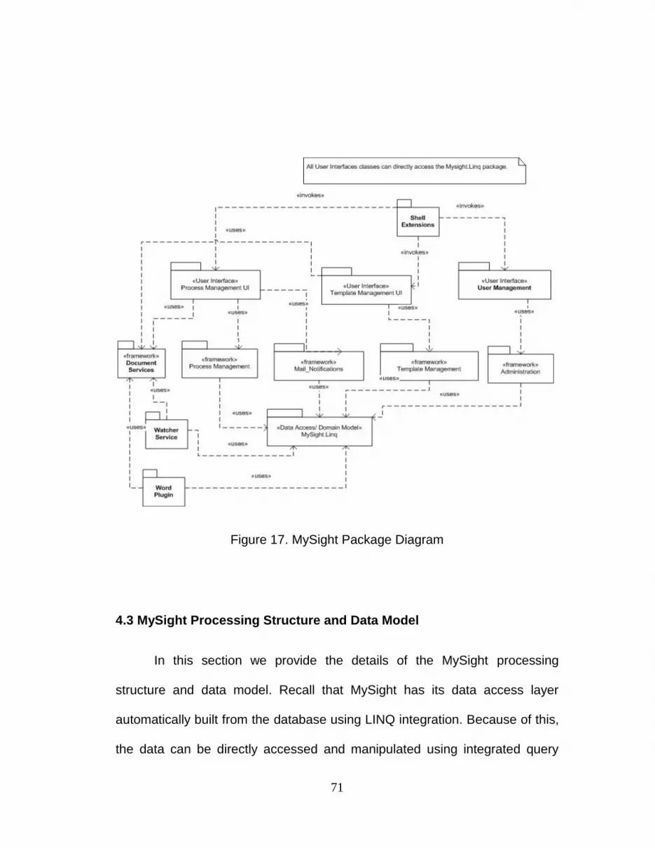
71
Figure 17. MySight Package Diagram
4.3 MySight Processing Structure and Data Model
In this section we provide the details of the MySight processing
structure and data model. Recall that MySight has its data access layer
automatically built from the database using LINQ integration. Because of this,
the data can be directly accessed and manipulated using integrated query

72
mechanisms and native .NET objects, eliminating the need for a manually
programmed domain class structure. This being said we will first present a
general framework for how user actions are processed in the system.
4.3.1 MySight Processing Structure
The sequence diagram shown in Figure 18 is meant to provide the
context for how LINQ data objects are accessed and manipulated to perform
MySight tasks. The classes at the top represent components of the system.
For example, the UI picture is meant to represent a UI classe while the Core
Routine picture is meant to represent the appropriate core routine classes for
the processing of a particular user action.

73
Figure 18. MySight Processing Structure
To aid in the understanding of the diagram we will walk through a
concrete example of downloading a space in the context of Figure 18. The
first step is that the user loads the UI component. During loading the UI needs
to authenticate so a call will be made to the core routine Authenticate(). In
reality this routine is housed in the MySight.Adminstration.Security class. The
authenticate method will automatically get the Windows credentials for the

74
user and generate an integrated query to see if the user exists in the
database. This query is executed through the MySight_DBDataContext class,
another automatically generated LINQ class. Its main job is to provide a
connection to the database and keep track of changes to any LINQ data
objects so they can be propagated to the database. After the UI
authenticates, it executes a LINQ query to acquire and load the appropriate
data. In the case of downloading a space this UI class will be the
MySightManger.Forms.ProcessManger.CheckOuts class. The CheckOuts
class will retrieve and display the space, document and section information
joined with each entity‟s check out status. At this point the user will perform
an action; in this case they will right click a Space and click download. This
will cause the UI to instantiate the process-management core routine object
and call the Download Space routine. This routine will retrieve the binary data
from the data context and download it to the user‟s specified location. There
were no changes to the data for the download operation so the UI will not
update the display data. In other cases, such as check-out, the UI would
update itself to show the checked-out document.
The above processing structure is extremely simplified. Often helper
and liaison objects are used in the core processing routines and the
interaction among the UI, core routines and data contexts can be much more
complex than a single message. The key points are that the LINQ data
objects provide facilities for the UI to directly query and display LINQ objects
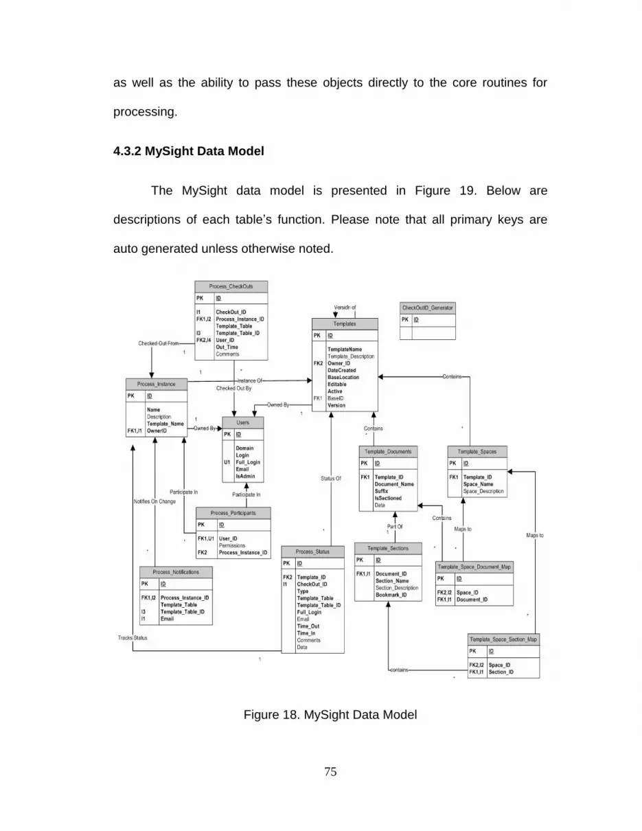
75
as well as the ability to pass these objects directly to the core routines for
processing.
4.3.2 MySight Data Model
The MySight data model is presented in Figure 19. Below are
descriptions of each table‟s function. Please note that all primary keys are
auto generated unless otherwise noted.
Figure 18. MySight Data Model

76
Users: The users table holds login domain credential information, email
address as well as admin status for each user.
Templates: The templates table provides records for all templates
housed in the system. The editable attribute determines whether the template
can be edited. If a template is editable it is not executable, The active attribute
determines if the template is the latest version. The foreign key BaseID points
back to version 1 of a particular template, so all entries with the same BaseID
are different versions of the same template. An important note is that
whenever a new version of a template is created, all documents, sections and
spaces are copied in order to preserve the process traces of any previous
version‟s instances.
Template_Documents: This table holds documents for every templated
document stored in the system. The Template_ID field provides a link back to
the associated template. The data field holds binary data for the document.
Template_Sections: This table holds section metadata that is extracted
from sectioned documents when they are uploaded into MySight. The actual
content of the section is housed in the corresponding document linked by the
Document_ID foreign key. The bookmark_id field holds the Microsoft Word
bookmark name that contains the section content. This means that to access
section data one must take the binary document data, open it with Microsoft
Word and use Microsoft interop to extract the bookmark content and save it.
77
Template_Spaces: This table holds space records for a particular
template.
Template_Space_Document_Map: This table maps a template‟s
documents to a space. It is possible for a document to be associated with
multiple spaces.
Template_Space_Section_Map: This table maps a template‟s sections
to a space. It is possible for a section to be associated with multiple spaces;
however, a section cannot be contained in a space that its parent is already a
part of.
Process_Instance: The process instance table holds records of all
instantiated processes. This table contains foreign keys to associate a
process owner and its template. The link to the template provides the context
so a process trace can be generated.
Process_Participants: The process participants table links users to
process instances giving them the ability to manipulate documents and view
process traces.
Check outID_Generator: This table serves only to generate checkout
IDs. This table is used instead of auto generated identity column because
multiple objects may fall under a single checkout. For example, a space with
5 documents will generate just one check out ID.

78
Process_CheckOuts: The Process_CheckOuts table contains all active
check outs. An entry will be created for each item checked out, bit only a
single CheckOutID will be generated from the CheckOutID_Generator. For
example, a space with 5 documents associated with it will have entries placed
into this table for the space itself as well as the five documents. Each of these
entries will have a unique ID but the same Check out_ID.. The
Template_Table attribute provides the table (Template_Spaces,
Template_Sections or Template_Documents) for the checked out content.
This will be filled with Space, Section or Document. The Template_Table_ID
is the id of the object in the Template_Table for which the content is checked
out. Because of this a link can be made to the template structure to determine
whether a process document is either checked in or available for check out.
Process_Status: The process status functions as both a repository that
stores the work breakdown structure for check outs as well as updated
process content. It contains a link back to the template definition which allows
this table to provide process traces and document context information.
When a check-in occurs the entries from the Process_CheckOuts table
are copied into the Process_Status table, along with the check-in times,
comments, the user‟s credentials and any updated data. The Type field is
particularly important to this process. Because section data is housed inside
its parent document‟s entry, any section check-in must have a corresponding
virtual document check-in. Thus when a section is checked in the latest
version of the document will be retrieved, the section will be merged and an
79
updated entry for the document will be saved with a “Virtual” type field. The
Type field is marked either virtual or real to allow the process viewer to
distinguish between full document check outs and section check outs. When
check outs occur this table is checked first for the updated data. If none exists
the original template version is downloaded.
Process_Notifications: This table holds notification for a process‟s
content which various users have subscribed to. This table is queried every
time a check in occurs to see if it contains any matches for the content being
checked in. Emails are generated and sent out for any matches.
80
Chapter 5
Implemented MySight Templates
In this chapter we discuss two MySight document based process
templates developed by CETI for infrastructure management. The description
for each template begins with motivation for why such a document based
processe is important and then moves into the details of the template. These
details are laid out with a description of documents and sections as well as
their content followed by the space grouping information.
5.1 The CETI Core Architecture Template
The CETI Core Architecture Template was devised to allow for life
cycle tracking and management of the CETI research group‟s core enterprise
computing assets. In the context of this template, core computing asset can
be defined as any piece of hardware or software that supports enterprise
applications in their execution, but provides no real business value on its own.
Examples include physical and virtual hardware, directory services, database
services, middleware services, as well as application and web servers.
Because this core infrastructure provides the basic services needed by all
enterprise applications, the ability to manage and track changes is critical for
efficient functioning of any enterprise computing infrastructure.

81
The CETI research group‟s core hardware infrastructure is composed
of five IBM Blade servers running Red Hat Enterprise Linux 5, two Dell Power
Edge servers, one running Windows 2003 server and the other running Red
Hat Enterprise Linux 5, and SAN storage unit. Each of these servers also has
an instance of VMWare Server running, allowing it to host up to 5 virtual
machines. Each of these virtual machines can be running one or many core
infrastructure services. The dynamic nature of the research domain often
requires that new core services be setup with little to no prior notice. For
example, a CETI student working on a sponsored project discovers an open
source middleware tool that could prove invaluable in solving a problem that
their project is encountering. In order to evaluate the new tools effectiveness,
the student must setup a test environment. This environment requires not
only the middle ware tool to be installed, but also all the prerequisite software
the tool requires such as databases and specific types and version of Java
application servers. With multiple students and projects all potentially
requiring different core infrastructure one can see how the management of
core services in a small architecture such as this can become rather
cumbersome, allowing the architecture to become fragmented and unstable.
In order to combat this instability and fragmentation the CETI Core
Infrastructure template was devised. This template was designed to
document and track changes to the core services of the infrastructure in order
to provide a clear picture of what services exist, as well as provide an audit of
infrastructure changes. The log of infrastructure changes provides help for
82
troubleshooting as well as a source for identifying experts on certain pieces of
infrastructure.
5.1.1 Core Architecture Template Documents
The CETI Core Architecture Template (shown in Figure 20.) is
composed of the following six documents:
Physical servers and hardware: This is an un-sectioned document. It
contains basic information for each physical machine in the infrastructure.
The document contains an entry for each physical machine. An entry
captures basic machine information such as Physical Location, IP Address,
DNS Name, hardware specifications, mount points, etc.
Storage: The storage document is a standalone document which
documents all SAN and NAS units and the volumes associated with them.
Information pertaining to the administration of these storage components is
also housed in this document.
Virtual servers: The virtual servers‟ document provides information
about each virtual machine that exists in the architecture. This document is
sectioned based on service types, e.g., database service, windows
application services, Java application service, etc. Each section provides an
entry for the specifics of the virtual machine housing the service. Generic
information such as machine, name, location, admin credentials is replicated
across all section types. In addition to this general information, each section
type allows for more specific information to be entered about the machine.
83
For example, a virtual machine entry in the “Windows Application Services”
section would contain fields for information about .NET version installed on
the virtual server, while a database entry would provide fields for specifics of
the type and version of database server running on the server.
Network: The network document provides information on the
networking setup of various services. This document is section based on
service types, e.g., database service, windows application services, Java
application service, etc. When a new service is added to the infrastructure, an
entry should be added to the appropriate section in this document noting the
name, server and port the service is running on.
Vendor products: This document is once again sectioned by service
type. It contains information about the administrative tools and documentation
for each piece of software that is present in the infrastructure. Details
captured in these entries include support resource locations, related
administrative packages, product keys, and servers with the product installed.
Each time a new core software package is installed an entry should be
created so that basic information needed to support the product can easily be
obtained by the architecture team.
Utility document: The utility document severs as a catch-all document
for information not explicitly mandated in the other core infrastructure
documents. This document is sectioned by service type, and allows for user
84
to freely enter information they feel is relevant to the management of the core
architecture components.
5.1.2 CETI Core Architecture Template Spaces
The CETI Core Architecture Template defines five spaces. Each of
these spaces roughly corresponds with the sections present in the documents
described above, and represents the activity of creating or modifying a certain
type of service present in the infrastructure. Below we describe each space
and the documents and sections contained within it.
Physical servers and hardware: The physical servers and hardware
space corresponds to the activity of adding or changing a piece of physical
hardware. It contains both the Physical Hardware and Storage documents.
Java application services: The Java applications services space
corresponds with an activity for modifying or adding Java application servers.
It contains the Java application services sections from the virtual servers,
vendor products, network, and utility documents.
Windows Application Services: The Windows applications services
space corresponds with an activity for modifying or adding .NET Application
Servers. It contains the Windows Application Services sections from the
virtual servers, vendor products, network, and utility documents.
Database Services: The Database Services space corresponds with
an activity for modifying or adding database infrastructure. It contains the
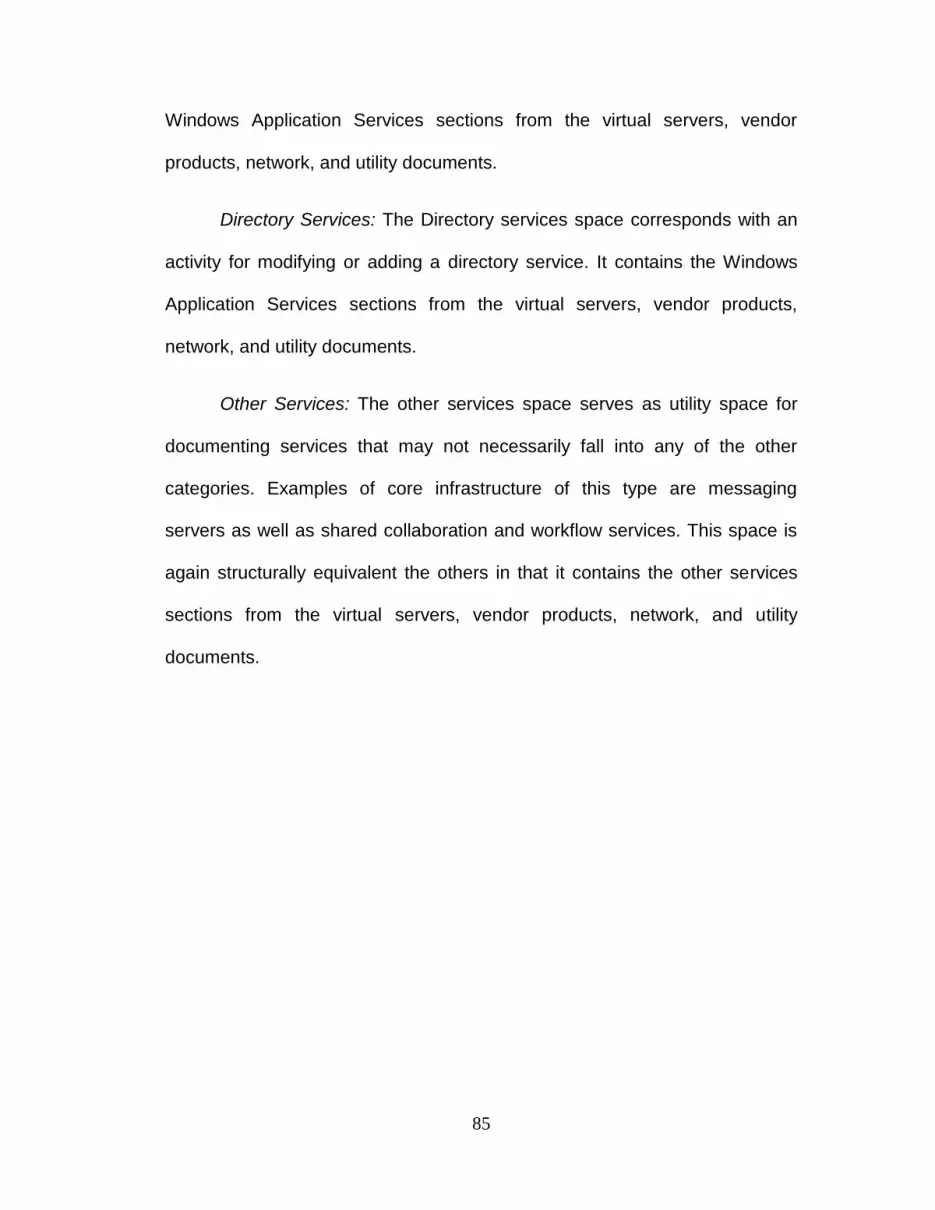
85
Windows Application Services sections from the virtual servers, vendor
products, network, and utility documents.
Directory Services: The Directory services space corresponds with an
activity for modifying or adding a directory service. It contains the Windows
Application Services sections from the virtual servers, vendor products,
network, and utility documents.
Other Services: The other services space serves as utility space for
documenting services that may not necessarily fall into any of the other
categories. Examples of core infrastructure of this type are messaging
servers as well as shared collaboration and workflow services. This space is
again structurally equivalent the others in that it contains the other services
sections from the virtual servers, vendor products, network, and utility
documents.
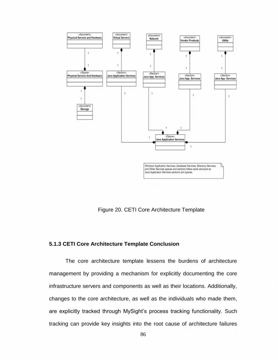
86
Figure 20. CETI Core Architecture Template
5.1.3 CETI Core Architecture Template Conclusion
The core architecture template lessens the burdens of architecture
management by providing a mechanism for explicitly documenting the core
infrastructure servers and components as well as their locations. Additionally,
changes to the core architecture, as well as the individuals who made them,
are explicitly tracked through MySight‟s process tracking functionality. Such
tracking can provide key insights into the root cause of architecture failures
87
induced by changes to the core infrastructure, as well as provide a
mechanism for finding experts for a particular infrastructure service.
5.2 The Architecture Design Review Template
The Architecture Design Review template is a MySight implementation
of the general architecture design review process outlined in chapter 2. The
focus of this template is not only to provide documentation about production
enterprise systems, but also to make sure that all systems are designed in
such a way as not to comprise the existing architecture. This process also
ensures that all information related to deployment and day to day operations
of the system has also been created and reviewed. Examples of such
information are capacity planning, maintenance plans, deployment plans, and
disaster recovery plans.
5.2.1 Architecture Design Review Documents and Spaces
Because the Architecture Design Review template is much bigger than
the core architecture template, the description deviates slightly from the
prescribed method for template description. Instead of explicitly describing
each document and section, a tabular view of the documents and spaces
present in the template will be provided followed by discussion of key points.

88
Document Name Description
CETI_TQA.docx TQA Documents. Described in chapter 2.
Capacity Planning.docx Capacity Planning Template.
ClassDiagram.vsd Visio class diagram.
ComponentModel.vsd Visio component model.
Configuration Management.doc
Document for identify, control, and report functional and physical configurations of system.
CPMMProjectCharter.doc General Information: Charter
CPMMProjectSchedule.xls General Information: Schedule
deploymentDiagram.vsd Diagram Representing deployment of the components onto physical processing nodes.
Deploymentplan.doc Comprehensive plan for installation of the various components of the system.
DeviationsFromLogicalModel.xlsx
Identifies deviations between physical and logical data models.
LogicalArchitecture.vsd Logical Architecture Diagrams
LogicalDataModel.vsd Logical Database Independent data Model
LogicalToPhysicalMapping.vsd
Diagrams showing mapping of logical architecture to physical architecture if it is not obvious.
Maintenance plan.doc
Major operational document. Security and maintenance procedures and responsibilities for deployed system operation
Non-Functional Requirements Document Template.doc
Document specifies non functional requirements for the system.
PhysicalArchitecture.vsd Physical system architecture. Includes servers and network infrastructure designed system will be installed on.
physicalDBDesign.vsd Physical Database Specific data model.
sequenceDiagrams.vsd Sequence Diagrams for the designed system.
System Context Diagram.vsd System context diagrams. Details all business units and external systems which interact with designed system.
Test Plan.doc Test Plan for all major use cases
UseCaseTemplateFormal.doc Textual Use Case Descriptions
use_case.vsd Graphical Use Case descriptions
VendorReview.docx Document detailing all considered vendor products used in the project.
Table 5.1 Architecture Design Review Documents

89
Space Name Description Documents Sections
Architecture Overview
This space contains the core architecture components to be reviewed. Includes review of 3rd party tools.
ComponentModel.vsd, deploymentDiagram.vsd, LogicalArchitecture.vsd, LogicalToPhysicalMapping.vsd, VendorReview.docx
TQA - Architectural Overview
Class Diagram
Contains Detailed Class Diagram and related TQA section for the reviewed system. ClassDiagram.vsd
TQA - Class Diagram
Component Model
High Level Component model for the system ComponentModel.vsd
TQA - Component Model
General Information
General Information about project being reviewed as well as issues and risks.
CPMMProjCharterSnap.doc, CPMMProjectSchedule.xls
TQA - General Information
Logical Data Model
Logical database independent data model. LogicalDataModel.vsd
TQA - Logical Data Model
Non Functional Requirements
Non functional requirements review.
Non-Functional Requirements Document Template.doc
TQA - Non Functional Requirements
Operations Manual
Contains required information for the deployment and day to day operations of the system. Includes capacity planning, testing procedures, change management information as well maintenance procedures and responsibilities.
Capacity Planning.docx, Configuration Management.doc, deploymentDiagram.vsd, deploymentplan.doc, Maintenance plan.doc, Test Plan.doc
TQA - Operations Manual, TQA - Test Scripts
Physical Data Model
Contains mapping from logical data model to physical data model
physicalDBDesign.vsd, LogicalDataModel.vsd, DeviationsFromLogicalModel.xlsx
TQA - Physical Database Design
Sequence Diagrams
Sequence Diagrams for the system.
sequenceDiagrams.vsd, ClassDiagram.vsd
TQA - Sequence Diagram
Continued
Table 5.2 Architecture Design Review Spaces
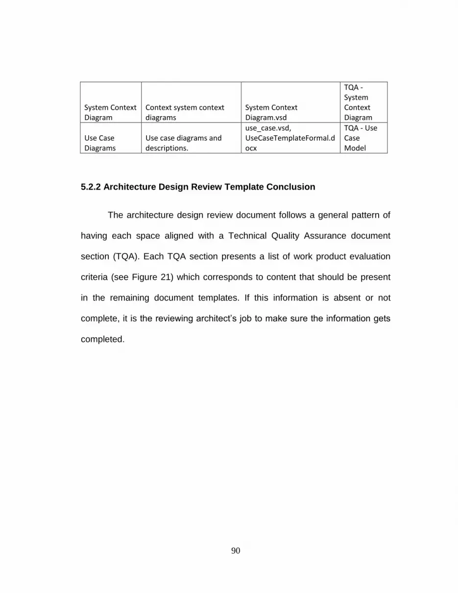
90
System Context Diagram
Context system context diagrams
System Context Diagram.vsd
TQA - System Context Diagram
Use Case Diagrams
Use case diagrams and descriptions.
use_case.vsd, UseCaseTemplateFormal.docx
TQA - Use Case Model
5.2.2 Architecture Design Review Template Conclusion
The architecture design review document follows a general pattern of
having each space aligned with a Technical Quality Assurance document
section (TQA). Each TQA section presents a list of work product evaluation
criteria (see Figure 21) which corresponds to content that should be present
in the remaining document templates. If this information is absent or not
complete, it is the reviewing architect‟s job to make sure the information gets
completed.
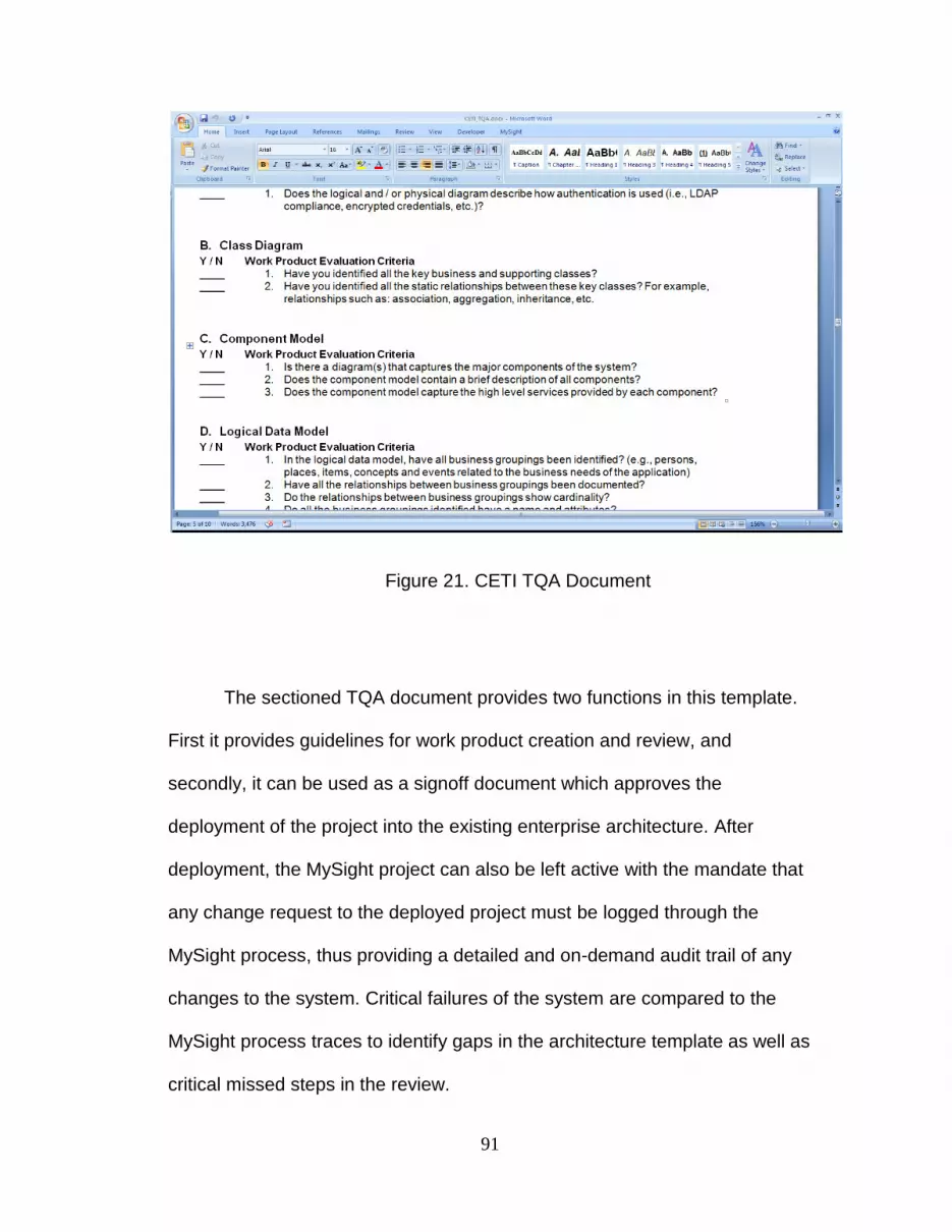
91
Figure 21. CETI TQA Document
The sectioned TQA document provides two functions in this template.
First it provides guidelines for work product creation and review, and
secondly, it can be used as a signoff document which approves the
deployment of the project into the existing enterprise architecture. After
deployment, the MySight project can also be left active with the mandate that
any change request to the deployed project must be logged through the
MySight process, thus providing a detailed and on-demand audit trail of any
changes to the system. Critical failures of the system are compared to the
MySight process traces to identify gaps in the architecture template as well as
critical missed steps in the review.
92
Chapter 6
Conclusion and Future Work
6.1 Future Work
The current implementation of MySight leaves opportunities for future
work. These opportunities range from development of new MySight
templates, additional facilities for metrics capturing and intelligence mining
across processes, and the overhauling of the document meta-model in order
to support additional work contingencies and work product reuse.
6.1.1 Additional MySight Templates
The two implemented MySight templates discussed in this thesis are
based on the enterprise architecture management practices of a large
insurance company and the CETI research group at Ohio State. While these
templates are derived from a real world situation they are in no way universal.
The creation of templates based on popular a Enterprise Architecture
framework such as ITIL, TOGAF and the Zachman framework can provide
more pervasive use of the MySight system, as well as help with the elicitation
of future requirements for the document based meta-model [40,41,42]. The
Zachman framework in particular, with its multiple views of the enterprise
architecture, already appears to mesh very well with the document meta-

93
model. With a little study this framework could provide a relatively complete
and extremely intuitive model for enterprise architecture traceability.
Additional research is also needed to find domains outside enterprise
architecture management in which MySight can prove to be useful.
6.1.2 Metrics Dashboard
Currently MySight‟s facilities for cross process analysis discovery are
lacking. The current implementation focuses on the ability to view process
information for a single process instance. A topic of future work is developing
methodologies and metrics for capturing aggregated process information as
well as developing schemes to mine usable intelligence from the process
instance traces and their document content. The goal of such work would be
to provide a dashboard like view of metrics for various process types to policy
makers which will aid in process improvement initiatives.
6.1.3 Additions to the Document Meta-Model
The current document meta-model implemented in MySight only
extends as far as the content defined in the initial template. The model
provides no mechanism to add content dynamically during execution. This
severely limits flexibility when it comes to collaborative process execution.
The introduction of a dynamic space concept into the model could eliminate
this problem. Such a concept would allow users to dynamically alter the
process model on a per instance basis, allowing the insertion of additional
document templates when needed.

94
Another shortcoming of the document meta-model is that is provides
no linking of content between processes. This can severely limit reuse,
especially when taken in the context of service-oriented architectures, which
define applications as the composition of shared services and components.
Subsequent version of the meta-model must explicitly handle cross-process
document content links in order to ensure that service oriented architecture
documentation stays consistent.
6.1.4 More Descriptive Process Viewer
The current process viewer‟s work breakdown structure is very
simplistic. Further research is required in order to implement views that are
closer to those produced in production workflow systems. Future views
should be able to identify common workflow patterns, such as dependency
structures between users and documents as well as branching of work in
serial and parallel paths.
6.2 Conclusion
This thesis presents a system which provides highly traceable
collaborative interactions to bridge the gap between production workflow
traceability and collaborative flexibility. The tools usage is framed in the
context of document-based architecture review and management processes
which require both traceable and flexible execution. Through the development
of a document based meta-model and tight integration with the Microsoft
Office client, users are able to execute architecture processes in a flexible

95
manner while still maintaining the traceability that is fundamental for
enterprise architecture stability and improvement. This document meta-model
also provides business users the ability to create their own traceable
collaborative processes without developer support. The framework also
provides users with an activity and process centric view of enterprise
architecture documents and artifacts, thus relieving the burdens of dealing
with complex and unintuitive directory based enterprise repositories.
Additionally, the system also provides a scheme for partial checkout of
Microsoft Word content. Such a scheme can allow for additional concurrency
by allowing multiple parties to edit distinct sections of a single document at
the same time.

96
Bibliography
[1] M. Koch and T. Gross, "Computer-Supported Cooperative Work - Concepts and
Trends," Proc. Conf. of the Association Information And Management (AIM), 2006.
[2] G. J. Nutt, "The evolution towards flexible workflow systems," Distrib. Syst. Engng, pp.
276-294, 1996.
[3] Microsoft Corporation. (2009, May) What is Microsoft Office SharePoint Server? .
[Online]. http://www.microsoft.com/sharepoint/prodinfo/what.mspx
[4] IBM Corporation. (2009, May) IBM Collaboration Software. [Online]. http://www-
01.ibm.com/software/lotus/
[5] Microsoft Corporation. (2009, May) Groove Home Page. [Online].
http://office.microsoft.com/en-us/groove/FX100487641033.aspx
[6] The Google Corporation. (2009, Jul.) Google Wave Preview. [Online].
http://wave.google.com
[7] The Workflow Management Coalition, "Workflow Managemetn Coalition Terminology
& Glossary," The Workflow Management Coalition, 1999.
[8] The Oracle Corporation. (2009, Jul.) Overview Of Oracle Workflow (Oracle Workflow
API Reference). [Online].
http://download.oracle.com/docs/cd/B14117_01/workflow.101/b10286/arov.htm#index-

97
Oracle-Workflow-Builder---0
[9] H. A. Reijers, Design and Control of Workflow Processes. New York, USA: Springer-
Verlag New York, Inc, 2003.
[10] M. Zacklad, "Communities of action: a cognitive and social approach to the design of
CSCW systems," in GROUP '03: Proceedings of the 2003 international ACM
SIGGROUP conference on Supporting group work, Sanibel Island, Florida, USA,
2003, pp. 190-197.
[11] (2009, May) The Workflow Management Coalition. [Online]. http://www.wfmc.org/
[12] Microsoft Corporation. (2009, May) Windows Workflow Foundation Overview. [Online].
http://msdn.microsoft.com/en-us/library/ms734631.aspx
[13] Oracle Corporation. (2009, May) Oracle Workflow FAQ. [Online].
http://www.oracle.com/technology/products/ias/workflow/release263/workflow_faq.html
[14] W. M. P. v. d. Aalst and A. H. M. T. Hofstede, "YAWL: Yet Another Workflow
Language," Information Systems, vol. 30, pp. 245-275, 2003.
[15] W. M. v. d. Aalst. (2009, Jul.) Workflow Patterns. [Online].
http://www.workflowpatterns.com
[16] M. H. Schonenberg, R. S. Mans, N. C. Russell, N. A. Mulyer, and W. M. P. van der
Aalst, "Towards a Taxonomy of Process Flexibility," in The 20th International
Conference on Advanced Information Systems Engineering (CAiSE'08), Montpellier,
France, 2008, pp. 81-84.

98
[17] W. van der Aalst, T. Weijters, and L. Maruster, "Workflow Mining: Discovering Process
Models from Event Logs," IEEE Transactions on Knowledge and Data Engineering,
vol. 16, no. 9, pp. 1128-1142, 2004.
[18] S. Castellani and Pacull, "XFolders: a flexible workflow system based on electronic
circulation folders," in Database and Expert Systems Applications, 2002. Proceedings.
13th International Workshop on, 2202, pp. 307-312.
[19] R. Carbon, et al., "Mobility in the virtual office: a document-centric workflow approach,"
in SAM '08: Proceedings of the 1st international workshop on Software architectures
and mobility, Leipzig, Germany, 2008, pp. 21-26.
[20] P. Dourish, et al., "A programming model for active documents," in 13th Annual ACM
Symposium on User interface Software and Technology, San Diego, California, United
States, 2000.
[21] P. Dourish, R. Bentley, R. Jones, and A. MacLean, "Getting some perspective: using
process descriptions to index document history," in GROUP '99: Proceedings of the
international ACM SIGGROUP conference on Supporting group work, New York, NY,
USA, 1999, pp. 375-384.
[22] J. J. M. Uijlenbroek and H. G. Sol, "Document Based Process Improvement in the
Public Sector: Settling for the second best is the best you can do," in HICSS '97:
Proceedings of the 30th Hawaii International Conference on System Sciences, 1997,
p. 107.
[23] A. P. Sheth, "From contemporary workflow process automation to adaptive and
dynamic work activity coordination and collaboration," in SIGGROUP Bull, 1997.
99
[24] S. Carlsen, J. Krogstie, A. Solvberg, and O. I. Lindland, "Evaluating Flexible Workflow
Systems," in System Sciences Proceedings of the Thirtieth Hawaii International
Conference on, Wailea, HI, USA, 1997, pp. 230-239.
[25] M. Weske, "Flexible Modeling and Execution of Workflow Activities," in Thirty-First
Annual Hawaii international Conference on System Sciences, Kohala Coast, Hawaii,
USA, 1998.
[26] H. D. Jørgensen, "Interaction as a framework for flexible workflow modeling," in In
Proceedings of the 2001 international ACM SIGGROUP Conference on Supporting
Group Work, Boulder, Colorado, USA, 2001.
[27] V. Bellottie, N. Doucheneaut, M. Howard, and I. Smith, "Taking email to task: the
design and evaluation of a task management centered email tool," in In Proceedings
of the SIGCHI Conference on Human Factors in Computing Systems , Ft. Lauderdale,
Florida, USA, 2003, pp. 345-352.
[28] N. Kushmerick and T. Lau, "Automated email activity management: An unsupervised
learning approach," in International Conference on Intelligent User Interfaces, San
Diego, California, USA, 2005.
[29] A. Abeta and K. Kakizaki, "Operation Record Based Workflow Extracting Method for
Personal Information Management System,," in In Proceedings of the Third Asian
Pacific Computer and Human interaction, Shonan Village Center, Japan, 1998.
[30] W. M. P. van der Aalst, M. Adams, A. H. M. ter Hofstede, M. Pesic, and H.
Schonenberg, "Flexibility as a Service," BPMcenter.org, 2008.

100
[31] The Microsoft Corporation. (2009, May) Microsoft Visual Studio Tools For Office.
[Online]. http://msdn.microsoft.com/en-us/library/d2tx7z6d(VS.80).aspx
[32] S. Papadopoulou, E. Reuss, and N. C. Moira, "A User Study of Edit Profiles in
Collaborative Authoring Systems," in The 2008 International Symposium on
Collaborative Technologies and Systems, Irvine, California, USA, 2008.
[33] The Microsoft Corporation. (2009, Jun.) LINQ. [Online]. http://msdn.microsoft.com/en-
us/netframework/aa904594.aspx
[34] R. Elmsari and S. B. Navathe, "Concepts For Object Databases," in Fundamentals Of
Database Systems 4th Ed. Boston: Addison Wesley, 2004, ch. 6-7, pp. 639-700.
[35] M. Fowler, "Active Record," in Patterns of Enterprise Application Architecture.
Addison-Wesley Professional, 2002, pp. 160-165.
[36] The Microsoft Corporation. (June, ) Microsoft SQL Server Compact 3.5. [Online].
http://www.microsoft.com/Sqlserver/2005/en/us/compact.aspx
[37] The Microsoft Corporation. (2009, Jun.) .NET Framework: Windows Presentatation
Foundation. [Online].
http://www.microsoft.com/net/WindowsPresentationFoundation.aspx
[38] The Microsoft Corporation. (June, ) XAML Overview. [Online].
http://msdn.microsoft.com/en-us/library/ms752059.aspx
[39] LoginNP Software. (2009, Jun.) EZShellExtensions.NET. [Online].
http://www.ssware.com/ezshell/ezshell.htm

101
[40] APM Group Ltd. (2009, Jul.) ITIL Home. [Online]. http://www.itil-
officialsite.com/home/home.asp
[41] The Open Group. (2009, Jul.) TOGAF Version 9. [Online].
http://www.opengroup.org/togaf/
[42] J. Zachman, "A Framework for Information System Architecture," IBM Systems
Journal, vol. 26, no. 3, 1987.


