Embed Size (px)
Citation preview
Where innovation happenswww.bordignon.com
Direct Drive tapping unitwith touch screen
multiple control panelinstructions manual


Direct Drive tapping unit with touch screen multiple control panel
ATTENTION!
BEFORE connecting the tapping unit, read this instruction manual very carefully,especially the warnings on page 1
Rev. 8
Direct Drive tapping unit with touch screen multiple control panel
Index
WARNINGS
INTRODUCTION
CONTROL PANEL
TAPPING UNIT
FUNCTIONING
INSTALLING
ACCESSING FUNCTIONS WITH A PASSWORD
SET UP
TORQUE CONTROL
THREADING TIME
LUBRICATION
TAP CHANGE
ALARMS
TROUBLE SHOOTING
SERvICE— Reverse cycle— Tap data— Counter— Setting a production lot— Lubrication oil— Programs— Diagnostics— Alarms history— Language selection— Brightness control
DISPOSAL OF COMPONENTS AND MATERIAL
OPTIONAL— D-TC: tapping control sensor— 4D-USB: USB drive for data reading— D-APR: automatic pressure regulator.— Right/left hand threading— Change of return speed
DTAP-1 DRAWING
DTAP-2 DRAWING
DTAP-3 DRAWING
CONTROL PANEL DRAWING
PREHOLES
CE DECLARATION OF CONFORMITY
ELECTRIC DIAGRAM
1
2
2
3
3
4
4
5
5
6
6
7
7
8
1010101011111112121212
12
1314161718
19
20
21
22
23
24
25
1
Direct Drive tapping unit with touch screen multiple control panel
wArNINgs
NO YEs
Max.����������80°C
AVVERTENZE
1
NON�ESEGUIRE�LAVORAZIONI�MECCANICHE�SULLA MASCHIATRICE�O�SUL PANNELLO
NON ALLACCIARE ALTRE APPARECCHIATURE AL PANNELLO
LAVORARE�CON�IL PANNELLO�SEMPRE�CHIUSO
PROTEGGERE�IL PANNELLO�ED�IL MOTORE�DA LIQUIDI,�POLVERI�E TRUCIOLI
TEMPERATURA MASSIMA DI�LAVORO�80°
MASCHIARE�SEMPRE�CON�LUBRIFICANTE
- NON�SCOLLEGARE/�COLLEGARE�I�CAVI�MENTRE�LA JOLLY TAP E��IN�FUNZIONE�OE’ CONNESSA ALLA LINEA ELETTRICA
-�MAI�MODIFICARE�IL PANNELLO�DI�CONTROLLO�ELETTRICO�E�/�O�LA MASCHIATRICE- NON�SMONTARE�NE’ TOCCARE�LA MASCHIATRICE,�NON AVVICINARSI ALLA MASCHIATRICEQUANDO�E’ COLLEGATA ALLA LINEA ELETTRICA (ECCETTO�DURANTE�IL CAMBIO�MASCHIO)
-�NON�COLLEGARE�PANNELLO�E�MASCHIATRICE�CON�NUMERO�DI�SERIE�DIVERSO(vedi “INSTALLAZIONE” -�pag.�4)
NON�FISSARE�IL PANNELLO A SUPERFICI�VIBRANTI
MANUTENZIONE�SOLO�DA PERSONALE AUTORIZZATO
TOGLIERE�LA TENSIONE�O�PREMERE�IL TASTO�EMERGENZA PRIMA DI TOCCARE�L’UTENSILE.ALLONTANARSI�DALL’ UTENSILE�IN�ROTAZIONE
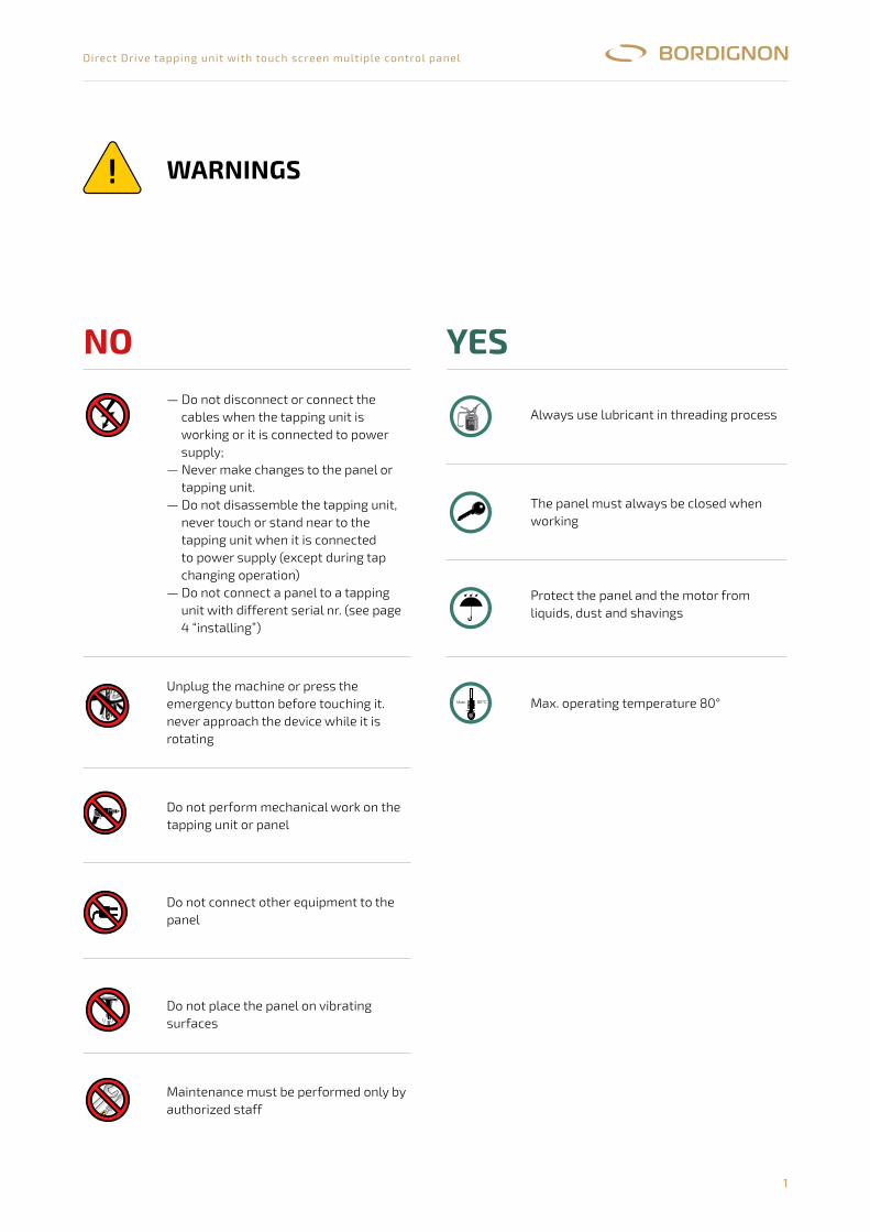
Always use lubricant in threading process
Max.����������80°C
AVVERTENZE
1
NON�ESEGUIRE�LAVORAZIONI�MECCANICHE�SULLA MASCHIATRICE�O�SUL PANNELLO
NON ALLACCIARE ALTRE APPARECCHIATURE AL PANNELLO
LAVORARE�CON�IL PANNELLO�SEMPRE�CHIUSO
PROTEGGERE�IL PANNELLO�ED�IL MOTORE�DA LIQUIDI,�POLVERI�E TRUCIOLI
TEMPERATURA MASSIMA DI�LAVORO�80°
MASCHIARE�SEMPRE�CON�LUBRIFICANTE
- NON�SCOLLEGARE/�COLLEGARE�I�CAVI�MENTRE�LA JOLLY TAP E��IN�FUNZIONE�OE’ CONNESSA ALLA LINEA ELETTRICA
-�MAI�MODIFICARE�IL PANNELLO�DI�CONTROLLO�ELETTRICO�E�/�O�LA MASCHIATRICE- NON�SMONTARE�NE’ TOCCARE�LA MASCHIATRICE,�NON AVVICINARSI ALLA MASCHIATRICEQUANDO�E’ COLLEGATA ALLA LINEA ELETTRICA (ECCETTO�DURANTE�IL CAMBIO�MASCHIO)
-�NON�COLLEGARE�PANNELLO�E�MASCHIATRICE�CON�NUMERO�DI�SERIE�DIVERSO(vedi “INSTALLAZIONE” -�pag.�4)
NON�FISSARE�IL PANNELLO A SUPERFICI�VIBRANTI
MANUTENZIONE�SOLO�DA PERSONALE AUTORIZZATO
TOGLIERE�LA TENSIONE�O�PREMERE�IL TASTO�EMERGENZA PRIMA DI TOCCARE�L’UTENSILE.ALLONTANARSI�DALL’ UTENSILE�IN�ROTAZIONE
The panel must always be closed when working
Max.����������80°C
AVVERTENZE
1
NON�ESEGUIRE�LAVORAZIONI�MECCANICHE�SULLA MASCHIATRICE�O�SUL PANNELLO
NON ALLACCIARE ALTRE APPARECCHIATURE AL PANNELLO
LAVORARE�CON�IL PANNELLO�SEMPRE�CHIUSO
PROTEGGERE�IL PANNELLO�ED�IL MOTORE�DA LIQUIDI,�POLVERI�E TRUCIOLI
TEMPERATURA MASSIMA DI�LAVORO�80°
MASCHIARE�SEMPRE�CON�LUBRIFICANTE
- NON�SCOLLEGARE/�COLLEGARE�I�CAVI�MENTRE�LA JOLLY TAP E��IN�FUNZIONE�OE’ CONNESSA ALLA LINEA ELETTRICA
-�MAI�MODIFICARE�IL PANNELLO�DI�CONTROLLO�ELETTRICO�E�/�O�LA MASCHIATRICE- NON�SMONTARE�NE’ TOCCARE�LA MASCHIATRICE,�NON AVVICINARSI ALLA MASCHIATRICEQUANDO�E’ COLLEGATA ALLA LINEA ELETTRICA (ECCETTO�DURANTE�IL CAMBIO�MASCHIO)
-�NON�COLLEGARE�PANNELLO�E�MASCHIATRICE�CON�NUMERO�DI�SERIE�DIVERSO(vedi “INSTALLAZIONE” -�pag.�4)
NON�FISSARE�IL PANNELLO A SUPERFICI�VIBRANTI
MANUTENZIONE�SOLO�DA PERSONALE AUTORIZZATO
TOGLIERE�LA TENSIONE�O�PREMERE�IL TASTO�EMERGENZA PRIMA DI TOCCARE�L’UTENSILE.ALLONTANARSI�DALL’ UTENSILE�IN�ROTAZIONE
Protect the panel and the motor from liquids, dust and shavings
Max.����������80°C
AVVERTENZE
1
NON�ESEGUIRE�LAVORAZIONI�MECCANICHE�SULLA MASCHIATRICE�O�SUL PANNELLO
NON ALLACCIARE ALTRE APPARECCHIATURE AL PANNELLO
LAVORARE�CON�IL PANNELLO�SEMPRE�CHIUSO
PROTEGGERE�IL PANNELLO�ED�IL MOTORE�DA LIQUIDI,�POLVERI�E TRUCIOLI
TEMPERATURA MASSIMA DI�LAVORO�80°
MASCHIARE�SEMPRE�CON�LUBRIFICANTE
- NON�SCOLLEGARE/�COLLEGARE�I�CAVI�MENTRE�LA JOLLY TAP E��IN�FUNZIONE�OE’ CONNESSA ALLA LINEA ELETTRICA
-�MAI�MODIFICARE�IL PANNELLO�DI�CONTROLLO�ELETTRICO�E�/�O�LA MASCHIATRICE- NON�SMONTARE�NE’ TOCCARE�LA MASCHIATRICE,�NON AVVICINARSI ALLA MASCHIATRICEQUANDO�E’ COLLEGATA ALLA LINEA ELETTRICA (ECCETTO�DURANTE�IL CAMBIO�MASCHIO)
-�NON�COLLEGARE�PANNELLO�E�MASCHIATRICE�CON�NUMERO�DI�SERIE�DIVERSO(vedi “INSTALLAZIONE” -�pag.�4)
NON�FISSARE�IL PANNELLO A SUPERFICI�VIBRANTI
MANUTENZIONE�SOLO�DA PERSONALE AUTORIZZATO
TOGLIERE�LA TENSIONE�O�PREMERE�IL TASTO�EMERGENZA PRIMA DI TOCCARE�L’UTENSILE.ALLONTANARSI�DALL’ UTENSILE�IN�ROTAZIONE
Max. operating temperature 80°
— Do not disconnect or connect the cables when the tapping unit is working or it is connected to power supply;
— Never make changes to the panel or tapping unit.
— Do not disassemble the tapping unit, never touch or stand near to the tapping unit when it is connected to power supply (except during tap changing operation)
— Do not connect a panel to a tapping unit with different serial nr. (see page 4 “installing”)
Max.����������80°C
AVVERTENZE
1
NON�ESEGUIRE�LAVORAZIONI�MECCANICHE�SULLA MASCHIATRICE�O�SUL PANNELLO
NON ALLACCIARE ALTRE APPARECCHIATURE AL PANNELLO
LAVORARE�CON�IL PANNELLO�SEMPRE�CHIUSO
PROTEGGERE�IL PANNELLO�ED�IL MOTORE�DA LIQUIDI,�POLVERI�E TRUCIOLI
TEMPERATURA MASSIMA DI�LAVORO�80°
MASCHIARE�SEMPRE�CON�LUBRIFICANTE
- NON�SCOLLEGARE/�COLLEGARE�I�CAVI�MENTRE�LA JOLLY TAP E��IN�FUNZIONE�OE’ CONNESSA ALLA LINEA ELETTRICA
-�MAI�MODIFICARE�IL PANNELLO�DI�CONTROLLO�ELETTRICO�E�/�O�LA MASCHIATRICE- NON�SMONTARE�NE’ TOCCARE�LA MASCHIATRICE,�NON AVVICINARSI ALLA MASCHIATRICE
QUANDO�E’ COLLEGATA ALLA LINEA ELETTRICA (ECCETTO�DURANTE�IL CAMBIO�MASCHIO)-�NON�COLLEGARE�PANNELLO�E�MASCHIATRICE�CON�NUMERO�DI�SERIE�DIVERSO(vedi “INSTALLAZIONE” -�pag.�4)
NON�FISSARE�IL PANNELLO A SUPERFICI�VIBRANTI
MANUTENZIONE�SOLO�DA PERSONALE AUTORIZZATO
TOGLIERE�LA TENSIONE�O�PREMERE�IL TASTO�EMERGENZA PRIMA DI TOCCARE�L’UTENSILE.ALLONTANARSI�DALL’ UTENSILE�IN�ROTAZIONE
Unplug the machine or press the emergency button before touching it.never approach the device while it is rotating
Max.����������80°C
AVVERTENZE
1
NON�ESEGUIRE�LAVORAZIONI�MECCANICHE�SULLA MASCHIATRICE�O�SUL PANNELLO
NON ALLACCIARE ALTRE APPARECCHIATURE AL PANNELLO
LAVORARE�CON�IL PANNELLO�SEMPRE�CHIUSO
PROTEGGERE�IL PANNELLO�ED�IL MOTORE�DA LIQUIDI,�POLVERI�E TRUCIOLI
TEMPERATURA MASSIMA DI�LAVORO�80°
MASCHIARE�SEMPRE�CON�LUBRIFICANTE
- NON�SCOLLEGARE/�COLLEGARE�I�CAVI�MENTRE�LA JOLLY TAP E��IN�FUNZIONE�OE’ CONNESSA ALLA LINEA ELETTRICA
-�MAI�MODIFICARE�IL PANNELLO�DI�CONTROLLO�ELETTRICO�E�/�O�LA MASCHIATRICE- NON�SMONTARE�NE’ TOCCARE�LA MASCHIATRICE,�NON AVVICINARSI ALLA MASCHIATRICE
QUANDO�E’ COLLEGATA ALLA LINEA ELETTRICA (ECCETTO�DURANTE�IL CAMBIO�MASCHIO)-�NON�COLLEGARE�PANNELLO�E�MASCHIATRICE�CON�NUMERO�DI�SERIE�DIVERSO(vedi “INSTALLAZIONE” -�pag.�4)
NON�FISSARE�IL PANNELLO A SUPERFICI�VIBRANTI
MANUTENZIONE�SOLO�DA PERSONALE AUTORIZZATO
TOGLIERE�LA TENSIONE�O�PREMERE�IL TASTO�EMERGENZA PRIMA DI TOCCARE�L’UTENSILE.ALLONTANARSI�DALL’ UTENSILE�IN�ROTAZIONE
Do not perform mechanical work on the tapping unit or panel
Max.����������80°C
AVVERTENZE
1
NON�ESEGUIRE�LAVORAZIONI�MECCANICHE�SULLA MASCHIATRICE�O�SUL PANNELLO
NON ALLACCIARE ALTRE APPARECCHIATURE AL PANNELLO
LAVORARE�CON�IL PANNELLO�SEMPRE�CHIUSO
PROTEGGERE�IL PANNELLO�ED�IL MOTORE�DA LIQUIDI,�POLVERI�E TRUCIOLI
TEMPERATURA MASSIMA DI�LAVORO�80°
MASCHIARE�SEMPRE�CON�LUBRIFICANTE
- NON�SCOLLEGARE/�COLLEGARE�I�CAVI�MENTRE�LA JOLLY TAP E��IN�FUNZIONE�OE’ CONNESSA ALLA LINEA ELETTRICA
-�MAI�MODIFICARE�IL PANNELLO�DI�CONTROLLO�ELETTRICO�E�/�O�LA MASCHIATRICE- NON�SMONTARE�NE’ TOCCARE�LA MASCHIATRICE,�NON AVVICINARSI ALLA MASCHIATRICE
QUANDO�E’ COLLEGATA ALLA LINEA ELETTRICA (ECCETTO�DURANTE�IL CAMBIO�MASCHIO)-�NON�COLLEGARE�PANNELLO�E�MASCHIATRICE�CON�NUMERO�DI�SERIE�DIVERSO(vedi “INSTALLAZIONE” -�pag.�4)
NON�FISSARE�IL PANNELLO A SUPERFICI�VIBRANTI
MANUTENZIONE�SOLO�DA PERSONALE AUTORIZZATO
TOGLIERE�LA TENSIONE�O�PREMERE�IL TASTO�EMERGENZA PRIMA DI TOCCARE�L’UTENSILE.ALLONTANARSI�DALL’ UTENSILE�IN�ROTAZIONE
Do not connect other equipment to the panel
Max.����������80°C
AVVERTENZE
1
NON�ESEGUIRE�LAVORAZIONI�MECCANICHE�SULLA MASCHIATRICE�O�SUL PANNELLO
NON ALLACCIARE ALTRE APPARECCHIATURE AL PANNELLO
LAVORARE�CON�IL PANNELLO�SEMPRE�CHIUSO
PROTEGGERE�IL PANNELLO�ED�IL MOTORE�DA LIQUIDI,�POLVERI�E TRUCIOLI
TEMPERATURA MASSIMA DI�LAVORO�80°
MASCHIARE�SEMPRE�CON�LUBRIFICANTE
- NON�SCOLLEGARE/�COLLEGARE�I�CAVI�MENTRE�LA JOLLY TAP E��IN�FUNZIONE�OE’ CONNESSA ALLA LINEA ELETTRICA
-�MAI�MODIFICARE�IL PANNELLO�DI�CONTROLLO�ELETTRICO�E�/�O�LA MASCHIATRICE- NON�SMONTARE�NE’ TOCCARE�LA MASCHIATRICE,�NON AVVICINARSI ALLA MASCHIATRICE
QUANDO�E’ COLLEGATA ALLA LINEA ELETTRICA (ECCETTO�DURANTE�IL CAMBIO�MASCHIO)-�NON�COLLEGARE�PANNELLO�E�MASCHIATRICE�CON�NUMERO�DI�SERIE�DIVERSO(vedi “INSTALLAZIONE” -�pag.�4)
NON�FISSARE�IL PANNELLO A SUPERFICI�VIBRANTI
MANUTENZIONE�SOLO�DA PERSONALE AUTORIZZATO
TOGLIERE�LA TENSIONE�O�PREMERE�IL TASTO�EMERGENZA PRIMA DI TOCCARE�L’UTENSILE.ALLONTANARSI�DALL’ UTENSILE�IN�ROTAZIONE
Do not place the panel on vibrating surfaces
Max.����������80°C
AVVERTENZE
1
NON�ESEGUIRE�LAVORAZIONI�MECCANICHE�SULLA MASCHIATRICE�O�SUL PANNELLO
NON ALLACCIARE ALTRE APPARECCHIATURE AL PANNELLO
LAVORARE�CON�IL PANNELLO�SEMPRE�CHIUSO
PROTEGGERE�IL PANNELLO�ED�IL MOTORE�DA LIQUIDI,�POLVERI�E TRUCIOLI
TEMPERATURA MASSIMA DI�LAVORO�80°
MASCHIARE�SEMPRE�CON�LUBRIFICANTE
- NON�SCOLLEGARE/�COLLEGARE�I�CAVI�MENTRE�LA JOLLY TAP E��IN�FUNZIONE�OE’ CONNESSA ALLA LINEA ELETTRICA
-�MAI�MODIFICARE�IL PANNELLO�DI�CONTROLLO�ELETTRICO�E�/�O�LA MASCHIATRICE- NON�SMONTARE�NE’ TOCCARE�LA MASCHIATRICE,�NON AVVICINARSI ALLA MASCHIATRICE
QUANDO�E’ COLLEGATA ALLA LINEA ELETTRICA (ECCETTO�DURANTE�IL CAMBIO�MASCHIO)-�NON�COLLEGARE�PANNELLO�E�MASCHIATRICE�CON�NUMERO�DI�SERIE�DIVERSO(vedi “INSTALLAZIONE” -�pag.�4)
NON�FISSARE�IL PANNELLO A SUPERFICI�VIBRANTI
MANUTENZIONE�SOLO�DA PERSONALE AUTORIZZATO
TOGLIERE�LA TENSIONE�O�PREMERE�IL TASTO�EMERGENZA PRIMA DI TOCCARE�L’UTENSILE.ALLONTANARSI�DALL’ UTENSILE�IN�ROTAZIONE
Maintenance must be performed only by authorized staff
2
Direct Drive tapping unit with touch screen multiple control panel
INTrODUCTION
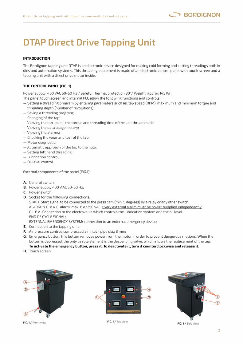
The Bordignon tapping unit DTAP is an electronic device designed for making cold forming and cutting threadings both in dies and automation systems. This threading equipment is made of an electronic control panel with touch screen and a tapping unit with a direct drive motor inside.
THE CONTrOL PANEL (FIg. 1)
Power supply: 400 VAC 50-60 Hz / Safety: Thermal protection 80°/ Weight: approx 145 KgThe panel touch screen and internal PLC allow the following functions and controls:— Setting a threading program by entering parameters such as: tap speed (RPM), maximum and minimum torque and
threading depth (number of revolutions);— Saving a threading program;— Changing of the tap;— Viewing the tap speed, the torque and threading time of the last thread made;— Viewing the data usage history;— Viewing the alarms;— Checking the wear and tear of the tap;— Motor diagnostic;— Automatic approach of the tap to the hole;— Setting left hand threading;— Lubrication control;— Oil level control.
External components of the panel (FIG.1):
DTAP Direct Drive Tapping Unit
A.B. C.D.
E.F.g.
H.
General switch;Power supply 400 V AC 50-60 Hz;Power switch;Socket for the following connections:START: Start signal to be connected to the press cam (min. 5 degrees) by a relay or any other switch.ALARM: N.O. o N.C. alarm, max. 6 A/250 VAC. Every external alarm must be power supplied independently.OIL E.V.: Connection to the electrovalve which controls the lubrication system and the oil level.END OF CYCLE SIGNAL;EXTERNAL EMERGENCY SYSTEM: connection to an external emergency device;Connection to the tapping unit;Air pressure control: compressed air inlet - pipe dia.: 8 mm;Emergency button: this button removes power from the motor in order to prevent dangerous motions. When thebutton is depressed, the only usable element is the descending valve, which allows the replacement of the tap.To activate the emergency button, press it. To deactivate it, turn it counterclockwise and release it.Touch screen.
FiG. 1 / Front view FiG. 1 / side viewFiG. 1 / top view
3
Direct Drive tapping unit with touch screen multiple control panel
THE TAPPINg UNIT (FIg. 2)
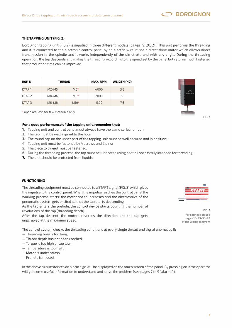
Bordignon tapping unit (FIG.2) is supplied in three different models (pages 19, 20, 21). This unit performs the threading and it is connected to the electronic control panel by an electric wire. It has a direct drive motor which allows direct transmission to the spindle and it works independently of the die stroke and with any angle. During the threading operation, the tap descends and makes the threading according to the speed set by the panel but returns much faster so that production time can be improved.
* upon request, for few materials only
rEF. N° THrEAD mAx. rPm wEIgTH (kg)
DTAP 1 M2-M5 M6* 4000 3,3
DTAP 2 M4-M6 M8* 2000 5
DTAP 3 M6-M8 M10* 1800 7,6
FiG. 2
For a good performance of the tapping unit, remember that:1.2. 3.4.5.6.7.
Tapping unit and control panel must always have the same serial number;The tap must be well aligned to the hole;The round cap on the upper part of the tapping unit must be well secured and in position;Tapping unit must be fastened by 4 screws and 2 pins;The piece to thread must be fastened;During the threading process, the tap must be lubricated using neat oil specifically intended for threading;The unit should be protected from liquids.
FUNCTIONINg
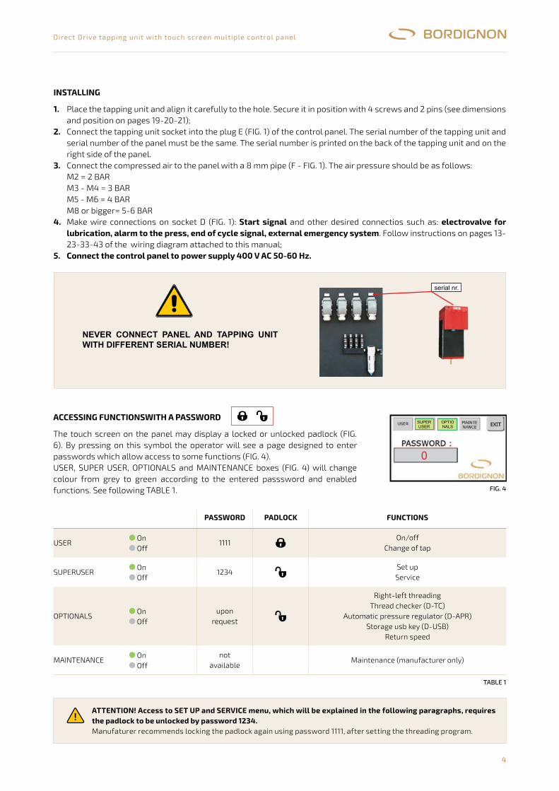
The threading equipment must be connected to a START signal (FIG. 3) which gives the impulse to the control panel. When the impulse reaches the control panel the working process starts: the motor speed increases and the electrovalve of the pneumatic system gets excited so that the tap starts descending.As the tap enters the prehole, the control device starts counting the number of revolutions of the tap (threading depth).After the tap descent, the motors reverses the direction and the tap gets unscrewed at the maximum speed.
The control system checks the threading conditions at every single thread and signal anomalies if:— Threading time is too long;— Thread depth has not been reached;— Torque is too high or too low;— Temperature is too high;— Motor is under stress;— Prehole is missed.
In the above circumstances an alarm sign will be displayed on the touch screen of the panel. By pressing on it the operator will get some useful information to understand and solve the problem (see pages 7 to 9 “alarms”).
FiG. 3
for connection seepages 13-23-33-43
of the wiring diagramFig.�3
per�il�collegamento�vederepag.�4�dello�schema�elettrico
La maschiatrice DTAP fornita in 3 diversi mod è l’unità che esegue la filettatura sul pezzo ed è collegata alpannello di controllo attraverso un cavo. Essa ha al suo interno un motore Direct Drive che trasmette il movimento direttamente almandrino. Durante il processo di filettatura il maschio scende ed esegue il filetto alla velocità programmata nel pannello e ritornaalla massima velocità ottimizzando così i tempi di produzione.La maschiatrice inoltre può essere posizionata in qualsiasi direzione e lavora indipendentemente dalla corsa dello stampo.
:1) collegare la maschiatrice al pannello avente lo stesso numero di serie2) allineare bene la maschiatrice al foro;3) accertarsi che il tappo circolare posto nella parte superiore della maschiatrice
sia
LA MASCHIATRICE (fig. 2)
Per un corretto funzionamento della maschiatrice, è molto importante
DESCRIZIONE DEL FUNZIONAMENTO
elli (pagine 18,19,20),
sempre ben posizionato e avvitato4) fissare bene la maschiatrice con le 4 viti e le 2 spine.5) fissare il pezzo da filettare6) lubrificare con olio intero il maschio durante il processo di filettatura7) proteggere il più possibile la macchina da liquidi
Il sistema viene collegato ad un segnale di start (fig. 3) che, una volta azionato, dà inizio al processo di lavoro del pannello dicontrollo, all’aumento di velocità del motore ed alla sollecitazione sulla elettrovalvola del sistema pneumatico che provoca ladiscesa del maschio.Quando il maschio entra nel pre-foro, il sistema di controllo conta il numero di giridel maschio che determinano la profondità del filetto.Ultimata la discesa del maschio, il motore effettua un’inversione ed il maschioviene svitato alla massima velocità.Ad ogni filetto il sistema effettua controlli utili a rilevare eventuali anomalie quali:- tempo di filettatura eccessivo;- profondità di filettatura non raggiunta;- momento torcente troppo alto o troppo basso;- temperatura elevata;- eccessivo sforzo motore;- mancanza del pre-foro.Al verificarsi di circostanze come quelle sopra elencate, apparirà un segnale di allarme in basso a destra del touch screen .Premendo su di esso sarà possibile visualizzare la descrizione utile all’individuazione del problema (paragrafo “allarmi”, pag.7 e 8)
START
modello giri/min. max.
DTAP1 M2-M5 M6* 4000 modello Kg.
DTAP2 M4-M6 M8* 2000 DTAP1 3,3
DTAP3 M6-M8 M10* 1800 DTAP2 5
* a richies ta , solo su determinati materia l i DTAP3 7,6
PESIfiletto
Fig.�2
3
4
Direct Drive tapping unit with touch screen multiple control panel
ACCEssINg FUNCTIONswITH A PAsswOrD
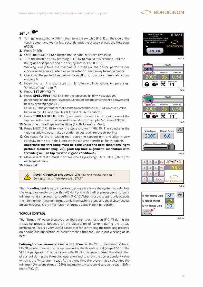
The touch screen on the panel may display a locked or unlocked padlock (FIG. 6). By pressing on this symbol the operator will see a page designed to enter passwords which allow access to some functions (FIG. 4).USER, SUPER USER, OPTIONALS and MAINTENANCE boxes (FIG. 4) will change colour from grey to green according to the entered passsword and enabled functions. See following TABLE 1.
taBlE 1
ATTENTION! Access to sET UP and sErVICE menu, which will be explained in the following paragraphs, requires the padlock to be unlocked by password 1234.Manufaturer recommends locking the padlock again using password 1111, after setting the threading program.
PAsswOrD PADLOCk FUNCTIONs
USER On Off
1111On/off
Change of tap
SUPERUSER On Off
1234Set upService
OPTIONALS On Off
uponrequest
Right-left threadingThread checker (D-TC)
Automatic pressure regulator (D-APR)Storage usb key (D-USB)
Return speed
MAINTENANCE On Off
notavailable
Maintenance (manufacturer only)
INsTALLINg
1.
2.
3.
4.
5.
Place the tapping unit and align it carefully to the hole. Secure it in position with 4 screws and 2 pins (see dimensions and position on pages 19-20-21);Connect the tapping unit socket into the plug E (FIG. 1) of the control panel. The serial number of the tapping unit and serial number of the panel must be the same. The serial number is printed on the back of the tapping unit and on the right side of the panel.Connect the compressed air to the panel with a 8 mm pipe (F - FIG. 1). The air pressure should be as follows:M2 = 2 BARM3 - M4 = 3 BARM5 - M6 = 4 BARM8 or bigger= 5-6 BARMake wire connections on socket D (FIG. 1): start signal and other desired connectios such as: electrovalve for lubrication, alarm to the press, end of cycle signal, external emergency system. Follow instructions on pages 13-23-33-43 of the wiring diagram attached to this manual;Connect the control panel to power supply 400 V AC 50-60 Hz.
FiG. 4
INSTALLING:
Start signa electrovalve for lubrication ,alarm to the press, end of cycle signal, external emergency system
Connect the control panel to power supply 230 VAC 50-60 Hz
ACCESSING FUNCTIONS WITH A PASSWORD
ATTENTION: Access to SET UP and SERVICE menu, which will be explained in the following paragraphs, requires thepadlock to be unlocked by password 1234.
1- Place the tapping unit and align it carefully to the hole. Secure it in position with 4 screws and 2 pins (see dimensions andposition on pages 18-19-20)
2- Connect the tapping unit socket into the plug D ( fig.1) of the control panel. The serial number of the tapping unit and serialnumber of the panel must be the same. The serial number is printed on the back of the tapping unit and on the right side of thepanel.
3- Connect the compressed air to the panel with a 6 mm pipe (E - fig. 1).The air pressure should be as follows:M2 = 2 barM3- M4 = 3 barM5- M6 = 4 barM8 or bigger= 5-6 BAR
4- Make wire connections on socket C (fig. 1): l and other desired connectios such as:. Follow instructions on pag. 4 of the wiring diagram
attached to this manual5-
The touch screen on the panel may display a locked or unlocked padlock (fig. 6).By pressing on this symbol the operator will see a page designed to enterpasswords which allow access to some functions (fig.4).USER, SUPER USER, OPTIONALS and MAINTENANCE boxes (fig.4) willchange colour from grey to green according to the entered passsword andenabled functions. See following table 1
Manufaturer recommends locking the padlock again using password 1111, after setting the threading program.
NEVER�CONNECT�PANEL AND�TAPPINGUNIT�WITH�DIFFERENT�SERIAL NUMBER!
4
serial�n°
ON/OFF
CHANGE OF TAP
SET UP
SERVICE
RIGHT-LEFT THREADING
upon THREAD CHECKER (D-TC)
reques t AUTOMATIC PRESSURE REGULATOR (D-APR)
STORAGE USB KEY (D-USB)
RETURN SPEED
not MAINTENANCE
ava i lable (MANUFACTURER ONLY)
FUNCTIONS
USER
SUPERUSER
MAINTENANCE
1111
1234
PASSWORD
OPTIONALS
PADLOCK
table1
onoff
onoff
onoff
onoff
Fig.�4
SUPERUSER
OPTIONALS
0
NEVER CONNECT PANEL AND TAPPING UNIT WITH DIFFERENT SERIAL NUMBER!
serial nr.
5
Direct Drive tapping unit with touch screen multiple control panel
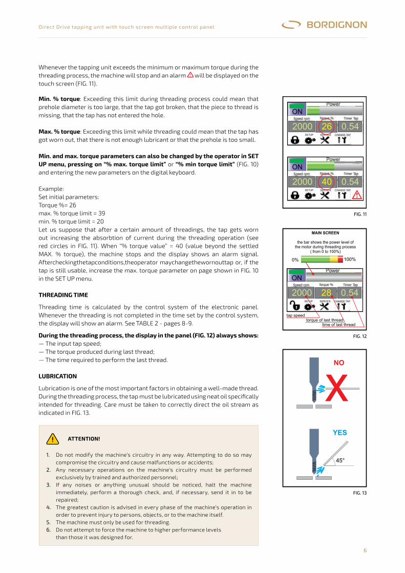
The threading test is very important because it allows the system to calculate the torque value (% torque thread) during the threading process and to set a minimum and a maximum torque limit (FIG. 10). Whenever the tapping unit exceeds the minimum or maximum torque limit, the machine stops and the display shows an alarm signal. More information on torque value in next paragraph.
TOrQUE CONTrOL
The “Torque %” value displayed on the panel touch screen (FIG. 7) during the threading process, depends on the absorption of current during the thread performing. This is a very useful parameter for controlling the threading process: an anomalous absorption of current means that the unit is not working at its best .
Entering torque parameters in the sET UP menu: The “% torque thread” value in FIG. 10 is determinated by the system during the threading test (steps 12-13 of the SET UP paragraph). This test allows the PLC in the panel to read the absorption of current during the threading operation and to show the correspondent value which is the “% torque thread”. At the same time the system also calculates the minimum (% torque thread - 25%) and maximum torque (% torque thread + 50%) limits (FIG. 10).
istante finché appare laschermata iniziale (fig.5)
2- premere il tasto ENTER3- accertarsi che il tasto di emergenza sul pannello sia disattivato4-�eseguire�l’accensione:�premere�il�tasto�OFF�(fig.�6)��ed�attendere�il�tempo
scandito�dalla�clessidra�finchè�appare�la�scritta�ON�(fig.�7).Attenzione: Ad�ogni�accensione,�l’utensile�esegue�una�rotazione�in�sensoorario�e�antiorario. Allontanarsi�dall’utensile.
5-�accertarsi�che�il�lucchetto�sia�aperto�(fig.�7).Vedi�paragrafo�precedente6-�inserire�il�maschio�seguendo�la�procedura “sostituzione�maschio” (pag.7)7-�premere “ ” (fig.�7).8- premere “ ” (fig. 8). Digitare sulla tastiera digitale (fig. 9) la
velocità di rotazione (giri/minuto) che dovrà essere compresa tra il valoreminimo e massimo indicati in alto a destra. In fig. 9 si è inserito il parametro2000 che è un valore compreso tra min. 100 e max. 4000. Confermare conENTER.
9-��premere�la�casella “ ” ed�impostareovvero�il�numero�di�giri�del�maschio.�Confermare�con�ENTER.
10-�selezionare�il�tipo�di�filetto�nella�barra�a�scorrimento�(fig.8).�Es.:��M6-811-�premere��NEXT (fig.�8)�per�visualizzare�la�pagina�illustrata�in�fig.�10.
Il�mandrino�farà�una�rotazione�per�predisporsi�alla�filettatura12- predisporre ora la prova filetto: posizionare ed allineare la maschiatrice ed
il pezzo da filettare. Lubrificare il maschio con olio intero
13- Fare il test di filettatura eseguendo un certo numero di filetti su vari prefori.Per eseguire ognuno dei filetti è necessario premere il tasto START CYCLE(fig.10).
Il è�molto�importante�perchè�consente�al�sistema�dirilevare�lo�sforzo�(%�torque�thread)�durante�la�filettatura�e��di�calcolare�unlimite�massimo�e�minimo�di�sforzo�(fig.�10),�superato�il�quale�la�macchinasubirà�un�arresto�e�segnalerà�un�allarme.Per�la�definizione�del�momento�torcente,�vedi�paragrafo�seguente.
e durante il processo di lavorazione nella casella“Torque %” (fig. 7) indica lo sforzo della macchina nell’esecuz
SET�UPSPEED RPM
THREAD�DEPTH la�profondità�delfiletto
Importante: la filettatura deve essere eseguita in condizioni di lavoroottimali: maschio non usurato, preforo corretto (vd pag.22),allineamento corretto, olio specifico per filettatura.
test�di�filettatura
SET UP:
MOMENTO TORCENTE
Programmazione del momento torcente nella procedura SET UP
soglia minimasoglia massima
1- accendere l’interruttore generale A (fig.1) e di seguito l’interruttore C (fig. 1)posto al lato del touch screen. Attendere qualche
Il momento torcente visibilione della
filettatura. Esso è correlato alla corrente assorbita durante la lavorazione ediventa perciò un parametro utile al controllo della filettatura: un assorbimentodi corrente troppo alto o troppo basso è indice di un’anomalia in corso.
: Ilmomento torcente di riferimento viene rilevato durante il test di filettaturaelencato al punto 13 del paragrafo SET UP ed è perciò molto importante chequesto venga eseguito nelle migliori condizioni. Il test infatti consente al PLCinterno al pannello di leggere lo sforzo durante la filettatura (% torque thread) edi calcolare, rispetto a questo, i parametri di (% torque thread -25%) e di di sforzo (% torque thread + 50%). Vd. fig.10Qualora, durante il normale processo di lavoro, lo sforzo superasse la sogliaminima o massima stabilita, la macchina subirà un arresto e segnalerà unallarme (fig. 11).
Fig.�8
Fig.�10
3
Fig.�8
392620
Fig.�9
Fig.�5
Fig.�6
Fig.�7
2000 33 0.54
ON
2000 33 0.54
2000 6.0
MANTENERSI�LONTANO�DALL’UTENSILE-�in�fase�di�accensione-�quando�si�eseguono�le�impostazioni-�quando�si�preme�START
5
2000������100�������4000
2000
sET UP
1.
2. 3. 4.
5.
6.
7.8.
9.
10.11.
12.
13.
14.
Turn general switch A (FIG. 1), then turn the switch C (FIG. 1) on the side of the touch screen and wait a few seconds until the display shows the first page (FIG.5);Press ENTER;Check that EMERGENCY button on the panel has been released;Turn the machine on by pressing OFF (FIG. 6). Wait a few seconds until thehourglass disappears and the display shows “ON” (FIG. 7).Warning: every time the machine is turned on, the device performs one clockwise and one counterclockwise rotation. Keep away from the device;Check that the padlock has been unlocked (FIG. 7). To unlock it, see instructions on page 4;Insert the tap into the tapping unit following instructions on paragragh “change of tap” - pag. 7;Press “sET UP” (FIG. 7);Press “sPEED rPm” (FIG. 8). Enter the tap speed (in RPM = revolutionsper minute) on the digital keyboard. Minimum and maximum speed allowed will be displayed top right (FIG. 9).I.e: in FIG. 9 the parameter that has been entered is 2000 RPM which is a value between min. 100 and max. 4000. Press ENTER to confirm;Press “THrEAD DEPTH” (FIG. 8) and enter the number of revolutions of the tap needed to reach the desired thread depth. Example: 6.0. Press ENTER.;Select the thread type on the slider (FIG.8). Example: M6-8;Press NEXT (FIG. 8) to view the page shown in FIG. 10. The spindle in the tapping unit will now make a rotation to get ready for the threading;Get ready for the threading test: place the tapping unit and align it very carefully to the pre-hole. Lubricate the tap with specific oil for threading.Important: the threading must be done under the best conditions: right prehole diameter (pag. 23), good tap-hole alignment, lubrication with threading oil. The tap must be in good conditions.;Make several test threads in different holes, pressing START CYCLE (FIG. 10) for each one of them;Press EXIT.
NEVEr APPrOACH THE DEVICE: When turning the machine on /During settings / While pressing START
SET�UP:
SET�UPSPEED�RPM
THREAD�DEPTH
Important: the threading must be done under the best conditions:right prehole diameter (pag. 22), good tap-hole alignment,lubrication with threading oil. The tap must be in good conditions.
threading�test
TORQUE�CONTROL
Entering torque parameters in the SET UP menu
1-�turn�general�switch�B�(fig.�1)�on�and�wait�a�few�seconds�until�the�displayshows�the�first�page��(fig.5)
2-�press�ENTER3-�check�that�EMERGENCY button�on�the�panel�has�been�released4- turn the machine on by pressing OFF (fig. 6). Wait a few seconds until the
hourglass disappears and the display shows “ON” (fig. 7).Warning: every time the machine is turned on, the device performs oneclockwise and one counterclockwise rotation. Keep away from the device
5-�check�that�the�padlock�has�been�unlocked�(fig.�7). To�unlock�it,�seeinstructions�on�page�4
6-��insert�the�tap�into�the�tapping�unit�following�instructions�on�paragragh“change�of�tap” -�pag.�7
7-��press “ ” (fig.�7).8-��press “ ” (fig.�8).�Enter�the�tap�speed�(in�RPM�=�revolutions
per�minute)�on�the�digital�keyboard.�Minimum�and�maximum�speedallowed�will�be�displayed�top�right�(fig.�9).I.e: in fig. 9 the parameter that has been entered is 2000 RPM which is avalue between min. 100 and max. 4000. Press ENTER to confirm.
9-��press “ ” (fig.�8)�and�enter�the�number�of�revolutions�ofthe�tap�needed�to�reach�the�desired�thread�depth.�Example:�6.0.�PressENTER.
10-select�the�thread�type�on�the�slider�(fig.8).�Example:��M6-811- press NEXT (fig. 8) to view the page shown in fig. 10.
The spindle in the tapping unit will now make a rotation to get ready for thethreading
12- get ready for the threading test: place the tapping unit and align it verycarefully to the pre-hole. Lubricate the tap with specific oil for threading.
13- Make several test threads in different holes, pressing START CYCLE(fig. 10) for each one of them.
14- Press EXIT
The is�very�important�because�it�allows�the�system�tocalculate�the�torque�value�(%�torque�thread)�during�the�threading�processand�to�set�a�minimum�and�a�maximum�torque�limit�(fig.�10).�Whenever�thetapping�unit�exceeds�the�minimum�or�maximum�torque�limit,�the�machinestops�and�the�display�shows�an�alarm�signal.More�information�on�torque�value�in�next�paragraph
The “Torque %” value displayed on the panel touch screen (fig. 7 ) during thethreading process, depends on the absorption of current during the threadperforming. This is a very useful parameter for controlling the threadingprocess: an anomalous absorption of current means that the unit is notworking at its best .
: The “% torque thread”value in fig. 10 is determinated by the system during the threading test (steps12 and 13 of the SET UP paragraph). This test allows the PLC in the panel toread the absorption of current during the threading operation and to show thecorrespondent value which is the “% torque thread”. At the same time thesystem also calculates the minimum (% torque thread - 25%) and maximumtorque ( % torque thread + 50%) limits (fig. 10).Whenever the tapping unit exceeds the minimum or maximum torque duringthe threading process, the machine will stop and an alarm will be displayedon the touch screen (fig. 11).
5
NEVER APPROACH�THE�DEVICE-�when�turning�the�machine�on-�during�settings-�while�pressing�START
Fig.�8
Fig.�10
3
Fig.�8
392620
Fig.�9
Fig.�6
Fig.�7
2000 33 0.54
ON
2000 33 0.54
2000 6.0
Fig.�5
2000������100�������4000
2000
ENTER
D-TAP1
FiG. 5
FiG.6
FiG.7
FiG.10
FiG.8
FiG.9
6
Direct Drive tapping unit with touch screen multiple control panel
min. % torque: Exceeding this limit during threading process could mean that prehole diameter is too large, that the tap got broken, that the piece to thread is missing, that the tap has not entered the hole.
max. % torque: Exceeding this limit while threading could mean that the tap has got worn out, that there is not enough lubricant or that the prehole is too small.
min. and max. torque parameters can also be changed by the operator in sET UP menu, pressing on “% max. torque limit” or “% min torque limit” (FIG. 10) and entering the new parameters on the digital keyboard.
Example:Set initial parameters:Torque %= 26max. % torque limit = 39min. % torque limit = 20Let us suppose that after a certain amount of threadings, the tap gets worn out increasing the absorbtion of current during the threading operation (see red circles in FIG. 11). When “% torque value” = 40 (value beyond the settled MAX. % torque), the machine stops and the display shows an alarm signal. Aftercheckingthetapconditions,theoperator maychangethewornouttap or, if the tap is still usable, increase the max. torque parameter on page shown in FIG. 10 in the SET UP menu.
THrEADINg TImE
Threading time is calculated by the control system of the electronic panel. Whenever the threading is not completed in the time set by the control system, the display will show an alarm. See TABLE 2 - pages 8-9.
During the threading process, the display in the panel (FIg. 12) always shows:— The input tap speed;— The torque produced during last thread;— The time required to perform the last thread.
LUBrICATION
Lubrication is one of the most important factors in obtaining a well-made thread.During the threading process, the tap must be lubricated using neat oil specifically intended for threading. Care must be taken to correctly direct the oil stream as indicated in FIG. 13.
Soglia minima
Soglia massima
Le soglie minima e massima possono essere impostate anchedall ’ %timileuqrot.xam%,erotarepomin torque limit
Il display durante la lavorazione visualizza :
LUBRIFICAZIONE
(% Min Torque Limit): Il superamento della soglia minima puòessere indice di un preforo troppo largo, di maschio rotto, di pezzo da filettaremancante o di mancato imbocco del maschio.
(% Max Torque Limit): il superamento della soglia massimadurante la filettatura può essere indice di anomalie quali, ad esempio, usuradel maschio, scarsa lubrificazione, preforo troppo stretto.
:
premendo direttamente sui tasti “ ” o “” ed inserendo nuovi parametri sulla tastiera digitale.
Esempio di gestione della soglia:Parametri iniziali (fig. 10):Torque %= 26max. % torque limit = 39 (soglia massima)min. % torque limit = 20 (soglia minima)
0 % ,
(fig. 12)- la velocità impostata- lo sforzo di filettatura- il tempo dell’ultimo filetto eseguito
La lubrificazione è uno degli elementi più importanti per la buona riuscita delfiletto.Durante il processo di filettatura è necessario lubrificare il maschio con oliointero specifico per filettatura, avendo cura di indirizzare correttamente il gettod’olio come indicato nella fig. 13
Nota
Supponiamo ora che durante la produzione il maschio inizi ad usurarsiprovocando un assorbimento di corrente pari a 4 (fig. 11) valore superiorealla soglia massima. A questo punto la macchina si fermerà ed il pannellovisualizzerà un segnale di allarme. Si andrà di seguito a verificare le condizionidi usura del maschio: se molto usurato, si sostituirà con uno nuovo, altrimentisi potrà scegliere di impostare una soglia massima più alta nella paginaillustrata in fig. 10.
Il tempo di filettatura è calcolato dal sistema di controllo del pannelloelettronico.Qualora la filettatura non fosse eseguita nel tempo calcolato dal sistema, lamacchina andrà in allarme. Vedi tabella 2 - pag. 8
TEMPO
2000 28 0.54
ON
SCHERMATA PRINCIPALE
100%0%
ERRATO!
CORRETTO
x45°
1- Non modificare in nessun modo l’impianto elettrico della macchina.Qualsiasi tentativo a tale riguardo può compromettere i dispositivielettrici provocando malfunzionamenti o incidenti
2- Lavori nell’impianto elettrico della macchina devono essere eseguitisolo ed esclusivamente da personale specializzato ed autorizzato
3- Se si avvertono rumori insoliti o qualcosa di strano, fermare lamacchina , effettuare un controllo ed, eventualmente,inviare a riparare
4-Durante tutte le fasi di lavoro con la macchina si raccomanda la massimacautela in modo da evitare danni a persone, a cose o alla macchinastessa
5- Utilizzare la macchina solo per filettare6- Non richiedere alla macchina prestazioni superiori a quelle per cui è
stata progettata
immediatamente
6
2000 26 0.54
ON
2000 40 0.54
ON
FiG. 11
FiG. 12
FiG. 13
Whenever the tapping unit exceeds the minimum or maximum torque during the threading process, the machine will stop and an alarm will be displayed on the touch screen (FIG. 11).
ATTENTION!
1.
2.
3.
4.
5.6.
Do not modify the machine’s circuitry in any way. Attempting to do so may compromise the circuitry and cause malfunctions or accidents;Any necessary operations on the machine’s circuitry must be performed exclusively by trained and authorized personnel;If any noises or anything unusual should be noticed, halt the machine immediately, perform a thorough check, and, if necessary, send it in to be repaired;The greatest caution is advised in every phase of the machine’s operation in order to prevent injury to persons, objects, or to the machine itself.The machine must only be used for threading.Do not attempt to force the machine to higher performance levelsthan those it was designed for.
Min. % torque
Max. % torque:
Min. and max. torque parameters can also be changed by the operator inSET UP menu, pressing on “% max. torque limit % min torque limit
THREADING TIME
During the threading process, the display in the panel (fig. 12) alwaysshows:
LUBRICATION
: Exceeding this limit during threading process could mean thatprehole diameter is too large, that the tap got broken, that the piece to thread ismissing, that the tap has not entered the hole.
Exceeding this limit while threading could mean that the taphas got worn out, that there is not enough lubricant or that the prehole is toosmall.
” or “ ”(fig. 10) and entering the new parameters on the digital keyboard.
Example:Set initial parameters:Torque %= 26max. % torque limit = 39min. % torque limit = 20Let us suppose that after a certain amount of threadings, the tap gets worn outincreasing the absorbtion of current during the threading operation (see redcircles in fig. 11). When “ % torque value” = 40 ( value beyond the settled MAX.% torque) , the machine stops and the display shows an alarm signal.After checking the tap conditions, the operator may change the worn out tapor , if the tap is still usable, increase the max. torque parameter on page shownin fig. 10 in the SET UP menu.
Threading time is calculated by the control system of the electronic panel.Whenever the threading is not completed in the time set by the control system,the display will show an alarm. See table 2 - page 8
- the input tap speed- the torque produced during last thread- the time required to perform the last thread
Lubrication is one of the most important factors in obtaining a well-madethread.During the threading process, the tap must be lubricated using neat oilspecifically intended for threading. Care must be taken to correctly direct theoil stream as indicated in fig. 13.
6
1. Do not modify the machine's circuitry in any way. Attempting to doso may compromise the circuitry and cause malfunctions oraccidents.
2. Any necessary operations on the machine's circuitry must beperformed exclusively by trained and authorized personnel.
3. If any noises or anything unusual should be noticed, halt themachine immediately, perform a thorough check, and, ifnecessary, send it in to be repaired.
4. The greatest caution is advised in every phase of the machine'soperation in order to prevent injury to persons, objects, or to themachine itself.
5. The machine must only be used for threading.6. Do not attempt to force the machine to higher performance levels
than those it was designed for.
2000 26 0.54
ON
Fig.�11
2000 40 0.54
ON
Fig.�12
2000 28 0.54
ON
MAIN�SCREEN
the�bar�shows�the�power�level�ofthe�motor�during�threading�process
(�from�0�to�100%)
100%0%
tap�speedtorque�of�last�thread
time�of�last�thread
x
45°
Fig.�13
NO
YES
7
Direct Drive tapping unit with touch screen multiple control panel
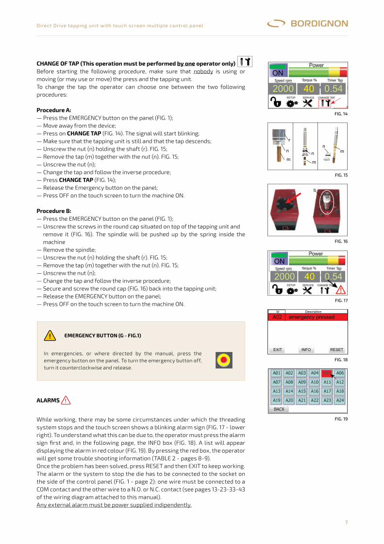
CHANgE OF TAP (This operation must be performed by one operator only)Before starting the following procedure, make sure that nobody is using or moving (or may use or move) the press and the tapping unit.To change the tap the operator can choose one between the two following procedures:
Procedure A:— Press the EMERGENCY button on the panel (FIG. 1);— Move away from the device;— Press on CHANgE TAP (FIG. 14). The signal will start blinking;— Make sure that the tapping unit is still and that the tap descends;— Unscrew the nut (n) holding the shaft (r). FIG. 15;— Remove the tap (m) together with the nut (n). FIG. 15;— Unscrew the nut (n);— Change the tap and follow the inverse procedure;— Press CHANgE TAP (FIG. 14);— Release the Emergency button on the panel;— Press OFF on the touch screen to turn the machine ON.
Procedure B:— Press the EMERGENCY button on the panel (FIG. 1);— Unscrew the screws in the round cap situated on top of the tapping unit and
remove it (FIG. 16). The spindle will be pushed up by the spring inside the machine
— Remove the spindle;— Unscrew the nut (n) holding the shaft (r). FIG. 15;— Remove the tap (m) together with the nut (n). FIG. 15;— Unscrew the nut (n);— Change the tap and follow the inverse procedure;— Secure and screw the round cap (FIG. 16) back into the tapping unit;— Release the EMERGENCY button on the panel;— Press OFF on the touch screen to turn the machine ON.
SOSTITUZIONE DEL MASCHIO(Eseguito da operatore)
CHANGE TAP
un soloAssicurarsi che stia usando o muovendo (o possa usare o muovere) lapressa e / o la maschiatrice prima di eseguire l’operazione.Per la sostituzione del maschio, sono possibili due procedure:
:-
, premere tasto (fig. 14). Sivedrà il segnale lampeggiare
- verificare che la maschiatrice sia ferma ed il maschio esca-�svitare�il�dado�(n)�tenendo�fermo�il�gambo�superiore�(r).�Fig.�15-�sfilare�il�maschio�(m)�con�il�dado�(n)-�svitare�il�dado�(n)�dal�maschio�(m)-�sostituire�il�maschio�con�l’operazione�inversa-�cliccare�nuovamente�su�CHANGE TAP (fig.�14)-�disatti
-�premere�il�tasto�OFF�sul�touch�screen�per�riaccendere�la�macchina�(ON)
:-
- svitare le viti del tappo circolare sulla parte superiore della maschiatrice erimuoverlo (fig. 16).
- sfilare il mandrino (b) che uscirà spinto da una molla.- sfilare il maschio (m) con il dado (n). Fig. 15-�svitare�il�dado�(n)�dal�maschio�(m)-�inserire�il�nuovo�maschio�nel�portamaschio
-�premere�il�tasto�OFF�sul�touch�screen�per�riaccendere�la�macchina�(ON))
dividuata e rimossa la causa dell’allarme, il sistema dovrà essereripristinato con il tasto RESET e successivamente EXIT.Il sistema di allarme o sistema di fermo pressa può essere collegato al pannello dellamaschiatrice grazie all’attacco predisposto nel connettore a lato del pannello (fig. 1) :un filo deve essere collegato a COM e l’altro filo al pin N.O. o N.C. ( vedi pagg. 13-23-33-43 dello schema elettrico allegato al presente manuale)
nessuno
ProceduraA
Procedura B
L’allarme esterno deve essere alimentato indipendentemente.
sul pannello premere il tasto emergenza G (fig. 1- pag.2) oppure ruotare in sensoorario la chiave del selettore P (fig. 1- pag.2)
- allontanarsi dall’utensile- sulla schermata principale del pannello
vare�il�tasto�emergenza�sul�pannello�e�ruotare�in�senso�antiorario�la�chiavedel�selettore�P (fig.�1�-�pag.2)�riportandola�in�posizione�verticale.�Premere�il�tastoblu�N�(fig.1-pag.2)
sul pannello premere il tasto emergenza G (fig. 1- pag.2) oppure ruotare in sensoorario la chiave del selettore P (fig. 1- pag.2)
-�eseguire�l’operazione�inversa-�una�volta�riposizionato�e�avvitato�il�tappo�circolare�posto�sulla�parte�superiore
della�maschiatrice,�disattivare�il�tasto�di�emergenza�G�(fig.1-pag.2)�e�ruotare�insenso�antiorario�la�chiave�del�selettore�P (fig.�1�-�pag.2)�riportandola�inposizione�verticale.�Premere�il�tasto�blu�N�(fig.1-pag.2)
Durante il processo di lavorazione, si possono verificare condizioni che determinanol’arresto della macchina e la comparsa di un segnale di allarme nel display delpannello (fig. 17 in basso a destra). Al verificarsi di questo evento, l’operatore dovràpremere sul simbolo di allarme e successivamente sul tasto INFO (fig. 18): si apriràuna tabella che visualizzerà gli allarmi attivi in rosso (fig 19). Premendo la casellarossa si aprirà una pagina che fornirà informazioni e suggerimenti per la risoluzionedel problema ( tabella 2-pag.8).Una volta in
ALLARMI
Fig.�17
2000 40 0.54
ON
A02 emergency�pressedId�����������������������������Description
EXIT INFO������������������RESET
Fig.�18
A05
Fig.�19
m
n
r
m
n mn
Fig.�15
Fig.�16
Fig.�14
2000 40 0.54
ON
7
b
ON����������OFF
EMERGENZAIn caso di emergenza e dove previsto dal presente manuale,premere il tasto di emergenza G (fig.1 -pag.2) sul pannello.Per�disattivare:�ruotare�il�tasto�in�senso�antiorario�e�rilasciare.Premere�il�tasto�blu�N�(fig.1-pag.2)
oppure
Ruotare�il�selettore�P (fig.1�-�pag.2)�sul�pannello�in�senso�orarioin�posizione�inclinata.�Per�disattivare�riposizionare�il�selettore�inposizione�verticale�girando�in�senso�antiorario
In emergencies, or where directed by the manual, press the emergency button on the panel. To turn the emergency button off, turn it counterclockwise and release.
EmErgENCY BUTTON (g - FIg.1)
ALArms
While working, there may be some circumstances under which the threading system stops and the touch screen shows a blinking alarm sign (FIG. 17 - lower right). To understand what this can be due to, the operator must press the alarm sign first and, in the following page, the INFO box (FIG. 18). A list will appear displaying the alarm in red colour (FIG. 19). By pressing the red box, the operator will get some trouble shooting information (TABLE 2 - pages 8-9).Once the problem has been solved, press RESET and then EXIT to keep working.The alarm or the system to stop the die has to be connected to the socket on the side of the control panel (FIG. 1 - page 2): one wire must be connected to a COM contact and the other wire to a N.O. or N.C. contact (see pages 13-23-33-43 of the wiring diagram attached to this manual).Any external alarm must be power supplied indipendently.
CHANGE OF TAP
(This operation must be performed by one operator only)
CHANGE TAP
CHANGE TAP
Before starting the following procedure, make sure that nobody is using ormoving (or may use or move) the press and the tapping unit
To change the tap the operator can choose one between the two followingprocedures:
:- press the EMERGENCY button on the panel (fig. 1)- move away from the device- press on (fig. 14). The signal will start blinking- make sure that the tapping unit is still and that the tap descends-�unscrew�the�nut�(n)�holding�the�shaft�(r).�Fig.�15- remove the tap (m) together with the nut (n). Fig. 15-�unscrew�the�nut�(n)-�change�the�tap�and�follow�the�inverse�procedure- press (fig. 14).-�release�the�Emergency�button�on�the�panel-�press�OFF�on�the�touch�screen�to�turn�the�machine�ON
:- press the EMERGENCY button on the panel (fig. 1)- unscrew the screws in the round cap situated on top of the tapping unit andremove it (fig. 16). The spindle will be pushed up by the spring inside themachine
- remove the spindle.-�unscrew�the�nut�(n)�holding�the�shaft�(r).�Fig.�15-�remove�the�tap�(m)�together�with�the�nut�(n).�Fig.�15-�unscrew�the�nut�(n)-�change�the�tap�and�follow�the�inverse�procedure-�secure�and�screw�the�round�cap�(fig.�16)�back�into�the�tapping�unit-�release�the�EMERGENCY button�on�the�panel-�press�OFF�on�the�touch�screen�to�turn�the�machine�ON
While working, there may be some circumstances under which the threadingsystem stops and the touch screen shows a blinking alarm sign (fig. 17 - lowerright). To understand what this can be due to, the operator must press thealarm sign first and, in the following page,the INFO box (fig. 18). A list willappear displaying the alarm in red colour (fig. 19). By pressing the red box, theoperator will get some trouble shooting information (table 2- pag. 8).Once the problem has been solved, press RESET and then EXIT to keepworking
contact
ProcedureA
Procedure B
ALARMS
.The alarm or the system to stop the die has to be connected to the socket onthe side of the control panel (fig. 1 - page 2): one wire must be connected to aCOM and the other wire to a N.O. or N.C. contact ( see pag. 4 of thewiring diagram attached to this manual)
.Any external alarm must be power supplied indipendently
7
EMERGENCY BUTTON�(F�-�fig.�1)In emergencies, or where directed by the manual,press the emergency button on the panel.To turn the emergency button off, turn itcounterclockwise and release
Fig.�17
A02 emergency�pressedId�����������������������������Description
EXIT INFO������������������RESET
Fig.�18
A05
Fig.�19
m
n
r
m
n mn
Fig.�15
Fig.�16
Fig.�14
b
2000 40 0.54
ON
2000 40 0.54
ON
FiG. 19
FiG. 18
FiG. 17
FiG. 14
FiG. 15
FiG. 16
8
Direct Drive tapping unit with touch screen multiple control panel
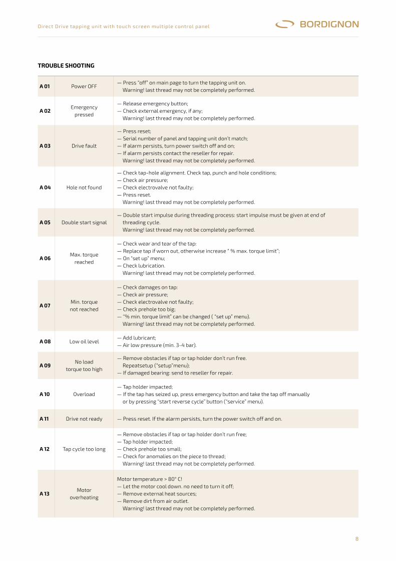
TrOUBLE sHOOTINg
A 01 Power OFF— Press “off” on main page to turn the tapping unit on.
Warning! last thread may not be completely performed.
A 02Emergency
pressed
— Release emergency button;— Check external emergency, if any;
Warning! last thread may not be completely performed.
A 03 Drive fault
— Press reset;— Serial number of panel and tapping unit don’t match;— If alarm persists, turn power switch off and on;— If alarm persists contact the reseller for repair.
Warning! last thread may not be completely performed.
A 04 Hole not found
— Check tap-hole alignment. Check tap, punch and hole conditions;— Check air pressure;— Check electrovalve not faulty;— Press reset.
Warning! last thread may not be completely performed.
A 05 Double start signal— Double start impulse during threading process: start impulse must be given at end of
threading cycle.Warning! last thread may not be completely performed.
A 06Max. torque
reached
— Check wear and tear of the tap:— Replace tap if worn out, otherwise increase “ % max. torque limit”;— On “set up” menu;— Check lubrication.
Warning! last thread may not be completely performed.
A 07Min. torquenot reached
— Check damages on tap:— Check air pressure;— Check electrovalve not faulty;— Check prehole too big;— “% min. torque limit” can be changed ( “set up” menu).
Warning! last thread may not be completely performed.
A 08 Low oil level— Add lubricant;— Air low pressure (min. 3-4 bar).
A 09No load
torque too high
— Remove obstacles if tap or tap holder don’t run free.Repeatsetup (“setup”menu);
— If damaged bearing: send to reseller for repair.
A 10 Overload— Tap holder impacted;— If the tap has seized up, press emergency button and take the tap off manually
or by pressing “start reverse cycle” button (“service” menu).
A 11 Drive not ready — Press reset. If the alarm persists, turn the power switch off and on.
A 12 Tap cycle too long
— Remove obstacles if tap or tap holder don’t run free;— Tap holder impacted;— Check prehole too small;— Check for anomalies on the piece to thread;
Warning! last thread may not be completely performed.
A 13Motor
overheating
Motor temperature > 80° C!— Let the motor cool down. no need to turn it off;— Remove external heat sources;— Remove dirt from air outlet.
Warning! last thread may not be completely performed.
9
Direct Drive tapping unit with touch screen multiple control panel
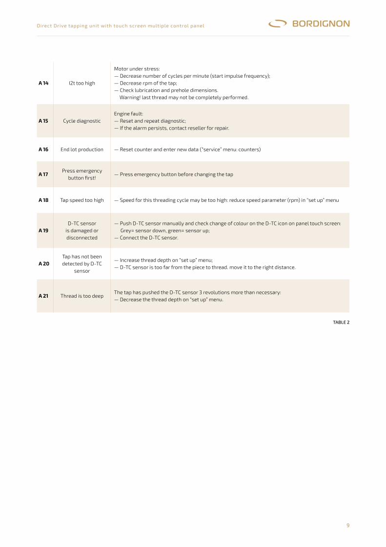
taBlE 2
A 14 I2t too high
Motor under stress:— Decrease number of cycles per minute (start impulse frequency);— Decrease rpm of the tap;— Check lubrication and prehole dimensions.
Warning! last thread may not be completely performed.
A 15 Cycle diagnosticEngine fault:— Reset and repeat diagnostic;— If the alarm persists, contact reseller for repair.
A 16 End lot production — Reset counter and enter new data (“service” menu: counters)
A 17Press emergency
button first!— Press emergency button before changing the tap
A 18 Tap speed too high — Speed for this threading cycle may be too high: reduce speed parameter (rpm) in “set up” menu
A 19D-TC sensor
is damaged or disconnected
— Push D-TC sensor manually and check change of colour on the D-TC icon on panel touch screen: Grey= sensor down, green= sensor up;
— Connect the D-TC sensor.
A 20Tap has not been detected by D-TC
sensor
— Increase thread depth on “set up” menu;— D-TC sensor is too far from the piece to thread. move it to the right distance.
A 21 Thread is too deepThe tap has pushed the D-TC sensor 3 revolutions more than necessary:— Decrease the thread depth on “set up” menu.
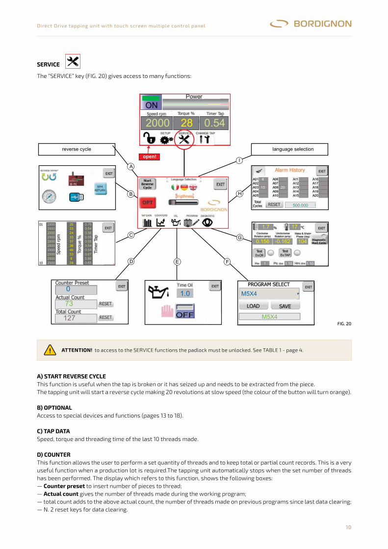
10
Direct Drive tapping unit with touch screen multiple control panel
sErVICE
The “SERVICE” key (FIG. 20) gives access to many functions:
SERVICE
Il tasto “SERVICE” (fig. 20) da’accesso a varie funzioni.
Attenzione!
START REVERSE CYCLE (inversione di marcia)
OPTIONAL:
TAP DATA (memoria dati)
COUNTER (contacolpi)
counter preset:actual count:total�count:
: per utilizzare le funzioni “SERVICE” è necessario che il lucchetto sia aperto. Vedi pag.4
A)Questa funzione permette di estrarre il maschio dal foro nel caso in cui, ad esempio, il maschio sia grippato o rotto.La macchina eseguirà l’inversione di marcia effettuando 20 giri a velocità ridotta (il tasto diventa arancione).
B)Accesso alla gestione di dispositivi e funzioni speciali (vedi da pag. 13 a pag. 17).
C )Visualizza la velocità, lo sforzo ed il tempo di filettatura degli ultimi 10 filetti eseguiti
D)Funzione da utilizzare a scelta qualora si desiderasse programmare un lotto di produzione o si voglia tenere un conteggio totaleo parziale di filetti eseguiti.La schermata COUNTER visualizza le seguenti caselle:- ’inserimento del numero di filetti da eseguire,- conteggio dei filetti del lotto corrente- totale�di�filetti�eseguiti�in�tutti�i�lotti�programmati��a�partire�dall’ultimo�azzeramento�dati- n . 2 tasti reset per l’azzeramento dati.
Fig.�20
9
0
73
127 M5X4
M5X4
2000 28 0.54
ON
aperto!
1.0
2000
2000
2000
2000
2000
2000
2000
2000
2000
2000
20
33
24
33
37
36
40
33
6
34
0.70
0,54
0.56
0.55
0.55
0.54
0.54
0.67
0.90
0.65
inversione�di�marcia selezione�lingue
13
4
20
500.000
-0.162 1040.156
1.7 17
1.10 1.101
G
H
I
D
C
E F
A
B
A) sTArT rEVErsE CYCLEThis function is useful when the tap is broken or it has seized up and needs to be extracted from the piece.The tapping unit will start a reverse cycle making 20 revolutions at slow speed (the colour of the button will turn orange).
B) OPTIONALAccess to special devices and functions (pages 13 to 18).
C) TAP DATA Speed, torque and threading time of the last 10 threads made.
D) COUNTErThis function allows the user to perform a set quantity of threads and to keep total or partial count records. This is a very useful function when a production lot is required.The tapping unit automatically stops when the set number of threads has been performed. The display which refers to this function, shows the following boxes:— Counter preset to insert number of pieces to thread;— Actual count gives the number of threads made during the working program;— total count adds to the above actual count, the number of threads made on previous programs since last data clearing;— N. 2 reset keys for data clearing.
ATTENTION! to access to the SERVICE functions the padlock must be unlocked. See TABLE 1 - page 4.
SERVICE
The “SERVICE” key�(fig.�20)�gives�access�to�many�functions:
9
Attention:
START REVERSE CYCLE
OPTIONAL:
TAP DATA
COUNTER
counter presetactual counttotal count
to access to the SERVICE functions the padlock must be unlocked. See table 1 - page 4
A)This function is useful when the tap is broken or it has seized up and needs to be extracted from the piece.The tapping unit willstart a reverse cycle making 20 revolutions at slow speed (the colour of the button will turn orange).
B)Access�to�special�devices�and�functions�(pages�13�to�17)
C )Speed, torque and threading time of the last 10 threads made
D)This function allows the user to perform a set quantity of threads and to keep total or partial count records. This is a very usefulfunction when a production lot is required.The tapping unit automatically stops when the set number of threads has beenperformedThe display which refers to this function, shows the following boxes:- to insert number of pieces to thread- gives the number of threads made during the working program,- adds to the above actual count, the number of threads made on previous programs since last data clearing- n . 2 reset keys for data clearing.
Fig.�20
0
73
127 M5X4
M5X4
2000 28 0.54
ON
open!
1.0
2000
2000
2000
2000
2000
2000
2000
2000
2000
2000
20
33
24
33
37
36
40
33
6
34
0.70
0,54
0.56
0.55
0.55
0.54
0.54
0.67
0.90
0.65
reverse�cycle language�selection
13
4
20
500.000
-0.162 1040.156
1.7 17
1.10 1.101
G
H
I
D
C
E F
A
B
FiG. 20

11
Direct Drive tapping unit with touch screen multiple control panel
setting a production lot:The “counter preset” box allows the user to enter a number >0 of threads to be performed. Once the parameter has been entered the operator can press EXIT and begin the threading process. When the last thread of the program has been made the machine will stop and an alarm will be displayed on the touch screen panel.By pressing the alarm sign, the operator will get the message “A16: end of production lot”.Press RESET to get the machine to work again. The tapping unit is now ready for another production lot.If “counterpreset”=0, the tapping unit will work normally with no quantity limit.The “RESET”keys next to the “actual count” and “total count” boxes are used for clearing count data and get ready for new ones.
E) OILThis function allows to turn ON/OFF the lubrication system and to control it by entering the lubrication time.— Manual lubrification : Enter “0” in the lubrication time box and keep pressing “ON” as long as the lubrication is needed. — Automatic lubrication: Enter a time parameter in “time oil”. Press ON. The lubrication will last the entered time at every
single cycle.Remember that the tap lubrication is one of the most important conditions to obtain a good performance in threading process and a long lasting tap. Special oil for threading is highly recommended.For connecting the lubrication system, see instructions on pages 13-23-33-43 of the wiring diagram attached to this manual.
F) PrOgrAmThis function allows storage and backup of threading settings. The page displays the following information:
saving a new setting:
1. 2. 3. 4.5.6.
Carry out set up (paragraph “SET UP” - page 5);From main menu, press SERVICE and then PROGRAM;Tap Program Select box and select the program where the new settings will be saved;Enter the name of the new program in the lower box;Press SAVE : the new program will be saved and loaded;Make sure that previous name in the “in work” field has changed into the new name. Press EXIT.
10
Setting a production lot
OIL
Manual lubrificationAutomatic lubrication
PROGRAM
Saving a new setting
Loading a program:
ATTENTION:
The “counter preset” box allows the user to enter a number >0 of threads to be performed. Once the parameter has beenentered the operator can press EXIT and begin the threading process. When the last thread of the program has been madethe machine will stop and an alarm will be displayed on the touch screen panel. By pressing the alarm sign, the operator willget the message “A16: end of production lot”. Press RESET to get the machine to work again. The tapping unit is nowready for another production lot.If “counter preset”=0, the tapping unit will work normally with no quantity limit.The “RESET” keys next to the “actual count” and “ total count” boxes are used for clearing count data and get ready for newones.
E)This function allows to turn ON/OFF the lubrication system and to control it by entering the lubrication time.
: Enter “0” in the lubrication time box and keep pressing “ON” as long as the lubrication is needed.: Enter a time parameter in “time oil”. Press ON. The lubrication will last the entered time at every
single cycle.Remember that the tap lubrication is one of the most important conditions to obtain a good performance in threading processand a long lasting tap. Special oil for threading is highly recommended
F)This function allows storage and backup of threading settingsThe page displays the following information:
:1- carry out set up (paragraph “SET UP” - page 5)2- from main menu, press SERVICE and then PROGRAM3- tap Program Select box and select the program where the new settings will be saved4- enter the name of the new program in the lower box.5- press SAVE : the new program will be saved and loaded6-make sure that previous name in the “in work” field has changed into the new name. Press EXIT
1- from main screen, select SERVICE and then PROGRAM.2- tap “Program Select”3- scroll and select the program from the menu4- press LOAD.5- make sure that the program has been loaded: the name should appear in green characters on top. Press EXIT.
In case the loaded program has a different rotation (left/right threading) than the previous one, the panel mustbe turned off and on before starting the threading process otherwise it won’t change the direction
.
For connecting the lubrication system, see instructions on pages 13-23-33-43 of the wiring diagram attached to this manual
M8X10(page�5)
M5x8
1��������������������2����������������������������������3�������������������������������������������������4�������������������������������������������������5������������������������������������������������6
M8x... M8x10
M8x10
M8x10PROGRAM
SERVICE
PROGRAM0
M5x8M5x8
PROGRAM1
PROGRAM9
PROGRAM1PROGRAM0
M8x10PROGRAM0
M8x10
M8x10
M8x10 program1
program3M8x10
PROGRAM
SERVICE
PROGRAM5
1������������������������������������2��������������������������������������������������3��������������������������������������������������4�������������������������������������������������5
M3x6
PROGRAM5
PROGRAM5
program1
program3M3X6
M3x6 M3x6
M3x6
PROGRAM5
PROGRAM5
PROGRAM5 PROGRAM5
view�of�the�last�loaded�program
name�of�last�loaded�program
scroll�menu�with�n.�10available�programs:
key�for�loading�a�program
key�for�saving�and�loading�a�programfield�for�naming�a�program
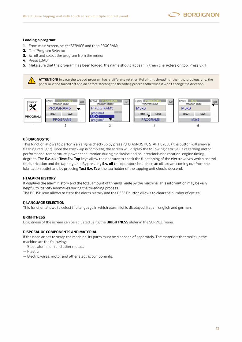
12
Direct Drive tapping unit with touch screen multiple control panel
ATTENTION! In case the loaded program has a different rotation (left/right threading) than the previous one, the panel must be turned off and on before starting the threading process otherwise it won’t change the direction.
Loading a program:
1. 2. 3. 4.5.
From main screen, select SERVICE and then PROGRAM;Tap “Program Selecto;Scroll and select the program from the menu;Press LOAD;Make sure that the program has been loaded: the name should appear in green characters on top. Press EXIT.
g ) DIAgNOsTICThis function allows to perform an engine check-up by pressing DIAGNOSTIC START CYCLE ( the button will show aflashing red light). Once the check-up is complete, the screen will display the following data: value regarding motor performance, temperature, power consumption during clockwise and counterclockwise rotation, engine timing degrees. The E.v. oil e Test E.v. Tap keys allow the operator to check the functioning of the electrovalves which control the lubrication and the tapping unit. By pressing E.v. oil the operator should see an oil stream coming out from the lubrication outlet and by pressing Test E.v. Tap, the tap holder of the tapping unit should descend.
H) ALArm HIsTOrYIt displays the alarm history and the total amount of threads made by the machine. This information may be very helpful to identify anomalies during the threading process.The BRUSH icon allows to clear the alarm history and the RESET button allows to clear the number of cycles.
I) LANgUAgE sELECTIONThis function allows to select the language in which alarm list is displayed: italian, english and german.
BrIgHTNEssBrightness of the screen can be adjusted using the BrIgHTNEss slider in the SERVICE menu.
DIsPOsAL OF COmPONENTs AND mATErIALIf the need arises to scrap the machine, its parts must be disposed of separately. The materials that make up the machine are the following:— Steel, aluminium and other metals;— Plastic;— Electric wires, motor and other electric components.
10
Setting a production lot
OIL
Manual lubrificationAutomatic lubrication
PROGRAM
Saving a new setting
Loading a program:
ATTENTION:
The “counter preset” box allows the user to enter a number >0 of threads to be performed. Once the parameter has beenentered the operator can press EXIT and begin the threading process. When the last thread of the program has been madethe machine will stop and an alarm will be displayed on the touch screen panel. By pressing the alarm sign, the operator willget the message “A16: end of production lot”. Press RESET to get the machine to work again. The tapping unit is nowready for another production lot.If “counter preset”=0, the tapping unit will work normally with no quantity limit.The “RESET” keys next to the “actual count” and “ total count” boxes are used for clearing count data and get ready for newones.
E)This function allows to turn ON/OFF the lubrication system and to control it by entering the lubrication time.
: Enter “0” in the lubrication time box and keep pressing “ON” as long as the lubrication is needed.: Enter a time parameter in “time oil”. Press ON. The lubrication will last the entered time at every
single cycle.Remember that the tap lubrication is one of the most important conditions to obtain a good performance in threading processand a long lasting tap. Special oil for threading is highly recommended
F)This function allows storage and backup of threading settingsThe page displays the following information:
:1- carry out set up (paragraph “SET UP” - page 5)2- from main menu, press SERVICE and then PROGRAM3- tap Program Select box and select the program where the new settings will be saved4- enter the name of the new program in the lower box.5- press SAVE : the new program will be saved and loaded6-make sure that previous name in the “in work” field has changed into the new name. Press EXIT
1- from main screen, select SERVICE and then PROGRAM.2- tap “Program Select”3- scroll and select the program from the menu4- press LOAD.5- make sure that the program has been loaded: the name should appear in green characters on top. Press EXIT.
In case the loaded program has a different rotation (left/right threading) than the previous one, the panel mustbe turned off and on before starting the threading process otherwise it won’t change the direction
.
For connecting the lubrication system, see instructions on pages 13-23-33-43 of the wiring diagram attached to this manual
M8X10(page�5)
M5x8
1��������������������2����������������������������������3�������������������������������������������������4�������������������������������������������������5������������������������������������������������6
M8x... M8x10
M8x10
M8x10PROGRAM
SERVICE
PROGRAM0
M5x8M5x8
PROGRAM1
PROGRAM9
PROGRAM1PROGRAM0
M8x10PROGRAM0
M8x10
M8x10
M8x10 program1
program3M8x10
PROGRAM
SERVICE
PROGRAM5
1������������������������������������2��������������������������������������������������3��������������������������������������������������4�������������������������������������������������5
M3x6
PROGRAM5
PROGRAM5
program1
program3M3X6
M3x6 M3x6
M3x6
PROGRAM5
PROGRAM5
PROGRAM5 PROGRAM5
view�of�the�last�loaded�program
name�of�last�loaded�program
scroll�menu�with�n.�10available�programs:
key�for�loading�a�program
key�for�saving�and�loading�a�programfield�for�naming�a�program
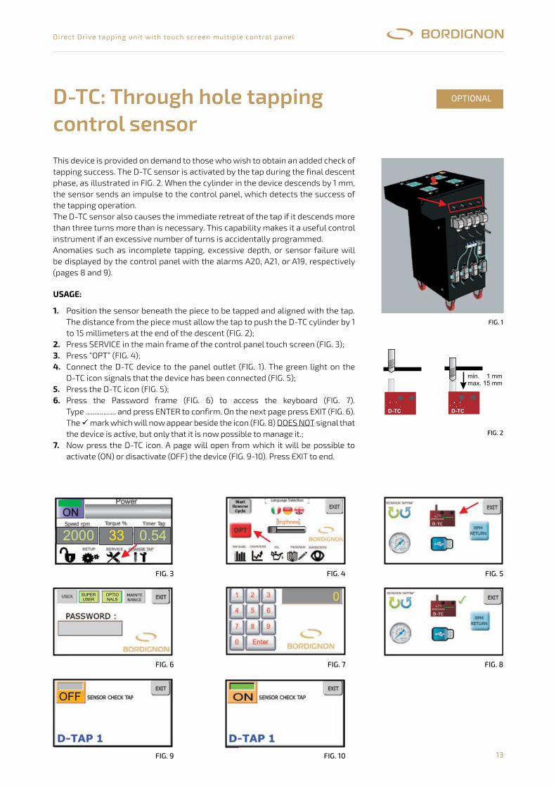
13
Direct Drive tapping unit with touch screen multiple control panel
This device is provided on demand to those who wish to obtain an added check of tapping success. The D-TC sensor is activated by the tap during the final descent phase, as illustrated in FIG. 2. When the cylinder in the device descends by 1 mm, the sensor sends an impulse to the control panel, which detects the success of the tapping operation.The D-TC sensor also causes the immediate retreat of the tap if it descends more than three turns more than is necessary. This capability makes it a useful control instrument if an excessive number of turns is accidentally programmed.Anomalies such as incomplete tapping, excessive depth, or sensor failure will be displayed by the control panel with the alarms A20, A21, or A19, respectively (pages 8 and 9).
D-TC: Through hole tapping control sensor
OPTIONAL
D-TC sensore di controllo filettatura a foro passante
Dispositivo fornito su richiesta per ottenere un controllo aggiuntivo di avvenutafilettatura.Il sensore D-TC viene attivato dal maschio durante la fase finale della suadiscesa come illustrato nella figura 2. Quando il cilindro presente nel dispositivoscende di 1 mm, il sensore invia un impulso al pannello che rileva l’avvenutafilettatura.Il D-TC inoltre provoca il ritorno immediato del maschio qualora esso scendaoltre 3 giri rispetto al dovuto. Questa caratteristica lo rende uno strumento utiledi controllo qualora si imposti un numero eccessivo di giri.Anomalie quali filetto non eseguito o profondità eccessiva o guasto al sensoreverranno segnalate dal pannello di controllo rispettivamente con gli allarmiA20,A21 oA19 (pagg. 7 e 8).
1- Posizionare il sensore sotto il pezzo da filettare ed in asse con il maschio. Ladistanza dal pezzo deve essere tale da consentire al maschio a fine discesadi spingere il cilindro del D-TC per una corsa da min. 1 mm fino a max. 15 mm(fig. 2)
2- Premere SERVICE nella videata principale del touch screen del pannello dicontrollo (fig. 3)
3- premere “OPT” (fig. 4)4- collegare il dispositivo D-TC alla presa pannello (fig. 1)
La luce verde sull’icona D-TC segnala che il dispositivo è stato collegato(fig.5)
5- Premere l’icona D-TC (fig. 5)6- premere sul riquadro Password (fig. 6) per accedere alla tastiera (fig. 7).
Digitare ................., confermare con ENTER. Sulla pagina successiva
premere EXIT (fig. 6). Il segno che apparirà ora a fianco dell’icona (fig. 8)segnala che il dispositivo è attivo ma solo che è possibile accedere alla
gestione dello stesso.7- Premere ora l’icona del D-TC. Si aprirà una pagina dalla quale sarà possibile
attivare (ON) o disattivare (OFF) il dispositivo (fig. 9-10). Premere EXIT peruscire.
Modalità d’uso:
NON�
13
pressionemin.5BAR
pressionemin.5BAR
1
OPTIONAL
2000 33 0.54
ON
3
6
9
OFF
4
7
10
SUPERUSER
OPTIONALS
8
5
min.����1�mmmax.�15�mm
2
D-TC D-TC
FiG. 1
FiG. 2
UsAgE:
1.
2. 3. 4.
5.6.
7.
Position the sensor beneath the piece to be tapped and aligned with the tap. The distance from the piece must allow the tap to push the D-TC cylinder by 1 to 15 millimeters at the end of the descent (FIG. 2);Press SERVICE in the main frame of the control panel touch screen (FIG. 3);Press “OPT” (FIG. 4);Connect the D-TC device to the panel outlet (FIG. 1). The green light on the D-TC icon signals that the device has been connected (FIG. 5);Press the D-TC icon (FIG. 5);Press the Password frame (FIG. 6) to access the keyboard (FIG. 7). Type ................. and press ENTER to confirm. On the next page press EXIT (FIG. 6). The mark which will now appear beside the icon (FIG. 8) DOES NOT signal that the device is active, but only that it is now possible to manage it.;Now press the D-TC icon. A page will open from which it will be possible to activate (ON) or disactivate (OFF) the device (FIG. 9-10). Press EXIT to end.
D-TC sensore di controllo �lettatura a foro passante
Dispositivo fornito su richiesta per ottenere un controllo aggiuntivo di avvenutafilettatura.Il sensore D-TC viene attivato dal maschio durante la fase finale della suadiscesa come illustrato nella figura 2. Quando il cilindro presente nel dispositivoscende di 1 mm, il sensore invia un impulso al pannello che rileva l’avvenutafilettatura.Il D-TC inoltre provoca il ritorno immediato del maschio qualora esso scendaoltre 3 giri rispetto al dovuto. Questa caratteristica lo rende uno strumento utiledi controllo qualora si imposti un numero eccessivo di giri.Anomalie quali filetto non eseguito o profondità eccessiva o guasto al sensoreverranno segnalate dal pannello di controllo rispettivamente con gli allarmiA20,A21 oA19 (pagg. 7 e 8).
1- Posizionare il sensore sotto il pezzo da filettare ed in asse con il maschio. Ladistanza dal pezzo deve essere tale da consentire al maschio a fine discesadi spingere il cilindro del D-TC per una corsa da min. 1 mm fino a max. 15 mm(fig. 2)
2- Premere SERVICE nella videata principale del touch screen del pannello dicontrollo (fig. 3)
3- premere “OPT” (fig. 4)4- collegare il dispositivo D-TC alla presa pannello (fig. 1)
La luce verde sull’icona D-TC segnala che il dispositivo è stato collegato(fig.5)
5- Premere l’icona D-TC (fig. 5)6- premere sul riquadro Password (fig. 6) per accedere alla tastiera (fig. 7).
Digitare ................., confermare con ENTER. Sulla pagina successivapremere EXIT (fig. 6). Il segno che apparirà ora a fianco dell’icona (fig. 8)
segnala che il dispositivo è attivo ma solo che è possibile accedere allagestione dello stesso.
7- Premere ora l’icona del D-TC. Si aprirà una pagina dalla quale sarà possibileattivare (ON) o disattivare (OFF) il dispositivo (fig. 9-10). Premere EXIT peruscire.
Modalità d ’uso:
NON
13
1
OPTIONAL
2000 33 0.54
ON
3
6
9
OFF
4
7
10
SUPERUSER
OPTIONALS
8
5
2
D-TC D-TC
FiG. 3
FiG. 6
FiG. 9
FiG. 5
FiG. 8
FiG. 4
FiG. 7
FiG. 10
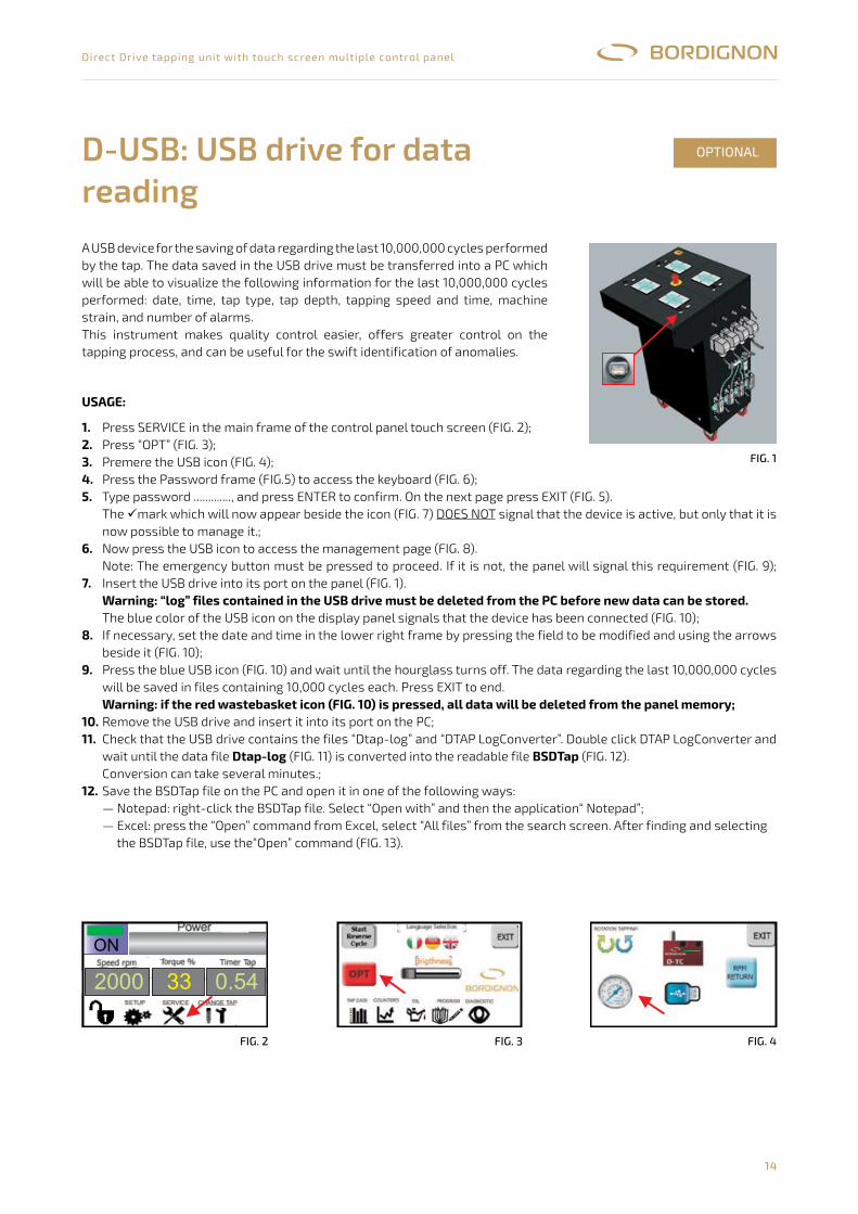
14
Direct Drive tapping unit with touch screen multiple control panel
A USB device for the saving of data regarding the last 10,000,000 cycles performed by the tap. The data saved in the USB drive must be transferred into a PC which will be able to visualize the following information for the last 10,000,000 cycles performed: date, time, tap type, tap depth, tapping speed and time, machine strain, and number of alarms.This instrument makes quality control easier, offers greater control on the tapping process, and can be useful for the swift identification of anomalies.
UsAgE:
1.2. 3. 4.5.
6.
7.
8.
9.
10.11.
12.
Press SERVICE in the main frame of the control panel touch screen (FIG. 2);Press “OPT” (FIG. 3);Premere the USB icon (FIG. 4);Press the Password frame (FIG.5) to access the keyboard (FIG. 6);Type password ............., and press ENTER to confirm. On the next page press EXIT (FIG. 5).The mark which will now appear beside the icon (FIG. 7) DOES NOT signal that the device is active, but only that it is now possible to manage it.;Now press the USB icon to access the management page (FIG. 8).Note: The emergency button must be pressed to proceed. If it is not, the panel will signal this requirement (FIG. 9); Insert the USB drive into its port on the panel (FIG. 1).warning: “log” files contained in the UsB drive must be deleted from the PC before new data can be stored.The blue color of the USB icon on the display panel signals that the device has been connected (FIG. 10);If necessary, set the date and time in the lower right frame by pressing the field to be modified and using the arrows beside it (FIG. 10);Press the blue USB icon (FIG. 10) and wait until the hourglass turns off. The data regarding the last 10,000,000 cycles will be saved in files containing 10,000 cycles each. Press EXIT to end.warning: if the red wastebasket icon (FIg. 10) is pressed, all data will be deleted from the panel memory;Remove the USB drive and insert it into its port on the PC;Check that the USB drive contains the files “Dtap-log” and “DTAP LogConverter”. Double click DTAP LogConverter and wait until the data file Dtap-log (FIG. 11) is converted into the readable file BsDTap (FIG. 12).Conversion can take several minutes.;Save the BSDTap file on the PC and open it in one of the following ways:— Notepad: right-click the BSDTap file. Select “Open with” and then the application“ Notepad”;— Excel: press the “Open” command from Excel, select “All files” from the search screen. After finding and selecting
the BSDTap file, use the“Open” command (FIG. 13).
D-USB: USB drive for data reading
OPTIONAL
D-USB chiave�USB�per�lettura�dati
Dispositivo USB per il salvataggio dei dati relativi agli ultimi 10.000.000 dicicli eseguiti dalla maschiatrice. I dati salvati nella chiave USB dovrannoessere trasferiti in un PC il quale visualizzerà per ognuno dei 10.000.000cicli eseguiti, i seguenti dati: data, ora, tipo di filetto, profondità filetto,velocità e tempo di filettatura, sforzo macchina e numero allarmi.Questo strumento rende più facile il controllo di qualità, offre un maggiorecontrollo sul processo di filettatura e può essere utile alla rapidaindividuazione di anomalie
Modalità d’uso
Attenzione! Se si preme l’icona cestino rosso (fig. 10) verranno cancellati dalla tutti i dati.
Dtap-log BSDTap
1- premere SERVICE nella videata principale del touch screen delpannello di controllo (fig. 2)
2- premere “OPT” (fig. 3)3- premere l’icona USB (fig. 4)4- premere sul riquadro Password (fig. 5) per accedere alla tastiera (fig. 6).
Digitare ............., confermare con ENTER. Sulla pagina successivapremere EXIT (fig. 5)
Il segno che apparirà ora a fianco dell’icona (fig. 7) segnala che il dispositivo è attivo ma solo che è possibile lagestione dello stesso.
6- premere ora l’icona USB per accedere alla pagina di gestione (fig. 8).Nota: Per procedere è necessario che il tasto di emergenza sia premuto. Qualora non lo fosse il pannello segnalerà questanecessità (fig. 9)
7- inserire la chiavetta USB nell’apposita sede del pannello (fig. 1))
Il colore azzurro dell’icona USB sul display del pannello segnala che il dispositivo è stato collegato (fig. 10).8- se necessario, regolare data e ora nel riquadro in basso a destra, premendo il campo da variare ed utilizzando le frecce a
lato (fig. 10)9- premere l’icona USB azzurra (fig. 10) ed attendere il tempo scandito dalla clessidra. I dati degli ultimi 10.000.000 cicli
verranno così salvati in singoli file contenenti ognuno 10.000 cicli. Infine premere EXIT
10-estrarre la chiavetta USB ed inserirla nella presa USB del PC.11-controllare dal PC che siano presenti nella chiave USB i file “Dtap-log” e “D ”. Fare doppio clic su DTAP
LogConverter ed attendere il tempo necessario affinché il file dati (fig. 11) si trasformi nel file di lettura(fig. 12).La conversione può richiedere diversi minuti.
12- Salvare nel PC il file BSDTap ed aprirlo in una delle seguenti modalità:- notepad: cliccare sul file BSDTap con il tasto destro. Scegliere “apri con” e selezionare dall’elenco l’applicazione “ blocconote” o “notepad”
- excel: scegliere il comando “apri” dal programma excel, selezionare “tutti i files” dalla schermata di ricercaUna volta Individuato e selezionato il file BSDTap, dare il comando “apri” (fig. 13)
NON
Attenzione! E’necessario cancellare tutti i files “log” presenti nella chiave USB dal PC prima di memorizzare nuovidati
memoria del pannello
TAP LogConverter
�
pressione�min.5�BAR
1
OPTIONAL
SUPERUSER
OPTIONALS
Tutti�i�fileblu:�D-USB
inserito
53 4
10
0.54
2
2000
ON
13
33
dtap-logX
DTAP LogConverter
BSDTap
DTAP LogConverter
11 12
DTAP LogConverter
86 97
FiG. 1
Il regolatore di pressione automatico D-APR collegato al pannellodi controllo della maschiatrice permette una regolazioneautomatica dell’aria ad un determinata pressione.
1- Dal riduttore di pressione manuale regolare la pressione ad unvalore superiore a 6 BAR (fig. 1)
2- Premere SERVICE nella videata principale del touch screen delpannello di controllo (fig. 2)
3- premere “OPT” (fig. 3)4- Premere l’icona Manometro (fig. 4)5- Premere sul riquadro Password (fig. 5) per accedere alla tastiera
(fig. 6). Digitare ..............., confermare con ENTER. Sulla paginasuccessiva premere EXIT (fig. 5)Il segno che apparirà ora a fianco dell’icona (fig. 7)segnala che il dispositivo è attivo ma solo che è possibile la suagestione.
6- Premere ora l’icona Manometro (fig. 7) per accedere alla paginadi gestione (fig. 8).
7- Premere nella casella centrale (fig. 8) per accedere alla tastierache permetterà di inserire la pressione desiderata (fig. 9). Suldisplay in alto a destra sono visibili i valori massimi e minimiconsentiti, oltre all’ultimo parametro inserito. Una volta eseguital’impostazione, confermare con ENTER.
8- Premere EXIT per uscire.
Modalità d ’uso:
NON
D-APR
15
1
OPTIONAL
2.0
2000 33 0.54
ON
2
5
8
3
6
9
4
7
SUPERUSER
OPTIONALS
FiG. 2 FiG. 3 FiG. 4
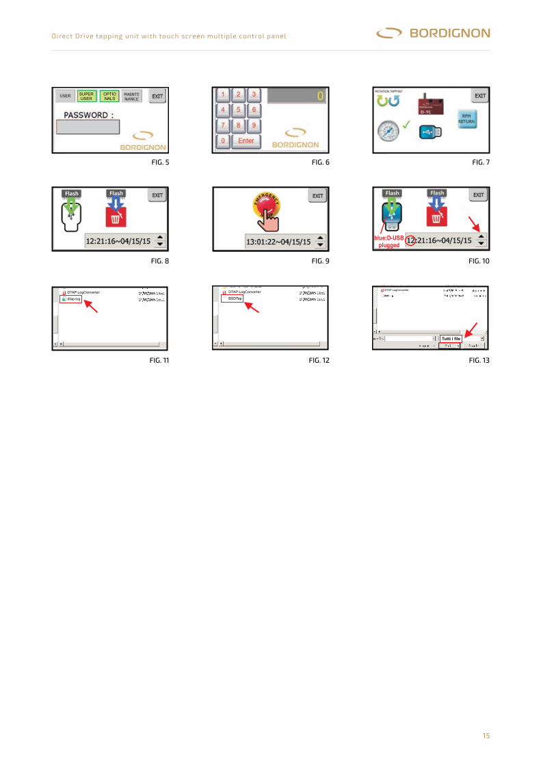
15
Direct Drive tapping unit with touch screen multiple control panel
D-USB
Dispositivo USB per il salvataggio dei dati relativi agli ultimi 10.000.000 dicicli eseguiti dalla maschiatrice. I dati salvati nella chiave USB dovrannoessere trasferiti in un PC il quale visualizzerà per ognuno dei 10.000.000cicli eseguiti, i seguenti dati: data, ora, tipo di filetto, profondità filetto,velocità e tempo di filettatura, sforzo macchina e numero allarmi.Questo strumento rende più facile il controllo di qualità, offre un maggiorecontrollo sul processo di filettatura e può essere utile alla rapidaindividuazione di anomalie
Modalità d ’uso
Attenzione! Se si preme l ’ .itadiittutalladitallecnaconnarrev)01.gif(ossoronitsecanoci
paTDSBgol-patD
1- premere SERVICE nella videata principale del touch screen delpannello di controllo (fig. 2)
2- premere “OPT” (fig. 3)3- premere l’icona USB (fig. 4)4- premere sul riquadro Password (fig. 5) per accedere alla tastiera (fig. 6).
Digitare ............., confermare con ENTER. Sulla pagina successivapremere EXIT (fig. 5)Il segno che apparirà ora a fianco dell’icona (fig. 7) segnala che il dispositivo è attivo ma solo che è possibile lagestione dello stesso.
6- premere ora l’icona USB per accedere alla pagina di gestione (fig. 8).Nota: Per procedere è necessario che il tasto di emergenza sia premuto. Qualora non lo fosse il pannello segnalerà questanecessità (fig. 9)
7- inserire la chiavetta USB nell’apposita sede del pannello (fig. 1))
Il colore azzurro dell’icona USB sul display del pannello segnala che il dispositivo è stato collegato (fig. 10).8- se necessario, regolare data e ora nel riquadro in basso a destra, premendo il campo da variare ed utilizzando le frecce a
lato (fig. 10)9- premere l’icona USB azzurra (fig. 10) ed attendere il tempo scandito dalla clessidra. I dati degli ultimi 10.000.000 cicli
verranno così salvati in singoli file contenenti ognuno 10.000 cicli. Infine premere EXIT
10-estrarre la chiavetta USB ed inserirla nella presa USB del PC.11-controllare dal PC che siano presenti nella chiave USB i file “Dtap-log” e “D ”. Fare doppio clic su DTAP
LogConverter ed attendere il tempo necessario affinché il file dati (fig. 11) si trasformi nel file di lettura(fig. 12).La conversione può richiedere diversi minuti.
12- Salvare nel PC il file BSDTap ed aprirlo in una delle seguenti modalità:- notepad: cliccare sul file BSDTap con il tasto destro. Scegliere “apri con” e selezionare dall’elenco l’applicazione “ blocco
note” o “notepad”- excel: scegliere il comando “apri” dal programma excel, selezionare “tutti i files” dalla schermata di ricercaUna volta Individuato e selezionato il file BSDTap, dare il comando “apri” (fig. 13)
NON
Attenzione! E ’ necessario cancellare tutti i �les “ log ” presenti nella chiave USB dal PC prima dimemorizzare nuovidati
memoria del pannello
TAP LogConverter
1
OPTIONAL
SUPERUSER
OPTIONALS
inserito
53 4
10
0.54
2
2000
ON
13
33
dtap-logX
DTAP LogConverter
BSDTap
DTAP LogConverter
11 12
DTAP LogConverter
86 97
D-USB USB�drive�for�data�reading
A USB device for the saving of data regarding the last 10,000,000 cyclesperformed by the tap. The data saved in the USB drive must be transferred into aPC which will be able to visualize the following information for the last10,000,000 cycles performed: date, time, tap type, tap depth, tapping speed andtime, machine strain, and number of alarms.This instrument makes quality control easier, offers greater control on thetapping process, and can be useful for the swift identification of anomalies.
1 - Press SERVICE in the main frame of the control panel touch screen (fig. 2).2 - Press “OPT” (fig. 3).3 - Press the USB icon (fig. 4).4 - Press the Password frame (fig. 5) to access the keyboard (fig. 6).5 - Type password .................. and press ENTER to confirm. On the next page
press EXIT (fig. 5).
The mark which will now appear beside the icon (fig. 7) DOES NOT signalthat the device is active, but only that it is now possible to manage it.
6 - Now press the USB icon to access the management page (fig. 8).Note: The emergency button must be pressed to proceed. If it is not, the panel will signal this requirement (fig. 9).
7 - Insert the USB drive into its port on the panel (fig. 1).
The blue color of the USB icon on the display panel signals that the device has been connected (fig.10).8 - If necessary, set the date and time in the lower right frame by pressing the field to be modified and using the arrows beside
it (fig. 10).9 - Press the blue USB icon (fig. 10) and wait until the hourglass turns off. The data regarding the last 10,000,000 cycles will
be saved in files containing 10,000 cycles each. Press EXIT to end.
10 - Remove the USB drive and insert it into its port on the PC.11 - Check that the USB drive contains the files “Dtap-log” and “DTAP LogConverter”.
Double click DTAP LogConverter and wait until the data file (fig. 11) is converted into the readable file(fig. 12).Conversion can take several minutes.
12 - Save the BSDTap file on the PC and open it in one of the following ways:- Notepad: right-click the BSDTap file. Select “Open with” and then the application “ Notepad”.- Excel: press the “Open” command from Excel, select “All files” from the search screen. After finding and selecting theBSDTap file, use the “Open” command (fig. 13)
Usage:
Warning: “log” files contained in the USB drive must be deleted from the PC before new data can be stored.
Warning: if the red wastebasket icon (fig. 10) is pressed, all data will be deleted from the .
dtap-log BSDTap
panel memory
�
pressione�min.5�BAR
1
OPTIONAL
SUPERUSER
OPTIONALS
Tutti�i�file
53 4
10
0.54
2
2000
ON
13
33
dtap-logX
DTAP LogConverter
BSDTap
DTAP LogConverter
11 12
DTAP LogConverter
86 97
blue:D-USB
plugged
FiG. 8
FiG. 11 FiG. 12 FiG. 13
FiG. 9 FiG. 10
Il regolatore di pressione automatico D-APR collegato al pannellodi controllo della maschiatrice permette una regolazioneautomatica dell’aria ad un determinata pressione.
1- Dal riduttore di pressione manuale regolare la pressione ad unvalore superiore a 6 BAR (fig. 1)
2- Premere SERVICE nella videata principale del touch screen delpannello di controllo (fig. 2)
3- premere “OPT” (fig. 3)4- Premere l’icona Manometro (fig. 4)5- Premere sul riquadro Password (fig. 5) per accedere alla tastiera
(fig. 6). Digitare ..............., confermare con ENTER. Sulla paginasuccessiva premere EXIT (fig. 5)Il segno che apparirà ora a fianco dell’icona (fig. 7)segnala che il dispositivo è attivo ma solo che è possibile la suagestione.
6- Premere ora l’icona Manometro (fig. 7) per accedere alla paginadi gestione (fig. 8).
7- Premere nella casella centrale (fig. 8) per accedere alla tastierache permetterà di inserire la pressione desiderata (fig. 9). Suldisplay in alto a destra sono visibili i valori massimi e minimiconsentiti, oltre all’ultimo parametro inserito. Una volta eseguital’impostazione, confermare con ENTER.
8- Premere EXIT per uscire.
Modalità d ’uso:
NON
D-APR
15
1
OPTIONAL
2.0
2000 33 0.54
ON
2
5
8
3
6
9
4
7
SUPERUSER
OPTIONALS
FiG. 5 FiG. 6 FiG. 7
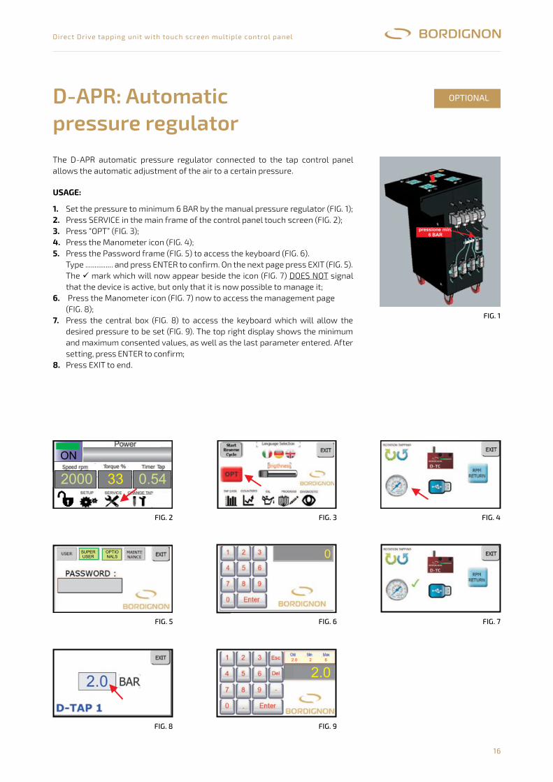
16
Direct Drive tapping unit with touch screen multiple control panel
The D-APR automatic pressure regulator connected to the tap control panel allows the automatic adjustment of the air to a certain pressure.
D-APR: Automaticpressure regulator
OPTIONAL
Il regolatore di pressione automatico D-APR collegato al pannellodi controllo della maschiatrice permette una regolazioneautomatica dell’aria ad un determinata pressione.
1- Dal riduttore di pressione manuale regolare la pressione ad unvalore superiore a 6 BAR (fig. 1)
2- Premere SERVICE nella videata principale del touch screen delpannello di controllo (fig. 2)
3- premere “OPT” (fig. 3)4- Premere l’icona Manometro (fig. 4)5- Premere sul riquadro Password (fig. 5) per accedere alla tastiera
(fig. 6). Digitare ..............., confermare con ENTER. Sulla paginasuccessiva premere EXIT (fig. 5)
Il segno che apparirà ora a fianco dell’icona (fig. 7)segnala che il dispositivo è attivo ma solo che è possibile la suagestione.
6- Premere ora l’icona Manometro (fig. 7) per accedere alla paginadi gestione (fig. 8).
7- Premere nella casella centrale (fig. 8) per accedere alla tastierache permetterà di inserire la pressione desiderata (fig. 9). Suldisplay in alto a destra sono visibili i valori massimi e minimiconsentiti, oltre all’ultimo parametro inserito. Una volta eseguital’impostazione, confermare con ENTER.
8- Premere EXIT per uscire.
Modalità d’uso:
NON�
D-APR regolatore�di�pressione�automatico
15
1
pressione�min.6�BAR
OPTIONAL
2.0����������2�����������6
2.0
2000 33 0.54
ON
2
5
8
3
6
9
4
7
SUPERUSER
OPTIONALS
UsAgE:
1. 2. 3. 4.5.
6.
7.
8.
Set the pressure to minimum 6 BAR by the manual pressure regulator (FIG. 1);Press SERVICE in the main frame of the control panel touch screen (FIG. 2);Press “OPT” (FIG. 3);Press the Manometer icon (FIG. 4);Press the Password frame (FIG. 5) to access the keyboard (FIG. 6).Type ............... and press ENTER to confirm. On the next page press EXIT (FIG. 5).The mark which will now appear beside the icon (FIG. 7) DOES NOT signal that the device is active, but only that it is now possible to manage it; Press the Manometer icon (FIG. 7) now to access the management page(FIG. 8);Press the central box (FIG. 8) to access the keyboard which will allow the desired pressure to be set (FIG. 9). The top right display shows the minimum and maximum consented values, as well as the last parameter entered. After setting, press ENTER to confirm;Press EXIT to end.
FiG. 1
Il regolatore di pressione automatico D-APR collegato al pannellodi controllo della maschiatrice permette una regolazioneautomatica dell’aria ad un determinata pressione.
1- Dal riduttore di pressione manuale regolare la pressione ad unvalore superiore a 6 BAR (fig. 1)
2- Premere SERVICE nella videata principale del touch screen delpannello di controllo (fig. 2)
3- premere “OPT” (fig. 3)4- Premere l’icona Manometro (fig. 4)5- Premere sul riquadro Password (fig. 5) per accedere alla tastiera
(fig. 6). Digitare ..............., confermare con ENTER. Sulla paginasuccessiva premere EXIT (fig. 5)Il segno che apparirà ora a fianco dell’icona (fig. 7)segnala che il dispositivo è attivo ma solo che è possibile la suagestione.
6- Premere ora l’icona Manometro (fig. 7) per accedere alla paginadi gestione (fig. 8).
7- Premere nella casella centrale (fig. 8) per accedere alla tastierache permetterà di inserire la pressione desiderata (fig. 9). Suldisplay in alto a destra sono visibili i valori massimi e minimiconsentiti, oltre all’ultimo parametro inserito. Una volta eseguital’impostazione, confermare con ENTER.
8- Premere EXIT per uscire.
Modalità d ’uso:
NON
D-APR
15
1
OPTIONAL
2.0
2000 33 0.54
ON
2
5
8
3
6
9
4
7
SUPERUSER
OPTIONALS
Il regolatore di pressione automatico D-APR collegato al pannellodi controllo della maschiatrice permette una regolazioneautomatica dell’aria ad un determinata pressione.
1- Dal riduttore di pressione manuale regolare la pressione ad unvalore superiore a 6 BAR (fig. 1)
2- Premere SERVICE nella videata principale del touch screen delpannello di controllo (fig. 2)
3- premere “OPT” (fig. 3)4- Premere l’icona Manometro (fig. 4)5- Premere sul riquadro Password (fig. 5) per accedere alla tastiera
(fig. 6). Digitare ..............., confermare con ENTER. Sulla paginasuccessiva premere EXIT (fig. 5)Il segno che apparirà ora a fianco dell’icona (fig. 7)segnala che il dispositivo è attivo ma solo che è possibile la suagestione.
6- Premere ora l’icona Manometro (fig. 7) per accedere alla paginadi gestione (fig. 8).
7- Premere nella casella centrale (fig. 8) per accedere alla tastierache permetterà di inserire la pressione desiderata (fig. 9). Suldisplay in alto a destra sono visibili i valori massimi e minimiconsentiti, oltre all’ultimo parametro inserito. Una volta eseguital’impostazione, confermare con ENTER.
8- Premere EXIT per uscire.
Modalità d ’uso:
NON
D-APR
15
1
OPTIONAL
2.0
2000 33 0.54
ON
2
5
8
3
6
9
4
7
SUPERUSER
OPTIONALS
Il regolatore di pressione automatico D-APR collegato al pannellodi controllo della maschiatrice permette una regolazioneautomatica dell’aria ad un determinata pressione.
1- Dal riduttore di pressione manuale regolare la pressione ad unvalore superiore a 6 BAR (fig. 1)
2- Premere SERVICE nella videata principale del touch screen delpannello di controllo (fig. 2)
3- premere “OPT” (fig. 3)4- Premere l’icona Manometro (fig. 4)5- Premere sul riquadro Password (fig. 5) per accedere alla tastiera
(fig. 6). Digitare ..............., confermare con ENTER. Sulla paginasuccessiva premere EXIT (fig. 5)Il segno che apparirà ora a fianco dell’icona (fig. 7)segnala che il dispositivo è attivo ma solo che è possibile la suagestione.
6- Premere ora l’icona Manometro (fig. 7) per accedere alla paginadi gestione (fig. 8).
7- Premere nella casella centrale (fig. 8) per accedere alla tastierache permetterà di inserire la pressione desiderata (fig. 9). Suldisplay in alto a destra sono visibili i valori massimi e minimiconsentiti, oltre all’ultimo parametro inserito. Una volta eseguital’impostazione, confermare con ENTER.
8- Premere EXIT per uscire.
Modalità d ’uso:
NON
D-APR
15
1
OPTIONAL
2.0
2000 33 0.54
ON
2
5
8
3
6
9
4
7
SUPERUSER
OPTIONALS
FiG. 2
FiG. 5
FiG. 8
FiG. 3
FiG. 6
FiG. 9
FiG. 4
FiG. 7
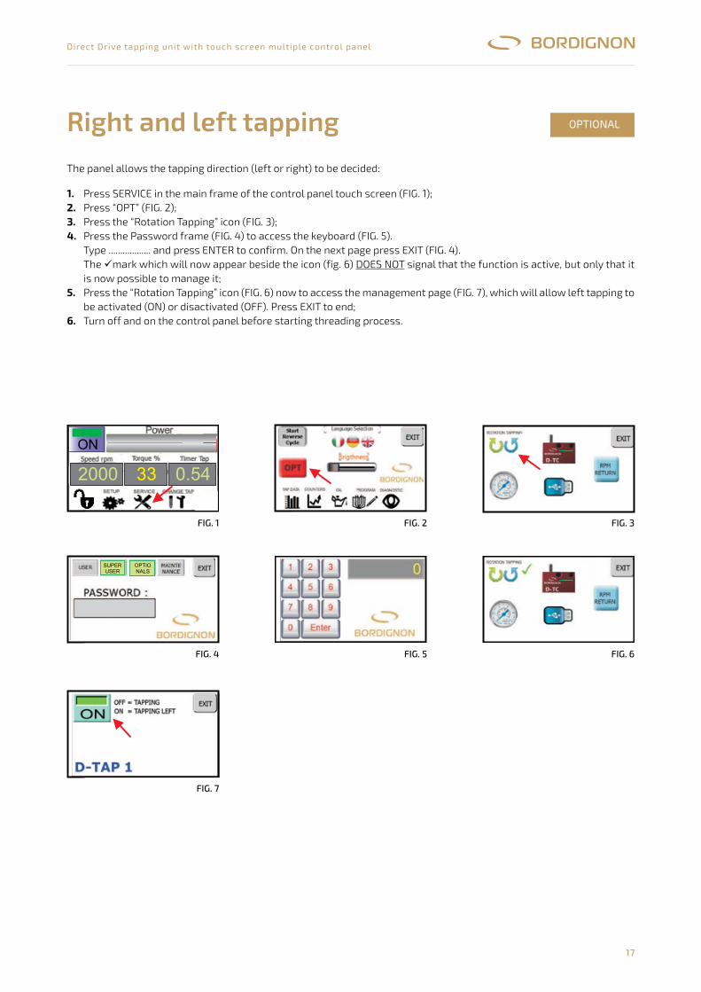
17
Direct Drive tapping unit with touch screen multiple control panel
The panel allows the tapping direction (left or right) to be decided:
Right and left tapping OPTIONAL
1. 2. 3. 4.
5.
6.
Press SERVICE in the main frame of the control panel touch screen (FIG. 1);Press “OPT” (FIG. 2);Press the “Rotation Tapping” icon (FIG. 3);Press the Password frame (FIG. 4) to access the keyboard (FIG. 5).Type .................. and press ENTER to confirm. On the next page press EXIT (FIG. 4).The mark which will now appear beside the icon (fig. 6) DOES NOT signal that the function is active, but only that it is now possible to manage it;Press the “Rotation Tapping” icon (FIG. 6) now to access the management page (FIG. 7), which will allow left tapping to be activated (ON) or disactivated (OFF). Press EXIT to end;Turn off and on the control panel before starting threading process.
Il pannello consente di programmare il verso di filettatura (destro o sinistro):
1- Premere SERVICE nella videata principale del touch screen del pannello di controllo (fig. 1)2- premere “OPT” (fig. 2)3- Premere l’icona “Rotation Tapping” (fig. 3)4- premere sul riquadro Password (fig. 4) per accedere alla tastiera (fig. 5). Digitare .................., confermare con
ENTER. Sulla pagina successiva premere EXIT (fig. 4)Il segno che apparirà ora a fianco dell’icona (fig. 6) segnala che il dispositivo è attivo ma solo che è possibile lasua gestione.
5- premere ora l’icona “Rotation Tapping” (fig. 6) per accedere alla pagina di gestione (fig. 7) che consentirà di attivare(ON) o disattivare (OFF) la filettatura sinistra.Premere EXIT per uscire.
6- spegnere e riaccendere il pannello prima di iniziare il processo di lavorazione
NON
16
OPTIONAL
2000 33 0.54
ON
1
4
7
2 3
65
SUPERUSER
OPTIONALS
FiG. 1 FiG. 2 FiG. 3
FiG. 4 FiG. 5 FiG. 6
Il pannello consente di programmare il verso di filettatura (destro o sinistro):
1- Premere SERVICE nella videata principale del touch screen del pannello di controllo (fig. 1)2- premere “OPT” (fig. 2)3- Premere l’icona “Rotation Tapping” (fig. 3)4- premere sul riquadro Password (fig. 4) per accedere alla tastiera (fig. 5). Digitare .................., confermare con
ENTER. Sulla pagina successiva premere EXIT (fig. 4)Il segno che apparirà ora a fianco dell’icona (fig. 6) segnala che il dispositivo è attivo ma solo che è possibile lasua gestione.
5- premere ora l’icona “Rotation Tapping” (fig. 6) per accedere alla pagina di gestione (fig. 7) che consentirà di attivare(ON) o disattivare (OFF) la filettatura sinistra.Premere EXIT per uscire.
6- spegnere e riaccendere il pannello prima di iniziare il processo di lavorazione
NON
16
OPTIONAL
2000 33 0.54
ON
1
4
7
2 3
65
SUPERUSER
OPTIONALS
FiG. 7
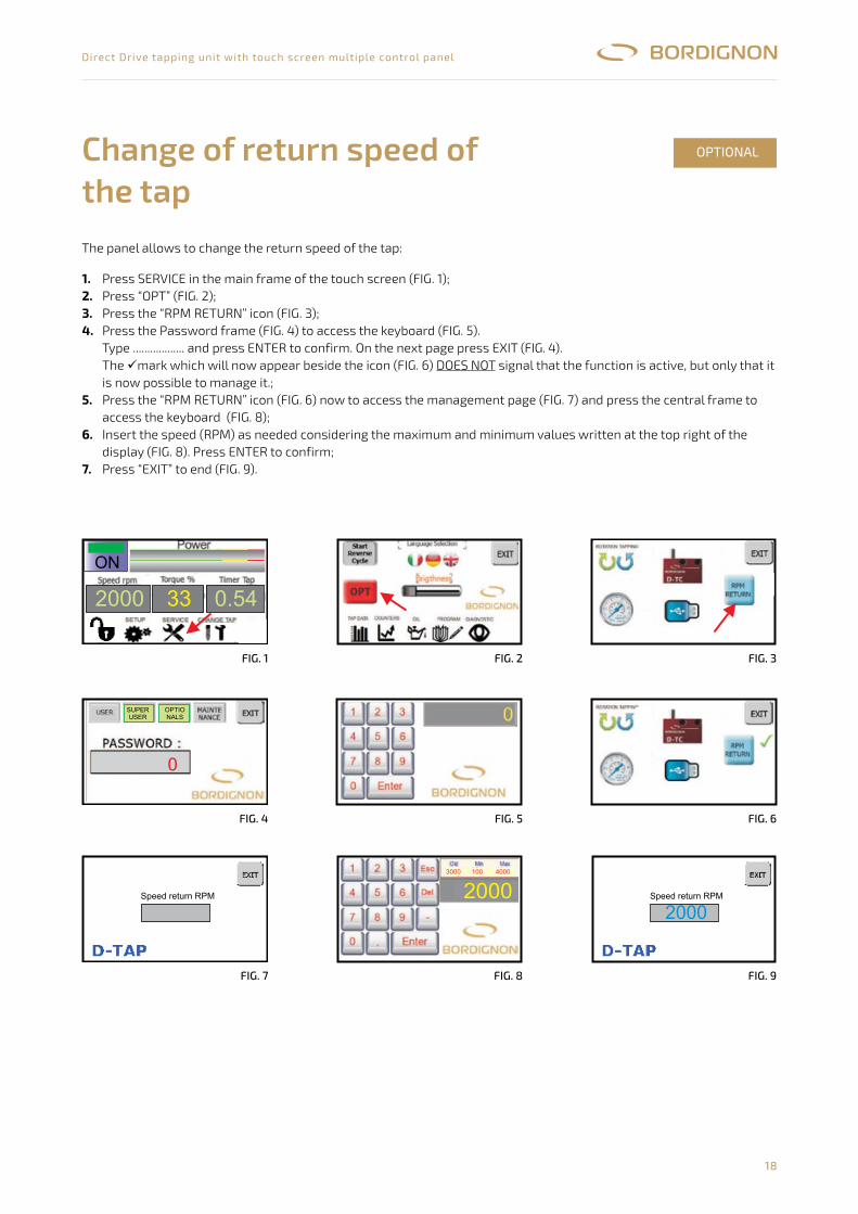
18
Direct Drive tapping unit with touch screen multiple control panel
The panel allows to change the return speed of the tap:
Change of return speed ofthe tap
OPTIONAL
1. 2. 3. 4.
5.
6.
7.
Press SERVICE in the main frame of the touch screen (FIG. 1);Press “OPT” (FIG. 2);Press the “RPM RETURN” icon (FIG. 3);Press the Password frame (FIG. 4) to access the keyboard (FIG. 5).Type .................. and press ENTER to confirm. On the next page press EXIT (FIG. 4).The mark which will now appear beside the icon (FIG. 6) DOES NOT signal that the function is active, but only that it is now possible to manage it.;Press the “RPM RETURN” icon (FIG. 6) now to access the management page (FIG. 7) and press the central frame to access the keyboard (FIG. 8);Insert the speed (RPM) as needed considering the maximum and minimum values written at the top right of the display (FIG. 8). Press ENTER to confirm;Press “EXIT” to end (FIG. 9).
FiG. 1
FiG. 4
FiG. 7
FiG. 2
FiG. 5
FiG. 8
FiG. 3
FiG. 6
FiG. 9
’
Il pannello consente di modificare la velocità di ritorno del maschio
1- Premere SERVICE nella videata principale del touch screen (fig. 1)2- premere “OPT” (fig. 2)3- Premere l’icona “RPM return” (fig. 3)4- premere il riquadro Password (fig. 4) per accedere alla tastiera (fig. 5). Digitare .................. e confermare con
ENTER. Sulla pagina successiva premere EXIT (fig. 4)Il segno che apparirà ora a fianco dell’icona (fig. 6) segnala che il dispositivo è attivo ma solo che è possibile lasua gestione.
5- premere ora l’icona “RPM RETURN” (fig. 6) per accedere alla pagina di gestione (fig. 7) e premere il riquadro centraleper accedere alla tastiera (fig. 8)
6- inserire la velocità (giri al minuto) desiderata tenendo conto dei limiti evidenziati in alto a destra del display econfermare con ENTER (fig. 8)
7- Premere “EXIT” per uscire (fig. 9)
NON
17
OPTIONAL
2000 33 0.54
1 2
5
3
64
7 8 9
2000
ON
2000
SUPERUSER
OPTIONALS
0
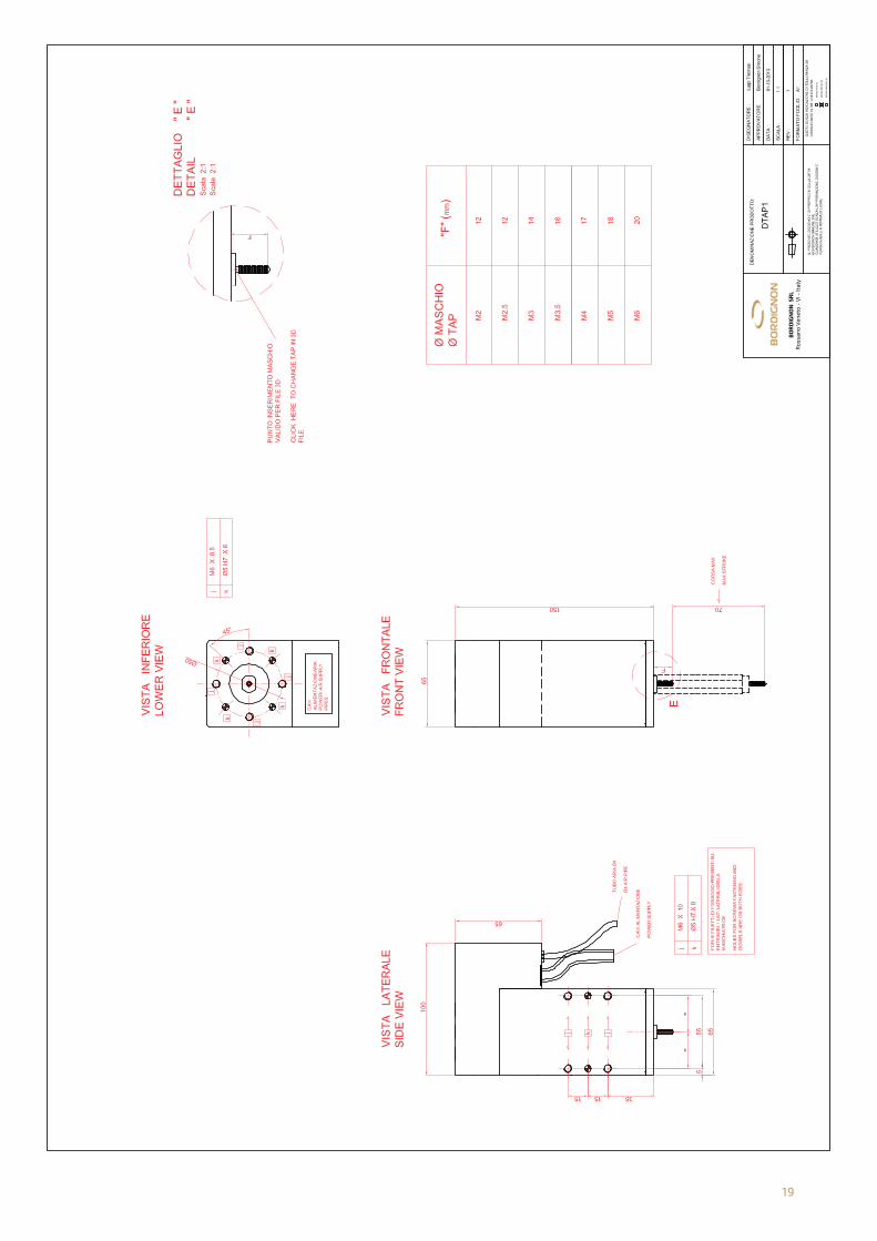
19
18
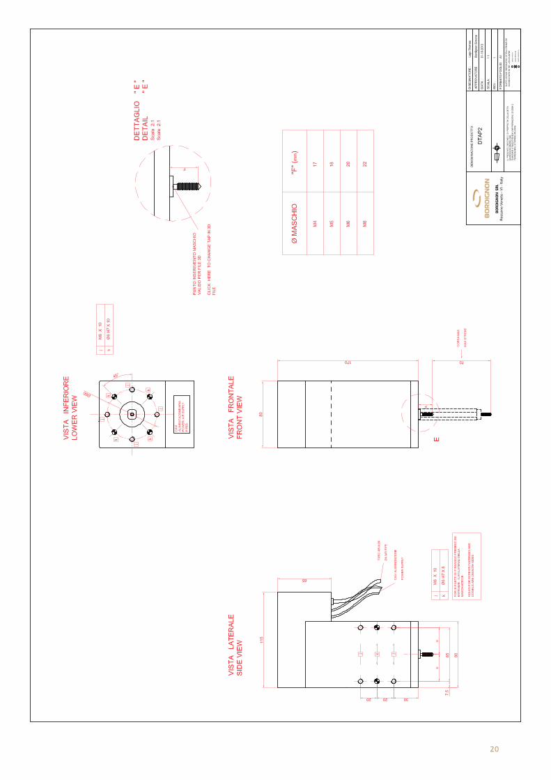
20
19
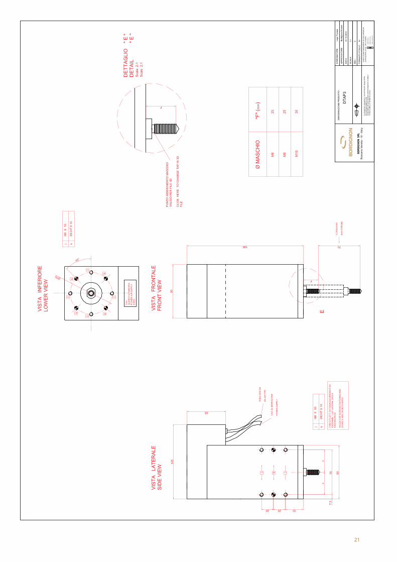
21
20
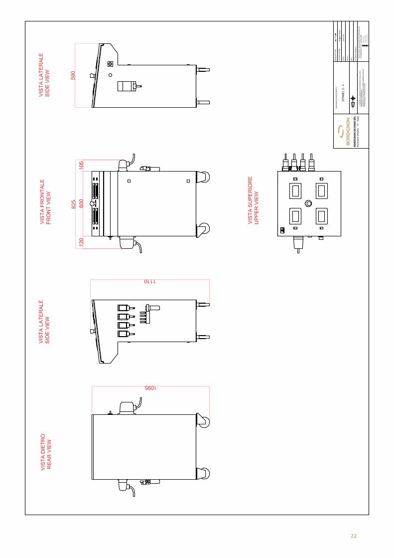
22
21
BO
RD
IGN
ON
�SIL
VA
NO
�SR
L
Ro
ss
an
o�V
en
eto
�-�V
I�-�
Ita
ly
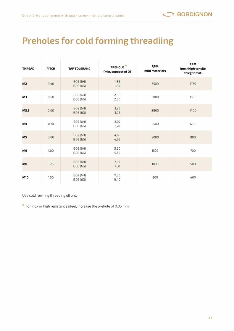
23
Direct Drive tapping unit with touch screen multiple control panel
Preholes for cold forming threadiing
THrEAD PITCH TAP TOLErANC PrEHOLE(min. suggested Ø)
rPmmild materials
rPminox/high tensile
streght mat.
m2 0,40ISO2 (6H)ISO3 (6G)
1,851,85
3500 1750
m3 0,50ISO2 (6H)ISO3 (6G)
2,802,80
3000 1500
m3.5 0,60ISO2 (6H)ISO3 (6G)
3,253,25
2800 1400
m4 0,70ISO2 (6H)ISO3 (6G)
3,703,70
2500 1200
m5 0,80ISO2 (6H)ISO3 (6G)
4,654,65
2000 900
m6 1,00ISO2 (6H)ISO3 (6G)
5,605,65
1500 700
m8 1,25ISO2 (6H)ISO3 (6G)
7,457,50
1000 500
m10 1,50ISO2 (6H)ISO3 (6G)
9,359,40
800 400
Use cold forming threading oil only
For inox or high resistance steel, increase the prehole of 0,05 mm
24
Direct Drive tapping unit with touch screen multiple control panel
EC DECLARATION OF CONFORMITY
in accordance with European Directive 2006/42 EC – annex IIA
The producer BORDIGNON s.r.l. - Via Volta, 2 – 36028 Rossano Veneto – VI - Italia hereby declares that:
� equipment tapping unit
� model DTAP
� serial n° ………….
� year …………..
�
is in accordance with the following Directives:
� 2006/42 EC the machinery directive;
� 2014/35 EC the low voltage directive;
� 2014/30 EC the electromagnetic directive.
The person authorized to compile the technical file is Mr. Simone Bordignon – Company BORDIGNON s.r.l.
Rossano Veneto, ………………
25
PROG
ETTA
ZIONE
ORIG
INE
REV.
DATA
FOG
LIO
T.F.
SOST
. IL:
APPR
OV.
DESC
RIZIO
NE R
EVIS
IONE
FILE
SOST
. DA:
VIST
O
ESER
CIZIO
TENS
IONE
COMA
NDI
TENS
IONE
SEGN
ALI
TENS
IONE
NORM
E
RIF.:
CLIEN
TE:
DISEG
NATO
RE
DATA
ULTIM
A MO
DIF.
DISE
GNAT
.
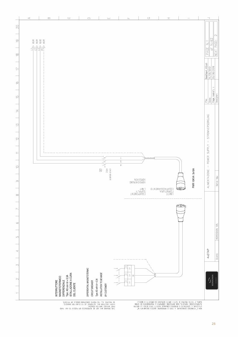
26
DEL C
LIENT
EIS
TALL
AZIO
NE A
CUR
ATip
o: AS
con I
d = 0,
3ADI
FFER
ENZIA
LEMA
GNET
OTER
MICO
INTE
RRUT
TORE
PWR
10KV
A 3x
16A
BY C
USTO
MER
INST
ALLA
TION
TO B
E MA
DE
Type
AS
with
Id = 0
,3A
CIRC
UIT B
REAK
ER
DIFF
EREN
TIAL M
AGNE
TOTE
RMIC
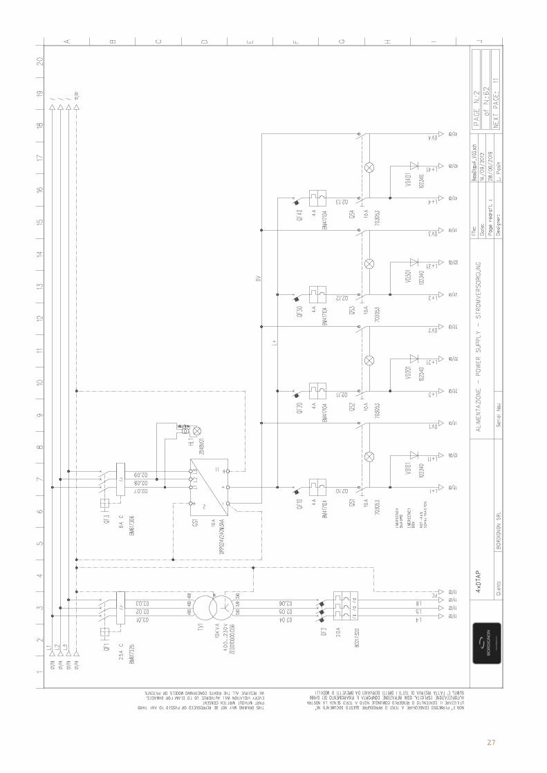
27
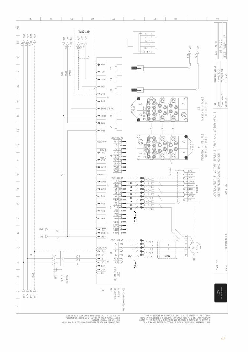
28
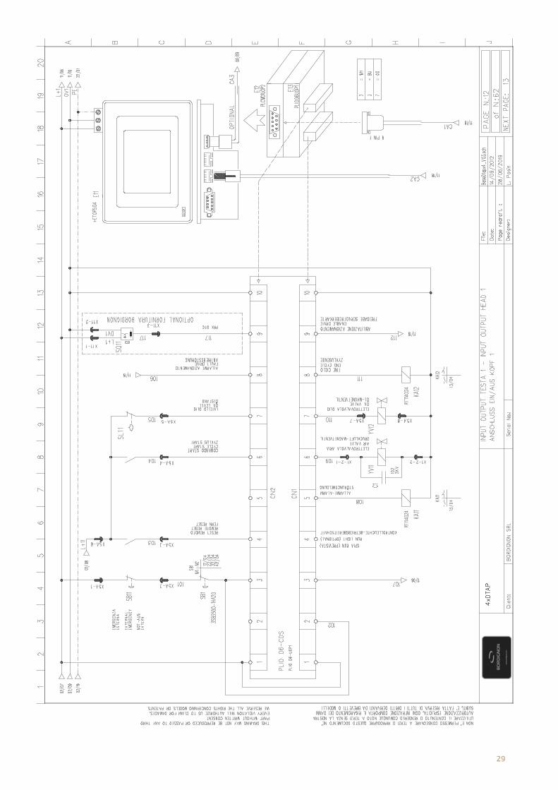
29
TMOP
Uni

30
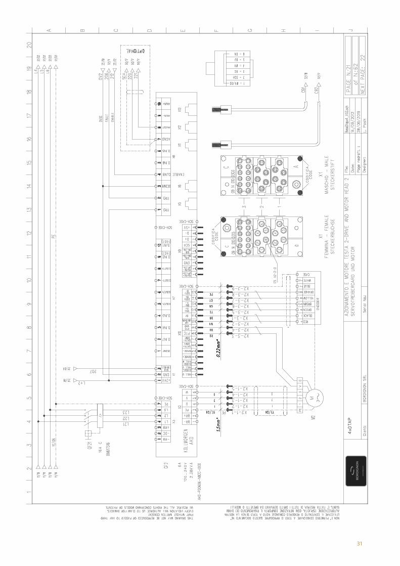
31

32
TMOP
Uni

33

34
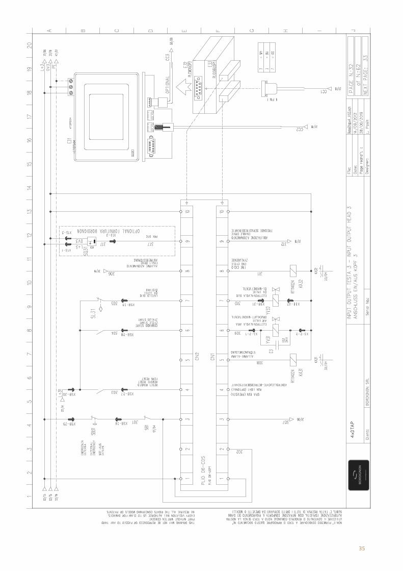
35
TMOP
Uni

36
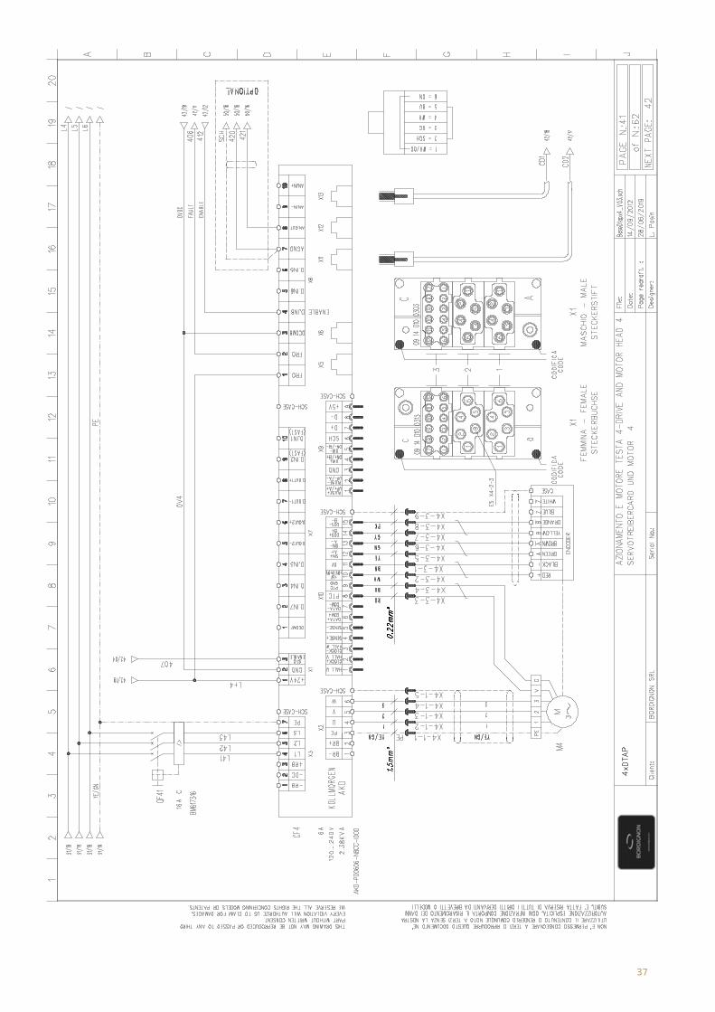
37

38
TMOP
Uni
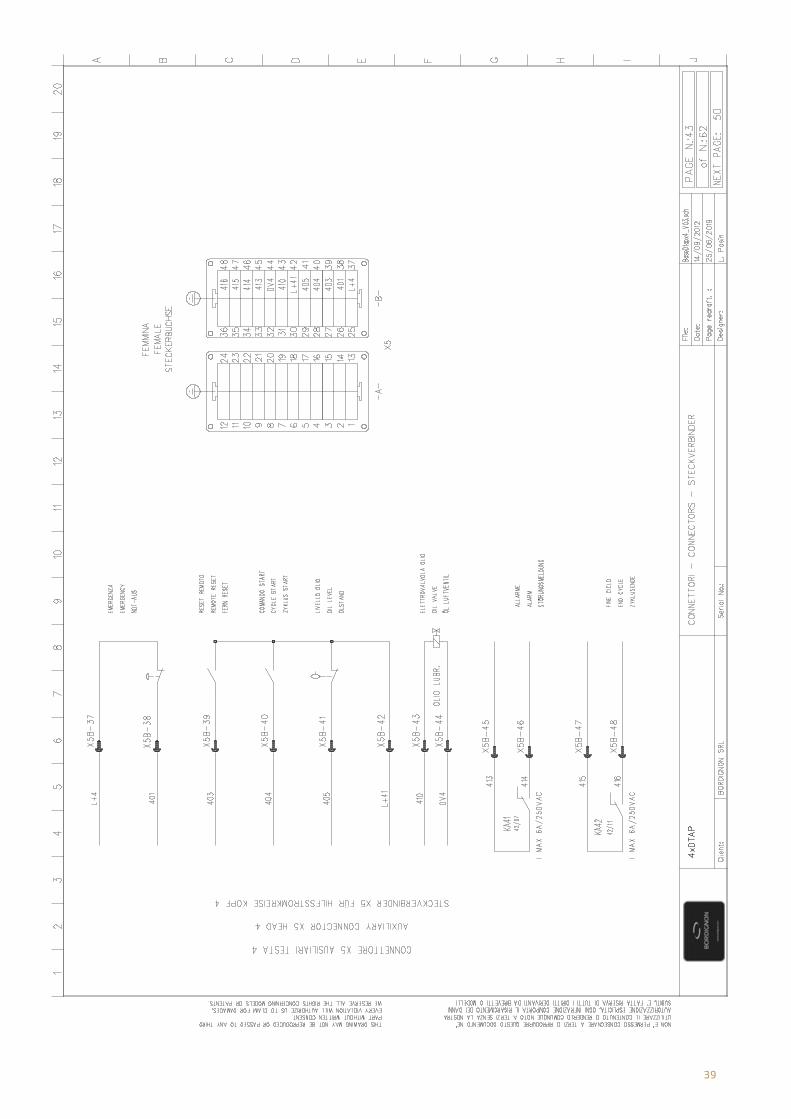
39
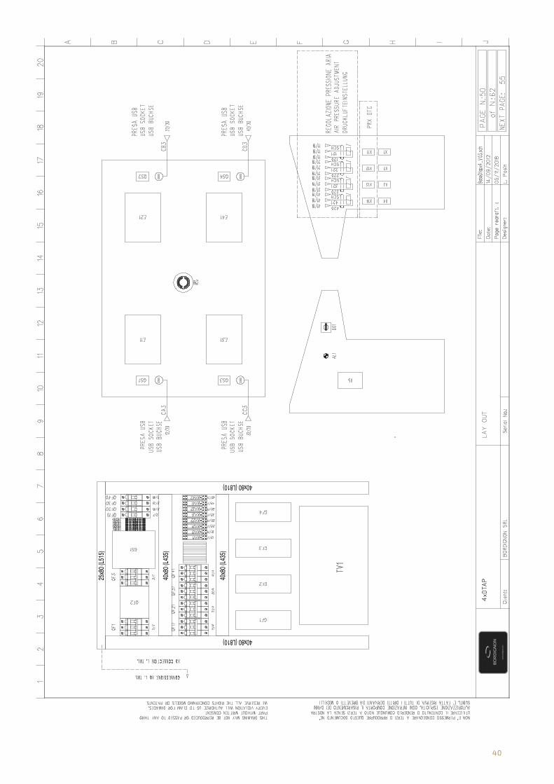
40
40x80 (L810)
40x80 (L810)
40x8
0 (L4
35)
25x8
0 (L5
15)
40x8
0 (L4
35)
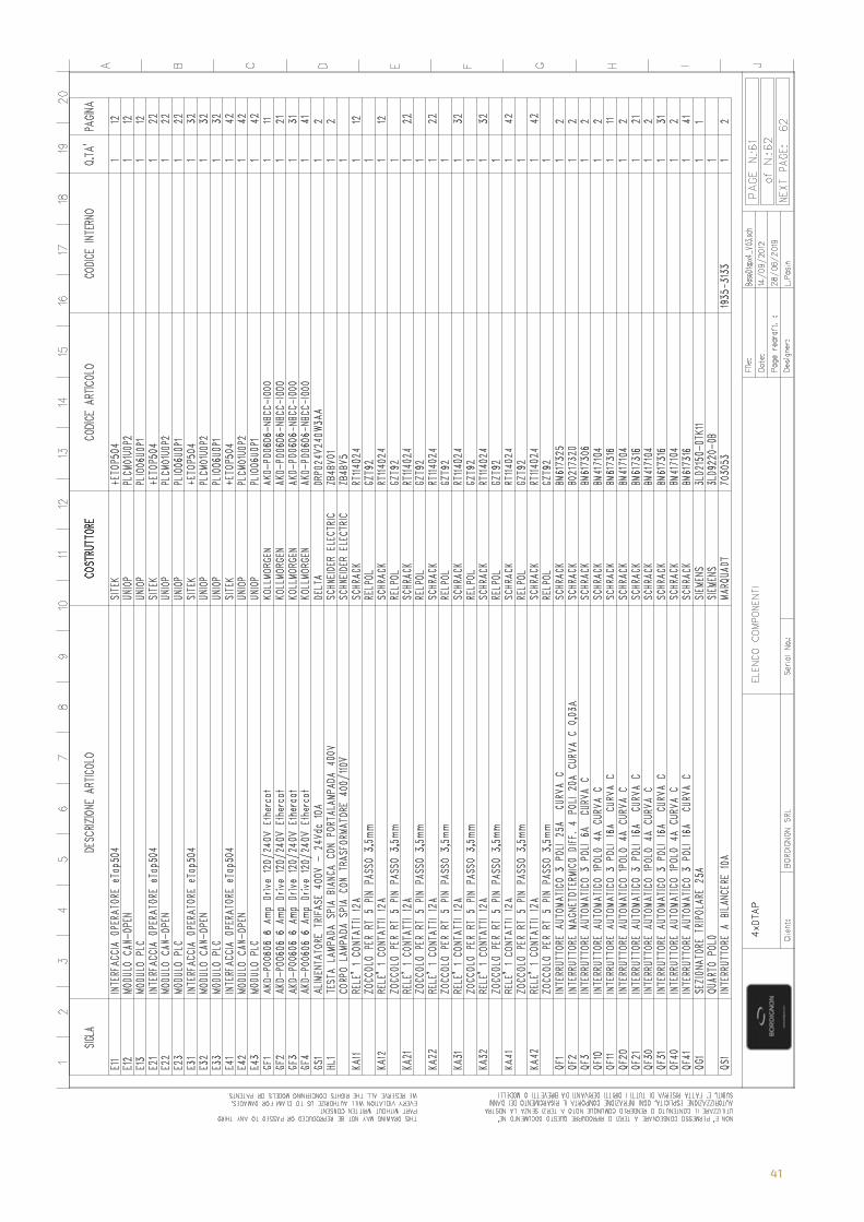
41
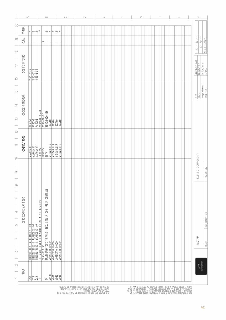
42

43
Direct Drive tapping unit with touch screen multiple control panel
User’s information

BOrDIgNON srL / COmmErCIAL OFFICEVia Volta 20 - 36028 Rossano Veneto (VI) ItalyT +39 0424 36157 - F +39 0424 [email protected]
PrODUCTION / TECHNICAL OFFICEVia Volta, 2 - 36028 Rossano Veneto (VI) ItalyT +39 0424 540311 - F +39 0424 [email protected]
Bordignon Srl reserves the right to make modifications to the
technical data of this manual, without prior notice.
www.bordignon.com


