Embed Size (px)
Citation preview

Current CONtrolled Transmit And Receive CoilElements (C2ONTAR) for Parallel Acquisitionand Parallel Excitation Techniques at High-Field MRI
E. Kirilina • A. Kuhne • T. Lindel • W. Hoffmann •
K. H. Rhein • T. Riemer • F. Seifert
Received: 7 May 2011 / Revised: 11 July 2011
� The Author(s) 2011. This article is published with open access at Springerlink.com
Abstract A novel intrinsically decoupled transmit and receive radio-frequency
coil element is presented for applications in parallel imaging and parallel excitation
techniques in high-field magnetic resonance imaging. Decoupling is achieved by a
twofold strategy: during transmission elements are driven by current sources, while
during signal reception resonant elements are switched to a high input impedance
preamplifier. To avoid B0 distortions by magnetic impurities or DC currents a
resonant transmission line is used to relocate electronic components from the
vicinity of the imaged object. The performance of a four-element array for 3 T
magnetic resonance tomograph is analyzed by means of simulation, measurements
of electromagnetic fields and bench experiments. The feasibility of parallel acqui-
sition and parallel excitation is demonstrated and compared to that of a conventional
power source-driven array of equivalent geometry. Due to their intrinsic decoupling
the current-controlled elements are ideal basic building blocks for multi-element
transmit and receive arrays of flexible geometry.
1 Introduction
Going to high and ultrahigh static magnetic fields and corresponding higher
resonance frequencies was proved to open a broad range of new fascinating
applications in magnetic resonance imaging [1, 2]. However, the construction of
E. Kirilina (&) � A. Kuhne � T. Lindel � W. Hoffmann � K. H. Rhein � F. Seifert
Physikalisch-Technische Bundesanstalt (PTB), Abbestraße 2-12, 10587 Berlin, Germany
e-mail: [email protected]
E. Kirilina
Free University of Berlin, Habelschwerdter Allee 45, 14195 Berlin, Germany
T. Riemer
University of Leipzig, Hartelstraße 16-18, 04107 Leipzig, Germany
123
Appl Magn Reson
DOI 10.1007/s00723-011-0248-y
Applied
Magnetic Resonance

high-field magnetic resonance imaging (MRI) instrumentation poses severe
technical challenges. One of the fundamental problems arises from the shortening
of the electromagnetic wavelength in high-permittivity biological tissues, leading to
a wavelength of about 27 cm for the proton resonance frequency of 125 MHz at 3 T
and to 12 cm for 297 MHz at 7 T [3]. Therefore, in high-field MRI the generation of
homogeneous B1 fields within the human torso at 3 T and even in human head at
7 T is no longer feasible with a single radio-frequency (RF) transmit coil which
makes the application of multi-element RF coil arrays a necessity [4]. By combining
spatially varying B1 profiles of single elements arranged around the imaged object in
a phased array it is possible to mitigate B1 inhomogeneity during RF excitation as
well as to improve homogeneity of sensitivity profiles during signal reception [5].
Once introduced for B1 homogenization coil arrays opened fascinating possibil-
ities for parallel acquisition [6, 7] and parallel excitation techniques [8–10]. In
parallel acquisition, the variation of sensitivity profiles of multiple receive coil
elements across the imaged object is used to partially substitute gradient encoding,
thereby reducing imaging time or increasing image resolution. In parallel excitation
techniques, the excitation across multiple coil elements with different excitation
field profiles made spatially selective pulses applicable [11]. Together with the
travelling wave approach [12] parallel excitation is the most promising way to
improve B1 homogeneity in ultra high-field MRI [13]. In addition, parallel
excitation opens the door for novel applications in the areas of volume selective
excitation for MRI spectroscopy, reduction of the field of view, perfusion imaging
[11] and mitigating susceptibility dephasing in functional MRI (fMRI) [14, 15].
Parallel MR techniques impose new requirements on RF coils and request the
development of a new generation of multi-element RF arrays [16]. In parallel
acquisition, the coil geometry determines the signal-to-noise ratio and maximum
imaging reduction factor [17]. In parallel excitation technology, the specific
absorption rate (SAR) of the spatially selective excitation pulse can be strongly
reduced via optimization of coil array geometry [13]. One potential strategy to
optimize spin excitation and signal reception is to design a coil array that allows for
the adjustment of the coil geometry to the individual subject or other application
needs. In this way, the geometry factor would be optimized and the higher B1 field
close to the coil conductor could be better utilized leading to a higher ratio of
unloaded to loaded Q-factor for each coil element.
Parallel acquisition already led to a multitude of applications in clinical scanners
where receive-only coil arrays are routinely applied for signal detection, while
excitation is performed with a single-channel body coil. To achieve the same state
of application for parallel excitation techniques the development of multi-element
local transmit and receive coils is mandatory, allowing an optimized implemen-
tation of parallel acquisition and parallel excitation in the same coil setup.
The major challenge while designing and constructing transmit and receive coil
arrays is to control the mutual electromagnetic coupling between the array elements.
Coupling may lead to constructive and destructive interferences of the transmitted
RF fields within a typical volume of excitation. Furthermore, RF power is lost due to
parasitic currents induced in the coils coupled to the excited coil element. This fact
poses severe restrictions to peak power demanding MR applications as, e.g., MR
E. Kirilina et al.
123
spectroscopy. Since coupling between the elements strongly depends on the coil
load, adaptation of the coil array to different patients requires tedious iterative
tuning and matching steps. These problems are aggravated when going to higher
fields and higher RF frequencies and may be avoided only by the design of
alternative RF coil schemes.
For receive-only coils, coupling is usually reduced by the use of preamplifiers
with high input impedance, suppressing currents induced by the neighboring
elements [4]. It is not possible to apply the direct analog of this preamplifier
decoupling to transmit arrays due to the impedance match required for maximum
power deposition efficiency.
Reactive coupling within an array coil can be compensated either inductively by
properly chosen mutual arrangement of the individual elements [13] or by placing
suitable capacitors between neighboring elements. This solution works well for a
rigid arrangement of coil elements but it is only seldom applicable if geometrically
flexible arrays are desired [18]. To compensate reactive coupling in an n-element
array externally, a n 9 n decoupling network matrix is needed [19]. Tedious
iterative readjustment of all its elements is necessary to adopt such a network to
changes in geometry or load, which strongly limits the applicability of this
approach.
Alternatively, the Cartesian feedback approach introduced by Hoult [20] for
decoupling of transmit–receive elements could be used. Here, a high level of
decoupling is achieved by feedback via pick-up coils. The major limitation of this
solution is a narrow decoupling frequency band, a severe constraint for parallel
excitation techniques, where broad-band pulses are needed for selective excitation
[21].
A promising approach to actively decouple the array elements during transmis-
sion was proposed by Kurpad et al. [22, 23]. Using voltage-controlled metal–oxide–
semiconductor field-effect transistors (MOSFETs) as current sources they managed
to gain independent control of the currents in a multi-coil array. An additional
benefit of the active decoupling is the reduced influence of sample loading on the
resonance frequency, thus eliminating the need for iterative tuning and matching
procedures for each subject.
Implementation of these current elements solved the problem of decoupling
during transmission, however, the coil elements presented in Refs. [22, 23] are not
designed for signal reception.
In this article we present a novel Current CONtrolled Transmit And Receive coil
element (C2ONTAR-coil) for parallel transmit and receive applications. Improved
decoupling in both modes was achieved by combining a current source as
introduced by Kurpad et al. [22, 23] for transmission with a specially designed
transmit–receive switch that allows for preamplifier decoupling for reception. The
intrinsically decoupled elements were combined in arrays of flexible geometry. To
evaluate the performance of the presented design in comparison with conventional
transmit–receive elements, the results of the first proof of principle comparative
study implementing parallel acquisition and parallel excitation experiments are
presented.
C2ONTAR at High-Field MRI
123

2 Methods
2.1 C2ONTAR Elements
The electric scheme of the C2ONTAR element is shown in Fig. 1a. Figure 1b shows
the RF-scheme of the C2ONTAR element without preamplifier and current sheet
antenna (CSA) element. All used components are specified in Table 1.
For clarity Fig. 1a is divided into four blocks: (i) transmission block including
RF current source and matching input network; (ii) coil block with the resonant MR
coil element and resonant transmission line; (iii) MR signal reception block
consisting of a low-input impedance preamplifier and the resonant transmission line,
and (iv) the transmit–receive switch. The construction and working principles are
described in the following.
2.1.1 Block (i)
The core unit of the transmit RF current source consists of a power MOSFET
(BLF245, Philips Semiconductors), which is, due to its nickel content, slightly
magnetic. The transistor’s operating point is controlled by two direct-current (DC)
voltages, VD (drain voltage) and VG (gate voltage), to achieve a current source-like
behavior and A-class operation mode. During transmission VD is switched on by the
transmit–receive switch and VG = 3 V is overlaid by the input RF signal fed in via
an input matching network. The output RF current of the MOSFET is controlled by
the input RF signal and VG only, thereby suppressing parasitic currents induced by
mutual electromagnetic coupling between neighboring array elements. In this way,
effective decoupling of the individual coil elements in the array is achieved by
controlling the coil’s currents during transmission. It is worthwhile noting here that,
that the amplitude of the output current of the C2ONTAR element is restricted by
the MOSFET’s half value of the maximum drain current (here 6 A). In practical
applications the RF-current amplitude has to be further reduced to stay within the
linear regime of the MOSFET.
2.1.2 Block (ii)
The RF coil element consists of a series LC resonant circuit which is tuned to the
proton resonance frequency, in our case to 125.3 MHz. Impedance of the resonant
circuit is determined by the resistive impedance of the coil load Rl when tuned to the
resonance frequency. The MR coil is connected to the circuitry by a 76-cm long
RG58 cable, which constitutes a resonant k/2 transmission line. Thereby, the
slightly magnetic RF elements and static magnetic fields generated by DC currents
of the current source are more remote from the imaged object to avoid B0-field
inhomogeneities degrading the image quality [23]. Due to the resonant properties of
the transmission line the low-input impedance of the series resonant circuit is
translated to the output of the current source and allows direct current control in the
resonant element.
E. Kirilina et al.
123

Fig. 1 Electrical scheme (a) and photograph (b) of the C2ONTAR element. The scheme is intersected infour blocks: (i) transmission block; (ii) resonant MR coil element and resonant transmission line; (iii) MRsignal reception block; and (iv) transmit–receive switch. All used components are specified in Table 1
Table 1 Specifications of RF-components used for construction of C2ONTAR elements
Component Description Value
C1, C4, C5, C6 Film dielectric trimmer 4–40 pF
C2, C8 Multilayer ceramic chip 100 nF
C3, C7 Multilayer ceramic chip 100 pF
C9 Dielectric capacitor 30 mF
L1 6 turns enameled 1.5 mm copper wire; length 12.5 mm, i.d. 5 mm 98 nH
L2 4 turns enameled 0.5 mm copper wire; length 3.5 mm, i.d. 2 mm 13.5 nH
D1, D2 PIN diode
R1 Metal film resistor 1 kX
R2 Metal film resistor 1 MX
The principal scheme and photograph of C2ONTAR elements are shown in Fig. 1
C2ONTAR at High-Field MRI
123

2.1.3 Block (iii)
To form a high-impedance preamplifier in the reception mode, a low-input
impedance preamplifier is connected to the MR coil via the k/4 transmission line
and a series resonant circuit. The input impedance of the used GaAsFET
preamplifier (Advanced Receiver Research, Burlington, CT, USA) was 10 X. The
resonant line transforms the low-input impedance of the preamplifier into the high-
input impedance according to [24]:
Z ¼ Z2line
Zin
¼ ð50 XÞ2
10 X¼ 250 X: ð1Þ
High load impedance during reception limits the current in the RF coil, thus
reducing inductive coupling between adjacent elements. In this way preamplifier
decoupling during signal reception is achieved. Here we have to note that for the
amplifier type used in this work, high impedance at the input can compromise a
noise figure and thus reduce the signal-to-noise ratio. The reception efficiency can
be further improved using a lower impedance preamplifier.
2.1.4 Block (iv)
Switching between transmission and reception is realized in the following way.
During transmission the drain DC voltage VD = 24 V of the power MOSFET is
switched on by an external trigger pulse (TTL-inp). The drain voltage adjusts the
power MOSFET to its working point, and the drain current opens the PIN diodes D1
and D2 (MA4P4006F, M/A-COM). Opening of diode D2 grounds the input of the
preamplifier via the small impedance of the capacitance C2 ? C3. In this way the
receive block is isolated during transmission of high-frequency signals. Shutdown
of diode D1 during reception isolates the input of the signal preamplifier from the
noise of the power MOSFET.
The theoretical limit of the decoupling achievable with a MOSFET-based current
source is determined by the MOSFET’s parasitic output capacitance Cp [22]. As was
shown by Kurpad et al. [22, 23], decoupling is determined by the relation:
K ¼ �20 log10
R1ffiffiffiffiffiffiffiffiffiffiffiffiffiffiffiffiffiffiffiffiffiffiffiffiffiffiffiffi
ðxCpÞ�2 þ R21
q : ð2Þ
With Cp of 75 pF and coil load resistance Rl of 2 X, we expect an additional
decoupling of 18.6 dB at 125.3 MHz for the MOSFETs used in this work.
2.2 Four-Element Head Array
We constructed two geometrically identical four-element CSA arrays [25] for
human head imaging at 3 T, to evaluate the performance of the C2ONTAR elements
in state-of-the-art imaging techniques and to compare them with conventional
power source-driven elements. Parallel acquisition and parallel excitation experi-
ments were performed with both setups and used for comparison. The first array
E. Kirilina et al.
123

consists of four C2ONTAR–CSA elements, while the elements of the second array
were matched to a 50-X input impedance and driven by conventional power
sources. Schematic views of C2ONTAR and power source-driven CSAs together
with their electrical schemes are given in Fig. 2a and b, respectively.
In both cases the inductive loop of the CSA is formed by four plates of copper-
clad base material with the size of 30 mm 9 80 mm 9 160 mm. The thickness of
the copper layer (9 lm) was chosen to minimize eddy currents induced in the CSA
by switching gradients during the MRI experiment.
The C2ONTAR–CSA element has three 5-mm gaps on the upper plate of the
resonant circuit (see Fig. 2a). Distributed fixed and tuneable capacitors were placed
into both outer gaps, providing adjustable capacity in a range from 19.5 to 28.5 pF.
The element represents a series resonant circuit at 125.3 MHz. The third gap is used
to connect the output of the resonance transmission line RF-in. Tuning of the
resonant element to the proton resonance frequency of x = 2p�(125.319 MHz) was
achieved by adjusting the tuning capacitor to Ct = 1/(x2L), where L is the
inductance of the element. We would like to stress here that, unlike conventional
coils, for C2ONTAR elements the optimal value for the tuning capacitor does not
depend on the element load Rl.
For the power source-driven CSA shown in Fig. 2b, the upper part of the sheet
was intersected by a 5-mm gap in which a variable capacitor Ct was placed for
tuning. The element represents a resonant circuit. It was inductively coupled to the
50-X transmission line by an inductive coupling loop inside of the rectangular
block. Critical matching to the impedance of the transmission line was realized with
the help of the tuning capacitor Ct and matching capacitor Cm. First, by changing Ct,
the real part of the input impedance of the port AB was adjusted to 50-X [24]
Fig. 2 Top Schematic views of C2ONTAR–CSA (a) and power source-driven CSAs (b). BottomElectrical schematics of C2ONTAR–CSA (a) and power source-driven CSAs (b)
C2ONTAR at High-Field MRI
123

ReðZABÞ ¼x2L2
mRl
R2l þ xL� 1
xCt
� �2¼ Z0 ¼: 50 X; ð3Þ
where Lm is the mutual inductance of the coupling loop and resonance circuit. As
the second step, the imaginary part of the impedance of port AB, Im(ZAB), was
compensated by adjusting the trimmer capacitance Cm
ImðZABÞ ¼ xLm �Z0
Rl
xL� 1
xCt
� �
¼:1
xCm
: ð4Þ
It becomes apparent from Eqs. (3) and (4) that the values of the tuning and
matching capacitors have to be changed depending of the load Rl. This implies a
readjustment of the power source-driven CSA for every experiment or subject. For
an electromagnetically coupled multi-element coil array, Rl also depends on the
tuning of the neighboring coils. This fact makes the application of the aforemen-
tioned iterative tuning and matching procedure mandatory to adjust the element to
the resonance frequency and to avoid power reflection, which constitutes a major
drawback of a conventionally driven coil array.
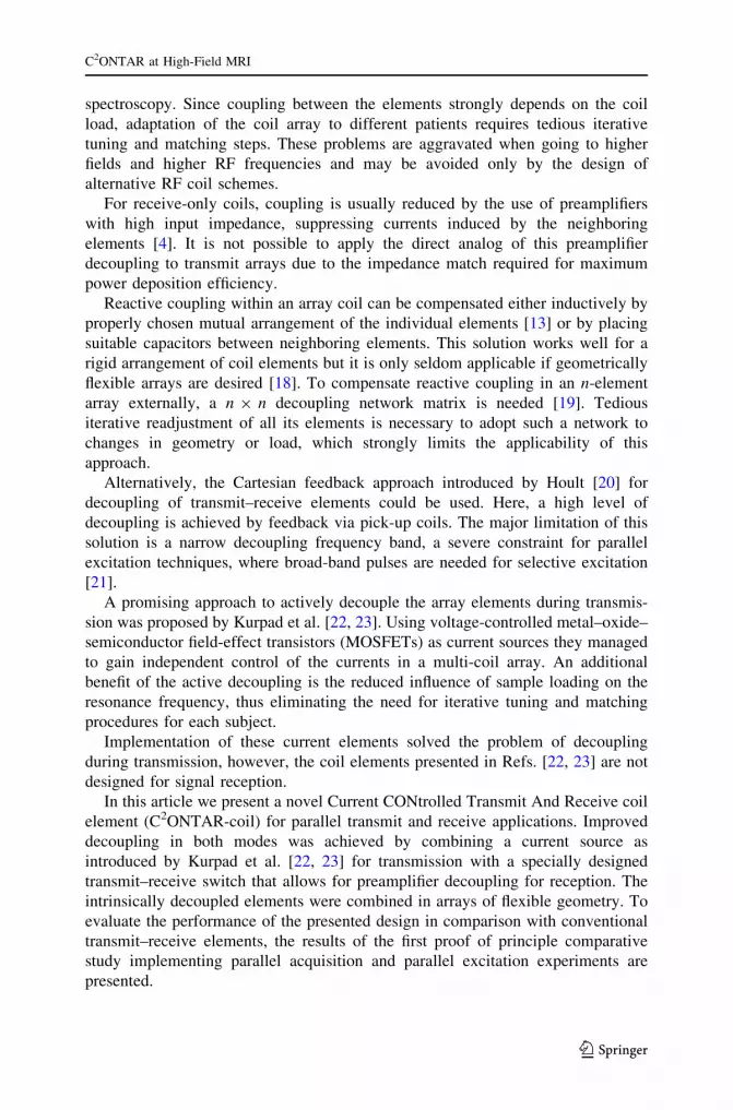
Four elements of each kind were combined to the head array shown in Fig. 3,
each with its long axis parallel to the magnetic field direction.
All phantom experiments were performed with a head-sized cylindrical agarose
gel phantom (inner diameter (i.d.), 19 cm; length, 19 cm) as described in Ref. [25].
The electrical properties and relaxation times of the phantom gel were roughly that
of brain tissue (e = 76, r = 0.33 S m-1).
2.3 Finite-difference time-domain (FDTD) Simulations
We performed electromagnetic field simulations for all considered coil configura-
tions to understand the influence of RF driving conditions on measured B1 field
distributions: (1) a single CSA, (2) the four-element CSA array, (3) a single
C2ONTAR–CSA element, and (4) the four-element C2ONTAR–CSA array. To this
end numerical simulations were performed using the XFDTD 6.4 software
(REMCOM, State College, PA, USA). The models were implemented on a 2-mm
grid consisting of 200 9 200 9 200 cells together with seven perfectly matched
layers to achieve free space behavior. The CSAs and C2ONTAR–CSAs were
assumed to consist of planar sheets of perfectly conducting material. All capacitors
were simulated by dielectric bars filling the 5-mm gaps on the upper plate of the
resonant element. The dielectric constant of the bars was adjusted to tune the coil
elements to 125 MHz. The load was modelled as a homogenous cylinder
(D = L = 200 mm) with er = 76 and r = 0.33 S m-1, omitting the small influ-
ence of the Perspex walls (er & 2) on the dielectric properties of the phantom. The
distance from the surface of the load to the bottom face of each element was set to
20 mm in general. For the single C2ONTAR–CSA simulation additional runs were
performed for distances varying from 6 to 30 mm. RF excitation of the coil
elements was accomplished either by driving a C2ONTAR–CSA directly by a
current source or using a coupling loop inside the CSAs (Fig. 2b). In the later case
E. Kirilina et al.
123
lumped element complex valued resistors at the feeding points were iteratively
adjusted to achieve the matching condition, i.e., zero reflection at all feeding ports
(power matched mode of operation).
2.4 Bench Experiments
In the first step, the conventionally power source-driven CSA array was compared to
the C2ONTAR–CSA array of identical geometry in bench experiments. The
linearity of RF-voltage to current conversion was measured in a pick-up coil
experiment.
The coupling of the CSA elements in transmit and receive mode was directly
determined via the measurement of the two-port S parameters. To measure the
coupling between two C2ONTAR–CSA elements we used the procedure described
in Ref. [20]. Broadband pick-up loops were placed in fixed positions inside of the
C2ONTAR–CSA elements. Voltages induced in the pick-up coils during the
transition of each RF-element were measured by an oscilloscope. Since voltages
induced in the pick-up coils are proportional to the currents of RF elements, they
were used to estimate the decoupling matrix of the C2ONTAR–CSA array.
2.5 B1 Measurements
The excitation profile of RF elements during transmission and sensitivity profiles
during reception were determined by the circularly polarized components B1? and
B1- of the B1 field, respectively [26]. Relative B1
- maps of each element were
Fig. 3 Four-elementC2ONTAR–CSA array with ahead-sized cylinder gel phantom
C2ONTAR at High-Field MRI
123

obtained by dividing the images obtained with single element by the sum-of-square
image of all elements [11]. In this way only relative B1- maps can be measured. In
addition, we measured the absolute values of B1? by means of a preparation pulse
method [25]. The fast gradient echo images of an axial slice in a cylinder phantom
were acquired after an inversion pulse of varying power. By fitting the dependence
of the signal intensity onto the amplitude of the inversion pulse, local B1? values for
each power level were determined.
2.6 Parallel Acquisition
Performances of C2ONTAR–CSA array in parallel acquisition were evaluated by
performing in vivo sensitivity encoding (SENSE) experiments on a human subject.
These experiments were performed in compliance with the institutional
guidelines for those studies. We applied a two-dimensional (2-D) fast low-angle
shot (FLASH) (TE/TR = 11.2 ms/100 ms) sequence with a resolution of 256 9 256
and a field of view of 256 mm 9 256 mm. The ‘worst case’ local SAR for the
FLASH sequence applied and the cylindrical C2ONTAR–CSA array was estimated
to be 0.5 W kg-1 which is well below the limit of 20 W kg-1 [25, 27]. The
thickness of an axial slice was 10 mm. Based on sensitivity maps and noise
correlation matrices measured prior to the experiments, the g-factor was calculated
by applying the relation [6]
gðrÞ ¼ffiffiffiffiffiffiffiffiffiffiffiffiffiffiffiffiffiffiffiffiffiffiffiffiffiffiffiffiffiffiffiffiffiffiffiffiffiffiffiffiffiffiffiffiffiffiffiffiffiffiffi
SHW�1S� ��1
r;r0ðSHW�1SÞr;r0
q
; ð5Þ
where S is the coil sensitivity matrix, W is the noise correlation matrix, r0 is the
coordinate of all aliased points.
2.7 Parallel Excitation
C2ONTAR–CSA array performance in parallel excitation was evaluated by an
extension of the transmit SENSE method introduced by Katscher et al. [8].
In our experiments we used a 16-turn spiral excitation k-space trajectory during
excitation with a slew rate of 91.1 Tm-1 s-1. After selective excitation, the 3-D fast-
gradient echo images (TE/TR = 7 ms/100 ms) were acquired to sample the spatially
selective excitation patterns. The size of the target pattern was 32 9 32 voxels with a
field of excitation of 256 mm 9 256 mm, Nt = 16 9 64/R, where R is the reduction
factor. Experiments with a reduction factor of 2, 3.2 and 4 were performed. The
lengths of the excitation pulses were 6.36, 3.98, and 3.178 ms, respectively.
3 Results
3.1 FDTD Simulation
The inductance L of the resonant CSA element (see Fig. 2) was calculated from the
imaginary part of the impedance on the input port obtained from FDTD simulation
E. Kirilina et al.
123

of the CSA element with capacitors removed. Thus, the value of capacitance Ct can
be estimated from the resonance condition (Ct = 1/(x2L)) to be 25 pF, which is in a
good agreement with the value of tuneable capacitors of the C2ONTAR element.
The imaginary part of the impedance obtained from the simulations was not
dependent on the load, decreasing only 0.5% with the change of the distance to the
phantom from 30 to 6 mm. The real part of the impedance representing the induced
coil losses critically depends on the distance to the phantom. It changes by 320%
from 0.15 X at 30 mm to 0.47 X at 6 mm as results from the FDTD simulations.
For the C2ONTAR CSA element driven by 1 A amplitude of RF current and the
distance between the phantom and RF current of 20 mm, the total power absorbed
in the phantom was calculated to be 0.1091 W.
When comparing the simulated B1 distributions for a single C2ONTAR–CSA
element with the B1 distributions for the same element within the four-channel
C2ONTAR–CSA array, as expected, no significant differences can be observed.
Hence, only field distributions for the latter case are displayed in Fig. 4.
3.2 Bench Experiments
The relation of loaded to unloaded Q was estimated to be 2.5 for a single
conventional CSA element.
The coupling matrices of the four-element array of power source-driven CSA and
C2ONTAR–CSA were measured to be:
KCSA ¼ �
0 10 15 11
12 0 11 15
15 11 0 10
12 16 11 0
2
6
6
4
3
7
7
5
dB; KTrCONTAR
¼ �
0 24:5 30 25
25:5 0 25 32
30 25 0 26
25 32 25 0
2
6
6
4
3
7
7
5
dB; KRsCONTAR ¼ �
0 25 34 25
26 0 26:5 34
30 25 0 25
25 34 26 0
2
6
6
4
3
7
7
5
dB;
where KCSA is the coupling matrix of the power source-driven CSA array, KTrCONTAR
and KRsCONTAR are the coupling matrices of the C2ONTAR–CSA array during
transmission and reception, respectively. The coupling values are given in dB and
the numeration of elements is shown in Fig. 3.
Due to the symmetry of the coil array, the matrix K has two independent values
corresponding to coupling to the nearest neighbor and to the opposite element. The
coupling matrices for transmission and reception are equivalent for the power
source-driven CSA since the 50-X input impedance of the transmitter is equal to the
input impedance of the receiver. The matrices depict couplings of the four
C2ONTAR matrix elements in transmission (KTrCONTAR) and reception (KRs
CONTAR)
modes. It becomes apparent that in comparison to the power source-driven CSA
array the C2ONTAR elements show in average additional decoupling of 14 dB in
transmission and 15 dB in reception, in reasonable agreement with our estimation
(Eq. (2)).
C2ONTAR at High-Field MRI
123
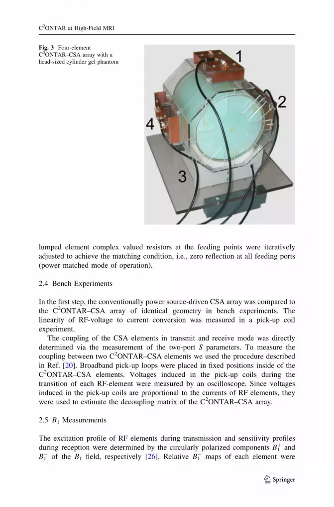
3.3 B1 Sensitivity Maps
Color-coded maps of single-element B1? and B1
- magnitudes obtained from the
FDTD simulations and experimentally measured for a central axial slice of the
head-sized cylinder phantom are shown in Fig. 4. Figure 4 shows maps for a single
uncoupled CSA element (row a), for the single element of four CSA element array
of Fig. 3 (row b) and for the single element of four C2ONTAR element array (row
c). The results of the FDTD simulation are given in the first column, the
experimentally measured absolute B1? maps in the second column, the experimen-
tally obtained relative B1- maps in the third column of Fig. 4.
The simulated and experimentally measured B1? maps of current-controlled
elements (Fig. 4b, c) are normalized to the RF current amplitude of 1 A on the input
port of the element. According to the FDTD simulation of single current-controlled
element this current amplitude corresponds to the absorbed power of
Fig. 4 Simulated and experimentally measured absolute B1? and relative B1
- field magnitude maps inan axial slice of a head-sized cylinder phantom: a B1 maps of a single power-matched CSA elementarranged at the position corresponding to element 1 in Fig. 3; b B1 maps of a single element of the four-element CSA array (Fig. 3) with power-matched elements; c B1 maps of a single element of thecomparable four-element C2ONTAR–CSA array. The absolute B1
? maps of current-controlled elementsare normalized to the amplitude of the RF current of 1 A on the input port of the element. The B1
? mapsof the power source-driven elements correspond to the absorbed power of P = 0.1091 W
E. Kirilina et al.
123

P = 0.1091 W. Therefore, simulated and experimentally measured B1? maps for
power source-driven elements are normalized to the absorbed power of
P = 0.1091 W, to allow a quantitative comparison with current-controlled
elements. Since only relative B1- maps were measured, they are presented in
arbitrary units.
Figure 4a shows simulated and experimental B1? and B1
- maps of a single power
source-driven CSA. The position of the single CSA element corresponds to the
position of element 1 in Fig. 3. The B1 amplitude decreases with increasing distance
from the element. Influenced by RF eddy currents in the lossy phantom material, B1?
and B1- profiles are asymmetrical and not identical to each other. In accordance to
the reciprocity theorem, B1? and B1
- can be transformed into each another by
inverting the direction of the B0 field [25]. Good agreement was obtained between
simulation and experimentally measured B1? maps.
Figure 4b shows the simulated and experimental B1? and B1
- maps of the four-
element power source-driven CSA array, when only element #1 was used for
transmission. The B1?,- maps for the other elements may be derived by 90�, 180�
and 270� rotations around B0, respectively. Due to electromagnetic coupling
between the elements the B1? and B1
- maps of the power source-driven CSA in the
array differ strongly from those obtained with the isolated CSA element (Fig. 4a).
This difference may be rationalized by the fact that while CSA #1 is transmitting,
secondary currents are induced in CSA #2, #3 and #4 resulting in additional B1
fields. Destructive interference of B1 fields from different elements then leads to
zero B1?,- amplitude in several areas—so-called transmission and reception holes.
Figure 4c shows the analog results for the C2ONTAR–CSA array. These B1? and
B1- maps differ drastically from those of the power-driven CSA array in Fig. 4b;
they rather resemble the field maps of the single uncoupled CSA element, which
clearly indicates the diminished coupling between the elements during transmission
and reception.
The absolute B1? field amplitude in the center of the cylinder phantom, generated
by all four C2ONTAR–CSAs driven in the circular polarized (CP) mode with the
maximum obtainable RF current of 3 A, was measured to be 2 lT. This value is in
reasonable agreement with the simulation result of 3 lT for the same mode of
operation, taking into account RF losses of the used components.
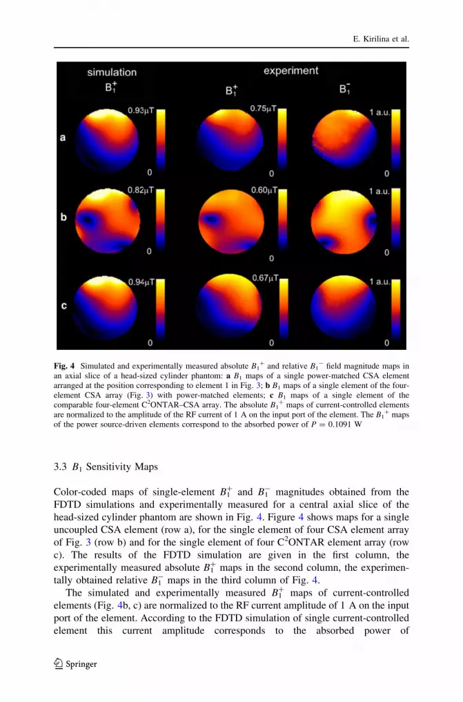
3.4 Parallel Reception
Figure 5 shows parallel acquisition results obtained with the four-element
C2ONTAR–CSA array. In the top line SENSE-FLASH images of the human head
are depicted, recorded with acceleration factors of two, three and four. The bottom
line depicts g-factor maps for these reduction factors. The array shows good image
quality and reasonable g-factor values as long as the reduction factor is less than the
number of elements, which is a fundamental limitation for parallel acquisition [16].
This experiment demonstrates the feasibility of the parallel acquisition with
inherently decoupled C2ONTAR element arrays.
C2ONTAR at High-Field MRI
123
3.5 Parallel Excitation
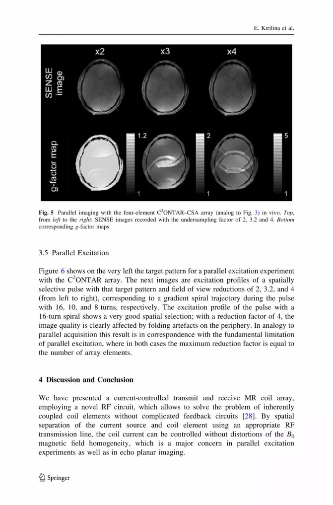
Figure 6 shows on the very left the target pattern for a parallel excitation experiment
with the C2ONTAR array. The next images are excitation profiles of a spatially
selective pulse with that target pattern and field of view reductions of 2, 3.2, and 4
(from left to right), corresponding to a gradient spiral trajectory during the pulse
with 16, 10, and 8 turns, respectively. The excitation profile of the pulse with a
16-turn spiral shows a very good spatial selection; with a reduction factor of 4, the
image quality is clearly affected by folding artefacts on the periphery. In analogy to
parallel acquisition this result is in correspondence with the fundamental limitation
of parallel excitation, where in both cases the maximum reduction factor is equal to
the number of array elements.
4 Discussion and Conclusion
We have presented a current-controlled transmit and receive MR coil array,
employing a novel RF circuit, which allows to solve the problem of inherently
coupled coil elements without complicated feedback circuits [28]. By spatial
separation of the current source and coil element using an appropriate RF
transmission line, the coil current can be controlled without distortions of the B0
magnetic field homogeneity, which is a major concern in parallel excitation
experiments as well as in echo planar imaging.
Fig. 5 Parallel imaging with the four-element C2ONTAR–CSA array (analog to Fig. 3) in vivo. Top,from left to the right: SENSE images recorded with the undersampling factor of 2, 3.2 and 4. Bottomcorresponding g-factor maps
E. Kirilina et al.
123

Since the presented implementation of C2ONTAR is a proof of the principle
only, we will discuss only a few limitation of the concept. One technical limitation
of C2ONTAR elements is the fact that the RF current in a single element is limited
to half the maximum drain current of the power MOSFET. For our particular
transistor type, this limit was 3 A resulting in a maximum achievable B1? field
amplitude of 2 lT in the center of the head-sized phantom. A possible way to
increase this maximum B1? amplitude would be the use of push–pull current sources
[23, 29] together with high DC voltages. The preferred alternative, however, to
partly overcome this limitation is to increase the number of C2ONTAR elements in
the coil array. In this way, the maximum B1, which is the superposition of B1 fields
of many elements, can be increased by keeping the maximum RF current in each
element the same. Due to their intrinsic properties C2ONTAR elements are
particularly suitable for this multi-element array applications, since no manual coil
decoupling is needed. Thus, the major challenge in the construction of multi-coil
transmit–receive arrays is solved this way. Additional amplification of the RF input
signal in the C2ONTAR element makes them suitable to be used in low-cost
transmit channels based on digital RF pulse generators [30], thus completely
avoiding the need of expensive RF-power amplifiers.
In general, decoupling of RF array elements is not a necessary condition for
performing parallel excitation or parallel acquisition. The performance of an array
in parallel acquisition and parallel excitation is solely determined by the array
geometry and the properties of the imaged object, and cannot be changed by
element decoupling [31]. However, internal decoupling opens the opportunity to
combine C2ONTAR elements in flexible adjustable arrays avoiding time-consuming
iterative tuning, matching and decoupling procedures. This allows increased
sensitivity and improved performance of the parallel acquisition and parallel
excitation methods by directly optimizing the array to the size and shape of every
subject, every imaged region or even to particular excitation target patterns.
One useful characteristic property of the C2ONTAR elements in comparison with
power source-driven elements is the weak dependence of the B1 amplitude on coil
loading. For the conventional power source-driven element in the case of perfect
matching, all incoming RF power is absorbed by the load. This means that for a
higher loading factor, lower B1 amplitudes are achieved at the same input power.
Fig. 6 Selective excitation in transmit SENSE experiment with the four-element C2ONTAR–CSA array(comparable to Fig. 3) in an axial slice of the cylinder gel phantom. From left to the right: target pattern,selective excitation with 16, 10 and 8 turns spiral gradient trajectory
C2ONTAR at High-Field MRI
123

In contrast to conventional coil arrays, the RF current for C2ONTAR elements is
directly controlled by the input signals. Consequently, the B1 fields are hardly
affected by the loading factor. The remaining influence of the load’s dielectric
losses on the B1 field due to RF eddy currents is significantly weaker than for power
source-driven RF elements. Due to this fact the B1 fields and consequently RF pulse
flip angles generated in C2ONTAR elements are robust against movements or
changes in the imaged object’s size or conductivity. This valuable property may
lead to improved image quality in applications like cardiac imaging where the B1
profiles have to be stable against respiratory or cardiac motion. In addition, for a
given distribution of e and r the SAR for C2ONTAR is determined by the desired B1
distributions only, simplifying SAR management considerably.
The experiments described above demonstrate that C2ONTAR elements can be
successfully used for parallel acquisition and parallel excitation and may for certain
MRI applications substitute conventional power source-driven transmit and receive
elements.
Acknowledgments We kindly thank the German Federal Ministry of Education (BMBF) for funding
grants 01EZ0411 and 01EZ0501 received within the ‘Innovative Medical Devices Competition-2004’.
E. K. thanks German Scientific Society for financial support in the frame of Excellence Academy Medical
Techniques Deutschland KI 1337/1-1. We thank Eela Vanee Pathmanathan for her assistance during the
measurements, Alfred Walter and Stefan Hetzer for stimulating discussions on decoupling strategies.
Open Access This article is distributed under the terms of the Creative Commons Attribution Non-
commercial License which permits any noncommercial use, distribution, and reproduction in any med-
ium, provided the original author(s) and source are credited.
References
1. E. Yacoub, N. Harel, K. Ugurbil, Proc. Natl. Acad. Sci. USA 105, 10607–10612 (2008)
2. K. Ugurbil, G. Adriany, P. Andersen, W. Chen, M. Garwood, R. Gruetter, P.G. Henry, S.G. Kim, H.
Lieu, I. Tkac, T. Vaughan, P.F. Van de Moortele, E. Yacoub, X.H. Zhu, Magn. Reson. Imaging 21,
1263–1281 (2003)
3. S. Gabriel, R.W. Lau, C. Gabriel, Phys. Med. Biol. 41, 2271–2293 (1996)
4. P.B. Roemer, W.A. Edelstein, C.E. Hayes, S.P. Souza, O.M. Mueller, Magn. Reson. Med. 16,
192–225 (1990)
5. G.J. Metzger, C. Snyder, C. Akgun, T. Vaughan, K. Ugurbil, P.F. Van de Moortele, Magn. Reson.
Med. 59, 396–409 (2008)
6. K.P. Pruessmann, M. Weiger, M.B. Scheidegger, P. Boesiger, Magn. Reson. Med. 42, 952–962
(1999)
7. M. Blaimer, F. Breuer, M. Mueller, R.M. Heidemann, M.A. Griswold, P.M. Jakob, Top. Magn.
Reson. Imaging 15, 223–236 (2004)
8. U. Katscher, P. Bornert, C. Leussler, J.S. van den Brink, Magn. Reson. Med. 49, 144–150 (2003)
9. Y.D. Zhu, Magn. Reson. Med. 51, 775–784 (2004)
10. W. Grissom, C.Y. Yip, Z.H. Zhang, V.A. Stenger, J.A. Fessler, D.C. Noll, Magn. Reson. Med. 56,
620–629 (2006)
11. P. Ullmann, S. Junge, M. Wick, F. Seifert, W. Ruhm, J. Hennig, Magn. Reson. Med. 54, 994–1001
(2005)
12. D.O. Brunner, N. De Zanche, J. Frohlich, J. Paska, K.P. Pruessmann, Nature 457, 994–998 (2009)
13. G.C. Wiggins, C. Triantafyllou, A. Potthast, A. Reykowski, M. Nittka, L.L. Wald, Magn. Reson.
Med. 56, 216–223 (2006)
E. Kirilina et al.
123

14. V.A. Stenger, F.E. Boada, D.C. Noll, Magn. Reson. Med. 44, 525–531 (2000)
15. A. Deng, C. Yang, V. Alagappan, L. Wald, V.A. Stenger, in Proceedings of the 17th Annual Meetingof ISMRM (Honolulu, Hawaii, 2009), p. 5
16. G. Adriany, P.F. Van de Moortele, F. Wiesinger, S. Moeller, J.P. Strupp, P. Andersen, C. Snyder,
X.L. Zhang, W. Chen, K.P. Pruessmann, P. Boesiger, T. Vaughan, K. Ugurbil, Magn. Reson. Med.
53, 434–445 (2005)
17. F. Wiesinger, P. Boesiger, K.P. Pruessmann, Magn. Reson. Med. 52, 376–390 (2004)
18. G. Adriany, P.F.V. De Moortele, J. Ritter, S. Moeller, E.J. Auerbach, C. Akgun, C.J. Snyder,
T. Vaughan, K. Ugurbill, Magn. Reson. Med. 59, 590–597 (2008)
19. R.F. Lee, R.O. Giaquinto, C.J. Hardy, Magn. Reson. Med. 48, 203–213 (2002)
20. D.I. Hoult, G. Kolansky, D. Kripiakevich, S.B. King, J. Magn. Reson. 171, 64–70 (2004)
21. M.G. Zanchi, J.M. Pauly, G.C. Scott, IEEE Trans. Microwave Theory Tech. 58, 1297–1308 (2010)
22. K.N. Kurpad, S.M. Wright, E.B. Boskamp, Concepts Magn. Reson. B: Magn. Reson. Eng. 29, 75–83
(2006)
23. W. Lee, E. Boskamp, T. Grist, K. Kurpad, Magn. Reson. Med. 62, 218–228 (2009)
24. J. Mispelter, M. Lupu, A. Briguet, NMR Probeheads for Biophysical and Biomedical Experiments:Theoretical Principles and Practical Guidelines (Imperial College Press, London, 2006)
25. F. Seifert, G. Wuebbeler, S. Junge, B. Ittermann, H. Rinneberg, J. Magn. Reson. Imaging 26,
1315–1321 (2007)
26. D.I. Hoult, Concepts Magn. Reson. 12, 173–187 (2000)
27. International Electrotechnical Commission. Medical electrical equipment. Part 2–33: particular
requirements for the safety of magnetic resonance equipment for medical diagnosis., Ed. 2.1, IEC
60601-2-33, Geneva, 2006
28. F. Seifert, E. Kirilina, T. Riemer, US Patent, 20100166279, USPTO, 2011
29. N. Gudino, J.A. Heilman, M.J. Riffe, C.A. Flask, M.A. Griswold, in Proceedings of the 17th AnnualMeeting of ISMRM (Honolulu, Hawaii, 2009), p. 397
30. A. Kuehne, W. Hoffmann, F. Seifert, in Proceedings of the 17th Annual Meeting of ISMRM(Honolulu, Hawaii, 2009), p. 3017
31. M.A. Ohliger, P. Ledden, C.A. McKenzie, D.K. Sodickson, Magn. Reson. Med. 52, 628–639 (2004)
C2ONTAR at High-Field MRI
123


