Embed Size (px)
Citation preview

Corrosion and Wear Studies of Cr3C2NiCr-HVOF Coatings Sprayed on AA7050 T7
Under CoolingM. Magnani, P.H. Suegama, N. Espallargas, C.S. Fugivara, S. Dosta, J.M. Guilemany, and A.V. Benedetti
(Submitted September 10, 2008; in revised form January 9, 2009)
In this work, cermet coatings were prepared by high-velocity oxygen-fuel (HVOF) technique using aDiamalloy 3007 powder. The influence of the spray parameters on corrosion, friction, and abrasivewear resistance was studied. The samples were obtained using the standard conditions (253 L/min ofoxygen and 375 L/min of compressed air), higher oxygen flux (341 L/min), and higher carrier gas flux(500 L/min). The coatings were characterized using scanning electron microscopy (SEM), and x-raydiffraction (XRD). X-ray diffraction and SEM studies showed well-bounded coating/substrate interface,pores, metallic matrix, chromium oxides, carbides, and carbides dissolution into the matrix. In com-parison with the standard condition, the sample prepared using higher oxygen flux showed the highestcarbide dissolution because of the high temperature achieved in the spray process. When the carrier gasflux was increased, the sample showed denser structure because of the higher particle velocity. Thefriction and abrasive wear resistance of the coatings were studied using rubber wheel and ball-on-disktests. All samples showed similar sliding and abrasive behavior, and all of them showed better perfor-mance than the aluminum alloy. The electrochemical behavior was evaluated using open-circuit potential(EOC) measurements, electrochemical impedance spectroscopy (EIS), and potentiodynamic polarizationcurves. The coating prepared with higher carrier gas flux showed the highest corrosion resistance in 3.5%NaCl solution and probably no pitting attack to the substrate occurred even after around 26 h of test.Tests performed for longer immersion times showed that the total impedance values significantlydecreased (6 and 4 times) for samples sprayed using standard and higher oxygen flux, and no greatchange for sample sprayed using higher carrier gas flux was observed. The last sample presents acorrosion resistance around 200 times higher than the others.
Keywords aluminum alloy, corrosion, EIS, HVOF, sprayingparameters, wear
1. Introduction
Aluminum alloys of 7xxx series (Al-Zn-Mg-Cu) havelow hardness, poor tribological properties, and low cor-rosion resistance in aggressive medium, exhibit someresistance to stress-corrosion cracking, and, when in con-tact motion with other alloys, aluminum suffers fromscoring, adhesive wear, plastic deformation, and severemetallic sliding and abrasion (Ref 1-4).
Different processes were used to increase the corrosionresistance of the aluminum alloy, maintaining or even
increasing the mechanical properties: heat treatments(Ref 5, 6), anodizing coatings (Ref 7, 8), deposition ofmetal-matrix composite by plasma transferred arc (Ref 9),physical vapor deposition (PVD) (Ref 10, 11), duplextreatment (Ref 12, 13), ion beam (Ref 14), hard chromiumelectroplating (Ref 15), and thermal spray processes(Ref 14, 16-21).
Among the thermal spray techniques, the high-velocityoxygen fuel (HVOF) is one of those used most often toreplace hard chromium plating (Ref 22, 23), becausecoatings with low porosity, high density, excellent adhe-sive strength (Ref 23, 24), good tribological properties(Ref 20), and higher corrosion resistance when comparedwith other spraying technologies (Ref 25-27) can be pro-duced. In the HVOF process, a suspension of powder inthe carrier gas is injected into the combustion chamber ofa gun, where a fuel (propylene, hydrogen, kerosene, etc.)is burnt with oxygen at high pressure, generating a spraywith supersonic velocity (Ref 28, 29). Thermally sprayedcoatings have emerged as an available solution for awide range of wear-resistance applications to improve theservice life of machine components (Ref 22).
There are many different powder materials that can besprayed by HVOF process, such as ceramics, metal alloys,pure metals, cermets, and polymers (Ref 28-30). Cermetcoatings, such as chromium carbide and tungsten-based
M. Magnani, P.H. Suegama, C.S. Fugivara, and A.V. Benedetti,Departamento Fısico-Quımica, Instituto de Quımica, UNESP-Universidade Estadual Paulista, CP 355, 14801-970 Araraqu-ara, SP, Brazil; and N. Espallargas, S. Dosta, and J.M. Guilemany,Departament de Ciencia dels Materials i Enginyeria Metallurgica,CPT Thermal Spray Centre, Materials Engineering, Universitatde Barcelona, C/Martı i Franques 1, E-08028 Barcelona, Spain.Contact e-mail: [email protected].
JTTEE5 18:353–363
DOI: 10.1007/s11666-009-9305-6
1059-9630/$19.00 ASM International
Journal of Thermal Spray Technology Volume 18(3) September 2009—353
Peer
Revie
wed

carbide coatings are frequently used in gas and steamturbines and aeroengines to improve the resistance tosliding and abrasive and erosive wear (Ref 22). They canalso usually increase the corrosion resistance of the sub-strate (Ref 16, 25, 26, 30, 31).
Different materials can be used as substrates for theHVOF technique such as: copper, steel, titanium, alumi-num alloys, magnesium alloys, and so forth. There areonly few studies that applied cermet materials on alumi-num alloys (Ref 21), probably because it is difficult toobtain coatings of high hardness using standard condi-tions, which adheres on aluminum and aluminum alloysubstrates, since the high residual stress generated duringthe thermal spray process can delaminate the coating/substrate (Ref 32, 33).
The temperature of aluminum and aluminum alloy sub-strates during the spray process is another very importantfactor that can contribute to the delaminating phenomenon,but its effect can be minimized applying different simulta-neous cooling techniques and changing the spray parameterssuch as gas ratio and flow rate, spray distance, gun transversespeed, torch passes, and so forth (Ref 30, 31, 34).
The aim of this work is to study the influence of sprayparameters (carrier gas velocity and the amount of oxygenflow) on wear and corrosion properties of Cr3C2-NiCrcoatings applied onto an AA 7050-T7 aluminum alloyusing the HVOF technique. It is particularly important tonote that the coatings were applied with simultaneousrefrigeration of the substrate (Ref 35).
2. Experimental Procedure
An AA 7050-T7 aluminum alloy provided by Embraer(Sao Jose dos Campos, Brazil) with a nominal composition(wt.%) of 6.1 Zn, 2.2 Cu, 2.1 Mg, 0.05 Si, 0.08 Fe, 0.01 Mn,0.11 Zr, 0.02 Ti, and a balance of Al was used as substrate.Similar compositions for AA 7050-T7 aluminum alloyswere previously given in literature (Ref 36, 37). The T73heat treatment was used in this work to increase the SCCresistance (Ref 5). Before the spraying process, rectangular(100 9 20 9 5 mm3) samples were degreased with acetoneand grit blasted with white corundum, Al2O3 (grade 24) at5.6 bar, 45, and using a blasting distance of 250 mm, to geta surface with a mean roughness of around 5 lm.
Cr3C2-NiCr coatings were obtained using Sulzer Metco(Westbury, NY) Diamond Jet Hybrid DJH 2700 HVOFequipment (CPT-Universitat de Barcelona). The powderselected was a commercial 80Cr3C2-20NiCr (wt.%) Di-amalloy 3007, where the NiCr matrix contained 80 wt.%Ni and 20 wt.% Cr. The thermal spray parameters areshown in Table 1. The coatings were thermally sprayed on
the aluminum alloy using three different parameters:(a) parameters supplied by the gun manufacturer (stan-dard parameters), (b) higher temperature of the flame(greater amount of oxygen), and (c) higher particlevelocity (greater flow of compressed air); this will alsoincrease the temperature of the flame, but to a lesserdegree compared to the parameter described in (b). Allsamples were cooled during the spraying process using aliquid nitrogen prototype device provided by Air Products(Air Products and Chemicals, Inc., Allentown, PA, USA)(Ref 35).
The microstructure of powder and coatings was studiedusing a JEOL 5310 scanning electron microscope (SEM,JEOL Ltd., Tokyo, Japan) coupled to an energy-dispersiveanalyzer (EDS), and the coating thickness was estimatedfrom digital micrographs. The microhardness was obtainedby cross-sectional measurements using a Vickers indenterwith a load of 300 g (an average of 20 indentations persample). The phase composition of the powder and coat-ings was studied using a Siemens D500 and D5000 x-raygenerator (Siemens Corporation, Karlsruhe, Germany);Ka (Cu) = 1.54 A radiation was used at 40 kV and 30 mA.The range recorded was 30 to 60 with step time of 0.05 s.
The abrasion tests for each coating were carried outusing rubber-wheel equipment (ASTM G 65-91 D), with arotating speed of 139 rpm, load of 50 N, and abrasiveparticles of SiO2 (flow of 295 ± 2 g/min). The wear rateswere calculated by means of mass loss measurements.
The wear test was performed using ball-on-diskequipment, ASTM G 99-90. The test diameter was 16 mm,the counterpart was a bulk of WC-6Co ball, the normalload applied was 15 N, and the sample relative velocitywas 131 rpm, with a total testing distance of 1000 m. Therelative humidity was constant and lower than 20%, andtests were performed at room temperature. The weartracks produced on the coatings were examined by SEMand a Zygo New View 100 Scanning White Light Inter-ferometer (SWLI, Zygo Corporation, Middlefield, CT,USA), which works up to a depth of 100 lm with 0.1 nmresolution and 0.3 nm root mean square (rms) repeat-ability and lateral resolution of 500 nm.
The corrosion resistance of the coated aluminum alloyswas evaluated by electrochemical impedance (EIS) mea-surements of the as-sprayed HVOF coated samples in80 mL unstirred and aerated 3.5% NaCl solution. Open-circuit potential (EOC) measurements were also per-formed in chloride solution. The potential was measuredand referred to an Ag|AgCl|KCl(sat.) electrode used as areference and connected to the working solution through aLuggin capillary. A platinum network was used as anauxiliary electrode. Finally, a working electrode of eachcoated sample was placed at the lateral face of a
Table 1 Thermal spray parameters
Condition Coating referenceNumber of
torchesPowder feed rate,
g/min C3H6, L/minSpraying distance,
mm O2, L/minAir jet,L/min
1 D15S 15 38 77 250 253 3752 D15H 15 38 77 250 341 3753 D15F 15 38 77 250 253 >500
354—Volume 18(3) September 2009 Journal of Thermal Spray Technology
Peer
Revie
wed

horizontal electrochemical cell, exposing a geometric areaof 0.8 cm2 to the solution. This area is generally differentfrom the actual area exposed to the solution, since itdepends on the electrolyte penetration, surface roughness,and on the many defects present in the cermet (Ref 31).
EOC and EIS measurements were performed using aPotentiostat/Galvanostat E.G&G Parc-273 and a Fre-quency Response Analyzer Solartron-SI1255 (AMETEK,Inc., Paoli, PA, USA) coupled to a computer. The EIStests were performed applying 10 mV (rms) to the EOC
value, starting from 5 9 104 to 102 Hz with 10 points/decade. For all samples, EOC and EIS measurements wereperformed after 26 h in chloride-containing solution andat room temperature. Complementary experiments werealso done after 72 h of immersion.
3. Results and Discussion
3.1 Structural Characterization
3.1.1 Cr3C2-NiCr Powder. The XRD pattern for thispowder (Fig. 1) shows the crystalline structure of the
material and the peaks are attributed to Cr3C2, Cr7C3, andNi (solid solution of Cr in Ni) phases. Figure 2 shows thatthe powder presents a clad structure with carbide particles(size between 10 and 30 lm) completely embedded in thenickel-chromium matrix. The particles show both facetedand rounded morphologies (Fig. 2), and the cross-sectionimage clearly shows two phases with different contrasts(Fig. 2b): Ceramic phase (dark contrast) and metallicphase (light contrast).
3.1.2 Cr3C2-NiCr Coating. X-ray diffraction analyses(Fig. 3) were carried out to identify the different phasespresent in the coatings, and patterns are different from theone obtained for the powder (Fig. 1). For all samples,chromium oxide and different carbide phases such asCr7C3 and Cr3C2 were detected. Even though Cr7C3 car-bide was already present in the initial powder, it was alsoproduced by partial decomposition of the initial Cr3C2
phase during the spraying process (Ref 25). Chromiumoxides were grown during the spraying process by areaction of chromium with the oxygen that comes fromthe flame and also from the atmosphere. At high tem-peratures and oxidant atmosphere, several reactions canbe involved in the decomposition of original phases andnew phases formation (Ref 38):
7=5Cr3C2 ! 3=5Cr7C3 þ C
Cr3C2 þ 5=14O2 ! 3=7Cr7C3 þ 5=7CO
2Cr3C2 þ 13=2O2 ! 3Cr2O3 þ 4CO
2Cr7C3 þ 27=2O2 ! 7Cr2O3 þ 6CO
The increase of the background intensity in the XRDspectra of the coatings is the main difference observedbetween the coatings and the feedstock material. Thisincrease is caused by the formation of an amorphousnoncrystalline phase (Ref 25), which in thermal sprayprocesses appears mainly as a consequence of the very fastcooling of the coatings.
Scanning electron microscopic cross-section images(Fig. 4) of the coating/substrate interface showed well-bounded layers for all samples, sample D15S showed somedelaminating in the coating (detail of Fig. 4a) but not inthe coating/substrate interface (Fig. 4a).
Figure 5 shows SEM cross-section images (originals at20009) of the D15S (a), D15H (b), and D15F (c) coatings
Rel
ativ
e In
tens
ity
30 35 40 45 50 55
Ni
Cr3C2
Cr7C2
60
2θ
Fig. 1 XRD pattern for Cr3C2-NiCr powder
Fig. 2 SEM images of Cr3C2-NiCr powder. (a) Three-dimensional section. (b) Cross section (inset: rough surface)
Journal of Thermal Spray Technology Volume 18(3) September 2009—355
Peer
Revie
wed

at high magnification. As a result of the spraying tech-nique, all the coatings showed melted and semimeltedparticles of Cr3C2 in a NiCr matrix. The presence of (A)carbides, (B) melting zones, (C) pores, (D) oxides, and (E)matrix is observed, as previously described (Ref 25, 39).
The structure of sample D15H (Fig. 5b) shows a highnumber of oxidation-dissolution layers, as well as a highnumber of rounded Cr3C2 particles, as a result of the
high temperature reached inside the flame during thermalspray process. Under these conditions, some carbideunderwent superficial dissolution presenting a roundedform. The presence of low amount of oxidation-dissolutionregions for samples D15F and D15S (Fig. 5a, c) was alsoobserved. In the D15F sample, it is possible to observe thepresence of more carbides and fewer oxidation-dissolutionzones, indicating that the temperature was not enough highfor dissolving the carbides probably because of the lesserexposition time to the flame.
The thicknesses of the coatings were around 210, 205,and 200 lm and the hardness was 960 ± 43, 913 ± 37, and950 ± 39 HVN300 for samples D15S, D15H, and D15F,respectively, showing only a small difference in theseparameters for the different coatings studied. The lowesthardness of D15H sample can be associated with the lowernumber of chromium carbides.
3.2 Tribological Properties
3.2.1 Sliding Wear Test (Ball-on-Disk). The evolutionof the friction coefficient during the ball-on-disk test forall coatings are shown in Fig. 6, where it can be clearlyseen that for the first 700 m of sliding, thermal spraycoatings have higher friction coefficient than aluminumalloy. The mechanism that explains the sliding behavior ofthermal spray coatings is the adhesion of the metallicbinder to the counterpart followed by the pulling out ofthe carbides. The adhesion of the metallic phase promotesthe increase of the friction coefficient, while the pulloutof the ceramic phase generates a third body involved in
Rel
ativ
e In
tens
ity
30 35 40
Cr2O3
Cr3C2
Cr7C3
Ni
452θ
50 55 60
D15S
D15H
D15F
Fig. 3 XRD patterns obtained for samples D15H, D15F, andD15S
Fig. 4 SEM cross-section images of samples (a) D15S, (b) D15H, and (c) D15F
356—Volume 18(3) September 2009 Journal of Thermal Spray Technology
Peer
Revie
wed

the sliding process that acts as an abrasive material. Theabrasion generated during the friction test leads to anincrease in the material loss. For the aluminum alloysample, there are two different wear mechanisms involved.During the first 700 m of test, the high hardness of thecounterpart (and also the normal load applied) producesplastic deformation in the aluminum surface, leading to apulling out of material during sliding. This process pro-duces debris that is pulled out during the sliding test,increasing the amount of material loss and decreasing thefriction coefficient. After 700 m of test, the friction coef-ficient for the aluminum alloy increases up to the samevalue as observed for the coatings. It is well known thataluminum alloys are very sensitive to the temperatureeffect involved in the sliding process (Ref 38). Thus, for700 m or more of test (a large number of cycles), the hightemperatures achieved lead to an increase of the frictioncoefficient because of the transition from mild to severewear, commonly observed in metals (Ref 38).
The SWLI profilometric images of the wear tracks areshown in Fig. 7. It can be clearly seen that the volume lossand material transferred from the counterpart is higher inthe aluminum alloy than for samples with thermal spraycoatings. When comparing all coatings, the lowest mate-rial loss was observed for sample D15F, which could bebecause of the presence of a great amount of unmeltedpowder particles in the coating.
After the sliding tests, SEM images of wear tracks showa high amount of material transferred between the
counterpart and the aluminum surface. An EDS analysisperformed on a flake adhered on the wear track of sampleD15S (Fig. 7d) showed peaks attributed to tungsten. Forsamples D15F and D15S, a high quantity of debris on thesurface was observed. The debris are generated by thepulling out of the material (third body, which includesceramic and metallic phases), and during the sliding pro-cess this material is deformed and remains stuck betweenthe counterpart and the surface. So, particles with flakedshape on the surface of the wear track are formed as a
Fig. 5 SEM cross-section images of samples (a) D15S, (b) D15H, and (c) D15F
Fig. 6 Evolution of the friction coefficient for samples D15S,D15H, D15F, and AA70050 aluminum alloy
Journal of Thermal Spray Technology Volume 18(3) September 2009—357
Peer
Revie
wed

consequence of this process (Fig. 7). However, themetallic phase is mainly responsible for the formation ofthe flakes on the surface of the wear track. Nevertheless, itseems that the amount of carbides removed from thematrix was lower for samples D15F and D15S than forsample D15H. This behavior could be due to: (a) at the
beginning of the test, the adhesion process in sampleD15H takes place in a higher amount than for the othercoatings and then, (b) when the abrasion mechanismbegins it takes place in a larger amount than for samplesD15F and D15S. The presence of a high amount ofoxidation-dissolution areas in sample D15H could be
Fig. 7 SWLI and SEM images of the wear tracks after ball-on-disk tests for (a) AA7050-T7 aluminum alloy, (b) D15H, (c) D15F, and(d) D15S
358—Volume 18(3) September 2009 Journal of Thermal Spray Technology
Peer
Revie
wed
responsible for its greater adhesion when compared withthe other thermal spray coatings.
3.2.2 Abrasive Wear Test. Figure 8 shows the evolu-tion of the abrasive wear rate versus time for all coatingsand aluminum alloy. It can be observed that the wear rateof the same order of magnitude was measured for allcoatings. Nevertheless, the aluminum alloy shows a wearrate about 10 times higher than that of thermal spraycoatings. Therefore, it can be concluded that all coatingshere obtained can offer good protection against abrasivewear for the AA7050-T7 aluminum alloy.
Rubber wheel tests were carried out without previouspreparation of the samples surfaces. For shorter testingtimes, the decrease in the wear rate was higher for thethermal spray coatings than for the aluminum alloy due tothe different initial surface roughness (Ra). This differ-ence decreases until a steady state is achieved, and thenthe wear rate of the sample begins to stabilize. The mea-sured wear rates were: 3.2 9 105 ± 3.4 9 106; 4.5 9105 ± 4.7 9 106; 3.3 9 105 ± 2.3 9 106; 2.1 9 104 ±5.4 9 105 mm3 N/m for samples D15S, D15F, D15H, andaluminum alloy, respectively. These results indicated smalldifferences in wear rate among thermal spray samples.Aluminum alloys are tougher than Cr3C2-NiCr coatings,and their low hardness leads to a higher material lossduring abrasion process.
3.3 Electrochemical Results
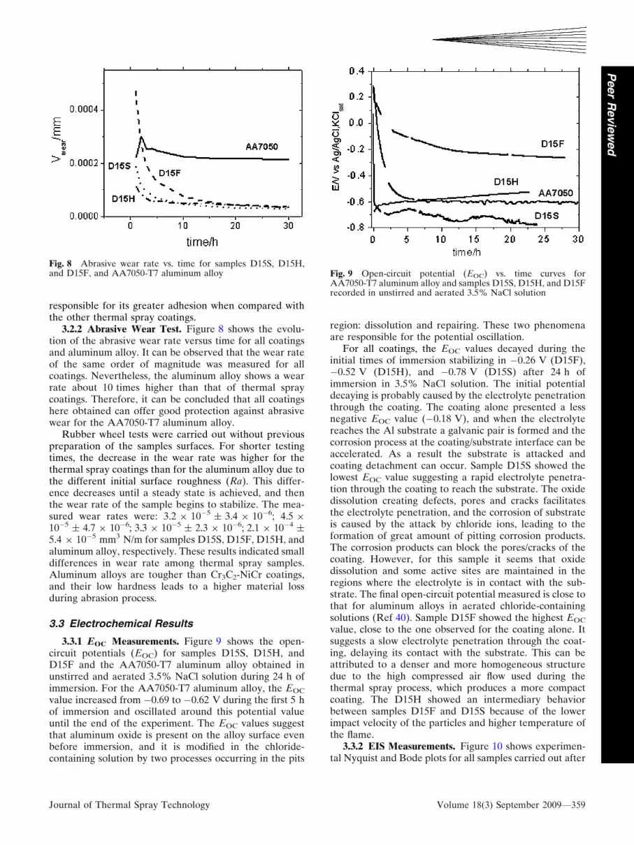
3.3.1 EOC Measurements. Figure 9 shows the open-circuit potentials (EOC) for samples D15S, D15H, andD15F and the AA7050-T7 aluminum alloy obtained inunstirred and aerated 3.5% NaCl solution during 24 h ofimmersion. For the AA7050-T7 aluminum alloy, the EOC
value increased from 0.69 to 0.62 V during the first 5 hof immersion and oscillated around this potential valueuntil the end of the experiment. The EOC values suggestthat aluminum oxide is present on the alloy surface evenbefore immersion, and it is modified in the chloride-containing solution by two processes occurring in the pits
region: dissolution and repairing. These two phenomenaare responsible for the potential oscillation.
For all coatings, the EOC values decayed during theinitial times of immersion stabilizing in 0.26 V (D15F),0.52 V (D15H), and 0.78 V (D15S) after 24 h ofimmersion in 3.5% NaCl solution. The initial potentialdecaying is probably caused by the electrolyte penetrationthrough the coating. The coating alone presented a lessnegative EOC value (0.18 V), and when the electrolytereaches the Al substrate a galvanic pair is formed and thecorrosion process at the coating/substrate interface can beaccelerated. As a result the substrate is attacked andcoating detachment can occur. Sample D15S showed thelowest EOC value suggesting a rapid electrolyte penetra-tion through the coating to reach the substrate. The oxidedissolution creating defects, pores and cracks facilitatesthe electrolyte penetration, and the corrosion of substrateis caused by the attack by chloride ions, leading to theformation of great amount of pitting corrosion products.The corrosion products can block the pores/cracks of thecoating. However, for this sample it seems that oxidedissolution and some active sites are maintained in theregions where the electrolyte is in contact with the sub-strate. The final open-circuit potential measured is close tothat for aluminum alloys in aerated chloride-containingsolutions (Ref 40). Sample D15F showed the highest EOC
value, close to the one observed for the coating alone. Itsuggests a slow electrolyte penetration through the coat-ing, delaying its contact with the substrate. This can beattributed to a denser and more homogeneous structuredue to the high compressed air flow used during thethermal spray process, which produces a more compactcoating. The D15H showed an intermediary behaviorbetween samples D15F and D15S because of the lowerimpact velocity of the particles and higher temperature ofthe flame.
3.3.2 EIS Measurements. Figure 10 shows experimen-tal Nyquist and Bode plots for all samples carried out after
Fig. 8 Abrasive wear rate vs. time for samples D15S, D15H,and D15F, and AA7050-T7 aluminum alloy Fig. 9 Open-circuit potential (EOC) vs. time curves for
AA7050-T7 aluminum alloy and samples D15S, D15H, and D15Frecorded in unstirred and aerated 3.5% NaCl solution
Journal of Thermal Spray Technology Volume 18(3) September 2009—359
Peer
Revie
wed

26 h of immersion in chloride solution at open-circuitpotential. The Nyquist plot (Fig. 10a) showed a capacitivesemicircle that increases according to the following order:D15F D15H > D15S and the value of total impedancemeasured at 10 mHz was about 90, 34, and 11 kX forD15F, D15H, and D15S, respectively. These results are ingood agreement with the tendency shown by EOC values.Figures 10(b) and 11 show the evolution of Bode data withthe immersion time and no changes in time constants andphase angle attributed to the coating response for samplesD15H and D15F. Sample D15S shows a constant phaseangle for 1 and 6 h of immersion at high frequency, whichdecreases with time (25 h) and shifts to lower frequency,followed by a dispersion of the data at low frequency. Thisis a clear indication that a coating degradation is in pro-gress, suggesting that the contribution of the substrate tothe global electrode process increased as the immersiontime increased, probably because of the pit formation.
Sample D15F presented a time constant at higher fre-quencies (Fig. 10b and 11b), which was associated with the
response of the coating and embraces a large range (fromalmost 1 kHz to 1 Hz) of frequencies with a constantphase angle near 75 throughout this frequency range,indicating a more capacitive behavior due to the compactstructure of this coating. The higher compactness of this
Fig. 10 Experimental (a) complex plane plots and (b) log |Z|and / vs. log (f) Bode plots for samples D15S, D15H, and D15Fobtained in unstirred and aerated 3.5% NaCl solution after 26 hof immersion
5
4
3
2
5
4
3
2
log
( Z
/Ω)
log
( Z
/Ω)
log
( Z
/Ω)
-3 -2 -1(a)
(b)
(c)
D15S 1h90
80
70
60
50
40
30
20
10
-θ /
degr
ees
-θ /
degr
ees
0
-10
80
70
60
50
40
30
20
10
0
-10
-θ /
degr
ees
80
70
60
50
40
30
20
10
0
-10
D15S 6hD15S 26h
D15F 0hD15F 6hD15F 20hD15F 28h
D15H 1hD15H 6hD15H 23h
0 1 2
log (f / Hz)
log (f / Hz)
log (f / Hz)
3 4 5
-3 -2 -1 0 1 2 3 4 5
-3 -2 -1 0 1 2 3 4 5
6
5
4
3
2
1
Fig. 11 Experimental log |Z| and / vs. log (f) Bode plots forsamples D15S (a), D15F (b), and D15H (c) for differentimmersion times at 25 C
360—Volume 18(3) September 2009 Journal of Thermal Spray Technology
Peer
Revie
wed

coating likely prevents the corrosion of the substrate bypitting attack during the testing, and since both the sub-strate and coating corresponding time constants remainthe same no coating degradation is evident. In the case ofD15H, the phase angle remains constant with immersiontime at high frequencies, while the one at low frequenciesdecreases, suggesting some modification on the substratesurface. For samples D15H and D15S, Bode phase plots(Fig. 10b and 11a, c) showed a well-defined time constantembracing around 10 Hz and centered at 10 and 2 Hz,respectively, with a phase angle from 65 to 70. This timeconstant is related to the coating and aluminum oxidesmainly for the D15S sample. For the D15H and D15Ssamples, another time constant seems to appear at low-frequency region with a maximum at 0.1 Hz, which isassociated to the pitting process or corrosion of substrate.
The samples were also analyzed after 72 h of NaClsolution (Fig. 12). The following values for the totalimpedance were measured: 100 kX (D15F), 0.5 kX(D15H), 0.4 kX (D15S). It is clear that the total imped-ance values significantly decreased (6 and 4 times) withimmersion time for samples D15H and D15S, while nogreat change for sample D15F was observed. Then, thethermal spray parameters have strong influence on thetotal resistance values of these samples, and the D15Fsample presents a corrosion resistance around 200 timeshigher than the others.
3.3.3 Polarization Studies. Potentiodynamic polariza-tion curves for all the coatings and aluminum 7050 alloywere recorded in aerated sodium chloride solution(Fig. 13). The estimated corrosion potential (V) valueswere:0.22 (D15F) > 0.33 (D15S) > 0.37 (D15H) 0.67 (AA7050 alloy), while the corrosion current(i/lA cm2) values were: 0.03 (D15F) < 0.32 (D15S) =0.32 (D15H) 1.1 (AA7050 alloy), indicating a corrosionpotential difference of around 450 mV and 2 orders ofmagnitude in the current corrosion density between the bestcoating and the substrate. Therefore, the D15F sampleshowed the best performance among the coatings to protectthe aluminum alloy substrate against corrosion in chloridesolution, since it presented the most positive Ecorr and thelowest corrosion current density value. Samples D15H andD15S showed similar Ecorr and current density values, buttheir corrosion potential and corrosion current density werehigher than aluminum alloy.
4. Conclusion
The present study clearly demonstrated the possibilityof applying Cr3C2-NiCr coatings on aluminum alloyswithout an intermediary metallic layer to minimize theeffects of the very different thermal expansion coefficientbetween the coating and the aluminum alloy.
Fig. 12 (a) Experimental complex plane plots for samples D15S, D15F, and D15H for 72 h of immersion in NaCl solution and (b) zoomof the high frequency region
0.2
0.0
D15F
D15S
E /V
vs
Ag/
AgC
l 'KC
l sat.
D15H
AA7050
-9.6 -8.8 -8.0 -7.2
log(i/A cm-2)
-6.4 -5.6 -4.8 -4.0
-0.2
-0.4
-0.6
-0.8
-1.0
Fig. 13 Potentiodynamic polarization curves for D15S, D15F,D15S samples and aluminum alloy 7050 in unstirred and aerated3.5% NaCl solution
Journal of Thermal Spray Technology Volume 18(3) September 2009—361
Peer
Revie
wed

The structural characterization of the different coatingsshowed that samples prepared using higher oxygen orhigher compressed air flux are well-bounded to the sub-strate, while the sample prepared using the standardconditions showed cracks with some delaminating insidethe coating. The coating prepared using higher com-pressed air flux is denser than the others.
All studied coatings presented high sliding comparedwith the aluminum alloy, and the abrasive wear resistancewas at least 10 times higher than for the AA7050-T7aluminum alloy. The coating sprayed using higher carriergas flux showed the highest corrosion resistance in 3.5%NaCl solution, and no pitting attack to the substrateoccurred even after around 26 h of test.
Tests performed for longer immersion times (72 h)showed that the total impedance values significantlydecreased (6 and 4 times) for samples sprayed usingstandard and higher oxygen flux, and no great change forsample sprayed using higher carrier gas flux was observed.The last sample presents a corrosion resistance around200 times higher than the others.
Acknowledgments
The authors wish to thank FAPESP (proc. no 02/11542-4; 02/00448-7; 05/11542-4; 05/51851-4), CAPES (BEX-2283/04-2) and CNPq (proc.no 300728/2007-7) for thescholarships, Generalitat de Catalunya for financial sup-port (Project 2005SGR00310) and the CPT—ThermalSpray Centre, Universitat de Barcelona, Barcelona, Spainfor samples preparation. The authors also wish to thankAir Products for the facilities to use the cooling device andEmbraer (Empresa Brasileira de Aeronautica S.A.) forproviding the AA 7050 aluminum alloy samples.
References
1. Y. Sun, Tribological Rutile-TiO2 Coating on Aluminium Alloy,Appl. Surf. Sci., 2004, 233(1-4), p 328-335
2. M.J. Ghazali, W.M. Rainforth, and H. Jones, The Wear ofWrought Aluminium Alloys under Dry Sliding Conditions, Tri-bol. Int., 2007, 40(2), p 160-169
3. P. Leo, E. Cerri, P.P. Marco, and H.J. Roven, Properties andDeformation Behaviour of Severe Plastic Deformed AluminiumAlloys, J. Mater. Process. Technol., 2007, 2(1-3), p 207-214
4. T. Yasmin, A.A. Khalid, and M.M. Haque, Tribological (Wear)Properties of Aluminum-Silicon Eutectic Base Alloy Under DrySliding Condition, J. Mater. Process. Technol., 2004, 153-154(10),p 833-838
5. J.C. Lin, H.-L. Liao, W.-D. Jehng, C.-H. Chang, and S.-L. Lee,Effect of Heat Treatments on the Tensile Strength and SCC-Resistance of AA7050 in an Alkaline Saline Solution, Corros.Sci., 2006, 48(10), p 3139-3156
6. L. Ceschini, I. Boromei, G. Minak, A. Morri, and F. Tarterini,Microstructure, Tensile and Fatigue Properties of AA6061/20 vol% Al2O3p friction stir welded joints, Composites Part A:Appl. Sci. Manuf., 2007, 38(4), p 1200-1210
7. R.G. Rateick, T.C. Binkowski, and B.C. Boray, Effects of HardAnodize Thickness on the Fatigue of AA6061 and C355 Alu-minium, J. Mater. Sci. Lett., 1996, 15(15), p 1321-1323
8. A. Merati and G. Eastaugh, Determination of Fatigue RelatedDiscontinuity State of 7000 Series of Aerospace AluminumAlloys, Eng. Fail. Anal., 2007, 14(4), p 673-685
9. R.L. Deuis, C. Subramanian, and J.M. Yellup, Abrasive Wear ofComposite Coatings in a Salines and Slurry Environment, Wear,1997, 203-204, p 119-128
10. K. Kawata, H. Sugimura, and O. Takai, Characterization ofMultilayer Films of Ti-Al-O-C-N System Prepared by Pulsed d.c.Plasma-Enhanced Chemical Vapor Deposition, Thin Solid Films,2001, 390(1-2), p 64-69
11. H. Hoche, C. Blawert, E. Broszeit, and C. Berger, GalvanicCorrosion Properties of Differently PVD-Treated MagnesiumDie Cast Alloy AZ9, Surf. Coat. Technol., 2005, 193(1-3), p 223-229
12. M. Khaled, B.S. Yilbas, and J. Shirokoff, Electrochemical Studyof Laser Nitrided and PVD TiN Coated Ti-6Al-4 V Alloy: TheObservation of Selective Dissolution, Surf. Coat. Technol., 2001,148(1), p 46-54
13. K.S. Klimek, H. Ahn, I. Seebach, M. Wang, and K.T. Rie, DuplexProcess Applied for Die-Casting and Forging Tools, Surf. Coat.Technol., 2003, 174-175, p 677-680
14. J.V. Ringleben, Ch. Sundermann, T. Matsutani, M. Kiuchi, andW. Ensinger, Sealing Performance of Thin Amorphous CarbonFilms Formed by Ion Beam Assisted Deposition at Low Tem-perature for Protection of Aluminium against Aggressive Media:The Influence of the Ion Energy, Thin Solid Films, 2005, 482(1-2),p 115-119
15. A.L.M. Carvalho and H.J.C. Voorwald, Influence of Shot Peen-ing and Hard Chromium Electroplating on the Fatigue Strengthof 7050-T7451 Aluminum Alloy, Int. J. Fat., 2007, 29(7), p 1282-1291
16. M. Magnani, A.V. Benedetti, C.S. Fugivara, P.H. Suegama, andJ.M. Guilemany, Analysis of Electrochemical Impedance andNoise Data for Thermal Spray Coatings in 3.5% NaCl Solution,EUROCORR 2005 (Lisboa-Portugal), Anais do EUROCORR,2005
17. S. Uozato, K. Nakata, and M. Ushio, Evaluation of FerrousPowder Thermal Spray Coatings on Diesel Engine CylinderBores, Surf. Coat. Technol., 2005, 200(7), p 2580-2586
18. M.F. Morks, Y. Gao, N.F. Fahim, F.U. Yingqing, and M.A.Shoeib, Influence of Binder Materials on the Properties of LowPower Plasma Sprayed Cermet Coatings, Surf. Coat. Technol.,2005, 199(1), p 66-71
19. A. Edrisy, T. Perry, and A.T. Alpas, Investigation of ScuffingDamage in Aluminum Engines with Thermal Spray Coating,Wear, 2005, 259(7-12), p 1056-1062
20. A. Edrisy, T. Perry, Y.T. Cheng, and A.T. Alpas, Wear ofThermal Spray Deposited Low Carbon Steel Coatings on Alu-minum Alloys, Wear, 2004, 251(1-12), p 1023-1033
21. P.M. Natishan, S.H. Lawrence, R.L. Foster, J. Lewis, and B.D.Sartwell, Salt Fog Corrosion Behavior of High-Velocity Oxygen-Fuel Thermal Spray Coatings Compared to ElectrodepositedHard Chromium, Surf. Coat. Technol., 2000, 130(2-3), p 218-223
22. J.K.N. Murthy and B. Venkataraman, Abrasive Wear Behaviourof WC-CoCr and Cr3C2-20(NiCr) Deposited by HVOF andDetonation Spray Processes, Surf. Coat. Technol., 2006, 200(8),p 2642-2652
23. M.P. Nascimento, R.C. Souza, I.M. Miguel, W.L. Pigatin, andH.J.C. Voorwald, Effects of Tungsten Carbide Thermal SprayCoating by HP/HVOF and Hard Chromium Electroplatingon AISI 4340 High Strength Steel, Surf. Coat. Technol., 2001,138(2-3), p 113-124
24. Y. Xie and H.M. Hawthorne, The Damage Mechanisms of Sev-eral Plasma-Sprayed Ceramic Coatings in Controlled Scratching,Wear, 1999, 233-235, p 293-305
25. J.M. Guilemany, N. Espallargas, P.H. Suegama, and A.V.Benedetti, Comparative Study of Cr3C2-NiCr Coatings Obtainedby HVOF and Hard Chromium Coatings, Corros. Sci., 2006,48(10), p 2998-3013
26. P.H. Suegama, C.S. Fugivara, A.V. Benedetti, J. Fernandez,J. Delgado, and J.M. Guilemany, Electrochemical Behaviour ofThermally Sprayed Cr3C2-NiCr Coatings in 0.5 m H2SO4 Envi-ronment, J. Appl. Electrochem., 2002, 14, p 1287-1295
27. J.M. Guilemany, C. Lorenzana, J. Nin, and J. Delgado, On-LineMonitoring Control of Stainless Steel Coatings Obtained byHVOF and APS Processes, Proceedings of the United Thermal
362—Volume 18(3) September 2009 Journal of Thermal Spray Technology
Peer
Revie
wed

Spray Congress and Exhibition (UTSC2002) (Essen, Germany),2002, p 86-90
28. L. Pawlowski, The Science and Engineering of Thermal SprayCoatings, John Wiley & Sons, New York, 1995
29. V. Sobolev, J.M. Guilemany, and J. Nutting, High Velocity Oxy-Fuel Spraying, Maney, England, 2004
30. P.H. Suegama, C.S. Fugivara, A.V. Benedetti, J. Fernandez, N.Espallargas, J. Delgado, and J.M. Guilemany, Microstructure andElectrochemical Studies of Cr3C2-NiCr Coatings, New Researcheson Electrochemistry, E.P. Vargus, Ed., Nova Science Publishers,New York, 2007, p 113
31. P.H. Suegama, N. Espallargas, J.M. Guilemany, J. Fernandez,and A.V. Benedetti, Electrochemical and Structural Character-ization of Treated Cr3C2-NiCr Coatings, J. Electrochem. Soc.,2006, 153, p B434-B445
32. M. Magnani, P.H. Suegama, A.A.C. Recco, J.M. Guilemany, C.S.Fugivara, and A.V. Benedetti, WC-CoCr Coatings Sprayed byHigh Velocity Oxygen-Fuel (HVOF) Flame on AA7050 Alumi-num Alloy: Electrochemical Behavior in 3.5% NaCl Solution,Mater. Res., 2007, 10(4), p 377-385
33. J.A. Picas, A. Forn, R. Rilla, and E. Martin, HVOF ThermalSprayed Coatings on Aluminium Alloys and Aluminium MatrixComposites, Surf. Coat. Technol., 2005, 200(1-4), p 1178-1181
34. M. Wenzelburger, M. Escribano, and R. Gadow, Modeling ofThermally Sprayed Coatings on Light Metal Substrates: Layer
Growth and Residual Stress Formation, Surf. Coat. Technol.,2004, 180-181, p 429-435
35. M. Magnani, P.H. Suegama, N. Espallargas, S. Dosta, C.S.Fugivara, J.M. Guilemany, and A.V. Benedetti, Influence ofHVOF Parameters on the Corrosion and Wear Resistance ofWC-Co Coatings Sprayed on AA7050 T7, Surf. Coat. Technol.,2008, 202(19), p 4746-4757
36. ‘‘Properties and Selection: Nonferrous Alloys and Special-Purpose Materials,’’ ASM Handbook, Vol 2, 10th ed., ASMInternational, Materials Park, OH, 1992, p 1328
37. J. Yan, L. Chunzhi, and Y. Minggao, On the g0 Precipitate Phasein 7050 Aluminium Alloy, Mater. Sci. Eng., 1991, A141, p 123-128
38. M.I. Hutchings, Tribology, Friction and Wear of EngineeringMaterials, CRC Press, London, 1992, p 273
39. P.H. Suegama, C.S. Fugivara, A.V. Benedetti, J.M. Guilemany,J. Fernandez, and J. Delgado, The Influence of Gun TransverseSpeed on Electrochemical Behaviour of Thermally SprayedCr3C2-NiCr Coatings in 0.5 M H2SO4 Solution, Electrochim.Acta, 2004, 49, p 627-634
40. P.L. Cabot, F. Centellas, J.A. Garrido, E. Perez, A.H. Moreira,P.T.A. Sumodjo, A.V. Benedetti, and W.G. Proud, Character-ization of Localized Corrosion Processes in Al-Zn-Mg Alloys byImpedance Spectroscopy, Progress in the Understanding andPrevention of Corrosion, J.M. Costa and A.D. Mercer, Eds.,Institute of Materials, London, 2, 1993, p 1409-1418
Journal of Thermal Spray Technology Volume 18(3) September 2009—363
Peer
Revie
wed