Embed Size (px)
Citation preview
Surface & Coatings Technology 203 (2008) 335–344
Contents lists available at ScienceDirect
Surface & Coatings Technology
j ourna l homepage: www.e lsev ie r.com/ locate /sur fcoat
Influence of the elementary mixing scale on HVOF-sprayed coatings derived fromnanostructured aluminosilicate/mullite feedstock
Jarkko Leivo a,d,⁎, Tommi E. Varis b, Erja Turunen b, Minnamari Vippola a, Kati Rissa a, Ulla Kanerva c,Jussi Silvonen d, Tapio A. Mäntylä a
a Department of Materials Science, Tampere University of Technology, 33101 Tampere, Finlandb VTT Advanced Materials, 02044 VTT, Espoo, Finlandc VTT Advanced Materials, 33101 Tampere, Finlandd Millidyne Oy, Hermiankatu 6-8, 33720 Tampere, Finland
⁎ Corresponding author. Current address: Millidyne OTampere, Finland. Tel.: +358 50 322 64 55; fax: +358 3 3
E-mail address: [email protected] (J. Leivo).
0257-8972/$ – see front matter © 2008 Elsevier B.V. Aldoi:10.1016/j.surfcoat.2008.09.008
a b s t r a c t
a r t i c l e i n f oArticle history:
Aluminosilicate/mullite coa Received 3 April 2008Accepted in revised form 8 September 2008Available online 16 September 2008Keywords:Thermal sprayingNanostructured coatingsHigh velocity oxy-fuel (HVOF)AluminosilicateCrystallizationMullite
tings were prepared from nanosized sources of aluminium and silicon bymeans ofa high velocity oxy-fuel thermal spray process. X-ray diffraction, analytical electron microscopy, differentialthermal analysis and Fourier transform infrared spectroscopy were used to characterize the phasecomposition, elementary distribution, and microstructure in the feedstock and in the coatings. It was revealedthat the chemical environment of the alumina component, as well as the inherent elementary distribution inthe nanoparticulate aluminosilicate feedstock, showed the greatest influence on the microstructure and thecrystallization of nanosized ceramic phases in the sprayed coatings. A uniform distribution of alumina andsilica in a short-range ordered monophasic-like nanostructure was the most appropriate physico-chemicalconditions of the feedstock to achieve nanosized crystallites of mullite in a monolithic-like aluminosilicatecoating. In turn, when using diphasic feedstock, clearly heterogeneous but nanostructured coatings with agood abrasion resistance were obtained. The agglomerated and heat-treated powders were considered as themost suitable type of feedstock for providing nanostructured aluminosilicate coatings.
© 2008 Elsevier B.V. All rights reserved.
1. Introduction
Thermally sprayed aluminosilicates with the chemical compositionofmullite have shown applicability as coatings in furnace tubes and heatexchangers [1–8], in aircraft and stationary gas turbines [9,10], inspacecrafts [11,12], in electrical industry [13] and in the field ofbiomaterials [14]. However, a general disadvantage for mullite coatingsis that the chemical homogeneity of the coating is difficult to reach.When polycrystalline mullite is used as the feedstock material, thesprayed material is reported as amorphous with partially unmoltenparticles and fluctuating chemical composition [1,6]. When the feed-stock is derived from separate sources of aluminium and silicon, thetendency to yield chemically heterogeneous regions becomes pro-nounced, and various crystalline phases may exist [1,5–9,14–17]. Forinstance, a feedstock consisting of silica and α-alumina is known toresult in low-viscosity silica melt and partially unmelted α-aluminagrains after spraying [15]. However, there is still an advantage if usingseparate phases in the feedstock, as if the sizes of the primary particlesare in the nanoscale, it may yield nanostructured coatings. In nano-structured coatings, a portion of nanosized clusters of semi-molten
y, Hermiankatu 6-8 G, 3372017 79 00.
l rights reserved.
nanoparticles is formed between the well-melted amorphous regions,which have recently reported to improve the coating properties, such asmechanical performance [18–20] or biological compatibility [20–24].
For thermally sprayed aluminosilicate/mullite coatings, however,only a little information, if any, deals essentially with the issue of theirfeedstock quality. For aluminium and silicon sources in general, it isknown that the phase composition [13] and the chemical environmentof the aluminium source [25] are important, and the nucleation beha-viour of the crystalline aluminosilicate phases may further affect on theuniformity of the crystallinity [26]. If the aluminosilicate feedstock iscomposed of mullitized clays [27], amorphous phase with residualmullite may appear, whereas if composed of non-crystalline sol–gelbased sources [14], theas-sprayedmaterialmay result innanocrystallinemullite.
For the conventional reaction syntheses of mullite, a vast number ofpapers deal with the aluminosilicate precursor quality. In these papers,in order to achieve ahighchemical homogeneityandmullite yield,manyauthors have stressed that the length of the diffusion paths between Aland Si in the precursor play the significant role [1,2]. For submicron-sized α-alumina and nanosized silica (transient viscous sintering, TVS[28]), the mullitization do not occur readily below 1500 °C, but if theparticle size is diminished so that both components are derived fromnanosized colloids, i.e., from a diphasic Type II precursor [1], the reac-tion can begin below 1250 °C, yet first with a formation of nanosized

Table 1Description of the aluminosilicate feedstock materials
Abbreviation Feedstock description Heat-treatment parameters (T,t)
Monophasic-like nanoparticulate sol–gel, Type IMG Gel, dried and crushed 180 °C, 2 daysMC Crystalline powder, agglomerated 1000 °C, 1 h
Hybrid nanoparticulate sol–gel, Type IIIHGS Gel, dried and crushed; sintered 700 °C, 1 hHGC Gel, dried and crushed; Crystallized 1050 °C, 1 h
Diphasic colloidal sol–gel, Type IIDG Gel, dried and crushed 180 °C, 2 daysDC Crystalline powder, agglomerated 1000 °C, 1 h
Transient viscous sintered (TVS)TC Crystalline powder, agglomerated 1000 °C, 1 h
336 J. Leivo et al. / Surface & Coatings Technology 203 (2008) 335–344
transitional alumina phases. Of importance, in themost uniform systemof amonophasic-like Type I sol–gel precursor [1–3,29–34], the diffusionpaths between Al and Si are in a molecular scale, hence so short thatnanosized crystals ofmullitewill form rapidly at 900–1000 °C. However,if any heterogeneous domains exist in the gel, even in the scale ofnanometres [1], an Al-rich spinel phase tends to dominate the crys-tallization at 1000 °C (10–25% of SiO2 incorporated in γ-Al2O3 [1,31], ahybrid Type III system [1,30]).
The aim of this paper was to carry out a systematic study from theapproach that how the quality of the feedstock, especially the nano-structure and the scale of the chemical homogeneity, will affect on thechemical and physical structure of the sprayed coating. A high velocityoxy-fuel flame spray process, HVOF [18–24,35], was used to preparealuminosilicate/mullite coatings from various types of nanostructuredaluminosilicate feedstock, each with the chemical composition of thecommon 3/2-mullite, 3Al2O3·2SiO2. Although HVOF is less commonlyemployed for aluminosilicates, however, in cases when used [7,14], agood homogeneity within the aluminosilicate/mullite coating isachieved. The HVOF coatings from a feedstock of crushed Type I gel
Fig. 1. SEM SE images illustrating the morphology of the feedstock particles (scale bar20 µm).
have previously shown poor flowability [14], as to why feedstock ofagglomerated [36] and heat-treated [19] powders were prepared aswell.
2. Experimental method
2.1. Materials
The nanostructured feedstock materials carrying various mixingscales of aluminium and silicon are listed in Table 1, each consisting ofa corresponding nAl/nSi ratio of 3 found in 3/2-mullite, 3Al2O3·2SiO2.
For the monophasic-like Type I aluminosilicate precursor, a stablenanoparticulate hydrosol, denoted M0, was sol–gel synthesised asdescribed previously [32]. The feedstock gel, denoted MG, wasobtained by allowing the sol M0 to evaporate until a physical gelwas formed. In this condition, the gel MG contains a high Al–O–Sibond density in a monophasic-like nanoparticulate structure thatresembles proto-imogolite allophane (PI/A) particles of a size of about2 nm [32–34]. The gel was then further dried in an oven first for 1 dayat 110 °C and then for 2 days at 180 °C, and finally crushed and sieved
Fig. 2. (a) Particle size distributions of agglomerated and (b) crushed feedstockmeasuredby laser diffraction.
337J. Leivo et al. / Surface & Coatings Technology 203 (2008) 335–344
(b63 µm). The agglomerated and crystallized feedstock powder, denotedMC,was prepared by spray-drying a concentrated sol ofM0using aBüchiMini B-290 laboratory apparatus with a nozzle feeder at the chamberinlet/outlet temperature of 220 °C/110 °C. The agglomerated powderwasfurther dried in an oven for 1 day at 110 °C, and then calcined for 60minat 1000 °C, and finally fractioned by sieving (b36 µm).
For a hybrid Type III precursor, additives of poly(vinylpyrrolidone),polyethylene glycol and hydrochloric acid were mixed into the sol ofM0 [33,34]. As above, a similar kind of drying, crushing, and sieving(b63 µm) procedures were employed to obtain a hybrid gel, denotedHG. Spray-drying, however, was not performed due to a rapid removalof volatile matter at 140 °C [33]. For the calcined feedstock material, inorder to eliminate the organic matter and induce porosity and phaseseparation in the scale of nanometres [33], the dry gel HGwas sinteredfor 60 min at 700 °C, then denoted HGS. For the crystallized hybridfeedstock, denoted HGC, the sintered HGS was re-treated for 120 minat 1050 °C [34], and then sieved (b36 µm).
For the diphasic Type II precursor, colloidal boehmite (10 nm) wasprecipitated with colloidal silica sol (30 nm) [14]. The precipitateaggregates were dried, crushed and sieved (b63 µm), and then denotedDG. For the agglomerated and crystalline diphasic feedstock powder,denoted DC, a dispersed sol was prepared from the above-mentionedcolloidal precursors, and spray-dried. The agglomerated powder wasthen oven-dried at 110 °C, heat-treated for 60min at 1000 °C, and sieved(b36 µm).
For a TVS-like submicron-nanocomposite material, a solution ofsubmicron α-alumina grains (N100 nm) with colloidal silica (30 nm)
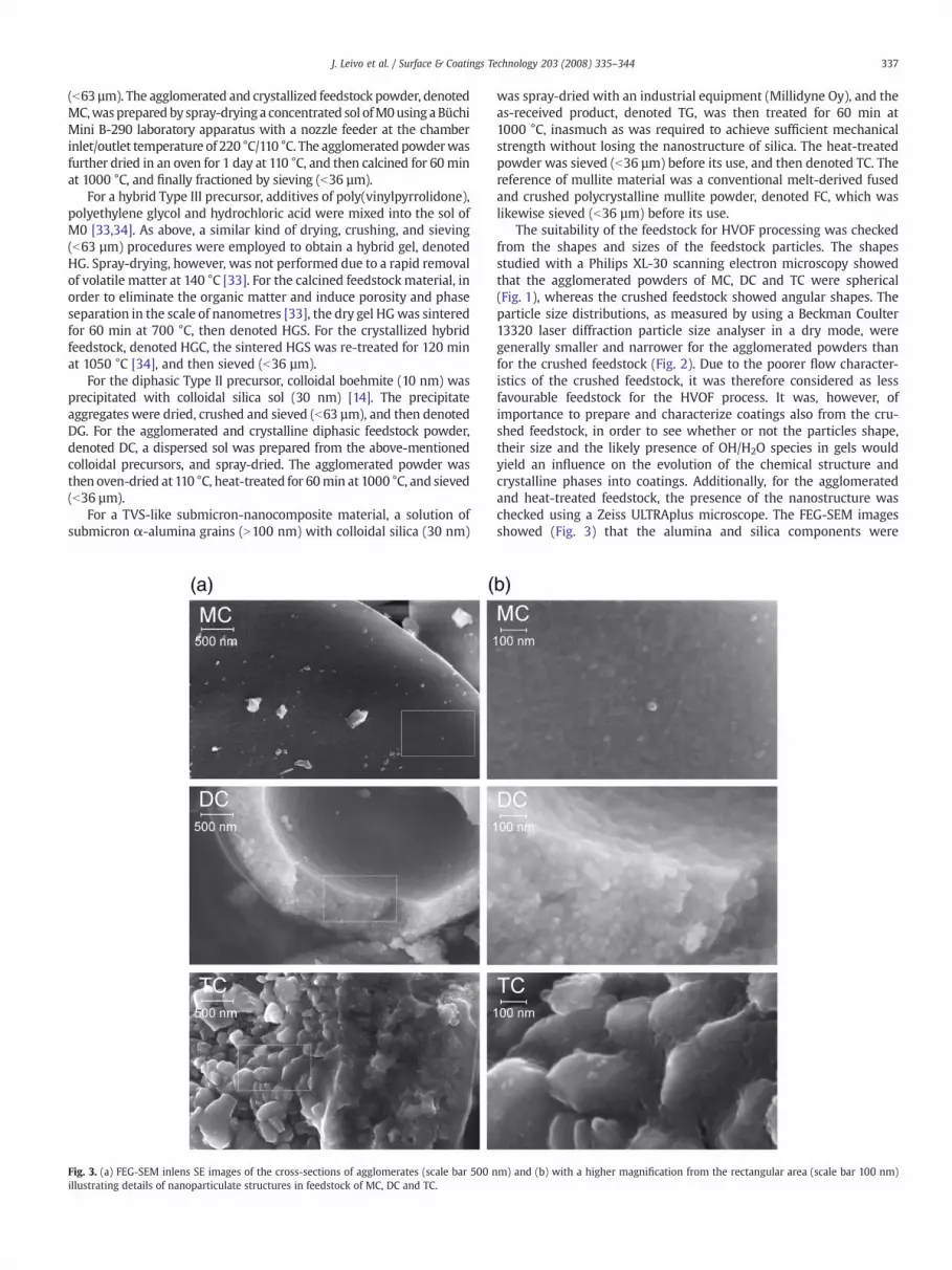
Fig. 3. (a) FEG-SEM inlens SE images of the cross-sections of agglomerates (scale bar 500 nillustrating details of nanoparticulate structures in feedstock of MC, DC and TC.
was spray-dried with an industrial equipment (Millidyne Oy), and theas-received product, denoted TG, was then treated for 60 min at1000 °C, inasmuch as was required to achieve sufficient mechanicalstrength without losing the nanostructure of silica. The heat-treatedpowder was sieved (b36 µm) before its use, and then denoted TC. Thereference of mullite material was a conventional melt-derived fusedand crushed polycrystalline mullite powder, denoted FC, which waslikewise sieved (b36 µm) before its use.
The suitability of the feedstock for HVOF processing was checkedfrom the shapes and sizes of the feedstock particles. The shapesstudied with a Philips XL-30 scanning electron microscopy showedthat the agglomerated powders of MC, DC and TC were spherical(Fig. 1), whereas the crushed feedstock showed angular shapes. Theparticle size distributions, as measured by using a Beckman Coulter13320 laser diffraction particle size analyser in a dry mode, weregenerally smaller and narrower for the agglomerated powders thanfor the crushed feedstock (Fig. 2). Due to the poorer flow character-istics of the crushed feedstock, it was therefore considered as lessfavourable feedstock for the HVOF process. It was, however, ofimportance to prepare and characterize coatings also from the cru-shed feedstock, in order to see whether or not the particles shape,their size and the likely presence of OH/H2O species in gels wouldyield an influence on the evolution of the chemical structure andcrystalline phases into coatings. Additionally, for the agglomeratedand heat-treated feedstock, the presence of the nanostructure waschecked using a Zeiss ULTRAplus microscope. The FEG-SEM imagesshowed (Fig. 3) that the alumina and silica components were
m) and (b) with a higher magnification from the rectangular area (scale bar 100 nm)

Fig. 4. XRD diffractograms of the feedstock. Peak attributes are mullite (M; JCPDS no. 15–776 and no. 73–1389),α-alumina (A; JCPDS no.10–173), pseudoboehmite (B; γ-AlO2H·1/2H2O, JCPDS no. 83–1505), and spinel and γ-alumina (sp. and γ, respectively, bothwith 2θ at 46° and 67° of γ-alumina JCPDS no. 10–425).
Fig. 5. TEM micrographs of the feedstock of MG, HGS, DG,
338 J. Leivo et al. / Surface & Coatings Technology 203 (2008) 335–344
distributed evenly in each agglomerate structure, and nanosizeddetails were still present in the heat-treated feedstock, agreeinggenerally well with the primary particle sizes used in the gel statesource. For MC, however, the particles were slightly coarsened duringthe heat-treatment at 1000 °C, uniformly up to sizes of about 10 to30 nm, which was nevertheless in a good agreement with the criticalsize of mullite nucleus of about 10 nm [1].
2.2. Thermal spraying
Coatings were sprayed by using a Praxair HV-2000 HVOF gun equip-ped with a 22 mm combustion chamber nozzle. Spraying parametersyielding the highest particle temperatures were selected [37,38]:standoff distance was 150 mm, N2 was a carrier gas and H2 and O2
were fuel gases with a H2/O2 volume ratio of 2.85 and a total gas flow of1050 dm3 min−1. These parameters resulted typically in a particlevelocity of 1025 m s−1 and a particle temperature of 2050 °C, whichshould provide an appropriate melting of nanostructured feedstockcontaining alumina [38]. The good flowability of the feedstock [19] wasensured using a Thermico CPF-2HP feeding system designed forpowders with a small particle size. Dense α-alumina discs (N99.7%, in-house) and carbon steel bars were used as substrate materials in thecondition of grinded and sandblasted to ascertain an equal surfaceroughness.
2.3. Characterization methods
Crystalline phases were studied by X-ray diffraction, XRD, using aSiemens Diffrac 500 X-ray diffractometer that was operated at 40 kV and30mA.Patternswere recordedusingCuKα radiationwitha steptime1.2 s/step and a scan step 0.02 ° within the 2θ range from 5° to 80°. Nano-structural features and crystallinity were characterized by transmissionelectron microscopy, TEM, performed with a JEOL JEM-2010 microscope.The studied materials were crushed carefully prior to fixing them onto acarbon coated copper grid. The temperature of the mullite or spinelreaction exotherms were determined by differential thermal analysis,DTA, using a Netzsch STA 409 equipment with a linear heating rate, β, of5 °C min−1 in purified air flow (75 cm3 min−1). The chemical structure ofthe materials was analysed by using Fourier transform infrared spectro-scopy, FTIR. The spectrawere collectedwith a Perkin-Elmer SpectrumOne
and TC. The bar corresponds to 20 nm in each image.
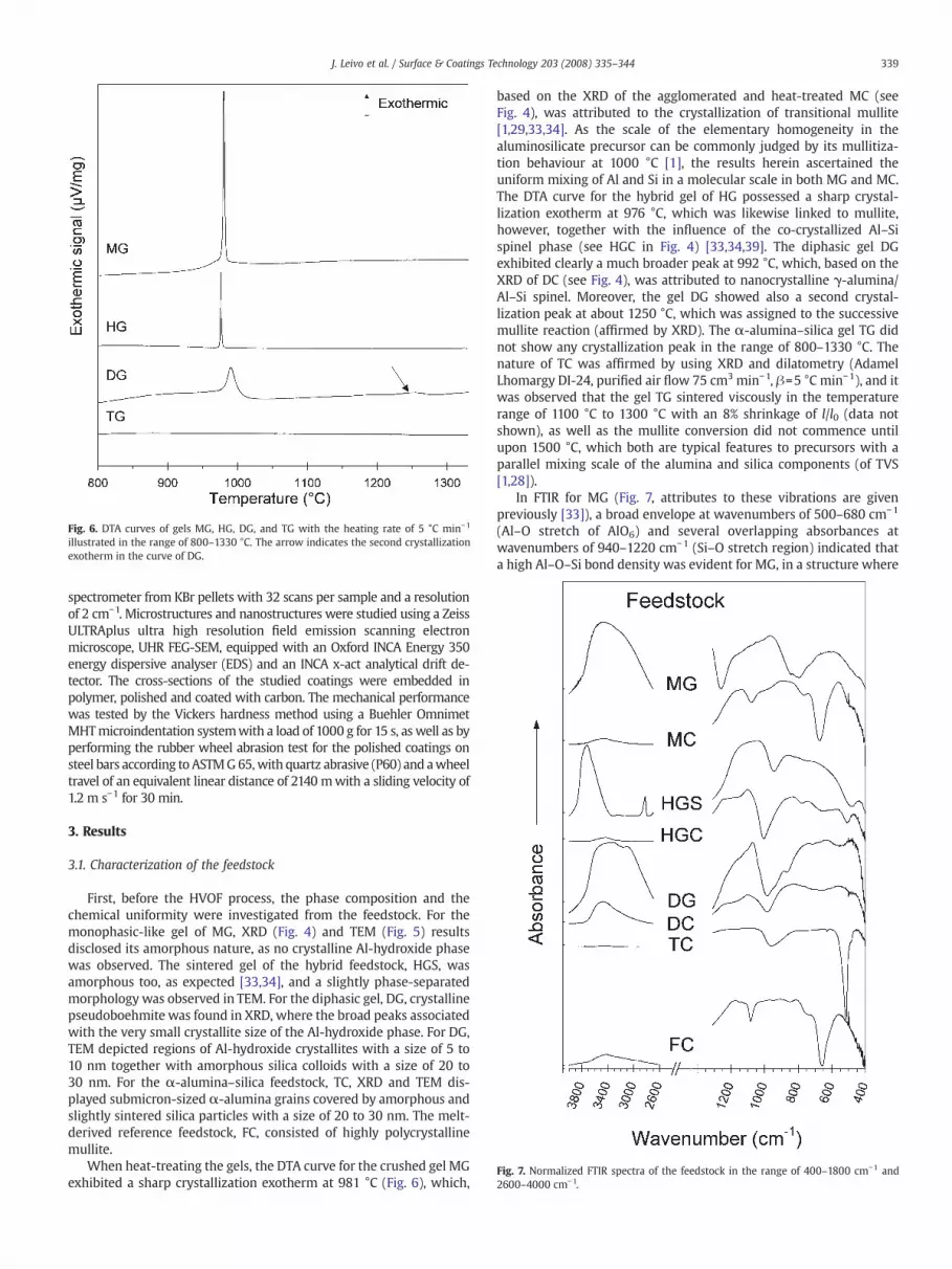
Fig. 6. DTA curves of gels MG, HG, DG, and TG with the heating rate of 5 °C min−1
illustrated in the range of 800–1330 °C. The arrow indicates the second crystallizationexotherm in the curve of DG.
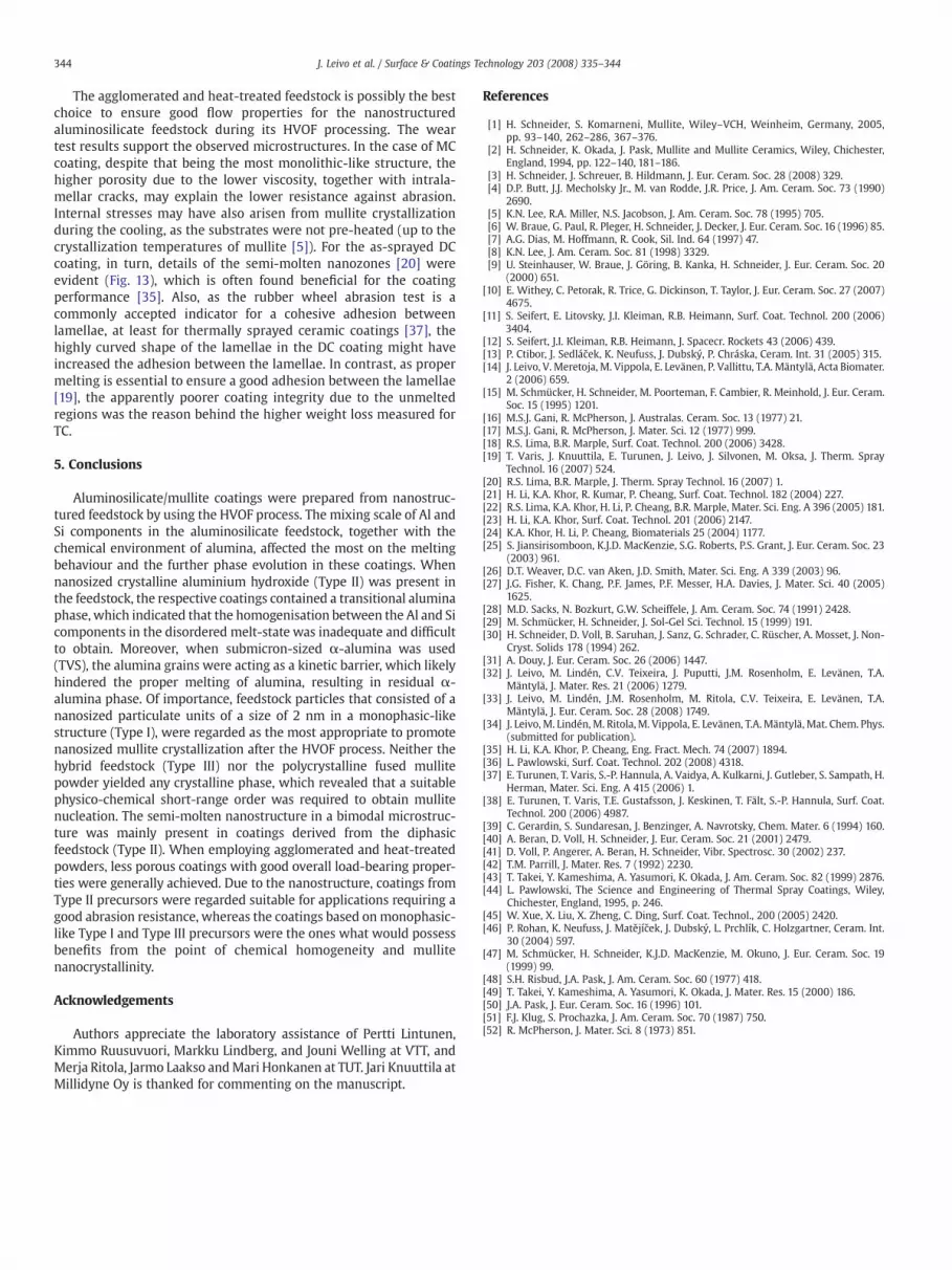
Fig. 7. Normalized FTIR spectra of the feedstock in the range of 400–1800 cm−1 and2600–4000 cm−1.
339J. Leivo et al. / Surface & Coatings Technology 203 (2008) 335–344
spectrometer from KBr pellets with 32 scans per sample and a resolutionof 2 cm−1. Microstructures and nanostructures were studied using a ZeissULTRAplus ultra high resolution field emission scanning electronmicroscope, UHR FEG-SEM, equipped with an Oxford INCA Energy 350energy dispersive analyser (EDS) and an INCA x-act analytical drift de-tector. The cross-sections of the studied coatings were embedded inpolymer, polished and coated with carbon. The mechanical performancewas tested by the Vickers hardness method using a Buehler OmnimetMHTmicroindentation systemwith a load of 1000 g for 15 s, as well as byperforming the rubber wheel abrasion test for the polished coatings onsteel bars according to ASTMG65,with quartz abrasive (P60) and awheeltravel of an equivalent linear distance of 2140 mwith a sliding velocity of1.2 m s−1 for 30 min.
3. Results
3.1. Characterization of the feedstock
First, before the HVOF process, the phase composition and thechemical uniformity were investigated from the feedstock. For themonophasic-like gel of MG, XRD (Fig. 4) and TEM (Fig. 5) resultsdisclosed its amorphous nature, as no crystalline Al-hydroxide phasewas observed. The sintered gel of the hybrid feedstock, HGS, wasamorphous too, as expected [33,34], and a slightly phase-separatedmorphology was observed in TEM. For the diphasic gel, DG, crystallinepseudoboehmite was found in XRD, where the broad peaks associatedwith the very small crystallite size of the Al-hydroxide phase. For DG,TEM depicted regions of Al-hydroxide crystallites with a size of 5 to10 nm together with amorphous silica colloids with a size of 20 to30 nm. For the α-alumina–silica feedstock, TC, XRD and TEM dis-played submicron-sized α-alumina grains covered by amorphous andslightly sintered silica particles with a size of 20 to 30 nm. The melt-derived reference feedstock, FC, consisted of highly polycrystallinemullite.
When heat-treating the gels, the DTA curve for the crushed gel MGexhibited a sharp crystallization exotherm at 981 °C (Fig. 6), which,
based on the XRD of the agglomerated and heat-treated MC (seeFig. 4), was attributed to the crystallization of transitional mullite[1,29,33,34]. As the scale of the elementary homogeneity in thealuminosilicate precursor can be commonly judged by its mullitiza-tion behaviour at 1000 °C [1], the results herein ascertained theuniform mixing of Al and Si in a molecular scale in both MG and MC.The DTA curve for the hybrid gel of HG possessed a sharp crystal-lization exotherm at 976 °C, which was likewise linked to mullite,however, together with the influence of the co-crystallized Al–Sispinel phase (see HGC in Fig. 4) [33,34,39]. The diphasic gel DGexhibited clearly a much broader peak at 992 °C, which, based on theXRD of DC (see Fig. 4), was attributed to nanocrystalline γ-alumina/Al–Si spinel. Moreover, the gel DG showed also a second crystal-lization peak at about 1250 °C, which was assigned to the successivemullite reaction (affirmed by XRD). The α-alumina–silica gel TG didnot show any crystallization peak in the range of 800–1330 °C. Thenature of TC was affirmed by using XRD and dilatometry (AdamelLhomargy DI-24, purified air flow 75 cm3 min−1, β=5 °C min−1), and itwas observed that the gel TG sintered viscously in the temperaturerange of 1100 °C to 1300 °C with an 8% shrinkage of l/l0 (data notshown), as well as the mullite conversion did not commence untilupon 1500 °C, which both are typical features to precursors with aparallel mixing scale of the alumina and silica components (of TVS[1,28]).
In FTIR for MG (Fig. 7, attributes to these vibrations are givenpreviously [33]), a broad envelope at wavenumbers of 500–680 cm−1
(Al–O stretch of AlO6) and several overlapping absorbances atwavenumbers of 940–1220 cm−1 (Si–O stretch region) indicated thata high Al–O–Si bond density was evident for MG, in a structure where

Fig. 8. XRD diffractograms of the coatings. Peak attributes are mullite (M; JCPDS no. 15–776 and no. 73–1389), α-alumina (A; JCPDS no. 10–173), and spinel or γ-alumina (sp. orγ, respectively, both with 2θ at 46 ° and 67 ° of γ-alumina JCPDS no. 10–425).
Fig. 9. TEMmicrographs of detached MG, HGS, DG, and TC coatings. The bar corresponds to 2the arrow, ED patterns correspond to structures of mullite for MG and of γ-alumina for DG
340 J. Leivo et al. / Surface & Coatings Technology 203 (2008) 335–344
Al is known to be mostly in its six-coordinated environment, AlO6
[33,34]. The absorption at wavenumbers of 3000–3600 cm−1 waslinked to region of OH/H2O stretching vibrations [40], which affirmedthe hydroxylated aluminosilicate structure [34]. In FTIR for MC, alu-mina was observed to locate homogeneously in transitional mulliteand in an amorphous aluminosilicate network [33,34], as the bandswere close to those of mullite [41] (note that differences to the mullitereference FCwere small as well). In FTIR for calcined HGS, based on theemerged absorption at wavenumbers of around 800–870 cm−1 thatwas assigned to 4-folded alumina, AlO4, a condensed aluminosilicatestructure was evident [33,34]. For crystallized HGC, the absorption atwavenumbers of around 730 cm−1 was assigned to triclusteredtetrahedra T–O–T (TfAl or Si, TO4) [40] that associated with mullitecrystals (and amorphous aluminosilicate network) present in HGC.However, FTIR revealed also pronounced peaks at wavenumbers ofaround 1100 cm−1 and 1220 cm−1 attributed to the TO and LO modesof Si–O–Si stretch (SiO2), respectively [42], which suggests somewhatseparated SiO2 and Al2O3 regions [34], supporting the presence of the(Al-rich) spinel phase and Si-rich matrix. For the gel DG, the Si–O–Sistretches, including the one at wavenumbers of 800 cm−1, wereassigned to pure SiO2, as well as the clear absorptions of AlO6 (andAlO4 in the case of crystallized DC) were assigned to Al-rich regimesdue to the Al-hydroxide source. In FTIR for TC, pure SiO2 was obvious(note also a strong Si–O–Si bend at wavenumbers of 430 cm−1), andthe Al–O–T stretch (of AlO6) was clearly absent at wavenumbers ofaround 500 cm−1, as was expected due to the α-alumina source (pureAlO6).
Thus, the XRD, TEM, FTIR and DTA results indicated that the feed-stock of MG and MC behaved as Type I system [1,29–34], being in goodagreement with our previous results for M0, which affirmed that the
0 nm in each image. The centre of the electron diffraction (ED) analysis is indicated with.

Fig. 10. Normalized FTIR spectra in the regions of 400–1800 cm−1 and 2600–4000 cm−1
of the coatings.
Fig.11. FEG-SEM AsB images (scale bar 10 µm) of the cross-sections of coatings preparedfrom the agglomerated feedstock.
341J. Leivo et al. / Surface & Coatings Technology 203 (2008) 335–344
molecular mixing scale was present in MG and MC. In turn, for gelsderived fromHG, the Al–Si spinel phase co-appeared due to a portion ofslightly heterogeneous regions, which were evolved in the HGS gelduring the heat-treatment and sintering [33,34]. Thus, the hybridfeedstock HGS and HGC carried a good amount of truly mixed alumi-nosilicate phase, but contained somewhat longer elementary diffusionpaths (generally in the nanometre scale [1,33,34]) and heterogeneousdomains, corresponding then to Type III system [1,30]. The diphasicfeedstock, DG and DC, was heterogeneous in the scale of tens ofnanometres, thus of Type II [1]. Eventually, the feedstock TC was a TVS-likemicro-nanocomposite,which clearly represented the largestmixingscale in this study, from tens to hundreds of nanometres between the Aland Si species.
3.2. Characterization of HVOF-sprayed coatings
The XRD results of the HVOF-sprayed coatings are illustrated inFig. 8. In the case of Type I feedstock, MG and MC, solely mullite wascrystallized after the HVOF process. TEM image of the MG coating(Fig. 9) depicts mullite nanocrystallites with the sizes of about 30 nm,which corresponds to the size of nanocrystalline mullite obtained byconventional means from M0 [1,34,43]. For the coatings derived fromthe Type III feedstock, HGS and HGC, XRD and TEM revealed that thesecoatings were X-ray amorphous. However, for the coatings from thediphasic sources, DG and DC, γ-alumina was found. For the coatingderived from submicron-sized α-alumina, TC, the presence of α-alumina was clear, whereas the coating derived from the polycrystal-line mullite feedstock (FC) was amorphous, indicating a good meltingof mullite.
For each coating, FTIR results illustrate two broad envelopes ofabsorbances at wavenumbers of 500–900 cm−1 and 940–1220 cm−1
(Fig. 10), which associated with the formation of an amorphousaluminosilicate network during the HVOF spraying, most notable forcoatings derived from the feedstock of Type I and Type III. Most of thephysical and chemical water (3000–3600 cm−1) was removed duringspraying, which supports the condensation of the aluminosilicatenetwork. However, FTIR clearly shows that separated silica was alsopresent in each coating (absorbances at wavenumbers of around430 cm−1, 800 cm−1 and 1100 cm−1 for pure silica), which waspronounced in coatings derived from the feedstock that carried theless uniform mixing scales (Type II, TVS).
For monophasic-like feedstock, the microstructure of the cross-section of theMC coating (Fig.11) illustrates that the coating containeda fair amount of closed porosity, which was due to a numerousspherical pores with a droplet-like shape (Fig. 12). These pores,however, were clearly smaller than the ones observed previously in theMGcoating.More intralamellar cracks ([44])were also observed inMC.The FEG-SEM image (Fig. 13) nevertheless displays a well-meltedmonolithic-like structure for the MC coating, only with a very small

Fig. 12. FEG-SEM inlens SE image of the polished cross-section of the MC coating.
Fig. 13. FEG-SEM inlens SE images (scale bar 100 nm) of the cross-sections of thecoatings derived from the agglomerated feedstock.
342 J. Leivo et al. / Surface & Coatings Technology 203 (2008) 335–344
nanosized details, if any. The chemical uniformity in the coating waschecked frommaps that illustrated the spatial distribution of Al and Si(Fig. 14), showing that Al and Si were generally well distributed in theMC coating (in the HGC coating too) within the resolution of EDS.Although few Al-rich regions were detected, the overall chemicalanalysis indicated a fairly good approximate of the composition of 3/2-mullite,which at least excludes any strongvolatilisation of silica duringthe HVOF process.
In the case of the diphasic source, themicrostructure of the coatingDC showed lamellae that were highly curved (see Fig. 11), and detailsof somewhat molten and coarsened nanoclusters [20] were evident inthe as-sprayed DC coating (Fig. 13). Spatial distribution maps (Fig. 14)and the chemical analysis together revealed again that an inhomo-geneous distribution of Al and Si was clearly present in the coating,even in a micrometre scale. However, despite the heterogeneousnature of the DC coating, it resulted in the best mechanicalperformance (see Table 2 for hardness and the abrasion wearresistance). For the coating TC, unmelted α-alumina stripes wereobserved along the less wavy lamella boundaries (see Figs. 11 and 14),and due to the inherent grain size of the unmelted α-alumina, thenano/submicron-sized details were naturally larger in the TC coating(Fig. 13).
4. Discussion
The behaviour of the feedstock can be divided into groups thatfollow the classification of the precursor types; Type I showedmullite,Type III was amorphous, Type II yielded spinel/γ-alumina and TVSdisplayed α-alumina. Differences in particle sizes, in shapes, in heat-treatment and in the OH/H2O content between the crushed gels andthe agglomerated powders were showing here only aminor impact onthe crystallization, if at all. In contrast, it seems fairly obvious that theelementary mixing scale and the quality of the alumina phase playedthe crucial role.
As mullite was found in the coating prepared from the amorphousmonophasic-like gel (MG), a direct crystallization of mullite from thePI/A-resembling phase is therefore evident. As spray parametersyielding high particle temperatures were used, the spherical poresfound in MC were apparently evolved due to the low viscosity of thealuminosilicate matrix [1,6], which is typical for thermally sprayedsilica-based materials [6,45,46]. Glass phase, however, should notform readily in high-purity Al-rich aluminosilicate gels [1,15–17,47,48],and if not quenched ultra-rapidly, mullite tends to crystallize, whichimply that mullite likely recrystallized in MC. Prior to Al-richtransitional mullite formation, phase separation to Al-rich and Si-rich domains often occurs in homogeneous aluminosilicate gels and inglasses that are crystallized by conventional means [34,43]. Also, thecrystals of melt-derived mullite are typically Al-rich within a Si-richamorphous aluminosilicate matrix [1,6]. The slightly Al-rich and Si-
rich regions detected in MC coating might be then due to theimmiscibility in the Al2O3–SiO2 equilibrium [48,49], again indicatingof momentarily low viscosity, as diffusion was facilitated. Thestructure favouring the nucleation of mullite, however, can be partlysustained, in a way what allows the nanocrystallites of mullite torecrystallize from the amorphous and slightly phase-separatedaluminosilicate matrix. In contrast, when mullite or Al–Si spinelcrystals were present in hybrid precursor (HGC), although showingfairly monophasic-like microstructure of the coating, the driving forcein the disordered melt-state was not supporting recrystallizationof mullite or the spinel phase, as any new crystals were not foundfrom hybrid coatings (note also a similar disappearance of thepolycrystalline mullite in FC). As crystalline phases were not inducingrecrystallization, it supports the fact that the phase formation inthe sprayed coatings was generally linked to the phase separationand a suitable physico-chemical short-range order present in thefeedstock.
The anomalous melting behaviour of mullite, in respect to thecase-sensitive melting behaviour of the applied aluminosilicatesource, has often been long a point of controversy [1,2,50]. Based on

Fig.14. FEG-SEM angle selective backscattered, AsB, images (scale bar 1 µm) of the cross-sections of coatings prepared fromMC, HGC, DC and TC feedstock. For TC, the arrows indicateunmelted regions of α-alumina particles. The maps below display the spatial distribution of either Al or Si (mol%) in the respective image shown above. Numbers in the Al mapspresent the amount of Al2O3 (mol%) in the image area determined by using EDS.
Table 2Vickers hardness and weight loss in rubber wheel abrasion test for coatings derivedfrom agglomerated feedstock
Feedstock Microhardness (HV 1.0) Weight loss (mg)
MC 654±29 27.2±0.7DC 740±57 18.3±0.4TC 641±45 24.1±2.6
343J. Leivo et al. / Surface & Coatings Technology 203 (2008) 335–344
the binary phase equilibria diagrams, when finely mixed sol–gelprecursors are used, the Al content of mullite begins to increaseabove 1600 °C as silica expels from the 3/2-mullite into the liquidphase [1,51]. The melting point of the final Al-rich 2/1 mullite isthen at around 1890 °C. In turn, if precursors containing α-aluminaare used, the 3/2-mullite melts at 1830 °C, decomposing into anamount of 65% of liquid phase, together with 35% of α-aluminacrystals [1,48,50]. If non-reacted α-alumina exists above 1830 °C, itshould begin to dissolve in SiO2 to form an aluminosilicate melt,which is sometimes difficult due to the stagnant melting of thehighly covalent α-alumina (melting point 2050 °C) [15,50]. Themelting power of the HVOF torch was nevertheless adequate formullite; if all of the alumina was in a highly polycrystalline mullitesolid solution of FC, the feedstock melted thoroughly due to thelow melting point of mullite, resulting in an amorphous coating.When crystalline aluminium oxide or hydroxide phase was presentin the feedstock, crystalline alumina was detected in the respectivecoatings. The presence of pure silica and α-alumina in the coatingTC affirmed that alumina was in an unmelted condition, as α-
alumina tends usually to recrystallize as γ-alumina [46,52]. At leastthe results herein indicate that, on the one hand, when crystallinealumina phases were absent from the feedstock, HVOF neverinduced such soaking conditions [50] that could have led to aformation of nuclei of any new alumina phases. On the other hand,it was also evident that when an alumina phase was present, itcreated a kinetic diffusion barrier for its dissolution, which for onepart led to an incomplete homogenisation of the aluminosilicate melt.Although the heat input of HVOF seems to be clearly high enough formelting mullite and finely sized alumina species, the homogenisationin the melt-like state was not occurring readily.
344 J. Leivo et al. / Surface & Coatings Technology 203 (2008) 335–344
The agglomerated and heat-treated feedstock is possibly the bestchoice to ensure good flow properties for the nanostructuredaluminosilicate feedstock during its HVOF processing. The weartest results support the observed microstructures. In the case of MCcoating, despite that being the most monolithic-like structure, thehigher porosity due to the lower viscosity, together with intrala-mellar cracks, may explain the lower resistance against abrasion.Internal stresses may have also arisen from mullite crystallizationduring the cooling, as the substrates were not pre-heated (up to thecrystallization temperatures of mullite [5]). For the as-sprayed DCcoating, in turn, details of the semi-molten nanozones [20] wereevident (Fig. 13), which is often found beneficial for the coatingperformance [35]. Also, as the rubber wheel abrasion test is acommonly accepted indicator for a cohesive adhesion betweenlamellae, at least for thermally sprayed ceramic coatings [37], thehighly curved shape of the lamellae in the DC coating might haveincreased the adhesion between the lamellae. In contrast, as propermelting is essential to ensure a good adhesion between the lamellae[19], the apparently poorer coating integrity due to the unmeltedregions was the reason behind the higher weight loss measured forTC.
5. Conclusions
Aluminosilicate/mullite coatings were prepared from nanostruc-tured feedstock by using the HVOF process. The mixing scale of Al andSi components in the aluminosilicate feedstock, together with thechemical environment of alumina, affected the most on the meltingbehaviour and the further phase evolution in these coatings. Whennanosized crystalline aluminium hydroxide (Type II) was present inthe feedstock, the respective coatings contained a transitional aluminaphase, which indicated that the homogenisation between the Al and Sicomponents in the disordered melt-state was inadequate and difficultto obtain. Moreover, when submicron-sized α-alumina was used(TVS), the alumina grains were acting as a kinetic barrier, which likelyhindered the proper melting of alumina, resulting in residual α-alumina phase. Of importance, feedstock particles that consisted of ananosized particulate units of a size of 2 nm in a monophasic-likestructure (Type I), were regarded as the most appropriate to promotenanosized mullite crystallization after the HVOF process. Neither thehybrid feedstock (Type III) nor the polycrystalline fused mullitepowder yielded any crystalline phase, which revealed that a suitablephysico-chemical short-range order was required to obtain mullitenucleation. The semi-molten nanostructure in a bimodal microstruc-ture was mainly present in coatings derived from the diphasicfeedstock (Type II). When employing agglomerated and heat-treatedpowders, less porous coatings with good overall load-bearing proper-ties were generally achieved. Due to the nanostructure, coatings fromType II precursors were regarded suitable for applications requiring agood abrasion resistance, whereas the coatings based onmonophasic-like Type I and Type III precursors were the ones what would possessbenefits from the point of chemical homogeneity and mullitenanocrystallinity.
Acknowledgements
Authors appreciate the laboratory assistance of Pertti Lintunen,Kimmo Ruusuvuori, Markku Lindberg, and Jouni Welling at VTT, andMerja Ritola, Jarmo Laakso andMari Honkanen at TUT. Jari Knuuttila atMillidyne Oy is thanked for commenting on the manuscript.
References
[1] H. Schneider, S. Komarneni, Mullite, Wiley–VCH, Weinheim, Germany, 2005,pp. 93–140, 262–286, 367–376.
[2] H. Schneider, K. Okada, J. Pask, Mullite and Mullite Ceramics, Wiley, Chichester,England, 1994, pp. 122–140, 181–186.
[3] H. Schneider, J. Schreuer, B. Hildmann, J. Eur. Ceram. Soc. 28 (2008) 329.[4] D.P. Butt, J.J. Mecholsky Jr., M. van Rodde, J.R. Price, J. Am. Ceram. Soc. 73 (1990)
2690.[5] K.N. Lee, R.A. Miller, N.S. Jacobson, J. Am. Ceram. Soc. 78 (1995) 705.[6] W. Braue, G. Paul, R. Pleger, H. Schneider, J. Decker, J. Eur. Ceram. Soc. 16 (1996) 85.[7] A.G. Dias, M. Hoffmann, R. Cook, Sil. Ind. 64 (1997) 47.[8] K.N. Lee, J. Am. Ceram. Soc. 81 (1998) 3329.[9] U. Steinhauser, W. Braue, J. Göring, B. Kanka, H. Schneider, J. Eur. Ceram. Soc. 20
(2000) 651.[10] E. Withey, C. Petorak, R. Trice, G. Dickinson, T. Taylor, J. Eur. Ceram. Soc. 27 (2007)
4675.[11] S. Seifert, E. Litovsky, J.I. Kleiman, R.B. Heimann, Surf. Coat. Technol. 200 (2006)
3404.[12] S. Seifert, J.I. Kleiman, R.B. Heimann, J. Spacecr. Rockets 43 (2006) 439.[13] P. Ctibor, J. Sedláček, K. Neufuss, J. Dubský, P. Chráska, Ceram. Int. 31 (2005) 315.[14] J. Leivo, V. Meretoja, M. Vippola, E. Levänen, P. Vallittu, T.A. Mäntylä, Acta Biomater.
2 (2006) 659.[15] M. Schmücker, H. Schneider, M. Poorteman, F. Cambier, R. Meinhold, J. Eur. Ceram.
Soc. 15 (1995) 1201.[16] M.S.J. Gani, R. McPherson, J. Australas. Ceram. Soc. 13 (1977) 21.[17] M.S.J. Gani, R. McPherson, J. Mater. Sci. 12 (1977) 999.[18] R.S. Lima, B.R. Marple, Surf. Coat. Technol. 200 (2006) 3428.[19] T. Varis, J. Knuuttila, E. Turunen, J. Leivo, J. Silvonen, M. Oksa, J. Therm. Spray
Technol. 16 (2007) 524.[20] R.S. Lima, B.R. Marple, J. Therm. Spray Technol. 16 (2007) 1.[21] H. Li, K.A. Khor, R. Kumar, P. Cheang, Surf. Coat. Technol. 182 (2004) 227.[22] R.S. Lima, K.A. Khor, H. Li, P. Cheang, B.R. Marple, Mater. Sci. Eng. A 396 (2005) 181.[23] H. Li, K.A. Khor, Surf. Coat. Technol. 201 (2006) 2147.[24] K.A. Khor, H. Li, P. Cheang, Biomaterials 25 (2004) 1177.[25] S. Jiansirisomboon, K.J.D. MacKenzie, S.G. Roberts, P.S. Grant, J. Eur. Ceram. Soc. 23
(2003) 961.[26] D.T. Weaver, D.C. van Aken, J.D. Smith, Mater. Sci. Eng. A 339 (2003) 96.[27] J.G. Fisher, K. Chang, P.F. James, P.F. Messer, H.A. Davies, J. Mater. Sci. 40 (2005)
1625.[28] M.D. Sacks, N. Bozkurt, G.W. Scheiffele, J. Am. Ceram. Soc. 74 (1991) 2428.[29] M. Schmücker, H. Schneider, J. Sol-Gel Sci. Technol. 15 (1999) 191.[30] H. Schneider, D. Voll, B. Saruhan, J. Sanz, G. Schrader, C. Rüscher, A. Mosset, J. Non-
Cryst. Solids 178 (1994) 262.[31] A. Douy, J. Eur. Ceram. Soc. 26 (2006) 1447.[32] J. Leivo, M. Lindén, C.V. Teixeira, J. Puputti, J.M. Rosenholm, E. Levänen, T.A.
Mäntylä, J. Mater. Res. 21 (2006) 1279.[33] J. Leivo, M. Lindén, J.M. Rosenholm, M. Ritola, C.V. Teixeira, E. Levänen, T.A.
Mäntylä, J. Eur. Ceram. Soc. 28 (2008) 1749.[34] J. Leivo, M. Lindén, M. Ritola,M. Vippola, E. Levänen, T.A. Mäntylä, Mat. Chem. Phys.
(submitted for publication).[35] H. Li, K.A. Khor, P. Cheang, Eng. Fract. Mech. 74 (2007) 1894.[36] L. Pawlowski, Surf. Coat. Technol. 202 (2008) 4318.[37] E. Turunen, T. Varis, S.-P. Hannula, A. Vaidya, A. Kulkarni, J. Gutleber, S. Sampath, H.
Herman, Mater. Sci. Eng. A 415 (2006) 1.[38] E. Turunen, T. Varis, T.E. Gustafsson, J. Keskinen, T. Fält, S.-P. Hannula, Surf. Coat.
Technol. 200 (2006) 4987.[39] C. Gerardin, S. Sundaresan, J. Benzinger, A. Navrotsky, Chem. Mater. 6 (1994) 160.[40] A. Beran, D. Voll, H. Schneider, J. Eur. Ceram. Soc. 21 (2001) 2479.[41] D. Voll, P. Angerer, A. Beran, H. Schneider, Vibr. Spectrosc. 30 (2002) 237.[42] T.M. Parrill, J. Mater. Res. 7 (1992) 2230.[43] T. Takei, Y. Kameshima, A. Yasumori, K. Okada, J. Am. Ceram. Soc. 82 (1999) 2876.[44] L. Pawlowski, The Science and Engineering of Thermal Spray Coatings, Wiley,
Chichester, England, 1995, p. 246.[45] W. Xue, X. Liu, X. Zheng, C. Ding, Surf. Coat. Technol., 200 (2005) 2420.[46] P. Rohan, K. Neufuss, J. Matějíček, J. Dubský, L. Prchlík, C. Holzgartner, Ceram. Int.
30 (2004) 597.[47] M. Schmücker, H. Schneider, K.J.D. MacKenzie, M. Okuno, J. Eur. Ceram. Soc. 19
(1999) 99.[48] S.H. Risbud, J.A. Pask, J. Am. Ceram. Soc. 60 (1977) 418.[49] T. Takei, Y. Kameshima, A. Yasumori, K. Okada, J. Mater. Res. 15 (2000) 186.[50] J.A. Pask, J. Eur. Ceram. Soc. 16 (1996) 101.[51] F.J. Klug, S. Prochazka, J. Am. Ceram. Soc. 70 (1987) 750.[52] R. McPherson, J. Mater. Sci. 8 (1973) 851.