Embed Size (px)
Citation preview
CONTRACT SPECIFICATIONS
For The Construction Of:
TERRACE HEIGHTS WATER SYSTEM RESERVOIR #4 PROJECT
U6 3424
Yakima County Public Services Project
G&O #12009
U6 3424 Terrace Heights Water System Reservoir #4 Project
Page i
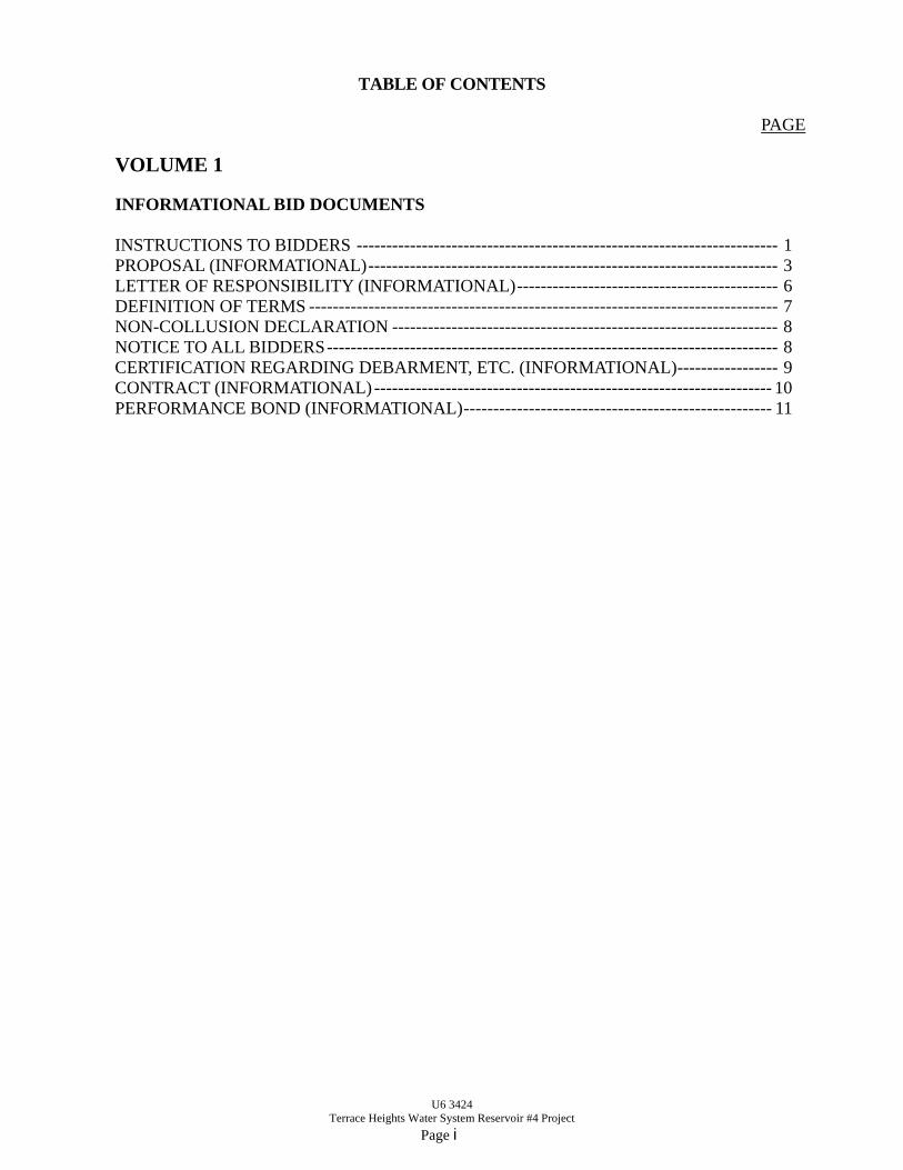
TABLE OF CONTENTS
PAGE
VOLUME 1
INFORMATIONAL BID DOCUMENTS
INSTRUCTIONS TO BIDDERS ----------------------------------------------------------------------- 1 PROPOSAL (INFORMATIONAL) --------------------------------------------------------------------- 3 LETTER OF RESPONSIBILITY (INFORMATIONAL) -------------------------------------------- 6 DEFINITION OF TERMS ------------------------------------------------------------------------------- 7 NON-COLLUSION DECLARATION ----------------------------------------------------------------- 8 NOTICE TO ALL BIDDERS ---------------------------------------------------------------------------- 8 CERTIFICATION REGARDING DEBARMENT, ETC. (INFORMATIONAL) ----------------- 9 CONTRACT (INFORMATIONAL) ------------------------------------------------------------------- 10 PERFORMANCE BOND (INFORMATIONAL) ---------------------------------------------------- 11
U6 3424 Terrace Heights Water System Reservoir #4 Project
Page ii
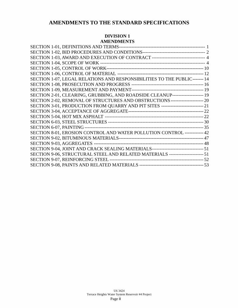
AMENDMENTS TO THE STANDARD SPECIFICATIONS
DIVISION 1
AMENDMENTS SECTION 1-01, DEFINITIONS AND TERMS ------------------------------------------------------- 1 SECTION 1-02, BID PROCEDURES AND CONDITIONS ---------------------------------------- 2 SECTION 1-03, AWARD AND EXECUTION OF CONTRACT ---------------------------------- 4 SECTION 1-04, SCOPE OF WORK ------------------------------------------------------------------- 4 SECTION 1-05, CONTROL OF WORK-------------------------------------------------------------- 10 SECTION 1-06, CONTROL OF MATERIAL ------------------------------------------------------- 12 SECTION 1-07, LEGAL RELATIONS AND RESPONSIBILITIES TO THE PUBLIC ------- 14 SECTION 1-08, PROSECUTION AND PROGRESS ---------------------------------------------- 16 SECTION 1-09, MEASUREMENT AND PAYMENT---------------------------------------------- 19 SECTION 2-01, CLEARING, GRUBBING, AND ROADSIDE CLEANUP -------------------- 19 SECTION 2-02, REMOVAL OF STRUCTURES AND OBSTRUCTIONS --------------------- 20 SECTION 3-01, PRODUCTION FROM QUARRY AND PIT SITES --------------------------- 21 SECTION 3-04, ACCEPTANCE OF AGGREGATE ------------------------------------------------ 22 SECTION 5-04, HOT MIX ASPHALT --------------------------------------------------------------- 22 SECTION 6-03, STEEL STRUCTURES ------------------------------------------------------------- 30 SECTION 6-07, PAINTING ---------------------------------------------------------------------------- 35 SECTION 8-01, EROSION CONTROL AND WATER POLLUTION CONTROL ------------ 42 SECTION 9-02, BITUMINOUS MATERIALS ------------------------------------------------------ 47 SECTION 9-03, AGGREGATES ---------------------------------------------------------------------- 48 SECTION 9-04, JOINT AND CRACK SEALING MATERIALS --------------------------------- 51 SECTION 9-06, STRUCTURAL STEEL AND RELATED MATERIALS ---------------------- 51 SECTION 9-07, REINFORCING STEEL ------------------------------------------------------------ 52 SECTION 9-08, PAINTS AND RELATED MATERIALS ----------------------------------------- 53
U6 3424 Terrace Heights Water System Reservoir #4 Project
Page iii
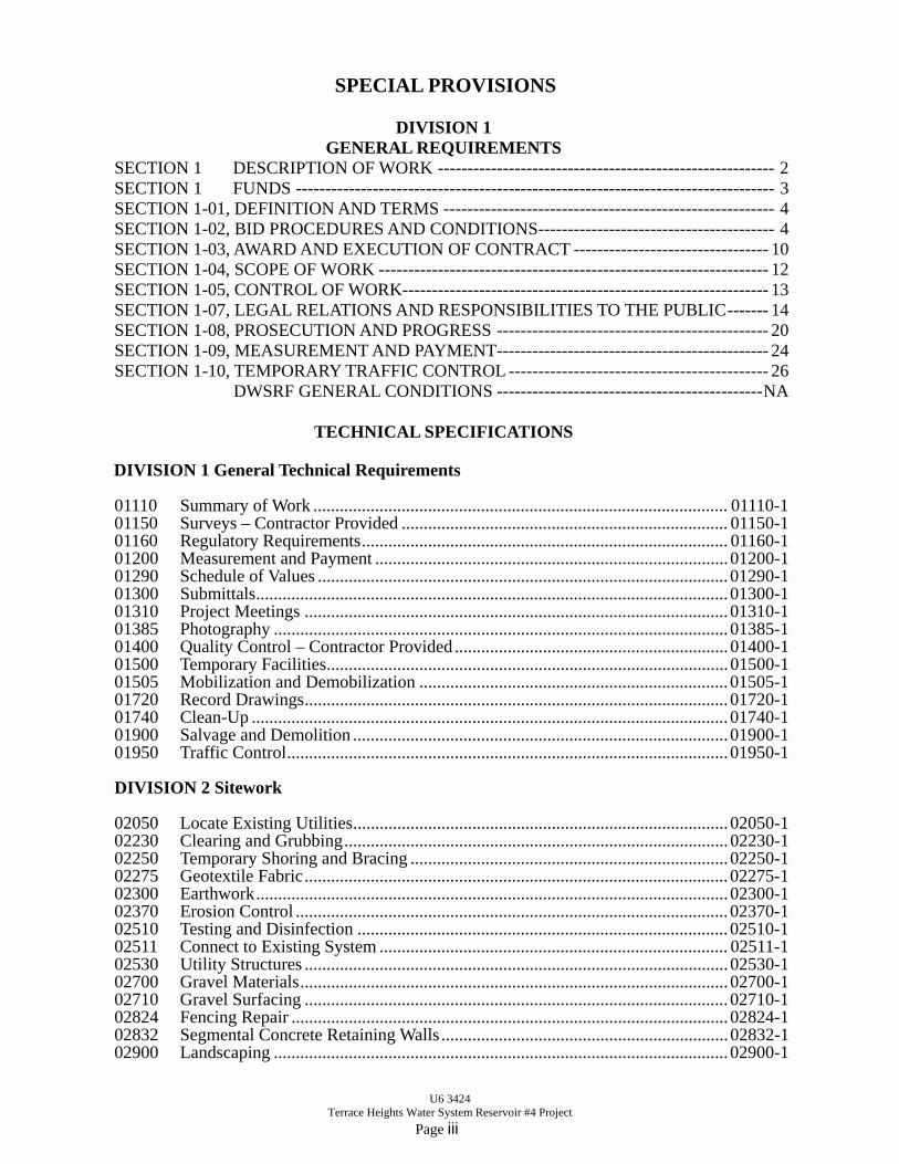
SPECIAL PROVISIONS
DIVISION 1 GENERAL REQUIREMENTS
SECTION 1 DESCRIPTION OF WORK --------------------------------------------------------- 2 SECTION 1 FUNDS --------------------------------------------------------------------------------- 3 SECTION 1-01, DEFINITION AND TERMS -------------------------------------------------------- 4 SECTION 1-02, BID PROCEDURES AND CONDITIONS ---------------------------------------- 4 SECTION 1-03, AWARD AND EXECUTION OF CONTRACT --------------------------------- 10 SECTION 1-04, SCOPE OF WORK ------------------------------------------------------------------ 12 SECTION 1-05, CONTROL OF WORK-------------------------------------------------------------- 13 SECTION 1-07, LEGAL RELATIONS AND RESPONSIBILITIES TO THE PUBLIC ------- 14 SECTION 1-08, PROSECUTION AND PROGRESS ---------------------------------------------- 20 SECTION 1-09, MEASUREMENT AND PAYMENT---------------------------------------------- 24 SECTION 1-10, TEMPORARY TRAFFIC CONTROL -------------------------------------------- 26 DWSRF GENERAL CONDITIONS --------------------------------------------- NA
TECHNICAL SPECIFICATIONS
DIVISION 1 General Technical Requirements 01110 Summary of Work .............................................................................................. 01110-1 01150 Surveys – Contractor Provided .......................................................................... 01150-1 01160 Regulatory Requirements ................................................................................... 01160-1 01200 Measurement and Payment ................................................................................ 01200-1 01290 Schedule of Values ............................................................................................. 01290-1 01300 Submittals ........................................................................................................... 01300-1 01310 Project Meetings ................................................................................................ 01310-1 01385 Photography ....................................................................................................... 01385-1 01400 Quality Control – Contractor Provided .............................................................. 01400-1 01500 Temporary Facilities ........................................................................................... 01500-1 01505 Mobilization and Demobilization ...................................................................... 01505-1 01720 Record Drawings ................................................................................................ 01720-1 01740 Clean-Up ............................................................................................................ 01740-1 01900 Salvage and Demolition ..................................................................................... 01900-1 01950 Traffic Control .................................................................................................... 01950-1 DIVISION 2 Sitework 02050 Locate Existing Utilities ..................................................................................... 02050-1 02230 Clearing and Grubbing ....................................................................................... 02230-1 02250 Temporary Shoring and Bracing ........................................................................ 02250-1 02275 Geotextile Fabric ................................................................................................ 02275-1 02300 Earthwork ........................................................................................................... 02300-1 02370 Erosion Control .................................................................................................. 02370-1 02510 Testing and Disinfection .................................................................................... 02510-1 02511 Connect to Existing System ............................................................................... 02511-1 02530 Utility Structures ................................................................................................ 02530-1 02700 Gravel Materials ................................................................................................. 02700-1 02710 Gravel Surfacing ................................................................................................ 02710-1 02824 Fencing Repair ................................................................................................... 02824-1 02832 Segmental Concrete Retaining Walls ................................................................. 02832-1 02900 Landscaping ....................................................................................................... 02900-1
U6 3424 Terrace Heights Water System Reservoir #4 Project
Page iv
DIVISION 3 Concrete 03200 Concrete Reinforcement..................................................................................... 03200-1 03300 Cast-in-Place Concrete ....................................................................................... 03300-1 DIVISION 5 Metals 05120 Structural Steel ................................................................................................... 05120-1 05500 Miscellaneous Metal Fabrications...................................................................... 05500-1 DIVISION 8 Doors and Windows 08310 Metal Access Hatches ........................................................................................ 08310-1 DIVISION 9 Finishes 09900 Painting .............................................................................................................. 09900-1 09970 Reservoir Surface Preparation and Painting ...................................................... 09970-1
DIVISION 10 Specialties 10300 Safety Equipment ............................................................................................... 10300-1
DIVISION 13 Special Construction 13211 Unanchored Steel Reservoir ............................................................................... 13211-1 13418 Pressure Switches ............................................................................................... 13418-1 13419 Pressure (Gauge) Transmitters ........................................................................... 13419-1 13424 Float Switches .................................................................................................... 13424-1 DIVISION 15 Mechanical 15050 Piping Systems ................................................................................................... 15050-1 15100 Valves ................................................................................................................. 15100-1 DIVISION 16 Electrical 16010 Basic Electrical Requirements ........................................................................... 16010-1 16050 Basic Electrical Materials and Methods ............................................................. 16050-1 16060 Grounding .......................................................................................................... 16060-1 16120 Conductors and Cables ....................................................................................... 16120-1 16130 Raceway and Boxes ........................................................................................... 16130-1 16140 Wiring Devices ................................................................................................... 16140-1 16520 Exterior Lighting ................................................................................................ 16520-1
U6 3424 Terrace Heights Water System Reservoir #4 Project
Page v
APPENDIX A - PREVAILING WAGE RATES
Washington State Prevailing Wage Rates - Yakima County Benefit Code Key Supplement to Wage Rates Federal Wage Rates
APPENDIX B – PERMITS APPENDIX C – STANDARD PLANS APPENDIX D – GEOTECHNICAL REPORT APPENDIX E – PAINT TESTING RESULTS APPENDIX F – RESERVOIR NO. 1 SHOP DRAWINGS

INFORMATIONAL BID DOCUMENTS
INFORMATIONAL BID DOCUMENTS U6 3424
1
INSTRUCTIONS TO BIDDERS DELIVERY OF PROPOSALS Sealed bids will be received at the following location before the specified time: Yakima County Public Services, Fourth Floor County Courthouse, 128 N. 2nd Street, Yakima, Washington 98901 until 2:00 p.m. of the bid opening date. Each proposal, or bid shall be completely sealed in a separate package, addressed to the Engineer of Yakima County with the name of the improvements for which the bid is submitted plainly written on the outside of the package. No oral, telephonic, facsimile, or telegraphic Bids or modifications shall be accepted. DATE OF OPENING BIDS The bid opening date for this project shall be December 16, 2015 . The bids shall be publicly opened and read after 2:00 p.m. on that date at the following location:
Yakima County Road Engineer’s Office, fourth floor, Yakima County Courthouse, 128 N. 2nd Street, Yakima, Washington 98901.
RIGHT TO REJECT BIDS: The right is reserved to reject any and all proposals, to accept the proposal or proposals deemed best for the County or to advertise for new proposals when in the opinion of the Board the best interest of the County shall be promoted thereby. BASIS OF AWARDS: The basis of award will be on either Schedules A and B combined or on Schedules A and C combined. PROPOSAL GUARANTY: A certified check, cashiers check, cash or bid bond made payable to the Treasurer of the County of Yakima for an amount equal to at least five percent (5%) of the total amount bid must accompany each bid as evidence of good faith and as a guarantee that if awarded the Contract the bidder shall execute the Contract and give Bond as required. FORM FURNISHED: Each bid must be made on authorized “Bid Document” forms supplied by Yakima County. Any bid submitted on forms marked “Informational” or otherwise watermarked shall be considered irregular and will be rejected. Bid Document forms may be purchased from the County Road Engineer’s office, 128 North 2nd Street, 4th Floor County Courthouse, Yakima, Washington 98901, (509) 574-2300 for $30.00 per set, non-refundable. CIVIL RIGHTS: Yakima County in accordance with Title VI of the Civil Rights Act of 1964, 78 Stat. 252, 42 U.S.C. 2000d to 2000-4 and Title 49, Code of Federal Regulations, Department of Transportation, subtitle A, Office of the Secretary, Part 21, nondiscrimination in federally assisted programs of the Department of Transportation issued pursuant to such Act, hereby notifies all bidders that it shall affirmatively insure that in any contract entered into pursuant to this advertisement, disadvantaged business enterprises shall be afforded full opportunity to submit bids in response to this invitation and shall not be discriminated against on the grounds of race, color or national origin in consideration for an award.
INFORMATIONAL BID DOCUMENTS U6 3424
2
ADDITIONAL INFORMATION:
1. “All work performed on this project will be subject to the higher of the prevailing state or federal; Davis Bacon wage rates.”
2. Yakima County is an Equal Opportunity Affirmative Action Employer.” 3. “Small, Minority, and Woman-owned firms are encouraged to submit bids.” 4. Buy-American requirement of P.L. 113-76 Consolidated Appropriations Act of 2014 for
American Iron and Steel. The following information must be obtained from all prime and subcontractors:
a. Entity’s name with point of contact; b. Entity’s mailing address, telephone number, and e-mail address; c. The procurement on which the entity bid or quoted, and when; and d. Entity’s status as an MBE/WBE or non-MBE/WBE.
Financing of the Project has been provided by Yakima County, Washington and the Washington State Drinking Water State Revolving Fund program with federal funds from the Environmental Protection Agency. Yakima County expressly reserves the right to reject any or all Proposals and to waive minor irregularities or informalities and to Award the Project to the lowest responsive, responsible bidder as it best serves the interests of the County and of the Schedules awarded. YAKIMA COUNTY IS AN EQUAL OPPORTUNITY EMPLOYER
INFORMATIONAL BID DOCUMENTS U6 3424
3
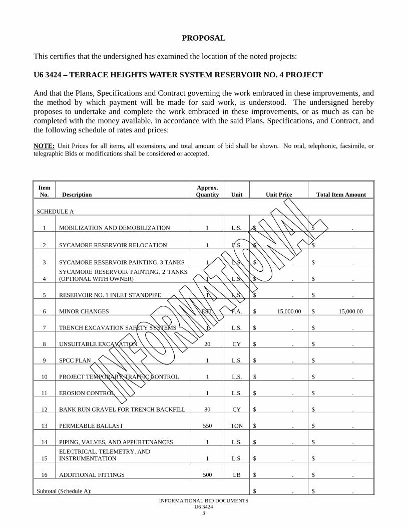
PROPOSAL This certifies that the undersigned has examined the location of the noted projects: U6 3424 – TERRACE HEIGHTS WATER SYSTEM RESERVOIR NO. 4 PROJECT And that the Plans, Specifications and Contract governing the work embraced in these improvements, and the method by which payment will be made for said work, is understood. The undersigned hereby proposes to undertake and complete the work embraced in these improvements, or as much as can be completed with the money available, in accordance with the said Plans, Specifications, and Contract, and the following schedule of rates and prices: NOTE: Unit Prices for all items, all extensions, and total amount of bid shall be shown. No oral, telephonic, facsimile, or telegraphic Bids or modifications shall be considered or accepted.
Item No. Description
Approx. Quantity Unit Unit Price Total Item Amount
SCHEDULE A
1 MOBILIZATION AND DEMOBILIZATION 1 L.S. $ . $ .
2 SYCAMORE RESERVOIR RELOCATION 1 L.S. $ . $ .
3
SYCAMORE RESERVOIR PAINTING, 3 TANKS 1 L.S. $ . $ .
4 SYCAMORE RESERVOIR PAINTING, 2 TANKS (OPTIONAL WITH OWNER) 1 L.S. $ . $ .
5 RESERVOIR NO. 1 INLET STANDPIPE 1 L.S. $ . $ .
6 MINOR CHANGES EST. F.A. $ 15,000.00 $ 15,000.00
7 TRENCH EXCAVATION SAFETY SYSTEMS 1 L.S. $ . $ .
8 UNSUITABLE EXCAVATION 20 CY $ . $ .
9 SPCC PLAN 1 L.S. $ . $ .
10 PROJECT TEMPORARY TRAFFIC CONTROL 1 L.S. $ . $ .
11 EROSION CONTROL 1 L.S. $ . $ .
12 BANK RUN GRAVEL FOR TRENCH BACKFILL 80 CY $ . $ .
13 PERMEABLE BALLAST 550 TON $ . $ .
14 PIPING, VALVES, AND APPURTENANCES 1 L.S. $ . $ .
15 ELECTRICAL, TELEMETRY, AND INSTRUMENTATION 1 L.S. $ . $ .
16 ADDITIONAL FITTINGS 500 LB $ . $ .
Subtotal (Schedule A): $ . $ .
INFORMATIONAL BID DOCUMENTS U6 3424
4
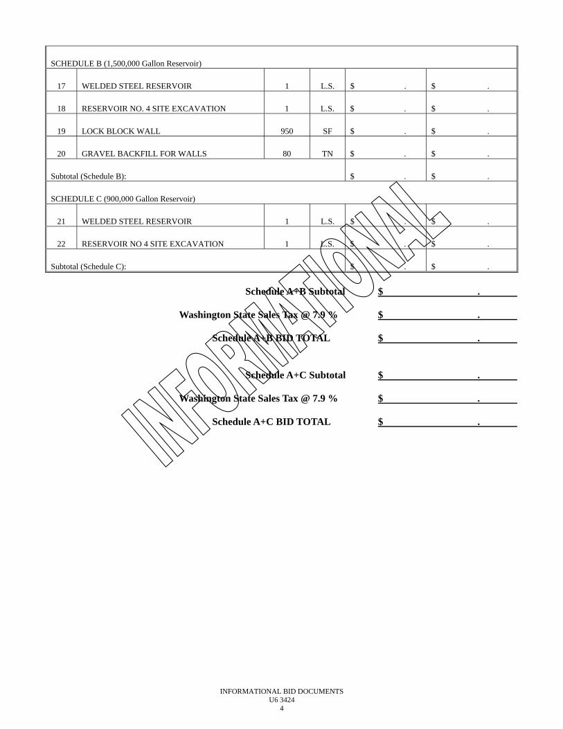
SCHEDULE B (1,500,000 Gallon Reservoir)
17 WELDED STEEL RESERVOIR 1 L.S. $ . $ .
18 RESERVOIR NO. 4 SITE EXCAVATION 1 L.S. $ . $ .
19 LOCK BLOCK WALL 950 SF $ . $ .
20 GRAVEL BACKFILL FOR WALLS 80 TN $ . $ .
Subtotal (Schedule B): $ . $ .
SCHEDULE C (900,000 Gallon Reservoir)
21 WELDED STEEL RESERVOIR 1 L.S. $ . $ .
22 RESERVOIR NO 4 SITE EXCAVATION 1 L.S. $ . $ .
Subtotal (Schedule C): $ . $ .
Schedule A+B Subtotal $ .
Washington State Sales Tax @ 7.9 % $ .
Schedule A+B BID TOTAL $ .
Schedule A+C Subtotal $ .
Washington State Sales Tax @ 7.9 % $ .
Schedule A+C BID TOTAL $ .
INFORMATIONAL BID DOCUMENTS U6 3424
5
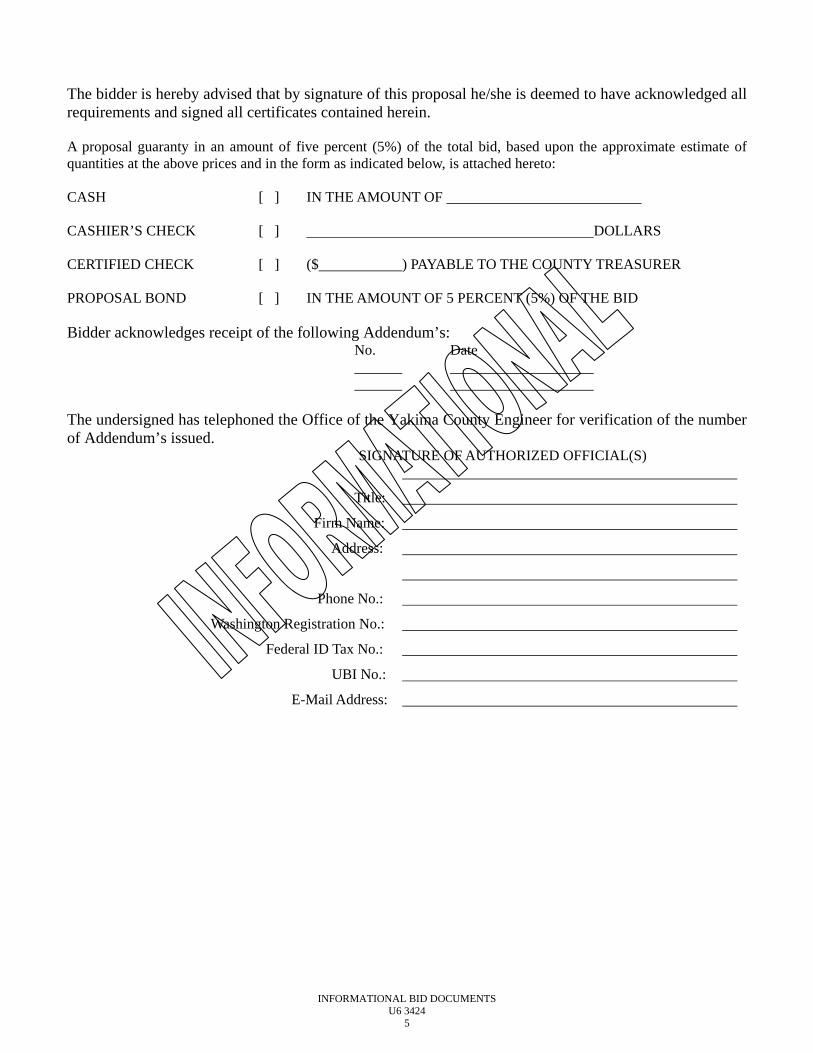
The bidder is hereby advised that by signature of this proposal he/she is deemed to have acknowledged all requirements and signed all certificates contained herein. A proposal guaranty in an amount of five percent (5%) of the total bid, based upon the approximate estimate of quantities at the above prices and in the form as indicated below, is attached hereto: CASH [ ] IN THE AMOUNT OF CASHIER’S CHECK [ ] DOLLARS CERTIFIED CHECK [ ] ($ ) PAYABLE TO THE COUNTY TREASURER PROPOSAL BOND [ ] IN THE AMOUNT OF 5 PERCENT (5%) OF THE BID Bidder acknowledges receipt of the following Addendum’s: No. Date The undersigned has telephoned the Office of the Yakima County Engineer for verification of the number of Addendum’s issued.
SIGNATURE OF AUTHORIZED OFFICIAL(S)
Title:
Firm Name:
Address:
Phone No.:
Washington Registration No.:
Federal ID Tax No.:
UBI No.:
E-Mail Address:
INFORMATIONAL BID DOCUMENTS U6 3424
6
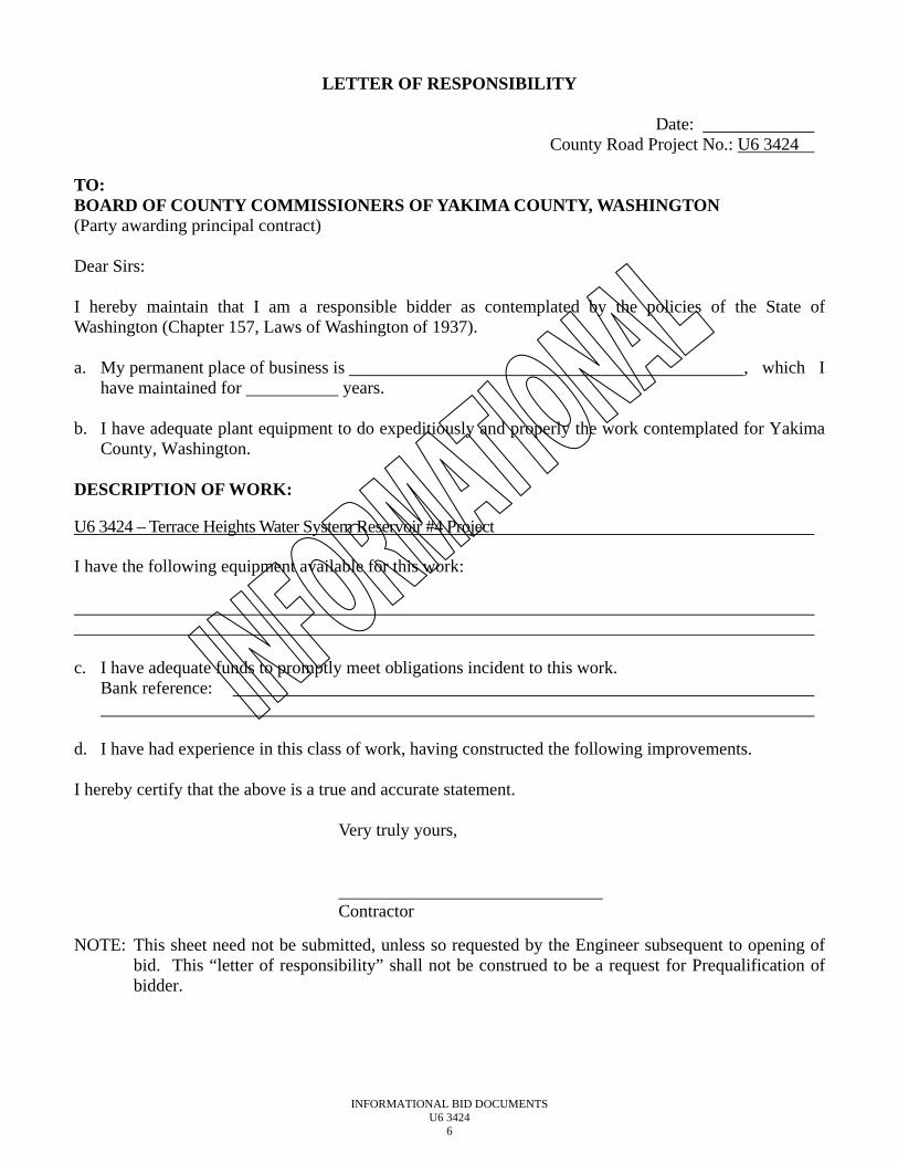
LETTER OF RESPONSIBILITY
Date: County Road Project No.: U6 3424
TO: BOARD OF COUNTY COMMISSIONERS OF YAKIMA COUNTY, WASHINGTON (Party awarding principal contract) Dear Sirs: I hereby maintain that I am a responsible bidder as contemplated by the policies of the State of Washington (Chapter 157, Laws of Washington of 1937). a. My permanent place of business is , which I
have maintained for years. b. I have adequate plant equipment to do expeditiously and properly the work contemplated for Yakima
County, Washington. DESCRIPTION OF WORK: U6 3424 – Terrace Heights Water System Reservoir #4 Project I have the following equipment available for this work: c. I have adequate funds to promptly meet obligations incident to this work.
Bank reference:
d. I have had experience in this class of work, having constructed the following improvements. I hereby certify that the above is a true and accurate statement. Very truly yours, Contractor
NOTE: This sheet need not be submitted, unless so requested by the Engineer subsequent to opening of bid. This “letter of responsibility” shall not be construed to be a request for Prequalification of bidder.
INFORMATIONAL BID DOCUMENTS U6 3424
7
DEFINITION OF TERMS
In interpreting these specifications, the following definitions shall prevail: STATE: The State of Washington. SECRETARY OF TRANSPORTATION: Secretary of Transportation of the State of Washington. BOARD: The Board of County Commissioners of Yakima County. ENGINEER: County, or construction engineer, or his duly authorized assistants by whom all explanations and directions necessary for the satisfactory prosecution and completion of the work described in these specifications will be given. CONTRACTOR AND/OR SUPPLIER: The person, firm, co-partnership, or corporation, or any lawful agent of such person, firm, partnership or corporation constituting one of the principals to the contract and undertaking to perform the work herein specified. CONTRACT: The Agreement between the Contractor and the County of Yakima acting through the Board of County Commissioners. The contract shall include the accepted “Proposal”, “Plans”, “Specifications” and “Contract Bond”, also any and all supplemental agreements which reasonably could be required to complete the construction of the work in a substantial and acceptable manner. PROPOSAL: The written offer, or copy thereof of the bidder to perform the work proposed. PLANS: The officially approved drawings, or reproductions thereof attached to this contract. SPECIFICATIONS: The directions, provisions and requirements contained herein, together with all written agreements made, or to be made pertaining to the method and manner of performing the work, or to the quantities and qualities of materials to be furnished under the contract. CONTRACT BOND: The approved form of security furnished by the Contractor and his surety as a guarantee of good faith on the part of the Contractor to execute the work in accordance with the terms of the contract. LABORATORY: The laboratories of the Department of Transportation, or other laboratories designated by the engineer. AMOUNT OF THE CONTRACT: For the purpose of awarding the contract and determining the amount of the bond, the lump sum bid, or the summation of the products of the approximate quantities shown on the plans or otherwise stated by the unit prices will be considered the total amount of the bid and the full amount of the contract price.
INFORMATIONAL BID DOCUMENTS U6 3424
8
Failure to return this Declaration as part of the bid proposal package will make the bid nonresponsive and ineligible for award.
NON-COLLUSION DECLARATION
I, by signing the proposal, hereby declare, under penalty of perjury under the laws of the United States that the following statements are true and correct:
1. That the undersigned person(s), firm, association or corporation has (have) not, either directly or indirectly, entered into any agreement, participated in any collusion, or otherwise taken any action in restraint of free competitive bidding in connection with the project for which this proposal is submitted.
2. That by signing the signature page of this proposal, I am
deemed to have signed and have agreed to the provisions of this declaration.
NOTICE TO ALL BIDDERS
To report bid rigging activities call:
1-800-424-9071
The U. S. Department of Transportation (USDOT) operates the above toll-free “hotline” Monday through Friday, 8:00 a.m. to 5:00 p.m., eastern time. Anyone with knowledge of possible bid rigging, bidder collusion, or other fraudulent activities should use the “hotline” to report such activities. The “hotline” is part of USDOT’s continuing effort to identify and investigate highway construction contract fraud and abuse and is operated under the direction of the USDOT Inspector General. All information will be treated confidentially and caller anonymity will be respected.
INFORMATIONAL BID DOCUMENTS U6 3424
9
Certification Regarding Debarment, Suspension, Ineligibility and Voluntary Exclusion
Lower Tier Covered Transactions This certification is required by the regulations implementing Executive Order 12549, Debarment and Suspension, 29 CFR Part 98, Section 98.510, Participant’s responsibilities. The regulations were published as Part VII of the May 26, 1998 Federal Register (pages 19160-19211).
(BEFORE COMPLETING CERTIFICATION, READ ATTACHED INSTRUCTIONS WHICH ARE AN INTEGRAL PART OF THE CERTIFICATION)
(1) The prospective recipient of federal assistance funds certifies, by submission of this proposal, that
neither it nor its principals are presently debarred, suspended, proposed for debarment, declared ineligible, or voluntarily excluded from participation in this transaction by any federal department or agency.
(2) Where the prospective recipient of federal assistance funds is unable to certify to any of the
statements in this certification, such prospective participant shall attach an explanation to this proposal.
This certification is also applicable to violations to prevailing wage law (chapter 39.12 RCW), registration law (chapter 18.27 RCW), or industrial insurance law (chapter 51.48 RCW). Name and Title of Authorized Representative Signature Date
INFORMATIONAL BID DOCUMENTS U6 3424
10
CONTRACT
THIS AGREEMENT is made and entered into between Yakima County acting under and by virtue of Titles 36 and 39 RCW, hereinafter called the “COUNTY” and , hereinafter called the “CONTRACTOR”. That in consideration of the terms and conditions contained herein and attached and made a part of this agreement, the parties hereto covenant and agree as follows: I. The CONTRACTOR shall do all work and furnish all tools and equipment for U6 3424 – Terrace Heights Water
System Reservoir #4 Project, and shall perform any changes in the work in accordance with the Contract Documents, which include the Contract Form, Bidder’s completed Proposal Form, Scope of Work, Contract Plans, Contract Provisions, Standard Specifications, Standard Plans, Addenda, various certifications and affidavits, supplemental agreements, and any change orders.
II. The CONTRACTOR shall provide and bear the expense of all equipment, material and labor of any sort whatsoever
that may be required for the transfer of materials and for constructing and completing the work provided for in the Contract Documents except those items mentioned therein to be furnished by Yakima County.
III. The COUNTY hereby promises and agrees to pay the CONTRACTOR according to the conditions stated in the
Contract Documents. IV. The CONTRACTOR for itself, and for its heirs, executors, administrators, successors and assigns does hereby agree
to the full performance of all the covenants herein contained upon the part of the CONTRACTOR. V. It is further provided that no liability shall attach to the COUNTY by reason of entering into this Contract, except as
expressly provided herein. VI. The parties agree that, for the purpose of this agreement, the CONTRACTOR is an independent contractor and neither
the CONTRACTOR nor any employee of the CONTRACTOR is an employee of the COUNTY. Neither the CONTRACTOR nor any employee of the CONTRACTOR is entitled to any benefits that the COUNTY provides its employees. The CONTRACTOR is solely responsible for payment of any statutory workers compensation or employer’s liability insurance as required by state law.
IN WITNESS WHEREOF, the CONTRACTOR has executed this instrument, on the date indicated below and Yakima County has caused this instrument to be executed in the name of said COUNTY by and through the Board of Yakima County Commissioners on the date indicated below. CONTRACTOR: BOARD OF YAKIMA COUNTY COMMISSIONERS Signed:___________________, 20__ Signed:___________________, 20__ Kevin J. Bouchey, Commissioner Signature for Michael D. Leita, Chairman Print or Type Name of Person Signing J. Rand Elliott, Commissioner Title ATTEST: Clerk of the Board Foregoing Contract approved and ratified , 20 Tiera Girard _____________________________ Approved as to form: Surety _____________________________
INFORMATIONAL BID DOCUMENTS U6 3424
11
Attorney in fact Deputy Prosecuting Attorney
PERFORMANCE BOND (RCW 39.08)
KNOW ALL MEN BY THESE PRESENTS, That , as “PRINCIPAL”, and , a corporation authorized to do business in the State of Washington, as “SURETY”, are jointly and severally held and bound unto Yakima County, Washington in the penal sum Dollars ($ ) for the payment of which by these presents we jointly and severally bind ourselves, our heirs, executors, administrators, assigns, and successors.
THE CONDITION of this bond is such that WHEREAS, on , 20 , the PRINCIPAL executed a certain Contract with the County, by the terms of which PRINCIPAL agrees to furnish all material and labor and will undertake and complete the construction of for U6 3424 – Terrace Heights Water System Reservoir #4 Project, according to the maps, plans and specifications made a part of said Contract, which Contract is attached hereto and by this reference is incorporated herein and made a part hereof. FURTHER, the SURETY agrees to be bound by the laws of the State of Washington and subjected to the jurisdiction of the State of Washington.
NOW, THEREFORE, if the PRINCIPAL shall faithfully perform all the provisions of such contract and pay all
laborers, mechanics, subcontractors and materialmen, and all persons who supply such persons or subcontractors with provisions or supplies for the carrying on of such work, then this obligation to be void, otherwise to remain in full force and effect.
Dated this day of , 2013. APPROVED: YAKIMA COUNTY PRINCIPAL By: By: Chair of the Board of Title: Yakima County Commissioners Date: 2013 SURETY By: Approved as to form: Attorney-in-Fact Deputy Prosecuting Attorney Name of Local Office of Agent Address of Local Office Agent BOND NUMBER YAKIMA COUNTY CONTRACT NUMBER
AMENDMENTS TO THE STANDARD SPECIFICATIONS
DIVISION 1
AMENDMENTS
U6 3424 Terrace Heights Water System Reservoir No. 4 A 1 AMENDMENTS
INTRO.AP1 1
INTRODUCTION 2
The following Amendments and Special Provisions shall be used in conjunction with the 2014 3 Standard Specifications for Road, Bridge, and Municipal Construction. 4 5
AMENDMENTS TO THE STANDARD SPECIFICATIONS 6 7 The following Amendments to the Standard Specifications are made a part of this contract and 8 supersede any conflicting provisions of the Standard Specifications. For informational purposes, 9 the date following each Amendment title indicates the implementation date of the Amendment or 10 the latest date of revision. 11 12 Each Amendment contains all current revisions to the applicable section of the Standard 13 Specifications and may include references which do not apply to this particular project. 14 15 1-01.AP1 16
Section 1-01, Definitions and Terms 17 August 3, 2015 18
1-01.3 Definitions 19 The definition for “Engineer” is revised to read: 20 21
The Contracting Agency’s representative who directly supervises the engineering and 22 administration of a construction Contract. 23 24
The definition for “Inspector” is revised to read: 25 26
The Engineer’s representative who inspects Contract performance in detail. 27 28
The definition for “Project Engineer” is revised to read: 29 30
Same as Engineer. 31 32
The following new term and definition is inserted after the definition for “Proposal Form”: 33 34
Reference Information – Information provided to the Contractor by the Contracting 35 Agency that is not part of the Contract. 36
37 The definition for “Working Drawings” is revised to read: 38 39
Drawings, plans, diagrams, or any other supplementary data or calculations, including a 40 schedule of submittal dates for Working Drawings where specified, which the Contractor 41 must submit to the Engineer. 42
43
U6 3424 Terrace Heights Water System Reservoir No. 4 A 2 AMENDMENTS
1-02.AP1 1
Section 1-02, Bid Procedures and Conditions 2 August 3, 2015 3
1-02.8(1) Noncollusion Declaration 4 The third paragraph is revised to read: 5 6
Therefore, by including the Non-collusion Declaration as part of the signed bid Proposal, the 7 Bidder is deemed to have certified and agreed to the requirements of the Declaration. 8
9 1-02.9 Delivery of Proposal 10 This section is revised to read: 11 12
For projects scheduled for Bid opening in Olympia, the Proposal shall be sealed and 13 submitted in the envelope provided with it to the address below or shall be submitted 14 electronically via Trns·Port Expedite® software and BidExpress®. The Bidder shall fill in 15 all blanks on this envelope to ensure proper handling and delivery. Bids are to be received 16 no later than until 11:00:59 A.M. Pacific time on the date of Bid opening: 17 18
Washington State Department of Transportation 19 Room 2D20 20 310 Maple Park Avenue SE 21 Olympia WA 98501-2361 22
23 For projects scheduled for Bid opening in other locations the Proposal shall be sealed and 24 submitted in the envelope provided with it at the location and time identified in the Special 25 Provisions. The Bidder shall fill in all blanks on this envelope to ensure proper handling and 26 delivery. 27 28 Proposals that are received as required will be publicly opened and read as specified in 29 Section 1-02.12. The Contracting Agency will not open or consider any Proposal when the 30 Proposal or Bid deposit is received after the time specified for receipt of Proposals or 31 received in a location other than that specified for receipt of Proposals. 32 33 When a Bid deposit is furnished in a physical format as specified in Section 1-02.7 the Bid 34 deposit shall be submitted in a sealed envelope marked as “BID SUPPLEMENT” and with 35 the Bidder’s company name, project title, and Bid date. 36
37 1-02.10 Withdrawing, Revising, or Supplementing Proposal 38 The first sentence of the third paragraph is revised to read: 39 40
Unless specifically allowed in the Contract, emailed requests to withdraw, revise, or 41 supplement a Proposal are not acceptable. 42
43 1-02.13 Irregular Proposals 44 This section is revised to read: 45
U6 3424 Terrace Heights Water System Reservoir No. 4 A 3 AMENDMENTS
1 1. A Proposal will be considered irregular and may be rejected if: 2 3
a. The Bidder is not prequalified; 4 5 b. The Bidder adds provisions reserving the right to reject or accept the Award, or 6
enter into the Contract; 7 8 c. A price per unit cannot be determined from the Bid Proposal; 9 10 d. The Proposal form is not properly executed; 11 12 e. The Bidder fails to submit or properly complete a Subcontractor list, if applicable, 13
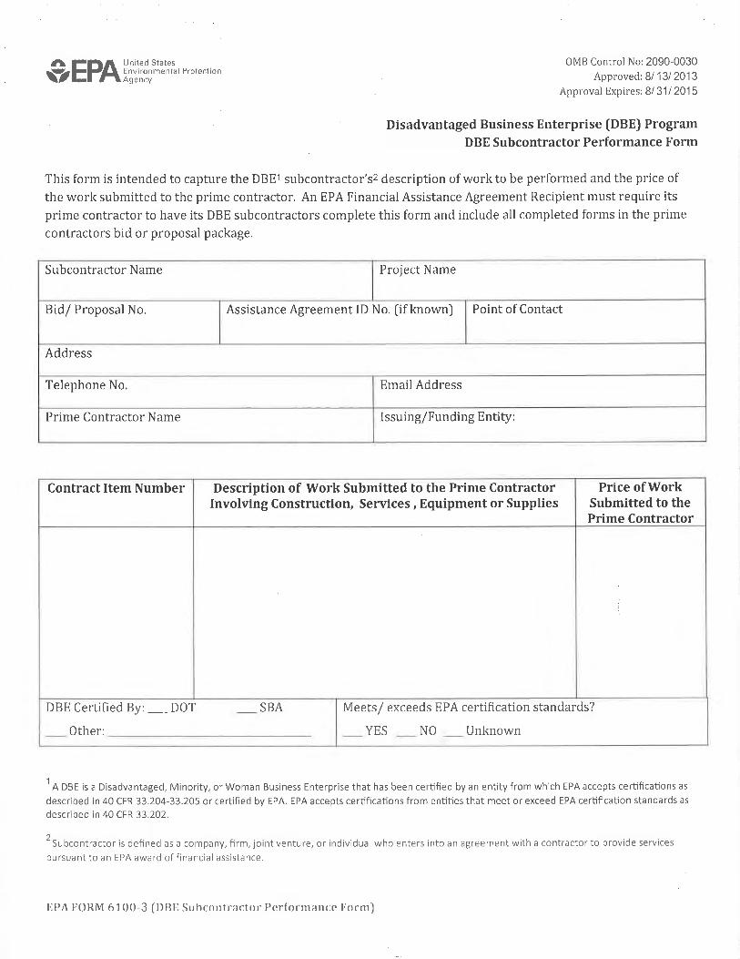
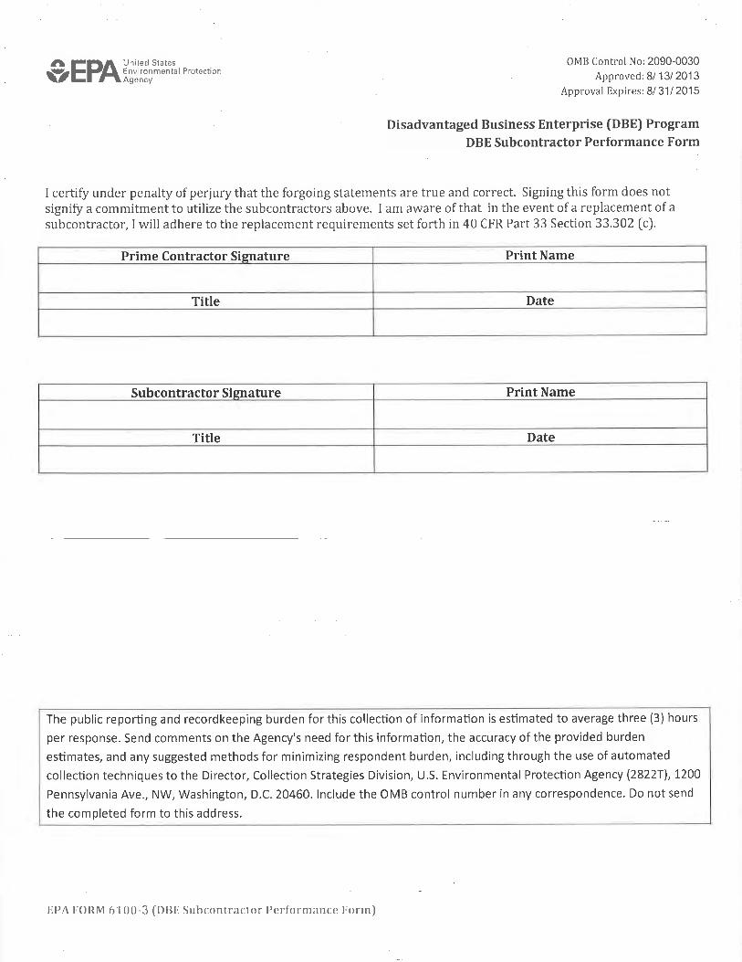
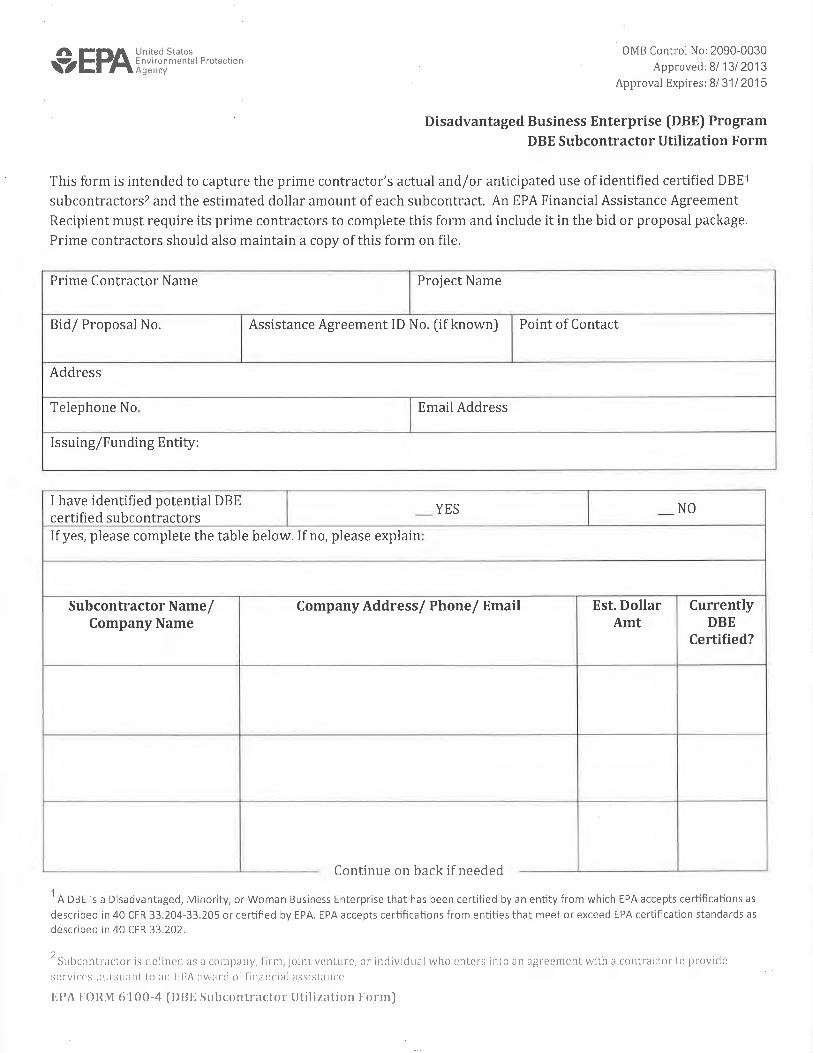
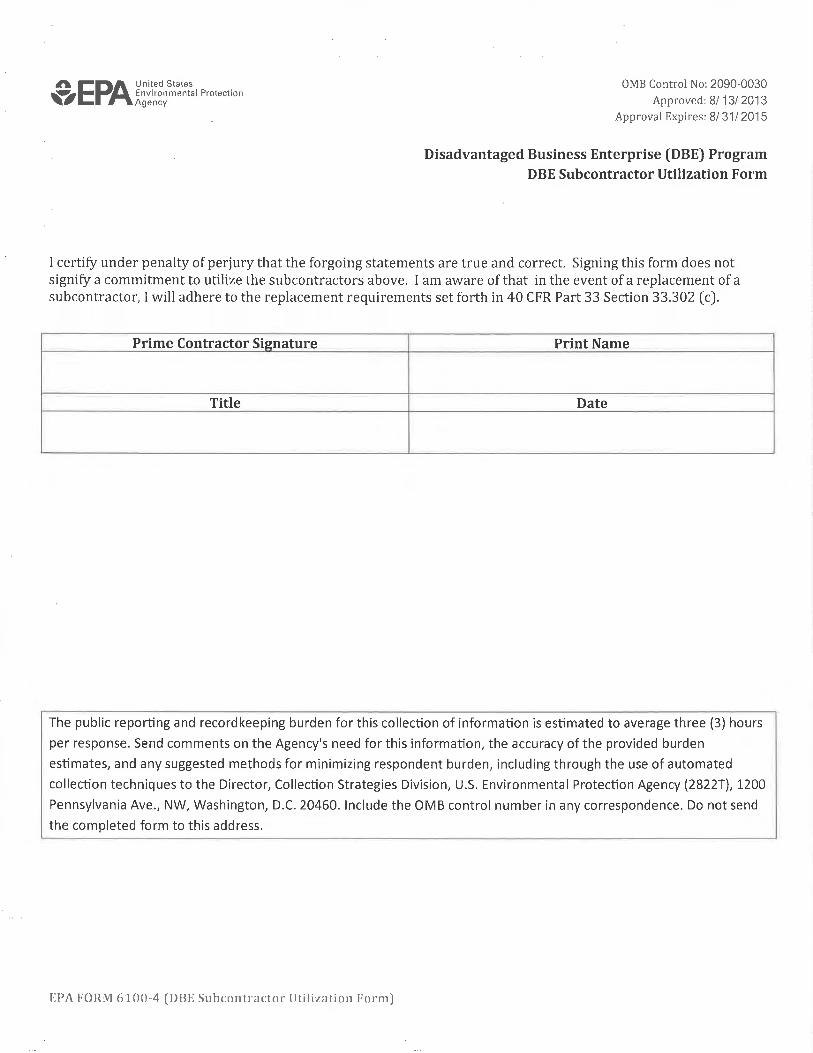
as required in Section 1-02.6; 14 15 f. The Bidder fails to submit or properly complete a Disadvantaged Business 16
Enterprise Utilization Certification, if applicable, as required in Section 1-02.6; 17 18 g. The Bidder fails to submit written confirmation from each DBE firm listed on the 19
Bidder’s completed Disadvantaged Business Enterprise Utilization Certification 20 that they are in agreement with the Bidder’s DBE participation commitment, if 21 applicable, as required in Section 1-02.6, or if the written confirmation that is 22 submitted fails to meet the requirements of the Special Provisions; 23
24 h. The Bidder fails to submit Disadvantaged Business Enterprise Good Faith Effort 25
documentation, if applicable, as required in Section 1-02.6, or if the documentation 26 that is submitted fails to demonstrate that a Good Faith Effort to meet the 27 Condition of Award was made; or 28
29 i. The Bid Proposal does not constitute a definite and unqualified offer to meet the 30
material terms of the Bid invitation. 31 32 2. A Proposal may be considered irregular and may be rejected if: 33 34
a. The Proposal does not include a unit price for every Bid item; 35 36 b. Any of the unit prices are excessively unbalanced (either above or below the 37
amount of a reasonable Bid) to the potential detriment of the Contracting Agency; 38 39 c. The authorized Proposal Form furnished by the Contracting Agency is not used or 40
is altered; 41 42 d. The completed Proposal form contains any unauthorized additions, deletions, 43
alternate Bids, or conditions; 44 45 e. Receipt of Addenda is not acknowledged; 46
U6 3424 Terrace Heights Water System Reservoir No. 4 A 4 AMENDMENTS
1 f. A member of a joint venture or partnership and the joint venture or partnership 2
submit Proposals for the same project (in such an instance, both Bids may be 3 rejected); or 4
5 g. If Proposal form entries are not made in ink. 6
7 1-03.AP1 8
Section 1-03, Award and Execution of Contract 9 January 5, 2015 10
1-03.3 Execution of Contract 11 The first paragraph is revised to read: 12 13
Within 20 calendar days after the Award date, the successful Bidder shall return the signed 14 Contracting Agency-prepared Contract, an insurance certification as required by Section 1-15 07.18, and a satisfactory bond as required by law and Section 1-03.4, and shall be registered 16 as a contractor in the state of Washington. 17
18 1-03.4 Contract Bond 19 The last word of item 3 is deleted. 20 21 Item 4 is renumbered to 5. 22 23 The following is inserted after item 3 (after the preceding Amendments are applied): 24 25
4. Be conditioned upon the payment of taxes, increases, and penalties incurred on the 26 project under titles 50, 51, and 82 RCW; and 27
28 1-03.5 Failure to Execute Contract 29 The first sentence is revised to read: 30 31
Failure to return the insurance certification and bond with the signed Contract as required in 32 Section 1-03.3, or failure to provide Disadvantaged, Minority or Women’s Business 33 Enterprise information if required in the Contract, or failure or refusal to sign the Contract, 34 or failure to register as a contractor in the state of Washington shall result in forfeiture of the 35 proposal bond or deposit of this Bidder. 36
37 1-04.AP1 38
Section 1-04, Scope of the Work 39 August 3, 2015 40
1-04.3 Vacant 41 This section, including title, is revised to read: 42 43
U6 3424 Terrace Heights Water System Reservoir No. 4 A 5 AMENDMENTS
1-04.3 Reference Information 1 Reference Information provided to the Contractor is not part of the Contract. The 2 Contracting Agency does not guarantee the accuracy of the Reference Information and is not 3 responsible for the content of the Reference Information in any manner. Any use of 4 Reference Information by the Contractor is done solely at the Contractor’s risk. 5
6 1-04.4 Changes 7 In the third paragraph, item number 1 and 2 are revised to read: 8 9
A. When the character of the Work as altered differs materially in kind or nature from that 10 involved or included in the original proposed construction; or 11
12 B. When an item of Work, as defined elsewhere in the Contract, is increased in excess of 13
125 percent or decreased below 75 percent of the original Contract quantity. For the 14 purpose of this Section, an item of Work will be defined as any item that qualifies for 15 adjustment under the provisions of Section 1-04.6. 16
17 The following two new sentences are inserted at the beginning of the eighth paragraph: 18 19
Within 14 calendar days of delivery of the change order the contractor shall endorse and 20 return the change order, request an extension of time for endorsement or respond in 21 accordance with Section 1-04.5. The Contracting Agency may unilaterally process the 22 change order if the Contractor fails to comply with these requirements. 23
24 The last two paragraphs are deleted. 25 26 This section is supplemented with the following new subsections: 27 28
1-04.4(2) Value Engineering Change Proposal (VECP) 29 1-04.4(2)A General 30 A VECP is a Contractor proposed change to the Contract Provisions which will 31 accomplish the projects functional requirements in a manner that is equal to or better 32 than the requirements in the Contract. The VECP may be: (1) at a less cost or time, or 33 (2) either no cost savings or a minor increase in cost with a reduction in Contract time. 34 The net savings or added costs to the Contract Work are shared by the Contractor and 35 Contracting Agency. 36 37 The Contractor may submit a VECP for changing the Plans, Specifications, or other 38 requirements of the Contract. The Engineer’s decision to accept or reject all or part of 39 the proposal is final and not subject to arbitration under the arbitration clause or 40 otherwise subject to litigation. 41 42
43
U6 3424 Terrace Heights Water System Reservoir No. 4 A 6 AMENDMENTS
The VECP shall meet all of the following: 1 2
1. Not adversely affect the long term life cycle costs. 3 4 2. Not adversely impact the ability to perform maintenance. 5 6 3. Provide the required safety and appearance. 7 8 4. Provide substitution for deleted or reduced Disadvantaged Business Enterprise 9
Condition of Award Work, Apprentice Utilization and Training. 10 11 VECPs that provide a time reduction shall meet the following requirements: 12 13
1. Time saving is a direct result of the VECP. 14 15 2. Liquidated damages penalties are not used to calculate savings. 16 17 3. Administrative/overhead cost savings experienced by either the Contractor or 18
Contracting Agency as a result of time reduction accrue to each party and are 19 not used to calculate savings. 20
21 1-04.4(2)B VECP Savings 22
1-04.4(2)B1 Proposal Savings 23 The incentive payment to the Contractor shall be one-half of the net savings of the 24 proposal calculated as follows: 25 26
1. (gross cost of deleted work) – (gross cost of added work) = (gross 27 savings) 28
29 2. (gross savings) – (Contractor’s engineering costs) – (Contracting 30
Agency’s costs) = (net savings) 31 32 3. (net savings) / 2 = (incentive pay) 33
34 The Contracting Agency’s costs shall be the actual consultant costs billed to the 35 Contracting Agency and in-house costs. Costs for personnel assigned to the 36 Engineer’s office shall not be included. 37 38 1-04.4(2)B2 Added Costs to Achieve Time Savings 39 The cost to achieve the time savings shall be calculated as follows: 40 41
1. (cost of added work) + (Contractor’s engineering costs - Contracting 42 Agency’s engineering costs) = (cost to achieve time savings) 43
44 2. (cost to achieve time savings) / 2 = (Contracting Agency’s share of added 45
cost) 46
U6 3424 Terrace Heights Water System Reservoir No. 4 A 7 AMENDMENTS
1 If the timesaving proposal also involves deleting work and, as a result, creates a 2 savings for the Contracting Agency, then the Contractor shall also receive one-half 3 of the savings realized through the deletion. 4 5
1-04.4(2)C VECP Approval 6 1-04.4(2)C1 Concept Approval 7 The Contractor shall submit a written proposal to the Engineer for consideration. 8 The proposal shall contain the following information: 9 10
1. An explanation outlining the benefit provided by the change(s). 11 12 2. A narrative description of the proposed change(s). If applicable, the 13
discussion shall include a demonstration of functional equivalency or a 14 description of how the proposal meets the original contract scope of work. 15
16 3. A cost discussion estimating any net savings. Savings estimates will 17
generally follow the outline below under the section, “Proposal Savings”. 18 19 4. A statement providing the Contracting Agency with the right to use all or 20
any part of the proposal on future projects without future obligation or 21 compensation. 22
23 5. A statement acknowledging and agreeing that the Engineer’s decision to 24
accept or reject all or part of the proposal is final and not subject to 25 arbitration under the arbitration clause or otherwise be subject to claims 26 or disputes. 27
28 6. A statement giving the dates the Engineer must make a decision to accept 29
or reject the conceptual proposal, the date that approval to proceed must 30 be received, and the date the work must begin in order to not delay the 31 contract. If the Contracting Agency does not approve the VECP by the 32 date specified by the Contractor in their proposal the VECP will be 33 deemed rejected. 34
35 7. The submittal will include an analysis on other Work that may have costs 36
that changed as a result of the VECP. Traffic control and erosion control 37 shall both be included in addition to any other impacted Work. 38
39 After review of the proposal, the Engineer will respond in writing with acceptance 40 or rejection of the concept. This acceptance shall not be construed as authority to 41 proceed with any change contract work. Concept approval allows the Contractor 42 to proceed with the Work needed to develop final plans and other information to 43 receive formal approval and to support preparation of a change order. 44 45
U6 3424 Terrace Heights Water System Reservoir No. 4 A 8 AMENDMENTS
1-04.4(2)C2 Formal Approval 1 The Contractor’s submittal to the Engineer for formal approval shall include the 2 following: 3 4
1. Deleted Work – Include the calculated quantities of unit price Work to be 5 deleted. Include the proposed partial prices for portions of lump sum 6 Work deleted. For deletion of force account items include the time and 7 material estimates. 8
9 2. Added Work – Include the calculated quantities of unit price Work to be 10
added, either by original unit Contract prices or by new, negotiated unit 11 prices. For new items of Work include the quantities and proposed prices. 12
13 3. Contractor’s Engineering Costs – Submit the labor costs for the 14
engineering to develop the proposal; costs for Contractor employees 15 utilized in contract operations on a regular basis shall not be included. 16
17 4. Schedule Analysis – If the VECP is related to time savings, the Contractor 18
shall submit a partial progress schedule showing the changed Work. The 19 submittal shall also include a discussion comparing the partial progress 20 schedule with the approved progress schedule for the project. 21
22 5. Working Drawings – Type 3 Working Drawings shall be submitted; those 23
drawings which require engineering shall be a Type 3E. 24 25 Formal approval of the proposal will be documented by issuance of a change order. 26 The VECP change order will contain the following statements which the 27 Contractor agrees to by signing the change order: 28 29
1. The Contractor accepts design risk of all features, both temporary and 30 permanent, of the changed Work. 31
32 2. The Contractor accepts risk of constructability of the changed Work. 33 34 3. The Contractor provides the Contracting Agency with the right to use all 35
or any part of the proposal on future projects without further obligation or 36 compensation. 37
38
U6 3424 Terrace Heights Water System Reservoir No. 4 A 9 AMENDMENTS
1 VECP change orders will contain separate pay items for the items that are 2 applicable to the Proposal. These are as follows: 3 4
1. Deleted Work. 5 6 2. Added Work. 7 8 3. The Contractor’s engineering costs, reimbursed at 100 percent of the 9
Contractor’s cost. 10 11 4. Incentive payment to the Contractor. 12
13 When added Work costs exceed Deleted Work costs, but time savings make a 14 viable proposal, then items 3 and 4 above are replaced with the following: 15 16
3. The Contracting Agency’s share of added cost to achieve time savings. 17 18 4. The Contractor’s share of savings from deleted Work. 19
20 1-04.4(2)C3 Authority to Proceed with Changed Work 21 The authority for the Contractor to proceed with the VECP Work will be provided 22 by one of the following options: 23 24
1. Execution of the VECP change order, or 25 26 2. At the Contractor’s request the Contracting Agency may provide approval 27
by letter from the Engineer for the Work to proceed prior to execution of a 28 change order. All of the risk for proceeding with the VECP shall be the 29 responsibility of the Contractor. Additionally, the following criteria are 30 required to have been met: 31
32 a) Concept approval has been granted by the Contracting Agency. 33 34 b) All design reviews and approvals have been completed, including 35
plans and specifications. 36 37 c) The Contractor has guaranteed, in writing, the minimum savings to 38
the Contracting Agency. 39 40 1-04.4(1) Minor Changes 41 The first sentence of the first paragraph is revised to read: 42 43
Payments or credits for changes amounting to $25,000 or less may be made under the Bid 44 item “Minor Change”. 45
46
U6 3424 Terrace Heights Water System Reservoir No. 4 A 10 AMENDMENTS
1-04.5 Procedure and Protest by the Contractor 1 The first sentence of the first paragraph is revised to read: 2 3
The Contractor accepts all requirements of a change order by: (1) endorsing it, (2) writing a 4 separate acceptance, (3) not responding within the allotted time as outlined in Section 1-5 04.4, or (4) not protesting in the way this Section provides. 6
7 1-05.AP1 8
Section 1-05, Control of Work 9 August 4, 2014 10
1-05.1 Authority of the Engineer 11 In this section, “Project Engineer” is revised to read “Engineer”. 12 13 The second paragraph (up until the colon) is revised to read: 14 15
The Engineer’s decisions will be final on all questions including the following: 16 17 The first sentence in the third paragraph is revised to read: 18 19
The Engineer represents the Contracting Agency with full authority to enforce Contract 20 requirements. 21 22
1-05.2 Authority of Assistants and Inspectors 23 The first paragraph is revised to read: 24 25
The Engineer may appoint assistants and Inspectors to assist in determining that the Work 26 and materials meet the Contract requirements. Assistants and Inspectors have the authority 27 to reject defective material and suspend Work that is being done improperly, subject to the 28 final decisions of the Engineer. 29 30
In the third paragraph, “Project Engineer” is revised to read “Engineer”. 31 32 1-05.3 Plans and Working Drawings 33 This section’s title is revised to read: 34 35
Working Drawings 36 37
This section is revised to read: 38 39
The Contract may require the Contractor to submit Working Drawings for the performance 40 of the Work. Working Drawings shall be submitted by the Contractor electronically to the 41 Engineer in PDF format; drawing details shall be prepared in accordance with conventional 42 detailing practices. If the PDF format is found to be unacceptable, at the request of the 43 Engineer, the Contractor shall provide paper copies of the Working Drawings with drawings 44 on 11 by 17 inch sheets and calculations/text on 8½ by 11 inch sheets. 45
U6 3424 Terrace Heights Water System Reservoir No. 4 A 11 AMENDMENTS
1 Working Drawings will be classified under the following categories: 2 3
1. Type 1 – Submitted for Contracting Agency information. Submittal must be 4 received by the Contracting Agency a minimum of 7 calendar days before work 5 represented by the submittal begins. 6 7
2. Type 2 – Submitted for Contracting Agency review and comment. Unless otherwise 8 stated in the Contract, the Engineer will require up to 20 calendar days from the 9 date the Working Drawing is received until it is returned to the Contractor. The 10 Contractor shall not proceed with the Work represented by the Working Drawing 11 until comments from the Engineer have been addressed. 12 13
3. Type 2E – Same as a Type 2 Working Drawing with Engineering as described 14 below. 15 16
4. Type 3 – Submitted for Contracting Agency review and approval. Unless otherwise 17 stated in the Contract, the Engineer will require up to 30 calendar days from the 18 date the Working Drawing is received until it is returned to the Contractor. The 19 Contractor shall obtain the Engineer’s written approval before proceeding with the 20 Work represented by the Working Drawing. 21 22
5. Type 3E – Same as a Type 3 Working Drawing with Engineering as described 23 below. 24
25 All Working Drawings shall be considered Type 3 Working Drawings except as specifically 26 noted otherwise in the Contract. Unless designated otherwise by the Contractor, submittals 27 of Working Drawings will be reviewed in the order they are received by the Engineer. In the 28 event that several Working Drawings are received simultaneously, the Contractor shall 29 specify the sequence in which they are to be reviewed. If the Contractor does not submit a 30 review sequence for simultaneous Working Drawing submittals, the review sequence will be 31 at the Engineer’s discretion. 32 33 Working Drawings requiring Engineering, Type 2E and 3E, shall be prepared by (or under 34 the direction of) a Professional Engineer, licensed under Title 18 RCW, State of Washington, 35 and in accordance with WAC 196-23-020. Design calculations shall carry the Professional 36 Engineer’s signature and seal, date of signature, and registration number on the cover page. 37 The cover page shall also include the Contract number, Contract title and sequential index to 38 calculation page numbers. 39 40 If more than the specified number of days is required for the Engineer’s review of any 41 individual Working Drawing or resubmittal, an extension of time will be considered in 42 accordance with Section 1-08.8. 43
44
U6 3424 Terrace Heights Water System Reservoir No. 4 A 12 AMENDMENTS
1 Review or approval of Working Drawings shall neither confer upon the Contracting Agency 2 nor relieve the Contractor of any responsibility for the accuracy of the drawings or their 3 conformity with the Contract. The Contractor shall bear all risk and all costs of any Work 4 delays caused by rejection or nonapproval of Working Drawings. 5 6 Unit Bid prices shall cover all costs of Working Drawings. 7
8 1-06.AP1 9
Section 1-06, Control of Material 10 August 3, 2015 11
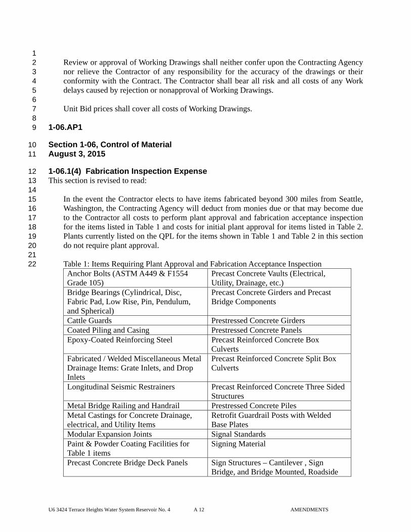
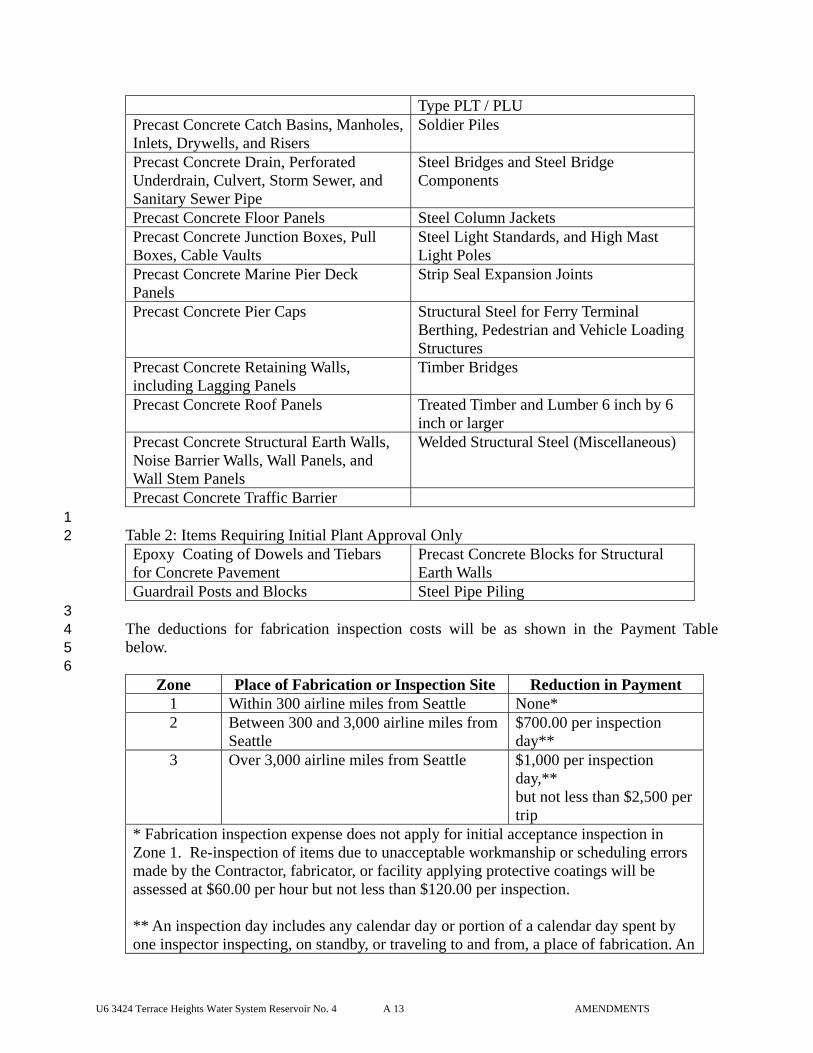
1-06.1(4) Fabrication Inspection Expense 12 This section is revised to read: 13 14
In the event the Contractor elects to have items fabricated beyond 300 miles from Seattle, 15 Washington, the Contracting Agency will deduct from monies due or that may become due 16 to the Contractor all costs to perform plant approval and fabrication acceptance inspection 17 for the items listed in Table 1 and costs for initial plant approval for items listed in Table 2. 18 Plants currently listed on the QPL for the items shown in Table 1 and Table 2 in this section 19 do not require plant approval. 20 21 Table 1: Items Requiring Plant Approval and Fabrication Acceptance Inspection 22 Anchor Bolts (ASTM A449 & F1554 Grade 105)
Precast Concrete Vaults (Electrical, Utility, Drainage, etc.)
Bridge Bearings (Cylindrical, Disc, Fabric Pad, Low Rise, Pin, Pendulum, and Spherical)
Precast Concrete Girders and Precast Bridge Components
Cattle Guards Prestressed Concrete Girders Coated Piling and Casing Prestressed Concrete Panels Epoxy-Coated Reinforcing Steel Precast Reinforced Concrete Box
Culverts Fabricated / Welded Miscellaneous Metal Drainage Items: Grate Inlets, and Drop Inlets
Precast Reinforced Concrete Split Box Culverts
Longitudinal Seismic Restrainers Precast Reinforced Concrete Three Sided Structures
Metal Bridge Railing and Handrail Prestressed Concrete Piles Metal Castings for Concrete Drainage, electrical, and Utility Items
Retrofit Guardrail Posts with Welded Base Plates
Modular Expansion Joints Signal Standards Paint & Powder Coating Facilities for Table 1 items
Signing Material
Precast Concrete Bridge Deck Panels Sign Structures – Cantilever , Sign Bridge, and Bridge Mounted, Roadside
U6 3424 Terrace Heights Water System Reservoir No. 4 A 13 AMENDMENTS
Type PLT / PLU Precast Concrete Catch Basins, Manholes, Inlets, Drywells, and Risers
Soldier Piles
Precast Concrete Drain, Perforated Underdrain, Culvert, Storm Sewer, and Sanitary Sewer Pipe
Steel Bridges and Steel Bridge Components
Precast Concrete Floor Panels Steel Column Jackets Precast Concrete Junction Boxes, Pull Boxes, Cable Vaults
Steel Light Standards, and High Mast Light Poles
Precast Concrete Marine Pier Deck Panels
Strip Seal Expansion Joints
Precast Concrete Pier Caps Structural Steel for Ferry Terminal Berthing, Pedestrian and Vehicle Loading Structures
Precast Concrete Retaining Walls, including Lagging Panels
Timber Bridges
Precast Concrete Roof Panels Treated Timber and Lumber 6 inch by 6 inch or larger
Precast Concrete Structural Earth Walls, Noise Barrier Walls, Wall Panels, and Wall Stem Panels
Welded Structural Steel (Miscellaneous)
Precast Concrete Traffic Barrier 1 Table 2: Items Requiring Initial Plant Approval Only 2 Epoxy Coating of Dowels and Tiebars for Concrete Pavement
Precast Concrete Blocks for Structural Earth Walls
Guardrail Posts and Blocks Steel Pipe Piling 3 The deductions for fabrication inspection costs will be as shown in the Payment Table 4 below. 5 6
Zone Place of Fabrication or Inspection Site Reduction in Payment 1 Within 300 airline miles from Seattle None* 2 Between 300 and 3,000 airline miles from
Seattle $700.00 per inspection day**
3 Over 3,000 airline miles from Seattle $1,000 per inspection day,** but not less than $2,500 per trip
* Fabrication inspection expense does not apply for initial acceptance inspection in Zone 1. Re-inspection of items due to unacceptable workmanship or scheduling errors made by the Contractor, fabricator, or facility applying protective coatings will be assessed at $60.00 per hour but not less than $120.00 per inspection. ** An inspection day includes any calendar day or portion of a calendar day spent by one inspector inspecting, on standby, or traveling to and from, a place of fabrication. An
U6 3424 Terrace Heights Water System Reservoir No. 4 A 14 AMENDMENTS
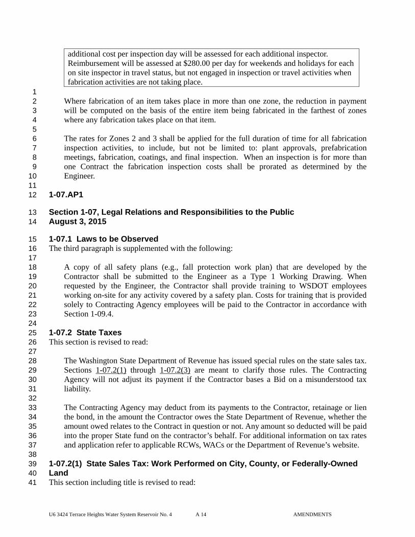
additional cost per inspection day will be assessed for each additional inspector. Reimbursement will be assessed at $280.00 per day for weekends and holidays for each on site inspector in travel status, but not engaged in inspection or travel activities when fabrication activities are not taking place.
1 Where fabrication of an item takes place in more than one zone, the reduction in payment 2 will be computed on the basis of the entire item being fabricated in the farthest of zones 3 where any fabrication takes place on that item. 4 5 The rates for Zones 2 and 3 shall be applied for the full duration of time for all fabrication 6 inspection activities, to include, but not be limited to: plant approvals, prefabrication 7 meetings, fabrication, coatings, and final inspection. When an inspection is for more than 8 one Contract the fabrication inspection costs shall be prorated as determined by the 9 Engineer. 10
11 1-07.AP1 12
Section 1-07, Legal Relations and Responsibilities to the Public 13 August 3, 2015 14
1-07.1 Laws to be Observed 15 The third paragraph is supplemented with the following: 16 17
A copy of all safety plans (e.g., fall protection work plan) that are developed by the 18 Contractor shall be submitted to the Engineer as a Type 1 Working Drawing. When 19 requested by the Engineer, the Contractor shall provide training to WSDOT employees 20 working on-site for any activity covered by a safety plan. Costs for training that is provided 21 solely to Contracting Agency employees will be paid to the Contractor in accordance with 22 Section 1-09.4. 23
24 1-07.2 State Taxes 25 This section is revised to read: 26 27
The Washington State Department of Revenue has issued special rules on the state sales tax. 28 Sections 1-07.2(1) through 1-07.2(3) are meant to clarify those rules. The Contracting 29 Agency will not adjust its payment if the Contractor bases a Bid on a misunderstood tax 30 liability. 31 32 The Contracting Agency may deduct from its payments to the Contractor, retainage or lien 33 the bond, in the amount the Contractor owes the State Department of Revenue, whether the 34 amount owed relates to the Contract in question or not. Any amount so deducted will be paid 35 into the proper State fund on the contractor’s behalf. For additional information on tax rates 36 and application refer to applicable RCWs, WACs or the Department of Revenue’s website. 37 38
1-07.2(1) State Sales Tax: Work Performed on City, County, or Federally-Owned 39 Land 40 This section including title is revised to read: 41
U6 3424 Terrace Heights Water System Reservoir No. 4 A 15 AMENDMENTS
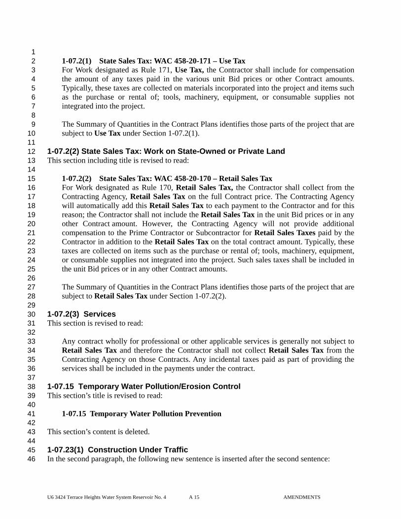
1 1-07.2(1) State Sales Tax: WAC 458-20-171 – Use Tax 2 For Work designated as Rule 171, Use Tax, the Contractor shall include for compensation 3 the amount of any taxes paid in the various unit Bid prices or other Contract amounts. 4 Typically, these taxes are collected on materials incorporated into the project and items such 5 as the purchase or rental of; tools, machinery, equipment, or consumable supplies not 6 integrated into the project. 7
8 The Summary of Quantities in the Contract Plans identifies those parts of the project that are 9 subject to Use Tax under Section 1-07.2(1). 10 11
1-07.2(2) State Sales Tax: Work on State-Owned or Private Land 12 This section including title is revised to read: 13 14
1-07.2(2) State Sales Tax: WAC 458-20-170 – Retail Sales Tax 15 For Work designated as Rule 170, Retail Sales Tax, the Contractor shall collect from the 16 Contracting Agency, Retail Sales Tax on the full Contract price. The Contracting Agency 17 will automatically add this Retail Sales Tax to each payment to the Contractor and for this 18 reason; the Contractor shall not include the Retail Sales Tax in the unit Bid prices or in any 19 other Contract amount. However, the Contracting Agency will not provide additional 20 compensation to the Prime Contractor or Subcontractor for Retail Sales Taxes paid by the 21 Contractor in addition to the Retail Sales Tax on the total contract amount. Typically, these 22 taxes are collected on items such as the purchase or rental of; tools, machinery, equipment, 23 or consumable supplies not integrated into the project. Such sales taxes shall be included in 24 the unit Bid prices or in any other Contract amounts. 25 26 The Summary of Quantities in the Contract Plans identifies those parts of the project that are 27 subject to Retail Sales Tax under Section 1-07.2(2). 28 29
1-07.2(3) Services 30 This section is revised to read: 31 32
Any contract wholly for professional or other applicable services is generally not subject to 33 Retail Sales Tax and therefore the Contractor shall not collect Retail Sales Tax from the 34 Contracting Agency on those Contracts. Any incidental taxes paid as part of providing the 35 services shall be included in the payments under the contract. 36 37
1-07.15 Temporary Water Pollution/Erosion Control 38 This section’s title is revised to read: 39 40
1-07.15 Temporary Water Pollution Prevention 41 42 This section’s content is deleted. 43 44 1-07.23(1) Construction Under Traffic 45 In the second paragraph, the following new sentence is inserted after the second sentence: 46
U6 3424 Terrace Heights Water System Reservoir No. 4 A 16 AMENDMENTS
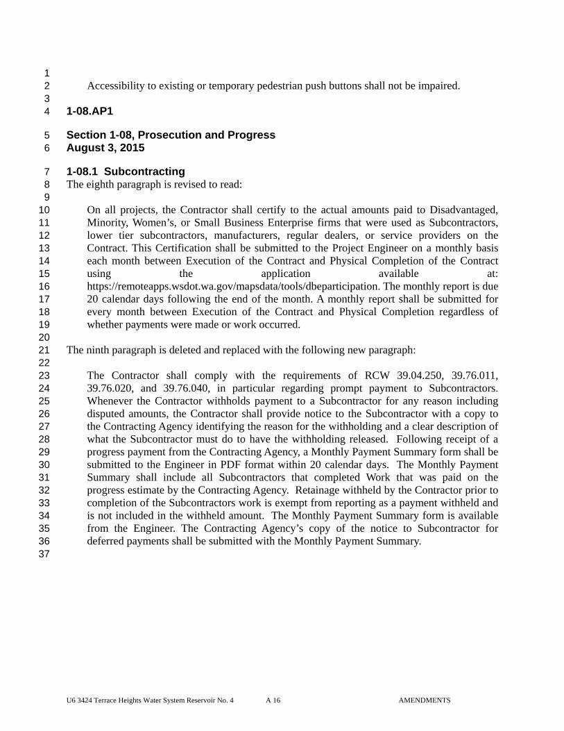
1 Accessibility to existing or temporary pedestrian push buttons shall not be impaired. 2
3 1-08.AP1 4
Section 1-08, Prosecution and Progress 5 August 3, 2015 6
1-08.1 Subcontracting 7 The eighth paragraph is revised to read: 8 9
On all projects, the Contractor shall certify to the actual amounts paid to Disadvantaged, 10 Minority, Women’s, or Small Business Enterprise firms that were used as Subcontractors, 11 lower tier subcontractors, manufacturers, regular dealers, or service providers on the 12 Contract. This Certification shall be submitted to the Project Engineer on a monthly basis 13 each month between Execution of the Contract and Physical Completion of the Contract 14 using the application available at: 15 https://remoteapps.wsdot.wa.gov/mapsdata/tools/dbeparticipation. The monthly report is due 16 20 calendar days following the end of the month. A monthly report shall be submitted for 17 every month between Execution of the Contract and Physical Completion regardless of 18 whether payments were made or work occurred. 19 20
The ninth paragraph is deleted and replaced with the following new paragraph: 21 22
The Contractor shall comply with the requirements of RCW 39.04.250, 39.76.011, 23 39.76.020, and 39.76.040, in particular regarding prompt payment to Subcontractors. 24 Whenever the Contractor withholds payment to a Subcontractor for any reason including 25 disputed amounts, the Contractor shall provide notice to the Subcontractor with a copy to 26 the Contracting Agency identifying the reason for the withholding and a clear description of 27 what the Subcontractor must do to have the withholding released. Following receipt of a 28 progress payment from the Contracting Agency, a Monthly Payment Summary form shall be 29 submitted to the Engineer in PDF format within 20 calendar days. The Monthly Payment 30 Summary shall include all Subcontractors that completed Work that was paid on the 31 progress estimate by the Contracting Agency. Retainage withheld by the Contractor prior to 32 completion of the Subcontractors work is exempt from reporting as a payment withheld and 33 is not included in the withheld amount. The Monthly Payment Summary form is available 34 from the Engineer. The Contracting Agency’s copy of the notice to Subcontractor for 35 deferred payments shall be submitted with the Monthly Payment Summary. 36
37
U6 3424 Terrace Heights Water System Reservoir No. 4 A 17 AMENDMENTS
1-08.1(1) Subcontract Completion and Return of Retainage Withheld 1 This section is revised to read: 2 3
The following procedure shall apply to all subcontracts entered into as a part of 4 this Contract: 5 6
Requirements 7 1. Upon request, the Engineer will provide a copy of any or all progress payment 8
estimates, with regard to contract payments to any interested party to the project. 9 10 2. The Contractor shall make payment to the Lower Tier Subcontractor not later than 11
ten calendar days after receipt of payment for work satisfactorily completed by the 12 Lower Tier Subcontractor, to the extent of the Lower Tier Subcontractor’s interest 13 therein. 14
15 3. In the event the Contractor believes they have the right under the Contract or 16
Subcontract to withhold payment in part or whole from a Lower Tier Subcontractor 17 they shall provide immediate notification to that Lower Tier Subcontractor and the 18 Engineer. The notice shall include an accounting of payments to date, the value 19 and reason for the withheld amount, and an explanation of what must be done to 20 have the withheld amount released. The Lower Tier Subcontractor shall be paid 21 within eight calendar days after the Subcontractor completes the remedial action 22 identified. 23
24 4. Every subcontract and lower tier subcontract shall have a dispute resolution 25
process incorporated for resolving issues between the parties to the subcontract, or 26 one shall be established as necessary. 27
28 5. If the parties agree, the WSDOT will make a third party neutral available provided 29
the parties to the dispute agree that the cost of doing so is split between them. 30 31 6. The Engineer will withhold the same amount of funds from the Contractor as was 32
withheld if the issue is not resolved by the next progress estimate. 33 34 7. Failure by a Contractor or Subcontractor to comply with these requirements may 35
result in one or more of the following: 36 37
a) Reflected in the Prime Contractor’s Performance Evaluation. 38 39 b) Cancellation, termination or suspension of the Contract, in whole or in part. 40 41 c) Sanctions as provided by the Contract; subcontract; or by law under applicable 42
prompt payment statutes including RCW 39.04.250. 43 44
8. The Subcontractor shall make a written request to the Contractor for the release of 45 the Subcontractor’s retainage or retainage bond. 46
U6 3424 Terrace Heights Water System Reservoir No. 4 A 18 AMENDMENTS
1 9. Within 10 calendar days of the request, the Contractor shall determine if the 2
subcontract has been satisfactorily completed including any required lien releases, 3 documentation and material testing and shall inform the Subcontractor, in writing, 4 of the Contractor’s determination. 5
6 10. If the Contractor determines that the subcontract has been satisfactorily completed, 7
the Subcontractor’s retainage or retainage bond shall be released by the Contractor 8 within 10 calendar days from the date of the written notice. If the Contractor 9 determines that the Subcontractor has not achieved satisfactory completion of the 10 subcontract, the Contractor must provide the Subcontractor with written notice, 11 stating specifically why the subcontract Work is not satisfactorily completed and 12 what has to be done to achieve completion. The Contractor shall release the 13 Subcontractor’s retainage or retainage bond within 10 calendar days after the 14 Subcontractor has satisfactorily completed the Work identified in the notice. 15
16 11. In determining whether satisfactory completion has been achieved, the Contractor 17
may require the Subcontractor to provide documentation such as certifications and 18 releases, showing that all laborers, lower-tiered Subcontractors, suppliers of 19 material and equipment, and others involved in the Subcontractor’s Work have 20 been paid in full. The Contractor may also require any documentation from the 21 Subcontractor that is required by the subcontract or by the Contract between the 22 Contractor and Contracting Agency or by law such as affidavits of wages paid, 23 material acceptance certifications and releases from applicable governmental 24 agencies to the extent that they relate to the Subcontractor’s Work. 25
26 12. If the Contractor fails to comply with the requirements of the Specification and the 27
Subcontractor’s retainage or retainage bond is wrongfully withheld, the 28 Subcontractor may seek recovery against the Contractor under applicable prompt 29 pay statutes in addition to any other remedies provided for by the subcontract or by 30 law. 31
32 Conditions 33 1. This clause does not create a contractual relationship between the Contracting 34
Agency and any Subcontractor as stated in Section 1-08.1. Also, it is not intended 35 to bestow upon any Subcontractor, the status of a third-party beneficiary to the 36 Contract between the Contracting Agency and the Contractor. 37
38 2. This Section of the Contract does not apply to retainage withheld by the 39
Contracting Agency from monies earned by the Contractor. The Contracting 40 Agency shall continue to process the release of that retainage based upon the 41 Completion Date of the project as defined in Section 1-08.5 Time for Completion 42 and in accordance with the requirements and procedures set forth in RCW 60.28. 43
44
U6 3424 Terrace Heights Water System Reservoir No. 4 A 19 AMENDMENTS
Payment 1 The Contractor shall be solely responsible for any additional costs involved in paying 2 retainage to the Subcontractors prior to total project completion. Those costs shall be 3 incidental to the respective Bid items. 4
5 1-09.AP1 6
Section 1-09, Measurement and Payment 7 January 5, 2015 8
1-09.6 Force Account 9 In the third paragraph of item number 3, the last sentence is revised to read: 10 11
In the event that prior quotations are not obtained and the vendor is not a firm independent 12 from the Contractor or Subcontractor, then after-the-fact quotations may be obtained by the 13 Engineer from the open market in the vicinity and the lowest such quotation may be used in 14 place of submitted invoice. 15
16 2-01.AP2 17
Section 2-01, Clearing, Grubbing, and Roadside Cleanup 18 August 3, 2015 19
2-01.2 Disposal of Usable Materials and Debris 20 This section is revised to read: 21 22
The Contractor shall meet all requirements of state, county, and municipal regulations 23 regarding health, safety, and public welfare in the disposal of all usable material and debris. 24 25 The Contractor shall dispose of debris by one or more of the disposal methods described 26 below. 27
28 2-01.2(1) Disposal Method No. 1 – Open Burning 29 The first paragraph is supplemented with the following: 30 31
All burning operations shall be strictly in accordance with these authorizations. 32 33 The second paragraph is deleted. 34 35 2-01.2(3) Disposal Method No. 3 – Chipping 36 This section is revised to read: 37 38
Wood chips may be disposed of on-site in accordance with the following: 39 40
1. Chips shall be no larger than 6 square inches and no thicker than ½ inch. 41 42
U6 3424 Terrace Heights Water System Reservoir No. 4 A 20 AMENDMENTS
2. Chips shall be disposed outside of environmentally sensitive areas, and in areas 1 that aren’t in conflict with permanent Work. 2
3 3. Chips shall not be incorporated into the embankment but may be spread on slopes 4
where feasible at depths no greater than 2 inches. 5 6 4. Chips shall be tractor-walked into the ground. 7
8 2-01.3(1) Clearing 9 In the second paragraph, item number 3 (up until the colon) is revised to read: 10 11
3. Follow these requirements for all stumps that will be buried deeper than 5 feet from the 12 top, side, or end surface of the embankment or any structure and are in a location that 13 will not be terraced as described in Section 2-03.3(14): 14
15 2-02.AP2 16
Section 2-02, Removal of Structures and Obstructions 17 January 5, 2015 18
2-02.3(2) Removal of Bridges, Box Culverts, and Other Drainage Structures 19 This section is supplemented with the following new subsections: 20 21
2-02.3(2)A Bridge Removal 22 2-02.3(2)A1 Bridge Demolition Plan Submittal 23 The Contractor shall submit a Type 2E Working Drawing consisting of a bridge 24 demolition plan, showing the method of removing the existing bridge(s), or portions of 25 bridges, as specified. 26 27 The bridge demolition plan shall show all equipment, sequence of operations, and 28 details required to complete the work, including containment, collection, and disposal 29 of all debris. The plan shall include a crane foundation stability analysis and crane load 30 calculations for the work. The plan shall detail the containment, collection, and 31 disposal of all debris. The plan shall show all stages of demolition. 32 33 When the bridge removal work includes removal of a truss, and when the Contractor’s 34 removal method involves use of a crane or cranes to pick, lift, and remove the truss, the 35 Contractor shall confirm the truss dead load weight prior to beginning the truss removal 36 operation. The operation of confirming the truss dead load shall be performed at both 37 ends of the truss, and shall ensure that the truss is broken free of its support bearings. 38 The Contractor’s method of confirming the truss dead load, whether by hydraulic jacks 39 or other means, shall be included in the Contractor’s bridge demolition plan submittal. 40 41 When the bridge removal work involves removing portions of existing concrete without 42 replacement, the methods and tools used to achieve the smooth surface and profile 43 specified in Section 2-02.3(2)A2 shall be included in the Contractor’s bridge demolition 44 plan submittal. 45
U6 3424 Terrace Heights Water System Reservoir No. 4 A 21 AMENDMENTS
1 2-02.3(2)A2 Removing Portions of Existing Concrete 2 Care shall be taken in removing concrete to prevent overbreakage or damage to 3 portions of the existing Structure which are to remain. Before concrete removal begins, 4 a saw cut shall be made into the surface of the concrete at the perimeter of the removal 5 limits. The saw cut shall be 3/4-inch deep when the steel reinforcement is to remain, 6 and may be deeper when the steel reinforcement is removed with the concrete. 7 8 Concrete shall be completely removed (exposing the deformed surface of the bar) from 9 existing steel reinforcing bars which extend from the existing members and are 10 specified to remain. Steel reinforcing bars that are not designated to remain shall be cut 11 a minimum of 1-inch behind the final surface. The void left by removal of the steel 12 reinforcing bar shall be filled with mortar conforming to Section 9-20.4(2). The mortar 13 shall match the color of the existing concrete surface as nearly as practicable. 14 15 The Contractor shall roughen, clean, and saturate existing concrete surfaces, against 16 which fresh concrete will be placed, in accordance with Section 6-02.3(12)B. When a 17 portion of existing concrete is to be removed without replacement, concrete shall be 18 removed to a clean line with a smooth surface of less than 1/16 inch profile. 19 20 2-02.3(2)A3 Use of Explosives for Bridge Demolition 21 Explosives shall not be used for bridge demolition, except as specifically allowed by 22 the Special Provisions. 23 24
2-02.5 Payment 25 This section is supplemented with the following new Bid items: 26 27
“Removing Existing Bridge___”, lump sum. 28 29 “Removing Existing Structure___”, lump sum. 30 31 “Removing Portion of Existing Bridge___”, lump sum. 32 33 “Removing Portion of Existing Structure___”, lump sum. 34
35 36 3-01.AP3 37
Section 3-01, Production From Quarry and Pit Sites 38 August 3, 2015 39
3-01.2(2) Preparation of Site 40 This section is supplemented with the following three new paragraphs: 41 42
The Contractor shall provide sufficient space as required for the setup and operation of the 43 Contracting Agency’s field testing facilities at the site of crushing or hot mix asphalt 44 production. 45
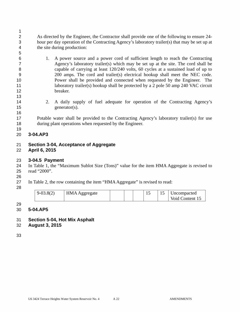
U6 3424 Terrace Heights Water System Reservoir No. 4 A 22 AMENDMENTS
1 As directed by the Engineer, the Contractor shall provide one of the following to ensure 24-2 hour per day operation of the Contracting Agency’s laboratory trailer(s) that may be set up at 3 the site during production: 4 5
1. A power source and a power cord of sufficient length to reach the Contracting 6 Agency’s laboratory trailer(s) which may be set up at the site. The cord shall be 7 capable of carrying at least 120/240 volts, 60 cycles at a sustained load of up to 8 200 amps. The cord and trailer(s) electrical hookup shall meet the NEC code. 9 Power shall be provided and connected when requested by the Engineer. The 10 laboratory trailer(s) hookup shall be protected by a 2 pole 50 amp 240 VAC circuit 11 breaker. 12
13 2. A daily supply of fuel adequate for operation of the Contracting Agency’s 14
generator(s). 15 16
Potable water shall be provided to the Contracting Agency’s laboratory trailer(s) for use 17 during plant operations when requested by the Engineer. 18
19 3-04.AP3 20
Section 3-04, Acceptance of Aggregate 21 April 6, 2015 22
3-04.5 Payment 23 In Table 1, the “Maximum Sublot Size (Tons)” value for the item HMA Aggregate is revised to 24 read “2000”. 25 26 In Table 2, the row containing the item “HMA Aggregate” is revised to read: 27
28 9-03.8(2) HMA Aggregate 15 15 Uncompacted
Void Content 15 29 5-04.AP5 30
Section 5-04, Hot Mix Asphalt 31 August 3, 2015 32
33
U6 3424 Terrace Heights Water System Reservoir No. 4 A 23 AMENDMENTS
5-04.2 Materials 1 The third through eighth paragraphs are deleted and replaced with the following: 2 3
The Contractor may choose to utilize recycled asphalt pavement (RAP) or reclaimed asphalt 4 shingles (RAS) in the production of HMA. The RAP may be from pavements removed 5 under the Contract, if any, or pavement material from an existing stockpile. The RAS may 6 be from reclaimed shingles. 7 8 The Contractor may use up to 20 percent RAP by total weight of HMA with no additional 9 sampling or testing of the RAP. If greater than 20 percent RAP by total weight of HMA or 10 any amount of RAS is utilized in the production of HMA, the Contractor shall sample and 11 test the RAP and RAS during stockpile construction in accordance with WSDOT FOP for 12 AASHTO T 308 for determination of asphalt binder content and WSDOT FOP for 13 WAQTC/AASHTO T 27/T 11 for gradation of the aggregates. The RAP shall be sampled 14 and tested at a frequency of one sample for every 1,000 tons produced and not less than ten 15 samples per project. The RAS shall be sampled and tested at a frequency of one sample for 16 every 100 tons produced and not less than ten samples per project. The asphalt content and 17 gradation test data shall be reported to the Contracting Agency when submitting the mix 18 design for approval on the QPL. If utilized, the amount of RAS shall not exceed 5-percent of 19 the total weight of the HMA. The Contractor shall include the RAP and RAS as part of the 20 mix design as defined in these Specifications. 21 22 The grade of asphalt binder shall be as required by the Contract. Blending of asphalt binder 23 from different sources is not permitted. 24 25 The Contractor may only use warm mix asphalt (WMA) processes in the production of 26 HMA with 20 percent or less RAP by total weight of HMA and no RAS. The Contractor 27 shall submit to the Engineer for approval the process that is proposed and how it will be 28 used in the manufacture of HMA. 29 30 When the Contracting Agency provides aggregates or provides a source for the production 31 of aggregates, the Contract Provisions will establish the approximate percentage of asphalt 32 binder required in the mixture for each class of HMA. 33 34 Production of aggregates shall comply with the requirements of Section 3-01. 35 36 Preparation of stockpile site, the stockpiling of aggregates, and the removal of aggregates 37 from stockpiles shall comply with the requirements of Section 3-02. 38
39 5-04.3(1) Hot Mix Asphalt Mixing Plant 40 In the first paragraph, the last sentence of item number 4 is revised to read: 41 42
The Contractor shall provide for the setup and operation of the field testing facilities of the 43 Contracting Agency as provided for in Section 3-01.2(2). 44
45 The first paragraph is supplemented with the following: 46
U6 3424 Terrace Heights Water System Reservoir No. 4 A 24 AMENDMENTS
1 6. Equipment for Processing RAP and RAS. When producing HMA for mix designs 2
with greater than 20 percent RAP by total weight of HMA or any amount of RAS the 3 HMA plant shall be equipped with screens or a lump breaker to eliminate oversize 4 RAP/RAS particles from entering the pug mill or drum mixer. 5
6 5-04.3(3)A Material Transfer Device/Vehicle 7 The first paragraph is supplemented with the following new sentence: 8 9
At the Contractor’s request the Engineer may approve paving without an MTD/V; the 10 Engineer will determine if an equitable adjustment in cost or time is due. 11
12 In the last sentence of the second paragraph, “Project Engineer” is revised to read “Engineer”. 13 14 5-04.3(5)A Preparation of Existing Surfaces 15 The first sentence of the last paragraph is revised to read: 16 17
Unless otherwise approved by the Engineer, the tack coat shall be CSS-1 or CSS-1h 18 emulsified asphalt. 19
20 5-04.3(7) Preparation of Aggregates 21 This section is revised to read: 22 23
The aggregates, RAP and RAS shall be stockpiled according to the requirements of Section 24 3-02. Sufficient storage space shall be provided for each size of aggregate, RAP and RAS. 25 The Contractor may uniformly blend fine aggregate or RAP with the RAS as a method of 26 preventing the agglomeration of RAS particles. The aggregates, RAP and RAS shall be 27 removed from stockpile(s) in a manner to ensure minimal segregation when being moved to 28 the HMA plant for processing into the final mixture. Different aggregate sizes shall be kept 29 separated until they have been delivered to the HMA plant. 30
31 5-04.3(7)A1 General 32 This section is revised to read: 33 34
An approved mix design, listed on the Qualified Products List (QPL), is required for all 35 HMA paving. The Contractor shall develop a mix design prior to the initial production of 36 HMA and no more than 3 months prior to submitting for QPL evaluation. The mix design 37 shall be developed in accordance with WSDOT Standard Operating Procedure 732 and meet 38 the requirements of Sections 9-03.8(2) and 9-03.8(6). 39 40 Mix designs shall be submitted by the Contractor to the WSDOT State Materials Laboratory 41 on WSDOT Form 350-042EF. If the mix design is approved it will be listed on the QPL for 42 up to 24 consecutive months. Mix designs not listed on the QPL or past the 24 month 43 approved period shall not be used. After a mix design has been on the QPL for 12 months 44 the listing will be extended provided the Contractor submits a certification letter to the 45 Qualified Products Engineer verifying that the aggregate and asphalt binder have not 46
U6 3424 Terrace Heights Water System Reservoir No. 4 A 25 AMENDMENTS
changed. The Contractor may submit the certification one month prior to expiration of the 1 mix design approval. Within 7 calendar days of receipt of the Contractor’s certification the 2 QPL will be updated. The maximum duration for approval of a mix design and listing on the 3 QPL will be 24 months from the date of initial approval or as approved by the Engineer. 4 5 Changes to the job mix formula of a mix design may require the development of a new mix 6 design and resubmittal for QPL approval. 7 8 Changes to aggregate that may require a new mix design include the source of material or a 9 change in the percentage of material from a stockpile greater than 5 percent. Changes to the 10 percentage of material from a stockpile will be calculated exclusive of the RAP content for 11 mix designs with 20 percent RAP or less by total weight of HMA. 12 13 Changes to asphalt binder that may require a new mix design include the source of the crude 14 petroleum supplied to the refinery, the refining process, and additives or modifiers in the 15 asphalt binder. 16 17 The Contractor shall include the brand and type of anti-stripping additive in the mix design 18 submittal and provide certification from the asphalt binder manufacture that the anti-19 stripping additive is compatible with the crude source and formulation of asphalt binder 20 proposed in the mix design. All changes to anti-strip require the submittal of a new mix 21 design for approval. 22 23 Mix designs with 20 percent RAP or less by total weight of HMA and no RAS will be 24 completed without the inclusion of the RAP. For HMA mix designs with greater than 20 25 percent RAP by total weight of HMA or any amount of RAS the Contractor shall develop a 26 mix design including RAP, RAS, recycling agent and new asphalt binder. Asphalt binder 27 contributed from RAS shall be determined in accordance with AASHTO PP 78. The total 28 quantity of asphalt binder from the RAP and RAS shall not exceed 40 percent of the total 29 asphalt binder content of the HMA. 30 31 Once the RAP and RAS stockpiles have been constructed the Contractor shall extract, 32 recover and test the asphalt residue from the RAP and RAS stockpiles to determine the 33 percent of recycling agent and/or grade of new asphalt binder needed to meet the grade of 34 asphalt binder required by the contract. The asphalt extraction testing shall be performed in 35 accordance with AASHTO T 164 or ASTM D 2172 using reagent grade trichloroethylene. 36 The asphalt recovery shall be performed in accordance with AASHTO R 59 orASTM D 37 1856. The recovered asphalt residue shall be tested in accordance with AASHTO R 29 to 38 determine the asphalt binder grade in accordance with Section 9-02.1(4). Once the 39 recovered asphalt binder grade is determined the percent of recycling agent and/or grade of 40 new asphalt binder shall be determined in accordance with ASTM D 4887. The final blend 41 of recycling agent, recovered and new asphalt shall be tested in accordance with AASHTO 42 R 29. The final blended asphalt binder shall be the grade as required by the Contract and 43 comply with the requirements of in accordance with Section 9-02.1(4). 44
45
U6 3424 Terrace Heights Water System Reservoir No. 4 A 26 AMENDMENTS
5-04.3(7)A2 Statistical or Nonstatistical Evaluation 1 This section is revised to read: 2 3
The Contractor shall submit WSDOT Form 350-041EF to the Engineer for approval to use a 4 mix design from the QPL. The Contractor may include changes to the job mix formula that 5 have been approved on other contracts. The request to use a mix design from the QPL may 6 be rejected if production of the HMA from another contract is not in compliance with 7 Section 5-04.3(11)D. 8 9 The Contractor shall submit representative samples of the materials that are to be used in the 10 HMA production to the State Materials Laboratory in Tumwater. For HMA mix designs with 11 20 percent RAP or less by total weight of HMA and no RAS, the Contractor shall submit 12 representative samples of the mineral materials that are to be used in the HMA production; 13 the submittal of RAP samples is not required for these mix designs. For HMA mix designs 14 with greater than 20 percent RAP by total weight of HMA or any amount of RAS the 15 Contractor shall submit representative samples of the mineral materials, RAP, RAS and 100 16 grams of recovered asphalt residue from the RAP and RAS that are to be used in the HMA 17 production. The Contracting Agency will use these samples to evaluate the mix design for 18 approval on the QPL in accordance with WSDOT Standard Practice QC-8. 19
20 5-04.3(7)A3 Commercial Evaluation 21 This section is revised to read: 22
23 Approval of a Commercial Evaluation mix design for listing on the QPL will be based on a 24 review of the Contractor’s submittal of WSDOT Form 350-042EF for conformance to the 25 requirements of Section 9-03.8(2). Testing of the HMA by the Contracting Agency for mix 26 design approval is not required. Mix designs for HMA with greater than 20 percent RAP by 27 total weight of HMA or any amount of RAS may be evaluated in accordance with Section 5-28 04.3(7)A2. 29 30 For the Bid item Commercial HMA, the Contractor shall select a class of HMA and design 31 level of Equivalent Single Axle Loads (ESAL’s) appropriate for the required use. 32
33 5-04.3(8) Mixing 34 The first sentence of the second paragraph is revised to read: 35 36
When discharged, the temperature of the HMA shall not exceed the optimum mixing 37 temperature by more than 25°F as shown on the reference mix design report or as approved 38 by the Engineer. 39
40 The last paragraph is supplemented with the following new sentence: 41 42
After the required amount of mineral materials, RAP, RAS, new asphalt binder and asphalt 43 rejuvenator have been introduced into the mixer the HMA shall be mixed until complete and 44 uniform coating of the particles and thorough distribution of the asphalt binder throughout 45 the mineral materials, RAP and RAS is ensured. 46
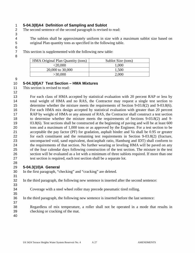
U6 3424 Terrace Heights Water System Reservoir No. 4 A 27 AMENDMENTS
5-04.3(8)A4 Definition of Sampling and Sublot 1 The second sentence of the second paragraph is revised to read: 2 3
The sublots shall be approximately uniform in size with a maximum sublot size based on 4 original Plan quantity tons as specified in the following table. 5
6 This section is supplemented with the following new table: 7 8
HMA Original Plan Quantity (tons) Sublot Size (tons) <20,000 1,000
20,000 to 30,000 1,500 >30,000 2,000
9 5-04.3(8)A7 Test Section – HMA Mixtures 10 This section is revised to read: 11 12
For each class of HMA accepted by statistical evaluation with 20 percent RAP or less by 13 total weight of HMA and no RAS, the Contractor may request a single test section to 14 determine whether the mixture meets the requirements of Section 9-03.8(2) and 9-03.8(6). 15 For each HMA mix design accepted by statistical evaluation with greater than 20 percent 16 RAP by weight of HMA or any amount of RAS, the Contractor shall construct a test section 17 to determine whether the mixture meets the requirements of Sections 9-03.8(2) and 9-18 03.8(6). Test sections shall be constructed at the beginning of paving and will be at least 600 19 tons and a maximum of 1,000 tons or as approved by the Engineer. For a test section to be 20 acceptable the pay factor (PF) for gradation, asphalt binder and Va shall be 0.95 or greater 21 for each constituent and the remaining test requirements in Section 9-03.8(2) (fracture, 22 uncompacted void, sand equivalent, dust/asphalt ratio, Hamburg and IDT) shall conform to 23 the requirements of that section. No further wearing or leveling HMA will be paved on any 24 of the four calendar days following construction of the test section. The mixture in the test 25 section will be evaluated as a lot with a minimum of three sublots required. If more than one 26 test section is required, each test section shall be a separate lot. 27
28 5-04.3(10)A General 29 In the first paragraph, “checking” and “cracking” are deleted. 30 31 In the third paragraph, the following new sentence is inserted after the second sentence: 32 33
Coverage with a steel wheel roller may precede pneumatic tired rolling. 34 35
In the third paragraph, the following new sentence is inserted before the last sentence: 36 37
Regardless of mix temperature, a roller shall not be operated in a mode that results in 38 checking or cracking of the mat. 39
40
U6 3424 Terrace Heights Water System Reservoir No. 4 A 28 AMENDMENTS
5-04.3(10)B1 General 1 In this section, “Project Engineer” is revised to read “Engineer”. 2 3 The first paragraph is revised to read: 4 5
HMA mixture accepted by statistical or nonstatistical evaluation that is used in traffic lanes, 6 including lanes for ramps, truck climbing, weaving, and speed change, and having a 7 specified compacted course thickness greater than 0.10-foot, shall be compacted to a 8 specified level of relative density. The specified level of relative density shall be a 9 Composite Pay Factor (CPF) of not less than 0.75 when evaluated in accordance with 10 Section 1-06.2, using a minimum of 91 percent of the maximum density. The specified level 11 of density attained will be determined by the statistical evaluation of the density of the 12 pavement. The density of the pavement shall be determined in accordance with WSDOT 13 FOP for WAQTC TM 8 when using the nuclear density gauge and WSDOT SOP 736 when 14 using cores to determine density. 15 16
The following four new paragraphs are inserted after the first paragraph: 17 18
Tests for the determination of the pavement density will be taken in accordance the required 19 procedures for measurement by a nuclear density gauge or roadway cores after completion 20 of the finish rolling. 21 22 If the Contracting Agency uses a nuclear density gauge to determine density the test 23 procedures FOP for WAQTC TM 8 and WSDOT SOP T 729 will be used on the day the mix 24 is placed. 25 26 Roadway cores for density may be obtained by either the Contracting Agency or the 27 Contractor in accordance with WSDOT SOP 734. The core diameter shall be 4-inches unless 28 otherwise approved by the Engineer. Roadway cores will be tested by the Contracting 29 Agency in accordance with WSDOT FOP for AASHTO T 166. 30 31 If the Contract includes the Bid item “Roadway Core” the cores shall be obtained by the 32 Contractor in the presence of the Engineer on the same day the mix is placed and at 33 locations designated by the Engineer. If the Contract does not include the Bid item 34 “Roadway Core” the Contracting Agency will obtain the cores. 35
36 In the sixth paragraph (after the preceding Amendments are applied), the second sentence is 37 revised to read: 38 39
Sublots will be uniform in size with a maximum sublot size based on original Plan quantity 40 tons of HMA as specified in the table below. 41
42
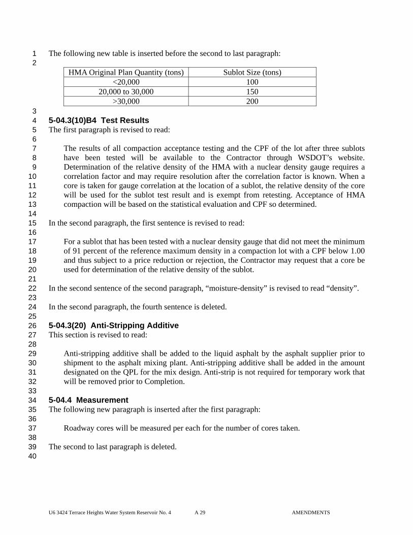
U6 3424 Terrace Heights Water System Reservoir No. 4 A 29 AMENDMENTS
The following new table is inserted before the second to last paragraph: 1 2
HMA Original Plan Quantity (tons) Sublot Size (tons) <20,000 100
20,000 to 30,000 150 >30,000 200
3 5-04.3(10)B4 Test Results 4 The first paragraph is revised to read: 5 6
The results of all compaction acceptance testing and the CPF of the lot after three sublots 7 have been tested will be available to the Contractor through WSDOT’s website. 8 Determination of the relative density of the HMA with a nuclear density gauge requires a 9 correlation factor and may require resolution after the correlation factor is known. When a 10 core is taken for gauge correlation at the location of a sublot, the relative density of the core 11 will be used for the sublot test result and is exempt from retesting. Acceptance of HMA 12 compaction will be based on the statistical evaluation and CPF so determined. 13 14
In the second paragraph, the first sentence is revised to read: 15 16
For a sublot that has been tested with a nuclear density gauge that did not meet the minimum 17 of 91 percent of the reference maximum density in a compaction lot with a CPF below 1.00 18 and thus subject to a price reduction or rejection, the Contractor may request that a core be 19 used for determination of the relative density of the sublot. 20 21
In the second sentence of the second paragraph, “moisture-density” is revised to read “density”. 22 23 In the second paragraph, the fourth sentence is deleted. 24 25 5-04.3(20) Anti-Stripping Additive 26 This section is revised to read: 27 28
Anti-stripping additive shall be added to the liquid asphalt by the asphalt supplier prior to 29 shipment to the asphalt mixing plant. Anti-stripping additive shall be added in the amount 30 designated on the QPL for the mix design. Anti-strip is not required for temporary work that 31 will be removed prior to Completion. 32
33 5-04.4 Measurement 34 The following new paragraph is inserted after the first paragraph: 35 36
Roadway cores will be measured per each for the number of cores taken. 37 38 The second to last paragraph is deleted. 39 40
U6 3424 Terrace Heights Water System Reservoir No. 4 A 30 AMENDMENTS
5-04.5 Payment 1 The bid item “Removing Temporary Pavement Marking”, per linear foot and paragraph 2 following bid item are deleted. 3 4 The following new bid item is inserted before the second to last paragraph: 5 6
“Roadway Core”, per each. 7 8 The Contractor’s costs for all other Work associated with the coring (e.g., traffic control) 9 shall be incidental and included within the unit Bid price per each and no additional 10 payments will be made. 11
12 6-03.AP6 13
Section 6-03, Steel Structures 14 April 6, 2015 15
6-03.2 Materials 16 The first sentence in the fifth paragraph is revised to read: 17 18
The Contractor shall submit Type 1 Working Drawings describing the methods for visibly 19 marking the material so that it can be traced. 20
21 6-03.3 Construction Requirements 22 This section is revised to read: 23 24
Structural steel fabricators of plate and box girders, floorbeams, truss members, stringers, 25 cross frames, diaphragms, and laterals shall be certified under the AISC Certification 26 Program for Steel Bridge Fabricators, Advanced Bridges Category. When fracture critical 27 members are specified in the contract, structural steel fabricators shall also meet the 28 supplemental requirements F, Bridges with Fracture-Critical Members, under the AISC 29 Certification Program for Steel Bridge Fabricators. 30
31 6-03.3(7) Shop Plans 32 This section is revised to read: 33 34
The Contractor shall submit all shop detail plans for fabricating the steel as Type 2 Working 35 Drawings. 36 37 If these plans will be submitted directly from the fabricator, the Contractor shall so notify 38 the Engineer in writing. 39 40 No material shall be fabricated until: (1) the Working Drawing review is complete, and (2) 41 the Engineer has accepted the materials source. 42 43 Before physical completion of the project, the Contractor shall furnish the Engineer one set 44 of reproducible copies of the as-built shop plans. The reproducible copies shall be clear, 45
U6 3424 Terrace Heights Water System Reservoir No. 4 A 31 AMENDMENTS
suitable for microfilming, and on permanent sheets that measure no smaller than 11 by 17-1 inches. Alternatively, the shop drawings may be provided in an electronic format with the 2 concurrence of the Engineer. 3
4 6-03.3(7)A Erection Methods 5 The first paragraph is revised to read: 6 7
Before beginning to erect any steel Structure, the Contractor shall submit Type 2E Working 8 Drawings consisting of the erection plan and procedure describing the methods the 9 Contractor intends to use. 10
11 The second paragraph (up until the colon) is revised to read: 12 13
The erection plan and procedure shall provide complete details of the erection process 14 including, at a minimum, the following: 15
16 The third paragraph (up until the colon) is revised to read: 17 18
As part of the erection plan Working Drawings, the Contractor may submit details of an 19 engineered and fabricated lifting bracket bolted to the girder top flanges providing the 20 following requirements are satisfied: 21
22 In the third paragraph, the second sentence of item number 4 is revised to read: 23 24
Certification documentation from a previous project may be submitted; 25 26 The last sentence of the fourth paragraph is deleted. 27 28 The last paragraph is deleted. 29 30 6-03.3(10) Straightening Bent Material 31 In the first paragraph, the last sentence is revised to read: 32 33
A limited amount of localized heat may be applied only if carefully planned and supervised, 34 and only in accordance with the heat-straightening procedure Working Drawing submittal. 35
36 The third paragraph is revised to read: 37 38
After straightening, the Contractor shall inspect the member for fractures using a method 39 proposed by the Contractor and accepted by the Contracting Agency. 40
41 The last paragraph is revised to read: 42 43
The procedure for heat straightening of universal mill (UM) plates by the mill or the 44 fabricator shall be submitted as a Type 2 Working Drawing. 45
46
U6 3424 Terrace Heights Water System Reservoir No. 4 A 32 AMENDMENTS
6-03.3(14) Edge Finishing 1 In the first paragraph, the last sentence is revised to read: 2 3
Corners along exposed edges shall be broken by light grinding or another method acceptable 4 to the Engineer to achieve an approximate 1/16-inch chamfer or rounding. 5
6 In the fifth paragraph, the last sentence is revised to read: 7 8
The fabricator shall prevent excessive hardening of flange edges through preheating, post 9 heating, or control of the burning process as recommended by the steel manufacturer. 10
11 The sixth paragraph is revised to read: 12 13
Hardness testing shall consist of testing thermal-cut edges with a portable hardness tester. 14 The hardness tester, and its operating test procedures, shall be submitted as a Type 1 15 Working Drawing. The hardness tester shall be convertible to Rockwell C scale values. 16
17 In the last paragraph, the last sentence is revised to read: 18 19
If thermal-cutting operations conform to procedures established by the steel manufacturer, 20 and hardness testing results are consistently within acceptable limits, the Engineer may 21 authorize a reduction in the testing frequency. 22
23 6-03.3(15) Planing of Bearing Surfaces 24 This section is supplemented with the following new paragraph: 25 26
Where mill to bear is specified in the Plans, the bearing end of the stiffener shall be flush 27 and square with the flange and shall have at least 75 percent of this area in contact with the 28 flange. 29
30 6-03.3(25) Welding and Repair Welding 31 In the first paragraph, the first sentence is revised to read: 32 33
Welding and repair welding of all steel bridges shall comply with the AASHTO/AWS 34 D1.5M/D1.5, latest edition, Bridge Welding Code. 35
36 In the second paragraph, the last sentence is revised to read: 37 38
No welding, including tack and temporary welds shall be done in the shop or field unless the 39 location of the welds is shown on the shop drawings reviewed and accepted by the Engineer. 40
41 In the third paragraph, the first sentence is revised to read: 42 43
Welding procedures shall accompany the shop drawing Working Drawing submittal. 44 45 In the fourth paragraph, the first sentence is revised to read: 46
U6 3424 Terrace Heights Water System Reservoir No. 4 A 33 AMENDMENTS
Welding shall not begin until completion of the shop plan Working Drawing review as 1 required in Section 6-03.3(7). 2
3 In item number 1 of the ninth paragraph, “approves” is revised to read “concurs”. 4 5 6-03.3(25)A3 Ultrasonic Inspection 6 The following new paragraph is inserted before the last paragraph: 7 8
A minimum of 30 percent of complete penetration vertical welds on steel column jackets 9 thicker than 5/16-inch, within 1.50 column jacket diameter of the top and bottom of each 10 column, shall be inspected. If any rejectable flaws are found, 100 percent of the weld within 11 the specified limits shall be inspected. The largest column cross section diameter for tapered 12 column jackets shall constitute one column jacket diameter. 13
14 6-03.3(25)A4 Magnetic Particle Inspection 15 Items number 3 and 4 are revised to read: 16 17
3. Complete penetration groove welds on plates 5⁄16-inch or thinner (excluding steel column 18 jackets) shall be 100 percent tested by the magnetic particle method. Testing shall apply 19 to both sides of the weld, if backing plate is not used. The ends of each complete 20 penetration groove weld at plate edges shall be tested by the magnetic particle method. 21 22
4. A minimum of 30 percent of complete penetration vertical welds on steel column jackets 23 5⁄16-inch or thinner, within 1.50 column jacket diameters of the top and bottom of each 24 column, shall be magnetic particle inspected. The largest column cross section diameter 25 for tapered column jackets shall constitute one column jacket diameter. 26
27 The last paragraph is supplemented with the following new sentence: 28 29
If any rejectable flaws are found in any test length of item 4 above, 100 percent of the weld 30 within the specified limits shall be inspected. 31
32 6-03.3(27) High Strength Bolt Holes 33 The last paragraph is revised to read: 34 35
The Contractor shall submit Type 2 Working Drawings consisting of a detailed outline of the 36 procedures proposed to accomplish the work from initial drilling through shop assembly. 37
38 6-03.3(27)C Numerically Controlled Drilled Connections 39 In the second paragraph, the first sentence is revised to read: 40 41
The Contractor shall submit Type 1 Working Drawings consisting of a detailed outline of 42 proposed N/C procedures. 43
44 6-03.3(29) Welded Shear Connectors 45 This section’s content is deleted and replaced with the following: 46
U6 3424 Terrace Heights Water System Reservoir No. 4 A 34 AMENDMENTS
1 Installation, production control, and inspection of welded shear connectors shall conform to 2 Chapter 7 of the AASHTO/AWS D1.5M/D1.5:2010 Bridge Welding Code. If welded shear 3 connectors are installed in the shop, installation shall be completed prior to applying the 4 shop primer coat in accordance with Section 6-07.3(9)G. If welded shear connectors are 5 installed in the field, the steel surface to be welded shall be prepared to SSPC-SP 11, power 6 tool cleaning, just prior to welding. 7
8 6-03.3(33) Bolted Connections 9 In the second paragraph, the first sentence is revised to read: 10 11
The Contractor shall submit Type 1 Working Drawings providing documentation of the bolt 12 tension calibrator, including brand, capacity, model, date of last calibration, and 13 manufacturer’s instructions for use. 14
15 In the second sentence of the second paragraph, the word “approved” is deleted. 16 17 In item number 3 of the fifth paragraph, “approved” is revised to read “specified”. 18 19 In the center column header of table 1, “AASHTO M 164” is revised to read “ASTM A 325”. 20 21 In the column headings of table 3, “M 164” is revised to read “A 325”. 22 23 In the tenth paragraph, item number 3, “approved” is revised to read “accepted” in the second 24 and third sentences of the first paragraph. 25 26 In the tenth paragraph, item number 3, the third paragraph is revised to read: 27 28
The Contractor shall submit Type 1 Working Drawings of the tension control bolt assembly, 29 including bolt capacities, type of bolt, nut, and washer lubricant, method of packaging and 30 protection of the lubricated bolt, installation equipment, calibration equipment, and 31 installation procedures. 32
33 In the first sentence of the last paragraph, “AASHTO M 164” is revised to read “ASTM A 325”. 34 35 The second sentence of the last paragraph is revised to read: 36 37
Black ASTM A 325 bolts may be reused once if accepted by the Engineer. 38 In the last paragraph, the fourth sentence is revised to read: 39 40
Bolts to be reused shall be relubricated in accordance with the manufacturer’s 41 recommendations. 42
43
U6 3424 Terrace Heights Water System Reservoir No. 4 A 35 AMENDMENTS
6-03.3(33)A Pre-Erection Testing 1 In the fifth sentence of the first paragraph, “approved” is revised to read “accepted”. 2 3 The third paragraph is revised to read: 4 5
The Contractor shall submit Type 1 Working Drawings consisting of the manufacturer’s 6 detailed procedure for pre-erection (rotational capacity) testing of tension control bolt 7 assemblies. 8
9 6-03.3(33)B Bolting Inspection 10 In the last sentence of the first paragraph, “approved” is revised to read “specified”. 11 12 The last paragraph is revised to read: 13 14
The Contractor shall submit Type 1 Working Drawings consisting of the manufacturer’s 15 detailed procedure for routine observation to ensure proper use of the tension control bolt 16 assemblies. 17
18 6-03.3(42) Surface Condition 19 The first subparagraph is revised to read: 20 21
Painted steel surfaces shall be cleaned by methods required for the type of staining. The 22 Contractor shall submit a Type 1 Working Drawing of the cleaning method. 23
24 6-07.AP6 25
Section 6-07, Painting 26 January 5, 2015 27
6-07.3 Painting 28 This section is supplemented with the following new subsections: 29 30
6-07.3(14) Metallic Coatings 31 32 6-07.3(14)A General Requirements 33 This specification covers the requirements for thermal spray metallic coatings, with and 34 without additional paint coats, as a means to prevent corrosion. 35 36 The coating system consists of surface preparation by wash cleaning and abrasive blast 37 cleaning, thermal spray application of a metallic coating using a material made 38 specifically for that purpose, and, when specified, shop primer coat or shop primer coat 39 plus top coat in accordance with Section 6-07.3(11)A. The system also includes 40 inspection and acceptance requirements. 41 42 6-07.3(14)B Reference Standards 43 SSPC-SP 10/NACE No. 2 Near White Blast Cleaning 44 SSPC CS 23.00 Guide for Thermal Spray Metallic Coating Systems 45
U6 3424 Terrace Heights Water System Reservoir No. 4 A 36 AMENDMENTS
ASTM-C-633 Standard Test Method for Adhesion or Cohesion Strength 1 of Thermal Spray Coatings 2
ASTM D 4417 Standard Test Methods for Field Measurement of Surface 3 Profile of Blast-Cleaned Steel 4
ASTM D 6386 Standard Practice for Preparation of Zinc (Hot-Dip 5 Galvanized) Coated Iron and Steel Product and Hardware 6 Surfaces for Painting 7
ASTM D 4541 Standard Test Method for Pull-Off Strength of Coatings 8 Using Portable Adhesion Testers 9
ANSI/AWS C2.18 Guide for the Protection of Steel with Thermal Sprayed 10 Coatings of Aluminum, Zinc and their Alloys and 11 Composites 12
13 6-07.3(14)C Quality Assurance 14 A representative sample of each lot of the coating material used shall be submitted to 15 the Engineer for analysis prior to use. Zinc shall have a minimum purity of 99.9 16 percent. Zinc Aluminum 85/15 wire shall be 14 percent minimum to 16 percent 17 maximum aluminum. 18 19 The thermal sprayed coating shall have a uniform appearance. The coating shall not 20 contain any blisters, cracks, chips or loosely adhering particles, oil or other surface 21 contaminants, nodules, or pits exposing the substrate. 22 23 The thermal spray coating shall adhere to the substrate with a minimum bond of 700 24 psi. The Contractor's QA program shall include thermal spray coating bond testing. 25 26 The Engineer may cut through the coating with a knife or chisel. If upon doing so, any 27 part of the coating lifts away from the base metal 1/4 in. or more ahead of the cutting 28 blade without cutting the metal, then the bond is considered not effective and is 29 rejected. 30 31 Coated areas which have been rejected or damaged in the inspection procedure 32 described shall have the defective sections blast cleaned to remove all of the thermal 33 sprayed coating and shall then be recoated. Before resubmittal and inspection, those 34 sections where coating has not reached the required thickness shall be sprayed with 35 additional metal until that thickness is achieved. 36 37 6-07.3(14)D Submittals 38 The Contractor shall submit to the Engineer, prior to abrasive blast cleaning, a 12 inch 39 square steel plate, of the same material and approximate thickness of the steel to be 40 coated, blasted clean in accordance with Section 6-07.3(14)E. The sample plate will be 41 checked for specified angular surface pattern, the abrasive grit size and type used, and 42 the procedure used. This plate shall be used as the visual standard to determine the 43 acceptability of the cleaned surface. In the event the Contractor's cleaning operation is 44 inferior to the sample plate, the Contractor shall be required to correct the cleaning 45 operation to do a job comparable to the specimen submitted. 46
U6 3424 Terrace Heights Water System Reservoir No. 4 A 37 AMENDMENTS
At the same time as submitting the abrasive blast cleaned steel plate sample, the 1 Contractor shall submit to the Engineer, a second 12 inch square steel plate of the same 2 material and thickness, cleaned and thermal spray coated in accordance with the same 3 processes and with the same equipment as intended for use in applying the thermal 4 spray coatings. The Engineer may request additional cleaned and thermal spray coated 5 samples to be produced and submitted coincident with thermal spray coating of the 6 items specified in the Plans to receive thermal spray coatings. 7 8 6-07.3(14)E Surface Preparation 9 Surface irregularities (e.g., sharp edges and/or carburized edges, cracks, delaminations, 10 pits, etc.) interfering with the application of the coating shall be removed or repaired, 11 prior to wash cleaning. Thermal cut edges shall be ground to reduce hardness to attain 12 the surface profile required from abrasive blast cleaning. 13 14 All dirt, oil, scaling, etc. shall be removed prior to blast cleaning. All surfaces shall be 15 wash cleaned with either clean water at 8000 psi or water and detergent at 2000 psi with 16 two rinses with clean water. 17 18 The surface shall be abrasive blast cleaned to near white metal (SSPC-SP 10). The 19 surface profile shall be measured using a surface profile comparator, replica tape, or 20 other method suitable for the abrasive being used in accordance with ASTM D 4417. 21 22 Where zinc coatings up to and including 0.009 inch thick are to be applied, one of the 23 following abrasive grits shall be used with pressure blast equipment to produce a 3.0 24 mils AA anchor tooth pattern: 25 26
1. Aluminum oxide or silicon carbide 27 mesh size: SAE G-25 to SAE G-40 28 29
2. Hardened steel grit 30 mesh size: SAE G-25 to SAE G-40 31 32
3. Garnet, flint, or crushed nickel or black beauty coal slag 33 mesh size: SAE G-25 to SAE G-50 34
35 Where zinc coatings greater than 0.010 inch thick are to be applied, one of the 36 following abrasive grits shall be used with pressure blast equipment to produce a 5.0 37 mils AA anchor tooth pattern: 38 39
1. Aluminum oxide or silicon carbide 40 mesh size: SAE G-18 to SAE G-25 41 42
2. Hardened steel grit 43 mesh size: SAE G-18 to SAE G-25 44
45
U6 3424 Terrace Heights Water System Reservoir No. 4 A 38 AMENDMENTS
3. Garnet, flint, or crushed nickel or black beauty coal slag 1 mesh size: SAE G-18 to SAE G-25 2
3 The pressure of the blast nozzle, as measured with a needle probe gauge, with pressure 4 type blasting equipment shall be as follows: 5 6
1. With aluminum oxide, silicon carbide, flint, or slag - 50 psi minimum and 60 7 psi maximum. 8
9 2. With garnet or steel grit - 75 psi minimum. 10
11 The pressure at the blast nozzle, with siphon blasting (suction blasting), shall be as 12 follows: 13 14
1. With aluminum oxide, silicon carbide, flint, or slag - 75 psi maximum. 15 16 2. With garnet or steel grit - 90 psi maximum. 17
18 The abrasive blast stream shall be directed onto the substrate surface at a spray angle of 19 75 to 90 degrees, and moved side to side. The nozzle to substrate distance shall be 4 to 20 12 inches. 21 22 6-07.3(14)F Application of Metallic Coating 23 No surface shall be sprayed which shows any sign of condensed moisture or which does 24 not comply with Section 6-07.3(14)E. If rust bloom occurs within the holding time 25 between abrasive blast cleaning and thermal spraying, the surface shall be reblasted at a 26 blast angle as close to perpendicular to the surface as possible to achieve a 2.0 to 4.0 27 mil anchor tooth pattern. Thermal spraying shall not take place when the relative 28 humidity is 90% or greater, when the steel temperature is less than 5°F above the dew 29 point, or when the air or steel temperature is less than 40°F. 30 31 Clean, dry air shall be used with not less than 50 psi air pressure at the air regulator. 32 Not more than 50 feet of 3/8 in. ID hose shall be used between the air regulator and the 33 metallizing gun. The metallizing gun shall be started and adjusted with the spray 34 directed away from the work. During the spraying operation and depending upon the 35 equipment being used, the gun shall be held as close to perpendicular as possible to the 36 surface from 5 to 8 inches from the surface of the work. 37 38 Manual spraying shall be done in a block pattern, typically 2 feet by 2 feet square. The 39 sprayed metal shall overlap on each pass to ensure uniform coverage. The specified 40 thickness of the coating shall be applied in multiple layers. In no case are fewer than 41 two passes of thermal spraying, overlapping at right angles, acceptable. 42 43 At least one single layer of coating shall be applied within 4 hours of blasting and the 44 surface shall be completely coated to the specified thickness within 8 hours of blasting. 45 46
U6 3424 Terrace Heights Water System Reservoir No. 4 A 39 AMENDMENTS
The minimum coating thickness shall be 6 mils unless otherwise shown in the Plans. 1 2 6-07.3(14)G Applications of Shop Coats and Field Coats 3 The surface shall be wiped clean with solvent immediately before applying the wash 4 primer. The wash primer shall have a low viscosity appropriate for absorption into the 5 thermal spray coating, and shall be applied within 8 hours after completion of thermal 6 spraying or before oxidation occurs. The dry film thickness of the wash primer shall 7 not exceed 0.5 mils or be less than 0.3 mils. It shall be applied using an appropriate 8 spray gun except in those areas where brush or roller application is necessary. The 9 subsequent shop primer or field coats shall be applied no less than one-half hour after a 10 wash primer. 11 12 The shop primer coat, when specified, shall be applied in accordance with Section 6-13 07.3(11)A and the paint manufacturer's recommendations. 14 15 All field coats, when specified, shall be applied in accordance with Section 6-07.3(11)A 16 and the paint manufacturer's recommendations. The color of the top coat shall conform 17 to Section 6-03.3(30) as supplemented in these Special Provisions. 18 19
6-07.3(2) Submittals 20 The first paragraph is revised to read: 21 22
The Contractor shall submit Type 2 Working Drawings of the painting plan. 23 24 6-07.3(10)A Containment 25 The second paragraph is revised to read: 26 27
The containment length shall not exceed the length of a span (defined as pier to pier). The 28 containment system shall not cause any damage to the existing structure. All clamps and 29 other attachment devices shall be padded or designed such that they shall not mark or 30 otherwise damage the steel member to which they are attached. All clamps and other 31 attachment devices shall be fully described in the Contractor's painting plan Working 32 Drawing submittal. Field welding of attachments to the existing structure will not be 33 allowed. The Contractor shall not drill holes into the existing structure or through existing 34 structural members except as shown in the Contractor's painting plan Working Drawing 35 submittal. All provisions for dust collection, ventilation and auxiliary lighting within the 36 containment system shall be fully described the Contractor's painting plan Working Drawing 37 submittal. 38
39 In the second to last paragraph, “approved” is revised to read “accepted”. 40 41 6-07.3(10)E Surface Preparation – Full Paint Removal 42 This section is revised to read: 43
44 For structures where full removal of existing paint is specified, the Contractor shall remove 45 any visible oil, grease, and road tar in accordance with SSPC-SP 1. 46
U6 3424 Terrace Heights Water System Reservoir No. 4 A 40 AMENDMENTS
1 Following preparation by SSPC-SP 1, all steel surfaces to be painted shall be prepared in 2 accordance with SSPC-SP 10, near-white metal blast cleaning. Surfaces inaccessible to near-3 white metal blast cleaning shall be prepared in accordance with SSPC-SP 11, power tool 4 cleaning to bare metal, as allowed by the Engineer. 5
6 6-07.3(10)F Collecting, Testing and Disposal of Containment Waste 7 In the first paragraph, the last sentence before the numbered list is revised (up until the colon) to 8 read: 9 10
The sealed waste containers shall be stored in accordance with Section 1-06.4, the painting 11 plan, and the following requirements: 12
13 In the second paragraph, the first sentence is revised to read: 14 15
All material collected by and removed from the containment system shall be taken to a 16 landside staging area, provided by the Contractor, for further processing and storage prior to 17 transporting for disposal. 18
19 The ninth paragraph is revised to read: 20 21
The Contractor shall submit a Type 1 Working Drawing of all TCLP results. 22 23 The first sentence of the last paragraph is revised to read: 24 25
The Contractor shall submit a Type 1 Working Drawing consisting of waste disposal 26 documentation within 15 working days of each disposal. 27
28 6-07.3(10)K Coating Thickness 29 The last paragraph is revised to read: 30 31
If the specified number of coats does not produce a combined dry film thickness of at least 32 the sum of the thicknesses required per coat, or if an individual coat does not meet the 33 minimum thickness, or if visual inspection shows incomplete coverage, the coating system 34 will be rejected, and the Contractor shall discontinue painting and surface preparation 35 operations and shall submit a Type 2 Working Drawing of the repair proposal. The repair 36 proposal shall include documentation demonstrating the cause of the less than minimum 37 thickness along with physical test results, as necessary, and modifications to work methods 38 to prevent similar results. The Contractor shall not resume painting or surface preparation 39 operations until receiving the Engineer’s acceptance of the completed repair. 40
41 6-07.3(10)L Environmental Condition Requirements Prior to Application of Paint 42 In the last paragraph, the second to last sentence is revised to read: 43 44
If a paint system manufacturer's recommendations allow for application of a paint under 45 environmental conditions other than those specified, the Contractor shall submit a Type 2 46
U6 3424 Terrace Heights Water System Reservoir No. 4 A 41 AMENDMENTS
Working Drawing consisting of a letter from the paint manufacturer specifying the 1 environmental conditions under which the paint can be applied. 2
3 In the last sentence of the last paragraph, “approval” is revised to read “concurrence”. 4 5 6-07.3(11)B1 Submittals 6 The first paragraph (up until the colon) is revised to read: 7 8
The Contractor shall submit Type 2 Working Drawings consisting of the following 9 information: 10
11 6-07.3(11)B3 Galvanized Surface Cleaning and Preparation 12 The first paragraph is revised to read: 13 14
Galvanized surfaces receiving the powder coating shall be cleaned and prepared for coating 15 in accordance with ASTM D 6386, and the project-specific powder coating plan. 16
17 6-07.3(11)B4 Powder Coating Application and Curing 18 The first paragraph (up until the colon) is revised to read: 19 20
After surface preparation, the two-component powder coating shall be applied in accordance 21 with the powder coating manufacturer’s recommendations, the project-specific powder 22 coating plan, and as follows: 23
24 6-07.3(11)B5 Testing 25 In the fifth sentence of the first paragraph, the phrase “as approved by the Engineer” is deleted. 26 27 The second paragraph is revised to read: 28 29
The results of the QC testing shall be documented in a QC report, and submitted as a Type 2 30 Working Drawing. 31
32 In the fourth paragraph, the phrase “as approved by the Engineer” is deleted. 33 34 In the last paragraph, “Engineer’s approval” is revised to read “Engineer’s acceptance”. 35 36 6-07.3(11)B6 Coating Protection for Shipping 37 The phrase “as approved by the Engineer” is deleted from this section. 38 39 The first sentence of the last paragraph is revised to read: 40 41
After erection, all coating damage due to the Contractor’s shipping, storage, handling, and 42 erection operations shall be repaired by the Contractor in accordance with the project-43 specific powder coating plan. 44
45
U6 3424 Terrace Heights Water System Reservoir No. 4 A 42 AMENDMENTS
6-07.5 Payment 1 The following new paragraph is inserted before the last paragraph: 2 3
All costs in connection with producing the metallic coatings as specified shall be included in 4 the unit contract price for the applicable item or items of work. 5
6 8-01.AP8 7
Section 8-01, Erosion Control and Water Pollution Control 8 August 3, 2015 9
8-01.2 Materials 10 This section is supplemented with the following new paragraph: 11 12
For all seed the Contractor shall furnish the Engineer with the following documentation: 13 14
1. The state or provincial seed dealer license and endorsements. 15 16
2. Copies of Washington State Department of Agriculture (WSDA) test results on each 17 lot of seed. Test results must be within six months prior to the date of application. 18
19 8-01.3(1)A Submittals 20 The first sentence in the second paragraph is revised to read: 21 22
Modified TESC Plans shall meet all requirements of the current edition of the WSDOT 23 Temporary Erosion and Sediment Control Manual M 3109. 24 25
8-01.3(1)C Water Management 26 Items number 1 through 3 are deleted. 27 28 This section is supplemented with the following new subsections: 29 30
8-01.3(1)C1 Disposal of Dewatering Water 31 When uncontaminated groundwater with a pH range of 6.5 – 8.5 is encountered in an 32 excavation on a project covered by a NPDES Construction Stormwater General Permit, it 33 may be disposed of as follows: 34 35
1. When the turbidity of the groundwater is 25 NTU or less, it may bypass detention 36 and treatment facilities and be discharged into the stormwater conveyance system at 37 a rate that will not cause erosion or flooding in the receiving surface water body. 38
39 2. When the turbidity of the groundwater is not more than 25 NTU above or 125% of 40
the turbidity of the site stormwater runoff, whichever is greater, the same detention 41 and treatment facilities as used to treat the site runoff may be used. 42
43
U6 3424 Terrace Heights Water System Reservoir No. 4 A 43 AMENDMENTS
3. When the turbidity of the groundwater is more than 25 NTU above or 125% of the 1 turbidity of the site stormwater runoff, whichever is greater, the groundwater shall 2 be treated separately from the site stormwater. 3
4 Alternatively, the Contractor may pursue independent disposal and treatment alternatives 5 that do not use the stormwater conveyance system. 6 7 8-01.3(1)C2 Process Wastewater 8 Wastewater generated on-site as a byproduct of a construction process shall not be 9 discharged to surface waters of the State. Some sources of process wastewater may be 10 infiltrated in accordance with the NPDES Construction Stormwater General Permit. 11 12 8-01.3(1)C3 Shaft Drilling Slurry Wastewater 13 Wastewater generated on-site during shaft drilling activity shall be managed and disposed of 14 in accordance with the requirements below. No shaft drilling slurry wastewater shall be 15 discharged to surface waters of the State. Neither the sediment nor liquid portions of the 16 shaft drilling slurry wastewater shall be contaminated, as detectable by visible or olfactory 17 indication (e.g., chemical sheen or smell). 18 19
1. Water-only shaft drilling slurry or water slurry with approved flocculants may be 20 infiltrated on-site. Flocculants used shall meet the requirements of Section 9-14.5(1) 21 or shall be chitosan products listed as General Use Level Designation (GULD) on 22 the Department of Ecology’s stormwater treatment technologies webpage for 23 construction treatment. Infiltration is permitted if the following requirements are 24 met: 25
26 a. Wastewater shall have a pH of 6.5 – 8.5 prior to discharge. 27 28 b. The source water meets drinking water standards or the Groundwater Quality 29
Criteria listed in WAC 173-200-040. 30 31
c. The amount of flocculant added to the slurry shall be kept to the minimum 32 needed to adequately settle out solids. The flocculant shall be thoroughly mixed 33 into the slurry. 34
35 d. Infiltration locations shall be at least 100 feet away from surface waters, wells, 36
on-site sewage systems, aquifer-sensitive recharge areas, sole source aquifers, 37 and well-head protection areas. Before infiltration begins, there shall be a 38 minimum of 5 feet of unsaturated soil between the soil surface receiving the 39 wastewater for infiltration and the groundwater surface (i.e., saturated soil). 40
41 e. The slurry removed from the shaft shall be contained in a leak proof cell or 42
tank for a minimum of 3 hours. 43 44
f. Within a 24 hour period, a maximum of 21,000 gallons of slurry wastewater 45 may be infiltrated in an infiltration location. The infiltration rate shall be 46 reduced if needed to prevent wastewater from leaving the infiltration location. 47
U6 3424 Terrace Heights Water System Reservoir No. 4 A 44 AMENDMENTS
The infiltration site shall be monitored regularly during infiltration activity. All 1 wastewater discharged to the ground must fully infiltrate and discharges must 2 stop before the end of each work day. 3
4 g. After infiltration activity is complete, loose sediment in the infiltration location 5
that may have resulted from the infiltration activity or the removal of BMPs 6 used to manage infiltration activity shall be stabilized to prevent mobilization 7 by stormwater runoff. 8
9 h. Drilling spoils and settled sediments remaining in the containment cell or tank 10
shall be disposed of in accordance with Section 6-19.3(4)F. 11 12
i. Infiltration locations shall be marked on the on-site temporary erosion and 13 sediment control (TESC) plan sheets before the infiltration activity begins. 14
15 j. Prior to infiltrating water-only shaft drilling slurry or water slurry with 16
approved flocculants, the Contractor shall submit a Shaft Drilling Slurry 17 Wastewater Management and Infiltration Plan as a Type 2 Working Drawing. 18 This Plan shall be kept on-site, adapted if needed to meet the construction 19 requirements, and updated to reflect what is being done in the field. The 20 Working Drawing shall include, at a minimum, the following information: 21
22 i. Plan sheet showing the proposed infiltration location and all surface 23
waters, wells, on-site sewage systems, aquifer-sensitive recharge areas, 24 sole source aquifers, and well-head protection areas within 150 feet. 25
26 ii. The proposed elevation of soil surface receiving the wastewater for 27
infiltration and the anticipated phreatic surface (i.e., saturated soil). 28 29
iii. The source of the water used to produce the slurry. 30 31
iv. The estimated total volume of wastewater to be infiltrated. 32 33
v. The approved flocculant to be used (if any). 34 35
vi. The controls or methods (e.g., trenches, traps, berms, silt fence, 36 dispersion, or discharge metering devices) that will be used to prevent 37 surface wastewater runoff from leaving the infiltration location. The 38 Working Drawing shall include all pertinent design details (e.g., sizing of 39 trenches or traps, placement or height of berms, application techniques) 40 needed to demonstrate the proposed controls or methods are adequate to 41 prevent surface wastewater runoff from leaving the infiltration location. 42
43 vii. The strategy for removing slurry wastewater from the shaft and 44
containing the slurry wastewater once it has been removed from the shaft. 45 46
viii. The strategy for monitoring infiltration activity and adapting methods to 47 ensure compliance. 48
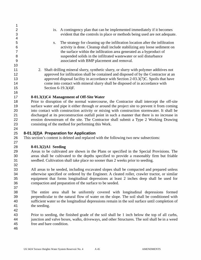
U6 3424 Terrace Heights Water System Reservoir No. 4 A 45 AMENDMENTS
1 ix. A contingency plan that can be implemented immediately if it becomes 2
evident that the controls in place or methods being used are not adequate. 3 4
x. The strategy for cleaning up the infiltration location after the infiltration 5 activity is done. Cleanup shall include stabilizing any loose sediment on 6 the surface within the infiltration area generated as a byproduct of 7 suspended solids in the infiltrated wastewater or soil disturbance 8 associated with BMP placement and removal. 9
10 2. Shaft drilling mineral slurry, synthetic slurry, or slurry with polymer additives not 11
approved for infiltration shall be contained and disposed of by the Contractor at an 12 approved disposal facility in accordance with Section 2-03.3(7)C. Spoils that have 13 come into contact with mineral slurry shall be disposed of in accordance with 14 Section 6-19.3(4)F. 15
16 8-01.3(1)C4 Management of Off-Site Water 17 Prior to disruption of the normal watercourse, the Contractor shall intercept the off-site 18 surface water and pipe it either through or around the project site to prevent it from coming 19 into contact with construction activity or mixing with construction stormwater. It shall be 20 discharged at its preconstruction outfall point in such a manner that there is no increase in 21 erosion downstream of the site. The Contractor shall submit a Type 2 Working Drawing 22 consisting of the method for performing this Work. 23
24 8-01.3(2)A Preparation for Application 25 This section’s content is deleted and replaced with the following two new subsections: 26 27
8-01.3(2)A1 Seeding 28 Areas to be cultivated are shown in the Plans or specified in the Special Provisions. The 29 areas shall be cultivated to the depths specified to provide a reasonably firm but friable 30 seedbed. Cultivation shall take place no sooner than 2 weeks prior to seeding. 31 32 All areas to be seeded, including excavated slopes shall be compacted and prepared unless 33 otherwise specified or ordered by the Engineer. A cleated roller, crawler tractor, or similar 34 equipment that forms longitudinal depressions at least 2 inches deep shall be used for 35 compaction and preparation of the surface to be seeded. 36 37 The entire area shall be uniformly covered with longitudinal depressions formed 38 perpendicular to the natural flow of water on the slope. The soil shall be conditioned with 39 sufficient water so the longitudinal depressions remain in the soil surface until completion of 40 the seeding. 41 42 Prior to seeding, the finished grade of the soil shall be 1 inch below the top of all curbs, 43 junction and valve boxes, walks, driveways, and other Structures. The soil shall be in a weed 44 free and bare condition. 45 46
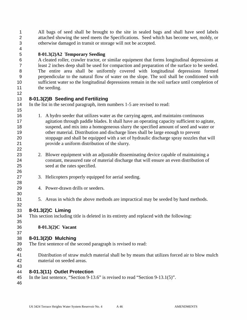
U6 3424 Terrace Heights Water System Reservoir No. 4 A 46 AMENDMENTS
All bags of seed shall be brought to the site in sealed bags and shall have seed labels 1 attached showing the seed meets the Specifications. Seed which has become wet, moldy, or 2 otherwise damaged in transit or storage will not be accepted. 3 4 8-01.3(2)A2 Temporary Seeding 5 A cleated roller, crawler tractor, or similar equipment that forms longitudinal depressions at 6 least 2 inches deep shall be used for compaction and preparation of the surface to be seeded. 7 The entire area shall be uniformly covered with longitudinal depressions formed 8 perpendicular to the natural flow of water on the slope. The soil shall be conditioned with 9 sufficient water so the longitudinal depressions remain in the soil surface until completion of 10 the seeding. 11 12
8-01.3(2)B Seeding and Fertilizing 13 In the list in the second paragraph, item numbers 1-5 are revised to read: 14 15
1. A hydro seeder that utilizes water as the carrying agent, and maintains continuous 16 agitation through paddle blades. It shall have an operating capacity sufficient to agitate, 17 suspend, and mix into a homogeneous slurry the specified amount of seed and water or 18 other material. Distribution and discharge lines shall be large enough to prevent 19 stoppage and shall be equipped with a set of hydraulic discharge spray nozzles that will 20 provide a uniform distribution of the slurry. 21 22
2. Blower equipment with an adjustable disseminating device capable of maintaining a 23 constant, measured rate of material discharge that will ensure an even distribution of 24 seed at the rates specified. 25 26
3. Helicopters properly equipped for aerial seeding. 27 28
4. Power-drawn drills or seeders. 29 30
5. Areas in which the above methods are impractical may be seeded by hand methods. 31 32 8-01.3(2)C Liming 33 This section including title is deleted in its entirety and replaced with the following: 34 35
8-01.3(2)C Vacant 36 37
8-01.3(2)D Mulching 38 The first sentence of the second paragraph is revised to read: 39 40
Distribution of straw mulch material shall be by means that utilizes forced air to blow mulch 41 material on seeded areas. 42 43
8-01.3(11) Outlet Protection 44 In the last sentence, “Section 9-13.6” is revised to read “Section 9-13.1(5)”. 45 46
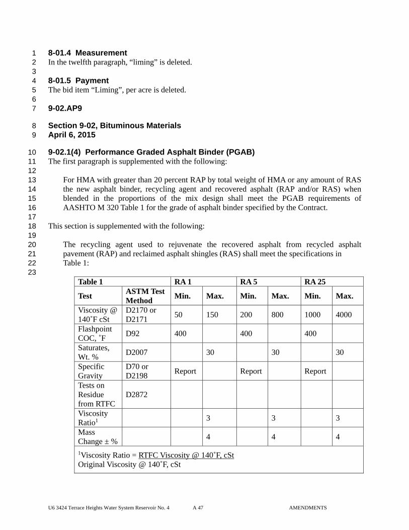
U6 3424 Terrace Heights Water System Reservoir No. 4 A 47 AMENDMENTS
8-01.4 Measurement 1 In the twelfth paragraph, “liming” is deleted. 2 3 8-01.5 Payment 4 The bid item “Liming”, per acre is deleted. 5 6 9-02.AP9 7
Section 9-02, Bituminous Materials 8 April 6, 2015 9
9-02.1(4) Performance Graded Asphalt Binder (PGAB) 10 The first paragraph is supplemented with the following: 11 12
For HMA with greater than 20 percent RAP by total weight of HMA or any amount of RAS 13 the new asphalt binder, recycling agent and recovered asphalt (RAP and/or RAS) when 14 blended in the proportions of the mix design shall meet the PGAB requirements of 15 AASHTO M 320 Table 1 for the grade of asphalt binder specified by the Contract. 16
17 This section is supplemented with the following: 18 19
The recycling agent used to rejuvenate the recovered asphalt from recycled asphalt 20 pavement (RAP) and reclaimed asphalt shingles (RAS) shall meet the specifications in 21 Table 1: 22 23
Table 1 RA 1 RA 5 RA 25
Test ASTM Test Method
Min. Max. Min. Max. Min. Max.
Viscosity @ 140˚F cSt
D2170 or D2171
50 150 200 800 1000 4000
Flashpoint COC, ˚F
D92 400 400 400
Saturates, Wt. %
D2007 30 30 30
Specific Gravity
D70 or D2198
Report Report Report
Tests on Residue from RTFC
D2872
Viscosity Ratio1
3 3 3
Mass Change ± %
4 4 4
1Viscosity Ratio = RTFC Viscosity @ 140˚F, cSt Original Viscosity @ 140˚F, cSt

U6 3424 Terrace Heights Water System Reservoir No. 4 A 48 AMENDMENTS
1 9-02.1(6)A Polymerized Cationic Emulsified Asphalt CRS-2P 2 In the ninth row of the table, “Test” is revised to read “Tests”. 3 4 The eleventh row in the table is revised to read: 5 6
Elastic Recovery % T 3012 50 7
The last two rows of the table are deleted. 8 9 Footnote 2 below the table is revised to read: 10 11
2 The residue material for T 301 shall come from the modified distillation per note 1. 12 13 Footnote 3 below the table is deleted. 14 15 The last paragraph is deleted. 16 17 9-03.AP9 18
Section 9-03, Aggregates 19 August 3, 2015 20
9-03.1(2)C Use of Substandard Gradings 21 This section including title is deleted in its entirety and replaced with the following: 22 23
Vacant 24 25 9-03.1(4)C Grading 26 In the second paragraph, the first sentence is deleted. 27 28 The third paragraph is deleted. 29 30 9-03.1(5)B Grading 31 The last paragraph is revised to read: 32 33
The Contracting Agency may sample each aggregate component prior to introduction to the 34 weigh batcher or as otherwise determined by the Engineer. Each component will be sieve 35 analyzed separately in accordance with WSDOT FOP for WAQTC/AASHTO Test Method 36 T-27/11. All aggregate components will be mathematically re-combined by the proportions 37 (percent of total aggregate by weight) provided by the Contractor on Concrete Mix Design 38 Form 350-040. 39
40
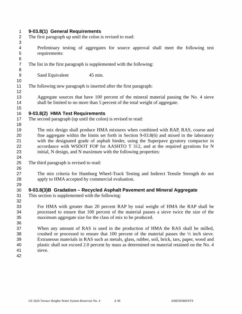
U6 3424 Terrace Heights Water System Reservoir No. 4 A 49 AMENDMENTS
9-03.8(1) General Requirements 1 The first paragraph up until the colon is revised to read: 2 3
Preliminary testing of aggregates for source approval shall meet the following test 4 requirements: 5
6 The list in the first paragraph is supplemented with the following: 7 8
Sand Equivalent 45 min. 9 10
The following new paragraph is inserted after the first paragraph: 11 12
Aggregate sources that have 100 percent of the mineral material passing the No. 4 sieve 13 shall be limited to no more than 5 percent of the total weight of aggregate. 14 15
9-03.8(2) HMA Test Requirements 16 The second paragraph (up until the colon) is revised to read: 17 18
The mix design shall produce HMA mixtures when combined with RAP, RAS, coarse and 19 fine aggregate within the limits set forth in Section 9-03.8(6) and mixed in the laboratory 20 with the designated grade of asphalt binder, using the Superpave gyratory compactor in 21 accordance with WSDOT FOP for AASHTO T 312, and at the required gyrations for N 22 initial, N design, and N maximum with the following properties: 23
24 The third paragraph is revised to read: 25 26
The mix criteria for Hamburg Wheel-Track Testing and Indirect Tensile Strength do not 27 apply to HMA accepted by commercial evaluation. 28
29 9-03.8(3)B Gradation – Recycled Asphalt Pavement and Mineral Aggregate 30 This section is supplemented with the following: 31 32
For HMA with greater than 20 percent RAP by total weight of HMA the RAP shall be 33 processed to ensure that 100 percent of the material passes a sieve twice the size of the 34 maximum aggregate size for the class of mix to be produced. 35 36 When any amount of RAS is used in the production of HMA the RAS shall be milled, 37 crushed or processed to ensure that 100 percent of the material passes the ½ inch sieve. 38 Extraneous materials in RAS such as metals, glass, rubber, soil, brick, tars, paper, wood and 39 plastic shall not exceed 2.0 percent by mass as determined on material retained on the No. 4 40 sieve. 41
42
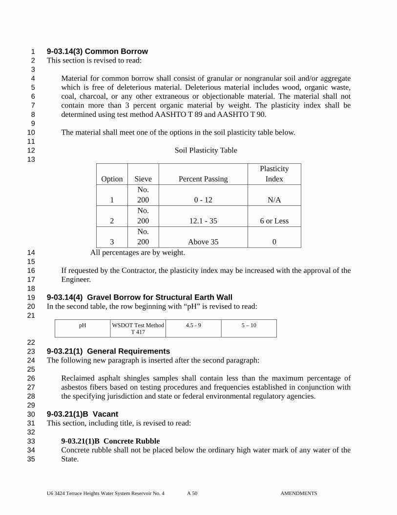
U6 3424 Terrace Heights Water System Reservoir No. 4 A 50 AMENDMENTS
9-03.14(3) Common Borrow 1 This section is revised to read: 2 3
Material for common borrow shall consist of granular or nongranular soil and/or aggregate 4 which is free of deleterious material. Deleterious material includes wood, organic waste, 5 coal, charcoal, or any other extraneous or objectionable material. The material shall not 6 contain more than 3 percent organic material by weight. The plasticity index shall be 7 determined using test method AASHTO T 89 and AASHTO T 90. 8 9 The material shall meet one of the options in the soil plasticity table below. 10 11
Soil Plasticity Table 12 13
Option Sieve Percent Passing Plasticity
Index
1 No. 200 0 - 12 N/A
2 No. 200 12.1 - 35 6 or Less
3 No. 200 Above 35 0
All percentages are by weight. 14 15 If requested by the Contractor, the plasticity index may be increased with the approval of the 16 Engineer. 17 18
9-03.14(4) Gravel Borrow for Structural Earth Wall 19 In the second table, the row beginning with “pH” is revised to read: 20
21 pH WSDOT Test Method
T 417 4.5 - 9 5 – 10
22 9-03.21(1) General Requirements 23 The following new paragraph is inserted after the second paragraph: 24 25
Reclaimed asphalt shingles samples shall contain less than the maximum percentage of 26 asbestos fibers based on testing procedures and frequencies established in conjunction with 27 the specifying jurisdiction and state or federal environmental regulatory agencies. 28
29 9-03.21(1)B Vacant 30 This section, including title, is revised to read: 31 32
9-03.21(1)B Concrete Rubble 33 Concrete rubble shall not be placed below the ordinary high water mark of any water of the 34 State. 35
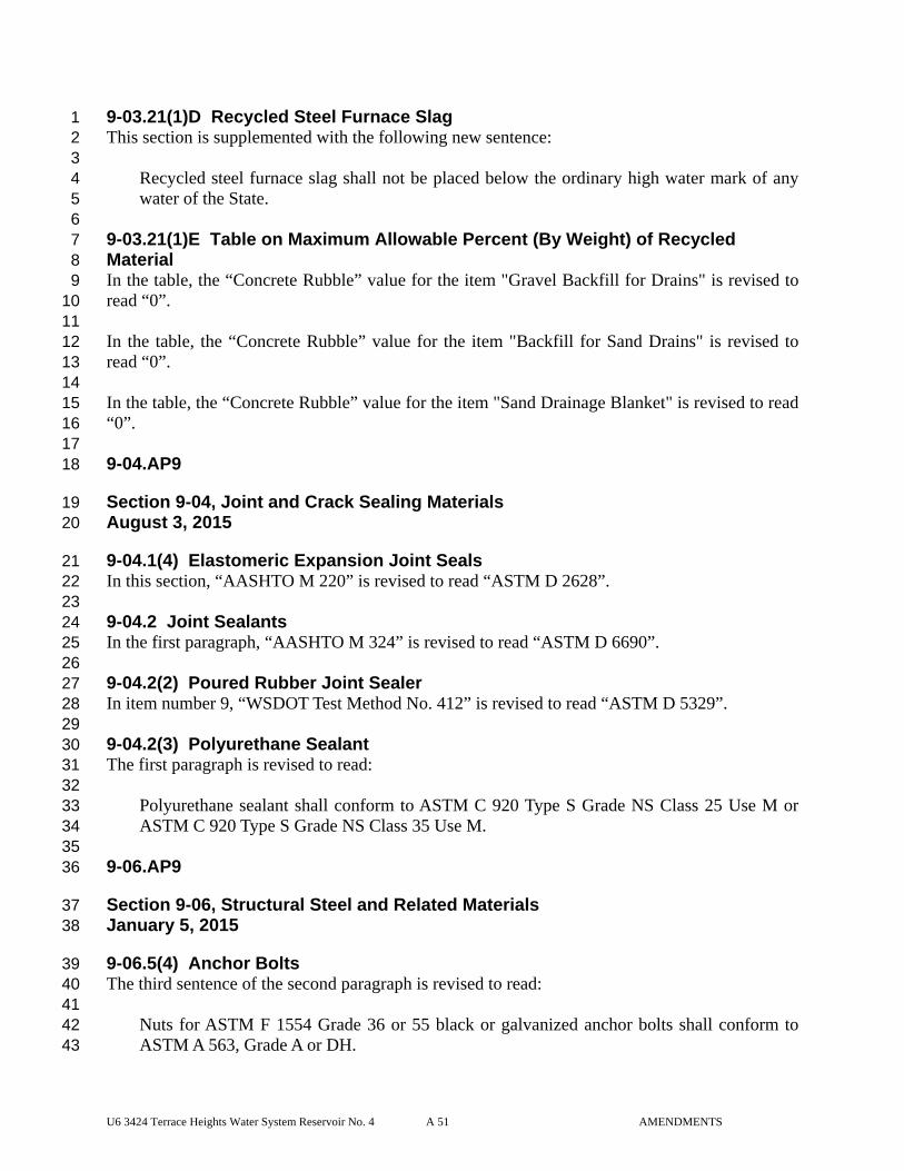
U6 3424 Terrace Heights Water System Reservoir No. 4 A 51 AMENDMENTS
9-03.21(1)D Recycled Steel Furnace Slag 1 This section is supplemented with the following new sentence: 2 3
Recycled steel furnace slag shall not be placed below the ordinary high water mark of any 4 water of the State. 5
6 9-03.21(1)E Table on Maximum Allowable Percent (By Weight) of Recycled 7 Material 8 In the table, the “Concrete Rubble” value for the item "Gravel Backfill for Drains" is revised to 9 read “0”. 10 11 In the table, the “Concrete Rubble” value for the item "Backfill for Sand Drains" is revised to 12 read “0”. 13 14 In the table, the “Concrete Rubble” value for the item "Sand Drainage Blanket" is revised to read 15 “0”. 16 17 9-04.AP9 18
Section 9-04, Joint and Crack Sealing Materials 19 August 3, 2015 20
9-04.1(4) Elastomeric Expansion Joint Seals 21 In this section, “AASHTO M 220” is revised to read “ASTM D 2628”. 22 23 9-04.2 Joint Sealants 24 In the first paragraph, “AASHTO M 324” is revised to read “ASTM D 6690”. 25 26 9-04.2(2) Poured Rubber Joint Sealer 27 In item number 9, “WSDOT Test Method No. 412” is revised to read “ASTM D 5329”. 28 29 9-04.2(3) Polyurethane Sealant 30 The first paragraph is revised to read: 31 32
Polyurethane sealant shall conform to ASTM C 920 Type S Grade NS Class 25 Use M or 33 ASTM C 920 Type S Grade NS Class 35 Use M. 34
35 9-06.AP9 36
Section 9-06, Structural Steel and Related Materials 37 January 5, 2015 38
9-06.5(4) Anchor Bolts 39 The third sentence of the second paragraph is revised to read: 40 41
Nuts for ASTM F 1554 Grade 36 or 55 black or galvanized anchor bolts shall conform to 42 ASTM A 563, Grade A or DH. 43
U6 3424 Terrace Heights Water System Reservoir No. 4 A 52 AMENDMENTS
1 9-07.AP9 2
Section 9-07, Reinforcing Steel 3 August 3, 2015 4
9-07.2 Deformed Steel Bars 5 The first sentence is revised to read: 6 7
Deformed steel bars for concrete reinforcement shall conform to either AASHTO M 31 8 Grade 60 or ASTM A 706 Grade 60, except as otherwise noted in this Section or as shown in 9 the Plans. 10
11 This section is supplemented with the following new sub-section: 12 13
9-07.2(1) Headed Steel Reinforcing Bar 14 Headed steel reinforcing bars shall conform to Section 9-07.2 and ASTM A 970, including 15 Annex A1 requirements for Class HA head dimensions. Headed steel reinforcing bars shall 16 be forged headed bars or threaded headed bars. 17
18 9-07.5(1) Epoxy-Coated Dowel Bars (for Cement Concrete Pavement 19 Rehabilitation) 20 This section is revised to read: 21 22
Epoxy-coated dowel bars shall be round plain steel bars of the dimensions shown in the 23 Standard Plans. They shall conform to AASHTO M 31, Grade 60 or ASTM A 615, Grade 60 24 and shall be coated in accordance with ASTM A 1078 Type 2 coating, except that the bars 25 may be cut to length after being coated. Cut ends shall be coated in accordance with ASTM 26 A 1078 with a patching material that is compatible with the coating, inert in concrete and 27 recommended by the coating manufacturer. The thickness of the epoxy coating shall be 10 28 mils plus or minus 2 mils. The Contractor shall furnish a written certification that properly 29 identifies the coating material, the number of each batch of coating material used, quantity 30 represented, date of manufacture, name and address of manufacturer, and a statement that 31 the supplied coating material meets the requirements of ASTM A 1078 Type 2 coating. 32 Patching material, compatible with the coating material and inert in concrete and 33 recommended by the manufacturer shall be supplied with each shipment for field repairs by 34 the Contractor. 35
36 9-07.5(2) Corrosion Resistant Dowel Bars (for Cement Concrete Pavement) 37 This section’s title is revised to read: 38 39
9-07.5(2) Corrosion Resistant Dowel Bars (for Cement Concrete Pavement and 40 Cement Concrete Pavement Rehabilitation) 41
42
U6 3424 Terrace Heights Water System Reservoir No. 4 A 53 AMENDMENTS
9-08.AP9 1
Section 9-08, Paints and Related Materials 2 January 5, 2015 3
9-08.1(2)H Top Coat, Single Component, Moisture-Cured Polyurethane 4 The second paragraph is revised to read: 5 6
Color and Gloss: As specified in the Plans or Special Provisions 7 8
The last item in the requirements list is revised to read: 9 10
The top coat shall be a gloss or semi-gloss 11 12 13
14 9-08.1(8) Standard Colors 15 The second paragraph is deleted. 16 17 The third paragraph is revised to read: 18 19
Unless otherwise specified, all top or finish coats shall be gloss or semi-gloss, with the paint 20 falling within the range of greater than 70 for gloss and 35 to 70 for semi-gloss on the 60-21 degree gloss meter. 22
23 24 25

SPECIAL PROVISIONS
U6 3424 Terrace Heights Water System Reservoir #4 SP 1 SPECIAL PROVISIONS
INTRODUCTION TO THE SPECIAL PROVISIONS 1 2 (July 31, 2007 APWA GSP) 3 4 The work on this project shall be accomplished in accordance with the Standard Specifications 5 for Road, Bridge and Municipal Construction, 2014 edition, as issued by the Washington State 6 Department of Transportation (WSDOT) and the American Public Works Association (APWA), 7 Washington State Chapter (hereafter “Standard Specifications”). The Standard Specifications, 8 as modified or supplemented by the Amendments to the Standard Specifications and these 9 Special Provisions, all of which are made a part of the Contract Documents, shall govern all of 10 the Work. 11 12 These Special Provisions are made up of both General Special Provisions (GSPs) from various 13 sources, which may have project-specific fill-ins; and project-specific Special Provisions. Each 14 Provision either supplements, modifies, or replaces the comparable Standard Specification, or is 15 a new Provision. The deletion, amendment, alteration, or addition to any subsection or portion 16 of the Standard Specifications is meant to pertain only to that particular portion of the section, 17 and in no way should it be interpreted that the balance of the section does not apply. 18 19 The project-specific Special Provisions are not labeled as such. The GSPs are labeled under the 20 headers of each GSP, with the date of the GSP and its source, as follows: 21 22 (May 18, 2007 APWA GSP) 23 (August 7, 2006 WSDOT GSP) 24 25 Also incorporated into the Contract Documents by reference are: 26
Manual on Uniform Traffic Control Devices for Streets and Highways, currently adopted 27 edition, with Washington State modifications, if any 28
Standard Plans for Road, Bridge and Municipal Construction, WSDOT/APWA, current 29 edition 30
Yakima County Standard Plans 31 32 Contractor shall obtain copies of these publications, at Contractor’s own expense. 33 34
DIVISION 1
GENERAL REQUIRMENTS
U6 3424 Terrace Heights Water System Reservoir #4 SP 2 SPECIAL PROVISIONS
DIVISION 1 1 GENERAL REQUIREMENTS 2
3 4
DESCRIPTION OF WORK 5 6
(******) 7 The work to be performed under this Contract consists of the construction of the work 8 described in Schedule A and either Schedule B or Schedule C as follows: 9
10 SCHEDULE A 11 12
The work specified in this Schedule consists of furnishing all labor, materials, and equipment 13 necessary for construction of the reservoir project (except for the work included in Schedules B 14 and C) including the relocation of and recoating of three existing 11-foot diameter by 42.5' long 15 welded steel tanks and the recoating of two existing tanks (optional with Owner), constructing 16 new reservoir inlet structure as shown on the Drawings, and herein specified. The work of 17 Schedule A shall include, but not be limited to, the following: 18 19
A. Relocate and install the three (3) existing 42.5' long by 11-foot diameter welded steel 20 reservoirs (3 Steel Tanks) from the Reservoir No. 4 site to the Sycamore Booster Station 21 site. Construct reinforced concrete pads and welded steel supports and appurtenances. 22
23 B. Construct new inlet structure inside of the existing Reservoir No. 1. Mount new inlet 24
structure supports to interior of existing reservoir. 25 26
C. Sandblast and recoat the interior and exterior of the 3 relocated existing steel tanks with 27 NSF 61 approved coatings. 28
29 D. Sandblast and recoat the interior and exterior of the 2 existing steel tanks (2 Steel Tanks) 30
currently located at the Sycamore Booster Pumping Station (BPS) site with NSF 61 31 approved coatings (Optional with Owner). 32
33 E. Properly dispose of removed tank coatings and sand blasting materials. 34
35 F. Furnish and install crushed surfacing top course. 36
37 G. Furnish and install all required piping, valves and appurtenances. 38
39 H. Furnish and install all required electrical, telemetry and instrumentation. 40
41 I. Provide testing, commissioning, and training as specified herein. 42
43
U6 3424 Terrace Heights Water System Reservoir #4 SP 3 SPECIAL PROVISIONS
SCHEDULE B (1,500,000 GALLON RESERVOIR) 1 2 The work specified in this Schedule consists of furnishing all labor, materials, and 3 equipment necessary for site excavation and grading, construction of the 1,500,000 gallon 4 welded steel reservoir and lock block wall as shown on the Drawings, and herein specified. 5 Schedule B work shall include, but not be limited to, the following: 6
7 J. Construct required site excavation and grading for the 1,500,000 gallon reservoir site. 8
9 K. Furnish and install a 1,500,000 gallon, 90-foot diameter by 32-foot high welded steel 10
reservoir, with reinforced concrete foundation, and appurtenances. It is the intent of this 11 Contract that the new reservoir structure be constructed with an appearance similar to the 12 existing Reservoir No. 1. 13 14
L. Furnish and install lock block wall and appurtenances. 15 16
SCHEDULE C (900,000 GALLON RESERVOIR) 17 18 The work specified in this Schedule consists of furnishing all labor, materials, and 19 equipment necessary for site excavation, grading and the construction of the 900,000 gallon 20 welded steel reservoir as shown on the Drawings, and herein specified. Schedule C work 21 shall include, but not be limited to, the following: 22
23 M. Construct required site excavation and grading for the 900,000 gallon reservoir site. 24
25 N. Furnish and install a 900,000 gallon, 70-foot diameter by 32-foot high welded steel 26
reservoir, with reinforced concrete foundation, and appurtenances. It is the intent of this 27 Contract that the new reservoir structure be constructed with an appearance similar to the 28 existing Reservoir No. 1. 29 30 The Contract consists of the above described work and other work, in accordance with the 31 attached Plans, these Special Provisions and the 2014 Standard Specifications and 32 Amendments thereto. 33
34 The quantities of work indicated in the proposal are to be considered as estimates and are for 35 comparative bidding purposes only. All payments shall be made on the basis of actual field 36 measurement of Contract work completed. 37
38 FUNDS 39 40
(******) 41 This project is funded by reserves from the Yakima County Terrace Heights Water System 42 and by Washington State Department of Health through the Drinking Water State Revolving Fund. 43 44
U6 3424 Terrace Heights Water System Reservoir #4 SP 4 SPECIAL PROVISIONS
SECTION 1-01, DEFINITION AND TERMS 1 2 1-01.3 Definitions 3 (March 13, 2012 APWA GSP) 4 5 Delete the heading Completion Dates and the three paragraphs that follow it, and replace them 6 with the following: 7
8 Dates 9
Bid Opening Date 10 The date on which the Contracting Agency publicly opens and reads the Bids. 11 Award Date 12 The date of the formal decision of the Contracting Agency to accept the lowest 13 responsible and responsive Bidder for the Work. 14 Contract Execution Date 15 The date the Contracting Agency officially binds the Agency to the Contract. 16 Notice to Proceed Date 17 The date stated in the Notice to Proceed on which the Contract time begins. 18 Substantial Completion Date 19 The day the Engineer determines the Contracting Agency has full and unrestricted use 20 and benefit of the facilities, both from the operational and safety standpoint, any 21 remaining traffic disruptions will be rare and brief, and only minor incidental work, 22 replacement of temporary substitute facilities, plant establishment periods, or correction 23 or repair remains for the Physical Completion of the total Contract. 24 Physical Completion Date 25 The day all of the Work is physically completed on the project. All documentation 26 required by the Contract and required by law does not necessarily need to be furnished by 27 the Contractor by this date. 28 Completion Date 29 The day all the Work specified in the Contract is completed and all the obligations of the 30 Contractor under the contract are fulfilled by the Contractor. All documentation required 31 by the Contract and required by law must be furnished by the Contractor before 32 establishment of this date. 33 Final Acceptance Date 34 The date on which the Contracting Agency accepts the Work as complete. 35
36 Supplement this Section with the following: 37 38
All references in the Standard Specifications, Amendments, or WSDOT General Special 39 Provisions, to the terms “State”, “Department of Transportation”, “Washington State 40 Transportation Commission”, “Commission”, “Secretary of Transportation”, “Secretary”, 41 “Headquarters”, and “State Treasurer” shall be revised to read “Contracting Agency”. 42 43 All references to “State Materials Laboratory” shall be revised to read “Contracting Agency 44 designated location”. 45 46
U6 3424 Terrace Heights Water System Reservoir #4 SP 5 SPECIAL PROVISIONS
All references to “final contract voucher certification” shall be interpreted to mean the final 1 payment form established by the Contracting Agency. 2 3 The venue of all causes of action arising from the advertisement, award, execution, and 4 performance of the contract shall be in the Superior Court of the County where the 5 Contracting Agency’s headquarters are located. 6 7 Additive 8 A supplemental unit of work or group of bid items, identified separately in the Bid Proposal, 9 which may, at the discretion of the Contracting Agency, be awarded in addition to the base 10 bid. 11 12 Alternate 13 One of two or more units of work or groups of bid items, identified separately in the Bid 14 Proposal, from which the Contracting Agency may make a choice between different methods 15 or material of construction for performing the same work. 16 17 Business Day 18 A business day is any day from Monday through Friday except holidays as listed in Section 19 1-08.5. 20 21 Contract Documents 22 See definition for “Contract”. 23 24 Contract Time 25 The period of time established by the terms and conditions of the Contract within which the 26 Work must be physically completed. 27 28 Notice of Award 29 The written notice from the Contracting Agency to the successful Bidder signifying the 30 Contracting Agency’s acceptance of the Bid Proposal. 31 32 Notice to Proceed 33 The written notice from the Contracting Agency or Engineer to the Contractor authorizing 34 and directing the Contractor to proceed with the Work and establishing the date on which the 35 Contract time begins. 36 37 Traffic 38 Both vehicular and non-vehicular traffic, such as pedestrians, bicyclists, wheelchairs, and 39 equestrian traffic. 40 41
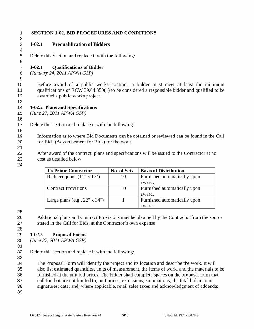
U6 3424 Terrace Heights Water System Reservoir #4 SP 6 SPECIAL PROVISIONS
SECTION 1-02, BID PROCEDURES AND CONDITIONS 1 2 1-02.1 Prequalification of Bidders 3 4 Delete this Section and replace it with the following: 5 6 1-02.1 Qualifications of Bidder 7 (January 24, 2011 APWA GSP) 8
9 Before award of a public works contract, a bidder must meet at least the minimum 10 qualifications of RCW 39.04.350(1) to be considered a responsible bidder and qualified to be 11 awarded a public works project. 12
13 1-02.2 Plans and Specifications 14 (June 27, 2011 APWA GSP) 15 16 Delete this section and replace it with the following: 17 18
Information as to where Bid Documents can be obtained or reviewed can be found in the Call 19 for Bids (Advertisement for Bids) for the work. 20 21 After award of the contract, plans and specifications will be issued to the Contractor at no 22 cost as detailed below: 23 24
To Prime Contractor No. of Sets Basis of Distribution Reduced plans (11" x 17") 10 Furnished automatically upon
award. Contract Provisions 10 Furnished automatically upon
award. Large plans (e.g., 22" x 34") 1 Furnished automatically upon
award. 25
Additional plans and Contract Provisions may be obtained by the Contractor from the source 26 stated in the Call for Bids, at the Contractor’s own expense. 27 28
1-02.5 Proposal Forms 29 (June 27, 2011 APWA GSP) 30 31 Delete this section and replace it with the following: 32 33
The Proposal Form will identify the project and its location and describe the work. It will 34 also list estimated quantities, units of measurement, the items of work, and the materials to be 35 furnished at the unit bid prices. The bidder shall complete spaces on the proposal form that 36 call for, but are not limited to, unit prices; extensions; summations; the total bid amount; 37 signatures; date; and, where applicable, retail sales taxes and acknowledgment of addenda; 38
39
U6 3424 Terrace Heights Water System Reservoir #4 SP 7 SPECIAL PROVISIONS
the bidder’s name, address, telephone number, and signature; the bidder’s D/M/WBE 1 commitment, if applicable; a State of Washington Contractor’s Registration Number; and a 2 Business License Number, if applicable. Bids shall be completed by typing or shall be 3 printed in ink by hand, preferably in black ink. The required certifications are included as 4 part of the Proposal Form. 5
6 The Contracting Agency reserves the right to arrange the proposal forms with alternates and 7 additives, if such be to the advantage of the Contracting Agency. The bidder shall bid on all 8 alternates and additives set forth in the Proposal Form unless otherwise specified. 9
10 1-02.6 Preparation Of Proposal 11 (June 27, 2011 APWA GSP) 12 13 Supplement the second paragraph with the following: 14 15
4. If a minimum bid amount has been established for any item, the unit or lump sum price 16 must equal or exceed the minimum amount stated. 17
18 5. Any correction to a bid made by interlineation, alteration, or erasure, shall be initialed 19
by the signer of the bid. 20 21
Delete the last paragraph, and replace it with the following: 22 23
The Bidder shall make no stipulation on the Bid Form, nor qualify the bid in any manner. 24 25 A bid by a corporation shall be executed in the corporate name, by the president or a vice 26 president (or other corporate officer accompanied by evidence of authority to sign). 27 28 A bid by a partnership shall be executed in the partnership name, and signed by a partner. A 29 copy of the partnership agreement shall be submitted with the Bid Form if any D/M/WBE 30 requirements are to be satisfied through such an agreement. 31 32 A bid by a joint venture shall be executed in the joint venture name and signed by a member 33 of the joint venture. A copy of the joint venture agreement shall be submitted with the bid 34 form if any D/W/MBE requirements are to be satisfied through such an agreement 35 36
(August 2, 2004) 37 The fifth and sixth paragraphs of Section 1-02.6 are deleted. 38 39
1-02.7 Bid Deposit 40 (October 1, 2005 APWA GSP) 41 42 Supplement this section with the following: 43
44 Bid bonds shall contain the following: 45
46
U6 3424 Terrace Heights Water System Reservoir #4 SP 8 SPECIAL PROVISIONS
1. Contracting Agency-assigned number for the project; 1 2. Name of the project; 2 3. The Contracting Agency named as obligee; 3 4. The amount of the bid bond stated either as a dollar figure or as a percentage which 4
represents five percent of the maximum bid amount that could be awarded; 5 5. Signature of the bidder’s officer empowered to sign official statements. The signature of 6
the person authorized to submit the bid should agree with the signature on the bond, and 7 the title of the person must accompany the said signature; 8
6. The signature of the surety’s officer empowered to sign the bond and the power of 9 attorney. 10
11 If so stated in the Contract Provisions, bidder must use the bond form included in the 12 Contract Provisions. 13 14
1-02.9 Delivery of Proposal 15 (August 15, 2012 APWA GSP, Option A) 16 17 Delete this section and replace it with the following: 18
19 Each proposal shall be submitted in a sealed envelope, with the Project Name and Project 20 Number as stated in the Call for Bids clearly marked on the outside of the envelope, or as 21 otherwise required in the Bid Documents, to ensure proper handling and delivery. 22 23 If the project has FHWA funding and requires DBE Written Confirmation Documents or 24 Good Faith Effort Documentation, then to be considered responsive, the Bidder shall submit 25 with their Bid Proposal, written Confirmation Documentation from each DBE firm listed on 26 the Bidder’s completed DBE Utilization Certification, form 272-056A EF, as required by 27 Section 1-02.6. 28 29 The Contracting Agency will not open or consider any Bid Proposal that is received after the 30 time specified in the Call for Bids for receipt of Bid Proposals, or received in a location other 31 than that specified in the Call for Bids. 32
33 1-02.13 Irregular Proposals 34 (March 13, 2012 APWA GSP) 35 36 Revise item 1 to read: 37 38
1. A proposal will be considered irregular and will be rejected if: 39 a. The Bidder is not prequalified when so required; 40 b. The authorized proposal form furnished by the Contracting Agency is not used or 41
is altered; 42 c. The completed proposal form contains any unauthorized additions, deletions, 43
alternate Bids, or conditions; 44 d. The Bidder adds provisions reserving the right to reject or accept the award, or 45
enter into the Contract; 46 e. A price per unit cannot be determined from the Bid Proposal; 47
U6 3424 Terrace Heights Water System Reservoir #4 SP 9 SPECIAL PROVISIONS
f. The Proposal form is not properly executed; 1 g. The Bidder fails to submit or properly complete a Subcontractor list, if applicable, 2
as required in Section 1-02.6; 3 h. The Bidder fails to submit or properly complete a Disadvantaged Business 4
Enterprise Certification, if applicable, as required in Section 1-02.6; 5 i. The Bidder fails to submit written confirmation from each DBE firm listed on the 6
Bidder’s completed DBE Utilization Certification that they are in agreement with 7 the bidders DBE participation commitment, if applicable, as required in Section 8 1-02.6, or if the written confirmation that is submitted fails to meet the 9 requirements of the Special Provisions; 10
j The Bidder fails to submit DBE Good Faith Effort documentation, if applicable, 11 as required in Section 1-02.6, or if the documentation that is submitted fails to 12 demonstrate that a Good Faith Effort to meet the Condition of Award was made; 13
k. The Bid Proposal does not constitute a definite and unqualified offer to meet the 14 material terms of the Bid invitation; or 15
l. More than one proposal is submitted for the same project from a Bidder under the 16 same or different names. 17
18 1-02.14 Disqualification of Bidders 19 (March 25, 2009 APWA GSP, Option B) 20 21 Delete this Section and replace it with the following: 22
23 A Bidder will be deemed not responsible if: 24
1. the Bidder does not meet the mandatory bidder responsibility criteria in RCW 25 39.04.350(1), as amended; or 26
2. evidence of collusion exists with any other Bidder or potential Bidder. 27 Participants in collusion will be restricted from submitting further bids; or 28
3. the Bidder, in the opinion of the Contracting Agency, is not qualified for the work 29 or to the full extent of the bid, or to the extent that the bid exceeds the authorized 30 prequalification amount as may have been determined by a prequalification of the 31 Bidder; or 32
4. an unsatisfactory performance record exists based on past or current Contracting 33 Agency work or for work done for others, as judged from the standpoint of 34 conduct of the work; workmanship; or progress; affirmative action; equal 35 employment opportunity practices; termination for cause; or Disadvantaged 36 Business Enterprise, Minority Business Enterprise, or Women’s Business 37 Enterprise utilization; or 38
5. there is uncompleted work (Contracting Agency or otherwise), which in the 39 opinion of the Contracting Agency might hinder or prevent the prompt completion 40 of the work bid upon; or 41
6. the Bidder failed to settle bills for labor or materials on past or current contracts, 42 unless there are extenuating circumstances acceptable to the Contracting Agency; 43 or 44
7. the Bidder has failed to complete a written public contract or has been convicted 45 of a crime arising from a previous public contract, unless there are extenuating 46 circumstances acceptable to the Contracting Agency; or 47
U6 3424 Terrace Heights Water System Reservoir #4 SP 10 SPECIAL PROVISIONS
8. the Bidder is unable, financially or otherwise, to perform the work, in the opinion 1 of the Contracting Agency; or 2
9. there are any other reasons deemed proper by the Contracting Agency. 3 4
As evidence that the Bidder meets the bidder responsibility criteria above, the apparent two 5 lowest Bidders must submit to the Contracting Agency within 24 hours of the bid submittal 6 deadline, documentation (sufficient in the sole judgment of the Contracting Agency) 7 demonstrating compliance with all applicable responsibility criteria, including all 8 documentation specifically listed in the supplemental criteria. The Contracting Agency 9 reserves the right to request such documentation from other Bidders as well, and to request 10 further documentation as needed to assess bidder responsibility. 11 12 The basis for evaluation of Bidder compliance with these supplemental criteria shall be any 13 documents or facts obtained by Contracting Agency (whether from the Bidder or third 14 parties) which any reasonable owner would rely on for determining such compliance, 15 including but not limited to: (i) financial, historical, or operational data from the Bidder; (ii) 16 information obtained directly by the Contracting Agency from owners for whom the Bidder 17 has worked, or other public agencies or private enterprises; and (iii) any additional 18 information obtained by the Contracting Agency which is believed to be relevant to the 19 matter. 20 21 If the Contracting Agency determines the Bidder does not meet the bidder responsibility 22 criteria above and is therefore not a responsible Bidder, the Contracting Agency shall notify 23 the Bidder in writing, with the reasons for its determination. If the Bidder disagrees with this 24 determination, it may appeal the determination within 24 hours of receipt of the Contracting 25 Agency’s determination by presenting its appeal to the Contracting Agency. The Contracting 26 Agency will consider the appeal before issuing its final determination. If the final 27 determination affirms that the Bidder is not responsible, the Contracting Agency will not 28 execute a contract with any other Bidder until at least two business days after the Bidder 29 determined to be not responsible has received the final determination. 30
31 SECTION 1-03, AWARD AND EXECUTION OF CONTRACT 32 33 1-03.1 Consideration of Bids 34 (January 23, 2006 APWA GSP) 35 36 Revise the first paragraph to read: 37
38 After opening and reading proposals, the Contracting Agency will check them for correctness 39 of extensions of the prices per unit and the total price. If a discrepancy exists between the 40 price per unit and the extended amount of any bid item, the price per unit will control. If a 41 minimum bid amount has been established for any item and the bidder’s unit or lump sum 42 price is less than the minimum specified amount, the Contracting Agency will unilaterally 43 revise the unit or lump sum price, to the minimum specified amount and recalculate the 44 extension. The total of extensions, corrected where necessary, including sales taxes where 45 applicable and such additives and/or alternates as selected by the Contracting Agency, will be 46 used by the Contracting Agency for award purposes and to fix the Awarded Contract Price 47
U6 3424 Terrace Heights Water System Reservoir #4 SP 11 SPECIAL PROVISIONS
amount and the amount of the contract bond. 1 2
1-03.3 Execution of Contract 3 (October 1, 2005 APWA GSP) 4 5 Revise this section to read: 6 7
Copies of the Contract Provisions, including the unsigned Form of Contract, will be available 8 for signature by the successful bidder on the first business day following award. The number 9 of copies to be executed by the Contractor will be determined by the Contracting Agency. 10 11 Within 10 calendar days after the award date, the successful bidder shall return the signed 12 Contracting Agency-prepared contract, an insurance certification as required by Section 1-13 07.18, and a satisfactory bond as required by law and Section 1-03.4. Before execution of the 14 contract by the Contracting Agency, the successful bidder shall provide any pre-award 15 information the Contracting Agency may require under Section 1-02.15. 16 17 Until the Contracting Agency executes a contract, no proposal shall bind the Contracting 18 Agency nor shall any work begin within the project limits or within Contracting Agency-19 furnished sites. The Contractor shall bear all risks for any work begun outside such areas and 20 for any materials ordered before the contract is executed by the Contracting Agency. 21 22 If the bidder experiences circumstances beyond their control that prevents return of the 23 contract documents within the calendar days after the award date stated above, the 24 Contracting Agency may grant up to a maximum of 10 additional calendar days for return 25 of the documents, provided the Contracting Agency deems the circumstances warrant it. 26 27
1-03.4 Contract Bond 28 (October 1, 2005 APWA GSP) 29 30 Revise the first paragraph to read: 31 32
The successful bidder shall provide an executed contract bond for the full contract amount. 33 This contract bond shall: 34 1. Be on a Contracting Agency-furnished form; 35 2. Be signed by an approved surety (or sureties) that: 36
a. Is registered with the Washington State Insurance Commissioner, and 37 b. Appears on the current Authorized Insurance List in the State of Washington 38
published by the Office of the Insurance Commissioner, 39 3. Be conditioned upon the faithful performance of the contract by the Contractor within the 40
prescribed time; 41 4. Guarantee that the surety shall indemnify, defend, and protect the Contracting Agency 42
against any claim of direct or indirect loss resulting from the failure: 43 a. Of the Contractor (or any of the employees, subcontractors, or lower tier 44
subcontractors of the Contractor) to faithfully perform the contract, or 45 b. Of the Contractor (or the subcontractors or lower tier subcontractors of the 46
Contractor) to pay all laborers, mechanics, subcontractors, lower tier subcontractors, 47
U6 3424 Terrace Heights Water System Reservoir #4 SP 12 SPECIAL PROVISIONS
materialperson, or any other person who provides supplies or provisions for carrying 1 out the work; 2
5. Be accompanied by a power of attorney for the Surety’s officer empowered to sign the 3 bond; and 4
6. Be signed by an officer of the Contractor empowered to sign official statements (sole 5 proprietor or partner). If the Contractor is a corporation, the bond must be signed by the 6 president or vice-president, unless accompanied by written proof of the authority of the 7 individual signing the bond to bind the corporation (i.e., corporate resolution, power of 8 attorney or a letter to such effect by the president or vice-president). 9
10 Section 1-03.4 is supplemented with the following: 11 12
(June 27, 2011) 13 Release of Contract Bond will be 60 days following Contracting Agency Final Acceptance 14 of Contract, provided following conditions are met: 15
16 1. Payment to the State with respect to taxes imposed pursuant to Title 82, RCW on 17
Contracts totaling more than $ 35,000, a release has been obtained from the 18 Washington State Department of Revenue. 19
20 2. Affidavits of Wages Paid for the Contractor and all Subcontractors are on file with 21
the Contracting Agency (RCW 39.12.040). 22 23 3. A certificate of Payment of Contributions Penalties and Interest on Public Works 24
Contract is received from the Washington State Employment Security Department. 25 26 4. Washington State Department of Labor and Industries (per Section 1-07.10) shows 27
the Contractor, Subcontractor(s) and any lower tier Subcontractor(s) are current 28 with payments of industrial insurance and medical aid premiums. 29
30 5. All claims, as provided by law, filed against the Contract Bond have been resolved. 31
32 SECTION 1-04, SCOPE OF WORK 33 34 1-04.2 Coordination of Contract Documents, Plans, Special Provisions, Specifications, 35
and Addenda 36 (March 13, 2012 APWA GSP) 37 38 Revise the second paragraph to read: 39
40 Any inconsistency in the parts of the contract shall be resolved by following this order of precedence 41 (e.g., 1 presiding over 2, 2 over 3, 3 over 4, and so forth): 42 1. Addenda, 43 2. Proposal Form, 44 3. Special Provisions (Special Provisions include Part 4 Technical Specifications), 45 4. Contract Plans, 46 5. Amendments to the Standard Specifications, 47 6. Standard Specifications, 48
U6 3424 Terrace Heights Water System Reservoir #4 SP 13 SPECIAL PROVISIONS
7. Contracting Agency’s Standard Plans or Details (if any), and 1 8. WSDOT Standard Plans for Road, Bridge, and Municipal Construction. 2
3 SECTION 1-05, CONTROL OF WORK 4 5 1-05.7 Removal of Defective and Unauthorized Work 6 (October 1, 2005 APWA GSP) 7 8 Supplement this section with the following: 9 10
If the Contractor fails to remedy defective or unauthorized work within the time specified in 11 a written notice from the Engineer, or fails to perform any part of the work required by the 12 Contract Documents, the Engineer may correct and remedy such work as may be identified 13 in the written notice, with Contracting Agency forces or by such other means as the 14 Contracting Agency may deem necessary. 15 16 If the Contractor fails to comply with a written order to remedy what the Engineer 17 determines to be an emergency situation, the Engineer may have the defective and 18 unauthorized work corrected immediately, have the rejected work removed and replaced, or 19 have work the Contractor refuses to perform completed by using Contracting Agency or 20 other forces. An emergency situation is any situation when, in the opinion of the Engineer, a 21 delay in its remedy could be potentially unsafe, or might cause serious risk of loss or damage 22 to the public. 23 24 Direct or indirect costs incurred by the Contracting Agency attributable to correcting and 25 remedying defective or unauthorized work, or work the Contractor failed or refused to 26 perform, shall be paid by the Contractor. Payment will be deducted by the Engineer from 27 monies due, or to become due, the Contractor. Such direct and indirect costs shall include in 28 particular, but without limitation, compensation for additional professional services required, 29 and costs for repair and replacement of work of others destroyed or damaged by correction, 30 removal, or replacement of the Contractor’s unauthorized work. 31 32 No adjustment in contract time or compensation will be allowed because of the delay in the 33 performance of the work attributable to the exercise of the Contracting Agency’s rights 34 provided by this Section. 35 36 The rights exercised under the provisions of this section shall not diminish the Contracting 37 Agency’s right to pursue any other avenue for additional remedy or damages with respect to 38 the Contractor’s failure to perform the work as required. 39
40 1-05.13 Superintendents, Labor and Equipment of Contractor 41 (March 25, 2009 APWA GSP) 42
43 Revise the seventh paragraph to read: 44
Whenever the Contracting Agency evaluates the Contractor’s qualifications pursuant to 45 Section 1-02.14, it will take these performance reports into account. 46
47
U6 3424 Terrace Heights Water System Reservoir #4 SP 14 SPECIAL PROVISIONS
Add the following new section: 1 2
1-05.16 Water and Power 3 (October 1, 2005 APWA GSP) 4 5 The Contractor shall make necessary arrangements, and shall bear the costs for power and 6 water necessary for the performance of the work, unless the contract includes power and 7 water as a pay item. 8
9 Add the following new section: 10 11
1-05.17 Oral Agreements 12 (October 1, 2005 AWPA GSP) 13 14 No oral agreement or conversation with any officer, agent, or employee of the Contracting 15 Agency, either before or after execution of the contract, shall affect or modify any of the 16 terms or obligations contained in any of the documents comprising the contract. Such oral 17 agreement or conversation shall be considered as unofficial information and in no way 18 binding upon the Contracting Agency, unless subsequently put in writing and signed by the 19 Contracting Agency. 20
21 SECTION 1-07, LEGAL RELATIONS AND RESPONSIBILITIES TO THE PUBLIC 22 23 1-07.1 Laws to be Observed 24 (October 1, 2005 APWA GSP) 25 26 Supplement this section with the following: 27
28 In cases of conflict between different safety regulations, the more stringent regulation shall 29 apply. 30 31 The Washington State Department of Labor and Industries shall be the sole and paramount 32 administrative agency responsible for the administration of the provisions of the Washington 33 Industrial Safety and Health Act of 1973 (WISHA). 34 35 The Contractor shall maintain at the project site office, or other well known place at the 36 project site, all articles necessary for providing first aid to the injured. The Contractor shall 37 establish, publish, and make known to all employees, procedures for ensuring immediate 38 removal to a hospital, or doctor’s care, persons, including employees, who may have been 39 injured on the project site. Employees should not be permitted to work on the project site 40 before the Contractor has established and made known procedures for removal of injured 41 persons to a hospital or a doctor’s care. 42 43 The Contractor shall have sole responsibility for the safety, efficiency, and adequacy of the 44 Contractor’s plant, appliances, and methods, and for any damage or injury resulting from 45 their failure, or improper maintenance, use, or operation. The Contractor shall be solely and 46 completely responsible for the conditions of the project site, including safety for all persons 47
U6 3424 Terrace Heights Water System Reservoir #4 SP 15 SPECIAL PROVISIONS
and property in the performance of the work. This requirement shall apply continuously, and 1 not be limited to normal working hours. The required or implied duty of the Engineer to 2 conduct construction review of the Contractor’s performance does not, and shall not, be 3 intended to include review and adequacy of the Contractor’s safety measures in, on, or near 4 the project site. 5 6
1-07.2 State Taxes 7 8 Delete this section, including its sub-sections, in its entirety and replace it with the following: 9 10
1-07.2 State Sales Tax 11 (June 27, 2011 APWA GSP) 12 13 The Washington State Department of Revenue has issued special rules on the State sales tax. 14 Sections 1-07.2(1) through 1-07.2(3) are meant to clarify those rules. The Contractor should 15 contact the Washington State Department of Revenue for answers to questions in this area. 16 The Contracting Agency will not adjust its payment if the Contractor bases a bid on a 17 misunderstood tax liability. 18 19 The Contractor shall include all Contractor-paid taxes in the unit bid prices or other contract 20 amounts. In some cases, however, state retail sales tax will not be included. Section 1-21 07.2(2) describes this exception. 22 23 The Contracting Agency will pay the retained percentage (or release the Contract Bond if a 24 FHWA-funded Project) only if the Contractor has obtained from the Washington State 25 Department of Revenue a certificate showing that all contract-related taxes have been paid 26 (RCW 60.28.051). The Contracting Agency may deduct from its payments to the Contractor 27 any amount the Contractor may owe the Washington State Department of Revenue, whether 28 the amount owed relates to this contract or not. Any amount so deducted will be paid into 29 the proper State fund. 30 31 1-07.2(1) State Sales Tax — Rule 171 32 33 WAC 458-20-171, and its related rules, apply to building, repairing, or improving streets, 34 roads, etc., which are owned by a municipal corporation, or political subdivision of the state, 35 or by the United States, and which are used primarily for foot or vehicular traffic. This 36 includes storm or combined sewer systems within and included as a part of the street or road 37 drainage system and power lines when such are part of the roadway lighting system. For 38 work performed in such cases, the Contractor shall include Washington State Retail Sales 39 Taxes in the various unit bid item prices, or other contract amounts, including those that the 40 Contractor pays on the purchase of the materials, equipment, or supplies used or consumed in 41 doing the work. 42 43 1-07.2(2) State Sales Tax — Rule 170 44 45 WAC 458-20-170, and its related rules, apply to the constructing and repairing of new or 46 existing buildings, or other structures, upon real property. This includes, but is not limited to, 47
U6 3424 Terrace Heights Water System Reservoir #4 SP 16 SPECIAL PROVISIONS
the construction of streets, roads, highways, etc., owned by the state of Washington; water 1 mains and their appurtenances; sanitary sewers and sewage disposal systems unless such 2 sewers and disposal systems are within, and a part of, a street or road drainage system; 3 telephone, telegraph, electrical power distribution lines, or other conduits or lines in or above 4 streets or roads, unless such power lines become a part of a street or road lighting system; 5 and installing or attaching of any article of tangible personal property in or to real property, 6 whether or not such personal property becomes a part of the realty by virtue of installation. 7 8 For work performed in such cases, the Contractor shall collect from the Contracting Agency, 9 retail sales tax on the full contract price. The Contracting Agency will automatically add this 10 sales tax to each payment to the Contractor. For this reason, the Contractor shall not include 11 the retail sales tax in the unit bid item prices, or in any other contract amount subject to Rule 12 170, with the following exception. 13 14 Exception: The Contracting Agency will not add in sales tax for a payment the Contractor or 15 a subcontractor makes on the purchase or rental of tools, machinery, equipment, or 16 consumable supplies not integrated into the project. Such sales taxes shall be included in the 17 unit bid item prices or in any other contract amount. 18 19 1-07.2(3) Services 20 21 The Contractor shall not collect retail sales tax from the Contracting Agency on any contract 22 wholly for professional or other services (as defined in Washington State Department of 23 Revenue Rules 138 and 244). 24 25 (June 27, 2011) 26 The Contracting Agency will release the Contract Bond only if the Contractor has obtained 27 from the State Department of Revenue a certificate showing that all Contract-related taxes 28 have been paid. 29
30 1-07.6 Permits and Licenses 31 32 Section 1-07.6 is supplemented with the following: 33
34 (September 20, 2010) 35 The Contracting Agency has obtained the below-listed permit(s) for this project. A copy of 36 the permit(s) is attached as an appendix for informational purposes. All contacts with the 37 permitting agency concerning the below-listed permit(s) shall be through the Engineer. The 38 Contractor shall obtain additional permits as necessary. All costs to obtain and comply with 39 additional permits shall be included in the applicable bid items for the work involved. 40 Copies of these permits are required to be onsite at all times. 41 42 Conditional Use Permit, Type 2 (Reservoir No. 4 Site) 43 Conditional Use Permit, Type 1 (Sycamore Booster Station Site) 44
45 The following permit must be obtained by the Contractor, but will be paid for by the Contracting 46 Agency: 47
U6 3424 Terrace Heights Water System Reservoir #4 SP 17 SPECIAL PROVISIONS
1 Yakima County Building Permit 2 Clean Air Authority Dust Control Plan Approval 3 4
1-07.7 Load Limits 5 6
Section 1-07.7 is supplemented with the following: 7 8
(March 13, 1995) 9 If the sources of materials provided by the Contractor necessitates hauling over roads other 10 than State Highways, the Contractor shall, at the Contractor's expense, make all arrangements 11 for the use of the haul routes. 12 13
1-07.9 Wages 14 15 1-07.9(1) General 16
17 Section 1-07.9(1) is supplemented with the following: 18 19 The Federal wage rates for Highway Construction incorporated in this contract 20 have been established by the Secretary of Labor under United States Department 21 of Labor General Decision No. WA140001. These rates are applicable to highway 22 construction. 23 24 The Federal wage rates for Heavy Construction incorporated in this contract have 25 been established by the Secretary of Labor under United States Department of 26 Labor General Decision No. 1. These rates are applicable to heavy 27 construction. 28 29 The State rates incorporated in this contract are applicable to all construction activities 30 associated with this contract. 31
32 1-07.13 Contractor’s Responsibility for Work 33 34 1-07.13(4) Repair of Damage 35 36 Section 1-07.13(4) is revised to read: 37 38
(August 6, 2001) 39 The Contractor shall promptly repair all damage to either temporary or permanent work as 40 directed by the Engineer. For damage qualifying for relief under Sections 1-07.13(1), 1-41 07.13(2) or 1-07.13(3), payment will be made in accordance with Section 1-04.4. Payment 42 will be limited to repair of damaged work only. No payment will be made for delay or 43 disruption of work. 44
U6 3424 Terrace Heights Water System Reservoir #4 SP 18 SPECIAL PROVISIONS
1 1-07.18 Public Liability and Property Damage Insurance 2 3 Delete this section in its entirety, and replace it with the following: 4 5
1-07.18 Insurance 6 (January 24, 2011 APWA GSP) 7 8 1-07.18(1) General Requirements 9 A. The Contractor shall obtain the insurance described in this section from insurers approved 10
by the State Insurance Commissioner pursuant to RCW Title 48. The insurance must be 11 provided by an insurer with a rating of A-: VII or higher in the A.M. Best’s Key Rating 12 Guide, which is licensed to do business in the state of Washington (or issued as a surplus 13 line by a Washington Surplus lines broker). The Contracting Agency reserves the right to 14 approve or reject the insurance provided, based on the insurer (including financial 15 condition), terms and coverage, the Certificate of Insurance, and/or endorsements. 16
17 B. The Contractor shall keep this insurance in force during the term of the contract and for 18
thirty (30) days after the Physical Completion date, unless otherwise indicated (see C. 19 below). 20
21 C. If any insurance policy is written on a claims made form, its retroactive date, and that of 22
all subsequent renewals, shall be no later than the effective date of this Contract. The 23 policy shall state that coverage is claims made, and state the retroactive date. Claims-24 made form coverage shall be maintained by the Contractor for a minimum of 36 months 25 following the Final Completion or earlier termination of this contract, and the Contractor 26 shall annually provide the Contracting Agency with proof of renewal. If renewal of the 27 claims made form of coverage becomes unavailable, or economically prohibitive, the 28 Contractor shall purchase an extended reporting period (“tail”) or execute another form of 29 guarantee acceptable to the Contracting Agency to assure financial responsibility for 30 liability for services performed. 31
32 D. The insurance policies shall contain a “cross liability” provision. 33 34 E. The Contractor’s and all subcontractors’ insurance coverage shall be primary and non-35
contributory insurance as respects the Contracting Agency’s insurance, self-insurance, or 36 insurance pool coverage. 37
38 F. The Contractor shall provide the Contracting Agency and all Additional Insureds with 39
written notice of any policy cancellation, within two business days of their receipt of 40 such notice. 41
42 G. Upon request, the Contractor shall forward to the Contracting Agency a full and certified 43
copy of the insurance policy(s). 44 45 H. The Contractor shall not begin work under the contract until the required insurance has 46
been obtained and approved by the Contracting Agency. 47
U6 3424 Terrace Heights Water System Reservoir #4 SP 19 SPECIAL PROVISIONS
1 I. Failure on the part of the Contractor to maintain the insurance as required shall constitute 2
a material breach of contract, upon which the Contracting Agency may, after giving five 3 business days notice to the Contractor to correct the breach, immediately terminate the 4 contract or, at its discretion, procure or renew such insurance and pay any and all 5 premiums in connection therewith, with any sums so expended to be repaid to the 6 Contracting Agency on demand, or at the sole discretion of the Contracting Agency, 7 offset against funds due the Contractor from the Contracting Agency. 8
9 J. All costs for insurance shall be incidental to and included in the unit or lump sum prices 10
of the contract and no additional payment will be made. 11 12 1-07.18(2) Additional Insured 13 All insurance policies, with the exception of Professional Liability and Workers 14 Compensation, shall name the following listed entities as additional insured(s): 15 the Contracting Agency and its officers, elected officials, employees, agents, and 16
volunteers 17 Gray & Osborne, Inc. 18
19 1-07.18(3) Subcontractors 20 Contractor shall ensure that each subcontractor of every tier obtains and maintains at a 21 minimum the insurance coverages listed in 1-07.18(5)A and 1-07.18(5)B. Upon request of 22 the Contracting Agency, the Contractor shall provide evidence of such insurance. 23 24 1-07.18(4) Evidence of Insurance 25 The Contractor shall deliver to the Contracting Agency a Certificate(s) of Insurance and 26 endorsements for each policy of insurance meeting the requirements set forth herein when 27 the Contractor delivers the signed Contract for the work. The certificate and endorsements 28 must conform to the following requirements: 29 1. An ACORD certificate or a form determined by the Contracting Agency to be equivalent. 30 2. Copies of all endorsements naming Contracting Agency and all other entities listed in 1-31
07.18(2) as Additional Insured(s), showing the policy number. The Contractor may 32 submit a copy of any blanket additional insured clause from its policies instead of a 33 separate endorsement. A statement of additional insured status on an ACORD Certificate 34 of Insurance shall not satisfy this requirement. 35
3. Any other amendatory endorsements to show the coverage required herein. 36 37 1-07.18(5) Coverages and Limits 38 The insurance shall provide the minimum coverages and limits set forth below. Providing 39 coverage in these stated minimum limits shall not be construed to relieve the Contractor from 40 liability in excess of such limits. All deductibles and self-insured retentions must be 41 disclosed and are subject to approval by the Contracting Agency. The cost of any claim 42 payments falling within the deductible shall be the responsibility of the Contractor. 43
44
U6 3424 Terrace Heights Water System Reservoir #4 SP 20 SPECIAL PROVISIONS
1 1-07.18(5)A Commercial General Liability 2 A policy of Commercial General Liability Insurance, including: 3 4
Per project aggregate 5 Premises/Operations Liability 6 Products/Completed Operations – for a period of one year following final acceptance of 7 the work. 8 Personal/Advertising Injury 9 Contractual Liability 10 Independent Contractors Liability 11 Stop Gap / Employers’ Liability 12 Explosion, Collapse, or Underground Property Damage (XCU) 13 Blasting (only required when the Contractor’s work under this Contract includes 14
exposures to which this specified coverage responds) 15 16 Such policy must provide the following minimum limits: 17
$1,000,000 Each Occurrence 18 $2,000,000 General Aggregate 19 $1,000,000 Products & Completed Operations Aggregate 20 $1,000,000 Personal & Advertising Injury, each offence 21
22 Stop Gap / Employers’ Liability 23
$1,000,000 Each Accident 24 $1,000,000 Disease - Policy Limit 25 $1,000,000 Disease - Each Employee 26
27 1-07.18(5)B Automobile Liability 28 Automobile Liability for owned, non-owned, hired, and leased vehicles, with an MCS 90 29 endorsement and a CA 9948 endorsement attached if “pollutants” are to be transported. Such 30 policy(ies) must provide the following minimum limit: 31
$1,000,000 combined single limit 32 33
1-07.18(5)C Workers’ Compensation 34 The Contractor shall comply with Workers’ Compensation coverage as required by the 35 Industrial Insurance laws of the state of Washington. 36
37 SECTION 1-08, PROSECUTION AND PROGRESS 38 39 Add the following new section: 40 41 1-08.0 Preliminary Matters 42 (May 25, 2006 APWA GSP) 43 44 Add the following new section: 45
46 47
U6 3424 Terrace Heights Water System Reservoir #4 SP 21 SPECIAL PROVISIONS
1-08.0(1) Preconstruction Conference 1 (October 10, 2008 APWA GSP) 2 3 Prior to the Contractor beginning the work, a preconstruction conference will be held 4 between the Contractor, the Engineer and such other interested parties as may be invited. 5 The purpose of the preconstruction conference will be: 6 1. To review the initial progress schedule; 7 2. To establish a working understanding among the various parties associated or affected by 8
the work; 9 3. To establish and review procedures for progress payment, notifications, approvals, 10
submittals, etc.; 11 4. To establish normal working hours for the work; 12 5. To review safety standards and traffic control; and 13 6. To discuss such other related items as may be pertinent to the work. 14 15 The Contractor shall prepare and submit at the preconstruction conference the following: 16 1. A breakdown of all lump sum items; 17 2. A preliminary schedule of working drawing submittals; and 18 3. A list of material sources for approval if applicable. 19
20 1-08.1 Subcontracting 21
22 1-08.1(1) Subcontract Completion and Return of Retainage Withheld 23 24 Section 1-08.1(1) is revised to read: 25 26 (June 27, 2011) 27
The following procedures shall apply to all subcontracts entered into as a part of this 28 Contract: 29
30 Requirements 31 1. The Prime Contractor or Subcontractor shall make payment to the Subcontractor not 32
later than ten (10) days after receipt of payment from the Contracting Agency for work 33 satisfactorily completed by the Subcontractor, to the extent of each Subcontractor’s 34 interest therein. 35
36 2. Prompt and full payment of retainage from the Prime Contractor to the Subcontractor 37
shall be made within 30 days after Subcontractor’s Work is satisfactorily completed. 38 39 3. For purposes of this Section, a Subcontractor’s work is satisfactorily completed when 40
all task and requirements of the Subcontract have been accomplished and including any 41 required documentation and material testing . 42
43 4. Failure by a Prime Contractor or Subcontractor to comply with these requirements may 44
result in one or more of the following: 45 46
a. Withholding of payments until the Prime Contractor or Subcontractor complies 47
U6 3424 Terrace Heights Water System Reservoir #4 SP 22 SPECIAL PROVISIONS
1 b. Failure to comply shall be reflected in the Prime Contractor’s Performance 2
Evaluation 3 4 c. Cancellation, Termination, or Suspension of the Contract, in whole or in part 5 6 d. Other sanctions as provided by the subcontractor or by law under applicable 7
prompt pay statutes. 8 9
Conditions 10 This clause does not create a contractual relationship between the Contracting Agency and 11 any Subcontractor as stated in Section 1-08.1. Also, it is not intended to bestow upon any 12 Subcontractor, the status of a third-party beneficiary to the Contract between the Contracting 13 Agency and the Contractor. 14
15 Payment 16 The Contractor will be solely responsible for any additional costs involved in paying 17 retainage to the Subcontractors. Those costs shall be incidental to the respective Bid Items. 18
19 1-08.4 Prosecution of Work 20
21 Delete this section in its entirety, and replace it with the following: 22 23 1-08.4 Notice to Proceed and Prosecution of Work 24 (June 27, 2011 APWA GSP) 25 26
Notice to Proceed will be given after the Contract has been executed and the contract bond 27
and evidence of insurance have been approved and filed by the Contracting Agency. The 28
Contractor shall not commence with the work until the Notice to Proceed has been given by 29
the Engineer. The Contractor shall commence construction activities on the project site 30
within ten days of the Notice to Proceed Date, unless otherwise approved in writing. The 31
Contractor shall diligently pursue the work to the physical completion date within the time 32
specified in the Contract. Voluntary shutdown or slowing of operations by the Contractor 33
shall not relieve the Contractor of the responsibility to complete the work within the time(s) 34
specified in the Contract. 35
36 1-08.5 Time for Completion 37 38 Section 1-08.5 is supplemented with the following: 39 40
(March 13, 1995) 41 This project shall be physically completed within 160 working days. 42
43 (June 28, 2007 APWA GSP, Option A) 44 45 Revise the third and fourth paragraphs to read: 46 47
U6 3424 Terrace Heights Water System Reservoir #4 SP 23 SPECIAL PROVISIONS
Contract time shall begin on the first working day following the Notice to Proceed Date. 1 2 Each working day shall be charged to the contract as it occurs, until the contract work is 3 physically complete. If substantial completion has been granted and all the authorized 4 working days have been used, charging of working days will cease. Each week the Engineer 5 will provide the Contractor a statement that shows the number of working days: (1) charged 6 to the contract the week before; (2) specified for the physical completion of the contract; and 7 (3) remaining for the physical completion of the contract. The statement will also show the 8 nonworking days and any partial or whole day the Engineer declares as unworkable. Within 9 10 calendar days after the date of each statement, the Contractor shall file a written protest of 10 any alleged discrepancies in it. To be considered by the Engineer, the protest shall be in 11 sufficient detail to enable the Engineer to ascertain the basis and amount of time disputed. 12 By not filing such detailed protest in that period, the Contractor shall be deemed as having 13 accepted the statement as correct. If the Contractor elects to work 10 hours a day and 4 days 14 a week (a 4-10 schedule) and the fifth day of the week in which a 4-10 shift is worked would 15 ordinarily be charged as a working day then the fifth day of that week will be charged as a 16 working day whether or not the Contractor works on that day. 17
18 Revise the sixth paragraph to read: 19 20
The Engineer will give the Contractor written notice of the completion date of the contract 21 after all the Contractor’s obligations under the contract have been performed by the 22 Contractor. The following events must occur before the Completion Date can be established: 23 1. The physical work on the project must be complete; and 24 2. The Contractor must furnish all documentation required by the contract and required by 25
law, to allow the Contracting Agency to process final acceptance of the contract. The 26 following documents must be received by the Project Engineer prior to establishing a 27 completion date: 28
a. Certified Payrolls (Federal-aid Projects) 29 b. Material Acceptance Certification Documents 30 c. Annual Report of Amounts Paid as MBE/WBE Participants or Quarterly Report of 31
Amounts Credited as DBE Participation, as required by the Contract Provisions. 32 d. Final Contract Voucher Certification 33 e. Property owner releases per Section 1-07.24 34
35 1-08.9 Liquidated Damages 36 (March 13, 2012 APWA GSP) 37 38 Revise the fourth paragraph to read: 39 40
When the Contract Work has progressed to Substantial Completion as defined in the 41
Contract. The Engineer may determine that the work is Substantially Complete. The 42
Engineer will notify the Contractor in writing of the Substantial Completion Date. For 43
overruns in Contract time occurring after the date so established, the formula for liquidated 44
damages shown above will not apply. For overruns in Contract time occurring after the 45
Substantial Completion Date, liquidated damages shall be assessed on the basis of direct 46
engineering and related costs assignable to the project until the actual Physical Completion 47
U6 3424 Terrace Heights Water System Reservoir #4 SP 24 SPECIAL PROVISIONS
Date of all the Contract Work. The Contractor shall complete the remaining Work as 1
promptly as possible. Upon request by the Project Engineer, the Contractor shall furnish a 2
written schedule for completing the physical Work on the Contract. 3
4 SECTION 1-09, MEASUREMENT AND PAYMENT 5 6 1-09.6 Force Account 7 (October 10, 2008 APWA GSP) 8 9 Supplement this section with the following: 10
11 The Contracting Agency has estimated and included in the Proposal, dollar amounts for all 12 items to be paid per force account, only to provide a common proposal for Bidders. All such 13 dollar amounts are to become a part of Contractor's total bid. However, the Contracting 14 Agency does not warrant expressly or by implication, that the actual amount of work will 15 correspond with those estimates. Payment will be made on the basis of the amount of work 16 actually authorized by Engineer. 17
18 1-09.9 Payments 19 (March 13, 2012 APWA GSP) 20 21 Delete the first four paragraphs and replace them with the following: 22
23 The basis of payment will be the actual quantities of Work performed according to the 24 Contract and as specified for payment. 25 26 The Contractor shall submit a breakdown of the cost of lump sum bid items at the 27 Preconstruction Conference, to enable the Project Engineer to determine the Work performed 28 on a monthly basis. A breakdown is not required for lump sum items that include a basis for 29 incremental payments as part of the respective Specification. Absent a lump sum 30 breakdown, the Project Engineer will make a determination based on information available. 31 The Project Engineer’s determination of the cost of work shall be final. 32 33 Progress payments for completed work and material on hand will be based upon progress 34 estimates prepared by the Engineer. A progress estimate cutoff date will be established at the 35 preconstruction conference. 36
37 The initial progress estimate will be made not later than 30 days after the Contractor 38 commences the work, and successive progress estimates will be made every month thereafter 39 until the Completion Date. Progress estimates made during progress of the work are 40 tentative, and made only for the purpose of determining progress payments. The progress 41 estimates are subject to change at any time prior to the calculation of the final payment. 42
43 The value of the progress estimate will be the sum of the following: 44
1. Unit Price Items in the Bid Form — the approximate quantity of acceptable units of 45 work completed multiplied by the unit price. 46
U6 3424 Terrace Heights Water System Reservoir #4 SP 25 SPECIAL PROVISIONS
2. Lump Sum Items in the Bid Form — based on the approved Contractor’s lump sum 1 breakdown for that item, or absent such a breakdown, based on the Engineer’s 2 determination. 3
3. Materials on Hand — 100 percent of invoiced cost of material delivered to Job site or 4 other storage area approved by the Engineer. 5
4. Change Orders — entitlement for approved extra cost or completed extra work as 6 determined by the Engineer. 7
8 Progress payments will be made in accordance with the progress estimate less: 9
1. Retainage per Section 1-09.9(1), on non FHWA-funded projects; 10 2. The amount of progress payments previously made; and 11 3. Funds withheld by the Contracting Agency for disbursement in accordance with the 12
Contract Documents. 13 14 Progress payments for work performed shall not be evidence of acceptable performance or an 15 admission by the Contracting Agency that any work has been satisfactorily completed. The 16 determination of payments under the contract will be final in accordance with Section 1-05.1. 17
18 1-09.13(3) Claims $250,000 or Less 19 (October 1, 2005 APWA GSP) 20 21 Delete this Section and replace it with the following: 22
23 The Contractor and the Contracting Agency mutually agree that those claims that total 24 $250,000 or less, submitted in accordance with Section 1-09.11 and not resolved by 25 nonbinding ADR processes, shall be resolved through litigation unless the parties mutually 26 agree in writing to resolve the claim through binding arbitration. 27
28 1-09.13(3)A Administration of Arbitration 29 (October 1, 2005 APWA GSP) 30 31 Revise the third paragraph to read: 32 33
The Contracting Agency and the Contractor mutually agree to be bound by the decision of 34 the arbitrator, and judgment upon the award rendered by the arbitrator may be entered in the 35 Superior Court of the county in which the Contracting Agency’s headquarters are located. 36 The decision of the arbitrator and the specific basis for the decision shall be in writing. The 37 arbitrator shall use the Contract as a basis for decisions. 38
39 40
U6 3424 Terrace Heights Water System Reservoir #4 SP 26 SPECIAL PROVISIONS
SECTION 1-10, TEMPORARY TRAFFIC CONTROL 1 2 1-10.2 Traffic Control Management 3 4 1-10.2(1) General 5 6 Section 1-10.2(1) is supplemented with the following: 7 8
(December 1, 2008) 9 Only training with WSDOT TCS card and WSDOT training curriculum is recognized in the 10 State of Washington. The Traffic Control Supervisor shall be certified by one of the 11 following: 12
13 The Northwest Laborers-Employers Training Trust 14 27055 Ohio Ave. 15 Kingston, WA 98346 16 (360) 297-3035 17 18 Evergreen Safety Council 19 401 Pontius Ave. N. 20 Seattle, WA 98109 21 1-800-521-0778 or 22 (206) 382-4090 23
24 The American Traffic Safety Services Association 25 15 Riverside Parkway, Suite 100 26 Fredericksburg, Virginia 22406-1022 27 Training Dept. Toll Free (877) 642-4637 28 Phone: (540) 368-1701 29
30
2015 DWSRF Borrower’s Handbook | Section 7. Requirements and Procedures for Procuring Construction Contracts
77
Attachment 7-D: Bid Spec Insert for Municipal Borrowers
(Pages 77-108)
WASHINGTON STATE DEPARTMENT OF COMMERCE DRINKING WATER STATE REVOLVING FUND (DWSRF)
SPECIFICATIONS INSERT
MUNICIPAL The following clauses will be incorporated into construction contracts receiving financial assistance from the Washington State Department of Commerce Drinking Water State Revolving Fund. In the event of conflict within the contract these clauses shall take precedence.
Required Bid Submittals
The following submittals are required to be submitted with the bid proposal:
EPA Form 6100-4 (DBE Subcontractor Utilization Form) EPA Form 6100-3 (DBE Subcontractor Performance Form) for all DBE subcontractors. Complete Bidders List
Compliance with State and Local Laws
The Contractor shall assure compliance with all applicable federal, state, and local laws, requirements, and ordinances as they pertain to the design, implementation, and administration of the approved project.
Civil Rights
All contracts must include and comply with the following: Title VI of the Civil Rights Act of 1964, 42 U.S.C. § 2000d No person in the United States shall, on the ground of race, color, or national origin, be excluded from participation in, be denied the benefits of, or be subjected to discrimination under any program or activity receiving federal financial assistance. Section 504 of the Rehabilitation Act of 1973, 29 U.S.C. § 794 (n)o otherwise qualified individual with a disability in the United States . . . shall, solely by reason of his or her disability, be excluded from participation in, be denied the benefits of, or be subject to discrimination under any program or activity receiving federal financial assistance
2015 DWSRF Borrower’s Handbook | Section 7. Requirements and Procedures for Procuring Construction Contracts
78
The Age Discrimination Act of 1975, 42 U.S.C. § 6102 no person in the United States shall, on the basis of age, be excluded from participation in, be denied the benefits of, or be subject to discrimination under any program or activity receiving financial assistance. Equal Employment Opportunity, Executive Order No. 11246 (1965) Through a series of Executive Orders, and a decision by the Equal Employment Opportunity Commission, the federal government has established a national policy designed to battle discrimination based on race, color, sex, religion, and national origin in federal assistance programs and to enhance hiring, training, and promotion opportunities for minorities and women in construction programs financed, in part, by federal dollars. If a Contract exceeds $10,000, the Contractor shall comply with Executive Order 11246, “Equal Employment Opportunity,” as amended by Executive Order 11375, “Amending Executive Order 11246 Relating to Equal Employment Opportunity,” and as supplemented by regulations at 41 CFR part 60. Contractor’s compliance with Executive Order 11246 shall be based on implementation of the Equal Opportunity Clause, and specific affirmative active obligations required by the Standard Federal Equal Employment Opportunity Construction Contract Specifications, as set forth in 41 CFR Part 60-4. Must be included in all contracts:
Equal Opportunity Clause (41 CFR part 60-1.4(b))
During the performance of this contract, the contractor agrees as follows: The contractor will not discriminate against any employee or applicant for employment because
of race, color, religion, sex, or national origin. The contractor will take affirmative action to ensure that applicants are employed, and that employees are treated during employment without regard to their race, color, religion, sex, or national origin. Such action shall include, but not be limited to the following: Employment, upgrading, demotion, or transfer; recruitment or recruitment advertising; layoff or termination; rates of pay or other forms of compensation; and selection for training, including apprenticeship. The contractor agrees to post in conspicuous places, available to employees and applicants for employment, notices to be provided setting forth the provisions of this nondiscrimination clause.
The contractor will, in all solicitations or advertisements for employees placed by or on behalf of the contractor, state that all qualified applicants will receive considerations for employment without regard to race, color, religion, sex, or national origin.
The contractor will send to each labor union or representative of workers with which he has a collective bargaining agreement or other contract or understanding, a notice to be provided advising the said labor union or workers' representatives of the contractor's commitments under this section, and shall post copies of the notice in conspicuous places available to employees and applicants for employment.
The contractor will comply with all provisions of Executive Order 11246 of September 24, 1965, and of the rules, regulations, and relevant orders of the Secretary of Labor.
The contractor will furnish all information and reports required by Executive Order 11246 of
2015 DWSRF Borrower’s Handbook | Section 7. Requirements and Procedures for Procuring Construction Contracts
79
September 24, 1965, and by rules, regulations, and orders of the Secretary of Labor, or pursuant thereto, and will permit access to his books, records, and accounts by the administering agency and the Secretary of Labor for purposes of investigation to ascertain compliance with such rules, regulations, and orders.
In the event of the contractor's noncompliance with the nondiscrimination clauses of this contract or with any of the said rules, regulations, or orders, this contract may be canceled, terminated, or suspended in whole or in part and the contractor may be declared ineligible for further Government contracts or federally assisted construction contracts in accordance with procedures authorized in Executive Order 11246 of September 24, 1965, and such other sanctions may be imposed and remedies invoked as provided in Executive Order 11246 of September 24, 1965, or by rule, regulation, or order of the Secretary of Labor, or as otherwise provided by law.
The contractor will include the portion of the sentence immediately preceding paragraph (1) and the provisions of paragraphs (1) through (7) in every subcontract or purchase order unless exempted by rules, regulations, or orders of the Secretary of Labor issued pursuant to section 204 of Executive Order 11246 of September 24, 1965, so that such provisions will be binding upon each subcontractor or vendor. The contractor will take such action with respect to any subcontract or purchase order as the administering agency may direct as a means of enforcing such provisions, including sanctions for noncompliance: Provided, however, That in the event a contractor becomes involved in, or is threatened with, litigation with a subcontractor or vendor as a result of such direction by the administering agency the contractor may request the United States to enter into such litigation to protect the interests of the United States.
Federal Equal Employment Opportunity Construction Contract Specifications
(Executive Order 11246 and 41 CFR part 60-4.3) As used in these specifications:
a. “Covered area” means the geographical area described in the solicitation from which this contract resulted;
b. “Director” means Director, Office of Federal Contract Compliance Programs, United States Department of Labor, or any person to whom the Director delegates authority;
c. “Employer identification number” means the Federal Social Security number used on the Employer's Quarterly Federal Tax Return, U.S. Treasury Department Form 941.
d. “Minority” includes:
i. Black (all persons having origins in any of the Black African racial groups not of Hispanic origin);
ii. Hispanic (all persons of Mexican, Puerto Rican, Cuban, Central or South American or other Spanish Culture or origin, regardless of race);
iii. Asian and Pacific Islander (all persons having origins in any of the original peoples of the Far East, Southeast Asia, the Indian Subcontinent, or the Pacific Islands); and
iv. American Indian or Alaskan Native (all persons having origins in any of the original peoples of North America and maintaining identifiable tribal affiliations through membership and participation or community identification).
2015 DWSRF Borrower’s Handbook | Section 7. Requirements and Procedures for Procuring Construction Contracts
80
Whenever the Contractor, or any Subcontractor at any tier, subcontracts a portion of the work involving any construction trade, it shall physically include in each subcontract in excess of $10,000 the provisions of these specifications and the Notice which contains the applicable goals for minority and female participation and which is set forth in the solicitations from which this contract resulted.
If the Contractor is participating (pursuant to 41 CFR 60–4.5) in a Hometown Plan approved by the U.S. Department of Labor in the covered area either individually or through an association, its affirmative action obligations on all work in the Plan area (including goals and timetables) shall be in accordance with that Plan for those trades which have unions participating in the Plan. Contractors must be able to demonstrate their participation in and compliance with the provisions of any such Hometown Plan. Each Contractor or Subcontractor participating in an approved Plan is individually required to comply with its obligations under the EEO clause, and to make a good faith effort to achieve each goal under the Plan in each trade in which it has employees. The overall good faith performance by other Contractors or Subcontractors toward a goal in an approved Plan does not excuse any covered Contractor's or Subcontractor's failure to take good faith efforts to achieve the Plan goals and timetables.
The Contractor shall implement the specific affirmative action standards provided in paragraphs 7 a through p of these specifications. The goals set forth in the solicitation from which this contract resulted are expressed as percentages of the total hours of employment and training of minority and female utilization the Contractor should reasonably be able to achieve in each construction trade in which it has employees in the covered area. Covered Construction contractors performing construction work in geographical areas where they do not have a Federal or federally assisted construction contract shall apply the minority and female goals established for the geographical area where the work is being performed. Goals are published periodically in the Federal Registering notice form, and such notices may be obtained from any Office of Federal Contract Compliance Programs office or from Federal procurement contracting officers. The Contractor is expected to make substantially uniform progress in meeting its goals in each craft during the period specified.
Neither the provisions of any collective bargaining agreement, nor the failure by a union with whom the Contractor has a collective bargaining agreement, to refer either minorities or women shall excuse the Contractor's obligations under these specifications, Executive Order 11246, or the regulations promulgated pursuant thereto.
In order for the nonworking training hours of apprentices and trainees to be counted in meeting the goals, such apprentices and trainees must be employed by the Contractor during the training period, and the Contractor must have made a commitment to employ the apprentices and trainees at the completion of their training, subject to the availability of employment opportunities. Trainees must be trained pursuant to training programs approved by the U.S. Department of Labor.
The Contractor shall take specific affirmative action’s to ensure equal employment opportunity. The evaluation of the Contractor's compliance with these specifications shall be based upon its effort to achieve maximum results from its actions. The Contractor shall document these efforts fully, and shall implement affirmative action steps at least as extensive as the following:
a. Ensure and maintain a working environment free of harassment, intimidation, and coercion at all sites, and in all facilities at which the Contractor's employees are assigned to work. The Contractor, where possible, will assign two or more women to each construction project. The Contractor shall specifically ensure that all foremen, superintendents, and other
2015 DWSRF Borrower’s Handbook | Section 7. Requirements and Procedures for Procuring Construction Contracts
81
on-site supervisory personnel are aware of and carry out the Contractor's obligation to maintain such a working environment, with specific attention to minority or female individuals working at such sites or in such facilities.
b. Establish and maintain a current list of minority and female recruitment sources, provide written notification to minority and female recruitment sources and to community organizations when the Contractor or its unions have employment opportunities available, and maintain a record of the organizations' responses.
c. Maintain a current file of the names, addresses and telephone numbers of each minority and female off-the-street applicant and minority or female referral from a union, a recruitment source or community organization and of what action was taken with respect to each such individual. If such individual was sent to the union hiring hall for referral and was not referred back to the Contractor by the union or, if referred, not employed by the Contractor, this shall be documented in the file with the reason therefore, along with whatever additional actions the Contractor may have taken.
d. Provide immediate written notification to the Director when the union or unions with which the Contractor has a collective bargaining agreement has not referred to the Contractor a minority person or woman sent by the Contractor, or when the Contractor has other information that the union referral process has impeded the Contractor's efforts to meet its obligations.
e. Develop on-the-job training opportunities and/or participate in training programs for the area which expressly include minorities and women, including upgrading programs and apprenticeship and trainee programs relevant to the Contractor's employment needs, especially those programs funded or approved by the Department of Labor. The Contractor shall provide notice of these programs to the sources compiled under 7b above.
f. Disseminate the Contractor's EEO policy by providing notice of the policy to unions and training programs and requesting their cooperation in assisting the Contractor in meeting its EEO obligations; by including it in any policy manual and collective bargaining agreement; by publicizing it in the company newspaper, annual report, etc.; by specific review of the policy with all management personnel and with all minority and female employees at least once a year; and by posting the company EEO policy on bulletin boards accessible to all employees at each location where construction work is performed.
g. Review, at least annually, the company's EEO policy and affirmative action obligations under these specifications with all employees having any responsibility for hiring, assignment, layoff, termination or other employment decisions including specific review of these items with onsite supervisory personnel such as Superintendents, General Foremen, etc., prior to the initiation of construction work at any job site. A written record shall be made and maintained identifying the time and place of these meetings, persons attending, subject matter discussed, and disposition of the subject matter.
h. Disseminate the Contractor's EEO policy externally by including it in any advertising in the news media, specifically including minority and female news media, and providing written notification to and discussing the Contractor's EEO policy with other Contractors and Subcontractors with whom the Contractor does or anticipates doing business.
i. Direct its recruitment efforts, both oral and written, to minority, female and community organizations, to schools with minority and female students and to minority and female recruitment and training organizations serving the Contractor's recruitment area and
2015 DWSRF Borrower’s Handbook | Section 7. Requirements and Procedures for Procuring Construction Contracts
82
employment needs. Not later than one month prior to the date for the acceptance of applications for apprenticeship or other training by any recruitment source, the Contractor shall send written notification to organizations such as the above, describing the openings, screening procedures, and tests to be used in the selection process.
j. Encourage present minority and female employees to recruit other minority persons and women and, where reasonable, provide after school, summer and vacation employment to minority and female youth both on the site and in other areas of a Contractor's work force.
k. Validate all tests and other selection requirements where there is an obligation to do so under 41 CFR part 60–3.
l. Conduct, at least annually, an inventory and evaluation at least of all minority and female personnel for promotional opportunities and encourage these employees to seek or to prepare for, through appropriate training, etc., such opportunities.
m. Ensure that seniority practices, job classifications, work assignments and other personnel practices, do not have a discriminatory effect by continually monitoring all personnel and employment related activities to ensure that the EEO policy and the Contractor's obligations under these specifications are being carried out.
n. Ensure that all facilities and company activities are nonsegregated except that separate or single-user toilet and necessary changing facilities shall be provided to assure privacy between the sexes.
o. Document and maintain a record of all solicitations of offers for subcontracts from minority and female construction contractors and suppliers, including circulation of solicitations to minority and female contractor associations and other business associations.
p. Conduct a review, at least annually, of all supervisors' adherence to and performance under the Contractor's EEO policies and affirmative action obligations.
Contractors are encouraged to participate in voluntary associations which assist in fulfilling one or more of their affirmative action obligations (7a through p). The efforts of a contractor association, joint contractor-union, contractor-community, or other similar group of which the contractor is a member and participant, may be asserted as fulfilling any one or more of its obligations under 7a through p of these Specifications provided that the contractor actively participates in the group, makes every effort to assure that the group has a positive impact on the employment of minorities and women in the industry, ensures that the concrete benefits of the program are reflected in the Contractor's minority and female workforce participation, makes a good faith effort to meet its individual goals and timetables, and can provide access to documentation which demonstrates the effectiveness of actions taken on behalf of the Contractor. The obligation to comply, however, is the Contractor's and failure of such a group to fulfill an obligation shall not be a defense for the Contractor's noncompliance.
A single goal for minorities and a separate single goal for women have been established. The Contractor, however, is required to provide equal employment opportunity and to take affirmative action for all minority groups, both male and female, and all women, both minority and non-minority. Consequently, the Contractor may be in violation of the Executive Order if a particular group is employed in a substantially disparate manner (for example, even though the Contractor has achieved its goals for women generally, the Contractor may be in violation of the Executive Order if a specific minority group of women is underutilized).
The Contractor shall not use the goals and timetables or affirmative action standards to
2015 DWSRF Borrower’s Handbook | Section 7. Requirements and Procedures for Procuring Construction Contracts
83
discriminate against any person because of race, color, religion, sex, or national origin.
The Contractor shall not enter into any Subcontract with any person or firm debarred from Government contracts pursuant to Executive Order 11246.
The Contractor shall carry out such sanctions and penalties for violation of these specifications and of the Equal Opportunity Clause, including suspension, termination and cancellation of existing subcontracts as may be imposed or ordered pursuant to Executive Order 11246, as amended, and its implementing regulations, by the Office of Federal Contract Compliance Programs. Any Contractor who fails to carry out such sanctions and penalties shall be in violation of these specifications and Executive Order 11246, as amended.
The Contractor, in fulfilling its obligations under these specifications, shall implement specific affirmative action steps, at least as extensive as those standards prescribed in paragraph 7 of these specifications, so as to achieve maximum results from its efforts to ensure equal employment opportunity. If the Contractor fails to comply with the requirements of the Executive Order, the implementing regulations, or these specifications, the Director shall proceed in accordance with 41 CFR 60–4.8.
The Contractor shall designate a responsible official to monitor all employment related activity to ensure that the company EEO policy is being carried out, to submit reports relating to the provisions hereof as may be required by the Government and to keep records. Records shall at least include for each employee the name, address, telephone numbers, construction trade, union affiliation if any, employee identification number when assigned, social security number, race, sex, status (e.g., mechanic, apprentice trainee, helper, or laborer), dates of changes in status, hours worked per week in the indicated trade, rate of pay, and locations at which the work was performed. Records shall be maintained in an easily understandable and retrievable form; however, to the degree that existing records satisfy this requirement, contractors shall not be required to maintain separate records.
Nothing herein provided shall be construed as a limitation upon the application of other laws which establish different standards of compliance or upon the application of requirements for the hiring of local or other area residents (e.g., those under the Public Works Employment Act of 1977 and the Community Development Block Grant Program).
Reporting Requirements (EEO-1)
On or before September 30 of each year, a contractor that is subject to Title VII of the Civil Rights Act of 1964, as amended, and that has 100 or more employees, shall file with the EEOC or its delegate an “Employer Information Report EEO-1”. Instructions on how to file are available on the EEOC’s website at http://www.eeoc.gov/employers/eeo1survey/howtofile.cfm. The contractor shall retain a copy of the most recent report filed.
Segregated Facilities (41 CFR part 60-1.8)
The contractor shall ensure that facilities provided for employees are provided in such a manner that segregation on the basis of race, color, religion, sex or national origin cannot result. The contractor may neither require such segregated use by written or oral policies nor tolerate such use by employee custom. The contractor's obligation extends further to ensuring that its employees are not assigned to perform their services at any location, under the contractor's control, where the facilities are segregated. This obligation extends to all contracts containing the equal opportunity clause regardless of the amount of the contract. The term “facilities,” as used in this section, means waiting rooms, work areas, restaurants and other eating areas, time clocks, restrooms, wash rooms, locker rooms, and other
2015 DWSRF Borrower’s Handbook | Section 7. Requirements and Procedures for Procuring Construction Contracts
84
storage or dressing areas, parking lots, drinking fountains, recreation or entertainment areas, transportation, and housing provided for employees; Provided, That separate or single-user restrooms and necessary dressing or sleeping areas shall be provided to assure privacy between the sexes.
a. Provision During the performance of this Contract, the Contractor shall comply with all federal and state nondiscrimination laws, including, but not limited to Chapter 49.60 RCW, Washington’s Law Against Discrimination, and 42 U.S.C. 12101 et seq, the Americans with Disabilities Act (ADA).
In the event of the Contractor’s noncompliance or refusal to comply with any applicable nondiscrimination law, regulation, or policy, this Contract may be rescinded, canceled, or terminated in whole or in part, and the Contractor may be declared ineligible for further contracts with the Board. The Contractor shall, however, be given a reasonable time in which to cure this noncompliance.
The Contractor must also include the following terms and conditions in contracts with all contractors, subcontractors, engineers, vendors, and any other entity for work or services listed in Attachment I: Scope of Work.
“The Contractor shall not discriminate on the basis of race, color, national origin or sex in the performance of this Contract. The Contractor shall carry out applicable requirements of 40 CFR part 33 in the award and administration of contracts awarded under Environmental Protection Agency financial agreements. Failure by the Contractor to carry out these requirements is a material breach of this Contract which may result in termination of this Contract.”
Buy American
Congress passed a law January 17, 2014, that requires water systems to use U.S. steel and iron products for projects funded in part or in full by a Drinking Water State Revolving Fund (DWSRF) loan.
The act defines iron and steel products as, “…the following products made primarily of iron or steel: lined or unlined pipes and fittings, manhole covers and other municipal castings, hydrants, tanks, flanges, pipe clamps and restraints, valves, structural steel, reinforced precast concrete, and construction materials.”
Prohibition Statement
Pursuant to Section 106 of the Trafficking Victims Protection Act of 2009, as amended, the Contractor and its employees may not engage in severe forms of trafficking in persons during the period of time the Contract is in effect, procure a commercial sex act during the period of time the Contract is in effect, or use forced labor during the performance of this Contract. The Contractor shall require this prohibition statement in contracts with all contractors, subcontractors, engineers, vendors, and any other entity for work or services listed in Attachment I: Scope of Work.
In the event that the Contractor or any of its employees is determined to have violated the terms of this section, this Contract may be terminated.
Prevailing Wage
The work performed under this contract is subject to the wage requirements of the Davis-Bacon Act. The Contractor shall conform to the wage requirements prescribed by the federal Davis-Bacon and Relate Acts which requires that all laborers and mechanics employed by contractors and subcontractors
2015 DWSRF Borrower’s Handbook | Section 7. Requirements and Procedures for Procuring Construction Contracts
85
performing on contracts funded in whole or in part by SRF appropriations in excess of $2000 pay their laborers and mechanics not less than the prevailing wage rates and fringe benefits, and determined by the Secretary of Labor, for corresponding classes of laborers and mechanics employed on similar projects in the area. Attachment 1A or 1B to this specification insert, and an up to date wage determination must be included in full into any contract and in any subcontract in excess of $2,000. Wage determinations can be found at www.wdol.gov.
Certification Regarding Suspension, Debarment, Ineligibility Or Voluntary Exclusion
1. The CONTRACTOR, by signing this agreement, certifies that it is not suspended, debarred,
proposed for debarment, declared ineligible or otherwise excluded from contracting with the federal government, or from receiving contracts paid for with federal funds. If the CONTRACTOR is unable to certify to the statements contained in the certification, they must provide an explanation as to why they cannot.
2. The CONTRACTOR shall provide immediate written notice to the Department if at any time
the CONTRACTOR learns that its certification was erroneous when submitted or had become erroneous by reason of changed circumstances.
3. The terms covered transaction, debarred, suspended, ineligible, lower tier covered transaction,
participant, person, primary covered transaction, principal, proposal, and voluntarily excluded, as used in this clause, have the meaning set out in the Definitions and Coverage sections of rules implementing Executive Order 12549. You may contact the department for assistance in obtaining a copy of those regulations..
4. The CONTRACTOR agrees it shall not knowingly enter into any lower tier covered transaction
with a person who is proposed for debarment under the applicable Code of Federal Regulations, debarred, suspended, declared ineligible, or voluntarily excluded from participation in this covered transaction.
5. The CONTRACTOR further agrees by signing this agreement, that it will include this clause
titled “Certification Regarding Suspension, Debarment, Ineligibility Or Voluntary Exclusion” without modification in all lower tier covered transactions and in all solicitations for lower tier covered transactions.
6. Pursuant to 2CFR180.330, the CONTRACTOR is responsible for ensuring that any lower tier
covered transaction complies with certification of suspension and debarment requirements.
7. CONTRACTOR acknowledges that failing to disclose the information required in the Code of Federal Regulations may result in the delay or negation of this funding agreement, or pursuance of legal remedies, including suspension and debarment.
8. CONTRACTOR agrees to keep proof in its agreement file, that it, and all lower tier recipients
or contractors, are not suspended or debarred, and will make this proof available to the Department upon request. RECIPIENT/CONTRACTOR must run a search in www.sam.gov and print a copy of completed searches to document proof of compliance.
This term and condition supersedes EPA Form 5700-49, “Certification Regarding Debarment, Suspension, and Other Responsibility Matters.”
2015 DWSRF Borrower’s Handbook | Section 7. Requirements and Procedures for Procuring Construction Contracts
86
Disadvantaged Business Enterprises
Small, minority and women-owned firms should be afforded the maximum opportunity to compete for and obtain bid documents for projects funded by the DWSRF program. The level of participation by small, minority and women-owned firms should be consistent with their general availability within the professional community involved.
General Compliance (40 CFR Part 33).
The contractor shall comply with the requirements of the Environmental Protection Agency’s Program for Participation By Disadvantaged Business Enterprises (DBE) 40 CFR Part 33.
Non-discrimination Provision (40CFR Appendix A to Part 33).
The contractor shall not discriminate on the basis of race, color, national origin or sex in the performance of this contract. The contractor shall carry out applicable requirements of 40 CFR part 33 in the award and administration of contracts awarded under EPA financial assistance agreements. Failure by the contractor to carry out these requirements is a material breach of this contract which may result in the termination of this contract or other legally available remedies. The contractor shall comply with all federal and state nondiscrimination laws, including, but not limited to Title VI and VII of the Civil Rights Act of 1964, Section 504 of the Rehabilitation Act of 1973, Title IX of the Education Amendments of 1972, the Age Discrimination Act of 1975, and Chapter 49.60 RCW, Washington’s Law Against Discrimination, and 42 U.S.C. 12101 et seq, the Americans with Disabilities Act (ADA).
Six Good Faith Efforts (40 CFR Part 33 Subpart C).
The contractor agrees to make the following good faith efforts whenever procuring subcontracts, equipment, services and supplies. The contractor shall retain records documenting compliance with the following six good faith efforts. Ensuring Disadvantaged Business Enterprises are made aware of contracting opportunities to
the fullest extent practicable through outreach and recruitment activities. For Indian Tribal, State and Local and Government recipients, this will include placing Disadvantaged Business Enterprises on solicitation lists and soliciting them whenever they are potential sources. Qualified Women and Minority business enterprises may be found on the Internet at www.omwbe.wa.gov or by contacting the Washington State Office of Minority and Women’s Enterprises at 360-704-1181.
Making information on forthcoming opportunities available to Disadvantaged Business Enterprises and arrange time frames for contracts and establish delivery schedules, where the requirements permit, in a way that encourages and facilitates participation by Disadvantaged Business Enterprises in the competitive process. This includes, whenever possible, posting solicitations for bids or proposals for a minimum of thirty (30) calendar days before the bid or proposal closing date.
Considering in the contracting process whether firms competing for large contracts could subcontract with Disadvantaged Business Enterprises. For Indian Tribal, State and local Government recipients, this will include dividing total requirements when economically feasible into smaller tasks or quantities to permit maximum participation by Disadvantaged Business Enterprises in the competitive process.
Encourage contracting with a consortium of Disadvantaged Business Enterprises when a
2015 DWSRF Borrower’s Handbook | Section 7. Requirements and Procedures for Procuring Construction Contracts
87
contract is too large for one of these firms to handle individually.
Using services and assistance of the Small Business Administration and the Minority Business Development Agency of the Department of Commerce.
If the prime contractor awards subcontracts, requiring the subcontractors to take the six good faith efforts in paragraphs 1 through 5 above.
Fair Share Objective Goal (40 CFR Part 33 Subpart D).
A fair share objective is a goal based on the capacity and availability of qualified, certified Minority Business Enterprises (MBEs) and Women’s Business Enterprises (WBEs) in the relevant geographic market. As mandated by EPA, all general contractors and subcontractors must comply with the requirements of the EPA’s Program for Utilization of Small, Minority, and Women’s Business Enterprises (40 CFR, Part 33) in procurement under the DWSRF program. The goals for the utilization of disadvantaged businesses are as follows:
Construction 10% MBE 6% WBE Supplies 8% MBE 4% WBE Equipment 8% MBE 4% WBE Purchased Services 10% MBE 4% WBE
All general contractors and subcontractors must accept the fair share objective/goals stated above and attest to the fact they are purchasing the same or similar construction, supplies, services, and equipment, in the same or similar relevant geographic buying market as the Washington Office of Minority Women Business goals.
Under the DWSRF program, borrowers receiving a total of $250,000 or less in EPA funds in a given fiscal year are exempted from the Fair Share Objective requirements. IMPORTANT: Only MBEs and WBEs that are certified by EPA, SBA, DOT, or by state, local, tribal or private entities whose certification criteria match EPA’s can be counted towards the MBEs and WBEs utilization goal.
MBE/WBE Reporting (40 CFR Part 33 Parts 33.302, 33.502 and 33.503).
The contractor shall provide EPA Form 6100-2 DBE Subcontractor Participation Form to all DBE subcontractors. Subcontractors may submit EPA Form 6100-2 Subcontractor Participation Form to the EPA Region 10 DBE coordinator in order to document issues or concerns with their usage or payment for a subcontract. The contractor shall require all DBE subcontractors to complete EPA Form 6100-3 DBE Subcontractor Performance Form. The contractor shall complete EPA Form 6100-4 DBE Subcontractor Utilization Form. The contractor shall submit EPA Form 6100-4 and all completed EPA Form 6100-3 forms with the bid proposal.
Bidders List (40 CFR Part 33 part 33.501)
All bidders shall submit the following information for all firms that bid or quote on subcontracts (including both DBE and non-DBE firms) with their bid proposal. Entity's name with point of contact; Entity's mailing address, telephone number, and e-mail address; The procurement on which the entity bid or quoted, and when; and
2015 DWSRF Borrower’s Handbook | Section 7. Requirements and Procedures for Procuring Construction Contracts
88
Entity's status as an MBE/WBE or non-MBE/WBE.
Contract Administration Provisions (40 CFR part 33.302).
The contractor shall comply with the contract administration provisions of 40 CFR, Part33.302. The contractor shall pay its subcontractor for satisfactory performance no more than 30 days
from the contractor's receipt of payment. The contractor shall notify the owner in writing prior to any termination of a DBE
subcontractor. If a DBE subcontractor fails to complete work under the subcontract for any reason, the
contractor shall employ the six good faith efforts when soliciting a replacement subcontractor. The contractor shall employ the six good faith efforts even if the contractor has achieved its fair
share objectives.
Third Party Beneficiary
Partial funding of this project is being provided through the Washington State Department of Commerce Drinking Water State Revolving Fund. All parties agree that the State of Washington shall be, and is hereby, named as an express third-party beneficiary of this contract, with full rights as such.
Access to the Construction Site and to Records
The contractor shall provide for the safe access to the construction site and to the contractor's records by Washington State Department of Commerce, Washington State Department of Health, and Environmental Protection Agency (EPA) personnel. The Contractor shall maintain accurate records and accounts to facilitate the Owner’s audit requirements and shall ensure that all subcontractors maintain auditable records. These Project records shall be separate and distinct from the Contractor’s other records and accounts. All such records shall be available to the Owner and to Washington State Department of Commerce, Washington State Department of Health and EPA personnel for examination. All records pertinent to this project shall be retained by the Contractor for a period of three (3) years after the final audit.
Attachments:
1. Wage Rate Requirements For Subrecipients a. Attachment 1A for municipal borrowers
2. Current Wage Rate Determination (Verified by CAU project Manager) 3. Certification Of Nonsegregated Facilities 4. Notice To Labor Unions Or Other Organization Of Workers: Non-Discrimination In
Employment 5. EPA Form 6100-2 (DBE Subcontractor Participation Form) 6. EPA Form 6100-3 (DBE Subcontractor Performance Form) for all DBE subcontractors. 7. EPA Form 6100-4 (DBE Subcontractor Utilization Form) 8. Buy American Requirements – The Use of American Iron and Steel
WAGE RATE REQUIREMENTS FOR SUBRECIPIENTS
The following terms and conditions specify how recipients will assist EPA in meeting its Davis-Bacon (DB) responsibilities when DB applies to EPA awards of financial assistance under the FY 2013 Continuing Resolution with respect to State recipients and subrecipients that are governmental entities.
2015 DWSRF Borrower’s Handbook | Section 7. Requirements and Procedures for Procuring Construction Contracts
89
If a subrecipient has questions regarding when DB applies, obtaining the correct DB wage determinations, DB provisions, or compliance monitoring, it may contact the State recipient. 1. Applicability of the Davis- Bacon (DB) prevailing wage requirements.
Under the FY 2013 Continuing Resolution, DB prevailing wage requirements apply to the construction, alteration, and repair of treatment works carried out in whole or in part with assistance made available by a State water pollution control revolving fund and to any construction project carried out in whole or in part by assistance made available by a drinking water treatment revolving loan fund. If a subrecipient encounters a unique situation at a site that presents uncertainties regarding DB applicability, the subrecipient must discuss the situation with the recipient State before authorizing work on that site.
2. Obtaining Wage Determinations.
(a) Subrecipients shall obtain the wage determination for the locality in which a covered activity subject to DB will take place prior to issuing requests for bids, proposals, quotes or other methods for soliciting contracts (solicitation) for activities subject to DB. Subrecipients need to submit the wage determination to Department of Commerce, Contracts Administration Unit project manager prior to inserting the wage determination into a solicitation, contract or issuing task orders, work assignments or similar instruments to existing contractors ordering instruments unless subsequently directed otherwise by the State recipient Award Official. These wage determinations shall be incorporated into solicitations and any subsequent contracts. Prime contracts must contain a provision requiring that subcontractors follow the wage determination incorporated into the prime contract.
(i) While the solicitation remains open, the subrecipient shall monitor www.wdol.gov weekly to ensure that the wage determination contained in the solicitation remains current. The subrecipients shall amend the solicitation if DOL issues a modification more than 10 days prior to the closing date (i.e. bid opening) for the solicitation. If DOL modifies or supersedes the applicable wage determination less than 10 days prior to the closing date, the subrecipients may request a finding from the State recipient that there is not a reasonable time to notify interested contractors of the modification of the wage determination. The State recipient will provide a report of its findings to the subrecipient. (ii) If the subrecipient does not award the contract within 90 days of the closure of the solicitation, any modifications or supersedes DOL makes to the wage determination contained in the solicitation shall be effective unless the State recipient, at the request of the subrecipient, obtains an extension of the 90 day period from DOL pursuant to 29 CFR 1.6(c)(3)(iv). The subrecipient shall monitor www.wdol.gov on a weekly basis if it does not award the contract within 90 days of closure of the solicitation to ensure that wage determinations contained in the solicitation remain current.
(b) If the subrecipient carries out activity subject to DB by issuing a task order, work assignment or similar instrument to an existing contractor (ordering instrument) rather than by publishing a solicitation, the subrecipient shall insert the appropriate DOL wage determination from www.wdol.gov into the ordering instrument.
2015 DWSRF Borrower’s Handbook | Section 7. Requirements and Procedures for Procuring Construction Contracts
90
(c) Subrecipients shall review all subcontracts subject to DB entered into by prime contractors to verify that the prime contractor has required its subcontractors to include the applicable wage determinations. (d) As provided in 29 CFR 1.6(f), DOL may issue a revised wage determination applicable to a subrecipient’s contract after the award of a contract or the issuance of an ordering instrument if DOL determines that the subrecipient has failed to incorporate a wage determination or has used a wage determination that clearly does not apply to the contract or ordering instrument. If this occurs, the subrecipient shall either terminate the contract or ordering instrument and issue a revised solicitation or ordering instrument or incorporate DOL’s wage determination retroactive to the beginning of the contract or ordering instrument by change order. The subrecipient’s contractor must be compensated for any increases in wages resulting from the use of DOL’s revised wage determination.

2015 DWSRF Borrower’s Handbook | Section 7. Requirements and Procedures for Procuring Construction Contracts
91
ATTACHMENT 1A LABOR STANDARDS PROVISIONS
MUNICIPAL BORROWERS
Contract and Subcontract provisions. (a) The Recipient shall insure that the subrecipient(s) shall insert in full in any contract in excess of $2,000 which is entered into for the actual construction, alteration and/or repair, including painting and decorating, of a treatment work under the CWSRF or a construction project under the DWSRF financed in whole or in part from Federal funds or in accordance with guarantees of a Federal agency or financed from funds obtained by pledge of any contract of a Federal agency to make a loan, grant or annual contribution (except where a different meaning is expressly indicated), and which is subject to the labor standards provisions of any of the acts listed in § 5.1 or the FY 2013 Continuing Resolution, the following clauses: (1) Minimum wages. (i) All laborers and mechanics employed or working upon the site of the work will be paid unconditionally and not less often than once a week, and without subsequent deduction or rebate on any account (except such payroll deductions as are permitted by regulations issued by the Secretary of Labor under the Copeland Act (29 CFR part 3)), the full amount of wages and bona fide fringe benefits (or cash equivalents thereof) due at time of payment computed at rates not less than those contained in the wage determination of the Secretary of Labor which is attached hereto and made a part hereof, regardless of any contractual relationship which may be alleged to exist between the contractor and such laborers and mechanics. Contributions made or costs reasonably anticipated for bona fide fringe benefits under section 1(b)(2) of the Davis-Bacon Act on behalf of laborers or mechanics are considered wages paid to such laborers or mechanics, subject to the provisions of paragraph (a)(1)(iv) of this section; also, regular contributions made or costs incurred for more than a weekly period (but not less often than quarterly) under plans, funds, or programs which cover the particular weekly period, are deemed to be constructively made or incurred during such weekly period. Such laborers and mechanics shall be paid the appropriate wage rate and fringe benefits on the wage determination for the classification of work actually performed, without regard to skill, except as provided in § 5.5(a)(4). Laborers or mechanics performing work in more than one classification may be compensated at the rate specified for each classification for the time actually worked therein: Provided, That the employer's payroll records accurately set forth the time spent in each classification in which work is performed. The wage determination (including any additional classification and wage rates conformed under paragraph (a)(1)(ii) of this section) and the Davis-Bacon poster (WH-1321) shall be posted at all times by the contractor and its subcontractors at the site of the work in a prominent and accessible place where it can be easily seen by the workers. Subrecipients may obtain wage determinations from the U.S. Department of Labor’s web site, www.dol.gov. (ii)(A) The subrecipient(s), on behalf of EPA, shall require that any class of laborers or mechanics, including helpers, which is not listed in the wage determination and which is to be employed under the contract shall be classified in conformance with the wage determination. The State award official shall
2015 DWSRF Borrower’s Handbook | Section 7. Requirements and Procedures for Procuring Construction Contracts
92
approve a request for an additional classification and wage rate and fringe benefits therefore only when the following criteria have been met: (1) The work to be performed by the classification requested is not performed by a classification in the wage determination; and (2) The classification is utilized in the area by the construction industry; and (3) The proposed wage rate, including any bona fide fringe benefits, bears a reasonable relationship to the wage rates contained in the wage determination. (B) If the contractor and the laborers and mechanics to be employed in the classification (if known), or their representatives, and the subrecipient(s) agree on the classification and wage rate (including the amount designated for fringe benefits where appropriate), documentation of the action taken and the request, including the local wage determination shall be sent by the subrecipient (s) to the State award official. The State award official will transmit the request, to the Administrator of the Wage and Hour Division, Employment Standards Administration, U.S. Department of Labor, Washington, DC 20210 and to the EPA DB Regional Coordinator concurrently. The Administrator, or an authorized representative, will approve, modify, or disapprove every additional classification request within 30 days of receipt and so advise the State award official or will notify the State award official within the 30-day period that additional time is necessary. (C) In the event the contractor, the laborers or mechanics to be employed in the classification or their representatives, and the subrecipient(s) do not agree on the proposed classification and wage rate (including the amount designated for fringe benefits, where appropriate), the award official shall refer the request and the local wage determination, including the views of all interested parties and the recommendation of the State award official, to the Administrator for determination. The request shall be sent to the EPA DB Regional Coordinator concurrently. The Administrator, or an authorized representative, will issue a determination within 30 days of receipt of the request and so advise the contracting officer or will notify the contracting officer within the 30-day period that additional time is necessary. (D) The wage rate (including fringe benefits where appropriate) determined pursuant to paragraphs (a)(1)(ii)(B) or (C) of this section, shall be paid to all workers performing work in the classification under this contract from the first day on which work is performed in the classification. (iii) Whenever the minimum wage rate prescribed in the contract for a class of laborers or mechanics includes a fringe benefit which is not expressed as an hourly rate, the contractor shall either pay the benefit as stated in the wage determination or shall pay another bona fide fringe benefit or an hourly cash equivalent thereof. (iv) If the contractor does not make payments to a trustee or other third person, the contractor may consider as part of the wages of any laborer or mechanic the amount of any costs reasonably anticipated in providing bona fide fringe benefits under a plan or program, Provided, That the Secretary of Labor has found, upon the written request of the contractor, that the applicable standards of the Davis-Bacon Act have been met. The Secretary of Labor may require the contractor to set aside in a separate account assets for the meeting of obligations under the plan or program.
2015 DWSRF Borrower’s Handbook | Section 7. Requirements and Procedures for Procuring Construction Contracts
93
(2) Withholding. The subrecipient(s), shall upon written request of the EPA Award Official or an authorized representative of the Department of Labor, withhold or cause to be withheld from the contractor under this contract or any other Federal contract with the same prime contractor, or any other federally-assisted contract subject to Davis-Bacon prevailing wage requirements, which is held by the same prime contractor, so much of the accrued payments or advances as may be considered necessary to pay laborers and mechanics, including apprentices, trainees, and helpers, employed by the contractor or any subcontractor the full amount of wages required by the contract. In the event of failure to pay any laborer or mechanic, including any apprentice, trainee, or helper, employed or working on the site of the work, all or part of the wages required by the contract, the (Agency) may, after written notice to the contractor, sponsor, applicant, or owner, take such action as may be necessary to cause the suspension of any further payment, advance, or guarantee of funds until such violations have ceased. (3) Payrolls and basic records. (i) Payrolls and basic records relating thereto shall be maintained by the contractor during the course of the work and preserved for a period of three years thereafter for all laborers and mechanics working at the site of the work. Such records shall contain the name, address, and social security number of each such worker, his or her correct classification, hourly rates of wages paid (including rates of contributions or costs anticipated for bona fide fringe benefits or cash equivalents thereof of the types described in section 1(b)(2)(B) of the Davis-Bacon Act), daily and weekly number of hours worked, deductions made and actual wages paid. Whenever the Secretary of Labor has found under 29 CFR 5.5(a)(1)(iv) that the wages of any laborer or mechanic include the amount of any costs reasonably anticipated in providing benefits under a plan or program described in section 1(b)(2)(B) of the Davis-Bacon Act, the contractor shall maintain records which show that the commitment to provide such benefits is enforceable, that the plan or program is financially responsible, and that the plan or program has been communicated in writing to the laborers or mechanics affected, and records which show the costs anticipated or the actual cost incurred in providing such benefits. Contractors employing apprentices or trainees under approved programs shall maintain written evidence of the registration of apprenticeship programs and certification of trainee programs, the registration of the apprentices and trainees, and the ratios and wage rates prescribed in the applicable programs. (ii)(A) The contractor shall submit weekly, for each week in which any contract work is performed, a copy of all payrolls to the subrecipient, that is, the entity that receives the sub-grant or loan from the State capitalization grant recipient. Such documentation shall be available on request of the State recipient or EPA. As to each payroll copy received, the subrecipient shall provide written confirmation in a form satisfactory to the State indicating whether or not the project is in compliance with the requirements of 29 CFR 5.5(a)(1) based on the most recent payroll copies for the specified week. The payrolls shall set out accurately and completely all of the information required to be maintained under 29 CFR 5.5(a)(3)(i), except that full social security numbers and home addresses shall not be included on the weekly payrolls. Instead the payrolls shall only need to include an individually identifying number for each employee (e.g., the last four digits of the employee's social security number). The required weekly payroll information may be submitted in any form desired. Optional Form WH-347 is available for this purpose from the Wage and Hour Division Web site at http://www.dol.gov/whd/forms/wh347instr.htm or its successor site. The prime contractor is responsible for the submission of copies of payrolls by all subcontractors. Contractors and subcontractors shall maintain the full social security number and current address of each covered worker, and shall provide them upon request to the subrecipient(s) for transmission to the State or EPA if requested by EPA , the State, the contractor, or the Wage and Hour Division of the Department of
2015 DWSRF Borrower’s Handbook | Section 7. Requirements and Procedures for Procuring Construction Contracts
94
Labor for purposes of an investigation or audit of compliance with prevailing wage requirements. It is not a violation of this section for a prime contractor to require a subcontractor to provide addresses and social security numbers to the prime contractor for its own records, without weekly submission to the subrecipient(s). (B) Each payroll submitted shall be accompanied by a “Statement of Compliance,” signed by the contractor or subcontractor or his or her agent who pays or supervises the payment of the persons employed under the contract and shall certify the following: (1) That the payroll for the payroll period contains the information required to be provided under § 5.5 (a)(3)(ii) of Regulations, 29 CFR part 5, the appropriate information is being maintained under § 5.5 (a)(3)(i) of Regulations, 29 CFR part 5, and that such information is correct and complete; (2) That each laborer or mechanic (including each helper, apprentice, and trainee) employed on the contract during the payroll period has been paid the full weekly wages earned, without rebate, either directly or indirectly, and that no deductions have been made either directly or indirectly from the full wages earned, other than permissible deductions as set forth in Regulations, 29 CFR part 3; (3) That each laborer or mechanic has been paid not less than the applicable wage rates and fringe benefits or cash equivalents for the classification of work performed, as specified in the applicable wage determination incorporated into the contract. (C) The weekly submission of a properly executed certification set forth on the reverse side of Optional Form WH-347 shall satisfy the requirement for submission of the “Statement of Compliance” required by paragraph (a)(3)(ii)(B) of this section. (D) The falsification of any of the above certifications may subject the contractor or subcontractor to civil or criminal prosecution under section 1001 of title 18 and section 231 of title 31 of the United States Code. (iii) The contractor or subcontractor shall make the records required under paragraph (a)(3)(i) of this section available for inspection, copying, or transcription by authorized representatives of the State, EPA or the Department of Labor, and shall permit such representatives to interview employees during working hours on the job. If the contractor or subcontractor fails to submit the required records or to make them available, the Federal agency or State may, after written notice to the contractor, sponsor, applicant, or owner, take such action as may be necessary to cause the suspension of any further payment, advance, or guarantee of funds. Furthermore, failure to submit the required records upon request or to make such records available may be grounds for debarment action pursuant to 29 CFR 5.12. (4) Apprentices and trainees-- (i) Apprentices. Apprentices will be permitted to work at less than the predetermined rate for the work they performed when they are employed pursuant to and individually registered in a bona fide apprenticeship program registered with the U.S. Department of Labor, Employment and Training Administration, Office of Apprenticeship Training, Employer and Labor Services, or with a State Apprenticeship Agency recognized by the Office, or if a person is employed in his or her first 90 days of probationary employment as an apprentice in such an apprenticeship program, who is not individually registered in the program, but who has been certified by the Office of Apprenticeship
2015 DWSRF Borrower’s Handbook | Section 7. Requirements and Procedures for Procuring Construction Contracts
95
Training, Employer and Labor Services or a State Apprenticeship Agency (where appropriate) to be eligible for probationary employment as an apprentice. The allowable ratio of apprentices to journeymen on the job site in any craft classification shall not be greater than the ratio permitted to the contractor as to the entire work force under the registered program. Any worker listed on a payroll at an apprentice wage rate, who is not registered or otherwise employed as stated above, shall be paid not less than the applicable wage rate on the wage determination for the classification of work actually performed. In addition, any apprentice performing work on the job site in excess of the ratio permitted under the registered program shall be paid not less than the applicable wage rate on the wage determination for the work actually performed. Where a contractor is performing construction on a project in a locality other than that in which its program is registered, the ratios and wage rates (expressed in percentages of the journeyman's hourly rate) specified in the contractor's or subcontractor's registered program shall be observed. Every apprentice must be paid at not less than the rate specified in the registered program for the apprentice's level of progress, expressed as a percentage of the journeymen hourly rate specified in the applicable wage determination. Apprentices shall be paid fringe benefits in accordance with the provisions of the apprenticeship program. If the apprenticeship program does not specify fringe benefits, apprentices must be paid the full amount of fringe benefits listed on the wage determination for the applicable classification. If the Administrator determines that a different practice prevails for the applicable apprentice classification, fringes shall be paid in accordance with that determination. In the event the Office of Apprenticeship Training, Employer and Labor Services, or a State Apprenticeship Agency recognized by the Office, withdraws approval of an apprenticeship program, the contractor will no longer be permitted to utilize apprentices at less than the applicable predetermined rate for the work performed until an acceptable program is approved. (ii) Trainees. Except as provided in 29 CFR 5.16, trainees will not be permitted to work at less than the predetermined rate for the work performed unless they are employed pursuant to and individually registered in a program which has received prior approval, evidenced by formal certification by the U.S. Department of Labor, Employment and Training Administration. The ratio of trainees to journeymen on the job site shall not be greater than permitted under the plan approved by the Employment and Training Administration. Every trainee must be paid at not less than the rate specified in the approved program for the trainee's level of progress, expressed as a percentage of the journeyman hourly rate specified in the applicable wage determination. Trainees shall be paid fringe benefits in accordance with the provisions of the trainee program. If the trainee program does not mention fringe benefits, trainees shall be paid the full amount of fringe benefits listed on the wage determination unless the Administrator of the Wage and Hour Division determines that there is an apprenticeship program associated with the corresponding journeyman wage rate on the wage determination which provides for less than full fringe benefits for apprentices. Any employee listed on the payroll at a trainee rate who is not registered and participating in a training plan approved by the Employment and Training Administration shall be paid not less than the applicable wage rate on the wage determination for the classification of work actually performed. In addition, any trainee performing work on the job site in excess of the ratio permitted under the registered program shall be paid not less than the applicable wage rate on the wage determination for the work actually performed. In the event the Employment and Training Administration withdraws approval of a training program, the contractor will no longer be permitted to utilize trainees at less than the applicable predetermined rate for the work performed until an acceptable program is approved. (iii) Equal employment opportunity. The utilization of apprentices, trainees and journeymen under this part shall be in conformity with the equal employment opportunity requirements of Executive Order 11246, as amended, and 29 CFR part 30.
2015 DWSRF Borrower’s Handbook | Section 7. Requirements and Procedures for Procuring Construction Contracts
96
(5) Compliance with Copeland Act requirements. The contractor shall comply with the requirements of 29 CFR part 3, which are incorporated by reference in this contract. (6) Subcontracts. The contractor or subcontractor shall insert in any subcontracts the clauses contained in 29 CFR 5.5(a)(1) through (10) and such other clauses as the EPA determines may by appropriate, and also a clause requiring the subcontractors to include these clauses in any lower tier subcontracts. The prime contractor shall be responsible for the compliance by any subcontractor or lower tier subcontractor with all the contract clauses in 29 CFR 5.5. (7) Contract termination; debarment. A breach of the contract clauses in 29 CFR 5.5 may be grounds for termination of the contract, and for debarment as a contractor and a subcontractor as provided in 29 CFR 5.12. (8) Compliance with Davis-Bacon and Related Act requirements. All rulings and interpretations of the Davis-Bacon and Related Acts contained in 29 CFR parts 1, 3, and 5 are herein incorporated by reference in this contract. (9) Disputes concerning labor standards. Disputes arising out of the labor standards provisions of this contract shall not be subject to the general disputes clause of this contract. Such disputes shall be resolved in accordance with the procedures of the Department of Labor set forth in 29 CFR parts 5, 6, and 7. Disputes within the meaning of this clause include disputes between the contractor (or any of its subcontractors) and Subrecipient(s), State, EPA, the U.S. Department of Labor, or the employees or their representatives. (10) Certification of eligibility. (i) By entering into this contract, the contractor certifies that neither it (nor he or she) nor any person or firm who has an interest in the contractor's firm is a person or firm ineligible to be awarded Government contracts by virtue of section 3(a) of the Davis-Bacon Act or 29 CFR 5.12(a)(1). (ii) No part of this contract shall be subcontracted to any person or firm ineligible for award of a Government contract by virtue of section 3(a) of the Davis-Bacon Act or 29 CFR 5.12(a)(1). (iii) The penalty for making false statements is prescribed in the U.S. Criminal Code, 18 U.S.C. 1001. 4. Contract Provision for Contracts in Excess of $100,000. (a) Contract Work Hours and Safety Standards Act. The subrecipient shall insert the following clauses set forth in paragraphs (a)(1), (2), (3), and (4) of this section in full in any contract in an amount in excess of $100,000 and subject to the overtime provisions of the Contract Work Hours and Safety Standards Act. These clauses shall be inserted in addition to the clauses required by Item 3, above or 29 CFR 4.6. As used in this paragraph, the terms laborers and mechanics include watchmen and guards. (1) Overtime requirements. No contractor or subcontractor contracting for any part of the contract work which may require or involve the employment of laborers or mechanics shall require or permit any such laborer or mechanic in any workweek in which he or she is employed on such work to work in excess of forty hours in such workweek unless such laborer or mechanic receives compensation at a
2015 DWSRF Borrower’s Handbook | Section 7. Requirements and Procedures for Procuring Construction Contracts
97
rate not less than one and one-half times the basic rate of pay for all hours worked in excess of forty hours in such workweek. (2) Violation; liability for unpaid wages; liquidated damages. In the event of any violation of the clause set forth in paragraph (a)(1) of this section the contractor and any subcontractor responsible therefore shall be liable for the unpaid wages. In addition, such contractor and subcontractor shall be liable to the United States (in the case of work done under contract for the District of Columbia or a territory, to such District or to such territory), for liquidated damages. Such liquidated damages shall be computed with respect to each individual laborer or mechanic, including watchmen and guards, employed in violation of the clause set forth in paragraph (a)(1) of this section, in the sum of $10 for each calendar day on which such individual was required or permitted to work in excess of the standard workweek of forty hours without payment of the overtime wages required by the clause set forth in paragraph (a)(1) of this section. (3) Withholding for unpaid wages and liquidated damages. The subrecipient, upon written request of the EPA Award Official or an authorized representative of the Department of Labor, shall withhold or cause to be withheld, from any moneys payable on account of work performed by the contractor or subcontractor under any such contract or any other Federal contract with the same prime contractor, or any other federally-assisted contract subject to the Contract Work Hours and Safety Standards Act, which is held by the same prime contractor, such sums as may be determined to be necessary to satisfy any liabilities of such contractor or subcontractor for unpaid wages and liquidated damages as provided in the clause set forth in paragraph (b)(2) of this section. (4) Subcontracts. The contractor or subcontractor shall insert in any subcontracts the clauses set forth in paragraph (a)(1) through (4) of this section and also a clause requiring the subcontractors to include these clauses in any lower tier subcontracts. The prime contractor shall be responsible for compliance by any subcontractor or lower tier subcontractor with the clauses set forth in paragraphs (a)(1) through (4) of this section. (b) In addition to the clauses contained in Item 3, above, in any contract subject only to the Contract Work Hours and Safety Standards Act and not to any of the other statutes cited in 29 CFR 5.1, the Subrecipient shall insert a clause requiring that the contractor or subcontractor shall maintain payrolls and basic payroll records during the course of the work and shall preserve them for a period of three years from the completion of the contract for all laborers and mechanics, including guards and watchmen, working on the contract. Such records shall contain the name and address of each such employee, social security number, correct classifications, hourly rates of wages paid, daily and weekly number of hours worked, deductions made, and actual wages paid. Further, the Subrecipient shall insert in any such contract a clause providing hat the records to be maintained under this paragraph shall be made available by the contractor or subcontractor for inspection, copying, or transcription by authorized representatives of the (write the name of agency) and the Department of Labor, and the contractor or subcontractor will permit such representatives to interview employees during working hours on the job. 5. Compliance Verification (a) The subrecipient shall periodically interview a sufficient number of employees entitled to DB prevailing wages (covered employees) to verify that contractors or subcontractors are paying the appropriate wage rates. As provided in 29 CFR 5.6(a)(6), all interviews must be conducted in
2015 DWSRF Borrower’s Handbook | Section 7. Requirements and Procedures for Procuring Construction Contracts
98
confidence. The subrecipient must use Standard Form 1445 (SF 1445) or equivalent documentation to memorialize the interviews. Copies of the SF 1445 are available from EPA on request. (b) The subrecipient shall establish and follow an interview schedule based on its assessment of the risks of noncompliance with DB posed by contractors or subcontractors and the duration of the contract or subcontract. Subrecipients must conduct more frequent interviews if the initial interviews or other information indicated that there is a risk that the contractor or subcontractor is not complying with DB. Subrecipients shall immediately conduct interviews in response to an alleged violation of the prevailing wage requirements. All interviews shall be conducted in confidence." (c) The subrecipient shall periodically conduct spot checks of a representative sample of weekly payroll data to verify that contractors or subcontractors are paying the appropriate wage rates. The subrecipient shall establish and follow a spot check schedule based on its assessment of the risks of noncompliance with DB posed by contractors or subcontractors and the duration of the contract or subcontract. At a minimum, if practicable, the subrecipient should spot check payroll data within two weeks of each contractor or subcontractor’s submission of its initial payroll data and two weeks prior to the completion date the contract or subcontract . Subrecipients must conduct more frequent spot checks if the initial spot check or other information indicates that there is a risk that the contractor or subcontractor is not complying with DB. In addition, during the examinations the subrecipient shall verify evidence of fringe benefit plans and payments thereunder by contractors and subcontractors who claim credit for fringe benefit contributions. (d) The subrecipient shall periodically review contractors and subcontractors use of apprentices and trainees to verify registration and certification with respect to apprenticeship and training programs approved by either the U.S Department of Labor or a state, as appropriate, and that contractors and subcontractors are not using disproportionate numbers of, laborers, trainees and apprentices. These reviews shall be conducted in accordance with the schedules for spot checks and interviews described in Item 5(b) and (c) above. (e) Subrecipients must immediately report potential violations of the DB prevailing wage requirements to the EPA DB contact listed above and to the appropriate DOL Wage and Hour District Office listed at http://www.dol.gov/contacts/whd/america2.htm.
2015 DWSRF Borrower’s Handbook | Section 7. Requirements and Procedures for Procuring Construction Contracts
99
ATTACHMENT 2 FEDERAL & STATE WAGE RATE DETERMINATIONS
[DWSRF Assistance Recipient to insert applicable wage determinations here. Wage determination is to be verified by CAU Project Manager.]
2015 DWSRF Borrower’s Handbook | Section 7. Requirements and Procedures for Procuring Construction Contracts
100
ATTACHMENT 3
CERTIFICATION OF NONSEGREGATED FACILITIES (Applicable to federally assisted construction contracts and related subcontracts exceeding $10,000 which are not exempt from the Equal Opportunity clause.) The federally assisted construction contractor certifies that he does not maintain or provide for his employees any segregated facilities at any of his establishments, and that he does not permit his employees to perform their services at any location, under his control, where segregated facilities are maintained. The federally assisted construction contractor certified, further that he will not maintain or provide for his employees any segregated facilities at any of his establishments, and that he will not permit his employees to perform their services at any location, under his control, where segregated facilities are maintained. The federally assisted construction contractor agrees that a breach of this certification is a violation of the Equal Opportunity clause in this contract. As used in this certification, the term "segregated facilities" means any waiting rooms, work area, rest rooms and wash rooms, restaurants and other eating areas, time clocks, locker rooms and other storage or dressing areas, parking lots, drinking fountains, recreation or entertainment areas, transportation, and housing facilities provided for employees which are segregated by explicit directive or area, in fact, segregated on the basis of race, creed, color, or national origin, because of habit, local custom, or otherwise. The federally assisted construction contractor agrees that (except where he has obtained identical certifications from proposed contractors for specific time periods) he will obtain identical certifications from proposed subcontractors prior to the award of subcontracts exceeding $10,000 which are not exempt from the provisions of the Equal Opportunity clause, and that he will retain such, certification in this file. _______________________________ __________________ Signature Date ______________________________________________________ Name and title of signer (please type) [THIS FORM SHALL BE COMPLETED IN FULL AND SUBMITTED WITH THE BID PROPOSAL]
2015 DWSRF Borrower’s Handbook | Section 7. Requirements and Procedures for Procuring Construction Contracts
101
ATTACHMENT 4
NOTICE TO LABOR UNIONS OR OTHER ORGANIZATION OF WORKERS: NON-DISCRIMINATION IN EMPLOYMENT
TO: _____________________________________________________________________
(name of union or organization of worker) The undersigned currently holds contract(s) with _________________________________
(name of applicant) involving funds or credit of the U.S. Government or (a) subcontract(s) with a prime contractor holding such contract(s). You are advised that under the provisions of the above contract(s) or subcontract(s) and in accordance with Section 202 of Executive Order 11246 dated September 24, 1965, the undersigned is obliged not to discriminate against any employee or applicant for employment because of race, color, creed, or national origin. This obligation not to discriminate in employment includes, but is not limited to, the following:
EMPLOYMENT, UPGRADING, TRANSFER OR DEMOTION
RECRUITMENT AND ADVERTISING RATES OF PAY OR OTHER FORMS OF COMPENSATION SELECTION FOR TRAINING INCLUDING APPRENTICESHIP, LAYOFF OR TERMINATION This notice is furnished you pursuant to the provisions of the above contract(s) or subcontract(s) and Executive Order 11246. Copies of this notice will be posted by the undersigned in conspicuous places available to employees or applicants for employment. _________________________________ _________________________________ _________________________________ _________________________________
(contractor or subcontractor(s)) _________________________________ (Date)
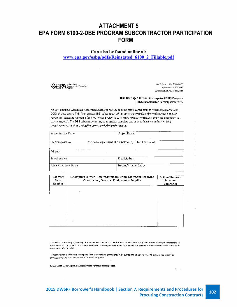
2015 DWSRF Borrower’s Handbook | Section 7. Requirements and Procedures for Procuring Construction Contracts
102
ATTACHMENT 5 EPA FORM 6100-2-DBE PROGRAM SUBCONTRACTOR PARTICIPATION
FORM
Can also be found online at: www.epa.gov/osbp/pdfs/Reinstated_6100_2_Fillable.pdf
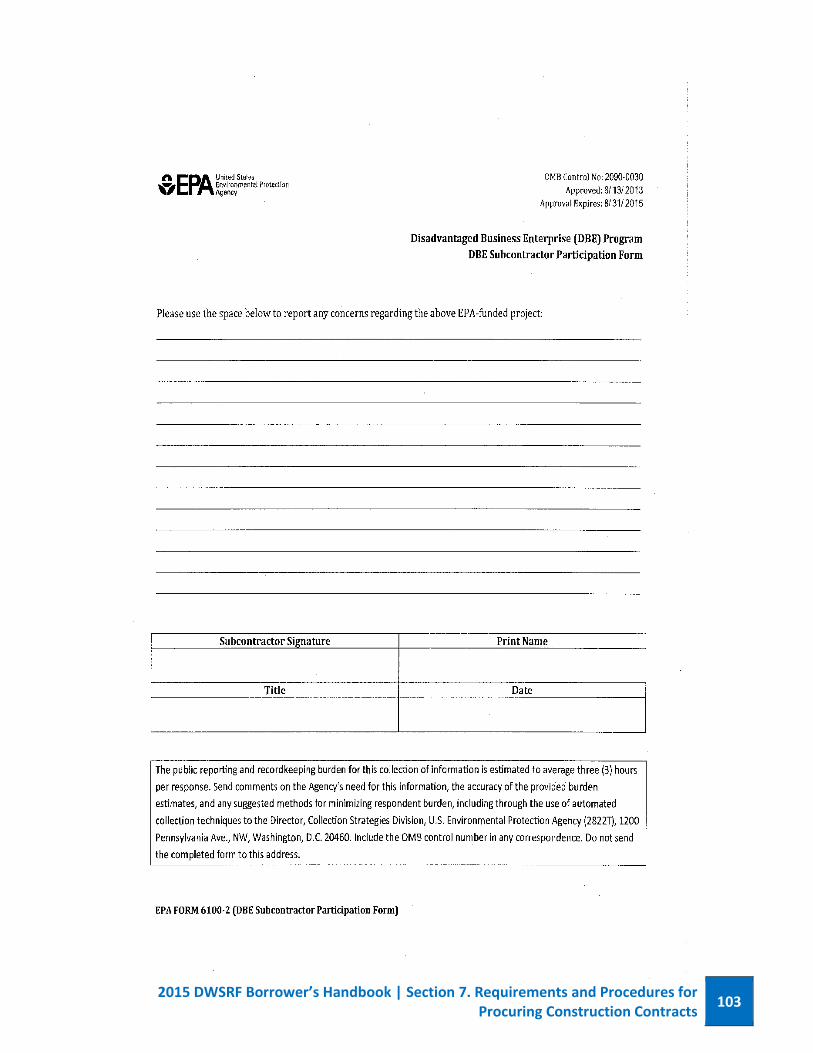
2015 DWSRF Borrower’s Handbook | Section 7. Requirements and Procedures for Procuring Construction Contracts
103
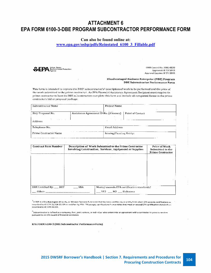
2015 DWSRF Borrower’s Handbook | Section 7. Requirements and Procedures for Procuring Construction Contracts
104
ATTACHMENT 6 EPA FORM 6100-3-DBE PROGRAM SUBCONTRACTOR PERFORMANCE FORM
Can also be found online at:
www.epa.gov/osbp/pdfs/Reinstated_6100_3_Fillable.pdf
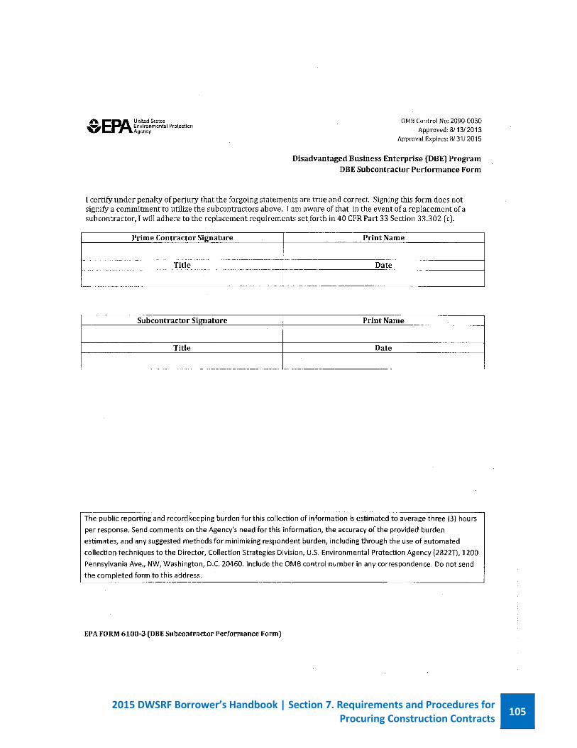
2015 DWSRF Borrower’s Handbook | Section 7. Requirements and Procedures for Procuring Construction Contracts
105
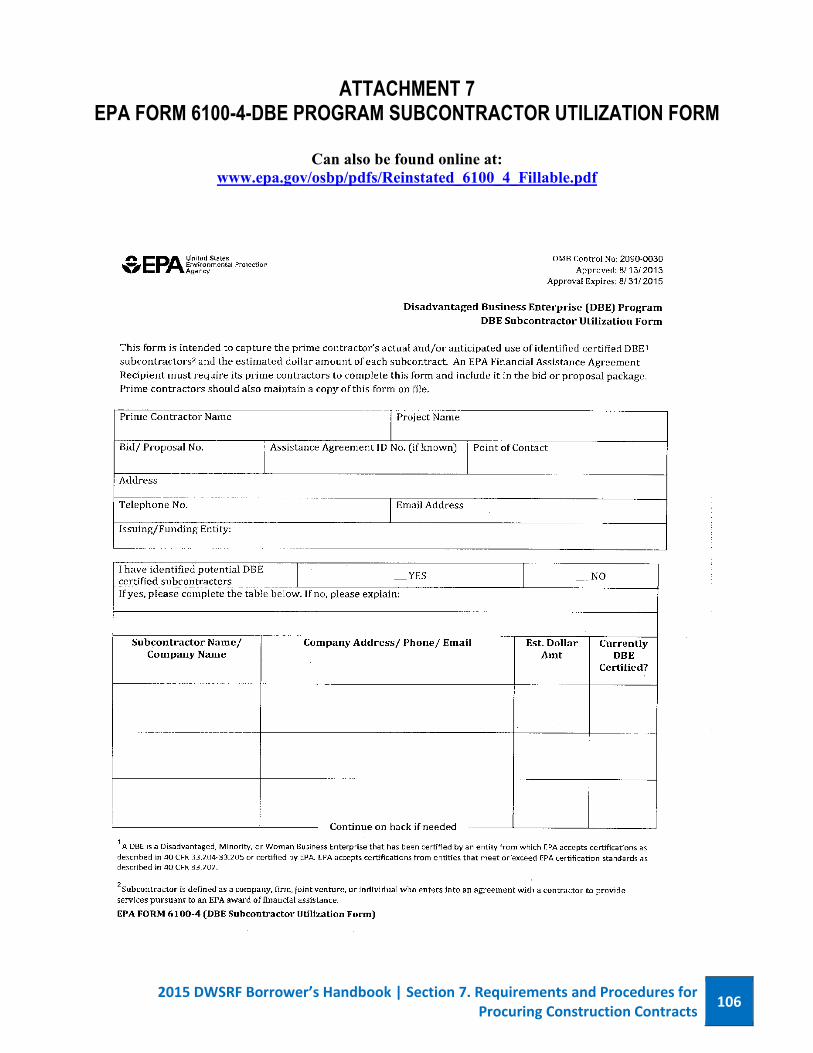
2015 DWSRF Borrower’s Handbook | Section 7. Requirements and Procedures for Procuring Construction Contracts
106
ATTACHMENT 7 EPA FORM 6100-4-DBE PROGRAM SUBCONTRACTOR UTILIZATION FORM
Can also be found online at:
www.epa.gov/osbp/pdfs/Reinstated_6100_4_Fillable.pdf
2015 DWSRF Borrower’s Handbook | Section 7. Requirements and Procedures for Procuring Construction Contracts
107
2015 DWSRF Borrower’s Handbook | Section 7. Requirements and Procedures for Procuring Construction Contracts
108
ATTACHMENT 8 BUY AMERICAN REQUIREMENT
USE OF AMERICAN IRON AND STEEL MUST BE INCLUDED IN ALL CONTRACTS (PRIME AND SUB-CONTRACTORS): This provision applies to projects for the construction, alteration, maintenance, or repair of a public water system as defined in the Safe Drinking Water Act (42 U.S.C 300j-12). This provision does not apply if the engineering plans and specification for the project were approved by the Department of Health prior the January 17, 2014. The Contractor acknowledges to and for the benefit of the Project Owner and the State of Washington that is understands the goods and services under this Agreement are being funded with monies made available by the Drinking Water State Revolving Loan Fund which contains provision commonly known as “Buy American;” that requires all of iron and steel products used in the project be produced in the United States (Buy American Requirements). The act defines iron and steel products as, “…the following products made primarily of iron or steel: lined or unlined pipes and fittings, manhole covers and other municipal castings, hydrants, tanks, flanges, pipe clamps and restraints, valves, structural steel, reinforced precast concrete, and construction materials.” The Contractor hereby represents and warrants to and for the benefit of the Project Owner and the State that:
a) The Contractor has reviewed and understands the Buy American Requirements, b) All of the iron and steel products used in the project will be and/or have been produced in the
United States in a manner that complies with the Buy American Requirements, unless a waiver of the requirements is approved, and
c) The contractor will provide any further verified information, certification or assurance of compliance with this paragraph, or information necessary to support a waiver of the Buy American Requirements, as may be requested by the Project Owner or the State.
Notwithstanding any other provisions of this Agreement, any failure to comply with this paragraph bythe Contractor shall permit the Project Owner or State to recover as damages against the Contractorany loss, expense or cost (including without limitation attorney’s fees) incurred by the Project Owner� .or State resulting from any such failure (including without limitation any impairment or loss offunding, whether in whole or part, from the State or any damages owed to the State by the ProjectOwner). While the contractor has no direct contractual privity with the State, as a lender to the ProjectOwner for the funding of its project, the Project Owner and the Contractor agree that the State is athird-party beneficiary and neither this paragraph nor any other provision of the Agreement necessaryto give this paragraph force or effect shall be amended or waived without the prior written consent ofthe State.

PART 4
TECHNICAL SPECIFICATIONS
DIVISION 1
GENERAL TECHNICAL REQUIREMENTS
(G&O #12009) 01110-1
SECTION 01110
SUMMARY OF WORK
PART 1 GENERAL 1.1 SCOPE OF WORK
1.1.1 SCHEDULE A The work specified in this Schedule consists of furnishing all labor, materials, and equipment necessary for construction of the reservoir project (except for the work included in Schedules B and C) including the relocation of and recoating of three existing 11-foot diameter by 42.5' long welded steel tanks and the recoating of two existing tanks (optional with Owner), constructing new reservoir inlet structure as shown on the Drawings, and herein specified. The work of Schedule A shall include, but not be limited to, the following:
A. Relocate and install the three (3) existing 42.5' long by 11-foot diameter
welded steel reservoirs (3 Steel Tanks) from the Reservoir No. 4 site to the Sycamore Booster Station site. Construct reinforced concrete pads and welded steel supports and appurtenances.
B. Construct new inlet structure inside of the existing Reservoir No. 1.
Mount new inlet structure supports to interior of existing reservoir.
C. Sandblast and recoat the interior and exterior of the 3 relocated existing steel tanks with NSF 61 approved coatings.
D. Sandblast and recoat the interior and exterior of the 2 existing steel tanks
(2 Steel Tanks) currently located at the Sycamore Booster Pumping Station (BPS) site with NSF 61 approved coatings (Optional with Owner).
E. Take all required steps to properly dispose of removed tank coatings
(containing lead) and sand blasting materials, in accordance with applicable federal, state and local regulations.
F. Furnish and install permeable ballast.
G. Furnish and install all required piping, valves and appurtenances.
H. Furnish and install all required electrical, telemetry and instrumentation.
I. Provide testing, commissioning, and training as specified herein.
(G&O #12009) 01110-2
1.1.2 SCHEDULE B (1,500,000 GALLON RESERVOIR) The work specified in this Schedule consists of furnishing all labor, materials, and equipment necessary for site excavation and grading, construction of the 1,500,000 gallon welded steel reservoir and lock block wall as shown on the Drawings, and herein specified. Schedule B work shall include, but not be limited to, the following:
A. Construct required site excavation and grading for the 1,500,000 gallon
reservoir site.
B. Furnish and install a 1,500,000 gallon, 90-foot diameter by 32-foot high welded steel reservoir, with reinforced concrete foundation, piping, safety equipment and appurtenances. It is the intent of this Contract that the new reservoir structure be constructed with an appearance similar to the existing Reservoir No. 1.
C. Furnish and install lock block wall and appurtenances.
1.1.3 SCHEDULE C (900,000 GALLON RESERVOIR) The work specified in this Schedule consists of furnishing all labor, materials, and equipment necessary for site excavation, grading and the construction of the 900,000 gallon welded steel reservoir as shown on the Drawings, and herein specified. Schedule C work shall include, but not be limited to, the following:
A. Construct required site excavation and grading for the 900,000 gallon
reservoir site.
B. Furnish and install a 900,000 gallon, 70-foot diameter by 32-foot high welded steel reservoir, with reinforced concrete foundation, piping, safety equipment and appurtenances. It is the intent of this Contract that the new reservoir structure be constructed with an appearance similar to the existing Reservoir No. 1.
1.2 PROJECT INFORMATION
The Contract Documents show the location, arrangement, and type of work to be performed under the proposed project. The Contractor shall be responsible for proper notification to and coordination with all utility districts, service districts, and all other persons and services that will be affected by this project at least one week in advance of beginning any construction that affects them.
(G&O #12009) 01110-3
The bidders are advised that there is a geotechnical report for the Project. The report is included in the appendix and is for information only and is not a warranty of subsurface conditions. The Contractor shall be held responsible for determining actual field soil conditions.
It is the intent and purpose of these Contract Documents to have constructed complete facilities in good working order for the least practical cost to the Owner. Suggestions, recommendations, as well as inquiries from the Contractor that will serve this purpose are welcome and will be given consideration by the Owner and the Engineer. The Buy American provisions as specified in the DWSRF General Conditions for iron and steel apply to this project. The appropriate Buy American provision is the American Iron and Steel Provisions of P.L. 113-76 Consolidated Appropriations Act of 2014. All contractors, including subcontractors, are required to submit the forms as specified in the DWSRF General Conditions.
1.3 CONTRACTOR USE OF SITE AND PREMISES
Construction operations shall be limited to the areas noted as Construction Area on Sheet G-2 of the Plans and subject to the approval of the Engineer. The Contractor shall submit a traffic control plan for all site access and egress routes for construction vehicle traffic per Section 01950.
The Contractor shall allow representatives of the funding and regulatory agencies access to the project site at all times.
The Contractor shall notify the Owner (or other water utility purveyor) at least 48 hours in advance of any proposed water system shut downs. The Contractor shall also be responsible for notifying all impacted water users 48 hours in advance of any water shutoff.
1.4 ORDER OF WORK
The order of work will be at the option of the Contractor, except as noted below, in keeping with good construction practice, time restrictions, requirements of the permits applicable to this project, and the order of work as outlined herein, all costs of which shall be included in the various bid amounts. The Contractor shall conduct the order of work to allow the existing facilities to remain operational during the construction of the Project and shall coordinate all of his activities through the Engineer with the Owner’s operations and maintenance staff. The
(G&O #12009) 01110-4
Contractor shall provide a written plan of activities to the Engineer and Owner each Thursday for the following week, for review and coordination with existing facility operations.
The implementation of any measure required to protect the environment shall supersede any order of work designated within these Specifications. The Contractor shall meet the conditions as outlined in any and all permits and requirements of the Federal, State, County, and City regulatory agencies. The Contractor shall keep the disruption of the existing facility operations to a minimum. Water system shutdowns shall be limited to 8 hours during any 24-hour period. Access to the existing operations areas shall be maintained. Disruption of this access shall be kept to a minimum and must be prearranged and scheduled through the Engineer with the Owner’s operations and maintenance staff. The following summary shall be used as a general guideline of the construction tasks to be performed. The tasks are generally listed in the order of completion. The tasks, however, can be completed in a different order than listed herein, including performance of two or more tasks concurrently. The Contractor shall prepare a complete project schedule, which shall be provided in accordance with the limitations specified herein. A. LOCATE EXISTING UTILIITIES
Locate existing utilities sufficiently ahead of construction (during the first five working days of the project) So that the engineer can modify the alignment or grade prior to construction if necessary.
B. RELOCATE AND RECOAT 3 STEEL TANKS
The 3 Steel Tanks must be removed from the Reservoir No. 4 site before beginning the Reservoir No. 4 improvements. Install the 3 Steel Tanks at the Sycamore BPS. Perform surface preparation and recoating of the 3 Steel Tanks and all associated electrical improvements to make the 3 Steel Tanks operational. Install hot tap insert valve in existing 12-inch PVC pipe in order to allow the western-most tank to remain in service while the connection of the pipe to the 3 Steel Tanks is performed.
(G&O #12009) 01110-5
The 3 Steel Tanks must be put into service (including the associated electrical improvements) prior to recoating of the existing 2 Steel Tanks that are currently located at the Sycamore BPS site.
C. RECOAT 2 STEEL TANKS (OPTIONAL WITH OWNER)
After the 3 Steel Tanks are placed into service, take the 2 Steel Tanks out of service and perform surface preparations and recoat the 2 Steel Tanks.
D. CONSTRUCT RESERVOIR NO. 4
Reservoir No. 4 must be completed and put into service prior to taking Reservoir No. 1 off-line to construct the inlet structure improvements to Reservoir No. 1. The Contractor shall provide a written schedule on how the above requirements will be met. The Contractor shall provide any equipment deemed necessary to ensure that either Reservoir No. 1 and/or Reservoir No. 4 remain in service at all times.
*** END OF SECTION ***
(G&O #12009) 01150-1
SECTION 01150
SURVEYS – CONTRACTOR PROVIDED PART 1 GENERAL 1.1 SCOPE
The work specified in this Section includes all survey for the project. The Contractor shall provide all construction survey for the Work. The Engineer will provide primary horizontal and vertical control data and monuments, as shown on the Plans. At the Contractor’s request, the Engineer will provide the Plans in electronic format. Electronic files are provided for the Contractor’s convenience and are not part of the Contract. Calculations shall be made from the Plans.
During the prosecution of the work, the Contractor shall make all necessary measurements to prevent misfitting, and shall be responsible for the accurate construction of the work.
1.2 DEFINITIONS
The meaning of words and terms used in this provision shall be as listed in “Definitions of Surveying and Associated Terms” current edition, published by the American Congress on Surveying and Mapping, and the American Society of Civil Engineers.
1.3 RELATED WORK SPECIFIED ELSEWHERE
Section Item 01200 Measurement and Payment 01720 Record Drawings
1.4 QUALIFICATIONS
The Contractor shall employ a Professional Land Surveyor (PLS) registered in the State of Washington and acceptable to the Owner. All surveying shall be completed by or under the direct supervision of the PLS.
1.5 SUBMITTALS
The Contractor shall submit the name, address, and license number of the Professional Land Surveyor before starting construction.
(G&O #12009) 01150-2
1.6 QUALITY ASSURANCE
The Contractor shall ensure a surveying accuracy within the following tolerances: Vertical Horizontal Slope Stakes ±0.1 feet ±0.10 feet Subgrade Grade Stakes Set 0.04 foot Below Grade
±0.01 feet
±0.5 feet
(parallel to alignment) ±0.1 feet
(normal to alignment) Stationing on Roadway N/A ±0.1 feet Alignment on Roadway
N/A
±0.04 feet
Surfacing Grade Stakes
±0.01 feet
±0.1 foot
(parallel to alignment) ±0.1 feet
(normal to alignment)
Roadway Paving Pins for Surfacing or Paving
±0.01 feet ±0.1 feet (parallel to alignment)
±0.05 feet (normal to alignment)
Alignment of sewer and storm manholes and catch basins
±.01 feet ±0.1 feet
Stationing on Structures
±.02 feet
Alignment on structures ±.02 feet Superstructure elevations
±.01 feet
variation from Plan elevation
Substructure ±.02 feet
variation from Plan grades
(G&O #12009) 01150-3
When the following items are included in the project, the Contractor shall perform independent checks from different secondary control to ensure that the points staked are within the specified survey accuracy tolerances:
Piles Shafts Footings Columns
The Owner may spot-check the Contractor’s surveying. These spot-checks will not change the requirements for accuracy by the Contractor
PART 2 PRODUCTS
Not Used. PART 3 EXECUTION
The Contractor’s PLS shall establish all secondary survey controls, horizontal and vertical, as necessary to assure proper placement of all Work based upon the primary control points provided by the Owner. The Contractor shall be responsible for setting, maintaining, and resetting all alignment stakes, clearing limit stakes, slope stakes, and grades for the Work. Except for the survey control data to be furnished by the Owner, calculations, surveying, and measuring required for setting and maintaining the lines and grades shall be the Contractor’s responsibility.
Survey records shall be maintained by the Contractor’s PLS, including a description of the work performed on each shift, the methods utilized, and the control points used. The record shall be adequate to allow the survey to be reproduced. A copy of each day’s record shall be provided to the Engineer within three working days of Engineer’s request. All surveyed points shall be established by placing hubs and tacks with marked stakes in unpaved areas or P.K. nails with painted markings in paved areas. All surveying stakes shall be marked in accordance with WSDOT Standard Plan A-10.10-00. When stakes are needed that are not described in the Standard Plans, then those stakes shall be marked as ordered by the Engineer. The Contractor’s surveyor shall maintain and replace survey hubs, stakes, nails and markings immediately if destroyed, removed, or the Engineer determines the stake or pavement markings are illegible.
For monuments to be removed or destroyed as shown on the Plans, the Contractor’s PLS shall file all required permit forms with the Department of
(G&O #12009) 01150-4
Natural Resources (DNR), as required by RCW 58.09.130 and WAC 332-120. The form “Application for Permit to Remove or Destroy a Survey Monument” shall be signed by the PLS, and submitted directly to DNR and the Owner. No work affecting monumentation shall commence until DNR has approved the permit. The form “Completion Report for Monument Removal or Destruction” shall be signed by the PLS and submitted to DNR and the Owner upon completion of work affecting monumentation. The Contractor shall be responsible for locating and preserving existing monuments within the right-of-way, which shall include existing property corners on the right-of-way lines. In the event the Contractor disturbs or destroys any survey marker, monument, or property corner during the course of construction, not indicated to be removed on the Plans, the Contractor shall bear all costs or survey, resetting, legal claims and filing state forms as required by RCW 58.09.130 and WAC 332-120.
*** END OF SECTION ***
(G&O #12009) 01160-1
SECTION 01160
REGULATORY REQUIREMENTS PART 1 GENERAL 1.1 SCOPE
The work specified in this Section contains information pertaining to permits and licenses, and use of private property.
1.2 PERMITS AND LICENSES
Except as noted below, the Contractor shall be responsible for obtaining and paying all fees associated with all the necessary permits, licenses, approvals, and construction permits necessary for the execution of this Contract, whether they be City, County, State, or federal permits. The Owner will be responsible for obtaining the following approvals and permits, and will pay the fees associated with the application and procurement of such approvals and permits. The Contractor is advised to become familiar with these approvals and permits necessary for this project. The Contractor shall comply with all conditions of each approval/permit as if the conditions were detailed herein.
A. Yakima County Building Permit (applied and paid for by Owner, obtained
by Contractor)
B. Type 2 Conditional Use Permit for Reservoir No. 4 (obtained by Owner)
C. Type 1 Conditional Use Permit for the work at the Sycamore Booster Station (obtained by Owner)
1.3 USE OF PRIVATE PROPERTY
The Contractor shall be responsible for all conditions of any arrangements the Contractor makes for the use of any privately owned property. In the event any dispute occurs and claims for damages are filed by the property owners, the Owner will request that the Contractor give evidence that he has requested his insurance company to make personal contact with the claimants. Any settlement for insurance claims shall be strictly an act restricted to the claimant, the Contractor, and his insurance company.
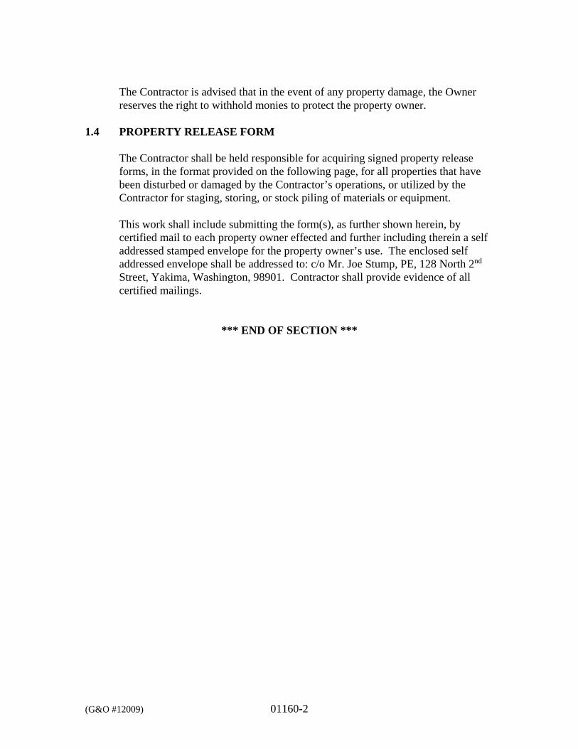
(G&O #12009) 01160-2
The Contractor is advised that in the event of any property damage, the Owner reserves the right to withhold monies to protect the property owner.
1.4 PROPERTY RELEASE FORM
The Contractor shall be held responsible for acquiring signed property release forms, in the format provided on the following page, for all properties that have been disturbed or damaged by the Contractor’s operations, or utilized by the Contractor for staging, storing, or stock piling of materials or equipment. This work shall include submitting the form(s), as further shown herein, by certified mail to each property owner effected and further including therein a self addressed stamped envelope for the property owner’s use. The enclosed self addressed envelope shall be addressed to: c/o Mr. Joe Stump, PE, 128 North 2nd Street, Yakima, Washington, 98901. Contractor shall provide evidence of all certified mailings.
*** END OF SECTION ***
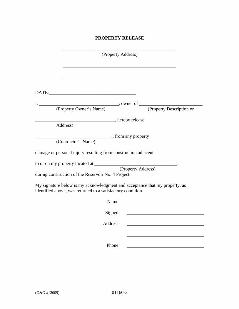
(G&O #12009) 01160-3
PROPERTY RELEASE
________________________________________________ (Property Address)
________________________________________________
________________________________________________
DATE:_____________________________________ I, __________________________________, owner of ___________________________ (Property Owner’s Name) (Property Description or __________________________________, hereby release Address) _________________________________, from any property (Contractor’s Name) damage or personal injury resulting from construction adjacent to or on my property located at ___________________________________, (Property Address) during construction of the Reservoir No. 4 Project. My signature below is my acknowledgment and acceptance that my property, as identified above, was returned to a satisfactory condition. Name: Signed: Address: Phone:
(G&O #12009) 01200-1
SECTION 01200
MEASUREMENT AND PAYMENT PART 1 GENERAL 1.1 SCOPE
This Section further defines Measurement and Payment for this project. 1.2 RELATED WORK SPECIFIED ELSEWHERE
Section Item Section 1.09 Measurement and Payment 01300 Submittals
1.3 MEASUREMENT
Measurement for all items shall be as indicated in these Specifications for unit price and lump sum price bid items. Bid items are outlined in detail in this Specification Section and listed in the Proposal. Measurement shall be in accordance with Section 1-09.1 of the WSDOT Standard Specifications. Volumes of gravel materials and concrete volumes shall be measured by the Engineer in the field and quantities will be limited to the relative neat line dimensions shown on the Plans or as approved by the Engineer in the field. Weighing equipment, scale verification checks, load tickets for quarry spalls, rock riprap, cobbles, gravel materials, hot mix asphalt, bituminous construction materials, etc., shall conform to Section 1-09.2 of the WSDOT Standard Specifications. Load tickets shall include all gravel materials, cast-in-place concrete, cement grout, CDF, hot mix asphalt, ATB, and reinforcing steel. The Owner will pay for no material received by weight unless they have been weighed as required in this Section or as required by another method the Engineer has approved in writing. All costs incidental to weighing shall be merged into the various unit prices bid.
1.4 INDIVIDUAL BID ITEMS
The following is a list of bid items for the project. The contract price for each item constitutes full compensation for furnishing all equipment, labor, materials, appurtenances, and incidentals and performing all operations necessary to construct and complete the various bid items in accordance with the Contract Documents. Payment for each item shall be considered as full compensation,
(G&O #12009) 01200-2
notwithstanding that minor features may not be mentioned herein. Work paid for under one item will not be paid for under any other item. If a particular item of work shown on the Plans or described in Specifications is not described in a specific bid item, this item of work shall be considered as incidental to the work and the costs for this work shall be merged into the various respective unit price and lump sum bid items.
SCHEDULE A (BASE BID): A. MOBILIZATION AND DEMOBILIZATION (SCHEDULE A)
1. Measurement: Shall be measured by lump sum. 2. Payment: The lump sum contract price for MOBILIZATION
AND DEMOBILIZATION shall include all costs for the labor, materials, and equipment required for mobilization and demobilization on the project as described in Section 01505.
Payment for MOBILIZATION AND DEMOBILIZATION shall be as follows:
35% Payment: When Contractor has mobilized on-site
and temporary facilities are in place.
50% Payment: When 5 percent of the total pay items are completed (not including payment for materials on hand).
75% Payment: When 50 percent of the total pay items are
completed (not including payment for materials on hand).
100% Payment: When Project is completed and
recommended for acceptance.
B. SYCAMORE RESERVOIR RELOCATION (SCHEDULE A)
1. Measurement: Shall be measured by lump sum.
2. Payment: Shall be paid for at the applicable Contract lump sum price, payment for which shall constitute full compensation for furnishing all labor, materials and equipment to relocate the three existing steel tank reservoirs measuring approximately 11-feet in diameter by 42.5' in length, from the Reservoir No. 4 site to the Sycamore Booster Station site, including haul, excavation,
(G&O #12009) 01200-3
grading, removal and wastehaul of existing welded steel and concrete foundations, furnishing and constructing concrete and welded steel foundations, PVC venting and screens, replacing existing access port fasteners, foundation gravel, and traffic control.
C. SYCAMORE RESERVOIR PAINTING, 3 TANKS (SCHEDULE A)
1. Measurement: Shall be measured by lump sum.
2. Payment: Shall be paid for at the applicable Contract lump sum price, payment for which shall constitute full compensation for furnishing all labor, materials and equipment to paint the three relocated steel tanks and their supports, including but not limited to, sand blasting, hazardous waste disposal, surface preparation, priming, coating and disinfecting, dehumidification and heating, including providing the independent testing agency to provide inspection and testing of the paint system.
D. SYCAMORE RESERVOIR PAINTING, 2 TANKS (SCHEDULE A,
OPTIONAL WITH OWNER)
1. Measurement: Shall be measured by lump sum.
2. Payment: Shall be paid for at the applicable Contract lump sum price, payment for which shall constitute full compensation for furnishing all labor, materials and equipment to paint the two existing steel tanks and their supports, currently located at the Sycamore site, including but not limited to, sand blasting, hazardous waste disposal, surface preparation, priming, coating and disinfecting, dehumidification and heating, including providing the independent testing agency to provide inspection and testing of the paint system.
E. RESERVOIR NO. 1 INLET STANDPIPE (SCHEDULE A)
1. Measurement: Shall be measured by lump sum.
2. Payment: Shall be paid for at the applicable Contract lump sum price, payment for which shall constitute full compensation for furnishing all labor, materials and equipment to install new inlet standpipe, including, inlet standpipe, support system, surface preparation, coating of new surfaces and surfaces damaged in construction cleaning and disinfecting Reservoir No. 1, and bacteriological testing.
(G&O #12009) 01200-4
F. MINOR CHANGES (SCHEDULE A)
1. Measurement: Shall be negotiated prior to commencing any such
work under this pay item and shall be for work to remedy unforeseen conditions, utility conflicts, minor landscaping, minor drainage improvements, or special surface restoration.
2. Payment: Payment or credits for changes amounting to $15,000 or
less may be made under the Bid Item MINOR CHANGE. At the discretion of the Owner, this procedure for Minor Changes may be used in lieu of the more formal procedure as outlined in Section 1-04.4 Changes. The Contractor will be provided a copy of the completed order for Minor Change. The agreement for the Minor Change will be documented by signature of the Contractor or notation of the verbal agreement.
Payments or credits will be determined in accordance with Section 1-04.4 Changes. For the purpose of providing a common Proposal for all Bidders, the Owner has entered an amount for MINOR CHANGE in the Proposal to become part of the total Bid by the Contractor.
G. TRENCH EXCAVATION SAFETY SYSTEMS (SCHEDULE A)
1. Measurement: Shall be measured by lump sum.
2. Payment: The lump sum contract price for TRENCH
EXCAVATION SAFETY SYSTEMS shall include all costs for labor, materials, and equipment required to provide sheeting, shoring, and bracing of trenches and open excavations as required to meet the Washington Industrial Safety and Health Act, Chapter 49.17 RCW and Section 02250. These costs shall not be considered incidental to any other bid item.
H. UNSUITABLE EXCAVATION (SCHEDULE A)
1. Measurement: Will be measured by the cubic yard, in-place and
shall be to the limits as designated by the Engineer. There shall be no payment if the Engineer believes removal of materials is needed because of damage caused by the Contractor’s operations.
All quantities will be measured and recorded by the Engineer in his Daily Report and the Contractor shall be responsible for reconciling his quantities with the Engineer on a daily basis.
(G&O #12009) 01200-5
2. Payment: The unit price per cubic yard for UNSUITABLE
EXCAVATION shall include all cost for labor, material, and equipment to excavate and wastehaul unsuitable native subgrade materials, including backfilling the resulting excavations with compacted foundation gravel materials.
The Contractor is advised that the excavation of any and all unsuitable material must be authorized by the Engineer in writing prior to the commencement of said excavation by the Contractor.
I. SPCC PLAN (SCHEDULE A)
1. Measurement: Shall be measured by lump sum. 2. Payment: Shall be paid for at the applicable Contract lump sum
price, which shall constitute full compensation for furnishing and supplying all material, labor, tools, equipment, and incidentals necessary to provide spill prevention, control and countermeasures, as specified herein and in the Contractor’s SPCC Plan, to include, but not be limited to, preparation of the SPCC Plan, providing and maintaining onsite standby materials and equipment described in the SPCC Plan, and all other items necessary to accomplish this work.
J. PROJECT TEMPORARY TRAFFIC CONTROL (SCHEDULE A)
1. Measurement: Shall be measured by lump sum.
2. Payment: The lump sum contract price for PROJECT TEMPORARY TRAFFIC CONTROL shall include costs for all labor, material, and equipment to provide temporary traffic control for the project as specified in Section 01950.
K. EROSION CONTROL (SCHEDULE A)
1. Measurement: Shall be measured by lump sum.
2. Payment: The lump sum contract price for EROSION CONTROL
shall include all costs for the labor, material, and equipment for installation and maintenance of all temporary erosion and sediment control measures and best management practices (BMPs), as shown on the Drawings and as further described in Section 02370. This item shall also include all costs for general surface restoration
(G&O #12009) 01200-6
including grading and raking the disturbed surfaces to remove rocks and cobbles and seeding, fertilizing, and mulching.
L. BANK RUN GRAVEL FOR TRENCH BACKFILL (SCHEDULE A)
1. Measurement: Measurement for BANK RUN GRAVEL FOR TRENCH BACKFILL, in lieu of native material, if any, shall be per cubic yard and shall be based on the computed, compacted volume within the excavated trench to a maximum width, as approved by the Engineer, measured in the horizontal plane.
2. Payment: The unit price bid for bank run gravel for trench
backfill, if any, shall be full payment for all labor, equipment, tools, and materials necessary to furnish and place the material in lieu of suitable native material and shall include the excavation and waste haul of unsuitable native material displaced for the installation of the bank run gravel for trench backfill. In the event the Contractor over-excavates the trench width and it becomes wider than that approved by the Engineer, all material placed outside the approved trench width shall be at the Contractor’s sole expense.
M. PERMEABLE BALLAST (SCHEDULE A)
1. Measurement: Shall be measured per ton, in-place, based on truck
tickets and shall be to the limits designated and approved by the Engineer.
2. Payment: The unit price bid per ton for PERMEABLE BALLAST shall include all costs for the labor, material, and equipment associated with furnishing, installing, and testing permeable ballast as shown on the Drawings and as described in Section 02710.
N. PIPING, VALVES, AND APPURTENANCES (SCHEDULE A)
1. Measurement: Shall be measured by lump sum.
2. Payment: The lump sum contract price for PIPING, VALVES,
AND APPURTENANCES shall include all costs for the labor, materials, and equipment at the Reservoir No. 4 site and the Sycamore Booster Station site to install piping, valves, and appurtenances including, but not limited to trench excavation, dewatering, bedding, backfilling with native material (if allowed), compaction, connecting to existing system, pipe penetrations, pipe,
(G&O #12009) 01200-7
fittings, pressure sensing lines, valves, check valves, hot taps with valves, vaults, flexible expansion joints, connections, saddles, corporation stops, blow-off assembly, pipe supports, thrust blocks, restraints, plumbing, pipe insulation, detectable marking tape, tracer wire, concrete plugs for abandoned pipe, waste hauling, grading, and dealing with other interferences, disinfection and testing as shown on the Drawings and as specified herein.
O. ELECTRICAL, TELEMETRY, AND INSTRUMENTATION
(SCHEDULE A)
1. Measurement: Shall be measured by lump sum.
2. Payment: The lump sum contract price for ELECTRICAL, TELEMETRY, AND INSTRUMENTATION shall include all labor, materials and equipment to furnish electrical, telemetry, and instrumentation components of this Project including conduit, wiring, panel boards, receptacles, fixtures, mounting hardware, instrumentation, float switches, pressure transmitter and telemetry as shown on the Drawings and as described in Divisions 13 and 16 of these Specifications. Costs shall also include all costs for demolition or abandonment of electrical components.
P. ADDITIONAL FITTINGS (SCHEDULE A)
1. Measurement: Shall be measured per pound based on the actual
weight of the additional fittings alone, excluding follower glands, bolts, gaskets, and blocking.
2. Payment: The unit price bid per pound for ADDITIONAL FITTINGS shall include all costs for the labor, material, and equipment to furnish and install any fittings required in addition to those specifically referenced on the Drawings and shall include, where appropriate, all costs for follower glands, bolts, fusing, gaskets, thrust blocks, anchor blocks, connect to existing system, excavation, compaction, and any and all other costs of material, equipment, tools, and labor incurred in the installation of the additional fittings.
(G&O #12009) 01200-8
SCHEDULE B: - 1,500,000 GALLON WELDED STEEL RESERVOIR (ALTERNATE)
A. WELDED STEEL RESERVOIR (SCHEDULE B)
1. Measurement: Shall be measured by lump sum. 1,500,000 gallon welded steel reservoir.
2. Payment: Shall be paid for at the applicable Contract lump sum price, payment for which shall constitute full compensation for furnishing all labor, materials and equipment to design and construct the welded steel reservoir, including foundation, crushed surfacing base course, welded steel tank, reservoir inlet and outlet, access ladders and platform, overflow and drain piping, cathodic protection system, safety equipment, surface preparation, priming, coating and disinfecting, dehumidification and heating including providing the independent testing agency to provide inspection and testing of the paint system, cleaning and disinfecting the reservoir, and bacteriological testing.
B. RESERVOIR No. 4 SITE EXCAVATION (SCHEDULE B)
1. Measurement: Shall be measured by lump sum.
2. Payment: Shall be paid for at the applicable Contract unit price
per lump sum, payment for which shall constitute full compensation to excavate, load, and wastehaul native materials for the reservoir and the reservoir foundation to the lines and grades shown on the Plans.
C. LOCK BLOCK WALL (SCHEDULE B)
1. Measurement: Shall be measured per square foot as measured in
elevation view.
2. Payment: The unit price bid per square foot for LOCK BLOCK WALL shall include all costs for the labor, material and equipment necessary to construct modular block wall including, but not limited to excavating, preparing the subgrade, furnish and installing crushed surfacing base course leveling pad, block units and caps, foundation drainage pipe, trenching and placing foundation drainage pipe to daylight, construction geosynthetic, gravel backfill for walls, for a complete installation as shown on the Drawings and as described in Section 02832.
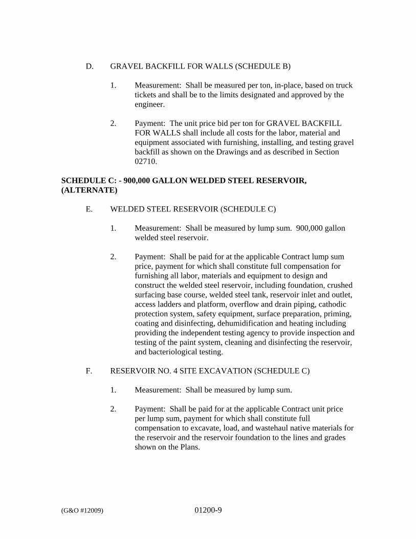
(G&O #12009) 01200-9
D. GRAVEL BACKFILL FOR WALLS (SCHEDULE B)
1. Measurement: Shall be measured per ton, in-place, based on truck tickets and shall be to the limits designated and approved by the engineer.
2. Payment: The unit price bid per ton for GRAVEL BACKFILL
FOR WALLS shall include all costs for the labor, material and equipment associated with furnishing, installing, and testing gravel backfill as shown on the Drawings and as described in Section 02710.
SCHEDULE C: - 900,000 GALLON WELDED STEEL RESERVOIR, (ALTERNATE)
E. WELDED STEEL RESERVOIR (SCHEDULE C)
1. Measurement: Shall be measured by lump sum. 900,000 gallon
welded steel reservoir.
2. Payment: Shall be paid for at the applicable Contract lump sum price, payment for which shall constitute full compensation for furnishing all labor, materials and equipment to design and construct the welded steel reservoir, including foundation, crushed surfacing base course, welded steel tank, reservoir inlet and outlet, access ladders and platform, overflow and drain piping, cathodic protection system, safety equipment, surface preparation, priming, coating and disinfecting, dehumidification and heating including providing the independent testing agency to provide inspection and testing of the paint system, cleaning and disinfecting the reservoir, and bacteriological testing.
F. RESERVOIR NO. 4 SITE EXCAVATION (SCHEDULE C)
1. Measurement: Shall be measured by lump sum.
2. Payment: Shall be paid for at the applicable Contract unit price
per lump sum, payment for which shall constitute full compensation to excavate, load, and wastehaul native materials for the reservoir and the reservoir foundation to the lines and grades shown on the Plans.

(G&O #12009) 01200-10
1.5 PROJECT MATERIALS ON HAND
See Section 1-09.8 Payment for Material on Hand. 1.6 PAYMENT
Payment for all work will be made at the contract unit price or lump sum price as indicated in the Proposal, payment of which shall constitute full compensation, for a complete installation. The County will make payment to the Contractor within 30 days of when the County receives DWSRF funds to cover the payment. The County anticipates receiving DWSRF funds within 30 days of when an application for funding is presented to Commerce for consideration. For items of equipment, acceptable operating and maintenance information shall be delivered to the Engineer before the Contractor will be paid for more than 90 percent of the purchase value of that equipment. Purchase value shall be the net price for the equipment as given on the invoice. Final operating and maintenance manuals per Section 01300 must be delivered to the Engineer prior to the Project being 90 percent complete. Progress payments for work in excess of 90 percent completion will not be made until the specified acceptable operating and maintenance information has been delivered to the Engineer.
*** END OF SECTION ***
(G&O #12009) 01290-1
SECTION 01290
SCHEDULE OF VALUES PART 1 GENERAL 1.1 SCOPE
The work specified in this Section establishes the procedures for preparing the schedule of values used for preparation of the Contractor’s progress pay estimates.
1.2 RELATED WORK SPECIFIED ELSEWHERE
Section Item WSDOT Section 1-09 Measurement and Payment 01200 Measurement and Payment 01300 Submittals
1.3 DESCRIPTION
Within 10 days following receipt of Notice to Proceed, the Contractor shall submit to the Engineer, for review and approval, a complete breakdown of components of all lump sum bid items showing the value assigned to each portion of the work, prepared in such form, and supported by data that substantiates its accuracy as may be required by the Engineer. This schedule of values shall, once approved by Engineer, be used as the basis for reviewing and determining each monthly progress payment estimate and as such shall be subject to periodic review by the Engineer to assure that the schedule of values reasonably represents, in the opinion of the Engineer, the actual value of the individual items of work to be performed. No payments shall be made until the schedule of values has been approved.
*** END OF SECTION ***
(G&O #12009) 01300-1
SECTION 01300
SUBMITTALS PART 1 GENERAL 1.1 SCOPE
The work specified in this Section includes requirements that apply to all equipment and materials supplied on the Project. The Contractor shall be responsible for the accuracy and completeness of the information contained in each submittal and shall assure that the material, equipment or method of work shall be as described in the submittal. The Contractor shall verify that all features of all products conform to the requirements of the Contract Documents. Submittal documents shall be clearly edited to indicate only those items, models, or series of equipment that are being submitted for review. All extraneous materials shall be crossed out or otherwise obliterated. The Contractor shall ensure that there is no conflict with other submittals and notify the Engineer in each case where his submittal may affect the work of another contractor or the Owner. The Contractor shall ensure coordination of submittals among the related crafts and subcontractors and shall verify such coordination on all submittals. Where noted in the Contract Documents, the structural, mechanical, and electrical designs associated with the indicated equipment items are specific to the manufacturer and model number specified. Any structural, mechanical, or electrical modifications required to utilize an approved substitution to the specified equipment shall be made by the Contractor at no additional cost to the Owner. Where approved substitutions of specified equipment affect other materials or equipment, mechanical, structural, or electrical work, the Contractor shall note in the equipment submittal any necessary changes to accommodate the substituted equipment. It shall also be the responsibility of the Contractor to coordinate other mechanical, structural, or electrical equipment submittals to make sure that all changes necessary to accommodate the substituted equipment are addressed in these submittals as well.
1.2 RELATED WORK SPECIFIED ELSEWHERE
Section Item 01720 01800 11000 16050
Record Drawings Testing, Commissioning, and Training Equipment General Provisions Basic Electrical Materials and Methods
(G&O #12009) 01300-2
1.3 WORK INCLUDED
Submittals required for this work shall include any or all of the following as required by the particular specification section and the submittal schedule:
A. Schedules and Plans
B. PRODUCT SUBMITTALS
1. Manufacturer’s Literature 2. Shop Drawings 3. Color and Material Samples 4. Design Calculations 5. Test Reports
C. Equipment Operation and Maintenance Manuals
D. Post-Construction (Record) Drawings (see Section 01720)
1.4 SUBMITTAL INFORMATION
Shop, catalog, and other appropriate drawings and information shall be submitted to the Engineer for review prior to fabrication or ordering of all equipment and materials specified. The number of copies of submittal information to be submitted shall be as indicated below. All submittal information shall be sent to the Engineer through the Contractor. The Contractor shall assign a separate submittal number to each item or group of items that relate to each specification section. Submittal numbers shall be assigned in consecutive ascending order, with the first project submittal assigned the number “1.” Resubmittals shall be numbered using the same number followed by an alphabetical suffix. All submittals shall bear the Contractor’s certification that he has reviewed, checked, and approved the submittal information prior to transmitting to the Engineer. The submittal number and related specification section shall be marked on each submittal.
PART 2 PRODUCTS 2.1 GENERAL
When the Contract Documents require a submittal of some type of information, the Contractor shall submit the following number of copies for each type of submittal.
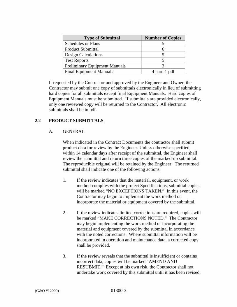
(G&O #12009) 01300-3
Type of Submittal Number of Copies Schedules or Plans 5 Product Submittal 6 Design Calculations 5 Test Reports 5 Preliminary Equipment Manuals 3 Final Equipment Manuals 4 hard 1 pdf
If requested by the Contractor and approved by the Engineer and Owner, the Contractor may submit one copy of submittals electronically in lieu of submitting hard copies for all submittals except final Equipment Manuals. Hard copies of Equipment Manuals must be submitted. If submittals are provided electronically, only one reviewed copy will be returned to the Contractor. All electronic submittals shall be in pdf.
2.2 PRODUCT SUBMITTALS
A. GENERAL
When indicated in the Contract Documents the contractor shall submit product data for review by the Engineer. Unless otherwise specified, within 14 calendar days after receipt of the submittal, the Engineer shall review the submittal and return three copies of the marked-up submittal. The reproducible original will be retained by the Engineer. The returned submittal shall indicate one of the following actions: 1. If the review indicates that the material, equipment, or work
method complies with the project Specifications, submittal copies will be marked “NO EXCEPTIONS TAKEN.” In this event, the Contractor may begin to implement the work method or incorporate the material or equipment covered by the submittal.
2. If the review indicates limited corrections are required, copies will
be marked “MAKE CORRECTIONS NOTED.” The Contractor may begin implementing the work method or incorporating the material and equipment covered by the submittal in accordance with the noted corrections. Where submittal information will be incorporated in operation and maintenance data, a corrected copy shall be provided.
3. If the review reveals that the submittal is insufficient or contains
incorrect data, copies will be marked “AMEND AND RESUBMIT.” Except at his own risk, the Contractor shall not undertake work covered by this submittal until it has been revised,
(G&O #12009) 01300-4
resubmitted, and returned marked either “NO EXCEPTIONS TAKEN” or “MAKE CORRECTIONS NOTED.”
4. If the review indicates that the material, equipment, or work
method does not comply with the project Specifications, copies of the submittal will be marked “REJECTED - SEE REMARKS.” Submittals with deviations that have not been identified clearly may be rejected. Except at his own risk, the Contractor shall not undertake the work covered by such submittals until a new submittal is made and returned marked either “NO EXCEPTIONS TAKEN” or “MAKE CORRECTIONS NOTED.”
B. MANUFACTURER’S LITERATURE
Where the contents of submitted literature include data not pertinent to the submittal, the portion(s) of the contents being submitted for the Engineer’s review shall be clearly indicated.
C. SHOP DRAWINGS
Shop drawings shall be submitted in the form of blue-line or black-line prints of each sheet. Blueprint submittals will not be acceptable. All shop drawings shall be accurately drawn to a scale sufficiently large enough to show pertinent features and method of connection or joining. On all shop drawings, figure dimensions shall be used as opposed to scaled dimensions.
D. COLOR AND MATERIAL SAMPLES
All material samples shall be of the exact article proposed to be furnished for the work and shall be submitted in the quantity required. Samples shall be returned to the Contractor, with one retained by the Engineer. Unless the precise color is specifically described in the Contract Documents, or whenever a choice of color or pattern is available in a specified product, accurate color charts shall be submitted to the Engineer for his review and selection.
E. DESIGN CALCULATIONS
Where required in the Specifications, design calculations shall be submitted to the Engineer. Design calculations shall be complete, concise, and in an easy-to-read format. All design calculations shall be stamped by a Professional Engineer licensed in the State of Washington.
(G&O #12009) 01300-5
F. TEST REPORTS
Copies of all test reports shall be submitted to the Engineer.
2.3 EQUIPMENT MANUALS
A. GENERAL
For all items of equipment, preliminary manufacturer’s equipment operation and maintenance manuals shall be submitted to the Engineer for review. One copy will be returned to the Contractor with comments.
The following information shall be furnished for all items of equipment installed on the project requiring operational and/or maintenance procedures, and for any additional items indicated by the Engineer. 1. Lubrication Information
This shall consist of the manufacturer’s recommendations regarding the lubricants to be used and the lubrication schedule to be followed.
2. Electrical and Control Diagrams
Diagrams shall show internal and connection wiring.
3. Startup Procedures
These instructions consist of equipment manufacturer’s recommendations for installation, adjustment, calibration, and troubleshooting.
4. Operating Procedures
These instructions consist of the equipment manufacturer’s recommended step-by-step procedures for starting, operating, and stopping the equipment under specified modes of operation.
(G&O #12009) 01300-6
5. Preventive Maintenance Procedures
These instructions consist of the equipment manufacturer’s recommended steps and schedules for maintaining the equipment.
6. Overhaul Instructions
These instructions consist of the manufacturer’s directions for the disassembly, repair, and reassembly of the equipment and any safety precautions that must be observed while performing the work.
7. Parts List
This list consists of the generic title and identification number of each component part of the equipment.
8. Spare Parts List
This list consists of the manufacturer’s recommendations of number of parts, which should be stored by the Owner and any special storage precautions, which may be required.
9. Exploded View
Exploded or cut views of equipment shall be provided if available as a standard item of the manufacturer’s information. When exploded or cut views are not available, plan and section views shall be provided with detailed callouts.
10. Test Documentation
Reports, records, data and forms documenting the results of equipment factory tests, including pump and blower performance curves, shall be provided, with the operating points for the specific equipment designated. When a special factory test of the supplied equipment is not performed, the manufacturer’s standard performance reports and curves, with specified operating points, shall be provided for the supplied equipment.
(G&O #12009) 01300-7
11. Specific Information
Where items of information not included in the above list are required, they will be provided as described in the specifications for the equipment.
12. Warranty Information.
13. Maintenance Information Summaries (see below for requirements). In addition, the following items of equipment shall be provided with Maintenance Information Summaries in each appropriate section of the equipment manuals, prepared according to the format specified herein: Valves (larger than 1-inch in size) Telemetry and Control Equipment Electrical Equipment Maintenance information summaries shall be prepared on 8-1/2-inch x 11-inch paper only and shall contain the following information compiled from manufacturer’s recommendations in the order shown. 1. Description or name of item of equipment.
2. Manufacturer.
3. Name, address, and telephone number of local manufacturer’s
representative.
4. Serial number (where applicable). The Contractor shall verify that it matches the equipment installed on the project.
5. Equipment nameplate data including model number.
6. Recommended maintenance procedures:
a. Description of procedures.
b. Maintenance frequency required.
(G&O #12009) 01300-8
c. Lubricant(s) or other materials required (where applicable), including type of lubricant, lubricant manufacturer, and specific compound.
d. Additional information as required for proper maintenance.
7. Recommended spare parts (where applicable). The maintenance information summary shall be placed at the beginning of the manual. All operation and maintenance information shall be comprehensive and detailed, and shall contain information adequately covering all normal operation and maintenance procedures. For ease of identification, each manufacturer’s brochure and manual shall be appropriately labeled with the equipment name and equipment specification number as it appears in the project Specifications. The information shall be organized in binders. The binders shall be provided with a table of contents and tab sheets to permit easy location of desired information.
Lubricants shall be described in detail, including type, recommended manufacturer, and manufacturer’s specific compound to be used. It shall be the responsibility of the Contractor to ensure that all operation and maintenance materials are obtained. Material submitted must meet the approval of the Engineer prior to project acceptance.
B. EXTRANEOUS DATA
Where the contents of the manuals include manufacturers’ standard brochures or catalog pages, the exact item(s) used in this installation shall be clearly indicated and all manufacturers’ data which is extraneous shall be clearly deleted.
C. FINAL EQUIPMENT MANUALS
The Contractor shall be responsible for tracking and coordinating each separate manufacturer’s equipment operation and maintenance manual submittal and shall resubmit, as necessary, until the Engineer’s review indicates that the submittal is acceptable. The Contractor shall maintain equipment manual files until final approval copies are delivered to the Engineer. The Contractor shall be responsible for collating the approved operation and maintenance submittal sections into complete final
(G&O #12009) 01300-9
manufacturers’ equipment operation and maintenance manuals bound in post binders which are indexed to the Specifications. The Contractor shall deliver the complete final operation and maintenance manuals to the Engineer prior to project completion. All copies of final manufacturers’ equipment manuals submitted will be retained by the Engineer or Owner. The Contractor shall also supply one copy of the final equipment manuals in a tabbed, searchable .pdf format on CD-Rom.
PART 3 EXECUTION 3.1 IDENTIFICATION OF SUBMITTALS
A. GENERAL
Each submittal shall be accompanied by a letter of transmittal showing the date of transmittal, specification section, or drawing number to which the submittal pertains, submittal number, and a brief description of the material submitted.
B. RESUBMITTALS
When material is resubmitted for any reason, it shall be submitted under a new letter of transmittal and referenced to the previous submittal.
3.2 REVIEW OF SUBMITTALS
The Engineer will review all submittals for general conformance with the design and other requirements of the Contract Documents. Markings or comments shall not be construed as relieving the Contractor from compliance with the Contract Documents. Submittals may be rejected based on inadequate information and/or not meeting the requirements of the Contract Documents. Rejection of submittals requires action on the part of the Contractor to correct the reason for the rejection. The Contractor remains responsible for details and accuracy, for confirming and correlating all quantities and dimensions, for selecting fabrication processes, and for techniques of assembly and installation.
3.3 COORDINATION OF PRODUCT SUBMITTALS
A. GENERAL
Prior to submittal for review by the Engineer, all data shall be fully coordinated, including the following:
1. All field dimensions and conditions.
(G&O #12009) 01300-10
2. All trades and public agencies involved, including necessary
approvals.
3. All deviations from the Contract Documents.
B. GROUPING OF SUBMITTALS
1. All submittals shall be grouped with associated items, unless otherwise specifically permitted by the Engineer.
2. The Engineer may reject the submittals in their entirety or any part
thereof, if not in accordance with the Contract Documents.
C. CERTIFICATION
Submittals shall bear the Contractor’s certification that he has reviewed, checked, and approved the shop drawings prior to forwarding them to the Engineer.
3.4 TIMING OF PRODUCT SUBMITTALS
A. GENERAL
1. All submittals shall be made far enough in advance of installation to provide all required time for reviews and securing necessary approvals.
2. In scheduling, the Contractor shall allow for the time indicated in
Part 2.2A for the Engineer’s review following his receipt of the submittal.
B. DELAYS
No additional or separate payment will be made for costs of delays occasioned by tardiness of submittals on the part of the Contractor.
3.5 EQUIPMENT MANUALS
The preliminary copies of the manufacturer’s equipment manuals shall be delivered to the Engineer for review not later than the time of equipment delivery to the project site. The Contractor will not be paid for more than 90 percent of the purchase value of an item of equipment until the Engineer has received the preliminary equipment manual for that item of equipment.
(G&O #12009) 01300-11
Final copies of the manufacturer’s equipment manuals shall be delivered to the Engineer at least 10 days prior to requesting payment in excess of 90 percent completion for the project. Progress payments for work in excess of 90 percent completion will not be made until the final equipment manuals have been received and accepted by the Engineer. Prior to submittal of the final equipment manuals, the Contractor shall check the manuals for accuracy and completeness and shall verify that prior review comments have been addressed.
*** END OF SECTION ***
(G&O #12009) 01310-1
SECTION 01310
PROJECT MEETINGS PART 1 GENERAL
1.1 SCOPE
The work specified in this Section includes information pertaining to the various meetings that will be held during the course of constructing this project.
1.2 PRECONSTRUCTION CONFERENCE
As soon as possible following the award of the Contract, a preconstruction conference shall be scheduled for representatives of the Owner, the Contractor, the Engineer, funding agencies, regulatory agencies, and affected utilities.
1.3 PROJECT PROGRESS MEETINGS
The Owner and the Engineer will schedule and attend regular meetings every other week, with the Contractor for coordination, administrative, and procedural requirements of the project.
1.4 CONSTRUCTION MEETINGS
The Contractor shall schedule and hold regular meetings during the project:
A. Safety Meetings (Contractor’s subcontractors shall attend if they are working onsite.)
B. Project Progress Meetings
C. Equipment Installation Meetings
D. Coordination Meetings
E. Startup and Testing Meetings
The Contractor shall notify the Owner and Engineer in advance of all meetings. The meetings may or may not be attended by the Owner and Engineer.
*** END OF SECTION ***
(G&O #12009) 01385-1
SECTION 01385
PHOTOGRAPHS PART 1 GENERAL 1.1 SCOPE
The work specified in this Section includes all photography requirements for the project. The Contractor shall provide comprehensive preconstruction photographs of the entire construction area and adjacent properties. The photographs shall provide complete coverage of all features in the project area, and in no event shall photographs be more than 50 feet apart. Prior to construction, photographs shall be taken in the project area where work is to be done. Special attention shall be given to depict existing roadway and property conditions, fences, buildings, trees, ditches, culverts, meter boxes, etc. The photographs shall be of commercial quality and shall indicate the date and location where each photograph was taken. Before construction may start, annotated photos on a CD-ROM shall be submitted to the Engineer. The photographs shall not be randomly arranged, but shall be arranged in a continuous fashion indicating topographical features from one end of the project to the other. The Contractor shall invite the Engineer to the site during this work. Photographs shall be taken during a period of good visibility. Unless otherwise directed by the Engineer, photographs will not be allowed during times of precipitation or poor visibility.
Following construction, the Contractor shall provide post-construction photographs of the entire construction area and adjacent properties in a similar format to the preconstruction photographs.
*** END OF SECTION ***
(March 13, 2012) 01400-1
SECTION 01400
QUALITY CONTROL – CONTRACTOR PROVIDED PART 1 GENERAL
1.1 SCOPE
The work specified in this Section includes the control tests, test sample collection, required field-testing, and special inspections as specified herein, and indicated on the Plans.
1.2 RELATED WORK SPECIFIED ELSEWHERE
Section Item 02300 Earthwork 02700 Gravel Materials 02710 Gravel Surfacing 03300 Reinforced Concrete
1.3 PAYMENT
All testing as required by this Section shall be paid for by the Contractor. All costs to prepare and implement the sample and testing program shall be included in the bid prices for the various items associated with the sampling and testing program. Retesting and reinspection required because of defective work and testing performed for the convenience of the Contractor shall also be paid for by the Contractor. Testing requirements shall not be cause for claims of delay by the Contractor and all expenses accruing therefrom shall be deemed incidental to the performance of the Contract.
PART 2 PRODUCTS
2.1 GENERAL
The Contractor shall be responsible for all material testing specified in the Contract Documents and any applicable permits and codes. The materials testing laboratory shall be accredited for performing the various testing methods either by AASHTO R18, AASHTO 150/IEC 17025 or the American Association for
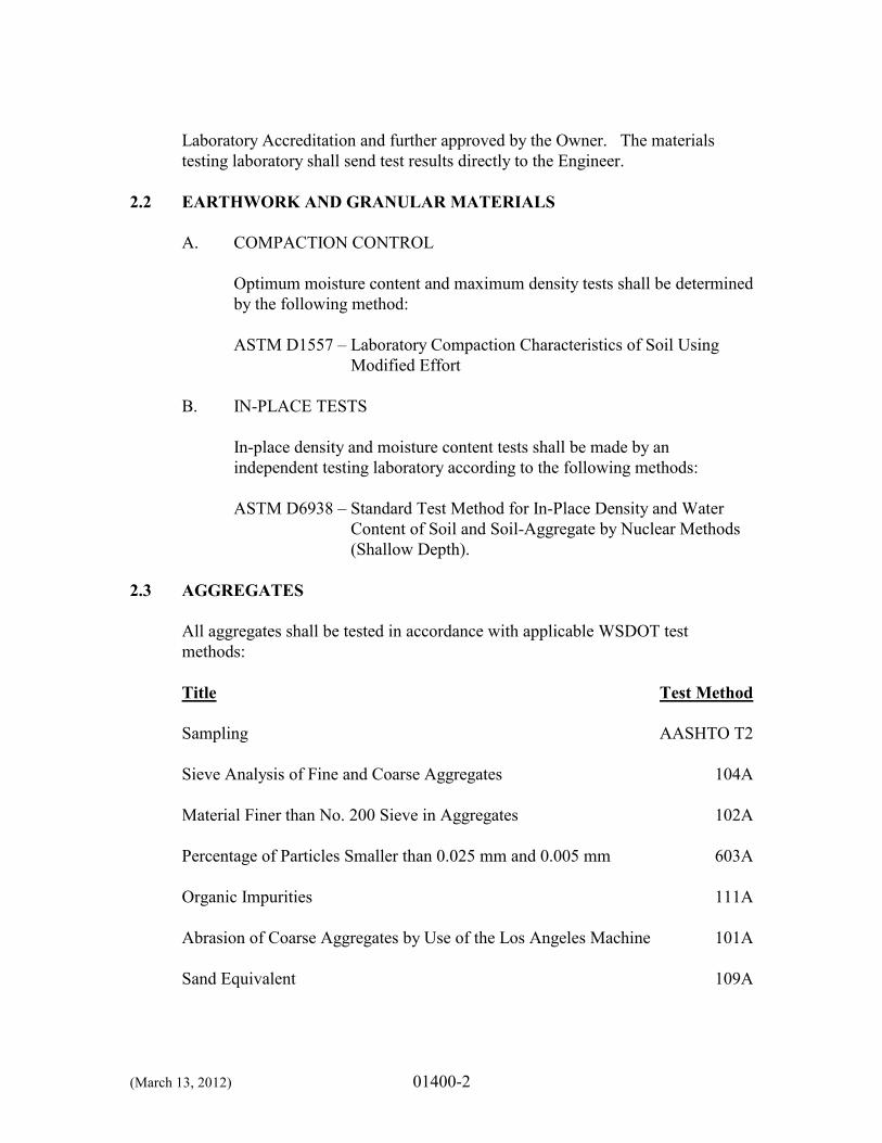
(March 13, 2012) 01400-2
Laboratory Accreditation and further approved by the Owner. The materials testing laboratory shall send test results directly to the Engineer.
2.2 EARTHWORK AND GRANULAR MATERIALS
A. COMPACTION CONTROL
Optimum moisture content and maximum density tests shall be determined by the following method: ASTM D1557 – Laboratory Compaction Characteristics of Soil Using
Modified Effort
B. IN-PLACE TESTS
In-place density and moisture content tests shall be made by an independent testing laboratory according to the following methods: ASTM D6938 – Standard Test Method for In-Place Density and Water
Content of Soil and Soil-Aggregate by Nuclear Methods (Shallow Depth).
2.3 AGGREGATES
All aggregates shall be tested in accordance with applicable WSDOT test methods:
Title Test Method Sampling AASHTO T2 Sieve Analysis of Fine and Coarse Aggregates 104A Material Finer than No. 200 Sieve in Aggregates 102A Percentage of Particles Smaller than 0.025 mm and 0.005 mm 603A Organic Impurities 111A Abrasion of Coarse Aggregates by Use of the Los Angeles Machine 101A Sand Equivalent 109A
(March 13, 2012) 01400-3
2.4 CAST-IN-PLACE CONCRETE
Cast-in-place concrete shall be tested in accordance with applicable parts of Chapter 16 of ACI 301. Concrete reinforcement and concrete special inspections shall be performed in accordance with local Building Official and WABO requirements.
PART 3 EXECUTION
3.1 SAMPLING AND TESTING FREQUENCY
A. GENERAL
The Contractor shall provide the following quality control tests at the number and frequency described herein. On-site testing technicians and testing laboratories shall be WABO-certified. The precise location of the tests shall be designated by the Engineer. The Contractor shall cooperate with laboratory personnel employed to conduct the density testing, sampling of material(s), and special inspections. The Contractor shall provide safe access within the work site for laboratory personnel such that density testing and visual inspection can be performed. The Contractor shall provide samples of materials to be tested in the quantities required and herein specified to the appropriate laboratory personnel. The Contractor shall furnish all labor, equipment, tools, and materials necessary to obtain and deliver samples as herein designated. He shall also provide and repair any test holes required in order to facilitate the testing and sampling and to provide for the testing laboratory’s exclusive use for storage and curing of test samples until removed to the laboratory.
Any areas tested and further failing compliance with the Specifications shall be recompacted and retested at the Contractor’s expense, until a successful density test indicating compliance with these Specifications has been achieved.
B. SOIL TESTING
The following soil quality control tests shall be completed at the given frequency:
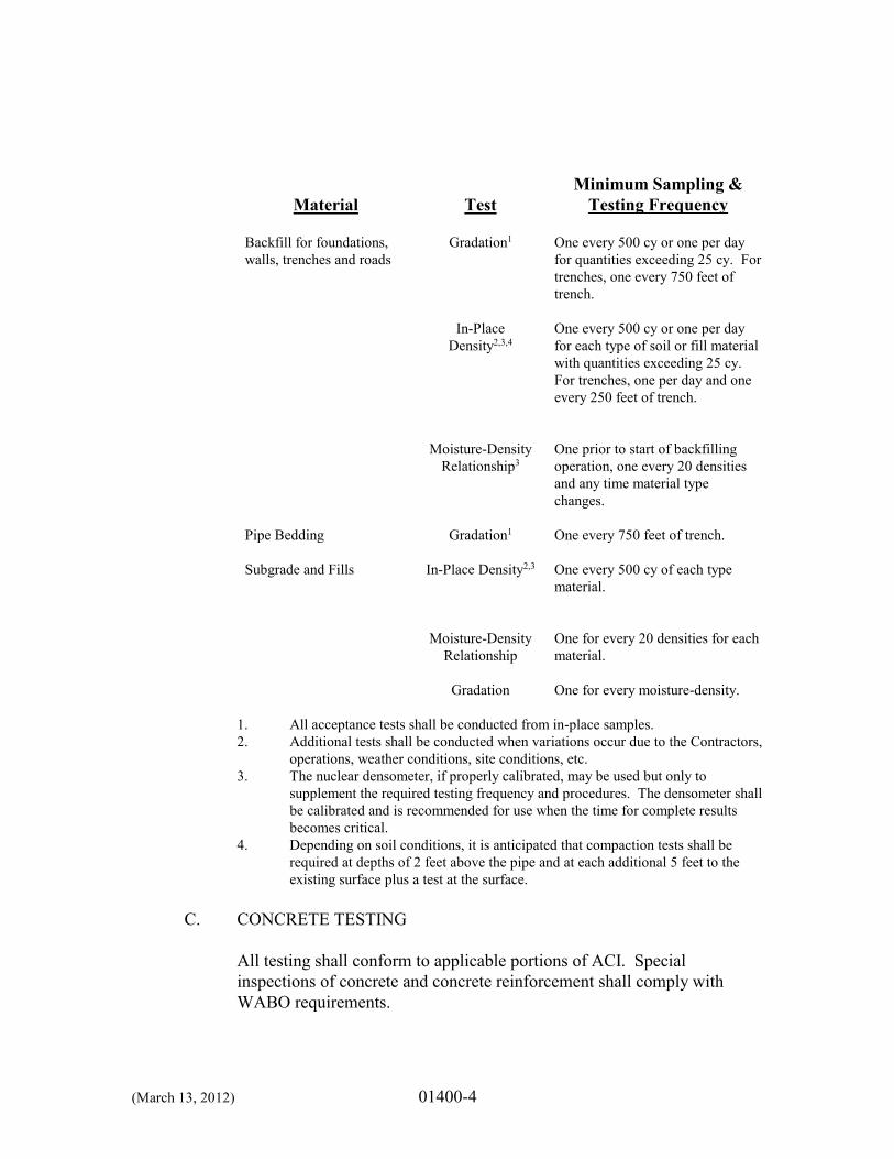
(March 13, 2012) 01400-4
Material
Test
Minimum Sampling & Testing Frequency
Backfill for foundations, walls, trenches and roads
Gradation1 One every 500 cy or one per day for quantities exceeding 25 cy. For trenches, one every 750 feet of trench.
In-Place
Density2,3,4 One every 500 cy or one per day for each type of soil or fill material with quantities exceeding 25 cy. For trenches, one per day and one every 250 feet of trench.
Moisture-Density
Relationship3 One prior to start of backfilling operation, one every 20 densities and any time material type changes.
Pipe Bedding Gradation1 One every 750 feet of trench. Subgrade and Fills In-Place Density2,3 One every 500 cy of each type
material.
Moisture-Density
Relationship One for every 20 densities for each material.
Gradation One for every moisture-density.
1. All acceptance tests shall be conducted from in-place samples. 2. Additional tests shall be conducted when variations occur due to the Contractors,
operations, weather conditions, site conditions, etc. 3. The nuclear densometer, if properly calibrated, may be used but only to
supplement the required testing frequency and procedures. The densometer shall be calibrated and is recommended for use when the time for complete results becomes critical.
4. Depending on soil conditions, it is anticipated that compaction tests shall be required at depths of 2 feet above the pipe and at each additional 5 feet to the existing surface plus a test at the surface.
C. CONCRETE TESTING
All testing shall conform to applicable portions of ACI. Special inspections of concrete and concrete reinforcement shall comply with WABO requirements.
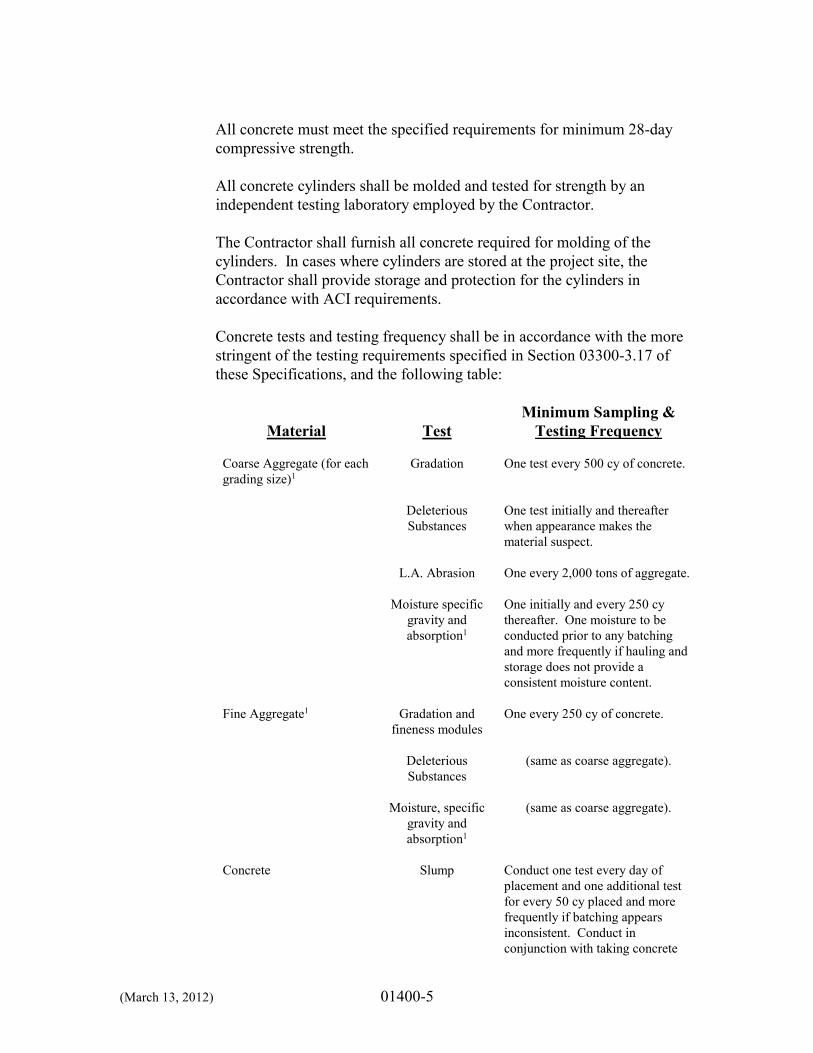
(March 13, 2012) 01400-5
All concrete must meet the specified requirements for minimum 28-day compressive strength. All concrete cylinders shall be molded and tested for strength by an independent testing laboratory employed by the Contractor. The Contractor shall furnish all concrete required for molding of the cylinders. In cases where cylinders are stored at the project site, the Contractor shall provide storage and protection for the cylinders in accordance with ACI requirements. Concrete tests and testing frequency shall be in accordance with the more stringent of the testing requirements specified in Section 03300-3.17 of these Specifications, and the following table:
Material
Test Minimum Sampling &
Testing Frequency Coarse Aggregate (for each grading size)1
Gradation One test every 500 cy of concrete.
Deleterious
Substances One test initially and thereafter when appearance makes the material suspect.
L.A. Abrasion One every 2,000 tons of aggregate. Moisture specific
gravity and absorption1
One initially and every 250 cy thereafter. One moisture to be conducted prior to any batching and more frequently if hauling and storage does not provide a consistent moisture content.
Fine Aggregate1 Gradation and
fineness modules One every 250 cy of concrete.
Deleterious
Substances (same as coarse aggregate).
Moisture, specific
gravity and absorption1
(same as coarse aggregate).
Concrete Slump Conduct one test every day of
placement and one additional test for every 50 cy placed and more frequently if batching appears inconsistent. Conduct in conjunction with taking concrete
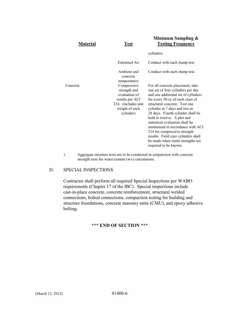
(March 13, 2012) 01400-6
Material
Test
Minimum Sampling & Testing Frequency
cylinders.
Entrained Air Conduct with each slump test. Ambient and
concrete temperatures
Conduct with each slump test.
Concrete Compressive strength and evaluation of
results per ACI 214. (includes unit
weight of each cylinder)
For all concrete placement, take one set of four cylinders per day and one additional set of cylinders for every 50 cy of each class of structural concrete. Test one cylinder at 7 days and two at 28 days. Fourth cylinder shall be held in reserve. A plot and statistical evaluation shall be maintained in accordance with ACI 214 for compressive strength results. Field cure cylinders shall be made when insitu strengths are required to be known.
1. Aggregate moisture tests are to be conducted in conjunction with concrete strength tests for water/cement (w/c) calculations.
D. SPECIAL INSPECTIONS
Contractor shall perform all required Special Inspections per WABO requirements (Chapter 17 of the IBC). Special inspections include cast-in-place concrete, concrete reinforcement, structural welded connections, bolted connections, compaction testing for building and structure foundations, concrete masonry units (CMU), and epoxy adhesive bolting.
*** END OF SECTION ***
(G&O #12009) 01500-1
SECTION 01500
TEMPORARY FACILITIES
PART 1 GENERAL 1.1 SCOPE
The work specified in this Section includes the temporary facilities required for this project, but not necessarily limited to:
A. Temporary utilities such as water, electricity, telephone, off-site staging,
and off-site parking.
B. Temporary piping, pumps, valves, fittings, manholes, vaults, and appurtenances necessary to keep existing facilities fully operational during construction.
C. Sanitary facilities.
D. Temporary enclosures such as fences, tarpaulins, barricades, and canopies.
1.2 RELATED WORK SPECIFIED ELSEWHERE
Section Item 01110 Summary of Work
PART 2 PRODUCTS 2.1 UTILITIES
A. TEMPORARY ELECTRICITY
The Contractor shall provide temporary power for construction at the project site. He shall make arrangements with the electrical utility (to obtain temporary power) and shall pay all costs and fees charged by the utility associated with connection of temporary power. The Contractor shall provide all special connections, receptacles, panelboards, etc., which are required for temporary service, and are not provided by the utility. The Contractor shall furnish and install all temporary wiring and associated equipment required to keep all portions of the existing facilities in operation at all times.
(G&O #12009) 01500-2
20A 120V outlets are available from the owner for power for small appliances/lighting at no additional cost to the contractor at both construction sites. Area distribution boxes shall be furnished, installed, and so located that the individual trades may use their own construction-type extension cords to obtain proper power and artificial lighting at all points where required. The Contractor shall provide a main disconnect on all temporary wiring panels, labeled “MAIN DISCONNECT,” to ensure the safety of personnel using extension cords and hand tools. Panels shall also be properly grounded and equipped with GFCI breakers in accordance with WISHA requirements. The Contractor shall provide the Engineer single line diagrams of the temporary wiring showing all circuit breakers. These diagrams shall be provided prior to installation of this wiring. These diagrams are necessary to provide information to Owner personnel for off-hours operation. The Contractor shall pay all demand, consumption, taxes, and fees associated with the temporary electrical service.
B. WATER
The Contractor shall be responsible for providing water necessary for construction. This includes costs for supplying potable water for hydrostatic pressure leak testing of all water-holding structures and operational testing of all equipment and processes. Water is available from Yakima County for use on the Reservoir No. 4 site (for filling a water truck) from a hydrant at the intersection of 57th and Channel Drive. There is a hose bib connection inside Well #2 (on the Reservoir No. 4 site) that could be used for small quantities of water. At the Sycamore Booster Station, the Contractor may connect to the hydrant at Maple and Sycamore, or a blowoff near the gate. The charge for the required meter is $5.00 per day for the meter rental and $1.00 day for the rental of a double check valve. Water is billed at $1.73 per 100 cu-ft. There is also a $250 deposit for a hydrant meter and $50 deposit for the double check valve.
2.2 TEMPORARY PIPING
The Contractor shall furnish and install all temporary piping and pumping and, upon completion of the work, remove all such temporary piping as required, except as designated on the Plans to remain as a part of the Project. Prior to installation, the Contractor shall submit drawings to the Engineer showing the
(G&O #12009) 01500-3
proposed installation of temporary piping and pumps, including location, type of pipe, fittings, and valves. The Contractor shall obtain the Engineer’s approval for temporary piping and pumping plan prior to installation. Temporary piping and pumping shall be provided as necessary to maintain the existing facilities in operation until the new facilities are constructed, operational. An effort has been made on the Plans and/or Specifications to note instances and locations where temporary piping and/or pumping may be required; however, this in no way limits the temporary piping and pumping to be provided by the Contractor at these locations.
2.3 SANITARY FACILITIES
The Contractor shall provide toilet and wash-up facilities for his workforce and the Engineer at the site of work. They shall comply with applicable laws, ordinances, and regulations pertaining to the public health and sanitation of dwellings and camps.
2.4 OFF-SITE STAGING AND PARKING
The Contractor shall note that space is limited throughout the construction site. Employees of the Contractor, all subcontractors, vendors, suppliers, and associated personnel may park on site during the course of construction if they do not interfere with water system operations and residential access. No parking on Terracota Place. Steel tracked vehicles are not allowed on Terracota Place. It shall be the responsibility of the Contractor to provide sufficient parking facilities in authorized area(s) other than the construction site for the above-mentioned personnel. In addition, the Contractor shall not be allowed to stockpile and store equipment and materials throughout the construction site. The Contractor shall coordinate his schedule so that all equipment and materials shall be brought to the construction site only when they are to be installed/utilized. The Contractor shall provide storage of equipment and materials at an offsite, bonded warehouse, to be approved by the Engineer. The Contractor shall pay all costs associated with off-site delivery, storage, and transfer to the construction site.
2.5 ENCLOSURES
The Contractor shall furnish, install, and maintain during the project time all required scaffolds, tarpaulins, barricades, canopies, warning signs, steps, bridges, platforms, and other temporary construction necessary for proper completion of the work in compliance with all pertinent safety and other regulations.
(G&O #12009) 01500-4
PART 3 EXECUTION
All temporary facilities and controls shall be maintained as long as required for the safe and proper completion of the work. The Contractor shall remove such temporary facilities and controls as rapidly as progress of the work will permit or as directed by the Owner.
*** END OF SECTION ***
(G&O #12009) 01505-1
SECTION 01505
MOBILIZATION AND DEMOBILIZATION PART 1 GENERAL
1.1 SCOPE
The work specified in this Section consists of mobilization and demobilization. Mobilization consists of preconstruction activities and preparatory work for the project necessary to mobilize labor, materials, and equipment to the project site. Demobilization consists of activities to remove materials and equipment from the project site upon project completion, including final cleanup.
The work specified in this Section includes, but is not necessarily limited to, the following items and work associated with any or all of the various schedules of the work when required by the Contract Documents:
A. Bonds and Insurance
B. Conferences
C. Permits and Licenses
D. Submittals including shop drawings and operation and maintenance
information
E. Invoice Preparation
F. Administration Costs
G. Compliance with Funding Agency requirements
H. Materials Testing
I. Construction Schedule
J. Temporary Facilities
K. Cleanup
L. Record Drawings
(G&O #12009) 01505-2
Items which are not considered mobilization or demobilization include but are not limited to: M. On-going activities throughout the duration of construction.
N. Profit, interest on borrowed money, overhead, or management costs.
1.2 RELATED WORK SPECIFIED ELSEWHERE
Section Item 01110 Scope of Work 01150 Surveying 01160 Regulatory Requirements 01200 Measurement and Payment 01300 Submittals 01310 Project Meetings 01385 Photographs 01400 Quality Control 01500 Temporary Facilities 01720 Record Drawings 01740 Clean-up 01950 Traffic Control
PART 2 PRODUCTS
Products and materials required for mobilization and demobilization are described in the various sections of Division 1 and in other parts of the Contract Documents.
PART 3 EXECUTION
Complete mobilization and demobilization as required by the various sections of Division 1 and other parts of the Contract Documents.
*** END OF SECTION ***
(G&O #12009) 01720-1
SECTION 01720
RECORD DRAWINGS PART 1 GENERAL
1.1 SCOPE
The work specified in this Section includes the record drawings, which shall be maintained and annotated by the Contractor during construction.
1.2 RELATED WORK SPECIFIED ELSEWHERE
Section Item 01300 Submittals
1.3 INFORMATION PROVIDED BY THE OWNER The Contractor will be provided with the following items to maintain record drawings for the project: A. One full size paper set of Plans.
PART 2 PRODUCTS
NOT USED PART 3 EXECUTION
3.1 GENERAL
The Contractor shall maintain the following record drawings for the project:
A. A neat and legibly marked set of Contract Plans showing the final location of piping, equipment, electrical conduits, outlet boxes and cables;
B. Additional documents such as schedules, lists, drawings, and electrical and
instrumentation diagrams included in the Contract Documents; and
C. Contractor layout and installation drawings.
Unless otherwise specified, record drawings shall be full size and maintained in a clean, dry, and legible condition. Record documents shall not be used for construction purposes and shall be available for review by the Engineer during
(G&O #12009) 01720-2
normal working hours at the Contractor’s field office. At the completion of the work, prior to final payment, all record drawings shall be submitted to the Engineer.
Marking of the drawings shall be kept current and shall be done at the time the material and equipment are installed. Annotations to the record documents shall be made with an erasable colored pencil conforming to the following color code:
A. Additions - Red
B. Deletions - Green
C. Comments - Blue
D. Dimensions - Graphite
Legibly mark drawings to record actual depths, horizontal and vertical location of underground raceways, cables, and appurtenances referenced to permanent surface improvements. The Contractor’s record drawings (full-size hard-copy) will be reviewed monthly for completeness by the Engineer prior to preparing the progress estimate for payment. If the record drawings do not reflect the work performed, payment for that item of work will not be included in the progress estimate.
*** END OF SECTION ***
(G&O #12009) 01740-1
SECTION 01740
CLEANUP PART 1 GENERAL
1.1 SCOPE
The work specified in this Section includes the maintenance of the building, structures, and site(s) in a standard of cleanliness throughout the construction period as described herein. Throughout the construction period, the Contractor shall maintain the cleanliness of the site and structures as described herein. The Contractor is also to maintain access to all existing, operating equipment such that the equipment may be serviced and operated. Dust of all kinds, including concrete dust produced by construction activities, shall be controlled to avoid damage to existing, operating equipment. Enclosures, ventilation, and air scrubbing may be required where significant potential for damage is determined by the Engineer.
1.2 RELATED WORK SPECIFIED ELSEWHERE
In addition to standards described in this Section, comply with all requirements for cleaning up when described in other sections of these Contract Documents.
1.3 QUALITY ASSURANCE
A. INSPECTION
The Contractor shall conduct daily site inspections, and more often if necessary, to verify that requirements are being met.
B. CODES AND STANDARDS
In addition to the standards described in this Section, comply with all pertinent requirements of governmental agencies having jurisdiction.
(G&O #12009) 01740-2
PART 2 PRODUCTS
2.1 CLEANING MATERIALS AND EQUIPMENT
Provide all required personnel, equipment, and materials needed to maintain the specified standard of cleanliness.
2.2 COMPATIBILITY
Use only the cleaning materials and equipment which are compatible with the surface being cleaned, as recommended by the manufacturer of the material or as approved by the Engineer.
PART 3 EXECUTION
3.1 PROGRESS CLEANING
A. GENERAL
Retain all stored materials and equipment in an orderly fashion allowing maximum access, not impeding drainage or traffic, and providing protection. Do not allow the accumulation of scrap, debris, waste material, and other items not required for this work. At least twice each month, and more often if necessary, completely remove all scrap, debris, and waste material from the project site. Provide adequate storage for all materials awaiting removal from the project site, observing all requirements for fire protection and protection of the environment.
B. SITE
Daily, and more often if necessary, inspect the site and pick up all scrap, debris, and waste material. Move these items into a place designated for their storage until disposal becomes available. Weekly, and more often if necessary, inspect all arrangements of materials stored on the site, restack, arrange, or otherwise service all arrangements to meet the requirements above.
(G&O #12009) 01740-3
Maintain the site in a neat and orderly condition at all times so as to meet the approval of the Engineer.
C. STRUCTURES
Weekly, and more often if necessary, inspect the structures and pick up all scrap, debris and waste material. Move these items into a place designated for their storage until disposal becomes available. Weekly, and more often if necessary, sweep clean all interior spaces. “Clean” shall be interpreted to mean free from dust and other materials that can be swept with a broom using reasonable diligence. In preparing to install succeeding materials, clean the structures or pertinent portions thereof to the degree of cleanliness recommended by the manufacturer of the succeeding material. Use all equipment and materials required to achieve the required cleanliness.
D. STREETS
All paved and unpaved streets in the vicinity of the project shall be kept free of material tracked from the project site(s) or dropped from vehicles entering and leaving the site(s). The Contractor shall inspect roads in each active area daily, and all material deposited on the road from the Contractor’s activities shall be removed prior to the end of the workday. This shall include sweeping, as required, to collect any mud, dirt and dust from the surface. All catch basins and culverts in the work area shall be inspected before completion and cleaned as directed by the Engineer.
3.2 FINAL CLEANING
A. DEFINITION
Except as otherwise specifically provided, “clean” shall be interpreted as meaning the level of cleanliness generally provided by commercial building maintenance equipment and materials.
B. GENERAL
Prior to final inspection, remove from the jobsite all tools, surplus materials, equipment, scrap, debris, and waste. Conduct final project cleaning as described below.
(G&O #12009) 01740-4
C. STRUCTURES
1. Exterior
Visually inspect all exterior surfaces and remove all traces of soil, waste, smudges, and other foreign matter. Remove all traces of splashed materials from adjacent surfaces. If necessary to achieve a uniform degree of exterior cleanliness, hose down the exterior of the structure. In the event of stubborn stains not removable with water, the Engineer may require light sandblasting or other cleaning at no additional cost to the Owner.
2. Interior
Visually inspect all interior surfaces and remove all traces of soil, waste, smudges, and other foreign matter. Remove all traces of splashed materials from adjacent surfaces. Remove all paint droppings, spots, stains, and dirt from finished surfaces. Use only appropriate cleaning materials and equipment.
D. TIMING
Schedule final cleaning as approved by the Engineer to enable the Owner to accept a completely clean project, ready for occupancy.
*** END OF SECTION ***
(G&O# 12009) 01900-1
SECTION 01900
SALVAGE AND DEMOLITION PART 1 GENERAL 1.1 SCOPE
The work specified in this Section covers the demolition of existing structures, piping, equipment, and sitework, and the salvage of existing materials and equipment as indicated on the Plans and as specified herein. All facilities of the existing facility, which are not to be modified or removed, must remain in continuous operation during the work. Demolition and salvage work shall create a minimum of interference with the operation of the facility. The Plans show the major items to be demolished and removed. The Contractor shall, however, remove any other incidental above-grade items, which are not to be used in the completed project.
1.2 RELATED WORK SPECIFIED ELSEWHERE
Section Item 02230 Clearing and Grubbing 09970 Reservoir Surface Preparation and Painting
1.3 SALVAGE
Salvageable equipment and material shall be removed with care so as not to impair future uses and shall include all equipment and material so indicated on the Plans. Salvaged equipment and material not reused or rejected by the Owner shall be cleaned and protected from corrosion and weather and delivered by the Contractor to the Owner at the Public Works facility in Yakima, Washington.
Reuse of salvageable equipment and material by the Contractor will not be permitted except where specifically indicated on the Plans and Specifications or where approved by the Engineer and Owner. Salvageable equipment and materials rejected in writing by the Owner shall become the property of the Contractor and be disposed of away from the site without additional cost to the Owner.
All salvageable equipment and materials associated with the reservoir site shall become the property of the Contractor upon removal. This equipment can then be sold by the Contractor to any interested party.
(G&O# 12009) 01900-2
1.4 DEMOLITION
The Contractor shall be responsible for compliance with current City, County, State, and Federal codes and regulations related to demolition.
The Contractor shall notify all affected utilities and comply with their respective requirements for abandonment of such utilities including power, telephone, natural gas, water, sanitary sewer, and storm sewer utilities. The Contractor shall maintain access for the Owner’s employees during the demolition period and provide barricades, fences, etc., as required for job site safety. Demolition of concrete, masonry, roofing, asphalt, and other materials shall be done so as to avoid damage to existing structures intended to remain. Demolition or cutting required to add to or modify existing structures shall be done in such a manner that the appearance and utility of the existing structure is not impaired and so that a neat transition from new to old material may occur. All piping and appurtenances located less than 4 feet below finished grade shall be removed and hauled to an approved disposal site. All piping and appurtenances located four feet or more below finished grade may be abandoned in place, unless shown otherwise on the Plans, as long as Contractor fully seals all pipe and appurtenance openings with grout. All waste materials from demolition or cutting shall become the property of the Contractor and shall be removed from the site and hauled to an approved waste disposal site, if declared surplus by the Owner. All materials and equipment, however, are property of the Owner unless declared surplus. Some equipment and materials scheduled for salvage and delivery to the Owner are noted on the Plans.
1.5 HAZARDOUS MATERIALS
A. GENERAL
Hazardous materials are known to be present on the project site. Their types and locations are described in the following sections. The Contractor shall communicate the presence of these potential hazards to employees, subcontractors, and other site occupants. The Contractor shall ensure the safety of all workers, visitors to the site, and the general public in accordance with all applicable laws, rules, and regulations. The Contractor shall comply with all applicable federal, state, and local laws relating working with hazardous materials. All costs related to work in
(G&O# 12009) 01900-3
compliance with established rules and regulations shall be the responsibility of the Contractor.
B. LEAD CONTAINING MATERIALS
Lead (and possibly other metals) containing coating materials are known to be present on the site in the following locations: On the interior and exterior of the 5 existing 11-foot diameter by
42.5-foot tanks.
Test results for solids analysis of the existing coating systems are included in the appendices. Only lead was tested. Other metals were not tested. The Contractor shall provide all necessary protections to workers, the public, and property to mitigate these hazards during construction activities in accordance with all applicable federal, state, and local regulations including WAC 296-155-176. Contractor shall assume that all removed existing paint shall be removed and hauled to the hazard waste facility.
C. HAZARDOUS MATERIAL TRANSPORT AND DISPOSAL
The Contractor shall comply with all federal, state, and local regulations regarding the collection, containment and transportation of hazardous materials, including but not limited to WAC 173-303 Dangerous Waste Regulation, and shall ensure that all subcontractors comply as well.
*** END OF SECTION ***
(G&O #12009) 01950-1
SECTION 01950
TRAFFIC CONTROL PART 1 GENERAL 1.1 SCOPE
The work specified in this Section includes the traffic control required for the project. The Contractor, utilizing contractor labor and contractor-provided equipment and materials (except when such labor, equipment, or materials are to be provided by the Owner as specifically identified in the Contract Documents), shall plan, manage, supervise and perform all temporary traffic control activities need to support the work of the Contract. The Contractor shall provide flaggers, signs, and other traffic control devices not otherwise specified as being furnished by the Owner. The Contractor shall erect and maintain all construction signs, warning signs, detour signs, and other traffic control devices, necessary to warn and protect the public at all times from injury or damage as a result of the Contractor’s operations which may occur on highways, roads or streets. No work shall be done on or adjacent to the roadway until all necessary signs and traffic control devices are in place. These flaggers, signs, and other traffic control devices shall be used for the safety of the public, the Contractor’s employees, and the Owner’s personnel and to facilitate the movement of the traveling public. They may be used for the separation or merging of public and construction traffic when in accordance with a specific approved traffic control plan. Upon failure of the Contractor to immediately provide flaggers; erect, maintain, and remove signs; or provide, erect, maintain, and remove other traffic control devices when ordered to do so by the Owner, the Owner may, without further notice to the Contractor or the Surety, perform any of the above and deduct all of the costs from the Contractor’s payment. The Contractor shall be responsible for providing adequate flaggers, signs and other traffic control devices for the protection of the work and the public at all times regardless of whether or not the flaggers, signs, and other traffic control devices are ordered by the Owner, furnished by the Owner, or paid for by the Owner.
(G&O #12009) 01950-2
1.2 RELATED WORK SPECIFIED ELSEWHERE
Section Item 01160 Regulatory Requirements 01300 Submittals
1.3 REFERENCES This Section references the latest revisions to the following documents:
Reference Title MUTCD Manual of Uniform Traffic Control Devices
Washington State Modifications to the MUTCD Quality Guidelines for Temporary Traffic Control Devices
ANSI 107 High Visibility Garment Standard
1.4 TRAFFIC CONTROL MANAGEMENT
The duties of the Contractor’s traffic control management personnel shall include: A. Overseeing and approving the actions of the Traffic Control Supervisor
(TCS) to ensure that proper safety and traffic control measures are implemented and consistent with the specific requirements created by the Contractor’s work zones and the Contract. Some form of oversight shall be in place and effective even when the traffic control management personnel are not present at the jobsite.
B. Providing the Contractor’s designated TCS with approved Traffic Control
Plans (TCPs), which are compatible with the work operations, and traffic control for which they will be implemented.
C. Discussing proposed traffic control measures and coordinating
implementation of the Contractor-adopted traffic control plan(s) with the Owner.
D. Coordinating all traffic control operations, including those of
subcontractors, suppliers, and any adjacent construction or maintenance operations.
E. Coordinating the project’s activities (road closures and lane closures) with
appropriate police, fire control agencies, city or county engineering, medical emergency agencies, school districts, and transit companies.
(G&O #12009) 01950-3
F. Overseeing all requirements of the Contract, which contribute to the convenience, safety, and orderly movement of vehicular and pedestrian traffic.
G. Having the latest adopted edition of the MUTCD including the
Modifications to the MUTCD for Streets and Highways for the State of Washington and applicable standards and specifications available at all times on the Project.
H. Attending all Project meetings where traffic management is discussed.
I. Being present onsite a sufficient amount of time to adequately accomplish
the above-listed duties. 1.5 TRAFFIC CONTROL SUPERVISOR
A Traffic Control Supervisor (TCS) shall be on the Project whenever traffic control labor is required or less frequently, as approved by the Owner. The TCS shall personally perform all the duties of the TCS. The TCS’s duties shall include: A. Inspecting traffic control devices and nighttime lighting for proper
location, installation, message, cleanliness, and effect on the traveling public. Traffic control devices shall be inspected each work shift except that Class A signs and nighttime lighting need to be checked only once a week. Traffic control devices left in place for 24 hours or more should also be inspected once during the nonworking hours when they are initially set up (during daylight or darkness, whichever is opposite of the working hours).
B. Ensuring that corrections are made if traffic control devices are not
functioning as required. The TCS may make minor revisions to the approved traffic control plan to accommodate site conditions as long as the original intent of the traffic control plan is maintained and the revision has concurrence of the TCM and/or Owner.
C. Attending traffic control coordinating meetings or coordination activities
as authorized by the Owner.
D. Ensuring that all needed traffic control devices are available and in good working condition prior to the need to install those devices.
E. Ensuring that all pedestrian routes or access points, existing or temporary,
are kept clear and free of obstructions and that all temporary pedestrian
(G&O #12009) 01950-4
routes or access points are detectable and accessible to persons with disabilities as provided for in the approved plans.
F. Having a current set of approved TCPs and applicable contract provisions
as provided by the TCM and the latest adopted edition of the MUTCD including the Washington State Modifications to the MUTCD and applicable standards and specifications.
1.6 TCM AND TCS QUALIFICATIONS
The TCM and TCS shall be certified by one of the following:
The Northwest Laborers – Employers Training Trust 27055 Ohio Avenue Kingston, Washington 98346 (360) 297-3035 Evergreen Safety Council 401 Pontius Avenue N. Seattle, Washington 98109 (800) 521-0778 or (206) 382-4090
The TCS and all flaggers shall have a current flagging card from the State of Washington, Oregon, or Idaho.
1.7 SUBMITTALS
A. TRAFFIC CONTROL PLAN
The Contractor shall prepare and submit five copies of a Traffic Control Plan(s). All construction signs, flaggers, spotters, and other traffic control devices shall be shown on the traffic control plans except for emergency situations. The Contractor shall designate and adopt in writing the specific traffic control plan or plans required for their method of performing the work. The traffic control plan(s) shall be in accordance with the established standards for plan development as shown in the MUTCD, Part VI. The Contractor shall be solely responsible for providing copies of the approved Traffic Control Plans to the Traffic Control Supervisor.
The Traffic Control Plan shall meet the specific requirements of the franchise agreements and right-of-way permits required for this project. In addition, the Traffic Control Plan shall meet the following requirements:
(G&O #12009) 01950-5
At least one-way traffic on state highways and through roads.
Local access and emergency access on local access roads.
Alleys can be blocked with at least 1-week notification of all affected property owners.
PART 2 PRODUCTS 2.1 CONFORMANCE TO ESTABLISHED STANDARDS
Flagging, signs and all other traffic control devices furnished or provided shall conform to the standards established in the latest adopted edition of the Manual on Uniform Traffic Control Devices (MUTCD) published by the U.S. Department of Transportation and the Washington State Modifications to the MUTCD and Quality Guidelines for Temporary Traffic Control Devices. Copies of the MUTCD and the Quality Guidelines for Temporary Traffic Control Devices may be purchased from the American Traffic Safety Services Association, 15 Riverside Parkway, Suite 100, Fredericksburg, Virginia 22406-1022. The Washington State Modifications to the MUTCD may be obtained from the Department of Transportation, Olympia, Washington 98504. In addition to the standards of the MUTCD described above, the WSDOT has scheduled the implementation of crashworthiness requirements for all work zone devices. The National Cooperative Highway Research Project (NCHRP) Report 350 has established requirements for crash testing. Work zone devices are divided into four categories. Each of those categories and the schedule for implementation is described: Category 1 includes those items that are small and lightweight,
channelizing, and delineating devices that have been in common use for many years and are known to be crashworthy by crash testing of similar devices or years of demonstrable safe performance. These include cones, tubular markers, flexible delineator posts, and plastic drums with no attachments. All Category 1 devices used on the Project shall meet the requirements of NCHRP 350 as certified by the manufacturer of the device. The Contractor shall obtain the manufacturer’s certification documentation for all such devices purchased and shall keep the documentation available for inspection throughout the life of the Project.
Category 2 includes devices that are not expected to produce significant
vehicular velocity change, but may otherwise be hazardous. Examples of this class are barricades, portable sign supports and signs, intrusion alarms and vertical panels. Any new Category 2 device purchased after October
(G&O #12009) 01950-6
1, 2000 shall meet the requirements of NCHRP 350. Existing equipment, purchased prior to October, 1, 2000, may be used on the Project until December 31, 2007. For the purpose of definition, a sign support and sign shall be considered a single unit. A new sign may be purchased for an existing sign support and the entire unit will be defined as “existing equipment.”
Category 3 is for hardware expected to cause significant velocity changes
or other potentially harmful reactions to impacting vehicles. Barriers, fixed sign supports, crash cushions, truck mounted attenuators (TMAs) and other work zone devices not meeting the definitions of Category 1 or 2 are examples from this category. Many Category 3 devices are defined in the design of the Project. Where this is the case, NCHRP 350 requirements have been incorporated into the design and the Contractor complies with the requirements by constructing according to the Drawings and Specifications. Where the device is a product chosen by the Contractor, the device chosen shall be compliant with the requirements of NCHRP 350.
Category 4 includes portable or trailer-mounted devices such as Arrow
Displays, Temporary Traffic Signals, Area Lighting Supports, and Portable Changeable Message Signs.
The condition of signs and traffic control devices shall be new or “acceptable” as defined in the book Quality Standards for Work Zone Traffic Control Devices, and will be accepted based on a visual inspection by the Owner. The Owner’s decision on the condition of a sign or traffic control device shall be final. When a sign or traffic control device becomes classified as “not acceptable” it shall be removed from the Project and replaced within 12 hours.
2.2 CONSTRUCTION SIGNS
All signs required by the approved traffic control plan(s) as well as any other appropriate signs prescribed by the Owner shall be furnished by the Contractor. The Contractor shall provide the posts or supports and erect and maintain the signs in a clean, neat, and presentable condition until the necessity for them has ceased. All non-applicable signs shall be removed or completely covered with either metal or plywood during periods when they are not needed. When the need for any of these signs has ceased, the Contractor, upon approval of the Owner, shall take down these signs, post, or supports. Construction signs will be divided into two classes. Class A construction signs are those signs that remain in service throughout the construction or during a major phase of the work. They are mounted on posts, existing fixed structures, or
(G&O #12009) 01950-7
substantial supports of a semi-permanent nature. Sign and support installation for Class A signs shall be in accordance with the WSDOT Standard Plans. Class B Construction signs are those signs that are placed and removed daily, or are used for short durations which may extend for one or more days. They are mounted on portable or temporary mountings. If it is necessary to add weight to the signs for stability, only a bag of sand that will rupture on impact shall be used. The bag of sand shall: (1) be furnished by the Contractor, (2) have a maximum weight of 40 pounds, and (3) be suspended no more than 1 foot from the ground.
PART 3 EXECUTION 3.1 GENERAL
The Contractor shall provide all labor and equipment to execute the Traffic Control Plan. It is the Contractor’s responsibility to plan, conduct, and safely perform the work. The Contractor shall designate an individual or individuals to perform the duties of Traffic Control Manager (TCM). The Contractor shall also designate an individual or individuals to perform the duties of the Traffic Control Supervisor (TCS). The TCS shall be responsible for safe implementation of approved Traffic Control Plans provided by the TCM. The TCM may also perform the duties of the TCS. The Contractor shall identify an alternate TCM and TCS who can assume the duties of the assigned or primary TCM and TCS in the event of that person’s inability to perform. Such alternates shall meet the same requirements as the primary TCM and TCS. The Contractor shall maintain 24-hour telephone numbers at which the TCM and TCS can be contacted and be available upon the Engineer’s request at other than normal working hours. The TCM and TCS shall have the appropriate personnel, equipment, and material available at all times in order to expeditiously correct any deficiency in the traffic control system.
3.2 TRAFFIC CONTROL LABOR
The Contractor shall furnish all personnel for flagging, spotting, for the execution of all procedures related to temporary traffic control and for setup, maintenance and removal of all temporary traffic control devices and construction signs necessary to control traffic during construction operations. Vests and other high-visibility apparel shall be in conformance with ANSI 107.
(G&O #12009) 01950-8
Flaggers and spotters shall possess a current flagging card issued by the State of Washington, Oregon, or Idaho. The flagging card shall be immediately available and shown upon request by the Owner. During hours of darkness, flagging stations shall be illuminated in a manner that insures that flaggers can easily be seen but that does not cause glare to the traveling public. Flagger station illumination shall meet the requirements of the MUTCD. Flaggers shall be equipped wit portable two-way radios, with a range suitable for the project. The radios shall be capable of having direct contact wit project management (foreman, superintendents, etc.) The Contractor shall furnish flagger Stop/Slow paddles conforming to the requirements of the MUTCD, except the minimum width shall be 24 inches.
*** END OF SECTION ***
DIVISION 2
SITEWORK
(G&O #12009) 02050-1
SECTION 02050
LOCATE EXISTING UTILITIES
PART 1 GENERAL 1.1 SCOPE
The work specified in this Section includes the anticipated conflicts, which may exist with existing utilities. A reasonable attempt has been made to locate the existing utilities; however, the exact location, and/or depth are unknown in most instances. Locations and dimensions shown in the Plans for existing facilities are in accordance with available information obtained without uncovering, measuring, or other verification. It shall be the responsibility of the Contractor to locate existing utilities and their depth.
1.2 RELATED WORK SPECIFIED ELSEWHERE
Section Item 01200 Measurement and Payment 02250 Temporary Shoring and Bracing
02300 Earthwork
PART 2 PRODUCTS
Not Used.
PART 3 EXECUTION 3.1 GENERAL
During the first four working days on site, The Contractor shall determine the difficulties to be encountered in constructing the Project and his locate effort based upon the information provided on the Plans, field investigation, and the Contractor’s contacts with the existing utility companies. The Contractor shall determine the extent of exploration required to first prevent damage to those existing utilities, and secondly to determine if the proposed improvements are in conflict with existing utilities. The Contractor shall locate existing utilities sufficiently ahead of construction so that the Engineer can modify the proposed improvements or existing utilities prior to starting construction. The Contractor shall locate existing utilities sufficiently ahead of construction so that the Engineer can modify the alignment, or grade prior to construction. Where underground utilities are found to be in the way of construction, such condition
(G&O #12009) 02050-2
shall not be deemed to be a changed or differing site condition, if necessary, pipe alignment or grade shall be modified at the Contractor’s expense. The Contractor shall call the Utility Location Request Center (One Call Center), for field location, not less than 2 nor more than 10 business days before the scheduled date for commencement of excavation that may affect underground utility facilities, unless otherwise agreed upon by the parties involved. A business day is defined as any day other than Saturday, Sunday, or a legal local, State, or Federal holiday. The telephone number for the One Call Center for this project is 811. If no one-number locator service is available, notice shall be provided individually to those owners known to or suspected of having underground facilities within the area of the proposed excavation. The Contractor is alerted to the existence of Chapter 19.122 RCW, a law relating to underground utilities. Any cost to the Contractor incurred as a result of this law shall be at the Contractor’s expense. No excavation shall begin until all know facilities in the vicinity of the excavation area have been located and marked.
*** END OF SECTION ***
(G&O #12009) 02230-1
SECTION 02230
CLEARING AND GRUBBING PART 1 GENERAL 1.1 SCOPE
The work specified in this Section includes the clearing, grubbing, and stripping of the proposed project areas in preparation of foundations, embankment construction, and pipeline installation.
1.2 RELATED WORK SPECIFIED ELSEWHERE
Section Item 01200 Measurement and Payment 02300 02370
Earthwork Erosion Control
1.3 DEFINITIONS
“Clearing, grubbing, and stripping debris” as hereinafter used shall be considered as all material removed by the clearing, grubbing, and stripping operations.
PART 2 PRODUCTS
Not Used. PART 3 EXECUTION 3.1 DISPOSAL OF CLEARING AND GRUBBING DEBRIS
Clearing and grubbing debris shall be disposed of by hauling to waste and disposal sites approved by the Owner.
3.2 CLEARING AND GRUBBING
Contractor shall limit the total disturbed area of the project to be less than 1 acre in size. Contractor shall obtain a Construction Stormwater General Permit from the Washington State Department of Ecology and comply with the permit if their operations disturb more than one acre. Clearing and grubbing shall be performed as required to complete the work shown on the Plans to a minimum depth of 8 inches in order to remove the root zone of existing vegetation.
(G&O #12009) 02230-2
This work shall include removal and disposal of all trees, logs, brush, stumps, roots, and minor manmade structures to include but not limited to concrete, asphalt abandoned metal and equipment, rubbish and debris to the limits indicated on the plans or as required and approved by the owner. This work shall be to a depth necessary to remove stumps, large roots and all other objectionable material. This work shall also include the protection from injury or defacement of trees, bushes, shrubs, and other objects designated to remain.
*** END OF SECTION ***
(G&O #12009) 02250-1
SECTION 02250
TEMPORARY SHORING AND BRACING
PART 1 GENERAL 1.1 SCOPE
The work specified in this Section includes the temporary shoring and bracing for excavators including the trench excavation safety systems as shown on the Plans and as specified herein.
1.2 RELATED WORK SPECIFIED ELSEWHERE
Section Item 01200 Measurement and Payment 01300 Submittals 02300 15050
Earthwork Piping System
1.3 GEOTECHNICAL REPORT
Geotechnical Report, Proposed Reservoir Bohoskey Drive & North 57th Street Terrace Heights, Washington, April 12, 2012, Washington, by PanGeo, Inc., Geotechnical & Earthquake Engineering Consultants.
1.4 WORK INCLUDED
The extent of temporary shoring and bracing work includes, but is not limited to: A. Temporary shoring and bracing necessary to protect the following against
loss of ground or caving embankments: existing structures, buildings, roads, walkways, utilities, electrical transmission towers and support wiring, other facilities and improvements where required to comply with codes and authorities having jurisdiction.
B. Trench excavation safety systems, pursuant to RCW Chapter 49.17 and
WAC 296-155-655. C. Maintenance of shoring and bracing.
(G&O #12009) 02250-2
1.5 QUALITY ASSURANCE
A. SHORING CONSULTANT
The Contractor shall engage the services of a qualified geotechnical engineer and qualified structural engineer registered in the State of Washington to design temporary shoring and bracing when required by applicable regulations.
B. SHORING DESIGN
The Contractor shall provide layout and design drawings and specifications for shoring and bracing when a trench box is inadequate for the purpose or will not be used and trench depth exceeds 4 feet and back sloping will not be used. Temporary shoring and bracing system design and calculations shall be prepared, stamped, and signed by a Professional Engineer registered in the State of Washington.
C. REGULATIONS
The Contractor shall design sheeting, shoring and bracing in accordance with the Washington State Safety Code and any local codes and ordinances of governing authorities having jurisdiction. Pile driving will not be allowed on the site; drilling shall be required for all required piles.
1.6 SUBMITTALS
The Contractor shall submit shoring and bracing layout and design drawings, calculations and other backup data to the Owner for review in accordance with Section 01300 prior to the start of construction.
1.7 PROJECT CONDITIONS
A. SOILS INFORMATION
A Geotechnical investigation has been conducted for this project and a copy of the report is included in Appendix D.
B. SITE SURVEY
The background survey information provided on the Plans is shown for clarity only. The Contractor shall determine, before commencing work, the exact location of all existing features that may be disrupted by new construction, including existing underground utilities. The Contractor shall be fully responsible for any and all damages, which might be caused
(G&O #12009) 02250-3
by the Contractor’s failure to exactly locate and/or preserve existing site features. Prior to commencing work, the Contractor shall check and verify governing dimensions and elevations. The Contractor shall survey adjacent structures and facilities, establishing exact elevations at fixed points to act as temporary bench marks to monitor potential settlement from the contractor’s ongoing operations. Clearly identify temporary bench marks and record existing elevations from the control points shown on the Plans. During excavation, the Contractor shall resurvey bench marks weekly. The Contractor shall maintain and make available at the job site an accurate log of surveyed elevations for comparison with original elevations, and promptly notify the Owner if changes in elevations occur or if cracks, sags or other damage is evident.
1.8 EXISTING UTILITIES
The Contractor shall protect existing active sewer, water, gas, electrical, and other utility services and structures that may be present. This shall also include all pipelines, services, and structures that are the property of the Owner.
PART 2 PRODUCTS
The Contractor shall provide suitable shoring and bracing materials, which shall support loads imposed. Materials for shoring systems need not be new, but shall be in serviceable conditions.
PART 3 EXCAVATION 3.1 VERIFICATION OF CONDITIONS
The Contractor shall notify the Owner immediately if, during construction, subsurface conditions are different from those encountered in the exploratory holes or as described in the Geotechnical Report.
3.2 INSTALLATION AND APPLICATION
The Contractor shall provide shoring systems adequately anchored and braced to resist earth and hydrostatic pressures at locations as needed to support excavations during construction. The Contractor shall locate required bracing to clear all permanent work. Bracing which must be relocated shall be installed prior to the removal of original bracing. The Contractor shall not place bracing where it will be cast into or included in permanent concrete work, except as otherwise acceptable to the Owner. The Contractor shall maintain bracing until
(G&O #12009) 02250-4
structural elements are rebraced by other bracing or until permanent construction is able to withstand lateral earth and hydrostatic pressures.
3.3 REMOVAL
The Contractor shall remove shoring and bracing in stages to avoid disturbances to adjacent and underlying soils and damage to structures, pavements, facilities and utilities. The Contractor shall repair or replace, as acceptable to the Owner, adjacent work damaged or displaced through the installation or removal of shoring and bracing work.
3.4 EXCAVATION SAFETY SYSTEMS
All work shall be carried out with due regard for public safety. Open trenches shall have proper barricades and at night they shall be distinctly indicated by adequately placed lights, as provided for elsewhere in the Specifications.
The Contractor is reminded that the Owner has not so delegated, and the Owner’s Representative does not purport to be a trench or excavation system safety expert, is not so engaged in that capacity under this Contract, and has neither the authority nor the responsibility to enforce construction, safety laws, rules, regulations, or procedures or to order the stoppage of work for claimed violations of trench or excavation safety.
The furnishing by the Owner of resident representation and inspection personnel shall not make the Owner responsible for the enforcement of such laws, rules, regulations, or procedures, nor shall such make the Owner responsible for construction means, methods, techniques, sequences, procedures, or for the Contractor’s failure to properly perform the work necessary for proper trench and excavation safety.
*** END OF SECTION ***
(G&O #12009) 02275-1
SECTION 02275
GEOTEXTILE FABRIC
PART 1 GENERAL
1.1 SCOPE
The work specified in this Section includes providing and installing a geotextile fabric to separate two dissimilar aggregate and/or soil materials.
1.2 RELATED WORK SPECIFIED ELSEWHERE
Section Item 01200 Measurement and Payment 01300 Submittals 02250 Temporary Shoring and Bracing 02300 Earthwork 02370 Erosion Control 02700 Gravel Materials
1.3 SUBMITTALS
The Contractor shall submit a certificate stating the name of the manufacturer, product name, style number, chemical composition of the filaments or yarns and other pertinent information to fully describe the geotextile in accordance with Section 01300. The Certification shall be attested to by a person having legal authority to bind the Manufacturer.
1.4 QUALITY ASSURANCE
The geotextile Manufacturer shall have all of the following credentials: Geosynthetic Accreditation Institute (GAI)- Laboratory Accreditation
Program (LAP)
American Association for Laboratory Accreditation ISO 9001: Quality Management System
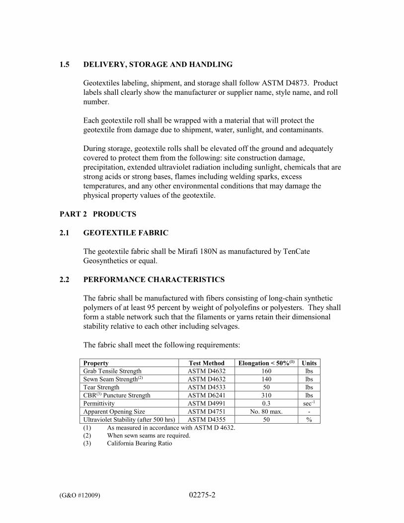
(G&O #12009) 02275-2
1.5 DELIVERY, STORAGE AND HANDLING
Geotextiles labeling, shipment, and storage shall follow ASTM D4873. Product labels shall clearly show the manufacturer or supplier name, style name, and roll number. Each geotextile roll shall be wrapped with a material that will protect the geotextile from damage due to shipment, water, sunlight, and contaminants. During storage, geotextile rolls shall be elevated off the ground and adequately covered to protect them from the following: site construction damage, precipitation, extended ultraviolet radiation including sunlight, chemicals that are strong acids or strong bases, flames including welding sparks, excess temperatures, and any other environmental conditions that may damage the physical property values of the geotextile.
PART 2 PRODUCTS
2.1 GEOTEXTILE FABRIC
The geotextile fabric shall be Mirafi 180N as manufactured by TenCate Geosynthetics or equal.
2.2 PERFORMANCE CHARACTERISTICS
The fabric shall be manufactured with fibers consisting of long-chain synthetic polymers of at least 95 percent by weight of polyolefins or polyesters. They shall form a stable network such that the filaments or yarns retain their dimensional stability relative to each other including selvages. The fabric shall meet the following requirements: Property Test Method Elongation < 50%(1) Units Grab Tensile Strength ASTM D4632 160 lbs Sewn Seam Strength(2) ASTM D4632 140 lbs Tear Strength ASTM D4533 50 lbs CBR(3) Puncture Strength ASTM D6241 310 lbs Permittivity ASTM D4991 0.3 sec-1 Apparent Opening Size ASTM D4751 No. 80 max. - Ultraviolet Stability (after 500 hrs) ASTM D4355 50 % (1) As measured in accordance with ASTM D 4632. (2) When sewn seams are required. (3) California Bearing Ratio
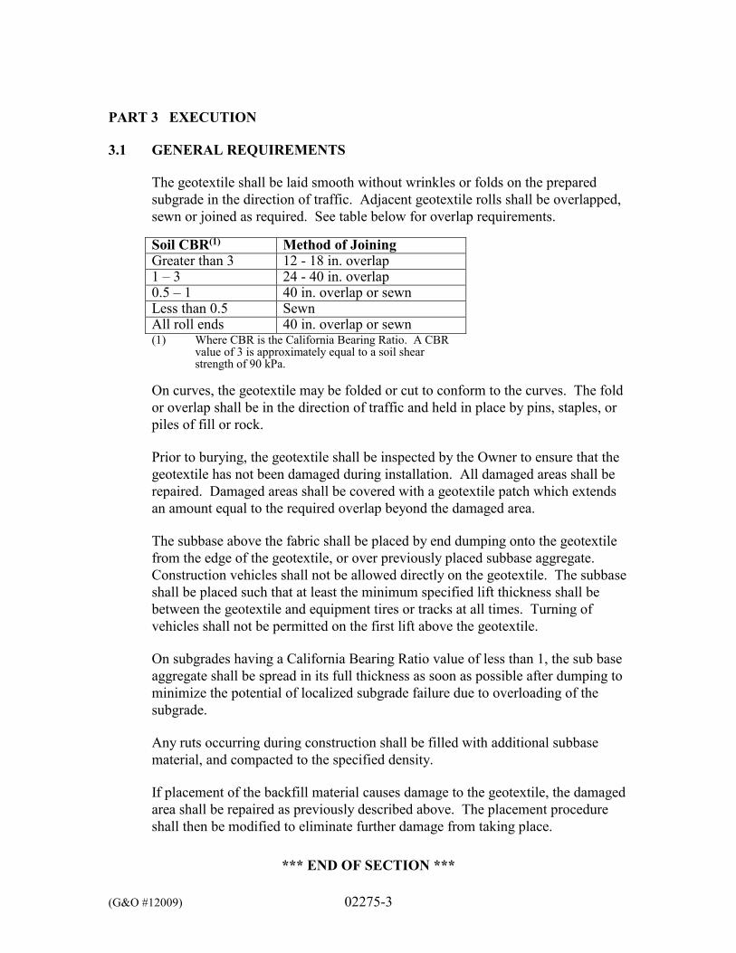
(G&O #12009) 02275-3
PART 3 EXECUTION 3.1 GENERAL REQUIREMENTS
The geotextile shall be laid smooth without wrinkles or folds on the prepared subgrade in the direction of traffic. Adjacent geotextile rolls shall be overlapped, sewn or joined as required. See table below for overlap requirements.
Soil CBR(1) Method of Joining Greater than 3 12 - 18 in. overlap 1 – 3 24 - 40 in. overlap 0.5 – 1 40 in. overlap or sewn Less than 0.5 Sewn All roll ends 40 in. overlap or sewn (1) Where CBR is the California Bearing Ratio. A CBR
value of 3 is approximately equal to a soil shear strength of 90 kPa.
On curves, the geotextile may be folded or cut to conform to the curves. The fold or overlap shall be in the direction of traffic and held in place by pins, staples, or piles of fill or rock. Prior to burying, the geotextile shall be inspected by the Owner to ensure that the geotextile has not been damaged during installation. All damaged areas shall be repaired. Damaged areas shall be covered with a geotextile patch which extends an amount equal to the required overlap beyond the damaged area. The subbase above the fabric shall be placed by end dumping onto the geotextile from the edge of the geotextile, or over previously placed subbase aggregate. Construction vehicles shall not be allowed directly on the geotextile. The subbase shall be placed such that at least the minimum specified lift thickness shall be between the geotextile and equipment tires or tracks at all times. Turning of vehicles shall not be permitted on the first lift above the geotextile. On subgrades having a California Bearing Ratio value of less than 1, the sub base aggregate shall be spread in its full thickness as soon as possible after dumping to minimize the potential of localized subgrade failure due to overloading of the subgrade. Any ruts occurring during construction shall be filled with additional subbase material, and compacted to the specified density. If placement of the backfill material causes damage to the geotextile, the damaged area shall be repaired as previously described above. The placement procedure shall then be modified to eliminate further damage from taking place.
*** END OF SECTION ***
(G&O #12009) 02300-1
SECTION 02300
EARTHWORK
PART 1 GENERAL 1.1 SCOPE
The work specified in this Section includes the earthwork, including trench excavation and backfill for piping, excavation and backfill for structures, and finish grading.
1.2 RELATED WORK SPECIFIED ELSEWHERE
Section Item 01200 Measurement and Payment 01300 Submittals 01500 Temporary Facilities 02250 Temporary Shoring and Bracing 02370 Erosion Control 02510 Testing and Disinfection 02700 Gravel Materials
PART 2 PRODUCTS 2.1 GRAVEL MATERIALS
All gravel materials shall conform to Section 02700. PART 3 EXECUTION 3.1 PREPARATION
Excavation may commence once all erosion control measures are in place in accordance with the Plans and Section 02370 and to the satisfaction of the Owner.
3.2 GENERAL REQUIREMENTS
Excavation, compaction and backfill for structures, pipelines and the final site contours shall be formed by either excavating or compacting fill, as required, providing the elevations and/or cross-sections as shown on the Plans. Contractor shall limit the total disturbed area of the project to be less than 1 acre in size.
(G&O #12009) 02300-2
All excavation performed on this Project shall be considered unclassified. Excavation shall consist of the removal of any and all material encountered, including debris, rubble, concrete, metal, topsoil, cutting and removal of existing surfacing, tree stumps, trees, logs, abandoned rail ties, abandoned piping, piling, riprap, etc. Excavations shall be kept free of water, both surface water and groundwater, during the excavation, installation of pipelines and structures, and the placement of backfill. The Contractor’s attention is also called to the depth of the structures and piping; for this reason, special shoring and bracing may be required. All shoring and bracing or sheeting required to perform and protect the excavation and to safeguard the employees, shall be furnished by the Contractor. For additional requirements see Section 02250. No timber bracing, lagging, sheathing or other lumber shall be left in any excavation except with permission of the Engineer and in the event such permission is granted, no separate payment shall be allowed for burying such material. All stockpiles shall be covered with plastic and no stockpile shall be higher than 6 feet above existing grade.
3.3 ESTIMATED SITE EXCAVATION VOLUMES
SCHEDULE A (SYCAMORE RESERVOIR) The estimated volume of excavation for Schedule A is 45 cubic yards. This volume excludes that volume excavated for piping, valves and valve structures. SCHEDULE B (1,500,000 GALLON RESERVOIR) The estimated volume of excavation for Schedule B is 8,000 cubic yards. This volume excludes that volume excavated for lock block wall, piping, valves and valve structures. SCHEDULE C (900,000 GALLON RESERVOIR) The estimated volume of excavation for Schedule C is 5,500 cubic yards. This volume excludes that volume excavated for piping, valves and valve structures. Excavation and backfill for structures shall be in conformance with Section 2-09 of the WSDOT Standard Specifications, and as further described herein.
(G&O #12009) 02300-3
3.4 EXCAVATION AND BACKFILL FOR STRUCTURES
Excavation and backfill for structures shall be in conformance with Section 2-09 of the WSDOT Standard Specifications, and as further described herein. All excavation for structures shall be done to the dimensions and levels indicated on the Plans or specified herein. Excavation shall be made to such width outside the lines of the structures to be constructed as may be required for proper working methods, the erection of forms and the protection of the work. Excavation shall consist of the removal of any and all material encountered to the elevations shown on the Plans. Excavations for structures shall be continued down to the subgrade which is defined as 12 inches below concrete mat foundations, concrete footings, and slab on grade floors for the installation of foundation gravel material, unless otherwise noted on the Plans. Fill material placed under structures, including footings and floor slabs, shall be foundation gravel free from debris and organics, as specified in Section 02700. In the event unsuitable material is encountered below the subgrade shown on the Plans and described herein, the Contractor, as required by the Engineer, shall over-excavate until a suitable foundation is reached. If over-excavation of unsuitable material is required by the Engineer, it will be under the unit price bid item entitled “UNSUITABLE EXCAVATION,” as described in Section 01200. The Contractor shall then replace the material with compacted bank run gravel for trench backfill, as specified in Section 02700. If imported bank run gravel for trench backfill is required; it will be paid under the unit price bid item titled “BANK RUN GRAVEL FOR TRENCH BACKFILL,” as specified in Section 01200. Quantities, if any, shall be calculated by neat line measurement to the depth agreed to in the field by the Engineer. The Contractor shall notify the Engineer when excavation for compacted fill or structures is complete. No forms, reinforcing steel, or concrete shall be placed until the excavation has been inspected by the Engineer.
Backfill for structures shall be suitable native material, free of organics and particles greater than 4 inches or Gravel Backfill for Walls as specified in Section 02700. There is no warranty that the native material is suitable for backfill or is suitable, as excavated, for placement and compaction as required by these Specifications. In the event that the Contractor is unable to find onsite, sufficient native material to accomplish the structure backfilling, the select material that he shall furnish and install shall be Gravel Backfill for Walls, as specified in Section 02700.
(G&O #12009) 02300-4
3.5 PROTECTION OF FOUNDATION SURFACES
Care shall be taken to preserve the foundation surfaces shown on the Plans in an undisturbed condition. If the Contractor unnecessarily over excavates or disturbs the foundation surfaces shown on the Plans or specified herein without written authorization of the Engineer the Contractor shall replace such foundations with concrete fill or other suitable material approved by the Owner in a manner which will show by test an equal bearing capacity with the undisturbed foundation material. No additional payment shall be made for the added quantity of concrete fill or other suitable material used because of unnecessary over excavation caused by the Contractor or his operations.
3.6 EXCAVATION AND BACKFILL FOR TRENCHES
Excavation and backfill for trenches shall be in conformance with Sections 7-08 and 7-09 of the WSDOT Standard Specifications, and as further described herein. The following pipe materials shall be considered flexible:
PVC Polyethylene Tubing FRP HDPE Polyethylene Corrugated Polyethylene
All other pipe materials shall be considered rigid. Upon completion of work each day, all pipeline open trenches shall be completely backfilled, leveled, and temporarily patched or graveled, as herein specified. Under certain conditions, the trench may be left open at the last length of pipe laid during the day to avoid re-excavation the following morning, provided that the opening is adequately plated or covered for vehicle traffic. Special attention shall be given to barricading to keep vehicular traffic away from newly-backfilled trench areas until restored for traffic. The Engineer reserves the right to restrict the Contractor in the amount of trench for pipeline that can be opened during the working day. Should the Contractor, in the Engineer’s opinion, fail to diligently pursue backfilling, an allowable limit of open trench shall be 100 lineal feet and shall be strictly enforced. The width of the trench at or below a point 12 inches above the top of the outside diameter of the pipe shall be carefully controlled and maintained to ensure the strength of the pipe and prevent pipe failures. Backfilling shall proceed as follows:
(G&O #12009) 02300-5
A. SUBGRADE PREPARATION
The subgrade for piping is defined as the elevation of the bottom of the pipe bedding material as shown on the Plans. In the event unsuitable material is encountered below the subgrade shown on the Plans and described herein, the Contractor, as required by the Engineer, shall over-excavate until a suitable foundation is reached. If over-excavation of unsuitable material is required by the Engineer, it will be paid for under the unit price bid item entitled “UNSUITABLE EXCAVATION,” as found in the Proposal. The Contractor shall then replace the material with compacted foundation gravel, as specified in Section 02700. Imported foundation gravel is required, it will be paid under the unit price bid item titled “BANK RUN GRAVEL FOR TRENCH BACKFILL.” Quantities, if any, shall be calculated by neat line measurement to the depth agreed to in the field by the Engineer.
B. BEDDING FOR RIGID PIPE
Above the foundation material, if any, the bedding material shall be suitable native or Gravel Backfill for Pipe Bedding, as specified in Section 02700. This material shall be placed in lifts of approximately 8 inches up to a point 12 inches above the pipe. This material shall be hand shoveled in place and carefully worked under and around the pipe.
C. BEDDING FOR FLEXIBLE PIPE
Above the foundation material, if any, Gravel Backfill for pipe bedding, as specified in Section 02700, shall be placed in lifts of approximately 8 inches up to a point 12 inches above the pipe. This material shall be hand shoveled in place and carefully worked under and around the pipe.
D. BACKFILL FOR TRENCHES Partial backfill to protect the pipe will be permitted immediately after the pipe has been properly laid in accordance with the Plans and these Specifications. Complete backfilling of trenches will not be permitted until the section of pipe installed has been inspected by the Engineer. From the point 12 inches above the top of the pipe barrel, the backfill material to be used in the trench section shall be suitable native material or Bank Run Gravel, as specified in Section 02700, except where required or shown on the Plans to use other material. The Contractor shall place
(G&O #12009) 02300-6
backfill in horizontal lifts not to exceed 8 inches in thickness. All backfill shall be free of large rocks, organic matter, stumps, trees, pieces of pavement, broken concrete and other deleterious substances.
The Contractor shall remedy, at his expense, any defects that appear in the backfill prior to final acceptance of the work. Cleanup operations shall progress immediately behind backfilling to accommodate the return to normal use of the trench area. During placement of the initial lifts, the backfill material shall not be bulldozed into the trench or dropped directly over the pipe with less than 3 feet of backfill material above the top of the pipe.
3.7 ROCK EXCAVATION It is not anticipated that solid rock will be encountered. Should such material be
encountered, however, it will be paid for change order as directed by the Engineer and approved by the Owner. Boulders or broken rock less than 2 cubic yards in volume as measured in the field by the Engineer, will not be classified as rock, nor will so-called “hard-pan” or cemented gravel, even though it may be advantageous to use explosives in its removal if blasting were allowed. For the purpose of this contract, rock excavation shall be defined as mineral matter in place and of such hardness and texture that, when it is encountered, cannot be loosened by three passes of a ripper tooth mounted on the larger of a tracked backhoe of at least 25,000 pounds operating weight and 75 horsepower or the largest backhoe being utilized on the job by the Contractor. Where rocks occur as boulders that are smaller than the larger of: (1) 2 cubic yards in volume, or (2) the volume that can be readily handled by the largest backhoe being utilized on the job by the Contractor, they shall be considered incidental to excavation.
Where removal of a boulder results in a void below the desired elevation of the intended excavation, backfilling of the void shall be handled in the same manner as the replacement of unsuitable excavated material.
3.8 REUSE AND DISPOSAL OF EXCAVATED MATERIAL
Excavated materials shall be properly protected and reused where possible. Excavated materials not used for fill shall be hauled to an approved waste site(s), as selected by the Contractor. The Contractor shall submit a list of approved waste haul site(s) to the Owner prior to the commencement of hauling of waste materials. Any permits required for waste haul and disposal shall be the responsibility of the Contractor.
(G&O #12009) 02300-7
3.9 FINAL SITE GRADING
The site shall be graded consistent with the elevations shown on the Plans. The slopes between elevations shall be uniform or as shown on the Plans. Excavations and backfill shall be to the elevations required for the placement of all surface restorations, such as asphalt, concrete, gravel surfacing, or landscaping. All areas shall be graded to provide proper drainage. The final ground surface shall be smooth, raked free of debris and stones.
3.10 STRUCTURE COMPACTION
The foundation gravel material placed underneath all structures shall be moisture conditioned to within 3 percent of optimum moisture content and shall be placed in loose, horizontal layers. The thickness of layers placed before compaction shall not exceed 8 inches for heavy equipment compactors and shall not exceed 4 inches for hand-operated mechanical compactors. Water settlement is not allowed for compaction.
Layers shall be compacted to a dense state equaling at least 95 percent of the maximum dry density, using the Modified Proctor, per ASTM D1557. Prior to the placement of fill below structures, any and all groundwater and surface water shall be drained or pumped from areas to be filled.
Wall backfill material shall be compacted to at least 90 percent of the maximum dry density, using the Modified Proctor, per ASTM D1557 within 5 feet of all walls and shall be compacted to at least 95 percent of the maximum dry density, using the Modified Proctor, per ASTM D1557 beyond 5 feet of all walls. Any and all compaction within 5 feet of all walls shall be accomplished by means of hand-operated mechanical equipment rather than heavy equipment compactors.
3.11 TRENCH COMPACTION
Trench backfill materials shall be moisture conditions to within three percent of optimum moisture content. Water settlement is not allowed for compaction. Pipe bedding materials, for both rigid and flexible pipes, shall be compacted to at least 95 percent of the maximum dry density, using the Modified Proctor, per ASTM D1557. Compaction of the backfill above the bedding material in all trenches in non-structural and non-paved areas shall be performed by using mechanical equipment to at least 90 percent of the maximum dry density, using the Modified Proctor, per ASTM D1557.

(G&O #12009) 02300-8
Compaction of the backfill above the bedding material in all trenches in structural or paved areas shall be performed by using mechanical equipment to at least 95 percent of the maximum dry density, using the Modified Proctor, per ASTM D1557.
*** END OF SECTION ***
(G&O #12009) 02370-1
SECTION 02370
EROSION CONTROL
PART 1 GENERAL 1.1 SCOPE
The work specified in this Section includes the temporary erosion and sedimentation control (TESC) in and around the site caused by the actions of the Contractor as shown on the Plans and as specified herein. Work under this Section shall be directed towards site areas disturbed during construction as well as all off-site storage and parking areas maintained by the Contractor.
1.2 RELATED WORK SPECIFIED ELSEWHERE
Section Item 01160 Regulatory Requirements 01200 Measurement and Payment 01300 Submittals 02300 Earthwork
1.3 CERTIFIED EROSION AND SEDIMENT CONTROL LEAD (CESCL)
The Contractor shall designate a Certified Erosion and Sediment Control Lead (CESCL) for this project. The CESCL shall have, for the life of this Contract, a current Certificate of Training in Construction Site Erosion and Spill Control signed by the WSDOT Water Quality Program Manager. Duties of the CESCL shall include, but are not limited to: A. Inspecting temporary erosion and spill control Best Management Practice
(BMPs) for proper location, installation, maintenance, and repair. Inspections shall be made as noted on the Plans and after each significant precipitation event, including those that occur during weekends and after working hours. A Temporary Erosion and Spill Control Inspection Report shall be prepared for each inspection and shall be included in the Temporary Erosion and Spill Control file. The inspection report shall include, but not be limited to:
1. When BMPs are installed, removed or changed;
(G&O #12009) 02370-2
2. Repairs needed or made;
3. Turbidity monitoring results;
4. Observations of BMP effectiveness and proper placement;
5. Recommendations for improving performance of BMPs.
B. Prepare and maintain a Temporary Erosion and Spill Control file on site that includes but is not limited to:
1. Temporary Erosion and Spill Control Inspection Reports;
2. Contractor’s Stormwater Pollution Prevention Plan (SWPPP);
3. Spill Prevention, Control, and Countermeasures (SPCC) Plan;
4. All project permits, including but not limited to grading permits
and Hydraulics Project Approval;
5. Manufacturer instructions for all products used for TESC BMPs;
6. Washington State Department of Ecology’s Stormwater Management Manual for Eastern Washington, Chapter 7.
1.4 STORMWATER POLLUTION PREVENTION PLAN
The CESCL Contractor shall be responsible for preparing a Stormwater Pollution Prevention Plan (SWPPP). The intent of the SWPPP is to reflect the Contractor’s operations by supplementing the TESC Drawings, details, and notes shown on the Plans to provide comprehensive pollution control at the construction site, staging areas, stockpiles, and borrow sites. The SWPPP shall be prepared by the CESCL for the project and submittal in accordance with Section 01300. The SWPPP shall be submitted to the Owner for approval at the preconstruction conference. No work shall begin until the Contractor’s SWPPP, as approved by the Owner, is implemented. The SWPPP shall address, at least, the following items: Identification of construction haul routes and location of BMPs (e.g.,
stabilized construction entrance, silt fences, storm drain inlet protection).
Waste disposal methods and locations.
(G&O #12009) 02370-3
Detailed construction sequence and schedule, including identifying dates scheduled for BMP installation, removal, clearing, grading, seeding, and landscaping.
Details for any temporary flow diversions, dewatering systems, and BMPs
(in accordance with the current edition of the Washington State Department of Ecology’s Stormwater Management Manual for Western Washington) proposed by the Contractor.
Calculations for temporary sedimentation ponds, if used A list of products to be used, including Material Safety Data Sheets. Identification of stockpile and staging areas, and BMPs to be implemented
at these locations.
The SWPPP shall be prepared in accordance with details shown on the Plans, these Specifications, and Chapter 7– BMPs from the current edition of the Washington State Department of Ecology’s Stormwater Management Manual for Eastern Washington, which are hereby referenced and made a part of the Contract Documents. Only those sections of the Stormwater Management Manual for Western Washington that address preparation, implementation, and maintenance of permanent and temporary erosion and sedimentation control BMPs are applicable. The SWPP shall include best management practices to control windblown dust.
PART 2 PRODUCTS 2.1 SILT FENCES
Silt fences shall conform to the details shown on the Plans and the fabric shall conform to the following properties:
Property Test Method Result Polymeric Mesh AOS ASTM D4751 0.6 mm max. for slit film wovens (#30
sieve). 0.3 mm max. for all other geotextile types (#50 sieve). 0.15 mm for all fabric types (#100 sieve).
(G&O #12009) 02370-4
Property Test Method Result Water Permittivity ASTM D4491 0.02 sec-1 min. Grab Tensile Strength ASTM D4632 180 lbs. min. for extra strength fabric
100 lbs min. for standard strength fabric
Grab Tensile Elongation ASTM D4632 30% max. UV Resistance ASTM D4355 70% min.
2.2 STRAW BALES
Straw bale dams shall conform to the details shown on the Plans. 2.3 STORM DRAIN INLET (CATCH BASIN) PROTECTION
Storm drain inlet protection shall be with a “silt sack,” as manufactured by ACF Environmental or equal.
PART 3 EXECUTION 3.1 PREPARATION
Site preparation work shall be performed only during periods when beneficial results can be obtained. When drought, excessive moisture or other unsatisfactory conditions prevail, the work shall be stopped.
3.2 BEST MANAGEMENT PRACTICES (BMPS)
Silt fences and straw bale dams shall be constructed to control erosion and migration of soils disturbed during construction. The fences and dams shall provide temporary protection and shall be removed only upon approval of the Owner.
All areas or drainage ways downstream of the construction site shall have Best Management Practices (BMPs) installed prior to the beginning of any clearing activities. Runoff from cleared or disturbed area shall be directed through the BMPs. Disturbed ground shall be stabilized at the end of each work day. Permanent soil stabilization and erosion and sedimentation control shall be implemented upon reaching finish grade. Slope protection shall be immediately
(G&O #12009) 02370-5
implemented upon any soils showing signs of erosion. This shall be done in a manner approved by the Owner.
All BMPs shall be inspected, maintained and kept in a condition sufficient to provide effective erosion and sedimentation control at all times. The site shall be inspected to ensure the BMPs are properly located, constructed and operating as designed during the first storm. Any necessary adjustments or repairs shall be made immediately and be approved by the Owner. The BMPs shall be inspected thereafter and after all significant storm events. Turbidity monitoring will be held on a weekly basis at a minimum, or more frequently if necessary as determined by the CESCL.
All BMPs shall be removed no later than 30 consecutive calendar days after final site stabilization has been achieved as determined by the Owner. BMPs such as storm drain inlet protection, straw bales, silt fences and supports and plastic coverings shall be removed and properly disposed of offsite by the Contractor. Areas disturbed by removal of these BMPs shall be immediately stabilized in a manner approved by the Owner.
*** END OF SECTION ***
(G&O #12009) 02510-1
SECTION 02510
TESTING AND DISINFECTION PART 1 GENERAL 1.1 SCOPE
The work specified in this Section includes disinfection of potable water piping, distribution mains, filter basins, and structures; testing; and reporting results.
1.2 RELATED WORK SPECIFIED ELSEWHERE
Section Item Division 15 Mechanical
1.3 REFERENCES
A. AWWA B300 - Standard for Hypochlorites.
B. AWWA B301 - Standard for Liquid Chlorine.
C. AWWA B302 - Standard for Ammonium Sulfate.
D. AWWA B303 - Standard for Sodium Chlorite.
E. AWWA C651 - Standards for Disinfecting Water Mains. 1.4 SUBMITTALS
A. TEST REPORTS Indicate results comparative to specified requirements.
1.5 PROJECT RECORD DOCUMENTS
A. Submit under provisions of Section 01300.
B. DISINFECTION REPORT; RECORD
1. Type and form of disinfectant used.
2. Date and time of disinfectant injection start and time of completion.
(G&O #12009) 02510-2
3. Test locations.
4. Initial and 24-hour disinfectant residuals (quantity in treated water) in ppm for each outlet tested.
5. Date and time of flushing start and completion.
6. Disinfectant residual after flushing in ppm for each outlet tested.
C. BACTERIOLOGICAL REPORT; RECORD
1. Date issued, project name, and testing laboratory name, address,
and telephone number.
2. Time and date of water sample collection.
3. Name of person collecting samples.
4. Test locations.
5. Initial and 24-hour disinfectant residuals in ppm for each outlet tested.
6. Coliform bacteria test results for each outlet tested.
7. Certification that water conforms, or fails to conform, to bacterial
standards of the Department of Health.
8. Bacteriologist’s signature and authority. 1.6 QUALITY ASSURANCE
Perform Work in accordance with AWWA C651. 1.7 REGULATORY REQUIREMENTS
A. Conform to Department of Health code or regulation for performing the work of this Section.
B. Provide certificate of compliance from Department of Health indicating
approval of water system.
(G&O #12009) 02510-3
1.8 PAYMENT
No separate or additional payment shall be made for testing and disinfection, as shown on the Plans and as specified herein, shall be considered incidental to the work and merged into various unit price and lump sum bid items.
PART 2 PRODUCTS 2.1 DISINFECTION CHEMICALS
Chemicals: AWWA B300, Hypochlorite, AWWA B301, Liquid Chlorine, AWWA B302, Ammonium Sulfate, and AWWA B303, Sodium Chlorite.
PART 3 EXECUTION 3.1 EXAMINATION
A. Verify that piping system has been cleaned, inspected, and pressure tested.
B. Perform scheduling and disinfection activity prior to startup, testing, adjusting and balancing, demonstration procedures, including coordination with related systems.
3.2 WATER PIPE DISINFECTION
A. Provide and attach required equipment to perform the work of this Section.
B. Inject treatment disinfectant into piping system.
C. Maintain disinfectant in system for 24 hours.
D. Replace permanent system devices removed for disinfection.
E. Water for disinfection must be obtained by the Contractor by arrangement
with the Owner. The following describe specific procedures to be used by the Contractor in maintaining a satisfactory environment for prevention of contamination of the proposed water system installation, the cleanliness of the pipe and fittings and the actual method of disinfection.
F. When the line is completed and ready to disinfect, water shall be allowed
to flow in slowly, until it appears at the far end of the line so as not to displace the disinfecting agent. The system shall then be allowed to stand for at least 24 hours. The line shall then be flushed through the drain
(G&O #12009) 02510-4
stations until a test shows no more than 0.2 parts per million of available chlorine more than what is in the water supply system.
G. In all instances, the Contractor shall utilize a state approved double check
valve type backflow prevention device to protect the potable water supply while filling, flushing and disinfecting the particular water main.
H. Where connections are made to existing facilities and it is impractical to
use the methods described herein to disinfect the section between the existing water main and the point of isolation of the new water main (valve or temporarily plugged line) or where pipes and fittings require immediate use, cleaning and disinfecting shall be directed by the Owner.
I. The Contractor is herein advised that prior to making any restorations or
permanent connections to the existing water mains, that the Contractor shall first demonstrate to the Owner, that the new water main has adequately passed a pressure test, been adequately flushed, and finally passed the required bacteriological test.
J. In all disinfection processes, the Contractor shall take particular care in
flushing and wasting the chlorinated water from the mains to assure that the flushed and chlorinated water does no physical or environmental damage to property, streams, storm sewers or any waterways. The Contractor shall chemically or otherwise treat the chlorinated water to prevent damage to the effected environment, particularly aquatic and fish life of receiving streams. The method and the time of flushing is to be approved by the Owner.
K. Before placing the lines in service, satisfactory results must be obtained on
samples collected from representative points in the new system and submitted to a State DOH approved laboratory. The Owner shall collect all samples for the bacteriological tests. However, the Contractor shall notify the Owner for collection of samples two days in advance, and schedule on days wherein samples can be conveniently processed by State DOH approved laboratory. If any of the pipeline materials are replaced thereafter, then that section shall again be disinfected and tested for bacteriological count. The owner shall collect two consecutive sets of acceptable samples before the new water main is placed in service. Each set shall include as a minimum of least one sample from every 1200-feet of the new water main, plus one sample from the end of the line, and at least one sample from each branch. The first set of samples shall be collected at least 24-hours after flushing, and the second set of samples shall be collected at least 48-hours after flushing.
(G&O #12009) 02510-5
If disinfection of mains by the above methods, prove unsatisfactory and the lab report indicates any type of bacteria count, then the Owner may direct the Contractor to use one of the following two disinfection methods until a satisfactory report is obtained. No additional compensation will be made to the Contractor for any work necessary to achieve a satisfactory bacteriological test result.
L. METHOD NO. 1
A chlorine gas-water mixture, or dry chlorine gas may be applied by means of a chlorinator, or the gas may be fed indirectly from a chlorine cylinder equipped with the proper devices for regulating the flow, and the effective diffusion of gas within the pipe. (Use of the chlorinator is preferred to direct feed from the cylinder.) 1. Point of Application
The preferable point of application for the chlorinating agent is at the beginning of the pipeline extension, or any valved section thereof, and through a corporation cock inserted in the horizontal axis of the pipe may be supplied from a tap on the pressure side of the gate valve controlling the flow into the pipeline extension.
2. Rate of Application
Water from the existing distribution system, or other source of supply, shall be controlled to flow very slowly into the newly laid pipeline during application of the chlorine. The rate chlorine gas-water mixture or dry gas feed shall be in such proportion to the rate of water entering the newly laid pipe that the dose applied to the water entering the newly laid pipe will be at least 50 parts per million. A color comparator set shall be used to determine chlorine residual.
3. Cross-Connection Prevention
A cross-connection control device (DOH approved) shall be utilized to prevent potential cross-connections.
4. Retention Period
Treated water shall be retained in the pipe at least 24 hours. After this period, the chlorine residual at pipe extremities and at other representative points shall be at least 5 parts per million.
(G&O #12009) 02510-6
5. Chlorinating Valves and Hydrants
In the process of chlorinating newly laid water pipe, all valves or other appurtenances shall be operated while the pipeline is filled with the chlorinating agent.
6. Final Flushing and Chlorine Residual Test
Following chlorination, all treated water shall be thoroughly flushed from the newly laid pipe at its extremity until the replacement water throughout its length, upon test, shows the absence of chlorine (or in the event chlorine is normally used in the source of supply, then the tests shall show a residual not in excess of that carried by the system). A state-approved bacteriological test shall then be conducted.
7. Repetition of Procedure
Should the initial treatment prove ineffective, the chlorination procedure shall be repeated until tests show that the water sample from the newly laid pipe conforms to the requirements of these Specifications.
M. METHOD NO. 2
1. Calcium or Sodium Hypochlorite or Chlorinated Lime in Water
A mixture of either calcium or sodium hypochlorite or chlorinated lime of known chlorine content and water may be substituted as an alternative for liquid chlorine. (Typical commercial products of this type are Perchloron, Chlor, Purex, etc.)
2. Proportions of Chlorine Compound and Water Mixtures
Prepare a solution containing approximately 5 percent available chlorine by weight. In the case of Perchloron, at 70 percent available chlorine, use 6 pounds per 10 gallons of water. In the case of Chlor, at 15 percent available chlorine, add 2 parts water to 1 part of Chlor. For other strength compounds, adjust the dilution accordingly.
3. Preparation and Application of Chlorine Compound
(G&O #12009) 02510-7
To prepare the chlorine compound-mixture, first make a paste, and then thin to a slurry to ensure getting all active ingredients into solution. The prepared solution shall be injected by means of a hypochlorinator, or hand or engine operated pump. Pumping into the newly laid pipe shall follow the conditions outlined under Method No. 1 for chlorine applications to provide a residual of 50 ppm. See Item Nos. (a) to (3) inclusive under Method No. 1. For solutions containing approximately 5 percent available chlorine, the rate of bleeding the main to be sterilized should be 1,000 times the rate of feed or injection of the chlorine solution.
4. Further Procedure
Provisions for final flushing and bacteriological testing under this alternative should be the same as those described in Item Nos. (L) under Method No. 1 above.
3.3 QUALITY CONTROL
Samples shall be taken and tested in accordance with AWWA C651.
***END OF SECTION***
(G&O #12009) 02511-1
SECTION 02511
CONNECTION TO EXISTING SYSTEM PART 1 GENERAL 1.1 SCOPE
The work specified in this Section includes the connection of pipelines being constructed under this project to existing water mains as shown on the Plans and as specified herein.
1.2 RELATED WORK SPECIFIED ELSEWHERE
Section Item 01200 Measurement and Payment Division 15 Mechanical
PART 2 PRODUCTS
Not used. PART 3 EXECUTION
All cut-in connections to the existing system shall be made after a successful pressure test of the new main has been witnessed by the Owner and after a purity test has been satisfactorily evidenced except as allowed by the Owner.
The location, type and size of existing facilities have been determined from available records and are approximate. It is anticipated that connections to these existing facilities may be made, in general, as shown on the Plans except adjustments may be required for vertical and horizontal alignment.
It shall be the responsibility of the Contractor to determine the exact location and ascertain the type and size of the existing facilities prior to starting work on each connection and to provide any alternations as required in the connection detail.
Connections to existing facilities shall be made with the use of fittings, valves, flexible couplings, solid sleeves, shackling and other miscellaneous fittings, and thrust blocks as shown on the or with additional pipe or fittings as approved by the Owner and as indicated in Piping Systems to connect the new construction under this Project to the existing pipelines.
(G&O #12009) 02511-2
All pipe and fittings used for the connection shall be clean and disinfected with a minimum 5 percent chlorinated solution immediately prior to making said connection. The Contractor shall take extra precautions to ensure the tightness of the connections, nuts, and bolts. The existing water main shall be placed back into service by the Owner and the connection observed by the Owner prior to backfilling the pipe.
All valves shall be operated by Owner personnel only. Where it is necessary to shut off the existing mains to make a connection, the Contractor shall notify the Owner and all water customers affected 48 hours in advance of such shut off, and the Owner will shut off the mains. Once the water has been shut off, the Contractor shall diligently pursue the connection to completion so that the time required for the shut off is held to a minimum.
All connections to existing mains shall be completed the same day as they are started. The Contractor shall time its operations so that the water will not be shut off overnight or over weekends or during holidays.
*** END OF SECTION ***
(G&O #12009) 02530-1
SECTION 02530
UTILITY STRUCTURES PART 1 GENERAL 1.1 SCOPE
The work specified in this Section includes precast concrete vaults, manholes, catch basins, castings, and steps for a complete installation as shown on the Plans and specified herein.
1.2 RELATED WORK SPECIFIED ELSEWHERE
Section Item 01200 Measurement and Payment 01300 Submittals 02300 Earthwork 02832 Segmental Concrete Retaining Walls 08310 Metal Access Hatches
PART 2 PRODUCTS 2.1 GENERAL
The exterior finish of all precast concrete utility structures shall be smooth with no imperfections larger than 1/8 inch in diameter. The interior finish of all precast concrete utility structures shall be smooth and sacked with non-shrink cementatious materials and epoxy bonding agent. No bug holes, fins, projections, or other defects are acceptable.
2.2 PRECAST VAULTS
Precast concrete vaults shall be cast in an established precast yard. Precast vaults shall be designed for H-20 loads. Submit design calculations and shop drawings for review and approval prior to fabrication. Shop drawings shall detail wall thickness, concrete strength, reinforcing requirements, and shall include all appurtenances, such as access hatches, floor drains, and other items called for on the Plans. All vaults shall be constructed with a minimum of 4-inch thick solid walls. The access hatches shall be as specified in Section 08310.
(G&O #12009) 02530-2
2.3 PRECAST CONCRETE MANHOLES
Precast components shall conform to the requirements of ASTM C478. All Portland cement used in the manufacture of the precast sections shall conform to the requirements of ASTM C150 and shall be Type II or Type V.
Precast base sections shall conform to the requirements for precast riser sections. The base shall be a minimum of 6-inches thick underneath the pipe invert. Openings for pipe shall be circular, tapered toward the inside of the section, and shall be of the minimum size possible to accommodate the size of pipe to be inserted and to effectively seal the joint.
Standard precast riser sections shall consist of circular sections in standard nominal inside diameter as shown on the Plans. Reinforcement shall be in accordance with ASTM C478. Minimum height of a riser section shall be 1 foot. The height of riser and base sections shall be arranged so no pipes pass through the joining surfaces.
The taper section (cone) shall be eccentric, tapering to 24-inches inside diameter and shall be between 18-inches and 36-inches high. Joining to the riser sections shall be similar to joining between riser sections, but the top surface shall be flat and at least 5 inches wide, radially, to receive grade rings.
Grade rings above the taper section shall be 24-inches inside diameter and 4-inches high. Grade ring height shall be a minimum of 8 inches, with a maximum of 20 inches. Otherwise another section of manhole rings shall be installed.
2.4 RINGS AND COVERS
Castings for manhole rings shall be gray-iron conforming to the requirements of ASTM A48/AASHTO M105, Grade 30B. Covers shall be ductile iron conforming to ASTM A536, Grade 80-55-06. All rings and covers shall be of uniform quality, free from blowholes, porosity, shrinkage, distortion, cracks, or other defects. Repair of defects shall not be permitted. All mating surfaces shall be machined finished to ensure a nonrocking fit. All covers shall be interchangeable within the dimensions as shown on the Plans and marked “sewer,” “drain,” or “water” as appropriate. Locking/tamperproof covers shall be secured to the ring with three 5/8-inch stainless steel Allen head cap screws. When watertight covers are required the locking style ring and covers shall be used and include a machined groove in the seat of the ring or underside of the cover and a gasket installed to assure a watertight seal. Covers shall be without pickholes. The manufacturer’s identification shall be cast with a minimum of
(G&O #12009) 02530-3
1/2-inch letters on exposed surfaces. Manhole rings and covers shall have a design wheel load conforming to AASHTO/ASTM A16 design loading HS20-44.
The frames and covers shall be made by Olympic Foundry, Inc., D&L Foundry, East Jordan Iron Works, or Neenah.
2.5 STEPS
Polypropylene manhole steps shall be made of a copolymer polypropylene, superior in its resistance to corrosion, meeting the requirements of ASTM 2146 Type II, Grade 16906, and shall completely encapsulate a deformed 1/2-inch steel reinforcing rod conforming to ASTM A615, Grade 60. Polypropylene steps shall be factory installed in complete accordance with the manufacturer’s instructions. This shall be accomplished by predrilling two parallel 1-inch holes, 3-3/4-inch deep, and 13 inches on center in the cured concrete base, riser, and taper sections of the manhole. The insertion ends of the step shall be fully coated with non-shrink epoxy grout then driven into the holes to the prescribed depth. In no case will the predrilled hole be allowed to penetrate through the wall of the manhole section.
Steps shall be Lane International Corporation Manhole Step or equal.
PART 3 EXECUTION 3.1 MANHOLES
Manhole installation shall be as shown on the Plans. Precast sections with damaged joint surfaces or with cracks or damage that would permit infiltration shall not be installed. Precast base sections shall be set on prepared bedding materials. Before the precast base is set in place, the bedding material shall be carefully leveled to provide full bearing for the entire base section. Precast riser sections and cones shall be set using the specified joint sealant or gasket. Priming and preparation of surfaces and installation of jointing material shall be in strict conformance with the manufacturer’s instructions. Only one 12-inch-high riser section shall be used per manhole and it shall be placed immediately below the cone. Grade rings shall be set in a full bed of cement grout. All pipe connections to manholes shall be made with manhole adaptors. Manhole frames shall be set carefully to the established surface grade in a full bed of cement grout. The manhole rim elevation shall be set flush with the existing pavement or grade in paved and improved areas. In unimproved areas, manhole
(G&O #12009) 02530-4
rim elevations shall be set 2 inches above grade unless otherwise shown on the Plans to be set higher. After placement, channel decks shall be given a light broom finish and shall be sloped to drain into the channels. Patch all lifters after removed picking eyes. Patch all joints inside and outside flush with walls. Steps shall be installed in base sections, riser sections and tapered sections so that the completed manhole will have a continuous vertical ladder with equally spaced rungs as shown on the Plans. Steps shall be firmly cast or grouted in place. Infiltration from or around steps will not be permitted. Pipe connections to existing manholes or vaults shall be in accordance with Section 7-05.3(3) of the WSDOT Standard Specifications and as further shown on the Plans.
3.2 PRECAST VAULTS
Precast vaults shall be installed as shown on the Plans and in accordance with the manufacturer’s recommendations.
3.3 FINAL ADJUSTMENT AND CLEANUP
After installation is complete, the Contractor shall cleanout all precast structures prior to placing the new facilities into service. The adjustment of castings shall be done in a manner satisfactory to the Owner. Adjustment shall be done only with precast grade rings. Bricks are unacceptable. Grouting and final adjustment of castings shall be done with non-shrink grout.
*** END OF SECTION ***
(G&O #12009) 02700-1
SECTION 02700
GRAVEL MATERIALS PART 1 GENERAL 1.1 SCOPE
The work specified in this Section includes the various types of granular materials that are to be used in trenches and other excavations as shown on the Plans and as specified herein.
1.2 RELATED WORK SPECIFIED ELSEWHERE
Section Item 01200 Measurement and Payment 01300 Submittals 02300 Earthwork 02710 Gravel Surfacing
1.3 SUBMITTALS
The Contractor shall provide certificates of laboratory tests in accordance with Section 01300, indicating particle size distribution for review for each type of granular material furnished and proctor test reports for all material to be placed as pipe bedding material, trench backfill, backfill under and around structures and underneath crushed surfacing and asphalt concrete pavements. The certificates and proctor test reports shall be provided to the Owner at least 5 calendar days prior to placement.
PART 2 PRODUCTS 2.1 FOUNDATION GRAVEL
Foundation gravel shall be Class A Gravel Backfill for Foundations in conformance with Section 9-03.12(1)A of the WSDOT Standard Specifications.
2.2 GRAVEL BACKFILL FOR PIPE BEDDING
Gravel backfill for pipe bedding shall meet the requirements of Section 9-03.12(3) of the WSDOT Standard Specifications except that no more than 5 percent passing shall pass the No. 200 Sieve.
(G&O #12009) 02700-2
Native granular material shall not be utilized for gravel backfill for pipe bedding.
2.3 STRUCTURAL FILL
Structural fill shall consist of clean, non-plastic, free-draining sand and crushed rock, free from organic matter or other deleterious materials, in conformance with crushed surfacing base course in Section 9-03.9(3) of the WSDOT Standard Specifications. During period of wet weather the allowable fines content of the structural fill materials shall be no more than 5 percent passing the U.S. Standard No. 200 size sieve.
2.4 BANK RUN GRAVEL FOR TRENCH BACKFILL
Bank run gravel for trench backfill shall be free from organic matter or other deleterious materials and in conformance with Section 9-03.19 of the WSDOT Standard Specifications.
2.5 GRAVEL BACKFILL FOR WALLS
Gravel backfill for walls shall conform to Section 9-03.12(2) of the WSDOT Standard Specifications.
2.6 PERMEABLE BALLAST
Permeable ballast shall conform to Section 9-03.9(2) of the WSDOT Standard Specifications.
2.7 CRUSHED SURFACING
Crushed surfacing base course and top course shall conform to Section 9-03.9(3) of the WSDOT Standard Specifications.
2.8 MISCELLANEOUS GRAVEL
If the Plans call for a gravel that is not herein specified than the gravel shall conform to the type of gravel called for as per the WSDOT Specifications.
(G&O #12009) 02700-3
PART 3 EXECUTION 3.1 FOUNDATION GRAVEL
Foundation gravel shall be placed and compacted underneath all structures to a minimum depth of 12 inches unless indicated otherwise on the Plans, and to a greater depth where foundations are unstable and excess suitable excavated material is unavailable to stabilize such foundations. In the event the Contractor unnecessarily overexcavates the pipe trench or structure foundation, or if the width of the pipe trench becomes wider than the pay limit shown on the Plans, all material so placed shall be at the Contractor’s sole expense.
3.2 GRAVEL BACKFILL FOR PIPE BEDDING
Bedding material shall be placed simultaneously on both sides of the pipe for the full width of the trench in lifts not exceeding 6 inches. To assure uniform support, the material shall be carefully worked underneath the pipe haunches with a tool capable of preventing the formation of void spaces around the pipe. In the event the Contractor overexcavates the pipe trench, or if the width of the pipe trench becomes wider than the pay limit shown on the Plans, all material so placed shall be at the Contractor’s sole expense.
3.3 STRUCTURAL FILL
Provide structural fill as shown on the Plans or where excavated material is unsuitable as directed by the Engineer. Structural fill shall be installed in lifts not to exceed 8 to 10 inches maximum thickness. Structural fill placed under structures shall be compacted to at least 95 percent of the maximum dry density as determined by the modified Proctor, per ASTM D1557.
3.4 BANK RUN GRAVEL FOR TRENCH BACKFILL
Bank run gravel for trench backfill shall be used where excavated material is unsuitable or unavailable for the backfill of trenches as approved by the Owner. In the event the Contractor overexcavates the pipe trench, or if the width of the pipe trench becomes wider than the pay limit shown on the Plans, all material so placed shall be at the Contractor’s sole expense.
(G&O #12009) 02700-4
3.5 GRAVEL BACKFILL FOR WALLS
Gravel backfill for walls shall be used where excavated materials are unsuitable for backfilling around the walls of structures, as approved by the Owner, as shown on the Plans and specified in these specifications.
3.6 PERMEABLE BALLAST
Permeable ballast shall be placed to the lines and grades shown on the Plans or as required by the Plans and shall be lightly rolled in place.
3.7 CRUSHED SURFACING
Crushed surfacing base course and/or top course shall be placed underneath asphalt paving, to the lines and grades shown on the Plans or as required by the Plans and shall be compacted to a dense, unyielding state of at least 95 percent of the maximum dry density, using the modified Proctor, per ASTM D1557.
3.8 MISCELLANEOUS GRAVEL
Miscellaneous gravel shall be installed per the Plans.
*** END OF SECTION ***
(G&O #12009) 02710-1
SECTION 02710
GRAVEL SURFACING PART 1 GENERAL
1.1 SCOPE
The work specified in this Section includes the installation of gravel materials and permeable ballast. It is intended that the majority of the new surfaced areas be constructed with less than a 0.5 percent slope in order to encourage onsite water infiltration into the ground surface.
1.2 RELATED WORK SPECIFIED ELSEWHERE
Section Item 01200 Measurement and Payment 01300 Submittals 02300 Earthwork 02700 Gravel Materials
1.3 SUBMITTALS
The Contractor shall provide the Owner with a certificate of laboratory test indicating gradation of each material provided in accordance with Section 01300. The certificate shall be provided to the Owner 5 days prior to placement of any materials.
PART 2 PRODUCTS
2.1 GRAVEL MATERIALS
All gravel materials shall conform to the requirement of Section 02700. PART 3 EXECUTION
3.1 SUBGRADE PREPARATION
The subgrade shall be prepared as per Section 2-06.3 of the WSDOT Standard Specifications except that the level of desired compaction indicated in 2-06.3(1).6 shall be 90 percent. As the rolling of the subgrade proceeds, all soft or spongy areas shall be removed and the resulting holes filled with permeable ballast
(G&O #12009) 02710-2
material or crushed surfacing base course as shown on the Plans. The Contractor shall dispose of excess materials resulting from the preparation of the subgrade. Rollers shall not be operated adjacent to structures where such use may cause damage. Where the subgrade abuts structures and compaction with a roller is not possible for practical reasons, the area shall be compacted with mechanical tampers or other approved equipment.
3.2 GRAVEL MATERIAL
Gravel materials and permeable ballast shall be placed in the layers and thickness as shown on the Plans. Gravel materials shall be placed in accordance with Section 4-04.3 of the WSDOT Standard Specifications.
The Contractor shall place gravel materials in a uniform layer over the entire area to receive gravel materials without segregation of sizes, to such depth that when compacted with the power roller, the course shall have the required thickness. The maximum layer thickness for compaction with a roller shall be 6 inches for ballast or base course and 4 inches for crushed surfacing. The gravel material shall be bladed with a grader and rolled while damp with a power roller until the course is uniformly compacted and until its surface is smooth and conforms to grade requirements shown on the Plans. The cross-section of the finished surface shall be subject to reasonable variations as approved by the Owner to meet the varying conditions encountered. The surface shall be maintained in its finished condition until the succeeding layer is placed. The roller shall not be operated adjacent to structures where such use may cause damage. Where the gravel materials abuts structures and compaction with a roller is not possible for practical reasons, the area shall be compacted with mechanical tampers or other approved equipment.
3.3 COMPACTION
All materials shall be lightly compacted to a uniform, unyielding state.
***END OF SECTION***
(G&O #12009) 02824-1
SECTION 02824
FENCING REPAIR PART 1 GENERAL 1.1 SCOPE
The work specified in this Section includes the repair of all types of fencing and gates.
1.2 RELATED WORK SPECIFIED ELSEWHERE
Section Item 01200 Measurement and Payment 01300 Submittals 03300 Cast-In-Place Concrete
PART 2 EXECUTION 2.1 FENCING REPAIR
Certain site locations will require temporary removal of fencing or gates for site access and construction. The Contractor shall be required to remove and replace existing barbwire, wood, and chain link fences and/or gates. The Contractor is urged to inspect the construction site so as to ascertain the condition of existing fences and/or gates. The fences and/or gates shall be replaced as soon as practicable with matching materials. If existing fence posts are cast in concrete the contractor shall install new fence posts and cast them in place to match the original installation methods.
***END OF SECTION***
(G&O #12009) 02832-1
SECTION 02832
SEGMENTAL CONCRETE RETAINING WALLS
PART 1 GENERAL
1.1 SCOPE
The work specified in this Section includes the segmental concrete retaining walls as shown on the Plans and as specified herein.
1.2 RELATED WORK SPECIFIED ELSEWHERE
Section Item 01200 Measurement and Payment 01300 Submittals 02300 Earthwork 02700 Gravel Materials 15050 Piping Systems
1.3 SUBMITTALS
Submit segmental concrete retaining wall manufacturer’s data in accordance with Section 01300.
PART 2 PRODUCTS
Manufacturers of segmental concrete retaining walls (lock blocks) include, but are not limited to, the following:
Ultrablock, Inc.
Provide size and configuration as indicated on the Plans. Blocks shall be concrete with dimensions of 29.5" x 29.5" x 59" and weigh approximately 4,300 lbs. The blocks shall have shear keys. Chamfered edges provide 8 square inches of drainage area per block. Top blocks shall have flush tops. Blocks shall be standard grade with one full and one side face free from large imperfections. Surface face shall be “Cutstone” face. Base material shall conform to Section 02700. Drain pipe shall be PVC or CPEP and conform to Section 15050.
(G&O #12009) 02832-2
PART 3 EXECUTION
3.1 EXCAVATION
Confirm location and elevation of walls. Width of excavation should allow for width of wall base and drain pipe. Where the wall steps up one block in height, the base block shall be installed at the lowest level to establish grade and face location of the second level. All excavation shall follow state, local and OSHA guidelines.
3.2 BASE PREPARATION
Base material shall be compacted to at least 95 percent of the maximum dry density, using the modified Proctor, per ASTM D1557. The perforated drain pipe shall be placed at a slope to ensure drainage away from the lock block wall base area.
3.3 SETTING BLOCKS
Clean top and bottom of lock blocks before placement. Place first lock block at lowest elevation of wall. Mark a line perpendicular to the wall. Place the first lock block 1 inch from the string line. Align the face of the next lock block with first and set in place. If the base width of the wall requires two or more lock blocks, place the lock blocks at the back of the wall first. Always place the best face of the lock blocks on the outside of the wall. Do not set more than 25 to 30 feet of lock block along the length of base before starting the second and third row. The face of the assembled lock block wall shall be straight and without curves.
*** END OF SECTION ***
(August 29, 2014) 02900-1
SECTION 02900
LANDSCAPING PART 1 GENERAL 1.1 SCOPE
The work specified in this Section includes the installation of all landscaping work as shown on the Plans and as specified herein. Landscaping activities shall include work both at the project location as well as any residential properties that are affected by construction activities.
1.2 RELATED WORK SPECIFIED ELSEWHERE
Section Item 01200 Measurement & Payment 01300 Submittals 02230 Clearing & Grubbing 02300 Earthwork
1.3 SUBMITTALS
A. WATERING SCHEDULE
Prior to Final Acceptance of the Landscaping, the Contractor shall submit a written “watering schedule” to the Owner to ensure adequate watering (summer, fall, winter, and spring) of all plant materials. Watering shall be by hand and watering truck, unless otherwise directed by the Owner.
B. SEED MIX
See Section 2.4 of this Specification.
1.4 QUALITY ASSURANCE
A. CONTRACTOR QUALIFICATIONS
All landscaping work shall be performed by a licensed Landscape Contractor registered in the State of Washington and shall be qualified for landscaping work through certification by the Washington Association of Landscape Professionals (WALP).
(August 29, 2014) 02900-2
B. FERTILIZER
Conform to Washington State Department of Agriculture Laws and Federal Specification O-F-241D pertaining to commercial fertilizers.
C. SEED
Conform to the minimum standards for “certified” grade seed. Furnished in standard container on which the following information is shown: seed name, lot number, net weight, percentage of purity, germination, weed seed and inert material. Furnish to the Owner duplicate copies of a statement signed by the vendor, certifying that each lot of seed has been tested by a recognized seed testing laboratory within 6 months before the date of delivery on the Project. Seed that is wet, moldy, or otherwise damaged in transit or storage will not be accepted.
PART 2 MATERIALS 2.1 SEEDING, FERTILIZING, AND MULCHING
All areas that have been cleared and grubbed, graded, and where restoration is required, shall receive seeding, fertilizing and mulching. These areas shall be leveled, acceptable to the Owner, existing topsoil broken up to a depth of 3 inches and hydroseeded. Graded areas shall receive 6 inches of Class A topsoil prior to hydroseeding. Native materials selected by the Engineer from material excavated for foundations and stockpiled on site shall be used for topsoil.
For those areas in which hydroseeding would be difficult, the Contractor may request approval from the Owner to hand-apply the hydroseeding mix. Approval shall be granted for hand-application only after reviewing and approving the procedure that the Contractor recommends. Seeding, fertilizing and mulching shall be installed using an approved-type hydroseeder. The seed mixture shall have the following composition, proportion and quality:
Dryland Grass Mixture Typical Eastern Washington
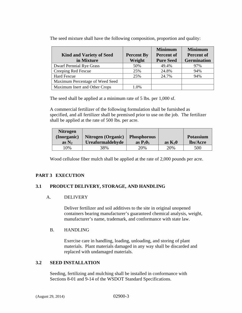
(August 29, 2014) 02900-3
The seed mixture shall have the following composition, proportion and quality:
Kind and Variety of Seed
in Mixture
Percent By
Weight
Minimum Percent of Pure Seed
Minimum Percent of
Germination Dwarf Pernnial Rye Grass 50% 49.4% 97%Creeping Red Fescue 25% 24.8% 94%Hard Fescue 25% 24.7% 94%Maximum Percentage of Weed Seed Maximum Inert and Other Crops 1.0%
The seed shall be applied at a minimum rate of 5 lbs. per 1,000 sf.
A commercial fertilizer of the following formulation shall be furnished as specified, and all fertilizer shall be premixed prior to use on the job. The fertilizer shall be applied at the rate of 500 lbs. per acre.
Nitrogen (Inorganic)
as N2
Nitrogen (Organic) Ureaformaldehyde
Phosphorous
as P205
as K20
Potassium lbs/Acre
10% 38% 20% 20% 500
Wood cellulose fiber mulch shall be applied at the rate of 2,000 pounds per acre. PART 3 EXECUTION 3.1 PRODUCT DELIVERY, STORAGE, AND HANDLING
A. DELIVERY Deliver fertilizer and soil additives to the site in original unopened containers bearing manufacturer’s guaranteed chemical analysis, weight, manufacturer’s name, trademark, and conformance with state law.
B. HANDLING Exercise care in handling, loading, unloading, and storing of plant materials. Plant materials damaged in any way shall be discarded and replaced with undamaged materials.
3.2 SEED INSTALLATION
Seeding, fertilizing and mulching shall be installed in conformance with Sections 8-01 and 9-14 of the WSDOT Standard Specifications.
(August 29, 2014) 02900-4
The seed materials will be applied in two applications. The first application shall consist of seed and a non-toxic tracer. The second application shall consist of a homogenous mixture of fertilizer and wood cellulose fiber mulch, and shall be uniformly applied over the seed within 48 hours of the seed application unless otherwise directed by the Owner. When weather conditions are not conducive to satisfactory results from seeding operations, the Owner may order the work suspended and it shall be resumed only when the desired results are likely to be obtained. Inspection is required for each area when seeding and fertilizing is complete, and again after mulching is complete. Areas not receiving a uniform application of seeding at the specified rate as determined by the Engineer shall be reseeded at the Contractor’s expense prior to mulching or payment.
3.3 SEEDED AREA SOIL PREPARATION Verify that grades are in accordance with those indicated on the Plans before proceeding with work. Verify that soil conditions are satisfactory for soil preparation work. Loosen compacted soils to a depth of 3 inches.
3.4 PROTECTION
All planting materials shall be properly protected against harm from normal weather conditions and the public by the Contractor until Final Acceptance. Maintenance of all the planted areas until Final Acceptance, shall include, but not be limited to watering. Planting should occur in spring or fall and when weather conditions are favorable. No work shall be performed in, over or adjacent to planting areas without approved protection and safeguards. Plant losses due to abnormal weather conditions such as, floods, excessive wind, drought, severe freezing or abnormal rains; as determined by the National Weather Service shall not be the responsibility of the Contractor.
3.5 CONSTRUCTION ACCEPTANCE
Construction acceptance shall be subject to well-established trees, shrubs, groundcover, and seeded areas that fulfills the requirement of the approved Plans. The Contractor shall protect and care for all plantings until fully established and
(August 29, 2014) 02900-5
healthy. Care shall include equipment and labor necessary to provide sufficient and continuous watering of all seeded areas until final acceptance.
Final Acceptance of all landscaping work described in this Specification, shall be made by the Owner to determine 100 percent completion of the Contract work. This review shall be made upon written request to the Owner no less than 48 hours prior to the anticipated date of inspection.
*** END OF SECTION ***
DIVISION 3
CONCRETE
(G&O #12009) 03200-1
SECTION 03200
CONCRETE REINFORCEMENT PART 1 GENERAL 1.1 SCOPE
The work specified in this Section includes reinforcement and associated items for all concrete, including, but not necessarily limited to: reinforcing steel bars, wire fabric, and accessories for cast-in-place concrete.
1.2 RELATED WORK SPECIFIED ELSEWHERE
Section Item 01300 Submittals 03300 Cast-in-Place Concrete 05500 Miscellaneous Metal Fabrications
1.3 REFERENCES
This Section references the latest revisions of the following documents:
Reference Title ACI 301 Structural Concrete for Buildings ACI 318 Building Code Requirements for Structural
Concrete ACI SP-66 American Concrete Institute - Detailing Manual ANSI/ASTM A82 Cold Drawn Steel Wire for Concrete Reinforcement ANSI/ASTM A185 Welded Steel Wire Fabric for Concrete
Reinforcement ANSI/AWS D1.4 Structural Welding Code for Reinforcing Steel ASTM A615 Deformed and Plain Billet Steel Bars for Concrete
Reinforcement 1.4 SUBMITTALS
Submit in accordance with provisions of Section 01300. A. SHOP DRAWINGS
Indicate bar sizes, spacings, locations, and quantities of reinforcing steel and welded wire fabric, bending and cutting schedules, and supporting and spacing devices.
(G&O #12009) 03200-2
B. MANUFACTURER’S CERTIFICATE
Certify that reinforcing bar and welded wire fabric meet or exceed specified requirements. Submit certified copies of mill test reports of reinforcement materials analysis.
1.5 QUALITY ASSURANCE
Perform Work in accordance with ACI 301. 1.6 COORDINATION
Coordinate with placement of formwork, formed openings, and other Work.
PART 2 PRODUCTS 2.1 REINFORCEMENT
A. REINFORCING STEEL
ASTM A615, deformed bars: Grade 40 for #3 bars and smaller, Grade 60 for #4 bars and larger, unless noted otherwise on the Plans.
B. WELDED STEEL WIRE FABRIC
ASTM A185 Plain Type; in flat sheets; plain.
2.2 ACCESSORY MATERIALS
A. TIE WIRE Minimum 16-gauge annealed type.
B. CHAIRS, BOLSTERS, BAR SUPPORTS, SPACERS
Sized and shaped for strength and support of reinforcement during concrete placement conditions including load-bearing pad on bottom where required to prevent vapor barrier puncture.
(G&O #12009) 03200-3
C. SPECIAL CHAIRS, BOLSTERS, BAR SUPPORTS, SPACERS ADJACENT TO WEATHER EXPOSED CONCRETE SURFACES
Plastic-coated steel type; size and shape as required.
D. MECHANICAL BAR SPLICES
Comply with ACI 318 requirement of minimum tensile strength of 125 percent of specified yield for reinforcement.
Subject to compliance with the requirements and approval of the Engineer, products ,which may be incorporated into the work include, but are not limited to, the following:
BAR-LOCK (MBT) Coupler Systems “ERICO” REBAR SPLICING
E. ADHESIVE ANCHORS
Injection adhesive system shall consist of a dual-cylinder adhesive refill pack, a mixing nozzle, and dispenser. The adhesive shall be formulated to include resin and hardeners.
1. Subject to compliance with the requirements, products which may
be incorporated in the work include, but are not limited to, the following: a. HIT RE 500 Injection Adhesive Anchor, Hilti, Inc.
b. HIT HY 150 Injection Adhesive Anchor, Hilti, Inc.
c. Power-Fast, Powers Fasteners, Inc.
2.3 FABRICATION
Fabricate concrete reinforcing in accordance with ACI SP-66. Obtain written approval from the Engineer prior to welding reinforcing steel. Weld reinforcement in accordance with ANSI/AWS D1.4.
(G&O #12009) 03200-4
PART 3 EXECUTION 3.1 PLACEMENT
Comply with Concrete Reinforcing Steel Institute’s recommended practice for “Placing Reinforcing Bars” for details and methods of reinforcement placement and supports, and as herein specified. Avoiding cutting or puncturing vapor barrier during reinforcement placement and concreting operations.
Clean reinforcement of loose rust and mill scale, earth, ice, and other materials that reduce or destroy bond with concrete. Accurately position, support, and secure reinforcement against displacement by formwork, construction, or concrete placement operations. Locate and support reinforcing by metal/plastic chairs, runners, bolsters, spacers, and hangers, as required.
Install reinforcing bars with clearance indicated on the Plans. Provide laps as shown and stagger locations to minimize the concentration of multiple reinforcing at joints. Unless noted otherwise on the Plans, provide two #5 minimum trim bars around all openings and penetrations. Arrange, space, and securely tie bars and bar supports to hold reinforcement in position during concrete placement operations. Set wire ties so ends are directed into concrete, not toward exposed concrete surfaces. Install welded wire fabric in lengths as long as practicable. Lap adjoining pieces at least one full mesh and lace splices with tie wire. Offset end laps in adjacent widths to prevent continuous laps in either direction.
*** END OF SECTION ***
(G&O #12009) 03300-1
SECTION 03300
CAST-IN-PLACE CONCRETE PART 1 GENERAL 1.1 SCOPE
The work specified in this Section includes schedules, notes, and details for the construction of cast-in-place concrete structures, landings, equipment piers, housekeeping pads and slabs on grade.
1.2 RELATED WORK SPECIFIED ELSEWHERE
Section Item 01300 Submittals 01400 Quality Control 03200 Concrete Reinforcement
1.3 REFERENCES
This Section references the latest revisions of the following documents:
Reference Title ACI 117 Specifications for Tolerances for Concrete Construction
and Materials and Commentary ACI 212.3 Chemical Admixtures for Concrete ACI 301 Specifications for Structural Concrete ACI 304 Guide for Measuring, Mixing, Transporting, and Placing
Concrete ACI 305 Hot Weather Concreting ACI 306 Cold Weather Concreting ACI 309 Guide for Consolidation of Concrete ACI 318 Building Code Requirements for Structural Concrete and
Commentary ACI 350 Code Requirements for Environmental Engineering
Concrete Structures and Commentary ACI 347 Guide to Formwork for Concrete ACI 350.1 Tightness Testing of Reinforced Engineering Concrete
Structures and Commentary ASTM C31 Making and Curing Concrete Test Specimens in the Field ASTM C33 Concrete Aggregates ASTM C39 Compressive Strength of Cylindrical Concrete Specimens ASTM C42 Obtaining and Testing Drilled Cores and Sawed Beams of
Concrete
(G&O #12009) 03300-2
ASTM C94 Ready-Mixed Concrete ASTM C131 Resistance to Degradation of Small-Size Coarse Aggregate
by Abrasion and Impact in the Los Angeles Machine ASTM C143 Slump of Hydraulic Cement Concrete ASTM C150 Portland Cement ASTM C172 Sampling Freshly Mixed Concrete ASTM C173 Air Content of Freshly Mixed Concrete by the Volumetric
Method ASTM C231 Air Content of Freshly Mixed Concrete by the Pressure
Method ASTM C260 Air-Entraining Admixtures for Concrete ASTM C309 Liquid Membrane-Forming Compounds for Curing
Concrete ASTM C494 Chemical Admixtures for Concrete ASTM C535 Resistance to Degradation of Large-Size Coarse Aggregate
by Abrasion and Impact in the Los Angeles Machine ASTM C618 Coal Fly Ash and Raw or Calcined Natural Pozzolan for
Use as a Mineral Admixture in Concrete ASTM C881 Epoxy-Resin-Base Bonding Systems for Concrete
1.4 SUBMITTALS
Submittals shall be in accordance with Section 01300.
A. GENERAL
The submittal for each included concrete mix shall include, as a complete package, the following as defined below:
1. Concrete Mix Design
2. Certified Test Results
3. Sieve Analysis
4. Product Data
An incomplete concrete mix submittal package may render a rejection of the mix or could delay the review process.
(G&O #12009) 03300-3
B. CONCRETE MIX DESIGN
Submit mix design for the proposed mix to be used on the Project, indicating components, and proportions by weight, including any admixtures. Mix design shall state chloride content. Mix designs to be provided are:
1. Unspecified Concrete for Liquid Containment Structures
2. Unspecified Concrete
3. Lean Concrete
4. Cement Grout
C. CERTIFIED TEST RESULTS
Submit laboratory test results indicating compressive strength of concrete in compliance with requirements specified herein and in accordance with ACI 301.
D. SIEVE ANALYSIS
Submit sieve analysis for proposed coarse and fine aggregates indicating components, source, gradation, and WSDOT aggregate source approval report, including WSDOT Aggregate Source ID.
E. PRODUCT DATA
Provide product data on all proposed admixtures, accessories, and embedded items to be used on the Project, including, but not limited to:
1. Cement; source and type
2. Air Entraining Agent
3. Water Reducing Admixtures
4. Pozzolans
5. Bonding Agents
6. Curing Compounds/Floor Hardeners
7. Non-Shrink Grout; Non-metallic and Metallic
(G&O #12009) 03300-4
8. Waterstops
9. Plastic Joint Formers
10. Vapor Barriers
11. Stair Nosings
For admixtures other than those proposed for air entrainment, submit a letter from the manufacturer describing the benefits of its use for the project and effect of its use on the properties of the concrete. Product data shall expressly state admixtures are chloride free, or the manufacturer shall submit a letter certification stating the same.
F. MATERIAL DELIVERY TICKETS
Provide copies of all concrete and grout material delivery tickets for the Project to the Engineer.
1.5 QUALITY ASSURANCE
Perform work in accordance with ACI 301. Acquire cement and aggregates from same source for all work performed on the Project. Conform to ACI 305 when concreting during hot weather. Conform to ACI 306 when concreting during cold weather. Provide or coordinate field and laboratory testing as described later in this Section and under provisions of Section 01400.
1.6 COORDINATION
Coordinate work in accordance with provisions of Section 01310. Coordinate the placement of embedded items with erection of concrete formwork and placement of form accessories.
PART 2 PRODUCTS 2.1 FORM MATERIALS
A. FORMS FOR EXPOSED FINISH CONCRETE
Plywood, metal, metal-framed plywood faced, or other acceptable panel-type materials, to provide continuous, straight, smooth, exposed surfaces. Furnish in largest practicable sizes to minimize number of joints and to conform to joint system shown on the Plans.
(G&O #12009) 03300-5
B. FORMS FOR UNEXPOSED FINISH CONCRETE
Plywood, lumber, metal, or other acceptable material. Provide lumber dressed on at least two edges and one side for tight fit.
C. FORMS FOR CYLINDRICAL COLUMNS AND SUPPORTS
Metal, fiberglass reinforced plastic, or paper or fiber tubes. Construct paper or fiber tubes of laminated plies using water-resistant adhesive with wax-impregnated exterior for weather and moisture protection. Provide units with sufficient wall thickness to resist loads imposed by wet concrete without deformation.
D. FORM COATINGS
Provide commercial formulation form-coating compounds that will not bond with, stain, or adversely affect concrete surfaces, and will not impair subsequent treatments of concrete surfaces.
E. FORM TIES
Factory-fabricated, adjustable-length, removable or snapoff metal form ties, designed to prevent form deflection and to prevent spalling of concrete upon removal. Provide units, which will leave no metal closer than 1-1/2 inches to surface. Unless noted otherwise on Plans, provide ties with plastic cone devices which, when removed, will leave holes not larger than 1-inch diameter in concrete surface.
2.2 CONCRETE MATERIALS
A. CEMENT
ASTM C150, Type II – Moderate or Type I - II. Use one brand of cement throughout the project, unless otherwise approved by the Engineer. Provide low alkali cement where Alkali-Silica Reaction (ASR) mitigation measures are required by WSDOT Aggregate Source Approval.
B. FINE AND COARSE AGGREGATES
Comply with ASTM C33. Provide aggregates from a single source. Coarse aggregate shall be size designation 467 (Nominal size 1-1/2 inch to No. 4 sieve) for all liquid containing structures, and size designation 67 (Nominal size 3/4-inch to No. 4 sieve) for all other concrete. Aggregates shall show a loss of weight not exceeding 35 percent after 500 revolutions in a Los Angeles wear machine, when tested in accordance with ASTM
(G&O #12009) 03300-6
C131 or ASTM C535. Aggregates shall be from a WSDOT approved source.
C. WATER
Clean, potable, and not detrimental to concrete, in compliance with ASTM C94.
2.3 ADMIXTURES
Except for air entrainment, use of all other admixtures used shall be subject to approval of the Engineer and at no additional cost to the Owner. Only admixtures expressly stated by the manufacturer as being chloride-free shall be used. Subject to compliance with requirements, products, which may be incorporated into the work include, but are not limited to, the following:
A. AIR ENTRAINMENT
ASTM C260 certified by manufacturer to be compatible with other proposed admixtures.
Master Builders MB AE 90 or MICRO-AIR Sika AER W.R. Grace Daravair or Darex Series
B. WATER REDUCING ADMIXTURE
ASTM C494 Type A.
Master Builders PolyHeed Sika Plastocrete 161 W.R. Grace WRDA Series
C. ACCELERATING ADMIXTURE
ASTM C494 Type C.
Master Builders Pozzolith NC534 Sika Plastocrete 161 FL W.R. Grace Polarset or DCI
D. WATER REDUCING, RETARDING ADMIXTURE
ASTM C494, Type D.
(G&O #12009) 03300-7
Master Builders Pozzolith 100XR Sika Plastiment W.R. Grace Daratard Series
E. WATER REDUCING, ACCELERATING ADMIXTURE
ASTM C494, Type E.
Euclid Chemical Co. Accelguard 80 Master Builders Pozzutec 20 W.R. Grace Daraccel
F. HIGH RANGE WATER REDUCER (HRWR)
ASTM C494, Type F.
Master Builders Rheobuild 1000/3000 FC Sika Sikament 10 ESL W.R. Grace ADVA 100
G. HIGH RANGE WATER REDUCER AND RETARDER
ASTM C494, Type G.
Master Builders Pozzolith 440N W.R. Grace Daracem-100
H. POZZOLAN
ASTM C618 - CLASS F, with a CaO maximum content of 10 percent.
(G&O #12009) 03300-8
2.4 ACCESSORIES
A. BONDING AGENT
ASTM C881, Type I and II, Grade 2, Class C, Epoxy Resin. Subject to Contract requirements, provide one of the following or equal:
Sika Armatec 110 Conspec SpecBond 100 W.R. Meadows Sealtight Rezi Weld 1000
B. CURING COMPOUND/CHEMICAL FLOOR HARDENER
ASTM C309, Type I, Class A and B. Subject to Contract requirements, provide one of the following or equal:
W.R. Meadows Sealtight 1100-Clear Conspec RX cure Chemrex, Inc. Masterkure Burke Spartan-Cote WB
C. GENERAL PURPOSE NON-SHRINK NON-METALLIC GROUT
Premixed compound consisting of non-metallic aggregate, cement, water reducing and plasticizing agents; capable of developing minimum compressive strength of 2,400 psi (17 Mpa) in 48 hours and 7,000 psi (48 Mpa) in 28 days. Subject to Contract requirements, provide one of the following or equal:
Sika SikaGrout 212 Conspec 100 Non Metallic Chemrex, Inc. Masterflow 928 Grout W.R. Meadows Sealtight 588
D. WATERSTOPS
Provide waterstop of type and size at construction joints and other joints as indicated on the Plans.
1. PVC (Polyvinyl Chloride)
Serrated (ribbed), 3/8 of an inch minimum thickness for 6 inches and larger and 3/16 of an inch minimum thickness for 4 inches. Comply with Corps of Engineers CRD-C-572. No reclaimed PVC will be allowed in waterstop.
(G&O #12009) 03300-9
Subject to compliance with requirements, manufacturers offering products, which may be incorporated in the work, include, but are not limited to, the following:
Greenstreak Vinylex Corporation W.R. Meadows
2. Cold Joint Waterstop
Install where shown on the Plans or at locations approved by the Engineer. Cold joint waterstop shall be certified by the manufacturer to be compatible for use in wastewater (sewage) containment structures. Subject to compliance with requirements, manufacturers offering products, which may be incorporated in the work, include, but are not limited to, the following:
Hydrotite, Greenstreak Waterstop-RX, Colloid Environmental Technologies, Co.
E. PLASTIC JOINT FORMER
Provide and install, per manufacturer’s recommendations, where shown on the Plans or at locations approved by the Engineer. Subject to compliance with requirements, manufacturers offering products, which may be incorporated in the work, include, but are not limited to, the following: Greenstreak
Vinylex Corporation W.R. Meadows
F. VAPOR BARRIER
Six mil fabric reinforced plastic film.
G. STAIR NOSINGS American Safety Tread Co., Inc., Style 816 with steel wing anchors with nuts and anchor bolts or equal.
(G&O #12009) 03300-10
2.5 CONCRETE MIX
A. GENERAL
Prepare design mixes for each type and strength of concrete by either laboratory trial batch or field experience methods as specified in ACI 301. If trial batch method is used, use an independent testing facility acceptable to the Engineer for preparing and reporting proposed mix designs. The testing facility shall not be the same as that used for field quality control testing. The maximum water soluble chloride ion content, expressed as a percent of the cement, contributed from all ingredients of the concrete mix, including water, aggregates, cementitious materials, and admixtures, shall not exceed 0.10 percent. Pozzolans may be counted as part of the total cementitious material in the concrete mix design. The cementitious material is the “minimum cement content” specified in the mix design for each type of concrete. When pozzolans are used as part of this “cement content,” the minimum content shall be 15 percent by weight of the total cementitious materials (Portland cement and pozzolans) and not more than 20 percent. Where ASR mitigation measures are required by WSDOT, provide a minimum of 15 percent pozzolan included in the cementitious material in the design mix.
B. MIX DESIGNS
Provide normal weight concrete with the following properties, unless noted otherwise on the Plans.
1. Unspecified Concrete for Liquid Containment Structures
Structural concrete of general use in liquid containment structures.
Minimum compressive strength @ 28 days: 4,000 psi Minimum cement content: 6 sacks per cubic yard Maximum water cement ratio by weight: 0.45 Nominal coarse aggregate size: 1-1/2" to No. 4 (size designation 467)
(G&O #12009) 03300-11
2. Unspecified Concrete
Structural concrete of general use in structures, sidewalks, and where no specific class of concrete is designated.
Minimum compressive strength @ 28 days: 3,500 psi Minimum cement content: 5.5 sacks per cubic yard Maximum water cement ratio by weight: 0.45 Nominal coarse aggregate size: 3/4" to No. 4 (size designation 67)
3. Lean Concrete
Concrete for pipe thrust blocks or for use as noted as “Concrete Fill” on the Plans.
Minimum compressive strength @ 28 days: 2,500 psi Minimum cement content: 5 sacks per cubic yard
4. Cement Grout
Material for filling guard posts, grouting of clarifier bottoms or for other uses as shown on the Plans. Cement grout shall be sand and cement only and shall not contain coarse aggregate.
Minimum compressive strength @ 28 days: 2,500 psi Minimum cement content: 6.5 sacks per cubic yard Maximum water cement ratio by weight: 0.54
C. ADMIXTURES
1. Air Entrainment
Use air-entraining admixture in all exterior exposed concrete. Add air-entraining admixture at manufacturer’s prescribed rate to result in concrete at point of placement in accordance with ASTM C173 or C231 having total air content with a tolerance of plus or minus 1 percent within the following limits:
5.5 percent for 1.5 inch max. coarse aggregate size 6.0 percent for 1.0 inch max. coarse aggregate size 7.0 percent 0.50 inch or less max. coarse aggregate size
(G&O #12009) 03300-12
2. Other Admixtures
Use of all other admixtures shall be subject to the approval of the Engineer, and shall be in accordance with ACI 212.3 and Manufacturer’s recommendations. Only admixtures stated by the manufacturer to be chloride free shall be used.
D. SLUMP LIMITS
Proportion and design mixes to result in concrete slump (1 inch ± of the maximum) at the point of placement in accordance with ASTM C143 as follows: Ramps, slabs, and sloping surfaces: 3 inches. Reinforced foundation systems: 3 inches. Other concrete: 4 inches. Concrete containing HRWR admixture (super-plasticizer): Not more than 8 inches after addition of HRWR to site-verified 2- to 3-inch slump concrete.
E. CONCRETE MIXING
Comply with requirements of ASTM C94, and as herein specified. During hot weather, or under conditions contributing to rapid setting of concrete, a shorter mixing time than that specified in ASTM C94 may be required.
PART 3 EXECUTION 3.1 GENERAL
Coordinate the installation of joint materials and vapor barriers with placement of forms and reinforcing steel.
3.2 FORMS
Design, erect, support, brace, and maintain formwork to support vertical and lateral, static, and dynamic loads that might be applied until such loads can be supported by concrete structure. Construct formwork so concrete members and structures are of correct size, shape, alignment, elevation, and position. Maintain formwork construction tolerances complying with ACI 347.
(G&O #12009) 03300-13
Design formwork to be readily removable without impact, shock, or damage to cast-in-place concrete surfaces and adjacent materials. Construct forms to sizes, shapes, lines, and dimensions shown, and to obtain accurate alignment, location, grades, level and plumb work in finished structures. Provide for openings, offsets, sinkages, keyways, recesses, moldings, rustications, reglets, chamfers, blocking, screeds, bulkheads, anchorages and inserts, and other features required in the work. Use selected materials to obtain required finishes. Solidly butt joints and provide back up at all joints to prevent leakage of cement paste. Fabricate forms for easy removal without hammering or prying against concrete surfaces. Provide crush plates or wrecking plates where stripping may damage cast-in-place concrete surfaces. Provide top forms for inclined surfaces where slope is too steep to place concrete with bottom forms only. Provide Kerf wood inserts for forming keyways, reglets, recesses, and the like, to prevent swelling and for easy removal. Provide temporary openings where interior area of formwork is inaccessible for cleanout, for inspection before concrete placement, and for placement of concrete. Securely brace temporary openings and set tightly to forms to prevent loss of concrete mortar. Locate temporary openings in forms at inconspicuous locations. Chamfer all exposed corners and edges and other areas shown on the Plans, using wood, metal, PVC, or rubber chamfer strips fabricated to produce uniform smooth lines and tight edge joints. Provisions for Other Trades: Provide openings in concrete formwork to accommodate work of other trades. Determine size and location of openings, recesses, and chases from trades providing such items. Accurately place and securely support items built into forms.
3.3 JOINTS AND WATERSTOPS
A. CONSTRUCTION JOINTS
Locate and install construction joints where indicated, or locate so as not to impair strength and appearance of the structure, as acceptable to the Engineer. Place construction joints perpendicular to main reinforcement. Continue reinforcement across construction joints, except as otherwise shown on the Plans.
(G&O #12009) 03300-14
B. WATERSTOPS
Provide waterstops in construction joints of all water containment structures and where shown on the Plans. Install waterstops to form continuous diaphragm in each joint in accordance with manufacturer’s recommendations. Make provisions to support and protect exposed waterstops during progress of work. Fabricate field joints in waterstops in accordance with manufacturer’s printed instructions and recommendations. All waterstops shall be tied into place using hog rings and/or tie wire to keep the waterstop from moving during placement of concrete. Provide manufacturer’s written warranty for all waterstop installations.
C. ISOLATION JOINTS IN SLABS-ON-GRADE
Unless otherwise noted, construct isolation joints in slabs-on-grade at points of contact between slabs-on-grade and vertical surfaces, such as column pedestals, foundation walls, grade beams, and elsewhere as shown on the Plans.
D. SLAB (CONTROL) JOINTS
Construct joints in slabs-on-grade as shown on the Plans. Use saw cuts 1/8 of an inch wide x 1/4 of the slab depth or inserts 1/4-inch wide x 1/4 of the slab depth.
E. PREMOLDED (CONTROL) JOINTS
Insert premolded plastic, hardboard or fiberboard strip into fresh concrete until top surface of strip is flush with slab surface. Tool slab edges round on each side of insert. After concrete has cured, remove inserts and clean groove of loose debris.
F. EDGE FORMS AND SCREED STRIPS FOR SLABS
Set edge forms or bulkheads and intermediate screed strips for slabs to obtain required elevations and contours in finished slab surface. Provide and secure units sufficiently to support types of screed strips by use of strike-off templates or accepted compacting type screeds.
(G&O #12009) 03300-15
3.4 INSTALLATION OF EMBEDDED ITEMS:
A. GENERAL
Set and build into work anchorage devices and other embedded items required for other work that is attached to, or supported by, cast-in-place concrete. Use installation drawings, diagrams, instructions, and directions provided by suppliers of items to be embedded.
B. CLEANING AND TIGHTENING
Thoroughly clean forms and adjacent surfaces to receive concrete. Remove chips, wood, sawdust, dirt, or other debris just before concrete is placed. Retighten forms and bracing after concrete placement as required to eliminate mortar leaks and maintain proper alignment.
C. REGLETS
Install reglets to receive top edge of foundation sheet waterproofing, and to receive thru-wall flashing as shown at lintels, relieving angles, and other conditions.
3.5 VAPOR BARRIER INSTALLATION
Following leveling and tamping of granular base material for slabs on grade, place vapor barrier sheeting with longest dimension parallel with direction of concrete placement. Lap joints a minimum of 6 inches and seal with appropriate approved tape. After placement of vapor barrier, cover with sand material and compact to depth as shown on the Plans.
3.6 PLACING REINFORCEMENT
See Section 03200. 3.7 PREPARATION OF FORM SURFACES
Clean reused forms of concrete matrix residue, repair and patch as required to return forms to acceptable surface condition. Coat contact surfaces of forms with a form-coating compound before reinforcement is placed.
Thin form coating compounds only with thinning agent of type, amount, and under conditions of form-coating compound manufacturer’s directions. Do not allow excess form-coating material to accumulate in forms or to come into
(G&O #12009) 03300-16
contact with in-place concrete surfaces against which fresh concrete will be placed. Apply in compliance with manufacturer’s instructions.
Coat steel forms with a non-staining, rust-preventative form oil or otherwise protect against rusting. Rust-stained steel formwork is not acceptable.
3.8 PREPARATION OF EXISTING CONCRETE SURFACES
The Contractor shall bush hammer all existing concrete surfaces that are to have new concrete cast against them. Apply epoxy bonding agent prior to placing concrete.
3.9 CONCRETE PLACEMENT
A. GENERAL
Comply with ACI 304 and as herein specified. Before placing concrete, inspect and complete formwork installation, reinforcing steel, and items to be embedded or cast-in. Notify other crafts to permit installation of their work; cooperate with other trades in setting such work. Apply temporary protective covering to lower 2 feet of finished walls adjacent to poured floor slabs and similar conditions, and guard against spattering during concrete placement.
B. PLACING CONCRETE IN FORMS
Deposit concrete in forms in horizontal layers not deeper than 24 inches and in a manner to avoid inclined construction joints. Where placement consists of several layers, place each layer while preceding layer is still plastic to avoid cold joints. Consolidate placed concrete by mechanical vibrating equipment supplemented by hand-spading, rodding, or tamping. Use equipment and procedures for consolidation of concrete in accordance with ACI 309. Do not use vibrators to transport concrete inside forms. Insert and withdraw vibrators vertically at uniformly spaced locations not farther than visible effectiveness of machine. Place vibrators to rapidly penetrate placed layer and at least 6 inches into preceding layer. Do not insert vibrators into lower layers of concrete that have begun to set. At each insertion limit duration of vibration to time necessary to consolidate concrete and complete embedment of reinforcement and other embedded items without causing segregation of mix.
(G&O #12009) 03300-17
C. PLACING CONCRETE SLABS
Deposit and consolidate concrete slabs in a continuous operation, within limits of construction joints, until the placing of a panel or section is completed. Consolidate concrete during placing operations so that concrete is thoroughly worked around reinforcement and other embedded items and into corners. Bring slab surfaces to correct level with straightedge and strikeoff. Use bull floats or darbies to smooth surface, free of humps or hollows. Do not disturb slab surfaces prior to beginning finishing operations. Maintain reinforcing in proper position during concrete placement operations.
D. COLD WEATHER PLACING
Protect concrete work from physical damage or reduced strength, which could be caused by frost, freezing actions, or low temperatures, in compliance with ACI 306 and as herein specified. When air temperature has fallen to or is expected to fall below 40 degrees F (4 degrees C), uniformly heat water and aggregates before mixing to obtain a concrete mixture temperature of not less than 50 degrees F (10 degrees C), and not more than 80 degrees F (27 degrees C) at point of placement. Do not use frozen materials or materials containing ice or snow. Do not place concrete on frozen subgrade or on subgrade containing frozen materials. Do not use calcium chloride, salt, and other materials containing antifreeze agents or chemical accelerators, unless otherwise accepted in mix designs.
E. HOT WEATHER PLACING
When hot weather conditions exist that would seriously impair quality and strength of concrete, place concrete in compliance with ACI 305 and as herein specified. Cool ingredients before mixing to maintain concrete temperature at time of placement below 90 degrees F (32 degrees C). Mixing water may be chilled, or chopped ice may be used to control temperature provided water equivalent of ice is calculated to total amount of mixing water. Use of liquid nitrogen to cool concrete is at Contractor’s option. Cover reinforcing steel with water-soaked burlap if it becomes too hot, so that steel temperature will not exceed the ambient air temperature immediately before embedment in concrete. Fog spray forms, reinforcing
(G&O #12009) 03300-18
steel, and subgrade just before concrete is placed. Upon approval, water-reducing retarding admixture (Type D) may be used when required by high temperatures, low humidity, or other adverse placing conditions.
3.10 FINISH OF FORMED SURFACES
Provide smooth form finish for all formed concrete surfaces exposed-to-view including all surfaces exposed to water or wastewater, or that are to be covered with a coating material applied directly to the concrete, or a covering material applied directly to concrete, such as veneer plaster, painting, or other similar type of system. Provide smooth form finish for surfaces to be waterproofed or dampproofed. Surfaces must comply with recommendations of the manufacturer of the product being utilized. Provide rough form finish for formed concrete surfaces not exposed-to-view in the finished work or by other construction, unless otherwise indicated. A. SMOOTH FORM FINISH
This is to be the as-cast concrete surface obtained utilizing selected form facing material, arranged orderly and symmetrically with a minimum of seams, and as specified herein. Repair and patch tie holes and defective areas, with all fins or other projections completely removed and smoothed, by the following methods: 1. Provide smooth rubbed finish to concrete surfaces after form
removal. Moisten concrete surfaces and rub with carborundum brick or other abrasive until a uniform color and texture is produced. Do not apply cement grout other than that created by the rubbing process.
2. Provide grout “sacked” cleaned finish. The sacking grout shall be
one part Portland cement to 1-1/2 parts fine sand by volume, and mixed with water to consistency of thick paint. Proprietary additives such as epoxy bonding agents or adhesives may be used at Contractor’s option. Blend standard Portland cement and white Portland cement, amounts to be determined by trial patches, so that final color of dry grout matches adjacent surfaces. Thoroughly wet concrete surfaces and apply grout to coat surfaces and fill small holes. Remove excess grout by scraping and rubbing with clean burlap. Keep sacked surfaces damp by fog spray or other acceptable method so surfaces do not dry out.
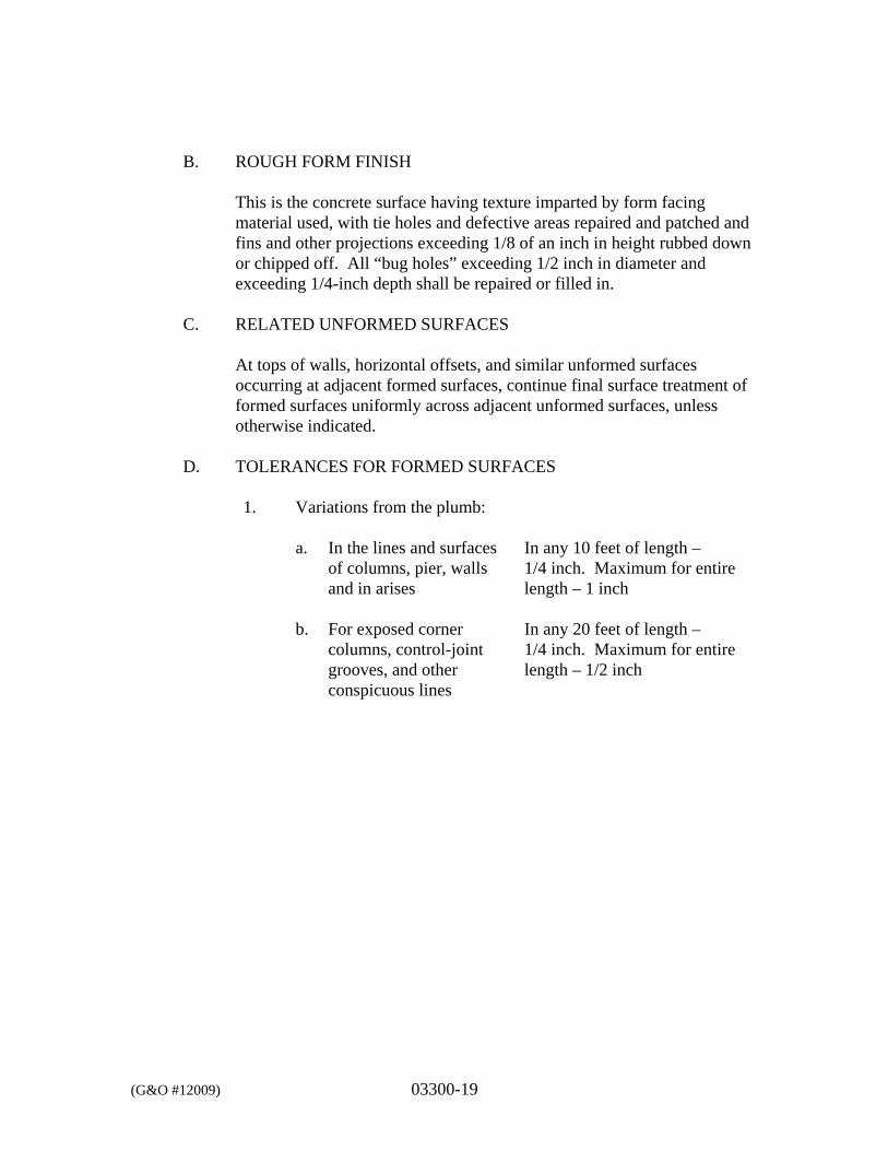
(G&O #12009) 03300-19
B. ROUGH FORM FINISH
This is the concrete surface having texture imparted by form facing material used, with tie holes and defective areas repaired and patched and fins and other projections exceeding 1/8 of an inch in height rubbed down or chipped off. All “bug holes” exceeding 1/2 inch in diameter and exceeding 1/4-inch depth shall be repaired or filled in.
C. RELATED UNFORMED SURFACES
At tops of walls, horizontal offsets, and similar unformed surfaces occurring at adjacent formed surfaces, continue final surface treatment of formed surfaces uniformly across adjacent unformed surfaces, unless otherwise indicated.
D. TOLERANCES FOR FORMED SURFACES
1. Variations from the plumb: a.
In the lines and surfaces of columns, pier, walls and in arises
In any 10 feet of length – 1/4 inch. Maximum for entire length – 1 inch
b.
For exposed corner columns, control-joint grooves, and other conspicuous lines
In any 20 feet of length – 1/4 inch. Maximum for entire length – 1/2 inch
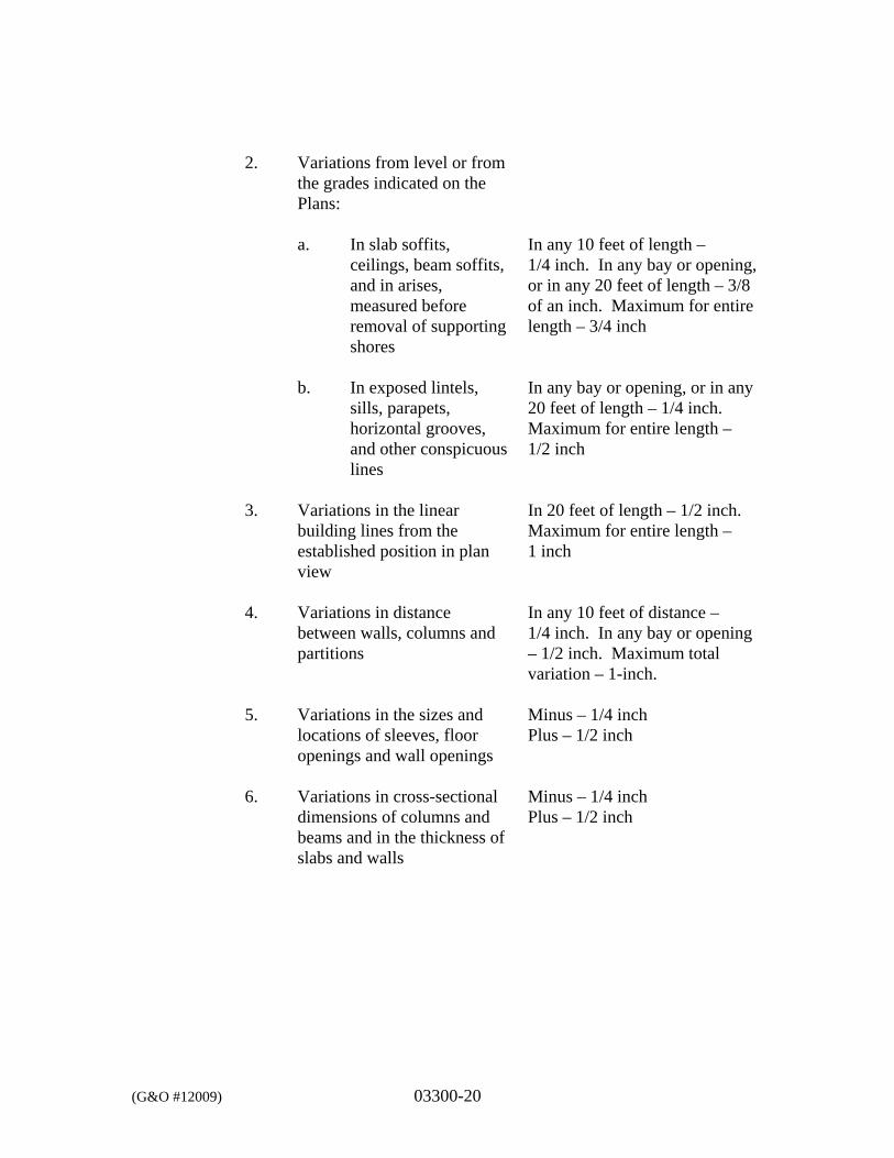
(G&O #12009) 03300-20
2. Variations from level or from
the grades indicated on the Plans:
a.
In slab soffits, ceilings, beam soffits, and in arises, measured before removal of supporting shores
In any 10 feet of length – 1/4 inch. In any bay or opening, or in any 20 feet of length – 3/8 of an inch. Maximum for entire length – 3/4 inch
b.
In exposed lintels, sills, parapets, horizontal grooves, and other conspicuous lines
In any bay or opening, or in any 20 feet of length – 1/4 inch. Maximum for entire length – 1/2 inch
3. Variations in the linear
building lines from the established position in plan view
In 20 feet of length – 1/2 inch. Maximum for entire length – 1 inch
4. Variations in distance
between walls, columns and partitions
In any 10 feet of distance – 1/4 inch. In any bay or opening – 1/2 inch. Maximum total variation – 1-inch.
5. Variations in the sizes and
locations of sleeves, floor openings and wall openings
Minus – 1/4 inch Plus – 1/2 inch
6. Variations in cross-sectional
dimensions of columns and beams and in the thickness of slabs and walls
Minus – 1/4 inch Plus – 1/2 inch
(G&O #12009) 03300-21
7. Variations in footings: a.
Variation from dimensions on Plans when formed or plus 3-inches when placed against unformed excavations
Minus – 1/2 inch Plus – 2 inches
b.
Misplacement of eccentricity
2 percent of the footing width in the direction of the misplacement, but not more than 2 inches
c.
Reduction in thickness of specified thickness
Minus – 5 percent
8. Variations in steps: a. In a flight of stairs Riser – 1/8 of an inch
Tread – 1/4 inch b. In consecutive steps Riser – 1/16 of an inch
Tread – 1/8 of an inch 3.11 MONOLITHIC SLAB FINISHES:
A. SCRATCH FINISH
Apply scratch finish to monolithic slab surfaces that are to receive concrete floor topping, including grout finishes where indicated on plans, or mortar setting beds for tile, portland cement terrazzo, and other bonded applied cementitious finish flooring material, and as otherwise indicated. Slope surfaces uniformly to floor drains where required. After leveling, roughen surface before final set, with stiff brushes, brooms, or rakes.
B. FLOAT FINISH
Apply float finish to monolithic slab surfaces to receive trowel finish and other finishes as hereinafter specified, and slab surfaces which are to be covered with membrane or elastic waterproofing, membrane or elastic roofing, or sand-bed terrazzo, and as otherwise indicated.
(G&O #12009) 03300-22
After screeding, consolidating, and leveling concrete slabs, do not work surface until ready for floating. Begin floating when surface water has disappeared or when concrete has stiffened sufficiently to permit operation of power-driven floats, or by hand-floating if area is small or inaccessible to power units. Check and level surface plane. Cut down high spots and fill low spots. Uniformly slope surfaces to drains. Immediately after leveling, refloat surface to a uniform, smooth, granular texture.
C. TROWEL FINISH
Apply trowel finish to monolithic slab surfaces to be exposed-to-view, and slab surfaces to be covered with resilient flooring, carpet, ceramic or quarry tile, paint, or other thin film finish coating system. After floating, begin first trowel finish operation using a power-driven trowel. Begin final troweling when surface produces a ringing sound as trowel is moved over surface. Consolidate concrete surface by final hand-troweling operation, free of trowel marks and uniform in texture and appearance. Grind smooth surface defects that would telegraph up through applied floor covering system.
D. TROWEL AND FINE BROOM FINISH
Where ceramic or quarry tile is to be installed with thin-set mortar, apply trowel finish as specified, then immediately follow with slightly scarifying surface by fine brooming.
E. NON-SLIP BROOM FINISH
Apply non-slip broom finish to exterior concrete platforms, landings, steps, and ramps, sidewalks and elsewhere as indicated. Immediately after float finishing, slightly roughen concrete surface by brooming with fiber bristle broom perpendicular to main traffic route. Coordinate required final finish with Owner before application.
F. CHEMICAL-HARDENER FINISH
Apply chemical-hardener finish to interior exposed concrete floors and steps, unless noted otherwise. Apply liquid chemical-hardener after complete curing and drying of the concrete surface. Evenly apply each coat, and allow 24 hours for drying between coats. Apply proprietary chemical hardeners, in accordance with manufacturer’s printed instructions. After final coat of chemical-hardener solution is applied and dried, remove surplus hardener by scrubbing and mopping with water.
G. TOLERANCES FOR MONOLITHIC SLAB FINISHES
(G&O #12009) 03300-23
The flatness of the concrete shall be carefully controlled and the tolerances shall be measured by the straight edge system as specified in paragraph 4.5.7 of ACI 117, using a 10-foot straight edge, within 72 hours after floor slab installation and before shores and/or forms are removed. The listed tolerances shall be met at any and every location at which the straight edge can be placed.
Bullfloated 1/2 inch Float Finish 3/16 inch Trowel Finish 1/8 inch Straightedges 5/16 inch
3.12 CONCRETE CURING AND PROTECTION
A. GENERAL
Protect freshly placed concrete from premature drying and excessive cold or hot temperatures. Start initial curing as soon as free water has disappeared from concrete surface after placing and finishing. Weather permitting, keep concrete continuously wet for not less than 7 days. Begin final curing procedures immediately following initial curing and before concrete has dried out. Continue final curing for at least 7 days in accordance with ACI 301 curing methods. Avoid rapid drying of concrete at the end of final curing period.
B. CURING METHODS
Perform curing of concrete by use of curing and sealing compound, by moist curing, by moisture-retaining cover curing, or by combinations thereof, as herein specified. Provide moisture curing by the following methods. Keep concrete surface continuously wet by covering with water, or provide continuous water-fog spray. Covering concrete surface with absorptive cover, thoroughly saturating cover with water and keeping continuously thoroughly saturating cover with water and keeping continuously wet. Place absorptive cover to provide coverage of concrete surfaces and edges, with 4-inch lap over adjacent absorptive covers. Provide moisture-cover curing as follows: Cover concrete surfaces with moisture-retaining cover for curing concrete, placed in wide as practicable width with sides and ends lapped at least 3 inches and sealed by
(G&O #12009) 03300-24
waterproof tape or adhesive. Immediately repair any holes or tears during curing period using cover material and waterproof tape. Provide curing and sealing compound to exposed interior slabs and to exterior slabs, walls, sidewalks, and curbs, as follows: Apply curing and sealing compound to concrete slabs and walls as soon as initial curing operations are complete or immediately after the forms have been stripped (within 2 hours). Apply uniformly in continuous operation by power-spray or roller in accordance with manufacturer’s directions. Completely cover the concrete surfaces with curing and sealing compound. Recoat areas subjected to heavy rainfall within 3 hours after initial application. Maintain continuity of coating and repair any damage during curing period. Do not use membrane curing compounds on surfaces which are to be covered with coating material applied directly to concrete, liquid floor hardener, waterproofing, dampproofing, membrane roofing, flooring (such as ceramic or quarry tile, glue-down carpet), painting, and other coatings and finish materials, unless otherwise acceptable to the Engineer.
C. CURING FORMED SURFACES
Cure formed concrete surfaces, including undersides of beams, supported slabs, and other similar surfaces by moist curing with forms in place for full curing period and until forms are removed. When forms are removed, continue curing by methods specified above, as applicable.
D. CURING UNFORMED SURFACES
Cure unformed surfaces, such as slabs, floor topping, and other flat surfaces by application of an appropriate curing method. Final cure concrete surfaces to receive liquid floor hardener or finish flooring by use of moisture retaining cover.
(G&O #12009) 03300-25
3.13 SHORES AND SUPPORTS
A. GENERAL
Comply with ACI 347 for shoring, and as herein specified. Extend shoring from ground to roof for structures four stories or less, unless otherwise permitted. Remove shores and reshore in a planned sequence to avoid damage to partially cured concrete. Locate and provide adequate reshoring to safely support work without excessive stress or deflection. Keep reshores in place a minimum of 15 days after placing upper tier, and longer if required, until all concrete has attained its required 28 day strength and heavy loads due to construction operations have been removed.
B. REMOVAL OF FORMS
Formwork not supporting weight of concrete, such as sides of beams, walls, columns, and similar parts of the work, may be removed after cumulatively curing at not less than 50 degrees F (10 degrees C) for 24 hours after placing concrete, provided concrete is sufficiently hard to not be damaged by form removal operations, and provided curing and protection operations are maintained. Formwork supporting weight of concrete, such as beam soffits, joints, suspended slabs, and other structural elements, may not be removed in less than 14 days and until concrete has attained 70 percent of the design minimum compressive strength at 28 days. Determine potential compressive strength of in-place concrete by testing field-cured specimens, representative of concrete location or members. Form facing material may be removed 4 days after placement, only if shores and other vertical supports have been arranged to permit removal of form facing material without loosening or disturbing shores and supports.
3.14 REUSE OF FORMS
Clean and repair surfaces of forms to be reused in work. Split, frayed, delaminated, or otherwise damaged form facing material will not be acceptable for exposed surfaces. Provide new form facing material. Apply new form coating compound as specified for new formwork prior to reuse of forms. When forms are extended for successive concrete placement, thoroughly clean surfaces, remove fins and laitance, and tighten forms to close joints. Align and
(G&O #12009) 03300-26
secure joint to avoid offsets. Do not use “patched” forms for exposed concrete surfaces, unless approved by the Engineer and acceptable to the Owner.
3.15 MISCELLANEOUS CONCRETE ITEMS
A. FILLING-IN
Fill-in holes and openings left in concrete structures for passage of work by other trades, unless otherwise shown or directed, after work of other trades is in place. Mix, place, and cure concrete as herein specified, to blend with in-place construction. Provide other miscellaneous concrete filling shown or required to complete work. Fill-in all form tie holes and other forming system holes with non-shrink grout.
B. CURBS
Provide monolithic finish to interior curbs by stripping forms while concrete is still green and steel-troweling surfaces to a hard, dense finish with corners, intersections, and terminations slightly rounded.
C. BASE PLATE, EQUIPMENT BASES AND FOUNDATIONS
Provide machine and equipment bases (housekeeping pad/pier) and foundations, as shown on the Plans. Set anchor bolts for machines and equipment with template at correct elevations, complying with certified diagrams or templates of manufacturers furnishing machines and equipment. Provide 4-inch-high, square or rectangular concrete pad around all conduits and small diameter pipes that penetrate through floor slabs. Provide leveling grout under base plates and equipment frames using non-metallic, non-shrink grout. Minimum thickness for leveling grout shall be 1/2 inches unless noted otherwise on the Plans or specified by equipment manufacturer.
D. STAIR NOSINGS
Provide stair nosings at all exterior cast-in-place concrete stairs or steps. The stair nosings shall be installed in accordance with the manufacturer’s written instructions.
(G&O #12009) 03300-27
3.16 CONCRETE SURFACE REPAIRS
A. PATCHING DEFECTIVE AREAS
Repair and patch defective areas immediately after removal of forms. Cut out honeycomb, rock pockets, voids or bugholes over 1/4 inch in any dimension, and holes left by tie rods and bolts, down to solid concrete but, in no case to a depth of less than 1 inch. Make edges of cuts perpendicular to the concrete surface. Thoroughly clean, dampen with water, and brush-coat the area to be patched with specified bonding agent. For water and wastewater containment structures, utilize an epoxy resin bonding agent. Place patching mortar after bonding compound has dried. For exposed-to-view surfaces, blend white Portland cement and standard Portland cement so that, when dry, patching mortar will match surrounding color. Provide test areas at inconspicuous location to verify mixture and color match before proceeding with patching. Compact mortar in place and strike-off slightly higher than surrounding surface.
B. REPAIR OF FORMED SURFACES
Remove and replace concrete having defective surfaces if defects cannot be repaired to satisfaction of the Engineer. Surface defects, as such, include color and texture irregularities, cracks, spalls, air bubbles, bug holes, honeycomb, rock pockets; fins and other discolorations that cannot be removed by cleaning. Flush out form tie holes and form bolt holes, fill with non-shrink grout, or precast concrete cone plugs or rubber plugs secured in place with bonding agent or epoxy adhesive. Repair concealed formed surfaces, where possible, that contain defects that affect the durability of concrete. All repairs shall be approved by the Engineer. If defects cannot be repaired, the Contractor shall remove and replace the concrete.
C. REPAIR OF UNFORMED SURFACES
Test unformed surfaces, such as monolithic slabs, for smoothness and verify surface plane to tolerances specified for each surface and finish. Correct low and high areas as herein specified. Test unformed surfaces sloped to drain for trueness of slope, in addition to smoothness using a template having required slope. Repair finished unformed surfaces that contain defects, which affect durability of concrete. Surface defects, as such, include crazing, cracks in excess of 0.01 inches wide or which penetrate to reinforcement or
(G&O #12009) 03300-28
completely through non-reinforced sections regardless of width, spalling, pop-outs, honeycomb, rock pockets, and other objectionable conditions. Correct high areas in unformed surfaces by grinding, after concrete has cured at least 14 days. Correct low areas in unformed surfaces during or immediately after completion of surface finishing operations by cutting out low areas and replacing with fresh concrete. Finish repaired areas to blend into adjacent concrete. Proprietary patching compounds may be used when acceptable to the Engineer. Repair defective areas, except random cracks and single holes not exceeding 1-inch diameter, by cutting out and replacing with fresh concrete. Remove defective areas to sound concrete with clean, square cuts and expose reinforcing steel with at least 3 inches of clearance all around. Dampen concrete surfaces in contact with patching concrete and apply bonding agent. Mix patching concrete of same materials to provide concrete of same type or class as original concrete. Place, compact, and finish to blend with adjacent finished concrete. Cure in same manner as adjacent concrete. Repair isolated random cracks and single holes not over 1 inch in diameter by dry-pack method. Groove top of cracks and cutout holes to sound concrete and clean off dust, dirt, and loose particles. Dampen cleaned concrete surfaces and apply bonding agent. Mix dry-pack, consisting of one part Portland cement to 2-1/2 parts fine aggregate passing a No. 16 mesh sieve, using only enough water as required for handling and placing. Place dry pack after bonding agent has dried. Compact dry-pack mixture in place and finish to match adjacent concrete. Keep patched area continuously moist for not less than 72 hours. Perform structural repairs with prior approval of the Engineer for method and procedure, using specified epoxy adhesive and mortar. Repair methods not specified above may be used, subject to approval of the Engineer. If acceptable repairs cannot be made, the Contractor shall remove and replace the concrete at no cost to the Owner.
3.17 QUALITY CONTROL TESTING DURING CONSTRUCTION
A. GENERAL
Sampling and testing for quality control during placement of concrete shall include the following:
1. Sampling Fresh Concrete
(G&O #12009) 03300-29
ASTM C172, except modified for slump to comply with ASTM C94.
2. Slump
ASTM C143: one test at point of discharge for each day’s placement of each type of concrete; additional tests when concrete consistency seems to have changed.
3. Air Content
ASTM C173, volumetric method for lightweight or normal weight concrete; ASTM C231 pressure method for normal weight concrete; one for each day’s placement of each type of air-entrained concrete.
4. Concrete Temperature
Test hourly when air temperature is 40 degrees F (4 degrees C) and below, and when 80 degrees F (27 degrees C) and above; and each time a set of compression test specimens is made.
5. Compression Test Specimen
ASTM C31; one set of four standard cylinders for each compressive strength test, unless otherwise directed. Mold and store cylinders for laboratory cured test specimens except when field-cure test specimens are required.
6. Compressive Strength Tests
ASTM C39; one set for each day’s placement exceeding 5 cubic yards plus additional sets for each 50 cubic yards over and above the first 25 cubic yards of each concrete class placed in any 1 day; one specimen tested at 7 days, two specimens tested at 28 days, and one specimen retained in reserve for later testing if required. When total quantity of a given class of concrete is less than 50 cubic yards, Engineer may waive strength test if, in his judgment, adequate evidence of satisfactory strength is provided. When strength of field-cured cylinders is less than 85 percent of companion laboratory-cured cylinders, evaluate current operations and provide corrective procedures for protecting and curing the in-place concrete. Strength level of concrete will be considered
(G&O #12009) 03300-30
satisfactory if averages of sets of three consecutive strength test results equal or exceed specified compressive strength, and no individual strength test result falls below specified compressive strength by more than 500 psi. Test results will be reported in writing to Engineer and Contractor within 24 hours after testing. FAX of test results is acceptable; however, mailing hard copies of test results is also required. Reports of compressive strength tests shall contain the project identification name and number, date of concrete placement, name of concrete testing service, concrete type and class, location of concrete batch in structure, design compressive strength at 28 days, concrete mix proportions and materials; compressive breaking strength and type of break for both 7 day tests and 28-day tests.
7. Nondestructive Testing
Impact hammer, sonoscope, or other nondestructive device may be permitted but shall not be used as the sole basis for acceptance or rejection of concrete.
8. Additional Tests
The testing service will make additional tests of in-place concrete when test results indicate specified concrete strengths and other characteristics have not been attained in a structure, as directed by the Owner. Testing service may conduct tests to determine adequacy of concrete by cored cylinders complying with ASTM C42, or by other methods as directed. Contractor shall pay for cost of such tests when unacceptable concrete is verified.
3.18 WATERTIGHTNESS
All water and wastewater holding tanks, basins and structures listed on the Structural Plans shall be tested for watertightness. Each tank, structure or basin shall be tested independently.
Watertightness tests shall be made after the concrete has obtained at least 90 percent of its required 28-day compressive strength, but in no case sooner than 20 days after placement. Watertightness shall conform to the requirements of ACI 350.1. Leakage testing shall not be conducted during periods of time with measurable precipitation. Evaporation correction shall be made on the basis of an
(G&O #12009) 03300-31
evaporation pan. Suitable evaporation pan shall be approved by Owner and shall be provided by Contractor. Watertightness testing may follow backfill of the structure, at the Contractor’s option. However, if the structure does not pass the test, re-excavation to locate leaks shall be required. All costs associated with location (re-excavation and backfilling) and repair of leaks shall be borne by the Contractor.
*** END OF SECTION ***

DIVISION 5
METALS
(G&O #12009) 05120-1
SECTION 05120
STRUCTURAL STEEL PART 1 GENERAL
1.1 SCOPE
The work specified in this Section includes structural steel work as shown on the Plans, including schedules, notes, and details to show size and location of members, typical connections, and type of steel required. Miscellaneous metal fabrications are specified elsewhere in Division 5.
1.2 RELATED WORK SPECIFIED ELSEWHERE
Section Item 01300 Submittals 03300 Cast-In-Place Concrete
1.3 REFERENCES
This Section references the latest revisions of the following documents:
Reference Title ASTM A36 Structural Steel ASTM A53 Hot-Dipped, Zinc-coated Welded and Seamless Steel Pipe ASTM A123 Zinc (Hot Dipped Galvanized) Coatings on Iron and Steel
Products ASTM A153 Zinc Coating (Hot Dip) on Iron and Steel Hardware ASTM A276 Stainless Steel Bars and Shapes ASTM A307 Carbon Steel Externally Threaded Standard Fasteners ASTM A325 High Strength Bolts for Structural Steel Joints ASTM A490 Quenched and Tempered Alloy Steel Bolts for Structural
Steel Joints ASTM A500 Cold-Formed Welded and Seamless Carbon Steel
Structural Tubing in Round and Shapes ASTM A501 Hot-Formed Welded and Seamless Carbon Steel Structural
Tubing ASTM A572 High-Strength Structural Steel ASTM A992 High-Strength Structural Steel AWS A2.4 Standard Welding Symbols AWS D1.1 Structural Welding Code AISC Specification for Structural Steel Buildings SSPC Steel Structures Painting Council
(G&O #12009) 05120-2
1.4 SUBMITTALS
Submit under provisions of Section 01300.
A. SHOP DRAWINGS
Indicate profiles, sizes, spacing, locations, and complete details of structural members, to include openings, cuts, camber, fasteners, connections, and other pertinent data. Indicate welded connections with AWS A2.4 welding symbols. Indicate net weld lengths. Provide setting drawings, templates, and directions for installation of anchor bolts and other anchorages to be installed as work of other sections.
B. MANUFACTURER’S MILL CERTIFICATE
Submit under provisions of Section 01300 certifying that products meet or exceed specified requirements.
C. MILL TEST REPORTS
Submit under provisions of Section 01300 Manufacturer’s Certificates, indicating structural strength, destructive and non-destructive test analysis.
D. WELDERS’ CERTIFICATES
Submit under provisions of Section 01300 Manufacturer’s Certificates, certifying welders employed on the Work, verifying AWS qualifications within the previous 12 months.
1.5 QUALITY ASSURANCE
Codes and Standards: Comply with the provisions of the following, except otherwise indicated:
Standard Title AISC “Code of Standard Practice for Steel Buildings and
Bridges” AISC “Specifications for Structural Steel Buildings,” including
“Commentary” and Supplements thereto as issued AISC “Specifications for Structural Joints using ASTM A325 or
A490 Bolts” approved by the Research Council on Riveted and Bolted Structural Joints of the Engineering Foundation.
(G&O #12009) 05120-3
American Welding D1.1 “Structural Welding Code – Steel” Society (AWS) ASTM A6 “General Requirements for Delivery of Rolled Steel Plates,
Shapes, Sheet Piling and Bars for Structural Use”
1.6 DELIVERY, STORAGE, AND HANDLING
Deliver material to site at such intervals to ensure uninterrupted progress of work. Deliver anchor bolts and anchorage devices that are to be embedded in cast-in-place concrete or masonry in ample time as to not delay work. Store materials to permit easy access for inspection and identification. Keep steel members off ground, using pallets, platforms, or other supports. Protect steel members and packaged materials from erosion and deterioration. Do not store materials on structure in a manner that might cause distortion or damage to members or supporting structures. Repair or replace damaged materials or structures as directed.
PART 2 PRODUCTS
2.1 MATERIALS
A. STRUCTURAL STEEL SHAPES
ASTM A992, High-Strength Structural Steel.
B. STRUCTURAL STEEL PLATES AND BARS
ASTM A36, unless noted otherwise.
C. STRUCTURAL TUBING
Cold-Formed: ASTM A500, Grade B, Fy=46KSI Hot-Formed: ASTM A501, Fy=36KSI
D. STEEL PIPE
ASTM A53, Type E or S Grade B.
(G&O #12009) 05120-4
E. HEADED STUD-TYPE CONNECTORS
ASTM A108, Grade 1015, forged steel, uncoated.
F. HIGH-STRENGTH THREADED FASTENERS
Heavy hexagon structural bolts, heavy hexagon nuts and hardened washers as follows:
Quenched and tempered medium carbon steel bolts, nuts and washers complying with ASTM A325. Quenched and tempered alloy steel bolts, nuts and washers complying with ASTM A490 where indicated.
Provide and install bolts with load indicator devices (load indicator washers or snap-off heads).
G. ANCHOR BOLTS AND THREADED RODS
ASTM F1554, Grade 36, unless noted otherwise. ASTM A276, stainless steel.
H. UNFINISHED THREADED FASTENERS
ASTM A307, Grade A, regular low-carbon steel bolts and nuts. Provide hexagonal heads and nuts for all connections.
I. EXPANSION ANCHORS
Provide size and type indicated. Expansion anchors shall be one piece stud type, wedge-style anchor. Carbon steel expansion anchors shall meet the following:
Stud: ASTM A108 and zinc plated in accordance with ASTM B633
Wedge: AISI 1010 carbon steel Nut: ASTM A563 Grade A Washer: SAE 1005-1020
(G&O #12009) 05120-5
Stainless steel expansion anchors shall meet the following:
Stud: ASTM F593, AISI 304 or 316 Wedge: AISI 304 or 316 Nut: ASTM F594 Washer: AISI 304 or 316 conforming to ASTM A240
Subject to compliance with the requirements, products which may be incorporated in the work include, but are not limited to, the following:
KWIK Bolt, Hilti, Inc. Power-Stud, Powers Fasteners, Inc.
J. FLUSH TYPE EXPANSION ANCHORS
Provide size to match fastener indicated, conforming to AISI 12L14, meeting ASTM A108, and zinc plated in accordance with ASTM B633, SC1, Type III. Subject to compliance with the requirements products, which may be incorporated in the work include, but are not limited to, the following:
HDI Anchor, Hilti, Inc. Drop-In Anchor, Powers Fasteners, Inc.
K. ADHESIVE ANCHORS
1. Adhesive capsules shall be self-contained two-part component
consisting of a vinyl urethane resin with a Dibenzoyl Peroxide Hardener.
Subject to compliance with the requirements products, which may be incorporated in the work include, but are not limited to the following:
HVU Adhesive capsule, Hilti, Inc. Chem-Stud Capsule, Powers Fasteners, Inc.
2. Injection adhesive system shall consist of a dual-cylinder adhesive
refill pack, a mixing nozzle, and dispenser. The adhesive shall be formulated to include resin and hardeners.
(G&O #12009) 05120-6
Subject to compliance with the requirements products, which may be incorporated in the work include, but are not limited to, the following:
HIT RE 500 Injection Adhesive Anchor, Hilti, Inc. HIT HY 150 Injection Adhesive Anchor, Hilti, Inc. Power-Fast, Powers Fasteners, Inc.
3. For hollow-base materials such as concrete masonry units (CMU), provide galvanized screen tubes as required. The adhesive shall be a methacrylate resin.
Subject to compliance with the requirements products, which may be incorporated in the work include, but are not limited to, the following:
HIT HY 20 Adhesive Anchor System for Unreinforced Masonry, Hilti, Inc. Power-Fast, Powers Fasteners, Inc.
L. WELDING MATERIALS
AWS A5.1 or A5.5, E70XX; AWS A5.17, E70S-X; AWS A5.20, E70XT-X. Comply with AWS code.
M. GROUTING MATERIALS
Shall comply with Section 03300 “Cast-in-Place Concrete.”
N. STRUCTURAL STEEL PRIMER PAINT
Epoxy Primer per Section 09900, SSPC SP-10.
2.2 FABRICATION
A. SHOP FABRICATION AND ASSEMBLY
Fabricate and assemble structural assemblies in shop to greatest extent possible. Fabricate items of structural steel in accordance with AISC Specifications and as indicated on final shop drawings. Provide camber in structural members where indicated.
(G&O #12009) 05120-7
Properly mark and match-mark materials for field assembly. Fabricate for delivery sequence, which will expedite erection and minimize field handling of materials. Where finishing is required, complete assembly, including welding of units, before start of finishing operations. Provide finish surfaces of members exposed in final structure free of markings, burrs, and other defects.
B. CONNECTIONS
Weld or bolt shop connections, as indicated on the Plans or as specified. Bolt field connections, except where welded connections or other connections are indicated. Provide high-strength threaded fasteners for all bolted connections, except where unfinished bolts are indicated.
C. HIGH-STRENGTH BOLTED CONSTRUCTION
Install high-strength threaded fasteners in accordance with AISC “Specifications for Structural Joints using ASTM A325 or A490 Bolts.”
D. WELDED CONSTRUCTION
Comply with AWS Code for procedures, appearance and quality of welds, and methods used in correcting welding work. Assemble and weld built-up sections where indicated by methods which will produce true alignment of axes without warp.
E. SHEAR CONNECTORS
Prepare steel surfaces as recommended by manufacturer of shear connectors. Shop weld shear connectors, spaced as shown, to beams and girders in composite construction. Use automatic end welding of headed stud shear connectors in accordance with manufacturer’s printed instructions.
F. STEEL WALL FRAMING
Select members, which are true and straight for fabrication of steel wall framing. Straighten as required to provide uniform, square and true members in completed wall framing. Where indicated, build up welded
(G&O #12009) 05120-8
doorframes attached to structural steel framing. Weld exposed joints continuously and grind smooth. Plug weld steel bar stops to frames, except where shown removable. Secure removable stops to frames with countersunk, cross-recessed head machine screws, uniformly spaced not more than 10-inches oc, unless otherwise indicated. Provide holes required for securing other work to structural steel framing, and for passage of other work through steel framing member, as shown on final shop drawings. Provide threaded nuts welded to framing, and other specialty items as indicated to receive other work. Cut, drill, or punch holes perpendicular to metal surfaces. Do not flame cut holes or enlarge holes by burning. Drill holes in bearing plates.
2.3 SHOP PAINTING
A. GENERAL
Shop paint structural steel, except those members or portions of members to be embedded in concrete or mortar. Paint embedded steel that is partially exposed, or the exposed portions and initial two inches of embedded areas only. Do not paint surfaces that are to be welded or are high-strength bolted with friction-type connections. Apply two coats of paint complying with Section 09900 to surfaces that are inaccessible after assembly or erection.
B. SURFACE PREPARATION
After inspection and before shipping, clean steelwork to be painted. Remove loose rust, loose mill scale, and spatter, slag or flux deposits. Clean steel in accordance with Steel Structures Painting Council (SSPC) as follows: SP-10 “Near-White Blast Cleaning.”
C. PAINTING
Immediately after surface preparation, apply structural steel primer paint in accordance with Section 09900 and manufacturer’s instructions and at a rate to provide dry film thickness of not less than 1.5 mils DFT. Use painting methods, which result in full coverage of joints, corners, edges and exposed surfaces.
(G&O #12009) 05120-9
D. ZINC COATING
Unless noted otherwise, where structural steel (ferrous metal) is exposed to weather, it shall be zinc coated or galvanized by the “hot-dip” method in accordance with ASTM A123. Provide the following minimum coating weight per square foot of actual surface. (a) Steel 1/8 inch 2.0 Ounces Average and 3/16 inch 1.8 Ounces Minimum (b) Steel 1/4 inch 2.3 Ounces Average and heavier 2.0 Ounces Minimum Provide galvanized fasteners with zinc-coated items.
2.4 SOURCE QUALITY CONTROL AND TESTS
Testing and analysis of components will be performed under provisions of Section 01400.
PART 3 EXECUTION
3.1 ERECTION
A. GENERAL
Provide temporary shoring and bracing members with connections of sufficient strength to bear imposed loads. Remove temporary members and connections when permanent members are in place and final connections are made. Provide temporary guy lines to achieve proper alignment of structures as erection proceeds.
B. SETTING BASES AND BEARING PLATES
Clean concrete and masonry bearing surfaces of bond-reducing materials and roughen to improve bond to surfaces. Clean bottom surface of base and bearing plates. Set loose and attached base plates and bearing plates for structural members on wedges or other adjusting devices. Tighten anchor bolts after supported members have been positioned and plumbed. Do not remove wedges or shims, but if protruding, cut off flush with edge of base or bearing plate prior to packing with grout.
(G&O #12009) 05120-10
Pack non-shrink grout solidly between bearing surfaces and bases or plates to ensure that no voids remain. Finish exposed surfaces, protect installed materials, and allow to cure. For proprietary grout materials, comply with manufacturer’s instructions.
C. FIELD ASSEMBLY
Set structural frames accurately to lines and elevations indicated. Align and adjust various members forming part of complete frame or structure before permanently fastening. Clean bearing surfaces and other surfaces that will be in permanent contact before assembly. Perform necessary adjustments to compensate for discrepancies in elevations and alignment. Level and plumb individual members of structure within specified AISC tolerances. Splice members only where indicated and accepted on shop drawings.
D. ERECTION BOLTS
On exposed welded construction, remove erection bolts, fill holes with plug welds, and grind smooth at exposed surfaces. Comply with AISC Specification for bearing, adequacy of temporary connections, alignment, and removal of paint on surfaces adjacent to field welds. Do not enlarge unfair holes in members by burning or by use of drift pins, except in secondary bracing member. Ream holes that must be enlarged to admit bolts.
E. GAS CUTTING
Do not use gas-cutting torches in field for correcting fabrication errors in primary structural framing. Cutting will be permitted only on secondary members, which are not under stress, as acceptable to the Engineer.
F. TOUCHUP PAINTING
Immediately after erection, clean field welds, bolted connections, and abraded areas of shop paint. Apply paint to exposed areas using same material as used for shop painting. Apply by brush or spray to provide minimum dry film thickness of 1.5 mils. Painting shall conform to the requirements of Section 09900.
(G&O #12009) 05120-11
Cleaning and touchup painting of field welds, bolted connections and abraded areas of shop paint on structural steel is included in Section 09900.
G. REPAIR OF GALVANIZED WORK
Galvanized work damaged during installation shall be repaired with a “hot stick method” using “galv-bar.”
3.2 QUALITY CONTROL
A. GENERAL
Comply with Section 01400 for independent testing and inspection agency to inspect high-strength bolted connections and welded connections and to perform tests and prepare test reports. Testing agency shall conduct and interpret tests and state in each report whether test specimens comply with requirements, and specifically state any deviations therefrom. Provide testing agency access to places where structural steel work is being fabricated or produced so that required inspection and testing can be accomplished. Testing agency may inspect structural steel at plant before shipment; however, the Engineer reserves right, at any time before final acceptance, to reject material not complying with specified requirements. Correct deficiencies in structural steel work that inspections and laboratory test reports indicate as not in compliance with requirements. The performance of additional tests, at the Contractor’s expense, may be necessary to reconfirm any non-compliance of original work, as well as to show compliance of corrected work.
B. SHOP-BOLTED CONNECTIONS
Inspect or test in accordance with AISC specifications.
C. SHOP WELDING
Inspect and test during fabrication of structural steel assemblies, as follows:
(G&O #12009) 05120-12
Certify welders and conduct inspections and tests as required. Record types and locations of defects found in work. Record work required and performed to correct deficiencies. Perform visual inspection of all welds. Perform tests of welds as follows. Inspection procedures listed are to be used at Contractor’s option.
CONTRACTOR’S OPTION
Liquid Pentrant Inspection: ASTM E165 Magnetic Particle Inspection: ASTM E709; performed on root
pass and on finished weld. Cracks or zones of incomplete fusion or penetration not acceptable.
Radiographic Inspection: ASTM E94 Ultrasonic Inspection: ASTM E164
D. FIELD-BOLTED CONNECTIONS
Inspect in accordance with AISC specifications.
E. FIELD WELDING
Inspect and test during erection of structural steel as follows: Certify welders and conduct inspections and tests as required. Record types and locations of defects found in work. Record work required and performed to correct deficiencies. Perform visual inspection of all welds. Perform tests of welds as follows:
Liquid Pentrant Inspection: ASTM E165 Magnetic Particle Inspection: ASTM E709; performed on root
pass and on finished weld. Cracks or zones of incomplete
(G&O #12009) 05120-13
fusion or penetration not acceptable.
Radiographic Inspection: ASTM E94 Ultrasonic Inspection: ASTM E164
*** END OF SECTION ***
(G&O #12009) 05500-1
SECTION 05500
MISCELLANEOUS METAL FABRICATIONS PART 1 GENERAL 1.1 SCOPE
The extent of miscellaneous metal fabrication work is shown on the Drawings and includes, but is not limited to, the following: preassembled stairs, ladders, handrails, railings, grating, including stair treads and nosings; floor plates and covers, custom fabricated pipe brackets, supports, and pipe sleeves.
1.2 RELATED WORK SPECIFIED ELSEWHERE
Section Item 03000 Cast-In-Place Concrete 05120 Structural Steel Division 13 Special Construction Division 15 Mechanical Division 16 Electrical
1.3 REFERENCES
This section references the latest revisions of the following documents:
Reference Title ASTM A36 Structural Steel ASTM A53 Hot-Dipped, Zinc-coated Welded and Seamless Steel Pipe ASTM A123 Zinc (Hot-Galvanized) Coatings on Products Fabricated
From Rolled, Pressed and Forged Steel Shapes, Plates, Bars, and Strip
ASTM A153 Zinc Coating (Hot-Dip) on Iron and Steel Hardware ASTM A240 Heat-Resisting Chromium and Chromium-Nickel Stainless
Steel Plate, Sheet and Strip for Pressure Vessels ASTM A283 Carbon Steel Plates, Shapes, and Bars ASTM A307 Carbon Steel Externally Threaded Standard Fasteners ASTM A325 High Strength Bolts for Structural Steel Joints ASTM A386 Zinc-Coating (Hot-Dip) on Assembled Steel Products ASTM A446 Steel Sheet, Zinc-Coated (Galvanized) by the Hot-Dip
Process, Structural (Physical) Quality ASTM A500 Cold-Formed Welded and Seamless Carbon Steel
Structural Tubing in Round and Shapes ASTM A501 Hot-Formed Welded and Seamless Carbon Steel Structural
Tubing
(G&O #12009) 05500-2
ASTM B221 Aluminum-Alloy Extruded Bars, Rods, Wire, Shapes, and Tubes
ASTM B241 Aluminum-Alloy Seamless Pipe and Seamless Extruded Steel Tube
NAAMM National Association of Architectural Metal Manufacturers, “Metal Bar Grating Manual”
AISC American Institute of Steel Construction AWS D1.1 Structural Welding Code - Steel AWS D1.2 Structural Welding Code - Aluminum SSPC Steel Structures Painting Council
1.4 SUBMITTALS
Submit under provisions of Section 01300. Indicate profiles, sizes, connection attachments, reinforcing, anchorage, anchorage and method, size and type of fasteners, and accessories. Include erection drawings, elevations, and details where applicable.
PART 2 PRODUCTS 2.1 MATERIALS
A. STRUCTURAL STEEL Structural steel members and sections as defined in the AISC “Code of Standard Practice” are specified in Section 05120, “Structural Steel.”
B. STEEL CASTINGS
Comply with ASTM A27. Grade 65-35, medium strength carbon steel.
C. CAST IRON
Comply with ASTM A48, Class 20.
D. STAINLESS STEEL
Comply with ASTM A316.
E. ALUMINUM ALLOY EXTRUDED BARS, RODS, WIRE, SHAPES
AND TUBES Comply with ASTM B221, Alloy 6061-6. Structural aluminum items are specified in Section 05130.
(G&O #12009) 05500-3
F. ELECTRODES FOR WELDING
Comply with AWS, using ASTM A233, E-60 or E-70 Series.
G. ZINC COATING
Comply with ASTM A123 or ASTM A153. H. FASTENERS, ANCHORS, AND ANCHOR BOLTS
As specified in Section 05120.
I. PAINTING
Comply with Section 09900. J. GROUT MATERIALS
As specified in Section 03300.
2.2 PRODUCTS
A. HANDRAILS AND RAILINGS
Handrails and railings shall be clear satin finish, anodized 1-1/2-inch nominal diameter Schedule 40 extruded aluminum tubing conforming to ASTM B241, Alloy 6063 with concealed aluminum spigot splice connectors and fasteners countersunk and flush. Fasteners shall be 316 stainless steel. Maximum post spacing shall be 6'-0" on center. Post connections shall be cast aluminum R&B Wagner Interna-Rail or approved equal. Mounting shall be cast aluminum R&B Wagner-Interna-Rail drive on flange or approved equal; other acceptable manufacturers are Golden Railings, Inc., or Alumaguard Corporation.
(G&O #12009) 05500-4
2.3 FABRICATION
Fit and shop assemble components in the largest practical size for delivery and installation at site.
A. STRUCTURAL STEEL MEMBERS AND SECTIONS
Fabrication of structural steel members and sections shall comply with Section 05120. Provide galvanized fasteners with zinc coated items except as noted below. For all items installed in submerged, intermittently submerged, or areas subject to splash and spill, or corrosive atmospheres, fasteners shall be 316 stainless steel. The term fasteners includes nut, bolts, washers, leveling nuts, and U-bolts.
B. STRUCTURAL ALUMINUM MEMBERS AND SECTIONS
Fabrication of structural aluminum members and sections shall comply with Section 05130. All fasteners for aluminum items shall be 316 stainless steel.
C. HANDRAIL AND RAILINGS
Unless noted otherwise, handrail and railing assemblies shall include a minimum 1/4" x 4" aluminum kick plate. Fabricate components with joints tightly fitted and secured. Fabricate anchors and related components of the same material and finish unless noted otherwise. Coordinate and accurately form components to suit stairs, landings and building structure. All stair stringers shall have handrail installed on them, unless noted otherwise.
D. ACCESSORIES
Provide necessary accessories as required for complete installation of products. Provide anchors, anchor bolts, plates, angles, hangers, struts, and other items required for connecting stairs to structure.
E. ANCHORAGE TO SUPPORTING STRUCTURES
For anchorage to supporting structures, provide 316 stainless steel fasteners for all aluminum items. Provide tapered washers where required to avoid point loading of structural members.
(G&O #12009) 05500-5
PART 3 EXECUTION 3.1 EXAMINATION
Verify that field conditions are acceptable and are ready to receive the work. 3.2 PREPARATION
Clean and strip primed steel items to bare metal where site welding is required. Supply items required to be cast into concrete or embedded in masonry with setting templates. Paint embedded aluminum items in accordance with Section 09900.
3.3 INSTALLATION
A. TOLERANCES
Install items plumb and level, accurately fitted, free from distortion or defects. Comply with the following tolerances:
Maximum Variation From Plumb: 1/4 inch (6 mm) per story, non-accumulative. Maximum Offset From True Alignment: 1/4 inch (6 mm).
Allow for erection loads, and provide sufficient temporary bracing to maintain true alignment until completion of erection and installation of permanent attachments.
B. BOLTING AND WELDING
Field bolt and weld to match shop bolting and welding. Conceal bolts and screws whenever possible. Field weld components as indicated on the Drawings. Perform field welding in accordance with AWS D1.1 or AWS D1.2.
Obtain Engineer approval prior to field cutting or making adjustments not scheduled on the shop drawings.
(G&O #12009) 05500-6
C. COATINGS
After erection, prime welds, abrasions, and surfaces not shop primed or galvanized, except surfaces to be in contact with concrete complying with Section 09900, “Painting.” Field galvanizing shall be done by the hot-stick method utilizing Galv-bar, or equal. Spray-on zinc paint is not acceptable.
D. DISSIMILAR MATERIALS
Avoid direct fastening of dissimilar metals to one another, i.e., steel to aluminum. Where dissimilar metals are in contact, the contact surface of each metal shall be entirely coated with epoxy paint. Where aluminum components are mounted to concrete, coat the aluminum surfaces in accordance with Section 09900.
*** END OF SECTION ***

DIVISION 8
DOORS AND WINDOWS
(G&O #12009) 08310-1
SECTION 08310
METAL ACCESS HATCHES PART 1 GENERAL
1.1 SCOPE
The work specified in this Section consists of the Contractor furnishing and installing the aluminum access hatch and accessories as shown on the Drawings and as specified herein.
1.2 RELATED WORK SPECIFIED ELSEWHERE
Section 01300 Submittals 03300 Cast-In-Place Concrete 13211 Unanchored Welded Steel Reservoir
1.3 QUALITY ASSURANCE
Access hatches shall be guaranteed against defects in material and/or workmanship for a period of 5 years by the manufacturer.
PART 2 PRODUCTS
2.1 APPROVED MANUFACTURERS
Metal access hatches shall be as manufactured by Bilco, L. W. Hatch or Halliday Products, Inc., or equal.
2.2 ACCESS HATCH TYPE 1
Furnish and install one weather-proof type reservoir access hatch, size as shown on the Plans. Access hatch shall be a “Type S” Roof Scuttle as manufactured by Bilco Co., or equal. Hatch shall be constructed of 11-guage aluminum, Type 316 stainless steel hardware and shall have EPDM or neoprene gasket, interior and exterior turn handles, and exterior padlock hasp. The Contractor shall provide and coordinate the installation of stainless steel fasteners and neoprene gasket to form a water-tight seal and anchor to the reservoir roof.
(G&O #12009) 08310-2
The door shall open to 90 degrees and automatically lock with a stainless steel hold-open arm shall incorporate an enclosed stainless steel compression spring assist. The door shall close flush with the frame and rest on a built-in neoprene cushion/gasket. Hinges and all fastening hardware shall be stainless steel. The unit shall lock with a stainless steel slam lock with removable key and have a non-corrosive handle.
PART 3 EXECUTION
Unit shall be installed as specified herein and as shown on the Drawings. The unit shall be installed according to the manufacturer’s recommendations for safe and proper installation and operation.
*** END OF SECTION ***

DIVISION 9
FINISHES
(G&O #12009) 09900-1
SECTION 09900
PAINTING PART 1 GENERAL 1.1 SCOPE
The work specified in this Section covers the furnishing and installation of protective coatings, complete-in-place. Special shop coatings and/or factory-applied finishes on manufactured or fabricated items may be specified elsewhere. Regardless of the number of paint coats previously applied, at least two field coats of paint shall be applied to all surfaces unless otherwise specified herein. Field painting is not required for factory prefinished equipment items such as pumps, blowers, motors, etc. Touchup of the factory applied coatings may be required.
The word “paint” as used herein shall be taken to include all protective coatings and incidental materials as required with the exception that anodized aluminum or zinc galvanized coatings shall not be considered as paint. Unless specifically noted otherwise in these Specifications or on the Drawings, all work performed under this Contract (both new work and modifications to existing facilities) shall be painted. If an existing wall or ceiling (or similar surface) is modified in some way, the entire wall or ceiling surface is to be painted.
1.2 RELATED WORK SPECIFIED ELSEWHERE
Section Item 01300 Submittals 09970 Reservoir Surface Preparation and Painting Division 5 Metals Division 13 Special Construction Division 15 Mechanical Division 16 Electrical
1.3 REFERENCED STANDARDS
The following standards are referenced and shall be considered a part of these Specifications:
American National Standards Institute (ANSI):
A159.1, Surface Preparation Specifications; Z53.1, Safety Color Code for Marking Physical Hazards
(G&O #12009) 09900-2
American Society for Testing and Materials (ASTM): D4263, Standard Test Method for Indicating Moisture in Concrete by the Plastic Sheet Method E84, Standard Test Method for Surface Burning Characteristics of Building Materials
National Fire Protection Association (NFPA):
101, Life Safety Code
Steel Structures Painting Council (SSPC): SP-1, Solvent Cleaning SP-2, Hand Tool Cleaning SP-3, Power Tool Cleaning SP-5, White Metal Blast Clearing SP-6, Commercial Blast Cleaning SP-7, Brush-off Blast Cleaning SP-10, Near-White Blast Cleaning SP-11, Power Tool Cleaning VIS-89, Visual Standard
1.4 DEFINITIONS
A. PAINT Includes fillers, primers, sealers, emulsions, oils, alkyds, latex, enamels, thinners, stains, epoxies, vinyl’s, urethanes, shellacs, varnishes and any other applied coating specified within these Specifications or shown on the Drawings.
B. PAINTING COVERAGE RATE
Coverage’s expressed in SF/GAL/coat are the manufacturer’s published theoretical coverage’s in square feet per gallon per coat.
1.5 SUBMITTALS
In addition to the general submittal requirements listed in Section 01300, the following shall be submitted:
1. Written acknowledgment and certification that products submitted meet
requirements of standards referenced in this Section.
2. Manufacturer’s application instructions for primer and finish coats.
(G&O #12009) 09900-3
3. Manufacturer’s surface preparation instructions.
4. Manufacturer’s full line of color samples for color selection by Owner.
5. If products being used are manufactured by a company other than the specified reference standard, provide complete comparison of proposed products with specified products including application procedure, coverage rates, and verification that product is designed for intended use. Information must be provided that demonstrates that manufacturer’s products are equal to the performance standards of products manufactured by the Tnemec Company, which is the reference standard.
6. Manufacturer’s approval of protective coating systems applicator.
7. List of Applicator’s experience and qualifications. A minimum of 5-years
of experience in the painting of wastewater treatment plant facilities required.
PART 2 PRODUCTS 2.1 APPROVED MANUFACTURERS
The following is an approved coating systems manufacturers list subject to compliance with the Specifications contained herein:
1. Ameron Protective Coatings Division. 2. Sherwin Williams. 3. Tnemec Company. 4. Or equal.
Tnemec Company products are the reference standard and Tnemec designations for product type are used herein.
The specified coating shall be understood as establishing the type and quality of coating desired. Other manufacturers’ products will be accepted provided sufficient information is submitted to allow the Engineer to determine that the coatings proposed are equivalent to those named. Proposed coatings shall be submitted for review in accordance with these Specifications. Requests for review of equivalency will not be accepted from anyone except the Contractor, and such requests shall not be considered until after the Contract has been awarded.
No substitutions shall be allowed that change the number of coats, thickness or generic type of paint required. All materials shall be brought to the jobsite in the
(G&O #12009) 09900-4
original sealed and labeled containers of the paint manufacturer and shall be subject to inspection by the Engineer.
No coating materials other than those specified shall be brought to the jobsite. Thinners, driers and oils brought to the jobsite shall be only those recommended and approved by the paint manufacturer. All paint shall conform to the applicable air quality regulations at the point of application. Any paint material which cannot be guaranteed by the manufacturer to comply, whether specified by product designation or not, shall not be used. It shall be the responsibility of the Contractor to ensure the compatibility of the field painting products which will be in contact with each other or which will be applied over shop painted or previously painted surfaces. Paint used in successive field coats shall be produced by the same manufacturer. Paint used in the first field coat over shop painted or previously painted surfaces shall cause no wrinkling, lifting, or other damage to the underlying paint. All paint used for intermediate and finish coats shall be guaranteed by the paint manufacturer to be fumeproof and suitable for water reservoirs.
2.2 PAINT SYSTEMS
A. COATING OF FACTORY NON-APPROVED FINISHES
1. Scope
This Section shall apply to all interior and exterior steel windows and frames and other similar type of items which have a factory finish which is not an approved corrosion resistant finish.
2. Surface Preparation
Factory coating is to remain. Provide solvent cleaning, SSPC-SP-1.
3. Coatings
Primer System:
Coat One Product: Typoxy Tnemec Series N27 MDFT: 2-3 mils
Finish System:
Coat One
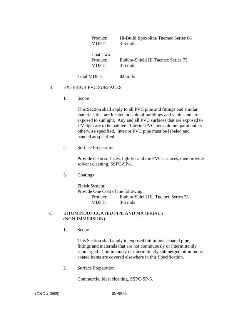
(G&O #12009) 09900-5
Product: Hi-Build Epoxoline Tnemec Series 66 MDFT: 3-5 mils Coat Two Product: Endura-Shield III Tnemec Series 73 MDFT: 3-5 mils
Total MDFT: 8.0 mils
B. EXTERIOR PVC SURFACES
1. Scope
This Section shall apply to all PVC pipe and fittings and similar materials that are located outside of buildings and vaults and are exposed to sunlight. Any and all PVC surfaces that are exposed to UV light are to be painted. Interior PVC items do not paint unless otherwise specified. Interior PVC pipe must be labeled and banded as specified.
2. Surface Preparation
Provide clean surfaces, lightly sand the PVC surfaces, then provide solvent cleaning, SSPC-SP-1.
3. Coatings
Finish System: Provide One Coat of the following:
Product: Endura-Shield III, Tnemec Series 73 MDFT: 3-5 mils
C. BITUMINOUS COATED PIPE AND MATERIALS
(NON-IMMERSION)
1. Scope
This Section shall apply to exposed bituminous coated pipe, fittings and materials that are not continuously or intermittently submerged. Continuously or intermittently submerged bituminous coated items are covered elsewhere in this Specification.
2. Surface Preparation
Commercial blast cleaning, SSPC-SP-6.
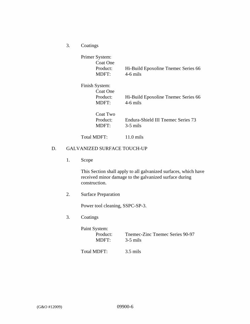
(G&O #12009) 09900-6
3. Coatings
Primer System:
Coat One Product: Hi-Build Epoxoline Tnemec Series 66 MDFT: 4-6 mils
Finish System:
Coat One Product: Hi-Build Epoxoline Tnemec Series 66 MDFT: 4-6 mils Coat Two Product: Endura-Shield III Tnemec Series 73 MDFT: 3-5 mils
Total MDFT: 11.0 mils
D. GALVANIZED SURFACE TOUCH-UP
1. Scope
This Section shall apply to all galvanized surfaces, which have received minor damage to the galvanized surface during construction.
2. Surface Preparation
Power tool cleaning, SSPC-SP-3.
3. Coatings
Paint System:
Product: Tnemec-Zinc Tnemec Series 90-97 MDFT: 3-5 mils
Total MDFT: 3.5 mils
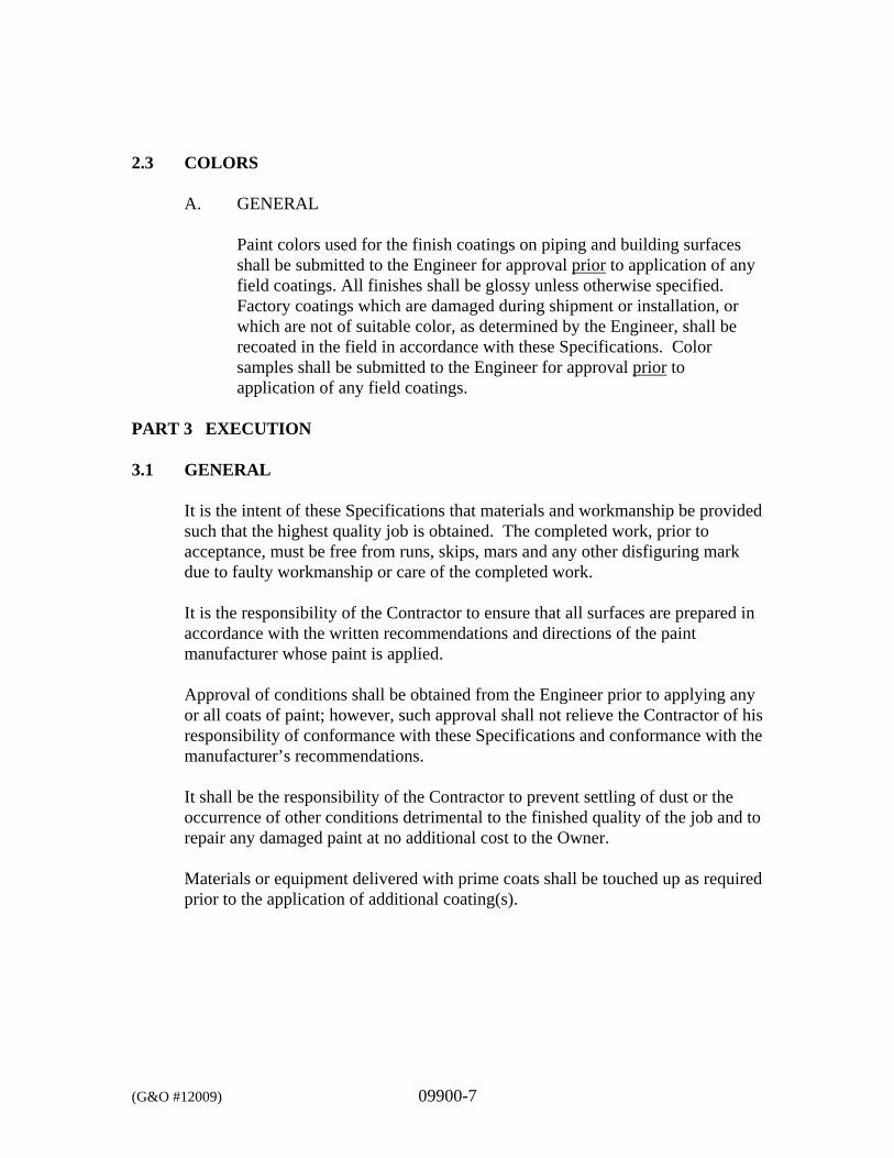
(G&O #12009) 09900-7
2.3 COLORS
A. GENERAL
Paint colors used for the finish coatings on piping and building surfaces shall be submitted to the Engineer for approval prior to application of any field coatings. All finishes shall be glossy unless otherwise specified. Factory coatings which are damaged during shipment or installation, or which are not of suitable color, as determined by the Engineer, shall be recoated in the field in accordance with these Specifications. Color samples shall be submitted to the Engineer for approval prior to application of any field coatings.
PART 3 EXECUTION 3.1 GENERAL
It is the intent of these Specifications that materials and workmanship be provided such that the highest quality job is obtained. The completed work, prior to acceptance, must be free from runs, skips, mars and any other disfiguring mark due to faulty workmanship or care of the completed work.
It is the responsibility of the Contractor to ensure that all surfaces are prepared in accordance with the written recommendations and directions of the paint manufacturer whose paint is applied. Approval of conditions shall be obtained from the Engineer prior to applying any or all coats of paint; however, such approval shall not relieve the Contractor of his responsibility of conformance with these Specifications and conformance with the manufacturer’s recommendations. It shall be the responsibility of the Contractor to prevent settling of dust or the occurrence of other conditions detrimental to the finished quality of the job and to repair any damaged paint at no additional cost to the Owner. Materials or equipment delivered with prime coats shall be touched up as required prior to the application of additional coating(s).
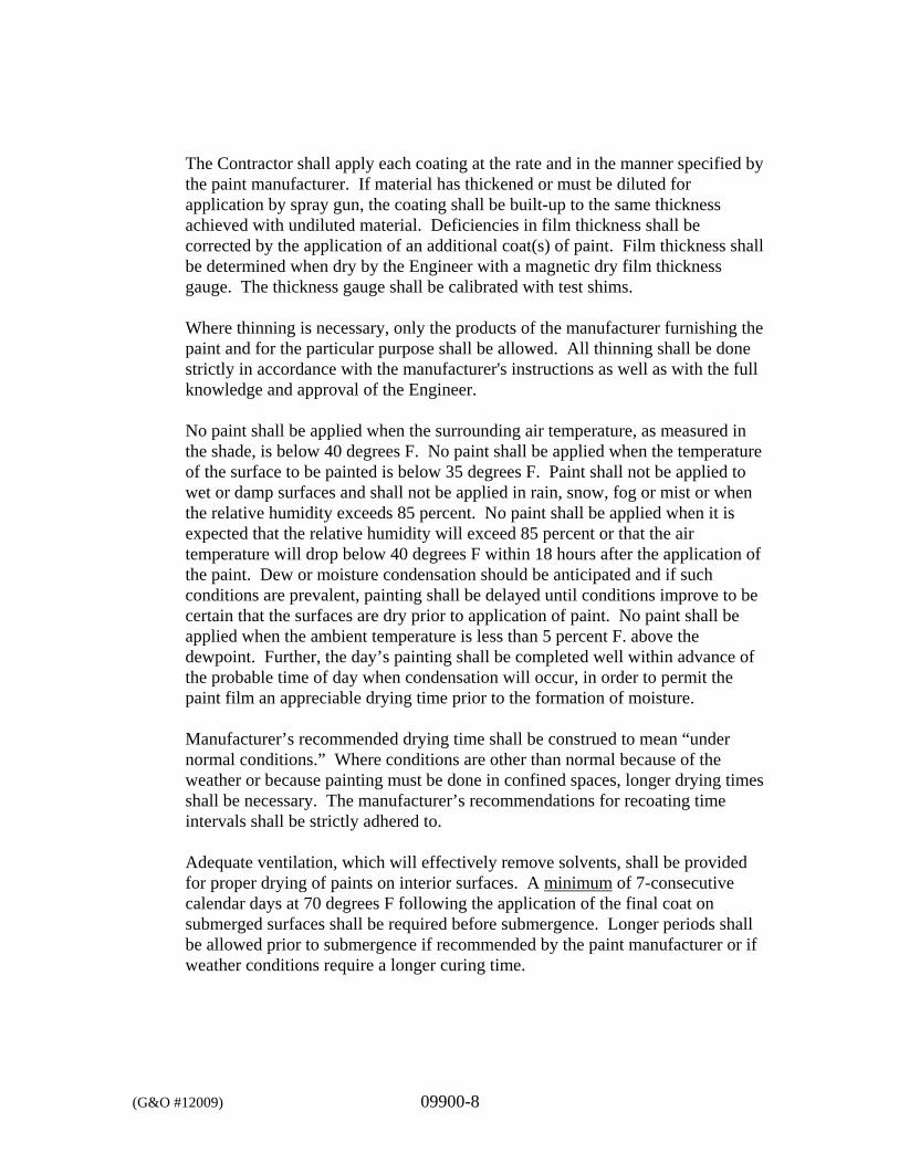
(G&O #12009) 09900-8
The Contractor shall apply each coating at the rate and in the manner specified by the paint manufacturer. If material has thickened or must be diluted for application by spray gun, the coating shall be built-up to the same thickness achieved with undiluted material. Deficiencies in film thickness shall be corrected by the application of an additional coat(s) of paint. Film thickness shall be determined when dry by the Engineer with a magnetic dry film thickness gauge. The thickness gauge shall be calibrated with test shims. Where thinning is necessary, only the products of the manufacturer furnishing the paint and for the particular purpose shall be allowed. All thinning shall be done strictly in accordance with the manufacturer's instructions as well as with the full knowledge and approval of the Engineer. No paint shall be applied when the surrounding air temperature, as measured in the shade, is below 40 degrees F. No paint shall be applied when the temperature of the surface to be painted is below 35 degrees F. Paint shall not be applied to wet or damp surfaces and shall not be applied in rain, snow, fog or mist or when the relative humidity exceeds 85 percent. No paint shall be applied when it is expected that the relative humidity will exceed 85 percent or that the air temperature will drop below 40 degrees F within 18 hours after the application of the paint. Dew or moisture condensation should be anticipated and if such conditions are prevalent, painting shall be delayed until conditions improve to be certain that the surfaces are dry prior to application of paint. No paint shall be applied when the ambient temperature is less than 5 percent F. above the dewpoint. Further, the day’s painting shall be completed well within advance of the probable time of day when condensation will occur, in order to permit the paint film an appreciable drying time prior to the formation of moisture. Manufacturer’s recommended drying time shall be construed to mean “under normal conditions.” Where conditions are other than normal because of the weather or because painting must be done in confined spaces, longer drying times shall be necessary. The manufacturer’s recommendations for recoating time intervals shall be strictly adhered to. Adequate ventilation, which will effectively remove solvents, shall be provided for proper drying of paints on interior surfaces. A minimum of 7-consecutive calendar days at 70 degrees F following the application of the final coat on submerged surfaces shall be required before submergence. Longer periods shall be allowed prior to submergence if recommended by the paint manufacturer or if weather conditions require a longer curing time.
(G&O #12009) 09900-9
3.2 MIXING AND THINNING
Paint shall be thoroughly mixed each time any is withdrawn from the container. Paint containers shall be kept tightly closed except while paint is being withdrawn.
Paint shall be factory mixed to proper consistency and viscosity for hot weather application without thinning. Thinning will be permitted only as necessary to obtain recommended coverage at lower application temperatures. Only thinners approved by the paint manufacturer shall be used. In no case shall the wet film thickness of applied paint be reduced, by addition of paint thinner or otherwise, below the thickness recommended by the paint manufacturer.
3.3 SURFACE PREPARATION
A. GENERAL
Surfaces shall be dry and thoroughly cleaned of foreign materials with all defects filled or removed. All trades employed shall leave the surfaces of their work in such a condition that only minor cleaning, sanding and filling is required of the painting trade for surface preparation. Hardware, switchplates, machined surfaces, nameplates, lighting fixtures and all other surfaces not to be painted shall be removed or otherwise protected. Drop cloths shall be provided, where necessary, to avoid spotting of surfaces adjacent to the item being painted. Working parts of electrical equipment shall be protected from damage during surface preparation and painting operations. Ferrous metal cleaning shall be in accordance with Steel Structures Painting Council Specifications (SSPC). Description SSPC White Metal Blast Cleaning SP-5 Commercial Blast Cleaning SP-6 Brush-Off Blast Cleaning SP-7 Near-White Blast Cleaning SP-10 The words “blast cleaning” or equivalent phrases of equal intent shall be taken to refer to the applicable SSPC specification when used in the paint manufacturer’s recommendations or these Specifications.
(G&O #12009) 09900-10
Hand tool cleaning shall be used when power tool cleaning is not possible. Hand and power tool cleaning shall be in accordance with SSPC Specifications SP-2, SP-3 or SP-11, respectively. The blast cleaning profile depth shall be not less than 1 mil or greater than 2 mils. In the case of equipment to which the manufacturer applies a primer coating in the shop after fabrication, the blast profile depth needs to be as noted above.
B. FERROUS METAL, GALVANIZED METAL AND HOLLOW METAL
SURFACES
The Contractor shall assure that fabrication, welding or burning is completed prior to the sandblasting operation. The Contractor shall chip or grind off flux, splatter, slag or other laminations left from welding. The Contractor shall remove all mill scale. The Contractor shall grind smooth rough welds and other sharp projections. The Contractor shall near-white blast clean, in accordance with SSPC SP-10, submerged surfaces and surfaces to 12 inches above highest liquid level, and areas subject to splash or spillage. The Contractor shall commercial blast clean, in accordance with SSPC SP-6, all interior and exterior structural steel surfaces, surfaces located 12 inches above submerged areas, and surfaces located in areas not subject to splash or spillage where exposed to open bodies of liquids. The Engineer reserves the right to accept preparation of these surfaces in accordance with SSPC-SP-3 for areas not practical or possible to sandblast to SSPC-SP-6 requirements. The Contractor shall near-white blast clean, in accordance with SSPC-SP-10 surfaces, subject to heat in excess of 600 degrees F. The Contractor shall power tool or hand clean in accordance with SSPC-SP-2 or SSPC-SP-3. The Contractor shall apply prime coat on cleaned surfaces within 2 hours of cleaning. The Contractor shall solvent clean galvanized surfaces in accordance with SSPC-SP-1.
C. NEW CONCRETE AND CONCRETE BLOCK MASONRY
The Contractor shall allow new concrete and concrete block masonry to cure for a minimum of 28 days and shall verify that the moisture content contained in the concrete is stable and not in motion. The Contractor shall verify by performance of a Wet Matt Test per ASTM D4263. The Contractor shall fill concrete surface cracks and irregularities with
(G&O #12009) 09900-11
Portland cement grout to provide a uniform surface texture and shall fill concrete block masonry surface with an epoxy block filler as specified. As a minimum, the Contractor shall brush off blast clean surfaces. The Contractor shall prepare the surface as specified elsewhere in these Specifications.
D. EXISTING CONCRETE AND CONCRETE BLOCK MASONRY
The Contractor shall verify that the moisture content is acceptable as noted above, shall remove existing paint that has a tendency to powder, peel or shatter when scraped with a knife, shall hydroblast or sandblast the surfaces of any previous coatings, shall fill cracks and irregularities with portland cement grout to provide a uniform surface texture compatible with new concrete and shall fill concrete block masonry surfaces with a block filler.
E. PREPARATION BY SANDBLASTING
The Contractor shall not sandblast surfaces that will be wet after blasting and before painting. The Contractor shall apply primer to sandblasted surfaces the same day that the surface is blasted and before rusting occurs. The Contractor shall reblast surfaces allowed to set overnight prior to priming or surfaces that show rust bloom.
The sand shall be clean, water washed, with controlled particle size and high silica content. The sand shall have sharp, angular surfaces and contain no clay particles or other extraneous matter. The profile depth of sandblasted surfaces shall be not less than 1 mil or greater than 2 mils, unless required otherwise by the coating manufacturer. Compressed air for blasting shall be free of water and oil. The Contractor shall provide accessible separators and traps, shall confine sandblast sand to the area being blasted, shall provide shields of polyethylene sheeting or other such barriers to confine sand and shall plug pipes, holes or openings before sandblasting and keep them plugged until the sandblasting operation is complete and the sand is removed. The Contractor shall protect nameplates, valve stems, rotating equipment, motors and other items that may be damaged from sandblasting. The Contractor shall reblast surfaces not meeting the requirements of these Specifications.
(G&O #12009) 09900-12
3.4 APPLICATION
A. GENERAL
The Contractor shall mix and apply coatings by brush, roller or spray in accordance with the manufacturer’s installation instructions. Spraying equipment shall be inspected and approved in writing by the coating manufacturer. The Contractor shall provide complete coverage’s to the mil thickness specified. The thickness specified shall be dry film mil thickness. All paint systems are “to cover.” In situations of discrepancy between the manufacturer’s square footage coverage rates and mil thickness, mil thickness requirements govern. When color or undercoats show through, the Contractor shall apply additional coats until paint film is of uniform finish and color. The Contractor shall not apply consecutive coats until the Engineer has had an opportunity to observe and approve previous coats. The Contractor shall apply materials under adequate illumination, shall evenly spread and flow on to provide full, smooth coverage, shall work each application of material into corners, crevices, joints and other difficult to work areas, shall avoid degradation and contamination of blasted surfaces and avoid intercoat contamination, shall clean contaminated surfaces before applying next coat and shall immediately smooth out runs or sags, or remove and recoat entire surfaces. The Contractor shall assure that preceding coats are dry before recoating, shall recoat within the time limits specified by the coating manufacturer and shall allow coated surfaces to cure prior to allowing traffic or other work to proceed. The Contractor shall coat all aluminum surfaces in contact with dissimilar materials. All fabricated and structural steel shall have prime coat(s) applied in the shop and finish coat(s) applied in the field. During application of either prime or finish coats, brush coat all weld seams, edges, angles, fasteners and other irregular surfaces to insure a monolithic film, pinhole free surface. Finish coats of paint shall be uniform in color and sheen without streaks, laps, runs, drips, sags or missed areas. All submerged or intermittently submerged materials shall have surface preparation and coatings applied prior to installation unless otherwise approved by the Engineer. All pipe, pipe supports, and pipe hangers that paint shall have surface preparation and coatings applied prior to installation.
(G&O #12009) 09900-13
B. PRIME COAT INSTALLATION
The Contractor shall prime all surfaces indicated to be painted, shall touch-up damaged primer coats prior to finish coats and shall assure field-applied coatings are compatible with factory-applied coatings. If coatings are not compatible, and if approved in writing by the Engineer, the Contractor shall apply a 2-mil-thick universal barrier coat recommended by the paint manufacturer prior to applying field coats or completely remove factory coatings and reprime. The Contractor shall prime ferrous metals bedded in concrete to a minimum of 1 inch below exposed surfaces. The Contractor shall backroll all primer coats applied to existing or new CMU block. The Contractor shall assure sandblasting operations do not result in the embedment of sand particles in paint film. The Contractor shall brush or spray bolts, welds, edges and difficult access areas with primer prior to primer application over the entire surface being coated. The Contractor shall backroll concrete, masonry, gypsum board and plaster surfaces with a roller if the primer has been spray applied.
C. FINISH SCHEDULE
All work performed under this Contract (both new work and modifications to existing facilities) shall be painted. If the finish schedule requires wall surfaces to be painted in a particular space, the Contractor shall paint all appurtenant surfaces unless specifically noted not to be painted on the Drawings. These items to be painted shall include: Pipe supports, and equipment supports. Reservoir supports Insulated or wrapped piping, valves, fittings, hydrants and
appurtenances except where covered by lagging. Insulated or wrapped ductwork and appurtenances. Conduit and appurtenances. Ferrous metals. Exposed woodwork.
(G&O #12009) 09900-14
Copper and brass surfaces. Inside and/or outside of ferrous metal tankage. New machinery and equipment except:
Electrical panels; Switchboards; Switchgear; Safety switches; Motor starter equipment; Busways; Raceways.
The Contractor shall paint the following surfaces in areas not considered as finished areas: Insulated or wrapped piping, valves, fittings, yard or fire hydrants
and appurtenances. Insulated or wrapped ductwork and appurtenances. New machinery and equipment. Machinery and equipment in sumps, pits, boxes, channels,
wetwells and structures. The Contractor shall paint all exposed interior and exterior surfaces including: Insulated or wrapped piping, valves, fittings, yard or fire hydrants
and appurtenances except when covered by lagging. Insulated or wrapped ductwork and appurtenances except when
covered by lagging. Conduit and appurtenances. Exterior and interior surfaces of ferrous metal tankage. Ferrous metals. Exposed wood. Plaster surfaces. The Contractor shall not paint the following elements unless specifically noted on the Drawings to be painted: Segmental block retaining wall Concrete foundation of Reservoir No. 4 Stainless steel surfaces except as required to identify piping. Exposed to view aluminum surfaces. Galvanized metal surfaces.
(G&O #12009) 09900-15
Fiberglass surfaces except fiberglass piping and piping appurtenances.
FRP ductwork unless gel coat color is not acceptable to the Owner. Interior of pipe, ductwork, and conduits. Moving parts of mechanical and electrical units. Code labels and equipment identification and rating plates. Piping, ductwork, or pipe conduit when enclosed between
suspended ceiling and overhead slabs or located in pipe chases or surfaces to be lagged.
Factory-finished furniture, laboratory casework, metal toilet partitions, kitchen units, lockers, shop and storage equipment or miscellaneous items that have pre-approved factory applied finishes.
Prefaced masonry, burnished masonry units, or glass masonry. Structural steel or steel deck required to be fireproofed. Contact surfaces of friction-type connections. Pipe and/or duct lagging. Concrete walls or floors
3.5 FIELD QUALITY CONTROL
The Contractor shall be responsible for performing, testing and assuring conformance with all requirements of these Specifications.
The Contractor shall maintain daily records showing:
Start date of work in each area. Date of application for each following coat. Moisture content and surface temperature of substrate. Also record
weather conditions, ambient air temperature and dew point. Provisions utilized to maintain temperature and humidity of work area
within paint manufacturer’s recommended ranges. The Contractor shall measure the surface temperature of items to be painted with surface temperature gauges specifically designed for such use. The Contractor shall measure substrate humidity with humidity gauges specifically designed for such use. The Contractor shall measure wet paint with wet film thickness gauges. The Contractor shall measure paint dry film thickness with a Mikrotest gauge calibrated against the National Bureau of Standards “Certified Coating Thickness Calibration Standards.” The Engineer may direct measurement of paint thickness at any time during the project to ensure conformance with these Specifications. A sufficient number of dry film thickness measurements shall be made so that there
(G&O #12009) 09900-16
is approximately one measurement for each 100 square feet of surface area painted. Where a wall or ceiling or other type of surface is disturbed and patched, the Contractor shall repaint entire wall or ceiling. The Contractor shall provide wet paint signs as necessary. The Contractor shall touch up damaged finish coats using the same material as specified for the finish coat. At the conclusion of all painting activities, Contractor shall submit a painting field test report to the Engineer showing the above information plus results of wet film and dry film thickness tests. Provide four copies of final test report.
3.6 PAINTING SITE
Either shop painting or field painting and surface preparation shall be acceptable when painting work is performed in conformance with this Section, unless the painting is activity specified elsewhere in these Specifications.
3.7 PAINT THICKNESS
All paint thicknesses specified herein are minimum dry film thickness (MDFT). The thickness of paint over metallic surfaces shall be measured with a magnetic thickness gauge; paint thickness over wood or masonry shall vary in accordance with surface texture, but in no case shall the manufacturer’s recommended coverage rate be exceeded. The minimum thicknesses given are total coating thickness for the coating specified, including multiple coats of the same material, where applicable.
*** END OF SECTION ***
(G&O #12009) 09970-1
SECTION 09970
RESERVOIR SURFACE PREPARATION AND PAINTING PART 1 GENERAL 1.1 SCOPE
The work specified in this Section includes preparation of surfaces, performance requirements and completion of painting of all exterior and interior surfaces of the reservoirs as required by the Drawings and as specified herein. All coating materials and workmanship shall be in conformance with AWWA D102 and as specified herein. The more stringent requirements of the AWWA Standard or this Section shall apply. The Contractor shall prepare and coat the interior and exterior of the new Reservoir No. 4. On the existing Reservoir No. 1, the Contractor shall prepare and coat the interior and exterior surfaces of those areas damaged by the welding of the new welded inlet pipe brackets/welding pads to the tank wall. Prepare and coat the area providing a perimeter of a minimum of 6 inches around the location of the new welded inlet pipe brackets/welding pads. Prepare and coat new welded inlet pipe brackets/welding pads. As these repaired coating areas on exterior of Reservoir No. 1 will be visible, the spot painting shall be done in a neat and workmanship-like manner with uniform rectangular spot repairs using a coating color matching the existing coating. The Contractor shall prepare and coat the interior and exterior of the existing 11-foot diameter by 42-foot long reservoirs. The quantity of tanks to be prepared and coated is determined by the option(s) of work selected by the Owner. These reservoirs have existing coatings that are lead-based paints and may contain other metals as well. The Contractor shall take all necessary safety precautions and measures necessary to safely and properly remove and dispose of the hazardous wastes generated in this work. See Section 01900 concerning Lead in paint on these reservoirs.
1.2 RELATED WORK SPECIFIED ELSEWHERE
Section Item 01300 Submittals 01900 Salvage and Demolition Division 5 Metals 09900 Painting
(G&O #12009) 09970-2
1.3 REFERENCES
ANSI/NSF 61 - Drinking Water System Components - Health Effects. ASTM D16 - Terminology Relating to Paint, Varnish, Lacquer, and Related Products. AWWA C652 - Disinfections of Water-Storage Facilities. AWWA D102 - Painting Steel Water Storage Tanks. SSPC-SP 6/NACE 3 - Commercial Blast Cleaning. SSPC-SP 10/NACE 2 - Near-White Metal Blast Cleaning. SSPC-Guide 7 - Guide for Disposal of Lead-Contaminated Surface Preparation Debris.
1.4 SUBMITTALS
Submit the following information in accordance with Section 01300 for each of the distinctive products to be used:
A. Manufacturer’s quality assurance: submit manufacturer’s certification that
coatings comply with specified requirements and are suitable for intended application.
B. Applicator’s quality assurance: Submit list of a minimum of 5 completed
projects of similar size and complexity to this Work. Include for each project: 1. Project name and location. 2. Name of owner. 3. Name of contractor. 4. Name of engineer. 5. Name of coating manufacturer. 6. Approximate area of coatings applied. 7. Date of completion.
C. Paint system data sheet for each of the distinctive products to be used. The information shall include manufacturer’s name, product name, and number and required minimum dry film thickness.
D. Drawdown samples of proposed finish colors indicated herein.
(G&O #12009) 09970-3
E. Manufacturer’s written instructions for applying the primer and finished
coats of paint.
F. Provide certification that interior coatings in contact with potable water have been certified in accordance with the National Sanitation Foundation Standard No. 61.
G. A Health and Safety plan that includes but is not limited to methods for
protecting workers from dust, paint fumes, exposure to lead, a description of the air handling system and appropriate emergency procedures.
H. An abrasive blast disposal plan that includes, but is not limited to, methods
and materials planned for the proper storage, testing, disposal method, and disposal site for project blast material. Documentation of proper disposal will be required prior to project closeout. Proper adherence to all applicable laws, regulations, and standards for the safe handling of lead contaminated materials will be the responsibility of the Contractor.
The above information shall be submitted 20 days prior to the painting process and shall be approved by the Owner before any coatings are applied.
To allow the Owner an opportunity to observe the completed surface preparation, the Contractor shall notify the Owner at least 5 days before application of coatings is to begin.
1.5 DEFINITIONS
A. Definitions of Painting Terms: ASTM D 16, unless otherwise specified.
B. Dry Film Thickness (DFT): Thickness of a coat of paint in fully cured state measured in mils (1/1000 inch).
1.6 SITE ENVIRONMENTAL REQUIREMENTS
A. The contractor, in executing the work, shall maintain affected areas within and outside project boundaries free from environmental pollution that would be in violation of any federal, state, county, or local regulations.
B. Staging areas established by the Contractor shall be limited to the
minimum area absolutely required. Hazardous materials stored in the staging areas shall be placed on a leak proof membrane and surrounded with temporary retaining curbs as required to prevent soil contamination and/or the release of any contaminated material.
(G&O #12009) 09970-4
Other precautions to prevent soil contamination shall consist of acceptable containers for the collection and disposal of all waste materials including rubbish, other debris, existing paint chips and other painting materials used for this project.
C. Any liquid, semi-liquid, or saturated solids that tend to bleed must be conveyed in watertight containers.
D. The Contractor shall not dispose of volatile wastes such as mineral spirits, oil, chemicals, paint thinner, or paint stripper in storm or sanitary drains. Disposal of wastes into streams or waterways is also strictly prohibited. Wastes shall be prohibited from entering the surface or subsurface water source(s). No paint or solvent material shall be disposed of on site, nor shall the Contractor burn or bury rubbish or waste materials on the project site.
E. The use of petroleum products on the site shall be limited during
construction to that amount absolutely necessary. Refueling shall be done in an area covered by a leakproof membrane and surrounded by temporary retaining curbs as required. Any vehicle or piece of equipment that is leaking petroleum products, including fuel or hydraulic fluid, shall be prohibited from the construction site.
F. In the event a spill occurs on the construction site, the Contractor is
responsible for contacting the Owner and all appropriate agencies in accordance with applicable federal, state, and local regulations, including but not limited to WAC 173-303-145 (Spills and Discharges into the Environment).
G. The Contractor shall comply with all applicable federal, state, and local
laws including but not limited to WAC 173-303 Dangerous Waste Regulation relating to the collection, containment and transportation of hazardous substances and shall be contractually responsible for ensuring all subcontractors comply as well.
H. Noise shall be minimized by using appropriate construction methods and
equipment. The Contractor shall provide mufflers or acoustical barriers to maintain noise levels from tools and equipment within legal noise levels.
I. The Contractor shall strictly adhere to applicable regulations for fugitive
dust emissions as specified by the Puget Sound Clean Air Agency. Any dust complaints received shall be immediately addressed by the Contractor.
(G&O #12009) 09970-5
J. The Contractor shall be responsible for the temporary storage of painting materials, solvents, plus the collection and containment of all non-hazardous and hazardous wastes, debris and rubbish generated by construction activities for the duration of the Project and until the Owner accepts the work as complete. The Contractor shall employ the necessary safe guards to protect the materials temporarily stored on site from accidental spills and vandalism. Temporary storage areas required for the Contractor to store hazardous substances and other wastes on site shall be confined to mutually agreed upon locations within the site. The Contractor shall be confined to the location(s) specified. Changes or modification to the temporary storage shall be permitted, provided the request is submitted in writing with a sketch of the proposed modification to the Owner for review.
K. Hazardous and non-hazardous substance storage on site is limited to the
length of the Contract. All containers with hazardous substances shall be water tight and environmentally safe. When temporarily stored on site, all containers shall be placed on wooden pallets and contained within leakproof membranes surrounded with temporary retaining curbs. Containers shall be stored up right in multiple rows, stacking containers on top of one other is prohibited.
L. The Contractor shall be responsible for transporting and disposal of all
materials generated from the cleaning process to include but not limited to: all abrasive paint removal materials and all other hazardous and non-hazardous substances, debris and rubbish generated from the surface preparation, application of the new coating system and other construction activities. All materials shall be removed from the site by the Contractor prior to Project acceptance and disposed of or recycled in accordance with all federal, state, county, and local regulations.
1.7 CONTRACTOR’S QUALIFICATIONS
The Contractor or subcontractor performing the surface preparation and painting (shop and field) shall have completed at least five water reservoirs in the State of Washington within the past 10 years. The Owner shall have the right to reject the painter based on lack of qualifications. Any costs associated with obtaining approval of the painter or substitution of a new painter shall be considered incidental to the Project and no additional payment will be made.
1.8 MANUFACTURER’S SERVICE
It shall be the responsibility of the paint manufacturer to work with the Contractor as a working team to obtain a good protective coating for the interior and exterior surfaces of the reservoir.
(G&O #12009) 09970-6
A. The Manufacturer’s representative shall be notified and be present at the jobsite on the first day of painting to verify that proper surface preparation has been provided and that coatings are being applied in conformance with these Specifications.
B. The Manufacturer’s representative shall be available on request by either
the Owner or the Contractor for further confirmation of proper painting procedures throughout the field painting phase of construction, particularly prior to applying the next coat of paint.
C. The Manufacturer’s representative shall assist in the inspection of the
surface coatings, upon completion of the final coats of paint to principally check the minimum dry film thickness (DFT) of the coatings.
D. The Manufacturer’s representative shall assist in performing the first year
anniversary inspection of the interior and exterior coatings at no additional cost to the Owner.
1.9 INSPECTION
The Contractor shall provide an independent Painting Inspector approved by the Owner. The Painting Inspector shall be National Association of Corrosion Engineer’s (NACE) certified and/or knowledgeable in Steel Structure Painting Council (SSPC) standards. The Inspector shall verify proper surface preparation, dry film thickness measurements, coating product identification verification including batch numbers of each product, and weather conditions. The Inspector shall visit the site as often as necessary to provide the proper inspection, but as a minimum, shall include at least eight interior inspections, five exterior inspections, and shop prime inspection. The Inspector shall submit written inspection reports to the Owner within 2-working days following each site visit. The report shall include written daily report forms prepared by the Contractor and reviewed by the Inspector. The Inspector shall provide a final written report that paint coatings have been applied properly and meet the requirements of the Specifications. As a minimum the reports shall include: Daily Activities Log, Surface Preparation Checklist, Coating Materials Report, Paint Mixing Data Report, Wet Mil Thickness Report, Dry Mil Thickness Report. The Inspector shall assist in inspecting the coatings at the first year anniversary inspection.
(G&O #12009) 09970-7
PART 2 PRODUCTS 2.1 APPROVED MANUFACTURERS
Subject to compliance with the Specifications contained herein, approved manufacturers offering coating systems which may be incorporated into the work include, but is not necessarily limited to the following: A. Tnemec Company B. Ameron Protective Coatings Division C. Carboline Protective Coatings D. Sherwin Williams
Tnemec Company, Inc. paint products are listed. All colors and types of paints indicated are Tnemec. All coating applications shall be to Tnemec standards, specifications, requirements, and recommendations. Substitutions will be considered but must meet the performance requirements stated herein and be approved by the Owner. Offers for substitutions will not be considered which decrease film thickness, solids by volume, the number of coats to be applied, or which proposes a change from the generic type of coating specified herein. All substitutions shall include complete laboratory test reports to demonstrate proposed coating materials comply with specified performance criteria. Paint application shall be performed in strict accordance with manufacturer’s printed instructions except that minimum coating thickness specified in paint schedule herein shall govern. All materials delivered to the jobsite shall be in original sealed and labeled containers of the paint manufacturer. Store paint materials in a protected area that is heated or cooled to maintain temperature range recommended by the paint manufacturer.
2.2 INTERIOR RESERVOIR COATING AND ACCESSORIES
The interior topcoat shall be a modified polyamine epoxy suitable for potable water service (AWWA D102-03, System ICS-5 modified for zinc-rich primer for entire interior surface). The interior system shall include: A. COATING SYSTEM (SHOP)
Reservoir No. 1, Reservoir No. 4 1. Primer: All prepared surfaces shall receive one coat of Tnemec
Series 91-H2O at 2.5 to 3.5 mils dry film thickness.
(G&O #12009) 09970-8
2. All new components and accessories located inside the reservoir including ladders, platforms, painters rail, rafters, piping, etc., shall be shop primed.
3. Intermediate: Coated surfaces receive one coat of Tnemec Series N140 PotaPox Plus at 6.0 to 9.0 mils dry film thickness.
4. If roof is not fully seal welded, all components and accessories for
the interior of the reservoir including the top flanges of the rafters and top surfaces of the compression ring shall be shop coated with a finish coat.
5. Finish: Coated surfaces receive one coat of Tnemec Series N140 PotaPox Plus at 6.0 to 9.0 mils dry film thickness.
B. COATING SYSTEM (FIELD)
Reservoir No. 1 (Partial), Reservoir No. 4, Sycamore Booster Station Tanks
1. Primer: All blasted areas shall receive one coat of Tnemec Series
91-H2O at 2.5 to 3.5-mils dry film thickness.
2. Intermediate: Coated surfaces receive one coat of Tnemec Series N140 PotaPox Plus at 6.0 to 9.0 mils dry film thickness.
3. Finish: Coated surfaces receive one coat of Tnemec Series N140 PotaPox Plus at 6.0 to 9.0 mils dry film thickness.
The total dry film thickness of the complete interior paint coating system shall be a minimum of 14.5 mils.
2.3 EXTERIOR RESERVOIR COATING AND ACCESSORIES Reservoir No. 1 (Surfaces damaged in construction), Reservoir No. 4, Sycamore Booster Station Tanks
The exterior topcoat shall be a high-build acrylic polyurethane enamel (AWWA D102, System 6). The exterior system shall include:
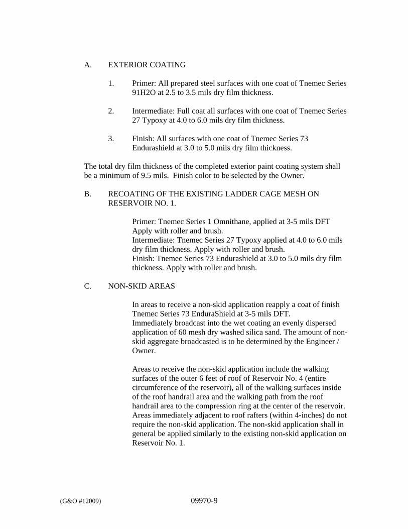
(G&O #12009) 09970-9
A. EXTERIOR COATING
1. Primer: All prepared steel surfaces with one coat of Tnemec Series 91H2O at 2.5 to 3.5 mils dry film thickness.
2. Intermediate: Full coat all surfaces with one coat of Tnemec Series 27 Typoxy at 4.0 to 6.0 mils dry film thickness.
3. Finish: All surfaces with one coat of Tnemec Series 73 Endurashield at 3.0 to 5.0 mils dry film thickness.
The total dry film thickness of the completed exterior paint coating system shall be a minimum of 9.5 mils. Finish color to be selected by the Owner.
B. RECOATING OF THE EXISTING LADDER CAGE MESH ON
RESERVOIR NO. 1.
Primer: Tnemec Series 1 Omnithane, applied at 3-5 mils DFT Apply with roller and brush. Intermediate: Tnemec Series 27 Typoxy applied at 4.0 to 6.0 mils dry film thickness. Apply with roller and brush. Finish: Tnemec Series 73 Endurashield at 3.0 to 5.0 mils dry film thickness. Apply with roller and brush.
C. NON-SKID AREAS
In areas to receive a non-skid application reapply a coat of finish Tnemec Series 73 EnduraShield at 3-5 mils DFT. Immediately broadcast into the wet coating an evenly dispersed application of 60 mesh dry washed silica sand. The amount of non-skid aggregate broadcasted is to be determined by the Engineer / Owner.
Areas to receive the non-skid application include the walking surfaces of the outer 6 feet of roof of Reservoir No. 4 (entire circumference of the reservoir), all of the walking surfaces inside of the roof handrail area and the walking path from the roof handrail area to the compression ring at the center of the reservoir. Areas immediately adjacent to roof rafters (within 4-inches) do not require the non-skid application. The non-skid application shall in general be applied similarly to the existing non-skid application on Reservoir No. 1.
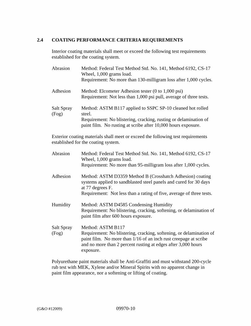
(G&O #12009) 09970-10
2.4 COATING PERFORMANCE CRITERIA REQUIREMENTS Interior coating materials shall meet or exceed the following test requirements established for the coating system. Abrasion Method: Federal Test Method Std. No. 141, Method 6192, CS-17
Wheel, 1,000 grams load. Requirement: No more than 130-milligram loss after 1,000 cycles. Adhesion Method: Elcometer Adhesion tester (0 to 1,000 psi) Requirement: Not less than 1,000 psi pull, average of three tests. Salt Spray Method: ASTM B117 applied to SSPC SP-10 cleaned hot rolled (Fog) steel. Requirement: No blistering, cracking, rusting or delamination of
paint film. No rusting at scribe after 10,000 hours exposure.
Exterior coating materials shall meet or exceed the following test requirements established for the coating system. Abrasion Method: Federal Test Method Std. No. 141, Method 6192, CS-17
Wheel, 1,000 grams load. Requirement: No more than 95-milligram loss after 1,000 cycles. Adhesion Method: ASTM D3359 Method B (Crosshatch Adhesion) coating
systems applied to sandblasted steel panels and cured for 30 days at 77 degrees F.
Requirement: Not less than a rating of five, average of three tests. Humidity Method: ASTM D4585 Condensing Humidity Requirement: No blistering, cracking, softening, or delamination of
paint film after 600 hours exposure. Salt Spray Method: ASTM B117 (Fog) Requirement: No blistering, cracking, softening, or delamination of
paint film. No more than 1/16 of an inch rust creepage at scribe and no more than 2 percent rusting at edges after 3,000 hours exposure.
Polyurethane paint materials shall be Anti-Graffiti and must withstand 200-cycle rub test with MEK, Xylene and/or Mineral Spirits with no apparent change in paint film appearance, nor a softening or lifting of coating.
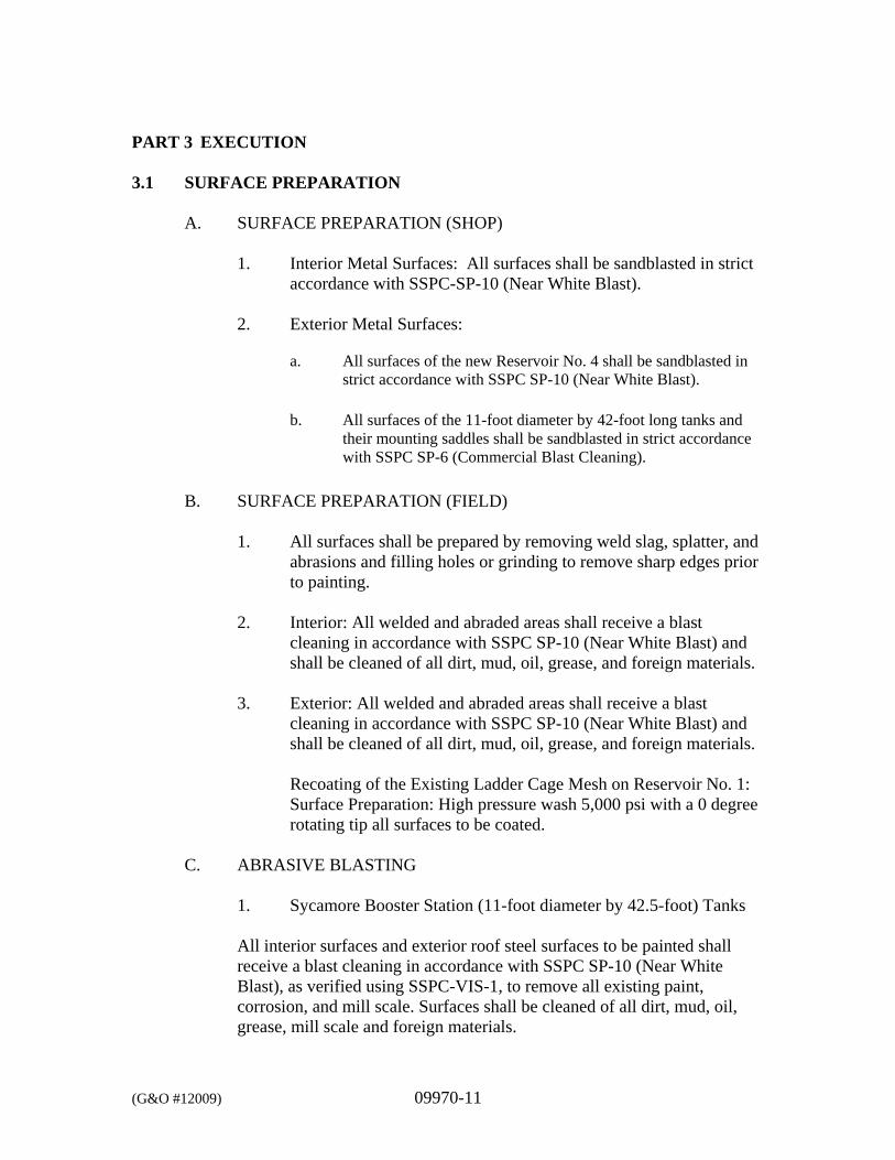
(G&O #12009) 09970-11
PART 3 EXECUTION 3.1 SURFACE PREPARATION
A. SURFACE PREPARATION (SHOP)
1. Interior Metal Surfaces: All surfaces shall be sandblasted in strict accordance with SSPC-SP-10 (Near White Blast).
2. Exterior Metal Surfaces:
a. All surfaces of the new Reservoir No. 4 shall be sandblasted in strict accordance with SSPC SP-10 (Near White Blast).
b. All surfaces of the 11-foot diameter by 42-foot long tanks and their mounting saddles shall be sandblasted in strict accordance with SSPC SP-6 (Commercial Blast Cleaning).
B. SURFACE PREPARATION (FIELD)
1. All surfaces shall be prepared by removing weld slag, splatter, and abrasions and filling holes or grinding to remove sharp edges prior to painting.
2. Interior: All welded and abraded areas shall receive a blast
cleaning in accordance with SSPC SP-10 (Near White Blast) and shall be cleaned of all dirt, mud, oil, grease, and foreign materials.
3. Exterior: All welded and abraded areas shall receive a blast
cleaning in accordance with SSPC SP-10 (Near White Blast) and shall be cleaned of all dirt, mud, oil, grease, and foreign materials.
Recoating of the Existing Ladder Cage Mesh on Reservoir No. 1: Surface Preparation: High pressure wash 5,000 psi with a 0 degree rotating tip all surfaces to be coated.
C. ABRASIVE BLASTING
1. Sycamore Booster Station (11-foot diameter by 42.5-foot) Tanks
All interior surfaces and exterior roof steel surfaces to be painted shall receive a blast cleaning in accordance with SSPC SP-10 (Near White Blast), as verified using SSPC-VIS-1, to remove all existing paint, corrosion, and mill scale. Surfaces shall be cleaned of all dirt, mud, oil, grease, mill scale and foreign materials.
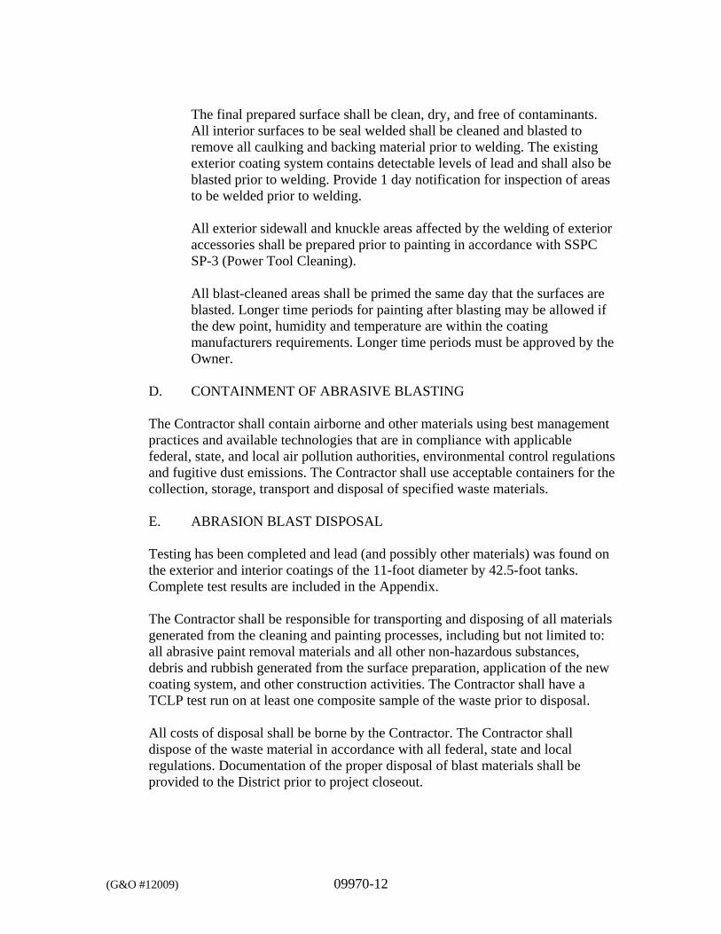
(G&O #12009) 09970-12
The final prepared surface shall be clean, dry, and free of contaminants. All interior surfaces to be seal welded shall be cleaned and blasted to remove all caulking and backing material prior to welding. The existing exterior coating system contains detectable levels of lead and shall also be blasted prior to welding. Provide 1 day notification for inspection of areas to be welded prior to welding. All exterior sidewall and knuckle areas affected by the welding of exterior accessories shall be prepared prior to painting in accordance with SSPC SP-3 (Power Tool Cleaning). All blast-cleaned areas shall be primed the same day that the surfaces are blasted. Longer time periods for painting after blasting may be allowed if the dew point, humidity and temperature are within the coating manufacturers requirements. Longer time periods must be approved by the Owner.
D. CONTAINMENT OF ABRASIVE BLASTING
The Contractor shall contain airborne and other materials using best management practices and available technologies that are in compliance with applicable federal, state, and local air pollution authorities, environmental control regulations and fugitive dust emissions. The Contractor shall use acceptable containers for the collection, storage, transport and disposal of specified waste materials. E. ABRASION BLAST DISPOSAL
Testing has been completed and lead (and possibly other materials) was found on the exterior and interior coatings of the 11-foot diameter by 42.5-foot tanks. Complete test results are included in the Appendix.
The Contractor shall be responsible for transporting and disposing of all materials generated from the cleaning and painting processes, including but not limited to: all abrasive paint removal materials and all other non-hazardous substances, debris and rubbish generated from the surface preparation, application of the new coating system, and other construction activities. The Contractor shall have a TCLP test run on at least one composite sample of the waste prior to disposal. All costs of disposal shall be borne by the Contractor. The Contractor shall dispose of the waste material in accordance with all federal, state and local regulations. Documentation of the proper disposal of blast materials shall be provided to the District prior to project closeout.
(G&O #12009) 09970-13
If materials chosen by the Contractor for surface preparation, i.e., abrasives and/or additives, cause the waste blast to be categorized as hazardous waste, the additional costs for hazardous waste disposal shall be borne by the Contractor, regardless of any hazardous materials in the paint removed.
Shop primed surfaces shall receive a cleaning to ensure surfaces are free of contaminants and to prepare the surfaces for field painting. Sweep blasting may be required as determined by the Painting Inspector and Owner. The sweep blast shall not be done more than 3 days prior to field painting. All blast cleaned areas shall be primed the same day that the surfaces are blasted. Longer time periods for painting after blasting may be allowed depending upon dew point, humidity and temperature. Longer time periods must be approved by the Painting Inspector and Owner.
3.2 INTERIOR RESERVOIR ENVIRONMENTAL REQUIREMENTS
A. GENERAL The space to be controlled shall be sealed off as well as possible allowing air to escape at the bottom of the reservoir away from the point where the dehumidified air is being introduced. Maintain aslight positive pressure in the reservoir unless the dust from the blasting operation is hazardous. Environmental conditions shall be monitored using a manual Sling Psychrometer and US Department of Commerce Psychrometric tables. Conditions will be taken and recorded at 4-hour intervals beginning at the start of each shift and throughout each work day where blasting and/or coating application takes place.
Any equipment including generators, dehumidifiers, heaters and other environmental control equipment intended to operate after normal work house shall be critically silenced to minimize noise.
B. HUMIDITY Provide dehumidification as required to maintain the interior relative humidity within the Paint Manufacturer’s specified humidity range.
(G&O #12009) 09970-14
C. TEMPERATURE
1. Provide auxiliary heaters as required to maintain the interior temperature within the Paint Manufacturer’s specified temperature range.
2. Heaters shall be installed in the process air supply duct
between the dehumidifier and the reservoir as close to the reservoir as possible.
3. Only electric or indirect gas-fired auxiliary heaters shall be
used. No direct-fired space heaters will be allowed. 4. Air heaters or refrigeration equipment are not acceptable
substitutions for dehumidification equipment.
D. VENTILATION
1. Provide ventilation during the coating evaporation stage in confined or enclosed areas in accordance with AWWA D102.
2. The ventilation system must be designed to match the air volume of the dehumidification equipment in such a manner that it will not interfere with the dehumidification equipment’s capacity to control the reservoir as described herein.
3. Do not recirculate the air from the reservoir or from filtration equipment back through the dehumidifier when coating or solvent vapors are present.
E. DUST AND CONTAMINANTS
1. Schedule coating work to avoid excessive dust and airborne contaminants.
2. Protect work areas from excessive dust and airborne contaminants during coating application and curing.
(G&O #12009) 09970-15
3.3 EXTERIOR RESERVOIR ENVIRONMENTAL REQUIREMENTS
The Contractor shall employ containment for the exterior preparation in accordance with SSPC – Guide 6 (Publication 97-21) Method 2 and as required by the regulatory agencies.
3.4 PAINTING
Materials shall be mixed, thinned, and applied according to the manufacturer’s printed instructions. All reservoir accessories including conduits shall be painted except for the Saf-T-Notch Carrier rail and aluminum items. All surfaces adjacent to the area being painted shall be protected by sufficient coverings to prevent paint spray and droplets from spotting the areas. After surface preparation has been completed and prior to painting, all dirt, dust and similar contaminants shall be removed from the surface.
It is the responsibility of the Contractor to ensure that all surfaces are prepared in accordance with the written recommendations and the directions of the paint manufacturer whose paint is being applied. Also comply with any directions from the Painting Inspector and the Owner. The Contractor shall provide written confirmation that specifications are being met from either the paint manufacturer’s representative or the Painting Inspector at each stage gate; surface preparation, primer, and finish coat for both interior and exterior coatings. All surfaces to be painted shall be in proper condition at the time the work is in progress, and no painting shall be performed under adverse conditions. Coatings shall be applied during good painting weather. Air and surface temperatures and humidity shall be continuously monitored and be within acceptable limits prescribed by the manufacturer for the coatings being applied and work areas shall be reasonably free of airborne dust at the time of application and while the coating is drying. Allow each coat of paint to dry thoroughly before applying next coat. All units to be bolted together or to the structures shall be painted prior to assembly or installation. During application of either prime or finish coats of paint, brush coat all weld seams, all blasted areas, edges, angles, fasteners and other irregular surfaces to insure a monolithic film, pinhole free surface. Provide adequate ventilation for interior of reservoir to carry off solvents during drying phase and to meet all safety requirements.
(G&O #12009) 09970-16
Allow reservoir interior to cure for a minimum of 7 days at 70 degrees F after application of final coat of paint before flushing, sterilizing, or filling with water. Manufacturer’s representative shall provide a written report that the interior coating is cured before flushing, sterilizing, or filling with water. Curing shall be performed in strict accordance with manufacturer’s recommendations and the reservoir shall be completed, inspected, cleaned, disinfected and ready for filling within 14 days unless otherwise approved by the Owner. Power venting and heating during curing may be required to meet the curing requirements of 14 days. All costs for outside sources of equipment and electrical energy shall be paid by the Contractor. All field coatings on the exterior of the reservoir shall be applied with rollers or brushes. The coatings shall be applied to provide a monolithic surface to meet the minimum dry film thickness (mils) specified. Finish coats shall be uniform in color and sheen without streaks, laps, runs, sags, ridges, or missed areas. The Contractor shall correct finish coat defects to the satisfaction of the Owner.
PART 4 TESTING
The Contractor shall be responsible for testing and assuring conformance with all requirements of these Specifications. Contractor shall have on-site a wet film thickness gauge, dry film thickness gauge, steel temperature gauge, sling psychrometer, wet sponge type “holiday” detector and any other testing equipment necessary to assure the quality control requirements of the coating manufacturer and these Specifications are met. On any day which new coatings are applied and prior to their application, the Contractor shall record weather conditions, ambient air temperature, steel temperature, and dewpoint. The Contractor shall provide the Paint Inspector and Owner with necessary equipment to inspect all areas of the reservoir. Necessary equipment shall include safety harness, hoisting equipment, ladders, etc., and this equipment shall be the same as that used by the Contractor to paint the reservoir.
Wet film thickness tests shall be measured with a gauge that measures the wet film thickness within an accuracy of plus or minus 0.5 mil. A wet film thickness measurement shall be made for each 100 square feet of surface area painted. Dry film thickness tests shall be measured with a magnetic gauge that will measure the dry film thickness within an accuracy of plus or minus 0.25 mil. A sufficient number of dry film thickness measurements shall be made so that there is approximately one measurement for each 100 square feet of surface painted.
(G&O #12009) 09970-17
The Contractor shall furnish the Owner four copies of a written test report showing the results of the wet and dry film thickness tests made on the reservoir surfaces as well as daily weather and humidity conditions for all days when painting was performed on site. The report shall includes the daily reports prepared by the Contractor and also the final report by the Painting Inspector.
4.1 DISINFECTION AND TESTING Before disinfecting, all scaffolding, planks, tools, rags, and any other material not part of the reservoir or operating facilities of the reservoir shall be removed. Then the surfaces of the walls, floor, roof, and operating facilities of the reservoir shall be cleaned thoroughly using a high-pressure water jet or sweeping. Contractor shall be careful not to damage the structure or the new coating system in preparing the reservoir for disinfection. All water, dirt, and foreign material accumulated in this cleaning operation shall be discharged from the reservoir, or otherwise removed. This foreign material may be discharged out the reservoir drain piping but shall be captured in the drainage catch basin and disposed of to waste. The reservoir shall be disinfected and tested after all interior accessories are in place and the interior painting is completed and properly cured. Methods and procedures for disinfecting the reservoir shall conform to AWWA C652, Disinfection of Water-Storage Facilities. The use of chlorine solution (sodium hypochlorite) or dry chlorine (calcium hypochlorite) is anticipated as the active disinfecting agent. The Contractor shall be responsible for safe and proper handling and storage of chlorine compounds or other hazardous chemical that are used to perform this work. Handling of such chemicals shall be in accordance with chemical manufacturer’s instructions and federal, state and local regulations. Other hazardous chemicals shall be used only after acceptance by the Owner and the Department of Health.
The intent of this Section of the Specifications is for the passage of bacterial and odor tests, protection of materials, health/safety and conservation of water. To achieve these requirements the Contractor shall submit written procedures and Drawings for disinfection of the reservoir and collecting of samples to be tested by an independent laboratory. The submittal shall include: A. Type of disinfection solution and method of preparation.
B. Method of disposal for disinfecting reservoir wastewater.
Disinfect all interior surfaces of the reservoir in accordance with the following method:
(G&O #12009) 09970-18
Spray or brush a solution containing 200 ppm of available chlorine onto the interior surfaces of the reservoir as prescribed in AWWA C652 Method 2. Apply solution from the bottom up and to include the entire interior surface area of the reservoir. Allow to remain 30 minutes or until dry before being rinsed off. Drain, dechlorinate and dispose of all chlorinated cleaning water. Fill reservoir with potable water as specified in AWWA C652. Remove chlorinated solution within 48 hours, or dilute by filling tank.
Prior to disinfecting the reservoir, the Contractor shall schedule with the Owner to collect and analyze water samples. After the reservoir has been cleaned, disinfected and filled with potable water, the Owner will take water samples and have them analyzed for conformance to bacterial limitations for public drinking water supplies and offensive odors. As a minimum, the owner will collect one sample at least 24-hours after filling and a second sample at least 24 after the first. If the bacterial or VOC tests are negative, or are within acceptable limits, then the reservoir may be placed into service. If the bacterial or VOC tests are positive, or exceed acceptable limits, repeated sampling and testing shall be performed by the Contractor until two consecutive samples are negative or the reservoir shall again be subjected to Contractor cleaning, disinfection, refilling, and then retesting. All costs of any additional cleaning, disinfecting, refilling, and retesting of the reservoir after a failed bacterial or VOC test shall be borne by the Contractor. The reservoir shall be hydrostatically tested immediately after the time the reservoir is disinfected by filling the reservoir to the overflow level. Zero leakage will be allowed.
4.2 FIRST ANNIVERSARY INSPECTION
A first anniversary inspection of the coatings shall be performed approximately 10 months after the Project is accepted by the Owner as complete. The Owner will notify the Contractor of the specific date of the first anniversary inspection. The Contractor shall be prepared to perform remedial work, if any, on the following workday. Such remedial work shall be completed in the shortest practicable time to put the reservoir back in service as soon as possible considering the prevailing weather conditions that would affect such work. Four copies of the anniversary report stating the condition of the paint coating system shall be prepared by the painting inspector and furnished to the Owner upon completion of the inspection and any repairs.
***END OF SECTION***
DIVISION 10
SPECIALTIES
(G&O #12009) 10300-1
SECTION 10300
SAFETY EQUIPMENT PART 1 GENERAL 1.1 SCOPE
The Contractor shall furnish and install safety equipment items including safe climbing devices, self retracting leashes (SRL), fall arresters, safety harness, shock absorbers and anchors.
One SRL shall be furnished and installed on each of Reservoir No. 1 and Reservoir No. 4 (for a total of two SRL).
1.2 RELATED WORK SPECIFIED ELSEWHERE
Section Item 01200 Measurement and Payment 01300 Submittals 05120 Structural Steel
PART 2 PRODUCTS 2.1 LADDER CLIMBING SYSTEM
The ladder on Reservoir No. 4 shall be designed to be in compliance with WAC 296-24. The ladder shall be steel, fabricated and welded and painted, and securely attached to the tank. The ladder shown on the Drawings shall be furnished with an approved safe climbing system meeting OSHA requirements. The climbing system shall include: Saf-T-Notch Carrier Rail-Galvanized Ladder Climbing System, quantity
of one (1) for installation on Reservoir No. 4. Saf-T-Lok Sleeve, quantity of three (3). The fall arresters shall be
attachable to the rail at the top or bottom of the ladder. Saf-T-Pivot Dismount Section-Galvanized with quick release pin. Ladder Rung Clamp shall be furnished every 6-feet minimum-Galvanized Saf-T-Climb Lanyard shall be 3-feet.
The Saf-T-Climb components shall be manufactured by North Safety Products, Brea, California.
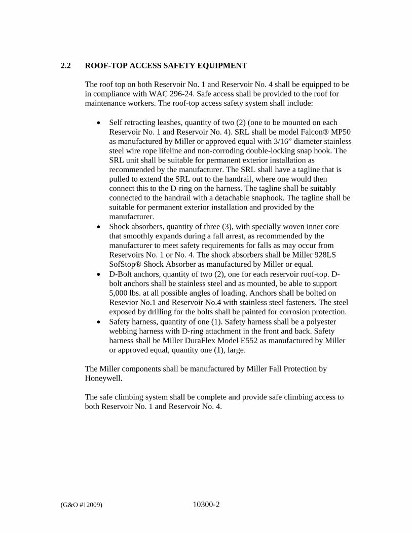
(G&O #12009) 10300-2
2.2 ROOF-TOP ACCESS SAFETY EQUIPMENT
The roof top on both Reservoir No. 1 and Reservoir No. 4 shall be equipped to be in compliance with WAC 296-24. Safe access shall be provided to the roof for maintenance workers. The roof-top access safety system shall include:
Self retracting leashes, quantity of two (2) (one to be mounted on each Reservoir No. 1 and Reservoir No. 4). SRL shall be model Falcon® MP50 as manufactured by Miller or approved equal with 3/16” diameter stainless steel wire rope lifeline and non-corroding double-locking snap hook. The SRL unit shall be suitable for permanent exterior installation as recommended by the manufacturer. The SRL shall have a tagline that is pulled to extend the SRL out to the handrail, where one would then connect this to the D-ring on the harness. The tagline shall be suitably connected to the handrail with a detachable snaphook. The tagline shall be suitable for permanent exterior installation and provided by the manufacturer.
Shock absorbers, quantity of three (3), with specially woven inner core that smoothly expands during a fall arrest, as recommended by the manufacturer to meet safety requirements for falls as may occur from Reservoirs No. 1 or No. 4. The shock absorbers shall be Miller 928LS SofStop® Shock Absorber as manufactured by Miller or equal.
D-Bolt anchors, quantity of two (2), one for each reservoir roof-top. D-bolt anchors shall be stainless steel and as mounted, be able to support 5,000 lbs. at all possible angles of loading. Anchors shall be bolted on Resevior No.1 and Reservoir No.4 with stainless steel fasteners. The steel exposed by drilling for the bolts shall be painted for corrosion protection.
Safety harness, quantity of one (1). Safety harness shall be a polyester webbing harness with D-ring attachment in the front and back. Safety harness shall be Miller DuraFlex Model E552 as manufactured by Miller or approved equal, quantity one (1), large.
The Miller components shall be manufactured by Miller Fall Protection by Honeywell. The safe climbing system shall be complete and provide safe climbing access to both Reservoir No. 1 and Reservoir No. 4.
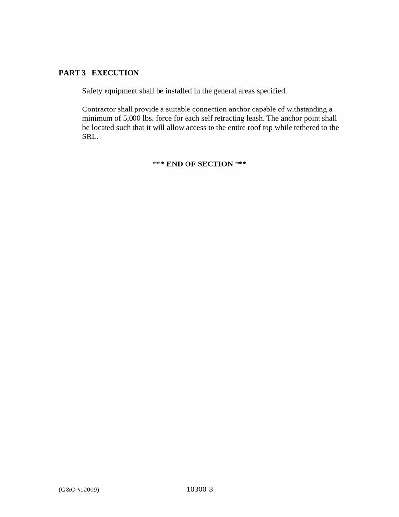
(G&O #12009) 10300-3
PART 3 EXECUTION
Safety equipment shall be installed in the general areas specified. Contractor shall provide a suitable connection anchor capable of withstanding a minimum of 5,000 lbs. force for each self retracting leash. The anchor point shall be located such that it will allow access to the entire roof top while tethered to the SRL.
*** END OF SECTION ***
DIVISION 13
SPECIAL CONSTRUCTION
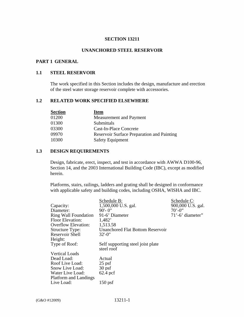
(G&O #12009) 13211-1
SECTION 13211
UNANCHORED STEEL RESERVOIR PART 1 GENERAL 1.1 STEEL RESERVOIR
The work specified in this Section includes the design, manufacture and erection of the steel water storage reservoir complete with accessories.
1.2 RELATED WORK SPECIFIED ELSEWHERE
Section Item 01200 Measurement and Payment 01300 Submittals 03300 Cast-In-Place Concrete 09970 Reservoir Surface Preparation and Painting 10300 Safety Equipment
1.3 DESIGN REQUIREMENTS
Design, fabricate, erect, inspect, and test in accordance with AWWA D100-96, Section 14, and the 2003 International Building Code (IBC), except as modified herein.
Platforms, stairs, railings, ladders and grating shall be designed in conformance with applicable safety and building codes, including OSHA, WISHA and IBC. Schedule B: Schedule C: Capacity: 1,500,000 U.S. gal. 900,000 U.S. gal.Diameter: 90'- 0" 70’-0” Ring Wall Foundation 91-6’ Diameter 71’-6’ diameter”Floor Elevation: 1,482’Overflow Elevation: 1,513.58Structure Type: Unanchored Flat Bottom ReservoirReservoir Shell Height:
32'-0"
Type of Roof: Self supporting steel joist plate steel roof
Vertical Loads Dead Load: ActualRoof Live Load: 25 psfSnow Live Load: 30 psfWater Live Load: 62.4 pcfPlatform and Landings Live Load: 150 psf
(G&O #12009) 13211-2
Design earthquake load in accordance with ASCE 7 Section 19.14.4.3, “Tanks and Vessels.” The accepted national standard for design shall be AWWA D100-96 Section 13. A. LATERAL FORCES
1. Lateral forces are transmitted by the reservoir to the foundation by
the anchor bolts. The ultimate displacement is resisted by passive pressure of earth. Overturning is resisted by dead load of the structure and the foundation.
For wind loading conditions, the overall stability of the reservoir shall be designed to resist the larger of the two forces generated by the requirements for wind per ASCE 7 and AWWA D100-96. Reservoir components shall be designed per AWWA D100-96.
2. Wind:
Basic Wind Speed = 85 mph Importance Coefficient = 1.15 Wind Exposure = C The tank shall also comply with wind requirements of AWWA D100-96 (with basic wind speed of 100 mph)
3. Seismic:
Evaluate the seismic loads according to AWWA D100-96 Section 13 and ASCE 7 with the following parameters: Site Class = C Ss = 51% S1 = 17% Sds = 0.41g Sd1 = 0.19g Seismic Importance Factor, Ie = 1.5 Seismic Use Group = III
B. SOIL BEARING PRESSURE
Soil bearing pressure has been determined to be 5,000 psf (See Geotechnical Investigation in Appendix).
C. RESERVOIR DESIGN
(G&O #12009) 13211-3
The reservoir shall be designed by a Professional Structural Engineer licensed in the State of Washington. The reservoir shall be designed according to the Specifications outlined above. The maximum water level for design will be 29.7 feet above the bottom of the reservoir. The overflow will be 31.58 feet above the bottom of the reservoir. The shell height will be 32.0 feet. The reservoir design, along with shop drawings, shall be submitted to the Owner for review. If the designer of the reservoir feels that other special inspections are necessary other than the ones listed below, in accordance with AWWA D100-96, then they shall be noted on the shop drawings. All testing and fabrication procedures shall be noted on the shop drawings.
1.4 APPROVED ERECTORS
Contractors using experienced reservoir suppliers who have furnished and erected at least three similar reservoirs within the last five years of equal or greater capacity. A letter shall accompany the bid listing five such tanks, including name of owner, capacity, location, year completed, and telephone number of owner or owner’s consultant.
1.5 APPROVED DIVERS
Divers shall be certified in commercial diving. Diving company shall meet all state regulatory requirements and national standards. The Contractor shall submit certification of diving company and compliance with all applicable regulations and standards. Divers shall follow all protocol for work in potable water and provide disinfection as required.
1.6 SUBMITTALS
The following information shall be submitted in accordance with Section 01300, SUBMITTALS.
A. Provide shop drawings showing location and thickness of all plates,
structural members, welds, and details of all accessories and their attachment to the reservoir.
B. Furnish mill test report for all steel used for the reservoir.
C. Provide calculations, stamped by a Professional Structural Engineer
registered in the State of Washington, for the design of the reservoirs and accessories, for the loads as given herein. If required for issuance of the building permit, the Contractor shall submit these calculations and shop
(G&O #12009) 13211-4
drawings to the permit department and answer questions, if any that arise in review of the submittal.
D. WELDING
1. Welding Procedure Specifications: Welding documentation shall
be submitted on appropriate forms found in the appendixes to the ASME Boiler and Pressure Vessel Code, Section IX, Appendix A, Forms AW-482 and QW-483.
2. Welder/Welding Operator Qualifications: Submit all shop and
field welder or welding operator performance qualification records to the Owner for review prior to any welding. Welding documentation shall be submitted on Form QW-484 in Appendix A to ASME Boiler and Pressure Vessel Code Section IX.
3. Welding Inspector Credentials: The Contractor shall submit the
credentials of the welding inspector to be employed by the Contractor to the Owner for review prior to starting any welding. The credentials shall include, but not be limited to, American Welding Society AC1 Certification. The welding inspector shall have prior inspection experience with the governing welding codes specified in the table. The duties of the welding inspector shall include, but not be limited to, the following:
a. Verifying job material and storage. b. Monitoring conformance with approved welding procedure
specifications. c. Checking welding and welding operator qualification. d. Supervising of nondestructive testing personnel and
evaluation of test results. e. Maintaining records and preparing report.
4. Testing Agency Credentials: The Contractor shall retain a
qualified testing agency employing nondestructive testing personnel. This testing agency shall perform the radiography, ultrasonic, magnetic particle, liquid penetrates, and other testing methods as specified. Personnel employed by the testing agency shall be certified in accordance with the current American Society of Nondestructive Testing (4153 Arlingate Plaza, Columbus, OH 43228) recommended Practice No. SNT-TC-1A and all supplements, NDT Level II. The Contractor shall submit the credentials of the testing agency and personnel to the Owner for review prior to any welding.
(G&O #12009) 13211-5
5. Nondestructive Testing procedure Specifications: The Contractor shall submit all nondestructive testing procedure specifications to Owner for review 10-working days prior to any welding.
E. CONTRACT CLOSE-OUT SUBMITTALS
Provide written report, signed by the Contractor’s certified welding inspector, on inspection and testing of welds in accordance with AWWA D100-96, Section 11.2.1.
1.7 GUARANTEE
The Contractor shall guarantee the complete tank and all items related thereto against defective materials and workmanship for a period of 2 years after date of acceptance by the Owner. Any defective materials or workmanship shall be replaced by the Contractor, at the Contractor’s expense, immediately upon notification by the Owner.
PART 2 MATERIALS 2.1 RESERVOIR
All steel shall be in accordance with AWWA D100-96, Section 14. The design metal temperature shall be assumed to be 15 degrees F above the lowest one-day mean ambient temperature of 6 degrees F. The maximum allowable design tensile stress for the cylindrical shell steel plates shall be 23,300 psi. Weld in accordance with “Structural Welding Code," AWS D1.1 and AWWA D100-96.
The floor plate shall have a minimum plate thickness of 1/4 inch and shall be sloped upward towards the center at to provide a 6-inch crown. The floor plate shall include a butt-welded annular ring at the wall. The wall steel and roof shall have a minimum plate thickness of 1/4 inch. The roof shall be an externally stiffened, plate steel roof similar in proportion and design to the Yakima County Reservoir No. 1 (located on the same site as the proposed Reservoir No. 4), complete with roofing members. Copies of the submittal shop drawings for the existing reservoir are included in the appendices.
2.2 ACCESSORIES
(G&O #12009) 13211-6
A. STAIRS, LADDERS AND PLATFORMS
Provide outside ladders and platforms at the locations shown on the Drawings. The ladders and landings shall be designed to be in compliance with WAC 296-24. They shall be steel, fabricated and welded to the reservoir. All ladders shall be furnished with an approved Saf-T-Climb system meeting OSHA requirements. See Section 10300 SAFETY EQUIPMENT for details.
B. HANDRAILING
Provide necessary handrailing as shown on the Drawings.
C. ROOF ACCESS HATCHES
Provide weather-proof type access hatch, size as shown on the Drawings. Hatch shall have hinge cover, complete with gasket and locking device to hold padlock, plus device to hold cover open.
D. BOLTS-ANTI-SEIZE COMPOUND
All bolts shall be coated with Armite Anti-Seize Compound No. 609, or equal, prior to installation.
E. SHELL MANHOLES Provide two 36-inch-diameter shell manholes on the tank wall located near the ground surface, as shown on the Drawings. Provide stainless steel bolts and nuts and red rubber gaskets. Provide 1/4-inch-diameter telltale hole between the reinforcing plate and the shell for pressure testing the weld. The manhole shall be pressure tested to 15 psi per API Standard 650. The reinforcing plate shall be on the inside of the shell.
F. ROOF VENT
Provide one circular removable roof vent located at the center of the reservoir, as shown on the Drawings or an approved fabricator standard design. The minimum size opening in the roof shall be 24 inches in diameter. The vent shall be of adequate size to handle pressure differential caused by water entering or leaving the tank at a maximum rate with 30 percent of the vent screen blocked. The maximum flow rate into the tank is 2,680 gpm and maximum withdrawal rate is estimated at 8,500 gpm (emergency pipe break). The open area of the overflow shall not be considered as venting area. The Contractor shall provide a special screened vent to ensure fail-safe operation, in the event the screen frosts
(G&O #12009) 13211-7
over or is otherwise clogged. The vent shall be easily dismantled to remove the screens for cleaning. The vent shall be screened with No. 24 mesh bronze screen and properly attached to prevent insects, water or other contaminants from entering.
G. PAINTER’S RING
Provide a self-draining painter’s ring on the interior wall of the reservoir of a design that will accommodate a painter’s trolley for inspection and painting the reservoir. The support system shall be designed to meet the applicable safety requirements.
H. OVERFLOW FUNNEL
Provide a funnel shaped overflow with a crest diameter as shown in the plans, and an anti-vortex entrance device. Funnel shall be at least 30 inches in height. Overflow pipe, connected thereto, shall be 12 inches in diameter and discharge into the drain system, as shown on the Drawings.
The overflow funnel shall be covered with a split and bolted circular type frame removable through the roof hatch complete with supporting cross members. The ring enclosing the screen shall fit loosely around the funnel shaped overflow and shall not be permanently attached.
I. WELDED STEEL PIPE
Steel pipe and fittings shall be seamless and manufactured in accordance with ASTM A53 and ASTM A234. The pipe and fittings shall be fabricated from Grade B standard weight carbon steel. Pipe shall be Schedule 40 unless otherwise noted on the Drawings. Minimum wall thickness for the steel pipe shall not vary more than 3/32 of an inch over the standard outside diameter specified and no less than 1/32 of an inch under the outside diameter measured at any point. Wall thickness for steel butt welded fittings shall comply with the tolerances specified in ANSI B16.9 and B16.28. Inside diameter at welded ends shall not vary from the nominal diameter more than ± 1/8 of an inch for pipe sizes 10 inches thru 18 inches. Grooved joints shall comply with AWWA C606 to provide the maximum deflection of the joint allowed by the pipe couplers. The pipe and fittings shall be epoxy-polyamide lined and tested in accordance with AWWA C210. The nominal thickness of the lining shall
(G&O #12009) 13211-8
be 12 mils. Certification shall be provided that interior coatings in contact with potable water have been certified with the National Sanitation Foundation Standard No. 61. The exterior of the buried pipe and pipe in contact with concrete shall be coated with minimum 80 mils of cold-applied tape coating in accordance with AWWA C214.
J. PIPE CONNECTIONS
Provide inlet, outlet, overflow, and drain connections, as shown on the Drawings.
K. NAMEPLATE
Provide a brass nameplate for the reservoir to include the name of the Owner, Fabricator, and Consulting Engineer, along with the standard data suggested by the AWWA D100, Section 14, including diameter, height, capacity, year of construction, and other information.
L. ROOF 6-INCH INSTRUMENT PORT
Provide 6-inch Instrument Port as shown on the Drawings.
M. PRESSURE SENSING PIPE
Provide Pressure Sensing Pipes as shown on the Drawings.
N. ELECTRICAL CONDUIT
Provide electrical conduit and pull boxes per Division 16, ELECTRICAL.
O. BASEPLATE GROUT
Provide minimum 1-inch-thickness nonshrink grout between baseplate and concrete foundation. Nonshrink grout shall be as specified in Section 03300, CAST-IN-PLACE CONCRETE.
P. OPENINGS FOR CATHODIC PROTECTION
Provide welded-on flanged outlets and blind flanges at the locations shown on the Drawings for future cathodic protection system.
Q. REFERENCE ELECTRODES
(G&O #12009) 13211-9
Provide zinc reference electrode installed as noted on Drawings without conduit or wire. Unit shall be Bayanode (R) BOD 1/4 type II cadmium plating “Iridite."
PART 3 EXECUTION 3.1 RESERVOIR
All shell and annular floor plate joints shall be complete penetration butt weld joints. The floor plates may be lap welded. The entire roof structure shall be seal welded. All roof joints shall be continuously butt-welded or double lap welded. Seal welding shall seal off all areas not accessible for painting to preclude the formation of rust or rust stains. Seal welding includes, but not limited to, roof plate butt or lap joints, roof to rim angle to shell plate, to include all joints and seams and roof plate to column and floor plate. To avoid undue stresses and warping of roof plates, the roof assembly shall consist of only radial and circumferential joints.
All accessories welded to reservoir shall be seal welded.
The quality of the welds shall be checked and records furnished to the Owner as a written report. The method of checking welds shall comply with AWWA D100-96 for radiographic testing, as outlined in Section 14. The Owner shall have the right to designate an additional 30-spot radiographs in excess of those specified. The Contractor shall keep daily records on the actual welds (location and type), performed by each welder and keep such information on the job site available for inspection. Grind all welds, edges, and sharp corners to a smooth surface. Remove all weld splatter. Clean inlet, outlet and overflow pipe interiors and recoat with specified coating where shop coating has been damaged by welding. Steel shims shall be utilized for setting and leveling the reservoir on the concrete, and these shall be grouted in place upon completion of the reservoir. The shims shall be of a size and location such that the grout will adequately cover them, so that no shim will or can be easily exposed. Grouting shall be flush with bottom of the floor plate to permit expansion and contraction of the steel floor plate. Grout shall be injected into the space with a nozzle working from back side to front edge with the nozzle submerged in grout. Utilize piston type grout pump with a 15 gallon (more or less) capacity. Grout to be troweled finished on a 45-degree sloped face, commencing from the bottom edge of floor plate, thereby permitting floor expansion, without damaging grout face. Moisture curing with
(G&O #12009) 13211-10
wet cloth is a must to minimize surface cracks. Curing compound may be applied later.
3.2 PAINTING
The reservoir shall be painted in accordance with Section 09970, RESERVOIR SURFACE PREPARATION AND PAINTING. All accessories including electrical conduit shall be painted except for the Saf-T-Notch Carrier Rail, and FRP.
3.3 LADDERS
Install safety climb device per section 10300 SAFETY EQUIPMENT in accordance with manufacturer’s instructions in such a manner to enable worker to be attached to device at all times during the climb without having to remove worker’s hands from ladder to operate the system effectively and to be able to easily pivot onto and off of work platforms or landings while safely attached to device. When installed to required height, fall prevention system shall be rigid and a integral part of the structure.
3.4 ELECTRICAL CONDUITS
Conduit shall be installed in a straight, or uniformly curved alignment to give a neat appearance. Conduit shall be supported in such a manner as to provide a 1-inch clear space between conduit and reservoir to facilitate future cleaning and painting procedures.
Pull boxes and other items shall be mounted with adequate clearance from the reservoir structure to clean and paint to the surfaces covered thereby, wherein the minimum clearance shall be 8 inches for such items, with exception of ladders.
3.5 SERVICE
The Owner will provide the water for all testing and to fill the reservoir. The Contractor must meter the water or otherwise measure the water and provide records to the Owner for all water used. The Contractor must provide a plan to fill the reservoir and coordinate the filling of the reservoir with the Owner. The reservoir will be filled from existing system by controlling the inlet valve of the new reservoir. The plan for reservoir filling must detail method to control system pressure during filling, maintaining existing reservoir level and control and coordination of valve operation.
(G&O #12009) 13211-11
3.6 DISINFECTION AND TESTING
The reservoir shall be disinfected and tested in accordance with Section 09970, RESERVOIR SURFACE PREPARATION AND PAINTING.
*** END OF SECTION ***
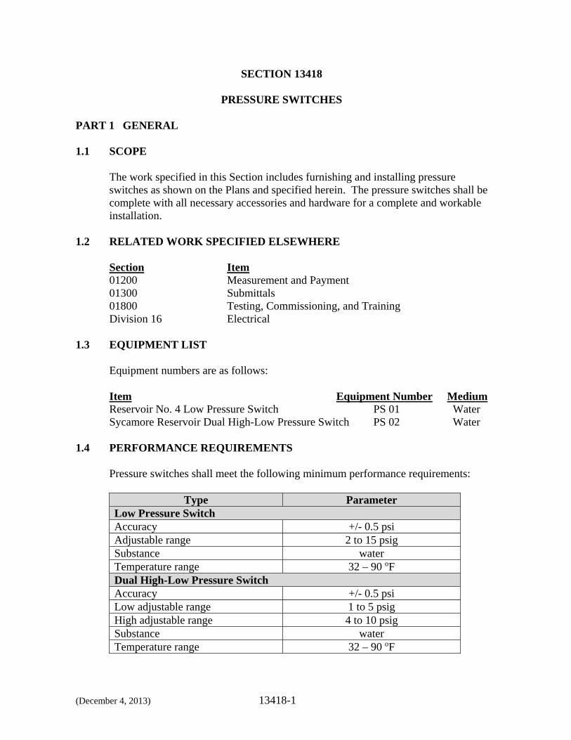
(December 4, 2013) 13418-1
SECTION 13418
PRESSURE SWITCHES PART 1 GENERAL 1.1 SCOPE
The work specified in this Section includes furnishing and installing pressure switches as shown on the Plans and specified herein. The pressure switches shall be complete with all necessary accessories and hardware for a complete and workable installation.
1.2 RELATED WORK SPECIFIED ELSEWHERE
Section Item 01200 Measurement and Payment 01300 Submittals 01800 Testing, Commissioning, and Training Division 16 Electrical
1.3 EQUIPMENT LIST
Equipment numbers are as follows: Item Equipment Number Medium Reservoir No. 4 Low Pressure Switch PS 01 Water Sycamore Reservoir Dual High-Low Pressure Switch PS 02 Water
1.4 PERFORMANCE REQUIREMENTS
Pressure switches shall meet the following minimum performance requirements:
Type Parameter Low Pressure Switch Accuracy +/- 0.5 psi Adjustable range 2 to 15 psig Substance water Temperature range 32 – 90 oF Dual High-Low Pressure SwitchAccuracy +/- 0.5 psi Low adjustable range 1 to 5 psig High adjustable range 4 to 10 psig Substance water Temperature range 32 – 90 oF
(December 4, 2013) 13418-2
1.5 DELIVERY, STORAGE AND HANDLING
All equipment shall be completely factory assembled, crated and delivered to protect against damage during shipment. All equipment delivered to the site shall be stored as specified in accordance with the manufacturer’s instructions.
1.6 WARRANTY
In addition to the warranty required in the General Conditions, the equipment manufacturer shall provide an extended warranty covering defects in material and workmanship for 2 years following the date of substantial completion. The warranty shall be in printed form, shall apply to all similar units, and shall include parts and labor.
PART 2 PRODUCTS 2.1 APPROVED MANUFACTURERS
The pressure switches shall be Barksdale or approved equal.
2.2 PRESSURE SWITCHES
Liquid-service pressure switches shall be diaphragm or Bourdon tube type with vibration isolators and pulsation dampers. Switch action shall be snap-acting to eliminate “dead-center” where contacts could chatter. Contact blocks shall be rated for 600 volts AC, 10 amps. Terminal screws shall be readily accessible for wiring. Wiring may be for cut-in or cut-out action as required for the specific application. Enclosure and type of contacts shall be as shown on the Plans and as specified in Division 16, Electrical. Note that the Contractor may also elect to provide and install both a high pressure switch and a low pressure switch in lieu of the dual high-low pressure switch, but if this option is selected, any modifications to the mechanical, structural, electrical, instrumentation and control and other portions of work that may be required to adapt the general layout and details shown on the Plans to the equipment actually furnished shall be at no additional cost to the Owner. All necessary revisions shall be made at Contractor’s sole expense. All redesign information prepared by the contractor shall be submitted for review prior to incorporating the redesign into the work. if this option is selected, an additional isolation valve for the additional pressure switch will be required.
(December 4, 2013) 13418-3
2.3 FACTORY TESTING
The equipment shall be fully tested at the manufacturer’s plant before shipment. Tests shall insure that the equipment will operate as desired under anticipated field conditions. Certified copies of test report(s) shall be submitted to the Engineer prior to shipment.
PART 3 EXECUTION 3.1 INSTALLATION
The pressure switches shall be installed as shown on the Plans. Installation shall be in strict accordance with the manufacturer’s recommendations and instructions.
3.2 FIELD TESTING
The field test shall insure that the equipment will operate as desired under field conditions. The manufacturer shall provide a formal test procedure and report forms for recording data. The Contractor shall submit the report forms to the Engineer prior to operational testing. Any defects in the equipment or failure to meet requirements of the Specification shall be promptly corrected by the Contractor.
3.3 MANUFACTURER’S SERVICES
The services of a factory-trained representative of the equipment manufacturer shall be provided by the Contractor. Services shall include 1 day onsite for the supervision of equipment startup, initial adjustment, testing and instruction of the Owner’s personnel in the operation and maintenance of the equipment. Instruction and training of the Owner’s personnel shall not take place until startup is completed and the equipment is fully operational and shall be at a time and location agreed to by the Owner. The cost of these services shall be included in the bid price. The representative shall provide for one additional service calls during the initial 2 years of equipment operation.
*** END OF SECTION ***
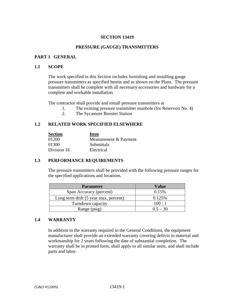
(G&O #12009) 13419-1
SECTION 13419
PRESSURE (GAUGE) TRANSMITTERS
PART 1 GENERAL
1.1 SCOPE
The work specified in this Section includes furnishing and installing gauge pressure transmitters as specified herein and as shown on the Plans. The pressure transmitters shall be complete with all necessary accessories and hardware for a complete and workable installation. The contractor shall provide and install pressure transmitters at
1. The existing pressure transmitter manhole (for Reservoir No. 4) 2. The Sycamore Booster Station
1.2 RELATED WORK SPECIFIED ELSEWHERE
Section Item 01200 Measurement & Payment 01300 Submittals Division 16 Electrical
1.3 PERFORMANCE REQUIREMENTS
The pressure transmitters shall be provided with the following pressure ranges for the specified applications and locations.
Parameter Value Span Accuracy (percent) 0.15%
Long term drift (5 year max, percent) 0.125% Turndown capacity 100 : 1
Range (psig) 0.5 – 30
1.4 WARRANTY
In addition to the warranty required in the General Conditions, the equipment manufacturer shall provide an extended warranty covering defects in material and workmanship for 2 years following the date of substantial completion. The warranty shall be in printed form, shall apply to all similar units, and shall include parts and labor.
(G&O #12009) 13419-2
PART 2 PRODUCTS
2.1 APPROVED MANUFACTURERS
The pressure transmitter shall be Rosemount Model 3051 or approved equivalent equipment manufactured by Siemens, Sitrans P, or Endress and Hauser. No other manufacturers or models shall be accepted. The structural, mechanical and electrical designs shown on the Plans are based on the equipment manufactured by Rosemount. Any modifications to the mechanical, structural, electrical, instrumentation and control and other portions of work that may be required to adapt the general layout and details shown on the Plans to the equipment actually furnished shall be at no additional cost to the Owner. All necessary revisions shall be made at Contractor’s sole expense. All redesign information prepared by the contractor shall be submitted for review prior to incorporating the redesign into the work.
2.2 PRESSURE TRANSMITTER
The pressure transmitter shall be a digital transmitter with piezoresistive or capacitance-based sensor and Type 316 stainless steel diaphragm seal. The pressure sensitive element shall be Type 316 stainless steel and shall be calibrated for the range as specified in the Schedules. Data specific to the measuring cell, the electronics data, and the parameter data shall be stored in two non-volatile memories. One memory shall be coupled to the measuring cell, the other to the electronics. The measuring cell and the electronics shall be individually replaceable. The transmitter shall be a true two-wire device without the requirement of a separate power supply at the transmitter. The unit shall be modular plug-in design and all circuitry shall be solid state. The pressure transmitters shall display the measured pressure on the front of the unit enclosure and all units shall have a menu-driven keyboard on the front panel of the transmitter. The unit shall be capable of recalibration in the field by the menu-driven keyboard. The keyboard shall allow for viewing control of results, the error messages, the operating modes, and the digital display.
The transmitter pressure sensor shall be protected from the effects of pressure swings and spikes up to the maximum working pressure (body rating) of the pressure capsule. The pressure transmitters shall be listed and labeled by an electrical testing laboratory recognized by the Washington State Department of Labor and Industries or be acceptable to the Washington State Department of Labor and Industries for installation on this project.
(G&O #12009) 13419-3
2.3 ANALOG INSTRUMENTATION
The pressure transmitter shall be of the solid-state type and of the manufacturer’s latest design. The equipment shall have 4 to 20 milliamperes standard DC (direct current) isolated floating outputs and shall conform to ISA Standard S 50.1. The output voltage created by the sensor shall be amplified by the instrument amplifier and digitized in the analog-to-digital converter. The digital information shall be evaluated in the microcontroller, its linearity and temperature response corrected and converted in a digital-to-analog converter into an output current of 4 to 20 mA. Analog instruments shall operate without loss of loop accuracy due to electromagnetic interference, resistive or inductive losses or similar problems related to field interconnection of components when connected with shielded copper wire in the manner shown on the Plans. The transmitter shall be capable of providing linear or square root output with pressure requiring only a change of configuration, and shall have an LCD display for indicating the pressure in real engineering units. The display shall be rotatable in 90 degree increments. The transmitter shall have the ability to electronically compensate for the effects of mounting position on the sensor. Furthermore, the transmitter shall be able to force the loop current to various values to aid in loop setup and testing. Data specific to the measuring cell, the electronics data, and the parameter data shall be stored in two non-volatile memories. One memory shall be coupled to the measuring cell, the other to the electronics. The transmitter shall have online diagnostics and registers to detect and store various parameters such as min/max electronics temperature, min/max pressure, capsule temperature, and min/max process pressure to help diagnose process problems. The transmitter shall also have dual timer registers that allow the transmitter to signal when a settable time has elapsed for preventative maintenance or calibration.
2.4 SPARE PARTS
The manufacturer shall supply one spare transmitter that will be identical to the equipment specified above. All spare parts shall be suitably identified and effectively protected from moisture and corrosion with appropriate wrappings or coatings or a combination thereof. All parts shall be furnished in sturdy labeled boxes.
(G&O #12009) 13419-4
2.5 FACTORY TESTING
The equipment shall be fully tested at the manufacturer’s plant before shipment. Tests shall insure that the equipment will operate as desired under anticipated field conditions. Certified copies of test report(s) shall be submitted to the Engineer prior to shipment.
PART 3 EXECUTION
3.1 DELIVERY, STORAGE, AND HANDLING
All equipment shall be completely factory assembled, crated and delivered to protect against damage during shipment. All equipment delivered to the site shall be stored as specified in accordance with the manufacturer’s instructions.
3.2 INSTALLATION
The pressure transmitters shall be installed at the locations shown on the Plans in accordance with manufacturer’s recommendations. All mounting hardware and supports shall be provided by the Contractor. The existing Reservoir No. 1 pressure transmitter and electrical junction box that is located in the existing vault (same vault as where the new Reservoir No. 4 pressure transmitter will be located) shall be re-mounted with suitable stainless steel mounting hardware. The existing mounting hardware (screws, etc.) has corroded and failed.
3.3 FIELD TESTING
The field test shall insure that the equipment will operate as desired under field conditions. The manufacturer shall provide a formal test procedure and report forms for recording data. The Contractor shall submit the report forms to the Engineer prior to operational testing. Any defects in the equipment or failure to meet requirements of the Specification shall be promptly corrected by the Contractor.
3.4 MANUFACTURER’S SERVICES
The services of a factory-trained representative of the pressure transmitter manufacturer shall be provided. Services shall include a minimum of 1 day on
(G&O #12009) 13419-5
site. Services shall include inspection and supervision of installation, initial configuration, programming, startup, and adjustments and instruction of the Owner’s personnel in operation and maintenance for the pressure transmitters. Instruction and training of the Owner’s personnel shall not take place until startup is complete and the pressure transmitters are fully operational and shall be at a time and location agreed to by the Owner. The cost of these services shall be included in the bid price.
*** END OF SECTION ***
(G&O #12009) 13424-1
SECTION 13424
FLOAT SWITCHES
PART 1 GENERAL 1.1 SCOPE
There shall be furnished and installed float switches and associated equipment as specified herein and as shown on the Drawings.
PART 2 PRODUCTS 2.1 APPROVED MANUFACTURERS
The float switches shall be Davis, Hydromatic, Flygt, or approved equal.
2.2 FLOAT SWITCHES
Float switches shall be the tilting type non-mercury, and NSF61 approved. The cable shall be of sufficient length to reach to the terminating device shown. It shall have single pole double throw contacts and be wired as shown on the Plans.
PART 3 EXECUTION 3.1 GENERAL
The float switches shall be mounted and positioned according to the manufacturer’s approved method and at heights as directed by the Engineer (where heights are not indicated on the Drawings). It shall be suspended at the proper position to hang or float, depending on the liquid level. The electrical cable, supplied with the float, shall be connected from the float to the terminating device terminal.
*** END OF SECTION ***

DIVISION 15
MECHANICAL
(G&O #12009) 15050-1
SECTION 15050
PIPING SYSTEMS PART 1 GENERAL 1.1 SCOPE
The work specified in this Section describes process and utility piping, fittings, supports, and accessories shown on the Plans, described in these Specifications and as required to completely interconnect all equipment with piping for complete and operable systems. The Contractor shall direct the attention of all subcontractors and suppliers of piping systems and related appurtenances for the work to the applicable provisions in the Contract Documents wherever they may occur.
1.2 RELATED WORK SPECIFIED ELSEWHERE
Section Item 01300 Submittals 02300 Earthwork 02050 Locate Existing Utilities 02510 Testing and Disinfection 02511 Connect To Existing Systems 09900 Painting Division 13 Special Construction Division 15 Mechanical Division 16 Electrical
1.3 STANDARDS FOR THE WORK
Pipe, fittings, and supports shall be provided to produce complete, operable systems with all elements properly interconnected as shown in schematic diagrams or to provide specified operations. If a specific dimensioned location is not shown for interconnections or smaller system elements, the Contractor shall select appropriate locations and show them on Shop Drawing submittals for review.
Piping systems and materials shall be new and without imperfections and shall be erected in a neat and workmanlike manner; aligned, leveled, cleaned and adjusted for satisfactory operation; installed in accordance with the best standard practices for this type of work so that connecting and disconnecting of piping and accessories can be readily made and so that all parts are easily accessible for inspection, operation, maintenance and repair. In order to meet these requirements minor deviation from the Plans may be made as approved by the Engineer.
(G&O #12009) 15050-2
1.4 PIPE MATERIALS
The materials to be utilized for the various pipe sizes and applications on the project shall be as shown on the drawings.
1.5 SUBMITTALS
Submittal data shall be supplied in accordance with Section 01300. Detailed installation drawings of all piping and connected equipment shall be submitted. The drawings shall include all piping, valves, fittings, pipe support locations and types, seismic bracing, and appurtenances. Submit data to show that the following items conform to the Specification requirements:
A. Pipe, fittings, and accessories.
B. Valves.
C. Couplings and couplers.
D. Pipe supports and seismic braces as required herein.
Submit certified test reports as required herein and by the referenced standards.
PART 2 PRODUCTS 2.1 GENERAL
Pipe sizes are nominal inside diameter unless otherwise noted. Minimum pipe spool length shall be 4 times the diameter of the pipe spool. All materials delivered to the job site shall be new, free from defects, and marked to identify the material, class and other appropriate data such as thickness for piping. Acceptance of materials shall be subject to strength and quality testing in addition to inspection of the complete product. Acceptance of installed piping systems shall be based on inspection and leakage tests as specified in Part 3 Execution of this Section.
All water piping shall be certified under NSF 61 for potable water use.
(G&O #12009) 15050-3
2.2 DUCTILE IRON PIPE AND FITTINGS
A. GENERAL
Ductile iron pipe shall be centrifugal cast pipe conforming to AWWA C151, Class 52, unless otherwise noted, bituminous coated and cement mortar lined in accordance with, AWWA C104. All flanged spools shall be Class 53 as shall all piping where grooved couplings are used. All above ground piping shall be flanged piping unless otherwise specified or indicated. Below ground piping shall be mechanical joints or push on joint unless otherwise specified or indicated. Mechanical joints shall comply with AWWA C111. All mechanical joints that are shown to be restrained shall be restrained joints with a restrainer. The restrainer shall utilize the full circumference of the pipe for restraining and utilize standard MJ gasket and bolts. The restrainer shall be Grip Ring as manufactured by Romac Industries, Mega-Lug, or equal. Flanges shall comply with ANSI Bl6.1, Class 125. Flange gaskets shall be full face. Approved adaptor flanges shall be used instead of flanges where shown on the Plans. Fittings shall be ductile iron and shall comply with AWWA C110 or AWWA C153, bituminous-coated exterior and cement mortar lined, 250-psi minimum pressure. Fittings shall be mechanical joint or flanged fittings. Fittings with grooved ends shall comply with AWWA C606 and shall be Victaulic or approved equal. Tyton (Push-on) joints shall be acceptable for pipes. The exterior of buried ductile iron pipe and pipe in contact with concrete shall be coated with an asphaltic coating. The exterior surface of ductile iron pipe inside of buildings, structures, and vaults shall be painted in accordance with Section 09900 of the Specifications. All bolts, buried and unburied, shall be coated with Armite Anti-Seize Compound No. 609, or equal, prior to installation.
(G&O #12009) 15050-4
2.3 FABRICATED STEEL PIPE AND FITTINGS
Steel pipe shall be as specified in 13211-2.2(I) 2.4 PVC PIPE AND FITTINGS
A. PRESSURE PIPE
All PVC pipe 3-inch and smaller shall be Schedule 80. Pipe shall be constructed of material that meets or exceeds ASTM D2241 and D1784 and Commercial Standard CS 256. Joints shall be solvent weld with press fit. Fittings shall conform to ASTM D2466 and D2467 for socket type and ASTM D2464 for threaded pipe. PVC pipe 4-inch and larger shall be, Cast Iron Pipe equivalent O.D., Class 235, conforming to the requirements of AWWA C900. Pipe joints shall be gasketed. Solvent-cement joints will not be acceptable. Fittings for PVC pipe 4-inch and larger shall be ductile iron, as specified in Part 2.2 of this Section. Provisions for pipe expansion shall be as recommended by the pipe manufacturer. Bolts for PVC pipe, where required, shall be 316 stainless steel, ASTM A193, Grade B8M, hex head with ASTM A194, Grade 8M hex nuts. Washers of the same material shall be supplied.
B. GROUNDWATER AND SLOTTED DRAIN PIPE Groundwater, footing drain, and trench sub-drain pipe shall be Type 1, Grade 1 PVC, Schedule 80, conforming to ASTM D1785, socket end. Fittings shall conform to ASTM D2467, socket ends.
2.5 GALVANIZED STEEL PIPE AND FITTINGS
Steel pipe shall be general service, carbon steel pipe conforming to ASTM A53, Grade A, Type E. Pipe shall be Schedule 40 with threaded and coupled fittings. Galvanized pipe and fittings shall be hot-dip galvanized. Grooved joints may be used in lieu of threaded joints. Where grooved joints are used, they shall be Victaulic or approved equal and shall comply with AWWA C606. Fittings and couplings shall be galvanized in accordance with ASTM A-153.
(G&O #12009) 15050-5
2.6 MISCELLANEOUS FITTINGS
A. FLEXIBLE COUPLINGS
Flexible couplings shall be Romac 501 or approved equal. Middle ring and follower shall have fusion bonded epoxy coating. All buried flexible couplings shall be furnished with stainless steel bolts and nuts.
B. FLANGED COUPLING ADAPTERS
Flanged coupling adapters shall be Rockwell (Smith-Blair) Type 912 Dresser Style 127 or equal.
C. DISMANTLING JOINTS
Dismantling joints shall be Romac Industries model DJ405 or DJ400 dismantling joint or equal
D. ADAPTER FLANGES
Adapter flanges for ductile iron pipe shall be manufactured of high strength ductile iron, ASTM A536, Grade 65-45-12. Flange dimensions shall be in accordance with ANSI B16.1, 125-lb. pattern. Gasket shall be Buna-N. Setscrews shall be AISI 4140, high strength, low alloy steel. The adapter flanges shall be Uni-Flange Series 400, or equal.
E. FLEXIBLE EXPANSION JOINTS
Flexible expansion joints shall be ductile iron, double ball joint, FLEX-TEND as manufactured by EBBA Iron, Inc., of Eastland Texas, U.S.A. or equal. Expansion joints shall be set at 50% with +4-inches/-4-inches of expansion.
F. SERVICE SADDLE
Service saddle for the 2” blow off shall be Romac Style 202S with I.P. threads or equivalent. Service saddle for the water sampling line shall be Romac Style 101S with I.P. threads or equivalent.
G. CORPORATION STOP
Corporation Stop shall be Ford model FB 1100 or equivalent.
(G&O #12009) 15050-6
H. GROOVED PIPE COUPLERS
Grooved pipe couplers for steel pipe shall consist of two ductile iron housing segments conforming to ASTM A536, pressure responsive elastomer gasket, and ASTM A449 zinc electroplated steel bolts and nuts. Couplings shall comply with ASTM F1476 “Standard Specification for the Performance of Fittings for Use with Gasketed Mechanical Couplings Used in Piping Applications.” 1. Rigid Type
Housings shall be cast with offsetting angle-pattern bolt pads to provide rigidity and system support and hanging in accordance with ANSI B31.1 and B31.9.
a. 2 Inch through 8 Inch
Installation-Ready, for direct stab installation without field disassembly, with grade EHP gasket rated to +250 degrees F/120 degrees C. Couplings shall be Victaulic Style 107, or approved equal.
b. Couplings shall be Victaulic Zero-Flex Style 07. 2. Flexible Type
For use in locations where vibration attenuation and stress relief are required. The couplings shall be placed in close proximity to the source of the vibration. Couplings shall be Victaulic Style 77, or approved equal.
Grooved pipe couplers for ductile iron pipe shall be Victaulic Style 31, or approved equal. All grooved joint couplings, fittings, valves, and specialties shall be the products of a single manufacturer. Grooving tools shall be of the same manufacturer as the grooved components.
(G&O #12009) 15050-7
I. DIELECTRIC INSULATED UNIONS
Dielectric insulated unions shall be used to connect dissimilar metals. They shall separate the metals so that the passage of more than one percent of the galvanic current, which would exist with metal to metal contact, is prevented. Unions shall be of the same material as the pipe to which attached, and pressure and temperature ratings shall be no lower than that of the piping system in which it is installed.
2.7 PIPING INSULATION
All new above ground exterior pipe carrying liquids, shall be insulated with 1-inch-thick fiberglass insulation and 0.016-inch anodized aluminum jacket; insulated by Owens-Corning, Certainteed, Johns-Manville or equal, unless otherwise noted. Buried piping carrying liquids with less than 36 inches of cover shall be insulated with Rubitex closed cell foam insulation or equal.
PART 3 EXECUTION 3.1 PIPING INSTALLATION
A. GENERAL HANDLING AND PLACING
All piping constructed on this project shall be performed in accordance with the Uniform Plumbing Code. These Plans do not detail all items such as complete venting, etc.; however, it is understood that this work shall be included as a part of this Section and all costs included in the lump sum bid. Pipe and accessories shall be handled in such a manner as to insure delivery on site in sound, undamaged condition. Particular care taken not to injure pipe coating. No other pipe or material of any kind shall be placed inside of lined pipe or fitting after lining has been applied. All pipe and fittings shall be unloaded, stored, handled in such a manner as to insure against damage. Dropping of pipe or fittings shall be cause for rejection. The types and sizes of pipes to be used shall be as specified herein and as shown on the Plans. Where sizes of small pipe are omitted from the plans and not mentioned in the Specifications, the sizes to be used shall correspond to plumbing code requirements. In any event, undesignated pipe sizes shall be proper for the function to be performed and as accepted by the Engineer.
(G&O #12009) 15050-8
All pipe shall be carefully placed and supported at the proper lines and grades and where possible shall be sloped to permit complete drainage. Piping runs shown on the Plans shall be followed as closely as possible, except for minor adjustments to avoid architectural and structural features. If major relocations are required, they shall be approved by the Engineer. Unions shall be installed in all threaded joint piping to facilitate the removal of sections for maintenance and repair in accordance with the best trade practice. Unions shall be ground joint, malleable iron type. Where unions connect dissimilar materials, the union shall be protected from reaction with dissimilar metals by installation of insulating materials and dielectric unions at contact points. The interior of all piping shall be cleaned after assembly and before connecting to equipment. All piping for which no location dimensions are shown shall be installed in a neat and workmanlike manner in accordance with best trade practice. Wherever possible runs and rises shall be grouped and kept parallel. Properly lay out all miscellaneous piping to clear obstructions such as passageways, equipment, larger sized pipes, ventilation ducts, lights, etc. Whenever pipe requires field cutting to fit in line, work shall be done by a machine in a satisfactory manner so as to leave a smooth end at right angles to axis of pipe. All piping to be buried below structures, foundations, or slabs shall be installed with extreme care. When all joints have been made, Contractor shall demonstrate to Engineer’s satisfaction that all of piping is watertight and that all lines are clear before proceeding with any work above this piping. It shall be Contractor’s responsibility to see that these lines are kept clear until final acceptance of the project, providing suitable tight wooden bulkheads or plugs for open end pipes. Any blockage of these systems due to earth, debris, cement slurry or anything else shall be rectified at Contractor’s expense before project is accepted. All pipe shall be installed in strict accordance with manufacturer’s recommendations and/or specifications, and best commercial trade practice. Any special tools required for laying, jointing, cutting, etc., shall be supplied and properly used. All pipe shall be kept thoroughly clean until acceptance of completed work, and shall conform accurately to lines and grades given. At all times during pipe laying operations keep trench free of water either by pumping, bailing, or drainage. Seal end of line with a tight-fitting plug when pipe is not being laid.
(G&O #12009) 15050-9
Valves shall have interiors cleaned of all foreign matter and inspected, both in open and closed positions prior to installation. All pipes running through concrete walls below water surface or where subject to groundwater pressure shall be assembled as shown on the plans. Pipes running through concrete not subject to water pressure may be installed through standard steel sleeves, one or two pipe sizes larger than pipe in question. The pipe shall be free of all dirt and grease and thoroughly cleaned to insure a tight bond with the concrete. All above ground outside pipe carrying liquids shall be insulated. All buried, submerged, or intermittently submerged piping that is bolted together or uses bolts to hold materials together shall use 316 stainless steel nuts, bolts, and washers. This requirement applies to a distance of 12 inches above the highest water level in any tank, channel, or structure. Otherwise, bolts, nuts, and washers may be hot-dip galvanized steel.
B. GENERAL EXPOSED PIPING INSTALLATION
Unless shown otherwise, piping shall be installed parallel to building lines, plumb, and level. Piping shall be installed without springing or forcing. All pipe flanges shall be set level, plumb, and aligned. All flanged fittings shall be true and perpendicular to the axis of the pipe. All bolt holes in flanges shall straddle vertical centerline of pipes. Flexible couplings shall be provided for all piping connections to motor-driven equipment and where otherwise shown in the Plans. The Contractor may install additional flexible couplings at approved location to facilitate piping installation, provided that he submits complete details describing location, pipe supports, and hydraulic thrust protection. Unions or flexible couplings shall be installed where shown on the Plans, and at all non-motor-driven equipment to facilitate removal of the equipment. Where equipment drain connections are provided, they shall be valved, with the discharge pipe carried to the nearest floor drain, drain trench, or sump. Where no receptacle for drain exists, drain valves shall be piped to 1 inch above the floor. Drain piping and valve materials shall conform to the requirements of the system served.
(G&O #12009) 15050-10
All exposed or submerged piping shall be painted and color-coded in accordance with Section 09900, unless otherwise specified.
3.2 PVC PIPING
A. GENERAL
PVC piping socket weld connections shall be made up in accordance with the pipe manufacturer’s recommendations and as follows: Where pipe is cut, remove all burrs and ream inside to provide smooth flow line. Joints shall be first cleaned with cleaner before making up. Cement both pipe pieces to be joined and join quickly. If joint cannot be made up to full depth of socket, cut out and discard. Wipe off excessive cement. Do not move for 15 minutes after making up joint. Pipe joining below 40 degrees F will not be permitted. Cleaner and cement types shall be as recommended by the manufacturer for the size of pipe being used.
3.3 FLANGED PIPING
Flanged joints shall be made in accordance with best trade practice. Screwed flanges for piping shall be run until pipe projects beyond face and no more than one thread is exposed on backside. All flange faces shall then be machined so as to be perfectly parallel. All flanged pipe shall be accurately dimensioned; no “drawing-up” will be allowed. Gaskets shall be full face, rubber.
3.4 THREADED PIPING
Threads for threaded joint piping shall be neatly cut with sharp tools and jointing procedure shall conform to best practice. Before jointing, all scale shall be removed from pipe by some suitable means such as pounding. After cutting, all pipe shall be reamed. All pipe shall be screwed together with an application of approved pipe compound applied to all male threads. Once a joint has been tightened, it shall not be backed off unless threads are recleaned and new compound applied. This application neatly made; all compound, dirt thoroughly wiped off outside of every joint. Unions shall be installed in all threaded joint piping to facilitate removal of sections for maintenance, repair in accordance with best trade practice. All such unions shall be included in bid price whether shown on Plans or not.
(G&O #12009) 15050-11
3.5 MECHANICAL JOINT PIPING
Mechanical joint piping shall be installed in best trade practice with torque wrenches used to avoid overstressing bolts. Piping shall be installed using recommended procedures outlined in “Handbook of Cast Iron Pipe” as published by Cast Iron Research Association which in part requires that all contact surfaces of rubber seal with pipe be wire brushed, spigot be centrally located in bell. When tightening bolts, it is essential that the gland be brought up toward pipe flange evenly, maintaining approximately same distance between gland and face of flange at all points around socket.
3.6 WELDED PIPING
All welding shall be by the inert gas, MIG, or TIG method. Procedures are in accordance with ANSI B31.1. Filler wire shall be added to all welds to provide for a cross section and weld metal equal to or greater than the parent metal. Butt welds shall have full penetration to the interior surface and gas shielding shall be provided to the interior and exterior of the joint mechanically bevel pipe ends.
Interior weld beads shall be smooth, evenly distributed with an interior projection not exceeding 1/16-inch beyond the ID of the air header or fittings. The outside welds shall be wire brushed. Brushes shall be of stainless steel and used only on stainless steel.
3.7 PIPE SUPPORTS
Provide all necessary supports, tie rods, bracing, brackets or other types of supports which may be required, as shown on the Plans.
3.8 PIPE BEDDING
All pipe shall be bedded as specified in Section 02300. 3.9 TESTING
A. GENERAL
All piping shall be pressure tested and flushed per Section 7-09 of the WSDOT Standard Specifications.
(G&O #12009) 15050-12
B. DISINFECTION
Before being placed into service, all new and modified potable water pipe and appurtenances shall be sterilized and a satisfactory bacteriological report obtained in accordance with Section 02510 of these specifications.
*** END OF SECTION ***
(G&O #12009) 15100-1
SECTION 15100
VALVES PART 1 GENERAL 1.1 SCOPE
The work specified in this Section shall consist of valves and accessories as shown on the Plans, described in these Specifications, and as required to completely interconnect all equipment with piping for complete operable systems.
1.2 RELATED WORK SPECIFIED ELSEWHERE
Section Item 01200 Payment 01300 Submittals Division 15 Mechanical
1.3 SUBMITTALS
Submit catalog cuts and shop drawings in accordance with Section 01300 to demonstrate that the valves and appurtenances conform to the Specifications requirements. The Contractor shall furnish manufacturer’s installation and operation manuals, bulletins, and spare parts lists for all valves.
1.4 QUALITY ASSURANCE
All materials and equipment furnished under this Section shall be by the manufacturer specified.
PART 2 PRODUCTS 2.1 GATE VALVES
Gate valves 3 inches and smaller shall be bronze, non-rising stem, wedge disc, 125 pound service, Crane No. 438, Kennedy Figure 427 or equal. Gate valves larger than 3 inches shall be iron body, bronze mounted, resilient seat, wedge disc, left opening, high-strength bronze stem, O-ring with a 2-inch-square operating nut and complying with AWWA C509 or C515. Gate valves shall be non-rising stem unless noted otherwise.
(G&O #12009) 15100-2
Above ground gate valves shall be provided with handwheels. 2.2 BUTTERFLY VALVES
Butterfly valves for liquid service shall have iron body and disc, Buna N seats attached to the valve body, stainless steel shaft, corrosion resistant bearings, and flanged style body and shall comply with AWWA C504. Extension bonnets shall be sealed from liquid intrusion and shall encase the valve torque tube from the valve trunnion to the top-mounted geared handwheel actuator. The entire assembly shall be factory assembled and tested. Liquid service butterfly valves shall be DeZurik, Pratt 2FII, or equal. Where butterfly valves are installed adjacent to check valves or other fittings, which interfere with the valve’s full range operation, flange fillers, or other spacers, shall be installed between the valve and the obstructing fitting as necessary to insure unrestricted operation of the butterfly valve from full open to closed.
2.3 CHECK VALVES
Check valves for liquid service shall be resilient hinge swing check, with disc accelerator, ductile, iron body, 125 pound service, Val-Matic SurgeBuster Valve.
2.4 PVC BALL VALVES
Ball valves shall be PVC Class 1245 4-B, conforming to ASTM D1784, single union type, threaded per ANSI B1.20.1, full port design, rated 150 psi, Nibco Chemtrol Tru-Block, Asahi/America, or equal.
2.5 VALVE BOXES
There shall be furnished and installed with all valves installed underground, two piece adjustable cast iron valve boxes with a minimum inside diameter of 5 inches. The valve boxes shall be set concentric with the axis of the stem and adjusted to the finish grade. Valve box lids shall be identified with a letter/number code and opening direction designation as shown on the Plans.
(G&O #12009) 15100-3
PART 3 EXECUTION 3.1 GENERAL
All valves and accessories shall be installed in a manner and location as shown on the Plans or as required for the application and in accordance with manufacturer’s instructions. Valve size is fully equal to line piping in which the valve is installed unless otherwise noted on the Plans. Support all valves where necessary. In case on conflict between these Specifications and a governing code, the more stringent standard shall prevail.
All valves of the same style or type shall be furnished by a single manufacturer. Provide all accessories necessary for proper valve operation as specified or required for the application. Buried valves shall be installed with square operating nuts and adjustable cast iron valve boxes with covers. Valve boxes shall be set such that the slots in the boxes are in line with the run of pipe the valves are in. Provide two sets of T wrenches for buried valve operation. Buried valves shall be provided with 1-inch solid steel extension stems with rock guards if the operating nut will be 18 inches or more below the ground surface. Valves shall be installed with the operator in a position for convenient operation. Particular care shall be taken to insure that space is available for operation of lever or handwheel operated valves without interference to walls, piping or equipment. Any valve which is installed, in the opinion of the Engineer, in a manner that operation is inconvenient shall be modified or removed and reinstalled in a manner suitable to the Engineer at the expense of the Contractor. Operations for manual valves shall be lever or handwheel as is standard with the manufacturer unless another type of operator is specified or required by the manufacturer.
*** END OF SECTION ***

DIVISION 16
ELECTRICAL
16010–1
SECTION 16010
BASIC ELECTRICAL REQUIREMENTS
PART 1 — GENERAL
1.1 RELATED DOCUMENTS
A. Drawings and general provisions of the Contract, including General and Supplementary Conditions and Division 1 Specification Sections, apply to this Section.
1.2 SUMMARY
A. Section Includes:
1. General requirements for electrical work.
a. Systems Descriptions b. Area classifications c. Submittals d. Records e. Coordination
B. Related Sections include but are not necessarily limited to:
1. General Conditions. 2. Division 1 - General Technical Requirements. 3. Division 2 - Site work. 4. Division 3 - Concrete. 5. Division 13 - Special Construction. 6. Division 15 - Mechanical.
C. Installation of systems and equipment is subject to clarification as indicated in reviewed shop drawings and field coordination drawings.
1.3 WORK DESCRIPTION
A. Provide the labor, materials, and equipment necessary to furnish, install, and place into operation the power, lighting, instrumentation, control, alarm, and associated electrical systems of this Contract.
B. Provide functioning systems in compliance with manufacturer's instructions, performance requirements specified or indicated, and modifications resulting from reviewed shop drawings and field coordinated drawings.
C. Provide electrical connections to instrumentation, controls, meters, and any other electrical device installed or provided as part of the project.
16010–2
D. Test, adjust and calibrate equipment and start-up all electrical equipment, instrumentation equipment, and its associated mechanical attachments as necessary to place the project into operation.
E. Mark and identify circuits, equipment, and enclosures with wire numbers, nameplates, and warning signs.
1.4 SYSTEMS DESCRIPTIONS
A. Provide complete 120 volt power distribution systems including raceways, wiring, and power supply to equipment:
B. Provide completesite lighting system including all lighting fixtures, raceways, wiring, photoelectric and switching/control equipment.
1.5 PROVIDE MODIFICATIONS TO EXISTING CONTROL PANELS AS SHOWN ON CONTRACT DRAWINGS. AREA CLASSIFICATIONS
A. Areas of the project are classified as “damp” or “wet” as defined in Article 100 - Definitions of the NEC. For the purposes of this specification, areas considered as damp under the NEC shall be considered wet. Areas are also classified as wet as listed below:
1. Areas outdoors or underground. 2. Areas in below grade vaults, manholes, or pullholes. 3. Areas in buildings or structures that are below grade.
B. Process Areas:
1. Reservoir No. 4 and Pump Building 2. Sycamore Booster Station
1.6 DEFINITIONS
A. Outdoor Areas:
1. Those locations on the Project site where the equipment is normally exposed to wind, dust, rain, snow, or similar natural environmental conditions.
B. Indoor Areas:
1. Those locations on the Project site where the equipment is normally protected from wind, dust, rain, snow, and similar natural environmental conditions by a building or structure with a complete floor-wall-roof/ceiling enclosure.
C. Shop Fabricated:
1. Manufactured or assembled equipment for which a NRTL test procedure has not been established.
D. NRTL: Nationally Recognized Testing Laboratory.
16010–3
E. NEC: National Electrical Code
F. NFPA: National Fire Protection Association
G. NECA: National Electrical Contractors Association
1.7 QUALITY ASSURANCE
A. Testing Agency Qualifications: A "Nationally Recognized Testing Laboratory" (NRTL) as defined in OSHA Regulation 1910.7, or a full member company of the InterNational Electrical Testing Association (NETA).
1. Testing Agency Field Supervision: Use persons currently certified by NETA or the National Institute for Certification in Engineering Technologies, or equal, to supervise on-site testing specified in Part 3.
2. Comply with NEC for components and installation. 3. Comply with WAC and RCW requirements.
B. Listing and Labeling: Provide products specified in these specifications that are listed and labeled.
1. The Terms "Listed and Labeled": As defined in the NEC, Article 100.
2. Listing and Labeling Agency Qualifications: A "Nationally Recognized Testing Laboratory" (NRTL) as defined in OSHA Regulation 1910.7.
3. Comply with WAC and RCW requirements.
C. Electrical Component Standard: Provide components that comply with NFPA 70.
D. When a specific code or standard has not been cited, the applicable codes and standards of the following code-making authorities and standards organizations apply:
1. American Association of State Highway and Transportation Officials (AASHTO).
2. American Iron and Steel Institute (AISI). 3. American National Standard Institute (ANSI). 4. American Society for Testing and Materials (ASTM). 5. ETL Testing Laboratories, Inc (ETL). 6. Insulated Cable Engineers Association (ICEA). 7. Institute of Electrical and Electronic Engineers (IEEE). 8. Illuminating Engineering Society of North America (IES). 9. Instrument Society of America (ISA). 10. Joint Industrial Council (JIC).
16010–4
11. Lightning Protection Institute (LPI). 12. National Electrical Manufacturers Association (NEMA). 13. National Fire Protection Association (NFPA). 14. Occupational, Health and Safety Administration (OSHA). 15. Underwriters Laboratories, Inc. (UL).
E. In case of conflict or disagreement between codes, standards, laws, ordinances, rules, regulations, plans and specifications, or within either document itself, the more stringent condition governs.
1.8 SUBMITTALS
A. See Section 01300.
B. Make submittals as soon as practicable after the date of notice to proceed, but prior to purchase, fabrication, or installation of materials or equipment Make submittals as a single package for each specification section or group related sections in one submittal, with proposed products and materials grouped according to the sections specified in Division 16. Do not split submittals having a common bill of materials. Group Division 16 submittals with Division 13 submittals where submittals have related items.
C. Product Data:
1. Provide manufacturer's product technical data, including, but not limited to:
a. Identification of the manufacturer. b. Manufacturer’s product descriptive bulletin. c. Current, voltage, nameplate, load, impedance, and other
electrical data pertinent to the Project and necessary to assure compliance with the Specifications and Plans.
d. Equipment weights and dimensions.
2. Clearly indicate by using arrows or brackets precisely what is being submitted on. Designate optional accessories, which are being included and those which are excluded in the submittal.
D. Shop Drawings: Submit Shop Drawings containing detailed drawings, diagrams and instructions for installing, operating and maintaining the material and equipment proposed for installation in the electrical work.
1. See individual Division 16 sections for specific additional requirements.
2. Provide technical drawings as follows:
16010–5
a. Provide diagrams and drawings similar to the contract plans and named in a similar fashion for all technical drawings submittals.
b. Provide electrical elementary wiring diagrams for the electrical control systems showing the wiring of electrical control items, such as starters, control systems, interlocks, switches, programmable controllers, microprocessor controllers, and relays.
E. Clearly indicate on submittals that equipment or material is NRTL listed or is constructed utilizing listed or recognized components. Where a NRTL standard has not been established clearly identify that no NRTL standard exists for that equipment.
F. Operation and Maintenance Manuals:
1. See specific sections for information specific to each type of equipment which is to be included in O&M manuals.
2. Provide preliminary manuals of each equipment item to the Owner for review no later than when the electrical equipment is submitted and final copies before the equipment is shipped to the job site. Drawings and Bill of Materials included in final manuals shall show “as shipped” wiring and components. Provide updates to the final manuals with Record Drawings of the work upon completion of the work, folded and punched for insertion into the manual after they are reviewed by the Owner.
3. Clearly indicate by using arrows or brackets precisely what has been provided. Designate optional accessories, which are being included and those which are excluded in the manual.
4. Final manuals for the electrical system shall consist of 3-post, expandable metal hinge binders labeled with the job name and the Contractor's name with tab dividers for each major type of equipment.
a. Provide manufacturer's installation, operation, maintenance, and service information for each item of equipment furnished under Division 16.
b. Assemble and index each section listing the contents individually on the tab divider for that section.
c. Compile a spare parts list and a suppliers index for each section and assemble in the section provided.
d. Assemble records of tests, measurements, and calibration settings made for each device. Provide Record Drawings of the work upon completion of the work. Fold, punch, and
16010–6
insert these records into the manual after they are reviewed by the Owner.
1.9 RECORDS
A. Maintain and annotate on the job at all times a separate set of Record Drawings in accordance with the General Conditions. Show changes from the Contract Documents plan drawings including: routing of raceways, stubups, actual equipment and fixture locations, equipment sizes and dimensions and building or structure outline changes. Review the drawings with the Owner as the work progresses whenever requested and provide color copies of record drawings when requested. At the end of the end of the project, forward to the Owner a complete set of drawings marked in red pencil in a manner consistent with the Contract Plans, indicating the changes made on the job. Equipment furnished under this Contract for use on future work and all concealed materials, including conduits, shall be dimensioned from visible and permanent building/structure features or drawn to scale on the record drawings.
B. Digital Record Photographs
1. Requirements for the Photographs
a. Digital photographs shall be at the native resolution of the camera or smart phone. The file format of the photographs shall be JPEG using the modest compression. (Where the compression levels are described, the typical description of the compression level might be “good”.)
b. JPEG files shall be stored so that the EXIF (Exchangeable Image File Format) data is maintained. Prior to taking any photographs, the camera time should be set so that EXIF data includes the time and date of the photograph. The JPEG files shall be stored so that the creation (or modification) time and date of the file also reflect the time and date of the photograph. (The EXIF data should be viewable under Windows 7.)
c. The camera shall have a native resolution of at least 8.0 megapixels.
d. Photographs of signs, nameplates, or labels shall be taken using macro modes. The photographs shall be taken so that text is legible. If required, the photographs of reflective items may be taken at an angle to the item to reduce glare.
2. Take photographs of conduits prior to concealing them. The photograph files shall be labeled with location or shall contain adequate context to determine location. The photographs shall include the following:
16010–7
a. Conduit placement prior to pouring concrete or backfilling
3. Take photographs of electrical equipment following installation or modification. The photographs shall include nameplates, labels, and similar identifiers. The equipment shall include but not necessarily be limited to, the following:
a. Control Panels b. Instrumentation providing electrical signals including
transmitters, sensors, and switches.
4. Photographs shall be supplied to the Owner at least once every day. Photographs shall be supplied to the Owner no later than one day after they are taken. Photographs shall be supplied on optical media (CD-R, DVD-R, or DVD+R), by email or by another method by prior arrangement with the Owner.
1.10 COORDINATION
A. Coordinate the interruption of electrical systems to any part of the facility in use by the Owner at least 48 hours before interruption of the system.
B. Coordinate the cutting of existing structures with the new and existing electrical systems. Identify, locate, and protect existing and underground, underslab or embedded conduits/cables where excavation or cutting of existing structures is to be performed.
C. Coordinate installing electrical identifying devices and markings prior to installing acoustical ceilings and similar finishes that conceal such items.
D. Coordinate installing electrical identification after completion of finishing where identification is applied to field-finished surfaces.
E. Coordinate the electrical work with the requirements of equipment provided under other Divisions. Portions of the electrical design are based upon the equipment specified in other Divisions. Where modifications to the specified electrical systems or equipment devices or materials are required to accommodate actual electrical requirements of equipment which is specified under other Divisions of the Contract but which has electrical requirements different from those specified under those Divisions for the equipment, make modifications to the electrical system or systems required to accommodate the equipment, and pay for all such changes. No additional payment or “extras” are allowed for changes required to accommodate substitutions or changes proposed by the Contractor.
F. Where changes in the work, or substitutions in material or equipment specified under this Division are proposed, ensure that sizes, weights,
16010–8
openings, etc., are provided that do not require changes in the work outside this Division. If changes to work outside this Division are required to accommodate substitutions or changes proposed by the Contractor, submit complete descriptions of these changes for approval by the Owner, and pay for all such changes. No additional payment or “extras” are allowed for changes required to accommodate substitutions or changes proposed by the Contractor.
G. Coordinate the installation of electrical equipment with other trades:
1. Arrange for the building-in of equipment and materials during structure construction. Arrange for the building in of anchors, supports, sleeves, or other equipment and materials during concrete placement, framing, precasting or other structure construction. Coordinate installing required supporting devices and set sleeves in poured-in-place concrete and other structural components as they are constructed. Install sleeves for cable and raceway penetrations of concrete slabs and walls, except where core-drilled holes are used. Install for cable and raceway penetrations of masonry and gypsum walls and of all other fire-rated floor and wall assemblies. Install sleeves during erection of concrete and masonry walls. Where equipment or materials cannot be built-in during construction, arrange for chases, slots, box-outs or other openings in the structure, as required to allow installation of equipment after structure construction is complete.
2. Where penetration of completed or permanent construction elements such as walls, beams, ceilings, floors, etc. is required, obtain approval from Owner for penetration (drilling, cutting, shooting, punching) of structural components prior to penetrating the element or component.
H. Coordinate electrical work with work under other Divisions. Sequence, coordinate, and integrate installing electrical materials and equipment for efficient flow of the Work. Cooperate in locating equipment to avoid interference with work of others, and plan this work to harmonize with the work of other trades so that all work may proceed as expeditiously as possible. No extras are allowed because of moving work required to avoid interference with work of other trades or contractors.
I. Coordinate connecting electrical circuits to components furnished under other Divisions. Coordinate the location of points of connection with the equipment manufacturers or vendors prior to conduit installation, and route circuits to the actual connection point. Remove and reinstall conduit, outlet boxes and other electrical connections, even if removal
16010–9
and reinstallation of building materials is necessary, where electrical connections are not made to the appropriate equipment location.
1.11 DELIVERY, STORAGE, AND HANDLING
A. Receive, handle, and store electrical materials and equipment in accordance with the manufacturer’s instructions.
B. Protect materials and equipment from damage, corrosion, or disfiguring; protect nameplates on electrical equipment from defacing. Deliver equipment to their final locations in protective wrappings, containers, and other protection that will exclude dirt and moisture and prevent damage from construction operations. Remove protection only after equipment is safe from such hazards. Field repair of material or equipment made defective by improper storage or site construction damage by other trades is not acceptable.
C. Repair, restore, or replace damaged, corroded and rejected items at no additional cost to the Owner.
D. Provide dry, heated storage for materials and equipment intended to be installed indoors which is not protected by packaging suitable for outdoor storage by the manufacturer and for equipment that requires an electrical connection or heater to mitigate water condensation and like hazards.
E. Keep electrical equipment rooms clean and vacuumed after each day when work is performed in the area.
F. Protect nameplates on electrical equipment from defacing.
G. Repair, restore, or replace damaged, corroded and rejected items at no additional cost to the Owner.
1.12 PAYMENT
A. No separate or additional payment will be made for the work and material specified herein. All costs for basic electrical requirements, as specified herein, shall be included in the appropriate lump sum bid items.
PART 2 — PRODUCTS
2.1 ACCEPTABLE MANUFACTURERS
A. Refer to individual Division 16 sections.
1. Provide equipment, which is of a similar type, made by one manufacturer throughout the project unless otherwise noted in the Specifications.
16010–10
B. Submit requests for substitution in accordance with Specification Section 01300
2.2 MATERIALS
A. Except as otherwise indicated, provide new materials and equipment which are standard products of manufacturers regularly engaged in production of such equipment. Provide similar items of equipment of the same manufacturer and quality. Where systems are specified, provide components of the system from one manufacturer.
B. Trade names and catalog numbers may be used in the Plans or Specifications to establish quality standards and basis of design:
1. Other listed manufacturers in the applicable specification sections with equal equipment may be acceptable.
2. If no other manufacturer is listed then any manufacturer of equal equipment may be acceptable.
C. Provide material or equipment approved and labeled for the purpose for which it is to be used by a nationally recognized electrical testing laboratory (NRTL) or other organization acceptable to the State of Washington Department of Labor and Industries.
1. Where NRTL test procedures have been established for the product type, provide electrical equipment approved under that procedure and bearing the NRTL label.
D. Where voltage, current, power, temperature or other ratings are specified that do not correspond to standard ratings of the manufacturer selected by the Contractor, furnish the next rating level which increases the capacity of the device or material in question.
E. Furnish materials, devices, equipment or supplies of materials that are inherently non-corrosive or are coated or covered in a manner, acceptable to the Owner, which renders them non-corrosive. Do not provide materials which contain polychlorinated biphenyls, asbestos or other hazardous or detrimental materials. Do not install materials in a manner, location or construction that produces galvanic action or any other materials corroding or eroding action. Material that may cause rusting or streaking on a building/structure surface shall not be used.
F. Fabricate equipment or devices in the field equivalent in every respect to manufactured items used for the same purpose. Where cutting, drilling, grinding, or similar actions are performed on galvanized or painted metal, regalvanize or repaint, respectively, to match original finish.
16010–11
PART 3 — EXECUTION
3.1 INSTALLATION
A. Make arrangements for and pay for necessary permits, licenses, and inspections.
B. Equipment shall be installed in accordance with the requirements of the National Electrical Code, National Electrical Safety Code, and applicable state and local regulations and ordinances.
C. Install equipment in accordance with the manufacturer's instructions and the NECA “NEIS” (National Electric Installation Standards).
D. Provide on-site testing as listed in individual specification sections. Test results shall be in writing.
E. Equipment Dimensions and Clearances:
1. Dimensions indicated for electrical equipment and dimensions indicated for the installation of electrical equipment are restrictive dimensions. Verify that equipment will fit within the indicated locations and spaces. Do not use equipment that impinges upon the required clearance, reduces actual clearance, or exceeds the indicated dimensions:
a. Except as approved in writing by the Owner.
2. Do not use arrangements of equipment that impinge upon the required clearance, reduce actual clearances or exceed the space allocation.
F. Equipment Access:
1. Install equipment so it is readily accessible for operation and maintenance.
2. Access to equipment shall not be blocked or concealed by conduits, supporting devices, boxes, or other items.
3. Do not install electrical equipment such that it interferes with normal maintenance requirements of other equipment.
G. Install materials and equipment in a manner, location and construction that does not produce galvanic action or any other materials corroding or eroding action. Equipment fabricated from aluminum shall not be placed in direct contact with earth or concrete.
H. Screen or seal all raceways and openings into equipment to prevent the entrance of moisture, rodents and insects.
I. Plans indicate the approximate location and arrangement of electrical equipment and the approximate location of other equipment requiring
16010–12
electrical work. The general arrangement of equipment is diagrammatic and approximate as to locations. To avoid interference with structural members and equipment of other trades, it may be necessary to adjust the intended location of electrical equipment. Where minor changes are required because of structural or finish conditions or for the convenience of the Owner, provide such changes without additional expense to the Owner. Unless specifically dimensioned or detailed, the Contractor may, at his discretion, make minor adjustments in equipment location without obtaining the Owner's approval.
3.2 DEMONSTRATION
A. Demonstrate equipment is fully functional.
B. Demonstrate to the Owner that the electrical installation is working by operating all electrical systems and equipment. Simulate control and emergency conditions, artificially where necessary, for complete system tests. Adjust installed equipment for proper operation of all electrical and mechanical components.
3.3 ASSISTANCE
A. Provide assistance to the Owner during the demonstration or testing of equipment by operating devices and equipment, during construction observation by opening enclosures for inspection, checking record drawing information, and similar tasks, as necessary, in the Owner’s judgment to verify all work provided.
END OF SECTION
16050–1
SECTION 16050
BASIC ELECTRICAL MATERIALS AND METHODS
PART 1 — GENERAL
1.1 RELATED DOCUMENTS
A. Drawings and general provisions of the Contract, including General and Supplementary Conditions and Division 1 Specification Sections, apply to this Section.
1.2 SUMMARY
A. This Section includes the following:
1. Supporting devices. 2. Electrical identification. 3. Electrical demolition. 4. Cutting and patching 5. Cleaning and finish touchup painting. 6. Testing
1.3 SUBMITTALS
A. General: Submit each item in this section according to the Conditions of the Contract and Division 1 Specification Sections.
B. Test reports.
1.4 QUALITY ASSURANCE
A. Refer to Section 16010 paragraph 1.7.
1.5 PAYMENT
A. No separate or additional payment will be made for the work and material specified herein. All costs for basic electrical materials and methods, as specified herein, shall be included in the appropriate lump sum bid items.
PART 2 — PRODUCTS
2.1 SUPPORTING DEVICES
A. Provide tubing, channel and angle support systems, hangers, sleeves, brackets, fabricated items, and fasteners for secure support of electrical equipment, devices, components and materials:
1. Material:
a. Wet locations (including outdoors and in below-grade structures): Stainless steel or hot-dipped galvanized.
16050–2
b. Other locations: Steel, except as otherwise indicated, protected from corrosion with zinc coating, cadmium plating, or with treatment of equivalent corrosion resistance using approved alternative finish or inherent material characteristics.
B. Conduit clamps: one hole or beam clamps
1. Rigid Steel Conduit: cast iron hot dipped galvanized clamps with cast iron hot dipped galvanized clamp back (AKA foot or spacer).
2. PRMC: cast iron PVC coated or stainless steel clamps with cast iron PVC coated or stainless steel clamp back (AKA foot or spacer).
C. Anchors: stainless steel in wet areas; cadmium plated or galvanized steel in dry areas.
1. lag screws or Type A tapping screws for wood. 2. Toggle bolts with springhead for light loads in masonry. 3. thru-bolt with fender washers for loads in masonry. 4. toggle bolts with springhead for hollow partitions. 5. epoxy set or self drilling anchors with threaded studs for concrete. 6. clamps or U-bolts for structural steel. 7. Epoxy set or self drilling anchors with extension rods for hollow
tile over concrete. 8. hanger rods: 1/4-inch diameter or larger threaded steel, except as
otherwise indicated.
D. Sleeves:
1. Wet areas:
a. ASTM A 53, Type E, Grade A, Schedule 40, hot dipped galvanized steel, plain ends.
b. Hot dipped galvanized cast iron, with weep rings.
2. Dry Areas:
a. PVC, schedule 40. b. 0.0276-inch or heavier galvanized sheet steel, round tube,
closed with welded longitudinal joint.
2.2 ELECTRICAL ENCLOSURES
A. Enclosures for use with Electrical Equipment:
1. Standards:
a. NEMA ICS-6, Enclosures for Industrial Controls and Systems.
b. UL 508, Industrial Control Equipment.
16050–3
c. UL 698, Industrial Control Equipment for Use in Hazardous Locations.
2. Provide NEMA enclosure types as indicated on the Contract Documents. Where the enclosure type is not indicated by the Contract Documents provide enclosures as follows:
a. NEMA 1: Use in electrical rooms and in dry indoor finished areas.
b. NEMA 12: Use in unclassified (non-hazardous and non-corrosive) indoor locations which are neither wet nor damp.
c. NEMA 4X: Use in all non-hazardous wet or corrosive locations.
B. Shop or Factory Finishes:
1. Exteriors of painted enclosures shall be ANSI gray. 2. Interiors of painted enclosures shall be either white or light gray.
2.3 ELECTRICAL IDENTIFICATION
A. Manufacturer's Standard Products: Where more than one type is listed for a specified application, selection is Contractor's option, but provide single type for each application category. Use colors prescribed by ANSI A13.1, NEC and these Specifications.
B. Colored Adhesive Marking Tape for Raceways, Wires, and Cables: Self-adhesive vinyl tape not less than 3 mils thick by 1 inch wide.
C. Underground Line Warning Tape: Permanent, bright-colored, continuous-printed, vinyl tape with the following features:
1. Size: Not less than 4 mils thick by 6 inches wide. 2. Compounded for permanent direct-burial service.
D. Color-Coding Cable Ties: Type 6/6 nylon, self-locking type. Colors to suit coding scheme.
E. Engraved, Plastic-Laminated Labels, Signs, and Instruction Plates: Engraving stock, melamine plastic laminate punched for mechanical fasteners 1/16 inch minimum thick for signs up to 20 sq. in., 1/8 inch thick for larger sizes. Engraved legend in white letters on black face.
F. Fasteners for Plastic-Laminated and Metal Signs: Self-tapping stainless-steel screws or stainless-steel No. 10/32 machine screws with nuts and flat and lock washers.
G. Wire markers: machine printed, black ink, alpha-numerical identifiers on yellow polyolefin shrink tubing. Kroy K4350 Shrink Tube, or approved equal.
16050–4
1. Where it is not possible to use shrink tubing (i.e. on pre-terminated cables) it is acceptable to use the following:
a. Tape Markers: Vinyl or vinyl-cloth, self-adhesive, wraparound type with preprinted numbers and letters.
2.4 TOUCHUP PAINT
A. For Equipment: Provided by equipment manufacturer and selected to match equipment finish.
B. For Non-equipment Surfaces: Matching type and color of undamaged, adjacent finish.
C. For Galvanized Surfaces: Zinc-rich paint recommended by item manufacturer.
PART 3 — EXECUTION
3.1 INSTALLATION
A. Comply with NECA's "Standard of Installation."
B. Install the equipment and materials in a neat and workmanlike manner employing workmen skilled in the particular trade and in accordance with the manufacturer’s instructions and industry standards. Maintain adequate supervision of the work by a person in charge at the site during any time that work under this division is in process or when necessary for coordination with other work.
C. Install components and equipment to provide the maximum possible headroom where mounting heights or other location criteria are not indicated. Mount enclosures for individual units at fifty-four inches above floors to centerline of controls.
D. Install items level, plumb, parallel and perpendicular to other building systems and components, except where otherwise indicated.
E. Install equipment to facilitate service, maintenance, and repair or replacement of components. Connect for ease of disconnecting, with minimum interference with other installations.
F. Give right of way to raceways and piping systems installed at a required slope.
G. Make all penetrations of electrical work through floors, walls and roofs water, rodent, insect and weather-tight.
16050–5
3.2 ELECTRICAL SUPPORTING METHODS
A. Support electrical equipment, devices and materials from framing members or structure with sufficient clearance for maintaining and servicing.
1. Provide metal structure fabricated of structural shapes such as C-channel or square tubing (not strut channels, unistrut, b-line, etc.) for mounting equipment and devices except where components are mounted directly to structural features of adequate strength.
B. Fastening and Supports: Unless otherwise indicated, securely fasten electrical items and their supporting hardware to the building/structure/support.
1. Use supports as detailed on the Plans and as specified:
a. Where not detailed on the Plans or specified, use supports and anchoring devices rated for the equipment load and as recommended by the manufacturer.
2. Attach enclosures mounted on equipment with machine screws or clamps as required Do not mount external equipment to other equipment enclosures, unless enclosure mounting surface is adequately reinforced structurally to accept mounting of external equipment.
3. Base rating and size of supports and anchoring devices on dimensions and weights verified from approved equipment submittals. Attach wall mounted enclosures with a minimum of three fasteners, and more if the manufacturer so recommends.
4. Stand off outdoor wall-mounted equipment and indoor equipment mounted on earth or water bearing walls a minimum of one-quarter inch where enclosures are mounted on walls in wet areas (outdoors, below grades, etc.). Use corrosion resistant spacers such as neoprene, or fiberglass or plastic shim washers to maintain ¼ IN separation between the equipment and the wall.
5. Do not cut, or weld to, building structural members without permission of the owner. Welding to steel structure may be used only for threaded studs, not for conduits, pipe straps, or any other items.
6. Select fasteners so the load applied to any fastener does not exceed 25 percent of the proof-test load.
C. Raceway Supports: Comply with NEC and the following requirements:
1. Conform to manufacturer's recommendations for selecting and installing supports.
16050–6
2. Install individual and multiple raceway hangers and riser clamps to support raceways. Provide U bolts, clamps, attachments and other hardware necessary for hanger assembly and for securing hanger rods and conduits.
3. Support parallel runs of horizontal raceways together on trapeze- or bracket-type hangers.
4. Spare Capacity: Size supports for multiple conduits so capacity can be increased by a 25 percent minimum in the future.
5. Support individual horizontal raceways with separate, malleable iron pipe hangers or clamps.
6. In vertical runs, arrange support so the load produced by the weight of the raceway and the enclosed conductors is carried entirely by the conduit supports, with no weight load on raceway terminals.
7. Use double nuts or jam nuts with regular nuts on threaded rods and bolts.
8. Trim rod ends to within ¼ inch after installation of last nut, clamp or similar hardware; smooth cut ends or install cap nut.
D. Install hangers, inserts, supports, and anchors prior to installation of fireproofing.
E. Cable supports - provide cable ties and straps for clamping, tying, securing and banding wires and cables in all junction boxes, panelboards and terminal cabinets. Support each circuit independently; group phases of three phase circuits.
3.3 IDENTIFICATION
A. Install labels where indicated and at locations for best convenience of viewing without interference with operation and maintenance of equipment.
B. Coordinate names, abbreviations, colors, and other designations used for electrical identification with corresponding designations indicated on the Plans or required by codes and standards. Use consistent designations throughout the Project.
C. Self-Adhesive Identification Products: Clean surfaces of dust, loose material, and oily films before applying.
D. Tag or label power circuits in enclosures using tags or adhesive marking tape. Identify source and circuit numbers in each cabinet, pull box, pull hole, vault, maintenance hole, junction box, and outlet box. Color coding may be used for voltage and phase indication.
E. Identify Paths of Underground Electrical Lines: During trench backfilling, for exterior underground power, control, signal, and
16050–7
communication lines, install continuous underground plastic line marker located directly above power and communication lines. Where multiple lines installed in a common trench or concrete envelope do not exceed an overall width of 16 inches, use a single line marker.
F. Provide engraved phenolic name plates (white with black background) on equipment enclosures giving the name and circuit identification (Panel/Enclosure served from and circuit location or ID) of the enclosed device/equipment in one-quarter inch letters.
G. Provide electrical danger, caution, warning or safety instruction signs including arc flash signs in accordance with WAC/RCW, WISHA/OSHA and other applicable state/federal safety requirements.
3.4 DEMOLITION
A. Demolish all existing electrical devices and circuits which are noted for demolition. Demolition includes, but is not limited to:
1. Remove all conduit, conductors, fittings, device boxes, hangers, panels, devices, etc., which are not concealed in the building structure or below grade/slab.
B. Locate, identify, and protect electrical equipment and materials to remain. Where existing work to remain is damaged in the course of the work, remove damaged portions and install new products of equal capacity, quality, and functionality at no additional cost to the Owner.
C. Remove existing conductors from conduits or other enclosures, unless otherwise indicated, where existing work is to be abandoned in place. Cut and remove buried cable or raceway indicated to be abandoned in place at the point where it stubs up or emerges from burial 12 inches below the surface of adjacent grade or construction; cap and patch surface to match existing finish.
D. Remove demolished material from the Project site and legally dispose of demolished material by wastehaul to approved landfill or recycling facility.
E. Remove, store, clean, reinstall, reconnect, and make operational components indicated for relocation and/or reconnection.
3.5 TEMPORARY POWER
A. Provide temporary power to existing branch circuit panels, branch circuits, and/or directly to electrical devices as required to keep all portions of the existing facility, which are occupied by the Owner, or required for facility operation, in operation at all times. Obtain approval by all appropriate code authorities, including the Department of Labor &
16050–8
Industries Electrical Inspection Department, for any temporary connections provided.
3.6 CUTTING AND PATCHING
A. Cut, channel, chase, and drill floors, walls, partitions, ceilings, and other surfaces necessary for electrical installations. Perform cutting by skilled mechanics of the trades involved.
B. Repair disturbed surfaces to match adjacent undisturbed surfaces.
3.7 CLEANING AND TOUCHUP PAINTING
A. Clean dirt and debris from all surfaces. Thoroughly vacuum the interior of enclosures to remove dirt and debris.
B. Replace nameplates damaged during installation.
C. Apply touch-up paint as required to repair scratches, etc. Field paint in accordance with Section 09900. Thoroughly clean damaged areas and provide primer, intermediate, and finish coats to suit the degree of damage at each location. Follow paint manufacturer's written instructions for surface preparation and for timing and application of successive coats.
3.8 TESTING
A. Testing shall be performed by a person currently certified by the InterNational Electrical Testing Association.
B. Additional testing requirements specific to other sections are specified in those sections.
C. Test electrical equipment as described in individual specification sections after installation but before it is energized and placed in service. All equipment shall be tested as recommended by the manufacturer. Report all test results in writing. Where tests disclose a defect in the work, rework or repair equipment which performs unsatisfactorily during or as a result of system testing at no additional expense to the Owner and retest to confirm the rework or repair until retesting confirms that the defect has been corrected. Test in accordance with the manufacturer's installation and testing instructions and the applicable electrical standards (i.e., NEMA, IEEE, ISA, ANSI, or other) for the class of equipment. If equipment or system fails retest, replace it with products which conform with Contract Documents. Continue remedial measures and retests until satisfactory results are obtained. Remedial measures and retests will be done at no cost to the Owner.
3.9 DEMONSTRATION
A. Demonstrate equipment in accordance with Section 16010.

16050–9
END OF SECTION
16060–1
SECTION 16060
GROUNDING
PART 1 — GENERAL
1.1 RELATED DOCUMENTS
A. Drawings and general provisions of the Contract, including General and Supplementary Conditions and Division 1 Specification Sections, apply to this Section.
1.2 SUMMARY
A. This Section includes grounding of electrical systems and equipment and basic requirements for grounding for protection of life, equipment, circuits, and systems. Grounding requirements specified in this Section may be supplemented in other Sections of these Specifications.
B. Related Sections: The following Sections contain requirements that relate to this Section:
1. Section 16120 for grounding conductor requirements.
1.3 SUBMITTALS
A. General: Submit each item in this Section according to the Conditions of the Contract and Division 1 Specification Sections.
1. Field tests and observation reports certified by the testing organization and indicating and interpreting the test reports for compliance with performance requirements.
1.4 QUALITY ASSURANCE
A. Refer to Section 16010 Basic Electrical Requirements 1.7 Quality Assurance
B. Comply with UL 467, “Grounding and Bonding Equipment”.
1.5 PAYMENT
A. No separate or additional payment will be made for the work and material specified herein. All costs for grounding, as specified herein, shall be included in the appropriate lump sum bid items.
PART 2 — PRODUCTS
2.1 GROUNDING AND BONDING PRODUCTS
A. Governing Requirements: Where types, sizes, ratings, and quantities indicated are in excess of NEC requirements, the more stringent
16060–2
requirements and the greater size, rating, and quantity indications govern.
2.2 WIRE AND CABLE GROUNDING CONDUCTORS
A. Comply with Section 16120Conductors and Cables." Conform to NEC Table 8 (Conductor Properties), except as otherwise indicated, for conductor properties, including stranding.
B. Equipment Grounding Conductors: Insulated with green color insulation.
2.3 CONNECTOR PRODUCTS
A. Pressure Connectors: High-conductivity-plated units.
B. Bolted Clamps: Heavy-duty type.
PART 3 — EXECUTION
3.1 APPLICATION
A. Equipment Grounding Conductors: Comply with NEC Article 250 for types, sizes, and quantities of equipment grounding conductors, except where specific types, larger sizes, or more conductors than required by NEC are indicated.
1. Install insulated equipment grounding conductor with circuit conductors for the items below.
a. Flexible raceway runs.
2. Nonmetallic Raceways: Install an equipment grounding conductor in nonmetallic raceways unless they are designated for telephone or data cables. Bond the conductor at each end of non-metallic raceway to grounded metallic raceway or equipment.
3. Provide boxes or fittings suitable for connecting equipment grounding conductors where metallic conduit transitions to non-metallic.
B. Separately Derived Systems: Where NEC requires grounding, ground according to NEC Paragraph 250-30.
3.2 INSTALLATION
A. General: Ground electrical systems and equipment according to NEC requirements, except where Plans or Specifications exceed NEC requirements.
3.3 CONNECTIONS
A. General: Make connections so possibility of galvanic action or electrolysis is minimized. Select connectors, connection hardware,
16060–3
conductors, and connection methods so metals in direct contact will be galvanically compatible.
1. Use electroplated or hot-tin-coated materials to assure high conductivity and to make contact points closer in order of galvanic series.
2. Make connections with clean, bare metal at points of contact. 3. Coat and seal connections having dissimilar metals with inert
material to prevent future penetration of moisture to contact surfaces.
B. Noncontact Metal Raceway Terminations: Where metallic raceways terminate at metal electrical enclosures without mechanical and electrical connection to electrical enclosures, terminate each conduit with a metallic, insulating grounding bushing. Connect grounding bushings with a bare grounding conductor to grounding bus or terminal in electrical enclosures. Bond electrically noncontinuous conduits at both entrances and exits with grounding bushings and bare grounding conductors, except as otherwise indicated.
C. Connect discontinuous sections of metallic raceway using grounding (bonding) connections at each end of metallic raceway with equipment grounding conductor in the non-metallic portion of the raceway.
D. Tighten screws and bolts for grounding and bonding connectors and terminals according to manufacturer's published torque-tightening values. Where these requirements are not available, use those specified in UL 486A and UL 486B.
END OF SECTION
16120–1
SECTION 16120
CONDUCTORS AND CABLES
PART 1 — GENERAL
1.1 RELATED DOCUMENTS
A. Drawings and general provisions of the Contract, including General and Supplementary Conditions and Division 1 Specification Sections, apply to this Section.
1.2 SUMMARY
A. This Section includes building wires and cables and associated connectors, splices, and terminations for wiring systems rated 600 V and less.
1.3 SUBMITTALS
A. General: Submit each item in this Article according to the Conditions of the Contract and Division 1 Specification Sections.
1. Field Test Reports: Indicate and interpret test results for compliance with performance requirements.
1.4 QUALITY ASSURANCE
A. Refer to Section 16010 paragraph 1.7 .
1.5 PAYMENT
A. No separate or additional payment will be made for the work and material specified herein. All costs for conductors and cables, as specified herein, shall be included in the appropriate lump sum bid items.
PART 2 — PRODUCTS
2.1 BUILDING WIRES AND CABLES
A. UL-listed building wires and cables with conductor material, insulation type, cable construction, and rating as specified in Part 3 "Wire and Insulation Applications" Article.
B. Thermoplastic Insulation Material: Comply with NEMA WC 5.
C. Cross-Linked Polyethylene Insulation Material: Comply with NEMA WC 7.
D. Ethylene Propylene Rubber Insulation Material: Comply with NEMA WC 8.
E. Conductor Material: Copper.
16120–2
F. Stranding:
1. Class B for power applications. 2. Class C for control applications.
G. Size and Type:
1. Solid or stranded conductor for No. 10 AWG and smaller gauge 120 VAC branch power circuits;
2. Stranded conductor for any power circuit larger than No. 10 AWG. 3. Stranded conductors for control circuits. 4. Grounding conductors: solid conductor in sizes No. 6 AWG and
smaller gauge; stranded in No. 4 AWG and larger gauge.
2.2 INSTRUMENTATION AND SPECIALTY WIRE
A. Low voltage instrument cable: 600 volt rated, multi-conductor cable with overall neoprene or PVC jacket. Individual conductors PVC or polyethylene insulated, with or without nylon overcoat.
1. Unshielded instrument cable Belden 9486 (18 gauge), 9488 (14 gauge) or equal, Alpha or NEC.
2. Shielded single pair instrument cable (2/C#18) Belden 9341 or equal, Alpha or NEC.
3. Shielded three conductor instrument cable (3/C#18) Belden 1121A or equal, Alpha or NEC.
4. Shielded multi-pair (#18 gauge) instrument cable Belden 1048A (2 pair), 1049A (4 pair), 1050A (8 pair), 1051A (12 pair) or equal, Alpha or NEC.
B. Specialty wire: As specified in the section describing the system it serves.
2.3 CONNECTORS AND SPLICES
A. Provide UL-listed, factory-fabricated wiring connectors and splices of size, ampacity rating, material, type, and class for application and service indicated.
B. Conductor Connections, Splices or Taps:
1. Solid Conductors size 18 through 10 AWG: Twist on insulated spring connectors.
2. Stranded Conductors size 18 through 6 AWG: insulated, solid barrel, crimp type plated copper alloy connectors.
3. Outdoors or wet areas: wire splice kits, epoxy resin, hardener, and mold. 3M Scotchcast or equal.
C. Terminations: suitable for 75 degree Celsius rated copper conductor.
16120–3
1. Conductor size 18 through 10 AWG: insulated, solid copper barrel, crimp type, plated copper alloy spade tongue terminal, made for the wire size and terminal on which they are installed and crimped with an approved plier or tool for the connector.
2.4 INSULATING MATERIALS
A. Fillers: Scotchfill, or equal.
B. Tape: 7 mil vinyl plastic tape, logo bearing, Scotch 33+, or equal.
PART 3 — EXECUTION
3.1 EXAMINATION
A. Examine raceways and building finishes to receive wires and cables for compliance with requirements for installation tolerances and other conditions affecting performance of wires and cables. Do not proceed with installation until unsatisfactory conditions have been corrected.
3.2 WIRE AND INSULATION APPLICATIONS
A. Branch circuits: Type THHN/THWN insulated, solid or stranded conductors, may be used indoors, above grade only, for 120 volt lighting and receptacle branch circuits in sizes #12 AWG and #10 AWG.
B. Equipment Grounding Conductors: Same type insulation and conductor as the circuit conductors supplying the equipment to be grounded.
C. Class 1 and 2 Control Circuits: Type USE/RHW/RHH, size #14 AWG or larger, in raceway; Type MTW/THWN, size #14 AWG or larger, in raceway may be used indoors above grade or above above grade in weatherproof enclosures.
D. Instrumentation Circuits: Shielded or unshielded instrument cable, as indicated on the Contract Plans.
3.3 INSTALLATION
1. Install wires and cables in raceway system, according to manufacturer's written instructions and NECA's "Standard of Installation", after raceway system is complete, and following "Examination" article of this section.Where existing conductors or cables are removed and later repulled through new or existing conduits, test the conductors after each pulling operation, and replace the conductors or cables with new conductors or cables if the test results are not acceptable per NETA standards
B. Provide individual neutral conductors for each 120 volt circuit. Common neutral conductors for multi branch circuits are not permitted unless specifically noted and shown on the plans.
16120–4
C. Install control, instrumentation and signaling circuits continuously without splices from equipment terminal to equipment terminal or motor lead. 120 volt single phase branch circuits may be spliced or connected at taps or connection for outlet devices. Do not splice circuits at other locations without written permission from the Owner.
D. Color code conductors as follows:
1. Grounding conductors: Green. 2. 208Y/120, three phase systems:
a. Phase A - black b. Phase B - red c. Phase C - blue d. Neutral - white
3. Use control wiring of colors different than power wiring or supplied with a trace of color in addition to the basic color of the insulation. Number control wiring individually to match equipment number and terminal numbering or use wires of different colors with equipment number for each node or different function in each circuit but use the same color scheme throughout each system for any control or signal wires performing the same function.
4. Use wire with insulation of required color for conductors of No. 8 AWG and smaller. Do not use white, gray, or green color for any power, lighting, or control conductor not intended for neutral or grounding purposes.
a. low voltage control circuits, or 18 AWG or smaller control conductors, may use gray, green or white singly or as part of a trace color in addition to the base color.
E. Connect power circuit conductors of the same color to the same phase throughout the installation. Viewing all equipment from the front, make connections so phase color sequence is in the same order as that for panelboardsetc. Install wiring to equipment neutral and grounding blocks on the bottom or furthest back row first. Leave unconnected blocks accessible for future neutral or grounding connections.
F. Leave six inches or more of free conductor at each connected device or equipment terminal and nine inches of free conductors at each unconnected outlet. Tape free ends of conductors at unconnected outlets and coil neatly in outlet box.
G. Install wires neatly in enclosures. Bend or form wires in neat runs from conduits to terminals. Arrange wires so that they may be grouped by conduit or function in the enclosure. Install cable ties and straps to
16120–5
support and bundle wires in enclosures. Arrange wires to allow wire tags and numbers to be easily read without bending or flexing wiring.
H. Install grounding conductors according to Section 16060.
I. Pulling Conductors:
1. Make all cable pulls by hand. Use pulling means, including fish tape, cable, rope, and basket-weave wire/cable grips, or wrapping extra conductor into an eye, that will not damage cables or raceway.
2. Use manufacturer-approved pulling compound or lubricant where necessary; compound used must not deteriorate conductor or insulation. Do not exceed manufacturer's recommended maximum pulling tensions and sidewall pressure values. Install pullboxes or pull fittings where necessary to prevent exceeding manufacturer's recommendations.
3. Cut cable or conductor ends off after pulling and clean all lubricant and/or pulling compound from conductors before terminating.
J. Support cables according to Section 16050.
K. Identify wires and cables according to Section 16050 "Basic Electrical Materials and Methods and as follows:
1. For power circuits:
a. In each enclosure or box where more than one ungrounded power conductor is spliced or connected, tag for panelboard identification and pole number.
2. For control circuits:
a. Tag at ends of wire.
3. Labels shall be identified as follows unless otherwise noted in the specifications:
a. Wires from control panels to devices shall be labeled with the device tag (CP terminal #) – for example, 05MFM01(0501)(1) - would reference magnetic flow meter 05MFM01 landed on terminal 0501 in the control panel and terminal 1 at the flowmeter.
b. 2-conductor and 3-conductors cables to devices shall be labeled with the device tag located on a label on the outer insulation. The individual conductors will have only the control panel terminal and the device terminal. As an example for a flowmeter circuit, “05MFM01” would be located on the outer insulation of the 2-conductor cable to flowmeter 05MFM01 and (S140)(1) would be located on one
16120–6
of the conductors, which would represent terminal S140 in the control panel and terminal 1 at the flowmeter.
c.
3.4 CONNECTIONS
A. Use an approved pliers or tool for crimping connectors for conductors of size #10 AWG or smaller gauge.
B. Make splices or tap connections with filler, and tape that possess equivalent or better mechanical strength and insulation ratings than conductors being connected. Insulate to same thickness as connectors being spliced or connected.
C. Shielded cables used for analog signals shall be terminated with not greater than 1 inch of conductor left outside the shield. This applies to field wires entering the panel for termination, and to panel conductors. Conductor twist shall be maintained over the unshielded length to as close as possible to the point of termination. Where the overall jacket is cut back to expose the individual conductors, provide a heat shrink sleeve over the jacket, the signal, and the shield (drain) conductors. Insulate the shield (drain) conductor where not covered by the jacket or the sleeve. Where shield (drain) conductors are not terminated, cut the conductor even with the jacket so that it is covered by the sleeve to prevent inadvertant contact with other devices, terminals, or conductors in the panel.
D. Connect outlets and components to wiring and to ground as indicated and instructed by manufacturer, and in compliance with other Sections of Division 16.
E. Tighten electrical connectors and terminals according to manufacturer's published torque-tightening values. If manufacturer's torque values are not indicated, use those specified in UL 486A and UL 486B.
3.5 FIELD QUALITY CONTROL
A. Testing Agency: Engage a qualified testing agency to perform field quality-control testing.
B. Test installation of wires and cables before electrical circuitry has been energized.
1. Test wire and cable installation, when complete and seventy-two hours prior to energization of the system.
2. Procedures: Perform each visual and mechanical inspection and electrical test stated in NETA ATS, Section 7.3.2. Certify compliance with test parameters.
16120–7
3. Remove and replace conductors with visible damage on conductor insulation ends due to installation in an incomplete or damaged conduit system such as, but not limited to, missing bushings or burrs on conduit ends.
C. Correct malfunctioning conductors, cables, and connections at Project site, where possible, and retest to demonstrate compliance; otherwise, remove and replace with new materials and retest.
END OF SECTION
16130–1
SECTION 16130
RACEWAYS AND BOXES
PART 1 — GENERAL
1.1 RELATED DOCUMENTS
A. Drawings and general provisions of the Contract, including General and Supplementary Conditions and Division 1 Specification Sections, apply to this Section.
1.2 SUMMARY
A. This Section includes raceways, fittings, boxes, enclosures, and cabinets for electrical wiring.
1. Raceways include the following:
a. RMC. b. PRMC. c. LFMC. d. PVC. e. RTRC f. Wireways.
2. Boxes, enclosures, and cabinets include the following:
a. Device boxes. b. Outlet boxes. c. Pull and junction boxes. d. Cabinets and hinged-cover enclosures.
B. Related Sections include the following:
1. Section 16050 for raceway and box supports. 2. Section 16120 for conductors installed in raceways and boxes. 3. Section 16140 for devices installed in boxes.
1.3 DEFINITIONS
A. LFMC: Liquidtight flexible metal conduit.
B. RMC: Rigid metal conduit.
C. PRMC: PVC coated rigid metal conduit.
D. PVC: Rigid polyvinyl chloride conduit.
E. RTRC: Reinforced thermosetting Resin Conduit (Fiberglass).
F. NPT: National Pipe Thread
G. NEMA: National Electrical Manufacturers Association
16130–2
H. ANSI: American National Standards Institute
1.4 SUBMITTALS
A. General: Submit each item in this Article according to the Conditions of the Contract and Division 1 Specification Sections.
1.5 QUALITY ASSURANCE
A. Refer to Section 16010 Paragraph 1.7.
1.6 COORDINATION
A. Coordinate layout and installation of raceways and boxes with other construction elements to ensure adequate headroom, working clearance, and access.
1.7 PAYMENT
A. No separate or additional payment will be made for the work and material specified herein. All costs for raceways and boxes, as specified herein, shall be included in the appropriate lump sum bid items.
PART 2 — PRODUCTS
2.1 METAL CONDUIT AND TUBING
A. RMC:
1. Conduit: Hot dipped galvanized steel with threaded ends meeting ANSI C80.1.
2. Couplings: unsplit, NPT threaded steel cylinders with galvanizing equal to the conduit.
3. Nipples: same as conduit, factory made through eight inches, no running threads.
B. PRMC (PVC-Coated Rigid Steel Conduit and Fittings): NEMA RN 1.
1. Minimum 40 mil exterior PVC coating, and 2 mil interior urethane coating
2. Manufacturers:
a. RobRoy Industries b. Thomas & Betts Ocal c. KorKap
C. LFMC:
1. Conduit: flexible, galvanized steel convolutions forming a continuous raceway, covered by a liquid tight PVC layer. Electri-Flex Type LA or American Sealtite, Type UA. The use of thinwall conduit is not permitted.
16130–3
2. Connectors: Hot-Dip galvanized steel or hot-dip galvanized malleable iron, screw in ferrule which covers the end of the conduit inside and out, insulated throat, approved for grounding. O-Z/Gedney Type 4Q series, or approved equal.
2.2 RIGID NONMETALLIC CONDUIT (RNC)
A. Rigid nonmetallic conduit (RNC) includes PVC and RTRC per NEC Article 352 (Rigid Polyvinyl Chloride Conduit: Type PVC) and NEC Article 355 (Reinforced thermosetting Resin Conduit: Type RTRC) and as follows:
1. PVC:
a. NEMA TC 2, Schedule 40 or 80 PVC. b. Fittings: NEMA TC 3; match to conduit or conduit/tubing
type and material.
2. RTRC:
a. NEMA TC 14 b. UL 1684
2.3 OUTLET AND DEVICE BOXES
A. Exposed dry locations which are not hazardous or are not in process areas: Stamped steel, deep drawn one piece (without welds or tab connections), galvanized, with knockouts for conduit or connector entrance, meeting NEMA OS 1. Boxes 6”x6”x4” or larger may be code gauge fabricated steel continuously welded at seams and painted after fabrication. Covers shall be of the same material and finish as the device box.
B. Exposed outdoors, below grade, wet locations, or exposed in indoor locations in process areas which are not hazardous: galvanized, cast iron alloy box, one piece, with threaded holes or hubs, integral mounting lugs and with neoprene gaskets and galvanized cast iron alloy cover (covers shall be of the same material and finish as the device box).
2.4 PULL AND JUNCTION BOXES
A. Exposed dry locations which are not hazardous or are not process areas: Stamped steel, deep drawn one piece (without welds or tab connections), galvanized, with knockouts for conduit or connector entrance, meeting NEMA OS 1. Boxes 6”x6”x4” or larger may be code gauge fabricated steel continuously welded at seams and painted after fabrication. Covers shall be of the same material and finish as the device box.
B. Exposed outdoors, below grade, wet locations, or exposed in indoor locations in process areas which are not hazardous: Cast-Metal Boxes
16130–4
meeting NEMA FB 1, with gasketed screw down cover. Boxes 6”x6”x4” or larger may be code gauge fabricated stainless steel continuously welded at seams and with rubber gasketed covers. Hoffman or equal. Covers shall be of the same material and finish as the device box. Device boxes associated with control stations shall be the same material as the disconnect and control station enclosure.
2.5 MISCELLANEOUS FITTINGS
1. NEMA FB 1; compatible with conduit/tubing materials. 2. Deep socket PVC coupling for connecting RTRC to PVC conduit
runs. 3. Conduit bodies shall be cast or malleable iron, hot dipped
galvanized. Covers shall be of the same material and finish as the fitting. Appleton, Crouse Hinds, OZ Gedney, or equal.
4. Conduit bushings shall be malleable iron. Locknuts and sealing locknuts in sizes smaller than 2 ½” shall be steel. Locknuts and sealing locknuts in sizes 2 ½” and larger shall be malleable iron. Appleton, Cooper Crouse Hinds, OZ Gedney, Thomas Betts or equal
5. Conduit sealing bushings shall be OZ Gedney Type CSM series. Cabinet sealing bushing shall be OZ Gedney Type GRK.
6. Conduit sealing fittings, drains and breathers shall be OZ Gedney Type EY and DB, or equal Appleton or Crouse Hinds.
7. Through wall and floor seals shall be OZ Gedney FS and WS series.
8. Cord grip connectors shall be OZ Gedney CGA, or equal Appleton or Crouse Hinds.
9. External Cable Grip (Kellum’s Grip): Woven wire mesh type made of high-strength galvanized or stainless steel wire strand and matched to cable diameter and with attachment provision designed for the corresponding connector.
10. Conduit spacers for direct buried raceways shall be Underground Devices, Inc. “Wunpeece Spacers” or equal.
PART 3 — EXECUTION
3.1 EXAMINATION
A. Examine surfaces and spaces to receive raceways, boxes, enclosures, and cabinets for compliance with installation tolerances and other conditions affecting performance of raceway installation. Do not proceed with installation until unsatisfactory conditions have been corrected.
16130–5
3.2 WIRING METHODS
A. Install RMC unless other raceways are shown on the Contract Documents, are required by Code, or are permitted under these specifications.
B. Where the manufacturer of equipment provided by the Contractor recommends or requires RMC for circuits associated with the equipment, provide RMC or PRMC for the entire circuit, even if other conduit types would otherwise be permitted under these specifications.
C. Indoors: Use the following wiring methods:
1. Exposed raceway runs in non-process areas which are dry and above grade: RMC.
2. Exposed in process areas: RMC or PRMC. 3. Exposed Wet or below grade Locations: RMC or PRMC. 4. Connection to Vibrating Equipment (Including Electric Solenoid
Equipment): LFMC. Do not use flexible conduit in place of elbows, offsets, or fittings to attach to equipment. See below for further requirements for the installation of raceway terminations and connections using flexible connections.
D. Outdoors: Use the following wiring methods:
1. Exposed: RMC or PRMC. 2. Concealed in concrete slab: RNC or PRMC 3. Below slab-on-grade, or in earth (backfill): RNC or PRMC.
a. Use PRMC where metal conduit is indicated on the Plans for underground circuits. It is not permissible to use RMC in outdoor below grade locations.
b. At stub up locations and at entrances to buildings or other locations where the raceway changes from buried to exposed conditions, transition conduit as described in paragraph 3.3:
4. Connection to Vibrating Equipment: LFMC. Do not use flexible conduit in place of elbows, offsets, or fittings to attach to equipment. See below for further requirements for the installation of raceway terminations and connections using flexible connections.
3.3 INSTALLATION
A. Install raceways, boxes, enclosures, and cabinets as indicated, according to manufacturer's written instructions. Provide a raceway for each circuit indicated. Do not gang raceway into wireways, pullboxes, junction boxes, etc., without specific approval. Do not group home runs or circuits without approval of the Owner.
16130–6
B. Minimum Raceway Size: 1 inch trade size for underground or imbedded circuits, 3/4 inch trade size for other circuits.
C. Provide PRMC or RTRC elbows for all RNC runs where conduit transitions horizontally or vertically. Where RTRC is used in PVC runs, provide elbows with factory attached socket PVC couplings.
D. Install conduit as a complete, continuous system without wires, mechanically secure and electrically connected to all metal boxes, fittings and equipment. Blank off all unused openings using factory made knockout seals.
E. Install conduit exposed unless shown otherwise on the Plans.
F. Do not install raceway in the slab or below grade/slab unless specifically shown on the Plans as being installed in the slab or below grade/slab.
G. Run parallel or banked raceways together, on common supports where practical. Use factory elbows where elbows can be installed parallel; otherwise, provide field bends for banked raceways. Make bends in parallel or banked runs from same centerline to make bends parallel.
H. Wherever practical, route conduit with adjacent ductwork or piping and support on common racks. Base required strength of racks, hangers, and anchors on combined weights of conduit and piping.
I. Exposed Conduit Installation:
1. Install exposed raceways in lines parallel or perpendicular to the building or structural members or the structure lines except where the structure is not level. Follow the surface contours as much as practical. Do not install crossovers or offsets that can be avoided by installing the raceway in a different sequence or a uniform line. Provide adequate headroom.
2. Where several circuits follow a common route, stagger pullboxes or fittings, or if shown grouped in one box, individually fireproof each conduit.
3. Support exposed raceways as specified in Section 16050.
a. Provide anchors, hangers, supports, clamps, etc. to support the raceways from the structures in or on which they are installed. Do not space supports further apart than ten feet.
b. Support raceway within three feet of every outlet box, junction box, gutter, panel, fitting, etc.
c. Raceway in "wet" areas shall have clamp backs (spacers) or other appropriate spacers to hold them a minimum of ½ inch off the surface.
16130–7
J. Keep raceways at least 6 inches away from parallel runs of flues and steam or hot-water pipes or other heat sources operating at temperatures above 40° C (104° Fahrenheit). Install horizontal raceway runs above water and steam piping.
K. Where conduits cross building or structure expansion joints, use suitable sliding or offsetting expansion fittings. Unless specifically approved for bonding, use a suitable bonding jumper. For sizes one inch and smaller, a half-loop of flexible conduit between boxes or fittings may be used.
L. Underground raceway runs
1. Run as straight as practicable. Make changes in direction and/or grade of sufficient length to allow a gradual change (three foot radius minimum). Make slight offsets with five degree couplings.
2. Run trench true, and clear of stones or soft spots. Place three inches of fine sand in the trench bottom and tamp into place. Provide preformed plastic spacers on top of sand spaced five feet on center where more than one conduit is placed in a trench. After the raceway is placed in the trench, backfill to six inches above top of conduits with sand, then with native earth backfill passing a No. 8 sieve, free of stones. Do not tamp on top of the conduit until the final backfill is placed. Tamp or water settle the final backfill to finish the grade. Compact the backfill as specified under Division 2 .
3. Mark direct buried conduit by an underground line warning tape as described in Section 16050.
M. Where raceway exits from grade or concrete, provide the following:
1. For runs exiting from grade, slabs or encasement, transition to one of the following for a minimum of 24" inches of raceway (including elbows) before exiting and for vertical runs, a minimum of 3" beyond the exiting point:
1) PRMC 2) RMC taped with a half lapped wrap of Scotchrap No.
51 plastic tape (40 mil total thickness). The conduit shall be wrapped a minimum of 3" above the exiting point and at least 24” of raceway below the exiting point (at a minimum, the rigid steel elbow and conduit located at/above the exiting point shall be fully wrapped).
3) RMC coated with Kopper’s Bitumastic No. 505. 4) RTRC
16130–8
2. Do not extend plastic conduit (PVC or RTRC) above grade, into buildings, or equipment.
N. Stub-ups:
1. Arrange stub-ups so that no curved portion of bends are visible above the finished slab.
2. Protect stub-ups from damage where conduits rise through slabs or out of wall by installing a steel bushing or coupling on the threaded end before slab is poured.
O. Bend and offset metal conduit with hickey or power bender, standard elbows, conduit fittings or pull boxes. Bending of PVC shall be by hot box bender and, for PVC two inches in diameter and larger, expanding plugs. Make elbows, offsets and bends uniform and symmetrical. Make bends and offsets so ID is not reduced. Keep legs of bends in the same plane and straight legs of offsets parallel, unless otherwise indicated.
P. Support conduit connections to equipment independently of the equipment. Rise or drop vertically to the nearest practicable point of connection to the unit. Run vertical drops to the floor and fasten with a floor flange. Unsupported drops are not permitted. Horizontal runs on the floor or on equipment are not permitted. Drop or rise at the appropriate closest location. Run conduit on equipment frames or supports to closely follow the contours of the equipment. Locate conduit to maintain access to all equipment services and adjustment points and so as not to interfere with operation of the equipment.
Q. Connect conduit to hubless enclosures, cabinets and boxes with double locknuts and with insulating type bushings. Use grounding type bushings where connecting to concentric or eccentric knockouts. Connect to enclosures, boxes and devices from below in wet areas. Make conduit connections to enclosures at the nearest practicable point of entry to the enclosure area where the devices are located to which the circuits contained in the conduit will connect.
R. Penetrations for raceways:
1. Do not bore holes in floor and ceiling joists outside center third of member depth or within two feet of bearing points. Holes shall be one inch diameter maximum.
2. Penetrate through building or structure wall or surfaces with a PVC or sheet metal sleeve with at least ¼" greater interior diameter (ID) than conduit exterior diameter (OD), set flush with walls, pack with fiberglass and seal with silicone sealant and cover with escutcheon plate.
16130–9
3. Penetrate through poured-in-place or below grade walls and free slabs, with a sleeve. Set sleeves flush with forms or edges of slab/wall. Pack around conduit with fiberglass and seal with silicone sealant. For penetrations below exterior grade, provide a floor or wall sealing fitting on the interior of the building wall.
S. Raceway terminations and connections:
1. Join raceways with fittings designed and approved for the purpose and make joints tight.
2. Make threaded connections waterproof and rustproof by application of a watertight, conductive thread compound. Clean threads of cutting oil before applying thread compound.
3. PRMC: Use only fittings approved for use with that material. Patch all nicks and scrapes in PVC coating after installing conduits.
4. Make raceway terminations tight. Use bonding bushings or wedges at connections subject to vibration. Use bonding jumpers where joints cannot be made tight.
5. Cut ends of conduit square with hand or power saw or pipe cutter. Ream cut ends to remove burrs and sharp ends. Make conduit threads which are cut in the field to have same effective length and same thread dimensions and taper as specified for factory-cut threads.
6. Flexible Connections: Use maximum of 18 inches of flexible conduit for equipment subject to vibration, noise transmission, or movement or equipment such as instruments which must be removed for service. Install flexible conduit in a straight length. Do not use flexible conduit in place of elbows, offsets, or fittings to attach to fixed equipment such as panels, enclosures or switches. With the Owner’s approval, longer lengths of flexible conduit may be used for connection to items of equipment which require longer lengths for installation and removal of the equipment for maintenance or replacement purposes. Do not strap flexible conduit to structures or other equipment.
7. Provide double locknuts and insulating bushings at conduit connections to boxes and cabinets. Align raceways to enter squarely and install locknuts with dished part against the box. Use grounding type bushings where connecting to concentric or eccentric knockouts. In “wet” areas, use locknuts of the sealing type, use Myers hubs or O-Z/Gedney rain tight conduit hubs.
8. Connect conduits to enclosures at the location of the gutter or device to which the contained conductors will be routed
16130–10
9. Where a device manufacturer requires a device or junction box to permit multiple conduit entries into the device from a single conduit, provide the device or junction box at no additional cost to the Owner.
10. Where raceways are terminated with threaded hubs, screw raceways or fittings tightly into the hub so the end bears against the wire protection shoulder. Where chase nipples are used, align raceways so the coupling is square to the box and tighten the chase nipple so no threads are exposed.
T. Keep conduits clean and dry and close each end left exposed. When blowing through conduits, cover electrical components installed in enclosures to avoid blowing dirt or water into equipment. Use temporary closures to prevent foreign matter from entering raceways.
U. Install pull wires in empty raceways. Use No. 14 AWG zinc-coated steel or monofilament plastic line with not less than 200-lb tensile strength. Leave at least 8 inches of slack at each end of the pull wire.
V. Seal interior of raceways around conductors where conduits pass from warm to cold locations, such as the boundaries of air conditioned, heated or refrigerated spaces and where conduits enter or exit buildings from outdoor areas, including underground ducts or conduit runs or where otherwise required by NFPA 70.
1. Methods used to seal interior of raceways around conductors shall be as follows:
a. Install raceway sealing fittings according to manufacturer’s written instructions. Locate fittings at suitable, approved, and accessible locations. For non-hazardous areas, fill with expansive foam or Ducseal. Seal conduits using expansive foam or Ducseal for individual items of equipment where it is not practical to install raceway seal fittings such as building mounted lighting fixtures and convenience receptacles.
b. As otherwise required by NFPA 70.
W. Device and Outlet Boxes
1. Coordinate box locations with building surfaces and finishes to avoid bridging wainscots, joints, finish changes, etc.
2. Use gang boxes in indoor areas wherever more than one device is used at one location. In wet, corrosive or hazardous areas, use multiple double gang boxes.
3. Boxes in wet areas shall be surface mounted on channel iron stanchions or set with spacers on walls and shall be attached with clamps or feet (drilling or punching enclosure to mount through
16130–11
side of box or enclosure is not permitted), and they shall have all conduit connections from below arranged to drain moisture away with suitable EYD drains installed at the bottom. It is not permissible to install conduits into the top and side of the boxes at exterior locations unless otherwise noted on Plans.
4. Attach exposed (surface mounted) boxes to building structure with a minimum of two fasteners. Provide attachments to withstand a force of one-hundred pounds applied vertically or horizontally.
5. Set recessed boxes at the following heights to the bottom of the box, except where noted otherwise:
a. convenience outlet receptacles in finished areas at sixteen inches;
b. lighting switches, dimmers, etc. at forty-four inches above floor and within one foot of the door opening on the strike or lock side of the door or on the side closing last.
6. Arrange boxes used in wet areas to drain moisture away from devices or enclosures for equipment and make conduit connections from below.
X. Install pullboxes for underground raceway systems true to line and grade. Provide a compacted foundation of fine sand or three-eighths minus crushed rock for the bearing surface edges of the pullboxes.
Y. Install wall or surface mounted enclosures and cabinets plumb. Support at each corner.
3.4 PROTECTION
A. Provide protection and maintain ambient conditions, in a manner acceptable to manufacturer and Owner, that ensure coatings, finishes, and cabinets are without damage or deterioration at the time of Substantial Completion.
1. Repair damage to galvanized finishes with zinc-rich paint recommended by manufacturer.
2. Repair damage to PVC or paint finishes with matching touchup coating recommended by manufacturer.
3.5 CLEANING
A. On completion of installation, including outlet fittings and devices, inspect exposed finish. Remove burrs, dirt, and construction debris and repair damaged finish, including chips, scratches, and abrasions.
END OF SECTION
16140–1
SECTION 16140
WIRING DEVICES
PART 1 — GENERAL
1.1 RELATED DOCUMENTS
A. Drawings and general provisions of the Contract, including General and Supplementary Conditions and Division 1 Specification Sections, apply to this Section.
1.2 SUMMARY
A. This Section includes various types of receptacles, connectors, switches, and finish plates.
1.3 SUBMITTALS
A. No submittals are required.
1.4 QUALITY ASSURANCE
A. Refer to Section 16010 Basic Electrical Requirements 1.7 Quality Assurance.
1.5 PAYMENT
A. No separate or additional payment will be made for the work and material specified herein. All costs for wiring devices, as specified herein, shall be included in the appropriate lump sum bid items.
PART 2 — MATERIALS
2.1 MANUFACTURERS
A. Available Manufacturers: Subject to compliance with requirements, manufacturers offering products that may be incorporated in the Work include the following:
1. Wiring Devices:
a. Cooper Wiring Devices. b. Bryant Electric, Inc. c. Hubbell Inc. d. Killark Electrical Mfg. Co. e. Leviton Mfg. Co., Inc. f. Pass & Seymour/Legrand. g. Crouse-Hinds h. Paragon i. Mulberry j. Square-D
16140–2
2.2 WIRING DEVICES
A. Comply with NEMA Standard WD 1 “General Color Requirements for Wiring Devices” and NEMA Standard WD 6, "Wiring Devices – Dimensional Specifications"
B. Enclosures: NEMA 1 equivalent, except as otherwise indicated.
C. Color: Ivory except as otherwise indicated or required by Code.
D. Snap Switches: Quiet–type AC switches, NRTL listed and labeled as complying with UL Standard 20 "General Use Snap Switches," and with Federal Specification W–S–896.
1. Lighting Switches: 120/277V ac only, rated 20 amperes. 2. Motor rated switches: horsepower rated for application indicated.
E. Wall Plates: Single and combination types that mate and match with corresponding wiring devices. Features include the following:
1. Plate–Securing Screws: Metal with heads colored to match plate finish.
2. For Architecturally finished areas with exposed electrical construction: Stainless steel.
3. For non-rchitecturally finished areas, in process equipment areas, or electrical rooms: Stainless steel.
F. Device Box Covers: Cast iron to match box to which installed.
G. Security Switch
1. Industrial limit switch (for intrusion at reservoir hatches). Square D Class 9007 Type C, with lever arm.
PART 3 — EXECUTION
3.1 INSTALLATION
A. Except as otherwise indicated on Plans, surface mount, with long dimension vertical. Mount with grounding terminal of receptacles on bottom.
B. Arrangement of Devices:
1. See Section 16130 for mounting height of devices.
C. Install switches with the “Off” position down. Install three and four way switches so the load is de-energized when all switch handles are down.
D. Connect phase, neutral, and grounding wires to devices with full loops around screws installed to tighten with tightening of the screw. The use of push-in terminals are not acceptable. Trim insulation to within one-eighth inch of screw terminal.
16140–3
E. Surface mounted devices and wall plates: Install devices and assemblies plumb, level and secure.
F. Use corrosion resistant devices outdoors.
3.2 GROUNDING
A. Connect receptacle or switch ground lug to device box.
3.3 FIELD QUALITY CONTROL
A. Acceptance Testing:
1. Test wiring devices for proper connections, polarity and ground continuity. Perform this testing with testing equipment designed for testing polarity and connections.
2. Operate each operable device at least 6 times.
B. Replace damaged or defective components, and retest.
3.4 CLEANING
A. General: Internally clean devices, device outlet boxes, and enclosures. Replace stained or improperly painted wall plates or devices.
END OF SECTION
16520–1
SECTION 16520
EXTERIOR LIGHTING
PART 1 — GENERAL
1.1 RELATED DOCUMENTS
A. Drawings and general provisions of the Contract, including General and Supplementary Conditions and Division 1 Specification Sections, apply to this Section.
1.2 SUMMARY
A. This Section includes exterior lighting fixtures, lamps, ballasts, pole standards, and accessories.
1.3 DEFINITIONS
A. Fixture: A complete lighting device. Fixtures include a lamp or lamps and parts required to distribute light, position and protect lamps, and connect lamps to power supply.
B. Lighting Unit: A fixture or an assembly of fixtures with a common support, including a pole or bracket plus mounting and support accessories.
C. Luminaire: A fixture.
1.4 SUBMITTALS
A. General: Submit each item in this Article according to the Conditions of the Contract and Division 1 Specification Sections.
B. Maintenance data for products to include in the operation and maintenance manual specified in Division 1.
1.5 QUALITY ASSURANCE
A. Electrical Component Standard: Provide components that comply with NFPA 70.
B. Refer to Section 16010 paragraph 1.7 .
1.6 STORAGE AND HANDLING OF POLES
A. General: Store poles on decay-resistant treated skids at least 12 inches above grade and vegetation. Support pole to prevent distortion and arrange to provide free air circulation.
B. Metal Poles: Retain factory-applied pole wrappings until just before pole installation. For poles with nonmetallic finishes, handle with web fabric straps.
16520–2
1.7 EXTRA MATERIALS
A. Furnish extra materials described below that match products installed, are packaged with protective covering for storage, and are identified with labels describing contents.
1. Lamps: 10% of each type and rating installed. Furnish at least one of each type.
2. Glass and Plastic Lenses, Covers, and Other Optical Parts: 1% of each type and rating installed. Furnish at least one of each type.
3. Ballasts: 1% 100 of each type and rating installed. Furnish at least one of each type.
4. Globes and Guards: 5% of each type and rating installed. Furnish at least one of each type.
1.8 PAYMENT
A. No separate or additional payment will be made for the work and material specified herein. All costs for exterior lighting, as specified herein, shall be included in the appropriate lump sum bid items.
PART 2 — PRODUCTS
2.1 MANUFACTURERS
A. Products: Subject to compliance with requirements, provide one of the products specified in Lighting Fixture Schedule.
2.2 FIXTURES AND FIXTURE COMPONENTS, GENERAL
A. Metal Parts: Free from burrs, sharp edges, and corners.
B. Sheet Metal Components: Corrosion-resistant aluminum, except as otherwise indicated. Form and support to prevent warping and sagging.
C. Housings: Rigidly formed, weather- and light-tight enclosures that will not warp, sag, or deform in use. Provide filter/breather for enclosed fixtures.
D. Doors, Frames, and Other Internal Access: Smooth operating, free from light leakage under operating conditions, and arranged to permit relamping without use of tools. Arrange doors, frames, lenses, diffusers, and other pieces to prevent accidental falling during relamping and when secured in operating position. Provide for door removal for cleaning or replacing lens. Arrange for door opening to disconnect ballast.
E. Exposed Hardware Material: Stainless steel.
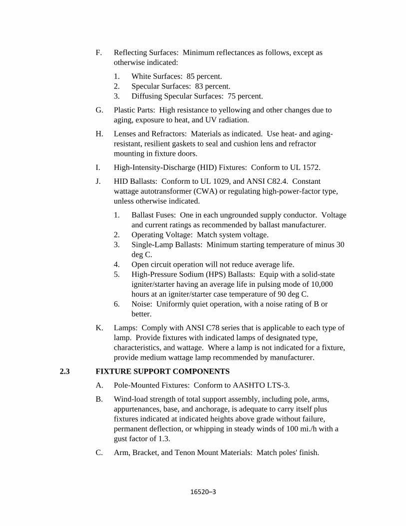
16520–3
F. Reflecting Surfaces: Minimum reflectances as follows, except as otherwise indicated:
1. White Surfaces: 85 percent. 2. Specular Surfaces: 83 percent. 3. Diffusing Specular Surfaces: 75 percent.
G. Plastic Parts: High resistance to yellowing and other changes due to aging, exposure to heat, and UV radiation.
H. Lenses and Refractors: Materials as indicated. Use heat- and aging-resistant, resilient gaskets to seal and cushion lens and refractor mounting in fixture doors.
I. High-Intensity-Discharge (HID) Fixtures: Conform to UL 1572.
J. HID Ballasts: Conform to UL 1029, and ANSI C82.4. Constant wattage autotransformer (CWA) or regulating high-power-factor type, unless otherwise indicated.
1. Ballast Fuses: One in each ungrounded supply conductor. Voltage and current ratings as recommended by ballast manufacturer.
2. Operating Voltage: Match system voltage. 3. Single-Lamp Ballasts: Minimum starting temperature of minus 30
deg C. 4. Open circuit operation will not reduce average life. 5. High-Pressure Sodium (HPS) Ballasts: Equip with a solid-state
igniter/starter having an average life in pulsing mode of 10,000 hours at an igniter/starter case temperature of 90 deg C.
6. Noise: Uniformly quiet operation, with a noise rating of B or better.
K. Lamps: Comply with ANSI C78 series that is applicable to each type of lamp. Provide fixtures with indicated lamps of designated type, characteristics, and wattage. Where a lamp is not indicated for a fixture, provide medium wattage lamp recommended by manufacturer.
2.3 FIXTURE SUPPORT COMPONENTS
A. Pole-Mounted Fixtures: Conform to AASHTO LTS-3.
B. Wind-load strength of total support assembly, including pole, arms, appurtenances, base, and anchorage, is adequate to carry itself plus fixtures indicated at indicated heights above grade without failure, permanent deflection, or whipping in steady winds of 100 mi./h with a gust factor of 1.3.
C. Arm, Bracket, and Tenon Mount Materials: Match poles' finish.
16520–4
D. Mountings, Fastenings, and Appurtenances: Corrosion-resistant items compatible with support components. Use materials that will not cause galvanic action at contact points. Use mountings that correctly position luminaire to provide indicated light distribution.
E. Pole Bases: Anchor type with galvanized steel hold-down or anchor bolts, leveling nuts, and bolt covers.
F. Metal Pole Grounding Provisions: Welded 1/2-inch threaded lug, accessible through handhole.
G. Concrete for Pole Foundations: Comply with Division 3. Use 3000-psig strength, 28-day concrete.
2.4 FINISHES
A. Metal Parts: Manufacturer's standard finish, except as otherwise indicated, applied over corrosion-resistant primer, free of streaks, runs, holidays, stains, blisters, and similar defects.
B. Other Parts: Manufacturer's standard finish, except as otherwise indicated.
PART 3 — EXECUTION
3.1 INSTALLATION
A. Set units plumb, square, level, and secure according to manufacturer's written instructions and approved Shop Drawings.
B. Concrete Foundations: Construct according to Division 3.
1. Comply with details and manufacturer's recommendations for reinforcing, anchor bolts, nuts, and washers. Verify anchor-bolt templates by comparing with actual pole bases furnished.
C. Pole Installation: Use web fabric slings (not chain or cable) to raise and set poles.
D. Fixture Attachment: Fasten to indicated structural supports.
E. Lamp fixtures with indicated lamps according to manufacturer's written instructions. Replace malfunctioning lamps.
3.2 FIELD QUALITY CONTROL
A. Inspect each installed unit for damage. Replace damaged fixtures and components.
B. Give advance notice of dates and times for field tests.
C. Provide instruments to make and record test results.
16520–5
D. Tests and Observations: Verify normal operation of lighting units after installing fixtures and energizing circuits with normal power source. Include the following:
1. Check for excessively noisy ballasts.
E. Replace or repair damaged and malfunctioning units, make necessary adjustments, and retest. Repeat procedure until all units operate properly.
3.3 ADJUSTING AND CLEANING
A. Clean units after installation. Use methods and materials recommended by manufacturer.
3.4 LIGHTING FIXTURE SCHEDULE
A. Lighting Fixture Schedule is shown on the Plans.
END OF SECTION

APPENDIX A WAGE RATES

WASHINGTON STATE PREVAILING WAGE RATES

State of WashingtonDepartment of Labor & Industries
Prevailing Wage Section - Telephone 360-902-5335PO Box 44540, Olympia, WA 98504-4540
Washington State Prevailing WageThe PREVAILING WAGES listed here include both the hourly wage rate and the hourly rate of
fringe benefits. On public works projects, worker's wage and benefit rates must add to not lessthan this total. A brief description of overtime calculation requirements are provided on the
Benefit Code Key.
Journey Level Prevailing Wage Rates for the Effective Date: 11/16/2015
County Trade Job Classification Wage Holiday Overtime NoteYakima Asbestos Abatement Workers Journey Level $17.83 1
Yakima Boilermakers Journey Level $64.29 5N 1C
Yakima Brick Mason Journey Level $44.94 5A 1M
Yakima Building Service Employees Janitor $9.47 1
Yakima Building Service Employees Shampooer $11.14 1
Yakima Building Service Employees Waxer $9.47 1
Yakima Building Service Employees Window Cleaner $9.47 1
Yakima Cabinet Makers (In Shop) Journey Level $16.35 1
Yakima Carpenters Journey Level $29.72 1
Yakima Cement Masons Journey Level $39.60 7B 1N
Yakima Divers & Tenders Diver $107.22 5D 4C 8A
Yakima Divers & Tenders Diver On Standby $64.42 5D 4C
Yakima Divers & Tenders Diver Tender $58.33 5D 4C
Yakima Divers & Tenders Surface Rcv & Rov Operator $58.33 5D 4C
Yakima Divers & Tenders Surface Rcv & Rov OperatorTender
$54.27 5A 4C
Yakima Dredge Workers Assistant Engineer $56.44 5D 3F
Yakima Dredge Workers Assistant Mate (Deckhand) $56.00 5D 3F
Yakima Dredge Workers Boatmen $56.44 5D 3F
Yakima Dredge Workers Engineer Welder $57.51 5D 3F
Yakima Dredge Workers Leverman, Hydraulic $58.67 5D 3F
Yakima Dredge Workers Mates $56.44 5D 3F
Yakima Dredge Workers Oiler $56.00 5D 3F
Yakima Drywall Applicator Journey Level $40.98 5D 4C
Yakima Drywall Tapers Journey Level $36.10 7E 1P
Yakima Electrical Fixture MaintenanceWorkers
Journey Level $43.32 1
Yakima Electricians - Inside Cable Splicer $59.51 5A 1E
https://fortress.wa.gov/lni/wagelookup/prvWagelookup.aspx
1 of 16 11/16/2015 10:14 AM
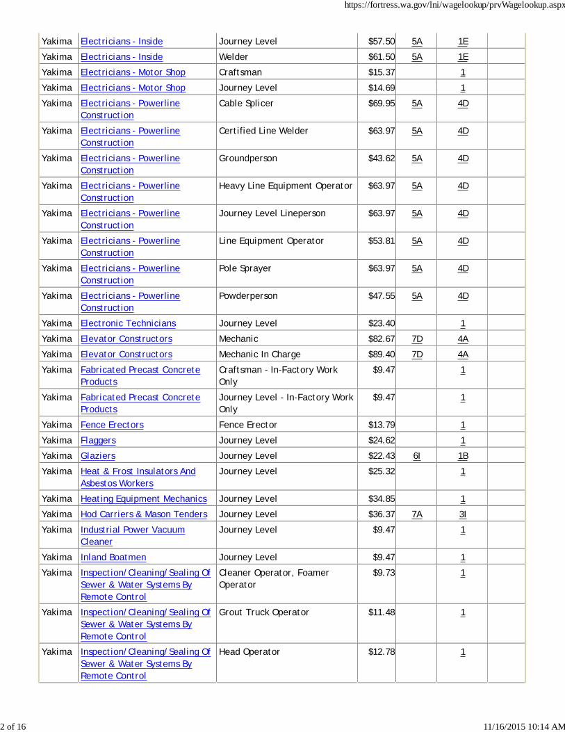
Yakima Electricians - Inside Journey Level $57.50 5A 1E
Yakima Electricians - Inside Welder $61.50 5A 1E
Yakima Electricians - Motor Shop Craftsman $15.37 1
Yakima Electricians - Motor Shop Journey Level $14.69 1
Yakima Electricians - PowerlineConstruction
Cable Splicer $69.95 5A 4D
Yakima Electricians - PowerlineConstruction
Certified Line Welder $63.97 5A 4D
Yakima Electricians - PowerlineConstruction
Groundperson $43.62 5A 4D
Yakima Electricians - PowerlineConstruction
Heavy Line Equipment Operator $63.97 5A 4D
Yakima Electricians - PowerlineConstruction
Journey Level Lineperson $63.97 5A 4D
Yakima Electricians - PowerlineConstruction
Line Equipment Operator $53.81 5A 4D
Yakima Electricians - PowerlineConstruction
Pole Sprayer $63.97 5A 4D
Yakima Electricians - PowerlineConstruction
Powderperson $47.55 5A 4D
Yakima Electronic Technicians Journey Level $23.40 1
Yakima Elevator Constructors Mechanic $82.67 7D 4A
Yakima Elevator Constructors Mechanic In Charge $89.40 7D 4A
Yakima Fabricated Precast ConcreteProducts
Craftsman - In-Factory WorkOnly
$9.47 1
Yakima Fabricated Precast ConcreteProducts
Journey Level - In-Factory WorkOnly
$9.47 1
Yakima Fence Erectors Fence Erector $13.79 1
Yakima Flaggers Journey Level $24.62 1
Yakima Glaziers Journey Level $22.43 6I 1B
Yakima Heat & Frost Insulators AndAsbestos Workers
Journey Level $25.32 1
Yakima Heating Equipment Mechanics Journey Level $34.85 1
Yakima Hod Carriers & Mason Tenders Journey Level $36.37 7A 3I
Yakima Industrial Power VacuumCleaner
Journey Level $9.47 1
Yakima Inland Boatmen Journey Level $9.47 1
Yakima Inspection/Cleaning/Sealing OfSewer & Water Systems ByRemote Control
Cleaner Operator, FoamerOperator
$9.73 1
Yakima Inspection/Cleaning/Sealing OfSewer & Water Systems ByRemote Control
Grout Truck Operator $11.48 1
Yakima Inspection/Cleaning/Sealing OfSewer & Water Systems ByRemote Control
Head Operator $12.78 1
https://fortress.wa.gov/lni/wagelookup/prvWagelookup.aspx
2 of 16 11/16/2015 10:14 AM
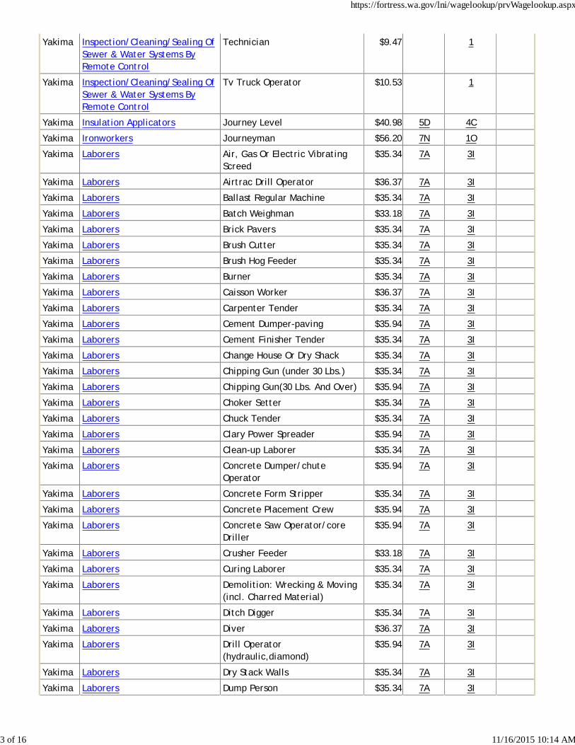
Yakima Inspection/Cleaning/Sealing OfSewer & Water Systems ByRemote Control
Technician $9.47 1
Yakima Inspection/Cleaning/Sealing OfSewer & Water Systems ByRemote Control
Tv Truck Operator $10.53 1
Yakima Insulation Applicators Journey Level $40.98 5D 4C
Yakima Ironworkers Journeyman $56.20 7N 1O
Yakima Laborers Air, Gas Or Electric VibratingScreed
$35.34 7A 3I
Yakima Laborers Airtrac Drill Operator $36.37 7A 3I
Yakima Laborers Ballast Regular Machine $35.34 7A 3I
Yakima Laborers Batch Weighman $33.18 7A 3I
Yakima Laborers Brick Pavers $35.34 7A 3I
Yakima Laborers Brush Cutter $35.34 7A 3I
Yakima Laborers Brush Hog Feeder $35.34 7A 3I
Yakima Laborers Burner $35.34 7A 3I
Yakima Laborers Caisson Worker $36.37 7A 3I
Yakima Laborers Carpenter Tender $35.34 7A 3I
Yakima Laborers Cement Dumper-paving $35.94 7A 3I
Yakima Laborers Cement Finisher Tender $35.34 7A 3I
Yakima Laborers Change House Or Dry Shack $35.34 7A 3I
Yakima Laborers Chipping Gun (under 30 Lbs.) $35.34 7A 3I
Yakima Laborers Chipping Gun(30 Lbs. And Over) $35.94 7A 3I
Yakima Laborers Choker Setter $35.34 7A 3I
Yakima Laborers Chuck Tender $35.34 7A 3I
Yakima Laborers Clary Power Spreader $35.94 7A 3I
Yakima Laborers Clean-up Laborer $35.34 7A 3I
Yakima Laborers Concrete Dumper/chuteOperator
$35.94 7A 3I
Yakima Laborers Concrete Form Stripper $35.34 7A 3I
Yakima Laborers Concrete Placement Crew $35.94 7A 3I
Yakima Laborers Concrete Saw Operator/coreDriller
$35.94 7A 3I
Yakima Laborers Crusher Feeder $33.18 7A 3I
Yakima Laborers Curing Laborer $35.34 7A 3I
Yakima Laborers Demolition: Wrecking & Moving(incl. Charred Material)
$35.34 7A 3I
Yakima Laborers Ditch Digger $35.34 7A 3I
Yakima Laborers Diver $36.37 7A 3I
Yakima Laborers Drill Operator(hydraulic,diamond)
$35.94 7A 3I
Yakima Laborers Dry Stack Walls $35.34 7A 3I
Yakima Laborers Dump Person $35.34 7A 3I
https://fortress.wa.gov/lni/wagelookup/prvWagelookup.aspx
3 of 16 11/16/2015 10:14 AM
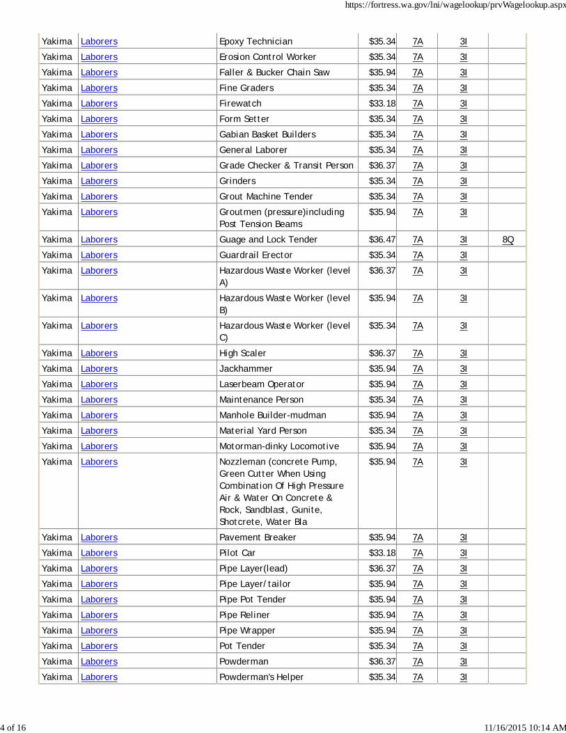
Yakima Laborers Epoxy Technician $35.34 7A 3I
Yakima Laborers Erosion Control Worker $35.34 7A 3I
Yakima Laborers Faller & Bucker Chain Saw $35.94 7A 3I
Yakima Laborers Fine Graders $35.34 7A 3I
Yakima Laborers Firewatch $33.18 7A 3I
Yakima Laborers Form Setter $35.34 7A 3I
Yakima Laborers Gabian Basket Builders $35.34 7A 3I
Yakima Laborers General Laborer $35.34 7A 3I
Yakima Laborers Grade Checker & Transit Person $36.37 7A 3I
Yakima Laborers Grinders $35.34 7A 3I
Yakima Laborers Grout Machine Tender $35.34 7A 3I
Yakima Laborers Groutmen (pressure)includingPost Tension Beams
$35.94 7A 3I
Yakima Laborers Guage and Lock Tender $36.47 7A 3I 8Q
Yakima Laborers Guardrail Erector $35.34 7A 3I
Yakima Laborers Hazardous Waste Worker (levelA)
$36.37 7A 3I
Yakima Laborers Hazardous Waste Worker (levelB)
$35.94 7A 3I
Yakima Laborers Hazardous Waste Worker (levelC)
$35.34 7A 3I
Yakima Laborers High Scaler $36.37 7A 3I
Yakima Laborers Jackhammer $35.94 7A 3I
Yakima Laborers Laserbeam Operator $35.94 7A 3I
Yakima Laborers Maintenance Person $35.34 7A 3I
Yakima Laborers Manhole Builder-mudman $35.94 7A 3I
Yakima Laborers Material Yard Person $35.34 7A 3I
Yakima Laborers Motorman-dinky Locomotive $35.94 7A 3I
Yakima Laborers Nozzleman (concrete Pump,Green Cutter When UsingCombination Of High PressureAir & Water On Concrete &Rock, Sandblast, Gunite,Shotcrete, Water Bla
$35.94 7A 3I
Yakima Laborers Pavement Breaker $35.94 7A 3I
Yakima Laborers Pilot Car $33.18 7A 3I
Yakima Laborers Pipe Layer(lead) $36.37 7A 3I
Yakima Laborers Pipe Layer/tailor $35.94 7A 3I
Yakima Laborers Pipe Pot Tender $35.94 7A 3I
Yakima Laborers Pipe Reliner $35.94 7A 3I
Yakima Laborers Pipe Wrapper $35.94 7A 3I
Yakima Laborers Pot Tender $35.34 7A 3I
Yakima Laborers Powderman $36.37 7A 3I
Yakima Laborers Powderman's Helper $35.34 7A 3I
https://fortress.wa.gov/lni/wagelookup/prvWagelookup.aspx
4 of 16 11/16/2015 10:14 AM
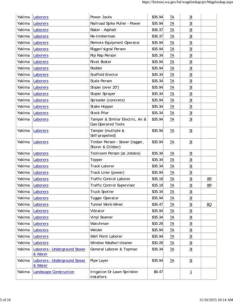
Yakima Laborers Power Jacks $35.94 7A 3I
Yakima Laborers Railroad Spike Puller - Power $35.94 7A 3I
Yakima Laborers Raker - Asphalt $36.37 7A 3I
Yakima Laborers Re-timberman $36.37 7A 3I
Yakima Laborers Remote Equipment Operator $35.94 7A 3I
Yakima Laborers Rigger/signal Person $35.94 7A 3I
Yakima Laborers Rip Rap Person $35.34 7A 3I
Yakima Laborers Rivet Buster $35.94 7A 3I
Yakima Laborers Rodder $35.94 7A 3I
Yakima Laborers Scaffold Erector $35.34 7A 3I
Yakima Laborers Scale Person $35.34 7A 3I
Yakima Laborers Sloper (over 20") $35.94 7A 3I
Yakima Laborers Sloper Sprayer $35.34 7A 3I
Yakima Laborers Spreader (concrete) $35.94 7A 3I
Yakima Laborers Stake Hopper $35.34 7A 3I
Yakima Laborers Stock Piler $35.34 7A 3I
Yakima Laborers Tamper & Similar Electric, Air &Gas Operated Tools
$35.94 7A 3I
Yakima Laborers Tamper (multiple &Self-propelled)
$35.94 7A 3I
Yakima Laborers Timber Person - Sewer (lagger,Shorer & Cribber)
$35.94 7A 3I
Yakima Laborers Toolroom Person (at Jobsite) $35.34 7A 3I
Yakima Laborers Topper $35.34 7A 3I
Yakima Laborers Track Laborer $35.34 7A 3I
Yakima Laborers Track Liner (power) $35.94 7A 3I
Yakima Laborers Traffic Control Laborer $35.18 7A 3I 8R
Yakima Laborers Traffic Control Supervisor $35.18 7A 3I 8R
Yakima Laborers Truck Spotter $35.34 7A 3I
Yakima Laborers Tugger Operator $35.94 7A 3I
Yakima Laborers Tunnel Work-Miner $36.47 7A 3I 8Q
Yakima Laborers Vibrator $35.94 7A 3I
Yakima Laborers Vinyl Seamer $35.34 7A 3I
Yakima Laborers Watchman $30.28 7A 3I
Yakima Laborers Welder $35.94 7A 3I
Yakima Laborers Well Point Laborer $35.94 7A 3I
Yakima Laborers Window Washer/cleaner $30.28 7A 3I
Yakima Laborers - Underground Sewer& Water
General Laborer & Topman $35.34 7A 3I
Yakima Laborers - Underground Sewer& Water
Pipe Layer $35.94 7A 3I
Yakima Landscape Construction Irrigation Or Lawn SprinklerInstallers
$9.47 1
https://fortress.wa.gov/lni/wagelookup/prvWagelookup.aspx
5 of 16 11/16/2015 10:14 AM
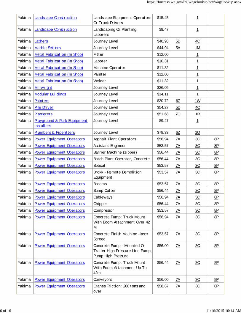
Yakima Landscape Construction Landscape Equipment OperatorsOr Truck Drivers
$15.45 1
Yakima Landscape Construction Landscaping Or PlantingLaborers
$9.47 1
Yakima Lathers Journey Level $40.98 5D 4C
Yakima Marble Setters Journey Level $44.94 5A 1M
Yakima Metal Fabrication (In Shop) Fitter $12.00 1
Yakima Metal Fabrication (In Shop) Laborer $10.31 1
Yakima Metal Fabrication (In Shop) Machine Operator $11.32 1
Yakima Metal Fabrication (In Shop) Painter $12.00 1
Yakima Metal Fabrication (In Shop) Welder $11.32 1
Yakima Millwright Journey Level $26.05 1
Yakima Modular Buildings Journey Level $14.11 1
Yakima Painters Journey Level $30.72 6Z 1W
Yakima Pile Driver Journey Level $54.27 5D 4C
Yakima Plasterers Journey Level $51.68 7Q 1R
Yakima Playground & Park EquipmentInstallers
Journey Level $9.47 1
Yakima Plumbers & Pipefitters Journey Level $78.33 6Z 1Q
Yakima Power Equipment Operators Asphalt Plant Operators $56.94 7A 3C 8P
Yakima Power Equipment Operators Assistant Engineer $53.57 7A 3C 8P
Yakima Power Equipment Operators Barrier Machine (zipper) $56.44 7A 3C 8P
Yakima Power Equipment Operators Batch Plant Operator, Concrete $56.44 7A 3C 8P
Yakima Power Equipment Operators Bobcat $53.57 7A 3C 8P
Yakima Power Equipment Operators Brokk - Remote DemolitionEquipment
$53.57 7A 3C 8P
Yakima Power Equipment Operators Brooms $53.57 7A 3C 8P
Yakima Power Equipment Operators Bump Cutter $56.44 7A 3C 8P
Yakima Power Equipment Operators Cableways $56.94 7A 3C 8P
Yakima Power Equipment Operators Chipper $56.44 7A 3C 8P
Yakima Power Equipment Operators Compressor $53.57 7A 3C 8P
Yakima Power Equipment Operators Concrete Pump: Truck MountWith Boom Attachment Over 42M
$56.94 7A 3C 8P
Yakima Power Equipment Operators Concrete Finish Machine -laserScreed
$53.57 7A 3C 8P
Yakima Power Equipment Operators Concrete Pump - Mounted OrTrailer High Pressure Line Pump,Pump High Pressure.
$56.00 7A 3C 8P
Yakima Power Equipment Operators Concrete Pump: Truck MountWith Boom Attachment Up To42m
$56.44 7A 3C 8P
Yakima Power Equipment Operators Conveyors $56.00 7A 3C 8P
Yakima Power Equipment Operators Cranes Friction: 200 tons andover
$58.67 7A 3C 8P
https://fortress.wa.gov/lni/wagelookup/prvWagelookup.aspx
6 of 16 11/16/2015 10:14 AM
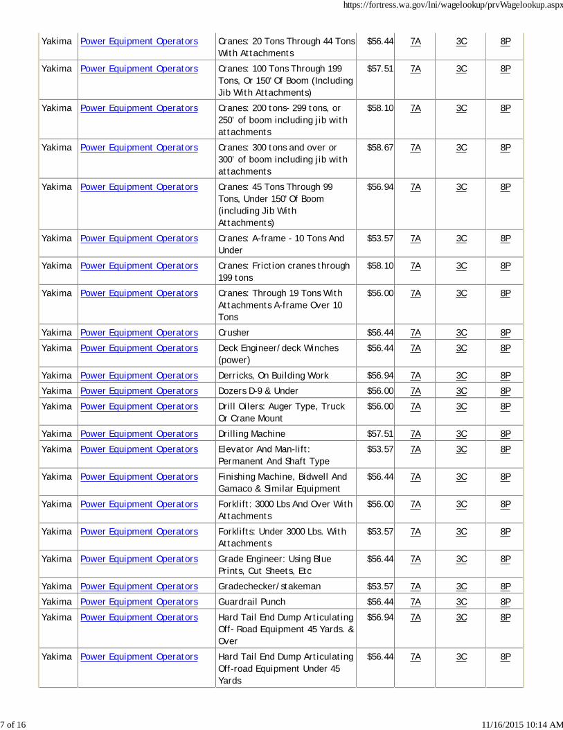
Yakima Power Equipment Operators Cranes: 20 Tons Through 44 TonsWith Attachments
$56.44 7A 3C 8P
Yakima Power Equipment Operators Cranes: 100 Tons Through 199Tons, Or 150' Of Boom (IncludingJib With Attachments)
$57.51 7A 3C 8P
Yakima Power Equipment Operators Cranes: 200 tons- 299 tons, or250’ of boom including jib withattachments
$58.10 7A 3C 8P
Yakima Power Equipment Operators Cranes: 300 tons and over or300’ of boom including jib withattachments
$58.67 7A 3C 8P
Yakima Power Equipment Operators Cranes: 45 Tons Through 99Tons, Under 150' Of Boom(including Jib WithAttachments)
$56.94 7A 3C 8P
Yakima Power Equipment Operators Cranes: A-frame - 10 Tons AndUnder
$53.57 7A 3C 8P
Yakima Power Equipment Operators Cranes: Friction cranes through199 tons
$58.10 7A 3C 8P
Yakima Power Equipment Operators Cranes: Through 19 Tons WithAttachments A-frame Over 10Tons
$56.00 7A 3C 8P
Yakima Power Equipment Operators Crusher $56.44 7A 3C 8P
Yakima Power Equipment Operators Deck Engineer/deck Winches(power)
$56.44 7A 3C 8P
Yakima Power Equipment Operators Derricks, On Building Work $56.94 7A 3C 8P
Yakima Power Equipment Operators Dozers D-9 & Under $56.00 7A 3C 8P
Yakima Power Equipment Operators Drill Oilers: Auger Type, TruckOr Crane Mount
$56.00 7A 3C 8P
Yakima Power Equipment Operators Drilling Machine $57.51 7A 3C 8P
Yakima Power Equipment Operators Elevator And Man-lift:Permanent And Shaft Type
$53.57 7A 3C 8P
Yakima Power Equipment Operators Finishing Machine, Bidwell AndGamaco & Similar Equipment
$56.44 7A 3C 8P
Yakima Power Equipment Operators Forklift: 3000 Lbs And Over WithAttachments
$56.00 7A 3C 8P
Yakima Power Equipment Operators Forklifts: Under 3000 Lbs. WithAttachments
$53.57 7A 3C 8P
Yakima Power Equipment Operators Grade Engineer: Using BluePrints, Cut Sheets, Etc
$56.44 7A 3C 8P
Yakima Power Equipment Operators Gradechecker/stakeman $53.57 7A 3C 8P
Yakima Power Equipment Operators Guardrail Punch $56.44 7A 3C 8P
Yakima Power Equipment Operators Hard Tail End Dump ArticulatingOff- Road Equipment 45 Yards. &Over
$56.94 7A 3C 8P
Yakima Power Equipment Operators Hard Tail End Dump ArticulatingOff-road Equipment Under 45Yards
$56.44 7A 3C 8P
https://fortress.wa.gov/lni/wagelookup/prvWagelookup.aspx
7 of 16 11/16/2015 10:14 AM
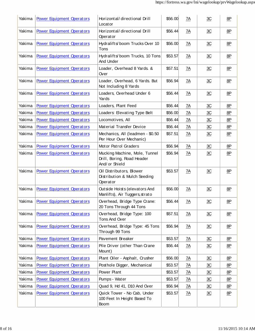
Yakima Power Equipment Operators Horizontal/directional DrillLocator
$56.00 7A 3C 8P
Yakima Power Equipment Operators Horizontal/directional DrillOperator
$56.44 7A 3C 8P
Yakima Power Equipment Operators Hydralifts/boom Trucks Over 10Tons
$56.00 7A 3C 8P
Yakima Power Equipment Operators Hydralifts/boom Trucks, 10 TonsAnd Under
$53.57 7A 3C 8P
Yakima Power Equipment Operators Loader, Overhead 8 Yards. &Over
$57.51 7A 3C 8P
Yakima Power Equipment Operators Loader, Overhead, 6 Yards. ButNot Including 8 Yards
$56.94 7A 3C 8P
Yakima Power Equipment Operators Loaders, Overhead Under 6Yards
$56.44 7A 3C 8P
Yakima Power Equipment Operators Loaders, Plant Feed $56.44 7A 3C 8P
Yakima Power Equipment Operators Loaders: Elevating Type Belt $56.00 7A 3C 8P
Yakima Power Equipment Operators Locomotives, All $56.44 7A 3C 8P
Yakima Power Equipment Operators Material Transfer Device $56.44 7A 3C 8P
Yakima Power Equipment Operators Mechanics, All (leadmen - $0.50Per Hour Over Mechanic)
$57.51 7A 3C 8P
Yakima Power Equipment Operators Motor Patrol Graders $56.94 7A 3C 8P
Yakima Power Equipment Operators Mucking Machine, Mole, TunnelDrill, Boring, Road HeaderAnd/or Shield
$56.94 7A 3C 8P
Yakima Power Equipment Operators Oil Distributors, BlowerDistribution & Mulch SeedingOperator
$53.57 7A 3C 8P
Yakima Power Equipment Operators Outside Hoists (elevators AndManlifts), Air Tuggers,strato
$56.00 7A 3C 8P
Yakima Power Equipment Operators Overhead, Bridge Type Crane:20 Tons Through 44 Tons
$56.44 7A 3C 8P
Yakima Power Equipment Operators Overhead, Bridge Type: 100Tons And Over
$57.51 7A 3C 8P
Yakima Power Equipment Operators Overhead, Bridge Type: 45 TonsThrough 99 Tons
$56.94 7A 3C 8P
Yakima Power Equipment Operators Pavement Breaker $53.57 7A 3C 8P
Yakima Power Equipment Operators Pile Driver (other Than CraneMount)
$56.44 7A 3C 8P
Yakima Power Equipment Operators Plant Oiler - Asphalt, Crusher $56.00 7A 3C 8P
Yakima Power Equipment Operators Posthole Digger, Mechanical $53.57 7A 3C 8P
Yakima Power Equipment Operators Power Plant $53.57 7A 3C 8P
Yakima Power Equipment Operators Pumps - Water $53.57 7A 3C 8P
Yakima Power Equipment Operators Quad 9, Hd 41, D10 And Over $56.94 7A 3C 8P
Yakima Power Equipment Operators Quick Tower - No Cab, Under100 Feet In Height Based ToBoom
$53.57 7A 3C 8P
https://fortress.wa.gov/lni/wagelookup/prvWagelookup.aspx
8 of 16 11/16/2015 10:14 AM
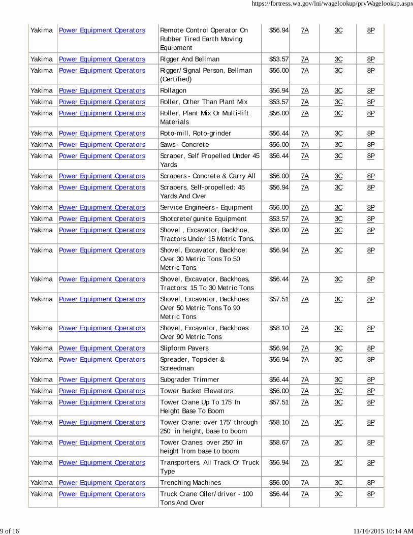
Yakima Power Equipment Operators Remote Control Operator OnRubber Tired Earth MovingEquipment
$56.94 7A 3C 8P
Yakima Power Equipment Operators Rigger And Bellman $53.57 7A 3C 8P
Yakima Power Equipment Operators Rigger/Signal Person, Bellman(Certified)
$56.00 7A 3C 8P
Yakima Power Equipment Operators Rollagon $56.94 7A 3C 8P
Yakima Power Equipment Operators Roller, Other Than Plant Mix $53.57 7A 3C 8P
Yakima Power Equipment Operators Roller, Plant Mix Or Multi-liftMaterials
$56.00 7A 3C 8P
Yakima Power Equipment Operators Roto-mill, Roto-grinder $56.44 7A 3C 8P
Yakima Power Equipment Operators Saws - Concrete $56.00 7A 3C 8P
Yakima Power Equipment Operators Scraper, Self Propelled Under 45Yards
$56.44 7A 3C 8P
Yakima Power Equipment Operators Scrapers - Concrete & Carry All $56.00 7A 3C 8P
Yakima Power Equipment Operators Scrapers, Self-propelled: 45Yards And Over
$56.94 7A 3C 8P
Yakima Power Equipment Operators Service Engineers - Equipment $56.00 7A 3C 8P
Yakima Power Equipment Operators Shotcrete/gunite Equipment $53.57 7A 3C 8P
Yakima Power Equipment Operators Shovel , Excavator, Backhoe,Tractors Under 15 Metric Tons.
$56.00 7A 3C 8P
Yakima Power Equipment Operators Shovel, Excavator, Backhoe:Over 30 Metric Tons To 50Metric Tons
$56.94 7A 3C 8P
Yakima Power Equipment Operators Shovel, Excavator, Backhoes,Tractors: 15 To 30 Metric Tons
$56.44 7A 3C 8P
Yakima Power Equipment Operators Shovel, Excavator, Backhoes:Over 50 Metric Tons To 90Metric Tons
$57.51 7A 3C 8P
Yakima Power Equipment Operators Shovel, Excavator, Backhoes:Over 90 Metric Tons
$58.10 7A 3C 8P
Yakima Power Equipment Operators Slipform Pavers $56.94 7A 3C 8P
Yakima Power Equipment Operators Spreader, Topsider &Screedman
$56.94 7A 3C 8P
Yakima Power Equipment Operators Subgrader Trimmer $56.44 7A 3C 8P
Yakima Power Equipment Operators Tower Bucket Elevators $56.00 7A 3C 8P
Yakima Power Equipment Operators Tower Crane Up To 175' InHeight Base To Boom
$57.51 7A 3C 8P
Yakima Power Equipment Operators Tower Crane: over 175’ through250’ in height, base to boom
$58.10 7A 3C 8P
Yakima Power Equipment Operators Tower Cranes: over 250’ inheight from base to boom
$58.67 7A 3C 8P
Yakima Power Equipment Operators Transporters, All Track Or TruckType
$56.94 7A 3C 8P
Yakima Power Equipment Operators Trenching Machines $56.00 7A 3C 8P
Yakima Power Equipment Operators Truck Crane Oiler/driver - 100Tons And Over
$56.44 7A 3C 8P
https://fortress.wa.gov/lni/wagelookup/prvWagelookup.aspx
9 of 16 11/16/2015 10:14 AM
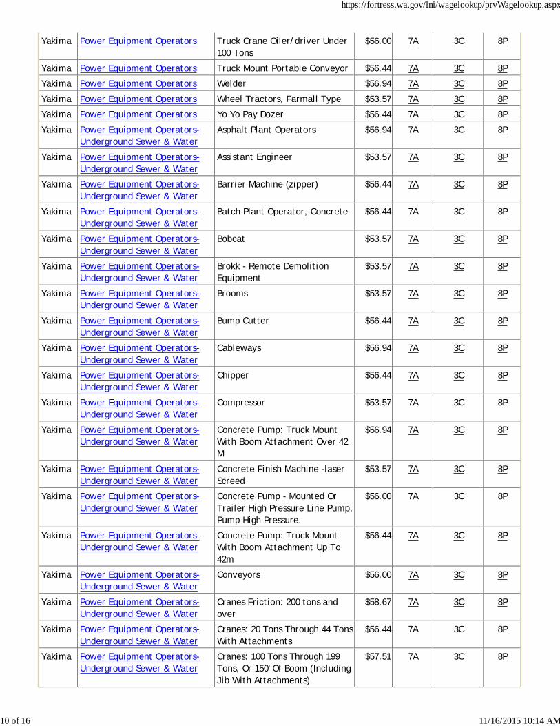
Yakima Power Equipment Operators Truck Crane Oiler/driver Under100 Tons
$56.00 7A 3C 8P
Yakima Power Equipment Operators Truck Mount Portable Conveyor $56.44 7A 3C 8P
Yakima Power Equipment Operators Welder $56.94 7A 3C 8P
Yakima Power Equipment Operators Wheel Tractors, Farmall Type $53.57 7A 3C 8P
Yakima Power Equipment Operators Yo Yo Pay Dozer $56.44 7A 3C 8P
Yakima Power Equipment Operators-Underground Sewer & Water
Asphalt Plant Operators $56.94 7A 3C 8P
Yakima Power Equipment Operators-Underground Sewer & Water
Assistant Engineer $53.57 7A 3C 8P
Yakima Power Equipment Operators-Underground Sewer & Water
Barrier Machine (zipper) $56.44 7A 3C 8P
Yakima Power Equipment Operators-Underground Sewer & Water
Batch Plant Operator, Concrete $56.44 7A 3C 8P
Yakima Power Equipment Operators-Underground Sewer & Water
Bobcat $53.57 7A 3C 8P
Yakima Power Equipment Operators-Underground Sewer & Water
Brokk - Remote DemolitionEquipment
$53.57 7A 3C 8P
Yakima Power Equipment Operators-Underground Sewer & Water
Brooms $53.57 7A 3C 8P
Yakima Power Equipment Operators-Underground Sewer & Water
Bump Cutter $56.44 7A 3C 8P
Yakima Power Equipment Operators-Underground Sewer & Water
Cableways $56.94 7A 3C 8P
Yakima Power Equipment Operators-Underground Sewer & Water
Chipper $56.44 7A 3C 8P
Yakima Power Equipment Operators-Underground Sewer & Water
Compressor $53.57 7A 3C 8P
Yakima Power Equipment Operators-Underground Sewer & Water
Concrete Pump: Truck MountWith Boom Attachment Over 42M
$56.94 7A 3C 8P
Yakima Power Equipment Operators-Underground Sewer & Water
Concrete Finish Machine -laserScreed
$53.57 7A 3C 8P
Yakima Power Equipment Operators-Underground Sewer & Water
Concrete Pump - Mounted OrTrailer High Pressure Line Pump,Pump High Pressure.
$56.00 7A 3C 8P
Yakima Power Equipment Operators-Underground Sewer & Water
Concrete Pump: Truck MountWith Boom Attachment Up To42m
$56.44 7A 3C 8P
Yakima Power Equipment Operators-Underground Sewer & Water
Conveyors $56.00 7A 3C 8P
Yakima Power Equipment Operators-Underground Sewer & Water
Cranes Friction: 200 tons andover
$58.67 7A 3C 8P
Yakima Power Equipment Operators-Underground Sewer & Water
Cranes: 20 Tons Through 44 TonsWith Attachments
$56.44 7A 3C 8P
Yakima Power Equipment Operators-Underground Sewer & Water
Cranes: 100 Tons Through 199Tons, Or 150' Of Boom (IncludingJib With Attachments)
$57.51 7A 3C 8P
https://fortress.wa.gov/lni/wagelookup/prvWagelookup.aspx
10 of 16 11/16/2015 10:14 AM
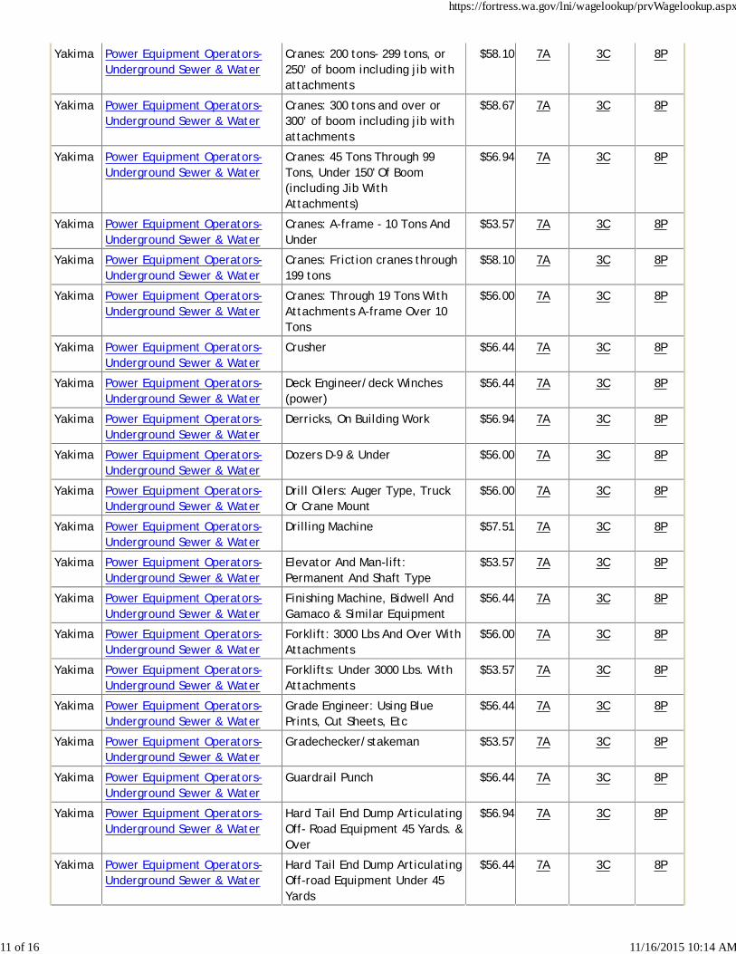
Yakima Power Equipment Operators-Underground Sewer & Water
Cranes: 200 tons- 299 tons, or250’ of boom including jib withattachments
$58.10 7A 3C 8P
Yakima Power Equipment Operators-Underground Sewer & Water
Cranes: 300 tons and over or300’ of boom including jib withattachments
$58.67 7A 3C 8P
Yakima Power Equipment Operators-Underground Sewer & Water
Cranes: 45 Tons Through 99Tons, Under 150' Of Boom(including Jib WithAttachments)
$56.94 7A 3C 8P
Yakima Power Equipment Operators-Underground Sewer & Water
Cranes: A-frame - 10 Tons AndUnder
$53.57 7A 3C 8P
Yakima Power Equipment Operators-Underground Sewer & Water
Cranes: Friction cranes through199 tons
$58.10 7A 3C 8P
Yakima Power Equipment Operators-Underground Sewer & Water
Cranes: Through 19 Tons WithAttachments A-frame Over 10Tons
$56.00 7A 3C 8P
Yakima Power Equipment Operators-Underground Sewer & Water
Crusher $56.44 7A 3C 8P
Yakima Power Equipment Operators-Underground Sewer & Water
Deck Engineer/deck Winches(power)
$56.44 7A 3C 8P
Yakima Power Equipment Operators-Underground Sewer & Water
Derricks, On Building Work $56.94 7A 3C 8P
Yakima Power Equipment Operators-Underground Sewer & Water
Dozers D-9 & Under $56.00 7A 3C 8P
Yakima Power Equipment Operators-Underground Sewer & Water
Drill Oilers: Auger Type, TruckOr Crane Mount
$56.00 7A 3C 8P
Yakima Power Equipment Operators-Underground Sewer & Water
Drilling Machine $57.51 7A 3C 8P
Yakima Power Equipment Operators-Underground Sewer & Water
Elevator And Man-lift:Permanent And Shaft Type
$53.57 7A 3C 8P
Yakima Power Equipment Operators-Underground Sewer & Water
Finishing Machine, Bidwell AndGamaco & Similar Equipment
$56.44 7A 3C 8P
Yakima Power Equipment Operators-Underground Sewer & Water
Forklift: 3000 Lbs And Over WithAttachments
$56.00 7A 3C 8P
Yakima Power Equipment Operators-Underground Sewer & Water
Forklifts: Under 3000 Lbs. WithAttachments
$53.57 7A 3C 8P
Yakima Power Equipment Operators-Underground Sewer & Water
Grade Engineer: Using BluePrints, Cut Sheets, Etc
$56.44 7A 3C 8P
Yakima Power Equipment Operators-Underground Sewer & Water
Gradechecker/stakeman $53.57 7A 3C 8P
Yakima Power Equipment Operators-Underground Sewer & Water
Guardrail Punch $56.44 7A 3C 8P
Yakima Power Equipment Operators-Underground Sewer & Water
Hard Tail End Dump ArticulatingOff- Road Equipment 45 Yards. &Over
$56.94 7A 3C 8P
Yakima Power Equipment Operators-Underground Sewer & Water
Hard Tail End Dump ArticulatingOff-road Equipment Under 45Yards
$56.44 7A 3C 8P
https://fortress.wa.gov/lni/wagelookup/prvWagelookup.aspx
11 of 16 11/16/2015 10:14 AM
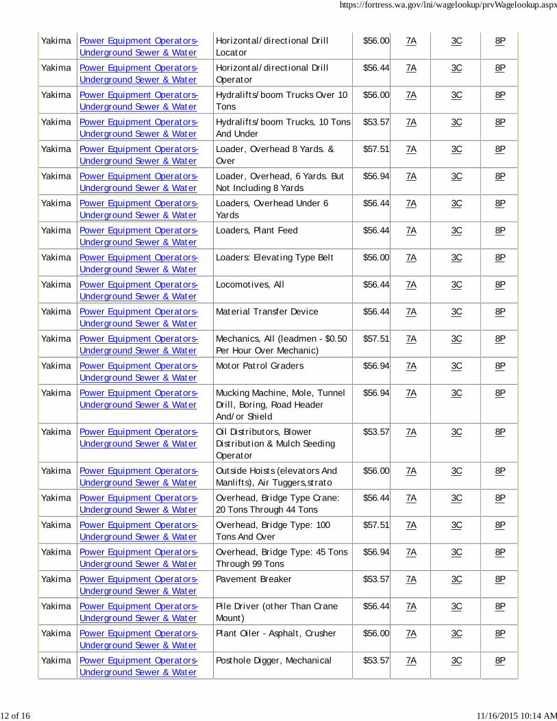
Yakima Power Equipment Operators-Underground Sewer & Water
Horizontal/directional DrillLocator
$56.00 7A 3C 8P
Yakima Power Equipment Operators-Underground Sewer & Water
Horizontal/directional DrillOperator
$56.44 7A 3C 8P
Yakima Power Equipment Operators-Underground Sewer & Water
Hydralifts/boom Trucks Over 10Tons
$56.00 7A 3C 8P
Yakima Power Equipment Operators-Underground Sewer & Water
Hydralifts/boom Trucks, 10 TonsAnd Under
$53.57 7A 3C 8P
Yakima Power Equipment Operators-Underground Sewer & Water
Loader, Overhead 8 Yards. &Over
$57.51 7A 3C 8P
Yakima Power Equipment Operators-Underground Sewer & Water
Loader, Overhead, 6 Yards. ButNot Including 8 Yards
$56.94 7A 3C 8P
Yakima Power Equipment Operators-Underground Sewer & Water
Loaders, Overhead Under 6Yards
$56.44 7A 3C 8P
Yakima Power Equipment Operators-Underground Sewer & Water
Loaders, Plant Feed $56.44 7A 3C 8P
Yakima Power Equipment Operators-Underground Sewer & Water
Loaders: Elevating Type Belt $56.00 7A 3C 8P
Yakima Power Equipment Operators-Underground Sewer & Water
Locomotives, All $56.44 7A 3C 8P
Yakima Power Equipment Operators-Underground Sewer & Water
Material Transfer Device $56.44 7A 3C 8P
Yakima Power Equipment Operators-Underground Sewer & Water
Mechanics, All (leadmen - $0.50Per Hour Over Mechanic)
$57.51 7A 3C 8P
Yakima Power Equipment Operators-Underground Sewer & Water
Motor Patrol Graders $56.94 7A 3C 8P
Yakima Power Equipment Operators-Underground Sewer & Water
Mucking Machine, Mole, TunnelDrill, Boring, Road HeaderAnd/or Shield
$56.94 7A 3C 8P
Yakima Power Equipment Operators-Underground Sewer & Water
Oil Distributors, BlowerDistribution & Mulch SeedingOperator
$53.57 7A 3C 8P
Yakima Power Equipment Operators-Underground Sewer & Water
Outside Hoists (elevators AndManlifts), Air Tuggers,strato
$56.00 7A 3C 8P
Yakima Power Equipment Operators-Underground Sewer & Water
Overhead, Bridge Type Crane:20 Tons Through 44 Tons
$56.44 7A 3C 8P
Yakima Power Equipment Operators-Underground Sewer & Water
Overhead, Bridge Type: 100Tons And Over
$57.51 7A 3C 8P
Yakima Power Equipment Operators-Underground Sewer & Water
Overhead, Bridge Type: 45 TonsThrough 99 Tons
$56.94 7A 3C 8P
Yakima Power Equipment Operators-Underground Sewer & Water
Pavement Breaker $53.57 7A 3C 8P
Yakima Power Equipment Operators-Underground Sewer & Water
Pile Driver (other Than CraneMount)
$56.44 7A 3C 8P
Yakima Power Equipment Operators-Underground Sewer & Water
Plant Oiler - Asphalt, Crusher $56.00 7A 3C 8P
Yakima Power Equipment Operators-Underground Sewer & Water
Posthole Digger, Mechanical $53.57 7A 3C 8P
https://fortress.wa.gov/lni/wagelookup/prvWagelookup.aspx
12 of 16 11/16/2015 10:14 AM
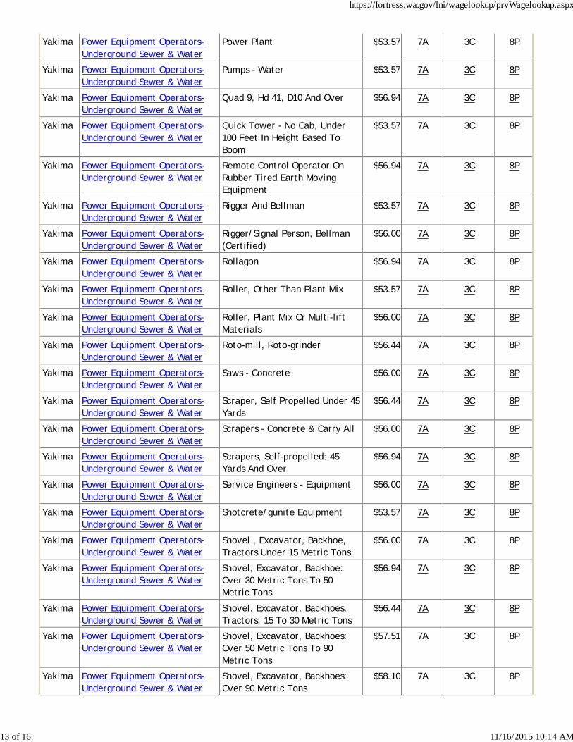
Yakima Power Equipment Operators-Underground Sewer & Water
Power Plant $53.57 7A 3C 8P
Yakima Power Equipment Operators-Underground Sewer & Water
Pumps - Water $53.57 7A 3C 8P
Yakima Power Equipment Operators-Underground Sewer & Water
Quad 9, Hd 41, D10 And Over $56.94 7A 3C 8P
Yakima Power Equipment Operators-Underground Sewer & Water
Quick Tower - No Cab, Under100 Feet In Height Based ToBoom
$53.57 7A 3C 8P
Yakima Power Equipment Operators-Underground Sewer & Water
Remote Control Operator OnRubber Tired Earth MovingEquipment
$56.94 7A 3C 8P
Yakima Power Equipment Operators-Underground Sewer & Water
Rigger And Bellman $53.57 7A 3C 8P
Yakima Power Equipment Operators-Underground Sewer & Water
Rigger/Signal Person, Bellman(Certified)
$56.00 7A 3C 8P
Yakima Power Equipment Operators-Underground Sewer & Water
Rollagon $56.94 7A 3C 8P
Yakima Power Equipment Operators-Underground Sewer & Water
Roller, Other Than Plant Mix $53.57 7A 3C 8P
Yakima Power Equipment Operators-Underground Sewer & Water
Roller, Plant Mix Or Multi-liftMaterials
$56.00 7A 3C 8P
Yakima Power Equipment Operators-Underground Sewer & Water
Roto-mill, Roto-grinder $56.44 7A 3C 8P
Yakima Power Equipment Operators-Underground Sewer & Water
Saws - Concrete $56.00 7A 3C 8P
Yakima Power Equipment Operators-Underground Sewer & Water
Scraper, Self Propelled Under 45Yards
$56.44 7A 3C 8P
Yakima Power Equipment Operators-Underground Sewer & Water
Scrapers - Concrete & Carry All $56.00 7A 3C 8P
Yakima Power Equipment Operators-Underground Sewer & Water
Scrapers, Self-propelled: 45Yards And Over
$56.94 7A 3C 8P
Yakima Power Equipment Operators-Underground Sewer & Water
Service Engineers - Equipment $56.00 7A 3C 8P
Yakima Power Equipment Operators-Underground Sewer & Water
Shotcrete/gunite Equipment $53.57 7A 3C 8P
Yakima Power Equipment Operators-Underground Sewer & Water
Shovel , Excavator, Backhoe,Tractors Under 15 Metric Tons.
$56.00 7A 3C 8P
Yakima Power Equipment Operators-Underground Sewer & Water
Shovel, Excavator, Backhoe:Over 30 Metric Tons To 50Metric Tons
$56.94 7A 3C 8P
Yakima Power Equipment Operators-Underground Sewer & Water
Shovel, Excavator, Backhoes,Tractors: 15 To 30 Metric Tons
$56.44 7A 3C 8P
Yakima Power Equipment Operators-Underground Sewer & Water
Shovel, Excavator, Backhoes:Over 50 Metric Tons To 90Metric Tons
$57.51 7A 3C 8P
Yakima Power Equipment Operators-Underground Sewer & Water
Shovel, Excavator, Backhoes:Over 90 Metric Tons
$58.10 7A 3C 8P
https://fortress.wa.gov/lni/wagelookup/prvWagelookup.aspx
13 of 16 11/16/2015 10:14 AM
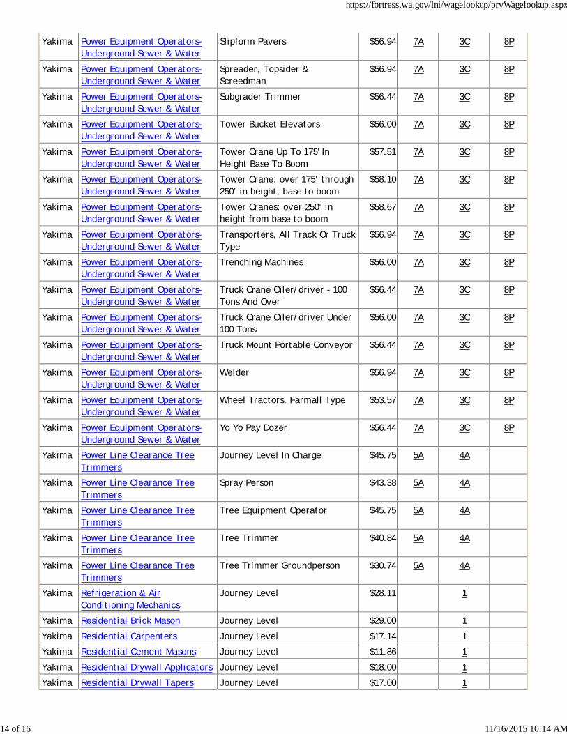
Yakima Power Equipment Operators-Underground Sewer & Water
Slipform Pavers $56.94 7A 3C 8P
Yakima Power Equipment Operators-Underground Sewer & Water
Spreader, Topsider &Screedman
$56.94 7A 3C 8P
Yakima Power Equipment Operators-Underground Sewer & Water
Subgrader Trimmer $56.44 7A 3C 8P
Yakima Power Equipment Operators-Underground Sewer & Water
Tower Bucket Elevators $56.00 7A 3C 8P
Yakima Power Equipment Operators-Underground Sewer & Water
Tower Crane Up To 175' InHeight Base To Boom
$57.51 7A 3C 8P
Yakima Power Equipment Operators-Underground Sewer & Water
Tower Crane: over 175’ through250’ in height, base to boom
$58.10 7A 3C 8P
Yakima Power Equipment Operators-Underground Sewer & Water
Tower Cranes: over 250’ inheight from base to boom
$58.67 7A 3C 8P
Yakima Power Equipment Operators-Underground Sewer & Water
Transporters, All Track Or TruckType
$56.94 7A 3C 8P
Yakima Power Equipment Operators-Underground Sewer & Water
Trenching Machines $56.00 7A 3C 8P
Yakima Power Equipment Operators-Underground Sewer & Water
Truck Crane Oiler/driver - 100Tons And Over
$56.44 7A 3C 8P
Yakima Power Equipment Operators-Underground Sewer & Water
Truck Crane Oiler/driver Under100 Tons
$56.00 7A 3C 8P
Yakima Power Equipment Operators-Underground Sewer & Water
Truck Mount Portable Conveyor $56.44 7A 3C 8P
Yakima Power Equipment Operators-Underground Sewer & Water
Welder $56.94 7A 3C 8P
Yakima Power Equipment Operators-Underground Sewer & Water
Wheel Tractors, Farmall Type $53.57 7A 3C 8P
Yakima Power Equipment Operators-Underground Sewer & Water
Yo Yo Pay Dozer $56.44 7A 3C 8P
Yakima Power Line Clearance TreeTrimmers
Journey Level In Charge $45.75 5A 4A
Yakima Power Line Clearance TreeTrimmers
Spray Person $43.38 5A 4A
Yakima Power Line Clearance TreeTrimmers
Tree Equipment Operator $45.75 5A 4A
Yakima Power Line Clearance TreeTrimmers
Tree Trimmer $40.84 5A 4A
Yakima Power Line Clearance TreeTrimmers
Tree Trimmer Groundperson $30.74 5A 4A
Yakima Refrigeration & AirConditioning Mechanics
Journey Level $28.11 1
Yakima Residential Brick Mason Journey Level $29.00 1
Yakima Residential Carpenters Journey Level $17.14 1
Yakima Residential Cement Masons Journey Level $11.86 1
Yakima Residential Drywall Applicators Journey Level $18.00 1
Yakima Residential Drywall Tapers Journey Level $17.00 1
https://fortress.wa.gov/lni/wagelookup/prvWagelookup.aspx
14 of 16 11/16/2015 10:14 AM
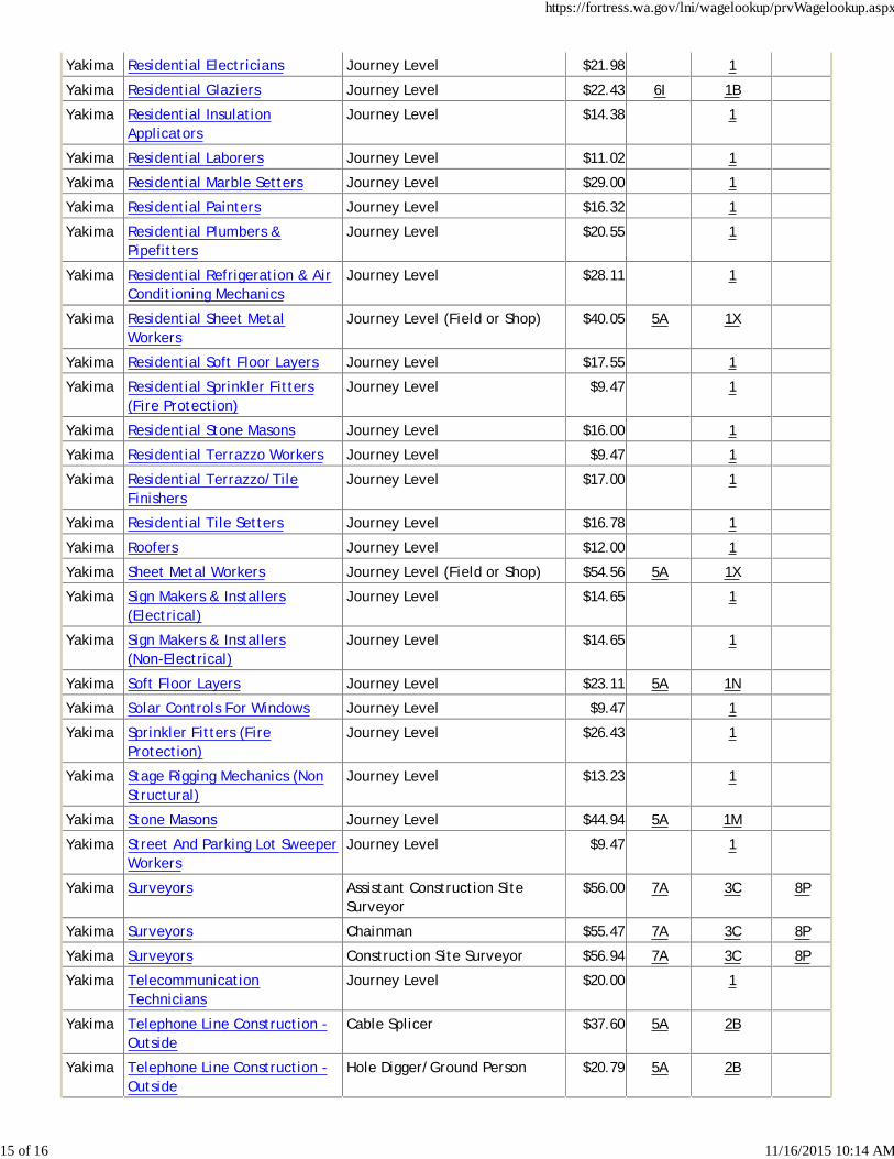
Yakima Residential Electricians Journey Level $21.98 1
Yakima Residential Glaziers Journey Level $22.43 6I 1B
Yakima Residential InsulationApplicators
Journey Level $14.38 1
Yakima Residential Laborers Journey Level $11.02 1
Yakima Residential Marble Setters Journey Level $29.00 1
Yakima Residential Painters Journey Level $16.32 1
Yakima Residential Plumbers &Pipefitters
Journey Level $20.55 1
Yakima Residential Refrigeration & AirConditioning Mechanics
Journey Level $28.11 1
Yakima Residential Sheet MetalWorkers
Journey Level (Field or Shop) $40.05 5A 1X
Yakima Residential Soft Floor Layers Journey Level $17.55 1
Yakima Residential Sprinkler Fitters(Fire Protection)
Journey Level $9.47 1
Yakima Residential Stone Masons Journey Level $16.00 1
Yakima Residential Terrazzo Workers Journey Level $9.47 1
Yakima Residential Terrazzo/TileFinishers
Journey Level $17.00 1
Yakima Residential Tile Setters Journey Level $16.78 1
Yakima Roofers Journey Level $12.00 1
Yakima Sheet Metal Workers Journey Level (Field or Shop) $54.56 5A 1X
Yakima Sign Makers & Installers(Electrical)
Journey Level $14.65 1
Yakima Sign Makers & Installers(Non-Electrical)
Journey Level $14.65 1
Yakima Soft Floor Layers Journey Level $23.11 5A 1N
Yakima Solar Controls For Windows Journey Level $9.47 1
Yakima Sprinkler Fitters (FireProtection)
Journey Level $26.43 1
Yakima Stage Rigging Mechanics (NonStructural)
Journey Level $13.23 1
Yakima Stone Masons Journey Level $44.94 5A 1M
Yakima Street And Parking Lot SweeperWorkers
Journey Level $9.47 1
Yakima Surveyors Assistant Construction SiteSurveyor
$56.00 7A 3C 8P
Yakima Surveyors Chainman $55.47 7A 3C 8P
Yakima Surveyors Construction Site Surveyor $56.94 7A 3C 8P
Yakima TelecommunicationTechnicians
Journey Level $20.00 1
Yakima Telephone Line Construction -Outside
Cable Splicer $37.60 5A 2B
Yakima Telephone Line Construction -Outside
Hole Digger/Ground Person $20.79 5A 2B
https://fortress.wa.gov/lni/wagelookup/prvWagelookup.aspx
15 of 16 11/16/2015 10:14 AM
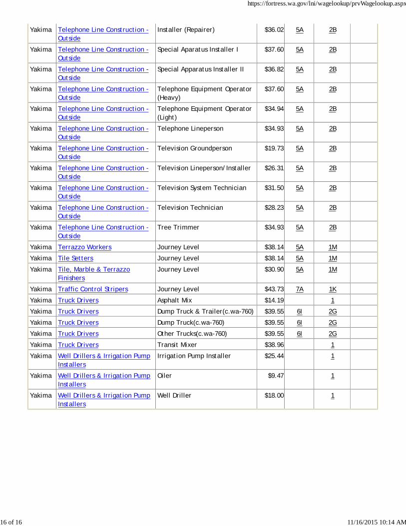
Yakima Telephone Line Construction -Outside
Installer (Repairer) $36.02 5A 2B
Yakima Telephone Line Construction -Outside
Special Aparatus Installer I $37.60 5A 2B
Yakima Telephone Line Construction -Outside
Special Apparatus Installer II $36.82 5A 2B
Yakima Telephone Line Construction -Outside
Telephone Equipment Operator(Heavy)
$37.60 5A 2B
Yakima Telephone Line Construction -Outside
Telephone Equipment Operator(Light)
$34.94 5A 2B
Yakima Telephone Line Construction -Outside
Telephone Lineperson $34.93 5A 2B
Yakima Telephone Line Construction -Outside
Television Groundperson $19.73 5A 2B
Yakima Telephone Line Construction -Outside
Television Lineperson/Installer $26.31 5A 2B
Yakima Telephone Line Construction -Outside
Television System Technician $31.50 5A 2B
Yakima Telephone Line Construction -Outside
Television Technician $28.23 5A 2B
Yakima Telephone Line Construction -Outside
Tree Trimmer $34.93 5A 2B
Yakima Terrazzo Workers Journey Level $38.14 5A 1M
Yakima Tile Setters Journey Level $38.14 5A 1M
Yakima Tile, Marble & TerrazzoFinishers
Journey Level $30.90 5A 1M
Yakima Traffic Control Stripers Journey Level $43.73 7A 1K
Yakima Truck Drivers Asphalt Mix $14.19 1
Yakima Truck Drivers Dump Truck & Trailer(c.wa-760) $39.55 6I 2G
Yakima Truck Drivers Dump Truck(c.wa-760) $39.55 6I 2G
Yakima Truck Drivers Other Trucks(c.wa-760) $39.55 6I 2G
Yakima Truck Drivers Transit Mixer $38.96 1
Yakima Well Drillers & Irrigation PumpInstallers
Irrigation Pump Installer $25.44 1
Yakima Well Drillers & Irrigation PumpInstallers
Oiler $9.47 1
Yakima Well Drillers & Irrigation PumpInstallers
Well Driller $18.00 1
https://fortress.wa.gov/lni/wagelookup/prvWagelookup.aspx
16 of 16 11/16/2015 10:14 AM
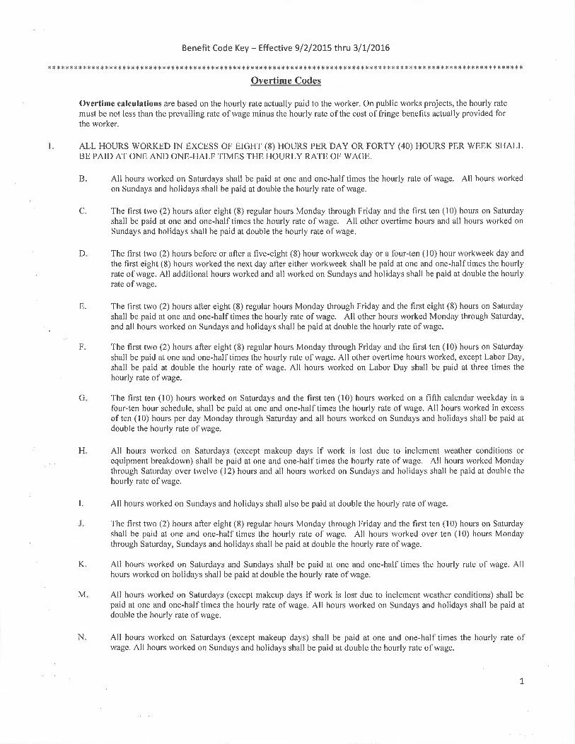
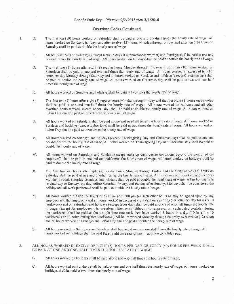
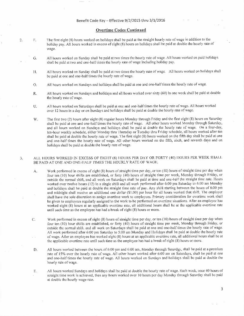
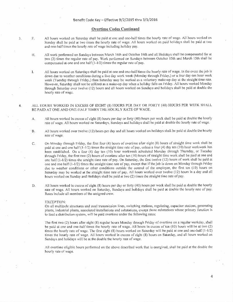
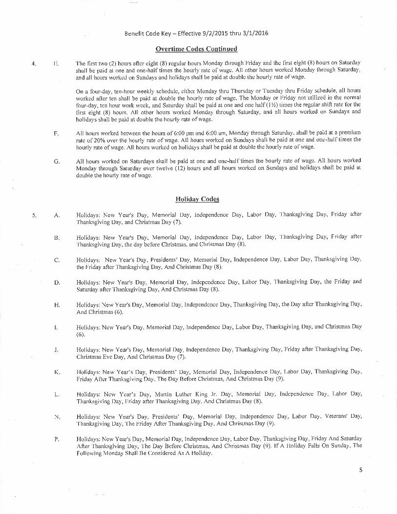
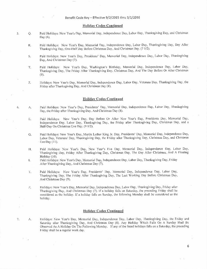
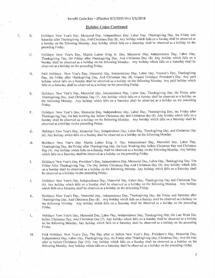
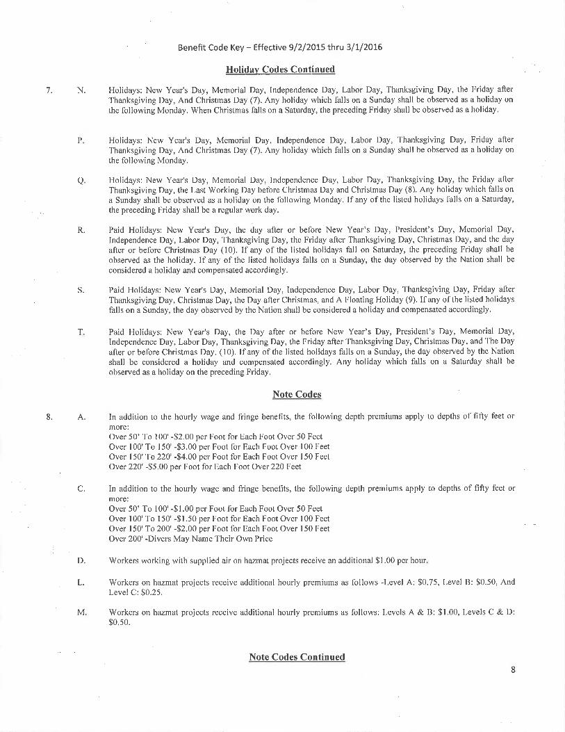
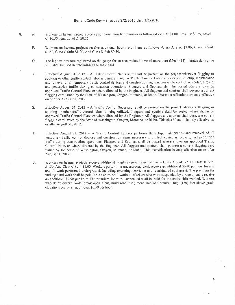

Supplemental to Wage Rates 09/02/2015 Edition, Published August 3rd, 2015
1
Washington State Department of Labor and Industries Policy Statement
(Regarding the Production of "Standard" or "Non-standard" Items)
Below is the department's (State L&I's) list of criteria to be used in determining whether a prefabricated item is "standard" or "non-standard". For items not appearing on WSDOT's predetermined list, these criteria shall be used by the Contractor (and the Contractor's subcontractors, agents to subcontractors, suppliers, manufacturers, and fabricators) to determine coverage under RCW 39.12. The production, in the State of Washington, of non-standard items is covered by RCW 39.12, and the production of standard items is not. The production of any item outside the State of Washington is not covered by RCW 39.12. 1. Is the item fabricated for a public works project? If not, it is not subject to RCW 39.12. If it is, go to question 2. 2. Is the item fabricated on the public works jobsite? If it is, the work is covered under RCW 39.12. If not, go to question 3. 3. Is the item fabricated in an assembly/fabrication plant set up for, and dedicated primarily to, the public works project? If it is, the work is covered by RCW 39.12. If not, go to question 4. 4. Does the item require any assembly, cutting, modification or other fabrication by the supplier? If not, the work is not covered by RCW 39.12. If yes, go to question 5. 5. Is the prefabricated item intended for the public works project typically an inventory item which could reasonably be sold on the general market? If not, the work is covered by RCW 39.12. If yes, go to question 6. 6. Does the specific prefabricated item, generally defined as standard, have any unusual characteristics such as shape, type of material, strength requirements, finish, etc? If yes, the work is covered under RCW 39.12. Any firm with questions regarding the policy, WSDOT's Predetermined List, or for determinations of covered and non-covered workers shall be directed to State L&I at (360) 902-5330.
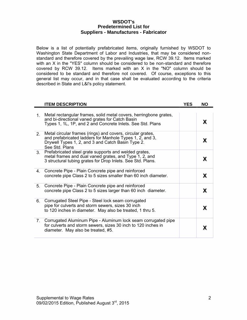
WSDOT's
Predetermined List for Suppliers - Manufactures - Fabricator
Supplemental to Wage Rates 09/02/2015 Edition, Published August 3rd, 2015
2
Below is a list of potentially prefabricated items, originally furnished by WSDOT to Washington State Department of Labor and Industries, that may be considered non-standard and therefore covered by the prevailing wage law, RCW 39.12. Items marked with an X in the "YES" column should be considered to be non-standard and therefore covered by RCW 39.12. Items marked with an X in the "NO" column should be considered to be standard and therefore not covered. Of course, exceptions to this general list may occur, and in that case shall be evaluated according to the criteria described in State and L&I's policy statement. ITEM DESCRIPTION YES NO
1. Metal rectangular frames, solid metal covers, herringbone grates,
and bi-directional vaned grates for Catch Basin Types 1, 1L, 1P, and 2 and Concrete Inlets. See Std. Plans
X
2. Metal circular frames (rings) and covers, circular grates, and prefabricated ladders for Manhole Types 1, 2, and 3, Drywell Types 1, 2, and 3 and Catch Basin Type 2. See Std. Plans
X
3. Prefabricated steel grate supports and welded grates, metal frames and dual vaned grates, and Type 1, 2, and 3 structural tubing grates for Drop Inlets. See Std. Plans.
X
4. Concrete Pipe - Plain Concrete pipe and reinforced concrete pipe Class 2 to 5 sizes smaller than 60 inch diameter.
X
5. Concrete Pipe - Plain Concrete pipe and reinforced concrete pipe Class 2 to 5 sizes larger than 60 inch diameter.
X
6. Corrugated Steel Pipe - Steel lock seam corrugated pipe for culverts and storm sewers, sizes 30 inch to 120 inches in diameter. May also be treated, 1 thru 5.
X
7. Corrugated Aluminum Pipe - Aluminum lock seam corrugated pipe for culverts and storm sewers, sizes 30 inch to 120 inches in diameter. May also be treated, #5.
X
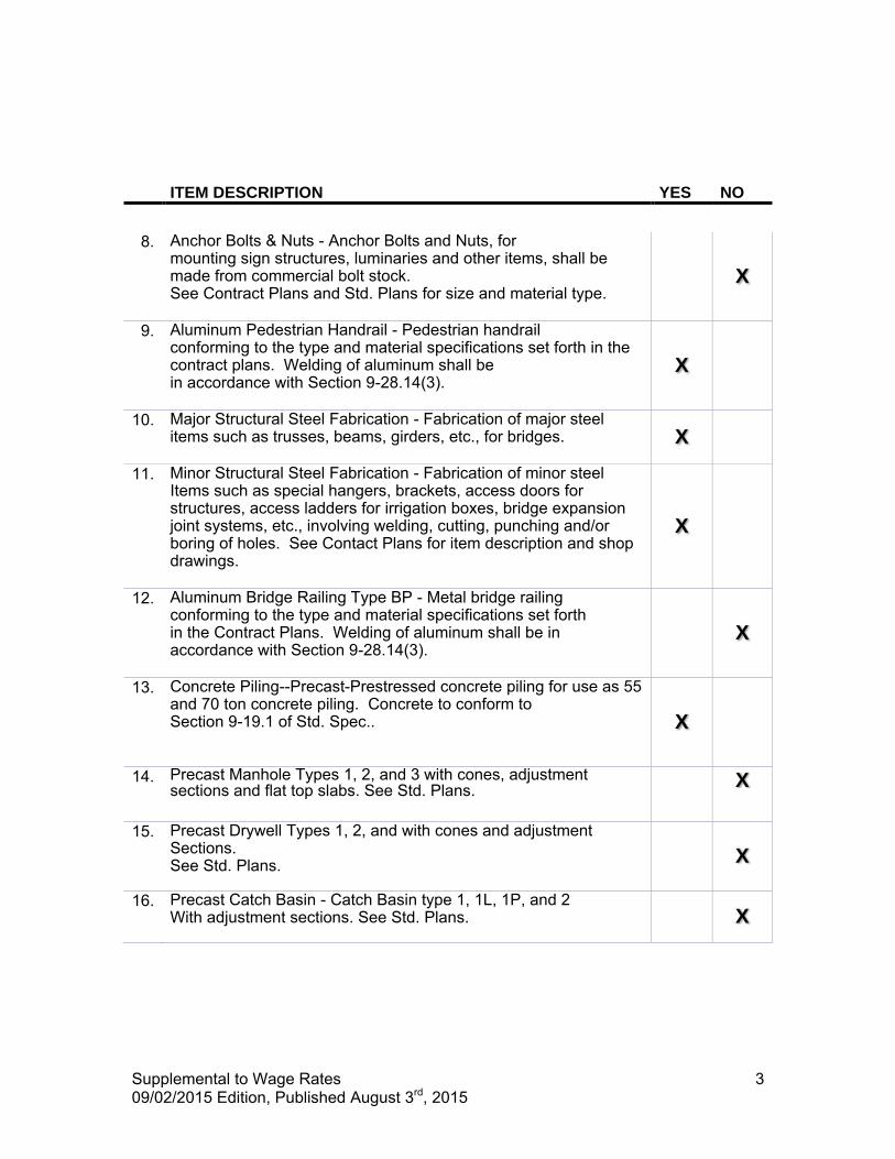
Supplemental to Wage Rates 09/02/2015 Edition, Published August 3rd, 2015
3
ITEM DESCRIPTION YES NO
8. Anchor Bolts & Nuts - Anchor Bolts and Nuts, for
mounting sign structures, luminaries and other items, shall be made from commercial bolt stock. See Contract Plans and Std. Plans for size and material type.
X
9. Aluminum Pedestrian Handrail - Pedestrian handrail conforming to the type and material specifications set forth in the contract plans. Welding of aluminum shall be in accordance with Section 9-28.14(3).
X
10. Major Structural Steel Fabrication - Fabrication of major steel items such as trusses, beams, girders, etc., for bridges.
X
11. Minor Structural Steel Fabrication - Fabrication of minor steel Items such as special hangers, brackets, access doors for structures, access ladders for irrigation boxes, bridge expansion joint systems, etc., involving welding, cutting, punching and/or boring of holes. See Contact Plans for item description and shop drawings.
X
12. Aluminum Bridge Railing Type BP - Metal bridge railing conforming to the type and material specifications set forth in the Contract Plans. Welding of aluminum shall be in accordance with Section 9-28.14(3).
X
13. Concrete Piling--Precast-Prestressed concrete piling for use as 55 and 70 ton concrete piling. Concrete to conform to Section 9-19.1 of Std. Spec..
X
14. Precast Manhole Types 1, 2, and 3 with cones, adjustment sections and flat top slabs. See Std. Plans.
X
15. Precast Drywell Types 1, 2, and with cones and adjustment
Sections. See Std. Plans.
X
16. Precast Catch Basin - Catch Basin type 1, 1L, 1P, and 2 With adjustment sections. See Std. Plans.
X
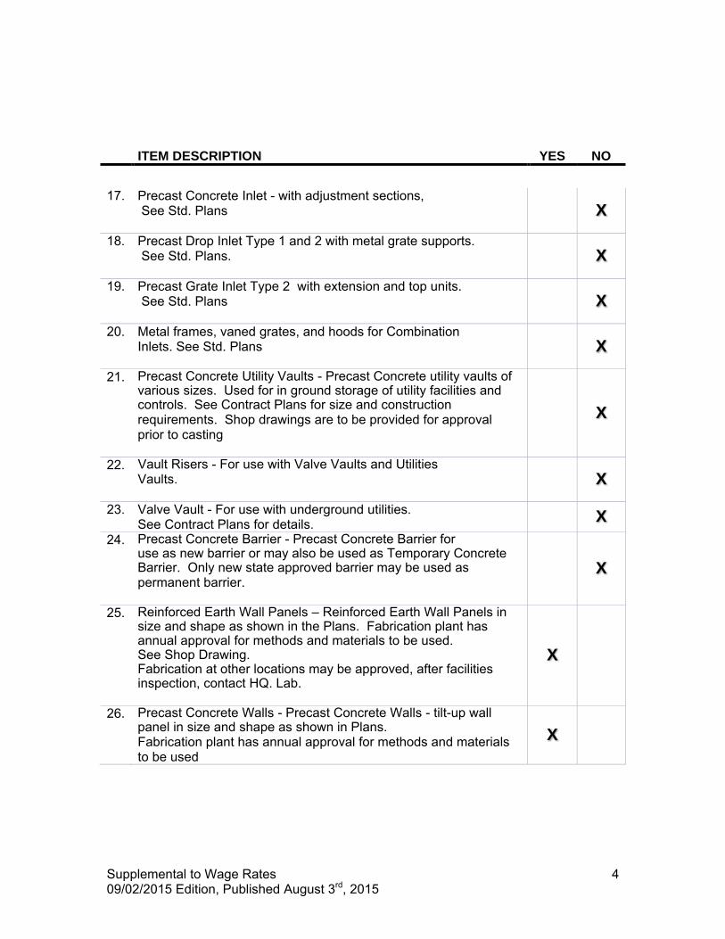
Supplemental to Wage Rates 09/02/2015 Edition, Published August 3rd, 2015
4
ITEM DESCRIPTION YES NO
17. Precast Concrete Inlet - with adjustment sections,
See Std. Plans
X
18. Precast Drop Inlet Type 1 and 2 with metal grate supports. See Std. Plans.
X
19. Precast Grate Inlet Type 2 with extension and top units. See Std. Plans
X
20. Metal frames, vaned grates, and hoods for Combination Inlets. See Std. Plans
X
21. Precast Concrete Utility Vaults - Precast Concrete utility vaults of various sizes. Used for in ground storage of utility facilities and controls. See Contract Plans for size and construction requirements. Shop drawings are to be provided for approval prior to casting
X
22. Vault Risers - For use with Valve Vaults and Utilities X Vaults.
X
23. Valve Vault - For use with underground utilities. See Contract Plans for details. X
24. Precast Concrete Barrier - Precast Concrete Barrier for use as new barrier or may also be used as Temporary Concrete Barrier. Only new state approved barrier may be used as permanent barrier.
X
25. Reinforced Earth Wall Panels – Reinforced Earth Wall Panels in size and shape as shown in the Plans. Fabrication plant has annual approval for methods and materials to be used. See Shop Drawing. Fabrication at other locations may be approved, after facilities inspection, contact HQ. Lab.
X
26. Precast Concrete Walls - Precast Concrete Walls - tilt-up wall panel in size and shape as shown in Plans. Fabrication plant has annual approval for methods and materials to be used
X
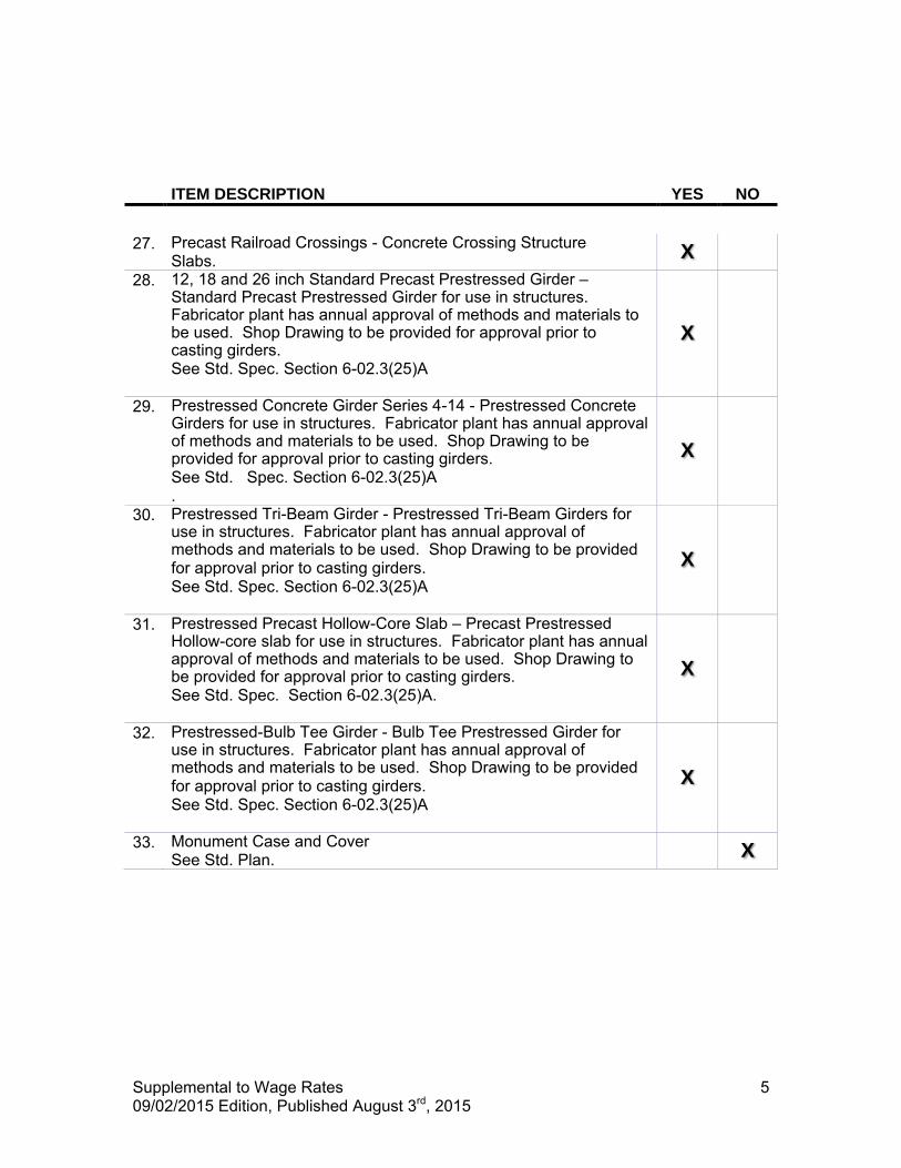
Supplemental to Wage Rates 09/02/2015 Edition, Published August 3rd, 2015
5
ITEM DESCRIPTION YES NO
27. Precast Railroad Crossings - Concrete Crossing Structure
Slabs. X
28. 12, 18 and 26 inch Standard Precast Prestressed Girder – Standard Precast Prestressed Girder for use in structures. Fabricator plant has annual approval of methods and materials to be used. Shop Drawing to be provided for approval prior to casting girders. See Std. Spec. Section 6-02.3(25)A
X
29. Prestressed Concrete Girder Series 4-14 - Prestressed Concrete Girders for use in structures. Fabricator plant has annual approval of methods and materials to be used. Shop Drawing to be provided for approval prior to casting girders. See Std. Spec. Section 6-02.3(25)A .
X
30. Prestressed Tri-Beam Girder - Prestressed Tri-Beam Girders for use in structures. Fabricator plant has annual approval of methods and materials to be used. Shop Drawing to be provided for approval prior to casting girders. See Std. Spec. Section 6-02.3(25)A
X
31. Prestressed Precast Hollow-Core Slab – Precast Prestressed Hollow-core slab for use in structures. Fabricator plant has annual approval of methods and materials to be used. Shop Drawing to be provided for approval prior to casting girders. See Std. Spec. Section 6-02.3(25)A.
X
32. Prestressed-Bulb Tee Girder - Bulb Tee Prestressed Girder for use in structures. Fabricator plant has annual approval of methods and materials to be used. Shop Drawing to be provided for approval prior to casting girders. See Std. Spec. Section 6-02.3(25)A
X
33. Monument Case and Cover See Std. Plan. X
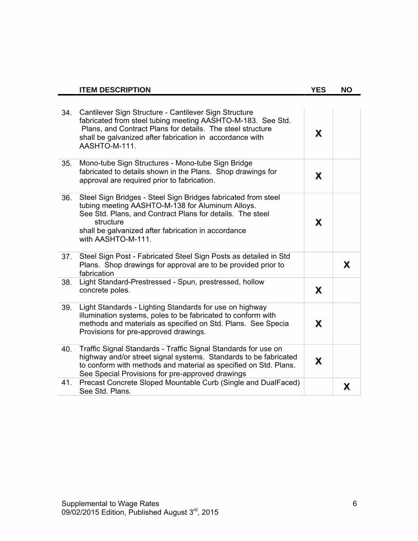
Supplemental to Wage Rates 09/02/2015 Edition, Published August 3rd, 2015
6
ITEM DESCRIPTION YES NO
34. Cantilever Sign Structure - Cantilever Sign Structure
fabricated from steel tubing meeting AASHTO-M-183. See Std. Plans, and Contract Plans for details. The steel structure shall be galvanized after fabrication in accordance with AASHTO-M-111.
X
35. Mono-tube Sign Structures - Mono-tube Sign Bridge fabricated to details shown in the Plans. Shop drawings for approval are required prior to fabrication.
X
36. Steel Sign Bridges - Steel Sign Bridges fabricated from steel tubing meeting AASHTO-M-138 for Aluminum Alloys. See Std. Plans, and Contract Plans for details. The steel
structure shall be galvanized after fabrication in accordance with AASHTO-M-111.
X
37. Steel Sign Post - Fabricated Steel Sign Posts as detailed in Std Plans. Shop drawings for approval are to be provided prior to fabrication
X
38. Light Standard-Prestressed - Spun, prestressed, hollow concrete poles.
X
39. Light Standards - Lighting Standards for use on highway illumination systems, poles to be fabricated to conform with methods and materials as specified on Std. Plans. See Specia Provisions for pre-approved drawings.
X
40. Traffic Signal Standards - Traffic Signal Standards for use on highway and/or street signal systems. Standards to be fabricated to conform with methods and material as specified on Std. Plans. See Special Provisions for pre-approved drawings
X
41. Precast Concrete Sloped Mountable Curb (Single and DualFaced) See Std. Plans. X
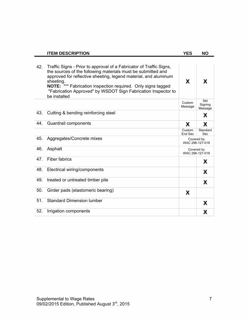
Supplemental to Wage Rates 09/02/2015 Edition, Published August 3rd, 2015
7
ITEM DESCRIPTION YES NO
42. Traffic Signs - Prior to approval of a Fabricator of Traffic Signs,
the sources of the following materials must be submitted and approved for reflective sheeting, legend material, and aluminum sheeting. NOTE: *** Fabrication inspection required. Only signs tagged "Fabrication Approved" by WSDOT Sign Fabrication Inspector to be installed
X X
Custom Message
Std Signing
Message 43. Cutting & bending reinforcing steel
X
44. Guardrail components X X Custom
End Sec Standard
Sec 45. Aggregates/Concrete mixes
Covered by
WAC 296-127-018 46. Asphalt
Covered by
WAC 296-127-018 47. Fiber fabrics
X
48. Electrical wiring/components X
49. treated or untreated timber pile X
50. Girder pads (elastomeric bearing) X
51. Standard Dimension lumber X
52. Irrigation components X
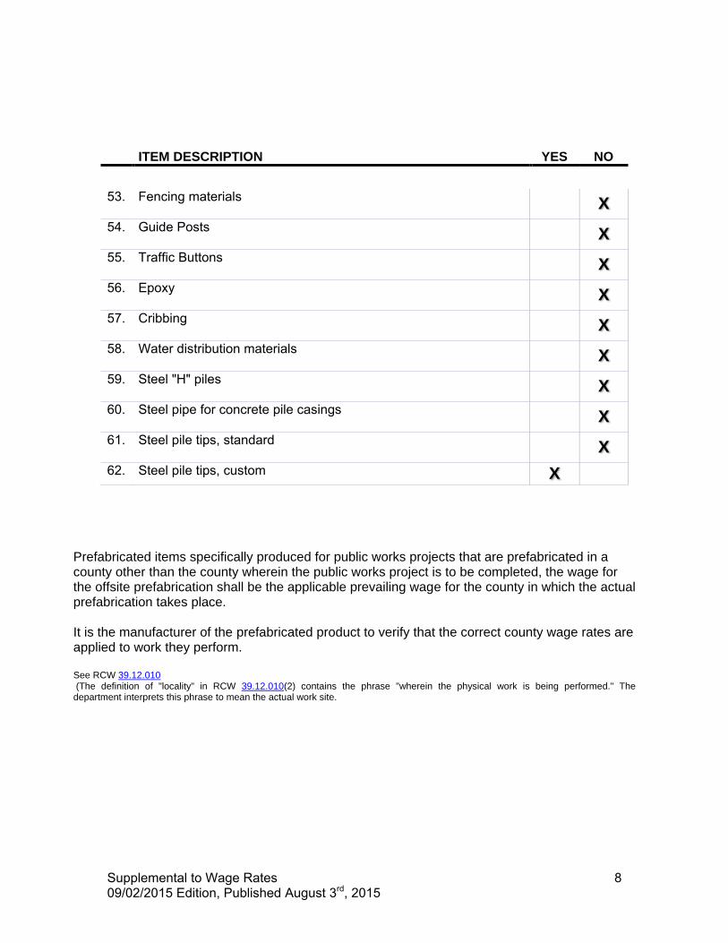
Supplemental to Wage Rates 09/02/2015 Edition, Published August 3rd, 2015
8
ITEM DESCRIPTION YES NO
53. Fencing materials
X
54. Guide Posts X
55. Traffic Buttons X
56. Epoxy X
57. Cribbing X
58. Water distribution materials X
59. Steel "H" piles X
60. Steel pipe for concrete pile casings X
61. Steel pile tips, standard X
62. Steel pile tips, custom X
Prefabricated items specifically produced for public works projects that are prefabricated in a county other than the county wherein the public works project is to be completed, the wage for the offsite prefabrication shall be the applicable prevailing wage for the county in which the actual prefabrication takes place. It is the manufacturer of the prefabricated product to verify that the correct county wage rates are applied to work they perform. See RCW 39.12.010 (The definition of "locality" in RCW 39.12.010(2) contains the phrase "wherein the physical work is being performed." The department interprets this phrase to mean the actual work site.

Supplemental to Wage Rates 09/02/2015 Edition, Published August 3rd, 2015
9
WSDOT's List of State Occupations not applicable to Heavy and Highway Construction Projects
This project is subject to the state hourly minimum rates for wages and fringe benefits in the contract provisions, as provided by the state Department of Labor and Industries. The following list of occupations, is comprised of those occupations that are not normally used in the construction of heavy and highway projects. When considering job classifications for use and / or payment when bidding on, or building heavy and highway construction projects for, or administered by WSDOT, these Occupations will be excepted from the included "Washington State Prevailing Wage Rates For Public Work Contracts" documents.
Building Service Employees
Electrical Fixture Maintenance Workers
Electricians - Motor Shop
Heating Equipment Mechanics
Industrial Engine and Machine Mechanics
Industrial Power Vacuum Cleaners
Inspection, Cleaning, Sealing of Water Systems by Remote Control
Laborers - Underground Sewer & Water
Machinists (Hydroelectric Site Work)
Modular Buildings
Playground & Park Equipment Installers
Power Equipment Operators - Underground Sewer & Water
Residential *** ALL ASSOCIATED RATES ***
Sign Makers and Installers (Non-Electrical)
Sign Makers and Installers (Electrical)
Stage Rigging Mechanics (Non Structural) The following occupations may be used only as outlined in the preceding text concerning "WSDOT's list for Suppliers - Manufacturers - Fabricators"
Fabricated Precast Concrete Products
Metal Fabrication (In Shop) Definitions for the Scope of Work for prevailing wages may be found at the Washington State Department of Labor and Industries web site and in WAC Chapter 296-127.
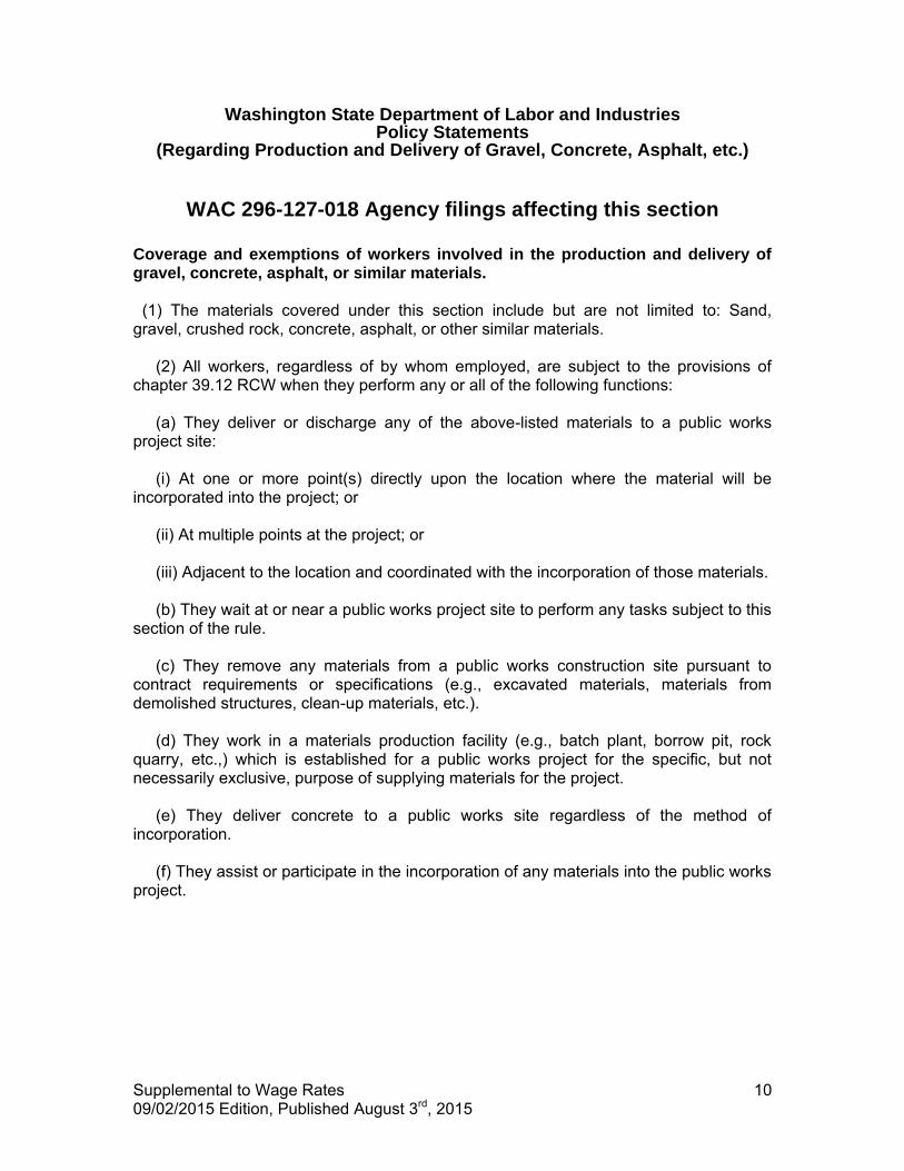
Supplemental to Wage Rates 09/02/2015 Edition, Published August 3rd, 2015
10
Washington State Department of Labor and Industries Policy Statements
(Regarding Production and Delivery of Gravel, Concrete, Asphalt, etc.)
WAC 296-127-018 Agency filings affecting this section
Coverage and exemptions of workers involved in the production and delivery of gravel, concrete, asphalt, or similar materials. (1) The materials covered under this section include but are not limited to: Sand, gravel, crushed rock, concrete, asphalt, or other similar materials. (2) All workers, regardless of by whom employed, are subject to the provisions of chapter 39.12 RCW when they perform any or all of the following functions: (a) They deliver or discharge any of the above-listed materials to a public works project site: (i) At one or more point(s) directly upon the location where the material will be incorporated into the project; or (ii) At multiple points at the project; or (iii) Adjacent to the location and coordinated with the incorporation of those materials. (b) They wait at or near a public works project site to perform any tasks subject to this section of the rule. (c) They remove any materials from a public works construction site pursuant to contract requirements or specifications (e.g., excavated materials, materials from demolished structures, clean-up materials, etc.). (d) They work in a materials production facility (e.g., batch plant, borrow pit, rock quarry, etc.,) which is established for a public works project for the specific, but not necessarily exclusive, purpose of supplying materials for the project. (e) They deliver concrete to a public works site regardless of the method of incorporation. (f) They assist or participate in the incorporation of any materials into the public works project.
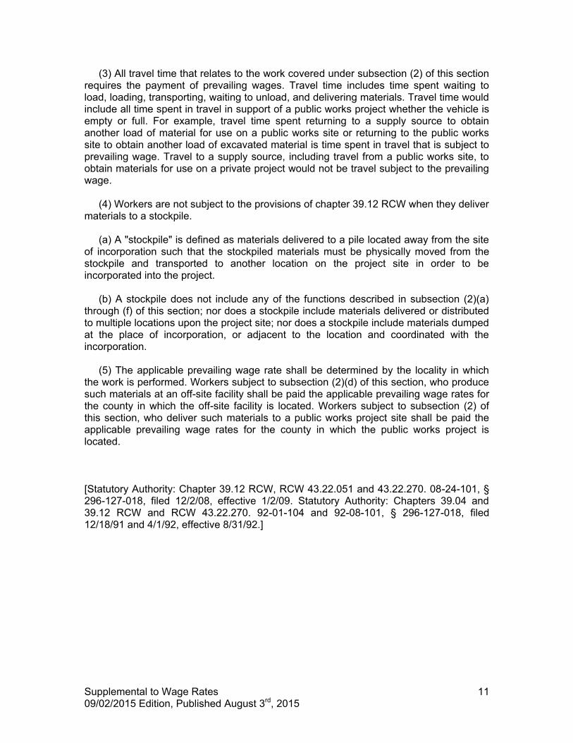
Supplemental to Wage Rates 09/02/2015 Edition, Published August 3rd, 2015
11
(3) All travel time that relates to the work covered under subsection (2) of this section requires the payment of prevailing wages. Travel time includes time spent waiting to load, loading, transporting, waiting to unload, and delivering materials. Travel time would include all time spent in travel in support of a public works project whether the vehicle is empty or full. For example, travel time spent returning to a supply source to obtain another load of material for use on a public works site or returning to the public works site to obtain another load of excavated material is time spent in travel that is subject to prevailing wage. Travel to a supply source, including travel from a public works site, to obtain materials for use on a private project would not be travel subject to the prevailing wage. (4) Workers are not subject to the provisions of chapter 39.12 RCW when they deliver materials to a stockpile. (a) A "stockpile" is defined as materials delivered to a pile located away from the site of incorporation such that the stockpiled materials must be physically moved from the stockpile and transported to another location on the project site in order to be incorporated into the project. (b) A stockpile does not include any of the functions described in subsection (2)(a) through (f) of this section; nor does a stockpile include materials delivered or distributed to multiple locations upon the project site; nor does a stockpile include materials dumped at the place of incorporation, or adjacent to the location and coordinated with the incorporation. (5) The applicable prevailing wage rate shall be determined by the locality in which the work is performed. Workers subject to subsection (2)(d) of this section, who produce such materials at an off-site facility shall be paid the applicable prevailing wage rates for the county in which the off-site facility is located. Workers subject to subsection (2) of this section, who deliver such materials to a public works project site shall be paid the applicable prevailing wage rates for the county in which the public works project is located. [Statutory Authority: Chapter 39.12 RCW, RCW 43.22.051 and 43.22.270. 08-24-101, § 296-127-018, filed 12/2/08, effective 1/2/09. Statutory Authority: Chapters 39.04 and 39.12 RCW and RCW 43.22.270. 92-01-104 and 92-08-101, § 296-127-018, filed 12/18/91 and 4/1/92, effective 8/31/92.]

FEDERAL WAGE RATES
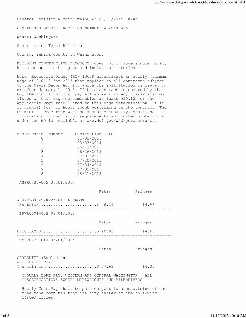
General Decision Number: WA150045 08/21/2015 WA45
Superseded General Decision Number: WA20140045
State: Washington
Construction Type: Building
County: Yakima County in Washington.
BUILDING CONSTRUCTION PROJECTS (does not include single familyhomes or apartments up to and including 4 stories).
Note: Executive Order (EO) 13658 establishes an hourly minimumwage of $10.10 for 2015 that applies to all contracts subjectto the Davis-Bacon Act for which the solicitation is issued onor after January 1, 2015. If this contract is covered by theEO, the contractor must pay all workers in any classificationlisted on this wage determination at least $10.10 (or theapplicable wage rate listed on this wage determination, if itis higher) for all hours spent performing on the contract. TheEO minimum wage rate will be adjusted annually. Additionalinformation on contractor requirements and worker protectionsunder the EO is available at www.dol.gov/whd/govcontracts.
Modification Number Publication Date 0 01/02/2015 1 02/27/2015 2 06/12/2015 3 06/26/2015 4 07/03/2015 5 07/10/2015 6 07/24/2015 7 07/31/2015 8 08/21/2015
ASBE0007-002 06/01/2015
Rates Fringes
ASBESTOS WORKER/HEAT & FROST INSULATOR........................$ 46.21 16.97---------------------------------------------------------------- BRWA0001-002 06/01/2015
Rates Fringes
BRICKLAYER.......................$ 28.82 14.60---------------------------------------------------------------- CARP0770-017 06/01/2015
Rates Fringes
CARPENTER (Excluding Acoustical Ceiling Installation)....................$ 27.61 14.00
(HOURLY ZONE PAY: WESTERN AND CENTRAL WASHINGTON - ALL CLASSIFICATIONS EXCEPT MILLWRIGHTS AND PILEDRIVERS
Hourly Zone Pay shall be paid on jobs located outside of the free zone computed from the city center of the following listed cities:
http://www.wdol.gov/wdol/scafiles/davisbacon/wa45.dvb
1 of 8 11/16/2015 10:18 AM
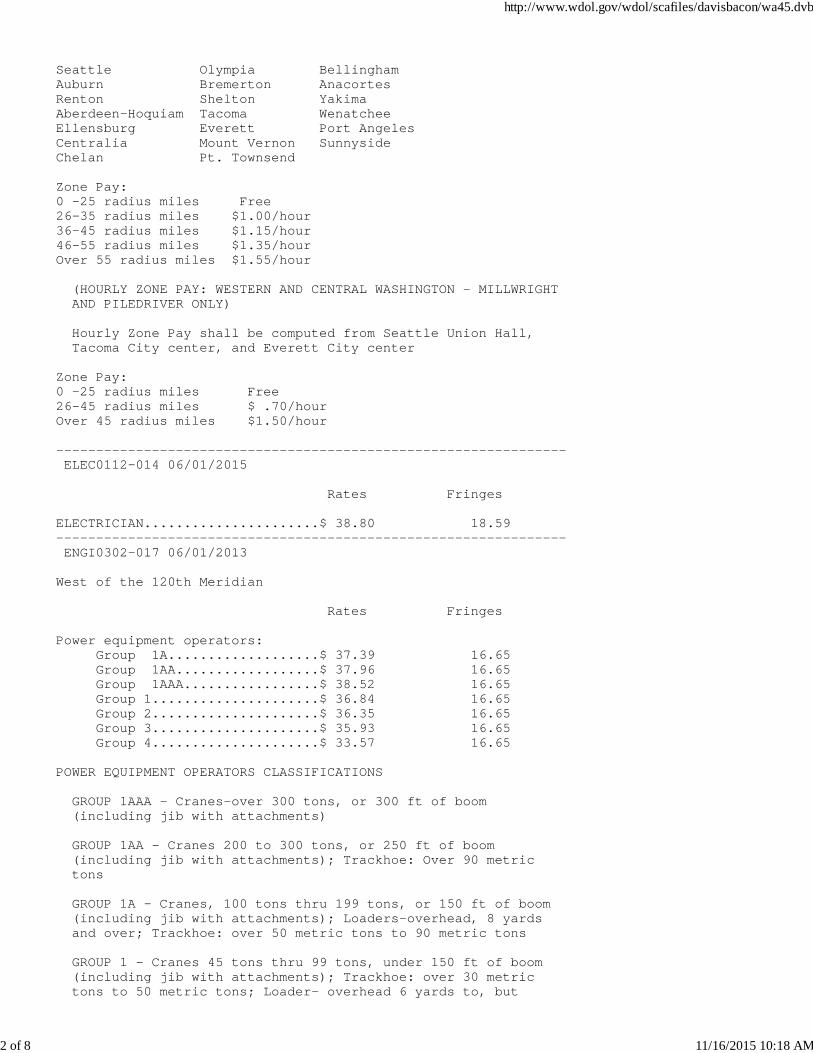
Seattle Olympia BellinghamAuburn Bremerton AnacortesRenton Shelton YakimaAberdeen-Hoquiam Tacoma WenatcheeEllensburg Everett Port AngelesCentralia Mount Vernon SunnysideChelan Pt. Townsend
Zone Pay:0 -25 radius miles Free26-35 radius miles $1.00/hour36-45 radius miles $1.15/hour46-55 radius miles $1.35/hourOver 55 radius miles $1.55/hour
(HOURLY ZONE PAY: WESTERN AND CENTRAL WASHINGTON - MILLWRIGHT AND PILEDRIVER ONLY)
Hourly Zone Pay shall be computed from Seattle Union Hall, Tacoma City center, and Everett City center
Zone Pay:0 -25 radius miles Free26-45 radius miles $ .70/hourOver 45 radius miles $1.50/hour
---------------------------------------------------------------- ELEC0112-014 06/01/2015
Rates Fringes
ELECTRICIAN......................$ 38.80 18.59---------------------------------------------------------------- ENGI0302-017 06/01/2013
West of the 120th Meridian
Rates Fringes
Power equipment operators: Group 1A...................$ 37.39 16.65 Group 1AA..................$ 37.96 16.65 Group 1AAA.................$ 38.52 16.65 Group 1.....................$ 36.84 16.65 Group 2.....................$ 36.35 16.65 Group 3.....................$ 35.93 16.65 Group 4.....................$ 33.57 16.65
POWER EQUIPMENT OPERATORS CLASSIFICATIONS
GROUP 1AAA - Cranes-over 300 tons, or 300 ft of boom (including jib with attachments) GROUP 1AA - Cranes 200 to 300 tons, or 250 ft of boom (including jib with attachments); Trackhoe: Over 90 metric tons
GROUP 1A - Cranes, 100 tons thru 199 tons, or 150 ft of boom (including jib with attachments); Loaders-overhead, 8 yards and over; Trackhoe: over 50 metric tons to 90 metric tons
GROUP 1 - Cranes 45 tons thru 99 tons, under 150 ft of boom (including jib with attachments); Trackhoe: over 30 metric tons to 50 metric tons; Loader- overhead 6 yards to, but
http://www.wdol.gov/wdol/scafiles/davisbacon/wa45.dvb
2 of 8 11/16/2015 10:18 AM
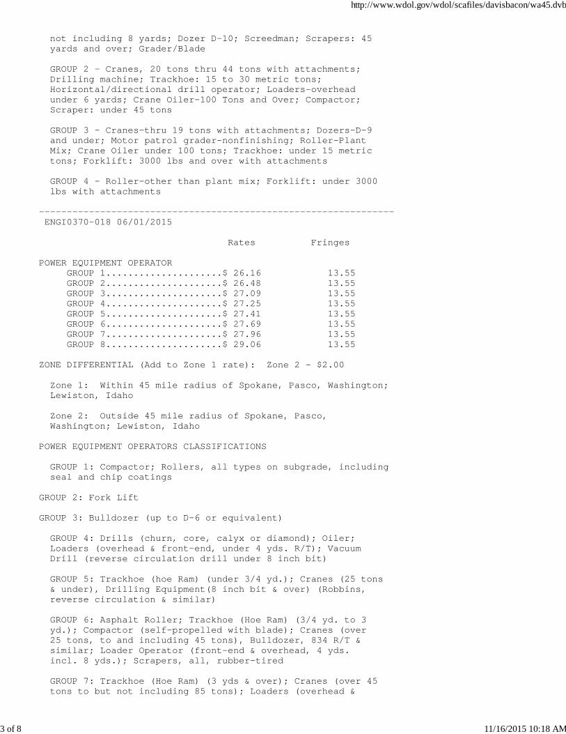
not including 8 yards; Dozer D-10; Screedman; Scrapers: 45 yards and over; Grader/Blade
GROUP 2 - Cranes, 20 tons thru 44 tons with attachments; Drilling machine; Trackhoe: 15 to 30 metric tons; Horizontal/directional drill operator; Loaders-overhead under 6 yards; Crane Oiler-100 Tons and Over; Compactor; Scraper: under 45 tons
GROUP 3 - Cranes-thru 19 tons with attachments; Dozers-D-9 and under; Motor patrol grader-nonfinishing; Roller-Plant Mix; Crane Oiler under 100 tons; Trackhoe: under 15 metric tons; Forklift: 3000 lbs and over with attachments
GROUP 4 - Roller-other than plant mix; Forklift: under 3000 lbs with attachments
---------------------------------------------------------------- ENGI0370-018 06/01/2015
Rates Fringes
POWER EQUIPMENT OPERATOR GROUP 1.....................$ 26.16 13.55 GROUP 2.....................$ 26.48 13.55 GROUP 3.....................$ 27.09 13.55 GROUP 4.....................$ 27.25 13.55 GROUP 5.....................$ 27.41 13.55 GROUP 6.....................$ 27.69 13.55 GROUP 7.....................$ 27.96 13.55 GROUP 8.....................$ 29.06 13.55
ZONE DIFFERENTIAL (Add to Zone 1 rate): Zone 2 - $2.00
Zone 1: Within 45 mile radius of Spokane, Pasco, Washington; Lewiston, Idaho
Zone 2: Outside 45 mile radius of Spokane, Pasco, Washington; Lewiston, Idaho
POWER EQUIPMENT OPERATORS CLASSIFICATIONS
GROUP 1: Compactor; Rollers, all types on subgrade, including seal and chip coatings
GROUP 2: Fork Lift
GROUP 3: Bulldozer (up to D-6 or equivalent)
GROUP 4: Drills (churn, core, calyx or diamond); Oiler; Loaders (overhead & front-end, under 4 yds. R/T); Vacuum Drill (reverse circulation drill under 8 inch bit)
GROUP 5: Trackhoe (hoe Ram) (under 3/4 yd.); Cranes (25 tons & under), Drilling Equipment(8 inch bit & over) (Robbins, reverse circulation & similar)
GROUP 6: Asphalt Roller; Trackhoe (Hoe Ram) (3/4 yd. to 3 yd.); Compactor (self-propelled with blade); Cranes (over 25 tons, to and including 45 tons), Bulldozer, 834 R/T & similar; Loader Operator (front-end & overhead, 4 yds. incl. 8 yds.); Scrapers, all, rubber-tired
GROUP 7: Trackhoe (Hoe Ram) (3 yds & over); Cranes (over 45 tons to but not including 85 tons); Loaders (overhead &
http://www.wdol.gov/wdol/scafiles/davisbacon/wa45.dvb
3 of 8 11/16/2015 10:18 AM
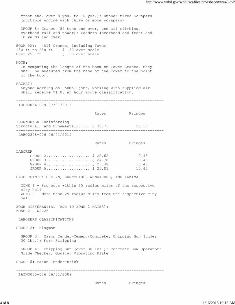
front-end, over 8 yds. to 10 yds.); Rubber-tired Scrapers (multiple engine with three or more scrapers)
GROUP 8: Cranes (85 tons and over, and all climbing, overhead,rail and tower); Loaders (overhead and front-end, 10 yards and over)
BOOM PAY: (All Cranes, Including Tower)180 ft to 250 ft $ .50 over scale Over 250 ft $ .80 over scale
NOTE: In computing the length of the boom on Tower Cranes, they shall be measured from the base of the Tower to the point of the boom.
HAZMAT: Anyone working on HAZMAT jobs, working with supplied air shall receive $1.00 an hour above classification.
---------------------------------------------------------------- IRON0086-009 07/01/2015
Rates Fringes
IRONWORKER (Reinforcing, Structural, and Ornamental)......$ 32.76 23.19---------------------------------------------------------------- LABO0348-006 06/01/2015
Rates Fringes
LABORER GROUP 2....................$ 22.62 10.45 GROUP 3....................$ 24.78 10.45 GROUP 4....................$ 25.38 10.45 GROUP 5....................$ 25.81 10.45
BASE POINTS: CHELAN, SUNNYSIDE, WENATCHEE, AND YAKIMA
ZONE 1 - Projects within 25 radius miles of the respective city hall ZONE 2 - More than 25 radius miles from the respective city hall
ZONE DIFFERENTIAL (ADD TO ZONE 1 RATES):ZONE 2 - $2.25 LABORERS CLASSIFICATIONS
GROUP 2: Flagman
GROUP 3: Mason Tender-Cement/Concrete; Chipping Gun (under 30 lbs.); Form Stripping
GROUP 4: Chipping Gun (over 30 lbs.); Concrete Saw Operator; Grade Checker; Gunite; Vibrating Plate
GROUP 5: Mason Tender-Brick
---------------------------------------------------------------- PAIN0005-026 06/01/2008
Rates Fringes
http://www.wdol.gov/wdol/scafiles/davisbacon/wa45.dvb
4 of 8 11/16/2015 10:18 AM
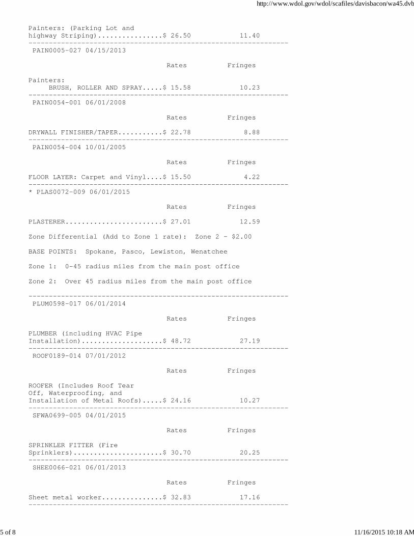
Painters: (Parking Lot and highway Striping)................$ 26.50 11.40---------------------------------------------------------------- PAIN0005-027 04/15/2013
Rates Fringes
Painters: BRUSH, ROLLER AND SPRAY.....$ 15.58 10.23---------------------------------------------------------------- PAIN0054-001 06/01/2008
Rates Fringes
DRYWALL FINISHER/TAPER...........$ 22.78 8.88---------------------------------------------------------------- PAIN0054-004 10/01/2005
Rates Fringes
FLOOR LAYER: Carpet and Vinyl....$ 15.50 4.22----------------------------------------------------------------* PLAS0072-009 06/01/2015
Rates Fringes
PLASTERER........................$ 27.01 12.59
Zone Differential (Add to Zone 1 rate): Zone 2 - $2.00
BASE POINTS: Spokane, Pasco, Lewiston, Wenatchee
Zone 1: 0-45 radius miles from the main post office
Zone 2: Over 45 radius miles from the main post office
---------------------------------------------------------------- PLUM0598-017 06/01/2014
Rates Fringes
PLUMBER (including HVAC Pipe Installation)....................$ 48.72 27.19---------------------------------------------------------------- ROOF0189-014 07/01/2012
Rates Fringes
ROOFER (Includes Roof Tear Off, Waterproofing, and Installation of Metal Roofs).....$ 24.16 10.27---------------------------------------------------------------- SFWA0699-005 04/01/2015
Rates Fringes
SPRINKLER FITTER (Fire Sprinklers)......................$ 30.70 20.25---------------------------------------------------------------- SHEE0066-021 06/01/2013
Rates Fringes
Sheet metal worker...............$ 32.83 17.16----------------------------------------------------------------
http://www.wdol.gov/wdol/scafiles/davisbacon/wa45.dvb
5 of 8 11/16/2015 10:18 AM
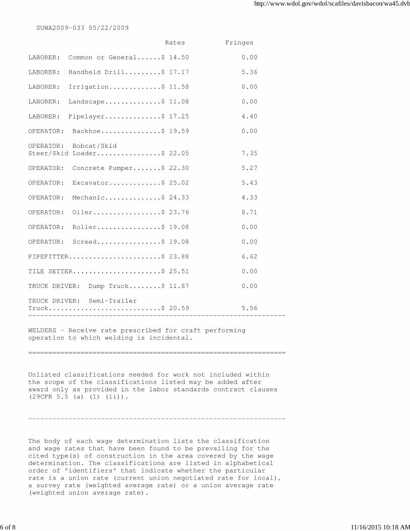
SUWA2009-033 05/22/2009
Rates Fringes
LABORER: Common or General......$ 14.50 0.00 LABORER: Handheld Drill.........$ 17.17 5.36 LABORER: Irrigation.............$ 11.58 0.00 LABORER: Landscape..............$ 11.08 0.00 LABORER: Pipelayer..............$ 17.25 4.40 OPERATOR: Backhoe...............$ 19.59 0.00 OPERATOR: Bobcat/Skid Steer/Skid Loader................$ 22.05 7.35 OPERATOR: Concrete Pumper.......$ 22.30 5.27 OPERATOR: Excavator.............$ 25.02 5.43 OPERATOR: Mechanic..............$ 24.33 4.33 OPERATOR: Oiler.................$ 23.76 8.71 OPERATOR: Roller................$ 19.08 0.00 OPERATOR: Screed................$ 19.08 0.00 PIPEFITTER.......................$ 23.88 6.62 TILE SETTER......................$ 25.51 0.00 TRUCK DRIVER: Dump Truck........$ 11.87 0.00 TRUCK DRIVER: Semi-Trailer Truck............................$ 20.59 5.56----------------------------------------------------------------
WELDERS - Receive rate prescribed for craft performingoperation to which welding is incidental.
================================================================
Unlisted classifications needed for work not included withinthe scope of the classifications listed may be added afteraward only as provided in the labor standards contract clauses(29CFR 5.5 (a) (1) (ii)).
----------------------------------------------------------------
The body of each wage determination lists the classificationand wage rates that have been found to be prevailing for thecited type(s) of construction in the area covered by the wagedetermination. The classifications are listed in alphabeticalorder of "identifiers" that indicate whether the particularrate is a union rate (current union negotiated rate for local),a survey rate (weighted average rate) or a union average rate(weighted union average rate).
http://www.wdol.gov/wdol/scafiles/davisbacon/wa45.dvb
6 of 8 11/16/2015 10:18 AM
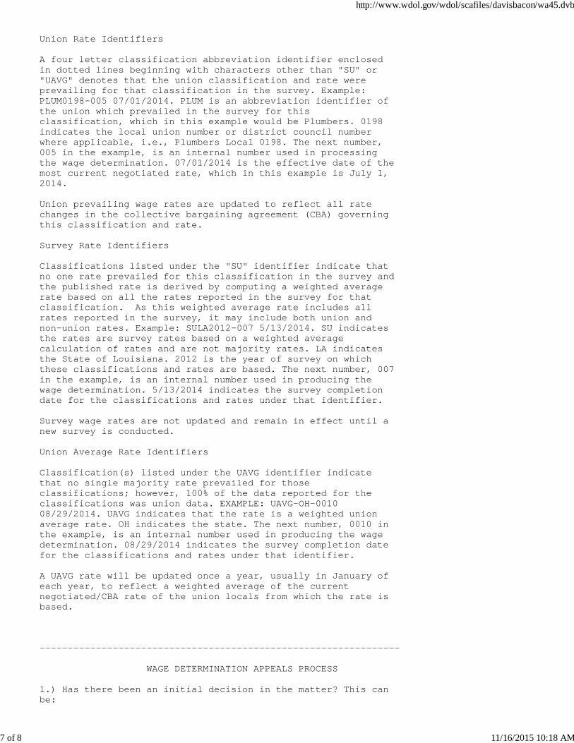
Union Rate Identifiers
A four letter classification abbreviation identifier enclosedin dotted lines beginning with characters other than "SU" or"UAVG" denotes that the union classification and rate wereprevailing for that classification in the survey. Example:PLUM0198-005 07/01/2014. PLUM is an abbreviation identifier ofthe union which prevailed in the survey for thisclassification, which in this example would be Plumbers. 0198indicates the local union number or district council numberwhere applicable, i.e., Plumbers Local 0198. The next number,005 in the example, is an internal number used in processingthe wage determination. 07/01/2014 is the effective date of themost current negotiated rate, which in this example is July 1,2014.
Union prevailing wage rates are updated to reflect all ratechanges in the collective bargaining agreement (CBA) governingthis classification and rate.
Survey Rate Identifiers
Classifications listed under the "SU" identifier indicate thatno one rate prevailed for this classification in the survey andthe published rate is derived by computing a weighted averagerate based on all the rates reported in the survey for thatclassification. As this weighted average rate includes allrates reported in the survey, it may include both union andnon-union rates. Example: SULA2012-007 5/13/2014. SU indicatesthe rates are survey rates based on a weighted averagecalculation of rates and are not majority rates. LA indicatesthe State of Louisiana. 2012 is the year of survey on whichthese classifications and rates are based. The next number, 007in the example, is an internal number used in producing thewage determination. 5/13/2014 indicates the survey completiondate for the classifications and rates under that identifier.
Survey wage rates are not updated and remain in effect until anew survey is conducted.
Union Average Rate Identifiers
Classification(s) listed under the UAVG identifier indicatethat no single majority rate prevailed for thoseclassifications; however, 100% of the data reported for theclassifications was union data. EXAMPLE: UAVG-OH-001008/29/2014. UAVG indicates that the rate is a weighted unionaverage rate. OH indicates the state. The next number, 0010 inthe example, is an internal number used in producing the wagedetermination. 08/29/2014 indicates the survey completion datefor the classifications and rates under that identifier.
A UAVG rate will be updated once a year, usually in January ofeach year, to reflect a weighted average of the currentnegotiated/CBA rate of the union locals from which the rate isbased.
----------------------------------------------------------------
WAGE DETERMINATION APPEALS PROCESS
1.) Has there been an initial decision in the matter? This canbe:
http://www.wdol.gov/wdol/scafiles/davisbacon/wa45.dvb
7 of 8 11/16/2015 10:18 AM
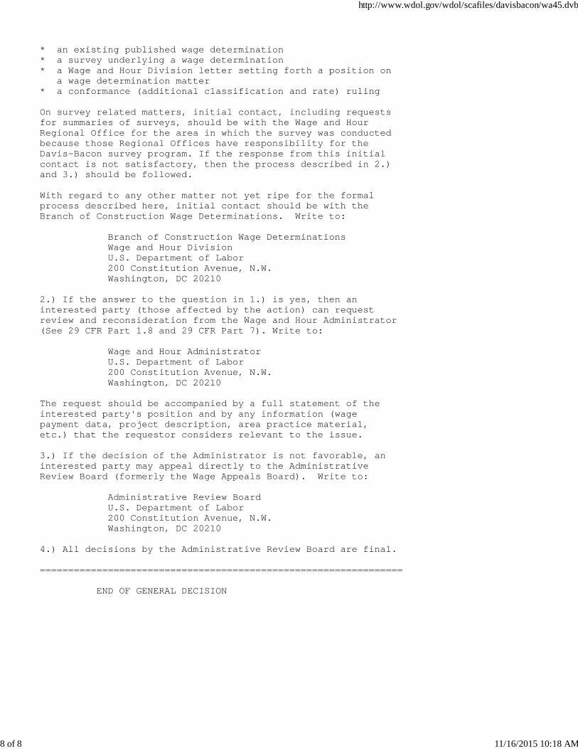
* an existing published wage determination* a survey underlying a wage determination* a Wage and Hour Division letter setting forth a position on a wage determination matter* a conformance (additional classification and rate) ruling
On survey related matters, initial contact, including requestsfor summaries of surveys, should be with the Wage and HourRegional Office for the area in which the survey was conductedbecause those Regional Offices have responsibility for theDavis-Bacon survey program. If the response from this initialcontact is not satisfactory, then the process described in 2.)and 3.) should be followed.
With regard to any other matter not yet ripe for the formalprocess described here, initial contact should be with theBranch of Construction Wage Determinations. Write to:
Branch of Construction Wage Determinations Wage and Hour Division U.S. Department of Labor 200 Constitution Avenue, N.W. Washington, DC 20210
2.) If the answer to the question in 1.) is yes, then aninterested party (those affected by the action) can requestreview and reconsideration from the Wage and Hour Administrator(See 29 CFR Part 1.8 and 29 CFR Part 7). Write to:
Wage and Hour Administrator U.S. Department of Labor 200 Constitution Avenue, N.W. Washington, DC 20210
The request should be accompanied by a full statement of theinterested party's position and by any information (wagepayment data, project description, area practice material,etc.) that the requestor considers relevant to the issue.
3.) If the decision of the Administrator is not favorable, aninterested party may appeal directly to the AdministrativeReview Board (formerly the Wage Appeals Board). Write to:
Administrative Review Board U.S. Department of Labor 200 Constitution Avenue, N.W. Washington, DC 20210
4.) All decisions by the Administrative Review Board are final.
================================================================
END OF GENERAL DECISION
http://www.wdol.gov/wdol/scafiles/davisbacon/wa45.dvb
8 of 8 11/16/2015 10:18 AM
APPENDIX B PERMITS

See Section: 1‐07.6 Permits and Licenses of the Special Provisions regarding permits the Contractor must obtain
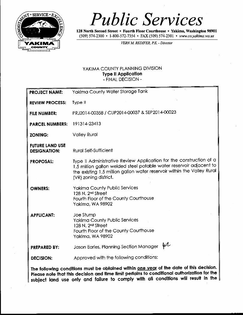
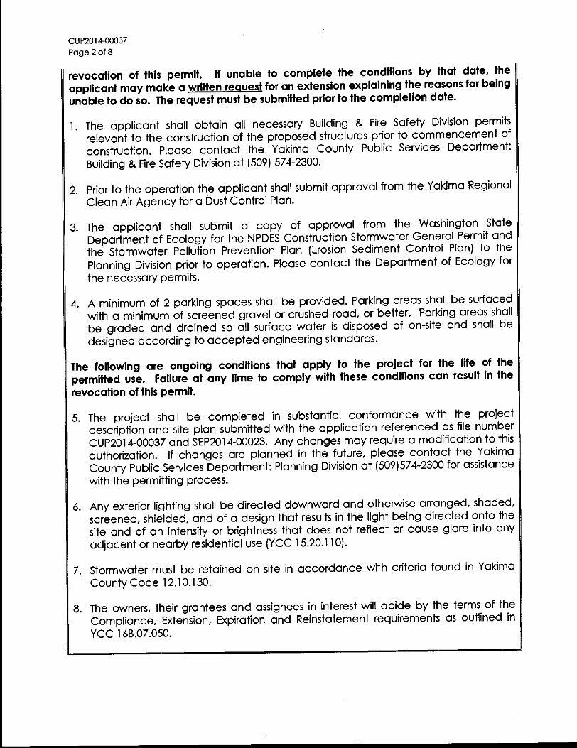
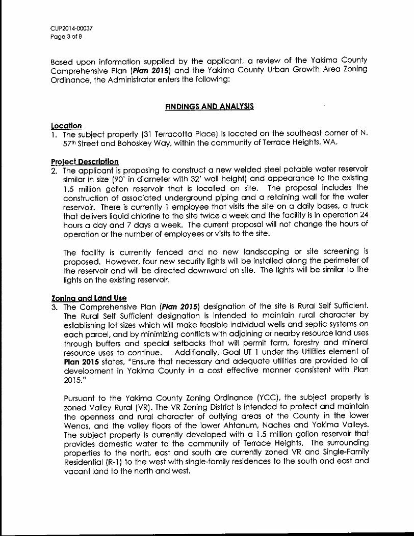

APPENDIX C STANDARD PLANS


APPENDIX D GEOTECHNICAL REPORT
________________________________________________ 3213 Eastlake Avenue East, Suite B
Seattle, WA 98102 T. (206) 262-0370 F. (206) 262-0374
Geotechnical & Earthquake
Engineering Consultants April 12, 2012 PanGEO Project No. 12-016 Mr. David van Cleve, P.E. Mr. Jim Bricel, P.E. Gray & Osborne, Inc. 107 South Third Street Yakima, WA 98901 Subject: GEOTECHNICAL REPORT Proposed Reservoir Bohoskey Drive & North 57th Street Terrace Heights, Washington Dear Mr. van Cleve and Mr. Bricel,
PanGEO completed a geotechnical study to assist the project team with the design and construction of the proposed 1.0 or 1.5 MG reservoir in Terrace Heights, Washington. In summary, the site is underlain by competent soils at shallow depths, and the proposed reservoir may be supported on a conventional shallow foundation. Final grading of the site may be accomplished by utilizing permanent 2H:1V cut slopes and a block gravity wall, if necessary.
We appreciate the opportunity to be of service. Should you have any questions, please do not hesitate to call.
Sincerely, Siew L. Tan, P.E. Principal Geotechnical Engineer
12-016_Terrace Hts Reservoir_Yakima_WA_final.doc Page i PanGEO Inc.
TABLE OF CONTENTS Section Page 1.0 GENERAL .................................................................................................................1
2.0 SITE AND PROJECT DESCRIPTION......................................................................1
3.0 SUBSURFACE EXPLORATIONS ...........................................................................2 3.1 CURRENT EXPLORATIONS ...............................................................................2 3.2 PREVIOUS EXPLORATIONS ...............................................................................3
4.0 SUBSURFACE CONDITIONS .................................................................................3 4.1 GEOLOGY ........................................................................................................3 4.2 SOIL AND GROUNDWATER ...............................................................................4 4.3 LABORATORY TESTS .......................................................................................5
5.0 GEOTECHNICAL RECOMMENDATIONS ............................................................5 5.1 SEISMIC HAZARDS ASSESSMENT .....................................................................5 5.2 SEISMIC DESIGN PARAMETERS ........................................................................5 5.3 FOUNDATION DESIGN ......................................................................................6
5.3.1 Allowable Bearing Pressure ...........................................................6
5.3.2 Lateral Resistance ...........................................................................7 5.4 PERMANENT CUT SLOPES ................................................................................7 5.5 RETAINING WALL ...........................................................................................7 5.6 INFILTRATION CONSIDERATIONS .....................................................................8
6.0 EARTHWORK CONSIDERATIONS .......................................................................10 6.1 SITE PREPARATION ..........................................................................................10 6.2 TEMPORARY EXCAVATIONS ............................................................................10 6.3 MATERIAL REUSE ...........................................................................................10 6.4 STRUCTURAL FILL AND COMPACTION .............................................................11 6.5 WET WEATHER CONSTRUCTION .....................................................................12 6.6 SURFACE DRAINAGE AND EROSION CONSIDERATIONS ....................................12
7.0 UNCERTAINTY AND LIMITATIONS ....................................................................13
8.0 REFERENCES ...........................................................................................................15
LIST OF FIGURES Figure 1 Vicinity Map Figure 2 Site and Exploration Plan Figure 3 Geologic Map LIST OF APPENDICES Appendix A Summary Test Pit Logs Figure A-1 Terms and Symbols for Boring and Test Pit Logs Test Pit Logs TP-1 through TP-3
Appendix B Laboratory Test Results Figure B-1 Grain Size Distribution
Appendix C Previous Explorations - TP-1 through TP-4 (HWA, 1993)
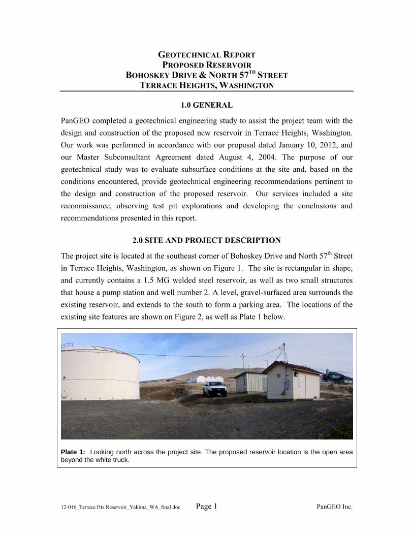
12-016_Terrace Hts Reservoir_Yakima_WA_final.doc Page 1 PanGEO Inc.
GEOTECHNICAL REPORT PROPOSED RESERVOIR
BOHOSKEY DRIVE & NORTH 57TH STREET TERRACE HEIGHTS, WASHINGTON
1.0 GENERAL
PanGEO completed a geotechnical engineering study to assist the project team with the design and construction of the proposed new reservoir in Terrace Heights, Washington. Our work was performed in accordance with our proposal dated January 10, 2012, and our Master Subconsultant Agreement dated August 4, 2004. The purpose of our geotechnical study was to evaluate subsurface conditions at the site and, based on the conditions encountered, provide geotechnical engineering recommendations pertinent to the design and construction of the proposed reservoir. Our services included a site reconnaissance, observing test pit explorations and developing the conclusions and recommendations presented in this report.
2.0 SITE AND PROJECT DESCRIPTION
The project site is located at the southeast corner of Bohoskey Drive and North 57th Street in Terrace Heights, Washington, as shown on Figure 1. The site is rectangular in shape, and currently contains a 1.5 MG welded steel reservoir, as well as two small structures that house a pump station and well number 2. A level, gravel-surfaced area surrounds the existing reservoir, and extends to the south to form a parking area. The locations of the existing site features are shown on Figure 2, as well as Plate 1 below.
Plate 1: Looking north across the project site. The proposed reservoir location is the open area beyond the white truck.
Geotechnical Report Proposed Reservoir, Terrace Heights, Washington April 12, 2012
12-016_Terrace Hts Reservoir_Yakima_WA_final.doc Page 2 PanGEO, Inc.
Site grades slope gently down from northeast to southwest. The western approximately half of the site was previously graded during construction of the existing reservoir, and cut slopes are exposed on the north and east sides of the existing reservoir, while fill slopes are located along the west and south sides of the level gravel area south of the reservoir.
We understand that a second 1.0 to 1.5MG reservoir will be constructed at the site. The reservoir would have a diameter of 70 or 90 feet, and will be located to the east of the existing reservoir, in the open area north of the pump station. We understand that the new reservoir may consist of either a partially buried concrete reservoir, or an above-ground steel reservoir. If a 1.5 MG steel reservoir is constructed, an approximately 20-foot tall permanent slope cut would be needed to the north and east of the new reservoir. A retaining wall may also be needed along the south side of Bohoskey Drive to prevent the permanent slope cut from day-lighting outside the property boundaries. As currently proposed, we understand the reservoir will be supported by a shallow foundation.
3.0 SUBSURFACE EXPLORATIONS
3.1 Current Explorations
Three test pits (TP-1 through TP-3) were excavated on February 28, 2012, to explore subsurface conditions at the proposed reservoir location. The approximate test pit locations were measured from existing site features, and are indicated on Figure 2. The test pits were excavated to depths of 5½ to 15 feet below the existing ground surface using a CAT rubber-tired backhoe provided by Yakima County personnel.
An engineer from PanGEO was present during the field explorations to observe the test pit excavations, obtain representative soil samples, and to describe and document the soils encountered in the explorations. A summary of the test pit logs are presented in Appendix A, and provide descriptions of the materials encountered, depths to soil contacts, and depths of seepage or caving, if present, observed in the test pit sidewalls. The relative in-situ density of cohesionless soils, or the relative consistency of fine-grained soils, was estimated from the excavating action of the back-hoe, and the stability of the test pit sidewalls. Where soil contacts were gradual or undulating, the average depth of the contact was recorded in the log. After each test pit was logged, the
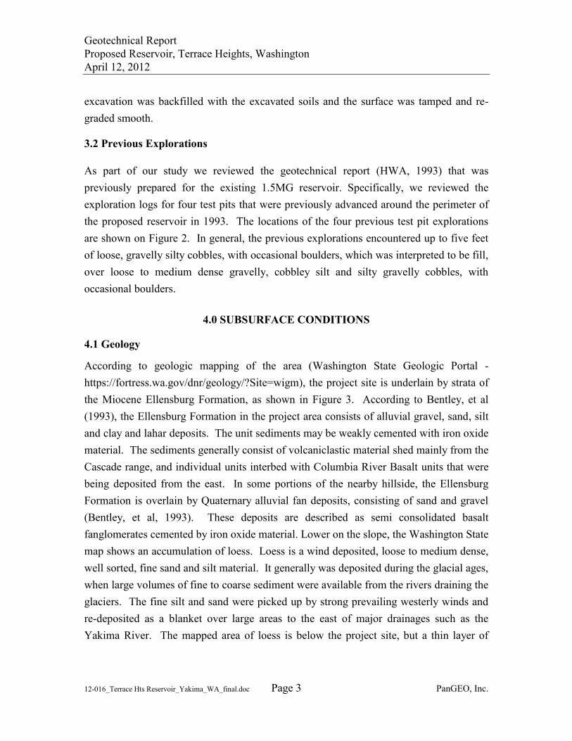
Geotechnical Report Proposed Reservoir, Terrace Heights, Washington April 12, 2012
12-016_Terrace Hts Reservoir_Yakima_WA_final.doc Page 3 PanGEO, Inc.
excavation was backfilled with the excavated soils and the surface was tamped and re-graded smooth.
3.2 Previous Explorations
As part of our study we reviewed the geotechnical report (HWA, 1993) that was previously prepared for the existing 1.5MG reservoir. Specifically, we reviewed the exploration logs for four test pits that were previously advanced around the perimeter of the proposed reservoir in 1993. The locations of the four previous test pit explorations are shown on Figure 2. In general, the previous explorations encountered up to five feet of loose, gravelly silty cobbles, with occasional boulders, which was interpreted to be fill, over loose to medium dense gravelly, cobbley silt and silty gravelly cobbles, with occasional boulders.
4.0 SUBSURFACE CONDITIONS
4.1 Geology
According to geologic mapping of the area (Washington State Geologic Portal -https://fortress.wa.gov/dnr/geology/?Site=wigm), the project site is underlain by strata of the Miocene Ellensburg Formation, as shown in Figure 3. According to Bentley, et al (1993), the Ellensburg Formation in the project area consists of alluvial gravel, sand, silt and clay and lahar deposits. The unit sediments may be weakly cemented with iron oxide material. The sediments generally consist of volcaniclastic material shed mainly from the Cascade range, and individual units interbed with Columbia River Basalt units that were being deposited from the east. In some portions of the nearby hillside, the Ellensburg Formation is overlain by Quaternary alluvial fan deposits, consisting of sand and gravel (Bentley, et al, 1993). These deposits are described as semi consolidated basalt fanglomerates cemented by iron oxide material. Lower on the slope, the Washington State map shows an accumulation of loess. Loess is a wind deposited, loose to medium dense, well sorted, fine sand and silt material. It generally was deposited during the glacial ages, when large volumes of fine to coarse sediment were available from the rivers draining the glaciers. The fine silt and sand were picked up by strong prevailing westerly winds and re-deposited as a blanket over large areas to the east of major drainages such as the Yakima River. The mapped area of loess is below the project site, but a thin layer of
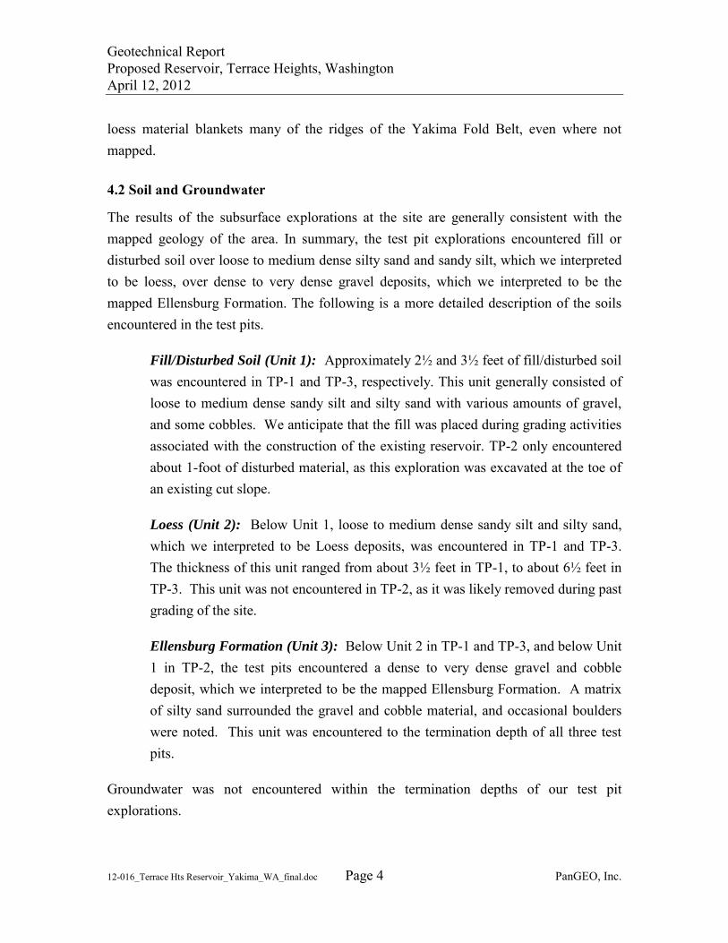
Geotechnical Report Proposed Reservoir, Terrace Heights, Washington April 12, 2012
12-016_Terrace Hts Reservoir_Yakima_WA_final.doc Page 4 PanGEO, Inc.
loess material blankets many of the ridges of the Yakima Fold Belt, even where not mapped.
4.2 Soil and Groundwater
The results of the subsurface explorations at the site are generally consistent with the mapped geology of the area. In summary, the test pit explorations encountered fill or disturbed soil over loose to medium dense silty sand and sandy silt, which we interpreted to be loess, over dense to very dense gravel deposits, which we interpreted to be the mapped Ellensburg Formation. The following is a more detailed description of the soils encountered in the test pits.
Fill/Disturbed Soil (Unit 1): Approximately 2½ and 3½ feet of fill/disturbed soil was encountered in TP-1 and TP-3, respectively. This unit generally consisted of loose to medium dense sandy silt and silty sand with various amounts of gravel, and some cobbles. We anticipate that the fill was placed during grading activities associated with the construction of the existing reservoir. TP-2 only encountered about 1-foot of disturbed material, as this exploration was excavated at the toe of an existing cut slope.
Loess (Unit 2): Below Unit 1, loose to medium dense sandy silt and silty sand, which we interpreted to be Loess deposits, was encountered in TP-1 and TP-3. The thickness of this unit ranged from about 3½ feet in TP-1, to about 6½ feet in TP-3. This unit was not encountered in TP-2, as it was likely removed during past grading of the site.
Ellensburg Formation (Unit 3): Below Unit 2 in TP-1 and TP-3, and below Unit 1 in TP-2, the test pits encountered a dense to very dense gravel and cobble deposit, which we interpreted to be the mapped Ellensburg Formation. A matrix of silty sand surrounded the gravel and cobble material, and occasional boulders were noted. This unit was encountered to the termination depth of all three test pits.
Groundwater was not encountered within the termination depths of our test pit explorations.
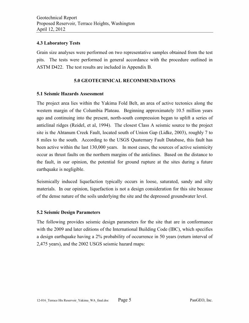
Geotechnical Report Proposed Reservoir, Terrace Heights, Washington April 12, 2012
12-016_Terrace Hts Reservoir_Yakima_WA_final.doc Page 5 PanGEO, Inc.
4.3 Laboratory Tests
Grain size analyses were performed on two representative samples obtained from the test pits. The tests were performed in general accordance with the procedure outlined in ASTM D422. The test results are included in Appendix B.
5.0 GEOTECHNICAL RECOMMENDATIONS
5.1 Seismic Hazards Assessment
The project area lies within the Yakima Fold Belt, an area of active tectonics along the western margin of the Columbia Plateau. Beginning approximately 10.5 million years ago and continuing into the present, north-south compression began to uplift a series of anticlinal ridges (Reidel, et al, 1994). The closest Class A seismic source to the project site is the Ahtanum Creek Fault, located south of Union Gap (Lidke, 2003), roughly 7 to 8 miles to the south. According to the USGS Quaternary Fault Database, this fault has been active within the last 130,000 years. In most cases, the sources of active seismicity occur as thrust faults on the northern margins of the anticlines. Based on the distance to the fault, in our opinion, the potential for ground rupture at the sites during a future earthquake is negligible.
Seismically induced liquefaction typically occurs in loose, saturated, sandy and silty materials. In our opinion, liquefaction is not a design consideration for this site because of the dense nature of the soils underlying the site and the depressed groundwater level.
5.2 Seismic Design Parameters
The following provides seismic design parameters for the site that are in conformance with the 2009 and later editions of the International Building Code (IBC), which specifies a design earthquake having a 2% probability of occurrence in 50 years (return interval of 2,475 years), and the 2002 USGS seismic hazard maps:
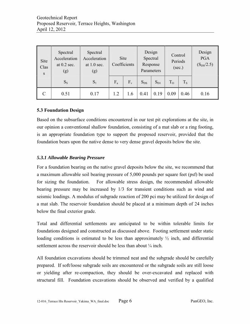
Geotechnical Report Proposed Reservoir, Terrace Heights, Washington April 12, 2012
12-016_Terrace Hts Reservoir_Yakima_WA_final.doc Page 6 PanGEO, Inc.
5.3 Foundation Design
Based on the subsurface conditions encountered in our test pit explorations at the site, in our opinion a conventional shallow foundation, consisting of a mat slab or a ring footing, is an appropriate foundation type to support the proposed reservoir, provided that the foundation bears upon the native dense to very dense gravel deposits below the site.
5.3.1 Allowable Bearing Pressure
For a foundation bearing on the native gravel deposits below the site, we recommend that a maximum allowable soil bearing pressure of 5,000 pounds per square feet (psf) be used for sizing the foundation. For allowable stress design, the recommended allowable bearing pressure may be increased by 1/3 for transient conditions such as wind and seismic loadings. A modulus of subgrade reaction of 200 pci may be utilized for design of a mat slab. The reservoir foundation should be placed at a minimum depth of 24 inches below the final exterior grade.
Total and differential settlements are anticipated to be within tolerable limits for foundations designed and constructed as discussed above. Footing settlement under static loading conditions is estimated to be less than approximately ½ inch, and differential settlement across the reservoir should be less than about ¼ inch.
All foundation excavations should be trimmed neat and the subgrade should be carefully prepared. If soft/loose subgrade soils are encountered or the subgrade soils are still loose or yielding after re-compaction, they should be over-excavated and replaced with structural fill. Foundation excavations should be observed and verified by a qualified
Site Clas
s
Spectral Acceleration
at 0.2 sec. (g)
SS
Spectral Acceleration
at 1.0 sec. (g)
S1
Site Coefficients
Design Spectral
Response Parameters
Control Periods (sec.)
Design PGA
(SDS/2.5)
Fa Fv SDS SD1 TO TS
C 0.51 0.17 1.2 1.6 0.41 0.19 0.09 0.46 0.16
Geotechnical Report Proposed Reservoir, Terrace Heights, Washington April 12, 2012
12-016_Terrace Hts Reservoir_Yakima_WA_final.doc Page 7 PanGEO, Inc.
individual to confirm that the exposed subgrade is consistent with the expected conditions and adequate to support the proposed reservoir.
5.3.2 Lateral Resistance
Lateral forces from wind or seismic loading may be resisted by a combination of passive earth pressures acting against the embedded portions of the foundations, and by friction acting on the base of the foundations. Passive resistance values may be determined using an equivalent fluid weight of 350 pounds per cubic foot (pcf). This value includes a factor safety of at least 1.5 assuming that properly compacted structural fill will be placed adjacent to the sides of the footings. A friction coefficient of 0.4 may be used to determine the frictional resistance at the base of the footings. This coefficient includes a factor safety of approximate 1.5.
5.4 Permanent Cut Slopes
Based on the anticipated soil that will be exposed in the planned excavation, as well as the performance of the existing cut slopes at the site, we recommend that permanent cut slopes, where applicable, be constructed no steeper than 2H:1V (horizontal:vertical).
5.5 Retaining Wall
If there is not enough space for a permanent 2H:1V slope around the north side of the proposed steel reservoir, a low retaining wall of about 4 feet or less, may be needed. In our opinion a cost effective wall type would consist of a gravity wall. The principal advantage of a gravity wall is the ease and speed of construction, and the relatively low construction cost. If a gravity wall will be used for this project, we recommend a precast concrete block wall be utilized.
Concrete blocks should have a minimum dimension of 2½ feet by 2½ feet by 5 feet (such as Ultra Blocks, www.ultrablocks.com) and be made of new concrete. Blocks made of returned concrete, or having dimensions of 2 feet by 2 feet by 6 feet (i.e. ecology blocks) should not be used. Concrete blocks can be made with various finishes or textures to provide the desired aesthetics.
Geotechnical Report Proposed Reservoir, Terrace Heights, Washington April 12, 2012
12-016_Terrace Hts Reservoir_Yakima_WA_final.doc Page 8 PanGEO, Inc.
To improve the long-term performance and stability of the wall, we recommend that the wall be constructed at the toe of the slope, and have a 2H:1V backslope, rather than constructing the wall at the top of slope, where a greater embedment depth would be needed. We offer the following recommendations for gravity block wall design:
Block Configuration – We recommend that the top two rows of blocks be oriented with their long axis parallel to the wall face (corresponding to a wall width of 2½ feet), and the lower row (third row) of blocks, if needed, be rotated 90 degrees to form a wall width of 5 feet. The blocks should be oriented such that adequate interlocking occurs between adjacent blocks. If the exposed wall height will be more than 6½ feet, we can provide additional recommendations for block wall configurations. We will also provide additional recommendations if the project team plans to use concrete blocks with different dimensions.
Minimum Embedment (Assuming wall located at toe of slope) - Walls founded on level ground surface should have a minimum of one foot of embedment. All walls should be founded on competent native soils or properly compacted fill. If needed, a 6-inch layer of granular structural fill such as crushed rock or shoulder ballast may be placed as a leveling course before placing the base course of blocks.
Foundation Preparation – Based on our test pit explorations at the site, the wall will be constructed upon dense to very dense gravel deposits, and should adequately support the proposed block wall. A leveling course likely will be needed to provide a relatively smooth surface for uniform foundation support. The leveling course may consist of 4 inches of properly compacted Crushed Surfacing Top Course. If loose subgrade soils are exposed however, they should either be re-compacted to a dense condition, or removed and replaced with properly compacted structural fill.
5.6 Infiltration Considerations
We understand that on-site infiltration of stormwater may be considered in the southwest portion of the site if soils suitable for infiltration are present. Based on the results of TP-3, which was advanced in the southwest portion of the site, the existing soils at this location consist of about 3½ feet of fill, consisting of sandy silt and silty sand, over loose to medium dense sandy silt and silty fine sand to a depth of about 10 feet below grade. Below a depth of 10 feet, the test pit encountered dense angular gravel and cobbles in a
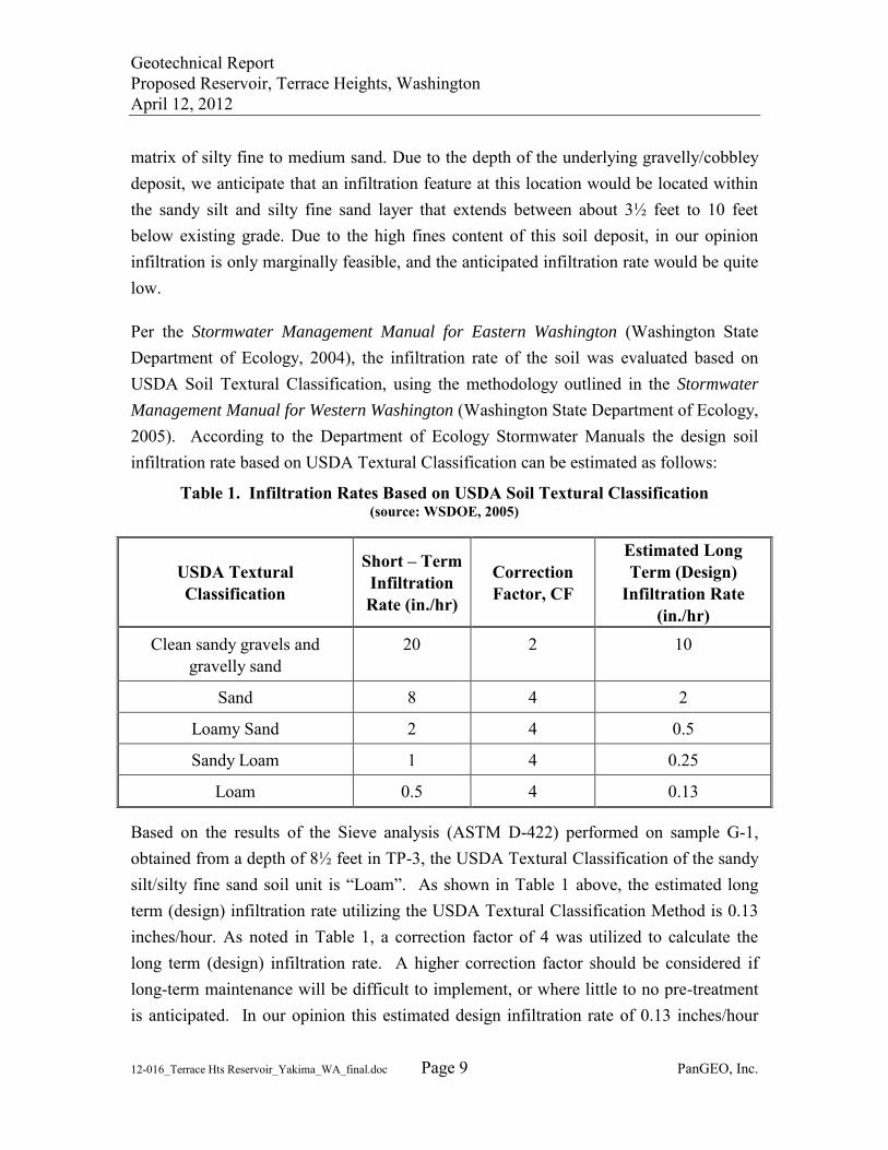
Geotechnical Report Proposed Reservoir, Terrace Heights, Washington April 12, 2012
12-016_Terrace Hts Reservoir_Yakima_WA_final.doc Page 9 PanGEO, Inc.
matrix of silty fine to medium sand. Due to the depth of the underlying gravelly/cobbley deposit, we anticipate that an infiltration feature at this location would be located within the sandy silt and silty fine sand layer that extends between about 3½ feet to 10 feet below existing grade. Due to the high fines content of this soil deposit, in our opinion infiltration is only marginally feasible, and the anticipated infiltration rate would be quite low.
Per the Stormwater Management Manual for Eastern Washington (Washington State Department of Ecology, 2004), the infiltration rate of the soil was evaluated based on USDA Soil Textural Classification, using the methodology outlined in the Stormwater
Management Manual for Western Washington (Washington State Department of Ecology, 2005). According to the Department of Ecology Stormwater Manuals the design soil infiltration rate based on USDA Textural Classification can be estimated as follows:
Table 1. Infiltration Rates Based on USDA Soil Textural Classification (source: WSDOE, 2005)
USDA Textural Classification
Short – Term Infiltration Rate (in./hr)
Correction Factor, CF
Estimated Long Term (Design)
Infiltration Rate (in./hr)
Clean sandy gravels and gravelly sand
20 2 10
Sand 8 4 2
Loamy Sand 2 4 0.5
Sandy Loam 1 4 0.25
Loam 0.5 4 0.13
Based on the results of the Sieve analysis (ASTM D-422) performed on sample G-1, obtained from a depth of 8½ feet in TP-3, the USDA Textural Classification of the sandy silt/silty fine sand soil unit is “Loam”. As shown in Table 1 above, the estimated long term (design) infiltration rate utilizing the USDA Textural Classification Method is 0.13 inches/hour. As noted in Table 1, a correction factor of 4 was utilized to calculate the long term (design) infiltration rate. A higher correction factor should be considered if long-term maintenance will be difficult to implement, or where little to no pre-treatment is anticipated. In our opinion this estimated design infiltration rate of 0.13 inches/hour
Geotechnical Report Proposed Reservoir, Terrace Heights, Washington April 12, 2012
12-016_Terrace Hts Reservoir_Yakima_WA_final.doc Page 10 PanGEO, Inc.
represents a reasonable maximum infiltration rate for the soil deposit located about 3½ to 10 feet below surface grades in the southwest corner of the site, and may be utilized for design.
6.0 EARTHWORK CONSIDERATIONS
6.1 Site Preparation
Site preparation for the proposed project includes striping and clearing of any remaining surface vegetation or organic material and excavating to the design foundation subgrade elevation. All stripped and over-excavated materials should be disposed off-site or be “wasted” on site in non-structural landscaping areas.
Following the site clearing and excavation, the exposed subgrade should be compacted to a dense and unyielding condition as confirmed by a qualified individual. Soil in loose or soft areas should be over-excavated and replaced with compacted structural fill as described above.
6.2 Temporary Excavations
We anticipate that excavations up to about 20 feet may be required. Based on our understanding of the subsurface conditions at the sites, we anticipate that the excavations will encounter up to 6 feet of loose to medium dense sandy silt and silty fine sand over dense to very dense silty sandy gravel with cobbles and boulders. All temporary excavations should be performed in accordance with Part N of WAC (Washington Administrative Code) 296-155. The contractor is responsible for maintaining safe excavation slopes and/or shoring. For planning purposes, the temporary excavations may be sloped as steep as 1H:1V, but should be re-evaluated in the field during construction based on actual observed soil conditions. During wet weather, the cut slopes may need to be flattened to reduce potential erosion.
6.3 Material Reuse
The contractor should be aware that the upper 6 feet of soil that exists over most of the footprint of the reservoir are moisture sensitive, and will become disturbed and soft when exposed to inclement weather conditions. If use of the existing soils is planned in non-
Geotechnical Report Proposed Reservoir, Terrace Heights, Washington April 12, 2012
12-016_Terrace Hts Reservoir_Yakima_WA_final.doc Page 11 PanGEO, Inc.
structural areas, any excavated soil should be stockpiled and protected with plastic sheeting to prevent softening from rainfall.
It may be possible to re-use the underlying native silty sandy gravel for general purposes, such as for access roads or raising site grades, but due to the cobbles and boulders that may be present, fine grading with the native material will be difficult.
6.4 Structural Fill and Compaction
Although we do not anticipate the need for over-excavations of unsuitable soil below the reservoir, if needed, imported structural fill should be used within the footprint of the proposed reservoir. We recommend that the structural fill consist of clean, free-draining crushed rock such as crushed surfacing base course as specified in section 9-03.9(3) of the 2012 WSDOT Standard Specifications for Road, Bridge, and Municipal Construction (WSDOT, 2012), or approved similar material.
All structural fill soils should be moisture conditioned to within about 3 percent of optimum moisture content, placed in loose, horizontal lifts less than 8 inches in thickness, and compacted to at least 95 percent maximum density, determined using ASTM D 1557 (Modified Proctor). The procedure to achieve proper density of a compacted fill depends on the size and type of compacting equipment, the number of passes, thickness of the layer being compacted, and certain soil properties. In areas where the size of the excavation restricts the use of heavy equipment, smaller equipment can be used, but the soil must be placed in thin enough layers to achieve the required relative compaction.
Generally, loosely compacted soils are a result of poor construction technique or improper moisture content. Soils with high fines contents are particularly susceptible to becoming too wet, and coarse-grained materials easily become too dry, for proper compaction. Silty or clayey soils with a moisture content too high for adequate compaction should be dried as necessary, or moisture conditioned by mixing with drier materials, or other methods.
Geotechnical Report Proposed Reservoir, Terrace Heights, Washington April 12, 2012
12-016_Terrace Hts Reservoir_Yakima_WA_final.doc Page 12 PanGEO, Inc.
6.5 Wet Weather Construction
General recommendations relative to earthwork performed in wet weather or in wet conditions are presented below. The following procedures are best management practices recommended for use in wet weather construction:
Earthwork should be performed in small areas to minimize subgrade exposure to wet weather. Excavation or the removal of unsuitable soil should be followed promptly by the placement and compaction of clean structural fill. The size and type of construction equipment used may have to be limited to prevent soil disturbance.
During wet weather, the allowable fines content of the structural fill should be reduced to no more than 5 percent by weight based on the portion passing ¾-inch sieve. The fines should be non-plastic.
The ground surface within the construction area should be graded to promote run-off of surface water and to prevent the ponding of water.
Bales of straw and/or geotextile silt fences should be strategically located to control erosion and the movement of soil.
Excavation slopes and soils stockpiled on site should be covered with plastic sheets.
6.6 Surface Drainage and Erosion Considerations
Surface runoff can be controlled during construction by careful grading practices. Typically, this includes the construction of shallow, upgrade perimeter ditches or low earthen berms in conjunction with silt fences to collect runoff and prevent water from entering excavations or to prevent runoff from the construction area from leaving the immediate work site. Temporary erosion control may require the use of hay bales on the downhill side of the project to prevent water from leaving the site and potential storm water detention to trap sand and silt before the water is discharged to a suitable outlet. All collected water should be directed under control to a positive and permanent discharge system.
Geotechnical Report Proposed Reservoir, Terrace Heights, Washington April 12, 2012
12-016_Terrace Hts Reservoir_Yakima_WA_final.doc Page 13 PanGEO, Inc.
Permanent control of surface water should be incorporated in the final grading design. Adequate surface gradients and drainage systems should be incorporated into the design such that surface runoff is collected and directed away from the reservoir structure to a suitable outlet. Potential problems associated with erosion may also be reduced by establishing vegetation within disturbed areas immediately following grading operations.
7.0 UNCERTAINTY AND LIMITATIONS
We have prepared this report for use by Gray & Osborne, Yakima County, and other project team members. Recommendations contained in this report are based on a site reconnaissance, a subsurface exploration program, review of pertinent geologic publications, and our understanding of the project. The study was performed using a mutually agreed-upon scope of work.
Variations in soil conditions may exist between the locations of the explorations and the actual conditions underlying the site. The nature and extent of soil variations may not be evident until construction occurs. If any soil conditions are encountered at the site that are different from those described in this report, we should be notified immediately to review the applicability of our recommendations. Additionally, we should also be notified to review the applicability of our recommendations if there are any changes in the project scope.
The scope of our work does not include services related to construction safety precautions. Our recommendations are not intended to direct the contractors’ methods, techniques, sequences or procedures, except as specifically described in our report for consideration in design. Additionally, the scope of our work specifically excludes the assessment of environmental characteristics, particularly those involving hazardous substances. We are not mold consultants nor are our recommendations to be interpreted as being preventative of mold development. A mold specialist should be consulted for all mold-related issues.
This report may be used only by the client and for the purposes stated, within a reasonable time from its issuance. Land use, site conditions (both off and on-site), or other factors including advances in our understanding of applied science, may change over time and could materially affect our findings. Therefore, this report should not be relied upon after 24 months from its issuance. PanGEO should be notified if the project is delayed by
Geotechnical Report Proposed Reservoir, Terrace Heights, Washington April 12, 2012
12-016_Terrace Hts Reservoir_Yakima_WA_final.doc Page 14 PanGEO, Inc.
more than 24 months from the date of this report so that we may review the applicability of our conclusions considering the time lapse.
It is the client’s responsibility to see that all parties to this project, including the designer, contractor, subcontractors, etc., are made aware of this report in its entirety. The use of information contained in this report for bidding purposes should be done at the contractor’s option and risk. Any party other than the client who wishes to use this report shall notify PanGEO of such intended use and for permission to copy this report. Based on the intended use of the report, PanGEO may require that additional work be performed and that an updated report be reissued. Noncompliance with any of these requirements will release PanGEO from any liability resulting from the use this report.
Within the limitation of scope, schedule and budget, PanGEO engages in the practice of geotechnical engineering and endeavors to perform its services in accordance with generally accepted professional principles and practices at the time the Report or its contents were prepared. No warranty, express or implied, is made.
We appreciate the opportunity to be of service to you on this project. Please feel free to contact our office with any questions you have regarding our study, this report, or any geotechnical engineering related project issues.
Sincerely,
Jon C. Rehkopf, P.E. Siew L. Tan, P.E. Senior Project Geotechnical Engineer Principal Geotechnical Engineer
Geotechnical Report Proposed Reservoir, Terrace Heights, Washington April 12, 2012
12-016_Terrace Hts Reservoir_Yakima_WA_final.doc Page 15 PanGEO, Inc.
8.0 REFERENCES
Bentley, R.D.; Campbell, N.P.; and Powell, J.E., 1993, Geologic maps of part of the Yakima Fold Belt, northeastern Yakima County, Washington, Washington State Department of Natural Resources Open File Report 93-3.
Hong West & Associates, Inc, (1993). Terrace Heights 1.5 MG Reservoir, Yakima,
Washington. Project 93106.
International Building Code (IBC), 2009, International Code Council.
Lidke, D.J., compiler, 2003, Fault number 564a, Ahtanum Ridge structures, Ahtanum Creek fault, in Quaternary fault and fold database of the United States: U.S. Geological Survey website, http://earthquakes.usgs.gov/regional/qfaults, accessed March 2012.
Reidel, S.P.; Campbell, N.P.; Fecht, K.R. and Lindsey, K.A., 1994, Late Cenozoic structure and stratigraphy of south-central Washington, in Regional Geology of Washington State, ed. Raymond Lasmanis and Eric S. Cheney, Washington Division of Geology and Earth resources Bulletin 80, pp. 159 – 180.
Washington State Department of Ecology (2004). Stormwater Management Manual for
Eastern Washington, Publication Number 04-10-076.
Washington State Department of Ecology (2005). Stormwater Management Manual for
Western Washington, Publication Numbers 99-11 through 99-15.
WSDOT, 2012, Standard Specifications for Road, Bridges, and Municipal Construction.
The Washington State Geologic Portal (https://fortress.wa.gov/dnr/geology/?Site=wigm), downloaded March, 2012.
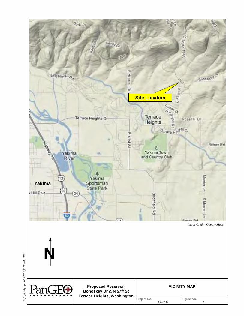
Figure No.Project No.
N
Proposed Reservoir
Bohoskey Dr & N 57th St
Terrace Heights, Washington
Fig
1_
vic
inity.p
pt 4
/13
/20
12
(10
:12
AM
) J
CR
12-016 1
VICINITY MAP
Site Location
Image Credit: Google Maps
Yakima
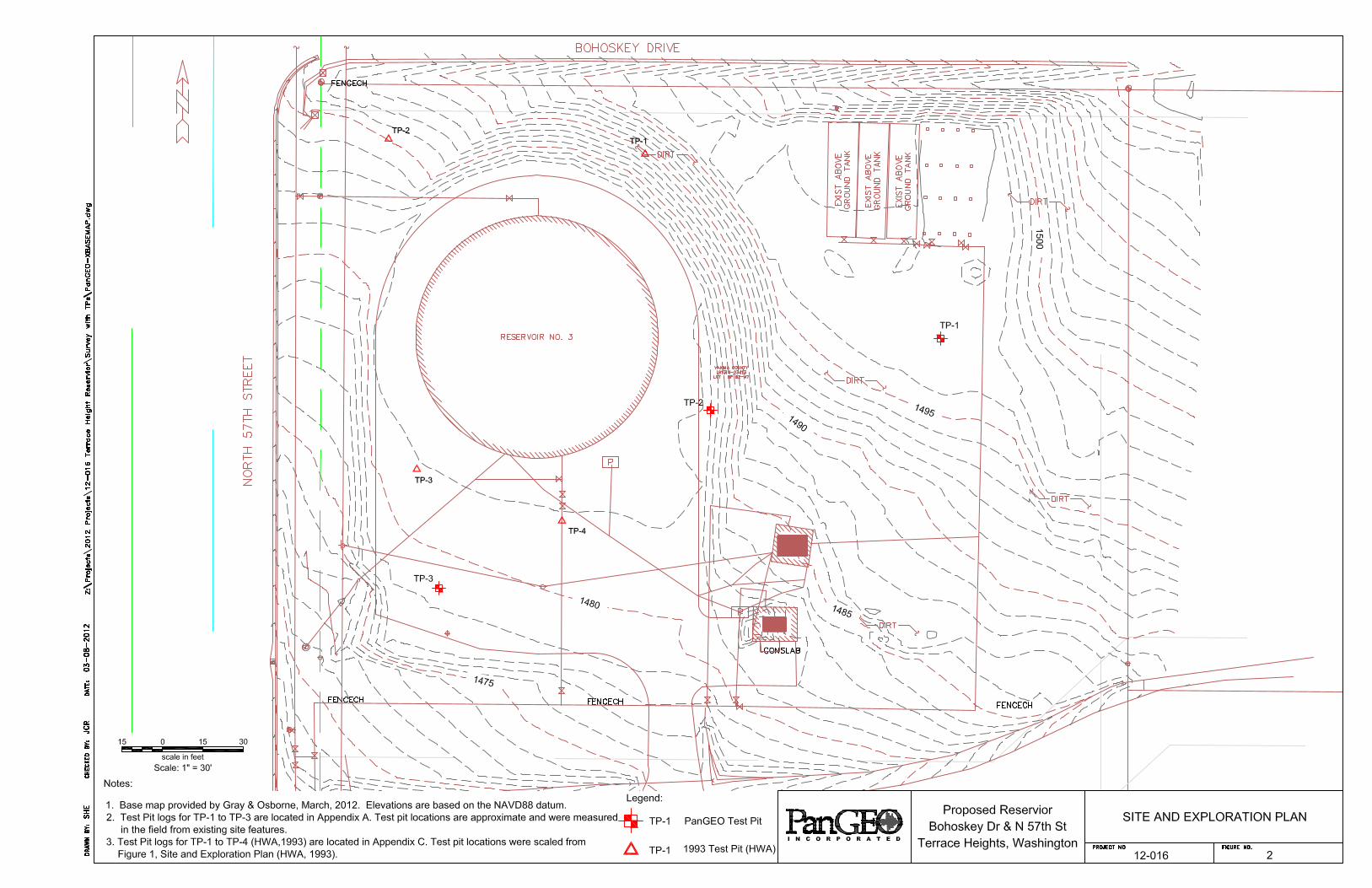
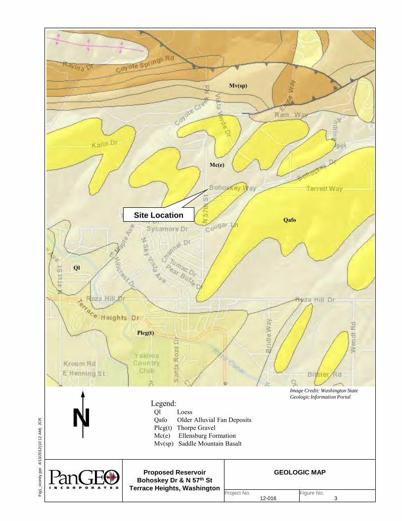
Figure No.Project No.
N
Proposed Reservoir
Bohoskey Dr & N 57th St
Terrace Heights, Washington
Fig
1_
vic
inity.p
pt 4
/13
/20
12
(10
:12
AM
) J
CR
12-016 3
GEOLOGIC MAP
Site Location
Image Credit: Washington State
Geologic Information Portal
Yakima
Qafo
Mc(e)
Ql
Plcg(t)
Mv(sp)
Legend: Ql Loess Qafo Older Alluvial Fan Deposits Plcg(t) Thorpe Gravel Mc(e) Ellensburg Formation Mv(sp) Saddle Mountain Basalt
APPENDIX A
SUMMARY TEST PIT LOGS
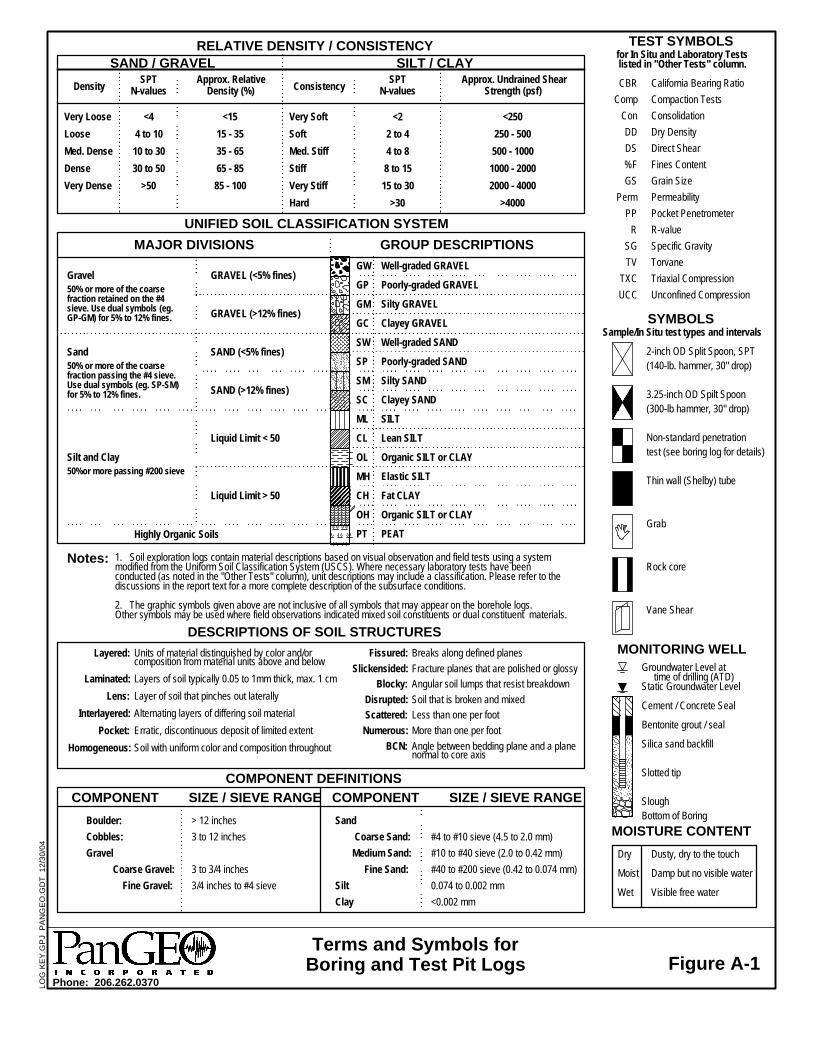
MONITORING WELL
<1515 - 3535 - 6565 - 8585 - 100
GW
GP
GM
GC
SW
SP
SM
SC
ML
CL
OL
MH
CH
OH
PT
TEST SYMBOLS
50% or more of the coarsefraction retained on the #4sieve. Use dual symbols (eg.GP-GM) for 5% to 12% fines.
1. Soil exploration logs contain material descriptions based on visual observation and field tests using a systemmodified from the Uniform Soil Classification System (USCS). Where necessary laboratory tests have beenconducted (as noted in the "Other Tests" column), unit descriptions may include a classification. Please refer to thediscussions in the report text for a more complete description of the subsurface conditions.
2. The graphic symbols given above are not inclusive of all symbols that may appear on the borehole logs.Other symbols may be used where field observations indicated mixed soil constituents or dual constituent materials.
COMPONENT SIZE / SIEVE RANGE COMPONENT SIZE / SIEVE RANGE
SYMBOLSSample/In Situ test types and intervals
Consistency
Well-graded GRAVEL
Poorly-graded GRAVEL
Silty GRAVEL
Clayey GRAVEL
Well-graded SAND
Poorly-graded SAND
Silty SAND
Clayey SAND
SILT
Lean SILT
Organic SILT or CLAY
Elastic SILT
Fat CLAY
Organic SILT or CLAY
PEAT
SAND / GRAVEL
California Bearing RatioCompaction TestsConsolidationDry DensityDirect ShearFines ContentGrain SizePermeabilityPocket PenetrometerR-valueSpecific GravityTorvaneTriaxial CompressionUnconfined Compression
SPTN-values
Units of material distinguished by color and/orcomposition from material units above and belowLayers of soil typically 0.05 to 1mm thick, max. 1 cmLayer of soil that pinches out laterallyAlternating layers of differing soil materialErratic, discontinuous deposit of limited extentSoil with uniform color and composition throughout
Approx. RelativeDensity (%)
Gravel
Sand50% or more of the coarsefraction passing the #4 sieve.Use dual symbols (eg. SP-SM)for 5% to 12% fines.
MOISTURE CONTENT
2-inch OD Split Spoon, SPT(140-lb. hammer, 30" drop)
3.25-inch OD Spilt Spoon(300-lb hammer, 30" drop)
Non-standard penetrationtest (see boring log for details)
Thin wall (Shelby) tube
Grab
Rock core
Vane Shear
Dusty, dry to the touch
Damp but no visible water
Visible free water
Boulder:Cobbles:Gravel Coarse Gravel: Fine Gravel:
Sand Coarse Sand: Medium Sand: Fine Sand:SiltClay
> 12 inches3 to 12 inches
3 to 3/4 inches3/4 inches to #4 sieve
SILT / CLAY
GRAVEL (<5% fines)
GRAVEL (>12% fines)
SAND (<5% fines)
SAND (>12% fines)
Liquid Limit < 50
Liquid Limit > 50
Terms and Symbols forBoring and Test Pit Logs
Density
DESCRIPTIONS OF SOIL STRUCTURES
Breaks along defined planesFracture planes that are polished or glossyAngular soil lumps that resist breakdownSoil that is broken and mixedLess than one per footMore than one per footAngle between bedding plane and a planenormal to core axis
Very LooseLooseMed. DenseDenseVery Dense
SPTN-values
Approx. Undrained ShearStrength (psf)
<44 to 10
10 to 3030 to 50
>50
<22 to 44 to 88 to 15
15 to 30>30
Layered:
Laminated:Lens:
Interlayered:Pocket:
Homogeneous:
Highly Organic Soils
#4 to #10 sieve (4.5 to 2.0 mm)#10 to #40 sieve (2.0 to 0.42 mm)#40 to #200 sieve (0.42 to 0.074 mm)0.074 to 0.002 mm<0.002 mm
Silt and Clay
Very SoftSoftMed. StiffStiffVery StiffHard
Phone: 206.262.0370
Bottom of Boring
CBRComp
ConDDDS%FGS
PermPP
RSGTV
TXCUCC
50%or more passing #200 sieve
Groundwater Level at time of drilling (ATD)Static Groundwater Level
Cement / Concrete Seal
Bentonite grout / seal
Silica sand backfill
Slotted tip
Slough
<250250 - 500500 - 1000
1000 - 20002000 - 4000
>4000
RELATIVE DENSITY / CONSISTENCY
Fissured:Slickensided:
Blocky:Disrupted:Scattered:
Numerous:BCN:
COMPONENT DEFINITIONS
Dry
Moist
Wet
UNIFIED SOIL CLASSIFICATION SYSTEM
MAJOR DIVISIONS GROUP DESCRIPTIONS
Notes:
for In Situ and Laboratory Testslisted in "Other Tests" column.
Figure A-1
LO
G K
EY
.GP
J P
AN
GE
O.G
DT
1
2/3
0/0
4
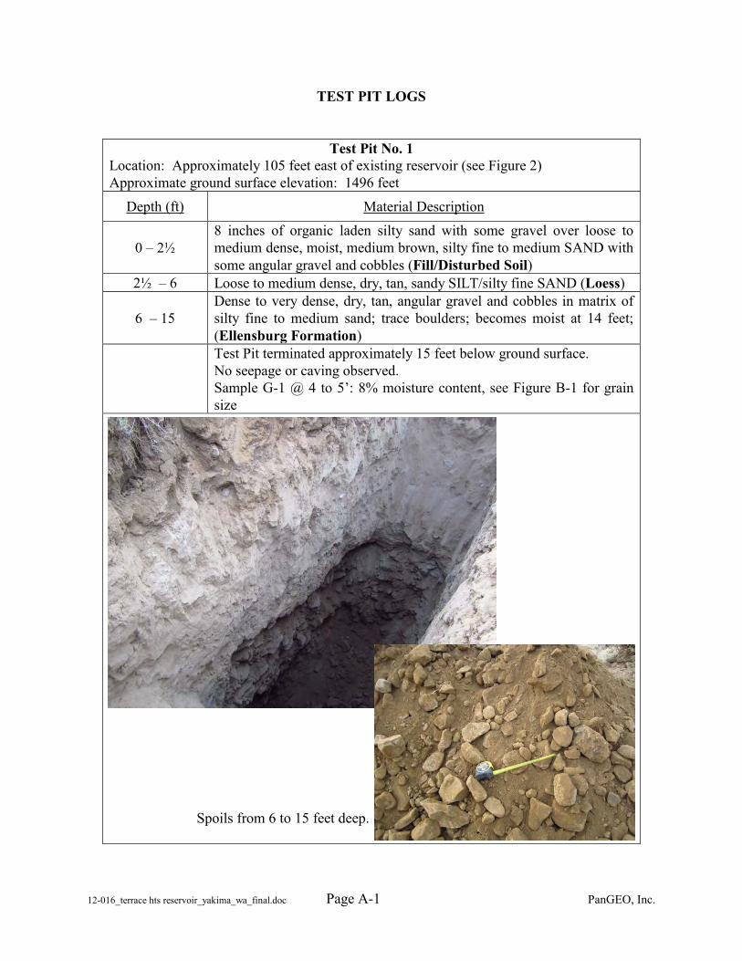
12-016_terrace hts reservoir_yakima_wa_final.doc Page A- PanGEO, Inc. 1
TEST PIT LOGS
Test Pit No. 1 Location: Approximately 105 feet east of existing reservoir (see Figure 2) Approximate ground surface elevation: 1496 feet
Depth (ft) Material Description
0 – 2½ 8 inches of organic laden silty sand with some gravel over loose to medium dense, moist, medium brown, silty fine to medium SAND with some angular gravel and cobbles (Fill/Disturbed Soil)
2½ – 6 Loose to medium dense, dry, tan, sandy SILT/silty fine SAND (Loess)
6 – 15 Dense to very dense, dry, tan, angular gravel and cobbles in matrix of silty fine to medium sand; trace boulders; becomes moist at 14 feet; (Ellensburg Formation)
Test Pit terminated approximately 15 feet below ground surface. No seepage or caving observed. Sample G-1 @ 4 to 5’: 8% moisture content, see Figure B-1 for grain size
Spoils from 6 to 15 feet deep.
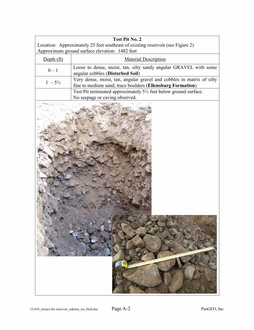
12-016_terrace hts reservoir_yakima_wa_final.doc Page A- PanGEO, Inc. 2
Test Pit No. 2
Location: Approximately 25 feet southeast of existing reservoir (see Figure 2) Approximate ground surface elevation: 1482 feet
Depth (ft) Material Description
0 – 1 Loose to dense, moist, tan, silty sandy angular GRAVEL with some angular cobbles (Disturbed Soil)
1 – 5½ Very dense, moist, tan, angular gravel and cobbles in matrix of silty fine to medium sand; trace boulders (Ellensburg Formation)
Test Pit terminated approximately 5½ feet below ground surface. No seepage or caving observed.
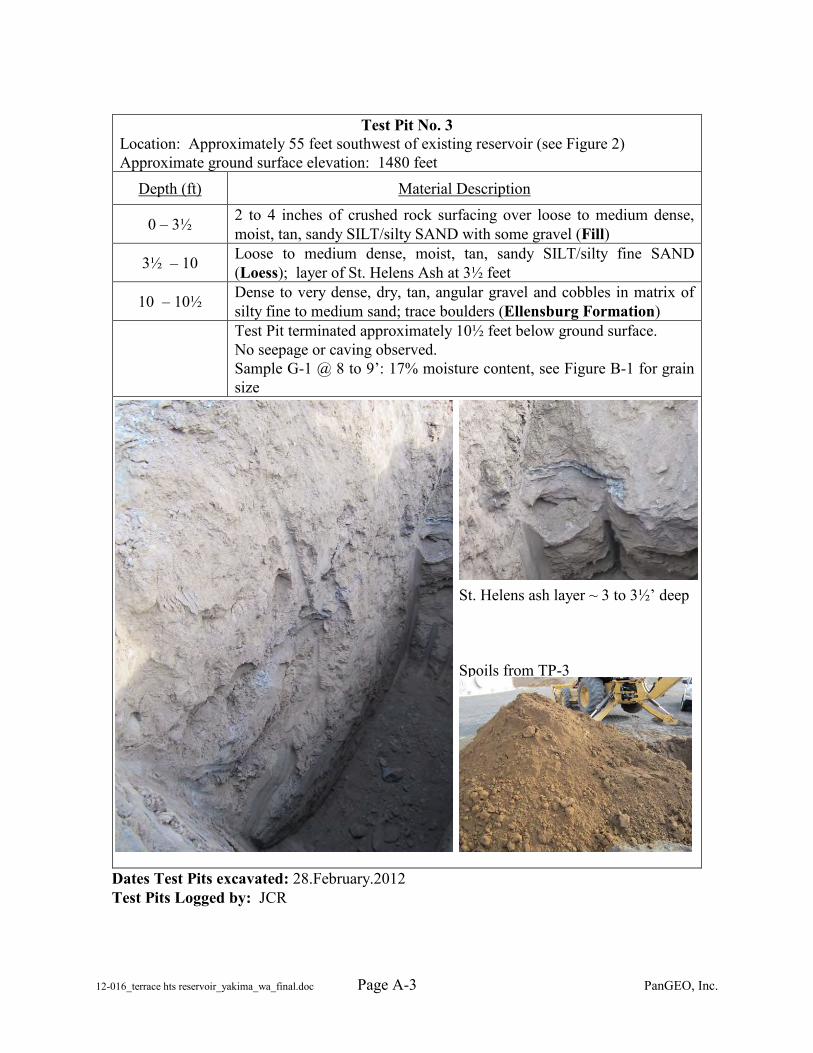
12-016_terrace hts reservoir_yakima_wa_final.doc Page A- PanGEO, Inc. 3
Test Pit No. 3
Location: Approximately 55 feet southwest of existing reservoir (see Figure 2) Approximate ground surface elevation: 1480 feet
Depth (ft) Material Description
0 – 3½ 2 to 4 inches of crushed rock surfacing over loose to medium dense, moist, tan, sandy SILT/silty SAND with some gravel (Fill)
3½ – 10 Loose to medium dense, moist, tan, sandy SILT/silty fine SAND (Loess); layer of St. Helens Ash at 3½ feet
10 – 10½ Dense to very dense, dry, tan, angular gravel and cobbles in matrix of silty fine to medium sand; trace boulders (Ellensburg Formation)
Test Pit terminated approximately 10½ feet below ground surface. No seepage or caving observed. Sample G-1 @ 8 to 9’: 17% moisture content, see Figure B-1 for grain size
St. Helens ash layer ~ 3 to 3½’ deep Spoils from TP-3
Dates Test Pits excavated: 28.February.2012 Test Pits Logged by: JCR
12-016_terrace hts reservoir_yakima_wa_final.doc PanGEO, Inc.
APPENDIX B
LABORATORY TEST RESULTS
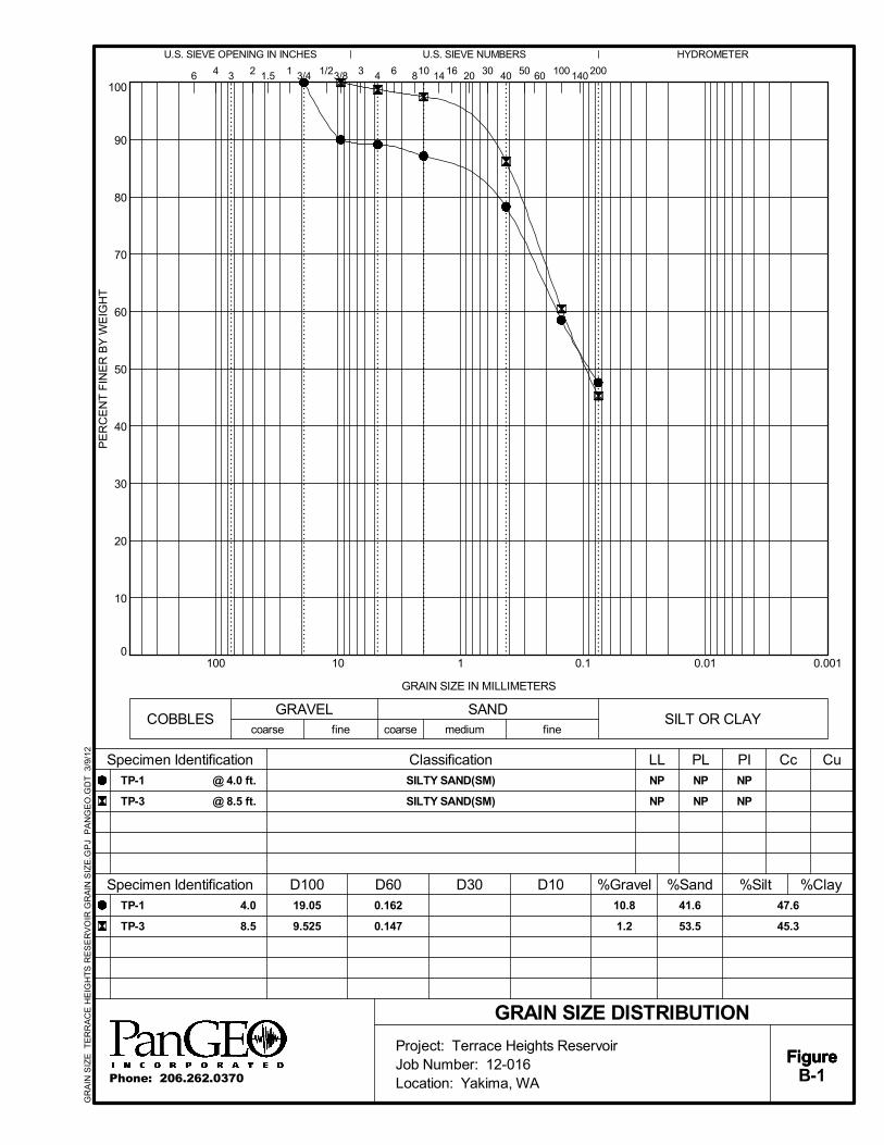
0
10
20
30
40
50
60
70
80
90
100
0.0010.010.1110100
Specimen Identification
1.5 16
D10
GRAIN SIZE DISTRIBUTION
fine
30
PI CcNP
NP
NP
NP
D100 D60 %Gravel41.6
53.5
10.8
1.2
coarse
%Sand
6 2
coarse
47.6
45.3
SILT OR CLAY
4
Specimen Identification
1/23/81 404
GRAVEL
%Clay
100 1403
D30
10 14
NP
NP
50
HYDROMETERU.S. SIEVE OPENING IN INCHES
Figure
U.S. SIEVE NUMBERS
Figure
200
4.0
8.5
TP-1
TP-3
CuLL
3 60
19.05
9.525
@ 4.0 ft.
@ 8.5 ft.
PE
RC
EN
T F
INE
R B
Y W
EIG
HT
Classification
GRAIN SIZE IN MILLIMETERS
3/4
%Silt
medium
6 8
TP-1
TP-3
COBBLESSAND
fine
PL
20
0.162
0.147
FigureB-1
SILTY SAND(SM)
SILTY SAND(SM)
Project: Terrace Heights ReservoirJob Number: 12-016Location: Yakima, WAPhone: 206.262.0370
GR
AIN
SIZ
E T
ER
RA
CE
HE
IGH
TS
RE
SE
RV
OIR
GR
AIN
SIZ
E.G
PJ
PA
NG
EO
.GD
T 3
/9/1
2
APPENDIX C
PREVIOUS EXPLORATIONS
TP-1 to TP-4 (HWA, 1993)
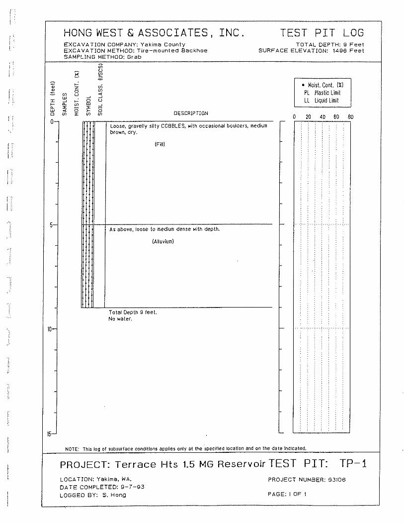
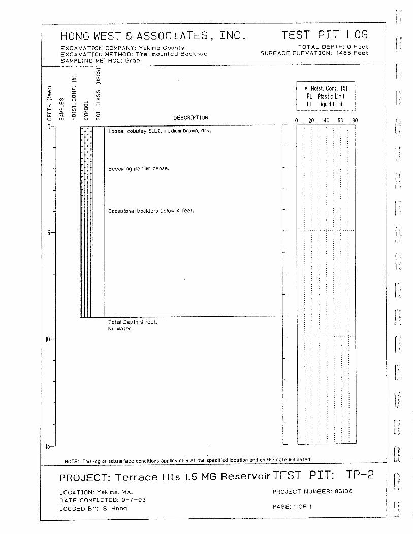
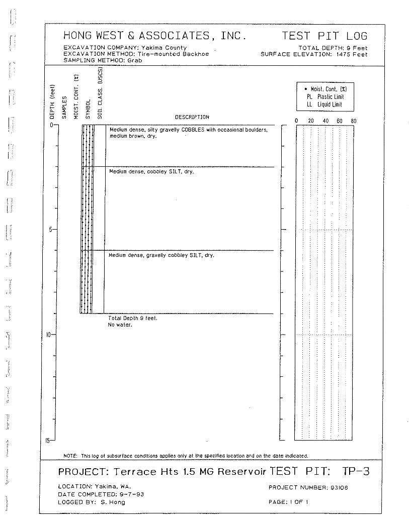
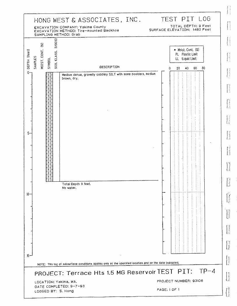

APPENDIX E PAINT TESTING RESULTS
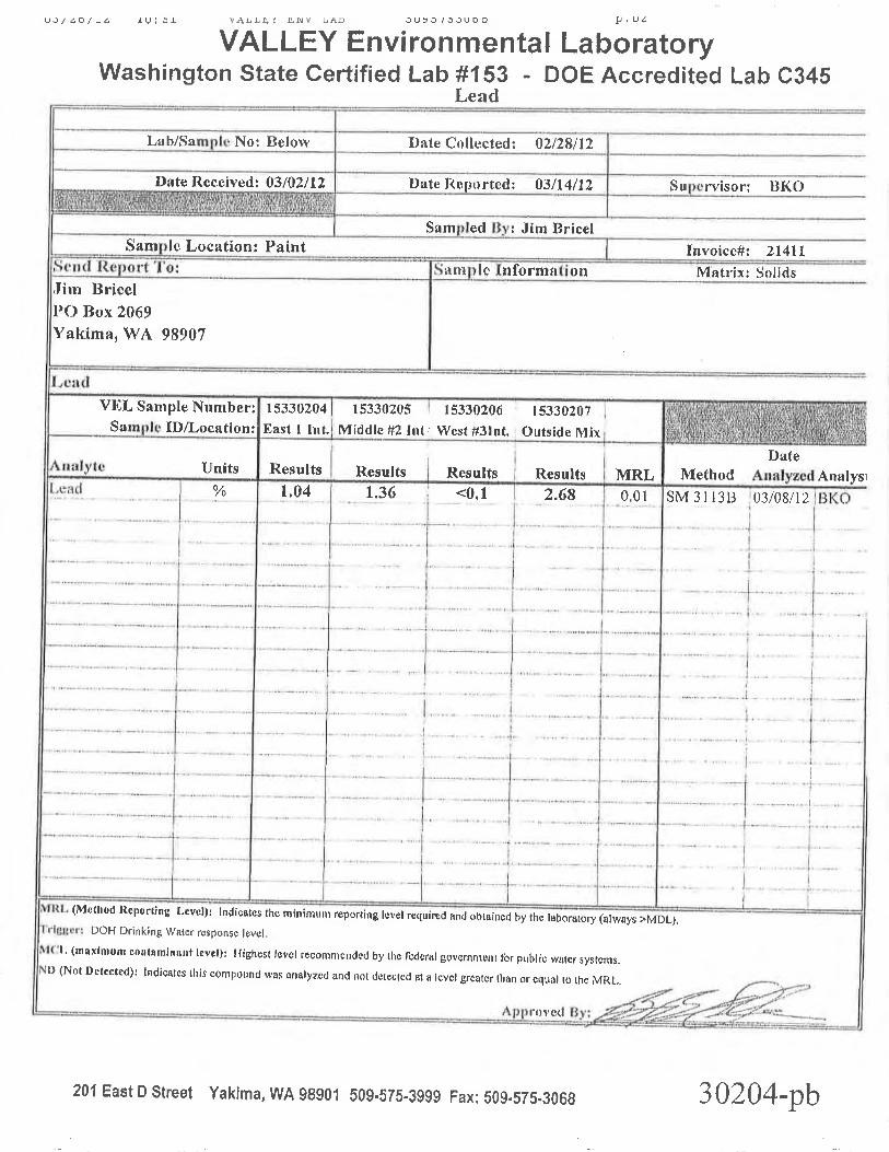

APPENDIX F RESERVOIR NO. 1 SHOP
DRAWINGS
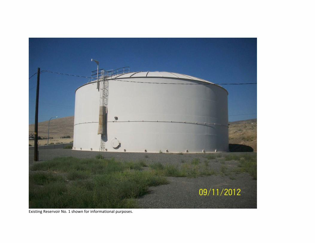
Existing Reservoir No. 1 shown for informational purposes.
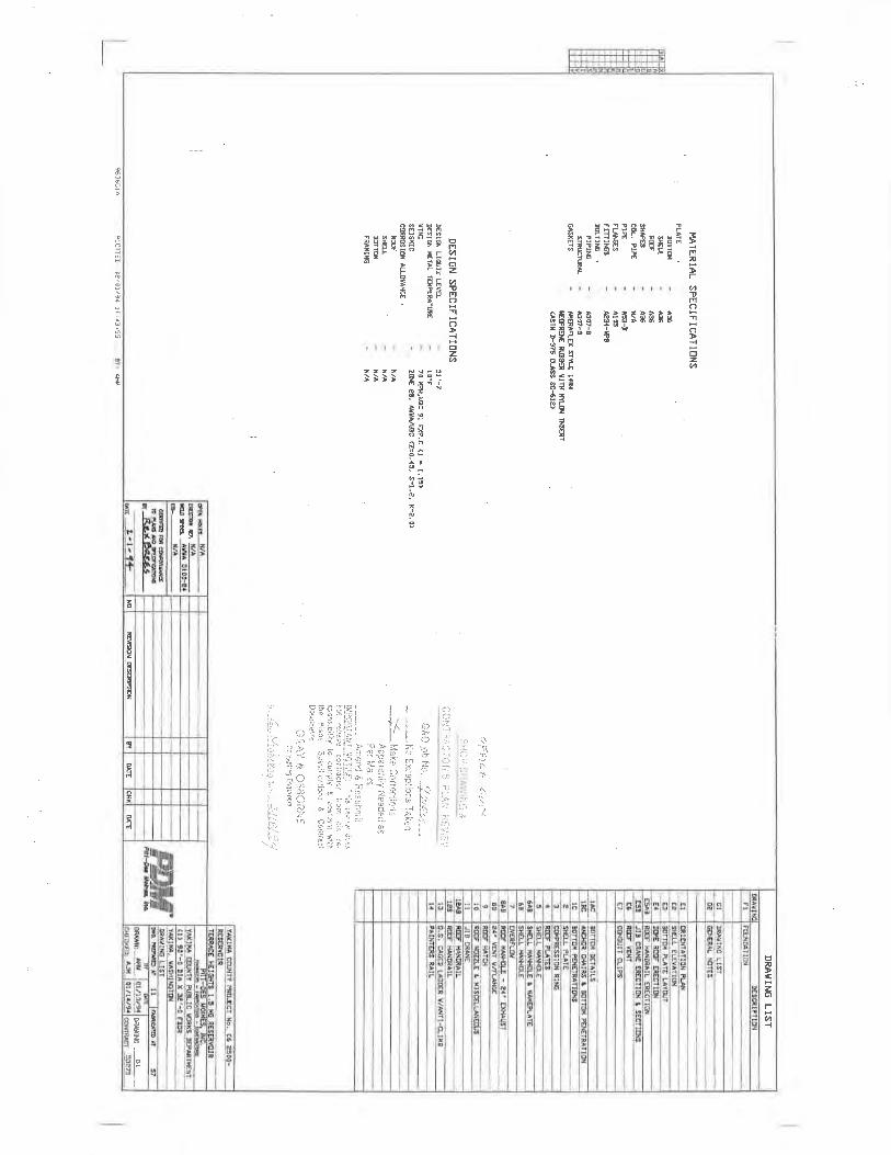
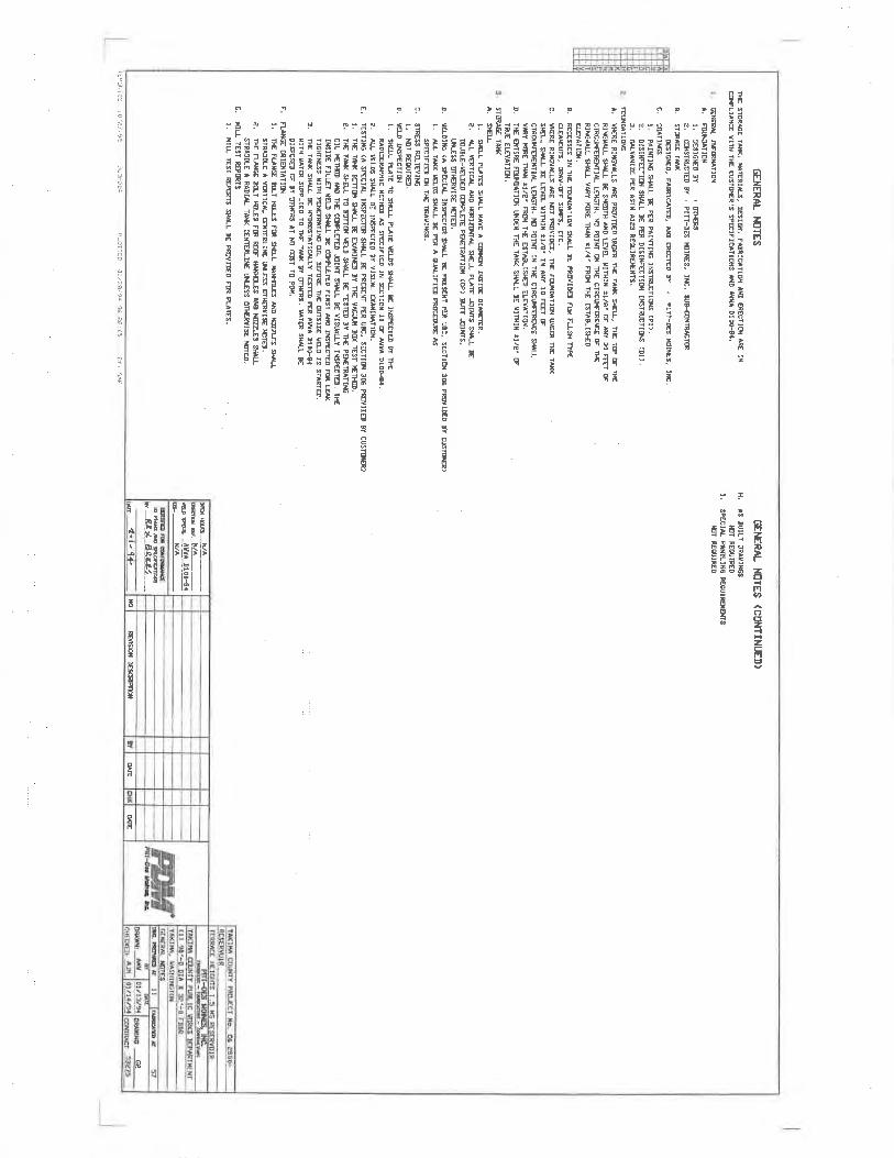
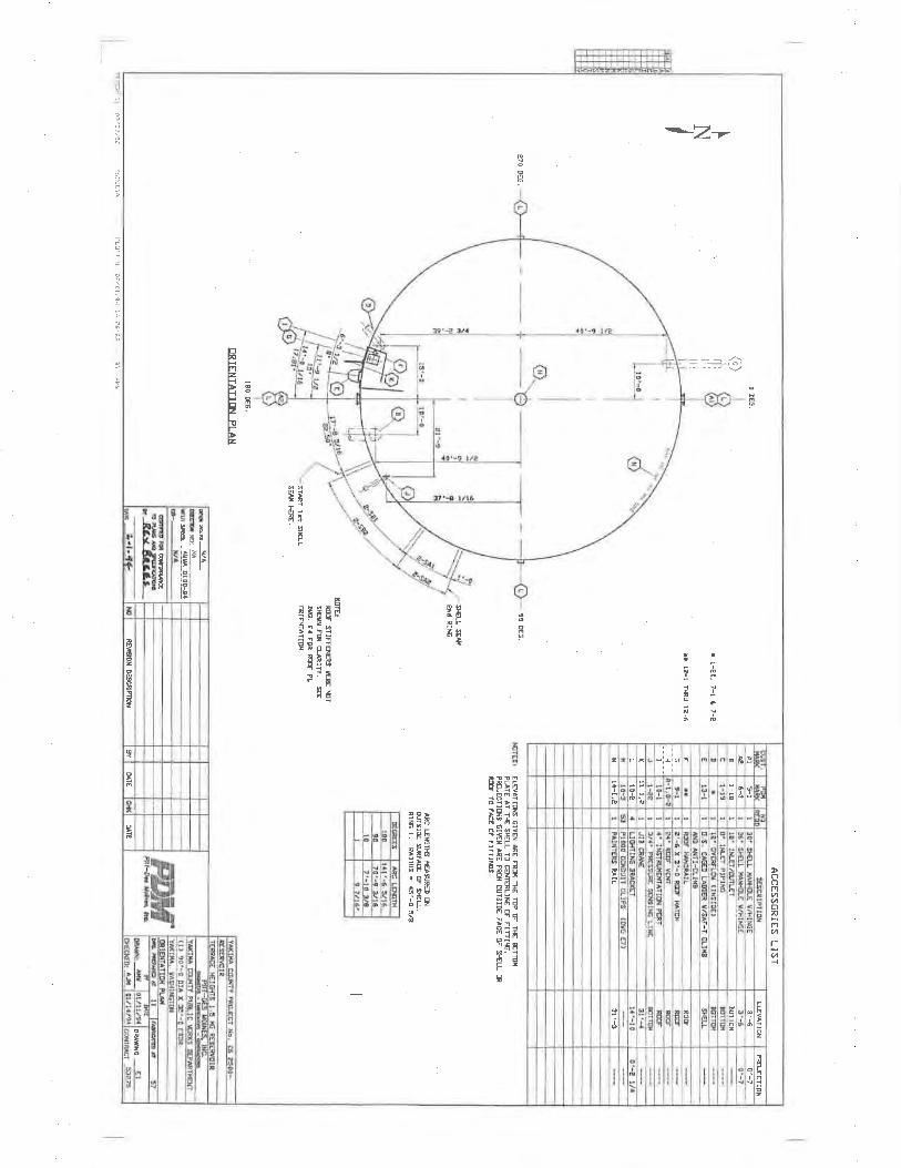
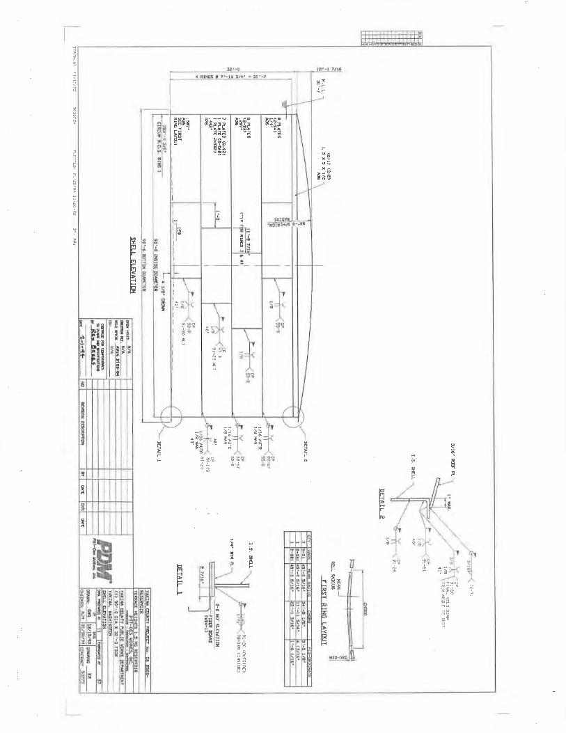
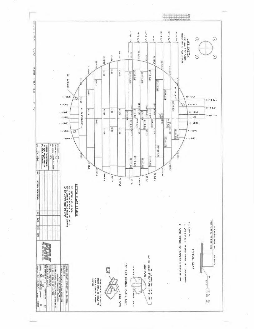
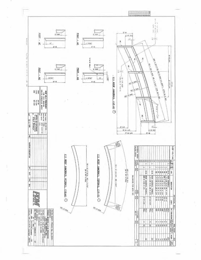
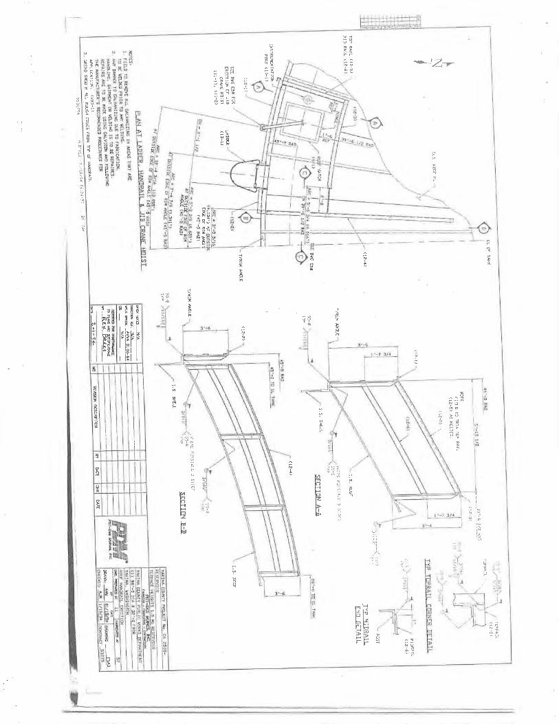
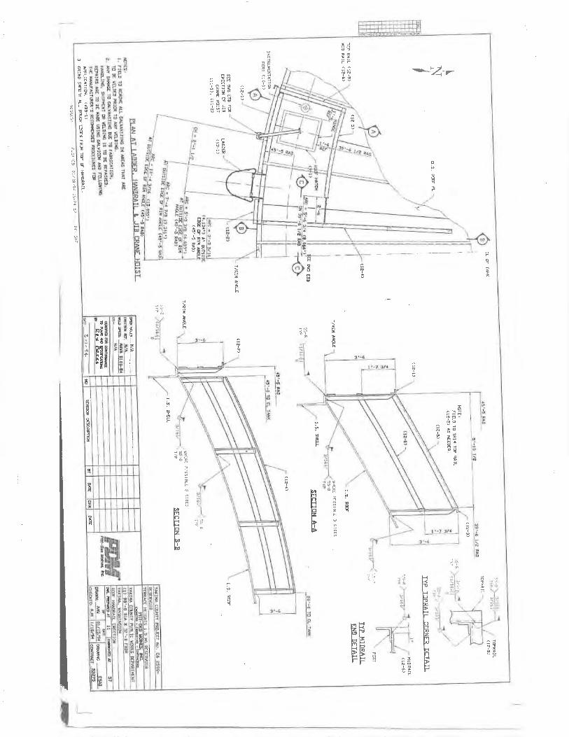
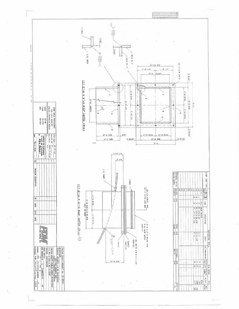
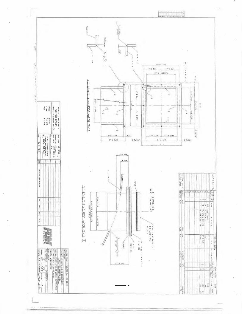

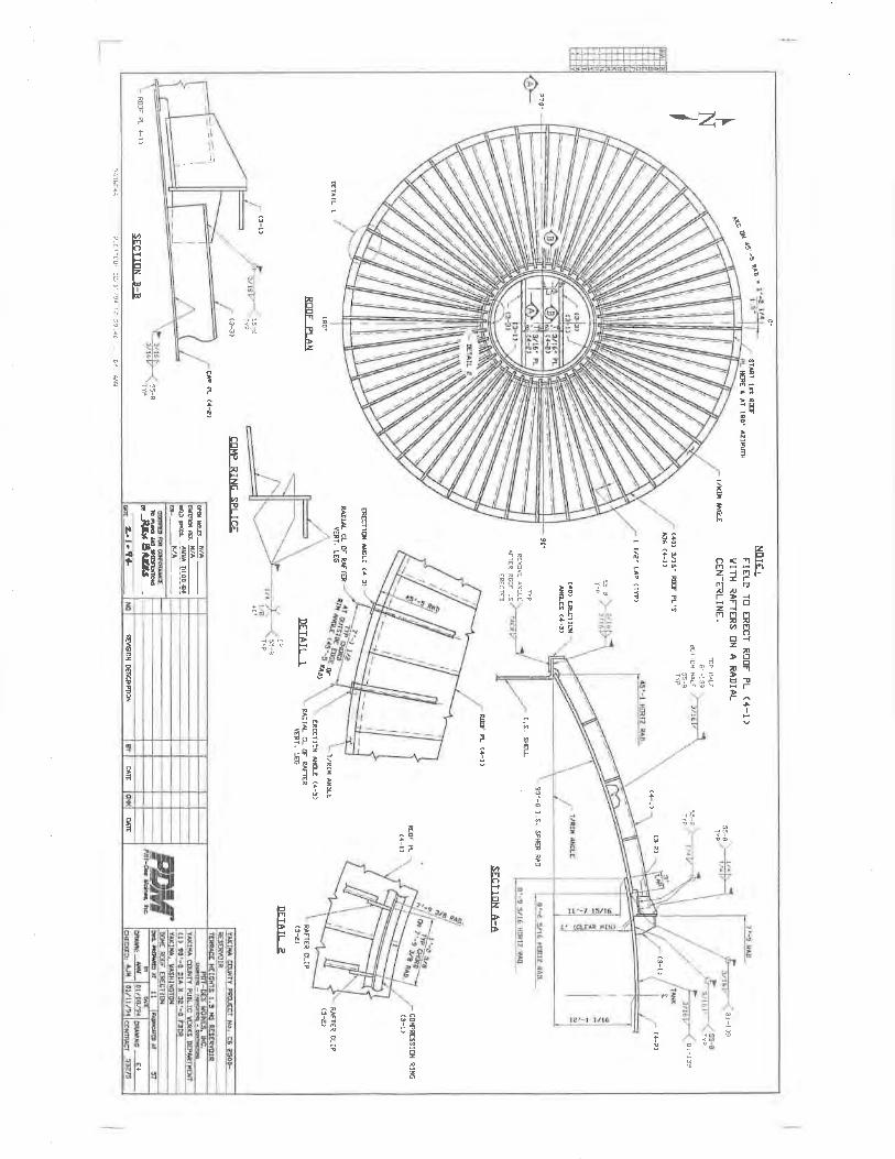
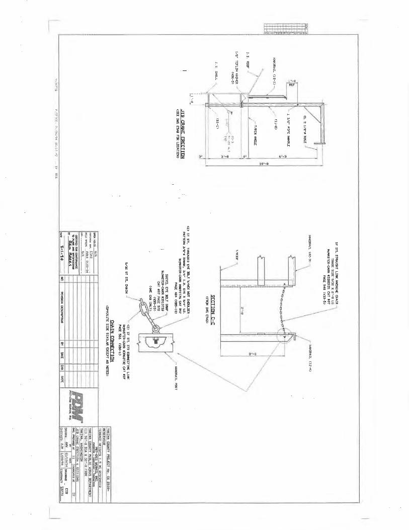
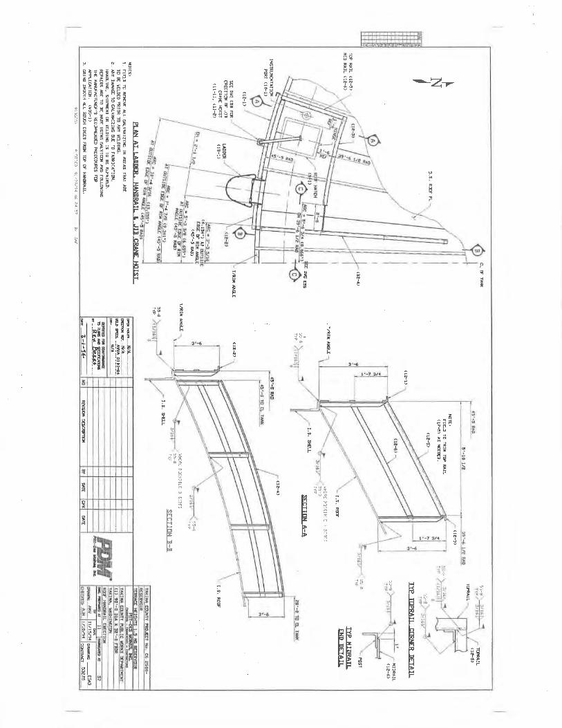
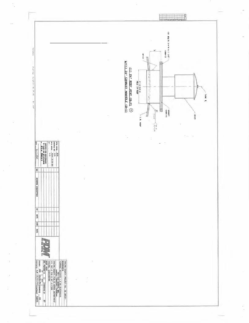
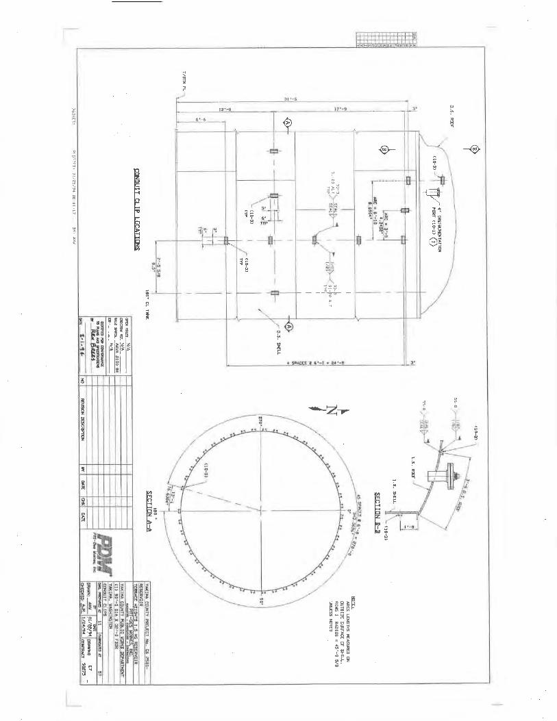
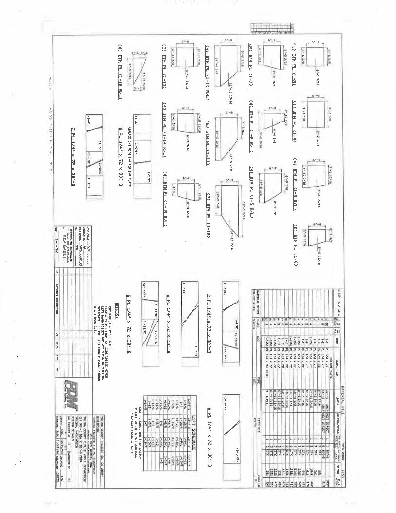
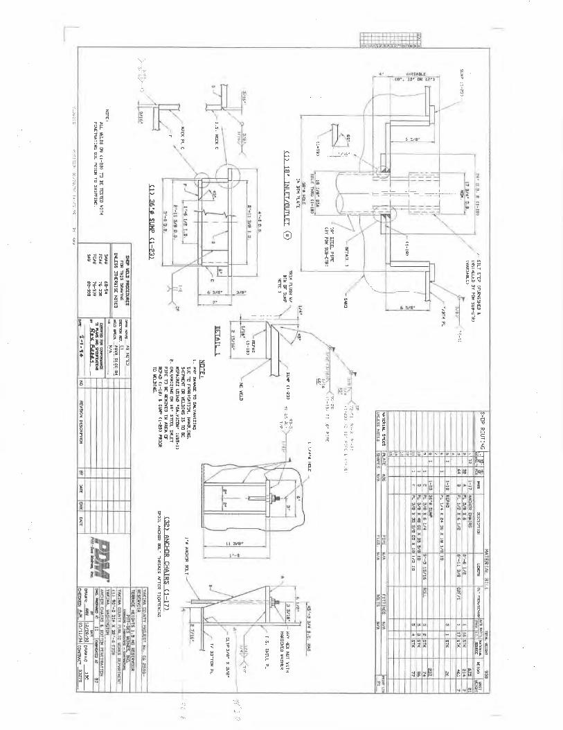
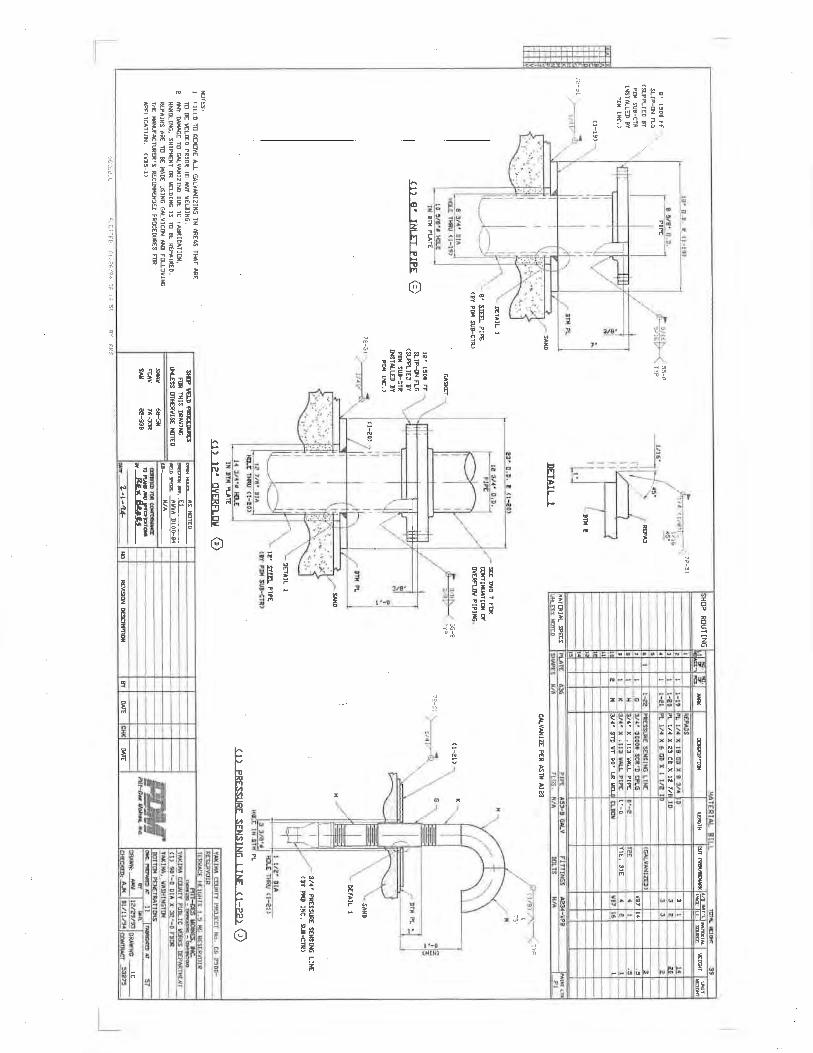
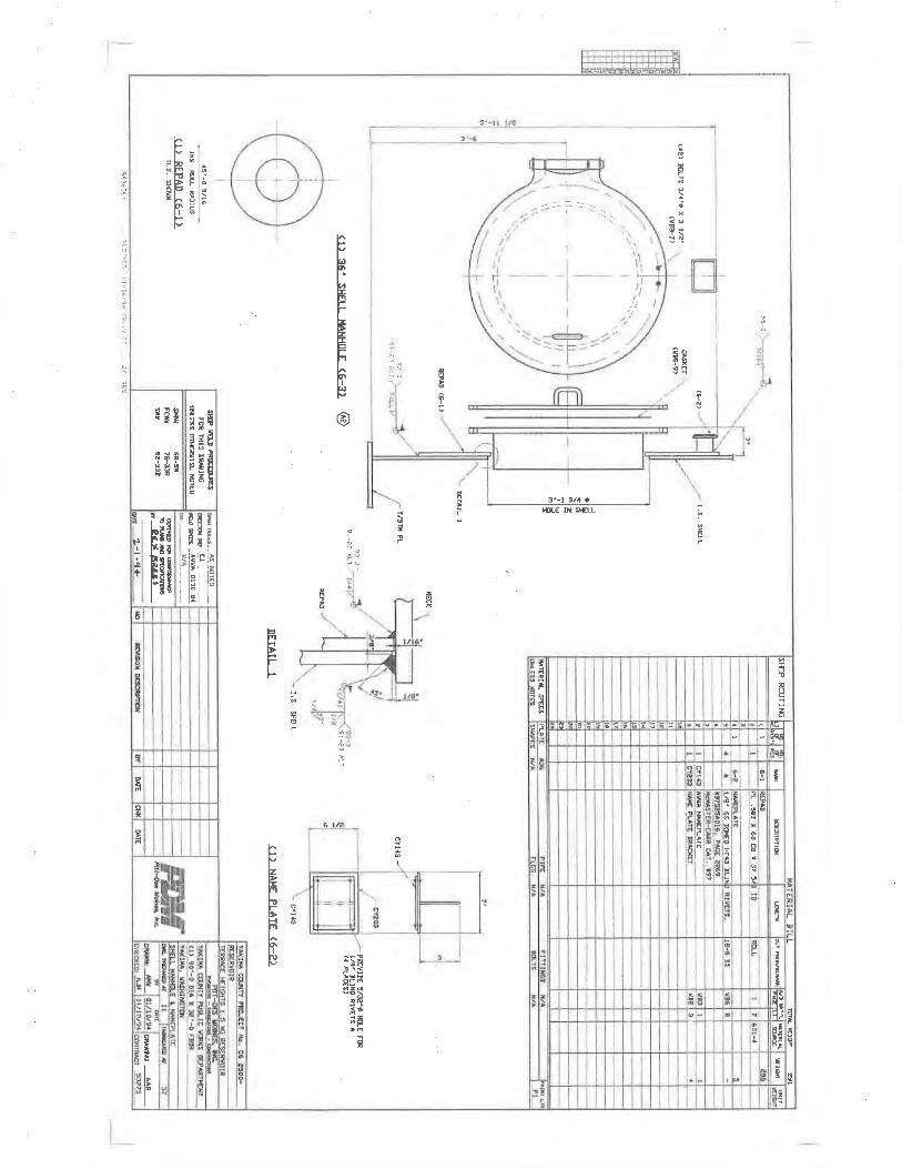
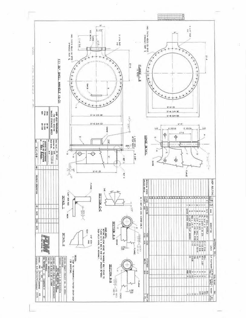
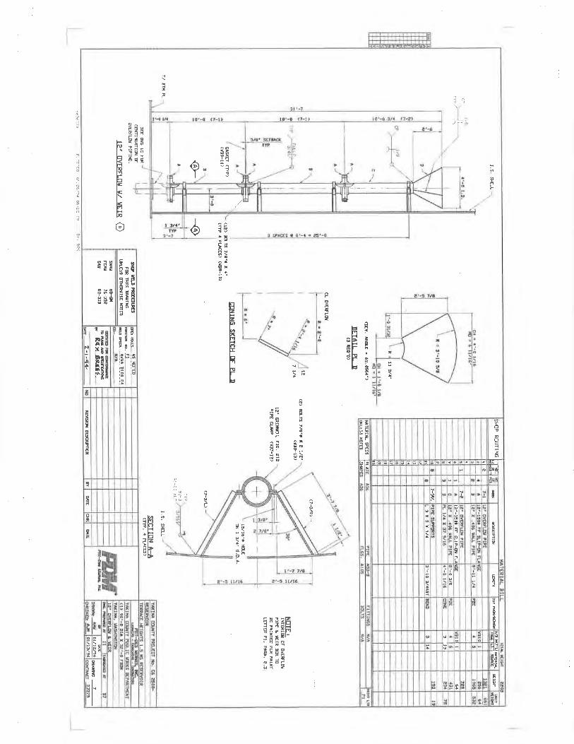
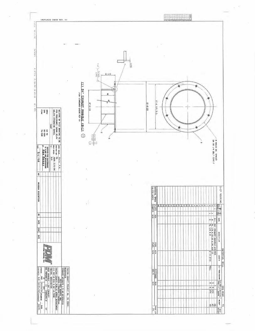
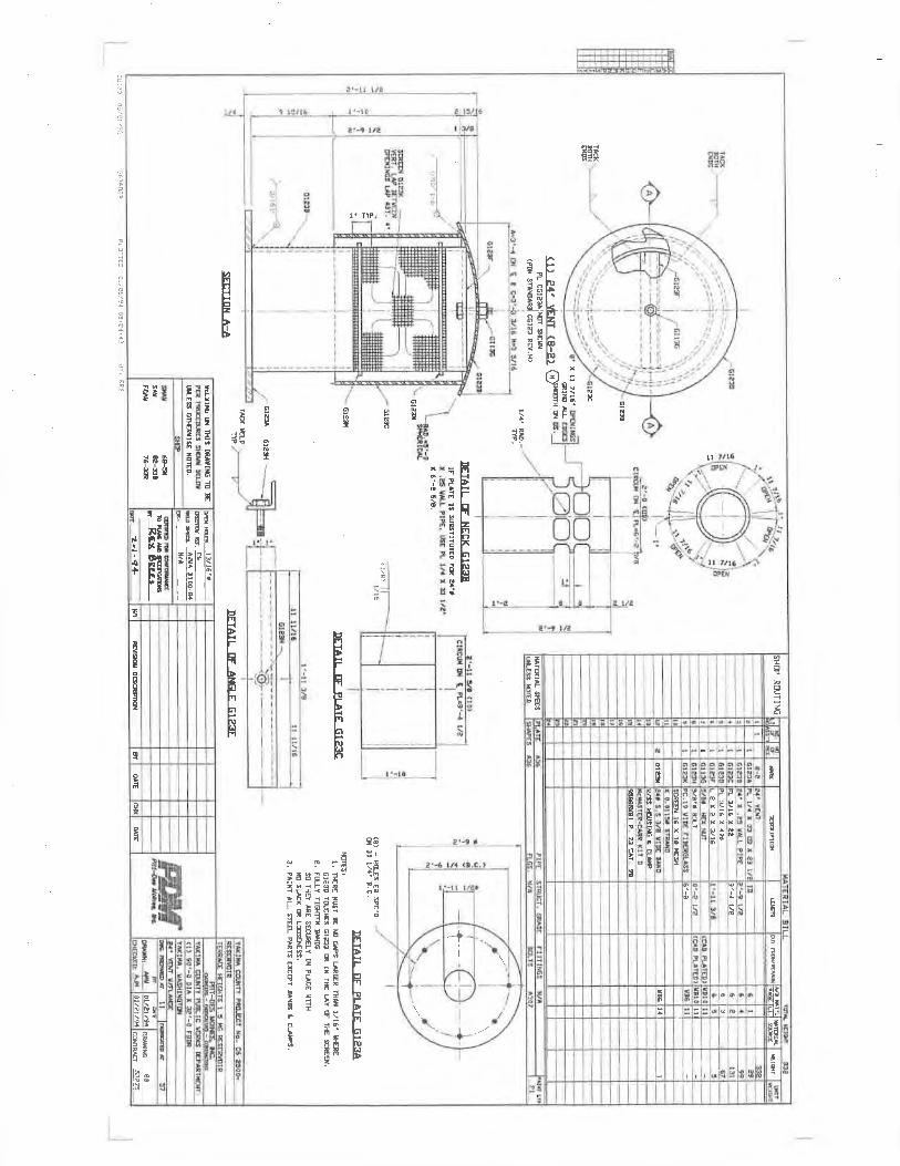
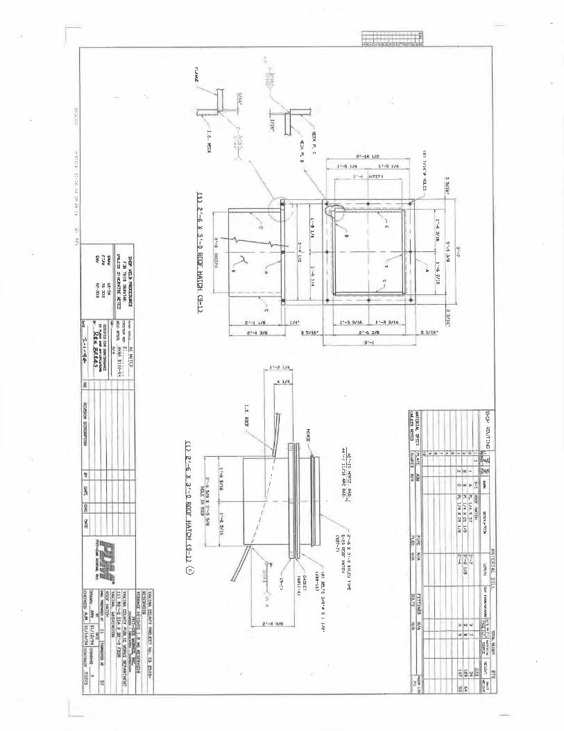
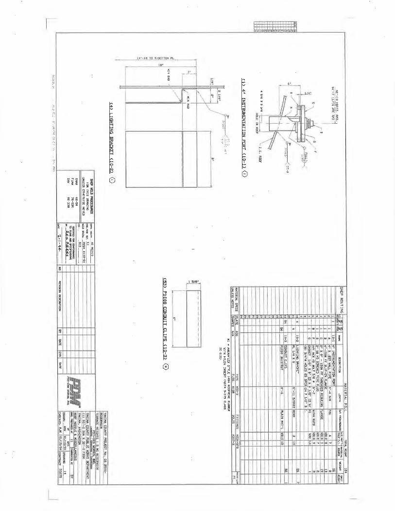
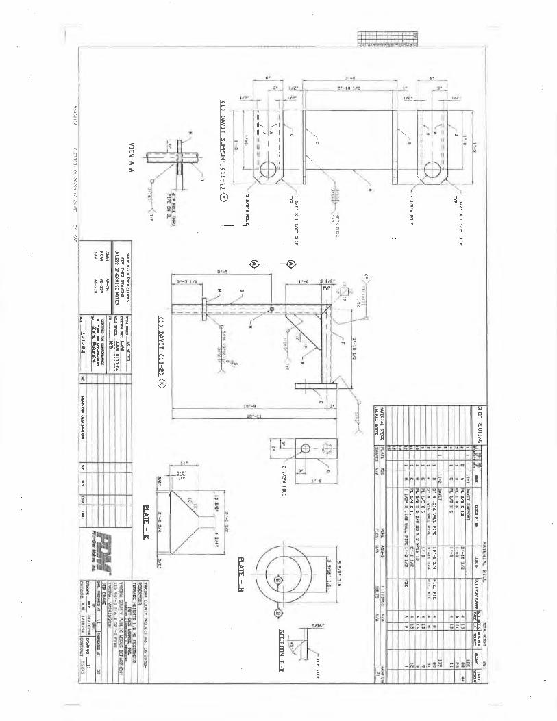
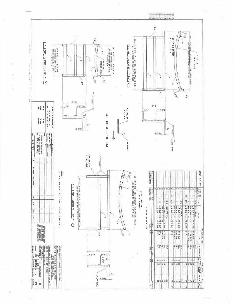
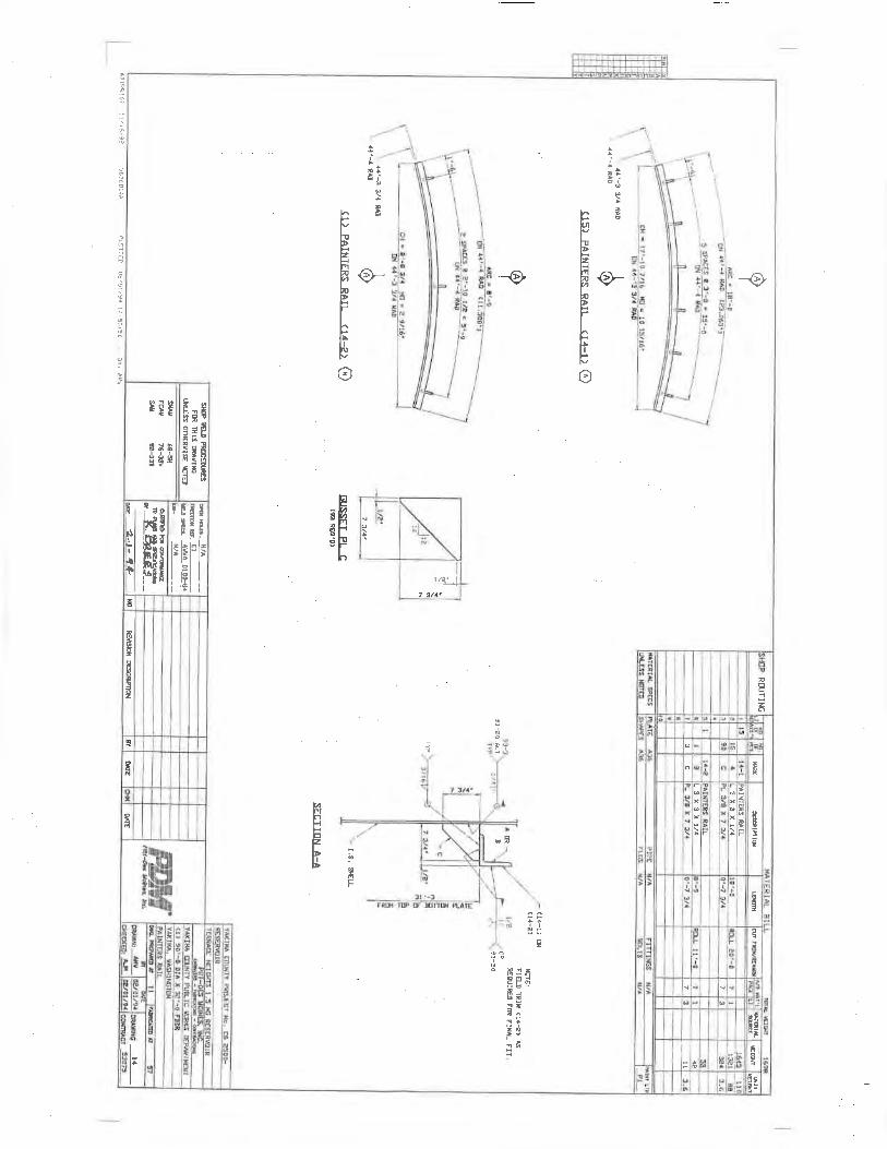
WASHINGTON
Kevin Bouchey
Utilities Manager
Joe Stump, P.E.
YAKIMA COUNTY
Director of Public Services
Vern M. Redifer, P.E.
YAKIMA, WASHINGTON 98901 (509) 453-4833
CONSULTING ENGINEERS
107 SOUTH THIRD STREET
Michael D. Leita
COUNTY OFFICIALS
YAKIMA COUNTY
TERRACE HEIGHTS WATER SYSTEM
County Commissioners
Rand Elliot - Chair
Assistant Director of Public Services
Donald Gatchalian, P.E.
RESERVOIR NO. 4 PROJECT
U6 3424
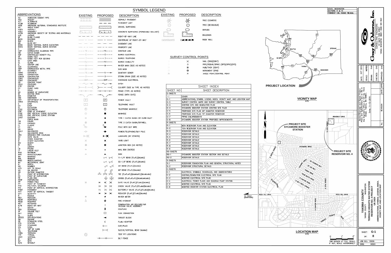
PROJECT LOCATION
LOCATION MAP
VICINITY MAP
DESCRIPTIONPROPOSEDEXISTING
SYMBOL LEGEND
EXISTING PROPOSED DESCRIPTION
ABBREVIATIONS
G-1
AB
BR
EV
IA
TIO
NS
, S
YM
BO
L L
EG
EN
D, IN
DE
X,
VIC
IN
IT
Y M
AP
, A
ND
L
OC
AT
IO
N M
AP
PROJECT SITE
RESERVOIR NO. 4
SURVEY CONTROL POINTS
8
YA
KIM
A C
OU
NT
Y
TE
RR
AC
E H
EIG
HT
S W
AT
ER
S
YS
TE
M
RE
SE
RV
OIR
N
O. 4 P
RO
JE
CT
U6 3424
PROJECT SITE
SYCAMORE BOOSTER
STATION
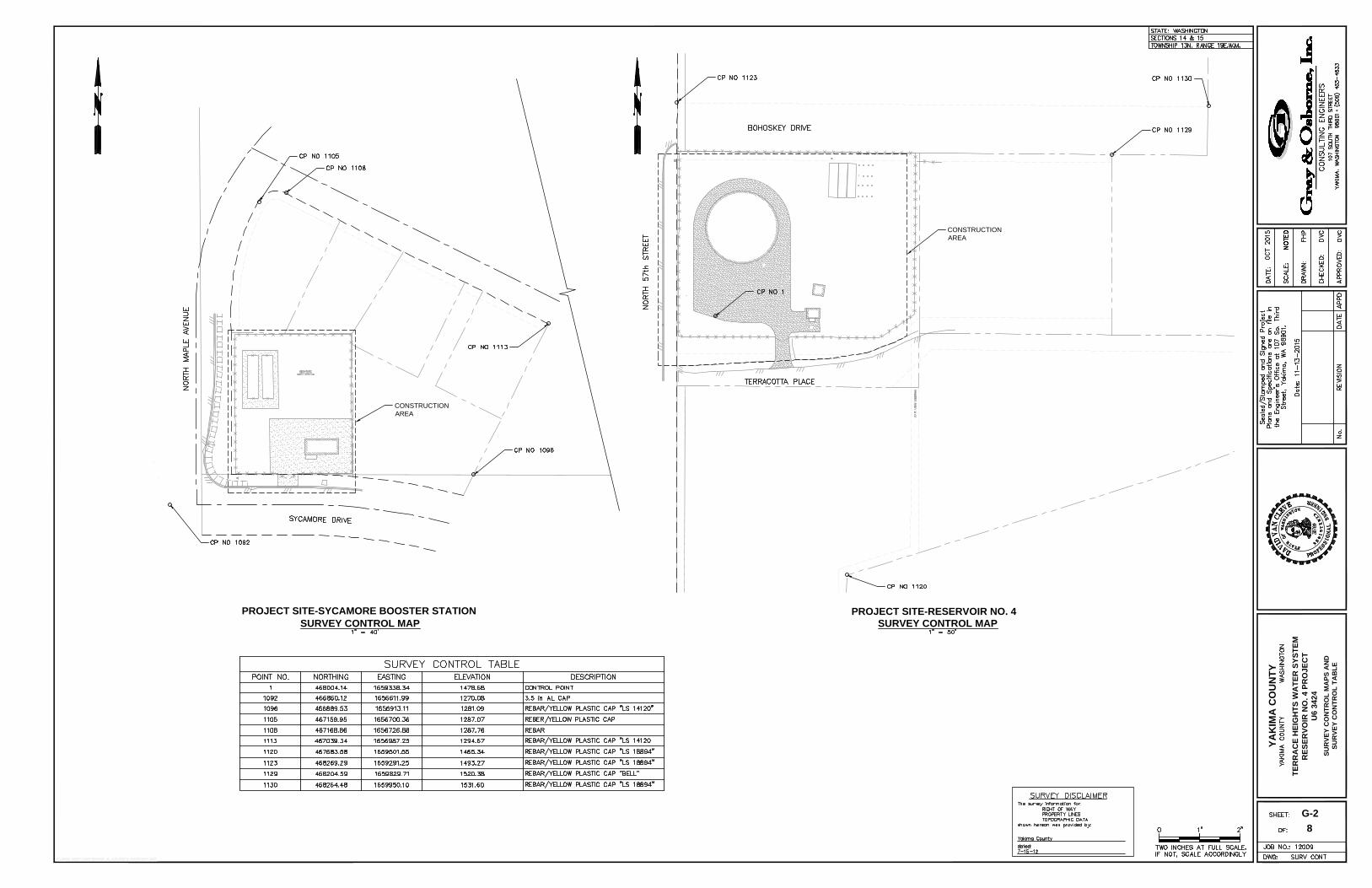
G-2
SU
RV
EY
C
ON
TR
OL
M
AP
S A
ND
SU
RV
EY
C
ON
TR
OL
T
AB
LE
8
YA
KIM
A C
OU
NT
Y
TE
RR
AC
E H
EIG
HT
S W
AT
ER
S
YS
TE
M
RE
SE
RV
OIR
N
O. 4 P
RO
JE
CT
U6 3424
SURVEY CONTROL MAPSURVEY CONTROL MAP
PROJECT SITE-SYCAMORE BOOSTER STATIONPROJECT SITE-RESERVOIR NO. 4
CONSTRUCTION
AREA
CONSTRUCTION
AREA
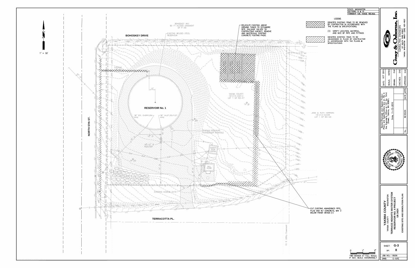
8
YA
KIM
A C
OU
NT
Y
TE
RR
AC
E H
EIG
HT
S W
AT
ER
S
YS
TE
M
RE
SE
RV
OIR
N
O. 4 P
RO
JE
CT
U6 3424
G-3
EX
IS
TIN
G S
IT
E A
ND
D
EM
OL
IT
IO
N P
LA
N
BOHOSKEY DRIVE
NO
RT
H 57th
S
T.
TERRACOTTA PL.
RESERVOIR No. 1
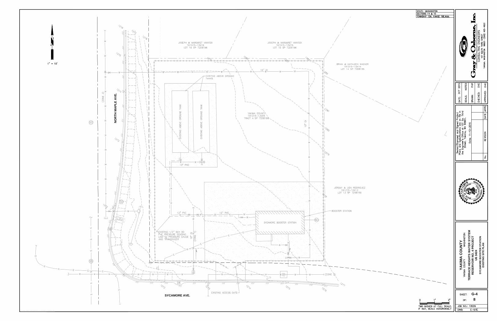
8
YA
KIM
A C
OU
NT
Y
TE
RR
AC
E H
EIG
HT
S W
AT
ER
S
YS
TE
M
RE
SE
RV
OIR
N
O. 4 P
RO
JE
CT
U6 3424
G-4
SY
CA
MO
RE
B
OO
ST
ER
S
TA
TIO
N
EX
IS
TIN
G S
IT
E P
LA
N
NO
RT
H M
AP
LE
A
VE
.
SYCAMORE AVE.
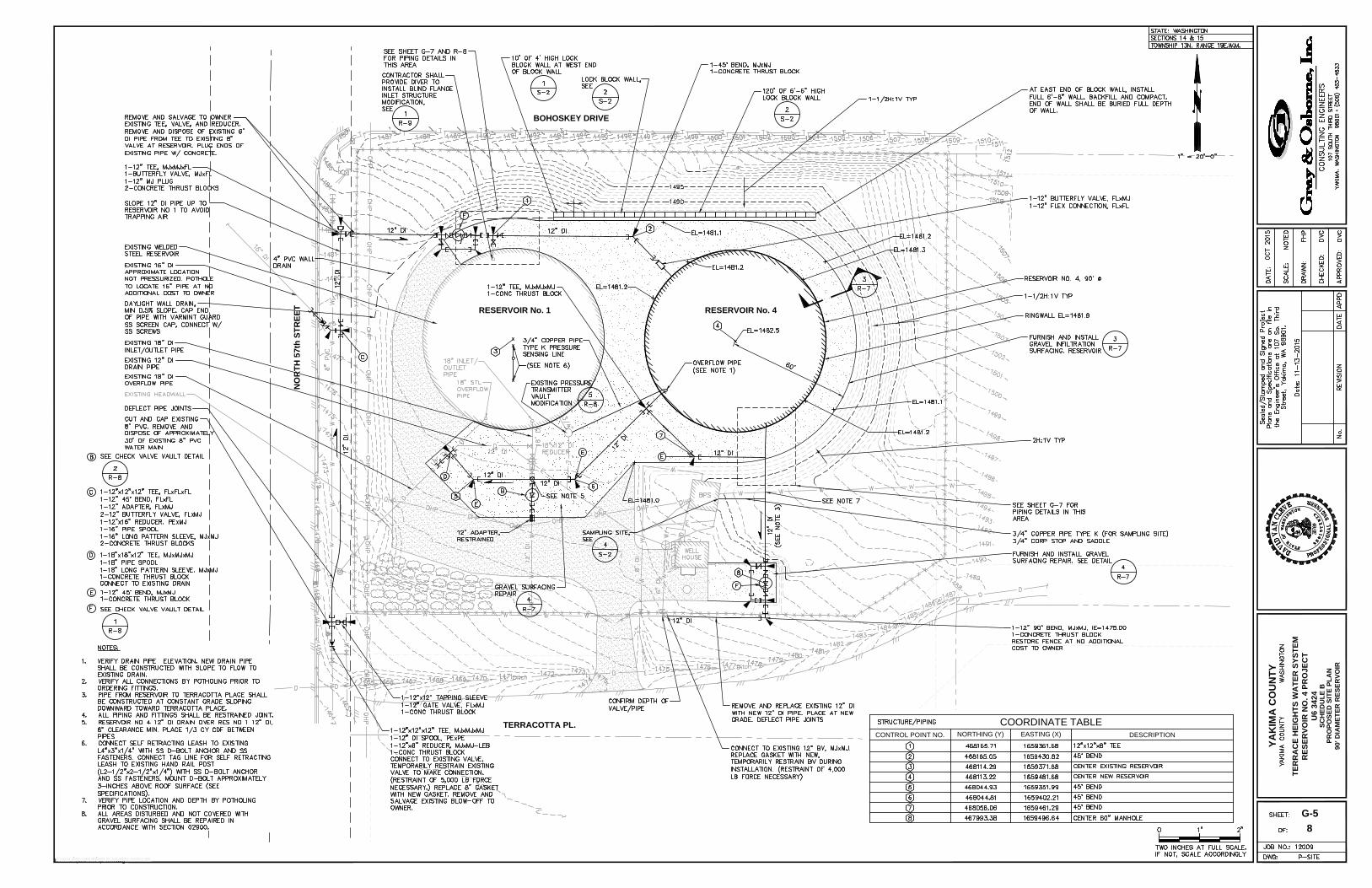
8
YA
KIM
A C
OU
NT
Y
TE
RR
AC
E H
EIG
HT
S W
AT
ER
S
YS
TE
M
RE
SE
RV
OIR
N
O. 4 P
RO
JE
CT
U6 3424
G-5
SC
HE
DU
LE
B
BOHOSKEY DRIVE
NO
RT
H 57th
S
TR
EE
T
TERRACOTTA PL.
PR
OP
OS
ED
S
IT
E P
LA
N
90' D
IA
ME
TE
R R
ES
ER
VO
IR
COORDINATE TABLE
CONTROL POINT NO.
NORTHING (Y) EASTING (X)
DESCRIPTION
RESERVOIR No. 4RESERVOIR No. 1
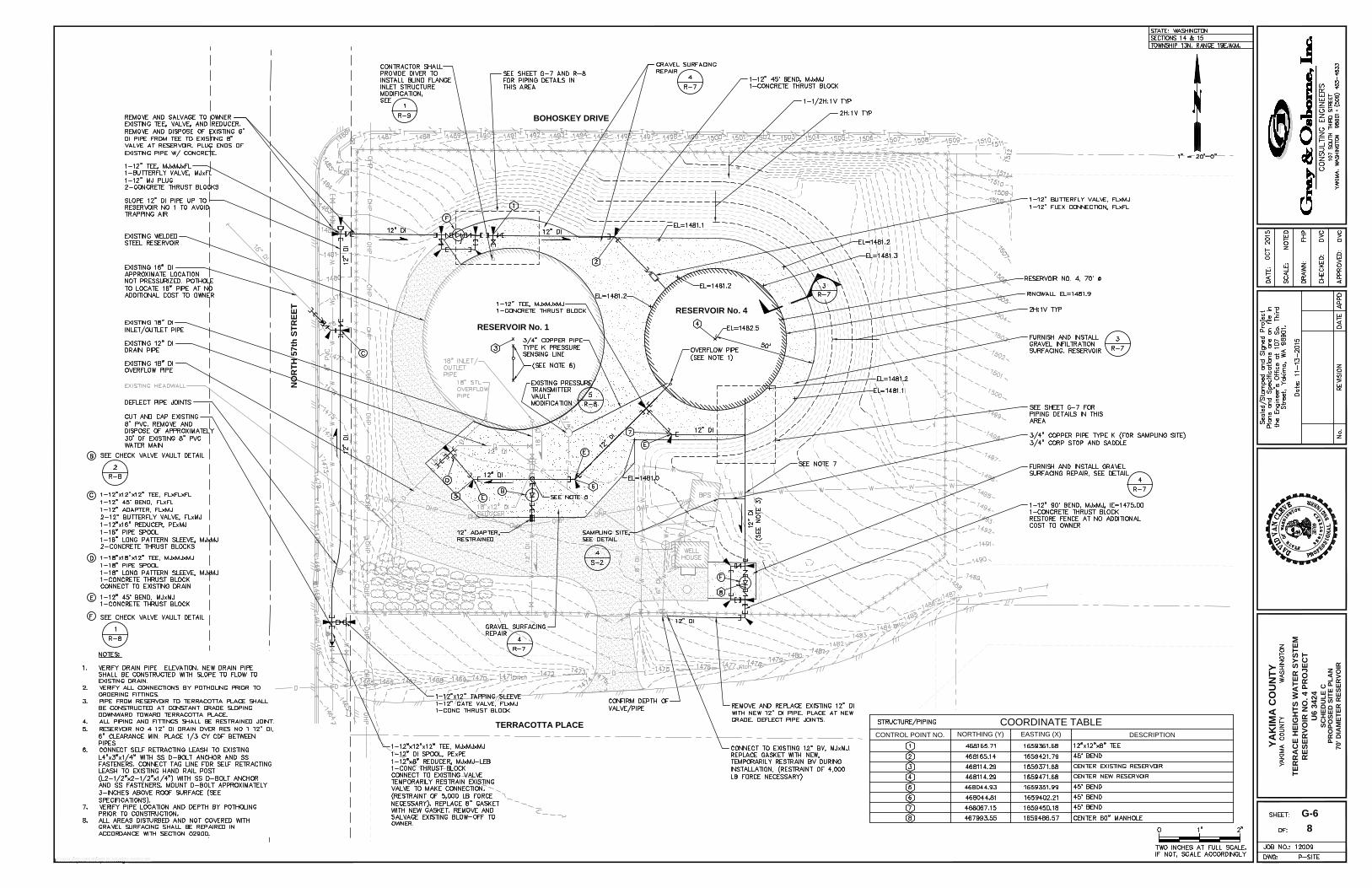
8
YA
KIM
A C
OU
NT
Y
TE
RR
AC
E H
EIG
HT
S W
AT
ER
S
YS
TE
M
RE
SE
RV
OIR
N
O. 4 P
RO
JE
CT
U6 3424
PR
OP
OS
ED
S
IT
E P
LA
N
70' D
IA
ME
TE
R R
ES
ER
VO
IR
G-6
COORDINATE TABLE
CONTROL POINT NO.
NORTHING (Y) EASTING (X)
DESCRIPTION
BOHOSKEY DRIVE
NO
RT
H 57th
S
TR
EE
T
TERRACOTTA PLACE SC
HE
DU
LE
C
RESERVOIR No. 1
RESERVOIR No. 4
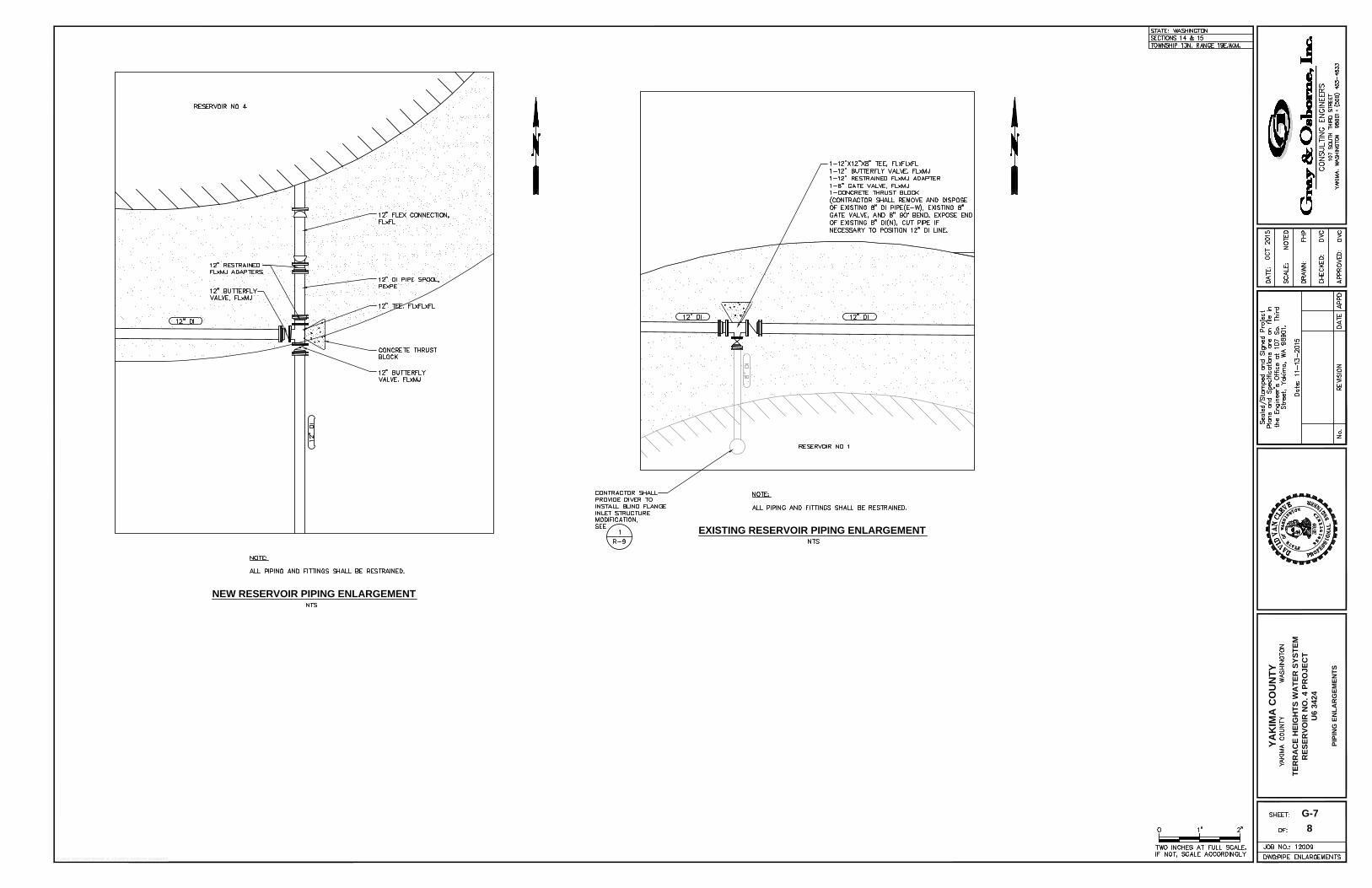
8
YA
KIM
A C
OU
NT
Y
TE
RR
AC
E H
EIG
HT
S W
AT
ER
S
YS
TE
M
RE
SE
RV
OIR
N
O. 4 P
RO
JE
CT
U6 3424
PIP
IN
G E
NL
AR
GE
ME
NT
S
G-7
NEW RESERVOIR PIPING ENLARGEMENT
EXISTING RESERVOIR PIPING ENLARGEMENT
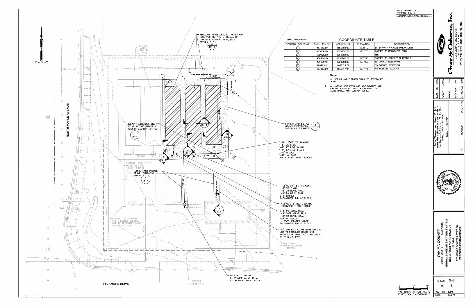
8
YA
KIM
A C
OU
NT
Y
TE
RR
AC
E H
EIG
HT
S W
AT
ER
S
YS
TE
M
RE
SE
RV
OIR
N
O. 4 P
RO
JE
CT
U6 3424
SY
CA
MO
RE
B
OO
ST
ER
S
TA
TIO
N
PR
OP
OS
ED
IM
PR
OV
EM
EN
TS
G-8
COORDINATE TABLE
CONTROL POINT NO.
NORTHING (Y) EASTING (X)
ELEVATION DESCRIPTION
SYCAMORE DRIVE
NO
RT
H M
AP
LE
A
VE
NU
E
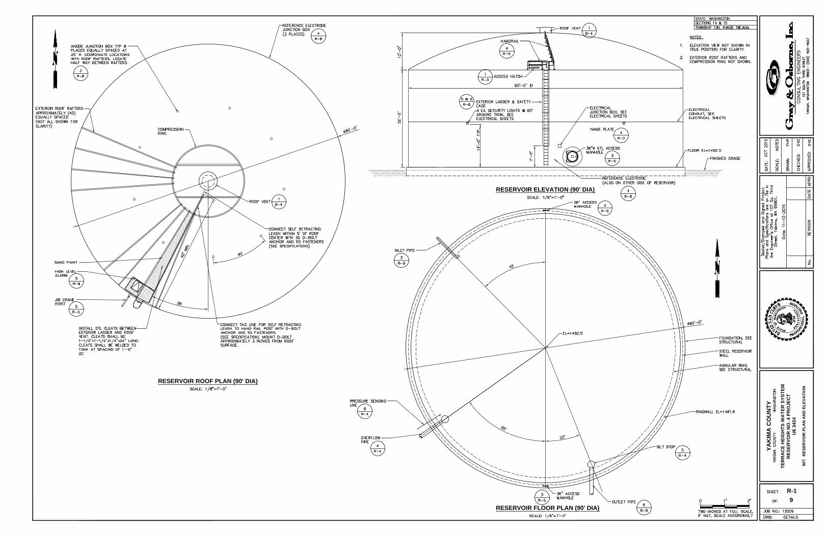
RESERVOIR ELEVATION (90' DIA)
RESERVOIR ROOF PLAN (90' DIA)
RESERVOIR FLOOR PLAN (90' DIA)
YA
KIM
A C
OU
NT
Y
TE
RR
AC
E H
EIG
HT
S W
AT
ER
S
YS
TE
M
RE
SE
RV
OIR
N
O. 4 P
RO
JE
CT
U6 3424
90'Ï RESERVOIR PLAN AND ELEVATION
R-1
9
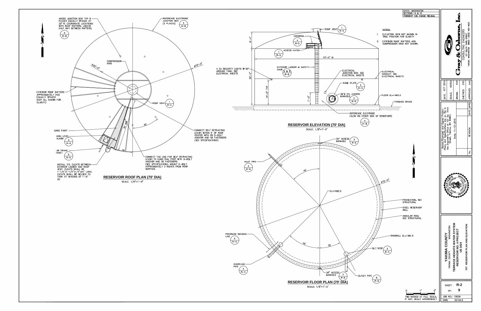
RESERVOIR ELEVATION (70' DIA)
RESERVOIR ROOF PLAN (70' DIA)
RESERVOIR FLOOR PLAN (70' DIA)
YA
KIM
A C
OU
NT
Y
TE
RR
AC
E H
EIG
HT
S W
AT
ER
S
YS
TE
M
RE
SE
RV
OIR
N
O. 4 P
RO
JE
CT
U6 3424
70'Ï RESERVOIR PLAN AND ELEVATION
R-2
9
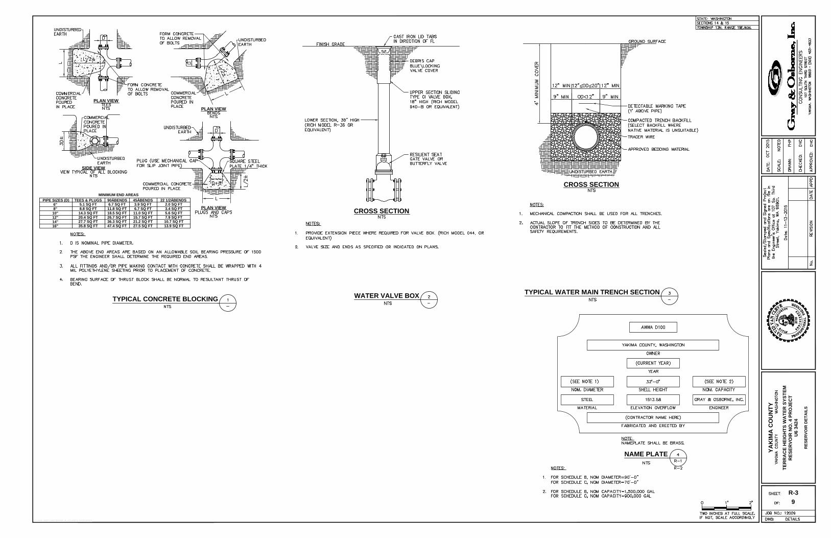
NAME PLATE
PLAN VIEW
PLAN VIEW
SIDE VIEW
PLAN VIEW
PIPE SIZES (D) TEES & PLUGS 90Á BENDS 45Á BENDS 22 1/2Á BENDS
2.0 SQ FT5.1 SQ FT6" 6.7 SQ FT 3.9 SQ FT
3.4 SQ FT8.8 SQ FT8" 11.8 SQ FT 6.7 SQ FT
5.6 SQ FT14.3 SQ FT10" 18.5 SQ FT 11.0 SQ FT
7.9 SQ FT20.4 SQ FT12" 26.7 SQ FT 15.7 SQ FT
10.7 SQ FT27.7 SQ FT14"
36.3 SQ FT 21.2 SQ FT
13.9 SQ FT35.8 SQ FT16" 47.4 SQ FT 27.5 SQ FT
MINIMUM END AREAS
CROSS SECTION
CROSS SECTION
TYPICAL CONCRETE BLOCKING
WATER VALVE BOX
TYPICAL WATER MAIN TRENCH SECTION
YA
KIM
A C
OU
NT
Y
TE
RR
AC
E H
EIG
HT
S W
AT
ER
S
YS
TE
M
RE
SE
RV
OIR
N
O. 4 P
RO
JE
CT
U6 3424
RE
SE
RV
OIR
D
ET
AIL
S
R-3
9
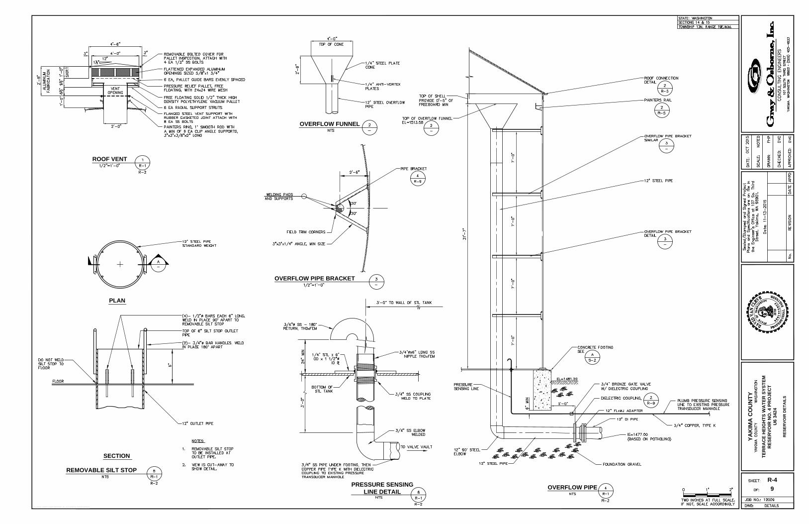
ROOF VENT
OVERFLOW PIPE BRACKET
OVERFLOW PIPE
OVERFLOW FUNNEL
PRESSURE SENSING
LINE DETAIL
REMOVABLE SILT STOP
SECTION
PLAN
YA
KIM
A C
OU
NT
Y
TE
RR
AC
E H
EIG
HT
S W
AT
ER
S
YS
TE
M
RE
SE
RV
OIR
N
O. 4 P
RO
JE
CT
U6 3424
RE
SE
RV
OIR
D
ET
AIL
S
R-4
9
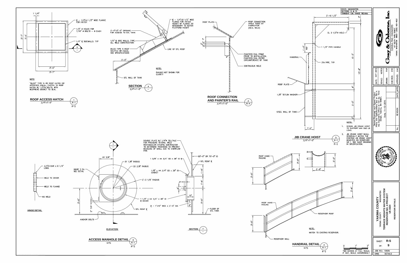
AND PAINTER'S RAIL
ROOF CONNECTION
ROOF ACCESS HATCH
SECTION
ACCESS MANHOLE DETAIL
HINGE DETAIL
ELEVATIONSECTION
HANDRAIL DETAIL
JIB CRANE HOIST
YA
KIM
A C
OU
NT
Y
TE
RR
AC
E H
EIG
HT
S W
AT
ER
S
YS
TE
M
RE
SE
RV
OIR
N
O. 4 P
RO
JE
CT
U6 3424
RE
SE
RV
OIR
D
ET
AIL
S
R-5
9
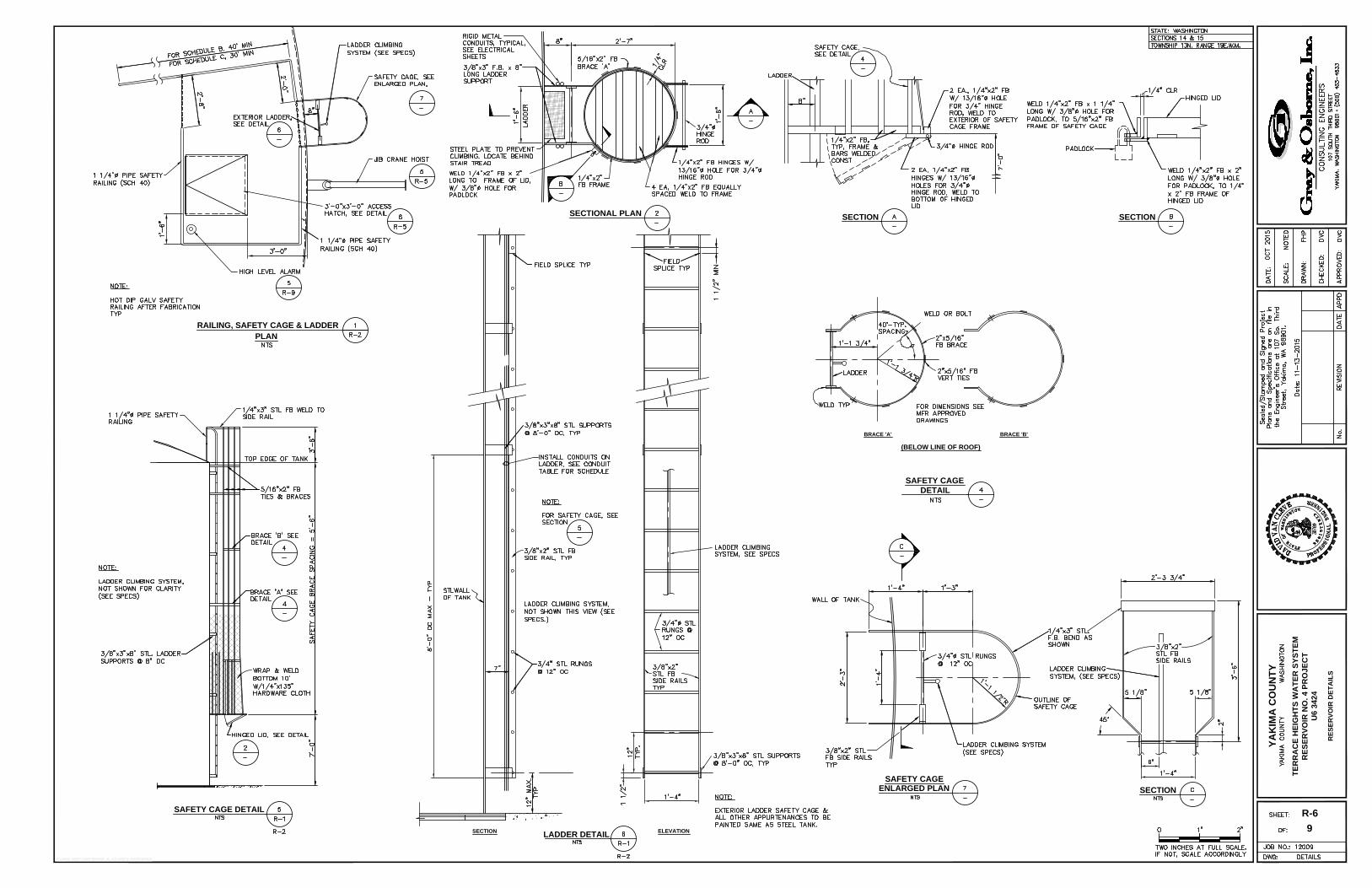
SECTION ELEVATION
ENLARGED PLAN
PLAN
SAFETY CAGE DETAIL
SAFETY CAGE
BRACE 'B'
(BELOW LINE OF ROOF)
BRACE 'A'
RAILING, SAFETY CAGE & LADDER
SECTION
DETAIL
LADDER DETAIL
SAFETY CAGE
SECTION
SECTION
SECTIONAL PLAN
YA
KIM
A C
OU
NT
Y
TE
RR
AC
E H
EIG
HT
S W
AT
ER
S
YS
TE
M
RE
SE
RV
OIR
N
O. 4 P
RO
JE
CT
U6 3424
RE
SE
RV
OIR
D
ET
AIL
S
R-6
9
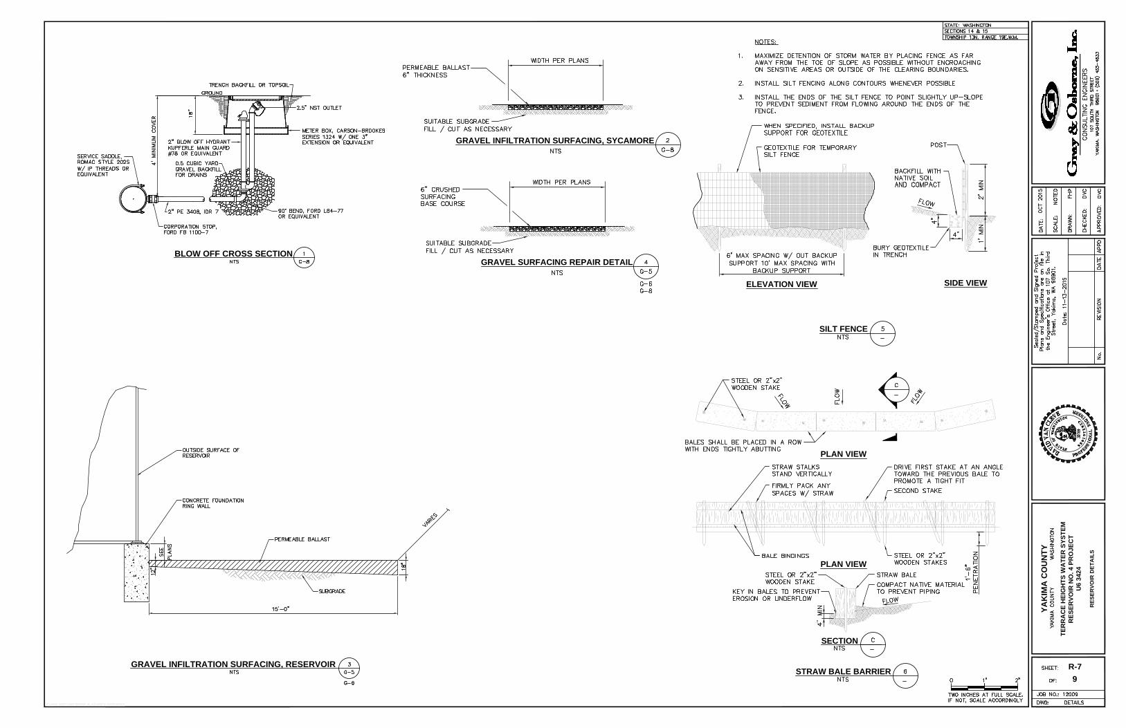
BLOW OFF CROSS SECTION
GRAVEL INFILTRATION SURFACING, RESERVOIR
YA
KIM
A C
OU
NT
Y
TE
RR
AC
E H
EIG
HT
S W
AT
ER
S
YS
TE
M
RE
SE
RV
OIR
N
O. 4 P
RO
JE
CT
U6 3424
RE
SE
RV
OIR
D
ET
AIL
S
R-7
GRAVEL INFILTRATION SURFACING, SYCAMORE
GRAVEL SURFACING REPAIR DETAIL
9
SILT FENCE
ELEVATION VIEW
SIDE VIEW
PLAN VIEW
PLAN VIEW
SECTION
STRAW BALE BARRIER
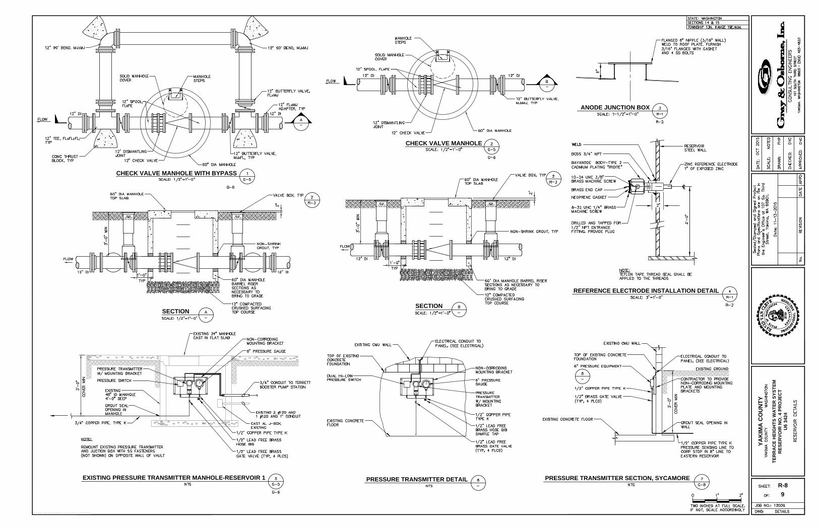
ANODE JUNCTION BOX
REFERENCE ELECTRODE INSTALLATION DETAIL
SECTION
EXISTING PRESSURE TRANSMITTER MANHOLE-RESERVOIR 1
PRESSURE TRANSMITTER DETAIL
PRESSURE TRANSMITTER SECTION, SYCAMORE
SECTION
CHECK VALVE MANHOLE
CHECK VALVE MANHOLE WITH BYPASS
YA
KIM
A C
OU
NT
Y
TE
RR
AC
E H
EIG
HT
S W
AT
ER
S
YS
TE
M
RE
SE
RV
OIR
N
O. 4 P
RO
JE
CT
U6 3424
R-8
9
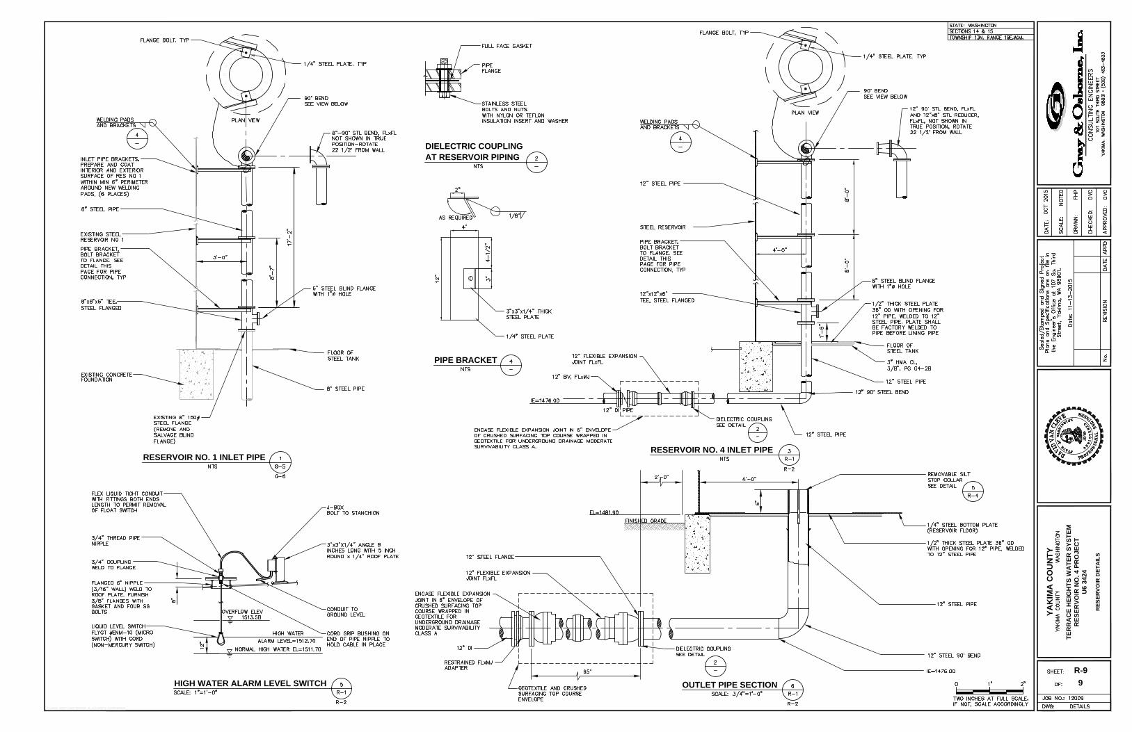
AT RESERVOIR PIPING
DIELECTRIC COUPLING
PIPE BRACKET
RESERVOIR NO. 4 INLET PIPE
HIGH WATER ALARM LEVEL SWITCH
RESERVOIR NO. 1 INLET PIPE
OUTLET PIPE SECTION
YA
KIM
A C
OU
NT
Y
TE
RR
AC
E H
EIG
HT
S W
AT
ER
S
YS
TE
M
RE
SE
RV
OIR
N
O. 4 P
RO
JE
CT
U6 3424
RE
SE
RV
OIR
D
ET
AIL
S
R-9
9
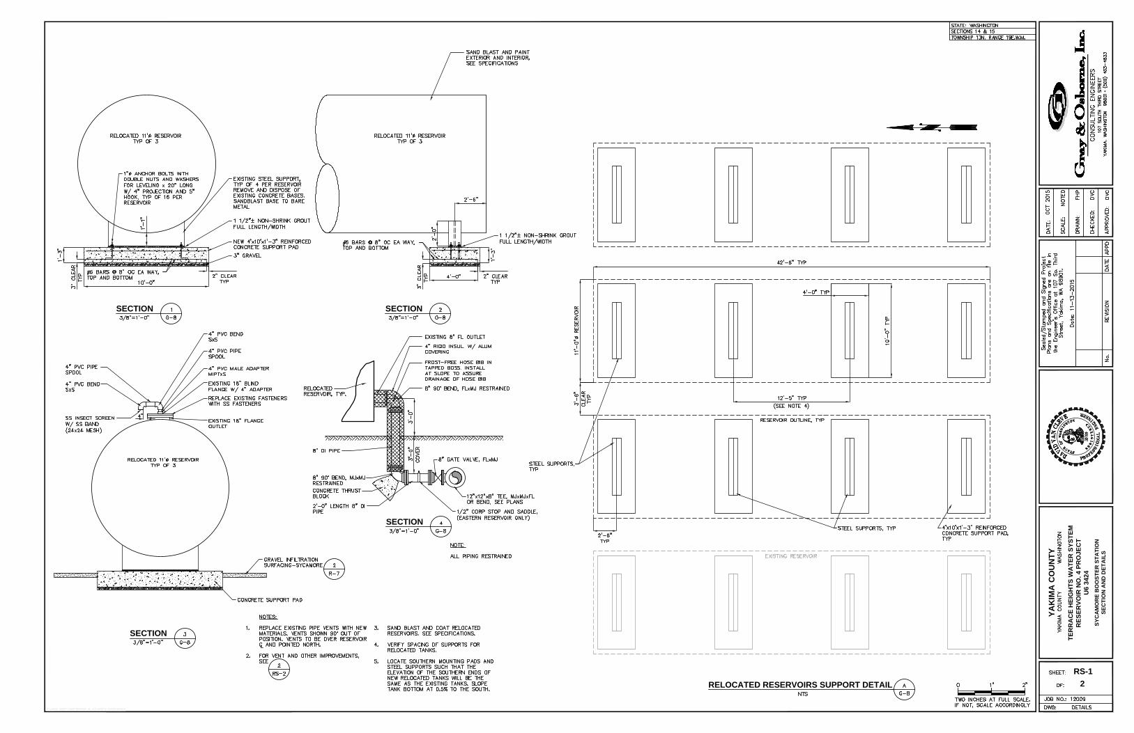
SECTION
RELOCATED RESERVOIRS SUPPORT DETAIL
SECTION SECTION
SECTION
YA
KIM
A C
OU
NT
Y
TE
RR
AC
E H
EIG
HT
S W
AT
ER
S
YS
TE
M
RE
SE
RV
OIR
N
O. 4 P
RO
JE
CT
U6 3424
SY
CA
MO
RE
B
OO
ST
ER
S
TA
TIO
N
SE
CT
IO
N A
ND
D
ET
AIL
S
RS-1
2
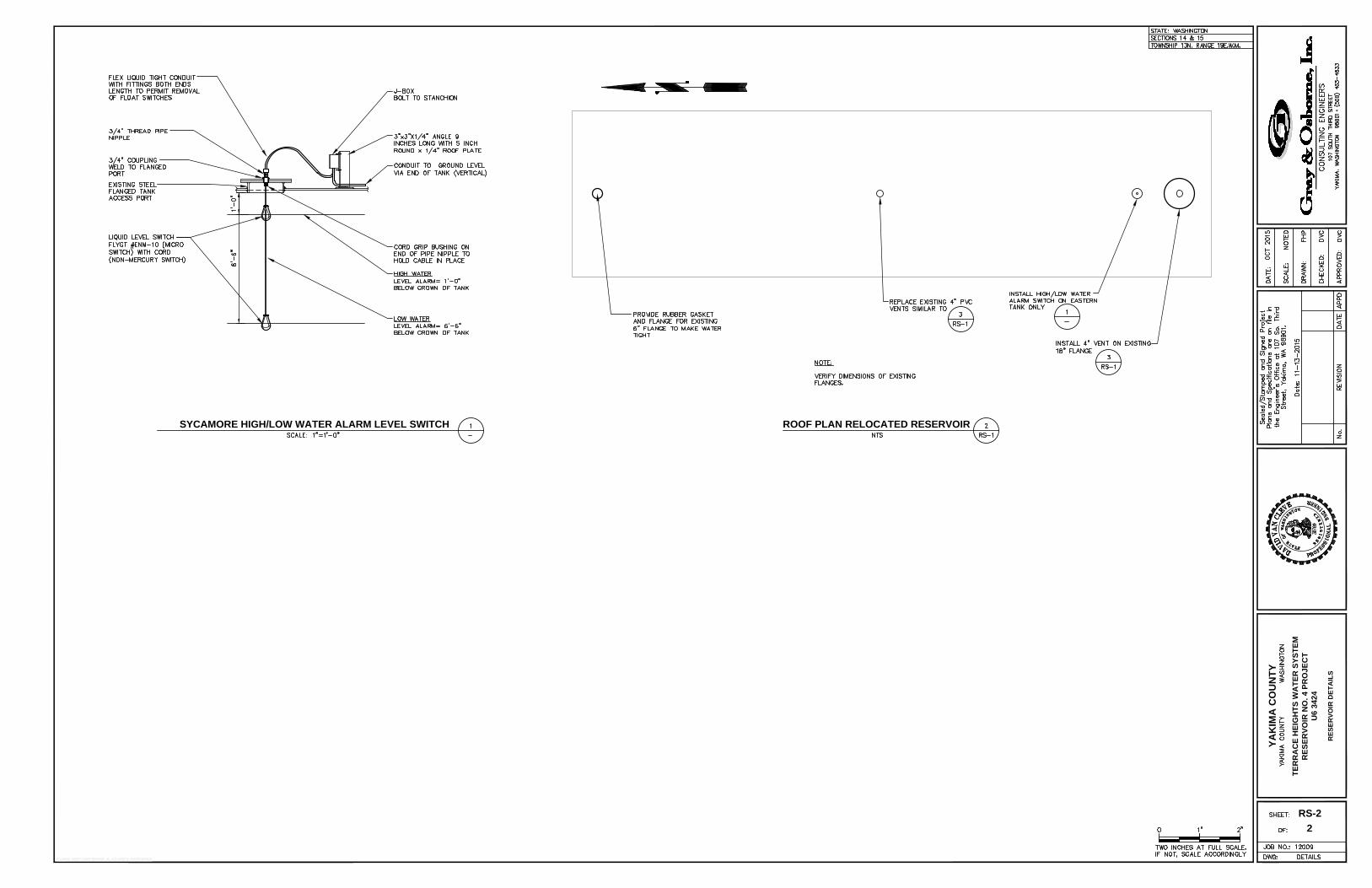
SYCAMORE HIGH/LOW WATER ALARM LEVEL SWITCH ROOF PLAN RELOCATED RESERVOIR
YA
KIM
A C
OU
NT
Y
TE
RR
AC
E H
EIG
HT
S W
AT
ER
S
YS
TE
M
RE
SE
RV
OIR
N
O. 4 P
RO
JE
CT
U6 3424
RE
SE
RV
OIR
D
ET
AIL
S
RS-2
2
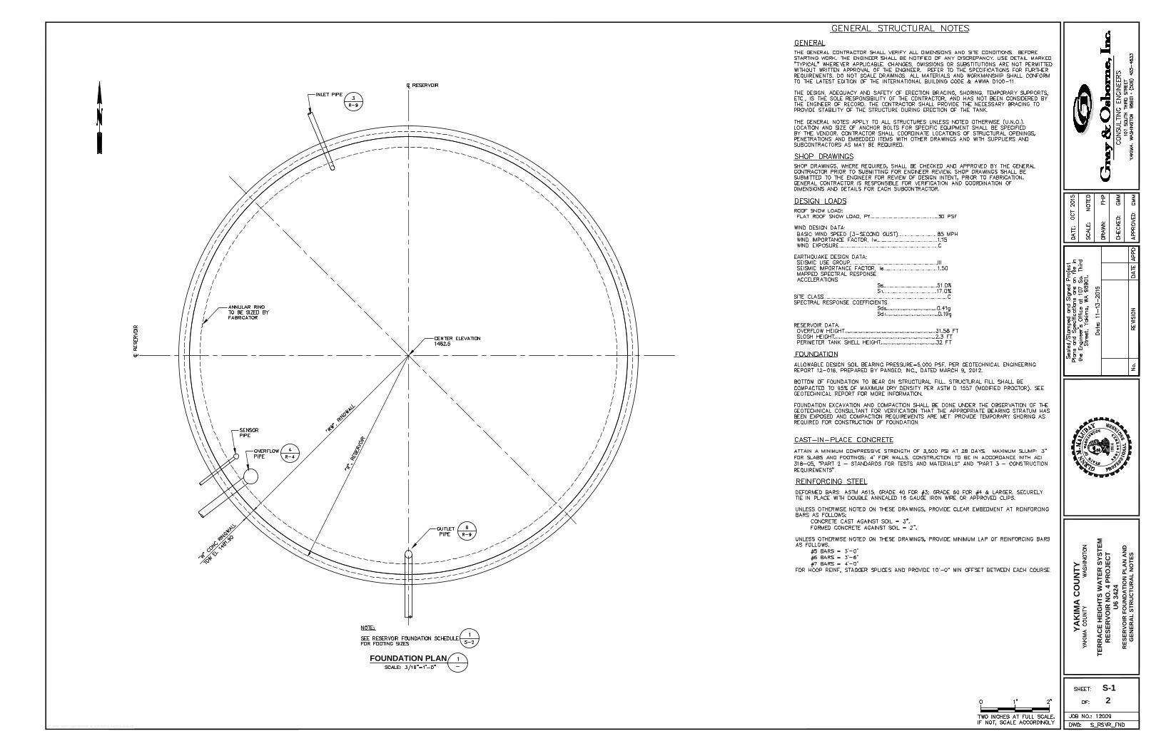
FOUNDATION PLAN
2
YA
KIM
A C
OU
NT
Y
TE
RR
AC
E H
EIG
HT
S W
AT
ER
S
YS
TE
M
RE
SE
RV
OIR
N
O. 4 P
RO
JE
CT
U6 3424
S-1
RE
SE
RV
OIR
F
OU
ND
AT
IO
N P
LA
N A
ND
GE
NE
RA
L S
TR
UC
TU
RA
L N
OT
ES
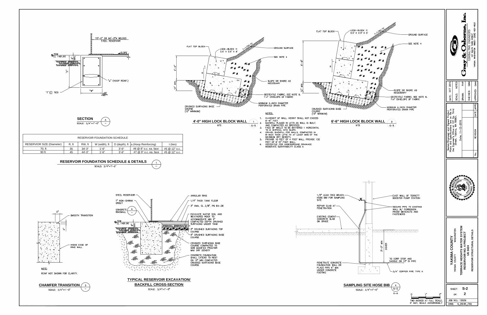
CHAMFER TRANSITION
TYPICAL RESERVOIR EXCAVATION/
BACKFILL CROSS-SECTION
SAMPLING SITE HOSE BIB
RESERVOIR FOUNDATION SCHEDULE & DETAILS
SECTION
2
YA
KIM
A C
OU
NT
Y
TE
RR
AC
E H
EIG
HT
S W
AT
ER
S
YS
TE
M
RE
SE
RV
OIR
N
O. 4 P
RO
JE
CT
U6 3424
S-2
RE
SE
RV
OIR
S
TR
UC
TU
RA
L D
ET
AIL
S
R, ft RW, ft W (width), ft D (depth), ft a (Hoop Reinforcing) t (ties)
35 34'-3" 1'-6" 3'-6" #5 @ 12" o.c.
45 44'-3" 1'-6" 3'-6" #5 @ 12" o.c.
RESERVOIR FOUNDATION SCHEDULE
RESERVIOR SIZE (Diameter)
70, ft
90 ft
#6 @ 8" o.c. ea. face
#7 @ 9" o.c. ea. face
®
®
4'-0" HIGH LOCK BLOCK WALL 6'-6" HIGH LOCK BLOCK WALL