Embed Size (px)
Citation preview
CONGESTION CONTROL MECHANISMS FORINTER-DATACENTER NETWORKS
by
GAOXIONG ZENG
A Thesis Submitted toThe Hong Kong University of Science and Technology
in Partial Fulfillment of the Requirements for
the Degree of Doctor of Philosophy
in Computer Science and Engineering
January 2022, Hong Kong
Copyright © by Gaoxiong Zeng 2022
arX
iv:2
201.
0373
4v1
[cs
.NI]
11
Jan
2022

Authorization
I hereby declare that I am the sole author of the thesis.
I authorize the Hong Kong University of Science and Technology to lend this thesis to
other institutions or individuals for the purpose of scholarly research.
I further authorize the Hong Kong University of Science and Technology to reproduce
the thesis by photocopying or by other means, in total or in part, at the request of other
institutions or individuals for the purpose of scholarly research.
GAOXIONG ZENG
ii
CONGESTION CONTROL MECHANISMS FORINTER-DATACENTER NETWORKS
by
GAOXIONG ZENG
This is to certify that I have examined the above Ph.D. thesis
and have found that it is complete and satisfactory in all respects,
and that any and all revisions required by
the thesis examination committee have been made.
Prof. Kai Chen, Supervisor
Prof. Dit-Yan YEUNG, Head of Department
Department of Computer Science and Engineering
10 January 2022
iii

To my family and friends
ACKNOWLEDGMENTS
The last six years at HKUST were an incredible journey in my life. There were dilemmas
and breakthroughs, depressions and endeavors, failures and successes along the journey.
After all, I did not only become stronger in ability, but also got to know many brilliant
people. First of all, I am gratitude to my supervisor, Prof. Kai Chen. He provides me all
kinds of help throughout my PhD studies, and encourages me to do great research for life.
I have been very fortunate to collaborate with many outstanding researchers from both
academia and industry. I am grateful to Prof. Dongsu Han from Korea Advanced Institute
of Science and Technology, Dr. Kun Tan and Dr. Lei Cui from Huawei, Dr. Yibo Zhu from
then Microsoft Research and now ByteDance, Dr. Hongqiang Liu and Dr. Yifei Yuan from
Alibaba, etc. for the help and guidance on my research.
I am thankful to Prof. Yongshun Cai, Prof. Qiong Luo, Prof. Brahim Bensaou, Prof.
Jiang Xu, and Prof. Hong Xu for serving on my thesis defense committee. I would also like
to thank my thesis proposal committee and qualifying examination committee members:
Prof. Bo Li, Prof. Shueng-Han Gary Chan, and Prof. Wei Wang, etc.
I am grateful to my labmates of the HKUST SING Group. Many thanks to Wei Bai
and Shuihai Hu for their tremendous help on my research and life. I enjoy chatting with
Hong Zhang and Li Chen, who can always come up with inspiring ideas. I am fortu-
nate to work with many amazing colleagues: Hengky Susanto, Yuchao Zhang, Wenxin
Li, Jinbin Hu, Weiyan Wang, Junxue Zhang, Ge Chen, Yiding Wang, Han Tian, Ziyang Li,
Hao Wang (from SJTU), Jiacheng Xia, Qinghe Jing, Bairen Yi, Zhaoxiong Yang, Justinas
Lingys, Jinzhen Bao, Zhouwang Fu, Zhuotao Liu, Xuya Jia, Baochen Qiao, Jingrong Chen,
Xinchen Wan, Chaoliang Zeng, Yiqing Ma, Liu Yang, Zhaorong Liu, Duowen Liu, Zhuoyi
Peng, Cengguang Zhang, Ding Tang, Hao Wang (from PKU), Zilong Wang, Di Chai, Yilun
Jin, Hao Xu, Xudong Liao, Kaiqiang Xu, Yuxuan Qin, Zhenghang Ren, Tianjian Chen,
Wenxue Li, Xiaodian Cheng, Decun Sun, Xinyang Huang, Shuowei Cai, Jianxin Qiu, Xi-
aoyu Hu, etc. Also, I am very grateful to Connie Lau, Isaac Ma, and Lily Chan for their
administration work; and staff from CS system that helps to maintain the lab facilities.
v

I would like to thank my HKUST friends outside SING Group for their company and
help: Mingfei Sun, Peng Xu, Shiheng Wang, Kaiyi Wu, Chen Chen, Lili Wei, Jieru Zhao,
etc. I am also thankful to my friends outside HKUST who enriched my life outside work:
Hao Wei, Jinghua Zhong, Hongwei Yuan, Jin Xiao, Shuguang Hu, etc.
Last but not least, I would like to thank my family for their continuous love and sup-
port in the past 30 years. Without them, this thesis would have not been possible.
vi
TABLE OF CONTENTS
Title Page i
Authorization Page ii
Signature Page iii
Acknowledgments v
Table of Contents vii
List of Figures x
List of Tables xii
List of Algorithms xiii
Abstract xiv
Chapter 1 Introduction 1
1.1 Contributions 2
1.1.1 Congestion Control under Network Heterogeneity 2
1.1.2 Congestion Control under Shallow-buffered WAN 3
1.2 Organization 3
Chapter 2 Background: Network Optimization for Data Centers 5
2.1 Introduction to Data Centers 5
2.2 Optimizing Intra- and Inter-Datacenter Networks 6
2.2.1 Network Architectures 6
2.2.2 Transport Protocols and Congestion Control 7
2.2.3 Emerging Technologies 9
vii
Chapter 3 GEMINI: Reactive Congestion Control for Inter-Datacenter Networks 11
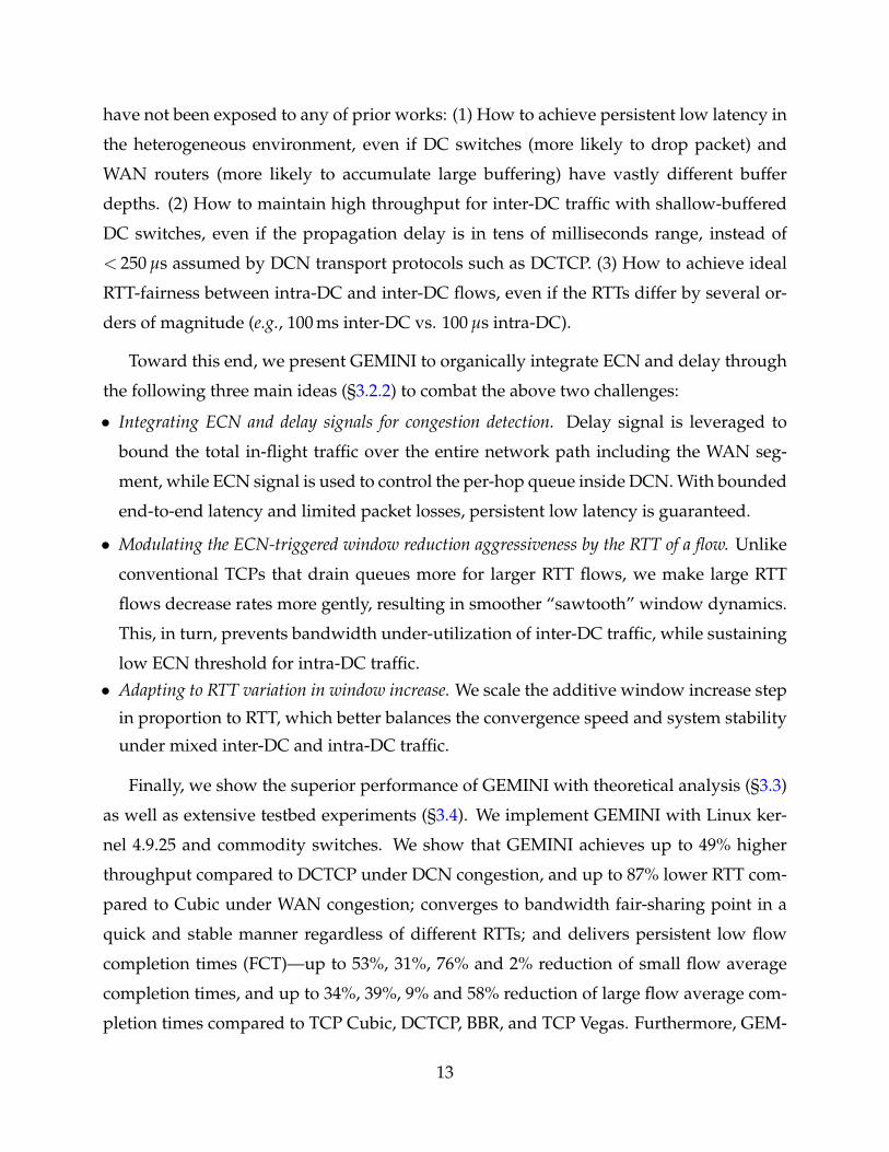
3.1 Background and Motivation 14
3.1.1 Heterogeneity in Cross-Datacenter Networks 14
3.1.2 Single Signal’s Limitations under Heterogeneity 15
3.2 Design 21
3.2.1 Design Rationale 21
3.2.2 GEMINI Algorithm 22
3.3 Theoretical Analysis 27
3.3.1 Derivation of the Scale Factor F 27
3.3.2 Proof of RTT-fairness 30
3.3.3 Guidelines for Setting Parameters 31
3.4 Evaluation 33
3.4.1 Implementation and Experiment Setup 33
3.4.2 Throughput and Latency 35
3.4.3 Convergence, Stability and Fairness 38
3.4.4 Realistic Workloads 40
3.5 Discussion 42
3.5.1 Practical Considerations 42
3.5.2 Alternative Solutions 44
3.6 Related Work 45
3.7 Final Remarks 47
Chapter 4 FlashPass: Proactive Congestion Control for Inter-Datacenter Networks 48
4.1 Background and Motivation 50
4.1.1 Shallow-buffered Network 50
4.1.2 Reactive Congestion Control (RCC) is Insufficient 51
4.1.3 Proactive Congestion Control (PCC) as a Solution 53
4.2 Design 58
4.2.1 Design Overview 58
4.2.2 Sender-driven Emulation Mechanism 60
4.2.3 Over-provisioning with Selective Dropping Mechanism 62
4.3 Evaluation 64
4.3.1 Evaluation Setup 65
viii
4.3.2 Evaluation Results 67
4.3.3 Evaluation Deep Dive 72
4.4 Practical Deployment Analysis 73
4.5 Related Work 74
4.6 Final Remarks 75
Chapter 5 Conclusion and Future Work 76
5.1 Summary 76
5.2 Future Directions 77
References 78
PhD’s Publications 90
ix
LIST OF FIGURES
2.1 Data Centers (DCs) in Google [4]. 6
3.1 Cross-Datacenter Network (Cross-DCN). 12
3.2 RTT Heat Map in Cross-DC Network. 15
3.3 Cross-Datacenter Network Testbed. 16
3.4 Flow completion time (FCT) results. Small flow: Size < 100 KB. Large flow:Size > 10 MB. 18
3.5 Conflicting ECN requirements in DCTCP. The right y-axis shows latencyby the inflated RTT ratio — the queueing-inflated RTT normalized by thebase RTT (w/o queueing). 19
3.6 Dilemma in setting delay threshold. The left y-axis shows throughputby the flow completion time (FCT) of large flows. The right y-axis showspacket loss rate (PLR) inside DCN. 20
3.7 GEMINI Congestion Control Process. 23
3.8 AIMD Sawtooth Illustration. 28
3.9 Aggregate throughput of inter-DC flows that bottlenecked at a DCN link.GEMINI is less buffer-hungry (requires 0-76% smaller K) than DCTCP whenachieving similar throughput. 35
3.10 RTT and throughput of inter-DC flows bottlenecked at a WAN link. 37
3.11 GEMINI converges quickly, fairly and stably. 38
3.12 RTT-fairness. RTT1 and RTT2 are the intra-DC and inter-DC RTTs.GEMINIachieves bandwidth fair-sharing regardless of different RTTs. 39
3.13 [Large-scale 1Gbps Testbed] FCT results under traffic pattern 1: Inter-DCtraffic, highly congested in WAN. Small flow: Size < 100 KB. Large flow:Size > 10 MB. GEMINI achieves the best or second best results in most casesof Figure 3.13- 3.16 (within 11% of the second best scheme in the worst case). 40
3.14 [Small-scale 10Gbps Testbed] FCT results under traffic pattern 1: Inter-DCtraffic, highly congested in WAN. Small flow: Size < 100 KB. Large flow:Size > 10 MB. 41
3.15 [Large-scale 1Gbps Testbed] FCT results under traffic pattern 2: mixedinter-DC and intra-DC traffic, highly congested both in WAN and DCN.Small flow: Size < 100 KB. Large flow: Size > 10 MB. 43
3.16 [Small-scale 10Gbps Testbed] FCT results under traffic pattern 2: mixedinter-DC and intra-DC traffic, highly congested both in WAN and DCN.Small flow: Size < 100 KB. Large flow: Size > 10 MB. 44
x
4.1 Design space of transport protocols. 49
4.2 Performance of reactive transports under shallow buffer. The solid linesindicate throughput (or tp) on the left y-axis, and the dash lines indicateloss rate on the right y-axis. 54
4.3 Receiver-driven proactive congestion control (PCC). 55
4.4 Competing flows have different RTTs on WAN. 56
4.5 Credit wastage of ExpressPass. 58
4.6 Sender-driven emulation mechanism. 59
4.7 Over-provisioning with selective dropping mechanism. 63
4.8 Flow size distribution. 66
4.9 Dumbbell network topology. There are N senders that simultaneouslytransfer bulk data to the same receiver. All links have 10Gbps capacity. Thenetwork delays vary for different senders to reach the bottleneck switchdue to the distinct geographical distances on WAN. 67
4.10 Static workload experiment results running on a dumbbell network topol-ogy shown in Figure 4.9. The blue bar indicates the throughput (Gbps)performance on the left y-axis. The red line indicates the packet loss rate(%) on the right y-axis. 68
4.11 Wide-area network (WAN) topology. Three datacenters (DCs) connect witheach other by WAN links of 20ms, 30ms, and 40ms one-way delay, respec-tively. All wide-area links have 10Gbps capacity. There are 20 hosts in eachDC connecting to the wide-area border router with 1Gbps links. 69
4.12 Flow completion times (FCTs) of various transport protocols under realisticdynamic workload (average load = 0.4). ExpressPass* indicates the Aeolus-enhanced ExpressPass version. FlashPass* indicates the Aeolus-enhancedFlashPass version. 70
4.13 Flow completion times (FCTs) of various transport protocols under realisticdynamic workload (average load = 0.8). ExpressPass* indicates the Aeolus-enhanced ExpressPass version. FlashPass* indicates the Aeolus-enhancedFlashPass version. 71
4.14 FCT (blue bar on the left y-axis) and credit loss rate (red line on the right y-axis) of FlashPass. The average FCT is normalized by the result of FlashPasswith min target loss = 1% and max target loss = 5%. 72
4.15 FCT (blue bar on the left y-axis) and credit savage (red line on the righty-axis) of FlashPass with over-provisioning and selective dropping mecha-nism over that without over-provisioning mechanism. The average FCT isnormalized by the result of FlashPass without over-provisioning. 73
xi
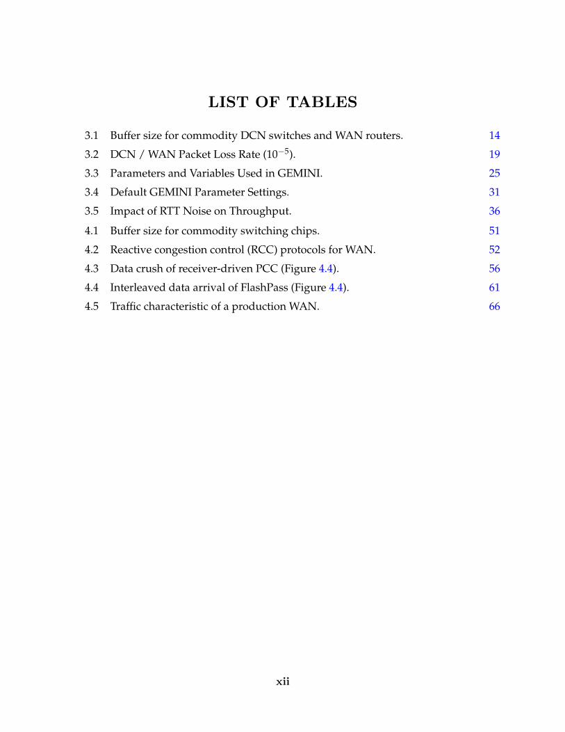
LIST OF TABLES
3.1 Buffer size for commodity DCN switches and WAN routers. 14
3.2 DCN / WAN Packet Loss Rate (10−5). 19
3.3 Parameters and Variables Used in GEMINI. 25
3.4 Default GEMINI Parameter Settings. 31
3.5 Impact of RTT Noise on Throughput. 36
4.1 Buffer size for commodity switching chips. 51
4.2 Reactive congestion control (RCC) protocols for WAN. 52
4.3 Data crush of receiver-driven PCC (Figure 4.4). 56
4.4 Interleaved data arrival of FlashPass (Figure 4.4). 61
4.5 Traffic characteristic of a production WAN. 66
xii
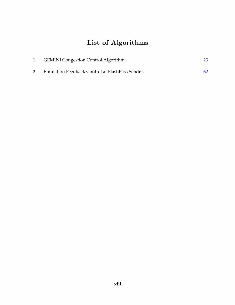
List of Algorithms
1 GEMINI Congestion Control Algorithm. 23
2 Emulation Feedback Control at FlashPass Sender. 62
xiii
CONGESTION CONTROL MECHANISMS FORINTER-DATACENTER NETWORKS
by
GAOXIONG ZENG
Department of Computer Science and Engineering
The Hong Kong University of Science and Technology
ABSTRACT
Applications running in geographically distributed setting are becoming prevalent.
Large-scale online services often share or replicate their data into multiple data centers
(DCs) in different geographic regions. Driven by the data communication need of these
applications, inter-datacenter network (IDN) is getting increasingly important.
However, we find congestion control for inter-datacenter networks quite challenging.
Firstly, the inter-datacenter communication involves both data center networks (DCNs)
and wide-area networks (WANs) connecting each data center. Such a network environ-
ment presents quite heterogeneous characteristics (e.g., buffer depths, RTTs). Existing con-
gestion control mechanisms consider either DCN or WAN congestion, while not simulta-
neously capturing the degree of congestion for both.
Secondly, to reduce evolution cost and improve flexibility, large enterprises have been
building and deploying their wide-area routers based on shallow-buffered switching chips.
However, with legacy congestion control mechanisms (e.g., TCP Cubic), shallow buffer
can easily get overwhelmed by large BDP (bandwidth-delay product) wide-area traffic,
leading to high packet losses and degraded throughput.
xiv
This thesis describes my research efforts on optimizing congestion control mechanisms
for the inter-datacenter networks. First, we design GEMINI — a reactive congestion con-
trol mechanism that simultaneously handles congestions both in DCN and WAN. Second,
we present FlashPass — a proactive congestion control mechanism that achieves near zero
loss without degrading throughput under the shallow-buffered WAN. Extensive evalua-
tion shows their superior performance over existing congestion control mechanisms.
xv
CHAPTER 1
INTRODUCTION
Applications running in geographically distributed setting are becoming prevalent [74,
116, 96, 60, 65, 57]. Large-scale online services often share or replicate their data into
multiple DCs in different geographic regions. For example, a retailer website runs a
database of in-stock items replicated in each regional data center for fast serving local
customers. These regional databases synchronize with each other periodically for the lat-
est data. Other examples include image sharing on online social networks, video storage
and streaming, geo-distributed data analytics, etc.
With the prevalence of the geo-distributed applications and services, inter-datacenter
network (IDN) is becoming an increasingly important cloud infrastructure [64, 55, 71, 56].
For example, Google [56] reveals that its inter-datacenter wide-area traffic has been grow-
ing exponentially with a doubling of every 9 months in recent 5 years. This pushes the
IDN facility to evolve much faster than the rest of its infrastructure components.
However, we find congestion control for inter-datacenter networks quite challenging.
Firstly, the inter-datacenter communication involves both data center networks (DCNs)
and wide-area networks (WANs) connecting each data center. Such a network environ-
ment presents quite heterogeneous characteristics (e.g., buffer depths, RTTs). Existing con-
gestion control mechanisms consider either DCN or WAN congestion, while not simulta-
neously capturing the location and degree of congestion for both network segments. Sec-
ondly, to reduce evolution cost and improve flexibility, large enterprises have been build-
ing and deploying their wide-area routers based on shallow-buffered switching chips.
However, with legacy congestion control mechanisms (e.g., TCP Cubic), shallow buffer
can easily get overwhelmed by large BDP (bandwidth-delay product) wide-area traffic,
leading to high packet losses and degraded throughput.
This thesis describes my research efforts on optimizing congestion control mechanisms
for the inter-datacenter networks. First, we design GEMINI [119] — a reactive conges-
tion control mechanism that simultaneously handles congestions both in DCN and WAN.
1
The key idea is to strategically integrate ECN and delay signal for congestion control.
Second, we present FlashPass [123] — a proactive congestion control mechanism that
achieves near zero loss without degrading throughput under the shallow-buffered WAN.
A sender-driven emulation mechanism is adopted to achieve accurate bandwidth alloca-
tion. Finally, we conduct extensive experiments for evaluation, and results validate their
superior performance over existing congestion control mechanisms.
1.1 Contributions
This thesis focuses on the congestion control mechanisms for the inter-datacenter net-
works (IDNs). In the following subsections, we overview our two key contributions.
1.1.1 Congestion Control under Network Heterogeneity
Geographically distributed applications hosted on cloud are becoming prevalent [74, 96,
65, 57]. They run on cross-datacenter network (cross-DCN) that consists of multiple data cen-
ter networks (DCNs) connected by a wide area network (WAN). Such a cross-DC network
poses significant challenges in transport design because the DCN and WAN segments
have vastly distinct characteristics (e.g., buffer depths, RTTs).
In this work, we find that existing DCN or WAN transport reacting to ECN or delay
alone do not (and cannot be extended to) work well for such an environment. The key
reason is that neither of the signals, by itself only, can simultaneously capture the location
and degree of congestion, mainly due to the discrepancies between DCN and WAN.
Motivated by this, we present the design and implementation of GEMINI [119] that
strategically integrates both ECN and delay signals for cross-DC congestion control. To
achieve low latency, GEMINI bounds the inter-DC latency with delay signal and prevents
the intra-DC packet loss with ECN. To maintain high throughput, GEMINI modulates the
window dynamics and maintains low buffer occupancy utilizing both congestion signals.
GEMINI is supported by rigorous theoretical analysis, implemented in Linux ker-
nel 4.9.25, and evaluated by extensive testbed experiments. Results show that GEMINI
achieves up to 53%, 31%, 76% and 2% reduction of small flow completion times (FCTs)
2
on average, and up to 34%, 39%, 9% and 58% reduction of large flow average completion
times compared to Cubic [49], DCTCP [11], BBR [25], and Vegas [23]. Furthermore, GEM-
INI requires no customized hardware support and can be readily deployed in practice.
1.1.2 Congestion Control under Shallow-buffered WAN
To reduce evolution cost and improve flexibility, large enterprises (e.g., Google [4], Al-
ibaba [1], etc.) have been building and deploying their wide-area routers based on shallow-
buffered switching chips. However, with legacy reactive transport (e.g., TCP Cubic [49]),
shallow buffer can easily get overwhelmed by large BDP wide-area traffic, leading to high
packet losses and degraded throughput. To address it, current practice seeks help from
traffic engineering, rate limiting, or multi-service traffic scheduling.
Instead, we ask: can we design a transport to simultaneously achieve high throughput
and low loss for shallow-buffered WAN? We answer this question affirmatively by em-
ploying proactive congestion control (PCC). However, two issues exist for existing PCC
to work on WAN. Firstly, wide-area traffics have diverse RTTs. The interleaved credits can
still trigger data crush due to RTT difference. Secondly, there is one RTT delay for credits
to trigger data sending, which can degrade network performance.
Therefore, we propose a novel PCC design — FlashPass [123]. To address the first
issue, FlashPass adopts sender-driven emulation process with send time calibration to
avoid the data packet crush. To address the second issue, FlashPass enables early data
transmission in the starting phase, and incorporates an over-provisioning with selective
dropping mechanism for efficient credit allocation in the finishing phase.
Our evaluation with production workload demonstrates that FlashPass reduces the
overall flow completion times of Cubic [49] and ExpressPass [32] by up to 32% and 11.4%,
and the 99-th tail completion times of small flows by up to 49.5% and 38%, respectively.
1.2 Organization
The remainder of the dissertation is organized as follows. Chapter 2 briefly goes through
some background regarding network optimization mechanisms for data centers (DCs),
3
including network architecture design, transport-layer congestion control, etc. Chapter 3
introduces GEMINI, where we present the detailed design, theoretical analysis, imple-
mentation and evaluation of a reactive congestion control mechanism under the hetero-
geneous cross-datacenter network (cross-DCN). Chapter 4 describes FlashPass, where we
demonstrate the design challenges we observe and design choices we made to the proac-
tive congestion control mechanisms under the shallow-buffered inter-datacenter network
(IDN). Finally, Chapter 5 concludes the thesis work and presents the future directions.
4
CHAPTER 2
BACKGROUND: NETWORK OPTIMIZATIONFOR DATA CENTERS
In this chapter, we present a general picture of intra-datacenter and inter-datacenter net-
works1 and the related optimization efforts. In §2.1, we give an introduction to data cen-
ters (DCs). We show some characteristics and requirements of the applications hosted in
DCs. In §2.2, we introduce some research directions that try to optimize intra-DCN or
inter-DCN, including network architecture designs and congestion control mechanisms.
2.1 Introduction to Data Centers
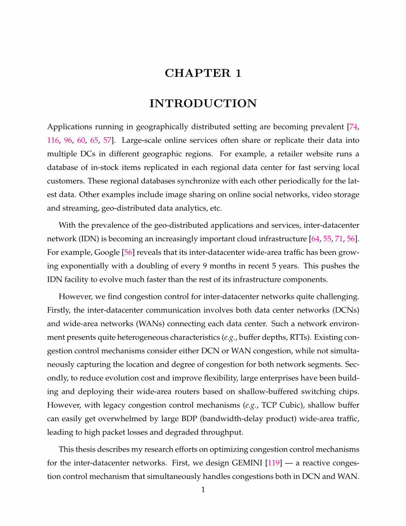
Driven by the need of fast computation and large data storage of various web applications
and services, large clusters of commodity PCs or servers have been built around the globe
at a large scale rapidly [1, 3, 4, 5]. Such kind of commodity server clusters together with
the associated components (e.g., telecommunication, storage and power systems) is called
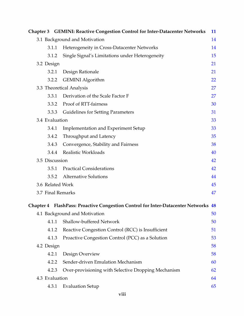
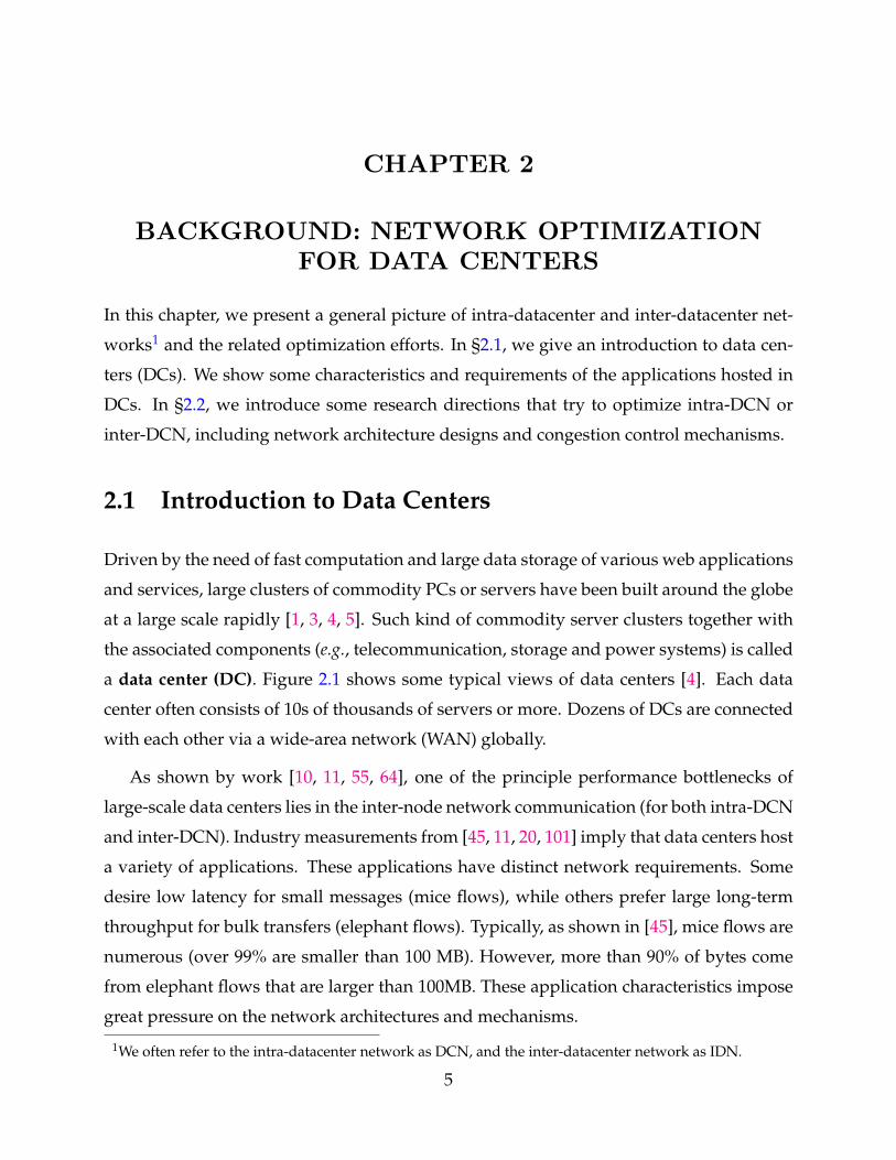
a data center (DC). Figure 2.1 shows some typical views of data centers [4]. Each data
center often consists of 10s of thousands of servers or more. Dozens of DCs are connected
with each other via a wide-area network (WAN) globally.
As shown by work [10, 11, 55, 64], one of the principle performance bottlenecks of
large-scale data centers lies in the inter-node network communication (for both intra-DCN
and inter-DCN). Industry measurements from [45, 11, 20, 101] imply that data centers host
a variety of applications. These applications have distinct network requirements. Some
desire low latency for small messages (mice flows), while others prefer large long-term
throughput for bulk transfers (elephant flows). Typically, as shown in [45], mice flows are
numerous (over 99% are smaller than 100 MB). However, more than 90% of bytes come
from elephant flows that are larger than 100MB. These application characteristics impose
great pressure on the network architectures and mechanisms.
1We often refer to the intra-datacenter network as DCN, and the inter-datacenter network as IDN.
5
(a) Inside View of Datacenter (b) Outside View of Datacenter
(c) Global View of Inter-Datacenter Network (IDN)
Figure 2.1. Data Centers (DCs) in Google [4].
2.2 Optimizing Intra- and Inter-Datacenter Networks
Driven by the stringent requirements of various web applications and services, network
research community proposes numbers of designs in various aspects to deliver high net-
work performance. We now discuss some key directions in the following subsections:
2.2.1 Network Architectures
Network architecture refers to the layout of the network, consisting of the hardware, soft-
ware, connectivity, etc. One dividing crest of DCN architectures is the underlying switch-
ing technology: (1) Electric packet switching (EPS); (2) Optical circuit switching (OCS).
Currently, the EPS network is dominant, while OCS is under exploration [110, 40, 28, 29].
6
Network topology design has also drawn great interests from both academia and
industry [10, 80, 48, 46, 45, 106, 105]. Traditionally, DCNs are built with multi-level,
multi-rooted trees of switches. The leaves of the tree are the so-called top-of-rack (TOR)
switches, each connecting to dozens of servers downward with the access links and the
network aggregates and cores upward with the core links. The access links vary from
1-10 Gbps while the core links are 40-100 Gbps typically. One obvious downside of these
networks is that they do not scale. Building a non-blocking network requires large port
counts and high internal backplane bandwidth of core switches, which won’t be cheap
even available.
Fattree [10] is one of the seminal DCN topology optimization solutions. It is essen-
tially a special instance of the Clos topology [10, 18]. It also uses a multi-level, multi-
rooted tree structure. However, based on the well-designed wiring scheme, it manages
to deliver scalable bandwidth for non-blocking network communication with commodity
Ethernet switches. F10 [80] is a variant of Fattree topology that are resistant to switch or
link failures. Other works include DCell [48], BCube [46], VL2 [45], Jellyfish [106], Jupiter
Rising [105], etc.
2.2.2 Transport Protocols and Congestion Control
Network protocols characterize or even standardize the behavior of network communi-
cations. In particular, transport protocol (layer 4 in OSI network model [125]) is of great
importance. It provides the communication service for upper application layers, such as
connection-oriented data streaming, reliability and congestion control. The well-known
transport protocols of the Internet include the connection-oriented Transmission Control
Protocol (TCP) [26] and the connectionless User Datagram Protocol (UDP) [95].
Congestion control (CC) is one of the fundamental building blocks of the TCP transport
protocol, the goal of which is to allocate network bandwidth among hosts efficiently, e.g.,
avoiding congestion collapse. At a high level, TCP congestion control is an end-to-end
protocol built upon the principle of “conservation of packets” [61]. That is, a flow “in
equilibrium” should run stably with a full window of data in transit. There should be no
new packet injection into the network until old ones leave. Following this principle, the
implementation of TCP often employs the “ACK clocking” to trigger new packets into the
7
network.
TCP Tahoe [61] is the seminal TCP congestion control algorithm. It consists of two
stages: (1) Slow Start; (2) Congestion Avoidance. For slow start, the sender begins with
an initial congestion window (CWND). Then for each acknowledgement (ACK) received
from receiver, it increases the CWND by the same ACKed size, resulting in roughly win-
dow doubling in each round-trip time (RTT). Thus, it can probe for the available band-
width at an exponential speed. Congestoin avoidance follows the additive increase mul-
tiplicative decrease (AIMD) principle. It increments CWND linearly until it encounters
a packet loss, which indicates possible network congestion. It then saves the half of the
current window as a threshold value, resets CWND to one, and restarts from slow start.
TCP Tahoe [61] adopts “Fast Retransmission” for fast loss detection. Specifically, it
takes 3 duplicate ACKs as a sign for packet loss and thus avoid waiting for long timeout.
TCP Reno [62] adds the “Fast Recovery” mechanism. Fast recovery suggests to reset the
CWND to its half instead of one in case of 3 duplicate ACKs. This helps TCP to handle
single packet loss, but not for consecutive losses as it may cut CWND multiple times. TCP
NewReno [43] remedies the problem by keeping fast recovery state until all outstanding
data gets ACKed. However, both TCP Reno and NewReno can retransmit at most one
packet per RTT. TCP with “Selective Acknowledgment” (TCP SACK) [82] enables multi-
ple retransmissions by ACKing received data selectively instead of cumulatively.
In the early years of DCN, the legacy TCP congestion control [61, 62, 43, 82, 49] has
been adopted directly from the Internet for DCN data communication. These protocols
typically leverage packet loss signal for congestion feedback. There are often two reasons
for packet losses: packet corruption in transit, or the network congestion with insufficient
buffer capacity. On most network paths, loss corruption is extremely rare. If packet loss is
(almost) always due to congestion and if a timeout is (almost) always due to a lost packet,
we can take it as a good indicator for the “network is congested” signal.
Although loss-based congestion control gets widely adopted due to its simplicity, it
tends to fill switch buffer and cause excessive packet losses, thus failing to meet the harsh
low latency requirements in DCN. Motivated by this observation, the seminal DCN trans-
port design, DCTCP [11], is proposed in 2010. DCTCP detects the network congestion
with the Explicit Congestion Notification (ECN) [99] signal and reacts to the extent of
8
congestion based on the ACK fraction with ECN marks.
Since then, many congestion control mechanisms [122, 11, 13, 109, 14, 87, 86, 124, 83,
117, 111] have been proposed for high performance data communication in DCN. For
example, HULL [13] trades off some network bandwidth to achieve near zero queueing
with a phantom queue. D2TCP [109] and L2DCT [87] modulate the window adjustment
function of DCTCP to meet deadlines and minimize FCT, respectively. DCQCN [124] is
built on the top of DCTCP and QCN [92]. It enables the realistic deployment of Remote
Direct Memory Access (RDMA) in large-scale ethernet DCNs. The other line of work
leverages delay signal with microsecond-level accuracy for congestion feedback, which is
enabled by recent advances [51, 83, 77] in NIC technology. For example, TIMELY [83] uses
RTT signal for congestion control in RDMA networks.
There are also congestion control mechanisms aiming to optimize data communication
for inter-datacenter networks. For example, BBR [25] is proposed primarily for the enter-
prise WAN. The core idea is to work at the theoretically optimal point [68] with the aid of
sophisticated network sensing (e.g., precise bandwidth and RTT estimation). Copa [16] ad-
justs sending rate towards 1/(δdq), where dq is the queueing delay, by additive-increase
additive-decrease (AIAD). It detects buffer-fillers by observing the delay evolution and
switches between delay-sensitive and TCP-competitive mode. These wide-area transport
protocols usually assume little help (e.g., no ECN support) from the network switches so
as to work across the complex wide-area network (WAN) environment.
2.2.3 Emerging Technologies
Remote Direct Memory Access (RDMA): Datacenter has been upgrading its link band-
width from 10Gbps to 40Gbps and more to meet its rising application need. Traditional
TCP/IP stacks fall short to run at such speed due to the high CPU overhead. Moreover,
some applications require ultra-low latency message transfers (a few microseconds). Tra-
ditional TCP/IP stacks have much higher latency. To address it, Remote Direct Memory
Access (RDMA) is adopted from the high performance computing (HPC) community to
the DCN scenario [124, 47, 84]. With RDMA, network interface cards (NICs) directly trans-
fer data in and out of pre-registered memory buffers, only involving host CPUs during the
initialization step. This reduces CPU consumption and network latency to a great extent.
9
Programmable Networks: Software-Defined Networking (SDN) provides administra-
tors flexible control over the network control planes. Unlike conventional switches, SDN
separates the network control plane from the data plane, and leverages a central controller
to manage multiple switch data planes. However, it targets at fixed-function switches
that support a predetermined set of header fields and actions. Data plane programmabil-
ity [22, 21] is one step towards more flexible switches whose data plane can be changed.
For example, P4 [21] allows the programmers to control the packet processing of the for-
warding plane without worrying about the underlying realization. This enables lots of
optimization mechanisms for data centers.
While these emerging technologies (e.g., RDMA, programmable networks, etc.) seem
promising in theory, there are still plenty of practical challenges to be addressed as well
as research opportunities for realistic deployment at scale [124, 47, 84, 89, 79, 97, 31, 27].
10
CHAPTER 3
GEMINI: REACTIVE CONGESTION CONTROLFOR INTER-DATACENTER NETWORKS
Applications running in geographically distributed setting are becoming prevalent [74,
64, 55, 116, 96, 60, 65, 57]. Large-scale online services often share or replicate their data
into multiple DCs in different geographic regions. For example, a retailer website runs a
database of in-stock items replicated in each regional data center for fast serving local cus-
tomers. These regional databases synchronize with each other periodically for the latest
data. Other examples include image sharing on online social networks, video storage and
streaming, geo-distributed data analytics, etc.
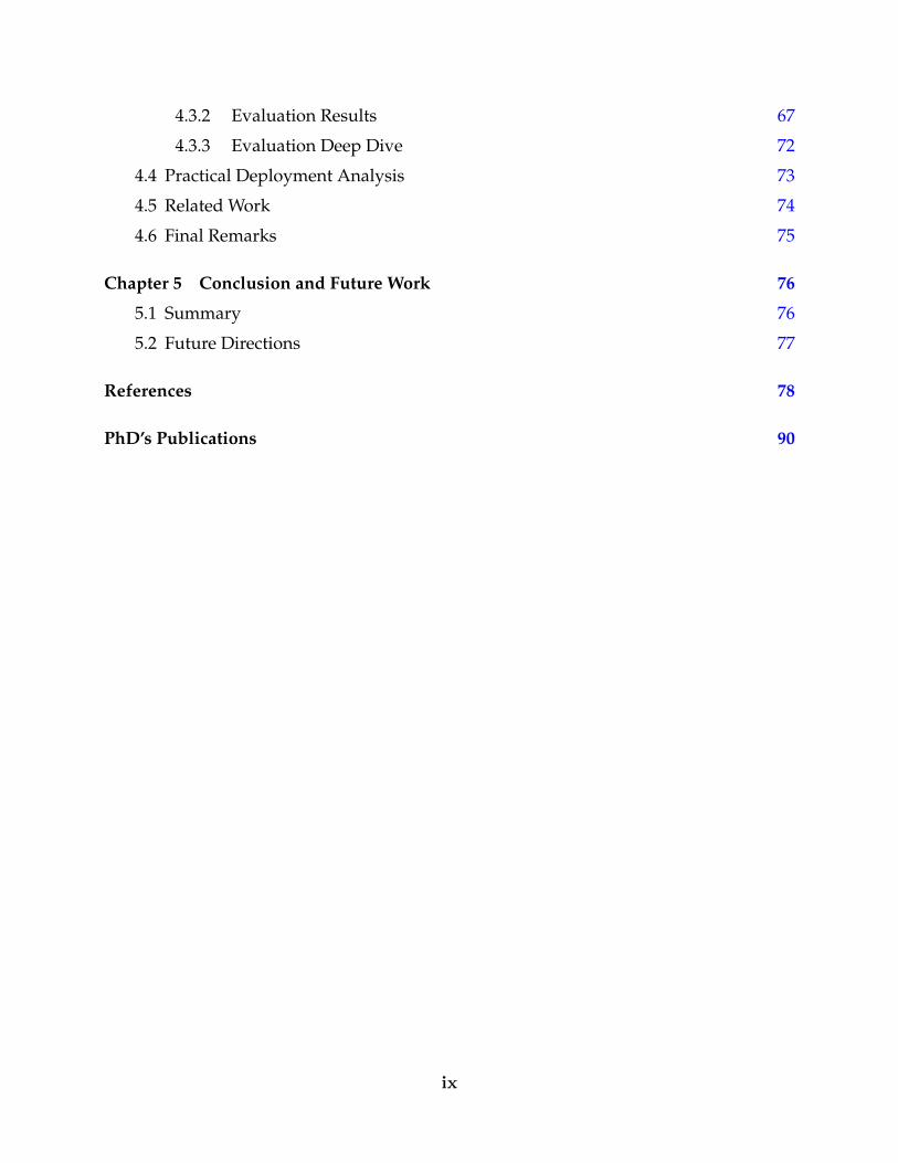
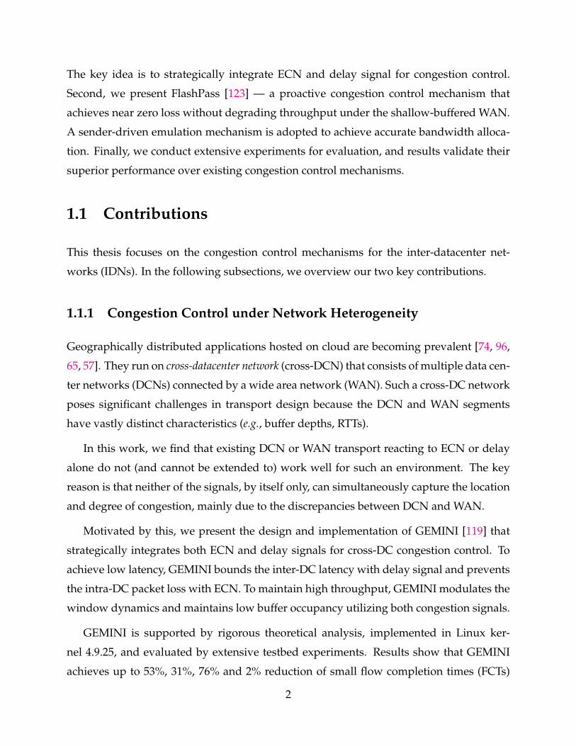
These applications run on cross-datacenter (DC) network (Figure 3.1) that consists of mul-
tiple data center networks (DCNs) connected by a wide area network (WAN). The wide
area and intra-DC networks have vastly distinct characteristics (§3.1.1). For WAN, achiev-
ing high network utilization is a focus and switches have deep buffers. In contrast, latency
is critical in DCN and switches have shallow buffers. While there are numerous transport
protocols designed for either DCN or WAN individually, to the best of our knowledge, lit-
tle work has considered a heterogeneous cross-DC environment consisting of both parts.
To handle congestion control in either DCN or WAN, existing solutions have lever-
aged either ECN (e.g., DCTCP [11] and DCQCN [124]) or delay (e.g., Vegas [23] and
TIMELY [83]) as the congestion signal, and successfully delivered compelling performance
in terms of high-throughput and low-latency [11, 124, 23, 83, 25, 16]. Unfortunately, due to
the discrepancies between DCN and WAN, none of existing solutions designed for DCN
or WAN works well for a cross-DC network (§3.1.2). Even worse, it is unlikely, if not
impossible, that they can be easily extended to work well.
The fundamental reason is that these solutions only exploit one of the signals (either
ECN or delay), which suffices for a relatively homogeneous environment. However, by
their nature, ECN or delay alone cannot handle heterogeneity. First, ECN is difficult to
11
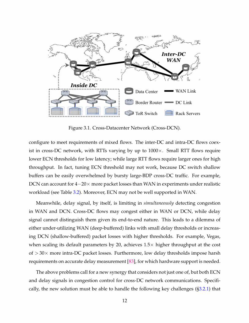
InterDCWAN
Inside DC
ToR Switch
Border Router
Data Center WAN Link
DC Link
Rack Servers
Figure 3.1. Cross-Datacenter Network (Cross-DCN).
configure to meet requirements of mixed flows. The inter-DC and intra-DC flows coex-
ist in cross-DC network, with RTTs varying by up to 1000×. Small RTT flows require
lower ECN thresholds for low latency; while large RTT flows require larger ones for high
throughput. In fact, tuning ECN threshold may not work, because DC switch shallow
buffers can be easily overwhelmed by bursty large-BDP cross-DC traffic. For example,
DCN can account for 4−20×more packet losses than WAN in experiments under realistic
workload (see Table 3.2). Moreover, ECN may not be well supported in WAN.
Meanwhile, delay signal, by itself, is limiting in simultaneously detecting congestion
in WAN and DCN. Cross-DC flows may congest either in WAN or DCN, while delay
signal cannot distinguish them given its end-to-end nature. This leads to a dilemma of
either under-utilizing WAN (deep-buffered) links with small delay thresholds or increas-
ing DCN (shallow-buffered) packet losses with higher thresholds. For example, Vegas,
when scaling its default parameters by 20, achieves 1.5× higher throughput at the cost
of > 30× more intra-DC packet losses. Furthermore, low delay thresholds impose harsh
requirements on accurate delay measurement [83], for which hardware support is needed.
The above problems call for a new synergy that considers not just one of, but both ECN
and delay signals in congestion control for cross-DC network communications. Specifi-
cally, the new solution must be able to handle the following key challenges (§3.2.1) that
12
have not been exposed to any of prior works: (1) How to achieve persistent low latency in
the heterogeneous environment, even if DC switches (more likely to drop packet) and
WAN routers (more likely to accumulate large buffering) have vastly different buffer
depths. (2) How to maintain high throughput for inter-DC traffic with shallow-buffered
DC switches, even if the propagation delay is in tens of milliseconds range, instead of
< 250 µs assumed by DCN transport protocols such as DCTCP. (3) How to achieve ideal
RTT-fairness between intra-DC and inter-DC flows, even if the RTTs differ by several or-
ders of magnitude (e.g., 100 ms inter-DC vs. 100 µs intra-DC).
Toward this end, we present GEMINI to organically integrate ECN and delay through
the following three main ideas (§3.2.2) to combat the above two challenges:
• Integrating ECN and delay signals for congestion detection. Delay signal is leveraged to
bound the total in-flight traffic over the entire network path including the WAN seg-
ment, while ECN signal is used to control the per-hop queue inside DCN. With bounded
end-to-end latency and limited packet losses, persistent low latency is guaranteed.
• Modulating the ECN-triggered window reduction aggressiveness by the RTT of a flow. Unlike
conventional TCPs that drain queues more for larger RTT flows, we make large RTT
flows decrease rates more gently, resulting in smoother “sawtooth” window dynamics.
This, in turn, prevents bandwidth under-utilization of inter-DC traffic, while sustaining
low ECN threshold for intra-DC traffic.
• Adapting to RTT variation in window increase. We scale the additive window increase step
in proportion to RTT, which better balances the convergence speed and system stability
under mixed inter-DC and intra-DC traffic.
Finally, we show the superior performance of GEMINI with theoretical analysis (§3.3)
as well as extensive testbed experiments (§3.4). We implement GEMINI with Linux ker-
nel 4.9.25 and commodity switches. We show that GEMINI achieves up to 49% higher
throughput compared to DCTCP under DCN congestion, and up to 87% lower RTT com-
pared to Cubic under WAN congestion; converges to bandwidth fair-sharing point in a
quick and stable manner regardless of different RTTs; and delivers persistent low flow
completion times (FCT)—up to 53%, 31%, 76% and 2% reduction of small flow average
completion times, and up to 34%, 39%, 9% and 58% reduction of large flow average com-
pletion times compared to TCP Cubic, DCTCP, BBR, and TCP Vegas. Furthermore, GEM-
13
DCNSwitch / Router Arista 7010T Arista 7050T Arista 7050QX
Capacity (ports×BW) 48×1Gbps 48×10Gbps 32×40GbpsTotal buffer size 4 MB 9 MB 12 MB
Buffer over Capacity 85 KB 19.2 KB 9.6 KB
WANSwitch / Router Arista 7504R Arista 7516R
Capacity (ports×BW) 576×10 Gbps/144×100Gbps 2304×10Gbps/576×100GbpsTotal buffer size 96 GB 384 GB
Buffer over Capacity 16.7 / 6.7 MB 16.7 / 6.7 MB
Table 3.1. Buffer size for commodity DCN switches and WAN routers.
INI requires no customized hardware support and can be readily deployed in practice.
3.1 Background and Motivation
We show heterogeneity of cross-DC networks in §3.1.1, and demonstrate transport perfor-
mance impairments in §3.1.2.
3.1.1 Heterogeneity in Cross-Datacenter Networks
The real-world cross-datacenter networks present heterogeneous characteristics in the fol-
lowing aspects:
Heterogeneous networking devices. A cross-DC network consists of heterogeneous
networking devices (e.g., with distinct buffer depths) from intra-DC network (DCN) and
inter-DC WAN. Table 3.1 gives a survey of switches or routers [2] commonly used in DCN
and WAN. DCN switches have shallow buffers, up to tens of kilobytes per port per Gbps.
In contrast, WAN routers adopt deep buffers, up to tens of megabytes per port per Gbps.
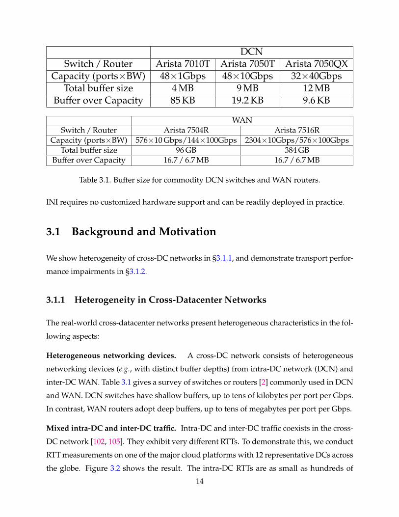
Mixed intra-DC and inter-DC traffic. Intra-DC and inter-DC traffic coexists in the cross-
DC network [102, 105]. They exhibit very different RTTs. To demonstrate this, we conduct
RTT measurements on one of the major cloud platforms with 12 representative DCs across
the globe. Figure 3.2 shows the result. The intra-DC RTTs are as small as hundreds of
14
North E
urope
West
Europe
East U
S 1
East U
S 2
Centra
l US 1
Centra
l US 2
Centra
l US 3
Centra
l US 4
West
US 1
West
US 2
East A
sia
Southe
ast A
sia
North EuropeWest Europe
East US 1East US 2
Central US 1Central US 2Central US 3Central US 4
West US 1West US 2
East AsiaSoutheast Asia
100ms
101ms
102ms
Figure 3.2. RTT Heat Map in Cross-DC Network.
microseconds. In contrast, the inter-DC RTTs vary from several milliseconds to hundreds
of milliseconds.
Different administrative control. Cloud operators have full control over DCN, but do
not always control the WAN devices. This is because many cloud operators lease the
network resource (e.g., guaranteed bandwidth) from Internet service providers (ISPs) and
WAN gears are maintained by the ISPs. As a result, some switch features, e.g., ECN, may
not be well supported [19, 70] (either disabled or configured with undesirable marking
thresholds) in WAN.
The heterogeneity imposes great challenges in transport design. Ideally, transport pro-
tocols should take congestion location (buffer depth), traffic type (RTT) and supported
mechanism (e.g., ECN) into consideration. We show how prior designs are impacted with-
out considering the heterogeneity in the following subsection (§3.1.2).
3.1.2 Single Signal’s Limitations under Heterogeneity
Most of the existing transport protocols [11, 124, 23, 83, 25, 16] use either ECN or delay
as the congestion signal. While they may work well in either DCN or WAN, we find that
15
... ...... ...
DC A Border Router DC B Border Router
DC Switch 1 DC Switch 2
DC Switch 3
DC Switch 4
Rack 1 Servers Rack 2 Servers Rack 3 Servers Rack 4 Servers
InterDC WAN Link
Figure 3.3. Cross-Datacenter Network Testbed.
ECN or delay alone cannot handle heterogeneity. We conduct extensive experiments to
study the performance impairments of leveraging ECN or delay signal alone in cross-DC
networks.
Testbed: We build a testbed (Figure 3.3) that emulates 2 DCs connected by an inter-DC
WAN link. Each DC has 1 border router, 2 DC switches and 24 servers. All links have
1 Gbps capacity. The intra-DC and inter-DC base RTTs (without queueing) are ∼ 200 µs
and ∼ 10 ms 1, respectively. The maximum per-port buffer size of DC switch and border
router are ∼450 and 10,000 1.5 KB-MTU-sized packets, respectively.
Schemes Experimented: Instead of enumerating every transport protocol, we select sev-
eral transport solutions that are representative for their own category based on the con-
gestion signal and are readily deployable with solid Linux kernel implementation. Specif-
ically, we experiment Cubic [49], Vegas [23], BBR [25] and DCTCP [11]. Cubic is exper-
imented with and without ECN. ECN threshold at DC switches is set to 300 packets2
to guarantee high throughput for inter-DC traffic (as suggested by Figure 3.5(b)). ECN
is not enabled in the WAN segment. Vegas uses two parameters α and β to control the
lower and upper bound of excessive packets in flight. We experiment the default setting
(α = 2, β = 4) and scaled by 10 settings (α = 20, β = 40).
1Our DC border routers are emulated by servers with multiple NICs, so that we can use NETEM [7] toemulate inter-DC propagation delay.
2We have tuned the ECN threshold for both DCTCP and Cubic. The selected ECN marking thresholdachieves the best throughput. A higher one leads to higher loss rate and thus lower throughput. A lowerone also results in lower throughput due to frequent congestion notification.
16
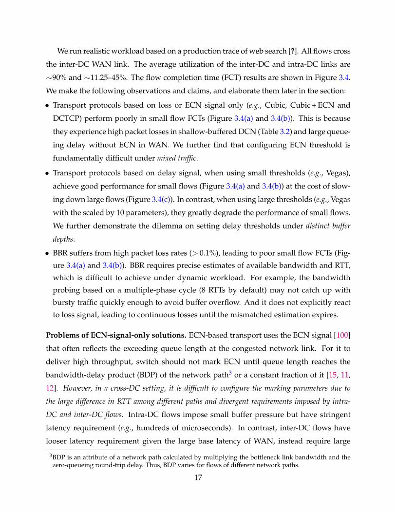
We run realistic workload based on a production trace of web search [?]. All flows cross
the inter-DC WAN link. The average utilization of the inter-DC and intra-DC links are
∼90% and ∼11.25–45%. The flow completion time (FCT) results are shown in Figure 3.4.
We make the following observations and claims, and elaborate them later in the section:
• Transport protocols based on loss or ECN signal only (e.g., Cubic, Cubic + ECN and
DCTCP) perform poorly in small flow FCTs (Figure 3.4(a) and 3.4(b)). This is because
they experience high packet losses in shallow-buffered DCN (Table 3.2) and large queue-
ing delay without ECN in WAN. We further find that configuring ECN threshold is
fundamentally difficult under mixed traffic.
• Transport protocols based on delay signal, when using small thresholds (e.g., Vegas),
achieve good performance for small flows (Figure 3.4(a) and 3.4(b)) at the cost of slow-
ing down large flows (Figure 3.4(c)). In contrast, when using large thresholds (e.g., Vegas
with the scaled by 10 parameters), they greatly degrade the performance of small flows.
We further demonstrate the dilemma on setting delay thresholds under distinct buffer
depths.
• BBR suffers from high packet loss rates (> 0.1%), leading to poor small flow FCTs (Fig-
ure 3.4(a) and 3.4(b)). BBR requires precise estimates of available bandwidth and RTT,
which is difficult to achieve under dynamic workload. For example, the bandwidth
probing based on a multiple-phase cycle (8 RTTs by default) may not catch up with
bursty traffic quickly enough to avoid buffer overflow. And it does not explicitly react
to loss signal, leading to continuous losses until the mismatched estimation expires.
Problems of ECN-signal-only solutions. ECN-based transport uses the ECN signal [100]
that often reflects the exceeding queue length at the congested network link. For it to
deliver high throughput, switch should not mark ECN until queue length reaches the
bandwidth-delay product (BDP) of the network path3 or a constant fraction of it [15, 11,
12]. However, in a cross-DC setting, it is difficult to configure the marking parameters due to
the large difference in RTT among different paths and divergent requirements imposed by intra-
DC and inter-DC flows. Intra-DC flows impose small buffer pressure but have stringent
latency requirement (e.g., hundreds of microseconds). In contrast, inter-DC flows have
looser latency requirement given the large base latency of WAN, instead require large
3BDP is an attribute of a network path calculated by multiplying the bottleneck link bandwidth and thezero-queueing round-trip delay. Thus, BDP varies for flows of different network paths.
17
0
100
200
300FC
T (m
s)CubicCubic+ECNDCTCP
VegasVegas-10BBR
(a) Small Flow - Average
0
100
200
300
400
FCT
(ms)
(b) Small Flow - 99th Tail
0
2000
4000
6000
8000
FCT
(ms)
(c) Large Flow - Average
0
200
400
600
FCT
(ms)
(d) All Flow - Average
Figure 3.4. Flow completion time (FCT) results. Small flow: Size < 100 KB. Large flow:Size > 10 MB.
buffer space for high WAN utilization.
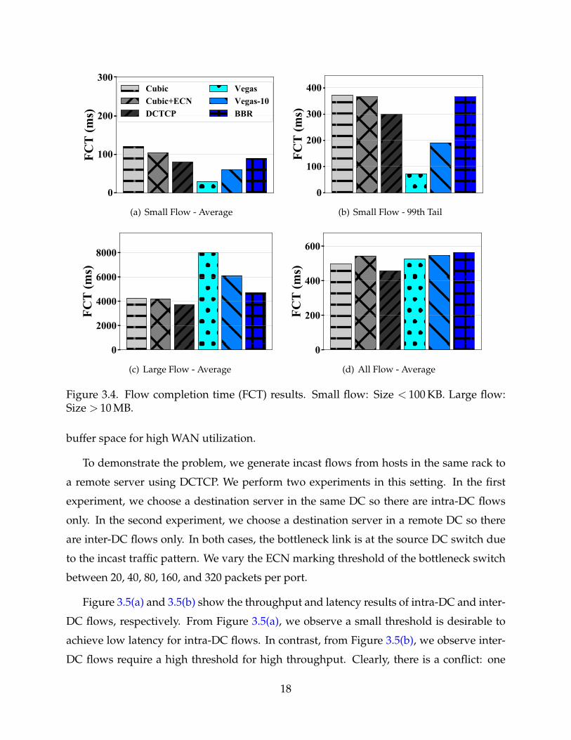
To demonstrate the problem, we generate incast flows from hosts in the same rack to
a remote server using DCTCP. We perform two experiments in this setting. In the first
experiment, we choose a destination server in the same DC so there are intra-DC flows
only. In the second experiment, we choose a destination server in a remote DC so there
are inter-DC flows only. In both cases, the bottleneck link is at the source DC switch due
to the incast traffic pattern. We vary the ECN marking threshold of the bottleneck switch
between 20, 40, 80, 160, and 320 packets per port.
Figure 3.5(a) and 3.5(b) show the throughput and latency results of intra-DC and inter-
DC flows, respectively. From Figure 3.5(a), we observe a small threshold is desirable to
achieve low latency for intra-DC flows. In contrast, from Figure 3.5(b), we observe inter-
DC flows require a high threshold for high throughput. Clearly, there is a conflict: one
18
100 200 300ECN Threshold - K (pkts)
0
250
500
750
1000T
hrou
ghpu
t (m
bps)
0
10
20
30
Infla
ted
RT
T R
atio
Better
(a) Intra-DC Flows: RTT=200 µs
100 200 300ECN Threshold - K (pkts)
0
250
500
750
1000
Thr
ough
put (
mbp
s)
0
10
20
30
Infla
ted
RT
T R
atio
Better
(b) Inter-DC Flows: RTT=10 ms
Figure 3.5. Conflicting ECN requirements in DCTCP. The right y-axis shows latency bythe inflated RTT ratio — the queueing-inflated RTT normalized by the base RTT (w/oqueueing).
cannot achieve high throughput and low latency simultaneously for both inter-DC and
intra-DC flows in the cross-DC network.
In fact, achieving high utilization over cross-DC is non-trivial because intra-DC switches
have shallow buffers — the shallow buffer is easily overwhelmed by bursty large-BDP
cross-DC flows (we call it buffer mismatch). We confirm that by measuring the packet loss
rate (PLR) in previous dynamic workload experiments. Table 3.2 shows the results. We
find that packet losses happen within DCN mostly (> 80%), even though inter-DC WAN is
more heavily loaded than intra-DC links. The high losses then lead to low throughput for
loss-sensitive protocols. Large-BDP cross-DC traffic is a key factor of the problem. We re-
peat the same experiments with the inter-DC link delay set to 0. All traffic is now with low
BDPs. We observe small PLRs (< 10×10−5) within DCN for all ECN-based schemes this
time. Further, we find that naively pacing packets like in BBR cannot completely resolve
the problem. For example, Cubic with FQ/pacing [34] has similar high PLR (66×10−5) in
DCN compared to raw Cubic.
Cubic Cubic + ECN DCTCP78 / 10 24 / 6 19 / < 1
Table 3.2. DCN / WAN Packet Loss Rate (10−5).
In addition, ECN-based transport protocols require ECN marking support from all net-
work switches. However, ECN marking may not be well supported. It is either disabled
19
1 5 10 15 20Delay Threshold Scaled by N
0
2
4
6
8
10
Lar
ge F
low
FC
T (s
ec)
0
10
20
30
PLR
(10
5 ) in
DC
N
Figure 3.6. Dilemma in setting delay threshold. The left y-axis shows throughput by theflow completion time (FCT) of large flows. The right y-axis shows packet loss rate (PLR)inside DCN.
or configured with undesirable marking thresholds in WAN (discussed in §3.1.1). As a
result, ECN-based transport such as DCTCP may fall back on using packet loss signal,
leading to high packet losses and long queueing delay.
Problems of delay-signal-only solutions. Delay-based transports use the delay signal [23,
83] that reflects the cumulative end-to-end network delay. Typically, they have a threshold
to control the total amount of in-flight traffic. However, given different buffer depths in WAN
and DCN, a dilemma arises when setting the delay threshold — either inter-DC throughput or
intra-DC latency is sacrificed.
Cross-DC flows may face congestion either in WAN or DCN. Delay signal handles both
indistinguishablly given its end-to-end nature. On the one hand, if we assume congestion
occurs in WAN, the delay thresholds should be large enough (usually in proportion to
the BDP) to fully utilize the WAN bandwidth. However, if the bottleneck resides in the
DCN instead, the large thresholds (e.g., 10 ms× 1 Gbps = 1.25 MB) can easily exceed the
DC switch shallow buffers (e.g., 83 KB per Gbps) and cause frequent packet losses. On the
other hand, if we assume congestion happens in DCN, the delay thresholds should be low
enough (at least bounded by the DC switch buffer sizes) to avoid severe intra-DC packet
losses. However, if the bottleneck resides in WAN instead, the low thresholds can greatly
impair the bandwidth utilization. In sum, the dilemma of setting delay thresholds arises.
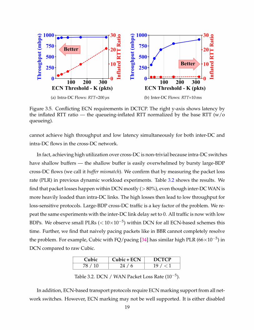
To demonstrate the problem, we run the same benchmark workloads used earlier in
20
the section. We experiment Vegas with the default setting (α = 2, β = 4) and scaled by
N settings (α = 2× N, β = 4× N), where N is set to 1, 5, 10, 15, 20. Results are shown
in Figure 3.6. On the one hand, small delay thresholds degrade the inter-DC throughput,
leading to high average FCT for large flows. On the other hand, large delay thresholds
increase packet losses significantly in shallow-buffered DCN. Therefore, setting the delay
thresholds are faced with a dilemma of either hurting inter-DC throughput or degrading
intra-DC packet loss rate.
In addition, low delay thresholds impose harsh requirement over accurate delay mea-
surement, for which extra device supports (e.g., NIC prompt ACK in [83]) are needed.
3.2 Design
We introduce our design rationale in §3.2.1, describe the detailed GEMINI congestion
control algorithm in §3.2.2, and provide guidelines for setting parameters in §3.3.3.
3.2.1 Design Rationale
How to achieve persistent low latency in the heterogeneous network environment?
Persistent low latency implies low end-to-end queueing delay and near zero packet loss.
Obviously, ECN, as a per-hop signal, is not a good choice for bounding the end-to-end la-
tency; not to mention, ECN has limited availability in WAN. If we use delay signal alone,
small delay threshold is necessary for low loss given the DC switch shallow buffer. How-
ever, with a small amount of in-flight traffic, we may not be able to fill the network pipe
of the WAN segment (demonstrated in §3.1.2).
Instead of using a single type of signal alone, we integrate ECN and delay signals to
address this challenge. In particular, delay signal, given its end-to-end nature, is effec-
tively used to bound the total in-flight traffic; and ECN signal, as a per-hop signal, is
leveraged to control the per-hop queues. Aggressive ECN marking is performed at the
DC switch to prevent shallow buffer overflow. Thus, the constraint of using small delay
thresholds is removed, leaving more space to improve WAN utilization. In this way, the
aforementioned dilemma of delay-based transport is naturally resolved.
21
How to maintain high throughput for inter-DC traffic in shallow-buffered DCN? A ma-
jority of transport (e.g., DCTCP) follow additive-increase multiplicative-decrease (AIMD)
congestion control rule. The queue length they drain in each window reduction is pro-
portionate to BDP (C× RTT) [15, 11, 12]. Essentially, the queue length drained each time
should be smaller than the switch buffer size to avoid buffer empty and maintain full
throughput. Thus, given large RTT range in cross-DC network, high buffers are required.
In deep-buffered WAN, setting a moderately high delay threshold works well to balance
throughput and latency. However, in shallow-buffered DCN, aggressive ECN marking is
required for low queueing and low loss rate. With limited buffer space, sustaining high
throughput gets extremely difficult (demonstrated in §3.1.2).
To address this buffer mismatch challenge, we modulate the aggressiveness of ECN-
triggered window reduction by RTT. Maintaining high throughput, in effect, requires
large RTT flows to drain queues as small as small RTT flows do during window re-
duction. Intuitively, we make larger RTT flows reduce rates more gently, thus result-
ing in smoother “sawtooth” window and queue length dynamics. In this way, band-
width under-utilization can be effectively mitigated, while still using a small ECN mark-
ing threshold. The use of small ECN threshold leave enough headroom in the shallow
buffer switches because it keeps the average buffer occupancy low, reducing the delay
and packet drop.
Further, we adjust the window increase step in proportion to BDP. Conventional AIMD
adopts fixed constant window increase step for all flows. This either hurts convergence
speed of large-BDP inter-DC flows, or makes the system unstable for small-BDP intra-DC
flows. When BDP is large, AIMD requires more RTTs to climb to the peak rate, leading to
slower convergence. In contrast, when BDP is small, AIMD may frequently overshoot the
bottleneck bandwidth, resulting in more frequent losses and thus less stable performance.
Therefore, we adjust the window increase step in proportion to BDP for better robustness
under heterogeneity.
3.2.2 GEMINI Algorithm
GEMINI is a window-based congestion control algorithm that uses additive-increase and
multiplicative-decrease (AIMD). Following the design rationale above, GEMINI lever-
22
G
CongestionLevel in DCN
CongestionLevel in WAN
Received an ACK
Congestion Detected?
False
Congestion Avoidance
True
Window Reduction
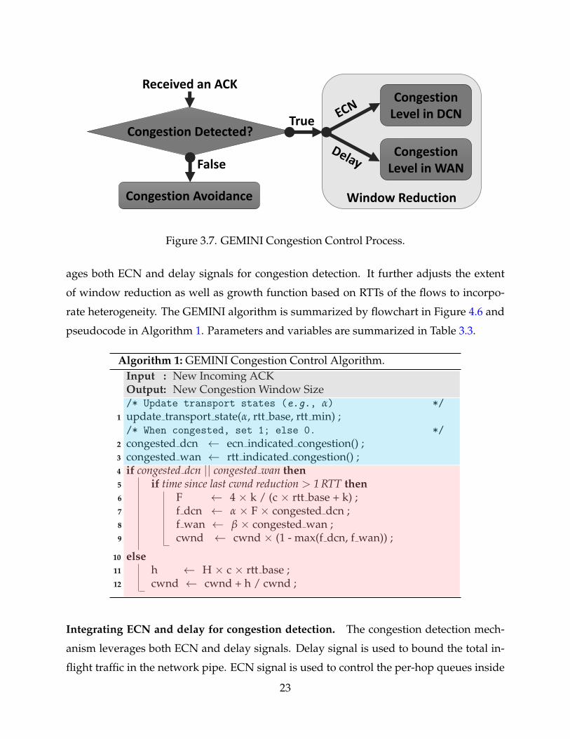
Figure 3.7. GEMINI Congestion Control Process.
ages both ECN and delay signals for congestion detection. It further adjusts the extent
of window reduction as well as growth function based on RTTs of the flows to incorpo-
rate heterogeneity. The GEMINI algorithm is summarized by flowchart in Figure 4.6 and
pseudocode in Algorithm 1. Parameters and variables are summarized in Table 3.3.
Algorithm 1: GEMINI Congestion Control Algorithm.Input : New Incoming ACKOutput: New Congestion Window Size/* Update transport states (e.g., α) */
1 update transport state(α, rtt base, rtt min) ;/* When congested, set 1; else 0. */
2 congested dcn ← ecn indicated congestion() ;3 congested wan ← rtt indicated congestion() ;4 if congested dcn || congested wan then5 if time since last cwnd reduction > 1 RTT then6 F ← 4 × k / (c × rtt base + k) ;7 f dcn ← α × F × congested dcn ;8 f wan ← β × congested wan ;9 cwnd ← cwnd × (1 - max(f dcn, f wan)) ;
10 else11 h ← H × c × rtt base ;12 cwnd ← cwnd + h / cwnd ;
Integrating ECN and delay for congestion detection. The congestion detection mech-
anism leverages both ECN and delay signals. Delay signal is used to bound the total in-
flight traffic in the network pipe. ECN signal is used to control the per-hop queues inside
23
DCN. By integrating ECN and delay signal, low latency can be achieved [118]. Specifi-
cally, DCN congestion is detected by ECN, so as to meet the stringent per-hop queueing
control requirement imposed by shallow buffers. WAN congestion is detected by delay,
because the end-to-end delay is dominated mostly in WAN than in DCN4.
DCN congestion is indicated by the ECN signal — the ECN-Echo flag set in the ACKs
received by the senders. The ECN signal is generated exactly the same as DCTCP. Data
packets are marked with Congestion Experienced (CE) codepoint when instantaneous
queueing exceeds marking threshold at the DC switches. Receivers then echo back the
ECN marks to senders through ACKs with the ECN-Echo flags. Given shallow-buffered
DCN, the ECN signal is leveraged with a small marking threshold for low packet losses.
WAN congestion is indicated by the delay signal — ACKs returned after data sending
with persistent larger delays: RTTmin > RTTbase + T, where RTTmin is the minimum RTT
observed in previous RTT (window); RTTbase, or simplified as RTT, is the base RTT (mini-
mum RTT observed during a long time); T is the delay threshold. Inspired by [90], we use
RTTmin instead of average or maximum RTTs, which can better detect persistent queueing
and tolerate transient queueing possibly caused by bursty traffic. Given deep-buffered
WAN, the delay signal is used with a moderately high threshold for high throughput and
bounded end-to-end latency.
When either of the two signals indicate congestion, we react to the signal by reduc-
ing the congestion window correspondingly. When both ECN and delay signals indicate
congestion, we react to the one of heavier congestion:
CWND = CWND× (1−max( f dcn, f wan))
where f dcn determines the extent of window reduction for congestion in DCN; and
f wan determines that of WAN. We show how to compute them later in the section.
Modulating the ECN-triggered window reduction aggressiveness by RTT. The win-
dow reduction algorithm aims to maintain full bandwidth utilization while reducing the
network queueing as much as possible. This essentially requires switch buffer never un-
4The delay signal cannot exclude the DCN queueing delay. However, DCN queueing is often low due toDCN shallow buffer, much lower than that on WAN. Such a low DCN queueing delay has very limitedimpact with a relative large delay threshold as shown in Table 3.5.
24
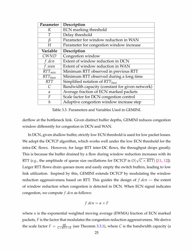
Parameter DescriptionK ECN marking thresholdT Delay thresholdβ Parameter for window reduction in WANH Parameter for congestion window increase
Variable DescriptionCWND Congestion window
f dcn Extent of window reduction in DCNf wan Extent of window reduction in WAN
RTTmin Minimum RTT observed in previous RTTRTTbase Minimum RTT observed during a long time
RTT Simplified notation of RTTbaseC Bandwidth capacity (constant for given network)α Average fraction of ECN marked packetsF Scale factor for DCN congestion controlh Adaptive congestion window increase step
Table 3.3. Parameters and Variables Used in GEMINI.
derflow at the bottleneck link. Given distinct buffer depths, GEMINI reduces congestion
window differently for congestion in DCN and WAN.
In DCN, given shallow buffer, strictly low ECN threshold is used for low packet losses.
We adopt the DCTCP algorithm, which works well under the low ECN threshold for the
intra-DC flows. However, for large RTT inter-DC flows, the throughput drops greatly.
This is because the buffer drained by a flow during window reduction increases with its
RTT (e.g., the amplitude of queue size oscillations for DCTCP is O(√
C× RTT) [11, 12]).
Larger RTT flows drain queues more and easily empty the switch buffers, leading to low
link utilization. Inspired by this, GEMINI extends DCTCP by modulating the window
reduction aggressiveness based on RTT. This guides the design of f dcn — the extent
of window reduction when congestion is detected in DCN. When ECN signal indicates
congestion, we compute f dcn as follows:
f dcn = α× F
where α is the exponential weighted moving average (EWMA) fraction of ECN marked
packets, F is the factor that modulates the congestion reduction aggressiveness. We derive
the scale factor F = 4KC×RTT+K (see Theorem 3.3.1), where C is the bandwidth capacity (a
25
constant parameter for given network), RTT is the minimum RTT observed during a long
time, K is the ECN marking threshold. Thus, for intra-DC flows, following the guideline
in DCTCP by setting K = (C × RTT)/7, we have F = 12 , exactly matching the DCTCP
algorithm. For inter-DC flows with larger RTTs, F gets smaller, leading to smaller window
reduction and smoother queue length oscillation.
In WAN, given much deeper buffer, high throughput can be more easily maintained
than in DCN. In fact, window reduction based on a fixed constant, like standard TCPs [61,
49] do, is enough for high throughput. There are potentially a wide range of threshold
settings to effectively work with (see §3.3.3). This guides the design of f wan — the extent
of window reduction when congestion is detected in WAN. When RTT signal indicates
congestion, we compute f wan as follows:
f wan = β
where β is a window decrease parameter for WAN.
The window reduction is performed no more than once per RTT, which is the mini-
mum time required to get feedback from the network under the new sending rate. De-
spite the congestion detection by ECN and delay, packet losses and timeouts may still
occur. For that, we keep the same fast recovery and fast retransmission mechanism from
TCP.
Window increase that adapts to RTT variation. The congestion avoidance algorithm
adapts to RTTs (or BDP when the bandwidth capacity is fixed) to help balance convergence
speed and stability. For conventional AIMD, large BDP flows need more RTTs to climb to
the peak rate, leading to slow convergence; while small BDP flows may frequently over-
shoot the bottleneck bandwidth, leading to unstable performance. Therefore, adjusting
the window increasing step in proportion to BDP compensates the RTT variation, and
makes the system more robust under diverse RTTs. Further, it also mitigates RTT unfair-
ness [73, 24], which in turn helps to improve tail performance. This leads to the adaptive
congestion window increase factor h. When there is no congestion indication, for each
ACK,
CWND = CWND +h
CWND
26
h is a congestion avoidance factor in proportion to BDP: h = H × C × RTT, where H is
a constant parameter, C is the bandwidth capacity, RTT is the minimum RTT observed
during a long time. We prove that factor h together with the scale factor F guarantees
bandwidth fair-sharing regardless of different RTTs in Appendix §3.3.2.
Summary. GEMINI resolves the conflicting requirements imposed by network hetero-
geneity naturally by integrating ECN and delay signal, specifically, (1) in face of distinct
buffer depths, GEMINI handles congestion in WAN and DCN by delay and ECN signal
respectively, simultaneously meeting the need of strictly low latency in DCN and high
bandwidth utilization in WAN; (2) in face of mixed traffic with large range of RTTs in
shallow-buffered DCN, GEMINI maintains high throughput by modulating the window
reduction aggressiveness based on RTTs. In particular, large RTT flows reduce the win-
dows more gently, effectively avoiding buffer empty and bandwidth under-utilization.
This is achieved by scale factor F, which guarantees full throughput under limited buffer
space or small ECN threshold at steady state (see Theorem 3.3.1 with detailed proof). Be-
sides, Gemini adapts its window increase step in proportion to the RTT, achieving faster
convergence speed and better fairness. Further, window growth function is also adapted
to RTTs. This leads to faster convergence when more bandwidths are available, especially
for those large RTT flows.
3.3 Theoretical Analysis
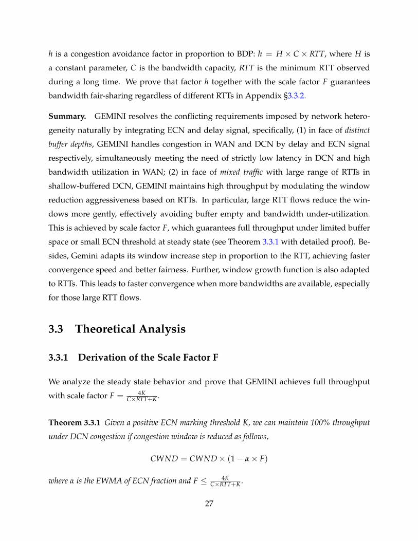
3.3.1 Derivation of the Scale Factor F
We analyze the steady state behavior and prove that GEMINI achieves full throughput
with scale factor F = 4KC×RTT+K .
Theorem 3.3.1 Given a positive ECN marking threshold K, we can maintain 100% throughput
under DCN congestion if congestion window is reduced as follows,
CWND = CWND× (1− α× F)
where α is the EWMA of ECN fraction and F ≤ 4KC×RTT+K .
27
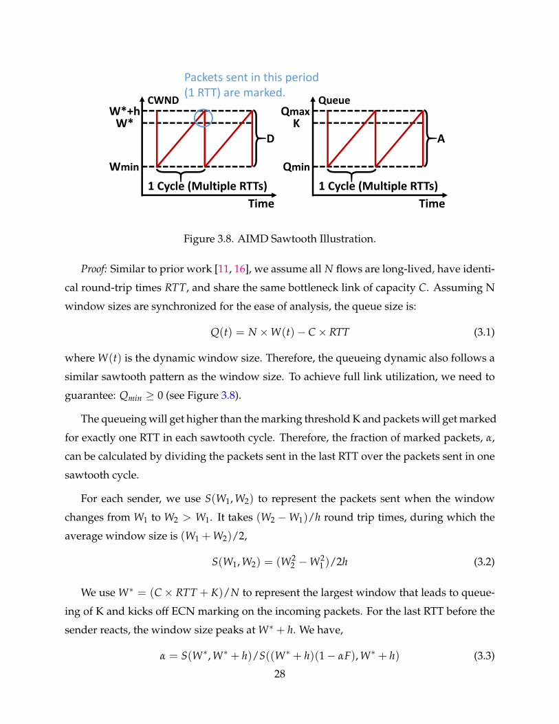
D
W*+hW*
Wmin
CWND
Packets sent in this period (1 RTT) are marked.
Time
1 Cycle (Multiple RTTs)
A
QmaxK
Qmin
Queue
Time
1 Cycle (Multiple RTTs)
Figure 3.8. AIMD Sawtooth Illustration.
Proof: Similar to prior work [11, 16], we assume all N flows are long-lived, have identi-
cal round-trip times RTT, and share the same bottleneck link of capacity C. Assuming N
window sizes are synchronized for the ease of analysis, the queue size is:
Q(t) = N ×W(t)− C× RTT (3.1)
where W(t) is the dynamic window size. Therefore, the queueing dynamic also follows a
similar sawtooth pattern as the window size. To achieve full link utilization, we need to
guarantee: Qmin ≥ 0 (see Figure 3.8).
The queueing will get higher than the marking threshold K and packets will get marked
for exactly one RTT in each sawtooth cycle. Therefore, the fraction of marked packets, α,
can be calculated by dividing the packets sent in the last RTT over the packets sent in one
sawtooth cycle.
For each sender, we use S(W1, W2) to represent the packets sent when the window
changes from W1 to W2 > W1. It takes (W2 −W1)/h round trip times, during which the
average window size is (W1 + W2)/2,
S(W1, W2) = (W22 −W2
1 )/2h (3.2)
We use W∗ = (C× RTT + K)/N to represent the largest window that leads to queue-
ing of K and kicks off ECN marking on the incoming packets. For the last RTT before the
sender reacts, the window size peaks at W∗ + h. We have,
α = S(W∗, W∗ + h)/S((W∗ + h)(1− αF), W∗ + h) (3.3)
28
Combining (3.2) and (3.3) and rearranging, we get:
α2F(2− αF) = (2W∗ + h)h/(W∗ + h)2 ≈ 2h/W∗ (3.4)
We assume αF/2 is small for approximation:
α ≈√
h/FW∗ (3.5)
Therefore, the queueing amplitude A in Figure 3.8 can be obtained (N flows):
D = (W∗ + h)− (W∗ + h)(1− αF) = (W∗ + h)αF (3.6)
A = N × D = N(W∗ + h)αF ≈ N√
hFW∗
=√
NhF(C× RTT + K)(3.7)
With (3.1), we have:
Qmax = N × (W∗ + h)− C× RTT = K + Nh (3.8)
With (3.7) and (3.8), the minimum queue length is:
Qmin = Qmax − A = K + Nh−√
NhF(C× RTT + K) (3.9)
Finally, to find the relationship between the scale factor F and the ECN marking thresh-
old K, we minimize (3.9) over N so that the value is no smaller than zero (i.e., no network
under-utilization). We have:
F ≤ 4KC× RTT + K
(3.10)
As we can see, given a fixed ECN marking threshold K, the larger RTT a flow has, the
smaller F it gets. Therefore, the flows with larger RTTs adjust window more smoothly to
achieve high throughput.
Note that the theoretical analysis here is a generalized form of that in the DCTCP pa-
per [11] and the result is consistent with it. Specifically, when following the DCTCP algo-
rithm by setting a constant parameter F = 12 , we have K ≥ (C×RTT)/7, exactly matching
the original DCTCP guideline.
29
3.3.2 Proof of RTT-fairness
We show GEMINI achieves fair-share of the bottleneck bandwidth in DCN where inter-
DC and intra-DC flows coexist.
Theorem 3.3.2 GEMINI achieves ideal RTT-fairness with following AIMD rule:
Decrease: When congestion indicated by ECN per RTT,
CWND = CWND× (1− α× F)
where α is the ECN fraction and F = 4KC×RTT+K .
Increase: When there is no congestion indication per ACK,
CWND = CWND +h
CWND
where h is an adaptive congestion avoidance function in proportion to BDP: h ∝ RTT.
Proof: From previous subsection, we know that the average window size is:
W =W∗ + h + (W∗ + h)× (1− αF)
2(3.11)
Therefore, when two flows competing for one bottleneck link reach the steady state:
W1
W2=
(W∗1 + h1)× (1− α1F12 )
(W∗2 + h2)× (1− α2F22 )≈
W∗1W∗2
(3.12)
when assuming that 1 >> αF2 and W∗ >> h.
When two flows F1 and F2 with different RTTs (assuming RTT1 < RTT2) are competing
on one bottleneck link, Equation 3.5 is still valid for the small RTT flow F1, in other form:
W∗1 = 2h1/(F1α21) (3.13)
However, Equation 3.13 does not hold for large RTT flow F2. When small RTT flow F1
reduces its CWND as soon as it gets the ECN feedback after RTT1, the bottleneck queue
length drops immediately and packets of large RTT flow F2 will stop being marked with
30
ECN. So flow F2 will get only around S(W∗2 , W∗2 + h2)RTT1RTT2
packets marked with ECN.
Following same approach from Equation 3.3 to 3.13, for F2,
W∗2 = 2h2/(F2α22)×
RTT1
RTT2(3.14)
Packets traversing the same link have the same probability to be ECN marked. Thus,
we get:
α1 = α2 (3.15)
Plugging Equation 3.10, 3.13, 3.14, 3.15 into Equation 3.12, we have:
W1
W2=
F2
F1=
C× RTT1 + KC× RTT2 + K
(3.16)
When assuming the average queue length is around K. We have the average RTT:
RTT ≈ RTT +KC
(3.17)
Therefore, we have the bandwidth sharing ratio:
R1
R2=
W1
RTT1/
W2
RTT2≈ 1 (3.18)
where Ri denotes the sending rate of flow i.
3.3.3 Guidelines for Setting Parameters
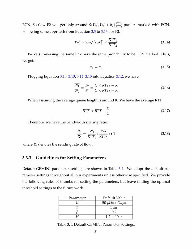
Default GEMINI parameter settings are shown in Table 3.4. We adopt the default pa-
rameter settings throughout all our experiments unless otherwise specified. We provide
the following rules of thumbs for setting the parameters, but leave finding the optimal
threshold settings to the future work.
Parameter Default ValueK 50 pkts / GbpsT 5 msβ 0.2H 1.2× 10⁻⁷
Table 3.4. Default GEMINI Parameter Settings.
31
ECN Marking Threshold (K). The scaling factor F ensures full link utilization given an
ECN threshold (K). As a lower K indicates a smaller queue, setting K as low as possible
may seem desirable. However, there is actually a trade-off here. When K is small, the
scaling factor F is also small, making the flows reduce their congestion window slowly,
leading to slower convergence. Therefore, we recommend a moderately small threshold
of 50 packets per Gbps. In addition, to mitigate the effect of packet bursts (especially for
large BDP inter-DC traffic), we use a per-flow rate limiter at the sender to evenly pace out
each packet.
Queueing Delay Threshold (T). T should be sufficiently large to achieve high through-
put in the cross-DC pipe. It should also leave enough room to filter out the interference
from the DCN queueing delay. In practice (§3.1.1), RTTs (include queueing) in production
DCNs are at most 1ms. We recommend to set T = 5 ms that is higher enough to remove
the potential DCN queueing interference (see Table 3.5).
Window Decrease Parameter (β). GEMINI reduces the window size by β multiplica-
tively when WAN congestion is detected. To avoid bandwidth under-utilization, we need
to have queueing headroom T > β1−β RTT, or β < T
T+RTT based on the buffer sizing the-
ory [15]. Thus, we have β < 0.33, assuming RTT = 10ms and T = 5ms. We recommend
to set β = 0.2 (the same reduction factor as Cubic and Vegas) for smoother ’sawtooth’. In
practice, this is stricter than necessary as competing flows are often desynchronized [15].
We show that the recommended T and β settings can well serve the cross-DC networks in
a wide range of RTTs in §3.4.2.
Window Increase Parameter (H). In congestion avoidance phase, GEMINI grows its
congestion window size by h MSS every RTT. In our implementation, we actually scale
h with BDP (C × RTT) instead of RTT only, that is, h = H × C × RTT. This is reasonable
as large BDP means potentially large window size. Scaling h with BDP achieves better
balance between convergence speed and stability. We recommend to set H = 1.2× 10⁻⁷
with bounded minimum/maximum increase speed of 0.1 / 5 respectively as a protection.
This leads to h = 1 when C = 1Gbps and RTT = 8ms, a middle ground between large
BDP inter-DC traffic and low BDP intra-DC traffic.
32
3.4 Evaluation
In this section, we present the detailed GEMINI Linux kernel implementation and evalua-
tion setup in §3.4.1, and conduct extensive experiments to answer the following questions:
§3.4.2 Does GEMINI achieve high throughput and low latency? We show that GEMINI
achieves higher throughput (1−1.5×) and equally low delay compared to DCTCP under
DCN congestion; lower delay (> 7×) and equally high throughput compared to Cubic
under WAN congestion.
§3.4.3 Does GEMINI converge quickly, fairly and stably? In static traffic experiments,
we show that GEMINI converges to the bandwidth fair-sharing point quickly and stably
under both DCN congestion and WAN congestion, regardless of distinct RTTs differed
by up to 64 times.
§3.4.4 How does GEMINI perform under realistic workload? In realistic traffic experi-
ments, we show that under both cases (intra-DC heavy or inter-DC heavy traffic pat-
tern), GEMINI persistently achieves the one of the best flow completion times for both
short and large flows.
3.4.1 Implementation and Experiment Setup
GEMINI Implementation: GEMINI is developed based on Linux kernel 4.9.25. Linux
TCP stack has a universal congestion control interface defined in struct tcp congestion ops,
which supports various pluggable congestion control modules. The congestion window
reduction algorithm is implemented in in ack event() and ssthresh(). The congestion
avoidance algorithm is implemented in cong avoid().
Testbed: Experiments are conducted in 2 testbeds with 1Gbps and 10Gbps capacity re-
spectively. The 1Gbps testbed has a larger scale than the 10Gbps one. Both testbeds share
the same topology as shown in Figure 3.3. There are 2 data centers connected by an inter-
DC WAN link. Each data center has one border router, two DC switches and multiple
servers. Border routers are emulated by servers with multiple NICs, so that we can use
NETEM [7] to emulate WAN propagation delay. Intra-DC (under single ToR) and inter-DC
base RTTs are∼ 200 µs and∼ 10 ms, respectively. Dynamic buffer allocation [33] at the DC
33
switches is enabled like most operators do in real deployments to absorb bursts.
• Large-scale 1Gbps Testbed: There are 50 Dell PowerEdge R320 servers and 4 Pica8 P-3297
switches. Pica8 P-3297 switches have 4MB buffer shared by 48 ports. The WAN buffer is
set to 10,000 1.5 KB-MTU-sized packets per port. All network interfaces are set to 1Gbps
full duplex mode.
• Small-scale 10Gbps Testbed: There are 10 HUAWEI RH1288 V2 servers and 1 Mellanox
SN2100 switch (divided into multiple VLANs). Mellanox SN2100 switches have 16MB
buffer shared by 16 ports. The WAN buffer is set to 80,000 1.5 KB-MTU-sized packets
per port. All network interfaces are set to 10Gbps full duplex mode.
Remark: We show results of the large-scale testbed by default.
Benchmark Workloads: We generate realistic workloads based on traffic patterns that
have been observed in a data center supporting web search [11]. Flows arrive by the
Poisson process and the source and destination is chosen randomly from a configured
IP pool. The workload is heavy-tailed with about 50% small flows (size < 100 KB) while
95% of all bytes belong to the the larger 30% of the flows of size greater than 1 MB. We
run the workload with a publicly available traffic generator that has been used by other
work [78, 17].
Performance Metrics: We measure flow throughput and packet round-trip time in §3.4.2
to quantify the throughput and latency. We measure throughput in §3.4.3 to demonstrate
the convergence, stability and fairness. For realistic experiments in §3.4.4, similar to prior
work [11, 14], we use flow completion time (FCT) as the main performance metric.
Schemes Compared: We experiment Cubic [49], Vegas [23], BBR [25], DCTCP [11] and
GEMINI. All these protocols have implementations in Linux kernel TCP and are readily
deployable in practice. Cubic is the default loss-based congestion control algorithm used
in Linux system. It is experimented with and without ECN. DCTCP is an ECN-based
congestion control algorithm designed to achieve high throughput, low latency and high
burst tolerance in DCN. The ECN marking threshold is set to 300 packets to guarantee
high throughput for inter-DC traffic. Vegas uses two parameters α and β to control the
lower and upper bound of excessive packets in flight. We experiment the default setting
(α = 2, β = 4) and scaled by 10 settings (α = 20, β = 40) to show the throughput and
34
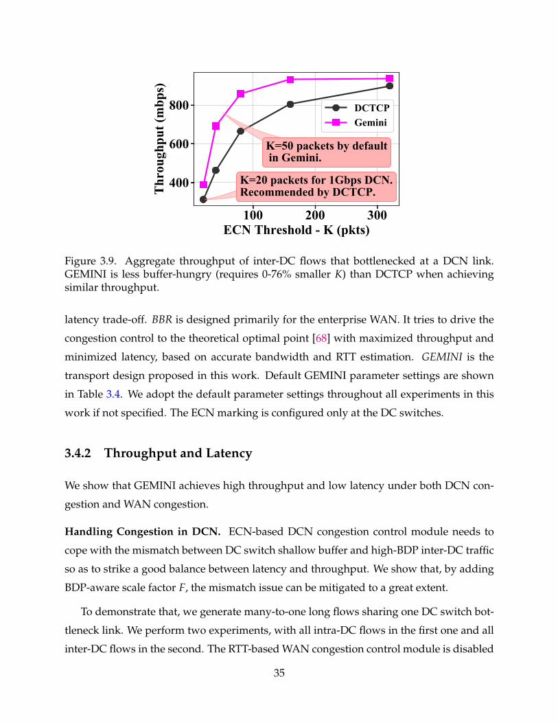
100 200 300ECN Threshold - K (pkts)
400
600
800
Thr
ough
put (
mbp
s)K=50 packets by default in Gemini.
K=20 packets for 1Gbps DCN.Recommended by DCTCP.
DCTCPGemini
Figure 3.9. Aggregate throughput of inter-DC flows that bottlenecked at a DCN link.GEMINI is less buffer-hungry (requires 0-76% smaller K) than DCTCP when achievingsimilar throughput.
latency trade-off. BBR is designed primarily for the enterprise WAN. It tries to drive the
congestion control to the theoretical optimal point [68] with maximized throughput and
minimized latency, based on accurate bandwidth and RTT estimation. GEMINI is the
transport design proposed in this work. Default GEMINI parameter settings are shown
in Table 3.4. We adopt the default parameter settings throughout all experiments in this
work if not specified. The ECN marking is configured only at the DC switches.
3.4.2 Throughput and Latency
We show that GEMINI achieves high throughput and low latency under both DCN con-
gestion and WAN congestion.
Handling Congestion in DCN. ECN-based DCN congestion control module needs to
cope with the mismatch between DC switch shallow buffer and high-BDP inter-DC traffic
so as to strike a good balance between latency and throughput. We show that, by adding
BDP-aware scale factor F, the mismatch issue can be mitigated to a great extent.
To demonstrate that, we generate many-to-one long flows sharing one DC switch bot-
tleneck link. We perform two experiments, with all intra-DC flows in the first one and all
inter-DC flows in the second. The RTT-based WAN congestion control module is disabled
35
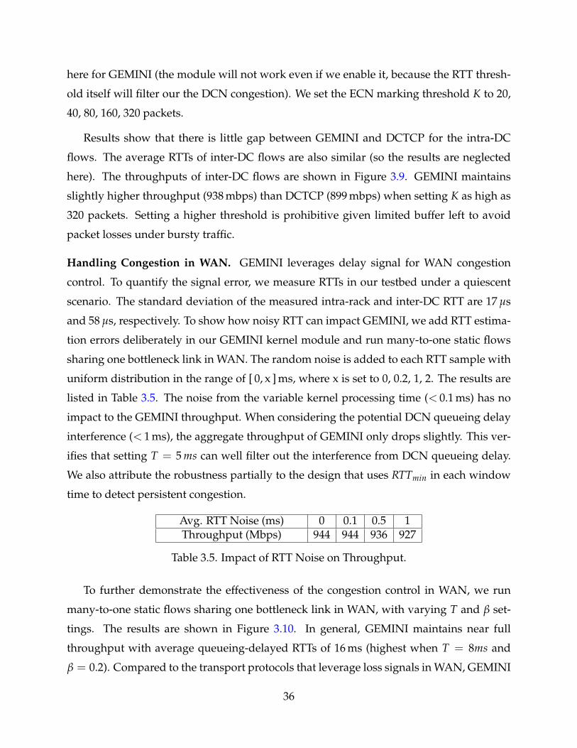
here for GEMINI (the module will not work even if we enable it, because the RTT thresh-
old itself will filter our the DCN congestion). We set the ECN marking threshold K to 20,
40, 80, 160, 320 packets.
Results show that there is little gap between GEMINI and DCTCP for the intra-DC
flows. The average RTTs of inter-DC flows are also similar (so the results are neglected
here). The throughputs of inter-DC flows are shown in Figure 3.9. GEMINI maintains
slightly higher throughput (938 mbps) than DCTCP (899 mbps) when setting K as high as
320 packets. Setting a higher threshold is prohibitive given limited buffer left to avoid
packet losses under bursty traffic.
Handling Congestion in WAN. GEMINI leverages delay signal for WAN congestion
control. To quantify the signal error, we measure RTTs in our testbed under a quiescent
scenario. The standard deviation of the measured intra-rack and inter-DC RTT are 17 µs
and 58 µs, respectively. To show how noisy RTT can impact GEMINI, we add RTT estima-
tion errors deliberately in our GEMINI kernel module and run many-to-one static flows
sharing one bottleneck link in WAN. The random noise is added to each RTT sample with
uniform distribution in the range of [ 0, x ] ms, where x is set to 0, 0.2, 1, 2. The results are
listed in Table 3.5. The noise from the variable kernel processing time (< 0.1 ms) has no
impact to the GEMINI throughput. When considering the potential DCN queueing delay
interference (< 1 ms), the aggregate throughput of GEMINI only drops slightly. This ver-
ifies that setting T = 5 ms can well filter out the interference from DCN queueing delay.
We also attribute the robustness partially to the design that uses RTTmin in each window
time to detect persistent congestion.
Avg. RTT Noise (ms) 0 0.1 0.5 1Throughput (Mbps) 944 944 936 927
Table 3.5. Impact of RTT Noise on Throughput.
To further demonstrate the effectiveness of the congestion control in WAN, we run
many-to-one static flows sharing one bottleneck link in WAN, with varying T and β set-
tings. The results are shown in Figure 3.10. In general, GEMINI maintains near full
throughput with average queueing-delayed RTTs of 16 ms (highest when T = 8ms and
β = 0.2). Compared to the transport protocols that leverage loss signals in WAN, GEMINI
36
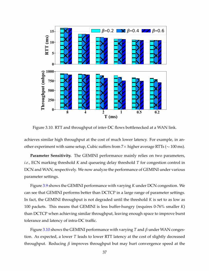
0
5
10
15
RT
T (m
s)
=0.2 =0.4 =0.6
8 4 2 1 0.5 0.2T (ms)
0
250
500
750
1000
Thr
ough
put (
mbp
s)
Figure 3.10. RTT and throughput of inter-DC flows bottlenecked at a WAN link.
achieves similar high throughput at the cost of much lower latency. For example, in an-
other experiment with same setup, Cubic suffers from 7× higher average RTTs (∼ 100 ms).
Parameter Sensitivity. The GEMINI performance mainly relies on two parameters,
i.e., ECN marking threshold K and queueing delay threshold T for congestion control in
DCN and WAN, respectively. We now analyze the performance of GEMINI under various
parameter settings.
Figure 3.9 shows the GEMINI performance with varying K under DCN congestion. We
can see that GEMINI performs better than DCTCP in a large range of parameter settings.
In fact, the GEMINI throughput is not degraded until the threshold K is set to as low as
100 packets. This means that GEMINI is less buffer-hungry (requires 0-76% smaller K)
than DCTCP when achieving similar throughput, leaving enough space to improve burst
tolerance and latency of intra-DC traffic.
Figure 3.10 shows the GEMINI performance with varying T and β under WAN conges-
tion. As expected, a lower T leads to lower RTT latency at the cost of slightly decreased
throughput. Reducing β improves throughput but may hurt convergence speed at the
37
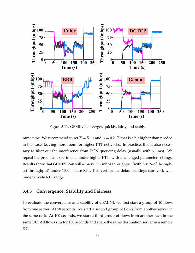
0 50 100 150 200 250Time (s)
0
25
50
75
100T
hrou
ghpu
t (m
bps)
Cubic
0 50 100 150 200 250Time (s)
0
25
50
75
100
Thr
ough
put (
mbp
s)
DCTCP
0 50 100 150 200 250Time (s)
0
25
50
75
100
Thr
ough
put (
mbp
s)
BBR
0 50 100 150 200 250Time (s)
0
25
50
75
100
Thr
ough
put (
mbp
s)
Gemini
Figure 3.11. GEMINI converges quickly, fairly and stably.
same time. We recommend to set T = 5 ms and β = 0.2. T that is a bit higher than needed
in this case, leaving more room for higher RTT networks. In practice, this is also neces-
sary to filter out the interference from DCN queueing delay (usually within 1 ms). We
repeat the previous experiments under higher RTTs with unchanged parameter settings.
Results show that GEMINI can still achieve 857 mbps throughput (within 10% of the high-
est throughput) under 100 ms base RTT. This verifies the default settings can work well
under a wide RTT range.
3.4.3 Convergence, Stability and Fairness
To evaluate the convergence and stability of GEMINI, we first start a group of 10 flows
from one server. At 50 seconds, we start a second group of flows from another server in
the same rack. At 100 seconds, we start a third group of flows from another rack in the
same DC. All flows run for 150 seconds and share the same destination server in a remote
DC.
38
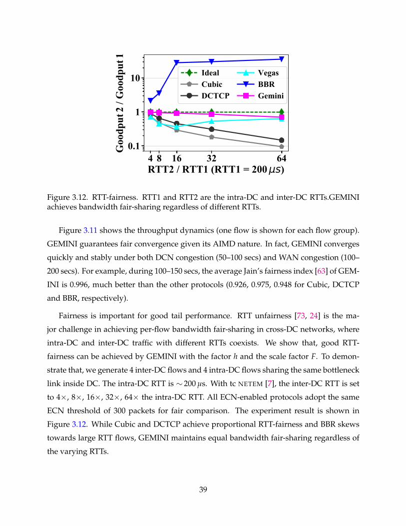
4 8 16 32 64RTT2 / RTT1 (RTT1 = 200 s)
0.1
1
10
Goo
dput
2 / G
oodp
ut1
IdealCubicDCTCP
VegasBBRGemini
Figure 3.12. RTT-fairness. RTT1 and RTT2 are the intra-DC and inter-DC RTTs.GEMINIachieves bandwidth fair-sharing regardless of different RTTs.
Figure 3.11 shows the throughput dynamics (one flow is shown for each flow group).
GEMINI guarantees fair convergence given its AIMD nature. In fact, GEMINI converges
quickly and stably under both DCN congestion (50–100 secs) and WAN congestion (100–
200 secs). For example, during 100–150 secs, the average Jain’s fairness index [63] of GEM-
INI is 0.996, much better than the other protocols (0.926, 0.975, 0.948 for Cubic, DCTCP
and BBR, respectively).
Fairness is important for good tail performance. RTT unfairness [73, 24] is the ma-
jor challenge in achieving per-flow bandwidth fair-sharing in cross-DC networks, where
intra-DC and inter-DC traffic with different RTTs coexists. We show that, good RTT-
fairness can be achieved by GEMINI with the factor h and the scale factor F. To demon-
strate that, we generate 4 inter-DC flows and 4 intra-DC flows sharing the same bottleneck
link inside DC. The intra-DC RTT is ∼ 200 µs. With tc NETEM [7], the inter-DC RTT is set
to 4×, 8×, 16×, 32×, 64× the intra-DC RTT. All ECN-enabled protocols adopt the same
ECN threshold of 300 packets for fair comparison. The experiment result is shown in
Figure 3.12. While Cubic and DCTCP achieve proportional RTT-fairness and BBR skews
towards large RTT flows, GEMINI maintains equal bandwidth fair-sharing regardless of
the varying RTTs.
39
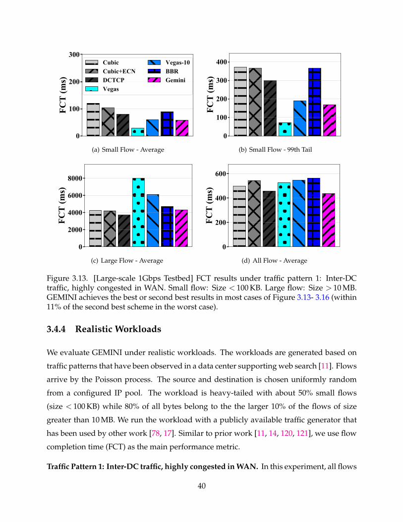
0
100
200
300FC
T (m
s)CubicCubic+ECNDCTCPVegas
Vegas-10BBRGemini
(a) Small Flow - Average
0
100
200
300
400
FCT
(ms)
(b) Small Flow - 99th Tail
0
2000
4000
6000
8000
FCT
(ms)
(c) Large Flow - Average
0
200
400
600
FCT
(ms)
(d) All Flow - Average
Figure 3.13. [Large-scale 1Gbps Testbed] FCT results under traffic pattern 1: Inter-DCtraffic, highly congested in WAN. Small flow: Size < 100 KB. Large flow: Size > 10 MB.GEMINI achieves the best or second best results in most cases of Figure 3.13- 3.16 (within11% of the second best scheme in the worst case).
3.4.4 Realistic Workloads
We evaluate GEMINI under realistic workloads. The workloads are generated based on
traffic patterns that have been observed in a data center supporting web search [11]. Flows
arrive by the Poisson process. The source and destination is chosen uniformly random
from a configured IP pool. The workload is heavy-tailed with about 50% small flows
(size < 100 KB) while 80% of all bytes belong to the the larger 10% of the flows of size
greater than 10 MB. We run the workload with a publicly available traffic generator that
has been used by other work [78, 17]. Similar to prior work [11, 14, 120, 121], we use flow
completion time (FCT) as the main performance metric.
Traffic Pattern 1: Inter-DC traffic, highly congested in WAN. In this experiment, all flows
40
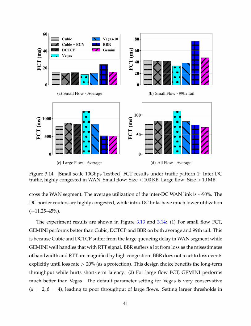
0
20
40
60FC
T (m
s)CubicCubic + ECNDCTCPVegas
Vegas-10BBRGemini
(a) Small Flow - Average
0
20
40
60
80
FCT
(ms)
(b) Small Flow - 99th Tail
0
500
1000
FCT
(ms)
(c) Large Flow - Average
0
50
100
FCT
(ms)
(d) All Flow - Average
Figure 3.14. [Small-scale 10Gbps Testbed] FCT results under traffic pattern 1: Inter-DCtraffic, highly congested in WAN. Small flow: Size < 100 KB. Large flow: Size > 10 MB.
cross the WAN segment. The average utilization of the inter-DC WAN link is ∼90%. The
DC border routers are highly congested, while intra-DC links have much lower utilization
(∼11.25–45%).
The experiment results are shown in Figure 3.13 and 3.14: (1) For small flow FCT,
GEMINI performs better than Cubic, DCTCP and BBR on both average and 99th tail. This
is because Cubic and DCTCP suffer from the large queueing delay in WAN segment while
GEMINI well handles that with RTT signal. BBR suffers a lot from loss as the misestimates
of bandwidth and RTT are magnified by high congestion. BBR does not react to loss events
explicitly until loss rate > 20% (as a protection). This design choice benefits the long-term
throughput while hurts short-term latency. (2) For large flow FCT, GEMINI performs
much better than Vegas. The default parameter setting for Vegas is very conservative
(α = 2, β = 4), leading to poor throughput of large flows. Setting larger thresholds in
41
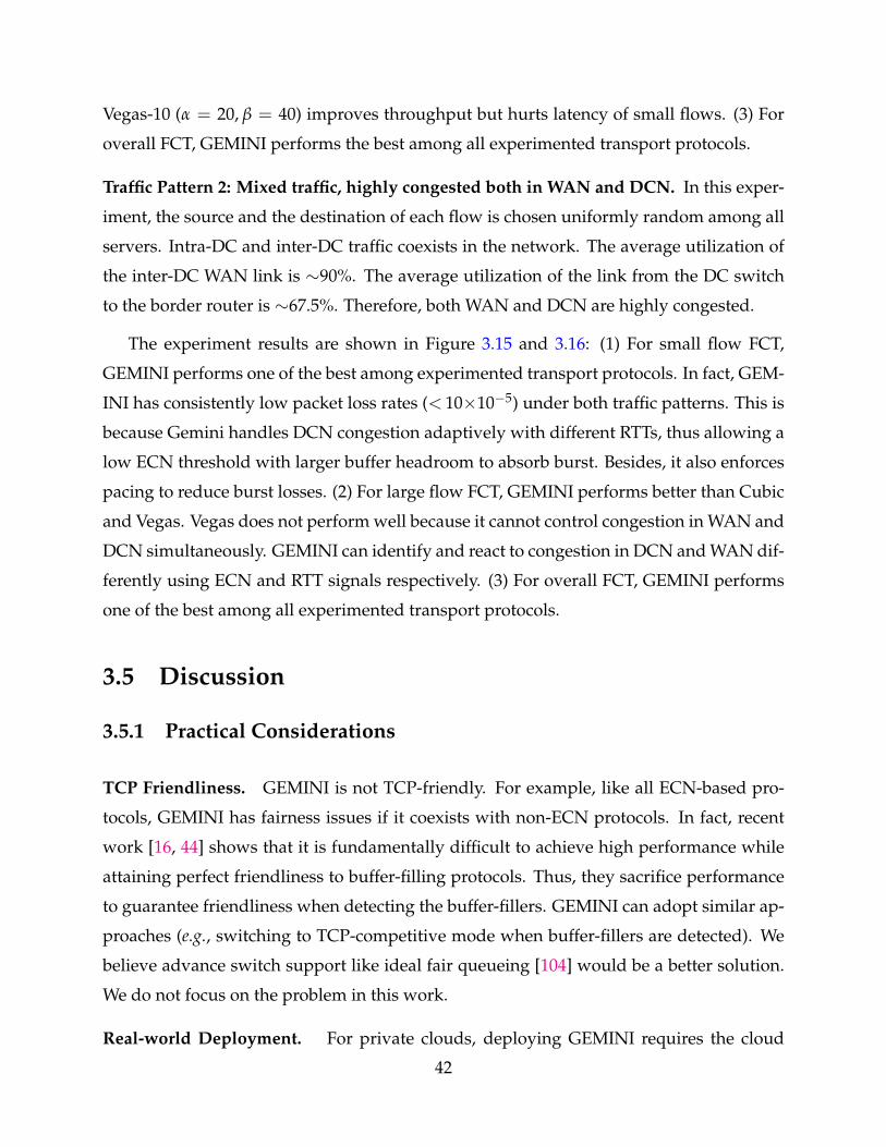
Vegas-10 (α = 20, β = 40) improves throughput but hurts latency of small flows. (3) For
overall FCT, GEMINI performs the best among all experimented transport protocols.
Traffic Pattern 2: Mixed traffic, highly congested both in WAN and DCN. In this exper-
iment, the source and the destination of each flow is chosen uniformly random among all
servers. Intra-DC and inter-DC traffic coexists in the network. The average utilization of
the inter-DC WAN link is ∼90%. The average utilization of the link from the DC switch
to the border router is ∼67.5%. Therefore, both WAN and DCN are highly congested.
The experiment results are shown in Figure 3.15 and 3.16: (1) For small flow FCT,
GEMINI performs one of the best among experimented transport protocols. In fact, GEM-
INI has consistently low packet loss rates (< 10×10−5) under both traffic patterns. This is
because Gemini handles DCN congestion adaptively with different RTTs, thus allowing a
low ECN threshold with larger buffer headroom to absorb burst. Besides, it also enforces
pacing to reduce burst losses. (2) For large flow FCT, GEMINI performs better than Cubic
and Vegas. Vegas does not perform well because it cannot control congestion in WAN and
DCN simultaneously. GEMINI can identify and react to congestion in DCN and WAN dif-
ferently using ECN and RTT signals respectively. (3) For overall FCT, GEMINI performs
one of the best among all experimented transport protocols.
3.5 Discussion
3.5.1 Practical Considerations
TCP Friendliness. GEMINI is not TCP-friendly. For example, like all ECN-based pro-
tocols, GEMINI has fairness issues if it coexists with non-ECN protocols. In fact, recent
work [16, 44] shows that it is fundamentally difficult to achieve high performance while
attaining perfect friendliness to buffer-filling protocols. Thus, they sacrifice performance
to guarantee friendliness when detecting the buffer-fillers. GEMINI can adopt similar ap-
proaches (e.g., switching to TCP-competitive mode when buffer-fillers are detected). We
believe advance switch support like ideal fair queueing [104] would be a better solution.
We do not focus on the problem in this work.
Real-world Deployment. For private clouds, deploying GEMINI requires the cloud
42
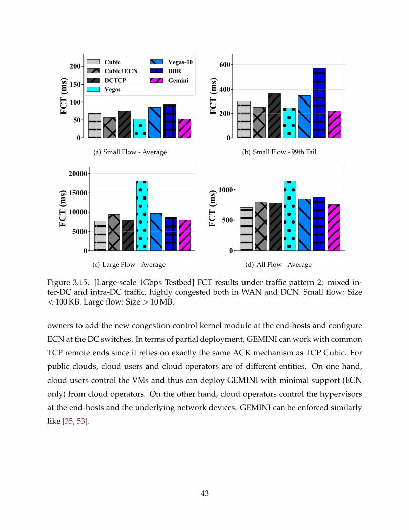
0
50
100
150
200FC
T (m
s)CubicCubic+ECNDCTCPVegas
Vegas-10BBRGemini
(a) Small Flow - Average
0
200
400
600
FCT
(ms)
(b) Small Flow - 99th Tail
0
5000
10000
15000
20000
FCT
(ms)
(c) Large Flow - Average
0
500
1000
FCT
(ms)
(d) All Flow - Average
Figure 3.15. [Large-scale 1Gbps Testbed] FCT results under traffic pattern 2: mixed in-ter-DC and intra-DC traffic, highly congested both in WAN and DCN. Small flow: Size< 100 KB. Large flow: Size > 10 MB.
owners to add the new congestion control kernel module at the end-hosts and configure
ECN at the DC switches. In terms of partial deployment, GEMINI can work with common
TCP remote ends since it relies on exactly the same ACK mechanism as TCP Cubic. For
public clouds, cloud users and cloud operators are of different entities. On one hand,
cloud users control the VMs and thus can deploy GEMINI with minimal support (ECN
only) from cloud operators. On the other hand, cloud operators control the hypervisors
at the end-hosts and the underlying network devices. GEMINI can be enforced similarly
like [35, 53].
43
0
10
20
30FC
T (m
s)CubicCubic + ECNDCTCPVegas
Vegas-10BBRGemini
(a) Small Flow - Average
0
50
100
150
FCT
(ms)
(b) Small Flow - 99th Tail
0
500
1000
FCT
(ms)
(c) Large Flow - Average
0
50
100
FCT
(ms)
(d) All Flow - Average
Figure 3.16. [Small-scale 10Gbps Testbed] FCT results under traffic pattern 2: mixed in-ter-DC and intra-DC traffic, highly congested both in WAN and DCN. Small flow: Size< 100 KB. Large flow: Size > 10 MB.
3.5.2 Alternative Solutions
Multiple Queues + Different Protocols. A seemingly straightforward solution under
cross-DC network is to use different transport protocols for intra-DC and inter-DC traf-
fic, like what major infrastructure owners, e.g., Google [105, 25] and Microsoft [11, 55]
do for their first-party applications. However, a few issues make this approach less at-
tractive: (1) classifying inter-DC and intra-DC flows based on IPs is nontrivial. In cloud
network, virtual subnets extend across DCs for the ease of management, decoupling the
IPs from the DC locations. Maintaining an always-up-to-date IP-to-DC mapping globally
is daunting and gives away the management benefit of running virtual subnets; (2) differ-
ent transport protocols are unlikely to fair-share the network bandwidth, thus requiring
the switches to allocate different queues for them. General cloud users usually do not
44
have this luxury; (3) even if we pay the cost to adopt such a solution, some desired perfor-
mance goals are still missed: (a) The inter-DC traffic may encounter congestion on either
WAN or DCN. The existing protocols do not address both at the same time. The inter-
DC traffic that tends to use wide-area transport will suffer from low throughput and high
loss rate when experiencing congestion at the shallow-buffered DC switch; (b) Flow-level
bandwidth fair-sharing cannot be guaranteed by coarse-grained traffic isolation. Static
bandwidth allocation may even lead to bandwidth under-utilization.
TCP Proxy. Another possible solution is to terminate and relay the TCP flows with
proxies at the border of each network, or the so-called Split TCP [69, 42, 75]. In this way,
traffic can be transported using the best-suited protocol for each network. The TCP proxy
way has flaws in practice:
• Proxies in the middle add extra latencies. The latency overhead can greatly impair net-
work performance, especially for short flows that can finish in one RTT.
• Relaying every inter-DC flow is impractical. As a rule of thumb, Google [105] allocates
10% of aggregate intra-DC bandwidth for external connectivity, requiring prohibitive
amount of relay bandwidth for peak WAN usage.
• Configuring and managing proxy chains is complex and error-prone. Single fault from
one of the intermediate relays may tear down the whole communication.
3.6 Related Work
To facilitate cross-DC network communication, there are three lines of work in general,
each operating on a different granularity. First, WAN traffic engineering [64, 55, 72] works
on the datacenter level. It distributes network traffic to multiple site-to-site paths (usually
hundreds of updates per day). Second, bandwidth allocation [71] applies to the tenant
or flow group level. It re-allocates the site-to-site bandwidths and split them among all
competing flow groups. Third, transport protocol regulates the per-flow sending rate in
realtime. We focus on the transport design in this work.
To the best of our knowledge, transport design under heterogeneous cross-DC network
is unexplored in literature. However, there are vast transport protocols under wide area
network and datacenter network that are highly related:
45
Wide Area Network Transport. Cubic [49] is the default TCP congestion control in the
Linux system. It achieves high scalability and proportional RTT-fairness by growing win-
dow with a cubic function of time. Vegas [23] is the seminal transport protocol that uses
delay signal to avoid intrinsic high loss and queueing delay of loss-based transport. After
that, many WAN protocols [108, 25, 16] are proposed to use delay signal. For example,
BBR [25] is proposed primarily for the enterprise WAN. The core idea is to work at the
theoretically optimal point [68] with the aid of sophisticated network sensing (e.g., pre-
cise bandwidth and RTT estimation). Copa [16] adjusts sending rate towards 1/(δdq),
where dq is the queueing delay, by additive-increase additive-decrease (AIAD). It detects
buffer-fillers by observing the delay evolution and switches between delay-sensitive and
TCP-competitive mode. These transport protocols consider WAN only and usually suffer
a lot from the intra-DC congestion in cross-DC network.
Datacenter Network Transport. DCTCP [11] detects the network congestion with ECN
and react in proportion to the measured extent of congestion. Following that, many ECN-
based protocols [13, 109, 87, 124] are proposed for DCN congestion control. The other
line of work leverages delay signal with microsecond-level accuracy for congestion feed-
back, which is enabled by recent advances [51, 83, 77] in NIC technology. For example,
TIMELY [83] and RoGUE [76] use RTT signal for congestion control in RDMA communica-
tion. DX [77] detects congestion and reduces window size based on the average queuing
delay. We show that ECN or delay signal alone is insufficient for cross-DC congestion
control.
vCC [35] and AC/DC [53] attempt to optimize the transport protocols in the cloud net-
works, from the cloud provider’s perspective with no interference to the user’s VMs. They
enforce the advanced congestion control mechanisms (e.g., DCTCP) in the hypervisors or
the virtual switches. On public cloud environments, GEMINI can be enforced by cloud
operators in a similar way to serve the users for the cross-DC network communication.
Explicit rate control [67, 39, 112, 54, 50] allocates network resources with in-network as-
sistance. Centralized rate control [94, 93] regulates traffic rate with a centralized controller.
Multi-path transport [114, 98, 81] creates subflows along multiple paths to achieve high
aggregate throughput and traffic load balance. Proactive congestion control [32, 52, 85, 58]
leverages receiver-side credits to trigger new traffic sending. Learning-based congestion
46
control [113, 36, 37] learns the congestion control strategy by machine either online or of-
fline. These novel transport protocols often have less comprehensive and unpredictable
performance, and may require advanced network support (e.g., cutting payload [30]) that
are unavailable or bad supported in cross-DC network facilities.
3.7 Final Remarks
As geo-distributed applications become prevalent, cross-DC communication gets increas-
ingly important. We investigate existing transport and find that they leverage either ECN
or delay signal alone, which cannot accommodate the heterogeneity of cross-DC net-
works. Motivated by this, we design GEMINI, a solution for cross-DC congestion control
that integrates both ECN and delay signal. GEMINI uses the delay signal to bound the
total in-flight traffic end-to-end, while ECN is used to control the per-hop queues inside
a DCN. It further modulates ECN-triggered window reduction aggressiveness with RTT
to achieve high throughput under limited buffer. We implement GEMINI with Linux ker-
nel and commodity switches. Experiments show that GEMINI achieves low latency, high
throughput, fair and stable convergence, and delivers lower FCTs compared to various
transport protocols (e.g., Cubic, Vegas, DCTCP and BBR) in cross-DC networks.
47
CHAPTER 4
FlashPass: PROACTIVE CONGESTION CONTROLFOR INTER-DATACENTER NETWORKS
With the prevalence of the geo-distributed web applications and services, wide-area net-
work (WAN) is becoming an increasingly important cloud infrastructure [64, 55, 71, 56].
For example, Google [56] reveals that its inter-datacenter wide-area traffic has been grow-
ing exponentially with a doubling of every 9 months in recent 5 years. This pushes the
WAN facility to evolve much faster than the rest of its infrastructure components.
To scale the wide-area network cost-effectively and flexibly, large enterprises such
as Google and Alibaba have been building and deploying their customized wide-area
routers based on shallow-buffered commodity switching chips [41, 64, 105, 107, 8] (§4.1.1).
However, conventional wisdom [15] dictates that buffer size of one bandwidth-delay
product (BDP) is required to achieve full link utilization in the worst (synchronized) case.
Thus, the cheap shallow-buffered WAN gear imposes stringent requirements on the un-
derlying transport protocols.
We revisit the buffer sizing problem with the newly evolved TCP-style reactive conges-
tion control (RCC) [62, 23, 49, 16, 25] algorithms, and find that shallow buffer can easily
get overwhelmed by the wide-area traffic (§4.1.2). Specifically, running legacy reactive
transport protocols over shallow-buffered WAN may lead to either high packet losses or
degraded throughput or both. To mitigate these problems, current practice seeks help
from global traffic engineering [64, 55, 56], endhost rate limiting [71], or traffic scheduling
with differentiated services.
Instead, we ask the question: can we design a transport to simultaneously achieve low
loss rate and high throughput under shallow-buffered WAN? Inspired by the emerging
proactive congestion control (PCC) [94, 32, 52, 85, 58] design (Figure 4.1), we answer this
question affirmatively by taking the initiative to extend the PCC idea for shallow-buffered
WAN.
48
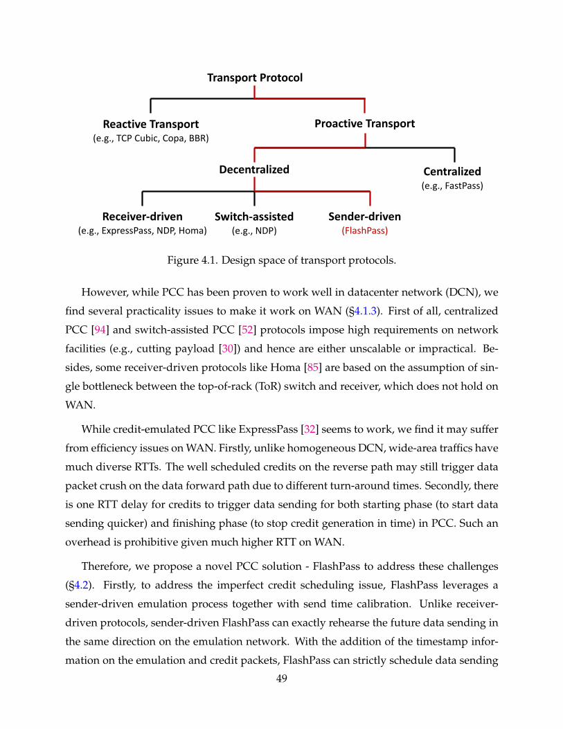
Reactive Transport(e.g., TCP Cubic, Copa, BBR)
Proactive Transport
Receiver-driven(e.g., ExpressPass, NDP, Homa)
Switch-assisted(e.g., NDP)
Sender-driven(FlashPass)
Decentralized Centralized(e.g., FastPass)
Transport Protocol
Figure 4.1. Design space of transport protocols.
However, while PCC has been proven to work well in datacenter network (DCN), we
find several practicality issues to make it work on WAN (§4.1.3). First of all, centralized
PCC [94] and switch-assisted PCC [52] protocols impose high requirements on network
facilities (e.g., cutting payload [30]) and hence are either unscalable or impractical. Be-
sides, some receiver-driven protocols like Homa [85] are based on the assumption of sin-
gle bottleneck between the top-of-rack (ToR) switch and receiver, which does not hold on
WAN.
While credit-emulated PCC like ExpressPass [32] seems to work, we find it may suffer
from efficiency issues on WAN. Firstly, unlike homogeneous DCN, wide-area traffics have
much diverse RTTs. The well scheduled credits on the reverse path may still trigger data
packet crush on the data forward path due to different turn-around times. Secondly, there
is one RTT delay for credits to trigger data sending for both starting phase (to start data
sending quicker) and finishing phase (to stop credit generation in time) in PCC. Such an
overhead is prohibitive given much higher RTT on WAN.
Therefore, we propose a novel PCC solution - FlashPass to address these challenges
(§4.2). Firstly, to address the imperfect credit scheduling issue, FlashPass leverages a
sender-driven emulation process together with send time calibration. Unlike receiver-
driven protocols, sender-driven FlashPass can exactly rehearse the future data sending in
the same direction on the emulation network. With the addition of the timestamp infor-
mation on the emulation and credit packets, FlashPass can strictly schedule data sending
49
in the time space. Secondly, to mitigate the impact of one RTT delay for credits to trig-
ger data sending, FlashPass leverages Aeolus [58] to enable early data transmission in the
starting phase, and further incorporates a credit over-provisioning mechanism together
with a selective dropping discipline for efficient credit or bandwidth allocation in the flow
finishing phase.
We measured realistic workload on a production wide-area network, and experimented
FlashPass with NS2 simulation to demonstrate its superior performance (§4.3). In static
workload experiments, FlashPass achieves near full throughput (9.14Gbps) with zero packet
loss persistently across various settings under the shallow-buffered WAN. The through-
put is up to 55.9% higher than that of TCP Cubic. While comparing to ExpressPass, Flash-
Pass achieves the similar throughput with zero packet loss rate (up to 0.12% losses for Ex-
pressPass). In realistic dynamic workload experiments, FlashPass (with Aeolus enhance-
ment) reduces the overall flow completion times of TCP Cubic and ExpressPass (also with
Aeolus enhancement) by up to 32% and 11.4%; and the reduction of small flow 99-th tail
completion times can get up to 49.5% and 38%, respectively. We also presented a prac-
tical deployment analysis (§4.4) for implementing FlashPass, however, building a fully
functional prototype is beyond the scope of this work.
4.1 Background and Motivation
4.1.1 Shallow-buffered Network
The last decade has witnessed an exponential growth of web applications and services
(e.g., web search, cloud computing, social networking, etc.). This drives the large Internet
companies (e.g., Google [4], Microsoft [5], Facebook [3], and Alibaba [1], etc.) to build
the modern data centers (DCs) at an unforeseen speed and scale across the globe. With
the ever-increasing communication demand, traditional network infrastructure built with
commercial switches [18] fall short to meet the scale, management, and cost requirements.
To address it, inspired by the then-emerging merchant switching silicon industry [41],
large enterprises start to build and deploy their own customized networking hardware
both on WAN [64, 107] and DCN [41, 105]. However, while the cutting-edge merchant
50
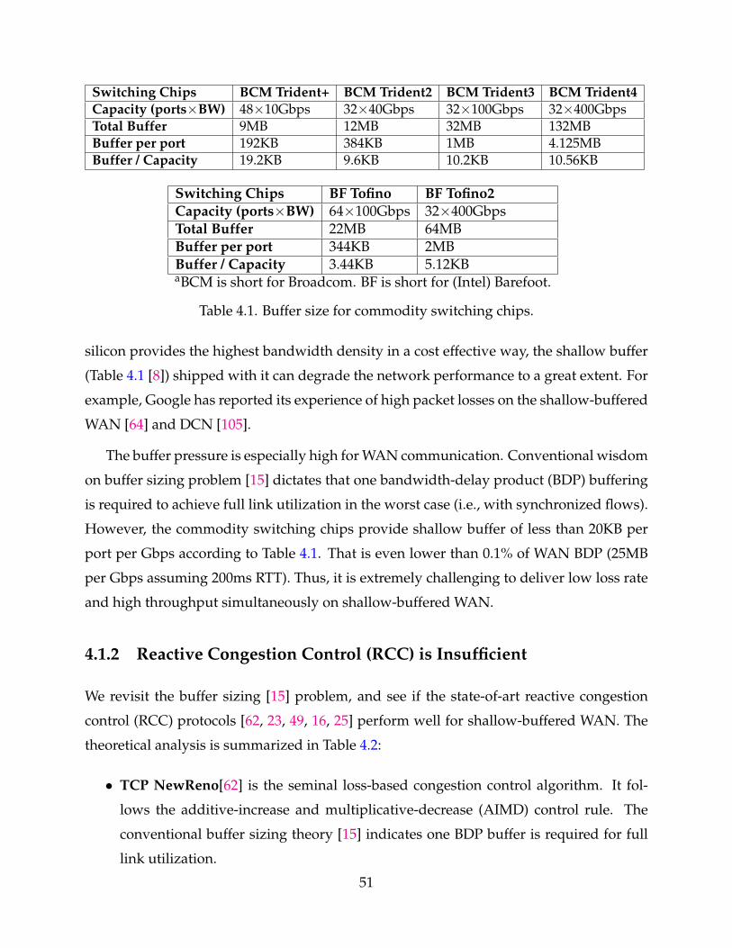
Switching Chips BCM Trident+ BCM Trident2 BCM Trident3 BCM Trident4Capacity (ports×BW) 48×10Gbps 32×40Gbps 32×100Gbps 32×400GbpsTotal Buffer 9MB 12MB 32MB 132MBBuffer per port 192KB 384KB 1MB 4.125MBBuffer / Capacity 19.2KB 9.6KB 10.2KB 10.56KB
Switching Chips BF Tofino BF Tofino2Capacity (ports×BW) 64×100Gbps 32×400GbpsTotal Buffer 22MB 64MBBuffer per port 344KB 2MBBuffer / Capacity 3.44KB 5.12KBaBCM is short for Broadcom. BF is short for (Intel) Barefoot.
Table 4.1. Buffer size for commodity switching chips.
silicon provides the highest bandwidth density in a cost effective way, the shallow buffer
(Table 4.1 [8]) shipped with it can degrade the network performance to a great extent. For
example, Google has reported its experience of high packet losses on the shallow-buffered
WAN [64] and DCN [105].
The buffer pressure is especially high for WAN communication. Conventional wisdom
on buffer sizing problem [15] dictates that one bandwidth-delay product (BDP) buffering
is required to achieve full link utilization in the worst case (i.e., with synchronized flows).
However, the commodity switching chips provide shallow buffer of less than 20KB per
port per Gbps according to Table 4.1. That is even lower than 0.1% of WAN BDP (25MB
per Gbps assuming 200ms RTT). Thus, it is extremely challenging to deliver low loss rate
and high throughput simultaneously on shallow-buffered WAN.
4.1.2 Reactive Congestion Control (RCC) is Insufficient
We revisit the buffer sizing [15] problem, and see if the state-of-art reactive congestion
control (RCC) protocols [62, 23, 49, 16, 25] perform well for shallow-buffered WAN. The
theoretical analysis is summarized in Table 4.2:
• TCP NewReno[62] is the seminal loss-based congestion control algorithm. It fol-
lows the additive-increase and multiplicative-decrease (AIMD) control rule. The
conventional buffer sizing theory [15] indicates one BDP buffer is required for full
link utilization.
51
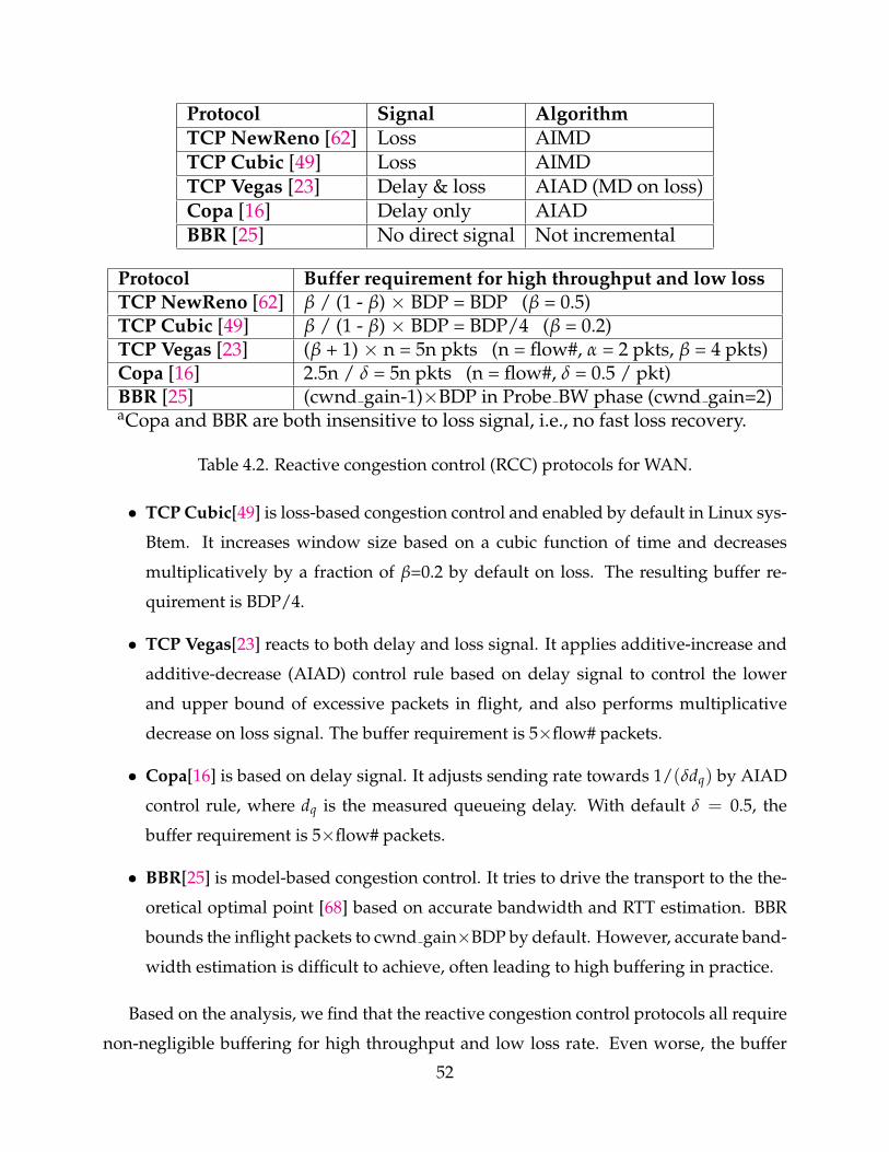
Protocol Signal AlgorithmTCP NewReno [62] Loss AIMDTCP Cubic [49] Loss AIMDTCP Vegas [23] Delay & loss AIAD (MD on loss)Copa [16] Delay only AIADBBR [25] No direct signal Not incremental
Protocol Buffer requirement for high throughput and low lossTCP NewReno [62] β / (1 - β) × BDP = BDP (β = 0.5)TCP Cubic [49] β / (1 - β) × BDP = BDP/4 (β = 0.2)TCP Vegas [23] (β + 1) × n = 5n pkts (n = flow#, α = 2 pkts, β = 4 pkts)Copa [16] 2.5n / δ = 5n pkts (n = flow#, δ = 0.5 / pkt)BBR [25] (cwnd gain-1)×BDP in Probe BW phase (cwnd gain=2)aCopa and BBR are both insensitive to loss signal, i.e., no fast loss recovery.
Table 4.2. Reactive congestion control (RCC) protocols for WAN.
• TCP Cubic[49] is loss-based congestion control and enabled by default in Linux sys-
Btem. It increases window size based on a cubic function of time and decreases
multiplicatively by a fraction of β=0.2 by default on loss. The resulting buffer re-
quirement is BDP/4.
• TCP Vegas[23] reacts to both delay and loss signal. It applies additive-increase and
additive-decrease (AIAD) control rule based on delay signal to control the lower
and upper bound of excessive packets in flight, and also performs multiplicative
decrease on loss signal. The buffer requirement is 5×flow# packets.
• Copa[16] is based on delay signal. It adjusts sending rate towards 1/(δdq) by AIAD
control rule, where dq is the measured queueing delay. With default δ = 0.5, the
buffer requirement is 5×flow# packets.
• BBR[25] is model-based congestion control. It tries to drive the transport to the the-
oretical optimal point [68] based on accurate bandwidth and RTT estimation. BBR
bounds the inflight packets to cwnd gain×BDP by default. However, accurate band-
width estimation is difficult to achieve, often leading to high buffering in practice.
Based on the analysis, we find that the reactive congestion control protocols all require
non-negligible buffering for high throughput and low loss rate. Even worse, the buffer
52
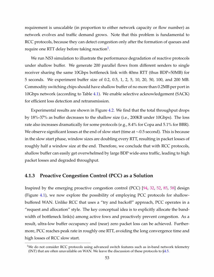
requirement is unscalable (in proportion to either network capacity or flow number) as
network evolves and traffic demand grows. Note that this problem is fundamental to
RCC protocols, because they can detect congestion only after the formation of queues and
require one RTT delay before taking reaction1.
We run NS3 simulation to illustrate the performance degradation of reactive protocols
under shallow buffer. We generate 200 parallel flows from different senders to single
receiver sharing the same 10Gbps bottleneck link with 40ms RTT (thus BDP=50MB) for
5 seconds. We experiment buffer size of 0.2, 0.5, 1, 2, 5, 10, 20, 50, 100, and 200 MB.
Commodity switching chips should have shallow buffer of no more than 0.2MB per port in
10Gbps network (according to Table 4.1). We enable selective acknowledgement (SACK)
for efficient loss detection and retransmission.
Experimental results are shown in Figure 4.2. We find that the total throughput drops
by 18%-37% as buffer decreases to the shallow size (i.e., 200KB under 10Gbps). The loss
rate also increases dramatically for some protocols (e.g., 8.4% for Copa and 5.1% for BBR).
We observe significant losses at the end of slow start (time at∼0.5 second). This is because
in the slow start phase, window sizes are doubling every RTT, resulting in packet losses of
roughly half a window size at the end. Therefore, we conclude that with RCC protocols,
shallow buffer can easily get overwhelmed by large BDP wide-area traffic, leading to high
packet losses and degraded throughput.
4.1.3 Proactive Congestion Control (PCC) as a Solution
Inspired by the emerging proactive congestion control (PCC) [94, 32, 52, 85, 58] design
(Figure 4.1), we now explore the possibility of employing PCC protocols for shallow-
buffered WAN. Unlike RCC that uses a “try and backoff” approach, PCC operates in a
“request and allocation” style. The key conceptual idea is to explicitly allocate the band-
width of bottleneck link(s) among active fows and proactively prevent congestion. As a
result, ultra-low buffer occupancy and (near) zero packet loss can be achieved. Further-
more, PCC reaches peak rate in roughly one RTT, avoiding the long convergence time and
high losses of RCC slow start.
1We do not consider RCC protocols using advanced switch features such as in-band network telemetry(INT) that are often unavailable on WAN. We leave the discussion of these protocols to §4.5.
53
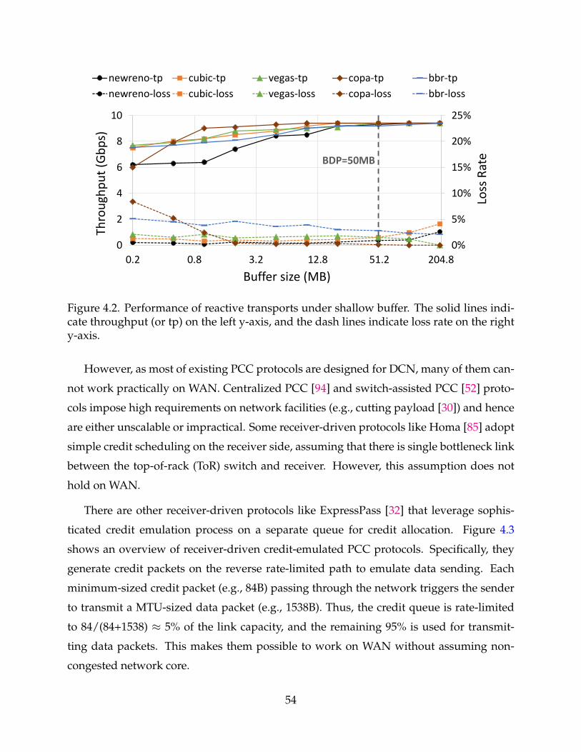
0%
5%
10%
15%
20%
25%
0
2
4
6
8
10
0.2 0.8 3.2 12.8 51.2 204.8
Loss
Rat
e
Thro
ughp
ut (G
bps)
Buffer size (MB)
newreno-tp cubic-tp vegas-tp copa-tp bbr-tpnewreno-loss cubic-loss vegas-loss copa-loss bbr-loss
BDP=50MB
Figure 4.2. Performance of reactive transports under shallow buffer. The solid lines indi-cate throughput (or tp) on the left y-axis, and the dash lines indicate loss rate on the righty-axis.
However, as most of existing PCC protocols are designed for DCN, many of them can-
not work practically on WAN. Centralized PCC [94] and switch-assisted PCC [52] proto-
cols impose high requirements on network facilities (e.g., cutting payload [30]) and hence
are either unscalable or impractical. Some receiver-driven protocols like Homa [85] adopt
simple credit scheduling on the receiver side, assuming that there is single bottleneck link
between the top-of-rack (ToR) switch and receiver. However, this assumption does not
hold on WAN.
There are other receiver-driven protocols like ExpressPass [32] that leverage sophis-
ticated credit emulation process on a separate queue for credit allocation. Figure 4.3
shows an overview of receiver-driven credit-emulated PCC protocols. Specifically, they
generate credit packets on the reverse rate-limited path to emulate data sending. Each
minimum-sized credit packet (e.g., 84B) passing through the network triggers the sender
to transmit a MTU-sized data packet (e.g., 1538B). Thus, the credit queue is rate-limited
to 84/(84+1538) ≈ 5% of the link capacity, and the remaining 95% is used for transmit-
ting data packets. This makes them possible to work on WAN without assuming non-
congested network core.
54
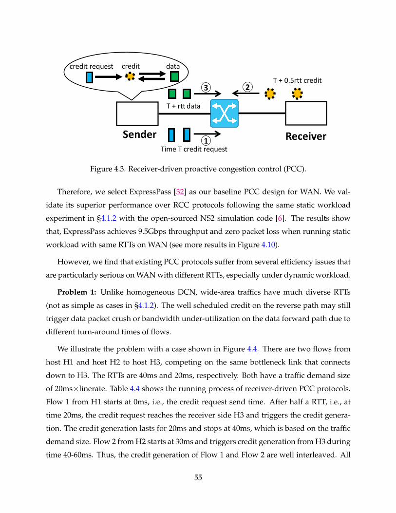
T + 0.5rtt credit
Sender Receiver
T + rtt data
Time T credit request
datacreditcredit request
2
1
3
Figure 4.3. Receiver-driven proactive congestion control (PCC).
Therefore, we select ExpressPass [32] as our baseline PCC design for WAN. We val-
idate its superior performance over RCC protocols following the same static workload
experiment in §4.1.2 with the open-sourced NS2 simulation code [6]. The results show
that, ExpressPass achieves 9.5Gbps throughput and zero packet loss when running static
workload with same RTTs on WAN (see more results in Figure 4.10).
However, we find that existing PCC protocols suffer from several efficiency issues that
are particularly serious on WAN with different RTTs, especially under dynamic workload.
Problem 1: Unlike homogeneous DCN, wide-area traffics have much diverse RTTs
(not as simple as cases in §4.1.2). The well scheduled credit on the reverse path may still
trigger data packet crush or bandwidth under-utilization on the data forward path due to
different turn-around times of flows.
We illustrate the problem with a case shown in Figure 4.4. There are two flows from
host H1 and host H2 to host H3, competing on the same bottleneck link that connects
down to H3. The RTTs are 40ms and 20ms, respectively. Both have a traffic demand size
of 20ms×linerate. Table 4.4 shows the running process of receiver-driven PCC protocols.
Flow 1 from H1 starts at 0ms, i.e., the credit request send time. After half a RTT, i.e., at
time 20ms, the credit request reaches the receiver side H3 and triggers the credit genera-
tion. The credit generation lasts for 20ms and stops at 40ms, which is based on the traffic
demand size. Flow 2 from H2 starts at 30ms and triggers credit generation from H3 during
time 40-60ms. Thus, the credit generation of Flow 1 and Flow 2 are well interleaved. All
55
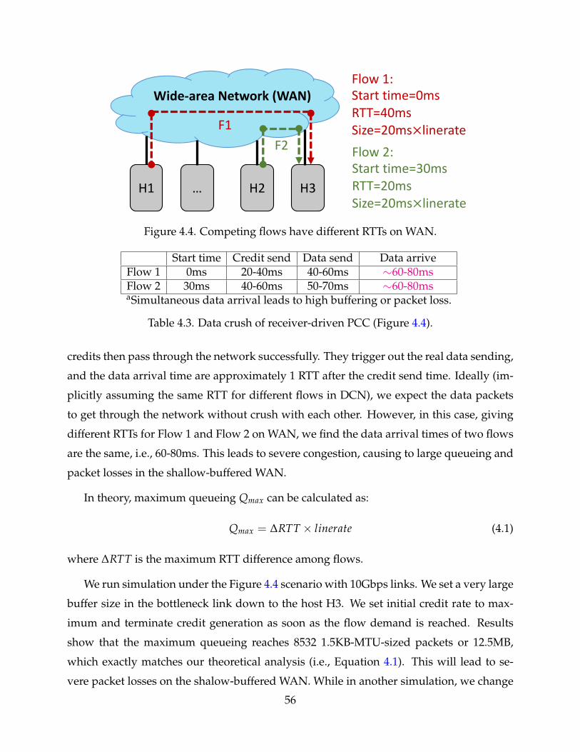
H1 … H2 H3
F1
Wide-area Network (WAN)
F2
Flow 1:Start time=0msRTT=40msSize=20ms×linerateFlow 2:Start time=30msRTT=20msSize=20ms×linerate
Figure 4.4. Competing flows have different RTTs on WAN.
Start time Credit send Data send Data arriveFlow 1 0ms 20-40ms 40-60ms ∼60-80msFlow 2 30ms 40-60ms 50-70ms ∼60-80msaSimultaneous data arrival leads to high buffering or packet loss.
Table 4.3. Data crush of receiver-driven PCC (Figure 4.4).
credits then pass through the network successfully. They trigger out the real data sending,
and the data arrival time are approximately 1 RTT after the credit send time. Ideally (im-
plicitly assuming the same RTT for different flows in DCN), we expect the data packets
to get through the network without crush with each other. However, in this case, giving
different RTTs for Flow 1 and Flow 2 on WAN, we find the data arrival times of two flows
are the same, i.e., 60-80ms. This leads to severe congestion, causing to large queueing and
packet losses in the shallow-buffered WAN.
In theory, maximum queueing Qmax can be calculated as:
Qmax = ∆RTT × linerate (4.1)
where ∆RTT is the maximum RTT difference among flows.
We run simulation under the Figure 4.4 scenario with 10Gbps links. We set a very large
buffer size in the bottleneck link down to the host H3. We set initial credit rate to max-
imum and terminate credit generation as soon as the flow demand is reached. Results
show that the maximum queueing reaches 8532 1.5KB-MTU-sized packets or 12.5MB,
which exactly matches our theoretical analysis (i.e., Equation 4.1). This will lead to se-
vere packet losses on the shalow-buffered WAN. While in another simulation, we change
56
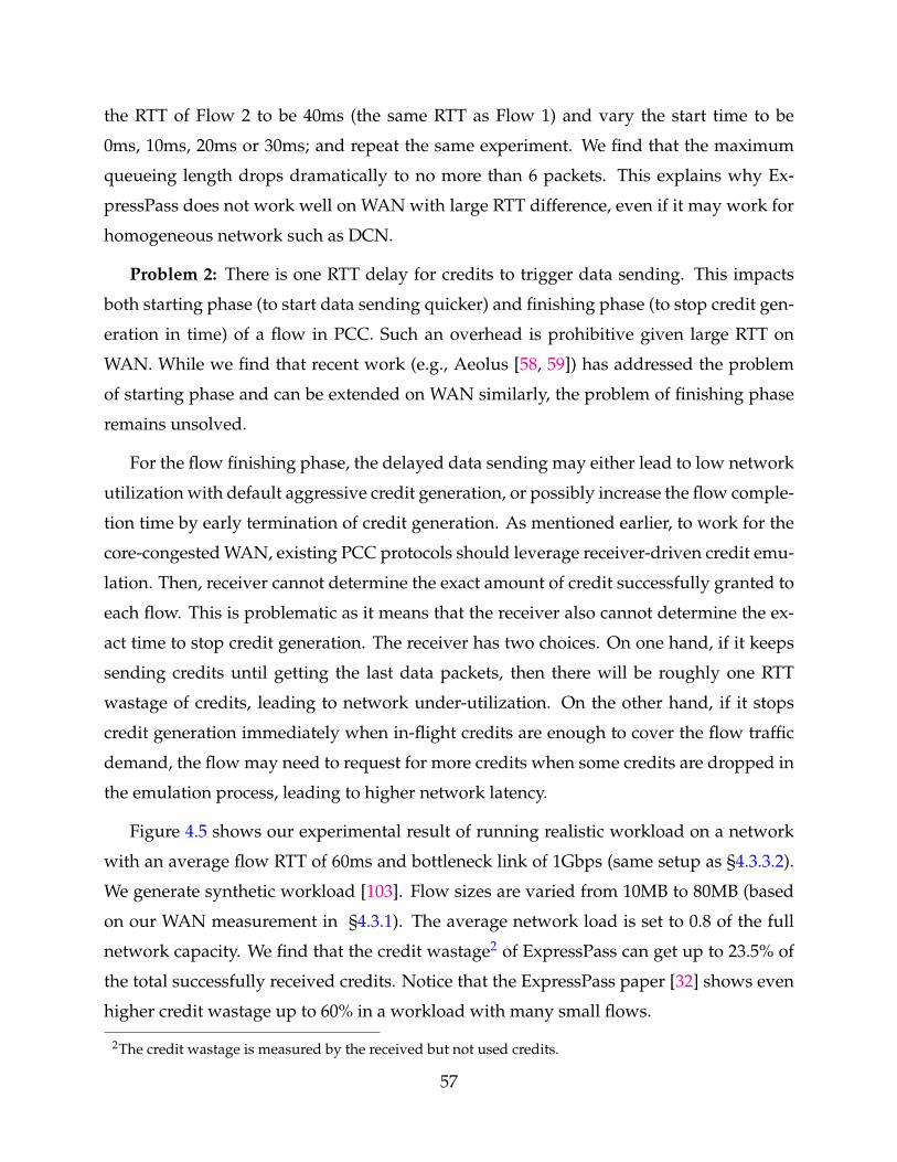
the RTT of Flow 2 to be 40ms (the same RTT as Flow 1) and vary the start time to be
0ms, 10ms, 20ms or 30ms; and repeat the same experiment. We find that the maximum
queueing length drops dramatically to no more than 6 packets. This explains why Ex-
pressPass does not work well on WAN with large RTT difference, even if it may work for
homogeneous network such as DCN.
Problem 2: There is one RTT delay for credits to trigger data sending. This impacts
both starting phase (to start data sending quicker) and finishing phase (to stop credit gen-
eration in time) of a flow in PCC. Such an overhead is prohibitive given large RTT on
WAN. While we find that recent work (e.g., Aeolus [58, 59]) has addressed the problem
of starting phase and can be extended on WAN similarly, the problem of finishing phase
remains unsolved.
For the flow finishing phase, the delayed data sending may either lead to low network
utilization with default aggressive credit generation, or possibly increase the flow comple-
tion time by early termination of credit generation. As mentioned earlier, to work for the
core-congested WAN, existing PCC protocols should leverage receiver-driven credit emu-
lation. Then, receiver cannot determine the exact amount of credit successfully granted to
each flow. This is problematic as it means that the receiver also cannot determine the ex-
act time to stop credit generation. The receiver has two choices. On one hand, if it keeps
sending credits until getting the last data packets, then there will be roughly one RTT
wastage of credits, leading to network under-utilization. On the other hand, if it stops
credit generation immediately when in-flight credits are enough to cover the flow traffic
demand, the flow may need to request for more credits when some credits are dropped in
the emulation process, leading to higher network latency.
Figure 4.5 shows our experimental result of running realistic workload on a network
with an average flow RTT of 60ms and bottleneck link of 1Gbps (same setup as §4.3.3.2).
We generate synthetic workload [103]. Flow sizes are varied from 10MB to 80MB (based
on our WAN measurement in §4.3.1). The average network load is set to 0.8 of the full
network capacity. We find that the credit wastage2 of ExpressPass can get up to 23.5% of
the total successfully received credits. Notice that the ExpressPass paper [32] shows even
higher credit wastage up to 60% in a workload with many small flows.
2The credit wastage is measured by the received but not used credits.
57
10 20 40 80Flow Size (MB)
0
10
20
30C
redi
t Was
tage
(%)
Figure 4.5. Credit wastage of ExpressPass.
4.2 Design
4.2.1 Design Overview
In this work, we aim to design a practical and efficient transport protocol to simulta-
neously achieve high throughput and low loss rate for shallow-buffered WAN (§4.1.1).
Our investigation over reactive transport shows its inherent insufficiency, requiring non-
negligible buffering (§4.1.2). We then turn to the emerging proactive transport. While
revealing the promising potential of the receiver-driven PCC protocols, we also find two
key technical challenges (§4.1.3):
1. How to schedule credits effectively without triggering data crush even if network
traffic has diverse RTTs?
2. How to generate credits sufficiently while not wasting credits even if the granted
amount is unpredictable?
The first challenge is fundamental to the receiver-driven protocols. This is because
receiver-driven protocols uses the credit sending on the reverse path to emulate forward
path data sending. The network delay between receiver and bottleneck link is different
from that between sender and bottleneck. Thus, interleaved credits passing through the
reverse path cannot guarantee well interleaved incoming data at the bottleneck. To ad-
dress it, we propose to adopt a sender-driven emulation mechanism. This ensures that
58
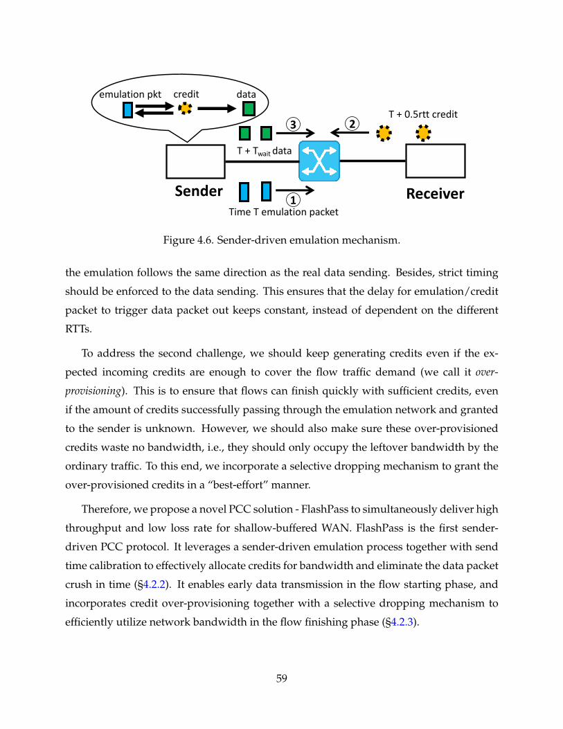
T + 0.5rtt credit
Sender Receiver
T + Twait data
Time T emulation packet
datacreditemulation pkt
2
1
3
Figure 4.6. Sender-driven emulation mechanism.
the emulation follows the same direction as the real data sending. Besides, strict timing
should be enforced to the data sending. This ensures that the delay for emulation/credit
packet to trigger data packet out keeps constant, instead of dependent on the different
RTTs.
To address the second challenge, we should keep generating credits even if the ex-
pected incoming credits are enough to cover the flow traffic demand (we call it over-
provisioning). This is to ensure that flows can finish quickly with sufficient credits, even
if the amount of credits successfully passing through the emulation network and granted
to the sender is unknown. However, we should also make sure these over-provisioned
credits waste no bandwidth, i.e., they should only occupy the leftover bandwidth by the
ordinary traffic. To this end, we incorporate a selective dropping mechanism to grant the
over-provisioned credits in a “best-effort” manner.
Therefore, we propose a novel PCC solution - FlashPass to simultaneously deliver high
throughput and low loss rate for shallow-buffered WAN. FlashPass is the first sender-
driven PCC protocol. It leverages a sender-driven emulation process together with send
time calibration to effectively allocate credits for bandwidth and eliminate the data packet
crush in time (§4.2.2). It enables early data transmission in the flow starting phase, and
incorporates credit over-provisioning together with a selective dropping mechanism to
efficiently utilize network bandwidth in the flow finishing phase (§4.2.3).
59
4.2.2 Sender-driven Emulation Mechanism
FlashPass leverages a sender-driven emulation mechanism (Figure 4.6) to allocate net-
work bandwidth without data packet crush. The emulation process requires to separate
the network into two parts: an emulation network running on the emulation queue, and a
real data communication network on the data communication queue. Emulation packet is
set to the minimum size, i.e., 84B Ethernet frame. The emulation packet passing through
the network triggers a credit return from receiver and then a sender data transmission up
to a maximum size Ethernet frame (e.g., 1538B). Thus, in Ethernet, the emulation network
is rate-limited to 84/(84+1538) ≈ 5% of the link capacity, and the remaining 95% is used
for the data communication. Unlike existing PCCs that send data packets as soon as cred-
its arrive, FlashPass encodes timestamps (T) in its emulation packets and credit packets,
and grants data sending at exact time of T + Twait to eliminate data crush at the bottleneck
link. This send time calibration mechanism effectively helps in avoiding data packet crush
in time as shown below.
Figure 4.6 shows the running process of the sender-driven emulation mechanism. 1©
At time T, a new flow arrives and immediately generates emulation packet at full rate
of the emulation network. The emulation packet will compete on the emulation network
and get dropped if queues form. The emulation network is configured with a low buffer
of several packets. 2©At around time T + 0.5rtt, emulation packet passes through the net-
work and triggers the credit feedback from the receiver side. And around half a RTT later,
the sender receives and records the credit packet. 3© At time T + Twait, the sender injects
the data packet correspondingly into the data communication network. Note that Twait
should be larger than the maximum RTT of the network. In this way, emulation network
exactly mimics the bandwidth competition of the future data communication network. If
network is over-utilized, only emulation packets get dropped on the emulation network
and data communication network remains zero buffering.
To further illustrate the effectiveness of sender-driven emulation mechanism, we com-
pare the result of FlashPass (Table 4.4) with that of the receiver-driven PCC (Table 4.3)
- the running process both in the case of Figure 4.4. In FlashPass, the Twait is set to the
maximum RTT of the network, i.e., 40ms. We find that the Flow 2 adjusts its data send
time to 70-90ms, and thus lead to ∼80-100ms data arrival time at the receiver side. This
60
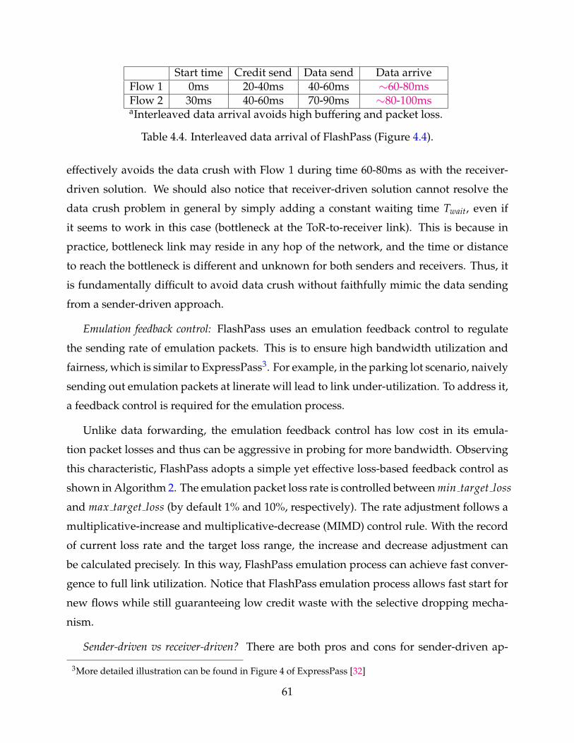
Start time Credit send Data send Data arriveFlow 1 0ms 20-40ms 40-60ms ∼60-80msFlow 2 30ms 40-60ms 70-90ms ∼80-100msaInterleaved data arrival avoids high buffering and packet loss.
Table 4.4. Interleaved data arrival of FlashPass (Figure 4.4).
effectively avoids the data crush with Flow 1 during time 60-80ms as with the receiver-
driven solution. We should also notice that receiver-driven solution cannot resolve the
data crush problem in general by simply adding a constant waiting time Twait, even if
it seems to work in this case (bottleneck at the ToR-to-receiver link). This is because in
practice, bottleneck link may reside in any hop of the network, and the time or distance
to reach the bottleneck is different and unknown for both senders and receivers. Thus, it
is fundamentally difficult to avoid data crush without faithfully mimic the data sending
from a sender-driven approach.
Emulation feedback control: FlashPass uses an emulation feedback control to regulate
the sending rate of emulation packets. This is to ensure high bandwidth utilization and
fairness, which is similar to ExpressPass3. For example, in the parking lot scenario, naively
sending out emulation packets at linerate will lead to link under-utilization. To address it,
a feedback control is required for the emulation process.
Unlike data forwarding, the emulation feedback control has low cost in its emula-
tion packet losses and thus can be aggressive in probing for more bandwidth. Observing
this characteristic, FlashPass adopts a simple yet effective loss-based feedback control as
shown in Algorithm 2. The emulation packet loss rate is controlled between min target loss
and max target loss (by default 1% and 10%, respectively). The rate adjustment follows a
multiplicative-increase and multiplicative-decrease (MIMD) control rule. With the record
of current loss rate and the target loss range, the increase and decrease adjustment can
be calculated precisely. In this way, FlashPass emulation process can achieve fast conver-
gence to full link utilization. Notice that FlashPass emulation process allows fast start for
new flows while still guaranteeing low credit waste with the selective dropping mecha-
nism.
Sender-driven vs receiver-driven? There are both pros and cons for sender-driven ap-
3More detailed illustration can be found in Figure 4 of ExpressPass [32]
61
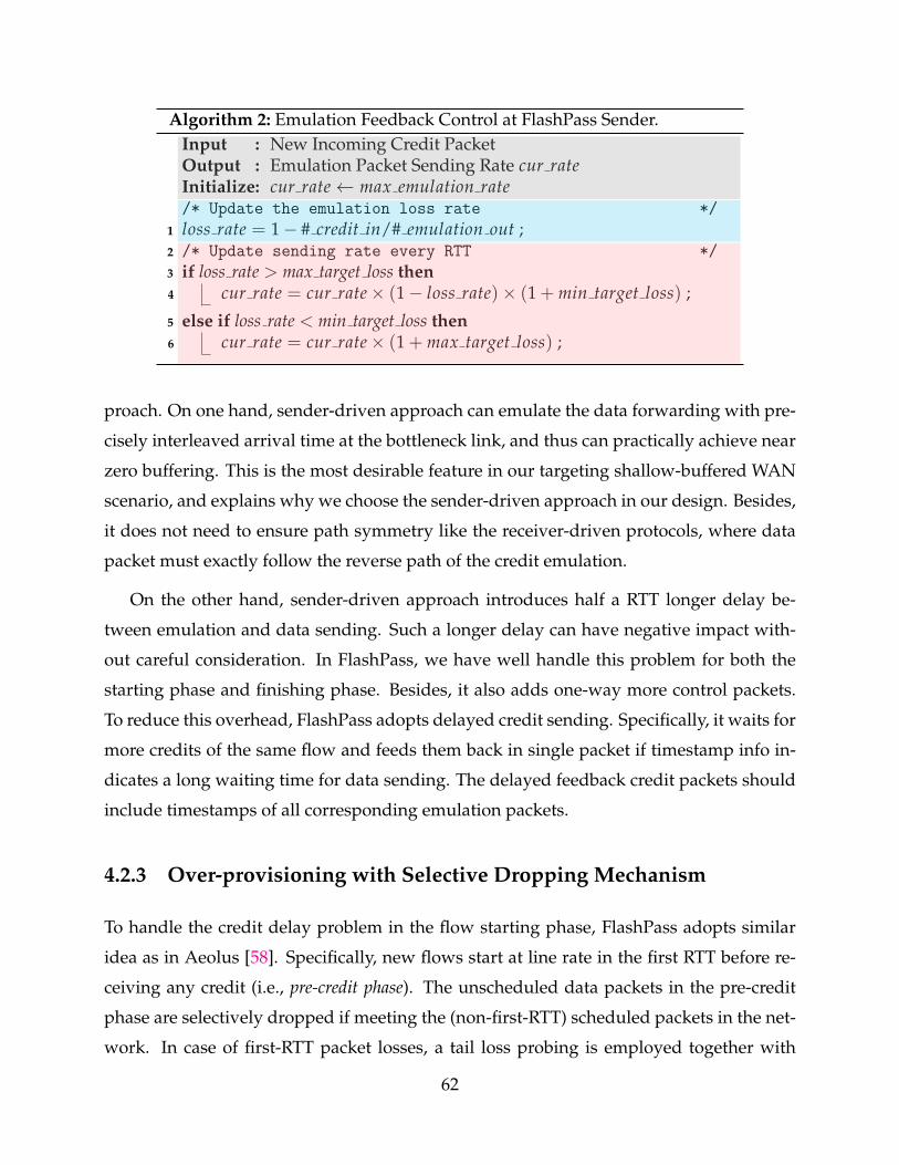
Algorithm 2: Emulation Feedback Control at FlashPass Sender.Input : New Incoming Credit PacketOutput : Emulation Packet Sending Rate cur rateInitialize: cur rate← max emulation rate/* Update the emulation loss rate */
1 loss rate = 1− # credit in/# emulation out ;2 /* Update sending rate every RTT */
3 if loss rate > max target loss then4 cur rate = cur rate× (1− loss rate)× (1 + min target loss) ;
5 else if loss rate < min target loss then6 cur rate = cur rate× (1 + max target loss) ;
proach. On one hand, sender-driven approach can emulate the data forwarding with pre-
cisely interleaved arrival time at the bottleneck link, and thus can practically achieve near
zero buffering. This is the most desirable feature in our targeting shallow-buffered WAN
scenario, and explains why we choose the sender-driven approach in our design. Besides,
it does not need to ensure path symmetry like the receiver-driven protocols, where data
packet must exactly follow the reverse path of the credit emulation.
On the other hand, sender-driven approach introduces half a RTT longer delay be-
tween emulation and data sending. Such a longer delay can have negative impact with-
out careful consideration. In FlashPass, we have well handle this problem for both the
starting phase and finishing phase. Besides, it also adds one-way more control packets.
To reduce this overhead, FlashPass adopts delayed credit sending. Specifically, it waits for
more credits of the same flow and feeds them back in single packet if timestamp info in-
dicates a long waiting time for data sending. The delayed feedback credit packets should
include timestamps of all corresponding emulation packets.
4.2.3 Over-provisioning with Selective Dropping Mechanism
To handle the credit delay problem in the flow starting phase, FlashPass adopts similar
idea as in Aeolus [58]. Specifically, new flows start at line rate in the first RTT before re-
ceiving any credit (i.e., pre-credit phase). The unscheduled data packets in the pre-credit
phase are selectively dropped if meeting the (non-first-RTT) scheduled packets in the net-
work. In case of first-RTT packet losses, a tail loss probing is employed together with
62
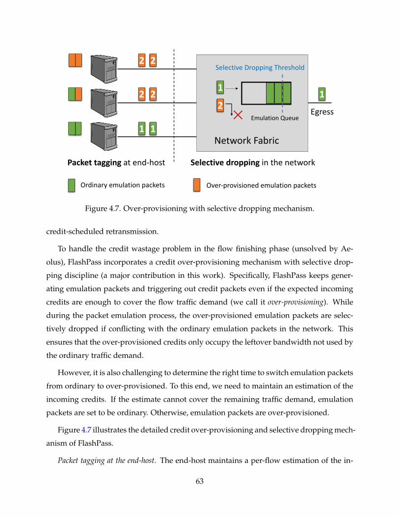
2 2
11
2 2
Packet tagging at end-host
Ordinary emulation packets Over-provisioned emulation packets
Selective Dropping Threshold
Network Fabric
1
2Emulation Queue
Selective dropping in the network
1
Egress
Figure 4.7. Over-provisioning with selective dropping mechanism.
credit-scheduled retransmission.
To handle the credit wastage problem in the flow finishing phase (unsolved by Ae-
olus), FlashPass incorporates a credit over-provisioning mechanism with selective drop-
ping discipline (a major contribution in this work). Specifically, FlashPass keeps gener-
ating emulation packets and triggering out credit packets even if the expected incoming
credits are enough to cover the flow traffic demand (we call it over-provisioning). While
during the packet emulation process, the over-provisioned emulation packets are selec-
tively dropped if conflicting with the ordinary emulation packets in the network. This
ensures that the over-provisioned credits only occupy the leftover bandwidth not used by
the ordinary traffic demand.
However, it is also challenging to determine the right time to switch emulation packets
from ordinary to over-provisioned. To this end, we need to maintain an estimation of the
incoming credits. If the estimate cannot cover the remaining traffic demand, emulation
packets are set to be ordinary. Otherwise, emulation packets are over-provisioned.
Figure 4.7 illustrates the detailed credit over-provisioning and selective dropping mech-
anism of FlashPass.
Packet tagging at the end-host. The end-host maintains a per-flow estimation of the in-
63
coming credit packets (Cexpected). Specifically, the sender end-host records the in-flight
emulation packets (Eout). With the regulation of the emulation feedback control loop, the
actual emulation packet loss rate is expected to be lower than max target loss most of the
time. Thus, the expected credits can be calculated following Equation (4.2):
Cexpected >= Eout × (1−max target loss) (4.2)
When the expected credit amount Cexpected exceeds the remaining traffic demand4 of the
flow, the sender end-host starts marking the emulation packets as over-provisioned, i.e.,
with high dropping priority label. Otherwise, emulation packets are marked as ordinary,
i.e., with low dropping priority label.
Selective dropping on the network fabric. Based on the dropping priority label in the em-
ulation packets, network switches selectively drop the high dropping priority packets be-
fore low priority ones when network bandwidth is not enough. Commodity switching
chips cannot push out packets that are already stored in the switch buffers. Thus, we
can only selectively drop packets at the ingress queue. To this end, we adopt a feature of
RED/ECN function, which is widely supported by commodity switches [115, 66]. Specif-
ically, when the switch queue length exceeds the ECN marking threshold, the switch will
mark the arrival ECN-capable packets and drop the non-ECN-capable packets. Therefore,
FlashPass can repurpose this function to achieve selective dropping. Senders can simply
set ordinary emulation packets as ECN-capable and over-provisioned emulation packets
as non-ECN-capable, to enable selective dropping of the over-provisioned packets with
high priority on the network fabric.
4.3 Evaluation
In this section, we present the detailed FlashPass evaluation setup in §4.3.1, and conduct
extensive experiments to answer the following questions:
• Can FlashPass achieve high throughput and low loss rate under static workload? In static
workload experiments (§4.3.2.1), FlashPass achieves near full throughput (9.14Gbps)
4We assume traffic demand information is available. If not, we simply use the send buffer occupancy tocalculate the remaining traffic demand [38].
64
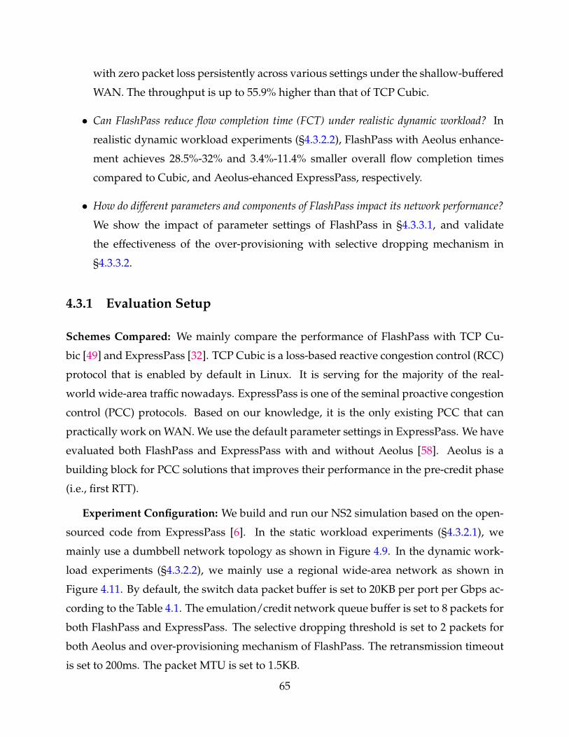
with zero packet loss persistently across various settings under the shallow-buffered
WAN. The throughput is up to 55.9% higher than that of TCP Cubic.
• Can FlashPass reduce flow completion time (FCT) under realistic dynamic workload? In
realistic dynamic workload experiments (§4.3.2.2), FlashPass with Aeolus enhance-
ment achieves 28.5%-32% and 3.4%-11.4% smaller overall flow completion times
compared to Cubic, and Aeolus-ehanced ExpressPass, respectively.
• How do different parameters and components of FlashPass impact its network performance?
We show the impact of parameter settings of FlashPass in §4.3.3.1, and validate
the effectiveness of the over-provisioning with selective dropping mechanism in
§4.3.3.2.
4.3.1 Evaluation Setup
Schemes Compared: We mainly compare the performance of FlashPass with TCP Cu-
bic [49] and ExpressPass [32]. TCP Cubic is a loss-based reactive congestion control (RCC)
protocol that is enabled by default in Linux. It is serving for the majority of the real-
world wide-area traffic nowadays. ExpressPass is one of the seminal proactive congestion
control (PCC) protocols. Based on our knowledge, it is the only existing PCC that can
practically work on WAN. We use the default parameter settings in ExpressPass. We have
evaluated both FlashPass and ExpressPass with and without Aeolus [58]. Aeolus is a
building block for PCC solutions that improves their performance in the pre-credit phase
(i.e., first RTT).
Experiment Configuration: We build and run our NS2 simulation based on the open-
sourced code from ExpressPass [6]. In the static workload experiments (§4.3.2.1), we
mainly use a dumbbell network topology as shown in Figure 4.9. In the dynamic work-
load experiments (§4.3.2.2), we mainly use a regional wide-area network as shown in
Figure 4.11. By default, the switch data packet buffer is set to 20KB per port per Gbps ac-
cording to the Table 4.1. The emulation/credit network queue buffer is set to 8 packets for
both FlashPass and ExpressPass. The selective dropping threshold is set to 2 packets for
both Aeolus and over-provisioning mechanism of FlashPass. The retransmission timeout
is set to 200ms. The packet MTU is set to 1.5KB.
65
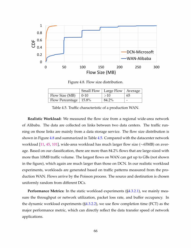
0
0.2
0.4
0.6
0.8
1
0 50 100 150 200 250 300
CDF
Flow Size (MB)
DCN-MicrosoftWAN-Alibaba
Figure 4.8. Flow size distribution.
Small Flow Large Flow AverageFlow Size (MB) 0-10 >10 65Flow Percentage 15.8% 84.2% -
Table 4.5. Traffic characteristic of a production WAN.
Realistic Workload: We measured the flow size from a regional wide-area network
of Alibaba. The data are collected on links between two data centers. The traffic run-
ning on those links are mainly from a data storage service. The flow size distribution is
shown in Figure 4.8 and summarized in Table 4.5. Compared with the datacenter network
workload [11, 45, 101], wide-area workload has much larger flow size (∼65MB) on aver-
age. Based on our classification, there are more than 84.2% flows that are large-sized with
more than 10MB traffic volume. The largest flows on WAN can get up to GBs (not shown
in the figure), which again are much larger than those on DCN. In our realistic workload
experiments, workloads are generated based on traffic patterns measured from the pro-
duction WAN. Flows arrive by the Poisson process. The source and destination is chosen
uniformly random from different DCs.
Performance Metrics: In the static workload experiments (§4.3.2.1), we mainly mea-
sure the throughput or network utilization, packet loss rate, and buffer occupancy. In
the dynamic workload experiments (§4.3.2.2), we use flow completion time (FCT) as the
major performance metric, which can directly reflect the data transfer speed of network
applications.
66
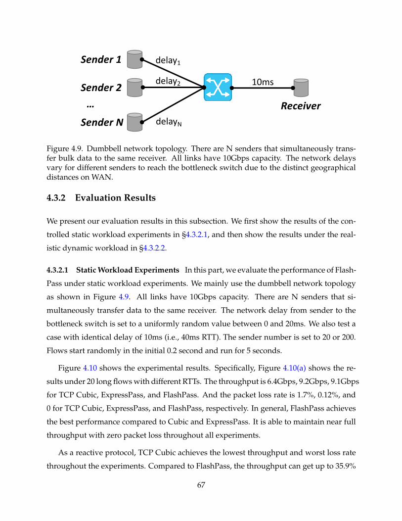
Sender 1
Receiver
Sender 2
Sender N
…
10ms
delay1
delay2
delayN
Figure 4.9. Dumbbell network topology. There are N senders that simultaneously trans-fer bulk data to the same receiver. All links have 10Gbps capacity. The network delaysvary for different senders to reach the bottleneck switch due to the distinct geographicaldistances on WAN.
4.3.2 Evaluation Results
We present our evaluation results in this subsection. We first show the results of the con-
trolled static workload experiments in §4.3.2.1, and then show the results under the real-
istic dynamic workload in §4.3.2.2.
4.3.2.1 Static Workload Experiments In this part, we evaluate the performance of Flash-
Pass under static workload experiments. We mainly use the dumbbell network topology
as shown in Figure 4.9. All links have 10Gbps capacity. There are N senders that si-
multaneously transfer data to the same receiver. The network delay from sender to the
bottleneck switch is set to a uniformly random value between 0 and 20ms. We also test a
case with identical delay of 10ms (i.e., 40ms RTT). The sender number is set to 20 or 200.
Flows start randomly in the initial 0.2 second and run for 5 seconds.
Figure 4.10 shows the experimental results. Specifically, Figure 4.10(a) shows the re-
sults under 20 long flows with different RTTs. The throughput is 6.4Gbps, 9.2Gbps, 9.1Gbps
for TCP Cubic, ExpressPass, and FlashPass. And the packet loss rate is 1.7%, 0.12%, and
0 for TCP Cubic, ExpressPass, and FlashPass, respectively. In general, FlashPass achieves
the best performance compared to Cubic and ExpressPass. It is able to maintain near full
throughput with zero packet loss throughout all experiments.
As a reactive protocol, TCP Cubic achieves the lowest throughput and worst loss rate
throughout the experiments. Compared to FlashPass, the throughput can get up to 35.9%
67
Cubic ExpressPass FlashPass0
2
4
6
8
10T
hrou
ghpu
t (G
bps)
0.0
0.5
1.0
1.5
2.0
Los
s Rat
e (%
)
(a) delayi = Uni f orm(0, 20ms), i = 1, 2, ..., N;N = 20.
Cubic ExpressPass FlashPass0
2
4
6
8
10
Thr
ough
put (
Gbp
s)
0.0
0.5
1.0
1.5
2.0
Los
s Rat
e (%
)
(b) delayi = Uni f orm(0, 20ms), i = 1, 2, ..., N;N = 200.
Cubic ExpressPass FlashPass0
2
4
6
8
10
Thr
ough
put (
Gbp
s)
0.0
0.5
1.0
1.5
2.0
Los
s Rat
e (%
)
(c) delayi = 10ms, i = 1, 2, ..., N; N = 20.
Figure 4.10. Static workload experiment results running on a dumbbell network topologyshown in Figure 4.9. The blue bar indicates the throughput (Gbps) performance on theleft y-axis. The red line indicates the packet loss rate (%) on the right y-axis.
lower in the worst case (Figure 4.10(c)). This is because the “try and backoff” nature of
RCC leads to inherently high data packet losses, and as well periodical under-utilization
after rate “backoff”. Besides, Cubic uses slow start to ramp up its sending rate at the
initial phase, which can lead to high losses at the end of the slow start (significant losses
are observed during time at ∼0.5 second in our experiments).
While ExpressPass achieves similar throughput with FlashPass, it has observable packet
losses in the scenario with different RTTs (i.e., Figure 4.10(a) and 4.10(b)). While the packet
losses only slightly reduce the throughput of large data transfer in this case, it has much
larger negative impact on small flows as we will see in the dynamic workload exper-
iments, especially when retransmission timeout is triggered. FlashPass can effectively
resolve the imperfect scheduling issue with its sender-driven emulation process. Notice
that FlashPass has a slightly lower throughput due to the emulation packet overhead. In
the static experiments, there is one-way traffic only, which hides the reverse path credit
68
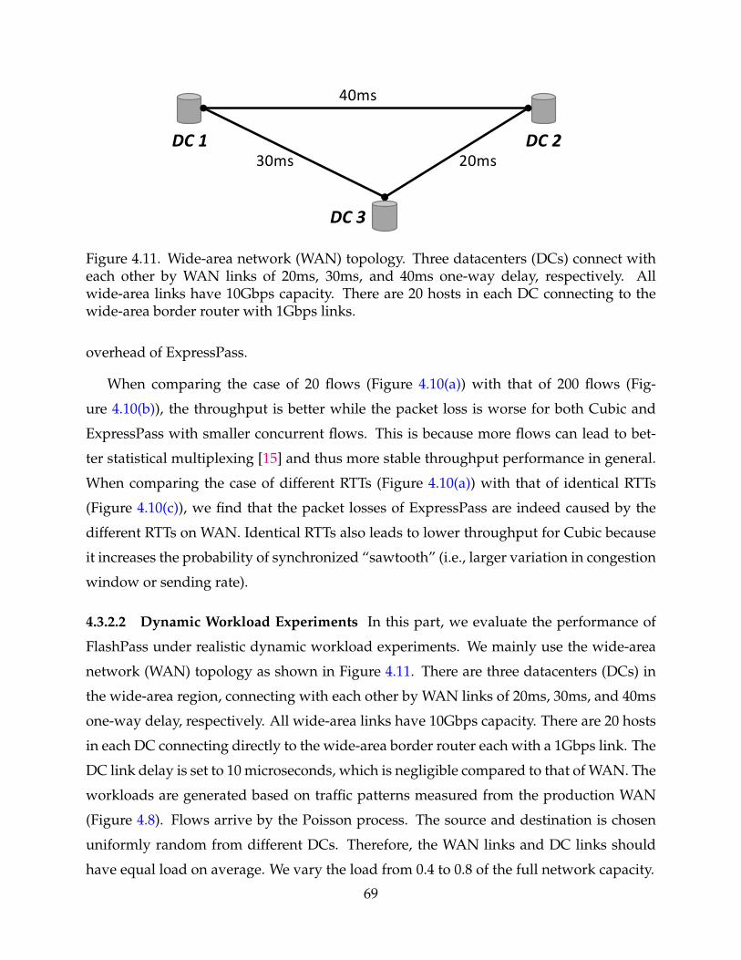
40ms
20ms30msDC 1 DC 2
DC 3
Figure 4.11. Wide-area network (WAN) topology. Three datacenters (DCs) connect witheach other by WAN links of 20ms, 30ms, and 40ms one-way delay, respectively. Allwide-area links have 10Gbps capacity. There are 20 hosts in each DC connecting to thewide-area border router with 1Gbps links.
overhead of ExpressPass.
When comparing the case of 20 flows (Figure 4.10(a)) with that of 200 flows (Fig-
ure 4.10(b)), the throughput is better while the packet loss is worse for both Cubic and
ExpressPass with smaller concurrent flows. This is because more flows can lead to bet-
ter statistical multiplexing [15] and thus more stable throughput performance in general.
When comparing the case of different RTTs (Figure 4.10(a)) with that of identical RTTs
(Figure 4.10(c)), we find that the packet losses of ExpressPass are indeed caused by the
different RTTs on WAN. Identical RTTs also leads to lower throughput for Cubic because
it increases the probability of synchronized “sawtooth” (i.e., larger variation in congestion
window or sending rate).
4.3.2.2 Dynamic Workload Experiments In this part, we evaluate the performance of
FlashPass under realistic dynamic workload experiments. We mainly use the wide-area
network (WAN) topology as shown in Figure 4.11. There are three datacenters (DCs) in
the wide-area region, connecting with each other by WAN links of 20ms, 30ms, and 40ms
one-way delay, respectively. All wide-area links have 10Gbps capacity. There are 20 hosts
in each DC connecting directly to the wide-area border router each with a 1Gbps link. The
DC link delay is set to 10 microseconds, which is negligible compared to that of WAN. The
workloads are generated based on traffic patterns measured from the production WAN
(Figure 4.8). Flows arrive by the Poisson process. The source and destination is chosen
uniformly random from different DCs. Therefore, the WAN links and DC links should
have equal load on average. We vary the load from 0.4 to 0.8 of the full network capacity.
69
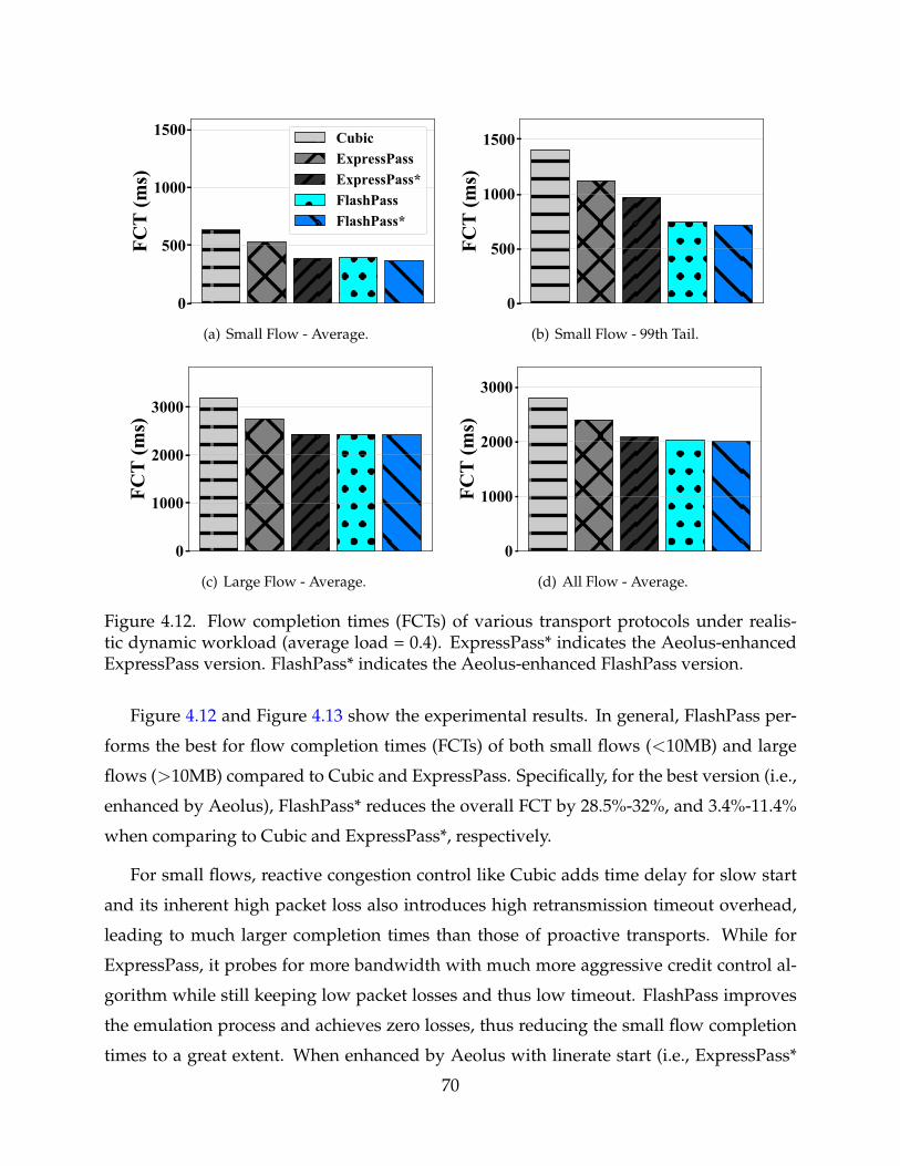
0
500
1000
1500FC
T (m
s)CubicExpressPassExpressPass*FlashPassFlashPass*
(a) Small Flow - Average.
0
500
1000
1500
FCT
(ms)
(b) Small Flow - 99th Tail.
0
1000
2000
3000
FCT
(ms)
(c) Large Flow - Average.
0
1000
2000
3000
FCT
(ms)
(d) All Flow - Average.
Figure 4.12. Flow completion times (FCTs) of various transport protocols under realis-tic dynamic workload (average load = 0.4). ExpressPass* indicates the Aeolus-enhancedExpressPass version. FlashPass* indicates the Aeolus-enhanced FlashPass version.
Figure 4.12 and Figure 4.13 show the experimental results. In general, FlashPass per-
forms the best for flow completion times (FCTs) of both small flows (<10MB) and large
flows (>10MB) compared to Cubic and ExpressPass. Specifically, for the best version (i.e.,
enhanced by Aeolus), FlashPass* reduces the overall FCT by 28.5%-32%, and 3.4%-11.4%
when comparing to Cubic and ExpressPass*, respectively.
For small flows, reactive congestion control like Cubic adds time delay for slow start
and its inherent high packet loss also introduces high retransmission timeout overhead,
leading to much larger completion times than those of proactive transports. While for
ExpressPass, it probes for more bandwidth with much more aggressive credit control al-
gorithm while still keeping low packet losses and thus low timeout. FlashPass improves
the emulation process and achieves zero losses, thus reducing the small flow completion
times to a great extent. When enhanced by Aeolus with linerate start (i.e., ExpressPass*
70
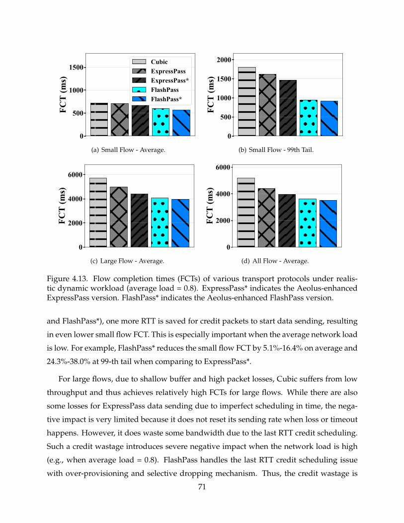
0
500
1000
1500FC
T (m
s)CubicExpressPassExpressPass*FlashPassFlashPass*
(a) Small Flow - Average.
0
500
1000
1500
2000
FCT
(ms)
(b) Small Flow - 99th Tail.
0
2000
4000
6000
FCT
(ms)
(c) Large Flow - Average.
0
2000
4000
6000
FCT
(ms)
(d) All Flow - Average.
Figure 4.13. Flow completion times (FCTs) of various transport protocols under realis-tic dynamic workload (average load = 0.8). ExpressPass* indicates the Aeolus-enhancedExpressPass version. FlashPass* indicates the Aeolus-enhanced FlashPass version.
and FlashPass*), one more RTT is saved for credit packets to start data sending, resulting
in even lower small flow FCT. This is especially important when the average network load
is low. For example, FlashPass* reduces the small flow FCT by 5.1%-16.4% on average and
24.3%-38.0% at 99-th tail when comparing to ExpressPass*.
For large flows, due to shallow buffer and high packet losses, Cubic suffers from low
throughput and thus achieves relatively high FCTs for large flows. While there are also
some losses for ExpressPass data sending due to imperfect scheduling in time, the nega-
tive impact is very limited because it does not reset its sending rate when loss or timeout
happens. However, it does waste some bandwidth due to the last RTT credit scheduling.
Such a credit wastage introduces severe negative impact when the network load is high
(e.g., when average load = 0.8). FlashPass handles the last RTT credit scheduling issue
with over-provisioning and selective dropping mechanism. Thus, the credit wastage is
71
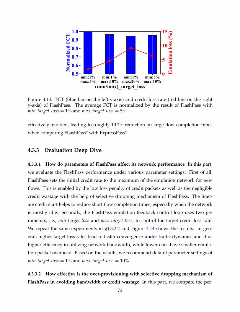
min:1%max:5%
min:1%max:10%
min:1%max:20%
min:5%max:10%
(min/max)_target_loss
0.50.60.70.80.91.0
Nor
mal
ized
FC
T0
5
10
15
Em
ulat
ion
loss
(%)
Figure 4.14. FCT (blue bar on the left y-axis) and credit loss rate (red line on the righty-axis) of FlashPass. The average FCT is normalized by the result of FlashPass withmin target loss = 1% and max target loss = 5%.
effectively avoided, leading to roughly 10.2% reduction on large flow completion times
when comparing FLashPass* with ExpressPass*.
4.3.3 Evaluation Deep Dive
4.3.3.1 How do parameters of FlashPass affect its network performance In this part,
we evaluate the FlashPass performance under various parameter settings. First of all,
FlashPass sets the initial credit rate to the maximum of the emulation network for new
flows. This is enabled by the low loss penalty of credit packets as well as the negligible
credit wastage with the help of selective dropping mechanism of FlashPass. The liner-
ate credit start helps to reduce short flow completion times, especially when the network
is mostly idle. Secondly, the FlashPass emulation feedback control loop uses two pa-
rameters, i.e., min target loss and max target loss, to control the target credit loss rate.
We repeat the same experiments in §4.3.2.2 and Figure 4.14 shows the results. In gen-
eral, higher target loss rates lead to faster convergence under traffic dynamics and thus
higher efficiency in utilizing network bandwidth, while lower ones have smaller emula-
tion packet overhead. Based on the results, we recommend default parameter settings of
min target loss = 1% and max target loss = 10%.
4.3.3.2 How effective is the over-provisioning with selective dropping mechanism of
FlashPass in avoiding bandwidth or credit wastage In this part, we compare the per-
72
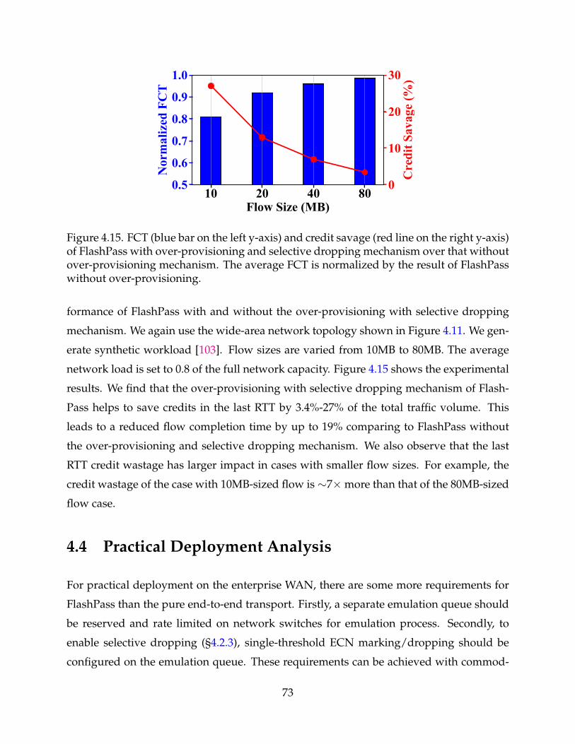
10 20 40 80Flow Size (MB)
0.5
0.6
0.7
0.8
0.9
1.0
Nor
mal
ized
FC
T
0
10
20
30
Cre
dit S
avag
e (%
)
Figure 4.15. FCT (blue bar on the left y-axis) and credit savage (red line on the right y-axis)of FlashPass with over-provisioning and selective dropping mechanism over that withoutover-provisioning mechanism. The average FCT is normalized by the result of FlashPasswithout over-provisioning.
formance of FlashPass with and without the over-provisioning with selective dropping
mechanism. We again use the wide-area network topology shown in Figure 4.11. We gen-
erate synthetic workload [103]. Flow sizes are varied from 10MB to 80MB. The average
network load is set to 0.8 of the full network capacity. Figure 4.15 shows the experimental
results. We find that the over-provisioning with selective dropping mechanism of Flash-
Pass helps to save credits in the last RTT by 3.4%-27% of the total traffic volume. This
leads to a reduced flow completion time by up to 19% comparing to FlashPass without
the over-provisioning and selective dropping mechanism. We also observe that the last
RTT credit wastage has larger impact in cases with smaller flow sizes. For example, the
credit wastage of the case with 10MB-sized flow is ∼7×more than that of the 80MB-sized
flow case.
4.4 Practical Deployment Analysis
For practical deployment on the enterprise WAN, there are some more requirements for
FlashPass than the pure end-to-end transport. Firstly, a separate emulation queue should
be reserved and rate limited on network switches for emulation process. Secondly, to
enable selective dropping (§4.2.3), single-threshold ECN marking/dropping should be
configured on the emulation queue. These requirements can be achieved with commod-
73
ity switches, but need non-trivial configuration across the whole network. Thirdly, we
also notice that PCC solutions cannot co-exist with the legacy TCP protocols. A straight-
forward workaround is to separate different traffic with multiple queues, but may bring
about some overheads.
Lastly, an efficient implementation of proactive congestion control logic is required.
Recent work [91, 9] presents a Linux kernel implementation (based on Homa) that achieves
magnitudes lower latency than TCP. Specifically, a variety of issues such as batching, load
balancing, and realtime processing, have been well addressed in the work. There are
some other efforts on realizing PCC protocols on user- space DPDK [58], or on congestion
control plane (CCP) [88]. While these efforts have validated the feasibility of building an
efficient PCC network stack, prototyping a fully functional FLASHPASS is our next step
effort and is beyond the scope of this work.
4.5 Related Work
For wide-area cloud network optimization, there are three lines of work in general, each
operating on a different granularity. Firstly, WAN traffic engineering [64, 55, 56] works
on the datacenter level. It distributes network traffic to multiple site-to-site paths (usually
hundreds of updates per day). Secondly, bandwidth allocation [71] applies to the tenant
or task flow group level. It re-allocates the site-to-site bandwidths and split them among
all competing flow groups. Thirdly, transport protocol regulates the per-flow sending rate
in realtime. We focus on the transport design in this work.
Reactive Congestion Control (RCC): The seminal work of TCP congestion control [62]
works in a reactive manner. It detects congestion based on a delayed feedback signal (e.g.,
packet loss) from the network and reacts passively. Many variants have emerged since
then, e.g., Cubic [49], Compound [108], etc. Vegas [23] is the first delay-based protocol
to avoid intrinsic high loss and queueing delay of loss-based transport. After that, many
protocols [25, 16] are proposed to use delay signal (either explicitly or implicitly). How-
ever, these RCC protocols are insufficient to achieve desired high throughput and low loss
under shallow-buffered WAN.
There are other RCC protocols designed in particular for DCN. DCTCP [11] detects the
74
network congestion with explicit congestion notification (ECN) signal. Following that,
many ECN-based protocols [13, 109, 87, 124] are proposed. More recently, HPCC [79]
leverages In-band Network Telemetry (INT) to detect rate mismatch, and adjust sending
rates accordingly. These protocols require advanced congestion signals that are not avail-
able or well supported [119] on WAN.
Proactive Congestion Control (PCC): To achieve low buffering and fast convergence, PCC
protocols have been proposed to allocate bandwidth proactively. Centralized PCC [94]
regulates traffic rate with a centralized controller. Switch-assisted PCC [52] leverages
switch assistance in bandwidth allocation. Both impose high requirements on network
facilities (e.g., cutting payload [30]) and hence are either unscalable or impractical. Some
receiver-driven protocols like Homa [85] employ simple credit scheduling on the receiver
side. They assume single bottleneck link between the top-of-rack (ToR) switch and re-
ceiver, which does not hold on WAN. Other receiver-driven protocols like ExpressPass [32]
that leverage credit emulation on a separate queue for bandwidth allocation. However,
they suffer from efficiency problems on WAN. In contrast, FlashPass addresses these prob-
lems to fully unleash the power of PCC on shallow-buffered WAN.
4.6 Final Remarks
In this work, we reveal the trend of adopting shallow-buffered commodity switching
chips on wide-area networks (WAN). We then investigate its impact on network per-
formance, and find the insufficiency of the TCP-style reactive congestion control (RCC).
To address it, we turn to the emerging proactive congestion control (PCC), and propose
FlashPass. FlashPass is the first attempt to employ PCC on WAN. It is also the first sender-
driven credit-scheduled PCC protocol. It leverages the sender-driven emulation process
and over-provisioning with selective dropping mechanism to work practically and effec-
tively for the shallow-buffered WAN. Extensive experiments are conducted and validate
the superior performance of FlashPass under realistic workload.
75
CHAPTER 5
CONCLUSION AND FUTURE WORK
My PhD research centers around one question: how to improve congestion control mecha-
nisms for inter-datacenter network communication? Specifically, we find two key challenges
that are underestimated before. Firstly, we observe that the heterogeneous characteristics
lead to significant performance degradation in the inter-datacenter network communica-
tion. Secondly, the trending shallow-buffered inter-DCN imposes great buffer pressure on
congestion control, resulting in low throughput or high packet losses or both.
5.1 Summary
Now we summarize the efforts we make to address each one of the above challenges.
To address the first challenge, we design GEMINI, a solution for cross-DC congestion
control that integrates both ECN and delay signal. GEMINI uses the delay signal to bound
the total in-flight traffic end-to-end, while ECN is used to control the per-hop queues in-
side a DCN. It further modulates ECN-triggered window reduction aggressiveness with
RTT to achieve high throughput under limited buffer. We implement GEMINI with Linux
kernel and commodity switches. Experiments show that GEMINI achieves low latency,
high throughput, fair and stable convergence, and delivers lower FCTs compared to vari-
ous transport protocols (e.g., Cubic, Vegas, DCTCP and BBR) in cross-DC networks.
TO address the second challenge, we seek help from the emerging proactive con-
gestion control (PCC), and propose FlashPass. FlashPass is the first attempt to employ
PCC on WAN. It is also the first sender-driven credit-scheduled PCC protocol. It lever-
ages the sender-driven emulation process to achieve accurate bandwidth allocation, and
employs over-provisioning with selective dropping mechanism to take advantage of the
spare bandwidth without unnecessary wastage. Extensive experiments are conducted
and validate the superior performance of FlashPass under realistic workload.
76
5.2 Future Directions
We envision that the future inter-datacenter networks need to accommodate a continu-
ously growing traffic demand, imposing even harsher pressure on the network communi-
cation. The opportunities are that the emerging technologies (e.g., RDMA, programmable
switch) enable lots of network innovations to get adopted in practice. Given these trends,
some new problems and opportunities will emerge.
Congestion Control based on Advanced Signal. With the prevalence of programmable
switches, the wide-area inter-DC network may have support of advanced signals in the
near future. For example, HPCC [79] is the seminal work that leverages in-band teleme-
try (INT) for congestion control in DCN. However, there are still plenty of challenges to
enable INT-based congestion control mechanisms to work for the inter-DC WAN. For ex-
ample, protocols like HPCC add a prohibitive header overhead as the hop counts increase
on the wide-area network, significantly degrading effective data throughput.
Congestion Control for Wide-area RDMA Network. As the RDMA technology getting
deployed in DCN, bringing the benefits to the wide-area inter-DC network communica-
tion becomes a natural next step. However, unlike intra-DC network, guaranteeing loss-
less fabric on wide-area network is quite challenging because of the long delays and thus
high buffer requirements when using PFC on WAN. Otherwise, with lossy fabric, how to
handle packet losses efficiently becomes a new challenge because the RDMA NIC have
only limited computation and memory capacity for packet processing.
77
REFERENCES
[1] Alibaba Cloud’s Global Infrastructure, Accessed in 2021. https://www.alibabacloud.
com/global-locations.
[2] Arista Production, Accessed in 2021. https://www.arista.com/en/products.
[3] Data Center Engineering - Facebook Engineering, Accessed in 2021. https://
engineering.fb.com/category/data-center-engineering.
[4] Data Centers - Google, Accessed in 2021. https://www.google.com/about/
datacenters.
[5] Datacenter Infrastructure - Microsoft, Accessed in 2021. https://www.microsoft.
com/en-us/cloud-platform/global-datacenters.
[6] kaist-ina/ns2-xpass, Accessed in 2021. https://github.com/kaist-ina/ns2-xpass.
[7] netem in Linux Foundation Wiki, Accessed in 2021. https://wiki.linuxfoundation.
org/networking/netem.
[8] Packet buffers, Accessed in 2021. https://people.ucsc.edu/warner/buffer.html.
[9] PlatformLab/HomaModule, Accessed in 2021. https://github.com/PlatformLab/
HomaModule.
[10] Mohammad Al-Fares, Alexander Loukissas, and Amin Vahdat. A scalable, com-
modity data center network architecture. In ACM SIGCOMM, 2008.
[11] Mohammad Alizadeh, Albert Greenberg, David A Maltz, Jitendra Padhye, Parveen
Patel, Balaji Prabhakar, Sudipta Sengupta, and Murari Sridharan. Data center tcp
(dctcp). In ACM SIGCOMM, 2010.
[12] Mohammad Alizadeh, Adel Javanmard, and Balaji Prabhakar. Analysis of dctcp:
stability, convergence, and fairness. In SIGMETRICS, 2011.
78
[13] Mohammad Alizadeh, Abdul Kabbani, Tom Edsall, Balaji Prabhakar, Amin Vahdat,
and Masato Yasuda. Less is more: trading a little bandwidth for ultra-low latency
in the data center. In USENIX NSDI, 2012.
[14] Mohammad Alizadeh, Shuang Yang, Milad Sharif, Sachin Katti, Nick McKeown,
Balaji Prabhakar, and Scott Shenker. pfabric: Minimal near-optimal datacenter
transport. In ACM SIGCOMM, 2013.
[15] Guido Appenzeller, Isaac Keslassy, and Nick McKeown. Sizing router buffers. In
ACM SIGCOMM, 2004.
[16] Venkat Arun and Hari Balakrishnan. Copa: Practical delay-based congestion con-
trol for the internet. In USENIX NSDI, 2018.
[17] Wei Bai, Li Chen, Kai Chen, and Haitao Wu. Enabling ecn in multi-service multi-
queue data centers. In USENIX NSDI, 2016.
[18] Luiz Andre Barroso, Urs Holzle, and Parthasarathy Ranganathan. The datacenter
as a computer: An introduction to the design of warehouse-scale machines. Morgan
& Claypool, 2013.
[19] Steven Bauer, Robert Beverly, and Arthur Berger. Measuring the state of ecn readi-
ness in servers, clients, and routers. In IMC, 2011.
[20] Theophilus Benson, Aditya Akella, and David A. Maltz. Network traffic character-
istics of data centers in the wild. In ACM SIGCOMM, 2010.
[21] Pat Bosshart, Dan Daly, Glen Gibb, Martin Izzard, Nick McKeown, Jennifer Rexford,
Cole Schlesinger, Dan Talayco, Amin Vahdat, George Varghese, and David Walker.
P4: Programming protocol-independent packet processors. In ACM SIGCOMM,
2014.
[22] Pat Bosshart, Glen Gibb, Hun-Seok Kim, George Varghese, Nick McKeown, Martin
Izzard, Fernando Mujica, and Mark Horowitz. Forwarding metamorphosis: Fast
programmable match-action processing in hardware for sdn. In ACM SIGCOMM,
2013.
79
[23] Lawrence S Brakmo, Sean W O’Malley, and Larry L Peterson. Tcp vegas: New
techniques for congestion detection and avoidance. In ACM SIGCOMM, 1994.
[24] Patrick Brown. Resource sharing of tcp connections with different round trip times.
In IEEE INFOCOM, 2000.
[25] Neal Cardwell, Yuchung Cheng, C Stephen Gunn, Soheil Hassas Yeganeh, and Van
Jacobson. Bbr: Congestion-based congestion control. In ACM Queue, 2016.
[26] Vinton. Cerf and Robert. Kahn. A protocol for packet network intercommunication.
IEEE Transactions on Communications, 1974.
[27] Ge Chen, Gaoxiong Zeng, and Li Chen. P4com: In-network computation with pro-
grammable switches. arXiv preprint arXiv:2107.13694, 2021.
[28] Kai Chen, Ankit Singla, Atul Singh, Kishore Ramachandran, Lei Xu, Yueping
Zhang, Xitao Wen, and Yan Chen. Osa: An optical switching architecture for data
center networks with unprecedented flexibility. IEEE/ACM Transactions on Network-
ing, 2014.
[29] Li Chen, Kai Chen, Zhonghua Zhu, Minlan Yu, George Porter, Chunming Qiao,
and Shan Zhong. Enabling wide-spread communications on optical fabric with
megaswitch. In USENIX NSDI, 2017.
[30] Peng Cheng, Fengyuan Ren, Ran Shu, and Chuang Lin. Catch the whole lot in an
action: Rapid precise packet loss notification in data center. In USENIX NSDI, 2014.
[31] Wenxue Cheng, Kun Qian, Wanchun Jiang, Tong Zhang, and Fengyuan Ren. Re-
architecting congestion management in lossless ethernet. In USENIX NSDI, 2020.
[32] Inho Cho, Keon Jang, and Dongsu Han. Credit-scheduled delay-bounded conges-
tion control for datacenters. In ACM SIGCOMM, 2017.
[33] Abhijit K. Choudhury and Ellen L. Hahne. Dynamic queue length thresholds for
shared-memory packet switches. In IEEE/ACM ToN, 1998.
[34] Jonathan Corbet. TSO sizing and the FQ scheduler, Accessed in 2021. https://lwn.
net/Articles/564978/.
80
[35] Bryce Cronkite-Ratcliff, Aran Bergman, Shay Vargaftik, Madhusudhan Ravi, Nick
McKeown, Ittai Abraham, and Isaac Keslassy. Virtualized congestion control. In
ACM SIGCOMM, 2016.
[36] Mo Dong, Qingxi Li, Doron Zarchy, Philip Brighten Godfrey, and Michael Schapira.
Pcc: Re-architecting congestion control for consistent high performance. In USENIX
NSDI, 2015.
[37] Mo Dong, Tong Meng, D Zarchy, E Arslan, Y Gilad, B Godfrey, and M Schapira. Pcc
vivace: Online-learning congestion control. In USENIX NSDI, 2018.
[38] Vojislav Dukic, Sangeetha Abdu Jyothi, Bojan Karlas, Muhsen Owaida, Ce Zhang,
and Ankit Singla. Is advance knowledge of flow sizes a plausible assumption? In
USENIX NSDI, 2019.
[39] Nandita Dukkipati, Masayoshi Kobayashi, Rui Zhang-Shen, and Nick McKeown.
Processor sharing flows in the internet. In IWQoS, 2005.
[40] Nathan Farrington, George Porter, Sivasankar Radhakrishnan, Hamid Hajabdolali
Bazzaz, Vikram Subramanya, Yeshaiahu Fainman, George Papen, and Amin Vah-
dat. Helios: A hybrid electrical/optical switch architecture for modular data cen-
ters. In ACM SIGCOMM, 2010.
[41] Nathan Farrington, Erik Rubow, and Amin Vahdat. Data center switch architecture
in the age of merchant silicon. In IEEE Symposium on High Performance Interconnects,
2009.
[42] Tobias Flach, Nandita Dukkipati, Andreas Terzis, Barath Raghavan, Neal Cardwell,
Yuchung Cheng, Ankur Jain, Shuai Hao, Ethan Katz-Bassett, and Ramesh Govin-
dan. Reducing web latency: the virtue of gentle aggression. In ACM SIGCOMM,
2013.
[43] S. Floyd and T. Henderson. The newreno modification to tcp’s fast recovery algo-
rithm. RFC 2582, 1999.
[44] Prateesh Goyal, Akshay Narayan, Frank Cangialosi, Deepti Raghavan, Srinivas
Narayana, Mohammad Alizadeh, and Hari Balakrishnan. Elasticity detection: A
81
building block for internet congestion control. In arXiv CoRR, 2018. [Online]. Avail-
able: https://arxiv.org/abs/1802.08730.
[45] Albert Greenberg, James R. Hamilton, Navendu Jain, Srikanth Kandula, Changhoon
Kim, Parantap Lahiri, David A. Maltz, Parveen Patel, and Sudipta Sengupta. Vl2:
A scalable and flexible data center network. In ACM SIGCOMM, 2009.
[46] Chuanxiong Guo, Guohan Lu, Dan Li, Haitao Wu, Xuan Zhang, Yunfeng Shi, Chen
Tian, Yongguang Zhang, and Songwu Lu. Bcube: A high performance, server-
centric network architecture for modular data centers. In ACM SIGCOMM, 2009.
[47] Chuanxiong Guo, Haitao Wu, Zhong Deng, Gaurav Soni, Jianxi Ye, Jitu Padhye, and
Marina Lipshteyn. Rdma over commodity ethernet at scale. In ACM SIGCOMM,
2016.
[48] Chuanxiong Guo, Haitao Wu, Kun Tan, Lei Shi, Yongguang Zhang, and Songwu
Lu. Dcell: A scalable and fault-tolerant network structure for data centers. In ACM
SIGCOMM, 2008.
[49] Sangtae Ha, Injong Rhee, and Lisong Xu. Cubic: a new tcp-friendly high-speed tcp
variant. In SIGOPS, 2008.
[50] Dongsu Han, Robert Grandl, Aditya Akella, and Srinivasan Seshan. Fcp: A flexible
transport framework for accommodating diversity. In ACM SIGCOMM, 2013.
[51] Sangjin Han, Keon Jang, Aurojit Panda, Shoumik Palkar, Dongsu Han, and Sylvia
Ratnasamy. Softnic: A software nic to augment hardware. In Technical Report
UCB/EECS-2015-155, EECS Department, University of California, Berkeley, 2015.
[52] Mark Handley, Costin Raiciu, Alexandru Agache, Andrei Voinescu, Andrew Moore,
Gianni Antichi, and Marcin Wojcik. Re-architecting datacenter networks and stacks
for low latency and high performance. In ACM SIGCOMM, 2017.
[53] Keqiang He, Eric Rozner, Kanak Agarwal, Yu Jason Gu, Wes Felter, John Carter, and
Aditya Akella. Ac/dc tcp: Virtual congestion control enforcement for datacenter
networks. In ACM SIGCOMM, 2016.
82
[54] Chi-Yao Hong, Matthew Caesar, and P Godfrey. Finishing flows quickly with pre-
emptive scheduling. In ACM SIGCOMM, 2012.
[55] Chi-Yao Hong, Srikanth Kandula, Ratul Mahajan, Ming Zhang, Vijay Gill, Mohan
Nanduri, and Roger Wattenhofer. Achieving high utilization with software-driven
wan. In ACM SIGCOMM, 2013.
[56] Chi-Yao Hong, Subhasree Mandal, Mohammad Al-Fares, Min Zhu, Richard Alimi,
Chandan Bhagat, Sourabh Jain, Jay Kaimal, Shiyu Liang, Kirill Mendelev, et al. B4
and after: managing hierarchy, partitioning, and asymmetry for availability and
scale in google’s software-defined wan. In ACM SIGCOMM, 2018.
[57] Kevin Hsieh, Aaron Harlap, Nandita Vijaykumar, Dimitris Konomis, Gregory R
Ganger, Phillip B Gibbons, and Onur Mutlu. Gaia: Geo-distributed machine learn-
ing approaching lan speeds. In USENIX NSDI, 2017.
[58] Shuihai Hu, Wei Bai, Gaoxiong Zeng, Zilong Wang, Baochen Qiao, Kai Chen, Kun
Tan, and Yi Wang. Aeolus: A building block for proactive transport in datacenters.
In ACM SIGCOMM, 2020.
[59] Shuihai Hu, Gaoxiong Zeng, Wei Bai, Zilong Wang, Baochen Qiao, Kai Chen, Kun
Tan, and Yi Wang. Aeolus: A building block for proactive transport in datacenter
networks. IEEE/ACM ToN, 2021.
[60] Chien-Chun Hung, Leana Golubchik, and Minlan Yu. Scheduling jobs across geo-
distributed datacenters. In ACM SoCC, 2015.
[61] Van Jacobson. Congestion avoidance and control. In ACM SIGCOMM, 1988.
[62] Van Jacobson. Modified TCP Congestion Control and Avoidance Algorithms, 1990. ftp:
//ftp.ee.lbl.gov/email/vanj.90apr30.txt.
[63] Rajendra K Jain, Dah-Ming W Chiu, and William R Hawe. A quantitative measure
of fairness and discrimination for resource allocation in shared computer systems.
1984.
83
[64] Sushant Jain, Alok Kumar, Subhasree Mandal, Joon Ong, Leon Poutievski, Arjun
Singh, Subbaiah Venkata, Jim Wanderer, Junlan Zhou, Min Zhu, et al. B4: Experi-
ence with a globally-deployed software defined wan. In ACM SIGCOMM, 2013.
[65] Xin Jin, Yiran Li, Da Wei, Siming Li, Jie Gao, Lei Xu, Guangzhi Li, Wei Xu, and
Jennifer Rexford. Optimizing bulk transfers with software-defined optical wan. In
ACM SIGCOMM, 2016.
[66] Glenn Judd. Attaining the promise and avoiding the pitfalls of tcp in the datacenter.
In USENIX NSDI, 2015.
[67] Dina Katabi, Mark Handley, and Charlie Rohrs. Congestion control for high
bandwidth-delay product networks. In ACM SIGCOMM, 2002.
[68] Leonard Kleinrock. Power and deterministic rules of thumb for probabilistic prob-
lems in computer communications. In ICC, 1979.
[69] Swastik Kopparty, Srikanth V Krishnamurthy, Michalis Faloutsos, and Satish K Tri-
pathi. Split tcp for mobile ad hoc networks. In GLOBECOM, 2002.
[70] Mirja Kuhlewind, David P Wagner, Juan Manuel Reyes Espinosa, and Bob Briscoe.
Using data center tcp (dctcp) in the internet. In GLOBECOM, 2014.
[71] Alok Kumar, Sushant Jain, Uday Naik, Anand Raghuraman, Nikhil Kasinadhuni,
Enrique Cauich Zermeno, C Stephen Gunn, Jing Ai, Bjorn Carlin, Mihai Amarandei-
Stavila, et al. Bwe: Flexible, hierarchical bandwidth allocation for wan distributed
computing. In ACM SIGCOMM, 2015.
[72] Praveen Kumar, Yang Yuan, Chris Yu, Nate Foster, Robert Kleinberg, Petr La-
pukhov, Chiun Lin Lim, and Robert Soule. Semi-oblivious traffic engineering: the
road not taken. In USENIX NSDI, 2018.
[73] T. V. Lakshman and Upamanyu Madhow. The performance of tcp/ip for networks
with high bandwidth-delay products and random loss. In IEEE/ACM ToN, 1997.
[74] Nikolaos Laoutaris, Michael Sirivianos, Xiaoyuan Yang, and Pablo Rodriguez.
Inter-datacenter bulk transfers with netstitcher. In ACM SIGCOMM, 2011.
84
[75] Franck Le, Erich Nahum, Vasilis Pappas, Maroun Touma, and Dinesh Verma. Expe-
riences deploying a transparent split tcp middlebox and the implications for nfv. In
HotMiddlebox, 2015.
[76] Yanfang Le, Brent Stephens, Arjun Singhvi, Aditya Akella, and Michael Swift.
Rogue: Rdma over generic unconverged ethernet. In ACM SoCC, 2018.
[77] Changhyun Lee, Chunjong Park, Keon Jang, Sue Moon, and Dongsu Han. Dx:
Latency-based congestion control for datacenters. In IEEE/ACM ToN, 2016.
[78] Bojie Li, Kun Tan, Layong Larry Luo, Yanqing Peng, Renqian Luo, Ningyi Xu,
Yongqiang Xiong, and Peng Cheng. Clicknp: Highly flexible and high-performance
network processing with reconfigurable hardware. In ACM SIGCOMM, 2016.
[79] Yuliang Li, Rui Miao, Hongqiang Harry Liu, Yan Zhuang, Fei Feng, Lingbo Tang,
Zheng Cao, Ming Zhang, Frank Kelly, Mohammad Alizadeh, and Minlan Yu. Hpcc:
High precision congestion control. In ACM SIGCOMM, 2019.
[80] Vincent Liu, Daniel Halperin, Arvind Krishnamurthy, and Thomas E Anderson.
F10: A fault-tolerant engineered network. In USENIX NSDI, 2013.
[81] Yuanwei Lu, Guo Chen, Bojie Li, Kun Tan, Yongqiang Xiong, Peng Cheng, Jiansong
Zhang, Enhong Chen, and Thomas Moscibroda. Multi-path transport for rdma in
datacenters. In USENIX NSDI, 2018.
[82] M. Mathis, J. Mahdavi, S. Floyd, and A. Romanow. Tcp selective acknowledgment
options. RFC 2018, 1996.
[83] Radhika Mittal, Nandita Dukkipati, Emily Blem, Hassan Wassel, Monia Ghobadi,
Amin Vahdat, Yaogong Wang, David Wetherall, David Zats, et al. Timely: Rtt-based
congestion control for the datacenter. In ACM SIGCOMM, 2015.
[84] Radhika Mittal, Alex Shpiner, Aurojit Panda, Eitan Zahavi, Arvind Krishnamurthy,
Sylvia Ratnasamy, and Scott Shenker. Revisiting network support for rdma. In
ACM SIGCOMM, 2018.
85
[85] Behnam Montazeri, Yilong Li, Mohammad Alizadeh, and John Ousterhout. Homa:
A receiver-driven low-latency transport protocol using network priorities. In ACM
SIGCOMM, 2018.
[86] Ali Munir, Ghufran Baig, Syed M Irteza, Ihsan A Qazi, Alex X Liu, and Fahad R
Dogar. Friends, not foes: synthesizing existing transport strategies for data center
networks. In ACM SIGCOMM, 2014.
[87] Ali Munir, Ihsan A Qazi, Zartash A Uzmi, Aisha Mushtaq, Saad N Ismail, M Safdar
Iqbal, and Basma Khan. Minimizing flow completion times in data centers. In IEEE
INFOCOM, 2013.
[88] Akshay Narayan, Frank Cangialosi, Deepti Raghavan, Prateesh Goyal, Srinivas
Narayana, Radhika Mittal, Mohammad Alizadeh, and Hari Balakrishnan. Restruc-
turing endpoint congestion control. In ACM SIGCOMM, 2018.
[89] Rolf Neugebauer, Gianni Antichi, Jose Fernando Zazo, Yury Audzevich, Sergio
Lopez-Buedo, and Andrew W. Moore. Understanding pcie performance for end
host networking. In ACM SIGCOMM, 2018.
[90] Kathleen Nichols and Van Jacobson. Controlling queue delay. In ACM Queue, 2012.
[91] John Ousterhout. A linux kernel implementation of the homa transport protocol. In
USENIX ATC, 2021.
[92] Rong Pan, Balaji Prabhakar, and Ashvin Laxmikantha. Qcn: Quantized congestion
notification. In IEEE802, 2007.
[93] Jonathan Perry, Hari Balakrishnan, and Devavrat Shah. Flowtune: Flowlet control
for datacenter networks. In USENIX NSDI, 2017.
[94] Jonathan Perry, Amy Ousterhout, Hari Balakrishnan, Devavrat Shah, and Hans Fu-
gal. Fastpass: A centralized zero-queue datacenter network. In ACM SIGCOMM,
2014.
[95] Jon Postel. User datagram protocol. RFC 768, 1980.
86
[96] Qifan Pu, Ganesh Ananthanarayanan, Peter Bodik, Srikanth Kandula, Aditya
Akella, Paramvir Bahl, and Ion Stoica. Low latency geo-distributed data analytics.
In ACM SIGCOMM, 2015.
[97] Kun Qian, Wenxue Cheng, Tong Zhang, and Fengyuan Ren. Gentle flow control:
Avoiding deadlock in lossless networks. In ACM SIGCOMM, 2019.
[98] Costin Raiciu, Sebastien Barre, Christopher Pluntke, Adam Greenhalgh, Damon
Wischik, and Mark Handley. Improving datacenter performance and robustness
with multipath tcp. In ACM SIGCOMM, 2011.
[99] K. Ramakrishnan and S. Floyd. A proposal to add explicit congestion notification
(ecn) to ip. RFC 2481, 1999.
[100] KK Ramakrishnan and Raj Jain. A binary feedback scheme for congestion avoid-
ance in computer networks. In TOCS, 1990.
[101] Arjun Roy, Hongyi Zeng, Jasmeet Bagga, George Porter, and Alex C. Snoeren. In-
side the social network’s (datacenter) network. In ACM SIGCOMM, 2015.
[102] Arjun Roy, Hongyi Zeng, Jasmeet Bagga, George Porter, and Alex C Snoeren. Inside
the social network’s (datacenter) network. In ACM SIGCOMM, 2015.
[103] Ahmed Saeed, Varun Gupta, Prateesh Goyal, Milad Sharif, Rong Pan, Mostafa Am-
mar, Ellen Zegura, Keon Jang, Mohammad Alizadeh, Abdul Kabbani, and Amin
Vahdat. Annulus: A dual congestion control loop for datacenter and wan traffic
aggregates. In ACM SIGCOMM, 2020.
[104] Naveen Kr Sharma, Ming Liu, Kishore Atreya, and Arvind Krishnamurthy. Ap-
proximating fair queueing on reconfigurable switches. In USENIX NSDI, 2018.
[105] Arjun Singh, Joon Ong, Amit Agarwal, Glen Anderson, Ashby Armistead, Roy Ban-
non, Seb Boving, Gaurav Desai, Bob Felderman, Paulie Germano, et al. Jupiter
rising: A decade of clos topologies and centralized control in google’s datacenter
network. In ACM SIGCOMM, 2015.
[106] Ankit Singla, Chi-Yao Hong, Lucian Popa, and P. Brighten Godfrey. Jellyfish: Net-
working data centers randomly. In USENIX NSDI, 2012.
87
[107] Sucha Supittayapornpong, Barath Raghavan, and Ramesh Govindan. Towards
highly available clos-based wan routers. In ACM SIGCOMM, 2019.
[108] Kun Tan, Jingmin Song, Qian Zhang, and Murad Sridharan. A compound tcp ap-
proach for high-speed and long distance networks. In IEEE INFOCOM, 2006.
[109] Balajee Vamanan, Jahangir Hasan, and TN Vijaykumar. Deadline-aware datacenter
tcp (d2tcp). In ACM SIGCOMM, 2012.
[110] Guohui Wang, David G. Andersen, Michael Kaminsky, Konstantina Papagiannaki,
T.S. Eugene Ng, Michael Kozuch, and Michael Ryan. C-through: Part-time optics in
data centers. In ACM SIGCOMM, 2010.
[111] Hao Wang, Jingrong Chen, Xinchen Wan, Han Tian, Jiacheng Xia, Gaoxiong Zeng,
Weiyan Wang, Kai Chen, Wei Bai, and Junchen Jiang. Domain-specific communi-
cation optimization for distributed dnn training. arXiv preprint arXiv:2008.08445,
2020.
[112] Christo Wilson, Hitesh Ballani, Thomas Karagiannis, and Ant Rowtron. Better
never than late: Meeting deadlines in datacenter networks. In ACM SIGCOMM,
2011.
[113] Keith Winstein and Hari Balakrishnan. Tcp ex machina: Computer-generated con-
gestion control. In ACM SIGCOMM, 2013.
[114] Damon Wischik, Costin Raiciu, Adam Greenhalgh, and Mark Handley. Design,
implementation and evaluation of congestion control for multipath tcp. In USENIX
NSDI, 2011.
[115] Haitao Wu, Jiabo Ju, Guohan Lu, Chuanxiong Guo, Yongqiang Xiong, and Yong-
guang Zhang. Tuning ecn for data center networks. In ACM CoNEXT, 2012.
[116] Zhe Wu, Michael Butkiewicz, Dorian Perkins, Ethan Katz-Bassett, and Harsha V
Madhyastha. Spanstore: Cost-effective geo-replicated storage spanning multiple
cloud services. In ACM SOSP, 2013.
88
[117] Jiacheng Xia, Gaoxiong Zeng, Junxue Zhang, Weiyan Wang, Wei Bai, Junchen Jiang,
and Kai Chen. Rethinking transport layer design for distributed machine learning.
In ACM APNet, 2019.
[118] Gaoxiong Zeng, Wei Bai, Ge Chen, Kai Chen, Dongsu Han, and Yibo Zhu. Combin-
ing ecn and rtt for datacenter transport. In ACM APNet, 2017.
[119] Gaoxiong Zeng, Wei Bai, Ge Chen, Kai Chen, Dongsu Han, Yibo Zhu, and Lei Cui.
Congestion control for cross-datacenter networks. In IEEE ICNP, 2019.
[120] Gaoxiong Zeng, Li Chen, Bairen Yi, and Kai Chen. Optimizing tail latency in com-
modity datacenters using forward error correction. arXiv preprint arXiv:2110.15157,
2021.
[121] Gaoxiong Zeng, Li Chen, Bairen Yi, and Kai Chen. Cutting tail latency in commod-
ity datacenters with cloudburst. In IEEE INFOCOM, 2022.
[122] Gaoxiong Zeng, Shuihai Hu, Junxue Zhang, and Kai Chen. Transport protocols for
data center networks: A survey. In Journal of Computer Research and Development,
2020.
[123] Gaoxiong Zeng, Jianxin Qiu, Yifei Yuan, Hongqiang Liu, and Kai Chen. Flashpass:
Proactive congestion control for shallow-buffered wan. In IEEE ICNP, 2021.
[124] Yibo Zhu, Haggai Eran, Daniel Firese, Chuanxiong Guo, Marina Lipshteyn,
Yehonatan Liron, Jitendra Padhye, Shachar Raindel, Mohamad Haj Yahia, and Ming
Zhang. Congestion control for large-scale rdma deployments. In ACM SIGCOMM,
2015.
[125] Hubert Zimmermann. Osi reference model - the iso model of architecture for open
systems interconnection. IEEE Transactions on Communications, 1980.
89
PHD’S PUBLICATIONS
Conference & Workshop Publications
• Gaoxiong Zeng, Li Chen, Bairen Yi, Kai Chen. “Cutting Tail Latency in Commodity
Datacenters with Cloudburst”, in IEEE INFOCOM, 2022.
• Gaoxiong Zeng, Jianxin Qiu, Yifei Yuan, Hongqiang Liu, Kai Chen. “FlashPass:
Proactive Congestion Control for Shallow-buffered WAN,” in IEEE ICNP, 2021.
• Shuihai Hu, Wei Bai, Gaoxiong Zeng, Zilong Wang, Baochen Qiao, Kai Chen, Kun
Tan, Yi Wang. “Aeolus: A Building Block for Proactive Transport in Datacenters,” in
ACM SIGCOMM, 2020.
• Gaoxiong Zeng, Wei Bai, Ge Chen, Kai Chen, Dongsu Han, Yibo Zhu, Lei Cui. “Con-
gestion Control for Cross-Datacenter Networks,” in IEEE ICNP, 2019.
• Jiacheng Xia, Gaoxiong Zeng, Junxue Zhang, Weiyan Wang, Wei Bai, Junchen Jiang,
Kai Chen. “Rethinking Transport Layer Design for Distributed Machine Learning,”
in ACM APNet, 2019.
• Gaoxiong Zeng, Wei Bai, Ge Chen, Kai Chen, Dongsu Han, Yibo Zhu. “Combining
ECN and RTT for Datacenter Transport,” in ACM APNet, 2017.
Journal Publications
• Shuihai Hu, Gaoxiong Zeng, Wei Bai, Zilong Wang, Baochen Qiao, Kai Chen, Kun
Tan, Yi Wang. “Aeolus: A Building Block for Proactive Transport in Datacenter Net-
works,” in IEEE/ACM Transactions on Networking (ToN), 2021.
• Gaoxiong Zeng, Shuihai Hu, Junxue Zhang, Kai Chen. “Transport Protocols for
Data Center Networks: A Survey,” in ICT-CAS/CCF Journal of Computer Research
and Development (J-CRAD), 2020.
90
• Wei Bai, Shuihai Hu, Gaoxiong Zeng, Kai Chen. “Data Center Flow Scheduling,” in
Communications of the China Computer Federation (CCCF), 2019.
Miscellaneous
• Gaoxiong Zeng, Li Chen, Bairen Yi, Kai Chen. “Optimizing Tail Latency in Com-
modity Datacenters using Forward Error Correction”, in arXiv:2110.15157 [cs.NI],
2021.
• Ge Chen, Gaoxiong Zeng, Li Chen. “P4COM: In-Network Computation with Pro-
grammable Switches,” in arXiv:2107.13694 [cs.NI], 2021.
• Hao Wang, Jingrong Chen, Xinchen Wan, Han Tian, Jiacheng Xia, Gaoxiong Zeng,
Weiyan Wang, Kai Chen, Wei Bai, Junchen Jiang. “Domain-specific Communication
Optimization for Distributed DNN Training,” in arXiv:2008.08445 [cs.DC], 2020.
• Shuihai Hu, Kai Chen, Gaoxiong Zeng. “Improved Path Compression for Explicit
Path Control in Production Data Centers,” in USENIX NSDI (Poster), 2016.
91


