Embed Size (px)
Citation preview

Communication as a Service for Cloud VANETs
Mouna Garai and Slim Rekhis and Noureddine BoudrigaCommunication Networks and Security Research Lab (CNAS)
University of Carthage, TunisiaEmails: [email protected]; [email protected]; [email protected]
Abstract—The advance in vehicular and wireless communica-tions has contributed to the release of Vehicular Clouds whichmakes it possible to release various multimedia and storageservices. However, providing a communication service whichallows to cope with the high mobility of vehicles, and the limitedavailability of wireless resources , while guaranteeing a highquality of service (QoS), is a challenging issue.
This paper proposes a cloud Communication-as-a-Service(CaaS) to: a) enable a continuous communication to vehicle lo-cated beyond the area uncovered by Roadside units; b) guaranteethe Quality of Service QoS (QoS) in terms of delay, throughputand packet loss rate; and c) cope with resources limitation invehicular networks. To implement these solutions, a VehicularCloud architecture (V-Cloud) which is composed by three layers,is proposed. The first layer, entitled Vehicular Cloudlet, consistsof a set of vehicles connected to the network and organizedinto groups, creating a tree topology. The second layer, namedRoadside Cloudlet, is a local cloud established among a set ofneighboring RSUs. Finally, the third layer is the central cloudwhich is a cloud established among a group of servers in theInternet.
Keywords—Vehicular Cloud, resources management, aggrega-tion technique, QoS provision.
I. INTRODUCTION
Recently, the development of Vehicular Ad-hoc Networks(VANETs) has contributed to the release of new variety ofservices, such as driver safety services, and multimedia ser-vices. However, the delivery of these services rises severalchallenges. First, a seamless connectivity, capable of handlingthe QoS requirements and multimedia service’s constraints(e.g. delay, jitter), is needed. Second, we have to providepowerful resources management to reduce resources limitationwithin the wireless access network. Third, it is important todevelop a routing protocols maximizing the network coverageto connect nodes that are located in the area uncovered by thedeployed RSUs. Fourth, the deployment and the maintenancecosts need to be reduced by minimizing, for example, thenumber of deployed roadside units. To cope with the aforementioned challenges, several research works have proposedthe integration of Cloud Computing for the development ofVANets [?], to promote the development of several emergingservices which require complex computation, high storagespace, large scale deployment, and high QoS.
Recently, several researchers have considered the com-bination of cloud computing with vehicular networks. Theauthors in [1] proposed an architecture which includes avehicular cloud, a roadside cloud, and a central cloud. Indeed,cloud resources allocation and virtual machines migrationmechanisms are developed. However, the illustrative results
focus only on the service dropping rate during virtual ma-chine migration and do not consider QoS parameters (e.g.,Bandwidth and delay) to provide a high usage quality ofmultimedia services. In [2], a new VANET-cloud service calledVWaaS (Vehicle Witnesses as a Service) was designed, whichutilizes the mounted cameras on the cars, together with fixedroadside cameras, to provide pictorial services to other entities(e.g., VANET users, law enforcement agencies). A handoff-as-a-service (HaaS) is proposed in [3] which computes andcontrols optimal handoff strategies on behalf of the vehiclesto seamlessly switch between different wireless technologies.Moreover, with the development of the Internet of Vehicles(loY), the work in [4] proposed a “vehicular cloud” thatimproves the wireless communication between vehicles, bycombining autonomous vehicles with a cloud-based infras-tructure. In [5], a model of Vehicular Cloud (VC), whichuses the self-organized autonomous resources of vehicles, wasproposed. In order to solve the congestion, the VC providesthe required resources from the available vehicles participat-ing in the traffic autonomously. All of these aforementionedcontributions require an efficient model for guaranteeing thequality of service to connected vehicles inside the vehicularcloud.
In this paper, we propose a hierarchical Vehicular Cloud (V-Cloud) architecture integrating Cloud Computing and VANETnetworks. The Vehicular Cloud Architecture consists of threeinteracting layers: a) a set of Vehicular Cloudlets (V-Cloudlet),composed of connected vehicles creating a tree topology tomaximize the network coverage, decrease the deployment cost,and provide a seamless and rapid connectivity to their neigh-bros; b) a set of Roadside cloudlets (R-Cloudlets) composedof set of neighboring Road Side Units (RSUs). When a vehiclerequests a service, it sends a request to the R-Cloudlet overwitch it is connected. According to the vehicle demand, theR-Cloudlet reserves, customizes, and optimizes resources interms of virtual machines (VM); c) a Central Cloud whichoffer the resources required for the complex computations,massive data storage, and generation of decisions regardingVM migration, et vehicles connections/disconnections. Thefirst and the second layers offer an access service to thevehicles, while taking into consideration the different QoSrequirements of the requested services. A QoS provision modeland techniques for the handover management and resourcesaggregation are also proposed.
The contribution of the paper is four-fold: 1) A tree-basedconnection scheme is proposed to provide a rapid and an easyconnection and disconnection of vehicles to the R-Cloudlet,while copying with the characteristics of VANets (e.g., highmobility of vehicles along roads).; 2) A resource managementscheme is developed to optimally allocate cloud resources
20th IEEE Symposium on Computers and Communication (ISCC)
978-1-4673-7194-0/15/$31.00 ©2015 IEEE 797
and guarantee a better exploitation of the unused resourcesto serve additional nodes asking for connections. In fact,an aggregation technique is developed to reallocate the freebandwidth previously reserved to V-Cloudlet vehicles in orderto serve an additional number of connections. ; 3) A techniquefor QoS management in the Vehicular Cloud networks whichis based on a dynamic computation of QoS metrics, which issuitable for the continuous delivery of multimedia services, isproposed, and 4) A QoS-aware VM migration technique froma R-Cloudlet to another is developed to fulfill the customer’sQoS requirements, and cope with the high mobility of vehiclesin the V-Cloud networks, since the location where the VM isexecuted has an impact on the delay.
This paper is organized as follows. The next sectiondescribes the Vehicular Cloud network architecture. SectionIII describes the access management mechanism and the QoSModel. In section IV, we present the techniques related to QoSmanagement in the vehicular Cloud. Section V, describes thetechniques proposed to manage different handover scenarios.The simulation results are described in Section VI. The lastsection concludes the work.
II. CLOUD ARCHITECTURE IN VANET
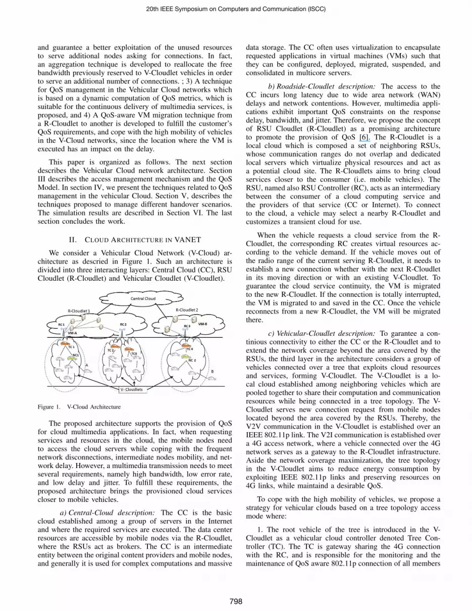
We consider a Vehicular Cloud Network (V-Cloud) ar-chitecture as descried in Figure 1. Such an architecture isdivided into three interacting layers: Central Cloud (CC), RSUCloudlet (R-Cloudlet) and Vehicular Cloudlet (V-Cloudlet).
Figure 1. V-Cloud Architecture
The proposed architecture supports the provision of QoSfor cloud multimedia applications. In fact, when requestingservices and resources in the cloud, the mobile nodes needto access the cloud servers while coping with the frequentnetwork disconnections, intermediate nodes mobility, and net-work delay. However, a multimedia transmission needs to meetseveral requirements, namely high bandwidth, low error rate,and low delay and jitter. To fulfill these requirements, theproposed architecture brings the provisioned cloud servicescloser to mobile vehicles.
a) Central-Cloud description: The CC is the basiccloud established among a group of servers in the Internetand where the required services are executed. The data centerresources are accessible by mobile nodes via the R-Cloudlet,where the RSUs act as brokers. The CC is an intermediateentity between the original content providers and mobile nodes,and generally it is used for complex computations and massive
data storage. The CC often uses virtualization to encapsulaterequested applications in virtual machines (VMs) such thatthey can be configured, deployed, migrated, suspended, andconsolidated in multicore servers.
b) Roadside-Cloudlet description: The access to theCC incurs long latency due to wide area network (WAN)delays and network contentions. However, multimedia appli-cations exhibit important QoS constraints on the responsedelay, bandwidth, and jitter. Therefore, we propose the conceptof RSU Cloudlet (R-Cloudlet) as a promising architectureto promote the provision of QoS [6]. The R-Cloudlet is alocal cloud which is composed a set of neighboring RSUs,whose communication ranges do not overlap and dedicatedlocal servers which virtualize physical resources and act asa potential cloud site. The R-Cloudlets aims to bring cloudservices closer to the consumer (i.e. mobile vehicles). TheRSU, named also RSU Controller (RC), acts as an intermediarybetween the consumer of a cloud computing service andthe providers of that service (CC or Internet). To connectto the cloud, a vehicle may select a nearby R-Cloudlet andcustomizes a transient cloud for use.
When the vehicle requests a cloud service from the R-Cloudlet, the corresponding RC creates virtual resources ac-cording to the vehicle demand. If the vehicle moves out ofthe radio range of the current serving R-Cloudlet, it needs toestablish a new connection whether with the next R-Cloudletin its moving direction or with an existing V-Cloudlet. Toguarantee the cloud service continuity, the VM is migratedto the new R-Cloudlet. If the connection is totally interrupted,the VM is migrated to and saved in the CC. Once the vehiclereconnects from a new R-Cloudlet, the VM will be migratedthere.
c) Vehicular-Cloudlet description: To garantee a con-tinious connectivity to either the CC or the R-Cloudlet and toextend the network coverage beyond the area covered by theRSUs, the third layer in the architecture considers a group ofvehicles connected over a tree that exploits cloud resourcesand services, forming V-Cloudlet. The V-Cloudlet is a lo-cal cloud established among neighboring vehicles which arepooled together to share their computation and communicationresources while being connected in a tree topology. The V-Cloudlet serves new connection request from mobile nodeslocated beyond the area covered by the RSUs. Thereby, theV2V communication in the V-Cloudlet is established over anIEEE 802.11p link. The V2I communication is established overa 4G access network, where a vehicle connected over the 4Gnetwork serves as a gateway to the R-Cloudlet infrastructure.Aside the network coverage maximization, the tree topologyin the V-Cloudlet aims to reduce energy consumption byexploiting IEEE 802.11p links and preserving resources on4G links, while maintaind a desirable QoS.
To cope with the high mobility of vehicles, we propose astrategy for vehicular clouds based on a tree topology accessmode where:
1. The root vehicle of the tree is introduced in the V-Cloudlet as a vehicular cloud controller denoted Tree Con-troller (TC). The TC is gateway sharing the 4G connectionwith the RC, and is responsible for the monitoring and themaintenance of QoS aware 802.11p connection of all members
20th IEEE Symposium on Computers and Communication (ISCC)
798

in the tree. QoS information is saved in a QoS vector which isperiodically forwarded to the RC in order to monitor the delayand minimize its variation increasing, the rate of allocatedresources.
2. The Node Controller (NC) is a connected node selectedto host a VM image and execute the bandwidth aggregationprocess in order to avoid QoS degradation, increase the avail-able bandwidth, and serve new connection requests.
3. The remaining nodes of the tree are named Tree Mem-bers (TMs). Each TM controls and updates a QoS vector(basically information on the delay and Throughput) and sendsit periodically to the TC.
III. ACCESS MANAGEMENT WITHIN THE V-CLOUDLET
A tree-based network access scheme is developed, whichallows to extend the network coverage beyond the area coveredby the RSU Cloudlet, make the global topology less dynamic,and provide a rapid and a seamless data connectivity tovehicles, while taking into consideration the different QoS re-quirements of the services executed on them. A QoS Model isproposed where each node, which is connected in a multi-hopway to the RC, controls and updates dynamically a QoS vector.The vehicular network offers an access service through theattachment of vehicles to a tree topology previously created.Two types of services are provided. The first service is the Con-nection Service which is a basic connection service providedto each connected vehicle allowing it finding a route throughthe tree already set and reserving a minimum bandwidth inorder to transfer notification/signaling messages as long as it isconnected. The second service is Multimedia Service which isan on-demand service executed during a limited period of timeover the route generated upon requesting a connection serviceand requiring a QoS guarantee and control. Each vehicle holdsa dynamic Route List used to identify potential routes to theRC. The route is described by the sequence of identities ofnodes forming the route, until reaching the RC.
A. QoS Model
In this section we will describe the QoS Model to con-trol how mobility and network attributes affect the QoSprovision of multimedia services. We use a QoS vectorQα = 〈Tα, Dα, Lα, Rα〉 to characterize the dynamic QoSmetrics of the route α in the tree S connecting a vehiclevi to the R-Cloudlet. The route α is described as α =〈vi, .., vm, vm+1..., vn〉 , where 〈v, .., vm〉 is the first segmentconnecting the vehicle vi to the NC, and 〈vi+m, ..., vn〉 is thesecond segment of the route connecting the NC to the TC. Thevehicle vi+m will be a NC (if bandwidth aggregation featureis required), and vn will be a TC. Note that the route α canbe composed by only one segment depending on the existenceof an elected NC. We describe in details each QoS metricscontained in Qα as follows:
1. Available Throughput Tα : Is computed by the TC,and set equal to the difference between the bandwidth ofthe wireless link connecting the TC to the RC, and the totalbandwidth reserved by all connected vehicles in the tree :Tαi
= T(TC,RC) −∑v∈S Tv , where: a) T(TC,RC) is the
throughput supported by the link connecting the TC to theRC; and b) Tv is the bandwidth reserved by a vehicle v.
2. Delay Dα : Is defined as: Dα =∑j∈[i,n](d(vj ,vj+1) +
Qvi) + d(TC,RC) where: a) d(TC,RC) is the traffic residencedelay in the buffer of the gateway vehicle TC, in addition to thetransmission delay between the TC and the RC; b) d(vj ,vj+1)
is the delay between two successive nodes (j, j+1) , which isequal to the sum of the transmission delay, the channel accessdelay and the decoding delay; and c) Qvi is the queuing delayin the node vi .
3. Average packet loss Lα : Is computed by vehicle vi asthe follows: Lα = max{l(vi,vi+1), ..., l(vn−1,vn)} where: vn isthe TC node. The value l(vj ,vj+1) is computed by vehicle vj. It represents the actual value of the packet loss of the linkconnecting vehicles vj and vj+1 , and as the percentage offrames that are dropped by the decoder in vj+1 if the packetarrival time exceeds the deadline.l(vn,RC) is the packet loss ofthe link connecting the RC (i.e., the RSU) to the TC.
4. Route lifetime Rα observed at vehicle vi : Is expressedas: Rα = min{r(vi,vi+1), ..., r(vn−1,vn)} where r(vj ,vj+1) isthe lifetime of the link connecting vehicle vj to vehiclevj+1 ; and r(vn,RC) is the lifetime of the link connectingthe root vehicle TC (i.e., vehicle vn ) to the RC (i.e., theRSU). We denote by the lifetime of a link (vj , vj+1) theremaining time before vj becomes out of coverage of vj+1
. We have r(vj ,vj+1)=(TRvj − σj,j+1)/ | svj− svj+1
| whereTRvj is the transmission range of the vehicles vj , σj,j+1 isthe distance between the vehicle vj and vj+1} , and sv
jis the
speed of the vehicle vj .
B. Access management
In this sub-section, the mechanisms related to access man-agement and QoS updates are developed.
1) Route selection process: To be connected, each vehicleis equipped with a 4G and an IEEE 802.11p interface. Wechoose that only the vehicle that is close enough to the RC(i.e. the distance between the vehicle and the RC, as well asthe vehicle remaining time in the RC coverage do not exceeda given threshold) can connect to that RC, unless it does notfind another vehicle part of an existing tree which can routeits messages to the RC. Therefore, a new Vehicular Cloudletis created and this vehicle is selected as a TC. Otherwise, thevehicle tries to choose the best route through the connectedneighbor vehicles it finds, by flowing the selection processexplained in the sequel.
Table I. CONTENT OF ROUTE ANNOUNCEMENT MESSAGE
AM parameter DescriptionR-Controller ID (R-ID) Identity of the RC
TM -ID Identity of the sender Tree Member
Speed Speed of the Node
Level (L) Number of intermediate nodes from a connected node to the RSU
Route Lifetime (R) Lifetime of the route
QoS vector (Q) QoS vector describing the QoS level in the route
Position (P) Geographic position of the node
T Reserved Bandwidth
U Used Bandwidth
Aggregation flag Indicates the starting of bandwidth aggregation process
To guarantee QoS satisfaction, each vehicle selects a routebased on a set of QoS requirements described as a vector Qin the form of Q = 〈D,L, T 〉 , where D is the maximumallowed delay, L is the maximum acceptable packet loss, and
20th IEEE Symposium on Computers and Communication (ISCC)
799

T is the requested throughput. Note that, Tε[Tmin Tmin+4] ,where Tmin is the minimum required bandwidth, and 4 is themaximum variation beyond Tmin that the vehicle can showduring data transmission. When a vehicle needs to establisha new connection, or requests a new service, it should firstlyformulate its own needs in term of QoS by generating the QoSrequirement vector Q. After that, it listens during a periodof time 4t to the different Route Announcement messages(RAN) broadcast by its neighbor vehicles, and also by the RCif it is located within an RC cell.
Table. I describes the content of the RAN message. Fromeach RAN message, the vehicle extracts the announced routeand saves it in the Route List. Then, the vehicle A proceedsas follows to select the vehicle to which it will connect, basedon its QoS requirements. First, it selects the routes havinga Throughput exceeding a predefined threshold, (T > T0 ).Second, it eliminates any offer that: a) is unable to guaranteethe maximum allowed delay (D > D0); or b) provides apacket loss rate, which is higher than the accepted value(L > L0). Finally, if there are many routes satisfying theserequirements, it selects the offer having the highest routelifetime. If any route can be selected, the vehicle waits forRAN messages during a second listening period.
From the selected offer, the vehicle A extracts the identityof the related neighbor vehicle and the route connecting it tothe RC. After that, it generates a Route Attachment message(RAT) to the RC containing: a) the QoS requirement vectorQ, b) its position and direction in the map; c) the identityof the vehicle, whose offer was selected; the identity of theRC toward which the message will be forwarded; and d) itsidentity. The RC checks the QoS availability and allocates therequired bandwidth T0 according to the node needs describedin Q. Moreover, the neighbor node, to which the vehiclewill be attached, called also the father node, accepts the newvehicle in the tree, updates the route, and sends an AttachmentAcknowledgment message (AA) to the concerned vehicle andthe RC. The latter RC allocates a minimal portion of the cloudresource (i.e. creation of a VM) to the new tree member. Thenew established link is saved by in the RC, and will be includedin the Route List of the intermediate nodes composing the routebetween the connected vehicles and the RC. As the requestedQoS needs to be guaranteed over this route, the QoS levelin the route should be periodically monitored and updated(e.g., the average bandwidth consumed by the vehicle thatuses a service, the packet delay along the route connectingthe vehicle, the mean error rate).
To provide QoS in the designed V-Cloud, a QoS awareservice delivery model is developed. Let α = 〈 v1, ..., vn〉 bethe route between the leaf node v1 and the Tree Controller vn.To update QoS Metrics, a progressive computing method isimplemented. First, vn computes the new value of the lifetimebased on the distance between it and the RC to which it isconnected. Second, vn computes the new value of the averagepacket loss, and the route delay by identifying the current timevalue and the timestamp saved in the AA message. Finally, itsaves this information in an updated QoS-Monitoring message(QM) to be locally broadcast to these child vehicles and toinform that this route is still active. Each neighbor vehicle,which receives the QM message, extracts the QoS metricvalues and reacts in the same way to calculate and update
the QoS parameters. A QM message is generated after that tocommunicate the new QoS metrics to the neighbor nodes in thetree. The process is repeated until reaching the leaf node v1.Each intermediate node is required to generate and broadcastQoS information in an updated QM message until reaching v1.This message contains a description of the QoS parameters ofthe active connection, the route description , the identity of thesender node and its speed, the timestamp, and the identities ofthe RC and the TC to which it is connected. The leaf node v1computes the recent values of QoS metrics in the route α andforwards the QM response message to the RC.
IV. QOS MANAGEMENT AT THE R-CLOUDLET LEVEL
The QoS-aware management of multimedia services ischallenging to address in V-Cloud networks. Among others,delay and jitter are important to guarantee as they may causea degradation of the quality of multimedia services. In fact,as a connected vehicle may hands over by changing its pointof attachment to the network, it must discover a new point ofattachment among its neighbors and establish new connectionwith the one offering the highest QoS, or directly connect to aRSU. Some sent or received data packets can be lost or delayeddue to the handover process, the variation of the size of bufferslocated in the old and new RC, and the modification of theattachment points in the trees. To cope with these issues, wepropose to define a de-jitter buffer in each RC and to minimizethe distance between the service and the location of the mobilenode, by migrating the VM from a RSU to another when thevehicle changes to a new cloudlet. Moreover, a bandwidthaggregation mechanism is implemented in vehicles to serve asnode controllers to face the QoS degradation and bandwidthresources starvation in the network. As it is mentioned above,an RC in the R-Cloudlet queries TCs for information aboutthe QoS state of the trees they are managing, and solves theresources starvation by increasing the allocated bandwidth.
A. De-jitter buffer management
Delay and packet loss can significantly affect the QoSof a multimedia service in the V-Cloud Networks. In fact,the packet transmitted from a source vehicle to a destinationvehicle may suffer from delay variation, or even may be lost.To cope with these issues, we develop an adaptive de-jitterbuffer management algorithm used in each RC, for everyvehicle. This algorithm manages the buffer size, which dependson the maximum time that a packet can wait in the buffer ofthe RC before being played out. There are different proposalsof dejitter buffer algorithms in the literature. This paper doesnot propose a new one, but rather extends the work of [7]which proposes an Adaptive Algorithm to increase in delaysby using a smaller weighting factor (δ and β, whose valuesset to 0.998002 and 0.75 respectively) as delays increase. Theoperation of the modified De-jitter buffer algorithm is shownin Algorithm 1.
At each reception of a new packet i througt the route α, the RC checks if the route lifetime, Rα, is in the interval[T′
0, T0
]or not. Three cases are distinguished:
1. If (Rα ≥ T0), a future handover is predicted and thebuffer size Pi is estimated as : Pi = d
i+a ·Vi , where di and
Vi are the i-th estimates of delay and its variance respectively,
20th IEEE Symposium on Computers and Communication (ISCC)
800

Algorithm 1 Adaptive De-jitter bufferWhile (receiving a new packet in the RC)
if Rα ≥ T0 then{di = δ · di−1 + (1− δ) ·DviVi = δ · Vi−1 + (1− δ) · |di −Dvi |Pi = di + a · Vi
if T′
0 ≤ Rα < T0 then{di = δ · di−1 + (1− δ) ·DviVi = δ · Vi−1 + (1− δ) · |di −Dvi |Pi = d
i+ a · V +DHO + µ ·DLeveli
if Rα ≤ T′
0 then{di = β · di−1 + (1− β) ·DviVi = β · Vi−1 + (1− β) · |di −Dvi |Pi = di + a · V +DHO + µ ·DLeveli
end while
while aε [0, 1] factor describing how important is the Jitter inthe computation of the buffer size. The values di and vi arecomputed for each received packet, where T0 is the thresholdto trigger a handover.
2. If (T′
0 ≤ Rα < T0) , a handover process is expected to betriggered and the buffer size Pi is estimated as Pi = d
i+a·V +
DHO+µ ·DLeveli , where DHO is the assumed Handover andVM migration delay, DLevel is a constant delay caused by aone-hop jump realized by the vehicle vi and µ is the differenceseen between the new and the old point of attachment of thenode in the new and the old route respectively. If this differenceis negative, µ is equal to zero.
3. If (Rαj ≤ T′
0), the route lifetime is considered to be tooshort. Thus, we try to increase the size of the De-jitter bufferby changing the weighting factors to β in order to achieve asuccessful handover before the link disconnection.
B. NC selection algorithm and Bandwidth aggregation
The allocated bandwidth defined in Sub-section III-B isdone according to the required bandwidth T0 defined in theQoS requirement vector Q. We point out that the reallyused bandwidth value is between Tmin and Tmin +4. Thisapproach can lead to an over-allocation of bandwidth resourcesas it may happens that the whole bandwidth is not totallyutilized all the time. While this method guarantees quality, itcan lead to resources under-utilization. Therefore, we proposeto reallocate the free resources, which are the differencebetween the allocated bandwidth T0 and the average usedbandwidth Tmean, to serve new vehicles that are unable tofind a route satisfying their required bandwidth or to increasetheir requested bandwidth in the route they are currentlyusing. One of the vehicles currently connected to the treewill be selected to behave as a node controller and performthe aggregation of the resources unused by the child vehiclesconnected to the same tree. To estimate the unused resources(the residual bandwidth, TAggv ) in the sub-tree of the node v,the resources aggregation function TAggv is defined as follows:TAggv =
∑xεSv
TAllocatedx − Tmean, where Sv is the set ofdirect and indirect child nodes of v in the tree, TAllocatedx isthe allocated bandwidth by a node x and TMean
x is the meanbandwidth defined by a node x.
We denote by Y a connected or an unconnected node.
When Y detects a decrease of its available bandwidth belowa defined threshold Tth or does not find a neighboring nodesatisfying its required bandwidth T reqY , it sends an Aggrega-tion Request (AR) to its neighbors to trigger the resourcesaggregation process. Upon receiving a request from Y, aneighbor Y1 (note that a neighbor can also be a father node inthe tree) checks if there is a sufficient residual bandwidth overits sub-tree. If TAggY1
> T reqY , the node Y1 checks if both of theroute lifetimeRY and the rote delay DY exceed a predefinedthresholds R0 and D0 respectively. If these conditions aresatisfied, the node Y1 becomes the new NC and the reallocationmechanism is triggered. If not, the node Y1 forwards the ARmessage to its father, which will processed in the same way. Toselect the future NC, the AR message is sent along the route tothe direct and indirect father until reaching the TC, while thevehicle continues looking for a suitable attachment point whileavoiding to the maximal possible the generation of requestsfor NC creation. In the case where the AR message reachesthe TC and is unable to satisfy the previous requirements,the aggregation is unsuccessful and the node Y will be soondisconnected due to insufficient resources. If the NC selectionis successful, the NC accepts the AR, returns an AggregationResponse message to node Y, updates the residual bandwidthof the links along the sub-tree accordingly, and broadcasts anAttachment message containing an aggregation flag set to 1and the updated QoS Vector. Note that the aggregation flag isused to guarantee that there no more than one NC defined alonga route to reduce the complexity and increase the successfulrate of the aggregation requests.
V. MOBILITY MANAGEMENT
As long as vehicles moves from an RC to another, a VMis migrated through the various servers connected to the set ofRCs. When the node is disconnected due to lack of connectionoffers, a VM image is saved in the CC in order to be re-usedlatter. The heterogeneity of the access networks used to connectvehicles, and their high mobility, make it necessary to managetwo types of handovers: a) Inter-R-Cloudlet Handover; and b)Intra-R-Cloudlet Handover where we differentiate between theInter-V-Cloudlet Handover and the Intra-V-Cloudlet Handover.Let us consider a vehicle A as a node looking for newconnection. It listens to broadcast RAN and saves the routesthat satisfy its QoS requirements in its Route List θ. Then, itsends an Alert message to its RC containing the Route List.
Before the HO is completely achieved, the vehicle Aremains connected to the RC for a short period of time toestimate the delay variation. Then, the RC calculates the newprovisioned size of the De-jitter Buffer to cope with this vari-ation, and therefore to estimate the quantity of supplementarydata to be sent to the vehicle by increasing the throughputto avoid the potential delay variation. In the Intra-R-CloudletHandover, the vehicle A is still in the same R-Cloudlet.However, it moves from a Tree Controller to another (i.e.Inter-V-Cloudlet Handover), or from a branch to another in thesame V-Cloudlet (i.e. Intra-V-Cloudlet). The radio handoverfrom a Tree Controller to another, or from a tree branch toanother may still take a short period of time. Thus, during theIntra-R-Cloudlet Handover, the de-jitter buffer is needed toavoid a potential QoS degradation. However, there is no needfor VM migration. Inter-R-Cloudlet Handover is establishedwhen a vehicle A moves from the coverage area of RC1 to
20th IEEE Symposium on Computers and Communication (ISCC)
801

that of RC2. In this case, a VM migration is needed. SinceRC1 and RC2 are connected to different R-Cloudlets, thevirtual machine VMA of the vehicle A should be transferredfrom R − Cloudlet1 to R − Cloudlet2. Then, A will accessR − Cloudlet2 via RC2 and needs to resume its service.In fact, to fulfill the customer QoS requirements and copewith the high mobility of the V-Cloud networks, we proceedto VM migration which is performed based on several QoSmetrics, namely the delay, and the node position and speed,to minimize the distance separating the Customer vehicle tothe service provider, make the VM execution location closer tothe customer, and avoid potential variation of the QoS servicelevel over the route connecting the vehicle. The VM migrationprocess requires the resources re-allocation in the neighbor R-Cloudlet. Moreover, the De-jitter process is needed to avoidthe important delay variation due to VM migration, and alsoto reduce the handover delay. A node network disconnectionprocess can happen due to a failure of the handover, or a failureof the bandwidth aggregation procedure and NC selection. Inthat case, the R-Cloudlet provider waits for a period of timeto new connection requests received from the same vehicle. Ifnone request is recieved, it migrates the VM to the CC, andthe interaction between the vehicle and guest VM is temporallysuspended. The guest VM will be saved in the CC for a periodof time in order to be recovered if the vehicle reconnects again.
VI. SIMULATION
In this section, the system performance will be analyzedbased on the Blocking Rate of vehicles connections andhandovers, and the average number of created Brokers perTime slot. A blocking can occurs when a new connection isnot satisfied, or an existing vehicle’s connection fails duringa handover. The simulation is conducted considering onedirectional highway segment of 150 Km composed of threelanes. The vehicle’s speed ranges from 70-90 km/h. We setthe vehicle and RSU radius coverage equal to 200 and 5000m, respectively and we varied the vehicles arriving rate (λ )from 0.05 to 0.7. Table II lists the simulation parameters. Therequested bandwidth varies between a nominal value denotedTmin (set equal to 5Mbps) and Tmin + 4 , where4 variesfrom 1 Mbps to 5 Mbps.
Table II. SIMULATION PARAMETERS
Parameters/Description Values
Simulation duration 2000 time-slots
Probability of service request / vehicle 10%
Duration of a service 200 seconds
Security distance between two vehicles 5/9 of the vehicle speed (km/h)
distance between each two successive RSUs 3Km
Figure 7 shows the Blocking Rate with respect to thearrival rate λ , and also with respect to 4. We notice thatthe Blocking Rate decreases while λ increases. However, theBlocking Rate inreases with the increase of 4. In fact, aslong as the network becomes dense (i.e., λ increases), mobilenodes are likely to find neighbor vehicles that meet theirrequirements, decreasing the Blocking Rate (i.e. .the morevehicles the more connections will happen to the RC, andhence to the CC). In addition, the graph shows that theBlocking Rate increases with the increase of 4. Indeed, aslong as the required bandwidth T increases, the Blocking Rateincreases due to the increase of the number of handovers and
the rate of aggregation requests because of the unavailabilityof free bandwidth. Figure 3 shows a 3D graph of the AverageNumber of NC/Time slot with respect to the arrival rate λ, andalso with respect to 4. We note that the average number ofNCs per Time slot increases with the increase of 4 and thearrival rate λ. In fact, as long as 4 increases, the bandwidthremaining on the available trees becomes insufficient. To copewith the bandwidth limitation, the aggregation mechanism isimplemented by mobile nodes which request new connections,creating thus new NC nodes. Such phenomena reduce theblocking rate caused by connection failures. Therefore, aslong as the network becomes dense, the number of successfulaggregation increases.
Figure 2. Blocking Rate with respect to 4 and λ
Figure 3. Average Number of NC per Time slot with respect to4 and λ
Two parameters EGTC and EGNC are defined to show theevolution of growth in the number of TCs and NCs respec-tively, in function of 4. EGTC and EGNC are calculatedas follows: EGTC(4) = TC(4)−TC0
TC0and EGNC(4) =
NC(4)−NC0
NC0, where 4ε [1, 5] , and TC (4) is the Average
number of TCs per Time slot, NC (4) is the Average numberof NCs per Time slot, TC0 (and respectively NC0 ) is theAverage number of TCs (and respectively NCs) per Time slot,considering a value of 4 equal to 0 Mbps. Figure 5 showsthe evolution of EGTC and EGNC in respect with 4, for avalue of λ equal to 0.5, while Figure 5 shows the variation ofthe same parameters for a value of λ equal to 0.05.
Both of these Figures show that EGTC and EGNC in-crease with the increase of 4. In addition, we notice thatwhile raising λ , EGNC is more important than EGTC .In fact, the proposed system reduces the connetion blockingrate by creating aggregation nodes (i.e. NC nodes) at anylocation of the tree. Such a decision is in most of timetaken byintermediate nodes before the aggregation request reaches theRC. Therefore, no new tree splitting, nor new trees creation,
20th IEEE Symposium on Computers and Communication (ISCC)
802

Figure 4. Evolution of growth rate of TC/NC Number with respect to 4 forλ = 0.5
Figure 5. Evolution of growth rate of TC and NC Number with respect to4 for λ = 0.05
will be made to release the network bandwidth. In Figure 5,this result is verified while the network density is lower (i.e., λequal to 0.05). In fact, we note that EGTC continues to growmore strongly than the number EGNC , while increasing 4due to the availability of low number of neighbor vehicleswhich can satisfy the aggregation requirements.
Figure 6. Blocking Rate with respect to λ for 4 = 1Mbps
Figure 7. Blocking Rate with respect to 4 for λ = 0.5
Figures 6 and 7 show a Blocking Rate comparison betweenone-hop tree topology and the proposed multi-hop tree topol-ogy. Figure 6 shows the Blocking Rate with respect to λ for
4 = 1 Mbps while Figure 7 shows the Blocking Rate withrespect to 4 for λ = 0.5. In Figure 6, the Blocking Rateis increasing when λ increases for both schemes (i.e., one-hop and multi-hop tree). Figure 7 shows that the BlockingRate decreases when4 increases for one-hop tree topologyinversely to the case of the proposed system. In addition, thetwo figures shows that the Blocking rate is more important inthe case of one-hop tree topology. The above figures justifythe performance of the proposed system in its ability to reducethe Blocking Rate using the aggregation process, and to copewith the limitation of bandwidth ressorces and the muli-hopaccess scheme in the tree to increase the network coverage.
VII. CONCLUSION
In this paper we designed a Vehicular Cloud architecture(V-Cloud) integrating Cloud Computing with VANET net-works. We proposed an Access Management scheme to the V-Cloudlet based on a tree topology. To provide a successful andrapid access to vehicles, we detailed the mechanisms of QoSmanagement over the generated routes and the routes selection.A technique for De-jitter buffer estimation and management,and a technique for NC selection algorithm and Bandwidthaggregation, are developed. Finally, to cope with high mobilityand QoS provision issues, a Handover management mechanismis developped.
REFERENCES
[1] R. Yu, Y. Zhang, S. Gjessing, W. Xia, and K. Yang, “Toward cloud-basedvehicular networks with efficient resource management,” IEEE Network,vol. 27, no. 5, pp. 48 – 55, October 2013.
[2] R. Hussain, F. Abbas, J. Son, D. Kimy, S. Kimz, and H. Oh, “Vehiclewitnesses as a service: Leveraging vehicles as witnesses on the road invanet clouds,” in Proceedings of the IEEE Cloud Computing Technologyand Science (CloudCom), Bristol, England, December 2013.
[3] K. Xu, R. Izard, F. Yang, K.-C. Wang, and J. Martin, “Cloud-based hand-off as a service for heterogeneous vehicular networks with openflow,” inProceedings of Research and Educational Experiment Workshop (GREE),Salt Lake City, UT, March 2013.
[4] M. Gerla, E.-K. Lee, G. Pau, and U. Lee, “Internet of vehicles: Fromintelligent grid to autonomous cars and vehicular clouds,” in Proceedingsof the IEEE World Forum on Internet of Things, Seoul, Korea, March2014.
[5] M. Eltoweissy, S. Olariu, and M. Younis, Ad Hoc Networks. SpringerBerlin Heidelberg, 2010, ch. Towards Autonomous Vehicular Clouds, pp.1–16.
[6] M. Satyanarayanan, P. Bahl, R. Cáceres, and N. Davies, “The case forvm-based cloudlets in mobile computing,” IEEE Pervasive Computing,vol. 8, no. 4, pp. 14–23, 2009.
[7] L. Sun and I. E, “Prediction of perceived conversational speech qualityand effects of playout buffer algorithms,” IEEE International Conferenceon Communications., vol. 1, no. 7890921, pp. 1 – 6, May 2003.
20th IEEE Symposium on Computers and Communication (ISCC)
803


