Embed Size (px)
Citation preview
CHARMY: A Framework for Designing andVerifying Architectural Specifications
Patrizio Pelliccione, Paola Inverardi, and Henry Muccini
Abstract—Introduced in the early stages of software development, the CHARMY framework assists the software architect in making
and evaluating architectural choices. Rarely, the software architecture of a system can be established once and forever. Most likely
poorly defined and understood architectural constraints and requirements force the software architect to accept ambiguities and move
forward to the construction of a suboptimal software architecture. CHARMY aims to provide an easy and practical tool for supporting the
iterative modeling and evaluation of software architectures. From an UML-based architectural design, an executable prototype is
automatically created. CHARMY simulation and model checking features help in understanding the functioning of the system and
discovering potential inconsistencies of the design. When a satisfactory and stable software architecture is reached, Java code
conforming to structural software architecture constraints is automatically generated through suitable transformations. The overall
approach is tool supported.
Index Terms—Software architectures, model checking.
Ç
1 INTRODUCTION
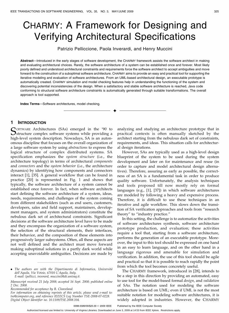
SOFTWARE Architectures (SAs) emerged in the ‘90 tostructure complex software systems while providing a
high-level system description. Nowadays, SA is an auton-omous discipline that focuses on the overall organization ofa large software system by using abstractions to express thelogical structure of complex distributed systems. SAspecification emphasizes the system structure (i.e., thearchitecture topology) in terms of architectural componentsand connectors and the system behavior (i.e., the architecturedynamics) by identifying how components and connectorsinteract [1], [35]. A general workflow that can be found inpractice [20] is represented in Fig. 1 and shows thattypically, the software architecture of a system cannot beestablished once forever. In fact, when software architectsstart defining the software architecture of a system, ideas,needs, requirements, and challenges of the system comingfrom different stakeholders (such as end users, customers,developers, sales and field support, maintainers, develop-ment managers, and system administrators) constitute thenebulous dark set of architectural constraints. Significantdecisions at the software architecture level have to be madeand they encompass the organization of a software system,the selection of the structural elements, their interfaces,their behavior, and the composition of these elements intoprogressively larger subsystems. Often, all these aspects arenot well defined and the architect must move forwardmaking suboptimal solutions in a partly dark world whileaccepting unavoidable ambiguities. Decisions are made by
analyzing and studying an architecture prototype that inpractical contexts is often manually sketched by thearchitect starting from the nebulous dark set of constraints,requirements, and ideas. This situation calls for architectur-al design iterations.
However, SAs are typically used as a high-level designblueprint of the system to be used during the systemdevelopment and later on for maintenance and reuse (inorder to capture and model architectural design alterna-tives). Therefore, assuring as early as possible, the correct-ness of an SA is a fundamental task in order to producequality software. Unfortunately, the analysis techniquesand tools proposed till now mostly rely on formallanguages (e.g., [1], [37]) in which software architecturesare modeled by following a heavy and expensive process.Therefore, it is difficult to use these techniques in aniterative and agile workflow. This slows down the transi-tion of SA verification approaches and tools from “researchtheory” to “industry practice.”
In this setting, the challenge is to automatize the activitiesof software architectures synthesis, software architectureprototype production, and evaluation; these activitiesrequire a tool that, starting from a software architecture,performs the generation of an executable prototype. More-over, the input to this tool should be expressed on one handin an easy to learn language, and on the other hand in alanguage rigorous and amenable for simulation andverification. In addition, the use of this tool should be agileand practical so that it is possible to reach rapidly the pointfrom which the tool becomes concretely useful.
The CHARMY framework, introduced in [28], intends tobe a step in this direction by providing an automated, easyto use tool for the model-based formal design, and validationof SAs. The notation used for modeling the softwarearchitecture is based on UML; even if UML is not the mostsuitable notation for modeling software architectures, it iswidely adopted in industries. However, the CHARMY
IEEE TRANSACTIONS ON SOFTWARE ENGINEERING, VOL. 35, NO. 3, MAY/JUNE 2009 325
. The authors are with the Dipartimento di Informatica, Universitadell’Aquila, Via Vetoio, 67010 L’Aquila, Italy.E-mail: {pellicci, inverard, muccini}@di.univaq.it.
Manuscript received 21 July 2008; accepted 16 Sept. 2008; published online2 Dec. 2008.Recommended for acceptance by R. Cleaveland.For information on obtaining reprints of this article, please send e-mail to:[email protected], and reference IEEECS Log Number TSE-2008-07-0228.Digital Object Identifier no. 10.1109/TSE.2008.104.
0098-5589/09/$25.00 � 2009 IEEE Published by the IEEE Computer Society
Authorized licensed use limited to: University of Virginia Libraries. Downloaded on June 3, 2009 at 14:53 from IEEE Xplore. Restrictions apply.
notation has a formal semantics, and thus it forces thesoftware architect to resolve ambiguities that could bepresent in a standard UML-based software architecturespecification. Starting from this specification, an executableprototype is automatically produced. It is executable in thesense that it can be simulated aiming at exploring the effectof certain design decisions or environmental conditions onthe system behavior. The prototype can also be exhaustivelyverified by means of model checking techniques [27], [12].In this way, software architects can better understand thefunctioning of complex systems, discover architecturaldecision inconsistencies, and improve the architecturaldesign model.
CHARMY offers an integrated environment supportingthe combination of simulation and verification. This combi-nation is useful for gaining confidence on the system andunderstanding the verification results. For example, in case,the verification returns a “not valid” result, then simulationcan be used for reproducing the error trace automaticallyproduced by the model checker. The model checker used byCHARMY is SPIN. Therefore, the software architecture,modeled in terms of CHARMY diagrams, is automaticallytranslated in Promela that is the specification language ofSPIN. Model checkers, as well as other finite-state verifica-tion techniques, allow for the automated checking of thesystem model compliance to given temporal properties.These properties are typically specified as linear-timeformulas in suitable temporal logics. In general, it is adifficult task to accurately and correctly express properties inthese logics. For this reason, CHARMY temporal propertiesare specified as Properties Sequence Charts (PSCs) [4]. PSC isa scenario-based visual language for describing temporalproperties. This language is the result of an accurate analysisin the direction of finding the “right” balance betweenexpressive power (what is required in a formalism to expressa “useful set” of temporal properties) and simplicity of use(easy of use and simplicity are mandatory requirements tomake a formalism adopted by industries).
The verified and final SA is the starting point of modeltransformations that produce a skeleton of the (Arch)Javacode of the system. The produced code reflects structuralSA constraints; more precisely, by means of the ArchJavaAPI [1], the generated Java code explicitly containsarchitectural constructs (such as components, connectors,channels, etc.) and will ensure the communication integrity,e.g., at the implementation level, each component can onlycommunicate accordingly to what explicitly declared in theSA. For instance, considering an SA composed of the three
components C1, C2, and C3 if the software architect hasmodeled that C1 can only send messages to the componentC2 (and not to the component C3), this will be respected andforced in the code so that developers will be unable tochange these communication rules.
The CHARMY approach for specifying and analyzingSAs hides most of the complexity of the modeling andanalysis process and it is tool supported. The tool has aplugin-based architecture, which allows an easy and rapidintegration of new modeling and analysis techniques.
The paper is structured as follows: Section 2 presents theunderlying formal specification of CHARMY and its seman-tics. This specification is hidden to the software architect thatis only asked to specify the software architecture by means ofthe CHARMY proprietary graphical notation that is presentedin Section 2. Section 3 presents a description of the algorithmsused to obtain an executable prototype, the model checkingand simulation features, and the Java code generation.Section 4 presents PSC, the language integrated in CHARMY
for behavioral properties specification. Section 5 presents thetool by focusing on its features and its implementation.Section 6 puts, in practice, the CHARMY approach on a simplecase study and discusses lessons learned from our experi-ences on using CHARMY in industrial projects. Section 7describes related work, and Section 8 concludes the paperproviding future research directions.
2 CHARMY SPECIFICATION
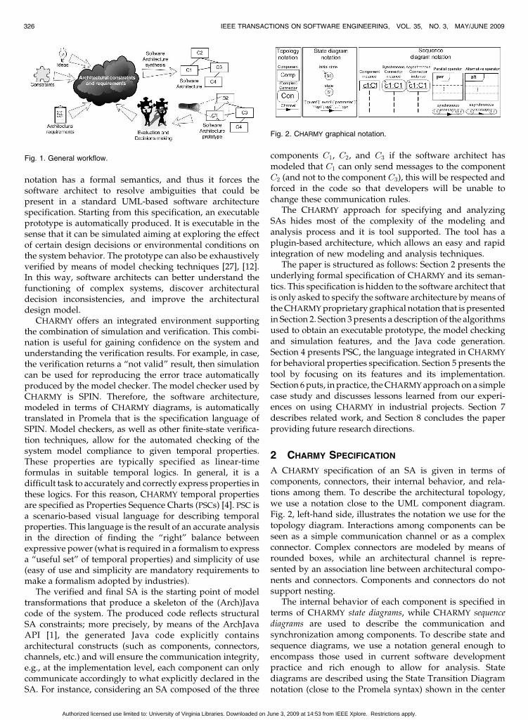
A CHARMY specification of an SA is given in terms ofcomponents, connectors, their internal behavior, and rela-tions among them. To describe the architectural topology,we use a notation close to the UML component diagram.Fig. 2, left-hand side, illustrates the notation we use for thetopology diagram. Interactions among components can beseen as a simple communication channel or as a complexconnector. Complex connectors are modeled by means ofrounded boxes, while an architectural channel is repre-sented by an association line between architectural compo-nents and connectors. Components and connectors do notsupport nesting.
The internal behavior of each component is specified interms of CHARMY state diagrams, while CHARMY sequencediagrams are used to describe the communication andsynchronization among components. To describe state andsequence diagrams, we use a notation general enough toencompass those used in current software developmentpractice and rich enough to allow for analysis. Statediagrams are described using the State Transition Diagramnotation (close to the Promela syntax) shown in the center
326 IEEE TRANSACTIONS ON SOFTWARE ENGINEERING, VOL. 35, NO. 3, MAY/JUNE 2009
Fig. 1. General workflow.
Fig. 2. CHARMY graphical notation.
Authorized licensed use limited to: University of Virginia Libraries. Downloaded on June 3, 2009 at 14:53 from IEEE Xplore. Restrictions apply.
of Fig. 2. Labels on arcs are structured as follows: ‘[‘guard’]’event ‘(‘parameter’)“/’ ‘op1’ ‘op2’ � � � ‘opn’, where guard is aBoolean condition that allows the transition activation, i.e.,two state diagrams are synchronized only if the guardcondition becomes true. The elements that can be writteninto the guard are variables local to the state diagram. Anevent can be a message sent or received (denoted by anexclamation mark “!” or a question mark “?”, respectively),or an internal operation (�) (i.e., an event that does notrequire synchronization among state diagrams). An eventcan have a parameter that is the value that will beexchanged between a pair of components when thetransition fires. op1; op2; . . . ; opn are the operations to beexecuted when the transition fires.
Components interact according to the semantics of theircommunication as expressed in a sequence diagram. Forexample, if a sequence diagram shows that two compo-nents communicate over a synchronous channel, it meansthat the sender component has to wait until the receiverwill receive the message. Consistency checks implementedin CHARMY forbid the definition of two different kinds ofcommunication for a specific channel that connects twocomponents. More precisely, two components can commu-nicate by means of both synchronous and asynchronouschannels but each channel can be either synchronousor asynchronous.
The notation used for sequence diagrams is shown inFig. 2, right-hand side. CHARMY sequence diagrams use anUML notation, stereotyped in the following way:
1. rectangular boxes represent instances of the archi-tectural components defined in the topology;
2. rectangular rounded boxes represent instances of thearchitectural synchronous and asynchronous con-nectors defined in the topology;
3. arrows represent messages exchanged between twocomponents;
4. the parallel operator is the interleaving among themessages contained into the parallel operands; andfinally
5. the alternative operator represents different possiblealternatives.
Parallel and alternative operators are represented asboxes that intersect the component and connector lifelines.Operands of parallel and alternative operators are identi-fied by the operand separators (see the dashed lines in theright-hand side of Fig. 2). CHARMY sequence diagrams areused to represent the communications between the compo-nents, and hence to derive the connectors that will managesuch a components orchestration.
A direct communication between two components iscalled simple connector and it is represented by means offilled arrows for synchronous communication and halfarrows for asynchronous communication (see Fig. 2) di-rectly connecting two components.1 State diagrams do notcontain synchronization information among components;and thus if a message is not contained in any sequencediagram, the specification is incomplete. Summarizing,
state diagrams are able to represent by means of transitions,that they send a message (or that they are waiting for amessage), but they do not know the kind of synchronizationand they do not have information on who is the receiver (orthe sender) of the message. State diagram messages (bothsent and received messages) and sequence diagrammessages are not obliged to have the same label. For thisreason, as can be seen in Fig. 2, messages in sequencediagrams are complemented with two ovals in order to bindthe sequence diagram message with both the message sentby the sender component state diagram and the messagereceived by the receiver component state diagram. Given asequence diagram message, if its label is equal to both thesender and the receiver message labels (within thecorresponding state diagrams), then the binding can beautomatically made and the ovals can be omitted.
Complex communication, i.e., multicast communication,is modeled by means of connectors that can only send andreceive synchronous messages. More precisely, theseconnectors can only receive one message that must be thefirst one in the interaction among components andconnector. The remaining messages are considered theforwarding of the message to the target components. Thischoice is made to unambiguously synthesize a connectorfrom a sequence diagram. There are two possible types ofcomplex connectors: 1) synchronous complex connectors inwhich the sender is stopped until the connector delegatesthe message to the receivers and 2) asynchronous complexconnectors in which the sender does not have to wait thereception of the message by the receivers. The behavior ofthe connector is synthesized by using the informationcontained in the sequence diagram that contains theconnector. Consistency checks disallow us to define thebehavior of a specific connector by means of more than onesequence diagram. The parallel and the alternative opera-tors are particularly useful to describe different kinds ofone-to-many communications.
2.1 CHARMY Formal Specification
In this section, we provide the formal textual definition ofa CHARMY specification (see Definition 6). This definitionrequires two additional definitions that are the definitionof a CHARMY state diagram (see Definition 1) and aCHARMY sequence diagram (see Definition 2) togetherwith other three auxiliary definitions (i.e., Definitions 3-5).Then, we provide the definition of valid CHARMY
specification (see Definition 10) that is a CHARMY
specification that satisfies the four properties stated inthe following. Definitions 7-9 introduce auxiliary functionsthat help to simplify the exposition. Finally, Definition 11explains how a system specified in CHARMY is obtainedby parallel composing, according to synchronizationpolicies provided by the CHARMY sequence diagrams,the CHARMY state diagrams. Note that in the followingwith the notation f� � �g, we denote nonempty finite sets,with the notation f� � �g0, we denote possibly empty finitesets, and with the notation f� � �g�c , we denote ordered setsby following the order �c . Moreover, we will denote with< tuple > : < name > the element in the tuple whosetype is name.
PELLICCIONE ET AL.: CHARMY: A FRAMEWORK FOR DESIGNING AND VERIFYING ARCHITECTURAL SPECIFICATIONS 327
1. Note that half arrows can be used only to represent communicationamong two components.
Authorized licensed use limited to: University of Virginia Libraries. Downloaded on June 3, 2009 at 14:53 from IEEE Xplore. Restrictions apply.
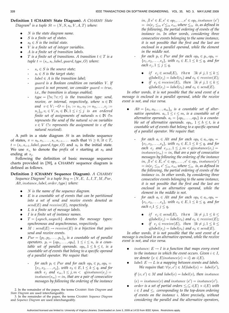
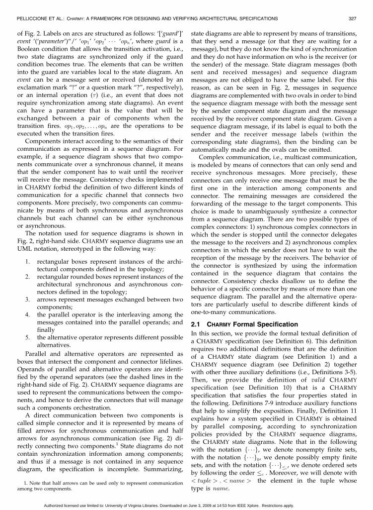
Definition 1 (CHARMY State Diagram). A CHARMY StateDiagram2 is a tuple St ¼ ðN;S; s0; V ; A; T Þ where:
. N is the state diagram name.
. S is a finite set of states.
. s0 2 S is the initial state.
. V is a finite set of integer variables.
. A is a finite set of transition labels.
. T is a finite set of transitions. A transition t 2 T is atuple t ¼ ðss; st; label; guard; type;OÞ where:
- ss 2 S is the source state;- st 2 S is the target state;- label 2 A is the transition label;- guard is a Boolean condition on variables V . If
guard is not present, we consider guard ¼ true,i.e., the transition is always enabled;
- type ¼ f!n; ?v; �g is the transition type: send,receive, or internal, respectively, where n 2 INand v 2 V ;�O ¼ fv1 :¼ n1; v2 :¼ n2; . . . ; vj :¼njg0; vi 2 V ; ni 2 IN; 1 � i � j is an orderedfinite set of assignments of naturals n 2 IN (!nrepresents the send of the natural n) on variablesv 2 V (?v represents the assignment to v of thenatural received).
A path in a state diagram St is an infinite sequenceof states, � ¼ s0; s1; . . . ; si; siþ1; . . . such that 8i � 0; 9t 2 T ,t ¼ ðsi; siþ1; label; guard; type; OÞ and s0 is the initial state.We use �sj to denote the prefix of � starting at s0 andending at sj.
Following the definition of basic message sequencecharts provided in [39], a CHARMY sequence diagram isdefined as follows.
Definition 2 (CHARMY Sequence Diagram). A CHARMY
Sequence Diagram3 is a tuple Seq ¼ ðN;E; L; I; T ;M; Par;Alt; instance; label; order; typeÞ where:
. N is the name of the sequence diagram.
. E is a countable set of events that can be partitionedinto a set of send and receive events denoted assendðEÞ and receiveðEÞ, respectively.
. L is a finite set of message labels.
. I is a finite set of instance names.
. T ¼ fsynch; asynchg denotes the message types:synchronous and asynchronous, respectively.
. M : sendðEÞ ! receiveðEÞ is a bijection that pairssend and receive events.
. Par ¼ fp1; p2; . . . ; png0 is a countable set of paralleloperators. pi ¼ fop1; . . . ; opt}, 1 � i � n, is a coun-table set of parallel operands. oph; 1 � h � t, is acountable set of events that belong to a specific operandof a parallel operator. We require that:
- for each pi 2 Par and for each oph 2 pi; oph ¼fe1; e2; . . . ; eqg, with ek 2 E; 1 � k � q, and foreach ej and em; 1 � j;m < qjinstanceðejÞ ¼instanceðemÞ ¼ in, that are a pair of consecutivemessages by following the ordering of the instance
in; 6 9 e0 2 E; e0 2 op1; . . . ; e0 2 opt; instance ðe0Þ¼ injej �in e0�in em, where �in is, as defined inthe following, the partial ordering of events of theinstance in. In other words, considering threeconsecutive events belonging to the same instance,it is not possible that the first and the last areenclosed in a parallel operand, while the elementin the middle not.
- for each pi 2 Par and for each oph 2 pi; oph ¼fe1; e2; . . . ; eqg, with ek 2 E; 1 � k � q, and foreach ej; 1 � j � q,
. i f ej 2 sendðEÞ, t h e n 9k 6¼ j; 1 � k �qjlabelðejÞ ¼ labelðekÞ and ek 2 receiveðEÞ;
. if ej 2 receiveðEÞ, then 9k 6¼ j; 1 � k �qjlabelðejÞ ¼ labelðekÞ and ek 2 sendðEÞ.
In other words, it is not possible that the send event of amessage is enclosed in a parallel operand, while the receiveevent is not, and vice versa.
. Alt ¼ fa1; a2; . . . ; amg0 is a countable set of alter-native operators. ai; 1 � i � m, is a countable set ofalternative operands. ai ¼ fop1; . . . ; optg is a counta-ble set of alternative operands. oph, 1 � h � t, is acountable set of events that belong to a specific operandof a parallel operator. We require that:
- for each ai 2 Alt and for each oph 2 ai; oph ¼fe1; e2; . . . ; eqg, with ek 2 E; 1 � k � q, and foreach ej and ejþ1; 1 � j;m < qjinstanceðejÞ ¼instanceðemÞ ¼ in, that are a pair of consecutivemessages by following the ordering of the instancein; 6 9 e0 2 E, e0 2 op1; . . . ; e0 2 opt, instanceðe0Þ¼ injej �in e0 �in em, where �in is, as defined inthe following, the partial ordering of events of theinstance in. In other words, by considering threeconsecutive events belonging to the same instance,it is not possible that the first and the last areenclosed in an alternative operand, while theelement in the middle is not.
- for each ai 2 Alt and for each oph 2 ai; oph ¼fe1; e2; . . . ; eqg, with ek 2 E; 1 � k � q, and foreach ej1 � j � q,
. i f ej 2 sendðEÞ, t h e n 9k 6¼ j; 1 � k �qjlabelðejÞ ¼ labelðekÞ and ek 2 receiveðEÞ;
. if ej 2 receiveðEÞ, then 9k 6¼ j; 1 � k �qjlabelðejÞ ¼ labelðekÞ and ek 2 sendðEÞ.
In other words, it is not possible that the sent event of amessage is enclosed in an alternative operand, while the receiveevent is not, and vice versa.
. instance: E ! I is a function that maps every eventto the instance in which the event occurs. Given i 2 I,we denote fe 2 EjinstanceðeÞ ¼ ig as iðEÞ.
. label: E ! L is a mapping between events and labels.We require that: 8ðe; e0Þ 2MjlabelðeÞ ¼ labelðe0Þ,
if ðv; v0Þ 2M and labelðeÞ ¼ labelðvÞ, then instance
ðeÞ ¼ instanceðvÞ and instance ðe0Þ ¼ instanceðv0Þ.. order is a set of partial orders �i� iðEÞ � iðEÞ with
i 2 I and �i corresponding to the top-down orderingof events on the instance i. More precisely, withoutconsidering the parallel and the alternative operators,
328 IEEE TRANSACTIONS ON SOFTWARE ENGINEERING, VOL. 35, NO. 3, MAY/JUNE 2009
2. In the remainder of the paper, the terms CHARMY State Diagram andState Diagram are used interchangeably.
3. In the remainder of the paper, the terms CHARMY Sequence Diagramand Sequence Diagram are used interchangeably.
Authorized licensed use limited to: University of Virginia Libraries. Downloaded on June 3, 2009 at 14:53 from IEEE Xplore. Restrictions apply.
events on the instance i 2 I are totally ordered. Theparallel operator allows the interleaving of the messagesequences within its operands, while the alternativeoperator introduces the possibility of specifying alter-native sequences of messages.
. type: E ! T is a function that associates to eachevent its message type. We require that 8ðe; e0Þ 2MtypeðeÞ ¼ typeðe0Þ.
The following three definitions are auxiliary definitions.
Definition 3 (Sender function). sender : L� SeqD! I is afunction that takes as input a label l 2 L and a sequence diagramSeq 2 SeqD and returns the sender component or connector ofthe message with label l in the sequence diagram Seq.
Definition 4 (Receiver function). receiver: L� SeqD! I isa function that takes as input a label l 2 L and a sequencediagram Seq 2 SeqD and returns the receiver component orconnector of the message with label l in the sequence diagramSeq.
Defini t ion 5 (IsComponent ) . IsComponent: I �CharmyD! Boolean is a function that takes as input aninstance name i 2 I of a component or connector and aCHARMY specification charmy 2 CharmyD (as defined herein the following) and returns true iff i is an instance name of aCHARMY component, false otherwise.
Definition 6 (CHARMY specification). A CHARMY specifica-tion is a tuple charmy ¼ ðComp;Con;ChN;Chan; StD;SeqD; StD Map; SeqSt MapÞ where:
. Comp ¼ fC1; C2; . . . ; Cng is a finite set of componentnames.
. Con ¼ fðCo1; t1Þ; ðCo2; t2Þ; . . . ; ðCom; tmÞg is a finiteset of pairs of connector names and types where type issynchronous or asynchronous.
. ChN is a finite set of channels name.
. Chan ¼ fch1; ch2; . . . ; chtg is a finite set of channels.A channel chi 2 Chan; 1 � i � t is a tuple ch ¼ðs; t; lÞ, where s; t 2 Comp [ Con are the source andthe target of the channel, respectively, and l 2 ChN isthe channel name.
. StD ¼ fSt1; St2; . . . ; Stng is a set of state diagrams.
. SeqD ¼ fSeq1; Seq2; . . . ; Seqhg is a set of sequencediagrams.
. StD Map: Comp! StD is a mapping betweencomponents fC1; C2; . . . ; Cng and state diagramsfSt1; St2; . . . ; Stng. Each component in fC1; C2;. . . ; Cng must be associated to one and only one statediagram in fSt1; St2; . . . ; Stng. Each state diagram infSt1; St2; . . . ; Stng must be associated to one and onlyone component in fC1; C2; . . . ; Cng.
. Given a sequence diagram Seq ¼ ðN;E;L; I; T ;M;instance; label, order; typeÞ 2 SeqD, and the set ofstate diagrams StD ¼ fSt1 ¼ ðN1; S1; s1
0; V1; A1;
T 1Þ; St2 ¼ ðN2; S2; s20; V
2; A2; T 2Þ; . . . ; Stn ¼ ðNn;Sn; sn0 ; V
n; An; TnÞg; 8l 2 L the function SeqSt Map:L!fTo; . . . ; To0 g�ffTk; . . . ; Tk0 g; . . . ; fTp; . . . ; Tp0gg;with To; . . . ; To0 ; Tk; . . . ; Tk0 ; . . . ; Tp; . . . ; Tp0 2fT 1; T 2;. . . ; Tng is defined as follows:
- i f IsComponentðsenderðl; SeqÞ; charmyÞ ¼true^ IsComponentðreceiverðl; SeqÞ; charmyÞ
¼ true (i.e., both the sender and the receiver of themessage are components) SeqSt MapðlÞ ¼ðft1; . . . ; tag; fft01; . . . ; t0bggÞ, with t1; . . . ; ta 2T i and t01; . . . ; t0b2 Tj, where Sti ¼ ðNi; Si;si0; V
i; Ai; T iÞ and Stj ¼ ðNj; Sj; sj0; Vj; Aj; T jÞ
are the sender and the receiver state diagrams,respectively, of the message with label l 2 L with1 � i; j � n.
- i f IsComponentðsenderðl; SeqÞ; charmyÞ ¼false_IsComponentðreceiverðl; SeqÞ; charmyÞ¼ false (i.e., either the sender or the receiver of themessage is a connector), let l0 and l1; . . . ; lu be thelabel of the message sent from a component to theinvolved connector and the labels of the messagessent by the connector to the involved components,respectively, and with l ¼ l0 _ l ¼ l1 _ � � � _l ¼ lu,then the function SeqSt Map returns ðft1;. . . ; tpg; fft11; . . . ; t1rg; . . . ; ftu1 ; . . . ; tuqggÞ, w i t ht1; . . . ; tp 2 T 0t11; . . . ; t1r 2 T1; . . . ,tu1 ; . . . ; tuq 2 Tu,where St0 ¼ ðN 0; S0; s00, V 0; A0; T 0Þ is the statediagram of the sender component and St1 ¼ðN1; S1; s10; V1; A1; T1Þ; . . . ; Stu ¼ ðNu; Su; su0;Vu; Au; TuÞ are the state diagrams of the receivercomponents, where St0; St1; . . . ; Stu 2 StD. Inwords, SeqSt Map takes as input a message labeland returns the involved transitions of the senderstate diagram and the involved transitions of thereceiver state diagram in case the message isexchanged between two components; if the con-sidered message is part of a communication thatinvolves a complex connector C (i.e., either themessage is sent by a component and received by aconnector or the message is sent by a connector andreceived by a component), the functionSeqSt Mapreturns the transitions of the state diagram of thecomponent that sends the message toC and the set ofset of involved transitions, i.e., one set of transitionsfor each state diagram that receives the messagefrom C.
We denote as CharmyD ¼ fcharmy1; charmy2 . . . ;
charmyng a set of CHARMY specifications.Definitions 7-9 are auxiliary definitions introduced to
simplify the explanation of the four properties that a valid
CHARMY specification must satisfy. The definition of valid
CHARMY specification is provided in Definition 10.
Definition 7 (Component behavior function). Component-
Behavior: StD� CharmyD! Comp is a function that
takes as input a CHARMY specification charmy 2 CharmyD,
with charmy ¼ ðComp;Con;Chan; StD; SeqD; StD Map,
SeqSt MapÞ and a state diagram St 2 charmy:StD, and
returns the component comp 2 Comp whose behavior is
described by St.
Definition 8 (isConnectorSynchronous). isConnector-
Synch: I � CharmyD! Boolean is a function that takes
as input an instance name i 2 I of a connector and a
CHARMY specification charmy 2 CharmyD and returns
true iff i is an instance of a synchronous connector, false
otherwise. More formally: isConnectorSynchði; charmyÞ ¼
PELLICCIONE ET AL.: CHARMY: A FRAMEWORK FOR DESIGNING AND VERIFYING ARCHITECTURAL SPECIFICATIONS 329
Authorized licensed use limited to: University of Virginia Libraries. Downloaded on June 3, 2009 at 14:53 from IEEE Xplore. Restrictions apply.
true i f f 9ði; typeÞ 2 charmy:Con ^ type ¼ synch; falseotherwise.
Definition 9 (isConnectorAsynchronous). isConnector-Asynch: I � CharmyD! Boolean is a function that takesas input an instance name i 2 I of a connector and aCHARMY specification charmy 2 CharmyD and returnstrue iff i is an instance of an asynchronous connector,false otherwise. More formally, isConnectorAsynchði; charmyÞ ¼ true iff 9ði; typeÞ 2 charmy:Con ^ type ¼asynch, false otherwise.
In the following, we enumerate the set of propertiesthat a valid CHARMY specification charmy ¼ ðComp; Con;ChN;Chan; StD; SeqD; StD Map; SeqSt MapÞ must satisfy:
Property 1. Sequence diagram component and connectorinstances consistency. 8 Seq 2 charmy.SeqD, with Seq ¼ðN;E;L; I; T ;M; instance; label; order; typeÞ; 8i 2 I; ðisComponent ði; charmyÞ _ isConnectorAsynchði; charmyÞ_ isConnectorSynchði; charmyÞÞ ¼ true.
Component and connector instances in a sequencediagram are instances of the components or connectorsdefined in the sets of components and connectors of theCHARMY specification.
Property 2. Sequence diagram consistency.
1. L e t charmy:SeqD ¼ fSeq1 ¼ ðN1; E1; L1; I1; T 1;M1; instance1; label1; order1; type1Þ; Seq2 ¼ ðN2; E2;L2; I2; T 2;M2; instance2; label2; order2; type2Þ; � � � ;Seqh ¼ ðNh; Eh; Lh; Ih; Th;Mh; instanceh; labelh;orderh; typehÞg be the set of sequence diagrams.8Seqi 2charmy:SeqD; 8e2Ei; 6 9 e0 2E1 [ � � � [ Eh;e0 6¼ ejlabeliðe0Þ ¼ labeliðeÞ ^ typeiðe0Þ 6¼ typeiðeÞ.
Each message is either synchronous or asynchro-nous. In other words, if a message is declaredsynchronous in a sequence diagram, then the samemessage cannot be declared asynchronous in any othersequence belonging to the CHARMY specification andvice versa.
2. 8 Seq ¼ ðN;E;L; I; T ;M; instance; label; order;typeÞ 2 charmy:SeqD and 8e 2 E; 6 9 e0; e0 2 EjlabelðeÞ ¼ labelðe0Þ ^ ðsenderðlabelðeÞ; SeqÞ 6¼ senderðlabelðe0Þ; SeqÞ _ receiver ðlabelðeÞ; SeqÞ 6¼ receiverðlabelðe0Þ; SeqÞÞ.
Each message can be sent and received by one andonly one component or connector. Note that this is nota limitation since we can always uniquely codify amessage with sender and receiver names, while thishelps in constructing the final CHARMY behavioralspecification.
3. 8 Seq ¼ ðN;E;L; I; T ;M; instance; label; order;typeÞ 2 charmy:SeqD; 6 9 e 2 EjisComponentðreceiverðlabelðeÞ; SeqÞ; charmyÞ ¼ false ^isComponentðsenderðlabelðeÞ; SeqÞ; charmyÞ¼ false.
A message cannot be both sent and received by aconnector.
4. 8 Seq ¼ ðN;E;L; I; T ;M; instance; label; order;typeÞ 2 charmy:SeqD; 8e 2 E i f isComponentðsenderðlabelðeÞ; SeqÞ; charmyÞ ¼ false _
isComponentðreceiverðlabelðeÞ; SeqÞ; charmyÞ ¼false then typeðeÞ ¼ synch.
Each message sent and received by a connector has
to be synchronous.5. 8 Seq ¼ ðN;E;L; I; T ;M; instance; label; order;
typeÞ 2 charmy:SeqD; 8ðc; typeÞ 2 charmy:Con letfe1; . . . ; ewg�c be the partial order set of events withleast element e1 of events ei 2 E; 1 � i � w such thatinstanceðeiÞ ¼ c, ordered by following the ordering�c 2 order, then e1 2 receiveðEÞ ^ ej 2 sendðEÞ;2 � j � w.
Connectors can receive only one message that must
be the first one in the interaction among components
and connector. The remaining messages are the
forwarding of the message to the target components.
Property 3. State and Sequence diagrams consistency.
State and sequence diagrams are two complementary views of
the same sets of components and connectors and their relations.
Therefore, sequence and state diagrams must be consistent.
Let Seq ¼ ðN;E;L; I; T ;M; instance; label; order; typeÞ 2SeqD be a sequence diagram, and let StD ¼ fSt1 ¼ðN1; S1; s1
0; V1; A1; T 1Þ; St2 ¼ ðN2; S2; s2
0; V2; A2; T 2Þ; . . . ; Stn
¼ ðNn; Sn; sn0 ; Vn; An; TnÞg be the set of state diagrams.
Furthermore, let us suppose that SeqSt MapðlÞ ¼ ðft1;. . . ; tag; fft01; . . . ; t0bggÞ; l 2 L; t1 ¼ ðs1
s; s1t ; label
1; guard1; type1;
O1Þ; . . . ; ta ¼ ðsas; sat ; labela; guarda; typea; OaÞ; t1; . . . ; ta 2 T iand t01 ¼ ðs01s ; s01t ; label01; guard01; type01; O01Þ; . . . ; t0b ¼ ðs0bs ; s0bt ;label0b; guard0b; type0b; O0bÞ; t01; . . . ; t0b 2 Tj. Then:
1. type1 ¼ type2 ¼ � � � ¼ typea and type01 ¼ type02 ¼ � � �¼ type0b. Informally, messages with the same label inthe same state diagram must have the same type.
2. If T i 6¼ Tj then type1 ¼ !n and type01 ¼ ?v; n 2 IN andv 2 V j and senderðl; SeqÞ 6¼ receiverðl; SeqÞ. Infor-mally, each message in the sequence diagram hasassociated two sets of transitions, one in the sendercomponent state diagram and another in the receivercomponent state diagram.
3. If T i ¼ Tj, then type1 ¼ type01 ¼ � and senderðl; SeqÞ¼ receiverðl; SeqÞ ¼ ist; ist 2 I and ist is an instanceof ComponentBehaviorðSti; charmyÞ ¼ Component-BehaviorðStj; charmyÞ. If the message is of type � ,then the sender and the receiver components coincide.
4. If type1 ¼ !n and type01 ¼ ?v with n 2 IN and v 2 V j,then senderðl; SeqÞ ¼ ist; ist 2 I and ist is an in-stance of ComponentBehaviorðSti; charmyÞ, andreceiverðl; SeqÞ ¼ ist0; ist0 2 I and ist0 is an instanceof ComponentBehaviorðStj; charmyÞ.
Property 4. Topology and Sequence diagrams consistency.
Links among components and connectors (i.e., the set Chan)
must be consistent with the set of sequence diagrams (i.e., the
set SeqD).
1. Let us suppose that Chan ¼ fch1; ch2; . . . ; chtg8chi¼ ðsi; ti; liÞ; 1 � i � t; si ¼ Cs and ti ¼ Ct; 9 Seq ¼ðN;E;L; I; T ;M; instance; label; order; typeÞ; Seq 2SeqDj9 lj 2 L and ðsenderðlj; SeqÞ ¼ CsÞ^ðreceiverðlj; SeqÞ ¼ Ct).
330 IEEE TRANSACTIONS ON SOFTWARE ENGINEERING, VOL. 35, NO. 3, MAY/JUNE 2009
Authorized licensed use limited to: University of Virginia Libraries. Downloaded on June 3, 2009 at 14:53 from IEEE Xplore. Restrictions apply.
2. 8 Seq 2 SeqD w i t h Seq ¼ ðN;E;L; I; T ;M;instance; label; order; typeÞ; 8li 2 Ljsenderðli; SeqÞ¼ s and receiverðli; SeqÞ ¼ t; 9Ch 2 Chan withCh ¼ ðs; t; lÞ.
Definition 10 (Valid CHARMY specification). A CHARMY
specification is valid iff properties 1, 2, 3, and 4 hold.
In the following, Definition 11 describes how to build thestate diagram of a CHARMY specification. This is obtainedby parallel composing, according to the synchronizationpolicies provided by the CHARMY sequence diagrams, theCHARMY component state diagrams.
Definition 11 (Synthesis of the CHARMY behavior). Letcharmy ¼ ðComp;Con;ChN;Chan; StD; SeqD; Std Map;SeqSt MapÞ be a CHARMY specification, where StD ¼fSt1 ¼ ðN1; S1; s1
0; V1; A1; T 1Þ; St2 ¼ ðN2; S2; s2
0; V2; A2; T 2Þ;
. . . ; Std ¼ ðNd; Sd; sd0; Vd; Ad; TdÞg.
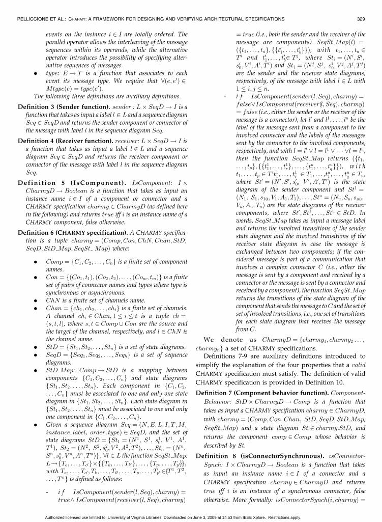
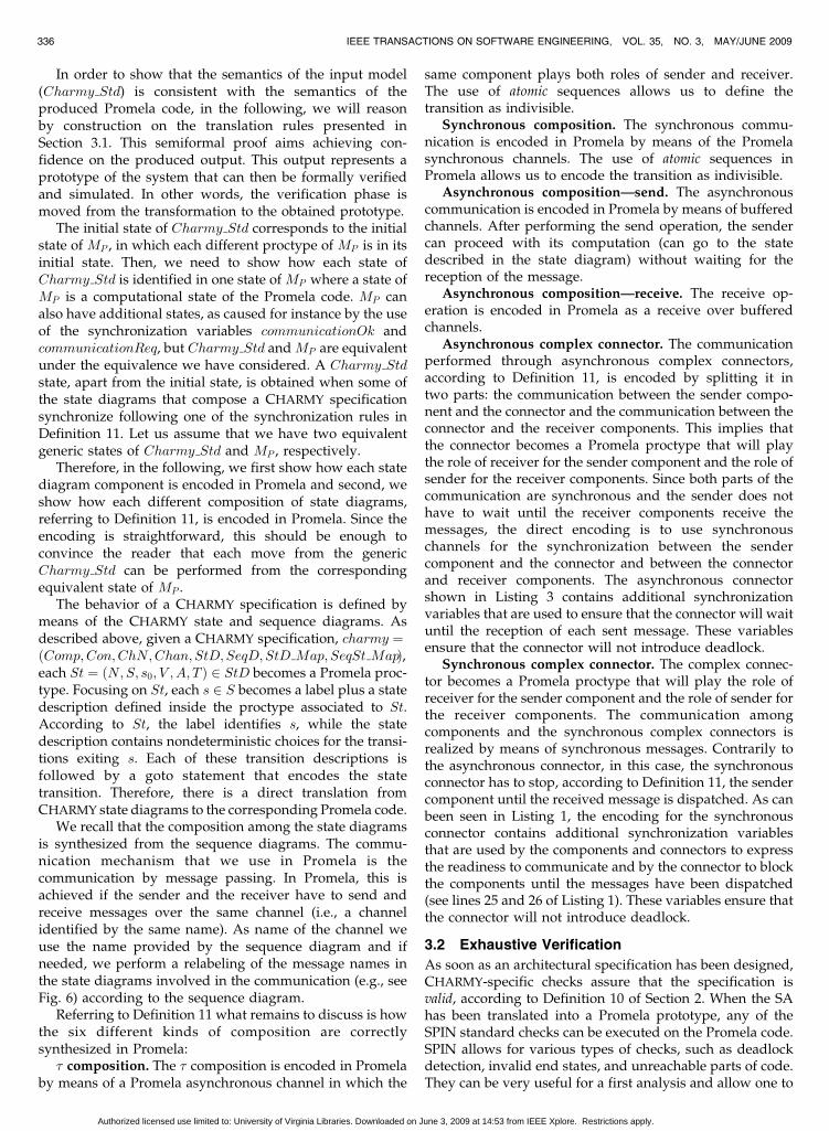
Fig. 3 shows three examples of synthesized CHARMY
specifications.The parallel composition of the d state diagrams is the
state diagram St1jSt2j � � � jStd ¼ ðN;S; s0; V ; A; T Þ defined asfollows:
. Name: N ¼ CHARMY_Std
. States: S � S1 � S2 � � � � � Sd
. Initial state: s0 ¼ ðs10; s
20; . . . ; sd0Þ
. Variables: V ¼Sdi¼1 V
i, where all V i are assumed tobe disjoint sets.
. Alphabet: A ¼ f�g
. Transitions: The set of transitions T is obtained asfollows:
- � composition. ððs1s; s
2s; . . . ; sdsÞ; ðs1
t ; s2t ; . . . ; sdt Þ;
� ; gi; �; oiÞ 2 T () 9 Seq ¼ ðN;E;L; I; T ;M; in-stance; label; order; typeÞ 2 SeqD and 9 e 2 E
such that senderðlabelðeÞ; SeqÞ ¼ receiverðlabelðeÞ; SeqÞ ^ SeqSt MapðlabelðeÞÞ ¼ ðfti1; . . . ; tiag;ffti1; . . . ; tiaggÞ; ti1; . . . ; tia 2 T i; 9tp ¼ ðsis; sit; labelip;gi; �; oiÞ2 fti1; . . . ; tiag and 8k 2 f1; � � � ; dg : k 6¼ i;sks ¼ skt .
- Synchronous composition. ððs1s; s
2s; . . . ; sdsÞ;
ðs1t ; s
2t ; . . . ; sdt Þ; � ; gi ^ gj; �; oi; ojÞ 2 T () 9Seq ¼
ðN;E;L; I; T ;M; instance; label; order; typeÞ 2SeqD and 9e 2 E such that typeðeÞ ¼ synch ^SeqSt MapðlabelðeÞÞ ¼ ðfti1; . . . ; tiag; fft
j1; . . . ;
tjbggÞ; ti1; . . . ; tia 2 T i; tj1; . . . ; tjb 2 Tj; 9 tip ¼ ðsis; sit;
labelip; gi; typeip; oiÞ 2 fti1; . . . ; tiag; 9 tjz ¼ ðsjs; -typejz; ojÞ 2 ftj1; . . . ; tjbg and 8k 2 f1; . . . ; dg : k 6¼i; j; sks ¼ skt .
- Asynchronous composition—send composi-tion. ððs1
s; s2s; . . . ; sdsÞ; ðs1
t ; s2t ; . . . ; sdt Þ; � ; gi; �; oiÞ 2
T () 9 Seq ¼ ðN;E;L; I; T ;M; instance; label;order; typeÞ 2 SeqD and 9e 2 E such that typeðeÞ ¼ asynch ^ SeqSt MapðlabelðeÞÞ ¼ ðfti1; . . . ;tiag; fft
j1; . . . ; tjbggÞ; ti1; . . . ; tia 2 T i; t
j1; . . . ; tjb 2 Tj;
9 tip ¼ ðsis; sit; labelip; gi; typeip; oiÞ 2 fti1; . . . ; tiagand 8k 2 f1; � � � ; dg : k 6¼ i; sks ¼ skt .
- Asynchronous composition—receive composi-tion. ððs1
s; s2s; . . . ; sdsÞ; ðs1
t ; s2t ; . . . ; sdt Þ; � ; gj; �; ojÞ 2
T() 9 Seq ¼ ðN;E;L; I; T ;M; instance; label;order; typeÞ 2 SeqD and 9e 2 E such that typeðeÞ¼ asynch ^ SeqSt MapðlabelðeÞÞ ¼ ðfti1; . . . ; tiag;fftj1; . . . ; tjbggÞ; ti1; . . . ; tia 2 T i; t
j1; . . . ; tjb 2 Tj; 9tjz ¼
ðsjs; sjt ; label
jz; gj; typejz; ojÞ 2 ftj1; . . . ; tjbg; 9 a pre-fix �sjs of a path � of Charmy Std in which themessage with label labelðeÞ has been sent by thestate diagram Sti and not received by Stj, and8k 2 f1; . . . ; dg : k 6¼ j; sks ¼ skt .
- Synchronous complex connector. ððs1s; s
2s; . . . ;
sdsÞ; ðs1t ; s
2t ; . . . ; sdt Þ; � ; gi ^ gx � � � ^ gy; �; oi; ox; � � � ;
oyÞ 2 T () 9 Seq ¼ ðN;E;L; I; T ;M; instance;label; order; typeÞ 2 SeqD and 9 e 2 E such thatlet C ¼ receiver ðlabelðeÞ; SeqÞ the involvedconnector ^ isConnectorSynchðC; charmyÞ ¼true ^ typeðeÞ ¼ synch ^ SeqSt MapðlabelðeÞÞ ¼ðfti1; . . . ; fft01; . . . ; t0bg; . . . ; ft0n1 ; . . . ; t0nq gg�C Þ; t
i1; . . . ;
tia 2 T i; t01; . . . ; t0b 2 T1; . . . ; t0n1 ; . . . ; t0nq 2 Tu, withT1; . . . ; Tu 2 fT 1; . . . ; T dg; 9 tip ¼ ðsis; sit; labelip; gi;typeip; oiÞ 2 fti1; . . . ; tiag; 9 txz ¼ ðsxs ; sxt ; labelxz; gx;typexz; oxÞ 2 ft01; . . . ; t0bg; . . . ; 9 tyr ¼ ðsys; s
yt ; label
yr;gy; typeyr; oyÞ 2 ft0n1 ; . . . ; t0nq g, where x is the indexof the state diagram to which T1 belongs, y is theindex of the state diagram to which Tu belongs,and 8k 2 f1; . . . ; dg : sks 6¼ sis; sxs ; . . . ; sys; s
ks ¼ skt .
In this case, the communication amongcomponents is managed by a synchronouscomplex connector that synchronously receivesthe message from the sender component. Thesender component is blocked and the connectorsynchronously sends each message that iscontained into its lifeline. Only after the recep-tion of the last message, the sender component isunblocked. Therefore, the obtained transition isthe following: ððs1
s; s2s; . . . ; sdsÞ; ðs1
t ; s2t ; . . . ; sdt Þ;
l0; g0; � ; o0Þ 2 T , where the states s1t ; s
2t ; . . . ; sdt
differ only for the states of the componentsinvolved in the communication accordingly tothe applied transition; the guard g0 is the
PELLICCIONE ET AL.: CHARMY: A FRAMEWORK FOR DESIGNING AND VERIFYING ARCHITECTURAL SPECIFICATIONS 331
Fig. 3. (a) Synthesis of behavior of the CHARMY specification described
in Fig. 6; (b) the same components coordinated with the asynchronous
connector in Fig. 7a; and (c) the same components coordinated with the
asynchronous connector with parallel operator in Fig. 7b.
Authorized licensed use limited to: University of Virginia Libraries. Downloaded on June 3, 2009 at 14:53 from IEEE Xplore. Restrictions apply.
conjunction of the guards of the involvedtransitions; o0 is the concatenation of the opera-tions of the involved transitions.
- Asynchronous complex connector composi-tion. In this case, the communication amongcomponents is managed by an asynchronouscomplex connector. Therefore, the communica-tion is split in two parts: the communicationbetween the sender component and the con-nector and the communication between theconnector and the receiver components. Notethat each communication between the connectorand the receiver components is handled sepa-rately. Both communication parts are performedby means of synchronous messages, and thusthe composition makes use of the synchronouscomposition explained above. More formally:
. Asynchronous complex connector compo-sition—send composition. ððs1
s; s2s; . . . ; sdsÞ;
ðs1t ; s
2t ; . . . ; sdt Þ; � ; gi; �; oiÞ 2 T () 9 Seq ¼
ðN; E;L; I; T ;M; instance; label; order; typeÞ2 SeqD and 9 e 2 E such that let C ¼receiverðlabelðeÞ; SeqÞ the involved connector^ isConnectorAsynch ðC; charmyÞ ¼ true ^typeðeÞ¼synch ^ SeqSt MapðlabelðeÞÞ ¼¼ ðfti1; . . . ; tiag; fft01; . . . ; t0bg; . . . ; ft0n1 ; . . . ; t0nq gg�C Þ; ti1; . . . ; tia 2 T i; t01; . . . ; t0b 2 T1; . . . ; t0n1 ; . . . ;t0nq 2 Tu, w i t h T1; . . . ;Tu 2 fT 1; . . . ; T dg; 9tip ¼ ðsis; sit; labelip; gi;typeip; oiÞ 2 fti1; . . . ; tiag ^8k 2 f1; . . . ; dg:sks 6¼ sis; sks ¼ skt .
. Asynchronous complex connector compo-sition—receive composition. ððs1
s; s2s;
. . . ; sdsÞ; ðs1t ; s
2t ; . . . ; sdt Þ; � ; gj; �; ojÞ 2 T () 9
Seq¼ ðN;E;L; I; T ;M; instance; label; order;typeÞ2SeqD and 9 e 2 E such that typeðeÞ ¼synch, let C ¼ senderðlabelðeÞ; SeqÞ the
involved connector ^ isConnectorAsynchðC; charmyÞ ¼ true and SeqSt MapðlabelðeÞÞ¼ ðfti1; . . . ; tiag; fft01; . . . ; t0bg; . . . ; ft0n1 ; . . . ; t0nq gg�C Þ, with ti1; . . . ; tia 2 T i; t01; . . . ; t0b 2 T1; . . . ;t0n1 ; . . . ; t0nq 2 Tu, with T1; . . . ; Tu 2 fT 1; . . . ;T dg, let Stj be the state diagram of thecomponent instance receiver ðlabelðeÞ; SeqÞand Tx ¼ Tj; 9 a prefix �sjs of a path � ofCharmy Std in which the message withlabel labelðeÞ has been sent by Sti and inwhich one transition for each set T1;. . . ; Tx�1 has been performed and 8 k 2f1; . . . ; dg : k 6¼ j; sks ¼ skt .
3 THE CHARMY FRAMEWORK
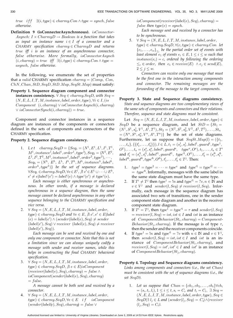
Software architectures can be modeled directly in theCHARMY tool by means of the CHARMY editors (Fig. 4, Aand B) and following the graphical notation presented inSection 2.
Once designed a valid CHARMY specification,4 theCharmy2Promela translation is used to obtain an executableprototype in Promela (as graphically depicted in Fig. 4, C)
from the model-based SA specification. Promela is thespecification language of SPIN [21] and allows thespecification of concurrent systems communicating viaeither messages or shared variables. On the generated Promelacode, we can use SPIN to find deadlocks, unreachable statesor we can verify specific temporal properties (Fig. 4, D). Asit will be explained in Section 4, we use the PSC notation forexpressing temporal properties [4] and the PSC2BA algorithmfor translating PSC models into Buchi Automata [7] whichcan be directly used by SPIN. SASIM, the CHARMY
Simulation feature (Fig. 4, E), makes use of the SPINsimulation and interprets its results in terms of CHARMY
state and sequence diagrams. SASIM is automaticallystarted in case the verification finds an error or it islaunched by the software architect to study how the systemreacts in particular situations. Whenever a final softwarearchitecture is reached, automatic Java code generation isperformed (Fig. 4, F).
3.1 Synthesis of A CHARMY Architecture Prototype
The architectural prototype of a CHARMY specification isobtained by automatically translating state and sequencediagrams into Promela code. The translation algorithmstructures the Promela code in order to preserve as much aspossible the architectural design. To this extent, componentsand connectors are represented as processes, called proc-types in Promela. In case, the communication is performedby means of a synchronous or asynchronous channel,Promela primitives for synchronous and asynchronouscommunication are utilized to optimize the producedPromela model. We start by describing the Promela codegenerated in case of a synchronous and asynchronouscommunication, and then we explain how the code changesto deal with architectures with complex connectors.
3.1.1 Architectures with Simple Connectors
Let us consider the CHARMY specification whose graphicalnotation is shown in the left-hand side of Fig. 5. The right-hand side of Fig. 5 shows the generated Promela code that isstructured in three parts: Part a for constant definitions, Partb for variable declarations, and Part c for component andconnector proctype definitions and instantiations.
Part a. #define < channel> : there is one “define”statement for each message defined in the set of sequencediagrams contained in the CHARMY specification. Thesemessages become Promela channels. The Promela definestatement represents constant definitions.
332 IEEE TRANSACTIONS ON SOFTWARE ENGINEERING, VOL. 35, NO. 3, MAY/JUNE 2009
4. The tool presented in Section 5 automatically checks the validity (seeDefinition 10) of a CHARMY specification.
Fig. 4. The CHARMY Framework.
Authorized licensed use limited to: University of Virginia Libraries. Downloaded on June 3, 2009 at 14:53 from IEEE Xplore. Restrictions apply.
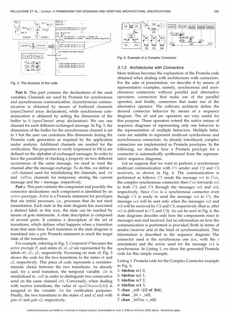
Part b. This part contains the declarations of the usedvariables. Channels are used by Promela for synchronousand asynchronous communication. Asynchronous commu-nication is obtained by means of buffered channels(asyncChannel array declaration), while synchronous com-munication is obtained by setting the dimension of thebuffer to 0 (syncChannel array declaration). We use onechannel for each different exchanged message. In Fig. 5, thedimension of the buffer for the asynchronous channel is setto 1 but the user can customize this dimension during thePromela code generation as required by the applicationunder analysis. Additional channels are needed for theverification. The properties to verify (expressed in PSCs) aredefined on the alphabet of exchanged messages. In order tohave the possibility of checking a property on two differentoccurrences of the same message, we need to reset thechannel after the message exchange. To do this, we define anill channel used for reinitializing the channels, and lst
and lstTau channels for temporary storing the currentmessage and the � message, respectively.
Part c. This part contains the component and possibly theconnector declarations: each component is identified by anactive proctype. Active is a Promela statement for proctypesthat are initial processes, i.e., processes that do not needinstantiation. Each state in the state diagram has associateda distinct label; in this way, the state can be reached bymeans of goto statements. A state description is composedof several parts. It contains a description of the set oftransitions, which defines what happens when a transitionfrom that state fires. Each transition in the state diagram istranslated into a goto Promela statement to reach the targetstate of the transition.
For example, referring to Fig. 5, Component P becomes theactive proctype P, and states s0, s1, s2 are represented by thelabels s0:, s1:, s2:, respectively. Focussing on state s0, Fig. 5shows the code for the two transitions to the states s1 ands2, respectively. This piece of code represents a nondeter-ministic choice between the two transitions. As alreadysaid, for a send transition, the temporal variable lst isreinitialized to nill in order to distinguish two consecutivesend on the same channel ch1. Conversely, when dealingwith receive transitions, the value of syncChannel½ch3� isassigned to the variable lst for verification purposes.Finally, the two transitions to the states s1 and s2 end withgoto s1 and goto s2, respectively.
3.1.2 Architectures with Connectors
More tedious becomes the explanation of the Promela codeobtained when dealing with architectures with connectors.For the sake of presentation, we describe it by means ofrepresentative examples, namely, synchronous and asyn-chronous connectors without parallel and alternativeoperators, connectors that make use of the paralleloperator, and finally, connectors that make use of thealternative operator. The software architects define thedesired connector behavior by means of a sequencediagram. The alt and par operators are very useful forthis purpose. These operators extend the native nature ofsequence diagrams of representing only one behavior tothe representation of multiple behaviors. Multiple beha-viors are suitable to represent multicast synchronous andasynchronous connectors. As already introduced, complexconnectors are implemented as Promela proctypes. In thefollowing, we describe how a Promela proctype for aconnector is automatically synthesized from the represen-tative sequence diagrams.
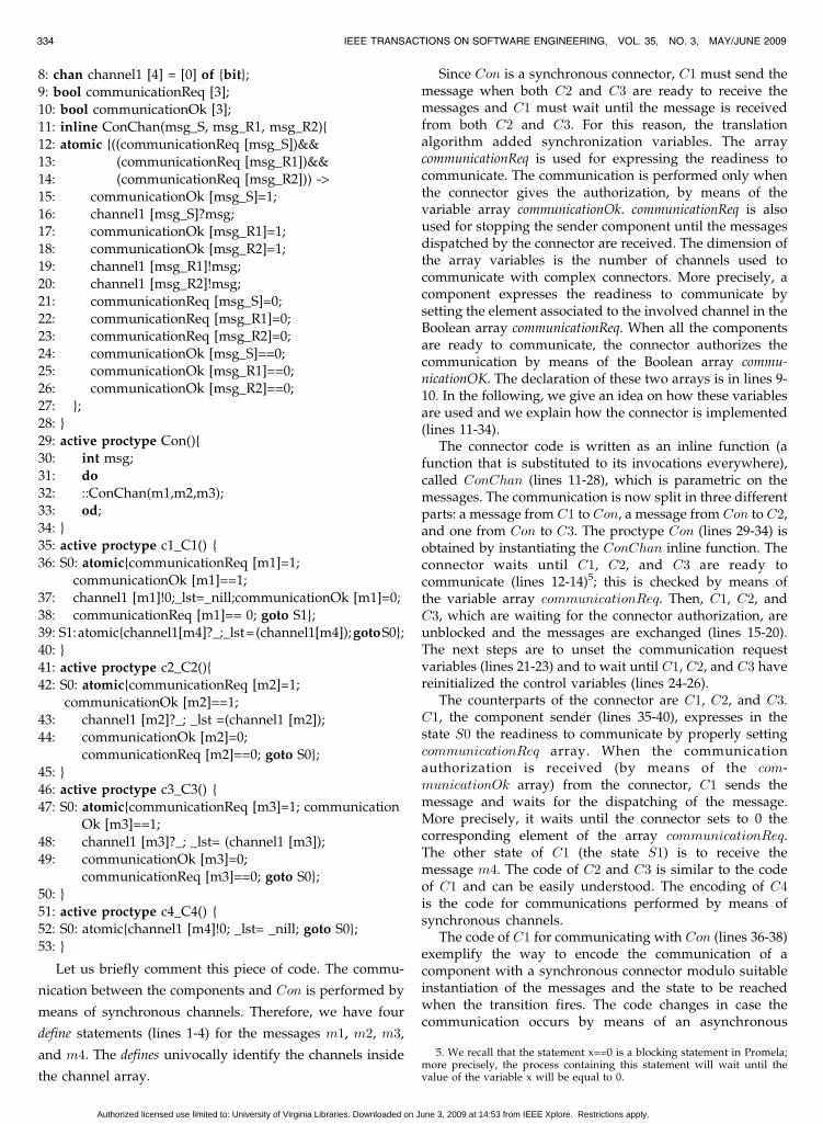
Let us suppose that we want to perform a synchronousmulticast communication with C1 sender and C2 and C3receivers, as shown in Fig. 6. The communication isperformed as follows: C1 sends the message m1 to Con,the complex synchronous connector; then Con forwards m1to both C2 and C3 through the messages m2 and m3,respectively. Since Con is a synchronous connector eventhough C4 is ready to send the message m4 to C1, themessage m4 will be sent only when the messages m2 andm3 will be received by C2 and C3, respectively (that is, afterm1 is delivered to C2 and C3). As can be seen in Fig. 6, thestate diagrams describe only how the components react tomessages sent and received, but no information on how thecommunication is performed is provided (both in terms ofsender/receiver and of the kind of synchronization). Thisinformation is described in the sequence diagram: Theconnector used is the synchronous one (i.e., with the sannotation) and the arrow used for the message m4 issynchronous. In Listing 1, we show the generated Promelacode for this simple example.
Listing 1. Promela code for the Complex Connector example
in Fig. 6,
1: #define m1 0;
2: #define m2 1;3: #define m3 2;
4: #define m4 3;
5: chan _nill =[0] of {bit};
6: chan _lst = _nill;
7: chan _lstTau =_nill;
PELLICCIONE ET AL.: CHARMY: A FRAMEWORK FOR DESIGNING AND VERIFYING ARCHITECTURAL SPECIFICATIONS 333
Fig. 5. The structure of the code.
Fig. 6. Example of a Complex Connector.
Authorized licensed use limited to: University of Virginia Libraries. Downloaded on June 3, 2009 at 14:53 from IEEE Xplore. Restrictions apply.
8: chan channel1 [4] = [0] of {bit};9: bool communicationReq [3];
10: bool communicationOk [3];
11: inline ConChan(msg_S, msg_R1, msg_R2){
12: atomic {((communicationReq [msg_S])&&
13: (communicationReq [msg_R1])&&
14: (communicationReq [msg_R2])) ->
15: communicationOk [msg_S]=1;
16: channel1 [msg_S]?msg;17: communicationOk [msg_R1]=1;
18: communicationOk [msg_R2]=1;
19: channel1 [msg_R1]!msg;
20: channel1 [msg_R2]!msg;
21: communicationReq [msg_S]=0;
22: communicationReq [msg_R1]=0;
23: communicationReq [msg_R2]=0;
24: communicationOk [msg_S]==0;25: communicationOk [msg_R1]==0;
26: communicationOk [msg_R2]==0;
27: };
28: }
29: active proctype Con(){
30: int msg;
31: do
32: ::ConChan(m1,m2,m3);33: od;
34: }
35: active proctype c1_C1() {
36: S0: atomic{communicationReq [m1]=1;
communicationOk [m1]==1;
37: channel1 [m1]!0;_lst=_nill;communicationOk [m1]=0;
38: communicationReq [m1]== 0; goto S1};
39: S1:atomic{channel1[m4]?_;_lst=(channel1[m4]);gotoS0};40: }
41: active proctype c2_C2(){
42: S0: atomic{communicationReq [m2]=1;
communicationOk [m2]==1;
43: channel1 [m2]?_; _lst =(channel1 [m2]);
44: communicationOk [m2]=0;
communicationReq [m2]==0; goto S0};
45: }46: active proctype c3_C3() {
47: S0: atomic{communicationReq [m3]=1; communication
Ok [m3]==1;
48: channel1 [m3]?_; _lst= (channel1 [m3]);
49: communicationOk [m3]=0;
communicationReq [m3]==0; goto S0};
50: }
51: active proctype c4_C4() {52: S0: atomic{channel1 [m4]!0; _lst= _nill; goto S0};
53: }
Let us briefly comment this piece of code. The commu-
nication between the components and Con is performed by
means of synchronous channels. Therefore, we have four
define statements (lines 1-4) for the messages m1, m2, m3,
and m4. The defines univocally identify the channels inside
the channel array.
Since Con is a synchronous connector, C1 must send themessage when both C2 and C3 are ready to receive themessages and C1 must wait until the message is receivedfrom both C2 and C3. For this reason, the translationalgorithm added synchronization variables. The arraycommunicationReq is used for expressing the readiness tocommunicate. The communication is performed only whenthe connector gives the authorization, by means of thevariable array communicationOk. communicationReq is alsoused for stopping the sender component until the messagesdispatched by the connector are received. The dimension ofthe array variables is the number of channels used tocommunicate with complex connectors. More precisely, acomponent expresses the readiness to communicate bysetting the element associated to the involved channel in theBoolean array communicationReq. When all the componentsare ready to communicate, the connector authorizes thecommunication by means of the Boolean array commu-nicationOK. The declaration of these two arrays is in lines 9-10. In the following, we give an idea on how these variablesare used and we explain how the connector is implemented(lines 11-34).
The connector code is written as an inline function (afunction that is substituted to its invocations everywhere),called ConChan (lines 11-28), which is parametric on themessages. The communication is now split in three differentparts: a message from C1 to Con, a message from Con to C2,and one from Con to C3. The proctype Con (lines 29-34) isobtained by instantiating the ConChan inline function. Theconnector waits until C1, C2, and C3 are ready tocommunicate (lines 12-14)5; this is checked by means ofthe variable array communicationReq. Then, C1, C2, andC3, which are waiting for the connector authorization, areunblocked and the messages are exchanged (lines 15-20).The next steps are to unset the communication requestvariables (lines 21-23) and to wait until C1, C2, and C3 havereinitialized the control variables (lines 24-26).
The counterparts of the connector are C1, C2, and C3.C1, the component sender (lines 35-40), expresses in thestate S0 the readiness to communicate by properly settingcommunicationReq array. When the communicationauthorization is received (by means of the com-municationOk array) from the connector, C1 sends themessage and waits for the dispatching of the message.More precisely, it waits until the connector sets to 0 thecorresponding element of the array communicationReq.The other state of C1 (the state S1) is to receive themessage m4. The code of C2 and C3 is similar to the codeof C1 and can be easily understood. The encoding of C4is the code for communications performed by means ofsynchronous channels.
The code of C1 for communicating with Con (lines 36-38)exemplify the way to encode the communication of acomponent with a synchronous connector modulo suitableinstantiation of the messages and the state to be reachedwhen the transition fires. The code changes in case thecommunication occurs by means of an asynchronous
334 IEEE TRANSACTIONS ON SOFTWARE ENGINEERING, VOL. 35, NO. 3, MAY/JUNE 2009
5. We recall that the statement x==0 is a blocking statement in Promela;more precisely, the process containing this statement will wait until thevalue of the variable x will be equal to 0.
Authorized licensed use limited to: University of Virginia Libraries. Downloaded on June 3, 2009 at 14:53 from IEEE Xplore. Restrictions apply.
connector. In this case, lines 36-38 of Listing 1 become as
shown in Listing 2, and similarly, also the code of
components C2 and C3 must change.
Listing 2. Changes to C1 in case of communication managedby asynchronous connectors
S0: atomic{communicationOk [m1]==1; channel1[m1]!0;
_lst = _nill;communicationOk [m1]=0; goto S1};
Note that we do not need the communicationReq array
since C1 does not have to wait for the dispatching of the
message m1. The asynchronous connector for the same
example is shown in Fig. 7a, while the synthesized code is
as reported in Listing 3.
Listing 3. Asynchonous connector
1: inline ConnChan(msg_S, msg_R1, msg_R2) {
2: atomic{
3: communicationOk [msg_S]=1;
4: channel1 [msg_S]?msg;
5: communicationOk [msg_R1]=1;6: communicationOk [msg_R2]=1;
7: channel1 [msg_R1]!msg;
8: channel1 [msg_R2]!msg;
9: communicationOk [msg_S]==0;
10: communicationOk [msg_R1]==0;
11: communicationOk [msg_R2]==0;
12: };
13: }
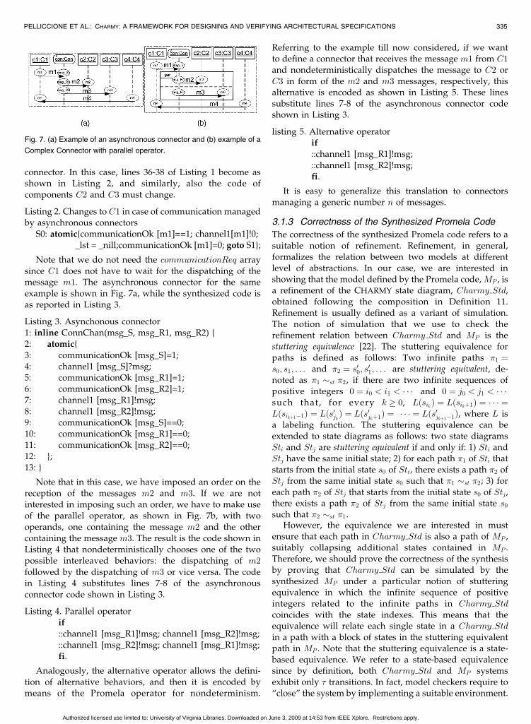
Note that in this case, we have imposed an order on the
reception of the messages m2 and m3. If we are not
interested in imposing such an order, we have to make use
of the parallel operator, as shown in Fig. 7b, with two
operands, one containing the message m2 and the other
containing the message m3. The result is the code shown in
Listing 4 that nondeterministically chooses one of the two
possible interleaved behaviors: the dispatching of m2
followed by the dispatching of m3 or vice versa. The code
in Listing 4 substitutes lines 7-8 of the asynchronous
connector code shown in Listing 3.
Listing 4. Parallel operator
if
::channel1 [msg_R1]!msg; channel1 [msg_R2]!msg;
::channel1 [msg_R2]!msg; channel1 [msg_R1]!msg;fi.
Analogously, the alternative operator allows the defini-
tion of alternative behaviors, and then it is encoded by
means of the Promela operator for nondeterminism.
Referring to the example till now considered, if we wantto define a connector that receives the message m1 from C1
and nondeterministically dispatches the message to C2 or
C3 in form of the m2 and m3 messages, respectively, thisalternative is encoded as shown in Listing 5. These linessubstitute lines 7-8 of the asynchronous connector codeshown in Listing 3.
listing 5. Alternative operatorif
::channel1 [msg_R1]!msg;
::channel1 [msg_R2]!msg;
fi.
It is easy to generalize this translation to connectors
managing a generic number n of messages.
3.1.3 Correctness of the Synthesized Promela Code
The correctness of the synthesized Promela code refers to asuitable notion of refinement. Refinement, in general,formalizes the relation between two models at different
level of abstractions. In our case, we are interested inshowing that the model defined by the Promela code, MP , isa refinement of the CHARMY state diagram, Charmy Std,obtained following the composition in Definition 11.
Refinement is usually defined as a variant of simulation.The notion of simulation that we use to check therefinement relation between Charmy Std and MP is thestuttering equivalence [22]. The stuttering equivalence for
paths is defined as follows: Two infinite paths �1 ¼s0; s1; . . . and �2 ¼ s00; s01; . . . are stuttering equivalent, de-noted as �1 st �2, if there are two infinite sequences ofpositive integers 0 ¼ i0 < i1 < � � � and 0 ¼ j0 < j1 < � � �such that, for every k � 0, LðsikÞ ¼ Lðsikþ1Þ ¼ � � � ¼Lðsikþ1�1Þ ¼ Lðs0jkÞ ¼ Lðs
0jkþ1Þ ¼ � � � ¼ Lðs0jkþ1�1Þ, where L is
a labeling function. The stuttering equivalence can beextended to state diagrams as follows: two state diagrams
Sti and Stj are stuttering equivalent if and only if: 1) Sti andStj have the same initial state; 2) for each path �1 of Sti thatstarts from the initial state s0 of Sti, there exists a path �2 ofStj from the same initial state s0 such that �1 st �2; 3) for
each path �2 of Stj that starts from the initial state s0 of Stj,there exists a path �2 of Stj from the same initial state s0
such that �2 st �1.However, the equivalence we are interested in must
ensure that each path in Charmy Std is also a path of MP ,
suitably collapsing additional states contained in MP .Therefore, we should prove the correctness of the synthesisby proving that Charmy Std can be simulated by thesynthesized MP under a particular notion of stuttering
equivalence in which the infinite sequence of positiveintegers related to the infinite paths in Charmy Std
coincides with the state indexes. This means that theequivalence will relate each single state in a Charmy Std
in a path with a block of states in the stuttering equivalentpath in MP . Note that the stuttering equivalence is a state-based equivalence. We refer to a state-based equivalencesince by definition, both Charmy Std and MP systems
exhibit only � transitions. In fact, model checkers require to“close” the system by implementing a suitable environment.
PELLICCIONE ET AL.: CHARMY: A FRAMEWORK FOR DESIGNING AND VERIFYING ARCHITECTURAL SPECIFICATIONS 335
Fig. 7. (a) Example of an asynchronous connector and (b) example of a
Complex Connector with parallel operator.
Authorized licensed use limited to: University of Virginia Libraries. Downloaded on June 3, 2009 at 14:53 from IEEE Xplore. Restrictions apply.
In order to show that the semantics of the input model(Charmy Std) is consistent with the semantics of theproduced Promela code, in the following, we will reasonby construction on the translation rules presented inSection 3.1. This semiformal proof aims achieving con-fidence on the produced output. This output represents aprototype of the system that can then be formally verifiedand simulated. In other words, the verification phase ismoved from the transformation to the obtained prototype.
The initial state of Charmy Std corresponds to the initialstate of MP , in which each different proctype of MP is in itsinitial state. Then, we need to show how each state ofCharmy Std is identified in one state of MP where a state ofMP is a computational state of the Promela code. MP canalso have additional states, as caused for instance by the useof the synchronization variables communicationOk andcommunicationReq, but Charmy Std and MP are equivalentunder the equivalence we have considered. A Charmy Stdstate, apart from the initial state, is obtained when some ofthe state diagrams that compose a CHARMY specificationsynchronize following one of the synchronization rules inDefinition 11. Let us assume that we have two equivalentgeneric states of Charmy Std and MP , respectively.
Therefore, in the following, we first show how each statediagram component is encoded in Promela and second, weshow how each different composition of state diagrams,referring to Definition 11, is encoded in Promela. Since theencoding is straightforward, this should be enough toconvince the reader that each move from the genericCharmy Std can be performed from the correspondingequivalent state of MP .
The behavior of a CHARMY specification is defined bymeans of the CHARMY state and sequence diagrams. Asdescribed above, given a CHARMY specification, charmy ¼ðComp;Con;ChN;Chan; StD; SeqD; StD Map; SeqSt MapÞ,each St ¼ ðN;S; s0; V ; A; T Þ 2 StD becomes a Promela proc-type. Focusing on St, each s 2 S becomes a label plus a statedescription defined inside the proctype associated to St.According to St, the label identifies s, while the statedescription contains nondeterministic choices for the transi-tions exiting s. Each of these transition descriptions isfollowed by a goto statement that encodes the statetransition. Therefore, there is a direct translation fromCHARMY state diagrams to the corresponding Promela code.
We recall that the composition among the state diagramsis synthesized from the sequence diagrams. The commu-nication mechanism that we use in Promela is thecommunication by message passing. In Promela, this isachieved if the sender and the receiver have to send andreceive messages over the same channel (i.e., a channelidentified by the same name). As name of the channel weuse the name provided by the sequence diagram and ifneeded, we perform a relabeling of the message names inthe state diagrams involved in the communication (e.g., seeFig. 6) according to the sequence diagram.
Referring to Definition 11 what remains to discuss is howthe six different kinds of composition are correctlysynthesized in Promela:� composition. The � composition is encoded in Promela
by means of a Promela asynchronous channel in which the
same component plays both roles of sender and receiver.The use of atomic sequences allows us to define thetransition as indivisible.
Synchronous composition. The synchronous commu-nication is encoded in Promela by means of the Promelasynchronous channels. The use of atomic sequences inPromela allows us to encode the transition as indivisible.
Asynchronous composition—send. The asynchronouscommunication is encoded in Promela by means of bufferedchannels. After performing the send operation, the sendercan proceed with its computation (can go to the statedescribed in the state diagram) without waiting for thereception of the message.
Asynchronous composition—receive. The receive op-eration is encoded in Promela as a receive over bufferedchannels.
Asynchronous complex connector. The communicationperformed through asynchronous complex connectors,according to Definition 11, is encoded by splitting it intwo parts: the communication between the sender compo-nent and the connector and the communication between theconnector and the receiver components. This implies thatthe connector becomes a Promela proctype that will playthe role of receiver for the sender component and the role ofsender for the receiver components. Since both parts of thecommunication are synchronous and the sender does nothave to wait until the receiver components receive themessages, the direct encoding is to use synchronouschannels for the synchronization between the sendercomponent and the connector and between the connectorand receiver components. The asynchronous connectorshown in Listing 3 contains additional synchronizationvariables that are used to ensure that the connector will waituntil the reception of each sent message. These variablesensure that the connector will not introduce deadlock.
Synchronous complex connector. The complex connec-tor becomes a Promela proctype that will play the role ofreceiver for the sender component and the role of sender forthe receiver components. The communication amongcomponents and the synchronous complex connectors isrealized by means of synchronous messages. Contrarily tothe asynchronous connector, in this case, the synchronousconnector has to stop, according to Definition 11, the sendercomponent until the received message is dispatched. As canbeen seen in Listing 1, the encoding for the synchronousconnector contains additional synchronization variablesthat are used by the components and connectors to expressthe readiness to communicate and by the connector to blockthe components until the messages have been dispatched(see lines 25 and 26 of Listing 1). These variables ensure thatthe connector will not introduce deadlock.
3.2 Exhaustive Verification
As soon as an architectural specification has been designed,CHARMY-specific checks assure that the specification isvalid, according to Definition 10 of Section 2. When the SAhas been translated into a Promela prototype, any of theSPIN standard checks can be executed on the Promela code.SPIN allows for various types of checks, such as deadlockdetection, invalid end states, and unreachable parts of code.They can be very useful for a first analysis and allow one to
336 IEEE TRANSACTIONS ON SOFTWARE ENGINEERING, VOL. 35, NO. 3, MAY/JUNE 2009
Authorized licensed use limited to: University of Virginia Libraries. Downloaded on June 3, 2009 at 14:53 from IEEE Xplore. Restrictions apply.
discover gross grain errors. For instance, if there are someparts of the code that are unreachable, it could mean that inthe CHARMY specification, there are some messages neverexchanged. More complex and sophisticated behaviors canbe checked by defining them as temporal properties. Howto express temporal properties will be presented inSection 4. It is important to note that CHARMY makes useof SPIN but both SPIN and Promela are hidden to thesoftware architect that will also have the verification resultsexpressed in terms of the diagrams he designed.
3.3 SASIM: Simulating Software Architecturesin CHARMY
CHARMY provides a software architecture-level simulationactivity that permits to improve the confidence on thearchitectural specification. This CHARMY extension is calledSASIM. SPIN natively supports different kinds of simula-tion: random (at each execution step, SPIN nondeterminis-tically selects an action among all the executable actions),interactive (SPIN asks the user to select the next moveamong the set of executable actions), and guided simulation(the next action is guided by a trail file typically generatedby SPIN itself as counter example generated as a result of a“not valid” check). However, the output of the simulationas well as the interaction with the SPIN simulator areprovided in terms of Promela processes. In other words,while the Charmy2Promela algorithm hides the Promelacode specification complexity, the SPIN simulation resultsare not filtered out. For this, we use SASIM. The idea ofSASIM, espousing the ideas of [18], is to work on the samearchitectural models designed by the software architect. Thestarting point is the Promela code generated by Charmy2-Promela. The results of the SPIN verification and of thetextual simulation outputs are translated, and then visua-lized as CHARMY state and sequence diagrams. At eachmoment, the designer can check the computational state ofeach component (through different colors) and when amessage is exchanged between two components, a messageis added on the sequence diagram automatically generatedby SASIM. The designer can also interact with the SPINsimulator during the simulation. This is useful for inter-active simulations and simulations performed step-by-step.The cooperation between CHARMY and the SPIN simulatoris realized by means of bidirectional transformationsbetween CHARMY diagrams and textual input/output ofthe SPIN simulator.
Four different simulation features are supported bySASIM:
1. Random simulation: The designer is a spectator and incase of multiples possibilities, one of the possible alter-natives is randomly chosen. The designer can choose toshow the simulation step-by-step instead of running thewhole simulation in one shot.
2. Interactive simulation: At each step, the possibleactions of the system are highlighted and the designer isasked to choose one of them. This functionality is particu-larly useful for the designer to understand the systembehaviors and gain confidence on the specified design.
3. Simulation guided by a sequence diagram: Thedesigner can design a sequence diagram representing adesired or an undesired behavior of the system and SASIM
tries to reproduce this trace. Differently from the random orinteractive simulation, this kind of simulation does notgenerate a sequence diagram but animates the one selectedto guide the simulation. In case, it is impossible toreproduce the sequence this is notified to the user. It isimportant to note that the sequence to be simulated mustcontain every message required by the simulation forhaving a reproducible trace. In other words, the sequencediagram cannot abstract behaviors and hide messages buteach message, according to all the state diagrams involved,must be designed.
4. Simulation and exhaustive verification: This func-tionality allows the use of simulation to support theverification by using the SPIN model checker. In case, theverification result is “not valid,” a counter example isgenerated and it is reproduced directly on the system statediagrams. A sequence diagram showing the trace is alsogenerated by SASIM. This feature helps in understandingthe output of the SPIN model checker (provided in terms ofthe Promela code) at the software architecture level.
3.4 Java Code Generation from CHARMY
Specification
Whenever a verified and final SA is reached, a skeleton Javacode is automatically generated from the SA specification.The aim of the code generation activity is to produce codethat reflects structural SA constraints. Various techniqueshave been proposed in recent years to generate code froman SA specification. They can be distinguished in Archi-tecture Description Languages (ADLs), i.e., languages fordescribing SAs, and Architectural Programming Languages(APLs), i.e., languages that integrate SA concepts intoprogramming languages.
Some ADLs, such as AADL, xADL, and PRISMA,support code generation from an architectural descriptionof the system. Typically, the produced code is not capable ofexplicitly representing architectural notions at the codelevel. Therefore, the notion of SA components, connectors,and configurations is kept implicit, and the implementationinevitably tends to loose the connection to the intendedarchitectural structure during the maintenance steps. Theresult is “architectural erosion” [32].
APLs overcome the problem of architectural erosion inimplementations by integrating SA concepts into program-ming languages. The basic idea of architectural program-ming is to preserve the SA structure throughout thesoftware development process so as to guarantee that eachcomponent in the implementation may only communicatedirectly with the components to which it is connected in thearchitecture. ArchJava and JAVA/A are examples of APLs[5], [2]. CHARMY makes use of ArchJava since it makespublicly available a mature tool set.
ArchJava extends the Java language with componentclasses (which describe objects that are part of thearchitecture), connections (which enable components com-munication), and ports (which are the endpoints ofconnections). Components are organized into a hierarchyusing ownership domains, which can be shared alongconnections, allowing the connected components to com-municate through shared data. Component code is definedin ArchJava using component classes. Components com-municate through explicitly declared ports. A port is a
PELLICCIONE ET AL.: CHARMY: A FRAMEWORK FOR DESIGNING AND VERIFYING ARCHITECTURAL SPECIFICATIONS 337
Authorized licensed use limited to: University of Virginia Libraries. Downloaded on June 3, 2009 at 14:53 from IEEE Xplore. Restrictions apply.
communication endpoint declared by a component. Eachport declares a set of required and provided methods. Aprovided method is implemented by the component and isavailable to be called by other components connected to thisport. Conversely, each required method is provided bysome other component connected to this port. Eachprovided method must be implemented inside the compo-nent. ArchJava requires developers to declare the connec-tion patterns that are permitted at runtime. Once connectpatterns have been declared, concrete connections can bemade among components. All connected components mustbe part of an ownership domain declared by the componentmaking the connection. Communication integrity is the keyproperty enforced by ArchJava. It ensures that componentscan only communicate using connections and ownershipdomains that are explicitly declared in the architecture.
The CHARMY code generation process is performed
through two main steps: starting from a CHARMY specifica-
tion, the ArchJava code is automatically obtained by means
of a JET-based [8] code generator. Then, by exploiting the
existing ArchJava compiler, executable Java code is gener-
ated. A prototypical implementation is available for down-
load at [11].The code translation is based on the following directives:
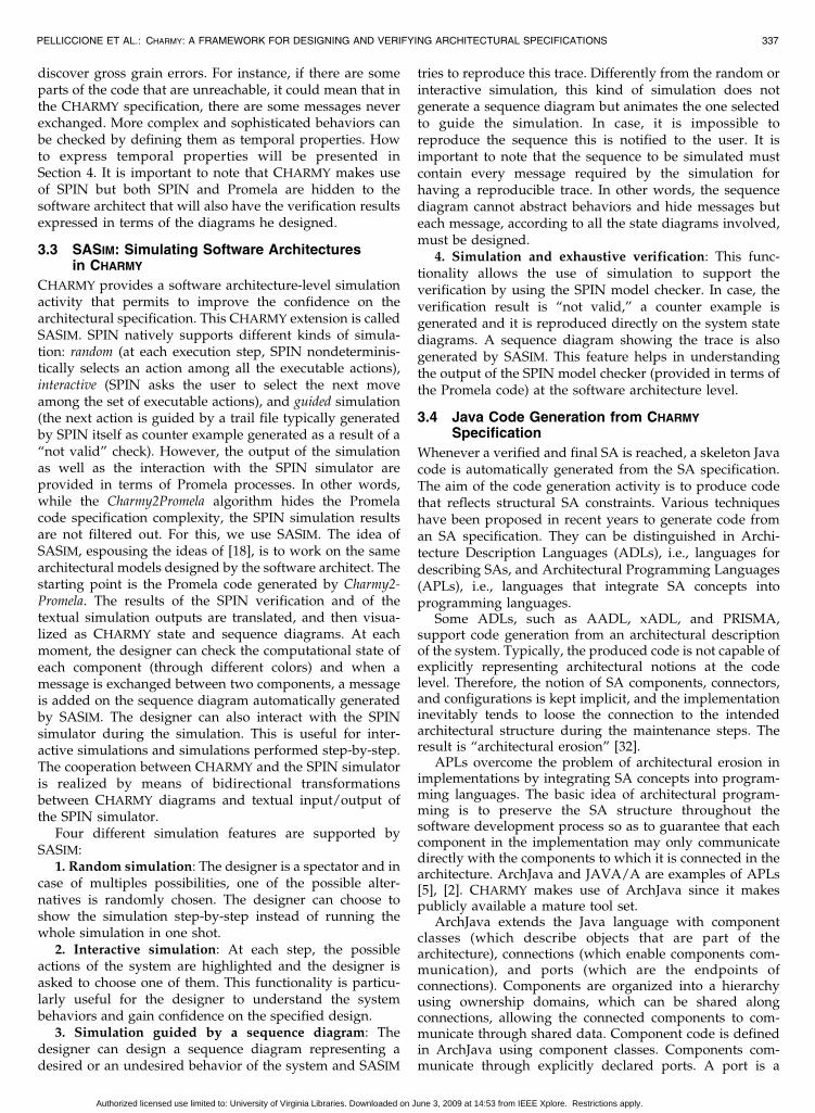
1. Each CHARMY component and complex connectorbecomes an ArchJava component. For instance, thecomponent C1 in Fig. 8 results in the ArchJavaspecification shown in Listing 6.
Listing 6. C1 Component translation
public component class C1 {
...}
2. Each exchanged message in the sequence diagramsis used to synthesize the component and connectorports. We recall that ArchJava has both providedports for provided services and required ports forrequired services. An ArchJava port connects only apair of components or connectors. This means that ifa component (or connector) needs to communicatewith more than one component (or connector), itneeds additional ports. Therefore, the providedcomponent (connector) services are partitioned intosets of services provided to different components(connectors). The same is done for required services.Accordingly, a suitable number of required andprovided ports is declared into the ArchJavaspecification of the component (containing thedeclaration of the required and provided services).For instance, the SA in Fig. 8 gives origin to theArchJava code fragments concerning the portsimplementation shown in Listing 7.
Listing 7. Ports translation
public port C1_TO_C2 {
requires void m1();
}
public port C2_TO_C1{
provides void m2();
}
3. A main ArchJava specification is also generated todefine the binding among component’s ports.
These directives ensure the communication integrity.
Further details can be found in [6] and the full implementa-
tion of the proposed code generator can be found in [11].
4 PROPERTY SEQUENCE CHARTS
The temporal logic used by SPIN to express properties to be
checked on the model of the system is the Linear-time
Temporal Logic (LTL). LTL provides descriptions of events
along a single computation path. A path is composed of a
succession of states and LTL can express requirements on
the ordering of state conditions. The downside of LTL is the
level of sophistication required in order to use it. The main
problem is related to the difficulty of expressing exactly the
desired property. In other words, there is a substantial gap
between natural language and the LTL language.For these reasons, CHARMY expresses properties to be
checked by means of the Property Sequence Chart (PSC [4])
notation (Fig. 9). PSC is a scenario-based visual language for
describing temporal properties. PSCs can express a useful
set of both liveness and safety properties in terms of
messages exchanged among the components forming a
system. Finally, an algorithm, called PSC2BA, translates PSC
into Buchi automata [7]. To make the paper self-contained
here in the following, we report some information on PSC;
however, we refer to [4] for a complete and detailed
description of the PSC syntax and semantics.PSCs are an extension of a subset of the UML 2.0
Sequence Diagrams stereotyped so that: each rectangular
box represents an architectural component, each arrow
defines a message exchanged among two components. In
order to clearly distinguish between mandatory, forbidden,
and provisional messages, PSC provides three different
types of messages to specify that a message can be
mandatory, forbidden, or provisional:Required messages: are identified by “r:” prefixed to the
message label. It is mandatory for the system to exchange
this type of messages.
338 IEEE TRANSACTIONS ON SOFTWARE ENGINEERING, VOL. 35, NO. 3, MAY/JUNE 2009
Fig. 9. PSC notation.
Fig. 8. CHARMY code generation example.
Authorized licensed use limited to: University of Virginia Libraries. Downloaded on June 3, 2009 at 14:53 from IEEE Xplore. Restrictions apply.
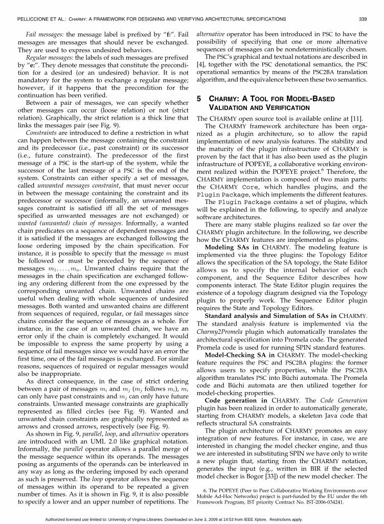
Fail messages: the message label is prefixed by “f:”. Failmessages are messages that should never be exchanged.They are used to express undesired behaviors.
Regular messages: the labels of such messages are prefixedby “e:”. They denote messages that constitute the precondi-tion for a desired (or an undesired) behavior. It is notmandatory for the system to exchange a regular message;however, if it happens that the precondition for thecontinuation has been verified.
Between a pair of messages, we can specify whetherother messages can occur (loose relation) or not (strictrelation). Graphically, the strict relation is a thick line thatlinks the messages pair (see Fig. 9).
Constraints are introduced to define a restriction in whatcan happen between the message containing the constraintand its predecessor (i.e., past constraint) or its successor(i.e., future constraint). The predecessor of the firstmessage of a PSC is the start-up of the system, while thesuccessor of the last message of a PSC is the end of thesystem. Constraints can either specify a set of messages,called unwanted messages constraint, that must never occurin between the message containing the constraint and itspredecessor or successor (informally, an unwanted mes-sages constraint is satisfied iff all the set of messagesspecified as unwanted messages are not exchanged) orwanted (unwanted) chain of messages. Informally, a wantedchain predicates on a sequence of dependent messages andit is satisfied if the messages are exchanged following theloose ordering imposed by the chain specification. Forinstance, it is possible to specify that the message m mustbe followed or must be preceded by the sequence ofmessages m1; . . . ;mn. Unwanted chains require that themessages in the chain specification are exchanged follow-ing any ordering different from the one expressed by thecorresponding unwanted chain. Unwanted chains areuseful when dealing with whole sequences of undesiredmessages. Both wanted and unwanted chains are differentfrom sequences of required, regular, or fail messages sincechains consider the sequence of messages as a whole. Forinstance, in the case of an unwanted chain, we have anerror only if the chain is completely exchanged. It wouldbe impossible to express the same property by using asequence of fail messages since we would have an error thefirst time, one of the fail messages is exchanged. For similarreasons, sequences of required or regular messages wouldalso be inappropriate.
As direct consequence, in the case of strict orderingbetween a pair of messages mi and mj (mj follows mi), mi
can only have past constraints and mj can only have futureconstraints. Unwanted message constraints are graphicallyrepresented as filled circles (see Fig. 9). Wanted andunwanted chain constraints are graphically represented asarrows and crossed arrows, respectively (see Fig. 9).
As shown in Fig. 9, parallel, loop, and alternative operatorsare introduced with an UML 2.0 like graphical notation.Informally, the parallel operator allows a parallel merge ofthe message sequence within its operands. The messagesposing as arguments of the operands can be interleaved inany way as long as the ordering imposed by each operandas such is preserved. The loop operator allows the sequenceof messages within its operand to be repeated a givennumber of times. As it is shown in Fig. 9, it is also possibleto specify a lower and an upper number of repetitions. The
alternative operator has been introduced in PSC to have thepossibility of specifying that one or more alternativesequences of messages can be nondeterministically chosen.
The PSC’s graphical and textual notations are described in[4], together with the PSC denotational semantics, the PSC
operational semantics by means of the PSC2BA translationalgorithm, and the equivalence between these two semantics.
5 CHARMY: A TOOL FOR MODEL-BASED
VALIDATION AND VERIFICATION
The CHARMY open source tool is available online at [11].The CHARMY framework architecture has been orga-
nized as a plugin architecture, so to allow the rapidimplementation of new analysis features. The stability andthe maturity of the plugin infrastructure of CHARMY isproven by the fact that it has also been used as the plugininfrastructure of POPEYE, a collaborative working environ-ment realized within the POPEYE project.6 Therefore, theCHARMY implementation is composed of two main parts:the CHARMY Core, which handles plugins, and thePlugin Package, which implements the different features.
The Plugin Package contains a set of plugins, whichwill be explained in the following, to specify and analyzesoftware architectures.
There are many stable plugins realized so far over theCHARMY plugin architecture. In the following, we describehow the CHARMY features are implemented as plugins.
Modeling SAs in CHARMY. The modeling feature isimplemented via the three plugins: the Topology Editorallows the specification of the SA topology, the State Editorallows us to specify the internal behavior of eachcomponent, and the Sequence Editor describes howcomponents interact. The State Editor plugin requires theexistence of a topology diagram designed via the Topologyplugin to properly work. The Sequence Editor pluginrequires the State and Topology Editors.
Standard analysis and Simulation of SAs in CHARMY.
The standard analysis feature is implemented via theCharmy2Promela plugin which automatically translates thearchitectural specification into Promela code. The generatedPromela code is used for running SPIN standard features.
Model-Checking SA in CHARMY. The model-checkingfeature requires the PSC and PSC2BA plugins: the formerallows users to specify properties, while the PSC2BA
algorithm translates PSC into Buchi automata. The Promelacode and Buchi automata are then utilized together formodel-checking properties.
Code generation in CHARMY. The Code Generationplugin has been realized in order to automatically generate,starting from CHARMY models, a skeleton Java code thatreflects structural SA constraints.
The plugin architecture of CHARMY promotes an easyintegration of new features. For instance, in case, we areinterested in changing the model checker engine, and thuswe are interested in substituting SPIN we have only to writea new plugin that, starting from the CHARMY notation,generates the input (e.g., written in BIR if the selectedmodel checker is Bogor [33]) of the new model checker. The
PELLICCIONE ET AL.: CHARMY: A FRAMEWORK FOR DESIGNING AND VERIFYING ARCHITECTURAL SPECIFICATIONS 339
6. The POPEYE (Peer to Peer Collaborative Working Environments overMobile Ad-Hoc Networks) project is part-funded by the EU under the 6thFramework Program, IST priority Contract No. IST-2006-034241.
Authorized licensed use limited to: University of Virginia Libraries. Downloaded on June 3, 2009 at 14:53 from IEEE Xplore. Restrictions apply.
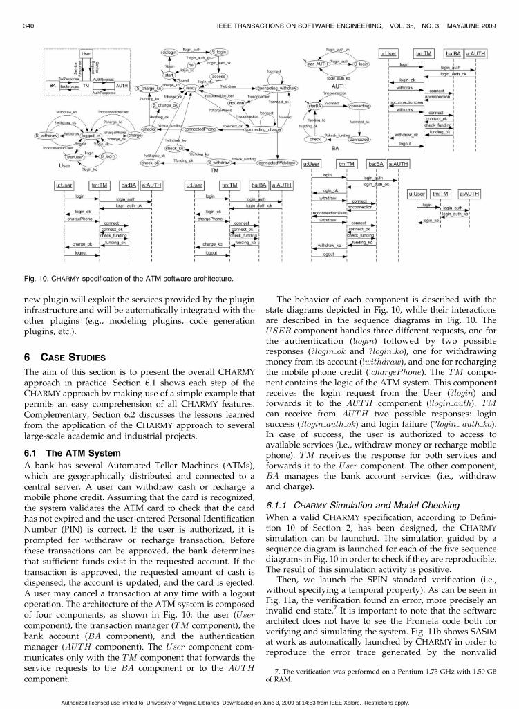
new plugin will exploit the services provided by the plugininfrastructure and will be automatically integrated with theother plugins (e.g., modeling plugins, code generationplugins, etc.).
6 CASE STUDIES
The aim of this section is to present the overall CHARMY
approach in practice. Section 6.1 shows each step of theCHARMY approach by making use of a simple example thatpermits an easy comprehension of all CHARMY features.Complementary, Section 6.2 discusses the lessons learnedfrom the application of the CHARMY approach to severallarge-scale academic and industrial projects.
6.1 The ATM System
A bank has several Automated Teller Machines (ATMs),which are geographically distributed and connected to acentral server. A user can withdraw cash or recharge amobile phone credit. Assuming that the card is recognized,the system validates the ATM card to check that the cardhas not expired and the user-entered Personal IdentificationNumber (PIN) is correct. If the user is authorized, it isprompted for withdraw or recharge transaction. Beforethese transactions can be approved, the bank determinesthat sufficient funds exist in the requested account. If thetransaction is approved, the requested amount of cash isdispensed, the account is updated, and the card is ejected.A user may cancel a transaction at any time with a logoutoperation. The architecture of the ATM system is composedof four components, as shown in Fig. 10: the user (Usercomponent), the transaction manager (TM component), thebank account (BA component), and the authenticationmanager (AUTH component). The User component com-municates only with the TM component that forwards theservice requests to the BA component or to the AUTHcomponent.
The behavior of each component is described with thestate diagrams depicted in Fig. 10, while their interactionsare described in the sequence diagrams in Fig. 10. TheUSER component handles three different requests, one forthe authentication (!login) followed by two possibleresponses (?login ok and ?login ko), one for withdrawingmoney from its account (!withdraw), and one for rechargingthe mobile phone credit (!chargePhone). The TM compo-nent contains the logic of the ATM system. This componentreceives the login request from the User (?login) andforwards it to the AUTH component (!login auth). TMcan receive from AUTH two possible responses: loginsuccess (?login auth ok) and login failure (?login auth ko).In case of success, the user is authorized to access toavailable services (i.e., withdraw money or recharge mobilephone). TM receives the response for both services andforwards it to the User component. The other component,BA manages the bank account services (i.e., withdrawand charge).
6.1.1 CHARMY Simulation and Model Checking
When a valid CHARMY specification, according to Defini-tion 10 of Section 2, has been designed, the CHARMY
simulation can be launched. The simulation guided by asequence diagram is launched for each of the five sequencediagrams in Fig. 10 in order to check if they are reproducible.The result of this simulation activity is positive.
Then, we launch the SPIN standard verification (i.e.,without specifying a temporal property). As can be seen inFig. 11a, the verification found an error, more precisely aninvalid end state.7 It is important to note that the softwarearchitect does not have to see the Promela code both forverifying and simulating the system. Fig. 11b shows SASIM
at work as automatically launched by CHARMY in order toreproduce the error trace generated by the nonvalid
340 IEEE TRANSACTIONS ON SOFTWARE ENGINEERING, VOL. 35, NO. 3, MAY/JUNE 2009
7. The verification was performed on a Pentium 1.73 GHz with 1.50 GBof RAM.
Fig. 10. CHARMY specification of the ATM software architecture.
Authorized licensed use limited to: University of Virginia Libraries. Downloaded on June 3, 2009 at 14:53 from IEEE Xplore. Restrictions apply.
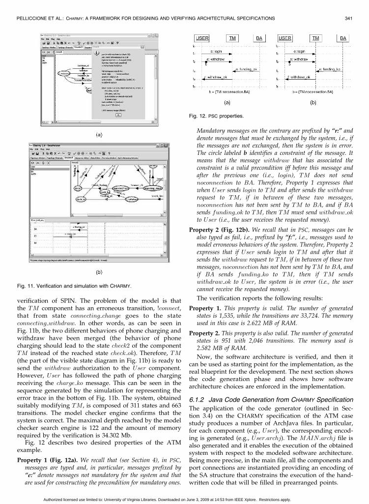
verification of SPIN. The problem of the model is thatthe TM component has an erroneous transition, !connect,that from state connecting change goes to the stateconnecting withdraw. In other words, as can be seen inFig. 11b, the two different behaviors of phone charging andwithdraw have been merged (the behavior of phonecharging should lead to the state check2 of the componentTM instead of the reached state check ok). Therefore, TM(the part of the visible state diagram in Fig. 11b) is ready tosend the withdraw authorization to the User component.However, User has followed the path of phone chargingreceiving the charge ko message. This can be seen in thesequence generated by the simulation for representing theerror trace in the bottom of Fig. 11b. The system, obtainedsuitably modifying TM, is composed of 311 states and 663transitions. The model checker engine confirms that thesystem is correct. The maximal depth reached by the modelchecker search engine is 122 and the amount of memoryrequired by the verification is 34.302 Mb.
Fig. 12 describes two desired properties of the ATMexample.
Property 1 (Fig. 12a). We recall that (see Section 4), in PSC,messages are typed and, in particular, messages prefixed by“e:” denote messages not mandatory for the system and thatare used for constructing the precondition for mandatory ones.
Mandatory messages on the contrary are prefixed by “r:” anddenote messages that must be exchanged by the system, i.e., ifthe messages are not exchanged, then the system is in error.The circle labeled b identifies a constraint of the message. Itmeans that the message withdraw that has associated theconstraint is a valid precondition iff before this message andafter the previous one (i.e., login), TM does not sendnoconnection to BA. Therefore, Property 1 expresses thatwhen User sends login to TM and after sends the withdrawrequest to TM, if in between of these two messages,noconnection has not been sent by TM to BA, and if BAsends funding ok to TM, then TM must send withdraw okto User (i.e., the user receives the requested money).
Property 2 (Fig. 12b). We recall that in PSC, messages can bealso typed as fail, i.e., prefixed by “f:”, i.e., messages used tomodel erroneous behaviors of the system. Therefore, Property 2expresses that if User sends login to TM and after that itsends the withdraw request to TM, if in between of these twomessages, noconnection has not been sent by TM to BA, andif BA sends funding ko to TM, then if TM sendswithdraw ok to User, the system is in error (i.e., the usercannot receive the requested money).
The verification reports the following results:
Property 1. This property is valid. The number of generatedstates is 1,535, while the transitions are 33,724. The memoryused in this case is 2.622 MB of RAM.
Property 2. This property is also valid. The number of generatedstates is 951 with 2,046 transitions. The memory used is2.582 MB of RAM.
Now, the software architecture is verified, and then itcan be used as starting point for the implementation, as thereal blueprint for the development. The next section showsthe code generation phase and shows how softwarearchitecture choices are enforced in the implementation.
6.1.2 Java Code Generation from CHARMY Specification
The application of the code generator (outlined in Sec-tion 3.4) on the CHARMY specification of the ATM casestudy produces a number of ArchJava files. In particular,for each component (e.g., User), the corresponding encod-ing is generated (e.g., User:archj). The MAIN:archj file isalso generated and it enables the execution of the obtainedsystem with respect to the modeled software architecture.Being more precise, in the main file, all the components andport connections are instantiated providing an encoding ofthe SA structure that constrains the execution of the hand-written code that will be filled in prearranged points.
PELLICCIONE ET AL.: CHARMY: A FRAMEWORK FOR DESIGNING AND VERIFYING ARCHITECTURAL SPECIFICATIONS 341
Fig. 11. Verification and simulation with CHARMY.
Fig. 12. PSC properties.
Authorized licensed use limited to: University of Virginia Libraries. Downloaded on June 3, 2009 at 14:53 from IEEE Xplore. Restrictions apply.
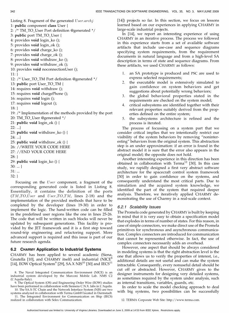
Listing 8. Fragment of the generated User:archj
1: public component class User {
2: /* TM_TO_User Port definition @generated */
3: public port TM_TO_User {
4: provides void login_ko ();
5: provides void login_ok ();
6: provides void charge_ko ();
7: provides void charge_ok ();
8: provides void withdraw_ko ();9: provides void withdraw_ok ();
10: provides void noconnectionUser ();
11: }
12: /* User_TO_TM Port definition @generated */
13: public port User_TO_TM {
14: requires void withdraw ();
15: requires void chargePhone ();
16: requires void login ();17: requires void logout ();
18: }
19: /* Implementation of the methods provided by the port
20: TM_TO_User @generated */
21: public void login_ok () {
22: ...}
23: public void withdraw_ko () {
24: ...}25: public void withdraw_ok () {
26: //WRITE YOUR CODE HERE
27: //END YOUR CODE HERE
28: }
29: public void login_ko () {
30: ... }
31: ...
32: }
Focusing on the User component, a fragment of thecorresponding generated code is listed in Listing 8.Essentially, it contains the definition of the ports(TM TO User and User TO TM, lines 2-18) and theimplementation of the provided methods that have to becompleted by the developer (lines 19-30) in order toimplement the logic. The hand-written code can be filledin the predefined user regions like the one in lines 25-26.The code that will be written in such blocks will never beupdated by subsequent generations. This facility is pro-vided by the JET framework and it is a first step towardround-trip engineering and refactoring support. Moreadvanced support is required and this issue is part of ourfuture research agenda.
6.2 CHARMY Application to Industrial Systems
CHARMY has been applied to several academic (Siena,Gnutella [10], and CHARMY itself) and industrial (NICE8
[14], EOW Optical System9 [29], SA.X NIS10 [30] and IECS11
[14]) projects so far. In this section, we focus on lessonslearned based on our experiences in applying CHARMY inlarge-scale industrial projects.
In [14], we report an interesting experience of usingCHARMY in an iterative process. The process we followedin this experience starts from a set of available softwareartifacts that include use-case and sequence diagramsspecifying system requirements, from the requirementdocuments in natural language and from a high-level SAdescription in terms of state and sequence diagrams. Fromthese artifacts, we used CHARMY as follows:
1. an SA prototype is produced and PSC are used toexpress selected requirements;
2. the executable model is extensively simulated togain confidence on system behaviors and getsuggestions about potentially wrong behaviors;
3. the global behavioral properties stated in therequirements are checked on the system model;
4. critical subsystems are identified together with theirrelevant properties suitably derived from the prop-erties defined on the entire system;
5. the subsystems architecture is refined and theprocess is iterated.
The process of focussing on a system part that weconsider critical implies that we intentionally restrict ourvisibility of the system behaviors by removing “noninter-esting” behaviors from the original system. This abstractionstep is an under approximation: if an error is found in theabstract model it is sure that the error also appears in theoriginal model; the opposite does not hold.
Another interesting experience in this direction has beenobtained in collaboration with Terma12 [30]. In this casestudy, we rapidly designed a first very abstract softwarearchitecture for the spacecraft control system framework[30] in order to gain confidence on the systems, andconsequently understand the most critical parts. Due tosimulation and the acquired system knowledge, weidentified the part of the system that required deeperanalysis. Therefore, we iteratively applied CHARMY de-monstrating the use of Charmy in a real-scale context.
6.2.1 Scalability Issues
The Promela code generated by CHARMY is built by keepingin mind that it is very easy to obtain a specification modelthat explodes in terms of number of states. For this reason, incase of simple connectors, we make direct use of the Promelaprimitives for synchronous and asynchronous communica-tion. Complex connectors are introduced for communicationthat cannot be represented otherwise. In fact, the use ofcomplex connectors necessarily adds an overhead.
However, one aspect that should be always consideredin modeling systems is that the right abstraction level is theone that allows us to verify the properties of interest, i.e.,additional details are not useful and can make the systemintractable. Consequently, every nonuseful detail should becut off or abstracted. However, CHARMY gives to thedesigner instruments for designing very detailed systems,as sometimes required by the system under analysis, suchas internal transitions, variables, guards, etc.
In order to scale the model checking approach to dealwith big systems, two possibilities can be successfully
342 IEEE TRANSACTIONS ON SOFTWARE ENGINEERING, VOL. 35, NO. 3, MAY/JUNE 2009
8. The Naval Integrated Communication Environment (NICE) is anindustrial system developed by the Marconi Mobile Lab. NMS C2(L’Aquila-Italy).
9. The Optical System (OS) and Engineering Order Wire (EOW) studieshave been performed in collaboration with Siemens C.N.X. labs in L’Aquila.
10. The SA.X-TC Chain and the Network Interface System (NIS) are twosystems analyzed in collaboration with Terma GmbH located in Darmstadt.
11. The Integrated Environment for Communication on Ship (IECS)realized in collaboration with Selex Communication. 12. TERMA Corporate Web Site: http://www.terma.com.
Authorized licensed use limited to: University of Virginia Libraries. Downloaded on June 3, 2009 at 14:53 from IEEE Xplore. Restrictions apply.
applied: 1) internal methods that are algorithms andtechniques used internally to the model checker in orderto efficiently represent and manage transition relationsbetween concurrent process and 2) external methods that aretechniques that operate on the input of the model checker(models), and can be used in conjunction with internalmethods. A CHARMY user can only deal with externalmethods, working at the modeling level and adoptingtechniques to reduce the model size. The usual techniquesconsist of slicing and abstracting the system, in limiting (tothe minimum necessary for analysis purposes) the numberof instances of a certain component/connector and inmaking use of compositional reasoning approaches thataim to reduce the verification of a system to the verificationof a set of small subsystems.
A slicing and abstraction approach has been proposed in[13]. This approach exploits the characteristic of the SAmodel and the structure of the property of interest and triesto reduce the model complexity without compromising theverification validity of the considered property. Architectur-al slicing is the result of applying the slicing idea to SA [36].Therefore, the basic elements of architectural slicing arecomponents, connectors, ports, roles, and messages ex-changed between components. An architectural slicing canbe considered as a subset of the behavior of a softwarearchitecture with the attempt to isolate the parts that areinvolved in the slicing criterion. In the approach that weproposed, the slicing criterion was the property we want tocheck on the SA. Due to the architectural slicing, we are ableto extract the parts of the system that play a role on thebehavior implied by the property of interested. The idea ofthe architectural abstraction is instead to reduce the complex-ity of the model by abstracting parts of the state diagrams(e.g., collapsing sets of states and transitions in only onestate or transition) without compromising the validity of theverification. The application of the approach to an industrialcase study [13] has shown that the technique is promising.
The SA of systems whose configuration can dynamicallychange and evolve at runtime (either by instantiating orremoving components) can change in terms of number ofcomponent instances and connectors. This would lead tocomplex specifications and models which might potentiallybe infinite-states. In this case, it is only possible to considera specific instance of the system and validate the propertiesof interest on it. Of course, proving that a certain property istrue for a given instance is not enough, in general, to assurethe correctness of the system. Therefore, an automatic ormanual reasoning on the obtained verification results isrequired in order to scale the properties to the generic case.The work in [9] shows the use of architectural patterns as anabstraction to carry on, and reuse, formal reasoning onsystems whose configuration can dynamically change.
In [10], we presented a compositional reasoning approachto verify middleware-based software architecture descrip-tions. The approach exploits the structure imposed on thesystem by the SA in order to develop an assume-guaranteemethodology to reduce properties verification from globalto local. The idea behind this work is that the middleware iswell established and defined, and thus we do not need toreverify it for each application making use of it. Therefore,the reduction in this case is huge since making assumptionson the behavior of the middleware, the only parts of thesystem to be verified are the component composing theapplication built on top of the middleware.
In a recent work [30], we also integrated CHARMY withSYNTHESIS [38] that is a tool for assembling component-based systems out of a set of already implementedheterogeneous components by ensuring the correct func-tioning of the system at the level of component interactionprotocol. By exploiting the software architecture verificationperformed by using CHARMY, the system assembler canperform code synthesis only focusing on each singlearchitectural component; hence, refining it as an assemblyof actual components which respect the architecturalcomponent observable behavior. In this way, code synthesisis performed locally to each architectural component,instead of globally on the whole system interactions, hencereducing the state explosion phenomenon. Concerning theadvantage that CHARMY takes from being combined withSYNTHESIS, the component glue code required for the SAimplementation is, when possible, automatically builtcorrect by construction without requiring the developersto work on it. This obviously reduces the development timeas well as the time spent to verify that the systemimplementation conforms its requirements. Furthermore,the integration with SYNTHESIS suggests a process in whichthe SA to be verified can be very abstract thus keeping it ona tractable and reasonable size. This is the case of the casestudy described in [30] that we successfully verified andimplemented even though we initially experienced stateexplosion problems when applying CHARMY on a morelower abstract level.
6.2.2 Drawbacks of the Approach
The use of CHARMY, in practice, also evidenced drawbacksof the approach. First of all, the iterative approach that wepromote in this paper would benefit from an integratedsupport to refinement and nesting. For instance, we appliedan iterative approach in the case studies previouslymentioned [30], [14]. We selected subparts of the systemsthat require deeper investigation and we created a differentmodel of the system. CHARMY does not manage relationsbetween different versions of the models produced at eachiteration. As future research direction we plan to investigatehow each component can be refined allowing softwarearchitects to focus on a system subpart.
Finally, as discussed above, the scalability of theapproach needs further investigation and we are progres-sing in the directions previously identified.
7 RELATED WORK
The works mostly related to CHARMY are in the area ofmodel-based architectural specification and automated analysis atthe architectural level.
7.1 Model-Based Architectural Specification
Up to the present day, many languages for specifying andanalyzing software architectures have been proposed, e.g.,[37], [17]. However additional requirements that come fromputting architecture modeling and analysis techniques, inpractice, impair the real use of ADLs in industrial contexts:
R1. It is not possible to assume to have a well-definedsoftware architecture without the need of makingfurther architectural decisions.
R2. Industries still prefer to make use of semiformal andeasy to learn specification languages for SA modeling.
PELLICCIONE ET AL.: CHARMY: A FRAMEWORK FOR DESIGNING AND VERIFYING ARCHITECTURAL SPECIFICATIONS 343
Authorized licensed use limited to: University of Virginia Libraries. Downloaded on June 3, 2009 at 14:53 from IEEE Xplore. Restrictions apply.
R3. Tool-supported modeling and analysis approachesare necessary. Automated tool support is funda-mental for reducing analysis costs.
R4. The use of a tool that requires a long start-up beforereaching the point from where the tool becomesuseful is not acceptable.
Furthermore, the primary goal of architectural modelingshould be to reach a common vision and understanding ofthe system and the way to built it. In other words, one of themain goals of architecting is modeling for understanding.This hardly accommodates with the ADLs proposed tillnow that may require investing too much time on thearchitecting phase. The result is that ADLs are notcommonly used in industrial contexts except for specificdomains such as the avionic, aerospace, and automotive inwhich AADL [37] has been identified as a good solution.
With the introduction of UML as the standard notationfor system modeling, UML has been adopted to modelsoftware architectures. Many proposals have been pre-sented so far to adapt UML 1.x to model softwarearchitectures. Most of them rely on the creation of UMLprofiles for reducing the gap between software architectureconcepts and UML modeling. With the advent of UML 2.0,five fundamentals novelties have been introduced for SAdescriptions:
1. in UML 2.0, a component is a subtype of a class,13
then it may have attributes and methods, as well asinterfaces, ports, and internal structure;
2. UML 2.0 extends the UML1.4 concept of interface, byexplicitly including provided and required interfaces;
3. Ports describe how components interact with theenvironment;
4. decomposition of components, useful to representthe internal structure, is performed due to thestructured classifier;
5. A UML 2.0 connector is introduced as a communica-tion link between two or more components’ instances.
The use of UML 2.0 (as it is) for SA modeling has beenanalyzed in some books. However, some aspects stillrequire adjustments in order to bridge the gap betweenUML 2.0 and ADLs. Therefore, many works have proposedextensions to adapt and use UML 2.0 as an ADL (e.g., [34],[31]). Even though UML is widely used and supported byprofessional tools, its principal drawback is the absolutelack of formality. The result is that each designer assumeshis own semantics and accordingly designs the system.
CHARMY aims to inherit from UML the agility and theappeal, with the aim to be a step in the direction ofproviding an automated, easy to use tool for the model-based design and validation of SAs. However, the CHARMY
notation has a formal semantics and forces the softwarearchitect to resolve ambiguities that could be present in astandard UML-based software architecture specification.The choice we made in CHARMY is to use diagrams mostcommonly used by industries. In fact, despite of theflourishing of diagrams in UML, the most used diagramsby software architects are still state, sequence, andcomponent diagrams. We provided these diagrams with atextual notation and a formal semantics. Since the differentdiagrams are different views of the same system, we ensure
consistency among these diagrams and we extract acomplete system description from components, state, andsequence diagrams. As described in the paper andspecifically in Section 2, component diagrams are used torepresent structural aspects, state diagrams are used todescribe how components behave and react to receivedmessages, and sequence diagrams are used to represent thecommunication and the synchronization among compo-nents. Typically, other approaches that generate a formaldescription starting from UML, even if not at the archi-tectural level, consider only one type of diagram. Thesolution proposed by CHARMY allows the softwarearchitect to represent each aspect in a natural way, usingfor each aspect the most appropriate diagram (e.g.,sequence diagrams are the most used and more appropriatediagrams to explicitly represent communication amongsubparts that compose the system).
7.2 Automated Analysis at the Architectural Level
Many analysis methods and tools have been proposed sofar for architecture-level automated analysis [1]: to performdeadlock analysis [3], [15], SA-level testing [26], depen-dence analysis [36], and many others. Since this paperaddresses architectural model-checking, we will focus onthis topic. Two main classes of approaches can be relatedwith CHARMY: specification-based checking based onformal languages, and UML models translation foranalysis purposes.
In the first class of approaches and tools, the mostlyrelated are Wright [3] and the Labeled Transition SystemAnalyser (LTSA) [23]. Wright is based upon CSP [19] toperform various architectural consistency checks support-ing deadlock detection and behavioral refinement. TheLTSA [23] tool supports the Tracta approach initiallyproposed by Magee et al. [24]. A formal specification inthe Finite-State Process (FSP) algebra is utilized to specifythe behavior of a software architecture. The Darwin ADL(integrated with the FSP algebra) permits to specify the SAstructure. As soon as the SA specification is ready, variouskind of analyses can be performed: safety, liveness,simulation, assume-guarantee checking, and implied sce-narios analysis. Both of these approaches make use asspecification formalisms of formal languages that requireparticular skills: Wright is based on CSP and LTSA on theprocess algebra FSP (a dialect of CSP). On the contrary,CHARMY aims to bring the gap between formal methodsand its applicability in real contexts by means of notationsclose to what really used in industrial contexts.
Another class of work that can be related to our work isbased on the idea of translating UML models for analysispurposes. The translation of UML diagrams in formallanguages has been addressed in numerous papers andseveral tools have been proposed (see [16] and citationtherein). In [16], the authors propose the translation of bothstatic aspects (described by UML class diagram) anddynamic aspects (described by a subset of UML state andcommunication diagrams) of a systems into a Maude formalspecification. Then, the Maude-integrated model checker isused to check desired properties expressed in LTL. Anotherinteresting work is [25] that proposes a metamodel-basedapproach to map UML diagrams to specification languagesof model checkers.
With the aim to have an unambiguous well-definedlanguage, the choice we made in CHARMY is for a newlanguage inspired to UML but independent. It is, in fact,
344 IEEE TRANSACTIONS ON SOFTWARE ENGINEERING, VOL. 35, NO. 3, MAY/JUNE 2009
13. Differently from UML 1.4, where a component is defined as asubclass of Classifier.
Authorized licensed use limited to: University of Virginia Libraries. Downloaded on June 3, 2009 at 14:53 from IEEE Xplore. Restrictions apply.
important to underline that UML is not only syntax but alsosemantics and users of UML attach meaning to thediagrams they produce. One way to propose a newlanguage “based” on an existent one is to extend theexistent one by retaining its original semantics. Unfortu-nately, in UML, it is not possible to completely follow thisway since UML has neither a native formal semantics nor awidely accepted one despite the several attempts to defineUML formal semantics. However, UML has an informalsemantics that people associate to them according to thespecification native documents. Therefore, in CHARMY, weinherit graphical elements from UML when these elementshave a native informal semantics that is consistent with theformal semantics we define, while we substitute those(graphical) elements that have an ambiguous semantics.
8 CONCLUSIONS AND FUTURE WORK
In this paper, we presented CHARMY, a framework toprovide an automated, easy to use tool for the model-baseddesign and validation of software architectures. CHARMY
suggests an iterative approach which allows designers toincrementally specify the SA of a software system throughdiagrammatic notations and to validate the architecturalspecification conformance with respect to temporal require-ments. CHARMY offers a graphical user interface to drawtopology, state, and sequence diagrams, and a translationengine to automatically derive Promela code which may besimulated and model-checked through the SPIN modelchecker. The PSC tool is integrated in CHARMY such that aCHARMY user can graphically draw PSC properties in thesame environment and translate them in the textualrepresentation of Buchi automata used by SPIN. Thesimulation and model checking engine complexity ishidden, providing the software engineer with an auto-mated, easy to use tool which takes in input thearchitectural models in an UML-based notation, createsthe prototype and automatically analyzes the prototypereducing as much as possible the human intervention. Oncethe SA is validated with respect to the desired require-ments, a skeleton Java code is automatically generated fromthe SA specification. The produced code embeds structuralSA constraints, and consequently assures that the architec-tural choices are maintained at implementation level. Theframework has been designed as a plugin architecture tosimplify the introduction of new features and help theintegration with other existing analysis tools.
On the ongoing and future work side, several interest-ing extensions are planned to take place. We are currentlyinvestigating how to exploit the behavioral informationpresent in a CHARMY specification for generating the Javacode. The idea is to generate an encoding of the CHARMY
state diagrams in order to force the system implementa-tion to behave accordingly to the state diagram models. Afirst result can be found in [6], where unallowed behaviorsare recognized and signalled by means of the javaexception mechanism.
The code generation supported by CHARMY can be usedonly in a context in which the system is completelyimplemented in-house, while neglecting the possibility ofintegrating external components. This is because acquiredcomponents are not necessarily implemented following theCHARMY approach, and thus it is not possible at runtime toallow the only admitted operations. Therefore, an interesting
future research direction consists of the ability of integrat-ing in-house components code with automatically gener-ated assembly code for acquired components, forcing thecomposed system to exhibit the properties specified at thearchitectural level. This integration would open thepossibility of managing dynamic systems (i.e., systems inwhich some components have to change at runtime)where a regenerated “correct” assembly code assures thatthe composed system is forced to exhibit only theproperties specified at the architectural level. A first resultin this direction can be found in [30].
We are also currently investigating the use of SMV orBogor model checkers as complementary to SPIN. Bogor is avery interesting model checker that takes advantage of aplugin-based structure. For instance, in Bogor, it is possibleto replace the module that implements the state-spaceexploration with a dedicated version to better steer thesearch process under particular assumptions, such asprimitive constructs (expressions or actions) as well as datatypes customized for SA. This extendibility of Bogor can beexploited by CHARMY in order to define a model checkingengine customized for SA verification, providing anabstraction of the model checker internal representation ofthe system under analysis, thus reducing time and spacesizes of the search engine.
Recently, much effort focusses on techniques thatoperate on the input of the model checker (models) inorder to continue improving time and space efficiency:abstraction, symmetry, and compositional reasoning [27],[12] are the currently evaluated solutions. In this direction,we are currently investigating slicing and abstractiontechniques to be applied at the architectural level (firstresults in [13]) and a compositional approach that, con-sidering a system composed of several components, aims toverify the system through the separate verification of thesingle components (first results in [10]).
REFERENCES
[1] Formal Methods for Software Architectures, Tutorial book onsoftware architectures and formal methods, M. Bernardo andP. Inverardi, eds. Springer, 2003.
[2] J. Aldrich, “Using Types to Enforce Architectural Structure,” Proc.Working IEEE/Int’l Federation for Information Processing (IFIP) Conf.Software Architecture, pp. 211-220, 2008.
[3] R. Allen and D. Garlan, “A Formal Basis for ArchitecturalConnection,” ACM Trans. Software Eng. and Methodology, vol. 6,no. 3, pp. 213-249, July 1997.
[4] M. Autili, P. Inverardi, and P. Pelliccione, “Graphical Scenarios forSpecifying Temporal Properties: An Automated Approach,”Automated Software Eng., vol. 14, no. 3, pp. 293-340, Sept. 2007.
[5] H. Baumeister, F. Hacklinger, R. Hennicker, A. Knapp, andM. Wirsing, “A Component Model for Architectural Program-ming,” Electronic Notes in Theoretical Computer Science, vol. 160,pp. 75-96, 2006.
[6] A. Bucchiarone, D. Di Ruscio, H. Muccini, and P. Pelliccione,“From Requirements to Code: An Architecture-Centric Approachfor Producing Quality Systems,” Chapter of The Book Model-DrivenSoftware Development: Integrating Quality Assurance, IRM Press,CyberTech Publishing and Idea Group Reference Imprints, 2008.
[7] R.J. Buchi, “On a Decision Method in Restricted Second OrderArithmetic,” Proc. Int’l Congress of Logic, Methodology and Philoso-phy of Science, pp. 1-11, 1960.
[8] F. Budinsky, D. Steinberg, E. Merks, R. Ellersick, and T. Grose,Eclipse Modeling Framework. Addison Wesley, 2003.
[9] M. Caporuscio, P. Inverardi, and P. Pelliccione, “Formal Analysisof Architectural Patterns,” Proc. European Workshop SoftwareArchitecture, 2004.
PELLICCIONE ET AL.: CHARMY: A FRAMEWORK FOR DESIGNING AND VERIFYING ARCHITECTURAL SPECIFICATIONS 345
Authorized licensed use limited to: University of Virginia Libraries. Downloaded on June 3, 2009 at 14:53 from IEEE Xplore. Restrictions apply.
[10] M. Caporuscio, P. Inverardi, and P. Pelliccione, “CompositionalVerification of Middleware-Based Software Architecture Descrip-tions,” Proc. Int’l Conf. Software Eng., 2004.
[11] Charmy Project, Charmy Website, http://www.di.univaq.it/charmy and http://sourceforge.org/charmy, June 2008.
[12] E.M. Clarke, O. Grumbeg, and D.A. Peled, Model Checking. MITPress, 2001.
[13] D. Colangelo, D. Compare, P. Inverardi, and P. Pelliccione,“Reducing Software Architecture Models Complexity: A Slicingand Abstraction Approach,” Proc. Formal Techniques for Networkedand Distributed Systems Conf., 2006.
[14] D. Compare, P. Inverardi, P. Pelliccione, and A. Sebastiani,“Integrating Model-Checking Architectural Analysis and Valida-tion in a Real Software Life-Cycle,” Proc. Int’l Symp. FormalMethods, 2003.
[15] D. Compare, P. Inverardi, and A. Wolf, “Uncovering ArchitecturalMismatch in Dynamic Behavior,” Science of Computer Program-ming, vol. 33, no. 2, pp. 101-131, Feb. 1999.
[16] P. Gagnon, F. Mokhati, and M. Badri, “Applying Model Checkingto Concurrent UML Models,” Object Technology, vol. 7, no. 1,pp. 59-84, 2008.
[17] D. Garlan, R.T. Monroe, and D. Wile, “Acme: ArchitecturalDescription of Component-Based Systems,” Foundations of Compo-nent-Based Systems, Cambridge Univ. Press, 2000.
[18] H. Goldsby, B.H.C. Cheng, S. Konrad, and S. Kamdoum, “AVisualization Framework for the Modeling and Formal Analysisof High Assurance Systems,” Proc. Int’l Conf. Model Driven Eng.Languages and Systems, 2006.
[19] C.A.R. Hoare, “Communicating Sequential Processes,” Comm.ACM, vol. 21, no. 8, pp. 666-677, 1978.
[20] C. Hofmeister, P. Kruchten, R.L. Nord, H. Obbink, A. Ran,and P. America, “A General Model of Software ArchitectureDesign Derived from Five Industrial Approaches,” J. Systemsand Software, vol. 80, no. 1, pp. 106-126, 2007.
[21] G.J. Holzmann, The SPIN Model Checker: Primer and ReferenceManual. Addison-Wesley, Sept. 2003.
[22] L. Lamport, “What Good Is Temporal Logic?” Proc. Int’l Federationof Information Processing Ninth World Congress, 1983.
[23] J. Magee and J. Kramer, Concurrency: State Models & Java Programs,second ed. John Wiley & Sons, 2006.
[24] J. Magee, J. Kramer, and D. Giannakopoulou, “Behaviour Analysisof Software Architectures,” Proc. Working IEEE/Int’l Federation forInformation Processing Conf. Software Architecture, 1999.
[25] W.E. McUmber and B.H.C. Cheng, “A General Framework forFormalizing UML with Formal Languages,” Proc. Int’l Conf.Software Eng., 2001.
[26] H. Muccini, A. Bertolino, and P. Inverardi, “Using SoftwareArchitecture for Code Testing,” IEEE Trans. Software Eng., vol. 30,no. 3, pp. 160-171, Mar. 2004.
[27] D. Peled, P. Pelliccione, and P. Spoletini, Wiley Encyclopedia ofComputer Science and Engineering, 5-Volume Set, Chapter ModelChecking. Wiley, 2009.
[28] P. Pelliccione, “CHARMY: A Framework for Software Architec-ture Specification and Analysis,” PhD thesis, Computer ScienceDept., Univ. of L’Aquila, May 2005.
[29] P. Pelliccione, H. Muccini, A. Bucchiarone, and F. Facchini,“Testor: Deriving Test Sequences from Model-Based Specifica-tions,” Proc. Int’l Symp. Component-Based Software Eng., 2005.
[30] P. Pelliccione, M. Tivoli, A. Bucchiarone, and A. Polini, “AnArchitectural Approach to the Correct and Automatic Assemblyof Evolving Component-Based Systems,” J. Systems and Software,doi: http://dx.doi.org/10.1016/j.jss.2008.05.030, 2008.
[31] J.E. Perez-Martinez and A. Sierra-Alonso, “UML 1.4 VersusUML 2.0 as Languages to Describe Software Architectures,” Proc.European Workshop Software Architecture, 2004.
[32] D.E. Perry and A.L. Wolf, “Foundations for the Study of SoftwareArchitecture,” ACM SIGSOFT Software Eng. Notes, vol. 17, no. 4,pp. 40-52, Oct. 1992.
[33] Robby, E. Rodriguez M.B. Dwyer, and J. Hatcliff, “CheckingStrong Specifications Using an Extensible Software Model Check-ing Framework,” Proc. Int’l Conf. Tools and Algorithms for theConstruction of Analysis of Systems, Mar. 2004.
[34] S. Roh, K. Kim, and T. Jeon, “Architecture Modeling LanguageBased on UML 2.0,“ Proc. Asia-Pacific Software Eng. Conf., 2004.
[35] M. Shaw and D. Garlan, Software Architecture: Perspectives on anEmerging Discipline. Prentice-Hall, 1996.
[36] J.A. Stafford, A.L. Wolf, and M. Caporuscio, The Application ofDependence Analysis to Software Architecture Descriptions. Springer-Verlag, 2003.
[37] The SAE Architecture Analysis and Design Language (AADL),http://www.aadl. info/, 2009.
[38] M. Tivoli and P. Inverardi, “Failure-Free Coordinators Synthesisfor Component-Based Architectures,” Science of Computer Program-ming, vol. 71, no. 3, pp. 181-212, 2008.
[39] S. Uchitel, J. Kramer, and J. Magee, “Incremental Elaboration ofScenario-Based Specifications and Behavior Models Using ImpliedScenarios,” ACM Trans. Software Eng. and Methodologies, vol. 13,no. 1, pp. 37-85, 2004.
Patrizio Pelliccione received the PhD degreefrom the Computer Science Department at theUniversity of L’Aquila, where he is an assistantprofessor. From April 2005 to April 2006, he wasa senior researcher on the Faculty of Sciences,Technologies and Communications at the Uni-versity of Luxembourg. He was a coordinator ofthe CORRECT project and group that is a part ofthe Software Engineering Competence Center(SE2C). The research topics are mainly in
software architectures, software architectures analysis, component-based systems, fault tolerance, middleware, model checking, and formalmethods. He is the chair of the ERCIM international workshop onSoftware Engineering for Resilient Systems (SERENE), a editor of abook: Software Engineering of Fault Tolerant Systems, and a reviewerfor several workshops, conferences, and journals.
Paola Inverardi is a professor of computerscience at the University of L’Aquila. Previously,she has worked at IEI-CNR in Pisa and at OlivettiResearch Lab., Pisa. She is the dean of theFaculty of Science at the University of L’Aquila,where she leads the Software Engineering andArchitecture Research Group. Her research areais in the application of formal methods to softwaredevelopment in order to improve software quality.Her research interests primarily concentrate in
the field of software architectures. She has actively worked on theverification and analysis of software architecture properties, bothbehavioural and quantitative for component-based, distributed, andmobile systems. She has served as the general chair, the program chair,and a program committee member for many international conferences.She was an associate editor and a member of the editorial board of theACM Transactions on Software Engineering and Methodology from 2004to 2007. Currently, she chairs the Steering Committee for the EuropeanSoftware Engineering Conferences (ESEC).
Henry Muccini is an assistant professor at theUniversity of L’Aquila, Italy. His research inter-ests are in the software engineering field andspecifically in software architecture modelingand analysis, component-based systems, mod-el-based analysis and testing, fault tolerance,and global software engineering. He has pub-lished various conference and journal articles onthese topics, coedited two books, SoftwareEngineering of Fault Tolerant Systems and
Architecting Fault Tolerant Systems V’, and coorganized variousworkshops on related topics. He is currently the local coordinator ofthe Global Software Engineering European Master (GSEEM) and theERASMUS MUNDUS External Cooperation EU project EURECA. Heserves as a PC member and a reviewer for many internationalconferences and journals.
. For more information on this or any other computing topic,please visit our Digital Library at www.computer.org/publications/dlib.
346 IEEE TRANSACTIONS ON SOFTWARE ENGINEERING, VOL. 35, NO. 3, MAY/JUNE 2009
Authorized licensed use limited to: University of Virginia Libraries. Downloaded on June 3, 2009 at 14:53 from IEEE Xplore. Restrictions apply.