Embed Size (px)
Citation preview
Bidirectional Telemetry Controller for Neuroprosthetic Devices
Vishnu Sharma, Douglas B. McCreery, Martin Han [Member, IEEE], and Victor PikovNeural Engineering Program, Huntington Medical Research Institutes, Pasadena, CA 91105 USAVishnu Sharma: vishnu_vds@yahoo. com; Douglas B. McCreery: [email protected]; Martin Han: [email protected];Victor Pikov: [email protected]
AbstractWe present versatile multifunctional programmable controller with bidirectional data telemetry,implemented using existing commercial microchips and standard Bluetooth protocol, which addsconvenience, reliability, and ease-of-use to neuroprosthetic devices. Controller, weighing 190 g, isplaced on animal's back and provides bidirectional sustained telemetry rate of 500 kb/s, allowingreal-time control of stimulation parameters and viewing of acquired data. In continuously-activestate, controller consumes ∼420 mW and operates without recharge for 8 h. It features independent16-channel current-controlled stimulation, allowing current steering; customizable stimulus currentwaveforms; recording of stimulus voltage waveforms and evoked neuronal responses with stimulusartifact blanking circuitry. Flexibility, scalability, cost-efficiency, and a user-friendly computerinterface of this device allow use in animal testing for variety of neuroprosthetic applications. Initialtesting of the controller has been done in a feline model of brainstem auditory prosthesis. In thismodel, the electrical stimulation is applied to the array of microelectrodes implanted in the ventralcochlear nucleus, while the evoked neuronal activity was recorded with the electrode implanted inthe contralateral inferior colliculus. Stimulus voltage waveforms to monitor the access impedanceof the electrodes were acquired at the rate of 312 kilosamples/s. Evoked neuronal activity in theinferior colliculus was recorded after the blanking (transient silencing) of the recording amplifierduring the stimulus pulse, allowing the detection of neuronal responses within 100 μs after the endof the stimulus pulse applied in the cochlear nucleus.
Index TermsBidirectional; electrode; neural prostheses; recording; stimulation; telemetry; wireless
I. IntroductionPRESENT and anticipated uses of neuroprosthetic and neuromodulation devices forrehabilitation and treatment of neurological disorders include deafness, blindness, Parkinson'sdisease, depression, epilepsy, spinal cord injury, amyotrophic lateral sclerosis, and stroke [1]–[9]. An increasing number of these devices require bidirectional data transfer to allowmonitoring and adjustment of the stimulus parameters as well as monitoring of neuronalactivity via the downlink.
For the development of novel neuroprosthetic devices, wireless communication offers severalbenefits, including continuous data recording without restricting the animal's mobility andavoiding the stress to the animals caused by constraint and tethering. Early biotelemetrycontrollers utilized unidirectional analog UHF for data uplink or downlink [10]–[12]. Thedevices with bidirectional telemetry employed specialized ASICs, making these devices costly
NIH Public AccessAuthor ManuscriptIEEE Trans Neural Syst Rehabil Eng. Author manuscript; available in PMC 2010 May 14.
Published in final edited form as:IEEE Trans Neural Syst Rehabil Eng. 2010 February ; 18(1): 67–74. doi:10.1109/TNSRE.2009.2036849.
NIH
-PA Author Manuscript
NIH
-PA Author Manuscript
NIH
-PA Author Manuscript
to develop and modify [13]–[15]. Recent development of compact high-power density Li-ionbatteries allows extended battery life even at relatively high power consumption [16] and theavailability of off-the-shelf components for digital wireless telecommunications protocols,such as Bluetooth and Wi-Fi/IEEE 802.11 [17], [18] allow increased data throughput, datasecurity, automatic error detection and correction not present in analog communicationprotocols [19]. Bluetooth 2.0 class 2 protocol is particularly well-suited for short-range (< 10m) and low-power (<2.5 mW) devices.1
In this article, we describe a prototype controller with bidirectional telemetry, utilizingcommercial-grade off-the-shelf integrated-circuit (COTS IC) components, standard Bluetoothprotocol, and a user-friendly graphical computer interface. This controller provides novelcapabilities, including independent control of the stimulating channels, customizablecontrolled-stimulus current waveforms, and flexible control of stimulus timing, allowing anycombination of simultaneous and interleaved pulsing across the array of 16 electrodes. Thecontroller is sufficiently compact and lightweight to be worn by larger animals (e.g., cats andrabbits). By utilizing COTS IC components and standard Bluetooth protocols, the developmenthas been cost-efficient and allows for future scalability and flexibility during the preclinicaldevelopment of a variety of neuroprosthetic and neuromodulation devices.
II. MethodsA. System Description of the Controller
The principal modules of the wearable controller are the stimulation pattern generator (SPG)module, a module for recording the stimulus voltage waveforms (SVW) from the electrodes,and a module for recording the evoked neuronal responses (ENR) [Fig. 1(a)]. The SPG consistsof 1) the stimulus pulse waveform generator, the trigger for synchronization with the SVWrecording module, and the stimulus artifact-blanking pulse for synchronization with the ENRrecording module; and 2) the electrode pattern generator which specifies the temporal patternof the stimulation across the 16 stimulating electrodes. The digital stimulus pulse output of thepulse waveform generator is converted to a biphasic analog voltage which is directed throughthe switching bank to the bank of voltage-to-current converters (Howland current pumps). Theswitches are turned on and off either simultaneously or sequentially to produce the specifiedpattern of stimulation. The output of each voltage-to-current converters ranges from 1 to 100μA.
The voltage-to-current converters include features to prevent injury to the neural tissue adjacentto the stimulating electrode in the event of a component failure, including partial or completefailure of the power supply. Each of the Howland pumps is coupled to its electrode through a0.3 μF capacitor which prevents injection of a net charge. The capacitor value was selected tobe large enough to avoid significant microelectrode polarization (less than 0.5 V), whenapplying the first phase of a biphasic pulse having relatively large charge (e.g., 150 nC/phase).Minimal microelectrode polarization is needed for preserving the voltage compliance of theHowland current pumps. The value of 0.3 μF satisfies this requirement.
On each channel, the electrode side of the capacitor is coupled through a 4 MΩ bias resistor(Rb) to an adjustable anodic bias voltage. The bias increases the charge injection capacity ofthe activated iridium electrode sites [20], [21]. The Rb value was selected to be much largerthan the impedance of the microelectrodes at the range of frequencies comprising the spectrumof the electrode voltage transients (mostly above 1 kHz) in order not to divert a significantproportion of stimulus current from the Howland pump. The Rb value also must be much
1http://www.bluetooth.org
Sharma et al. Page 2
IEEE Trans Neural Syst Rehabil Eng. Author manuscript; available in PMC 2010 May 14.
NIH
-PA Author Manuscript
NIH
-PA Author Manuscript
NIH
-PA Author Manuscript
smaller than the dc impedance of the microelectrodes, so that differences in their dc impedancedo not introduce significant variation in their anodic biases (all of the bias channels are drivenfrom a single source). The bias voltage is derived from the main power bus via of a simplevoltage divider circuit which limits the anodic bias voltage to an absolute maximum of 400mV with respect to the platinum counter electrode, and thus below the potential for oxidativehydrolysis of water. We have used this design for many years [22]–[32] and have validated itssafety for neural stimulation in different applications. In addition, there is a general power-linefuse to prevent overheating of the battery in the event of a circuit fault.
The SVWs induced by the stimulus pulses are monitored through a bank of 16 unity-gainbuffers. The ENRs are considerably smaller (up to ±500 μV) as compared to the SVWs (up to±8 V including the access voltage of the tissue), and the amplification in the ENR module isset at 1000× as opposed to 0.3 × in the SVW recording module. Level shifters in both recordingmodules are needed to convert the bipolar signals into positive-only signals, which are thendigitized using A/D converters. SVW data is digitized at 8 bit and 312 kilosamples/s in orderto capture rapid voltage dynamics at the beginning of the pulse, which is used for evaluatingthe access impedance of the electrodes. Recording of the SVWs begins 10 μs prior to theinitiation of the stimulus pulse and proceeds for 630 μs until 196 samples are collected. TheENR data is digitized at 12 bit and 27 kilosamples/s. The beginning of the ENR recording istriggered by the trailing edge of the artifact-blanking pulse, generated by SPG 15 μs after thestimulus pulse termination, and proceeds until it is terminated by the leading edge of the nextartifact-blanking pulse. The blanking (transient silencing) of high-gain (1000×) ENR amplifierduring the stimulus pulse suppresses the stimulus artifact and allows the ENR amplifier toremain unsaturated and to commence its activity at 15 μs after the stimulus pulse [Fig. 1(b)].
Bidirectional telemetry allows user control of the SPG, continuous monitoring of the ENR andsequential transmission of SVW data from the stimulating electrodes. The Bluetooth microchipsupports the standard Bluetooth protocol Version 2.0 + EDR, capable of 3 Mb/s datatransmission rate. In the prototype device, we use a rate to 0.5 Mb/s, which is adequate forcontinuous transmission of 16-bit ENR data (4 bits not used) and periodic transmission of 8-bit SVW data at a stimulation rate to up to 100 Hz (stimulation interval ≥10 ms). Datatransmission limitations of the Bluetooth protocol necessitate a sequential rather thansimultaneous recording of the SVW. Therefore, the amplifier in the SVW recording moduleis preceded by a 16:1 multiplexer for electrode selection.
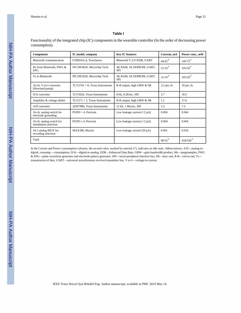
The above functions of the wearable controller have been implemented using the commercialmicrochip components listed in the Table I. The circuit diagram of the animal-worn controlleris presented in Supplemental Figure 1 and the key physical and electrical parameters of thecontroller are summarized in Supplemental Table 1.
The wearable controller was fabricated on three interconnected printed circuit boards and ishoused in a plastic enclosure measuring 13 × 6 × 3 cm (Fig. 2). The modular design will expeditedevelopment of future versions of controller with a higher number of stimulating and recordedchannels. The packaged controller with two 1400 mAh batteries and attached animal cableweighs 190 g. Battery recharging and programming of the PIC microcontroller chips is donevia three mini-USB connectors.
The wearable controller is powered by an 8.4 V lithium-polymer iPhone battery rated at 1400mAh. The controller consumes ∼418 mW with both microcontroller chips active, the Bluetoothchip in Rx&Tx mode, and during continuous stimulation of one of the electrodes. When thecontroller is operating autonomously between the hourly SVW checks, its power consumptionis reduced to ∼236 mW due to reduced power consumption of the Bluetooth chip and the Txmicrocontroller in the standby mode. During the actual controller test with continuous ENR
Sharma et al. Page 3
IEEE Trans Neural Syst Rehabil Eng. Author manuscript; available in PMC 2010 May 14.
NIH
-PA Author Manuscript
NIH
-PA Author Manuscript
NIH
-PA Author Manuscript
transmission via the Tx microcontroller, the battery lasted for 8 h, while with the Txmicrocontroller in standby mode for 59 min out of each hour, the battery life was extended toalmost 11 h (Fig. 3).
B. Computer-Based ControllerThe computer-based controller is composed of the USB Bluetooth transceiver and the softwareproviding the graphical interface for the control of the SPG and for viewing and saving of theENRs and SVWs (Fig. 4, Supplemental Figure 2). The user has flexible control of the stimuluswaveform and of the temporal pattern of the stimulation across the simulating electrode arrayparameters, as well as the ability to initiate and terminate the stimulation and/or recording atwill or at specified time intervals. The SVW data from all or a selected subset of the electrodescan be displayed. The software has been developed using Visual Basic 6 (Microsoft) with itsbuilt-in functions for data streaming to the hard drive and with several ActiveX controls,including: the Measurement Studio 8 (National Instruments) for graphical user interface, theLongTimer ActiveX (home.comcast.net) for timing recording and stimulating events over awide range of intervals (from 1 ms to 24 days), and the MSComm ActiveX (Microsoft) forcommunication with the USB Bluetooth transceiver via a virtual serial port.
Display and saving of the recorded data requires frequent asynchronous interaction with thewearable controller, which is accomplished by embedding 16-bit flags inside a continuous datastream. In Fig. 5, two typical data acquisition tasks are shown: the first is the user-initiatedsaving of the ENRs during a sequence of stimulation amplitudes and the second is automatedperiodic saving of the SVWs for measurement of electrode impedance. Since changes inelectrode impedance typically occurs over a course of many hours of stimulation, the SVWsare saved once per hour using a software timer, while the data between the saves is displayedon the monitor and then discarded.
III. ResultsThe wearable controller was evaluated with an array of 16 microstimulation sites [33],implanted in the ventral cochlear nucleus and with a bipolar electrode for simultaneousrecording of neural responses in the inferior colliculus [30], [34]. This is a prototype of acochlear nucleus auditory prosthesis to restore hearing to deaf persons who cannon benefitfrom a cochlear implant, due to a loss of the auditory nerves. Excluding one electrically opensite, the 15 usable stimulation sites had an average geometric surface area of 2,152 ± 91 μm2.Located on four shanks of the multisite silicon-substrate array, the gold electrode sites wereelectroplated with iridium oxide to increase the stimulus charge transfer capacity to a 17 ± 3mC/cm2 in phosphate buffered saline (measured by cyclic voltammetry with a scan rate of 50mV/s and between −0.6 V to +0.8 V vs. Ag/AgCl). The single-channel bipolar macroelectrodefor recording of ENRs (a pair of stainless steel wires, 100 μm in diameter, insulated withParylene C) was implanted in the contralateral inferior colliculus. The graphic user interfacehas been designed to provide a choice of amplitude-modulated rectangular pulses with a phaseduration of 50–200 μs, a pulse frequency of 20–250 Hz, and pulse amplitude of 10–40 μA.However, the controller hardware can accommodate a much greater stimulus charge per phasefor an application that might so require (e.g., stimulation with macroelectrodes rather thanmicroelectrodes).
The animal was outfitted with a torso vest which held the controller (Fig. 6). Using thepercutaneous head connector, the controller was connected to the stimulating array in thecochlear nucleus and the recording electrode in inferior colliculus, both chronically implantedfor one month. The animal did not display any signs of distress during the stimulation of anyof the sites in the cochlear nucleus at amplitude of 20 μA (3 nC/phase).
Sharma et al. Page 4
IEEE Trans Neural Syst Rehabil Eng. Author manuscript; available in PMC 2010 May 14.
NIH
-PA Author Manuscript
NIH
-PA Author Manuscript
NIH
-PA Author Manuscript
The controller allows interleaved (sequential) or simultaneous stimulation with all 16electrodes, or a subset of these, and simultaneous recording of the SVW data from thestimulated electrode. The ENR data is recorded in the intervals between the stimulation pulses.
The overall performance of the recording and transmitting part of the controller was tested bycontinuous acquisition of the ENR signal. The frequency response was 17 Hz to 5.3 kHz(attenuation <= − 3 dB) and the RMS noise over this passband was 7.8 μV.
The first tested function was the measurement of the impedance of the stimulating electrodesites at 30 days after implantation. The total impedance across the electrode–tissue interfaceis comprised of the impedance of the surrounding tissue, usually designated as the “accessimpedance,” and the electrode site impedance (polarization of the electrode-electrolyteinterface during injection of the stimulus charge). The access impedance is primarily resistiveand is measured as the initial fall (for cathodic pulses) or rise (for anodic pulses) of the SVWand represents the primarily resistive access impedance component, while the subsequentslower change in the SVW represents the polarization across the electrode–tissue interface[20], [35]. The SVW data was recorded from 15 electrodes during injection of rectangularcurrent pulses with amplitude of 20 μA [Fig. 7(a)]. The access impedance values werecalculated at 15 μs after pulse initiation, and for all electrodes they were in the range of 80–140 kΩ, which is typical of chronically-implanted iridium oxide-plated microelectrodes witha surface area of ∼ 2000 μm2.
We then acquired the ENRs from the bipolar electrode chronically implanted in the cat's inferiorcolliculus. The ENRs were recorded for 9 ms following each stimulus pulse pair applied in thecochlear nucleus at 10,20, and 30 μA (Fig. 8). Increasing the pulsing amplitude from 10 to 30μA produced a corresponding increase in the ENR for all electrodes. The initial portion of therecord immediately after the end of the stimulus pulse shows a lack of stimulus-related artifactand the controller's ability to record an early ENR in the inferior colliculus at less than 100μs after the end of the stimulus pulse applied in the cochlear nucleus [Fig. 8(d)].
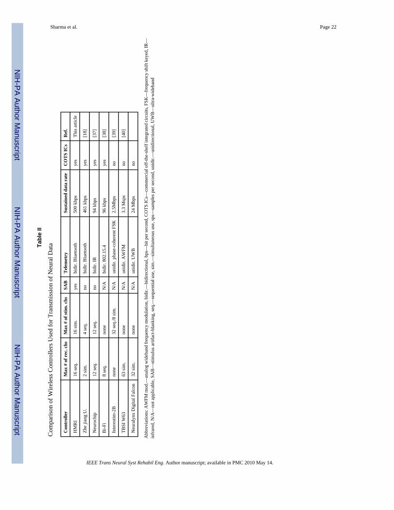
IV. DiscussionWe designed and tested a novel bidirectional telemetry controller for implementing flexibleprotocols of mutichannel neural stimulation and recording. While some of the previouscontrollers also utilize the COTS ICs and bidirectional telemetry, our device features severalunique capabilities, including the ability to simultaneously stimulate with up to 16 electrodeswith easily configurable controlled-current waveforms, recording of the stimulus voltagewaveforms, and the use of stimulus artifact-blanking for recording of evoked neuronal activityimmediately following the end of each stimulus pulse (Table II).
A key feature of our prototype is the completely independent control of the amplitude andtemporal interrelationship of the stimulus injected by each of the 16 stimulating electrode,enabling current steering that can be used for “sculpting” the spatial distribution of the stimulus[36].
The use of high-capacity rechargeable batteries in the wearable controller allowed us to utilizethe Bluetooth communication for up to 8 h of continuous bidirectional data transmission. TheBluetooth transmission rate of 0.5 Mb/s was considerably greater than is possible using analogRF telemetry and features automatic error detection and correction. The last three entries inTable II represent the controllers that provide a high number of stimulating or recordingchannels and high data throughput, but they are limited to unidirectional telemetry and do notprovide integration of recording and stimulation features. Moreover, these devices use
Sharma et al. Page 5
IEEE Trans Neural Syst Rehabil Eng. Author manuscript; available in PMC 2010 May 14.
NIH
-PA Author Manuscript
NIH
-PA Author Manuscript
NIH
-PA Author Manuscript
proprietary IC components, which make these systems considerably more expensive and lessflexible.
Another unique feature of our wireless device is the ability to record the stimulus voltagewaveforms, allowing regular and frequent monitoring of the stimulating electrode's impedance.The computer-based controller can be programmed to automatically turn off the stimulationat an individual site if a sudden increase or decrease in the site's impedance is detected.
The addition of the stimulus artifact-blanking circuitry into the ENR subsystem significantlyimproved the ability to record the neuronal activity immediately following the stimulus pulse.Other devices lacking the stimulus blanking, such as the Neurochip, employ rapid-recoveryamplifiers that remain saturated for 100–150 μs following each stimulation pulse [41]. Incontrast, the blanking circuitry on our device protects the amplifiers from saturation by stimulusartifacts and makes them available for recording within 15 μs after the end of the stimuluspulse. Monitoring of early neuronal responses is especially important in evaluating neuralstructures in which there is a short latency of action potential propagation between the sites ofstimulation and recording. In the feline brainstem, for example, the distance between theinferior colliculus and the cochlear nucleus is a few mm and the onset of the evoked responsewas seen at less than 0.5 ms after the end of the stimulus pulse.
In summary, we have demonstrated a bidirectional telemetry controller with a flexible andscalable design, user-friendly computer interface, and a set of features that are should expeditein vivo animal testing during the development of neuroprosthetic devices.
Supplementary MaterialRefer to Web version on PubMed Central for supplementary material.
AcknowledgmentsPreparation of the multisite silicon probes (probe grinding and cleaning) was performed by V. Cheng. Assembly ofthe probes into arrays was done by N. Kuleviciute. Electroplating and laser processes were performed by Y. Smirnova.The authors would like to thank E. Smith for surgical assistance and J. E. Lemke and F. Prater for animal care. Theanimal studies were conducted under a protocol approved by the HMRI Animal Care and Use Committee, accordingto the standards set forth in the Guide for the Care and Use of Laboratory Animals. HMRI has an animal use assuranceon file with the National Institutes of Health (A3606-01).
This work of D. B. McCreery was provided by the National Institutes of Health (NIH) under Grant R01-DC009643and Grant R01-NS054121. The work of V. Pikov was supported by the NIH under Grant R01-NS057287.
References1. Fayad JN, Otto SR, Shannon RV, et al. Neural interface for hearing restoration: Cochlear and brain
stem implants. Proc IEEE Jul;2008 96(no. 7):1085–1095.2. Weiland JD, Humayun MS. Visual prosthesis. Proc IEEE Jul;2008 96(no. 7):1076–1084.3. Liker MA, Won DS, Rao VY, et al. Deep brain stimulation: An evolving technology. Proc IEEE Jul;
2008 96(no. 7):1129–1141.4. Amar AP, Levy ML, Liu CY, et al. Vagus nerve stimulation. Proc IEEE Jul;2008 96(no. 7):1142–
1151.5. Lin V, Hsiao IN. Functional neuromuscular stimulation of the respiratory muscles for patients with
spinal cord injury. Proc IEEE Jul;2008 96(no. 7):1096–1107.6. Pikov V. Clinical applications of intraspinal microstimulation. Proc IEEE Jul;2008 96(no. 7):1120–
1128.7. He J, Ma C, Herman R. Engineering neural interfaces for rehabilitation of lower limb function in spinal
cord injured. Proc IEEE Jul;2008 96(no. 7):1152–1166.
Sharma et al. Page 6
IEEE Trans Neural Syst Rehabil Eng. Author manuscript; available in PMC 2010 May 14.
NIH
-PA Author Manuscript
NIH
-PA Author Manuscript
NIH
-PA Author Manuscript
8. Donoghue JP, Nurmikko A, Black M, et al. Assistive technology and robotic control using motor cortexensemble-based neural interface systems in humans with tetraplegia. J Physiol Mar 15;2007 579(pt.3):603–611. [PubMed: 17272345]
9. Loeb GE, Richmond FJ, Baker LL. The BION devices: Injectable interfaces with peripheral nervesand muscles. Neurosurg Focus 2006;20(no. 5):E2. [PubMed: 16711659]
10. Moxon, KA.; Morizio, J.; Chapin, JK., et al. Designing a brain-machine interface for neuroprostheticcontrol. In: Moxon, KA.; Chapin, JK., editors. Neural Prostheses for Restoration of Sensory andMotor Function. Boca Raton Fl: CRC Press; 2000.
11. Kimmich, HP. Biotelemetry. In: Webster, JG., editor. Encyclopedia of Medical Devices andInstrumentation Biotelemetry. New York: Wiley; 1988. p. 409-425.
12. Proakis, JG.; Salehi, M. Communication Systems Engineering. 2. Englewood Cliffs, Nj: PrenticeHall; 2001.
13. Zierhofer CM, Hochmair IJ, Hochmair ES. The advanced Combi 40+ cochlear implant. Am J OtolNov;1997 18(no. 6):S37–S38. [PubMed: 9391589]
14. Brown CJ, Abbas PJ, Gantz BJ. Preliminary experience with neural response telemetry in the nucleusCI24M cochlear implant. Am J Otol May;1998 19(no. 3):320–327. [PubMed: 9596182]
15. Suaning GJ, Lovell NH. CMOS neurostimulation ASIC with 100 channels, scaleable output, andbidirectional radio-frequency telemetry. IEEE Trans Biomed Eng Feb;2001 48(no. 2):248–260.[PubMed: 11296881]
16. Ritchie A, Howard W. Recent developments and likely advances in lithium-ion batteries. J PowerSources 2006;162(no. 2):809–812.
17. Hao Y, Foster R. Wireless body sensor networks for health-monitoring applications. Physiol MeasNov;2008 29(no. 11):R27–R56. [PubMed: 18843167]
18. Ye X, Wang P, Liu J, et al. A portable telemetry system for brain stimulation and neuronal activityrecording in freely behaving small animals. J Neurosci Methods Sep 30;2008 174(no. 2):186–193.[PubMed: 18674564]
19. Erasala N, Yen DC. Bluetooth technology: A strategic analysis of its role in global 3G wirelesscommunication era. Computer Standards Interfaces 2002;24(no. 3):193–206.
20. Cogan SF. Neural stimulation and recording electrodes. Annu Rev Biomed Eng 2008;10:275–309.[PubMed: 18429704]
21. Robblee LS, Lefko J, Brummer SB. Activated IR: An electrode suitable for reversible charge injectionin saline solution. J Electrochem Soc 1983;130:731–733.
22. McCreery DB, Agnew WF, Yuen TG, et al. Charge density and charge per phase as cofactors inneural injury induced by electrical stimulation. IEEE Trans Biomed Eng Oct;1990 37(no. 10):996–1001. [PubMed: 2249872]
23. McCreery DB, Bullara LA, Agnew WF. Neuronal activity evoked by chronically implantedintracortical microelectrodes. Exp Neurol 1986;92(no. 1):147–161. [PubMed: 3956646]
24. McCreery DB, Yuen TG, Agnew WF, et al. Stimulation with chronically implanted microelectrodesin the cochlear nucleus of the cat: Histologic and physiologic effects. Hear Res 1992;62(no. 1):42–56. [PubMed: 1429250]
25. McCreery DB, Yuen TG, Agnew WF, et al. Stimulus parameters affecting tissue injury duringmicrostimulation in the cochlear nucleus of the cat. Hear Res 1994;77(no. 1–2):105–115. [PubMed:7928722]
26. McCreery DB, Yuen TG, Agnew WF, et al. A characterization of the effects on neuronal excitabilitydue to prolonged microstimulation with chronically implanted microelectrodes. IEEE Trans BiomedEng Oct;1997 44(no. 10):931–939. [PubMed: 9311162]
27. McCreery DB, Yuen TG, Bullara LA. Chronic microstimulation in the feline ventral cochlear nucleus:Physiologic and histologic effects. Hear Res 2000;149(no. 1–2):223–238. [PubMed: 11033261]
28. McCreery D, Pikov V, Lossinsky A, et al. Arrays for chronic functional microstimulation of thelumbosacral spinal cord. IEEE Trans Neural Syst Rehabil Eng Jun;2004 12(no. 2):195–207.[PubMed: 15218934]
29. McCreery DB, Agnew WF, Bullara LA. The effects of prolonged intracortical microstimulation onthe excitability of pyramidal tract neurons in the cat. Ann Biomed Eng 2002;30(no. 1):107–119.[PubMed: 11874134]
Sharma et al. Page 7
IEEE Trans Neural Syst Rehabil Eng. Author manuscript; available in PMC 2010 May 14.
NIH
-PA Author Manuscript
NIH
-PA Author Manuscript
NIH
-PA Author Manuscript
30. McCreery D, Lossinsky A, Pikov V. Performance of multisite silicon microprobes implantedchronically, in the ventral cochlear nucleus of the cat. IEEE Trans Biomed Eng Jun;2007 54(no. 6):1042–1052. [PubMed: 17554823]
31. McCreery D, Lossinsky A, Pikov V, et al. A microelectrode array for chronic deep brain stimulationand recording. IEEE Trans Biomed Eng Apr;2006 53(no. 4):726–737. [PubMed: 16602580]
32. Pikov V, Bullara L, McCreery DB. Intraspinal stimulation for bladder voiding in cats before and afterchronic spinal cord injury. J Neural Eng 2007;4(no. 4):356–368. [PubMed: 18057503]
33. Han, M.; Bullara, LA.; McCreery, DB. Proc BMES Meeting. Los Angeles, CA: 2007. Developmentof a robust chronic neural probe; p. P2-146.
34. McCreery DB. Cochlear nucleus auditory prostheses. Hear Res Aug;2008 242(no. 1–2):64–73.[PubMed: 18207678]
35. Tykocinski M, Cohen LT, Cowan RS. Measurement and analysis of access resistance and polarizationimpedance in cochlear implant recipients. Otol Neurotol Sep;2005 26(no. 5):948–956. [PubMed:16151342]
36. Butson CR, McIntyre CC. Current steering to control the volume of tissue activated during deep brainstimulation. Brain Stimulat Jan;2008 1(no. 1):7–15. [PubMed: 19142235]
37. Jackson A, Moritz CT, Mavoori J, et al. The neurochip BCI: Towards a neural prosthesis for upperlimb function. IEEE Trans Neural Syst Rehabil Eng Jun;2006 14(no. 2):187–190. [PubMed:16792290]
38. Farshchi S, Pesterev A, Nuyujukian PH, et al. Bi-Fi: An embedded sensor/system architecture forREMOTE biological monitoring. IEEE Trans Inf Technol Biomed Nov;2007 11(no. 6):611–618.[PubMed: 18046936]
39. Ghovanloo M, Najafi K. A wireless implantable multichannel microstimulating system-on-a-chipwith modular architecture. IEEE Trans Neural Syst Rehabil Eng Sep;2007 15(no. 3):449–457.[PubMed: 17894278]
40. Triangle-BioSystems. Neural Stimulation [Online]. Available:www.trianglebiosystems.com/Products/NeuralStimulation.aspx
41. Mavoori J, Millard B, Longnion J, et al. A miniature implantable computer for functional electricalstimulation and recording of neuromuscular activity. 2004 IEEE Int Workshop Biomed Circ Syst2004:S1.7.INV.13–S1.7.INV.16.
Sharma et al. Page 8
IEEE Trans Neural Syst Rehabil Eng. Author manuscript; available in PMC 2010 May 14.
NIH
-PA Author Manuscript
NIH
-PA Author Manuscript
NIH
-PA Author Manuscript
Biographies
Vishnu Sharma received the B.Eng. degree in I&C Eng. from the South Gujarat University,Surat, India, in 2002, and the M.S. in biomedical engineering from the Louisiana TechUniversity, Ruston, in 2007. His M.S. research involved developing finite element model tostudy the effects of concentric ring electrode electrical stimulation on the rat skin.
He worked as Biomedical Engineer at the Huntington Medical Research Institutes, Pasadena,CA, designing low power custom analog and digital circuits for stimulation and recording. His
Sharma et al. Page 9
IEEE Trans Neural Syst Rehabil Eng. Author manuscript; available in PMC 2010 May 14.
NIH
-PA Author Manuscript
NIH
-PA Author Manuscript
NIH
-PA Author Manuscript
research interests include neural prostheses, functional electrical stimulation, and obstructivesleep apnea.
Douglas B. McCreery received the B.S. in electrical engineering and the Ph.D. degree inbiomedical engineering from the University of Connecticut, in 1966 in 1975, respectively. Hecompleted his postdoctoral training in neurosurgery and neurophysiology at the University ofMinnesota.
He joined the Huntington Medical Research Institutes, Pasadena, CA, in 1979 and became theDirector of the Neural Engineering Program in 2001. His research interests include thedevelopment of sensory and motor neuroprostheses and devices for neuromodulation of thecentral nervous system, and the physiologic and histologic effects of electrical stimulation ofthe central and peripheral nervous systems.
Martin Han (M'04) received the B.S. degree in electrical engineering from the University ofHawaii at Manoa, Honolulu, HI, in 1996, and the M.S. degree in electrical engineering and thePh.D. degree in biomedical engineering from the University of Southern California, LosAngeles, in 2000 and 2003, respectively. His Ph.D. dissertation focused on the developmentof planar microelectrode arrays for recording and stimulation in hippocampal tissue slices inthe development of cognitive prosthesis.
Since 2003, he is a Staff Scientist in the Neural Engineering Program at Huntington MedicalResearch Institutes, Pasadena, CA. His research interests include development of silicon- andbiodegradable polymer-based chronically-implantable microelectrode arrays using bio-MEMS technology for treatment of neurological disorders such as profound hearing loss,Parkinson's disease, and spinal cord injury.
Dr. Han is a member of the Eta Kappa Nu, Society for Neuroscience, and American Associationfor the Advancement of Science.
Sharma et al. Page 10
IEEE Trans Neural Syst Rehabil Eng. Author manuscript; available in PMC 2010 May 14.
NIH
-PA Author Manuscript
NIH
-PA Author Manuscript
NIH
-PA Author Manuscript
Victor Pikov received the BA. degree (cum laude) in biopsychology and computer sciencesat Vassar College, Poughkeepsie, NY, and the Ph.D. degree in cell biology and neurosciencefrom Georgetown University, Washington, DC. He completed the postdoctoral training inmolecular biology at the California Institute of Technology, Pasadena, in 2002.
He joined the Neural Engineering Laboratory at Huntington Medical Research Institutes(HMRI), Pasadena, CA. At HMRI, he works as a Neurophysiologist and Neural Engineer andsince 2005 also as a Director of the Summer Undergraduate Research Program. His researchinterests include the evaluation of efficacy and safety of electrical and electromagneticstimulation in the central nervous system, with an emphasis on the spinal control of bladder
Sharma et al. Page 11
IEEE Trans Neural Syst Rehabil Eng. Author manuscript; available in PMC 2010 May 14.
NIH
-PA Author Manuscript
NIH
-PA Author Manuscript
NIH
-PA Author Manuscript
function, brainstem involvement in tinnitus, and corticospinal excitability in stroke. In additionto his research duties, he is a founder and co-chair of the International Conferences onNeuroprosthetic Devices in Taiwan and China and an Associate Editor for the journal Frontiersin Neuroprosthetics.
Sharma et al. Page 12
IEEE Trans Neural Syst Rehabil Eng. Author manuscript; available in PMC 2010 May 14.
NIH
-PA Author Manuscript
NIH
-PA Author Manuscript
NIH
-PA Author Manuscript
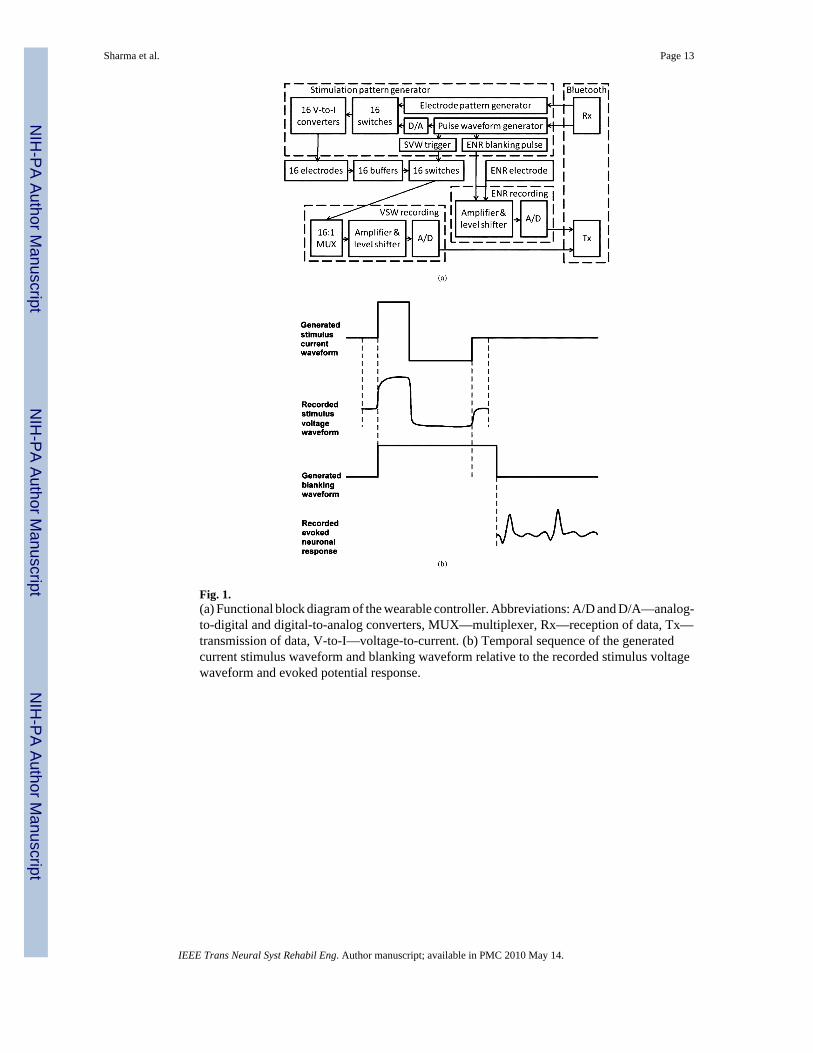
Fig. 1.(a) Functional block diagram of the wearable controller. Abbreviations: A/D and D/A—analog-to-digital and digital-to-analog converters, MUX—multiplexer, Rx—reception of data, Tx—transmission of data, V-to-I—voltage-to-current. (b) Temporal sequence of the generatedcurrent stimulus waveform and blanking waveform relative to the recorded stimulus voltagewaveform and evoked potential response.
Sharma et al. Page 13
IEEE Trans Neural Syst Rehabil Eng. Author manuscript; available in PMC 2010 May 14.
NIH
-PA Author Manuscript
NIH
-PA Author Manuscript
NIH
-PA Author Manuscript
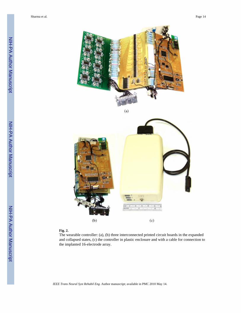
Fig. 2.The wearable controller: (a), (b) three interconnected printed circuit boards in the expandedand collapsed states, (c) the controller in plastic enclosure and with a cable for connection tothe implanted 16-electrode array.
Sharma et al. Page 14
IEEE Trans Neural Syst Rehabil Eng. Author manuscript; available in PMC 2010 May 14.
NIH
-PA Author Manuscript
NIH
-PA Author Manuscript
NIH
-PA Author Manuscript
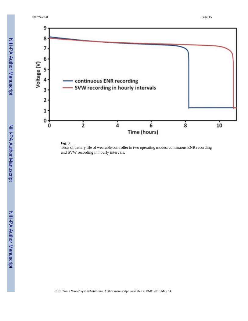
Fig. 3.Tests of battery life of wearable controller in two operating modes: continuous ENR recordingand SVW recording in hourly intervals.
Sharma et al. Page 15
IEEE Trans Neural Syst Rehabil Eng. Author manuscript; available in PMC 2010 May 14.
NIH
-PA Author Manuscript
NIH
-PA Author Manuscript
NIH
-PA Author Manuscript
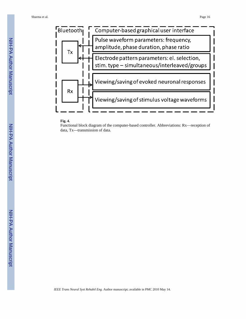
Fig. 4.Functional block diagram of the computer-based controller. Abbreviations: Rx—reception ofdata, Tx—transmission of data.
Sharma et al. Page 16
IEEE Trans Neural Syst Rehabil Eng. Author manuscript; available in PMC 2010 May 14.
NIH
-PA Author Manuscript
NIH
-PA Author Manuscript
NIH
-PA Author Manuscript
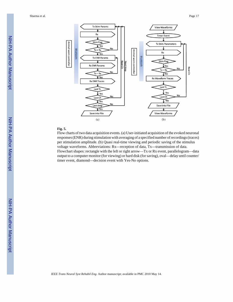
Fig. 5.Flow charts of two data acquisition events. (a) User-initiated acquisition of the evoked neuronalresponses (ENR) during stimulation with averaging of a specified number of recordings (traces)per stimulation amplitude. (b) Quasi real-time viewing and periodic saving of the stimulusvoltage waveforms. Abbreviations: Rx—reception of data, Tx—transmission of data.Flowchart shapes: rectangle with the left or right arrow—Tx or Rx event, parallelogram—dataoutput to a computer monitor (for viewing) or hard disk (for saving), oval—delay until counter/timer event, diamond—decision event with Yes-No options.
Sharma et al. Page 17
IEEE Trans Neural Syst Rehabil Eng. Author manuscript; available in PMC 2010 May 14.
NIH
-PA Author Manuscript
NIH
-PA Author Manuscript
NIH
-PA Author Manuscript
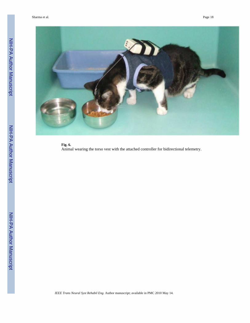
Fig. 6.Animal wearing the torso vest with the attached controller for bidirectional telemetry.
Sharma et al. Page 18
IEEE Trans Neural Syst Rehabil Eng. Author manuscript; available in PMC 2010 May 14.
NIH
-PA Author Manuscript
NIH
-PA Author Manuscript
NIH
-PA Author Manuscript
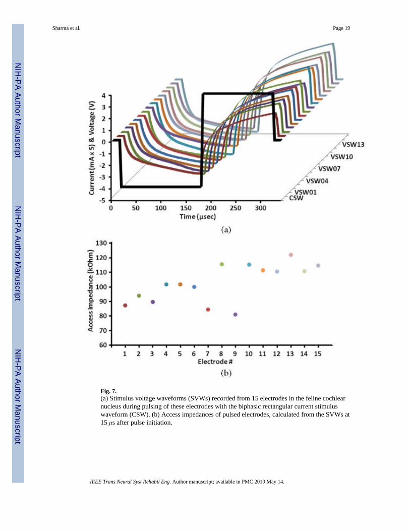
Fig. 7.(a) Stimulus voltage waveforms (SVWs) recorded from 15 electrodes in the feline cochlearnucleus during pulsing of these electrodes with the biphasic rectangular current stimuluswaveform (CSW). (b) Access impedances of pulsed electrodes, calculated from the SVWs at15 μs after pulse initiation.
Sharma et al. Page 19
IEEE Trans Neural Syst Rehabil Eng. Author manuscript; available in PMC 2010 May 14.
NIH
-PA Author Manuscript
NIH
-PA Author Manuscript
NIH
-PA Author Manuscript
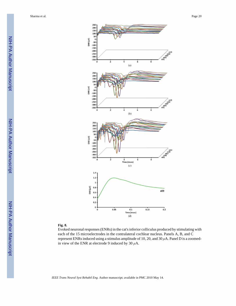
Fig. 8.Evoked neuronal responses (ENRs) in the cat's inferior colliculus produced by stimulating witheach of the 15 microelectrodes in the contralateral cochlear nucleus. Panels A, B, and Crepresent ENRs induced using a stimulus amplitude of 10, 20, and 30 μA. Panel D is a zoomed-in view of the ENR at electrode 9 induced by 30 μA.
Sharma et al. Page 20
IEEE Trans Neural Syst Rehabil Eng. Author manuscript; available in PMC 2010 May 14.
NIH
-PA Author Manuscript
NIH
-PA Author Manuscript
NIH
-PA Author Manuscript
NIH
-PA Author Manuscript
NIH
-PA Author Manuscript
NIH
-PA Author Manuscript
Sharma et al. Page 21
Table I
Functionality of the integrated chip (IC) components in the wearable controller (In the order of decreasing powerconsumption).
Component IC model, company Key IC features Current, mA Power cons., mW
Bluetooth communication F2M03GLA, Free2move Bluetooth V.2.0+EDR, UART 44/22* 145/73*
Rx from Bluetooth, PWG &EPG
PIC18F4620, Microchip Tech. 3K RAM, 1K EEPROM, UART,SPI
21/10* 105/50*
Tx to Bluetooth PIC18F2620, Microchip Tech. 3K RAM, 1K EEPROM, UART,SPI
21/10* 105/50*
16-ch. V-to-I converter(Howland pump)
TLV2741 × 8, Texas Instruments R-R output, high GBW & SR 3.2 per ch. 19 per ch.
D/A converter TLV5626, Texas Instruments 8 bit, 0.28/sec, SPI 3.7 18.5
Amplifier & voltage shifter TLV271 × 2, Texas Instruments R-R output, high GBW & SR 1.1 17.6
A/D converter ADS7886, Texas Instruments 12 bit, 1 Ms/sec, SPI 1.5 7.5
16-ch. analog switch forelectrode grounding
PS393 × 4, Pericom Low leakage current (<2 pA) 0.004 0.064
16-ch. analog switch forstimulation selection
PS393 x 4, Pericom Low leakage current (<2 pA) 0.004 0.064
16:1 analog MUX forrecording selection
MAX396, Maxim Low leakage current (30 pA) 0.001 0.016
Total 96/52* 418/236*
In the Current and Power consumption columns, the second value, marked by asterisk (*), indicates an idle state. Abbreviations: A/D—analog-to-digital, consump.—consumption, D/A—digital-to-analog, EDR—Enhanced Data Rate, GBW—gain bandwidth product, Ms—megasamples; PWG& EPG—pulse waveform generator and electrode pattern generator, SPI—serial peripheral interface bus, SR—slew rate, R-R—rail-to-rail, Tx—transmission of data, UART—universal asynchronous receiver/transmitter bus, V-to-I—voltage-to-current
IEEE Trans Neural Syst Rehabil Eng. Author manuscript; available in PMC 2010 May 14.
NIH
-PA Author Manuscript
NIH
-PA Author Manuscript
NIH
-PA Author Manuscript
Sharma et al. Page 22
Tabl
e II
Com
paris
on o
f Wire
less
Con
trolle
rs U
sed
for T
rans
mis
sion
of N
eura
l Dat
a
Con
trol
ler
Max
# o
f rec
. chs
Max
# o
f stim
. chs
SAB
Tel
emet
rySu
stai
ned
data
rat
eC
OT
S IC
sR
ef.
HM
RI
16 se
q.16
sim
.ye
sbi
dir.
Blu
etoo
th50
0 kb
psye
sTh
is a
rticl
e
Zhe
jiang
U.
2 si
m.
4 se
q.no
bidi
r. B
luet
ooth
461
kbps
yes
[18]
Neu
roch
ip12
seq.
12 se
q.no
bidi
r. IR
94 k
bps
yes
[37]
Bi-F
i8
seq.
none
N/A
bidi
r. 80
2.15
.496
kbp
sye
s[3
8]
Inte
rest
im-2
Bno
ne32
seq.
/8 si
m.
N/A
unid
ir. p
hase
-coh
eren
t FSK
2.5M
bps
no[3
9]
TBSI
W63
63 si
m.
none
N/A
unid
ir. A
WFM
3.3
Msp
sno
[40]
Neu
raly
nx D
igita
l Fal
con
32 si
m.
none
N/A
unid
ir. U
WB
24 M
bps
no
Abb
revi
atio
ns: A
WFM
mod
.—an
alog
wid
eban
d fr
eque
ncy
mod
ulat
ion,
bid
ir.—
bidi
rect
iona
l, bp
s—bi
t per
seco
nd, C
OTS
ICs—
com
mer
cial
off
-the-
shel
f int
egra
ted
circ
uits
, FSK
—fr
eque
ncy
shift
key
ed, I
R—
infr
ared
, N/A
—no
t app
licab
le, S
AB
—st
imul
us a
rtifa
ct-b
lank
ing,
seq.
—se
quen
tial u
se, s
im.—
sim
ulta
neou
s use
, sps
—sa
mpl
es p
er se
cond
, uni
dir.—
unid
irect
iona
l, U
WB
—ul
tra-w
ideb
and
IEEE Trans Neural Syst Rehabil Eng. Author manuscript; available in PMC 2010 May 14.


