Embed Size (px)
Citation preview

Structural analysis II
Beams and frames having nonprismatic members
Instructor:
Dr. Sawsan Alkhawaldeh
Department of Civil Engineering
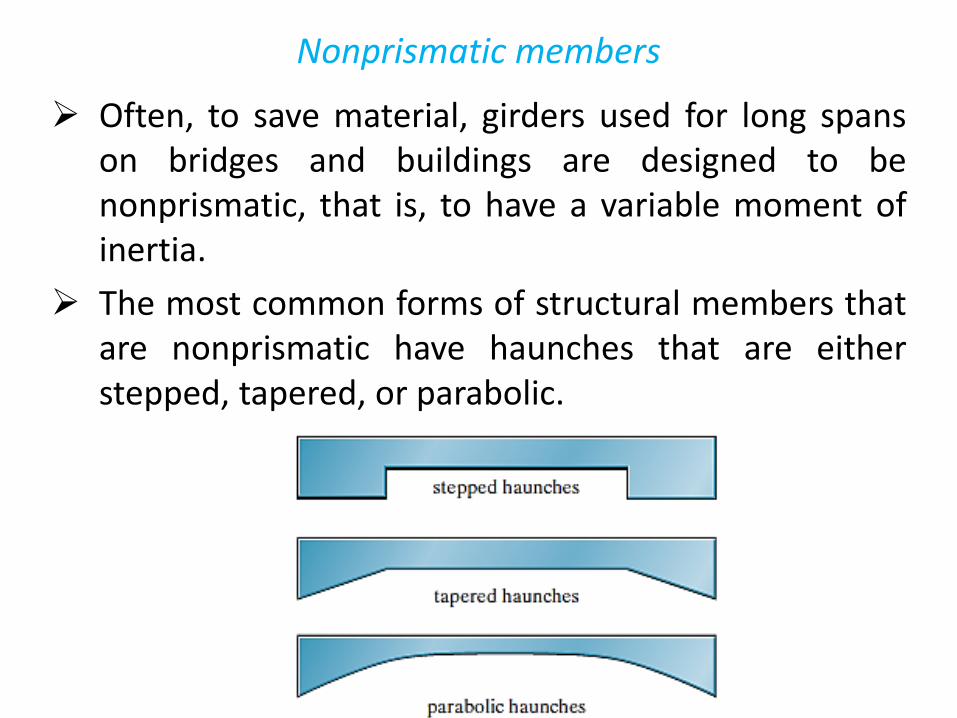
Nonprismatic members
Often, to save material, girders used for long spans on bridges and buildings are designed to be nonprismatic, that is, to have a variable moment of inertia.
The most common forms of structural members that are nonprismatic have haunches that are either stepped, tapered, or parabolic.

Nonprismatic members
If the slope deflection equations or moment distribution are used to determine the reactions on a nonprismatic member, then we must calculate the following properties for the member:
- Fixed-End Moments (FEM).
- Stiffness Factor (K ).
- Carry-Over Factor (COF ).
Once obtained, the computations for the stiffness and carry-over factors can be checked, by noting an important relationship that exists between them.
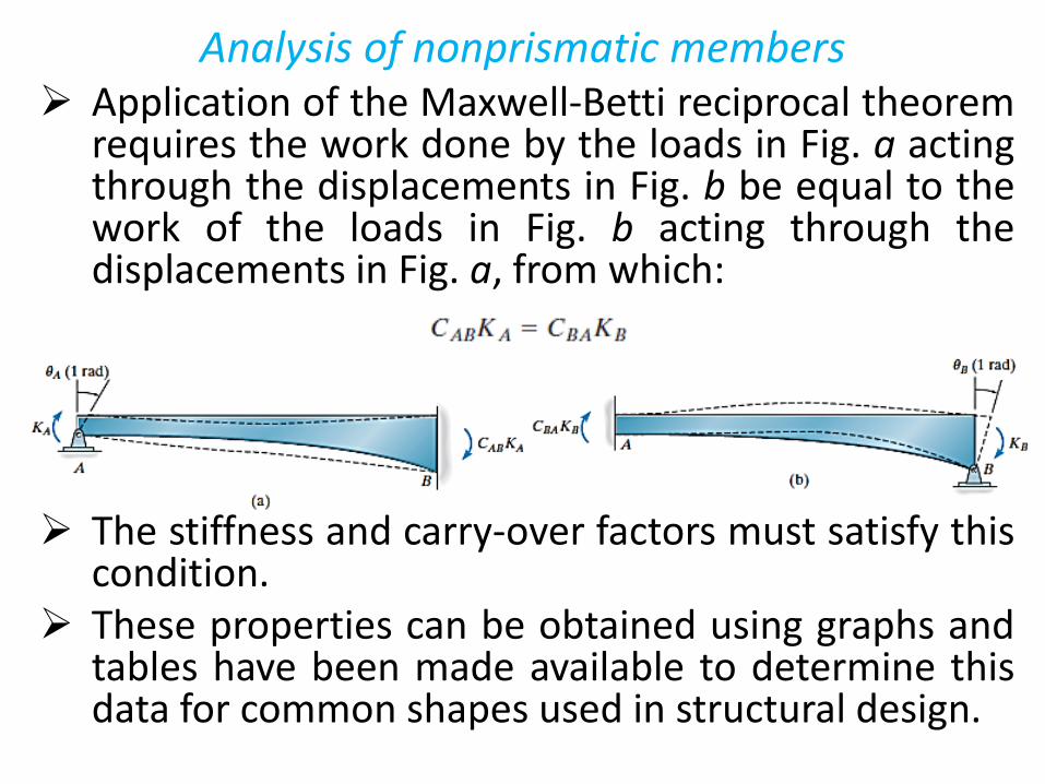
Analysis of nonprismatic members Application of the Maxwell-Betti reciprocal theorem
requires the work done by the loads in Fig. a acting through the displacements in Fig. b be equal to the work of the loads in Fig. b acting through the displacements in Fig. a, from which:
The stiffness and carry-over factors must satisfy this condition.
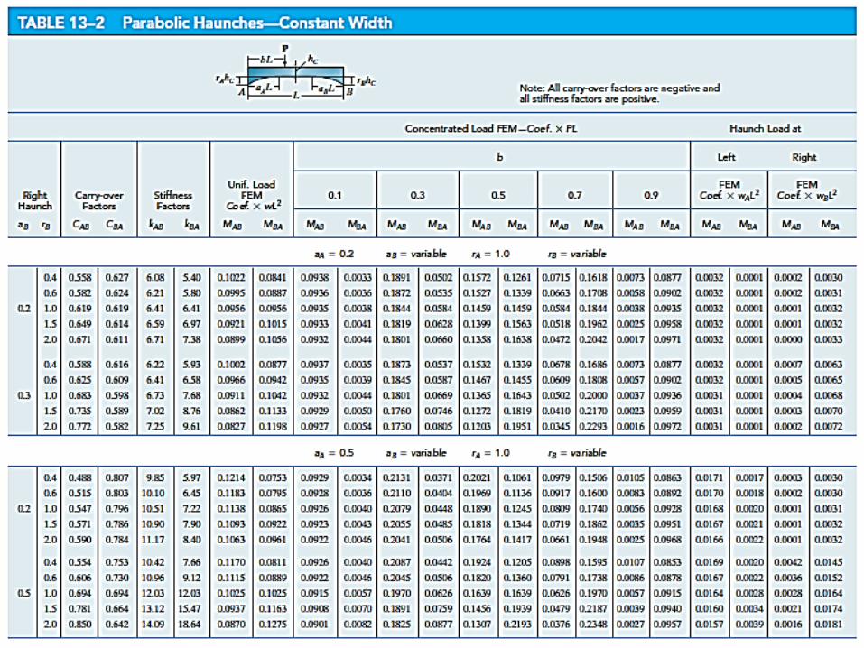
These properties can be obtained using graphs and tables have been made available to determine this data for common shapes used in structural design.
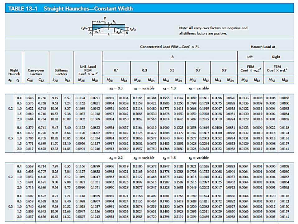
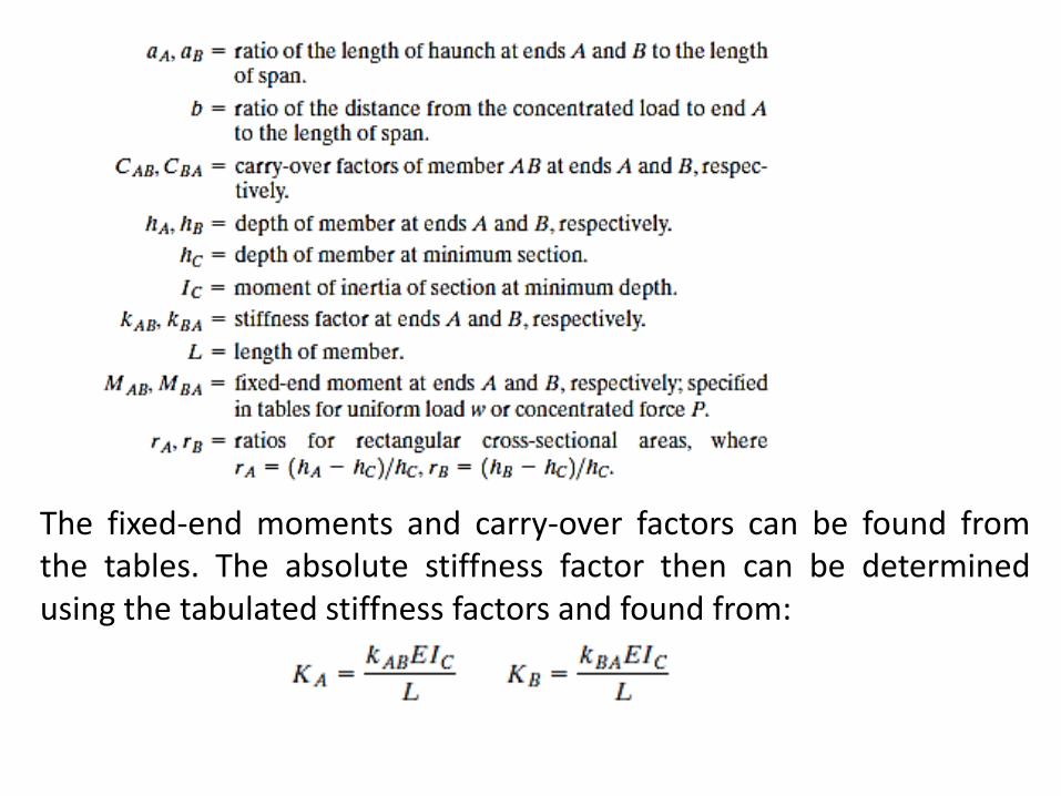
The fixed-end moments and carry-over factors can be found from the tables. The absolute stiffness factor then can be determined using the tabulated stiffness factors and found from:
Moment Distribution for Structures Having Nonprismatic Members
Once the fixed-end moments and stiffness and carry-over factors for the nonprismatic members of a structure have been determined, application of the moment-distribution method follows the same procedure as outlined in Chapter 12.
The distribution of moments may be shortened if a member stiffness factor is modified to account for conditions of end-span pin support and structure symmetry or antisymmetry. Similar modifications can also be made to nonprismatic members.
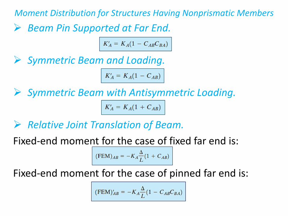
Moment Distribution for Structures Having Nonprismatic Members
Beam Pin Supported at Far End.
Symmetric Beam and Loading.
Symmetric Beam with Antisymmetric Loading.
Relative Joint Translation of Beam.
Fixed-end moment for the case of fixed far end is:
Fixed-end moment for the case of pinned far end is:
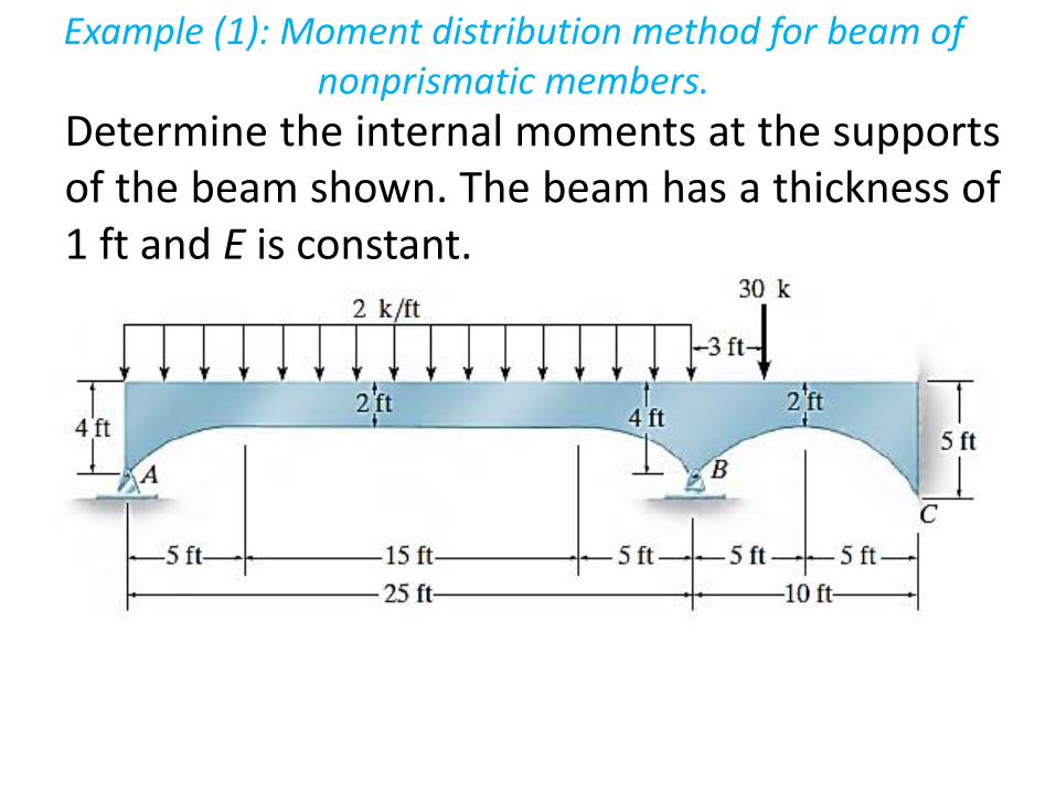
Example (1): Moment distribution method for beam of nonprismatic members.
Determine the internal moments at the supports of the beam shown. The beam has a thickness of 1 ft and E is constant.
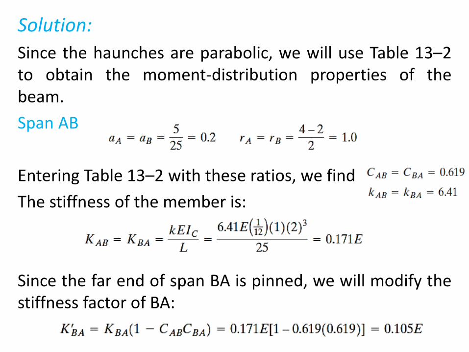
Solution:
Since the haunches are parabolic, we will use Table 13–2 to obtain the moment-distribution properties of the beam.
Span AB
Entering Table 13–2 with these ratios, we find
The stiffness of the member is:
Since the far end of span BA is pinned, we will modify the stiffness factor of BA:
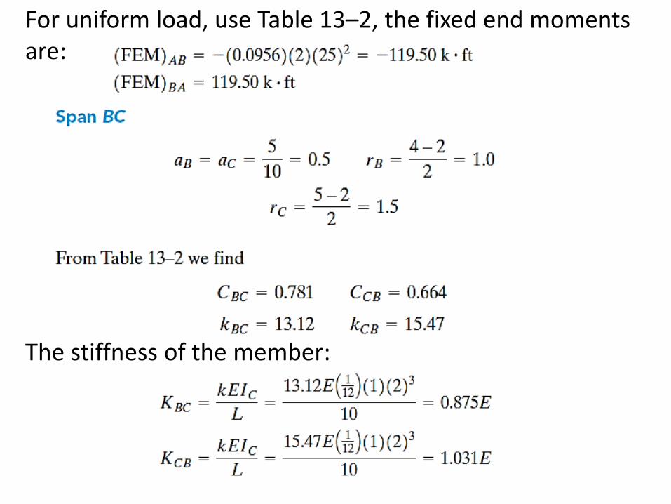
For uniform load, use Table 13–2, the fixed end moments are:
The stiffness of the member:
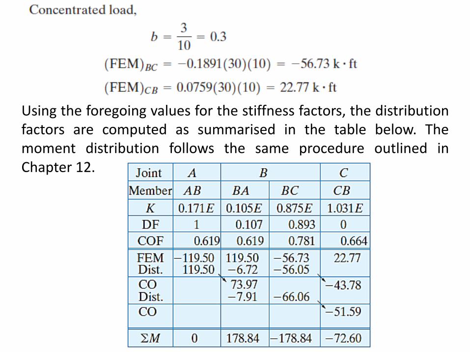
Using the foregoing values for the stiffness factors, the distribution factors are computed as summarised in the table below. The moment distribution follows the same procedure outlined in Chapter 12.
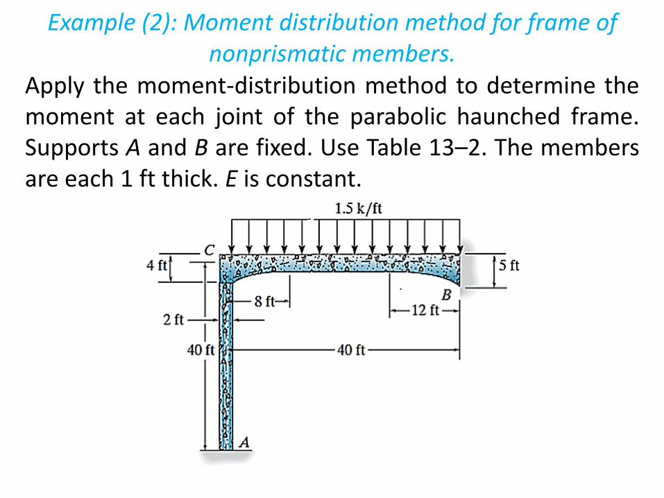
Example (2): Moment distribution method for frame of nonprismatic members.
Apply the moment-distribution method to determine the moment at each joint of the parabolic haunched frame. Supports A and B are fixed. Use Table 13–2. The members are each 1 ft thick. E is constant.
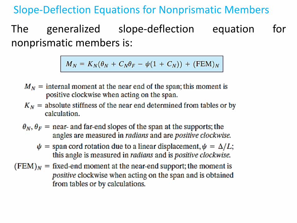
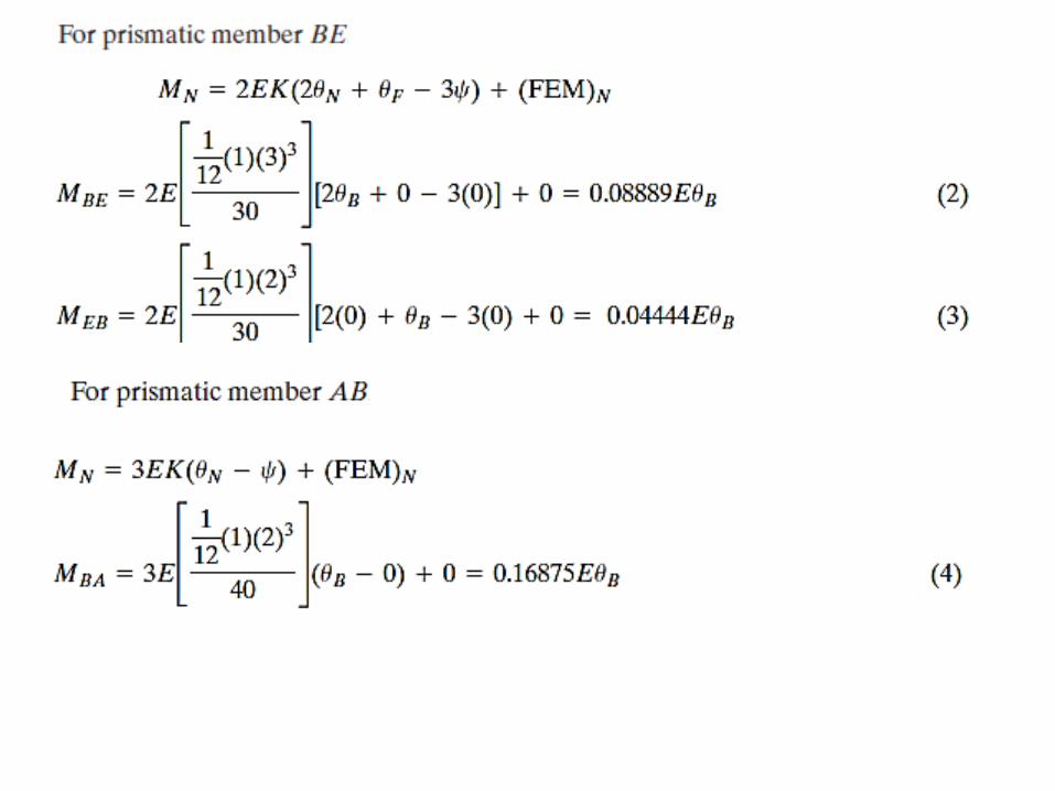
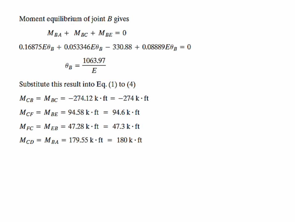
Slope-Deflection Equations for Nonprismatic Members
The generalized slope-deflection equation for nonprismatic members is:
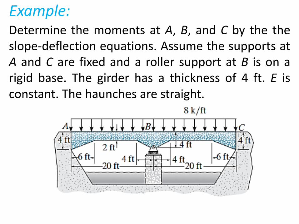
Example: Determine the moments at A, B, and C by the the slope-deflection equations. Assume the supports at A and C are fixed and a roller support at B is on a rigid base. The girder has a thickness of 4 ft. E is constant. The haunches are straight.
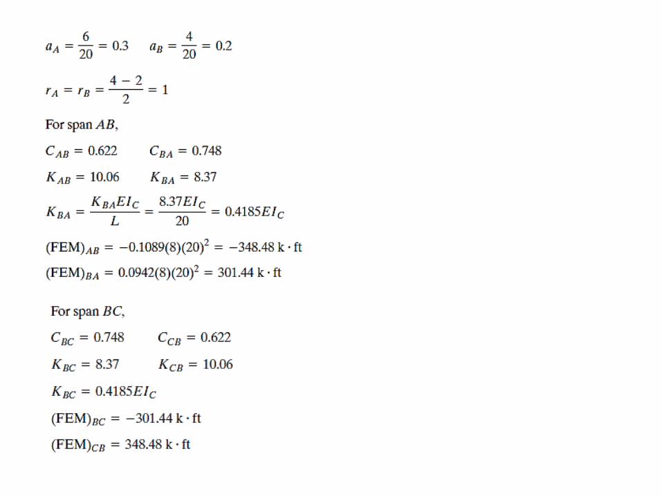
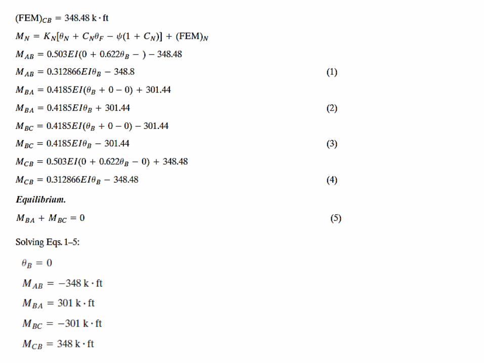

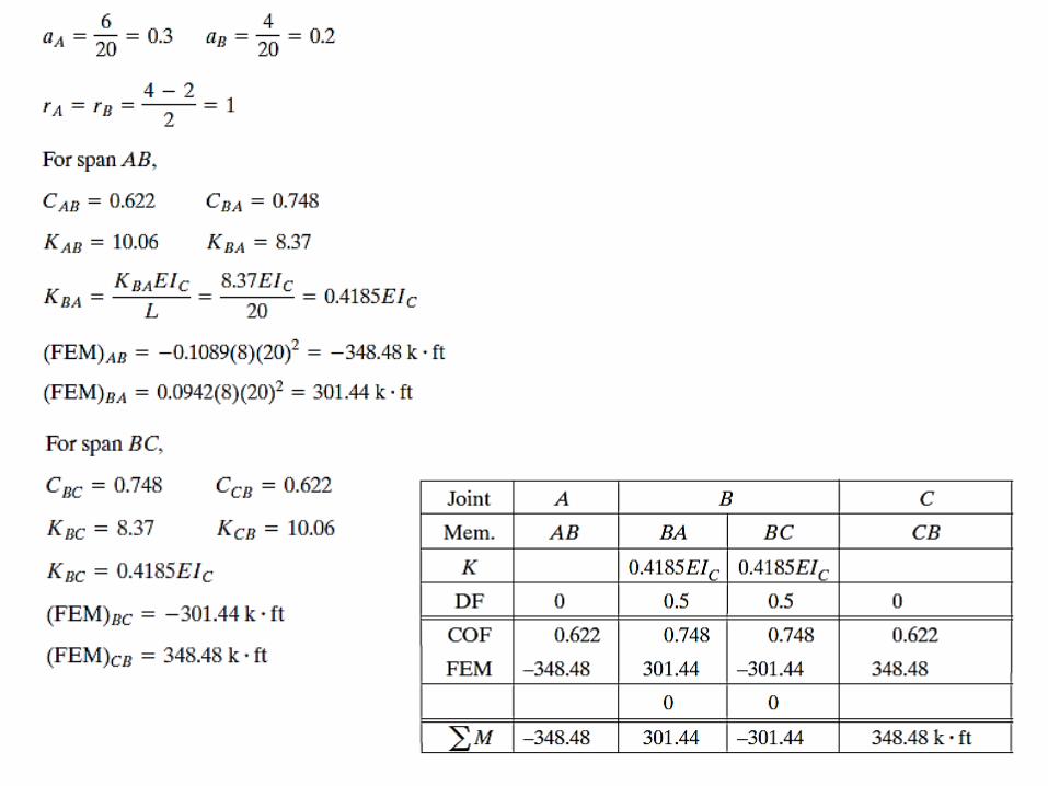
Example: Determine the moments at A, B, and C by the the moment distribution method. Assume the supports at A and C are fixed and a roller support at B is on a rigid base. The girder has a thickness of 4 ft. E is constant. The haunches are straight.
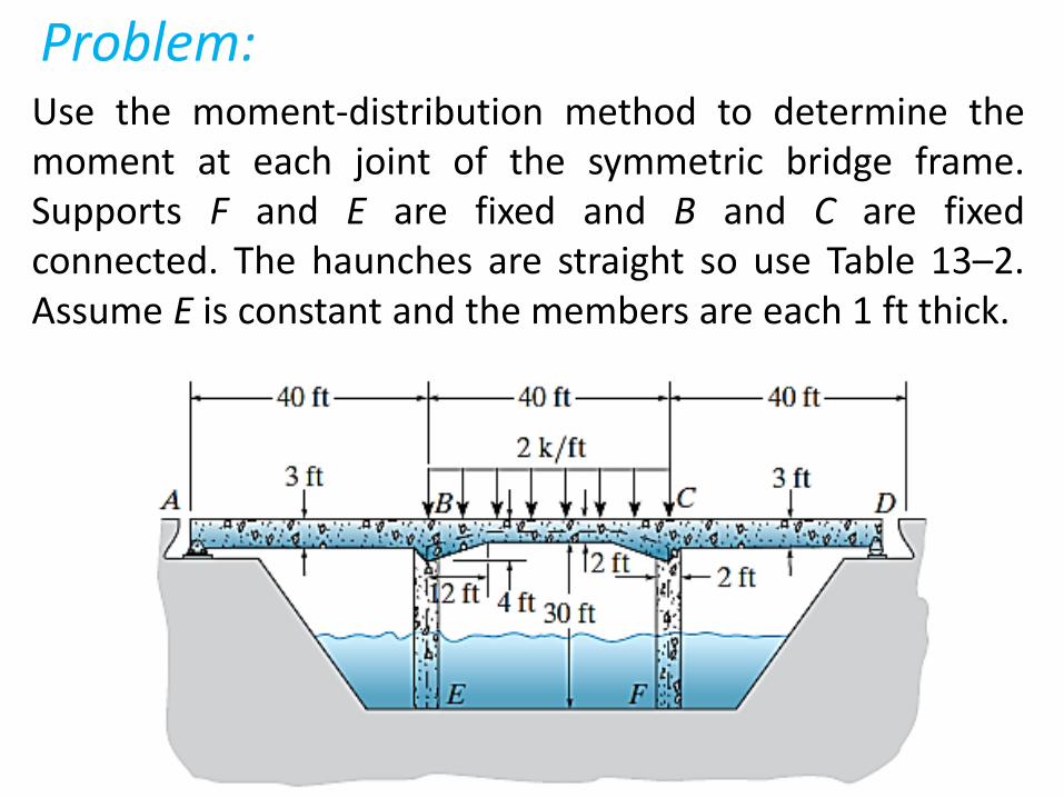
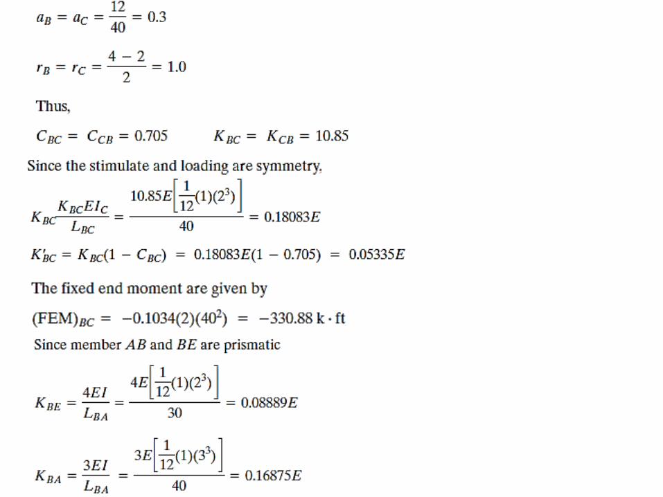
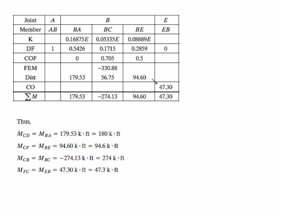
Problem: Use the moment-distribution method to determine the moment at each joint of the symmetric bridge frame. Supports F and E are fixed and B and C are fixed connected. The haunches are straight so use Table 13–2. Assume E is constant and the members are each 1 ft thick.
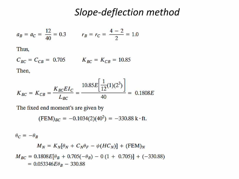
Slope-deflection method