Embed Size (px)
Citation preview

BattenLok® HSMechanically Seamed Roof System
Technical Installation Information
IMPORTANT NOTICEREAD THIS MANUAL COMPLETELY PRIOR TO BEGINNING THE INSTALLATION OF THE BattenLok® HSROOFING SYSTEM. THE MANUFACTURER DETAILS MUST BE FOLLOWED AS A MINIMUM TO INSUREAPPROPRIATE WARRANTIES WILL BE ISSUED.
ALWAYS INSPECT EACH AND EVERY PANEL AND ALL ACCESSORIES BEFORE INSTALLATION. NEVERINSTALL ANY PRODUCT IF ITS QUALITY IS IN QUESTION. NOTIFY MBCI IMMEDIATELY IF ANY PRODUCTIS BELIEVED TO BE OUT OF TOLERANCE, SPECIFICATION OR HAS BEEN DAMAGED DURING SHIP-MENT.
IF THERE IS A CONFLICT BETWEEN PROJECT INSTALLATION DRAWINGS PROVIDED OR APPROVED BYTHE MANUFACTURER AND DETAILS IN THIS MANUAL, PROJECT INSTALLATION DRAWINGS WILL TAKEPRECEDENCE.
Ice Dam DisclaimerMBCI designs it's standing seam roofs to meet the load requirements dictated by governing codes and project specifications,including applicable snow loads. However, MBCI expressly disclaims responsibilty for weathertightness or roof point loadingissues or other hazards resulting from ice dam situations. Any time ice and snow can melt on the main body of the roof andrefreeze at the eave or in the shadow of an adjacent wall, an ice dam situation may develop. In addition to local climate, icedam formation is affected by many other factors, including but not limited to, roof insulation R value, roof panel color, interiortemperature of building, heater location in building, eave overhangs, parapet walls, shading of building roof areas from adja-cent trees, parapets, buildings, etc. These factors are design and maintenance issues and are outside the control of MBCI.MBCI specifically disclaims any liability for damage due to ice dam formation, although the following issues should be takeninto consideration concerning standing seam roofs installed in freezing climates:
• Always use field seamed panels. These machine-folded seams are more durable when subjected to occasional icing.
• Eliminate "cold" eave overhangs and parapet walls from the building design. Roof overhangs outside the heatedenvelope of the building will tend to be colder than the roof areas over the heated envelope. Simple roof designs arepreferred. Parapet walls at the eave allow ice and snow to collect due to shading effects and the lower roof temper-atures caused thereby.
• Make sure the interior of the building is adequately insulated and the heating is properly distributed. Inadequate insu-lation in the roof and/or improper heat distribution causes heat flow though the main body of the roof. On days whenthe temperature is below freezing, this heat gain can cause ice and snow to melt and refreeze at the eave where theroof is colder.
• Lay out the building to prevent the eaves and other roof areas from being shaded during the winter. This may meaneliminating adjacent trees or reconsidering roof geometries.
• Consider using self-regulating heating cables at the eaves to mitigate the effects of ice dams.
• On building designs using attics, over-insulate the attic floor and provide adequate ventilation in the attic. This willreduce heat transfer through the roof resulting in more consistent roof temperatures between eave and field of roof.
• Increase the degree of diligence with respect to underlayment materials at roof areas prone to icing. This may includevalleys, eaves, dormers and roof areas near dormers, parapets and the like where shading may occur.
For more information on this subject, please refer to the MCA's Metal Roof Design For Cold Climates manual.
The Engineering data contained herein is for the expressed use of customers and design professionals. Along with this data, it is recommended that the designprofessional have a copy of the most current version of the North American Specification for the Design of Cold-Formed Steel Structural Members published bythe American Iron and Steel Institute to facilitate design. This Specification contains the design criteria for cold-formed steel components. Along with theSpecification, the designer should reference the most current building code applicable to the project jobsite in order to determine environmental loads. If furtherinformation or guidance regarding cold-formed design practices is desired, please contact the manufacturer
®Copyright NCI Group, Inc. All Rights Reserved 06-12
Descriptions and specifications contained herein were in effect at the time this publication was approved for printing. In a contin-uing effort to refine and improve products, MBCI reserves the right to discontinue products at any time or change specificationsand/or designs without incurring obligation. To ensure you have the latest information available, please inquire or visit ourwebsite at www.mbci.com. Application details are for illustration purposes only and may not be appropriate for all environmen-tal conditions, building designs or panel profiles. Projects should be designed to conform to applicable building codes, regulationsand accepted industry practices. If there is a conflict between this manual and project erection drawings, the erection drawingswill take precedence.
JUNE 1, 2012 SUBJECT TO CHANGE WITHOUT NOTICE BHS-1
TABLE OF CONTENTSROOFING SYSTEM
General Description . . . . . . . . . . . . . . . . . . . . . . . . . . . . . . . . . . . . . . . . . . . . . . . . . . . . . . . . . . . . . . . . . . . . . . . . . . . . . . . . . . . . . . . . . .BHS-3Architect/Engineering Information . . . . . . . . . . . . . . . . . . . . . . . . . . . . . . . . . . . . . . . . . . . . . . . . . . . . . . . . . . . . . . . . . . . . . . . . . . . . . . .BHS-4
ENGINEERINGRead This First . . . . . . . . . . . . . . . . . . . . . . . . . . . . . . . . . . . . . . . . . . . . . . . . . . . . . . . . . . . . . . . . . . . . . . . . . . . . . . . . . . . . . . . . . . . . .BHS-5UL 90 Requirements . . . . . . . . . . . . . . . . . . . . . . . . . . . . . . . . . . . . . . . . . . . . . . . . . . . . . . . . . . . . . . . . . . . . . . . . . . . . . . . . . . . . . . . . .BHS-6ICBO Approval . . . . . . . . . . . . . . . . . . . . . . . . . . . . . . . . . . . . . . . . . . . . . . . . . . . . . . . . . . . . . . . . . . . . . . . . . . . . . . . . . . . . . . . . . . . . . .BHS-612" Properties/Load Tables . . . . . . . . . . . . . . . . . . . . . . . . . . . . . . . . . . . . . . . . . . . . . . . . . . . . . . . . . . . . . . . . . . . . . . . . . . . . .BHS-7 – BHS-816" Properties/Load Tables . . . . . . . . . . . . . . . . . . . . . . . . . . . . . . . . . . . . . . . . . . . . . . . . . . . . . . . . . . . . . . . . . . . . . . . . . . . .BHS-7 – BHS-10
GENERAL INFORMATIONProduct Checklist . . . . . . . . . . . . . . . . . . . . . . . . . . . . . . . . . . . . . . . . . . . . . . . . . . . . . . . . . . . . . . . . . . . . . . . . . . . . . . . . . .BHS-11 – BHS-16Panel Orientation . . . . . . . . . . . . . . . . . . . . . . . . . . . . . . . . . . . . . . . . . . . . . . . . . . . . . . . . . . . . . . . . . . . . . . . . . . . . . . . . . . . . . . . . . . .BHS-17Installation Guidelines . . . . . . . . . . . . . . . . . . . . . . . . . . . . . . . . . . . . . . . . . . . . . . . . . . . . . . . . . . . . . . . . . . . . . . . . . . . . . . . . . . . . . . .BHS-17Preparatory Requirements . . . . . . . . . . . . . . . . . . . . . . . . . . . . . . . . . . . . . . . . . . . . . . . . . . . . . . . . . . . . . . . . . . . . . . . . . . . . . . . . . . .BHS-18Unloading . . . . . . . . . . . . . . . . . . . . . . . . . . . . . . . . . . . . . . . . . . . . . . . . . . . . . . . . . . . . . . . . . . . . . . . . . . . . . . . . . . . . . . . .BHS-19 – BHS-20Handling/Panel Storage . . . . . . . . . . . . . . . . . . . . . . . . . . . . . . . . . . . . . . . . . . . . . . . . . . . . . . . . . . . . . . . . . . . . . . . . . . . . . . . . . . . . . .BHS-21
INSTALLATION SEQUENCEStep 1 — Rake Attachment . . . . . . . . . . . . . . . . . . . . . . . . . . . . . . . . . . . . . . . . . . . . . . . . . . . . . . . . . . . . . . . . . . . . . . . . . . . . . . . . .BHS-22Step 2 — Low System Eave . . . . . . . . . . . . . . . . . . . . . . . . . . . . . . . . . . . . . . . . . . . . . . . . . . . . . . . . . . . . . . . . . . . . . . . . . . . . . . . .BHS-23Step 2A — High System Eave . . . . . . . . . . . . . . . . . . . . . . . . . . . . . . . . . . . . . . . . . . . . . . . . . . . . . . . . . . . . . . . . . . . . . . . . . . . . . . . .BHS-24Step 3 — Thermal Spacer (For High Systems Only) . . . . . . . . . . . . . . . . . . . . . . . . . . . . . . . . . . . . . . . . . . . . . . . . . . . . . . . . . . . . .BHS-25Step 4 — First Panel . . . . . . . . . . . . . . . . . . . . . . . . . . . . . . . . . . . . . . . . . . . . . . . . . . . . . . . . . . . . . . . . . . . . . . . . . . . . . . . . . . . . . .BHS-26Step 5 — Clip Installation . . . . . . . . . . . . . . . . . . . . . . . . . . . . . . . . . . . . . . . . . . . . . . . . . . . . . . . . . . . . . . . . . . . . . . . . . . . . . . . . . .BHS-27Step 6 — Endlap . . . . . . . . . . . . . . . . . . . . . . . . . . . . . . . . . . . . . . . . . . . . . . . . . . . . . . . . . . . . . . . . . . . . . . . . . . . . . . . . . . . . . . . . .BHS-28Step 7 — Ridge . . . . . . . . . . . . . . . . . . . . . . . . . . . . . . . . . . . . . . . . . . . . . . . . . . . . . . . . . . . . . . . . . . . . . . . . . . . . . . . . . . . . . . . . . .BHS-29Step 8 — Subsequent Runs Eave . . . . . . . . . . . . . . . . . . . . . . . . . . . . . . . . . . . . . . . . . . . . . . . . . . . . . . . . . . . . . . . . . . . . . . . . . . .BHS-30Step 9 — Subsequent Runs Endlap . . . . . . . . . . . . . . . . . . . . . . . . . . . . . . . . . . . . . . . . . . . . . . . . . . . . . . . . . . . . . . . . . . . . . . . . . .BHS-31Step 10 — Subsequent Runs Ridge . . . . . . . . . . . . . . . . . . . . . . . . . . . . . . . . . . . . . . . . . . . . . . . . . . . . . . . . . . . . . . . . . . . . . . . . . . .BHS-32Step 11 — Last Panel Run . . . . . . . . . . . . . . . . . . . . . . . . . . . . . . . . . . . . . . . . . . . . . . . . . . . . . . . . . . . . . . . . . . . . . . . . . . . . . . . . . .BHS-33Step 12 — Seaming Operation . . . . . . . . . . . . . . . . . . . . . . . . . . . . . . . . . . . . . . . . . . . . . . . . . . . . . . . . . . . . . . . . . . . . . .BHS-34 – BHS-35Step 13 — Outside Closure Installation . . . . . . . . . . . . . . . . . . . . . . . . . . . . . . . . . . . . . . . . . . . . . . . . . . . . . . . . . . . . . . . . . . . . . . . .BHS-36
SPECIAL ERECTION TECHNIQUESUL 90 Light Transmitting Panel Installation . . . . . . . . . . . . . . . . . . . . . . . . . . . . . . . . . . . . . . . . . . . . . . . . . . . . . . . . . . . . . . . . . . . . . . .BHS-37Curb Installation . . . . . . . . . . . . . . . . . . . . . . . . . . . . . . . . . . . . . . . . . . . . . . . . . . . . . . . . . . . . . . . . . . . . . . . . . . . . . . . . . . .BHS-38 – BHS-54Pipe Penetration Installation . . . . . . . . . . . . . . . . . . . . . . . . . . . . . . . . . . . . . . . . . . . . . . . . . . . . . . . . . . . . . . . . . . . . . . . . . .BHS-55 – BHS-56
ARCHITECTURAL DETAILS (BOX TRIM)
Open Framing
Fixed Eave With Gutter . . . . . . . . . . . . . . . . . . . . . . . . . . . . . . . . . . . . . . . . . . . . . . . . . . . . . . . . . . . . . . . . . . . . . . . . . . . . . . . . . . BHS-57Fixed Eave With Snow Gutter . . . . . . . . . . . . . . . . . . . . . . . . . . . . . . . . . . . . . . . . . . . . . . . . . . . . . . . . . . . . . . . . . . . . . . . . . . . . . BHS-58Fixed Eave With Hang On Gutter . . . . . . . . . . . . . . . . . . . . . . . . . . . . . . . . . . . . . . . . . . . . . . . . . . . . . . . . . . . . . . . . . . . . . . . . . . BHS-59Alternate Fixed Eave With Gutter . . . . . . . . . . . . . . . . . . . . . . . . . . . . . . . . . . . . . . . . . . . . . . . . . . . . . . . . . . . . . . . . . . . . . . . . . . BHS-60Fixed Eave With Eave Trim . . . . . . . . . . . . . . . . . . . . . . . . . . . . . . . . . . . . . . . . . . . . . . . . . . . . . . . . . . . . . . . . . . . . . . . . . . . . . . . BHS-61Floating Ridge . . . . . . . . . . . . . . . . . . . . . . . . . . . . . . . . . . . . . . . . . . . . . . . . . . . . . . . . . . . . . . . . . . . . . . . . . . . . . . . . . . . . . . . . . BHS-62Alternate Floating Ridge . . . . . . . . . . . . . . . . . . . . . . . . . . . . . . . . . . . . . . . . . . . . . . . . . . . . . . . . . . . . . . . . . . . . . . . . . . . . . . . . . BHS-63Floating Vented Ridge . . . . . . . . . . . . . . . . . . . . . . . . . . . . . . . . . . . . . . . . . . . . . . . . . . . . . . . . . . . . . . . . . . . . . . . . . . . . . . . . . . . BHS-64Fixed Vented Eave. . . . . . . . . . . . . . . . . . . . . . . . . . . . . . . . . . . . . . . . . . . . . . . . . . . . . . . . . . . . . . . . . . . . . . . . . . . . . . . . . . . . . . BHS-65Rake. . . . . . . . . . . . . . . . . . . . . . . . . . . . . . . . . . . . . . . . . . . . . . . . . . . . . . . . . . . . . . . . . . . . . . . . . . . . . . . . . . . . . . . . . . . . . . . . . BHS-66Parapet Rake . . . . . . . . . . . . . . . . . . . . . . . . . . . . . . . . . . . . . . . . . . . . . . . . . . . . . . . . . . . . . . . . . . . . . . . . . . . . . . . . . . . . . . . . . . BHS-67Floating High Side Eave . . . . . . . . . . . . . . . . . . . . . . . . . . . . . . . . . . . . . . . . . . . . . . . . . . . . . . . . . . . . . . . . . . . . . . . . . . . . . . . . . BHS-68Alternate Floating High Side Eave. . . . . . . . . . . . . . . . . . . . . . . . . . . . . . . . . . . . . . . . . . . . . . . . . . . . . . . . . . . . . . . . . . . . . . . . . . BHS-69Parapet Floating High Side Eave. . . . . . . . . . . . . . . . . . . . . . . . . . . . . . . . . . . . . . . . . . . . . . . . . . . . . . . . . . . . . . . . . . . . . . . . . . . BHS-70Fixed Valley . . . . . . . . . . . . . . . . . . . . . . . . . . . . . . . . . . . . . . . . . . . . . . . . . . . . . . . . . . . . . . . . . . . . . . . . . . . . . . . . . . . . . . . . . . . BHS-71Floating Hip . . . . . . . . . . . . . . . . . . . . . . . . . . . . . . . . . . . . . . . . . . . . . . . . . . . . . . . . . . . . . . . . . . . . . . . . . . . . . . . . . . . . . . . . . . . BHS-72
BHS-2 SUBJECT TO CHANGE WITHOUT NOTICE JUNE 1, 2012
TABLE OF CONTENTSWood Deck
Field Hemming Panel End . . . . . . . . . . . . . . . . . . . . . . . . . . . . . . . . . . . . . . . . . . . . . . . . . . . . . . . . . . . . . . . . . . . . . . . . . . . . . . . . BHS-73Endlap . . . . . . . . . . . . . . . . . . . . . . . . . . . . . . . . . . . . . . . . . . . . . . . . . . . . . . . . . . . . . . . . . . . . . . . . . . . . . . . . . . . . . . . . . . . . . . . BHS-74Floating Eave with Gutter. . . . . . . . . . . . . . . . . . . . . . . . . . . . . . . . . . . . . . . . . . . . . . . . . . . . . . . . . . . . . . . . . . . . . . . . . . . . . . . . . BHS-75Floating Eave with Eave Trim . . . . . . . . . . . . . . . . . . . . . . . . . . . . . . . . . . . . . . . . . . . . . . . . . . . . . . . . . . . . . . . . . . . . . . . . . . . . . BHS-76Fixed Ridge . . . . . . . . . . . . . . . . . . . . . . . . . . . . . . . . . . . . . . . . . . . . . . . . . . . . . . . . . . . . . . . . . . . . . . . . . . . . . . . . . . . . . . . . . . . BHS-77Fixed Vented Ridge . . . . . . . . . . . . . . . . . . . . . . . . . . . . . . . . . . . . . . . . . . . . . . . . . . . . . . . . . . . . . . . . . . . . . . . . . . . . . . . . . . . . . BHS-78Rake. . . . . . . . . . . . . . . . . . . . . . . . . . . . . . . . . . . . . . . . . . . . . . . . . . . . . . . . . . . . . . . . . . . . . . . . . . . . . . . . . . . . . . . . . . . . . . . . . BHS-79Parapet Rake . . . . . . . . . . . . . . . . . . . . . . . . . . . . . . . . . . . . . . . . . . . . . . . . . . . . . . . . . . . . . . . . . . . . . . . . . . . . . . . . . . . . . . . . . . BHS-80Fixed High Side Eave . . . . . . . . . . . . . . . . . . . . . . . . . . . . . . . . . . . . . . . . . . . . . . . . . . . . . . . . . . . . . . . . . . . . . . . . . . . . . . . . . . . BHS-81Parapet Fixed High Side Eave. . . . . . . . . . . . . . . . . . . . . . . . . . . . . . . . . . . . . . . . . . . . . . . . . . . . . . . . . . . . . . . . . . . . . . . . . . . . . BHS-82Floating Valley . . . . . . . . . . . . . . . . . . . . . . . . . . . . . . . . . . . . . . . . . . . . . . . . . . . . . . . . . . . . . . . . . . . . . . . . . . . . . . . . . . . . . . . . . BHS-83Fixed Hip . . . . . . . . . . . . . . . . . . . . . . . . . . . . . . . . . . . . . . . . . . . . . . . . . . . . . . . . . . . . . . . . . . . . . . . . . . . . . . . . . . . . . . . . . . . . . BHS-84
Rigid Insulation Over Metal Deck
Endlap . . . . . . . . . . . . . . . . . . . . . . . . . . . . . . . . . . . . . . . . . . . . . . . . . . . . . . . . . . . . . . . . . . . . . . . . . . . . . . . . . . . . . . . . . . . . . . . BHS-85Floating Eave With Gutter . . . . . . . . . . . . . . . . . . . . . . . . . . . . . . . . . . . . . . . . . . . . . . . . . . . . . . . . . . . . . . . . . . . . . . . . . . . . . . . . BHS-86Floating Eave With Eave Trim . . . . . . . . . . . . . . . . . . . . . . . . . . . . . . . . . . . . . . . . . . . . . . . . . . . . . . . . . . . . . . . . . . . . . . . . . . . . . BHS-87Fixed Ridge . . . . . . . . . . . . . . . . . . . . . . . . . . . . . . . . . . . . . . . . . . . . . . . . . . . . . . . . . . . . . . . . . . . . . . . . . . . . . . . . . . . . . . . . . . . BHS-88Fixed Vented Ridge . . . . . . . . . . . . . . . . . . . . . . . . . . . . . . . . . . . . . . . . . . . . . . . . . . . . . . . . . . . . . . . . . . . . . . . . . . . . . . . . . . . . . BHS-89Rake. . . . . . . . . . . . . . . . . . . . . . . . . . . . . . . . . . . . . . . . . . . . . . . . . . . . . . . . . . . . . . . . . . . . . . . . . . . . . . . . . . . . . . . . . . . . . . . . . BHS-90Parapet Rake . . . . . . . . . . . . . . . . . . . . . . . . . . . . . . . . . . . . . . . . . . . . . . . . . . . . . . . . . . . . . . . . . . . . . . . . . . . . . . . . . . . . . . . . . . BHS-91Fixed High Side Eave . . . . . . . . . . . . . . . . . . . . . . . . . . . . . . . . . . . . . . . . . . . . . . . . . . . . . . . . . . . . . . . . . . . . . . . . . . . . . . . . . . . BHS-92Parapet Fixed High Side Eave. . . . . . . . . . . . . . . . . . . . . . . . . . . . . . . . . . . . . . . . . . . . . . . . . . . . . . . . . . . . . . . . . . . . . . . . . . . . . BHS-93Floating Valley . . . . . . . . . . . . . . . . . . . . . . . . . . . . . . . . . . . . . . . . . . . . . . . . . . . . . . . . . . . . . . . . . . . . . . . . . . . . . . . . . . . . . . . . . BHS-94Fixed Hip . . . . . . . . . . . . . . . . . . . . . . . . . . . . . . . . . . . . . . . . . . . . . . . . . . . . . . . . . . . . . . . . . . . . . . . . . . . . . . . . . . . . . . . . . . . . . BHS-95
GENERAL INFORMATION
Proper Handling, Storage and Maintenance of Painted and Galvalume Plus® Panels . . . . . . . . . . . . . . . . . . . . . . . . . . . . .BHS-96 - BHS-97
JUNE 1, 2012 SUBJECT TO CHANGE WITHOUT NOTICE BHS-3
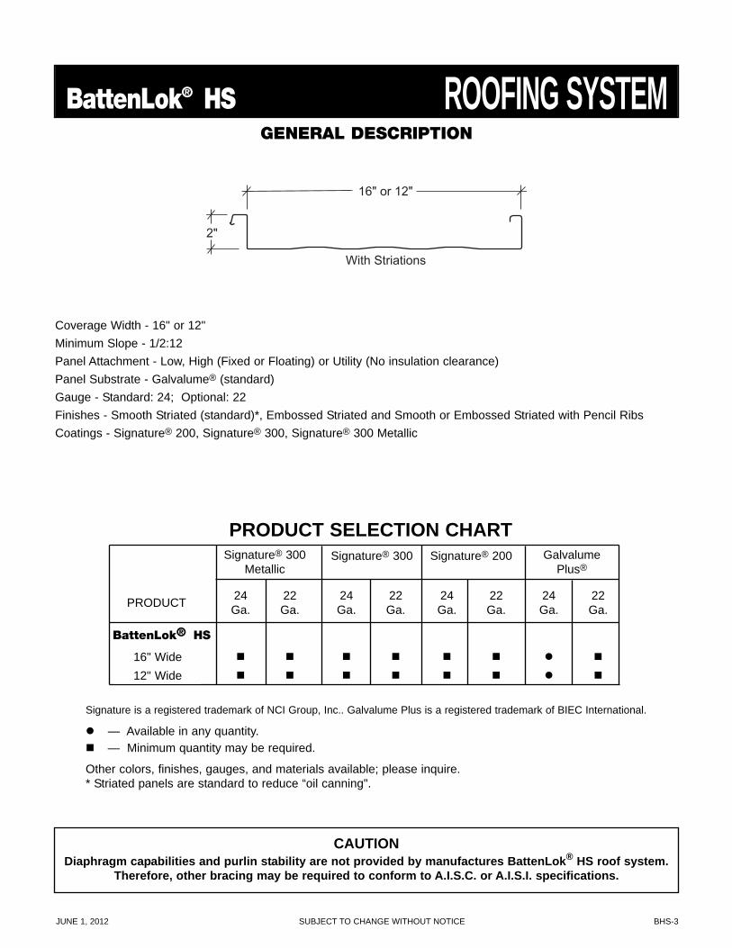
BattenLok® HS ROOFING SYSTEMGENERAL DESCRIPTION
Signature is a registered trademark of NCI Group, Inc.. Galvalume Plus is a registered trademark of BIEC International.
— Available in any quantity. — Minimum quantity may be required.
Other colors, finishes, gauges, and materials available; please inquire.* Striated panels are standard to reduce “oil canning".
2"
16" or 12"
With Striations
CAUTIONDiaphragm capabilities and purlin stability are not provided by manufactures BattenLok® HS roof system.
Therefore, other bracing may be required to conform to A.I.S.C. or A.I.S.I. specifications.
PRODUCT SELECTION CHARTSignature® 300
MetallicSignature® 300 Signature® 200 Galvalume
Plus®
24Ga.
24Ga.
24Ga.
24Ga.
22Ga.
22Ga.
22Ga.
22Ga.PRODUCT
BattenLok® HS
16" Wide12" Wide
Coverage Width - 16" or 12"Minimum Slope - 1/2:12Panel Attachment - Low, High (Fixed or Floating) or Utility (No insulation clearance)Panel Substrate - Galvalume® (standard)Gauge - Standard: 24; Optional: 22Finishes - Smooth Striated (standard)*, Embossed Striated and Smooth or Embossed Striated with Pencil RibsCoatings - Signature® 200, Signature® 300, Signature® 300 Metallic
BHS-4 SUBJECT TO CHANGE WITHOUT NOTICE JUNE 1, 2012
ROOFING SYSTEM BattenLok® HSARCHITECT/ENGINEER INFORMATION
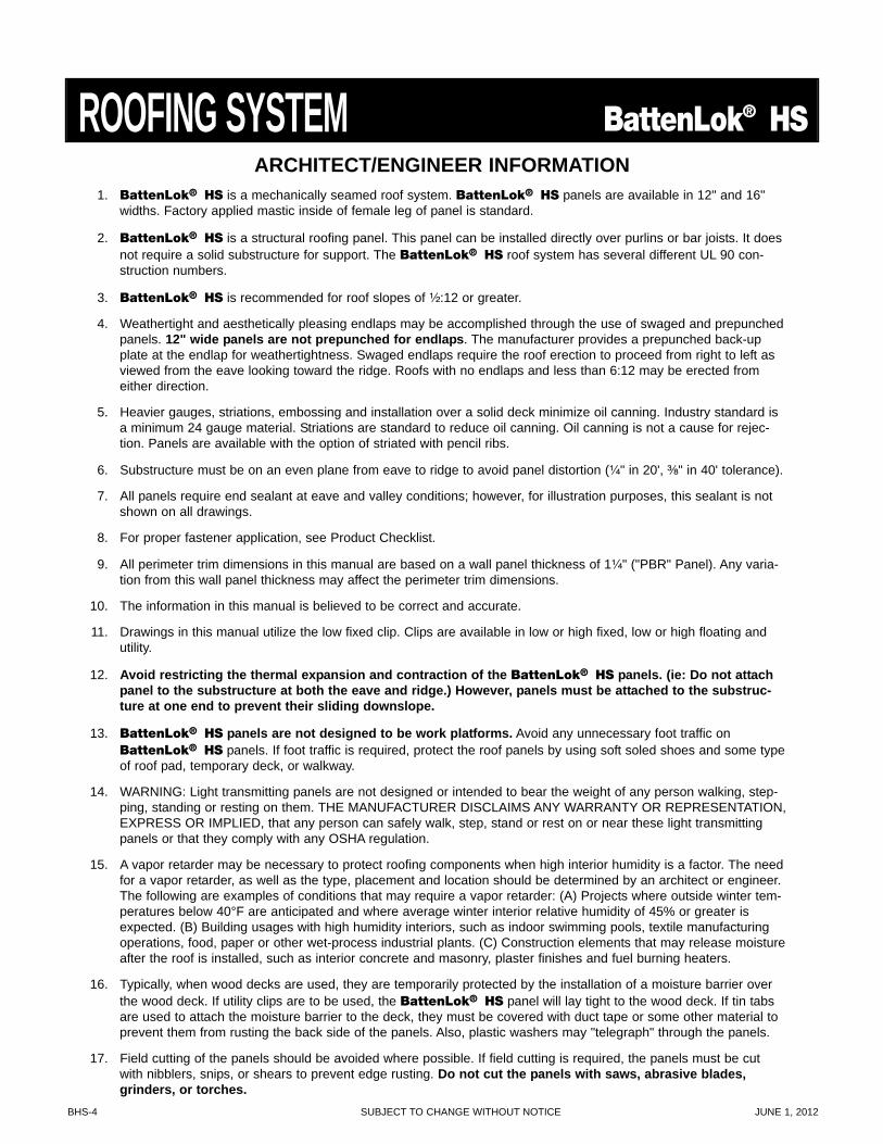
1. BattenLok® HS is a mechanically seamed roof system. BattenLok® HS panels are available in 12" and 16"widths. Factory applied mastic inside of female leg of panel is standard.
2. BattenLok® HS is a structural roofing panel. This panel can be installed directly over purlins or bar joists. It doesnot require a solid substructure for support. The BattenLok® HS roof system has several different UL 90 con-struction numbers.
3. BattenLok® HS is recommended for roof slopes of ¹⁄₂:12 or greater.
4. Weathertight and aesthetically pleasing endlaps may be accomplished through the use of swaged and prepunchedpanels. 12" wide panels are not prepunched for endlaps. The manufacturer provides a prepunched back-upplate at the endlap for weathertightness. Swaged endlaps require the roof erection to proceed from right to left asviewed from the eave looking toward the ridge. Roofs with no endlaps and less than 6:12 may be erected fromeither direction.
5. Heavier gauges, striations, embossing and installation over a solid deck minimize oil canning. Industry standard isa minimum 24 gauge material. Striations are standard to reduce oil canning. Oil canning is not a cause for rejec-tion. Panels are available with the option of striated with pencil ribs.
6. Substructure must be on an even plane from eave to ridge to avoid panel distortion (¹⁄₄" in 20', ³⁄₈" in 40' tolerance).
7. All panels require end sealant at eave and valley conditions; however, for illustration purposes, this sealant is notshown on all drawings.
8. For proper fastener application, see Product Checklist.
9. All perimeter trim dimensions in this manual are based on a wall panel thickness of 1¹⁄₄" ("PBR" Panel). Any varia-tion from this wall panel thickness may affect the perimeter trim dimensions.
10. The information in this manual is believed to be correct and accurate.
11. Drawings in this manual utilize the low fixed clip. Clips are available in low or high fixed, low or high floating andutility.
12. Avoid restricting the thermal expansion and contraction of the BattenLok® HS panels. (ie: Do not attachpanel to the substructure at both the eave and ridge.) However, panels must be attached to the substruc-ture at one end to prevent their sliding downslope.
13. BattenLok® HS panels are not designed to be work platforms. Avoid any unnecessary foot traffic onBattenLok® HS panels. If foot traffic is required, protect the roof panels by using soft soled shoes and some typeof roof pad, temporary deck, or walkway.
14. WARNING: Light transmitting panels are not designed or intended to bear the weight of any person walking, step-ping, standing or resting on them. THE MANUFACTURER DISCLAIMS ANY WARRANTY OR REPRESENTATION,EXPRESS OR IMPLIED, that any person can safely walk, step, stand or rest on or near these light transmittingpanels or that they comply with any OSHA regulation.
15. A vapor retarder may be necessary to protect roofing components when high interior humidity is a factor. The needfor a vapor retarder, as well as the type, placement and location should be determined by an architect or engineer.The following are examples of conditions that may require a vapor retarder: (A) Projects where outside winter tem-peratures below 40°F are anticipated and where average winter interior relative humidity of 45% or greater isexpected. (B) Building usages with high humidity interiors, such as indoor swimming pools, textile manufacturingoperations, food, paper or other wet-process industrial plants. (C) Construction elements that may release moistureafter the roof is installed, such as interior concrete and masonry, plaster finishes and fuel burning heaters.
16. Typically, when wood decks are used, they are temporarily protected by the installation of a moisture barrier overthe wood deck. If utility clips are to be used, the BattenLok® HS panel will lay tight to the wood deck. If tin tabsare used to attach the moisture barrier to the deck, they must be covered with duct tape or some other material toprevent them from rusting the back side of the panels. Also, plastic washers may "telegraph" through the panels.
17. Field cutting of the panels should be avoided where possible. If field cutting is required, the panels must be cutwith nibblers, snips, or shears to prevent edge rusting. Do not cut the panels with saws, abrasive blades,grinders, or torches.
JUNE 1, 2012 SUBJECT TO CHANGE WITHOUT NOTICE BHS-5
BattenLok® HS ENGINEERING
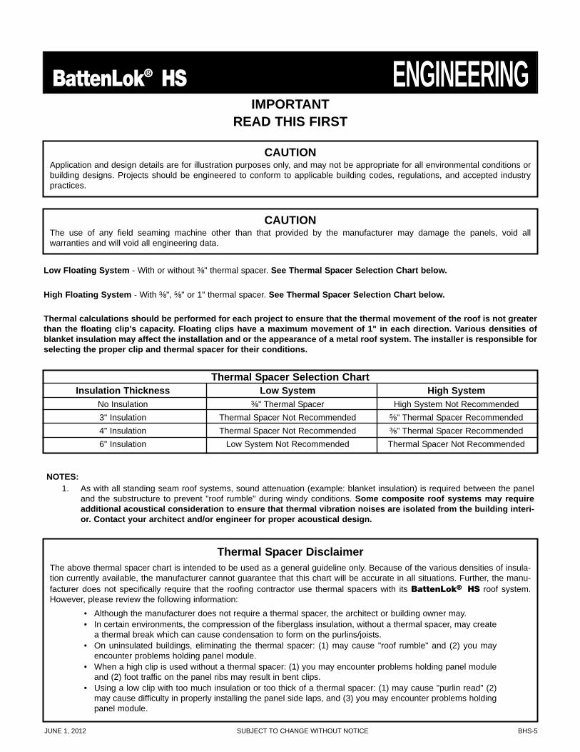
Low Floating System - With or without ³⁄₈" thermal spacer. See Thermal Spacer Selection Chart below.
High Floating System - With ³⁄₈", ⁵⁄₈" or 1" thermal spacer. See Thermal Spacer Selection Chart below.
Thermal calculations should be performed for each project to ensure that the thermal movement of the roof is not greaterthan the floating clip's capacity. Floating clips have a maximum movement of 1" in each direction. Various densities ofblanket insulation may affect the installation and or the appearance of a metal roof system. The installer is responsible forselecting the proper clip and thermal spacer for their conditions.
CAUTIONApplication and design details are for illustration purposes only, and may not be appropriate for all environmental conditions orbuilding designs. Projects should be engineered to conform to applicable building codes, regulations, and accepted industrypractices.
CAUTIONThe use of any field seaming machine other than that provided by the manufacturer may damage the panels, void allwarranties and will void all engineering data.
NOTES:1. As with all standing seam roof systems, sound attenuation (example: blanket insulation) is required between the panel
and the substructure to prevent "roof rumble" during windy conditions. Some composite roof systems may requireadditional acoustical consideration to ensure that thermal vibration noises are isolated from the building interi-or. Contact your architect and/or engineer for proper acoustical design.
IMPORTANTREAD THIS FIRST
Thermal Spacer Selection ChartInsulation Thickness Low System High System
No Insulation ³⁄₈" Thermal Spacer High System Not Recommended3" Insulation Thermal Spacer Not Recommended ⁵⁄₈" Thermal Spacer Recommended4" Insulation Thermal Spacer Not Recommended ³⁄₈" Thermal Spacer Recommended6" Insulation Low System Not Recommended Thermal Spacer Not Recommended
Thermal Spacer DisclaimerThe above thermal spacer chart is intended to be used as a general guideline only. Because of the various densities of insula-tion currently available, the manufacturer cannot guarantee that this chart will be accurate in all situations. Further, the manu-facturer does not specifically require that the roofing contractor use thermal spacers with its BattenLok® HS roof system.However, please review the following information:
• Although the manufacturer does not require a thermal spacer, the architect or building owner may.• In certain environments, the compression of the fiberglass insulation, without a thermal spacer, may create
a thermal break which can cause condensation to form on the purlins/joists.• On uninsulated buildings, eliminating the thermal spacer: (1) may cause "roof rumble" and (2) you may
encounter problems holding panel module.• When a high clip is used without a thermal spacer: (1) you may encounter problems holding panel module
and (2) foot traffic on the panel ribs may result in bent clips.• Using a low clip with too much insulation or too thick of a thermal spacer: (1) may cause "purlin read" (2)
may cause difficulty in properly installing the panel side laps, and (3) you may encounter problems holdingpanel module.
BHS-6 SUBJECT TO CHANGE WITHOUT NOTICE JUNE 1, 2012
ENGINEERING BattenLok® HS
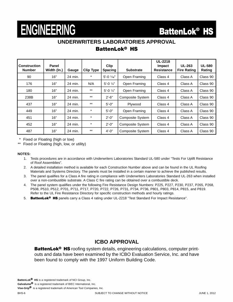
UL-2218Construction Panel Clip Impact UL-263 UL-580
Number Width (In.) Gauge Clip Type Spacing Substrate Resistance Fire Rating Rating
90 16" 24 min. * 5'-0 ¹⁄₁₆" Open Framing Class 4 Class A Class 90
176 16" 24 min. N/A 5'-0 ¹⁄₄" Open Framing Class 4 Class A Class 90
180 16" 24 min. ** 5'-0 ¹⁄₄" Open Framing Class 4 Class A Class 90
238B 16" 24 min. ** 2'-6" Composite System Class 4 Class A Class 90
437 16" 24 min. ** 5'-0" Plywood Class 4 Class A Class 90
449 16" 24 min. * 5'-0" Open Framing Class 4 Class A Class 90
451 16" 24 min. * 2'-0" Composite System Class 4 Class A Class 90
452 16" 24 min. * 2'-0" Composite System Class 4 Class A Class 90
487 16" 24 min. ** 4'-0" Composite System Class 4 Class A Class 90
UNDERWRITERS LABORATORIES APPROVALBattenLok® HS
* Fixed or Floating (high or low)** Fixed or Floating (high, low, or utility)
NOTES:1. Tests procedures are in accordance with Underwriters Laboratories Standard UL-580 under “Tests For Uplift Resistance
of Roof Assemblies".2. A detailed installation method is available for each Construction Number above and can be found in the UL Roofing
Materials and Systems Directory. The panels must be installed in a certain manner to achieve the published results.3. The panel qualifies for a Class A fire rating in compliance with Underwriters Laboratories Standard UL-263 when installed
over a non-combustible substrate. A Class C fire rating can be obtained over a combustible deck.4. The panel system qualifies under the following Fire Resistance Design Numbers: P225, P227, P230, P237, P265, P268,
P508, P510, P512, P701, P711, P717, P720, P722, P726, P731, P734, P736, P801, P803, P814, P815, and P819.Refer to the UL Fire Resistance Directory for specific construction methods and hourly ratings.
5. BattenLok® HS panels carry a Class 4 rating under UL-2218 "Test Standard For Impact Resistance".
ICBO APPROVALBattenLok® HS roofing system details, engineering calculations, computer print-outs and data have been examined by the ICBO Evaluation Service, Inc. and havebeen found to comply with the 1997 Uniform Building Code.
BattenLok® HS is a registered trademark of NCI Group, Inc.Galvalume® is a registered trademark of BIEC International, Inc.Vise-Grip® is a registered trademark of American Tool Companies, Inc.
JUNE 1, 2012 SUBJECT TO CHANGE WITHOUT NOTICE BHS-7
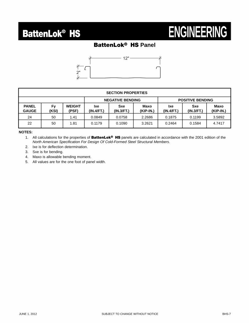
BattenLok® HS ENGINEERINGBattenLok® HS Panel
2"
12"
SECTION PROPERTIES
NEGATIVE BENDING POSITIVE BENDINGPANEL Fy WEIGHT Ixe Sxe Maxo Ixe Sxe MaxoGAUGE (KSI) (PSF) (IN.4/FT.) (IN.3/FT.) (KIP-IN.) (IN.4/FT.) (IN.3/FT.) (KIP-IN.)
24 50 1.41 0.0849 0.0758 2.2686 0.1875 0.1199 3.5892
22 50 1.81 0.1179 0.1090 3.2621 0.2464 0.1584 4.7417
NOTES:1. All calculations for the properties of BattenLok® HS panels are calculated in accordance with the 2001 edition of the
North American Specification For Design Of Cold-Formed Steel Structural Members.2. Ixe is for deflection determination.3. Sxe is for bending.4. Maxo is allowable bending moment.5. All values are for the one foot of panel width.
BHS-8 SUBJECT TO CHANGE WITHOUT NOTICE JUNE 1, 2012
ENGINEERING BattenLok® HSBattenLok® HS Panel
2"
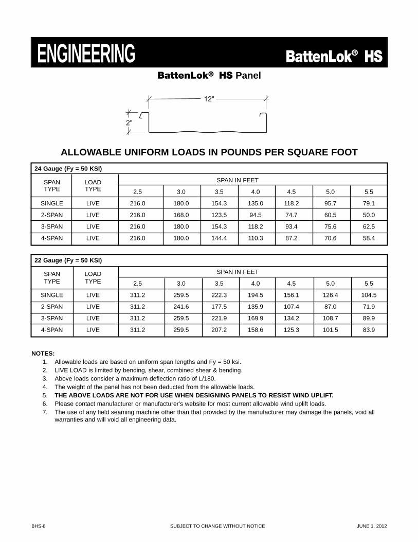
12"
ALLOWABLE UNIFORM LOADS IN POUNDS PER SQUARE FOOT24 Gauge (Fy = 50 KSI)
SPAN LOAD SPAN IN FEETTYPE TYPE 2.5 3.0 3.5 4.0 4.5 5.0 5.5
SINGLE LIVE 216.0 180.0 154.3 135.0 118.2 95.7 79.1
2-SPAN LIVE 216.0 168.0 123.5 94.5 74.7 60.5 50.0
3-SPAN LIVE 216.0 180.0 154.3 118.2 93.4 75.6 62.5
4-SPAN LIVE 216.0 180.0 144.4 110.3 87.2 70.6 58.4
NOTES:1. Allowable loads are based on uniform span lengths and Fy = 50 ksi.2. LIVE LOAD is limited by bending, shear, combined shear & bending.3. Above loads consider a maximum deflection ratio of L/180.4. The weight of the panel has not been deducted from the allowable loads.5. THE ABOVE LOADS ARE NOT FOR USE WHEN DESIGNING PANELS TO RESIST WIND UPLIFT.6. Please contact manufacturer or manufacturer's website for most current allowable wind uplift loads.7. The use of any field seaming machine other than that provided by the manufacturer may damage the panels, void all
warranties and will void all engineering data.
22 Gauge (Fy = 50 KSI)
SPAN LOAD SPAN IN FEETTYPE TYPE 2.5 3.0 3.5 4.0 4.5 5.0 5.5
SINGLE LIVE 311.2 259.5 222.3 194.5 156.1 126.4 104.5
2-SPAN LIVE 311.2 241.6 177.5 135.9 107.4 87.0 71.9
3-SPAN LIVE 311.2 259.5 221.9 169.9 134.2 108.7 89.9
4-SPAN LIVE 311.2 259.5 207.2 158.6 125.3 101.5 83.9
JUNE 1, 2012 SUBJECT TO CHANGE WITHOUT NOTICE BHS-9
BattenLok® HS ENGINEERINGBattenLok® HS Panel
2"
16"
With Striations
2"
16"
Striated with Pencil Ribs
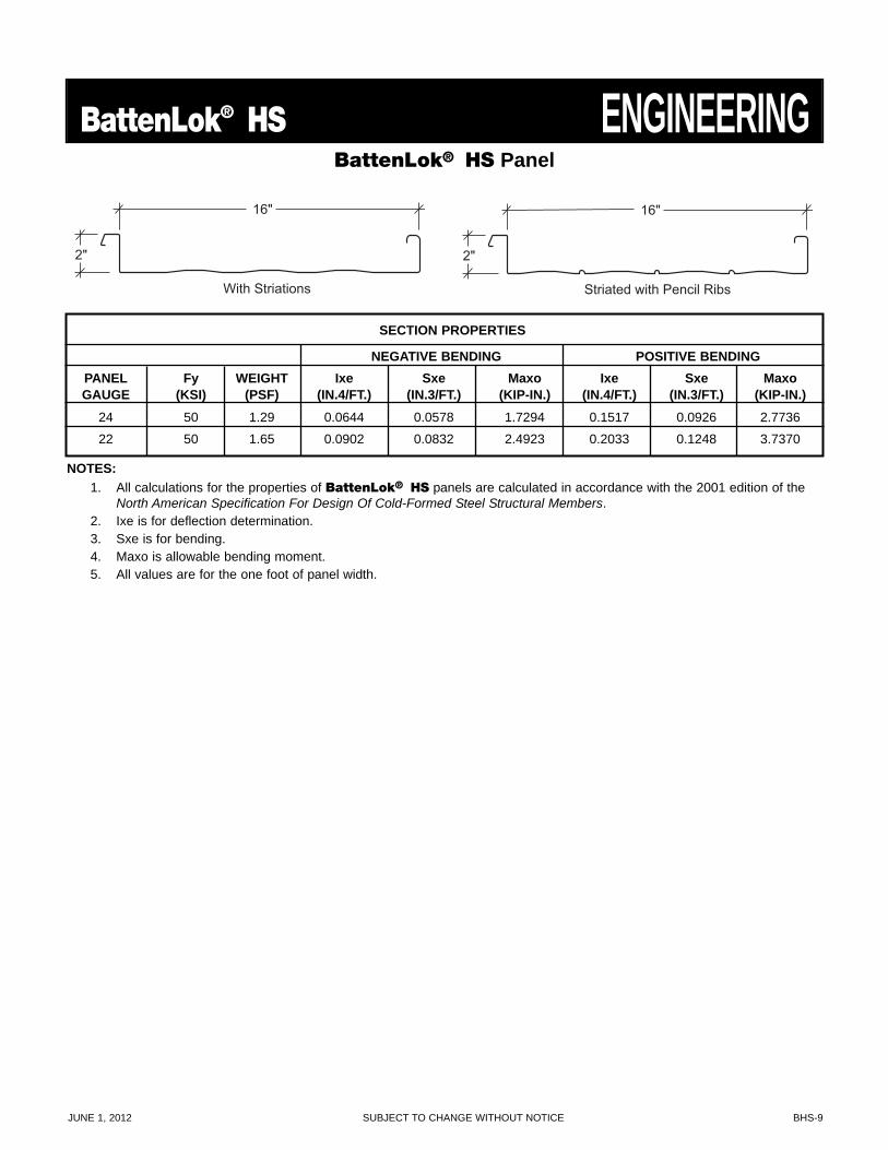
SECTION PROPERTIES
NEGATIVE BENDING POSITIVE BENDINGPANEL Fy WEIGHT Ixe Sxe Maxo Ixe Sxe MaxoGAUGE (KSI) (PSF) (IN.4/FT.) (IN.3/FT.) (KIP-IN.) (IN.4/FT.) (IN.3/FT.) (KIP-IN.)
24 50 1.29 0.0644 0.0578 1.7294 0.1517 0.0926 2.7736
22 50 1.65 0.0902 0.0832 2.4923 0.2033 0.1248 3.7370
NOTES:1. All calculations for the properties of BattenLok® HS panels are calculated in accordance with the 2001 edition of the
North American Specification For Design Of Cold-Formed Steel Structural Members.2. Ixe is for deflection determination.3. Sxe is for bending.4. Maxo is allowable bending moment.5. All values are for the one foot of panel width.
BHS-10 SUBJECT TO CHANGE WITHOUT NOTICE JUNE 1, 2012
ENGINEERING BattenLok® HSBattenLok® HS Panel
2"
16"
With Striations
2"
16"
Striated with Pencil Ribs
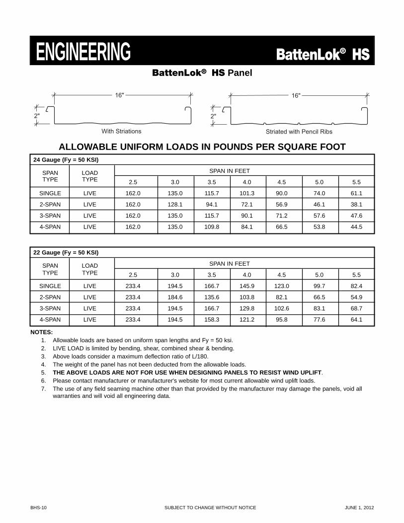
ALLOWABLE UNIFORM LOADS IN POUNDS PER SQUARE FOOT24 Gauge (Fy = 50 KSI)
SPAN LOAD SPAN IN FEETTYPE TYPE 2.5 3.0 3.5 4.0 4.5 5.0 5.5
SINGLE LIVE 162.0 135.0 115.7 101.3 90.0 74.0 61.1
2-SPAN LIVE 162.0 128.1 94.1 72.1 56.9 46.1 38.1
3-SPAN LIVE 162.0 135.0 115.7 90.1 71.2 57.6 47.6
4-SPAN LIVE 162.0 135.0 109.8 84.1 66.5 53.8 44.5
22 Gauge (Fy = 50 KSI)
SPAN LOAD SPAN IN FEETTYPE TYPE 2.5 3.0 3.5 4.0 4.5 5.0 5.5
SINGLE LIVE 233.4 194.5 166.7 145.9 123.0 99.7 82.4
2-SPAN LIVE 233.4 184.6 135.6 103.8 82.1 66.5 54.9
3-SPAN LIVE 233.4 194.5 166.7 129.8 102.6 83.1 68.7
4-SPAN LIVE 233.4 194.5 158.3 121.2 95.8 77.6 64.1
NOTES:1. Allowable loads are based on uniform span lengths and Fy = 50 ksi.2. LIVE LOAD is limited by bending, shear, combined shear & bending.3. Above loads consider a maximum deflection ratio of L/180.4. The weight of the panel has not been deducted from the allowable loads.5. THE ABOVE LOADS ARE NOT FOR USE WHEN DESIGNING PANELS TO RESIST WIND UPLIFT.6. Please contact manufacturer or manufacturer's website for most current allowable wind uplift loads.7. The use of any field seaming machine other than that provided by the manufacturer may damage the panels, void all
warranties and will void all engineering data.
JUNE 1, 2012 SUBJECT TO CHANGE WITHOUT NOTICE BHS-11
BattenLok® HS GENERAL INFORMATION
HW-7500HW-218
HW-7732
HW-224
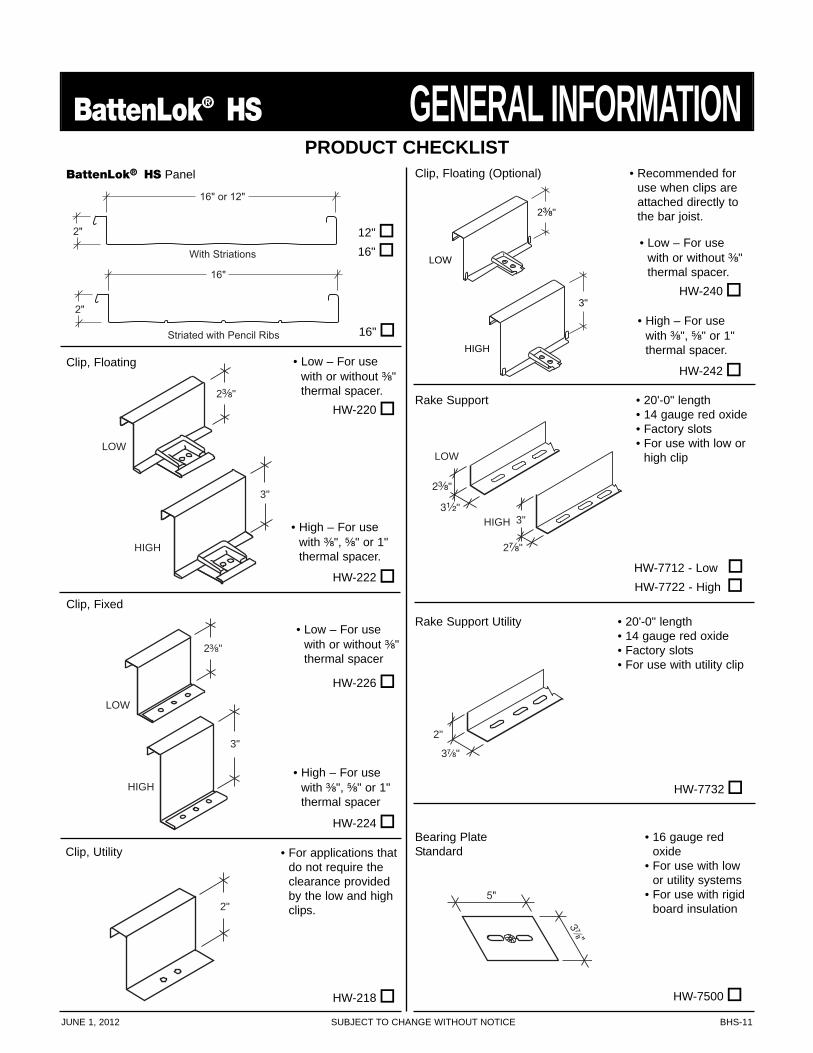
• High – For usewith ³⁄₈", ⁵⁄₈" or 1"thermal spacer
• Low – For usewith or without ³⁄₈"thermal spacer
HW-226
HW-7712 - Low
HW-7722 - HighHW-222
• High – For usewith ³⁄₈", ⁵⁄₈" or 1"thermal spacer.
HW-242
• High – For usewith ³⁄₈", ⁵⁄₈" or 1"thermal spacer.
2³⁄₈"
3"
LOW
HIGH
2"
3⁷⁄₈"
2"
16" or 12"
With Striations
BattenLok® HS Panel
2³⁄₈"
3"
LOW
HIGH
Clip, Floating (Optional) • Recommended foruse when clips areattached directly tothe bar joist.
• Low – For usewith or without ³⁄₈"thermal spacer.
HW-220
2³⁄₈"
3¹⁄₂"3"
2⁷⁄₈"
LOW
HIGH
Rake Support • 20'-0" length• 14 gauge red oxide• Factory slots• For use with low or
high clip
• 20'-0" length• 14 gauge red oxide• Factory slots• For use with utility clip
Rake Support Utility
5"
3⁷⁄₈"
• 16 gauge redoxide
• For use with lowor utility systems
• For use with rigidboard insulation
Bearing PlateStandard
2³⁄₈"
3"
LOW
HIGH
Clip, Fixed
2"
Clip, Floating
12"
16"
PRODUCT CHECKLIST
Clip, Utility • For applications thatdo not require theclearance providedby the low and highclips.
• Low – For usewith or without ³⁄₈"thermal spacer.
HW-2402"
16"
Striated with Pencil Ribs 16"
PRODUCT CHECKLIST
GENERAL INFORMATION BattenLok® HS
BHS-12 SUBJECT TO CHANGE WITHOUT NOTICE JUNE 1, 2012
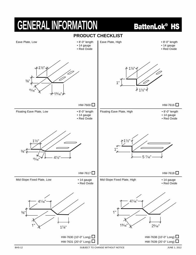
1¹⁄₂"
5 ⁷⁄₁₆"
1"
Floating Eave Plate, High
1⁹⁄₁₆"
³⁄₈"
¹⁵⁄₁₆"
1¹⁄₂"
³⁄₈"
1¹⁄₂"
4¹⁄₂"¹⁵⁄₁₆"
HW-7617
HW-7600
• 8'-0" length• 14 gauge• Red Oxide
1"
1¹⁄₂"
1¹⁄₂"
• 8'-0" length• 14 gauge• Red Oxide
HW-7616
4¹⁄₁₆"
³⁄₈"
1⁷⁄₈" 1"
HW-7630 (10'-0" Long)HW-7631 (20'-0" Long)
HW-7618
Eave Plate, Low
Floating Eave Plate, Low • 8'-0" length• 14 gauge• Red Oxide
Mid-Slope Fixed Plate, Low
Eave Plate, High
• 8'-0" length• 14 gauge• Red Oxide
Mid-Slope Fixed Plate, High
HW-7638 (10'-0" Long)HW-7639 (20'-0" Long)
4¹⁄₁₆"
1"
2⁵⁄₁₆" 1⁹⁄₁₆"
• 14 gauge• Red Oxide
• 14 gauge• Red Oxide
JUNE 1, 2012 SUBJECT TO CHANGE WITHOUT NOTICE BHS-13
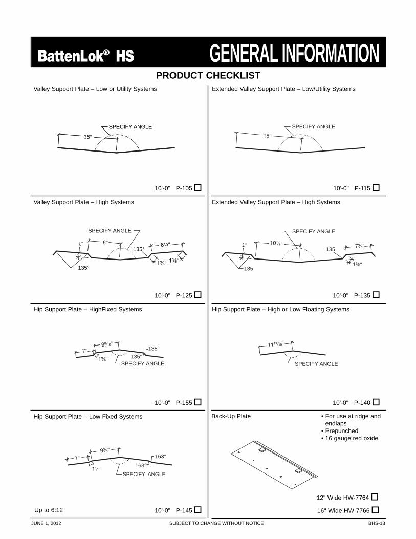
BattenLok® HS GENERAL INFORMATIONValley Support Plate – Low or Utility Systems
1³⁄₈"
1"
1³⁄₈"
6¹⁄₄"6"
SPECIFY ANGLE
135°
135°
10'-0" P-125
Valley Support Plate – High Systems
10'-0" P-115
Extended Valley Support Plate – Low/Utility Systems
10'-0" P-105
15"
SPECIFY ANGLE
15"
SPECIFY ANGLE
1" 10¹⁄₂"
1³⁄₈"
7³⁄₄"
SPECIFY ANGLE
135
135
18"
SPECIFY ANGLE
Extended Valley Support Plate – High Systems
10'-0" P-135
Hip Support Plate – HighFixed Systems
10'-0" P-155
7"9⁹⁄₁₆"
SPECIFY ANGLE
135°
1³⁄₈" 135°SPECIFY ANGLE
11¹¹⁄₁₆"
Hip Support Plate – High or Low Floating Systems
10'-0" P-140
Hip Support Plate – Low Fixed Systems
7"9³⁄₄"
SPECIFY ANGLE1¹⁄₄" 163°
163°
10'-0" P-145
Back-Up Plate
16" Wide HW-7766
• For use at ridge andendlaps
• Prepunched• 16 gauge red oxide
12" Wide HW-7764
Up to 6:12
PRODUCT CHECKLIST
PRODUCT CHECKLISTGENERAL INFORMATION BattenLok® HS
BHS-14 SUBJECT TO CHANGE WITHOUT NOTICE JUNE 1, 2012
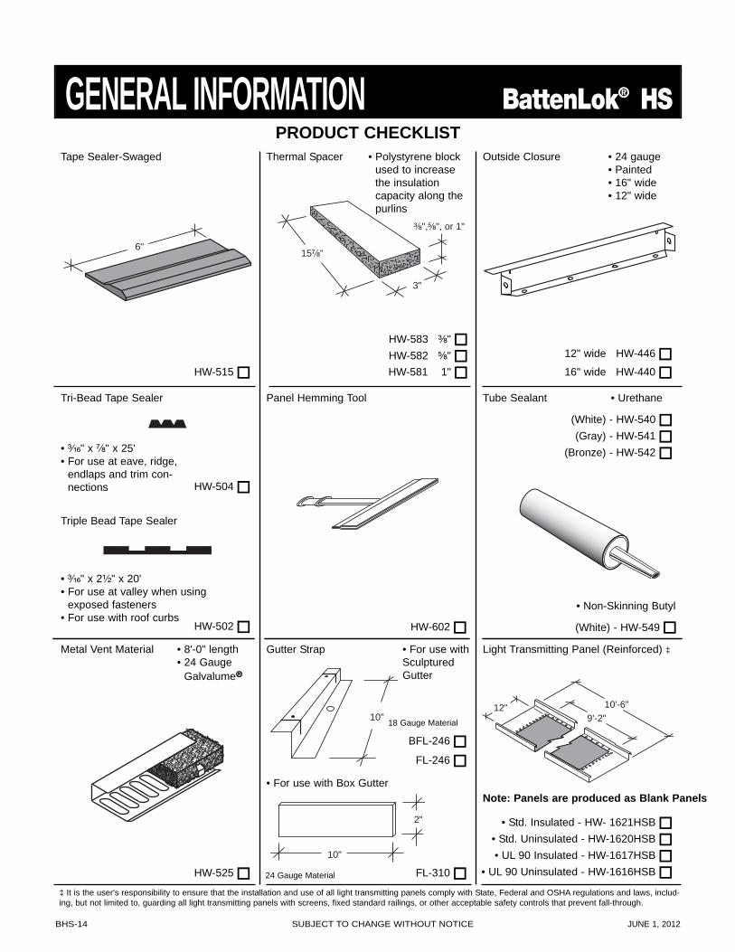
HW-525
HW-515
Panel Hemming Tool
12" 9'-2"
10'-6"
Light Transmitting Panel (Reinforced) ‡
Outside ClosureTape Sealer-Swaged
6"
3"
³⁄₈",⁵⁄₈", or 1"
15⁷⁄₈"
Thermal Spacer
HW-581 1"HW-582 ⁵⁄₈"HW-583 ³⁄₈"
• Polystyrene blockused to increasethe insulationcapacity along thepurlins
Tube Sealant • Urethane
• ³⁄₁₆" x 2¹⁄₂" x 20'• For use at valley when using
exposed fasteners• For use with roof curbs
Tri-Bead Tape Sealer
Triple Bead Tape Sealer
• ³⁄₁₆" x ⁷⁄₈" x 25'• For use at eave, ridge,
endlaps and trim con-nections HW-504
Gutter Strap
HW-502
(Bronze) - HW-542(Gray) - HW-541(White) - HW-540
• UL 90 Insulated - HW-1617HSB• Std. Uninsulated - HW-1620HSB• Std. Insulated - HW- 1621HSB
• UL 90 Uninsulated - HW-1616HSB
• 24 gauge• Painted• 16" wide• 12" wide
FL-310
• For use withSculpturedGutter
24 Gauge Material
Metal Vent Material • 8'-0" length• 24 Gauge
Galvalume®
HW-602
10"
2"
• For use with Box Gutter
• Non-Skinning Butyl
(White) - HW-549
12" wide HW-446
16" wide HW-440
10" 18 Gauge Material
FL-246BFL-246
Note: Panels are produced as Blank Panels
‡ It is the user's responsibility to ensure that the installation and use of all light transmitting panels comply with State, Federal and OSHA regulations and laws, includ-ing, but not limited to, guarding all light transmitting panels with screens, fixed standard railings, or other acceptable safety controls that prevent fall-through.
JUNE 1, 2012 SUBJECT TO CHANGE WITHOUT NOTICE BHS-15
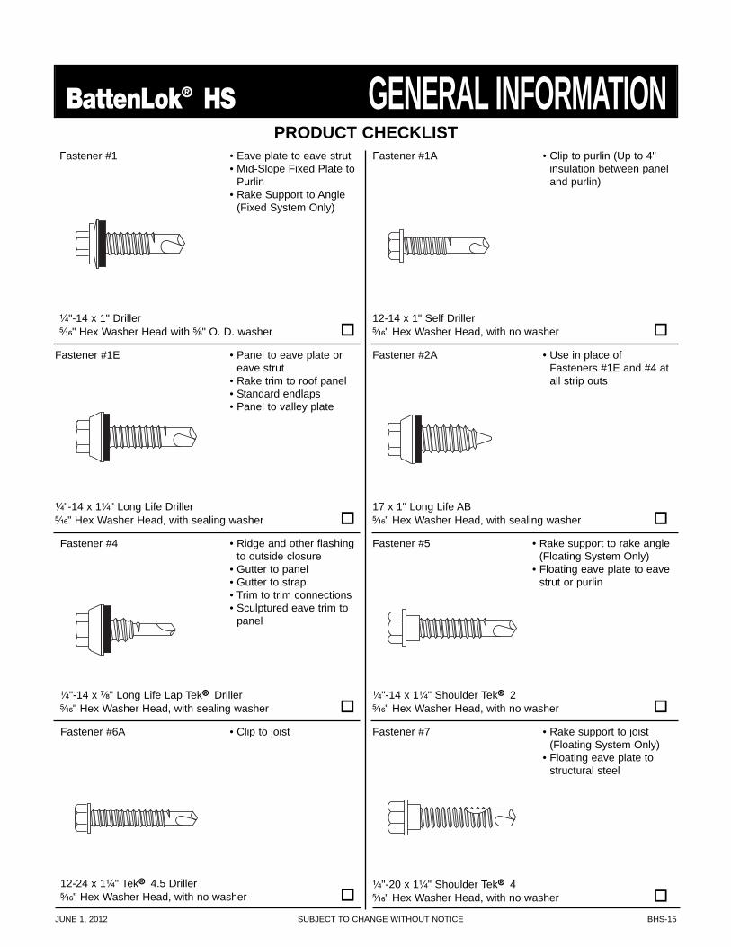
BattenLok® HS GENERAL INFORMATIONFastener #1A
• Use in place ofFasteners #1E and #4 atall strip outs
17 x 1" Long Life AB ⁵⁄₁₆" Hex Washer Head, with sealing washer
Fastener #1E • Panel to eave plate oreave strut
• Rake trim to roof panel• Standard endlaps• Panel to valley plate
¹⁄₄"-14 x 1¹⁄₄" Long Life Driller⁵⁄₁₆" Hex Washer Head, with sealing washer
Fastener #6A
Fastener #4
¹⁄₄"-14 x ⁷⁄₈" Long Life Lap Tek® Driller⁵⁄₁₆" Hex Washer Head, with sealing washer
• Ridge and other flashingto outside closure
• Gutter to panel• Gutter to strap• Trim to trim connections• Sculptured eave trim to
panel
Fastener #5
¹⁄₄"-14 x 1¹⁄₄" Shoulder Tek® 2⁵⁄₁₆" Hex Washer Head, with no washer
• Rake support to rake angle(Floating System Only)
• Floating eave plate to eavestrut or purlin
• Clip to joist
12-24 x 1¹⁄₄" Tek® 4.5 Driller⁵⁄₁₆" Hex Washer Head, with no washer
Fastener #7 • Rake support to joist(Floating System Only)
• Floating eave plate tostructural steel
¹⁄₄"-20 x 1¹⁄₄" Shoulder Tek® 4⁵⁄₁₆" Hex Washer Head, with no washer
• Clip to purlin (Up to 4"insulation between paneland purlin)
12-14 x 1" Self Driller⁵⁄₁₆" Hex Washer Head, with no washer
Fastener #1
• Eave plate to eave strut• Mid-Slope Fixed Plate to
Purlin• Rake Support to Angle
(Fixed System Only)
¹⁄₄"-14 x 1" Driller⁵⁄₁₆" Hex Washer Head with ⁵⁄₈" O. D. washer
Fastener #2A
PRODUCT CHECKLIST
PRODUCT CHECKLIST
GENERAL INFORMATION BattenLok® HS
BHS-16 SUBJECT TO CHANGE WITHOUT NOTICE JUNE 1, 2012
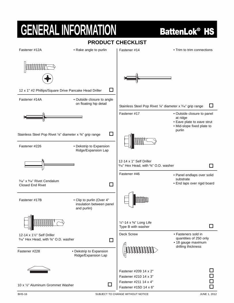
Fastener #14A
Fastener #46
Fastener #14
Stainless Steel Pop Rivet ¹⁄₈" diameter x ³⁄₁₆" grip range
• Trim to trim connections
Stainless Steel Pop Rivet ¹⁄₈" diameter x ³⁄₈" grip range
• Outside closure to angleon floating hip detail
Fastener #17 • Outside closure to panelat ridge
• Eave plate to eave strut• Mid-slope fixed plate to
purlin
12-14 x 1" Self Driller⁵⁄₁₆" Hex Head, with ⁵⁄₈" O.D. washer
Fastener #17B • Clip to purlin (Over 4"insulation between paneland purlin)
12-14 x 1¹⁄₂" Self Driller⁵⁄₁₆" Hex Head, with ⁵⁄₈" O.D. washer
• Panel endlaps over solidsubstrate
• End laps over rigid board
¹⁄₄"-14 x ⁵⁄₈" Long LifeType B with washer
Fastener #12A • Rake angle to purlin
12 x 1" #2 Phillips/Square Drive Pancake Head Driller
Deck Screw • Fasteners sold in quantities of 250 only
• 18 gauge maximumdrilling thickness
Fastener #209 14 x 2"Fastener #210 14 x 3"Fastener #211 14 x 4"Fastener #15D 14 x 6"
Fastener #228 • Dekstrip to ExpansionRidge/Expansion Lap
10 x ¹⁄₂" Aluminum Grommet Washer
Fastener #226 • Dekstrip to ExpansionRidge/Expansion Lap
³⁄₁₆" x ⁹⁄₁₆" Rivet CendalumClosed End Rivet
JUNE 1, 2012 SUBJECT TO CHANGE WITHOUT NOTICE BHS-17
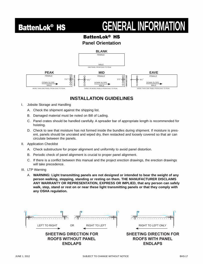
BattenLok® HS GENERAL INFORMATIONBLANK
FEMALE
MALE
EAVE FEMALE
MALE DOWN SLOPE
4 ¹⁄₂
MID FEMALE
MALE DOWN SLOPE
1 ¹⁄₂ "
PEAK
THREE OR MORE PANELS FROM EAVE TO PEAK
ONE PANEL FROM EAVE TO PEAK
MORE THAN ONE PANEL FROM EAVE TO PEAK MORE THAN ONE PANEL FROM EAVE TO PEAK
FEMALE
MALE DOWN SLOPE
1 ¹⁄₂ " "
SWA
GED
EN
D
SWA
GED
EN
D
4 ¹⁄₂ "
INSTALLATION GUIDELINESI. Jobsite Storage and Handling
A. Check the shipment against the shipping list.B. Damaged material must be noted on Bill of Lading.C. Panel crates should be handled carefully. A spreader bar of appropriate length is recommended for
hoisting.D. Check to see that moisture has not formed inside the bundles during shipment. If moisture is pres-
ent, panels should be uncrated and wiped dry, then restacked and loosely covered so that air cancirculate between the panels.
II. Application ChecklistA. Check substructure for proper alignment and uniformity to avoid panel distortion.B. Periodic check of panel alignment is crucial to proper panel alignment.C. If there is a conflict between this manual and the project erection drawings, the erection drawings
will take precedence.III. LTP Warning
A. WARNING: Light transmitting panels are not designed or intended to bear the weight of anyperson walking, stepping, standing or resting on them. THE MANUFACTURER DISCLAIMSANY WARRANTY OR REPRESENTATION, EXPRESS OR IMPLIED, that any person can safelywalk, step, stand or rest on or near these light transmitting panels or that they comply withany OSHA regulation.
BattenLok® HSPanel Orientation
SHEETING DIRECTION FORROOFS WITH PANEL
ENDLAPS
RIGHT TO LEFT ONLY
SHEETING DIRECTION FORROOFS WITHOUT PANEL
ENDLAPS
LEFT TO RIGHT OR RIGHT TO LEFT
BHS-18 SUBJECT TO CHANGE WITHOUT NOTICE JUNE 1, 2012
GENERAL INFORMATION BattenLok® HSPREPARATORY REQUIREMENTS
1. For the purpose of this manual, we have assumed that the BattenLok® HS roof will be installed overpurlins and an eave gutter will be installed. Please refer to the Design Section of the manuals for detailsof BattenLok® HS over other substrates.
2. A rake angle or an alternate structural flat surface must be installed on top of the purlins to accept therake support.
3. All primary and secondary framing must be erected, plumbed and squared with bolts tightened accord-ing to accepted building practices.
4. The substructure (eave to ridge) must be on plane (¹⁄₄" in 20' or ³⁄₈" in 40' tolerance).5. It is critical that the purlins or bar joists at the ridge and endlaps be located exactly as detailed and that
they are straight from rafter to rafter. Any mislocation or bowing of these members can cause the fasten-ers at the ridge or endlaps to foul as the panels expand and contract.
6. The manufacturer recommends the use of a screw gun with a speed range of 0-2000 RPM to properlyinstall all fasteners referenced in this manual. Tools rated to 4000 RPM should never be used for selfdrilling fasteners typically supplied with metal roof and wall systems.
7. Field cutting of the panels should be avoided where possible. If field cutting is required, the panels mustbe cut with nibblers, snips, or shears to prevent edge rusting. Do not cut the panels with saws, abrasiveblades, grinders, or torches. All metal shavings must be removed from panel surfaces immediately.
CAUTIONAvoid restricting the thermal expansion and contraction of the BattenLok® HS panels.
(i.e., Do not attach panel to the substructure at both the eave and ridge.)
WARNING: Light transmitting panels are not designed or intended to bear the weight of any person walking, stepping,standing or resting on them. THE MANUFACTURER DISCLAIMS ANY WARRANTY OR REPRESENTATION, EXPRESS ORIMPLIED, that any person can safely walk, step, stand or rest on or near these light transmitting panels or that they com-ply with any OSHA regulation.
CAUTIONDiaphragm capabilities and purlin stability are not provided by the BattenLok® HS roof system.
Therefore, other bracing may be required.
NOTEIt is the responsibility of the erector to install this roof using safe construction practices that are in compliance with OSHA regu-lations. The manufacturer is not responsible for the performance of this roof system if it is not installed in accordance with theinstructions shown in this manual. Deviations from these instructions and details must be approved in writing by themanufacturer.
JUNE 1, 2012 SUBJECT TO CHANGE WITHOUT NOTICE BHS-19
BattenLok® HS GENERAL INFORMATION
RIGHT WAY
5' Minimum
RIGHT WAY
WRONG WAY
WRONG WAY
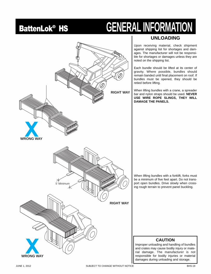
UNLOADINGUpon receiving material, check shipmentagainst shipping list for shortages and dam-ages. The manufacturer will not be responsi-ble for shortages or damages unless they arenoted on the shipping list.
Each bundle should be lifted at its center ofgravity. Where possible, bundles shouldremain banded until final placement on roof. Ifbundles must be opened, they should beretied before lifting.
When lifting bundles with a crane, a spreaderbar and nylon straps should be used. NEVERUSE WIRE ROPE SLINGS, THEY WILLDAMAGE THE PANELS.
When lifting bundles with a forklift, forks mustbe a minimum of five feet apart. Do not trans-port open bundles. Drive slowly when cross-ing rough terrain to prevent panel buckling.
CAUTIONImproper unloading and handling of bundlesand crates may cause bodily injury or mate-rial damage. The manufacturer is notresponsible for bodily injuries or materialdamages during unloading and storage.
BHS-20 SUBJECT TO CHANGE WITHOUT NOTICE JUNE 1, 2012
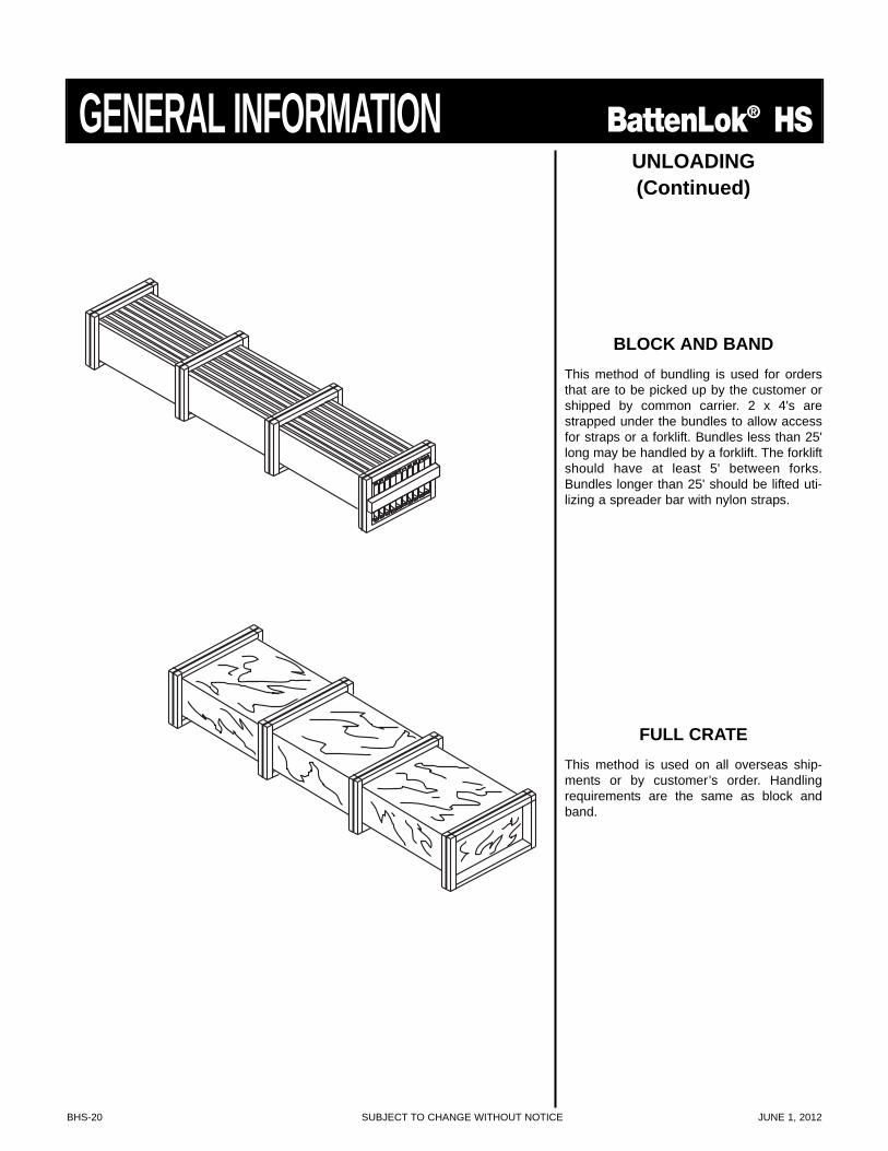
GENERAL INFORMATION BattenLok® HSUNLOADING(Continued)
BLOCK AND BANDThis method of bundling is used for ordersthat are to be picked up by the customer orshipped by common carrier. 2 x 4's arestrapped under the bundles to allow accessfor straps or a forklift. Bundles less than 25'long may be handled by a forklift. The forkliftshould have at least 5' between forks.Bundles longer than 25' should be lifted uti-lizing a spreader bar with nylon straps.
FULL CRATEThis method is used on all overseas ship-ments or by customer’s order. Handlingrequirements are the same as block andband.
JUNE 1, 2012 SUBJECT TO CHANGE WITHOUT NOTICE BHS-21
BattenLok® HS GENERAL INFORMATION
5'
10' to 12'
RIGHT WAY
WRONG WAY
10' to 12'
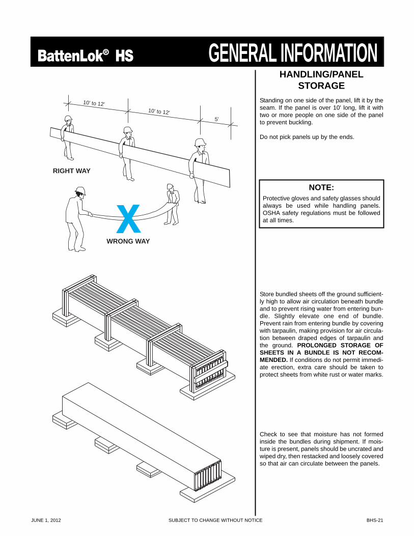
HANDLING/PANELSTORAGE
Standing on one side of the panel, lift it by theseam. If the panel is over 10' long, lift it withtwo or more people on one side of the panelto prevent buckling.
Do not pick panels up by the ends.
Store bundled sheets off the ground sufficient-ly high to allow air circulation beneath bundleand to prevent rising water from entering bun-dle. Slightly elevate one end of bundle.Prevent rain from entering bundle by coveringwith tarpaulin, making provision for air circula-tion between draped edges of tarpaulin andthe ground. PROLONGED STORAGE OFSHEETS IN A BUNDLE IS NOT RECOM-MENDED. If conditions do not permit immedi-ate erection, extra care should be taken toprotect sheets from white rust or water marks.
Check to see that moisture has not formedinside the bundles during shipment. If mois-ture is present, panels should be uncrated andwiped dry, then restacked and loosely coveredso that air can circulate between the panels.
NOTE:Protective gloves and safety glasses shouldalways be used while handling panels.OSHA safety regulations must be followedat all times.
BHS-22 SUBJECT TO CHANGE WITHOUT NOTICE JUNE 1, 2012
INSTALLATION SEQUENCE BattenLok® HS
RAKE ANGLE ATTACHMENT
RAKE SUPPORT ATTACHMENT
STEEL LINE
FASTENER #12A
WALL PANEL
PURLIN
RAKE ANGLE
FLOATING SYSTEM
FIXED SYSTEM
FASTENER #5
*DOUBLE FACED TAPE FASTENER #1
RAKE SUPPORT
2 ³⁄₄"
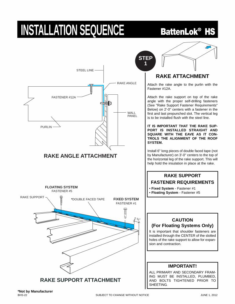
RAKE ATTACHMENTAttach the rake angle to the purlin with theFastener #12A.
Attach the rake support on top of the rakeangle with the proper self-drilling fasteners(See "Rake Support Fastener Requirements"Below) on 2'-0" centers with a fastener in thefirst and last prepunched slot. The vertical legis to be installed flush with the steel line.
IT IS IMPORTANT THAT THE RAKE SUP-PORT IS INSTALLED STRAIGHT ANDSQUARE WITH THE EAVE AS IT CON-TROLS THE ALIGNMENT OF THE ROOFSYSTEM.
Install 6" long pieces of double faced tape (notby Manufacturer) on 3'-0" centers to the top ofthe horizontal leg of the rake support. This willhelp hold the insulation in place at the rake.
STEP1
CAUTION(For Floating Systems Only)
It is important that shoulder fasteners areinstalled through the CENTER of the slottedholes of the rake support to allow for expan-sion and contraction.
IMPORTANT!ALL PRIMARY AND SECONDARY FRAM-ING MUST BE INSTALLED, PLUMBED,AND BOLTS TIGHTENED PRIOR TOSHEETING.
RAKE SUPPORTFASTENER REQUIREMENTS
• Fixed System - Fastener #1• Floating System - Fastener #5
*Not by Manufacturer
JUNE 1, 2012 SUBJECT TO CHANGE WITHOUT NOTICE BHS-23
BattenLok® HS INSTALLATION SEQUENCE
WALL PANEL INSTALLED AFTER ROOF
WALL PANEL INSTALLED BEFORE ROOF
FLAT EAVE TRIMENDLAP DETAIL
OFFSET PANEL CAPTRIM ENDLAP DETAIL
FASTENER #14
URETHANESEALANT
2" LAP 1"
URETHANESEALANT
2" LAP
1"
OFFSETPANEL CAPTRIM
FASTENER #4
TRI-BEADTAPE SEALER
EAVE STRUT
FLAT EAVETRIM
FLAT EAVETRIM
WALL PANEL
*DOUBLE FACED TAPE
FASTENER #14@ 10'-0" O.C.
FASTENER #14@ 36" O.C.
2" MAX.
EAVE STRUT
OFFSET PANELCAP TRIM
*DOUBLE FACED TAPE
TRI-BEADTAPE SEALER
1¹⁄₄" MAX.
FASTENER #14@ 36" O.C.
FASTENER #14@ 10'-0" O.C.
STEP2
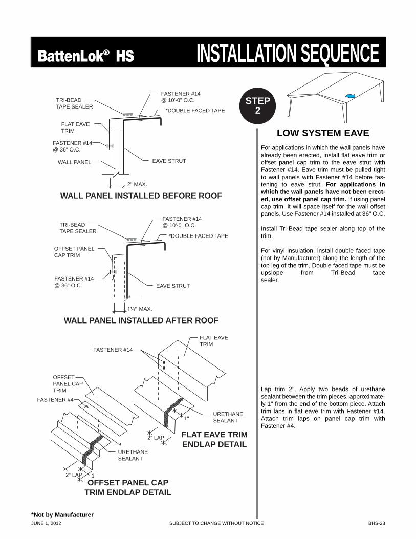
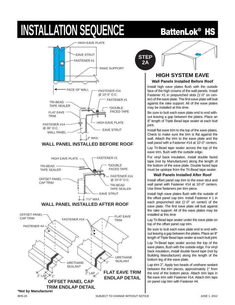
LOW SYSTEM EAVEFor applications in which the wall panels havealready been erected, install flat eave trim oroffset panel cap trim to the eave strut withFastener #14. Eave trim must be pulled tightto wall panels with Fastener #14 before fas-tening to eave strut. For applications inwhich the wall panels have not been erect-ed, use offset panel cap trim. If using panelcap trim, it will space itself for the wall offsetpanels. Use Fastener #14 installed at 36" O.C.
Install Tri-Bead tape sealer along top of thetrim.
For vinyl insulation, install double faced tape(not by Manufacturer) along the length of thetop leg of the trim. Double faced tape must beupslope from Tri-Bead tapesealer.
Lap trim 2". Apply two beads of urethanesealant between the trim pieces, approximate-ly 1" from the end of the bottom piece. Attachtrim laps in flat eave trim with Fastener #14.Attach trim laps on panel cap trim withFastener #4.
*Not by Manufacturer
BHS-24 SUBJECT TO CHANGE WITHOUT NOTICE JUNE 1, 2012
INSTALLATION SEQUENCE BattenLok® HS
RAKE SUPPORT
HIGH EAVE PLATE
FASTENER #1
EAVE STRUT
FACE OF WALL
EAVE STRUT
FASTENER #1
OFFSET PANELCAP TRIM
FASTENER #14@ 10'-0" O.C.
HIGH EAVE PLATE
TRI-BEADTAPE SEALER
TRI-BEADTAPE SEALER
1¹⁄₄" MAX.
*DOUBLE FACED TAPE
TRI-BEADTAPE SEALER
EAVE STRUT
FASTENER #1
*DOUBLE FACED TAPEFLAT EAVE
TRIM
HIGH EAVE PLATE
WALL PANEL
2" MAX.
FASTENER #14@ 36" O.C.
FASTENER #14@ 10'-0" O.C.
FLAT EAVE TRIMENDLAP DETAIL
OFFSET PANEL CAPTRIM ENDLAP DETAIL
FASTENER #14
URETHANESEALANT
2" LAP 1"2" LAP
1"
OFFSET PANELCAP TRIM
FASTENER #4
URETHANESEALANT
WALL PANEL INSTALLED AFTER ROOF
WALL PANEL INSTALLED BEFORE ROOF
FLAT EAVETRIM
HIGH SYSTEM EAVEWall Panels Installed Before Roof
Install high eave plates flush with the outsideface of the high crowns of the wall panels. InstallFastener #1 in prepunched slots (1'-0" on cen-ter) of the eave plate. The first eave plate will buttagainst the rake support. All of the eave platesmay be installed at this time.Be sure to butt each eave plate end to end with-out leaving a gap between the plates. Place an8" length of Triple Bead tape sealer at each buttjoint.Install flat eave trim to the top of the eave plates.Check to make sure the trim is flat against thewall. Attach the trim to the eave plate and thewall panel with a Fastener #14 at 10'-0" centers.Lay Tri-Bead tape sealer across the top of theeave trim, flush with the outside edge.For vinyl back insulation, install double facedtape (not by Manufacturer) along the length ofthe bottom of the eave plate. Double faced tapemust be upslope from the Tri-Bead tape sealer.
Wall Panels Installed After RoofInstall offset panel cap trim to the eave strut andwall panel with Fastener #14 at 10'-0" centers.Use three fasteners per trim piece.Install high eave plates flush with the outside ofthe offset panel cap trim. Install Fastener # 1 ineach prepunched slot (1'-0" on center) of theeave plate. The first eave plate will butt againstthe rake support. All of the eave plates may beinstalled at this timeLay Tri-Bead tape sealer under the eave plate ontop of the offset panel cap trim.Be sure to butt each eave plate end to end with-out leaving a gap between the plates. Place an 8"length of Triple Bead tape sealer at each butt joint.Lay Tri-Bead tape sealer across the top of theeave plates, flush with the outside edge. For vinylback insulation, install double faced tape (not byBuilding Manufacturer) along the length of thebottom leg of the eave plate.Lap trim 2". Apply two beads of urethane sealantbetween the trim pieces, approximately 1" fromthe end of the bottom piece. Attach trim laps inflat eave trim with Fastener #14. Attach trim lapson panel cap trim with Fastener #4.
STEP2A
*Not by Manufacturer
JUNE 1, 2012 SUBJECT TO CHANGE WITHOUT NOTICE BHS-25
BattenLok® HS INSTALLATION SEQUENCE
*DOUBLE
6" LONG PIECES @ 3'-0"
OFFSET PANELCAP TRIM
THERMAL SPACER
FACED TAPE
*DOUBLE FACED TAPE
INSULATION
THERMAL SPACER
THERMAL SPACER
*SPRAY ADHESIVE
RAKE SUPPORT
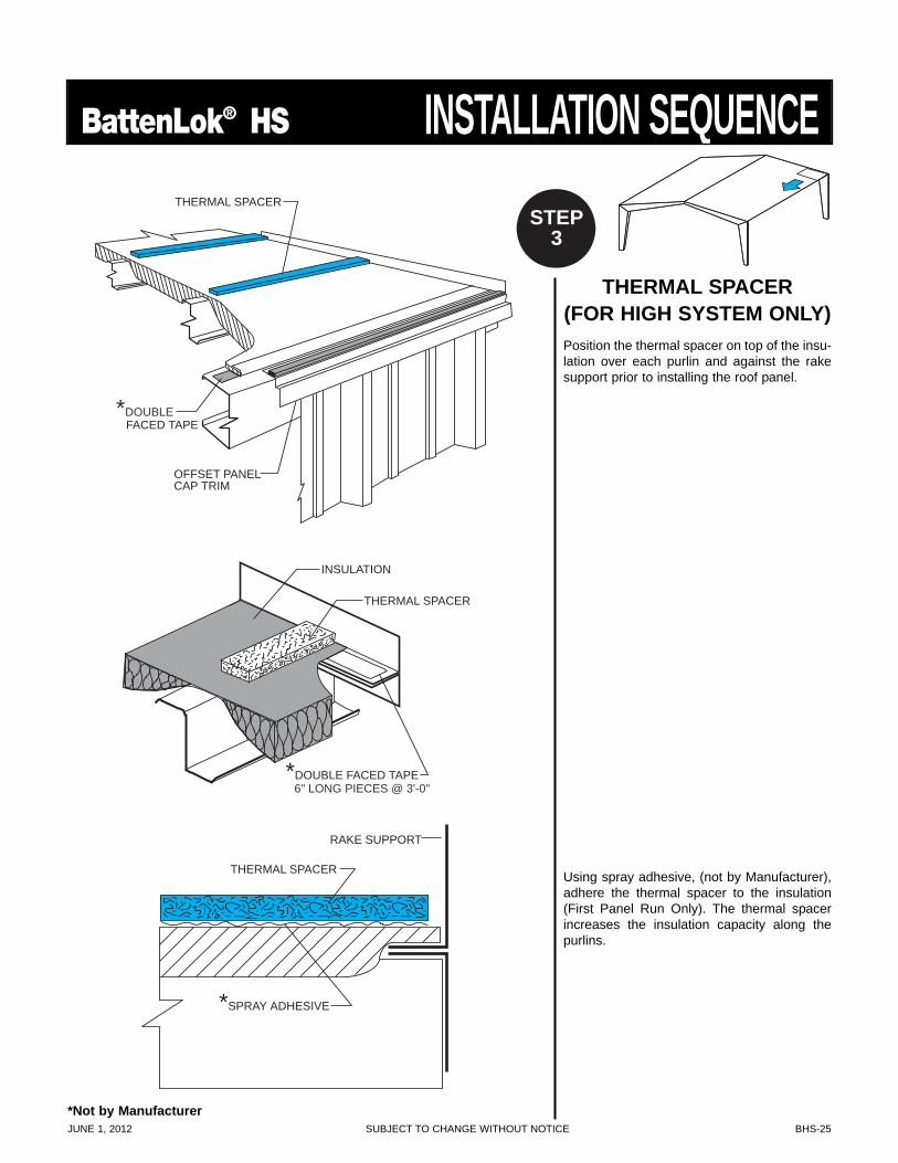
THERMAL SPACER(FOR HIGH SYSTEM ONLY)Position the thermal spacer on top of the insu-lation over each purlin and against the rakesupport prior to installing the roof panel.
Using spray adhesive, (not by Manufacturer),adhere the thermal spacer to the insulation(First Panel Run Only). The thermal spacerincreases the insulation capacity along thepurlins.
STEP3
*Not by Manufacturer
BHS-26 SUBJECT TO CHANGE WITHOUT NOTICE JUNE 1, 2012
INSTALLATION SEQUENCE BattenLok® HS
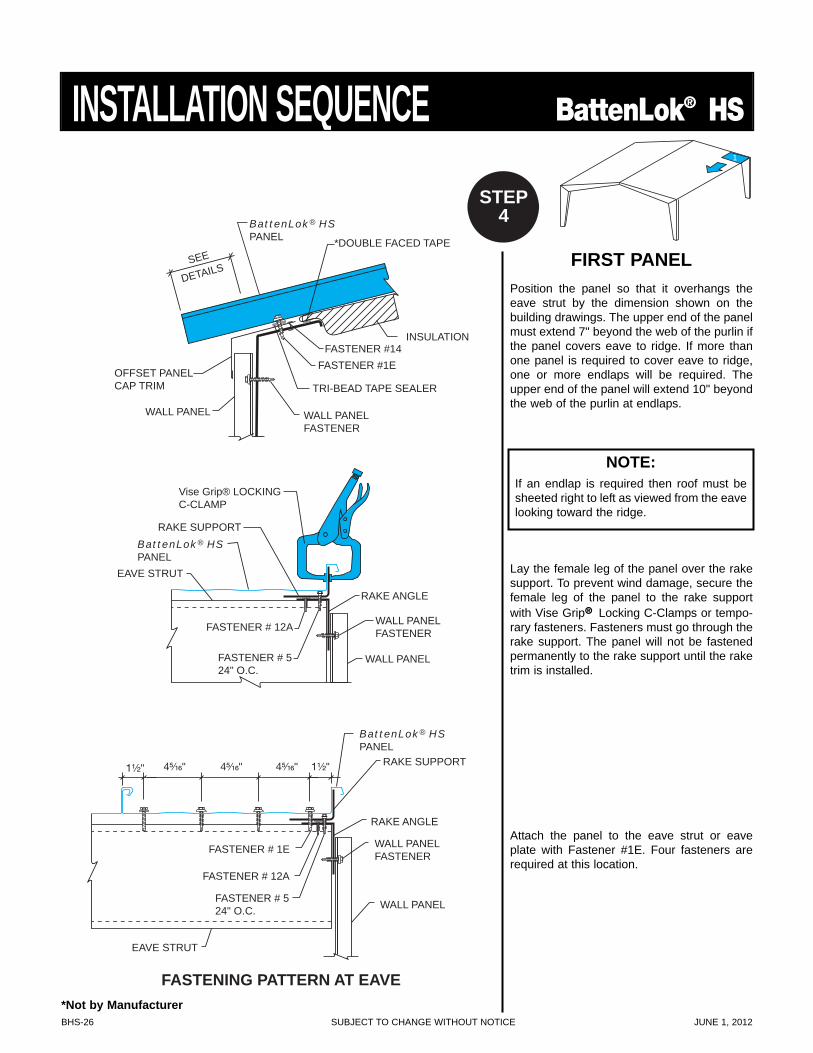
FIRST PANELPosition the panel so that it overhangs theeave strut by the dimension shown on thebuilding drawings. The upper end of the panelmust extend 7" beyond the web of the purlin ifthe panel covers eave to ridge. If more thanone panel is required to cover eave to ridge,one or more endlaps will be required. Theupper end of the panel will extend 10" beyondthe web of the purlin at endlaps.
Lay the female leg of the panel over the rakesupport. To prevent wind damage, secure thefemale leg of the panel to the rake supportwith Vise Grip® Locking C-Clamps or tempo-rary fasteners. Fasteners must go through therake support. The panel will not be fastenedpermanently to the rake support until the raketrim is installed.
Attach the panel to the eave strut or eaveplate with Fastener #1E. Four fasteners arerequired at this location.
BattenLok® HS PANEL
WALL PANEL
TRI-BEAD TAPE SEALER
FASTENER #1E
*DOUBLE FACED TAPE
INSULATION
WALL PANEL FASTENER
OFFSET PANEL CAP TRIM
RAKE SUPPORT
FASTENER # 12A
FASTENER # 5 24" O.C.
WALL PANEL
RAKE ANGLE
EAVE STRUT
BattenLok® HS PANEL
Vise Grip® LOCKING C-CLAMP
WALL PANEL FASTENER
EAVE STRUT
BattenLok® HS PANEL
WALL PANEL
WALL PANEL FASTENER
FASTENER # 12A
FASTENER # 5 24" O.C.
FASTENER # 1E
RAKE ANGLE
RAKE SUPPORT 1¹⁄₂" 4⁵⁄₁₆" 4⁵⁄₁₆" 4⁵⁄₁₆" 1¹⁄₂"
FASTENER #14
SEE
DETAILS
FASTENING PATTERN AT EAVE
1
STEP4
*Not by Manufacturer
NOTE:If an endlap is required then roof must besheeted right to left as viewed from the eavelooking toward the ridge.
JUNE 1, 2012 SUBJECT TO CHANGE WITHOUT NOTICE BHS-27
BattenLok® HS INSTALLATION SEQUENCE
PANEL CLIPINSTALLATION
FACTORY APPLIEDMASTIC
FACTORY APPLIEDMASTIC
BattenLok® HSPANEL
BattenLok® HSPANEL
LOW CLIP
RIGHT WAY
LOW FIXEDCLIP
PURLIN
BattenLok® HSPANEL
FASTENER #1A
WRONG WAY
LOW FIXEDCLIP
PURLIN
FASTENER #1A
BattenLok® HSPANEL
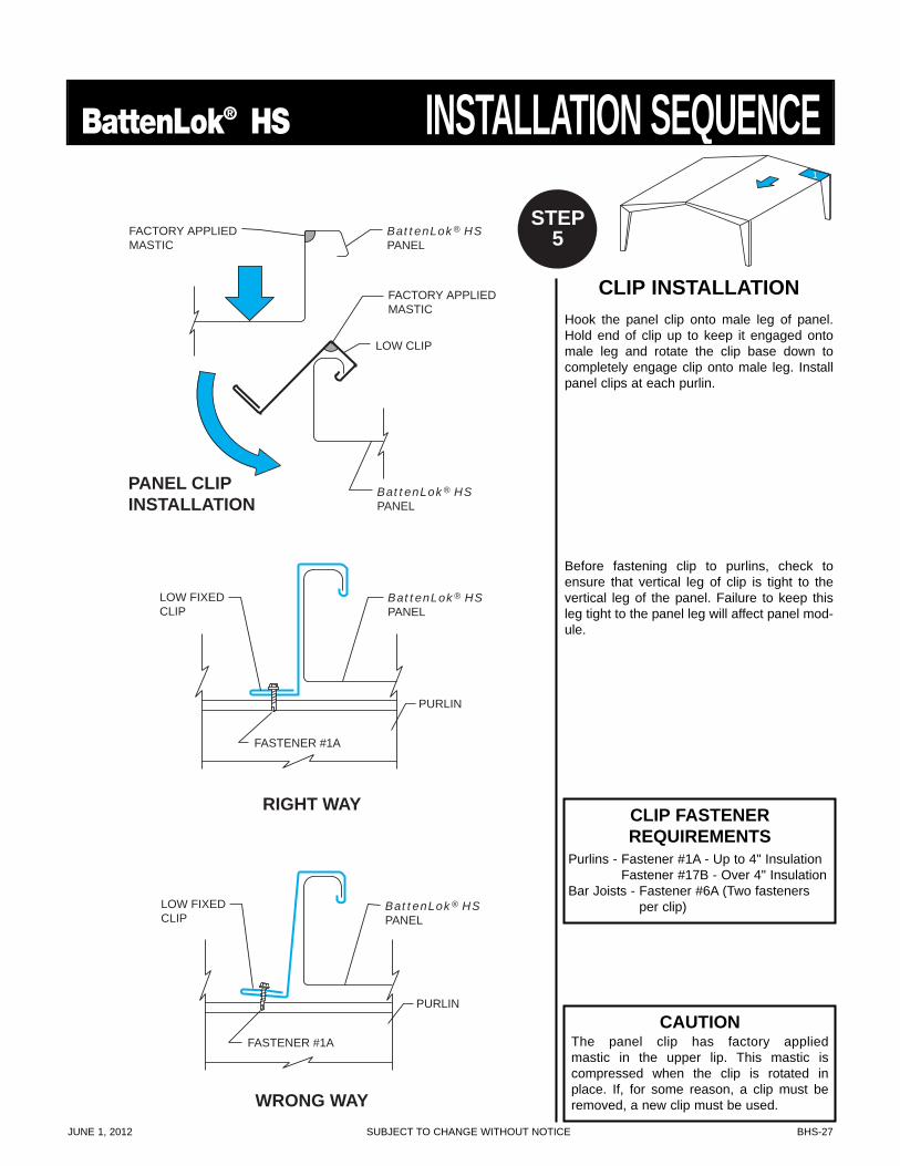
CLIP INSTALLATIONHook the panel clip onto male leg of panel.Hold end of clip up to keep it engaged ontomale leg and rotate the clip base down tocompletely engage clip onto male leg. Installpanel clips at each purlin.
Before fastening clip to purlins, check toensure that vertical leg of clip is tight to thevertical leg of the panel. Failure to keep thisleg tight to the panel leg will affect panel mod-ule.
1
STEP5
CAUTIONThe panel clip has factory applied mastic in the upper lip. This mastic is compressed when the clip is rotated inplace. If, for some reason, a clip must beremoved, a new clip must be used.
CLIP FASTENERREQUIREMENTS
Purlins - Fastener #1A - Up to 4" InsulationFastener #17B - Over 4" Insulation
Bar Joists - Fastener #6A (Two fastenersper clip)
BHS-28 SUBJECT TO CHANGE WITHOUT NOTICE JUNE 1, 2012
INSTALLATION SEQUENCE BattenLok® HS
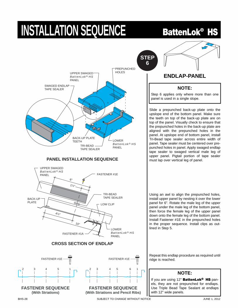
CROSS SECTION OF ENDLAP
1¹⁄₂"
UPPER SWAGED BattenLok® HS PANEL FASTENER #1E
6"
TRI-BEAD TAPE SEALER
LOW CLIP
BACK-UP PLATE
4¹⁄₂"
10"
LOWER BattenLok® HS
PANEL FASTENER #1A
PANEL INSTALLATION SEQUENCE
TRI-BEAD TAPE SEALER
BACK-UP PLATE TEETH LOWER
BattenLok® HS
PANEL
PREPUNCHED HOLES
SWAGED ENDLAP TAPE SEALER
UPPER SWAGED BattenLok® HS
PANEL
FASTENER SEQUENCE(With Striations)
FASTENER SEQUENCE(With Striations and Pencil Ribs)
2 3 4 5 1
FASTENER #1E
2 3 4 5 6 1
FASTENER #1E
ENDLAP-PANEL
Slide a prepunched back-up plate onto theupslope end of the bottom panel. Make surethe teeth on top of the back-up plate are ontop of the panel. Visually check to ensure thatthe prepunched holes in the back-up plate arealigned with the prepunched holes in thepanel. At upslope end of bottom panel, installTri-Bead tape sealer across entire width ofpanel. Tape sealer must be centered over pre-punched holes in panel. Apply swaged endlaptape sealer to swaged vertical male leg ofupper panel. Pigtail portion of tape sealermust lap over vertical leg of panel.
Using an awl to align the prepunched holes,install upper panel by nesting it over the lowerpanel for 6". Rotate the male leg of the upperpanel under the male leg of the bottom panel,then force the female leg of the upper paneldown onto the female leg of the bottom panel.Install Fastener #1E in the prepunched holesin the proper sequence. Install clips as out-lined in Step 5.
Repeat this endlap procedure as required untilridge is reached.
12
STEP6
NOTE:Step 6 applies only where more than onepanel is used in a single slope.
NOTE:If you are using 12" BattenLok® HS pan-els, they are not prepunched for endlaps.Use Triple Bead Tape Sealant at endlapswith 12" wide panels.
JUNE 1, 2012 SUBJECT TO CHANGE WITHOUT NOTICE BHS-29
BattenLok® HS INSTALLATION SEQUENCE
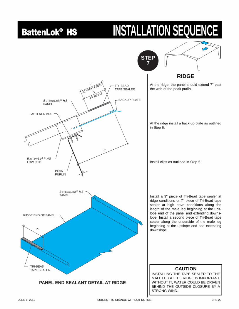
PANEL END SEALANT DETAIL AT RIDGE
7"
BACKUP PLATEBattenLok® HSPANEL
PEAKPURLIN
FASTENER #1A
BattenLok® HSLOW CLIP
3"
TRI-BEAD TAPE SEALER
BattenLok® HSPANEL
RIDGE END OF PANEL
3"
TRI-BEADTAPE SEALER
7"
AT HIGH EAVE
AT RIDGE
RIDGEAt the ridge, the panel should extend 7" pastthe web of the peak purlin.
At the ridge install a back-up plate as outlinedin Step 6.
Install clips as outlined in Step 5.
Install a 3" piece of Tri-Bead tape sealer atridge conditions or 7" piece of Tri-Bead tapesealer at high eave conditions along thelength of the male leg beginning at the ups-lope end of the panel and extending downs-lope. Install a second piece of Tri-Bead tapesealer along the underside of the male legbeginning at the upslope end and extendingdownslope.
32
1
STEP7
CAUTIONINSTALLING THE TAPE SEALER TO THEMALE LEG AT THE RIDGE IS IMPORTANT.WITHOUT IT, WATER COULD BE DRIVENBEHIND THE OUTSIDE CLOSURE BY ASTRONG WIND.
BHS-30 SUBJECT TO CHANGE WITHOUT NOTICE JUNE 1, 2012
INSTALLATION SEQUENCE BattenLok® HS
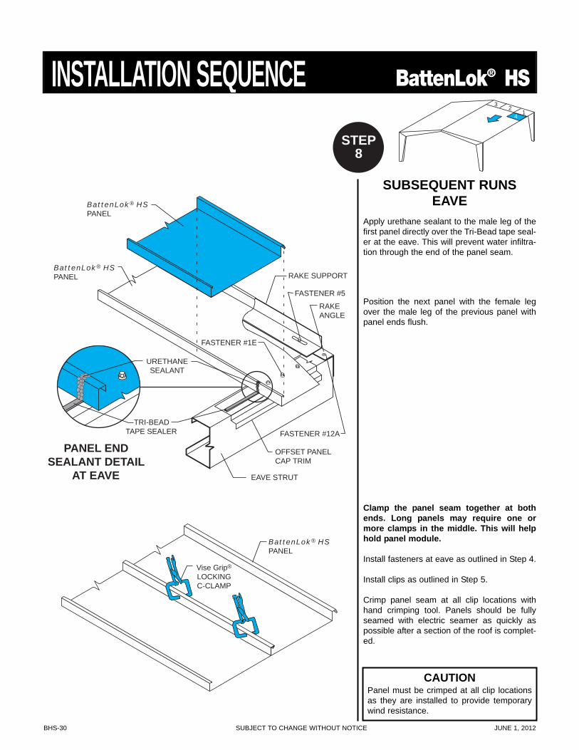
SUBSEQUENT RUNSEAVE
Apply urethane sealant to the male leg of thefirst panel directly over the Tri-Bead tape seal-er at the eave. This will prevent water infiltra-tion through the end of the panel seam.
Position the next panel with the female legover the male leg of the previous panel withpanel ends flush.
Clamp the panel seam together at bothends. Long panels may require one ormore clamps in the middle. This will helphold panel module.
Install fasteners at eave as outlined in Step 4.
Install clips as outlined in Step 5.
Crimp panel seam at all clip locations withhand crimping tool. Panels should be fullyseamed with electric seamer as quickly aspossible after a section of the roof is complet-ed.
BattenLok® HSPANEL
EAVE STRUT
RAKE SUPPORT
RAKEANGLE
OFFSET PANELCAP TRIM
FASTENER #5
FASTENER #1E
FASTENER #12A
BattenLok® HSPANEL
URETHANESEALANT
TRI-BEADTAPE SEALER
BattenLok® HSPANEL
PANEL ENDSEALANT DETAIL
AT EAVE
Vise Grip®
LOCKINGC-CLAMP
4
32
1
STEP8
CAUTIONPanel must be crimped at all clip locationsas they are installed to provide temporarywind resistance.
JUNE 1, 2012 SUBJECT TO CHANGE WITHOUT NOTICE BHS-31
BattenLok® HS INSTALLATION SEQUENCE
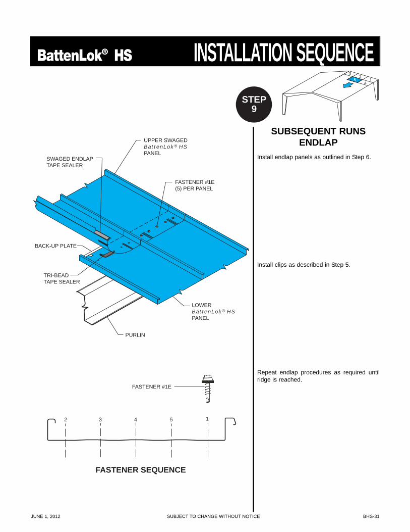
FASTENER SEQUENCE
UPPER SWAGEDBattenLok® HSPANEL
FASTENER #1E(5) PER PANEL
SWAGED ENDLAPTAPE SEALER
BACK-UP PLATE
TRI-BEADTAPE SEALER
PURLIN
LOWERBattenLok® HSPANEL
12 3 4 5
FASTENER #1E
SUBSEQUENT RUNSENDLAP
Install endlap panels as outlined in Step 6.
Install clips as described in Step 5.
Repeat endlap procedures as required untilridge is reached.
4
31
25
STEP9
BHS-32 SUBJECT TO CHANGE WITHOUT NOTICE JUNE 1, 2012
INSTALLATION SEQUENCE BattenLok® HS
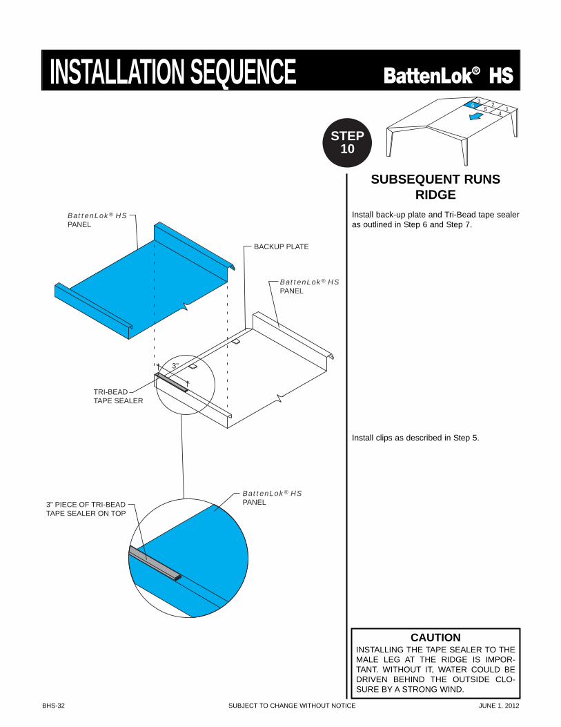
SUBSEQUENT RUNSRIDGE
Install back-up plate and Tri-Bead tape sealeras outlined in Step 6 and Step 7.
Install clips as described in Step 5.
3"
BattenLok® HSPANEL3" PIECE OF TRI-BEAD
TAPE SEALER ON TOP
TRI-BEADTAPE SEALER
BattenLok® HSPANEL
BattenLok® HSPANEL
BACKUP PLATE
4
31
265
STEP10
CAUTIONINSTALLING THE TAPE SEALER TO THEMALE LEG AT THE RIDGE IS IMPOR-TANT. WITHOUT IT, WATER COULD BEDRIVEN BEHIND THE OUTSIDE CLO-SURE BY A STRONG WIND.
JUNE 1, 2012 SUBJECT TO CHANGE WITHOUT NOTICE BHS-33
BattenLok® HS INSTALLATION SEQUENCE
PURLIN
RAKE ANGLE
PANELFASTENER
WALL PANEL
BattenLok® HSFLOATING CLIP
FASTENER #12A
BattenLok® HSPANEL
FASTENER # 1A
FASTENER #524" O.C.
RAKE SUPPORT
RAKE SUPPORTRAKESUPPORT
WALL PANEL
VARIABLETERMINATION TRIM
TRI-BEADTAPE SEALER
RAKE ANGLE
TRIM FASTENER
RAKE TRIM
PURLINCLOSURE
BattenLok® HSPANEL
FASTENER # 12A
RAKE ANGLE
FASTENER #524" O.C.
FASTENER #524" O.C.
FASTENER #1E24" O.C.
TRI-BEADTAPE SEALER
FASTENER #46" O.C.
PANELFASTENER
RAKE SLIDE
TRIM FASTENER
RAKE TRIM
CLOSURE
FASTENER #1E24" O.C.TRI-BEAD
TAPE SEALER
RAKE SLIDE
8" TO 14"
8" MAX
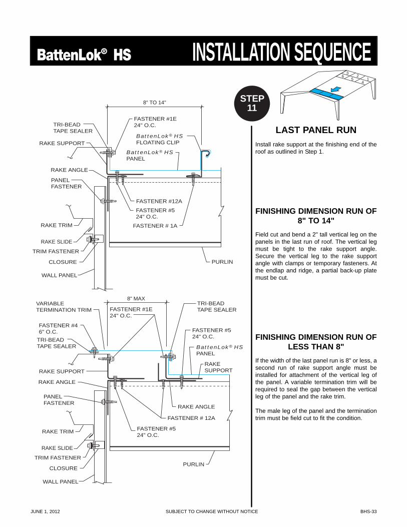
LAST PANEL RUNInstall rake support at the finishing end of theroof as outlined in Step 1.
FINISHING DIMENSION RUN OF8" TO 14"
Field cut and bend a 2" tall vertical leg on thepanels in the last run of roof. The vertical legmust be tight to the rake support angle.Secure the vertical leg to the rake supportangle with clamps or temporary fasteners. Atthe endlap and ridge, a partial back-up platemust be cut.
FINISHING DIMENSION RUN OFLESS THAN 8"
If the width of the last panel run is 8" or less, asecond run of rake support angle must beinstalled for attachment of the vertical leg ofthe panel. A variable termination trim will berequired to seal the gap between the verticalleg of the panel and the rake trim.
The male leg of the panel and the terminationtrim must be field cut to fit the condition.
4
31
265
6
STEP11
BHS-34 SUBJECT TO CHANGE WITHOUT NOTICE JUNE 1, 2012
INSTALLATION SEQUENCE BattenLok® HS
SEAMING OPERATION
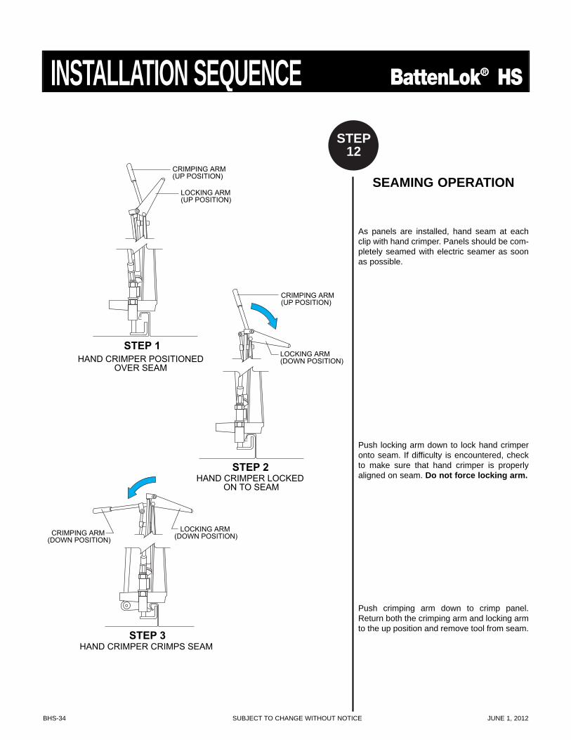
As panels are installed, hand seam at eachclip with hand crimper. Panels should be com-pletely seamed with electric seamer as soonas possible.
Push locking arm down to lock hand crimperonto seam. If difficulty is encountered, checkto make sure that hand crimper is properlyaligned on seam. Do not force locking arm.
Push crimping arm down to crimp panel.Return both the crimping arm and locking armto the up position and remove tool from seam.
STEP 1
CRIMPING ARM(UP POSITION)
LOCKING ARM(UP POSITION)
HAND CRIMPER POSITIONEDOVER SEAM
STEP 2HAND CRIMPER LOCKED
ON TO SEAM
CRIMPING ARM(UP POSITION)
LOCKING ARM(DOWN POSITION)
CRIMPING ARM (DOWN POSITION)
STEP 3HAND CRIMPER CRIMPS SEAM
LOCKING ARM (DOWN POSITION)
STEP12
JUNE 1, 2012 SUBJECT TO CHANGE WITHOUT NOTICE BHS-35
BattenLok® HS INSTALLATION SEQUENCE
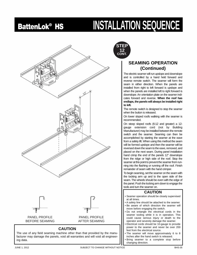
SEAMING OPERATION(Continued)
The electric seamer will run upslope and downslopeand is controlled by a hand held forward andreverse remote switch. The seamer will form theseam in either direction. When the panels areinstalled from right to left forward is upslope andwhen the panels are installed left to right forward isdownslope. An orientation plate on the seamer indi-cates forward and reverse. When the roof hasendlaps, the panels will always be installed rightto left.The remote switch is designed to stop the seamerwhen the button is released.On lower sloped roofs walking with the seamer isrecommended.On steep sloped roofs (6:12 and greater) a 12-gauge extension cord (not by BuildingManufacturer) may be installed between the remoteswitch and the seamer. Seaming can then beaccomplished by starting the seamer at the eavefrom a safety lift. When using this method the seamwill be formed upslope and then the seamer will bereversed down the seam to the eave, removed, andplaced on the next seam. During panel installationhand crimp the end of the panels 12" downslopefrom the ridge or high side of the roof. Stop theseamer at this point to prevent the seamer from run-ning into the flashing or running off the roof. Finishremainder of seam with the hand crimper.To begin seaming, set the seamer on the seam withthe locking arm up and to the open side of theseam. The wheels should be even with the edge ofthe panel. Push the locking arm down to engage thetools and turn the seamer on.
12"
PANEL PROFILEBEFORE SEAMING
PANEL PROFILEAFTER SEAMING
STEP12
CONT.
CAUTION• Seamer operation should be closely supervised
at all times.• A safety line should be attached to the seamer.• Be aware of which direction the seamer will
move before engaging the switch.• Do not entangle the electrical cords in the
seamer tooling while it is in operation. Thiscould cause serious injury or death to the operator and severely damage the seamer.
• Electrical cords should be 10-gauge to providepower to the seamer and never be over 200feet from the electrical source.
• The seamer will move approximately 6 to 8inches after the hand switch is released.
• Bring seamer to a complete stop before changing direction.
CAUTIONThe use of any field seaming machine other than that provided by the manu-facturer may damage the panels, void all warranties and will void all engineer-ing data.
BHS-36 SUBJECT TO CHANGE WITHOUT NOTICE JUNE 1, 2012
INSTALLATION SEQUENCE BattenLok® HS
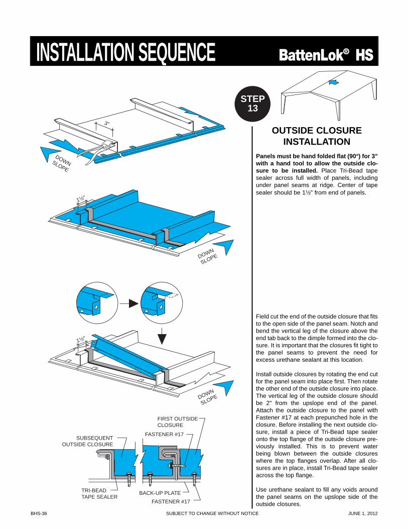
OUTSIDE CLOSUREINSTALLATION
Panels must be hand folded flat (90°) for 3"with a hand tool to allow the outside clo-sure to be installed. Place Tri-Bead tapesealer across full width of panels, includingunder panel seams at ridge. Center of tapesealer should be 1¹⁄₂" from end of panels.
Field cut the end of the outside closure that fitsto the open side of the panel seam. Notch andbend the vertical leg of the closure above theend tab back to the dimple formed into the clo-sure. It is important that the closures fit tight tothe panel seams to prevent the need forexcess urethane sealant at this location.
Install outside closures by rotating the end cutfor the panel seam into place first. Then rotatethe other end of the outside closure into place.The vertical leg of the outside closure shouldbe 2" from the upslope end of the panel.Attach the outside closure to the panel withFastener #17 at each prepunched hole in theclosure. Before installing the next outside clo-sure, install a piece of Tri-Bead tape sealeronto the top flange of the outside closure pre-viously installed. This is to prevent waterbeing blown between the outside closureswhere the top flanges overlap. After all clo-sures are in place, install Tri-Bead tape sealeracross the top flange.
Use urethane sealant to fill any voids aroundthe panel seams on the upslope side of theoutside closures.FASTENER #17
SUBSEQUENTOUTSIDE CLOSURE
FIRST OUTSIDECLOSURE
FASTENER #17
TRI-BEADTAPE SEALER
BACK-UP PLATE
DOWN
SLOPE
1¹⁄₂"
DOWNSLOPE
3"
DOWN
SLOPE
1¹⁄₂"
STEP13
JUNE 1, 2012 SUBJECT TO CHANGE WITHOUT NOTICE BHS-37
BattenLok® HS SPECIAL ERECTION TECHNIQUES
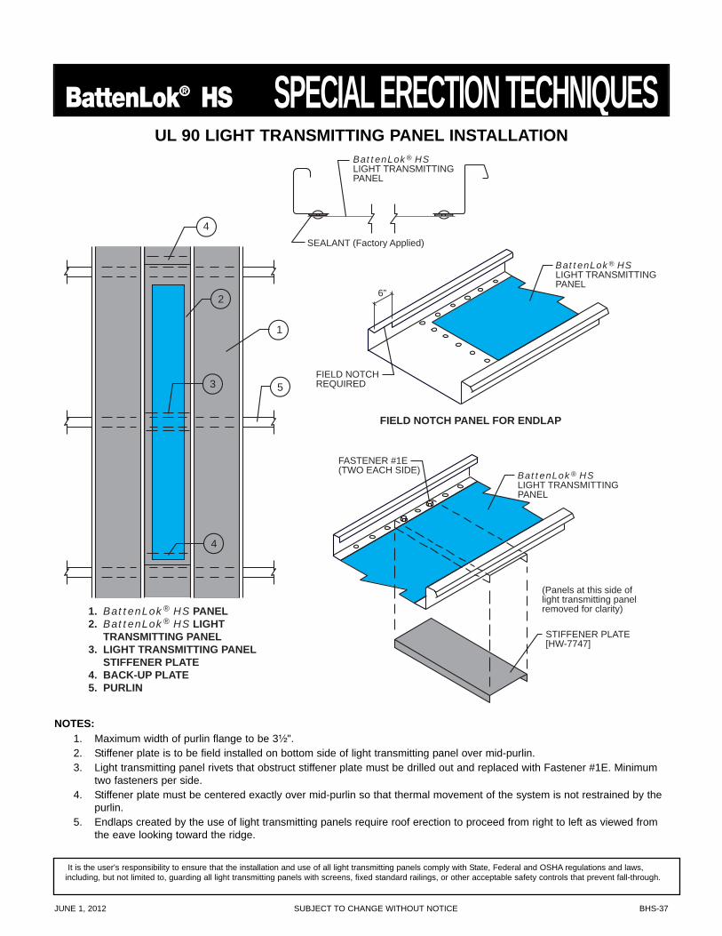
1. BattenLok® HS PANEL2. BattenLok® HS LIGHT TRANSMITTING PANEL3. LIGHT TRANSMITTING PANEL STIFFENER PLATE4. BACK-UP PLATE5. PURLIN
FIELD NOTCH PANEL FOR ENDLAP
4
2
3 5
4
1
SEALANT (Factory Applied)
BattenLok® HSLIGHT TRANSMITTINGPANEL
FASTENER #1E(TWO EACH SIDE)
STIFFENER PLATE[HW-7747]
6”
FIELD NOTCHREQUIRED
(Panels at this side oflight transmitting panelremoved for clarity)
BattenLok® HSLIGHT TRANSMITTINGPANEL
BattenLok® HSLIGHT TRANSMITTINGPANEL
UL 90 LIGHT TRANSMITTING PANEL INSTALLATION
NOTES:1. Maximum width of purlin flange to be 3¹⁄₂".2. Stiffener plate is to be field installed on bottom side of light transmitting panel over mid-purlin.3. Light transmitting panel rivets that obstruct stiffener plate must be drilled out and replaced with Fastener #1E. Minimum
two fasteners per side.4. Stiffener plate must be centered exactly over mid-purlin so that thermal movement of the system is not restrained by the
purlin.5. Endlaps created by the use of light transmitting panels require roof erection to proceed from right to left as viewed from
the eave looking toward the ridge.
It is the user's responsibility to ensure that the installation and use of all light transmitting panels comply with State, Federal and OSHA regulations and laws,including, but not limited to, guarding all light transmitting panels with screens, fixed standard railings, or other acceptable safety controls that prevent fall-through.
BHS-38 SUBJECT TO CHANGE WITHOUT NOTICE JUNE 1, 2012
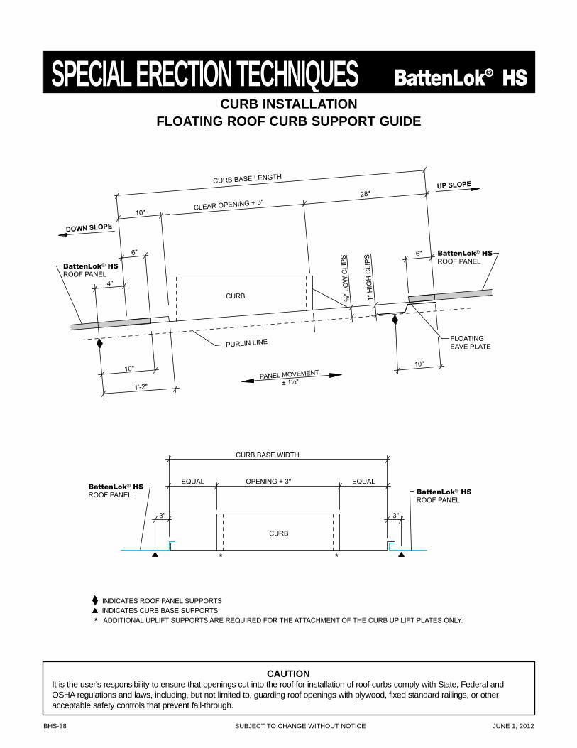
SPECIAL ERECTION TECHNIQUES BattenLok® HSCURB INSTALLATION
FLOATING ROOF CURB SUPPORT GUIDE
INDICATES ROOF PANEL SUPPORTS INDICATES CURB BASE SUPPORTS
* ADDITIONAL UPLIFT SUPPORTS ARE REQUIRED FOR THE ATTACHMENT OF THE CURB UP LIFT PLATES ONLY.
BattenLok® HS
ROOF PANEL
CURB
* *
EQUAL EQUAL
CURB BASE WIDTH
OPENING + 3"
3" 3"
BattenLok® HS
ROOF PANEL
PANEL MOVEMENT ± 1¹⁄₄"
10"
CURB
FLOATING EAVE PLATE PURLIN LINE
³⁄₈"
LO
W C
LIPS
1" H
IGH
CLI
PS
CURB BASE LENGTH
10" CLEAR OPENING + 3"
28"
4"
6" 6"
1'-2"
10"
BattenLok® HS
ROOF PANEL BattenLok® HS
ROOF PANEL
DOWN SLOPE
UP SLOPE
CAUTIONIt is the user's responsibility to ensure that openings cut into the roof for installation of roof curbs comply with State, Federal andOSHA regulations and laws, including, but not limited to, guarding roof openings with plywood, fixed standard railings, or otheracceptable safety controls that prevent fall-through.
JUNE 1, 2012 SUBJECT TO CHANGE WITHOUT NOTICE BHS-39
BattenLok® HS SPECIAL ERECTION TECHNIQUES
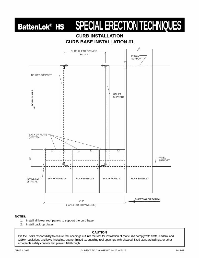
NOTES:1. Install all lower roof panels to support the curb base.2. Install back up plates.
BACK UP PLATE(HW-7766)
UP LIFT SUPPORT
(PANEL RIB TO PANEL RIB)
DO
WN
SLO
PE
ROOF PANEL #4 ROOF PANEL #3 ROOF PANEL #2
SHEETING DIRECTION
ROOF PANEL #1
UPLIFTSUPPORT
PANEL CLIP(TYPICAL)
PANELSUPPORT
PANELSUPPORT
PLUS 3"CURB CLEAR OPENING
10"
4'-0"
CURB INSTALLATIONCURB BASE INSTALLATION #1
CAUTIONIt is the user's responsibility to ensure that openings cut into the roof for installation of roof curbs comply with State, Federal andOSHA regulations and laws, including, but not limited to, guarding roof openings with plywood, fixed standard railings, or otheracceptable safety controls that prevent fall-through.
BHS-40 SUBJECT TO CHANGE WITHOUT NOTICE JUNE 1, 2012
SPECIAL ERECTION TECHNIQUES BattenLok® HS
BACK UP PLATE(HW-7766)
UP LIFT SUPPORT
DO
WN
SLO
PE
ROOF PANEL #4 ROOF PANEL #3 ROOF PANEL #2
SHEETING DIRECTION
ROOF PANEL #1
UPLIFTSUPPORT
PANEL CLIP(TYPICAL)
PANELSUPPORT
PANELSUPPORT
PLUS 3"CURB CLEAR OPENING
10"
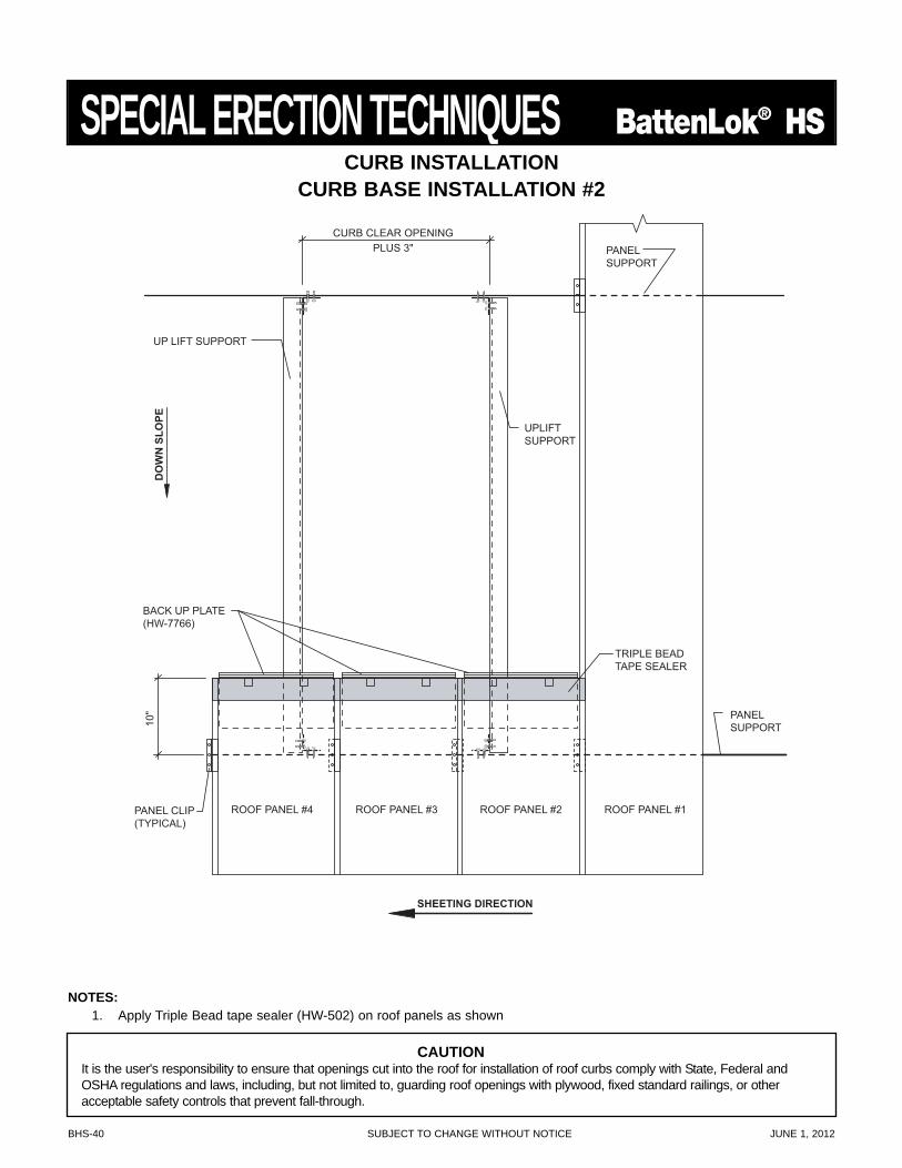
TRIPLE BEADTAPE SEALER
NOTES:1. Apply Triple Bead tape sealer (HW-502) on roof panels as shown
CURB INSTALLATIONCURB BASE INSTALLATION #2
CAUTIONIt is the user's responsibility to ensure that openings cut into the roof for installation of roof curbs comply with State, Federal andOSHA regulations and laws, including, but not limited to, guarding roof openings with plywood, fixed standard railings, or otheracceptable safety controls that prevent fall-through.
JUNE 1, 2012 SUBJECT TO CHANGE WITHOUT NOTICE BHS-41
BattenLok® HS SPECIAL ERECTION TECHNIQUESCURB INSTALLATION
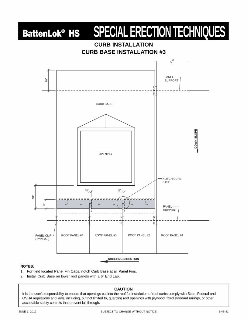
CURB BASE INSTALLATION #3
PANELSUPPORT
CURB BASE
NOTCH CURBBASE
OPENING
10"
10"
¹⁄₂"
6"
PANELSUPPORT
DO
WN
SLO
PE
SHEETING DIRECTION
ROOF PANEL #4 ROOF PANEL #3 ROOF PANEL #2 ROOF PANEL #1PANEL CLIP(TYPICAL)
¹⁄₂"
NOTES:1. For field located Panel Fin Caps, notch Curb Base at all Panel Fins.2. Install Curb Base on lower roof panels with a 6" End Lap.
CAUTIONIt is the user's responsibility to ensure that openings cut into the roof for installation of roof curbs comply with State, Federal andOSHA regulations and laws, including, but not limited to, guarding roof openings with plywood, fixed standard railings, or otheracceptable safety controls that prevent fall-through.
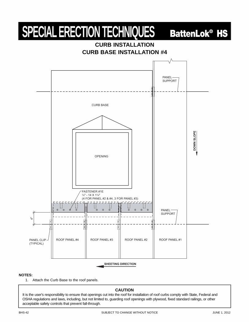
BHS-42 SUBJECT TO CHANGE WITHOUT NOTICE JUNE 1, 2012
SPECIAL ERECTION TECHNIQUES BattenLok® HS
PANELSUPPORT
CURB BASE
FASTENER #1E¹⁄₄" - 14 X 1¹⁄₄"(4 FOR PANEL #2 & #4, 3 FOR PANEL #3)
OPENING
4"
PANELSUPPORT
DO
WN
SLO
PE
SHEETING DIRECTION
ROOF PANEL #4 ROOF PANEL #3 ROOF PANEL #2 ROOF PANEL #1PANEL CLIP(TYPICAL)
NOTES:1. Attach the Curb Base to the roof panels.
CURB INSTALLATIONCURB BASE INSTALLATION #4
CAUTIONIt is the user's responsibility to ensure that openings cut into the roof for installation of roof curbs comply with State, Federal andOSHA regulations and laws, including, but not limited to, guarding roof openings with plywood, fixed standard railings, or otheracceptable safety controls that prevent fall-through.
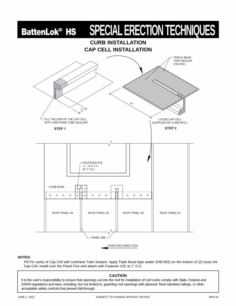
JUNE 1, 2012 SUBJECT TO CHANGE WITHOUT NOTICE BHS-43
BattenLok® HS SPECIAL ERECTION TECHNIQUES
NOTES:Fill Fin cavity of Cap Cell with Urethane Tube Sealant. Apply Triple Bead tape sealer (HW-502) on the bottom of (2) loose theCap Cell, install over the Panel Fins and attach with Fastener #1E at 1" O.C.
TRIPLE BEADTAPE SEALER(HW-502)
LOOSE CAP CELL(SUPPLIED BY CURB MFG.)
FASTENER #1E¹⁄₄ - 14 X 1¹⁄₄"AT 1" O.C.
CURB BASE
PANEL RIB
STEP 2STEP 1
FILL THE END OF THE CAP CELLWITH URETHANE TUBE SEALANT
1"
6"
SHEETING DIRECTION
ROOF PANEL #4 ROOF PANEL #3 ROOF PANEL #2 ROOF PANEL #1
CURB INSTALLATIONCAP CELL INSTALLATION
CAUTIONIt is the user's responsibility to ensure that openings cut into the roof for installation of roof curbs comply with State, Federal andOSHA regulations and laws, including, but not limited to, guarding roof openings with plywood, fixed standard railings, or otheracceptable safety controls that prevent fall-through.
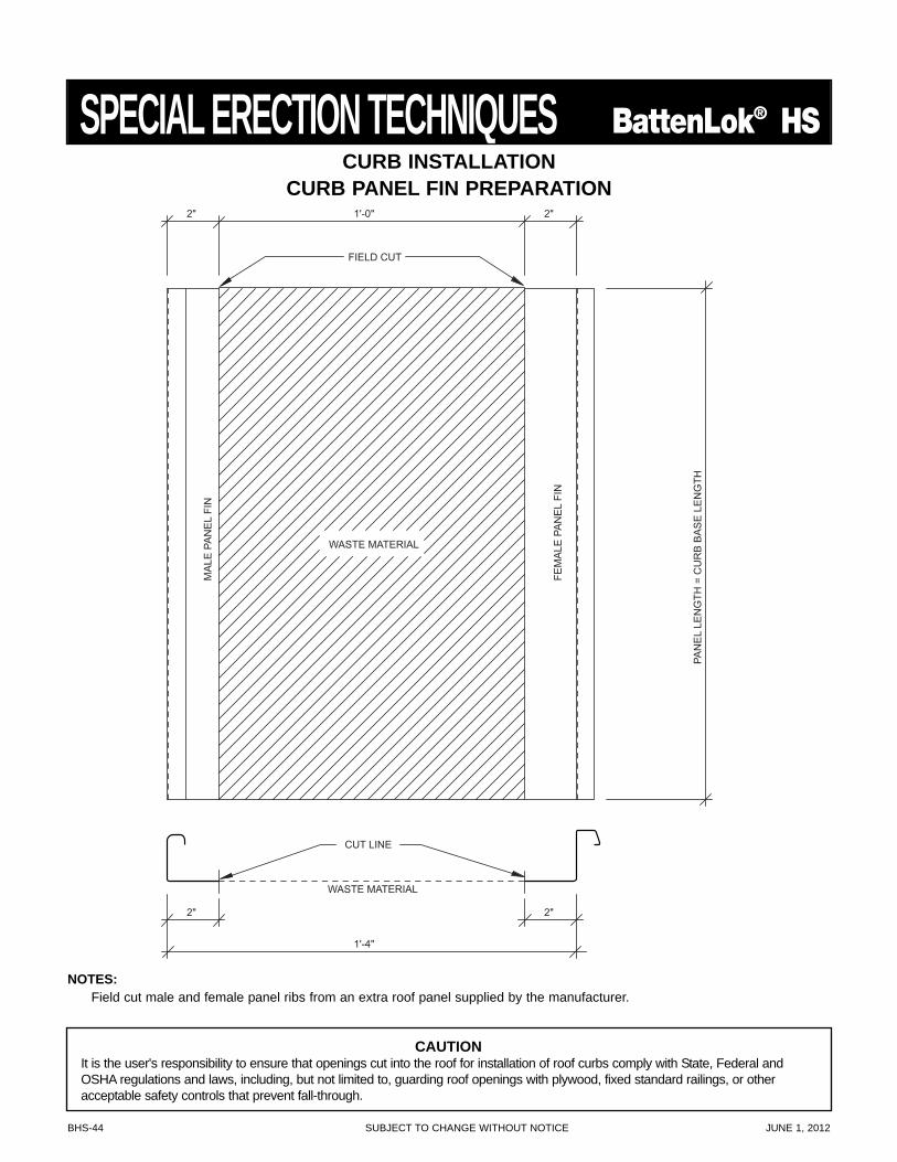
BHS-44 SUBJECT TO CHANGE WITHOUT NOTICE JUNE 1, 2012
SPECIAL ERECTION TECHNIQUES BattenLok® HS
NOTES:Field cut male and female panel ribs from an extra roof panel supplied by the manufacturer.
FIELD CUT
WASTE MATERIAL
WASTE MATERIAL
MA
LE P
AN
EL
FIN
FEM
ALE
PA
NE
L FI
N
PAN
EL
LEN
GTH
= C
UR
B B
AS
E L
EN
GTH
CUT LINE
2" 1'-0" 2"
1'-4"
2" 2"
CURB INSTALLATIONCURB PANEL FIN PREPARATION
CAUTIONIt is the user's responsibility to ensure that openings cut into the roof for installation of roof curbs comply with State, Federal andOSHA regulations and laws, including, but not limited to, guarding roof openings with plywood, fixed standard railings, or otheracceptable safety controls that prevent fall-through.
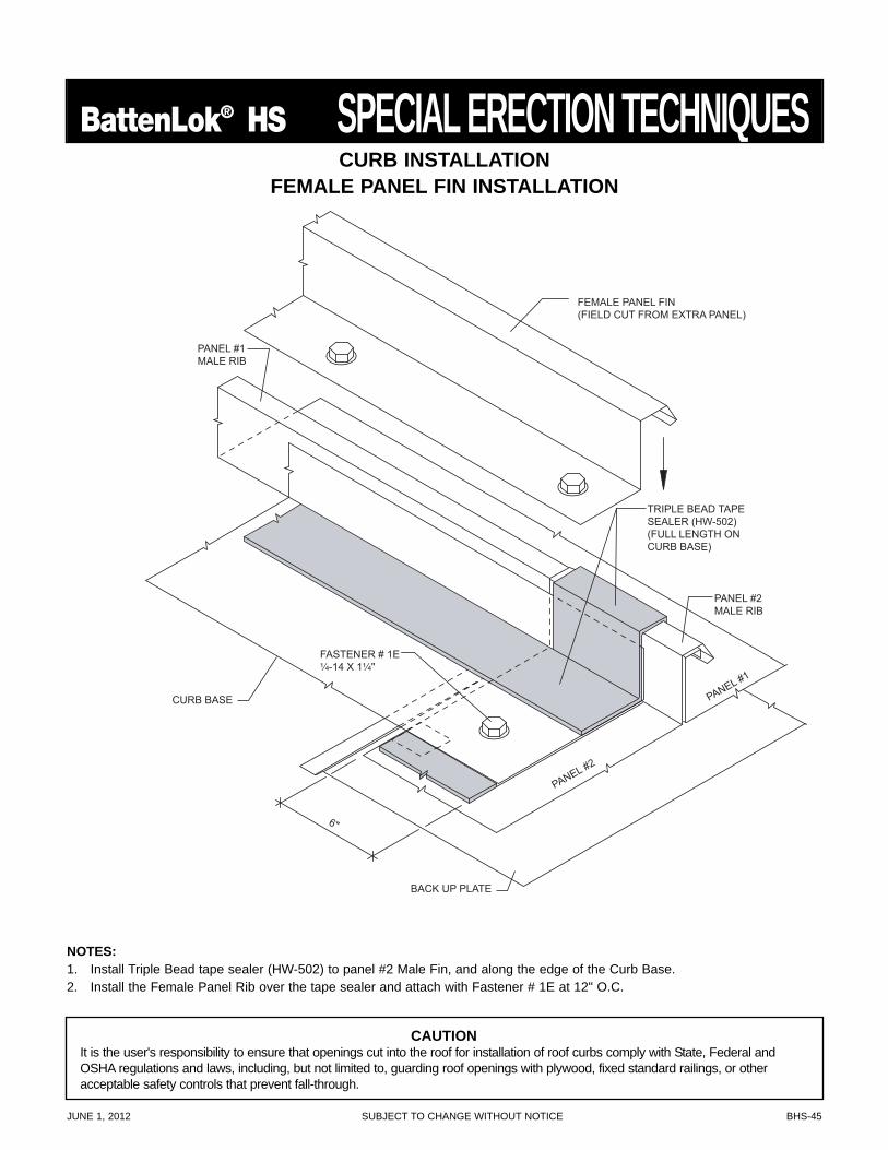
JUNE 1, 2012 SUBJECT TO CHANGE WITHOUT NOTICE BHS-45
BattenLok® HS SPECIAL ERECTION TECHNIQUES
PANEL #2
TRIPLE BEAD TAPESEALER (HW-502)(FULL LENGTH ONCURB BASE)
PANEL #1
6"
FEMALE PANEL FIN(FIELD CUT FROM EXTRA PANEL)
PANEL #2MALE RIB
FASTENER # 1E¹⁄₄-14 X 1¹⁄₄"
CURB BASE
BACK UP PLATE
PANEL #1MALE RIB
NOTES:1. Install Triple Bead tape sealer (HW-502) to panel #2 Male Fin, and along the edge of the Curb Base.2. Install the Female Panel Rib over the tape sealer and attach with Fastener # 1E at 12" O.C.
CURB INSTALLATIONFEMALE PANEL FIN INSTALLATION
CAUTIONIt is the user's responsibility to ensure that openings cut into the roof for installation of roof curbs comply with State, Federal andOSHA regulations and laws, including, but not limited to, guarding roof openings with plywood, fixed standard railings, or otheracceptable safety controls that prevent fall-through.
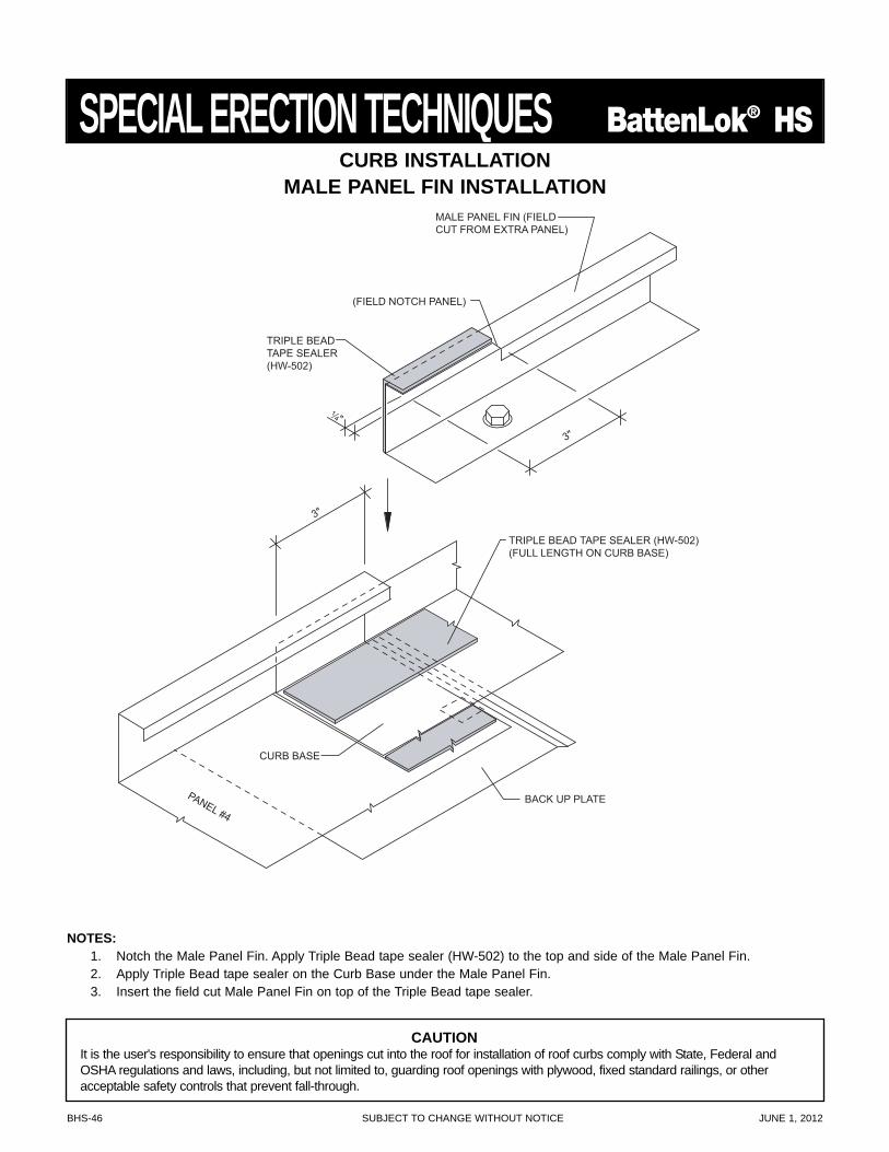
BHS-46 SUBJECT TO CHANGE WITHOUT NOTICE JUNE 1, 2012
SPECIAL ERECTION TECHNIQUES BattenLok® HS
NOTES:1. Notch the Male Panel Fin. Apply Triple Bead tape sealer (HW-502) to the top and side of the Male Panel Fin.2. Apply Triple Bead tape sealer on the Curb Base under the Male Panel Fin.3. Insert the field cut Male Panel Fin on top of the Triple Bead tape sealer.
TRIPLE BEADTAPE SEALER(HW-502)
(FIELD NOTCH PANEL)
PANEL #4
¹⁄₄"
3"
3"
MALE PANEL FIN (FIELDCUT FROM EXTRA PANEL)
TRIPLE BEAD TAPE SEALER (HW-502)(FULL LENGTH ON CURB BASE)
BACK UP PLATE
CURB BASE
CURB INSTALLATIONMALE PANEL FIN INSTALLATION
CAUTIONIt is the user's responsibility to ensure that openings cut into the roof for installation of roof curbs comply with State, Federal andOSHA regulations and laws, including, but not limited to, guarding roof openings with plywood, fixed standard railings, or otheracceptable safety controls that prevent fall-through.

JUNE 1, 2012 SUBJECT TO CHANGE WITHOUT NOTICE BHS-47
BattenLok® HS SPECIAL ERECTION TECHNIQUES
CURB BASE
FEMALE PANEL FIN(FIELD CUT)
OPENING
MALE PANEL FIN(FIELD CUT)
TYP.
MA
X.
1'-0
"
SHEETING DIRECTION
ROOF PANEL #4 ROOF PANEL #3 ROOF PANEL #2 ROOF PANEL #1
PANELSUPPORT
PANELSUPPORT
CURB INSTALLATIONCURB BASE INSTALLATION #5
CAUTIONIt is the user's responsibility to ensure that openings cut into the roof for installation of roof curbs comply with State, Federal andOSHA regulations and laws, including, but not limited to, guarding roof openings with plywood, fixed standard railings, or otheracceptable safety controls that prevent fall-through.
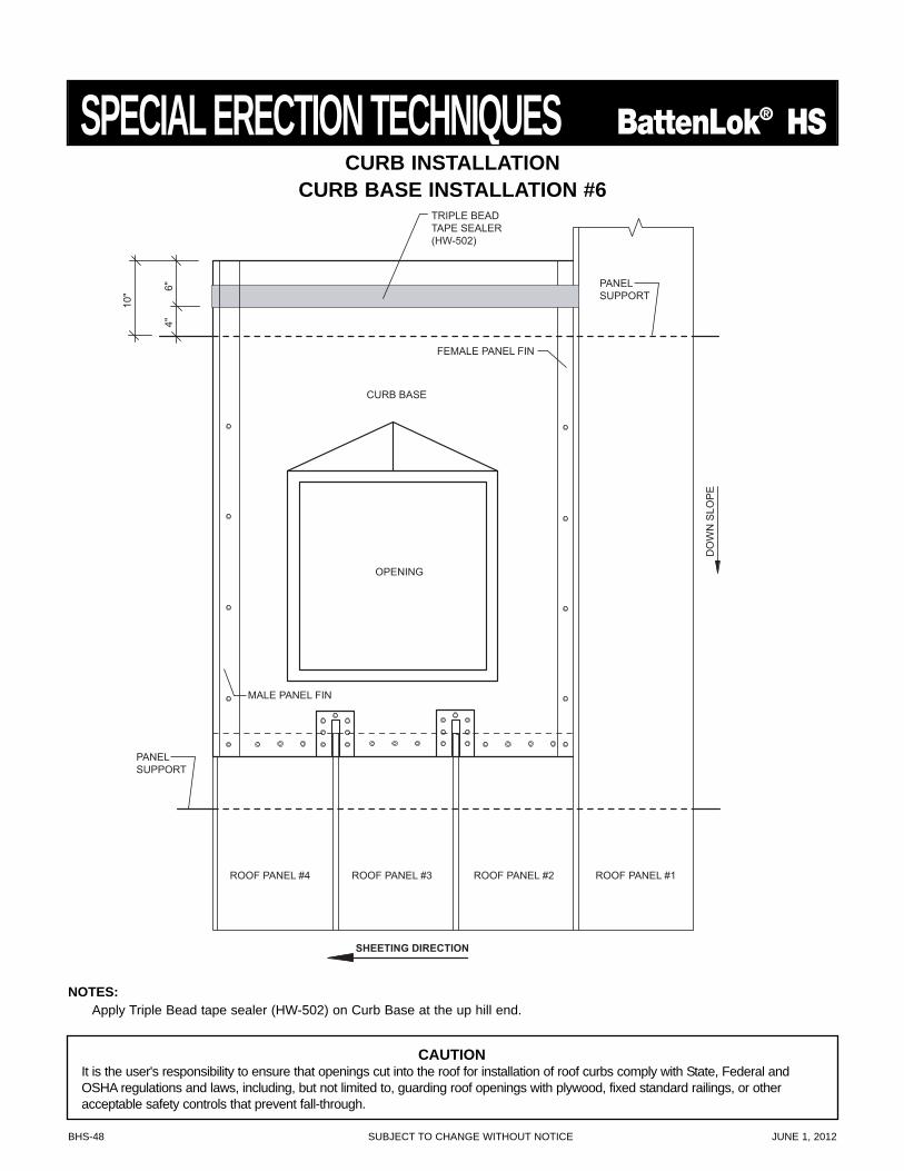
BHS-48 SUBJECT TO CHANGE WITHOUT NOTICE JUNE 1, 2012
SPECIAL ERECTION TECHNIQUES BattenLok® HS
CURB BASE
FEMALE PANEL FIN
OPENING
MALE PANEL FIN
SHEETING DIRECTION
ROOF PANEL #4 ROOF PANEL #3 ROOF PANEL #2 ROOF PANEL #1
PANELSUPPORT
PANELSUPPORT
DO
WN
SLO
PE
TRIPLE BEADTAPE SEALER(HW-502)
10"
4"6"
CURB INSTALLATIONCURB BASE INSTALLATION #6
NOTES:Apply Triple Bead tape sealer (HW-502) on Curb Base at the up hill end.
CAUTIONIt is the user's responsibility to ensure that openings cut into the roof for installation of roof curbs comply with State, Federal andOSHA regulations and laws, including, but not limited to, guarding roof openings with plywood, fixed standard railings, or otheracceptable safety controls that prevent fall-through.
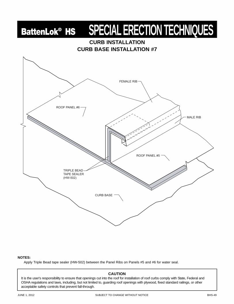
JUNE 1, 2012 SUBJECT TO CHANGE WITHOUT NOTICE BHS-49
BattenLok® HS SPECIAL ERECTION TECHNIQUES
TRIPLE BEADTAPE SEALER(HW-502)
MALE RIB
ROOF PANEL #6
FEMALE RIB
ROOF PANEL #5
CURB BASE
NOTES:Apply Triple Bead tape sealer (HW-502) between the Panel Ribs on Panels #5 and #6 for water seal.
CURB INSTALLATIONCURB BASE INSTALLATION #7
CAUTIONIt is the user's responsibility to ensure that openings cut into the roof for installation of roof curbs comply with State, Federal andOSHA regulations and laws, including, but not limited to, guarding roof openings with plywood, fixed standard railings, or otheracceptable safety controls that prevent fall-through.
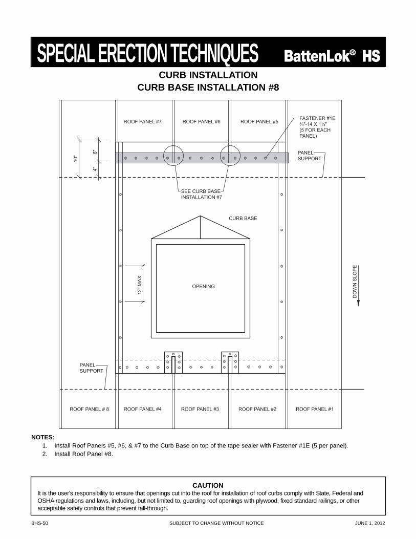
BHS-50 SUBJECT TO CHANGE WITHOUT NOTICE JUNE 1, 2012
SPECIAL ERECTION TECHNIQUES BattenLok® HS
NOTES:1. Install Roof Panels #5, #6, & #7 to the Curb Base on top of the tape sealer with Fastener #1E (5 per panel).2. Install Roof Panel #8.
CURB BASE
OPENING
ROOF PANEL #4 ROOF PANEL #3 ROOF PANEL #2 ROOF PANEL #1
PANELSUPPORT
PANELSUPPORT
DO
WN
SLO
PE
10"
4"6"
SEE CURB BASEINSTALLATION #7
ROOF PANEL # 8
ROOF PANEL #7 ROOF PANEL #5ROOF PANEL #6FASTENER #1E¹⁄₄"-14 X 1¹⁄₄"(5 FOR EACHPANEL)
12" M
AX
.
CURB INSTALLATIONCURB BASE INSTALLATION #8
CAUTIONIt is the user's responsibility to ensure that openings cut into the roof for installation of roof curbs comply with State, Federal andOSHA regulations and laws, including, but not limited to, guarding roof openings with plywood, fixed standard railings, or otheracceptable safety controls that prevent fall-through.
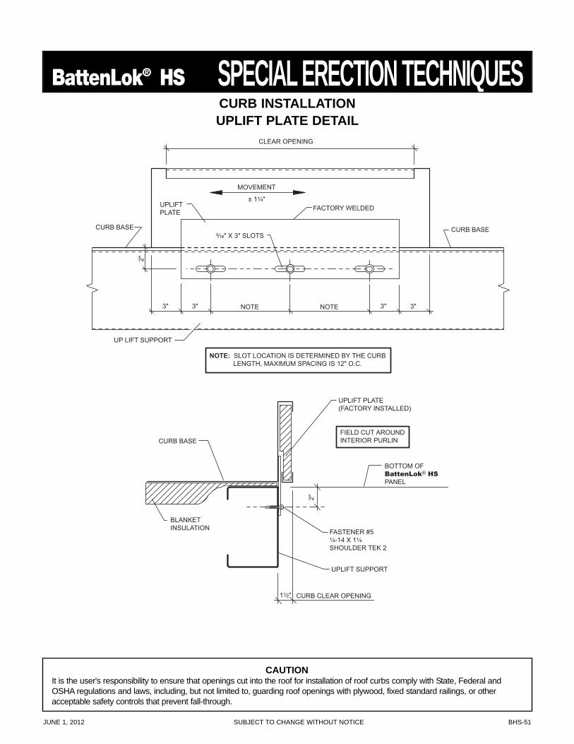
JUNE 1, 2012 SUBJECT TO CHANGE WITHOUT NOTICE BHS-51
BattenLok® HS SPECIAL ERECTION TECHNIQUES
NOTE: SLOT LOCATION IS DETERMINED BY THE CURB LENGTH, MAXIMUM SPACING IS 12" O.C.
UP LIFT SUPPORT
CURB BASE
UPLIFTPLATE
⁵⁄₁₆" X 3" SLOTS
FACTORY WELDED
CLEAR OPENING
CURB BASE
2"
3" 3" NOTENOTE 3" 3"
MOVEMENT
± 1¹⁄₄"
BLANKETINSULATION
CURB BASE
BOTTOM OFBattenLok® HSPANEL
FASTENER #5¹⁄₄-14 X 1¹⁄₄
SHOULDER TEK 2
UPLIFT SUPPORT
FIELD CUT AROUNDINTERIOR PURLIN
UPLIFT PLATE(FACTORY INSTALLED)
CURB CLEAR OPENING
2"
1¹⁄₂"
CURB INSTALLATIONUPLIFT PLATE DETAIL
CAUTIONIt is the user's responsibility to ensure that openings cut into the roof for installation of roof curbs comply with State, Federal andOSHA regulations and laws, including, but not limited to, guarding roof openings with plywood, fixed standard railings, or otheracceptable safety controls that prevent fall-through.
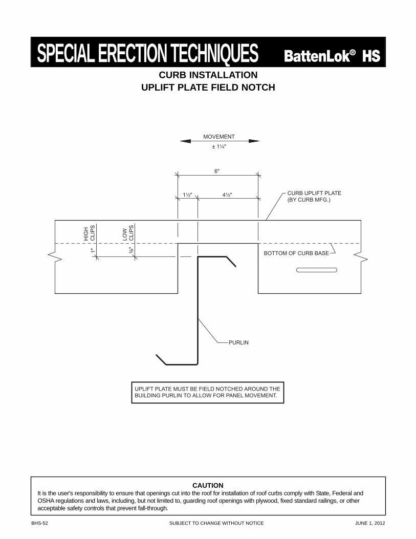
BHS-52 SUBJECT TO CHANGE WITHOUT NOTICE JUNE 1, 2012
SPECIAL ERECTION TECHNIQUES BattenLok® HS
UPLIFT PLATE MUST BE FIELD NOTCHED AROUND THEBUILDING PURLIN TO ALLOW FOR PANEL MOVEMENT.
CURB UPLIFT PLATE(BY CURB MFG.)
PURLIN
BOTTOM OF CURB BASE
HIG
HC
LIP
S1"
LOW
CLI
PS
1¹⁄₂" 4¹⁄₂"
6"
³⁄₈"
MOVEMENT
± 1¹⁄₄"
CURB INSTALLATIONUPLIFT PLATE FIELD NOTCH
CAUTIONIt is the user's responsibility to ensure that openings cut into the roof for installation of roof curbs comply with State, Federal andOSHA regulations and laws, including, but not limited to, guarding roof openings with plywood, fixed standard railings, or otheracceptable safety controls that prevent fall-through.
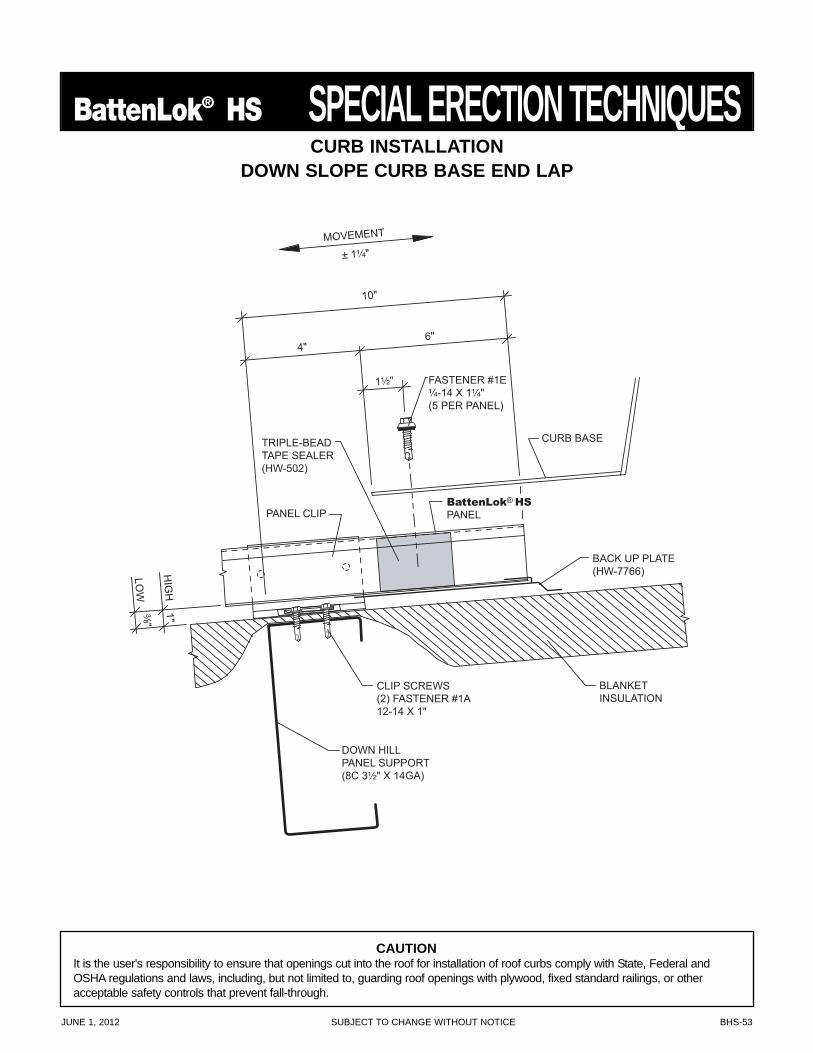
JUNE 1, 2012 SUBJECT TO CHANGE WITHOUT NOTICE BHS-53
BattenLok® HS SPECIAL ERECTION TECHNIQUES
BACK UP PLATE(HW-7766)
TRIPLE-BEADTAPE SEALER(HW-502)
CLIP SCREWS(2) FASTENER #1A12-14 X 1"
BLANKETINSULATION
DOWN HILLPANEL SUPPORT(8C 3¹⁄₂" X 14GA)
FASTENER #1E¹⁄₄-14 X 1¹⁄₄" (5 PER PANEL)
³⁄₈"LO
W
1"H
IGH
4"
10"
6"
1¹⁄₂"
MOVEMENT
± 1¹⁄₄"
BattenLok® HSPANEL
CURB BASE
PANEL CLIP
CURB INSTALLATIONDOWN SLOPE CURB BASE END LAP
CAUTIONIt is the user's responsibility to ensure that openings cut into the roof for installation of roof curbs comply with State, Federal andOSHA regulations and laws, including, but not limited to, guarding roof openings with plywood, fixed standard railings, or otheracceptable safety controls that prevent fall-through.
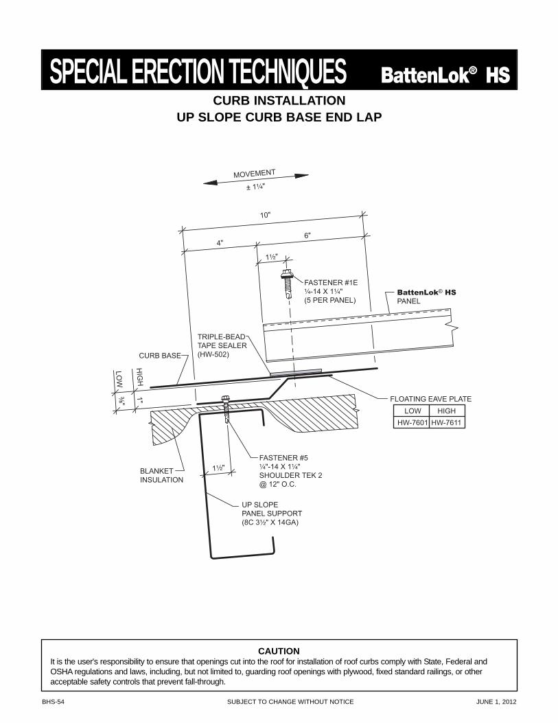
BHS-54 SUBJECT TO CHANGE WITHOUT NOTICE JUNE 1, 2012
SPECIAL ERECTION TECHNIQUES BattenLok® HS
FLOATING EAVE PLATE
HW-7611HW-7601LOW HIGH
1¹⁄₂"
CURB BASE
TRIPLE-BEADTAPE SEALER(HW-502)
FASTENER #5¹⁄₄"-14 X 1¹⁄₄"SHOULDER TEK 2@ 12" O.C.
BLANKETINSULATION
UP SLOPEPANEL SUPPORT(8C 3¹⁄₂" X 14GA)
FASTENER #1E¹⁄₄-14 X 1¹⁄₄" (5 PER PANEL)
³⁄₈"LO
W
1"H
IGH
4"
10"
6"
1¹⁄₂"
MOVEMENT
± 1¹⁄₄"
BattenLok® HSPANEL
CURB INSTALLATIONUP SLOPE CURB BASE END LAP
CAUTIONIt is the user's responsibility to ensure that openings cut into the roof for installation of roof curbs comply with State, Federal andOSHA regulations and laws, including, but not limited to, guarding roof openings with plywood, fixed standard railings, or otheracceptable safety controls that prevent fall-through.
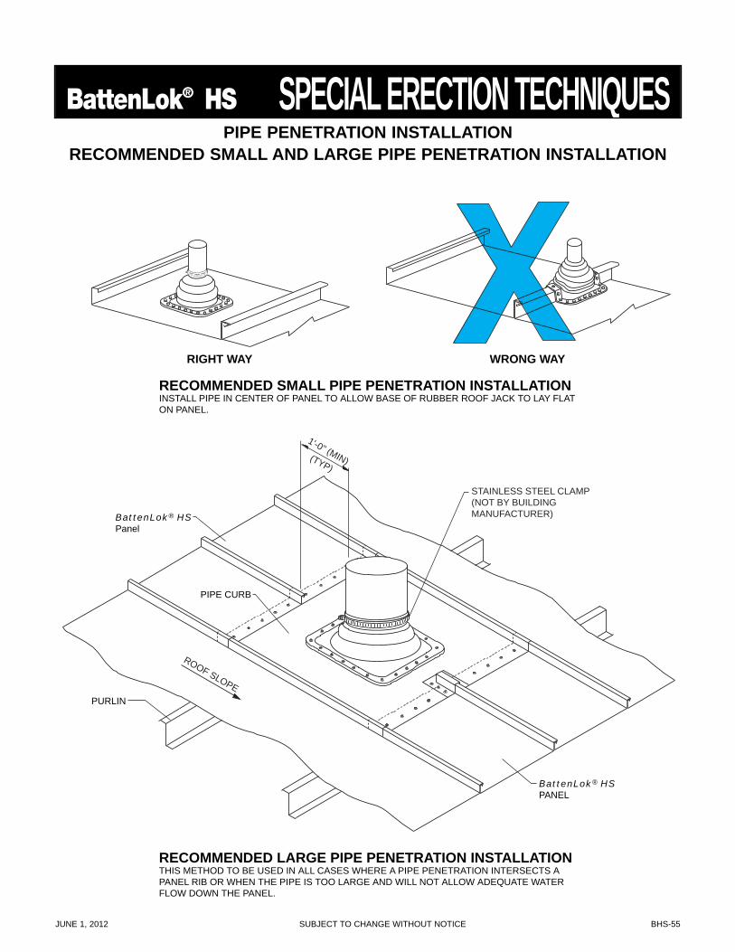
JUNE 1, 2012 SUBJECT TO CHANGE WITHOUT NOTICE BHS-55
BattenLok® HS SPECIAL ERECTION TECHNIQUES
RIGHT WAY
RECOMMENDED SMALL PIPE PENETRATION INSTALLATIONINSTALL PIPE IN CENTER OF PANEL TO ALLOW BASE OF RUBBER ROOF JACK TO LAY FLATON PANEL.
WRONG WAY
RECOMMENDED LARGE PIPE PENETRATION INSTALLATION THIS METHOD TO BE USED IN ALL CASES WHERE A PIPE PENETRATION INTERSECTS APANEL RIB OR WHEN THE PIPE IS TOO LARGE AND WILL NOT ALLOW ADEQUATE WATERFLOW DOWN THE PANEL.
PIPE CURB
PURLIN
BattenLok® HSPanel
STAINLESS STEEL CLAMP(NOT BY BUILDINGMANUFACTURER)
1'-0" (MIN)(TYP)
ROOF SLOPE
BattenLok® HSPANEL
PIPE PENETRATION INSTALLATIONRECOMMENDED SMALL AND LARGE PIPE PENETRATION INSTALLATION
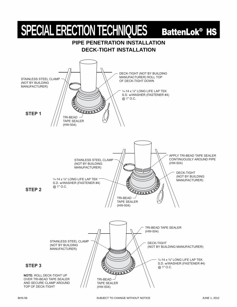
BHS-56 SUBJECT TO CHANGE WITHOUT NOTICE JUNE 1, 2012
SPECIAL ERECTION TECHNIQUES BattenLok® HS
STAINLESS STEEL CLAMP(NOT BY BUILDINGMANUFACTURER)
TRI-BEADTAPE SEALER(HW-504)
DECK-TIGHT (NOT BY BUILDINGMANUFACTURER) ROLL TOPOF DECK-TIGHT DOWN
¹⁄₄-14 x ⁷⁄₈" LONG LIFE LAP TEKS.D. w/WASHER (FASTENER #4)@ 1" O.C.
STEP 1
STAINLESS STEEL CLAMP(NOT BY BUILDINGMANUFACTURER)
TRI-BEADTAPE SEALER(HW-504)
APPLY TRI-BEAD TAPE SEALERCONTINUOUSLY AROUND PIPE(HW-504)
DECK-TIGHT(NOT BY BUILDINGMANUFACTURER)¹⁄₄-14 x ⁷⁄₈" LONG LIFE LAP TEK
S.D. w/WASHER (FASTENER #4)@ 1" O.C.
STEP 2
NOTE: ROLL DECK-TIGHT UPOVER TRI-BEAD TAPE SEALERAND SECURE CLAMP AROUNDTOP OF DECK-TIGHT
TRI-BEADTAPE SEALER(HW-504)
STAINLESS STEEL CLAMP(NOT BY BUILDINGMANUFACTURER)
TRI-BEAD TAPE SEALER(HW-504)
DECK-TIGHT(NOT BY BUILDING MANUFACTURER)
¹⁄₄-14 x ⁷⁄₈" LONG LIFE LAP TEKS.D. w/WASHER (FASTENER #4)@ 1" O.C.STEP 3
PIPE PENETRATION INSTALLATIONDECK-TIGHT INSTALLATION
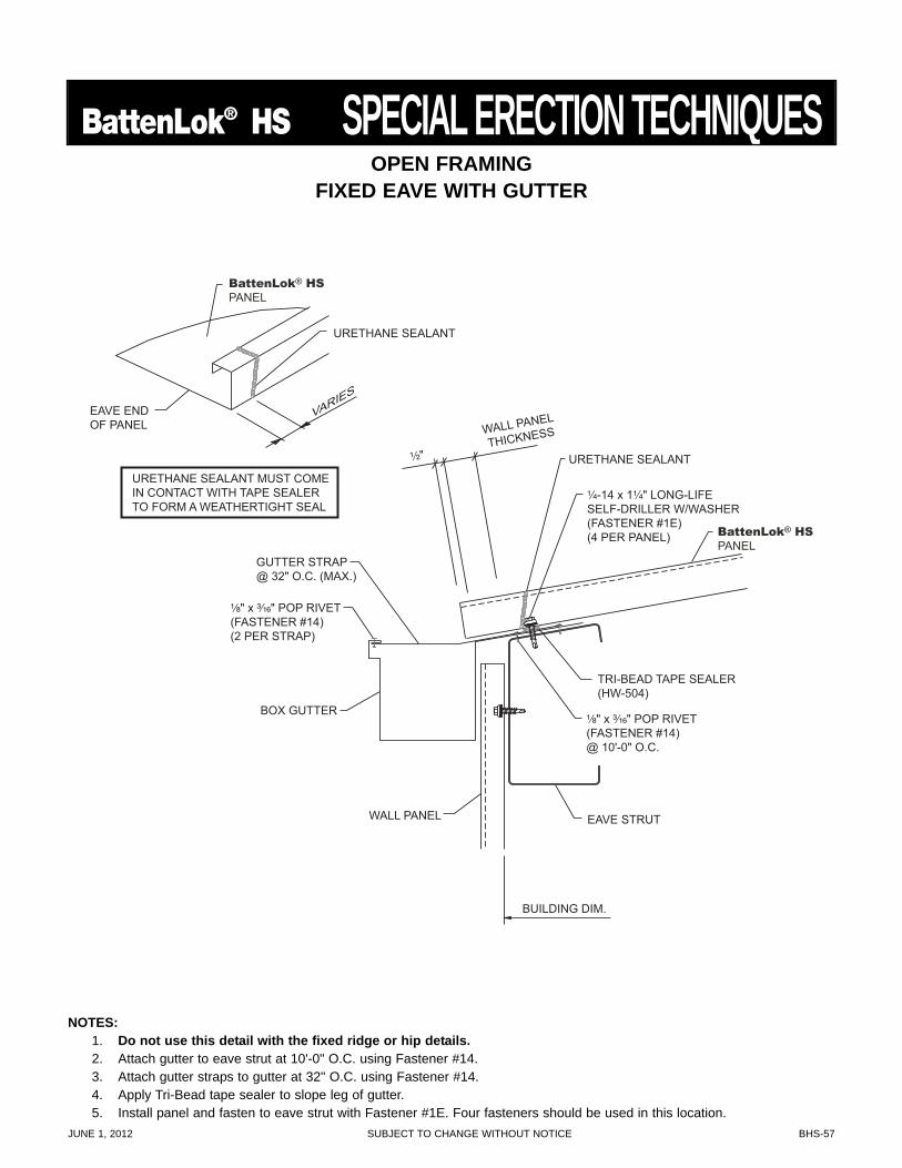
JUNE 1, 2012 SUBJECT TO CHANGE WITHOUT NOTICE BHS-57
BattenLok® HS SPECIAL ERECTION TECHNIQUES
¹⁄₂" URETHANE SEALANT
TRI-BEAD TAPE SEALER (HW-504)
¹⁄₄-14 x 1¹⁄₄" LONG-LIFE SELF-DRILLER W/WASHER (FASTENER #1E) (4 PER PANEL)
¹⁄₈" x ³⁄₁₆" POP RIVET (FASTENER #14) (2 PER STRAP)
¹⁄₈" x ³⁄₁₆" POP RIVET (FASTENER #14) @ 10'-0" O.C.
WALL PANEL
THICKNESS
BOX GUTTER
EAVE STRUT
BUILDING DIM.
WALL PANEL
GUTTER STRAP @ 32" O.C. (MAX.)
BattenLok® HS
PANEL
URETHANE SEALANT MUST COME IN CONTACT WITH TAPE SEALER TO FORM A WEATHERTIGHT SEAL
EAVE END OF PANEL
URETHANE SEALANT
VARIES
BattenLok® HS
PANEL
NOTES:1. Do not use this detail with the fixed ridge or hip details.2. Attach gutter to eave strut at 10'-0" O.C. using Fastener #14.3. Attach gutter straps to gutter at 32" O.C. using Fastener #14.4. Apply Tri-Bead tape sealer to slope leg of gutter.5. Install panel and fasten to eave strut with Fastener #1E. Four fasteners should be used in this location.
OPEN FRAMINGFIXED EAVE WITH GUTTER
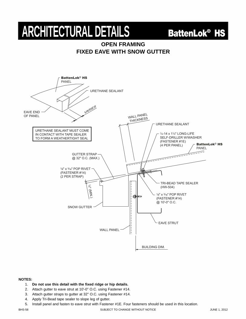
BHS-58 SUBJECT TO CHANGE WITHOUT NOTICE JUNE 1, 2012
¹⁄₂" (MIN
.)
URETHANE SEALANT
TRI-BEAD TAPE SEALER (HW-504)
¹⁄₄-14 x 1¹⁄₄" LONG-LIFE SELF-DRILLER W/WASHER (FASTENER #1E) (4 PER PANEL)
¹⁄₈" x ³⁄₁₆" POP RIVET (FASTENER #14) (2 PER STRAP)
¹⁄₈" x ³⁄₁₆" POP RIVET (FASTENER #14) @ 10'-0" O.C.
WALL PANEL
THICKNESS
SNOW GUTTER
EAVE STRUT
BUILDING DIM.
WALL PANEL
GUTTER STRAP @ 32" O.C. (MAX.)
BattenLok® HS
PANEL
URETHANE SEALANT MUST COME IN CONTACT WITH TAPE SEALER TO FORM A WEATHERTIGHT SEAL
EAVE END OF PANEL
URETHANE SEALANT
VARIES
BattenLok® HS
PANEL
OPEN FRAMINGFIXED EAVE WITH SNOW GUTTER
NOTES:1. Do not use this detail with the fixed ridge or hip details.2. Attach gutter to eave strut at 10'-0" O.C. using Fastener #14.3. Attach gutter straps to gutter at 32" O.C. using Fastener #14.4. Apply Tri-Bead tape sealer to slope leg of gutter.5. Install panel and fasten to eave strut with Fastener #1E. Four fasteners should be used in this location.
ARCHITECTURAL DETAILS BattenLok® HS
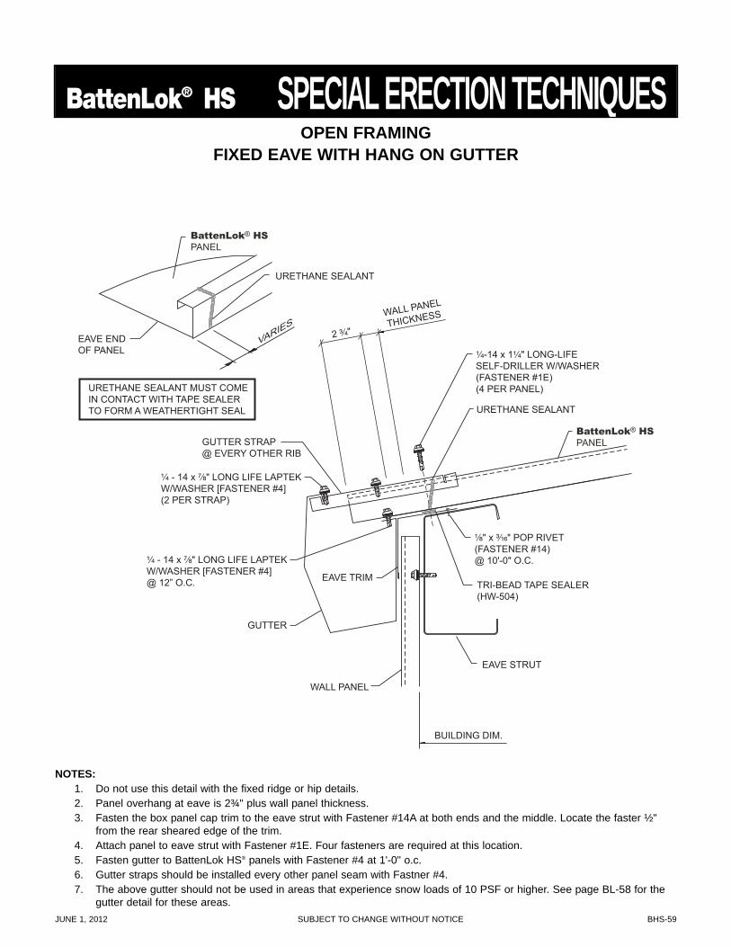
JUNE 1, 2012 SUBJECT TO CHANGE WITHOUT NOTICE BHS-59
BattenLok® HS SPECIAL ERECTION TECHNIQUES
2 ³⁄₄"
¹⁄₄ - 14 x ⁷⁄₈" LONG LIFE LAPTEKW/WASHER [FASTENER #4](2 PER STRAP)
¹⁄₄ - 14 x ⁷⁄₈" LONG LIFE LAPTEKW/WASHER [FASTENER #4]@ 12” O.C.
WALL PANEL
THICKNESS
EAVE TRIM
GUTTER STRAP@ EVERY OTHER RIB
BUILDING DIM.
URETHANE SEALANT
TRI-BEAD TAPE SEALER(HW-504)
¹⁄₄-14 x 1¹⁄₄" LONG-LIFESELF-DRILLER W/WASHER(FASTENER #1E)(4 PER PANEL)
¹⁄₈" x ³⁄₁₆" POP RIVET(FASTENER #14)@ 10'-0" O.C.
GUTTER
EAVE STRUT
WALL PANEL
BattenLok® HSPANEL
URETHANE SEALANT MUST COMEIN CONTACT WITH TAPE SEALERTO FORM A WEATHERTIGHT SEAL
EAVE ENDOF PANEL
URETHANE SEALANT
VARIES
BattenLok® HSPANEL
OPEN FRAMINGFIXED EAVE WITH HANG ON GUTTER
NOTES:1. Do not use this detail with the fixed ridge or hip details.2. Panel overhang at eave is 2¾" plus wall panel thickness.3. Fasten the box panel cap trim to the eave strut with Fastener #14A at both ends and the middle. Locate the faster ½"
from the rear sheared edge of the trim.4. Attach panel to eave strut with Fastener #1E. Four fasteners are required at this location.5. Fasten gutter to BattenLok HS® panels with Fastener #4 at 1'-0" o.c.6. Gutter straps should be installed every other panel seam with Fastner #4.7. The above gutter should not be used in areas that experience snow loads of 10 PSF or higher. See page BL-58 for the
gutter detail for these areas.
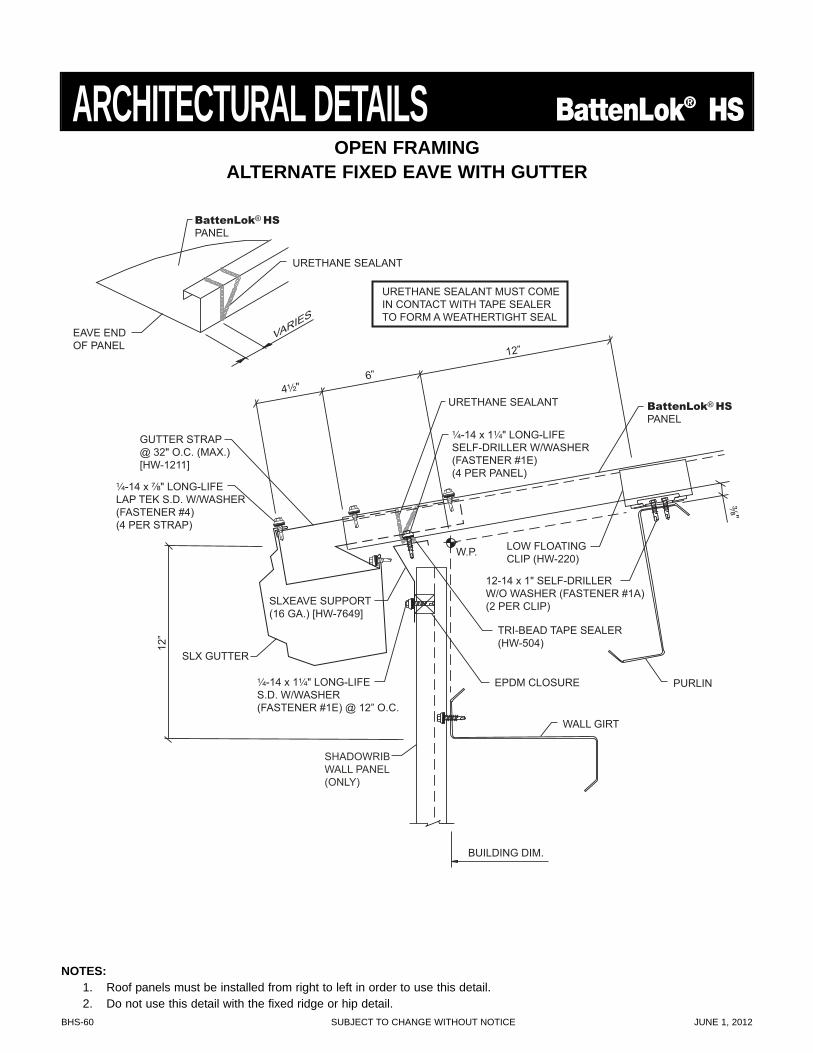
BHS-60 SUBJECT TO CHANGE WITHOUT NOTICE JUNE 1, 2012
4¹⁄₂" URETHANE SEALANT
TRI-BEAD TAPE SEALER (HW-504)
¹⁄₄-14 x 1¹⁄₄" LONG-LIFE SELF-DRILLER W/WASHER (FASTENER #1E) (4 PER PANEL)
¹⁄₄-14 x 1¹⁄₄" LONG-LIFE S.D. W/WASHER (FASTENER #1E) @ 12” O.C.
¹⁄₄-14 x ⁷⁄₈" LONG-LIFE LAP TEK S.D. W/WASHER (FASTENER #4) (4 PER STRAP)
6”
SLX GUTTER
SLXEAVE SUPPORT (16 GA.) [HW-7649]
WALL GIRT
PURLIN
BUILDING DIM.
GUTTER STRAP @ 32" O.C. (MAX.) [HW-1211]
URETHANE SEALANT MUST COME IN CONTACT WITH TAPE SEALER TO FORM A WEATHERTIGHT SEAL
EAVE END OF PANEL
URETHANE SEALANT
VARIES
12”
12”
SHADOWRIB WALL PANEL (ONLY)
³⁄₈"
LOW FLOATING CLIP (HW-220) W.P.
12-14 x 1" SELF-DRILLER W/O WASHER (FASTENER #1A) (2 PER CLIP)
BattenLok® HS PANEL
BattenLok® HS PANEL
EPDM CLOSURE
OPEN FRAMINGALTERNATE FIXED EAVE WITH GUTTER
ARCHITECTURAL DETAILS BattenLok® HS
NOTES:1. Roof panels must be installed from right to left in order to use this detail.2. Do not use this detail with the fixed ridge or hip detail.
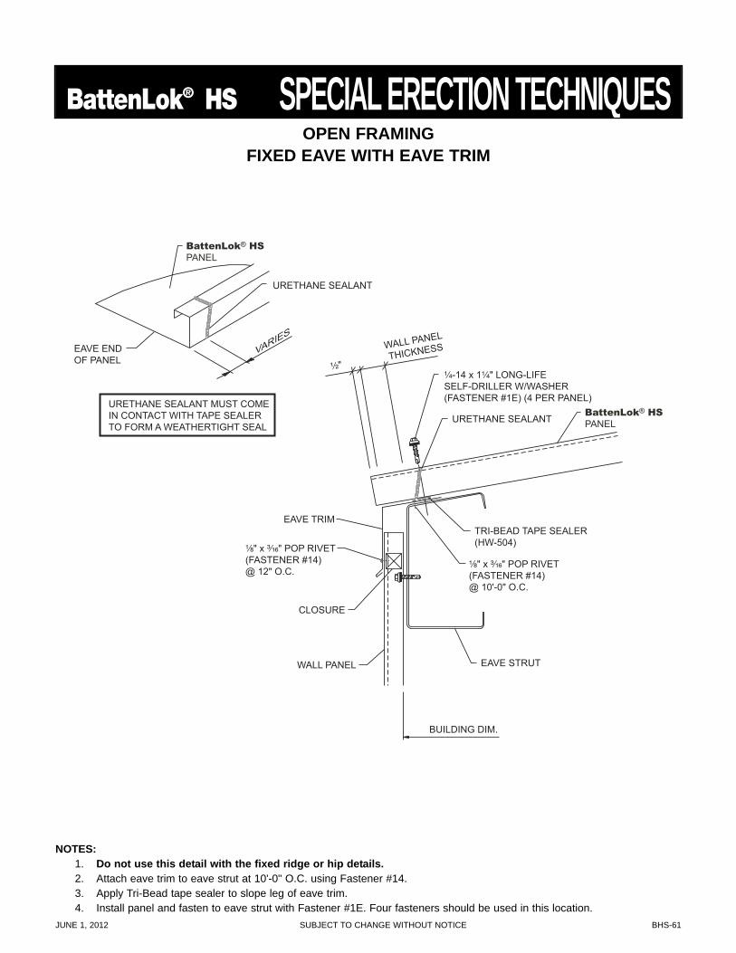
JUNE 1, 2012 SUBJECT TO CHANGE WITHOUT NOTICE BHS-61
BattenLok® HS SPECIAL ERECTION TECHNIQUES
¹⁄₂"
URETHANE SEALANT
TRI-BEAD TAPE SEALER (HW-504)
¹⁄₄-14 x 1¹⁄₄" LONG-LIFE SELF-DRILLER W/WASHER (FASTENER #1E) (4 PER PANEL)
¹⁄₈" x ³⁄₁₆" POP RIVET (FASTENER #14) @ 12" O.C.
¹⁄₈" x ³⁄₁₆" POP RIVET (FASTENER #14) @ 10'-0" O.C.
WALL PANEL
THICKNESS
EAVE TRIM
EAVE STRUT
BUILDING DIM.
WALL PANEL
CLOSURE
BattenLok® HS
PANEL
URETHANE SEALANT MUST COME IN CONTACT WITH TAPE SEALER TO FORM A WEATHERTIGHT SEAL
EAVE END OF PANEL
URETHANE SEALANT
VARIES
BattenLok® HS
PANEL
OPEN FRAMINGFIXED EAVE WITH EAVE TRIM
NOTES:1. Do not use this detail with the fixed ridge or hip details.2. Attach eave trim to eave strut at 10'-0" O.C. using Fastener #14.3. Apply Tri-Bead tape sealer to slope leg of eave trim.4. Install panel and fasten to eave strut with Fastener #1E. Four fasteners should be used in this location.
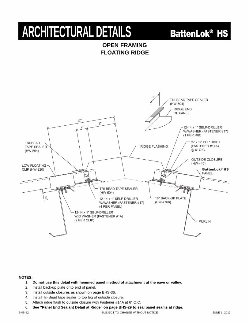
BHS-62 SUBJECT TO CHANGE WITHOUT NOTICE JUNE 1, 2012
TRI-BEADTAPE SEALER(HW-504)
TRI-BEAD TAPE SEALER(HW-504)
¹⁄₈" x ³⁄₈" POP RIVET(FASTENER #14A)@ 6" O.C.
12"
2"5"
RIDGE FLASHING
PURLIN
³⁄₈"
LOW FLOATINGCLIP (HW-220)
12-14 x 1" SELF-DRILLERW/WASHER (FASTENER #17)(1 PER RIB)
12-14 x 1" SELF-DRILLERW/WASHER (FASTENER #17)(4 PER PANEL)
12-14 x 1" SELF-DRILLERW/O WASHER (FASTENER #1A)(2 PER CLIP)
OUTSIDE CLOSURE(HW-440)
16" BACK-UP PLATE(HW-7766)
TRI-BEAD TAPE SEALER(HW-504)
RIDGE ENDOF PANEL
BattenLok® HSPANEL
3"
OPEN FRAMINGFLOATING RIDGE
NOTES:1. Do not use this detail with hemmed panel method of attachment at the eave or valley.2. Install back-up plate onto end of panel.3. Install outside closures as shown on page BHS-36.4. Install Tri-Bead tape sealer to top leg of outside closure.5. Attach ridge flash to outside closure with Fastener #14A at 6" O.C.6. See "Panel End Sealant Detail at Ridge" on page BHS-29 to seal panel seams at ridge.
ARCHITECTURAL DETAILS BattenLok® HS
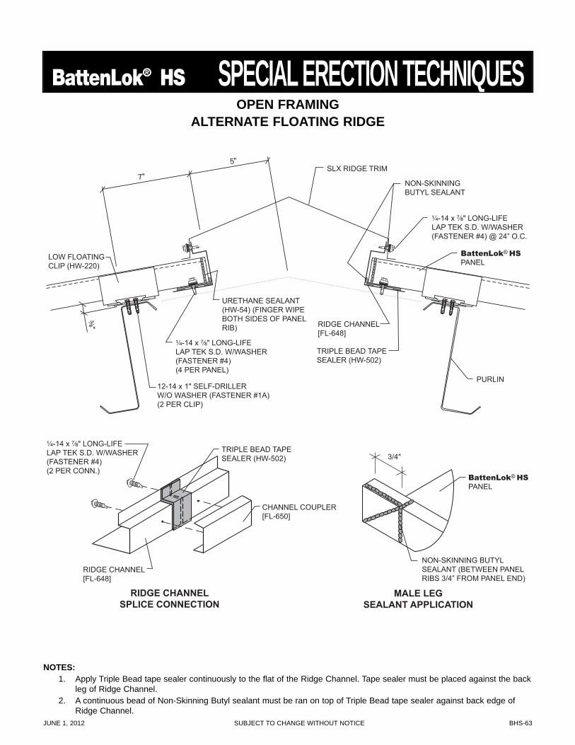
JUNE 1, 2012 SUBJECT TO CHANGE WITHOUT NOTICE BHS-63
BattenLok® HS SPECIAL ERECTION TECHNIQUES
NOTES:1. Apply Triple Bead tape sealer continuously to the flat of the Ridge Channel. Tape sealer must be placed against the back
leg of Ridge Channel.2. A continuous bead of Non-Skinning Butyl sealant must be ran on top of Triple Bead tape sealer against back edge of
Ridge Channel.
7"
5" SLX RIDGE TRIM
PURLIN
³⁄₈"
LOW FLOATINGCLIP (HW-220)
12-14 x 1" SELF-DRILLERW/O WASHER (FASTENER #1A)(2 PER CLIP)
BattenLok® HSPANEL
BattenLok® HSPANEL
RIDGE CHANNEL [FL-648]
RIDGE CHANNEL[FL-648]
CHANNEL COUPLER[FL-650]
NON-SKINNING BUTYL SEALANT
NON-SKINNING BUTYLSEALANT (BETWEEN PANELRIBS 3/4” FROM PANEL END)
¹⁄₄-14 x ⁷⁄₈" LONG-LIFE LAP TEK S.D. W/WASHER (FASTENER #4) @ 24” O.C.
URETHANE SEALANT(HW-54) (FINGER WIPEBOTH SIDES OF PANELRIB)
3/4"
MALE LEGSEALANT APPLICATION
RIDGE CHANNELSPLICE CONNECTION
TRIPLE BEAD TAPE SEALER (HW-502)
TRIPLE BEAD TAPESEALER (HW-502)
¹⁄₄-14 x ⁷⁄₈" LONG-LIFE LAP TEK S.D. W/WASHER (FASTENER #4) (4 PER PANEL)
¹⁄₄-14 x ⁷⁄₈" LONG-LIFELAP TEK S.D. W/WASHER(FASTENER #4)(2 PER CONN.)
OPEN FRAMINGALTERNATE FLOATING RIDGE
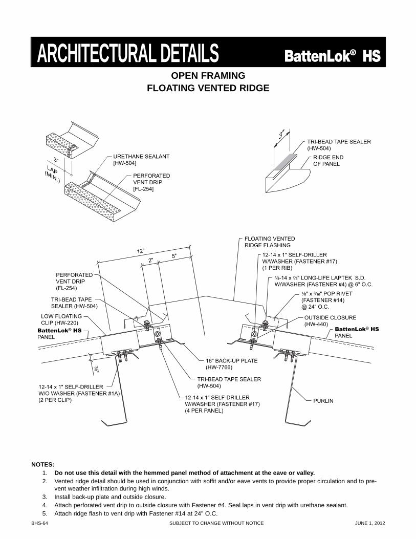
BHS-64 SUBJECT TO CHANGE WITHOUT NOTICE JUNE 1, 2012
TRI-BEAD TAPESEALER (HW-504)
TRI-BEAD TAPE SEALER(HW-504)
¹⁄₈" x ³⁄₁₆" POP RIVET(FASTENER #14)@ 24" O.C.
12"
2"5"
FLOATING VENTEDRIDGE FLASHING
PERFORATEDVENT DRIP(FL-254)
PURLIN
³⁄₈"LOW FLOATINGCLIP (HW-220)
12-14 x 1" SELF-DRILLERW/WASHER (FASTENER #17)(1 PER RIB)
12-14 x 1" SELF-DRILLERW/WASHER (FASTENER #17)(4 PER PANEL)
12-14 x 1" SELF-DRILLERW/O WASHER (FASTENER #1A)(2 PER CLIP)
OUTSIDE CLOSURE(HW-440)
16" BACK-UP PLATE(HW-7766)
¹⁄₄-14 x ⁷⁄₈" LONG-LIFE LAPTEK S.D.W/WASHER (FASTENER #4) @ 6" O.C.
TRI-BEAD TAPE SEALER(HW-504)
RIDGE ENDOF PANEL
3"
BattenLok® HSPANEL
BattenLok® HSPANEL
URETHANE SEALANT[HW-504]
PERFORATEDVENT DRIP[FL-254]
3”LAP(MIN.)
OPEN FRAMINGFLOATING VENTED RIDGE
NOTES:1. Do not use this detail with the hemmed panel method of attachment at the eave or valley.2. Vented ridge detail should be used in conjunction with soffit and/or eave vents to provide proper circulation and to pre-
vent weather infiltration during high winds.3. Install back-up plate and outside closure.4. Attach perforated vent drip to outside closure with Fastener #4. Seal laps in vent drip with urethane sealant.5. Attach ridge flash to vent drip with Fastener #14 at 24" O.C.
ARCHITECTURAL DETAILS BattenLok® HS
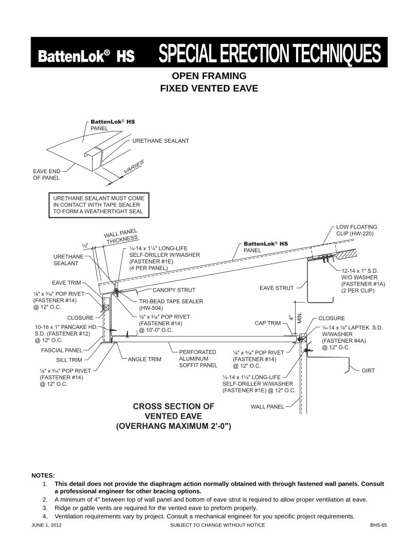
JUNE 1, 2012 SUBJECT TO CHANGE WITHOUT NOTICE BHS-65
BattenLok® HS SPECIAL ERECTION TECHNIQUES
¹⁄₂"
URETHANESEALANT
TRI-BEAD TAPE SEALER (HW-504)
¹⁄₄-14 x 1¹⁄₄" LONG-LIFE SELF-DRILLER W/WASHER (FASTENER #1E) (4 PER PANEL)
¹⁄₄-14 x 1¹⁄₄" LONG-LIFE SELF-DRILLER W/WASHER (FASTENER #1E) @ 12" O.C.
¹⁄₈" x ³⁄₁₆" POP RIVET (FASTENER #14) @ 12" O.C.
¹⁄₈" x ³⁄₁₆" POP RIVET (FASTENER #14) @ 10'-0" O.C.
¹⁄₈" x ³⁄₁₆" POP RIVET (FASTENER #14) @ 12" O.C.
WALL PANEL
THICKNESS
EAVE TRIM
GIRT
WALL PANEL
FASCIAL PANEL
CLOSURE CLOSURE
BattenLok® HS
PANEL
URETHANE SEALANT MUST COME IN CONTACT WITH TAPE SEALER TO FORM A WEATHERTIGHT SEAL
EAVE END OF PANEL
URETHANE SEALANT
VARIES
BattenLok® HS
PANEL
PERFORATED ALUMINUM SOFFIT PANEL
SILL TRIM ¹⁄₈" x ³⁄₁₆" POP RIVET (FASTENER #14) @ 12" O.C.
10-16 x 1" PANCAKE HD. S.D. (FASTENER #12) @ 12" O.C.
¹⁄₄-14 x ⁷⁄₈" LAPTEK S.D. W/WASHER (FASTENER #4A) @ 12" O.C.
LOW FLOATING CLIP (HW-220)
12-14 x 1" S.D. W/O WASHER (FASTENER #1A) (2 PER CLIP)
ANGLE TRIM
CAP TRIM
CANOPY STRUT EAVE STRUT 4"
M
IN.
CROSS SECTION OF VENTED EAVE
(OVERHANG MAXIMUM 2'-0")
OPEN FRAMINGFIXED VENTED EAVE
NOTES:1. This detail does not provide the diaphragm action normally obtained with through fastened wall panels. Consult
a professional engineer for other bracing options.2. A minimum of 4" between top of wall panel and bottom of eave strut is required to allow proper ventilation at eave.3. Ridge or gable vents are required for the vented eave to preform properly.4. Ventilation requirements vary by project. Consult a mechanical engineer for you specific project requirements.
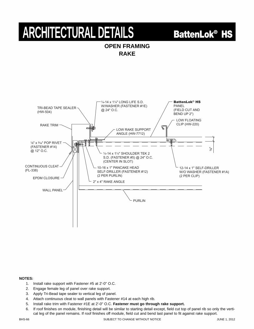
BHS-66 SUBJECT TO CHANGE WITHOUT NOTICE JUNE 1, 2012
BattenLok® HSPANEL(FIELD CUT ANDBEND UP 2")
TRI-BEAD TAPE SEALER(HW-504)
¹⁄₄-14 x 1¹⁄₄" LONG LIFE S.D.W/WASHER (FASTENER #1E)@ 24" O.C.
¹⁄₄-14 x 1¹⁄₄" SHOULDER TEK 2S.D. (FASTENER #5) @ 24" O.C.(CENTER IN SLOT)
10-16 x 1" PANCAKE HEADSELF-DRILLER (FASTENER #12)(2 PER PURLIN)
PURLIN
³⁄₈"
¹⁄₈" x ³⁄₁₆" POP RIVET(FASTENER #14)@ 12" O.C.
LOW FLOATINGCLIP (HW-220)
12-14 x 1" SELF-DRILLERW/O WASHER (FASTENER #1A)(2 PER CLIP)
CONTINUOUS CLEAT(FL-338)
EPDM CLOSURE
WALL PANEL
RAKE TRIM
2" x 4" RAKE ANGLE
LOW RAKE SUPPORTANGLE (HW-7712)
OPEN FRAMINGRAKE
NOTES:1. Install rake support with Fastener #5 at 2'-0" O.C.2. Engage female leg of panel over rake support.3. Apply Tri-Bead tape sealer to vertical leg of panel.4. Attach continuous cleat to wall panels with Fastener #14 at each high rib.5. Install rake trim with Fastener #1E at 2'-0" O.C. Fastener must go through rake support.6. If roof finishes on module, finishing detail will be similar to starting detail except, field cut top of panel rib so only the verti-
cal leg of the panel remains. If roof finishes off module, field cut and bend last panel to fit against rake support.
ARCHITECTURAL DETAILS BattenLok® HS
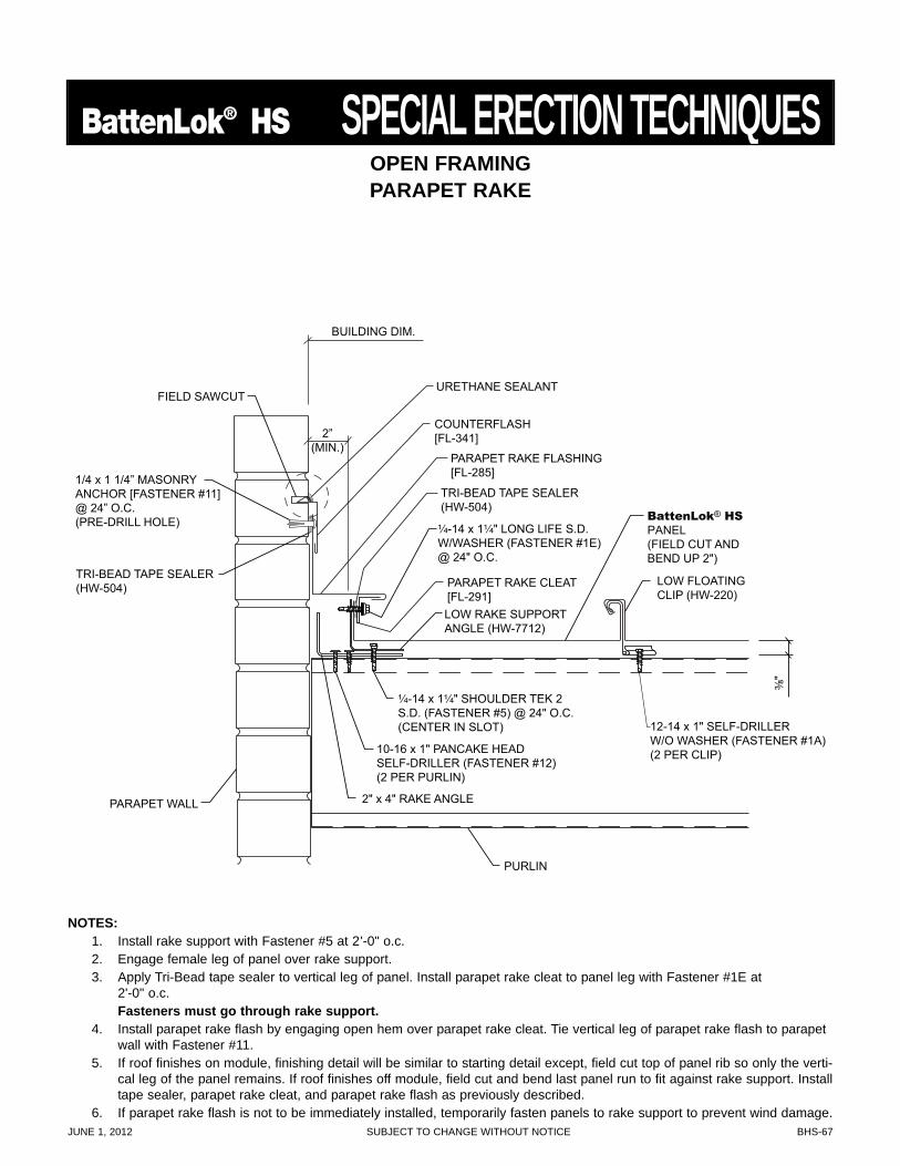
JUNE 1, 2012 SUBJECT TO CHANGE WITHOUT NOTICE BHS-67
BattenLok® HS SPECIAL ERECTION TECHNIQUES
BattenLok® HS PANEL (FIELD CUT AND BEND UP 2")
¹⁄₄-14 x 1¹⁄₄" LONG LIFE S.D. W/WASHER (FASTENER #1E) @ 24" O.C.
¹⁄₄-14 x 1¹⁄₄" SHOULDER TEK 2 S.D. (FASTENER #5) @ 24" O.C. (CENTER IN SLOT)
10-16 x 1" PANCAKE HEAD SELF-DRILLER (FASTENER #12) (2 PER PURLIN)
PURLIN
³⁄₈"
LOW FLOATING CLIP (HW-220)
12-14 x 1" SELF-DRILLERW/O WASHER (FASTENER #1A)(2 PER CLIP)
2" x 4" RAKE ANGLE
LOW RAKE SUPPORT ANGLE (HW-7712)
TRI-BEAD TAPE SEALER (HW-504)
URETHANE SEALANT
COUNTERFLASH [FL-341]
PARAPET RAKE FLASHING [FL-285]
PARAPET RAKE CLEAT [FL-291]
BUILDING DIM.
2” (MIN.)
PARAPET WALL
FIELD SAWCUT
1/4 x 1 1/4” MASONRY ANCHOR [FASTENER #11] @ 24” O.C. (PRE-DRILL HOLE)
TRI-BEAD TAPE SEALER (HW-504)
OPEN FRAMINGPARAPET RAKE
NOTES:1. Install rake support with Fastener #5 at 2'-0" o.c.2. Engage female leg of panel over rake support.3. Apply Tri-Bead tape sealer to vertical leg of panel. Install parapet rake cleat to panel leg with Fastener #1E at
2'-0" o.c.Fasteners must go through rake support.
4. Install parapet rake flash by engaging open hem over parapet rake cleat. Tie vertical leg of parapet rake flash to parapetwall with Fastener #11.
5. If roof finishes on module, finishing detail will be similar to starting detail except, field cut top of panel rib so only the verti-cal leg of the panel remains. If roof finishes off module, field cut and bend last panel run to fit against rake support. Installtape sealer, parapet rake cleat, and parapet rake flash as previously described.
6. If parapet rake flash is not to be immediately installed, temporarily fasten panels to rake support to prevent wind damage.
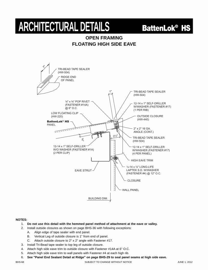
BHS-68 SUBJECT TO CHANGE WITHOUT NOTICE JUNE 1, 2012
2¹⁄₂"
TRI-BEAD TAPE SEALER (HW-504)
TRI-BEAD TAPE SEALER (HW-504)
¹⁄₄-14 x ⁷⁄₈" LONG-LIFE LAPTEK S.D. W/WASHER (FASTENER #4) @ 12" O.C.
¹⁄₈" x ³⁄₈" POP RIVET(FASTENER #14A)@ 6" O.C.
1"
HIGH EAVE TRIM
EAVE STRUT
BUILDING DIM.
WALL PANEL
CLOSURE
³⁄₈"
LOW FLOATING CLIP (HW-220)
12-14 x 1" SELF-DRILLER W/WASHER (FASTENER #17) (1 PER RIB)
12-14 x 1" SELF-DRILLER W/WASHER (FASTENER #17) (4 PER PANEL)
12-14 x 1" SELF-DRILLER W/O WASHER (FASTENER #1A) (2 PER CLIP)
OUTSIDE CLOSURE (HW-440)
2" x 2" 16 GA. ANGLE (CONT.)
TRI-BEAD TAPE SEALER (HW-504)
RIDGE END OF PANEL
BattenLok® HS
PANEL
7"
OPEN FRAMINGFLOATING HIGH SIDE EAVE
NOTES:1. Do not use this detail with the hemmed panel method of attachment at the eave or valley.2. Install outside closures as shown on page BHS-36 with following exceptions:
A. Align edge of tape sealer with end panel.B. Vertical Leg of outside closure is 1" from end of panel.C. Attach outside closure to 2" x 2" angle with Fastener #17.
3. Install Tri-Bead tape sealer to top leg of outside closure.4. Attach high side eave trim to outside closure with Fastener #14A at 6" O.C.5. Attach high side eave trim to wall panels with Fastener #4 at each high rib.6. See "Panel End Sealant Detail at Ridge" on page BHS-29 to seal panel seams at high side eave.
ARCHITECTURAL DETAILS BattenLok® HS
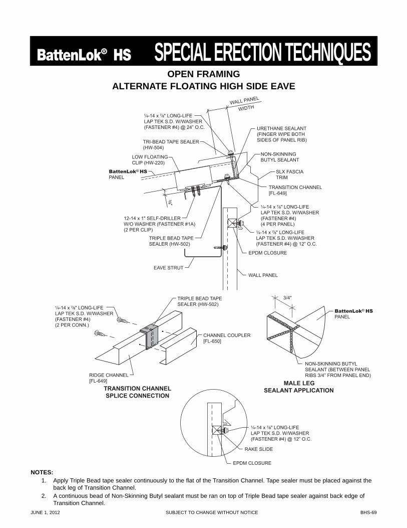
JUNE 1, 2012 SUBJECT TO CHANGE WITHOUT NOTICE BHS-69
BattenLok® HS SPECIAL ERECTION TECHNIQUESWALL PANEL
WIDTH
EAVE STRUT
³⁄₈"
LOW FLOATING CLIP (HW-220)
12-14 x 1" SELF-DRILLER W/O WASHER (FASTENER #1A) (2 PER CLIP)
TRANSITION CHANNEL [FL-649]
¹⁄₄-14 x ⁷⁄₈" LONG-LIFE LAP TEK S.D. W/WASHER (FASTENER #4) (4 PER PANEL)
URETHANE SEALANT(FINGER WIPE BOTH SIDES OF PANEL RIB)
EPDM CLOSURE
EPDM CLOSURE
WALL PANEL
¹⁄₄-14 x ⁷⁄₈" LONG-LIFE LAP TEK S.D. W/WASHER (FASTENER #4) @ 12” O.C.
TRI-BEAD TAPE SEALER (HW-504)
BattenLok® HS PANEL
TRIPLE BEAD TAPE SEALER (HW-502)
RAKE SLIDE
¹⁄₄-14 x ⁷⁄₈" LONG-LIFE LAP TEK S.D. W/WASHER (FASTENER #4) @ 12” O.C.
NON-SKINNING BUTYL SEALANT
SLX FASCIA TRIM
MALE LEG SEALANT APPLICATION TRANSITION CHANNEL
SPLICE CONNECTION
¹⁄₄-14 x ⁷⁄₈" LONG-LIFE LAP TEK S.D. W/WASHER (FASTENER #4) @ 24” O.C.
BattenLok® HS PANEL
RIDGE CHANNEL[FL-649]
CHANNEL COUPLER [FL-650]
NON-SKINNING BUTYL SEALANT (BETWEEN PANEL RIBS 3/4” FROM PANEL END)
3/4" TRIPLE BEAD TAPE SEALER (HW-502)
¹⁄₄-14 x ⁷⁄₈" LONG-LIFE LAP TEK S.D. W/WASHER (FASTENER #4) (2 PER CONN.)
OPEN FRAMINGALTERNATE FLOATING HIGH SIDE EAVE
NOTES:1. Apply Triple Bead tape sealer continuously to the flat of the Transition Channel. Tape sealer must be placed against the
back leg of Transition Channel.2. A continuous bead of Non-Skinning Butyl sealant must be ran on top of Triple Bead tape sealer against back edge of
Transition Channel.
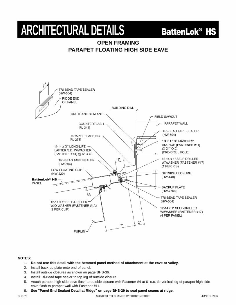
BHS-70 SUBJECT TO CHANGE WITHOUT NOTICE JUNE 1, 2012
7" 2"
TRI-BEAD TAPE SEALER (HW-504)
TRI-BEAD TAPE SEALER (HW-504)
¹⁄₄-14 x ⁷⁄₈" LONG-LIFE LAPTEK S.D. W/WASHER (FASTENER #4) @ 6" O.C.
2"
PURLIN
BUILDING DIM.
³⁄₈"
LOW FLOATING CLIP (HW-220)
12-14 x 1" SELF-DRILLER W/WASHER (FASTENER #17) (1 PER RIB)
12-14 x 1" SELF-DRILLER W/WASHER (FASTENER #17) (4 PER PANEL)
12-14 x 1" SELF-DRILLER W/O WASHER (FASTENER #1A) (2 PER CLIP)
OUTSIDE CLOSURE (HW-440)
BACKUP PLATE [HW-7766]
TRI-BEAD TAPE SEALER (HW-504)
RIDGE END OF PANEL
7"
BattenLok® HS
PANEL
URETHANE SEALANT
COUNTERFLASH [FL-341]
PARAPET FLASHING [FL-275]
PARAPET WALL
FIELD SAWCUT
1/4 x 1 1/4” MASONRY ANCHOR [FASTENER #11] @ 24” O.C. (PRE-DRILL HOLE)
TRI-BEAD TAPE SEALER (HW-504)
OPEN FRAMINGPARAPET FLOATING HIGH SIDE EAVE
ARCHITECTURAL DETAILS BattenLok® HS
NOTES:1. Do not use this detail with the hemmed panel method of attachment at the eave or valley.2. Install back-up plate onto end of panel.3. Install outside closures as shown on page BHS-36.4. Install Tri-Bead tape sealer to top leg of outside closure.5. Attach parapet high side eave flash to outside closure with Fastener #4 at 6" o.c. tie vertical leg of parapet high side
eave flash to parapet wall with Fastener #11.6. See "Panel End Sealant Detail at Ridge" on page BHS-29 to seal panel seams at ridge.
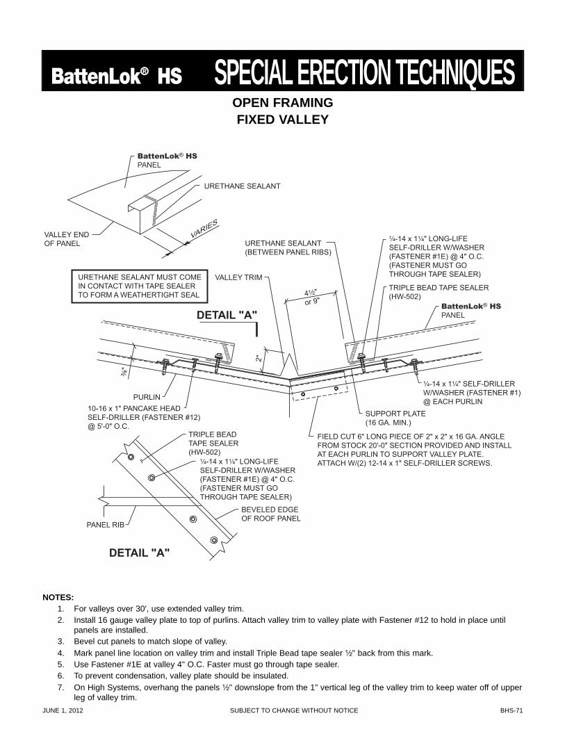
JUNE 1, 2012 SUBJECT TO CHANGE WITHOUT NOTICE BHS-71
BattenLok® HS SPECIAL ERECTION TECHNIQUES
4¹⁄₂" or 9"
URETHANE SEALANT(BETWEEN PANEL RIBS)
SUPPORT PLATE (16 GA. MIN.)
FIELD CUT 6" LONG PIECE OF 2" x 2" x 16 GA. ANGLE FROM STOCK 20'-0" SECTION PROVIDED AND INSTALL AT EACH PURLIN TO SUPPORT VALLEY PLATE. ATTACH W/(2) 12-14 x 1" SELF-DRILLER SCREWS.
TRIPLE BEAD TAPE SEALER (HW-502)
TRIPLE BEAD TAPE SEALER (HW-502)
¹⁄₄-14 x 1¹⁄₄" LONG-LIFE SELF-DRILLER W/WASHER (FASTENER #1E) @ 4" O.C. (FASTENER MUST GO THROUGH TAPE SEALER)
¹⁄₄-14 x 1¹⁄₄" LONG-LIFE SELF-DRILLER W/WASHER (FASTENER #1E) @ 4" O.C. (FASTENER MUST GO THROUGH TAPE SEALER)
¹⁄₄-14 x 1¹⁄₄" SELF-DRILLER W/WASHER (FASTENER #1) @ EACH PURLIN
10-16 x 1" PANCAKE HEAD SELF-DRILLER (FASTENER #12) @ 5'-0" O.C.
2"
³⁄₈"
VALLEY TRIM
BEVELED EDGE OF ROOF PANEL
PANEL RIB
DETAIL "A"
DETAIL "A"
PURLIN
URETHANE SEALANT MUST COME IN CONTACT WITH TAPE SEALER TO FORM A WEATHERTIGHT SEAL
VALLEY END OF PANEL
URETHANE SEALANT
VARIES
BattenLok® HS
PANEL
BattenLok® HS
PANEL
OPEN FRAMINGFIXED VALLEY
NOTES:1. For valleys over 30', use extended valley trim.2. Install 16 gauge valley plate to top of purlins. Attach valley trim to valley plate with Fastener #12 to hold in place until
panels are installed.3. Bevel cut panels to match slope of valley.4. Mark panel line location on valley trim and install Triple Bead tape sealer ¹⁄₂" back from this mark.5. Use Fastener #1E at valley 4" O.C. Faster must go through tape sealer.6. To prevent condensation, valley plate should be insulated.7. On High Systems, overhang the panels ¹⁄₂" downslope from the 1" vertical leg of the valley trim to keep water off of upper
leg of valley trim.
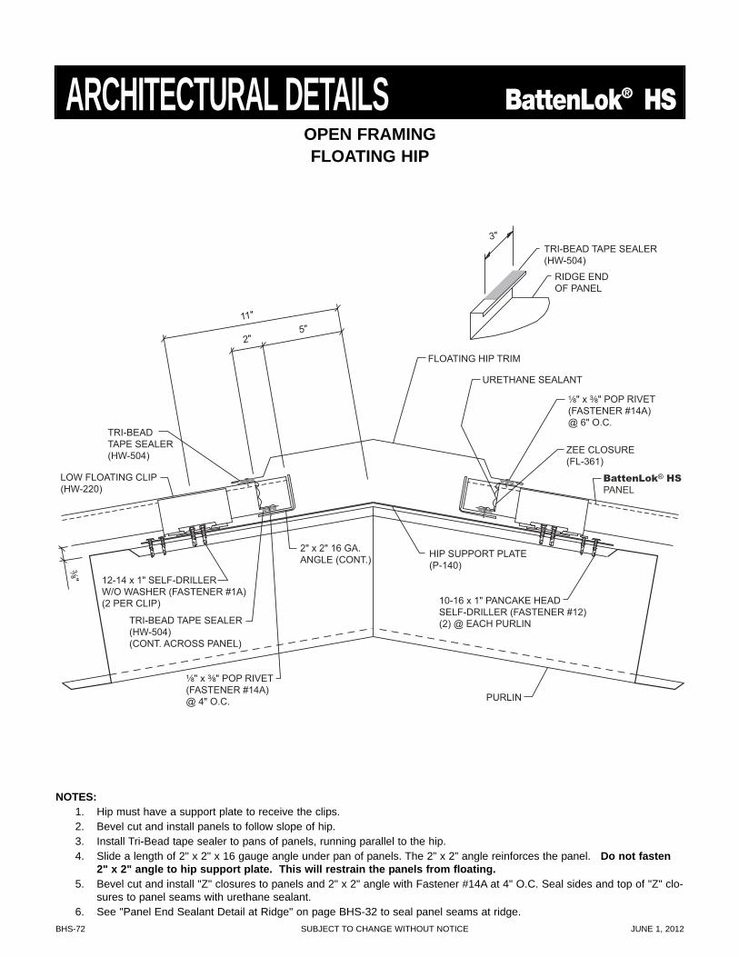
BHS-72 SUBJECT TO CHANGE WITHOUT NOTICE JUNE 1, 2012
OPEN FRAMINGFLOATING HIP
TRI-BEAD TAPE SEALER (HW-504)
TRI-BEAD TAPE SEALER (HW-504) (CONT. ACROSS PANEL)
¹⁄₈" x ³⁄₈" POP RIVET(FASTENER #14A)@ 6" O.C.
¹⁄₈" x ³⁄₈" POP RIVET (FASTENER #14A) @ 4" O.C.
11"
2" 5"
FLOATING HIP TRIM
PURLIN
³⁄₈"
LOW FLOATING CLIP (HW-220)
12-14 x 1" SELF-DRILLER W/O WASHER (FASTENER #1A) (2 PER CLIP)
ZEE CLOSURE(FL-361)
2" x 2" 16 GA. ANGLE (CONT.)
10-16 x 1" PANCAKE HEAD SELF-DRILLER (FASTENER #12) (2) @ EACH PURLIN
URETHANE SEALANT
HIP SUPPORT PLATE (P-140)
TRI-BEAD TAPE SEALER (HW-504)
RIDGE END OF PANEL
BattenLok® HSPANEL
3"
ARCHITECTURAL DETAILS BattenLok® HS
NOTES:1. Hip must have a support plate to receive the clips.2. Bevel cut and install panels to follow slope of hip.3. Install Tri-Bead tape sealer to pans of panels, running parallel to the hip.4. Slide a length of 2" x 2" x 16 gauge angle under pan of panels. The 2” x 2” angle reinforces the panel. Do not fasten
2" x 2" angle to hip support plate. This will restrain the panels from floating.5. Bevel cut and install "Z" closures to panels and 2" x 2" angle with Fastener #14A at 4" O.C. Seal sides and top of "Z" clo-
sures to panel seams with urethane sealant.6. See "Panel End Sealant Detail at Ridge" on page BHS-32 to seal panel seams at ridge.
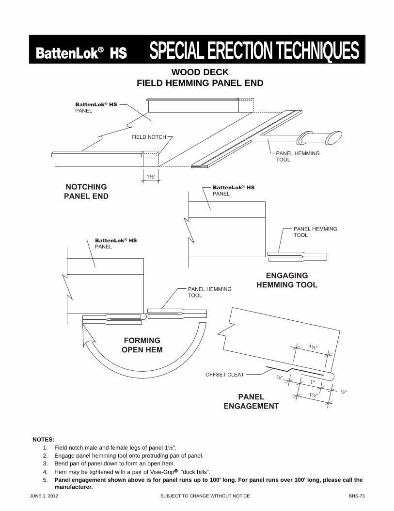
JUNE 1, 2012 SUBJECT TO CHANGE WITHOUT NOTICE BHS-73
BattenLok® HS SPECIAL ERECTION TECHNIQUES
NOTCHINGPANEL END
ENGAGINGHEMMING TOOL
PANELENGAGEMENT
FORMINGOPEN HEM 1¹⁄₂”
1¹⁄₂”
¹⁄₂”
¹⁄₂”
1"
BattenLok® HSPANEL
FIELD NOTCH
OFFSET CLEAT
1¹⁄₂”
PANEL HEMMINGTOOL
PANEL HEMMINGTOOL
PANEL HEMMINGTOOL
BattenLok® HSPANEL
BattenLok® HSPANEL
WOOD DECKFIELD HEMMING PANEL END
NOTES:1. Field notch male and female legs of panel 1¹⁄₂".2. Engage panel hemming tool onto protruding pan of panel.3. Bend pan of panel down to form an open hem.4. Hem may be tightened with a pair of Vise-Grip® "duck bills".5. Panel engagement shown above is for panel runs up to 100' long. For panel runs over 100' long, please call the
manufacturer.
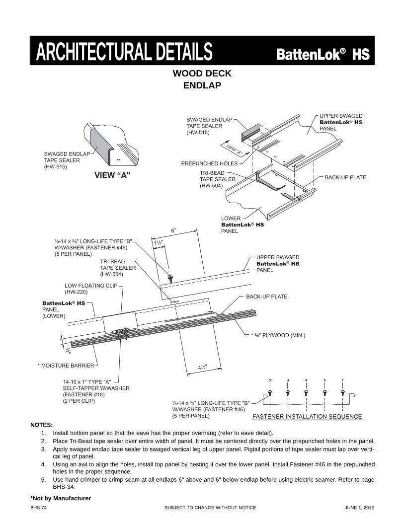
BHS-74 SUBJECT TO CHANGE WITHOUT NOTICE JUNE 1, 2012
FASTENER INSTALLATION SEQUENCE
¹⁄₄-14 x ⁵⁄₈" LONG-LIFE TYPE "B"W/WASHER (FASTENER #46)(5 PER PANEL)
VIEW “A"
SWAGED ENDLAPTAPE SEALER(HW-515)
UPPER SWAGEDBattenLok® HSPANEL
LOWERBattenLok® HSPANEL
PREPUNCHED HOLES
VIEW "A"
BACK-UP PLATETRI-BEADTAPE SEALER(HW-504)
SWAGED ENDLAPTAPE SEALER(HW-515)
¹⁄₄-14 x ⁵⁄₈" LONG-LIFE TYPE "B"W/WASHER (FASTENER #46)(5 PER PANEL)
BattenLok® HSPANEL(LOWER)
UPPER SWAGEDBattenLok® HSPANEL
BACK-UP PLATE
1¹⁄₂"
4¹⁄₂"
TRI-BEADTAPE SEALER(HW-504)
6"
* MOISTURE BARRIER
LOW FLOATING CLIP(HW-220)
³⁄₈"* ⁵⁄₈" PLYWOOD (MIN.)
14-10 x 1" TYPE "A"SELF-TAPPER W/WASHER(FASTENER #18)(2 PER CLIP)
WOOD DECKENDLAP
ARCHITECTURAL DETAILS BattenLok® HS
NOTES:1. Install bottom panel so that the eave has the proper overhang (refer to eave detail).2. Place Tri-Bead tape sealer over entire width of panel. It must be centered directly over the prepunched holes in the panel.3. Apply swaged endlap tape sealer to swaged vertical leg of upper panel. Pigtail portions of tape sealer must lap over verti-
cal leg of panel.4. Using an awl to align the holes, install top panel by nesting it over the lower panel. Install Fastener #46 in the prepunched
holes in the proper sequence.5. Use hand crimper to crimp seam at all endlaps 6" above and 6" below endlap before using electric seamer. Refer to page
BHS-34.
*Not by Manufacturer
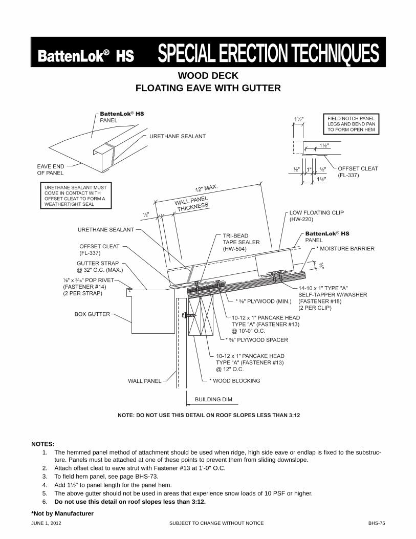
JUNE 1, 2012 SUBJECT TO CHANGE WITHOUT NOTICE BHS-75
BattenLok® HS SPECIAL ERECTION TECHNIQUES
NOTES:1. The hemmed panel method of attachment should be used when ridge, high side eave or endlap is fixed to the substruc-
ture. Panels must be attached at one of these points to prevent them from sliding downslope.2. Attach offset cleat to eave strut with Fastener #13 at 1'-0" O.C.3. To field hem panel, see page BHS-73.4. Add 1¹⁄₂" to panel length for the panel hem.5. The above gutter should not be used in areas that experience snow loads of 10 PSF or higher.6. Do not use this detail on roof slopes less than 3:12.
NOTE: DO NOT USE THIS DETAIL ON ROOF SLOPES LESS THAN 3:12
* MOISTURE BARRIER
* ⁵⁄₈" PLYWOOD (MIN.)
¹⁄₂"
TRI-BEAD TAPE SEALER (HW-504)
* ³⁄₈" PLYWOOD SPACER
WALL PANEL
THICKNESS
12" MAX.
BOX GUTTER
BUILDING DIM.
WALL PANEL
URETHANE SEALANT MUST COME IN CONTACT WITH OFFSET CLEAT TO FORM A WEATHERTIGHT SEAL
EAVE END OF PANEL
URETHANE SEALANT
LOW FLOATING CLIP (HW-220)
³⁄₈"
10-12 x 1" PANCAKE HEAD TYPE “A" (FASTENER #13) @ 12" O.C.
10-12 x 1" PANCAKE HEAD TYPE "A" (FASTENER #13) @ 10'-0" O.C.
* WOOD BLOCKING
OFFSET CLEAT (FL-337)
FIELD NOTCH PANEL LEGS AND BEND PAN TO FORM OPEN HEM
1¹⁄₂"
1¹⁄₂"
1¹⁄₂"
1" ¹⁄₂" ¹⁄₂"
14-10 x 1" TYPE "A" SELF-TAPPER W/WASHER (FASTENER #18) (2 PER CLIP)
URETHANE SEALANT
¹⁄₈" x ³⁄₁₆" POP RIVET (FASTENER #14) (2 PER STRAP)
OFFSET CLEAT (FL-337)
GUTTER STRAP @ 32" O.C. (MAX.)
BattenLok® HS
PANEL
BattenLok® HS
PANEL
WOOD DECKFLOATING EAVE WITH GUTTER
*Not by Manufacturer
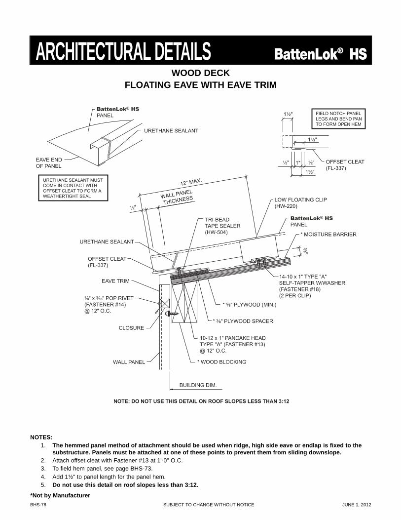
BHS-76 SUBJECT TO CHANGE WITHOUT NOTICE JUNE 1, 2012
ARCHITECTURAL DETAILS BattenLok® HS
* MOISTURE BARRIER
* ⁵⁄₈" PLYWOOD (MIN.)
¹⁄₂"
URETHANE SEALANT
TRI-BEAD TAPE SEALER (HW-504)
* ³⁄₈" PLYWOOD SPACER
¹⁄₈" x ³⁄₁₆" POP RIVET (FASTENER #14) @ 12" O.C.
WALL PANEL
THICKNESS
12" MAX.
EAVE TRIM
OFFSET CLEAT (FL-337)
BUILDING DIM.
WALL PANEL
CLOSURE
LOW FLOATING CLIP (HW-220)
³⁄₈"
10-12 x 1" PANCAKE HEAD TYPE "A" (FASTENER #13) @ 12" O.C.
* WOOD BLOCKING
OFFSET CLEAT (FL-337)
FIELD NOTCH PANEL LEGS AND BEND PAN TO FORM OPEN HEM
1¹⁄₂"
1¹⁄₂"
1¹⁄₂"
1" ¹⁄₂" ¹⁄₂"
14-10 x 1" TYPE "A" SELF-TAPPER W/WASHER (FASTENER #18) (2 PER CLIP)
NOTE: DO NOT USE THIS DETAIL ON ROOF SLOPES LESS THAN 3:12
BattenLok® HS
PANEL
URETHANE SEALANT MUST COME IN CONTACT WITH OFFSET CLEAT TO FORM A WEATHERTIGHT SEAL
EAVE END OF PANEL
URETHANE SEALANT
BattenLok® HS
PANEL
WOOD DECKFLOATING EAVE WITH EAVE TRIM
NOTES:1. The hemmed panel method of attachment should be used when ridge, high side eave or endlap is fixed to the
substructure. Panels must be attached at one of these points to prevent them from sliding downslope.2. Attach offset cleat with Fastener #13 at 1'-0" O.C.3. To field hem panel, see page BHS-73.4. Add 1¹⁄₂" to panel length for the panel hem.5. Do not use this detail on roof slopes less than 3:12.
*Not by Manufacturer
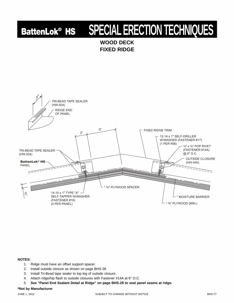
JUNE 1, 2012 SUBJECT TO CHANGE WITHOUT NOTICE BHS-77
BattenLok® HS SPECIAL ERECTION TECHNIQUES
* MOISTURE BARRIER
TRI-BEAD TAPE SEALER (HW-504)
¹⁄₈" x ³⁄₈" POP RIVET(FASTENER #14A)@ 6" O.C.
2" 5" FIXED RIDGE TRIM
³⁄₈"
OUTSIDE CLOSURE (HW-440)
* ³⁄₈" PLYWOOD SPACER
* ⁵⁄₈" PLYWOOD (MIN.)
14-10 x 1" TYPE "A" SELF-TAPPER W/WASHER (FASTENER #18) (4 PER PANEL)
TRI-BEAD TAPE SEALER (HW-504)
RIDGE END OF PANEL
3"
12-14 x 1" SELF-DRILLER W/WASHER (FASTENER #17) (1 PER RIB)
BattenLok® HS
PANEL
WOOD DECKFIXED RIDGE
NOTES:1. Ridge must have an offset support spacer.2. Install outside closure as shown on page BHS-363. Install Tri-Bead tape sealer to top leg of outside closure.4. Attach ridge/hip flash to outside closures with Fastener #14A at 6" O.C.5. See "Panel End Sealant Detail at Ridge" on page BHS-29 to seal panel seams at ridge.
*Not by Manufacturer
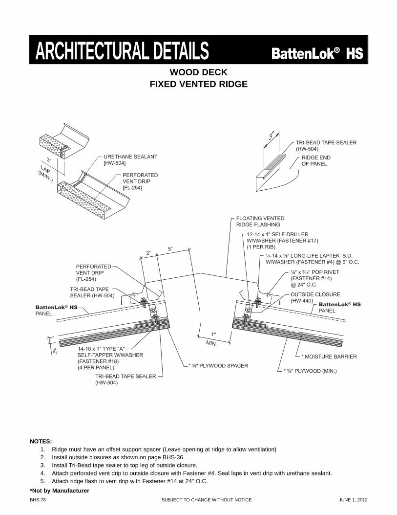
BHS-78 SUBJECT TO CHANGE WITHOUT NOTICE JUNE 1, 2012
NOTES:1. Ridge must have an offset support spacer (Leave opening at ridge to allow ventilation)2. Install outside closures as shown on page BHS-36.3. Install Tri-Bead tape sealer to top leg of outside closure.4. Attach perforated vent drip to outside closure with Fastener #4. Seal laps in vent drip with urethane sealant.5. Attach ridge flash to vent drip with Fastener #14 at 24" O.C.
TRI-BEAD TAPE SEALER (HW-504)
RIDGE END OF PANEL
3"
TRI-BEAD TAPE SEALER (HW-504)
TRI-BEAD TAPE SEALER (HW-504)
¹⁄₈" x ³⁄₁₆" POP RIVET (FASTENER #14) @ 24" O.C.
2" 5"
FLOATING VENTED RIDGE FLASHING
PERFORATED VENT DRIP (FL-254)
³⁄₈"
12-14 x 1" SELF-DRILLER W/WASHER (FASTENER #17) (1 PER RIB)
OUTSIDE CLOSURE (HW-440)
¹⁄₄-14 x ⁷⁄₈" LONG-LIFE LAPTEK S.D. W/WASHER (FASTENER #4) @ 6" O.C.
* MOISTURE BARRIER
* ³⁄₈" PLYWOOD SPACER * ⁵⁄₈" PLYWOOD (MIN.)
14-10 x 1" TYPE "A" SELF-TAPPER W/WASHER (FASTENER #18) (4 PER PANEL)
BattenLok® HS
PANEL
BattenLok® HS
PANEL
1" MIN.
URETHANE SEALANT [HW-504]
PERFORATED VENT DRIP [FL-254]
3” LAP (MIN.)
WOOD DECKFIXED VENTED RIDGE
ARCHITECTURAL DETAILS BattenLok® HS
*Not by Manufacturer
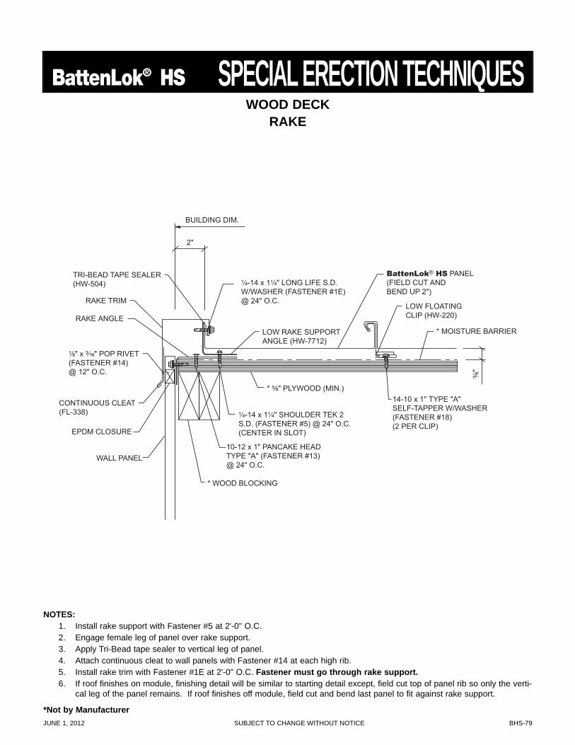
JUNE 1, 2012 SUBJECT TO CHANGE WITHOUT NOTICE BHS-79
BattenLok® HS SPECIAL ERECTION TECHNIQUES
14-10 x 1" TYPE "A"SELF-TAPPER W/WASHER(FASTENER #18)(2 PER CLIP)
10-12 x 1" PANCAKE HEADTYPE "A" (FASTENER #13)@ 24" O.C.
* MOISTURE BARRIER
* ⁵⁄₈" PLYWOOD (MIN.)
BattenLok® HS PANEL(FIELD CUT ANDBEND UP 2")
TRI-BEAD TAPE SEALER(HW-504) ¹⁄₄-14 x 1¹⁄₄" LONG LIFE S.D.
W/WASHER (FASTENER #1E)@ 24" O.C.
³⁄₈"
¹⁄₈" x ³⁄₁₆" POP RIVET(FASTENER #14)@ 12" O.C.
LOW FLOATINGCLIP (HW-220)
CONTINUOUS CLEAT(FL-338)
EPDM CLOSURE
WALL PANEL
RAKE TRIM
2"
BUILDING DIM.
LOW RAKE SUPPORTANGLE (HW-7712)
* WOOD BLOCKING
RAKE ANGLE
¹⁄₄-14 x 1¹⁄₄" SHOULDER TEK 2S.D. (FASTENER #5) @ 24" O.C.(CENTER IN SLOT)
WOOD DECKRAKE
NOTES:1. Install rake support with Fastener #5 at 2'-0" O.C.2. Engage female leg of panel over rake support.3. Apply Tri-Bead tape sealer to vertical leg of panel.4. Attach continuous cleat to wall panels with Fastener #14 at each high rib.5. Install rake trim with Fastener #1E at 2'-0" O.C. Fastener must go through rake support.6. If roof finishes on module, finishing detail will be similar to starting detail except, field cut top of panel rib so only the verti-
cal leg of the panel remains. If roof finishes off module, field cut and bend last panel to fit against rake support.
*Not by Manufacturer
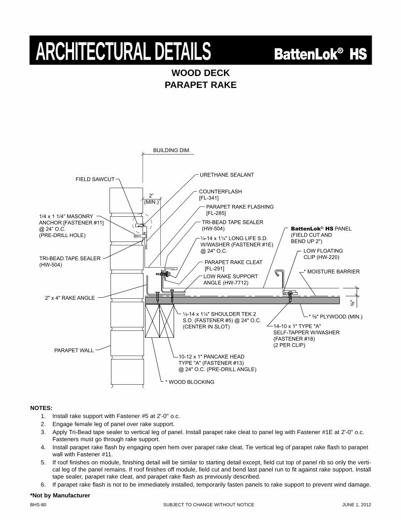
BHS-80 SUBJECT TO CHANGE WITHOUT NOTICE JUNE 1, 2012
ARCHITECTURAL DETAILS BattenLok® HS
¹⁄₄-14 x 1¹⁄₄" LONG LIFE S.D. W/WASHER (FASTENER #1E) @ 24" O.C.
¹⁄₄-14 x 1¹⁄₄" SHOULDER TEK 2 S.D. (FASTENER #5) @ 24" O.C. (CENTER IN SLOT)
LOW RAKE SUPPORT ANGLE (HW-7712)
TRI-BEAD TAPE SEALER (HW-504)
URETHANE SEALANT
COUNTERFLASH [FL-341]
PARAPET RAKE FLASHING [FL-285]
PARAPET RAKE CLEAT [FL-291]
BUILDING DIM.
2” (MIN.)
PARAPET WALL
FIELD SAWCUT
1/4 x 1 1/4” MASONRY ANCHOR [FASTENER #11] @ 24” O.C. (PRE-DRILL HOLE)
TRI-BEAD TAPE SEALER (HW-504)
2" x 4" RAKE ANGLE
14-10 x 1" TYPE "A"SELF-TAPPER W/WASHER(FASTENER #18)(2 PER CLIP)
10-12 x 1" PANCAKE HEAD TYPE "A" (FASTENER #13) @ 24" O.C. (PRE-DRILL ANGLE)
* MOISTURE BARRIER
* ⁵⁄₈" PLYWOOD (MIN.)
BattenLok® HS PANEL(FIELD CUT ANDBEND UP 2")
³⁄₈"
LOW FLOATINGCLIP (HW-220)
* WOOD BLOCKING
WOOD DECKPARAPET RAKE
NOTES:1. Install rake support with Fastener #5 at 2'-0" o.c.2. Engage female leg of panel over rake support.3. Apply Tri-Bead tape sealer to vertical leg of panel. Install parapet rake cleat to panel leg with Fastener #1E at 2'-0" o.c.
Fasteners must go through rake support.4. Install parapet rake flash by engaging open hem over parapet rake cleat. Tie vertical leg of parapet rake flash to parapet
wall with Fastener #11.5. If roof finishes on module, finishing detail will be similar to starting detail except, field cut top of panel rib so only the verti-
cal leg of the panel remains. If roof finishes off module, field cut and bend last panel run to fit against rake support. Installtape sealer, parapet rake cleat, and parapet rake flash as previously described.
6. If parapet rake flash is not to be immediately installed, temporarily fasten panels to rake support to prevent wind damage.
*Not by Manufacturer
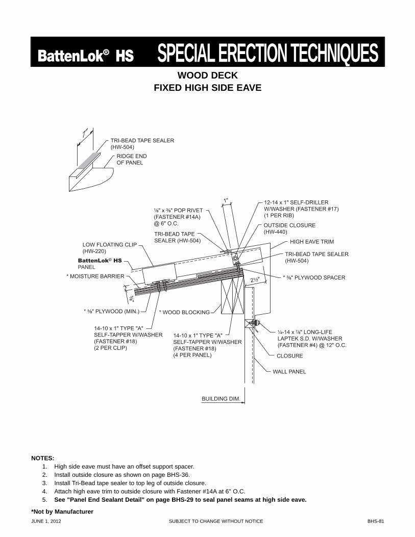
JUNE 1, 2012 SUBJECT TO CHANGE WITHOUT NOTICE BHS-81
BattenLok® HS SPECIAL ERECTION TECHNIQUES
* MOISTURE BARRIER
* ⁵⁄₈" PLYWOOD (MIN.)
* ³⁄₈" PLYWOOD SPACER
14-10 x 1" TYPE "A" SELF-TAPPER W/WASHER (FASTENER #18) (2 PER CLIP)
14-10 x 1" TYPE "A" SELF-TAPPER W/WASHER (FASTENER #18) (4 PER PANEL)
LOW FLOATING CLIP (HW-220)
2¹⁄₂"
TRI-BEAD TAPE SEALER (HW-504)
TRI-BEAD TAPE SEALER (HW-504)
¹⁄₄-14 x ⁷⁄₈" LONG-LIFE LAPTEK S.D. W/WASHER (FASTENER #4) @ 12" O.C.
¹⁄₈" x ³⁄₈" POP RIVET(FASTENER #14A)@ 6" O.C.
1"
HIGH EAVE TRIM
BUILDING DIM.
WALL PANEL
CLOSURE
³⁄₈"
* WOOD BLOCKING
12-14 x 1" SELF-DRILLER W/WASHER (FASTENER #17) (1 PER RIB)
OUTSIDE CLOSURE (HW-440)
TRI-BEAD TAPE SEALER (HW-504)
RIDGE END OF PANEL
7"
BattenLok® HS
PANEL
WOOD DECKFIXED HIGH SIDE EAVE
NOTES:1. High side eave must have an offset support spacer.2. Install outside closure as shown on page BHS-36.3. Install Tri-Bead tape sealer to top leg of outside closure.4. Attach high eave trim to outside closure with Fastener #14A at 6" O.C.5. See "Panel End Sealant Detail" on page BHS-29 to seal panel seams at high side eave.
*Not by Manufacturer
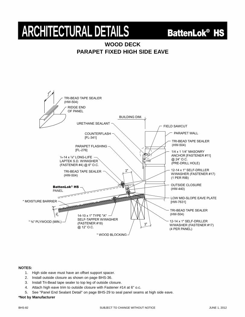
BHS-82 SUBJECT TO CHANGE WITHOUT NOTICE JUNE 1, 2012
2"
TRI-BEAD TAPE SEALER (HW-504)
TRI-BEAD TAPE SEALER (HW-504)
LOW MID-SLOPE EAVE PLATE [HW-7631]
¹⁄₄-14 x ⁷⁄₈" LONG-LIFE LAPTEK S.D. W/WASHER (FASTENER #4) @ 6" O.C.
2"
BUILDING DIM.
12-14 x 1" SELF-DRILLER W/WASHER (FASTENER #17) (1 PER RIB)
12-14 x 1" SELF-DRILLER W/WASHER (FASTENER #17) (4 PER PANEL)
OUTSIDE CLOSURE (HW-440)
TRI-BEAD TAPE SEALER (HW-504)
RIDGE END OF PANEL
7"
URETHANE SEALANT
COUNTERFLASH [FL-341]
PARAPET FLASHING [FL-276]
PARAPET WALL
FIELD SAWCUT
1/4 x 1 1/4” MASONRY ANCHOR [FASTENER #11] @ 24” O.C. (PRE-DRILL HOLE)
TRI-BEAD TAPE SEALER (HW-504)
* MOISTURE BARRIER
* ⁵⁄₈" PLYWOOD (MIN.)
14-10 x 1" TYPE "A" SELF-TAPPER W/WASHER (FASTENER #18) @ 12” O.C.
³⁄₈"
* WOOD BLOCKING
BattenLok® HS
PANEL
WOOD DECKPARAPET FIXED HIGH SIDE EAVE
ARCHITECTURAL DETAILS BattenLok® HS
NOTES:1. High side eave must have an offset support spacer.2. Install outside closure as shown on page BHS-36.3. Install Tri-Bead tape sealer to top leg of outside closure.4. Attach high eave trim to outside closure with Fastener #14 at 6" o.c.5. See "Panel End Sealant Detail" on page BHS-29 to seal panel seams at high side eave.
*Not by Manufacturer
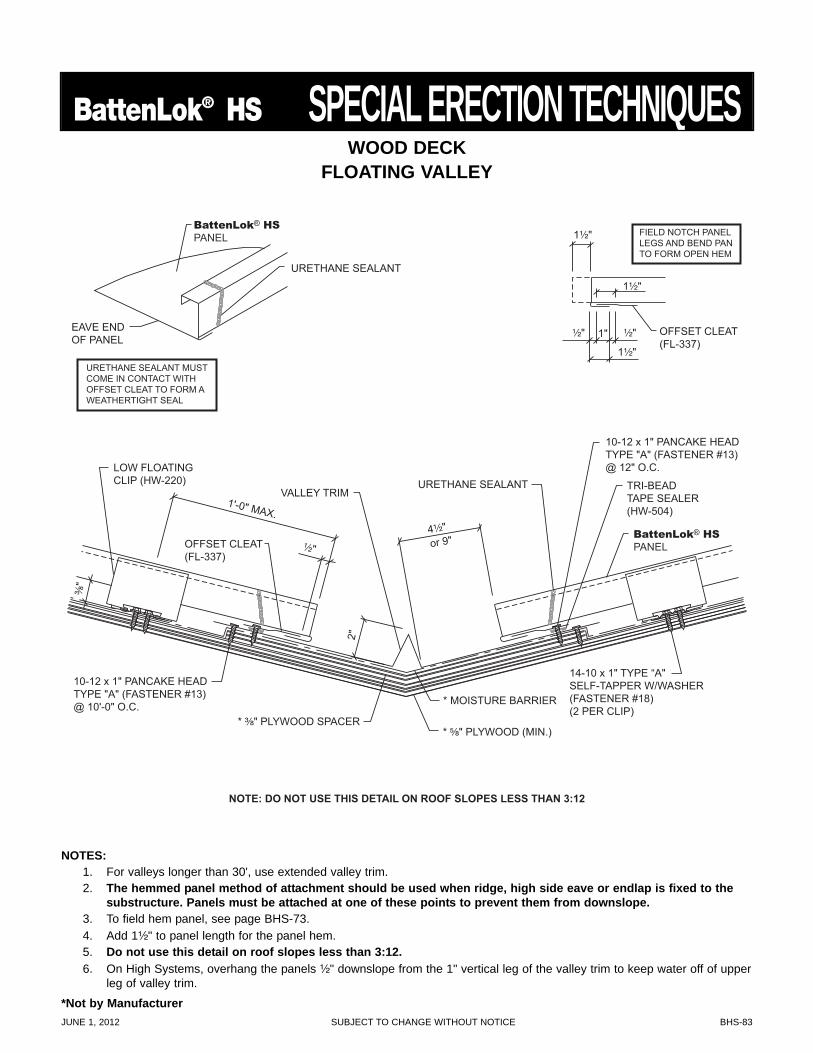
JUNE 1, 2012 SUBJECT TO CHANGE WITHOUT NOTICE BHS-83
BattenLok® HS SPECIAL ERECTION TECHNIQUES
OFFSET CLEAT (FL-337)
FIELD NOTCH PANEL LEGS AND BEND PAN TO FORM OPEN HEM
1¹⁄₂"
1¹⁄₂"
1¹⁄₂"
1" ¹⁄₂" ¹⁄₂"
4¹⁄₂"
TRI-BEAD TAPE SEALER (HW-504)
2"
1'-0" MAX.
¹⁄₂"
LOW FLOATING CLIP (HW-220) URETHANE SEALANT
VALLEY TRIM
OFFSET CLEAT (FL-337)
³⁄₈"
NOTE: DO NOT USE THIS DETAIL ON ROOF SLOPES LESS THAN 3:12
14-10 x 1" TYPE “A" SELF-TAPPER W/WASHER (FASTENER #18) (2 PER CLIP)
10-12 x 1" PANCAKE HEAD TYPE "A" (FASTENER #13) @ 12" O.C.
10-12 x 1" PANCAKE HEAD TYPE "A" (FASTENER #13) @ 10'-0" O.C. * MOISTURE BARRIER
* ³⁄₈" PLYWOOD SPACER * ⁵⁄₈" PLYWOOD (MIN.)
BattenLok® HS
PANEL
URETHANE SEALANT MUST COME IN CONTACT WITH OFFSET CLEAT TO FORM A WEATHERTIGHT SEAL
EAVE END OF PANEL
URETHANE SEALANT
BattenLok® HS
PANEL
or 9"
NOTES:1. For valleys longer than 30', use extended valley trim.2. The hemmed panel method of attachment should be used when ridge, high side eave or endlap is fixed to the
substructure. Panels must be attached at one of these points to prevent them from downslope.3. To field hem panel, see page BHS-73.4. Add 1¹⁄₂" to panel length for the panel hem.5. Do not use this detail on roof slopes less than 3:12.6. On High Systems, overhang the panels ¹⁄₂" downslope from the 1" vertical leg of the valley trim to keep water off of upper
leg of valley trim.
WOOD DECKFLOATING VALLEY
*Not by Manufacturer
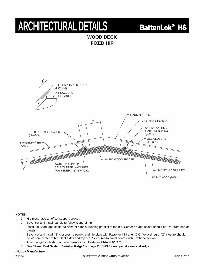
BHS-84 SUBJECT TO CHANGE WITHOUT NOTICE JUNE 1, 2012
* MOISTURE BARRIER
TRI-BEAD TAPE SEALER (HW-504)
¹⁄₈" x ³⁄₈" POP RIVET(FASTENER #14A)@ 6" O.C.
FIXED HIP TRIM
³⁄₈"
ZEE CLOSURE (FL-361)
URETHANE SEALANT
* ³⁄₈" PLYWOOD SPACER
* ⁵⁄₈" PLYWOOD (MIN.)
TRI-BEAD TAPE SEALER (HW-504)
RIDGE END OF PANEL
3"
BattenLok® HS
PANEL
2" 5"
14-10 x 1" TYPE "A" SELF-TAPPER W/WASHER (FASTENER #18) @ 6" O.C.
WOOD DECKFIXED HIP
ARCHITECTURAL DETAILS BattenLok® HS
NOTES:1. Hip must have an offset support spacer.2. Bevel cut and install panels to follow slope of hip.3. Install Tri-Bead tape sealer to pans of panels, running parallel to the hip. Center of tape sealer should be 1¹⁄₂" from end of
panels.4. Bevel cut and install "Z" closures to panels and hip plate with Fastener #18 at 6" O.C. Vertical leg of "Z" closure should
be 4" from center of hip. Seal sides and top of "Z" closures to panel seams with urethane sealant.5. Attach ridge/hip flash to outside closures with Fastener #14A at 6" O.C.6. See "Panel End Sealant Detail at Ridge" on page BHS-29 to seal panel seams at ridge.
*Not by Manufacturer
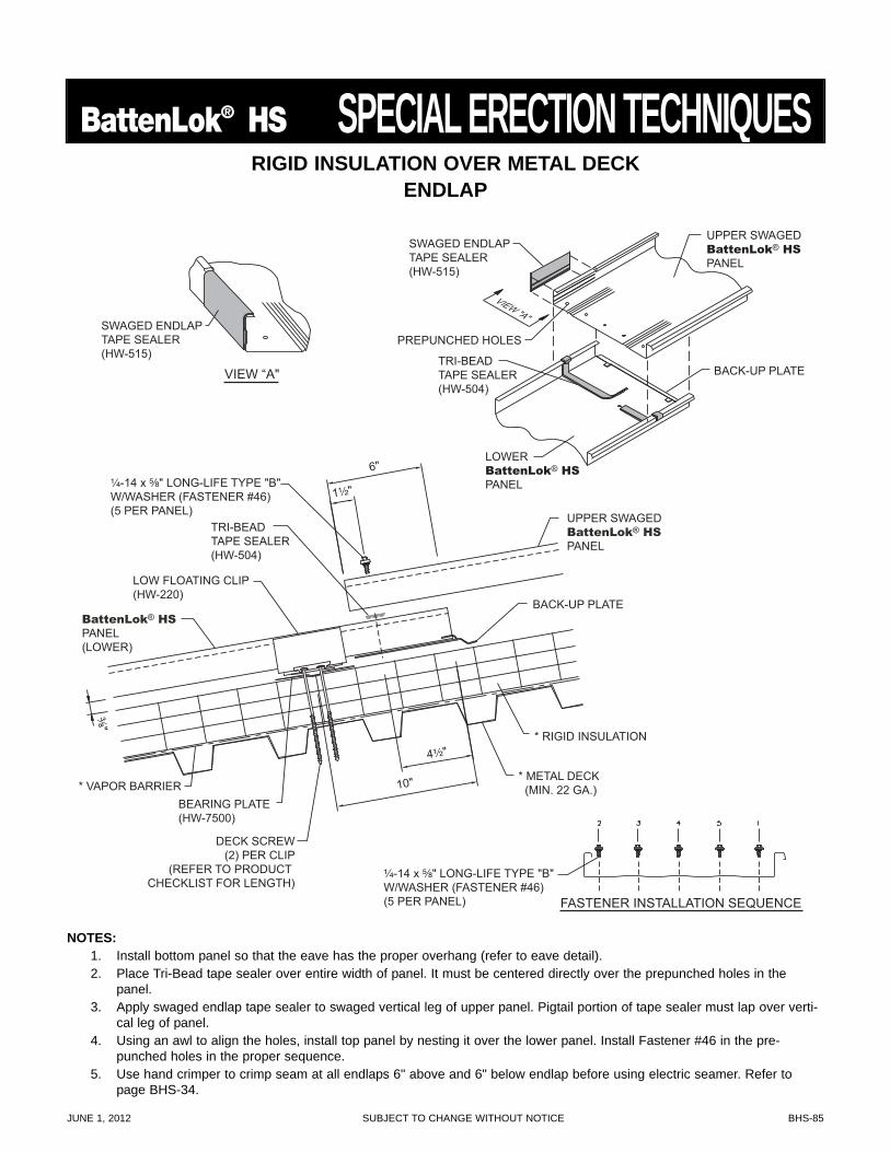
JUNE 1, 2012 SUBJECT TO CHANGE WITHOUT NOTICE BHS-85
BattenLok® HS SPECIAL ERECTION TECHNIQUES
VIEW “A"
SWAGED ENDLAP TAPE SEALER (HW-515)
¹⁄₄-14 x ⁵⁄₈" LONG-LIFE TYPE "B" W/WASHER (FASTENER #46) (5 PER PANEL)
BattenLok® HS PANEL (LOWER)
UPPER SWAGED BattenLok® HS PANEL
BACK-UP PLATE
1¹⁄₂"
4¹⁄₂"
TRI-BEAD TAPE SEALER (HW-504)
6"
10"
DECK SCREW(2) PER CLIP
(REFER TO PRODUCT CHECKLIST FOR LENGTH)
* VAPOR BARRIER
* RIGID INSULATION
LOW FLOATING CLIP (HW-220)
BEARING PLATE (HW-7500)
* METAL DECK (MIN. 22 GA.)
³⁄₈"
UPPER SWAGED BattenLok® HS
PANEL
LOWER BattenLok® HS
PANEL
PREPUNCHED HOLES
VIEW "A"
BACK-UP PLATE TRI-BEAD TAPE SEALER (HW-504)
SWAGED ENDLAP TAPE SEALER (HW-515)
FASTENER INSTALLATION SEQUENCE
¹⁄₄-14 x ⁵⁄₈" LONG-LIFE TYPE "B" W/WASHER (FASTENER #46) (5 PER PANEL)
RIGID INSULATION OVER METAL DECKENDLAP
NOTES:1. Install bottom panel so that the eave has the proper overhang (refer to eave detail).2. Place Tri-Bead tape sealer over entire width of panel. It must be centered directly over the prepunched holes in the
panel.3. Apply swaged endlap tape sealer to swaged vertical leg of upper panel. Pigtail portion of tape sealer must lap over verti-
cal leg of panel.4. Using an awl to align the holes, install top panel by nesting it over the lower panel. Install Fastener #46 in the pre-
punched holes in the proper sequence.5. Use hand crimper to crimp seam at all endlaps 6" above and 6" below endlap before using electric seamer. Refer to
page BHS-34.
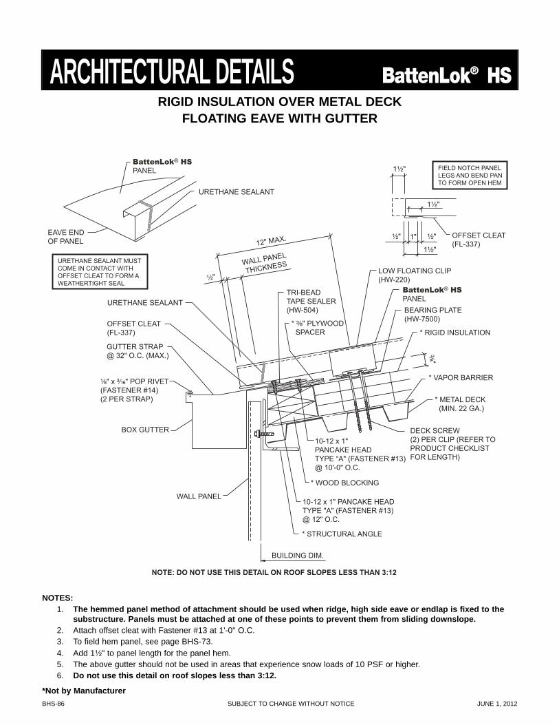
BHS-86 SUBJECT TO CHANGE WITHOUT NOTICE JUNE 1, 2012
URETHANE SEALANT MUST COME IN CONTACT WITH OFFSET CLEAT TO FORM A WEATHERTIGHT SEAL
EAVE END OF PANEL
URETHANE SEALANT
OFFSET CLEAT (FL-337)
FIELD NOTCH PANEL LEGS AND BEND PAN TO FORM OPEN HEM
1¹⁄₂"
1¹⁄₂"
1¹⁄₂"
1" ¹⁄₂" ¹⁄₂"
¹⁄₂"
URETHANE SEALANTTRI-BEAD TAPE SEALER (HW-504)
* ³⁄₈" PLYWOOD SPACER
¹⁄₈" x ³⁄₁₆" POP RIVET (FASTENER #14) (2 PER STRAP)
WALL PANEL
THICKNESS
12" MAX.
OFFSET CLEAT (FL-337)
BUILDING DIM.
WALL PANEL
DECK SCREW (2) PER CLIP (REFER TO PRODUCT CHECKLIST FOR LENGTH)
* VAPOR BARRIER
* RIGID INSULATION
LOW FLOATING CLIP (HW-220)
BEARING PLATE (HW-7500)
* METAL DECK (MIN. 22 GA.)
³⁄₈"
* WOOD BLOCKING
10-12 x 1" PANCAKE HEAD TYPE "A" (FASTENER #13) @ 12" O.C.
* STRUCTURAL ANGLE
BOX GUTTER
GUTTER STRAP @ 32" O.C. (MAX.)
NOTE: DO NOT USE THIS DETAIL ON ROOF SLOPES LESS THAN 3:12
10-12 x 1" PANCAKE HEAD TYPE “A" (FASTENER #13) @ 10'-0" O.C.
BattenLok® HS
PANEL
BattenLok® HS
PANEL
RIGID INSULATION OVER METAL DECKFLOATING EAVE WITH GUTTER
ARCHITECTURAL DETAILS BattenLok® HS
NOTES:1. The hemmed panel method of attachment should be used when ridge, high side eave or endlap is fixed to the
substructure. Panels must be attached at one of these points to prevent them from sliding downslope.2. Attach offset cleat with Fastener #13 at 1'-0" O.C.3. To field hem panel, see page BHS-73.4. Add 1¹⁄₂" to panel length for the panel hem.5. The above gutter should not be used in areas that experience snow loads of 10 PSF or higher.6. Do not use this detail on roof slopes less than 3:12.
*Not by Manufacturer
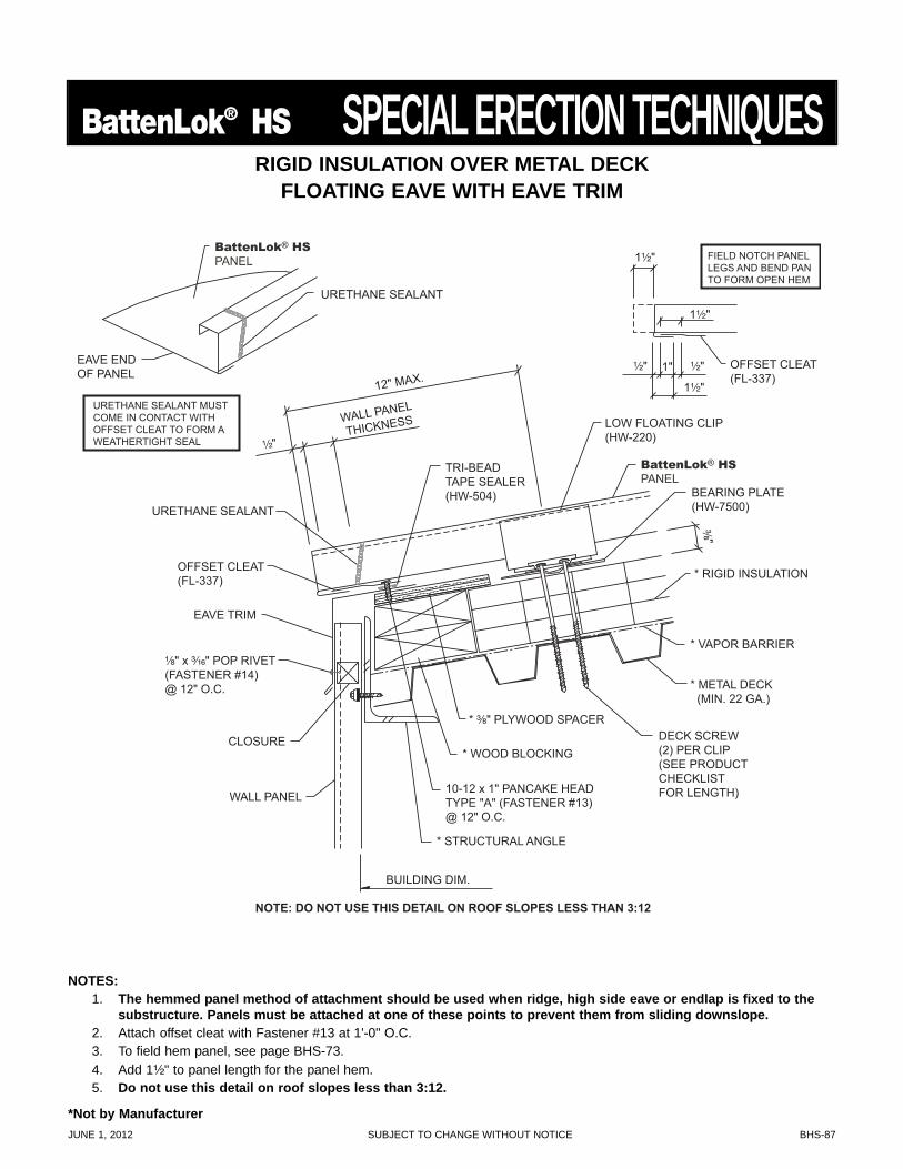
JUNE 1, 2012 SUBJECT TO CHANGE WITHOUT NOTICE BHS-87
BattenLok® HS SPECIAL ERECTION TECHNIQUES
¹⁄₂"
URETHANE SEALANT
TRI-BEAD TAPE SEALER (HW-504)
* ³⁄₈" PLYWOOD SPACER
¹⁄₈" x ³⁄₁₆" POP RIVET (FASTENER #14) @ 12" O.C.
WALL PANEL
THICKNESS
12" MAX.
EAVE TRIM
OFFSET CLEAT (FL-337)
BUILDING DIM.
WALL PANEL
CLOSURE DECK SCREW (2) PER CLIP(SEE PRODUCT CHECKLIST FOR LENGTH)
* VAPOR BARRIER
* RIGID INSULATION
LOW FLOATING CLIP (HW-220)
BEARING PLATE (HW-7500)
* METAL DECK (MIN. 22 GA.)
³⁄₈"
* WOOD BLOCKING
10-12 x 1" PANCAKE HEAD TYPE "A" (FASTENER #13) @ 12" O.C.
* STRUCTURAL ANGLE
OFFSET CLEAT (FL-337)
FIELD NOTCH PANEL LEGS AND BEND PAN TO FORM OPEN HEM
1¹⁄₂"
1¹⁄₂"
1¹⁄₂"
1" ¹⁄₂" ¹⁄₂"
NOTE: DO NOT USE THIS DETAIL ON ROOF SLOPES LESS THAN 3:12
BattenLok® HS
PANEL
URETHANE SEALANT MUST COME IN CONTACT WITH OFFSET CLEAT TO FORM A WEATHERTIGHT SEAL
EAVE END OF PANEL
URETHANE SEALANT
BattenLok® HS
PANEL
RIGID INSULATION OVER METAL DECKFLOATING EAVE WITH EAVE TRIM
NOTES:1. The hemmed panel method of attachment should be used when ridge, high side eave or endlap is fixed to the
substructure. Panels must be attached at one of these points to prevent them from sliding downslope.2. Attach offset cleat with Fastener #13 at 1'-0" O.C.3. To field hem panel, see page BHS-73.4. Add 1¹⁄₂" to panel length for the panel hem.5. Do not use this detail on roof slopes less than 3:12.
*Not by Manufacturer
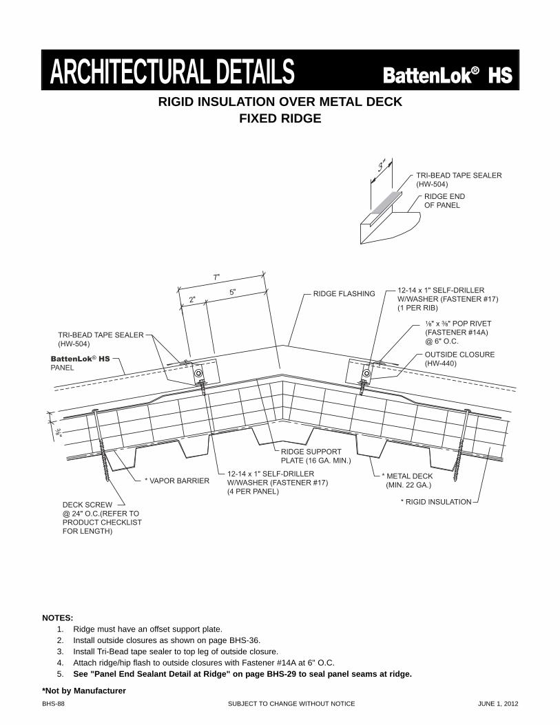
BHS-88 SUBJECT TO CHANGE WITHOUT NOTICE JUNE 1, 2012
TRI-BEAD TAPE SEALER (HW-504)
RIDGE END OF PANEL
3"
TRI-BEAD TAPE SEALER (HW-504)
¹⁄₈" x ³⁄₈" POP RIVET(FASTENER #14A)@ 6" O.C.
7"
2" 5" RIDGE FLASHING
³⁄₈"
12-14 x 1" SELF-DRILLER W/WASHER (FASTENER #17) (1 PER RIB)
12-14 x 1" SELF-DRILLER W/WASHER (FASTENER #17) (4 PER PANEL)
OUTSIDE CLOSURE (HW-440)
* VAPOR BARRIER
* RIGID INSULATION
* METAL DECK (MIN. 22 GA.)
DECK SCREW @ 24" O.C.(REFER TO PRODUCT CHECKLIST FOR LENGTH)
RIDGE SUPPORT PLATE (16 GA. MIN.)
BattenLok® HS
PANEL
RIGID INSULATION OVER METAL DECKFIXED RIDGE
ARCHITECTURAL DETAILS BattenLok® HS
NOTES:1. Ridge must have an offset support plate.2. Install outside closures as shown on page BHS-36.3. Install Tri-Bead tape sealer to top leg of outside closure.4. Attach ridge/hip flash to outside closures with Fastener #14A at 6" O.C.5. See "Panel End Sealant Detail at Ridge" on page BHS-29 to seal panel seams at ridge.
*Not by Manufacturer
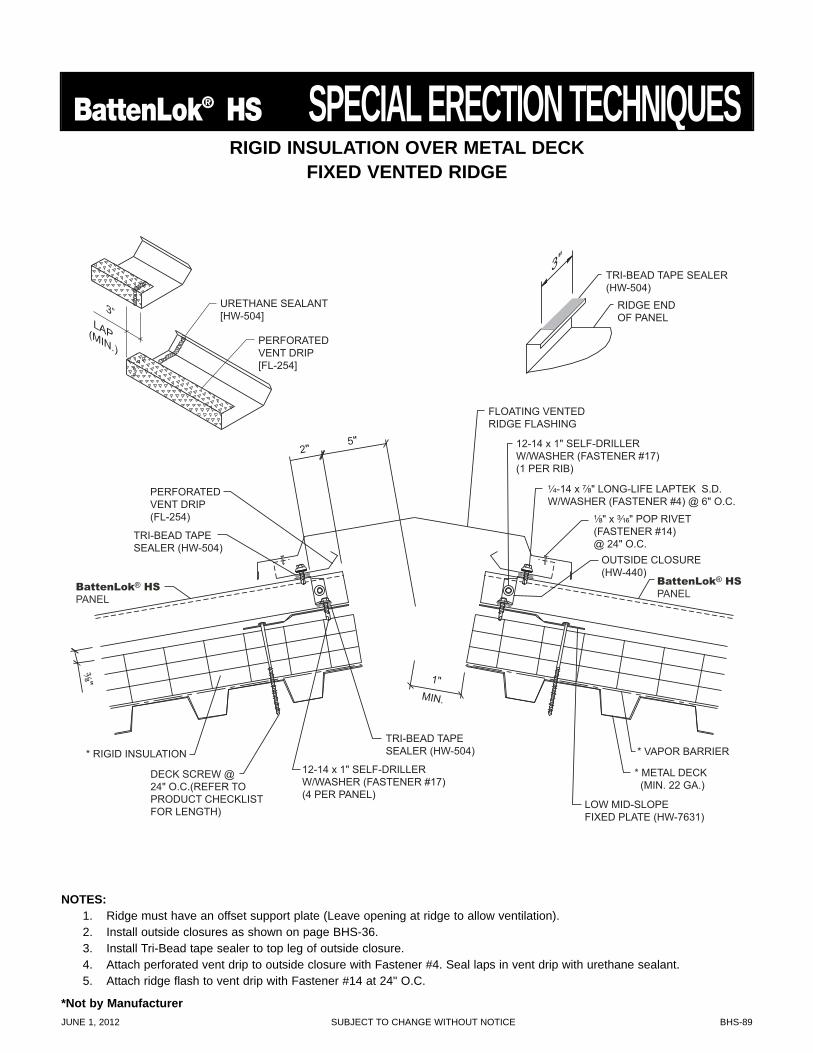
JUNE 1, 2012 SUBJECT TO CHANGE WITHOUT NOTICE BHS-89
BattenLok® HS SPECIAL ERECTION TECHNIQUES
TRI-BEAD TAPE SEALER (HW-504)
RIDGE END OF PANEL
3"
TRI-BEAD TAPE SEALER (HW-504)
TRI-BEAD TAPE SEALER (HW-504)
¹⁄₈" x ³⁄₁₆" POP RIVET (FASTENER #14) @ 24" O.C.
FLOATING VENTED RIDGE FLASHING
PERFORATED VENT DRIP (FL-254)
³⁄₈"
12-14 x 1" SELF-DRILLER W/WASHER (FASTENER #17) (1 PER RIB)
12-14 x 1" SELF-DRILLER W/WASHER (FASTENER #17) (4 PER PANEL)
OUTSIDE CLOSURE (HW-440)
LOW MID-SLOPEFIXED PLATE (HW-7631)
¹⁄₄-14 x ⁷⁄₈" LONG-LIFE LAPTEK S.D. W/WASHER (FASTENER #4) @ 6" O.C.
DECK SCREW @ 24" O.C.(REFER TO PRODUCT CHECKLIST FOR LENGTH)
* VAPOR BARRIER * RIGID INSULATION
* METAL DECK (MIN. 22 GA.)
BattenLok® HS
PANEL
BattenLok® HS
PANEL
2" 5"
URETHANE SEALANT [HW-504]
PERFORATED VENT DRIP [FL-254]
3” LAP (MIN.)
1" MIN.
RIGID INSULATION OVER METAL DECKFIXED VENTED RIDGE
NOTES:1. Ridge must have an offset support plate (Leave opening at ridge to allow ventilation).2. Install outside closures as shown on page BHS-36.3. Install Tri-Bead tape sealer to top leg of outside closure.4. Attach perforated vent drip to outside closure with Fastener #4. Seal laps in vent drip with urethane sealant.5. Attach ridge flash to vent drip with Fastener #14 at 24" O.C.
*Not by Manufacturer
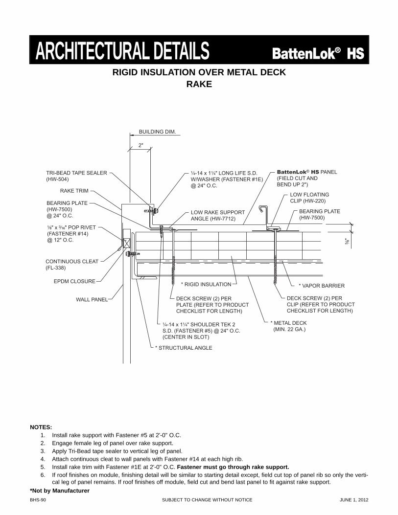
BHS-90 SUBJECT TO CHANGE WITHOUT NOTICE JUNE 1, 2012
BattenLok® HS PANEL (FIELD CUT AND BEND UP 2")
TRI-BEAD TAPE SEALER (HW-504)
¹⁄₄-14 x 1¹⁄₄" LONG LIFE S.D. W/WASHER (FASTENER #1E) @ 24" O.C.
¹⁄₄-14 x 1¹⁄₄" SHOULDER TEK 2 S.D. (FASTENER #5) @ 24" O.C. (CENTER IN SLOT)
³⁄₈"
¹⁄₈" x ³⁄₁₆" POP RIVET (FASTENER #14) @ 12" O.C.
LOW FLOATING CLIP (HW-220)
CONTINUOUS CLEAT (FL-338)
EPDM CLOSURE
WALL PANEL
RAKE TRIM
2"
BUILDING DIM.
LOW RAKE SUPPORT ANGLE (HW-7712)
DECK SCREW (2) PER PLATE (REFER TO PRODUCT CHECKLIST FOR LENGTH)
DECK SCREW (2) PER CLIP (REFER TO PRODUCT CHECKLIST FOR LENGTH)
* VAPOR BARRIER * RIGID INSULATION
* STRUCTURAL ANGLE
BEARING PLATE (HW-7500) @ 24" O.C.
BEARING PLATE (HW-7500)
* METAL DECK (MIN. 22 GA.)
RIGID INSULATION OVER METAL DECKRAKE
ARCHITECTURAL DETAILS BattenLok® HS
NOTES:1. Install rake support with Fastener #5 at 2'-0" O.C.2. Engage female leg of panel over rake support.3. Apply Tri-Bead tape sealer to vertical leg of panel.4. Attach continuous cleat to wall panels with Fastener #14 at each high rib.5. Install rake trim with Fastener #1E at 2'-0" O.C. Fastener must go through rake support.6. If roof finishes on module, finishing detail will be similar to starting detail except, field cut top of panel rib so only the verti-
cal leg of panel remains. If roof finishes off module, field cut and bend last panel to fit against rake support.*Not by Manufacturer
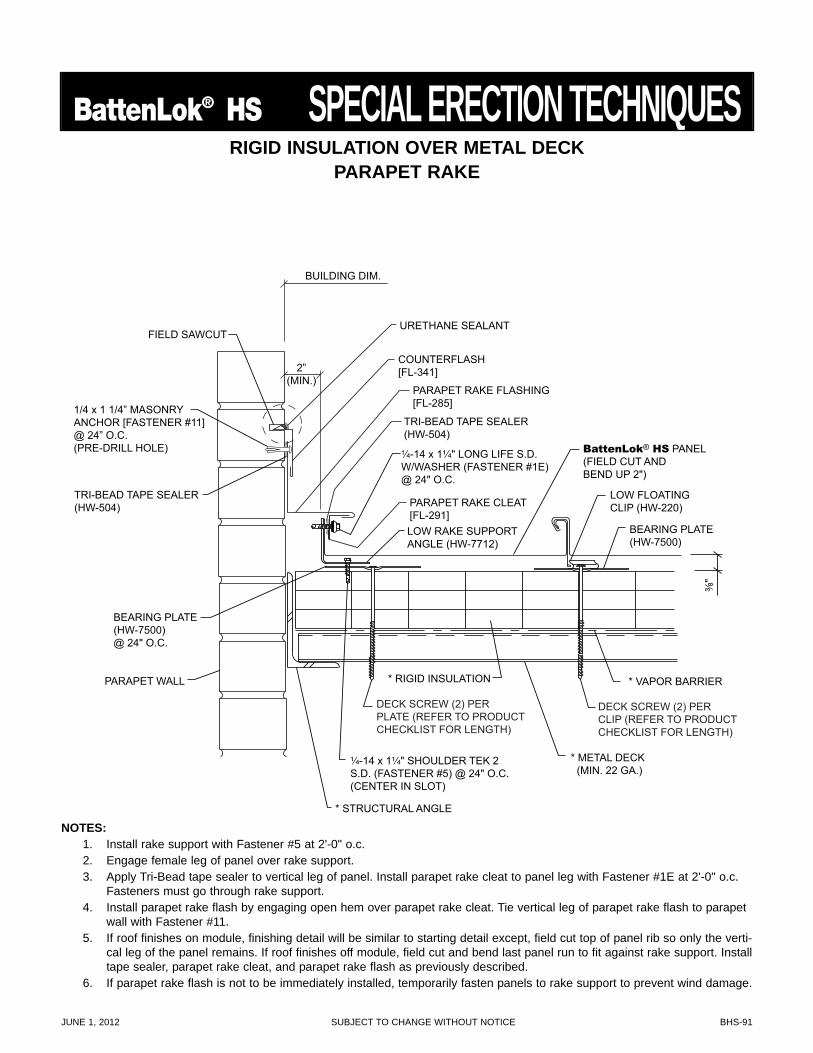
JUNE 1, 2012 SUBJECT TO CHANGE WITHOUT NOTICE BHS-91
BattenLok® HS SPECIAL ERECTION TECHNIQUES
¹⁄₄-14 x 1¹⁄₄" LONG LIFE S.D.W/WASHER (FASTENER #1E)@ 24" O.C.
LOW RAKE SUPPORTANGLE (HW-7712)
TRI-BEAD TAPE SEALER(HW-504)
URETHANE SEALANT
COUNTERFLASH[FL-341]
PARAPET RAKE FLASHING[FL-285]
PARAPET RAKE CLEAT[FL-291]
BUILDING DIM.
2”(MIN.)
PARAPET WALL
FIELD SAWCUT
1/4 x 1 1/4” MASONRYANCHOR [FASTENER #11]@ 24” O.C.(PRE-DRILL HOLE)
TRI-BEAD TAPE SEALER(HW-504)
BattenLok® HS PANEL(FIELD CUT ANDBEND UP 2")
³⁄₈"
LOW FLOATINGCLIP (HW-220)
¹⁄₄-14 x 1¹⁄₄" SHOULDER TEK 2S.D. (FASTENER #5) @ 24" O.C.(CENTER IN SLOT)
DECK SCREW (2) PER PLATE (REFER TO PRODUCT CHECKLIST FOR LENGTH)
DECK SCREW (2) PER CLIP (REFER TO PRODUCT CHECKLIST FOR LENGTH)
* VAPOR BARRIER* RIGID INSULATION
* STRUCTURAL ANGLE
BEARING PLATE(HW-7500)@ 24" O.C.
BEARING PLATE(HW-7500)
* METAL DECK (MIN. 22 GA.)
RIGID INSULATION OVER METAL DECKPARAPET RAKE
NOTES:1. Install rake support with Fastener #5 at 2'-0" o.c.2. Engage female leg of panel over rake support.3. Apply Tri-Bead tape sealer to vertical leg of panel. Install parapet rake cleat to panel leg with Fastener #1E at 2'-0" o.c.
Fasteners must go through rake support.4. Install parapet rake flash by engaging open hem over parapet rake cleat. Tie vertical leg of parapet rake flash to parapet
wall with Fastener #11.5. If roof finishes on module, finishing detail will be similar to starting detail except, field cut top of panel rib so only the verti-
cal leg of the panel remains. If roof finishes off module, field cut and bend last panel run to fit against rake support. Installtape sealer, parapet rake cleat, and parapet rake flash as previously described.
6. If parapet rake flash is not to be immediately installed, temporarily fasten panels to rake support to prevent wind damage.
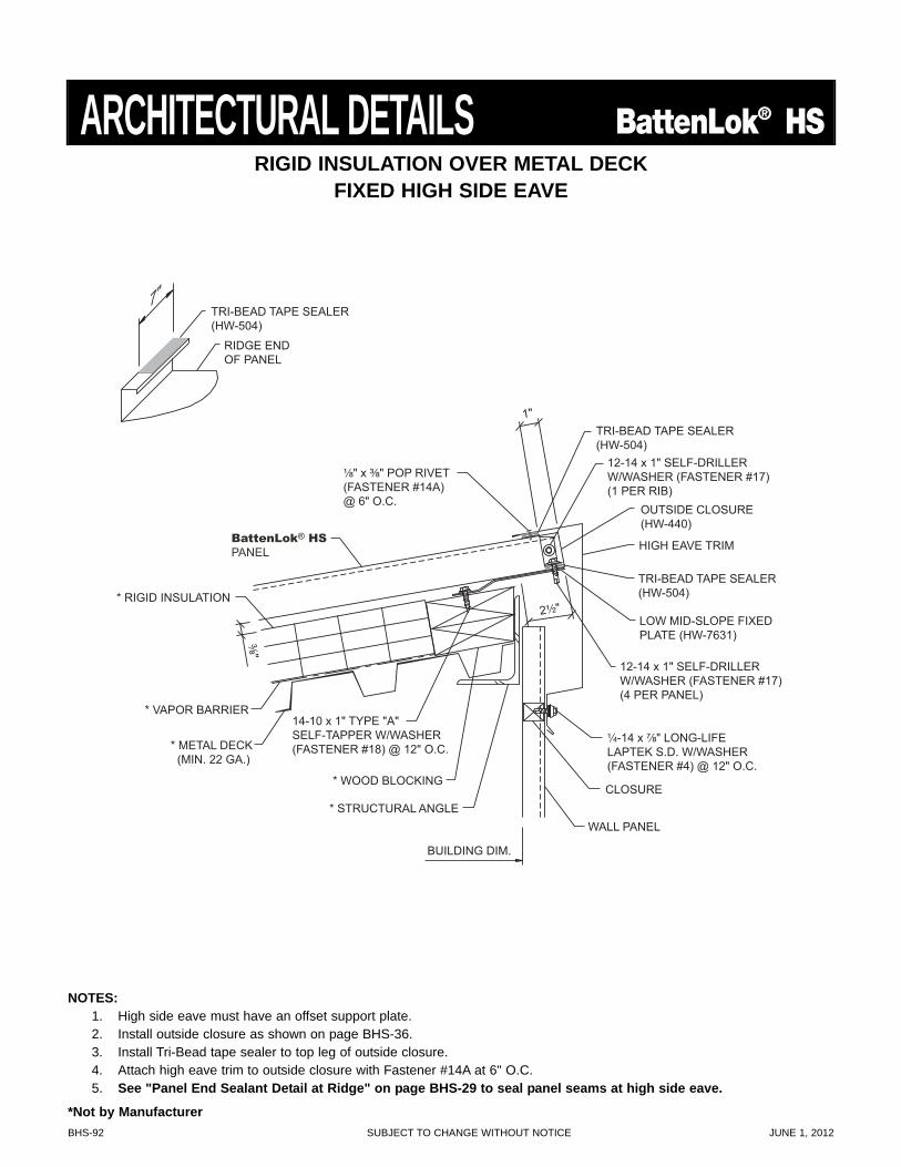
BHS-92 SUBJECT TO CHANGE WITHOUT NOTICE JUNE 1, 2012
NOTES:1. High side eave must have an offset support plate.2. Install outside closure as shown on page BHS-36.3. Install Tri-Bead tape sealer to top leg of outside closure.4. Attach high eave trim to outside closure with Fastener #14A at 6" O.C.5. See "Panel End Sealant Detail at Ridge" on page BHS-29 to seal panel seams at high side eave.
2¹⁄₂"
TRI-BEAD TAPE SEALER (HW-504)
TRI-BEAD TAPE SEALER (HW-504)
¹⁄₄-14 x ⁷⁄₈" LONG-LIFE LAPTEK S.D. W/WASHER (FASTENER #4) @ 12" O.C.
¹⁄₈" x ³⁄₈" POP RIVET(FASTENER #14A)@ 6" O.C.
1"
HIGH EAVE TRIM
* STRUCTURAL ANGLE
BUILDING DIM.
WALL PANEL
CLOSURE
³⁄₈"
* RIGID INSULATION
* VAPOR BARRIER
* METAL DECK (MIN. 22 GA.)
* WOOD BLOCKING
14-10 x 1" TYPE "A" SELF-TAPPER W/WASHER (FASTENER #18) @ 12" O.C.
12-14 x 1" SELF-DRILLER W/WASHER (FASTENER #17) (1 PER RIB)
12-14 x 1" SELF-DRILLER W/WASHER (FASTENER #17) (4 PER PANEL)
OUTSIDE CLOSURE (HW-440)
LOW MID-SLOPE FIXED PLATE (HW-7631)
TRI-BEAD TAPE SEALER (HW-504)
RIDGE END OF PANEL
7"
BattenLok® HS
PANEL
RIGID INSULATION OVER METAL DECKFIXED HIGH SIDE EAVE
ARCHITECTURAL DETAILS BattenLok® HS
*Not by Manufacturer
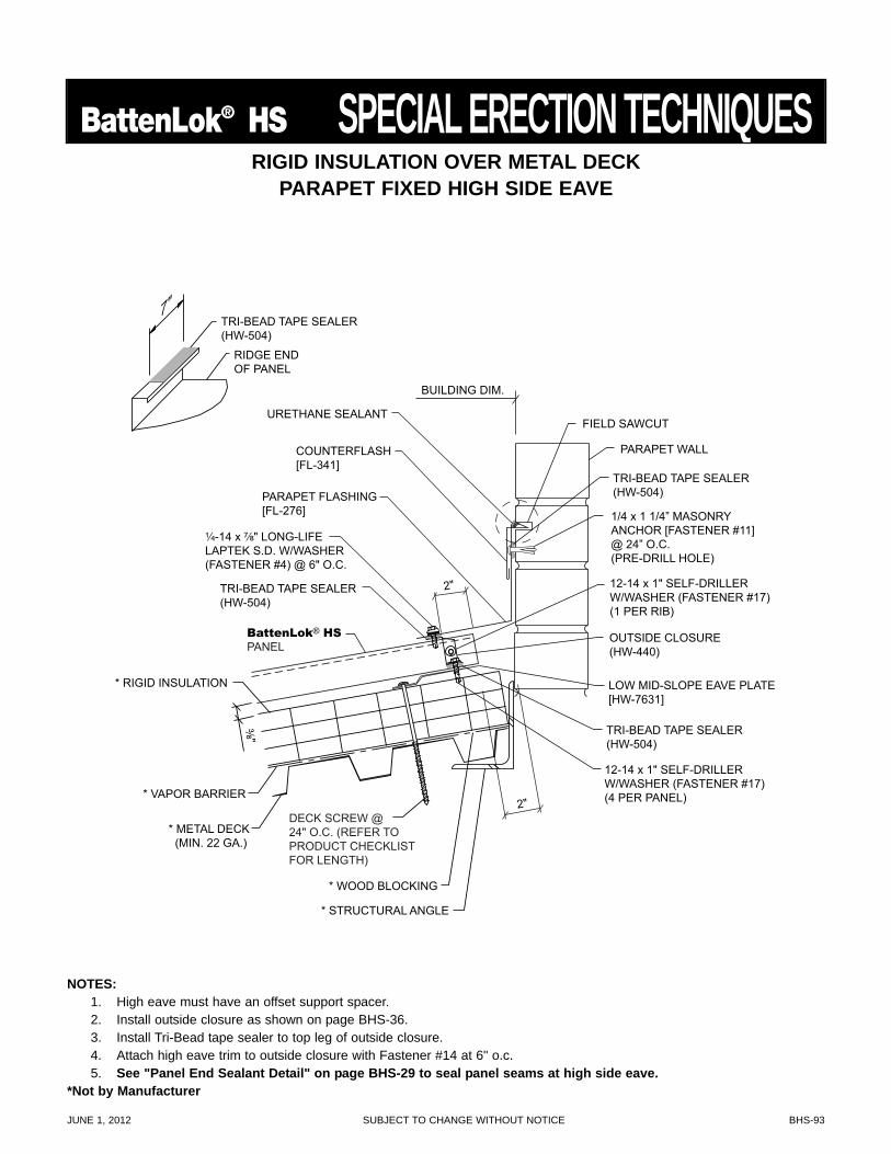
JUNE 1, 2012 SUBJECT TO CHANGE WITHOUT NOTICE BHS-93
BattenLok® HS SPECIAL ERECTION TECHNIQUES
2"
TRI-BEAD TAPE SEALER(HW-504)
TRI-BEAD TAPE SEALER(HW-504)
LOW MID-SLOPE EAVE PLATE[HW-7631]
¹⁄₄-14 x ⁷⁄₈" LONG-LIFELAPTEK S.D. W/WASHER(FASTENER #4) @ 6" O.C.
2"
BUILDING DIM.
12-14 x 1" SELF-DRILLERW/WASHER (FASTENER #17)(1 PER RIB)
12-14 x 1" SELF-DRILLERW/WASHER (FASTENER #17)(4 PER PANEL)
OUTSIDE CLOSURE(HW-440)
TRI-BEAD TAPE SEALER(HW-504)
RIDGE ENDOF PANEL
7"
URETHANE SEALANT
COUNTERFLASH[FL-341]
PARAPET FLASHING[FL-276]
PARAPET WALL
FIELD SAWCUT
1/4 x 1 1/4” MASONRYANCHOR [FASTENER #11]@ 24” O.C.(PRE-DRILL HOLE)
TRI-BEAD TAPE SEALER(HW-504)
BattenLok® HSPANEL
* STRUCTURAL ANGLE
³⁄₈"
* RIGID INSULATION
* VAPOR BARRIER
* METAL DECK (MIN. 22 GA.)
* WOOD BLOCKING
DECK SCREW @ 24" O.C. (REFER TO PRODUCT CHECKLIST FOR LENGTH)
RIGID INSULATION OVER METAL DECKPARAPET FIXED HIGH SIDE EAVE
NOTES:1. High eave must have an offset support spacer.2. Install outside closure as shown on page BHS-36.3. Install Tri-Bead tape sealer to top leg of outside closure.4. Attach high eave trim to outside closure with Fastener #14 at 6" o.c.5. See "Panel End Sealant Detail" on page BHS-29 to seal panel seams at high side eave.
*Not by Manufacturer
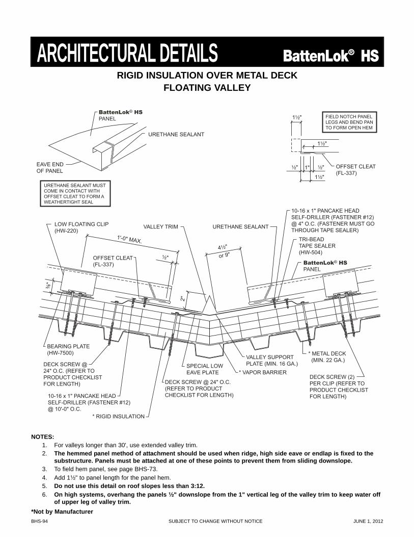
BHS-94 SUBJECT TO CHANGE WITHOUT NOTICE JUNE 1, 2012
OFFSET CLEAT (FL-337)
FIELD NOTCH PANEL LEGS AND BEND PAN TO FORM OPEN HEM
1¹⁄₂"
1¹⁄₂"
1¹⁄₂"
1" ¹⁄₂" ¹⁄₂"
4¹⁄₂" TRI-BEAD TAPE SEALER (HW-504)
2"
¹⁄₂"
1'-0" MAX.
DECK SCREW @ 24" O.C. (REFER TO PRODUCT CHECKLIST FOR LENGTH) DECK SCREW @ 24" O.C.
(REFER TO PRODUCT CHECKLIST FOR LENGTH)
DECK SCREW (2) PER CLIP (REFER TO PRODUCT CHECKLIST FOR LENGTH)
* VAPOR BARRIER
* RIGID INSULATION
LOW FLOATING CLIP (HW-220)
BEARING PLATE (HW-7500) * METAL DECK
(MIN. 22 GA.)
URETHANE SEALANTVALLEY TRIM
OFFSET CLEAT (FL-337)
³⁄₈"
10-16 x 1" PANCAKE HEADSELF-DRILLER (FASTENER #12)@ 10'-0" O.C.
10-16 x 1" PANCAKE HEAD SELF-DRILLER (FASTENER #12) @ 4" O.C. (FASTENER MUST GO THROUGH TAPE SEALER)
SPECIAL LOW EAVE PLATE
VALLEY SUPPORT PLATE (MIN. 16 GA.)
URETHANE SEALANT MUST COME IN CONTACT WITH OFFSET CLEAT TO FORM A WEATHERTIGHT SEAL
EAVE END OF PANEL
URETHANE SEALANT
BattenLok® HS
PANEL
BattenLok® HS
PANEL
or 9"
RIGID INSULATION OVER METAL DECKFLOATING VALLEY
ARCHITECTURAL DETAILS BattenLok® HS
NOTES:1. For valleys longer than 30', use extended valley trim.2. The hemmed panel method of attachment should be used when ridge, high side eave or endlap is fixed to the
substructure. Panels must be attached at one of these points to prevent them from sliding downslope.3. To field hem panel, see page BHS-73.4. Add 1¹⁄₂" to panel length for the panel hem.5. Do not use this detail on roof slopes less than 3:12.6. On high systems, overhang the panels ¹⁄₂" downslope from the 1" vertical leg of the valley trim to keep water off
of upper leg of valley trim.*Not by Manufacturer
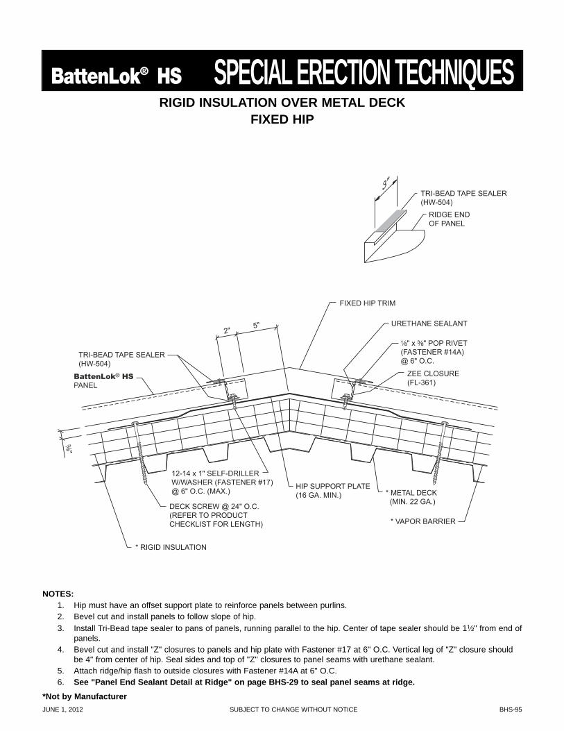
JUNE 1, 2012 SUBJECT TO CHANGE WITHOUT NOTICE BHS-95
BattenLok® HS SPECIAL ERECTION TECHNIQUES
* RIGID INSULATION
* VAPOR BARRIER
* METAL DECK (MIN. 22 GA.)
TRI-BEAD TAPE SEALER (HW-504)
RIDGE END OF PANEL
3"
TRI-BEAD TAPE SEALER (HW-504)
¹⁄₈" x ³⁄₈" POP RIVET(FASTENER #14A)@ 6" O.C.
2" 5"
FIXED HIP TRIM
³⁄₈" DECK SCREW @ 24" O.C.(REFER TO PRODUCT CHECKLIST FOR LENGTH)
ZEE CLOSURE(FL-361)
URETHANE SEALANT
HIP SUPPORT PLATE (16 GA. MIN.)
12-14 x 1" SELF-DRILLER W/WASHER (FASTENER #17) @ 6" O.C. (MAX.)
BattenLok® HS
PANEL
RIGID INSULATION OVER METAL DECKFIXED HIP
NOTES:1. Hip must have an offset support plate to reinforce panels between purlins.2. Bevel cut and install panels to follow slope of hip.3. Install Tri-Bead tape sealer to pans of panels, running parallel to the hip. Center of tape sealer should be 1¹⁄₂" from end of
panels.4. Bevel cut and install "Z" closures to panels and hip plate with Fastener #17 at 6" O.C. Vertical leg of "Z" closure should
be 4" from center of hip. Seal sides and top of "Z" closures to panel seams with urethane sealant.5. Attach ridge/hip flash to outside closures with Fastener #14A at 6" O.C.6. See "Panel End Sealant Detail at Ridge" on page BHS-29 to seal panel seams at ridge.
*Not by Manufacturer
BHS-96 SUBJECT TO CHANGE WITHOUT NOTICE JUNE 1, 2012
PANEL HANDLING
• All panel bundles must be inspected during unloading and carrier advised immediately if damage is noted.
• Never unload or move panel bundles that have been opened without adequately clamping them. Without thebanding to hold the bundle stable, panels may shift during unloading or movement, causing the bundle tofall.
• Never use wire slings to unload or move panel bundles.
• When unloading or moving panel bundles over 20' long, a spreader bar may be required. It is the erector'sresponsibility to determine the location and number of lift points required to safely unload or move panel bun-dles.
• When handling individual panels, always wear protective gloves. OSHA safety regulations must be followedat all times.
• When cutting panels, always wear all required safety equipment such as safety glasses and gloves. Cut pan-els with nibblers, shears or snips. Do not use abrasive blade saws as these will melt the Galvalume® coat-ing causing the panel to edge rust which will void the Galvalume® and Paint warranties. Drilling fastenersinto panels will create metal filings that will rust and create an unsightly stain. Metal filings must removed bysweeping or wiping down panels immediately after installation to avoid this occurrence.
PANEL STORAGE
• If water is permitted to enter panel bundles, it is necessary to open bundles, separate the panels and dry allsurfaces.
• Store bundled panels off the ground sufficiently high to allow air circulation beneath bundle and to preventrising water from entering bundle. Slightly elevate one end of bundle.
• Prevent rain from entering bundle by covering with tarpaulin, making provision for air circulation betweendraped edges of tarpaulin and the ground.
• Prolonged storage of panels in a bundle is not recommended. If conditions do not permit immediate erection,extra care should be taken to protect panels from white rust or water marks. If panels have not been erectedwithin three weeks of receipt, the panels should be removed from the bundle for inspection. Condensationmay cause damage to panels. The manufacturer's Paint and Galvalume® warranties do not cover damagecaused by improper panel storage.
PANEL MAINTENANCE
• Never allow Galvalume® panels to come into contact with or water runoff from dissimilar materials such ascopper, lead, or graphite. These materials will cause galvanic corrosion of the panels and will void theGalvalume® warranty. This includes treated wood and AC condensate, both of which contain copper com-pounds. This also applies to painted panels.
• Always use long life fasteners in all exposed fastener applications. Non long life fasteners can rust throughthe panel at each exposed fastener location. Use of non long life fasteners in exposed applications will voidthe Galvalume® and Paint warranties.
• Panels should be protected against exposure to masonry products, strong acids or bases and solvents.Exposure to these agents may etch or stain Galvalume Plus® panels and cause painted panels to blister orpeel.
GENERAL INFORMATION BattenLok® HSPROPER HANDLING, STORAGE AND MAINTENANCE OF PAINTED
AND GALVALUME PLUS® PANELS
JUNE 1, 2012 SUBJECT TO CHANGE WITHOUT NOTICE BHS-97
BattenLok® HS GENERAL INFORMATION• Never allow anyone to apply any coating or patching material to the panel surface. These products may con-
tain chemicals that will adversely affect the Galvalume Plus® or paint coating. Also, water may becometrapped between the coating material and the panel, causing premature corrosion.
If you have any question as to proper methods to use in the handling, storage or maintenance of these panels,call your nearest manufacturer representative.
NOTICEUniform visual appearance of Galvalume Plus® coated panels cannot be guaranteed. The Galvalume Plus® coating is subjectto variances in spangle from coil to coil which may result in a noticeable shade variation in installed panels. The Galvalume Plus®
coating is also subject to differential weathering after panel installation. Panels may appear to be different shades due to thisweathering characteristic. If uniform visual appearance is required, the manufacturer recommends that our prepainted Signature®
200 or Signature® 300 panels be used in lieu of Galvalume Plus® . Shade variations in panels manufactured from GalvalumePlus® coated material do not diminish the structural integrity of the product. These shade variations should be anticipated andare not a cause for rejection.

NOTES

NOTES
Houston, TX14031 West HardyP.O. Box 38217Houston, TX 77238877-713-6224
Adel, GA1601 Rogers RoadP.O. Box 1107Adel, GA 31620888-446-6224
Atlanta, GA2280 Monier AvenueP.O. Box 44729Atlanta, GA 30336877-512-6224
Atwater, CA550 Industry WayP.O. Box 793Atwater, CA 95301800-829-9324
Dallas, TX1804 Jack McKay Blvd.P.O. Box 1210Ennis, TX 75120800-653-6224
Indianapolis, IN1780 McCall DriveP.O. Box 657Shelbyville, IN 46176800-735-6224
Jackson, MS201 Apache DriveP.O. Box 720100Jackson, MS 39272800-622-4136
Lubbock, TX5711 East FM-40P.O. Box 10133Lubbock, TX 79408800-758-6224
Mattoon, IL1509 Dewitt Avenue EastMattoon, IL 61938888-885-0468
Memphis, TN300 Highway 51 NorthP.O. Box 366Hernando, MS 38632800-206-6224
Oklahoma City, OK7000 S. Eastern AvenueP.O. Box 95998Oklahoma City, OK 73143800-597-6224
Omaha, NE1011 Ellison AvenueOmaha, NE 68119800-458-6224
Phoenix, AZ660 South 91st AvenueP.O. Box 739Tolleson, AZ 85353888-533-6224
Richmond, VA801 South AvenueP.O. Box 239Colonial Heights, VA 23834800-729-6224
Rome, NY6168 State Route 233P.O. Box 4141Rome, NY 13442800-559-6224
Salt Lake City, UT1155 West 2300 NorthP.O. Box 16027Salt Lake City, UT 84116800-874-2404
San Antonio, TX8677 I-10 EastP.O. Box 69Converse, TX 78109800-598-6224
Descriptions and specifications contained herein were in effect at the time this publication was approved for printing. In acontinuing effort to refine and improve products, MBCI reserves the right to discontinue products at any time or change spec-ifications and/or designs without incurring obligation. To ensure you have the latest information available, please inquire orvisit our website at www.mbci.com. Application details are for illustration purposes only and may not be appropriate for allenvironmental conditions, building designs or panel profiles. Projects should be designed to conform to applicable buildingcodes, regulations and accepted industry practices. If there is a conflict between this manual and project erection drawings,the erection drawings will take precedence.
Litho in U.S.A. 06-12/5M
For current information, visit our Website at www.mbci.com.


