Embed Size (px)
Citation preview
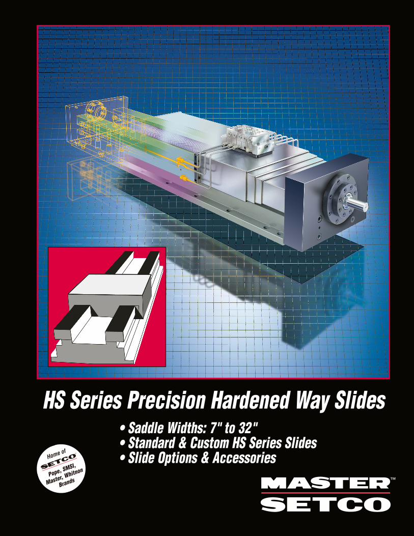
HS Series Precision Hardened Way Slides• Saddle Widths: 7" to 32"• Standard & Custom HS Series Slides• Slide Options & Accessories
2
We Meet Your Needs & ExpectationsThe SETCO manufacturing plant is located in Cincinnati, Ohio. This 40,000 square footfacility is dedicated to producing spindles,dovetail, hardened steel, linear ball slides,modules and combination spindle/slideassemblies.
With nearly 100 years of experience,SETCO has been providing single sourcesolutions for all industries and applications.
The new HS Hardened Way Slide designfeatured in this catalog provides morestandard sizes that can be shipped to youquicker, offering more drive variations thatadapt to your positioning devices, and acustomization technique to make your specialmachine application come to reality quicklyand with increased reliability.
SETCO is focused as world leaders indesign, manufacture, and rebuild of spindles,slides, and modules. Our goal is to provide“solution partnerships” that impact the quality of your product and your bottom line.We want to meet your needs and exceed yourexpectations through teamwork engineering,continuous improvement, and the use of thelatest manufacturing technologies.
© 2004 Setco Sales Company. SETCOTM and MASTER/SETCOTM are trademarks of SETCO Sales Company.
Production Slide Specialists
Easier Slide SelectionTo assist in your design and selection process,we’ve included our full line of SETCO PrecisionHardened Way Slides in one comprehensivecatalog. We’ve also included a full array of drive and accessory packages, illustrations,drawings, charts, design data and workingsolution photos.
To help speed up your slide design andpurchasing process, an Electronic supplementof the entire catalog, including detailed CADdrawings, can be downloaded from our website.
Our staff of slide experts is ready to assistwith your toughest linear and rotary motionapplications. The SETCO Solution Team can recommend the exact slide – includingdovetail, hardened way, and linear bearing or slide/spindle combination – that matchesyour application needs.
When you need technical expertise in slides,call the leader. Our customer service andtechnical support people are readily available to answer your questions. For details, visit ourwebsite: www.setcousa.com
Note: Due to continual improvements, specifications are subject to change without notice. For current specifications, request a certified print when placing your order.
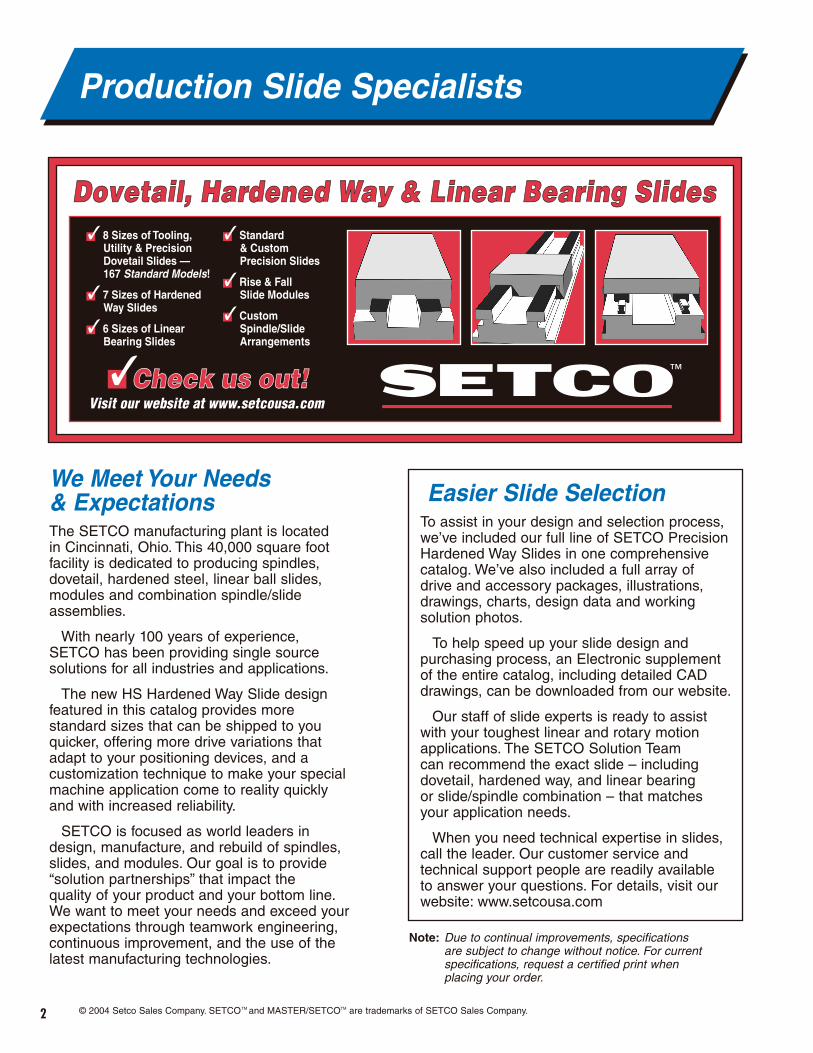
Dovetail, Hardened Way & Linear Bearing SlidesDovetail, Hardened Way & Linear Bearing Slides
Check us out!Check us out!Visit our website at www.setcousa.com
✓ 8 Sizes of Tooling, Utility & Precision Dovetail Slides — 167 Standard Models!
✓ 7 Sizes of Hardened Way Slides
✓ 6 Sizes of Linear Bearing Slides
✓ Standard & Custom Precision Slides
✓ Rise & Fall Slide Modules
✓ Custom Spindle/Slide Arrangements
HSStandard and Custom Slides
HSHow to Order
HSDrive Option
HSDrive Options
HSDrive Options
HSDrive Options
HSAccessories
HSHS Slide and Spindle Combinations
HSMaintenance and Design Data
HSApplication Photos
3
Quick-Reference Index
Page 4-6
Page 7-9
Page 10-11
Page 12
Page 13-14
Page 15
Page 16-22
Page 23
Page 24-29
Page 30-31
• Standard Features
• Ballscrew, Hand Feed, & Motor Drive
• Externally Mounted Cylinders
• Internally Mounted Cylinders
• Heavy Duty Cylinder JIC Package
• Way Covers,Way Wipers, Lubrication,Tapered Gib, Special Machining, Switches,Positive Stops, Scales, & Mounting Plates
• Slide Model Code Legend• General Dimensional Data
To Place Your OrderPhone: 1-800-543-0470 Fax: 1-513-941-6913
Email: [email protected]
4
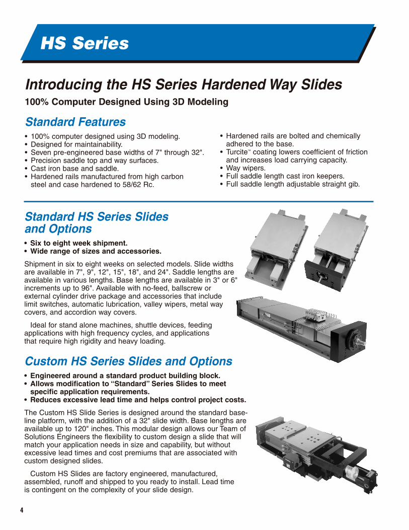
Standard HS Series Slides and Options• Six to eight week shipment.• Wide range of sizes and accessories.
Shipment in six to eight weeks on selected models. Slide widthsare available in 7", 9", 12", 15", 18", and 24". Saddle lengths areavailable in various lengths. Base lengths are available in 3" or 6"increments up to 96". Available with no-feed, ballscrew or external cylinder drive package and accessories that include limit switches, automatic lubrication, valley wipers, metal waycovers, and accordion way covers.
Ideal for stand alone machines, shuttle devices, feeding applications with high frequency cycles, and applications that require high rigidity and heavy loading.
Custom HS Series Slides and Options• Engineered around a standard product building block.• Allows modification to “Standard” Series Slides to meet
specific application requirements.• Reduces excessive lead time and helps control project costs.
The Custom HS Slide Series is designed around the standard base-line platform, with the addition of a 32" slide width. Base lengths areavailable up to 120" inches. This modular design allows our Team ofSolutions Engineers the flexibility to custom design a slide that willmatch your application needs in size and capability, but withoutexcessive lead times and cost premiums that are associated withcustom designed slides.
Custom HS Slides are factory engineered, manufactured, assembled, runoff and shipped to you ready to install. Lead time is contingent on the complexity of your slide design.
HS Series
Introducing the HS Series Hardened Way Slides100% Computer Designed Using 3D Modeling
Standard Features • 100% computer designed using 3D modeling.• Designed for maintainability.• Seven pre-engineered base widths of 7" through 32".• Precision saddle top and way surfaces.• Cast iron base and saddle.• Hardened rails manufactured from high carbon
steel and case hardened to 58/62 Rc.
• Hardened rails are bolted and chemicallyadhered to the base.
• TurciteTM coating lowers coefficient of frictionand increases load carrying capacity.
• Way wipers.• Full saddle length cast iron keepers.• Full saddle length adjustable straight gib.
5
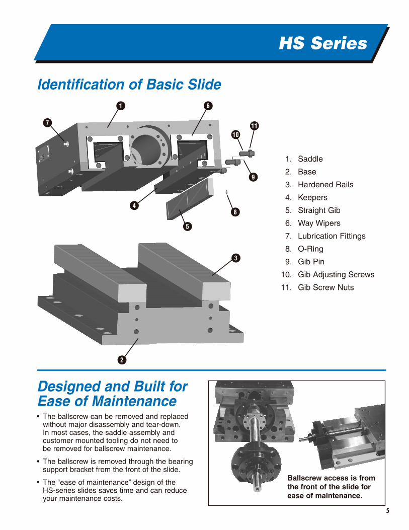
Identification of Basic Slide
HS Series
1
2
3
5
9
8
11
6
7
4
10
Designed and Built for Ease of Maintenance• The ballscrew can be removed and replaced
without major disassembly and tear-down.In most cases, the saddle assembly and customer mounted tooling do not need to be removed for ballscrew maintenance.
• The ballscrew is removed through the bearing support bracket from the front of the slide.
• The “ease of maintenance” design of the HS-series slides saves time and can reduce your maintenance costs.
1. Saddle
2. Base
3. Hardened Rails
4. Keepers
5. Straight Gib
6. Way Wipers
7. Lubrication Fittings
8. O-Ring
9. Gib Pin
10. Gib Adjusting Screws
11. Gib Screw Nuts
Ballscrew access is fromthe front of the slide forease of maintenance.
6
HS Series
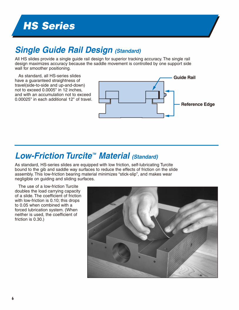
Single Guide Rail Design (Standard)All HS slides provide a single guide rail design for superior tracking accuracy. The single raildesign maximizes accuracy because the saddle movement is controlled by one support sidewall for smoother positioning.
As standard, all HS-series slides have a guaranteed straightness of travel(side-to-side and up-and-down) not to exceed 0.0005" in 12 inches, and with an accumulation not to exceed 0.00025" in each additional 12" of travel.
Low-Friction TurciteTM Material (Standard)As standard, HS-series slides are equipped with low friction, self-lubricating Turcitebound to the gib and saddle way surfaces to reduce the effects of friction on the slideassembly. This low-friction bearing material minimizes “stick-slip”, and makes wearnegligible on guiding and sliding surfaces.
The use of a low-friction Turcitedoubles the load carrying capacityof a slide. The coefficient of frictionwith low-friction is 0.10; this dropsto 0.05 when combined with aforced lubrication system. (Whenneither is used, the coefficient offriction is 0.30.)
Reference Edge
Guide Rail
7
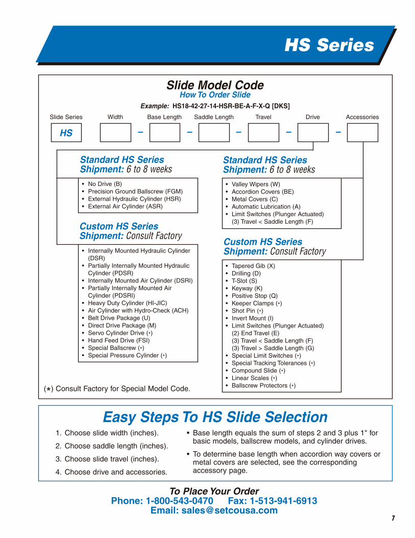
Easy Steps To HS Slide Selection1. Choose slide width (inches).
2. Choose saddle length (inches).
3. Choose slide travel (inches).
4. Choose drive and accessories.
• Base length equals the sum of steps 2 and 3 plus 1" forbasic models, ballscrew models, and cylinder drives.
• To determine base length when accordion way covers ormetal covers are selected, see the correspondingaccessory page.
• Internally Mounted Hydraulic Cylinder(DSR)
• Partially Internally Mounted HydraulicCylinder (PDSR)
• Internally Mounted Air Cylinder (DSRI)• Partially Internally Mounted Air
Cylinder (PDSRI)• Heavy Duty Cylinder (HI-JIC)• Air Cylinder with Hydro-Check (ACH)• Belt Drive Package (U)• Direct Drive Package (M)• Servo Cylinder Drive (*)• Hand Feed Drive (FSI)• Special Ballscrew (*)• Special Pressure Cylinder (*)
• No Drive (B) • Precision Ground Ballscrew (FGM)• External Hydraulic Cylinder (HSR)• External Air Cylinder (ASR)
• Tapered Gib (X)• Drilling (D) • T-Slot (S)• Keyway (K)• Positive Stop (Q)• Keeper Clamps (*)• Shot Pin (*)• Invert Mount (I)• Limit Switches (Plunger Actuated)
(2) End Travel (E)(3) Travel < Saddle Length (F)(3) Travel > Saddle Length (G)
• Special Limit Switches (*)• Special Tracking Tolerances (*)• Compound Slide (*)• Linear Scales (*)• Ballscrew Protectors (*)
Standard HS SeriesShipment: 6 to 8 weeks
Standard HS SeriesShipment: 6 to 8 weeks
Custom HS SeriesShipment: Consult Factory
Custom HS SeriesShipment: Consult Factory
• Valley Wipers (W)• Accordion Covers (BE)• Metal Covers (C)• Automatic Lubrication (A)• Limit Switches (Plunger Actuated)
(3) Travel < Saddle Length (F)
Slide Series Base LengthWidth Saddle Length Travel Drive Accessories
HS – – – – –
Slide Model CodeHow To Order Slide
Example: HS18-42-27-14-HSR-BE-A-F-X-Q [DKS]
(*) Consult Factory for Special Model Code.
HS Series
To Place Your OrderPhone: 1-800-543-0470 Fax: 1-513-941-6913
Email: [email protected]
8
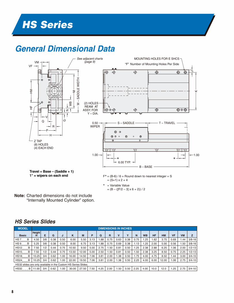
General Dimensional Data
HS Series
W –
SA
DD
LE W
IDT
H
KJ
MW
BN
G
HF
HM
S – SADDLE0.50WIPER
H
Z TAP(8) HOLES(4) EACH END
QV
VFVM
PR
1.00
* *6.00 TYP.
B – BASE
1.00
T – TRAVEL
(2) HOLESREAM AT
ASSY. FORY – DIA.
MOUNTING HOLES FOR E SHCS
“F” Number of Mounting Holes Per Side
See adjacent charts(page 9)
1" = wipers on each endTravel = Base – (Saddle + 1)
F* = (B-6) / 6 = Round down to nearest integer = S = (S+1) x 2 + 4
* = Variable Value = (B – ([F/2 – 3] x 6 + 2)) / 2
4.50
5.25
7.50
7.50
10.25
10.25
0.75
0.75
1.50
1.50
2.00
2.00
1.88
1.88
2.75
2.50
3.81
3.81
MODEL
Basic HHeight
E G J K M P Q
0.63
0.69
0.81
0.81
1.38
1.38
V
0.38
0.38
0.50
0.50
0.50
0.50
Y
0.75
1.13
1.25
1.50
1.75
2.25
N
1.25
1.25
2.38
2.38
4.00
4.00
WB
1.62
2.00
2.88
3.25
4.75
6.00
HF
3.75
5.00
6.25
8.50
8.50
12.00
HM
0.69
0.56
1.06
0.75
1.44
1.06
VF
1.44
1.50
2.00
2.25
3.00
2.75
VM
3/8-16
3/8-16
1/2-13
1/2-13
3/4-10
3/4-10
ZR
DIMENSIONS IN INCHES
3/8
3/8
1/2
1/2
3/4
3/4
0.38
0.38
0.44
0.44
0.62
0.62
0.50
0.50
0.75
0.75
1.00
1.00
6.00
8.00
10.50
13.50
16.00
22.00
5.50
6.75
9.50
12.00
14.50
19.50
3.13
3.13
5.00
5.00
7.06
7.06
HS 7_ _ _ B
HS 9_ _ _ B
HS12_ _ _ B
HS15_ _ _ B
HS18_ _ _ B
HS24_ _ _ B
HS32 slides are only available in the Custom HS Series Slides.
HS32_ _ _ B 11.00 3/4 0.62 1.00 30.00 27.50 7.50 4.25 2.00 1.50 0.50 2.25 4.00 10.0 12.0 1.25 2.75 3/4-10
Note: Charted dimensions do not include“Internally Mounted Cylinder” option.
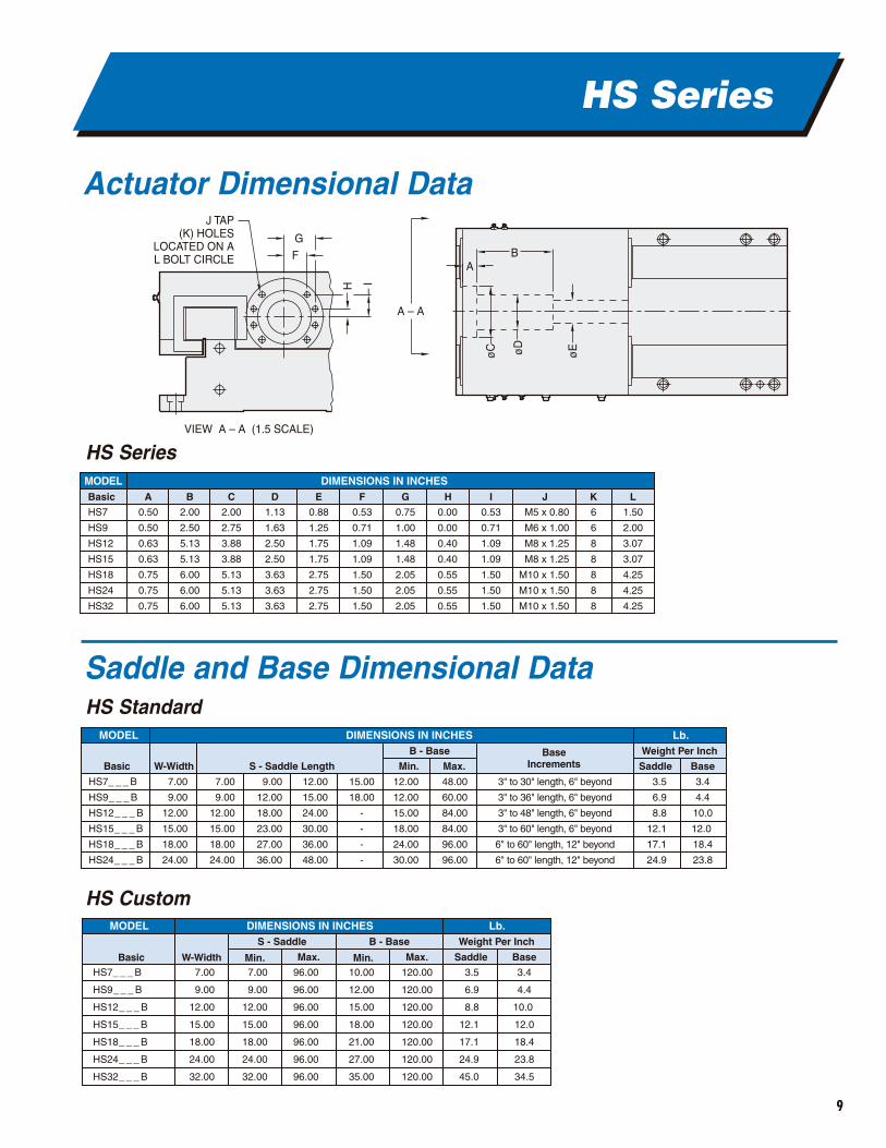
HS Series Slides
9
MODEL
W-WidthBasic Min.
DIMENSIONS IN INCHES Lb.
HS7_ _ _ B
HS9_ _ _ B
HS12_ _ _ B
HS15_ _ _ B
HS18_ _ _ B
HS24_ _ _ B
7.00
9.00
12.00
15.00
18.00
24.00
7.00
9.00
12.00
15.00
18.00
24.00
S - Saddle Length
B - Base Weight Per Inch
48.00
60.00
84.00
84.00
96.00
96.00
9.00
12.00
18.00
23.00
27.00
36.00
12.00
15.00
24.00
30.00
36.00
48.00
12.00
12.00
15.00
18.00
24.00
30.00
Max.Base
Increments
3.4
4.4
10.0
12.0
18.4
23.8
3.5
6.9
8.8
12.1
17.1
24.9
Saddle Base
15.00
18.00
-
-
-
-
3" to 30" length, 6" beyond
3" to 36" length, 6" beyond
3" to 48" length, 6" beyond
3" to 60" length, 6" beyond
6" to 60" length, 12" beyond
6" to 60" length, 12" beyond
HS Series
Actuator Dimensional Data
Saddle and Base Dimensional Data
H – I
øC øD
øE
A – A
AB
G
F
J TAP(K) HOLES
LOCATED ON AL BOLT CIRCLE
VIEW A – A (1.5 SCALE)
MODEL
W-WidthBasic Min. Max. Min.
DIMENSIONS IN INCHES Lb.
HS7_ _ _ B
HS9_ _ _ B
HS12_ _ _ B
HS15_ _ _ B
HS18_ _ _ B
HS24_ _ _ B
HS32_ _ _ B
7.00
9.00
12.00
15.00
18.00
24.00
32.00
7.00
9.00
12.00
15.00
18.00
24.00
32.00
S - Saddle B - Base Weight Per Inch
3.4
4.4
10.0
12.0
18.4
23.8
34.5
96.00
96.00
96.00
96.00
96.00
96.00
96.00
10.00
12.00
15.00
18.00
21.00
27.00
35.00
3.5
6.9
8.8
12.1
17.1
24.9
45.0
Max. Saddle Base
120.00
120.00
120.00
120.00
120.00
120.00
120.00
MODELBasic A B C D E F G H I J K L
DIMENSIONS IN INCHES
HS7
HS9
HS12
HS15
HS18
HS24
HS32
0.50
0.50
0.63
0.63
0.75
0.75
0.75
2.00
2.50
5.13
5.13
6.00
6.00
6.00
2.00
2.75
3.88
3.88
5.13
5.13
5.13
1.13
1.63
2.50
2.50
3.63
3.63
3.63
0.88
1.25
1.75
1.75
2.75
2.75
2.75
0.53
0.71
1.09
1.09
1.50
1.50
1.50
0.75
1.00
1.48
1.48
2.05
2.05
2.05
0.53
0.71
1.09
1.09
1.50
1.50
1.50
6
6
8
8
8
8
8
1.50
2.00
3.07
3.07
4.25
4.25
4.25
M5 x 0.80
M6 x 1.00
M8 x 1.25
M8 x 1.25
M10 x 1.50
M10 x 1.50
M10 x 1.50
0.00
0.00
0.40
0.40
0.55
0.55
0.55
HS Series
HS Standard
HS Custom
FD
DR
W – WIDTHRM
FL
RL
0.50 MIN S – SADDLE
BALLSCREWKEY
T – TRAVEL
OUTBOARD SUPPORTSEE CHART
FOR APPLICATION
B – BASEPR
RX
10
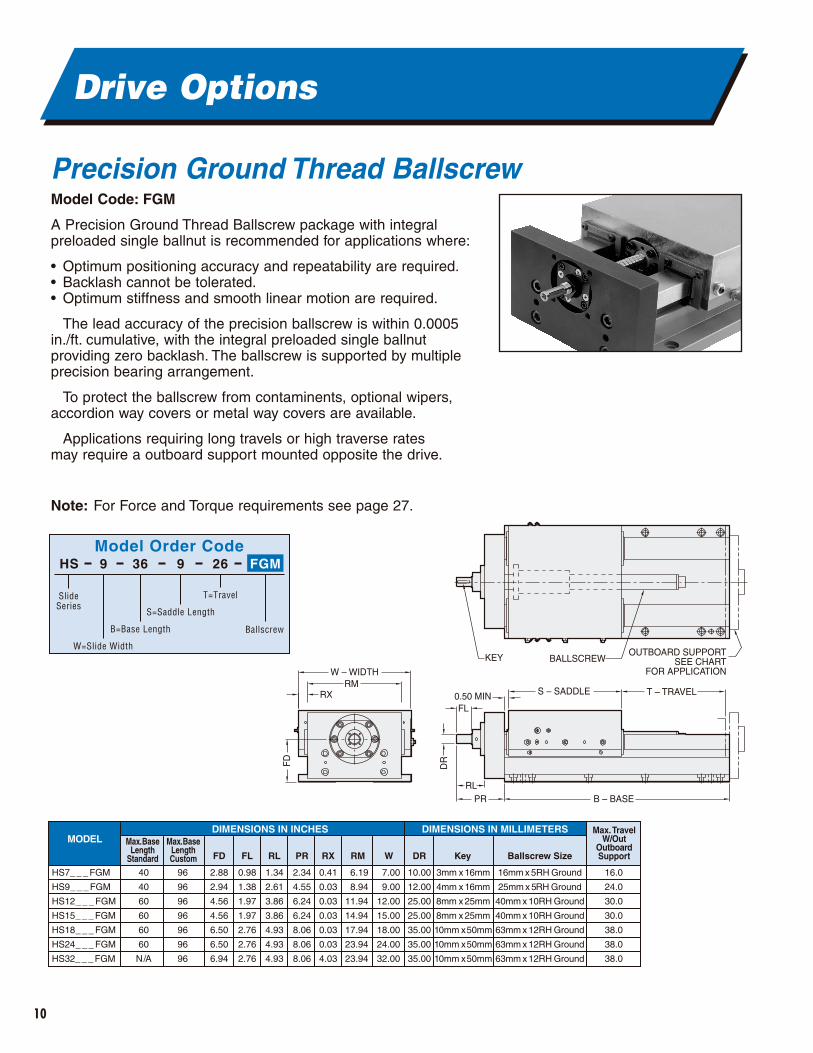
Drive Options
Precision Ground Thread BallscrewModel Code: FGM
A Precision Ground Thread Ballscrew package with integral preloaded single ballnut is recommended for applications where:
• Optimum positioning accuracy and repeatability are required.• Backlash cannot be tolerated.• Optimum stiffness and smooth linear motion are required.
The lead accuracy of the precision ballscrew is within 0.0005in./ft. cumulative, with the integral preloaded single ballnut providing zero backlash. The ballscrew is supported by multipleprecision bearing arrangement.
To protect the ballscrew from contaminents, optional wipers, accordion way covers or metal way covers are available.
Applications requiring long travels or high traverse rates may require a outboard support mounted opposite the drive.
Note: For Force and Torque requirements see page 27.
Model Order CodeHS 9 36 9 26
SlideSeries
W=Slide Width
B=Base Length
S=Saddle Length
T=Travel
Ballscrew
FGM
6.19
8.94
11.94
14.94
17.94
23.94
23.94
0.41
0.03
0.03
0.03
0.03
0.03
4.03
MODEL Max. BaseLength
Standard FD FL RL PR RX
7.00
9.00
12.00
15.00
18.00
24.00
32.00
W
10.00
12.00
25.00
25.00
35.00
35.00
35.00
DR
3mm x 16mm
4mm x 16mm
8mm x 25mm
8mm x 25mm
10mm x 50mm
10mm x 50mm
10mm x 50mm
Key
16mm x 5RH Ground
25mm x 5RH Ground
40mm x 10RH Ground
40mm x 10RH Ground
63mm x 12RH Ground
63mm x 12RH Ground
63mm x 12RH Ground
Ballscrew Size
Max. TravelW/Out
OutboardSupport
16.0
24.0
30.0
30.0
38.0
38.0
38.0
RM
DIMENSIONS IN INCHES DIMENSIONS IN MILLIMETERS
40
40
60
60
60
60
N/A
Max. BaseLengthCustom
96
96
96
96
96
96
96
2.88
2.94
4.56
4.56
6.50
6.50
6.94
0.98
1.38
1.97
1.97
2.76
2.76
2.76
1.34
2.61
3.86
3.86
4.93
4.93
4.93
2.34
4.55
6.24
6.24
8.06
8.06
8.06
HS7_ _ _ FGM
HS9_ _ _ FGM
HS12_ _ _ FGM
HS15_ _ _ FGM
HS18_ _ _ FGM
HS24_ _ _ FGM
HS32_ _ _ FGM
11
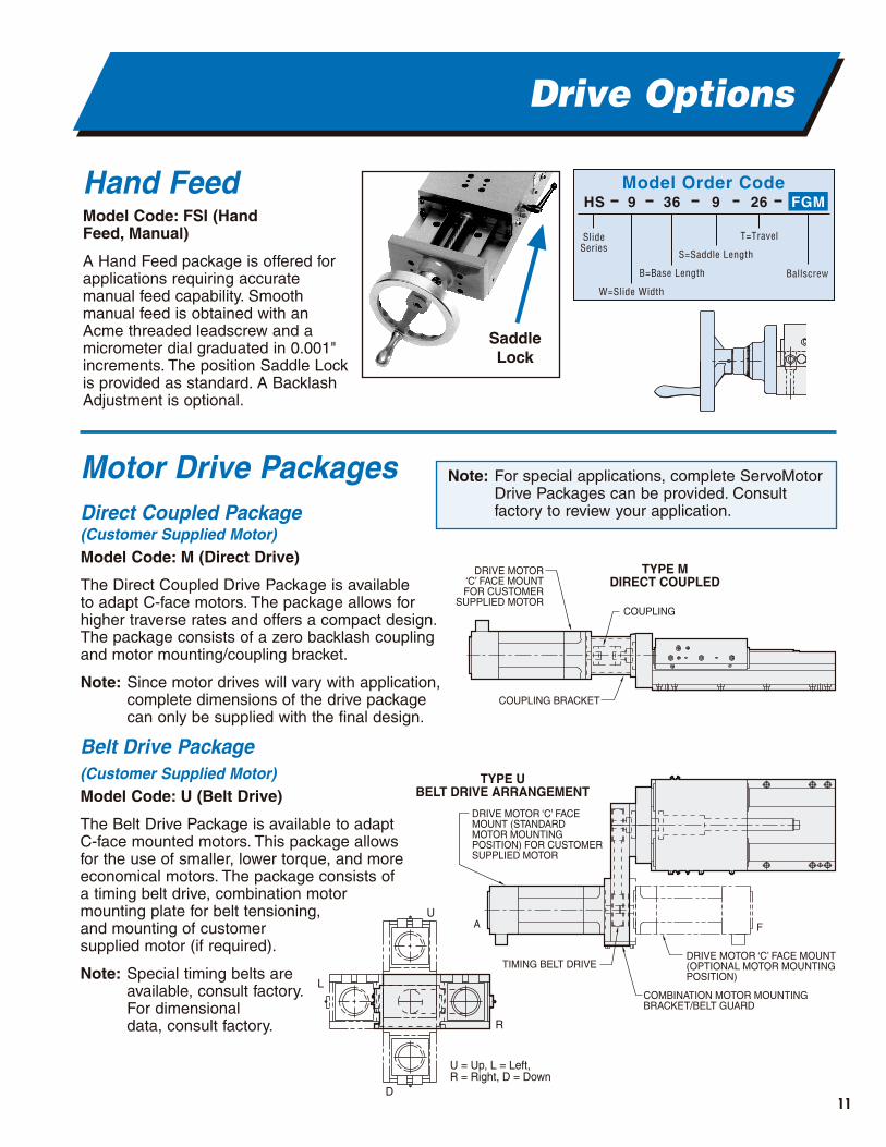
Drive Options
Motor Drive PackagesDirect Coupled Package (Customer Supplied Motor) Model Code: M (Direct Drive)
The Direct Coupled Drive Package is available to adapt C-face motors. The package allows for higher traverse rates and offers a compact design.The package consists of a zero backlash coupling and motor mounting/coupling bracket.
Note: Since motor drives will vary with application,complete dimensions of the drive packagecan only be supplied with the final design.
Belt Drive Package(Customer Supplied Motor) Model Code: U (Belt Drive)
The Belt Drive Package is available to adaptC-face mounted motors. This package allowsfor the use of smaller, lower torque, and moreeconomical motors. The package consists ofa timing belt drive, combination motor mounting plate for belt tensioning, and mounting of customer supplied motor (if required).
Note: Special timing belts are available, consult factory.For dimensional data, consult factory.
TYPE MDIRECT COUPLED
COUPLING
COUPLING BRACKET
DRIVE MOTOR‘C’ FACE MOUNT
FOR CUSTOMERSUPPLIED MOTOR
Model Order CodeHS 9 36 9 26
SlideSeries
W=Slide Width
B=Base Length
S=Saddle Length
T=Travel
Ballscrew
FGM
A
TIMING BELT DRIVE
TYPE UBELT DRIVE ARRANGEMENT
DRIVE MOTOR ‘C’ FACE MOUNT (OPTIONAL MOTOR MOUNTING POSITION)
F
COMBINATION MOTOR MOUNTINGBRACKET/BELT GUARD
DRIVE MOTOR ‘C’ FACE MOUNT (STANDARD MOTOR MOUNTING POSITION) FOR CUSTOMER SUPPLIED MOTOR
Hand FeedModel Code: FSI (Hand Feed, Manual)
A Hand Feed package is offered forapplications requiring accuratemanual feed capability. Smoothmanual feed is obtained with anAcme threaded leadscrew and amicrometer dial graduated in 0.001"increments. The position Saddle Lockis provided as standard. A BacklashAdjustment is optional.
Note: For special applications, complete ServoMotorDrive Packages can be provided. Consultfactory to review your application.
▲
SaddleLock
U
U = Up, L = Left, R = Right, D = Down
R
D
L
12
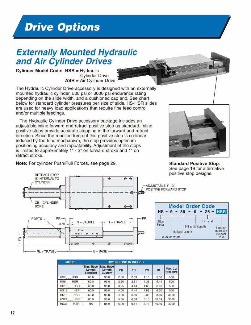
Drive Options
Externally Mounted Hydraulic and Air Cylinder DrivesCylinder Model Code: HSR = Hydraulic
Cylinder DriveASR = Air Cylinder Drive
The Hydraulic Cylinder Drive accessory is designed with an externallymounted hydraulic cylinder, 500 psi or 3000 psi endurance ratingdepending on the slide width, and a cushioned cap end. See chartbelow for standard cylinder pressures per size of slide. HS-HSR slidesare used for heavy load applications that require fine feed controland/or multiple feedings.
The Hydraulic Cylinder Drive accessory package includes anadjustable inline forward and retract positive stop as standard. Inlinepositive stops provide accurate stopping in the forward and retractdirection. Since the reaction force of this positive stop is co-linearinduced by the feed mechanism, the stop provides optimumpositioning accuracy and repeatability. Adjustment of the stops is limited to approximately 1" - 3" on forward stroke and 1" on retract stroke.
Note: For cylinder Push/Pull Forces, see page 29.
FD
PORTS
CB – CYLINDERBORE
RETRACT STOP IS INTERNAL TO CYLINDER
ADJUSTABLE 1"– 3" POSITIVE FORWARD STOP
RL + TRAVEL
0.50
PR PRS – SADDLE
B – BASE
T – TRAVEL
MODELMax. Base
LengthStandard
CB FD PR
DIMENSIONS IN INCHES
HS7_ _ _ HSR
HS9_ _ _ HSR
HS12_ _ _ HSR
HS15_ _ _ HSR
HS18_ _ _ HSR
HS24_ _ _ HSR
HS32_ _ _ HSR
60.0
60.0
60.0
60.0
60.0
60.0
NA
Max. BaseLengthCustom
96.0
96.0
96.0
96.0
96.0
96.0
96.0
Max. CylPressure
500
500
500
500
3000
3000
3000
2.00
2.50
3.25
4.00
4.00
5.00
5.00
2.69
2.81
4.44
4.44
6.50
6.38
6.81
1.13
1.38
1.63
1.88
2.38
3.13
3.13
RL
5.06
5.44
6.25
6.50
8.69
10.19
10.19
Model Order CodeHS 9 36 9 26
SlideSeries
W=Slide Width
B=Base Length
S=Saddle Length
T=Travel
ExternalHydraulicCylinder
Drive
HSR
Standard Positive Stop.See page 19 for alternativepositive stop designs.
13
Drive Options
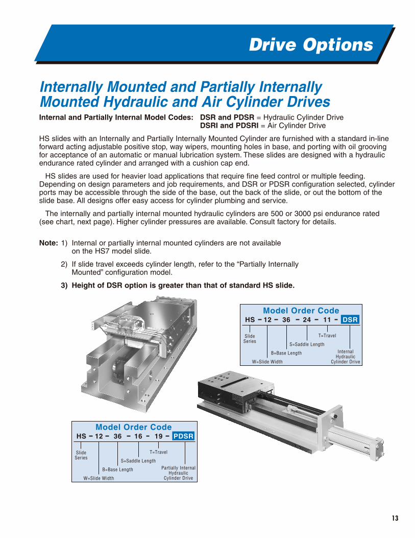
Model Order CodeHS 12 36 24 11
SlideSeries
W=Slide Width
B=Base Length
S=Saddle Length
T=Travel
InternalHydraulic
Cylinder Drive
DSR
Model Order CodeHS 12 36 16 19
SlideSeries
W=Slide Width
B=Base Length
S=Saddle Length
T=Travel
Partially InternalHydraulic
Cylinder Drive
PDSR
Internally Mounted and Partially Internally Mounted Hydraulic and Air Cylinder DrivesInternal and Partially Internal Model Codes: DSR and PDSR = Hydraulic Cylinder Drive
DSRI and PDSRI = Air Cylinder Drive
HS slides with an Internally and Partially Internally Mounted Cylinder are furnished with a standard in-lineforward acting adjustable positive stop, way wipers, mounting holes in base, and porting with oil groovingfor acceptance of an automatic or manual lubrication system. These slides are designed with a hydraulicendurance rated cylinder and arranged with a cushion cap end.
HS slides are used for heavier load applications that require fine feed control or multiple feeding.Depending on design parameters and job requirements, and DSR or PDSR configuration selected, cylinderports may be accessible through the side of the base, out the back of the slide, or out the bottom of theslide base. All designs offer easy access for cylinder plumbing and service.
The internally and partially internal mounted hydraulic cylinders are 500 or 3000 psi endurance rated(see chart, next page). Higher cylinder pressures are available. Consult factory for details.
Note: 1) Internal or partially internal mounted cylinders are not available on the HS7 model slide.
2) If slide travel exceeds cylinder length, refer to the “Partially Internally Mounted” configuration model.
3) Height of DSR option is greater than that of standard HS slide.
14
Drive Options
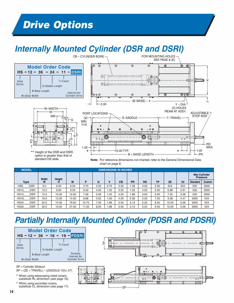
Internally Mounted Cylinder (DSR and DSRI)
Partially Internally Mounted Cylinder (PDSR and PDSRI)
CB – CYLINDER BORE FOR MOUNTING HOLESSEE PAGE 8 (E)
Y – DIA.(2) HOLES
REAM AT ASSY.
KJ(B–BASE) – 4
2.00
.50MIN.TYP.
W–WIDTHM
FD
H**
RV
QP
WB NG
1.006.00 TYP.
B = BASE LENGTH1.00
PR
RDMAX.
S–SADDLE T–TRAVEL
ADJUSTABLESTOP ROD
PORT LOCATIONS
* *** Height of the DSR and DSRI option is greater than that of standard HS slide. Note: For reference dimensions not charted, refer to the General Dimensional Data
chart on page 8.
SP = Cylinder StickoutSP = (ZE + TRAVEL) – [(SADDLE–V2)+.5*]
* When using telescoping metal covers, substitute RL dimension (see page 16).
* When using accordian covers, substitute CL dimension (see page 17). SP
TP
Model Order CodeHS 12 36 24 11
SlideSeries
W=Slide Width
B=Base Length
S=Saddle Length
T=Travel
Internal AirCylinder Drive
DSRI
Model Order CodeHS 12 36 16 19
SlideSeries
W=Slide Width
B=Base Length
S=Saddle Length
T=Travel
PartiallyInternal Air
Cylinder Drive
PDSRI
9.0
12.0
15.0
18.0
24.0
32.0
2.25
4.25
5.06
5.62
7.50
8.25
Type WWidth
HHeight
Max CylinderPressure
M P Q
0.75
1.25
1.25
1.63
1.88
1.88
V
2.00
3.25
4.00
4.00
5.00
5.00
CB
1.38
1.63
1.88
2.38
3.13
3.13
PR
4.00
4.63
4.63
5.00
5.25
5.25
RD
2.50
5.50
6.00
7.50
8.50
8.50
TP
N/A
6.88
7.25
9.38
10.50
10.50
ZE
N/A
2.91
3.06
4.47
5.06
5.06
V2 Standard Custom
500
500
500
3000
3000
3000
3000
3000
3000
N/A
N/A
N/A
DIMENSIONS IN INCHESMODEL
6.00
9.00
10.00
12.00
14.00
15.00
6.50
9.50
12.00
14.50
19.50
27.50
3.75
6.50
7.56
8.88
10.75
11.50
HS9_ _ _DSR
HS12_ _ _DSR
HS15_ _ _DSR
HS18_ _ _DSR
HS24_ _ _DSR
HS32_ _ _DSR
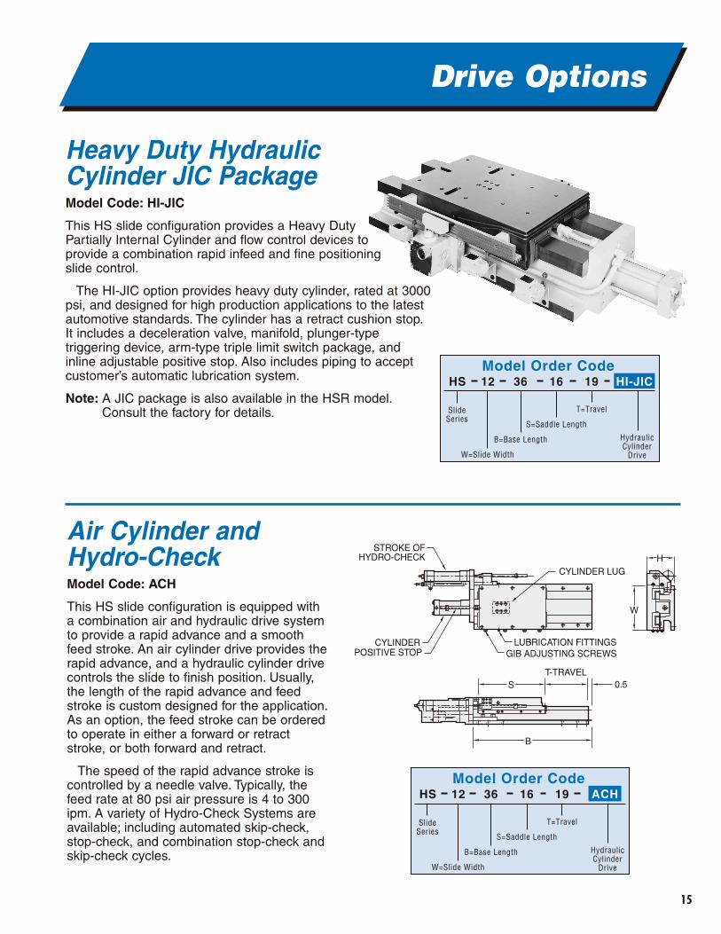
Heavy Duty Hydraulic Cylinder JIC PackageModel Code: HI-JIC
This HS slide configuration provides a Heavy DutyPartially Internal Cylinder and flow control devices toprovide a combination rapid infeed and fine positioningslide control.
The HI-JIC option provides heavy duty cylinder, rated at 3000psi, and designed for high production applications to the latestautomotive standards. The cylinder has a retract cushion stop.It includes a deceleration valve, manifold, plunger-typetriggering device, arm-type triple limit switch package, and inline adjustable positive stop. Also includes piping to acceptcustomer’s automatic lubrication system.
Note: A JIC package is also available in the HSR model.Consult the factory for details.
15
Drive Options
Air Cylinder and Hydro-CheckModel Code: ACH
This HS slide configuration is equipped witha combination air and hydraulic drive systemto provide a rapid advance and a smoothfeed stroke. An air cylinder drive provides therapid advance, and a hydraulic cylinder drivecontrols the slide to finish position. Usually,the length of the rapid advance and feedstroke is custom designed for the application.As an option, the feed stroke can be orderedto operate in either a forward or retractstroke, or both forward and retract.
The speed of the rapid advance stroke iscontrolled by a needle valve. Typically, thefeed rate at 80 psi air pressure is 4 to 300ipm. A variety of Hydro-Check Systems areavailable; including automated skip-check,stop-check, and combination stop-check andskip-check cycles.
Model Order CodeHS 12 36 16 19
SlideSeries
W=Slide Width
B=Base Length
S=Saddle Length
T=Travel
HydraulicCylinder
Drive
HI-JIC
CYLINDER
STROKE OFHYDRO-CHECK
W
H
B
ST-TRAVEL
0.5
POSITIVE STOP
CYLINDER LUG
GIB ADJUSTING SCREWSLUBRICATION FITTINGS
Model Order CodeHS 12 36 16 19
SlideSeries
W=Slide Width
B=Base Length
S=Saddle Length
T=Travel
HydraulicCylinder
Drive
ACH
CLS – SADDLE
B – BASE
T – TRAVELCL
OWTOP OF WAY COVER SEE PAGE 8 FOR SADDLE HEIGHTS
W – WIDTH
OH
U
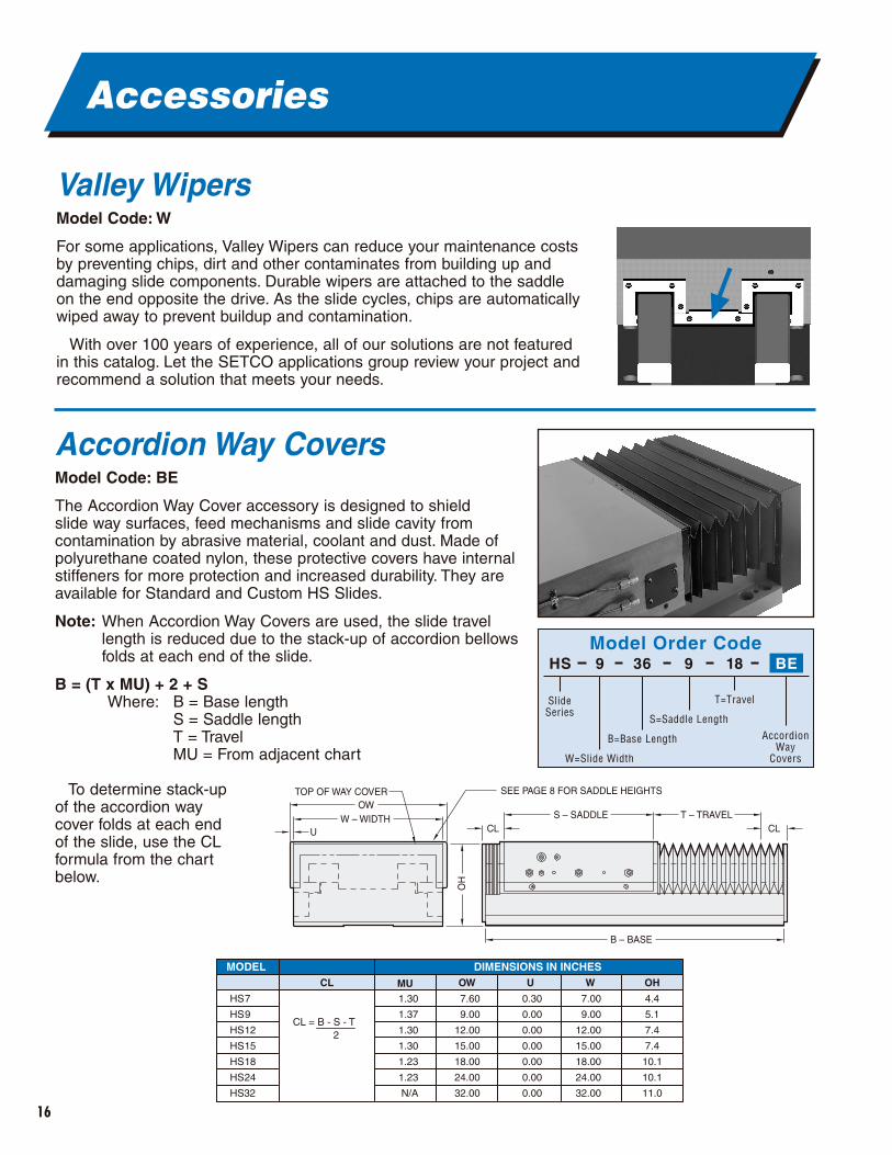
MODELCL MU OW W OH
DIMENSIONS IN INCHES
HS7
HS9
HS12
HS15
HS18
HS24
HS32
7.00
9.00
12.00
15.00
18.00
24.00
32.00
0.30
0.00
0.00
0.00
0.00
0.00
0.00
7.60
9.00
12.00
15.00
18.00
24.00
32.00
1.30
1.37
1.30
1.30
1.23
1.23
N/A
4.4
5.1
7.4
7.4
10.1
10.1
11.0
U
CL = B - S - T2
Model Order CodeHS 9 36 9 18
SlideSeries
W=Slide Width
B=Base Length
S=Saddle Length
T=Travel
AccordionWay
Covers
BE
16
Accessories
Valley WipersModel Code: W
For some applications, Valley Wipers can reduce your maintenance costsby preventing chips, dirt and other contaminates from building up anddamaging slide components. Durable wipers are attached to the saddle on the end opposite the drive. As the slide cycles, chips are automaticallywiped away to prevent buildup and contamination.
With over 100 years of experience, all of our solutions are not featuredin this catalog. Let the SETCO applications group review your project andrecommend a solution that meets your needs.
▲
Accordion Way CoversModel Code: BE
The Accordion Way Cover accessory is designed to shield slide way surfaces, feed mechanisms and slide cavity fromcontamination by abrasive material, coolant and dust. Made ofpolyurethane coated nylon, these protective covers have internalstiffeners for more protection and increased durability. They areavailable for Standard and Custom HS Slides.
Note: When Accordion Way Covers are used, the slide travellength is reduced due to the stack-up of accordion bellowsfolds at each end of the slide.
B = (T x MU) + 2 + SWhere: B = Base length
S = Saddle lengthT = TravelMU = From adjacent chart
To determine stack-up of the accordion way cover folds at each end of the slide, use the CL formula from the chart below.
17
Accessories
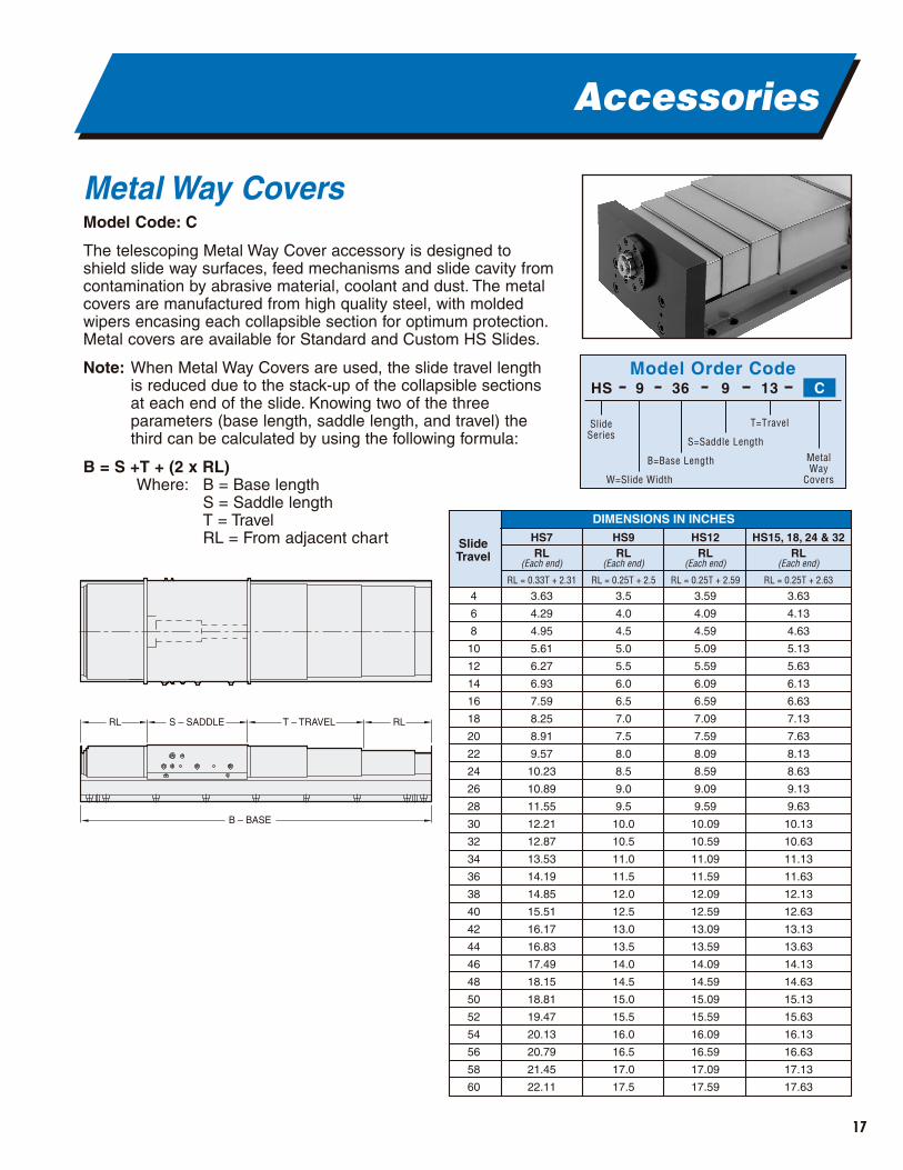
Metal Way CoversModel Code: C
The telescoping Metal Way Cover accessory is designed toshield slide way surfaces, feed mechanisms and slide cavity fromcontamination by abrasive material, coolant and dust. The metalcovers are manufactured from high quality steel, with moldedwipers encasing each collapsible section for optimum protection.Metal covers are available for Standard and Custom HS Slides.
Note: When Metal Way Covers are used, the slide travel lengthis reduced due to the stack-up of the collapsible sectionsat each end of the slide. Knowing two of the threeparameters (base length, saddle length, and travel) thethird can be calculated by using the following formula:
B = S +T + (2 x RL)Where: B = Base length
S = Saddle lengthT = TravelRL = From adjacent chart
RL S – SADDLE
B – BASE
T – TRAVEL RL
SlideTravel
HS9HS7RL
(Each end)
RL = 0.33T + 2.31
DIMENSIONS IN INCHES
4
6
8
10
12
14
16
18
20
22
24
26
28
30
32
34
36
38
40
42
44
46
48
50
52
54
56
58
60
3.63
4.29
4.95
5.61
6.27
6.93
7.59
8.25
8.91
9.57
10.23
10.89
11.55
12.21
12.87
13.53
14.19
14.85
15.51
16.17
16.83
17.49
18.15
18.81
19.47
20.13
20.79
21.45
22.11
RL(Each end)
RL = 0.25T + 2.5
3.5
4.0
4.5
5.0
5.5
6.0
6.5
7.0
7.5
8.0
8.5
9.0
9.5
10.0
10.5
11.0
11.5
12.0
12.5
13.0
13.5
14.0
14.5
15.0
15.5
16.0
16.5
17.0
17.5
HS12RL
(Each end)
RL = 0.25T + 2.59
3.59
4.09
4.59
5.09
5.59
6.09
6.59
7.09
7.59
8.09
8.59
9.09
9.59
10.09
10.59
11.09
11.59
12.09
12.59
13.09
13.59
14.09
14.59
15.09
15.59
16.09
16.59
17.09
17.59
HS15, 18, 24 & 32RL
(Each end)
RL = 0.25T + 2.63
3.63
4.13
4.63
5.13
5.63
6.13
6.63
7.13
7.63
8.13
8.63
9.13
9.63
10.13
10.63
11.13
11.63
12.13
12.63
13.13
13.63
14.13
14.63
15.13
15.63
16.13
16.63
17.13
17.63
Model Order CodeHS 9 36 9 13
SlideSeries
W=Slide Width
B=Base Length
S=Saddle Length
T=Travel
MetalWay
Covers
C
18
Accessories
Automatic LubricationModel Code: A
For ease and convenience in connecting and maintaining your lubrication system, allow SETCO to mount the necessary piping, manifold, distributionblocks and connections to your slide assembly.Hook-up requires the connection of only one input line.
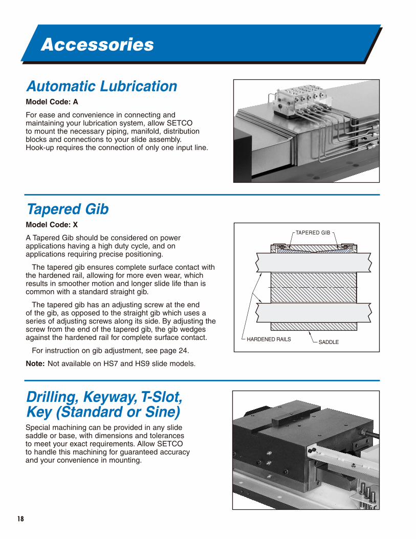
Tapered GibModel Code: X
A Tapered Gib should be considered on powerapplications having a high duty cycle, and on applications requiring precise positioning.
The tapered gib ensures complete surface contact withthe hardened rail, allowing for more even wear, whichresults in smoother motion and longer slide life than iscommon with a standard straight gib.
The tapered gib has an adjusting screw at the end of the gib, as opposed to the straight gib which uses aseries of adjusting screws along its side. By adjusting thescrew from the end of the tapered gib, the gib wedgesagainst the hardened rail for complete surface contact.
For instruction on gib adjustment, see page 24.
Note: Not available on HS7 and HS9 slide models.
TAPERED GIB
SADDLEHARDENED RAILS
Drilling, Keyway, T-Slot,Key (Standard or Sine)Special machining can be provided in any slidesaddle or base, with dimensions and tolerances to meet your exact requirements. Allow SETCO to handle this machining for guaranteed accuracyand your convenience in mounting.
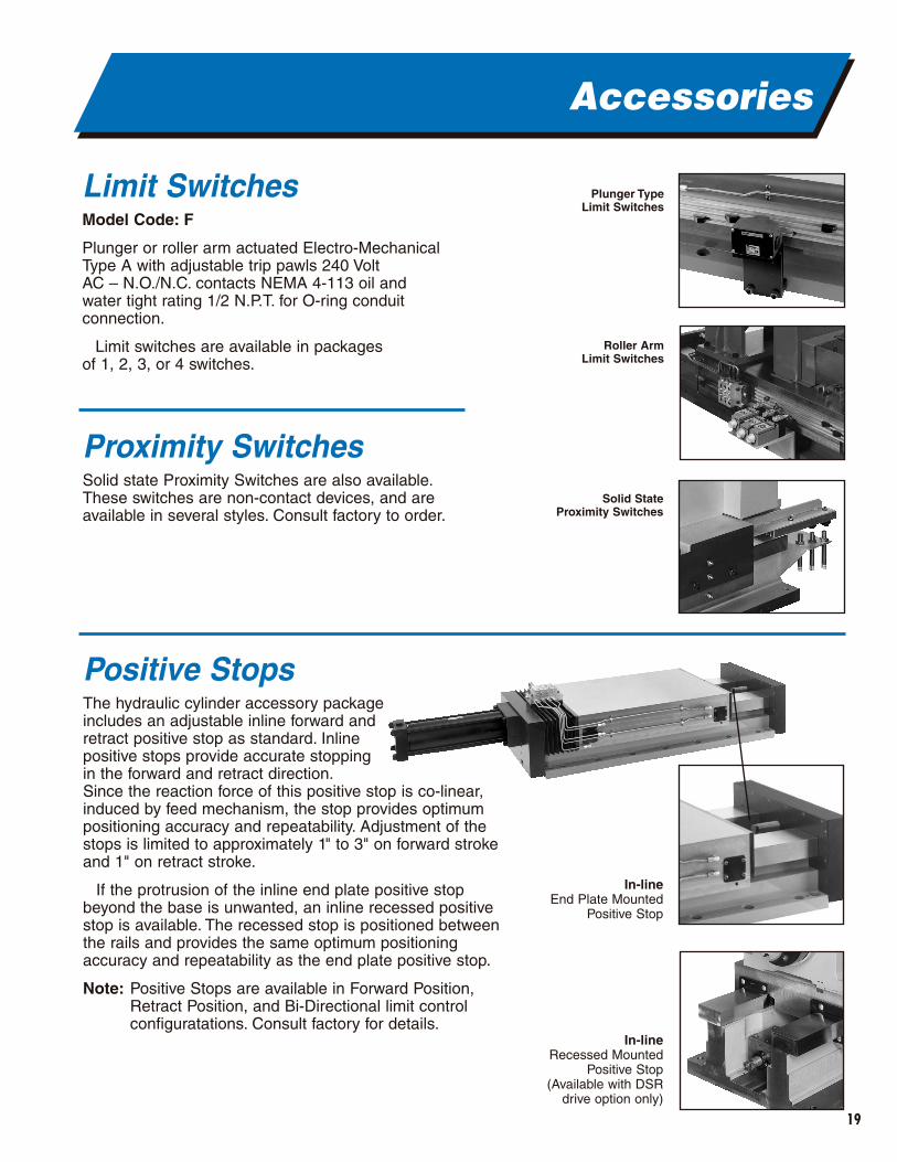
Positive StopsThe hydraulic cylinder accessory package includes an adjustable inline forward and retract positive stop as standard. Inline positive stops provide accurate stopping in the forward and retract direction.Since the reaction force of this positive stop is co-linear,induced by feed mechanism, the stop provides optimumpositioning accuracy and repeatability. Adjustment of thestops is limited to approximately 1" to 3" on forward strokeand 1" on retract stroke.
If the protrusion of the inline end plate positive stopbeyond the base is unwanted, an inline recessed positivestop is available. The recessed stop is positioned betweenthe rails and provides the same optimum positioningaccuracy and repeatability as the end plate positive stop.
Note: Positive Stops are available in Forward Position,Retract Position, and Bi-Directional limit controlconfiguratations. Consult factory for details.
19
Accessories
Limit SwitchesModel Code: F
Plunger or roller arm actuated Electro-MechanicalType A with adjustable trip pawls 240 Volt AC – N.O./N.C. contacts NEMA 4-113 oil andwater tight rating 1/2 N.P.T. for O-ring conduit connection.
Limit switches are available in packages of 1, 2, 3, or 4 switches.
Proximity SwitchesSolid state Proximity Switches are also available.These switches are non-contact devices, and areavailable in several styles. Consult factory to order.
Plunger TypeLimit Switches
Roller Arm Limit Switches
Solid StateProximity Switches
In-lineEnd Plate Mounted
Positive Stop
In-lineRecessed Mounted
Positive Stop(Available with DSR
drive option only)
20
Accessories
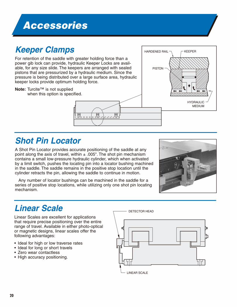
Keeper ClampsFor retention of the saddle with greater holding force than apower gib lock can provide, hydraulic Keeper Locks are avail-able, for any size slide. The keepers are arranged with sealedpistons that are pressurized by a hydraulic medium. Since thepressure is being distributed over a large surface area, hydraulickeeper locks provide optimum holding force.
Note: Turcite™ is not supplied when this option is specified.
Shot Pin LocatorA Shot Pin Locator provides accurate positioning of the saddle at anypoint along the axis of travel, within ± .005". The shot pin mechanismcontains a small low-pressure hydraulic cylinder, which when activatedby a limit switch, pushes the locating pin into a locator bushing machinedin the saddle. The saddle remains in the positive stop location until thecylinder retracts the pin, allowing the saddle to continue in motion.
Any number of locator bushings can be machined in the saddle for aseries of positive stop locations, while utilizing only one shot pin locatingmechanism.
KEEPERHARDENED RAIL
PISTON
HYDRAULICMEDIUM
Linear ScaleLinear Scales are excellent for applications that require precise positioning over the entirerange of travel. Available in either photo-opticalor magnetic designs, linear scales offer thefollowing advantages:
• Ideal for high or low traverse rates• Ideal for long or short travels• Zero wear contactless• High accuracy positioning.
DETECTOR HEAD
LINEAR SCALE
21
Accessories
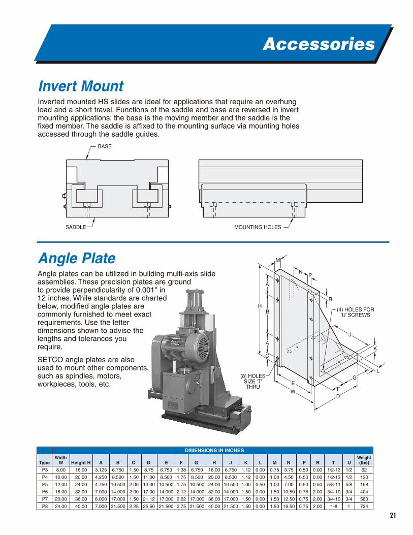
Invert MountInverted mounted HS slides are ideal for applications that require an overhungload and a short travel. Functions of the saddle and base are reversed in invertmounting applications: the base is the moving member and the saddle is thefixed member. The saddle is affixed to the mounting surface via mounting holesaccessed through the saddle guides.
Angle PlateAngle plates can be utilized in building multi-axis slideassemblies. These precision plates are ground to provide perpendicularity of 0.001" in 12 inches. While standards are charted below, modified angle plates are commonly furnished to meet exact requirements. Use the letter dimensions shown to advise the lengths and tolerances you require.
SETCO angle plates are also used to mount other components, such as spindles, motors, workpieces, tools, etc.
BASE
SADDLE MOUNTING HOLES
8.00
10.00
12.00
16.00
20.00
24.00
6.750
8.500
10.500
14.000
17.000
21.500
1.38
1.75
1.75
2.12
2.62
2.75
Type WWidth
(lbs)Weight
Height H A B C D E F
16.00
20.00
24.00
32.00
36.00
40.00
H
6.750
8.500
10.500
14.000
17.000
21.500
J
1.12
1.12
1.00
1.50
1.50
1.50
K
0.00
0.00
0.50
0.00
0.00
0.00
L
0.75
1.00
1.00
1.50
1.50
1.50
62
120
168
404
580
734
M
3.75
4.50
7.00
10.50
12.50
16.50
N
0.50
0.50
0.50
0.75
0.75
0.75
P
0.00
0.00
0.50
2.00
2.00
2.00
R
1/2-13
1/2-13
5/8-11
3/4-10
3/4-10
1-8
T
1/2
1/2
5/8
3/4
3/4
1
UG
DIMENSIONS IN INCHES
16.00
20.00
24.00
32.00
36.00
40.00
3.125
4.250
4.750
7.000
8.000
7.000
6.750
8.500
10.500
14.000
17.000
21.500
1.50
1.50
2.00
2.00
1.50
2.25
8.75
11.00
13.00
17.00
21.12
25.50
6.750
8.500
10.500
14.000
17.000
21.500
P3
P4
P5
P6
P7
P8
A
R
(4) HOLES FOR‘U’ SCREWS
(8) HOLESSIZE ‘T’THRU
A
D
G
F
K
L
W
E
J
N
M
P
C
BH
22
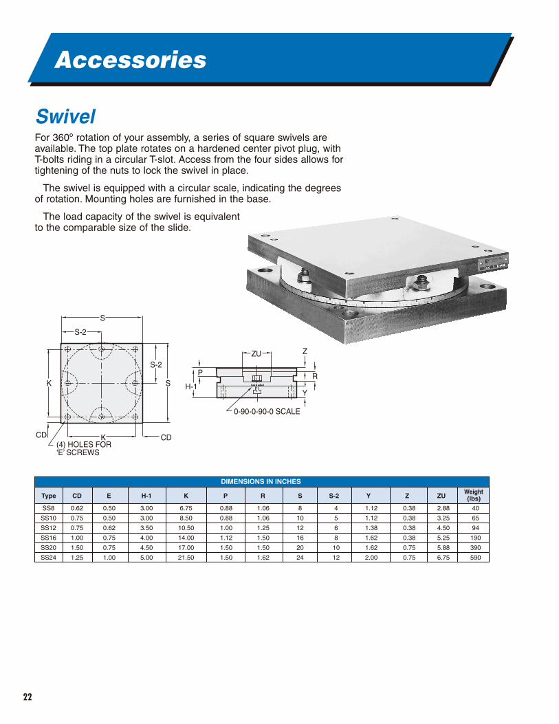
SwivelFor 360º rotation of your assembly, a series of square swivels areavailable. The top plate rotates on a hardened center pivot plug, withT-bolts riding in a circular T-slot. Access from the four sides allows fortightening of the nuts to lock the swivel in place.
The swivel is equipped with a circular scale, indicating the degreesof rotation. Mounting holes are furnished in the base.
The load capacity of the swivel is equivalent to the comparable size of the slide.
Accessories
S
CDK
K S
Z
0-90-0-90-0 SCALE
R
Y
S-2P
H-1
CD(4) HOLES FOR‘E’ SCREWS
S-2
ZU
0.62
0.75
0.75
1.00
1.50
1.25
1.12
1.12
1.38
1.62
1.62
2.00
4
5
6
8
10
12
Type CD (lbs)Weight
E H-1 K P R S S-2
0.38
0.38
0.38
0.38
0.75
0.75
Z
2.88
3.25
4.50
5.25
5.88
6.75
ZU
40
65
94
190
390
590
Y
DIMENSIONS IN INCHES
0.50
0.50
0.62
0.75
0.75
1.00
3.00
3.00
3.50
4.00
4.50
5.00
6.75
8.50
10.50
14.00
17.00
21.50
0.88
0.88
1.00
1.12
1.50
1.50
1.06
1.06
1.25
1.50
1.50
1.62
8
10
12
16
20
24
SS8
SS10
SS12
SS16
SS20
SS24
23
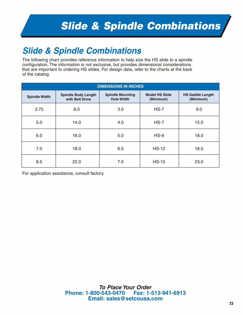
Slide & Spindle CombinationsThe following chart provides reference information to help size the HS slide to a spindleconfiguration. The information is not exclusive, but provides dimensional considerationsthat are important to ordering HS slides. For design data, refer to the charts at the backof the catalog.
For application assistance, consult factory.
Slide & Spindle Combinations
Spindle Width
DIMENSIONS IN INCHES
3.75
5.0
6.0
7.0
8.5
Spindle Body Lengthwith Belt Drive
8.0
14.0
16.0
18.0
22.0
Spindle MountingHole Width
3.0
4.0
5.0
6.0
7.0
Model HS Slide(Minimum)
HS-7
HS-7
HS-9
HS-12
HS-15
HS Saddle Length(Minimum)
9.0
15.0
18.0
18.0
23.0
To Place Your OrderPhone: 1-800-543-0470 Fax: 1-513-941-6913
Email: [email protected]
24
HS Maintenance
Slide GibStraight gibs are standard, and areadequate for most manual feed andpowered feed slide applications havinglow duty cycles.
Tapered gibs are optional and should be considered on most power applicationshaving high duty cycles and/or precisionpositioning applications. Single taperedgibs are limited to saddless with lengths no more than twice the saddle width.For lengths greater than twice the saddlewidth, two opposing tapered gibs must be used.
As standard, the gib is located on theright side of the slide, when viewing fromthe drive end. An exception to this iswhen the slide is mounted sidewall, the gib should be on the bottom. Also, the gib should always be on the sideopposite the direction of loading.
The following is offered as a guideline to properly adjust the gib. Gib adjustmentmay vary for each particular applicationwith final adjustment determined by thecustomer to assure proper performance.
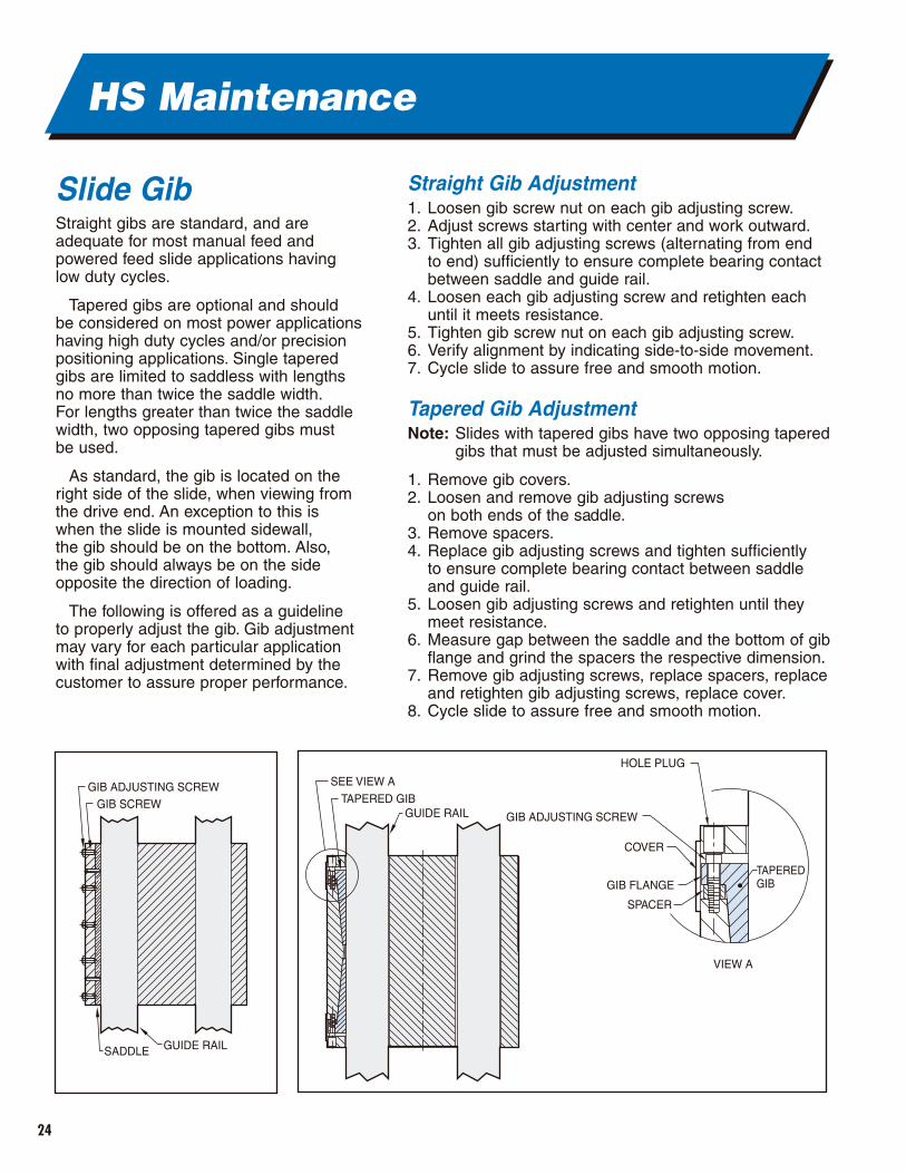
Straight Gib Adjustment1. Loosen gib screw nut on each gib adjusting screw.2. Adjust screws starting with center and work outward.3. Tighten all gib adjusting screws (alternating from end
to end) sufficiently to ensure complete bearing contactbetween saddle and guide rail.
4. Loosen each gib adjusting screw and retighten eachuntil it meets resistance.
5. Tighten gib screw nut on each gib adjusting screw.6. Verify alignment by indicating side-to-side movement.7. Cycle slide to assure free and smooth motion.
Tapered Gib AdjustmentNote: Slides with tapered gibs have two opposing tapered
gibs that must be adjusted simultaneously.
1. Remove gib covers.2. Loosen and remove gib adjusting screws
on both ends of the saddle.3. Remove spacers.4. Replace gib adjusting screws and tighten sufficiently
to ensure complete bearing contact between saddle and guide rail.
5. Loosen gib adjusting screws and retighten until theymeet resistance.
6. Measure gap between the saddle and the bottom of gibflange and grind the spacers the respective dimension.
7. Remove gib adjusting screws, replace spacers, replaceand retighten gib adjusting screws, replace cover.
8. Cycle slide to assure free and smooth motion.
GIB ADJUSTING SCREW
SADDLE GUIDE RAIL
GIB SCREW
SEE VIEW A
TAPERED GIBGUIDE RAIL
HOLE PLUG
GIB ADJUSTING SCREW
COVER
GIB FLANGE
SPACER
VIEW A
TAPERED GIB
25
HS Maintenance
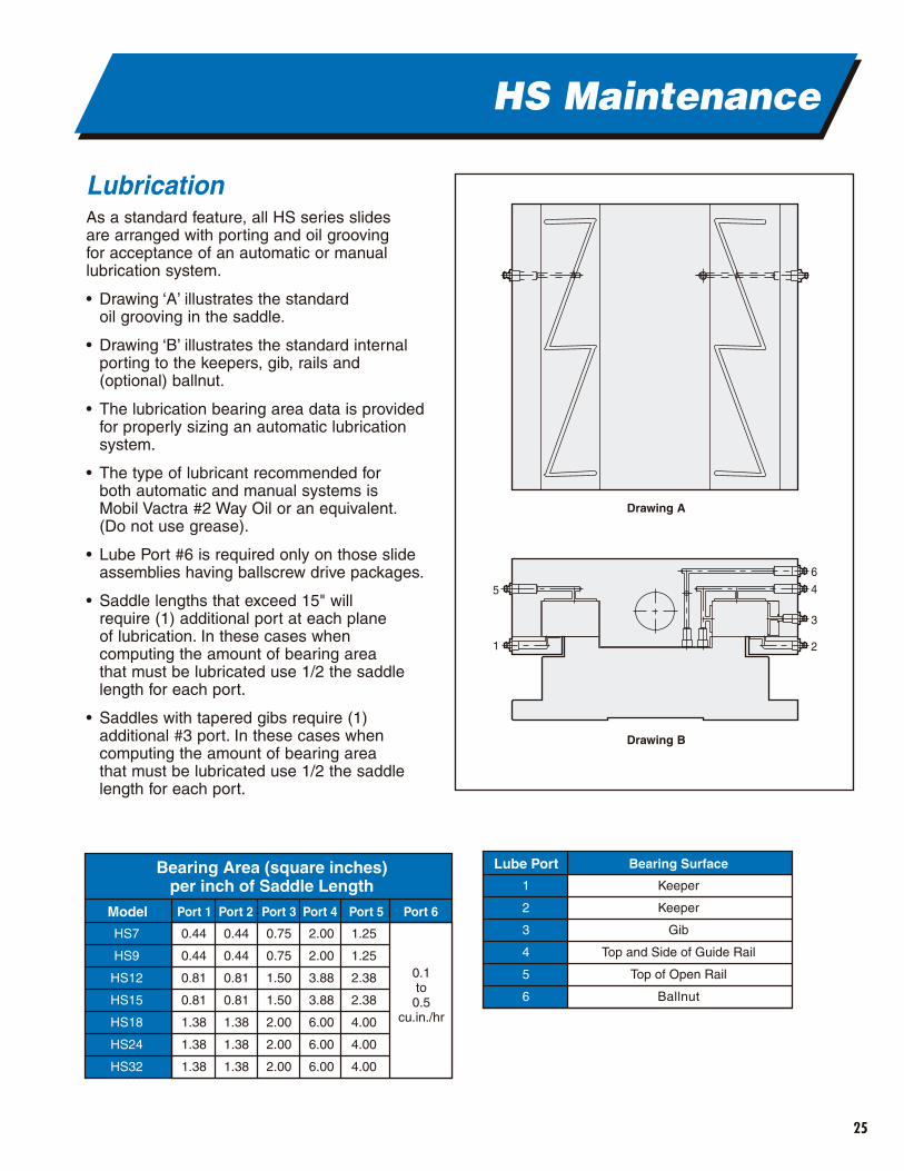
LubricationAs a standard feature, all HS series slides are arranged with porting and oil grooving for acceptance of an automatic or manuallubrication system.
• Drawing ‘A’ illustrates the standard oil grooving in the saddle.
• Drawing ‘B’ illustrates the standard internalporting to the keepers, gib, rails and(optional) ballnut.
• The lubrication bearing area data is providedfor properly sizing an automatic lubricationsystem.
• The type of lubricant recommended for both automatic and manual systems is Mobil Vactra #2 Way Oil or an equivalent.(Do not use grease).
• Lube Port #6 is required only on those slideassemblies having ballscrew drive packages.
• Saddle lengths that exceed 15" will require (1) additional port at each plane of lubrication. In these cases whencomputing the amount of bearing area that must be lubricated use 1/2 the saddlelength for each port.
• Saddles with tapered gibs require (1)additional #3 port. In these cases whencomputing the amount of bearing area that must be lubricated use 1/2 the saddlelength for each port.
6
4
3
21
5
Drawing A
Drawing B
Port 1 Port 2 Port 3 Port 4 Port 5 Port 6
0.44
0.44
0.81
0.81
1.38
1.38
1.38
0.44
0.44
0.81
0.81
1.38
1.38
1.38
0.75
0.75
1.50
1.50
2.00
2.00
2.00
2.00
2.00
3.88
3.88
6.00
6.00
6.00
1.25
1.25
2.38
2.38
4.00
4.00
4.00
0.1to0.5
cu.in./hr
Model
HS7
HS9
HS12
HS15
HS18
HS24
HS32
Bearing Area (square inches)per inch of Saddle Length
Lube Port Bearing Surface
Keeper
Keeper
Gib
Top and Side of Guide Rail
Top of Open Rail
Ballnut
1
2
3
4
5
6
26
Design Data
Slide Tolerances• Flatness of base bottom - 0.001" per 12".• Flatness of saddle top - 0.001" per 12".• Parallelism of saddle top to base
bottom - 0.001 per 12".• Parallelism of reference edge (on side base)
to guide rail - 0.001" per 12".• Slide overall height tolerance - nominal
to +/-0.010".• Perpendicularity to base ends to base bottom
and base reference edge - 0.001".• Perpendicularity of saddle ends to saddle
top and saddle reference edge - 0.003".• Squareness in each plane of compound
slide - 0.001" per 12" cumulative from axis to axis.
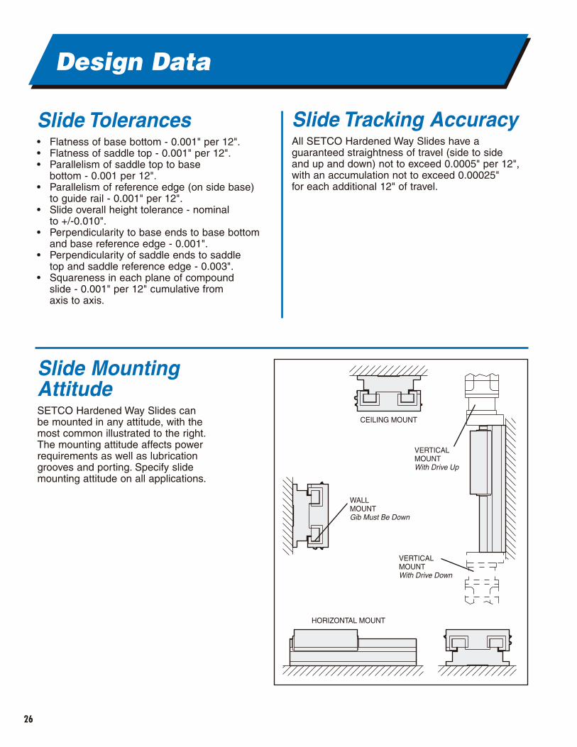
Slide MountingAttitudeSETCO Hardened Way Slides can be mounted in any attitude, with themost common illustrated to the right.The mounting attitude affects powerrequirements as well as lubricationgrooves and porting. Specify slidemounting attitude on all applications.
Slide Tracking AccuracyAll SETCO Hardened Way Slides have a guaranteed straightness of travel (side to side and up and down) not to exceed 0.0005" per 12",with an accumulation not to exceed 0.00025" for each additional 12" of travel.
CEILING MOUNT
VERTICALMOUNTWith Drive Up
VERTICALMOUNTWith Drive Down
WALLMOUNTGib Must Be Down
HORIZONTAL MOUNT
27
Design Data
Force and TorqueRequirementsThe force required to power the slide includes theforce required to move the saddle plus the forcerequired to overcome all external loads, multipliedby a factor of safety depending on the type ofdrive used. The factor of safety is applied toassure sufficient power to accelerate the load.
DefinitionsForce and Thrust RequirementsFh = Force required to power slide horizontally (lbs.)Fv = Force required to power slide vertically (lbs.) Fwh = Force required to power saddle weight
horizontally (lbs.)Fwv = Force required to power saddle weight
vertically (lbs.)Ff = Force required to overcome applied loads (lbs.)F = Applied external load (see force direction
in Load Cases on page 28)d = Perpendicular distance from saddle
to applied load (inches)Fh = Applied load perpendicular and into plane
of saddle top (lbs.) (see drawing to left)Fv = Applied load perpendicular and away from plane
of saddle top (lbs.) (see drawing to left)Fs = Applied load perpendicular and into or away from
plane of saddle side (lbs.) (see drawing to left).FMX = Force required to overcome moment
Mx and load F (lbs.)FMY = Force required to overcome moment
MY and load F (lbs.)FMZ = Force required to overcome moment
Mz and load F (lbs.)M = Applied external moment (inch-lbs)MX = Moment about saddle width (inch-lbs)MY = Moment about plane of saddle top (inch-lbs)MZ = Moment about saddle length (inch-lbs)fs = Factor of safety:
• Manual drives = 1.5• Feedscrew drives = 2• Hydraulic cylinder drives= 2.5.
µ = Coefficient of friction (see page 28)WSL = Unit weight of saddle (lbs./in.)SL = Saddle length (inches)SW = Saddle width (inches)Th = Torque required to power slide horizontally
(inch-lbs.)Tv = Torque required to power slide vertically
(inch-lbs.)L = Lead of screw (inches/rev.)k = Screw constant
• Acme screw = 0.5• Ballscrew = 0.2
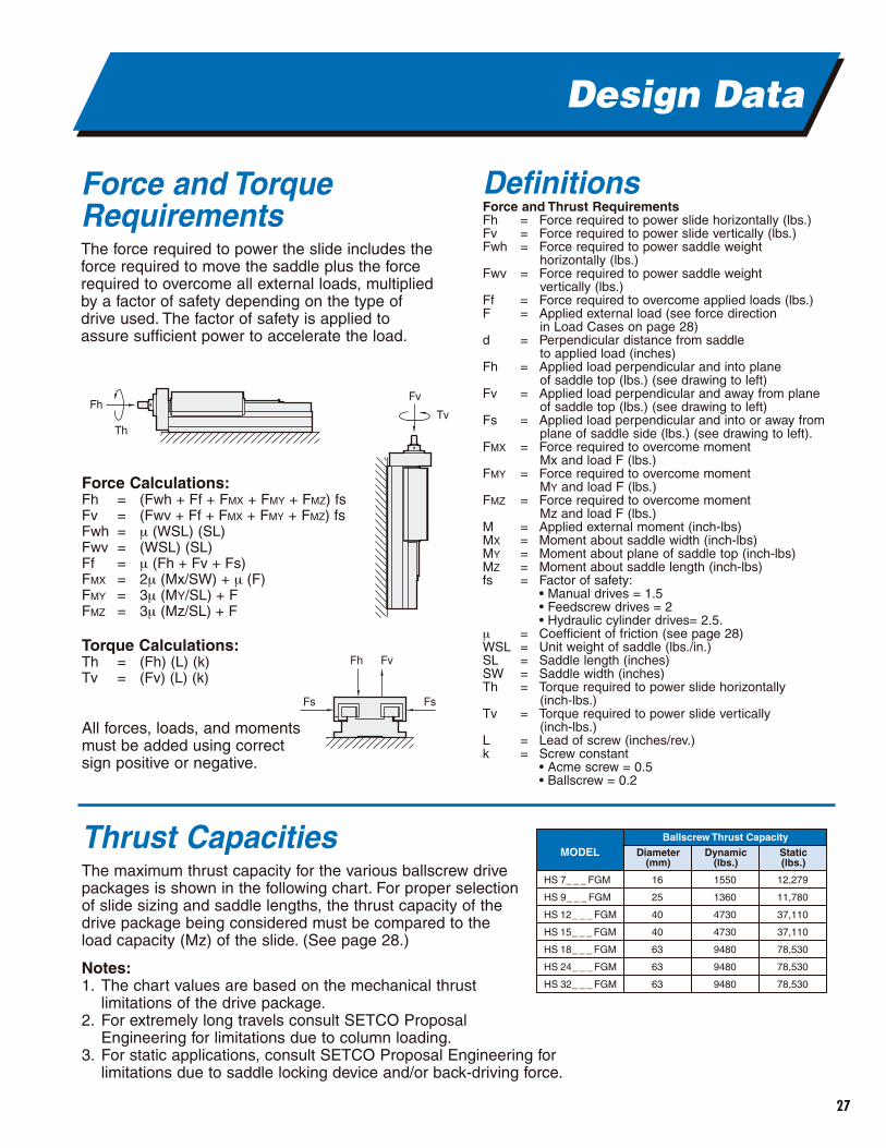
Thrust CapacitiesThe maximum thrust capacity for the various ballscrew drivepackages is shown in the following chart. For proper selectionof slide sizing and saddle lengths, the thrust capacity of thedrive package being considered must be compared to theload capacity (Mz) of the slide. (See page 28.)
Notes:1. The chart values are based on the mechanical thrust
limitations of the drive package.2. For extremely long travels consult SETCO Proposal
Engineering for limitations due to column loading.3. For static applications, consult SETCO Proposal Engineering for
limitations due to saddle locking device and/or back-driving force.
Fh
Th
Fv
Tv
Fh
Fs Fs
Fv
MODELBallscrew Thrust Capacity
16
25
40
40
63
63
63
HS 7_ _ _ FGM
HS 9_ _ _ FGM
HS 12_ _ _ FGM
HS 15_ _ _ FGM
HS 18_ _ _ FGM
HS 24_ _ _ FGM
HS 32_ _ _ FGM
Diameter(mm)
1550
1360
4730
4730
9480
9480
9480
Dynamic(lbs.)
12,279
11,780
37,110
37,110
78,530
78,530
78,530
Static(lbs.)
Force Calculations:Fh = (Fwh + Ff + FMX + FMY + FMZ) fsFv = (Fwv + Ff + FMX + FMY + FMZ) fsFwh = µ (WSL) (SL)Fwv = (WSL) (SL)Ff = µ (Fh + Fv + Fs)FMX = 2µ (Mx/SW) + µ (F)FMY = 3µ (MY/SL) + FFMZ = 3µ (Mz/SL) + F
Torque Calculations:Th = (Fh) (L) (k)Tv = (Fv) (L) (k)
All forces, loads, and moments must be added using correct sign positive or negative.
28
Design Data
Slide Load CapacityTo optimize slide operation over the long haul, oneof the most important considerations in selection isthe loading applied to the slide. Loading capacity isbased on the pressure exerted by an externallyapplied load on the engaged slide way surfaces.These externally applied loads are considered tobe the following:
• STATIC Loading - External loading is applied to a stationary saddle.
• DYNAMIC Loading - External loading is applied to a moving saddle.
• SINGLE Loading - Only one external load is applied.
• COMBINED Loading - More than one external load is applied.
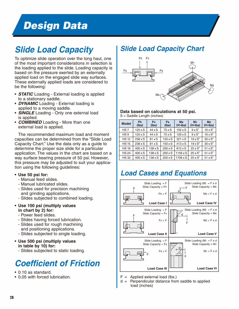
The recommended maximum load and momentcapacities can be determined from the “Slide LoadCapacity Chart.” Use the data only as a guide todetermine the proper size slide for a particularapplication. The values in the chart are based on away surface bearing pressure of 50 psi. However,this pressure may be adjusted to suit your applica-tion using the following guidelines:
• Use 50 psi for:- Manual feed slides.- Manual lubricated slides.- Slides used for precision machining
and grinding applications.- Slides subjected to combined loading.
• Use 100 psi (multiply values in chart by 2) for:- Power feed slides.- Slides having forced lubrication.- Slides used for rough machining
and positioning applications.- Slides subjected to single loading.
• Use 500 psi (multiply values in table by 10) for:- Slides subjected to static loading.
Coefficient of Friction• 0.10 as standard.• 0.05 with forced lubrication. F = Applied external load (lbs.)
d = Perpendicular distance from saddle to applied load (inches)
F F
F
F
FF
d
d
d
Model Fh(lbs)
Fv(lbs)
Fs(lbs)
Mx(in-lbs)
MY(in-lbs)
Mz(in-lbs)
HS 7
HS 9
HS 12
HS 15
HS 18
HS 24
HS 32
125 x S
125 x S
238 x S
238 x S
400 x S
400 x S
400 x S
44 x S
44 x S
81 x S
81 x S
138 x S
138 x S
138 x S
75 x S
75 x S
150 x S
150 x S
200 x S
200 x S
200 x S
102 x S
129 x S
321 x S
413 x S
812 x S
1156 x S
1706 x S
9 x S2
9 x S2
19 x S2
19 x S2
25 x S2
25 x S2
25 x S2
16 x S2
16 x S2
30 x S2
30 x S2
51 x S2
51 x S2
51 x S2
Fs
FvFh
Fs
MY
Mz
Mx
Slide Load Capacity Chart
Load Cases and Equations
Data based on calculations at 50 psi.S = Saddle Length (inches)
Slide Loading = FSlide Capacity = Fh
Fh > F
Load Case I
Slide Loading = FSlide Capacity = Fv
Fv > F
Load Case II
Slide Loading = FSlide Capacity = Fs
Fs > F
Load Case III
Slide Loading (M) = F x dSlide Capacity = Mx
Mx > F x d
Load Case IV
Slide Loading (M) = F x dSlide Capacity = Mz
Mz > F x d
Load Case V
Slide Loading (M) = F x dSlide Capacity = MY
MY > F x d
Load Case VI
29
Design Data
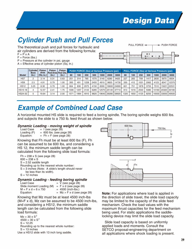
Cylinder Push and Pull ForcesThe theoretical push and pull forces for hydraulic and air cylinders are derived from the following formula:F = P x AF = Force (lbs.)P = Pressure at the cylinder in psi, gaugeA = Effective area of cylinder piston (Sq. In.)
Dynamic Loading - moving weight of spindleLoad Case = I (see page 28)Loading (F) = 600 lbs. (see page 28)Equation: = Fh > F (see page 28)
Knowing that Fh must be at least 600 lbs (F), Fhcan be assumed to be 600 lbs, and considering aHS 12, the minimum saddle length can becalculated from the following slide load formula:
Fh = 238 x S (see page 28)600 = 238 x SS = 2.52 saddle lengthRounding up to the nearest whole number:S = 3 inches (Note: A slide’s length should never
be less than its width).S = 12 inches
Dynamic Loading - feeding boring spindleLoad Case = V (see page 28)Slide moment Loading (M) = F x d (see page 28)M = F x d = 6 x 750 = 4500 (inch-lbs.)Equation: = Mz > F x d (see page 28)
Knowing that Mz must be at least 4500 inch-lbs(M=F x d), Mz can be assumed to be 4500 inch-lbs,and considering a HS12, the minimum saddlelength can be calculated from the following slideload formula:
Mz = 30 x S2
4500 = 30 x S2
S = 12.25Rounding up to the nearest whole number:S = 13 inches
Use a HS12 slide with 13 inch long saddle.
Note: For applications where load is applied in the direction of slide travel, the slide load capacitymay be limited to the capacity of the slide feedmechanism. Check the load values with themaximum thrust capacities for the feed mechanismbeing used. For static applications the saddle-locking device may limit the slide load capacity.
Slide load capacity is based on uniformly applied loads and moments. Consult the SETCO proposal-engineering department on all applications where shock loading is present.
CylinderBore(In.) 80 100 250 500 1000 2000 3000 100 250 500 1000 2000 3000
PUSH FORCE (lbs) at Various Pressure (psi) PULL FORCE (lbs) at Various Pressure (psi)
2
2.5
3.25
4
5
Model
HS7
HS9
HS12
HS15-18
HS24-32
PistonArea
(Sq. In.)
3.14
4.91
8.30
12.57
19.64
PistonRod Area
(In.)
PistonRod Dia.
(In.)
0.31
0.79
0.79
2.41
3.14
0.63
1.00
1.00
1.75
2.00
251
393
664
1006
1571
314
491
830
1257
1964
785
1228
2075
3143
4910
1570
2455
4150
6285
9820
3140
4910
8300
12570
19640
6280
9820
16600
25140
39280
9420
14730
24900
37710
58920
227
330
601
813
1320
283
412
751
1016
1650
709
1031
1878
2540
4125
1417
2062
3755
5080
8250
2835
4123
7510
10160
16500
5670
8247
15021
20320
33000
8504
12370
22531
30180
49500
80
750 lbs.600 lbs.
F
6"
Fnd
PULL FORCE PUSH FORCE
Example of Combined Load CaseA horizontal mounted HS slide is required to feed a boring spindle. The boring spindle weighs 600 lbs.and subjects the slide to a 750 lb. feed thrust as shown below.
30
HS Application Photos
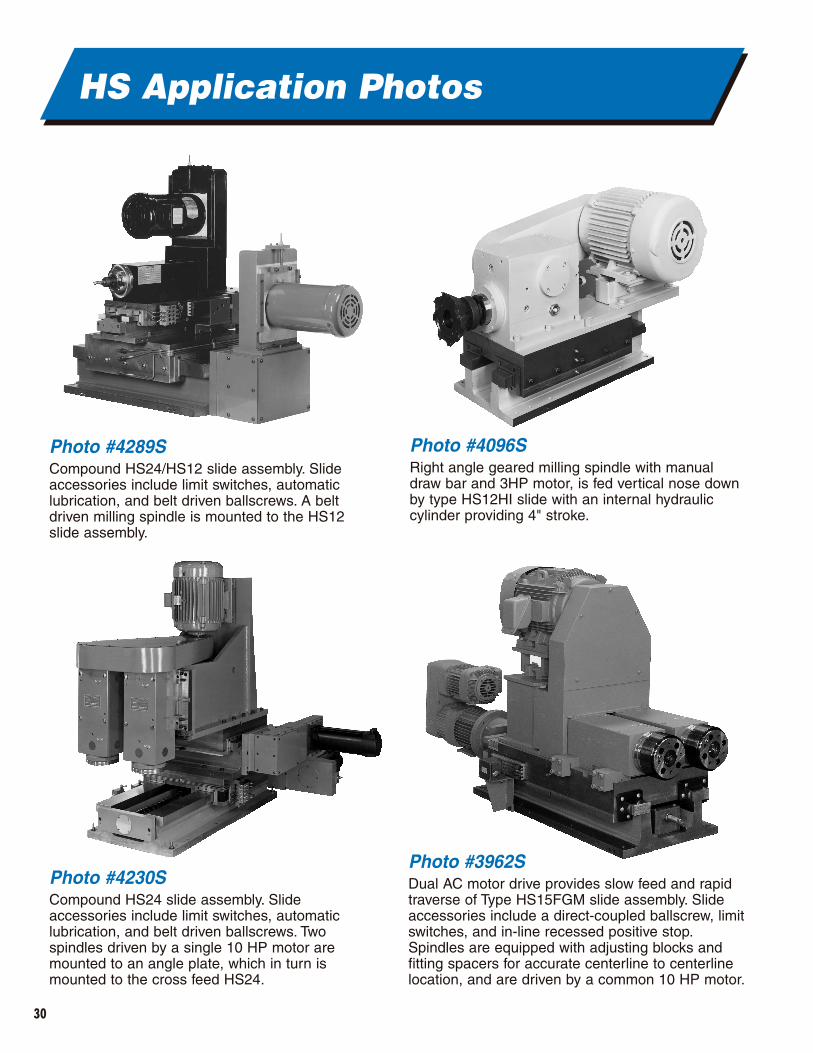
Photo #4289SCompound HS24/HS12 slide assembly. Slideaccessories include limit switches, automaticlubrication, and belt driven ballscrews. A beltdriven milling spindle is mounted to the HS12slide assembly.
Photo #4096SRight angle geared milling spindle with manualdraw bar and 3HP motor, is fed vertical nose downby type HS12HI slide with an internal hydrauliccylinder providing 4" stroke.
Photo #3962SDual AC motor drive provides slow feed and rapidtraverse of Type HS15FGM slide assembly. Slideaccessories include a direct-coupled ballscrew, limitswitches, and in-line recessed positive stop.Spindles are equipped with adjusting blocks andfitting spacers for accurate centerline to centerlinelocation, and are driven by a common 10 HP motor.
Photo #4230SCompound HS24 slide assembly. Slideaccessories include limit switches, automaticlubrication, and belt driven ballscrews. Twospindles driven by a single 10 HP motor aremounted to an angle plate, which in turn ismounted to the cross feed HS24.
31
HS Application Photos
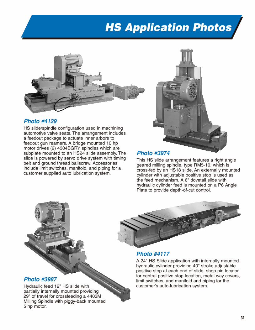
Photo #4129HS slide/spindle configuration used in machiningautomotive valve seats. The arrangement includesa feedout package to actuate inner arbors tofeedout gun reamers. A bridge mounted 10 hpmotor drives (2) 4304BGRY spindles which aresubplate mounted to an HS24 slide assembly. Theslide is powered by servo drive system with timingbelt and ground thread ballscrew. Accessoriesinclude limit switches, manifold, and piping for acustomer supplied auto lubrication system.
Photo #3974This HS slide arrangement features a right anglegeared milling spindle, type RM5-10, which iscross-fed by an HS18 slide. An externally mountedcylinder with adjustable positive stop is used asthe feed mechanism. A 6" dovetail slide withhydraulic cylinder feed is mounted on a P6 AnglePlate to provide depth-of-cut control.
Photo #4117A 24" HS Slide application with internally mountedhydraulic cylinder providing 40" stroke adjustablepositive stop at each end of slide, shop pin locatorfor central positive stop location, metal way covers,limit switches, and manifold and piping for thecustomer’s auto-lubrication system.
Photo #3987Hydraulic feed 12" HS slide withpartially internally mounted providing29" of travel for crossfeeding a 4403MMilling Spindle with piggy-back mounted5 hp motor.
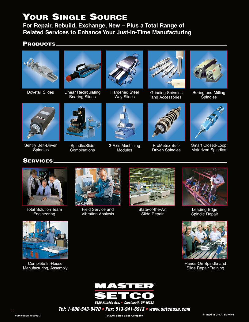
Dovetail Slides Linear RecirculatingBearing Slides
Spindle/SlideCombinations
Hardened Steel Way Slides
Sentry Belt-DrivenSpindles
ProMetrix Belt-Driven Spindles
Grinding Spindlesand Accessories
Boring and MillingSpindles
Total Solution TeamEngineering
Field Service andVibration Analysis
State-of-the-Art Slide Repair
Leading Edge Spindle Repair
Complete In-HouseManufacturing, Assembly
Hands-On Spindle andSlide Repair Training
Smart Closed-LoopMotorized Spindles
3-Axis MachiningModules
For Repair, Rebuild, Exchange, New – Plus a Total Range ofRelated Services to Enhance Your Just-In-Time Manufacturing
SERVICES
PRODUCTS
YOUR SINGLE SOURCE
Publication M-0003-3 Printed in U.S.A. 5M 0405© 2004 Setco Sales Company
5880 Hillside Ave. • Cincinnati, OH 45233
Tel: 1-800-543-0470 • Fax: 513-941-6913 • www.setcousa.com00


